


Foundry Work - Forgotten Books
217
-
Upload
khangminh22 -
Category
Documents
-
view
0 -
download
0
Transcript of Foundry Work - Forgotten Books


FOUNDRY WORKA Practical Handb o ok on Standard Found ry Practi ce,
Including Hand and Machine Mold ing ; CastIron, Malleable Iron , Steel, and Brass
Castings ; Foundry Manage
ment; Etc .
REVISED BY
BURTON L . GRAYIN STRUCTOR IN FOU N DRY PRACTICE , W ORCESTER POLYTECHN IC IN STITUTE
MEMBER, FO U N DRYMEN ’
S ASSOCIATION
ILLUSTRATED
AMER ICAN TECHNICAL SOC IETYCHICAGO
1920

COPYR IGHT . 1916, 1918, 1920. BY
AMER ICAN TE CHN ICAL SOC IETY
COPYRIGHTED IN GREAT B RITA INA L L RIGHTS RESERV ED
"6LA5 6 56 8 7

INTRODUCTION
HE making of a metal casting seems like a very simple opera
tion—g iven a pattern, a flask , a supply of molding sand , and
some molten metal ; presto"it is done— but a little study develops the fact that there are few industries where more depends
upon shop kinks and the many other essential things which make
up a broad knowledge of a distinct trade than in foundry work .
The industry, as such , is as old as our knowledge of brass and iron,
the former having been made into casting s from earl iest times .
(l
asting methods, however, have partaken of the genera l mechanical
development of the last few years and today there is no com
parison as to the "ua l ity of casting s, the complexity of the patterns
cast, and the speed of manufacture, with the work of a few years ago .
""In this article the methods of hand molding have been carefullydiscussed
,including the many questions of pattern construction
which are more or less closely associated with foundry work . The
presentation al so includes the uses of the various types of moldingmachines
,which have become so popular within the last few years .
M alleable iron practice has now become well standardized and this
type of casting , particularly for smal l work requiring much dupli
cation,is very important . An excellent discussion of steel casting s
is particularly pertinent as this type of casting is fast displacingdrop forg ing s for many classes of work .
"}Altogether the article represents a well - rounded and thoroughly
up- to- date discussion of this important subject . The orig inal author
and the reviser, both men of broad experience, have combined to
g ive the reader the benefit of their knowledge and it is the hope of
the publishers that the book will be found instructive and interest
ing to the practical foundry man as well as to the g eneral reader .


CONTENTS
gMolding practice
Main branches'
MoId-ing equipmentC la ss-es .
o o o o o o o o o o o o o o o o o o o o o o o o o o o o o o o o o o o o o o o o o o
Distinction .
Fire clay .
Parting dusts .
Core binders .
Tools
0 0 0 0 0 0 0 0 0 0 0 0 0 0 0 0 0 0 0 0 0 0 0 0 0 0 0 0 0 0 0 0 0 0 0 0 0 0 0
Finishing toolsClamps
Molding proces s esSand mixture .
Sifti‘ng .
RammingGatingShrinkag e heads .
Pressure in moldsCommon defects in casting s
Typicalmol'
ding problems .
Flat j oint .
C Oping out .
Sand match .
Splits—pattern molds .
Floor bedding .
Open m-ol’
d

CONTENTS
Core work
M aterialsEquipmentConditions of use.
M ethods of making .
Cylindrical cores .
Setting chaplets . .
Proj ecting cores .
Hang ing cores .
Bottom - anchored cores .
D uplicating castings .
Practical requisites i n hand molding .
U se of molding machines
D ry- sand work .
Characteristic featuresM olding eng ine cylinder .
M aking barrel core .
Loammold ing
Rigg ing .
M aterialsPrinciples of work .
Simple mold .
Intricate mold
Casting Operations .
Furnace partsBlast .
Running a heat .
Foundry ladles .Pouring .
Chemical analysis .Calculation of mixture .
Fuel .Sand mixingCleaning castings .
Steel work .
Present developmentProcesses .
Characteristics of metal.

CONTENTS
PAGE
Facing mixturesPacki
’
ng .
Steel castings .
Running a heat .
Setting up molds .
C leaning casting s .
Annealing .
M alleable practice .
Comparative characteristics of metal.
TestingProduction proce s sesMolding methodsM ethods of meltingIron mixture .
Variation from g ray - i ron practice .
C leaning casting sAnnealingFinishing .
Brass work .
M etalsM ixtures
ProductionM olding materials .
EquipmentExamples of workM eltingCleaning .
Shop manag ement .
Governing factors .M olding divisions .
Materials“.Handling systems .
Cleaning department .
P erformanceAccident prevention .
CheckingKeep ’s mechanical analysisArbitration - bar tests .


FOUNDRY W ORK
PART I
MO LD ING PRACT ICE
Introductory . Foundry work is the name applied to that
branch of eng ineering which deal s with melting metal and pouringit in l iquid form into sand molds to shape it into casting s of all
descriptions.
In the manufacture of modern machinery three classes of
casting s are employed, each one having its individual physicalproperties, such as strength, toughness, durabil ity, etc . These
casting s are as follows : gray iron ; copper alloys, i .e .,brass
,bronze ,
et‘
c . ; and mild steel . By far the g reatest number of casting s made
are of g ray iron, that is, iron which may be machined d irectly as it
comes from the mold without any further heat treatment .
The main purpose of this book is to expla in the underlying prin
ciples involved in making molds for g ray - iron casting s, and the mix
ing and melting of the metals for such casting s . The articles on
Mal leable Cast Iron as wel l as the articles on Brass Founding and
Steel Casting emphasize only those features of the methods used
which d iffer from gray- iron foundry practice . The article on Shop
Management is intended to set students thinking on this subject ;because the whol e trend of modern shop practice is toward special
ization and system in handling every department of the work, in
order to increase effi c iency and reduce cost .
D IVIS IONS OF IRON MOLD ING
Main Branches . There are four main branches in g ray iron
molding : ( l ) g reen- sand work ; (2) core work ; (3 ) dry—sand molding ;and ( l ) loam work .
Green- Sand 111olding .
‘ The cheapest quickest method of form
ing the general run of casting s is by green- sand molding . Damp
molding sand is rammed over the pattern, and suitable flasks are
used for handl ing the mold .
‘ When the pattern is withdrawn the

2 FOUND RY WORK
meld i s finished, and the metal i s poured while the efficiency of the
mold is stil l reta ined by reason of this dampness . The mold may be
poured as soon as made ; and in case of necessity it may be held overa day or more depending upon its size . If the sand dries out
,the
mold should not be poured .
Core Mairing . Core making supplements molding . It deals
with the construction of separate shapes in sand which form holes,
cavities, or pockets, in the castings . Such shapes are cal led cores .
They are held firmly i nposition by the sand of the mold itself or by
the use of chaplets . Core sand is of a different composition frommolding sand . It is shaped in wooden molds cal led core boxes . All
cores are baked in an even before they can be used . The whol e
detail of their construction is so different from that of a mold, thatcore making is a d istinct trade—a trade, however, that i s g eneral ly
considered a stepping stone to that of molding . Boys usual ly begin
to serve their t ime in the core shop .
Dry- Sand Molding . D ry
- sand molding is the term appl ied to
that class of work where a flask is used, but a layer of core sand mix
ture is used as a facing next to the pattern and the joint, and theentire mold is baked before pouring . This drives off all moisture
and gives hard clean surfaces to shape the iron . It is used whereheavy work having considerable detail is to be cast, or where the
rush of metal or the bulk of it might injure a mold of g reen sand .
Dry - sand molds are usually made up one day , baked over night, and
assembled and cast the next day .
Loam U’
ork. Loam work i s the term applied to molds built ofbricks carried on heavy iron plates . The facing is put on the bricks
in the form of mortar and shaped by sweeps or patterns dependingupon the design of thep iece to be cast . All parts of the mold arebaked, rendering the surfaces hard and clean . After being assem
bled, these brick molds must be rammed up on the outsidewith greensand in a p it or casing to prevent their bursting out u nder the castingpressure . Simple molds can be made up one day , assembled, rammed
up and poured the next,but it usually takes 3 or 4: days and some;
times as many weeks to turn out a casting .
Loam work is used for the heaviest class of iron casting s for
which, on account of the l imited number wanted, or the simplicity of
the shape, it would not pay to make complete patterns and use a

FOUND RY WORK 3
flask . In some cases the intricacy of the design makes a pattern
necessary,and size alone excludes the use of sand and flasks .
Selectionof Method. N0 hard and fast rules exist for the selec
tion of the method by which a piece wil l be molded . E specially
with.
large work, the question whether it shal l be put up in green
sand, dry sand, or loam, often depends upon local shop conditions .
The point to consider is : How can the best casting for the purpose
be made for the leastmoney, considering the facil ities at hand towork with?
MOLD ING E"UIPMENT
MATER IALS
Before taking up the making of molds, let us consider briefly
the material s used,where they are obta ined, and what is their
particular service in the mold . Also we shal l describe the principa l
tool s used by the molder in working up these materials into molds .
Clas ses . There are three g eneral classes ofmaterials for mold
ing kept in stock in the foundry, as tabulated herewith :
Mold ing Ma teria ls
SAN D S
Sands
"uality. All sands are formed by the breaking up of rocks due
to the action of natural‘
forces, such as frost, wind, ra in, and theaction of water .
Fragments of rocks on the mounta in sides, broken off by actionof frost are washed into mounta in streams by ra infal l . Here they
g rind against each other and pieces thus chipped off are carried by
the rush of - the current down into the rivers . Tumbled along by the
rapid current of the upper river,the sand will final ly be deposited
where the stream flows more g ently through the low land stretches

4 FOUND RY WORK
TABLE I
Propo r t ions of Elemen ts in Sands
M O LD IN G SAN D S
E L EM EN TS Iron Work
Light M edium Heavy(per cent) (p er cent) (per cent) (p
SilicaAlumina (clay ) A120 ,
Iron oxide . F€ 20 3
Lime oxide . C aOL ime carbonate C aCO q
Magnesia . .M gOSoda .
PO IRSh . . I{ 20
Combined water . H gO
Organic matter .
85 66 4 6
below the hills . Here the sl ight ag itation tends to cause the finer
sand and the clay to settle lower and lower down in the bed . Thus
we find beds that have been formed in ages past ; possibly with a top
soil formed over them, so long have they been deposited . But on
removing this top soil we find gravel or coarse sand on top ; this
merges into finer sand and this again final ly into a bed of clay .
Rocks, however, are very complex in their composition, and
sands conta in most of the elements of the rocks of which they are
fragments . For this reason molding sands in different parts of the
United States vary considerably .
A good molding sand first of all, should be refractory, that is,capable of withstanding the heat of molten metal . It should be
porous to allow the escape of gases from the mold . It should have
a certain amount of clay to g ive it bond or strength, and should have
an even gra in . All of these properties wil l vary according to the
class ofwork for which the sand is used .
Elements . The two important chemical elements in such sands
are s il ica,which is the heat - resisting element, and alum ina, or clay,
which gives the bond . O ther elements which are found in the mold
ing sands are oxide of iron, oxide of l ime, l ime carbonate, soda potash,combined water, etc . The analyses shown in Table I, made by

FOUND RY WORK 5
W . G . Scott, g ive an idea of the proportions of these elements in the
different foundry sands .
Sil ica alone is a fire- resisting element, but it has no bond . These
other elements help in forming the bond . But under heat, sil ica
combines and fuses—with them,forming sil icates . These sil icates
melt at a much lower temperature than does free sil ica . Therefore
with sands carrying much l imestone in their make up, or with those
containing much oxide of iron, soda potash, etc ., the molten iron will
burn in more,making it more diffi cult to clean the casings .
The limestone combinations also go to pieces under heat, tendingto make the sand crumble, which may result in dirty casting s .
The proportions g iven in Table I must not be considered as
absolutely fix ed, for no two samples of sand even from the same bed ,wil l analyze exactly al ike . The table IS instructive, however,because it indicates the reasons why the d ifferent sands are especial ly
adapted to the use to which they are put in practice .
Fire Sand. Such sand is used in the daubing mixture for repa ir
ing inside of cupola and ladles, and should be in the highest deg ree
refractory,and should contain as l ittle matter as possible that would
tend to make it fuse or melt .
Light Mold ing Sand. This sand is used for casting s such as
tove plate, etc ., which may have very finely carved deta il on their
surfaces,but are thin . The sand should be very fine to bring out
this detail ; it must be strong, i.e.
,high in clay, so that the mold will
retain every detail as the metal rushes in . On the other hand, the
work will cool so quickly that after the initia l escape of the a ir andsteam therewil l be very l ittle gas to come off through the sand .
Med ium Sand . Sand of this grade is used in bench work and
l ight floor work, for making machinery casting s having from to
2 - inch sections . These wil l have less fine deta il, so the sand may be
coarser than in the previous case . The bond should still be fairly
strong to preserve the shape of the mold, but the tendency of the
large proportion of clay to choke the vent will be offset by the largersize of the grain . This vent must be provided for because the metal
wil l rema in hot in the mold for a longer time and will cause gases to
form during the whole of its cool ing period .
Heavy Sand. This g rade of sand is used for the largest iron
castings . Here the sand must be high in sil ica and the gra in coarse,
FOUND RY WORK
because the heat of the molten metal must be resisted by the sand
and gases must be carried off through the sand for a very long time
after pouring . The amount of bond or clay must be smal l or it w il l
cause the sand to cake and choke these gases . The deta il i s g ener
ally so l arge that the lack of bond is compensated for by the use of
gaggers, nails, etc . The coarse grain is rendered smooth on the
mold surface by careful sl icking .
Core Sand . Core sand, often almost entirely surrounded by
metal,must be quite refractory but have very l ittle clay bond .
This bond would make the sand cake, choking the vent, and render
it d ifficult of removal from a cavity when cleaning the casting .
Compared with medium molding sand, it shows higher in silica ,
although having less than hal f the proportion of alumina .
Free Sands . Sands having practically no clay in them are
cal led free sands . Of these there are two kinds in use : river sands,
and beach sands .
River Sand. The grains of river sand reta in the sharp fractured appearance of chipped rock
,and these l ittle sharp g rains help
much in making a strong core because the sharp angular gra ins
interlock one with another . R iver sand is used on the larger
core work .
Beach Sand. Beach sand is considerably used in coast sections
because it is relatively inexpensive, but its gra ins are al l rounded
smooth by the incessant action of the waves . It w il l pack together
only as wil l so many minute marbles . For this reason it is used
onlv for smal l cores .
Fac ing s
Function. Foundry facing i s the term g iven to materials
appl ied to or mixed with the sand which comes 1n contact with
the melted metal . The object i s to g ive a smooth surface to the
casting . They accomplish this in two ways : (1) by fil l ing in the
pores between the sand,thus giving a smooth surface to the molt.
face before the metal i s poured ; and (2) by burning very slowly
under the heat of the metal,forming a thin film of gas between the
sand and iron during the cool ing process . This prevents the iron'
burning into the sand and causes,the sand to separate from the
casting when cold .

FOUND RY WORK 7
D ifferent forms of carbon are used for this purpose because“arbon w il l glow and give off gases, but it will not melt . The prin
cipal facing s are graphite, charcoal, and sea coal .
G raphite. G raphite 1s a mineral form of carbon . It is mined
from the earth and shipped in lumps which are blacker than coal
and are soft and greasy l ike a lump of clay . The purest g raphite
comes from the Island of Ceylon, India . There are several beds,however
, in the coal fields of North America .
Charcoal. Charcoal i s a vegetable form of carbon . It is made
by form ing a shapely p ile of wood, covering this over with earth and
sod, with the exception of four smal l Opening s at the bottom and one
at the top . The p il e is set on fire and the wood smoulders for days .
This burns Off the gases from the wood , leaving the fibrous structure
charred but not consumed . Charcoal burning is done in the lumber
ing d istricts . The charcoal for foundry facing s should be made
from hard wood .
Sea Coal. Although sea coal conta ins a high per cent Of car
bon,it is less pure than the other facing s and gives off much more
gas . Sea coal is made from the screening s from the soft - coa l
breakers . The coa l should be carefully selected by the manu
facturer and be free from slate and very low i n sulphur .
D istinction. All facings are manufactured by putting the
raw material s through a series of crushers, tumbl ing mill s, or old
fashioned burr stone m ill s, and then screening them . The finest
facing s are bolted much as flour is .
In the shop the molder d istinguishes between facing s or black
ings,and facing sand . Black- ing consists of g raphite or charcoal ,
and i s appl ied to the finished surface of a mold or core . Facing sand
is the name g iven to a mixture of new sand, Old sand , and sea coal ,which in the heavier classes of work forms the first layer of sand next
the pattern .
The use of the different facing s will be clearly seen from the
tabulation on pag e 8 .
M iscellaneous Materia ls
Fire Clay. Fire clay comes from the same source that sand
does . It is almost pure oxide of alumina,i
which is separated out
from the sand by a combination of the chemica l action of the watersof the streams . F ire clay has traces of the other impurities men

8 FOUND RY WORK
Characteris tics of Fac ing s
M ATERIA L U SE S ACTION
C harcoal Good facing for light molds ; dus ted Burns at low enoughon from bag after pattern is drawn . temperature to be effec
M ixed with molasses water for tive before thin workwash for small cores and dry - sand cools .
work .
M ixed with some g raphite and clay R esists mois ture ; prewash for blacking
‘
for heavy dry - sand vents sand surfaces fromand loam work ; slicked over w ith s ticking together .tools .
May be used as a parting dust onjoint of bench molds .
Graph ite Good facing for bench molds ; dus ted Good on heavier g reenon from bag ; good for medium and sand because it is moreheavy g reen—sand work . Applied w ith refractory than charcamel’s hair brush, and slicked over coal
,but s till forms gas
with tools . enough to keep metalAs heavy blacking for dry - sand and from burning into sand .
loam work, used as above .
Sea Coal M ixed w ith facing sand in propor Helps to force vents
tioned in the analysis of molding sands .
strata of the deposit beds .
tions from to l : 12 . See section on
Molding .
through sand whenmoldis . firs t poured
, and pre
vents strong sand of thefacing from caking , because it continues to
throw off gas after casting has solidified .
It is found in the lowest
It i s used to mix with fire sand in the
proportion of 1 to 4 as the daubing mixture for cupola and ladles .
Clay wash i s a mixture of fire clay and water . The test formixing it is to d ip the finger
“ into the '
wash and then withdraw it,whereupon there should be an even film of clay deposited on the
finger . Clay wash is used as the basis of heavy blacking s . It is
used as follows : for wetting crossbars of flasks ; for breaks in sand
where a repair i s to be made ; to wet up the dry edges of ladle l ining s
when repairing with fresh daubing mixture ; i n fact, any place where
a strong bond'
i s required at some particular spot .
Parting Dusts . Parting sands or parting dusts must contain no
bond . They are used to throw on to the damp surfaces of molds
which must separate one from another . They prevent these sur
faces formed of high bond sands from sticking to each other.

10 FOUND RY WORK
Rough boards or bottom boards of same size should be provided,one for eachmold that wil l be put up in a day.
Boards for snap work are made of from to 1—inch stuff, andShould have two stiff cleats, as shown in Fig . 2
, to hold them straight .
Wood F la s k. F o rheavier cast ings where the
molds are made on the
floor, box flasks are used
made of wood or iron .
In the jobbing shop,
wood flasks are more
economical, as they can
more readily be altered tofit a variety of patterns,while in a foundry turn
ing out a regular l ine of
castings, iron flasks pay because they require less repair .
Wooden flasks of necessity receive hard usage in the shop and
grow weaker each time they are used : They will burn more or lesseach heat ; they receive rough usage when the mold is shaken out ; and
often the flasks must be stored where they are exposed to al l k inds ofweather . It i s economy, therefore, to build wooden flasks heavier
than would be necessary if they were always to be used in their new
condit ion .
F ig . 3 shows the construction of a typical wooden flask ; the s ides
project to form l ifting handles ; the ends are ga ined in to the s ides .
Through belts, in addition to‘
the nail ing , hold the sides firmly . A
detail of the pin i s shown at A,
and at B is a cast- iron rocker
useful on flasks over 4 by 5 feet,to facilitate l ift ing and roll ing
over . The cleats make it a s imple
matter to alter crossbars. The
crossbars should be not over 8
inches on centers . For more than 3 - foot spans they should have shortcrossbars through the middle connecting the long ones. In flasks 4
feet and over there should be one ormore iron crossbars and a - inch
through bolt with good washers to clamp the s ides firmly to them .
Fig . l . Snap Flask
F ig . 2 . M old Board

FOUNDRY WORK 1 1
TABLE II
S izes of Wooden Flasks
M ATERIA L
FLASK SI"ES(6 inches deep)
(inches )
Up to 24 by 24 in .
18 in. to 24 in . w ide up to 5 ft . long24 in. to 36 in . w ide up to 6 ft . long36 in. to 48 in . w ide up to 7 ft . long
N OTE . For each additional 6—inch depth o f cope or drag add 2 5 per cent to the thickness given.
Table II shows thickness of stuff for sides and crossbars foraverage s izes of j obbing flasks .
Illustrative Example. Find thickness of sides and bars in a
flask 30 by48 inches.By referring to Table II , it is noted that for lengths on the sides
over 2 feet and under 5 feet the thickness of sides should be 2 inches .
F ig . 3 . W ooden Flask
Similarly, for widths of flask of over 2 4 inches and under 36 inches,
the thickness of crossbars should be 5; inches .

12 FOUND RY WORK
Iron F lash. In Fig . 4 i s shown the construction of a larg e iron
flask suitable for dry- sand work . The p ieces of the flask are usuallycast in Open sand from a skeleton pattern
, all holes cored in. The
crossbars are cast in the same way ; they have a slot in the flangeinstead of holes to facil itate adjusting them . Trunnions and rockersare sometimes cast on the s ides in a core instead of being madeseparate and bolted on. Holes for p ins are usually dril led throughthe joint flange . For p ins, short iron bars are used temporarily in
T r un{on
H a nd le
6 0 5 2 S te e l
F ig . 4 . Iron Flask
closi ng . The thickness of metal varies from 5 inch to 14 inches,accord ing to s ize of flask .
In F ig . 5 i s shown a typical form of iron flask used on somemolding machines . The boxes are cast i n one p iece. The handles
serve as lugs for the closing pins . O nly one pin is fixed on each box.
This makes the boxes interchangeable and capable of being used foreither cope or drag .
Shovel. For cutting and handl ing loose sand the molder usesa shovel with flat blade, as in F ig . 6, for it is often more convenientto let the sand s l ide off of the s ide of the shovel than off of the end.

FOUND RY WORK 13
This is especially true when shovel ing sand into bench molds or
molding- machine flasks .
Sieve. The foundry sieve or riddle, Fig . 7, is used to break upand remove lumps, shot iron,nails, etc . , from the sand
placed next the pattern or
j oint , Sieves should have
oak rims with brass or
galvanized - iron wire cloth .
In ordering, the diameter
of r im and the number of
meshes to {the inch of the
woven W Ire 1s given . Good
sizes for the iron foundryare 16 inches to 18 inches d iameter, N O . 8 to 12 on bench work
,
No . 4 to 8 on floor work .
Rammers . Rammers are used for evenlyand quickly packing the sand in the flask . One
end is in the shape of a dull wedge, called the
peen end, the other is round and flat cal l ed the
butt end . Of the rammers shown in F ig . 8, a is
the typ e used on bench work ; b is a floor rammer
having cast heads and wooden shaft ; 0 shows a
rammer made up in the foundry by casting the
Fig . 5 . Flask for M olding M achine
F ig . 6 Flat Blade F ig . 7 . Foundry SieveShovel
heads on the ends of an Iron bar ; d shows a smal l peen cast on a.
short rod—this is conven ient for getting into corners or pockets onfloor work.

14 FOUND RY WORK
Pneumatic Type. In shops equipped with compressed a ir a
pneumatic rammer, as shown in F ig . 9 , is sometimes used to buttoff large flasks, and for ramming loam molds in p its .
Finishing Tools . Molders’ tool s are designed for shaping andsl icking the joint surfaces of a mold and for finishing the faces of the
mold itself . Excepting the trowels, they are forged in one p iece
8 . Rammers Fig . 9 . Pneumatic Rammers
from steel . The trowels have steel blades and short round handles
which fit conven iently i nto the grasp of the hand . All of the tools
are ground sl ightly crowning on the bottom, and they are rocked
just a l ittle as they are worked back and forth over the sand to prevent the forward edg e cutting into the surface of the mold .
Of the s ixty or more combinations of shapes on the market,the few il lustrated represent the ones most commonly used in job
bing shop s .

FOUND RY WORK 15
Trowels . Trowels, F ig . 10 , are used for shaping and smoothingthe larger surfaces of a mold . The square trowel a i s convenient forwerking up into a square corner, and the finishing trowels b and c
F ig . 10 . Trowels F ig 1 1 . Slicks
for coping out finishing along the curved edges of a
Trowels are measured by the width and length of blade .
3 . Sl icks are designated by the shape of the blade and the
widest blade . In Fig . 11, a is a heart and leaf ; 1) i s a
Fig 12 . Lifters
oon ; c is a heart and square ; and d i s a spoon and bead .
s izes of 1 inch to inches . They are used for repa iringsmal l surfaces .
Fig . 12 shows l ifters used to clean and finish the
s ides of deep narrow openings ; a i s a floor l ifter, made in

16 FOUND RY WORK
sizes from g by 10 - inch to 1 by 20 - inch ; b i s a bench l ifter, the
s izes of which vary from 135 inch to inch wide .
Corner Slicks . Fig . 13
shows at a and b inside and
outside square - corner sl icks,
made in sizes of 1 to 3 inches ;0 i s a half - round corner
,
w idths 1 inch to 2 inches ;and d i s a pipe sl ick mad : 1
inch to 2 inches . This style
of tool is mainly used ondrysand and loam work .
Fig . 13 . Square Corner Slicks Swabs . Swabs are i sedto moisten the edges ofthe
sand about a pattern bfore
drawing it from the nold .
This foundry swab i s a lan
mg . 14 . F 10 0 , Swab gerous though useful tool .
Its danger l ies in the to free
use of water arou nd the mold, which may result in low
holes . A good swab for bench work is made by fsten
ing a p iece of sponge, about double the s ize of an gg , to
a goose quil l or even a pointed hardwood stick The
point wil l act as a guide and the water may b made
to run or s imply drop from the point by varyig the
pressure on the spong e .
Floor swabs, F ig . 14,are made from hen) fiber .
They should have a good body of fiber shajd to a
point,and should be made about 12 inches or c inches
long . They will take up considerable water ar deliver
it from the tip Of the point . In heavy workhe swab
i s trailed l ightly over the sand l ike a long bristd brush .
Vent Rods . Vent wires are used to pice smal l
Fig , 15 . Vent holes through the sand connecting the mold c ity withPM the outside air . For bench work a knitting ndle is the
most convenient thing to use . It should have a shori ardwood
handle or cast bal l on one end . Select a needle as smalls pos sible,so l ong as it wil l not bend when using it .

18 FOUND RY WORK
used in dry - sand work the clamps are very short,as only the flanges
are clamped together, as may be seen in F ig . 4 . In that connectioniron wedges are used instead of wood . O ften the iron bottom board
is clamped on and the joint
flanges bolted tog ether before
pouring .
MOLD ING PROCESSES
PR INC IPLES O F GREEN=
SAND MOLD ING)
Good Work. There are
certa in principles underlying
iron mold ing which hold good
in all classes of founding,
and a practical understand
ing of these principles is necessary for good work in any line .
Aside from the fact that g eneral ly a mold i s wanted which takes
the least poss ible time to put up , three th ing s a imed at in green
sand work are : (1) a sound casting , which i s free from internal
imperfections, such as blow hol es, porous spots, shrinkage cracks ,etc . ; (2) a clean casting, which i s free from d irt, such as slag, sand,etc . ; and (3) a smooth casting , having a uniform surface free from
scabs,buckles
,cold - shuts, or swell s .
Sand M ixture. The natural sands best adapted to obtain
these results have al ready been dealt with . The methods of addingnew sands vary with d ifferent classes of work . For l ight work theentire heap should be kept in good condition by adding a l ittl e new
sand every day, for the l ight casting s do not burn out the sand to
C l amp
F ig . 18. Illustrating M ethod of Clamping
a great extent .
On heavier work of 50 pounds and upward , the proportion of
sand next the pattern is so smal l compared with that used simplyto fill the flask, that it does not pay to keep the entire heap strong
enough for actual faci ng . The heap should be freshened occasional lywith a cheap molding sand , but for that portion of the mold which
forms the jo int surface, and especially that which comes in contact
with the metal , a facing sand should be used .
The range of new sand in facing mixtures on a 10 - part basis,
with sea coal in addition , i s as tabulated herewith :

FOUND RY WORK 19
P ropo rtions of Fac ing M ixtures
(BA S I S O F 1 0 PARTS)
These proportions, and the thickness of the layer of facing sand ,vary with the weight of meta l in the casting . TO O much new sand
tends to choke the vent and to cause sand to cake ; too l ittle new
sand renders facing l iable to cut or scab . Too much sea coal makes
sand brittl e and more d ifficult to work, and al so g ives off too much
gas which is l iable to cause blowholes in casting . Not enough
sea coal allows the sand to cake, making cleaning d ifficult .
Tenzpering and Cutting . To prepare foundry sand for making
a mold , it must be tempered and cut through . This is now usual ly
done by laborers . To temper the sand,throw water over the heap
in the form of a sheet by giving a pecul iar backward swing to the
pail as the water leaves it . Then out the pil e through , a shovelful
at a time, letting the a ir through the sand and breaking up the lumps .
This moistens the clay in the sand, making it adhesive and puts
the p il e in the best condition for working .
To test the temper,give one squeeze to a handful of sand.
An excess of water w il l at once be detected by the soggy feel ingOf the sand . Now hold the egg - shaped lump between thumb and
finger of each hand and break it in the middle . The edg es of the
break should rema in firm and not crumble . T OO much moisture
w il l make excess of steam in the .mold, causing blowholes . Not
enough moisture renders sand weak and apt to wash or cut .
Bearing in mind the nature of the material s we have to work
with, we must new study the important operations involved in
making a sand mold .
Sitting . The sand next to the joint and over the pattern
should be sifted . The thickness of this layer of sifted sand varies
from about 5} inch for l ight work to 2 inches on very heavy work .
The fineness of the s ieve used depends upon the class of work . No.
16 or 12 would be used for small name plates, stove plate, etc ., while

20 FOUND RY WORK
N O . 8 or 6 is good for general machinery work . On floor work ,from 4 to 6 inches of sand back of the facing should be riddled through
a N O . 4 sieve to ensure more even ramming and venting .
Ramming . The object of ramming i s to make the sand hang
into the flask and to support the wall s of the mold aga inst the flow
and pressure of the metal . The knack of ramming just r ight only
F ig . 19 . Set-ting Gaggers
comes with continued practice and comparison of results . Hard
ramming closes up the vent, causing blowholes . I ron will not“lay
”i nto a hard surface. Soft ramming leaves a weak mold sur
face, and the flow of the metal as it enters the mold washes or cuts
the sand, leaving a scab on one part of the cast ing and sand holeson another . A mold rammed too soft tends to swell under the
pressure of the liquid metal, making the casting larger than the

FOUND RY WORK 2 1
pattern or leaving an unsightly lump on the casting .The bottom
parts of a mold , being under greater casting pressure, must be
rammed somewhat harder than the upper portions . The joint
also should be packed firmly, as it is exposed to more handl ing than
any other part .
Caggers . Crossbars are put in the cope to make it possible
to l ift the sand with the cope without excessively hard ramming .
As an addit ional support for the cope sand on large work there are
F ig . 20 . Chaplets
used gaggers, which are L- shaped pieces of iron made from w roughtor cast iron of from n- lll Ch to - inch square section .
The force of sand pressing aga inst the long leg of the gagger
holds it in place and the short leg supports the sand about it . There
fore the gagger will hold best when the long leg i s placed tight aga inst
the crossbar and is plumb . The long leg of the gagger should not
project above the level of the cope,as there is much danger of striking
it and breaking in the mold after the flask is closed . In Fig . 19
are shown the right and wrong ways of setting gaggers .
Use of Chaplets . Chaplets should be used to support parts
of cores which cannot be entirely secured by the ir prints which are
held in the sand of the mold . In F ig . 20 are shown the three prin
cipal forms of chaplets used, and how they are set in the mold ;a i s a stern chaplet ; b is a double - headed or stud chaplet ; and c is
a form of Chaplet made up of strip metal .

22 FOUND RY WORK
That port ion of the chaplets which is to be bedded in metal
5 tinned to preserve it from rusting, because rusty iron wil l cause
l iquid metal to blow . For smal l cores nail s are often employedfor this purpose
,but only new ones should be used . With the stem
chaplets the tails must be cut off when the casting i s cleaned—thestud chaplet becomes entirely embedded in the metal . There are
now manufactured and on the market many different styles of
chaplets . In selecting the S ize and form for a given purpose the head
of the chaplet should be large enough to support the we ight of the
F ig . 2 1 . U se of Risers
core without crushing into the
sand and thin enough to fuseinto the l iqu id metal . The stemmust be smal l enough to fusewell to the metal and st iff enough,when hot, not to bend under its
load .
Venting . In the section on
Sands reference has already been
made to gases which must be
taken Off from a mold when it is
poured . There are three forms
of these : ( 1) air,w ith which the
mold cavity is fill ed before pour
ing ; (2) steam, formed by the
action of the hot metal against
the damp sand during the pour
ing process ; and (3) g ases formed
wh il e the casting is cool ing, from
chemical reactions w ithin the l iqu id meta l and from the burning
of organic matter,facings
,core b inder, etc .
,in the sands of the
mold . It i s of the greatest importance that these gases pass off
quickly and as completely as possible . If they do not find free
escape through the mold they are forced back into the l iquid
metal, making it boil or blow . This may blow the metal out
through risers and runners, or s imply form numerous l ittle bubble
shaped cavities in the casting, Called blowholes . These often form
just below the skin of the casting and are not discovered until
the p iece is partially finished .

FOUND RY WORK 23
Various Systems . One cannot depend entirely upon the
porosity of the mold ing sands, but must provide channel s or vents
for the escape of these gases . For l ight work a free use of the vent.
w ire through the sand in the cope wil l answer al l purposes .
On castings of medium weight, besides venting with the wire,risers are placed d irectly on the casting or j ust off to one s ide as
shown in F igs . 19 and 21 . These are left Open when the mold is
poured and provide mainly for the escape of the air from the mold .
Heavy castings that will take time to cool , and thus keep
facings burning for a long t ime after the mold i s poured , require
venting on sides and bottom as
well as top. F ig . 21 shows s ide
vents aaaa connecting with the
air through the channel bbb cut
along joint and risers ccc passing
through the cope . At the bottom
the vents connect with cross - vents
dd run from side to s ide between
the bottom board and edge of
flask . F ig . 22 shows a mold
bedded in the floor ; the s ide or
down vents connect at the top, as
in prev ious examples, and at the
bottom with a cinder bed about
2 inches thick,rammed over
entire bottom of pit . The g ases find escape from this c inder be'
d
through a large gas pipe .
Action During Pouring . In pouring, the gas from vents should
be l ighted as soon as may be . The burning at the mouths of vents
helps to draw the gases from below and also keeps the poisonous
gas out of the shop .
It is customary to keep risers closed with small cover plates
when large cast ings are being poured so that the a ir in the mold
wil l be compressed as the meta l r ises in the mold . This helps
sustain the wal l s of the mold and forces the vents clear so that they
wil l act more quickly when the mold i s full . These covers are
removed occasional ly to watch the prog ress of pouring, and are
entirely removed when the metal enters the risers .
F ig . 22 . NIold Bedded in Floor

24 FOUND RY WORK
Gating . Gating is the term appl ied to the methods of forming
openings and channel s in the sand by which l iquid metal may
enter the mold cavity . The terms sprues and runners are al so
used in the same connection in some shops .
Functions of Parts . There are practically three parts to al l
gates : pouring basin ; runners ; and gate, as seen in Fig . 21 . The
runner i s formed by a wooden gate plug made for the purpose . The
pouring basin i s shaped by hand on top Of the cope, and the gate
proper i s cut along the joint surface by means of a gate cutter .In al l cases the gate section should be smal ler than any other part
so that, when pouring, the runner and basin may be quickly flooded ;also that the gate when cold wil l break Off close to the casting and
lessen the work of cleaning .
The Object Of gating is to fil l the mold
cav ity with clean metal—to fil l it quickly,
and while fil l ing,to create as l ittle dis
turbance as possible in the metal .The impurities in l iquid metal are
l ighter than the metal itself, and they
always rise to the top when the melted
metal i s at rest or nearly so . Advantage
i s taken of this important property
to accompl ish the first of the objects
mentioned .
F ig 23 shows a g ood type of gate
to use on l ight work . For reasons given,the point a should have the smallest sectional area . This section
should be wider than it is deep as shown at b, because the hot iron
necessary for l ight work runs very fluid .
The runner should not be more than s to inch in d iameter.
The pouring basin should be made deepest at point e, and slantupward crossing the runner . When pouring, the stream from the
ladle should enter at c, flood the basin at once, and keep it in this
condition . The current of the metal wil l then tend to hold back
the slag,al lowing clean metal to flow down the runner .
Skimming Gate. When particularly clean casting s of medium
weight are required, some form of skimming gate should be used .
F ig . 24 i l lustrates one of several practical forms . They al l depend
F ig . 23 . Gate

26 FOUND RY WORK
the natural flow of the metal wil l tend to fi l l the mold quickly .
Usually gate on the l ighter sections of the casting . Select such
points on the cast ing that Ithe gates may bebroken and ground off with least troubl e—theg reater the number of castings to be handled,the more important this point becomes . A
study of the molding problems given will i l lus
trate th is point .
Provide enough gates to fi l l al l parts of
the mold with metal of uniform temperature .
This depends upon the thickness of the work,as i s il lustrated in F ig . 25 by two molds having
the same shape at the joints but of different
thicknesses . In thin castings the metal tends
to ' chill quickly, so i t must be wel l distrib
uted . In this il lustrat ion, a i s a plate i inch
thick, and should have several gates . "A pieceFig 25 U se“Gates having the same d iameter but heavier
,would
run better from one gate as at b, whil e if a bush
ing of this idiameter i s required,the best results
would be obtained by g at ing nea r the bottom , as in
F ig . 22 . For running work at the bottom as shown
F ig . 26 . Sinkingin F ig . 22
, the gate piece b i s separate from the run°
of Casting ner, and is slicked into the mol d after the pattern
is drawn . The runner r should extend below
the level of the gate to receive the force of the
first fal l ofmetal , which otherwise would tend
to cut the sand of the gate .
Shrinkage Heads . M elted metal shrinks
as it cool s, and this process begins from the
moment the mold is fi l led . The surfacesnext to the damp sand are the first to sol id ify,and they draw to themselves the more fluid
metal from the interior . This process goes
on until the whole casting has sol id ified .
This shr inkage causes the grain in the middle
to be coarse and sometimes even open or porous .
The lower parts of a casting are under the pressure or weight
F ig . 2 7 . Feeding Rod

FOUNDRY WORK 27
of al l the metal above, and so resist these shrinkag e stra ins . The
top parts, however, require the . pressure of l iquid metal in gates
or risers t o sustain them until they have hardened sufficiently to
hold their shape, or they will s ink as indicated by the section, Fig . 26 .
Risers, mentioned in connection with securing clean metal , are al so
required on heavy pieces to prevent th is d istortion and to g ive sound
metal . When used in this way they are cal led shrinkage heads
orfeeders . They should be 6 or 8 inches in diameter, so as to keep
the iron l iquid as long as possible, and should have a neck 2 or 3
inches in d iameter, to
reduce the labor required
to break them from the
casting in cleaning . To
prevent the metal in
this neck from freez
i n g , a n i r o n f e e d i n grod i s inserted
,as in
Fig . 27, and i s churned
slowly up and down .
This insures fluid metal
reach ing the interior . As
the level inthe feeder low
ers, hot metal should be
added from a hand ladle .
Pressure in Molds .
The subject of the pres
sure of l iquid iron men
tioned repeatedly' in the
foregoing pages, must be
dealt with by the molder,in weighting his copes, streng thening flasks,
securing cores, etc .
, and most frequently in connection with the firstof these .
N atural Laws . Molten iron acts in accordance with the same
natural laws that govern al l liquids—as,for example
,water (see
Mechanics, Part II) ; 1ron, however, i s 7 .2 times heavier than water.The two laws applicable m foundry work are these ( 1) L iquids
always seek their own level ; (2) pressure in l iquids is exerted in everydirection.
Fig . 28 . I llustrating Pressure of Liquids in I\Iolds

28 FOUNDRY WORK
Pressure- Head Examp le. Applying the first law ,i f we have
two columns of l iquid iron connected at the bottom,they would
just balance each other . For convenience we shal l leave out of our
calculations the upward pressure on the gates in the following
examples,for in practical work they need seldom be taken into
account .
In A,Fig . 28, suppose these columns stand 6 inches above
the joint bd, and that the column cd, has an area of 1 square inch .
In B,suppose the area of the right- hand column cdcf is 5 t imes
the area of column cd. In both cases the level w ith top of runner
a w i l l be mainta ined . The depth of the cavity below the joint
bdf makes no d ifference in main
taining these levels . The weight
of one cubi c inch of i ron , .26
pound, i s taken as the basi s of
all calculations .
N ow if we close the column
cd at d, as in C,it i s clear that
it would require the actua l
weight of that column to balance
the lifting pressure of the surface
d, or pounds .
And i f the larg er area (If i s closedover, as in D , i t takes 5 times
F ig . 29 . D i
lalg
qalr
éi
£35235Analys is of this weight to resist the pressure
exerted upon it by the runner,
or pounds . I f the pattern proj ected 2 inches into
the cope, the height of the runner above the surface acting
against the cope would be 4 inches, and the pressure to be overcome
would be equa l to the weight of cghe, or 4 X pounds .
The important factors, then, are : height of runner ; and area
of mold which presses against the cope . We can therefore state
a rule : T0 calculate the upward pressure of molten iron, multiplythe depth in inches by the weight of one cubic inch of i ron and
multiply this product by the area in square inches upon which the
pressure acts .
Pressure- D istribution Example. Applying the second law cited,the stra ins on sides and bottom of molds and upon cores i s explained.

FOUNDRY WORK 29
By the rule j ust stated we first find the pressure per squareinch at any given level by multiplying the depth by .26, and it isobvious that this pressure increases, the lower in the mold a point
is taken .
In Fig . 29, the pressure at a equals hX .26 . This also acts
against the sides at ee. The pressure at b i s h' X .26, and i s exerted
sidewise and downward . The pressure at c i s This
point, being half way between the levels a and b, represents the
average sidewise or latera l pressure on all of the sides .
I f this mold,then
,i s 1 1 inches square and 9 inches deep, with the
pouring basin 6 inches above the joint, we have the following con
ditions :
Area of a —121 sq . in .
Area of b 121 sq . in .
Area of 0 (one side) 99 sq . in .
Area of four sides —396 sq . in .
Height of h 6 in. ; pressure head lb . per
Height of h' 15 in. ; pressure head = 3 .9O lb . per
Height of h = 10% in. ; pressure head lb . per
Multiplying these together, we have the pressures onfaces as follows
Upward pressufe on a lb .
Total pressure on side 0 lb .
Total pressure on four sides lb .
Total downward pressure on b lb .
A study of these figures shows the necessity of well - made flasks
and bottom boards, for these must resist a g reater pressure even
than that required to keep the cope from lifting . They also
show clearly why"the lower parts of the casting resist'
the pres
sure of the gases more and require firmer ramming then the upper
portions .
Variation of Pressure Head. A difference in the way a pattern
is molded may make a great d ifference in the weight required on
the cope . Compare A and B , F ig . 30 . Supposing this pattern
is cylindrical in shape and w ith the dimensions as indicated, we would
have the fol lowing basis

30 FOUNDRY WORK
Area of circle a sq . in .
Area of circle b sq . in .
Area of ring c'c’ (b subtracted from a) sq . in.
Then
Total l ift on cope A i s 8X lb.
The l ift on cope B is
X .26X
Total l ift on B lb .
F ig . 30 . D iagram Show ing D ifi'
erence in Pressure on Cope Due to Placing of Pattern
Variation of Pressure Distribution. F ig . 31 is an example
of a core 5 inches square surrounded by 1 inch of metal , with a
runner 6 inches h igh . We have
here :
Pressure per square inch on a is
7X .26= lb .
Pressure per square inch on b is
12X .26= 3 . 12 lb .
The difference in these pressures
is pounds per square inch .
Then for every foot of length in
the core we must balance a l ifting
pressure on the bottom of the core
of 12x 3 . 12 pounds, untilfi g - m
g egia
ggf sggw
ggfl gige
gce "1 the metal covers surface a , when
O f a“cubeit wil l exert a counteracting down
ward pressure, and the stra in on the chaplets wil l be only
5X 12X 1 .30 = 78 pounds .

FOUNDRY WORK 3 1
Common Defects in Casting s . Some of the ordinary defects
which the beginner w il l find on h is casting s are as follows
Short Pourings . The amount of metal in the ladle is misjudged
with the result that the mold i s not completely fi l led .
Blowholes . These come from gases becoming pocketed in
the metal instead of passing off through the sand . This i s due
to hard ramming, wet sand, etc .
Cold~Shuts . These form when two streams of metal ch il l so
much before they meet , that the ir surfaces will not fuse when forcedaga inst each other, as il lustrated in
Fig . 32 .
Sand Holes . These come from the
washing of loose sand or excess of facing
into the mold cav ity when pouring . They are usually bedded in
the cope s ide of the casting .
Scabs . Scabs show l ike smal l warts or projections on the
surface of the casting . They result from smal l patches of the
mold face wash ing off . They may be caused from too much
sl icking , which draws the moisture to the surface of the mold ,making the skin flake under the drying effect of the incoming
metal .
Swells . Swells are bulged places on a casting and are due
to soft ramming which leaves the wal l s of the mold too soft to
withstand the pressure of the l iquid metal .
Shrinkage Cracks . These are due to unequal cool ing in the
casting . They are sometimes caused by the mold being so firm
that it resists the natural shrinkage of the iron , causing the metal
to pul l apart when only partial ly cold .
Warping . This occurs when these stra ins cause the castingto bend or twist, but are not sufficient to actual ly crack the metal .
Fig . 32 . Cold - Shuts
TYP ICAL MO LD lNG PROBLEMS
General Precautions . When starting to ram a flask,see that
the sands to be used are wel l cut through and properly tempered .
Select a flask larg e enough to hold the pattern and have at least2 inches clear of the flask al l around for bench work, and 4 to 8 inches
on floor molds, depending upon the weight of the work to be cast .
See that the flask is strong enough to carry the sand without racking

32 FOUNDRY WORK
and that the pins fit . Have the necessary tool s at hand , such as
sieve, rammer, sl icks, etc .
Jointing . Examine the pattern to be molded to see how it
i s drafted and note especial ly how the parting l ine runs . Thatpart of the mold forming the surface between the parts of the flask
i s called the joint, and where it touches the pattern this joint must
be made to correspond with the part ing l ine .
The joint of a mold may be a plane or flat surface, or it may
be an irregular one . When the joint is a flat surface it i s formed
entirely by the mold board except with work bedded in the floor ;there it i s struck off level with a stra ightedge . When it is irregular
the drag joint must be coped out for every mold needed , that is ,shaped freehand by the molder before making up the cope ; or, by
another method, the shape of the cope
joint i s bu ilt up first in a matchframe with
the cope part of the pattern bedded into it ,and upon this form the drag may be packed
repeatedly, receiv ing each time the desired
jo int surface W ithout further work on the
molder ’s part .
Our fi rst problems in molding il lustrate
these three methods of making the joint . It is a imed to g ive the
d irections for making up molds i n as concise a form as possible .
The student should refer frequently to the preceding sections and
famil iarize himself with the reasons underlying each operation .
Flat Joint. In the smal l faceplate shown in Fig . 33, al l of
the parting l ine aaa will touch the mold board , so the joint w il l beflat. The draft i s al l in one d irection from the cope side c, there
fore al l of the pattern wil l be in the drag . Use a snap flask for
this p iece .
Molding D rag . Place a smooth mold board upon the bench
or brackets . Place the drag with sockets down upon this . Set
the pattern a l ittle to one side of the center to allow for the runner .
Sift sand over this about 1% inches deep . Tuck the sand firmly
around the pattern and the edges of the flask as indicated by the
arrows in F ig . 34 , using the fingers of both hands /and being careful
not to shift the sand away from the pattern at one point when tucking
at another .
Fig . 33 . Faceplate

3 4 FOUNDRY WORK
the edges of the flask . Fil l the cope and proceed with the ramming
the same as for the drag .
Strike off the surplus sand, swinging the striking stick around
the runner so as to leave a fair flat surface of sand . Part ially shapea pouring basin a s il lustrated
in F ig . 23, with a gate cutter,before removing the runner .
D raw the runner and finish
the basin with a gate cutter
and gently smooth it up with
thefingers . C arefullymoisten
the edges with a swab and
blow it out clean with the
hand bel lows .
L ift the cope and repair any imperfections on the mold surface
with the trowel or sl icks . See that the sand is firm around the lower
end of the runner . Blow through the runner and all over the jo int
to remove al l loose parting sand . S l ick over the sand which forms
the top surface of the g ate, between the runner and the mold .
Hav ing finished the cope, moisten the sand about the edge
of the pattern with a swab . D rive a draw spike into the center
of the pattern and with a mallet or l ight iron rod, rap the draw
spike s l ightly front and back
and crosswise. Continuing a
gentl e tapping of the Sp ike,pull the pattern from the
sand . If any s l ight break
occurs, repair it with bench
l ifter or other convenient
sl ick. Cut the gate and
smooth it down gently with
the finger ; blow the mold out
clean with the bel lows . No
facing i s needed if the castings
are to be pickled . The mold should now be closed and the snap
flask removed .
Strengthening agains t Pressure. There are two methods used
to strengthen these molds against the casting pressure . One is
F ig . 36 . U se of Iron Band
F i g . 3 7 . Weight in Pos ition

FOUNDRY WORK 35
to use an iron band which will j ust sl ip inside of the flask before
the mold is packed,as in F ig . 36 . The other i s to sl ide a wooden
sl ip case over the mold after the snap flask is removed, as in Fig . 37 .
In either case the weight, shown in position in F ig . 37, should not
be placed on the mold until pouring time, l est by its continued
pressure it might crush the sand .
Coping O ut. The second type of j oint surface mentioned above
is illustrated by the method of molding the tailstock clamp shown
in F ig . 38. This i s a sol id pat
tern and rests firmly upon the
mold board on the edges aa,
but‘
the part ing l ine bbb runs
below these edges . The bulk
of the pattern drafts down from
this line and so will be molded
in the drag, wh ile all above it will be shaped in the cope .
To mold the p iece, set the pattern on the mold board,planning
to gate into one end . R am the drag, and roll it over, as described
in the last example . Wi th the b lade of the trowel turned up edge
wise, scrape away the sand to the depth of the parting l ine, bringing
the bevel up to the main,
level of the j oint, about 2% inches from the
pattern, as shown at F ig . 39, and sl ick thisi
surface smooth with the
F ig . 38 . T ailstock Joint
F ig . 39 . Coped - Out Mold
finish ing trowel or leaf and spoon . This process is called coping
out. D ust parting sand on the j oint thus made . Be careful not to
get too much at the bottom of the cOp ing next the pattern . Pack
the cope, then l ift it, and finish the mold as directed .

36 FOUNDRY WORK
Shape of D raft. In copi ng out, the molder practical ly shapesthe draft on the sand of the drag . Aim .
.to have the low er edge
of the coping parallel w ith the ma in joint for a short d istance, and
then spring gradual ly up to it at
about the angle shown i n the sec
t ion at c, F ig . 40, as th is i s the
strongest shape'
for the sand . If
made with an abrupt angle as in d,
the cope sand wil l tend to wedge
into the cut with the danger of a
drop or break when the cope isF ig . 4 0 . Ang le of Joint l ifted
In many cases, more especially in floor work,an abrupt coping
angle may be avoided as follows : Setwooden strips, whose thickness
i s equa l to the depth of the desired coping , under the edg es of the dragwhen ramming up the pattern . (Use, for example, the hand wheel
F ig . 4 1 . Molding a Hand Wheel
shown i n Pattern Making, Fig . When the drag is rolled over,the sand wil l be level w ith the top of strips and pattern at aa, F ig . 4 1 .
Remove the strips and strike surplus sand off level with edg es of
drag bb, and sl ick off the joint . Proceed with the cope in the usual
manner . In gating this pattern, andwheels general ly, place a smal l runner
4 d irectly on the hub .
Sand Match. The solid bush
ing, Fig . 4 2, serves to il lustrate the
use of a sand match . For exercisework, use only one pattern .
In practice,however
,severa l smal l patterns are bedded into
the same match . It i s clear that in th is pattern the parting l ine
runs along the center of the cylinder, and to make a safe l ift for the
Fig . 4 2 . Solid Bushing
0

FOUNDRY WORK 37
cope it should follow around the circumference of the ends abc,
as shown by the heavy lines .
The frame for the match is shal low , and of the same size as the
snap flask with which it is used . It i s provided with sockets to engage
the pins of the flask . The bottom board i s fastened -on with screws .
F il l the match with sifted sand rammed hard . Strike off a
flat jo int and bed in'
the pattern . Cope out the ends to the lower
edge of the pattern, as shown in F ig . 4 3, flaring it wel l in order to
make a good lift . S l ick the whole surface over smooth . R ap and
lift the pattern to test the correctness of the work .
Replace the pattern . D ust on parting sand and ram the drag,tucking carefully i n the pocket at each end . Roll the two over .
Lift off the match, and set it to one side . The pattern rema ins
F ig . 4 3 . Use of Sand M atch
in the drag . D ust on parting sand . Set the runner and ram
the cope as described . When the mold is opened and the pattern
is drawn, it should be set back immediately into the match, ready
for use again .
Usage. On account of economy of construction in the pattern
shop,i rregularly shaped work i s often made in one p iece . The
molder must then decide whether it i s cheaper to cope out each
joint or to make up a sand match . VV‘here the number of castings
required i s sma l l, or where the pattern i s large, it is better to cope
out . But where a number of castings i s required it i s cheaper
to make up a sand match . For methods of making quantities of
castings and the use of a more permanentmatch, see the section on
Dupl icating Castings .

38 FOUNDRY WORK
In the foregoing the ma in use of the match was to save time .
It frequently happens that a pattern i s so i rregular in shape thatit wil l not l ie flat on the board i n any position . In this case, a match
i s absolutely necessary before the drag can be packed . For large
patterns,the cope box of theflaskis used to bed the pattern into instead
of a separate frame . After the drag has been packed upon it and
rolled over,this fi rst cope i s dumped , and the box repacked
P ay er/7 mo/d é O d /d
F ig . 4 4 . Split and Loose- Piece Patterns
w ith the necessary gaggers,vents
,runners
,etc .
,required for casting .
The first cope i s then termed,not a match
,but a false cope.
For very l ight wooden patterns which may or may not have
irregular parting l ines, the pattern - maker builds up wooden forms
to support the thin wood while the drag i s being packed and to
g ive the proper joint surface to the sand . This board serves exactly
the same purpose as the sandmatch and false cope, but it i s termeda follow board. See articl e on Pattern - Making .
Split=PatternM olds . So far the patterns used have been made
in one piece, but a flat j oint i s the most economical for the molder,

FOUNDRY WORK 39
when many casting s are required . Generally such pieces as bushings,
pipe connections, and symmetrical machine parts are made in halves ;one piece of the pattern remaining in each part of the flask when
the mold i s separated . There are many cases, too,
where,to make
a flat j oint for the mold, the pattern maker can separate one or
more proj ections so as to have the main part of the pattern in the
drag and to let these loose parts l ift off in the cope .
The small punch frame and the gas - eng inepiston, shown in
Fig . 4 4 , are examples of these two classes of patterns . At A ,the
sections through the patterns show the methods of matching them
together . B shows the drag parts of the patterns in position for
m o l d i n g . A t C,i s t h e s e c t i o n
through the mold and the plan of
the drag showing how the gates are
connected . Attention is directed to
the use of the horn sprue— the sprue
p attern is shown at a—by c‘
which the
metal enters the mold at the bottom .
If the gate were cut at the joint sur
face, there would be danger of cuttingthe sand on top of the g reen - sand
core b as the metal flowed in upon it .
Loose- PieceMold. It often hap
pens that bosses or projections are
requ i red on a cast ing at r ight angles Fig , 4 5 , Strengthening Mold withI R d
to the ma in draft l ines of the patternm“0
and below the joint surface . Examples of such cases are shown
in Pattern - M aking . In molding such work, care must be taken
that the overhang ing portion of.
sand shal l be strong enough to
support itself . Where the projection is deep, the mold should be
strengthened by nails or rods, as shown in Fig . 4 5 . These should be
wet with clay wash and set into the sand , when the mold is rammed .
Use of Green- Sand Core. Some work has projections on it
which l ie above or below the parting l ine in such a way that it cannot
be molded by either of the foregoing methods . Examining the
patterns for some of this work, we find two entire parting lines with
the pattern made to separate between the two . Such patterns
require between the drag and cope an intermediate body of sand,
4 0 FOUNDRY WORK
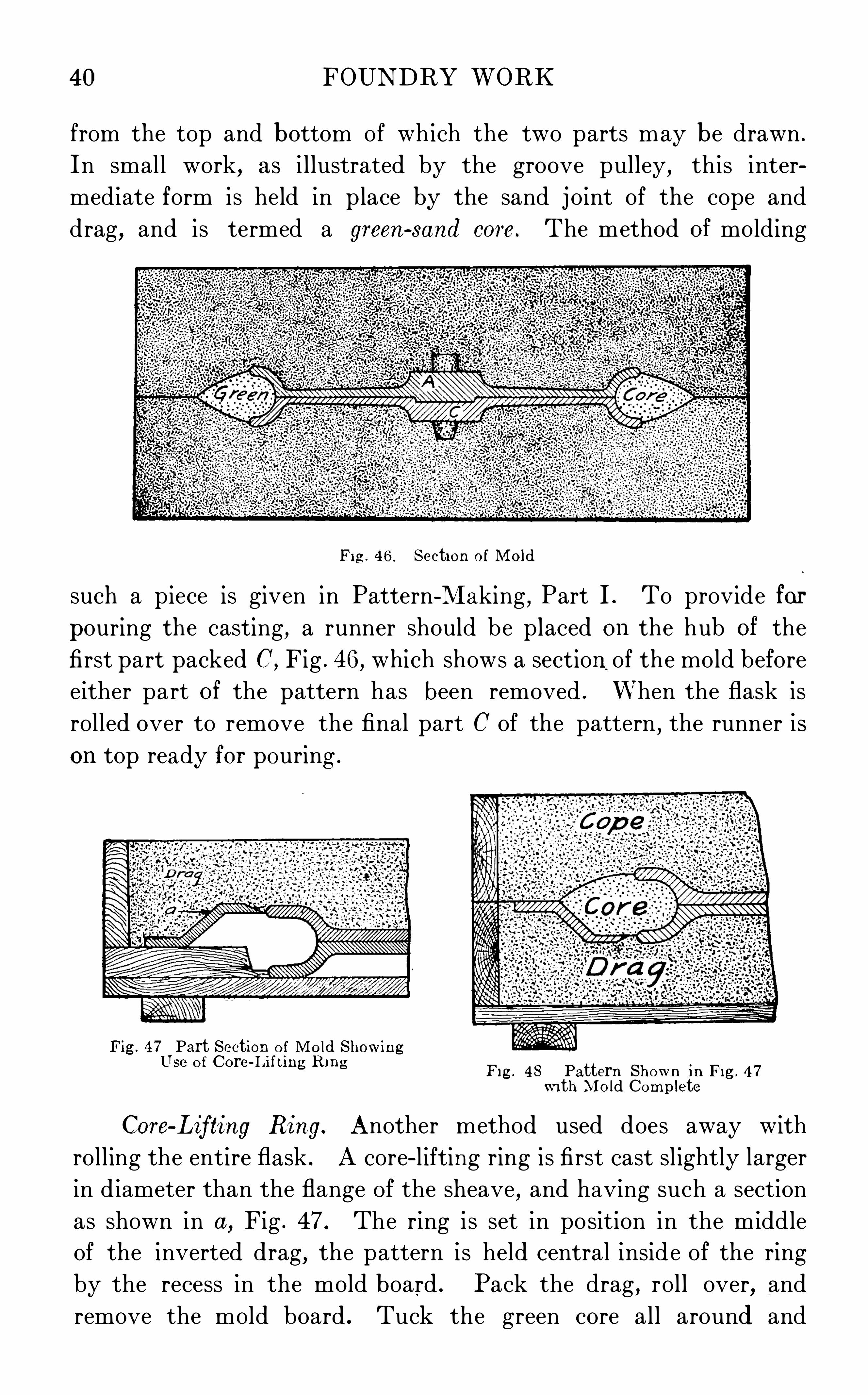
from the top and bottom of which the two parts may be drawn .
In small work, as i l lustrated by the groove pulley,this inter
mediate form is held in place by the sand joint of the cope and
drag,and is termed a green
- sand core. The method of molding
F ig . 4 6 . Section of M old
such a piece is given in Pattern - M aking, Part I . To provide for
pouring the casting, a runner should be placed on the hub of the
first part packed C, Fig . 46, which shows a sectionof the mold before
either part of the pattern has been removed . When the flask is
rolled over to remove the final part C of the pattern , the runner is
on top ready for pouring .
Fig . 4 7 Part Section of M old ShowingT~ j aL be O f Core I“h ug Rmo
Pg , 4 8 Pattern Shown in F i g . 4 7
W i th M o ld Complete
Core- Lifting Ring . Another method used does away with
roll ing the entire flask . A core - l ifting ring is first cast sl ightly larger
in diameter than the flange of the sheave,and having such a section
as shown in a, Fig . 47 . The ring is set in po sition in the middle
of the inverted drag, the pattern is held central inside of the ring
by the recess in the mold board . Pack the drag, rol l over, and
remove the mold board . Tuck the green core al l around and

42 FOUNDRY WORK
inches, tucking about the pattern with the fingers . Fil l in about 5inches of loose sand and before ramming tuck around the ends of
the side bars, compressing the sand between the finger t ips,having
a hand on each side of the bar, as i llustrated in Fig . 51 . N ow use
the peen end of the floor rammer in the same general way as the
hand rammer is used in bench mold ing . Guide the rammer around
the sides of the flask and bars first, then direct it toward the bottom
edges of the pattern . As the sand grad ually feels properly packed
at this level , direct the blows higher and higher up . Proceed in this
way to within about 1 inch of the drag joint . M ake th is joint by
ramming in sifted facing sand , being careful to tuck it firmly under
neath the flange . Cope this j oint to the
shape of the curved flang e .
D ust on parting sand . Place the
drag in position and ra in it up in the
usual way ,only using facing sand next
the joint and pattern . Place s ix long
gaggers to streng then the sand which
forms the inside of the casting . Clamp
the drag to the cheek and rol l them over .
Test, repa ir, and dust parting sand on
F ig . 5 1 . Tucking Sand under Bars the joint . Try the cope . The bars
should clear the pattern and joint by
about 1 inch . Set the cope runner about 2 inches to one side of the
cheek runner and set the riser in the corner opposite . Sift on facing
sand and tuck well with the fing ers under the crossbars . Shovel
in wel l - cut sand and finish packing the cope . Form a pouring
basin,and vent well . L ift the cope . D raw the pattern from the
cheek . Join the runners on the cope joint and connect the mold
with the riser . L i ft the cheek and repair it . D raw the drag pat
tern . All of the mold surfaces should have black lead facing brushed
over them with a camel ’s hair brush, and this facing sli cked over .
Cut a gate on the drag joint . Close the cheek on the drag .
Close the cope on the cheek, and the mold i s ready for clamping .
Floor Bedd ing . Owing to the development of the electric crane,there i s much larg e work now rammed in iron flasks and rol led over,which was formerly always bedded in the floor . This method is stil l
much used in jobbing shops to avoid making a complete large flask .

FOUNDRY WORK 43
The mold shown in F ig . 52 il lustrates the principal operations
involved . The casting is a flask section for a special steel - ingot mold,and in design is simply a heavy plate braced on one s ide by flanges
and rib s of equal thickness . For convenience in ramming between
F ig . 52 . Casting of Flask Section
the flanges, portions of the top plate of the pattern are left loose,
as seen in Fig . 53 .
Pit. D ig the pit for the mold 10 inches larg er on each side
than the pattern , and about 6 inches deeper . Having screened
some hard cinders through a No . 2 riddle,cover the bottom of the

44 FOUNDRY WORK
pit with them to a depth of 3 inches . Ram these over with ' a buttrammer
,and at one end set a p iece of large gas p ipe . Put a p iece
of waste on the top of th is to prevent its getting choked with sand .
Ram a 3 - inch course of sand over the cinder bed and strike it offlevel at the depth of the
pattern from the floor
l ine . Sift facing sand
over this where the pat
tern w il l rest ; set the pat
tern , and with a sledge,seat it until it rests level .
Remove the pattern and
with the fingers test the firmness of packing al l over the mold .
Vent these faces through to the c inder bed , and cover the vent
holes with a - inch course of facing sand . Now replace the pat
tern,and bed it home by a few more blows of the sledge . The
top of the pattern should now be level and flush with the floor
l ine . Seat the runner sticks, and , to prevent the sand on the bottom
of the runners from cutting, drive 10 - penny na il s about inch apart
into this surface until the heads are flush . R am the outside of the
mold the same as if i n a flask, and strike a joint on top . Ram
green sand between the inside
webs of the pattern,and
str ike off at the proper
he ight with a short stick a ,
Fig . 54 . D rive long rods 3
inches apart into these p iers
to pass through to sol id sandbelow the cinder bed .
Vent al l around the pat
tern, outside and inside,through to the cinder bed .
On top of the inside p iers
cover these vent holes with facing sand, ram, and sl ick to finish ;then cover with the l oose p ieces of the pattern .
Cope. Try the cope and stake it in place ; set the risers and vent
the plug s . Ram the cope, sl icking off level for about 2 inches around
the top of the risers, to receive a small iron cover .
F i g . 53 . Bedded - In Work
F ig . 5 4 . Section Show ing M ethod of M old ing

FOUNDRY WORK 4 5
Lift the cope, repair, and face with g raphite . D raw the pattern
with the crane and fin ish the mold . Connect the outer vent holes
by a channel w ith the vent pl ug . F rom the end of each core
print bbbb, F ig . 53, vent through to the c inder bed, and set the cores .Close the cope. Set the runner box against the s ide of the cope
and build a pouring basin with its bottom level with the top of
the risers .
In weighting, great care must be exercised not to strain the cope.
Place blocking upon the top ends of cope . Across these lay iron
beams whichwill be stiff enough to support the load, and pile weights
Fig . 55 . Leveling a Bed for Open Sand Work
on these, as shown in Fig . 52 . Now wedg e under the beams to the
cross-
bars of the cope at necessary points .
O pen Mold. There is a l arge class of foundry rigg ing , such as
loam plates, crossbars, and s ides to iron flasks, which may be cast
in open molds . As there is no head of metal, the beds must berammed only hard enough to support the actual weight of the metal,
or it will boil . To i nsure uniform thickness in the casting, the bed
must be absolutely level .
D rive four stakes aaaa, as shown in F ig . 55, and rest the guide
boards AA on the top of these. By using 3. Spirit level bb, make

46 FOUNDRY WORK
these level,and bring them to the same height by test ing with the
straightedge B .
The space between the guide boards AA should be fi l led with
well - cut sand even w ith their tops dd. S ift sand over the entire
surface . Strike this sand off 3’ inch higher than the guides, by
placing a gagger under each end of the straightedge, as it is drawn
over them . Tamp this extra sand to a level w ith the guides by
rapping it down with the edge of the cross - straightedge, and the bed
will be as shown in F ig . 56. We c an now proceed to build up
Fig . 56 . O pen Sand M old
to a segment of pattern, or with a sledge drive a pattern into thi s
surface .
The pouring basin should dra in itself at the l evel of the top of
mold, and an overflow may be cut on one edge to drain the casting
to any desired thickness .
CORE WORK
Reference has been made in the first part of this article, underD iv isions of Iron hl olding , to the genera l d ifference between core
work and green - sand work . This, and the section on Sands, the
reader should review carefully .
Dry=Sand Cores
Materials . Sand. Here, as in green - sand molding, the principal material used is a refractory sand . In molding sand, however,

FOUNDRY WORK 4?
the alumina or clay forms a natural bond in the sand. To meet
the necessary requirements of cores we must use a naturally free
sand as a base, and give it bond by adding some form of organic
matter as a b inder, then bake the core .Binders . The most common binders are the following four
materials : O rd inary wheat flour is an almost universal materia l
for use as a core b inder . Every one i s famil iar w ith its action when
moistened and baked . The hard vegetable gum rosin—a by
product of themanufacture of turpentine—for use as a core binder,should be reduced to a powder . It melts under the heat of the oven,flows between the grains of sand, and upon cool ing binds them
firmly together . Lins eed oil, made from flaxseed, acts in a way
similar to rosin ; a small proport ion of oil together with some flour
makes a very strong core . Glue, which i s obtained from anima l
hoofs and from fi sh stock, is also used to some extent as a core
binder . It should be d issolved in water before mixing w ith
the sand .
Tempering . A weak molas ses water i s used for tempering the
sand for sma l l cores ; and on the larger work the same purpose is
served by clay wash. There are many patent combinations of the
above or s im ilar material s put on the market a s core compounds .
There are two classes of these : dry compounds, and l iquid com
pounds . The advantages claimed for them is that they are more
economical because a smaller proportion of the compounds
i s sufficient to obtain the desired results ; and (2) because a large
proportion of the sand may be used over and over again .
Reinforcement. Among other necessary core - room supplies are
annea led iron wireNo . 6 to No . 16, and round bar i ron in sizes i - inch,
83
- inch,
- inch, g—inch, and g—inch, which are cut to length as needed ,
and are bedded in the core sand to strengthen the core, as wil l
be demonstrated later .
Venting . A supply of clean cinders must be ava i lable a l so for
venting larger cores . Smallwas: tapers make good vents for crooked
cores . There i s also a patented was: sent for sale on the market .
Facing . As before stated, charcoal with some graphite i s the
principa l facing materia l used on cores . It i s always appl ied in l iquid
form by dipping the core or by using a flat brush having extra
long bristles .

48 FOUNDRY WORK
Equipment. General Tools . The genera l tools of the core room
a i e similar to those al ready mentioned . A piece of iron rod very
often replaces the regular rammer on account of the small size
of the Opening into which sand must be packed .
The trowel is the most common sl ick, because most of the surfaces which require s l icking are flat ones formed by striking Off
after packing the box . Except in the largest work, the entire face
of the core i s not sl icked over,
so a variety small sl icks is
not needed .
A spraying can , shown in
F ig . 57, i s used for spraying
molasses water over small cores .
Fil l the can two- thirds full and
b low into the mouthpiece .
Small cores are made up
on a flat bench, the sand being in a small pile at the back .
Larger boxes are rammed up on horses or on the floor, as is most
convenient .
Baking . After being made up, cores are baked on core p lates .The smaller p lates are cast perfectly flat. Plates over 18 inches
long are strengthened by ribs cast about 1 inch from the edge,as shown in F ig . 58; th is keeps the p late from warping, and admits
of its being p icked up readily from a flat bench top or shelf .Ovens are built with reference to the size of the cores to be baked .
A good type of small oven i s illustrated in F ig . 59 . It can be runvery economically with either
coal or coke, and bakes cores
up to 2 inches in d iameter
within half an hour. Each
shelf is fastened to its own
door, and, when open for receiving or removing cores, a door at
the back of the shelf closes the Opening . This prevents a waste
of heat .
F ig . 60 shows the section through an oven suitable for the largest
work, including dry - sand and loam molds. The fire box A is situated
in one corner at the back ; its whole top Opens into the oven . At
the floor level d iagonally opposite is the flue B for conducting the
Fig . 57 . Spraying C an
F ig . 58 . Core Plate

50 FOUNDRY WORK
waste heat to the stack C . The entire front of the oven may be
opened by raising the sheet - steel door . Two tracks side by side
F ig . 6 1 . Cast- Iron C ar
accommodate cars upon which heavy work is run into the oven .
Fig . 61 shows a good form of cast - i ron car. The wheels are designed
on the rol ler principle to make it easier to start the
car when heavily loaded .
For medium work smaller ovens of this type
are used . Racks simi lar to the one shown in
Fig . 62 may be bolted on the sides, arranged
to hold the ends of the core plates ; and the car
may carry a l ine of double racks to increase the
capacity of the oven .
Cond itions of Use . As mentioned before,cores form those parts of a mold which are to be
nearly or entirely surrounded by metal ; i n other
words,such parts as would be in danger of breaking
or require too much work to be constructed in
green sand . The object, then , i n making cores is
to insure a better casting and to reduce costs .
Cores are held in position by means of core
prints (see Pattern- M aking) . The main weight
of the core i s supported by these prints and
through them all vent must be taken off and all
sand removed in cleaning . Therefo re, cores must
be strong er than green sand , because, whether large
or sma l l,they must stand handling whi le being
set and must not cut or break during pouring .
F ig . 62 . Rack They require g reater porosity than green sand
because their vent area i s l imited and their composition contains
more gas forming material . Furthermore, cores must lose al l their

FOUNDRY WORK 5 1
bond by the time the casting is cold , so that the sand may be easily
removed no matter how small the ava i lable opening .
These conditions are obta ined by using a coarse free sand and
a binder . To give additiona l strength when necessary, i ron wire
or rods, or cast - iron core arbors are bedded in the core . These
serve the same purpose in a core that the flask does in green
sand work .
Binder. The action of the binder enables the sand to retain
its shape when the box i s removed , and renders the core hard and
strong when baked . In the mold the intense heat of the metal
g radually burns out the organic matter or binder,leav ing the
core without bond . In this condit ion , the sand may readily be
removed .
T O O much binder tends to make the core sag out of shape before
baking, and blow when metal strikes it ; that is , give Off more gas
than the vents can carry away . With too l ittle binder the sand
does not bake hard , and cuts when the mold is poured .
The effectiveness of al l binders , especial ly flour,depends upon
their thorough mixing with the sand . The especial value of rosin
and oil liesi
in the fact that by melting under the oven heat they
form a more perfect bond with the sand .
M any intricate cores are now made with an oil mixture,without
using rods or wires, which formerly were considered absolutely
necessary for strength . Such cores must be wel l supported when
g reen , must be thoroughly baked , and handled with much care until
they are cold .
Core- Sand M ixture. N O universal mixture for core sand can
be g iven , as sands vary somuch in different local ities . The mixtures,as shown on the fol lowing page , il lustrate approximate proportions .
In preparing core sand , the different ing red ients should be
measured out,thoroughly mixed , and s ifted while dry . Temper the
mixture a l ittle damper than molding sand . T O O much moisture
makes the sand stick to the box . N ot enough makes it hard to
work and gives a crumbly surface if dried .
Facing . Blacking for l ight work should include one cup of
molasses to a pa il of water, into which is worked powdered charcoa l
until an even black coating is deposited upon the finger when dipped
into the blacking and out aga in .

52 FOUNDRY WORK
Core M ixtures
For heavy blacking there should be used about 2 parts charcoal
and 1 g raphite, mixed into thick clay wash .
Mis cellaneous . In finish ing smal l cores,they should be sprayed
with weak molasses water wh ile g reen, then well baked and removed
from the oven . When cool enough to handle , they are d ipped into
the blacking ; then put back in the oven unt il th is facing has dried .
For large cores the blacking i s appl ied with a brush before baking .
All cores should be baked as soon as made , for air - drying causes
the surface to crumble .
Cores must not be set in a mold while they are hot, or the mold
wil l sweat, that is , beads of moisture will form on the ins ide faces.This would make the mold blow when poured .
A core should be rammed evenly and somewhat harder than a
mold . Too hard ramming will make the sand stick in the box,besides g iving trouble in casting . T OO l ight ramming makes a
weak core .
From the very nature of cores,the matter of venting them is
very important and often cal l s for much ing enuity on the part of
the core maker .
For simple straight work a good sized vent wire is run through
before the box is removed . Half cores have their vents cut in each
half before pasting together . C inders are rammed in the center
of larg e cores connecting through the prints , with the mold vents .
For crooked cores, wax vent: are rammed in the center—the waxmelts away into the sand when the cores are baked , l eaving smooth
even holes . This i s il lustrated in one of the fol lowing examples .

FOUNDRY WORK 53
Methods of Making . The examples here given serve to il lus
trate the principal methods used in making cores .
Small Cylindrical Core. The s implest form of core is one which
can be rammed up and baked as made by S imply removing the box .
Short bolt—hole cores,etc .
,are made in thisway , as shown in F ig . 63 .
F ig . 63 . Short Bolt- Hole Cores
Set the box on a flat bench top . Hold the two halves together
by the clamp A . Ram the hol e ful l of core sand by the use of a
smal l rod . S l ick Off the top ; run a good sized vent wire through
the middle of the core . Remove the clamp . Set the box onto
the core plate, rap the s ides, and carefully draw them back from
the core .
Symmetrical Shapes . Larger cyl indrical cores, up to about
1% inches d iameter, are rammed in a Complete box also, only they
are rol l ed out on their Sides,as shown in Fig . 64 . This, however,
tends to make a flat place on the s ide, from the weight of the sand
supported on this narrow surface .
For th is reason cyl indrical cores of large d iameter, and manysymmetrica l shapes
,are
made in ha lf boxes . See
Pattern- M aking , F i g s110, 208, 2 13 , and 2 19 .
Such boxes are rammed
f r o m the,op en s ide .
Wires are bedded when
necessary about in the middle of the half core . The fingers and
the handle of a trowel are often used to ram the sand , and with
the blade of the trowel the sand is struck off and sl icked to the level
of the top of the box .
When baked,two half cores are held with their flat s ides together,
and any sl ight unevenness in the joint removed by a gentle rubbing
F ig . 64 . Large Cylindrical Cores

54 FOUNDRY WORK
motion . A vent channel i s then scraped centrally on each half .Paste, made of flour and molasses water
, is appl ied around the edges
and the two halves pressed firmly together ; care is taken to see
that they register all around . The core should then be placed in
the oven to dry out the paste . When pasting cores of 6 - inch d iam
eter and over, it i s wel l to b ind the halves at each end with a single
wrap of small wire .
Proper Seating . Wherever possible,core boxes should be made
with their widest opening exposed for packing the core, and designed
so that the core may rest, while being baked , on the flat surface
formed by striking O ff at this Opening .
Core plates w il l sometimes become warped . When a core would
be spoiled by resting it d irectly upon such a plate, the unevenness i s
F ig . 65 . Bedding a Crooked Core
overcome by sifting upon the plate a thin bed of molding sand and
seating the core on this .
Crooked Shapes . All cores cannot be made with a flat surfacefor baking, as illustrated by a port core, the box for which i s shown
in Pattern - M aking, F ig . 251 . This core must be rolled over on a
bed Of sand . U sing an oilmix ture, ram the core carefully, bedding
into it several wax vents. These should start near the end which
will touch the main cylinder core and lead out of the end which
wil l enter the chest core . To get this crooked core on a plate for
baking,a wooden frame is roughly nailed together, which is large
enough to sl ip over the core box when the loose p ieces have been
drawn off of the core,as shown in A , Fig . 65 .
The space on top of the core i s now fi l led with molding sand,rammed just enough_to support the weight of the core . The edgesof the frame project above the highest points of the core and form
guides for striking off this sand and seating a core p late, as at B,

FOUNDRY WORK 55
Fig . 65 . Box, frame, and plate are now firmly clamped and rolled
over, and the frame and box removed, leaving the core well beddedon the plate ready for the oven, as at C .
In manufacturing p lants quantities of cores are often required
which cannot be baked on a flat p late . To save the time and material
necessary to rol l each core onto a bed of sand,meta l boxes are made,Pattern - hi aking , F igs . 233 and 234 , and the core is baked inone part of the box . O nly one casting i s required of the larger
portion of the box . The smaller part is duplicated for every corerequired for the day ’s
mold .
Rod R ei nforc i ng .
hi ention has been made
of the use of wires for
s t r e n g t h e n i n g sm a l lcores. In making larger
ones, there is a greater
weight of sand to causestrain in handling the
core, and proportionately
greater casting strain .
TO resist these stresses
a systemati c network of
rods is bedded in the core
while being rammed,as
shown in the sectional F ig . 66 . N etwork of Rods in CoresV iew, F ig . 66 . Heavy
bars aabb extend the length of the core to give the main stiffness .
Smal ler cross- rods rest on these at the bottom and top, and with
the small vertical rods tie the whole core together .
At even distances from each end l ifting hooks c are placed .
Cross- rods through the lower eves of these hooks bring al l the strain
of the lift on the long heavy core rods . The holes in the top of the
cores where the lifting hooks are exposed , are stopped off when the
core is in the mold, by moistening the sides of the holes with oil
and fi l l ing up with green sand .
Cinders are packed in the middles of such cores . They aidin drying the core . They furnish good vent, and they allow the sand

56 FOUNDRY WORK
to give when the casting shrinks, thus rel ieving the strain on the
metal itself.
Use of Arbors . For the largest class of cores for green- sand
work, east- iron core arbors are used, of which a very satisfactory
type is shown in Fig . 67 . This
consists of a series of light rings, A,
carried ona cast- iron beam, B . The
rings are of about - inch metal cast
i n Open sand and set about 8 inches
on centers, and may be wedged to
the beam . The beam has a hole atFig ' 67 ' Sec
fri
ggs
cfifmigi r‘l se Of Cast: each end for lifting the core .
This skeleton is made up and
tried in the box before the work of ramming the core i s begun . It
is then removed and given a coat of thick clay wash . A layer of
core sand is fi rst lightly rammed over the inside of the box, andthe core arbor seated into this . The full thickness of core - sand
facing is then fi rmly rammed, and the entire center fi lled with wel l
packed cinders . Vents through the facing at both ends provide for
the escape of gases from these
cinders .
Sweeping . O ften, when but
one or two large cores are wanted,the cost of making a box is saved
by sweeping up the core . This
i s illustrated in the p ipe core
shown in F ig . 68.
The pattern - maker gets out
2 core boards and 1 sweep . The
boards are made by simply nail
ing together 3 thicknesses of
"~inch stuff, with the grain of themiddle piece crossing that of the
others to prevent warping . The
outer edges of the boards have the exact curve of the outside of
the pipe pattern, and at the ends i s tacked a half section of the
core, shown at aa . One sweep does for both boards . The curve
is cut the exact half section of the core . The edge b equals the
F ig . 68. Pipe Core

58 FOUNDRY WORK
a long to the next g roove when the core has run to the full length
of the plate .
The advantag e of the machine is that with it an apprentice
boy can produce a true, smooth,perfectly vented core
,in very much
less time than could possibly be done by hand - ramming .
Setting Cores
Cylindrical Cores . Plain F itting . Among the following exam
ples showing typical ways of setting and securing cores i n molds
and of connecting vents, the bolt - hol e core,shown at A,
Fig . 70,
il lustrates the Simplest form of core to set . Only a drag print is
necessary ; the flat top of the core Should just touch the cope surface
of the mold . The level may be tested by a stra ight stick or by
F ig . 70 . Bolt- Hole Core F ig . 7 1 . Calipers
s ighting across the joint . If the core is too long, one end may be
fi led off a l ittle, if too short, a l ittle sand may be fil l ed into the bot
tom O f the print . For longer cores, especially hub cores, a taper
print i s placed on the cope side of the pattern , and the same taper
i s g iven to the end of the core ; this guides it to the exact center
when the mold is closed . Numerous examples are shown in Pattern
Making. The exact length of the core should be obtained f rom
the pattern with a pa ir of cal ipers, as shown in Fig . 7 1 . One
point of the cal ipers should then be placed on the taper end of
the core,and the print fil led in, or the core Shortened in case of
variat ion from the right length . It i s wel l to make a vent hole
from the center of each print before set ting the core .
With pattern and core boxes properly made,l ittle difliculty
should be experienced in setting sma l l horizonta l cores for hol low
bushings,pipe connections, etc . (See Pattern - M aking
,Figs . 1 10 ,

FOUNDRY WORK 59
203, and The core must fit the print or a poor casting wil l
result . The sand supporting the prints must be tucked firmly
enough to withstand the l ifting pressure on the core . A scratch
F ig . 72 . Supported Body Core
with the po int of the trowel along the jo int surface from the end
of the print to the edge of the flask, wil l usual ly take care of
the vent .
For larger cores of this character crossbars made to fit snug
against the core print are na iled in both drag and cope . See aaaa,
Fig . 72 . These hold the core absolutely firm . The Spaces bb in
the cope, are not packed until the core i s set, when it is a simple
F ig . 73 . Setting Core below Surface
matter to ram these spaces and take off an a ir vent directly from
the center of the core .
Holes below J oint Level. There are two methods of coringholes below the level of the jo int . One is shown clearly in Fig . 73 .

60 FOUNDRY WORK
A stock core is set in the bottom of the prints ; a wooden template,shown at b and b’, i s set over the core, and the print a i s then
packed w ith molding sand, or stopped of , as it i s termed .
The other method is shown at B and B’
,F ig . 70 . Here that part
of the core which will shape the hol e through the casting,i s
formed on the end of a core which
exactly fil l s the print . A s ingle oper
ation sets the core and stops off the
print . For this reason this method
is used where a large number of
such holes are to be cored .
Setting Chaplets . In setting
chaplets, the height of the lower
one may be tested with a rul e,with a stra ightedge rested on the
prints, or by a gag e s imilar to that shown in Fig . 74 . A smal l boss
i s usual ly formed by pressing the trowel handle into the mold where
the chaplet i s to go .
The cope chaplet i s not fastened until the mold is closed , then
the stem can be properly wedged down under a bar clamped across
the top of the mold .
Projecting Cores . Balanced.
Type. In work where a hole
must project wel l into the casting , but not al l the way through it,a balanced core i s often used . Such a case i s ill ustrated by the
rammer head, F ig . 75 . When making th is core, l et the vent extend
through the entire length, then s top up the vent at the small end
with a bit of clay after the core
i s baked .
It is not always practicable
to enlarge the print as Shown
here,but when possible, it reduces
the l ength of print necessary to
balance the proj ecting end and
F ig . 75 . Small Balanced Core ensures accurate depth to the
hole .
Heavy Form. Heavy proj ecting cores must be supported by
chaplets, as il lustrated in F ig . 76 . Vents may be taken off through
a channel and air r iser as exp la ined in the section onVenting. F ig . 77
shows the shape of the print on the pattern for this mold at a, the
(F ig . 74 . Gage for Setting Chaplets

FOUNDRY WORK
pockets formed by the core are shown at bb, and 0 indicates the
position of the gate.
Hang ing Cores . A core i s frequently used to avoid a deep
l ift for the cope. Suitable wire hangers, shown at a,F ig . 78, are
bedded in the core when it is
made . In setting the core, small
annealed wire about N O . 20 or
fi g . 76. Large Balanced Core Fig . 77 . Shape.
oi Print on Pattern forProi ecting Core
No. 24 gage is looped through the hangers, passed through small
holes made in the cope, and fastened with a granny twist over an
iron bar on top . This bar should bear on the sides of the cope and
the core be brought up snug in its print by wedging under its ends .
The rigging need only be strong enough to support the weight of the
core, for the pressure of metal will force this core firmly into itsprint with l ittle danger of
shiftingi it. For heavy cores,a lifting eye, as previously
illustrated in F ig . 66, takes
the place of the wire hanger,and the core is hung by means
of a hooked rod with a nut on
the end. As shown in F ig . 79,
this rod passes through a long
washer which bears on a pair
of rails, or similar stiff r igging .
Bottom=Anchored Cores .
Where possible, the placing of
cores in the bottom of molds should be avoided, for in this position,being much l ighter than molten iron, they must be secured ag ainsta pressure tend ing to float or l ift them . This pressure is proportionate to their depth below the pouring basin. But the metal
Fig . 78 . Section Showing U se ofWire Hangers

62 FOUNDRY WORK
at the bottom of a mold is cleaner and more sound than that at
the top . Therefore, pl aner beds, large faceplates, and p ieces of
this character are usually cast face downward, making it necessary
to anchor the T- slot cores in the
bottom of the mold .
In some cases, such cores
may be held down by driv ing
nails so that their heads project
somewhat over the ends of the
core, as shown in F ig . 80 . If
this method is not strong enough,pointed anchors, with a foot on
one end, are run through a hole
in the core, and are carefully
driven into the bottom board, as
Shown in F ig . 81 . Where the
work i s bedded into the floor, a;Fig . 79 . Section Show ing U se of L i ft ing Ey e
pl ank must be set to receive thesefor HeaW C OW S anchors just below the cinder
bed . As in the case Of l ift ing eyes, the holes in the core, into
whi ch the foot on the anchor is driven , are smeared with oil and
stopped off with green sand .
Fig . 80 . Section Showing U se of N ails to Fig . 81 . Section Showing U se of AnchorsHold Cores in Place to Hold Cores in Place
Green=Sand Cores
Expediency in Use. M any times the j obbing foundry mayfind it expedient, where pattern s and core boxes are furnished bythe customer, to make certa in changes which will reduce the cost
of production ; for, unhappily, the patterns furnished sometimes

FOUNDRY WORK 63
Show a great desire on the part of the pattern - maker to produce
the patterns cheaply, without making due allowance for diffi culties
encountered in the foundry .
F ig . 82 . Half Core W ith Box Bui lt around It
Typical Instance. The practice of substituting green - sand
cores for dry sand has many possib il ities . As an example , consider
the case of a flange and Spigot p ipe 72 inches long and 6 inches
fl a w e l
Fig . 83 . Completed M old for Core
inside d iameter . The pattern furn ished was satisfactory, as was
the half - core box ,until it was found that the number to be made
each day was gradual ly increasing and the number of ha lf cores

64 FOUNDRY WORK
to be dried was seriously interfering with the production of the
regular cores required . It was decided by the foundry manag ement
F ig . 84 . C ast- Iron Arbor to Carry Core
F ig . 85 . Mold with Two Halves Together
to adopt the use of a green - sand core,and not only rel ieve the core
ovens, but also effect a considerable saving in core sand and core

66 FOUNDRY WORK
W ith these loose pieces in position the drag was duly rammed
and rolled over, the cope was rammed and the dry- sand core secured
in and l ifted off with the cope . The loose p ieces were withdrawn
from the drag, and the mold was properly finished ; when closed
and poured, this gave a satisfactory casting of the drag half of thecore box . The cope half was made in the same way
,the only change
being in the shape of the loose pieces forming the ends as seen
in F ig . 83 .
An arbor being required to carry the green sand , it was madeof cast iron, as shown in Fig . 84 . To make the green - sand core,first riddle sand in the drag half of the core box ; next place the
arbor as shown in Fig . 83 ; then fi l l and careful ly tuck the sand under
the flang es on the arbor . The cope is s imply fil led with sand and
rammed , and both drag and cope are struck off level with the jo int .
The two halves are now closed,as shown in Fig . 85, when the cope
may be rol led back to its former posit ion and the core removed
from the drag half of the box by l ifting an arbor extending throughthe end of the box .
The core should be placed on horses as shown in Fig . 86, so that
it may be repaired if necessary and blackened . F ig . 87 shows the
complete mold with green - sand core in posit ion .
In th is way a sat isfactory core box was made without heavy
expense for patterns, as the foundry carpenter or flask man was able
to produce the loose pieces from a rough sketch furnished by the
foundry foreman .
DUPL lCAT ING CASTINGS
Practical Requis ites in Hand Mold ing . D evising methods forincreasing production and decreasing its cost is one of the important
problems of modern eng ineering in the foundry as well a s elsewhere .
In the jobbing foundry where there i s a great variety not only in
the patterns themselves, but in the number of castings called for
from each pattern , the molder makes up a sand match as already
described . On this match he arranges such an assortment of pat
terns as will fi l l h is flask, and beds them into place . From a well
made sand match two or three hundred molds may be made up .
When the desired number of cast ing s i s made from one pattern
on the match , that one i s removed and another one which fits
in its place i s substituted .

FOUNDRY WORK 67
Gated Patterns . For manufacturing purposes thousands of
the same casting may be required, call ing for more durable patterns
and match . M etal patterns are made and as many as can be cast
in a flask are soldered to a smoothly fin ished metal gate pattern .
W ith a draw screw inserted in this gate, al l of the patterns may be
drawn at once . Two steady pins should be screwed and sweated
into the drag side of the gate pattern . These should be of smal l
round brass rod. and should project below the deepest po int of the
patterns,for they guide the pattern as it is being drawn and prevent
it from swaying and breaking the edges just as it leaves the sand .
Patterns so arranged are termed gated patterns .
Permanent Match. When such patterns have a flat j oint,a
special mold board should be provided , and the patterns stored
on the same board . When the
jo int is irregular, a permanent oil
match Should be made . Make a
strong hardwood frame the size
of the flask and about 1 inch deep ,with the bottom board arranged
to Screw on to the back . Nail s
should be driven into the inner
sides hanging parallel to the bot
tom board . M easure the quan F ’g ' gg ' 0 "“M b
tity of sand needed to fi l l th is match . M ix thoroughly and , while dry,put through a fine sieve one—half this quantity Of burnt sand, one- half
new mold ing sand, and about one- fort ieth l itharge . Temper the
same as molding sand, using boiled l inseed oil. Ram up the drag
and j oint the mold very carefully . Put on the match frame and
ram up with the above mixture ; strike off, and screw on the bottom
board . Remove the drag and al low the match to dry for a daywith the patterns left in it . A coat of shellac when dry improves
the surface . F ig . 88 shows a set of gated patterns bedded in a hard
match .
Use of M old ing M achines . Types . Although there are many
styles of molding machines on the market, these may be classified
under four general types as follows : stripping- plate machines ;squeezers ; rol l overs ; and jar or jolt - ramming machines . The
benefits derived from the use of these machines are manifold .

68 FOUNDRY WORK
Advantages . If no consideration were taken of the increase
in production possible by their use,the improvement in the qual ity
of castings alone would oftentimes warrant the ir i nstall at ion, as
the decrease in cost of machining cast ings produced by this method
pays g ood d ividends on the investment . The use of unskil led work
men on these machines i s no smal l item in their favor .Stripping
- Plate Machine. The stripping - plate machine i s best
adapted to that class of work which offers difficulties in drawing
the pattern from the sand .
F ig . 89 shows a pattern for a cast gear mounted on the strip
ping - pl ate machine . It is obvious
that it would require a consider
able degree O i skil l to produce this
class of work by the hand - mold ing
method . The pedestal base of
the machine has a flat top . The
stripping plate i s supported above
th is by a rigid open framework .
Working in guides carried on the
sides of th is framework is the drawing frame, made to rise or descend
by a strong crank and connecting
rod . On top of th is drawing frame
and parallel to the stripping plate
is screwed the plate to which the
pattern i s fastened . The stripping
plate i s cast with an opening which
leaves about 1 inch clear al l around the pattern . When both pat
tern and stripping plate are properly set i n place, th is space is fil led
with babbitt metal,this being an
‘easy way to secure a nice fit .
In many cases there may be an interior body of sand to be
supported when the pattern i s drawn . To accompl ish th is stool s
are used . A l eg screwed into the stool plate supports the stool
at the exact level of the stripping plate . The stool plate is fastened
to the flat top of the machine inside of the box - l ike framework
which supports the stripping plate,as seen in Fig . 90 .
A flask i s inverted on the machine, rammed, vented , and struckoff. Movement of the crank l ever at the s ide draws the pattern ;
F ig . 89 . T ypical M olding M achine

FOUNDRY WORK 69
and the mold then is removed and set on a level sand floor, thus doingaway with bottom boards . A second stripping plate and pattern
used for ramming the cope boxes .
F ig . 90 . Molding Stool w ith Pattern in Place
Pulleys are manufactured on molding machines of th is type,
as shown by the equipment il lustrated in Fig . 9 1 . The rim patterns
F ig . 9 1 . Pulley IVIO lding M achine
have the form of long hollow cyl inders and can readily be set for
any desired width of face . The hub carrying the core print separates

70 FOUNDRY WORK
from the spokes, l ifts Off in the mold, and is drawn by hand . The
arm patterns are so flat and smoothly rounded that the mold is
Fig . 92 . Simple M old ing M achine or Squeezer
F ig . 93 . M atch PlateCourtesy of Tabor Manufacturing Company, Phi ladelphia , P ennsylvania
easily l ifted off of them with l ittle fear of breaking the san d The
cope and drag molds are both al ike for a pulley mold .

FOUNDRY WORK
Squeezer. F ig . 92 shows a type of machine known as the hand
squeezer, which only packs the sand . Here the patterns are carried
on two s ides of a plate set between the cope and drag, as in Fig . 93 .
Both boxes are fi l led with s ifted sand and set on the machine . The
boards are made to follow inside of the flask . The molder ’s weight
on the lever compresses sand .
Fig . 94 . Hand Squeezing M achine w ith Cope and Drag Patterns Attached to Portab le T ableCourtesy of Arcade iVIanufa cturzng Company , Freeport, I llinois
The sprue is cut by a thin hollow steel tube called a sprue
cutter, which is pressed through the cope sand by the molder
before separating the flask . In separating the mold the cope
is first l ifted from the drag,and the plate is gently rapped and
l ifted from the drag . To make a clean l ift when parts of the
patterns project in the cope, a second molder raps with an ironbar between the battens of the bottom board while the cope is
being drawn off.

72 FOUNDRY WORK
Such machines are used chiefly on thin work which vents and
sol idifies very rapidly —for the outer surfaces of the drag and copeare apt to be rammed so hard that they might choke the vent onheavier castings .
A somewhat different style of hand squeezer is shown in Fig . 94 ,
which shows both cope and drag pattern plates attached to a portable
Beginning the Operation w ith Hand M olding M achine . Two Halves ofF lask in Pos ition
Courtesy of Arcade M anufacturing Company , Freeport, I llinois
table . Beginning the operation , the table holding the plates is
turned face up with the two halves of :the flask in posit ion a s shownin F ig . 95 . After the sand i s thrown in the flask and the surplus
scraped off, the bottom boards are placed in position and held by
four clamps . Next, the table i s rolled over as in Fig . 96 . The
ramming or squeez ing operation is accompl ished by pull ing down
74 FOUNDRY WORK
which when in position to receive flask is resting on pins at BB . The
mold is rammed bv hand in the usua l manner, the bottom board being
clamped on by a special device to the frame C . The mold i s next
rolled over and rests at A . The pattern i s w ithdrawn by the use
of the foot pedal E , the operator meantime rapping the match plate
Fig . 9 7 . Hamming or s queezing OperationCourtesy of A rcade lll anufacluring Company , Freeport. I lli nois
with a wooden maul . This type of machine is best adapted to side
floor work,the grate bar here shown being a good sample .
Power Operation . The above - mentioned types show only hand
machines which have been in general use for a considerable period
of time, but the last decade has shown a wonderful chang e in this
branch of foundry practice ; indeed so great i s the advance that

FOUNDRY WORK 75
hardly a month passes that there does not appear some new featuer.
The most important advancement, of course, was the adaptation of
power, usually compressed a ir being resorted to, but more recently
there has been quite a tendency to util ize electricity .
Power Squeezer. F ig . 101 shows compressed air appl ied to the
squeezer type of molding machine . This machine is designed
D rawing the Patterns . U se of M alletCourlesy of A rcade Al anufa ctarzng Company , Freeport, Illinois
especiallv for use in mold ing l ight snap - flask work in large or small
quantities,and the method of pattern fitting depends upon the
number of casting s to be made from one pattern .
A careful study of the l ine drawing of this machine shown
in F ig . 102 should give a clear understanding of the working parts
of the power squeeze "
, the numbered ones being identified as fol lows :

76 FOUNDRY WORK
F ig . 99 . Two Ha lves of M old in Open Pos itionCourtesy of Arca de "Manufacturing Company , Freeport, Illinois
YokeLeft - hand stop for yokeYoke handlePressure gagei - inch air cockEye boltLeft—hand strain barR ight - hand stra in barR ight - hand yoke stopPlatenKnee-
pad rod
Air hose from knee valvevibrator
Air hose from knee valvesupply
Hose guardKnee pad
Knee starting valveCylinder basePistonPiston ring
Counterbalance springAdjus tment block for spring seatAdjustment - block set screwTrunnionBracket for lower spring seatNo . 5 snap oilerTrunnion shaftPop throttle—valve leverValve- lever studThrottle- s top segmentValve sand guardValve Spring for exhaustAdjustable s train- bar stopValve bodyL hose nippleStraight hose nippleValve bracketTaper pins , trunnion to shaftBlow valveBlow—valve hose

FOUNDRY WORK 77
Attention is called to the fact that the production of the power
squeezer exceeds that of the hand squeezer by 15 to 30 per cent .For description of various ways of mounting patterns
,see Pattern
M aking .
Power Roll- Over. A power roll - over power - draft machine is
shown in Fig . 103 . This is designed to handle side floor work,
F ig . 100 Roll- Over M olding M achine W ith Pattern WithdrawnCourtesy of Tabor 1Wanufacturing Company , Philadelphia , Pennsylvania
and has a straight draft of 8 inches and sufficient power to rol l over
a weight of 1000 pounds . It w il l be noted that as in the hand roll
over the patterns are mounted on wooden match plates, the small
expense of which makes this sty l e of mach ine very effective in job
bing shops where but few castings are made from a pattern at a time .In F ig . 104 i s shown the latest type of this machine with the
flask shown in position ready for bar ramming . F ig . 105 shows the

FOUNDRY WORK
mold partly rolled over ; the mold rolled over and partly with
drawn is shown in F ig . 106 . The V iew given in F ig . 107 shows the
finished mold on one s ide and the pattern back in place .
The working parts of the above machine are shown in Fig . 108,
and are as follows
1 . R oll- over frame2 . Air cylinder3 . L ink4 . Wedge leveling device5 . Adjus table support for leveling device6 . Operating valve and lever7 . Vibrator
The plunger is made hollow and acts as an oil tank into which
air under pressure is admitted when the machine is to be operated .
When air pressure is admitted to the plunger, the oil is forced through
F i g . 10 1 . 10 - Inch Squeezer Operated by Compressed A irCourtesy of Tabor M anufacturing Company ,Phi ladelphi a , Pennsylvania

FOUNDRY WORK 79
a port into the cylinder, causing the plunger to rise and by meansof its l ink connections to rol l over the mold which 1s deposited on
the level ing device . After the flask has been unclamped air is
aga in admitted to the plung er, causing the pattern to be drawnvertically the ful l draft of the machine
,at which point the link
F ig . 102 . E levation of Tabor Squeezer Showi ng Working Parts
connections cause the rol l - over frame to return to its initia l positionready to receive another flask .
J olt- Hamming lil ac/tine. The jar or jolt - ramming machine isused for al l classes of work from light work up to the largest floorwork made in g reen sand , the l imit being only the capacity of the

FOUNDRY WORK
machine itself, which varies from a few hundred pounds to many
thousands of pounds . Large engine beds"
are a good example of the
castings produced on the heavy- duty machines .
F ig . 103 . Pow er Roll- Over, Power Dra ft hi olding M achi ne with 12—Inch Straight DraftCourtesy of Tabor lll anufacturing Company, P hiladelphia ,
Pennsylvania
F ig . 104 . Latest T ype of T abor M olding M achine w ith Flask Ready for Ramming
Patterns mounted on heavy wooden match plates are used in
the manner hereafter described . The flask is first placed on the drag

FOUNDRY WORK
F ig . 106 . M old Completely Rolled Over and Partly W ithdrawnCourtesy of Tabor M anufacturing Compam Philadelphia ,
Pennsylvania
Fig . 107 . Finished M old on One Side and Pattern in PlaceCourtesy of Tabor M anufacturing Company,P hi ladelphi a , P ennsylvania

FOUNDRY WORK 83
F ig . 108 . D iagram of Working Parts of the T abor M old ing hi achine
F ig . 109 . Simple T ype of Jolt- Ramming M achine
Courtesy of American M olding M achine Company, Terre Haute, Indiana
A quite distinct style of jolt machine, called an electropneumaticjolt- ramming machine
,i s shown in F ig . 1 11, the unique feature
being the motor - driven compressor without a clutch, spring, cam ,

84 FOUNDRY WORK
4 S ta nd a r d s
a t "u a r te r s
E x ha us i‘
F'
t‘"n tak er c e
Fig . 1 10 . Seet1on of American Jolt- Ramming M achi ne
Fig . 1 1 1 , Krause E lectropneumatic Jolt RammerCourtesy of Vulcan Eng ineering Sales Company , Chi cago, Illinois


86 FOUNDRY WORK
or valve . A very l ittle study of Fig . 112 should make clear its
radica l features .
Automatic Squeezer. F ig . 1 13 il lustrates an automatic molding
machine of the squeezer type . The operator places the flask and
bottom board in position, then by simply pressing on the starting
lever the fi lling of the flask with sand,the ramming and the drawing
of the pattern is completely automatic and accomplished in about
1 13 . Automatic M olding lVIachine of the Squeezer T ypeCourtesy of B erkshire M anufacturing Company , Cleveland, Ohio
e ight seconds or some six or seven hundred molds per day . This
machine is best adapted to the production of small dupl icate work
such as small pipe fittings .Roller- Hamming Machine. The very distinctive type of mold
ing machine shown in F ig . 114 i s known as the roller- ramming
machine . It is best adapted to long work of comparatively thin
cross - section , of which a corn ice section would be a good example .
This class of work could not be produced readily on any of the

FOUNDRY WORK 87
previously mentioned types of machines . F ig . 115 i s a detaileddrawing of Fig . 114 .
The success of any and all molding machines depends on theintell igent selection of the type best suited for the work in hand
.


90 FOUNDRY WORK
gates and risers . There must be another opening at the s ide of
the flask adjacent to the steam - chest core to provide for fastening
these cores . Iron plates serve for flask boards and there should
be a hole in the drag plate in l ine with the exhaust core to allow for
wenting and fastening its end .
One- half of F ig . 1 16 shows the end view of the flask . The
other half shows a section through the middle of the completed mold .
Here A is the hollow cylinder core, B i s the chest core, C the l ive
steam core hung in the cope, and D the exhaust core . The flask
is packed in a manner similar to green sand .
Use of Cover- Core. The method of molding the exhaust
flange, however, has not previously been exp lained . To do thi s,
Fig . 1 16 . M oldin g a Cylinder
proceed packing the drag unti l the pattern i s covered . Tuck the
facing careful ly underneath the flange, setting in rods as in core work,to strengthen the overhanging portions . Make a flat joint, F0 .
at the level of the top of the flange, then careful ly fit over the print
of the flange the cover—core E , and fix its position with nails driven
into the joint at its corners . N ow remove the cover - core, draw
the flange,and finish that part of the mold with b lack wash and
slicking . When this is accomplished, replace the cover - core, place
a short p iece of pipe over its central vent, and finish ramming the
drag . This method may be used in many cases, both in dry- sand

FOUNDRY WORK 9 1
and in green - sand work where a sma l l detai l of the casting requiresa separate joint surface .
A sectional p lan looking down on the drag i s shown in Fig . 117 .
When the mold has been properly finished and baked,the drag i s
brought from the oven and set on a pai r of stout horses . The
cylinder core is first set in place,then the exhaust core i s set in its
F ig . 1 17 . Sectional Plan of F ig . 1 16 Looking Down on Drag
drag print and held close to the cylinder core,while the port and
chest cores, previously pasted and fastened, are lowered into the
chest print . The chest print i s cut a l ittle long at ao, to a llow its
core to be drawn back s l ightly, while the exhaust core is entered
into its place between the port cores . Then al l of the cores are set
forward into position, the chaplets bb set, the space aa tightly packed
again, and the anchor bolts cc placed in position and made fast .

92 FOUNDRY WORK
The drag print of the exhaust core i s made fast from underneath
the drag plate . When al l the cores have been fi rmly fastened ,the cope i s closed on
, and the two boxes clamped at the flangesand set up on end . The runner R and the riser S were cut and
finished before baking ; the basins must be built in g reen sand after
the mold is closed .
M aking Barrel Core. Loam is used here for the outer shel l
of the core . It i s probably the simplest job in which a loam mix
ture i s employed,and i s made by a core maker more frequently
than by the higher paid loam molder . Barrel cores are used where
the core i s long and can best be supported at the ends only ; for
example,i n gas and water pipes and cyl inder work .
Loam. Loam is a facing mixture, of the consistencv of mortar,applied to the face of the core or mold . It contains fi re sand with
a bond of strong porous molding sand moi stened with a thick clay
wash . A small proportion of organi c matter in the shape of horse
manure i s put in to aid the bond and to leave the crust of loam more
fragile by burning out as the casting cools . Proportions of the
mixture wi ll vary according to loca l ity,but the principles already
cited hold here as with other molding compounds . With too much
bond the loam works easi er but'
tends to choke the vents when
casting . With not enough it i s weak and i s liable to break, cut,or crumble under
.
strain . A typical mixture is as fol lows :
Loam M ixtures
The advantages of loam cores are that they are l ighter, cheaper
to make, and carry. off the gases faster than do dry- sand cores .
M ethod. The method i s as follows : A piece of pipe about
3 inches smaller than the outside d iameter of the core is selected
to form the center . The pipe is perforated with a larg e number
of holes . If the pipe i s more than 3 or 4 inches in diameter, centers

94 FOUNDRY WORK
Slip . Sl ip or skinning loam is made by thinning regular loam
as it is rubbed through a N o . 8 sieve . The heat of the core is usually
sufficient to dry this s l ip coat enough so that black wash may be
brushed on and sl icked , as in dry - sand work , before running the
core into the oven again for its final baking .
The service of the hay rope on a barrel core is twofold : it fur
nishes a surface over the smooth metal of the barrel to which loam
will adhere ; and it i s elastic enough to g ive as the casting shrinks
around the core . The hay slowly burns out after the casting has
set, and this frees the barrel so that it can easily be withdrawn and
used again .
LOAM MO LD lNG
Skill Requnred . The loam molder requires the greatest all
around skil l in the whole range of foundry work . He must know al l
the tricks of the core room and dry- sand shop , and most of those in
g reen sand . Added to al l'
this he must have a practical workingknowledge of the principles of drawing and must possess to a large
degree the foresight of the designer .
111 order to save time and lumber in the pattern shop, only a set
of sweeps i s provided if the mold is s imple, and these, with blue
prints of the piece wanted , are al l the molder has to work from . In
intricate work, such as a modern Corl iss cyl inder, a skeleton pattern
carrying the steam chests, etc .
, in accurate position is made, and in
some very crooked work a pattern i s furnished complete . As a rule,
however, the loam molder must rely upon his own skil l and ingenuity
for the best method of constructing each detail of the work .
Rigg ing . The equipment for the loam floor varies in d ifferent
shops . In Fig . 119 are shown the essential features of an equipment
for sweeping - up circular fo rms .
Spindle. The spindle a should be larg e enough not to spring
when being used , and long enough to conveniently clear the highest
mold . A piece of 2 - inch shaft ing i s a handy size, forwith it the sweeps
may be made uniformly 1 inch less than the required d iameter and
placed snug to the Spindle when set up , and the correct s ize of mold
i s ensured . This spindle should revolve smoothly in a step b. The
step shown may be set at any convenient place on the floor . It hasa long taper bearing , as shown in section A capable of hold ing a 5 - foot
spindle without need of any top bearing . The three arms serve to

FOUNDRY WORK 95
make the step set firmly, and upon them any plate may be readily
leveled up . t ere a tal l spindle is used , the sp indle socket is more
shallow ; the step may be cast without arms and be bedded in the
floor . The top of the spindle i s steadied by the bracket c . This
must carry a bearing box so designed that the spindle may be readily
set in position or removed . And the bracket must swing back out of
the way when any parts of the mold are to be handled by the crane .
Sweeps . The sweeps are attached by means of the sweep arm d .
The detail B shows one method of clamping the sweep arm to the
spindle by using a key . The arm is offset so that one face hangs in
Fig . 1 19 . R ig for Loam Work
l ine with the center of the spindle . Bolting the face s ide of the sweep
to this bring s the working edge in a true radial plane . Sweeps are
usual ly made from pine about 1g inches thick . The working edg e
is cut to the exact contour of the form to be swept , and then is
beveled so that the edge actual ly sweeping the surface i s only about
g inch . For very accurate work or when sweeps are to be much used,the edge i s faced with thin strap iron to
p prevent wear .
P lates . We have seen that the wall s of g reen and dry - sand
molds are supported by sand packed into flasks and that the se flasks
may be l ifted, turned up sideways, or rol led completely over to suit

96 FOUNDRY WORK
the convenience of the workman . The facing which forms the wall
of a loam mold is supported by brickwork built upon flat plates of
cast iron,and laid in a weak mortar ofmud . From the nature of their
construction,therefore
,these molds must always be kept perpen
dicular when being handled . The parts may be raised , lowered , or
moved in any direction horizontally, but they must not be tipped or
rolled over .
The plates are cast in open sand molds , as illustrated in Fig . 56 .
Two methods are employed to provide for handl ing them by the crane ;
Build ing F la re
Fig . 120 . Laying - Up Loam Work
either lug s are cast on the edges of the plates, as in C, D , and E ,
Fig . 1 19, or wrought staples are cast in the plates, as shown in B,
Fig . 120, or in the crown plate of the main cyl inder core, Fig . 123 .
Three typ ical plates for a loam job are shown in F ig . 119 .
C i s the build ing plate ; it should be at least 18 or 20 inches larger
than the larg est d iameter of the casting to be made,and thick enough
to support the weight of the entire mold without spring ing . D shows
a cope ring ; its inside d iameter should clear the casting 2 inches
on all sides . The face should be 8 to 12 inches wide,depending upon

98 FOUNDRY WORK
up from loam, and air- dried . It is much more fragile than red
brick, and may be used in pockets, or where the shel l of the casting
is quite thin, and ordinary brick might resist the shrinkage strain
to such an extent as to endanger cracking the casting .
Mud. For laying up the brickwork, mud is used , loam facing
being appl ied only to these surfaces which come in actual contact
F ig . 122 . Complete T ypical Loam M old
with the iron . hi ud is made from burnt loam or old floor sand, mixed
with clay wash to the consistency of mortar .
Facing . The composition of loam facing and sl ip have already
been g iven under the description of making a barrel core .
Cinders . Cinders are an important material in this work . The ir
size wil l depend upon their posit ion in the mold . For working in
between brick,the cinders should be crushed if necessary
,put through
a No . 4 s ieve to remove smallest pieces, then passed through a No . 2
sieve to remove the larger pieces .

FOUNDRY WORK 99
Principles of Work. Parts of 111old. The names of the ma in
parts of a loam mold differ somewhat from those applied when mold ing
in flasks . As wil l be seen from the sect ion,F ig . 122
,there are three
main d ivisions in the mold : A , which corresponds to the drag in a
three - part mold , i s called the core. B , which corresponds to the cheek,i s called the cope in loam work . And C,
which serves the same purpose
as the cope of a green - sand mold, i s spoken of as the cover in loam
molding . When the central core i s actually made a separate piece,
as in F ig . 123 , the lower part of the mold is cal led the bed orfoundation.
F i g . 123 . Loam M old for M arine Cylinder
Laying- Up . In laying - up a loam mold
,Fig . 120 , set the
plate central w ith the spindle and approximately level . Then set
the sweep and finish level ing the plate until repeated measure
ments at the four quarters of the c ircl e show a uniform space
between the lower edg e of the sweep and the surface of the plate .
For the building plate this measurement should be 5 inches ; for a
sticker plate the sweep should clear the sticker points by to 1 inch
according to the thickness of the casting .
The hands are used in spread ing mud or loam upon the plates
or brickwork when building the mold . The brick must always be
set wel l apart, leaving a space at least the width of a finger between
them . Fi l l in these spaces with fine cinders . The reason for this is

100 FOUNDRY WORK
fourfold . It facil itates drying ; it prov ides good vent ; it gives or crushessuffi ciently when the casting shrinks not to cause undue strain ;and it reduces the labor in cleaning . In each course of brick the
jo ints should lead as directly as possible away from the casting,but
the jo ints should be broken between courses . These points are illustrated in the sketch A , F ig . 120 . As shown, the fi rst two courses of
the core are usuallv set edgewise . For the rest of the core and for the
cope, the bricks are la id flat . These bricks run lengthwise around the
circumference , w ith a course of headers about every fou r to sixcourses .
Venting . Cinders between brick form the ord inary means of
leading the vent from the loam facing . In confined places or pockets,as, for example, between the flang e D and the main casting , Fig . 122,
additiona l provision is made bv laying long wisps of straw betweenthe courses of brick . The service of the straw is similar to that of
the hay rope of a barrel core .
Jointing . The jo int in loam work is made by a plate l ifting away
from a loam seat, or by two loam surfaces separating one from
another . In forming the first of these the loam seat i s swept up and
allowed to partial ly set, then the surface i s brushed with oil, and part
ing sand is thrown over it . The seat should then be soft enough to
allow the iron plate to sink into it sufficiently to find a good bearing,whil e the oil and parting sand will prevent the loam facing from
adhering to the underside of the pl ate . For the loam - to- loam joint,the same method i s used , but the loam is allowed to set somewhat
harder before building the j o int against it . The ang l e of the main
joint should be about 1 in 4 inches .
To insure the d ifferent parts being put tog ether for cast ing in
exactly the same position in which they were built, a guide surface of
loam is smoothed across the j oint at three or four convenient points
on the outside wal l s of the mold . These surfaces are each marked
d ifferently with the edge of the trowel , similar to the cut at C,
F ig . 120 .
Drawback. To properly separate and finish some molds, it is
necessary to l ift away a port ion of the mold before l ifting the main
part . Such a port ion is cal led a drawback. The drawback is always
built up in posit ion aga inst a pattern or sweep . W ith the cover
plate,which on ‘a smaller scal e often serves the same purpose, as at
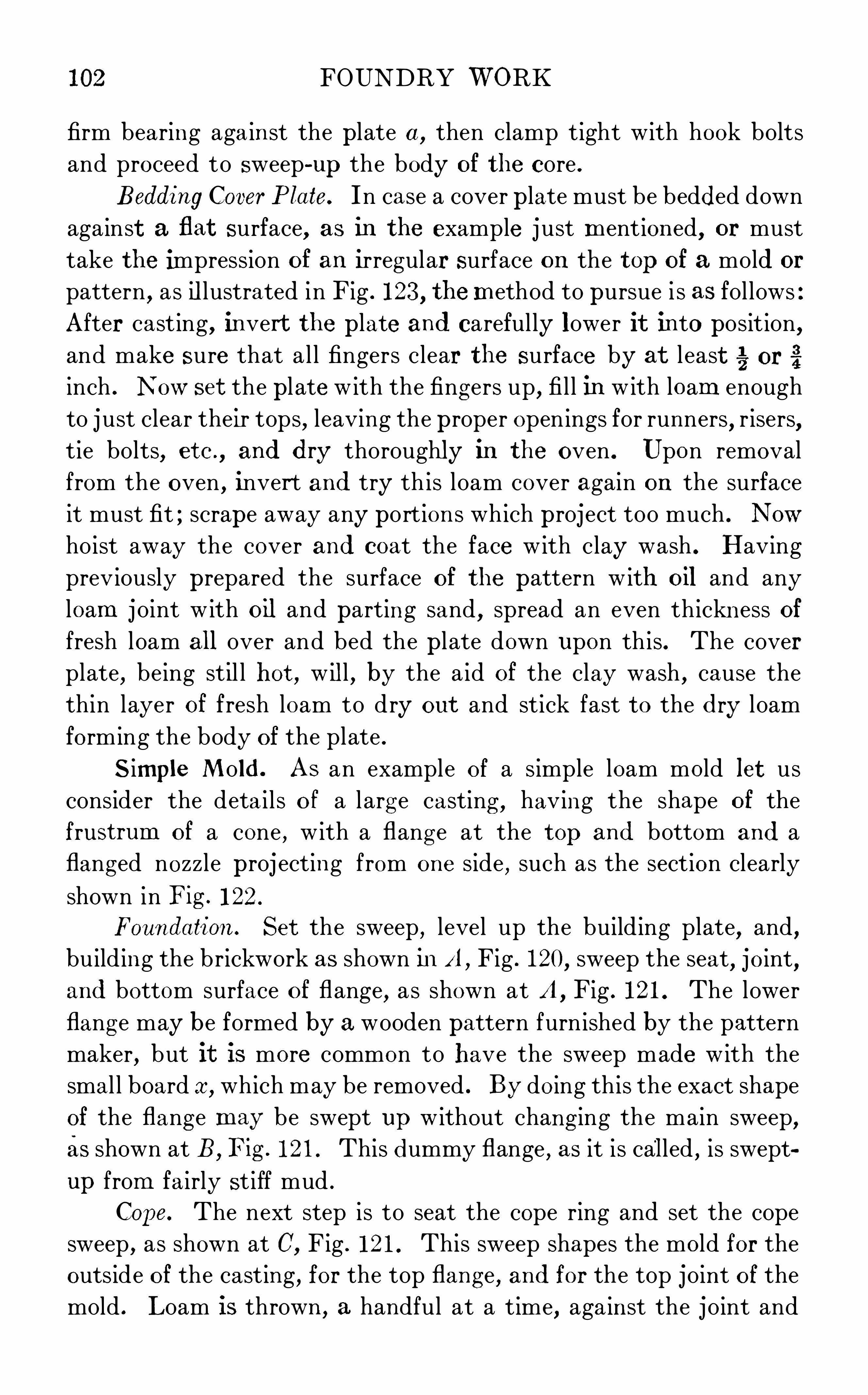
102 FOUNDRY WORK
firm bearing aga inst the plate a , then clamp tight with hook bolts
and proceed to sweep - up the body of the core .
Bedding Cover P late. In case a cover plate must be bedded down
against a flat surface, as in the example j ust mentioned, or must
take the impression of an irregular surface on the top of a mold or
pattern,as illustrated in F ig . 123, themethod to pursue i s as fol lows :
After cast ing, invert the plate and carefully lower it into posit ion,and make sure that al l fingers clear the surface by at l east g. orinch . N ow set the pl ate with the fing ers up, fi l l in with loam enough
to just clear their tops, l eaving the proper openings for runners, r isers,tie bolts
,etc .
, and dry thoroughly in the oven . Upon removal
from the oven , invert and try th is loam cover again on the surface
it must fit ; scrape away any port ions which project too much . Now
hoist away the cover and coat the face with clay wash . Having
prev iously prepared the surface of the pattern with oil and any
loam j oint w ith oil and parting sand, spread an even thick ness offresh loam all over and bed the pl ate down upon this . The coverplate
,being stil l hot, will , by the a id of the clay wash , cause the
thin layer of fresh loam to dry out and stick fast to the dry loam
forming the body of the plate .
Simple Mold . As an example of a simple loam mold let us
consider the deta i l s of a larg e casting , having the shape of the
frustrum of a cone , with a flang e at the top and bottom and a
flanged nozzle proj ecting from one side, such as the section clearly
shown in Fig . 122 .
Foundation. Set the sweep, level up the building plate, and,building the brickwork as shown i nA , Fig . 120
,sweep the seat
,joint
,
and bottom surface of flange, as shown at A , F ig . 121 . The lower
flang e may be formed by a wooden pattern furnished by the pattern
maker,but it is more common to have the sweep made with the
smal l board a ,which may be removed . By doing this the exact shape
of the flang e may be swept up without chang ing the main sweep,as shown at B , F ig . 121 . This dummy flange , as it i s called , is swept
up from fa irly st iff mud .
Cope. The next step is to seat the cope ring and set the cope
sweep,as shown at C,
Fig . 121 . This sweep shapes the mold for the
outside of the casting, for the top flange, and for the top joint of the
mold . Loam is thrown, a handful at a time, aga inst the joint and

FOUNDRY WORK 103
dummy flange,and the engag ing faces of bricks are rubbed with
loam and pressed into posit ion .
When the top of the lower flang e is reached in this way ,the
courses are la id - up for about 2 feet before the loam is Spread upon
their inner surface and struck off. This method is pursued unti l the
mold is built to its ful l height .
The projecting nozzle is formed by a wooden pattern ; this should
be well o iled, and the brickwork and loam laid - up under it to support
it at the proper level, as given by the center l ine on the pattern and
corresponding l ine on the sweep: Such project ions frequently must
be supported in the ir exact posit ion with reference to the ma in
pattern by temporary wooden framework or skeleton work until
the mold is built up under them .
A finger y nail ed to the top member of the cope sweep, shapes the
guide surfaces on the outside of the mold which are used to center the
cover pl ate in closing the mold . A s imilar finger exactly the same
d istance from the spindle, i s fastened to the sweep used to form the
cover p late .
After the finishing coat of slip has been swept on the surface ofthe cope, a joint surface about 4 inches w ide i s struck off flush with
the outer face of the nozzle and that pattern i s drawn out .
Then the whol e cope i s l ifted off and set on i ron supports where it
may be conveniently finished with black wash and sl icks . It is then
baked over night in the oven .
Center Core. The dummy flange is now entirely removed from
the first part swept, the core sweep is set, D , F ig . 121,and the
center core is struck up . This core i s then blackened , sl icked off, and
baked . The cover plate i s struck off with the stickers up, and baked
so. This cover carries s ix 1 - inch round holes through it, which will
be just over the shel l of the metal when the mold i s closed . F ive of
them connect with the pouring basin and serve as runners, while
the s ixth serves as a riser .
Closing . In assembl ing the mold for pouring, the core is first set
on a level bed of sand, the cope i s accurately closed over it by the
aid of the guide marks, and lastly the cover plate i s closed in posit ion.
N ow the W hol e mold i s firmly clamped by blocking under the spider,from which wrought—iron loops or string s connect under the lugs ofthe build ing plate, as shown in F ig . 122 .

104 FOUNDRY WORK
The small core for the nozzle is now set,resting on stud chaplets .
The cover plate D is sl id over the end of this core and thus holds it
firmly in position .
The casing is now placed around the mold and mold ing sand
rammed in to support the bricks against the casting pressure . At the
level of the nozzle core c inders are placed,and a p ipe leads off to
carry away the vent gases . The sand is rammed to about 12 inches
over the cover plate and in it are cut the channel s connecting the
pouring basin and runners . A couple of bricks are set in the bottom
of the basin to receive the first fal l ofmetal from the ladle .
Pouring . In pouring , the runners must be flooded at once and
kept so until the mold is ful l .
In heavy cylindrical castings it was formerly thought necessary
to carry the she ll of the casting some 6 inches higher than the top
flang e . This head served to collect al l d irt and slag that perchance
entered the mold with the i ron , and it was cut off in the machine shop
and returned to the foundry as scrap . W ith the increased knowl
edge of iron mix tures this head is now done away with in most
instances .
Where a large casting i s to finish practica l ly all over, and very
clean metal i s therefore necessary,overflow channels
,connecting with
p ig beds, are often constructed in modern practice . Then, when
pouring, the meta l i s not stopped unt il a certa in per cent of it has
been flowed entirely through the mold . This of course tends to wash
out any dirt which may have gotten into the mold when pouring
began .
When the casting is cold , the casing and packing sand as well as
the blocking under the spider are removed . Then the whole mold i s
carried to the cleaning shed where the bricks are removed and the
casting cleaned .
Intricate Mold . As an example of a complex p iece of loam work,let us consider the mold ing of a modern marine - eng ine cylinder, as
shown in section,Fig . 123 . The example given i s that of a double
ported low - pressure cyl inder of a triple - expansion typ e . In this
case a full wooden pattern should be built, with core boxes for the
various dry - sand cores that enter into the construction of the mold .
Foundation. The limits of this article prevent a deta iled d iscus
sion of this subj ect ; we will, therefore, confine ourselves mainly with

106 FOUNDRY WORK
The pattern is made in many parts so as to properly draw from
the mold . When this has been done, al l mold surfaces are carefullyblackened and sl icked before baking .
Caring . While the mold proper i s being built,the dry- sand
cores should be made up by the core makers,with the necessary rods
,
hangers, vent cinders , etc ., as described under Core M aking .
The manhole core, 1 1 , i s - made with a stop - off piece in the
box to give the proper angle at the bottom of the core . It i s hung to
the cover and clears the main core by inch . The stuffing - box core
rests in a print in the main cyl inder core,and is held by a taper print
in the cover plate 10 .
The jacket cores are hung as shown . The openings made in the
loam above the crab, to allow the hook bolts to be drawn up tight,are stopped off with g reen sand as previously described . The inlet
cores 12 12 , the exhaust core, 13 , and the lightening cores, 14 14 14,are al l bolted d irectly through the steam - chest core
, 15 ,to horizon
tal bars which are long enough to bear against the sides of the mold
at the back . The upper inlet core,12
,i s kept from lifting under the
pouring strain by being bolted to the body of the main cvlinder core .
Stud chaplets are also set between the inlet and exhaust cores to
ensure correct thickness of metal at these points .
Venting . The vent i s taken off from the main cyl inder core
through the stuffing - box core at the top . Sometimes a small ladle
ful of metal i s poured through th is opening , when the piece i s being
poured , to ensure l ighting these gases . The vent for the series of port
cores i s taken off by ramming a cinder bed up the entire back of the
steam - chest core,allow ing the g ases to escape at the top . For safety,
al so,vents are taken from the bottom of the port and chest cores
by the usual pipe vent .
Pouring . The provision for pouring this mold requires especial
attention . Notice the construction of the main basin, 16 . The long
runner 1 7, leading to the bottom gate, i s left open on one side when
the mold is built, so that it may be easily finished and kept free
from dirt . Its open side is closed by cover cores when the mold is
rammed up .
Ten or twelve small gates l ike 18 are connected with the
pouring basin,by semicircular channels, but are so placed that no
metal shal l fall on a core . With the basin arranged as shown, the

FOUNDRY WORK 107
bottom part of the mold is first flooded with iron . When this has
been done, the metal is poured in faster, so that hot iron is well
distributed around the shell of the casting through the small top
gates . Should the mold be poured at fi rst from these top gates,i
the
fall of the i ron through the full height of the cylinder to the lower
flang e might result in cutting the loam on that surface .
Molds of this size are usually rammed in a pit so as to bring the
pouring basin conveniently near the floor . The portion above the
floor level is, of course, rammed inside a casing , as described in the
previous example .
To guard against uneven cool ing strains in this intricate casting,the clamping pressure on the mold i s rel ieved when the meta l has
solid ified , but the sand is not removed from around the brickwork for
several days . This allows very gradual even cool ing .
It will be noticed that the piston does not work directly upon the
inner walls of this type of cyl inder . A separate hollow shel l or l ining
is cast of strong tough iron . This has outside annular ribs at topand bottom and middle which are turned to fit correspondingly pro
jecting ribs seen on the inside of the casting j ust under consideration .
An air space i s thus left between the l ining and ma in casting which
forms a jacket around the bore of the cylinder .


Fig . 124 .Section Through Modern Cupola Furnace
FOUNDRY WORK 1 11
iron bar p laced centrally under them . These doors , protected by a
sand bed,support the charge during the heat, and drop it out of the
furnace when al l the iron has been melted . The leg s curve outward
and the doors are hinged as far back as possible to protect them as
much as can be from the heat of this drop” .
Breast. At one side, level with the bottom , i s the breast opening,at which place the fire is l ighted , and in which the tap hole is formed
for drawing off the melted metal . The spout , protected by a fire- sand
mixture,projects in front of the breast and guides the metal into
the ladles .
Slag Hole. On cupolas over 36 inches inside of the l ining,a
slag hole is provided , which is similar to the tap hole, and is placed
opposite the spout and about 2 inches lower than the main tuyeres .
Fig . 124 shows a section through a modern cupola furnace , and needs
but l ittle further exp lanation .
Lining . In l ining the stack , the layer next the shel l i s usually
made of boiler - arch brick about the size of regular fire brick . These
are set on end , and should be fitted as tightly together as possible,and laid in a thin fire cement, made of very refractory fire clay
and fine sharp sil ica sand . The object is to fi l l every crevice with a
highly refractory material . Specially made curved fire brick can be
purchased for the inside l in ing , although some foundrymeri use the
arch brick for this l in ing as well . The l ining over the tuyeres is shaped
to overhang them sl ightly, to prevent melted slag dropping into them
during the heat . The l in ing burns out quickest about 22 inches
above the tuyeres , at what is practical ly the melting zone . The ang l e
shelves riveted to the shell , as seen in the il lustration,allow this
section of the l ining to be renewed without disturbing the rest of
the,stack .
Tngeres . The oblong air inlets,called tuyeres,are placed about
12 inches above the bed , and connect with an air - tight wind box
which surrounds the outside of the stack near the base . The tuyeres
d irect the blast into the fuel , increasing the heat sufficiently to melt
the charge . In the wind box , opposite each tuyere, is an air- tight
sl iding gate with a peephole, which al lows the melter to look directly
into the furnace .
In the larger cupolas a second set of tuyeres is arranged about
10 inches above the main ones . They are used, when long heats are

112 FOUNDRY WORK
TABLE III
S izes of Cupola Furnaces
M ELTING CAPAC ITY
(inches )
run off, to make up for loss of w ind caused bv the main tuyeres
becoming partially choked bv slag .
The height of the tuyeres above the bed varies with the class of
work to be poured . Where the metal is tapped and kept running
continuously and is taken away by hand ladles, as in stove - plate
work,the tuveres are as low as 8 inches or 10 inches above the bed ;
while in shops where several tons of metal may be required to fill
one mold , the tuyeres are as high as 18 inches above the bed . The
height of the spout above the mold ing floor also varies in the same
way ; for hand - ladle work it mav be but 18 inches above the floor,
while a height 0"
5 or 6 feet may be required to serve the largest
crane ladles .
Charging . Several feet above the bottom,there i s a door in the
s ide of the stack , through which the stock is charged into the furnace .
A platform or scaffold is constructed at a convenient level below
the charg ing door , and all stock is charged into the cupola from
this platform . It should be at least large enough to store the stock
for the first two charges of fuel and iron .
Table III , prepared by Dr . Edwin Kirk , g ives the approximate
height and size of charg ing door and the practical melting capacity
of cupolas of different d iameters .
Blast. Fan Blou‘er. Blast for the cupol a i s furnished by either
a fan blower or a pressure blower . Fig . 125 shows a modern fan
blower, of which the blast wheel i s deta iled at A . The high speed of
the blades forces the air, by centrifugal action , away from the
center of the shaft . The casing is so designed that the blades cut
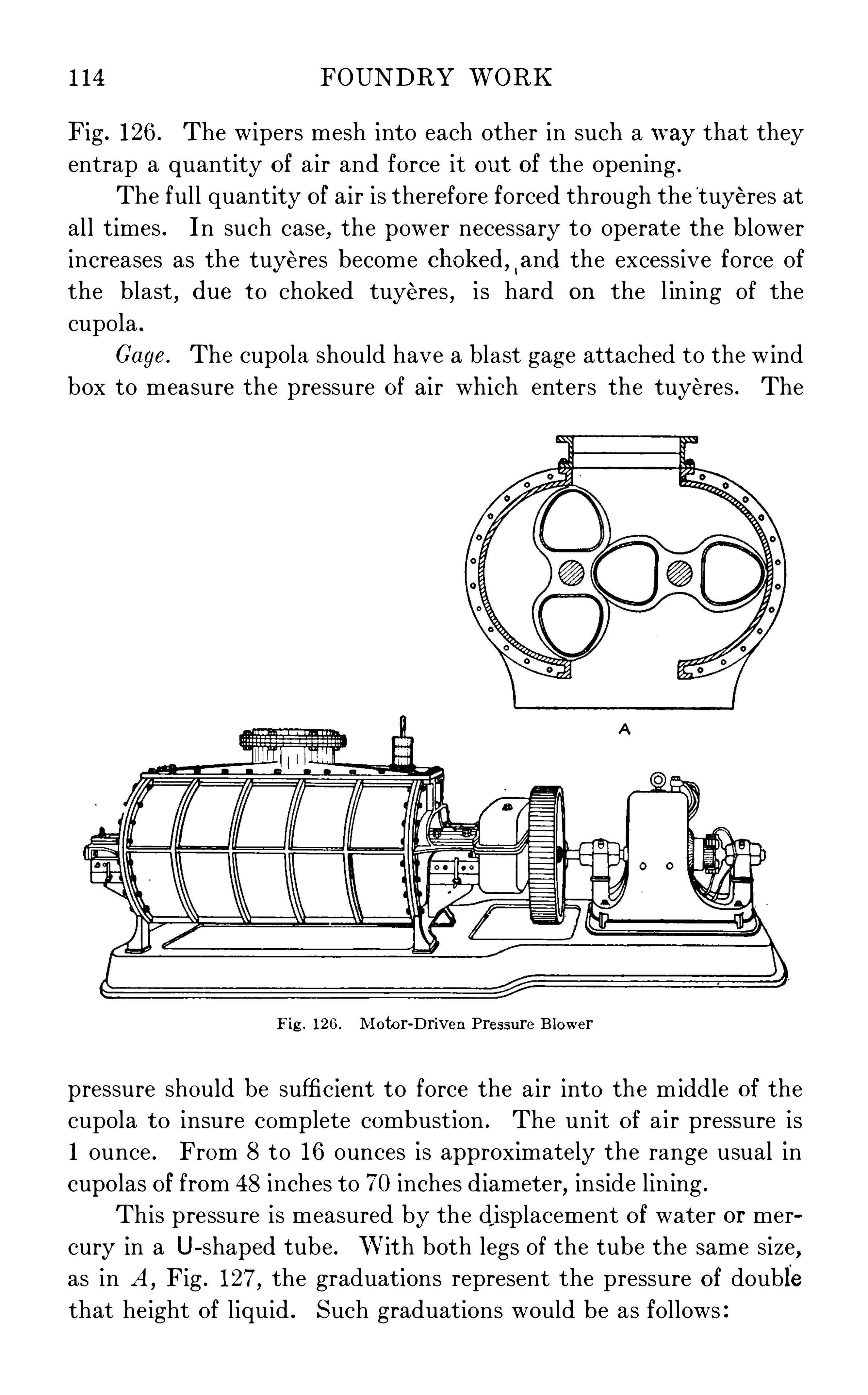
1 14 FOUNDRY WORK
F ig . 126 . The wipers mesh into each other in such a way that they
entrap a quantity of air and force it out of the opening .
The ful l quantity of air is therefore forced through the'
tuyeres at
al l times . In such case, the power necessary to operate the blower
increases as the tuyeres become chokedhand the excessive force of
the blast, due to choked tuyeres , i s hard on the l in ing of the
cupola .
Cage. The cupola should have a blast gag e attached to the wind
box to measure the pressure of air which enters the tuyeres . The
F ig . 126 . M otor- Driven Pressure Blower
pressure should be sufficient to force the air into the m iddle of the
cupola to insure complete combustion . The unit of air pressure is
1 ounce . From 8 to 16 ounces is approximately the range usual in
cupolas of from 48 inches to 70 inches d iameter, inside l in ing .
This pressure is measured by the displacement of water or mer
cury in a U- shaped tube . W ith both leg s of the tube the same size,as in A ,
Fig . 127 , the graduations represent the pressure of double
that height of l iquid . Such graduations would be as follows

FOUNDRY WORK 1 15
With a water gage, a difference in level s of inches corre
sponds to 1 ounce wind pressure, so that the scale g raduations per
ounce would be spaced
_ 55 7 . 1 .
2 64 8 64
With mercury,a difference in level s of inch corresponds to a
p ressure of 1 ounce so that the scal e graduations would be spaced
6635 in .
—12 16
As this last spacing would be too smal l for practical use, mercury
gages, as at B ,Fig . 127, are made with an increased area exposed to
the blast pressure,and are graduated
accordingly .
Pr inciples of Melting . Combus
tion cannot take place without oxygen, of which the a ir i s the most
abundant source of supply . For
example , in the incandescent electric
l ight, a strip of carbon is heated to
a white heat,but it does not consume,
or burn up,because al l a ir has been
exhausted from within the globe .
In the cupola furnace,both coal
and coke are used as fuel . They con
sist larg ely of carbon, and, after being
l ighted by the kindling s, are kept at
a glow ing red heat by the natural
draft through the open tuyeres . The
blast suppl ies the oxygen necessary
for a melting heat . The quantity of
air forced in by the blast cannot be
entirely taken up by the layers of fuel immediately above the tuyeres ;thus
,complete combustion does not take place until a distance of
18 to 23 inches above the tuyeres is reached . This is termed the
lting zone. It is the aim of the melter to keep the top of his bed
as nearly as possible at this level , so that the iron resting on it shal l
be exposed to this intense heat and melt rap idly . As the fuel of
F ig 127 . W ind Gages

1 16 FOUNDRY WORK
the bed burns away, thi s level tends to be lowered . But the iron
on top of it melts and drops to the bottom of the cupola ; and
the subsequent charge of coke restores the level of the bed for the
next charg e of i ron ; and so on.
Cupola Operation
Running a Heat. The following routine must be pursued each
time a heat is run off in the cupola
(1) Clear away the dump from the former heat .
(2) Chip out the inside of the furnace with a special hand pick,
removing the lumps of slag which col lect about the lower part of
the cupola wal l s,especial ly above the tuyeres . Where the slag coating
is comparatively smooth , do not touch it , as that is the best coating
possible for the l ining .
(3) Daub up with a mixture of fi re sand , held together with
about 1 :4 fire clay , and , wet with clay , wash to a consistency of thick
mortar . Smear the surface to be repa ired with clay wash ; then,using the hands, plaster the daub ing mixture into the broken spots in
the l ining , being careful to rub it in wel l , especial ly about the tuyeres .
The top of the tuyeres should be kept sl ightly overhang ing .
The greater part of the daubing wil l be required from the
bottom to the level ofmelt ing zone,about 22 inches above tuyeres .
(4 ) Sui ng up the bottom doors , and support them by a prop
of gas pipe .
(5) Build the bottom fi rst cover the doors with a 1 - inch layer of
gangway sand or fine cinders ; then ram in burnt sand tempered about
the same as for molds . This must be rammed evenly al l over the
bottom , and especially fi rm around the edges . The bottom should
be made flat and level from side to s ide,with only a sl ight rise around
the l ining which should not extend more than 1 or 2 inches from the
l ining . The pitch varies w ith size of cupola ; 1 inch to the foot wil l
answer for cupolas of 24 inches to 30 inches d iameter inside l ining,while one—half that pitch wil l do for the larger furnaces .
The cupola bottom should be able to vent so that it wil l dry out
quickly , and not cause the metal to bo il before the furnace i s tapped .
It should be strong enough to hold its surface during the heat, but
to break and drop at once when the bottom is dropped . Too much
pitch causes excess of pressure on the bott,making trouble in botting

1 18 FOUNDRY WORK
TABLE V
Found ry=Lad le Data
D imensions
(inches ) Shell
14 to 26 1 % 20 to 75
doors . Throw water on the dump by bucket or hose, to deaden the
heat, and leave it to cool off over night .Foundry Ladles . As the melted metal
j
flows from the spout of
the cupola, it is caught in ladles . The sizes of these are designated
by the weight of metal they wil l hold ; they'
vary from 30 poundsto 20 tons capacity .
TableV, containing references to Fig s . 129 and 130, g ive compact
data regarding foundry ladles .The names of ladles relate to the method of carrying them .
Hand ladles are made of cast iron or pressed steel . The larger
ladles are built up of boiler plate . Cast iron is poured from the topof the ladle, which should therefore be provided with l ips .
Lining . Ladles must be l ined toprotect them from burningthrough . Up to 1 - ton capacity
,the cupola daubing mixture is used .
The bowl is smeared with thick clay wash,and the clay pressed in
hard with the hands, being rubbed smooth on the inside . Thehiring should be kept as thin as possible
, 35
, to 73 inch on hand ladles,
1 inch to 1% inches on large ones ; the bottom l ining being from

FOUNDRY WORK 1 19
one- third to one- half thicker than sides, as it receives the first fal l
of the incoming metal .
The larger ladles are first l ined with fire brick of thickness pro
portionate to their size, and then daubed on the inside with clay
mixture similar to cupola l ining . The l ining must be well dried before
use,to drive out moisture . In stove - plate and hardware shops
,
where most of the pouring is done with hand ladles, a special ladle
drying stove similar to a sha llow core oven is provided . A wood fire
is built inside of the larger ladles to dry them out . To preserve a
l in ing as long as possible,sl ight breaks are repaired da ily . As with
the cupola, the slag formed by the hot metal forms the best coating
poss ible for the inside l ining .
Pouring . The first thing to be considered in connection with
pouring is skimming off the slag which collects on top of the metal .
This should be done on
the larger ladles before
leaving cupola,and again
while metal is beingpoured . For this, a longiron rod is used, with
blade shaped as in D ,
Fig . 128. This is rested
across the top of the ladle near the l ip,and effectively holds the
slag back ; the long handle permits the skimmer to stand well back
from the heat of the metal . On small ladles, Skimmers are of course
shorter,and the end is bent up more, for convenience, as the ladles
wil l be much nearer the floor when pouring with them .
Hand and bull ladles are shown in F ig . 129, while Fig . 130 shows
a crane ladle .
General Precautions . Much skil l i s required in pouring a mold .
A molder must know the character of the work,and j udge whether
it must be poured fast or slowly . In general,l ight work cannot
be poured too fast . Heavier work is poured more slowly . Care
must be exercised to keep the stream steady from the first, and not
to spil l into the mold , as this may cause cold—shuts or leave shot ironin the casting s . The runner basin must be kept full , for g ates and
runners are made with this express purpose in view, as has been stated
previously .
Fig . 129 . Hand and Bull Ladles

120 FOUNDRY WORK
Metai must not be al lowed to ch il l or freeze in the ladle, as thiswould destroy the l in ing when it came to removing the cold metal .
M etal left in the ladles when the mold is full, must be poured back
into a larger ladle or emptied into a convenient p ig bed . These latter
are built in'
a sand bed usually near the cupola ; or stout cast—iron p igtroughs or ch il l s are prov ided . The chill s should taper wel l on the
inside, holding about 60 pounds each . Some are arranged to swing
on trunnions for conven ience in dumping . They should be smeared
with a heavy oil and dusted with graphite, to prevent themetal stick
Fig . 130 . Crane Ladle
ing in them . It is safer to heat these pig molds as well, so that nomoisture wil l form and cause a kick or explosion when hot metal is
first poured into them .
Cupola M ixtures
Requirements . By the term cupolamixture i s meant the propor
tioning of the various p ig irons and the scrap that make up cupola
charges, with the obj ect of obtain ing definite physica l and chemical
properties in the resulting castings .
The requirements of castings vary ; and metal that would be good
if run into thin stove plate, would be entirely too soft for heavy
machine cast ings . Again, iron that might answer all requirements of
a bed plate would not be strong and tough enough for steam - cylinder

122 FOUNDRY WORK
iron,some of this free carbon may be rubbed off, and shows as d irt
on the finger . We shal l use the term graphite in referring to this form
of free carbon,and the term combined carbon in referring to the element
in its combined state .
Silicon. S il icon, of itself, i s a hardening element in cast iron,but on account of its marked infl uence upon carbon formations, it is
usually considered a softener . D uring the cool ing process, s il icon
retards the formation of combined carbon, thus increasing the forma
tion of g raphite in proportion to the increase of silicon . At the same
time, through its own influence on iron , it preserves the fine
character of the grain,and so maintains the strength of the cast
ing . In other words,within certain l imits, the addition of sil icon
softens casting s without impairing their strength . It makes iron
run more fluid,and reduces shrinkage . Sil icon varies in castings
from to per cent .
Sulphur. Sulphur is the most injurious element in iron . It
makes castings hard,red - short
,and tends to the formation of blow
holes . At the melting temperature,iron absorbs sulphur from the
fuel —a decided reason why foundry coke should be as free as possiblefrom this element . Sulphur in castings should not exceed
per cent .
Phosphorus . Phosphorus tends to make iron run very fluid
when melted . It i s a hardener . For mach ine casting s it should not
exceed 1 per cent .
Manganese. M anganese strengthens, and,of itself, hardens
iron . Chemi sts are beg inning to consider its proportions more care
ful ly ,in the belief that under certain conditions it acts as does si l icon ,
softening the casting s while retaining their strength . It i s usual to
keep it below per cent .
Factors of "uality. The strength of a casting and the fini sh
which it is capable of taking are larg ely dependent upon its having a
fine even g rain . We have seen that the porportions between the com
bined carbon, the graphite, and the si l icon have decided influence
upon this condition . But the rate of cooling must also be taken into
account . A thin casting cools rapid ly, tends to increase the combined
carbon , and, without the infl uence of sil icon, would be hard and
brittle . In a heavy casting,the metal stays liquid long er, more
graph ite is thrown off, and the casting is naturally softer . There

FOUNDRY WORK 123
fore light work requires a larger proportion of si l icon to counteract
the effect of the rapid cool ing than does larger work .
Chemical Analys is . M odern practice makes daily analysis for
the two carbons, for the sil icon, and the sulphur, occasionally testingfor the other elements to see that they are kept within their safe
limits . Si l icon , however, i s used as the guide for regulating mixtures .
Proportions of Silicon. The fol lowing shows good proportions
of silicon for different classes of work
CASTING
Steam cylinders
L ight w ork (less than - inch thickness )
A more complete analysis of results to be aimed for i s :
CASTING
To calculate for any result, we must first know the analysis of the
irons to be used in making the charge . We sha l l consider sil icon as
the guide .
In keeping track of results, the proportion of sil icon in the
local scrap of an establishment can be accurately estimated . With
miscellaneous machinery scrap , this i s more d iffi cult ; the following,however
,are safe estimates
CASTING
Small th in s crapLarge s crap ranges
Method. The analysis of pig i ron is made from drill ings taken
from a fresh fracture . Between the very fine g ra in about the chil led
sides of the pig and the very coarse grain in the center,average - sized

124 FOUNDRY WORK
crystals wil l be noticed in the fracture . It i s here that the dril lings
for analysis should be made, as indicated in Fig . 131 . About a- inch flat dril l i s best to use, as it cuts a more uniform chip from the
varying grades of pig than does a twist dril l .
To determine the analysis of a carload lot of pig i ron, the
following method i s employed : Select ten pigs which wil l represent
an average of the close, medium, and coarse - grained iron in the car .
These p igs should be broken,and dril l ing s taken from the fresh
fracture . The drill ings from these ten fractures are thoroughly
m ixed together, and about 2 ounces by
weight, or a large tablespoonful by meas
ure,i s sufficient for the chemical analysis .
The result i s taken as the average analysis
of the carload .
The smaller foundries who do not
employ a chemist can get a good work
Fig . 13 1 .
sgfqo
n
n
alggisp ig Drilled ing ana lysis of the ir iron from the fur
nace from which it i s bought . O r, in
many cases, sample dril l ings are sent to a practicing chemist .
Usual Silicon and Sulphur. The proportions of sil icon and
sulphur contained in the ordinary g rades of p ig i ron are approximately
as follows :
Calculation of M ixture . When we have the analysis of our i ron,we can proceed to calculate the mixture , bearing in mind that some
of the sil icon wil l be burned out of the i ron during the heat . From
to per cent i s a fair estimate for this loss in cupolas rang ing
in size from 36 inches to 72 inches inside l ining . This loss must be
deducted from the final estimate .
Illus trative Examp les . It i s proposed to make a mixture for
miscellaneous machinery castings which require about 2 per cent

FOUNDRY WORK
decided upon before beg inning calculations, and then the others are
varied unt il the desired sil icon content i s obta ined .
With thi s as a guide,it i s a simple matter to find the actual weight
for each grade,to make up any size of charge . For example
,we wish
to put pounds on the bed and pounds on other charg es .
Then,using the fi rst m ixture and the ratio 5 : 3 between the bed and
the other charges-
we have
From column (B ) Bed O ther chargesN o . 1 25 % x 5 ,000 = 1 ,250 lb . 7so lb .
N o . 2 20 % X 5 ,000 lb . 600 lb .
N o . 3 250 lb . 150 lb .
Scrap 50 % X 5,000 lb . lb .
Total l I‘O Il lb . lb .
Fuel. Both anthracite coal and foundry coke are used in the
cupola . Coal , owing to its density , carries a heavier load than coke ,but it requires g reater blast pressure and does not melt as fast
as coke .
Foundry Coke. Coke,for foundry use
,should be what is known
as“72 - hour coke,as free as poss ible from dust and cinders . Coke is
made up of a sponge - l ike coke structure wh ich is almost pure fixed
carbon , and an open cellular structure, which makes it especially
valuable as a furnace fuel because it i s so read ily penetrated by
the blast .
A representative analysis of a strong 72 - hour coke is as follows
ITEM
Cellular s tructureCoke structure
Heat units per pound B t u .
Specific g ravity
Proportions of Charge . The proport ions of the bed fuel , the
first charge of iron, and the subsequent charges of fuel and iron vary

FOUNDRY WORK 127
greatly with the size and design of the cupola, the g rade of fuel used ,and the method of charging . To determine the right amount of fuel
for the bed , the most practical thing to do is to cut and try,especially
with a new equipment .
For 36 to 48- inch cupolas,averaging 22 inches above the tuyeres
for the melt ing zone,with a lO- ounce blast to start
,the best way to
proceed is to chalk off this d istance inside the cupola before daubingup . Then
,from a é- inch rod of iron
,bend a shape l ike F ig . 132 .
The distance a equal s the distance from the mark inside the cupola
to about 4 inches above the bottom of the charg ing door . When the
coke is wel l l ighted ,before charg ing the iron , level off the bed accord
ing to th is gag e . The safe pract ice is to have the bed too high . If the
bed is too h igh, it i s indicated by slow but hot metal ; if the bed
is too low , the metal is dull . After
the first heat , the height may be
adjusted until proper melting i s
obtained ; then try always to work
to the same height .
The weight and character of the
coke charged on the bed should be
carefully noted . The fi rst charge of meta l should be in the pro
portions of 2 pounds of metal to 1 of fuel ; al l others in the ratio of
10 of metal to 1 of fuel . Intermediate charg es of coke should be
just sufficient to preserve the upper level of the bed . The layer is
usually about 6 inches th ick ; its weight should be carefully taken .
The action of the furnace must be carefully watched , with the
object of making it melt the i ron charged as rapidly as possible and
of bring ing it down white hot . Al so,the ratio of i ron to fuel should
be reduced as low as may be, without sacrificing either of these other
objects .
Fig . 132 . Bed Gage
Supplementary Operations
Sand M ixing . When a mold is poured,the intense heat of the
iron burns out those properties in the sand which g ive it its bond,making it necessary that a certa in proportion of new sand shal l
be mix ed with the heap sand and used as facing , as has been explained
in earl ier paragraphs .
The facing sand should be mixed daily for the molders by one
or more of the laborers , at a place convenient to the storag e sheds

128 FOUNDRY WORK
and molding floors . A hard smooth floor of clay or of iron platesis a great advantage .
The proportions of the d ifferent sands are measured by the
shovelful , bucketful, or barrowful , and the sands are spread over each
other in flat layers, suffi cient water being sprinkl ed on to temper the
pile . The sand then is cut through once with the shovel,is put through
a N o. 2 sieve , all lumps being broken up, and the refuse thrown
Fig . 13 3 . Rotary Sieve
out i s put through a No . 4 sieve, and final ly is thrown in a p ileready for use .
When this work i s done by hand , the ordinary screen sieve com
mouly employed by masons i s used for the riddl ing, and a round
foundry riddle for the final sifting . To reduce the labor of this, the
riddle i s sl id back and forth on a pair of parallel bars supported
conveniently above the storage pile .
M is 'ing M achines . The two classes of labor- saving machines
used in mixing facings, core sand, etc ., are those which mix by

130 FOUNDRY WORK
by means of a swivel j oint , to be swung over a wheelbarrow orover
a mold ing machine, and out of the way again when not i n use .
Fig . 135 shows a centrifugal mixer . Inside of the umbrella
casing , a horizontal plate about 12 inches in d iameter and carrying
a number of vert ical steel pins about 6 inches long is fastened to the
top of a short upright shaft driven by a belt running inside of the
casing shown at'
the base of the machine . The machine runs aboutrevolutions per m inute ; and sand shoveled into the hopper is
very evenly broken up by the pins and thrown against the steel hood,
breaking and shattering any lumps of clay or loam and making a
F ig . 136 . Facing Grinder
very uniform mixture . The hopper may easily be removed to clean
the plate . The machine i s used for the fina l mixing .
Fig . 136 shows a foundry grinder or facing m ill . It is the type
of mill used for mixing loam . E ither the pan or the rol lers are
attached to the driving shaft and made to revolve,crushing and
mixing whatever i s shoveled into the pan . Frequently, a stout blade ,something l ike a plow share, i s fixed between the rollers, and prevents
the mixture caking to the bottom of the pan. The faces of the rol ls
are of very hard or of ch il led cast i ron to withstand wear . When the
loam mixture is sufficiently g round , it must be shoveled from the pan,

FOUNDRY WORK 13 1
and del ivered to the molders or stored temporarily . It wil l set if
stored too long . This i s the type of mill used in the steel foundries,for grinding the facing material s . The various sands are dumped
into the pan at one s ide, and , when g round sufficiently, are shoveled
directly from the pan into a centrifugal mixer . This prepares them
for use .
Cleaning Casting s . After a casting has sol id ified in the mold,the flash should be removed
,l eav ing the casting i n the sand . For
l ight bench work and snap - flask work , the mold is l ifted bodily and
the sand dumped on the pile ; the bottom boards are pil ed in one
place, and the cases are piled in another ready for the next day’s
work . As the mold s are dumped , the castings are removed from the
sand and piled at the edg e
of the g angway . When all
castings have been removed
from the sand,the gates
are broken and thrown in a
pile by themselves . When
cold enough to handle, the
casting s are removed to the
cleaning room , and the gates
and sprues are sent to the
scrap p ile . With heavier
floor work,the clamps are
removed as soon as the casting has set ; the flash is rapped with a sledge
hammer and i s stripped off the mold,l eaving the casting s to cool
g radual ly in the sand . Sometimes a sharp blow is g iven on top of the
runner while it i s st il l red ; th is breaks it off before the flask i s shaken
out . At a red heat , cast iron i s very weak and can easily be broken .
Tumbling . The most effect ive way to clean smal l casting s i s in
a rattl ing barrel . F ig . 137 shows a modern set of dustless barrels .
The shel l of the barrel i s g—inch boil er plate riveted to cast - iron
heads,with a door arranged to be ent irely removed for packing and
dumping . The bearing s are hol low,and from one end the dust is
drawn off through a galvanized - iron pipe . This p ipe connects with
an air - t ight wooden chamber, as shown in Fig . 138, varying in s ize
with the number of barrel s connected with it . In this chamber hang
a number of cloth - covered screens . An exhaust fan i s connected to
F ig 13 7 . Dustless Tumbling Barrel

132 FOUNDRY WORK
this chamber at the opposite end from the inlet pipe . Wh en the fan
is in operation, a strong current of air i s drawn'
through the barrel s
and through the chamber . The dust, entering the chamber, settles
on the screens, so that but l ittle dust escapes to the outside air.
When necessary,the exhaust is stopped, and, by means of a crank
on the outside of the dust chamber, the screens are shaken and
the dust drops off, when it can be removed through a trap into an
ash can or wheelbarrow .
The d r i v i n g shaftcarrying the p inion re
volves al l the time,and
any barrel mav be thrown
over into gear or drawn
out of gear by the opera
tion of a hand lever . The
barrels should run about
25 revolutions perminute .
Each barrel should be
packed as ful l a s possible
w ith several shovelfuls of
g ates, shot iron, or hard
ened stars thrown in with
the casting s . The clean
ing is accompl ished in
from 20 minutes to half
an hour by the scour ing
action of casting s, scrap,etc .
,rubbing aga inst each
oth er . Cast ing s up to 50 or 100 pounds can be rattled, but only
those of a similar character as to design or weight should be packed
in tog ether, otherwise the l ighter cast ing s will be broken by the
heavier . When removed from the barrel , the work should show a
smooth clean surface of an even gray color .
From the rattlers,casting s go to the g rinding room, where pro
jecting gates or other sl ight roughness is removed on the emery
wheel .
Heavy castings are cleaned by hand,by pickl ing , or by sand
blasting .
I’ig . 138 . Dust Collector for Tumbling Barrel

134 FOUNDRY WORK
the iron itself . The washing water should be hot enough to warm
the casting s sufficiently for them to dry rapidly without rusting .
The acid must be thoroughly washed off, or it will continue to eat
F ig . 14 1 . Sand - Blast Arrangement
into the iron and cause a white powder—sulphate of iron~—to formon the surface
.
An excel lent arrangement for a pickl ing department i s to havethe trough arrang ed on skids which allow it to be rocked endwise .

FOUNDRY WORK 135
This drains into the pickl ing vat when acid i s being thrown on,and
into the gutter when the castings are being washed . Sheet lead is the
best protective covering for smal l pickl ing troughs, but it is expensive
and not durable enough to stand for heavy work .
Sand- Blasting . For castings of such shape and size that they
cannot well be rattled , but are too smal l to be cleaned by hand; thesand b last has been used to advantage in many shops .
F ig . 14 1 gives an idea of the arrangement of the cleaning stall .Castings are placed on the wooden grating . By means of com
142 . Core Rod Straightener
pressed air a sharp sil ica sand is forced through a strong rubber hose
and i s directed against the castings by a hardened—steel nozzle .
The operator wears a helmet supplied with fresh a ir by an a ir hose,to protect his eyes and lungs from the clouds offine dust . An exhaust
hood is arranged also to take off as much of the dust as possible .
The manual labor of this method is practically reduced to noth
ing,aside from handl ing the casting s . The system , however , requires
the installation of a rather considerable equipment,which has debarred
its use in many foundries .
136 FOUNDRY WORK
Be- Use of Core Bods . In removing cores, the bars become very
much bent . In such shape they were formerly scrapped, or refitted
to suit new cores w ith a hammer and block of iron . Fig . 142 shows a
very practical power machine wh ich del ivers the bars perfectly
straight . The machine consists of a pa i r of roll s,with d ifferent
sizes of grooves turned in them , which pull a rod through a flaring
mouthpiece and del iver it through a corresponding eye on the
opposite side s The machines are made in d ifferent sizes,and take
rods from i - inch to - inch d iameter .
STEEL WORK
Present Development. This class of work has developed within
the last few y ears, and, beg inning with the heavier parts of marine
and engine construction, it i s now crowding the field of drop forgings .Steel castings are malleable, and are very much stronger than iron
ones . The principles of molding involved are similar to those in
other classes of molding , but practice i s varied to meet special
conditions .
Processes . The art of making steel castings may be divided
into three heads : ( 1) preparation and melt ing of the metal ; (2)making and pouring the molds ; (3) heat - treatment offinished casting s .
As the fi rst and third heads come more properly under other depart
ments,we shal l heresimply outline these processes, dealing in detail
with the second head ing only .
Characteristics of Metal. This branch of foundry work has
developed to a great extent since the early nineties . The metal i s
similar in mix ture,method of melting, and physical properties to the
steel which is poured into ingot molds for forg ing purposes . The
g raphitic carbon i s entirely burned out; the strength of the metal is
therefore very much greater than that of cast iron . Combined carbon,manganese
,and silicon are the elements depended upon for this
strength ; sulphur and phosphorus are kept very low . A typical
analysis shows these elements in the following proportions
Carbon Manganese Silicon Sulphur Phosphorus
Owing to the purity of this form of i ron , about 50 per cent more
heat is required to melt it than i s necessary in the case of pig iron
or about degrees Fahrenheit . When melted, the metal runs

138 FOUNDRY WORK
PROPORTION S
INGREDIENTS (Castings up to 2 In . (Castings over 2 In .
T hi ck) T hick)
Forfacing uiash, these m ixtures are g round very fine , and thinned
with molasses water .
Core sand for steel work i s practically the same mixture as the
mold facing . For thin metal a somewhat less refractory natural
sand may be added to reduce the cost of the mixture .
For small round or flat cores , 3515 part rosin , with sil ica sand ,
tempered with molasses water,makes a g ood core . It should
,
however, be thoroughly
burnt .
For core- wash mix
ture , use 3 parts sil ica
flour ; 1 part Ceylon
g r a p h i t e ; m o l a s s e s
water .
Flasks . Flasks for
steel work are built of
cast iron , Fig . 4,Part I .
Full - l ength crossbars are
bolted in the cope , 6
inches to 8 inches on centers, depending on the size of the flask .
Short crossbars are fastened between these as needed , say 12 inches to
16 inches on centers, as seen in Fig . 144 . Oblong bolt holes 4 inches
on centers are cast in the sides of the flask and in al l crossbars .
Slots to correspond are cast in flang es of bars, so that they may be
readily removed or shifted when fitting the cope to the pattern .
F ig . 14 4 . Short Cros sbar

FOUNDRY WORK 139
The holes for pins should be dril led to template in al l flasks of the
same size, so that copes and drag s may be interchanged . Flask pins
are sl ipped through the holes temporarily when the flask is being
closed or opened .
On large work the cope is bolted to the drag while being rammed .
The bottom plate is of cast iron , and is clamped to the flang e of the
drag with short clamps and steel wedg es . The same tool s are used
for packing and finishing the mold as those described in connection
with iron mold ing .
Flasks of from 18 inches to 48 inches in length have two handles
bolted on the ends to l ift them with . Larger flasks have trunnions
rockers, or U- shaped handles cast on the sides .
F ig . 14 5 . Small Flask for Steel M olds
Fig . 145 shows type of convenient smal l flask built up of channel
and ang le iron , s ize 14 by 20 to 24 by 48 inches .
Packing . In packing the mold , place the pattern on the board
and cover with 1% to 3 inches of facing , depending on the size of the
job .Tuck wel l with the fingers . The facing i s used as prepared by
the mixer,not sifted . Set the drag on the board , shovel in heap sand ,
and ram the mold somewhat harder than for iron . Strike off, and
seat the bottom plate , fastening it fi rmly to the flange of drag with
clamps or bolts . When thi s i s done, rol l the mold over, and remove
the moldboard .
Press w ith the fingers al l over the joint surface , especially
around the pattern,to make sure of firm packing . If soft places are

140 FOUNDRY WORK
found , they should be tucked in with facing sand . When needed
repairs are made , sl ick the jomt al l over . Use burnt core sand formaking the parting .
Try on the cope and adjust bars to fit the pattern . Clay - wash
the cope before packing . Put on necessary facing over the joint
and the pattern . Set the gate on the j oint, but place risers d irectlyon the pattern . Set the necessary gaggers
,shovel in heap sand, and
F ig . 14 6 . Section Through Steel M old
ram the cope . Vent well , l ift the cope, moisten the edges, and
draw the pattern .
In finishing the mold , nail s are used freely, about 14 to 2 inches
apart, driven in til l the heads are flush with the surface of the sand .
This i s to prevent the cutting of the surface by the rush of hot metal
when the mold i s poured .
It is at this stage that the thin webs previously mentioned , are
cut into the corner fi l lets where needed . The whole surface of the
mold must be smoothly sl icked over with the trowel and convenientsl icks . Wh en this i s done, paint on the facing wash with a very
flexible long - bristled brush .

FOUNDRY WORK
plays on top of the charge, and the waste gases pass off through
the other regenerator section of the furnace, heating up its brick
work . The direction of the gases is changed about every 20 minutes .
The regenerator i s practically a tunnel about 15 feet long, fi l led with
brickwork built up as shown in F ig . 148. About 4 heats a day are
run from the furnaces .Samples of the bath are analyzed at interval s during the heat .
Guided by these analyses the proper proportions of ores, fluxes,
fi eg en er a tor s R eg en era/tor s
F ig . 14 7 . Section through Open- Hearth Furnace with Regenerators
and p ig are added to the bath to give it the right composition , a
typical analysis of which has been given .
Pouring . When the bath is in proper condition, the entire charge,be it 5 tons or 40 tons, i s drawn off into a ladle previously heated by
a special gas burner . This ladle i s l ifted by the crane and carried to
the pouring floor .
In order to secure the soundest metal free from pent gases or
slag, all steel for casting purposes i s tapped from the bottom of the
ladle . The stopper i s carried by a stiff round bar encased in fire- clay
tub ing . This passes through the l iquid metal, as in Fig . 149, andmay
be ra ised or lowered by an arm attached to a rack - and - pinion mech
anism bolted to the outer shell of the ladle and operated by means of
a large hand wheel . The ladle is swung into position with the tap

FOUNDRY WORK 143
hole directly over the pouring head . Four men hold the ladle steadywith long iron rods . The meta l thus enters the mold under the head
of pressure of al l the steel above
it in the ladle .
When al l the steel i s drawn
from the ladle,the latter i s swung
on its side near the furnaces, the
stopper i s removed,and al l the
slag possible i s racked out. The
ladles must be repaired after each
heat, often to the extent ofreplac
ing one- half Of the thin fi l‘G- bl‘l F ig . 148 . How Brick Is Set in Regenerators
l ining . The casing of the
stopper w il l last for but one
heat, as the rod is sure to
get bent out of shape . The
rods are repaired by a black
smith before recasing them .
Setting Up Molds . Set
ting up i s usual ly done by
a d ifferent set of men from
those employed to make the
molds .
For convenience in pour
ing, ru nner boxes, such as
shown in F ig . 150, and which
serve s imply as funnel- shaped
mouths to the runners,are rammed up
in small round sheet - metal boxes,using
a wooden pattern to form the hole .
These are baked in the oven .
When the molds are properly dried,
they should be removed from the oven,
placed on the pouring floor,and have the F‘g ' mo
stefiu
fi’
fiéBox for
dust blown out with compressed air .N ow set the cores, close the molds, and clamp along joint flanges .
Set runner boxes over the runners, and tuck heap sand around to
prevent leakage . In pouring,a mold is fi l led only to the level of
F ig 149 . Section of Steel Lad le

14 4 FOUNDRY WORK
the top of the risers . The metal drains from the runner box, thus
allowing it to be used more than once .
Cleaning Casting s . Steel castings do not run as smoothly as
cast - iron ones,but they have this advantage, that, if they show only
sl ight surface defects, the metal may be peened over with a hammer
to improve appearance . The intense heat makes the metal burn into
the sand greatly, so that cleaning i s much more d ifficult, and the
sand often must be almost cut from the casting s by means of long
cold chisel s,struck with sledg es . Pneumatic hammers are used to
a larg e extent in cleaning and in removing fins and slight projections .
Where shrinkag e webs show,they must be cut out . Steel does not
break off as does cast i ron . The heavy gates and risers must be
F ig . 15 1 . Cutting Ofi’ Riser
removed by metal saws as shown in Fig . 15 1, or by drill ing a number
of 1 - inch holes s ide by side through the base of the riser and then
breaking it off. The casting s are g eneral ly annealed before the
risers are cut off.
Annealing . In all steel castings of any size, cool ing strains will
develop on account of the shrinkage, and these should be rel ieved by
anneal ing . In suitable trench- l ike ovens, the steel i s heated to a dull
redness . This allows the grain to assume normal conditions . The
heating is usual ly done with a wood fire . Overheating renders the
g rain coarse, and weakens the casting . As ind icated by the following
figures,proper heat - treatment materially increases strength and
toughness, and the work which is properly annealed is not only
actually stronger, but being tougher, will stand more hard usage .

146 FOUNDRY WORK
The steel casting has the highest strength of any cast metal
it may be deformed considerably without danger, and is cheaper than
a corresponding forging .
The malleable casting is the connecting l ink between the two
above mentioned . It i s stronger than the gray casting but not as
strong as cast steel . It can be bent or twisted considerably without
breaking , and approaches g ray iron in compressive strength ; but its
most valuable characteristic i s res istance to shock . This propertv
is best il lustrated by the car coupler,a large number of drop tests
having shown the value of the malleable coupler as compared with
one of cast steel .
TEST ING
Methods . There are two general ways for testing malleable
cast iron : ( 1) by so- called shop tests ; and (2) by laboratory tests of
bars cast from every heat and anneal ed with the castings .Shop Tests . The usual shop tests consist Of bending occasional
casting s, as wel l a s Of twisting the longer pieces , and also Of the
making and break ing of test wedges . These wedges are about 6
inches long and 1 inch square for 3 inches of their total-
length,then
tapering down in thickness to nothing for the last 3 inches , but
keeping the ful l inch width ; this gives thick iron as wel l as thin on
the same piece . When the test wedges come from the anneal ing ,thev should be broken on an anvil by striking them with short l ight
blows, the obj ect being to see how much the thin end of the wedge
can be bent before the piece breaks, after which , by holding the two
parts together and observing the bend,a very fair idea of the qual ity
of the casting s these wedg es represent , may be had .
Laboratory Tests . Thei
regulation test bars are rectangular in
form and are of two sizes : the 1 - inch square bar to represent casting s
inch thick and over ; while a 1 by é- inch section bar cares for the
l ighter cast ings .
The fol lowing specifications adopted by the American Society
for Testing Material s form the only Officia l standard in existence .
Spec ifications for Ma lleab le Cas t I ron
Proces s of Manufacture . Malleable - iron cast ing s may be made by theopen- hearth
,a ir- furnace
,or cupola process . Cupola iron, however, is not
recommended for heavy or important cast ings .

FOUNDRY WORK 14 7
Chem ica l Propert ies . Cast ings for which phys ical requirements are
Specified shall not contain over per cent of sulphur or over per cent ofphosphorus .
Phy s ica l Properties . ( 1 ) Standard Test Bar . This bar shall be 1 inchsquare and 14 inches long , cas t w ithout chills and left perfectly free in the mold .
Three bars shall be cas t in one mold, heavy risers insuring sound bars .
Where the full heat goes into the cast ing s , which are subject to specifica
tion,one mold shall be poured 2 minutes after tapping into the first ladle, and
another mold shall be poured from the last iron of the heat .Molds shall be suitably s tamped to insure identificat ion of the bars , the
bars being annealed w ith the cast-ing s . Where only a partial heat is requiredfor the work in hand , one mold shall be cast from the first ladle used and anotherafter the required iron has been tapped .
(2 ) O f the three tes t bars from the two molds required for each heat, oneshall be tested for tens ile s treng th and elongation, the other for transversestreng th and deflect ion . The other remaining bar is reserved for either tens ileor transverse tes t , in case of failure of the other two bars to come up to requirements . The halves of the bars broken transversely may also be used for thetens ile test .
(3 ) Failure to reach the required limit for the tens ile test w ith elongation,
as also for the transverse tes t w ith deflect ion, on the part of at leas t one tes t ,rejects the cast ing s from that heat .
(4 ) Tens i le Test. The tens i le streng th of a s tandard tes t bar for casting
under specification shall not be less than pounds per square inch . The
elongation measured in 2 inches shall not be less than 2% per cent .(5 ) Transverse Test. The transverse s treng th of a s tandard tes t bar on
supports 12 inches apart,pressure being applied at the center, shall not be less
than pounds w ith deflection at leas t inch .
Tes t Lug s . Cas tings of special des ign or special importance may be
provided w ith suitable tes t lug s at the option of the Inspector . A t his reques t,
at leas t one of these lug s shall be left on the cas ting for his inspection.
Annea ling . ( 1 ) Malleable cas ting s shall neither be over nor underannealed . They mus t have received their full heat in the oven at leas t 60 hoursafter reaching that temperature .
(2 ) The saggers shall not be dumped unt il the contents shall be at leastblack hot.
F in ish . Cas tings shall be true to pa ttern,free from blemishes
,s cale
,or
shrinkage cracks . A variation of Tl
g inch per foot shall he permiss ible . Founders shall not be held respons ible for defects due to irregular cross - sections and
unevenly distributed metal.
Ins pec t ion . The inspector representing the purchaser shall have all
reasonable facilities g iven him by the founder to satis fy him that the finishedmaterial is furnished in accordance w ith these specifications . All tes ts and
inspections shall be made pr ior to shipment .
In general it may be sa id it i s not necessary to have a metal
very high in tensile strength but rather one which has high transverse
strength and good deflection . This means a soft ductile metal which

148 FOUNDRY WORK
adjusts itself to cond it ions more readily than a st iff strong product,for it i s very hard to produce a strong and at the same time soft
material,especial ly in the foundry making only the l ighter g rades of
casting s .
PRODUCT ION PROCESSES
Prepa ring Molds
Patterns . One of the most important departments of the
mal leable works is the pattern shop . M al leable cast ings are com
paratively l ight when considered in connection with general g ray
iron practice and many times are ordered in enormous quantities
from the same pattern .
Every refinement in pattern - making for l ight casting s i s found
in this branch Of the foundry industry . Wh en developing a new
article, the pattern - maker must pract ical ly l ive in the foundry .
As trial casting s are made hemust measure them up with the pattern
and make chang es as found necessary ; he must try them out again
both before and after anneal ing , and with iron from different parts of
the heat,and thus bring out new points cal culated to help the molder
and to l essen d ifficult ies from Shrinkage . It i s the rule never to start
an order for a quantity until the pattern has been tried out, the hard
casting s have been broken for evidence Of shrinkage, and everyone
has been satisfied it i s safe to proceed .
Construction D ifliculties . The terms shrinkag e and contraction,as applied to mal leable cast ings
,should be clearly understood before
anv further mention i s made O f th is subject . While shrinkage in
g ray - iron practice i s Often considered as the shorten ing of a casting
in cool ing,i n malleable practice shrinkag e means the tearing apart
of the part icles of i ron in the interior Of a larger section, close to a
small one, leaving a spongy mass which i s w eak and very dangerous
to the l ife of a casting . Contraction being simply reduction in size
while the casting i s cool ing , amounts roughly to 4 inch per foot in
the hard, i .e .
,before anneal ing . D uring the anneal ing , about half
of this i s recovered , so that the net result i s about the same as in gray
iron practice . It should be plain,however
,that this big contraction
causes the tearing as above mentioned when there are heavy sections
which remain in a molten state a l ittle longer than do adjoining
l ight sections, unless l iquid iron can be fed in . Where thi s is impos

FOUNDRY WORK
F ig . 153 : T ypical Gated Pattern and M atch P late
Fig . 154 . M olds in Position for Pouring

FOUNDRY WORK 15 1
F ig . 155 . View of M olding F loor, F ig 154 , Taken from Opposite End of Plant
156 . Sand - M ixmg M achine
Courtesy of Standard Sand and M achi ne Company, C leveland , Ohio

152 FOUNDRY WORK
best suited to local conditions . Fig . 155 is a view from the opposite
end of the same foundry floor .
F lashs . Wh il e much Of the work is handled in snap flasks,it
i s not unusual to find metal flasks closely conforming to the shape
of the pattern, thereby g reatly reducing the amount of sand to be
handled , with a correspond ing reduction in cost of production .
Cores . Praetieallv al l castings are cored and the problem is
to produce a sufficient number of cores that there may be no delay
for the molder . As there is no important difference in the preparation
of cores— the same sand and binders being used—the large numberrequired warrants the introduction of modern sand - handl ing and
mix ing machinery to a somewhat greater extent than in gray iron .
F ig . 157 . M ixing Padd les O f Standard Sand - M ixing M achine
The batch mixer alone proves of great value by the reduction of
binder required due to its more even distribution ; oftentimes this
amounts to nearly 100 per cent . The type of batch mixer shown
in F ig . 156 i s made by the Standard Sand and M achine Company,Cleveland
,Ohio . F ig . 15 1 i s a view of the mixing paddles .
Me lting Meta l
Methods of Melting . Under this head the several methods in
use wil l be described,which are as follows : ( 1) crucible ; (2) cupola ;
(3) air - furnace ; and (4 ) open - hearth .
CrucibleMelting . The qual ity ofmetal produced by this method
is without doubt of the best . Being melted out Of contact of the
fuel , there is no dang er of absorbing impurities therefrom, but the
small amount of metal available at one time l imits the production
to .only the smaller work . Partly for this reason, the excessive cost of

154 FOUNDRYWORK
and saving of fuel,but in ease of manipulation as well . It has some
d isadvantages which restrict its use,the greatest being the inferior
qual ity of metal produced , which i s caused by the contact of metal
with the fuel , and also the danger of burned iron which in turn makes
sluggish i ron, with the result that castings are l ikely to Show pinholes .
There i s also g reater difficultv in anneal ing—usually it requires200 or 300 deg rees Fahrenheit higher temperature . This method may
be safely used only when the property of bending, rather than
streng th, i s required . Pipe fittings form a large part of the pro
duction of the cupola method . However, it makes a convenient
melting medium for the production of anealing boxes .
F ig . 160 . Section of Roof of A i r Furnace
A ir- Furnace Melting . The number of furnaces of this type far
exceeds al l others . In the i ssue of the Foundry Magazine for Feb
ruary , 19 10, the number of the d ifferent types of furnaces engag ed in
the production of malleable in America was g iven as fol lows : air
furnaces, 369 ; cupolas, 42 ; open - hearth furnaces, 21 .
Fig s . 158 and 159 show two general typ es Of air furnace . In
the furnace represented in Fig . 159 the bath i s immediately behind :
the bridg e, whil e that shown in Fig . 158 has its bath at the end,remote from the bridge .
Fuel is placed on the gate through the charg ing door D , which is
Of cast i ron l ined with fire brick . The hearth H i s where the metal
i s placed when charged . E i s the stack through.
which the gases

FOUNDRY WORK
finally escape . B is the bath where the molten metal collects and at
its lowest point the tapping hole is located . The metal is charged by
F ig . 161 . Complete Installation of Air Furnace
removing a part of the roof as shown at 0 , a section of which is shown
in F ig . 160 . Peepholes are shown at PPP , which are for observation .
Fig . 162 . View Showing M ethod of Firing Air Furnace
The iron is charged on the hearth so as to leave Openings between
the p ieces,and the molten metal should be skimmed from time to

FOUNDRY WORK
time so that it may receive the direct action of the burning gasespassing over it .
Fig . 161 shows a type of air furnace complete . Fig . 162 is a v iew
of the Opposite s ide with a melter in the act of firing . Fig . 163 shows
the slag hole,and the slag just skimmed O ff .
The a ir furnace requires greater skil l to operate than does the
cupola, and the fuel ratio is h igher, but, i f of good qual ity and
F ig . 163 . Slag Hole
properly fired,i s not excessive and should average about 3 of metal
to 1 of fuel .
Open- Hearth Melting . It is said the Open - hearth instal lation
represents the highest type of melting yet devised, but the high
first cost, combined with frequent and heavy repairs and skil l required
to operate, confine its use to the largest plants, and as long as the
trade i s sat isfied w ith the qual ity of the product Of the more easily
operated air furnace , it i s quite doubtful if the Open hearth will be
g enerally adopted . The description of the open—hearth furnace whichhas been given in Steel - Casting Pract ice may be referred to .
Iron M ixture . Without the proper mixture Of iron no furnace
w il l produce sat isfactory iron , hence the importance of using the
g reatest care in th is part of malleable practice .

158 FOUNDRY WORK
produced , running as high as 60 per cent in the l ightest work or not
exc eeding 25 per cent for very heavy castings . From this it wil l be
seen that it i s quite likely to be a varying element . The practice
of taking the s il icon content for every heat before casting s go into
the anneal ing operation gives Opportunity for fairly exact calcu
lations . Corrections may be made in the mixtures as may be found
necessary, otherwise, should there be an accumulation of such
material , it would soon become an unknown quantity and so be a
source of annoyance as wel l as of loss to the management .
The annealed scrap Offers more d ifficult ies owing to the effect
which even small amounts have on the qual ity of the product . "uitefrequently there i s no attempt to use this in the regular mixture but
rather to util ize it in the production of anneal ing pots Of which more
will be said later .
The use of steel scrap in malleable m ixtures is proving beneficial
although the amount is at present l imited to something l ike 10 per
cent . This material should not be charged with the regular mixture,but should be introduced into the bath of molten metal so that it may
be quickly covered by the protecting slag , for the steel must not be
allowed to burn as this would seriously injure the qual ity of the
castingIt i s also possible to use smal l amounts of g ray - iron scrap ,
though it is seldom necessary to do so, and usually 5 per cent is the
l imit .
Ferros ilicon . This materia l i s carried in stock , either as a
or per cent allov for use in the ladle, or as a 14 to 20 per cent
pig for use in the furnace .
In choosing metals for the heat it first i s necessary to ascertain
the sil icon content desired in the castings, and then to select such
amounts of the d ifferent brands of pig iron at hand as are required
to bring about the des ired result , first making careful c alculation of
the amount of scrap to be cared for and its effect on the mixture as
regards its sil icon content . The previous section on M elting may
be referred to regard ing g ray - iron mixture .
In conclusion , it would be wel l for the reader to clearly under
stand that it requires greater skil l to produce malleables, and for
this reason a well - equipped laboratory and a good metallurg ist are
almost necessit ies where high qual ity is the order of the day .
F OUNDRY WORK 159
Malleable Casting
Variation from Gray=lron Practice . The furnace having been
duly charged for the day ’s melt with the desired mixture ofmetal , we
wil l now consider the casting operation which d iffers only from gray
iron practice in that the metal contains a larger per cent of carbon
in the comb ined form , melts at a lower temperature, and also cools
more quickly in the ladle, and for this reason must be handled more
rapidly . The hand ladles are of somewhat smaller capacity,usually
about 25 pounds, as compared with 40 to 60 pounds in g ray - iron
pract ice .
Carry ing . This l ighter burden allows the molder greater free
dom in his movements . It i s common practice to see the molder
catch ing - in to the stream of molten metal and running to h is floor
that the molds may receive the benefit Of the hottestmetal possible .
While this i s possib le in malleable - iron work, with the larger
ladles of gray—iron practice, this would not only be exhausting, buthighly dangerous as well .i
It must be remembered that the majority of work is l ight and
that the floor space required for the setting- up Of sufficient molds to
pour, say , a 30 - ton heat, is considerable, and even with the furnace
located as it should be in the center of the works, there must be long
carries . These are in part overcome by the installation Of some
overhead trolley system using 500 - pound ladles ; and where the
nature of the work permits it is not too l ight—this method isOf course preferable .
Cooling . As there is great danger of the castings developing
cracks if exposed to the air whil e stil l red hot, it is far better practice
to let them remain in the sand until they are at least black hot when
they may be safely shaken out : the exception being some special
work,as brake wheels
,for example, in which there are developed great
casting strains . In this case it is found best to shake out while stil l
red hot and quickly place them in a sO - cal led reheating oven which is
already fired very hot . This furnace, after being fully charged with
the day ’s output Of this special work, i s closed and the fire allowed
to die out over n ight, when the castings wil l be found to be partly
annealed,though not in a malleable sense . This treatment i s found
of considerable value in certain classes of work which otherwise
might be hard to save .

FOUNDRY WORK
Cleaning Castings . The castings having become cool so that theymay be readily handled, a rough separation of castings and ' gates
should be undertaken and the cores removed as far as possible,after
which the castings should be inspected and all missruns or otherwise
defective castings removed . The discards along with the gates and
sprues should then be tumbled to remove the sand scale before being
returned for remelting, otherwise it would form an excessive slag and
require a larger amount Of fuel to remelt .
Fig 164 . M odern Exhaus t Tumbling Barrel
Hard- Bolling . After this rough sort ing the castings are ready
for the hard - rol l ing room which contains a series of tumbl ing barrel s,al l of which should be equipped with an exhaust system , or else the
dust created in this department wil l become the bane of the plant .
F ig . 164 shows an instal lation of modern exhaust tumbling barrels .
The casting s should be rolled only long enough for the removal
of the sand scale,usual ly accompl ished in from 20 to 30 minutes .
Some classes of work may be so del icate that it would be impossibleto clean them in this manner w ithout too great a loss from breakage,and in such cases the acid bath may be resorted to, or perhaps the

FOUNDRY WORK
anneal ing process, usually by increasing the temperature some 200degrees, thereby reducing the total period of the process to about 6
F ig . 166 . Packing Annealing Boxes
Fig . 167 . Hand Charging Truck
days ; but this has been done at the expense of qual ity, and the bestresults are obtained by the former method .

FOUNDRY WORK 163
space div ided into two parts— the packing floor, and the ovens .
There are usually two row s of ovens, one on each side Of the build
ing,and the clear Space between is used for packing the pots and
al so for dumping them after the anneal ing . The floor of this is made
of 1 - inch iron plates .
The anneal ing boxes, or laggers, may be either square or round ,or perhaps more generally oblong, and are first east 1 inch thick .
These pots are piled three or four high— the first one is placed on
an iron stool— all joints being luted up with mud made by addingwater to the burnt sand from the rol l ing room with perhaps the
F ig 168 . Interior row of Annealing Oven
addit ion of a l ittle fire clay . The scale used for packing is cinder
squeezed from muck bal l s where wrought iron is made . It wasformerly the practice to spread this scale upon the floor and sprinkle
it daily with a solut ion of sal ammoniac to rust it,but later - day
practice has proven thi s unnecessary .
As the castings come into the annealing room the Operator
places a pot on the stool , shovels in some scale, carefully placing in a
layer Of casting s in such manner that none comes in contact with
the sides of the pot or no two casting s touch each other, then‘more
scale and more castings are added until the pot i s fil led,as shown
in F ig . 166. On this another pot is placed and duly packed,this to

FOUNDRY WORK
be continued until the pots are p iled as high as desired, after whichall j oints are sealed with mud making the whole pile more or less
F ig . 169 . Oven Charged
Fig . 170 . A sh P it and Firing Doors
air- tight . After this has been accomplished,the pots are placed in
the oven either by a hand or by a power charging machine, as
il lustrated in F ig . 167 .

FOUNDRY WORK
before escaping into the stack, so there may be as l ittle less of heat
as possible . Oil , gas, or coal may be used for fuel as best adapted
to the local ity .
F ig . 168_shows the interior Of an even, while Fig . 169 shows
the boxes in place . F ig . 170 i s a side view of an oven showing the
firing doors and the ash pits . Having placed the ful l number of
F ig 173 . Recording PyrometerCourtesy of The Bristol Company, Waterbury, Connecti cut
boxes in the oven,the front is closed and the ovens are fired . As
before stated this Operation requires from 6 to 10 days from the timethe fire i s started until the oven has cooled sufficiently to allow the
removal of the boxes .
As the boxes are withdrawn from the oven and are taken to thefloor
'
of the anneal ing room,they are suspended from an overhead
trolley,or by a crane
,and the casting s are removed by striking the

FOUNDRY WORK 167
boxes several sharp blows with a medium - weight sledge hammer,the casting s and scale fal l ing uponthe floor . The casting s are now
p icked from the scale and it wil l be noted that there i s some tendency
for the scale to adhere to them . This may be removed by the
ordinary rol l ing barrels,after which any gates or fins remaining
should be ground off. The amount of labor required for this oper
ation depends upon how carefully the g ates were moved while castings
were in the hard . After a final inspection,the castings should be
ready for shipment . F igs . 171 and 172 show the castings being
sorted out and ready for shipment in the shipping room .
Pymfineter. The use of the pyrometer in connection with the
anneal ing furnace i s almost obl igatory . Fig . 173 shows a standard
type of recording pyrometer . The pyrometer equipment is often
placed in the office of the head executive of a local plant ; it is pos
sible for him to plug into any two of his battery of anneal i ng
furnaces at any time during the day . Al so, in the morning, there
is recorded a true record of temperatures for the night before . As
no operator knows whether his furnace i s under observation or not,this system has the tendency to keep the men at al l times alert .
Finishing . The amount of finish given the castings varies
with local conditions and class of castings produced . There are some
classes of work where, by the use of leather scraps in the soft- rol l ingroom, the work is so carefully cleaned and pol ished that the castings
may be tinned or nickeled and sometimes gold or silver- plated,making very beautiful work in which g reat strength is combined with
cheapness of production .
BRASS WORK
ALLOYS
D istinctions . Cast iron, cast steel , and mal leable iron, whi ch we
have previously considered, are three forms of the same metal—iron .
The difference in their physical characteristics i s due solely to a
variation in the proportions of certain elements ormetaloids combined
with the iron .
The metal s to be dealt with in this section are termed alloys
that is, mixtures of two or more separate metal s . The common
al loys in use in the foundry, for casting various machine parts, are

168 FOUNDRY WORK
made from combinations of copper, tin,and z inc, and are called
brass , or bronze.
Brass and Bronze. Although the term brass is held by some
authorities to cover any of these combinations, the general classifica
tion accepts brass as an alloy of copper and zinc, and bronze as an
alloy of copper and tin . In some sections the latter is spoken of as
composition .
Bronze has been used by man in al l ages . Centuries before the
Christian Era the Egyptians employed it for making co in, armor,and weapons
, as well as household utensil s, and statuettes of their
gods . Analyses of many of these ancient rel ics show the composition
to be a lmost identical with the bronzes of the present day . Brass
al so was in use before the time of Christ, but unquestionably bronze
was of earl ier origin .
M etals . A short d iscussion of the separate metal s wil l help in
understanding the properties of their allovs .
Copper. Copper has a red color ; it i s hard , ductile, and very
tough . It melts at about 2000 deg rees F . but it i s d ifficult to make
castings of the pure metal . Copper does not rust as does iron, and
is one of the best conductors of heat and electricity . For this reason
it is largely used in sheet form as a sheathing metal , and in the form
of wire or rods for electrical transmission . Casting copper i s put
on the market in ingots of special form weighing from 18 to 25
pounds each .
Tin. Tin is a white lustrous metal,very malleable , but lacking
tenacity . It may be reduced extremely thin by rol l ing , as is shown
by tin foil . It melts at 450 degrees'
F . When a bar of tin is bent
it will give a crackl ing sound k nown as the cry, which at once dis
tinguishes it from other metal s such as solder, lead , etc ., which have
similar external appearance . It i s put on the market in pig s weighingabout 30 pounds and also in bars of about 1 pound each . Its cost is
approximately 1% times that of copper and 5 times as much as z inc .
Tin may be cast unal loyed,and is sometimes used to run pattern
letters or small dupl icate patterns cast in z inc ch il l molds . The
addition of to by weight of lead g ives a cheaper metal , however,and one that w il l run equally well .
Tin mixed with copper g ives greater fluidity, lower melting
point, and greater strength, changing the color from red to bright

170 FOUNDRY WORK
TABLE V I
Proportions of M ixtures
COPPER
Gun metal—for bearing s ;very tough hard mix
tureSteam or valve metalcuts freely ; very tough ;res is ts corros ion
Composition metal—forgeneral use on small
mach ine partsArt bronze—ri ch color ;
tively low heat
chine cast ing sBrass—to machine easie
than the above; tosame purposes
Antifriction metal—f ojournal boxes
It wil l cause them to run more fluidly in pouring , and be softer for
machining . For this reason , lead is added to bearing mixtures to
advantag e . But it tends to deaden the color and reduce the conduc
tivity of the metal for electrical purposes .
M ixtures . General Proportions . The percentages given in
Table VI are for convenience in comparison and for figuring large
heats . The beg inner, however, wil l general ly melt but 1 or 2 pigs of
copper at one time . These he wil l weigh first,and then figure the
other portions of his m ixture from this weight . In this case a
formula g iven in pounds and ounces i s much simpler .
Variation. From what has been sa id , it i s understood that it
i s possible to vary these mixtures to meet special conditions . To
harden or toughen an alloy, increase the tin ; to soften it, reduce the
tin . The same is true with z inc,but it wil l require larger proport ion
ate changes in this metal to effect similar results in the alloy .
Phosphorus . Phosphorus is not a metal , but i s a very active
chemical element manufactured from bone ash . It has such an

FOUNDRY WORK 17 1
TABLE V I"
Phos phor=Bronze M ixtures
PROPORT IONS O F ALLOY
ELEM ENT T ough
\ per cent ) (pounds ) (per cent)
affin ity for the oxygen of the air, that in its pure state it must be keptunder water, because the sl ightest scratch would cause it to burn
fiercely . It forms the principal substance used in making the heads
of matches .
As a rule it is never used in the foundry in its pure state . For
the production ofphosphor - bronze casting s there are several combined
forms of phosphorus on the market . The most convenient of these
is known as phosphor tin,which is metall ic tin carrying various
fixed percentages Of phosphorus ,'
of which 5 per cent i s one very
common proportion . Knowing the amount of phosphorus carried
by the tin,the exact proportion for the entire al loy may be readily
cal culated . This element should not be used in alloys containing
zinc or lead .
Phosphorus acts as a flux , combining with any oxidized or burned
impurities in the bath ofmetal and driving them to the top . It tends
to make the tin crystal l ine in form , in which cond ition it unites
more firmly with the copper . It apparently unites chemical ly withcopper, making that metal harder . The proportion of phosphorus
should not exceed per cent , while to per cent are safer
proportions .
Two typical mixtures , one using 5 per cent phosphor tin , are
g iven in Table VII.
PRODUCT ION
Mold ing Materials . Natural molding sands are used for brass
work . They are usual ly finer than sands used in iron work,because

172 FOUNDRY WORK
brass parts are generally smal l and often have fine detail which must
be brought out very sharply in the mold . For this reason, also, the'
sands should have more alumina or bond than iron sands . This
increase of bond i s possible because the metal s entering the
mold are not a s hot as iron would be , and therefore do not require
as much vent,but they have a greater tendency to cut the mold .
F ig . 174 . A—Flask for Brass ; B—Screw Clamp
For the general run of work the whole heap is kept in good con
dition by the frequent addition of new sand , but on large work a
facing mixture i s used similar to that of the iron foundry .
Burnt sand,powdered charcoa l , and partainol are al l good
parting material s ; the last two are best on small work, as they make
a cleaner jo int . S ince they make a good facing for the mold, they
are not blown Off of the patterns .
F ig . 175 . Spill Trough
Equipment. Tools . The brass molder uses practical ly the same
kind of tool s, such as shovels, sieves, rammers, and molder’s tools
generally, as already have been described .
F lasks . Snap flasks may be used, but the pins, hinges, andcatches must be kept in careful adjustment so that the parts of themold shal l reg ister perfectly . The same is true of the larg er box
flasks for floor work .

174 FOUNDRY WORK
sprayed with a weak molasses water,and the flask is set on end on
the wide platform with the face of the mold next to the stove . When
sufficiently dry, the mold is closed and poured at once .
Princ iples of Work. Size of Heat. Brass work deals, as a rule,with smaller quantities in every way than does iron work . The
patterns are generally smaller,and the brass molder takes particular
pride in making al l his jo ints so neat that hardly a fin shows on his
cast ings . The matter of catching the shot metal has been mentioned .
Up to the time of the introduction of the oil- melting furnace, it was
customary to heat a pot of metal for each molder . These heats were
comparatively smal l,so that the molder would make up possibly 6
or 8 molds, then draw his pot and pour them ,running in this way
several heats in a day . Using the furnace, several beats are run
each day, but a much larger quantity ofmetal i s melted at each heat,so that the work of several molders i s poured with exactly the same
metal .
Molds . A mold for brass should be rammed about the same as
for iron . On name plates and thin work,after the initial facing of
sifted sand has been properly tucked with the fingers,the flask is
fil led heaping ful l of sand . Then by the aid of a rope hanging down
from the ceil ing , the molder springs up on top of the flask and packs
the mold with h is feet,the w eight of his body g iving the right deg ree
of firmness to the sand . Stove - plate molders often pack their flasks
in the same way .
The main d i fferences between making up molds for brass and
those for iron are due to the three following causes : brass melts
at a lower heat ; it does not run as fluid as iron ; it has about double
the shrinkag e of i ron . For these reasons the sand may be somewhat
less porous and stil l vent sufficiently,i f risers are placed to allow for
the escape of the a ir . On bench work the vent wire i s not used .
The runners for brass should be larger than for i ron, and the gates,instead of being broad and shallow
,should be more semicircular in
section . Pouring molds on end gives the pressure necessary to force
a more sluggish meta l to take a sharp impression, and the heavy
runners shown in the following examples serve to feed the casting
as it shrinks . Forms of skimming g ates, as explained in an earlier
section, are used to g ood advantage when the work is of a very
particular nature .

FOUNDRY WORK 175
Cores for brass work are made up as previously described . To
g ive a smoother surface on the smal l cores, about fl; molding sand is
often mixed in with the beach sand of the stock mixture .
Examples of Work. To illustrate more clearly some of the
typical methods of brass work, let our first example be a thin flat
plate with decoration in low rel ief on one side .
Place the pattern face down , a l ittle below the center of flask .
Si ft on facing through a No . 16 sieve, then tuck, fi l l , and pack, as
previously described . Rol l over and make a joint . Now cut a half
section of the main runners and risers, but do not connect them with
the mold at this stag e . Dust on parting material from a bag, and
ram the other half of the flask just hard enough to stand handling .
F ig . 177 . A—M old for Thin Plate ; B—M old for Heavy Plate
Separate the flask ; spray the face of the mold with weak molasses
water,and dust on it from a bag some finely powdered pumice stone,
or any fine strong sand,and over this a little parting dust . N ow
replace this half over the pattern, and re- ram to the required'
firm
ness,and again separate and this time draw the pattern .
The impression of the runners and risers cut in the first half of
the mold show as ridges on the second half packed , and serve as
guides for cutting the runners to a full round section . Connect the
gates in four places, as shown in A , Fig . 177 . Skin- dry the mold and
it is ready to close and pour .
D usting fine sand on the face of the mold , then reprinting, as it
is termed,ensures a very smooth , perfect mold face . Where the
mold is not skin—dried,flour is dusted over the face, allowed to stand
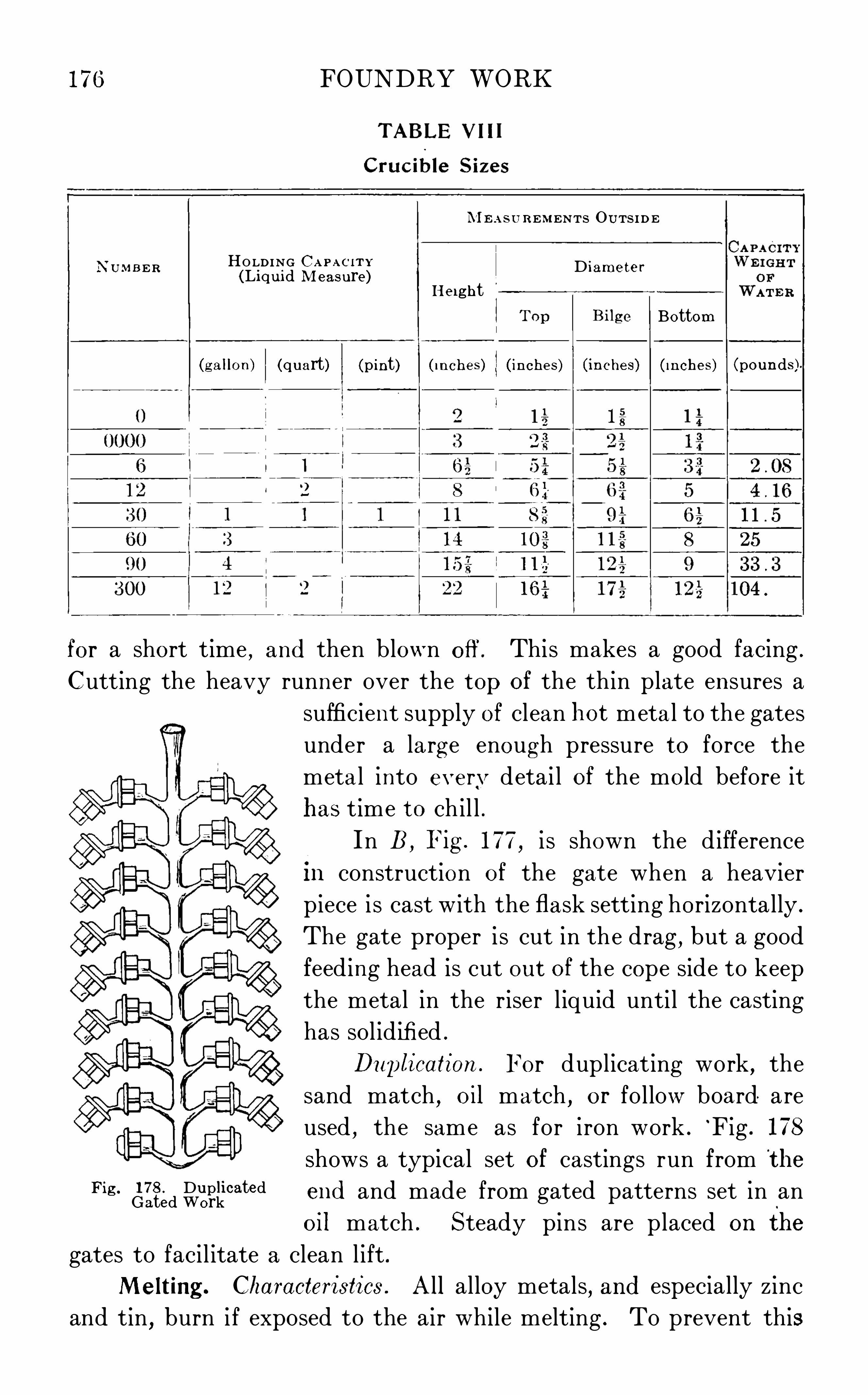
176
N U M B ER
FOUNDRY WORK
M E A SU B EM ENTS OU TS I D E
HO LDING C a p ac i r v D ’
ter(Liquid M easure) lame
(g allon)
He i ghtBottom
(quart) (pint) ( inches ) ( inches ) ( inches) ( inches ) (pounds )
for a short time , and then blown off. This makes a good facing .
Cutting the heavy runner over the top of the thin plate ensures a
Fig . 178 . DuplicatedGated Work
sufficient supply of clean hot meta l to the gates
under a la rg e enough pressure to force the
meta l into everv detai l of the mold before it
has time to ch il l .
In B , Fig . 177,i s shown the difference
in construction of the gate when a heavier
piece i s cast with the flask setting horizontally .
The gate proper i s cut in the drag,but a good
feeding head is cut out of the cope side to keep
the metal in the riser l iquid unti l the casting
has sol idifi ed .
Duplication . For duplicat ing work, the
sand match, oil match , or follow board are
used , the same as for iron work .
‘Fig . 178
shows a typical set of castings run from the
end and made from gated patterns set in an
oil match . Steady pins are placed on the
gates to facil itate a clean l ift .
M elting . Characteristics . All alloy metals, and especially zinc
and tin,burn i f exposed to the air while melting . To prevent this

178 FOUNDRY WORK
In the space made by the ribs, between the bottom plate and the
rails, the grate bars C’ are set . These bars are loose and may be
pulled out when it is desired to dump the fire for the day.
Operation . Before starting the fi re in preparing to run off a
heat, a good plan i s to use a half fire brick on which to rest the
crucible, or the bottom of a worn - out crucible cut off to the heightof 4 inches or 5 inches may be turned upside down and used for thispurpose .
Sufficient time and special care should be exercised in placing
the metal in a crucible . It i s more or l ess dang erous to j am in the
charg es, so particular care should be taken to see that they are placed
F loor L eve l
F ig 180 . N atural- Dra ft Furnace
in the crucible loosely . G raphite i s the crucible ’s principal ingre
cl ient ; the only expansion possible to a crucible comes from its clay
body,hence, i f th e charges are wedged in a crucible and jammed to
fit t ight, their expansion , which i s much greater than the expansion
of the crucible,cracks the latter before the melting point is reached .
The crucible should be kept covered , especially for brass .
In melting brass,melt down the copper first, then the scrap .
When this i s melted,charg e the z inc and st ir wel l before l ift ing the
pot. Al low the mixture to come to the proper heat again, then pull
the pot , skim off the dross,and stir in the lead if any is called for, just
before pour ing . In bronze the same method is pursued, but both the

FOUNDRY WORK
tin and z inc are stirred in after the pot i s drawn . In mixing in the
zinc in brass, care must be taken to plung e it well under the surface
Fig . 181 . Section through O il Furnace
of the copper with long handled pick - up tong s, and to hold the piece
down with the st irring bar until it has melted .
Where a larg e cast ing requires more metal than can be melted
in a sing l e crucible, several furnaces must be used and the contents
of their various crucibles assembled into one l arg e pouring ladle just
before pouring .
Fig . 182 . General Views of O il Furnace
Gas or
.
Oil Furnace. With the development of natural - gas and
crude - oil burners for commercial heating , severa l good furnaces have
been designed in which a large quantity of metal can be melted at

FOUNDRY WORK
one time . F ig . 181 shows a furnace of this character in section . This
type has tandem melting chambers w ith burners at the end,which
may be used separately or both together . The waste gases from the
F ig . 183 . Sprue T rimmerCourtesy of Toledo M achi ne and Tool Company , Toledo, Ohio
bath of l iquid metal are used to heat up a fresh charge in the other
chamber . The metal i s charg ed and poured from the open ing s at the
top of the furnace . Each chamber may be revolved separately, to

182 FOUNDRY WORK
sulphuric acid , in a stone jar . Place the piece to be cleaned in a stoned ipping basket, F ig . 184 , and dip once into the acid, then wash off
in clean water, and dry in sawdust .
Chip Separation. In many cases,brass chips and fi l ing s are
turned back to the foundry,
to be remelted . The smallest portions of
steel or iron in these would prevent their being used in this way,as
they make extremely hard Spots in the cast ings .
F ig . 185 shows a magnetic separator wh ich effectively removes
al l steel and iron chips . The brass chips and sweeping s from the
machine shop are p laced in the hopper of this machine . They are
caused to be spread out on one side of a slowly revolving brass covered
drum . Inside of this brass shel l are strong magnets which hold to
their surfaces the steel and iron chips,while the brass chips drop off
into a tote box . A stiff brush at the back of the cyl inder removes the
iron chips,and they drop into a separate box .
SHO P MANAGEMENT
PLANT ARRANGEMENT
Governing Factors . The success of a foundry depends upon the
abil ity of its manag ers to promptly turn out casting s which meet
the requirements demanded of them , at’
the lowest possible cost
commensurate w ith the qual ity of the work . In this article we wish
to direct the attention of students to some features in the way of
equipment and management which a id in accompl ishing these results .The most important processes in the foundry are the following
melting metal , making molds, and pouring them . Much of the work
necessary in preparing for these processes con sists in handl ing heavy
material s such as coke, iron, sand, etc . To reduce this handl ing
to its lowest l imits, as to distances, number of re—handl ing s, andmethods of conveyance, are problems to be considered in the plan
of the shop as a whole .
TYP ICAL FOUNDRY
General Plan. To briefly il lustrate some of the po ints to be
brought out, l et us consider the plan of the shop shown in Fig . 186,
and its sectional elevation shown in Fig . 187 .

FOUNDRY WORK 183
Building . The building is of steel construction,and the columns
supporting the roof trusses s erve also to carry the tracks for theoverhead travel ing cranes .
The outer walls should be fi l led in with some good weather
resisting material, of which there is nothing better than brick .These
wall s should be of good height and have a sufficient window area tosupply l ight wel l in toward the middle of the shop .
Ventilation . The method of heating and ventilating bestadapted for a foundry is the indirect fan system . One or more large
Upp er Le vel Stora g e
Coke B insL
. F ig /ron Ya rd
F ig . 186 . T ypical Plan of Foundry
fans, situated generally toward the ends of the shop, draw fresh air
in through a compact system of steam coil s,and
,by means of over
head piping, del iver it to al l portions of the shop . The impure g ases
are carried off through ventilators in the clearstory at the top of
the roof .
Floor. The floor of the foundry should consist of molding sand,the depth of the sand floor varying with the class of work to be done .
If the natural soil of the g rounds i s open and porous, a thickness of3 or 4 inches of clay, wel l rol led down, should be put in underneath

184 FOUNDRY WORK
the sand floor . This w ill help greatly in keep ing the molding floor in
good condition, as it prevents the moisture draini ng out of thesand .
Shop Ofiice. The foundry office should be located at such a
point that the foreman can command a Vi ew of the whole shop . It
should be conven ient to the different departments and at the same
time be protected as far as poss ible from dust . The office room,
shown in F ig . 186 at A , is built on the outside of the main building,but has a large bay window which projects a few feet into the shop
fromwhich al l corners of the foundry can be seen .
Pattern Room. A space B,having suitable low tables and shelv
ing , is reserved near the office for the temporary storing of patterns
in daily use. This brings them d irectly under the attention of
the foreman and his assistants who can readily check the patterns
as they come in and quickly find those requiring prompt attention.
Fig . 187 . T ypical E levation of Foundry
Cupolas . At C are shown the cupolas, directly opposite theforeman ’s office, and so situated that all of the molding floors may
be served as quickly as possible without interfering one with the
other .
In large foundries there are two or more cupolas, to admit of
different m ixtures being melted simultaneously . O ften a compara
tively small cupola i s installed near the floor for l ight work for the
service of that floor alone .
The‘ blowers should be placed near the cupolas, avoiding long
connecting wind p ipes . The appl ication of electric motors removesthe necessity of concentrating the power at one point in the shop .
Mold ing D ivis ions . Heaoy Work. The main bay of the found ryis devoted to the heaviest work and is served by at l east two
overhead cranes .

FOUNDRY WORK
Machines . The mold ing machines are placed on that side of
the shop near the sand storage sheds,to allow for handling the sand
by means of belt conveyors w ith hoppers above the machines, an
i llustration of which is shown in Fig . 188.
The sand - mix ing space i s in the side bay near the cupolas at K ,
and is furnished with power from independent motors or from a jack
shaft leading from the blower room . This position affords direct access
to the sand bins . The raw material after being mixed and tempered is
del ivered by barrow or sand car direct to the:various floors . The mixers might be insta l led in one of the storag e vaults across the roadway .
Materials . Unloading . The quickest means of unloading either
wagon or carload lots of material i s by dumping, where the material
can be so handled . One of two things is necessary to accompli sh
this : either the storage bins must be placed in a basement under
neath the roadbed ; or the roadway must be run up an incl ine over
the top of the bins . The former method is more frequently met with
in the crowded condition of the large cities, butthe latter i s preferable
because less time is consumed in running material up an incl ine in
larg e quantities than is required to hoist small quantities more
frequently from a basement .
Storage. At L and L ’
,Figs . 186 and 187 , are shown the storage
yards for p ig i ron and coke ; these are on a level with the charg ingplatform of the cupola
, C and C’
,and the materials can be loaded
on cars and pushed directly to the charg ing door . In some modern
shops these push cars are built so that their load may be dumped
as a whole into the cupola .
The storag e for core - oven fuel, sands, and clay, i s shown at
MM ,in b ins built underneath the tracks and on a level with the
foundry floor . These bins should be arranged to open on top , with a
chute under the track and a trap at the side, so that coal or sand may
either be dumped or shoveled directly into them .
Handling Systems . Tracks . In the larg est shops a standard
gage track should run d irectly through the main foundry, and there
should be also sim ilar tracks through the roadway next the cupola
bay for convenience in removing the dump . The track over the
storage bins has been mentioned .
Two methods of transferring material between departments
within the shop, aside from the cranes, are the overhead - trolley

FOUNDRY WORK
system , F ig . 189, and the narrow - gage industrial railway . The
former i s of advantage in manufacturing p lants where the loads to
be transferred are nearly uniform in weight and frequency of hand
ling . This system leaves gangways smooth and free from obstrue
tions . For general work, however, the industria l ra i lways are more
frequently installed . These serve al l floors to del iver flasks,sand
, or
iron,and to remove castings .
Cranes . Of the many styles of overhead travel ing cranes that
are on the market, those using electricity as the motive power are
undoubtedly the‘ most
serviceable . The cranes
in the ma in foundry in
dicated at Fig . 187,
should have two hoisting
drums on the carriage ;one for such light work as
handling flasks, rigging,and patterns ; the other
for the heavy work on the
large ladles and castings .
Small j ib cranes furnished with a 2 to 4 - ton
air or electric hoist placed
on the side of a man ’sfloor
make it possible for the
molder and helper to han
dle work of considerable size by themselves, and prevent loss of time
from waiting for the overhead crane .
The method of distributing the melted metal varies with the
class of work made . In shops doing g enera l jobbing work, the ladles
for pouring the largest work are carried from the cupola d irectly
by the overhead cranes .
Bay F loor. For serving the floors in the bays one of the systems
mentioned above i s general ly used . The metal i s conveyed to the
floor in a larg e ladle and from this smal l er ones are fi l led and carried
by hand or by a small crane to the molds .
Cleaning Department. The cleaning department should be
situated at one end of the shop ncar E , Fig . 186, or in a shed extension
F ig . 189 . Overhead T rack and T rolley

FOUNDRY WORK
to the foundry proper . It requires space to pile the castings as they
are brought from the floors with sufficient room for the men to begin
work on these piles . As a rule , the smaller castings are first collected
and put through the tumbling barrels, then the medium work is
cleaned by hand or by sand blast ; this leaves room for work around
the largest pieces . As soon as casting s are cleaned they are Weighed
and shipped to the customer , store house, or to the department which
does the next operation upon them .
PERFORMANCE
LABORD ivis ion. The div ision of labor in a foundry is briefly as follows
Superintendent. The superintendent i s responsib le for the
operation of the foundry as a whole . He h ires the men and oversees
the purchase of materials and supplies, having under h im clerks who
keep track of the details of this work . Some of the things to which
he gives personal attention are : In consultat ion with h is foreman he
g ives personal attention to the rece ipt of the most important patterns ;decides how they shal l be molded ; on what floor and ' with what
mixture they shal l be poured . He devises ways and means of increas
ing the productiveness of h is shop.
Foreman . The foreman or his assistants must be in the shop
a sufficient time before work beg ins for the day to see that each
molder has work la id out for h im , and must keep the men suppl ied
with work through the day . He est imates the amount of the charge
for the day and directs the melter as to mixtures .
It is the duty of the foreman and his assistants to g ive d irections
to the apprentice boys and to see that these direct ions are carried
out to the best of the boys ’ abil ity .
Molders . The molders should give their entire time to making
up molds . On floor work they are usually g iven a helper who carries
flasks, cores, chaplets, etc ., and does the heavier work when handl ing
the sand . When the molds are poured and h is flasks stripped off
the molder is through for the day .
Laborers . M ost modern shops employ a night gang of laborers
to put the shop in proper shape for the molders to start their special
work immediately when the whistle blows in the morning . These
men remove the castings from the sand and transfer them to the

190 FOUNDRY WORK
PHYSICAL RESULTS
Checking . The methods of mixing iron by analysis have been
previously dealt with,but these mixtures must be checked by physi
cal tests ou the resulting castings . Two systems of checking are
now in more or less general use throughout the United States .
Keep’s Mechanical Analys is . A very complete system of regu
lating mixtures, termed by the inventor "Mechanical Analysis has
been devised by W . J Keep, of Detroit, M ichigan, who has had long
experience in this subject . In Fig . 190, A shows a fol low board
arranged with patterns and yokes . The test bars are é inch square
and 12 inches long . They are cast in green sand with their ends
chilled against the faces of the cast - iron yokes, shown in the cut .
Three molds should be cast each heat, and the test bars a l l owed to
cool in the molds .
Silicon and Shrinkage. The analysis is based on the fact that
silicon is the most important variable chemical e lement in cast i ron,
Fig . 190 . A—Keep ’
s T est- Bar Pattern ; B—M easuring Shrinkage
and that shrinkage i n castings i s inversely proportionate to the
silicon in the mixture .
The fi rst test, as shown at B ,Fig . 190, i s to replace each bar in
the same yoke in which it was cast and by means of a specially
g raduated taper scale to ascertain accurately the amount of shrinkage .
The shrinkag e of the bars when the castings prove satisfactory,should be considered the standard for that class of work for that
shop . I f at any time the shrinkage i s greater than the standard,increase the s il icon by using more soft pig ; if it i s less, decreasesil icon by using more scrap or cheaper i ron .
Chilled Depth. The depth of chill on the casting s is measuredafter chipping off a piece from the end of the bar .
Transoerse Strength. The third test is to obtain the transverse
strength of each bar . This i s done on a special testing machine

FOUNDRY WORK 19 1
which gives a graphical record of the deflection and the ultimate
breaking load . These dead loads will vary with different mixtures
approximately from 340 to 500 pounds .Deductions . "uoting fromMr. Keep ’s circular
W ith high shrinkage and high streng th of a - inch square tes t bar, heavycas tings w ill be s trong but small castings may be brittle .
With low shrinkage and high s treng th , large castings w ill be weak and
small castings w ill be strong .
With uniform shrinkage, an increase in the streng th of a —inch squaretest bar w ill increase the s treng th of all casting s prOportionately .
Arb itration=Bar Tests . The other form of tests was devised
by a committee of the American Foundrymen’
s Association, and is
recommended in the Proposed Standard Specifications
for G ray - I ron Castings by the American Society for
Testing Materia l s .
Test Bar. The test bar specified i s Ii inches in
diameter and 15 inches long , and is known as the
arbitration bar.
The tensile test i s not recommended , but , if called
for,a special threaded test piece i s turned down from
the arbitration bar, and has a test section inch in
diameter and 1 inch between shoulders .
The transverse test i s made with supports 12
inches apart .
Fig . 191 shows a sketch of the patterns for these
bars . Two bars are rammed in a flask and poured
on end . The smal l prints on the two bar patterns
proj ect into the cope and are connected by one pouring
basin . A specia l green- sand mixture i s specified for
making these molds ; the molds are to be baked before F ig , 19 1 , p attern for Arbi
pourmg , and the bars allowed to rema1n 1n the sand tration Bar
until cold .
Specifications . Table IX shows the specified requirements ;in this connection casting s are distinguished as follows
Unless furnace iron is specified, all g ray cast ings are understood to be
made by the cupola process .
L ight casting s are those having any section less than inch .
Heavy cas ting s have no sect ion less than 2 inches .
Medium cas t ings are those not included in the above.

FOUNDRY WORK
TABLE IX
Arb itration=Bar Standard s
PHY S IC AL PROPERTIES
G RADE or CA STINGS
PRACT ICAL DATA
Us ing Percentage
(1) To find the percentag e of any number when the rate per
cent is given : Multiply the number by the rate per cent and set the
decimal point two places to the left .
Example: F ind per cent of 35 . decimal
point moved two places to the left gives Ans .
(2) To find what rate per cent one number i s of another :
Add two ciphers to the percentage and divide by the number on
which the percentag e i s reckoned .
Example: What per cent of 75 tons i s 9 tons? 900—1Ans . 12 per cent
(3) To find a number when the rate per cent and the percentag e
are known : Add two ciphers to the percentag e and divide by the
rate per cent .
Examp le: I f 68 pounds i s 15 per cent of the entire charge, how
many pounds in the tota l charge? Ans . 6800 15 pounds
(4 ) To find what number i s a certain per cent more or lessthan a given number : (a) When the g iven number i s more than the
required number,add two ciphers to the number and divide by 1001
plus the rate per cent .
Example: 465 i s 35 per cent more than what number?
Ans . 46500+
(b) When the g iven number i s less than the required number
add two ciphers to the number and divide by 100 minus the rate
per cent .*In no case , shall the deflection be under of an inch.

194 FOUNDRY WORK
C ircular Areas and Circum ferences
W e ight CalculationWeight of round iron per foot =D iameter (quarter inches ) squared X0 . 1666Weight of flat iron per foot W idthX thickness X 3 .333
Weig ht of plates per sq . ft . 5 pounds for each 35 inch in th ickness
Weight of chain D iameter squared X 10 .7 (approximate)Safe load (pounds ) for chain =Bar diameter (quarter inches ) squaredX
2000To compute weight of metal from weight of pattern,
w ith no allowance forcores or runners
, mult iply as follows
MU LT IPL ICAT IO N FACTOR S
WH ITE P INE M AHOGANY
Weight of brass patternX . 9 =weight of iron cas ting , approximately.

FOUNDRY WORK 195
Spec ific G ravities and Weig hts of Metals
M ATER IA L
Water , at 39 1°F .
AluminumAntimony
, cast to
BismuthBrass, cast to 8 4Bronze 8 4 to
Copper, cas t to
Gold, pure, 24 caratIron, cast to
Iron, wrought to 7 . 9
LeadMercury , at 60°Plat inum 2 1 . to 22 .
SilverSteel
, averageSpelter or zmc to
T in, cas t to
Pressure In Molds
To find the total lif ting pressure on the cope, mult iply the pressure persquare inch at a g iven depth below the pour ing bas in by the area (square inches)of the surface acted agains t . The result is in pounds .

196 FOUNDRY WORK
Temperatures*
CONN ECTION
Core ovens 250 to
Bright iron becomes
T in meltsMercury boilsLead melts"inc meltsSilver meltsCopper meltsGold melts
a dark room, just vis ibleIron bar red in ordinary offi ce
daylight, Open air
Cas t iron melts W h i te
Steel meltsAnnealing malleable iron
*From late scientific investigations .


Alloys , brass and bronzeAnalysis of cast iron
arbitration barKeep ’
s mechanical
oven forAnnealing steel castings
specifications fortest bar in
Arbors for core work
Balanced cores
fan- blower
BlowholesBottom doors
, cupola- furnaceBras s
chip separation
molding processpattern weight
Brass work
production processes inBreast
,cupola- furnace
SPGCifiC gravity and weight of

2 INDEX
Carbon 121, 136
‘
Cast - iron analysisCas ting operationsbras s workmalleable practicemelting g ray ironsteel work
Centrifugal sand mixerChaplets
settingCharcoal foundry facingCharg ing door, cupolar furnace
CheekClampsClay was hCleaning cas tings , methods of
Coke,foundry
Cold - shutsCope
flat joint,for
floor bedding , inloam molding , inpressure head ou
Coping out
Copperspecific gravity and weighttemperature
,m
‘
eltingCore—making machinesCore ovensCore platesracks for
Core sandmixtures
Core work
for brass molding
general equipment forgreen- sandfor malleable- iron moldingsetting cores ih __for steel molding
Core- rod straightening machineCover coreCover plates in loam moldingCrucible malleable- iron melting

4 INDEX
Foundry, typical (continued )core shopcranescupolasfloor planheavy - molding div is ionlight- molding divis ionmolding machinespattern roomshop offi ce
storage of materialstrackstyp e of buildingunloading of materialsventilation
Foundry workcas ting Operationsmolding practicepractical datashopmanagement
Free sands
GaggersGas furnace for bras s meltingGated patterns for duplicate cas ting s
Graphite foundry facing _
Green- sand cores - 39 , 62
Green- sand molding
typical problems in
Hard - rolling of cast ing sHeat
,running a
for brass workfor malleable cas tingfor s teel casting
Ironspecific g ravity and weight oftemperature indications
Jointingloammolds

INDEX
deductions by
transverse strength
superintendent
brass workmalleable—iron work
melting temperaturespecific g ravity and weight of
fou-udry - ladleLoam mixturesLoam molding
example of complex cylinderexample of simple
finishingmelting , methods ofmetal characteristicsmethod of castingmethods of testingmixture formolding r
patterns forspecifications for

6 INDEX
Malleable practicedevelopment ofproduction processes
Manganese
Match, sand
permanent oilMaterials, moldingbrick for loam moldingcindersfacingsmiscellaneous
mud for loam moldingsands
Meltingbrass
principles of ironsteelsupplementary Operations in iron
M ixing machines , sandM ixing of sandM ixtures
,cupola- furnace
calculation of
chemical analysis ofelements infuel inproportions of charge in
Mold board_Molders, dut ies of
Molding machinesMolding practicebrass
general molding equipmentmalleable iron
processessteel
Natural- draft furnace for brass workNowel or drag
Open sand moldingOpen- hearth malleable- iron meltingOpen- hearth steel, casting
Packing steel moldsParting dus ts

8 INDEX
Safety - first factors (continued )
Sand shakerSand- blastingSands , molding
core sandelements infire sandfor brass workfor malleable iron workfor steel workfree sandsg rades ofg reen- sand mixture
Scrap iron inmalleable workSea- coal foundry facingSetting coresShop management
governing factors in
of typical foundryphysical resultssafety first in
ShovelShrinkage cracksShrinkage heads or feedersShrinkage in malleable cas tingShrinkage in s teel workSieve, riddle or foundrySitting
Silicon
Skimming gateSlag hole, cupola - furnaceSlicks
cornerSlip or skinning loamSnap flaskSpill trough for brass pouringSpindle for loam mold sweepingSplit - patternmolds
core lifting ringg reen- sand coreloose—piecethree- part
Spraying can for core workSpruesSqueezer machine

INDEX
Squeezer machine (continued)
cores in moldingfacing s for, moldflasks for molding
Steel Workcastingmolding
Stripping - plate machineSulphurSuperintendent, duties of
alloys , proportions of mixtures inarbitration- bar standards for cas t ironcrucible sizes__
fan- blower performance
ladle data, foundry
sands,proportions of elements in
cores,dry - sand
Testing cast iron
specific g ravity and weight oftemperature, melting
Tools , hand - molding "
for brass work

10 INDEX
Tumbling castings‘
I‘uyéres
Vent rodsVentilation systems in typical foundryVentingdry - sand coresloam molds
WarpingWhite iron in malleable practice