


Manganese - Forgotten Books
220
-
Upload
khangminh22 -
Category
Documents
-
view
1 -
download
0
Transcript of Manganese - Forgotten Books

Bulletin 1 73
DEPARTM ENT OF THE INTERIOR
FRANKL IN K. LA NE , S E C R E T A R Y
BUREAU OF M IN ES
VAN . H . MAN N IN G . D IR E CTOR
MANGANESE
USES , PREPARATION , M IN ING CO STS
AND THE PRODUCTION OF
FERRO-ALLOYS
C . M . WELD and OTHERS
W ASH INGTO NGOVERNM ENT PRINT ING OFFIC E
1 920
The Bureau of Mines , in carrying out one of the provisions of its organic act— to
disseminate information concerning investigations made— prints a limited free editionof each of its publications .
When this edition is exhausted copies mav be obtained at cost price onl y through
the Superintendent of Documents, Government Printing O ffice, W ashington ,D . C .
The Superintendent of Documents is not an ofiicia l of the Bu reau. of Mines . His is
an entirelv separate office and he shoul d be addressed :
SUPERI N TEN DEN T or DOCUM EN TS,
Gorernment Printing Ofice,Washington,
D . C .
The general law under which publications are distributed prohibits the giving of
more than one copy of a publication to one person . The price of this publication is3 0 cents .
First edition . March, 1 920.
CONTE NTS .
PrefaceIntrod uction
(‘
hapter l .
— General information regarding manganese, by C . M . W ELDUses of manganese
Specifications .
Prices
Price schedu le of May 28 , 1 9 1 8
Silica premiums and penalties
Phosphorus penaltyPayments
Statistics
Chapter 2.
—Uses of manganese other than in steel making , by W . C . PI IALE N
Introduction
Uses of manganese dioxide ore
General remarks
The dry cell
General description .
Development
Method of manu factureConstituents used
Functions of di fferent constituentsRole of manganese
Character of manganese ore used
Physical requirements
Manganese ores in the ceramic industries
Glassmaking
Chemistry of use of manganese in glass-making process
Specifications formanganese ore used in making glass
Other ceramic u ses
Use of manganese salts in du ers
Definition .
Manganese sulphate
Manganese borate .
Manganese resinate
Manganese linoleate
Manganese oxalate .
Use of manganese in miscellaneous chemicals
Manganese chloride .
Manganese sulphateManganese persulphatePotassium permanganate
Use of manganese in manganese bronze
Function of manganese in manganese bronze
Uses of manganese bronze

IV CON TEN TS .
Chapter 3 .
— Problems involved in the concentration and u tilization of domestic
low-
grade manganese ore, by E DMUN D N E W TON .
Introductory statement
Manganese deposits in the United States
Concentration of domestic low—grade manganese ores
Factors control ling the possibilities of concentratio
Size and character of deposit
Condi tions affecting mining and marketing
Characteristics of ore affecting beneficiationCharacter of manganese minerals
Impurities associated W ith manganese minerals
Concentration processes
Commercial considerations regarding beneficiationE stimated cost data
Discussion of estimated cost data
Ore 1 009
Ore 1 01 1
Ore 1 020
Fineness of concentrates
Chapter 4 .
— Preparation of manganese ore , by W . R . CRAN EIntroductory statement
Methods employed
Dry miningWashing and concentration
Practice in cleaning manganese ore
Practice at a Virginia plantPractice at a plant in Georgia
Practice in the Batesville district , ArkansasPractice at a mill at Philipsburg, Mont
Description of a standard washinga p lant
Logs .
Screens
Picking bel ts
Jigs
Tables
Dry concentration
General summary of conditions affecting concentrationChapter — Leaching of manganese ores with su lphur dioxide
,by C . E . VAN
BARN EVELDIntroductory statement
Results of tests
Observations on resu l ts of tests
The ore
The pu lp .
Solubility of the manganese minerals
Iron
Phosphorus
Lime
Zinc and copperTreatment of the pregnant solutionsConditions essential in commercial practiceLeaching in two stages

CON TE N TS .
Chapters 5 .
—Leaching o f manganese orcs w ith su lphur dioxide— Continued .
Observations on resu lts o f tests— Continued .
Filter
Corrosion .
Su lphur dioxide
Complex ores .
Costs
General estimate
Calcu lated estimates for typical ores
Example 1
Examp le 2
Example 3 .
Example 4
Possible future application of SO2 method .
Chapter 6 .
— The Jones process for concentrating magnanse ores ; resu lts of lab
oratory investigations by PE TE R CHR I S/H AN S O N and W . H . HUN TE R
Introductory statement .
Low-temperature reduction
Preliminary tests
Apparatus usedProcedure
Charging and heatingDischargingSeparation
Analyses
Calcu lations
Conclusions
Tabulated resu lts
Discussion .
Products .
Reducing agent
Final tests
Outline
High-temperature reduction tests
General outline .
Pyrometer
Crucibles
Temperature
Tabulated resu lts
Discussion
General
Alloy
Recovery .
Conclusions
VI CON TE N TS .
Chapter 7 .
— Cost of producing ferro-
grade manganese ores,by C . M . WE LD and
W . R . CRAN E
Introductory statement
Costs of domestic manganese ores
Carbonate ores .
Oxide ores
Cost at the mine
Labor
SuppliesRoyaltyMining and treatment
Cost of transportation to railroad
Summary of cost of oxide ores on board cars
Cost of railroad transportation to ma rketSummary of cost of domestic ores
Discussion of future possibilities .
Cost of foreign ores
Brazil
Ocean freight ratesSummary of cost of foreign ores
Discussion of future possibil ities .
Comparison of domestic and foreign costs
Chapter 8 .
—Production of manganese alloys in the blast furnace , by P . H .
R OYSTE R
Introductory statement
Furnaces investigatedCol lection of data
Character
Completeness
Accuracy
Tabul ated operating data
Discussion of data on ferromanganese practice
General description of ferromanganese production .
High blast temperature
High hearth temperature
Résuméof conditions in ferromangenese furnace .
Theory as to fuel requirements for producing ferromanganese
Composition of furnace gasDirect
”and
“ indirect”reduction
Burdening and driving the furnaceFuel requirements
Percentage of manganese in slag
Rate of drivingE quation for percentage of manganese in slag
Burdening the furnaceStack loss
Cost figures for average practiceCoke ash .
Selection o f stone
Summary of observations on ferromanganese data
CON TE N TS .
Chapter 8 .
— Production of manganese al loys in the blast furnace— ContinuedDiscussion of data on spiegeleisen practice
General description on spiegleisen production
Slag composition .
Hearth temperature .
Composition o f furnace gas .
Carbon burned at the tuyeres
Fuel requirements .
Percentage of manganese in the slag
Stack loss
Summary of observations on sp l egeleisen practiceChapter 9 .
— National importance of al locating low-ash coke to manganese al loy
furnaces, by P . H . ROYS TE RIntroductory statement
Furnace data
Importance of allocating low-ash coke to manganese furna cesConclusion
Chapter 1 0.
— E lectric smelting of domestic mangan ese ores, by H . W . GLLL E TT
and C . E . WI LL IAM S .
Introductory statement .
Present development of electric smelting of domestic ores
E lectric smelting practice on ferromanganeseFurnaces used
Raw materia ls employedAverage resu lts obtained
E ffect of high silica in ores .
Concentra tion of ores
Redu ction of silicon
Production of silicomanganese
Future of high-silica ores dependent on use of silicomanganese
‘
.
Carbon content of manganese alloys
Reasons for experimental work .
Classes of low-grade ores .
Exp erimental work
Description of furnac e usedPreliminary tests .
Standardization of furnace .
Advantages of acid slag
Test of reducers .
Comments on use of rhodochrosite
Tests of eff ect of size of reducer constituentsSlag
-melting tests
E ffect of phosphorus content of oresTests with high
-phosphorus ores
Tests on volatilization of. phosphorus .
Dephosphorization and smelting in two stages
Conclusions as to two-stage process
Tests with high-silica ores
Applicability of two-stage process to cuyuna ores
Results of tests
Compilation of data
Conclusion as to electric smelting
VI I

VI I I CON TE N TS .
Chapter 1 1 .
—Use of manganese alloys in open—hearth steel practice,by SAM U E L
L . HOYTIntrodu ctory statement
Purpose and scope of investigationThe functions of manganese
Recommendations for the utilization of domestic alloys“ Molten spiegel mixture practice
High residual manganese practice
Standard open-hearth practice compared with certain other practices .
Use of manganese-silicon al loys .
Acid practice
E lectric-furnace practice .
Basic open-hearth practice
Selected bibliography on manganese deposits
General
United States
Panama
South America .
Brazil
Chile
E uropeAustria
GermanyRussia .
Spain
AfricaWest Africa
Japan
Publ ications on metal lurgy .
Publications available for free distributionPublications that may be obtained only through the Superintendent of
Documents
TABLE S.
TAB LE 1 . Range of composition of manganese al loys
2 . Manganese dioxide and available oxygen in the common manganese
minerals
Carnegie Steel Company’s price schedules for domestic ores
Freight rates on manganese ore from Western States to Chicago .
Comparison of prices of al loy and ore
Imports of manganese ores, N OS
Domestic production of manganese ores
Imports and production of manganese al loys, 1 905—1 91 8 .
E stimated cost data appl ied to three California oresResu l ts of tests of manganese ores by sulphur dioxide leachingwith
continuous-drum processP
s
ws
mg
e
w

CON TE N TS .
TABLE 1 1 . Resu lts of preliminary low- temperature reduction tests with the
Jones processResu l ts of final tests with l ow-temperature reduction
1 3 . Resul ts of high-temperature reduction tests
1 4 . Wages paid in several of the manganese-produ cing S tates1 5 . Cost of handling and hau l ing ore in manganese
-producing S tates1 6 . Dimensions of 1 4 of the 1 8 blast furnaces investigated1 7 . General data from operation of ferromanganese b last furnaces1 8 . General data from operation of spiegeleisen blast furnaces1 9 . Selected data on operation of ferromanganese bl ast furnaces . .
20. Resul ts of furnace runs arranged to show variation of carbon fuel withweight of slag and with b last temperature
21 . Resu lts of furnace runs arranged to show variation of percentage of
manganese in sl ag with excess or deficiency of carbon fuel as required for average hearth-temperature conditions
22. Resul ts of furnace runs arranged to show variation of percentage of
manganese in slag with basicity of slag
23 . Resul ts of furnace runs arranged to show variation of percentage of
manganese in slag with rate of driving24 . Resu lts of furnace runs arranged to show manganese lost in stack as
related to other factors25 . Selected data on operation of spiegeleisen blast furnaces26 . Average values for carbon fuel , blast temperature, and slag weight
in the furnace runs represented in Table 1 8 .
27 . Resu lts of furnace runs arranged to show variation of manganese
in slag according to basicity of slag and according to excess or de
ficiency of carbon fuel28 . Results of furnace runs arranged to show variation of manganese
in slag according to rate of drivin g
29. Results of furnace runs arranged to show comparative effects of
large and of small stack losses
3 0. Results of slag-smelting tests in electric furnace
3 1 . Data showing probable resul ts of electric smelting of domestic man
ganese ores
3 2. Data showing calculated costs of electric smelting of domestic ores
3 3 . Comparative results obtained with silicomanganese and with a mix
ture of ferromanganese and ferrosilicon
ILLUSTRATIONS .
FIGURE Flow sheet of proposed nlant for 50 2 leaching of manganese ores .
Curves showing recoveries of iron and of manganese in heats 1 6 , 1 7 ,
3 2 , and 3 5 , with varying temperature3 . Curves showing recoveries of iron and of manganese in heat 3 4 at
C . and with varying quantities of reducing agent
4 . Curves showing recoveries of iron and of manganese in heat 1 7 at
C . and with varying time
5 . Curves showing recoveries of iron and of manganese in heat 3 5 at
C . and with varying time
I X

X C ON TE N TS .
FI GUR E 6 . Curves showing percentages of iron and o f manganese in magnetic
part in heat 3 4 at C . and w ith varying reducing agent .
Curves showing percentages of iron and of mangan ese in magnetic
part in heats 1 6 , 1 7 , 3 1 , 3 2 , and 3 5 , with varying temperatures .
Curves showing percentages of iron and of manganese in magnetic
part in heat 3 5 at C
Curves showing percentages of iron and of manganese in magnetic
part in heat 1 7 at C
Curve showing relation of manganese in slag to carbon differenceCurve showing relation of percentage of manganese in slag to ratio
(CaO+MgO ) (Si0 2)Curve showing relation of percentage of manganese in slag to rate
1 3 . Curve showing relation of carbon to silicon in ferro-silico—manganesealloys

PREFACE .
The history of the domestic production of manganese ores and
alloys during the war, in common with that of several other materials equally essential for war purposes , is of interest because of itsshowing how a hitherto latent industry responded quickly to the
spur of necessity .
In the pas t the supplies of manganese ores used in this countryhave come largely from Russia and India . More recently importsfrom Brazil began to assume 1mportance, but up to 1 9 1 4 they werestill a relatively minor factor . Al so
,small amounts came from Cuba
and Central America . The domestic output,however, was practi
cally negligible .
The E uropean war soon shut off Russian sources , and receiptsfrom India declined . The domestic output became somewhat larger,but the deficit was principally made up by greatly increased importsfrom Brazil .When this country entered the war, the manganese situation be
came acute . Manganese being essential in the manufacture of steel ,the insuring of an adequate supply was imperative . On account ofthe increasing difficul ty of obtaining foreign ores
,through uncertain
output and shortage of shipp ing , it was obvious that this countrymust turn to its own deposits . In July,
1 9 1 7,the warminerals com
mittee was established, and surveys of the domestic manganese situation were begun. By the end of the year the domestic output hadreached hitherto unprecedented figures .E arly in 1 9 1 8 the need of diverting every ava ilable ship to the
transportation of tr0 0ps and mil itary supplies made necessary the
reducing to the minimum of all imports of materials that could beproduced in this country . The manganese s ituation was studiedmost thoroughly by various governmental bodies , in cooperationwith the ferro-alloys subcommittee of the American Iron and SteelInstitute, and a program was formulated for reducing overseas imports to the minimum figure consistent with the production of an.
adequate supply of steel . To s timulate domestic production,a
higher price s chedul e was announced by the American Iron and S teelInstitute
,with the approval of the W ar Industries Board . At the
same t ime the market for leaner domestic ores was broadened bylowering the standard grade for manganese alloys .
As a resul t , had the war continued through the year 1 9 1 8 , therewould have been produced more than tons of domestic orescontaining not less than 3 5 per cent metallic manganese, with larger
2 PREFACE .
quantities than ever before of the lower grade ores suitable for themanufacture of spiegeleisen . In addition
,alloys of domestic manu
facture of the alloys had entirely replaced those formerly imported .
In November,1 9 1 8
,when hostilities ceased
,there was nearly a year
’ssupply of ore and alloys on hand . As a result, the buying stoppedalmost at once and production fell rapidly . Mines were shut downand furnaces were blown out or used for other products .
Various proposed measures for stabilizing the industry were con
sidered,but none seemed to meet the situation . In 1 9 1 9 the war
minerals relief bill was passed,establishing a commission for investi
gating losses incurred in the production of manganese and certainother minerals and for reimbursement where the investments weredue to representations of the Government .During the war the engineers connected with the war minerals
investigations of the Bureau of Mines kept in touch with developments in the industry . W herever possible advice and help in miningand mill ing problems were given by correspondence or in person .
Metallurgical problems were carefully studied , not only those bearrngon the manuf acture of the alloys , but those relating to the use of the
all oys in the manufacture of steel . The chief end kept in view wasto eliminate waste and to widen and popularize the use of the leanerdomestic oresIn order
'
to supplement the field work and make public the resultsof its investigations
,the Bureau of Mines published a series of mimw
graphed bulletins dealing with these phases of the industry, whichwere studied 1n some detail . The object of this report is to presentthese papers in more permanent form
,in the hOpe that the informa
tion may be of present or future value to the industry .
J . E . SPURR,
Executive,War Minerals Investigations ;

MANGANESE USES: PREPARATION ,MINING COSTS,
ANDTHE PRODUCTION OFFERRO-ALLOYS.
By C . M . W E LD and O thers .
INTRODUCTION .
During the past two years the Bureau of Mines has issued a seriesof mimeographed reports giving the results of research work and
experiments conducted as part of i ts war minerals investigations .In this bul let in the reports on manganese are presented , which
range in scope from the beneficiation of the ore to the utilizationof the metal . The bulletin is in eleven chapters , each comprisinga separate report
,arranged in the order given below .
1 . General inf ormation regarding manganese, by C . M . W eld .
2 . Uses of manganese other than in s teel making,by W . C . Phalen .
3 . Problems involved in the concentration and utilization of
domestic low-
grade manganese ores,by E dmund N ewton .
4 . Preparation of manganese ore,by W . R . Crane.
5 . Leaching of manganese ores with sul phur dioxide, by C . E .
Van Barneveld .
6 . The Jones process for concentrating manganese ores ; results oflaboratory investigations , by Peter Christianson and W . H . Hunter.
7 . Cost of producing ferromanganese ores,by C . M . Weld and
W . R . Crane .
8 . Production of manganese alloys in the blast furnace,by P . H.
Royster .9 . National importance of allocating low-ash coke to the man
ganese-alloy furnaces , by P . H . Royster.
1 0. E lectric smel ting of domestic manganese ores,by H . W .
Gill ett and C . E . W illiams .1 1 . Use of manganese alloys in open-hearth steel prac tice
,by
Samuel L . Hoyt .As each chapter was originally prepared as a unit
,there is neces
sarily some duplication and overlapping . W ith certain exceptions,
however, each paper is reproduced in practically its original form .
In chapter 1,covering certain general phases of the industry,
such as uses,specifications , prices , and statistics , the subject matter
has been somewhat modified in view of changes in conditions .3
4 M AN GAN E SE .
About 95 per cent of the manganese consumed in the UnitedStates goes into the manufacture of s teel . The remaining 5 per centis used in a number of minor industries , the chief of which is themanuf acture of dry cells . These minor uses are described in chapter 2 .
N 0 discussion of the geology of manganese ores is presented , buta short bibliography on the subj ect is appended . VWth few excep
°tions the manganese depo sits of the United S tates are irregular,
pockety, and uncertain . Largely for this reason,mining me thods
are crude and hardly warrant descriptions .The concentrat ion of manganese ores
,however
,is an important
problem and involves some details not common to other ores .Chapter 3 discusses the concentration and utilization of low—gradeores
,notes the relat ionship of concentration to metallurgical prac
tices , outlines concentrating processes ,and treats of commercial
problems .In general
,as regards concentrat ion methods , manganese ores
may be divided into two groups , as follows : (1 ) Ores permittingmechanical separation of the manganese minerals and the gangue,and (2) ores in which the manganese minerals and the gangues areso intima tely associated that separation requires some hydrometal
lurgical or pyrome tallurgical process . Heretofore, attention has beenconfined almost wholly to mechanical separat ion,
chiefly by gravity .
In fact,so far as known ,
all production of concentrates has been bywet gravity methods , although during the war some companiesinvestigated the commercial poss ibilities of magnetic separation and
reported‘ favorable resul ts,the construction of one magnetic con
centration mill being started . The usua l wet gravity methods are
described inchapter 4 .
During the war,the Bureau of Mines undertook investigations of
methods appl icable to ores of group 2 . A hydrometallurgical processinvolving leaching with sulphur dioxide was studied at the miningexperiment station of the bureau at Tucson,
Ari'
z . The resul ts ofthis work
,presented in chapter 5 , indicate that the process is
metallurgically feasible but the cost makes i t unattractive.
The results of an investigation of a pyrometallurgical process knownas the Jones process are presented in chapter 6 . The process,which is still in the experimental s tage
,was found to be metal
lurgically sound . The manganese product is not a concentrate butan alloy , made directly from a lean unconcentrated ore. The customary method is to manufa cture all oys from high-grade ores or fromconcentrates of leaner ores .A discussion of the costs of ferro-grade manganese ores is pre
sented in chap ter 7 . This discussion is in general terms only ,
but should be of use in so far as it relates to competi tive conditions .

I N TRODU C T ION . 5
The resul ts of a s tudy o f blas t-furnace practice on ferromanganeseand on spiegeleisen are presented in chapter 8 . On account o f
the difficul ty of obtaining complete and reliable records,the work
is to be regarded as largely preliminary . Some of the conclusionstentatively advanced may be erroneous because of the nature of the
data on which they are based ; in the main, however, they are be
lieved to be correct and are put forward in the hope that they may
arouse criticism and thereby s timulate discussion and research.
The Bureau of Mines proposes to continue this investigation.
The importance of al loca ting good grades of coke to manganesealloy furnaces is discussed in chapter 9 . The need for such allocations has passed but i t is fel t tha t the paper has more than an his
toric interest . Conservation and economy woul d bo th be servedif the principles laid down were more effectively observed .
The chap ters already cited deal wi th the manuf acture of man
ganese alloys in the b las t furnace with coke fuel . During the war
there was considerable development in the electric smel ting of suchalloys . The Bureau of Mines was actively interested in the applicability of electric smel ting to the leaner
,more siliceous domestic ores,
and conducted experiments at the I thaca (Cornell University) fieldstation . The resul ts are presented in chapter 1 0 . The generalconclusions are that lean ores and manganiferous slags probablycan not be smel ted at a. profit in the electric furnace excep t in timesof high prices .
The purpose of the investigation described in chapter 1 1,on the
use of manganese alloys in open-hearth steel practice, was chieflyto po in t the way to conservation of resources . The resul ts showthat conservation could bes t be attained by developing the use of
those alloys , such as spiegeleisen and silicomanganese, which couldbe produced from lean domestic ores, thu s conserving the high-gradedomestic ores and reducing the need for high-grade foreign ores .In addition to those members of the s taff whose names appear on
the several papers , acknowledgment is due to F. H . Probert, G . D .
Louderback,Theodore Simons
,W . S . Palmer
,W . R . E aton
,F. B .
Foley , C . F. Julihn,and all o thers who contributed to the success of
the work by their active and whole-hearted cooperation .
CHAPTER 1 .— GENERAL INFORMATION REGARDING
MANGANE SE .
By C . M . WE LD .
USE S OF MAN GAN E SE .
Approximately 95 per cent of the manganese consumed in' thiscountry is used in making steel not only to
'
deoxidize and recarburizethe molten metal
,thereby making possible the production of cleaner
and sounder ingo ts containing the desired‘ amount of carbon,but
also to impart certain quali ties to the finished product . Small proportions of manganese
,to per cent, make the steel easier to
work and stronger in service . At the same time slight proportionsof impurities remaining in the steel are taken into combination and
rendered less harmf u l . Relatively small quantities of so-called man
ganese ” steel are made which contain 1 1 to 1 4 per cent or more of
manganese and possess special qualities of hardness and strength .
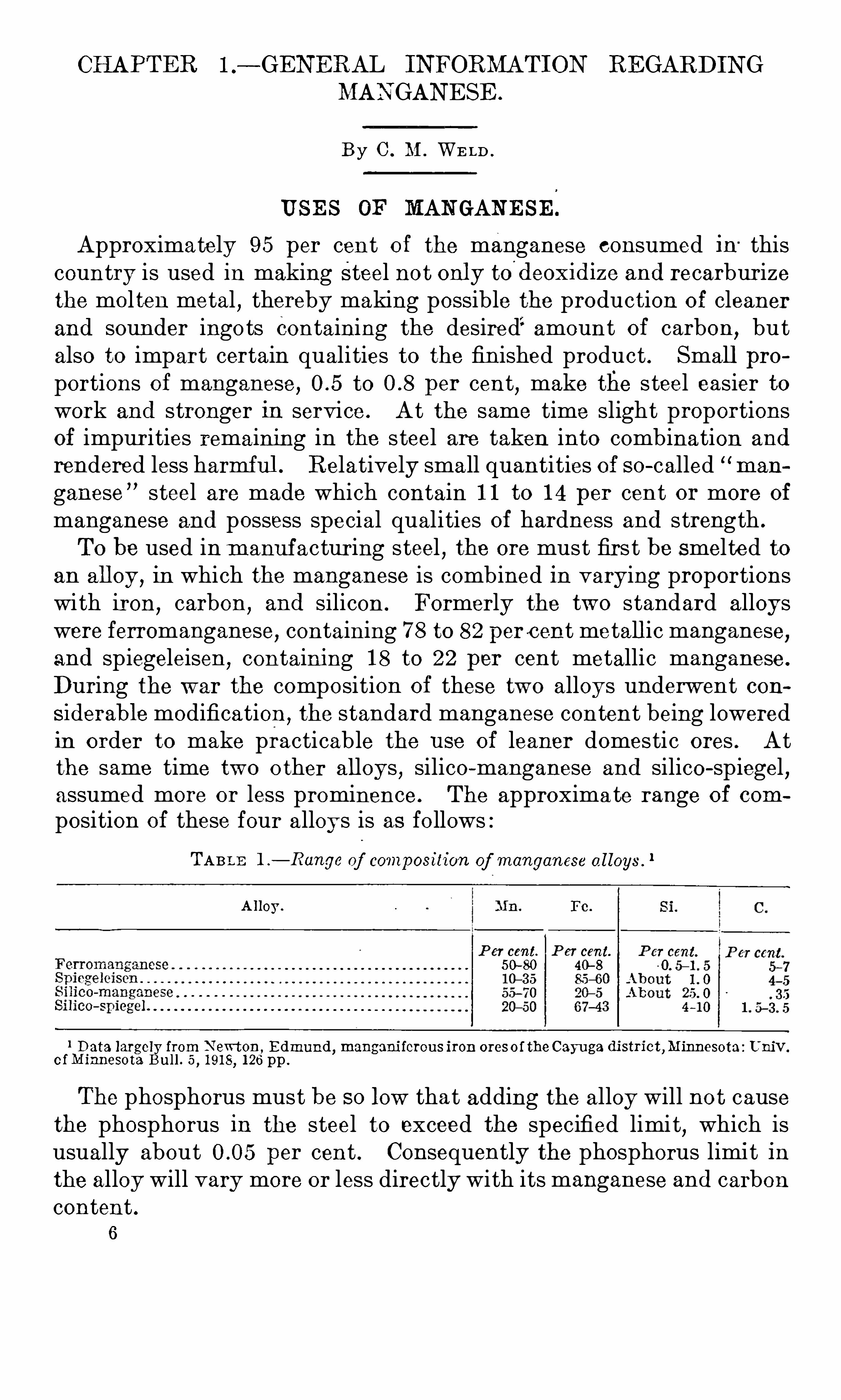
To be used inm anuf acturing steel,the ore must firs t be smelted to
an all oy , in which the manganese is combined in varying proportionswith iron
,carbon
,and silicon . Formerly the two standard alloys
were ferromanganese, containing 7 8 to 82 perc ent metall ic manganese,and spiegeleisen ,
containing 1 8 to 22 per cent metallic manganese .
During the war the composition of these two alloys underwent considerable modification ,
the standard manganese content being loweredin order to make practicable the use of leaner domestic ores . Atthe same time two o ther alloys , silico-manganese and silico-spiegel
,
assumed more or less prominence . The approxima te range of com
position of these four alloys is as fo llowsTABLE 1 .
— Range of composition of manganese a l loys .
1
A lloy .
P er cent. P er cent.
50-80 40—8
o o o o o o o o o o o o o o o o o o o o o o o o o o o o o o o o o o o o o o o o o o o o o o o
1 Data largely from N ewton , E dmund , mangani ferous iron ores of the Cayuga district ,a esota : Univ.
of M innesota Bull . 5 , 1 9 1 8, 1 26 pp .
The phosphorus must be so low that adding the alloy will not causethe phosphorus in the steel to exceed the specified limit, which isusually about per cent . Consequently the phosphorus limit inthe alloy will vary more or less directly with its manganese and carboncontent .
6
8 GE N ERAL I N FORBI A’
I‘
ION RE GARDIN G M AN GAN E SE .
class have been customary . In general , the silica and phosphorusrequirements have been about the same as for ferro-grade ores
,the
balance consisting of manganese plus iron in varying ratio , plus ganguematerials , such as alumina
,lime
,and magnesia . Ores conta ining 1 5
to 40 per cent metallic manganese were formerly classed as manganiferous
,and these limits will probably be adopted again in the future .
The war-time classification included ores containing 1 0 to 3 5 per
cent manganese .
Certain manganiferous ores from the weathered parts of silverlead deposits contain enough silver to warrant their shipment to leadsmelters for use in fiuxing . Hence these ores are not available tothe steel industry .
Wh en the alloy to be produced is silico—manganese or silico-spieg ela much higher content of silica is acceptable than with ores to be usedin making ferromanganese or spiegeleisen
,but the former alloys can
advantageously be made only in the electric furnace . Ores with 3 0to 40 per cent of manganese and 20 to 25 per cent of sil ica can be
used to advantage in making silico-manganese. The ratio of silicato manganese may be still higher if the usual slag-making constit
neuts are relatively absent . I t is also probable that at least a partof the phosphorus in the oremay be volatilized in the elec tric furnace,thus raising the permissible limit of this element . Roughly ,
the
same holds true for silico—spiegel , with the substitution of iron for a
part of the manganese.
A large class of manganiferous ores comprises those tha t are essentially iron ores containing small proportions of manganese
,generally
about 5 per cent but occasional ly as much as 1 0 per cent . These oresare not avail able for making manganese alloys , but enter into the
manuf acture of manganiferous pig iron,which in turn contributes its
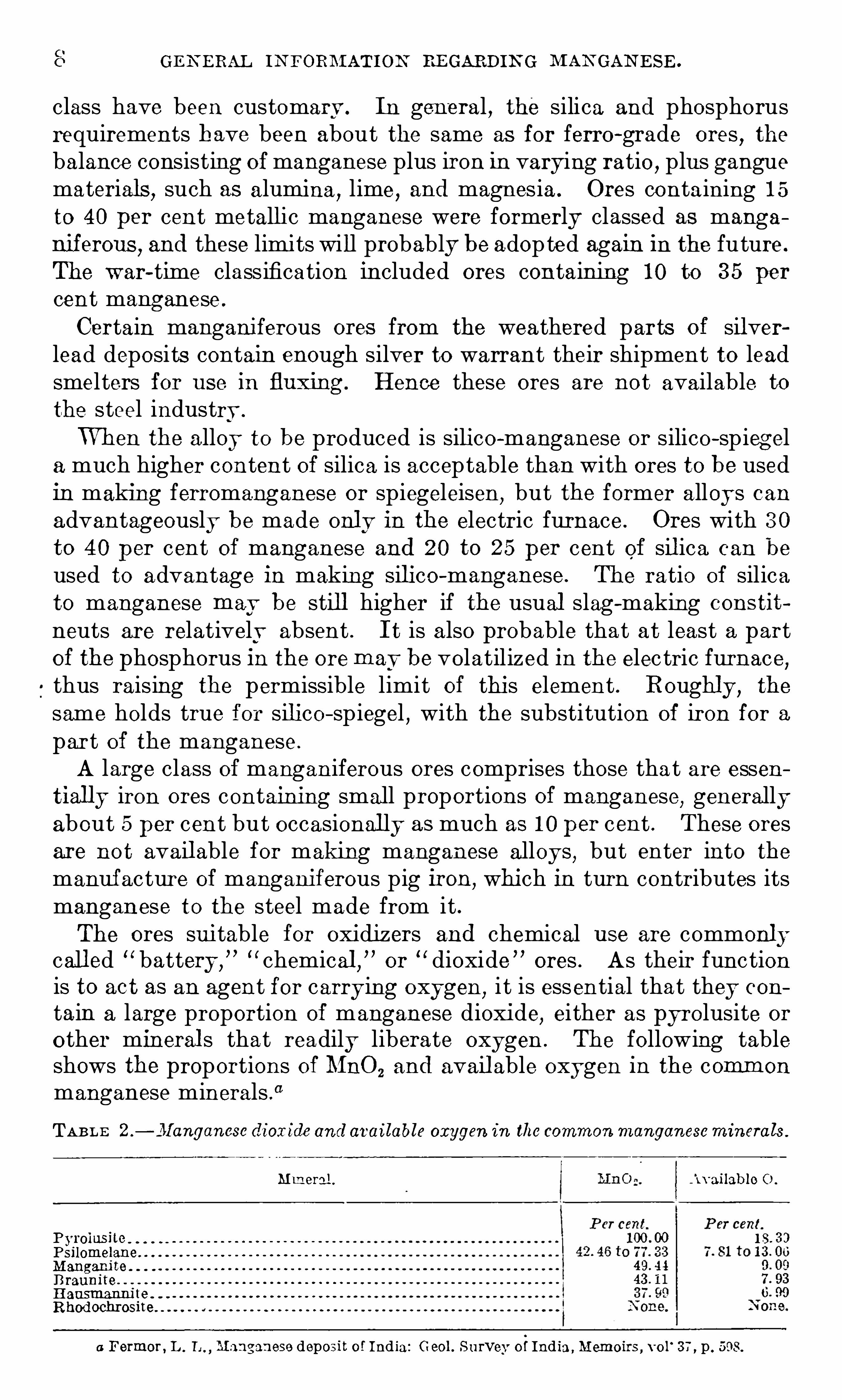
manganese to the steel made from it .The ores suitable for oxidizers and chemical use are commonly
call ed “ battery ,
” “ chemical,
”or
“ dioxide ”
ores . As their functionis to act as an agent for carrying oxygen,
i t is essential that they con
tain a large proportion of manganese dioxide,either as pyrolusite or
other mineral s that readily liberate oxygen . The following tableshows the proportions of MnO2 and avail able oxygen in the comm on
manganese minerals .
“
TABL E 2 .
—.
7l[anganesc dioxide and available oxygen in the commonmanganeseminera ls .
Mmeral . w ailablc O .
Pyrolusite 1 00 00 1 8 . 3 3
PsilomelaneM anganite
B rauniteHausmanni teRhodochrosne
a Formor, L . i Manganese deposit of India : Geol . S urvey o f India ,Memoirs , vo l
‘
3 7 , p . 598.

PRICE S . 9
The two most iniportant industrial uses of manganese ore as an
oxidiz er are in the manuf ac ture of dry cell s and of glass . Specifica
tions generally cal l for 80 to 90 per cent MnO , , but it is understoodtha t ores with as li t tle as 7 0 per cent MnO2 were accepted during thewar. Formerly i t was cus tomary to require tha t the iron contentshoul d no t exceed 1 per cent, but here al so specifications were greatlyrelaxed , particul arly as i t has been shown that the presence of severalper cent of iron does not grea tly affec t the efficiency of the battery .
Copper, nickel , and cobal t, on the other hand,are probably harmful
when present in excess of a few tenths of 1 p er cent, though there issome difference of op inion as to this . The po int. is discussed in the
chapter foll owing .
Leaner argill aceous and sil iceous ores,with less than 4 0 per cent
metallic manganese,are used for coloring pottery ,
til es,and brick .
The amounts used annually for this purpose and for paints,dyeing
and printing calicoes,and other purposes are M portant.
PRI CE S .
Prices paid for imported metal lurgical ores have always been subject to individual contrac ts, based on the chemical and physicalcharac teristics of the particular ores . The terms of these contrac tshave
,of course
,never been made public
,but their general trend has
no doubt been reflected in the price schedules for high~grade domesticores issued from time to time by the Carnegie S teel CO . The lat terare summarized in the following table :
TABL E 3 . Carnegie S teel Company’
s price schedu lesf or domestic ores fl
Prices in cents per un it forp ercentagesofmanganese ranging
Cents per PhosphoYear. un it of stifid
c
a
a
rdrus stand
From 40 From 43 From 46 49 andIron. ard .
to 43 . to 46 . to 49. more.
o o o o o o o o o o o o o o o o o o o o o o o o o o o o
o o o o o o o o o o o o o o o o o o o o o o o o o o o o
c c c c c c c c c c c c c c c c c c c c c c c c c c c c
o o o o o o o o o o o o o o o o o o o o o o o o o o o o
From 3 8 From 42 From 46 50 ani
to 42. to 46 . to 50. more.
1 91 8 .
0 Data largely itomM ineral Resources U . S . ,various years , U . S . Geological Survey .
These prices are based on long tons for material delivered at the
furnace ; material dried at 2 1 2 ° F. silicia penal ty, 1 5 cents per ton foreach unit over 8 per cent ; phosphorus penalty, up to 1 9 1 0 , 1 cent per
1 0 GE N ERAL I N FORMATION'
BEGABDI N G MAN GAN E SE .
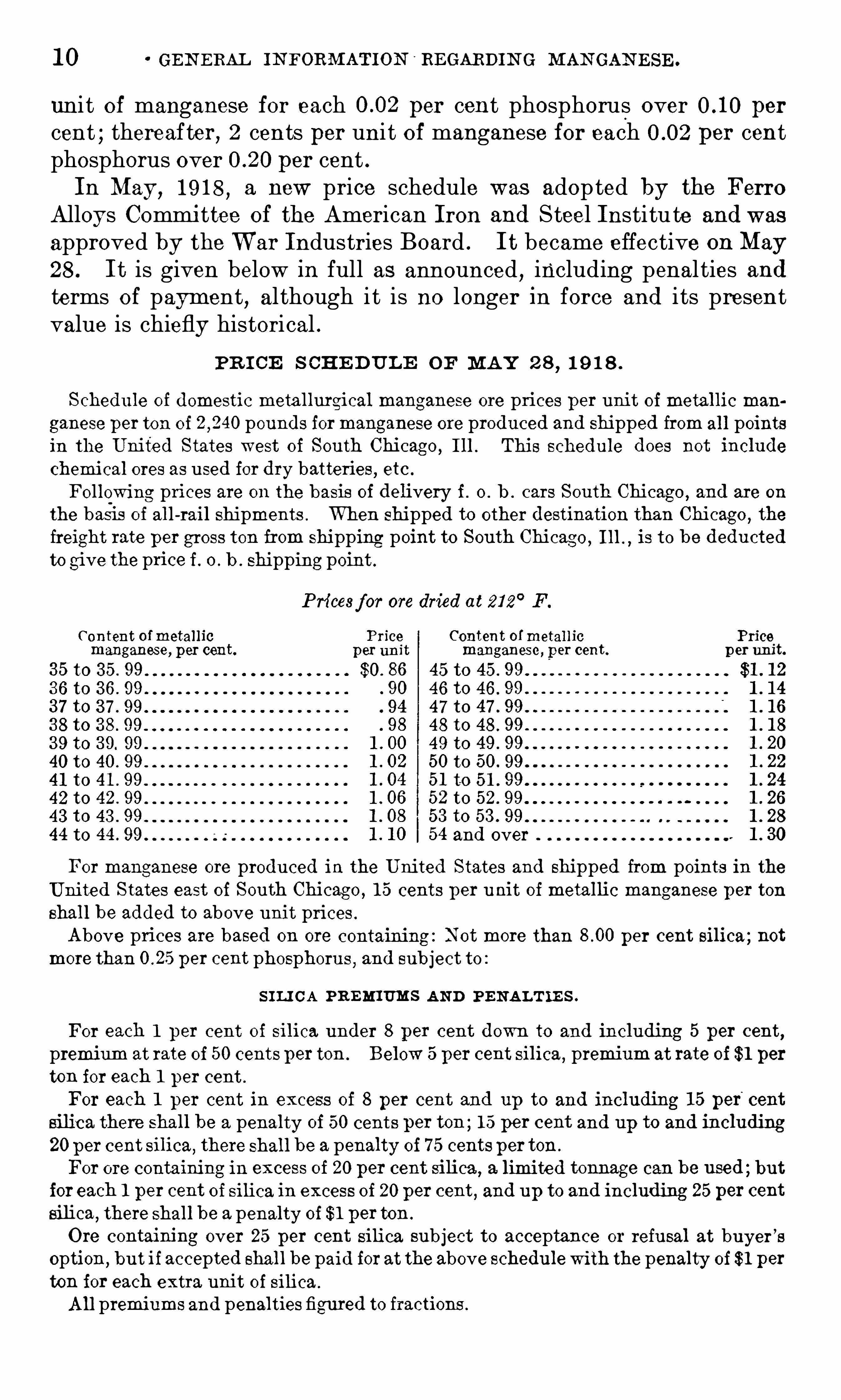
unit of manganese for each per cent phosphorus over per
cent ; thereafter, 2 cents per uni t of manganese for each per centphosphorus over per cent .In May, 1 9 1 8 , a new price schedule was adopted by the Ferro
Alloys Committee of the American Iron and Steel Institu te and was
approved by the W ar Industries Board . I t became effective on May
28 . I t is given below in full as announced , including penal ties andterms of payment, although it is no longer in force and i ts presentvalue is chiefly histori cal .
PR I CE S CHE DUL E OF MAY 2 8 , 1 9 1 8 .
Schedu le of domestic meta l lurgical manganese ore prices per unit of metallic man
ganese per ton of pounds formanganese ore produced and shipped from al l pointsin the United States west of South Chicago, I ll . This schedule does not include
chemical ores as used for dry batteries, etc .
Following prices are on the basis of delivery i . o . b . cars South Chicago , and are on
the basis of all -rail shipments . When shipped to other destination than Chicago , the
freight rate per gross ton from shipping point to South Chicag o ,I ll . ,
is to be dedu cted
to give the price i. o . b . shipping point .
Pricesf or ore dried at 21 2° F.
Content ofmetal lic Price Content ofmetal lic Pricemanganese, per cent. per un it manganese,
_p er cent. p er unit.
3 5 to 3 5 . 99 $0. 86 45 to 45 . 99 $1 . 1 2
3 6 to 3 6 . 99 90 46 to 46 . 99 1 . 1 4
3 7 to 3 7 . 99 94 4 7 to 47 . 99 1 . 1 6
3 8 to 3 8 . 99 98 48 to 48 . 99 1 . 1 8
3 9 to 3 9. 99 49 to
40 to 40 . 99 50 to 50. 99 1 . 22
4 1 to 4 1 . 99 5 1 to 5 1 . 99 1 . 24
42 to 42 . 99 1 . O6 52 to 52. 99
43 to 43 . 99 1 . 08 53 to 53 . 99 1 . 28
54 and over
For manganese ore produced in the Uni ted States and shipped from points in theUnited States east of South Chicago , 1 5 cents per unit of metallic manganese per ton
shal l be added to above unit prices .
Above prices are based on ore containing : Not more than per cent silica ; not
more than per cent phosphoru s, and subject to :
S I LI CA PREMI UMS AN D PE N AL T IE S .
For each 1 per cent of silica under 8 per cent down to and including 5 per cent,
premium at rate of 50 cents per ton . Below 5 per cent silica , premium at rate of $1 per
ton for each 1 per cent .
For each 1 per cent in excess of 8 per cent and up to and including 1 5 per“
cent
silica there shal l be a penalty of 50 cents per ten ; 1 5 per cent and up to and including
20 per cent silica,there shall be a penalty of 7 5 centsper ton .
For ore containing in excess of 20 per cent silica ,a limited tonnage can be used ; but
foreach 1 per cent of silica in excess of 20 per cent , and up to and including 25 per cent
silica,there shal l be a penalty of $1 perton .
Ore contaimng over 25 per cent silica sub ject to acceptance or refusal at buyer’
s
option,but if accepted shal l be paid forat the above schedu le with the penalty of $1 per
ton for each extra unit of silica .
All premiums and penalties figured to fractions .

PRICES . 1 1
PHOSPHORU S PE N ALTY.
For each per cent in excess of per cent phosphorus there shall be a penaltyagains t unit price paid formanganese of one-hal f cent per unit figured to fractions .
In view of existing conditions ,and for the purpose of stimulating production of
domestic manganese ores, there will be no penalty for phosphorus so long as the ore
shipped can be used to advantage by the buyer. The buyerreserves the right to penalize excess phosphorus as above by giving 60 days
’
notice to the shipper.
The above prices to be not to the producer ; any expenses , such as salary or com
mission to buyer’
s ag ent,to be paid to the buyer.
Settlements to be based on analysis of ore samp le dried at 21 2° F. The percentag e
ofmoisture in ore samp les as taken to be deducted from the weight .
PAYM E N T S .
E ighty per cent of the estimated value of ore (lessmoisture and freight from shippingpoint) based on actual railroad scale weights to be payab le ag ainst railroad bill of
lading with attached certificates of sampling and analysis of an approved independentsampling chemist, balance on receipt of ore by buyer.
Actual railroad scale weights to govern in final settlement .
Cost of sampling and analysis to be equally divided between buyer and seller.
I t will be observed that the value per long ton of natural (undried )manganese ore f . o . b . mine was to be cal cul ated from this schedule inthe following manner ; (1 ) Multiply the percentage of manganese inmaterial dried at 2 1 2
°F. by the corresponding uni t price as given in
the table , adding 1 5 cents to this price if the ore was produced eas t ofChicago ; (2 ) add premiums or deduct penalties , if any ,
for silica and
phosphorus ; (3 ) convert to wet or natural bas is ; (4 ) deduct freightper long ton to Chicago .
The following freight rates from points in the several W esternmanganese-producing States to Ch
i cago were still in force inDecember, 1 9 1 9 . These were for carload lots with a minimumweight of pounds .
TABLE 4 ,
— Freight rates on manganese orefrom Western S tates to Chicago .0
S tate.
a Personal communication from H . H . Porter 0 ! U . S . Shipping Board .
The ore prices given above applied only to ferro-grade ores . Pricesfor manganiferous ores have usually been subject to individual contract . In 1 9 1 8 the better class of Leadville ores sold for about 3 0
1 2 GE N ERAL I N FORM AT ION RE GARDIN G M AN GAN E SE .
cents per un it , with a premium of 6 cents p er unit for iron and a
moderate penalty for silica .
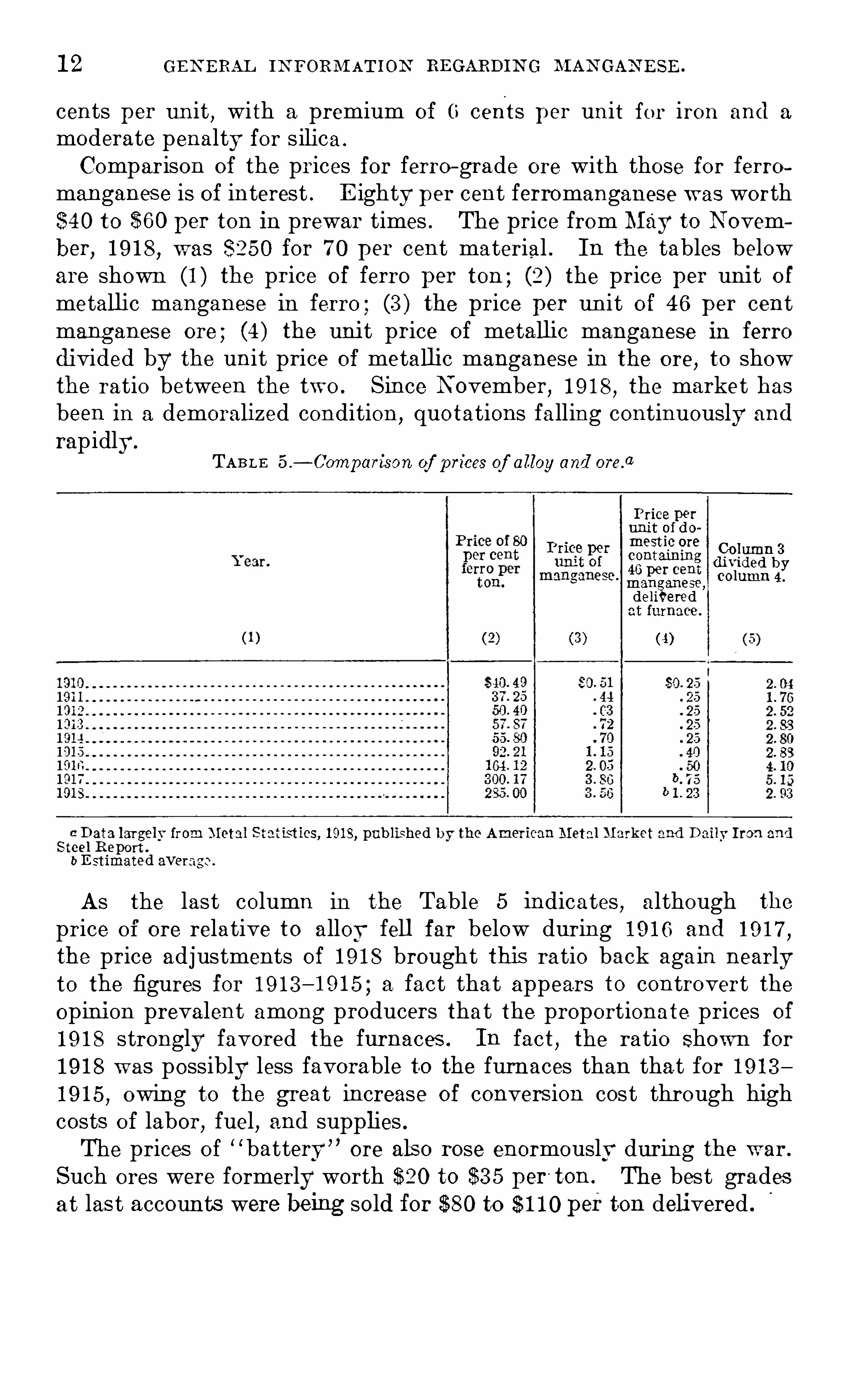
Comparison of the prices for ferro—grade ore with those for ferromanganese is of interest . E ighty per cent ferromanganese was worth$40 to $60 per ton in prewar times . The price from May to N ovember, 1 9 1 8 , was $250 for 7 0 per cent material . In the tables beloware shown (1 ) the price of ferro per ton ; (2) the price per unit o fmetallic manganese in ferro ; (3 ) the price per un i t O f 46 per centmanganese ore ; (4 ) the unit price of metallic manganese in ferrodivided by the unit price of metallic manganese in the ore, to showthe ratio between the two . Since N ovember, 1 9 1 8 , the market hasbeen in a demoralized condition , quotations falling continuously and
rapidly.
TABL E 5 ,
— Comparison of p rices of a lloy and orefl
Price perunit of domostic ore
Column 3containingre ver e nt
man anese,deli eredat furnace .
(4)
a Data largely from Metal S tatistics, 1 91 8, pub lished by the American Metal Market and Daily Iron andS teel R eport .
b E stimated aver
As the last column in the Table 5 indicates , although the
price of ore relative to alloy fell far below during 1 9 1 6 and 1 9 1 7 ,
the price adjustments of 1 9 1 8 brought this ratio back aga in nearlyto the figures for 1 9 1 3 — 1 9 1 5 ; a fact that appears to controvert theopinion prevalent among producers that the proportionate prices of
1 9 1 8 strongly favored the furnaces . In fact, the ratio Shown for
1 9 1 8 was possibly less favorable to the furnaces than tha t for 1 9 1 31 9 1 5 , owing to the great increase of conversion cost through highcosts of labor
,fuel , and supplies .
The prices of“ battery ”
ore als o rose enormously during the war.
Such ores were formerly worth $20 to $3 5 per'
ton . The best gradesat las t accounts were being sold for $80 to $ 1 1 0 perton delivered .
GEN E RAL IN FORIXIAT ION REGARDIN G
STATI STI CS .
LI AN GAN ESE . 1 3
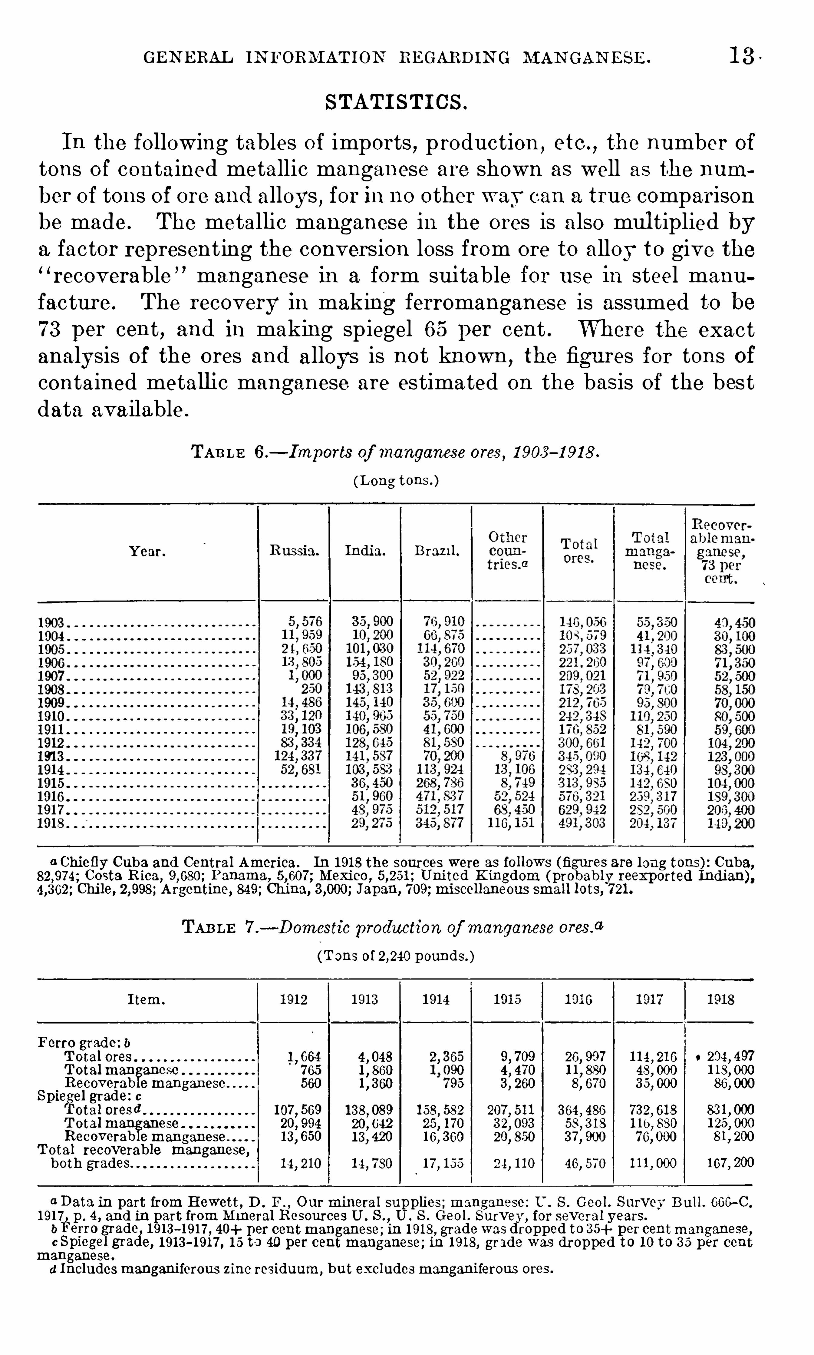
In the following tables of imports , production , etc . , the number oftons of contained metallic manganese are shown as well as the number of tons of ore and alloys , for in no other wavcan a true comparisonbe made . The metallic manganese in the ores is also mul tiplied bya factor representing the conversion loss from ore to alloy to give the“recoverable ” manganese in a form suitable for use in steel manufacture . The recovery in making ferromanganese is assumed to be
VVhere the exactanalysis of the ores and alloys is not known , the figures for tons ofcontained metallic manganese are estimated on the bas is of the best
7 3 per cent , and in making spiegel 65 per cent .
data ava ilable .
TAB LE 6 .— Import8 of manganese ores , 1 903 —1 9 1 8 .
Year.
o o o o o o o o o o o o o o o o o o o o o o o o o o o o
o o o o o o o o o o o o o o o o o o o o o o o o o o o o o o o
(L ong tons . )
India. B ran ] .
a Chiefly Cuba and Central America. In 1 91 8 the sources were as follows (figures are long tons ) : Cuba,Costa.R ica, Panama, Mexico, United Kingdom probably ree
Chile, Argentine, 849; China, Japan, 7 09 ; miscellaneous small lots, 7 21 .
TAB LE 7 ,
— Domestic production of manganese oresfl
(Tons of pounds. )
I tem.
Ferro grade : 6Total ores 1
, 664Totalman ancse 7 65Recoverab emanganese 560
S piergel grade: 0otal oresd 1 07 , 569
T otal In anese 20, 994Recoverab emanganese 1 3 650
Total recoverable manganese,both grades
1 3 8 , 08920, 0421 3 420
46, 570
xp orted Indian) ,
0 204, 497
1 07 , 200
a Data in part from Hewett , D . F. , Ourmineral supplies ; manganese : U . S . Geol. Survey B ul l. Goo-C .
1 91 7 p . 4 , and in part from M ineral Resources U . S . ,U . S . Geo l . S urvey , for several years.
b li‘
erro gradei1 9 1 3 - 1 91 7 , 40+ per centmanganese ; in 1 91 8 ,
c Spiegel gramanganese.
d Includesmanganiferous zinc residuum, but excludesmanganiferous ores.
grade was dropped to 3 5+ percentmanganese,e, 1 91 3
- 1 91 7 , 1 5 to 40 per cent manganese; in 1 91 8, grade was dropped to 1 0 to 3 0 per cent
1 4 GE N ERAL IN FORM ATION REGARDI N G M AN GAN E SE .
TABLE 8 ,
— Imports and production of manganese a lloys, 1 905
[Tons of pounds ]
Ferromanganese. Spiegeleisen.
Year.
Produc Total Produc Total
tion . alloy . tion. alloy .
n n n n n n
o o o o o o
a Data compiled from various sources, largely from the statistical bu lletins o f the American Iron andSteel Institute.
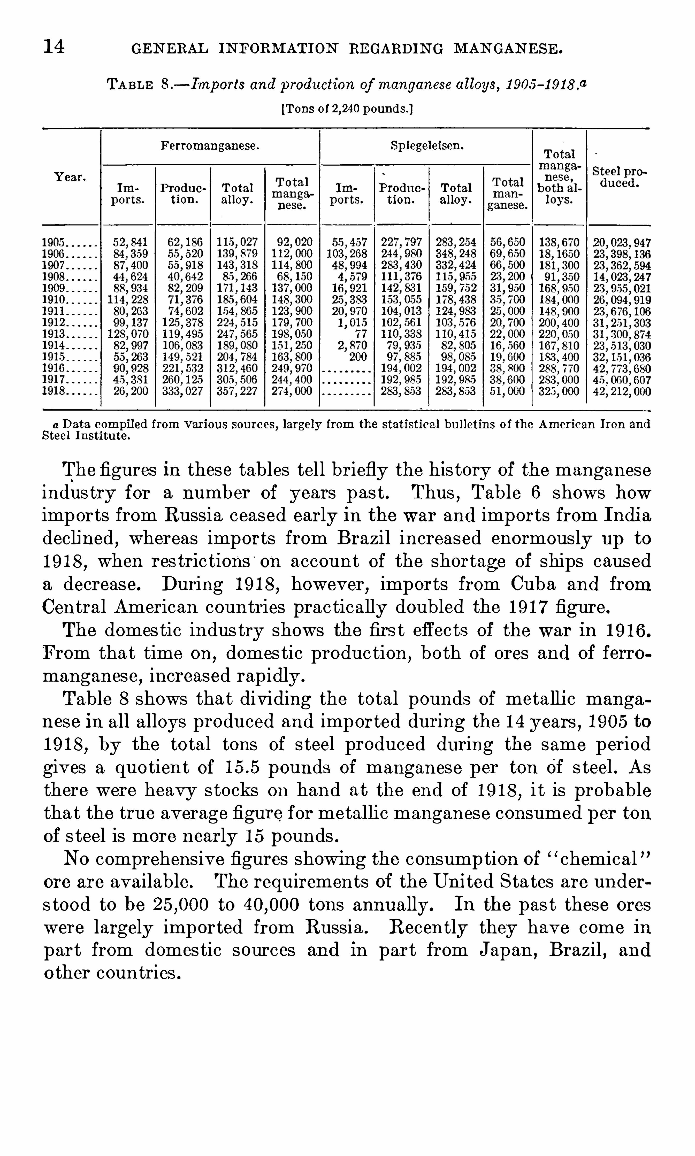
The figures In these tables tell briefly the his tory Of the manganeseindustry for a number of years pas t . Thus
,Table 6 shows how
imports from Russia ceased early in the war and imports from Indiadeclined
,whereas imports from Brazil increased enormously up to
1 9 1 8 , when restrictions'
on account of the shortage of ships causeda decrease. During 1 9 1 8 , however, imports from Cuba and fromCentral American countries prac tically doubled the 1 9 1 7 figure.
The domes tic indus try shows the firs t effects of the war in 1 9 1 6 .
From that time on, domes tic production
,both of ores and Of ferro
manganese,increased rapidly .
Table 8 shows tha t dividing the total pounds of metallic manganese in all alloys produced and imported during the 1 4 years ,
1 905 to
1 9 1 8 , by the total tons of s teel produced during the same periodgives a quotien t Of pounds of manganese per ton Of s teel . Asthere were heavy s tocks on hand at the end of 1 9 1 8
,i t is probable
tha t the true average figure for metallic manganese consumed per tonOf s teel is more nearly 1 5 pounds .NO comprehensive figures showing the consump tion of
“ chemicalore are available. The requirements of the United Sta tes are unders tood to be to tons annually. In the pas t these oreswere largely imported from Russia . Recently they have come in
part from domes tic sources and in part from Japan , Brazil , and
o ther countries .

1 6 U SE S OF M AN GAN E SE .
containing a carbon electrode and a mixture Of rather coarsely groundretort coke and pyrolusite . The cup was sealed
,two vents being
left for the escape of gases,and was placed
,with a zinc rod
,in a glass
j ar containing a solution of ammonium‘
chl oride . Because Of the simplicity and ease of operat ion of this cell
,many attempts were made
to fix the electrolyte in various media,such as sawdust
,gelatin
,ashes
tos,and silicic acid
,so as to make the cell portable .
In 1 888 Gassner brought ou t the first really successful dry cell .The positivepole consisted Of a cylindrical mass Of ground pyrolusiteand coke packed in a canvas bag aroun d a carbon electrode. Thiswas placed in a zinc container which also served as the negat ive po le
,
and a paste Of plaster Of Paris,zinc chl oride, and ammonium chl oride
was poured under and around it . As soon as the paste had set the
cell was sealed with a rosin or pitch composition .
The Gassner cell,though a great improvement over various other
dry cell s , did not meet with much favor becaus e of i ts high internalresistance and low voltage . The highes t current that could be Ob
tained was about 6 amperes,and i ts voltage w as about Hence
i ts use w as l imited to service requiring only small current drains .
D E VE LO PM E NT
The advent of the gasoline engine greatly stimul ated the development and production of the present type of dry cell . I gnition sys
tems demanded a cheap portable cell able to recuperate after com
paratively heavy current drains and by 1 89 7 the manufacture of suchcell s had attained considerable volume . The present normal yearlyrequirements Of dry
—cell production include about tons of
high-grade manganese dioxide ore,an equal amount of carbon (petro
leum coke and graphite) and to tons Of sheet zinc,
besides corresponding quant ities of zin c chl oride,ammonium chl o
ride,paper
,carbon electrodes
,pitch
,and sundry other substances .
M E THOD OF MAN UFACTUR E .
In the modern American dry cell of the usual type, the negativepole is a cylindr ical zinc can which also serves as a container. Sev
eral sizes Of cell s are on the market,the great maj ority,
however,
being about 2% inches in diameter by 6 inches high (the so-calledN O . 6 cell ) . The inner surface Of the zinc is lined with a special gradeof absorbent paper
,which acts as a reservo ir for the electrolyte and
as a diaphragm be tween the zinc and the posit ive po le . The depolar
izing mass,called the “ mix
,
” is tightly tamped into the can,around
a centrally placed carbon electrode, to about 1 inch from the top . This“ mix” is composed of ground carbon (usually cal cined petroleum cokeand graphite) manganese dioxide ore
,and the electrolyte. Themix
with the carbon electrode , constitutes the posit ive pole . After themix
TH E DRY C ELL . 1 7
has been tamped , the paper i s turned down over the mix ; sand or
sawdust is poured in,to a depth of about one-half inch
,and the cel l is
sealed with a hot pitch compo sition . The Obj ect of the layer Of sandis to provide an expansion chamber for the electrolyte and the excessgas , and also to provide a dry bed for the hot pitch .
CON ST ITU E NT S U S E D .
The sheets used for the cans are substantially pure zinc , prime
western spelter being generally used , and are usually about to
inch thick in the 2% by 6 inch cells . Comparatively little of
the zinc is used up during the service l ife of a cell . The mechanicalstrength to withstand fil ling and the fac t that the can corrodes nuevenly , in spots , patches, or streaks
,mus t be taken into accoun t
when considering the necessary thickness . One Of the problems of
the dry cell manufacturer is to cons truct the cell so as to make thicorrosion uniform .
Formerly,blott ing paper was larg ely used for lining the cans , but
at present most manufacturers use a special grad e of pulp board .
This is of ground wood pul p and sul phite pulp , and is to inchthick . The pul p board shoul d be porous enough to allow the electrolyte to diffuse readily through it , but still retain the smallest particles Of carbon and manganese ; and i t should be capable of absorbingseveral times its weight Of water. Furthermore
,i t should obviously
be free from metallic particles .
FUN CTION S OF D IFFE RE N T C ON ST ITUE N TS .
The depolarizing mass or mix is the vital part of the cell . To
render the most efficient service its different components must beproperly proportioned .
The ammonium chl oride shoul d be as pure as the usual chemicallypure article. I t shoul d be substantially free from alkalies
,sulphates
,
inert material,and heavy metals . When the cell is discharging
,by
virtue of the carbon,manganese dioxide
,and z inc couple the ammo
nium chloride is split up into hydrogen ,ammonia
,and chl orine
,
which attacks the zinc can,forming zinc chloride. The reaction is :
Zn + 2NH,Cl= ZnClz
—j—2NH3 + 2H . The l iberated gases caus e polarization.
Artificial graphite is generally used , several grades of i t being madefor dry cell s . The graphite does not enter into the chemistry of the
cell , merely serving, with the coke, to render the mix more conduc
tive . The c ake used is calc ined petroleum coke— that is,residues
remaining in petroleum stills . When raw i t is practically a nonconductor. However
,on being calcined at a high temperature it be
comes denser and as go od a conductor as the better grades of amor
phous natural graphite.
1 8 U SE S or MAN GAN E SE.
The relative fineness of the graphite,coke
,and manganese ore and
their distribution shoul d be so uniform as to make the mix approacha solid porous mass . The current shoul d flow al ong radial lines fromthe carbon electrode to every point on the surface of the mix adjacent to the paper lining. The ideal condition is to have each particle of manganese coated with enough carbon to render it a goodconductor but still porous enough to permit efficient depolariz ation,while the voids should be filled with the porous coke.
The zinc chl oride shoul d be as free as possible from heavy metal s .I ts function is to depolarize the ammonia
,which it does bythe forma
tion of double salts of zinc and ammonium chl oride. NO exact information is available as to the reactions involved
,but it appears
that a slightly soluble double chloride of zinc and ammonium isformed as the end product . During the earlier part of the servicelife of a cell
,inefficient depolarization of the ammonia is probably
Often the cause of failure under heavy drains . A cell that has beenshort-circuited or subj ected to a heavy drain smell s strongly ammoniacal when opened . Another cause of dry
-cell fail ure is the formation of a highly resistant
,nonporous crust between the paper l ining
and the zinc can ,probably through the formation Of the double sal t
mentioned or the formation Of zinc hydrate .
R OLE OF MAN GAN E SE .
The manganese serves to depolarize the hydrogen . The reactioninvolved is usually given as follows : 2H+ 2MDOZ=MDZO3 +H2QThe manganese reacts almost instantaneously in depolarizing the
hydrogen,very likely while the latter is still nascent .
CHARAC TE R OF M AN GAN E S E ORE USE D .
“
CHEM I CAL REQU IRE ME N T S .
Several factors determin e the suitability of manganese ore for drycells . The ore shoul d have a high available oxygen content presentin the form of pyrolusite (MnOz) , shoul d have a minimum amount Ofiron,
and shoul d be free from copper, nickel , cobal t, arsenic,and
other metals electronegative to zinc . Copper is particul arly harmful .I f these impurities are present in the electrolyte or insoluble com
pounds they do no harm other than as inert or poor conductingmaterial s . I f soluble
,however
,their solutions diffuse to the zinc
can,where they are deposited
,forming an electrocouple which causes
local and useless corrosion of the zinc and consequent deteriorationof the cell . W hen the cell is in service, the deleterious action of theseimpurities is greatly hastened .
a Storey, O . W .,Determination of manganese dioxide In pyrolusite: C . F. Burgess Laboratories, Madi
son,XVIS .
TH E DRY CELL . 1 9
PHYS I CAL REQU I RE ME N T S .
The physical properties of manganese ores influence their suitabil ity for use in the dry cell . An ore should be somewhat porous toperform its function efficiently . A somewhat hard but porous ore islikely to give better results than a hard
,dense ore
,even though the
latter is higher in available oxygen . In a dense ore the depolariz ingreaction takes place only on the surface
,whereas in a porous ore it
can occur throughout the mass . Better service life is Obtained froma dry cell containing rather coarsely ground ore
,as this can hold
more electrolyte than finely ground ore . O ther factors Of importanceare the porosity of the ore and the fact that more contact resistanceexists between particles of fine ore than those of coarse ore . Carefulgrading Of the ore greatly influences the performance of a cell . The
ore,therefore
,should not be of an earthy nature like wad
,as this
mineral does not lend itself to efficient mill ing and grading .
Before the war the manganese ore used in dry cells was Caucasianpyrolusite . Common Specifications call ed for material containing80 to 85 per cent MnO2 and less than 1 per cent iron . NO particul arattention was given to other ingredients
,at leas t by most buyers ,
because of the purity and uniformity O f the Caucasian ore. Thereare considerations other than the content Of l ino, which determinethe useful ness of manganese for depolarizer purposes
,such as the
screen analysis , hardness, density, and other physical qualities .Various manufacturers employ different specifications as to the
screen analysis , a comm on specification being that the run Of materialhall pass through a 1 0-mesh or a 20-mesh screen . Some manufac
turers specify the removal of the fine particles .During the war manganese from many other sources was used in
making dry cells because of the scarcity of the Caucasian ore. MostOf these ores run lower in MnO2 and higher in iron and have largerpercentages of M purities, some of which are decidedly harmful .During the war _users accepted material that ran 7 0 to 80 per centMnO2 and as high as 3 to 4 per cent iron . Users have found byexperiment and manipul ation how to get resul ts with domestic oresand foreign ores other than Caucasian
,closely approximating the
results obtained with Caucas ian .
An important source of manganese dioxide during the war was the
ore from Old dry cell s , which was rej uvenated by processes generallykept secret by the firms employing them . Such processes doubtlesscontributed to the conservation Of our high-grade domestic man
ganese ore.
In the manufacture of dry cells two classes may be recognizedthe standard or so-called N O . 6 cell , which is used for,
ignition, telephone, signal , and other simil ar purposes ; and the small siz e, or
20 USES OF M AN GAN E SE .
flash- light type, which is used for portable lighting . The quantityOf pyrolusite ores used in the standard N O . 6 cell is far larger thanthat used in other sizes . In the manuf acture of flash lights
,which is
growing rapidly ,the higher grades o f materials are required
,such as
80 to 8 5 per cent ore that has been purified and also various gradesOf chemically prepared manganese dioxide and hydrates of man
ganese .
MAN GAN E SE ORE S IN THE CE R AM O INDU STR I E S .
GL A S S M AKI N G .
Practically all the raw materials used in glass contain some ironusually in the form of ferric oxide . The iron
,when present even in
small quantity ,imparts to the glass a pale green color that increases
rapidly in intensity as the iron content increases . I f a colorless glassis desired
,this green color must be. removed by some decolorizer.
Manganese,selenium
,cobalt
,and nickel are the most common
decoloriz ers in use,and of these mangan ese has been most widely
employed because it permits easy contro l Of the color. In usingselenium and nickel
,the quantity must be carefully controll ed, but
these latter substances are desirable,especially in window and plate
glass,because glass decolorized with manganese Often changes to a
pink color on exposure to the light . A decreasing quantity O f man
ganese is being used by makers of tank glass,and its place is being
taken by selenium .
The quantity Of'
manganese used varies considerably,depending
On the charac ter of the glass,the method Of i ts manufacture, the
iron content of the raw materials,and the character of the manga
nese ore used . E ach manuf ac turer has his own ideas on this subjec t .The quantity used is figured in terms of poun ds of manganese dioxideper pounds of sand
,which constitutes 50 to 7 5 per cent by
weight of the entire batch . The temperature employed In the glassmaking process helps to determine the quantity of manganesedioxide used, for because of volatiliz ation the higher the temperature, the more manganese is necessary . The maximum l imit is 1 0
to 1 5 pounds Of manganese dioxide per pounds of sand, and
the minimum may be 2 to Qt pounds .CHEM IS TRY OF U S E OF MAN GAN E SE IN GLASS-MAK IN G PR OCE S S .
Compo unds of manganese,when other coloring ingredients are
absent,produce p ink
,purple
,and violet hues according to the chem
ical nature of the glass . Manganese dioxide neutral izes the greencolor caused by iron compounds . Used in excess
,i t imparts an ame
thyst tin t, and when used in considerable excess , the color is so
dark as to appear black .
The neutral ization of the iron tint by manganese dioxide ipla ined by some chemists on a physical, and by o thers on a purely

M AN GAN E S E ORE S I N TH E C ERAM I C IN DUSTRIE S . 2 1
chemical basis . The green tint is due to the presence O f ferroussilicate . Some chemists think that this green compound is oxidizedto the ferric s ilicate , which has an almost imperceptible. pal e strawyellow color. According to this V iew
,the oxidizing agent used
must not completely decompose at,
high temperatures, and manga
nese dioxide seems to be the most available compound fulfil ling thiscondition . A t red heat
,the dioxide loses one third of its oxygen,
leaving the tetraoxide (Mn3O 4 ) which , at still higher temperatures ,is an oxidiz ing agent .
Red lead and o ther oxidizing agents have not this decolorizingpower. Hence some chemists have thought that the resul t is notdue to oxidation
,or chemical reaction
,but is purely physical . I t
is possible,however
,that o ther compounds may lose their oxygen
at too low temperatures to be effective as oxidizing agents .
SPE C IF ICAT ION S FOR MA N GAN E SE ORE U S E D IN M AKI N G GLA S S .
Before the war,the ordinary spec ifications for manganese ore
used in glass making were 85 to 90 per cent manganese dioxide and
less than 1 per cent metallic iron . Outside of these two ingredients,
each manufacturer has his own requirements . Special glasses may
require ore carrying more than 90 per cent manganese dioxide and lessthan per cent iron . The higher the manganese content and thelower the iron
,the better the ore is for glass making . In general
,
the grades of ore are similar to those used in making dry cells .
Obviously ,sil iceous pyrolusite is not Objectionable but carbonaceous
pyrolusite is .
Manganese ore for glass making is sold in powdered,granul ated
,
or lump form . There are Objec tions to the lump form because of
the time required to mel t i t into the batch . Powdered ore 1 5 usedprincipally when the batch is mel ted in pots ; lump , or granul ar ore
is used when mel ting is done in tanks .Before the war
,high-grade pyrolus ite for glass making and other
chemical purposes was imported from Russia,Saxony ,
Japan,
Nova Scotia, and o ther foreign countries . As the war progressed,
such ore became scarce and,as a consequence
,specifications were
relaxed and low-grade ores were purchased . During the war someexcellent domestic ore was developed
,which found a ready market .
OTHE R C E RAM I C U S E S .
Ano ther use for manganese ore in glass making has developed inthe las t few years, namely ,
for producing black glass used for orna
mental purposes . About 3 per cent of ore is added to the batch inmaking this Opaque glass .
Pyrolusite is added to. the cons tituents of glazes and enamels toproduce purple tints . Black enamels are those containing manganese . Manganese oxide 1 8 al so used In brick making .

22 U SE S OF M AN GAN E SE .
U S E OF MA N GA N E S E SA L T S I N DR I E R S .
DE FIN ITI ON .
Driers are substances,general lym etal lic oxides or their compounds
,
that are added to linseed or o ther drying oils at high or low temperatures to make them capable of readily absorbing oxygen from the
air,or of drying by i ts action . Some chemists consider the action
to be catalytic , the manganese compound acting as a catalyser or
carrier of oxygen . The principal manganese compounds used as
driers are : Manganese sesquioxide (Muz0 3 ) , pyrolusite (Mnoz) , alSo
known in the trade as dioxide,binoxide or peroxide
,manganese
hydrate, sulphate, borate, resinate,linoleate
,oxalate
,and possibly
other sal ts . '
Certain Of the corresponding double salts of manganese and lead are Often used .
Some persons claim that pyrolusite is now li ttle used in driersbecause the manuf actured hydrate, on accoun t of its purity, givesbetter resul ts . This Claim does not agree with statements made bydealers in the trade . Of the various substances named above, eachacts in a way pecul iar to itself . These driers are added only in
small quantities, usually less than per cent .
MAN GAN E SE D IOX IDE .
Manganese dioxide,extensively used as a drier
,is marketed in
two forms , the natural and the artificial . The natural mineral,
pyrolusite, is S imply ground to a powder with water and then dried .
The mineral is essential ly a peroxide,a class of substances containing
more oxygen than is required to satisfy the valence of the metalpresent . This extra oxygen is loosely combined and readily entersinto combination with oxidizable bodies . This feature in the com
posi tion of manganese compounds makes them useful in Oil boiling,
because the oxygen combines with the oil,oxidizing it
,while some
Of the manganese dissolves and forms a compound with the linoleicacid of the Oil . In consequence of this action manganese compoundsare powerful driers . The quantity of manganese dioxide added inthe process Of boiling is small
,not more than a quarter of a pound to
a hundred weight Of Oil to get the bes t results . The use of the blackdioxide
,however
,tends to make the Oil dark .
M AN GAN E SE SULPH ATE .
The methods of preparing this compound and i ts uses are de
scribed ou page 24 . Rather less than one-hal f a pound is added toeach hundred weight of oil or pain t . Oil boilers use it largely as a
dryer of pal e boiled O ils .Q
M AN GAN E SE BOR ATE .
Manganese borate is perhaps the least Objectionable of all themanganese salts used as drying agents , although the black oxides
24 U SES OF M AN GAN E SE .
solution and passed through a caustic alkali,whereby manganese
hydroxide is precipitated in the fabric and on subsequent oxidationturns brown . The material thus treated may be used also for subsequent dyeing bv anilin black .
M AN G AN E S E SUL PHATE .
Manganese sulphate (MDSO4 ) may be prepared on a large scale
from the black dioxide by heating to redness with ferrous sulphateand subsequently extracting with water. The sal t forms pink crystals which are readily soluble in water and are used in calico printingand in porcelain painting . I t is a lso used as a drier for pale Oils or '
for conversion into the oxalate or borate which are used for the samepurpose .
M AN G AN E S E PE RSUL PH ATE .
Manganese persulphate,“ is prepared by the electrolytic
oxidation of manganous sulphate (MnSO4 ) and forms a. black substance that can be obtained in solution onl y . in the presence of sulphuric acid . I t is used as an oxidizing agent in the manufacture of
organic products .
POTA S S IUM PE RM AN GAN ATE .
Potassium permanganate (K MnO4 ) is prepared industrially by
mixing a solution of caustic potash (KOH) , Specific gravitywith powdered manganese dioxide and an oxidizing agent , such as
potassium chlorate . The mixture is boiled and evaporated, and theresidue is fused in crucibles and heated until it has a pasty consistency. The potassium manganate (K2Mn0 4 ) thus obtained is dissolved by boil ing withmuch water while a current of chl orine, carbondioxide, or ozone is passed through the liquid . Po tassium permanganate separates in crystalline form from concentrated solutionseven in the presence of the caustic potash formed during the reaction,
and is separa ted from the dissolved substances in a hydroextrac tor.
The permanganate is used for preserving wood ; i t is also usedfor bleaching textile fibers , by immersing them for a time in an
aqueous solution of i t and then dissolving the manganese dioxidewith sodium disulphite . The permanganate is
.
an energetic disinfecting and oxidizing agent and is used for purify ing various gases .
USE OF MAN GAN E SE I N MAN GANE SE BRONZE .
GE N E R AL R E M ARKS .
During the last twenty years manganese bronze has been widelyused . The requirements Of marine construction,
O f mining machinery, and wherever corrosion has presented a serious problem, havecreated a demand for a nonferrous metal to replace steel . Probablythe mos t popular of such substitutes has been manganese bronze.
USE OF M AN GAN E S E IN M AN GAN E SE BRON ZE . 25
Manganese brOnze made i ts first appearance about 1 8 7 6 . I ts nameis somewhat misleading for the alloy contains only a Small percentageof
‘manganese. Indeed , i t is simply a brass to which have beenadded by proper methods O f alloying, small quantities Of aluminum
,
iron, or manganese
,for the purpose of strengthening the alloy and
making it denser and closer grained than the average yellow-brasscasting .
FUN CT I O N OF M AN GAN E S E I N M AN GAN E S E B R ON Z E .
Manganese bronze should not contai n much manganese, in factnot. more than per cent in high-grade bronze . Consequentlythe consumption of manganese in such alloys is smal l . The ObjectOf the manganese is not so much to act as an ingredient of the a lloy,as to serve as a carrier of the iron necessary to insure the requiredstrength and elas tic limit . The manganese serves one purpose only
,
to introduce the iron,for without the manganese the iron woul d not
alloy with the copper. Usually the manganese is added in the formOf ferromanganese . I f added in large quantities it hardens the alloy,but not nearlyas much as iron ; such an addition also lowers the elasticlimit . Aluminum impai ts a good sand-casting quality to the bronze .
Two grades Of manganese bronze are now in common use. One
is used for rolling into sheets , or drawing into wire or tubes , and forforging . This grade contains no aluminum
,and has slightly less z inc
than the o ther and can not be cast in sand . The second all oy isused for sand casting and is the one employed in making propellersand other common appliances .The method of making manganese bronze—w that is , the materials
used , the methods Of combining them, and the process for castingis discussed by Sperry a
and will not be discussed here .
McKinneyb describes a process of manufacturing manganese
bronze wherein is used , ins tead of virgin metals and raw materialsof the highest purity, by
—products and scrap . The methods described are, therefore, timely .
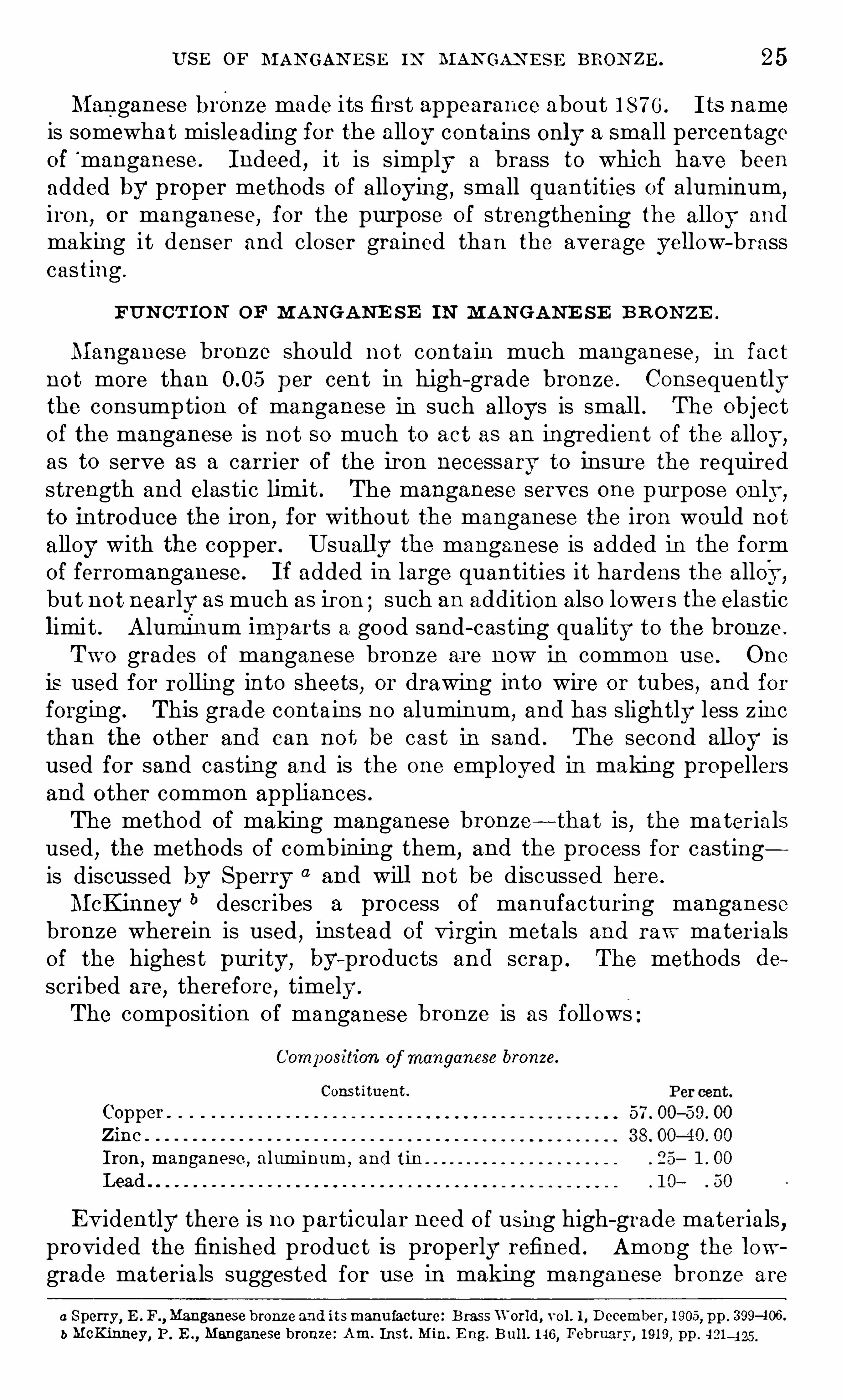
The composition of manganese bronze is as follows
Composition of manganese bronze.
Constituent
Copper .
Zinc .
Iron ,manganese ,
aluminum,and tin
Lead
E vidently there is no particular need of using high-grade materials ,provided the finished product IS properly refined . Among the lowgrade materials suggested for use in making manganese bronze are
a Sperry ,E .F Manganese bronze and itsmanufacture: Brass W orld, vol . 1 , December, 1 905, pp . 3 99-406 .
b McKinney, P . E .,Manganese bronze: Am. Inst . Min. E ng. Bu l l . 1 46 , February , 1 9 1 9, pp . 421—425 .
26 USE S or M AN GAN E SE .
the following : Skimmings from the foundry, especially skimmingsand dross ordinarily recovered from brass rolling mills or cartridge-caseplants ; zinc dross recovered from galvaniz ing plants ; aluminumturnings that are generally unrecoverable without serious loss and
deterioration of product through oxida tion, and other by-productsand Scrap metals that ordinarily are not usable in foundry practiceas remel ting scrap .
High-grade manganese bronze can not be made from the aboveraw materials on a small scale and thus manuf acture in cruciblefurnaces is excluded . A reverberatory furnace or other equipmentwith which a bath of considerable proportion may be employed isnecessary. McKinney
0 discusses a typical charge, the materialsbeing mel ted in the presence of charcoal with sal t as a flux .
U SE S OF MAN GANE S E BR ON ZE .
The most important use of manganese bronze is in propeller blades .
A strong,tough alloy is necessary which will resist the action of sea
water . The blades are made thin to save weight .aMcKinney, P . E Manganese Bronze: Am. Inst. Min. E ng . Bu ll . 1 46, February, 191 9, pp. 421 4 25 .

CHAPTER 3 .- PROBLEMS INVOLVED IN THE CONCENTRA
TION AND UTILIZATION OF DOME STIC LOW -GRADEMANGANE SE ORE .
DV E DM UN D N E W TON .
I NTRODUCTORY STATEMENT .
In the past, the steel industry of the Uni ted States has dependedalmos t wholly on imports for i ts supplies of manganese. Many of
the important domestic sources yield ores that in their natural condi tion conta in less manganese than the foreign ores the steel indus tryhas been accustomed to use. To make these domestic ores available,therefore, they must be concentrated or practice in the steel industrymust be modified .
Roughly, tons of high-grademanganese ores is used annuallyfor dry ba tteries , for chemical purposes , and in other minor ways,and approxima tely tons is required for making steel .By present practice every ton of s teel takes an average of about 1 5
pounds of metallic manganese, which generally is added to the s teelin the form of an alloy. The standard alloys are 80 per cent ferromanganese and 20 per cent spiegeleisen . During the year 1 9 1 7 ,
tons of ferromanganese and tons of spiegeleisenwere made in this country, the former largely from imported ores ;and tons of ferromanganese was imported . The metallicmanganese represented by these alloys was tons, beingroughly the product of tons of high-grade ore and
tons of low-grade ore.
There is an abundance of low-grade ore in this country suitable forthe manufacture of spiegel , but higher grade ore is necessary to makeferromanganese. For this reason the concentration of domestic orepresents a field for constructive and practical research .
MANGANE SE DEPOSITS IN THE UNITED STATES .
Before thewarmanganese ore wasmined in relatively small quantities in the Appalachian region , which includes parts of Virginia ,Tennessee, and Georgia
,and in Arkansas
,but in consequence of
higher ore prices because of the rise of ocean freight ra tes , manganesemining has been undertaken in Montana
, California , Arizona , NewMexico , N evada , Utah, and Minnesota as well as in the Appalachianregion.

28 PROBL EM S OF DOLI E STI C L O\V-GRADE M AN GAN E SE ORE .
Data now available indica te that in this country deposi ts of highgrade manganese ores are usually small
,but some deposits of ore
lower in manganese and higher in iron are of considerable S ize. In
the aggregate, the total quantity of manganese—bearing material is
relatively large, but the difficul ty of mining small deposi ts of the
better grades of material and the seeming undesirabili ty of low
manganese alloys in the steel industry, make the outlook for largeproduction of manganese in this country uncertain .
As regards the geologic origin of the majority of the manganese andmanganiferous iron ores in this country, Harder “ states that they are
largely the resul t of secondary concentration . Most of the ores of theE astern United S ta tes , Arkansas , the Lake Superior region
,Leadville
and other S ilver districts , and of western California are of this type .
The rhodonite and rhodochrosite in the unoxidized parts of the S ilverveins at Butte, however, are primary concentrations derived fromigneous intrusion . The ores of northern Arkansas are largely recon
centrations from low-grade secondary deposits , derived by decemposition of crystall ine rocks
,and the California ores are c oncentra
tions within chert lenses of material originally present in a dissem
inated form .
Manganese—bearing materials of the United States may be roughlyclassified as follows :1 . Manganese ore proper.
2 . Manganiferous iron ore.
3 . Miscellaneous material :(a) Manganiferous silver and lead ore.
(b) Zinc residuum from manganiferous zine ore.
Manganese ore, as now defined by the trade, is material that contains more than 3 5 per cent manganese and is suitable for themanufacture of 7 0 per cent ferromanganese . Manganiferous iron ore
contains less manganese and more iron . In general , the iron predominates , but there is no hard and fast line of demarcation betweenmanganese ore and manganiferous iron ore. Manganese and iron areso closely associated in nature that all gradations from low-manganese, high- iron ore, to high-manganese, low-iron ore may be found invarious deposits or in the same deposit .Manganiferous silver ore is similar to manganiferous iron ore ; i tcarries enough S ilver to make i t valuable for tha t metal . Commercialcons idera tions alone control the balance between the manganese or
the silver value.
Zinc residuum is a by-product of the smelting of zinc ores fromFrankl in Furnace
,N . J which contain cons iderable mang anese.
Af ter the zinc is removed the remaining product,call ed residuum ,
a Harder, E . C .,N agamese deposits of the United S tates : U . S . Geol . Survey Bull . 427 , 1 91 0, p . 4 .

M AN GAN E SE DE POS ITS I N TH E UN ITE D STATE S . 29
has nearly the same composition as natural manganiferous iron ore,
and for years i t has been smel ted to spiegeleisen .
I n general i t may be said that the domestic manganese ores consistof an aggregate of mineral s of manganese and iron with variousimpurities
,such as sil ica
,alumina
,lime
,and magnesia and accessory
constituents , such as phosphorus,sulphur
,silver
,lead
,and zinc .
The determining characteris tics of the manganese minerals and theirrelation to impuri ties are discussed in subsequent pages .In the steel industry manganese is chiefly used in the form of al
loys . A less important use is for increas ing the manganese contentof pig iron to give particular grades, as foundry irons , or to assist inmetallurgical operations of certain steel—making processes
,as in the
bas ic Open-hearth process . The all oys of manganese generall y usedin this country are ferromanganese
,formerly containing 80 per cent,
but now 7 0 per cent, metallic manganese,and spiegeleisen
,having
1 5 to 20 per cent metallic manganese. The rest of these all oys consists principally of iron with small quantities of carbon
,sil icon
,and
phosphorus .
During the las t few years ferromanganese has been gaining popul arity among steel manuf ac turers , with spiegeleisen declin ingproportionately . Until recently approximately nine—tenths of the
metal lic manganese used in the steel industry was in the form of the
standard 80 per cent alloy . Ferromanganese,or
“ ferro , ” as i t isusually called , is eas ier to use in steel making than all oys contain ingsmall er quantities Of manganese, as the required quantity of thatmetal is contained in a smaller bulk .
The difficulty of Obtaining ores suitable for the production of
ferro ”has led to a consideration of the possibility of us ing what
may be called intermediate alloys with manganese contents varyingbetween 20 and 80 per cent . In the electric furnace certain all oyscan be made with a relatively large content of silicon ,
in additionto the manganese and iron . The extent to which such all oys may
satisfactorily be used in s teel manufacture is not alone a technical oreconomic problem,
but is largely controlled by the human elementand the unwillingness of steel mas ters to deviate from long-establishedpractice.
Phosphorus is undesirable in finished steel . In the manuf actureof manganese all oys all the phosphorus contained in the ore will berecoverable in the all oy and will enter the steel when the all oy isused . I t is permissible
,however
,for an alloy high in manganese to
contain more phosphorus than one low in manganese,for less of the
former alloy is needed to carry a given quantity of manganese . I t isinteres ting to note that when 1 7 pounds of 80 per cent ferromanga
nese is added to a ton of steel‘
the all oy may contain per centphosphorus and yet increase the phosphorus content of the steel by
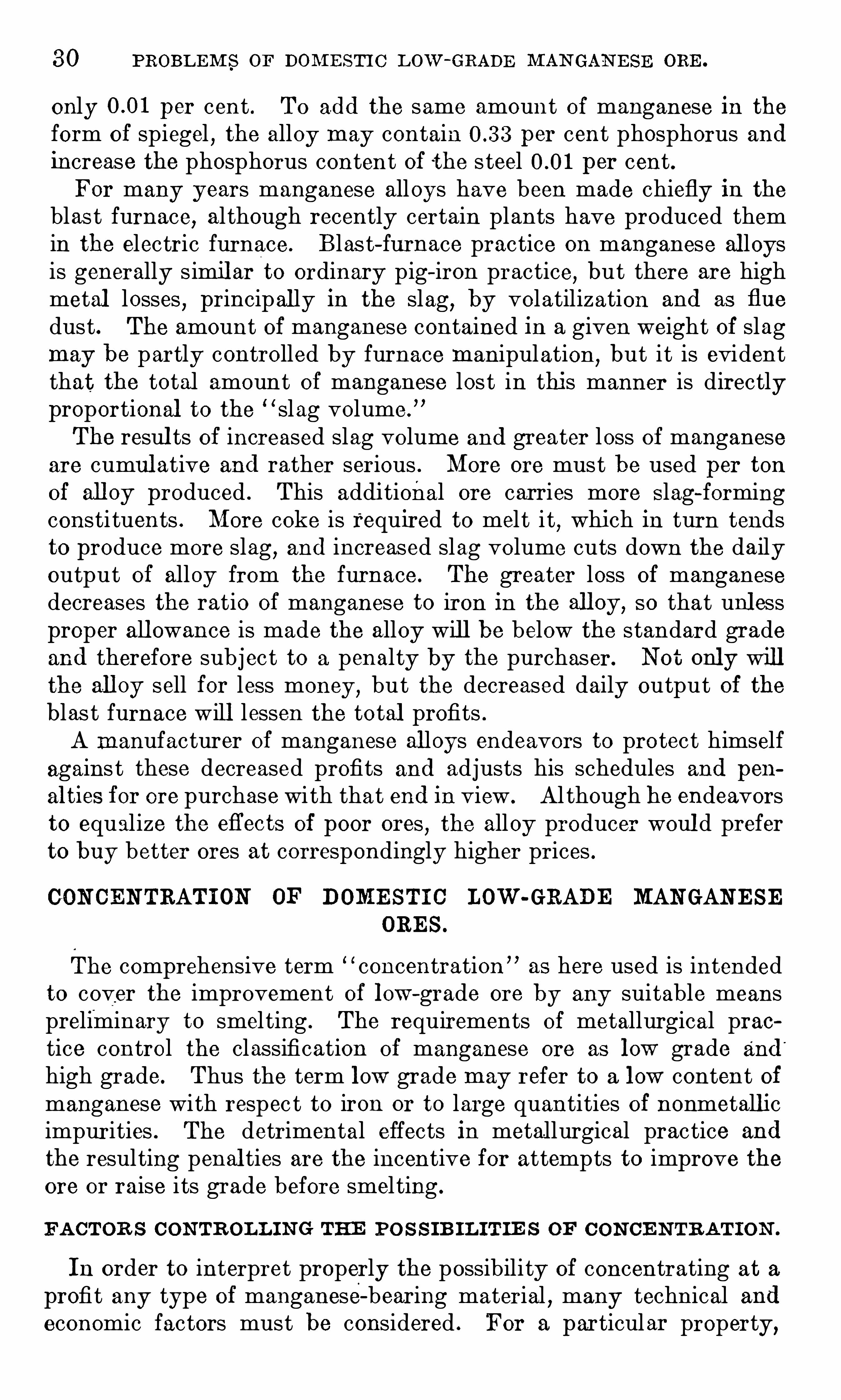
3 0 PROBL EM S OF DOM E STI C L ow -GRADE M AN GAN E SE ORE .
only per cent . To add the same amount of manganese in the
form of spiegel , the alloy may contain per cent phosphorus andincrease the phosphorus content of the s teel per cent .For many years manganese alloys have been made chiefly in the
blas t furnace, al though recently certain plants have produced themin the electric furnace. Blast furnace practice on manganese al loysis generally simil ar to ordinary pig—iron practice, but there are highmetal losses
,principal ly in the slag
,by volatilization and as flue
dust . The amount of manganese contained in a given weight Of slagmay be partly controlled by furnace manipulation
,but it is evident
that the total amount of manganese los t in this manner is directlyproportional to the “ slag volume.
”
The resul ts of increased slag volume and greater loss of manganeseare cumul ative and rather serious . More ore must be used per tonof all oy produced . This additional ore carries more S lag-formingconsti tuents . More coke is required to mel t i t
,which in turn tends
to produce more slag,and increased slag volume cuts down the daily
output of alloy from the furnace . The greater loss of manganesedecreases the ratio of manganese to iron in the all oy, so that unl essproper all owance is made the alloy will be below the standard gradeand therefore subject to a penalty by the purchaser. Not only willthe all oy sell for less money ,
but the decreased daily output of theblas t furnace will lessen the total profits .
A manufacturer of manganese al loys endeavors to protect himselfagains t these decreased profits and adjusts his schedules and pen
alties for ore purchase with that end in view . Although he endeavorsto equalize the eflects of poor ores
,the alloy producer woul d prefer
to buy better ores at correspondingly higher prices .
CON CENTRATI ON OF DOME STI C LOW -GRADE MANGANE SEORE S .
The comprehensive term concentration as here used is intendedto cover the improvement of low—grade ore by any suitable meanspreliminary to smel ting . The requirements of metallurgical praetice control the classification of manganese ore as low grade and
'
high grade. Thus the term low grade may refer to a low content ofmanganese with respec t to iron or to large quantities of nonmetallicimpurities . The detrimental effects in metallurgical practice and
the resulting penal ties are the incentive for attempts to improve theore or raise i ts grade before smel ting .
FA CTOR S CON TR OLL I N G THE PO S S IB I L ITIE S OF C ON CE N TRAT I ON .
In order to interpret properly the possibility of concentrating at a
profit any type of manganese-bearing material,many technical and
economic factors must be considered . For a particular property,

3 2 PROBLE M S OF DOM EST I C L OW -GRADE M AN GAN E SE ORE .
All these factors must be coordinated and the ir combined influencecareful ly studied before intensive production from individual properties begins . Concentration by eliminating waste may yield a
product desired by the s teel industry ,but its cost may be prohibitive .
Discarding was te may enable the producer to offset excessive freightrates, but geographic isolation will invariably handicap an enterprise .
Foreign Ores will always find a market in the Uni ted S tates becausethey come from larger and more un iform deposits
,are mined with
cheaper labor,and the o cean freights are lower than rail .
CHARACTE R I ST IC S OF ORE AFFE CT IN G BE N E FIC IAT ION .
CHAR ACTE R OF MAN GAN E SE M IN E RAL S .
Al though many minerals contain manganese,only a few are com
mercially important . Usually i t is rather difficult accurately to
identify the manganese minerals in domestic oxidized ore . Severalminerals may be intima tely associated , and one may have beenformed by alteration of another. The hardness of the individualminerals varies widely . Pyrolusi te is soft and may be readily pulverized between the fingers . Hence difficul ty might be expected inattempts to recover this mineral by the common processes of wetconcentration . The o ther minerals are harder, but usually brittle .
Al though the charac ter of the individual minerals is ‘
important, the
association of the several manganese minerals w ith various ganguematerials often has a more important bearing on methods of con
centration .
IMPUR IT IE S A S S OC IATED W I TH MAN GAN E SE M IN E RAL S .
W herever manganese ore is mined on a commercial scale, theproduct of the mine always contains impuri ties . Some of these are
Obvious on inspection ; o thers may require chemical analysis for theirdetermination . The impurities associated with manganese mineralsmay be classified as (1 ) those derived from associated rocks , or rockspartly replaced by manganese-bearing solutions , (2 ) those associated “
with "
the manganese in solution,and deposited simu ltaneous ly, and
(3 ) those chemically combined with manganese in the mineral .From ‘ the viewpoint of the metallurgist, all are impuri ties , and
must be removed either before or by metallurgical tre atment .For convenience
, the common impur ities in manganese ores may
be classified according to certain general physical and chemicalprinciples
,as follows :
1 . Metallic . Iron ,lead , zinc, silver, and in some ores, nickel, cop
per, and tun gsten .
2 . Gangue.
“ Basic lime, magnes ia,baryta , acid S ilica
,and
alumina .

FACTORS CON TROLL IN G POSS IBIL IT IE S OF CON CE N TRATION . 3 3
3 . Volatile . W ater (atmospheri c moisture and molecular water) ,carbon dioxide , and organic matter.
4 . Miscellaneous . Phosphor us and sulphur.
The chemical behavior of these impurities affects metallurgicaloperations , and the physical form in which they o ccur controls thepossibili ty of removal previous to smelting , and the choice of methodsfor accomplishing such removal .The proportion of manganese to the useless or harmf ul constitu
cuts of an ore determines the value and desirability of the ore .
The presence of appreciable quantities of any impurity means thatmore ore must be mined and smel ted in order to produce a givenweight of manganese alloy . Some impurities are more detrimentalto alloy manuf acture than o thers .Metallic impurities
, of which iron is the most common, are usually
reduced in smelting and are retained by the alloy . The quanti typresent naturally affects the character of the alloy produced , whichin turn contro ls its desirability for use in steel manufacture . O thermetall ic impur ities occur usually in such small amounts that theyare not detrimental to the resul ting alloy . Zinc is an exception
,
This metal is largely volatilized’
in smel ting,and if i t is present in
appreciable quantities i ts fume condenses as oxide in the hot-blaststoves and may hinder furnace operation . Unless the furnace-topgases are washed , the stoves must frequently be cleaned , with con
sequent loss of time . W hen the price of zinc is high , the zinc oxiderecovered from the stoves y ields a substantial sum .
S ilver,from the s tandpoint of the steel manufacturer, is nei ther
detrimental nor advantageous to manganese alloys . The S ilver content of a manganese alloy has no value ; consequently no credit isallowed the miner for S ilver contained in an ore to be used for man
ganese-alloy manufacture . In some ores the silver content is suchthat the ore has greater value for the lead smelter . The manganesethen acts as a flux and the silver may be recovered by purificationof the lead .
The gangue impurities classed as basic and acid may also‘
be
called “ slag-forming impurities . ” In smelting,these impuri ties
must be fluxed to form slag . Slag is usually considered a wasteproduct , but it has important metallurgical functions , and j ustenough slag must be present for performing these functions properlyand economically. An excess of slag must be avoided . In man
ganese-alloy manufacture the slag contains more or less manganese,
the quantity of manganese thereby lost being dependent on the
basicity of the slag , the temperature , and the slag volume . The
first two factors control the quantity O f manganese in a given weightof slag , and i t is obvious that the greater quantity of slag will resultin a greater loss of manganese . A large slag volume will rapidly

3 4 PROBLEM S OF DOM E STI C L OW -GRADE M AN GAN E SE ORE .
decrease the daily alloy output o f a blast furnace . The overheadcharges must be distributed over a smaller daily tonnage of alloyand the profit from the sales for a given uni t of time will decrease .
I t follows tha t more than the quantity of slag required to providefor the metallurgical functions is highly undesirable .
Silica is usually the predominant Slag-forming constituent indomestic manganese ore . Some silica is reduced to the metallic statein smel ting and is recovered in the alloy as Silicon,
but the largerpart must be fluxed with lime, magnesia, or o ther bases to form slag .
Manganese-alloy slags should be basic ; hence a larger quantity of
slag will be produced from an ore with acid gangue than in normaliron blast-furnace practice . Alumina is a slag-forming cons ti tuentand al though usu allv classed with silica
,i t acts somewhat differently
in the blast furnace . Braziliano res are notably high in alumina, butmost domestic ores contain relatively small quantities .Lime
,magnesia , and baryta in an ore are also slag-forming con
stituents, but they combine with the silica and alumina present andthereby reduce the quantities of those bases necessary in the formof limestone or dolomite for the furnace charge . Baryta is not common as a gangu e mineral . I t is not as strong a base as ei ther lime
or magnesia . W hile these cons tituents offset the metallurgicaleffects of silica or alumina
,as regards evaluating an ore
,they repre
sent weight , and if the ore must be transported a considerable distance to the point where i t is smel ted
,i t is doubtful whether their
value as bases would equal the additional freight charge . Limestonecan generally be obtained at low cost close to the smel ter .
- Volatile impuri ties are removed from the top of a blas t furnacelargely by the surplus heat . I t is desirable
,however
,in order to
reduce the loss of manganese to keep the top of a manganese-alloyblas t furnace cool . Volatile compounds are not particularly detrimental to smelting . When carbonate ores are being treated the
case is somewhat different . Some metallurgists claim that in treating rhodochrosite ores the ratio of carbon monoxide to dioxide in thefurnace gases is disturbed , which has a detrimental effect on the
reduction of the oxides in the upper part of the furnace . I t has
also been sugges ted that the carbon dioxide driven off combines withcarbon of the coke , forming carbon monoxide in the upper part ofthe furnace , and thus increases the coke consumption . Definitedata are not available on these points .In practice, all the phosphoru s in the ore mixture and that con
tained in the coke and limestone is recovered in the resul ting alloy .
The permissible quantity of phosphorus in an alloy (the proportiontha t does not produce detrimental effects when the alloy is addedto steel ) has not been definite ly determined . The higher the man
ganese con tent of an alloy ,the larger the proportion of phosphorus
that may safely be contained . Ordinarily steel makers desire as
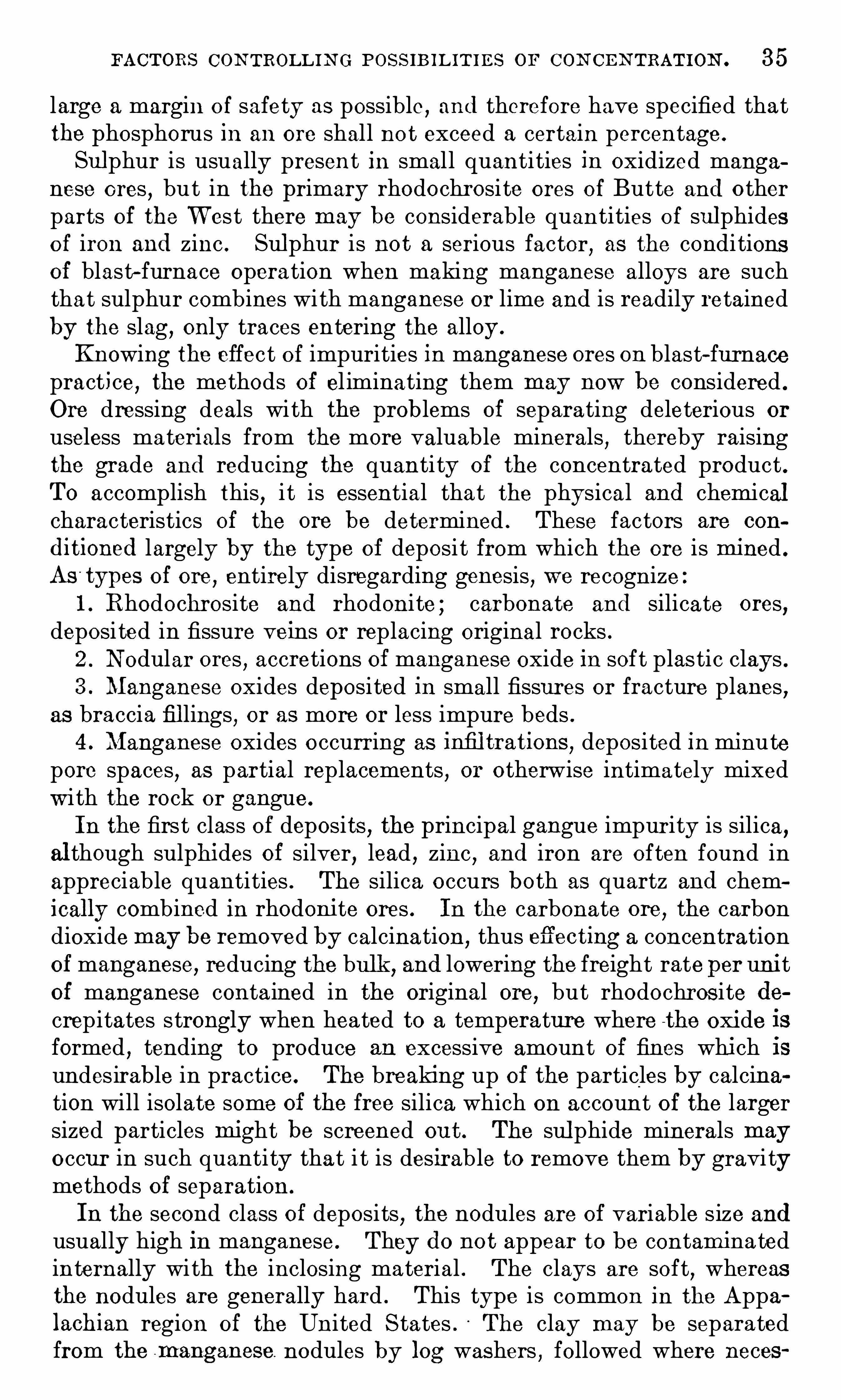
FACTORS CON TROLL I N G POSS IB l L IT I E S or CON CE N TRATION . 3 5
large a margin o f safety as possible , and therefore have specified thatthe phosphorus in an ore shall not exceed a certain percentage .
Sul phur is usually present in smal l quantities in oxidized manganese ores , but in the primary rhodochrosi te ores of Butte and o therparts of the W est there may be considerable quantities of sul phideso f iron and zinc . Sulphur is not a serious factor, as the conditionsof blast-furnace operation when making manganese alloys are suchthat sulphur combines with manganese or lime and is readily retainedby the slag , only traces entering the alloy .
Knowing the effect of impurities in manganese ores on blast-furnacepractice, the methods of el iminating them may now be considered .
Ore dressing deals with the prob lems of separating deleterious or
useless materials from the more valuable minerals , thereby raisingthe grade and reducing the quanti ty of the concentrated product .To accomplish this
,i t is essential that the physical and chemical
characteristics of the ore be determined . These factors are con
ditioned largely by the type of deposi t from which the ore is mined .
As types of ore , entirely disregarding genesis , we recognize1 . Rhodochrosite and rhodoni te ; carbonate and silicate ores
,
deposi ted in fissure veins or replacing original rocks .2 . N odular ores
,accretions of manganese oxide in soft plastic clays .
3 . Manganese oxides deposited in small fissures or fracture planes,
as braccia fil lings, or as more or less impure beds .4 . Manganese oxides o ccurring as infil trations
,deposited in minute
pore spaces, as partial replacements , or otherwise intimately mixedwi th the rock or gangue.
In the first class Of deposits,the principal gangue impurity is silica,
al though sulphides of silver, lead , zinc , and iron are often found inappreciable quantities . The silica occurs both as quartz and chemically combined in rhodonite ores . In the carbonate ore
,the carbon
dioxide may be removed by calcination,thus eflecting a concentration
of manganese, reducing the bulk,and lowering the freight rate per unit
of manganese conta ined in the original ore,but rhodochros ite de
crepitates strongly when heated to a temperature where the oxide isformed , tending to produce an excessive amount of fines which isundesirable in practice . The breaking up of the particles by calcination will isolate some of the free silica which on account o f the largersized particles might be screened out. The sulphide minerals may
occur in such quantity tha t i t is desirable to remove them by gravitymethods of separation.
In the second class of deposits,the nodules are of variable size and
usually high in manganese . They do not appear to be contaminatedinternally with the inclosing material . The clays are soft, whereasthe nodules are generally hard . This type is common in the Appalachian region of the United S tates . The clay may be separatedfrom the I nanganese. nodules by log washers , followed where neces

3 6 PROBL EM S OF DOM E STIC Low -GRADE M AN GAN E SE ORE .
sary ,and where the S iz e, o f the deposits warrants the installation
,by
picking belts,crushers
,screens
,and j igs .
In deposits of the third class,the manganese minerals
,a lthough
closely associated with the. inclosing rock,are generally not con
taminated by i t and may be relatively pure . The method of treatment varies with the size of the manganese particles and the hardnessof the rock , but does not differ essentially from the treatment of thesecond class . I f there is li ttle or no clay ,
the log washer will beomitted
,and crushing
,screening , j igging , and possibly tabling will
make up the concentrating process .I f the manganese mineral is largely pyrolusi te, and therefore friable
and soft, crushing may produce an excessive proportion of fines diffi‘
cult to recover by gravity or water methods of separation . I f,how
ever, the manganese mineral i s hard,dense
,and massive
,and the in
closing rock is more friable, the problem is simpler. W hen the specificgravity of the minerals and the gangue approximate each other
, wet
concentration is difficult unless the particles differ decidedly in size.
Obviously the association of gangue materials with the desiredmineral in ores of the fourth class is so intimate that the finest crushing imaginable will not permit separation by mechanical means . To
this type the sili ceous manganese ores of the W es tern States may be
assigned . Ore-dressing tests have conclusively shown that where thesilica is chemically combined with the manganese or where colloidalsilica envelops the manganiferous particles , any wet process or gravityconcentration will not give the desired results .
C ON CE N TR AT ION FR OGE S S E S .
This paper does not describe in any detail actual ore-dressing or
concentration practice . I t is axiomatic that small dep osits or minesof questionable life, as determined by tonn age and markets , do not
warrant e laborate plants or the adoption of intricate beneficiationprocesses . A general classification of methods applicable to the
manganese industry is given below . The processes -mentioned are
all preliminary to the greater and final concentration of the desirableelements in the blast furnace .
I . S imple methods of concentration .
(C ) Selective mining .
(6) Hand picking .
(c) Jigging .
(d) Screening .
(e) Log washing .
(f ) W ater classification .
(q) Roughing—table treatment .
(h) S lime-table or vanner treatment .(71) Pneumatic separation .
(j ) Combination of two or more of the above methods .

CON CEN TRAT ION PROCE SSE S . 3 7
Complex methods .(a ) Mag netic separation.
(1 ) W ithout preliminary thermal trea tment .(2 ) W i th preliminary thermal treatment
(b) E lectrostatic separation .
(c) Hydrometallurgical processes .
(1 ) Leaching with various acids . Precipitation bv chemi calsubstances .
(2 ) Leaching with various acids . Precipitation by electrolysis .
(3 ) Leaching with various acids . E vaporation of solutionand hea t treatment in rotary kiln .
(d) Preliminary thermal processes .
(1 ) Drying , to remove hygroscopic moisture .
(2 ) Calcining , to remove carbon dioxide or combined water.
(3 ) Agglomerating fine concentrates , to make them desirablefor blast-furnace use .
(4 ) Volatilizing manganese at high temperatures in the
presence. o f constituents that form readily volatile com
pounds .(5 ) Direct reduction of oxides by carbon,
under temperaturecontrol .
(6 ) Miscellaneous processes .(1 ) Flotation .
(2 ) Use of heavy solutions .There are many standard machines for the concentration of ores
,but
i t is unwise to think that a certain machine will accomplish the necessary result on manganese-bearing materials . AS the character of
the manganese materials varies greatly in different districts,i t is
more logical to determine in detail physical , as well as the chemical ,characteristics of the ma terial . W hen such preliminary study hasshown the nature of the impurity , and i ts relation to the manganesemineral , i t is easier to outline a suitable method of treatment . The
flow Sheet , however, must be determined by experiment .
C OLEME R C I AL C ON S ID E R AT I ON S R E GARD IN G B E N E FI C I AT ION .
I f the technical possibilities of beneficiating any particular ore are
favorable, i t is then necessary to ascertain whether such an operationon a commercial scale would yield a reasonable profit . The cost ofthe plant and i ts installation must be j ustified ei ther by the availableore in the deposit, or by the leng th of time dur ing which the profitcould be made . The amortization of capital and the interest on theinvestment must be included in the estimation of cost .The effect of concentrating an ore is not always clearly appreciated .
Concentration implies that an improvement of metallic content is

3 8 PROBL EM S or DOM E STI C Low -GRADE M AN GAN E SE ORE .
made by the intentional elimination of impurities , but there isalways a loss of the valuable mineral itself. W hen the grade of the
product is increased , i ts weight is decreased . In other words, 2 to25 tons of crude manganese-bearing material may be required to produce 1 ton of high-grade concentrate. The income resul ts from the
sale Of the smaller quantity of concentrate, but chargeable againstthis wil l be the cost of mining some tons of crude ore, the Cost of treating the ore, the freight to market, and the special overhead charges .Concentration,
however, may be necessary to make the materialmarketable at all .
E STIM ATE D CO ST DATA .
In order to illustrate the above points a little more clearly, theessential economic factors
,have been applied to three ores from
California .
I t is estimated that the three ores W ere obtained from desposits
of such S ize that i t would be possible to mine 7 5 tons of crude ore a
day . In the table below the figures from actual concentrating testshave been combined with estimates of the cost of mining and treatment . The mining- cost figures are those reported by one of the
three mines for the season of 1 9 1 7 .
A rough estimate of the cost of a small concentrating plan t capableof treating 7 5 tons of crude ore a day is I t is assumedthat this amount must be charged off in a year of 3 00 operatingdays . Instead of the amortization rate per ton being actuallycomputed , the and the interest charge of 7 per cent are
distributed over the annual production of concentrates . The
interest charge at 7“
per cent is also distributed over the total tonnageof concentrates .
Royalty is considered to remain at a ton of crude ore, evenif the material is concentrated . Based on concentrates, it thereforeincreases proportionally to the ratio of concentration .
The value of crude ore and concentrates has been computed on
the basis of the schedule approved by the W ar Industries Boardin May, 1 9 1 9 . These prices no longer hold, and new computationsshoul d be made on the basis of existing prices . The methods tobe followed are, however, indicated by the examples given . Afreight rate of per ton has been used from California pointsto Chicago on a long ton of poun ds .All figures in these estimates are bas ed on dry analyses and on a
long ton of pounds . Because of the length of haul , i t is assumedthat moisture would be negligible in both crude ores and concentrates .The figures follow in table 9 .
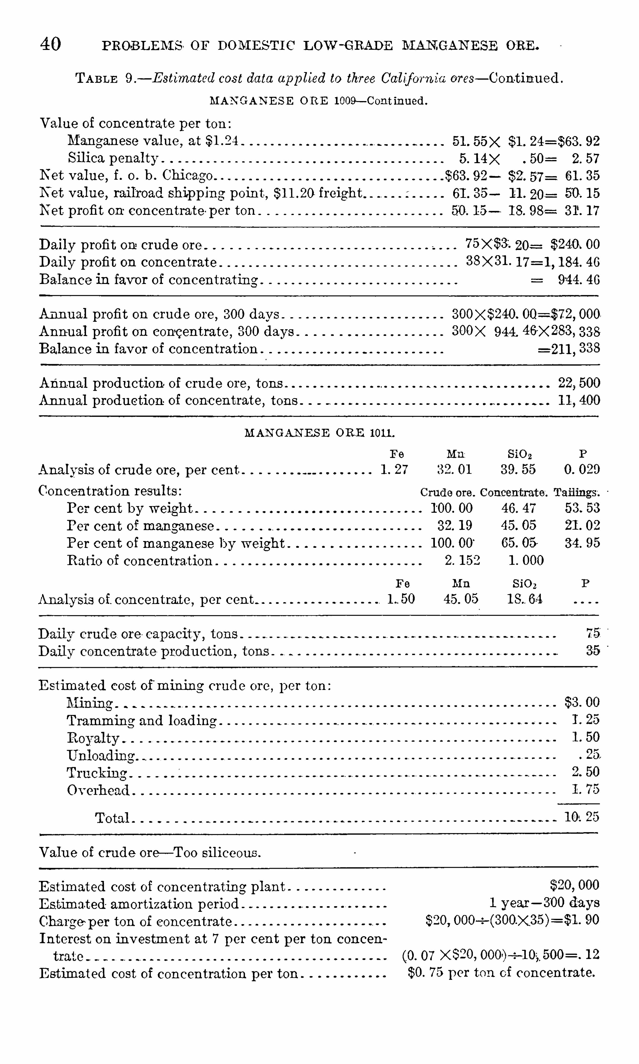
40 PROBL EM S or DOM ESTI C Low—GRADE MAN GAN E SE ORE .
TABLE 9 ,
— E sti7natcd cost data app lied to three Cal if ornia ores— Continued .
MAN GAN E S E 0 R E 1 009— C 0nt inned .
Value of concentrate per ton :Manganese value at
Silica penaltyN et value
,f . O . b . Chi cago. .
N et value, railroad shipping point , freightNet profit on concentrate per ton
51 . 55x $1 . 92
5 . 1 4 X 50= 2. 57
$63 . 92 $2. 57= 61 . 3 5
61 . 3 5 1 1 . 20 : 50 . 1 5
50. 1 5 1 7
Daily profit on crude ore 7 5 X'
$3 . 20: $240. 00
Daily profit on concentrate 3 8x3 1 . 1 84. 46
Balance in favor of concentrating . 944 . 46
Annual profit on crude ore,3 00 days 000
Annual profit on concentrate, 300 days
Balan ce in favor of concentration .
3 00X 944 . 46 X 283 , 3 3 8
=21 1 , 3 3 8
Annual production. of crude ore,tons
Annual production of conc entrate,tons
MAN GANE S E ORE 1 01 1 .
Analysis of crude ore, p er cent
Concentration resu lts :
Per cent by weight
Per cent of manganese
Per cent of manganese by weight .
Ratio of concentration
Analysis of. concentrate , per cent
E stimated cost of mining crude ore, per ton :
Tramming and loading
Valu e of crude oreh —Too siliceou s.
E stimated cost of concentrating plant
Estimated amortization period
Charge per ton of concentrate .
Interest on investment at 7 per cent p er ton coneen
E stimated cost of concentration per ton .
1 50
00
3 2. 1 9
1 00. 00’
2. 1 52
45 . 05
46. 47 53 . 53
45. 05 21 . 02
65. 05 3 4 . 95
1 . 000
Sio2
1 year- 300 days
$20, 90
(.O. 07 X 820, -e 1 2
$0. 7 5 p er ton of concentrate.
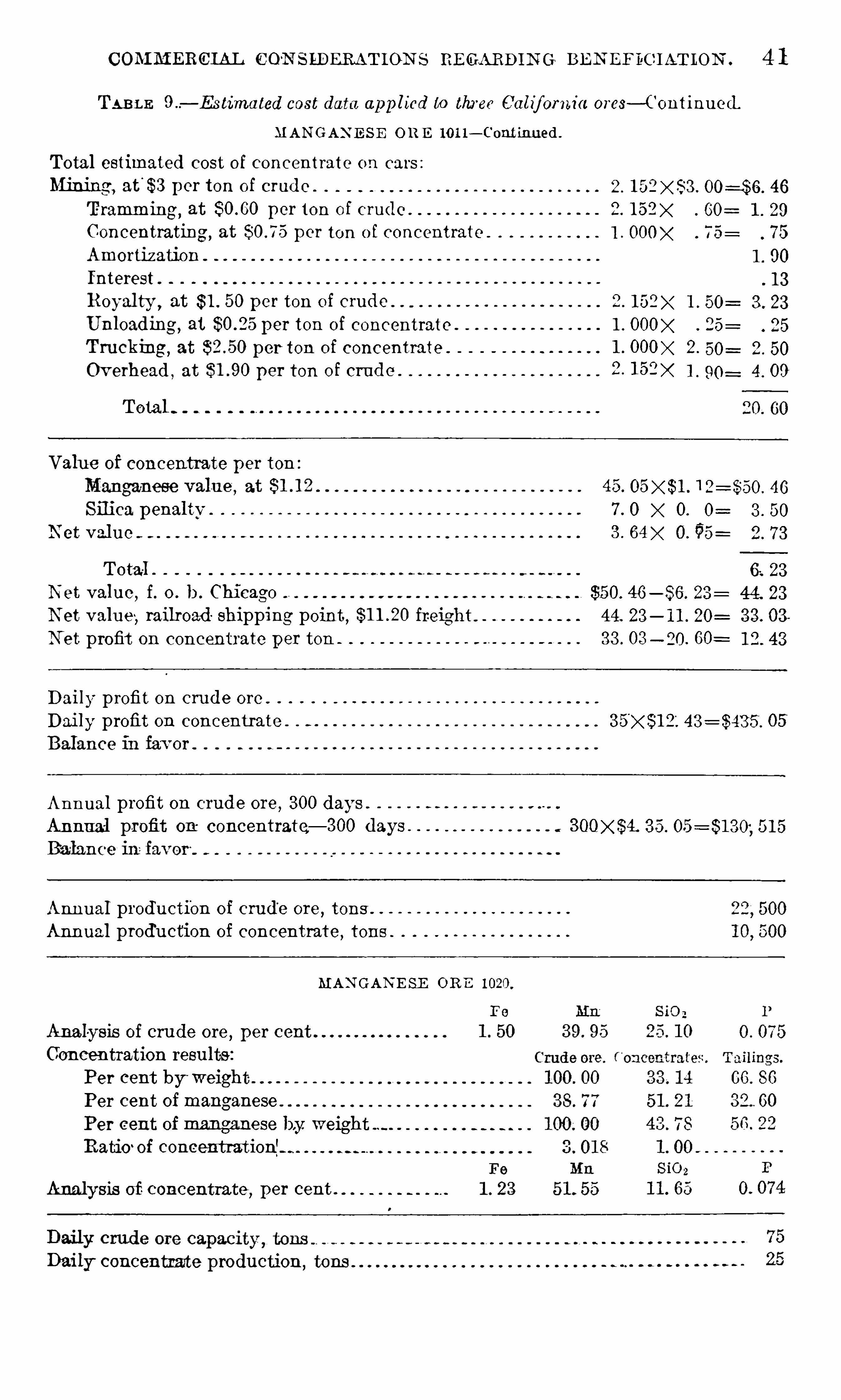
COAI M ERCIAL C O'N SLDERAT ION S REGARDI N G BE N EFBC IATLON . 4 1
TABLE — Estimated cost data app lied to three Calif ornia ores— Continued
MAN GAN E S E OR E 10 1 1 — Cont inued .
Total estimated cost of concentrate on cars :
Mining , at'
$3 per ton of crude .
Tramming, at per ton of crude .
Concentrating , at per ton o f concentrate
Amortiz ation
Interest .
Royalty ,at $ 1 . 50 per ton of crude
Unloading, at $0.25 per ton of concentrate
Truck'
mg, at per ton of concentrate
Overhead , at per ton of crude .
Total
Valu e of concentrate per ton :
Silica penaltv
N et val ue
Total .
N et value , f . o . b . Chicago
N et value, railroad shipping point , freig htN et profit on concentrate per ton
Daily profit on crude ore . o n . . o o o o o o o o o o o o o o
92°
F
?”
CO
C
O
a: 9
9
k“
4
01
7—1
Cr
e
te
I
I
I
!
( C?)
re
ca
p 4G
. 50
6. 23
$50. 46 23 : 44. 23
44 23 3 3 . 03
3 3 . 03 — 20. 60: 1 2. 43
Dai ly profit on concentrate 05
Annual profit on crude ore,3 00 days
Annual profit on concentrate— 300 days 3 5 . 5 1 5
Annual production of crude ore,tons
Annual produ ction of concentrate,tons .
Analysis of crude ore, per cent
Concentration resu lts :
Per cent by weight
MAN GAN E SE OR E 1 020
Per cent of manganese
Per cent of manganese by weight
RatiO ‘
of concentrat ionf
Analysis at concentrate , per cent .
Daily concentrarte production ,tons
o o o o o o o o o o o o o o o o
2 . 46
2. 1 52 X . 60= 1 . 29
l OOOX 7 5 7 5
1 . 90
1 32
1 . . 25 2 5
1 . OOOX 2. 50 :
2. 1 52X 1 . 90 : 4 . 09
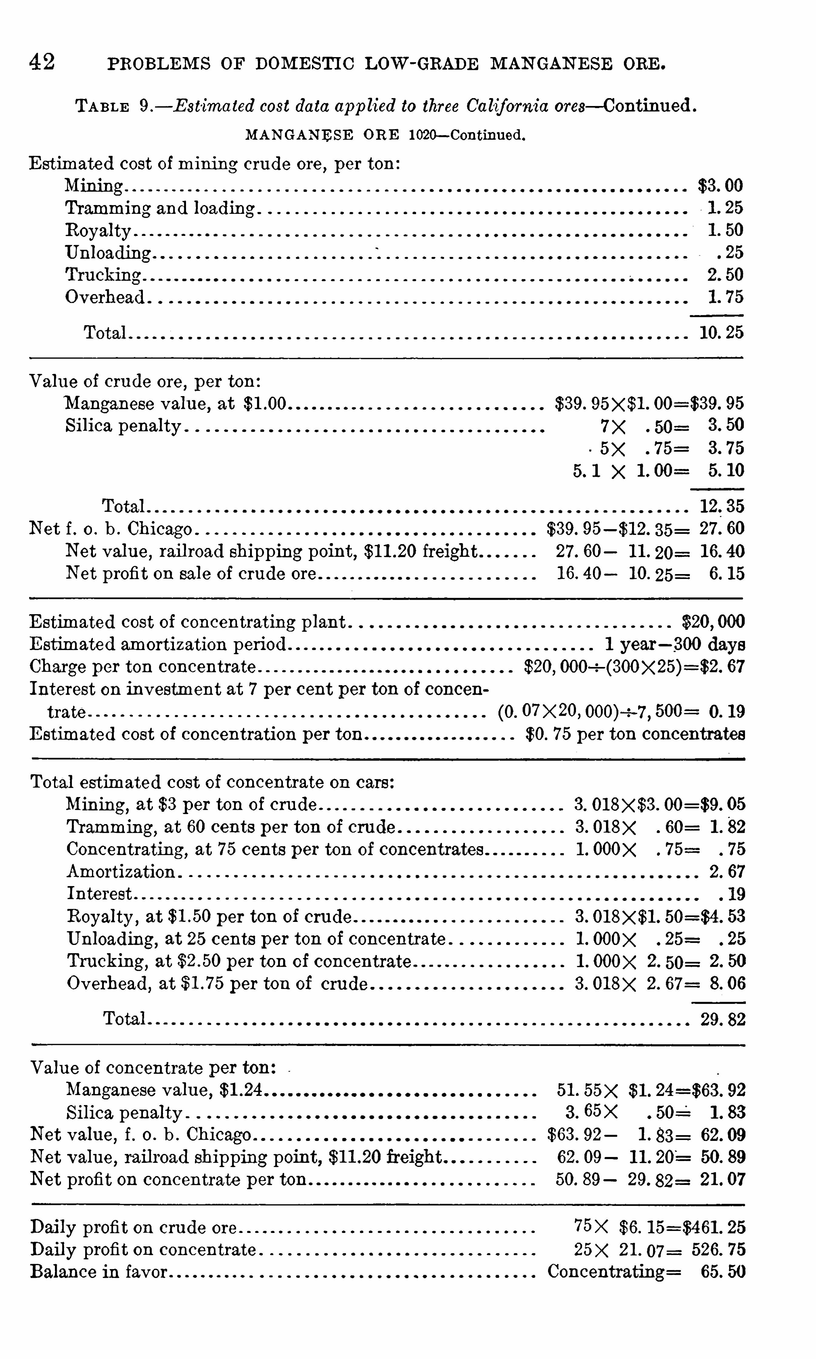
PROBLEM S OF DOM E STI C LOW -GRADE M AN GAN E SE ORE .
TABLE 9 .
— E st'ima ted cost data app lied to three Ca lifornia ores— Continued .
MAN GAN ESE ORE l ow—Continued.
E stimated cost of mining crude ore, per ton
Mining .
Tramming and loadingRoyalty .
Unloading
Value of crude ore, per ton
Manganese value, at $3 9. 95
Silica penalty . 7 X 50= 3 . 50
5 X . 7 5=
X
1 2. 3 5
N et f . o . b . Chicago $3 9. 95 3 5= 27 . 60
Net value,rail road shipping point, freight 27 . 60 1 1 . 20= 1 6. 40
N et profit on sale of crude ore 1 6. 40 1 0. 25= 6. 1 5
E stimated cost of concentrating plant . $20, 000
E stimated amortization period 1 year— 300 days
Charge per ton concentrate $20, 67
Interest on investment at 7 per cent per ton of concen
trate (0. o7x2o, 000) -7 , 500 : O. 1 9
E stimated cost of concentration per ton. $0. 7 5 per ton concentrates
Total estimated cost of concentrate on cars
Mining, at $3 per ton of crude . 3 . 05
Tramming, at 60 cents per ton of crude 3 . 60=
Concentrating, at 7 5 cents per ton of concentrates 1 . OOOX 7 5 7 5
Amortization . 2. 67
Interest
Royalty , at per ton of crude . 3 . 53
Unloading, at 25 cents per ton of concentrate . 1 . 25 25
Trucking, at per ton of concentrate 1 . 2. 50= 2. 50
Overhead, at per ton of crude 3 . 2. 67 8. 06
29. 82
Value of concentrate per ton
Manganese value, 5 1 . 55x $ 1 . 92
Silica penalty 3 . 65x 50 1 . 83
Net value, f . o . b . Chicago $63 . 92 1 . 83=
N et value, railroad shipping point, freight 62. 09 1 1 . 50. 89
Net profit on concentrate per ton 50. 89 29. 82= 21 . 07
Daily profit on crude ore 7 5x $6 . 25
Daily profit on concentrate . 2 1 . 07= 526. 7 5
Balance in favor Concentrating= 65. 50
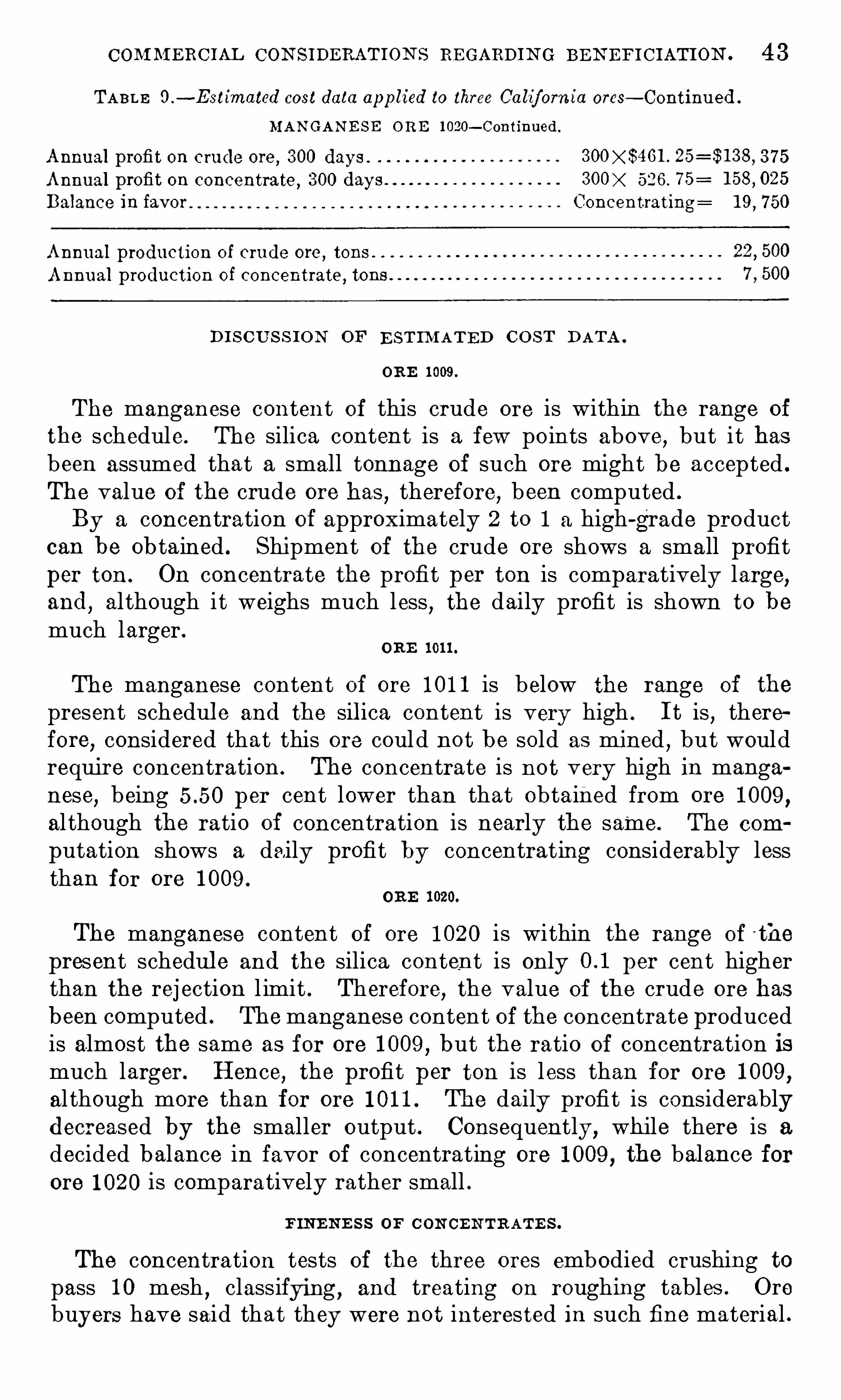
COM M ERC IAL CON SIDERATION S REGARDIN G BE N EFI C IATION . 4 3
TABLE 0 .
-E stimated cost data app lied to three Ca lif ornia ores— Continued .
MAN GAN E S E ORE 1 020— Continued .
Annual profit on crude ore,3 00 days . 3 7 5
Annual profit on concentrate,3 00 days 526 . 7 5 :
Balance in favor Concentrating= 1 9
,7 50
Annual production of crude ore,tons
Annual production of concentrate , tons
D I S C U S S IO N OF E STIM AT ED C O ST DATA .
ORE 1 009 .
The manganese content of this crude ore is within the range of
the schedule. The silica content is a few points above,but it has
been assumed that a small tonnage of such ore might be accepted .
The value of the crude ore has,therefore, been computed .
By a concentration of approximately 2 to 1 a high-grade productcan be ob tained . Shipment of the crude ore shows a small profitper ton . On concentrate the profit per ton is comparatively large,and
,al though it weighs much less
,the daily profit is shown to be
much larger .ORE 1 01 1 .
The manganese content of ore 1 01 1 is below the range of the
present schedul e and the sil ica content is very high . I t is , therefore
,considered that this ore could not be sold as mined
,but would
require concentration . The concentrate is not very high in manganese
,being per cent lower than that obtained from ore 1 009 ,
al though the ratio of concentration is nearly the same. The com
putation shows a daily profit by concentrating considerably lessthan for ore 1 009 .
ORE 1 020.
The manganese content of ore 1 020 is within the range of t he
present schedul e and the silica content is only per cent higherthan the rej ection l imit . Therefore
,the value of the crude ore has
been computed . Themanganese content of the concentrate producedis almost the same as for ore 1 009 , but the ratio of concentration ismuch larger. Hence
,the profit per ton is less than for ore 1 009 ,
al though more than for ore 1 01 1 . The daily profit is considerablydecreased by the smaller output . Consequently, while there is a
decided balance in favor of concentrating ore 1 009 , the balance forore 1 020 is comparatively rather small .
FIN E N E S S OF C ON CE N TRATE S .
The concentration tests of the three ores embodied crushing topass 1 0 mesh
,classifying , and treating on roughing tables . Ore
buyers have said that they were not interested in such fine material .

44 PROBL EM S or DOM E ST I C Low -GRADE M AN GAN E SE ORE .
Indeed,it woul d not be suitable as a major part of a mang anese blast
furnace mixture, but up to 5 , or possibly 1 0 per cent , i t should notbe excessively harmf ul . There would be a larger loss in flue dust
,and
if material of better structure were obtainable i t woul d be greatlypreferred by blast-furnace Operators . Because of the larger lossesattending the use of this fine material
,if it'were purchased at all
,
i t would probably be penalized .
Possibly such fin e concentrates could be agglomerated by briquetting
,sintering
,or nodul izing . But in practice, the application of
any such process to! a particul ar min e is rather doubtful . In the
first place,a small daily output wou ld not suffice to keep such a
plant in continuous and effective operation . A sintering plantmight.be erected for the joint use of several mines, ormight be erectedindependently and operated on a cus tom basis . The first cost of
the equipment and the operating costs that would probably prevailin California being high
,i t is doubtful whether such plants would be
profitable,unless there were some assurance of high prices prevailing
for a considerable period of. time .
At present nodul izing plants at iron blast furnaces in Chicagoand elsewhere are running on flue dust . In an emergency theymight be turned over to manganese concentrates
,and the Operating
company reimbursed in some manner,possibly by a joint assessment
of miner and alloy manufacturer . I t is presumed that the sinterwould be superior to natural manganese ores as mined. and shippeddirect
,and that a certain part of the cost might be charged off
against improved furnace practiceThe time required for the erection of a plant may be considerable,
and private capital might not be attracted to an enterprise of thischaracter unl ess there were some assurance that a given margin of
“
profit might be possible for a period long enough to permit retirementof the original investment for the plant and the gaining of a satisfac
tory return .

CHAPTER 4 ,
— PREPARATION OF MANGANE SE ORE .
By W. R . Calm s .
IN TRODUCTORY STATEMENT .
The grea t demand for manganese during the war caused manypersons to engage in mining and preparing man ganese ores formarket. As a result much money was spent on p lants tha t werenot adap ted to the work . This condition was recognized by the
Bureau of Mines earlv in 1 9 1 8,and an effort was made to ass is t the
opera tors of manganes e properties by sending engineers into the fieldto advis e as to the. proper methods of mining and treating the ores .
A. preliminary study of the Operations showed tha t the methodsin general use were was teful ; consequently, if prac tice could beimproved i t was es timated that the production of the various dis tric tscould be increased, by saving a. large proportion of the mineralformerly los t— thousands of tons a year. W ith this obj ec t in mind
,
a s tandard washing plan t was designed , which was based on the bes tand mos t successful prac tice in manganese properties in the country .
The methods employed in c leaning and concentra ting manganeseores and the scale of Opera tions depend largely upon the size and
charac ter of the deposits worked . The ores obtained from the different forms of depos its are so varied in charac ter that were i t economically possible to treat all of them,
a wide variation in prac tic e wouldbe necessary . The irregular deposi ts , consis ting largely of manganeseand rock fragments inclosed in clay,
are probably more largelytreated than the regul ar forms as they produce the bulk of the ores
trea ted . A relatively large amount of ore also comes fr om the
regular or blanket forma tions, which consis t of replacement deposits
in the limes tone bed rock.
The blanket depo sits may be hard ore ly in g upon or wi thin the
limes tone bed rock, ormay be soft or wad ores . The deposits of wad,some of which are of large s ize, are usually of low grade and presentspecial problems in washing and concentration ; as yet no seriousa ttemp t has been made toward their economic treatment .W ashing and concentra tion methods are discussed herein in the
following order : (1 ) Des crip tion of the practice in the variousdis tric ts and (2 ) description of a s tandard p lant the design of whichis based upon the bes t prac tice in the treatmen t of manganese ore
in this country .
4 6 PREPARATION or M AN GAN E SE ORE .
The principal difficulty in trea ting the ore,or wash dirt
,from the
irregular deposits is the uncertain supply .
‘
Next in importance isthe character of the manganese mineral and the proportion of ore
to was te,such as clay , sand, and iron . The kind of ore bes t adap ted ,
to washing and concentra tion is the nodular or pebble-like formsof small size ; next is the granular form ; both are usually of conven
ient size for leg washing and subsequent j ig work. The kidney,dornick, and massive ores require reduc tion before treatment bylog washers and on the picking bel t, but ow ing to the s ize and puri tyof many of the masses , i t is often possible to make a high recoveryprior to trea tment in logs and j igs .On accoun t of the uncertain and variable conditions mentioned
,
the tendency in trea ting manganese is to reduce the equipment to ‘
aminimum,both wi th regard to kind and number of parts employed .
This is frequently done irrespec tive of the des irability of such limitation . Imperfec t cleaning and excessive losses usually resul t fromthe curtailment of equipment. However
,inadequa te equiment of
plants is not always due to the wish to limi t the firs t cos t,but of ten
to lack of definite knowledge regarding proper methods of treatingmanganese ores , and the foll owing of local practice
,however poor i t
may be. I t is , therefore, important to present details regarding a
s tandard plant tha t incorporates the mos t useful and des irable features of the bes t practice in this country.
ME THODS EMPLOYED.
The preparation of manganese ores may be divided into two
separate and dis tinc t parts~namely, dry mining, and washing or
concentra tion .
DRY M IN I N G .
Dry mining does not refer to mining, excep t indirectly, but moreto the cleaning of the ore
,or wash dirt
,by screening i t as mined .
Not all wash dirt is adapted to dry mining, as some clays are wetand s ticky ,
or occur in large masses,rendering their separation from
the manganese mineral by screening prac tically impossible. Dirttha t can be bes t treated by dry mining is dry and granular
,and can
be easily broken and separated .
The dry-mining method is unsatisfactory at bes t and is scarcely
ever employed in operations of any s ize excep t as a temporaryexpedient prior to the erection of a washing p lant. In small-scaleopera tions where the deposi ts are small
,or sufficien t funds to prop
erly equip themine are lacking,such a method may be permissible.
Also,deposi ts dis tant from a water supply may require dry mining
if they are to be worked at all . In any event the method is was teful,
the loss of fine ore frequently amounting to 25 to 3 5 per cen t of therecoverable mineral in the bank.
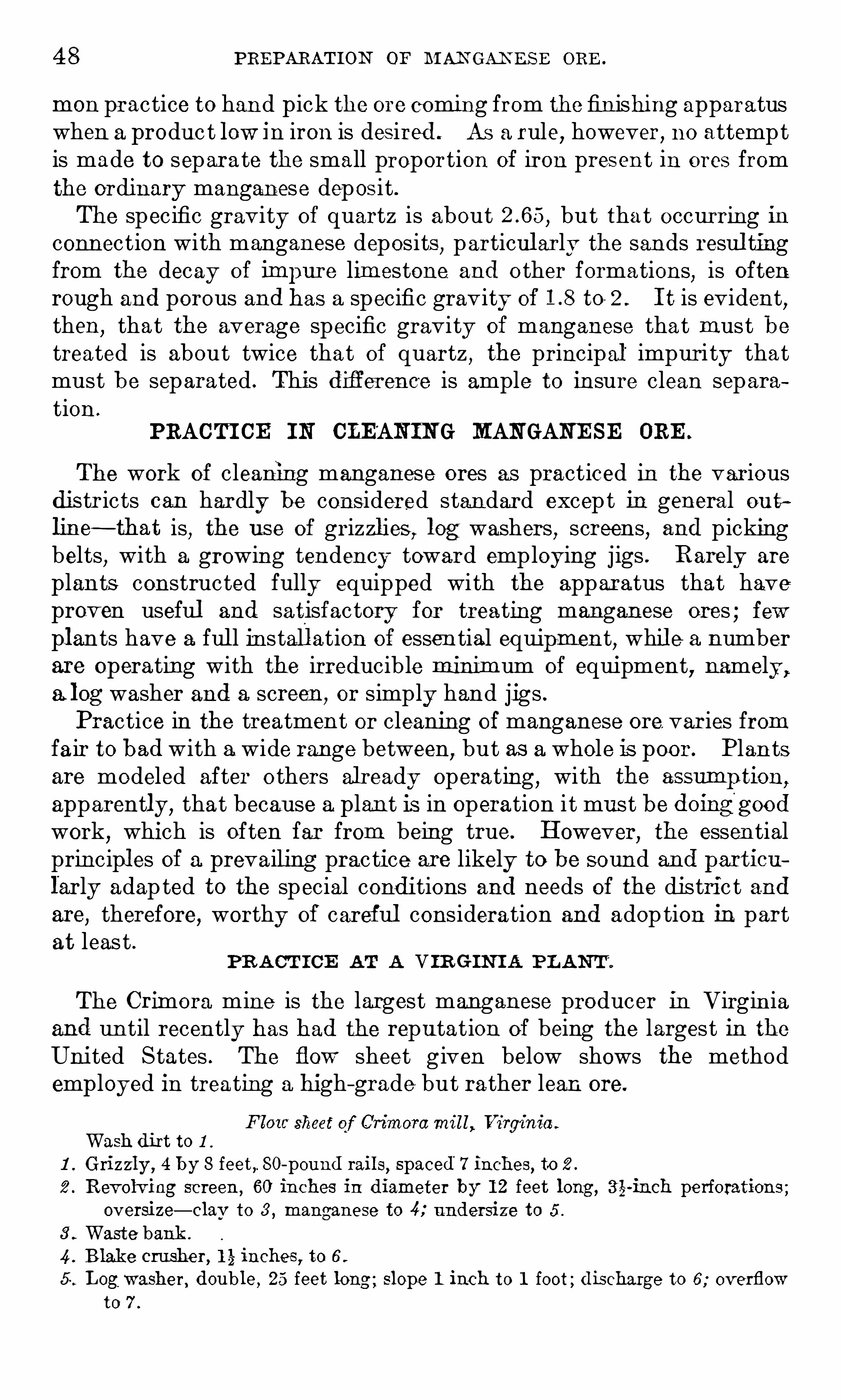
4 8 PREPARAT ION or M A NGAN ES E ORE .
mon practice to han d pick the ore coming from the fin ishing apparatuswhen a produc t low in iron is desired . As a rule
,however
,no attempt
is made to separa te the small proportion of iron present in ores fromthe ordinary manganese deposit .The specific gravity of quartz is about but tha t occurring inconn ection with manganese deposits
,particul arly the sands resul ting
from the decay of imjiure lim estone and o ther formations,is often
rough and porous and has a specific gravity of to 2 . I t is evident,
then,that the average specific gravity of manganese that must be
treated is about twice that of quartz , the principal impuri ty thatmust be separated . This drderence is ample to insure clean separation .
PRACTI CE IN CLEAN IN G MANGANE SE ORE .
The work of cleaning manganese ores as practiced in the variousdis tr icts can hardly be considered standard except in general ou tline~that is, the us e of grizzl ies
,log washers, screens, and picking
belts, with a growing tendency toward employing jigs . Rarely are
plants constructed fully equipped with the apparatus that haveproven useful and satisfactory for treating manganese ores ; fewpl ants have a ful l in stall ation of essen tial equipment
,whil e a number
are operating with the irreducible minimum of equipment,namely ,
a log washer and a screen,or simply hand jigs .
Practice in the treatment or cleaning of manganese ore. varies fromfair to bad with a wide range between, but as a whole is poor. Plan tsare modeled after o thers already operating
,with the assumli tion,
apparently,that because a plan t is in Operation it must be doinggood
work,which is often far from being true. However
,the essential
principl es of a prevailing practice are likely to be sound and particu
larly adap ted to the special conditions and needs of the distric t andare, therefore, worthy of careful consideration and adop tion in partat leas t .
PR A CT I CE AT A V IR G IN I A PL AN T .
The Crimora mine is the largest manganese producer in Virgin iaand un til recently has had the repu tation of being the largest in the
United States . The flow sheet given below shows the methodemployed in treating a high—grade but rather lean ore.
Flow sheet of Crimom mill,Virginia .
Wash dirt to 1 .
1 . Grizzly ,4 by 8 feet,. SO-pound rails
,spaced 7 inches, to 2 .
2 . Revolving screen,60 inches in diameter by 1 2 feet long , ti l-inch perforations ;
oversize— clav to 3 , manganese to 4; undersize to 5 .
3 . Waste bank .
4 . B lake crusher, 1 5» inches ; to 6
5 Log washer, double ,25 feet long ; slope 1 inch to 1 foot ; discharge to 6 ; overflow
to 7 .

PRACT IC E IN CLE AN IN G M AN GAN E SE ORE . 4 9
6 . Revolving screen,9 feet 8 inches long by 48 inches in diameter, i-inch perfora
tions ; oversize bv elevator to 8 ; undersize to 9 .
Settling pond .
Revolving screen,(5 feet long by 40 inches in diameter, l
-inch and 1 1 -inch per
forations ; oversize by elevator to 1 0 ; undersize— from l -inch screen to 1 1,from
l l -inch screen to 1 2 .
Revolving screen ,9 feet 8 inches long by 48 inches indiameter. g-inch perfora
tions ; oversize by elevator to 1 3 ; undersize by elevator to 1Picking belt, waste , 24 inches wide by 22 feet long ; ore to 1 5 ; was te to 1 6 .
Bu ll jig N O . 1 , two cells, 3 6 by 3 6 inches ; gate discharges to 1 5 ; overflow to 1 0 .
Bu ll jigN O . 2, two cel ls, 3 6 by 3 6 inches ; gate discharges to 1 5 ; overflow to 1 0 .
Harz jig , three cel ls , 3 0 by 40 inches ; gate di schargest o 1 7
,hutches to 1 7 , over
flow to 7 .
Woodbury ] Ig’
, two cel ls ; gate discharges to 1 7 ; hutches bv elevator to 1 7 ; overflow to 7 .
Picking belt , 3 0 inches by 22 feet long ; ore”
to-1 7 , waste to 1 0 .
Waste bin by cars to 3 .
Ore bin , finished ore
PR A CTI CE . AT A PLA NT IN GE OR G IA .
The flow sheet of the Aubrey plant Of the Georgia I ron Coal CO .,
given be low ,represents the best practice andmos t extensive operation
in the Cartersvill e distric t Georgia . The capacity of the p lant is 50tons of fi nished ore per day of 1 0 hours . There are three large opencuts tha t are connec ted with railroad tracks
,so that strippings as
well as wash dir t can be handled with equal facility . I t is possiblethat certain parts Of the plant might have been arra nged to betteradvantage, yet taken as a whole the design and arrangement. are
fairFlow sheet Of the Georgia. I ron ct Coa l CO . p lant a t A ubrey, Ga .
Wash dirt to 1 .
1 . Grizzly (fou r sets) five railway rails,four spaces of 4 inches each
,length 7 feet
3 inches ; oversizeg rock to~2 ; manganese broken by sledge to 3 ; undersize to 3 .
2 . Rock dump .
3 . Log washers (four double logs, 3 0 feet long ) ; discharge to 4 ; overflow to 5 .
4 . Screen (perforatedmetal , openings I by 2 inches) ; oversize to 6 ; undersize to 7 .
5 . Mud or settling pond .
6 . Picking be lts ; rock to 2 ; manganese and atta ched rock to 8 .
7 . Belt conveyors to 9 .
8 . Crusher redu cing to one-hal f inch to 9 .
Ore bins by elevator or l if t to 1 0.
1 0. Revolving screens for j 1 g feed ,Nos. 3 , 4 and 5 ; for jig N O . 3 , l
—Sg-inch , i-inch , and
12-inch perforations ; for jig N O . 4
, Tic-inch , i-inch ,
and 55 -inch perforations ; for
jig N O . 5 , i-inch, g-inch, and e-ineh perforations ; products from these screens
to 1 1 .
1 1 . Jigs Nos . 3,4+ and 5 (four singl e cells ) ; gate discharges tO 1 2; hutches to 1 3 ; over
flow to 1 4 .
1 2 . Concentrates bin to 1 7 .
1 3 . Flat screen , {w inch perforations ,for fig N o . I ; oversize to cel l N O . 1 Of 1 5; under
size to cell N o . 2 of 1 5 .
50 PREPARATION OF M AN GAN E SE ORE .
1 4. Revolving screen ,for jig NO . 2
, fi-inch , fi inch ,and j -inch ; oversize to cel l No.
1,undersize to cel ls Nos . 2
,3, and 4 , No. 2 jig.
1 5 . Jig No . 1 (two cel ls) ; gate discharges to 1 2; hutehes to 1 2; overflow to 5 .
1 6 . Jig NO . 2 (four cel ls) ; gate discharges to 1 2; hutches to overflow to 5 .
1 7 . Hand-picking table, where ore is sorted by attendants, who pick out iron and
other impurities . The iron is sold as manganif erous iron ore .
PR ACT I CE IN THE BATE S V I LLE D I S TR I CT,ARKAN S AS .
There were 1 1 washers buil t in the Batesvill e dis tric t, Arkansas,during 1 9 1 7 and 1 9 1 8 . N one of these did satisfactory work, largelybecause the builders and opera tors did not appreciate the necessityof providing screens for properly siz ing the ma terial treated on the
j igs .The prac tice in this distric t is s imple and may be outlined as fol
lowsFlew sheet usedin Batesmllle district, Arkansas.
Wash dirt to 1 .
1 . Gri zzly,size 5 by 6 feet , 1 0 to 1 4 railroad rails spaced 4 inches ; oversize— waste
rock thrown on dump , lump ore reduced to size that wil l pass through grizzlyto 2; undersize to 2 .
Double log washer, 28 feet long, slope 1 inch to 1 foot ; discharge to 3 ; overflow to 4.
3 . Revolving screen, 6 feet long by 30 inches in diameter, with i- inch perforations ;oversize to 5; undersiz e to 6 .
4 . Waste bank.
5 . Picking belt , 22 feet long by 24 inches wide ; ore to 7 ; waste to 4 .
Harz jig (four cells) ; size of cel ls 22 inches by 42 inches ; gate discharges to 7 ; hutchesto 8 .
Finished Ore bin .
8 . Harz jig (two cells ) , size 28 inches by 3 6 inches ; gate discharges to 7 , hutches to 7 ,tail s to 4 .
lm
05
Q
Rarely are more than two j igs employed in the plants for washingmanganese ores
,and in many plants only one j ig is used . Revolving
screens or tromm els are
'
commonly used , but fiat screens are occasional ly emmoyed. In ei ther case i t is the exception rather than therule to find more than one siz e of Opening
,which ranges from inch
to 1 4 inches . The wide range in siz e f ed to the j igs from such screensrenders good separation next to impossible. Few of the j ig productsare clean,
and they require extensive hand picking to complete thepreparation . This hand sorting could be obviated by simply rerunning the hutch products of the rougher j igs ; fairly clean productscoul d then be made on the second or cleaner j igs . W hen only one
j ig is employed , few or none Of the j ig products is suitable for market.Fairly close siz ing woul d greatly improve the work done by the j igsand reduce the expense of preparation by eliminating hand p icking .
Probably a dozen hand j igs have been in use in the distric t atdifferen t times . As with the power j igs, incomplete separa tion of
waste was the almost universal rul e, li ttle or no a ttention beingpaid to siz ing of the feed .
PRACT I CE IN CL EAN I N G M AN GAN E SE ORE . 5 1
PR A CTI CE AT A M I L L AT PH I L I P SBUR G,M ON T .
The mill of the Phil ipsburg Mining CO . is one O f the largest in theW est, having a capacity of 7 5 to 1 00 tons per day . The ores treatedare the oxides mined at Phil ipsburg
,Mont . The flow sheet Of the
mill foll ows :
Flow sheet of Phil ipsbnrg Mining Co . at Phil ipsburg ,Mont.
Wash dirt (ore) to 1 .
1 . Grizzly,2-inch spaces ; oversize to 2 , undersize to 3 .
2 . Gyratory crusher, NO . 4 , 1 } inches , to 3 .
3 . Ore bin to 4 .
4. Revolving screen,l j -mm. mesh ; oversize to .5
,undersize by elevator NO . 1 to 6 .
5 . Picking belt; clean ore to 7 , rejected by elevator No. 1 to 6 .
6 . Revolving screen , two sections— first, —inchmesh,second , i-inch mesh ; oversize
of first to second, undersize of first to 8 , oversize of second to 6 , undersize of
second to 9 .
7 . Clean-ore bin.
8 . Revolving screen , 4-mm. mesh ; oversize to 1 0; undersize to 1 1 .
9 . Bull jig ; concentrates to 1 2; overflow to 1 3 .
0. Middling jig ; concentrates to 1 2; overflow to 1 3 .
1 1 . Revolving screen ,l j -mm. mesh ; oversize to 1 4; undersize to 1 5 .
Dorr classifier ; spigot to 1 6; overflow to 1 7 .
1 3 . Rolls, fi-inch space , by elevator No . 2 to 1 8 .
1 4 . Fine j ig ; concentrates to 1 2 , overflow to 1 3 .
1 5 . Dewatering tank ; spigot to 1 9 , overflow to 1 7 .
1 6 . Frue vanner; concentrates by NO . 3 elevator to 20,overflow to 1 7 .
1 7 . Settling pond .
1 8 . Revolving screen ; 25-mm. mesh, oversize to two coarse jigs , undersize to 1 1 .
1 9 . Distributor to 21
20. Drier to 22 .
W ilfley tables ; concentrates to 1 6 , tailings to 23 .
22 . Concentrates bin.
23 . Waste bank.
DE S CR I PTION OF A STANDARD W A SHI N G PLAN T .
The cleaning of manganese ores by washin g and j igging can readilybe accomplished and that, too , with slight change in the presentpractice. The flow sheet Of a plant properly arranged to do satisfactory work is given below .
Flo'w sheet of standard washing p lant.Wash dirt to 1 .
1 . Grizzly, 2-inch to 4-inch spaces between bars ; oversize rock to 2 ; manganese by
sledge to 3 ; undersize to 3 .
2 . Rock dump .
3 . L og washer, double l og, 20 to 3 0 feet long ; discharge to 4 ; overflow to 5 .
4. Revolving screen, cylindrical or conical , perforations or mesh 1A-inch and fr o
inch ; oversize , everything above -inch, to 6 ; undersize ,-inch to 93 -inch,
to 7 ; {lg-inch and smal ler, to 8 .
5 . Mud or settling pond .
6 . Picking belt ; rock to 2 ; manganese to 9 .

52 PREPARATION OF M AN GAN E S E ORE .
7 . R oughcr jig, four cel ls ; gate-discha rges to 9 ; first hutch to 9 ; second ,third , and
fourth hutches to 1 0 .
8 . Sand jig, three cell s ; gate discharges to: 9 ; htrtches to 9 or 1 0.
Finished ore bin .
1 0. Cleaner jig; three cel ls ; gate discharges to 9 ; hatches to 9 or 1 1 .
1 1 Shaking table ; finished product to 9 ; tailing to 5 .
A standard washing plant having the above flow sheet may be
called a single washer or un it,and has a capacity of 40 to 50 tons of
fin ished ore per 1 0 hours . An increase in capacity of such a plant,aside from a small increase ga ined through crowding, would: meandoubling
,trebling
,or quadrupling of mos t of the equipment listed,
with corresponding increase in the volume of wash . dirt treatedBy single washer is not meant a singl e leg, bu t a single washerwith double. logs . S ingle log s do good
,
work, yet in a plant as ou t
lined,a double log shoul d be employed .
The sizes O f the various apparatus of a standard plant are indicatedin the flow sheet ; the sizes of screens and adjustments of the variousapparatus for proper Operation are given below.
The number of revolutions Of logs varies from I 2 to 1 5 per minu te.
The amount of water required varies widely with the nature of the
bank dirt,but is usually 50 to 7 5 gal lons per minu te. The capa city
likewise varies with the bank dirt ; average dirt should yield 40, to. 50
tons product per 1 0 hours . Roughly ,25 horsepower is required
to drive logs .S CRE E N S .
The number Of revolutions is 1 5 to 20 per minute, being approxi
mately the same for cylindrical and conical screens 3 6 to 48 inchesin diameter. The power required for driving varies somewhat withfeed and size of material handl ed , bu t is about one horsepower. The
capacity of. screens of the sizes given ran ges from 45 to 55 tons per1 0 hours for the smaller
,and 5 0 to 7 5 tons for the larger. For the
ordinary material treated the screen should be not less than 60 normore than 7 2 inches l ong . I f a larger number of sizes is desired‘
,it
might be better to shorten the length of the separate screening surfacethan to increase unduly the-length O f the whole screen .
P I CKI N G B E LTS .
The sizes of picking belts commonly employed , which have provedsatisf actory for the usual range of work done, are : 3 0 feet long by1 8 inches. wide to 50 feet long by 3 0 inches wide. The speed of the
picking bel t ranges from 50 to 60 linear fee t perminute. The capacityis limited by the character of the work ; if the material sorted islargely ore and the waste rock is fairly coarse , the capa city
“ is large,

PRACT I C E 1 1s CLEAN IN G M AN GAN ES E ORE . 5 3
imilarly where the percentage of ore is small and the individualpieces are large ; but where the ore and waste are about equal inamount and there is a wide range in sizes , the capacity may be small .Occasionallv two picking belts are used , one for coarse
,the other
for the finer materials,but such practice is neither necessary nor
desirable in a standard plant .
J IGS 0
The following data show the proper adjustment and operationo f j igs :
Dala regarding site and operation of j z'
g equ ipment.
(D imensions in inches. )W idth . Length .
Size of sieve compartments " 20 to 24 3 0 to 3 8
Size of plunger compartments 1 8 to 22 3 0 to 3 8
Size of sieve openings : 1 3 8 cell . 9ad cell . 3 rd cell. 431: cell .
3 0 11 t fig . 34 T3? it
f t 1/sCleaner jig 1
L, Vs
Length of stroke of jigs :Rougher jig. 1 % 1 % 1 %Sand j ig . 1
Cleaner jig 1
N umber of strokes per minute'
Rougher jigSand jig
Cleaner j ig .
Power for 4—cell jig, to hp .
Power for 3 -cel l jig ,to hp .
Hydrau lic water pipes : Main pipe 2 inches ; branch pipes 1 inch .
Amount of water used by a jig, 3 50 to 400 gal lons perminu te .
Height of tailboard or dams,3 % to 4% inches.
Slope of bed (sieve) shoul d not exceed 1 inch to length of bed ; with heavy mineral ,bed should be level . Slope should be against . not with movement of mineral .
Drop between tailboards ordams, 1 inch.
Height of gate discharge above bed ,2 to 2% inches. This must be varied to su i t con
ditions and cha racter of material treated .
Jigs to have ful l or large capacity -must be fed regu larly ; thereforej igs receiving the feed directly or indirectly from legs usuall y do
uns atisfactory work for the reason that irregular feeding does notpermit the maintenance of a bed of uniform depth . Further, thefeeding of materials which vary from sandy to clayey in characteralso renders i t difficult to keep a full bed ; clayey ores tend to clogthe j ig beds and are preferably cleaned by trommels and jets of water.
W ith a suitably arranged plant,practically all materials treated
may be handl ed by gravity ,but in places elevators are required .
El evators,although adding to the equipment and the expense of
operation,permit a better arrangement
,in that more. of the appa
ratus may be on the same level,and therefore more accessible.
5 4 PREPARATION OF M AN GAN ESE ORE .
5
E levators are particularly useful for raising the hutch productsfrom the rougher and sand j igs to the cleaner j igs . Shoul d it befound desirable to employ a shaking table in reworking the hutchproducts from the cleaner j igs
,elevators shoul d al so be employed
in handling them .
TABL E S .
I t is doubtful whether tables can be used to advantage in thepreparation of the usual run of manganese ore
,as outlined and
discussed . However,there is a well-defined field for their application
in treating certain ores,such as the low-grade blanket deposits and
breccia ores .
DRY CON CE N TR AT ION .
Largely through the lack of an adequate supply Of water a numberof attempts have been made to clean manganese ores by dry methods .Probably the most extensive and elaborate equipment is that of theSouthern Hill Manganese Co . on the Southern Hill property, in theBatesville district
,Arkansas .
I t is proposed to separate the ore from the clay and rock fragmentsby passing the material as excavated through a revolving drum
,
where i t will be thoroughly dried and the clay pulverized . On beingdischarged from the drum the fine material will be removed by a
revolving screen,which is a continuation of the drum . The coarse
manganese and waste will then pass to a picking bel t,where final
separation is to be made. The smaller sizes of ore are to be treatedon hand j igs . This plant has never been operated on a commercialscale ; consequently no defin ite statement can be made regarding itspracticability .
The water supply for manganese washing and concentratingplants is important
,as many of the workable properties are often
at considerable distance from an available supply . Pipe l ines3 to 4 inches in diameter are sufficiently large for a standard plant.The conservation of water by passing it through settling or impounding ponds usually solves the problem of water supply where the
quantity Of fresh water is limited . Once a plant has been put inoperation the addition of 25 per cent of the total consumption not
only provides for the loss due ' to wastage,but furnishes the required
amount of fresh water for those steps of the process requiring cleanwater.
GENERAL SUMMARY OF CONDI TI ON S AFFE CTINGCONCENTRATI ON .
On account of the irregularity of manganese deposits and the
uncertainty of an adequate supply of ore, great care should be exercised in connection with the various operations
,particul arly with
56 PREPARATION or M A NGAN E SE ORE .
The grade of ore upon which royalties are assessed has been thecause Of considerable trouble in different districts
,but in most of
the districts during the past year royal ties were paid on all orescoming within the schedul e unl ess otherw ise specified . In the
future high—grade ores will alone be subj ect to royal ty charges .In future careful mining in well-proved deposits of high-grade
ore will be necessary in the various manganese districts . The oresmin ed will
,in turn
,require either close hand-picking or concentra
tion in well -designed plants in order to produce a high-grade ore,
low in silica and phosphorus . W ith a dependable output of suchore
,it shoul d be possible to continue operation in the face of foreign
competition wherever freight rates to consuming furnaces are rea
sonably favorable.
CHAPTER 5 .—LEACHING OF MANGANE SE ORES W ITH
SULPHUR DIOX IDE .
By C . E . VAN BARN EVE LD .
I NTRODUCTORY STATEMENT .
E arly in 1 9 1 8 the Bureau of Mines,through its mining experiment
station at Tucson,Ariz .
,began an investigation of possible methods
of recovering manganese from the numerous deposits of low—grade,siliceous
,secondary manganese ores that are scattered throughout
Arizona , N ew Mexico,and Utah . The aggregate quantity Of such
ore is large, but as a rule these ores are not amenable to ordinarymethods Of concentration ,
and the preportion of ore that can bebroughtto shipping grade by sorting and screening is usually small . Much of
this ore is found in localities tributary to the copper-smelt ing districts where waste sulphurous roaster gases are available. The
poss ib ility of using sulphur dioxide as a leaching agent for manganesehad long been recognized , and i t was thought that a process developedat the Tucson station for leaching certain copper ores with hot sul
phurous fumes might be successfully applied to this type of manganif erous material . In May, 1 9 1 8 , some leaching tests were made at
this station on manganese ores from the Patagonia district in Arizona .
The results were sufficiently encouraging to lead to an extensiveprogram of research into the possibility of developing an SOz
—leachingprocess which would produce a high—grade sinter containing over 60per cent metallic manganese in the form of oxides
,free from silica
and phosphorus . The investigation had not been completed whenthe economic situation as regards manganese was entirely changedby the armistice and further experimentation was abandoned . How
ever,sufficient work had been done to warrant certain conclusions .
As these may have a scientific interest and a bearing upon otherchemical and metallurgical Operations , the following brief report ispresented .
The work was undertaken with due recognition of certai n facts1 . That prompt action was essential .2 . That the process would probably have to be applied at smelting
centers where sulphurous fumes were available as waste products ,and that the cost of transportation of ores to the smel ter would bea limiting factor in its application .

58 L EACH I N G or M AN GAN E SE ORE S WI TH SULPHUR DIOX IDE .
3 . That a plant of 250—ton capacity woul d be the desirab le unitand that in all probabil ity two such units would be the maximuminstallation for any one smel ter .
4 . That from 4 to 6 months woul d be required for constructionand that the cost of the plant woul d have to be written off over an
Operat ing period of 1 2 or even 6 months .
5 . That the cooperation of the Oopper-smelting companies inArizona and Utah and of the large consumers of manganese wouldbe necessary in order to arrange for prompt plant construction ; alsothat i t might be possible and necessary to use pub lic funds .
The investigation was carried through the laboratory stage on a
sufficiently large scale to warrant as a wartime measure the construction on the resul ts obtained of a commercial unit . On October 1 negotiationswere underway for the erection Of a -ton unit at one of thecopper smelters
,in Oooperationwith a large producer of lead-zinc-silver
iron-manganese ore in which only the fluxing value of the manganesewas being realized . While this negotiation was in progress the rapidimmovement in the military situation so changed the outlook thatthe undertaking w as abandoned before final plans were drawn .
RE SULTS OF TE STS .
The tests made included ores from the Clifton, Bisbee, and Patagonia districts in Arizona ; also representative ores from NewMexico,Utah
,N evada
,and California . The resul ts of the tests are presented
in Table 1 0 following :
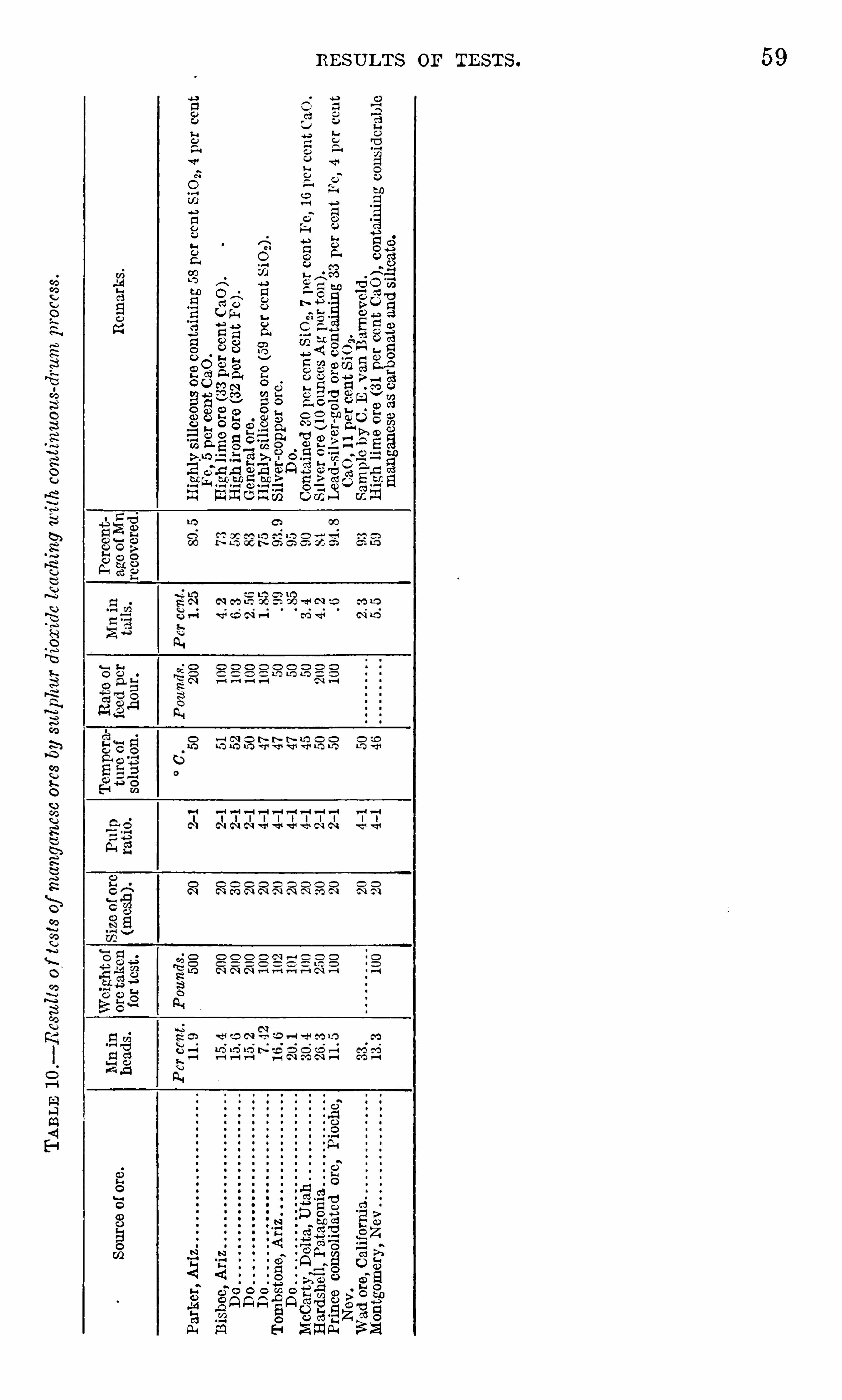

60 LEACH I N G OF BIAN GAN E SE ORE S WITH SUL PH UR DIOXIDE .
OBSERVATI ON S ON RE SULTS OF TE STS .
The foll owing observations , based entirely on work done with dilutehot sulphurous gases (under 6 per cent 80 2) used countercurrent tothe flow of the pulp , are presented
THE OR E .
The general run of western ores may be described as M pure
psil omelane resulting from al teration of silicate or carbonate . The
impurities may include numerous substances su ch as l ime,silica
(whichmay ormay not be combined ) , and iron in the form of limoni teor siderite .
Such an ore is readily leached with SOZ and need rarely be crushedfiner than 20 mesh to insure a good extraction .
THE PULP .
The pul p shoul d be broken into a fine spray to insure contactbetween the mineral particles and the reagent . A leaching drumwas designed at this station for the l ixiviation of nonsul phide copperores which 'gives the necessary agitation and contact .A patent (U. S . patent N o . 243 01 5 ) was applied for and was granted
on N ovember 8 , 1 9 1 8 .
Briefly ,this apparatus comprises a drum set horizontally ,
to rotateslowly . The interior is divided into compartments by a series Of
transverse partitions , each compartment having longitudinal bafflesand peripheral lif ters . The transverse partitions are perforated so
that the pul p may pass through the successive compartments to theend or discharge compartment . The pulp is fed into the firs t compartment and drops to the bottom of the compartment ; as the drumrotates the peripheral lifts raise the pulp until i t is spill ed onto thehorizontal staggered baffles below in such manner that the pulp issplashed and distributed over the surfaces of the bars and againstthe transverse partitions in fin e descending drops and particles
,
thereby insuring intimate and prolonged contact between the ore
particles and the countercurrent sulphurous and oxidizing gases .W ith a constant feed a flow is established within the drum
,so that
the pulp is gradually passed through the successive compartmentsinto the last or discharging compartment
,the l ifters of which raise
the pulp and drop it into a discharge or exit pipe whereby it is conducted through a trap Opening into a discharge launder .
The pulp enters one end of the drum cold,and the SOz
-charged airor gas enters the Opposite end hot . The countercurrent flow developed results in the pulp becoming progressively warmer and the gasbecoming correspondingly cooler, until the pul p at the discharge end
is heated to any desired temperature . W hen SO,2is introduced as a

OBSERVATION S ON RE SUL TS OF TE STS . 6 1
hot dilute gas containing less than 6 per cent SO,by volume (the
balance of the gas being largely air, which has lost part of its oxygenand which may contain the various impurities commonly found inroaster gases ) and is projected into a fine spray of hot pulp or solution
,
absorption of SO,i s practically negligible and the hot pulp or solution
will contain practically no free SO,and will discharge from the drum
in a practically neutral condition .
S OLUB I L I T Y OF THE M AN GANE S E M INE R AL S .
The various higher manganese oxides,
especially pyrolusite,psilomelane , and wad
,were found to be readily soluble in the hot
sulphurous acid formed by introducing hot air or furnace gas con
taining 2 to 6 per cent SO, (by volume) countercurrent to a pulp flowhaving a consistency of 2 Of water to 1 of ore crushed to 20 mesh .
Manganite and braunite are not commercially soluble .
Silicates of manganese are insoluble in sulphurous acid at atmospheric pressure and only slightly soluble under pressure .
Carbonates of manganese may ,from an Operating standpoint
,be
considered insoluble . The reagent S lowly attacks and decomposesthe carbonate , but some of the dissolved manganese at once repre
cipitates as a sul phite ; this precipitate coats the remaining undissolved carbonate and effectually prevents further dissolution .
IR ON .
The effect of SO, on iron minerals differs markedly from its effecton manganese minerals . Iron in the Oxide form
,such as magnetite
,
hematite,and l imonite
,is practically insoluble in S0 Metallic iron
and iron in the form of carbonate (siderite) is readily soluble . Thisiron will be in solution as a ferrous sulphite or sulphate ; it will ,however, precipitate as a basi c ferric compound in the presence Of
either CaCO 3and oxygen or ZnCO
3and oxygen ; i t will also be
similarly precipitated from solution so long as there is undissolvedMnO, in the ore charge .
PHO SPHORU S .
In some forms phosphorous dissolves readily in SO, . N o largescale tests in the drum were made on high phosphorus ores . Lab
oratory tests , however , indicate that by the use of tandem drumsphosphorus may be eliminated in the following manner : The phosphorus will not be dissolved in the first drum (the discharge fromwhich stil l contains much undissolved manganese and other bases ) .
Whatever dissolved phosphorus is discharged from the second drumwil l return to the ball mill . The addition of large quantities of
fresh ore will at once neutraliz e these solutions,and the phosphorus
wil l thereupon precipitate . I f sufficient soluble iron and phosphorus are present to cause the building up of these elements by reso
62 LEACH IN G or M AN GAN E SE ORE S WITH SUL PH UR DIOXIDE .
lution in the drum after precipitation in the ball mill,then the fil trate
from the second drum may be passed over any available carbonates ,such as CaCO, ,
prior to being returned to the ball mill . The iron and
phosphorus in solution would then be precipitated and eliminatedfrom the circuit .
L IME .
In the presence of an appreciable amount of MnO,the concentra
tion of free SO,is insufficient to decompose CaCO3 . As dissolution
of MnO2progresses
,some CaCO3 wil l be dissolved and precipitated as
CaSO4 (insoluble) . The catalytic action of the iron and manganese
oxides will convert a small proportion of the entering SO2to 80 3 ; the
resul ting sul phuric acid will convert CaCO3to CaSO4 . Some of the
CaCO3particles become coated with gypsum and are not further
acted upon by the acids in the drIIm .
Z I N C AND C OPPE R .
Z inc and COppeI’ in nonsulphide form are readily dissolved by SO, ,
but sul phides of these metals are not attacked .
TR E ATME N T OF THE PR E GN AN T S OLUTI ON .
The discharge from the drum will consist of a pulp containing insolution as sulphates the manganese, zinc , copper, and perhaps someiron as solids the gangue, the sulphides , the other insoluble minerals ,and any dissolved lime reprecipitated as CaSO
4 .
The pregnant solution may be separated from the solids by fil tration and washing in pressure filters .
Any copper present in the fil tratemay be recovere d by precipitationon iron .
The manganese-zinc content is removed together,either by crys
tallization,in large—scale permanent installations , where the lowest
operating costs are to be sought , or by evaporation in pans withartificial heat in small er Or in temporary installations , where minimuminstall ation expense would regul ate the choice .
The resul ting sulphate is roasted for two hours , more or less,in a
rotary type of clinker furnace at a temperature ranging from 825°to
C .
The product from the roaster is a hard, compac t clinker which inthe z inc-free ores will run from 60 to 64 per cent manganese . Anyremaining manganese sul phate may be removed by water leaching ;this leaching does not seem to cause the cake to crumble . The wasteheat from this operation is used to heat the cast-iron evaporationpans . The SO2 gas may be used over again as a solvent if desired .
The manganese sul phate commences to decompose around 7 00°C . and should break up completely at 83 0
°
C . I t was found that inorder to effec t complete decomposition of the sulphate with reason

64 LE ACH IN G OF M AN GAN E SE ORE S W ITH SULPH UR DIOXIDE .
form the feed for the second drum ,where the remaining SO,
—solubleminerals
,including perhaps some iron,
are dissolved .
The discharge from the second drum is fil tered and the variousproducts are disposed of as follows(a ) The residue or fil ter cake goes to waste, or to a briquetting
plant in case the lead-silver or copper-silver or o ther values warrantfurther treatment such as smelting .
B
One leaching drum, 1 4 feet in diameter by we leaching drums, 1 4 feet in diameterb48 feet long, to co etc the leaching. 48 feet long, each taking one-hal f of bal
mil l product and dissolving 60 to 7 0 percent of the S Oe-solubleminerals.
Pulp discharge, including solution carry ul discharge, including nearly saturateding 3 to 6 per cent Mn. so ation of Mn and other S Or soluble
minerals as sulphates .
Pressure fil ter.
Filtrate con Filter cake. W ash water. Filtercakeand Filtrate.
taining 3 to wash water.
6 per centMn to ballmill . Evaporation pans.
Dried Mn S O 4.
Rotary kiln washer.
Resulting sinter towater leaching, if
waste. necessary to removeu n d e c om p o s e dm m.
to bal lmil l .
FIGURE 1 .— Flow sheet of proposed plant for 8 0 2 leaching of manganese ores .
(b) The fil trate, which may contain up to 5 or 6 per cent man
ganese, goes to the ball mill to pul p the original ore for the firstdrum .
(0) The washwater from fil tration goes to the pulping tank inwhich the fil tercake from the firs t fil tration is pulped prior to beingf ed into the second drum.
The crushing,leaching
,fil tration
,and washing are thus carried on
in a circuit . Any iron dissolved in the second drum is returned tothe ball mill and is there immediately precipitated .
OBSE RvAT ION S ON RE SULTS or TE STS . 6 5
FIL TE R S .
A pulp made of 20—mesh ore and a saturated , sliiny MnSO4solu
tion presents an interesting fil tration problem . Tests on a semicommercial scale proved that the vacuum type of fil ter coul d beused only by the addition of fil ter cell s and by dilution of the MnSO4
solution considerably below the saturation point . In a series of
tests made under the direction of A . W . Hudson, of the Phelps
Dodge Corporation,on manganiferous silver ore from Tombstone,
Ariz .,vacuum fil ters proved inadequate. The addition of fil ter cells
partly nullified the concentration of silver values obtained by extraction of the manganese. The dilution of the pregnant liquid appre
ciably below the poin t of saturation increased the cos t of subsequentevaporation of MnSO 4 .
A test made on a pressure type of fil ter gave the following resultsThe quantity of pulp passed through the fil ter contained poundsof solid matter and yielded pounds of cake containing 20 percent water. The fil ter yielded pounds of fil ter cake (20 per centwa ter) per sq uare foo t per hour . On this basis a plant to treat 250tons of dry ore would yield tons of fil ter cake (20 per centwater) and woul d require (6 .6 x24 ) squarefeet Of fil tering surface.
CORR O S ION .
Corrosion of metal in contac t with the so lution was found by ex
periment to be due entirely to the action of ferrous sulphate and
liberated sulphuric acid . Leaching in two stages presents a simplesolution of this difficul ty . As sulphur dioxide has a marked affinityfor manganese
,conditions in the first drum may be so regul ated as
to avoid the dissolution of any iron,and the resul t ing pregnant
liquid will not corrode the evaporation pans . The solution from the
second drum may be neutralized and the dissolved iron may be pre
cipitated over carbonates prior to the return of this solution into thecrushing end of the c ircuit, or this may be done in the bal l mill .
SULPHUR D IOX IDE
Sulphur dioxide for leaching purposes may be obtained (a ) byburning flower sulphur in sulphur burners ; (b) by roasting high-gradeiron pyri tes containing sufficient copper or silver to give the calcinesa market value ; (0) as a waste product from roasting furn aces at acopper smel ting plant .Approximately three—fourths of a unit of sulphur is required on
an average for each unit of manganese, iron , zinc , and lime dissolved .
Most of the su lphur dioxide consumed in leaching is recovered inthe final roasting of the sulphate and can be reused . Sulphur incombination with lime is lost . In view of the plant requirement ,
the relatively small size of the average western manganese deposi t,
6 6 L EAOH IN G OF M AN GAN E SE ORE S WITH SULPH UR DIOXIDE .
and the uncertainty of the manganese market over a period of years ,it would seem that with sulphur dioxide reduction of straight man
ganese ores must be confined to favorably situated copper smel tingplants where sulphur dioxide of the proper strength is available as
a waste product .COMPLE X OR E S .
The foregoing observations relate largely to ores in which man
ganese is the principal constituent . Some study was also given tothe more complex manganiferous ores, such as silver ores
,lead-silver
ores,copper-silver Ores , and z inc ores
,containing sufficient man
ganese and occurring in sufficiently large quantities to warrant theirconsideration as a possible emergency source of manganese. Muchlaboratory work was done in an attemp t to determine the relativesolubility in sulphur dioxide of the various minerals that may be
present in a complex ore,in the hope that some selective action
might be discovered which woul d efl'ect a separation between man
ganese and zinc . However,i t was impossible to reproduce or to
maintain in the drum the conditions that in the laboratory mightproduce certain preferential action on oxides over carbonates . Underoperating conditions a large excess of acid is always present in somepart of the drum ; and the resul t is that the various SOZ solubleman
ganese,zinc
,and copper mineral s are attacked practically simul
taneously. If anything , z inc mineral s (with the excep tion of crystall ine zincite) will be dissolved fastest ; the higher manganese oxidesare next in the scale and the copper mineral s last .As the threemineral s soluble in 80 2, copper, z inc, andmanganese, arerecovered together as sulphates in the fil trate, their separate recoveryfrom sulphate solution was investigated . Copper Offers no difficulty ;i t may be recovered by passing the solution over iron . In order toretain the manganese in solution dur ing the precipitation of the
copper, the specific gravity of the pregnant solutions in treatingcopper-bearing ores
,must be lessened . The copper in solution will
be rep laced with iron which wil l , of course, resul t in a sl ightly lowermanganese content in the sinter . Some preliminary work was doneon the separation of zinc and manganese, which may be briefly summarized as follows :(a) A straight oxidizing roas t around C . converts the sul
phates to oxides . I f these oxides are mixed with powdered coal andare then heated in a retort to C .
, the zinc volatil izes with a
recovery of 80 per cent of condensed metal lic zinc .(b) A 60 per cent zinc recovery as oxide is possible by subjecting
the sulphates to a straight oxidizing roast until converted to oxidesand then adding coal or other reducing ag ent and continuing theroast in the presence of air at C .

COSTS . 6 7
(c) A chloridizing roast will cause the zinc to volatilize as chl oride .
I f sodium chloride is used the soda fuses with the mass,thus prevent
ing complete chloridization. I f cal cium chloride is used there is -
no
fusion . The lime is converted to sulphate (insoluble in part ofthe manganese becomes oxidized and part remains as sulphate.
The latter is water—soluble and the oxidized manganese can be ex
trac ted by redissolving i t with 50 2, an Operation which call s for toomuch manipul ation and expense to be commercial ly practicableexcep t under very favorable conditions .(d) E lectrolysis does not seem prac ticable. The z inc goes to the
cathode and the manganese to the anode. The HZSO4 set free at
both poles attacks the zinc . Apart from this,there are the troubles
engendered by foul solutions .This investigation is incomplete and should receive further attention .
COSTS .
GE NE R AL E ST IMATE .
The cost of a 250-ton uni t erected at the Sal t Lake smelters or at
the Douglas , Ar izona smel ter, woul d in normal times be roughlyA 500-ton un i t shoul d not cost to exceed Under
present (1 9 1 8 ) conditions a 250-ton unit woul d cost perhaps as muchas The operating cost woul d be $ 1 2 to $ 1 4 per ton of shipping product based on an 80 per cent recovery of manganese from an
ore which has a manganese content of 20 per cent . This includescrushing
,leaching
,and fil tering 4 tons of ore ; drying the fil trate
and roasting the dried manganese sul phate. The resul ting Shippingproduct would be a sinter, free from sil ica, alumina , and phosphorus ,which in the ores free from nonsulphide zinc or copper woul d contain60 to 64 per cent manganese as oxides .The cost of SOZ treatment per ton of ore at a smelter where waste
SOZ gases are available shoul d fall well within the estimated cost ofindicated in the following table .
E stimate cost of treating one ton of manganese ore.
Cr ushing in gyratory and bal l mill .
Disposal of tailings
Operation of drums and filtration plants
E vaporation of MnSO4 and roasting (heat, labor, and supplies)Incidental handling .
Power .
Water.
General overheadCharge for 80 2 .
a This item is high .
6 8 LE AOH IN G OP M AN GAN E SE ORES WITH SULPHUR DIOXIDE .
CAL CULATE D E ST IMATE S FOR T YP I CAL OR E S .
The foll owing estimates cover typical examples in Utah and
Arizona . A railroad freight rate of $ 1 2 per long ton on shipment ofsinter to eastern points has been assumed .
E XAMPL E 1 .
Assume that a large siliceous ore body is located 1 0 miles fromthe main line of a railroad . The manganese content varies from 1 5
to 40 per cent , and the silica, 3 0 to 20 per cent , the balance beingalumina
,lime
,and a little iron
,with no zinc or copper. Average
manganese content of the run-Of-mine ore is 20 per cent , and all the
manganese is Soluble in 80 2 .
Four tons of ore will (on an 80 per cent recovery basis ) produce 1short ton of high-grade sinter containing 60 per cent manganese
,no
S ilica,alumina
,or phosphorus . The price
,according to May ,
1 9 1 8,
schedule is per uni t plus silica premium = per longton
,f . o . b . Chicago , or freight= $ 7 2 .50 per long ton
f . o . b . smel ters . The costs wil l be as follows :Market value of one short ton shipping produ ct, f . o . b . smelters,based on above schedu le . $64. 7 4
Cost of mining 1 ton of ore
Haulage to railroad at 3 0 cents per ton-mil e
Loading, sampling, switching and general handlingRailroad freight to smelter.
SO, treatment charge
SO, p lant extinguishment .
Cost producing and treating 1 ton of ore . 1 4 . 00
Cost of producing 1 short ton of shipping product 56 . 00
N et profit on 4 tons of ore
N et profit per ton of ore mined 2. 1 8
I t is assumed that the market will hold for 1 2 months after completion of the SO, plant, or that 1 2 months ’ production has beencontracted for, and that the entire cost of the plant (at war-time costof mus t be charged off against tons of ore. The
plant-extinguishment charge will therefore, be $2 per ton,as given in
the table.
E XAMPL E 2 .
Assuming that the shipping grade of the ore in example 1 coul dreadily be raised to 25 per cent manganese at an additional miningcost of 50 cents per ton and to 3 0 per cent manganese at an additionalcos t of $ 1 per ton,
the returns would be,respectively ,
as followsFour tons of 25 per cent ore will yield long tons of 60 per cent
manganese sinter,having a market value of freight ) ]
X The profit un der these conditions woul d beper ton of sorted ore at the mine.

COSTS . 6 9
Four tons Of 3 0 per cent ore will yiel d long tons of 60 per centmanganese sinter, having a market value of freight )
f . o . b . smel ter. The profit would beper ton of sorted ore at the mine .
E vidently both these sorted ores would stand a larger haulagecharge .
E X AM PL E 3 .
Assume that a manganiferous lead-silver ore has a lime-silicagangue with sufficient iron and l ime to balance the silica after removalof the manganese . The manganese content is 20 per cent . This hasa fluxing value of The removal of the manganese effectsa shrinkage of smel ter tonnage
,which is in turn offset by a briquet
ting charge on the l ixiviation tail ings . The lead-silver contents areassumed to have- a net value of $4 per ton of original ore if the man
ganese is removed and per ton of original ore if smelted withoutremoval of manganese.
Assuming the same general conditions and prices as obtained inexample 1
,i t is evident that this woul d be a highly profitable war
time operation,as the $4 smelter return per ton of original ore woul d
be added to the profit on the manganese content per ton of
ore mined,making a total profit of per ton of ore mined . An
otherwise unprofitable operation woul d thus bemade highly profitableand an important source of manganese would be developed .
E X AM PL E 4 .
Assuming that under normal economic conditions there woul d bea ready eastern market for a 60 per cent manganese sinter at 7 5
cents per uni t , the value of the manganese f . o . b . smelter wouldshrink to about $28 and the maximum return per ton of originalore woul d be $28Under normal conditions there woul d be an appreciable sealingdown of operating costs and this operation woul d show a smallprofit as follows :
Market value at smelterof the manganese and othermetals in fourtons of ore $44 . 00
Mining per ton of ore .
Haulage to railroad at 20 cents p er ton-mile
Loading , sampling, and general handlingRailroad freight to smelter
SO2 treatment chargeSO , p lant extinguishmcnt and interest on investment(based on 4 years)
Cost o f producing and treating 1 ton of ore 1 0. 50
Cost of mining and treating 4 tons of ore necessary to produce 1short ton 60 per cent manganese shipping product 42. 00
Profit on 4 tons or ore at mine
Profit on 1~ton of ore at mine .

7 0 LEACH IN G OF M AN GAN E SE ORE S WITH SULPHUR DI OXIDE .
A slight increase in either the manganese content or in the leadsilver content on the one hand or a decrease in transportation costson the other hand woul d show a satisfactory balance .
POSSI BLE FUTURE APPLI CATI ON OF SOZ METHOD.
The war-need incentive to further investigation of this questionby the Bureau of Mines no longer exists . I t is probable
,however
,
that there are certain properties where the foregoing informationmight be profitably applied
,as these figures off er some encourage
ment when considered in connection W ith fairly large ore bodieswhich
,in addition to the manganese
,may contain other valuable
minerals,such ’
as (a ) 1 to 2 per cent of copper (whether sulphideor nonsulphide) ; (6) sufficient lead or silver
,or combined lead and
sil ver to leave a residue that would pay to smel t ; (0 ) sufficient zincto warrant separating the manganese and the zinc at the initialtreatment plant or to warrant experimentation along the lines Of
electri c smel ting and subsequent recovery of the zinc from the slag .
7 2 TH E J ON ES PROCE SS FOR CON CE N TRATIN G M AN GAN E SE ORES .
LOW -TEMPERATURE REDUCTION .
PR E L IM IN AR Y TE ST S .
OUTLI N E .
The ore used in preliminary tests was typical of those locallyknown as disseminated Cuyuna ores
,containing approximately 24
per cent iron,1 8 per cent manganese
,and 26 per cent sil ica . The
following temperatures were tried : and
1 3 50° C .
The time was varied from one-half hour to three hours .The reducing agent used w as Elkhorn coal , containing per
cent ash and per cent volatile matter ; the amount was variedfrom 1 0 to 50 per cent of the ore.
APP AR ATUS U S E D .
The apparatus used in the tests were as foll owsDixon graphite crucibles , size N o . 2 for 200 grams of ore, and others in proportion
to size of charge .
Gas muffle furnaces for temperatures of 1 050° and 1 1 50° C oil -fired muffles for
1 250° 0 ; electric carbon resistor furnace for 1 3 00° and 1 350° C .
Pyrometers : Hoskins base-metal couples and Hoskins meters for temperatures up
to and including 1 250° C .
Platinum-and-platinum-rhodium couples and Leeds Northrup potentiometer
for temperatures above 1 250° C .
Hand-crushing apparatus,screens , hand magnets, and panning apparatus for
separating magnetic from nonmagnetic material .
The temperatures indicated are those of the muffle outside the
crucibles . The temperatures of the charges within the crucibleswere probably nearly the same
,except as regards those charges
heated only 3 0 minutes . Temperatures of heats above 1 250° C .
were taken within the charge. Readings were generally takenevery five minutes .
PRO C E DUR E .
CHAR GIN G AN D HE AT IN G .
W hen muffle furnaces were used the ore and the reducing agent ,crushed to pass 1 0 mesh , were mixed and charged into cold crucibles ; these were placed in the muffle heated to nearly the desiredtemperature. W hen crucible furnaces were used the charge was
put into crucibles heated to nearly the desired temperature. By
using the muffle furnaces a number of crucibles coul d simul taneously be subjected to practically the same temperatures , thus keeping this variable constant ; and a variation in time could be obtainedby removing the crucibles at the end of different periods Of time.
D I S CHAR GIN G .
At the end of the reduction period the contents Of the crucibleswere discharged into cas t-iron molds , so as to effect a rapid cooling.

LOW -TEMPERATURE REDUCTION . 7 3
SE PARAT ION .
After cooling,the content of each crucible was generally separated
into the following :1 . Metal + 3 0 mesh2 . Metal — 3 0 mesh 1 0 part .
3 . Sla
4 . Carglmn .
em part .
This separation w as effected by a series of crushings , screenings ,and magnetic separations
,frequently supplemented by panning .
E ach of these parts , if panned , was weighed and sampled for analysis .
AN ALYSE S .
The determinations generally made were : Per cent soluble iron ;per cent total iron ; per cent soluble manganese ; per cent totalmanganese ; per cent insoluble.
C AL CUL AT ION S
The results obtained from the analyses , together with the weightsof the various parts
,were combined by calculations to Obtain the
metal content and percentages of iron and manganese recovered ineach of total magnetic and nonmagnetic part s .The following formulas were used in calculations
Formu las used in ca lcu lating recoveries.
Percentage E xtraction.
Formagnetic part.Grams Fe.
Grams of magnetic part+3 0><per cent Fe content
Grams of magnetic part — 3 0>( per cent Fe content
Sum=total grams Fe in magnetic part=
Grams Fe in
For nonmagnetic part.Grams Fe.
Grams of slagX per cent of Fe content :
Grams of carbon ><per cent of Fe content
Sum=total grams Fe in nonmagnetic part=
R ecovery Per 1 00 Units o f Ore.
Per cent Fe or Mn in ore ><per cent extraction=Recovery per 1 00 units of ore .
Per C ent S oluble Iron in C oncentrates.Grams soluble Fe.
Per cent so luble Fe X grams of magnetic part+3 0=
Per cent solub le Fe gramsmagnetic part
Sum=Total grams solub le Fe in magnetic partSum>< 1 00
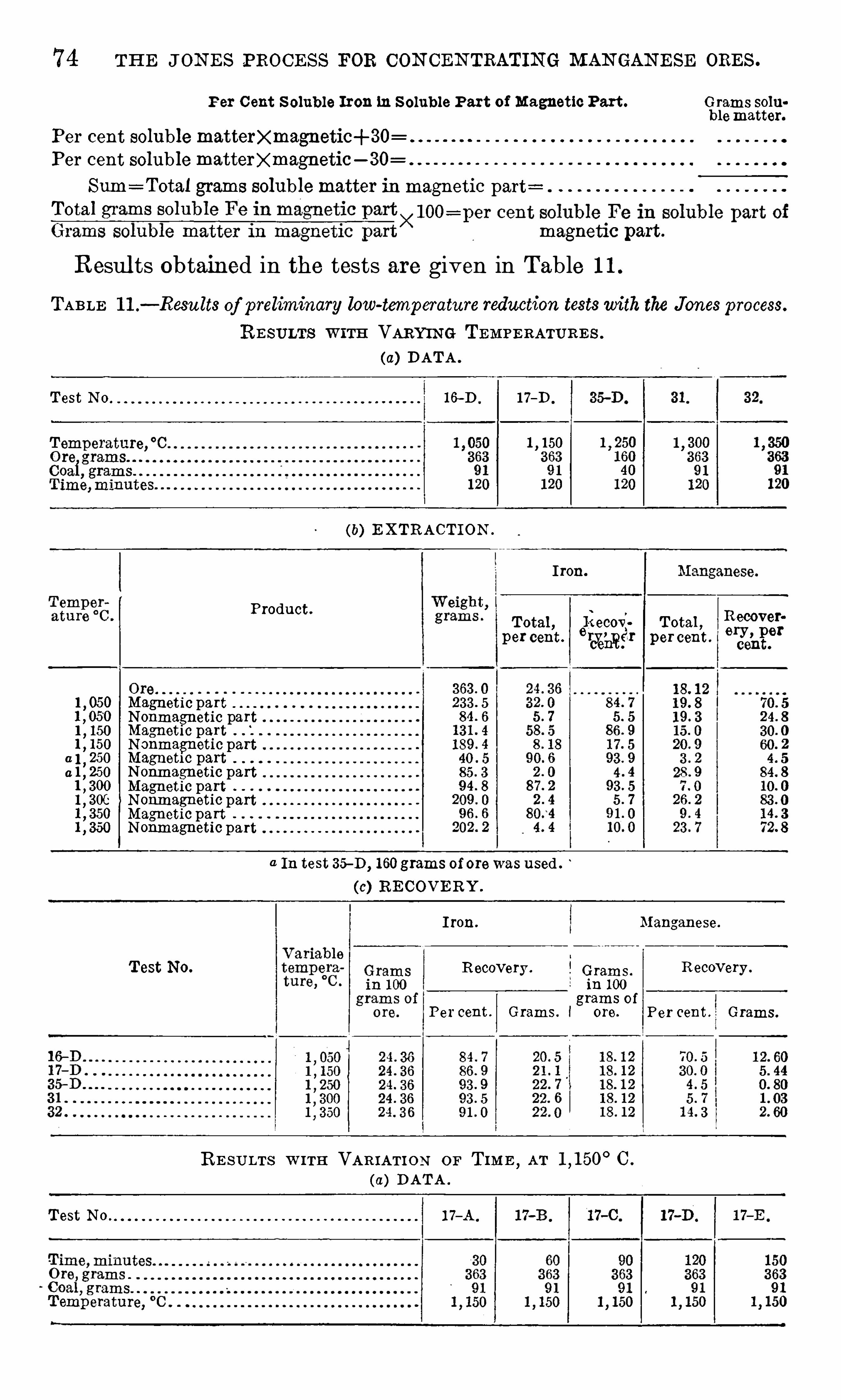
7 4 TH E J ON E S PROCE SS FOR CON CEN TRATING MAN GAN E SE ORE S .
Per C ent S oluble Iron in S oluble Part of Magnetic Part . Grams solublematter.
Per cent soluble mattee agnetic+3 0
Per cent solublemattee agnetic— SO
Sum=Total grams solub lematter in magnetic part=
Total grams solumagnetic part .
Resul ts Obtained in the tests are given in Table 1 1 .
TABLE 1 1 .— Resu lts of preliminary low-temperature reduction testswith the Jones process.
RE SULTS W ITH VARYIN G TEMPE RATURE S .
(a) DATA .
Test N o 1 6-D . 1 7—D .
1 1 50
(b) E XTRACTION .
I ron.
Product.
Total ,6
1
30
3 ; Total , sgfo
ggl
;percent .
ceht. percent .
echt.
1, 050 Magnetic part
N onmagnetic part1,1 50 Magnetic part
N onmagnetic part0 1
,250 Magnetic part
a 1,250 N onmagnetic part
Magnetic part1, 3 06 N onmagnetic part
Magnetic partN onmagnetic part
a In test —D, 1 60 grams of orewas used .
(c) RE COVE RY .
I ron. Manganese.
Test No. Recovery . Grams.R ecovery .
in 1 00
grams of
Per cent . Grams. l ore. Per cent . Grams.
RE SULTS W ITH VAR IATI O N OF TIM E,AT C .
(a) DATA .
Test N O 1 7—A .

Low -TEM PERATURE REDUCTION . 7 5
R E S ULTS W ITH VARIAT I O N ON TIM E , AT C .
— Continued .
(b) E XTRACTION .
I ron. Manganese.
Minu tes. Product.
Total , Recovery, Total , Recovery,percent. per cent . per cent . per cent.
o o o o o o o o o o
Magnetic partN onmagnetic partMagnetic partN onmagnetic partMagnetic partN onmagnetic part
1 20 Magnetic part1 20 N onmagnetic part1 50 Magnetic part1 50 N onmagnetic part
8
8
8
8
8
8
(c) R E COVERY .
Manganese.
Test N O. Recovery , Recovery.
Percent. Grams. Per cent . Grams .
(d) SOLUBL E IRON IN MAGN E TIC PART .
Percent Grams Total Percent
Minutes PrOductg
'Iigifi
l
s
’
. 535
1531912 solil
f
blegs
r
giiiiriigf$ 3131;
iron Iron. Iron. Iron.
3 0 Magnetic part
60 Magnetic part
90 Magnetic part
Magnetic part
C O .
(e) S OLUBL E IR ON IN S OLUBLE PART OFMAGN E TIC PAR T .
Percent GramsW eight Total age of ofMinutes. Product.
grams.
’
grams. soluble solublematter. matter.
30 Magnetic part
60 Magnetic part 1 44 . 4
90 Magnetic part 1 1 7 4
Magnetic part

7 6 TH E J ON E S PROCE SS FOR CON CE N TRAT IN G M AN GAN E SE ORES .
R E SU LTS W ITH VAR I ATION or T IM E ,AT C .
(a) DATA .
(b) E XTRACT ION .
Iron.
Minutes. Product.Total Recovery Total R ecoveryper cent . per cent . per cent . per cent.
1 60. 0 24 3 6 1 8. 1 2
Magnetic partN onmagnetic part
(c) R E COVERY .
Manganese.
Variable, minutes . Grams.Recovery . Recovery .
per 1 00
gramsof ore. Percent. Grams.
o o o o o o o o o o o o o o o o o o o o
(d) SOLUBL E IR ON IN MA GN E TIC PART.
W eight, Total ,Minutes. Products.
grams. grams.
30 . Magnetic part
60 Magnetic part
90 Magnetic part
Magnetic part
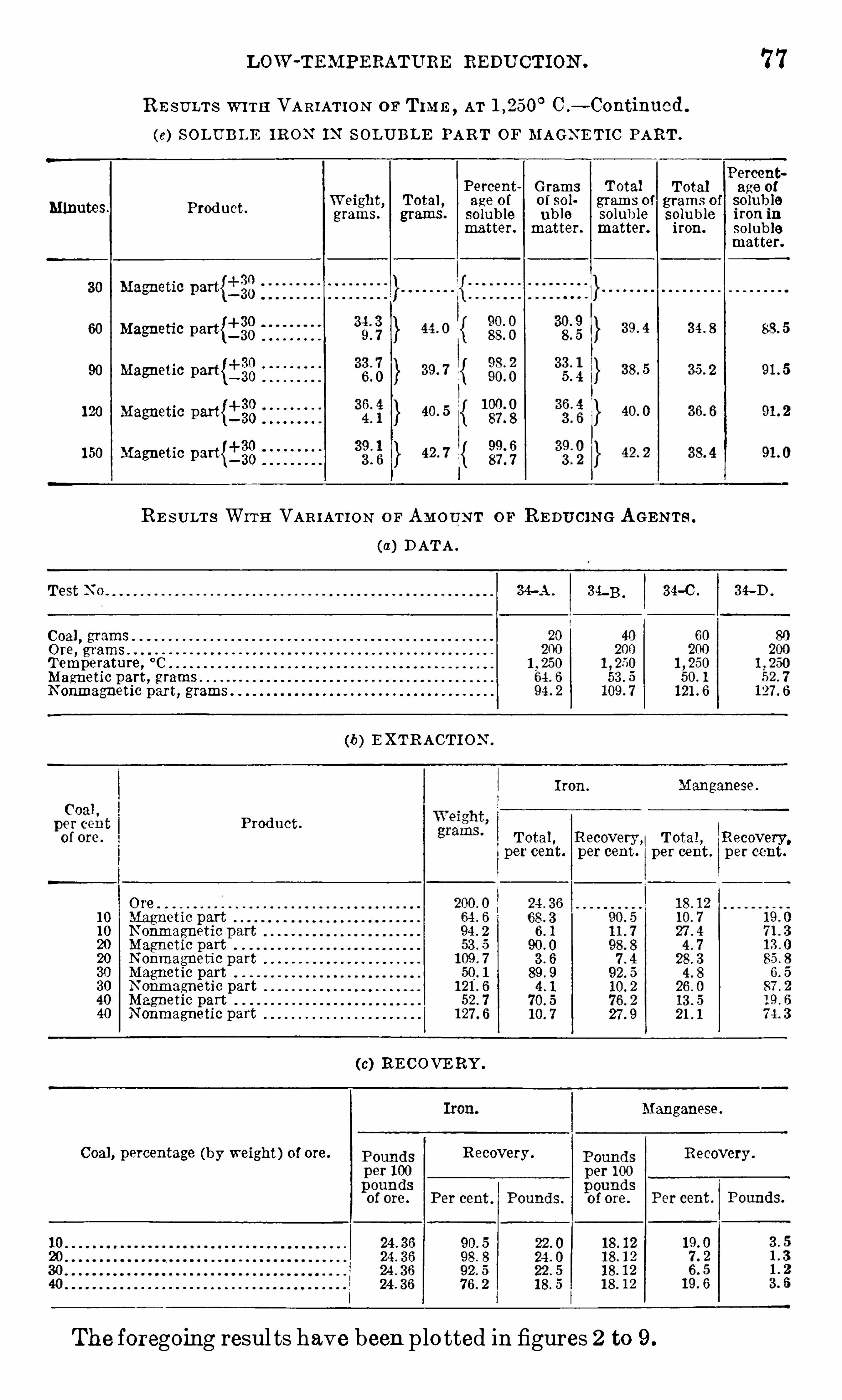
LOW -TEM PERATURE REDU CTION . 7 7
RE SULTS W ITH VAR IATI O N or TIM E ,AT C .
— Continucd.
(e) SOLUBLE I RON IN S OLUBLE PART OF MAGN E TIC PART .
Percent
W ht T t lPercegt Gj'an
is Total
fTotal
ra
ge
1p]!
9 1 g o s , age o 0 so grams o grams o so u 0Minutes. Product.
grams. grams. soluble ub le solub le soluble iron inmatter. matter. matter. iron. solub le
matter.
4Magnetic part{_
Magnetic part{i§8 zz
1 20 Magnetic part{i§81 50 Magnetic part{j §g
RE S ULT S WITH VAR IATION O F AM OUN T OF RE DUCIN G AGE N TS .
DATA .
34-A . 3 4-3 . 3 4-0 . 34-D .
Coal, grams
Ore, gramsTemperature , °C
Magnetic part , gramsN onmagnetic part, grams
(b) E XTRACT I ON .
Iron. Manganese .
Product .
Total , Recovery ,Total , Recovery,
per cent. per cent . per cent. per cent.
Ore1 0 Magnetic part1 0 N onmagnetic20 Magnetic part20 N onmagnetic part30 Magnetic part30 N onmagnetic part40 Magnetic part40 N onmagnetic part
(c) RE COVE RY .
Manganese .
Coal , percentage (by weight) of ore. Recovery .
The foregoing resul ts have been plo tted in figures 2 to 9 .
Recovery .

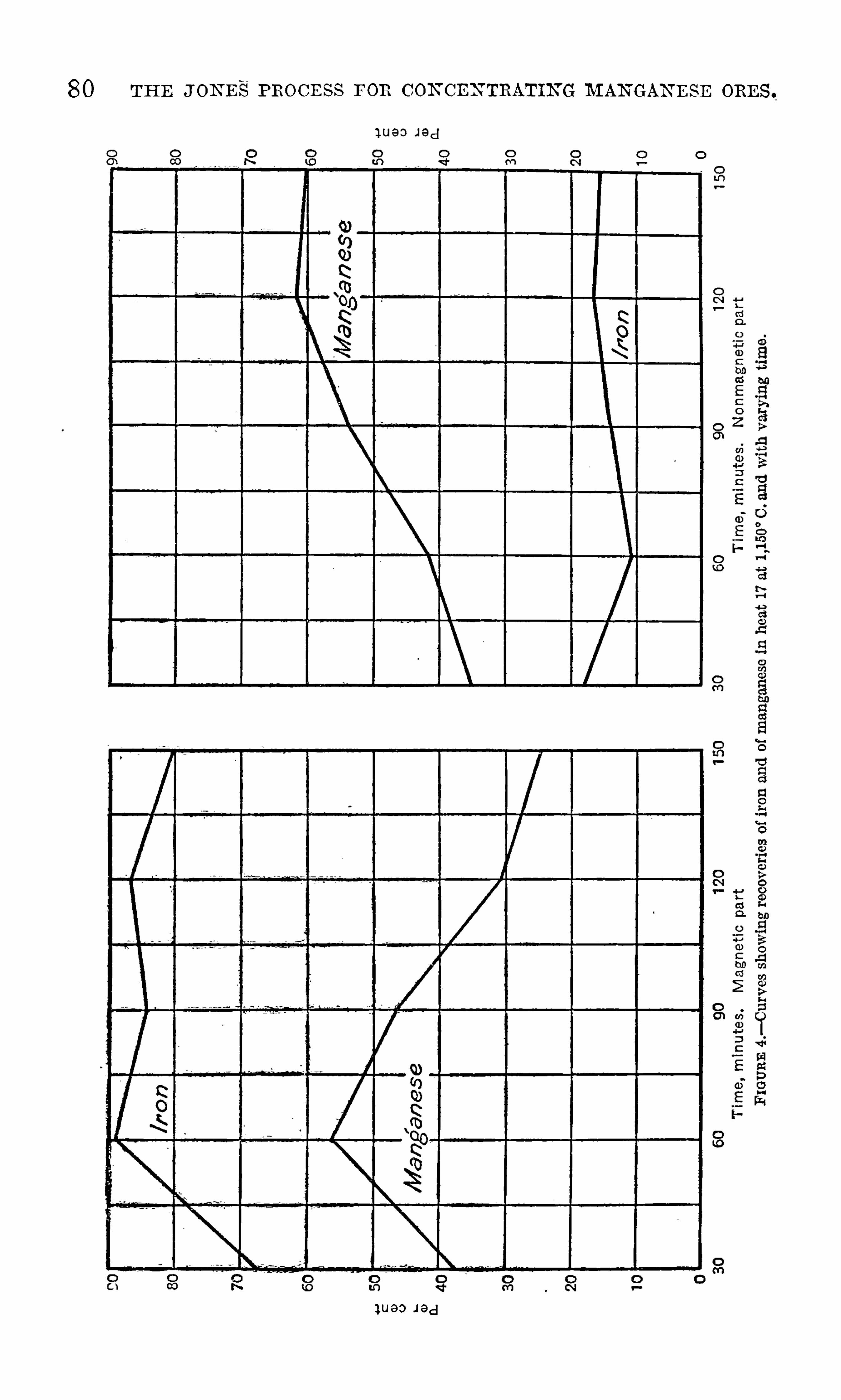
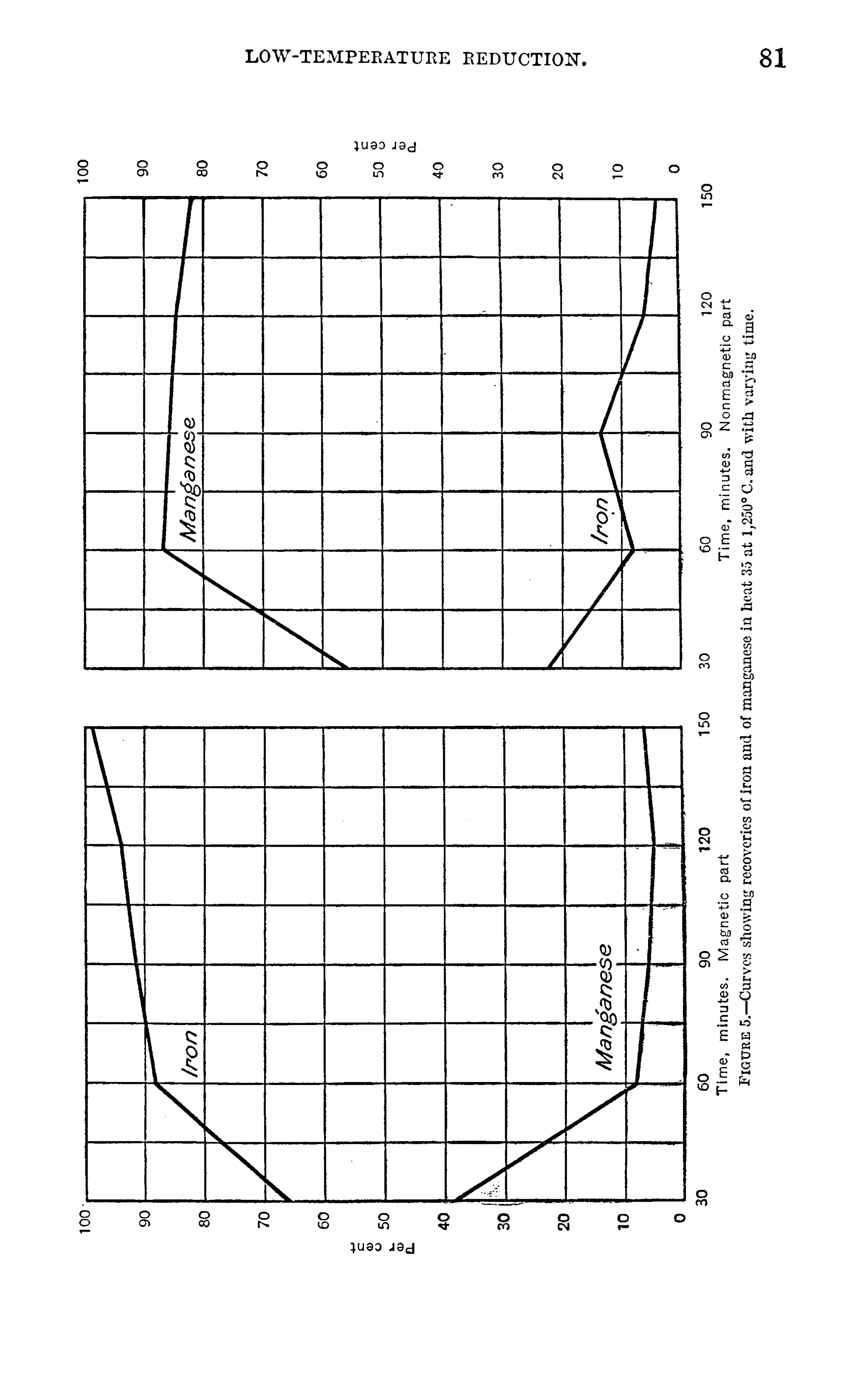
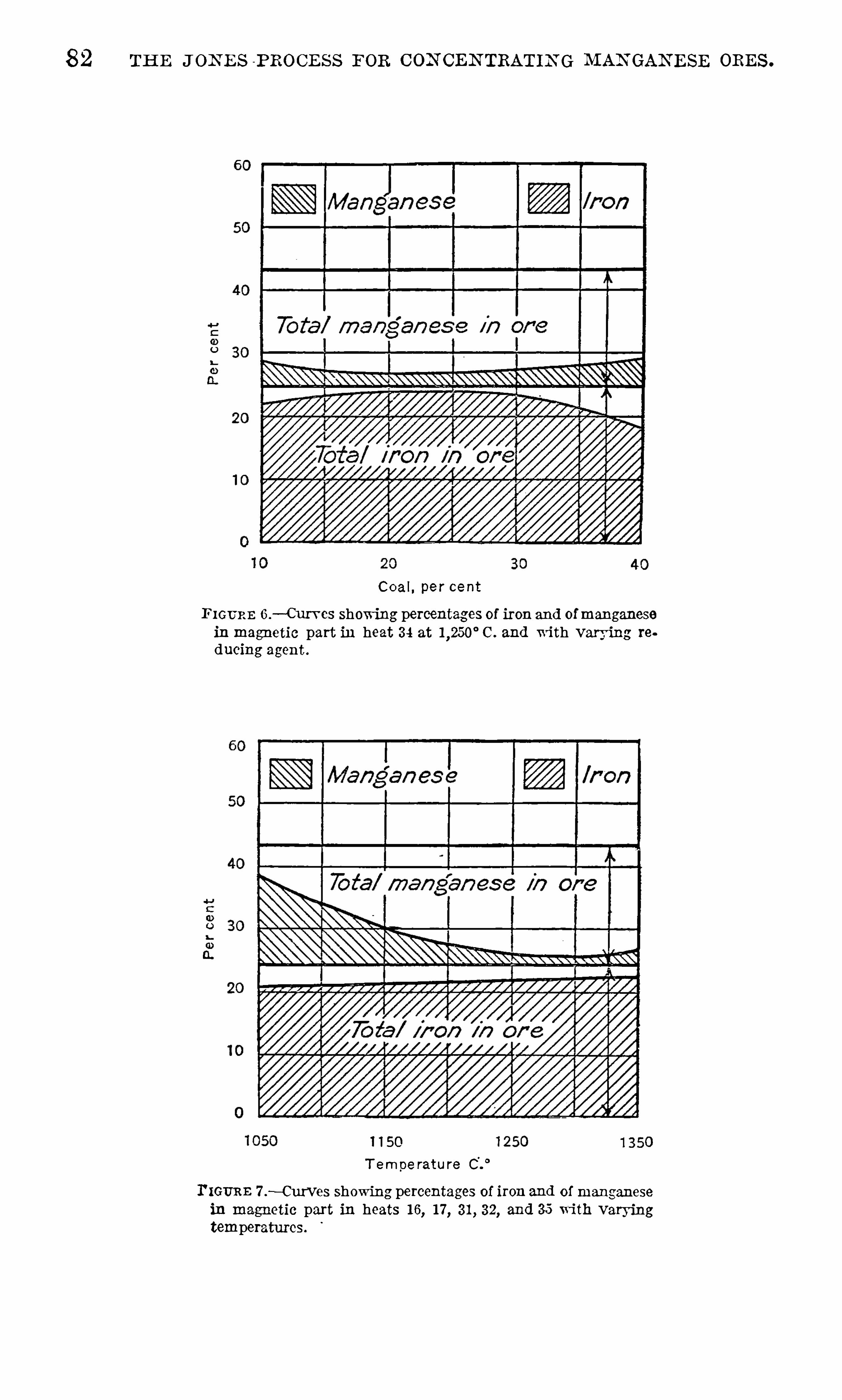
82 TH E J ON E S P ROCE S S FOR CON CEN TRATIN G M AN GAN E SE ORE S .
C oal, per cent
FIGURE 6 .— Curvcs showing percentag es of iron and ofmanganese
in magnetic part in heat 3 4 at l ,250° C . and with varying re
dueing agent .
1 1 50
T empe rature
I'IGURE 7 .
—Curves showing percentages of iron and of manganese
in magnetic part in heats 1 6, 1 7 , 3 1 , 3 2, and 35 wi th varyingtemperatures.
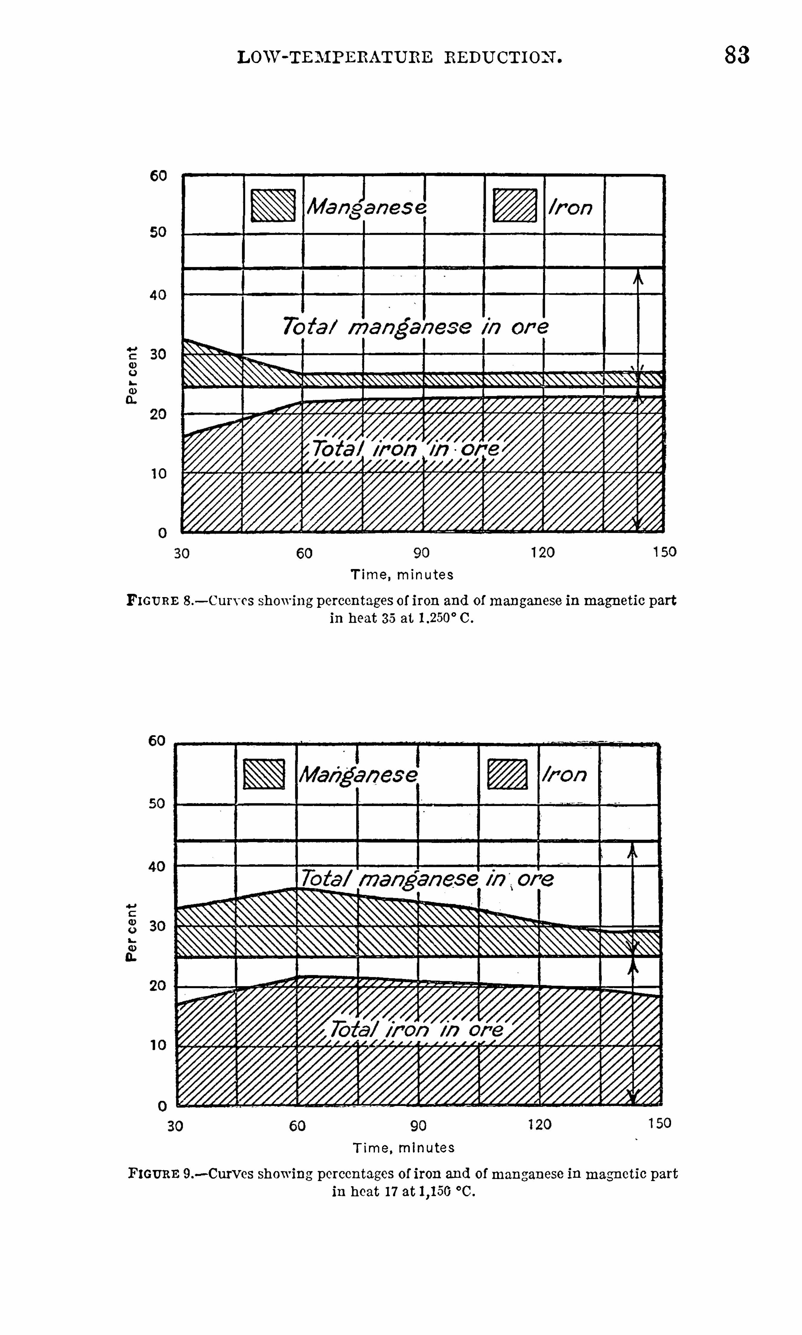
LOlV-TE BIPERATURE REDUCT ION .
T ime , minutes
FIGURE 8 .— Curvcs showing percentages of iron and of manganese inmagnetic part
in heat 3 5 at C .
T ime , minutes
FIGURE 9 .—Curves showing percentages of iron and of manganese inmagnetic part
in heat 1 7 at °C .
83

84 TH E J ON E S PROCE SS FOR C ON CE N TRATIN G M AN GAN E SE ORE S .
C ON CLU S ION S .
Figures 2 to 9 indicate that the following are the requisite con
ditions for the low-temperature reduction of the iron :
(a) Time, preferably 3 0 to 40 minutes, al though satisfactoryresul ts were obtained up to 2 hours .(6) Temperature, C .
(0) R educing agent, 20 per cent coal .
Analyses of ores used infinal'
tests with low-temperature reduction .
P er cent. P er cent. P er cent. P er cent.
24. 3 6 1 8 . 1 2 26 . 50 0. 09728 . 55 24. 55 1 7 . 60 09 1
3 5. 1 5 1 3 . 68 9. 46 1 7 940 . 30 1 07
3 5. 40 1 0. 25 21 . 3 6 059
Two kil ograms of each ore , crushed to 1 0 mesh and mixed with 20per cent reducing agent , was charged into a large graphite crucibleheated to redness .The tempera ture was raised to C . and kept as closely as pos
sible between and C . until reaction was complete .
The time was varied to some extent according to the appearanceof the charge, with a maximum time of two and one-half hours
,
except in heat 43 .
The reducing agent used was E lkhorn coal like that used in the
preliminary tests , except that in heat 4 1 coke was used .
The furnace used was a Case oil-fired melting furnace N O . 40.
The method of handling the furnace products was practically the
same as in the preliminary tests . However, the entire contents ofthe crucible were poured in a liquid condition
, and most of the metalproduced was recovered in the form of a large button .
TABULATE D RE SU LT S
Detail ed results of the tests are presented in Table 1 2 following
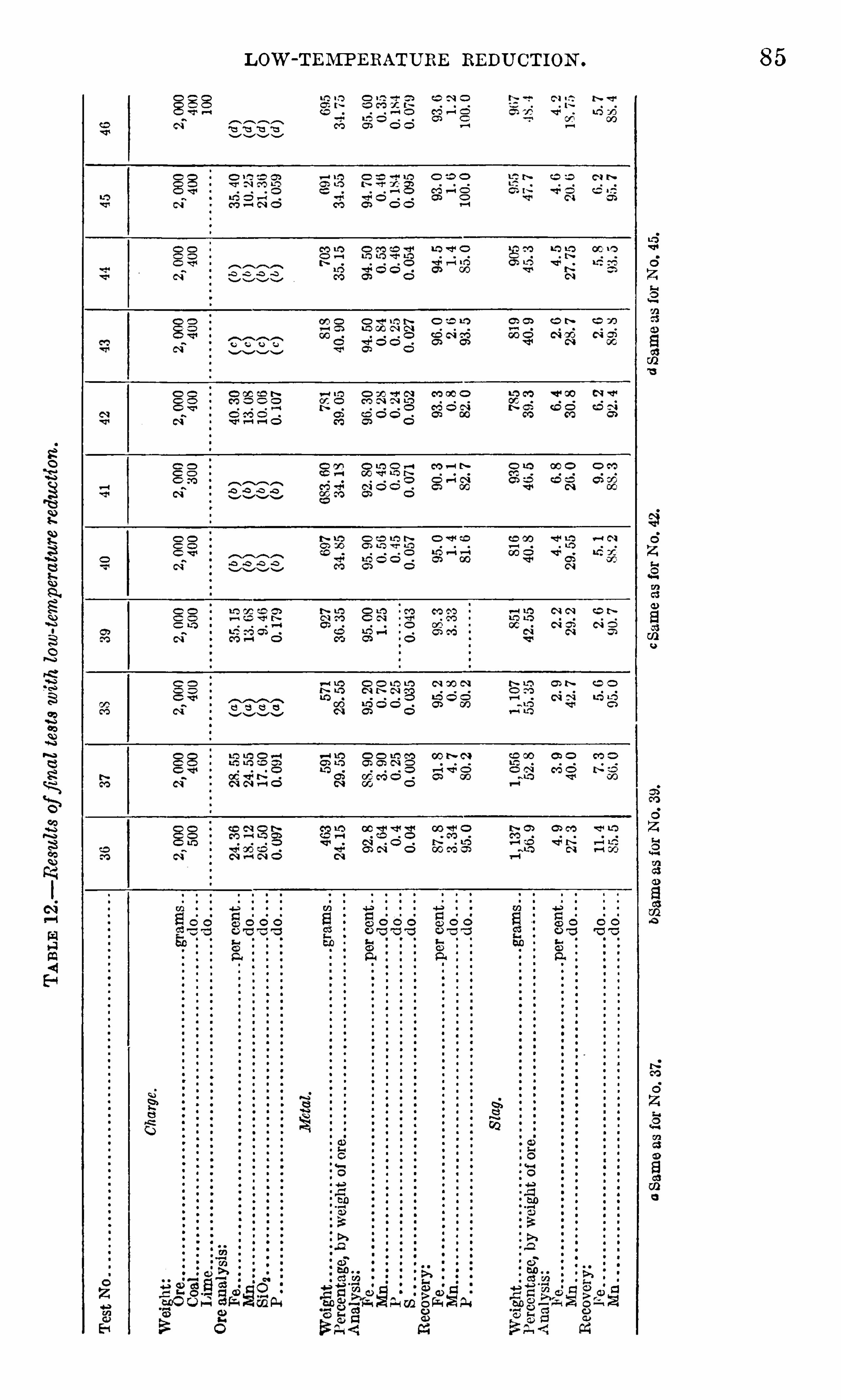
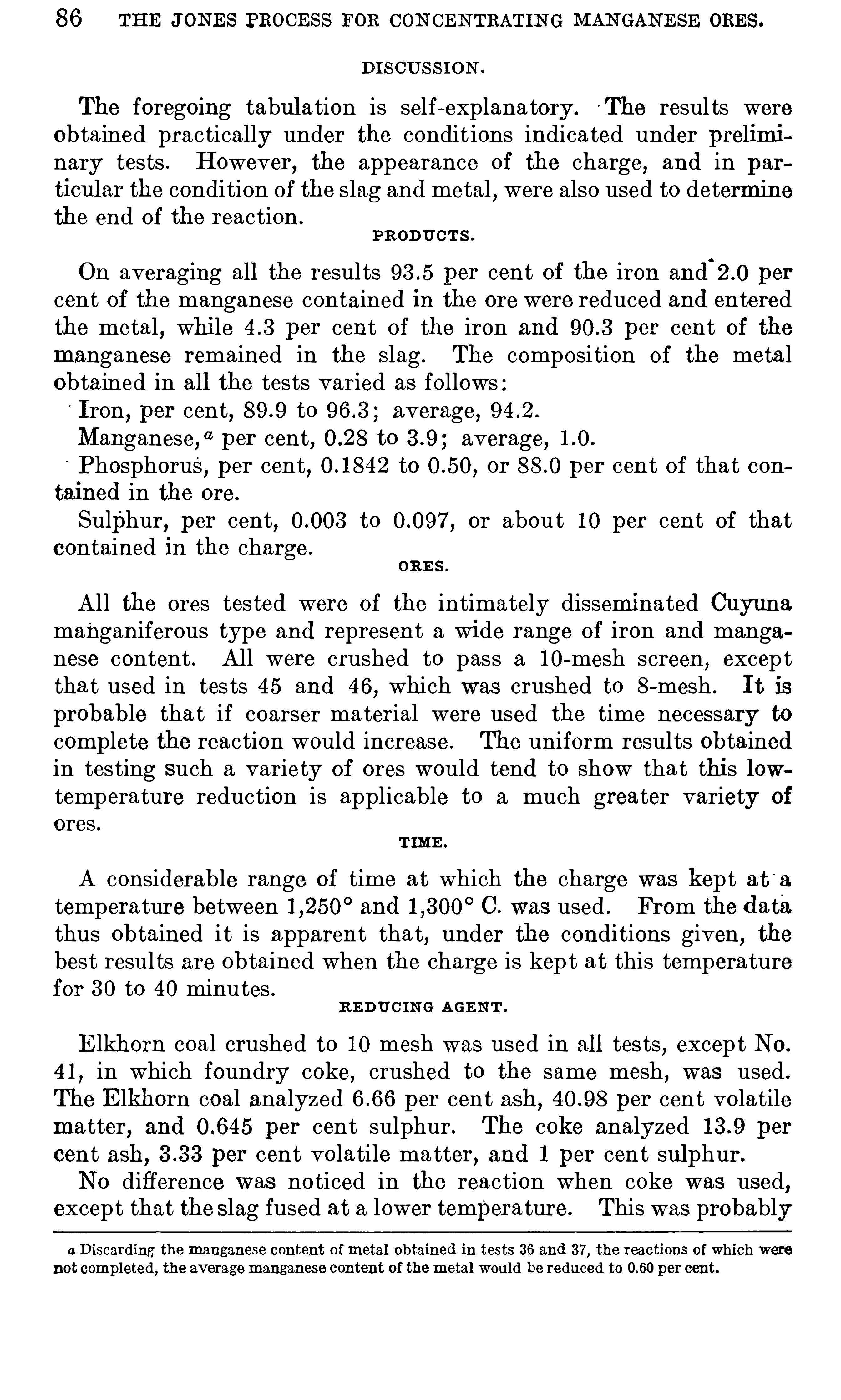
86 THE JON ES PROCE SS FOR CON CEN TRATIN G MAN GAN E SE ORES .
DI SCUS S I ON .
The foregoing tabul ation is self-explana tory. T he resul ts wereObtained practically under the condit ions indicated under preliminary tests . However, the appearance of the charge
,and in par
ticul ar the condi tion of the slag and metal,were also used to determine
the end of the reaction .
PR ODUCT S .
On averaging all the results per cent of the iron and‘
2 .0 per
cent of the manganese contained in the ore were reduced and enteredthe metal , while per cent of the iron and per cent of themanganese remained in the S lag . The composi tion of the metalObtained in all the tests varied as follows :
'
Iron, per cent, to average,Manganese, “ per cent, to average,Phosphorus, per cent, to or per cent of that con
tained in the ore.
Sulphur, per cent, to or about 1 0 per cent of thatcontained in the charge.
oRE s .
All the ores tested were of the intimately disseminated Cuyunamanganiferous type and represent a wide range of iron and manganese content . All were crushed to pass a 1 0-mesh screen, excepttha t used in tes ts 45 and 46
,which was crushed to 8 -mesh . I t is
probable tha t if coarser ma terial were used the time necessary to
complete the reaction would increase. The uniform results obtainedin testing such a variety of ores would tend to Show that this lowtemperature reduction is applicable to a much greater variety of
ores .T IME .
A considerable range Of time at which the charge was kept at '
a
temperature between and C . was used . From the datathus obtained i t is apparent that, under the conditions given, thebest results are obtained when the charge is kep t at this temperaturefor 3 0 to 40 minutes .
R E DU C IN G AGE N T .
E lkhorn coal crushed to 1 0 mesh was used in all tests,excep t No.
4 1 , in which foundry coke, crushed to the same mesh , was used .
The E lkhorn coal analyzed per cent ash, per cent volatilematter, and per cent sulphur . The coke analyzed per
cent ash, per cent volatile matter, and 1 per cent sul phur.
No difference was noticed in the reaction when coke was used,except that the S lag fused at a lower temperature. This was probablya Discarding the manganese content of metal obtained in tests 3 6 and 3 7 , the reactions of which were
not completed, the averagemanganese content of themetal would be reduced to per cent.

8 8 THE JON E S PROCES S FOR CON CE N TRATIN G M AN GAN E SE ORES .
CRU C IBLE S .
A number of standard crucibles were tried , as follows : Ordinaryassay crucible, graphite crucible, and alundum crucible. None of
these coul d withstand the conditions . The crucibles finally usedwere cut on a lathe from 4-inch carbon electrodes . W i th care theywoul d hold 200 grams of crushed slag mixed with the requisi te cokeand lime. These crucibles suffered deterioration onl y from oxidation at the upper edge and coul d be used until they became too
shallow to hold the charge.
TE MP E RATUR E .
The temperature at which a satisfactory reaction took place was
found to be about C . This satisfactory reaction may be
designated as uniform and rapid . Above C . the reactionwas so rapid tha t i t caused violent boiling , and below this temperature the reaction was so slow and inactive that no appreciable metalwas reduced . Hence , the condition of the reaction was used as a
cri terion for tempera ture regulation .
TABUL ATE D RE SULT S .
The detail ed resul ts of the high- temperature reduction tes ts are
presented in the tabul ation following :
TABLE 1 3 .
-Resu lts of high-temperature reduction tests .
Charge.
o o o o o o o o o o o o o o o o o o o o
A lloy produced.
W eight grams ”
Percentage of slag charged 33 1 5 3 3 3 5Analysis:
Fe . .
MnSi
Recovery , percent of content of slag chargedFe b b b b
7 7 . 2 7 5 . 4 7 4 . 8
S lag produced .
W eight . 1 08 . 7Percentage of slag charged
percent .
Q Q Q Q Q Q Q Q Q Q Q Q Q Q Q Q Q Q Q Q Q Q Q Q Q Q Q Q Q Q
a See test 54 for analysis.
b Recoveries are calcul ated on content of slag charged . Discrepancy shovm by getting more than 1 00percent recovery is due to fact that coke contains iron as part of the ash.
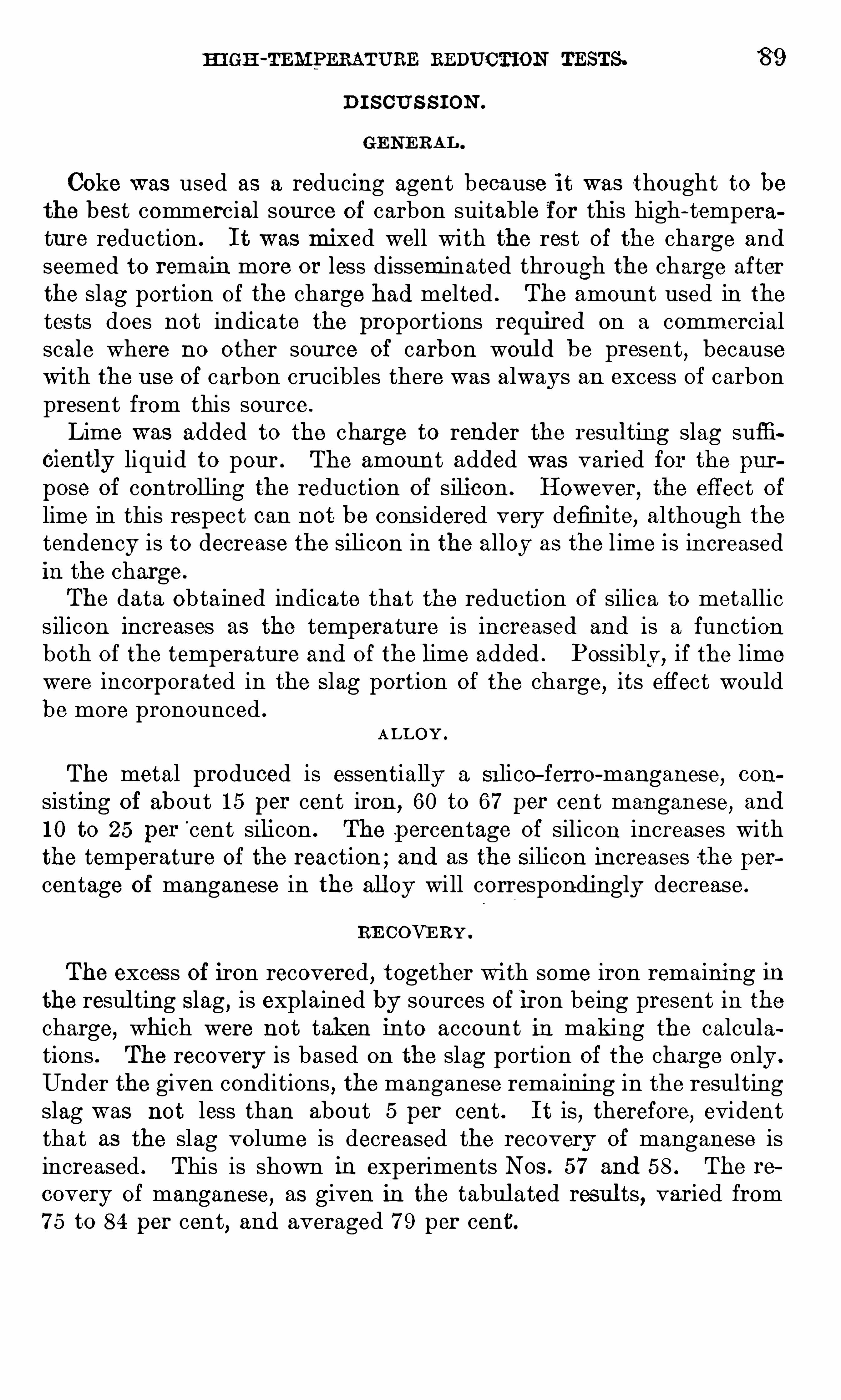
HI GH -TEMPERATURE REDUCTION TESTS. 8 9
D I S CU S S I ON
Coke was used as a reducing agent because it was thought to bethe best commercial source of carbon suitable for this high-temperature reduction . I t was mixed well with the rest of the charge and
seemed to remain more or less disseminated through the charge afterthe slag portion of the charge had melted . The amount used in thetests does not indicate the proportions required on a comm ercialscale where no other source of carbon woul d be present
,because
W ith the use of carbon crucibles there was always an excess of carbonpresent from this source .
Lime was added to the charge to render the resul ting slag sufficiently liquid to pour . The amoun t added was varied for the purpose Of controlling the reduction of silicon . However, the eff ect oflime in this respect can not be considered very definite, although thetendency is to decrease the silicon in the alloy as the l ime is increasedin the charge.
The data Obtained indicate that the reduction of silica to metallicsilicon increases as the temperature is increased and is a functionboth of the temperature and o f the lime added . Possibly ,
if the limewere incorporated in the S lag portion of the charge
,its effect would
be more pronounced .
ALL OY .
The metal produced is essentially a Si lico—ferro-manganese,con
sisting of about 1 5 per cent iron , 60 to 67 per cent manganese,and
1 0 to 25 per‘cent silicon . The p ercentage of silicon increases with
the temperature of the reaction ; and as the S ilicon increases the percentage of manganese in the alloy will correspondingly decrease.
RE COVE RY .
The excess of iron recovered , together with some iron remaining inthe resul ting S lag, is explained by sources of iron being present in thecharge, which were not taken into account in making the calculations . The recovery is based on the slag portion of the charge only .
Under the given conditions , the manganese remaining in the resul tingslag was not less than about 5 per cent . I t is
,therefore, evident
that as the slag volume is decreased the recovery of manganese isincreased . This is shown in experiments Nos . 5 7 and 58 . The re
covery of manganese,as given in the tabul ated res ul ts, varied from
7 5 to 84 per cent, and averaged 7 9 per cent.
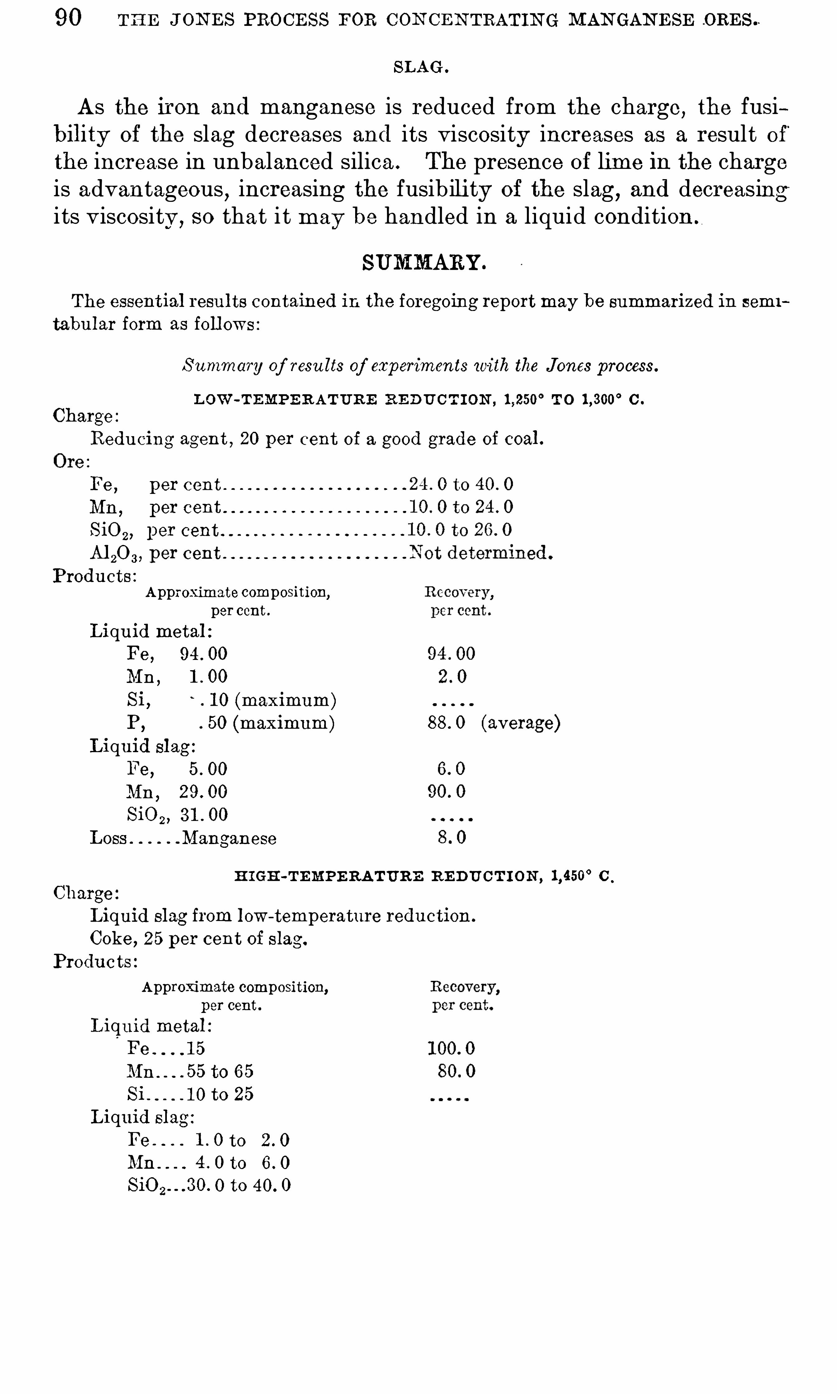
90 TH E J ON E S PROCE SS FOR CON CE N TRATIN G MAN GAN E SE ORE S .
SLAG O
As the iron and manganese is reduced from the charge,the fusi
bility of the slag decreases and its viscosity increases as a result O f ’
the increase in unbalanced silica . The presence of lime in the chargeis advantageous
,increasing the fusibility of the slag
,and decreasing
i ts viscosity , so that i t may be handled in a liquid condition
SUMMARY
The essential resu lts contained in the foregoing reportmay be summarized in semi
tabu lar form as foll ows :
S ummary of resu lts of experiments with the Jones process.
L OW -TEMPE R ATURE RE DU C T I ON , T O C .
Charge :
Redu cing agent , 20 per cent of a good grade of coal .
Fe , p er cent
Mn, per cent
SiOz, per cent
M 20 3 , per cent
Products :Approximate composition,
per cent .
Liqu id metal :
Fe , 94 . 00
Mn ,1 . 00
Si, 1 0 (maximum)P,
50 (maximum) 88 . 0 (average)Liquid slag
Fe, 5 . 00
Mn,29 . 00
SiOz, 3 1 . 00
Loss Manganese
H IGH-TEMPE RATURE R E DUCT I ON , C
Charge
Liquid slag from low-temperature redu ction.
Coke , 25 per cent of slag.
Products
Approximate composition,per cent.
Liquid metal :
Fe . 1 5
Mn . to 65
Si 1 0 to 25
Liquid slag :
Fe 1 . 0 to
Mn to
O to 40. 0

CHAPTER 7 .
—COST OF PRODUCING FERRO -GRADE MAN
GANE SE ORE S .
By C . M . WE LD and W . R . CRAN E .
IN TRODUCTORY STATEMENT.
In coll ecting and disseminating information on methods of min ingand preparing domestic manganese ores
,careful consideration was
given by the bureau to the important matter of costs . Unf ortu
mately few operators kept systematic cost sheets,hence the data
collected are incomplete and unsatisfactory ,particul arly for an
industry having so little uniformity . Domestic manganese deposits,
especially deposits of ferro—grade ores (3 5 + per cent metall ic man
ganese) , vary widely ,not only in the character of the ore
,but also
in the conditions of occurrence. Costs must therefore be expectedto vary correspondingly ,
even when cost—keeping methods are uni
form . But when the methods are as variable as the costs,compu
tation becomes still more difficul t .I t has
,nevertheless
,been possible by careful ly compiling the ma
terial at hand to arrive at certain estimated average figures whichare believed to be approximately correct , and to draw therefromcertain general conclusions . I t must be clearly un derstood , however
,that these average figures may be entirely misleading if applied
to some one particul ar deposit . The conditions are so variable thati t is necessary to consider each deposit strictly on its individual meritswhen considering its comm ercial possibil ities . The average figures
,
however,have distinct value as guides to the probable competition
which will have to be faced .
In fact these average figures have been compiled with this latterpoint especially in view . For this reason the more imm ediate foreign competitors , Brazil and Cuba, are cons idered as well as the
domestic sources .The subj ect may be approached in two ways— by determining so
far as possible the actual cost,and by determining what may be called
the“ proper ” cost . I t is thoroughly appreciated that at many prop
erties,owing to a mul titude of reasons
,costs have been unduly and
unnecessarily high . However,as regards the costs of producing man
ganese ores during the war,i t woul d serve no useful purpose to esti
mate what the cost ought to have been . W ar costs have become a
92
cos'rs or DOM E STIC M AN GAN ESE ORES . 9 3
matter of history ,but the actual figures as bearing on probable
future cos ts are of vital importance . W hen i t comes to estimatingthe future
,the opposite angle of approach may be taken . Domestic
ores will soon once more have to face active and unrestricted foreigncompetition
,and
“ proper ” costs will have to be attained in orderto keep the indus try alive. Furthermore
,if the question of proteo
tion be raised,only “ proper ” costs shoul d be considered . I t is
appropriate,therefore
,to discuss future possibil i ties from the second
point of view,namely ,
as regards what the costs should be.
Another vital question,in every discussion of this sort
,is what
constitutes cost . Strange as i t may seem ,the important factors of
amortization of plant and depletion of ore reserves are more oftenoverlooked than not. This has no doubt been especially true of a
business like that of the manganese industry during the war,chiefly
characterized by the hurried and ofttimes ill-considered undertak
ings of many small operators with little financial strength . Nevertheless, owing to the uncertain life of the business
,the writing off
of the investment shoul d have been the prime consideration .
In most instances the cost data collected evidently do not includeallowances for amortization and depletion . I t is now obviouslypossible to say what these items shou ld have amounted to ; therefore
,where they do seem to have been included
,they will be omitted
from the following discussion , for uniformity . This fact,however
,
shoul d be kept in mind , if any comparison of the average estimatedwar costs with the prices then prevailing is attempted . The apparent profit which such a comparison shows probably failed , in a largenumber of cases , to offset the investment before the business col
lapsed upon the ’ signing of the armistice. In fact,were not this the
case,there woul d be little ground to-day for any claims under the
W arMinerals Relief act.The same cons iderations must be kept in mind as regards the
estimated average future costs . These are not intended to includeappropriate charges for writing off investment .
COSTS OF DOMESTI C MAN GANE SE ORES .
The domestic manganese ores of ferro grade fall into two distinctclasses
,which vary widely from one another in their cost of produc
tion . These are (1 ) the carbonate ores,and (2 ) the oxide ores . A
third class,namely, the sili cate (rhodonite) ores, shoul d perhaps be
mentioned,but such ores in the natural state are too siliceous , and
concentration too costly, to make their use feasible even with a
war-time market . Consequently the small amounts produced wereincidental to the production of carbonate and oxide ores , and theyneed not be considered separa tely .
94 COST or PRODUC IN G FERRO-GRADE M AN GAN ESE ORE S .
CAR B ON ATE ORE S .
Carbonate ores were mined in quantity in only one locality ,namely ,
“
Butte,Mont .
,but the output for 1 9 1 8 was more than 20 per cent of
the total output of manganese ores mined in the United States . The
great bul k of the ore required no concentrating and little if any handsorting . Mining was of the underground type, bu t the deposits werepersistent and the mining operations were efficient . Furthermorethe haul to the railroad was short
,and accomplished by motor trucks
over well -paved roads . I t 1 s understood that the cost on board railroad cars was not more than $5 per long ton— probably less . As theproduct contained 3 6 to 3 7 per cent metallic manganese
,the unit
cost was about 1 4 cents .
A small amount of siliceous carbonate ore was produced in the
Butte district and concentrated at a neighboring customs mill,where
the milling cost is said to have been per ton of product .
O X I DE OR E S .
The oxide ores occur mixed with clay ,chert
,and other gangue
materials and invariably require careful hand cleaning or mechanicalwashing or concentrating . The deposits are generally erratic . Pro
duction costs have therefore necessarily been much higher than withthe carbonate ores . In a few places carbonate ores were encoun
tered as the weathered oxide ores were followed downward,but these
carbonate deposits were too small and generally too impure,to
lessen the otherwise high costs . Occasionally sil icate (rhodonite) oreswere encountered with depth
,when mining as a rul e had to be
abandoned .
The oxide ores are widely scattered over the United States . Theyrepresented nearly 80 per cent of the 1 9 1 8 production . In estim atingthe average cost of producing them
,they will be treated as a group
,
al though individual costs as between States
,districts
, and even minesin the same district
,frequently varied within wide limi ts .
These variations were principally due (a ) to inherent differencesin the deposits as regards their size and richness
,and (b) to their
situation as affecting the cost of haul ing to the railroad . Costs may
best be discussed therefore under two'
main heads,namely (a ) cost
at the mine,and (6) cost of transportation to the railroad .
C O ST AT THE M IN E .
Ordinarily i t woul d be found convenient to subdivide the costat the mine into min ing cost and treatment or preparation cost . Alarge part of the manganese ore produced , however, was hand cleanedby picking or screening
,and the available cost data do not differen
tlate between mining and hand cleaning . Consequently, three kinds
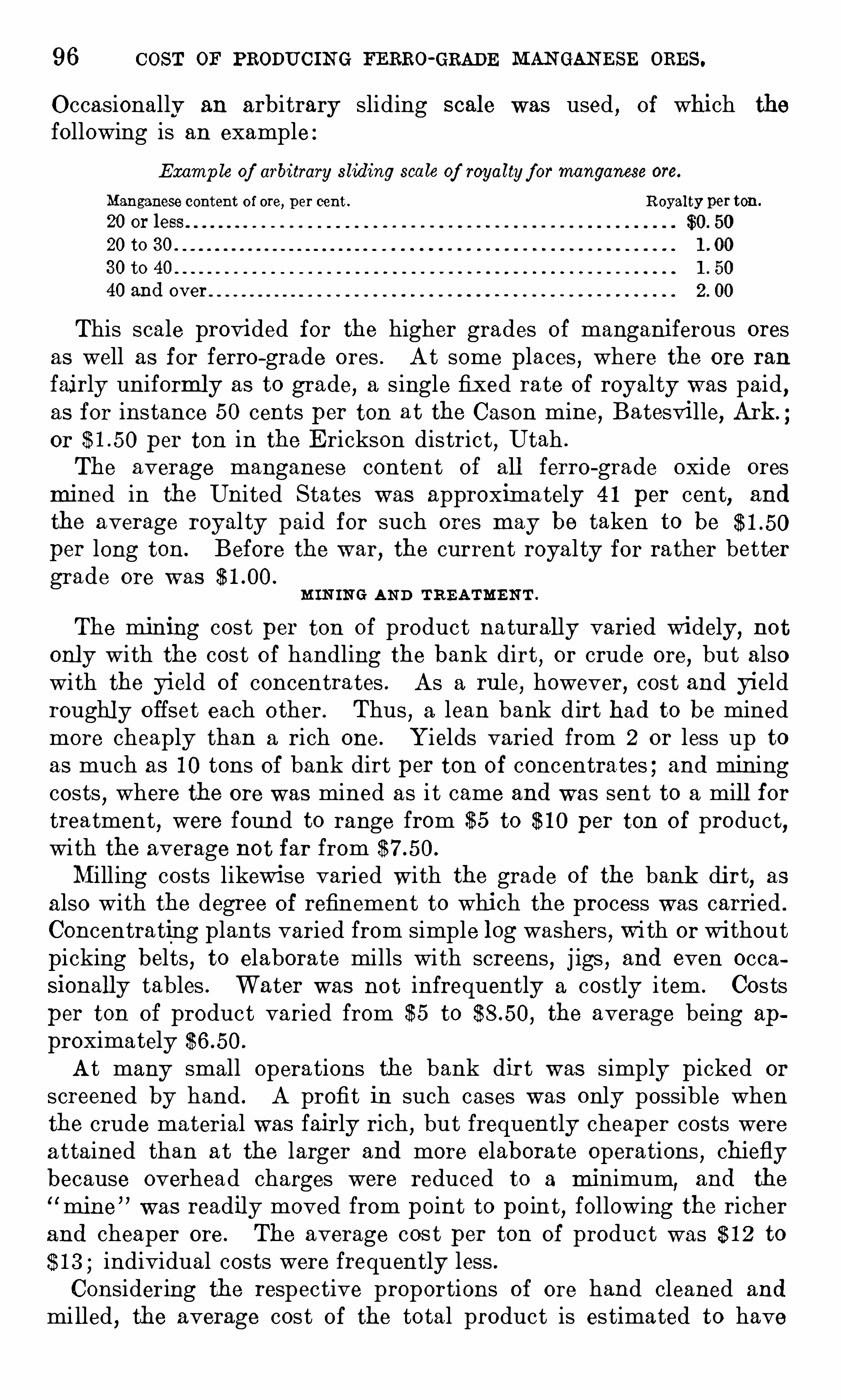
96 COST OF PRODUCIN G FERRO-GRADE MAN GAN ESE ORES .
Occasionally an arbitrary sliding scale was used , of which the
following is an example :Examp le of arbitrary sliding scale of royaltyf ormanganese ore.
Manganese content of ore, per cent . Royalty per ten.
20 or less.
20 to 3 0 .
3 0 to 40
40 and over
This scale provided for the higher grades of manganiferous oresas well as for ferro-grade ores . At some places , where the ore ran
fairly uniformly as to grade, a single fixed rate of royalty was paid ,as for instance 50 cents per ton at the Cason mine, Batesville, Ark.
or per ton in the E rickson district , Utah .
The average manganese content of all ferro-grade oxide oresmined in the United States was approximately 4 1 per cent, and
the average royal ty paid for such ores may be taken to beper long ton. Before the war, the current royal ty for rather bettergrade ore was
M IN IN G AN D TREATME N T .
The mining cost per ton of product naturally varied widely, notonly with the cost of handling the bank dirt , or crude ore, but alsowith the yield of concentrates . As a rule, however, cost and yieldroughly offset each other. Thus
,a lean bank dirt had to be mined
more cheaply than a rich one. Yields varied from 2 or less up toas much as 1 0 tons of bank dirt per ton of concentrates ; and miningcosts
,where the ore was mined as i t came and was sent to a mill for
treatment, were found to range from $5 to $ 1 0 per ton of product,
with the average not far fromMilling costs likewise varied wi th the grade of the bank dirt
,as
also with the degree of refinement to which the process was carried .
Concentrating plants varied from simple log washers , wi th or withoutpicking belts , to elaborate mills with screens , j igs , and even occasionally tables . Water was not infrequently a costly i tem . Costsper ton of product varied from $5 to the averag e being approximatelyAt many small operations the bank dirt was simply picked or
screened by hand . A profit in such cases was only possible whenthe crude material was fairly rich , but frequently cheaper costs werea ttained than at the larger and more elaborate operations , chieflybecause overhead charges were reduced to a minimum
,and the
mine ” was readily moved from point to point, following the richerand cheaper ore . The average cos t per ton of product was $ 1 2 to$ 1 3 ; individual costs were frequently less .Considering the respective proportions of ore hand cleaned and
mi lled , the average cost of the total product is estimated to have
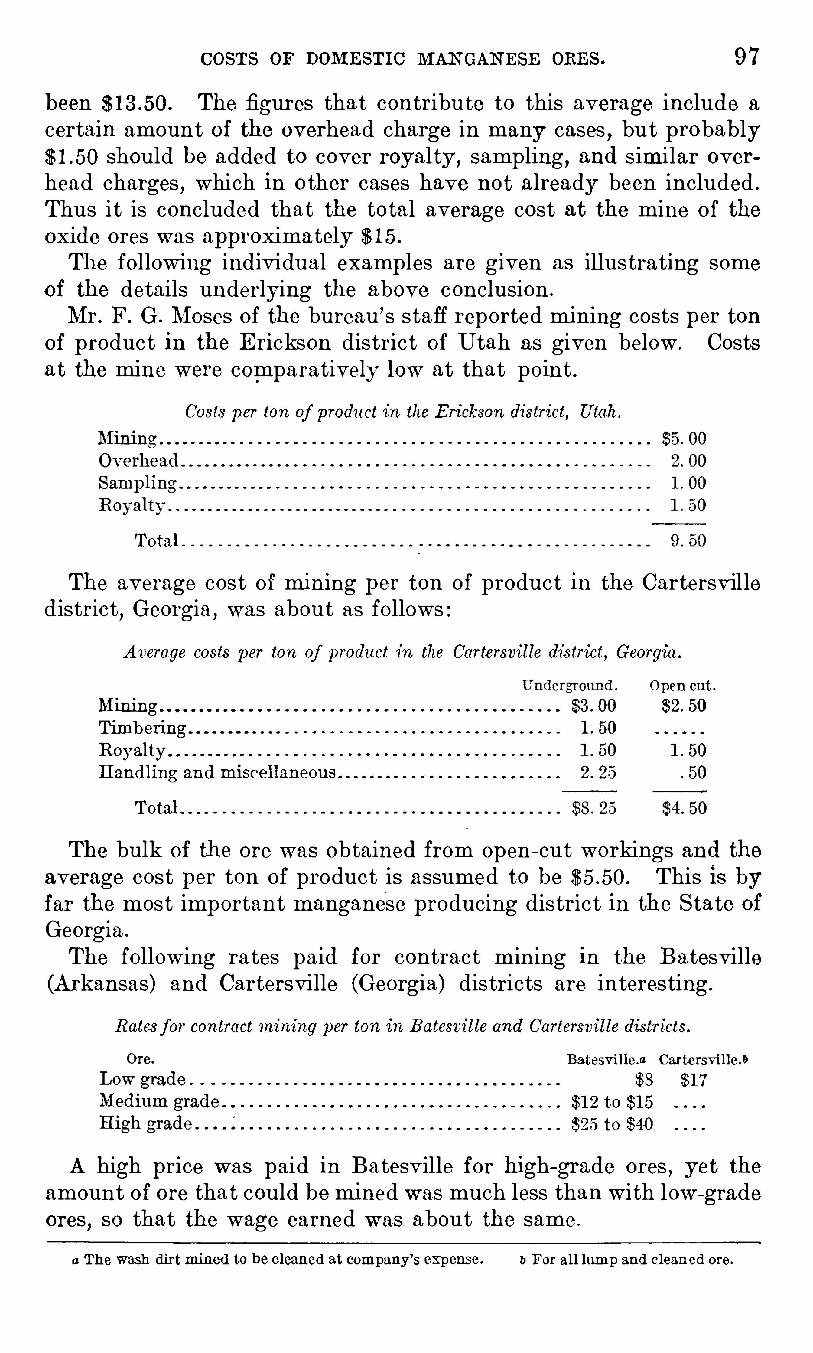
COSTS or DOM E STIC MAN GAN ESE ORE S . 9 7
been The fig ures that contribute to this average include a
certain amount of the overhead charge in many cases , but probablyshould be added to cover royal ty , sampling , and similar over
head charges , which in o ther cases have not already been included .
Thus i t is concluded that the total average cost at the mine of the
oxide ores was approximately $ 1 5 .
The following individual examples are given as ill ustrating someof the details underlying the above conclusion .
Mr. F. G . Moses of the bureau ’s staff reported mining costs per tonof product in the E rickson district of Utah as given below . Costsa t the mine were comparatively low at that point .
Costs p er ton of product in the E rickson district, Utah.
Total
The average cost of mining per ton of product in the Cartersvilledistrict
,Georgia ,
was about as follows :
Average costs per ton of product in the Cartersville district, Georgia .
Open cut .
MiningTimberingRoyal tyHandling and miscellaneous
Total
The bulk of the ore was obtained from open- cut workings and theaverage cost per ton of product is assumed to be This is byfar the most important manganese producing distric t in the S tate of
Georgia .
The following ra tes paid for contract mining in the Batesville(Arkansas) and Cartersville (Georgia) districts are interesting .
Rates f or contract mining per ton in Batesvil le and Cartersvil le districts.
Batesvil le .a Cartersville.b
$8 $1 7
$1 2 to $1 5
$25 to $40
A high price was paid in Batesville for high-grade ores , yet theamount of ore that could be mined was much less than with low -gradeores , so that the wage earned was about the same .
a The wash dirtmined to be cleaned at company’s expense. b For al l lump and cleaned ore.
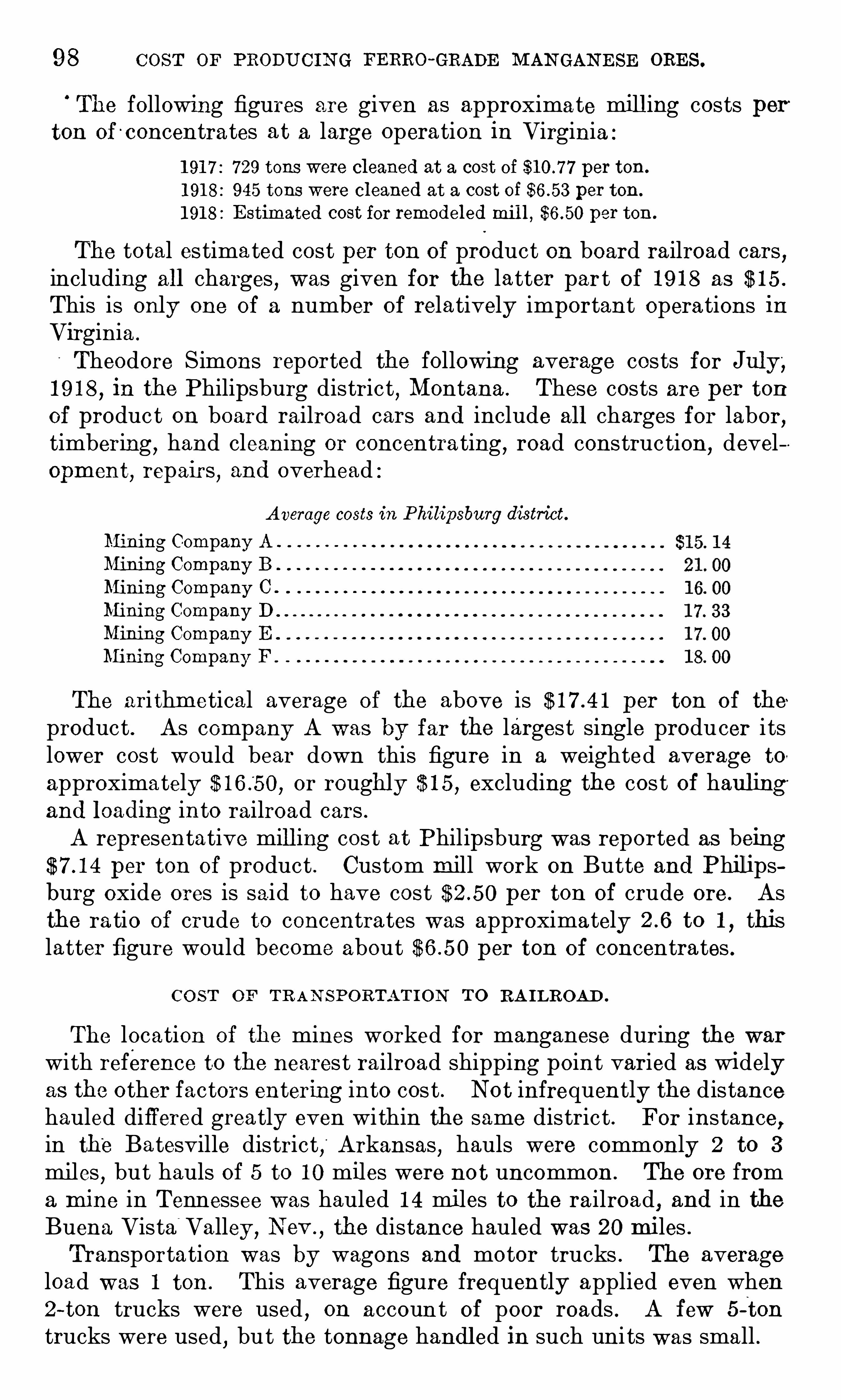
98 COST or PRODUCIN G FERRO~GRADE MAN GAN E SE ORE S .
The following figures are given as approximate mill ing costs perton of c oncentrates at a large operation in Virginia :
1 91 7 : 7 29 tons were cleaned at a cost of per ton.
1 91 8 : 945 tons were cleaned at a cost of per ton.
1 91 8 : E stimated cost for remodeled mil l , per ton .
The total estimated cost per ton of product on board railroad cars,
including all charges , was given for the latter part of 1 9 1 8 as $ 1 5 .
This is only one of a number of relatively important operations inVirginia .
Theodore Simons reported the following average costs for Jul y,1 9 1 8
,in the Philipsburg district
,Montana . These costs are per ton
of product on board railroad cars and include all charges for labor,timbering
,hand cleaning or concentrating , road construction,
development
,repairs
,and overhead :
Average costs in Philipsburg district.
Mining Company A
Mining Company B
Mining Company C .
Mining Company D
Mining Company E .
Mining Company F
The ari thmetical average of the above is per ton of the
product . As company A was by far the largest single producer i tslower cost would bear down this figure in a weighted average to
approximately or roughly $ 1 5 , excluding the cos t of haulingand leading into railroad cars .
A representative mill ing cost at Philipsburg was reported as beingper ton of product . Custom mill work on Butte and Philips
burg oxide ores is said to have cost per ton of crude ore. Asthe ra tio of crude to concentrates was approximately to 1
,this
latter figure would become about per ton of concentrates .
CO ST OF TR AN SPORTATI ON TO RA I LROAD .
The location of the mines worked for manganese during the warwith reference to the nearest railroad shipping point varied as widelyas the other factors entering into cos t . Not infrequently the distancehauled differed greatly even within the same district . For instance,in the Batesville district, Arkansas , hauls were commonly 2 to 3
miles , but hauls of 5 to 1 0 miles were not uncommon . The ore froma mine in Tennessee was hauled 1 4 miles to the railroad, and in theBuena Vista
“
Valley , N ev.
, the distance hauled was 20 miles .
Transportation was by wagons and motor trucks . The averageload was 1 ton . This average figure frequently applied even when2-ton trucks were used , on account of poor roads . A few 5 -ton
trucks were used, but the tonnage handl ed in such units was small .

1 00 COST OF PRODUC IN G FERRO-GRADE MAN GAN ESE ORES.
The Government schedul e of prices on which ores were sold duringthe war fixed the price per unit delivered at Chicago . The producercalcula ted the value O f his ore at Chicago and then deducted thefreight rate from point of production to Chicago to get the sellingprice of his ore f . o . b . railroad cars at shipping point . The buyerpaid the actual freight from shipping point to point of consummion.
Whether ores are sold in the future f . o . b . cars at the shippingpoint or delivered at the furnace makes no difference to the pro
ducer . I t is at the furnace that he must compete with other producers
,whether domestic or foreign
,and he must therefore com
pute the freight as part of his cost of production .
A small amount of ferro was made in western electric furnacesduring the war
,but the great bulk of i t was made east of the Missis
sippi,at Chicago and in Alabama
,Virginia
,Penn sylvania , and N ew
York . The production of Pennsylvania furnaces largely predominated, and this will unquestionably be even more true in the future
,as
production outside of Pennsylvania was principally stimulated bywar prices .
I t has already been pointed ou t that costs at the mine and costsof transportation to the rail road varied widely from point to point .These variations were not due to the section of the country in whichthe mines were situated
,however
,but rather to the nature of the
deposits themselves . Two distinct groups of deposits have beendifferentiated
,namely ,
the carbonates and the oxides . W ithin thesegroups it mattered little whether the min e was situated , for example,inVirginia or inCalifornia ; the cost might be high or low in either place .
Therefore i t w as found desirable to average all costs for each groupand so determine an estim ated average cost for producing ore of thatgroup
,irrespective of i ts locali ty .
I t seems necessary to consider the matter of railroad freights fromanother angle . I f all oxide ores
,for instance
,had been produced
in Virginia,their average cost delivered at Pennsylvania furnaces
would have been less than if a part had been shipped from points westof the Mississippi . Therefore
,the freight for each S tate or district
to the principal center shoul d be weighted in an average accordingto the amount of ore shipped from that S tate or district . I t has
been necessary to make certain assumptions,as exact freight rates are
in many cases not at hand,but the resulting figures without doubt
approximate the truth .
Proceeding by this method and assum ing that the principal consuming center is Pennsylvania , i t is found that the average freightrate for the oxide ores during the latter part of 1 9 1 8 was approxi
mately per long ten and for carbonate ores approximatelyincluding war tax.

DIS CUSSION or FUTURE Possrmmrnas. 1 0 1
SUMM AR Y OF CO ST OF D OME ST IC OR E S .
The foregoing estimates are summarized as follows
S ummarized data on estimated average cost of domestic ores .
Average .
E stimated tons produced in 1 91 8E stimated cost on railroad cars
Manganese , per centE stimated cost per unit, cents
Of course, the more favored districts coul d produce oxide oresmore cheaply than the average figures given . Virgin ia
,for instance
,
probably delivered ore to the furnaces at a cost of about 5 5 centsper un it . Cartersville (Ga ) and Batesvill e (Ark. ) ores Shoul dhave reached Birmingham ,
Chicago,or Pennsylvania furnaces for 55
to 60 cents per unit . N early 85 per cent of the oxide ores,however
,
came from the far western S tates and were subjec t to high railway
freights . The carbonate ores paid a. high railway freight but o thercosts were so low that these were probably the cheapest ores produced either on a ton or uni t basis .
D I S CU S S ION OF FUTUR E PO S S IB I L ITIE S .
The average costs computed in the forego ing pages are for war
times and more particul arly for the last six months before the signingof the armistice .
In estimating future costs we have little to guide us in the way
of prewar costs . Then only smal l amounts of domestic ores weremined
,frequently in a small way by farmers when not busy with
farm work . The production was in the southeastern States,W here
freight rates to consuming centers were no t excessive. Probablyonly smal l profits were made
,but these were satisfac tory under the
circumstances . Costs were $4 to $8 per ton on board railroad cars,but these costs are not fa ir guides to future possibil ities .
Aside from railway freights, the wage scal e enters more largely intothe cost of production than any other S ingle i tem ; and i t is probablethat reduction in cost will come chiefly from reduction in wages .Better practice Shoul d account for some reduction
,and cost of sup
plies may perhaps be properly expected to drop about in proportionto reduction in wages .The considera tion of future wages is a far-reaching problem , in
volving infinitely more important national industries than manganesemining
,and an infin ite number of correla ted problems . The subj ec t
is ventured upon only because i t seems desirable at this time to

1 02 COST or PRODU C I N G FERRO-GRADE M AN GAN E SE ORE S .
a ttemp t some reasonable forecast of the probable future cost of
manganese.
There is admittedly much difference of opinion in this respect,
but it may fairly be assumed that wages must inevitably drop . The
cost of labor is now approximately double the prewar figure in manyof the more important manganese-producing districts . An instancehas already been given where i t hasmore than doubled . I ts advancehas frequently outsped the increase in cost of living
,which is said
in general not to have increased more than approximately 50 per
cent in most manganese mining camps . The economic pressure of
competition must either depress these wages or else the industrymust be abandoned . If i t be assumed that wages will drop
,to fall
in line with the increased cost of living,and that the latter will not
decrease,then the drop in wages will be equivalent to 25 per cent of
the war wage.
In this connection i t may be further assumed that the cost of
supplies will decrease in like proportion ; whereas better practiceswill prevail and more efficient labor will be available than under warconditions . The net resul t is an estimated future reduction in costof manganese ore on board rai lroad cars of 25 per cent .I t does not seem likely tha t railway freights will be material ly
lowered in the near future,excep t perhaps to the extent of the re
moval of the war tax .
On the basis of the foregoing premises,the summarized costs for
war times given on page 1 0 1 become as followsRevised estimated average cost data on domesticmanganese ores.
Average.
E stimated proportionate tonnage, per cent .
E stimated cost on railroad carsE stimated railway freightTotal estimated cost, deliveredManganese, per centE stimated cost perunit, cents
Here again,in certain more favored distric ts, as regards freight
rates,the oxide ores can undoubtedly be delivered to the furnaces
for less than 60 cents per unit . For the Southern S tates , generally,rates of 50 cents per uni t or less should be a ttained , whereas forWestern ores the cost woul d probably exceed 60 cents . The Buttecarbonate ores are the one exception in the far west, owing to ex
cep tionally cheap mining and hauling costs .
COSTS OF FORE I GN ORE S .
-The principal source of foreign ore during the war was Brazil .The next most important Single source was Cuba . Smal ler amoun tscame from other points in the West Indies, Central and SouthAmerica
,and the Orient, chiefly India .
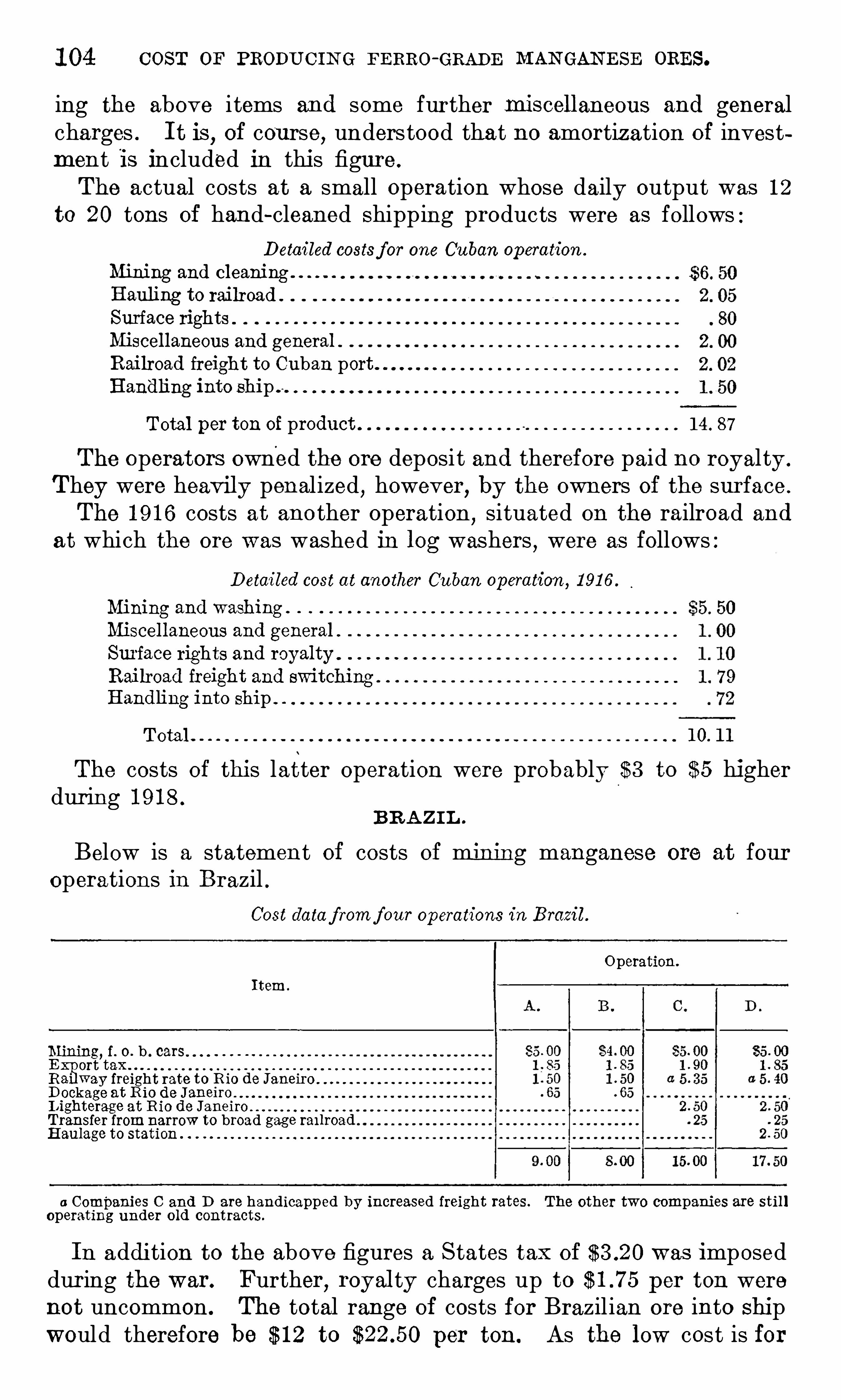
1 04 COST or PRODUC IN G FERRO-GRADE MAN GAN E SE ORES.
ing the above i tems and some further Iniscellaneous and generalcharges . I t is
,of cou rse
,understood tha t no amortization of invest
ment is included in this figure .
The actual costs at a small operation whose daily output was 1 2
to 20 tons of hand-cleaned Shipping products were as followsDetailed costsf or one Cuban operation .
Mining and cleaningHauling to railroad
Surface rights . .
Miscellaneous and
.
generalRailroad freight to Cuban portHandling into ship .
Total per ton of product 1 4 . 87
The operators owned the ore deposi t and therefore paid no royalty .
They were heavily penalized , however, by the owners of the surface .
The 1 9 1 6 costs at another operation,situated on the railroad and
at which the ore was washed in log washers , were as follows :Detailed cost at another Cuban operation , 1 91 6 .
Mining and washing .
Miscellaneous and general .
Surface rights and royalty .
Railroad freight and switchingHandling into ship .
Total 1 0. 1 1
The costs of this latter operation were probably $3 to $5 higherduring 1 9 1 8 .
BR A ZI L .
Below is a statement of costs of mining manganese ore at fouroperations in Brazil .
Cost data f romf our operations in Brazil .
Operation.
I tem.
Mining, f . o. b . cars
E x
port
y
tax
R wa freight rate to R io de JaneiroDockage at Rio de JaneiroI ighterage at R io de JaneiroTransfer fromnarrow to broad gage ra1 1roaHaulage to station
0 Companies C and D are handicapped by increased freight rates. The other two companies are stil loperating under old contracts.
In addition to the above figures a S tates tax of was imposedduring the war. Further
,royal ty charges up to per ton were
not uncommon . The total range of costs for Brazil ian ore into Shipwould therefore be $ 1 2 to per ton. As the low cost is for
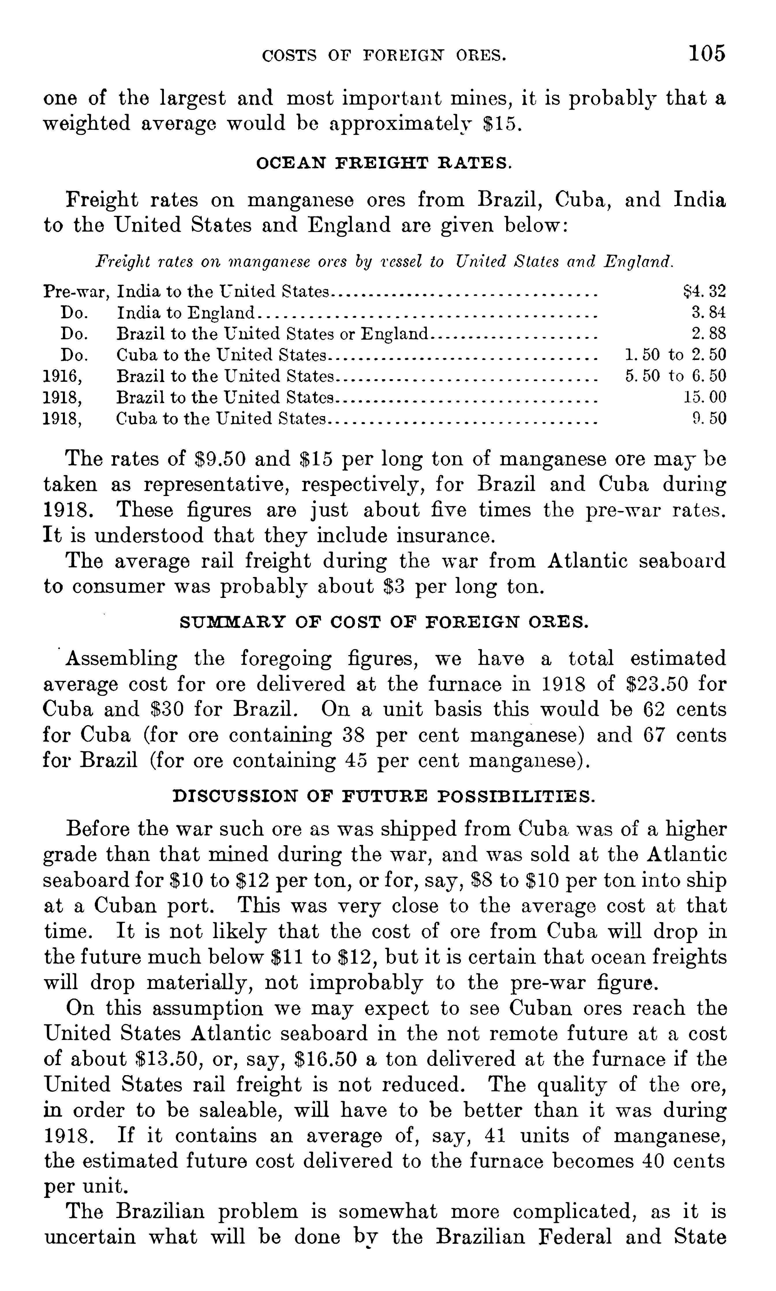
COSTS OF FORE IGN ORE S . 1 05
one of the largest and most important mines,it is probably that a
weighted average would be approximately $ 1 5 .
OCE AN FR E I GHT R ATE S .
Freight rates on manganese ores from Brazil Cuba,and India
to the United States and E ngland are given below :
Freight rates on manganese ores by t'essel to United S tates and E ngland .
Pre-war, India to the United States
Do . India to E ngland
DO . Brazil to the United States or E nglandDo . Cuba to the United States
1 91 6 , Brazil to the United States
1 91 8 , Brazil to the United States
1 91 8,
Cuba to the Uni ted S tates
The rates Of and $ 1 5 per long ton of manganese ore may be
taken as representative,respectively ,
for Brazil and Cuba during1 9 1 8 . These figures are j ust about five times the pre-w ar rates .
I t is understood that they include insurance .
The average rail freight during the war from Atlantic seaboardto consumer was probably about $3 per long ton .
SUM ARY OF CO ST OF FOR E IGN OR E S .
Assembling the foregoing figures,we have a total estimated
average cost for ore delivered at the furnace in 1 9 1 8 Of for
Cuba and $3 0 for Brazil . On a uni t basis this woul d be 62 centsfor Cuba (for ore containing 3 8 per cent manganese) and 6 7 centsfor Brazil (for ore containing 4 5 per cent manganese) .
D I S CU S S ION OF FUTUR E PO S S IB I L IT IE S .
Before the war such ore as was shipped from Cuba was of a highergrade than that mined during the war
,and was sold at the Atlantic
seaboard for $ 1 0 to $ 1 2 per ton ,or for
,say , $8 to $ 1 0 per ton into ship
at a Cuban port . This was very close to the average cost at thattime . I t is not likely that the cost of ore from Cuba will drop inthe future much below $ 1 1 to $ 1 2 , but it is certain that o cean freightswill drop materially ,
not improbably to the pre-war figure.
On this assumption we may expect to see Cuban ores reach theUnited States Atlantic seaboard in the not remote future at a costof about or
,say,
a ton delivered at the furnace if theUni ted S tates rail freight is not reduced . The quality of the ore
,
in order to be saleable,will have to be better than i t was during
1 9 1 8 . If i t contains an average Of,say ,
4 1 units Of manganese ,the estimated future cost delivered to the furnace becomes 40 centsper unit .
The Brazilian problem is somewhat more complicated , as i t isuncertain what wil l be done bv the Brazilian Federal and S tate

1 06 COST OF PRODU C I N G FERRO-GRADE MAN GAN E SE ORE S .
Governments with regard to the present high taxes . O ther Braziliancosts will probably not be much reduced . If we assume that thetaxes , which in 1 9 1 8 amounted to practically $5 per ton,
are reducedtwo-thirds
,the estimated average cost Of $ 1 5 becomes or
say $ 1 1 .50 to include some possible slight reduction in other directions .I t is interesting to compare this estimate with the Sell ing price
of Brazil ian ores at Rio de Janeiro in former years , which were as
follows :S elling prices of Brazilian ores atRio de Janeiro, 1 91 4—1 91 8 .
Selling price ApproximateYear. per ton, ries . equivalent.
22, $ooo
55, sooo
93 , $ooo
1 1 7 , sooo
The real difference in the future will come in the matter of oceanfreights . I f these drop to nearly their former level
,i t shoul d be
possible to deliver Brazilian ores to the United States consumer for
approximM ely per ton . This figure includes for costinto ship at Rio de Janeiro
, $ 3 ocean freight, $ 1 , say, for insurance,
and $3 for United States rail freight to the furnace.
Brazilian ores reaching this country were formerly of higher gradethan those imported during the war. I f the grade now improvesslightly, say to 46 per cent manganese, the estimated average futureunit cost becomes 40 cents .Thus it may fairly be expected that both Brazilian and Cuban
ores can before long be delivered to the United States consumer forabout 40 cents per unit . At an equal price
,Brazilian ore wil l always
have the preference owing to the higher content of metalli c man
ganese.
COMPARI SON OF DOME STIC AND FORE I GN COSTS .
The estimated average costs for manganese ores, per long ton delivered to the consumer, are compared in the following table
E stimated average costs of manganese ores delivered to the consumer during 1 9 1 8 and inthef u ture.
E stimated average cost during 1 91 8 .
Kind of ore. Average AverageCost per manganese Cost per manganese Cost perl ong ton. content, umt, cents. content, umt, cents.
per cent. per cent.
DomesticCarbonates

CHAPTER 8 .
— PRODUCTION OF MANGANE SE ALLOYS IN
THE BLAST FURNACE .
By P . H . ROYSTE R .
1
INTRODUCTORY STATEMENT .
This chapter gives data collected by the Bureau of Mines on the
operation Of blast-furnace plants in the United S tates producingmanganese alloys . This information should be of value to the furnace Operator ; certainly ,
without necessarily agreeing with any gen
eralizations and conclusions introduced,he can determine from the
data assembled in Table 1 7 what has been done by others with raw
materials and furnace conditions approximating his own,provided
comparable combinations can be found in the resul ts presented .
The operation of a blast furnace even for making pig iron is highlyempirical . Past furnace records and previous experience are nearlyas necessary to successful operation as good coke and a hot blast .As in the past
,the production Of manganese alloys in this country
has been comparatively small,and most Of the men in charge of man
ganese furnaces have had relatively little experience on such ores .Hence
,the information obtainable from the few records extant is
presented herein in considerable detail,to compensate in part for the
paucity of data that can be consul ted by furnace operators .The attempt has been made to have this investigation cover the
widest possible range Of materials and Operating conditions . Datafrom 1 8 furnaces will be found in the tables following . The infor
mation was obtained in the summer of 1 9 1 8,and includes every
furnace in blast that was making manganese alloys , with~the exception of the furnaces of the Carnegie Steel CO . ,
and Of the Lavino CO . ,
which were unwill ing to cooperate in the investigation . The com
panies which by their generous cooperation have made the reportpossible are the American Manganese CO .
,Bethlehem S teel CO . ,
B . B . Trading CO .,Buffalo Union Furnace CO .
,Colorado Fuel and
Iron CO .,John B . Guernsey CO . ,
Donner S teel CO .,E . E . Marshal l
,
Miami Metals CO . ,N ew Jersey Z inc CO . ,
Seaboard Steel ManganeseCorporation
,Southeastern Iron Corporation
,and W harton Steel Co .
1 Assistant physicist of the Bureau of Mines, with headquarters at themining experiment station at
Minneapolis, Minn. The investigation reported in this chapterwasmade in cooperation with the SchoolofMines of the University of Minnesota.
1 08
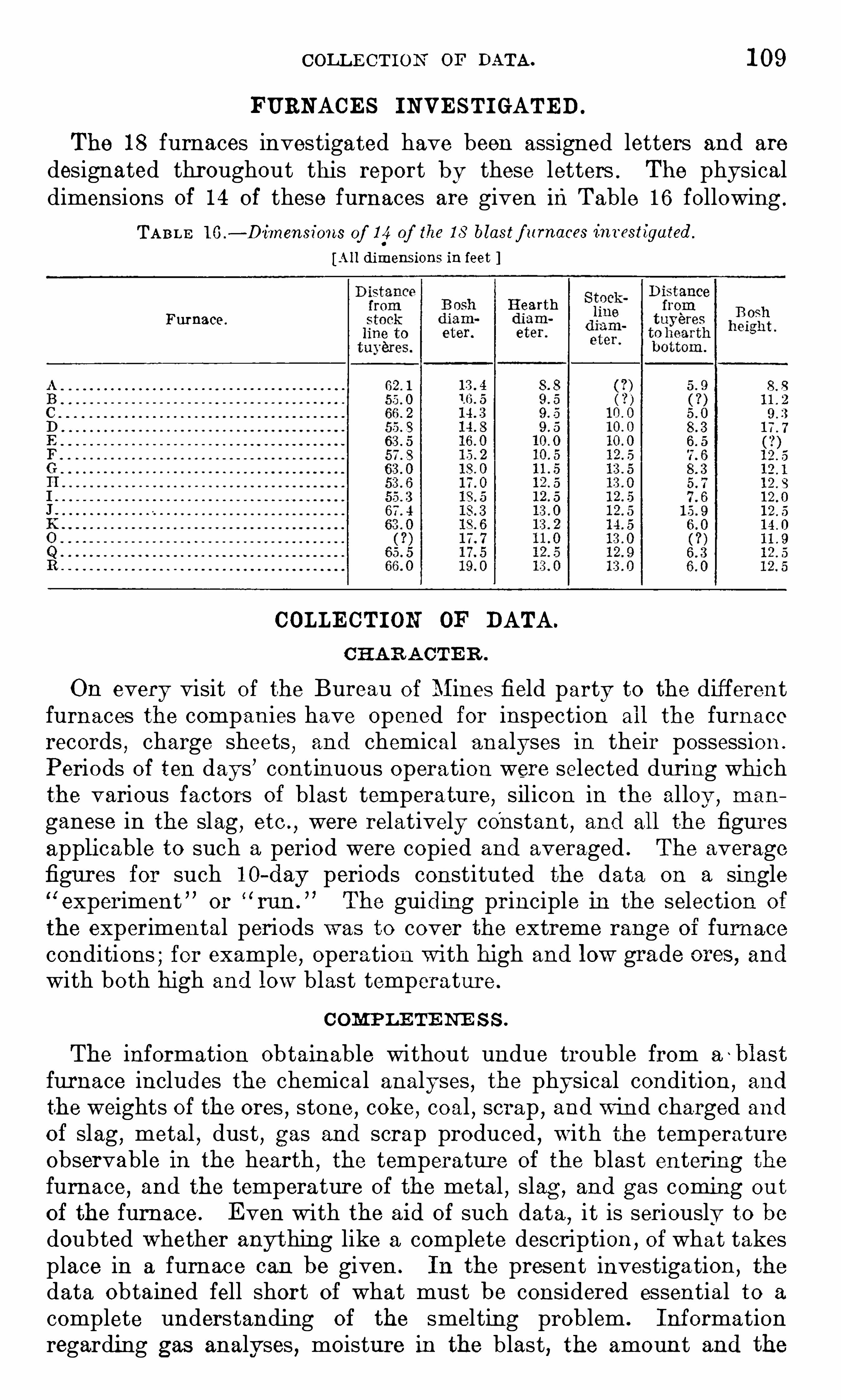
COLLE CTION or DATA. 1 09
FURNACES I NVE STI GATED.
The 1 8 furnaces investigated have been assigned letters and are
designated throughout this report by these letters . The physicaldimensions of 1 4 of these furnaces are given inTable 1 6 following .
TABLE 1 6 .
— Dimensions of 1 4 of the 1 8 blastf urnaces int estigated .
[A ll dimensions in feet
HearthFurnace.
COLLE CTI ON OF DATA.
CHAR A CTE R .
On every visit of the Bureau of Mines field party to the differentfurnaces the companies have opened for inspection all the furnacerecords , charge sheets , and chemical analyses in their possession .
Periods of ten days’ cont inuous operation were selected during whichthe various factors of blast temperature
,silicon in the alloy ,
man
ganese in the slag,etc .
,were relatively constant , and all the figures
applicable to such a period were copied and averaged . The averagefigures for such I O—day periods constituted the data on a singleexperiment ” or
“run . The guiding principle in the selection of
the experimental periods was to cover the extreme range of furnaceconditions ; for example
,operation wi th high and low grade ores, and
with both high and low blast temperature .
COMP LE TE N'
E S S .
The information obtainable without undue trouble from a~blast
furnace includes the chemical analyses , the physical condition,and
the weights of the ores,stone
,coke
,coal
,scrap
,and win d charged and
of slag , metal,dust
, gas and scrap produced,with the temperature
observable in the hearth,the temperature of the blast entering the
furnace,and the temperature of the metal
,slag ,
and gas coming ou t
of the furnace . E ven with the aid of such data,i t is seriously to be
doubted W hether anything like a complete description ,of what takes
place in a furnace can be given . In the pres ent investigation ,the
data obtained fell short of what must be considered essential to a
complete understanding of the smelting problem . Inf ormationregarding gas analyses , moisture in the blast, the amount and the
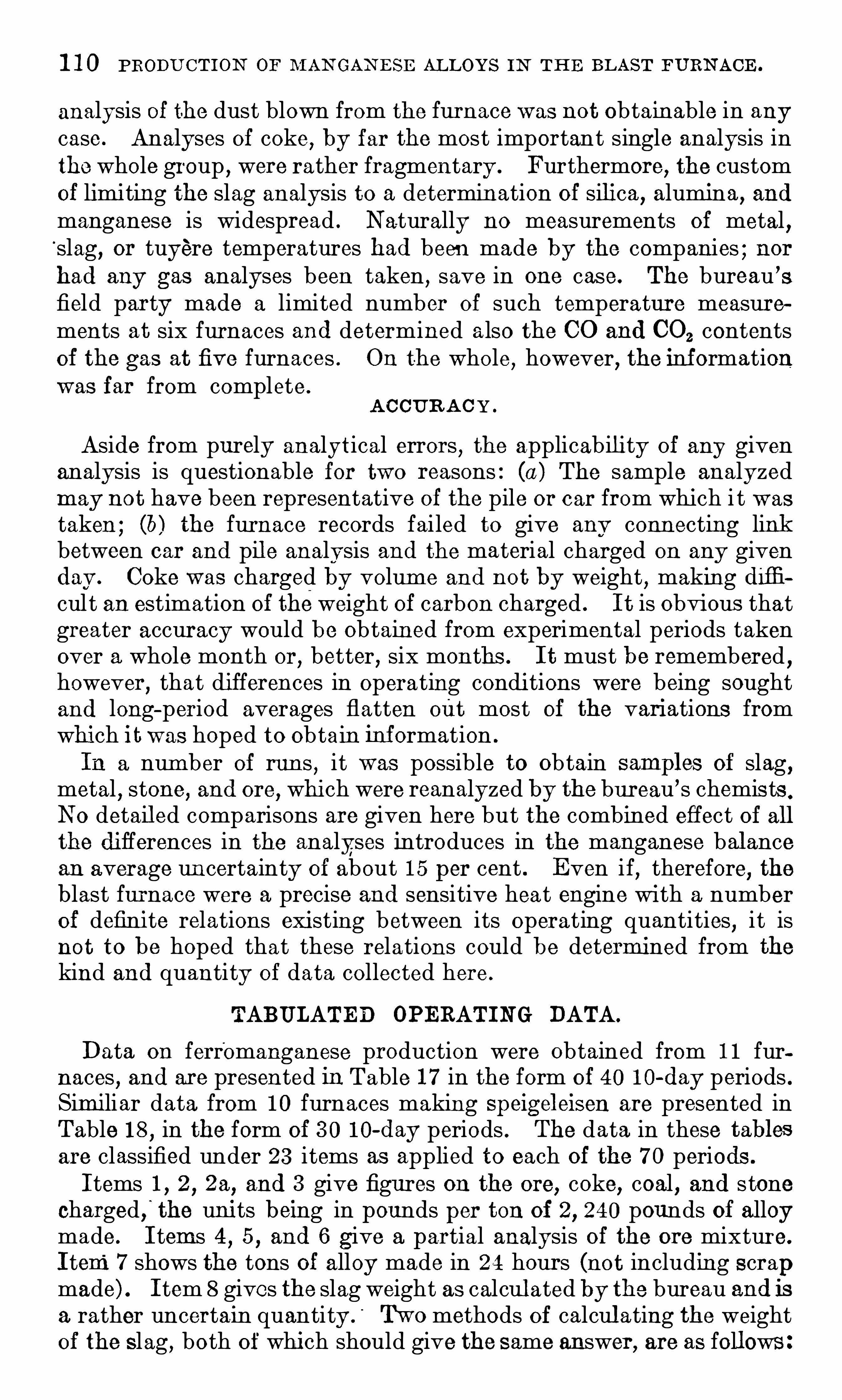
1 1 0 PRODU CTION OF M AN GAN E SE AL LOYS IN TH E BLAST FURN ACE .
analysis of the dust blown from the furnace was not obtainable in any
case. Analyses of coke, by far the most important single analysis inthe whole group , were rather fragmentary . Furthermore, the customof limiting the slag analysis to a determination of silica , alumina , andmanganese is widespread . Naturally no measurements of metal ,slag, or tuyere temperatures had been made by the companies ; norhad any gas analyses been taken , save in one case. The bureau ’sfield party made a limited number of such temperature measurements at six furnaces and determined also the CO and CO2 contentsof the gas at five furnaces . On the whole
,however, the inf ormation
was far from complete .
A CCUR A C Y .
Aside from purely analytical errors , the applicability of any givenanalysis is questionable for two reasons : (a ) The sample analyzedmay not have been representative of the pile or car from which i t was
taken ; (6) the furnace records fai led to give any connecting linkbetween car and pil e analysis and the material charged on any givenday . Coke was charged by volume and not by weight , making difficult an estimation of the weight of carbon charged . I t is obvious thatgreater accuracy would be obtained from experimental periods takenover a whole month or
,better , six months . I t must be remembered
,
however,that differences in operating conditions were being sought
and long-period averages flatten out most of the variations fromwhich itwas hoped to obtain inf ormation .
In a number of runs , it was possible to obtain samfles of slag,metal
,stone
,and ore
, which were reanalyzed by the bureau’s chemists .
No detail ed comparisons are given here but the combined effect of allthe differences in the analyses introduces in the manganese bal ancean average uncertainty of about 1 5 per cent . E ven if
,therefore, the
blast furnace were a precise and sensitive heat engine with a numberof definite relations existing between its operating quantities
,i t is
not to be hoped that these relations could be determined from the
kind and quantity of data collected here .
TABULATED OPERATI NG DATA.
Data on ferromanganese production were obtained from 1 1 furnaces , and are presented in Table 1 7 in the form of 40 1 0-day periods .Similiar data from 1 0 furnaces making speigeleisen are presented inTable 1 8 , in the form of 3 0 1 0-day periods . The data in these tablesare classified under 23 items as applied to each of the 7 0 periods .
I tems 1 , 2 , 2a, and 3 give figures on the ore, coke, coal , and stonecharged, the units being in pounds per ton of 2, 240 pounds of alloymade. I tems 4 , 5 , and 6 give a partial analysis of the ore mixture.
I tem7 shows the tons of alloy made in 24 hours (not including scrapmade) . I tem 8 gives the slag weight as calcul ated by the bureau and isa rather uncertain quantity . N o methods of calcul ating the weightof the slag , both of which should give the same answer, are as follows :
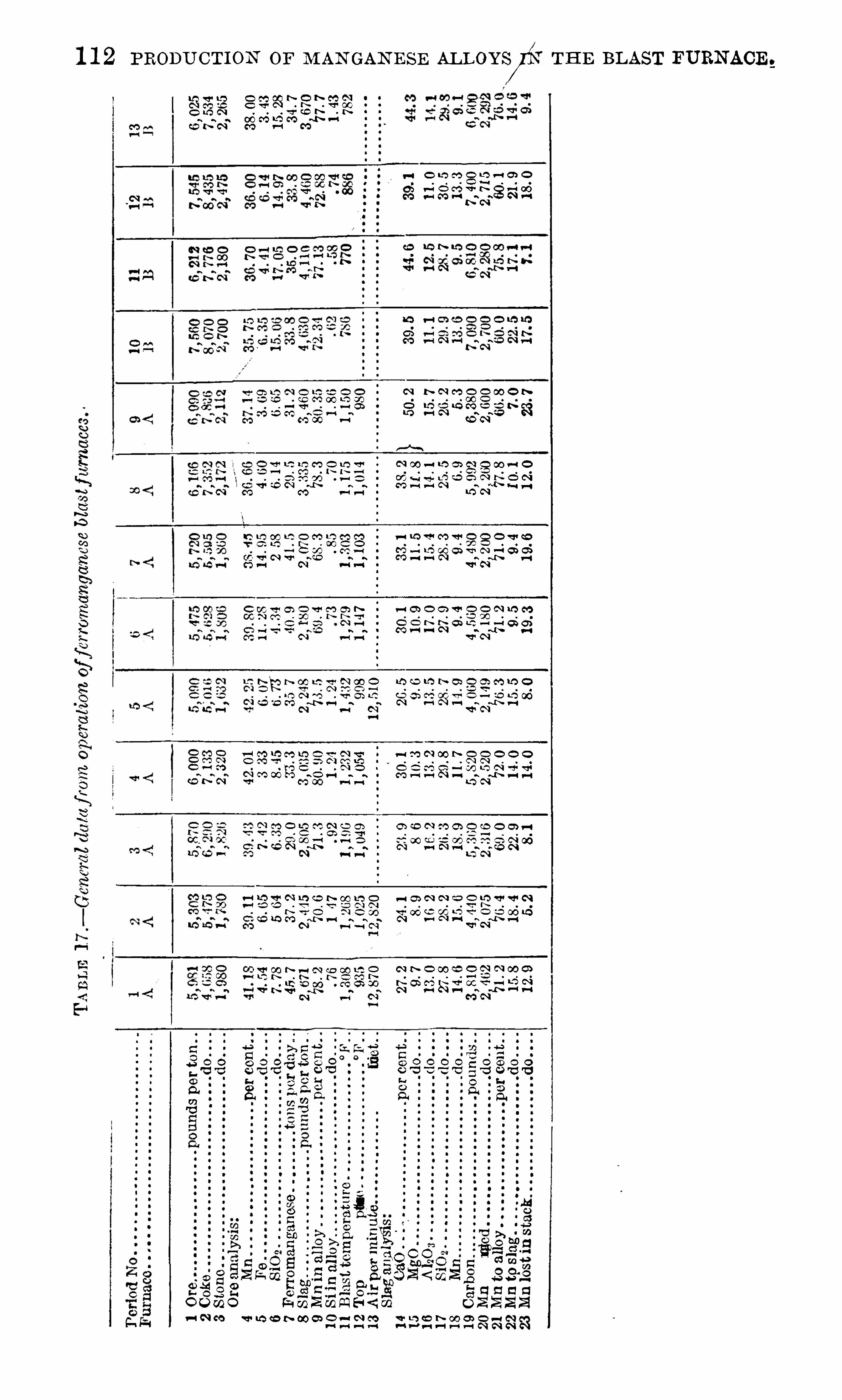
1 1 2 PRODU CTION OF M AN GAN E SE ALLOYS/N TH E BLAST FURNACE .
N00N
we
.
“
h.
u¢ems
m
s.
s
m
wa
.
mfl
we
.
”
so
.
mm
msw.
«
ews
H
s
was
e
0
53 53 23Q ’s
IN N
m o m ‘ s-h
O L’J C‘O O L‘Dv-QQ O. CDv—i
M OO N
ems
con
.~em
.
”
mm
.@w
ewe
m
N.
_m
ms
.
s
as
.
”
0 . Q'g c 0
m v—( fi ‘ l-E O Q N N O NGO P-( M N
ma
N—xh v-‘ fi
N oo—u o m ca o oo—c cen
s.
“
AAA
.
”
o“
.
”.
mE
mmm
m
m.
sm
e~.
e
cs
.
v
v-ivs“N —i oi ca
w as
0 ‘ TJ OLQW CDV
v-l lQQ'OO V O O O Q'QOtag -am—i
new
.
”
as
.
m.
wm
on:
m
A.
s
v
we
a
ma
.
vfi
o
F .a l ‘
$ 0 1
A
v
O O V O O N UDGO.
‘
LD ’X J“An
n
a
sumH
”A
.
e.
as
own
.
“
a.
ce
em
.
s
mat
:
awe
“
m.
mH
o.
s
m.
em
on
a.
mfi
was
.
m2.fl
e
m.~m.
e
¢
we
n
N
A
an
bu
d
so
.
o
0
'l
t
'.
ass.
”
mm
.
A.
E
E
new
N
o.
@m
mm
.
e
we
.
“
a.
NH
w.
2
N.
nw
N
S.«
N
on
e
A
s.
eH
w.
AN
o.
m~s .
s
N.
AN
os
w.
m~ans
mam
.~as
.
m.
m¢
fine
A
“.
me
as
.
“
ee
.
v
ow
.
c
v
28no
n
.
cv.
anon.
on
.
at
o:
.
ov
“
Eco
SQ
880
350
V
LO
O
O
O
Q
O
O
O
.
.
o
U
Roc
ha.
ccp
uo
amv
38hog
Goa
bo
amt
M
83
532
52
mm
.
m3C
Emm
58
8a
s
a
8928
54
on
.
E
EEO
2
5a
2
O
E
2
Cam—as
on
o
2
a.
”
0
8
v
m
mfim
SQ
b<ma
5533
253Amo
k.Na
8323
aS
w
i
mS
-.
wa.
mw
omo
cswcs
ao
to
h
N.
.
C_m
e
o
n”
A
nag
e
5.
Ofioe
wm
38N
on
e
A


1 1 4 PRODU CTION OF M AN GAN E SE ALLOYS IN THE BLAST FURN ACE .
o
w
.
Mo
fiw
5
.
mm
.
o
c.
Ema—m
8G
E.
um
38no
n
zo
za
8
Ea
.
8
8
20
C
E.
om
$55
8
Co
gna
c
A:
c
c
dz
.
wfi
.
o
v
9m
.
2
dz
.
2
to
e
.
2
.
p
aoo
SQ
Om
w
.
E
mam—28
2m
0
8
.
85
58
Ba
“
2..
2
.
ho
:
659
8888ac
e.
fi
a.
c
ease
52m
Eo
n.
.
S
.
u
coo
h
og
in
c—E
5
54
.
m
8a
2c
wflm
.
w
Sa
wc
o
mwa
s
gw
ao
fio
k.
N.
.
c
v
.
w
.
OHU
o
n
$
96
co
m
5a
.
v
“
mam—a
ce
20
.
cv
5:
o.
m
on
mo
o.
em
.
c
c
830
.
m
cog
po
mmvczo
g
.
80
A

1 1 6 PRODUCTION or M AN GAN E SE AL LOYS IN TH E BLAST FURNACE .
w
e
9
8
9
8S.o
:A
we
a
isZ;
A
2SN
m.
ma
0.
mm
.
mv
gm
om
.
vm
MK
.
N.
.
wm
a.
o
o.
mv
mA
o.
wn
A.
9.
Now
own
A
ww
n.
mm
a.
2
a.
mm
e.
2
o.
mm
a.
a.o
n:
camm
2s
m.
5
m.
2
H.
mm
e.
o
e
do.
a
8m8
.
own
a
3a
e.
em
N.
2
o.
2
a
As
an
n
c
A
m.
22
3
w
8mm
.
2
mm
.
sm
2.
2
.
OC
.
cv
.
Coo
SQ.
.
oc56
g
on
on
o
n
.
on
5
80
“o
n
50
80
550.
Q.
.
mo
.
o
c
“
Eco.
SQ
ace
SQm0
ma
c
Ho
g
.
ofi
.
c
v
38Ho
g
o
n
.
.
o@-o
c
no“
po
mmo
5asa
s.
mm
me
n
8a
s.
S
$33
8a
:.
8
60
820
5a
.
8
to
.
2
Hz
.
wfi
9m
.
2
o
f
.
2
Ow
n
.
2.
3
m
SEES
8aE
S.
.
2
4
38388ac
e.
fi
9
8388“mm—m
Ezso
za
s
a.
2
s
ea
Ems
.
s.
w
down
s—owo
fiw
.
N..
w.
m.
54
.
v
na
bs?80
se
am
.
m
go
o.
N
9
6A
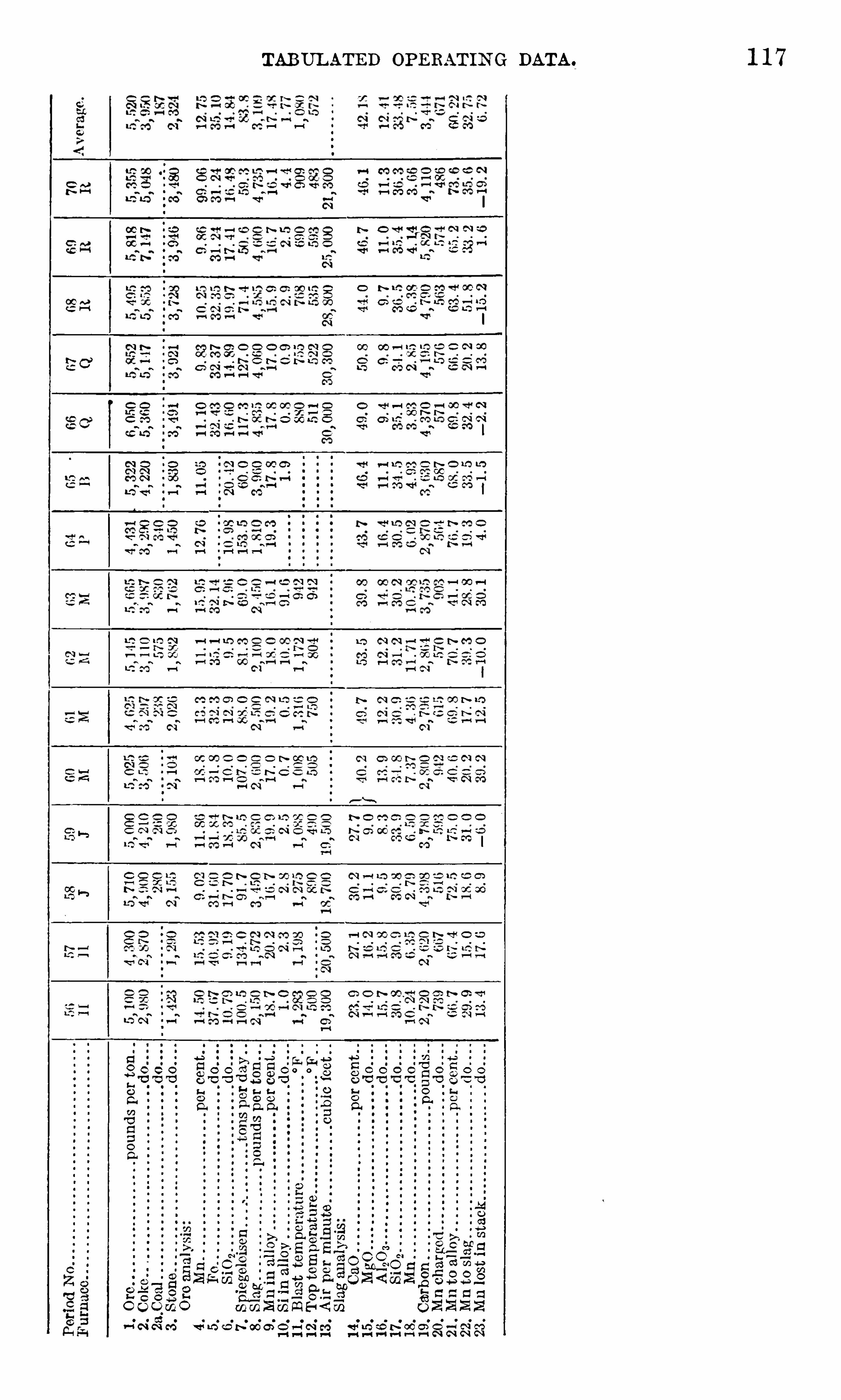
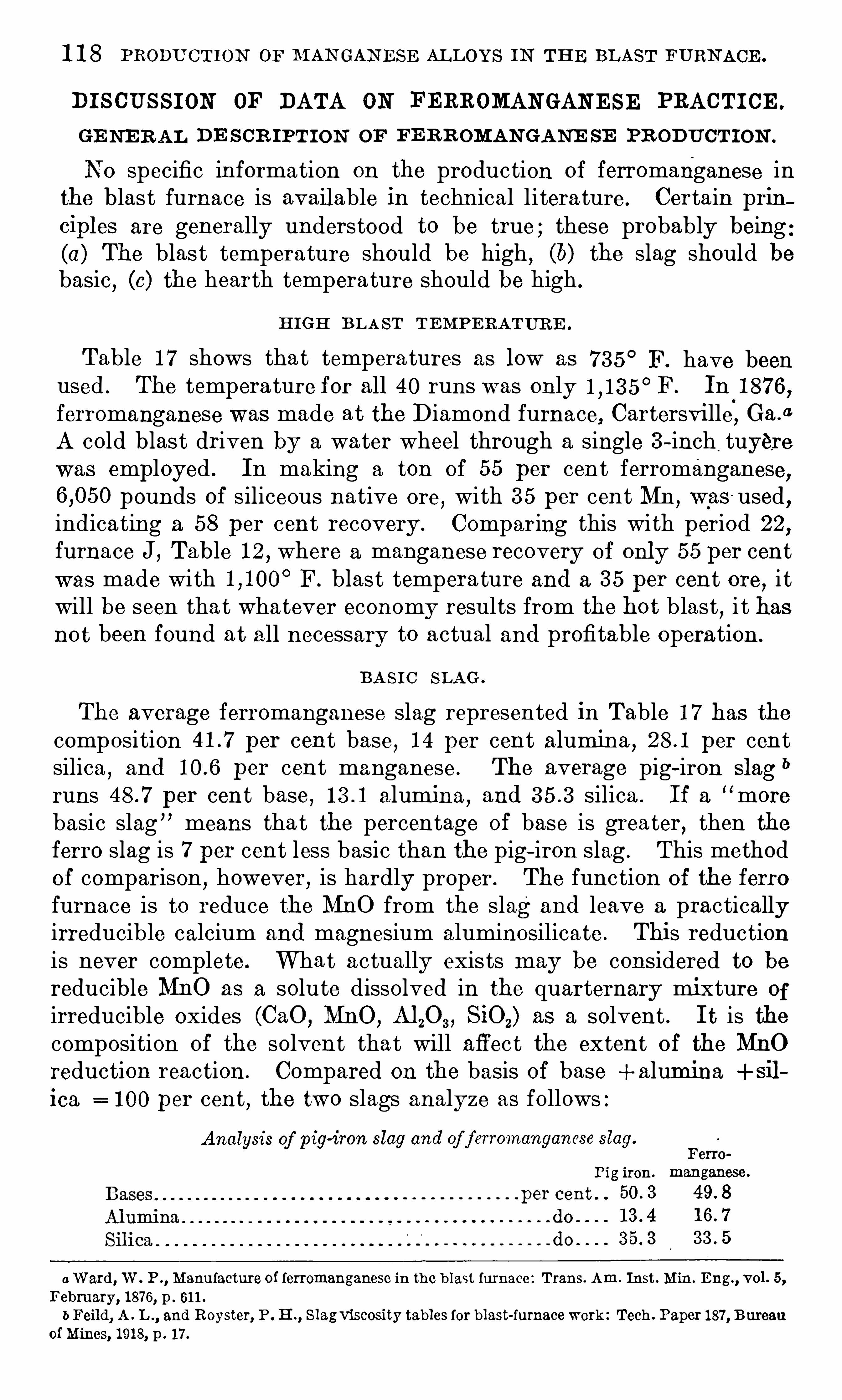
1 1 8 PRODU CT ION OF M AN GAN E SE ALLOYS IN TH E BLAST FURN ACE .
DI SCUSSI ON OF DATA ON FERROMAN GAN E SE PRACTI CE .
GE NE R AL DE S CR IPTI ON OF FE R ROMAN GANE SE PR ODUCT I ON .
N 0 specific information on the production of ferromanganese inthe blast furnace is available in technical li terature. Certain principles are generally understood to be true ,
these probably being(a) The blast temperature should be high , (6) the slag should bebasic , (0) the hearth temperature should be high .
H IGH BLA ST TEMPE RATUR E .
Table 1 7 shows tha t temperatures as low as 7 3 5° F. have been
used . The temperature for all 40 runs was only F. In 1 8 7 6 ,ferromanganese was made at the Diamond furnace, Cartersville, Ga .
0
A cold blas t driven by a water wheel through a single 3 -inch,
tuyerewas employed . In making a ton of 55 per cent ferromanganese,
pounds of siliceous native ore,with 3 5 per cent Mn , was
-used,
indicating a 58 per cent recovery . Comparing this with period 22,
furnace J, Table 1 2 , where a manganese recovery Of only 55 per centwas made with F. blast tempera ture and a 3 5 per cent ore, i twill be seen tha t whatever economy results from the hot blast, i t hasnot been found at all necessary to actual and profitable operation .
BAS I C SLAG .
The average ferromanganese slag represented in Table 1 7 has thecomposition per cent base, 1 4 per cent alumina , per centsilica
,and per cent manganese. The average pig-iron slag
b
runs per cent base, alumina,and silica . I f a “ more
basic slag means that the percentage of base is greater, then theferro slag is 7 per cent less basic than the pig- iron slag . This methodOf comparison
,however, is hardly proper. The function of the ferro
furnace is to reduce the MnO from the slag and leave a practicallyirreducible calcium and magnesium aluminosilicate . This reductionis never complete. What actually exists may be considered to bereducible MnO as a solute dissolved in the quarternary mixture of
irreducible oxides (CaO ,MnO ,
A120 3 , SiOz) as a solvent . I t is thecomposition of the solvent that wil l affect the extent of the MnOreduction reaction . Compared on the basis of base + alumina +si1
ica = 1 00 per cent , the two slags analyze as follows :Analysis of pig-iron slag and of f erromanganese slag.
F6 1770
I’ig iron. manganese.
per cent . .
do
0 W ard, W . P ., Manu facture of ferromanganese in the b last furnace : Trans. Am. Inst . Min. Eng., vol . 5,
February, 1 87 6, p . 61 1 .
bFeild, A . L ., and Royster, P . H ., S lagviscosity tables for blast-furnacework : Tech . Paper 1 87 , B ureauof Mines, 1 91 8, p . 1 7 .

1 20 PRODUCTION OF M AN GAN E SE ALLOYS I N TH E BLAST FURN ACE .
RESUME OF CON D IT IO N S I N FE RROM AN GAN E S E FURN AC E .
I t has been shown that in changing a furnace over from iron toferromanganese i t is nei ther necessary nor usual to raise the blasttemperature, to increase the basicity of the slag, or to run with a
hotter hearth .
True, there are certain resul tant changes in the practice, the mostimportant one being that the coke requirements are tripled . The
daily tonnage is reduced to about one-third ; the top tempera turerises to about to E ; the carbon monoxide content ofthe top gas is increased about 50 per cent ; and the blast pressuredrops to 3 to 8 pounds per square inch . The operation of the furnacebecomes
easier ; stock descends wi thout hanging, slips become inf requent
,fewer tuyeres burn out, sulphur I s takericare of completely
as MnS 1 11 the slag, and further, there are no silicon requirements tobe met. All furnace difficul ties practically resolve themselves intoone problem— to get into the metal the maximum percentage of the
manganese charged .
THE OR Y A s To FUE L R E QUIR E ME N T S FOR PR ODU C IN G FE RRO
M AN GANE SE .
A number of heat balances with values in B . t . u . have been published on the iron furnace
,but i t seems hardly justifiable to construct
a heat bal ance for the ferro furnace for comparison ,for the follow
ing reasons : A t room temperature, the heat of combustion of C +OZ
to CO2is either or B . t . 1 1 . per pound of C ; at C .
it is either or B . t . u . ,depending on the authori ty selec ted .
There is a wide lack of agreement among the few existing determinations of the heat of combustion,
and greater lack Of agreement amongthe experimental values for the specific heat Of carbon,
Of oxygen ,
and of CO . At 600° C . the specific heat of carbon may be or
At metallurgically interesting temperatures (betweenand the discrepancy in figures for the total heat of carbonis about 3 0 per cent .The specific heat of CO and of N 2 at C . may be either
or For the iron furnace the heat imparted to the gaseousproducts of reaction per pound of metal is either 9 7 2 or B . t . 1 1 .The rise in temperature of gases above that Of the burmng coke is ,therefore
,either 6 96 ° or F. , 54 per cent discrepancy . The
continued reprinting of some arbitrarily selected figure for the necessary thermal constants is both practically and scientifically Objectionable and tends almost invariably to erroneous conclusions .
I t is possible,
“however,to give an idea of the reason for the differ
ence between the fuel requ irements of the iron and those of the
ferromanganese furnace and yet avoid excessive accumulation of
meaningless B . t . u . figures . The comparison following is of interest .
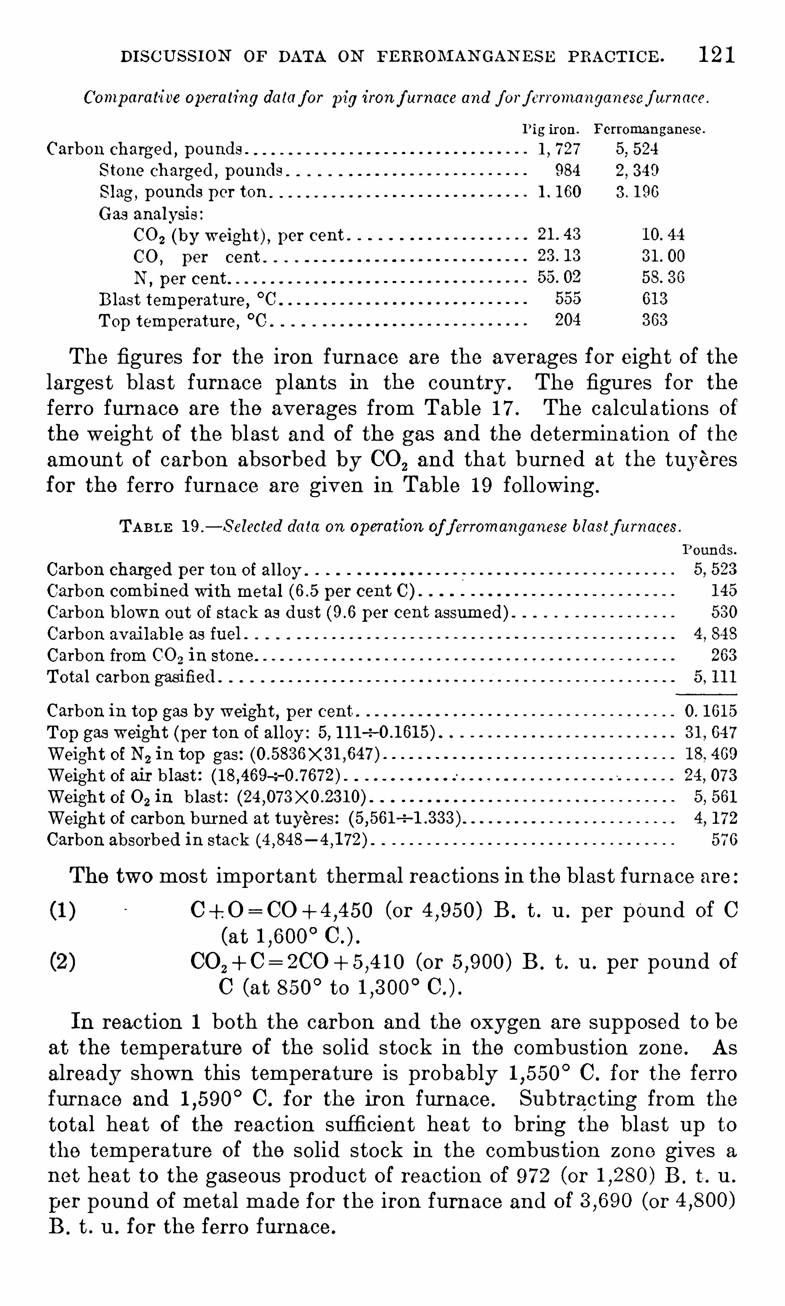
DISC US S ION OF DATA ON FERROM AN GAN E S E PRACTI CE . 1 2 1
Comparative operating da laf or pig ironf urnace and f orf erromanganesef arnace .
Pig iron. Ferromanganese.
Carbon charged ,pounds .
1, 7 27 5, 524
S tone charged ,pounds 984 2
, 3 40
Slag ,pounds p er ten 1 . 1 60 3 . 1 96
Gas analysis
C0 2 (by weight) , per cent .
CO , per cent .
N, per cent
Blast temperature ,°C
Top temperature,°C
The figures for the iron furnace are the averages for eight of thelarges t blas t furnace plan ts in the country . The figures for the
ferro furnace are the averages from Table 1 7 The calculations ofthe weight of the blas t and of the gas and the determination of the
amount o f carbon absorbed by CO2and that burned at the tuyeres
for the ferro furnace are given in Table 1 9 following .
TABLE 1 9 .
— S elected data on operation of f erromanganese blastf urnaces
Carbon charged per ton of al loy .
Carbon combined with metal per cent C ) .
Carbon blown out of stack as dust per cent assumed)Carbon available as fuel .
Carbon from CO2 in stone .
Tota l carbon gasified .
Carbon in top gas by weight, p er cent .
Top gas weight (per ton of al loy : 5 , 1 1 1—2
Weight of N 2 in top gas :
Weight of air b last :—z
Weight of 0 2 in blast :
Weight of carbon burned at tuyeres :
Carbon absorbed in stack
The two most important thermal reactions in the blast furnace are
(1 ) (or B . t . u . per pound of C
(at
(or B . t . u . per pound of
C (at 850°to
In reaction 1 both the carbon and the oxygen are supposed to beat the temperature of the solid stock in the combustion zone. Asalready shown this temperature is probably C . for the ferrofurnace and C . for the iron furnace . Subtracting from the
total heat of the reaction sufficient heat to bring the blast up to
the temperature Of the solid stock in the combustion zone gives a
not heat to the gaseous product O f reaction of 9 7 2 (or B . t . u .
per pound of metal made for the iron furnace and O f (or
B . t . u . for the ferro furnace.

1 22 PRODU C TION OF M AN GAN E SE AL L OYS IN TH E BLAST FURN ACE .
In the ferro furnace,either in the hearth
,at the tuyeres , or j ust
above them all the manganese in the metal was reduced from MnO .
All of the CO2resul ting from this reduction is itself reduced by solid
carbon to CO ; there is involved in this reaction pound Of car
bon per pound of metal,resul ting in a loss of (or B . t . u .
,
leaving to B . t . u . to be used in heating the ascendinggas above the temperature Of the solid stock . The ferro-furnace gasweighs pounds per pound of metal and the iron—furnace gaspounds . Hence, in the ferro furnace the amount of heat avail
able for raising the temperature Of the gases is two to three timesgreater than in the iron furnace
,and the weight Of gas to be heated is
three times as great . The rise in temperature,therefore
,is either
the same or less in the ferro furnace than in the iron furnace .
I t is unwise to go here in to any detailed consideration of why i tis neces sary to heat the ascending gas to this rather defin ite butsomewhat unknown elevation above the temperature of the descending stock . I t may be pointed ou t
,however
, (a ) that some 250 tonsof solid stock must be heated from 7 0
°F . to above F. in 24
hours ; (6) that the greater part of this stock , being coke and mineraloxides
,has a low thermal conductivity ; (0 ) that the ascending gas
stream does not have a chan ce to flow around every separate pieceof coke
,stone
,and ore ; and (cl ) that the transfer of heat from gas to
solid is,under the most favorable conditions , a slow process . In
order to heat the stock in the required time, therefore, the gases mustat every point in the furnace be appreciably hotter than the stock ;and this means not several degrees hotter but several hundred degreeshotter. Thus
,the pounds of c arbon burned at the tuyeres
in the ferro furnace gives the gas stream no greater temperatureelevation above the solid stock than does the pounds burnedin the iron furnace .
COMPO S I T ION OF FURN ACE GA S .
At five furnaces samples of downcomer gas were taken and analysesmade for the CO and CO 2 contents . The resul ts obtained were somewhat variable but indicated a distinct tendency toward what mightbe called a normal composition .
As regards oxygen the evidence was that the true furnace gascontains no oxygen . W ell taken samples showed to per cent .I t was fel t
,however
,that this oxygen coul d be safely attributed to
leakage Of air into the sample . W here the conditions of samplingpermit the chance of contamination by the atmosphere
,the oxygen
content might be as high as per cent .The CO2
content varied between the extreme limits Of and
per cent, with averages for the five furnaces ofand per cent. The CO content varied from to per cent,

1 24 PRODU CT ION OF M AN GAN E SE AL LOYS IN TH E BLAST FURN ACE .
stone is 968 pounds, from the reduction of 1 90 pounds of FezO 3 ,1 56
pounds , and from the reduction of pounds of MnO2 to MnO
by CO ,pounds ; total , pounds . This indicates a per
cent CO2 content in the gas as agains t per cent given ‘
on page 1 2 1 .
There is left 29 1 pounds of 002 ,which may be due to reduction
Of MnO by CO in the lower part of the furnace, to carbon depositionfrom CO in the upper part of the furnace, or— more likely— to e) :
perimental error either in the analyses , or in their application to theaverage practice given in Table 1 7 The evidence points closely to
a 1 00 per cent reduction of MnO “ directly”
by carbon .
0
I t is well to point ou t that direct ” reduction by carbon probablymeans -nothing of the kind . AS in most important metallurgicalproblems , no experiment yet made settles this question . I t can be
assumed that the reaction :
(A)
is the reaction by which the final reduction of MnO takes place at a
temperature somewhere between and, say , C . At thistemperature the following reac tion takes place, a lmost to completion
,and with great rapidity :
CO, + C= 29 0 (B)
Thus the resul t of the two react-ions going on simultaneously, althoughnot necessarily in the same part of the furnace, gives the same products as the single reaction :
MnO + C =Mn+ CO (C)
AS A and B together are not distinguishable frOmC by any cal cul ation based upon gas analysis , one must be content to realize thateither of these two reactions may be the one that takes place .
BUR D E N IN G AN D DR IV IN G THE FUR N AC E .
I t is all very well to apply to the furnace records accepted meta llurgical theory ,
but practically the important thing is to have at
hand something definite in the way of a guide to burdening and
driving the furnace. The following discussion,therefore
,is based
exclusively on the fig ures in Table 1 7 and is free from any theoreticalconsiderations whatever. I t is an a ttempt to establish from the
whole mass of data certain relationships between the 23 items of
each run . There are only three factors that the furnace operatorscan change at will . They are (1 ) ratio of coke and ore ; (2) ra tio of
stone and ore ; and (3 ) quantity of wind blown per minute. I t isassumed here that the blast temperature is kept as high as stoveconditions permit . The number Of rounds charged and the tons madeper day are decided by the furnace i tself . W ith the above threefactors determined , there is nothing left for the operator to do butwatch the furnace.
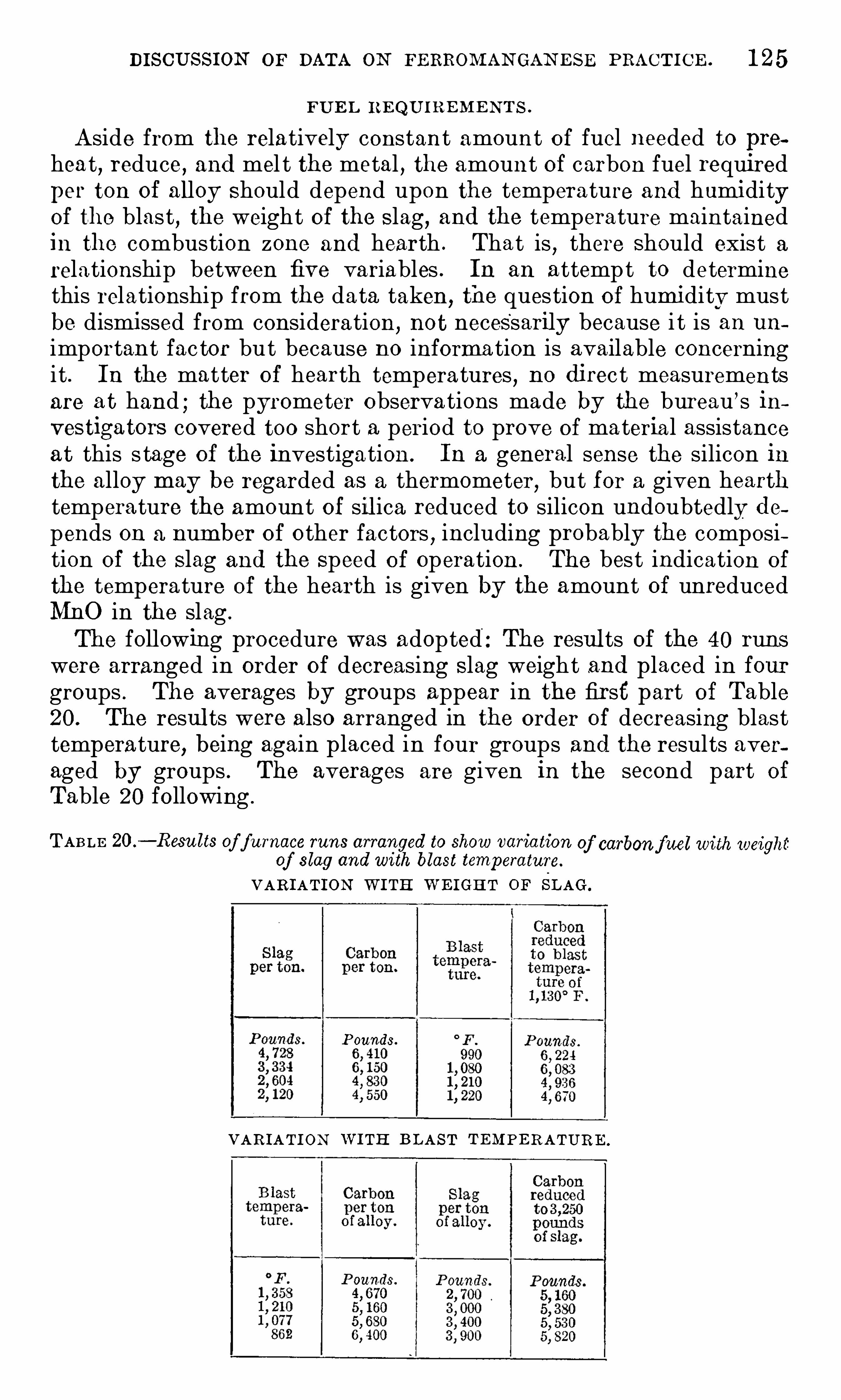
DISCUSSION or DATA ON FERROM AN GAN E SE PRACT ICE . 1 25
FU E L REQU I R E M E N TS .
Aside from the relatively constant amount of fuel needed to prehea t , reduce, and mel t the metal , the amount Of carbon fuel requiredper ton of alloy Should depend upon the temperature and humidityof the blast , the weight of the S lag, and the temperature maintainedin the combustion zone and hearth . That is , there Should exist arelationship between five variables . In an attempt to determinethis relationship from the data taken, the question O f humidity mustbe dismissed from consideration,
not necessarily because i t is an un
important fac tor but because no information is available concerningit . In the matter of hearth tempera tures , no direc t measurementsare at hand ; the pyrometer Observa tions made by the bureau ’s investigators covered too short a period to prove of material assistanceat this s tage of the investigation. In a general sense the silicon inthe alloy may be regarded as a thermometer
,but for a given hearth
temperature the amount of sil ica reduced to silicon undoubte dly depends ou a number of other factors , including probably the composition of the S lag and the Speed of operation . The best indication of
the temperature of the hearth is given by the amount of unreducedMnO in the slag .
The following procedure was adopted : The resul ts Of the 40 runswere arranged in order of decreasing S lag weight and placed in fourgroups . The averages by groups appear in the first part of Table20 . The resul ts were also arranged in the order of decreasing blasttemperature, being again placed in four groups and the results averaged by groups . The averages are given in the second part of
Table 20 following .
TABLE 20 .
— Resu lts of f urnace runs arranged to show variation of carbonf uel with weightof slag and with blast temperature.
VARIATION W I TH W E IGHT OF SLAG.
P ounds.
VAR IATI ON W I TH B LAST TEMPE RATURE .

1 26 PRODU CT ION OF M AN GAN E SE ALLOYS IN TH E BLAST FURN ACE .
By the method of successive approximation i t was found that1 pound of extra slag requires pound of carbon
,and 1
°F. extra
blas t temperature saves pounds of carbon . W ritten in the
form of an equation :
W hereKa=pounds of carbon per ton of alloy used by the average furnace ,V =pounds of slag per ton of al loy ,
T =blast temperature in degrees F.
Ka=4l 7 o+o.88 V T
This equation shows,for a given slag weight
,for a given blast
temperature,and for average humidity, the quantity of carbon
required to heat the materials in the hearth to the average hearthtemperature. AS has been shown
,this temperature is probably
about C . ,but it is better not to place too much confidence
in this figure.
I t is of course possible to charge either more or less carbon thanthe amount given by equation 1 . The average hearth temperatureused by any given furnace Operator means merely that temperaturefound by experience
,or assrimed from lack of experience
,to
'
be themost desirable to maintain . I f the Operator decides
i
to use a highertemperature in practice
,the furnace can be given “
excess Carbon,
”
a phrase taken to mean the carbon actual ly charged minus theamount indicated by equation 1 . When excess carbon is used
,the
percentage of manganese in the S lag will be lower,provided all the
other conditions remain cons tant . On the other hand, the carboncharged may be considerably lower than that given by equation 1
,
with a resul tant hearth temperature lower than the average .
PE RC E N TAG E OF M AN GAN E S E I N S L AG .
Determination of the percentage of manganese that goes into theslag is approached in the same manner as the problem of fuel requirements
,with the exception that there must not be any
“ left over ”
variable such as excess carbonover requirements . The operator canat his own free will charge so l ittle fuel that the hearth freezes
,or he
can charge so much fuel that ‘ he bankrupts the owners . The per
centage of manganese in the slag,however
,is the resul t of a number
Of metal lurgical phenomena and is definitely determined by the
actual furnace facts .The data in Table 1 7 Show that the percentage of manganese in
the S lag depended upon the following factors :(1 ) The ratio of bases to silica in the S lag ;(2 ) The hearth temperature as determined by the excess or
deficiency of fuel above or below that indicated in equation 1(3 ) The rate of driving .

1 28 PRODU CTION OF. M AN GAN E SE ALLOYS IN THE BLAST FURN ACE .
EQUAT I ON FOR PE RC E N TAGE OF M AN GAN E S E IN SL AG .
The results of the 40 runs represented in Table 1 8 were arrangedin order of decreasing excess carbon ”
as determined by equation 1 .
The resul ts were then divided into four groups and the averages bygroups recorded as in Table 2 1 . The results are also plotted in
was Jed‘Ee l s uneseueBueW iueo red
“
5 9 13 u! ase uefiuew
figure 1 0 . The resul ts of the same runs were rearranged’
in the orderof decreas ing basicity (ratio of bases to S ilica) , grouped , and averaged
,
and the averages recorded as in Table 22 . The resul ts are alsoplotted in figure 1 1 . In the same w ay Table 23 gives the averagesfor groups taken in order of decreasing rates of driving . The resul tsare also plotted in figure 1 2 . The three tables follow .
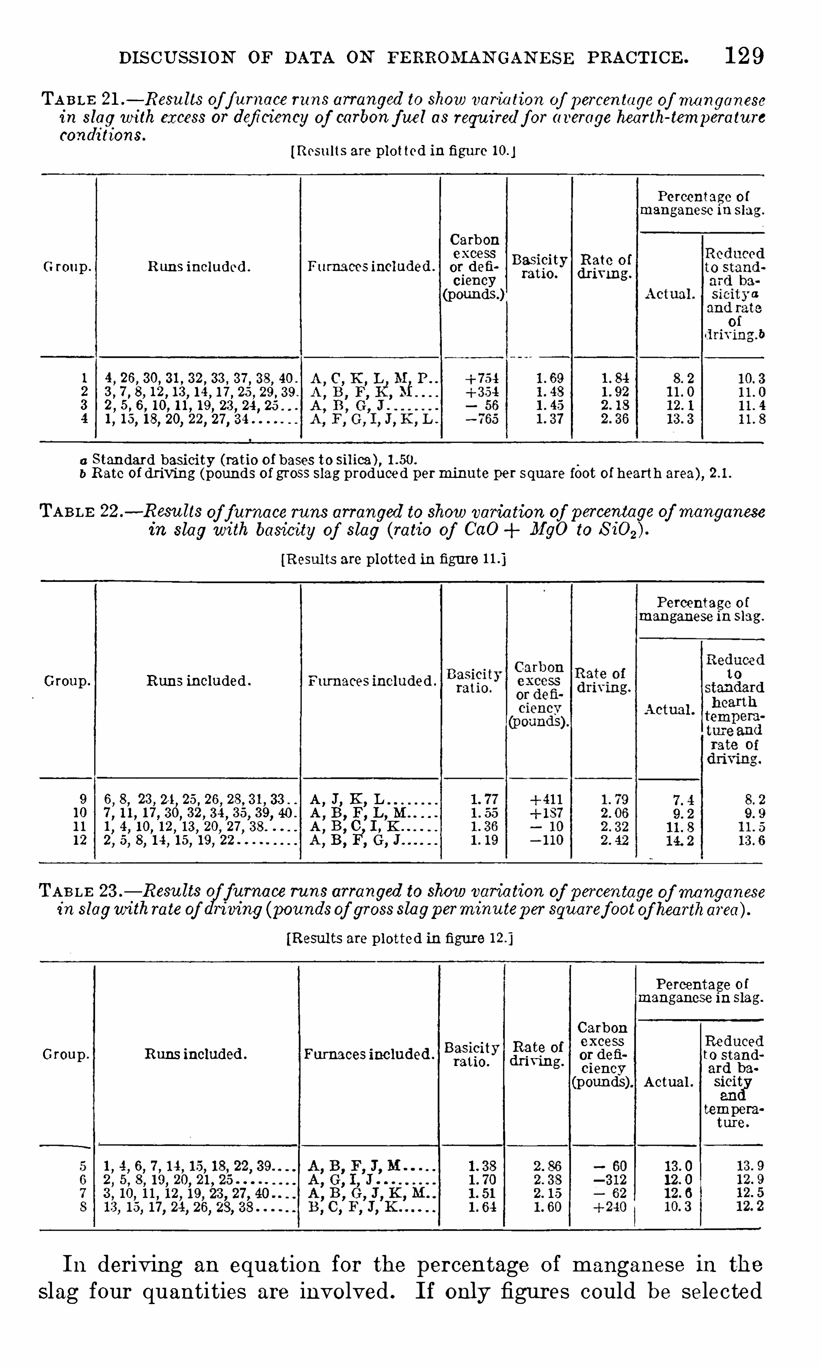
DISCUSS ION OF DATA ON FE RROMAN GAN E SE PRACTICE . 1 29
TA BLE 21 .— Resu lts of f urnace runs arranged to show variation of percentage of manganese
in slag with excess or deficiency of carbon f ue l as requ ired f or average hearth-temperatureconditions.
[Resu lts are plotted in figure
Percentage o fmanganese in slag .
Carbonexcess
G roup . Runs includcd . Furnaecs included .
B
gifgy (Egg?(pounds )
a Standard basicity (ratio of bases to silica ) ,b Rate of driving (pounds of gross slag produced perminute per square foot of hearth area) ,
TABLE 22 .—Resu lts of furnace runs arranged to show varia tion of percentage of manganesein slag with basicity of slag (ratio of CaO MgO to
[Resul ts are plotted in figure
Percentage o fmanganese in slag.
Group . Runs included . Furnaces included .
9 6,8, 23 , 2 1 , 25 , 26 , A
,J, K,
L1 0 1 7 , 3 0, 3 2, 3 4 , 3 5, 3 9, 40 . A
,B,F,L,M
1 1 1 4 1 0 1 2,1 3
,20
,27
,A
,B, C I ,
1 2 2 5 8
TAB LE 23 .— Resu lts
(q/furnace runs arranged to show variation of percentage of manganese
in slagwithrate of riving (poundsof gross slagperminu tep er squaref ootof heartharea ) .
[Resul ts are plotted in figure
Percentage of
manganese in slag.
CarbonRed (1excess uce
Group . Runs included . Furnaces included .
E
ffigy” fig“
or defi to standg.
ciency ard ba
(pounds) Actual . sicitan
temperature.
In deriving an equation for the percentage of manganese in the
Slag four quantities are involved . I f only figu res could be selected
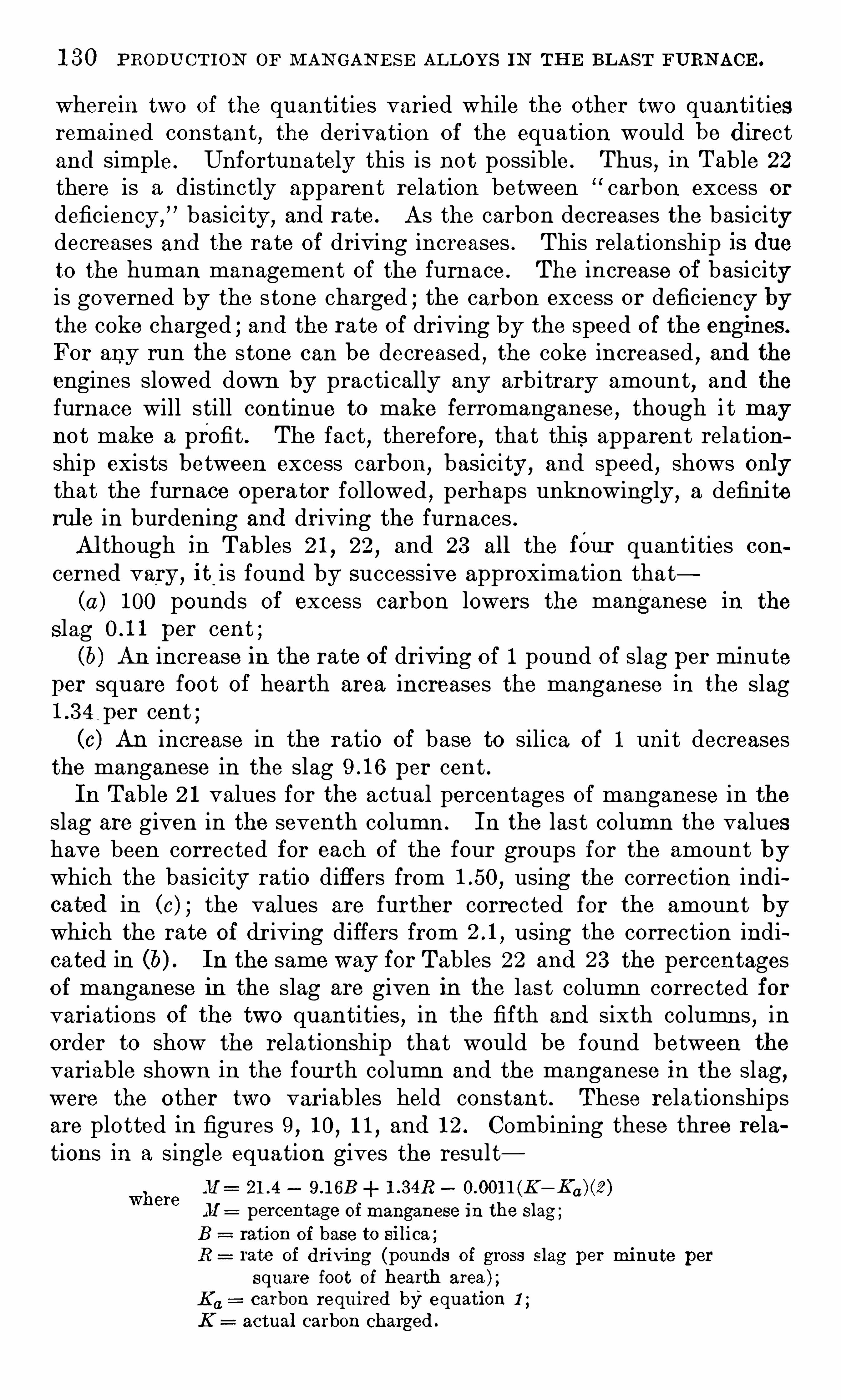
1 3 0 PRODU CTION OF M AN GAN E SE ALLOYS IN TH E BLAST FURN ACE .
wherein two of the quantities varied while the o ther two quantitiesremained constant, the derivation of the equation would be directand simple . Unfortunately this is not possible . Thus
,in Table 22
there is a distinctly apparent relation between “ carbon excess or
deficiency,” basici ty , and rate . As the carbon decreases the basicitydecreases and the rate of driving increases . This relationship is dueto the human management of the furnace . The increase of basicityis governed by the s tone charged ; the carbon excess or deficiency bythe coke charged ; and the rate of driving by the speed of the engines.
For any run the stone can be decreased,the coke increased , and the
engines slowed down by practically any arbitrary amount,and the
furnace will still continue to make ferromanganese,though i t may
not make a profit . The fact,therefore
,that this apparent relation
ship exists between excess carbon, basicity, and speed , shows onlythat the furnace opera tor followed
,perhaps unknowingly ,
a definiterule in burdening and driving the furnaces .Al though in Tables 2 1 , 22 , and 23 all the fOur quantities con
cerned vary , it_
is found by successive approximation that(a ) 1 00 pounds of excess carbon lowers the manganese in the
Slag per cent ;(b) An increase in the rate of driving of 1 pound of slag per minute
per square foot of hearth area increases the manganese in the slag1 .3 4
, per cent ;(0) An increase in the ratio of base to silica o f 1 uni t decreases
the manganese in the slag per cent .In Table 2 1 values for the actual percentages of manganese in the
slag are given in the seventh column . In the last column the valueshave been corrected for each of the four groups for the amount bywhich the basicity ratio differs from using the correction indicated in (c) ; the values are further corrected for the amount bywhich the rate of driving differs from using the correction indicated in (b) . In the same way for Tables 22 and 23 the percentagesof manganese in the slag are given in the last column corrected forvariations of the two quantities , in the fifth and sixth columns
,in
order to show the rela tionship that would be found between the
variable shown in the fourth column and the manganese in the slag,
were the o ther two variables held constant . These rela tionshipsare plo tted in figures 9
,1 0
,1 1 and 1 2 . Combining these three rela
tions in a single equation gives the resultM : 0.001 1 (K
M percentage of manganese in the slag ;
B ration of base to silica ;R rate of driving (pounds of gross Slag per minu te per
square foot of hearth area ) ;E u carbon required by equation 1 ;
K actual carbon charged .
where

1 3 2 PRODUCT ION or M AN GAN E SE AL LOYS IN TH E BLAST FURN ACE .
ciable, causes a decided decrease in profits of the furnace and, al thoug hin line with conserva tion of materials , will not appeal to the Operatorwho is to pay the labor and overhead charges .I t may be stated that the most effective methods of reducing the
slag loss of manganese are : (1 ) The use of low-ash coke and of low
silica stone and (2) carrying as basic a slag as is practicable. In
the matter of selecting a low—ash coke i t was not possible , perhaps ,in the pas t year for a number of operators to do more than take whatever they could get .
I t ‘ was universally realized at the furnace that the presence of
a large percentage of silica in the coke was playing havoc with thepractice ; bu t i t i s believed that , had the office fully appreciated theloss in profits occasioned by excess silica a considerable improvementin coke could have been effect-cd . Actual purchases of s tone
,i t is
certain,have not been made with the care the problem meri ted .
Calcites and dolomites have been used wi th silica content as high as
7 per cent . N atural ly the office did not purchase this stone on the
market withou t a considerable preferential price, but, as is shovvnlater, s tone with this sil ica conten t should not be used even if obtainedfree of charge f . o . b . the furnace .
S TACK L O S S .
The sum o f the manganese in the slag and tha t in the metal doesnot equal that charged into the furna ce. The percentage of manganese in the charge not accounted for by the mang anese carried fromthe hearth is for convenience called “ s tack loss . The value of thisquantity in Table 1 7 varies from to per cent . I ts averageis p er cent . As the average loss of manganese in the slag isonly per cent, the stack loss is as important as the slag loss .I t is a quantity, however, that has not thus far proved itself susceptible to analysis or defin ite explana tion. I t may be due to : (1 )Volatilization of metallic manganese from the hearth , (2) volatilization of manganese Oxide in the hearth or stack
, (3 ) manganese oxidecarried off mechanically as ore fines by the blast , and (4) a fictitiousresult due to error in chemical analyses and weights .To a certain extent in any individual run the apparent stack loss
is surely a combined resul t of these four causes . But for the 40
runs taken as a whole i t is difficult to understand how errors in weightsand analyses woul d give a loss in 3 9 cases , instead of g iving foronehalf of the runs a gain of manganese in the stack .
” Unl ess i t canbe Shown that the analyses for manganese in the ore are systemati
cally high or those for manganese in the slag and metal are systemati
cally low ,i t must be concluded that the errors are sufficiently elimi
nated in the average Of a number of runs .

DIS CUSS ION or DATA ON PERROMAN GAN E SE PRACTICE . 1 3 3
There is a possibility that the loss as ore fines carried ou t mechanically by the blast may account for the whole loss .
The Operating data from nine iron furnace. plant-S indicate thatper cent of the iron charged is not accounted for by the iron in
the slag and metal . This figure does not inspire much confidenceand is given here only for the sake of comparison . As to the lossby volatilization ,
i t is probably not important practically to disting u ish between volatiliz a tion of metallic manganese and volatilization of manganese oxide. The answer to this problem willappear doubtless , when the rela tion is found between s tack loss andsome other Opera ting quantity. I f the s tack loss is a volatiliza tionphenomenon,
i t Should increase with a rise in hearth temperature.
I t should also decrease with any increas e in the speed of Opera tion,
as the longer a given poun d of slag or metal remains in the hearththe greater the volatilization. The 40 runs in Table 1 7 were arrangedin the order of decreasing s tack loss and divided into four groups .The average for each Of the four groups appears in Table 24 followingTAB LE 24 .
— Resu lts of f urnace runs arranged to show manganese lost in stack as relatedto otherf actors .
0 Pounds of gross perminute per square foot of hearth area .
The results presented in the table show a manganese loss for eachgroup of runs
,but no systematic variation of stack loss with any
other probably related quantity . High hearth temperatures as in
dicated either by high-silicon metal, excess carbon, basic slag , or
low percentage of mang anese in the slag appear not to affect theamount of stack loss . There is only one practical conclusion to be
formed— the furnace man mus t adm i t that the stack loss is an
important physical constant and shoul d opera te his furnace on thatassumption
,or he must conclude that the data here presented are in
sufficient to permit a solution of the problem and Obtain for himselfmore complete and exact furnace records .
S OME T YP I CAL C AL CUL ATI ON S .
To illustrate the use o f calcul ations suggested in this report, toindicate how many factors are involved in the simples t detail Offurnace practice, and to serve as an introduction to the operatingproblem,
a brief outline Of the factors involved in the selection of
coke and s tone follows .

1 3 4“
PRODU CTION OF M AN GAN E SE AL LOYS I N THE BLAST FURN ACE .
CO ST FI GUR E S FOR AVE RAGE PRACTI C E .
For the sake of comparison a computation of the approxima tefurnace costs for the average run represented in Table 1 7 apart frominvestment charges , may be of interest .The average charge per ton of metal is tons of ore, tons
of coke,and tons of stone. At the arbitrary prices of $40, $ 1 0,
and $ 3 per ton,f . o . b . furnace, the materials cos t per ton of
metal made. The follow ing daily cos ts are assumed : Six hundreddoll ars for labor, and $ 1 7 5 for the aggregate of superintendence, chemical laboratory, and reserve for relining, repairs , liability insur ance,clerical work, demurrage, supplies , etc . Thus there is a total fixedcharge of $ 7 7 5 against a daily production of tons of ferromanga
nese,or a
_
charge of per ton. Hence the total cost per ton isThe sell ing price on per cent ferromanganese i s taken
to be per tenfor 7 0 per cent all oy plus or minusper uni t of manganese) , so that the profit per ton is or
per day .
COKE ASH .
The foll owing analyses of cokeare taken from furnace records andalthough the coke represented is not typical Of that used in averagepractice, i t is not abnormal
,as millions of tons of such coke have
been used annually at certain iron furnaces for years .
Ana lyses of cokeused in certain iron f urnaces.
Fixed Volatil ecarbon. matter.
Sul phur. Moisture.
P er cent. P er cent. P er cent. P er cent.90. 95 0. 7 9 0. 4 1 1 . 3 59 1 . 1 2 4 7 44 1 . 52
91 . 06 1 . 1 8 80 1 . 40
Let i t be assumed tha t coke 1 is available for a ferro campaignand that stone of grade “ A
,
”as described in the section following
(“ Selection of is also available. Let the ore have the average analysis given ih Table 1 7 . Then i t is possible to construct acharge sheet for these materials to give approximately the maximumdaily profits , subject to the - limitation that none of the Opera tingquantities shall lie appreciably beyond what has been tried ou t as
shown by Table 1 7 . The charge will be then as followsAna lysis of charge.
Material .
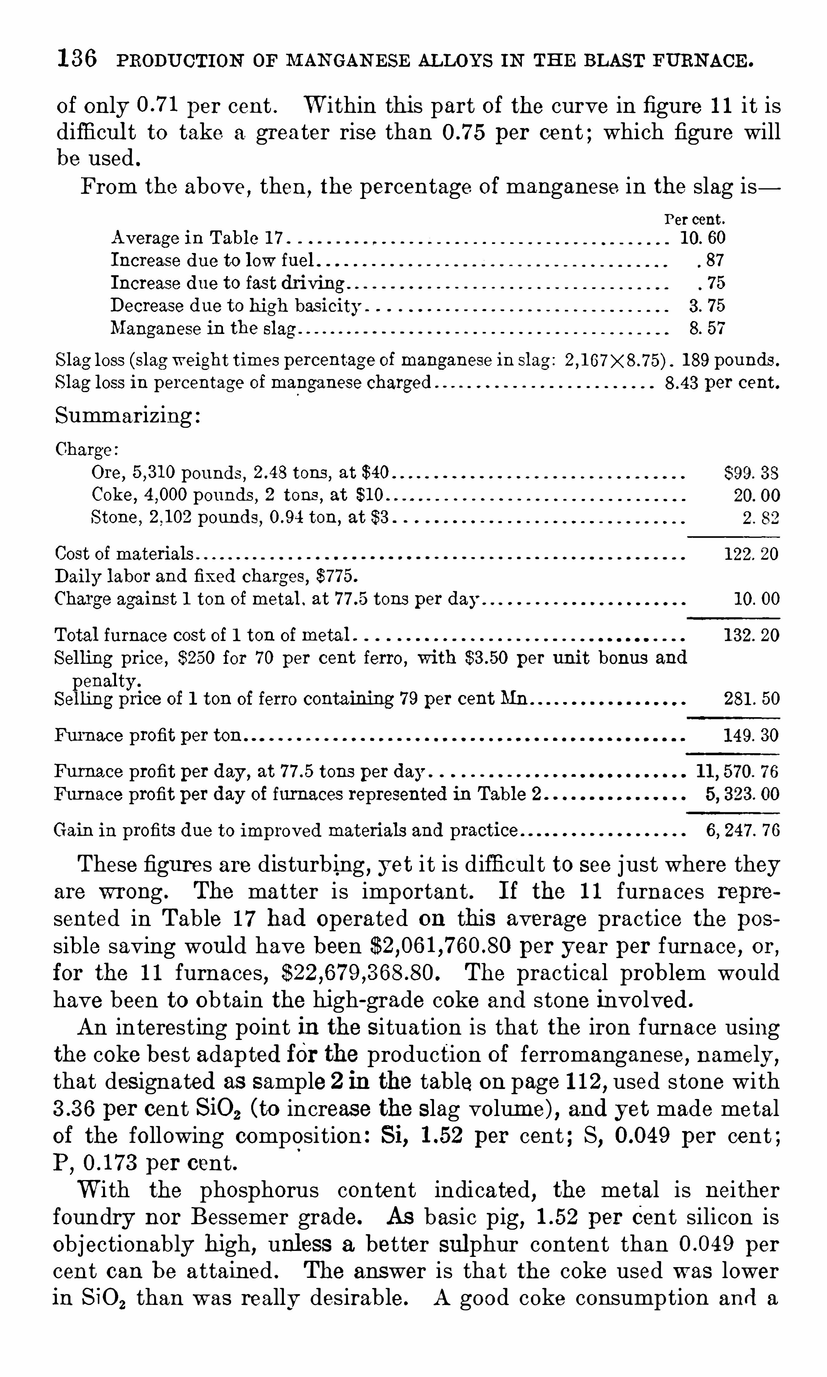
1 3 6 PRODUCTION OF M AN GAN ESE ALLOYS IN THE BLAST FURNACE .
of only per cent . W ithin this part of the curve in figure 1 1 i t isdifficul t to take a. greater rise than per cent ; which figure willbe used .
From the above , then,the percentage of manganese in the slag is
Percent.
Average in Table 1 7 . 1 0. 60
Increase due to low fuel 87
Increase due to fast driving 7 5
Decrease due to high basicity . 3 . 7 5
Manganese in the slag 8. 57
Slag loss (slag weight times percentage of manganese in slag : 2 1 89 pounds .
Slag loss in percentage of manganese charged per cent.
SummarizingCharge :
Ore, pounds , tons , at $40
Coke , pounds , 2 tons, at $ 1 0
Stone , pounds,
ton, at $3 .
Cost of materials 1 22. 20
Daily labor and fixed Charges, $7 7 5 .
Charge against 1 ton of metal . at tons per day 1 0. 00
Total furnace cost of 1 ton of metal . 1 3 2. 20
Sel ling price , $250 for 7 0 per cent ferro, with per unit bonus and
penaltySel ling pri ce of 1 ton of ferro containing 7 9 per cent Mn 281 . 50
Furnace profit per ton . 1 49. 30
Furnace profit per day ,at 7 tons per day .
Furnace profit per day of furnaces represented in Table 2
Gain in profits due to improved materials and practice 6 , 247 . 7 6
These figures are disturbing , yet i t is difficult to see j ust where theyare wrong . The matter is important . I f the 1 1 furnaces repre
sented in Table 1 7 had operated on this average practice the possible saving woul d have been per year per furnace, or,for the 1 1 furnaces, The practical prob lem wouldhave been to obtain the high-grade coke and stone involved .
An interesting point in the situation is that the iron furnace usingthe coke best adapted for the production of ferromanganese, namely ,that designated as sample 2 in the table on page 1 1 2, used stone with
per cent SiO2 (to increase the slag volume) , and yet made metalof the following composition : Si, per cent ; S, per cent ;P
, per cent .W i th the phosphorus content indicated, the metal is nei ther
foundry nor Bessemer grade. As basic pig, per Cent silicon isobjectionably high, unless a better sulphur content than per
cent can be attained . The answer is that the coke used was lowerin S iO2 than was really desirable . A good coke consumption and a

DISCUSS ION OF DATA ON FEBROMAN GAN E SE PRACTICE . 1 3 7
fair tonnage can be shown with low-silica coke and stone , but inbasic practice, where the logical function of the blast furnace is tokeep down the sul phur and the silicon , the slag volume Should not
be so low that i t can not take care Of the sulphur.
Undoubtedly the operator of the basic furnace above mentionedrealized this . Enough commercial pressure would have made himrelease this coke . H
0
the ferro furnace had paid $20 per ton for lowsilica coke, the daily profit would still have been per furnace,an improvement of per day , or roughly 1 00 per cent . I f the
desired quali ty of coke coul d have been procured for $20 per ton,and
if the o ther assumptions are correct , the increased profit for any one
furnace would have been p er annum .
S E L E CT IO N 0 1" STON'E .
As a typical problem relating to the selection of stone for use in
furnaces producing ferromanganese, two grades of stone may be
assumed to be under consideration . One may be designated gradeA , containing 53 per cent bas ic constituents and per centsil ica ; the other may be designated grade B
,containing per
cent basic consti tuents and 7 per cent S ilica . Stone of grade Ahas been used in great quantities at one iron furnace plant , and
hence is not of pure ly hypothetical composition. Stone Of grade Bhas been used in producing ferromanganese .
I f all the values , excep t for the grades of stone, be taken as for theaverage run represented in Table 1 7 a comparison can be made as
follows :Comparative resu lts obtained with two grades of stone.
Constituent orcharge.
The foregoing data are based on the as sumption that the slag hasa constant basicity rat io of and that an increase of 1 pound inthe rate of slag formation requires an increase in carbon of
pound .
The gross slag produced per ton of metal when stone A is used ispounds
, and when stone B is used pounds . If the rateof driving be assumed to be constant , the tonn ages will be tons
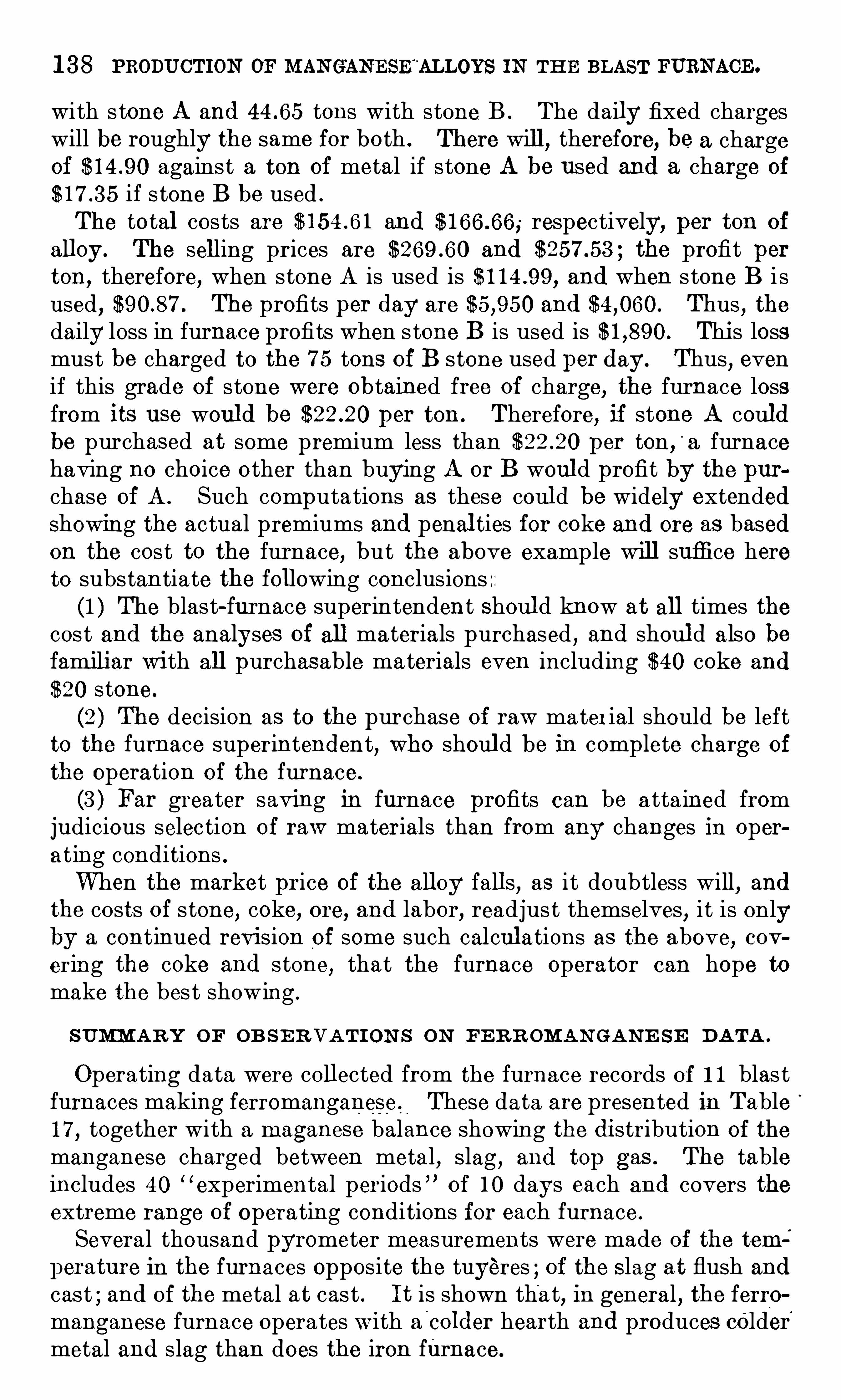
1 3 8 PRODUCTION OF MAN GAN ESE'
ALLOYS IN TH E BLAST FURNACE .
with stone A and tons with stone B . The daily fixed chargeswill be roughly the same for both . There will , therefore, be a chargeof against a ton of metal if stone A be used and a charge of
if stone B be used .
The total costs are and respectively, per ton of
all oy. The selling prices are and the profit perton,
therefore, when stone A is used is and when stone B i sused , The profits per day are and Thus
, the
daily loss in furnace profits when stone B is used is This lossmust be charged to the 7 5 tons of B stone used per day. Thus, evenif this grade of stone were obtained free of charge, the furnace lossfrom its use woul d be per ton . Therefore, if stone A couldbe purchased at some premium less than per ton ,
'
a furnacehaving no choice other than buying A or B woul d profit by the purchase Oi A . Such computations as these could be widely extendedshowing the actual premiums and penal ties for coke and ore as basedon the cost to the furnace, but the above example will suffice hereto substantiate the following conclusions(1 ) The blast-furnace superintendent Should know at all times the
cost and the analyses of all materials purchased , and shoul d also befamiliar with all purchasable materials even including $40 coke and
$20 stone.
(2 ) The decision as to the purchase of raw material should be leftto the furnace superintendent, who should be in complete charge of
the operation of the furnace.
(3 ) Far greater saving in furnace profits can be attained fromjudicious selection Of raw materials than from any changes in Operating conditions .When the market price of the alloy falls , as i t doubtless will, and
the costs of stone, coke, ore, and labor, readjust themselves, i t is onlyby a continued revision of some such calcul ations as the above, covering the coke and stone, that the furnace operator can hope tomake the bes t showing .
S UMZM AR Y OF OB S E R VAT I ON S ON FE R R OMAN GAN E S E DATA .
Operating data were coll ected from the furnace records of 1 1 blas tfurnaces making ferromanganese , These data are presented in Table1 7 , together with a maganese balance showing the distribution of the
manganese charged between metal , slag, and top gas . The tableincludes 40 “
experimental periods ” of 1 0 days each and covers theextreme range of Operating conditions for each furnace.
Several thousand pyrometer measurements were made of the tem
perature in the furnaces opposite the tuyeres of the S lag at flush andcast ; and of the metal at cast . I t is shown that, in general , the ferromanganese furnace operates w ith a
'
colder hearth and produces colder'
metal and slag than does the iron furnace .

1 40 PRODU CT ION OF M AN GAN E SE ALLOYS I N TH E BLAST FURN ACE .
making manganese . I t is desirable, therefore, that the two processesbe kept separate . The only logical reason, O f course, formaking spiegeleisen at all is to utilize manganiferous iron ores . Spiegeleisen hasnot
,however, always been made in this way . The manganese con
tent oi the metal made is frequently reduced by the addition of ironore or of iron scrap to the charge . During the year 1 9 1 8 , pressurefrom several sources was brought to bear upon the manganese producers to lower the manganese content of their alloys . The prevailing standard for ferromanganese was lowered from 80 to 7 2 per cent ,and for Spiegeleisen from 20 to 1 6 per cent . To the extent that thiswas done with the use of lower grade ores , i t served a real purpose bycrea ting a market for o therwise unsalable ores . I t should be remembered , however, that such a process was wasteful of coke and man
ganese, and caused decreased furnace tonnage. The rather analagous method of
“ sweetening a spiegel ore mixture with high-grademanganese ore is equally objectionable from the standpoint of a
metallurgist .The average Spiegel analysis given in Table 1 8 (p . 1 1 6 ) shows that
in order to produce 1 ton of manganese, tons of Spiegel was re
quired . This alloy contained about tons of metalli c iron, the
equivalen t of tons of pig iron . The carbon fuel required tomake tons of spiegel is pounds Creditingthis metal with the amount Of carbon required for making tonsof pig iron ,
namely, pounds of carbon mul tiplied by tonsOf pig iron, or pounds total, i t is seen tha t the ton of metal licmanganese in the form of sp iegel requires pounds of carbon .
I t is clear that in tons o f 7 per cent alloy there is 1 ton of
metallic manganese and ton of metalli c iron . the equivalent ofton of pig iron . The fuel consumption was pounds of
carbon according to Table 1 7 . Giving credit for 420pounds (1 7 27 X for the iron made, 1 ton of manganese in the formof ferro requires pounds Of carbon . Thus, i t appears that aton of manganese in the form of spiegel requires 7 8 per cen t morecarbon fuel than a ton of manganese in the form of ferro .
This result is by no means due wholly, or even largely, to the
mere combination of the two smelting processes . Most of the excessfuel requirement is due to the character of the ferro ores and of the
spiegel ores used . The manganese and S ilica contents of the two
ores are :Manganese , per cent .
Silica , per cent .
Silica per pound of manganese , pounds
The average spiegel ores were therefore 5 % times as siliceous as theferro ores .
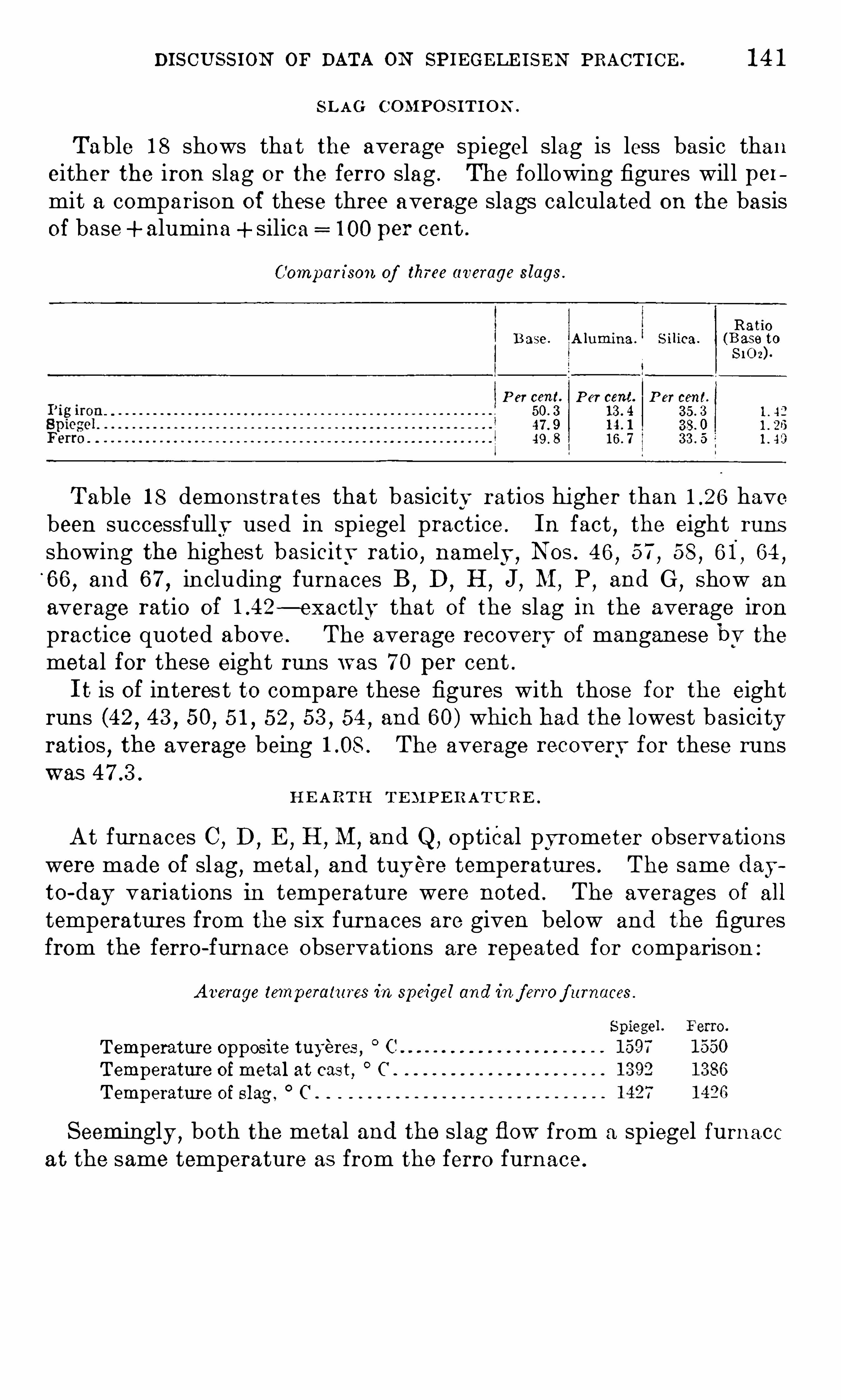
DISCUSS ION OF DATA ON SPIEGELE ISEN PRACTICE . 1 4 1
S L AG C OMPO S IT I O N .
Table 1 8 shows that the average Spiegel slag is less basic thaneither the iron slag or the ferro slag . The following figures will permit a comparison of these three average slags calculated on the basisof base+ alumina + silica 1 00 per cent..
Comparison of three average slags .
RatioB ase . A lumina . S ilica . (B ase to
$ 1 0 -z) .
P er cent. P er cent. P er cent.
1 3 . 4 3 5 . 347 . 9 3 8. 049 . 8 1 6 . 7 3 3 . 5
Table 1 8 demonstrates that basicity ratios higher than have.been successfully used in spiegel practice . In fact
,the eight runs
showing the highest basicitv ratio,namely ,
N os . 4 6,5 7
,58
,6 1
,64
,
66,and 6 7
,including furnaces B
,D
,H
,J,M
,P
,and G
,Show an
average ratio of — exactly that of the slag in the average ironpractice quoted above . The average recovery of manganese bv themetal for these eight runs was 7 0 per cent .
I t is of interes t to compare these figures with those for the eightruns (42 , 4 3 , 50, 5 1 , 52 , 5 3 , 54 , and 60) which had the lowest basicityratios
,the average being The average recovervfor these runs
was
H E ARTH T E M PE R ATURE .
At furnaces C,D
,E
,H
,M
,and Q, Optical pyrometer observations
were made of slag,metal
,and tuyere temperatures . The same day
to-day variations in temperature were noted . The averages of all
temperatures from the six furnaces are given below and the figuresfrom the ferro-furnace Observations are repeated for comparison :
Average temperatures in speigel and in f errof urnaces .
Temperature opposite tuyeres , C
Temperature of metal at cast, C
Temperature of slag , C .
Seemingly ,both the metal and the slag flow from a spiegel furnace
at the same temperature as from the ferro furnace .

1 42 PRODUCTION OF MAN GAN ESE ALLOYS IN THE BLAST FURNACE .
COMPO S IT ION OF FURN ACE GA S .
A nalyses of spiegel furnace gas were made by the bureau ’s fieldparty at only four furnaces . The composition Of the gas as indicatedby the average of all the observations was as follows :
Average composition of speigel f urnace gas .
By Byvolume. weight.00 2 . . per cent . 7 . 08 1 1 . 05
do . 3 0. 40
These figures are not at all satisfactory . The CO content is nearlyas high as in ferromanganese-furnace gas . I t is difficul t to chargethis resul t to ordinary analytical errors . Leakage of air in to the
sample would lower the CO content ; also ,the estimation of C0 by
cuprou’ s chloride absorption when improperly carried ou t gives a
resul t too low rather than too high . The average analyses for the fourfurnaces gave and per cent for CO2
content andand per cent for the CO content . The
extreme limits for CO2 were and per cent ; and for CO ,
and per cent . This range of variation is the same as that encountered in ferromanganese-furnace gas . This fact points stronglyto the conclusion that in both Of these alloy furnaces , the chemicalreactions in the lower part of the furnace are continuously changing .
I t might almost be said to prove that for a period Of time the boshand hearth reactions are nearly those of the iron furnace
,and that
following this period as a result of the settling down of the stock, a
large amoun t of manganese oxide is thrown into the hearth, resulting in a rapid reduction of MnO ,
with a consequent increase in the
ratio of CO to 00 2 . Therefore,unless more or less continuous samples
of furnace gas are taken over a rather long period,the actual analysis
might easily misrepresent the true average composition of the furnace gas .
C ARBON BURN E D AT TH E TUYE RE S .
From what has been said in regard to the gas analyses it will beanticipated that a calcul ation of the amount of carbon burned at
the tuyeres and of the carbon absorbed by C0 2 (or“
the carbonused in direct reduction will show figures that will have little significance . Table 25 following shows a calcul ation of the weight ofgas, the weight of blast , and the distribution of carbon between the
stack and the tuyeres . So‘long as the amount of carbon blown ou t
as flue dust must be guessed at ; and until systematic gas analysesare taken covering appreciable periods of time
,no satisfactory fig
ures for these quantities can be given . However,the figures 6 7 6
for the ferro furnace, 3 4 7 for the spiegel furnace, and 1 69 for the ironfurnace undoubtedly indicate, in a general qualitative way, the
pounds of carbon per ton of metal absorbed by C0 2.

1 44 PRODUCT ION OF M AN GAN E SE ALLOYS I N TH E BLAST FURN ACE .
On the assumption that the carbon fuel required for averagehearth temperature conditions can be written in the form
K,=A+B T+C l
'
where A,B
,and C are constants, the figures given in Table 26 are
sufficient to determine the va lue of the three constants . Substi
tuting in the above equation three times gives
4,I 7 5=A+ 825B+4 ,3 92C
From which it follows thatK
8=2
,3 65 (4)
As previously stated , K is the quantity of carbon per ton of metalused for any particul ar run . If , is the quantity that would be re
quired if the same thermal conditions were maintained in the furnaceas in the average furnace. Confusion has often arisen in discussions of blast-furnace fuel economy from identifying the carbon“ consumed in ”
the furnace with the carbon “required by ”
the
furnace . I t is true in iron furnace practice that for a givenproduct there is a min imum carbon consumption belowwhich the furnace will not work
,but there is practically
no upper lim it . In making manganese alloys , however, i t may be
said that there is neither a maximum nor a minimum l imit . The
actual amount of carbon,K
,charged into any furnace is merely
the amount the operator believes necessary to maintain a givenratio of coke to ore. In each run
,therefore, K, the actual carbon
will differ from E a , the carbon that would on the average be chargedin a furnace working with that particular blast temperature and
slag weight . K— Ka is a measure of the thermal condition of the
hearth . I t Should be true that when K —Ka is positive the furnaceis running hotter than when K— Ka is negative, and this differencein available fuel Shoul d influence the amount. of MnO left un reducedin the slag .
PE RCE N TAGE OF M AN GAN E SE I N THE SL AG .
I t has been Shown for the ferromanganese furnace that M ,the
percentage of manganese in the slag, is a function of three quantities
,namely : B ,
the ratio of base to S ilica ; K Ka ,the excess carbon ;
and R, the rate Of S lag formation per square foot of hearth area .
The relation between the quantities was found to beM=21 .4 - 0. 1 1 (K— K
, )
In the same way, as is shownbelow ,for the spiegel furnace.
M=1 4 .3 — O.O9(K— K, ) (5 )
This equation is determined as folloW s : The runs in Table 1 8 ,arranged in order of decreasing basicity, are divided into two groups

DIS CUSS ION or DATA ON SPIEGELE ISEN PRACTICE . 1 4 5
of 1 5 runs each , group 1 representi ng runs having the highest basicityand group 2 those having the lowest . T he runs are rearranged inorder of decreasing K— Ka ,
and two further groups— group 3 , rep
resenting run s w ith excess carbon,and group 4
,representing runs
th deficiency of carbon— are selected . The average values of M
B,and K— Ka for these four groups appear in Table 2 7 .
TABLE 27 .
— Results of f arnace runs arranged to show varia tion of manganese in slagaccording to basicity of slag and according to excess or defiewncg of carbon f ue l .
E xcess ManganeseGroup . Basicity .
carbon . in slag .
From these figures,assuming that the value of M can be expressed
in the form given in equation 5,a simple calculation shows : (a )
That one unit increase in basicity lowers the manganese in the slagper cent ; (b) That 1 00 pounds of carbon lowers the manganese
in the S lag per cent .To Show that the rate Of driving does not affect the manganesecontent of the S lag
,the runs can be again rearranged in order of
decreasing R (rate of slag formation p er square foot of hearth area) ,giving two further groups — group 5 representing runs with fastdriving, and group 6
,representing runs with slow driving . The
average values of M,B
,K— Ka,
and R for groups 5 and 6 ar e givenin Table 28 .
TAB LE 28 .
— Resu lts of f ztrnace runs arranged to show variation of manganese in slag
according to rate of driving .
Basicity ratio
Excess carbon ,pounds .
Rate of driving, expressed in pounds of slagmade permin
u te per square foot of hearth area .
Mn in slag, per cent .
Al though the rate of driving differs by pounds of S lag perminute p er square foot Of hearth area
,the difference of p er
cent manganese in the S lag is exactly accounted for by the diff erencein the values of B and of K— Ka . This might well have been anticipated . The curve in figure 1 0
, (p . Showing the relation of the
percentage of manganese in the S lag to the rate of dr iving for theferromanganese furnace
,is convex downward . W hen two or more
pounds of S lag per square foot of hearth area is being produced, thetime factor is Of importance. The lower end Of this curve, however,shows a distinct flattening with a dr iving rate as low as pounds Of
slag p er minute . I t is a peculiar coincidence that the average rate

1 4 6 PRODU CTION OF M AN GAN E SE AL LOYS IN TH E BLAST FURN ACE .
Of slag -formation in both the spiegel practice and in the ferro prac
tice is just AS regards merely the reduction of MnO,there
seems to be no necessity for running the spiegel furnace as S low as
the ferro furnace . There is S O much more MnO per pound of grossferro slag to be reduced that the ferro slag Shoul d probably enterthe hearth only at one—third the rate that is found economical inspiegel practice.
Seemingly, two conclusions may be drawn from these facts :(1 ) That overdriving results in a loss of manganese
,whil e under
driving does not resul t in any corresponding saving of manganese.
(2 ) That the spiegel furnaces investigated were driven muchS lower than is shown necessary by any facts presented in this paper.
I t is,of course
,possible that through other causes furnace ditfi
cultice might arise with fast driving, although no evidence of suchan effect is at hand .
S TACK L O S S .
The‘ stack loss is a factor of less importance in the spregel furnace
than in the ferro furnace ; the average value is only per cent ,whereas for ferromanganese i t was Shown to be per cent . The
Individual values vary from + 3 92 to a range of per
cent . The individual values for ferro stack loss varied over a rangeof per cent .The stack loss shown in Table 1 8 does not seem to be connected
with any of the other operating quantities . The 3 0 runs were dividedin half
,giving two groups of 1 5 runs each ; one group included runs
with the larger stack losses and the other included runs with thesmal ler stack losses . The average values of the figures that mayhave some possible connection are given in Table 29 following
TAB LE 29 .
— Resu lts o f f arnace runs arranged to show comparative ej ects of large and
of sma l l stack losses .
I tem.
Stack loss, per cent
Silicon in the metal , per cent .
Basicity
Blast temperature,°F.
Top temperature,°F.
Slag per ton ,pounds .
Manganese in slag, per cent
Carbon burned ,pounds .
Recovery , per cent
Excess carbon ,pounds .
The difference between the stack losses in the two groups isper cent . N one of the other factors
,however
,Show enough varia
tion to be responsible for such a change in the stack loss . In the
first group the S ilicon content in the metal is higher,as is also the
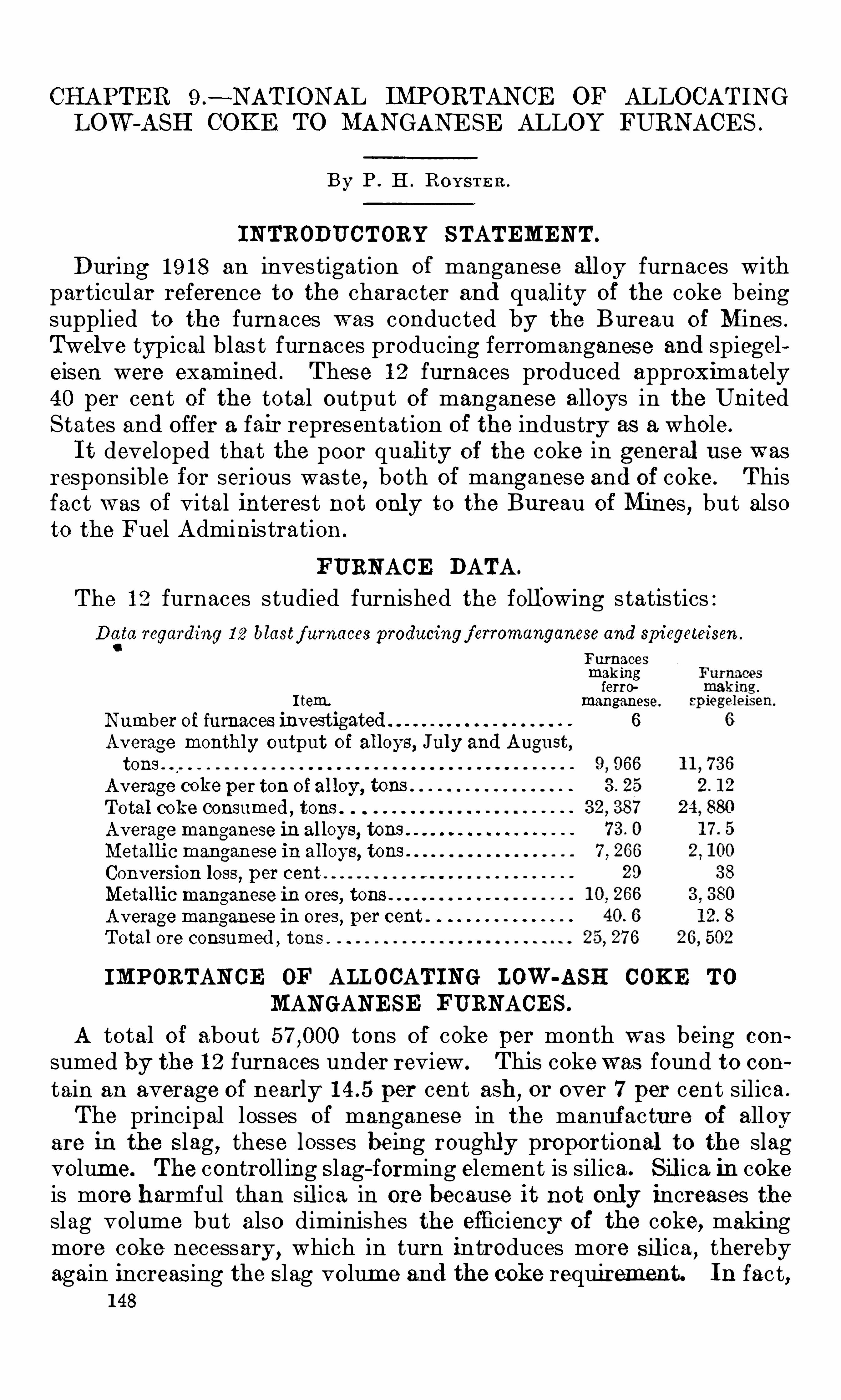
CHAPTER 9 .
—NATIONAL IMPORTANCE OF ALLOCATINGLOW -ASH COKE TO MANGANE SE ALLOY FURNACE S .
By P . H . ROYS TE R .
INTRODUCTORY STATEMENT.
During 1 9 1 8 an investigation of manganese al loy furnaces withparticular reference to the character and quality of the coke beingsupplied to the furnaces was conducted by the Bureau of Mines .
Twelve typical blas t furnaces producing ferromanganes e and spiegeleisen were examined . These 1 2 furnaces produced approximately40 per cent of the tota l output of manganese alloys in the UnitedStates and Offer a fair representation of the industry as a whole.
I t developed that the poor qual ity of the coke in general use wasresponsible for serious waste, both of manganese and of coke. Thisfact was of vital interest not onl y to the Bureau of Mines , but alsoto the Fuel Administration .
FURNACE DATA.
The 1 2 furnaces studied furnished the foll owing statistics :Data regarding 1 2 blastf urnaces producingf erromanganese and spiegeteisen .
C
Furnacesmakingferro
I tem. manganese.
Number of furnaces investigated 6
Average monthly output of al loys, July and August,tons
Average coke per ton of al loy , tons
Total coke consumed, tons .
Average manganese in al loys, tons
Metal lic manganese in alloys, tons .
Conversion loss, p er centMetallic manganese in ores, tons .
Average manganese in ores, per cent .
Total ore consumed ,tons .
IMPORTAN CE OF ALLOCATING LOW -ASH COKE TO
MANGANESE FURNACES .
A total of about tons of coke per month was being con
sumed by the 1 2 furnaces under review. This cokewas found to contain an average of nearly per cent ash, or over 7 per cent silica .
The principal losses of manganese in the manuf acture of alloyare in the S lag
,these losses being roughly proportional to the slag
volume. The controll ing S lag-forming element is silica. S il ica in cokeis more harmful than sil ica in ore because it not only increases theslag volume but also diminishes the efficiency of the coke, makingmore coke necessary , which in turn introduces more S il ica , therebyagain increas ing the S lag volume and the coke requirement. In fact,
1 48
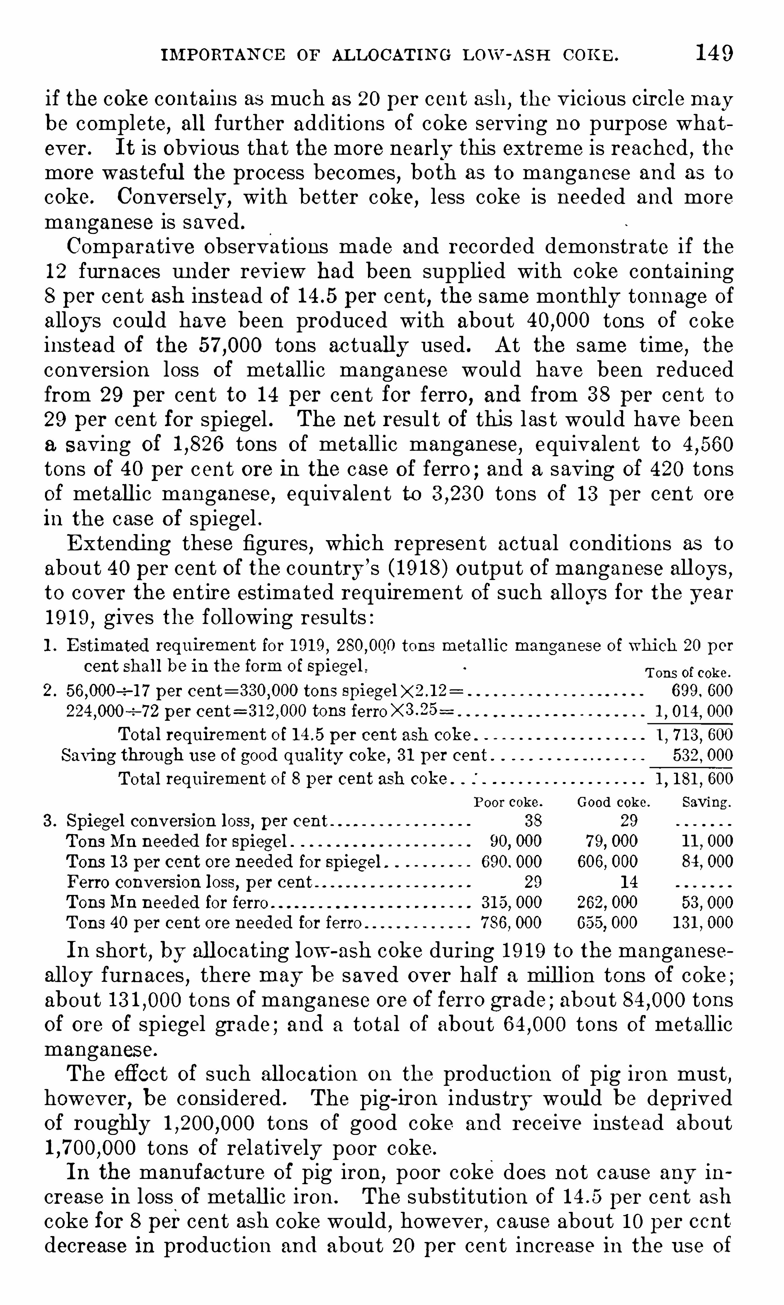
IM PORTAN CE or AL LOCATIN G L OW -ASH COKE . 1 4 9
if the coke contains as much as 20 per cent ash, the vicious circle may
be complete, all further additions of coke serving no purpose whatever. I t is obvious that the more nearly this extreme is reached , themore was teful the process becomes , both as to manganese and as to
coke. Conversely, with better coke, less coke is needed and more
manganese is saved .
Comparative observations made and recorded demonstrate if the1 2 furnaces u nder review had been supplied with coke containing8 per cent ash ins tead of per cent, the same monthly tonnage of
alloys coul d have been produced with about tons of cokeinstead of the tons actually used . At the same time
,the
conversion loss of metallic manganese would have been reducedfrom 29 per cent to 1 4 per cent for ferro, and from 3 8 per cent to29 per cent for spiegel . The net resul t of this las t would have beena saving of tons of metallic manganese, equivalent totons of 40 per c ent ore in the case of ferro ; and a saving of 420 tonsof metall ic manganese, equivalent to tons of 1 3 per cent orein the case of spiegel .E xtending these figures
,which represent actual conditions as to
about 40 per cent of the country’s (1 9 1 8 ) output of manganese all oys ,
to cover the entire estimated requirement of such alloys for the year1 9 1 9 , gives the following results :1 . E stimated requirement for 1 91 9 , tons metal lic manganese of which 20 per
cent shal l be in the form of spiegel Tons of coke.
2 .-z—1 7 per cent=3 30,000 tons 699. 600
p er cent=3 1 2 ,000 tons ferro X 3 .25 1, 01 4 , 000
Total requirement of per cent ash coke 1, 7 1 3 , 600
Saving through use of good quality coke , 3 1 p er cent . 532 , 000
Total requirement of 8 per cent ash coke . 1,1 81 , 600
Poor coke. Good coke. Saving .
3 . Spiegel conversion loss, p er cent 3 8 29
Tons Mn needed for spiegel 90, 000 7 9, 000
Tons 1 3 per cent ore needed for spiegel . 690. 000 606, 000
Ferro conversion loss, per cent 29 1 4
Tons Mn needed for ferro 3 1 5 , 000 262, 000 53 , 000
Tons 40 per cent ore needed for ferro 7 86,000 655, 000 1 3 1 , 000
In short , by all ocat ing low-ash coke during 1 9 1 9 to the manganesealloy furnaces , there may be saved over half a mill ion tons of coke ;about tons of manganese ore of ferro grade ; about tonsof ore of spiegel grade ; and a total of about tons of metallicmanganese.
The effect of such all ocation on the production of pig iron must ,however
,be considered . The pig-iron industry woul d be deprived
of roughly tons of good coke and receive instead abouttons of relatively poor coke.
In the manufacture of pig iron,poor coke does not cause any in
creas e in loss of metall ic iron. The substitution of per cent ashcoke for 8 percent ash coke woul d , however, cause about 1 0 per ccntdecrease in production and about 20 per cent increase in the use of
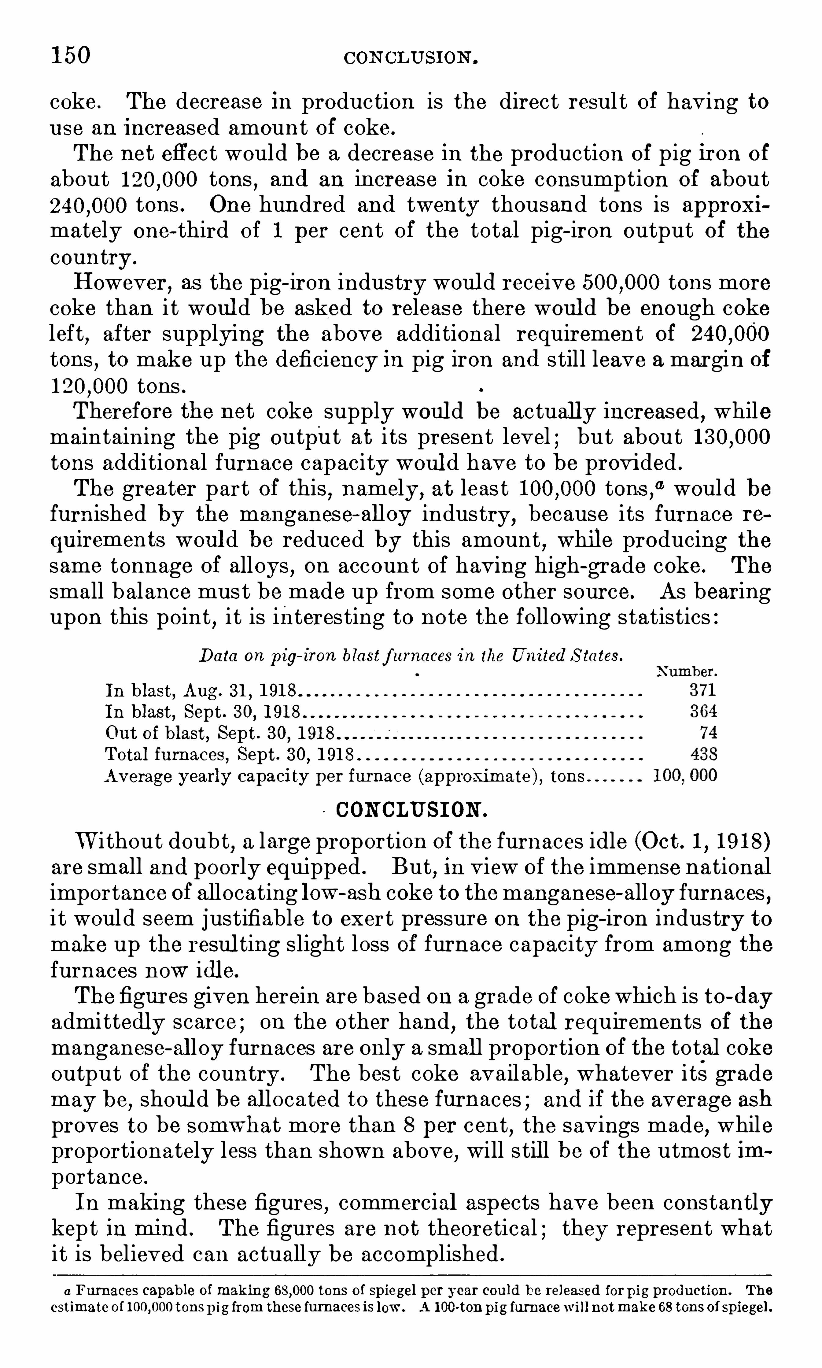
1 50 CON CLUS ION .
coke. The decrease in production is the direct resul t of having tou se an increased amount of coke.
The net effect would be a decrease in the production of pig iron of
about tons,and an increase in coke consumption of about
tons . One hundred and twenty thousand tons is approxi
mately one—third of 1 per cent of the total pig- iron output of thecountry .
However, as the pig- iron industry woul d receive tons more
coke than i t woul d be asked to releas e there woul d be enough cokeleft
,after supplying the above additional requirement of
tons,to make up the deficiency in pig iron and still leave a margin of
tons .Therefore the net coke supply woul d be actuall y increased , whilemaintaining the pig output at i ts present level ; but abouttons additional furnace capacity woul d have to be provided .
The greater part of this , namely ,at leas t tons
,
“ would befurnished by the manganese-alloy industry, because i ts furnace re
quirements woul d be reduced by this amount,while producing the
same tonnage of alloys , on accoun t of having high-grade coke . The
small balance must be made up from some other source. As bearingupon this point
,i t is interesting to note the following statistics :
Data on p ig- iron blastf urnaces in the United S tates.
In blast, Aug . 3 1 , 1 91 8
In blast, Sept. 3 0, 1 91 8
Out of blast, Sept. 3 0,1 91 8 .
Total furnaces, Sept. 3 0, 1 91 8 .
Average yearly capacity per furnace (approximate ) , tons
CON CLUSI ON .
W i thout doubt,a large proportion of the furnaces idle (Oct. 1 , 1 9 1 8 )
are small and poorly equipped . But,in view of the immense national
importance of allocating low-ash coke to themanganese-alloy furnaces ,i t would seem justifiable to exert pressure on the pig-iron industry tomake up the resul ting slight loss of furnace capacity from among thefurnaces now idl e.
The figures given herein are bas ed on a grade of cokewhich is to-dayadmittedly scarce ; on the other hand
,the total requirements of the
manganese-al loy furnaces are only a small proportion of the total cokeoutput of the country . The best coke available
,whatever its grade
may be, shoul d be al located to these furnaces ; and if the average ashproves to be somwhat more than 8 per cent, the savings made
,while
proportionately less than shown above,will s til l be of the utmost im
portance.
In making these figures,commercial aspects have been constantly
kept in mind . The figures are not theoretical ; they represent whatit is believed can actually be accomplished .
a Furnaces capable of making tons of spiegel per year cou ld be released forp ig production. The
estimateo f tons p ig from these furnaces is low . A 1 00-ton pig furnacewill notmake 68 tons of spiegel .

1 52 EL E CTRI C SM ELTIN G or DOM E ST IC M AN GAN E SE ORE S .
kilowatt furnaces at Great Falls, Mont .,on uncalcined rhodochrosite
ore from Butte, Mont . , and will probably also use some ore fromPhilipsburg, Mont . W ashed Philipsburg ore is also smelted by theBilroweAlloys CO .,
Tacoma,W ash , in six 3 50 to 400-kilowatt furnaces,and this firm has also smelted ore from the Olympic Mountains inW ashington .
The N oble E lectric Steel CO ., Heroul t, Calif .,smelts California ores
in two to -kilowatt furnaces . The Pacific E lectro MetalsCo .makes ferromanganeseand silicomanganesein a -kilowatt furnace at Bay Point, Calif ., from Cal ifornia ores .The Iron Mountain Alloy CO . , Utah Junction, Calif ., runs a
kilowatt and an -kilowatt furnace on Colorado , Utah, and
N evada Ores .
The W estern Reduction CO . , Portland , Oreg . ,is just starting the
production of ferromanganese in a 7 00-kilowatt furnace.
E LE CTRI C SME LTI NG PRACTI CE ON FERROMANGANE SE .
FURN ACE S U SE D .
Practice in making ferromanganese differs slightly at the variousplants, but in general is uniform . Keeney
“ has recently describedthe Iron Mountain Alloy Co .
’s practice . Furnace vol tages (electrode
to charge) run from 55 vol ts in the 3 50-kilowatt size to 85 in the—kilowatt size. The furnaces are usually three-phase, three—elec
trode, open-tOp furnaces, the exceptions being those of the Bilrowe
Alloys CO ., which are single-phase, and those of the N oble E lectricSteel CO .,
which are of a three-phase, four-electrode type. The
general type of furnace used is the rectangular form described byLyon, Keeney,
and Cull en? The N oble furnace is described byVom Baur.
c
The furnace lining is usually carbon or magnesite, rarely watercooled fire brick . The furnaces are charged continuously and
tapped every two hours . Slag and metal are tapped together intoa settler. A few plants use round electrodes jointed for continuousfeed, which shoul d reduce the electrode consumption . However,in mos t plants the feed is not continuous, and the butts are scrapped .
Seemingly, a Scott-connected , two-phase circuit from a three-phasecircuit with the conducting bottom of the furnace as the neutralelectrode, and two upper electrodes, might reduce the electrode con
sumption by presenting only two instead of three electrodes to oxidaa Keeney, R . M .
,Themanufacture of retro-alloys in the electric furnace. Bul l . Am. Inst. Min . E ng ,
vol . 1 40, August, 1 91 8, pp . 1 321—1 3 7 3 .
bLyon, D . A . , c uey, R . M .
, and Cu l len, J . F. The electric furnace in metal lurgical work : Bu ll . 7 7 ,Bureau of Mines, 1 91 4, p . 1 1 3 .
cRodcnhauser, W .
,Schoenawa, J and Vom Baur, C . E lectric furnaces in the iron and steel industry,
1 91 7 cd .
,p . 3 65 .
ELE CTRI C SM ELTIN G PRACTICE ON FERROMANGAN ESE . 1 5 3
tion,while still allowing the construction of a furnace of high kilowatt
capacity without the upper electrodes being required to carry too
much current .R AW M ATE R I A L S E MP L O YE D .
The ores of mixtures used at all these plants vary between to
p er cent manganese and 1 5 to 25 p er cent silica with low phosphorus, averaging about 40 per cent manganese, 20 per cent sil ica ,
per cent phosphorus , and less than 4 per cent ferro . The GreatFalls , Mont . , plant wil l be an exception , as it will Operate largely on
Butte rhodochrosite ore which is extremely low in silica and phosphorus .
The plants all flux the ore with limestone, except the plant at
Heroult, Cal if . , which uses a little fiuorspar. Also they produce a
S lag whose average composition is 1 0 to 1 2 per cent Mn ., 3 5
to 40 p er cent CaO +MgO ,about 3 0 p er cent SiO and such small
amounts of A1 20 3 as are carried by the ores . The latter are all low
in alumina with the exception of occasional lots smelted at Anniston , Al a .
AVE R A GE R E S U L T S OB TA INE D .
The power consumption and the electrode consumption in the
various furnaces,brought to the basis of a -kilowatt furnace
,
average kil owatt-hours and 1 7 0 pounds of carbon electrodesper long ton of 80 p er cent ferromanganese.
As the ores are low in iron ,a little iron ore, or better and more
generally used , some steel scrap,is added to supply enough iron to
bring the allov to 80 p er cent manganese. The all oy s containto p er cent phosphorus , the former figure being aimed at, butthe latter being taken by the trade whil e the ferro supply is low .
The California ores are low in phosphorus ; consequently the Califormia alloys meet the lower figure. The s ilicon content runs under2 p er cent , though it sometimes goes up to 5 p er cent in the Ann istonproduct when ores higher than usual in silica are employed .
The Ann iston,Anaconda
,and Iron Mounta in plants use anthracite
coal as reducer ; the Bay Po int and Tacoma plants use coke ; and theHeroult plant uses about half coke and half charcoal .The recovery of manganese averages 7 5 p er cent , being nearer 80
per cent on ores Of 1 5 p er cent silica and nearer 7 0 on those of 2 5
per cent sil ica content . From a sixth to a third of the conversionloss is due to volatil ization and dusting
,and slag losses account for
the rest . In the blas t furnace Operat ing on low silica ores theselosses are exactly reversed
,slag accounting for only a sixth to a
third and the rest being du e to vola tilization and dusti ng .
“
0 N ewt on,E dmund
,Mangani ierous iron ores of the Cuyuna District, M inn ,
B u l l . 5 , M inn School o fMines S ta ,
University of Minn ,1 9 1 8, p . 7 1 .
1 54 EL E CTRI C SM EL TIN G O'
F DOM ESTIC'
M AN C-AN E SE ORE S .
EFFE CT OF HI GH S I LI CA IN ORES .
I t is seen tha t the electric smelti ng plants use ores higher in' silicathan are standard for blast-furnace practice
, bu t‘
that 25 per centsilica is the present limit in ores used for making ferromanganese.
The trouble tha t silica causes is reflected in the manganese pricescale of the W ar Industries Board
,
“ by which an ore with 40 percentmanganese and 8 p er cent silica is worth p er ton and one
with 3 5 p er cent manganese and 3 5 per cent S ilica only , p er
ton . The scale does not“
run below 3 5 per cent manganese,but if it
did an ore with 2 7 p er cent manganese and 3 5 per cent silica wouldbe worth nothing , the penalty for silica entirely wiping out the valueof the manganese even though cal culated at the same price per unitas given in the scale for a 3 5 p er cent manganese content .
C ON C E N TR AT I ON OF OR E S .
The Philipsburg and the Butte, Mont .,districts contain vast ton
nages of manganese ores conta ining around 25 p er cent manganeseand 3 5 p er cent silica , to say nothing of the rhodonite ores of Colorado and of the ta ilings from concentrating ores by washing or
screeningb
Some concentration Of domestic ores is done,
6 but in general concentration, is not very successful d and a slight improvement in the
method of handl ing low-grade ores might make it more desirable tosmelt the run oi mine me than to attempt concentration . I t isstated e that some ores could be concentrated after fine crushing ;also that leaching and electrolytic deposition of the manganeseoxide is possible. The product would , however, be fine powdersand would be extremely difficult to smel t in the usual fashion , keeping the shaft full of charge, unless first briquetted or sintered . I t isnot certain that briquetting or sintering could be successfullyapplied .
R E DU CT I ON OF S I L I CON .
E ven though the usual basic slag be employed when smelting oreshigh in silica , silicon is reduced and enters the alloy when the slagvolume is high . Newton f s tates that this is true in the b las t furnace. Swann g also indicates i t for electric-furnace operation,
s tatingthat slags from electric smel ting containing 1 2 to 1 4 per cent Mn,
40
per cent CaO ,and 3 0 per cent SiO2
can be smel ted to an alloy con
0 Chapter 1 of this bul letin.
b See Pardee, J . T ,Manganese at Butte, Mont; U . S . Geol . Survey Bull . 690, 1 91 8, pp . 1 1 1 -1 30; Harder,
E . C . ,Manganiferous iron ores; U . S . Geol . Survey Bul l . 666-cc, 1 91 7 , 1 3 pp.
c See Swann , T . ,place cited ; Anonymous, Manganese concentrator at Philipsburg, Mont. : Met. and
Chem. E ng ,vol . 1 8, 1 91 8, p . 625 .
6 See Pardee, J . T . ,work cited, p . 1 1 ; Harder, E . C ., work cited , p . 1 3 ; N ewton, E ., work cited , p. 57 .
eN ew s item, Manganese in California : Chem. and Met. Eng ,vol . 1 9, 1 91 8, p . 7 02.
I Newton,E ., work cited, p . 7 2.
9 Swann ,T .
, place cited .
1 56 EL E CTRI C SM ELTIN G or DOM ESTIC M AN GAN E SE ORE S .
As regards conservation,silicomanganese
,rather than ferro
,should
therefore be made from ores low in lime and alumina .
The addi tion of iron is probably due to the buyer’s specification .
I t is ill ogical to add iron, use power to melt i t, and then have to shipit to the s teel works where all i t does is to chill the s teel bath whenthe alloy is added . By leaving ou t the iron an alloy containing 68per cent Mn ,
2 per cent Fe, per cent Si, per cent C , andper cent P could be produced and should be preferable to the alloynow made .
FUTUR E OF H IGH-S I L I CA OR E S DE PE NDE N T ON U SE OF S IL ICO
MAN GANE SE .
Any utilization of low-grade ores high in silica pos tulates that thesteel indus try can and will use silicomanganese.
Only a few brief calculations are required to prove that there isenough s teel produced for cas tings , forgings , etc . ,
to which bo thferromanganese and ferrosilicon are added, to absorb a very largeproduction of silicomanganese. Common sens e and foreign practice
,
as well as ac tual large-scale experiments in this country , indicatenot only that this alloy can be used, but that i ts use is dis tinctlydesirab le.
“
I t should be noted tha t the high-silicon a lloys contain very li ttlecarbon
, so that where recarburization is now done by ferromanganeseor spiegel
,o ther means of recarburization, such as the use of charcoal ,
coal,or coke
,mus t be resorted to when silicomanganese is subs tituted
for ferro or spiegel . The low carbon content would , on the o therhand
,often be a dis tinc t advantage.
CARBON CONTENT OF MANGANE SE ALLOYS .
The relation of the silicon to the carbon content in alloys containing60 to 80 per cent manganese is shown by the curve in figure 1 3 .
Silicospiegels of lower manganese content will give a curve lyingbelow this one, as iron takes up less carbon than manganese. The
smelting temperature, as well as the prac tice with regard to carbon,affects the carbon content ; but for alloys made by elec tric smeltingat normal smel ting temperature and wi th an excess Of carbon
, the"
curve is closely accura te. As regards a lloys wi th less than 5 per centsilicon
,the carbon content may vary about per cent from the
values shown by the curve. For a lloys wi th 1 0 per cent silicon thedeviation will be less than per cent carbon ; for those wi th 1 5 percent silicon and higher, the deviation will be only to per centcarbon.
0 See Swann, T . ,The development of the ferromanganese industry in the United S tates since 1 91 4 : Chem.
and Met. E ng , vol . 1 9, 1 91 8, p . 67 2.

CLASSE S or Low—GRADE ORE S . 1 5 7
REAS ON S FOR E X PERIME NTAL WORK.
I t is natural that commercial electric-furnace plants should procure the highes t grade raw material available . For this reasonlittle is known about the actual working possibilities of low-grademanganiferous ores . I f any experiments have been made on suchores , the records have not been published . Their behavior in the
electric furnace can, to a certain extent, be predicted by a metallurgist skill ed in smelting high-grade ores, but beyond a certainpoin t, such predictions become little more than speculation .
As the United States has imm ense known deposits of low-gradeores , many of which are not amenable to ordinary methods of
gravity concentration, the s tudy of the smelting of such materials
1 0 1 2 1 4 1 6 1 8 20 22 24 26 28 3 0
S ulicon, per cent
FIGURE 1 3 .—C urve showing relation of carbon to sil icon in term-silicomanganese alloys .
in the electric furnace, as herein described , was undertaken by the
Bureau of Mines . I t was fel t that if inf ormation could’
thereby be
secured that woul d make any portion of these immense ore reservescommercially ava ilable, a real contribution would be made to the
coun try’s resources .
CLASSE S OF LOW -GRADE ORE S .
In the utilization of low -grade domestic ores , one woul d naturallystart w ith the best of such ores— tha t is , those highes t in manganeseor lowest in silica, leaving the leaner ores un til experience had beengained on the better ores . Attention should , then, be paid (1 ) toores high in silica, low in manganese
,and low in phosphorus, like
the low-
grade Butte ores ; (2) to similar ores, but high in ratio of
phosphorus to manganese, such as the Philipsburg ores ; and (3 )to those high in iron,
such as the Cuyuna ores .Exact analyses of the low—grade Butte ores are no t ava ilable,
but from Fardee’s s tatements “ we may assume that large tonnagesaPardee, J . T . , Manganese at Butte, Mont . : U . S . Geol . Survey Bu l l . 690, 1 91 8, pp . 1 23 - 1 25 .
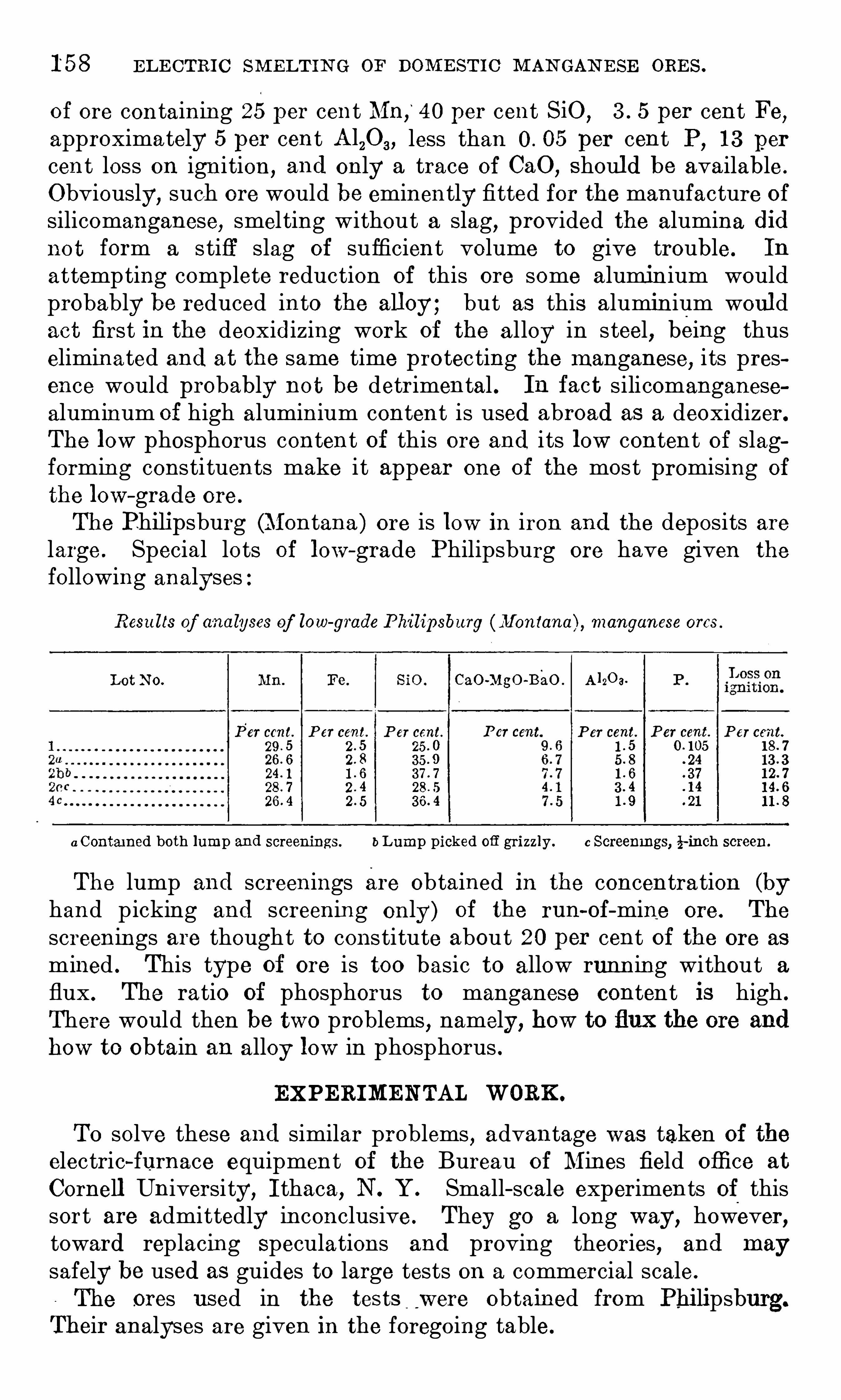
1 58 E L E CTRIC SM ELTIN G or DOM E STIC M AN GAN E SE ORE S .
of ore containing 25 per cent Mn,
“
40 per cent SiO , 3 . 5 per cent Fe,approximately 5 per cent Al,0 a, less than 0 . 05 per cent P, 1 3 per
cent loss on ignition, and only a trace of CaO ,Should be available .
Obviously, such ore would be eminently fitted for the manufacture ofsilicomanganese, smelting without a slag, provided the alumina didnot form a s tiff slag of sufficient volume to give trouble. In
attempting complete reduction of this ore some aluminium wouldprobably be reduced into the alloy ; but as this aluminium woul dact first in the deoxidizing work of the a lloy in steel, being thuseliminated and at the same time protecting the manganese, i ts presence would probably not be detrimental . In fact silicomanganesealuminum of high aluminium content is used abroad as a deoxidizer.
The low phosphorus content of this ore and i ts low content of slagforming constituents make i t appear one of the most promising of
the low—grade ore .
The Philipsburg (Montana ) ore is low in iron and the deposits arelarge . Special lots of low-grade Philipsburg ore have given the
following analyses
Resu lts of analyses of low-
grade Philipsburg (Montana) manganese ores .
Lot N o. CaO-Mgo-BaO . Anoa.
Per cent. P er cent. P er cent. P er cent P er cent. P er cent. P ercent.29 . 5 2 . 5 25 . 0 1 . 5
2 . 8 3 5 . 9 . 24
. 3 72 . 4 3 . 4 1 4
. 21
a Contained both lump and screenings.bL ump picked ongrizzly.
c Screenings, if-inch screen.
The lump and screenings are obtained in the concentra tion (byhand picking and screening only) of the run-of-mine ore. The
screenings are thought to constitute about 20 per cent of the ore as
mi ned . This type of Ore is too basic to allow running without a
flux . The ratio of phosphorus to manganese content is high .
There would then be two problems , namely, how to flux the ore and
how to obtain an alloy low in phosphorus .
E X PERIMENTAL WORK.
To solve these and similar problems , advantage was taken of the
electric-furnace equipment of the Bureau of Mines field Ofiice at
Cornell University, I thaca, N . Y . Small-scale experiments of thissort are admittedly inconclusive. They go a long way, however,toward replacing Speculations and proving theories, and maysafely be used as guides to large tests on a commercial scale.
The ores used in the testsfl
were obtained from Philipsburg.
Their analyses are given in the foregoing table.

1 60 ELE CTRIC SM ELTIN G or DOM ESTIC MAN GAN E SE ORE S .
in a small furnace, when the furnace is started cold “
and only a shortrun is made will be much higher than in commercial practice . Arough factor for calculating power consumption in large-scale operations can be obtained by running a high-grade ore in the smallfurnace and comparing the power used with that required in commercial operation on such an ore .
Such a standardization was made with a high-grade ore— Philipsburg concentrates— analyzing per cent MD , per
“ cent Fe,per cent SiO, , per cent CaO , per cent Al,O, , per cent P,
per cent loss on ignition . The usual basic slag was made .
The results follow :
Run 52 .
— Three charges, each consisting of 1 00 pounds of ore , 3 pounds of steel
scrap , 1 4 pounds of coke (metal lurgical coke , i-inch mesh ; anal yzing per cent
15120 , per cent ash,of which per cent was Fe , per cent SiO, , per cent
A120 3 , per cent CaO) , 1 4 pounds of charcoal (crushed to about 4 inch) , and 20
pOImds of CaCO3 (marble, crushed to 7} inch) . Time of run , 8 hours 1 0 minutes ;power used, 440 kw .
-hours (1 80 kw .-hours, first heat ; 1 40, second heat ; 1 20, third
heat) . Obtained pounds of metal , containing per cent Mn, per cent
Si, per cent P ; pounds of slag, containing per centMn ; and 1 1 pounds of
dross containing per cent Mn . Mn distribution : In metal per cent, in slag
per cent , in dross per cent, volatilization and dusting loss per cent . Re
covery of P in metal , 7 9 per cent .
As,in commercial practice , not over kw .
-hours per long tonof alloy woul d be required on such an ore in a -kw . furnace
,
or kw.-hours per pound of metallic manganese in the alloy, and
as the las t two taps in the small furnace used kw .-hours per
pound of manganese in the alloy, i t appears that 7 5 per cent of thepower used per pound of all oy in the experimental furnace on the
last two taps of a run on 3 00 pounds should give the approxima tepower required commercially . A previous run (No . 50) on this highgrade ore, using the same flux
,and adding 5 pounds of mill scale,
to supply iron, 1 0 pounds of burnt lime, and 3 3 pounds of charcoalper 1 00 pounds of ore , gave an alloy of 7 7 per cent Mn,
2 per cent Si,per cent P,
with a manganese recovery of 7 9 per cent . Someof the heats were not given enough power, and some of the slagswere high in manganese . I t was calculated that under correctoperating conditions 88 per cent of ,the manganese woul d havebeen recovered . This calculation was checked by the resul ts of run
52 . The results of these runs indicated that a mixture of halfcoke and half charcoal was as good a reducer as all charcoal .
FLUX I N G TE ST S W ITH HI GH-S IL IC A OR E .
A series of fluxing tests was made with a high-silica ore,namely,
the Philipsburg screenings, lot 4 (see table of analyses ) , containingper cent Mn, per cent Fe, per cent SiO, , per cent
CaO +MgO , per cent A120 3 ,and per cent P, with per

E XPERIM EN TAL WORK . 1 6 1
cent loss on ignition. In all the runs 1 0 pounds o f coke and 1 0
pounds of charcoal were used per 1 00 pounds of ore, except in run
7 3 in which 1 5 pounds of each were used . N o steel scrap was addedexcept pound per 1 00 pounds of ore in run 7 0 . The results o f
the. runs are. summarized as follows :
R un N o.
Resu lts of fluxing tests with high-silica ore.
CHARGE S AND POW E R C O N SUM PT ION .
CaO per (3a per CaFg per
1 00 1 00 poundpounds pounds ing CaO of
of ore. of ore. equ ivalent Silica.
to basesin ore.
P ounds. Pounds. Pounds. Pounds. Pounds . H. min. L uz-hours.
3 00 8 20 522
3 00 7 20 450
. 3 6 300 453
. 20 300 7 20 452
N one til l N one til lend , then 1 0 end , then 200 7 8
PR ODUCTS AND POW E R C ON SUMPTI ON .
Analysis of alloys.
Pounds . P er cent. P er cent. P er cent.7 1 . 0
7 1 . 4 1 1 . 6 7 37 3 0 1 3 . 0 687 1 . 0 1 5. 5 . 60
2. 7 57
D I STR IBUTION O F E LEME N TS IN PE RCE N TAGE S OF TOTAL .
Run N o.
Inmetal . In dross .
0 Amount of dross small ; included in weight of slag and in samp le of slag for analysis.
More power was used in run 7 0 than in the others because of the
large amounts of CaCO 3 charged . The slag was very s tiff in run 69
and an arc had to be used to tap . More power might have given a
slightly better recovery .

1 6 2 EL E CTRI C SM E L TIN G OF DOM E STIC M AN GAN E SE ORES .
In run 7 3 more reducer was used than in the other runs,and no
flux was added till the end. Two batches of 1 00 pounds of ore eachwere added before tapping. The metal tapped
,but the slag was
too s tiff to run ; the fluxes were than added,and 45 kw.
-hours wereused (included in the 469 total in the table) to get the slag ou t. I t
then tapped well .W i th the same power input for runs 69 and 6 7 as for run 7 0
,run
6 7 would have given better results than run 7 0 , but the results of run69 would not have been as satisfac tory as for run 7 0, the slag beingtoo s tiff . The acid slags containing fluorspar, however, tapped well .C onsidering the cos t of power and fluxes
,i t appears that the acid
slags of runs 6 7 and 68 were preferable to the basic slag of run 7 0.
I t is n oteworthy tha t the basic slag did not prevent the reductionof silicon in run The recovery of manganese was higher in run
7 3 , Operating without flux until the furnace got clogged wi th slagand then fluxing ou t the slag, but the power cons umption was too
high . The flux of run 68— all CaF2 , except for the CaO in the ore
itself— gave the bes t results metallurgically . The slag of run 68 was
very fluid,and Some of the CaF2 could probably have been replaced
by CaO , using a flux intermediate between those of runs 68 and 7 3 .
Slags made with fluorspar, are,for an equal Ca content
,much more
fluid than those made with lime.
AD VAN TA GE S OF AC ID S LAG .
The percentage of manganese is somewhat lower in a s tronglybasic slag than in an acid slag
,but the weight Of slag formed is
much greater. Hence,the weight of manganese lost in the slag is
greater with the basic slag,when the SiO,, content of the ore is much
above 25 per cent . I’Vhen the ore is fluxed to a basic slag the costof handling and disposing of the excess slag formed must be con
sidered. The cost of the lime flux for the basic slag would,of course
,
be lower than that of the fluorspar required to produce an acid slagfluid enough to tap ; although in a large furnace
,where the tap hole
would no t freeze as readily as in the small one when tapping a sticky .
slag,the amount of fluorspar could doubtless be materially reduced .
The weight of manganese los t in the slag is greater wi th the basicslag
,when the SiO2
content of the ore is much above 25 per cent.When the ore is fluxed to a
‘basic slag the cos t of handling and disposing Of the excess slag formed mus t be considered . The cos t ofthe lime flux for the basic slag would , of course, be lower than tha tof the fluorspar requ ired to produce an acid slag fluid enough to tap ;al though in a large furnace, where the tap hole would not freeze as
readily as in the small one when tapping a s ticky slag, the amount offluors par could doubtless be ma terially reduced .

1 64 ELE CTRI C SM ELTIN G or DOM ESTIC M AN GAN E SE ORE S .
Charge (weight of constituent to each poundsCaCo3Charcoal .
Quantity of ore charged
Tim9 of run
Power used
Weight of alloymade
Composition of alloy :
Weight of slag made
Manganese in slag per cent
Recovery in alloy
As-
regards the two tests , although the_
Ore used in run 49 was
slightly higher in manganese and lower in silica, and although more
power was used per uni t weight of ore, charcoal gave better resultsthan coke . However, neither result was satisfactory, the slag beingtoo acid and holding up too much manganese . A slag Of the sameacidity made with fluorspar would have shown better results . The
amount of reducer in ‘
both tests was too small for good resul ts .COM N TS ON U SE OF BHODOCHBO S ITE .
As the lot of ore used in run 48 was exhausted before run 49 wasfinished
, the las t few charges in run 49 were made with a mixtureof uncalcined rhodochrosite and Philipsburg lump (lo t 2b) . On
account of the high loss (3 1 per cent) on ignition of the rhodochro
site, it gave trouble, even when mixed wi th the other ore. The
large volume of CO2given O ff by the raw rhodochrosite tended toward
excessive electrode consumption, and probably also toward wastingof the reducer in the charge . I f ore so high in volatile matter fallsin to the mel t before i t has been thoroughly calcined in the shaft,the furnace will “ blow, or form a
“ volcano .
For these reasons, and because i t should be cheaper to calcine byfuel heat than to expel CO2 by electric heat in the furnace, i t willprobably be found des irable to calcine rhodochrosite ore beforecharging it in to the electric furnace. The ore decrepitates somewhaton cal cination, and the product may have to be screened , the coarsematerial being then smelted continuously and the fines fed to a
separate furnace as fas t as the mel t w ill take the ore, but withoutkeep ing the shaft piled full , in order to keep down dust losses . Rho
dochrosite, may, in fact, be too high grade an ore for electric smel ting withou t being mixed with ores containing more slag-formingconstituents .
The analysis of the rhodochosite used, after complete calcination,was per cent Mn, per cent Fe, per cent SiO, , per cent

EXPERIM E N TAL WORK . 1 6 5
CaO +MgO , per cent M 20 3 ,and per cent P . Fluxed to the
ordinary basic slag and with suitable addition o f steel scrap,this
would give only about pounds of slag per long ton of 80 per
cent ferromanganese produced . Compared to the 40 per cent Mn
20 per cent SiO2 ore in common use, which , when similarly slagged ,gives about pounds of slag per long ton O f alloy , the rhodochro
site may cause too short a column of slag , and hence , at the lowvoltage of a ferromanganese furnace , may not present sufficientelectrical resistance to develop enough hea t .In the ordinary three-phase, nonconducting-bottom furnace , thecurrent may flow from one electrode to the o ther two by two paths(1 ) throu g h slag entirely, or (2 ) from the electrode straight downthrough the slag to the alloy beneath and then through the alloyto directly beneath the other electrodes
,and up through the slag
again to the o ther electrodes . With too short a column of slag,
path 1 presents the least resistance and will result in the generationof heat in the slag in three spots only . With a deeper slag column
,
the resistance of the path from one electrode to another through theslag only is less than that from electrode to electrode by way O f
slag,alloy ,
and slag . I f the power input is too low ,the large mass
Of metal below the slag may get cool enough to make tapping difficult
,and the slag i tself may not get hot enough for complete reduc
tion of manganese,resulting in high manganese less in the slag .
I f,in order to develop enough heat
,the furnace is run as an arc
furnace instead of as a resistance furnace, local overheating willoccur and manganese will be lost by volatilization . In this connection
,the comments of Bardwell a on smelting rhodochrosite are of
interest .
TE ST S OF E FFE CT OF S I ZE OF RE DU CE R C ON S T ITUE N T S .
Runs 50 and 52 , previously mentioned , had shown that the mixture of half coke with half charcoal worked as well as all charcoal .W hen all one-fourth—inch coke was used as reducer, some Of the excessOf fine coke tended to emulsify with the slag, coming ou t with it andmaking it harder to tap . W hen half coke and half charcoal was usedthiswas not the case . I twas thought that larger coke might give betterresults
,so a series of runs was made to test this assumption and to
compare the results from coke and from anthracite with the resultsof runs in which a mixture Of half coke with half charcoal was used .
The results of the tests are presented in the table following . The'
ore used was Philipsburg screenings,lot 4 , containing per cent
Mn, per cent Fe , per cen t SiO , , per cent CaO +MgO ,
per cent M 20 3 ,and per cent P,
w i th a per cent loss on
ignition . I t was crushed to pass a one-half -inch screen . As a flux ,a Bardwell
,E . S .
,D iscussion ; Bu ll . 43 , Am . Inst . Mining E ng. ,
N ov.
,1 9 1 8
, p . 1 65 1 .
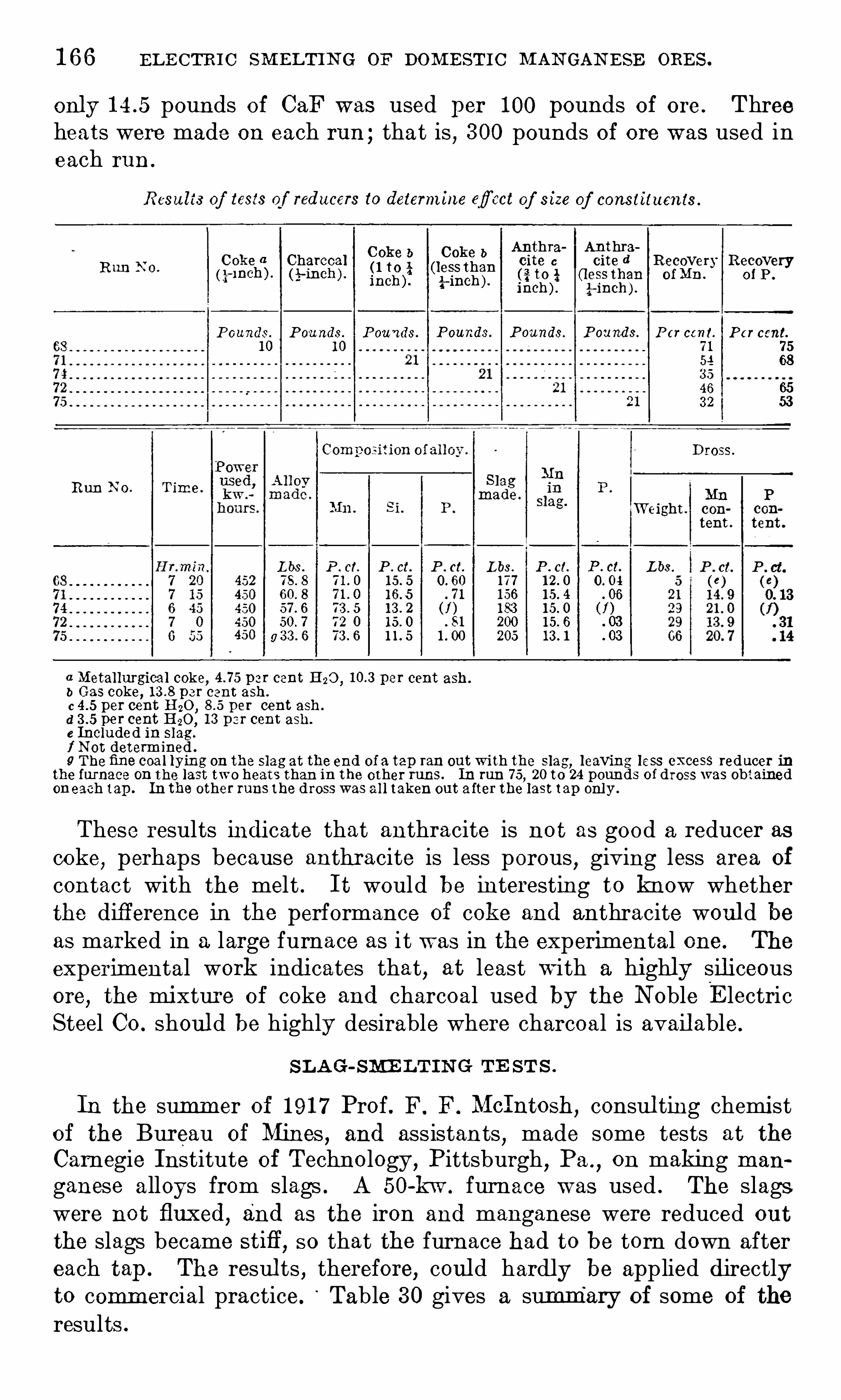
1 6 6 EL E CTRI C SM ELTI N G or DOM E STI C M AN GAN E SE ORE S .
only pounds of CaF was used per 1 00 pounds of ore . Threeheats were made on each run ; that is , 3 00 pounds Of ore was used ineach run .
Results of tests of reducers to determine efiect of size of constituents .
C Oke b COke bAnthra' Anthra
C oke a Charcoal cite c cite d Recovery Recovery1 1 1] 2\ I t 1 hR o(g-inch ) . (A-mch ) . (neg)
? (13225
?af-iiI
t
ciiE
in oa . of P .
O
40
P ounds . P ou nds. P ounds P ounds. P ounds. P ounds. P er cent. P er cent.
1 0 1 0 7 1 7 554 683 546 653 2 53
Dross.
Run N o . T imeMn P
W eight . con con
tent . tent .
Lbs . P . ct. P . ct. P . ct. L bs . P . ct. P . ct. L bs452 1 7 7
450 . 7 1 1 56 . 06450 (f ) 1 83 (f )450 7 2 0 . 81 200 . 03
1 1 5 205 . 03450 g
a Metallurgical coke, p er cent H20 , per cent ash .
b Gas coke, per cent ash.
c per cent HQO , per cent ash .
d per cent H20 ,1 3 p er cent ash.
e Included in slag .
f N ot determined .
9 Thefine coa l lying on the slag at the end of a tap ran out with the slag, leaving less excess reducer inthe furnace on the last two heats than in the other runs. In run 7 5
,20 to 24 pounds of dross was obtained
oneach tap . In the other runs the dross was al l taken out a fter the last tap onl y .
These results i ndicate that anthracite is not as good a reducer ascoke
,perhaps because anthracite is less porous , giving less area of
contact with the melt . I t would be interesting to know whetherthe diff erence in the performance of coke and anthracite woul d beas marked in a large furnace as i t was in the experimental one. The
experimental work indicates that, at least with a highly siliceousore
,the mixture of coke and charcoal used by the N oble E lectric
Steel Co . shoul d be highly desirable where charcoal is avail able.
S L AG-SME LT I N G TE ST S .
In the summer Of 1 91 7 Prof . F. F. McIntosh,consul ting chemist
of the Bureau of Mines,and assistants
,made some tests at the
Carnegie Institute of Technology,Pittsburgh
,Pa .
,on making man
ganese alloys from slags . A 50-kw . furnace was used . The slagswere not fluxed, and as the iron and manganese were reduced out
the slags became stifl’
,so that the furnace had to be torn down after
each tap . The resul ts , therefore, coul d hardly be applied directlyto comm ercial practice. Table 3 0 gives a summary of some of the
results .
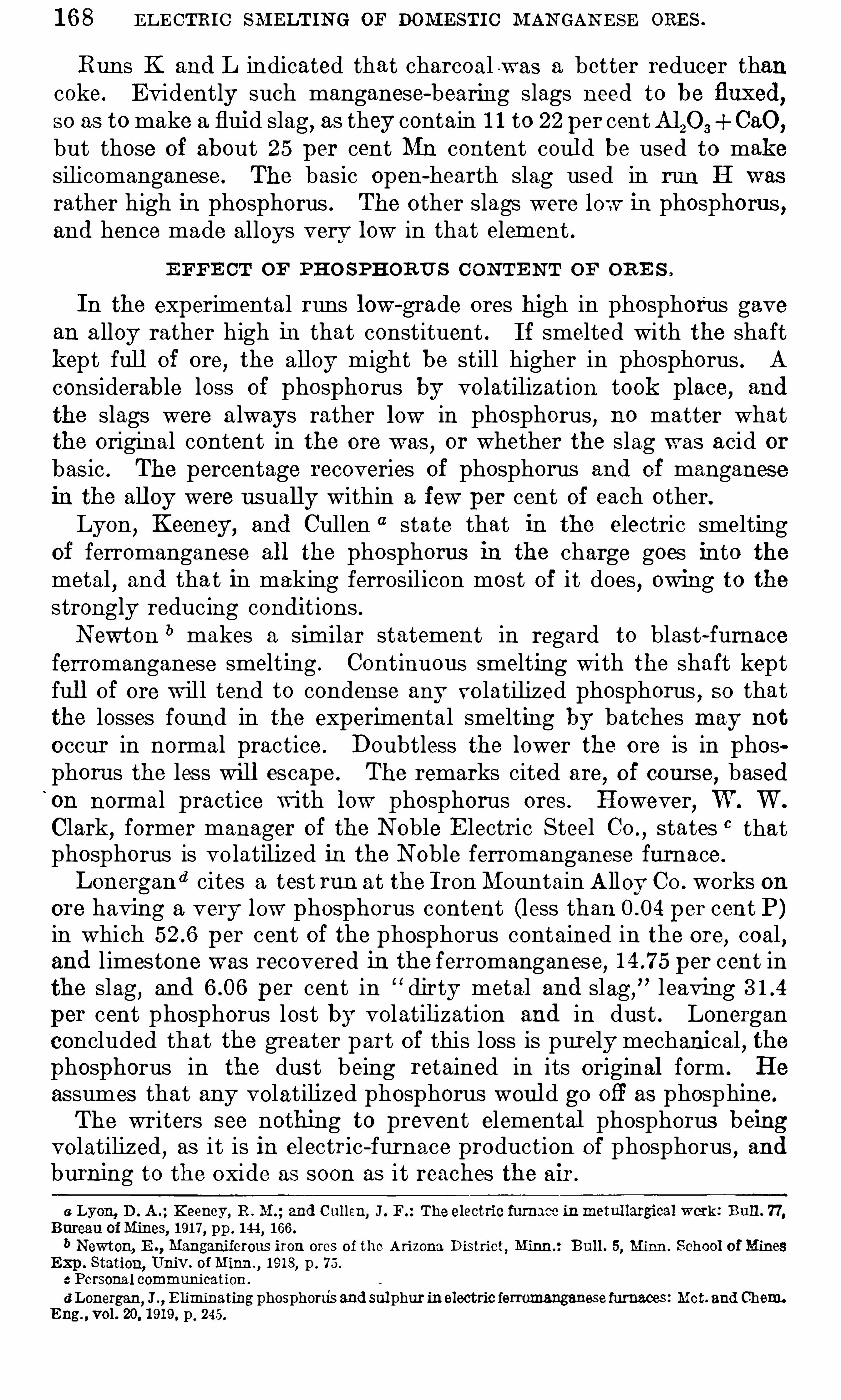
1 6 8 EL E CTRI C SM ELTIN G or DOMESTI C M AN GAN E SE ORE S .
Runs K and L indicated that charcoal w as a better reducer thancoke. E vidently such manganese-bearing slags need to be fluxed,so as to make a fluid slag, as they contain 1 1 to 22 per centA1 20 3 CaO,
but those of about 25 per cent Mn content coul d be used to makesilicomanganese. The basic open-hearth slag used in run H was
rather high in phosphorus . The other slags were low in phosphorus ,and hence made alloys very low in that element .
E FFE CT OF PHO SPHORU S C ON TE N T OF OR E S .
In the experimental runs low-grade ores high in phosphorus gavean a lloy rather high in that constituent . I f smelted with the shaftkept full Of ore
, the alloy might be still higher in phosphorus . Aconsiderable loss of phosphorus by volatil ization took place, and
the slags were a lways rather low in phosphorus, no matter whatthe original content in the ore was
,or whether the slag was acid or
bas ic . The percentage recoveries of phosphorus and of manganesein the all oy were usually within a few per cent of each other.Lyon,
Keeney, and Cullen state that in the electric smeltingof ferromanganese all the phosphorus in the charge goes into the
metal,and tha t in making ferrosil icon most of it does
,owing to the
strongly reducing conditions .N ewt on b makes a similar statement in regard to blast-furnace
ferromanganese smelting . Continuous smelting with the shaft keptfull Of ore w il l tend to condense any volatilized phosphorus
,so that
the losses found in the experimental smelting by batches may not
occur in normal practice . Doubtless the lower the ore is in phosphoras the less will escape . The remarks cited are
,of course, based
on normal practice with low phosphorus ores . However,W . W.
Clark,former manager of the N oble E lectric Steel CO . ,
states 0 thatphosphorus is vo latilized in the N oble ferromanganese furnace .
Lonergand cites a test run at the I ron Moun tain Alloy CO . works on
ore having a very low phosphorus content (less than per cent P)in which per cent of the phosphorus contained in the ore, coal ,and l imestone was recovered in the ferromanganese, per cent inthe slag, and per cent in dirty metal and slag ,
” leavingper cent phosphorus lost by volatilization and in dust . Lonerganconcluded that the greater part of this loss is purely mechanical
, the
phosphorus in the dus t being retained in its original form . He
assumes that any volatilized phosphorus woul d go Ofl as phosphine.
The writers see nothing to prevent elemental phosphorus beingvolatiliz ed
,as i t is in electric-furnace production of phosphorus
,and
burning to the oxide as soon as i t reaches the air .
6 Lyon, D . A . ; Keeney, R . M . ; and Cullen, J . F. : The electric furnam inmetul largical work : Bull . 7 7 ,Bureau of Mines, 1 91 7 , pp . 1 44
, 1 66.b Newton, E Manganiierous iron ores of the Arizona District, Minn : Bull . 5, Minn. School of Mines
Exp . Station, Univ. of Minn ,1 9 1 8
,p . 7 5 .
c Personal communication .
d Lonergan,J E liminating phosphorus and sul phur inelectric ferromanganesefurnaces: Mot. and Chem
Eng , vol . 20, 1 91 9. p . 245 .
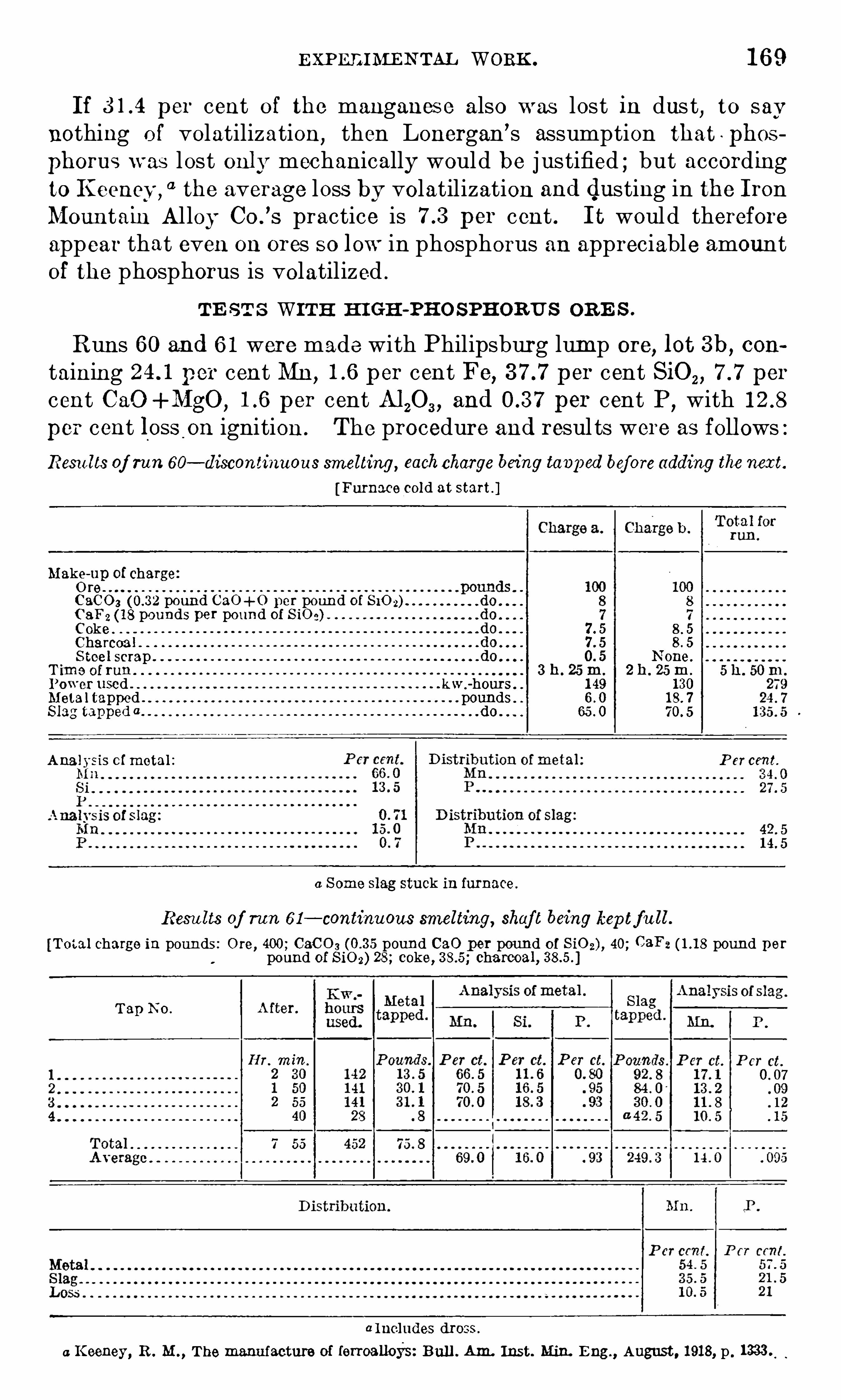
E X PE E IMEN TAL WORK . 1 6 9
I f per cent of the manganese also was lost in dus t,to say
nothing o f volatilization,then Lonergan’s assumption that ‘
phos
phorus w as lost only mechanically would be justified ; but accordingto Keeney ,
“1 the average loss by volatilization and dusting in the IronMountain Al loy Co .
’
s practice is per cent . I t would thereforeappear that even on ores so low in phosphorus an appreciable amountof the phosphorus is volatilized .
TE ST S WITH H I GH-PR O SPHORU S ORE S .
Runs 60 and 6 1 were made with Philipsburg lump ore,lot 3 b, con
taining per cent Mn, p er cent Fe, p er cent SiO , , per
cent C aO +MgO , per cent A120 3 ,and per cent P,
withper cent loss on ignition . The procedure and resul ts were as foll ows :Resu lts of run 60— discontinuous smelting, eachcharge being tavp ed before adding the next.
[Furnace cold at start ]
Mil ks
-up of chargere
C 3 0 0 3 pound CaO+ 0 per poun d of 8 10 2)0 9 3 2 (1 8 pounds per pound of 8 10 2)Coke 7 . 5 8 . 5Charcoa l 8 . 5S tee l scrap 0. 5 N one.
T ime oi ran 3 h . 25 m. 2 h . 25 m.
Power used ken-hours . 1 49 1 30Meta l tapped pounds . 1 8 . 7
Slag tapped a do .
Ana lysis of metal : P er cent.
0 S ome slag stuck in furnace .
Results of run 6 1 — continuous smelting, shaf t being kep tf u ll .
[Total charge in pounds : Ore, 400 ; CaC 0 3 pound 0 21 0 per pound of S iO z) , 40; (3a pound perpound of 8 10 2) 28 ; coke, charcoal ,
Tap N o .
a l ncludes dross .
a Keeney, R . M . ,The manu facture of lerroalloys: Bul l . Am. Inst. Min. E ng , August , 1 91 8, p .
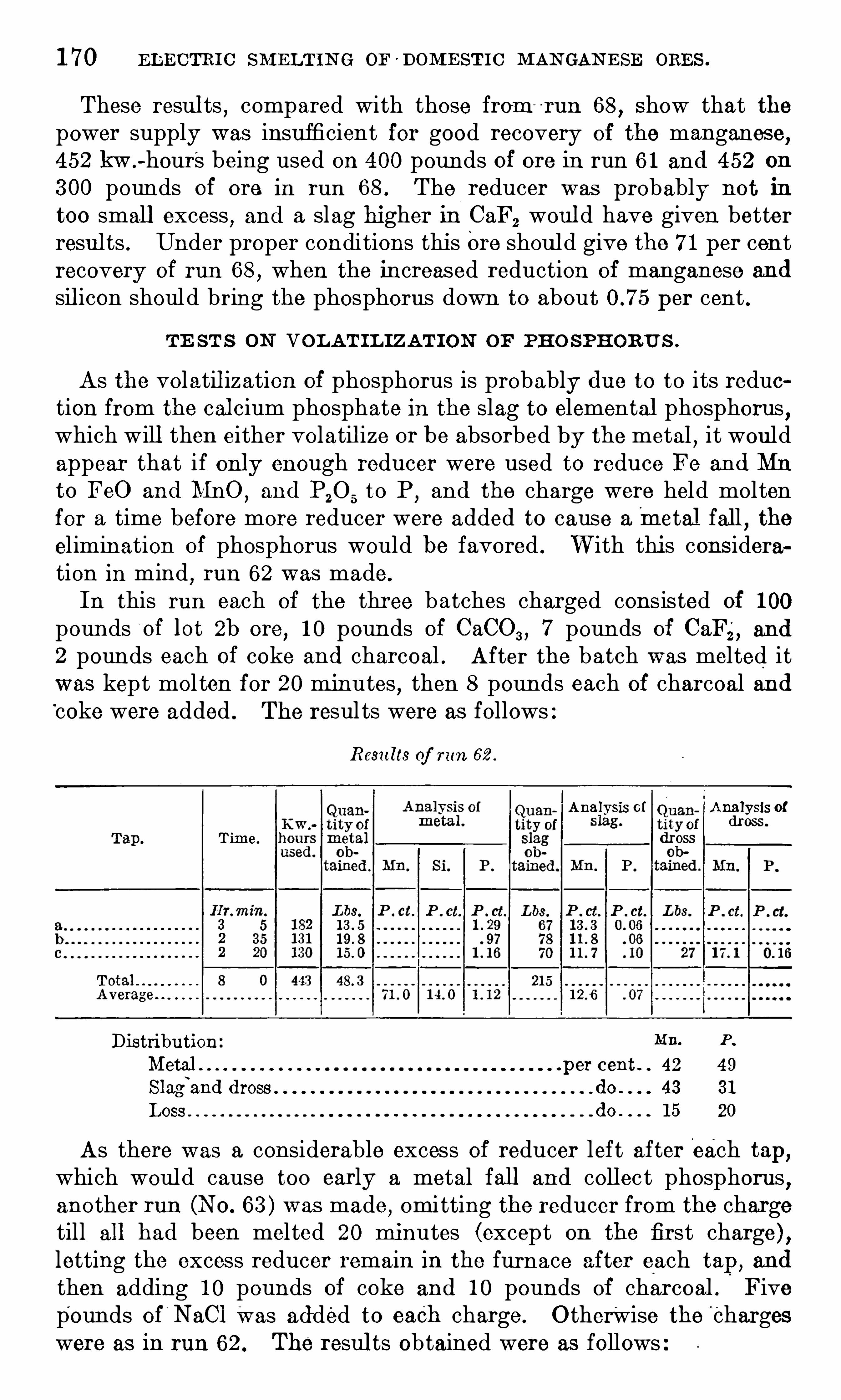
1 7 0 EL E CTRI C SM ELT IN G OF 'DOM E ST IC M AN GAN E SE ORE S .
These resul ts,compared with those from -
r un 68,Show that the
power supply was insufficient for good recovery of the manganese,
4 52 kw .
-hour 's being used on 400 pounds of ore in run 6 1 and 452 on
3 00 pounds of ore in run 68 . The reducer was probably not in
too small excess,and a slag higher In CaF2 woul d have given better
resul ts . Under proper conditions this Ore shoul d give the 7 1 per centrecovery of run 68
,when the increased reduction of manganese and
sil icon should bring the phosphorus down to about per cent .
TE ST S ON VOL AT IL IZAT I ON OF PHO S PHORU S .
As the volatil ization of phosphorus is probably due to to its reduetion from the cal cium phosphate in the slag to elemental phosphorus
,
which will then either volatil ize or be absorbed by the metal,it woul d
appear that if only enough reducer were used to reduce Fe and Mn
to FeO and MnO,and P20 5
to P,and the charge were held molten
for a time before more reducer were added to cause ametal fal l,the
elimination of phosphorus would be favored . W ith this cons ideration in mind
,run 62 was made.
In this run each of the three batches charged consisted of 1 00
pounds "
of lot 2b ore,1 0 pounds of CaCO, , 7 poun ds of Ca
‘
,and
2 pounds each of coke and charcoal . After the batch w as melted itwas kept mol ten for 20 minutes , then 8 pounds each of charcoal and‘coke were added . The resul ts were as follows :
Resu lts of run 62 .
Analysis of Analysis ofdross.
Time.
Distribution Mn. P .
Metal . . per cent . 42 49
Slagl
and dross do . 43 3 1
Loss do . 1 5 20
As there was a considerable excess of reducer left after each tap ,which woul d cause too early a metal fall and coll ect phosphorus
,
another run (NO . 6 3 ) was made,omitting the reducer from the charge
till all had been melted 20 minutes (except on the first charge) ,letting the excess reducer remain in the furnace after each tap, and
then adding 1 0 pounds Of coke and 1 0 pounds of charcoal . Fivepounds of ‘
N aCl Was added to eaCh charge . O therwise the " chargeswere as in run 62 . The resul ts obtained were as follows

1 7 2 E L E CTR I C SM E LT IN G OF DOM ES T I C M AN GAN E SE ORE S .
In run 5 9,the charge at the start consisted of 1 00 pounds of ore
(lot 2b) , 8 pounds of CaCO, ,5 pounds of CaFZ, and 4 pounds Of
charcoal . Af ter all was mel ted for 20 minutes,6 pounds of charcoal
and 6 pounds of coke were added ; then the furnace was tapped .
This procedure was repeated four times . The resul ts follow
Resu lts of run 59 .
MIL P .
per cent 29. 5 1 9. 5
20
do . 1 2 60. 5
These racul ts, owing to the poor slag and the lack o f suflficient ex
cess reducer, are far from satisfactory as regards recovery of man
ganese, but they are somewhat promising as regards volat ilizationof phosphorus .The low recoveries of manganese in this series were doubtlesslargely due to the ore not being properly fluxed. This defect wasnot realized till the later rims on fluxing were made. However
,it
is evident that one requirement for high recovery of manganese,
namely, an excess of reducer, and one for high volatilization of phosphorus , namely, no excess reducer beyond that necessary to formMnO ,
FeO and P (that is , no metal fall to collect phosphorus ) , areincompatible. I t is hardly practicable to clean the furnace from all
excess carbon after each tap .
DE PHO SPHOR IZAT I ON AND SME LT IN G IN TW O STAGE S .
Therefore, the only procedure metallurgically possible seems to beto carry out the dephosphorization in one furnace, running with justenough reducer to form MnO ,
FeO,and P,
and holding the chargemolten for a whil e to allow the phosphorus to escape ; then to tap
the hot slag into a second furnace, add excess reducer, and smelt theprevious ly dephosphorized slag .
As it woul d be difficult to determine the exact point where thereis complete reduction to MnO ,
FeO ,and P,
and as the electrode willal so supply a little carbon
,it would probably be more feasible to
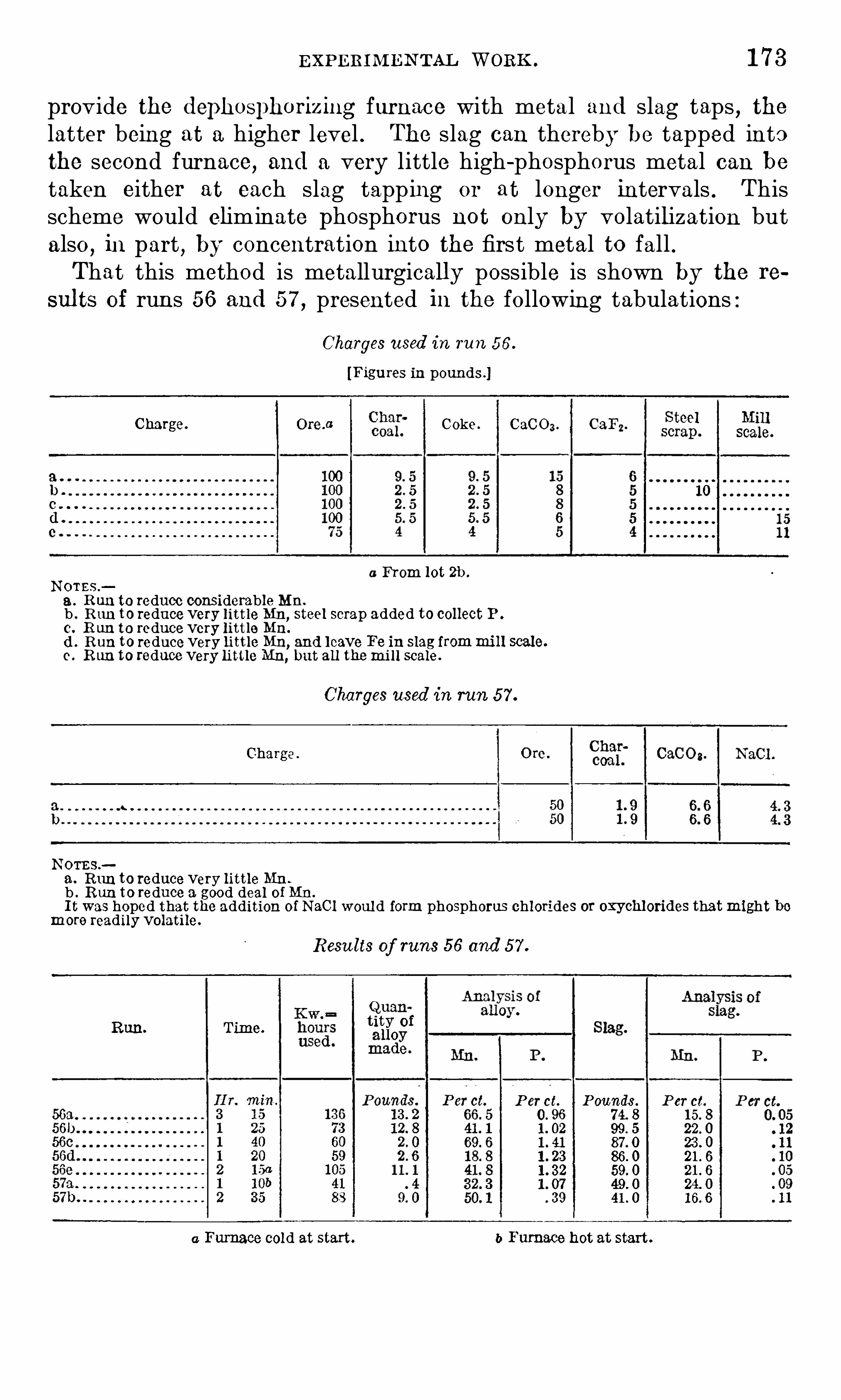
E XPERIM EN TAL WORK . 1 7 3
provide the dephosphorizing furnace with meta l and slag taps, the
latter being at a higher level . The slag can thereby be tapped intothe second furnace, and a very little high-phosphorus metal can betaken either at each slag tappi ng or at longer intervals . Thisscheme would eliminate phosphorus not only by volatilization butalso
,i npart , by concentration into the first metal to fall .
That this method is metallurgically possible is shown by the re
sul ts of runs 56 and 5 7 , presented in the following tabulations :
Charges used in run 5 6 .
[Figures in pounds ]
Charge. Coke . CaC0 3 .
scale
a From lot 2b .
N OTES .
8 . R un to reduce considerable Mn.
b . Run to reduce very little Mn,steel scrap added to collect P .
c. R un to reduce very little Mn.
(1 . Run to reducevery little Mn,and leave Fe in slag frommi ll scale.
0 . Run to reduce very little Mn, but all thewi l l scale .
Charges used in run 5 7 .
Charge
N ems.
a . Run to reduce very little Mn .
b . Run to reduce a good deal of Mn.
I t was hoped that the addition of N aCl woul d form phosphorus chlorides or oxychlorides thatmight bemore readily volatile.
Resu lts of runs 5 6 and 5 7 .
Run. Time.
P erct. P ounds. P er ct.
0. 96 7 4. 8 1 5. 81 . 02 99. 5 22 . 01 . 41 87 . 0 23 . 0l . 23 86. 0
1 . 07 49 . 0 24. 0
3 9 41 . 0 1 6. 6
a Furnace cold at start. b Furnace hot at start.
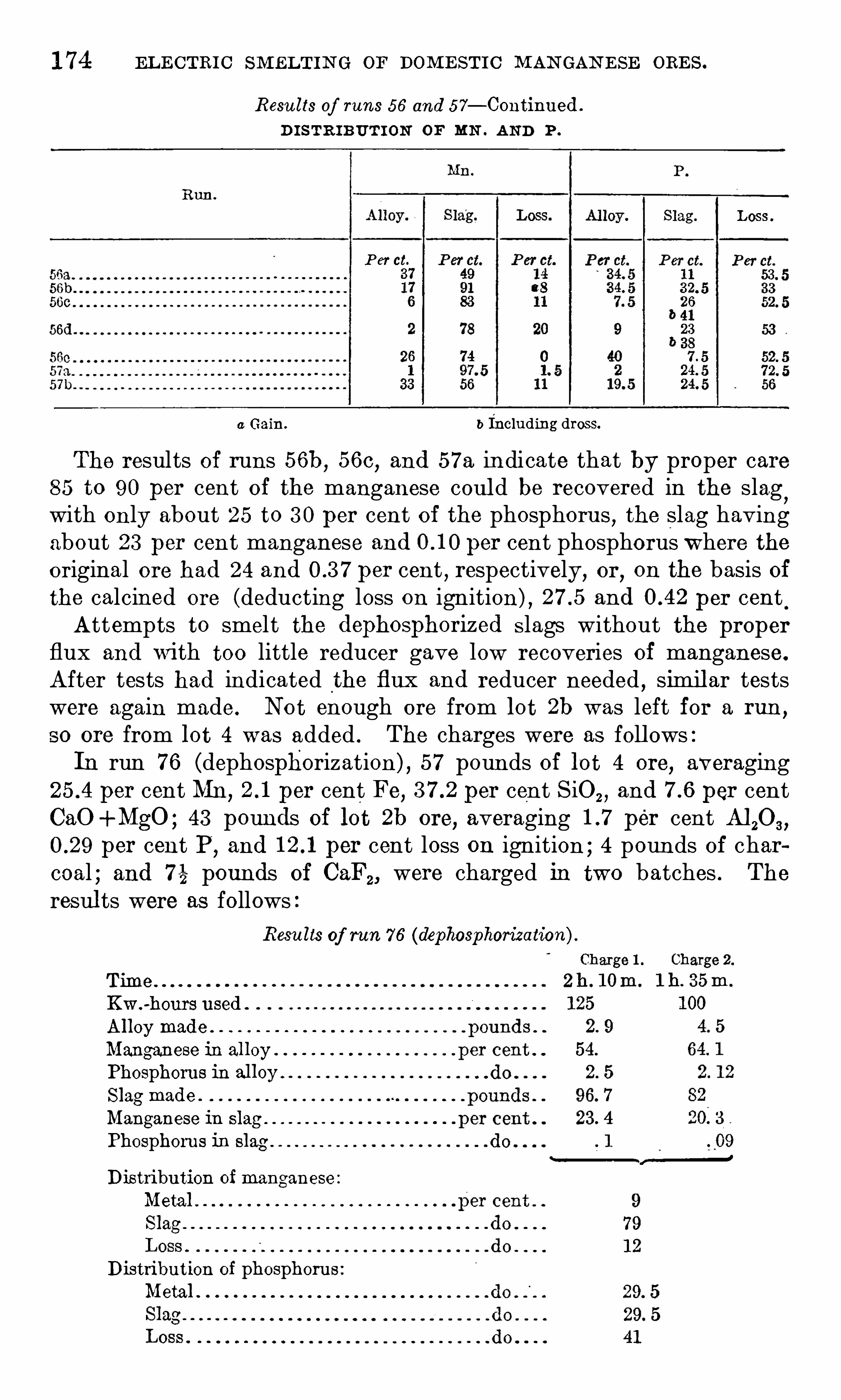
1 7 4 EL E CTRI C SM ELTI N G OF DOM E STI C M AN GAN E SE ORE S .
Resu lts of runs 5 6 and 5 7 — Continued .
D I STR IBUTI ON OF MN . AN D P .
Run .
P er ct.
a Gain. b Including dross.
The results of runs 56b, 56C , and 5 7 a indicate that by proper care8 5 to 90 per cent O f the manganese coul d be recovered in the slag
,
with only about 25 to 3 0 per cent of the phosphoru s , the slag havingabout 23 per cent manganese and per cent phosphorus where theoriginal ore had 24 and per cent , respectively, or, on the basis ofthe calcined ore (deducting loss on ignition) , and per centAttempts to smelt the dephosphorized slags without the proper
flux and with too little reducer gave low recoveries of manganese.
After tests had indicated the flux and reducer needed,simil ar tests
were again made. Not enough ore from lot 2b was left for a run,
so ore from lot 4 was added . The charges were as foll ows :In run 7 6 (dephosphorization) , 5 7 pounds of lot 4 ore
,averaging
per cent Mn, per cent Fe, per cent SiO, ,and per cent
CaO +MgO ; 43 pounds Of lot 2b ore, averaging per cent M 20 3 ,
per cent P,and per cent loss on ignition ; 4 pounds Of char
coal ; and 7 é pounds of (3a , were charged in two batches . The
resul ts were as followsResu lts of run 7 6 (dephosgohorization)
Time .
Kw .-hours used
Alloy made
Manganese in al loy
Phosphorus in alloy
Slag made .
Manganese in slag
Phosphorus in slag .
Distribution of manganese :
Metal
Slag
Distribution of phosphoru s :Metal
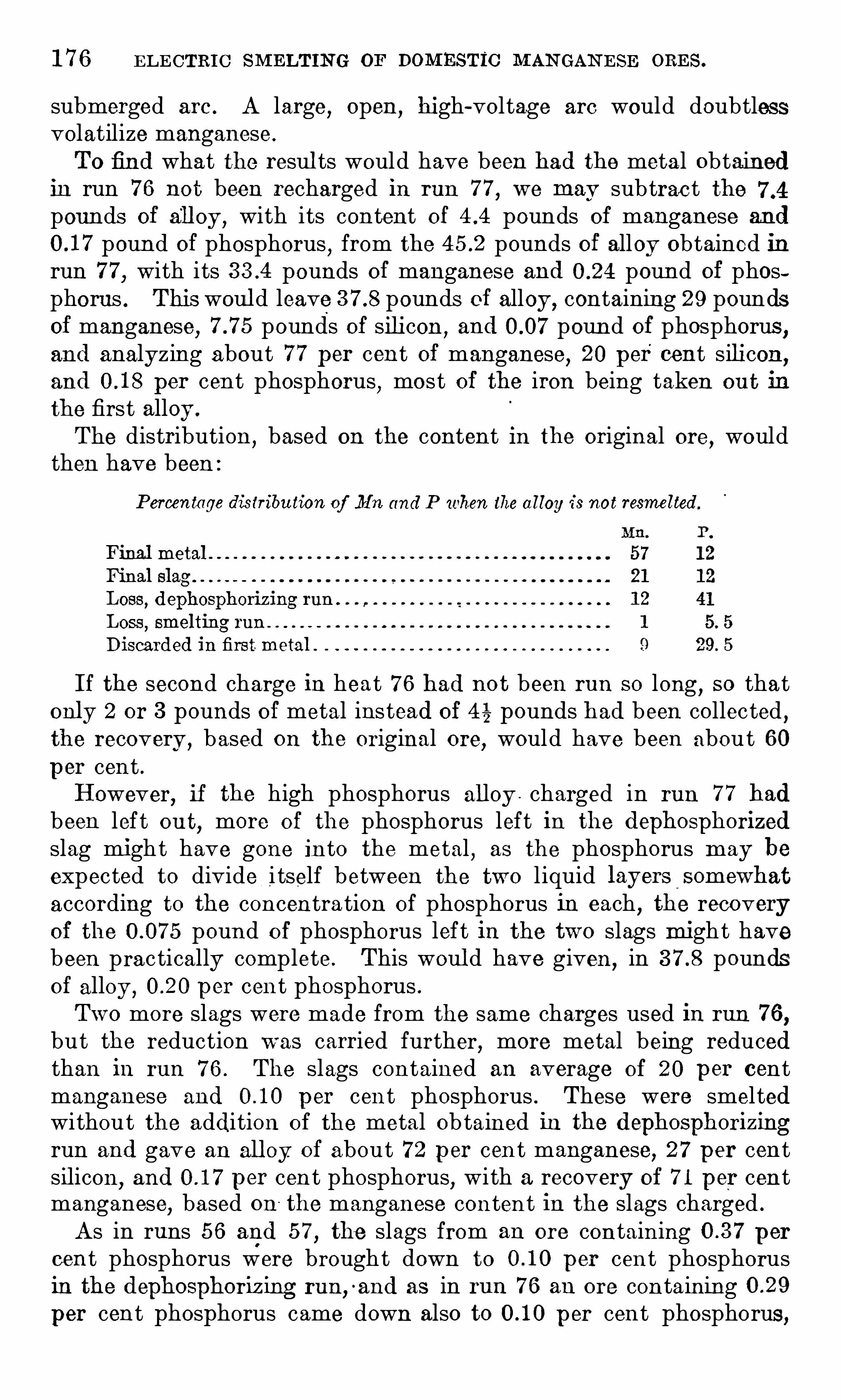
1 7 6 E L E CTRI C SM ELTIN G OF DOM ESTIC M AN GAN E SE ORE S .
submerged arc . A large,open
,high-voltage arc would doubtless
volatilize manganese .
To find what the resul ts would have been had the meta l obtainedin run 7 6 not been recharged in run 7 7
,we may subtrac t the
pounds of all oy, with its content of pounds of manganese and
pound of phosphorus,from the pounds of alloy Obtained in
run 7 7,with its pounds of manganese and pound of phos
phoras . This woul d leave pounds of alloy, containing 29 poundsof manganese
,pounds of silicon
,and pound of phosphorus
,
and analyzing about 7 7 per cent of manganese,20 per cent silicon
,
and per cent phosphorus, most of the iron being taken ou t in
the first alloy .
The distribution,based on the content in the original ore
,would
then have been :Percentage distribu tion of Mn and P when the a lloy is not resmelted
Final metal
Final slagLoss, dephosphorizing run .
Loss,smelting run
Discarded in first metal .
I f the second charge in heat 7 6 had not been run so long,so that
only 2 or 3 pounds of metal instead of 4 % pounds had been collected ,the recovery ,
based on the original ore,would have been about 60
p er cent .However
,if the high phosphorus alloy . charged in run 7 7 had
been lef t ou t,more of the phosphorus left in the dephosphorized
slag might have gone in to the metal,as the phosphorus may be
expected to divide i tself between the two l iquid layers somewhat
according to the concentra tion of phosphorus in each,the recovery
Of the pound of phosphorus left in the two slags might havebeen practically complete . This woul d have given,
in poundsof alloy , per cent phosphorus .Two more slags were made from the same charges used in run 7 6,but the reduction was carried further, more metal being reducedthan in run 7 6 . The slags contained an average of 20 p er centmanganese and per cent phosphorus . These were smel tedwithout the addition of the metal obtained in the dephosphorizingrun and gave an all oy of about 7 2 per cent manganese
,2 7 per cent
silicon,and per cent phosphorus, with a recovery of 7 1 per cent
manganese,based on
: the manganese content in the slags charged .
As in runs 5 6 and 5 7,the slags from an ore containing per
cent phosphorus were brought down to per cent phosphorusin the dephosphoriz ing run
,-and as in run 7 6 an ore containing
per cent phosphorus came down also to p er cent phosphorus,
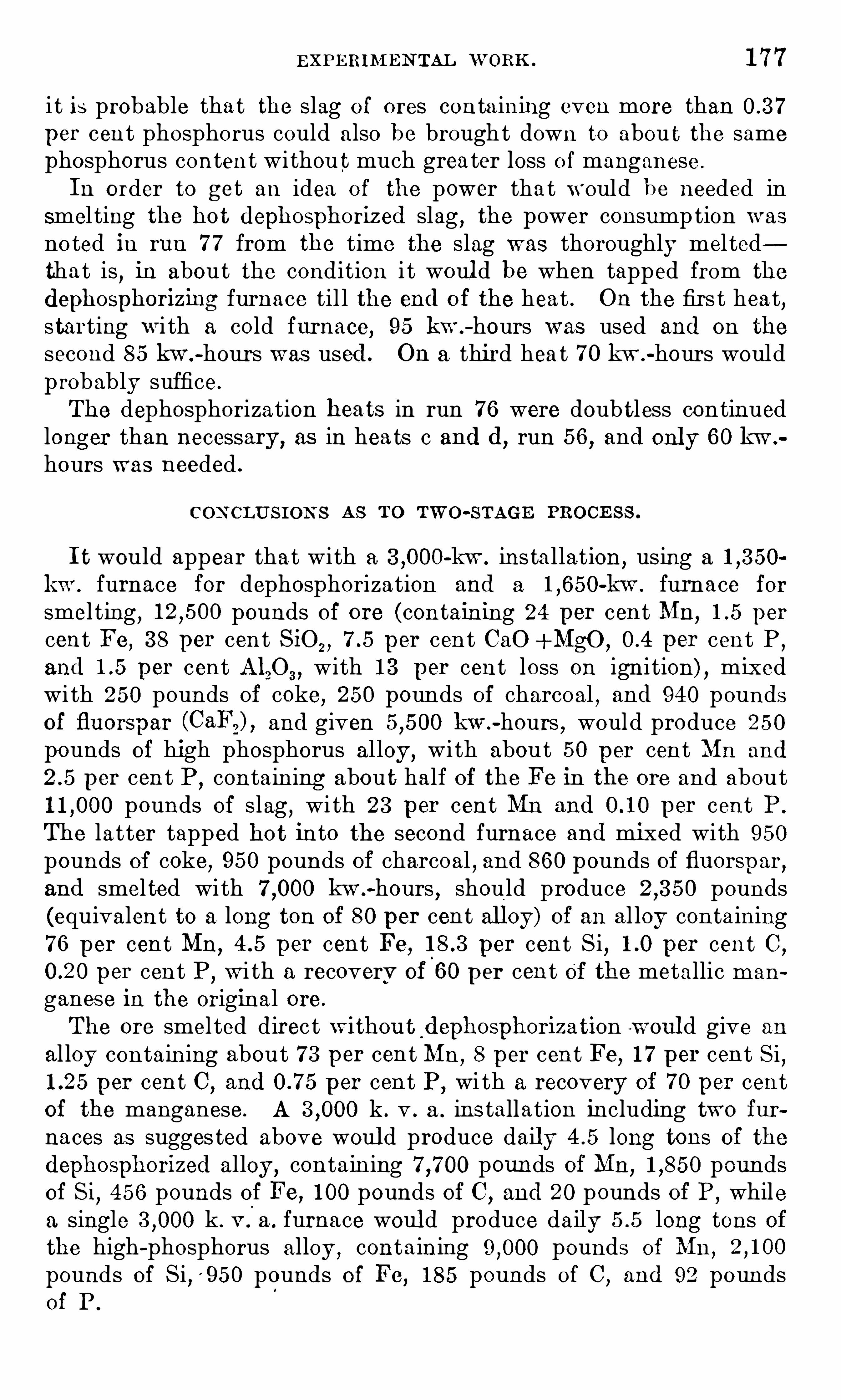
E XPERIM EN TAL W ORK . 1 7 7
i t is probable tha t the slag o f ores conta ini ng even more thanper cent phosphorus could also be brought down to abou t the same
phosphorus content withoutmuch grea ter loss of manganese .
In order to get an idea of the power that would be needed insmel ting the hot dephosphoriz ed slag , the power consumption wasno ted in run 7 7 from the time the slag was thoroughly mel tedtha t is , in about the condition i t woul d be when tapped from the
dephosphorizing furnace til l the end o f the heat . On the firs t heat,starting w i th a cold furnace, 95 kw .
-hours was used and on the
second 8 5 kw .-hours was used . On a third heat 7 0 kw.
-hours wouldprobably suffice .
The dephosphorization beats in run 7 6 were doubtless continuedlong er than necessary, as in hea ts c and (1
,run 5 6
,and only 60 kw .
hours was needed .
CON CLU S I ON S AS TO TW O-STAGE PROCE S S .
I t would appear that with a -kw . ins ta l lation,using a
kw . furnace for dephosphorization and a -kw . furnace for
smel ting,
pounds of ore (containing 24 per cent Mn, per
cent Fe,3 8 per cent S iO , , per cent CaO +Mg0 , per cen t P ,
and per cent A120 3 ,with 1 3 per cent loss on ignition) , mixed
wi th 250 pounds of coke, 250 pounds Of charcoal , and 940 poundsof fluorspar (Ca ) , and given kw .
-hours,would produce 250
pounds of high phosphorus al loy ,with about 50 per cent Mn and
per cen t P ,containing about half of the Fe in the ore and about
pounds of slag,with 2 3 per cent Mn and per cent P .
The latter tapped hot into the second furnace and mixed with 950pounds of coke
,950 pounds of charcoal
,and 8 60 pounds of fluorspar,
and smelted wi th kw.-hours
,should produce pounds
(equivalent to a long ton of 80 per cent all oy) of an al loy containing7 6 per cent MD
, per cent Fe, per cen t Si, per cent C ,
per cent P ,w i th a recovery of 6 0 per cent of the metallic man
ganes e in the original ore .
The ore smel ted direc t withou t dephosphorization w oul d give an
al loy contain ing about 7 3 per cent Mn,8 per cent Fe, 1 7 per cent Si,
per cent C ,and p er cent P ,
wi th a recovery of 7 0 per centof the manganese. A k . v . a . ins tallation including two furnaces as sugges ted above woul d produce daily long tons of thedephosphorized alloy ,
contain ing pounds of Mn,pounds
of Si,45 6 pounds of Fe, 1 00 pounds of C ,
and 20 pounds of P ,while
a single k . v.
'
a . furnace woul d produce daily long tons Ofthe high-phosphorus alloy ,
containing pounds of Mn,
pounds of Si,
'950 pounds O f Fe, 1 8 5 pounds of C,and 92 pounds
of P .
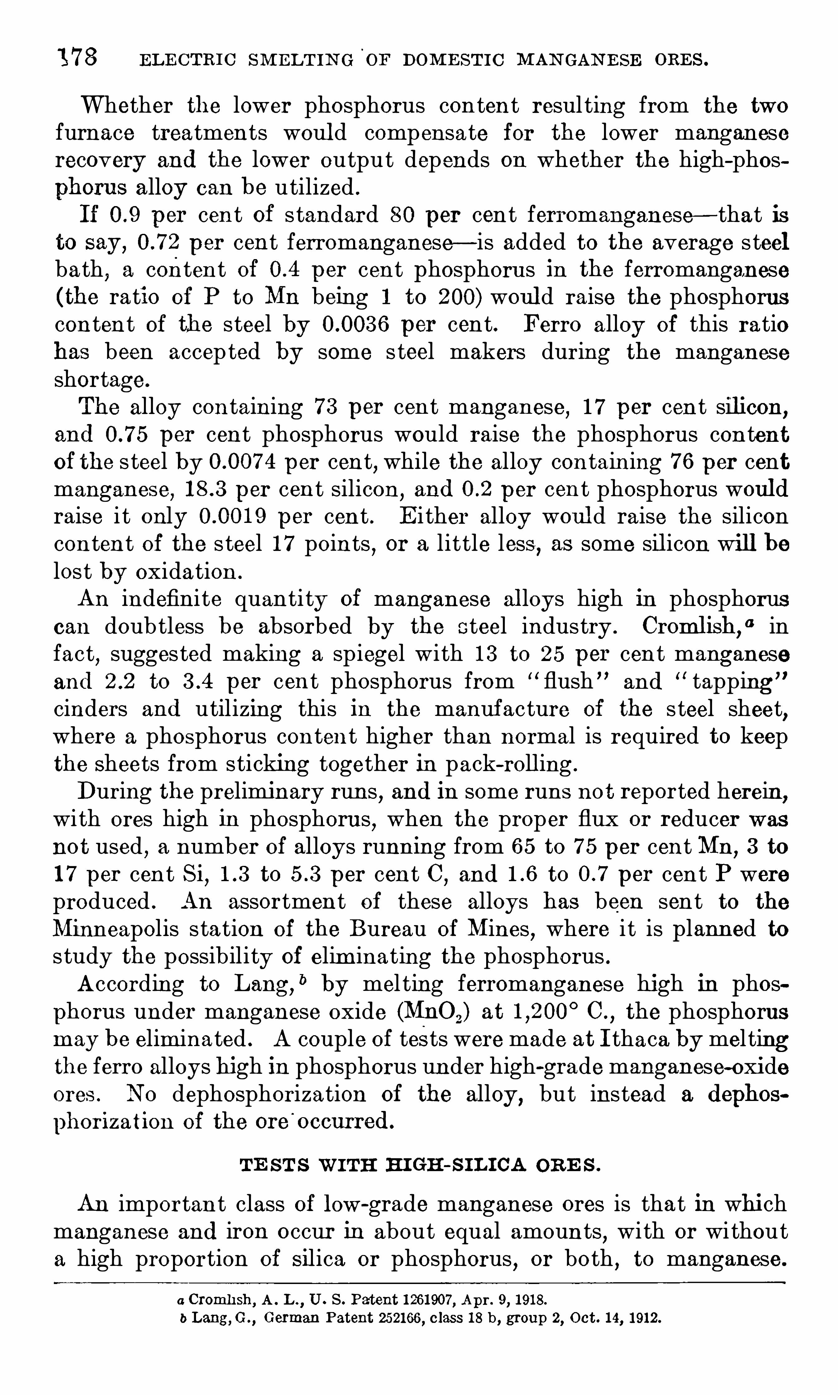
1 7 8 EL E CTRI C SM ELT I N G OE DOM E ST I C M AN GAN E SE ORE S .
Whether the lower phosphorus con tent resul ting from the two
furnace treatments woul d compensate for the lower manganeserecovery and the lower output depends on whether the high-phosphorus alloy can be utilized .
If per cen t of s tandard 80 per cent ferromanganese— that isto say , per cent ferromanganese— is added to the average s teelbath
,a content of p er cent phosphoru s in the ferromanganese
(the ratio of P to Mn being 1 to 200) woul d raise the phosphoruscontent of the steel by per cent. Ferro alloy of this ratiohas been accepted by some s teel makers during the manganeseshortage.
The alloy containing 7 3 per cent manganese,1 7 per cent silicon,
and per cent phosphorus would raise the phosphorus contentOf the s teel by p er cent, while the alloy containing 7 6 per centmanganese
, per cent silicon ,and per cent phosphorus woul d
raise i t only per cent . E i ther alloy woul d raise the siliconcontent of the s teel 1 7 points
,or a little less
,as some sil icon will be
lost by oxidation .
An indefinite quantity of manganese al loys high in phosphoruscan doubtless be absorbed by the steel industry . Cromlish
,
“ infact
,suggested making a spiegel with 1 3 to 25 per cent manganese
and to per cent phosphorus from “ flush ” and“ tapping ”
cinders and utilizing this in the manuf acture of the s teel sheet,
where a phosphorus content higher than normal is required to keepthe Sheets from sticking together in pack-roll ing .
During the preliminary run s,and in some runs not reported herein
,
with ores high in phosphoru s, when the proper flux or reducer wasnot used , a number of alloys running from 6 5 to 7 5 per cent Mn,
3 to
1 7 per cent Si, to per cent C ,and to per cent P were
produced . An assortment of these alloys has been sent to the
Minneapolis station Of the Bureau of Mines,where i t is planned to
study the possibility of eliminating the phosphorus .According to Lang,
b by mel ting ferromanganese high in phosphorus under manganese oxide (MnOz) at C .
,the phosphorus
may be eliminated . A couple of tests were made at I thaca by mel tingthe ferro alloys high in phosphorus under high-grade manganese-oxideores . No dephosphorization of the alloy , but instead a dephos
phorization of the ore'
occurred.
TE ST S W ITH HI GH-S IL I CA OR E S .
An importan t class of low-grade manganese ores is that in whichmanganese and iron occur in about equal amounts
,with or without
a high proportion of Silica or phosphorus,or bo th , to manganese .
a Cromh sh,A . L .
, U . s. Patent 1 26 1 907 , Apr. 9, 1 91 8.
b Lang, C .,German Patent 2521 66 , c lass 1 8 b , group 2, Oct. 1 4, 1 91 2.
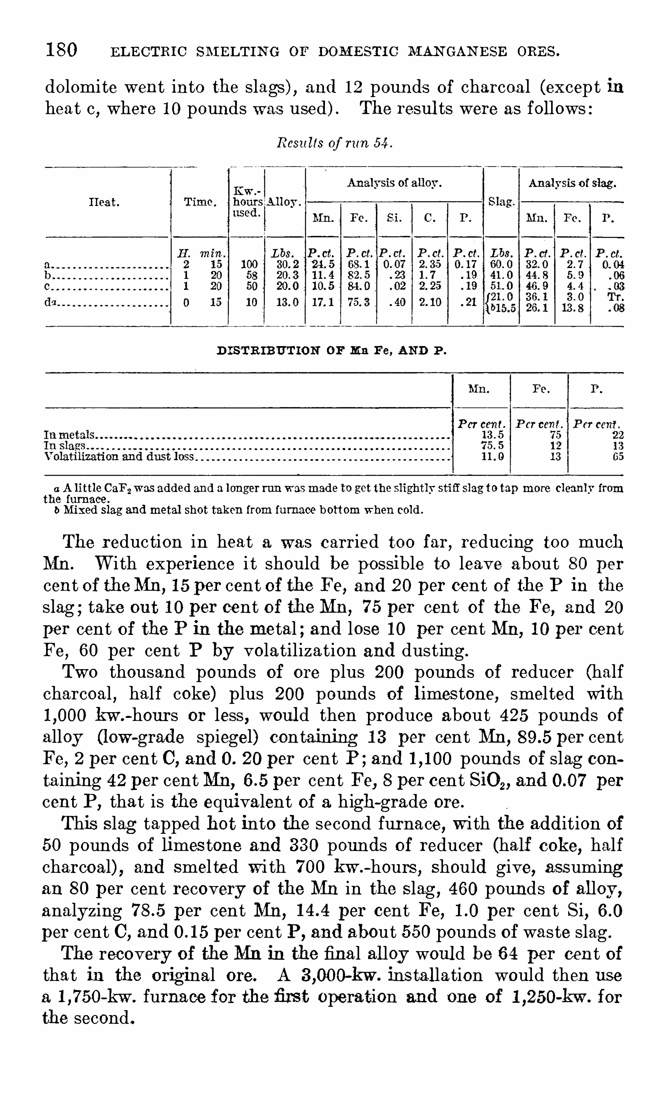
1 80 EL E CTRIC SM ELT IN G OP DOM E STI C MAN GAN ESE ORE S .
dolomite went into the slags) , and 1 2 pounds of charcoa l (except inheat c
,where 1 0 pounds was used ) . The resul ts were as follows :
Resu lts of run 54 .
Anal ysis o f slag.
Hea t.
D I ST R IBUT ION OF Mn Fe, AND P .
P er cent
a A little CaF2was added and a longer run wasmade to get the slightly stid slag to tap more cleanly fromthe furnace .
6 Mixed slag and metal shot taken from furnace bottom when cold .
The reduction in heat a was carried too far, reducing too muchMn. W i th experience i t should be po ssible to leave about 80 percent of theMD,
1 5 per cent of the Fe, and 20 per cent of the P in the
slag ; take out 1 0 per cent of the Mn, 7 5 per cent of the Fe, and 20
per cent of the P in the metal ; and lose 1 0 per cent Mn, 1 0 per centFe
, 60 per cent P by volatilization and dusting .
Two thousand pounds of ore plus 200 pounds of reducer (halfcharcoal , half coke) plus 200 pounds of l imestone, smelted with
kw .-hours or less , woul d then produce about 425 pounds of
alloy (low-grade spiegel) containing 1 3 per cent Mn, per centFe, 2 per cent C, and 0. 20 per cent P ; and pounds of slag containing 42 per centMn, per cent Fe, 8 per cent SiO, , and per
cent P,tha t is the equivalent of a high-grade ore .
This S lag tapped hot into the second furnace, wi th the addition of
50 pounds of limestone and 3 3 0 pounds of reducer (half coke, halfcharcoal) , and smel ted wi th 7 00 kw .
-hours , Should give, assumingan 80 per cent recovery of the Mn in the S lag , 460 pounds of alloy,analyzing per cent Mn , per cent Fe, per cent Si ,per cent C ,
and per cent P , and about 5 50 pounds of waste slag .
The recovery of the Mn in the fina l alloy woul d be 6 4 per cent ofthat in the original ore. A -kw . ins tallation would then use
a -kw . furna ce for the firs t operation and one of -kw . for
the second.
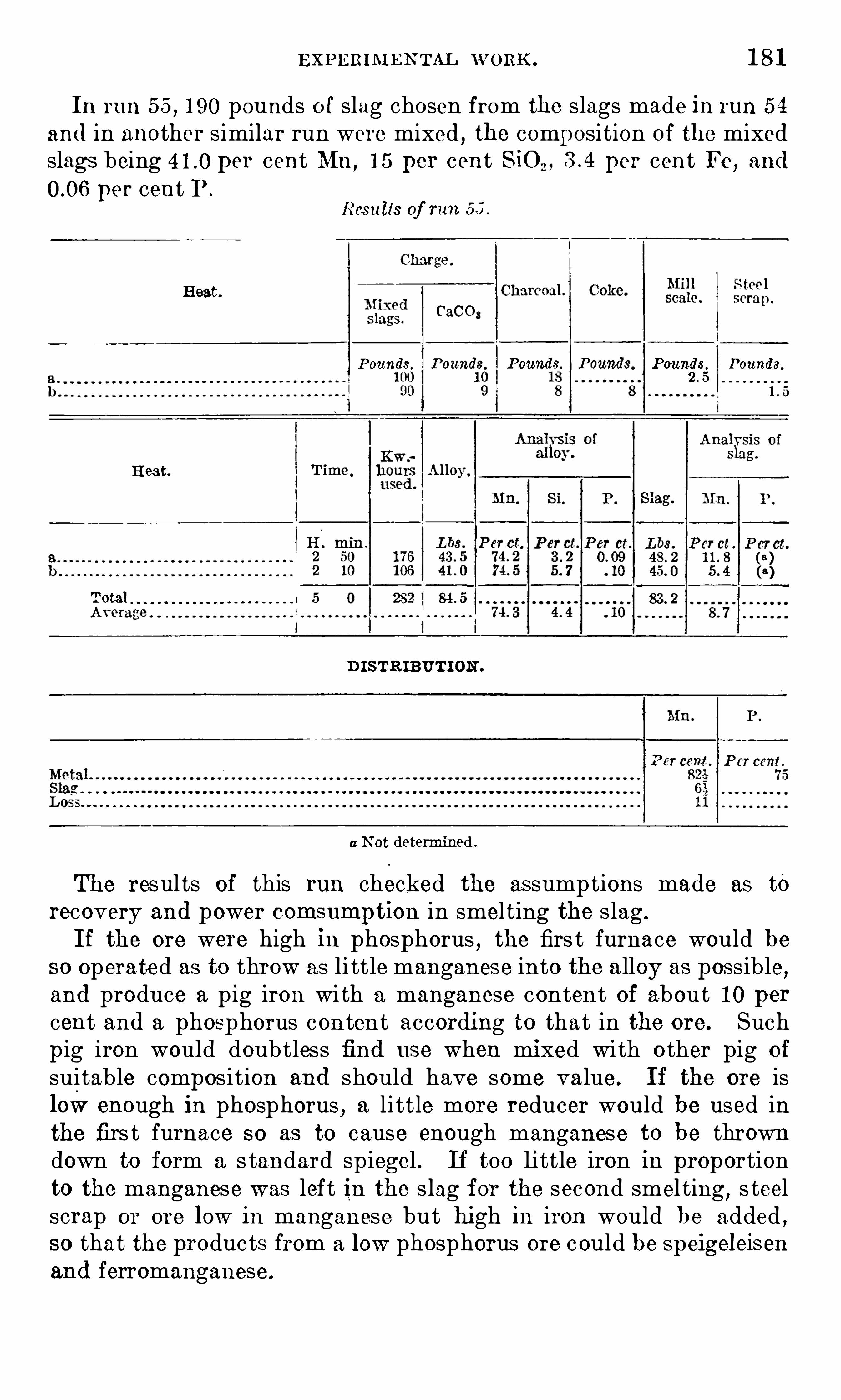
EXPE RIM E N TAL W ORK. 1 8 1
In run 5 5 , 1 90 pounds o f slag chosen from the slags made in run 5 4
and in another similar run were mixed , the composition of the mixedslags being per cent Mn,
1 5 per cent SiO per cent Fe , and
per cent I ’ .
Resu lts of run 55
P ounds. P ounds. Poung
s
s. Pounds.
Heat.
Total l
D I STRIBUTION .
0 0 0 0 0 0 0 0 0
a N ot determined .
The results of this run checked the as sump tions made as to
recovery and power comsumption in smel ting the slag .
I f the ore were high in phosphorus,the firs t furnace would be
so operated as to throw as li ttle manganese into the alloy as possible,and produce a pig iron with a manganese content of about 1 0 percent and a phosphorus content according to that in the ore. Suchp ig iron would doubtless find use when mixed wi th o ther pig of
suitable composi tion and should have some value. I f the ore islow enough in phosphorus , a li ttle more reducer would be used inthe firs t furnace so as to cause enough manganese to be throwndown to form a s tandard spiegel . If too little iron in preportionto the manganese was lef t In the s lag f or the second smel ting
,s teel
scrap or ore low in manganese but high in iron would be added,
so that the products from a low phosphorus ore could be speigeleisenand ferromanganese.

1 82 E L E CTRI C SM ELT I N G OF DOM E ST IC M AN GAN E SE ORE S .
COMPI LATI ON OF'
DATA.
The probable performance of several types of domes tic manganeseore under elec tric smel ting
,compiled from the data available on
present prac tice,and from the results of experimental work
,is
given in Table 3 1 following .
The elec trode consumption per ton of produc t has been calculatedon the basis of kw .
-hours required per ton of product,taking as
s tandard the normal commercial consumption of 1 7 5 pounds of
elec trode per ton of 80 per cen t ferromanganese produced from an
ore con taining 40 per cent manganese and 20 per cen t s ilica , and
using kw .-hours . In o ther words
,the elec trode consumption
per kw .-hours used is 3 1 pounds . The ac tual consumption
of elec trodes , not including s tub ends in the experimenta l runs,
varied from 6 to 1 0 pounds per 450 kw .-hours used
,which is of the
same general order of magni tude as the figures assumed .
In Table 3 2 an attempt has been made to calculate cos ts of
operation for the eight ores represented in Table 3 1 , on the assumption tha t the ores are priced as follows : Ores 1 and 2 in accordancewith the W ar Indus tries Board ’s schedule
,ores 3 and 4 at $ 1 5 per
ton ,ore 5 at per ton ,
ores 6 and 7 at $ 7 per ton ,and ore 8 at
$8 per ton . Limes tone is assumed to cos t cen t a pound,fiuorspar
3 cents a pound , coke cent a pound,charcoal 1 4 cents a pound
,
s teel scrap 2 cents a pound , electrodes 1 5 cents a pound , and powercen t per kw .
-hour used . Selling prices are calcula ted at
per long ton of 80 per cent ferromanganese (equivalen t to $250per long ton of 7 0 per cent ferromanganese) , and $ 1 50 per long tonof 5 0 per cent ferrosilicon ; and the manganese and silicon contentsin a sili comanganese a lloy are calculated as having the same valueas in the separate ferro a lloys . The alloy of ore 5 , with per centphosphorus , is figured as worth $260 per equivalen t ton of 80
per cent ferro , while that of ore 7 , with per cen t phosphorus ,is figured as worth $23 5 per equivalent ton . All these figures are
assumed,and would vary widely according to the si tuation of the
plant . They are included merely to give a rough idea of the cos ts .Peace-time figures would greatly al ter the cos ts and profits .Lyon,
Keeney, and Cullen“ give the following pri ces per metri cton in Germany ,
f . o . b . Louisberg , January 1,1 9 1 3 :
50 per cent ferrosilicon $7 7 . 55
80 per cent ferromanganese 68. 00
Silicomanganese (68 to 7 5 per cent MD ,20 to 25 per cent Si) . 1 06. 50
I t is seen that the price paid for contained manganese and siliconin the silicomanganese is higher than tha t paid for the same amountof manganese and silicon in ferro al loys .
0 Lyon, D . A . ,Keeney, R . M., and Cul len, J . F. ,
work cited , p . 1 40.
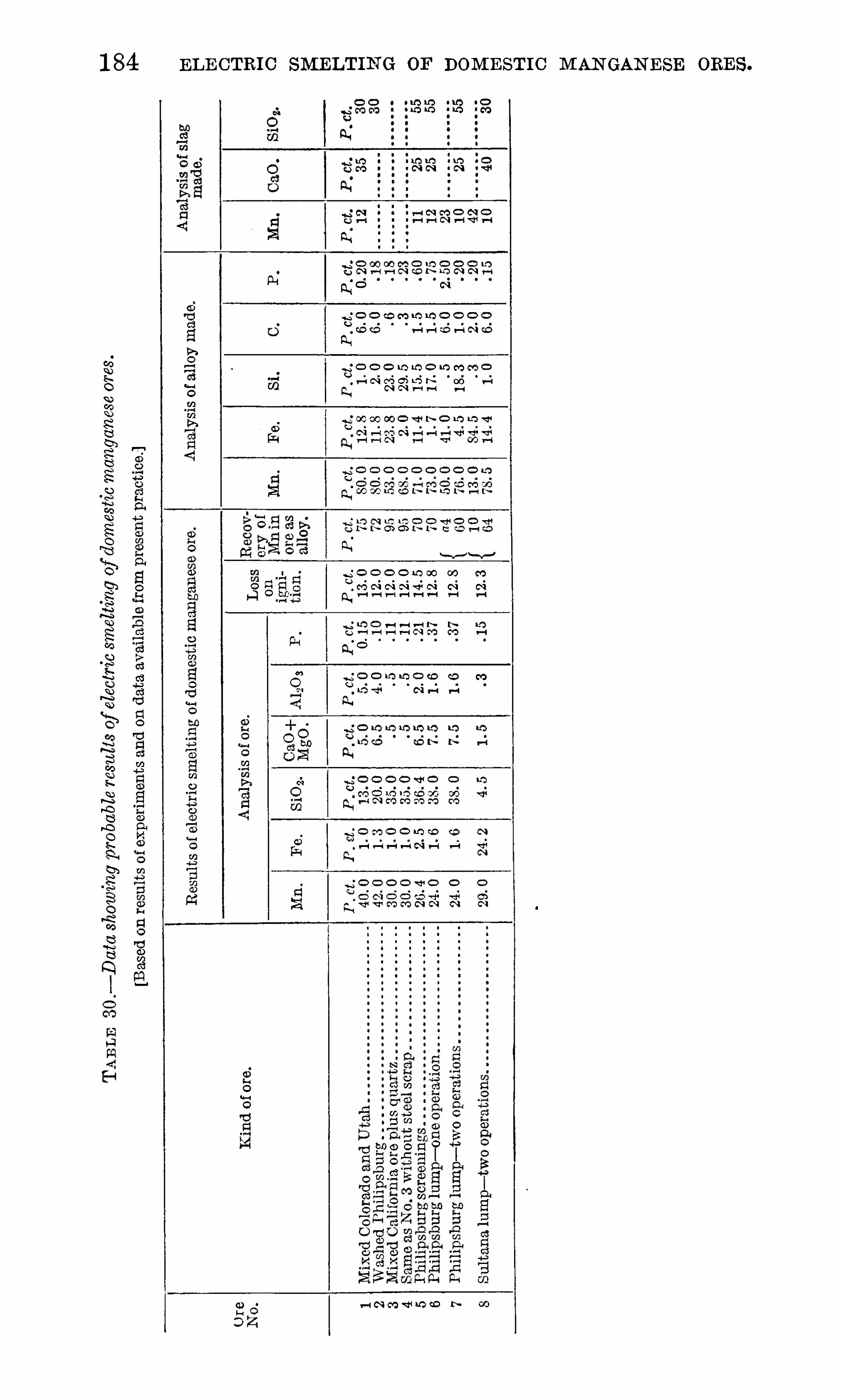
1 84 ELE CTRIC SMELTIN G OF DOM E STI C M AN GAN E SE ORE S .
I
g o o o mm o w mm oQ o o o o o o o o o o
. H N O’DO L’Q N 00 v—lQ, N N n—u—t H
N
'o ce o o m co o
C.) 0 0 0 0 0 0 o

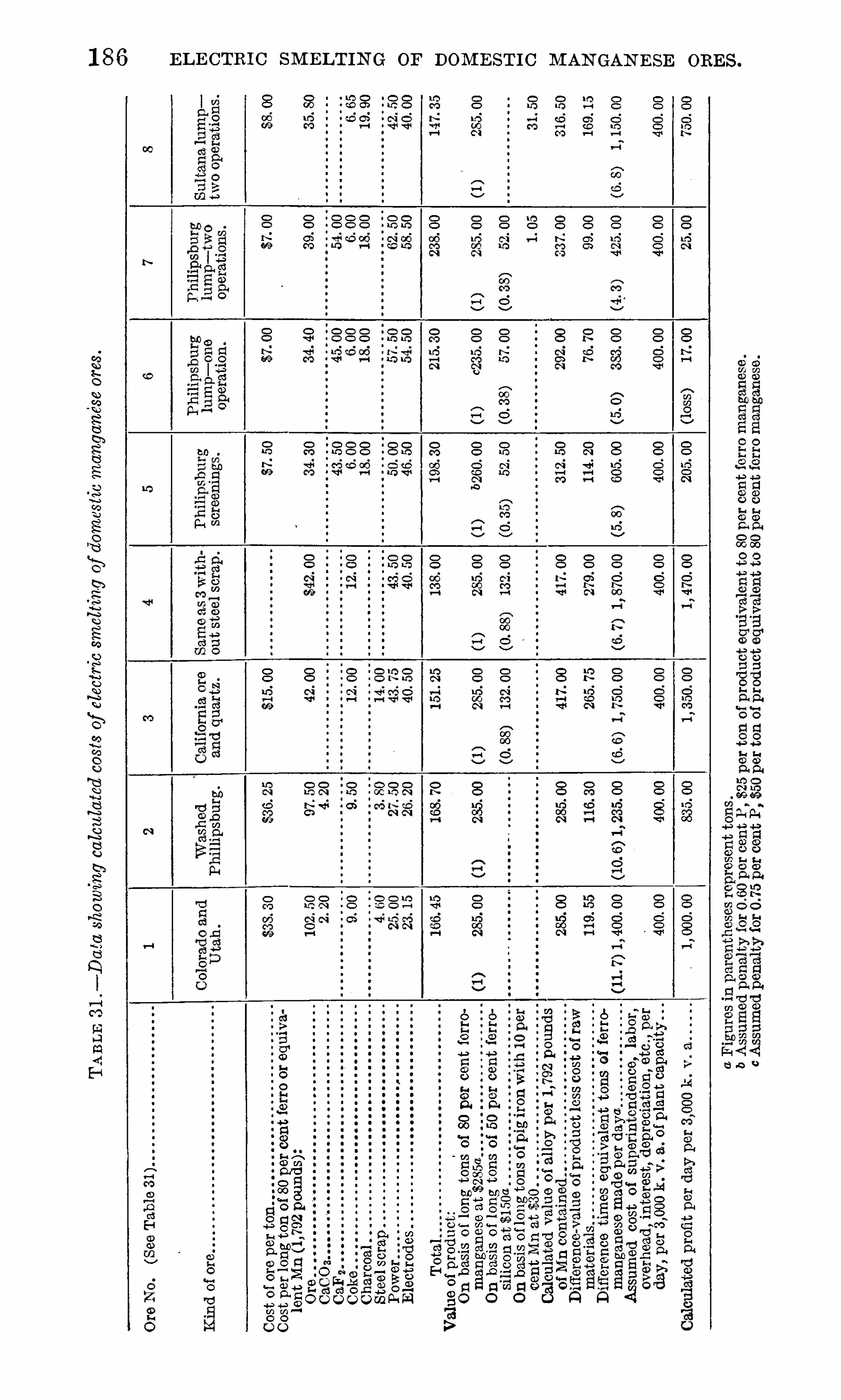
1 88 MAN GAN ESE ALLOYS IN OPEN -H EARTH STEEL PRACTICE .
a preliminary survey, it seemed important to determine (a ) theconditions in open-hearth practice that woul d lead to a conservationof manganese, both during the working of the heat and in makingthe final additions ; (b) the most satisfactory metallurgical conditionsfor the use of manganese in the form of low-grade or special alloys ;and (c) the effect on the finished steel
,both as to quality and
“con
dition , ” of the various methods and processes studied . With thesepoints in mind , the selection of the steel plants was made so thatresearch work bearing on one or more of these points could beconducted .
I t was decided to determine slag and metal compos itions duringthe refining of the heat ; also , the temperature was to be noted eachtime a sample was taken
,in order to determine
,if possible
,the
temperature effect . The“recovery ”
of manganese was to be
determined from the residual and final manganese contents and theweight of the metal . To this end a sample o f the finished steel w as
taken during teeming . By taking three such samples,one at the
beginn ing , one toward the middle, and one at the end of teeming,tests for uniformity were possible . This practice w as generallyobserved throughout the investigation . The data obta ined werealso supplemented by the plant records covering given heats as
well as by personal observation during refining, pouring , and teeming .
When plann ing steps that shoul d be taken to determine the qualityand
“ condition ”of the steel , it was found that no defin ite and well
proved method was available . True, the open-hearth melter
knows whether his heat is in proper condition, but what was neededwas a quantitative estimate of “ condition .
” W ithout attempt ingto discuss the physical chemistry of a heat of molten steel
,i t may
be said that the condition of the heat must depend , aside from the
temperature, upon the presence in the steel in those substances thataffect the “ condition . O f these there are two kinds : (1 ) Substances that promote “
openness ,” or the gases , which aga in may be
classified as (a ) gases that are products of chemical reactions , being,in so far as we know, CO and possibly C0 2 , and (b) gases that areabsorbed from the furnace gases , such as H
,N
,CO , and COZ ; and
(2) substances that promote “ soundness ,” such as the reducing and
solidifying agents, C ,Mn, Si , and Al .
In general i t is held that Mn, Si , and Al inhibit the chemicalreactions producing CO by reducing (or partly reducing) FeO , the
principal constituent that produces the reactions . In this statement only the metal bath is considered and the FeO ,
and not
PezO 3 , is assumed to be in so lution in the steel . According to thisidea
,reducing action on a slag containing Pez0 3 woul d produce
FeO,part of which woul d enter the steel to react later with C ,
Mn,
and other reducing agents present . The reduction of FeO, then ,

TH E FU N CT ION S or M AN GAN ES E . 1 89
is the principal means of settling the l iquid steel , and i t is forthis reason that Mn is added in the fin a l steps . I t is also held thatSi and Al produce so lidity in the finished steel
,aside from reducing
FeO and CO,either by keeping the gases H ,
N,etc .
,in solid solution
,
or by preventing the dissociation of the compounds of those elementsand iron .
The obvious procedure to get a quantitative estimate of the“con
dition ”
of the steel,considering both the behavior of the mol ten
metal and the character of the ingot,woul d be to determine the
amounts of the constituents in each of these two groups and to
weigh one set against the other. Even this procedure woul d not,
at present,lead to resul ts that could be interpreted with entire con
fidence,even though there were no uncertainties in the analytical
methods,because we do not know the quantitative effect of each
constituent,ei ther by i tself or when associated with other constitu
ents in varying amounts . In view of this lack of fundamental data,
i t was decided to make the analyses and use the resul ts in a qualitative way , at least , to compare the diff erent practices investigated .
THE FUN CTIONS OF MANGANESE .
During such a critical period as that now pas sed,the question
might be raised as to the possibility of eliminating manganese fromsteel making . This point -was duly considered but it was at onceheld that the use of manganese is not merely an expedient
,for which
some substitute might readily be had, but is rather one of the basicrequirements of successful practice in working steel . I t is quitetrue that in many ins tances the actual amoun t of manganese usedin a heat of steel is greater than purely metallurgical considerationsdemand
,and any excess coul d well be considered as so much wasted .
I t may be well to review briefly the important functions of man
ganese as they bear directly on both of the points mentioned above.
The firs t function of manganese,broadly considered , is to refine and
.settle ”the molten bath of steel . The aim here is to put the metal
in a proper condition for pouring,and to produce ingots (or castings )
of the desired quality and texture . Manganese is not the most efficien t element that can be used for this purpose, calculated from the
heat of combustion of the element to i ts oxide,but is without doubt
the most satisfactory because of the excellent condition (freedomfrom obj ectionable foreign inclusions) in which i t leaves the bath .
The proportion of manganese theoretically required for this operation might possibly be calculated from the amount of oxygen con
verted from the active form,FeO
,to the inactive form ,
MnO . Assuming an oxygen con tent of per cent in the unsettled steeland of per cent in the finished steel (oxygen by the Ledeburmethod ) , the amount of manganese used in this way woul d be

1 90 M AN GAN E SE ALL OYS IN OPE N -H E ARTH STE EL PRACTI CE .
per cent . The wri ter is informed by the Bureau of S tandards thatsuch a cal cul ation is premature
,owing to lack of knowledge on the
subject of “ deoxidation ”and the faul tiness of the Ledebur determi
nations . However it woul d seem to the writer,from the work done
at the Bureau of Standards,
“ that the amoun t of oxygen determinedis the amoun t present as FeO (active form) , subj ect possibly to an
error due to partial reduction of CO dur ing the determination . Atany rate
,the above is advanced as at leas t the firs t approximation of
the amoun t of manganese required S imply for destroying the ferrousoxide present in the bath . The amount of manganese required naturally woul d vary with the condition of the bath and
,in order to
insure efficient “ deoxidation,
” woul d be somewhat in excess of thecal cul a ted amount . A well -made heat of steel woul d probably not
require more than per cent Mn .
Manganese is also desirable in steel to improve the roll ing properties , in which capacity i t appears to serve a dual purpose . Firs t ofall
,manganese deoxidize
's ‘
and refines the mol ten steel in such a way
as to give ingots of the desired texture without robbing the Steel ofits hot-working properties . Thus
,ingots may be roll ed in to finished
shape,without the formation of excessive fissuring or surface de
fects . O ther reducing agents,such as aluminum and silicon
,are
prone to leave the metal in poor condition for rolling and forging .
They el iminate one cause of hot shortness—fi iron oxide— but fail toconvert the sul phur into a harml ess form
,as manganese does
,and
leave behind their highly refractory oxides,both of which tend to
produce poor rolling qualities . Secondl y ,manganese
,by retarding
the rate of coalescence or grain growth,renders steel less sens itive to
the effects of the high temperatures used in roll ing and is supposedto promote plasticity ,
at least in ordinary steels , at rolling temperatures . Silicon and aluminum
,on the other hand
,increase
,rather
than decrease,the grain S ize of steel . The proportion of manganese
required in this capacity probably does not exceed per cent inwell-made steel .Final ly ,
manganese is desired in the finished steel to produce cer
tain physical or mechanical properties or to make the steel more
amenable to subsequent heat treatment .
The foregoing discussion indicates that manganese is an importan tfactor in the steel industry . Of course
,material such as
“ Americaningot iron ”
can be successfully rolled,even though no manganese be
added,but requires greater time and care .
I t is of interest to note that manganese,coming in the periodic
system between iron and the strengthening elements on one S ide and
the hardening elements on the other ,has the dual function of strength
,
a Cain , J . R .
,and Pettijohn ,
E arl . A critical study of the L edebur method for determining oxygen in
iron and steel : Bureau of Standards Technologic Paper 1 1 8, 1 91 9, 3 3 pp .
1 92 M AN GAN ESE AL L OYS I N OPE N —H EARTH STEEL PRACTICE .
2 . The deoxidation is accomplished by means Of a dilute solution,
with a consequent increase (on theoretical grounds ) of the efficiencyof the deoxidizer . This point wil l receive further consideration . 3 .
The deoxidizer is added in the molten state, insuring certain attendant advantages , which will also be considered at greater length . 4 . Aspecial advantage , if a large steel output is desired , is that the amountof the recarburizer is comparatively large and the capacity of the plantis materially (and economically) increased thereby . There is somequestion as to the propriety Of including this advantage as pecul iarto this particul ar practice . The use of pig iron as a recarburizer may
be accomplished in other ways with the same economy and increasein plant capacity . 5 . Another advantage would seem to the writerto be as follows : As compared w i th the resul ts in the usual practiceOf adding carbon and manganese, there should be less likelihood of
ssing a heat .This practice, at least at the plant visi ted , and i t is understood to
be the same elsewhere , is limited to the manuf acture of the highcarbon steels or those runn ing per cent or more of carbon . To
make steels with per cent carbon woul d require working thebath until the carbon content w as about per cent , and the mol tenmixture added woul d have to contain about 20 per cent manganese(spiegel ) . The amount of the addition would be reduced frompounds to about pounds
,which would mean that some of the
advantages j ust enumerated would be lessened,and
,with the in
creased loss Of manganese the practice would probably not be com
mercially feasible . However,when the o ther al ternative— the use O f
ferromanganese, either solid or liquid— is considered , the practice of
premelting spiegel in the cupola seems commendable, on grounds tobe cons idered later. In the event of undue shortage of high-gradeferromanganese the practice would doubtless Offer a ready solutionof the problem of using domestic alloys in making steel for shapes ,plates, etc . Against the increased cost of production , as comparedwith the cost of cold ferromanganese practice , there would be thegreater uniformity of product and more uniform practice as an offset .
HIGH RE SIDUAL MANGANE SE PRACTI CE .
At certain plants the practice of preferential oxidation and elimination Of carbon and phosphorus has been developed , the residual man
ganese being kept at a_
comparatively high value, say ,to
per cent , as compared wi th per cent manganese for a final carboncontent Of per cent . This is accomplished , broadly speaking ,(a ) by rapidly removing the phosphorus and retaining i t as stablecalcium phosphate during the earlier and colder period of mel ting ;(b) by maintaining a high finishing temperature and working thecharge with a high manganese content so tha t the slag contains
H IGH RE S IDUAL M AN GAN E SE PRACT ICE . 1 9 3
about 8 per cent manganese ; and (c) by increasing the lime contentof the slag to about 4 7 per cent as a minimum .
This process possesses undoubted advantages , but they are suchthat they are probably best appreciated by plants in which the process has been developed and where i t is now in operation on a soundcommercial basis . Firs t of all i t may be stated that the practice ,correctly applied , leads to the production of high—grade and uniformsteel , which in i tself means increased roll ing—mill output , fewer rejections
, and a more ready market . This is largely due to the fact thatthe s teel is made— where i t should be made— in the furnace .
A second advantage derived from the high MnO and CaO contentsof the slag, is that the final additions O f manganese can be added inthe furnace , with a recovery comparing favorably with that O f ladleadditions . A third advantage is that the same pig~iron used for thecharge
,and containing appreciably more manganese than ordinary
basic iron does,can be used to recarburize and partly deoxidize the
bath . The rest of the manganese is added as ferromanganese . At asteel plant which operates in conj unction with a blast—furnace planta harmonious and economical cycle of plant operations is made possible . At the same time the open-hearth slag can be resmelted inthe blast furnace for the recovery of the iron and manganese and the
utilization of the lime .
This practice is largely dependent upon the amount of phosphorusin the slag
,for Obvious ly i t would not be worth while to recover the
manganese at the expense Of unduly increasing the phosphorus content of the pig iron . In this country we are fortunately situated inthis respect, as there is still a large amount of ore rather low in phosphorus available . N o defin i te figure can be given at this time as to
the maximum allowable phosphorus content of the pig iron,but it
is the opinion Of at leas t one steel man who uses this process that acontent Of per cent would not be excessive . Under the conditions prevailing in 1 9 1 8
,this practice had the additional advantages
that the high-manganese pig iron could be procured by smel tingdomestic manganiferous iron ore and that the manganese all oy addedto the furnace at the end of the heat could as well be Spiegel as ferromanganese , assuming that the finished stee l contains more than about
per cent carbon . There would also be certain disadvantages ,particularly that the carbon content of the bath would have to beworked to a lower figure than in present practice . On account of thehigh cost of spiegel and the greater time require d
,i t is doubtful
whether the steel plants would substi tute spiegel for ferromanganese .
Ano ther interesting point,as regards the utilizing of domestic man
ganiferous iron ore,is that low-silica ore coul d be added to the slag
as a source of manganese oxide .

1 94 M AN GAN E SE ALLOYS IN OPE N -H EARTH STE EL PRACTICE .
The high manganese content of the charge is generally Obtainedby using a
“ high-manganese ” pig iron (2 to 3 per cent manganese) ,but may also be obtained by adding manganese ore to the slag or
manganese alloys to the bath or by a combination of these methods .This point woul d be determined by plant economy ,
but it seemsdoubtful whether the practice woul d be worth whil e unl ess a highmanganese p ig Iron were available. The wri ter is inf ormed by one
blast—furnace superintendent that running the manganese up to 2 percen t does not materially aff ect the production
,so that lower pig-iron
production woul d not be a disadvantage in this practice . The lossOf manganese by oxidation and transferrence to the slag is considerable. This loss may be kept at a minimum by increasing the
basicity of the slag in CaO and FeO,which
,combined with the MnO
,
which also acts as a base,exert the desired efiect upon the manganese
of the bath .
As the working Of the charge progresses its temperature risesuntil finally with the high CaO
,and particul arly the high MnO
content of the slag,t he carbon is eliminated more rapidly than the
manganese,with the resul t already stated , namely ,
the manganesecan be hel d to about per cent at the end of the heat . Presentdata indicate
,unf ortunately ,
that no material decrease in the amoun tof manganese required and no material increase in the recovery Of
manganese in the additions may be expected,S O that the advantages
are derived not from a decreased consumption,but from the form
in which it can be added .
Data for one such heat showed that a total of pounds of
manganese was used in one form or another to produce poundsof manganese in the finished steel— that is
,pounds was used to
produce 1 poun d in the steel . The manganese added in the recarburizer and as ferromanganese amounted to pounds
,of which
,
assuming the manganese loss to come from these two sources,8 3 8
pounds was recovered in the finished steel,a recovery of per
cent . In this heat the ferromanganese was added to the furnace.
Another more or less comparable heat selected at random,but more
representative of“ standard ” practice
,used pounds of man
ganese to produce poun ds,or pounds (as compared to
pounds ) to produce 1 poimd Of manganese in the finished steel .
STANDARD OPEN -HEARTH PRACTI CE COMPARED WI THCERTAIN OTHER PRACTI CE S .
Data regarding the resul ts obtained in standard open-hearth steelpractice as compared with the resul ts w hen molten spiegel is used or
when there is a large percentage of residual manganese will be presented in a later report after more complete analytical resul ts havebeen received .
1 9 6 M AN GAN E SE ALLOYS IN OPEN -H EARTH STEEL PRACTICE .
a series of experiments on the occurrence and identification of foreigninclusions in acid open-hearth steel
,principally ordnance steel . In
this work ferromanganese, ferrosilicon,and a mixture Of ferroman
ganese and ferrosil icon were added to a steel sample taken shortlyaf ter “
oreing” — that is
,to
“ wild ” steel— in an attempt to producean excess of the cons tituent, or constituents , supposed to form as a
resul t of the addition .
I t seemed fairly clear as a resul t of this work that the use of
silicon was apt to be dangerous, not on account of any harmfuleffect Of the residual metall ic silicon but because i t produced a con
stituent (assumed to be SiO2 or at least a highly refractory silicate)that was likely to remain in the ingo t and produce hot shortness .Hence the idea was suggested that a manganese-silicon alloy might,and probably would , form a manganese silicate containing some ferrous oxide (a true slag ) which would be fluid and would more readilycoalesce into larger part icles than SiO2 woul d, and therefore freei tself more readily from the steel . By using such an alloy i t wouldthen be possible to take ful l advantage of the use of silicon as a
deoxidizer without suffering the usual attendant disadvantages of
i ts use . None Of the manganese-silicon alloy was availab le at the
time so a parallel experiment could not be conducted .
As binary alloys are known to be generally more active, or powerful
,than the weighted sum of the two cons tituents woul d indicate
,
i t was also assumed that , aside from the possibility of Obtaininga better separation Of the insoluble products of the deoxidationprocess , the alloy of manganese and silicon would prove to be a morepowerful reducing agent than ferromanganese and ferrosilicon usedseparately . On reflection, the thought occurs that manganese and
S ilicon,reacting separately with Feo, woul d produce the oxides
MnO and FeO or a silicate of iron . Manganese and silicon reactingas an alloy with FeO would produce a S il icate of manganese , whichmay or may not form a doub le silicate with Feo . In either case wewould expect to find the advantage in favor of the manganeseS ilicon alloy .
The relative weights of the silicomanganese and of the mixtureof the ferromanganese and ferrosilicon will be considered at anotherplace.
Another po int of grea t technical importance is the percentagerecovery of manganese when added as silicomanganese and as ferromanganese along wi th ferrosilicon . I t should be stated that a 1 00
per cent recovery ,based on the present theory of
“ deoxidation,
”
is hardly possible, nor is i t desirable . Such recovery would meanretention of the deoxidation products , to be determined later as
metallic manganese and S ilicon . A method of addition that woul dlead to satisfactory deoxidation and yet would eliminate the loss
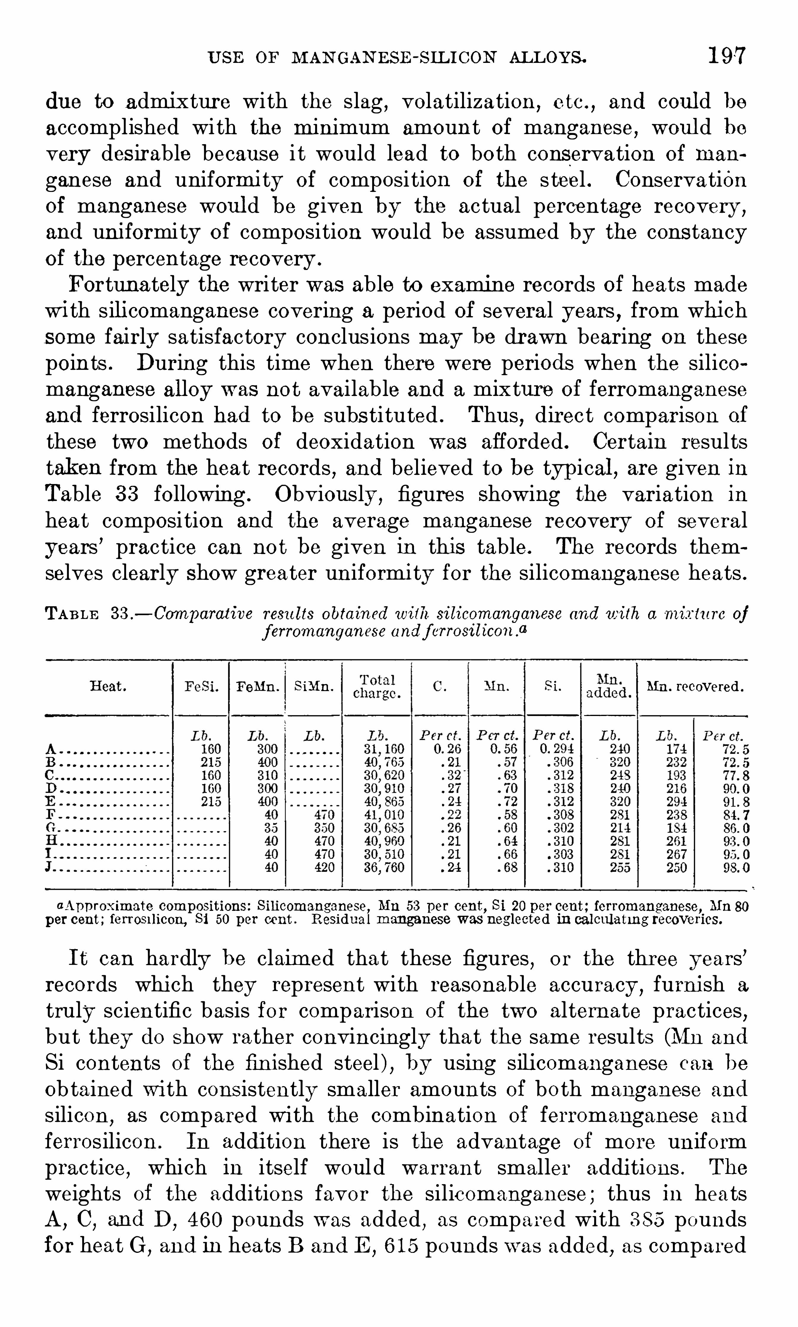
U SE or M AN GAN ESE -S IL I CON AL L OYS . 1 9 7
due to admixture with the slag , volatilization , e tc . ,and coul d be
accomplished with the minimum amount Of manganese , woul d bevery des irable because i t would lead to bo th conservation of man
ganese and uniformity of composi tion of the s teel . Conservationof manganese woul d be given by the actual percentage recovery ,
and uniformity of composition would be assumed by the cons tancyof the percentage recovery .
Fortuna tely the writer was able to examine records of heats madewi th silicomanganese covering a period of several years , from whichsome fairly satisfactory conclusions may be drawn bearing on thesepoints . During this time when there were periods when the silicomanganese alloy was not available and a mixture of ferromanganeseand ferrosilicon had to be subs tituted . Thus
,direct comparison of
these two methods of deoxidation was afforded . Certain resultstaken from the heat records , and believed to be typ ical , are given inTable 3 3 following . Obviously ,
figures Showing the variation in
hea t composi tion and the average manganese recovery of severalyears ’ practice can no t be given in this table . The records themselves clearly Show greater uniformity for the silicomanganese heats .
TAB LE 3 3 .— Comparative resu lts obtained with. silicomanganese and with a mixture of
f erromanganese andf errosd tcon .“
Heat . Femm. SiMn . Mn. recovered .
aAp p roximate compositions: S ilicomanganese, Mn 53 per cent, Si 20 per cent; ferromanganese, Mn
per cent ; ferrosrhcon, Si 50 per cent . Residual manganese was neglected in calculating recoveries.
I t can hardly be claimed that these figures , or the three years’records which they represent with reasonable accuracy ,
furnish a
truly scientific basis for comparison of the two alternate practices ,but they do Show rather convincingly that the same results (Mn and
Si contents of the finished steel ) , by using silicomanganese can be
obtained with consistently smaller amounts of bo th manganese and
silicon ,as compared with the combination of ferromanganese and
ferrosilicon . In addition there is the advantage of more uniformpractice, which in itself would warrant smaller additions . The
weights of the additions favor the silicomanganese ; thus in heatsA, C , and D ,
4 60 pounds was added , as compared with 3 8 5 poundsfor heat G
,and in heats B and E
,6 1 5 pounds was added
,as compared
1 98 M AN GAN ESE ALLOYS IN OPE N -H EARTH STE EL PRACTICE .
with 5 1 0 pounds in heats F,H
,and I . The low carbon content of
the silicomanganese may or may not be a material advan tage, butis in favor of the single-alloy addition because the carbon need notbe worked as low and there seems to be less danger Of missing thedesired carbon content .
E LE CTR IC -FUR N ACE PR ACT I CE .
No information is available to the wri ter bearing on the use of
manganese-silicon alloys in electric-furnace practice,but we may at
least consider such practice on the basis of the known behavior ofsuch alloys . Considering acid casting practice first
,there seems to
be no reasonable doubt that either silicomanganese or silicospiegel
could be at once substituted for ferromanganese and ferrosilicon .
Inasmuch as the usual aim is to make high-grade castings , themanganese—silicon alloys would appear to have the distinct advantageof making sounder and cleaner steel . Silicospiegel , aside frompossessing the theoretical advantage Of being diluted with iron
,could
be more readily prepared with the correct manganese-silicon ratioso as to eliminate the use of an additional alloy . In this practicethe advantage of greater dilution need not carry with it the disadvantage of increased weight on account of the higher temperatureof the electric furnace . The uncertainty as to the relative behaviorof the manganese-silicon alloys as compared with that of the ferroalloys , and the relative efficiencies of low-grade and of high-gradealloys , as well as the importance of this step in the manufacture of
steel , suggest the advisability of conducting a defin ite research tosettle such po ints . I t would seem that there is no better place forsuch a research than in this particular industry .
In basic electric—furnace practice the manganese—silicon alloys, onthe same grounds , could likewise be utilized , particul arly as the
attempt is always to produce sound and clean ingots . However, inthis practice, ferrosil icon is used as a reducing agent along withcoke, and hence the Operator woul d probably not see any advantagein changing his practice in favor of the manganese-silicon alloys .
BA S I C OPE N -HE ARTH PR ACT I CE .
The amount of information available on the use of silicomanganesein basic open-hearth practice is meager, but it can be said thatsil icomanganese can be used , probably with as satisfactory resul tsas with ferromanganese and f errosilicon . Through the cooperationof one steel plant the writer was able to follow two shell-steel heatsmade with silicomanganese which was added to the ladl e . The
results of the second of these heats are given here to Show what wasdone . To pounds of molten pig iron in the ladle was tapped
pounds (estimated) of steel analyzing per cent 0 ,

SELECTED BIBLIOGRAPHY ON MANGANE SE DEPOSITS.
GE N E R AL .
BEYSCHLAG ,F. ,
KRUS CH ,F.
, and VOGT , J . H . L . Die Lagerstatten der nutzbarenMineralien und Gesteine. 3 vols. ,
1 91 0, pp . 850- 869, 1 099—1 1 1 5 .
DEMORE ’
I‘,L . Le principaux gisements des minerais de manganese da monde . Ann.
des Mines de Belgique, t . 1 0, 1 905, pp . 809—901 .
FACH ,E . Le mineral de manganese . Paris . 1 91 4
,44 pp .
UN ITE D S TATE S .
HARDE R ,E . C . Manganese deposits of the United States. U . S . Geol . Survey Bul l .
427 , 1 91 0, pp . 298 .
PAN AM A :
CH IB IA s, E . J . Manganese deposits Of the Department of Panama, Republic of Co
lombia . Trans. Am. Inst. Min . Eng , vol . 27 , 1 897 , p . 63 .
WILLIAM S,E . G . The manganese industry Of the Department of Panama, Republic
of Colombia. Trans . Am. Inst . Min . E ng , vol . 3 3 , 1 902, pp . 1 97—23 4 .
SOUTH AME R ICA .
BRAZI L .
BRAN N E R ,J . C . Themanganese deposits of Bahia and Minas Geraes, Brazil . Trans.
Am . Inst. Min . Eng , vol . 29, 1 899, p . 7 56 .
SCOTT ,H . K. The manganese ores of Brazil . Jour. Iron and Steel Inst. , vol . 1 ,
1 900, p . 1 7 9 .
DE RBY, O . A. On the manganese deposits of the Queluz (Lafayette) district, MinasGeraes. Am. Jour. Sci. , 4th ser. , vol . 25, 1 901 , p . 1 8.
CH ILE .
HARDE R,E . C . Manganese ores Of Russia, India, Brazil , and Chile. Trans. Am.
Inst. Min. Eng , vol . 56 , 1 91 6, pp . 3 1 —68 .
E UR OPE .
AUSTR IA .
NASKE , T . [Manganese ore in Austria]. Stahl und E isen, Jahrg. 28, 1 907 , pp . 543—547 .
SCOTT , H . K. Manganese ores of the Bukowina. Jour. Iron and S teel Inst , vol ,‘
94 , 1 91 6 , pp . 288—3 55 .
GE RM AN Y .
KE RN, J Zur Frage der Mangan
—versorgung Deutschlands. Berg . Mitteilungen,Jahrg. 4 , 1 91 3 , pp . 49—59.
SCH EFFE R , [The importance of manganese and mangani ferous ores in German
industry]. Gluckau f, Jahrg. 49, 1 91 3 , pp . 2056 , 21 1 1 , 21 51 .
200
SELE CTED BIBLIOGRAPH Y ON M AN GAN E SE DE POS ITS . 20 1
RU S S I A .
DRAKE ,FRAN K. The manganese industry Of i the Caucasus . Trans . Am. Inst . Min.
Eng ,vol . 28
,1 898 , p . 1 91 .
SPA I N .
HOYE R,M . Contributions tothe knowledge Of the manganese deposits of the Province
of Huelva . Ztschr. prakt. Geol ., vol . 1 9, 1 91 1 , pp . 407 -43 8 .
AFR I CA .
W E ST AFR I C A .
FORD ,H . Manganese in West Africa . Mining Mag ,
vol . 1 7 , 1 91 7 ,
A S IA .
I N D I A .
FE RMOR,L . L . The manganese deposits of India
,
India Geol . Survey Mem., vo l
3 7 , pts . I , I I , I I I , IV,1 909,
CARTE R,H . A . Manganese mining in British India . Min . and Sci. Press . vol . 1 03 ,
1 91 1,pp . 834—83 5 .
I N DIA GE OLOGICAL SURVE Y RE CORD , Quinquennial revi ew of the mineral productionof India . Vol . 46 , 1 91 5 , pp . 1 3 5—1 3 9 .
S N O DC RAss,J . H . Manganese mining in Japan. Mining World, vol . 3 0, 1 909 , p . 7 90
PUBLICATIONS ON METALLURGY .
A limited supply of the following publica tions of the Bureau Of
Mines has been printed and is available for free distribution until theedition is exhausted . Requests for all publica tions can not be
granted,and to insure equitable distribution applicants are requested
to limit their selection to publications that may be of especial interestto them . Requests for publications Shoul d be addressed to the
Director, Bureau of Mines .The Bureau Of Mines issues a list showing all i ts publications
available for free distribution as well as those obtainable only fromthe Superintendent of Documents, Government Printing Office
,on
payment of the pri ce of printing . Interested persons should applyto the Director, Bureau of Mines
,for a copy of the latest list .
PUBL I CAT I ON S A VA I LAB L E FOR FR E E D I STR IBUT I ON .
BULLE TIN 67 . E lectric furnaces formaking iron and steel , by D . A . Lyon and R . M.
Keeney . 1 91 4 . 1 42 pp . , 3 6 figs.
BULLE TI N 7 3 . Brass furnace practice in the United S tates, by H . W . Gil lett . 1 91 4 .
298 pp . , 2 pls .,23 figs .
BULLE TIN 7 7 . The electric furnace in metallurgical work ,by D . A . Lyon,
R . M.
Keeney and J . R . Cul len . 1 91 4 . 21 6 pp . , 56 figs .
BULLE TI N 84 . Metallurgical smoke , by C . H . Ful ton . 1 91 5 . 94 pp . , 6 pls . , 1 5 figs.
BULLE TIN 97 . Samming and anal ysis of flue gases, by Henry Kreisinger and F. K.
Ovitz . 1 91 5 . 68 pp . , 1 pl . , 3 7 figs .
BULLE TI N 1 00 . Manuf ac ture and uses of alloy steels, by H . D . Hibbard . 1 91 5 ,
7 8 pp .
BULLE TIN 1 1 0. Concentration experiments on the siliceous red hematites of the
Birmingham district, by J . T . Singewal d , jr. 1 91 7 . 91 pp . ,1 p l . , 4 7 figs.
BULLE TI N 1 3 3 . The wet thiogen process of recovering su lphur from su lphur dioxide
in smelter gases, a critical study , by A . E . Wells . 1 91 7 . 66 pp . , 2 pls . , 3 figs .
BULLE TIN 1 40. Occupational hazards and accident prevention at blast-furnace
plants ; based on records of accidents in blast furnaces in Pennsylvania in 1 91 5 , byF. H . Willcox. 1 91 7 . 1 55 pp . ,
1 6 pls.
BULLE TIN 1 54 . Lead and zincmining andmil ling , by C . A . Wright . 1 91 8 . 1 3 4 pp .,
1 7 pls . , 1 3 figs.
BULLE TIN 1 57 . Innovations in the metal lurgy Of lead , by O . C . Ralston . 1 91 8 .
1 67 pp . ,1 3 figs.
BULLE TIN 1 68 . Recovery Of zinc from low-
grade and complex ores, by D . A . Lyon
and O . C . Ralston . 1 91 9 . 1 45 pp . , 23 figs.
TE CHN ICAL PAPE R 8 . Methods of analyzing coal and coke , by F. M . Stanton and
A . C . Fieldner. 1 91 3 . 42 pp . ,1 2 figs.
TE CHN ICAL PAPE R 50 . Metal lurgical coke , by A . W . Belden . 1 91 3 . 48 pp . , 1 p l . ,
23 figs
204 PUBL ICATION S ON M ETALLURGY.
PUBL I CATION S THAT MAY BE O BTA I N E D ON LY THR OU GH THE
SUPE R I N TE N DE N T OF DOCUM E N T S .
BULLE TI N 3 . The coke industry of the United States as related to the foundry ,by
Richard Moldenke . 1 91 0. 3 2 pp . 5 cents.
BULLETIN7 . E ssential factors in the formation of p roducer gas, by J . K. C lement,
L . H . Adams , and C . N . Haskins . 1 9 1 1 . 58 pp .,1 pl .
,1 6 figs . 1 0 cents.
BULLE TIN 1 2 . Apparatus and methods for the sampling and analysis of furnacegases, by J . C . W . Frazer and E . H . Hoffman. 1 91 1 . 22 pp .
,6 figs. 5 cents .
BULLETIN 47 . Notes onmineral wastes, by C . L . Parsons . 1 91 2 . 44 pp . 5 cents.
BULLE TIN 54 . Foundry-cupola gases and temperatures, by A . W . Belden . 1 9 1 3 .
29 pp .,3 p ls.
,1 6 figs. 1 0 cents.
BULLETIN 63 . Sampling coal deliveries and types of Government specificaitons for
the purchase of coal,by G . S . Pope. 1 91 3 . 68 pp .
,4 pls .
,3 figs. 1 0 cents.
BULLE TIN 64 . The titaniferous iron ores in the United Sta tes ; their composition and
economic value, by J . T . Singewals, ir. 1 91 3 . 1 45 pp .
,1 6 p ls .
,3 figs. 25 cents.
BULLE TI N 7 0. A preliminary report on uranium,radium
,and vanadium
,by R . B .
Moore and K. L . Kithil . 1 91 4 . 1 1 4 pp .,4 p ls.
,2 figs . 1 5 cents .
BULL E TI N 81 . The smelting of copper ores in the electric furnace,by D . A . Lyon
and R . M . Keen'ey . 1 91 5 . 80 pp .
,6 figs. 1 0 cents .
BULLETIN 85 . Analyses of mine and car samples Of coal col lected in the fiscal years1 91 1 to 1 91 3
,by A . C . Fieldner
,H . I . Smith
,A . H . Fay,
and Samuel Sanford . 1 91 4.
444 pp .,2 figs. 45 cents.
BULLE TIN 98 . Report of the Selby Smelter Commission,by J . A . Holmes
,E . C .
Franklin,and R . A . Goul d ,
with reports by associates on the commissioners’ staff .1 91 5 . 525 pp . ,
4 1 p ls.,1 4 figs.
BULLE TIN 1 08 . Melting aluminum chips,by H . W . Gil lett and G . M . James . 1 91 6.
88 pp . 1 0 cents .
BULLETIN 1 22 . The principles and practice of s ampling metal lic metal lurgicalmaterials
,with special reference to the sampling of copper bu ll ion, by E dward Kel ler.
1 91 6 . 1 02 pp .,1 3 pls.
,3 1 figs. 20 cents.
BULLE TIN 1 30. B last-furnace breakouts,explosions
,and slips
,and methods of
prevention,by F. H . Wil lcox. 1 91 7 . 280 pp .
,2 p ls .
,3 7 figs. 3 0 cents.
BULLE TIN 1 50. E lectro-deposition of gold and silver from cyanide solutions,by
S . B . Christy . 1 91 9 . 1 7 1 pp .,8 p le .
,4 1 figs. 25 cents.
BULLE TIN 1 7 1 . Tests of rocking e lectric brass furnace,by H . W. Gil lett and A . E .
Rhodes. 1 91 8 . 1 3 1 pp .,4 p ls.
,1 fig . 25 cents.
TE CHN I CAL PAPE R 3 1 . Apparatus for the exact analysis of flue gas, by G . A . Burrel l
and F. M. Seibert. 1 91 3 . 1 2 pp .,1 fig . 5 cents.
TE CHN ICAL PAPE R 41 . The mining and treatment of lead and zinc ores in the Jop linDistrict
,Mo .
,a preliminary report by C . A . Wright . 1 91 3 . 43 pp .
,5 figs. 5 cents.
TE CHN ICAL PAPE R 54 . E rrors in gas analysis due to the assumption that the moleen
larvolumes of al l gases are alike, by G . A . Burrel l and F. M . S eibert . 1 91 3 . 1 6 pp .
,
1 fig. 5 cents.
TE CHN ICAL PAPE R 60. The approximate melting points Of some commercial copperal loys, by H . W . Gil lett and A . B . Norton . 1 91 3 . 1 0 pp .
,1 fig. 5 cents .
TE CHN ICAL PAPE R 81 . The vapor pressure of arsenic trioxide,by H . V . Welch and
L . H. Duschak. 1 91 5 . 22 pp .,2 figs. 5 cents .
TE CHN ICAL PAPE R 83 . The buying and sel ling of ores and metal lurgical products,by C . H . Fu lton. 1 91 5 . 43 pp . 5 cents.
TE CHN I CAL PAPER 90 . Metal lurgical treatment of the low-grade and complex ores
of Utah,a preliminary report
, by D . A . Lyon,R . H. Bradford
,S . S . Arentz ,
C . C .
Ralston,and C . L . Larson . 1 91 5 . 40 pp . 5 cents.
TE CHN ICAL PAPE R 95 . Mining and mil ling of lead and zinc ores in the Wisconsindistrict
,Wisconsin
,by C . A . Wright. 1 91 5 . 3 9 pp .
,2 p ls. ,
5 figs. 5 cents.
TE CHN I CAL PAPE R 1 89 . Temperature-viscosity relations in the Ternary system
CaO-A120 3 -SIOZ, by A . L . Feild and P. H. Royster. 1 91 8 . 3 6 pp .,1 p l .
,1 6 figs. 5
cents.

INDE X .
Manganese
S ilico
Alloys, S ee Ferromanganese;al loys ; Since-manganese ;spiegel ; S piegeleisen.
American Iron and Steel Institute, war priceschedule of
American Manganese C O. , acknowledgement
Analyses . S ee B last furnace gas ; B last furnaces, charge for; Coke; Concentrates ; Manganese al loys, domestic ;
Manganese ore ; Pig iron; Rhodochrosite ; S lag , smelt ing tests of .
Arkansas, S ee Batesville, Arkansas .
Aubrey, Ga ,flow sheet ofmill at
B .
B . B . Trading CO . , acknow ledgement to .
Bardwel l , E . S . , work citedBasicity , of slag, ratio to manganese, in
ferromanganese runs
in spiegeleisen runsBatesvil le, Arkansas, flow sheet of mi l l at .
mining and treatment costs inBethlehem Steel CO. , acknowledgment toB ibliography , onmanganese deposits .
B last furnaces , burdening of , factors con
trolling
changeofrun from iron to ferromanganese
charge for, analysismanganese balance in
coke consumption oi. .
driving rate of , ratio to basicity of spiegelslag 1 45
ferromanganese runs, anal yses of ore for . 1 1 2
averagecosts for 1 3 4
fuel requirements for 1 20,1 48
1 21
results of , accuracy of 1 1 0
slagcharge for, amount of 1 1 2—1 1 4
slag from, analyses of . 1 1 8,1 41
slag from, ratio ofmangeuses to basicity oi 1 29
temperatures used in 1 1 2—1 1 4,1 1 8
,1 1 9
S ee also Carbon : E lectric furnace ;Slag.
gas from,analyseso f
hearth temperatures inlow-ash coke in, needmanganese losses in , causes of
S ee aiso Furnace losses ; Siag loss ;
Stack loss .
rate of driving. S eeDriving rate.
slag from , analysis of
S ee also S lag.
spiegeleisen runs , fuel requirements for 1 43,1 48
operating data on 1 1 6-1 1 7,1 43
ore for, ana lyses of 1 1 6—1 1 7
staCk loss in 1 46
Blast furnaces, sp iegeieisen runs, temperatures used in 1 1 6)
S ee also Carbon ; E lectric furnace ;S lag.
therma l reactions, formulas showing . 1 21
used in tests, dimensions of 1 09
Braunite, available oxygen in 8
8
Brazil ,manganese ore costs in 1 01 1 06
Bufialo Union Furnace Co . ackno wledgment
1 08
Butte,Montana ,miningand shipp ingcostsat 94
Q Q Q Q Q Q Q Q Q Q Q Q Q Q Q Q Q Q Q Q Q Q Q Q
o o o o o o o o o o o o o o o o o o o o o o o o o
n n n n n n n n n n n n n n n n n n n n n n
n n n n n n n n n n n n n n n n n n n n n n n n n n
o o o o o o o oo o o o o o o o
o o o o o o o o o o o o o o o o o o o o o o o
o o o o o o o o o o o o o
Q Q Q Q Q Q Q Q Q Q Q Q Q Q Q Q Q Q Q Q Q Q Q Q Q Q Q Q Q Q Q
C .
Caiifornia, ore from. S ee Manganese ores ;
Concentrates; Concentrationresults .
Cain, J. R . ,work cited
Carbon, blast furnace charge, amount neededfor
,determination of
burned at tuyeres, amount o f
excess of, definition of
ratio tomanganese in slagcurves showing
in ferromanganese furnaceabsorbed
inmanganese all oys, per cent
ratio to silicon in ferro-silicomanganesealloys, curves showing
spiegel furnace runs, average weightused in
Carbon fuel , in blast furnaces , relation to
weight of slagrelation to blast temperature
forspiegel furnace, formul a for .
Carbonate ores ,mining and shipping costs
occurrence
Carbon dioxide, in blast furnacegas, percentage of
Carbon monoxide, in b last furnace gas, percentage of
Carnegie Steel CO. , price schedul e for ore,
1 892- 1 91 7
Christianson, Peter, on Jones processCleaningmethods, dry , description of
disadvantages offactors controll ing
Coke, blast furnace consumption of
for iron furnaces , anal yses ofrequirements of, formanganese furnaces,
estimate of
in pig~iron industryColorado Fuel Iron CO. , acknow ledgment to 1 08
Concentrates from California ores, analyses
3 9
economic factors aff ecting 3 0
costs 3 8—43 , 96—98
Concentration ,commercial factors aff ecting 3?
dry, manganese ores, descript ion of 5 1
with C alifornia ore. S ee Manganese ore.
2CN5

206
Concentration, processes, classification oi . .
S eealso C leaningmethods, Jones process ;W ashing plant.
Copper ores, sul phur dioxide leaching oiCornell University , chemical department,
acknowledgment to
Corrosion, in sulphur dioxide leaching, pre
Costs. S ee Brazil ; Concentration; Cuba ;
E lectric smelting ; Freight rates ;
Mining costs; Sul phur dioxideleaching ; W ages .
Crane, W . R . , on preparation of ore 45—56
on production costs of ferrograde ores . . 92—1 07
Crimora mill , Va . ,flow sheet of 48
Cromlish , A . L . ,patent Cited 1 78
Cuba, mining costs in 1 03
Cu ll en,J . F. ,
work cited 1 52,1 55
,1 68, 1 82
Cuyuna ores, two-stage electric smelting of . 1 7 9—1 81
D .
Deitz, L . S. , jr. , acknowledgment toDenzler, E . O . , acknow ledgment toDephosphorization, in electric smelting, tests
1 72- 1 7 8
Donner Steel CO . , acknow ledgment to 1 08
Driers, for oils, definition of 22
use ofmanganese salts as 22—23,24
Driving rate, for blast furnace, defin ition of . 1 27
determination of . . 1 27
Dry cell , description of . 1 5-1 7
S ee alsoll
i eclanche dry cel l ; Gassner drycc
manganese dioxide for, requirements for. 1 8, 1 9
Dyeing of cotton fabrics , manganese salts for.
E .
E aton,W . R . , acknow ledgment to
E lectric furnace, formanganese ores, descrip
tion of 1 52,1 5 7
standardization of 1 59
manganese silicon alloys in 1 98
S ee Slag smelting tests.
E lectricsmelting, formanganese ores, development of
high-silica ores . S ee Silica, manganese
ores high in .
manganese, alloys made in, analyses of . 1 84
reducers for, tests of 1 63
two-stage process, tests with . 1 72—1 7 8, 1 79—1 81
cost data for 1 86
furnace data on 1 48
tests of, description of 1 59
ores used in 1 53 , 1 85
recovery of manganese in 1 53
resu lts of 1 84- 1 85
F .
Ferro A lloys Commi ttee, war-price schedu le
ruling on ore paymentsFerromanganese blast-furnace runs. S ce
Blast furnace, ferromanganese runs;E lectric furnace; Slag .
Ferromanganese, composition of 6"domestic production, 1 905—1 91 8 1 4
imports, 1 905—1 91 8 1 4
ore for, specifications for 7
usewith ferrosilicon 1 96, 1 97
IN DE X .
o o o o o o o o o o o o o o
o o o o o o o o o o o o o o o
n
J .Jigs, for standard washing plant 52
JohnB . Guernsey CO .
,acknow ledgment to . 1 08
Jones process, aim of 7 1
apparatus for, description of . 72
duration tests, resul ts of, curves showing . 80, 81
manganese recovered by, curves showing.
”
8—83
reducing tests, apparatus for, description87
,88
conclusions on
procedure for 7 2,87
resul ts of 85,
curves showing 7 9,
temperature tests, resu lts of , curves show
Julihn ,C . F.
, acknowledgment toK.
Keeney , R . M .
,work cited 1 52
,1 55
,1 68
,1 82
Ferrosilicon, usewi th ferromanganese in steel
making 1 96,1 97
Ferrosilicon-manganese alloys, ratio of carbonto silicon in, curves showing 1 57
Fermor, L . L . ,work cited 8
Fluxing tests high-silica ores 1 60—1 62
Foley , F. B acknowledgment to 5
Freight rates, ocean, prewar 1 91 8 1 05
railroadFuel requirements, ferromanganese furnace. 1 20
spiegeleisen furnace 1 43
Furnace. S eeBlast furnace; E lec tric furnaceFurnace losses, prevention of
S ee also S laghmanganese loss in ; S tackloss.
G .
Gas . S eeB last furnacegas ; Carbonmonoxide;Carbon dioxide.
Gassner dry cell , description of 1 6
Georgia, flow sheet of mi ll in 49
miningand treatment costs in 97
Gill ett, H . W . , on electric smelting 1 5 1—1 87
Glassmaking, u se of manganese dioxide inH .
Harder E . C work citedHarden, J work cited 1 55
Haul age costsinmanganese-producing States 96
S ee also Freight rates .
Hausmannite, available oxygen inmanganese dioxide in
Hearth temperatures . S ee B last-furnacetests.
Hewett, D . F.
,work cited
Hoyt, Samuel L on open-hearth steel practice 1 87—1 99
Hunter, W . H .
,on Jones process 7 1 -91
1 .
Imports,manganeseores, 1 903—1 91 8, statistics ,1 3
Impurities, in manganese ore, treatment of 3 2—3 5
Iron,in manganese ore, treatment of . 3 3
inmanganese alloys, per cent 6
in manganese minerals, efiect of sulphurdioxide on
recovery in Jones process ofcurves showing

208 IN DE X .
Pig-iron industry , aimual coke requirements , S lag , charge for ferromanganese furnace runs ,
estimate o f . 1 50 amounts of 1 1 2- 1 1 4
Pig-iron slag , analyses o f. 1 1 8, 1 41 charge for spiegeleisen furnace runs ,
Potassium permanganate, preparation and 1 1 6—1 1 7,l 43
uses of from electric smelting , analyses of 1 84
Price schedule, for domestic ores manganese in , percentage of 1 26
Probert, F . E . , acknow ledgement to formula for 1 30
Psil omelane, manganese dioxide in ratio to carbon di fference, curvesPul p ,
from sulphur dioxide leaching , treat
ment of resul ts of furnace runs
drum for,description of 1 ratio to basicity , resul ts of furnace
Pyrolusite, manganese dioxide inPyrometer, for high-temperature tests, de ratio to rate of driving, curves show
scription of
R .
1 11
R educers, for electric smelting , tests offor slag
-smelting tests, amounts usedR educing agent . S ee Jones process , tests
with varying quantities o freducing 0
agents.
R eduction tests, Jones process 7 2—90
R hodochrosite, analysis of 1 64
manganese dioxide in 8
electricm elting of, difficul ties of . 1 64
R odenhauser, W .,work cited 1 52
R oyalties on manganese, sliding scale for. 96
R oyster,P . H . ‘ onallocationo f low-ash coke. 1 48—1 50
on blast furnace practice 1 08—1 47
R yan,F. C .
, acknowledgement to . 1 5 1
S .
Schoenawa, J work citedScreens , for standard washing p lantSeaboard Steel Manganese Corporation,
acknowledgement to .
Silica , _inmanganese ore, treatment of
manganese ores high in, electric smeltingof , acid slag in, advantages of
eff ect of phosphorus onelectric furnace testswi thfiuxing tests of
smelting of,difficul ties of
premiums on, Ferro Alloys Commi tteerul ing on
ratio to bases inmanganese slag . S eeS lag,
manganese in .
standard o f Ferro A l loys Commi tteeSilicomanganese, composition of
in open-hearth steel practice, use ofpossible use ofproduction of , Sweden
United StatesSilicon ,
in manganese al loys, per cent
ratio to carbon in term-silicomanganese
alloys, curves showingreduction in electric furnace
Silicos p iegel , composition of “
Silver in manganese ore, recovery of .
Sintering p lants, for fine co ncentrates , prac
ticability of 44
S lag , acid , in electric smelting , advantages o f . 1 62
blast furnace charges o f, ana lyses o f. 1 1 2—1 1 4
basicity of 1 1 8
resul ts of furnace runsmanganese, loss insmelting tests of , analyses of
electric furnace, results of.S ee also E lectric smelting.
volume of, relation tomanganese lossweight of, method of calculating
relation to carbon fuelS ee also E lectric smelting ; Petroman
ganese; Pig iron, spiegeleisen.
Smelting . S ee Blast furnace ; E lectric fur
nace; E lectric smelting.
Southeastern Iron Corporation, acknowledgment to
S perry, E . F. ,work cited
Spiegeleisen, composition of
domestic production,1 905—1 91 8
furnace tests. S ee B last furnace, spie
geleisen runs.
imports, 1 905—1 91 8molten, in open-hearth steel making , ad
ore for, specifications forsmelting of, description of
Spiegeleisen furnace gas , composition of
Spiegeleisen slag , composition of
manganese in, percentage ofratio to basicity of slag and excess
carbonratio to rate of driving
Stack loss, causes ofdefinition of
furnace test or, resul ts ofspiegel furnace, effect on manganese, te
covery of
S teel , function of manganese inhigh manganese,manufacture ofopen-hearth production of, acid, discus
sion of
basic, discussion of
investigations ofmanganese recovery inuse ofmolten spiegel for
production statistics, 1 905-1 91 8Storey, O . W . ,
work citedSulphur, inmanganese ore, treatment of
Sul phur dioxide leaching, complex ores, in
vestigations of
plant for, costs of
plant for, flow sheet ofpracticability of

Sulphur dioxide leaching , tests of , description of
ores for
resul ts of
two-stage , advantage oftwo-stage , description of
S ee also Sul phur dioxide for leaching.
Sulphur dioxide, effect on impurities in manganese ores
for leaching, strengthpreparation of .
temperature oftime of contact required
Swann ,T . ,
work citedT .
Tabling , ores suitable forTemperature, see B last furnace temperature.
Thermal reactions, blast furnace , formul asshowing . .
Thompson,J . G . ,
acknow ledgment to
Transportation costs, seeFreight rates; Haulage.
IN DE X . 209
U. Page.
University of Minnesota , cooperation withUtah , mining and treatment costs in 97
t
1 51 - 1 86
V.
Van Barneveld , C . E . , on sul phur dioxideleaching
Virginia, flow sheet of Crimoramill inVolatilization, of phosphorus, tests ofVom Baur, C . E . ,
work citedW .
W ages, inmanganesedistricts, table showingW ashing plant, design of, factors control lingfl ow sheets ofstandard, description of
W ater supply , importance inwashing p lantsW eld, C . M. , on production costsofretro-grade
ores
on uses and prices ofmanganese
W harton,Steel Co. ,
acknow ledgment to
W ill cox, F. H . ,work cited
W il liams, C . E . , on electric smelting
Z .
Zinc, inmanganese ore, treatment of
in sulphur dioxide solution, remova l of