Focusing of synchrotron radiation by compound refractive lenses made from glassy carbon
10
Focusing of synchrotron radiation by compound refractive lenses made from glassy carbon A. Artemiev a , A. Snigirev b , V. Kohn a , I. Snigireva b , N. Artemiev a,c , M. Grigoriev d , S. Peredkov e , L. Glikin f , M. Levtonov f , V. Kvardakov a , . Zabelin a , . Maevsky a a Russian Research Center “Kurchatov Institute”, 123182, Moscow, Russia b European Synchrotron Radiation Facility, BP 220, F-38043, Grenoble, France c Laboratoire d'Optique Appliquee, ENSTA, Ecole Polytechnique, F-91761, Palaiseau, France d Institute of Microelectronics Technology RAS, 142432, Chernogolovka, Russia e MAXLAB, Lund University, Box-118, 22100, Lund, Sweden f SPG "Mechatron", Zelenograd, Russia ABSTRACT Experimental results of synchrotron radiation focusing by parabolic planar compound refractive lenses made of glassy carbon are presented. The lenses with the curvature radii of 5 m and 200 m and with the geometric aperture of 40 m and 900 m correspondingly were developed with various techniques of laser evaporation. The number of bi-concave elements in the compound lenses was 4, 7 and 200. The planar lenses allow one to obtain linear focuses of the lengths comparable with the depths of their parabolic profiles. Use of two lenses in the cross geometry provides a formation of 2- dimensional focus. The experiments were performed at the ESRF at the bending magnet beamline BM-5. The minimum experimental focus size was as fine as 1.4 m, which is larger than the theoretical estimation. The reasons of the focus broadening are discussed. Keywords: planar parabolic x-ray compound refractive lens, X-ray focusing, X-ray optics, synchrotron radiation. 1. INTRODUCTION During the last decade a new field of optics, namely, the compound refractive optics for hard x-rays has been intensively developed. Before 1996 the refractive optics for this kind of radiation was assumed to be unrealistic. The point is that the hard x-ray complex refractive index n = 1 – + i differs only slightly from unity. For instance, = 3.22·10 –6 for graphite and the photon energy E = 12 keV. In this case, the curvature radius R of parabolic surfaces of a bi-concave lens is determined by the relationship R = 2 F, where F is the focal length of the lens. Therefore, to get a reasonably short focal length, the curvature radius should be very small, whereas the lens thickness p = A 2 /4R should be much larger than the aperture A. Nevertheless, the refractive x-ray lenses became an important tool for synchrotron radiation beams of third generation sources, which have low angular divergence and small transverse size. For such beams the lens aperture of a fraction of millimeter and the focal length of the order of meter are admissible. To increase the curvature radius R in the practical implementation of refractive x-ray lenses, the Compound Refractive Lenses (CRL) were proposed 1 , which consist of a number of N single bi-concave elements of the radius of curvature R = 2 NF. The efficiency of an x-ray parabolic CRL is determined by the ratio / , because for hard X-rays, contrary to visible light optics, all materials absorb X-ray radiation. It is very advantageous that the focusing lens has a bi-concave profile since the real part of n < 1, and therefore, the material thickness on the optical axis (the thin part of a bi-concave lens) can be made as thin as possible. It was shown 1-3 that the intensity gain as the ratio of effective aperture and focus size for such parabolic lens is just equal approximately to the parameter / . The absorption index is related to the linear absorption coefficient as μ = 4 /, where is the radiation wavelength. Therefore, the most efficient lenses are manufactured of materials with low atomic numbers Z or, more exactly, with low values of the ratio / . The first high-quality parabolic lenses with 2D round aperture were made of aluminum 4 due to its good technological properties. These lenses allow one to focus 2D synchrotron radiation beam, or more precisely, to obtain a high-quality two-dimensional image of the source. In addition, the lenses can operate in the mode of an X-ray microscope 5 , and bring Design and Microfabrication of Novel X-Ray Optics II, edited by Anatoly A. Snigirev, Derrick C. Mancini, Proceedings of SPIE Vol. 5539 (SPIE, Bellingham, WA, 2004) · 0277-786X/04/$15 · doi: 10.1117/12.563254 208 DownloadedFrom:http://proceedings.spiedigitallibrary.org/on06/15/2014TermsofUse:http://spiedl.org/terms
-
Upload
kla-tencor -
Category
Documents
-
view
0 -
download
0
Transcript of Focusing of synchrotron radiation by compound refractive lenses made from glassy carbon

Focusing of synchrotron radiation by compound refractive lenses made from glassy carbon
A. Artemieva, A. Snigirev b, V. Kohn a, I. Snigireva b, N. Artemiev a,c, M. Grigoriev d,S. Peredkov e, L. Glikin f, M. Levtonov f, V. Kvardakov a, . Zabelin a, . Maevsky a
a Russian Research Center “Kurchatov Institute”, 123182, Moscow, Russia b European Synchrotron Radiation Facility, BP 220, F-38043, Grenoble, France
c Laboratoire d'Optique Appliquee, ENSTA, Ecole Polytechnique, F-91761, Palaiseau, France d Institute of Microelectronics Technology RAS, 142432, Chernogolovka, Russia
e MAXLAB, Lund University, Box-118, 22100, Lund, Sweden f SPG "Mechatron", Zelenograd, Russia
ABSTRACT Experimental results of synchrotron radiation focusing by parabolic planar compound refractive lenses made of glassy carbon are presented. The lenses with the curvature radii of 5 m and 200 m and with the geometric aperture of 40 mand 900 m correspondingly were developed with various techniques of laser evaporation. The number of bi-concave elements in the compound lenses was 4, 7 and 200. The planar lenses allow one to obtain linear focuses of the lengths comparable with the depths of their parabolic profiles. Use of two lenses in the cross geometry provides a formation of 2-dimensional focus. The experiments were performed at the ESRF at the bending magnet beamline BM-5. The minimum experimental focus size was as fine as 1.4 m, which is larger than the theoretical estimation. The reasons of the focus broadening are discussed.
Keywords: planar parabolic x-ray compound refractive lens, X-ray focusing, X-ray optics, synchrotron radiation.
1. INTRODUCTION
During the last decade a new field of optics, namely, the compound refractive optics for hard x-rays has been intensively developed. Before 1996 the refractive optics for this kind of radiation was assumed to be unrealistic. The point is that the hard x-ray complex refractive index n = 1 – + i differs only slightly from unity. For instance, = 3.22·10–6 for graphite and the photon energy E = 12 keV. In this case, the curvature radius R of parabolic surfaces of a bi-concave lens is determined by the relationship R = 2 F, where F is the focal length of the lens. Therefore, to get a reasonably short focal length, the curvature radius should be very small, whereas the lens thickness p = A2/4R should be much larger than the aperture A.
Nevertheless, the refractive x-ray lenses became an important tool for synchrotron radiation beams of third generation sources, which have low angular divergence and small transverse size. For such beams the lens aperture of a fraction of millimeter and the focal length of the order of meter are admissible. To increase the curvature radius R in the practical implementation of refractive x-ray lenses, the Compound Refractive Lenses (CRL) were proposed1, which consist of a number of N single bi-concave elements of the radius of curvature R = 2 NF. The efficiency of an x-ray parabolic CRL is determined by the ratio / , because for hard X-rays, contrary to visible light optics, all materials absorb X-ray radiation. It is very advantageous that the focusing lens has a bi-concave profile since the real part of n < 1, and therefore, the material thickness on the optical axis (the thin part of a bi-concave lens) can be made as thin as possible. It was shown 1-3 that the intensity gain as the ratio of effective aperture and focus size for such parabolic lens is just equal approximately to the parameter / . The absorption index is related to the linear absorption coefficient as µ = 4 / ,where is the radiation wavelength. Therefore, the most efficient lenses are manufactured of materials with low atomic numbers Z or, more exactly, with low values of the ratio / .
The first high-quality parabolic lenses with 2D round aperture were made of aluminum 4 due to its good technological properties. These lenses allow one to focus 2D synchrotron radiation beam, or more precisely, to obtain a high-quality two-dimensional image of the source. In addition, the lenses can operate in the mode of an X-ray microscope 5, and bring
Design and Microfabrication of Novel X-Ray Optics II, edited byAnatoly A. Snigirev, Derrick C. Mancini, Proceedings of SPIE Vol. 5539
(SPIE, Bellingham, WA, 2004) · 0277-786X/04/$15 · doi: 10.1117/12.563254
208
Downloaded From: http://proceedings.spiedigitallibrary.org/ on 06/15/2014 Terms of Use: http://spiedl.org/terms

enlarged images of the inner structure of micro-objects. For an aluminum lens at E = 12 keV, the value of the parameter= / is equal to 0.0084. Various plastics (see, for example 6) were also applied for the lens fabrication. However,polymers do not have reasonably high radiation stability. Recently, similar lenses were manufactured of beryllium 7,8 and lithium 9 possessing extremely low values of the parameter . However, there exist some problems with technologyconditioned by Be toxic properties and Li is a dangerous material and needs special handling.
In addition to manufacturing 2D lenses, the planar technology was developed according to which 1D lenses withparabolic profiles in the surface are "cut out" from a silicon plate by the methods of deep etching and lithography 10. Theplanar technique makes it possible to create a high-quality parabolic profile with minimum surface roughness and smalldeviation of the real profile from the parabolic one. Silicon is very good material from the technological point of view fora planar lens production. However, microelectronic technology can not provide a deep relief, and rather large atomicnumber of silicon does not allow minimization of the parameter . Very high quality of planar lens made of SU-8 resistwas achieved recently 11 with LIGA technology.
Carbon in various forms is very attractive material for development of CRLs. The compound x-ray lenses made ofpyrocarbon 12 were reported. These lenses were manufactured as an array of holes drilled in a block of the material.Diamond planar lenses with the relief depth of 200 m 13 were also developed. Despite of the great variety of materialstested for lens production, there is still a room for the next attempt. In this article we describe the first study of planarparabolic refractive lenses made of a new technological material – Glassy Carbon (GC), by means of new technology.The results of synchrotron radiation focusing by these lenses are reported. In addition to high efficiency ( = 0.00073 at E= 12 keV), GC is characterized by high thermal and radiation stability, which allows using it as the first optical elementin the experimental setup for preliminary collimation of a synchrotron radiation beam. The results show that, despite ofmoderate quality of the glassy carbon lenses, the new material and new technique of the lens manufacturing are appropriate for the lens development as x-ray optical elements.
2. LENS DEVELOPMENT
In this section we describe the development of the GC lenses. The density of commercial glassy carbon is 1.5 g/ccm. Thelenses were developed by the method of laser evaporation. GC is very convenient for such treatment because it cannotpractically be melted. Therefore no drops are created during laser heating. Additionally, as the result of carbon oxidation,non-toxic carbon dioxide appears, and therefore the procedure can be performed in open air. Two methods were appliedfor manufacturing the planar compound X-ray lenses.
The first method, named as “direct”, consists of direct evaporation of the GC from the surface by laser beam heating. Diameter of the laser beam was about 30 m. Precise rocking of a mirror controlled the position of the laser beam. Theparabolic profile was obtained step by step from very many cylindrical holes made by laser beam. Such a method isadmissible for a rather large curvature radius of millimeter range. It allows one to develop a rather deep relief of order ofone millimeter.
Fig. 1. The mask projection scheme of GC CRL production. 1 is cavity spherical mirror, 2 is mask,3 is active media, 4 is flat mirror, 5 is projection lens, 6 is glassy carbon block
Proc. of SPIE Vol. 5539 209
Downloaded From: http://proceedings.spiedigitallibrary.org/ on 06/15/2014 Terms of Use: http://spiedl.org/terms

The setup of the second method, named as “mask”, is shown schematically in Fig.1. The copper vapor laser (3) works atthe wavelength = 510.6 and 578.2 nm, the pulse duration t = 20 ns, and the repetition rate f = 16 kHz. It was applied inthe active projection scheme. The mask (2) was imaged with a demagnification factor up to 200 on the polished surfaceof the glassy carbon block (6), which was used as one of the cavity mirror. The mask was made of a thin metal sheet witha window of a bi-parabolic profile. Such a window corresponds to the area, which must be "cut out" from the glassycarbon block. The entrance pupil of the projection lens (5) was placed at center of curvature of the second cavityspherical mirror (1). In such a design we used rather high radiation density inside the laser cavity to burn GC and at thesame time do not care about the mask material because laser emission occurred only through the window in the mask.
The time of production for one elementary lens depends on the focal length of projection lens, and in all cases is notmore than a few seconds. After burning one elementary lens the GC block was moved by a translation stage versus thelaser beam for producing the next elementary lens. It is important to underline that demagnification of a masksimultaneously provides proportional demagnification of the roughness and other similar errors of the mask edge. Duringthe process of burning an elementary lens small change of the focus position inside the sample bulk was applied to havenecessary relief depth. It has to be noticed, that during destruction of the glassy carbon surface layer, the quality factor ofthe cavity quickly decreases. This leads to the practical limitation of the structure depth created by such method. Thereare ways to improve the quality of the lens surface, for example, by means of installation of additional cavity thatdecreases feedback factor.
Fig.2. SEM micrograph of a fragment of the parabolic planar CRL with four elements (CRL-4).
Table 1. Parameters of the lenses.
The lens Number ofbi-concaveelements, N
Curvatureradius, R,
m
Thin part of the bi-concaveelement, d, m
Relief depth,h, m
Geometricaperture, A,
m
Manufacturingmethod
CRL-4 4 200 < 100 1000 900 DirectCRL-7 7 5 20 50 40 Mask
CRL-200 200 5 20 50 40 Mask
The parameters of all the lenses, described in this work, are shown in the Table 1. The lenses were made in two differentslabs of glassy carbon having a length along the beam 20 mm and a thickness 5 mm. Each compound lens begins at thefront edge of the slab. To provide output for radiation, deep and wide grooves were burned by the laser from the end ofthe CRLs up to the end of the slabs. Fig. 2 presents the scanning electron microscopy (SEM) micrograph of the lensCRL-4, consisting of 4 bi-concave elementary lenses with the curvature radius of 200 m. The thickness of materialbetween apexes of parabolas (thin part of one elementary bi-concave lens d) is less than 100 m. Depth of the structure is about 1mm and geometric aperture of this lens is equal to 0.9 mm.
210 Proc. of SPIE Vol. 5539
Downloaded From: http://proceedings.spiedigitallibrary.org/ on 06/15/2014 Terms of Use: http://spiedl.org/terms
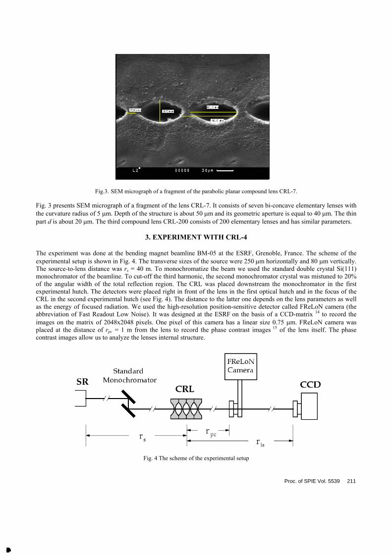
Fig.3. SEM micrograph of a fragment of the parabolic planar compound lens CRL-7.
Fig. 3 presents SEM micrograph of a fragment of the lens CRL-7. It consists of seven bi-concave elementary lenses withthe curvature radius of 5 m. Depth of the structure is about 50 m and its geometric aperture is equal to 40 m. The thinpart d is about 20 m. The third compound lens CRL-200 consists of 200 elementary lenses and has similar parameters.
3. EXPERIMENT WITH CRL-4
The experiment was done at the bending magnet beamline BM-05 at the ESRF, Grenoble, France. The scheme of theexperimental setup is shown in Fig. 4. The transverse sizes of the source were 250 m horizontally and 80 m vertically.The source-to-lens distance was rs = 40 m. To monochromatize the beam we used the standard double crystal Si(111)monochromator of the beamline. To cut-off the third harmonic, the second monochromator crystal was mistuned to 20%of the angular width of the total reflection region. The CRL was placed downstream the monochromator in the firstexperimental hutch. The detectors were placed right in front of the lens in the first optical hutch and in the focus of theCRL in the second experimental hutch (see Fig. 4). The distance to the latter one depends on the lens parameters as wellas the energy of focused radiation. We used the high-resolution position-sensitive detector called FReLoN camera (theabbreviation of Fast Readout Low Noise). It was designed at the ESRF on the basis of a CCD-matrix 14 to record theimages on the matrix of 2048x2048 pixels. One pixel of this camera has a linear size 0.75 m. FReLoN camera wasplaced at the distance of rpc = 1 m from the lens to record the phase contrast images 15 of the lens itself. The phasecontrast images allow us to analyze the lenses internal structure.
Fig. 4 The scheme of the experimental setup
Proc. of SPIE Vol. 5539 211
Downloaded From: http://proceedings.spiedigitallibrary.org/ on 06/15/2014 Terms of Use: http://spiedl.org/terms

In some experiments, the first lens CRL-4 was followed by the similar second lens installed in the position of thehorizontal focusing of the beam (not shown in the figure). The total effect of both lenses gives rise to the formation of a2D focus. Finally, one more position sensitive detector – a CCD-matrix was installed at the distance ris = 19 mdownstream the lenses to record the intensity distribution in their focus plane.
Fig. 5 presents a typical phase contrast image obtained for the system of two successive crossed lenses CRL-4. Phasecontrast image reveals the lens wall surface roughness although the lenses are only slightly absorbing. The reason of thecontrast is a heterogeneous total phase shift for the coherent wave, which appears during propagation through the twolenses. At the finite distance from the lenses this phase shift is transformed into heterogeneous intensity distribution.Under the near field conditions, i.e. at the short distance from the lenses, there is correspondence between the location ofthe phase and intensity heterogeneous regions. The surfaces of the lenses are readily seen because of their striatedstructure formed during the burning out of the material from glassy carbon. In the lower part of the figure one can see many horizontal lines. These are the images of the parabolic surface of the lens mounted to focus the beam in the verticalplane. In the middle part of the figure one can see the pattern of almost vertical lines. This is the image of the parabolicsurface of the lens mounted to focus the beam in the horizontal plane. It is seen that the lens used for focusing in thevertical plane has a higher quality. Nevertheless, it is also seen that the walls of this lens are not exactly perpendicular tothe top surface of the lens. The latter can be seen at the left due to change in the contrast caused by absorption andabsence of the lines.
Fig. 5. Phase contrast image of the two crossed planar lenses CRL-4.
These walls are seen as dark and almost horizontal bands in the upper and lower parts. The geometric aperture of the lensdecreases in the direction from the top surface toward the material bulk (from left to the right on the Fig.5). One canassume that the curvature radius of the parabolic profile varies along the profile height. As a result, the different parts of the lens have different focus distances. This is evident reason for increasing the focus size.
The second lens is placed downstream and somewhat higher than the first lens. The obvious striated structure indicatesthat the parabolic walls have uneven surfaces. One can assume that the burning out the material in the preparation of thislens was performed with a step much larger than the step used in the preparation of the first lens. The analysis of thephase-contrast images allows one to estimate the quality of the parabolic surfaces, which are responsible for focusing,and to compare quality of these surfaces with the quality of the focus obtained. The phase-contrast images can reveal the bulk defects in the sample. However, we do not see any bulk defects having sharp edges.
Since the lens parameters were known only approximately, the optimum condition of focusing was sought for fixed
212 Proc. of SPIE Vol. 5539
Downloaded From: http://proceedings.spiedigitallibrary.org/ on 06/15/2014 Terms of Use: http://spiedl.org/terms

Fig.6. Experimental dependence of vertical focus size (FWHM) for CRL-4 versus photon energy.
distance from CRL-4 lens to the detector ris = 19 m but for variable radiation wavelength. Fig. 6 shows the dependenceof measured vertical focus FWHM (full width at half maximum) on the photon energy. It follows from this dependencethat the minimum FWHM corresponds to the photon energy 12.2 keV and the minimum experimental focus size is 73
m. The nominal density of the glassy carbon used for manufacturing these lenses was 1.42 g/ccm 16. In this case, = 1.98·10–6. Using these parameters one can readily calculate the necessary curvature radius for the parabolic surfaces by the equation R = 8 ris /(1 + ris /rs). With the parameters pointed above we obtain R = 0.204 mm that corresponds to theinitial value used in the lens manufacturing.
Figure 7 shows the intensity distribution at the distance 19 m from the lens using optimal energy. In both fragments theexposure was 2 s. The fragment A corresponds to focusing by one lens CRL-4. The width of the linear focus (FWHM) is 73 m. This value is approximately twice as much as theoretically predicted value of 38 m. One of the reasons of thisdiscrepancy is non-ideal shape of the parabolic elementary lenses. Another reason of focus line broadening may beheterogeneity of the lens material. These reasons will be discussed below. The gain for this linear focus is estimated as G = 4.8. This value is defined as the ratio of the intensity in the focus to the intensity without the lens.
Fig. 7. A - linear focus made by one lens CRL-4. – 2D focus made by two lenses CRL-4 in crossed geometry.
Proc. of SPIE Vol. 5539 213
Downloaded From: http://proceedings.spiedigitallibrary.org/ on 06/15/2014 Terms of Use: http://spiedl.org/terms

The fragment B shows 2D focus obtained with two lenses CRL-4 in the crossed geometry. The 2D focus is somewhatbrighter than the linear one. The gain for this point like focus is estimated as G=6.4. This value is larger than the gain forone lens CRL-4.
4. EXPERIMENT WITH CRL-7 AND CRL-200
In this section we describe the results of measurements of two other lenses made by different technique. The experimentwas done at the same beamline but in other session. The scheme of the experimental layout is similar to one, shown inFig. 4. Figure 8 presents the phase contrast image of planar parabolic lens CRL-7. The distance from the lens CRL-7 toFReLoN camera was rpc = 10 cm. Gray field at the left corresponds to a direct monochromatized SR beam ( = 20 keV).Dark field at the right is a shadow from the glassy carbon slab that contained the lens. The large cone with the base at theleft side and the apex at the right side is the image of the groove made behind the lens for radiation output (see Section2). In the upper part of the cone one can see the image of the lens. The image of the lens is seen as a slightly broadeningsmall cone. Locating the FReLoN camera at the distance ris = 47 cm from the lens CRL-7, which corresponds to theimage of the source, we got the focus line with FWHM of 2.7 m instead of calculated source size projection of 0.9 m.
The most interesting result, obtained with the compound planar parabolic lens CRL-200, is shown in Fig.9. Here theinset shows the image of linear focus measured by FReLoN camera placed at the distance of the best focusing (2.8 cm atE = 25 keV). The width of the focus is close to the resolution limit for the FReLoN camera. To have accurate value for the focus width we have made a knife scan measurement. The procedure consists of a registration of the integral intensityat various positions of some opaque screen (knife) across the focus. The derivative of this dependence gives the focusprofile. The knife scan of the focus is presented in Fig. 9 by dots, whereas the solid line is the derivative. Gauss-fit of thesolid line allows one to estimate the size of the focus (FWHM) as 1.4 m.
Footprint of themonochromatizedbeam
Shadow fromthe glassy carbon slab
Image of CRL Groove behind CRL
Fig.8. Phase contrast image of planar parabolic compound lens CRL-7.
5. DISCUSSION
Table 2 presents the results for all the lenses. We note that glassy carbon was used for development of x-ray compoundrefractive lenses for the first time. The obtained experimental results are not very good, but they allow us to believe thatthe parabolic glassy carbon lenses may be used for focusing synchrotron radiation. The lens CRL-200 is rather long
214 Proc. of SPIE Vol. 5539
Downloaded From: http://proceedings.spiedigitallibrary.org/ on 06/15/2014 Terms of Use: http://spiedl.org/terms

compared to its focal length and some corrections must be taken into account beyond the thin lens approximation 3. In addition, the effective aperture Aeff determined from absorption is equal to 50 m. This value exceeds the real aperture ofthe CRL-200 which is equal to 40 m. For the CRL-7 lens the aperture is not optimal to
Fig. 9. Knife scan of the lens CRL-200 focus. The curvature radius is 5 m, the number of bi-concave elements is 200, the energy E = 25 keV. Dots present the intensity measured during the knife scan. Solid line is corresponding derivative. The FWHM of the
derivative curve is 1.4 m. The inset is the image of the linear focus recorded by FReLoN camera.
Table 2. Results of the lenses test.
Lenses Energy ofradiation,
keV
Focusdistance, cm,
calculated
Focus size, m,calculated.
Focus size, m,measured,
Gain,Measured
CRL-4 12.2 1194 38 73 4.8
Two CRL-4in crossedgeometry
12.2 1194 38 by 163 73 by 292 6.4
CRL-7 20 47 0.9 2.7 3.0
CRL-200 25 2.8 0.05 1.4 3.3
more extent. The minimum linear focus size of 1.4 m was achieved with CRL-200 lens, which is very close to the real resolution of the FReLoN camera that we used. This value is larger than that predicted by the theory 0.05 m as
Proc. of SPIE Vol. 5539 215
Downloaded From: http://proceedings.spiedigitallibrary.org/ on 06/15/2014 Terms of Use: http://spiedl.org/terms

demagnified projection of the source. We note that the diffraction-limited size of the focus spot is estimated as small as 0.01 m for such lens. The reasons of focus broadening may be the finite resolution of the knife scan method as well as the material defects and the deviations of the real lenses profiles from parabola.
It should be emphasized that contrary to lenses, made of aluminum and silicon, which always create the focus with the size close to the theoretically predicted values, the lenses made of plastics often show the focus of larger size 6. We assume that one of the main reasons for the focus broadening in the case of CRL-4 lenses is the small-angle scattering from heterogeneities of the glassy carbon density. It is well known that glassy carbon has pores with the average diameter 10 m. At a very large distance these pores may be considered as point defects which somewhat shift the wave phase. Under the experimental conditions used for study of CRL-4, the phase shift is 0.12 rad. Such a point-like phase shift of a coherent wave results in the formation of Fresnel fringes in the intensity distribution at large distances. The firstfringe of high intensity has a diameter 2( ris)1/2 = 86 m, which agrees, by the order of magnitude, with the focus size obtained in the experiments on CRL-4 prototypes.
As it was noted above that the focal length for the CRL-200 is approximately equal to lens length. Therefore the simple theory of thin lens cannot be applied directly. However, corrections followed from the accurate theory 3 are not so large. To get quantitative results to verify the theory we plan to measure energy dependence of the focus distance for the CRL-200. Unfortunately, the lenses do not show reasonable gain of practical use. The obvious reasons are the following. First of all, the parabolic surfaces of the lenses are not sufficiently smooth. It is clearly seen on the SEM micrographs. This problem can be eliminated in the following development of the technique of lens manufacturing. The second reason is porous structure of glassy carbon. As it was noted above, the density of glassy carbon is 1.5 g/ccm, which is much smaller than the density of pyrocarbon (2.25 g/ccm). Such porous structure must provide relatively intense small angle scattering. We plan to treat pyrocarbon with the same laser technology for planar refractive compound lens production.
In the light of the above stated the further study of the refractive glassy carbon lenses seems to be interesting. In particular, it is important to obtain phase-contrast images of thin plates for recording individual pores and thus to verify our hypothesis. One can assume two possible applications of such lenses, at least. First of all, the small size of the focus can be used in micro investigations such as microelement analysis, micro-tomography, and study at high pressure, surface investigation and micro-EXAFS measurements. Second, the application of the glassy carbon lenses that follows from good thermal and radiation stability of the material. Such lenses can be used as the first element of an optical setup for preliminary beam collimation in front of a monochromator to increase the monochromator output. We also hope to obtain sub-micron focus size and high gain with the developing technology.
ACKNOWLEDGMENTS
The authors would like to thank V.M. Frolov, V.Yu. Kireev and L.G. Saprikin for development of the technology and manufacturing the CRL-4 lens. The work was supported by RFBR grant N. 03-02-16971. The authors are very grateful to E. Ziegler, J. Hoszowska and J.-Y. Massonnat for their support during the experiments at BM5, ESRF.
REFERENCES
1. A. Snigirev, V. Kohn, I. Snigireva, B. Lengeler, "A compound refractive lens for focusing high-energy X-rays", Nature, 384, 49-51, 1996
2. V.G. Kohn, "The theory of X-ray refractive optic. Exact solution for parabolic media", JETP Lett., 76, 701-704, 2002
3. V.G. Kohn, "An Exact Theory of Imaging with a Parabolic Continuously Refracting X-ray Lens", JETP, 97,204-215, 2003.
4. B. Lengeler, C.G. Schroer, M. Richwin, J. Tummler, M. Drakopoulos, A. Snigirev, I. Snigireva, "A microscope for hard x rays based on parabolic compound refractive lenses", Appl. Phys. Lett., 74, 3924-3926, 1999
5. C.G. Schroer, B. Benner, T.F. Gunzler, M. Kuhlmann, C. Zimprich, B. Lengeler, C. Rau, T. Weitkamp, A. Snigirev, I. Snigireva, J. Appenzeller, "High resolution imaging and lithography with hard x-rays using parabolic compound refractive lenses", Rev. Sci. Instr., 73, 1640-1642, 2002
6 J.T. Cremer, M.A. Piestrup, H.R. Beguiristain, C.K. Gary, R.H. Pantell, R. Tatchyn, "Cylindrical compound refractive x-ray lenses using plastic substrates", Rev. Sci. Instrum. 70, 3545-3550, 1999.
7 C.G. Schroer, M. Kuhlmann, B. Lengeler, T. F. Gunzler, O. Kurapova, B. Benner, C. Rau, A. S. Simionovici,
216 Proc. of SPIE Vol. 5539
Downloaded From: http://proceedings.spiedigitallibrary.org/ on 06/15/2014 Terms of Use: http://spiedl.org/terms

A. A. Snigirev, I. Snigireva, “Beryllium parabolic refractive x-ray lenses”, Proc. SPIE, 4783, 10-18, 2002. 8. H.R. Beguiristain, J.T. Cremer, M.A. Piestrup, C.K. Gary, R.H. Pantell, “X-ray focusing with compound lenses
made from berillium”, Opt. Lett., 27, 778-780, 2002 9. J. Cremer, M. Piestrup, H. Beguiristan, C. Gary, R. Pantel, "Large aperture compound lenses made of lithium",
Rev. Sci. Instr. 74, 2262-2266, 2003 10. V. Aristov, M. Grigoriev, S. Kuznetsov, L. Shabelnikov, V. Yunkin, C. Rau, A. Snigirev, I. Snigireva, T. Weitkamp,
M. Hoffmann, E. Voges, "Silicon planar parabolic lenses", SPIE Proc., 4145, 285-292, 2001 11. A. Snigirev, I. Snigireva, M. Drakopolous, V. Nazmov, E. Reznikova, S. Kuznetsov, M. Grigoriev, J. Mohr, V. Saile,
"Focusing properties of X-ray polimer refractive lenses from SU-8 resist layer", SPIE 5195, 21-31, 2003. 12. P. Elleaume, "Optimization of compound refractive lenses for X-rays", Nucl. Instrum. Meth. A 424, 483-506, 1998. 13. B. Nohammer, J. Hoszowska. A. K. Freund, C. David, "Diamond planar refractive lenses for third- and forth-
generation X-ray sources", J. Synchrotron Rad. 10, 168-171, 2003. 14. Internet resource: "http://www.esrf.fr/computing/bliss/guides/detection/ccd/frelon" 15. A. Snigirev, I. Snigireva, V. Kohn, S. Kuznetsov, I. Schelokov, "On the possibilities of x-ray phase contrast
microimaging by coherent high-energy synchrotron radiation", Rev. Sci. Instr.,66, 5486-5492, 1995 16. Internet site: "http://www.advtech.ru/niigrafit/eng/prog/syeng.htm"
Proc. of SPIE Vol. 5539 217
Downloaded From: http://proceedings.spiedigitallibrary.org/ on 06/15/2014 Terms of Use: http://spiedl.org/terms