Floodway IJetermlnatlon Computer Program - USDA
12
: Technical Release : 64 Floodway - . . I IJetermlnatlon Computer Program Soil United States Conservation Department of Service Agriculture Engineering Division
-
Upload
khangminh22 -
Category
Documents
-
view
0 -
download
0
Transcript of Floodway IJetermlnatlon Computer Program - USDA

: Technical Release
: 64 Floodway - . . I
IJetermlnatlon
Computer
Program
Soil United States Conservation Department of Service Agriculture
Engineering Division

Preface
This technical release was prepared by hydraulic engi- neers from the Soil Conservation Service (SCS) Central Technical Unit, Glenn Dale, Maryland. It was approved by personnel of the SCS Engineering Division, Washington, D.C., and the SCS regional technical service centers.
The Floodway Determination (FLDWY) computer program is used to determine the floodway for flood hazard and flood insurance studies. It is a revision of and replacement for previous HUD-15 programs.
This technical release contains user instructions for the FLDWY program. It will assist engineers in preparing the input and in interpreting the results.
Issued June 1978

Floodway Determination Computer Program
Introduction
The SCS Floodway Determination (FLD~) computer program is used to calculate a floodway at given cross sections along a stream. For this program a floodway is defined as the minimum width at a cross section that is required to carry the selected (generally 100-year) flood with a specified increase in the water surface elevation. The procedure in the program is based on the equal conveyance reduction concept. No encroachment or narrowing of the channel is allowed. For multiple channels, any overbank segment between channel segments is consid- ered part of the channel. This program does not compute floodways at road sections.
Before FLDWY can be used, the elevation of the selected flood at each cross section must be known. The input data for WSPZ,l Upper Darby (U.D.)' and WSPIN3 water surface profile (WSP) programs can be used directly by FLDWY to make floodway calculations. This feature elimi- nates the need for repunching cards that were punched for these programs. The entire data decks are read, but only the cross-section and segment data are used in the computations. If the data have not been processed
ILJSDA, SCS, TR-61, WSPZ Computer Program, May 1976.
'USDA, SCS, NETSC Technical Note MGT-3, Attachment 113, May 1968.
3USDA, SCS, Fort Worth ADP Unit Technical Note 1, Automatic Data Processing Users Guide, Attachment 1, January 1975.
by one of the WSP programs, the cross-section and segment data must be punched in WSP2 format for processing by FLDWY.
FLDWY is a revision of the SCS HUD-15 computer program and replaces all versions of HUD-15. FLDWY was changed to allow (1) use of the last data point in the cross section when the maximum number of data points is used, (2) use of a channel as the leftmost segment of a cross section, (3) reordering of WSP2 cross-section data according to transverse distance, (4) use of multiple n-values in WSPZ data (only the first n-value of each segment was used in the HUD-15 programs), (5) use of WSP2 decks without the restriction that segment data precede section data, and (6) printing of the input data used in the com- putations.
Method of computation
Although the method of computation has not been changed, in this section it is outlined to give the user a basic understanding of how the cal- culations are made and to help in interpreting the output. The method is not described in detail in this document. For a detailed description of the method see TSC Advisory RB-UD-l.4
Equal conveyance reduction means that, as the water surface elevation changes at a cross section, the friction slope is assumed to remain the same or, in other words, the
--4USDA, SCS, NETSC Advisory RB-UD-1 and Attachment, May 6, 1971.
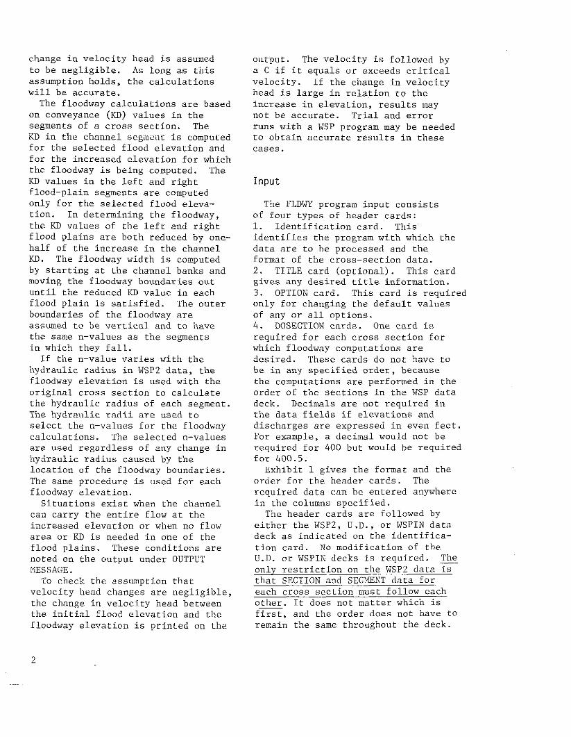
change in velocity head is assumed to be negligible. As long as this assumption holds, the calculations will be accurate.
The floodway calculations are based on conveyance (KD) values in the segments of a cross section. The KD in the channel segmat is computed for the selected flood elevation and for the increased elevation for which the floodway is being computed. The KD values in the left and right flood-plain segments are computed only for the selected flood eleva- tion. In determining the floodway, the KD values of the left and right flood plains are both reduced by one- half of the increase in the channel KD. The floodway width is computed by starting at the channel banks and moving the floodway boundaries out until the reduced KD value in each flood plain is satisfied. The outer boundaries of the floodway are assumed to be vertical and to have the same n-values as the segments in which they fall.
If the n-value varies with the hydraulic radius in WSP2 data, the floodway elevation is used with the original cross section to calculate the hydraulic radius of each segment. The hydraulic radii are used to select the n-values for the floodway calculations. The selected n-values are used regardless of any change in hydraulic radius caused by the location of the floodway boundaries. The same procedure is used for each floodway elevation.
Situations exist when the channel can carry the entire flow at the increased elevation or when no flow area or KD is needed in one of the flood plains. These conditions are noted on the output under OUTPUT MESSAGE.
To check the assumption that velocity head changes are negligible, the change in velocity head between the initial flood elevation and the floodway elevation is printed on the
output. The velocity is followed by a C if it equals or exceeds critical velocity. If the change in velocity head is large in relation to the increase in elevation, results may not be accurate. Trial and error runs with a WSP program may be needed to obtain accurate results in these cases.
Input
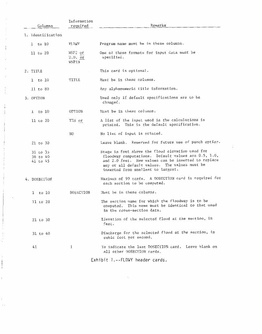
The FLDWY program input consists of four types of header cards: 1. Identification card. This identifies the program with which the data are to be processed and the format of the cross-section data. 2. TITLE card (optional). This card gives any desired title information. 3. OPTION card. This card is required only for changing the default values of any or all options. 4. DOSECTION cards. One card is required for each cross section for which floodway computations are desired. These cards do not have to be in any specified order, because the computations are performed in the order of the sections in the WSP data deck. Decimals are not required in the data fields if elevations and discharges are expressed in even feet. For example, a decimal would not be required for 400 but would be required for 400.5.
Exhibit 1 gives the format and the order for the header cards. The required data can be entered anywhere in the columns specified.
The header cards are followed by either the WSP2, U.D., or WSPIN data deck as indicated on the identifica- tion card. No modification of the U.D. or WSPIN decks is required. The - only restriction on the WSP2 data is that SECTION and SEGEBNT data for each cross section must follow each other. It does not matter which is first, and the order does not have to remain the same throughout the deck.
2
COlUZ
1. Identification
1 to 10
11 to 20
2. TITLE
1 to 10
11 to 80
3. OPTION
1 to 10
11 to 20
21 to 30
31 to 35 36 to 40 41 to 45
4. DOSECTION
1 to 10
11 to 20
21 to 30
31 to 40
41
Information required Remarks
FLDWY
WSP? or U.D. 2 WSPIN
Program name must be in these columns.
One of these formats for input data must be specified.
This card is optional.
TITLE Nust be in these columns.
Any alphanumeric title information.
Used only if default specifications are to be changed.
OPTION
YES or
Nuust be in these columns.
A list of the input used in the calculations is printed. This is the default specification.
NO No list oi input is printed.
Leave blank. Reserved for future use of punch optio-.
Stage in feet above the flood elevation used for floodway computations. Default values are 0.5. 1.0, and 2.0 feet. New values can be inserted to replace any or all default values. The values must be inserted from smallest to largest.
PIaximum of 99 cards. A DOSECTION card is required for each section to be computed.
DOSECTION Xuust be in these columns.
The section name for which the floodway is to be computed. This name must be identical to that used in the cross-section data.
Elevation of the selected flood at the SectiOn, in feet.
Discharge for the selected flood at the section, in cubic feet per second.
1 To indicate the last DOSECTION card. Leave blank on all other DOSECTION cards.
Exhibit l.--FLDWY header cards.

There is no checking of the input data as is done by WSP2. These data should have been run on a WSP program before being used in FLDWY.
No special end-of-run cards are required. The program terminates when the computations for all DOSECTION cards are complete.
output
The program output consists of: 1. A header sheet that gives brief information on the method, the re- quired input, and an explanation of the output messages. 2. The computations for the selected flood elevation (current conditions) and three elevation stages above this selected flood elevation. 3. An optional SO-80 listing of the input cards that were used in the floodway computations. For example, only the SECTION, SEGMENT, and NVALIJE cards that correspond to the DOSECTION card names will be listed from a WSP2 input deck. All other cards will be ignored and will not be listed.
Error Messages that are used and their causes are: 1. ""ERROR":: FIRST CARD NOT A PROPER IDENTIFICATION CARD. FLDWY was not in the first 10 columns of the first card. Processing terminates. 2. ""ERROR"W INPUT DATA NOT PROPERLY IDENTIFIED. The input type--WSP2, WSPIN, or U.D.--was not identified in the second 10 columns of the first card. Processing terminates. 3. ""ERROR"?< pR(,GRA;I EXPECTED DOSECTION CARD. This message appears when (1) the first DOSECTION card is not in proper sequence, (2) other data are mixed with DOSECTION cards, or (3) the numeral 1 that should have been entered in column 41 of the last DOSECTION card was omitted. PrOCeSS- ing terminates. 4. ""ERROR"" NUMBER OF SEGMENTS NOT EQUAL TO BOUNDARIES FOUND IN SECTION
XxXxXx. This message is used with U.D. and WSPIN input. It indicates that the number of segments specified did not equal the number of segment boundaries in the data. The section is ignored, and processing continues. 5. ""ERROR*" TOO %&NY POINTS IN CROSS SECTION XXXXXX. DATA ON ABOVE CARD IGNORED. This message appears only with the input listing option. It means that more than 48 cross-section points were read in WSP2 format. Only the first 48 are used: the rest are ignored. Processing continues. 6. ""ERROR"* TOO MANY POINTS IN CROSS SECTION XxXxXx. YY POINTS ON ABOVE CARD USED. This Gssage also appears only with the input listing option. It means that more than 72 cross- section points were read on U.D. or WSPIN format. Extra points are ignored. Processing continues.
Assembly language routines
Two assembly language routines are used with the FLDWY program: DATE and REREAD. DATE is used to obtain the current date from the computer. The execution date of the program appears on the output as XEQ date. REREAD allows the same input card to be read in different formats. This permits greater flexibility in the input data. REREAD requires a dummy unit 12 in core for reading, writing, and rewinding.
Both DATE and REREAD are IEM 360 and 370 assembly language routines; however, non-IB11 computers have similar routines.
Job control language (JCL) cards
The JCL cards necessary to run the FLDWY program with the FORTG compiler are shown in exhibit 2. Similar JCL cards can be used with the FORTH compiler; the FLDWY program has been run with both.

Computation time
The computation time required per cross section is about 0.3 second on the IBM 3701168 computer.
Example
The sample job in TR-61 is used as the input for this example.
The fourth computed water surface profile was chosen as the selected flood. Exhibit 3 shows the input header cards for the FLDWY program. The program identification card indicates that the data are to be
processed by FLDWY and are in WSP2 format. The data are identified by the TITLE card. The OPTION card requests that the input data be printed and the floodways be computed for elevations of 0.1, 0.4, and 1.0 foot above the given flood elevation. The six DOSECTION cards specify the cmss sections for which floodway calculations are to be made and give the selected flood elevation and discharge for each section.
Exhibit 4 is the output from the FLDWY runs of these data. The dis- charge for cross section TlSl was set very high to illustrate velocities equal to or greater than critical.
Exhibit 2.--Job control language (JCL) cards required to run FLDWY.
5

6

Exhibit 4.--Output from FLDWY program

STAGE _----
Exhibit 4.--Continued

FLncJDWAY STA STAGE LEFT @IGHT _ - - - _ _ - - _ - _ _ _ -
0.0 -534. 130. 0.1 -373. 115. 0.4 -34,. 106. 1.0 -2A7. 100.
_____ _-_____ -_________-___-_____---. 3.15 3.47 0.03 3.59 0.05 3.82 0.07 hII K” IN RIGHT F.P.
Exhibit 4.--Continued.

10”. -310. 91. -215. 82.5 -I”,. RZ.5 -177. 90.8 -85. 81.0 -26. 90.3 113. 9.?.3 37”. 115.
I ”
2 c
3 ”
END OF FLDWY JO”.
Exhibit 4.--Continued.
Exhibit 4.--Continued.