development of a computer program for - doiSerbia
10
FACTA UNIVERSITATIS Series: Architecture and Civil Engineering Vol. 16, N o 3, 2018, pp. 465-474 https://doi.org/10.2298/FUACE180802022O DEVELOPMENT OF A COMPUTER PROGRAM FOR THE DESIGN OF LATERALLY UNRESTRAINED STEEL BEAMS UDC 693.814.1.072.2 004.388 Oladimeji B. Olalusi, Tony Dirisu, Chinwuba Arum The Federal University of Technology Akure, Nigeria Abstract. This study presents the design results of a C-sharp based computer program developed for the design of laterally unrestrained I-section steel beams. The program was developed based on the stipulations of BS 5950 and Eurocode 3 (EC3) design standards. Several sets of steel beam models having the same cross-sectional dimensions but different laterally unrestrained span lengths, were designed using the developed program, and the results were validated using an established software, Staad Pro. The design results obtained were found similar to the results obtained using Staad Pro. For a specific beam section with constant loadings, as the span length of the laterally unrestrained compression flange increases the buckling capacity reduces, thus the longer the beam, the more it is susceptible to lateral torsional buckling. Comparison of the results obtained using BS 5950 to those of EC 3 at different laterally unrestrained span lengths revealed that the areas of design sections obtained for BS 5950 are 21.5%, on the average, higher than those of EC3. Thus, beams with laterally unrestrained compression flange designed according to the requirements of EC 3 are more economical. The difference in results is because of the differences in the principles of design and measures used between the two standards. Key words: laterally unrestrained beams, Eurocode 3, BS 5950, C-sharp, lateral torsional buckling INTRODUCTION Over the course of history, structural engineers have made significant contributions and improvements to the environment we live in today. As the prices of materials continue to increase, engineers are forced to reduce the costs of construction and shorten the implementation period to maintain their competitiveness. As a result, a new design trend was born: the use of the analysis and design software to evaluate feasible design options, Received August 2, 2018 / Accepted November 13, 2018 Corresponding author: Oladimeji B. Olalusi The Federal University of Technology Akure, P.M.B. 704, Akure, Nigeria E-mail: [email protected]
-
Upload
khangminh22 -
Category
Documents
-
view
0 -
download
0
Transcript of development of a computer program for - doiSerbia

FACTA UNIVERSITATIS Series: Architecture and Civil Engineering Vol. 16, No 3, 2018, pp. 465-474 https://doi.org/10.2298/FUACE180802022O
DEVELOPMENT OF A COMPUTER PROGRAM FOR
THE DESIGN OF LATERALLY UNRESTRAINED STEEL BEAMS
UDC 693.814.1.072.2
004.388
Oladimeji B. Olalusi, Tony Dirisu, Chinwuba Arum
The Federal University of Technology Akure, Nigeria
Abstract. This study presents the design results of a C-sharp based computer program
developed for the design of laterally unrestrained I-section steel beams. The program
was developed based on the stipulations of BS 5950 and Eurocode 3 (EC3) design
standards. Several sets of steel beam models having the same cross-sectional
dimensions but different laterally unrestrained span lengths, were designed using the
developed program, and the results were validated using an established software, Staad
Pro. The design results obtained were found similar to the results obtained using Staad
Pro. For a specific beam section with constant loadings, as the span length of the
laterally unrestrained compression flange increases the buckling capacity reduces, thus
the longer the beam, the more it is susceptible to lateral torsional buckling.
Comparison of the results obtained using BS 5950 to those of EC 3 at different laterally
unrestrained span lengths revealed that the areas of design sections obtained for BS
5950 are 21.5%, on the average, higher than those of EC3. Thus, beams with laterally
unrestrained compression flange designed according to the requirements of EC 3 are
more economical. The difference in results is because of the differences in the
principles of design and measures used between the two standards.
Key words: laterally unrestrained beams, Eurocode 3, BS 5950, C-sharp, lateral
torsional buckling
INTRODUCTION
Over the course of history, structural engineers have made significant contributions and
improvements to the environment we live in today. As the prices of materials continue to
increase, engineers are forced to reduce the costs of construction and shorten the
implementation period to maintain their competitiveness. As a result, a new design trend
was born: the use of the analysis and design software to evaluate feasible design options,
Received August 2, 2018 / Accepted November 13, 2018 Corresponding author: Oladimeji B. Olalusi
The Federal University of Technology Akure, P.M.B. 704, Akure, Nigeria
E-mail: [email protected]

466 O. B. OLALUSI, T, DIRISU, C. ARUM
replacing the conventional design methods [1]. The introduction of software usage in the
structural engineering industry has greatly reduced the complexities of different aspects in
the analysis and design of projects, as well as the amount of time necessary to complete the
designs [2]. Concurrently, this leads to greater savings and reductions in costs.
Beams are critical members of civil engineering structures. Their principal function is
to transmit vertical loads by means of bending action into, for example, the columns in a
rectangular building frame or the abutments in a bridge which support them. Beams span
between supports to carry transverse loads which are resisted by bending and shear. The
compression flange of an I-beam acts like a column and will buckle sideways if the beam
is not sufficiently stiff or the flange is not restrained laterally [3]. An unrestrained beam is
susceptible to lateral torsional buckling. Lateral-torsional buckling (LTB) is a limit-state
of structural usefulness where the deformation of a beam changes from predominantly in-
plane deflection to a combination of lateral deflection and twisting while the load capacity
remains first constant, before dropping off due to large deflections [4]. LTB occurs when
the compression portion of a beam is no longer sufficient in strength, and instead, the beam
is restrained by the tension portion of the beam which causes deflection or twisting to occur
[5]. The lateral torsional behaviour of a steel beam is illustrated in Figure 1.
a) Original beam b) Laterally buckled beam
Fig. 1 Steel beam undergoing lateral-torsional buckling (Source: Chan [6])
In the structural design of steel beams, reference to a standard/ code is essential. A standard or code serves as a reference document with relevant guidance. Today, many countries in the world have published their own codes of practice. These codes were produced through thorough research and past experiences of experts in respective fields. Some countries with no particular codes of practices adopt an established standard code as the national reference [6]. The most commonly used code of practice in Nigeria for steel design is BS 5950. Several non-European countries including South Africa, Saudi Arabia, Sri Lanka and Malaysia have based their national codes on the European standards. Eurocodes are recognized as the most advanced and completely integrated sets of structural codes which can be adjusted and modified for use in any region in the world. It is believed that Eurocode is more comprehensive and better developed compared to any other standard

Development of a Computer Program for the Design of Laterally Unrestrained Steel Beams 467
[7]. In a nutshell, it is essential to study the design provisions of Eurocode 3 [8] and BS 5950 [9] in order to have an in-depth understanding of their differences.
RESEARCH OBJECTIVES
The aim of this study is to develop a computer program for the design of simply
supported laterally unrestrained I-section steel beams based on the requirements of BS 5950
and Eurocode 3. The program will be developed using the C- sharp programming language.
The results from the developed program will be validated using an established software-
Staad-pro. The study will also review the differences in design provisions for the design of
laterally unrestrained I-section steel beams based on Eurocode 3 and BS 5950. The design
results of steel beams designed according to BS 5950 will be compared to Eurocode 3. The
comparison will be made in terms of bending moment and shear due to design loads, beam
sections and areas of the various sections obtained using the two codes.
RESEARCH METHODOLOGY
The overall process of the research and the computer program development, according
to [10, 11], can be classified into the following stages
Review of the design of laterally unrestrained beam according to the stipulations
of BS 5950 and Eurocode 3
Coding the BS 5950 and Eurocode 3 design provisions into computer algorithm
using Csharp programming
Development of the Graphical User Interface
Testing the developed code and verification of results
The above procedure will be followed in this research. A review of the design
stipulations by the relevant codes has already been carried out in the introduction section.
The rest of the procedure as outlined above will now follow systematically
Design concepts of Eurocode 3 and BS 5950
EC3 is based on the limit state design which covers the ultimate limit state and
serviceability state. Loadings are multiplied or divided with a given partial safety factor to
ensure structures are designed with a certain degree of reliability. EC 3 complies with the
principles and requirements for the safety and serviceability of structures. The basis of design
and verification are given in EN 1990 [12] (Basis of structural design). Furthermore, there are
two limit states concepts used in BS 5950 namely, the ultimate limit states and serviceability
limit state. The partial safety factor is applied to loadings to increase the reliability of the
structure.
An unrestrained beam section, according to BS 5950 and EC3, must be checked for
bending resistance and lateral torsional buckling. The differences in the design provisions
are outlined in Table 1.

468 O. B. OLALUSI, T, DIRISU, C. ARUM
Table 1 Beam design provisions
Eurocode 3[2005] Elements BS 5950[2000]
Partial Safety Factor for
Action (Load)
GK = 1.35 Permanent Action (Load) DL = 1.4
QK = 1.50 Variable Action (Load) LL = 1.6
Flange Subject to
Compression
Web Subject
to Bending
Cross Section Classification
Flange Subject to
Compression
Web Subject
to Bending
9Ɛ 72Ɛ Class 1 9Ɛ 80Ɛ
10Ɛ 83Ɛ Class 2 10Ɛ 100Ɛ
14Ɛ 124Ɛ Class 3 15Ɛ 120Ɛ
Coefficient, Ɛ
√ Shear capacity check
Moment capacity check
Buckling resistance check
where, is the shear capacity of a member. is the design strength of steel. is the
effective shear area. is the depth of section. is the thickness of web. is the plastic
modulus. is the plastic moment
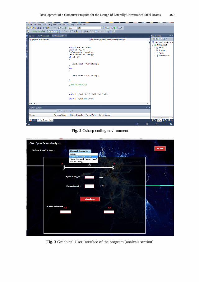
Coding the beam design provisions
The C# programming language was used as the language to convert the EC3 and BS
5950 design provisions for unrestrained steel beam into an algorithm. Figure 2 shows the
interface for the coding of the design provisions into an algorithm.
Development of graphical user interface (GUI)
A combination of programming in C# and Microsoft Visual Studio is used here to allow
an artistic application to be created. Microsoft C# was chosen for this project mainly
because of its advantage of presenting a visually appealing and interactive graphical user
interface as well as a robust language to create code that correctly executes the desired tasks
when adequately programmed. The graphical interface was created using a windows
application called Windows Presentation Foundation (WPF) in visual studio.Net (Figure 3).
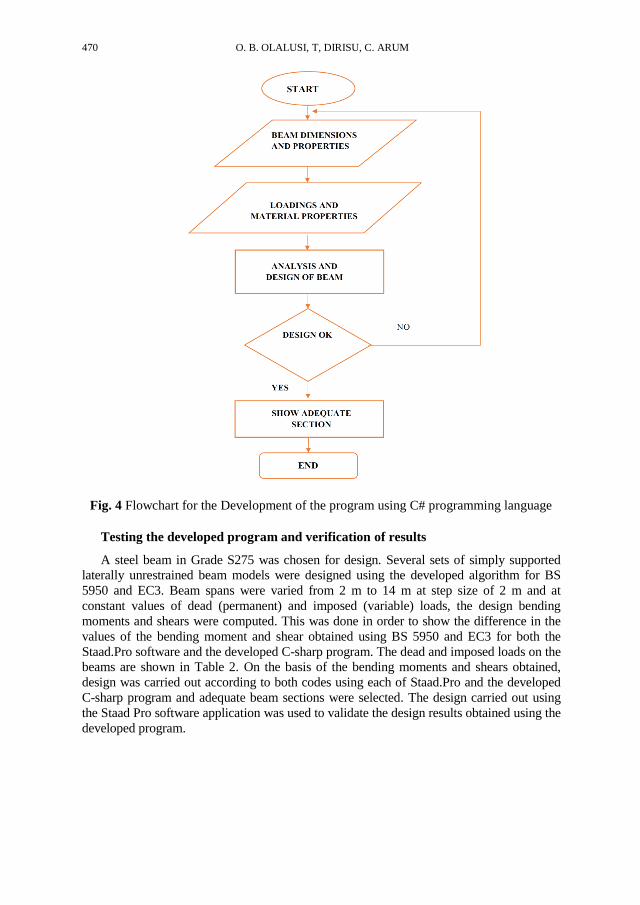
The flowchart for the development of the program using C# programming language is
illustrated in Figure 4.
Development of a Computer Program for the Design of Laterally Unrestrained Steel Beams 469
Fig. 2 Csharp coding environment
Fig. 3 Graphical User Interface of the program (analysis section)
470 O. B. OLALUSI, T, DIRISU, C. ARUM
Fig. 4 Flowchart for the Development of the program using C# programming language
Testing the developed program and verification of results
A steel beam in Grade S275 was chosen for design. Several sets of simply supported
laterally unrestrained beam models were designed using the developed algorithm for BS
5950 and EC3. Beam spans were varied from 2 m to 14 m at step size of 2 m and at
constant values of dead (permanent) and imposed (variable) loads, the design bending
moments and shears were computed. This was done in order to show the difference in the
values of the bending moment and shear obtained using BS 5950 and EC3 for both the
Staad.Pro software and the developed C-sharp program. The dead and imposed loads on the
beams are shown in Table 2. On the basis of the bending moments and shears obtained,
design was carried out according to both codes using each of Staad.Pro and the developed
C-sharp program and adequate beam sections were selected. The design carried out using
the Staad Pro software application was used to validate the design results obtained using the
developed program.

Development of a Computer Program for the Design of Laterally Unrestrained Steel Beams 471
Table 2 Beam loadings
Load Contributor Dead Load Live Load
Load (kN/m) 45 55
Other relevant information includes the following: Young Modulus, E = 210 GPa. Steel
Grade, Py = S275 N/mm2
RESULTS AND DISCUSSION
Several sets of beam geometries were set to compare the design results of the beams
designed according to BS 5950 and EC 3.
Beam design bending moment and shear
The design moment and shear of the beams at varying span length were compared and
tabulated as shown in Tables 2 and 3 respectively. The tables reveal that an increase in
span length for the test cases translates to an increase in the bending moment and shear.
A similar trend was observed in the developed program and Staad Pro. Generally, from
Table 4, the calculation based on EC3 had reduced member design shear compared to BS
5950. This can be attributed to the different shear design formulations specified by both
codes.
Table 3 Comparison of Beam design bending moment at varying span length
Beam No. Span Length
(m)
Developed Program Staad-Pro
BS 5950
(kNm)
EC 3
(kNm)
BS 5950
(kNm)
EC 3
(kNm)
I2A 2 132 97 131.81 97.08
I4B 4 246 181 243.50 181.23
I6C 6 333 246 332.23 246.4
I8D 8 431 353 431.22 353.93
I10E 10 533 404 533.75 404.53
I12F 12 591 479 591.56 479.92
I14G 14 869 764 869.53 764.90
Table 4 Comparison of beam design shear at varying span length
Beam No. Developed Program Staad-Pro
BS 5950
(kN)
EC 3
(kN)
BS 5950
(kN)
EC 3
(kN)
I2A 266 246 262.41 245.12
I4B 434 421 435.50 425
I6C 546 477 540.30 479.34
I8D 679 651 671.74 655.41
I10E 774 676 778.44 677.42
I12F 847 797 845.53 798.22
I14G 1072 942 1068.22 943.12

472 O. B. OLALUSI, T, DIRISU, C. ARUM
Beam Cross-sectional area
The optimum sections identified for each beam and the cross-sectional area of beams
at varying span length are the same using Staad- Pro and the developed program. The
optimum design sections obtained, and the area of sections are presented in Table 5 and 5
respectively. The percentage difference between the results was calculated as Equation 1,
and the results are shown in Table 6.
| |
(1)
Tables 5 indicate that the comparison of BS 5950 design results and EC 3 design
results gave an average difference of 21.5 % for the area of sections obtained. This shows
that beams designed using the requirements of EC 3 are economical. Close examination
of Table 5 reveals that the area of the beam section (and by extension, the weight of the
beam also) increases as the span length increases. This shows that the longer the span, the
greater the weight of the beams.
Table 5 Comparison of beam design section sizes at varying
span lengths using the developed program and Staad Pro.
Beam No. Span length
(m)
Developed program Staad Pro
BS 5950
(Section)
EC3
(Section)
BS 5950
(Section)
EC3
(Section)
I2A 2 254 × 146 × 37 254 × 102 × 28 254 × 146 × 37 254 × 102 × 28
I4B 4 356 × 171 × 51 356 × 127 × 39 356 × 171 × 51 356 × 127 × 39
I6C 6 356 × 171 × 67 356 × 171 × 51 356 × 171 × 67 356 × 171 × 51
I8D 8 457 × 191 × 74 457 × 152 × 60 457 × 191 × 74 457 × 152 × 60
I10E 10 457 × 191 × 89 457 × 191 × 67 457 × 191 × 89 457 × 191 × 67
I12F 12 457 × 191 × 98 457 x 191 × 82 457 × 191 × 98 457 × 191 × 82
I14G 14 610 x 229 × 113 533 x 210 × 92 610 x 229 × 113 533 × 210 × 92
Table 6 Comparison of the area of sections for the beams at varying
span length using the developed program and Staad Pro
Beam No. Span Length
(m)
Developed program Staad Pro
BS 5950
(m2)
EC 3
(m2)
%
Difference
BS 5950
(m2)
EC 3
(m2)
% Difference
I2A 2 47.2 36.1 23.5 47.2 36.1 23.5
I4B 4 64.9 49.8 23.3 64.9 49.8 23.3
I6C 6 85.5 64.9 24.1 85.5 64.9 24.1
I8D 8 94.6 76.2 19.5 94.6 76.2 19.5
I10E 10 114 85.6 24.9 114 85.6 24.9
I12F 12 125 104 16.8 125 104 16.8
I14G 14 144 117 18.8 144 117 18.8
Average 21.5% Average 21.5%
Development of a Computer Program for the Design of Laterally Unrestrained Steel Beams 473
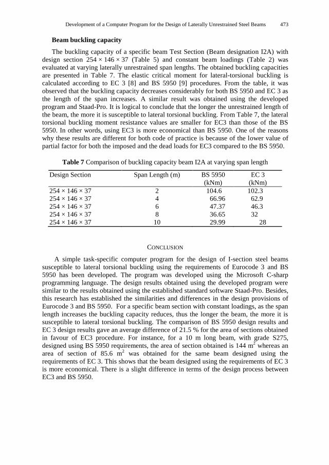
Beam buckling capacity
The buckling capacity of a specific beam Test Section (Beam designation I2A) with
design section 254 × 146 × 37 (Table 5) and constant beam loadings (Table 2) was
evaluated at varying laterally unrestrained span lengths. The obtained buckling capacities
are presented in Table 7. The elastic critical moment for lateral-torsional buckling is
calculated according to EC 3 [8] and BS 5950 [9] procedures. From the table, it was
observed that the buckling capacity decreases considerably for both BS 5950 and EC 3 as
the length of the span increases. A similar result was obtained using the developed
program and Staad-Pro. It is logical to conclude that the longer the unrestrained length of
the beam, the more it is susceptible to lateral torsional buckling. From Table 7, the lateral
torsional buckling moment resistance values are smaller for EC3 than those of the BS
5950. In other words, using EC3 is more economical than BS 5950. One of the reasons
why these results are different for both code of practice is because of the lower value of
partial factor for both the imposed and the dead loads for EC3 compared to the BS 5950.
Table 7 Comparison of buckling capacity beam I2A at varying span length
Design Section Span Length (m) BS 5950
(kNm)
EC 3
(kNm)
254 × 146 × 37 2 104.6 102.3
254 × 146 × 37 4 66.96 62.9
254 × 146 × 37 6 47.37 46.3
254 × 146 × 37 8 36.65 32
254 × 146 × 37 10 29.99 28
CONCLUSION
A simple task-specific computer program for the design of I-section steel beams
susceptible to lateral torsional buckling using the requirements of Eurocode 3 and BS
5950 has been developed. The program was developed using the Microsoft C-sharp
programming language. The design results obtained using the developed program were
similar to the results obtained using the established standard software Staad-Pro. Besides,
this research has established the similarities and differences in the design provisions of
Eurocode 3 and BS 5950. For a specific beam section with constant loadings, as the span
length increases the buckling capacity reduces, thus the longer the beam, the more it is
susceptible to lateral torsional buckling. The comparison of BS 5950 design results and
EC 3 design results gave an average difference of 21.5 % for the area of sections obtained
in favour of EC3 procedure. For instance, for a 10 m long beam, with grade S275,
designed using BS 5950 requirements, the area of section obtained is 144 m2 whereas an
area of section of 85.6 m2 was obtained for the same beam designed using the
requirements of EC 3. This shows that the beam designed using the requirements of EC 3
is more economical. There is a slight difference in terms of the design process between
EC3 and BS 5950.

474 O. B. OLALUSI, T, DIRISU, C. ARUM
REFERENCES
1. Vasanthakumar, C., Ganesh, G. M., & Santhi, A. S. (2013). Structural optimization of an industrial
building frame by genetic algorithm. International Journal of Engineering Science and Technology, 5(06S)
2. De los Reyes, A. (2006). The role of computer-aided drafting, analysis, and design software in structural
engineering practice (Doctoral dissertation, Massachusetts Institute of Technology). 3. Van den Berg, G and Bredenkamp, B. (1994): The lateral torsional buckling strength of cold-formed
stainless steel beam. International Specialty Conference on Cold-Formed Steel Structures. Paper 3.
4. AISC (2011): Certification Standard for Steel Bridge Fabricators, American Institute of Steel
Construction, Inc., One East Wacker Drive, Suite 3100, Chicago, Illinois 60601-2001.
5. Kochar, H.R. and Kulkarni, S.K. (2012): Lateral-Torsional Buckling of Steel Beam, International
Journal of Computational Engineering Research, Vol. 2, Issue. 6, pp. 178-181. 6. Chan, C. H. (2006). Comparison Between BS 5950: Part 1: 2000 & Eurocode 3 for the Design of Multi-
Storey Braced Steel Frame (Doctoral dissertation, Universiti Teknologi Malaysia). 7. King, C. (2005). Steel design can be simple using EC3. New steel construction, 13(4), 24-27.
8. Eurocode 3: Design of Steel Structures. Part 1-1: General Rules and Rules for Buildings, Brussels.
9. BS 5950 (2000): Structural use of steelwork in Building-Code of practice for design in simple and continuous construction: Hot rolled sections. British Standards Institute, United Kingdom.
10. Arum, C and Olalusi, O.B (2014): Development of Csharp-Based Algorithm for the Design of Single
Storey Fixed-Feet Pitched-Roof Portal Frame, Civil and Environmental Research, 6 (8), pp. 152-162 IISTE.
11. Olalusi, O. B. (2015). Development of Csharp-Based Algorithm for the Design of Single Storey Fixed-
Feet Pitched-Roof Portal Frame. DOI: 10.13140/RG.2.2.34776.75520 12. EN (1990): European Committee for standardization: Basis of structural design, Brussels
RAZVOJ KOMPJUTERSKOG PROGRAMA ZA
PROJEKTOVANJE ČELIČNIH NOSAČA SLOBODNIH
NA OBA KRAJA
Ovi istraživanje predstavlja rezultate korišćenja kompjuterskog programa koji se zasniva na
C-sharp softveru, razvijenom u cilju projektovanja čeličnih nosača I profila slobodno oslonjenih
na oba kraja. Program je razvijen na osnovu onoga što propisuju BS 5950 i Eurocode 3 (EC3)
standardi projektovanja.Korišćenjem razvijenog programa, projektovano je nekoliko grupa
modela čeličnih nosača sa istim dimenzijama poprečnog preseka ali sa različitim rasponima,
slobodno oslonjenih na oba kraja. Rezultati su provereni korišćenjem postojećeg programa, Staad
Pro. Došlo se do saznanja da su dobijeni rezultati projektovanja slični onima koji su dobijeni
korišćenjem Staad Pro softvera. Kod specificiranih preseka nosača pri konstantnim opterećenjima,
povećanje raspona slobodno oslonjenih greda na oba kraja smanjuje čvrstoću na savijanje, tako
da što je duži nosač, to je osetljiviji na bočno torziono izvijanje. Poređenje rezultata dobijenih
korišćenjem BS 5950 sa onima dobijenih korišćenjem EC 3 različitih dužina raspona nosača
slobodnih na oba kraja otkriva da su vrednosti dobijene korišćenjem BS 5950 u proseku 21.5%,
više od onih dobijenih korišćenjem EC3. Stoga su nosači sa bočno neuklještenim pritisnutim
flanšama projektovani u skladu sa zahtevima EC 3 ekonomičniji. Razlika u rezultatima dolazi od
razlika u principima projektovanja i merama korišćenjim u ova dva standarda.
Ključne reči: grede slobodno oslonjene na oba kraja, Eurokod 3, BS 950, C-Sharp, bočno torziono
savijanje