"Assessment of IMPACTS-BRC Computer Program for ...
101
. -. - - - _ . - - _ _ - _ - -. . . - - - - - _ - - - - - - - - <1 .O , Y h!AY .s . gem:sygg/; 3 ASSESSMENT OF THE IMPACTS-BRC COMPUTER ' PROGRAM FOR REACTOR WASTES 'Research' Project B101-11. . Final Report, November 1988 , Prepared by Rogers and Associates Engineering Corporation P.O. Box 330- Salt Lake City, Utah B4110-0330- Principal ' investigators V.C. Rogers E.S. Murphy Prepared for Below Regulatory Concern Owners Groep and Electric Power Research Institute 3412'Hillview Avenue i Palo Alto, California 94304 EPRI Project Manager * P. Robinson Nuclear Power Division | 1 .I E EE OGE ' PDC </ - ' ' _ _ _ _ _ _ _ _ _ _ _ _ _ _ _ _ _ _ __ __
-
Upload
khangminh22 -
Category
Documents
-
view
5 -
download
0
Transcript of "Assessment of IMPACTS-BRC Computer Program for ...
. -. . - - - _ . - - _ _ - _ - -. . . - - - - - _ - - - - - - - -
<1 .O,
Y h!AY.
.
_
.s . gem:sygg/;
3
ASSESSMENT OF THE IMPACTS-BRC COMPUTER' PROGRAM FOR REACTOR WASTES
'Research' Project B101-11.
. Final Report, November 1988
,
Prepared byRogers and Associates Engineering Corporation
P.O. Box 330-Salt Lake City, Utah B4110-0330-
Principal ' investigatorsV.C. RogersE.S. Murphy
Prepared forBelow Regulatory Concern Owners Groep
and
Electric Power Research Institute3412'Hillview Avenue i
Palo Alto, California 94304
EPRI Project Manager*
P. RobinsonNuclear Power Division
|
1
.IE EE OGE '
PDC </-
' '_ _ _ _ _ _ _ _ _ _ _ _ _ _ _ _ _ _ __ __
- _ _ _ . _ _ _ - _ _ _ _ _ _ _ _ _. ___ _ _ _ _ . _ - _ _ _ _ _ . _.
.
'" g f:
E
.
;,.
~
ORDERING iNFORMATION
Requests for copies of this report should be directed to Research Reports Center-(RRC), Box 50490, Palo Alto, CA 94303,(415)965-4081. On request, RRC will senda catalog of EPRI reports.
i
NOTICE-
This report was prepared by the organization (s) named below as an account of worksponsored by the Electric Power Research Institute, Inc. (EPRI) and the BelowRegulatory Concern Owners Group Neither EpRI, members of EPRI, the BelowRegulatory Concern Owners Group, the organization (s) named below, nor any personacting on behalf of any of them: (a) makes any warranty, express or implied, with 'respect. to the use of any information, apparatus, method, or process disclosed inthis report or that such use may not infringe privately owned rights; or (b)assumes any liabilities with respect to the use of, or for damages resulting fromthe use of, any information, apparatus, method, or process disclosed in thisreport.
,
Prepared by
Rogers and Associates Engineering CorporationSalt Lake City, Utah ,
.
_ - - - . _ _ _ _ _ _ _ _ - - . _ _ _ _ _ - - _ - _ - _ . - _ . _ _ _
.
__ - _ _ - _
' oi
.
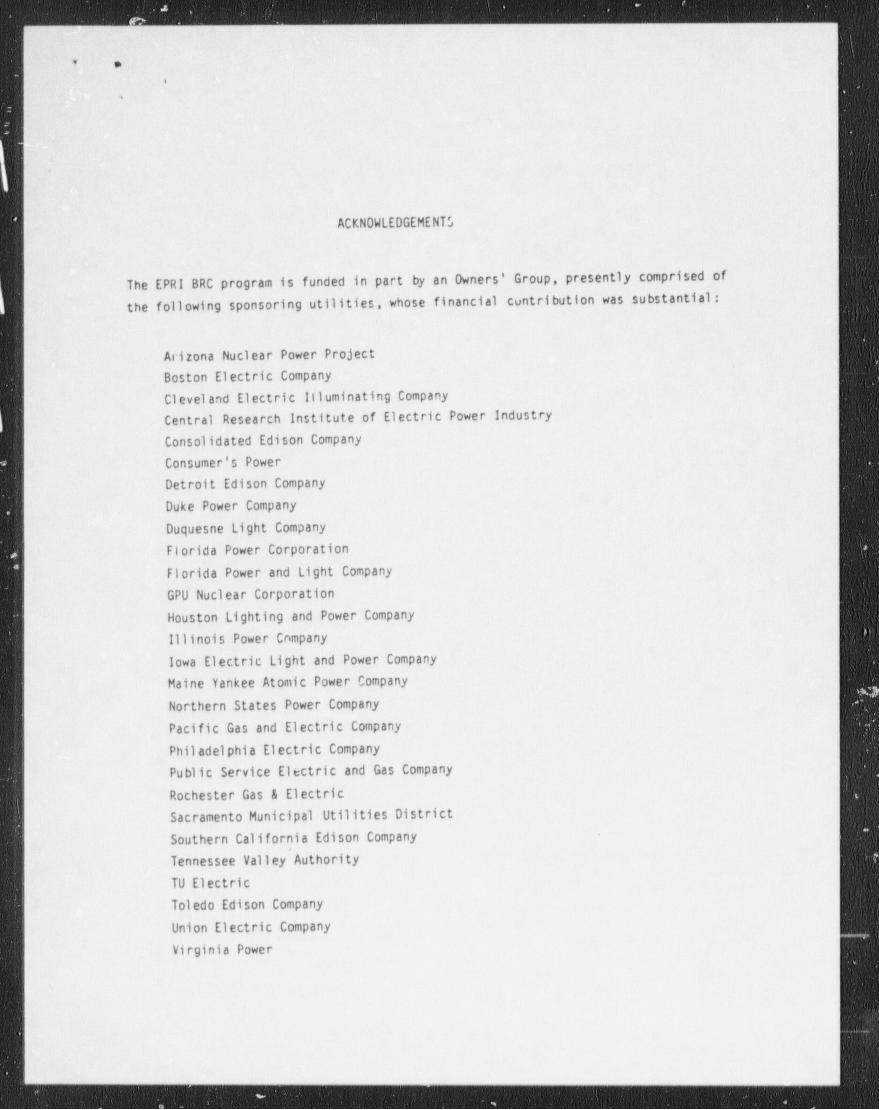
ACKNOWLEDGEMENTS
The EPRI BRC program is funded in part by an Dwners' Group, presently comprised ofthe following sponsoring utilities, whose financial contribution was substantial:
Arizona Nuclear Power ProjectBoston Electric Company
Cleveland Electric 111uminating CompanyCentral Research Institute of Electric Power IndustryConsolidated Edison Company
Consumer's PowerDetroit Edison Company
Duke Power Company
Duquesne Light Company
Florida Power Corporation
Florida Power and Light Company
GPU Nuclear Corporation
Houston Lighting and Power Company
lilinois Power Company
lowa Electric Light and Power CompanyMaine Yankee Atomic Power Company
Northern States Power Company
Pacific Gas and Electric Company
Philadelphia Electric CompanyPublic Service Electric and Gas Company
Rochester Gas & ElectricSacramento Municipal Utilities DistrictSouthern California Edison Company
Tennessee Valley Authority
TU ElectricToledo Edison Company
Union Electric Company
Virginia Power
1
- - - - - - _ - _ _ _ _ ____________________ _ _ _ _ _ _ _ _ _ _ _ _ _

- _ _ _ _ _ _ . _ . _ _ _ . _ _ - _ _
c .
.
.
Washington Public Power Supply SystemWisconsin Public Service CorporationYankee Atomic Electric Company'
:
$
_ _ _ _ _ _ _ _ _ _ _ _ _ __ _ __ _ _ _ _ _ _ _ _ _ . _ _ _
,_
t -- .
'4
'5
PREFACE
!
Over the past several years there has been considerable interest by the nuclear -
power industry in the NRC explicitly defining an activity level in plant wastematerials at which the radiological impacts would be so low as to be consideredbelow regulatory concern (BRC). This interest was also reflected in the Low-LevelWaste pol icy Amendments Act of 1985 in which it was mandated that the NRCesta blish procedures for acting expeditiously on petitions to exempt specificwaste types f rom the NRC regulations. In response to this mandate, the NRC has
pu blished in the Federal Register, August 29, 1986, a pol icy statement andimpl ementation pl an for the expeditious handling of such petitions. The
1
pu blication by the NRC of this policy statement and implementation pl an hasprovided the long-sought opportunity for the nuclear power industry to pursue theexemption of waste with very low-activity levels from the NRC's regulations.
The implementation plan is explicitly noted to be applicable only to multiplewaste producers on a national scal e (e.g., nuclear power pl ants ) . The
implementation plan delineates 14 NRC decision criteria that must be adequatelyaddressed in a rulemaking petition. Because of the industry-wide applicability
and the sizable technical effort required to respond to the 14 decision criteriarnd to support the development of such a petition, several utilities requestedthat EPRI provide the technical support required for a rulemaking petition.
In January 1987, EPRI initiated a major research program in the l ow-l evelradioactive waste area to develop the necessary technical information forinclusion in rulemaking petitions to exempt very low-activity nuclear plant wastesfrom NRC licensed disposal facilities.
The EPRI BRC research program is structured in response to the 14 decisioncriteria contained in the NRC's policy statement and implementation plan. The
program includes multiple research tasks that address the technical areas requiredfor the petition sutmittals. The description of the research tasks and results

_ _ _ - _ _ _ _ _ _ _ _ _ _ _ _ _ _
e v
,
,
are contained in stand-alone reports prepared by the individual contractors. Thisreport is one of a series of reports that addresses an area within the 14 decisioncriteria. Accordingly, a series of technical reports are available that describe
'
the technical aspects of the EPRI BRC program in its entirety.
l
|
.
- _. . _ _ _ _ _ . _ _ - . . - _ _ . _ _ - . _ _ _ _ _ - _ _
- 29: [s.
T
ir
f.
,
CONTENTS,
.PageChapter
1-1l' INTRODUCTION
-1-11.1 Purpose and Objectives-1-3
-l'. 2 Approach.1-3
1.3 Contents of the Report'
'
2-12 . CONCLUSIONS AND RECOMMENDATIONS
2-12.1 The IMPACTS-BRC Computer Program2-22.2 Sensitivity Analysis-2-4
2.3 Conservatism in the' Code.2-6
2.4 Correctness of Code Execution3-1
3 CODE STRUCTURE'3-13.1 General Description3-43.2 Dose Pathways ~and Scenarios3-113.3 Code Logic Flow4-1
4 EXAMPLE ANALYSES AND SENSITIVITY STUDIES
5-15 CONSERVATISM IN THE CODE
5-15.1~ Transportation Impacts5-15.1.1 Transportation Worker Dose5-4
5.1.2 Population Doses5-75.2 Incinerator Worker and Disposal Site Worker Impacts5-85.3 Intruder impacts5-9
5.4 Groundwater Impacts6-1
6 CORRECTNESS OF CODE EXECUTION6-1
6.1 1 Transportation Worker Dose6-3
6.2' Landfill Worker Dose6-4
6.3 Incinerator Worker Dose6-7-
6.4 Intruder dose6-8
6.5 Doses Based on Sorting Option 2
,
. . _ _ . _ . _ _ _ _ _ _ _ _ . _ _ _ _ _ _ _ . _ _ _ _ _ _ _ _ _ _ _ _ . . _ _ _ _ _ _ _ _ _ _ _ _ _ _ . _ _ _ _ _ _ _ _ _ . _ _ _ _ _
_ _ _ _. . _ _ _ . - _ - _ _ _ - - - _ _ _ _ - _ _ _ .
- . .
,
'? ,
,y
6;6 Dose Cal'culations for. Groundwater Pathways '6-86-9-6.7 Population-Doses From Transportation-J <
,
~ 6-9-'
,'6.8!'DoseCalculationsfortheSouthwestRegion6-96.9 Code Changes'for Onsite Disposal-
R-1REFERENCES
APPCt! DIX A- DATA IN THE IMPACTS-BRC DATA FILES A-1-
~ APPENDIX B PROPOSED' SOURCE CODE MODIFICATIONS B-1.o,
i -t
>
|
t
!
._ _ . _ - - _ _ _ - _ _ - - _ _ _ __ _ : _ - _ - - - _ - _ - - _ _ _ _ _ _ _ - _ _ _ _ - - _ _ - _ _ _ _ _ _ _ _ _ _ _ - _ _ _ _ - - _ _ _ _ - _ _ _ - _ - . - - _ _ _ _ - _ _ _ _ -
. _ - _ . . . _ _ . .-
.
, ,
4
%
e
i
ILLUSTRATIONS
"Figure
3-33-1 Waste Treatment and Disposal Options3-15
3-2 Logic of Program IMPACTS-BRC5-25-1 Exposure Geometry for Transportation Worker Dose
|
|.
._ _.__om__--__-____.__-_.-- _ _ __
- _ - _ - _ _ _ - - - - - _ _ - - _ - _ - - - _ --. - _ - - _ - - _ _ ;
-)-
']< .r-..
.[ ' '
,
1| 1
i'l
fTABLES
Page j:
Table J
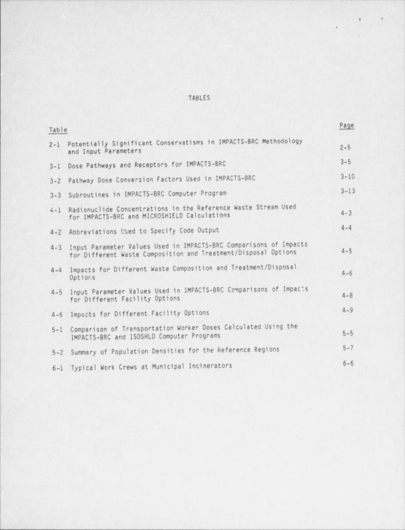
2-1 Potentially Significant' Conservatism in IMPACTS-BRC Methodology . ~)2-5and input Parameters'3-53-1 Dose Pathways and Receptors for IMPACTS-BRC
3-10 |3-2 Pathway Dose Conversion Factors Used in IMPACTS-BRC
3-133-3 - Subroutines in IMPACTS-BRC Computer Program
4-1 Radionuclides Concentrations in the Reference Waste Stream Used;
4-3 |for IMPACTS-BRC and MICROSHIELD Calculations
4-44-2: Abbreviations Used to Specify Code Output
4-3 Input Parameter Values Used in IMPACTS-BRC Comparisons of Impacts 4-5'for.Different Waste Composition and Treatment / Disposal Options
4-4 Impacts for Different Waste Composition and Treatment / Disposal 4-6Options
4-5 Input Parameter Values Used in IMPACTS-BRC Comparisons of Impact,s 4-8for Different Facility Options.4-9'4-6' Impacts for Different Facility Options
5-1 Comparison of Transportation Worker Doses Calculated Using the5-5IMPACTS-BRC and ISOSHLD Computer Programs
5-75-2 Summary of Population Densities for the Reference Regions
-6-66-1 Typical Work Crews at Municipal Incinerators
- - _ _ _ _ _ _ _ _ _ -
- - - - - _ -
, ,
.
,
|
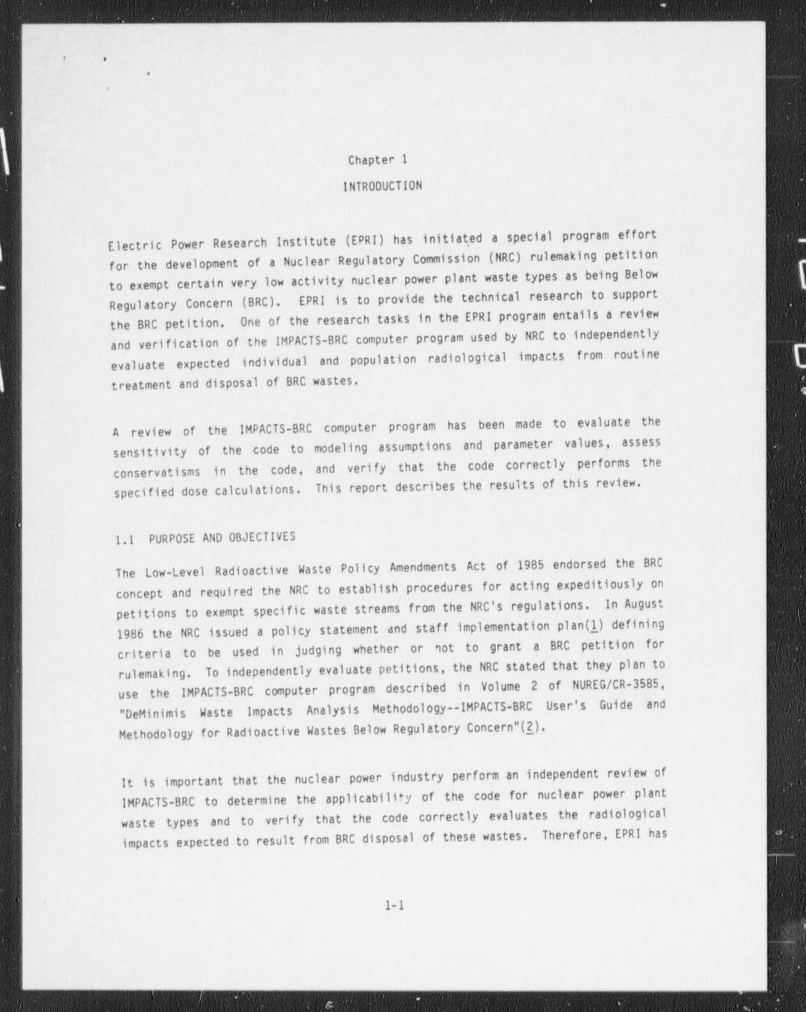
Chapter 1
INTRODUCTION
Electric Power Research Institute (EPRI) has initiat,ed a special program effortfor the development of a Nuclear Regulatory Commission (NRC) rulemaking petitionto exempt certain very low activity nuclear power plant waste types as being Below
Regulatory Concern (BRC). EPRI is to provide the technical research to supportOne of the research tasks in the EPRI program entails a reviewthe BRC petition.
and verification of the IMPACTS-BRC computer program used by NRC to independently|
' evaluate expected individual and population radiological impacts from routine1
treatment and disposal of BRC wastes.
A review of the IMPACTS-BRC computer program has been made to evaluate thesensitivity of the code to modeling assumptions and parameter values, assess
conservatism in the code, and veri fy that the code correctly performs thespecified dose calculations. This report describes the results of this review.
1.1 PURPOSE AND OBJECTIVES
The Low-Level Radioactive Waste Policy Amendments Act of 1985 endorsed the BRC
concept and required the NRC to establish procedures for acting expeditiously onpetitions to exempt specific waste streams from the NRC's regulations. In August1986 the NRC issued a policy statement and staf f implementation plan (1_) definingcriteria to be used in judging whether or '10 t to grant a BRC petition for
rulemaking. To independently evaluate petitions, the NRC stated that they plan touse the IMPACTS-BRC computer program described in Volume 2 of NUREG/CR-3585,"DeMinimis Waste Impacts Analysis Methodology -lMPACTS-BRC User's Guide and
Methodology for Radioactive Wastes Below Regulatory Concern"(_2_).
It is important that the nuclear power industry perform an independent review ofIMPACTS-BRC to determine the applicability of the code for nuclear power plantwaste types and to veri fy that the code correctly evaluates the radiological
Therefore, EPRI hasimpacts expected to result from BRC disposal of these wastes.
I 1_1'
_ _ _ .
, _ .__ _ _ _ _ _ _ . - _ _ _
;
. r
.
,
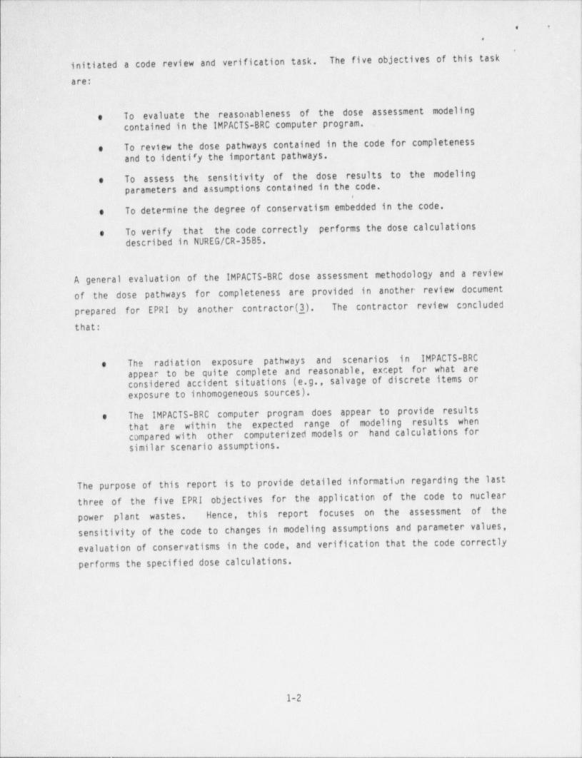
initiated a code review and verification task. The five objectives of this task
are:
e To evaluate the reasonableness of the dose assessment modelingcontained in the IMPACTS-BRC computer program.
To review the dose pathways contained in the code for completenesseand to identi'y the important pathways.
e To assess the sensitivity of the dose results to the modelingparameters and assumptions contained in the code.
To determine the degree of conservatism embedded in the code,e
e To verify that the code correctly performs the dose calculationsdescribed in NUREG/CR-3585.
A general evaluation of the IMPACTS-BRC dose assessment methodology and a reviewof the dose pathways for completeness are provided in another review documentprepared for EPRI by another contractor (3). The contractor review concluded
l
that:
e The radiation exposure pathways and scenarios in IMPACTS-BRCappear to be quite complete and reasonable, except for what areconsidered accident situations (e.g., salvage of discrete items orexposure to inhomogeneous sources).
e The IMPACTS-BRC computer program does appear to provide resultsthat are within the expected range of modeling results whencompared with other computerized models or hand calculations forsimilar scenario assumptions.
The purpose of this report is to provide detailed information regarding the lastthree of the five EPRI objectives for the application of the code to nuclearpower plant wastes. Hence, this report focuses on the assessment of thesensitivity of the code to changes in modeling assumptions and parameter values,evaluation of conservatism in the code, and verification that the code correctlyperforms the specified dose calculations.
1-2 ]
1
. - _ - _ _ _
- _ - _ - _ - _ _ .
* Q
.
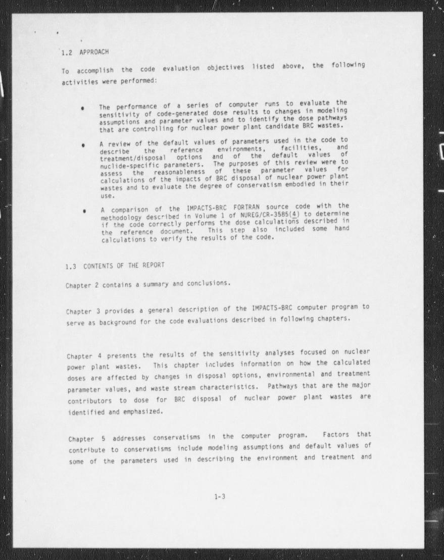
'1.2 APPROACH
To accomplish the code evaluation objectives listed above, the followingactivities were performed:
The performance of a series of computer runs to evaluate theesensitivity of code-generated dose results to changes in modelingassumptions and parameter values and to identify the dose pathwaysthat are controlling for nuclear power plant candidate BRC wastes.
A review of the default values of parameters used in the code toedescribe the reference environments, facilities, and r
treatment / disposal options and of the default values of (nuclide-specific parameters. The purposes of this review were to
the reasonableness of these parameter values forassesscalculations of the impacts of BRC disposal of nuclear power plantwastes and to evaluate the degree of conservatism embodied in theiruse.
e A comparison of the IMPACTS-BRC FORTRAN source code with themethodology described in Volume 1 of NUREG/CR-3585(4) to determineif the code correctly performs the dose calculations described inthe reference document. This step also included some handcalculations to verify the results of the code.
1.3 CONTENTS OF THE REPORT
Chapter 2 contains a summary and conclusions.
Chapter 3 provides a general description of the IMPACTS-BRC computer program toserve as background for the code evaluations described in following chapters.
Chapter 4 presents the results of the sensitivity analyses focused on nuclearpower plant wastes. This chapter includes information on how the calculateddoses are af fected by changes in disposal options, environmental and treatment
parameter values, and waste stream characteristics. Pathways that are the major
contributors to dose for BRC disposal of nuclear power plant wastes areidentified and emphasized.
Chapter 5 addresses conservatism in the computer program. Factors that
contribute to conservatism include modeling assumptions and def ault values of
some of the parameters used in describing the environment and treatment and
1-3-
- -- -_-__-_-_ - _ _ _ _ _ .
- _ _ _ _ _ _ - _ _ _ _
l
C *
1*
,
Estimates are made of the amounts of conservatism associateddisposal operations. jwith some of the modeling assumptions and parameter values.
Chapter 6 is an evaluation of the way the code performs the individual andpopulation dose calculations prescribed by the waste impacts methodology document
on which the code is based. Places in the code where(NUREG/CR-3585)(4_)
Recommendedcalculational or programming errors have been made are identified.changes to improve the correctness of the code execution are described,
a
A listing of the data in the IMPACTS-BRC input data files is given in Appendix A.Proposed changes to the FORTRAN source code for application of IMPACTS-BRC to thetreatment and disposal of nuclear power plant wastes are given in Appendix B.
|
)
1-4
|
_ _ _ _ _ - - _ - _ _ _ _ _ _ _ _ _ _
- - _ _ - _ _ _ _ .
? e.
Chapter 2
CONCLUSIONS AND RECOMMENDATIONS
The Electric Power Research Institute (EPRI) is providing support for anuclear utility industry rulemaking petition to exempt certain very
low-level radioactive wastes from NRC regulation under the SRC definition.One of the research tasks in the EPRI support program is a detailed reviewof the IMPACTS-BRC computer program being used by the NRC to evaluate theradiological health and safety impacts on the public from proposed BRC wastedisposal options.
2.1 THE IMPACTS-BRC COMPUTER PROGRAM
IMPACTS-BRC is a computer program prepared by NRC staff and contractors for use in
evaluating the radiological impacts to individuals and populations from
incineration and disposal of BRC wastes at f acilities that are not licensed forlow-level radioactive waste management. The program is written in IBM-PC FORTRAN
The calculationalVersion 2.00 and runs on IBM-PC and compatible microcomputers.methodology that provides the basis for the program is given in the NRC report,"De Minimis Waste Impacts Analysis Methodology" (NUREG/CR-3585)(4).
Treatment and disposal options evaluated by IMPACTS-BRC for BRC wastes include:
Sanitary landfill disposal.e
Onsite incineration with sanitary landfill disposal.o
Municipal incineration with sanitary landfill disposal.o
Hazardous waste landfill disposal,e
Onsite incineration with hazardous waste landfill disposal,e
Hazardous waste incineration with hazardous waste landfilledisposal.
2-1
- - - - - - - - _ - - _ - _ _ _ _ _ _ - _ _ _ _ _
- ___ -.
4' 3
,.,
|
|
Onsite landfill- disposal is not defined as an . option in the current version of, 'fIIMPACTS-BRC. However, onsite landfill disposal may be evaluated by using the
sanitary landfill model and making appropriate changes to the sanitary landfill'
default . data. (Default data for' the parameters that describe the reference,
disposal f acil'ities and environments are contained in an input data filedesignated TAPE 2.DAT.)
i
The radiological impacts from treatment or disposal of BRC waste are assumed byIIMPACTS-BRC to be proportional to the effective radionuclides concentration in the j
waste being incinerated or disposed. The code assumes a homogenization of BRC and ]non-radioactive wastes, and, in addition, assumes that the volume of j
non-radioactive waste incinerated or disposed greatly exceeds the BRC waste ]volume. The effective radionuclides concentration in the waste is determined by i
dividing the radionuclides inventory in the BRC waste by the total volume of waste,dominated by the non-BRC waste vol ume. Thus, for offsite incineration or
disposal, the Individual and population impacts calculated by IMPACTS-BRC aredetermined by the total radionuclides inventory incinerated or disposed rather thanby the radionuclides concentration in the BRC waste stream. j
!
2.2 SENSITIVITY ANALYSIS
A series of computer runs was made to assess. the sensitivity of the IMPACTS-BRCcomputer program to changes in waste composition, facility options, and wastetreatment and disposal options. These computer runs also identifie.d the exposurepathways that result in the largest individual and population doses from BRCdisposal of nuclear power plant wastes,
in all of these computer runs, the largest individual doses calculated for thedisposal of BRC reactor wastes are to the transportation worker and incineratorworker. Landfill worker doses are generally calculated to be about one order ofmagnitude smaller than transportation and incinerator worker doses. Intruder I
t
|doses are generally calculated to be about two orders of magnitude smaller than|
the transportation doses. Individual doses from leachate overflow pathways areabout three or four orders of magnitude smaller and doses from groundwaterpathways are four or five orders of magnitude smaller than the maximum exposed
| transportation worker and maximum exposed incinerator worker doses. Doses to themaximum exposed offsite individual are calculated to be about four or five orders
2-2
L
l1L____ _ __._ _. _ _ _ _ >
- - _ - _ _ _ _ _ _ _
|~
' *.
of magnitude smaller than -doses to the maximum er;,osed worker for each treatmentor disposal operation.
Impacts from erosion and exposu e of tne waste are the smallest of any impacts'
calculated by IMPACTS-BRC, and are negligible compared -to individual andpopulation impacts from transportation and incineration.
Changing the waste density '.;oes not affect any doses except the transportationdoses; These doses varv inversely with the effective density of the waste being
t m oorted. Fm- example, if the waste density is doubled, the transportation )dose is reduced by a factor of two.
The sensitivity of the code to changes in facility options was investigated bychanging the region, the facility environment, the facility operating ' lifetime,and the institutional control period following facility closure. In no instances
do these changes in facility options alter the conclusion that the controllingdoses are the doses to the transportation, incinerator, and landfill workers.Furthermore, the worker doses calculated by IMPACTS-BRC are not affected by any of
these changes in facility options.
Because the values used by the code for some hydrologic and meteorologicparameters are region specific, changing the region where the facility is locatedchanges the calculated doses to offsite individuals and populations. For the
northeast and southeast regions these changes are generally less than an order of
magnitude. For the southwest region, the impacts from groundwater and surface
water pathways are much smaller than they are for the northeast and southeastregions. Population impacts along the waste transportation routes areproportional to the assumed population densities along these routes.
Intruder impacts increase if the institutional control period is decreased or setequal to zero. Intruder impacts are affected by radioactive decay that is assumedto occur during the period of institutional control after a disposal site isclosed.
2-3
___ ___ _ _ _ - _- . . _ _ - _ _ _ _ _ _ _ _ _ _ _ _ _ . _ _ _ _ _ _ _ _ _ _ _ _ _ _ _ _ _ _ _ _ _ _ _ _ _ _
- _-_ _ _ - ___ _
'
. ,
.
,
2.3 CONSERVATISM IN THE CODE1
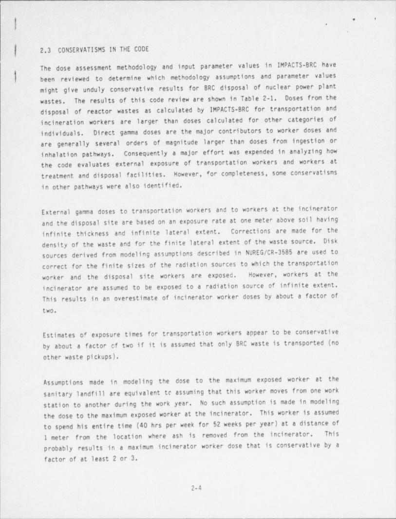
The dose assessment methodology and input parameter values in IMPACTS-BRC have ,
been reviewed to determine which methodology assumptions and parameter values
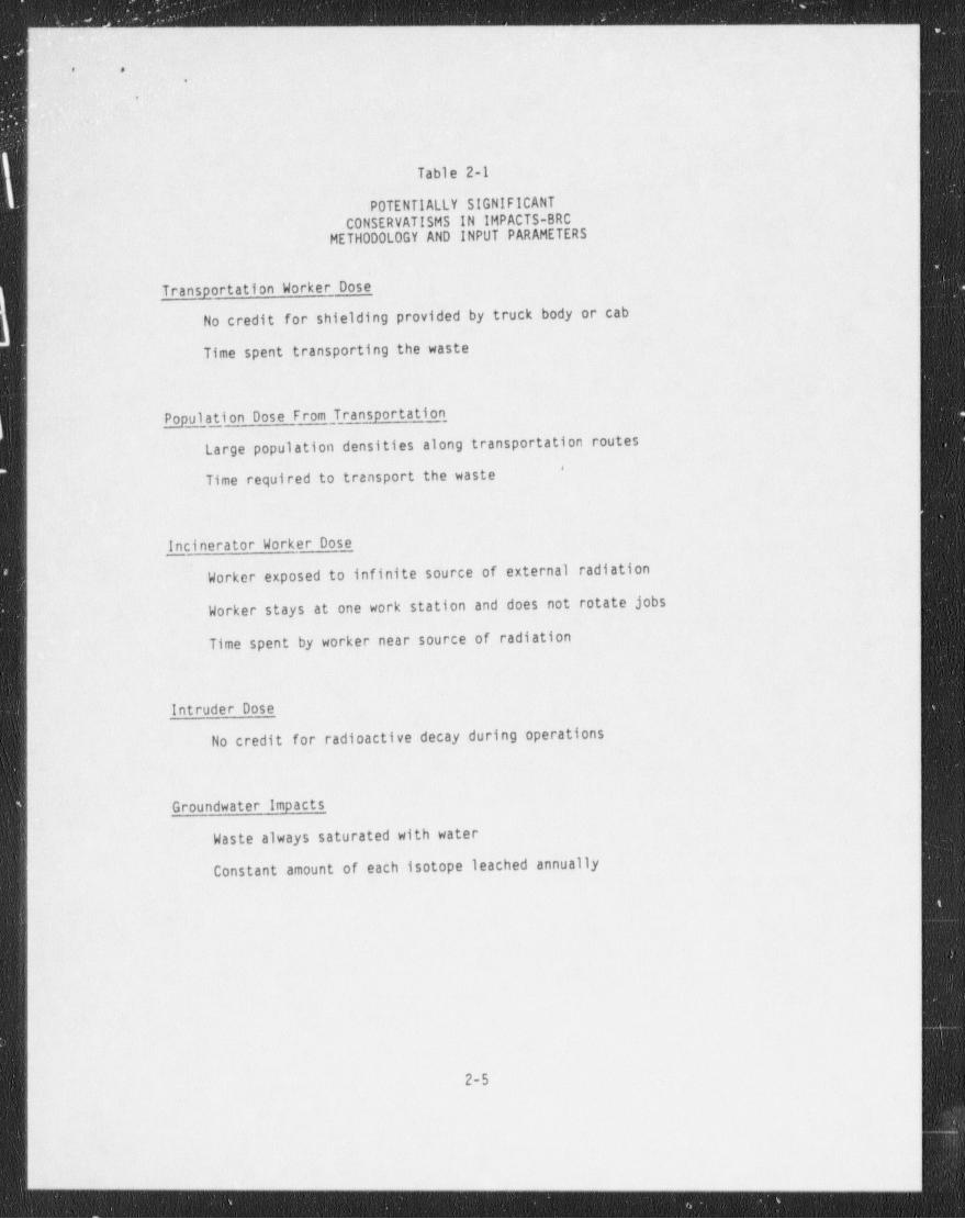
might give. unduly conservative results for BRC disposal of nuclear power plantwastes. The results of this code review are shown in Table 2-1. Doses from the
disposal of reactor wastes as calculated by IMPACTS-BRC for transportation andincineration workers are larger than doses calculated for other categories ofindividuals. Direct gamma doses are the major contributors to worker doses andare generally several orders of magnitude larger than doses from ingestion orinhalation pathways. Consequently a major effort was expended in analyzing howthe code evaluates external exposure of transportation workers and workers attreatment and disposal f acilities. However, for completeness, some conservatism !
<
in other pathways were also identified.
External gamma doses to transportation workers and to workers at the incinerator {and the disposal site are based on an exposure rate at one meter above soil having
infinite thickness and infinite lateral extent. Corrections are made for theDiskdensity of the waste and for the finite lateral extent of the waste source.
sources derived from modeling assumptions described in NUREG/CR-3585 are used tocorrect for the finite sizes of the radiation sources to which the transportationworker and the disposal site workers are exposed. However, workers at the !
incinerator are assumed to be exposed to a radiation source of infinite extent.This results in an overestimate of incinerator worker doses by about a factor of
two.
' i
Estimates of exposure times for transportation workers appear to be conservativeby about a factor of two if it is assumed that only BRC waste is transported (noother waste pickups),
i
Assumptions made in modeling the dose to the maximum exposed worker at thesanitary landfill are equivalent te assuming that this worker moves f rom one workstation to another during the work year. No such assumption is made in modelingthe dose to the maximum exposed worker at the incinerator. This worker is assumed
to spend his entire time (40 hrs per week for 52 weeks per year) at a distance of1 meter from the location where ash is removed from the incinerator. This
probably results in a maximum incinerator worker dose that is conservative by a. factor of at least 2 or 3. |
!
|
2-4
- --
- - - - _ _ _ - _ _ _ _ _
e .
.
.
Table 2-1
POTENTIALLY SIGNIFICANTCONSERVATISM IN IMPACTS-BRC
METHODOLOGY AND INPUT PARAMETERS
Transportation Worker Dose
No credit for shielding provided by truck body or cab
Time spent transporting the waste
Population Dose From Transportation
large population densities along transportation routes'
Time required to transport the waste
||
Incinerator Worker Dose1 Worker exposed to infinite source of external radiation'
Worker stays at one work station and does not rotate jobs
Time spent by worker near source of radiation
Intruder Dose
! No credit for radioactive decay during operations
| Groundwater Impacts
Waste always saturated with water
Constant amount of each isotope leached annually!
2-5
- - - - - _ - - _ _ - _ _ _ _ _ _
_ _ _ _ _ _ _ _ . _ _ - _ _ _ _ _ _ _ _ _ - _ _ _ - _ _ _ _ - _ _
. ,
,
'In calculating the dose to an intruder on the disposal site, IMPACTS-BRC assumesB that' radioactive decay occurs during the period of institutional control following'
closure of the site but not during the operational period. If the isotopic,
concentrations in the waste are as given - in Tabl e 4-1, taking credit for
radioactive decay during the operational period would reduce intruder - doses by
-about a factor of two.
2.4 CORRECTNESS OF CODE EXECUTION
There are a few places 'in the IMPACTS-BRC computer program where calculational or
programming errors appear to have been made. There are also some instances where
default values in TAPE 2.DAT might be changed to make them more consistent with
requirements for modeling the BRC treatment and disposal of nuclear power plantwastes. Errors and inconsistencies in the code and recommendations for somechanges to improve code execution are summarized in this section.
Transportation Worker Dose. Subroutine READ 5 that calculates the transportation
worker dose uses the same variable, A1, to represent both the volume fraction and
the weight fraction of the truck load that is BRC waste. For consistency, the
code should be modified so that all references to the fraction of a truck loadthat is BRC waste mean the volume fraction.
Landfill Collective Worker Dose. Subroutine OPSIMP calculates the disposal workercollective dose for a small landfill that employs only one worker. To provide areasonable but conservative estimate of the disposal worker collective dose forthe larger landfill that is the reference f acility for the disposal of |
reactor-generated BRC wastes, the factor of 10 should be removed from the jdenominator of statement OPSI 970.
Incinerator Worker Dose. in calculating external exposure doses to transportationworkers and sanitary landfill workers, IMPACTS-BRC takes account of the finitesize of the radiation sources to which these workers are exposed. However,
incinerator workers are assumed to be exposed to a radiation source of infinite
extent. For consistency, the coefficient C0FF that accounts for the finite size |
of the radiation source should be added to statements in subroutine INCIMP thatcalculate external exposure doses to incinerator workers. j
2-6
- _ _ - _ _ _ - _ _ _ _ - _ _ _ - _ _ - _ _ - _ - _ - _ _ - _ _ _ _ _ _
_ _ _ _ _ _ _ _ - _ _ _ -
| 1|
* *)
| )*
[,
The dose to'the maximum exposed incinerator worker is overestimated by postulating f|
a " refuse' handler" who spends the entire wcrk year at a distance of one meter fromthe ash. -Since laborers at an incinerator perform a variety of tasks, subroutineINCIMP should be modified to incorporate the assumption that incinerator workers-
rotate assignments. Rotating work assignments is equivalent to assuming that the |
maximum exposed- worker spends about one-third of his time at a distance of onemeter from the ash and the remainder at greater distances froin radiation sources.
Intruder Dose. The waste-soil mixing ratio, RMIX, is included in statements insubroutine INTIMP that calculate the intruder dose for the intruder-agriculturescenario but not in statements that calculate the dose for the
intruder-construction scenario. Because about 40 percent of an intruder's timewould be spent removing top cover and because excavation would likely involve theuse of mechanized equipment that could reduce the exposure to the intruder, theelimination of RMIX is considered to result in an overly conservative
intruder-construction dose estimate. Intruder dose estimates are inherently
conservative since no credit is taken for radioactive decay of the waste duringoperation of the facility. RMIX should therefore be included in statements that
calculate the dose for the intruder-construction scenario.
Doses Based on Sorting Option 2. Sorting Option 2 separates waste into a fraction
that is incinerated and a fraction that is not incinerated. Corrections should bemade to code statements that calculate the intruder, landfill worker, andgroundwater pathway doses for Sorting Option 2 so that these statements accountfor exposures from both the waste fraction that is incinerated and the wastef raction that is sorted and goes directly to the landfill.
Dose Calculations for Groundwater Pathways. The input data files contain five
sets of Kd values. The code uses the incorrect Kd when sets two through five arerequested. The constant amount leach calculation should be replaced by a constantfraction leach calculation in equations that account for the leaching ofradionuclides by percolating water. The constant fraction leaching is consistentwith the method of calculating leach rates.
!l!
!
!
2-7
!!
- _ _ _ -
. .
.
Population Doses ' f rom Transportation. Population densities along transportationroutes and travel distances and truck speeds specified. in TAPE 2.DAT should be
changed to conform to actual conditions for the transporta*. ion of nuclear ' power'
plant wastes.'
. Dose Calculations for the Southwest Region. The code will not execute if thesouthwest region is chosen because ' the TAPE 2.DAT default value for TIM (3) (the
groundwater travel time from the facility to surf ace water) is set equal to zero.A non-zero value for TIM (3) should be chosen that is consistent.with the defaultvalues for TIM (1) and TIM (2).
:
I
1
I
j-
-
t
2-8
- - - _ _ _ _ _ _ _ _ _ _ _ _ _ _ _ _ _ _ _ _ _ _ _ _ _ _ _ _ _ _ _ _ _ _ _ _ _ _ _ _ _ _ _ _ _ _ _ _ _ _ _ _ _ __ _
- _ - - - _ -
. ,
,
,
Chapter 3
CODE STRUCTURE
3.1 GENERAL DESCRIPTION
IMPACTS-BRC is a computer program that calculates the radiological impacts fromtreatment and disposal of slightly contaminated radioactive wastes at facilities
The program isthat are not licensed for low-level radioactive waste management.written in IBM-PC FORTRAN Version 2.00 and runs on IBM-PC and compatible
microcomputers. Treatment and disposal options include on-site incineration,off-site incineration and disposal as a municipal waste, and of f-site incinerationand disposal as a hazardous waste.
The calculational methodology that provides the basis for the IMPACTS-BRC computer
program is gi ven in the NRC report, "De Minimis Waste Impacts Analysis
Methodology," NUREG/CR-3585(4_). Radiological impacts to individuals and
of radioactive material alongpopulations are calculated based on the movement
Operational impacts to workers and the general population arevarious pathways.calculated for transportation, incineration, and landfill disposal of the waste.
Calculated doses to individuals who intrude on a closed site for construction oragriculture purposes are also evaluated. Possible impacts f rom erosion., leachateoverflow, or recycle of metal or glass fractions of the waste are estimated.Long-term impacts to individuals from various groundwater pathways are also
calculated.
DataInput data required to use IMPACTS-BRC are contained in three input files.
The first input file, TAPE 1.DAT,specified in each file are listed in Appendix A.This file containscontains nuclide-specific data for each of 85 radionuclides.
half lives, solubility classes, dose conversion factors, waste-to-leachatepartition ratios, and retardation coefficients. Generally, this file would not
require user editing, except under very specific circumstances.
3-1
- - - - _ - - _ - _ _ - _ _ _ _ _ _ _
_ _ - _ _ - _ _ - - - _ -
t. .
t
.
-The second' input file, TAPE 2.DAT, contains data for the reference environments andfacilitier, used by the code. Examples of the data contained in this file includeannual volumes of non-radioactive waste incinerated or disposed of at thereference facilities, distances and travel times to these facilities, wastedensities, population densities, meteorological information, landfill dimensions,dust mobilization data, potential water infiltration rates into disposal cells,groundwater travel times, soil retardation indices, dilution factors for wells andsurf ace streams, etc. Environmental data are provided for disposal locations
having meteorological characteristics and soil properties that are broadlyrepresentative of three geographic locations: a humid region with low
permeability -soil (northeast), a humid region with coderately permeable soil(southeast), and a semi-a ri d region (southwest). The data in TAPE 2.DAT may
require editing for specific situations. Recommended changes to the default datain this file for BRC disposal of utility generated very low-level radioactivewastes are given in Chapter 6.
The third input file, TAPES, contains data for the waste stream and the chosentreatment and disposal options. This file must be created by the user for the
specific waste stream and treatment / disposal options being evaluated. Waste-
stream data that must be specified by the user include the mass, volume anddensity of the waste, radionuclides concentrations, waste dispersability, and theweight fraction of the waste that is combustible. User-defined processing options
include:
Sanitary landfill disposale
On-site incineration with sanitary landfill disposale
Municipal incineration with sanitary landfill disposale
Hazardous waste landfill disposale
On-site incineration with hazardous waste landfill disposale
Hazardous waste incineration with hazardous waste landfille
disposal
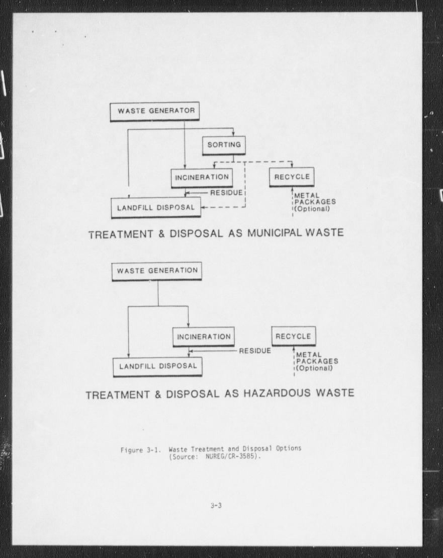
These options are shown schematically in Figure 3-1.
3-2
.- - _ _ _ _ - _ _ _ _ _ _ - _ _ _ . _ _ _ _ . _
. ,
,
,
WASTE GENERATOR
4
SORTING
7 _ _ .l _ 7 _ _ _ _ _ q,,
l
| INCINERATION I RECYCLE
{ METALb RESIDUE l,
^ ^|(Opt on ILANDFILL DISPOSAL +----i
TREATMENT & DISPOSAL AS MUNICIPAL WASTE
W ASTE GENERATION
,,
INCINERATION RECYCLE
RESIDUE:METAL,, ,,
PCA SLANDFILL DISPOSAL 'g
i
TREATMENT & DISPOSAL AS HAZARDOUS WASTE
Figure 3-1. Waste Treatment and Disposal Options(Source: NUREG/CR-3585).
3-3
- - - - _ _-- -_- _-_____-__. _
.
t
. ..
|.:
|. ..
For the municipal incinerator / sanitary landfill ' disposal option, three waste |
sorting sub-options are provided. These include: ,
1. Incinerate all the waste and dispose of the residue at- the,
landfill. :
2. Incinerate the combustible waste and dispose of the residue!
and the noncombustible waste at the landfill. ,
3. Recover the recyclable material (metal and gl a s s ) .-
Incinerate .the combustible waste and ' dispose of the residue ,
and the nonrecyclable, noncombustible waste at the landfill.,
I
Hazardous waste landfill disposal is modeled using average performance ar.d site
a environmental characteristics (hazardous waste landfill 1) and using more
conservative assumptions about performance and environmental characteristics
(hazardous waste landfill 11).i
07-site landfill disposal is not define <1 as an option in the current version of q
IIMPACTS-BRC. However, on-site disposal may be evaluated by using the sanitary
_
landfill model and making appropriate changes to the sanitary landfill default
. data in TAPE 2.DAT. Recommended changes for onsite disposal are described in
Chapter 5.
3.2 DOSE PATHWAYS AND SCENARIOS
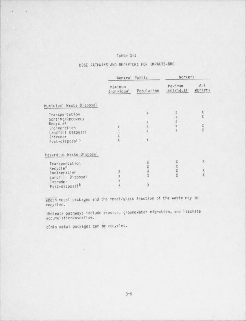
A summary of dose pathways and receptors for IMPACTS-BRC is shown in Table 3-1.The IMPACTS-BRC computer program uses the pathway analysis approach described inthe NRC's de minimis waste impacts methodology report (NUREG/CR-3585) (4). The
code uses the equations developed in that report to calculate maximum exposedindividual and total population dose rates from various operations relating to thetreatment and disposal of the waste. The operations modeled by the code include
transportation, sorting, recycle of material (for the municipal landfill option),incineration, disposal, and post-disposal activities. Workers who transport the
waste, along with workers at the incinerator and landfill are considered part ofthe population. None of these workers are assumed to be radiological workers.
3-4
_ _ _ _ _ _ _ _ _ _ _ _ _ _ _ _ _ _ _ _ _ - - _ _ _ _ _ _ _ _ - _ _ - - -_
.
y .-
,,
.
.
. . - :.
Tr: ,
r >
,
Table 3-1,.
' DOSE PATHWAYS AND RECEPTORS FOR IMPACTS-BRC-4
General Public Workers
Ma'ximum Maximum AllIndividua11 Popul ation Individual Workers.
' ; Municipal Waste Disposal6-
X X XTransportationX XSorting / Recovery
Recyc',ea X 'X
Incineration X X X' X
Landfill' Disposal X X .X X
Intruder X
Post-disposal b X X
Hazardous' Waste Disposal|-
1X= X XTransportation
c .X XRecycleIncineration' .
X X X X
' Landfill Disposal X -X X Xc
' Intruder. X
b X XPost-disposal
aBoth metal packages and the metal / glass fraction of the waste may berecycl ed.
|bRelease pathways include erosion, groundwater migration, and leachate,
accumul ation/ overflow.
conly metal packages can be recycled.
.
|3-5/
1
-__ - _ _ - - _ __ _ _ ______ - ____ _ _ _ _ _ _ _ _______ _
- - - _ _ _ _ _
. .
,
.
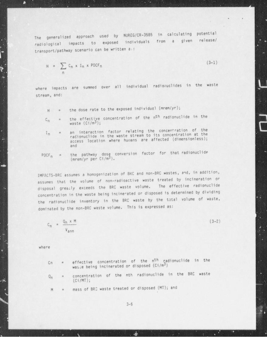
The generalized approach used by NUREG/CR-3585 in calculating potential
radiological impacts to exposed individuals from a given release /
transport / pathway scenario can be written at:
(3-1){ Cn X In x PDCFnH =
n
where impacts are summed over all individual radionuclides in the waste
stream, and:
the dose rate to the exposed individual (mrem /yr);H =
the ef fective concentration of the nth radionuclides in theC =n waste (C1/m3);
interaction factor relating the concentration of theI an=
radionuclides in the waste stream to its concentration at then
access location where humans are affected (dimensionless);and
the pathway dosg conversion factor for that radionuclidesPDCF =n (mrem /yr per Ci/m3).
IMPACTS-BRC assumes a homogenization of BRC and non-BRC wastes, and, in addition,
assumes that the volume of non-radioactive waste treated by incineration ordisposal greatly exceeds the BRC waste volume. The effective radionuclides
concentration in the waste being incinerated or disposed is determined by dividingthe radionuclides inventory in the BRC waste by the total volume of waste,dominated by the non-BRC waste volume. This is expressed as:
(3-2)C =
nV ann
where
effective concentration of the nth radionuclides in theCn =3waste being incinerated or disposed (Ci/m )
concentration of the nth radionuclides in the BRC wasteOn=
(Ci/MT);
mass of BRO waste treated or disposed (MT); andM =
! 3-6
- - - - - - _ - _ _ _ _ _ _ _ _ _ _ _ _ _ _ _ _ _ _ _ _ _ _ _ _ _ _ _ _ _ __ __
. _ _ _ _ _ _ _ _ _ _ _ _
. .
.
.
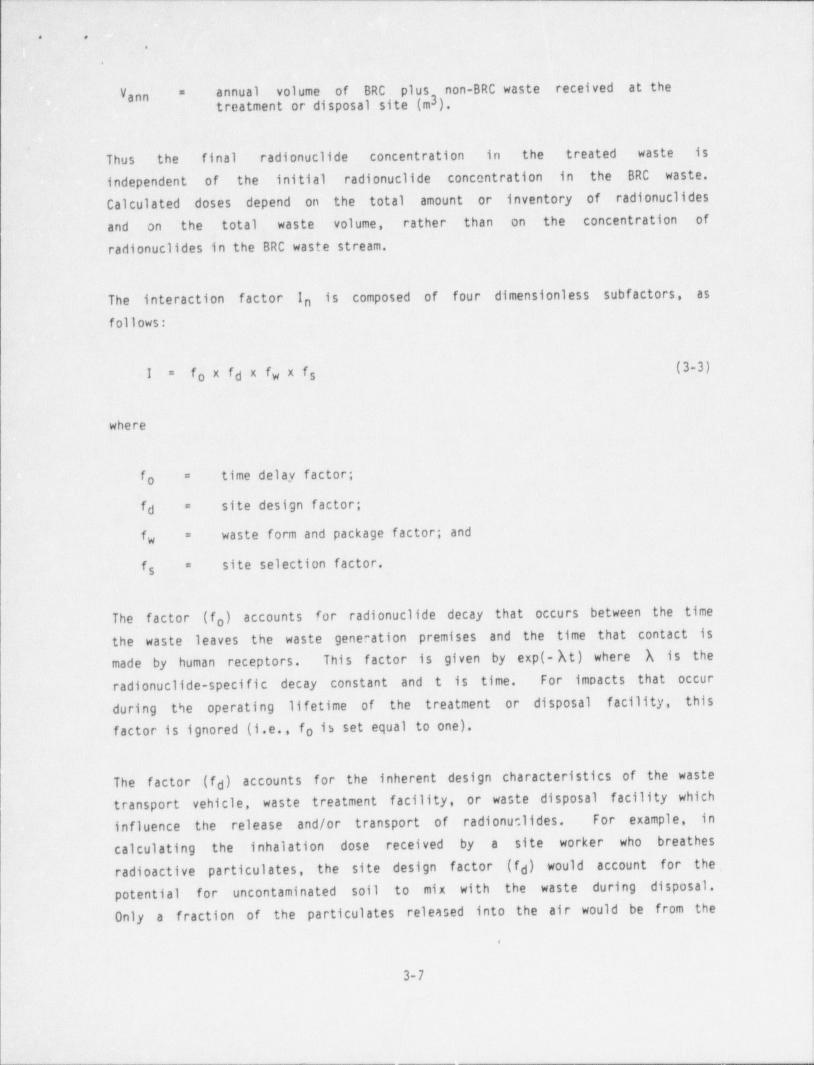
annual volume of BRC plus non-BRC waste received at theV- =
ann 3treatment or disposal site (m ).1
Thus the final -radionuclides concentration in the treated waste is,
independent of the initial radionuclides concentration in the BRC waste.,
Calculated doses depend on- the total amount or inventory of radionuclidesand on the total. waste volume, rather than on the concentration ofradionuclides in the BRC waste stream.
The interaction factor I is composed of four dimensionless subfactors, asn
follows:
f xfdX fw X fs (3-3)I =o
where
time delay factor;f =o
site design factor;fd =
waste form and package factor; andf =w
site selection factor.f =s
The factor (f ) accounts for radionuclides decay that occurs between the timeothe waste leaves the waste generation premises and the time that contact ismade by human receptors. This f actor is given by exp(- At) where h is theradionuclides-specific decay constant and t is time. For impacts that occur
during the operating lifetime of the treatment or disposal facility, thisf actor is ignored (i.e., fo is set equal to one).
The factor (f ) accounts for the inherent design characteristics of the wasted
transport vehicle, waste treatment facility, or waste disposal facility whichinfluence the release and/or transport of radionuclides. For example, in
calculating the inhalation dose received by a site worker who breathesradioactive particulate, the site design factor (f ) would account for thed
potential for uncontaminated soil to mix with the waste during disposal.Only a fraction of the particulate released into the air would be from the
,
3-7
. _ _ _ _ . _ _ _ _ _ _ _ _ - _ - _ - _ _ _ .
- _ _ _ _ _ _ _ _ _ _ _ _ _ _ _ _ _ - _ _ _ _ _ _ _ _ _ - _ _ _ _ _ _ _ _ _ _____ ______ ____,
. .
,
.
disposed waste; the remaining particulate would be from uncontaminated
soil.
.
The factor (f ) accounts for the physical and chemical characteristics of thewaste tha t'. may inhibit radionuclides transfer for a particular rekease-
w
transport scenario. For example, in calculating the inhalation dose to siteworkers at the disposal site it is logical to assume that for many wasteforms the waste will be much less dispersible into the air than ordinarysoil. This is accounted for by the waste form and package factor (f ) thatw
. corrects for the relative ability of the _ waste to disperse into the air asrespirable particles.
The factor (f ) includes the effects of the environment on radionuclidess
releast and transport. For the inhalation example being discussed, the siteselection factor (f ) would account for the tendency of disposal operations i
s
to raise dust at the site. It would also take into account the fraction of ayear that the worker breathes air containing this dust. In the IMPACTS-BRC
code the fraction of a year that a worker is stationed at an incinerator orlandfill is conservatively assumed to be 0.237. This is based on a 40-hour
work week for 52 weeks per year.
When the radionuclides concentration at a particular access location has beendetermined by multiplying the effective radionuclides concentration in thewaste by the appropriate interaction factors, the resultant dose rate to ahuman is determined in the IMPACTS-BRC code by using radionuclides specificparameters known as pathway dose conversion factors (PDCF). Seven PDCFs are
defined based on the various uptake pathways considered to be important inevaluating doses from BRC waste disposal. The PDCFs ,are formed from
combinations of fundamental dose conversion factors multiplied by constantsthat account for uptake into the human body of radionuclides or radiationpresent at the particular receptor location.
1
| Different PDCFs are used as appropriate to given situations. Some PDCFs are
composed of primary and secondary pathways. For some exposure scenarios, more
than one PDCF is used.
|
| Equations used to calculate the PDCFs are of the form:
3- 8'
i

--
. .
.
N~
Cips f1ps DCFirp (3-4)( PDCF rpsi =
pal,
where:
PDCF irps = the pathway dose conversion factor (50-year dose conunitment in
mrem /yr) (specific to organ (r), nuclide (i), pathway (p), andscenario s);
the total number of pathways in the scenario;N =
N!k!"k0b (fn[1"fb);"
enahfo h)$ik!h considNe he calEO bn $ t"n
accumulated radiation dose to man; and
DCF rp given nuclide (1) dose converfp)on factor, a(v)lukickekific to athe fundamental i si =
, pathway , and organ r w s used tocalculate radiation dose commitments.
All PDCFs are given in units of mrem /yr per Ci/m3 in the media at the accesslocation.
The seven pathway dose conversion factors used in IMPACTS-BRC are summarized in
Table 3-2. The first three PDCFs are very similar and are used to estimateexposures when the access location is contaminated air. PDCF-1 is used todetermine worker impacts from airborne releases of radionuclides that occur on achronic basis and in a working environment. Applications of PDCF-1 includeairborne releases to facility personnel during operation of a municipal
incinerator, sanitary landfill, hazardous waste incinerator, or hazardous wastedisposal facility. PDCF-2 is used to determine impacts from airborne release of
radionuclides due to construction activities at a closed disposal site(intruder-construction scenario) or for other impact scenarios when the period ofexposure is considerably less than one year (acute exposures). PDCF-3 is also
used to determine impacts of airborne releases to an intruder, but for a scenarioin which the intruder is assumed to live at the closed disposal site
(intruder-agriculture scenario). The exposure is assumed to be chronic -- i.e.,to last for several years. The main difference between PDCF-1 and PDCF-3 ' .iat
3-9

- _ _ - _ _ _ _ _ _ _ . . _. _
'
,-C''
: . .
\' 'j_ e
Table 3-2y..
PATHWAY DOSE CONVERSION FACTORS USED IN IMPACTS-BRC(Source: NUREG/CR-3585)
PDCF Biota Access Media Uptake Pathways
(p)**1* air Inhalation (air) .
(p)Direct Radiation (air)
Inhalation (soil) (s)**Direct Radiation (area) (s)Direct Radiation (air) (s)
2* . air Inhalation (air) (p)Direct Radiation (air) (p)
Inhalation (soil) (s)Direct Radiation (area). (s)Direct Radiation (air) (s)
3 air Inhalation (air)- (p)Direct Radiation (air) ()Food (air) ()Inhalation (soil) (s)Direct Radiation (area) (s)-Direct Radiation (air) (s)
4 soil Food (soll)
5 soil Direct Radiation (volume)
6 well water Food (water (p)*
Inhalation (soil) (s)*Direct Radiation (area) (s)Direct Radiation (air) (s)
7 open u ter Food (water) (p)Fish (water) (p)
Inhalation (soil) (s)Direct Radiation (area) (s)Direct Radiation (air) (s)
*PDCF-1 is used for exposures that last approximately for an entire year forseveral years (chronic exposures), while PDCF-2 is used for exposures thatoccur once for considerably less than a year (acute exposures).
**(p) = primary pathway, (s) = secondary pathway
3-10-
-
_. _ ____ _ _ . _ _ _
i o .
h'
.
the latter includes a pathway involving consumption of leafy vegetablescontaminated by radioactive particulate that settle out of the atmosphere.
'
.,
PDCF-4 is used to determine chronic exposures from consumption of food grown incontaminated soil as well as consumption of animals (or animal products) whichhave been fed forage grown in contaminated soil. This pathway dose conversion
factor is used for estimating part of the impacts in the intruder-agriculturescenario.
PDCF-5 is used to determine direct gamma exposures resulting from a person'sAn infinite slab source modelproximity to soil contaminated with radionuclides.
PDCF-5 is used in IMPACTS-BRC to determine direct gamma radiationis assumed.exposures f rom waste transportation, treatment and disposal of the waste, andpost-disposal operations involving human intrusion. In the equations describing
exposures to humans from these applications, correction factors are inserted tocorrect for specific materials (which may be dif ferent from dirt) and for thefinite extent of radiation cources such as the transport vehicle or the exposed
face of the landfill.
PDCF-6 and PDCF-7 are used to determine impacts from the use of contaminated
water. PDCF-6 is used for well water applications and PDCF-7 is used forexposures involving open water bodies such as a stream. Pathways include directconsumption of water as well as use of the water for irrigation. Consumption ofwatered crops is considered as well as resuspension of contaminated dust particles
from an irrigated ground surface. PDCF-7 includes a pathway involving the
consumption of fish.
Details of the calculation of the pathway dose conversion factors used inIMPACTS-BRC as well as tabulations of the seven PDCFs for 85 radionuclides aregiven in Appendix D of NVREG/CR-3585 (4).
3.3 CODE LOGIC FLOW
The IMPACTS-BRC computer program employs a modular structure that consists of aEachserier of subroutines linked together in a structurally disorganized way.
subroutine performs one or several specific functions such as reading input data
3-11
. .
4
r
I
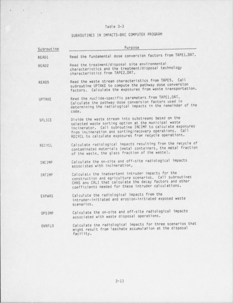
or . calculating .the . radiological -impacts resulting from a particular wastetreatment- or disposal operation. In some instances, the calculation of ~ a >
particular radiological impact is begun in one subroutine and completed in another.
subroutine. In addition, parameters defined in a particular way in one subroutine
may sometimes be used dif ferently in another. The subroutines are executed by
program IMPACTSB.EXE that calls the subroutines in the order needed to read theinput data, make the dose calculations, and write the output data.
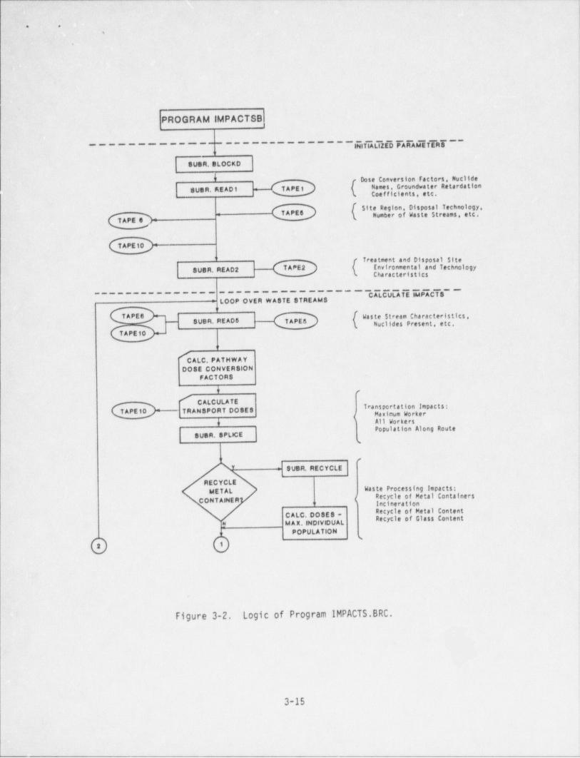
The subroutines included in Version 1.0 of the IMPACTS-BRC computer program andthe calculations performed by . these subroutines are listed in Table . 3-3. A
diagram showing the code structure and logic flow is presented in Figure 3-2.
l
..
i)1
3-12
- -- __ __ _ __-_ - _ _ - _ _ -
- _ - _ - _ - _ - _ _ - _ - _ _ _ _ _ __ ._. _ __ _ - _ _ _ __
!.; : .-
,
Table 3-3 i
9:
SUBROUTINES IN IMPACTS-BRC COMPUTER PROGRAM
n .,
Su broutine Purposei
I
READl' Read the fundamental: dose conversion factors from TAPE 1.DAT.
- READ 2 Read the treatment / disposal ' site environmentalcharacteristics and the treatment / disposal technologycharacteristics from TAPE 2.DAT.
READ 5 Read the waste stream characteristics from TAPE 5. Callsubroutine UPTAKE to compute the pathway dose conversion j
factors. Calculate the exposures f rom waste transportation. .|
UPTAKE Read the nuclide-specific parameters from TAPE 1.DAT.Calculate the pathway dose conversion factors used indetermining the radiological impacts in the remainder of thecode.
SPLICE Divide the waste stream.into substreams based on theselected waste sorting option at the municipal wasteincinerator. Call. subroutine INCIMP to calculate exposuresfrom incineration and sorting / recovery operations. CallRECYCL to calculate exposures from recycle operations.
RECYCL Calculate radiological impacts resulting from the recycle ofcontaminated materials (metal containers, the metal fractionof the waste, the glass fraction of the waste).
INCIMP Calculate the on-site and off-site radiological impactsassociated with incineration,
INTIMP Calculate the inadvertent intruder impacts for theconstruction and agriculture scenarios. Call subroutinesCHNS and CALI that calculate the decay factors and othercoefficients needed for these intruder calculations.
EXPWAS Calculste the radiological impacts from theintruder-initiated and erosion-initiated exposed wastescenarios.
i
OPSIMP Calculate the on-site and off-site radiological impactsassociated with waste disposal operations.
OVRFLO Calculate the radiological impacts for three scenarios thatmight result from leachate accumulation at the disposalf acility.
.
1
3-13
- - _ _ _ _ _ _ _ _ _ _ _ _ - _ _ _ - _ _ - _ _ _ _ _ _ _ _ _ _ _ - _ _ _ _ _ _ __ _ - . _ _ . _ - _ _ _
_ . - _ _ . - -- - _ _ _ _ _ _ _ _ - _ _ _ - _ _
. .
t
,
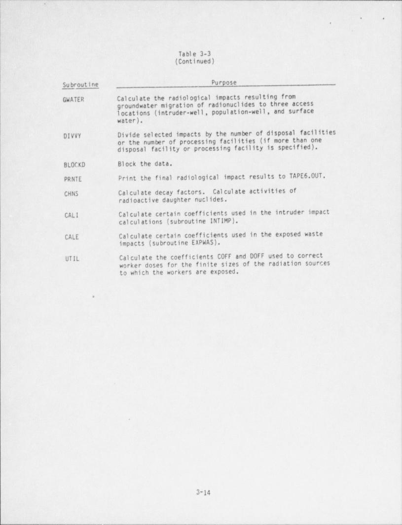
' Table 3-3(Continued)
.
Su broutine Purpose
GWATER. Calculate the radiological impacts. resulting fromgroundwater migration of radionuclides to three accesslocations (intruder-well, population-well, and surfacewater).
'
DIVVY Divide selected impacts by the number of disposal facilitiesor the number of processing facilities (if more than onedisposal facility or processing f acility is specified).
BLOCKD- Block the data.
PRNTE Print the final radiological impact results to TAPE 6.00T.
CHNS- Calculate decay factors. Calculate activities of.radioactive daughter nuclides.
CALI Calculate certain coef ficients used in the intruder impactcalculations (subroutine INTIMP).
CALE ' Calculate certain coefficients used in the exposed wasteimpacts (subroutine EXPWAS).
UTIL Calculate the coefficients C0FF and DOFF used to correctworker doses for the finite sizes of the radiation sourcesto which the workers are exposed.
.
*
3-14
- - __ _._ ___ - -__ _ __________ _ ____ ___ ___ _ - __ - ____-_ _- --- _-__-__ _ _ _ _ _ _ _ = _ - _ __ .._
c----- __ _ _ __ __
i <t;
..
m .
i..,
t,,
|.
PROGRAMIMPACTSB
y y___ - - - - - - - - - - - -- - - - _ _ _ _ _ _ _ _ _ - - .
SuSR.8LOCxDi
4 - Dose Conversion Factors Nucilde|'
| SU8R. READ 1 TAPEt Names, Groundwater RetardationCoefficients, etc.
.I
[SiteRegion.OlsposalTechnology.TAPE 6 \, Number of Waste Streams, etc. !
TAPE 8 ,e
( Treatment and Olsposal $lteEnvironmental and TechnologySUSR.REA02 TAPE 2Cha racteristics
_ _.- - - - - - - - - - - - - - - ------- _--___--.
- LOOP OVER WA8TE STREAM 8
Was e o hara '" ''SUBR. READ 6 p ,n e
-
TAPE 10
f. C ALC. PATHW AYDOSE CONVERSION
FACTOR 8.
S e
CALCULATE Transportation impacts:TAPE 10 TRANSPORT DO8ES Maximum Worker
44 All Workers
Population Along RouteSUSA. SPLICE
i4
ir e
SUBR, RECYCLE |
RECYCLE,
METAL Waste Processing Impacts *
CONTAINER (Recycle of Metal Containers |Incineration 1,
Recycle of Metal ContentCALC.DO8E8 Recycle of Glass Content9 MAX. (NOfVOUAL
POPULATION
|Figure 3-2. Logic of Program IMPACTS.BRC.||
|1
3-15
,. .. ..
. . - - _ - - _ _ _ , - _ _ _ _ _ _ _ _ _ _ _ _ .
.
> '\.-
,. . ..f
e
: i, ' i.,
J
-..
@ C
INCINERATE Y
|SUSR. INCIMPWASTE
h'! CALC. DOSES:,
MAX. WORKERALL WORMER
MAX, INOlVIOUAL
POPULATION
RECYCLE ,METAL SUSR. RECYCLE
CONTENTh
! CALC.DO8ES,M AX. INOlVIOUAL
POPULATION
:
RECYCLE ,OLA38 SUSR. RECYCLE
CONTENTh
[ CALC. DOSES,MA X. INDIVIDUAL
POPULATION
O O
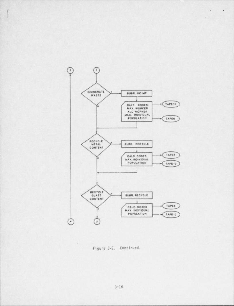
Figure 3-2. Continued.
3-16
- . . . _ _ _ - _ . _ - _ _ _ _ -

- _ _ _ _ _ _ _ - _ _ _ _
,
. ... .
[-
,. ,
.
I
1z-
SU5R. INTIMP
} 'I
Intruder impactst |
SUSR.CHNS ( Construction Doses,
Agriculture Doses
[ UPDATE DECAYCHAIN INOROWTH ,
'LAST NUCLIOE7-
N
P
SUBR,CALI
6
! CALCULATEIN TRUDE R
= :".:' -<EDAGRICULTURE AND
CONSTRUCTION
l[ RADON IMPACT
eO
Figure 3-2. Continued..
|
3-17 :
- - _ - - _ _ _ _ - _ _ _ _ _ _ _ _ _ _ _ _ - _ _ _ _ _ _ _ _ _ _ _ _ _ _ - _ _ _ _ _ . _ __ __ __ _ _ _ _ _ _ _ . _ - _ _ _ _ _
. _ - - - - _ - . _ _ _ _ _
* e
|. .t
. a.
'G G
'SU8R. E X PWA 8
*LAST NUCLIDE ?
Exposed Waste Impacts:Intruder Initiated
Airi Wateru
Erosion InitiatedAlf
SU8R.CHN8 Water
4
[ UPDATE DECAYCHAIN
IGR OW TH
'8U8R.CALE
f# CALCULATEEXPOSED WASTE -
-
SU8R OPSIMP
! C ALC. OFF Disposal Site Operations:MUNICIPAL 8ITE On-site |y
WASTE RELEA8Ep ( All Workers'
Man Worker jF ACILIT Y DO8E8 Off. site iPopulation i
Max Individualn
/CALC WORKER
DOSES
,
1
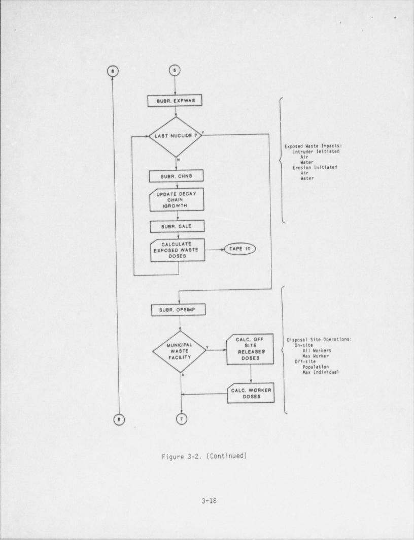
Figure 3-2. (Continued) )
i
I
3-18
. _ _ _ - - - _ - _ _ _ _ .-__ -_.
-.
_ _ - . _ .- _ .- - - _ - .
j. ' .-
-e . .
,
It
s
s
'
O O,..
^ PACKAGED YA8 E WA8TEFACILITY?
\
M w
IC ALC. OFF-81TE/ CALC. OFF-SITEfRELEASES AND RELEASE 8 ANO
DO8ES DOSE 8
fI7 CALC. WORKER CALC. WORKER
DO 8E 8 DOSE 8
I- I
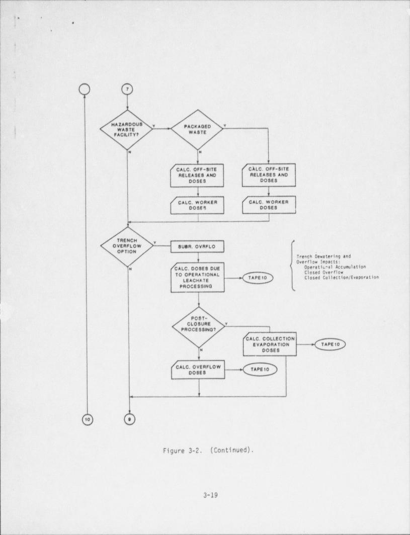
TRENCN #OVERFLOW guen,oynyto
OPTION
fTrenchbe'w'ateringandOverflow Impacts:
7 I Operatic al AccumulationCALC. DOSE 8 DUENClosed OverflowTO OPERATIONAL
TAPE 10 Closed Collection / EvaporationLEACHATE
PROCESSINO s
PO S T-CLOSURE Y
i PROCE88HO7 ||
CALC. COLLECTIONEVAPORATION
!CALC OVERFLOW
| -
1
@ O
Figure 3-2. (Continued).
3-19
i
'_ . . . . _ _ . _ . _ . _ _ _ _ _ _ _ _ _ _ _ . . _ _ _ _ . _ . . . _ _ . _ _ _ _ _ _ _ _ _ _ _ _ _ _ _ _ _ . _ ______a
,_. - . - - -- .- - ._. .,. ..
i. ,
e
|-
i-
#~
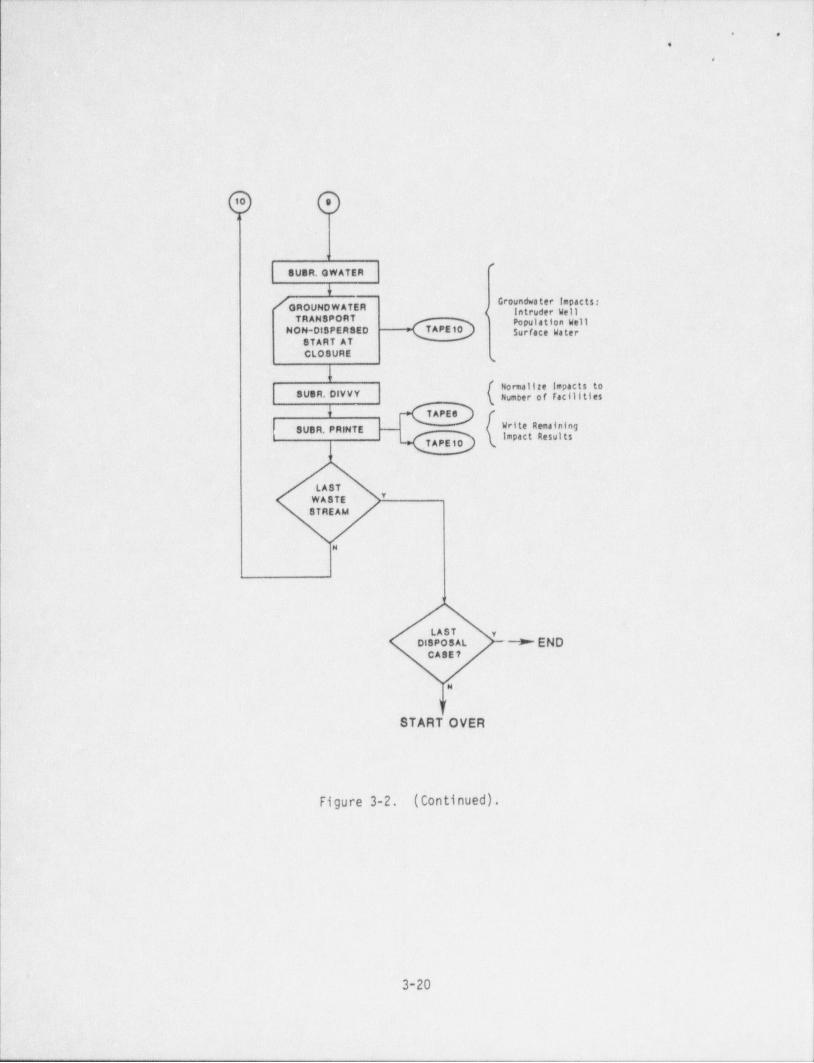
SUOR. 0W ATER
l !
- [OROUNOWATERGroundwater impactst i
( latruder We))TRANSPORT
~
'' I C 8t'FSTAR ATCLO8URE
w
I[ Normalite Impacts to
| ( Number of Facilities| sVOR. DIVVY
' 8UOR. PRINTE - Write Remainingimpact Results
LAST*
WASTESTREAM
N
i
LAST y
Disposal - + ENDCASE 7
N
V
START OVER
i
Figure 3-2. (Continued) .
\3-20
- - _ _ _ _ _ _ _ _ _ _ _ -
- _ _ _ _ . _ _ _ _ _ _ _ - _ _ _ _ _ _ _ _ _ _ _ _ _ _ - _ _ - _ _ _ _ _ _ _ - _ _ _
(
e *,
a
Chapter 4
EXAMPLE ANALYSES AND SENSITIVITY STUDIES
The analysis described in this chapter complements - the sensitivity analysisreported in Reference 3. A series of computer runs were made to determine whichwaste stream and treatment / disposal parameter values result in the largestindividual and population doses from BRC disposal of nuclear power plant wastes.These computer runs were also made to assess the sensitivity of the IMPACTS-BRCcomputer program to changes in waste composition, facility options, and wastetreatment and disposal options.
As ' discussed in Chapter 3, the potential radiological impacts from treatment anddisposal of BRC waste are assumed by IMPACTS-BRC' to be proportional to theeffective radionuclides concentration in the waste being incinerated or disposed.This concentration is determined by dividing the radionuclides inventory in the BRC
waste by the total volume of waste, which is dominated by the non-radioactivewaste volume. Therefore, it is important that VINC (annual volume of non-BRCwaste incinerated) and VANN (annual volume of non-BRC waste disposed) be given
.i
appropriate values.
A survey of electric utilities that operate nuclear power plants was made to {.
,
obtain information about sanitary landfills in their counties. Data collectedincluded landfill capacity, mass of waste received annually, distance from thepower plant to the landfill, and the use of a waste incinerator in the county.Responses were received from 60 percent of the generating stations where nuclear j
power reactors currently operating or seeking NRC licenses to operate are located.Survey respondents indicated that landfill capacities range from about
7,500 tons /yr to over 2,000,000 tons /yr, with an average capacity of almost ,
I300,000 tons /yr. Three-fourths of the landfills designated by the survey
respondents have annual capacities equal to or greater than 60,000 tons /yr.
I
,
4-1
.. . - _ _ - _ _ _ _ _ _ _
_- _ _ _ _ _ _ _ _ _ _ ___ __ _ _ _ _ _ . _ . _ _ _ _
. .
,
Distances from the reactor f,3cilities to the sanitary landfills identified by thesurvey range from 3 miles to 70 miles, with an average distance of 18.5 miles.Approximately 90 percent of the respondents indicated that sanitary landfills arelocated within 25 miles of their nuclear generating stations. ,
!
The computer runs described in this chapter use an annual waste receipt of60,000 tons /yr (54, 430 MT/yr) for a sanitary landfill, and a transportationdistance of 25 miles. Both values are conservative representations of the survey
3data. The non-BRC waste was assumed to have an initial density of 0.27 g/cm ,
5 3resulting' in an initial volume of 2.02 x 10 m /yr. Runs were made assuming that50 percent of the BRC waste was incinerable and that 100 percent of the BRC wastewas incinerable.
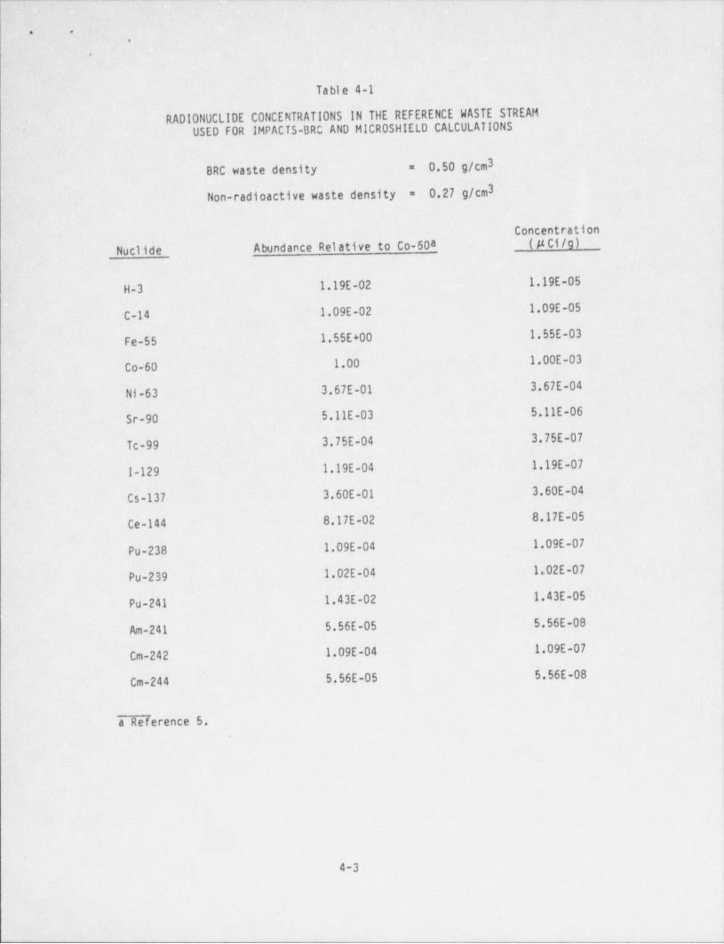
The radionuclides concentrations in the reference BRC waste stream used for thesecomputer runs are given in Table 4-1. These radionuclides concentrations are basedon a Co-60 concentration of 1.0 x 10⁻³ pCi/g. Radionuclides abundances of other
nuclides relative to Co-60 were taken from Reference 5. 100 MT of BRC waste was
assumed to be disposed of annually.
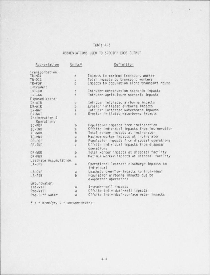
Table 4-2 lists the abbreviations used by IMPACTS-BRC to identify individual and
population doses in the code output.
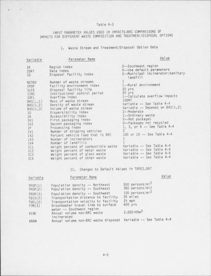
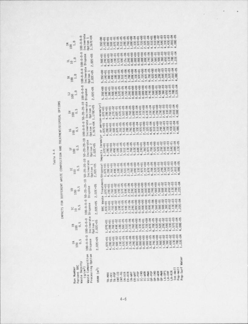
Table 4-3 lists the values of input parameters that were common to the computerruns made to assess the sensitivity of the code to different waste composition andwaste treatment / disposal options. The results of these computer runs are shown in
Table 4-4. Parameters that were varied for these runs included the BRC waste3and 1.0 g/cm ), weight percent of combustible waste (100 weightdensity (0.5 g/cm3
percent and 50 weight percent), percent of BRC waste in a truckload of waste (100percent and 10 percent), waste processing option, and annual volume of non-BRC ;
waste disposed. The two waste processing options evaluated were offsite sanitary f
landfill disposal and combustion at a municipal incinerator followed by landfill I
fdisposal of the ash. Values used for the annual volume of non-BRC waste disposed3included 2.02 x 10⁵ m3/yr, 1.18 x 10⁵ m /yr (50 percent of the non-BRC waste
4 3incinerated prior to disposal), and 3.37 x 10 m /yr (100 percent of the non-BRCwaste incinerated prior to disposal). Incineration was assumed to result in an
|- ash volume that was reduced f rom the initial volume by a factor of six.
4-2
|
_ _ _ _ _ _ _ _ _ _ _ _ _ _ _ _ _ _ _ _ _ _ _ _ _ _ _ _ _ _ _ _ _ _ _ _ _ _ _ _ _ _ _ _ . _ _ _ _ _ _ _ _ _ _ _ _ _ _ _ _ . _ _ _ _ _ _ _ . _ _ . . _ . _ _ _ _ .
- - _ ._ ._ __ _
~
6 e ._9
.a
8
Ta bl e 4-l '
RADIONUCLIOE CONCENTRATIONS IN THE REFERENCE WASTE STREAM'' USED FOR IMPACTS-BRC AND MICR0 SHIELD CALCULATIONS
BRC waste density' =~ 0.50 g/cm3
0.27 g/cm3-Non-radioactive waste density =
Concentration
Nucl ide Abundance Relative to Co-60a ( Ci/g)
H-3 1.19E-02- ~1.19E-05
C-14~ -1.09E-02 1.09E-05
Fe-55 -1.55E+00 1.55E-03
.Co-60 1.00 1.00E-03
Ni-63 3.67E-01 3.67E-04
Sr-90 5.11E-03 5.11E-06,
Tc-99 3.75E-04 3.75E-07
1-129 1.19E-04 1.19E-07
Cs-137 3.60E-01 3.60E-04
Ce-144 8.17E-02 8.17E-05
Pu-238 1.09E-04 .1.09E-07
Pu-239 1.02E-04 1.02E-07
Pu-241 1.43E-02 1.43E-05
Am-241 5.56E-05 5.56E-08
Cm-242 1.09E-04 1.09E-07
Cm-244 5.56E-05 5.56E-08
a Reference 5..
4-3
fL- _ _ _ - - _ - _ - _ _ _ _ _ _ _ _ _ _ _ _
_ _ _ _ - _ _ - - _ _ - _ _ _ _ _ _ _ _ _ _ _ - -
. .
.
.
Table 4-2
ABBREVIATIONS USED TO SPECIFY CODE OUTPUT
Abbreviation ' Units * Definition
Transportation:TR-MAX a Impacts to maximum' transport workerTR-0CC b Total impacts to transport workersTR-POP b Impacts to population along transport route-Intruder:INT-C0 a Intruder-construction scenario impacts
INT-AG a intruder-agriculture scenario impactsExposed Waste:IN-AIR b Intruder initiated airborne impacts
ER-AIR b Erosion initiated airborne impacts
IN-WAT a Intruder initiated waterborne impactsER-WAT a Erosion initiated waterborne impacts
Incineration &Operation: ,
IC-POP b Population impacts from incinerationIC-IND a Offsite individual impacts from incineration
IC-WOR b Total worker impacts at incinerator'IC-MWR a Maximum worker impacts at incineratorOP-POP b Population impacts from disposal operationsOP-IND e Offsite individual impacts from disposal
operationsOP-WOR b Total worker impacts at disposal facilityOP-MWR a Maximum worker impacts at disposal facilityLeachate Accumulation:LA-OPS a Operational leachate discharge impacts to
individualLA-0VF a Leachate overflow impacts to individualLA-AIR b Population airborne impacts due to
evaporator operationsGroundwater:Int-Well a Intruder-well impacts I
.
Pop-Well a Offsite individual-well impacts! Pop-Surf water a Offsite individual-surface water impacts
* a = mrem /yr, b = person-mrem /yr
4-4 |
1
o -- -_ - - - - - - _ _ - - - - - _ --
. _ _ _ _ _ _ _ .___ ._ ___-________ _ _ _ _ _ _ _ _ _ _ _ _ _ _ _ - _ - _ _ _ _ _ -
s:.
.
Table 4-3
INPUT. PARAMETER VALUES USED IN IMPACTS-BRC COMPARISONS OFIMPACTS FOR DIFFERENT WASTE COMPOSITION AND TREATMENT / DISPOSAL OPTIONS
1. Waste Stream and Treatment / Disposal Option Data
Varia bl e Parameter Name Value
IR Region index 2--Southeast regionIDAT Data'index 0--Use default parametersIQ Disposal facility index 2--Municipal incinerator / sanitary
landfill
NSTRD Number of waste streams 1
IPOP Facility environment index 1--Rural environmentILFE Disposal facility life .
20 yrs11NS Institutional control period 20 yrs10FL Overflow index 1--Calculate overflow impactsBAS (1,1) Mass of waste stream 100MT
BAS (1,2) Density of waste stream Variable -- See Table 4-41
BAS (1,3) Volume of waste stream Variable -- Depends on BAS (1,2)10 Dispersibility index 2--Moderate
4
1A - Accessibility index 1--Ordinary wasteIK1 First packaging index 0--Not packagedIK2 Second packaging index 0--Packages not recycledIP Processing index 1, 3, or 4 -- See Table 4-4IX1 Number of shipping vehicles 2 |
IX2 Percent vehicle load that is BRC 100 or 10 -- See Table 4-4IX3 Number of incinerators 1
IX4 Number of landfills 1
ICI Weight percent of combustible waste Variable -- See Table 4-4IC2 Weight percent of metal waste Variable -- See Table 4-4 ,
IC3 . Weight percent of glass waste Variable -- See Table 4-4 I'
IC4 Weight percent of other waste Variable -- See Table 4-4
11. Changes to Default Values in TAPE 2.DAT
Varia ble Parameter Name Value
2TPOP(1) Population density -- Northeast 500 persons /mi
TPOP(2) Population density -- Southeast 300 persons /mi2
TPOP(3) Population density -- Southwest 100 persons /m12
TDIS(2) Transportation distance to facility 25 miles
TVEL(2) Transportation velocity te facility 25 mph
TTM(3) Groundwater travel time to surface 600 yrswater -- Southwest region
VINC Annual volume non-BRC waste 2.02E+05m3incinerated
VANN Annual volume non-BRC waste disposed Variable -- See Table 4-4
1
l'
4-5
|)L _ --------
i!j l
b =
_.
. _
_
e011115555041034102333450t 4
00000000000000000000000- a10+ ++ ++ -0r +
EEEEEEEEEEEEEEEEEEEEEEE+ + + - -- enE0 0no7 54807518693722211943318M 31350352703973055253400I01 ii50 0ct3 52117931113722444124974
_
1 0 np1IO3
._111215565000056012323340 00000000000000000000000e 5
+ + + - - - - - + + + + - - + - - - - - - -0s 0EEEEEEE6EEEEEEEEEEEEEEE- o +0 642097954000094660653820p EL 52051551200008755536172I01 - s 2
1 0t 0164211322000036771413110O
1 2e
01121556504104.5012333450t00000000000000000000000- a15+ + + - - - - - - + - + + - - + - - - - - - -0r 0EEEEEEEEEEEEEEEEEEEEEEE- en+0
0noE 54898613693727 022943718K 31341551703978755253500I01 ii20 0ct0 521211321137236771241741 0 np
1IO2
0 121556500005601232334000000000000000000000000!- 5
+ + + - - - - - - + + + + - - + - - - - - - -0e 0EEEEEEEEEEEEEEEEEEEEEEE- s +0
0o E 54809795400009466065382J 31351551200008755536172I01 - p 20 0s 0
521211322000036771413111 0i1D 2
S 0eN )1tO y111215 5 6 5 0 410 4 410 2 3 3 3 4 5r- a1500000000000000000000000I 0r 0T + - - - - - - + - + + - - + + - - - - -2 en+ /5
- noE e++EEEEEEEEEEEEEEEEEEEEEPO H eEE 235999430l8I00 0ii8 r786727166937a 0 2 7 2 0 6 5 6 7 0 3 9 7 6 1 2 2.I.5 3 7 0 0L 0 2ct7A 1 - np1
n14242233113726111124274-0IOSO 5 1
e o11555504103410233345P
S 0t 4 s
e00000000000000000000000r111- a10+ ++ ++ -I
0 0r +EEEEEEEEEEEEEEEEEEEEEEE+ + - -- enE p+5 86937222t1943318/ no70.ii6T G o02750352703973055253400r786G751N 100
E 0 0ct3 r14217931113722444124974M 1 0np1IO3T y
A /E 0
1 e mr!1!21556514104501233145R e- t
m00000000000000000000000T 0a25+ + + -
2r 0D 5 en+ (
s78698613638467022943483EEEEEEEEEEEEEEEEEEEEEEE+ + + - -N F
4 A 100 0noEt02741551756238755253501- 0 2ii2
4 N 1 - ct0a14221132151413677124141cO 0np
5iO2e I pl T 0 mb I 1 e I
11121556504104501233345a S - tT O a000000000000000000000000a15 lP
s+++ - - - - - - + - + + - - + - - - - - - -2 r 0M 5
oEEEEEEEEEEEEEEEEEEEEEEE- en+O E p786986t3693727022943718C I00 0noE s027415517039787552535000 2ii2E 1 - ct0
D142211321137236771241740np iT 5iO2S _/A 0 tW n1
m11121556500005601232334eT -
t00000000000000000000000N 0 5
a+++ - - - - - - + + + + - - + - - - - - - -2 e 0E 5 eEEEEEEEEEEEEEEEEEEEEEEER D - s +
r78609795400009466065382E I00 0o E
T02751551200008755536172F 0 2 p 20F 1 s
e142211322000036771413110il
O 5D 2t
a11121556500005601232334sR 0 W00000000000000000000000- 5O + + + - - - - - - + + + + - - + - - - - - - -0e 0
CEEEEEEEEEEEEEEEEEEEEEEEF s +50o E 09795400009466065382S C B83751551200008755536172R311T 100 - p 2
C 1 0s 017421132200003677141311A 0i
P 1D 2M e
11121556504104501233345I0t 00000000000000000000000- a15 + + + - - - - - - + - + + - - + - - - - - - -5 0r 0
EEEEEEEEEEEEEEEEEEEEEEE- en+8 8698613693727022943718100 0noE 0274155170397875525350070 ii21 0ct0
0np 14221132113723617124174IO21
111215565000056012323340 00000000000000000000000- 5+ + + - - - - - - + + + + - - + - - - - - - -5 0e 0EEEEEEEEEEEEEEEEEEEEEEEs +A 78609795400009466065382I00 0o E027515512000087555361720 - p 2
1 0s 0 142211322000036771413110t1O 2
nnoo rii ett ty ip a
t sO WCi orR s) pg ) ltfe B n3 mnb emoi 3 ll r
_XCP0GRRTTPORRPORRSFReeuWWSmtccCs mAAONOWONOWPVIun / s (
ct(t c N M0P - AAWWPI WMPI WMO0A - - -ACOCAIINeegee- - TT - - - - - - - - - - - - - - - tppRRRNNNRNRCCCCPPPPAAAnoonrs so N
RPW WP V TTTIIIEIEIIIIOOOOLLLIPPuea ar A__
7m _
||llL
_
. .
.
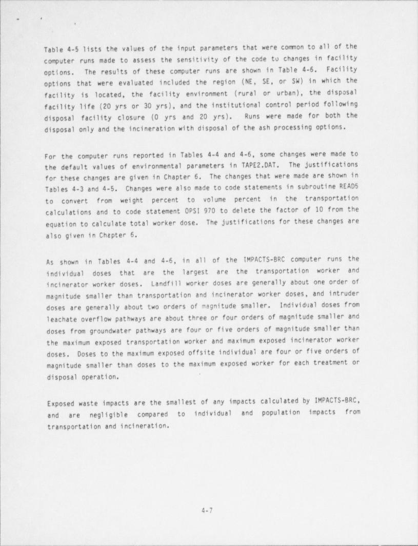
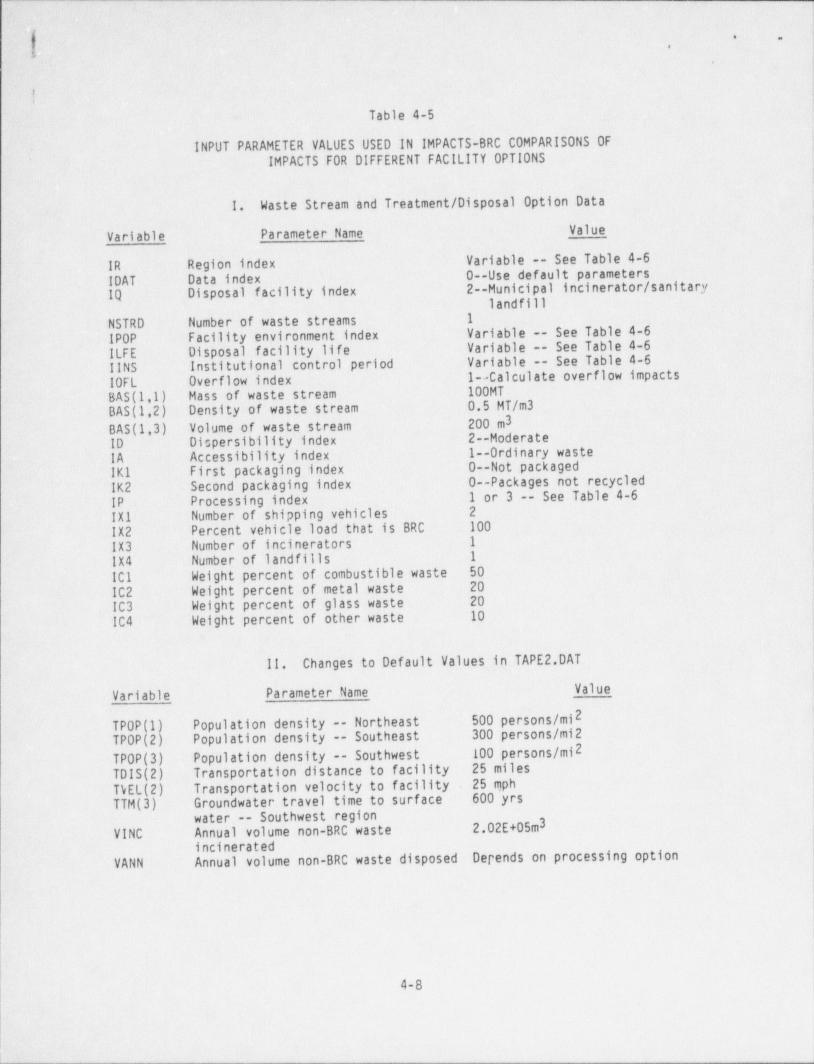
Table 4-5 lists the values of the input parameters that were common to all of thecomputer runs made to assess the sensitivity of the code to changes in facilityoptions. The results of these computer runs are shown. in Table 4-6. Facility
options that were evaluated included the region (NE, SE, or SW) .in which thefacility is. located, the f acility environment (rural or urban), the disposalf acility life (20 yrs or 30 yrs), and the institutional control period followingdisposal facility closure (0 yrs and 20 yrs). Runs were made for both thedisposal only and the incineration with disposal of the ash processing options.
For the computer runs reported in Tables 4-4 and 4-6, some changes were made tothe default values of environmental parameters in TAPE 2.DAT. The justifications-
for these changes are given in Chapter 6. The changes that were made are shown in
Tables 4-3 and 4-5. Changes were also made to code statements in subroutine READ 5
to convert from weight percent to volume percent in the transportationcalculations and to code statement OPSI 970 to delete the factor of 10 from theequation to calculate total worker dose. The justifications for these changes arealso given in Chapter 6.
As shown in Tables 4-4 and 4-6, in all of the IMPACTS-BRC computer runs the
individual doses that are the largest are the transportation worker andincinerator worker doses. Landfill worker doses are generally about one order ofmagnitude smaller than transportation and incinerator worker doses, and intruderdoses are generally about two orders of magnitude smaller. Individual doses from
leachate overflow pathways are about three or four orders of magnitude smaller and- doses from groundwater pathways are four or five orders of magnitude smaller thanthe maximum exposed transportation worker and maximum exposed incinerator workerdoses. Doses to the maximum exposed offsite individual are four or five orders ofmagnitude smaller than doses to the maximum exposed worker for each treatment or
*
disposal operation.
Exposed waste impacts are the smallest of any impacts calculated by IMPACTS-BRC,
and are negligible compared to individual and population impacts from
transportation and incineration.i
4-7
:
- - . _ .___ _ __-___- __ _-___ ___ __ ___ _ _ _
- - _ - _ - - _ _ - _ _ -
i._ ,
* -,.
'
Table 4-5
INPUT PARAMETER VALUES USED IN IMPACTS-BRC COMPARISONS OFiIMPACTS FOR DIFFERENT FACILITY OPTIONS
1. Waste Stream and Treatment / Disposal Option Data
Va'iable Parameter Name Valuer
IR Region index Variable -- See Table 4-610AT Data-index 0--Use default parameters
IQ Disposal facility index 2--Municipal incinerator / sanitarylandfill
NSTRD Number of waste streams 1!
IPOP ' Facility environment index Variable -- See Table 4-6i
ILFE Disposal facility life Variable -- See Table 4-6!!NS Institutional control period Variable -- See Table 4-610FL Overflow index 1--Calculate overflow impactsBAS (l',1) Hass of waste; stream 100MT-
BAS (1,2) Density of waste stream 0.5 MT/m3
BAS (1 ~,3 ) Volume of waste stream 200 m31
ID Dispersibility index 2--Moderate
IA . Accessibility index 1--Ordinary wasteIK1 First packaging _index 0--Not packaged
'IK2 Second packaging index 0--Packages not recycled1 or 3 -- See Table 4-6IP Processing index
.
2IX1 Number of shipping vehiclesIX2 Percent vehicle load that is BRC 100
IX3 Number of incinerators 1
IX4 Number of landfills 1
101 Weight percent of combustible waste 50
IC2 Weight percent of metal waste 20
IC3 Weight percent of glass waste 20
IC4 Weight percent of other waste 10
11. Changes to Default Values in TAPE 2.DAT
Variable Parameter.Name Value
2TPOP(1) Population density -- Northeast 500 persons /m1
TPOP(2) Population density -- Southeast 300 persons /mi2 |
TPOP(3) Population density -- Southwest 100 persons /mi2 ,
|
TDIS(2) Transportation distance to facility 25 miles
TbEL(2) Transportation velocity to f acility 25 mph
TTM(3) Groundwater travel time to surface 600 yrs|water -- Southwest region
VINC Annual volume non-BRC waste 2.02E+05m3;
incineratedVANN Annual volume non-BRC waste disposed Depends on processing option
it4
4-8
. _ _ _ _ _ _ _ _ - _ _ - _ _ _ _ _ _ _ _ _ _ _ _ _ _ _ _ _ _ _ _ _ _ _ _ _ _ _ _ _ _ _ _ _ _ ___
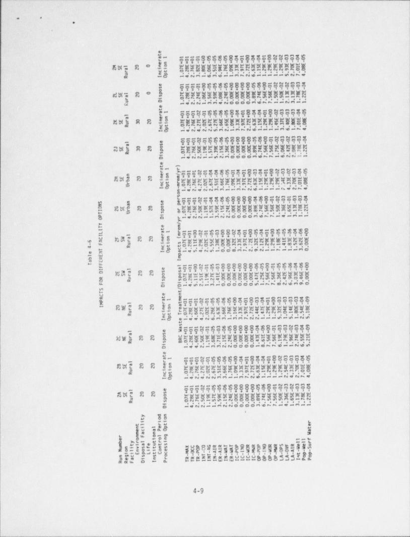
_ _ - _
w a
.
.
.v.- [email protected]@,--ONNMMee??? ? 999 99 9??? 9999oI' S.
e
WWWWwWW"5.W.$.W.WW~.W.W.W~.EWW~.WW.W.WEW% 2- ~ . E. O. .
m DOO~ Me N.v.Le e . . e . e e e
C, NM-eMw--M~No-----wN~na -O| \,
----@,,8.,@@@@ .$-~N~MM.99. o 9999??? 995
WE~WW"8.W.WW*8.5.*.5.W.~W.".WWW.W.We~.WWW 8
"dW~ 2 3,8. N.N C
NN-MM~CL -
e e e e e e e e= O - .ee
NOOOOMen~--NM--u .W --ONMMMnw
~~-N-ww.e@- !????9 999.-??? 99999 97% tCWWWWWWW"WgWW**WWWwg*~.WagWgMWh R * 239 N "N . 9 *.N E.* ."MN-M~NNE.* "*N
~ B"" .e
- N~ ----M -~
---N-... O!O@ .O-NMNMM.999*9o???99 999? ? 99?*;
W W W ".WeW W W " 5 5.,5.W. ~W W W, W " W. W ~W WW2Wh R 2 aM. 8 . ~ .8 . C. . N.C. ~e ~. S
NMOOOOM .~~~.eNN--M= . e e . .e- . N N - - .ee-O
.w e
L 3N- m---N-....-.-CM.-@NMNM,# 'L
??????? ??*??o79 ?9o999: *5'EWWWWWWWWW"WWWWW***WWWWW
C Og w" t " " t-
~& f O N ~ N.O.. . ~ $.M.e.~. .N.N. E...M ~.O. O.eD ----~.eN~.e e . .e eC-eN,NNMM--M-NO '
---N-wwWm$$O@veo-NM-MMWi
? 99999o *aa???9999*E
L W W W W W W W W W *8 8 8 8 *.W~.W W W.W W W.W~.W~.*ww
S SWE 2 2 a ,
O O ~ ~ - m - N. .. . M. W. ,- O _. e e e e e e e e e e . .
m L-WNN--MNNOOOOMWNN-e-M-- ii
O Oh 1
- %!
H & E
J e- L-- N-@MO N*-Oft- @@@de i|- y @
00000 !- - L ECO 00000 C. O. O O O. Q CU 43e O O WC w+ + 8 + + + s +
N N
, a U- - O N. eN o c.M 8 O0.M M.e..M. .N.N. .. m.. . O6 3 M
- C n v a e e e e . e e . e
-M -O m-4@4N@-DOOM ~NmN--h--MMOGW $
D M u==
9 W !
---ON-eMOCOOOOWWC-eWWWWO {h 6
4.O0000000000000.900000000 -6- - .
+ + + + + ++++ + +O w3 O O ,
NH L N N O OWWWWWWWW WWWWWWWWWWWWWWW D G Ghm--mk-O CQOOND@@@NDMDQO M .m . EON-@ .N.w O .OO.OO4N.w.DM.WWOe.oe e e . e e e e e e e e e e e
w OMt@N-M-COOOOO@-hkMN@M@C,
OM %
M |HU G C
u.o000000908W08MW-CMMMMW@0 0. 7 9 0 0 0 0 0 0---N-mm@@-A 0
OW. O O L.r - +++++ +C WWWWWWWWWWWWWWWWWWWWWWWW-NE L N N C O LNWONNWMWWWMNNwNemNwWOWs5 **
H O.N.c N O N.W e.h. .M e.h.w w N. N.M O .m.m. ea UW *** e e e e e eC G-O W-WWWNWMM-MMNNN---W-m-NW
,i&eMM--N-@M@@C OW@C-MMNMMO
++4
UW L O O O UWWwWWWWWWW WWwWWWWWWWWW- i
COMA @@mmWwm |NK D N N n aNWOOPM-meOD O N D. @e e @eh. . N. O .O O.4 % @ @ - h.@e% f N .N ,* e e e e e e .e e e e e
-WWN-MMNNOOOO-ONNW--Nwm'
OG
N- ---N-@@@@ 4-O99-QNMMMe@tC ???99 999+9???9?Y999999ew% C O WWWWWWWWWWWWWWWWWWWWWWWNM L N N C O
N W O N N N - W W m M N N M W m m m W M O. C. Qw
5 em
O N N N O. w e W ~ C M m h W - N N N m M P .& UM e e e e e e e e e e e e . e a e e e eC n -*NWNNMM--MhN@----N9NkW-O
---N-@@@@OOOO@@C-NMNMMQ$?$ 99999 ? 99? 999
4We O OWWWWWWWWWWWWWWWWWWW@WWWWNML N N O WCWQmNmmeOOOOmWWWO mMEN
3 n,M O N N W - W W - N O.O O O.W.N e.m W M.W. eN. Ng e e e e e e e e e e e e e . e
-WNN--MNNCOOOMWNh-9-M--C6
> %C9 0Oe we L
M- bM WCw - @ Q u
U eEO 94 C 3
L E O-@G O e DC -%
AL- WLe --LMe 4G DM M
18 2. . . < < 2 5. k. . b2 2 2. . @. f. C. O.3 3. M.,NO$ ;
E C C O. ,as,vv - . . . ... !--W
, OCov gWgEEEEEmuuuugCOOs -OO qAAh4 Ce C L
.s .e e m- --W-W----O - m.1|
|1
4-9
_ _ - _ _ - _ _ _ _ _ - _ _ _ _ _ _ _ - _ _ _ . __-___a
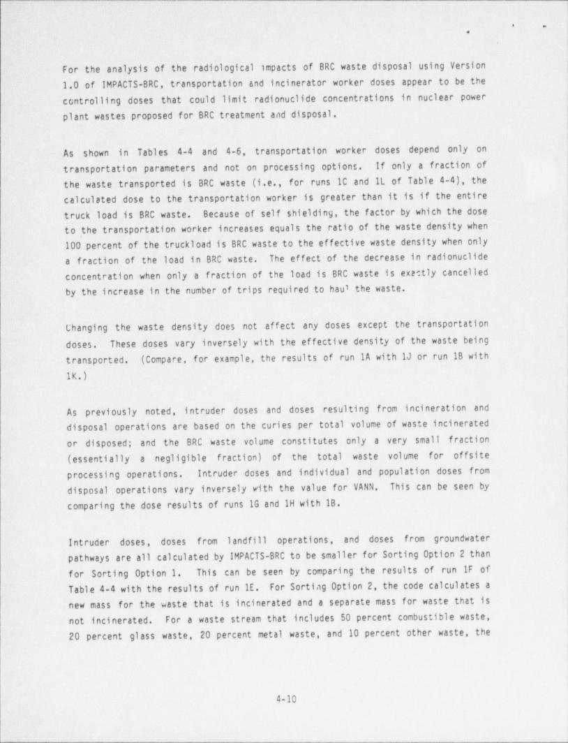
i
..
,
For the analysis o'f''the radiological impacts of BRC waste disposal using Version1.0 of IMPACTS-BRC,' transportation and incinerator worker doses appear to be the
controlling. doses that could limit radionuclides concentrations in nuclear powerplant wastes proposed for BRC treatment and disposal.'
As shown in Tables 4-4 and 4-6, ' transportation worker doses depend only ontransportation parameters and not on processing options. If only .a fraction of |
ithe waste transported is BRC waste (i.e., for- runs.1C and IL of Table 4-4), thecalculated dose to.the transportation worker is. greater than it is if the entire ;
truck load is BRC waste. Because of self shielding, the factor by which the doseto the transportation worker increases equals the ratio of the waste density when100 percent of the truckload is BRC waste to the effective waste density when onlya fraction of the load in BRC waste. The effect of the decrease in radionuclidesconcentration when only a fraction of the load is BRC waste is exactly cancelledby the increase in the number of trips required to haul the waste.
Changing the waste density does not affect any doses except the transportation I
doses. These doses vary inversely with the effective density of the waste being
transported. (Compare, for example, the results of run 1A with IJ or run IB with
1K.)
As previously noted, intruder doses and doses resulting from incineration anddisposal operations are based on the curies per total volume of waste incineratedor disposed; and the BRC waste volume constitutes only a very small fraction
4
(essentially a negligible fraction) of the total waste volume for offsiteprocessing operations. Intruder doses and individual and population doses from
disposal operations vary inversely with the value for VANN. This can be seen bycomparing the dose results of runs 1G and 1H with IB.
Intruder doses, doses from landfill operations, and doses from groundwaterpathways are all calculated by IMPACTS-BRC to be smaller for Sorting Option 2 thanfor Sorting Option 1. This can be seen by comparing the results of run IF ofTable 4-4 with the results of run IE. For Sorting Option 2, the code calculates anew mass for the-waste that is incinerated and a separate mass for waste that is
not incinerated. For a waste stream that includes 50 percent combustible waste,
20 percent glass waste, 20 percent metal waste, and 10 percent other waste, the
4-10
_ _ _ _ _ _ _ . _ _ _ _ _ _ _ _ _ _ _ _ _ _ _ _ _ - _ _ _ _ _ _ _ _ _ _ _ _ _ _
. e
,
.
mass of the waste that is incinerated is calculated to be 0.505 times the mass ofthe original waste stream and the mass of the waste that is not incinerated iscalculated to be 0.495 times the mass of the original waste stream (lines
,
SPLC 500, SPLC 660, and SPLC 760 of subroutine SPLICE). ' Both the incinerator ashand the waste that is not incinerated should go to the landfill for disposal.However, in subsequent intruder, landfill operations, and water pathway dose ,
calculations the code neglects the mass of the waste that is not incinerated. !
This error in the code is corrected in the revised listings for the INTIMP,
OPSIMP, and GWATER subroutines shown in Appendix B.
The sensitivity of the code to changes in the region (NE, SE, or SW), facilityenvironment (rural or urban), facility operating lifetime, and institutionalcontrol period are shown in Table 4-6. For comparison purposes, runs were made
for the disposal only option and for incineration and disposal of the ash. In noinstances do the indicated changes in facility options alter the conclusion that
j
the controlling doses are the doses to transportation, incinerator, and landfill'
workers. Furthermore, the worker doses calculated by IMPACTS-BRC were not affected
by any of the changes made in these facility options.
Because the values used by the code for some hydrologic and meteorologicparameters are region specific, changing the region where the facility is locatedresults in changes in calculated doses to offsite individuals and populations.For the northeast and southeast regions these differences in doses are small, and
are generally less than an order of magnitude. For the southwest region, the
impacts from groundwater and surface water pathways are much smaller than they arefor the northeast and southeast regions. Population impacts along the wastetransportation routes are proportional to the assumed population densities alongthese routes. j
The dose to the maximum exposed offsite individual from disposal operations(OP-IND) is calculated to be largest for the southwest region. To calculate thisdose, the code uses a site dependent wind velocity (WVEL) in determining thequantity of radioactive material (Q) released to the atmosphere per unit time.However, the atmospheric dispersion factor (Y/Q) which relates this source term tothe rate at which radioactive material is received at the receptor location, andwhich contains the wind velocity in the denominator of the equation, is assumed bythe code to have the same value for all regions. Thus instead of being independent
||
4-11
__ _ - - _ - _ _ - _ - _ _ _ _ _ _ _

I
' ''
1 .
t- ,
of wind velocity, this dose is proportional to wind velocity. Because the defaultvalue for WVEL is greater ' for the southwest region than it is for either thenortheast or southeast regions, values for OP-IND are overestimated for the !-
-11southwest region relative to their values for the other regions.
Some population impacts are observed to increase by exactly one order of magnitudewhen the urban environment is chosen instead of the rural environment. Except for
the population dose from incinerator operation, population impacts are small and )i
an order of magnitude change does not significantly affect the overall results of
the dose calculations.3
.
Leachate and erosion impacts increase when the disposal facility lifetime isincreased. In most i nstance.s , the increase in these impacts is directlyproportional to the increase in facility lifetime. Operational or intruder
impacts are not affected by changes in facility lifetime. |f
Intruder impacts increase if the institutional control period is decreased or setequal to zero. Intruder impacts are affected by radioactive decay of the. waste .f
that is assumed by IMPACTS-BRC to occur only during the period of institutional -
cont rol . The justification for this assumption is that an intruder might contact j'l
waste that had been disposed of during the last year of operation of the landfill.
|Ii
i
j
|
1
4-12!
-- _ _ _ _ - -
-. _ _ _ _ _ _ - _ _ - - _ _
.. .,,
.
L
i-
Chapter 5
CONSERVATISM 5 IN THE CODE
It- is customary for government agencies that regulate the production, use, . ordisposal of radioactive materials to employ computational models and default inputparameters that are generally very conservative. The IMPACTS-BRC computer program
. is no exception. . Most of the nuclide-specific data in TAPE 1.DAT and much of thegeneric ' environmental and facility data in TAPE 2.DAT are from NUREG/CR-3585.However, some changes - have been made to these generic data to increase the
conservatism of the IMPACTS-BRC results. As noted in the IMPACTS-BRC User's
Guide: "The ' supplied (input data) values are very conservative, but may beappropriate when the uncertainty in more realistic values is very high."
Conservatism in the methodology for calculating radiological impacts and in thedefault values of some input parameters are considered in this chapter. Changesare recommended in some cases- where more realistic assumptions or values could
justifiably be used. Conservatism in the calculation of external gamma doses
from transportation, incineration, and landfill disposal are described firstbecause these are the most important dose pathways for nuclear power plant wastes.However, conservatism in the calculation of inadvertent intruder and groundwater
impacts are also identified for completeness..
5.1 TRANSPORTATION IMPACTS
5.1.1 Transportation Worker Dose
The external gamma dose to the transportation worker who drives the truck thathuuls the waste to the incinerator or landfill is based on a pathway doseconversion factor (PDCF) that gives the exposure rate 1 meter above soil having aninfinite thickness and infinite lateral extent, and contaminated uniformly with a
3given radionuclides concentration (Ci/m ). Corrections are made for the density of
the waste being transported and for the finite lateral extent of the waste source(i.e., the dimensions of the truck). As shown in Figure 5-1, the correction
5-1

- _ _ _ _ _ _ _ _
. .,
.
i
\
p~ . ,
/
/ \ O// /
i /r2/ /,
/ O\ ,' 3,
N N / M\
Figure 5-1. Exposure Geometry for Transportation Worker Dose.
5-2
- - _ _ _ _ _ _ _ _ -
. .
,
.
factor for the finite lateral extent of the transport vehicle models the truck as j
a disk source of infinite thickness and finite radius. When the driver is in thecab he is exposed to a disk source of 2 m radius and when he is at the side of thetruck he is exposed to a source of 4 m radius. For transportation of the waste toa municipal incinerator or sanitary landfill the dose calculation assumes that the .
worker spends two hours in the cab of the truck and 1/2 hour in the vicinity ofthe side of the truck during each trip. For transportation to a hazardous wastetreatment facility the assumed driver exposure times are 5 hours in the cab and1/2 hour at the side of the truck during each trip.
This driver exposure model embodies several assumptions that may be conservative.These include the dimensions of the disk source used to model the truck, the factthat no credit is taken for the shielding provided by the truck body or the cab,and the time spent by the driver in the cab and in the vicinity of the truck.
A typical garbage truck has dimensions of 7 f t x 7 f t x 14 ft long (2.14 m x 2.14m x 4.27 m long). The radii assumed for the disk source model correspond to truckdimensions that are almost a factor of 2 greater than those of a typical garbage
truck.
The transportation worker dose calculated using IMPACTS-BRC was compared with thedose calculated using a microcomputer adaptation of the mainframe code ISOSHLD (6).
ISOSHLD calculates gamma exposures from shielded gamma sources. It has solution
algorithms for 14 different geometries, including point, area, and volume sources,and can accommodate as many as five shield regions that are specified by the user.Point-kernel integration is used to estimate the doses from rectangular solid
sources.
For the ISOSHLD dose calculations the transport vehicle was modeled as a 7 ft x 7ft x 14 ft rectangular solid. Two sets of runs were made. In one set of runs no
Icredit was taken for the shielding provided by the metal truck sides, in a secondset of runs the waste was modeled as being enclosed in a 1/8-inch thick steel box.The dose per trip was calculated on the basis that the transportation workerspends two hours 1-meter away from the 7 ft x 7 ft face of the load and 1/2 hour 9
1 meter away from the 7 ft x 14 ft side of the load.:
I
|
5-3 |
!
-___
. . ..
* ~..
.
Comparisons of the IMPACTS-BRC and ISdSHLD transportation worker dose estimates ar
shown in Table 5-1. Oose estimates were made for two cases: one in which 11percent of the waste in the transport vehicle is BRC waste and a second case ...,
which 10 percent of the waste is BRC waste. To determine the dose per trip'
calculated by IMPACTS-BRC, the maximum worker dose, TR-MAX, was divided by the
number of trips per vehicle required to transport the waste.
The results in Table 5-1 reveal that the IMPACfS-BRC transportation worker doseestimates are in good agreement with the ISOSHLD dose estimates based on the same
driver exposure times. The IMPACTS-BRC results are therefore consideredsatisf actory for this' application. Because the major isotope in the referencewaste stream is Co-60 that decays with the emission of two high energy (1.17 MeVand 1.33 MeV) gemma rays, little . reduction in transportation worker dose isobserved when the shielding provided by the 1/8-inch thick truck walls is included
in the ISOSHLD calculations.3
Assuming an average truck speed of 25 mph, the time required to haul waste the 25miles from a nuclear power plant to a sanitary landfill should typically be about
one hour. If o.ily BRC waste is transported (i.e., no other waste pickups), theexposure time used in IMPACTS-BRC to calculate the dose to the worker who haulswaste to the sanitary landfill may be conservative by about a f actor of two. If atruck makes multi ple pickups and the power plant waste is one of the firstpickups, the driver exposure time might be greater than that assumed forIMPACTS-BRC.
5.1.? Population Doses
| Two factors that have a major influence on the calculation of the population dosefrotn BRC waste transportation are the population density alor.g the transport routeand the time required to transport the waste from the reactor station to thetreatment or disposal location. Both of these parameters are given conservative
values by IMPACTS-BRC.
!
|
5-4
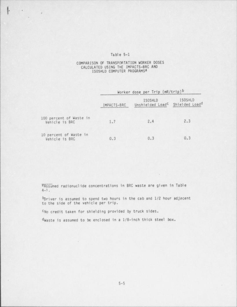
. .
,
e
i
.
Table 5-1
COMPARISON OF TRANSPORTATION WORKER DOSESCALCULATED USING THE IMPACTS-BRC AND
ISOSHLD COMPUTER PROGRAMSa
Worker dose per Trip (mR/ trip)b
ISOSHLD ISOSHLD
IMPACTS-BRC Unshielded Loadc Shielded Loadd
100 percent of Waste inVehicle is BRC 1.7 2.4 2.3
10 percent of Waste inVehicle is BRC 0.3 0.3 0.3 i
dAssumed radionuclides concentrations in BRC waste are given in Table4-1.
bDriver is assumed to spend two hours in the cab and 1/2 hour adjacentto the side of the vehicle per trip.
cNo credit taken for shielding provided by truck sides.
d aste is assumed to be enclosed in a 1/8-inch thick steel box.W
|
.
5-5
- _ _ _ _ _ _ - _ _ _

- -- - . __.
. .:,
*:
|.
The population densities used by IMPACTS-BRC for the three reference regions are:1
2Northeast Region: 2,280 persons /mi
2Southeast Region: 610 persons /mi
2Southwest Region: 60 persons /mi
County population densities were obtained for each county containing a nuclearpower plant using 1986 updates of 1980 census data. These county population
densities are summarized in Table 5-2 for the nuclear power stations in the threereference regions. For reactor stations in the northeast, county population
22 to a low of 51 persons /mi . . Thedensities range from a high of 1,459 persons /miaverage county population density for the 19 generating stations in the northeast
2region is about 402 persons /mi . For reactor stations in the southeast, county2 to a low of 23population densities range from a _ high of 913 persens/m1
persons /mi . The average county. population density for the 21 generating stations2
2in the southeast region is about 202 persons /mi . Thus the population densities
assumed in IMPACTS-BRC for both the northeast and southeast regions appear to be
conservative by factors of about 2 to 5.
2The average county population density for the southwest region is 101 persons /mi2with a range of 25 to 233 persons /mi . This value considers only the portion of
Orange County, California that is in the area of the San Onofre nuclear station.
To determine population exposures, IMPACTS-BRC assumes a transportation time offive hours to a sanitary landfill or municipal incinerator. This is based on anassumed distance of 100 miles to the treatment or disposal site and an averagetruck speed of 20 mph. (Note that the transport time assumed for the population
exposure calculations is different from the transport time assumed for the workerdose calculations.) As indicated in Chapter 4, a transport time of one hour orless is probably typical of 90 percent of the trips that would be required to haulwaste from a reactor site to a sanitary landfill.
5-6
'
_ _ _ _ _ _ _ _ _ _ _ _
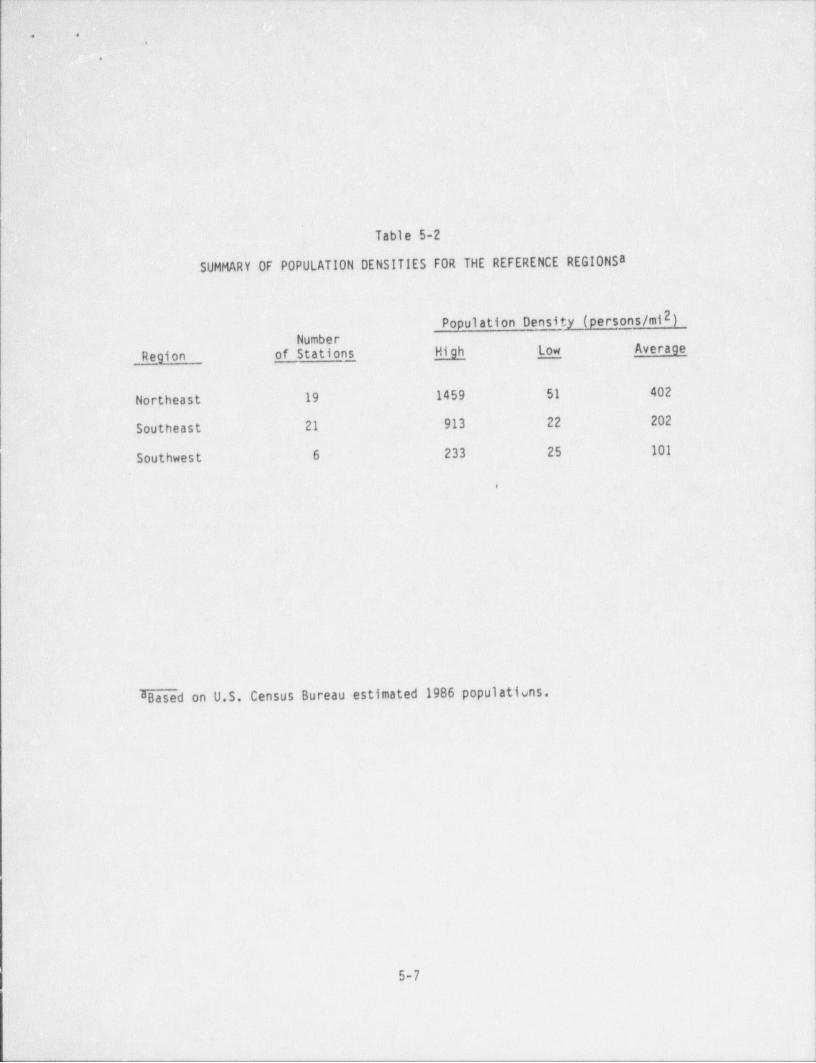
- - - - .
||
* *.
. \
||
|.,1
1
I
{
Table 5-2
SUMMARY OF POPULATION DENSITIES FOR THE REFERENCE REGIONSaj
2Population Density (persons /mi )Number
.
Region of Stations High Low Average !
Northeast 19 1459 51 402
Southeast 21 913 22 202
Southwest 6 233 25 101
,
8 Based on U.S. Census Bureau estimated 1986 populations.
!|
|
||
5-7
7_ - _ _ _ _ _ _ _ _ _ ______ _____ _,_____ _____ _ _ _ . ..
I !
[ ]
|; -.
'
1.
!
|To determine population exposures for transportation of waste to a hazardous wastetreatment facility, IMPACTS-BRC assumes a transportation time of about 3 hours.
|| This is based on an assumed distance of 100 miles to the incinerator and an
average truck speed of 35 mph.' '
5.2 INCINERATOR WORKER AND DISPOSAL SITE WORKER IMPACTS
The radiation dose to workers' at an incinerator or a disposal site includesThe externalcontributions from dust inhalation and from external gamma exposure.
gamma dose is estimated to be about four orders of magnitude greater than the dosef rom dust inhalation and is therefore the controlling dose for these workers.Especially in the case of the worker at the incinerator, modeling assumptions madein estimating the external gamma dose result in very conservative estimates of
this dose.i
One conservative assumption made in modeling the worker dose from both municipal
incinerator and hazardous waste incinerator operation is that the incineratorworker is exposed to an infinite rather than a finite source of external
' radiation. In modeling the external gamma dose for both the transportation workerand the landfill worker, the source of external exposure is assumed to be finite.
As noted in Section 5.1.1, the external gamma dose is based on the exposure rate1 meter above unif ormly contaminated soil having an infinite thickness and
infinite lateral extent. For both the transportation worker and the landfill
worker a correctiot for the finite size of the source is made by multiplying by acorrection factor, C0FF (defined as CF on page 3-6 of NUREG/CR-3585). Use of thiscorrection factor is appropriate at the incinerator and would reduce the estimateddose to the incinerator worker by a factor of 2 to 4, depending on the radius of
the disk source used to model the finite dimensions of the radiation source toiwhich the worker is exposed. !|
Assumptions made in modeling the dose to the maximum exposed worker at the sanitarylandfill are equivalent to assuming that this worker moves from one work station to
another during the year. (The assumption that workers rotate assignments during ;
the year is not made in modeling the dose to workers at the hazardous waste I~
i
disposal site.) Thus, the dose to the maximum exposed worker at the sanitary |1
landfill is actually an average dose. No assumption about workers rotating work
.
5-8
I
_ - - -
. ,
,
.
assignments is made in modeling the dose to the maximum exposed worker at anA
. incinerator. This worker (the residue handler) is assumed to spend the entire work
year (40 hrs per week for 52 weeks per year) at the station where ash is removed-from the incinerator, and he is always 1 meter from the waste.
I|
5.3 INTRUDER IMPACTS l
For the nuclear power plant waste stream, impacts from inadvertent intruders areabout two orders of magnitude less restrictive than impacts from the
transportation and incineration pathways considered in Sections 5.1 and 5.2. 3
Consequently, less attention was paid to them. Nonetheless, sc<.e conservatism jwere noted in the intruder scenario calculations and they are identified in this .
j;|section.
Persons who intrude on the disposal site after it is closed are assumed to be'exposed while engaged in construction and agriculture activities at the site.Modeling of these activities by the IMPACTS-BRC computer program is typical ofother models used for intruder scenarios, i
In calculating the radiation dose received by an intruder, IMPACTS-BRC assumesthat radioactive decay occurs during the period of institutional control .followingsite closure before the intruder arrives on the site. However, no credit is takenfor radioactive decay during the operating lifetime of the facility. Not taking
credit for decay during the operating period is equivalent to the assumption thatintrusion involves the waste last disposed at the site and conservatively neglectsthe possibility that intrusion might involve waste disposed earlier during thedisposal facility operation. If the BRC waste is disposed at a uniform rate duringa 20-year operating lifetime, taking credit for the decay of Co-60 during thisperiod would result in an intruder dose from this isotope that is a factor of threelower than if no credit is taken for radioactive decay during operations. Takingcredit for the decay of Cs-137 during the 20-year operating period would result ina dose from this isotope that is only 0.B as great as if no credit is taken fordecay. For the isotopic concentrations given in Table 4-1, the dose to intruderswould be reduced by about a factor of two.
5-9
_ _ - _ _ _ _ _ _ _ _
__ . _ _ _ _ _ _ _ _ _ _ _ _ _ _ _ _ _ _
* *.
.
5.4' GROUNDWATER IMPACTS
The _ groundwater pathway is- about four orders of _ magnitude less restrictive than_
the transportation and incineration pathways for the nuclear power plant wastestream. Consequently, conservatism in this pathway are = of lesser interest.However, for completeness some of- the conservatism in this pathway 'are
identified.
First, the contact time fractions are set to unity, so that the waste is alwaysassumed to be saturated with water, even for low infiltration rates. Second, it
is assumed that a constant amount of each isotope is leached every year, eventhough the basis of the leaching model specified that a constant f raction of eachisotope be leached annually. This results in an overestimate of the peak annual
doses because of the way nuclide quantities from each sector are summed toapproximate an areal source term.
1
i
||
5-10
4

. .,
,
t
Chapter 6
CORRECTNESS OF CODE EXECUTION
There are a few places in the IMPACTS-BRC computer program where calculational or
programming errors appear to have been made. There are also instances where thedefault values in TAPE 2.DAT might be changed to make them more consistent withrequirements for modeling the BRC treatment and disposal of nuclear power plantwastes. Errors in the code and inconsistencies in TAPE 2.DAT values tre identifiedand briefly described in this chapter. Recommended changes to improve the code
execution are described.
A listing of the IMPACTS-BRC source code subroutines, with recommended changes, is
given in Appendix B. The lines where coding changes are made are identified in
Appendix B with an asterisk in the f ar right column.
6.1 TRANSPORTATION WORKER DOSE
The dose to the transportation worker who drives the truck hauling BRC waste tothe incinerator or disposal site is calculated in subroutine READS. In subroutineREADS, the fraction of the load that is BRC waste is represented by the variableA1. Thus:
ISPC (1,9),
100
However, Al is used with dif ferent meanings in different statements of subroutineREADS, being used sometimes to represent a volume f raction and other times torepresent a weight fraction.
6-1
'- - -- __
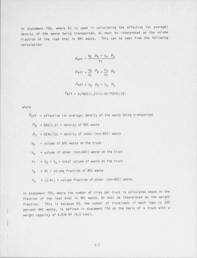
- . - _ _ _ . - - - - - . . - - _ - - _ - . - - - - _ - _ - . - - - _ _ - - - - - - - - - - - - - - - - _ - - - _ - - - - - - - - -- _ - - - - -
,
6. .,
g .
e
' In statement - 700, where ' Al is . used in calculating the . effective (or average)'
- density; of the ' waste being ' transported, Al must be interpreted as the - volume j-
fraction 'of the ' load that is BRC waste. This can be seen from the following
calculation:
VB PB + Vo PoPeff *
VT
Peff . N PB + h ' Po'
vt VT
Peff = f PB PB+fo o
Peff = Al* BAS (1,2)+(1-A1)* DEN 1(lQ)
where
Peff = effective (or average) density of the waste being transported
P = BAS (1,2) = density of BRC wasteB
Po = DEN 1(IQ)'= density of other-(non-BRC) waste
= volume of BRC, waste on the truck'VB
V = volume of other (non-BRC) waste on the trucko
VT "VB + Vo = total volume of waste on the truck
fB = A1 = volume fraction of BRC waste
fo = (1-A1) = volume fraction of other (non-BRC) waste.i
in statement 750, where the number of trips per truck is calculated based on the
'i. fraction of the load that is BRC waste, Al must be interpreted as the weight
fraction. This is because A3, the number of truckloads if each load is 100 j
percent BRC waste, is defined in statement 730 on the basis of a truck with aweight capacity of 4.534 MT (5.0 tons). ;
i
]' |
6-2,i:y
_ _ . - _ - - _ _ _ . _ _ _ _ _ _ _ _ _ _ _ _ _
_ _ _ _ - _ . _ . _ _ _ ,
. .,
.
Since Al cannot represent both the volume fraction and the weight fraction of theload that is BRC waste (since the BRC and non-BRC wastes may have differentdensities), changes should be made in subroutine READ 5 to provide a consistentinterpretation for A1. It appears more logical, as well as simpler, to changestatement 730 to define the truck capacity as 16.0 m3 and to allow Al to be thevolume fraction of BRC waste in statement 750. Statement 730 becomes
A3 = BAS (1,3)/16.0 ;
and the remaining statements in subroutine READ 5 can be left as they are.
3The following justifications can be given for using a truck capacity of 16.0 minstead of 4.534 MT.
e Capacities of waste hauling (i.e., garbage) trucks are normallygiven on the basis of volume rather than weight.
e 16.0 m3 is a typical value for the volume of waste in a garbagetruck.
If 100 percent of the load is BRC waste (dry active waste with ae
density of 0.5 g/cm3) the weight of the load would be 8.0 MT. Thisis a reasonable weight to be hauled and would not result in thetruck being overloaded.
3If 10 percent of the load is BRC waste with a density of 0.5 g/cme
and the remainder of the load is nonradioactive waste with a ,
3density of 0.27 g/cm the weight of the load would be 4.69 MT.
6.2 LANDFILL WORKER DOSEI
Doses to sanitary landfill workers are calculated by subroutine OPSIMP. The
methodology on which the statements of this subroutine are b& sed is described |
in Section 5.2 (p. 5-6) of NUREG/CR-3585( 4_) . Personnel requirements at thelandfill are discussed in Section 5.2.2 (p. 5-7). The reference landfill for
the IMPACTS-BRC dose calculations is assumed to occupy 25 acres and to employ
only one worker who performs all of the functions (foreman, gatekeeper /weigher, equipment operator, and laborer) required at the landfill. The !
|
|.
k
6-3
..
- - _ _ _ _ _ _ - _ --
._ _ _ ____
4
* '
|.
|*
I|'
l
fractions of this worker's time spent on each task and the radiologicalimpacts of each task are determined by extrapolation from a larger 250-acrelandfill assumed to employ 10 people. Because there is only one worker, themaximum worker dose, average worker dose, and cumulative worker dose are allequal and are obtained by summing the doses to 10 workers and then dividingi
I by 10.
1
i The reference landfill for the industry petition is assumed to have an annualcapacity of 92,300 m /yr and to operate for 20 years. This would require a3
landfill area of about 90 acres. Using the NUREG methodology to determine
landfill worker requi rement s gives the result that four workers are required,and they would still have to rotate assi gnments to cover all of the
responsibilities at the landfill. Thus the methodology used in IMPACTS-BRC
to determine the maximum landfill worker dose, which is equivalent to
assuming that workers rotate work assignments, is appropriate. Statement 980'
of OPSIMP was therefore used without modification to calculate the maximumworker dose for the reference 90-acre landfill.
However, the use of statement 970 as it stands to calculate the total workerdose is not appropriate for the larger landfill. Removing the factor of 10
from the denominator of statement 970 results in an estimate of the
! cumulative worker dose at the 90-acre landfill that is conservative by abouta factor of 2.5.
I
6.3 INCINERATOR WORKER DOSE
Doses to incinerator workers are calculated by subroutine INCIMP. The
methodology used by IMPACTS-BRC in estimating incinerator worker doses isdescribed in Section 4.3 (p. 4-12) of NUREG/CR-3585. Personnel requirements
at the incinerator are discussed in Section 4.3.2 (p. 4-14). The reference
municipal incinerator is assumed to be a 500 ton / day facility and is
characterized as being typical in size and design of older incinerators stillin operation. A workforce of 26 operating personnel (not including
management and office personnel) is postulated to operate the facility. The
worker who receives the largest radiation dose is the residue handler who. removes the ash from the incinerator. In IMPACTS-BRC this residue handler is| assumed to spend his full work time (40 hours per week for 52 weeks per year)
|
|1
6-4?
I
- _ _ _ _ _ _ _
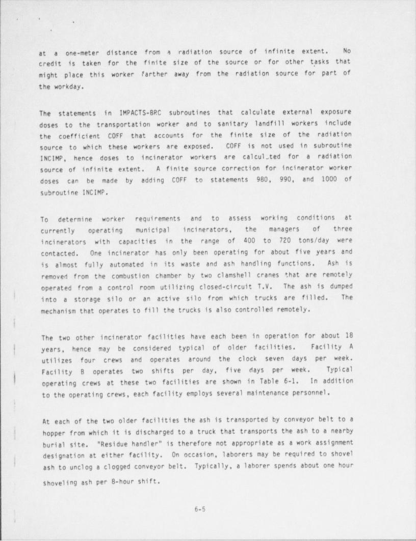
_ -_-_____. ._ _ _ _ - _ .
|* ' -.
|.
!
at a one-meter distance. from a radiation source of infinite extent. No-
credit is taken for the finite size of the source or for other t, asks that
might place this worker farther away from the radiation source for part ofthe workday.
The statements in IMPACTS-BRC subroutines that calculate external exposuredoses to the transportation worker and to sanitary landfill workers include'
the coefficient C0FF that accounts for the finite -size of the radiationsource to which these workers are exposed. C0FF is not used in subroutineINCIMP, hence doses to incinerator workers are calcul;ted for a radiationsource of infinite extent. A finite source correction for incinerator workerdoses can be made by adding C0FF to statements 980, 990, and 1000 of |
subroutine INCIMP.
To determine worker requirements and to assess working conditions at
currently operating municipal incinerators, the managers of three
incinerators with capacities in the range of 400 to 720 tons / day werecontacted. One -incinerator has. only been operating for about five years andis almost fully automated in its waste and ash handling functions. Ash isremoved from the combustion chamber by two clamshell cranes that are remotely
operated from a control room utilizing closed-circuit T.V. The ash is dumped,
! i nto a storage silo or an active silo from which trucks are filled. The
mechanism that operates to fill the trucks is also controlled remotely.
The two other incinerator facilities have each been in operation for about 18
| years, hence may be considered typical of older facilities. Facility A
utilizes four crews and operates around the clock seven days per week.Facility B operates two shifts per day, five days per week. Typical
operating crews at these two facilities are shown in Table 6-1. In addition f
to the operating crews, each facility employs several maintenance personnel. ,
At each of the two older facilities the ash is transported by conveyor belt to a I|
-1hopper from which it is discharged to a truck that transports the ash to a nearby1
burial site. " Residue handler" is therefore not appropriate as a work assignment )
designation at either facility. On occasion, laborers may be required to shovel
ash to unclog a clogged conveyor belt. Typically, a laborer spends about one hour
shoveling ash per 8-hour shif t.
6-5jr
. _ _ _ _ _ _ - _ _ _ ______-_________ _ _ -
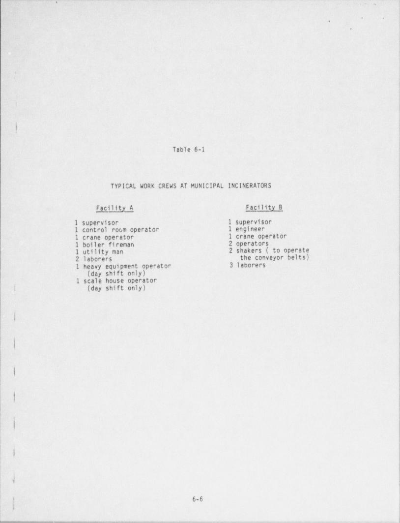
.. .., _ _~_ . _ _ . _ _ - _ . . - __ _
,_ ,
i:
|t... .,
1,,
' *
.
1 y.
+ g
. . .:
e
, [. - ., i .'
;j'.o
:),,
~
Table 6-1
TYPICAL WORK CREWS AT MUNICIPAL INCINERATORS
- Facility A Facility B
:1 supervisor. 1 supervisor1' control roc,m operator 1 engineer:
l' crane. operator. I crane operator2 operators-'l~ boiler fireman--~2 shakers:( to operate1 utility man
'the conveyor' belts).2-laborers .
3 laborers.:
l'. heavy equipment operator,
(day shift only)-.
I scale house operator
|[ {. day shif t only)(
.;|;
I
:\,
,I
s
6-6-
-__-___:____:_____ _. __
- _ _ _ _ _ _ _ _ _ _ _ _ _ _ _ _ _ _ _ _ _ _ _ _ _ - _ - _ _ _ _ _ - _ - _ _ _ - _ _ _ _ _ - _ _ _ - _ _ _ - -
~' '
,
.
The " residue handler" dose calculated by IMPACTS-BRC greatly overestimates theeven for workers at older' dose to the maximum exposed incinerator worker --
facilities. To reduce the conservatism in this estimated dose and account for thefact that laborers at an incinerator perform a variety of tasks, subroutine INCIMPmay be modified to incorporate the assumption that workers at. the incineratorrotate assignments. This modification has been made in the code revisions shownin Appendix B. The ef fect 'of this change is equivalent to having the maximumexposed worker spend about one-third of his time at a distance of one meter-fromthe ash and the remainder of his time at greater distances from radiation sources.
Even though IMPACTS-BRC appears to overestimate the number of workers needed tooperate a municipal incinerator, and hence the cumulative incinerator worker dose,no change was made to the total number of workers at the facility.
With these changes, the estimated maximum worker and cumulative worker doses forincinerator operation are considered to be conservative by about a factor of threeor more.
6.4 INTRUDER DOSE
Intruder doses are calculated by IMPACTS-BRC in subroutine INTIMP. The
| methodology used in estimating intruder doses is described in Section 6.2 (p. 6-6)
of NUREG/CR-3585. The site design and operation factor, f , which denotes thed
dilution of the waste with soil due to particular disposal practices, is defined- as the product of EMP (the waste emplacement efficiency) with RMIX (the cover
mixing efficiency). However, in estimating the intruder dose for the
f intruder-construction scenario, RMIX is not used. Since RMIX has values of 0.59
for sanitary landfill disposal and 0.41 for hazardous waste disposal, this has theeffect of increasing the conservatism in estimates of the intruder-constructiondose by about a factor of 2. The justification given in NUREG/CR-3585 for not
including the cover mixing efficiency in the intruder-construction dosecalculation is that the intruder is assumed to spend most of his time at thebottom of the excavation.
t! E
I
.
' 6-7
_ ___ _ ____ i

- _ _ . _ - _ _ _ __ _ _ - _ _ _ _ _ _ _ _ - _ - _ _ _ _ _ _ _ _ -
< .
,
'
1
This appears to be an extremely conservative interpretation of construction. )practics by. an individual building a house. In digging the foundation, about 40
-)i- percent of' the intruder's time would be spent removing the top cover which is ]
Iconsidered to be dirt unmixed with waste. When digging the hole, the intruderwould likely- employ a backhoe or front-loader and would sit in a metal cab whichwould place him some distance from the sides . and bottom of the excavation andwould :also provide shielding from exposure to gamma radiation. If the intruder
employed a backhoe he would be above and outside the hole during the digging !
process. He would not stand in the bottom of the hole and dig with a shovel. )i
intruder dose calculations are inherently conservative since no credit is taken j
for radioactive decay of the waste during the operating period of the disposalfacility. To increase the reasonableness of the intruder-construction scenario !
while still retaining a measure .of conservatism, the factor RMIX may beincorporated in the statements for calculating the intruder-construction dose. Asshown in Appendix B, RMIX has been included as a multiplier in statements 420 and
430 of subroutine INTIMP.
6.5 DOSES BASED ON SORTING OPTION 2
Sorting Option 2 separates waste into a fraction that is incinerated and afraction that is not incinerated. The fraction 'that is not incinerated ispresumed to be disposed of directly at the landfill. However, in subsequent dosecalculations for the intruder, the landfill worker, and the groundwater pathways,the waste stream fraction that is not incinerated is ignored. This results inunderestimates of intruder, landfill worker, and well water doses for SortingOption 2. The radionuclides inventory in the waste stream fraction that is not
;incinerated should be included in the waste disposed at the landfill and in allsubsequent dose calculations. As shown in Appendix B, this correction can be madeby adding the necessary statements in subroutines OPSIMP, INTIMP, and GWATER.
6.6 DOSE CALCULATIONS FOR GROUNDWATER PATHWAYS
Doses from groundwater pathways are calculated by subroutine GWATER. The code''j
uses an incorrect Kd set when sets two through five are requested. This can be
corrected by a minor change to line GWTR440. The constant amount leachcalculation should be replaced with a constant fraction leach calculation. Thisis accomplished by deleting line GWTR700 and mocifying line GWTR890.
.
6-8
...

- _ _ _ - _ _ _ _ _ _ _ _ _ _ _ _ _ _ _ _ _ _
. ,
,
.
6.7 POPULATION DOSES FROM TRANSPORTATION
Population densities along transportation routes and travel distances and truck.
.
speeds used in' calculating population impacts from transportation should conformas nearly as possible with actual conditions for the transportation of nuclear
,
! power plant wastes. The average distance from a nuclear generating station to asanitary landfill that might be used for the disposal of BRC wastes is probably
|less than 25 miles, as determined by the survey of electric utilities described inChapter 4 Average population densities for counties where reactors are locatedin the northeast, southeast, and southwest regions are given in Chapter 5. Based
on these data, the following values of environmental parameters in TAPE 2.DAT areconsidered reasonable, but still conservative, for evaluating the disposal of
! reactor-generated BRC wastes:
: TDIS (1) = 25 milesTDIS (2) = 25 milesTVEL (1) = 25 mph
TVEL (2) = 25 mph
TPOP (1) = 500 persons /mi2
TPOP (2) = 300 persons /mi2,
TPOP (3) = 100 persons /mi2
|6.8 0036 CALCULATIONS FOR THE SOUTHWEST REGION
| In TAPE 2.DAT, the def ault value for TIM (3) (the groundwater travel time from thef acility to surface water) is set equal to zero for the southwest region. The
code will not execute if this region is selected because division by zero isimpossible. A value of TIM (3) for IR = 3 should be selected that is consistentwith the def ault values of TTM(1) and TTM(2) for the northeast and southeastregions.'
| 6.9 CODE CHANGES FOR ONSITE DISPOSAL
Onsite disposal is not an option in Version 1.0 of IMPACTS-BRC. However, onsiteI disposal can be modeled by setting IQ=2 and IP=1 (i.e., by using the sanitary
landfill, disposal only processing option). Because, for onsite disposal, thevolume of BRC waste could be a significant fraction of the total volume of waste
|
disposed, the value used for VANN (annual volume of waste disposed) in TAPE 2.DAT
should be the sum of the BRC and non-BRC waste volumes.
6-9
!
* *
,, , <.,.
Transportation and landfill worker impacts calculated by IMPACTS-BRC would not-have meaning for onsite disposal. There would be no offsite transportation of thewaste.- Workers involved in disposal ' operations would be badged nuclear power
.
plant employees and be classified as radiation workers. If desired, the worker
dose from disposal operations could be estimated.- This would necessitate some,.
' changes to code statements in' subroutine OPSIMP to' account for changes in landfilldimensions, the number of landfill workers, and the fraction of a year spent by a
| worker in disposal operations.
.
'
I
1
!
i
,
i
|
1
6-10
- - - - -
_ _ _ _ _ _ _ _ - _ _ _ _ _ _ _ _ _ _ _ _ _ _ _ _ _ _ ,
o.t
'.
!
REFERENCES
- -
1 1. U.S. Nuclea r Regul atory Commission, " Radioactive Waste- Bel ow
Regul atory Concern; Policy Statement", Federal Register, Vol. 51,-pp. 30839-30847, August 29, 1986. i
|2. Forstom, J.M., and 0.J. Goode, "De Minimis Waste Impacts Analysis
Methodol ogy--IMPACTS-BRC User's Guide 'and Methodol ogy for Radioactive |Wastes Below Regul atory Concern", NUREG/CR-3585, _Vol . 2, Office of
Nucl ear Material Safety and Safeguards, U.S. Nucl ear - Regul atory ;Connission, Washington, D.C. , July 1986.
3. Kennedy, W.E., Jr., et al . , " Critical Review of the. IMPACTS-BRCComputer Program", Prepared by Battelle, Paci fic Northwest ,
JLaboratories for the Electric Power Research Institute, (in press).
4. Oztunali, 0.1., and G.W. Rol es , "De Minimis Waste Impacts AnalysisMethodol ogy", NUREG/CR-3585, Prepared by Dames and Moore for the U.S.Nuclear Regul atory Commission, February 1984.
5. C.F. Smith, et al . , " Bel ow Regul atory Concern Owners ' Group:Radionuclides Prioritization Study; EPRI rept. NP-5671,1988.
6. MICROSHIELD User's Manual, Version 2.0, Grove- Engineering, Inc., !
Washington Grove, Maryland,1985,'
is
i
)=
.
i
|
R-1
.
- - - - _ - - - - - _ - _ . _ _ _ _ _ _

. _ _ - - - - -
|'
. .
e
(|
j li'
|
|
I
,
i
ii
!
!APPENDIX A j
' DATA IN-THE IMPACTS-BRC INPUT DATA FILES
i
!.
,
,
Y
'i! <
| |
1|
1
-- .- .- _ _ _ . . _ _ _ _ _ _ _ _ _ - _ _ _ _ _ _ _ _____________________________]
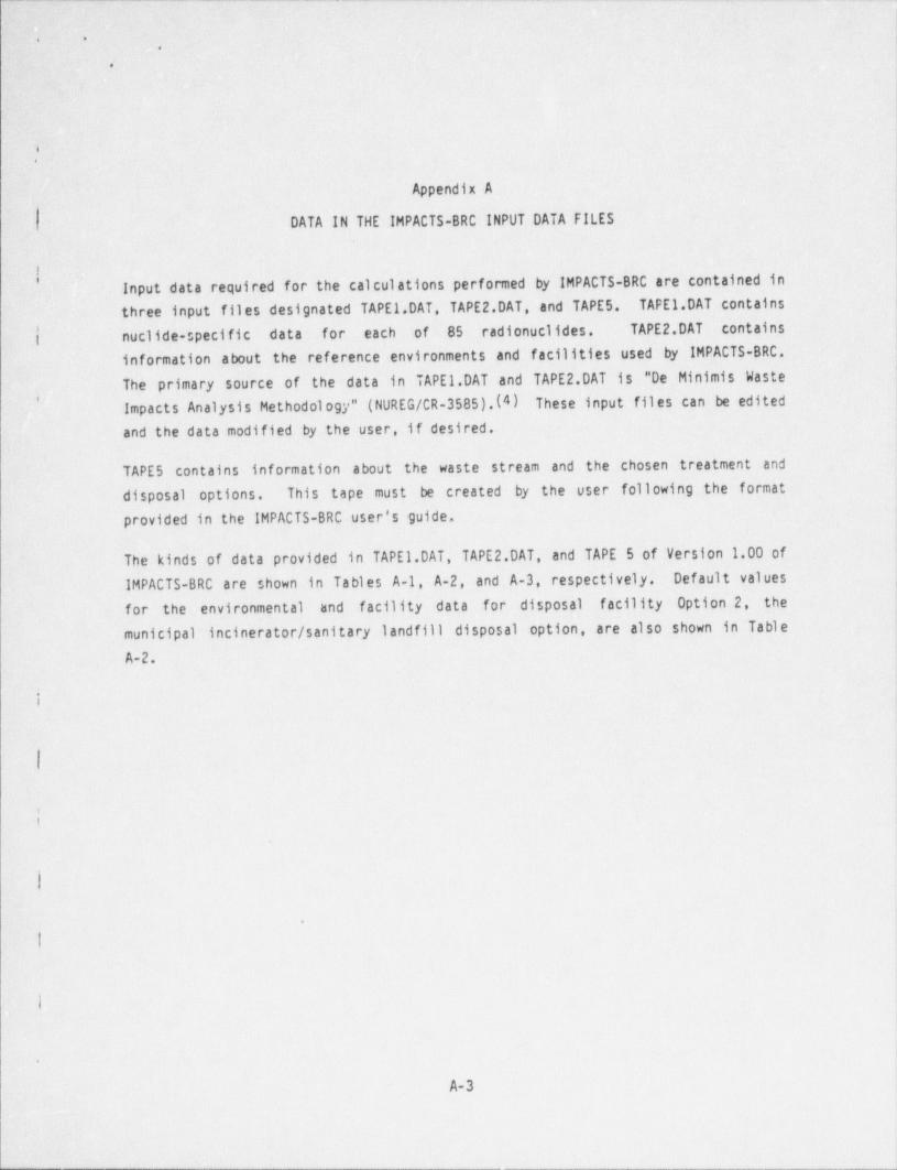
_ _ . ...
- ..
_
.
* *
..
i-1.-
|
Appendix A
DATA IN THE IMPACTS-BRC INPUT DATA FILES"i
iInput data required for the calculations performed .by IMPACTS-BRC are contained in'
three. input files designated TAPE 1.DAT. TAPE 2.DAT, and TAPES. TAPE 1.DAT contains ;
j' nuclide-speci fic data .for each of- 85 radionuclides.. TAPE 2.DAT - contains fi
information about the reference environments and f acilities used by IMPACTS-BRC.
The primary source of' the data in TAPE 1.DAT and TAPE 2.DAT is "De Minimis Waste:,
' Impacts Analysis Methodology" (NUREG/CR-3585).(4) .These' input files _ can be editedand the data modified by the user, if desired.
TAPE 5 contains information about the waste stream and the chosen treatment and -|
disposal options. This tape must be created by the user following. the formatprovided in the IMPACTS-BRC user's guide,
The kinds of data provided in TAPE 1.DAT, TAPE 2.DAT, and TAPE 5 of Version 1.00 of.IMPACTS-BRC are shown in Tables A-1, A-2, and A-3, respectively. Default valuesfor the environmental and ' f acility data for disposal facility Option 2, the
municipal incinerator / sanitary landfill disposal option - are also shown in TableA-2.
i
I
;
I
.
i
.
A-3
- _ - _ _ _ - _ . _ _ _ _ _ _ - _ _ _ _ _ _ _ _ _ _ _ _ _ _ _ -
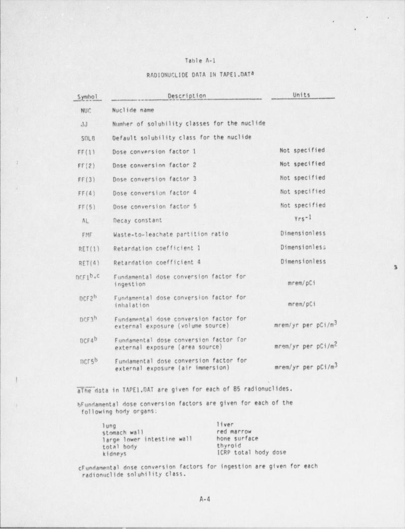
. _ _ _ = _ _
_
bq
. .
,
1.
Table A-1
RADIONUCLIDES DATA'IN TAPE 1. DATAj
J
pit ol ~3_ Des,,cri ption ' Units
'NUC, .Nuclide name
.JJ Number of solubility classes for the nuclide
LSDLG Default solubility class for the nuclide
FF(ll Dose conversion factor 1 Not specified
FF(2) Dose conversion factor 2 Not specified
FF(3) Dose conversion' factor 3 . Hot specifiedI
*
FF(4) Dose conversion factor 4 Not specified
FF(5) Dose conversion factor 5 Not specified
Yrs-IAL Decay constant
FMF Waste-to-leachate partition ratio Dimensionles s
RET (1) Retardation coef ficient 1 Dimensionless ]
RET (4) Retardation coefficient 4 Dimensionless3
bDCFi ,c fundamental dose conversion factor foringestion mrem /pCi
DCF2h Fundamental dose conversion factor forinhalation mrem /pCi
DCF3h Fundam9ntal dose conversion factor for '3external exposure (volume source) mrem /yr per pCl/m
DCF4b Fundamental dose conversion factor for2external exposure (area source) mrem /yr per pCi/m
DCr5b fundamental dose conversion factor forexternal exposure (air immersion) mrem /yr per pC1/m3
l. ,
aTiie~dsta in TAPEl.DAT are given for each of 85 radionuclides.
fundamental dose conversion factors are given for each of the !t J
following body organs *!
lung liver
stomach wall red marrow |
large lower intestine wall hone surfacetotal body thyroid j
kidneys ICRP total body dose,
fundamental dose conversion factors for ingestion are given for each 1
radionuclides solubility class.
A-4
- - - _ _ _ _ _ - _ - . _-.
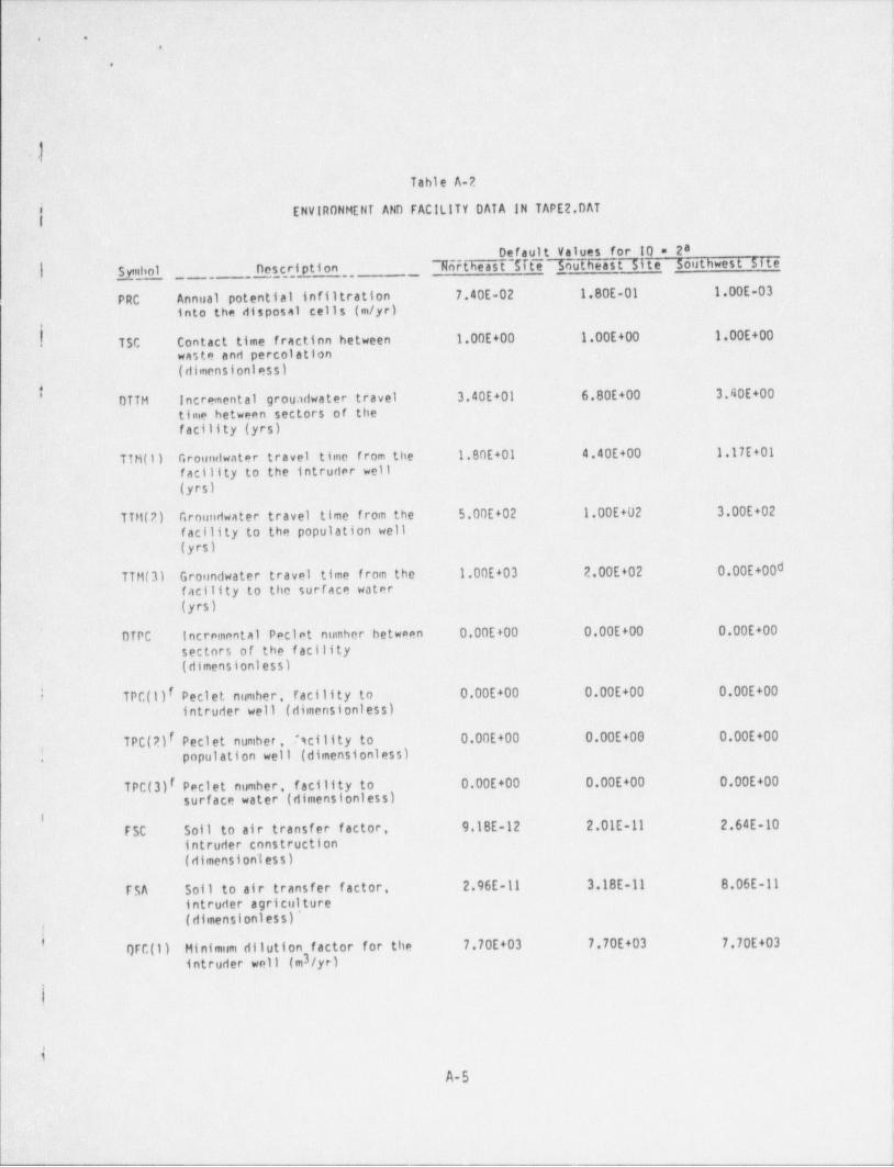
- - - - _ - _ - _ _ _ _ __- -_. . .. .
.i'. ..
- i. y
!
]
il| lTable A-2
f' ' ENVIRONMENT AND FACILITY DATA IN TAPE 2.DAT
Default Values for 10 = 2a.| jnhol psc,ription .
76rtheast $fte7nutheast Site Southwest Site_ .. _
PRC Annual potential infiltration 7.40E-02 1.80E-01 1.00E-03into the disposal cells (m/yr)
-
.
TSC Contact time fraction between 1.00E+00 1.00E+00 1.00E+00'.waste and percolation(dimensionless)
DTTH Incremental groundwater travel 3.40E+01 6.80E+00 3.40E+00
time between sectors of thefacility (yrs)
i
TIM (1) Groundwater travel time from the 1.80E+01 4.40E+00 1.17E+01facility to the intruder well(yrs)
TTH(2) Groundwater travel time from the 5.00E+02 1.00E+02 3.00E+02
facility to the population well(yrs)
TTM(3) Groundwater travel time from the 1.00E+03 2.00E+02 0.00E+00dfacility to the surface water(yrs)
DTPC' incremental Peclet number between 0.00E+00 0.00E+00 0.00E+00'
sectors of the f acility
(dimensionless).
I TPC(l)I Peclet number, facility to 0.00E+00 0.00E+00 0.00E+00
intruder well (dimensionless)
.TPC(2)I Peclet number . T'icility to 0.00E+00 0.00E+00 0.00E+00, population well -(dimensionless).
facility to 0.00E+00 0.00E+00 0.00E+00TPC(3)I Peclet number,(dimensionless)surface water
iFSC Soil to air transfer factor. 9.18E-12 2.01E-11 2.64E-10
intruder construction(dimensionless)
FSA Soll to air transfer factor. 2.96E-11 3.18E-11 8.06E-11intruder agriculture(dimensionless)'
3-l
f)FC(l) Hinimum dilution factor for the 7.70E+03 7.70E+03 7.70E+03intruder well (m3/yr)
| I
tA-5
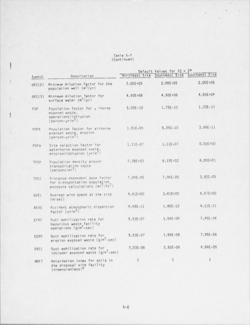
- mrw
. .,
,
.
-
1
4
.
Table A-2(Continued)
Default Values for 10 = 2asymbol _ nescri pt i on Northeast 5tte Southeast Site Southwest Site
~
1
_
0FC(2) Hinimum dilution factor for the 2.00E+05 2.00E+05 2.00E+05lpopulation well (m /yr)
' QFC(3) Minimum dilution' factor for 4.50E+06- 4.50E+06 4.50E+063surface water (m /yr)
POP . Population factor for o'eborne 5.05E-10 1.75E-10 1.33E-11exposed waste.{ operations / intrusion
3(person-yr/m )
POPE Population factor for airborno ' 1.51E-09 5.25E-10 3.99E-11..
exposedwastg, erosioni(person-yr/m )
POPW Site selection factor for 1.11E-07 1.11E-07 0.00E+00
waterbornoexposedwastq).erosion / intrusion (yr/m
TPOP Population density around- 2.28E+03 6.10E602 6.00E+01transportation route
|' (persons /mi2)
T00/. - Distance dependent dose factor 7.06E-05 7.06E-05 3.92E-05 |ifor. transportation popula ion
exposure calculations (mip/f t )2
WVEL. Average wind speed at the site 4.61E+00 3.61E+00 6.67E+00
(m/sec)$-
9.68E-11 1.40E-10 4.11E-11-AX00 Accidentatmgsphericdispersionfactor (yr/m ).
EFAC Dust mobilization rate for 5.53E-07 1 54E-08 7.95E-06 !
ihazarilous waste f acilityoperations (g/m2-sec) {
f
EERO Oust mobilization rate for 5.53E-07 1.54E-08 7.95E-06 i
2erosion exposed waste (g/m -sec)
EREC Oust mohllization rate for 2.03E-06 2.50E-06 6.84E-052intruder exposed waste (g/m -sec)
1
NRET Retardation index for soils in 1 1 1
the disposal site facility(dimensionless)b
!)
14
A-61
l
l_ _ _ _ _ _ _ _ _ _ _ _ _ _ _ _ _ _ _ _ _ _ _ _ . _ _ _ . . _ i
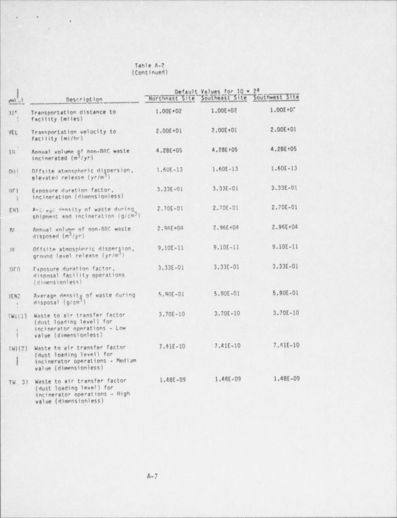
_ _ _ _ _ - _ __ - _ _ _ _ _ - _ _ _ _ _ _ - _ _ _ _ _ - _ _ _ _ _ _ _ _ _ _ _ _ _ _ _
. .
,
.
-|Table A-2 '
(Continued)
Default Values for 10 = 2aent.f 1, Description ~ Northeast 7ftTioutfMast $fte So'Uthwest 5ite
-
31? -Transportation distance to 1.00E+02 1.00E+02 1.00E+0
| ' facility (miles)
VEL Transportation velocity to 2.00E+01 2.00E+01 2.00E+01
facility (ml/hr)
f nnn-nRC waste 4.28E+05 4.2BE+05 4.2BE+05I
Annualvolumeg/yr)Irl
incinerated (m
00| Offsite atmospheric di persion. 1.60E-13 1.60E-13 1.60E-13' elevated release (yr/m- )
nr1 Exposure duration factor. 3.33E-01 3.33E-01 3.33E-01 ,
'
| incineration (dimensionless)
ENI A m gc dansity of waste during 2.70E-01 2.70E-01 2.70E-01 l)
shipment and incineration (g/cm3)
Af- Annual vnluma of non-BRC waste 2.96E+04 2.96E+04 2.96E+043disposed (m /yr)
Offsiteatmosphericdispergion, 9.10E-11 9.10E-11 9.10E-11.nfground level release (yr/m )
:Ur0 Exposure duration factor. 3.33E-01 3.33E-01 3.33E-01tilsposal f acility operations(dimensionl es s)
)EN2 Average densit of waste during 5.90E-01 5.90E-01 5.90E-01 ,
1riisposal (g/cm )i
TWitl) Waste to air transfer factor 3.70E-10 3.70E-10 3.70E-10I(dust loading level) for
i incinerator operations - Lowt, value (dimensionless)
TWl(2) Waste to air transfer factor 7.41E-10 7.41E-10 7.41E-10(dust loading level) for
i4
) incinerator operations - Mediume
value (dimensionless)I
TW; 3) Waste to air transfer factor 1.48E-09 1.48E-09 1.4BE-09
(dust loading level) for ,
!
incinerator operations - liighvalue (dimensionless)
i
A-7
.- _ _ - - _ - _ _ _ _ _ _ _ _ - _ _ _ _ _
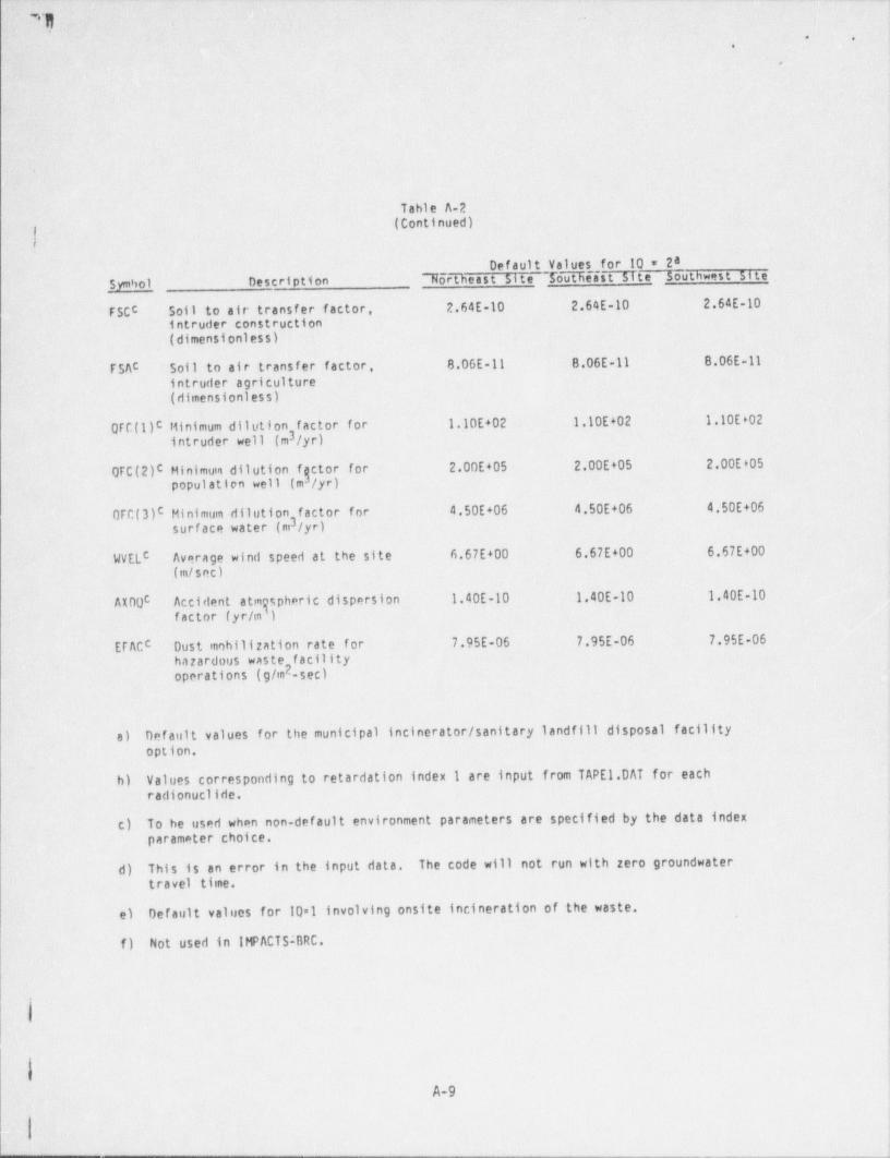
_ _ . _ _ _ _ _ _ - _ . _ - _ - _ - _ _ _ _ _ _ _ _ _ _ _ _ _ _ _ _ _ - _ _ _ _-
.\
**y L .
!' '* *
..
#
- br y
8 .
oTahle A-2.
~ (Continued)-
Default Values for 10 = 2a~
Symbol Description 7orTheast site ToTtTeast site _ Southwest 5ite
FSCc Soil to air transfer factor, 2.64E-10 2.64E-10 2.64E-10
intruder construction(dimensi onl es s)
FSAC Soll-to air transfer factor, 8.06E-11 8.06E-11 8.06E-11-
intruder agriculture(dimensionless)
QFC(1)C Minimum dilution factor for 1.10E+02 1.10E+02 1.10E&O23intruder well (m fyr)
QFC(2)C Hinimum dilution fgetor for 2.00E+05 2.00E+05 '2.00E*05populatten well (m3/yr)
0FC(3)c Minimum dilution factor for 4.50E+06 4.50E+06 4.50E+063surf ace water- (m /yr)
WELC Average wind speed at the site 6.67E+00 6.67E+00 6.67E+00
(m/sec)
Accidentatmgsphericdispersion 1.40E-10 1.40E-10 1.40E-10AXOOC
factor (yr/m )-
ETACC Dust mobilization rate for 7.95E-06 7.95E-06 7.95E-06hararduus waste f acility
2operations (g/m -sec)
a) Default values for the municipal incinerator / sanitary landfill disposal facilityoption,
b) Values corresponding to retardation index 1 are input from TAPE 1.DAT for each i
~|. radionuclides.
c) To be used when non-default environment parameters are specified by the data indexparameter choice.
d) This is an error in the input data. The code will not run with zero groundwatertravel time. i
e) Def ault values for 10=1 involving onsite incineration of the waste. ,
f) Not used in IMPACTS;BRC.
.
4A-9
;
_ . _ . _ _ _ _ _ _ _ _ . _ _ _ _ _ _ _ _ _ _ _ . _ . _ _ _ _ _ .
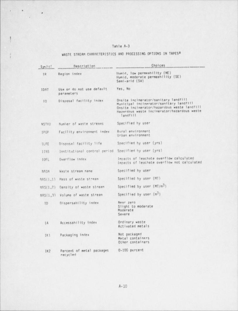
m-- .,
.n e7
.
.
|| ' .h.
- -f1
Table A-3
.|WASTE STREAM CllARACTERISTICS AND PROCESSING.0PTIONS IN TAPE 5a
Syntol Descriptio5' Choices_ _ _
IR Region index llumid, low permenhility (NE)llumid, moderate permeability (SE)Semi-arid (SW)
1DAT Use or do not use default. .Yes, Noparameters
10 Disposal facility index Onsite incinerator / sanitary landfill1 Municipal incinerator / sanitary landfillOnsite incinerator / hazardous waste landfillHarardous waste incinerator / hazardous waste
landfill
NSTRD Number of waste streams Specified by user
IPCP Facility environment index Rural environmentUrban environment
-ILFE Disposal facility life Specified by user (yrs)
llNS Institutional' control period Specified by user (yrs)
10FL Overflow index Impacts of leachate overflow calculatedimpacts of leachate overflow not calculated
BASN Waste stream name' . Specified~by user
BAS (1.1) Mass of waste stream Specified by user (Hf)
ilAS(1.2) Density of waste stream S'pecified by user (HT/m3)
3BAS (1,3) Volume of waste stream Specified by user (m )
10 Dispersability index Near reroSlight to moderate ,
|Hoderate'
Severe
1A Accessability index Ordinary waste-
Activated metals ,
i
!
IKI Packaging index Not packagedHetal containersOther contair.ers
IK2 Percent of metal packages 0-100 percentrecycled
4
|
A-10
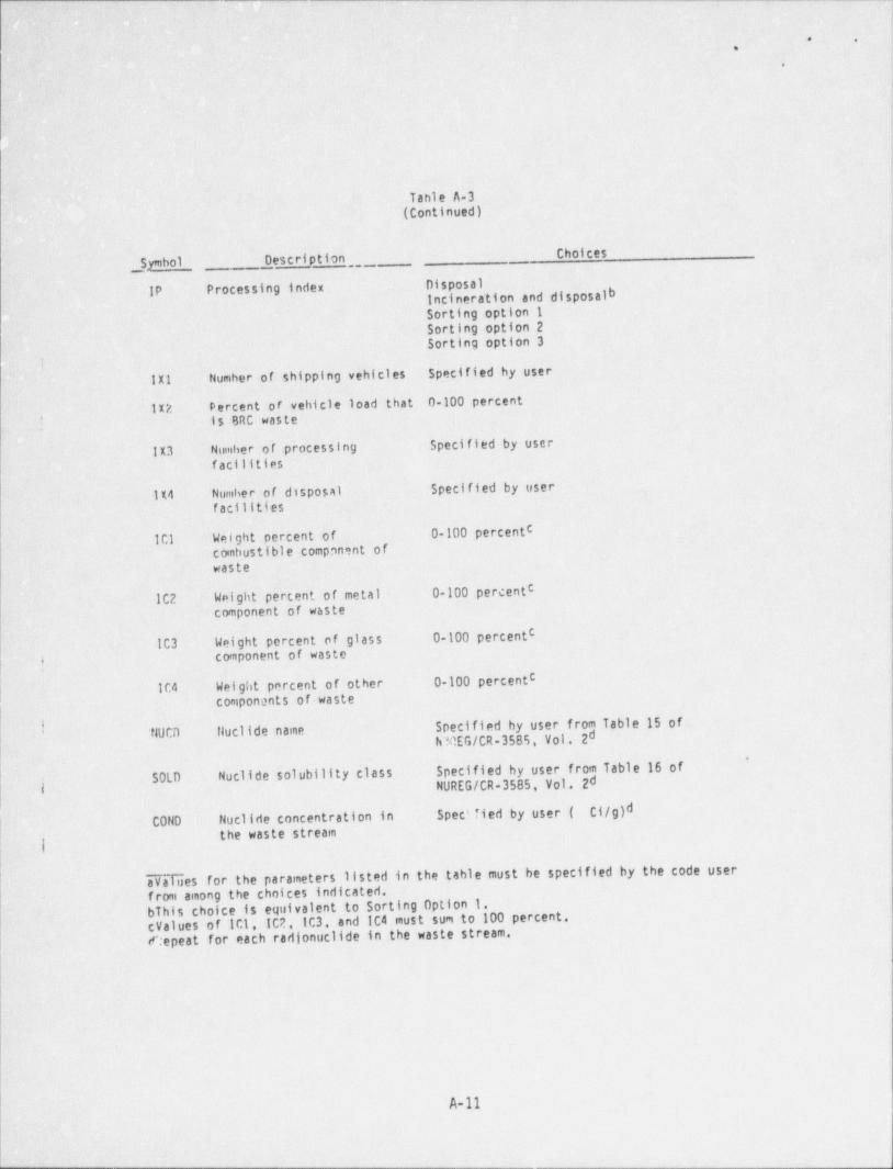
- _. _ _ _ _ - - _ - - - _ - _ _ _ -
.<
* =., ,.
.
!
,
Table A-3.(Continued)
ChoicesSymbol Description
-
IP Processing index. Disposal,. Incineration and disposalbSorting option 1Sorting option 2 ,
|. Sorting option 3
u- :
! !
IX1: Number of shipping vehicles .5pecified by. user-
1X2 percent or vehicle load that 0-100' percentI is BRC waste
IX3 ' Number of processing $pecified by user!
facilities !
'lX4 Number of disposal. Specified by userfacilities
CWeight percent'of, , 0-100 percent1C1
.' combustible component ofwaste
C102 - Weight percent of metal 0-100 percent
' component of waste-'
-
C
IC3 Weight percent of glass 0-100 percent|conponent of wastej |
C
104 Weight percent of other 0-100 percentcomponents of waste
I ~ Specified by user from Table 15 of.' - fl0CD fluclide name dDlEG/CR-358% Vol. 2'
SOLD Nuclide solubility class Specified by user from Table 16 ofdji NUREG/CR-3585. Vol. 2 '
L COND Nuclide concentration in Spectfied by user ( Ci/g)d,
the waste streamg |
aValues for the parameters listed in the table must be specified by the code user'
from among the choices indicated,bThis choice is equivalent to sorting Option 1.cValues of 1C1, IC2.103, and IC4 must sum to 100 percent.
-flepeat for each radionuclides in the waste stream.
1
)
A-11
- - _ _ _ - . . . _ - - . _ _ . _ _ - - . _ _ _ . - . _ _ . _ _ . .. a

_ _ - _ _ _ _ _
l. .
,
4
1
|
)i
l
!
APPENDIX B
PROPOSED SOURCE CODE MODIFICATIONS|
i
k
i
.
I
i
,
.
- - - - _ - - - - - - . _ _ _ _ _ _ _ _ _ _ _ _ . _ _ _ _ _ _ _ _ _ _ _ _
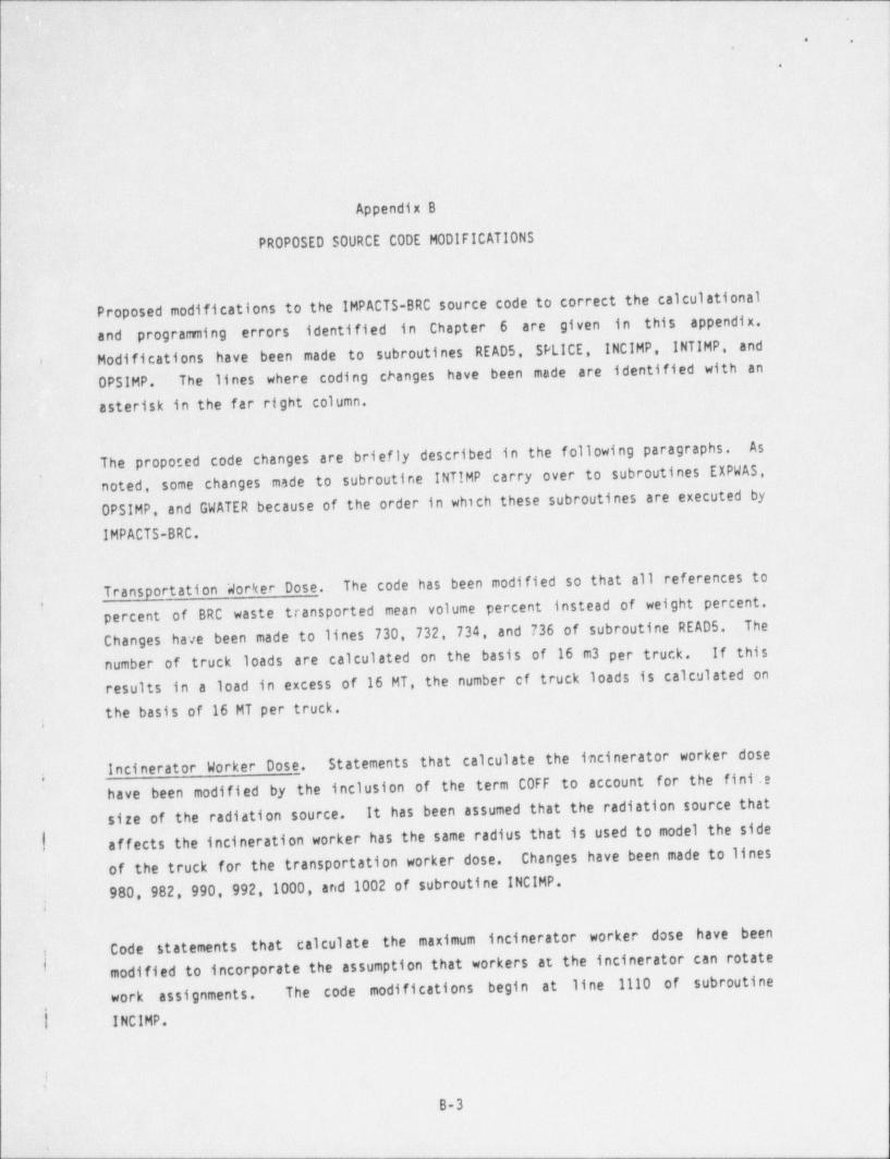
_ _ - _ _ _ _ _ _ _ __- _ _ _ _ . _ _ _ . __. ._ - _ _ - _ - _ _ _ _ _ _ _ _ _ _ _ _ _ - _ _ _ - _ _ _ _ _ _ _ _ _ _ - _ _ _
h* e
,
.
Appendix B
PROPOSED SOURCE CODE MODIFICATIONS
Proposed modifications to the IMPACTS-BRC source code to correct the calculationaland programming errors identified in Chapter 6 are given in this appendix.Modifications have been made to subroutines READ 5, SPLICE, INCIMP, INTIMP, and
*
The lines where coding changes have been made are identified with anOPSIMP.
asterisk in the far right column.
AsThe proposed code changes are briefly described in the following paragraphs.noted, some changes made to subroutine INTIMP carry over to subroutines EXPWAS,OPSIMP, and.GWATER because of the order in which these subroutines are executed by
IMPACTS-BRC.
.
Transportation Worker Dose. The code has been modified so that all references toof BRC ' waste transported mean volume percent' instead of weight percent.percent
Changes have been made to lines 730, 732, 734, and 736 of subroutine READS. Thenumber of truck loads are calculated on the basis of 16 m3 per truck. If this
results in a load in excess of 16 MT, the number cf truck loads is calculated onthe basis of 16 MT per truck.
;
Statements that calculate the incinerator worker doseincinerator Worker Dose.have been modified by the inclusion of the term C0FF to account for the fini .e
;
It has been assumed that the radiation source thatsize of the radiation source.| affects the incineration worker has the same radius that is used to model the side
of the truck for the transportation worker dose. Changes have been made to lines980, 982, 990, 992,1000, and 1002 of subroutine INCIMP.
Code statements that calculate the maximum incinerator worker dose have beenmodified to incorporate the assumption that workers at the incinerator can rotate
work assignments. The code modifications begin at line 1110 of subroutiner
| INCIMP.
iB-3
$
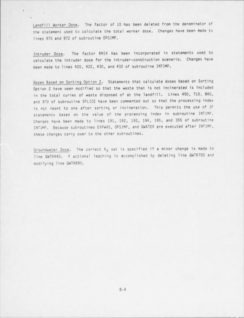
__ _ _ _ _ _ _ _ _ _ - _ _ _ _ _ _ _ _ _ _ _ _ _ _ _ _ _
; . ..
.
I Landfill Worker Dose. The factor of 10 has been deleted from the denominator of( *
the statement used to calculate the total worker dose. Changes have been made to'
', lines 970 and 972 of subroutine OPSIMP.
Intruder Dose. The factor RMIX has been incorporated in statements used tocalculate the intruder dose for the intruder-construction scenario. Changes havebeen made to lines 420, 422, 430, and 432 of subroutine INTIMP.
Doses Based on Sorting Option 2. Statements that calculate doses based on Sorting
Option 2 have oeen modified so that the waste that is not incinerated is includedin the total curies of waste disposed of at the landfill. Lines 450, 710, 840,
and 970 of subroutine SPLICE have been commented out so that the processing index
is not reset to one af ter sorting or incineration. This permits the use of IFstatements based on the value of the processing index in subroutine INTIMP.Changes have been made to lines 191, 192, 193, 194, 195, and 355 of subroutineINTIMP. Because subroutines EXPWAS, OPSIMP, and GWATER are executed after INTIMP,
these changes carry over to the other subroutines.
Groundwater Dose. The correct Kd set is specified if a minor change is made toline GWTR440. Fiactional leaching is accomplished by deleting line GWTR700 and
modifying line GWTR890.
i
iII
I1
1
B-4 |
|
_ _ _ - _ _ _ _ _ _ _ - ______.____________-_-N
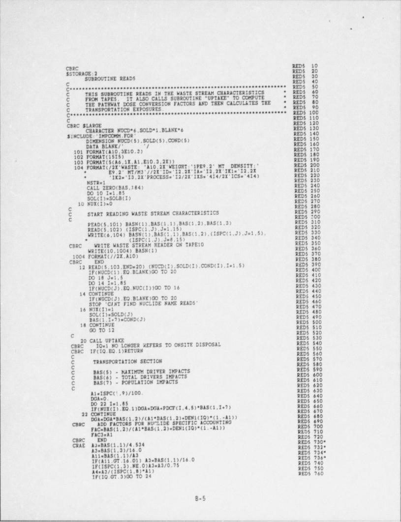
_ - . _ - _ _ _ _ . . _ _ - _ - _ _ _ _
|i
.- .,
. . .
RED 5 10CBRCSSTORAGE:2 -
RED 5 20SUBROUTINE READ 5 REDS 30 4
. REDS. 40 jC .
******************************** REDS 50 I
C' * * * * * * * * * * * * * * * * * * * * * * * * * * * * * * * * * * * * TE STRE AM CH ARACTERISTI CS -REDS 60' I*C THIS SUBROUTINE READS IN THE WAS RED 5 70 ]C- FROM TAPES. IT ALSO CALLS SUBROUTINE " UPTAKE" TO COMPUTE
*
* REDS 80 7C THE PATHWAT DOSE CONVERSION FACTORS AND THEN CALCULATES THE * REDS 90C TRANSPORTATION EIPOSURES. REDS 100.C********************************************************************* REDS 110C .
RED 5 120-CBRC SLARGE
CHARACTER NUCD* 6. SOLD *1.BLANE* 6 RED 5 130-
REDS 140SINCLUDE:'INPCOMM.FOR'DIMENSION NDCD(5). SOLD (5).COND(5) REDS 150 .
DATA BLANE/* */ REDS 160
101 FORMAT (A10.3E10.3) REDS 170REDS 180
< 102 FORMAT (15I5)103 FORMAT (5(A6.1I.A1.E10.3.21)) - RED 5 190'
104 FORMAT (/2I* WASTE: 'A10.21'WEIGHTt*1PE9.2' MT DENSITTs' RED 5 200E9.2'. MT/M3*//21*ID=*I2.2X'IA='I2.21*IE1=*I2.21 RED 5 210*'IE2='13.21* PROCESS ='I2/21'IIS.*414/21*1CS=*4I4) REDS 220*
RED 5 230-NSTR=1- RED 5 2401 CALL ZERO(BAS.)84) RED 5 250DO 10 I=1.85 . RED 5 260SOL (1)=SOLB(I) REDS 27010 HUI(I)=0 REDS 280CC START READING WASTE STREAM CHARACTERISTICS RED 5 290
REDS 300CPEAD(5.101) BASN(1). BAS (1,1)' BAS (1.2). BAS (1.3) RED 5 310
.
READ (5.102) (ISPC(1.J).Js1.15) REDS 320WRITE (6,104) BASN(1). BAS (1,1). BAS (1,2).(ISPC(1.J).J 1.5). REDS 330
(ISPC(1,J).Js8.15) REDS 340*-
CBRC WRITE WASTE STREAM READER ON TAPE 10 REDS 350RED 5 360WRITE (10,1004) BASN(1)REDS 3701004 FORMAT (//21.A10) RED 5 380CBRC. END
12 READ (5.103.END=20) (NUCD(I) SOLD (I).COND(I).I=1.5) RED 5 390REDS 400IF(NUCD(1).EQ.BLANE)GO TO 20 REDS 410DO 18 J.1,5RED 5 420DO 14 I=1.85 RED 5 430IF(NUCD(J).EQ.NUC(I))GO TO 16
14 CONTINUE .
REDS 440RED 5 450IF(NUCD(J).EQ.BLANE)OO TO 20
STOP ' CANT FIND NUCLIDE NAME READ 5' REDS 460RED 5 47016 NUI(I)=1 RED 5 480SOL (I)sSOLD(J) RED 5 490BAS (1 I+7) COND(J) RED 5 50018 CONTINUE- RED 5 51000 TO 12 REDS 520
C RED 5 53020 CALL UPTAKECBRC .-10 1 NO LONGER REFERS TO ONSITE DISPOSAL RED 5 540
RED 5 550CBRC IF(IQ.EQ.1) RETURN*
RED 5 560C REDS 570C TRANSPORTATION SECTION RED 5 500CC BAS (5) - MAIIMUM DRITER IMPACTS RED 5 590
C BAS (6) - TOTAL DRIVERS IMPACTS REDS 600RED 5 610
C BAS (7) - POPULATION IMPACTS RED 5 620C RED 5 630A l =ISPC( f; . 9 ) /100,- REDS 640DGA=0,
REDS 650DO 22 I=1.85IF(NUI(I).DQ.1)DGA*DGA+PDCF(I.4.5)* BAS (1.I+7) REDS 660
RED 5 67022 CONTINUE
DGA DGA* BAS (1.2)/(Al*DAS(1.2)+ DEN 1(IO)*(1.-A1)) RED 5 600
CBRC ADD FACTORS ICR NUCLIDE SPECIFIC ACCOUNTING REDS 690REDS 700FACeBAS(1,2)/(Al* BAS (1,2)+ DEN 1(IQ)*(1.-11))REDS 710
FAC3 A1 RED 5 720CBRC END RED 5 730*CRAE 13= BAS (1.1)/4.534 RED 5 732'
A3. BAS (1.3)/16.0 REDS 734'A11= BAS (1,1)/13r IF(111.GT.16.01) 13. BAS (1,11/16.0 RED 5 736'
REDS 740IF(ISPC(1.3).NE.0)A3 13/0.75 REDS 750A4 13/(ISPC(1.8)*A1) RED 5 760IF(IQ.GT.3)00 TO 24
|
B-5
- _ - _ - - _ .
,
,
e.
,
-e
i
A2=(COFF(1. 2.)*2.+COFF(1. 4.)*0.5)/8760. RED 3 770IF(A4.CT.750.) BAS (1.5)=DGA*Al*12*1.6*750. RED 5 780IF(A4.LE.750.) BAS (1.5)=DGA*A1*A2*1.6*A4 RED 5 790
CBRC SAVE FACTOR FOR NUCLIDE.SPECITIC CALCULATIONS RED 5 800FAC2=750. RED 5 810IF(A4.LE.750) FAC2=14 RED 5 820
CBRC END REDS 83000 TO 26 RED 5 840
)24 A2=(COFF(1. 2.)*5.+COFF(1.,4.)*0.51/8760. RED 5 850IF(A4,GT.250.) BAS (1.5)=DGA*Al*A2*1.6*250. RED 5 860 ,
IF(A4.LE.250.) BAS (1.5)=DGA*Al*A2*1.6*A4 REDS 870CBRC SAVE FACTOR FOR NUCLIDE-SPECIFIC CALCULATIONS- RED 5 880
FAC2 250. RED 5 890IF(A4,LE.250.) FAC2 14 REDS 900
CBRC END RED 5 91026 BAS (1.6)=2,*DGA*A2*1.6*A3 RED 5 920
Al=TPOP(IR)*TDIS(IQ)*TDOZ(IR)/TVEL(IQ) RED 5 930BAS (1.7)=Al*100.*DGA*A3*1.6*COFF(1. 4.)/8760. RED 5 940
CBRC COMPUTE AND PRINT TRANSPORTATION IMPACTS BY NUCLIDE RED 5 950WRITE (10.7010) - RED 5 960
7010 FORMAT (//21.' TRANSPORTATION ICRP IMPACTS BY NUCLIDE (MREM /TR)*// RED 5 970*
- 21.*NUC MAX INDIVIDUAL */) RED 5 980FAC4= TAC *FAC2*FAC3*A2*1.6 REDS 990TRNTOT=0.0 RED 51000
.)DO 30 1=1.85 RED 51010IF(NUK(I).NE.1) 00TO 30 RED 51020DOST=FAC4*PDCF(I.4,5)* BAS (1.I+7) RED 51030WRITE (10.7020) NUC(I).DOST RED 51040
7020 FORMAT (21.A6.4%.1PE12.3) RED 51050TRNIOT=TRNTOT+DOST RED 51060
30 CONTINUE RED 51070WRITE (10.7030) TRNTOT RED 51080
7030 FORMAT (/21 ' TOTAL TRANSPORTATION IMPACTS s', RED 510901PE12.3) RED 51100*
CBRC END RED 51110RETURN RED 51120
{END RED 51130
l
,
,
Ii
|
|
|
B-6
I
.. _ _ _ - _ _ _ _
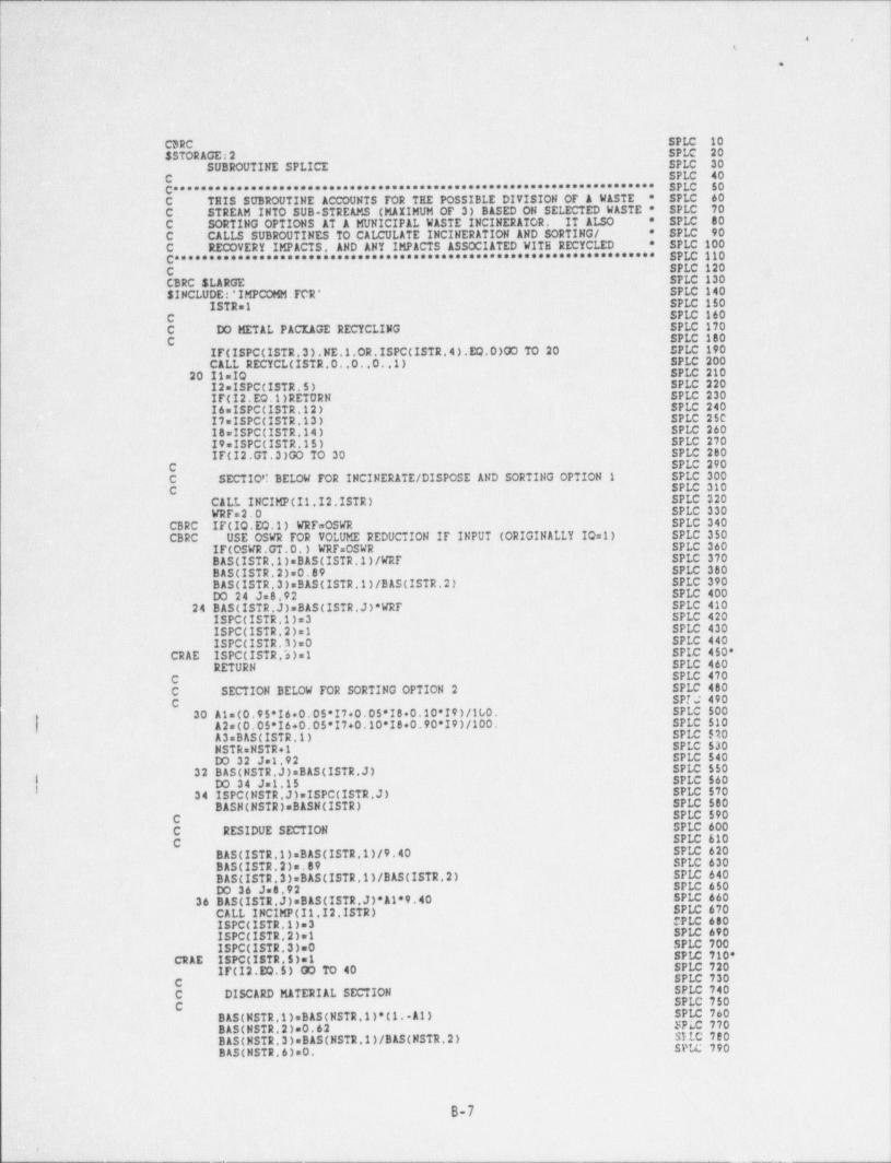
_ - _ - - - _ _ _ _ _ _ _ - - - - - _ _ _ - _ _ =
s .
4
CBRC SPLC. 10SSTORAGE:2 SPLC 20
SUBROUTINE SPLICE SPLC 30SPLC 40C .
******** SPLC 50C*************************************************************WASTE SPLC 60C THIS SUBROUTINE ACCOUNTS FOR TEE POSSIBLE DIVISION OF A *
C STREAM INTO SUB STREAMS (MAXIMUM OF 3) BASED ON SELECTED WASTE * SPLC 70C SORTING OPTIONS AT A MUNICIPAL WASTE INCINERATOR. IT ALSO * SPLC 80
* SPLC 90C CALLS SUBROUTINES TO CALCULATE INCINERATION AND SORTING /* SPLC 100C RECX)VERY IMPACTS. AND ANY IMPACTS ASSOCIATED WITH RECYCLED
C********************************************************************* SPLC 110C SPLC 120CBRC SLARGE SPLC 130$ INCLUDE 'IMPCOMM.FCR' SPLC 140
ISTR=1 SPLC 150C SPLC 160C DO METAL PACKAGE RECYCLING SPLC 170C SPLC 180
IF(ISPC(ISTR.3).NE.1.OR.ISPC(ISTR.4).EQ.0)OO TO 20 SPLC 190CALL RECYCL(ISTR.O. 0. 0.1) SPLC 200
20 11 10 SPLC 21012=ISPCCISTR.5) SPLC 220IF(12.EO 1) RETURN SPLC 230I6=ISPC(ISTR.12) SPLC 24017sISPC(ISTR.13) SPLC 250
,
18=ISPC(ISTR.14) SPLC 26019 ISPC(ISTR.15) SPLC 270IF(I2.GT.3)GO TO 30 SPLC 280
C SPLC 290C SECTIOC BELOW FOR INCINERATE / DISPOSE AND SORTING OPTION 1 SPLC 300C SPLC 310
CALL INCIMP(II.I2.ISTR) SPLC 320WRF=2.0 SPLC 330
CBRC IF(IO.EO 1) WRF=OSWR SPLC 340CBRC USE OSWR FOR VOLUME REDUCTION IF INPUT (ORIGINALLY 10=1) SPLC 350
IF(OSWR.GT.O.) WRF=OSWR SPLC 360BAS (ISTR.1)= BAS (ISTR.1)/WRF SPLC 370BAS (ISTR,2)=0.89 SPLC 380BAS (ISTR.3)= BAS (ISTR.1)/ BAS (ISTR 2) SPLC 390DO 24 Js8,92 SPLC 400
24 BAS (ISTR.J)= BAS (ISTR.J)*WRF SPLC 410ISPC(ISTR.1)=3 SPLC 420ISPC(ISTR.2)=1 SPLC 430ISPC(ISTR.3)=0 SPLC 440
CRAE ISPC(ISTR.3)=1 SPLC 450*RETURN SPLC 460-
C SPLC 470C SECTION BELOW FOR SORTING OPTION 2 SPLC 480C SPT:C 490
30 Al=(0.95'I6+0.0$*I7+0.05*I8+0.10*I9)/100. SPLC 500e
| A2=(0.05'I6+0.05'I7+0.10*IB+0.90*I9)/100. SPLC 510A3= BAS (ISTR,1) SPLC 510NSTR=NSTR+1 SPLC 530DO 32 Je1.92 SPLC 540
32 BAS (NSTR.J)= BAS (ISTR.J) SPLC 550
f DO 34 Jm1.15 SPLC 56034 ISPC(NSTR.J)=ISPC(ISTR.J) SPLC 570
BASH (NSTR)=BASN(ISTR) SPLC 580C SPLC 590C RESIDUE SECTION SPLC 600C SPLC 610
BAS (ISTR.1)= BAS (ISTR.1)/9.40 SPLC 620BAS (ISTR.2)=.89 SPLC 630B AS (ISTR . 3 ) = BAS (ISTR .1 ) / B AS(ISTR . 2 ) SPLC 640DO 36 Js8.92 SPLC 650
36 BAS (ISTR.J)= BAS (ISTR.J)*Al*9.40 SPLC 660CALL INCIMP(II.12 ISTR) SPLC 670ISPC(ISTR.1)=3 PLC 680ISPC(ISTR.2)=1 SPLC 690ISPC(ISTR.3)=0 SPLC 700
CRAE ISPC(ISTR.5)=1 SPLC 710'IF(12.EQ.5) 00 TO 40 SPLC 720
C SPLC 730C DISCARD MATERIAL SECTION SPLC 740
SPLC 750CBAS (NSTR.1)= BAS (NSTR.1)*(1. 11) SPLC 760BAS (NSTR.2)=0.62 SPLC 770B AS ( NSTR . 3 ) = B AS ( NSTR .1 ) /B AS ( NSTR . 2 ) SILC 780BAS (NSTR 6)=0. SPLC 790
B-7
- r j
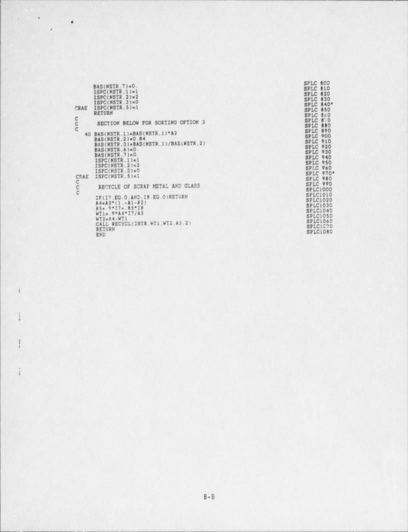
. _ _ _ _ . _ _ _ _ - _ _ _ - _ _
i
,- o . j
e
I
l
l i
SPLC 800 )BAS (NSTR.7)=0. SPLC 010 iISPC(NSTR 1) 1. SPLC 820 |ISPC(NSTR,2)s2 SPLC 830 l
ISPC(NSTR,3)=0 SPLC 840*CRAE ISPC(MSTR.5)=1 SPLC 850
' RETURN SPLC 060C SPLC 8*,0,C SECTION BEIM FOR SORTING OPTION 3 SPLC 000 -C . SPLC 89040 BAS (NSTR.1)eBAS(NSTR 1)*A2 SPLC 900BAS (NSTR.2)=0.84 SPLC 910BAS (NSTR,3)eBAS(NSTR.1)/BA5(NSTR 2) SPLC 920
BAS (NSTR.6)=0. SPLC 930BAS (NSTR.7) 0. SPLC 940ISPC(NSTR.1) 1 SPLC 950ISPC(NSTR,2)=2 SPLC 960ISPC(NSTR,3)=0 SPLC 970*CRAE.ISPC(NSTR.5)=1, SPLC 900- C SPLC 990
C RECYCLE OF SCRAP METAL AND GLASS SPLC1000C SPLC1010.IF(17.EQ.0.AND.18.EQ.0) RETURN SPLC1020A4=A3*(1..A1 A2) SPLC1030
| A5 9'I7+.85'I6 SPLC1040WT1=.9'A4*I7/A5 SPLC1050WT2 A4.WT1 SPLC1060CALL RECYCL(ISTR.WT1.WT2.A3.2) SPLC1C70RETURN SPLC1080END
I
.:#
1-i
-
B-8
u-_-___-_ _ _ _ _ _ _ _ _ _ _______- __ __-_ ___________ __ _ _ _ _ _ _ _ _ _ _ _ _ - _ _ _ . _ _ _ _ . _ _ _ _ _ _ _ _ _ _ _ _ _ _ _ _ - _ _______-_ _
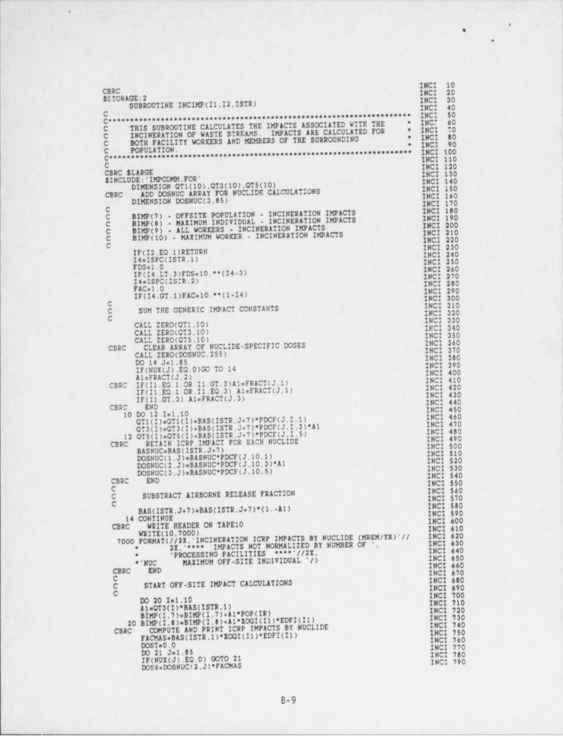
_ _ _ _ _ _ _ _ _ _ _ _ _ _ _ _ _ _ _ _ _ . _ _ .____ ._ __ _ _ . _ . . . _ _ _ _ _ _ _
. ,~
e ,
e
INCI 10CBRC' INCI 20SSTORAGE:2 INCI 30SUBROUTINE INCIMP(11,I2.ISTR) INCI 40C ************************************************ INCI 50C'********************
CALCULATES THE IMPACTS ASSOCIATED WITH THE INC7 60*
C THIS SUBROUTINE . INCI "O*
C' INCINERATION OF WASTE STREAMS. IMPACTS ARE CALCULATED FOR INCI 80 .'*
C DOTH FACILITT WORKERS AND MEMBERS OF TEE SURROUNDING - * INCI 90C POPULATION. INCI 100C********************************************************************* INCI 110C INCI 120CBRC SLARGE INCI 130SINCLUDE:'IMPCOMM. TOR * INCI 140
DIMENSION QT1(10).QT3(10).QT5(10) .
INCI 150 ;
CBRC ADD DOSNUC ARRAT FOR NUCLIDE CALCULATIONS >
INCI 160DIMENSION DOSNUC(3,85) INCI 170CC BIMP(7) . OFFSITE POPULATION - INCINERATION IMPACTS
INCI 180-INCI 190
C BIMP(8) . MAIIMUM INDIVIDUAL - INCINERATION IMPACTS INCI 200C BIMP(9) . ALL WORKIRS . INCINERATION IMPACTSC BIMP(10) - MAXIMUM WORKER - INCINERATION IMPACTS
INCI 210INCI 220
C INCI 230IF(I2.EO.1) RETURN INCI 240.I4=ISPC(ISTR 1) INCI 250FDS=1.0 INCI 260IF(14.LT.3)FDSs10.**(I4 3) INCI 27014=ISPC(ISTR.2) INCI 280 l
FAC=1.0 INCI 290IF(14.GT.1)FAC 10.**(1 14) INCI 300C INCI 310C SUM THE CENERIC IMPACT CONSTANTS INCI 320C INCI 330CALL ZERO(OT1,10) INCI 340
CALL 2ERO(QT3.10) INCI 350CALL ZERO(QT5,10) INCI 360CBRC CLEAR ARRAY OF NUCLIDE-SPECIFIC DOSES INCI 370
CALL 2ERO(DOSNUC.255) INCI 380DO 14 Js1,85 INCI 390IF(NUI(J).EQ.0)GO TO 14 INCI 400AlsFRACT(J,2) INCI 410CBRC IF(I1.EO.1,OR.11.GT,3)AlsFRACT(J,1)IF(II.EO.1.OR.II.EO.3) AlsFRACT(J,1) INCI 420
INCI 430IF(11,GT.3) AlsFRACT(J,3) INCI 440CBRC END INCI 45010 DO 12 I 1.10 INCI 460
QTi(I) QT1(I)+ BAS (ISTR.J+7)*PDCF(J.I 1) INCI 470QT3(I)sQT 3 ( I )+B AS(I STR ,J+ 7 ) *P DCF(J , I . 3 ) * A1 INCI 48012 QT5(I).QT5(I)+ BAS (ISTR.J+7)*PDCF(J.I.5) INCI 490
CBRC RETAIN ICRP IMPACT FOR EACH HUCLIDE INCI 500BASNUC= BAS (ISTR.J+7) INCI 510DOSNUC(1,J)=BASNUC*PDCF(J,10,1). INCI 520DOSNUC( 2 , J ) s B ASNUC* P DCF ( J ,10,3 ) * Al INCI 530DOSNUC(3 J)sBASNUC*PDCF(J,10,5) INCI 540
CBRC END INCI 550C INCI 560 /C SUBSTRACT AIRBORNE RELEASE TRACTION INCI 570C INCI 580BAS (ISTR.J+7)sBAS(ISTR,J+7)*(1. 11) INCI 590
14 OONTINUE INCI 600CBRC WRITE HEADER ON TAPE 10 INCI 610WRITE (10,7000)
7000 FORMAT (//2%,' INCINERATION ICRP IMPACTS BY NUCLIDE (MREM /TR)'// INCI 62021,'**** IMPACTS NOT NORMALIZED BY NUMBER OF * , INCI 630*
' PROCESSING FACILITIES ****'//21 INCI 640*
**NUC MAIIMUM OFF. SITE INDIVIDUAL */) INCI 650INCI 660
CBRC END INCI 670C INCI 680C START OFF. SITE IMPACT CALCULATIONS INCI 690 |
iC. DC 201 1.10 INCI 710 i
INCI 700
11=QT3(I)* BAS (ISTR 1) INCI 720BIMP(I,7)sBIMP(I,7)+Al* POP (IR) INCI 73020 BIMP(I.8)=BIMP(I,8)+11*IOQI(11)*EDFI(I1) INCI 740CBRC COMPUTE AND PRINT ICRP IMPACTS BY NUCLIDE INCI 750
F A CMAS=B AS (ISTR .1 ) *IOQI(11 ) * EDFI(II ) INCI 760DOST=0.0 INCI 770 ,
DO 21 J 1,85 INCI 780 lIF(NUI(J).EQ.0) 00TO 21 INCI 790DOS 8sDOSNUC(2.J)*FACMAS
B-9
|.
.__m_.__-__ . _ _ ____._.__.o_m. _ _ _ _ . _ _ . _ - _ _ _ -
__-- - - _ _ - - - -- - - _ _ _ _ _ . . - - - - -- -
s
7 f ;
y :.-,
*n
1.
INCI 800WRITE (10.7010) NUC(J). DOS 8 INCI 8107010 FORMAT (2I.16,41.1PE10.3) INCI 820a
'
DOSTsDOST+ DOS 8 .INCI 83021 CONTINUE .'
7015 FORMAT (/21.' TOTAL NON. NORMALIZED INCINERATOR IMPACT s'.1P1E12.3)' INCI 850>)
. WRITE (10.7015) DOST ..INCI 840
*
CBRC END .INCI 860
-
E CBRC' WOREER IMPACTS ARE COMPUTED F4)R ONSITE INCINERATIONINCI 870 1
CBRC' IF(11.EQ.1) RETURN' 'INCI 880 I
C- .
INCI $90INCI 900
C START WOREER IMPACT CALCULATIONS' '
C- . .. .
-INCI 910-INCI 920A1 0.237* BAS (ISTR.1)/YINC(I1) INCI 930 ;!
: ADSLs Al*TWI(11.1)*FDS INCI 940 1'ADSM Al*TWI(II.2)*FDS ''INCI 950'ADSHRHe&1*TWI(It.3) INCI 960ADSHMLa&1*TWI(11.3)*0.5'(1.+FDS) INCI 97011=&1*FAC*1.6/ DEN 1(11) INCI 980*r '- CRAE. ADGLeAl* DOFF (30.) INCI 982*ADGLeAl* DOFF (30.)*COFF(30. 4.) INCI 990*
CRAE ADGMmAl* DOFF (10.) INCI 992*-.ADGM Al* DOFF (10.)*COFF(10. 4.) -INCIl000* ;
.CRAE ADGHsAl* DOFF (1.)- INCIl002*ADGHmAl* DOFF (1.)*COFF(1. 4.) INCIl010-DO 30 I=1.10 INCIl020AlsCTi(I)*ADSt+0T5(I)*ADGL :INCIl030- A2 QT1(I)*ADSL+0T5(I)*ADGM INCIl040A3.QTi(I)*ADSM+0TS(I)*ADGM
A4=CTi(I)*ADSM4CT5(I)*ADGH INCIl050A5sOTi(I)*ADSHRH+QT5(I)*ADGH INCIl060
INCIl070A6 QT1(I)*ADSHML+ QTS (I)*ADGH INCIt080CC SELECT THE MAXIMUM WORKER INCIl090
INCI1100C . . INCI1110*CRAE, 17sAMAI1(A1.12.A3.A4.A5.A6) .
INCI1120'CRAE. IF(A7.GT.BIMP(I.10))BIMP(I.10)sA7 'INCI1130CBRC 00 TO (30.22.22.24.24).I100 TO (22.22.24.24.24).11 .
INCI1140't22 DUMs2.*A1+2.*A2+8.*A346.*A4+4.*A5+8.*A6 INCI1150
IF(I2.EO.3)DUM DUM*2.*A3+A4 INC11160IF(12.EO.4)DUMsDUM*3.*A3+A4+A6 INCI1170IF(I2.EQ.5)DUMsDUM+2.*12+4.*A3+2.*A4+2.*Ao INCI1180
INCI119000 TO 26-2 4 DUMs6. * A1+ 2. * A2+ 4. * A3+2.* A4+2. * A 5+ 2. * A6 INCI1200 '
'+ INdu210I- 26 BIMP(I 9)sBIMP(I.9)+DUM
00 TO (27.27.28.28.28) 11 INC11211*27 DOMS 8.*A3+6.*A4+4.*A5+8.*A6 INCI1213*
INCI1214'IF (12.EQ.3) DOMoDOM+2.*A3+A4 INCI1215*'IF (12.EO.4) DOMsDOM+3.*A3+A4+A6|I- IF (12.EQ.5) DOM DOM +4,*A3+2.*A4+2.*A6 INCI1216'
IF (12.LE.2) BIMP(I.101sBIMP(1.10)+ DOM /26. INCI1217*IF (12.EQ.3) BIMP(1.10)=BIMP(I.10)+ DOM /29. INCI1218*IF (12.EO.4) BIMP(I.10)sBIMP(I.10)+ DOM /31. INCI1219*
. IF (I2.EQ.5) BIMP(I.10)sBIMP(I .10)+ DOM /34. INCI!220'', INC11721*00 TO 30 INCI1222*28 DOMS 4.*A3+2 *A4+2 *A5+2.*A6 INCI1223'BIMP(I.10)sBIMP(I.10)+ DOM /10. INCI1225'30 CONTINUE
CBRC ICRP IMPACTS BT NUCLIDE FOR WORKERS INCI1230INCI1240WRITE (10.7020)
7020 FORMAT (//2I.' WORKER INCINERATION ICRP IMPACTS BY NUCLIDE *. INCI1250* * (MREM /YR)' //2% , '"" IMPACTS ARE NOT NORMALIZED BY '. INCI1260
' NUMBER OF PROCESSING FACILITIES "" * // INCI1270*
2I.'NUC MAIIMUM WORKER */) INCI1280*INCI1290A5Teo.0 INCI1300A6T=0.0 INCI1310DO 40 Js1.85 INCI1320IF(NUI(J).EQ.0) GOTO 40 INCI1330DisDOSNUC(1.J) INCI1340D3=DOSNUC(3.J) INCI1342*
A3=D1*ADSM+D3*ADGH INCI1344'A4sD1*ADSM+D3*ADGH INCI1350A$sD1*ADSHRH+D3*ADGR INCI1360 .
A6sD1'ADSlDfL+D3*ADGH iINCI1361*00 TO (31.31.32.32.32)I1 INCI1362*31 DOOMS 8.*A3+6.*A444.*A5+8.*A6 INCI1363*
IF (12.LE.2) DOOM DOOM /26. INCI1364*IF (12.EQ.3) DOOMS (DOOM +2.*A3+A4)/29. INCI1365*IF (12.EQ.4) D00Ms(DOOM +3.*A3+A4+A6)/31.
1
.
B-10

. . _ . _ _ _ _ _ _ _ _ _ _ _ _ _ _ _ _ _ _ _ . _ __ _ _ _ _ _ __ . _ _ _ _ _ _ _ _ _ _ _ _ _ _ _ _ _ _ _ _ _ . . _ _ _ _ _ _ _ _ _ . . _ _ _ _ _ _ _ _ _ _ . _ _ _ _ . . _ _ _ _ _ _ _ _ _ _ _ _ _ . _ _ - _ _ _ _ _ _ _ _ _ _ _ _ _ _ _ _ _ _ _ _ _ _ _ _ _ . _ _ _ _ _ _ _ _ _ _ _ _
9,
[ a
IF (I2.EQ.5)'D00M=(D00M+4.*A3+2.*A4+2.*A6)/34." INCI1366*INCI1367*00 TO 33 -INC11366*32 DOOMS (4.*A3+2.*A4+2.*A5+2.*A6)/10. INCI1369*33 CONTINUE
WRITE (10.7030) NUC(J). DOOM -INCI1370INCI1380'7030 FORMAT (21.A6.31.1P1E12.3) INCI1390*CRAE AST=AST+A5s INCI1400*
.[ CRAE A6T=A6T+A6 INCI1405*AST=AST+D00H INCI141040 CONTINUEWRITE (10.7035) AST INCI1420
1035 TORMAT(/2I.* TOTAL NON-NORMALIZED WORKER IMPACTS'/111.1P1E12.3) INCI1430INCI1440
1 CBRC END. 'INCI1450RETURN INCI1460-END.
.
9 ,,
e
i
. I
, .B-11
i.|
___. - -,
,- . _ - - ._. .
os v:J-
b ''b;
a...
CBRC OPSI 10SSTORAGE 2 .
OPSI 20'SUBROUTINE OPSIMP. OPSI 30
C . OPSI 40*********************** OPSI, 50.
C'*********************************************D OFF SITE IMPACTSC. TEIS SUBROUTINE CALCULATES THE ON SITE AN * OPSI 60OPSI 70*
' C- ASSOCIATED WITH DISPOSAL OPERATIONS.i C********************************************************************* OPSI 80
C OPSI 90. CBRC SLARGE . - OPSI 100
SINCLUDEt'IMPCOMM. TOR' OPSI 110- C . OPSI 120
C. BIMP(11) - 0FFSITE POPULATION . OPERATIONAL IMPACTS OPSI 130C- . BIMP(12). . MA11 MUM OFFSITE INDIVIDUAL - OPERATIONAL IMPACTS OPSI.140-
OPSI 150C BIMP(13) ~ . ALL WORKERS . OPERATIONAL IMPACTS .
OPSI 160C BIMP(14)-. MAKIMUM WOREER OPERATIONAL IMPACTS'ii C .
OPSI 170'00 TO (20,20.30.30.30) 30 OPSI 180
CBRC 00 TO (1D.20,20,30.30).IQ - OPSI iPOC . . . OPSI 200C START CALCULATION OF OFF SITE RELEASES FROM ON SITF FACILITY OPSI 21tfCBRC THIS SECTION NOT USED IN IMPACTS BRC OPSI 220
OPSI 230C ...
OPSI 240'
CBRC 10 DIAM SQRT(ADAY(IQ,11/3.1415927)''
-CBRC D016 ISTR=1.NSTR OPSI 250CBRC .I5=ISPC(ISTR.1) OPSI 260
- CBRC FDSe1. . .OPSI 270
CBRC IF(25.LT.3)FDSa)0.**(IS 3) OPSI 280CBRC IF(IO. EO. 3 )TDS s (1. +FDS)/ 2. . OPSI 290
- CBRC AleTDS*EMP(1)*0.237*TWO(1.3)*WVEL(IR)*2.* DIAM *3. OPSI 300: CBRC A2=Al* BAS (ISTR.1)*3.15E+7/VANN(1) OPSI 310CBRC DO 14 Im1.10 OPSI 320
OPSI 330CBRC A3e0. .
OPSI.340CBRC . DO 12 J=1.8 5CBRC IF(NUI(J).EQ.1)A3sA3+ BAS (ISTR,J+7)*PDCF(J.I.3) 'OPSI 350CBRC 12 CONTINUE OPSI 360CBRC BIMP(I.11)=BIMP(I.11)+A2*A3* POP (IR) . OPSI 370
- CBRC 14 BIMP(I.12).BIMP(I,12)+A2*A3*1000(IQ)*EDFO(IQ) OPSI 380'CBRC 16 CONTINUE-
' OPSI 390-CBRC RETURN OPSI 400CBRC- END OPSI 410
.OPSI 420C
,. START MUNICIPAL WASTE FACILITY IMPACTS OPSI 430CC OPSI 440 :
' #
20 DPOP= SORT (ADaT'IO.1)/3.1415927) OPSI 450DEOP SORT ( ADAY(10.2)/3.1415927) - OPSI 460DOTHsSQRT( ADAY( 73. 31/ 3.1415927 ) OPSI'470
CBRC EACH STREkM R6NDLED SEPARATELY OPSI 480CBRC DO 26 ISTR=1.NS?R OPSI 490'
ISTRs1 OPSI 50015=ISPC(ISTR.1) OPSI 510'
FDS.I. OPSI 520IF(15.LT.3)TDS=10.**(15 3) OPSI 53019sISPC(ISTR,2) OPSI 540FAC 1. OPSI 550IF(19.GT.1) TAC =10.**(1-19) OPSI 560AsisFDS*EMP(IO)*0.237* BAS (ISTR.11/VANN(IQ) OPSI 570AS2=&S1*TWO(IO 3)*WVEL(IR)*2.*DPOP'9.45E+7 OPSI 500AG1=AS1*(FAC/FDS)*1.6/ DEN 2(IQ) OPSI 590-DO 24 Is1.10 'OPSI 600Also. OPSI 610A2 0, OPSI 62013 0. OPSI 630A5 0. OPSI 640DO 22 Js1.85 OPSI 65017(NUI(J).EQ.0)GO TO 22 OPSI 660AleA1+ BAS (ISTR.J+7)*PDCF(J.I.1) OPSI 670 i
'
12=&2+ BAS (ISTR,J+7)*PDCF(J.I.3)*FRACT(J.3) OPSI.660A3= A3 + BAS (ISTR .J+ 7 ) * PDCF(J . I . 3 ) OPSI 69015;nA5+ BAS (ISTR.J+7)*PDCF(J.I.5) OPSI 700
22 CONTINUE OPSI 710.C OPSI 720C 0FF SITE RELEASES OPSI 730C OPSI 740
BIMP ( I .11 )=BIMP( I .11 ) + AS2 * A 3 * POP (IR ) OPSI 750CBBC IF(IQ.WQ.3)BINP(I,11) BIMP(I.111+ bks (ISTR.1)*A2* POP (IR) OPSI 760
BIMPCI.12) BIMP(1.12)+A52*A3*IOQO(IQ)*EDFO(IO) OPSI 770.CBRC IF(IQ.EQ.3)BIMP(I.12) BIMP(I.12)+ BAS (ISTR.1)*A2*IOQO(IQ)*.119 OPSI 780C OPSI 790
B-12
.'
|
|_ s
OPSI 800-C WOREER EXPOSURES OPSI 810
.C OPSI 820|. ADSL.AS1*TWO(IO.1) OPSI 830.ADSM.AS1*TWO(IQ.2) OPSI 840ADSH=&S1*TWO(IO 3)'OPSI 850ADGL=AGl* DOFF (50.)*COFF(50..DOTH) OPSI 860
ADGM.AGl* DOFF (30.)* CUFF (30..DOTH)ADGHe&Gl* DOFF ( 1.)*COFT( 1..DEQP) OPSI 870
OPSI 880-ACOVs6.26E 2*AG1 OPSI 890CB9C IF(IQ.EQ.3)ACOV=0.25*AG1* DEN 2(IQ)/ DEN 2(2) OPSI 900B2 11*ADSL+15*(ADGM+A00V) OPSI 910
B4=Al*ADSM+15*(ADGM+ACOV) OPSI 920B6 11*ADSH+AS*(ADGH+A00V) OPSI 930B7=2.*B2+4.*B4+2.*B6 OPSI 940CBRC IF(IO.EO.2)B7 2.*B2+5.*B4+3.*B6CBRC DISPOSAL UOREERS FOR SANITARY LANDFILL (10=1 OR 2) OPSI 950
IF(IQ.EQ.1.OR. IQ.EQ.2) B7 2.*B2+ 5. *B4+ 3.*B6 OPSI 960OPSI 970*CRAE BIMP(1,13)=BIMP(1,13)+B7/10. OPSI 972*BIMP(I.13)=BIMP(I.13)+B7 OPSI 980BIMP(I.14)=BIMP(I.14)+B7/10. OPSI 99024 CONTINUE- OPSIl000.26 CONTINUE OPSIl010
RETURN OPSIl020C OPSIl030C START' HAZARDOUS WASTE FACILITY IMPACTS OPSIl040C OPSIl05030 DPOP=SQRT(ADAY(IO.1)/3.1415927) OPSIl060DEQP.SQRT(ADAT(IQ 2)/3.1415927) OPSIl070DOTH= SORT (ADAY(IO.3)/3.1415927)CBRC- EACH STREAM EANDLED SEPARATELY OPSIl080
OPSIl090CBRC DO 38 ISTR=1.NSTR OPSI1100:ISTR=1 OPSI1110.I5=ISPC(ISTR.1) OPSI1120FDS=1.' OPSI1130IF(IS.LT.3)FDS=10.**(IS 3) OPSI114019mISPC(ISTR.2). OPSI1150-FAC=1. .
OPSI1160IF(19. GT .1 )F AC= 10. * * ( 1 -19 )AS1.FDS*EMP(IO)*0.237* BAS (ISTR.1)/VANN(IQ) OPSI117C
AS 2 = AS1 *EFAC( IR ) * A DAY (IO. 2 ) * 3.15E+ 1 OPSI1180AS3=AS1*EFAC(IR)*ADAY(IO.2)/(2.*DPOP*3.E+6*WVEL(IR)* DEN 2(IQ)) OPSI1190 ,
AG1=AS1*(FAC/FDS)*1.6/ DEN 2(IQ) OPSI1200 I!
AI1= BAS (ISTR.2)*2.6E-11*FDS*ISPC(ISTR.11) OPSI!210OPSI1220AI2=AI1*1.248*AIOQ(IR) OPSI1230 IDO 36 I=1.10 OPSI1240OPSI1250 |Al=0.
A2=0. IOPSI1260A3=0. OPSI1270AS=0. OPSI1280DO 32 J 1.85 OPSI1290IF(NUI(J) .EO.0)GO TO 32 OPSI130011=A1+ BAS (ISTR,J+7)*PDCF(J.I.1)12=A2+ BAS (ISTR.J+7)*PDCF(J.I.2) OPSI1310
OPSI1320 )A3=A3+ BAS (ISTR.J+7)*PDCF(J.I.3) OPSI1330AS=A5+ BAS (ISTR.J+7)*PDCF(J.I.5) OPSI134032 CONTINUE OPSI1350DIAM.DEQP . OPSI1360IF(ISPC(ISTR.3).NE.0) DIAM.DOTH OPSI1370ADGL= AGl * DOFF ( 50. )*COFF( 50. .DI AM) OPSI1380ADGM=AGl* DOFF (30.)*COFF(30.. DIAM)ADGH.AGl* DOFF ( 1.)*COFF( 1.. DIAM) OPSI1390 l
OPSI1400 |
ACOV 2.49E-2*AG1 OPSI1410IF(ISPC(ISTR.3).NE.0)GO TO 34 OPSI1420
C OPS 11430C SECTION BELOW FOR UNPACKAGED WASTE OPSI1440C OPSI1450BIMP(I.11)=BIMP(I.11)+AS2*A3* POP (IR) OPSI1460
BIMP ( I .12 ) =BIMP ( I .12 ) + A52 * 13 * IOQO(IQ ) * EDFO(IQ ) OPSI1470A DSL. AS3 OPSI1400Bl=11*ADSL+15'(ADGL+A00V) OPSI1490B2 11*ADSL+AS*(ADGM+1COV) OPS 11500B3=A1*ADSL+A5'(ADGH+ACOV) OPSI1510B4=AMAI1(B1.B2.33) OPSI1520BIMP(I.13)=BIMP(I.13)+14.*Bi+15.*B2+29.*B3 OPSI1530BIMP(I.14)=BIMP(I.14)+B4 OPSI1540GO 10 36 OPSI1550
C OPSI1560C SECTION BELOW FOR PACEAGED WASTE OPSI1570C
B-13
_ - _-
_ _ _ _ _ _ _ _ - _ _ _ ._. _ _
"
. . ' . .
!..
OPSI158034 BIMP(1.12) BIMP(I,12)+A12*A2OPSI1590ADSL.AX1
BleA2*ADSL+A$*(ADGL+ACOV) OPSI1600B2en2*ADSL+A5*(ADGH+ACOV) OPSI1610B3.A2'ADSL+A5*(ADGH+ACOV) OPS 11620B4eAMAI1(B1.B2.B3) OPSI1630
-BIMP(I,13)sBIPP(I,13)+14.*Bl+15.*B2+29.*B3 OPSI1640BIMP(I.14)=BIMP(I.14)+B4
~ OPSI165036 CONTINUE OPSI166038 CONTINUE OPSI1670
OPSI1680RETURNOPSI1690END
.
f
|=
,
B-14
1
'
|.
. _ _ _ _ _ _ _ - _ _ - - _ _ _ _ _ _ _ _ - - _ _ _ _ _ _ _ _ _ _ _ _ _ . _ _ . - _ _ _ _ _ _ _ __ _ _ __,
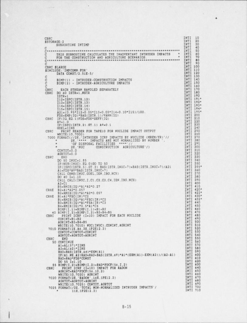
._ . _ . . . _ . _ . _ _ _ _ _ _ _ _ __,
'.ns. ' -
,
e-
CBRC INTI -10$ STORAGE:2 INTI 20
SUBROUTINE INTIMP INTI 30C INTI 40C********************************************************************* INTI 50
* INTI 60.C THIS SUBROUTINE CALCULATES THE INADVERTENT INTRUDER IMPACTS* INTI 70C FOR THE CONSTRUCTION AND AGRICULTURE SCENARIOS.
C********************************************************************* INTI 80C INTI 90CBRC $LARGE INTI 100SINCLUDE:'IMPCOMM.FOR' INTI 110
DATA CONST/2.51E-5/ .INTI 120C :INTI 130C BIMP(1) - INTRUDER-CONSTRUCTION IMPACTS INTI 140
- |. C BIMP(2) - INTRUDER-AGRICULTURE IMPACTS INTI 150C INTI 160CBRC. EACH STREAM HANDLED SEPARATELY INTI 170CBRC DO 60 ISTR=1.NSTR INTI 180
ISTR=1 INTI 190112=ISPC(ISTR.12) INTI 191*I13=ISPC(ISTR.13) INTI 192*114eISPC(ISTR.14) INTI 193*I15=ISPC(ISTR.15) INTI 194* !
A21=(0.95'I12+0.05'I13+0.05'I1440.10*I15)/100. INTI 195* 4
FDSsEMP(IQ)* BAS (ISTR.1)/VANN(IQ) INTI 200 |
'CBRC IF(IO.EQ.1)FDS=FDS*SEFF(IQ) INTI 210A9=1.0 .
. INTI 220IF(ISPC(ISTR.2).GT.1) A9*0.1 INTI 230GDELsIINS INTI 240
CBRC PRINT HEADER TOR TAPE 10 TOR NUCLIDE IMPACT OUTPUT INTI 250:| WRITE (10,7000) INTI 260 1
7000 FORMAT (//21.' INTRUDER ICRP IMPACTS BY NUCLIDE (MREM /YR)'// INTI 270 i
21, ' " * * IMPACTS ARE NOT NORMALIZED BY NUMBER '. INTI 280 1*
'OF DISPOSAL FACILITIES *****// INTI 290 I*
21.'NUC CONSTRUCTION AGRICULTURE'/) INTI 300 i*
.CONTOTs0.0 INTI 310 !
AGRTOT=0.0 INTI 320 '
CBRC END INTI 330DO 50 INUC=1.85- INTI 340IF(NUI(INUC).EQ.0)GO TO SO INTI 350IF(ISPC(ISTR.5).GT.3) BAS (ISTR.INUC+7)= BAS (ISTR.INUC+7)/121 INTI 355*AlsFDS*19* BAS (ISTR.INUC+7) INTI 360 i
CALL CHNS(INUC.GDEL.IEN.IBG,NCH) INTI 370 )DO 40 I=1.10 INTI 380 i
CALL CALI(INUC,I.C1.C2.C3.C4.IEN.IBG.NCH) INTI 390 iA2=C1 INTI 400 !.
CRAE. B5=RMII(IQ)*Al*A2'0.27INTI 410 ;
B2 Al*A2'0.057 INTI 420'B2sRMII(IQ)*Al*12*0.057 INTI 422*
CRAE Bl.Al*FSC(IR)*C2 INTI 430'B1.RMII(IQ)*Al*FSC(IR)*C2 INTI 432*B3sRMII(IQ)*Al*FSA(IR)*C3 INTI 440B4 RMII(IQ)*0.5*11*C4 INTI 450 a
'
BIMP(I.1)eBIMP(I.1)+B1+B2 INTI 46040 BIMP(I.2)=BIMP(I.2)+B3+B4+B5 INTI 470
! ~CBRC PRINT ICRP (I 10) IMPACT FOR EACH NUCLIDE INTI 480CONINT=B1+B2 INTI 490AGRINT.B3+B4+B5 INTI $00WRITE (10.7010) NUC(INUC).CONINT.AGRINT INTI 510
7010 FORMAT (21.A6.31.1P2E12.3) INTI 520CONTOT=CONTOT+CONINT INTI 530 -
AGRTOT=AGRTOT+AGRINT INTI $40 |CBRC END INTI $50 .
50 CONTINUE INTI 560 '
Al=AL(57)*IINS INTI 57012=AL(62)*IINS' INTI 580RAD * BAS (ISTR.64)*EIM(A1) INTI 590IF(A1.NE.12)RADeRAD+ BAS (ISTR 69)*Al*(EIM(11)-EIM(12))/(A2 11) INTI 600RAD = RAD *FDS*CONST INTI 610DO 55 I.1.10 INTI 620
55 BIMP(I.2)=BIMP(I.2). RAD *PDCF(56.I.2) INTI 630CBRC PRINT ICRP (Ie10) IMPACT FOR RADON INTI 640
AGRINT= RAD *PDCF(56.10.2) INTI 650WRITE (10,7020) AGRINT INTI 660
7020 FORMAT (21 ' RADON'.16I.1PE12.3) INTI 670AGRTOT.AGRTOT+AGRINT INTI 680WRITE (10.7025) CONTOT.AGRTOT INTI 690
7025 FORMAT (/21.' TOTAL NON NORMALI2ED INTRUDER IMPACTS'/ INTI 700111.1P2E12.3) INTI 710*
i
B-15
- _ - - _ - _ _ - _ - _ _ - - --

.. _ _ _ __ __ ._ __ _ _ . _ _ _ _ _ __ __
. ..
9
O
INTI 720'
CERC END INTI 13060 CONTINUE INTI 740C INTI 150
RETURN INTI '/60END
!
!
I I
!
i
i|
I
!
:,
6
|
I
i
B-1c
- - ___-
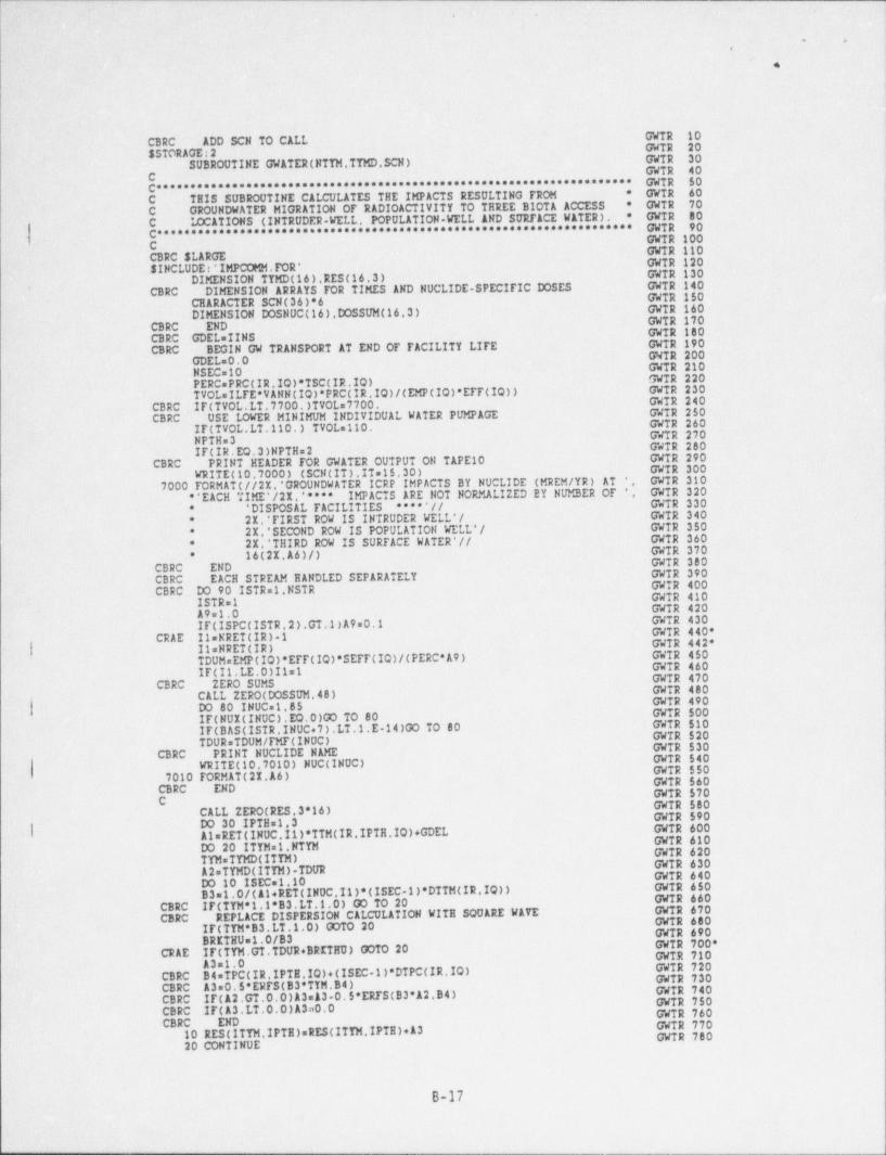
.
-!'.' r .
~ ,
' ' , . ,-i
4.-=(
1
l
. CBRC ADD SCN To CALL- GWTR 10
SSTORAGE:2 - -
GWTR 20SUBROUTINE GWATER(NTTM.TTMD.SCN)
GWTR; 30-GWTR 40C ********************************************** GWTR 50
C***********************LCULATES THE IMPACTS RESULTING FROM * GWTR: 60 ;C TEIS SUBROUTINE CA * -GWTR 70C GROUNDWATER MIGRATION OF RADIOACTIVITY TO THREE BIOTA ACCESS GWTR. 80
iE C ICC&TIONS (INTRUDER WELL. POPULATION WELL AND SURFACE WATER).*
C'******************************************************************** GWTR- 90-.) = - C. .
GWTR 110.GWTR~100-
CBRC SLARGE GWTR 120.SINCLUDE r * IMPCOPDI. FOR'
DIMENSION TYMD(16).RES(16.3) GWTR 130
CBRC DIMENSION ARRAYS FOR TIMES AND NUCLIDE-SPECIFIC DOSES GWTR 140 ''
GWTR 150CEARACTER SCN(36)*6 .DIMENSION DOSNUC(16).DOSSUM(16.3) GWTR 160' s
GWTR 170 1CBRC'' END
: CBRC GDEL=IINS- - GWTR 180 j
! ~CBRC BEGIN GW TRANSPORT AT END OF FACILITY LIFE- GWTR 190-
GWTR 200L GDEL=0.0 GWTR 210NSEC=10
PERC PRC(IR.IQ)*TSC(IR.IQ) .GWTR 220''
TVOLaILTE*VANN(IQ)*PRC(IR.IQ)/(EMP(IO)*EFF(IQ)) GWTR 230
CBRC .IF(TVOL.LT.7700.)TVOL=7700. .
GWIR 240
CBRC USE LOWER MINIMUM INDIVIDUAL WATER PUMPAGE GWTR 250GWTR 260IF(TVOL.LT.110.) TVOLs110. GWTR 270NPTHe3- GWTR 280IF(IR.EQ.3)NPTH=2
CBRC PRINT HEADER FOR GWATER OUTPUT ON TAPE 10. GWTR 290WRITE (10.7000) (SCN(IT).IT=15,30) GWTR 300
,7000 FORMAT (//21.' GROUNDWATER ICRP IMPACTS BY NUCLIDE (MREM /YR) AT.'. GWTR 310
E * * EACH TIME' /2I. ' *"* IMPACTS ARE NOT NORMALIZED BY NUMBER OF '. GWTR 320' DISPOSAL FACILITIES "" ' / /
'
GWTR 330*
21.'FIRST ROW IS INTRUDER WELL*/ GWTR 340*
21.'SECOND ROW IS POPULATION WELL'/ GWTR 350*
* . 21.* THIRD ROW IS SURFACE WATER *// GWTR 360GWTR 37016(21.A6)/)*
GWTR 380CBRC ENDCBRC EACH STREAM EANDLED SEPARATELY GWTR 390-
GWTR 400CBRC DO 90 ISTR=1.NSTR GWTR 410ISTR=1 GWTR 420A9 1.0 GWTR 430IF(ISPC(ISTR 2).GT.1)A9=0 1 GWTR 440*-CRAE 11=NRET(IR) 1 GWTR 442*| IleNRET(IR)
TDUMsEMP(IQ)*EFF(IQ)*SEFF(IQ)/(PERC*A9) GWTR 450GWTR 460. IF(II.LE.0)I1=1 GWTR 470
l- CBRC ZERO SUMS GWTR 480i- CALL ZERO(DOSSUM.48) GWTR 490| DO 80 INUC.1.85 GWTR 500' IF(NUI(INUC).EQ.0)GO TO 80 GWTR 510IF(BAS (ISTR.INUC+7).LT.1.E.14)GO TO 80 GWTR 520
TDUR=TDUM/FMF(INOC)CBRC PRINT NUCLIDE NAME .GWTR 530
GWTR 540.| WRITE (10.7010) NUC(INUC) GWTR 5507010 FORMAT (2I.A6) GWTR 560
CBRC END GWTR 570C GWTR 580
CALL ZERO(RES.3*16) GWTR 590DO 30 IPTHs1.3 GWTR 600'| AleRET(INUC.11)*TTM(IR. IPTH,IQ)+GDEL
GWTR 610Do 20 ITYM=1.NTYM GWTR 620TYM=TYMD(ITYM) GWTR 630A2=TYMD(ITYM).TDUR GWTR 640Do 10 ISECol.10 GWTR 650B3=1.0/(A1+ RET (INUC.11)*(ISEC.1)*DTTM(IR.IQ)) GWTR 660
CBRC IF(TYM*1.1*B3.LT.1.0) 00 TO 20CBRC REPLACE DISPERSION CALCULATION WITE SQUARE WAYE
GWTR 670GWTR 600
IF(TYM*B3.LT.1.0) GOTO 20 GWTR 690BRETHUs1.0/83 GWTR 700*
CRAE 'IF(TYM.GT.TDUR+BRETRU) GOTO 20 GWTR 710A3s1.0 GWTR 720
CBRC B4.TPC(IR.IPTI.IQ)+(ISEC 1)*DTPC(IR.IQ) GWTR 730CBRC A3 0.5'ERFS(83*TYM.B4). GWTR 740CBRC' IF(A2.GT.0.0)A3s&3 0.5'ERTS(83*12.B4) GWTR 750CBRC IF(A3.LT.0.0)A3=0.0 GWTR 760CBRC- END GWTR 77010 RES(ITYM.IPTB)=RES(ITYM,IPTE)+A3 GWTR 780
20 CONTINUE
B-17
_ _ - _ _ _ _ _ _ . _ _ _ _ _ - -
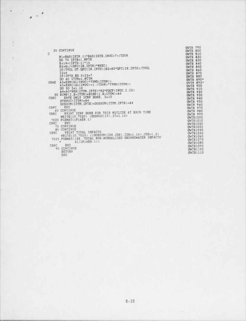
.. . - - . . _ _ . - _ - _ __ __ _ _ . _ _ _ . .________ ______ ______ __ - _ ____ _ _ __ _ - _ _ _ _ _ _ _ _ _ _
|"
e c i-
..
r.
c:'', . .
!
.._
, ..
- 4-
GWTR 79030 CONTINUE GWTR 800
C. Bi= BAS (ISTR.1)* BAS (ISTR.INUC+7)/TDUR GWTR 820
GWTR 810-#
DO 70 IPTE=1.NPTH GWTR 830''Ks14+(IPTH 1)*16 GWTR 340B2=B1/(OFC(IR. IPTH)*NSEC) .
GWTR 850Ir(TVOL.GT QFC(IR. IPTH))B2=B2*QFC(IR. IPTH)/TVOL GWTR 86012 6 GWTR 870i IT(IPTH.EQ.3)12 7 - GWTR 880|DO 60 ITTMel.NTTM GWTR 890*
CRAE A3 EIM(AL(INUC)*TYMD(ITTM)) GWTR 892*A3=EEM((AL(INUC)+1./TDUR)*TYMD(ITYM)) GWTR 900
. DO 50 Im1.10 - GWTR 910A4= A3*RESCITTM.IPTB)*B2*PDCF(INUC.I I2) GWTR 920
50 BIMP(I.K+1TTM)=BIMP(I.K+1TYM)+A4 - GWTR 930-CDRC SAVE ONLY ICRP DOSE. I 10 GWTR 940
DDSNUC(ITYM)sA4 GWIR 950DOSSUM(ITTM.IPIB)eDOSSUM(ITTM.IPTN)+A4 GWTR 960
CBRC . END GWTR 97060 OONTINUE GWTR 980
C3RC PRINT ICRP DOSE FOR THIS NUCLIDE AT EACH TIME GWTR 990WRITE (10.7020) (DOSNUC(IT ) . IT s1.16 ) GWTR1000
7020 TCRMAT(1P16E8.1) GWTR1010CBRC END GWTR1020,
70 CONTINUE GWTR103080 CONTINUE GWTR1040
PRINT TOTAL IMPACTS GWTR1050CBRC . WRITE (10.7025) ((DOSSUM(IDS.JDS). IDS =1.16).JDS=1.3) GWTR10607025 FORMAT (/21. * TOTAL NON NORMALIZED GROUNDWATER IMPACTS * GWTR1070
3C/1P16E8.1)) GWTR1080*
. CBRC ' END GWTR109090 CONTINUE .GWTR1100
RETURN GWTR1110END
|,
B-18
..
- - - - - - _ _ _ _ _ _ _ _ _ _ _ _ _