Computer Networks
99
Computer Networks Lecture 8: Interconnecting LANs Based on slides from D. Choffnes Northeastern U. and P. Gill from StonyBrook University Revised Autumn 2015 by S. Laki
-
Upload
khangminh22 -
Category
Documents
-
view
2 -
download
0
Transcript of Computer Networks
Computer Networks
Lecture 8: Interconnecting LANs
Based on slides from D. Choffnes Northeastern U. and P. Gill from StonyBrook University
Revised Autumn 2015 by S. Laki
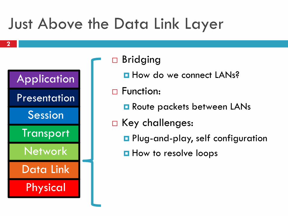
Just Above the Data Link Layer2
Bridging
How do we connect LANs?
Function:
Route packets between LANs
Key challenges:
Plug-and-play, self configuration
How to resolve loops
Application
Presentation
Session
Transport
Network
Data Link
Physical
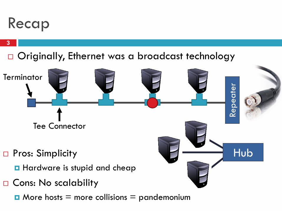
Pros: Simplicity
Hardware is stupid and cheap
Cons: No scalability
More hosts = more collisions = pandemonium
Recap3
Originally, Ethernet was a broadcast technology
Tee Connector
Terminator
Hub
Repeate
r
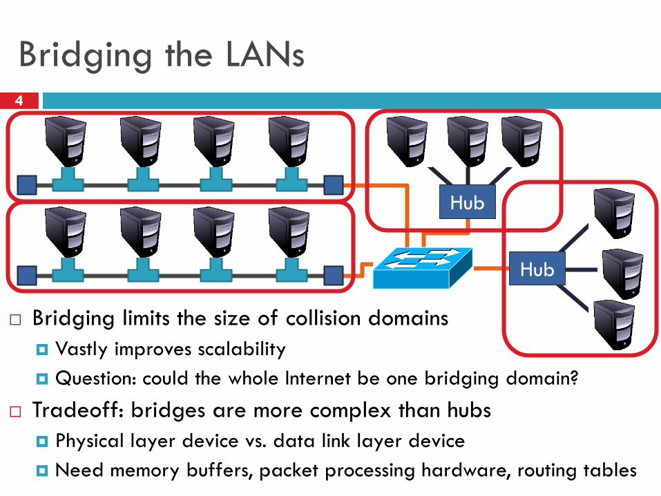
Bridging the LANs4
Bridging limits the size of collision domains
Vastly improves scalability
Question: could the whole Internet be one bridging domain?
Tradeoff: bridges are more complex than hubs
Physical layer device vs. data link layer device
Need memory buffers, packet processing hardware, routing tables
Hub
Hub
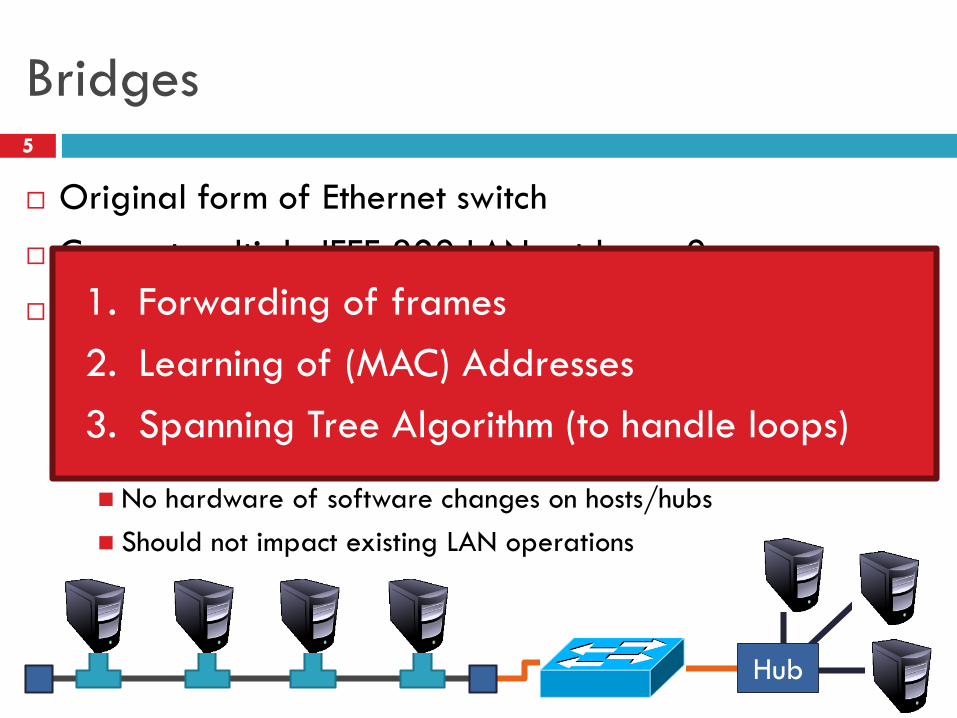
Bridges5
Original form of Ethernet switch
Connect multiple IEEE 802 LANs at layer 2
Goals
Reduce the collision domain
Complete transparency
“Plug-and-play,” self-configuring
No hardware of software changes on hosts/hubs
Should not impact existing LAN operations
Hub
1. Forwarding of frames
2. Learning of (MAC) Addresses
3. Spanning Tree Algorithm (to handle loops)
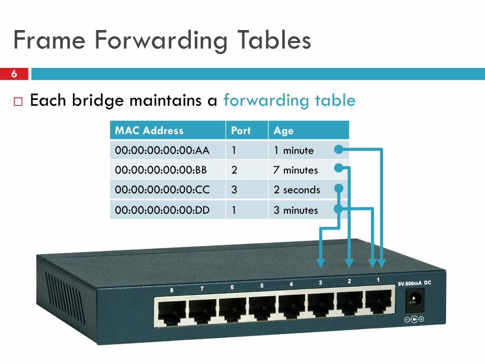
00:00:00:00:00:DD 1 3 minutes
Frame Forwarding Tables6
Each bridge maintains a forwarding table
MAC Address Port Age
00:00:00:00:00:AA 1 1 minute
00:00:00:00:00:BB 2 7 minutes
00:00:00:00:00:CC 3 2 seconds
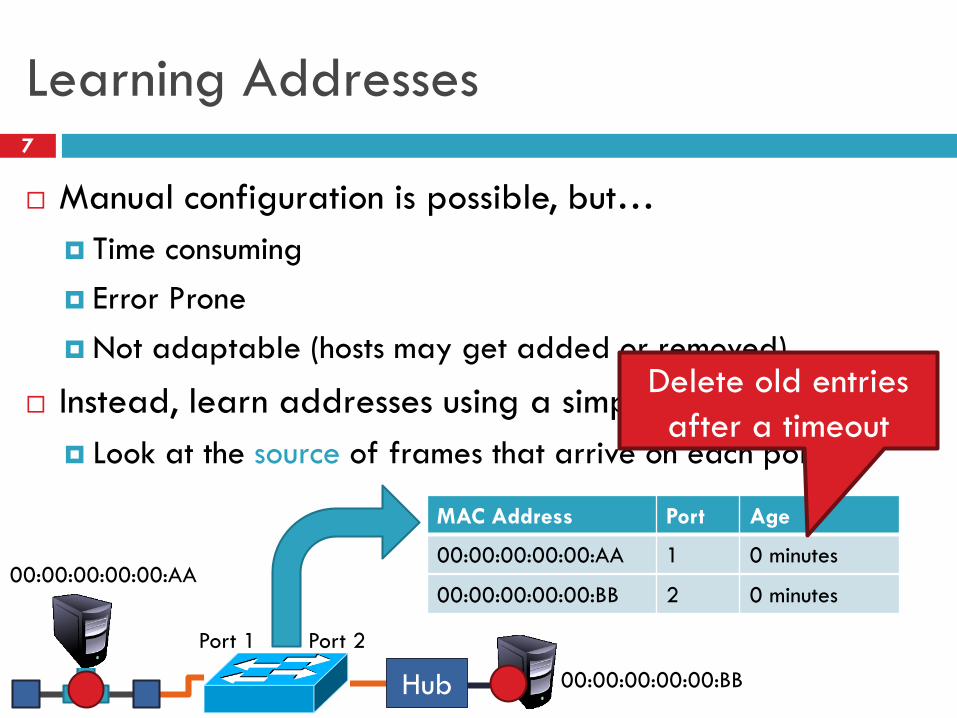
Learning Addresses7
Manual configuration is possible, but…
Time consuming
Error Prone
Not adaptable (hosts may get added or removed)
Instead, learn addresses using a simple heuristic
Look at the source of frames that arrive on each port
Hub
00:00:00:00:00:AA
00:00:00:00:00:BB
Port 1 Port 2
00:00:00:00:00:BB 2 0 minutes
MAC Address Port Age
00:00:00:00:00:AA 1 0 minutes
Delete old entries
after a timeout
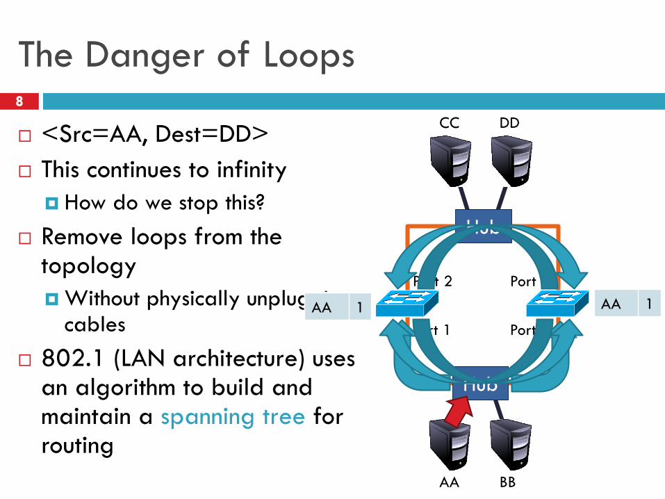
The Danger of Loops8
<Src=AA, Dest=DD>
This continues to infinity
How do we stop this?
Remove loops from the topology
Without physically unplugging cables
802.1 (LAN architecture) uses an algorithm to build and maintain a spanning tree for routing
AA
Port 1
Hub
Port 1
Hub
Port 2 Port 2
AA 1 AA 1
BB
CC DD
AA 2 AA 2AA 1 AA 1

Spanning Tree Definition9
A subset of edges in a graph that:
Span all nodes
Do not create any cycles
This structure is a tree
1
4
2
5
6
3
7
1
4
2
5
6
3
7
5
1
4 26
3
7
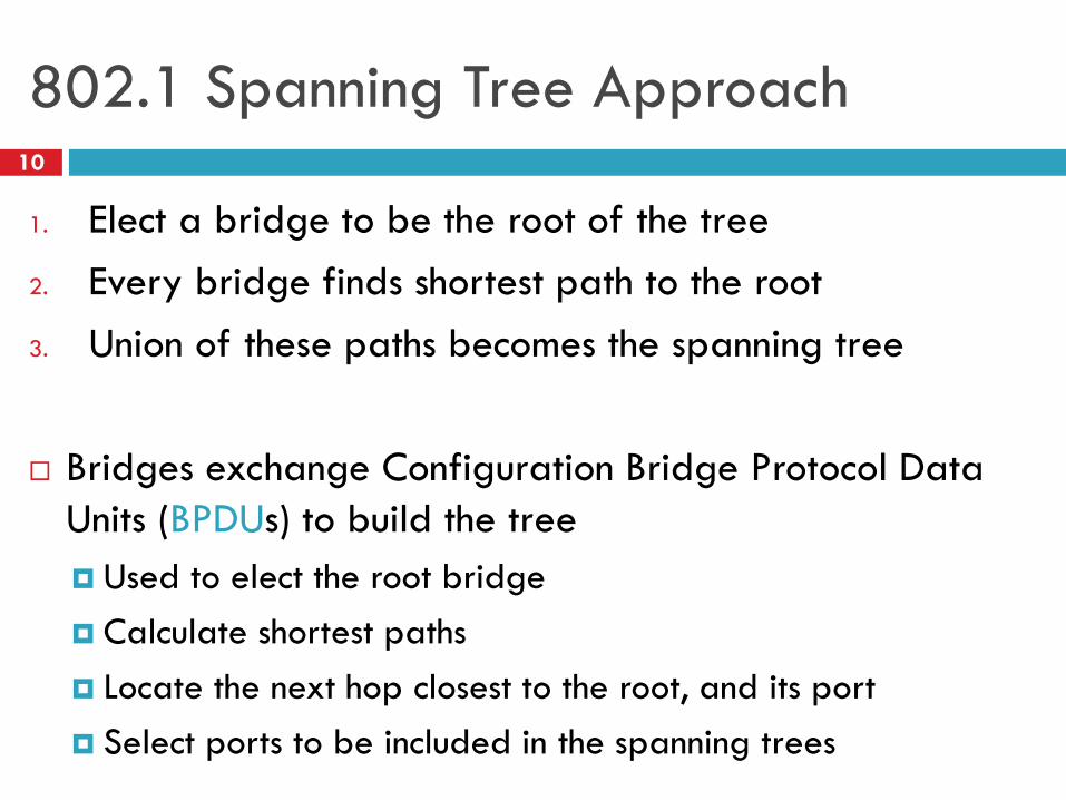
802.1 Spanning Tree Approach10
1. Elect a bridge to be the root of the tree
2. Every bridge finds shortest path to the root
3. Union of these paths becomes the spanning tree
Bridges exchange Configuration Bridge Protocol Data
Units (BPDUs) to build the tree
Used to elect the root bridge
Calculate shortest paths
Locate the next hop closest to the root, and its port
Select ports to be included in the spanning trees
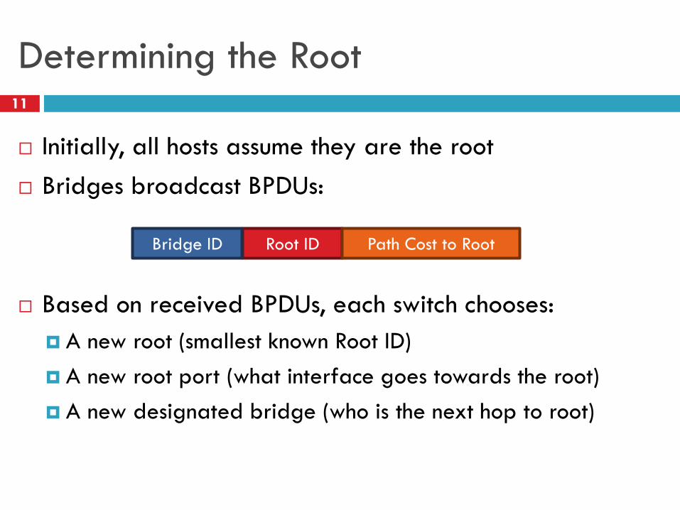
Determining the Root11
Initially, all hosts assume they are the root
Bridges broadcast BPDUs:
Based on received BPDUs, each switch chooses:
A new root (smallest known Root ID)
A new root port (what interface goes towards the root)
A new designated bridge (who is the next hop to root)
Root ID Path Cost to RootBridge ID

Spanning Tree Construction12
0: 0/0 12: 12/0 3: 3/0
27: 27/0 41: 41/0
9: 9/0 68: 68/0
27: 0/1
12: 0/1
41: 3/1
68: 9/1
41: 0/2
3: 0/2
68: 3/29: 3/2 68: 0/39: 0/3
Bridges vs. Switches13
Bridges make it possible to increase LAN capacity
Reduces the amount of broadcast packets
No loops
Switch is a special case of a bridge
Each port is connected to a single host
Either a client machine
Or another switch
Links are full duplex
Simplified hardware: no need for CSMA/CD!
Can have different speeds on each port
Switching the Internet14
Capabilities of switches:
Network-wide routing based on MAC addresses
Learn routes to new hosts automatically
Resolve loops
Could the whole Internet be one switching domain?
NO
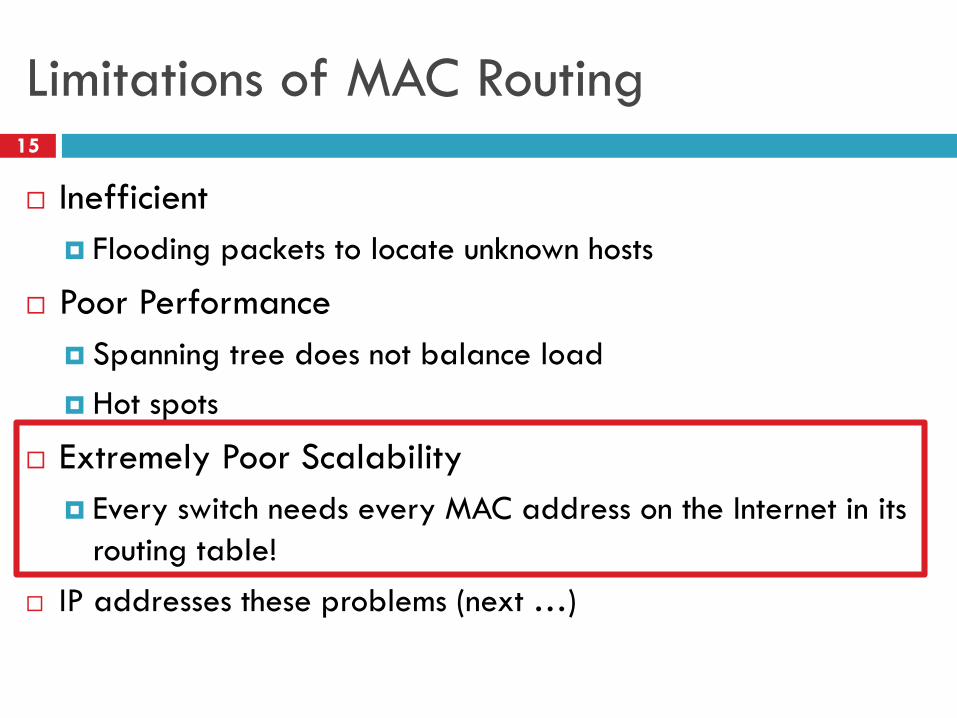
Limitations of MAC Routing15
Inefficient
Flooding packets to locate unknown hosts
Poor Performance
Spanning tree does not balance load
Hot spots
Extremely Poor Scalability
Every switch needs every MAC address on the Internet in its
routing table!
IP addresses these problems (next …)
Computer Networks
Lecture 8: Network Layer
Based on slides from D. Choffnes Northeastern U. and P. Gill from StonyBrook University
Revised Autumn 2015 by S. Laki
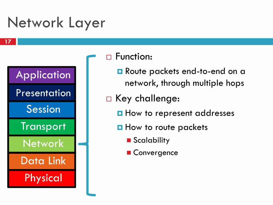
Network Layer17
Function:
Route packets end-to-end on a
network, through multiple hops
Key challenge:
How to represent addresses
How to route packets
Scalability
Convergence
Application
Presentation
Session
Transport
Network
Data Link
Physical
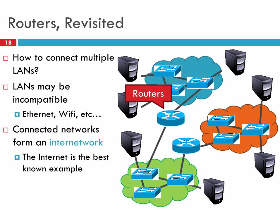
Routers, Revisited18
How to connect multiple
LANs?
LANs may be
incompatible
Ethernet, Wifi, etc…
Connected networks
form an internetwork
The Internet is the best
known example
Routers
Internetworking Issues19
Naming / Addressing
How do you designate hosts?
Routing
Must be scalable (i.e. a switched Internet won’t work)
Service Model
What gets sent?
How fast will it go?
What happens if there are failures?
Must deal with heterogeneity
Remember, every network is different
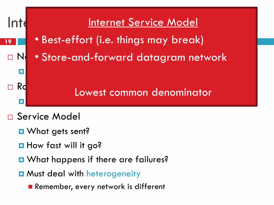
Internet Service Model
• Best-effort (i.e. things may break)
• Store-and-forward datagram network
Lowest common denominator

Addressing
Class-based
CIDR
IPv4 Protocol Details Packed Header
Fragmentation
IPv6
Outline20
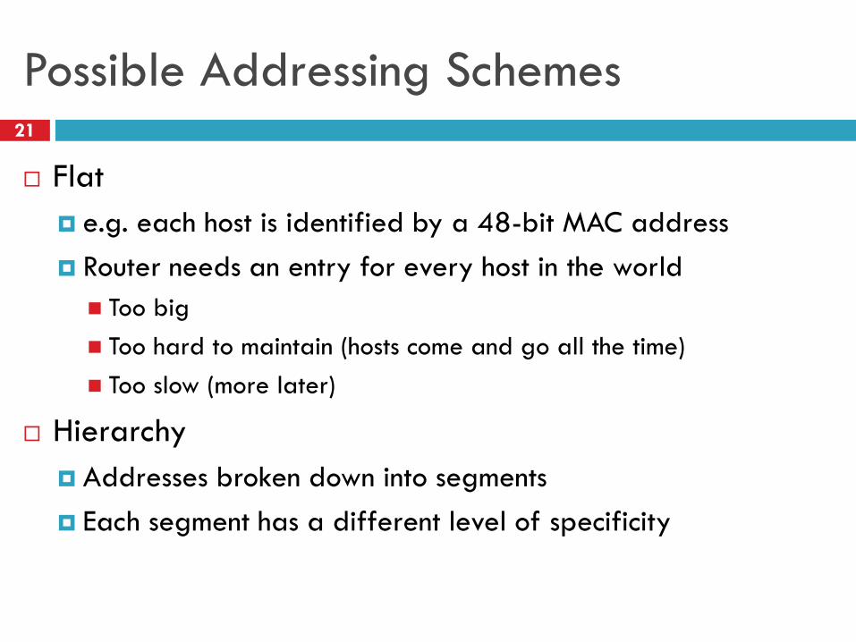
Possible Addressing Schemes21
Flat
e.g. each host is identified by a 48-bit MAC address
Router needs an entry for every host in the world
Too big
Too hard to maintain (hosts come and go all the time)
Too slow (more later)
Hierarchy
Addresses broken down into segments
Each segment has a different level of specificity
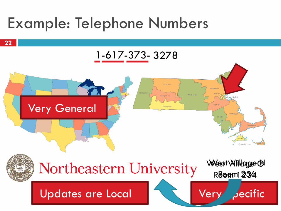
Example: Telephone Numbers22
1-617-373-1234
West Village H
Room 256
Very General
Very Specific
West Village G
Room 1234
3278
Updates are Local
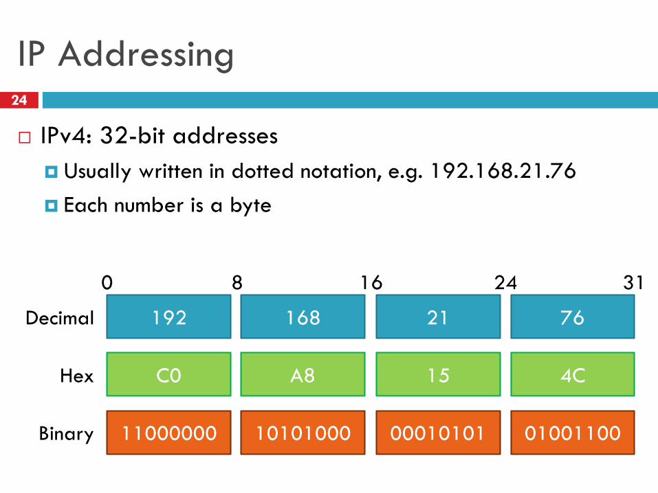
IP Addressing24
IPv4: 32-bit addresses
Usually written in dotted notation, e.g. 192.168.21.76
Each number is a byte
11000000
C0
192
10101000
A8
168
00010101
15
21
01001100
4C
76Decimal
Hex
Binary
0 8 16 24 31
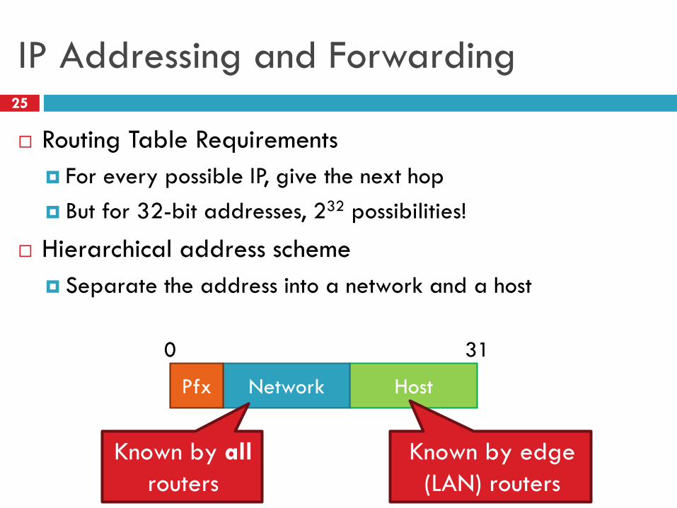
IP Addressing and Forwarding25
Routing Table Requirements
For every possible IP, give the next hop
But for 32-bit addresses, 232 possibilities!
Hierarchical address scheme
Separate the address into a network and a host
HostNetworkPfx
0 31
Known by all
routers
Known by edge
(LAN) routers
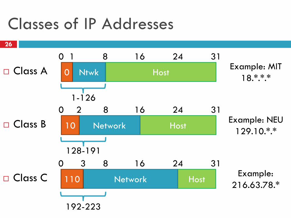
Classes of IP Addresses26
Class A HostNtwk0
0 311 8Example: MIT
18.*.*.*
1-126
Class B HostNetwork10
0 312 16Example: NEU
129.10.*.*
128-191
8
Class C HostNetwork110
0 313 24Example:
216.63.78.*
192-223
8
16
16
24
24
How Do You Get IPs?27
IP address ranges controlled by IANA
Internet Assigned Number Authority
Roots go back to 1972, ARPANET, UCLA
Today, part of ICANN
IANA grants IPs to regional authorities
ARIN (American Registry of Internet Numbers) may grant you a range of IPs
You may then advertise routes to your new IP range
There are now secondary markets, auctions, …
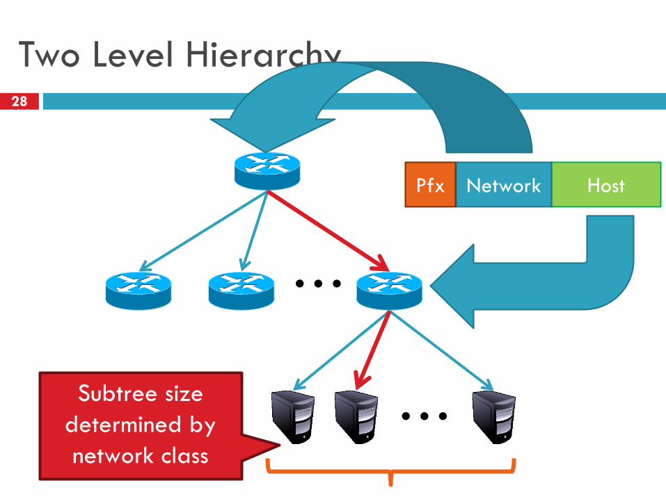
Two Level Hierarchy28
…
…
HostNetwork
Subtree size
determined by
network class
Pfx
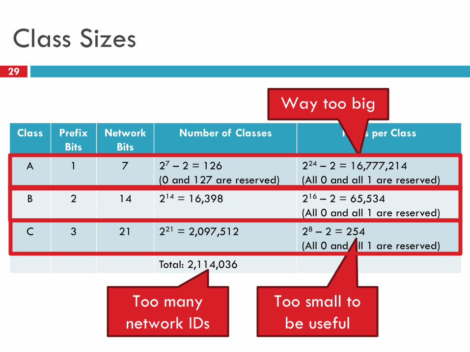
Class Sizes29
Class Prefix
Bits
Network
Bits
Number of Classes Hosts per Class
A 1 7 27 – 2 = 126
(0 and 127 are reserved)
224 – 2 = 16,777,214
(All 0 and all 1 are reserved)
B 2 14 214 = 16,398 216 – 2 = 65,534
(All 0 and all 1 are reserved)
C 3 21 221 = 2,097,512 28 – 2 = 254
(All 0 and all 1 are reserved)
Total: 2,114,036
Too many
network IDs
Too small to
be useful
Way too big
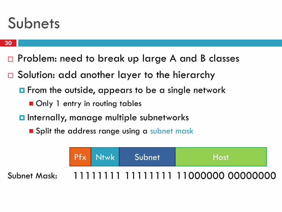
Subnets30
Problem: need to break up large A and B classes
Solution: add another layer to the hierarchy
From the outside, appears to be a single network
Only 1 entry in routing tables
Internally, manage multiple subnetworks
Split the address range using a subnet mask
HostNtwkPfx Subnet
11111111 11111111 11000000 00000000Subnet Mask:
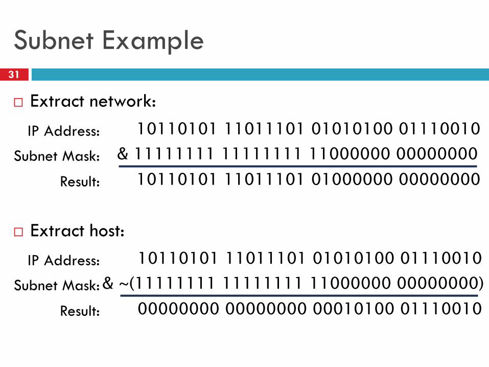
Subnet Example31
Extract network:
Extract host:
10110101 11011101 01010100 01110010IP Address:
& 11111111 11111111 11000000 00000000Subnet Mask:
10110101 11011101 01000000 00000000Result:
10110101 11011101 01010100 01110010IP Address:
& ~(11111111 11111111 11000000 00000000)Subnet Mask:
00000000 00000000 00010100 01110010Result:
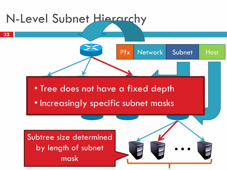
N-Level Subnet Hierarchy32
…
…
HostNetworkPfx
Subtree size determined
by length of subnet
mask
Subnet
…
• Tree does not have a fixed depth
• Increasingly specific subnet masks
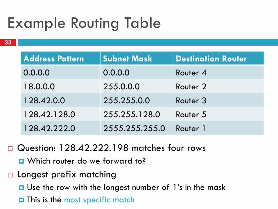
Example Routing Table33
Address Pattern Subnet Mask Destination Router
0.0.0.0 0.0.0.0 Router 4
18.0.0.0 255.0.0.0 Router 2
128.42.0.0 255.255.0.0 Router 3
128.42.128.0 255.255.128.0 Router 5
128.42.222.0 2555.255.255.0 Router 1
Question: 128.42.222.198 matches four rows
Which router do we forward to?
Longest prefix matching
Use the row with the longest number of 1’s in the mask
This is the most specific match
Subnetting Revisited34
Question: does subnetting solve all the problems of class-
based routing?
NO
Classes are still too coarse
Class A can be subnetted, but only 126 available
Class C is too small
Class B is nice, but there are only 16,398 available
Routing tables are still too big
2.1 million entries per router
Classless Inter Domain Routing35
CIDR, pronounced ‘cider’
Key ideas:
Get rid of IP classes
Use bitmasks for all levels of routing
Aggregation to minimize FIB (forwarding information base)
Arbitrary split between network and host
Specified as a bitmask or prefix length
Example: Stony Brook
130.245.0.0 with netmask 255.255.0.0
130.245.0.0 / 16
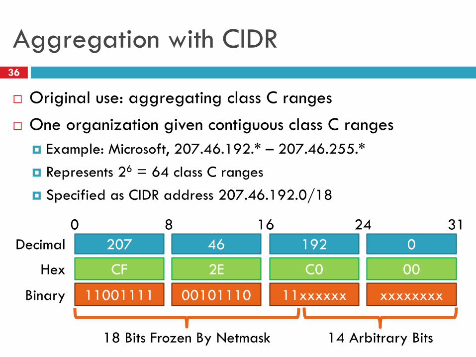
Aggregation with CIDR36
Original use: aggregating class C ranges
One organization given contiguous class C ranges
Example: Microsoft, 207.46.192.* – 207.46.255.*
Represents 26 = 64 class C ranges
Specified as CIDR address 207.46.192.0/18
11001111
CF
207
00101110
2E
46
11xxxxxx
C0
192
xxxxxxxx
00
0Decimal
Hex
Binary
0 8 16 24 31
18 Bits Frozen By Netmask 14 Arbitrary Bits
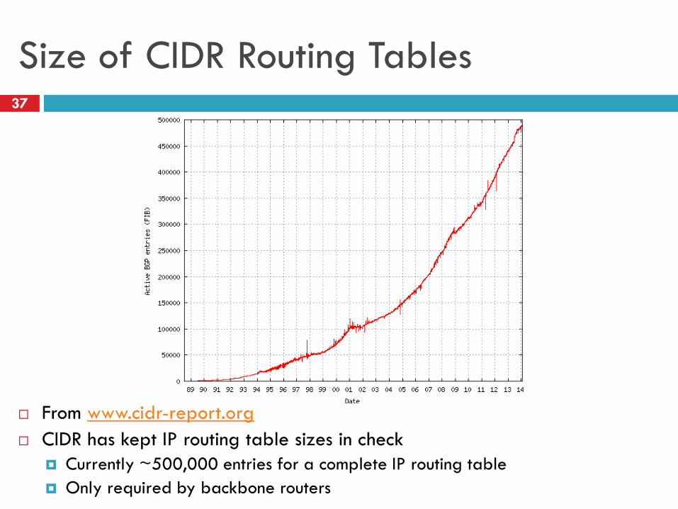
Size of CIDR Routing Tables37
From www.cidr-report.org
CIDR has kept IP routing table sizes in check
Currently ~500,000 entries for a complete IP routing table
Only required by backbone routers
We had a special day in summer 2014!
38
512K day – August 12, 2014
Default threshold size for IPv4 route data in older Cisco routers 512K routes
Some routers failed over to slower memory
RAM vs. CAM (content addressable memory)
Some routes dropped
Cisco issues update in May anticipating this issue
Reallocated some IPv6 space for IPv4 routes
Part of the cause
Growth in emerging markets
http://cacm.acm.org/news/178293-internet-routing-failures-bring-architecture-changes-back-to-the-table/fulltext

Takeaways39
Hierarchical addressing is critical for scalability
Not all routers need all information
Limited number of routers need to know about changes
Non-uniform hierarchy useful for heterogeneous networks
Class-based addressing is too course
CIDR improves scalability and granularity
Implementation challenges
Longest prefix matching is more difficult than schemes with no
ambiguity

Addressing
Class-based
CIDR
IPv4 Protocol Details Packed Header
Fragmentation
IPv6
Outline40
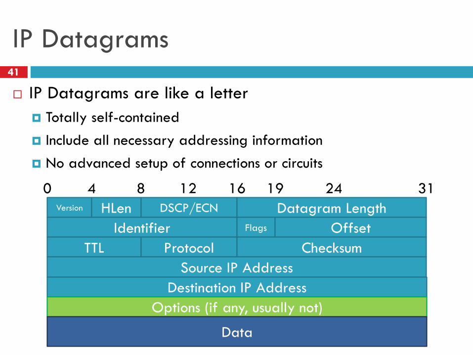
IP Datagrams41
IP Datagrams are like a letter
Totally self-contained
Include all necessary addressing information
No advanced setup of connections or circuits
Version HLen DSCP/ECN Datagram Length
0 8 16 24 314 12 19
Identifier Flags Offset
TTL Protocol Checksum
Source IP Address
Destination IP Address
Options (if any, usually not)
Data
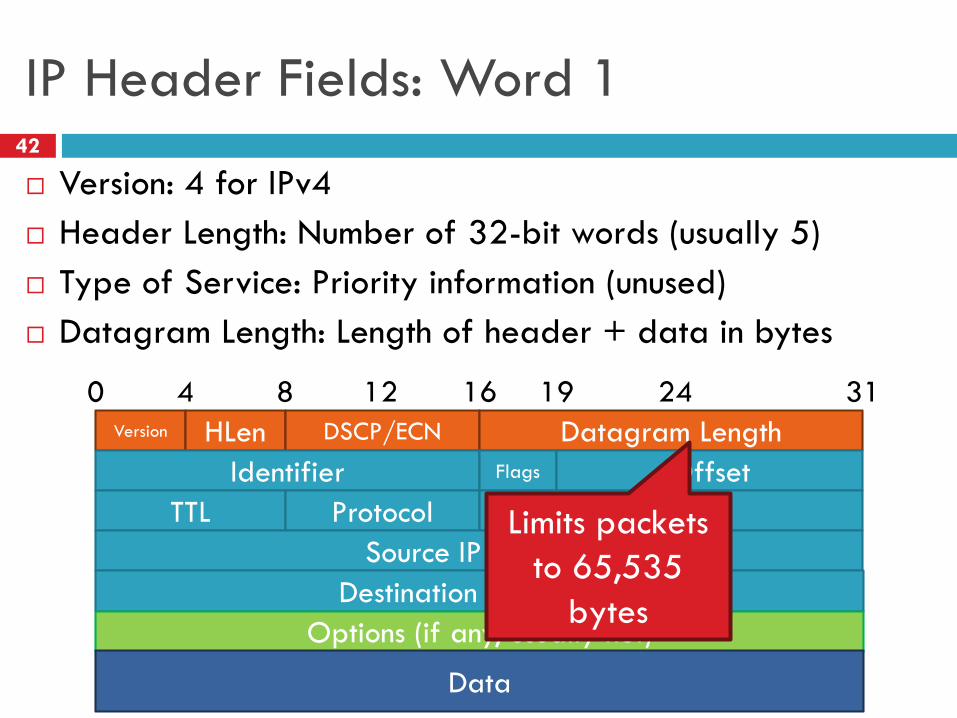
IP Header Fields: Word 142
Version: 4 for IPv4
Header Length: Number of 32-bit words (usually 5)
Type of Service: Priority information (unused)
Datagram Length: Length of header + data in bytes
Version HLen DSCP/ECN Datagram Length
0 8 16 24 314 12 19
Identifier Flags Offset
TTL Protocol Checksum
Source IP Address
Destination IP Address
Options (if any, usually not)
Data
Limits packets
to 65,535
bytes
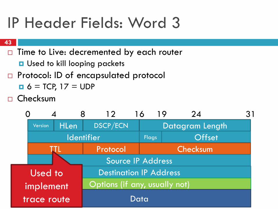
IP Header Fields: Word 343
Time to Live: decremented by each router
Used to kill looping packets
Protocol: ID of encapsulated protocol
6 = TCP, 17 = UDP
Checksum
Version HLen DSCP/ECN Datagram Length
0 8 16 24 314 12 19
Identifier Flags Offset
TTL Protocol Checksum
Source IP Address
Destination IP Address
Options (if any, usually not)
Data
Used to
implement
trace route
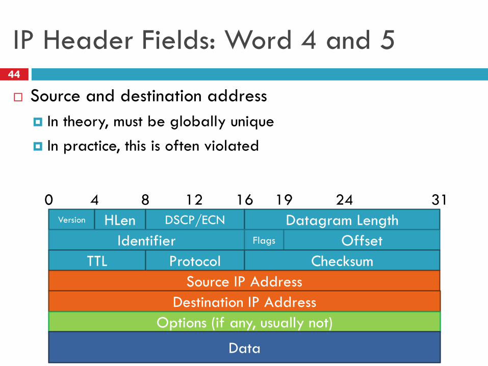
IP Header Fields: Word 4 and 544
Source and destination address
In theory, must be globally unique
In practice, this is often violated
Version HLen DSCP/ECN Datagram Length
0 8 16 24 314 12 19
Identifier Flags Offset
TTL Protocol Checksum
Source IP Address
Destination IP Address
Options (if any, usually not)
Data
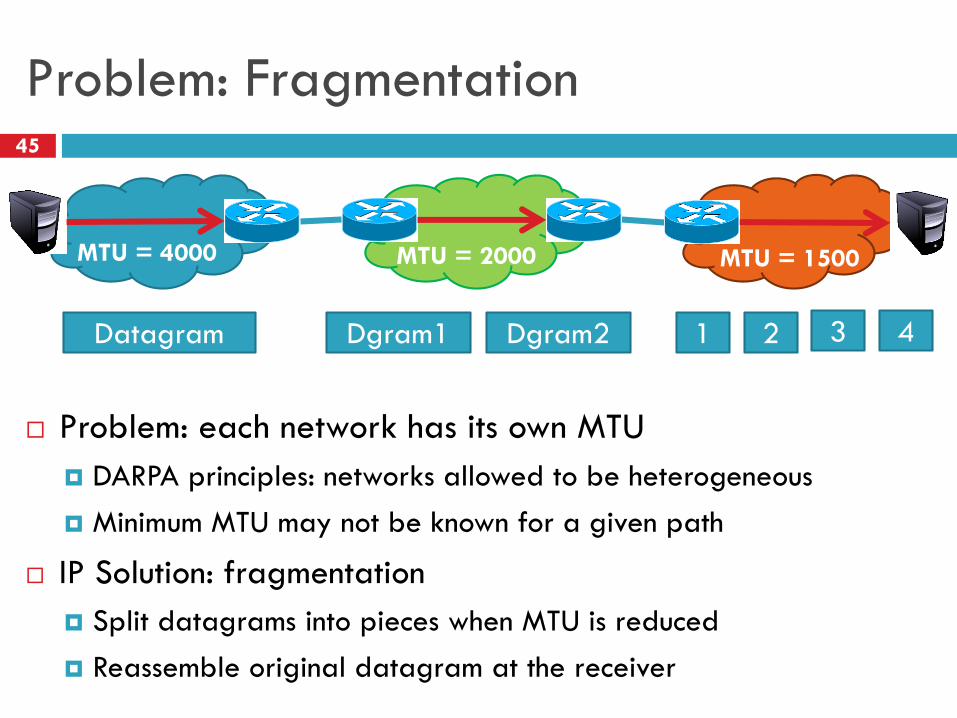
Problem: Fragmentation45
Problem: each network has its own MTU
DARPA principles: networks allowed to be heterogeneous
Minimum MTU may not be known for a given path
IP Solution: fragmentation
Split datagrams into pieces when MTU is reduced
Reassemble original datagram at the receiver
MTU = 2000MTU = 4000 MTU = 1500
Datagram Dgram1 Dgram2 1 2 3 4
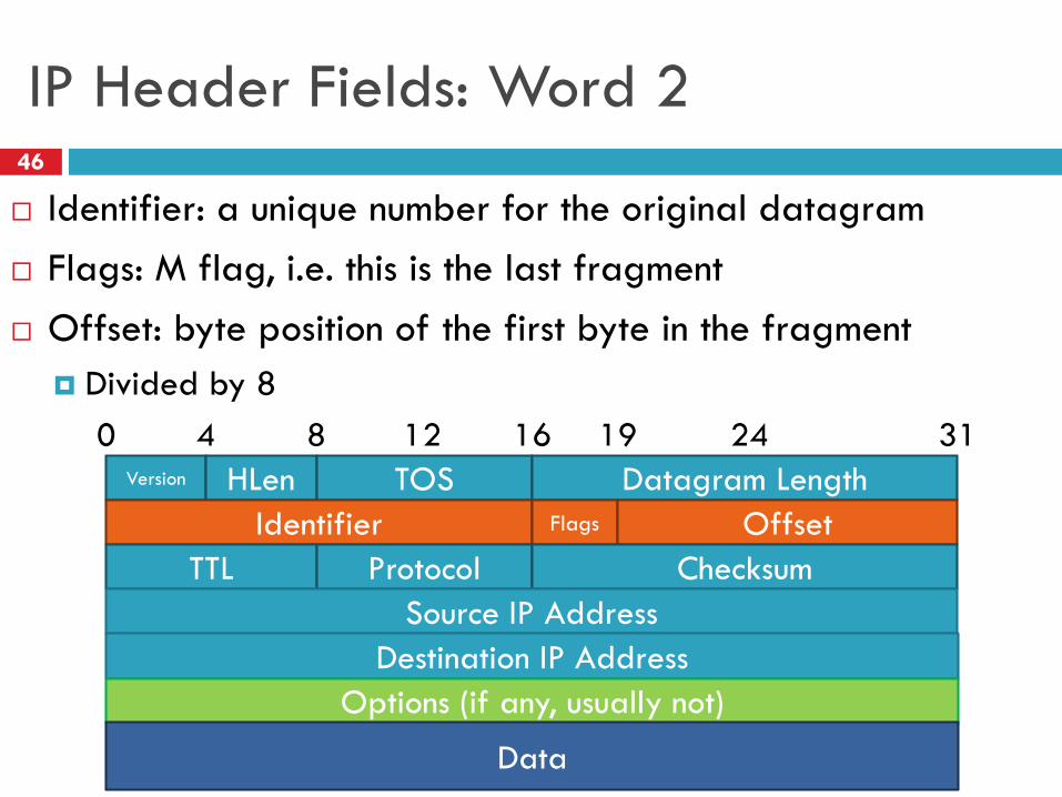
IP Header Fields: Word 246
Identifier: a unique number for the original datagram
Flags: M flag, i.e. this is the last fragment
Offset: byte position of the first byte in the fragment
Divided by 8
Version HLen TOS Datagram Length
0 8 16 24 314 12 19
Identifier Flags Offset
TTL Protocol Checksum
Source IP Address
Destination IP Address
Options (if any, usually not)
Data
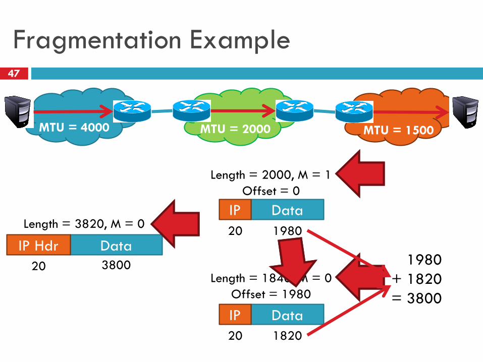
Fragmentation Example47
MTU = 2000MTU = 4000 MTU = 1500
Data
Data
Data
IP Hdr
IP
IP
Length = 3820, M = 0
380020
Length = 2000, M = 1
Offset = 0
Length = 1840, M = 0
Offset = 1980
198020
182020
1980
+ 1820
= 3800
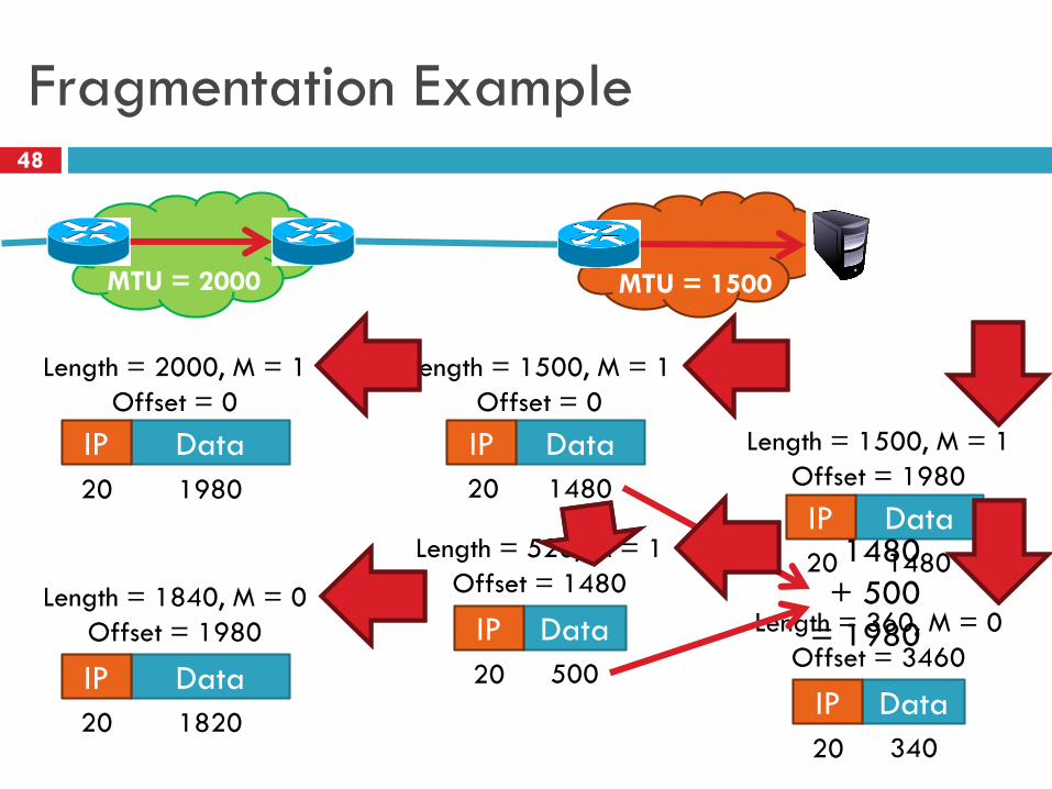
Fragmentation Example48
MTU = 2000 MTU = 1500
Data
Data
IP
IP
Data
Data
IP
IP
Length = 2000, M = 1
Offset = 0
Length = 1840, M = 0
Offset = 1980
198020
182020
20
20 1480
500
Length = 520, M = 1
Offset = 1480
Length = 1500, M = 1
Offset = 0
Data
Data
IP
IP
20
20 1480
340
Length = 360, M = 0
Offset = 3460
Length = 1500, M = 1
Offset = 1980
1480
+ 500
= 1980
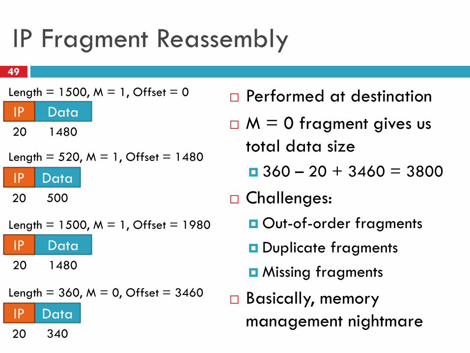
IP Fragment Reassembly49
Performed at destination
M = 0 fragment gives us
total data size
360 – 20 + 3460 = 3800
Challenges:
Out-of-order fragments
Duplicate fragments
Missing fragments
Basically, memory
management nightmare
DataIP
20 1480
DataIP
20 500
Length = 520, M = 1, Offset = 1480
Length = 1500, M = 1, Offset = 0
DataIP
20 1480
DataIP
20 340
Length = 360, M = 0, Offset = 3460
Length = 1500, M = 1, Offset = 1980
Fragmentation Concepts50
Highlights many key Internet characteristics
Decentralized and heterogeneous
Each network may choose its own MTU
Connectionless datagram protocol
Each fragment contains full routing information
Fragments can travel independently, on different paths
Best effort network
Routers/receiver may silently drop fragments
No requirement to alert the sender
Most work is done at the endpoints
i.e. reassembly
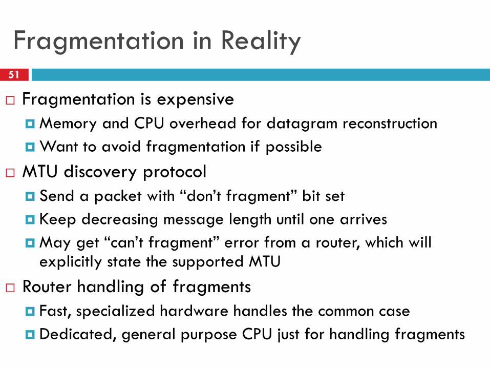
Fragmentation in Reality51
Fragmentation is expensive
Memory and CPU overhead for datagram reconstruction
Want to avoid fragmentation if possible
MTU discovery protocol
Send a packet with “don’t fragment” bit set
Keep decreasing message length until one arrives
May get “can’t fragment” error from a router, which will explicitly state the supported MTU
Router handling of fragments
Fast, specialized hardware handles the common case
Dedicated, general purpose CPU just for handling fragments
Addressing
Class-based
CIDR
IPv4 Protocol Details Packed Header
Fragmentation
IPv6
Outline52
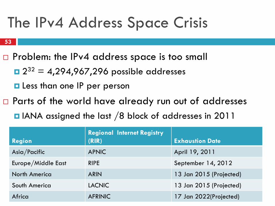
The IPv4 Address Space Crisis53
Problem: the IPv4 address space is too small
232 = 4,294,967,296 possible addresses
Less than one IP per person
Parts of the world have already run out of addresses
IANA assigned the last /8 block of addresses in 2011
Region
Regional Internet Registry
(RIR) Exhaustion Date
Asia/Pacific APNIC April 19, 2011
Europe/Middle East RIPE September 14, 2012
North America ARIN 13 Jan 2015 (Projected)
South America LACNIC 13 Jan 2015 (Projected)
Africa AFRINIC 17 Jan 2022(Projected)
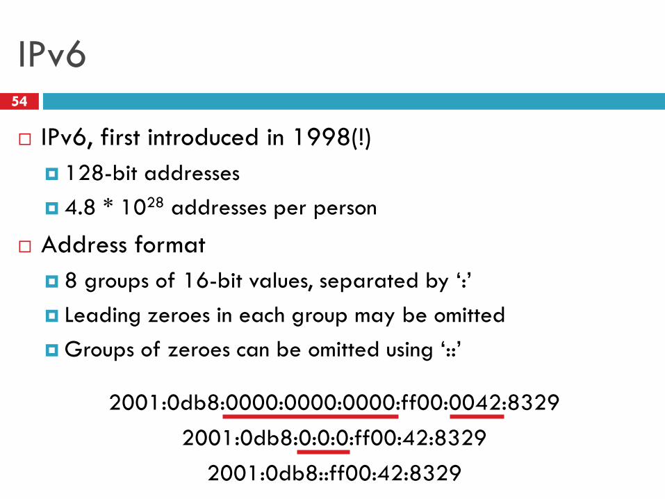
IPv654
IPv6, first introduced in 1998(!)
128-bit addresses
4.8 * 1028 addresses per person
Address format
8 groups of 16-bit values, separated by ‘:’
Leading zeroes in each group may be omitted
Groups of zeroes can be omitted using ‘::’
2001:0db8:0000:0000:0000:ff00:0042:8329
2001:0db8:0:0:0:ff00:42:8329
2001:0db8::ff00:42:8329
IPv6 Trivia55
Who knows the IP for localhost?
127.0.0.1
What is localhost in IPv6?
::1
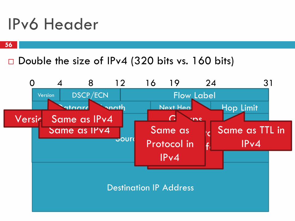
IPv6 Header56
Double the size of IPv4 (320 bits vs. 160 bits)
Version DSCP/ECN Flow Label
0 8 16 24 314 12 19
Datagram Length Next Header Hop Limit
Source IP Address
Destination IP Address
Version = 6 Groups
packets into
flows, used for
QoS
Same as IPv4 Same as
Protocol in
IPv4
Same as TTL in
IPv4
Same as IPv4

Differences from IPv4 Header57
Several header fields are missing in IPv6
Header length – rolled into Next Header field
Checksum – was useless, so why keep it
Identifier, Flags, Offset
IPv6 routers do not support fragmentation
Hosts are expected to use path MTU discovery
Reflects changing Internet priorities
Today’s networks are more homogeneous
Instead, routing cost and complexity dominate
Performance Improvements58
No checksums to verify
No need for routers to handle fragmentation
Simplified routing table design
Address space is huge
No need for CIDR (but need for aggregation)
Standard subnet size is 264 addresses
Simplified auto-configuration
Neighbor Discovery Protocol
Used by hosts to determine network ID
Host ID can be random!

Additional IPv6 Features59
Source Routing
Host specifies the route to wants packet to take
Mobile IP
Hosts can take their IP with them to other networks
Use source routing to direct packets
Privacy Extensions
Randomly generate host identifiers
Make it difficult to associate one IP to a host
Jumbograms
Support for 4Gb datagrams
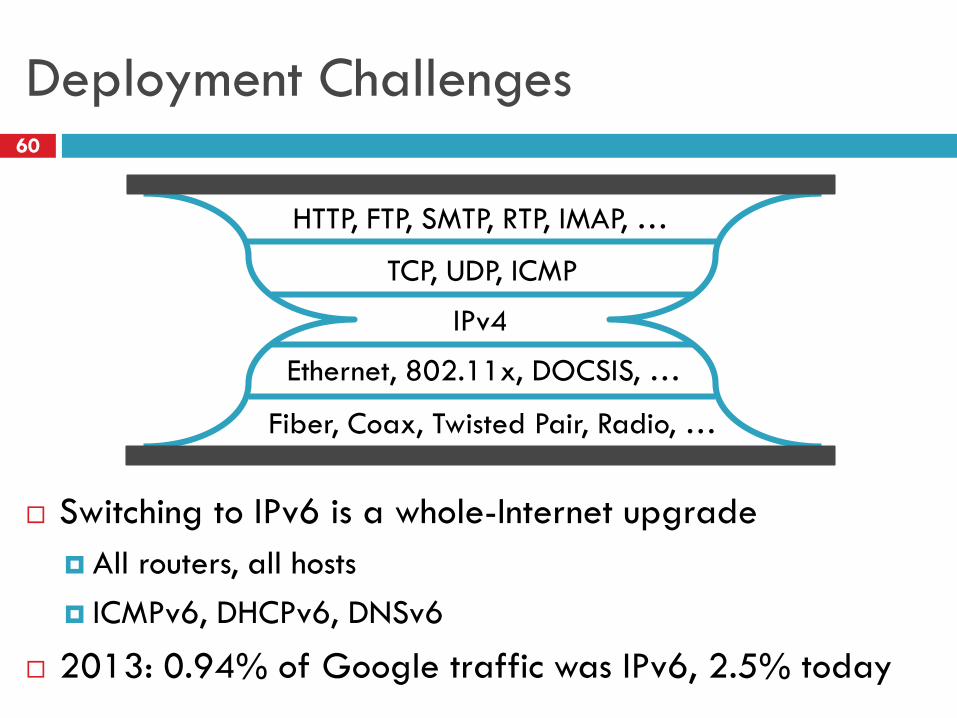
Deployment Challenges60
Switching to IPv6 is a whole-Internet upgrade
All routers, all hosts
ICMPv6, DHCPv6, DNSv6
2013: 0.94% of Google traffic was IPv6, 2.5% today
IPv4
TCP, UDP, ICMP
HTTP, FTP, SMTP, RTP, IMAP, …
Ethernet, 802.11x, DOCSIS, …
Fiber, Coax, Twisted Pair, Radio, …
Transitioning to IPv661
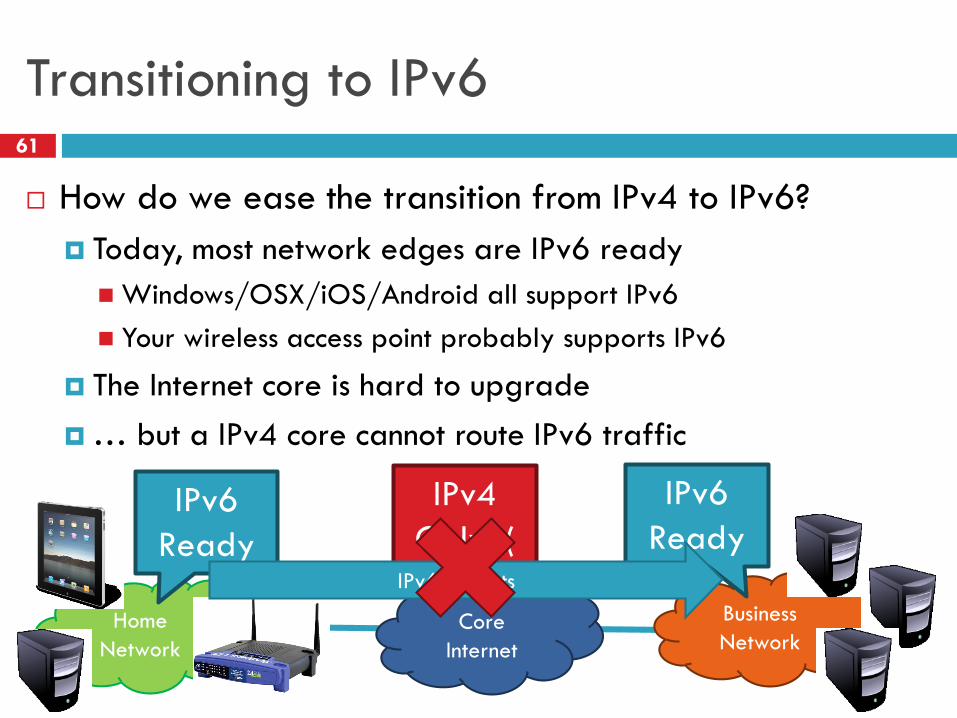
How do we ease the transition from IPv4 to IPv6?
Today, most network edges are IPv6 ready
Windows/OSX/iOS/Android all support IPv6
Your wireless access point probably supports IPv6
The Internet core is hard to upgrade
… but a IPv4 core cannot route IPv6 traffic
Core
Internet
Business
NetworkHome
Network
IPv6
Ready
IPv6
Ready
IPv4
Only :(IPv6 Packets
Transition Technologies62
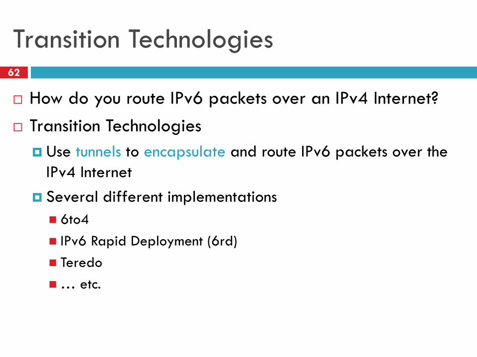
How do you route IPv6 packets over an IPv4 Internet?
Transition Technologies
Use tunnels to encapsulate and route IPv6 packets over the
IPv4 Internet
Several different implementations
6to4
IPv6 Rapid Deployment (6rd)
Teredo
… etc.
Network Layer, Control Plane63
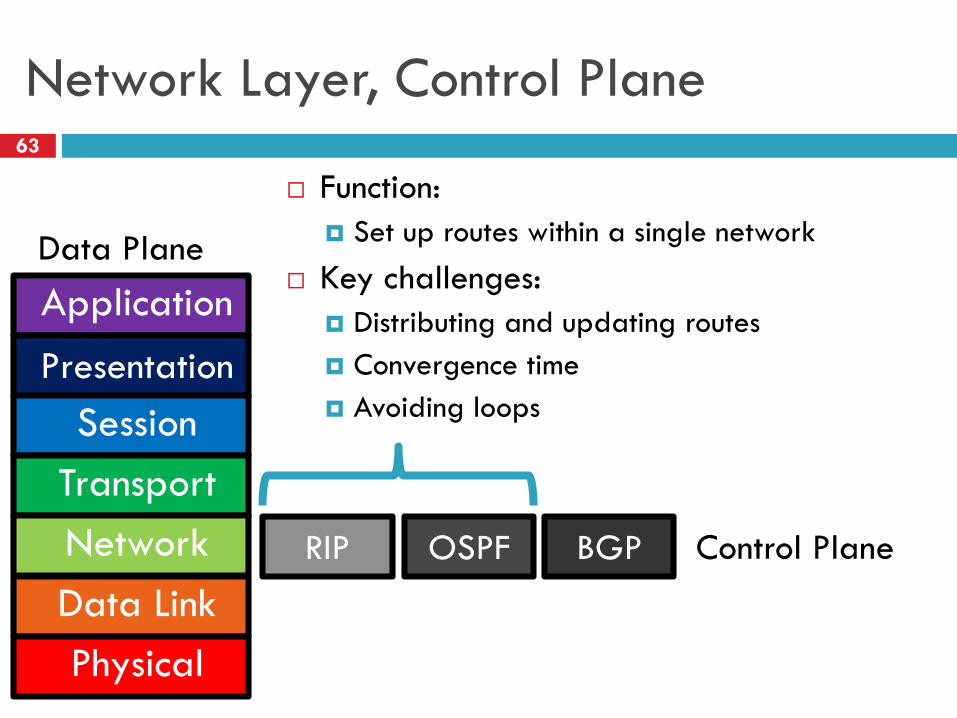
Function:
Set up routes within a single network
Key challenges:
Distributing and updating routes
Convergence time
Avoiding loops
Application
Presentation
Session
Transport
Network
Data Link
Physical
BGPRIP OSPF Control Plane
Data Plane
Internet Routing
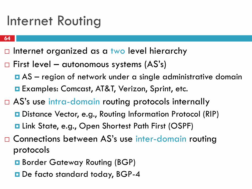
Internet organized as a two level hierarchy
First level – autonomous systems (AS’s)
AS – region of network under a single administrative domain
Examples: Comcast, AT&T, Verizon, Sprint, etc.
AS’s use intra-domain routing protocols internally
Distance Vector, e.g., Routing Information Protocol (RIP)
Link State, e.g., Open Shortest Path First (OSPF)
Connections between AS’s use inter-domain routing protocols
Border Gateway Routing (BGP)
De facto standard today, BGP-4
64
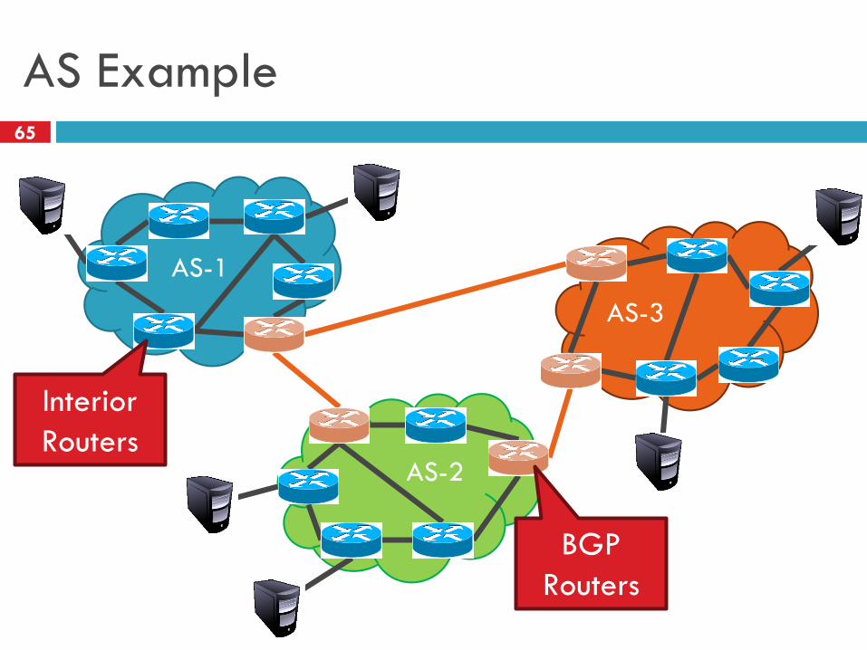
AS Example65
AS-1
AS-2
AS-3
Interior
Routers
BGP
Routers
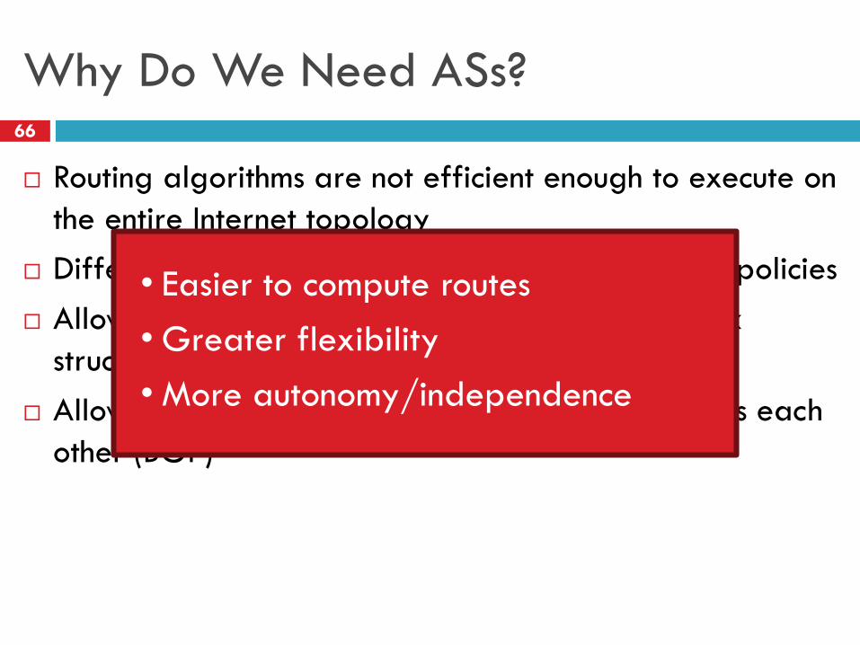
Why Do We Need ASs?66
Routing algorithms are not efficient enough to execute on
the entire Internet topology
Different organizations may use different routing policies
Allows organizations to hide their internal network
structure
Allows organizations to choose how to route across each
other (BGP)
• Easier to compute routes
• Greater flexibility
• More autonomy/independence
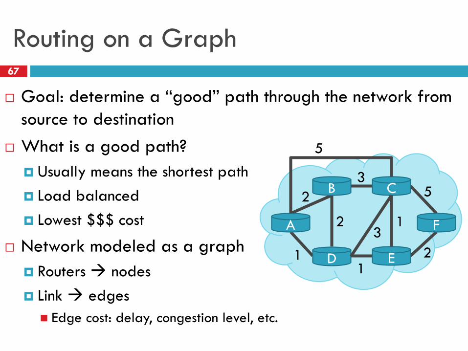
Routing on a Graph
Goal: determine a “good” path through the network from
source to destination
What is a good path?
Usually means the shortest path
Load balanced
Lowest $$$ cost
Network modeled as a graph
Routers nodes
Link edges
Edge cost: delay, congestion level, etc.
A
B C
D E
F
5
2
35
21
1
23
1
67
Networks: Routing
68
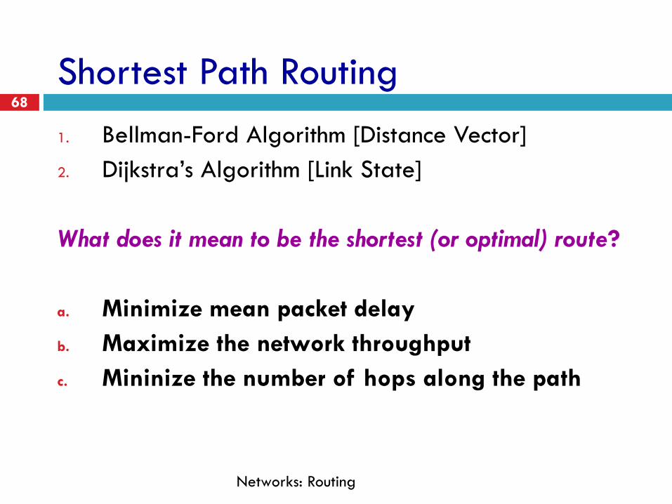
Shortest Path Routing
1. Bellman-Ford Algorithm [Distance Vector]
2. Dijkstra’s Algorithm [Link State]
What does it mean to be the shortest (or optimal) route?
a. Minimize mean packet delay
b. Maximize the network throughput
c. Mininize the number of hops along the path
Networks: Routing
69
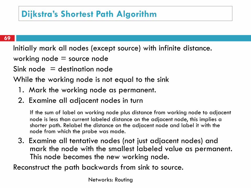
Dijkstra’s Shortest Path Algorithm
Initially mark all nodes (except source) with infinite distance.
working node = source node
Sink node = destination node
While the working node is not equal to the sink
1. Mark the working node as permanent.
2. Examine all adjacent nodes in turn
If the sum of label on working node plus distance from working node to adjacent node is less than current labeled distance on the adjacent node, this implies a shorter path. Relabel the distance on the adjacent node and label it with the node from which the probe was made.
3. Examine all tentative nodes (not just adjacent nodes) and mark the node with the smallest labeled value as permanent. This node becomes the new working node.
Reconstruct the path backwards from sink to source.
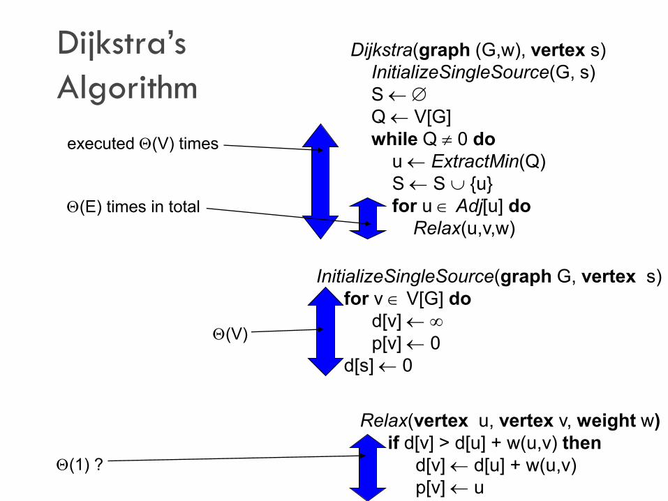
Dijkstra’s
Algorithm
Dijkstra(graph (G,w), vertex s)
InitializeSingleSource(G, s)
S
Q V[G]
while Q 0 do
u ExtractMin(Q)
S S {u}
for u Adj[u] do
Relax(u,v,w)
InitializeSingleSource(graph G, vertex s)
for v V[G] do
d[v]
p[v] 0
d[s] 0
Relax(vertex u, vertex v, weight w)
if d[v] > d[u] + w(u,v) then
d[v] d[u] + w(u,v)
p[v] u
(V)
(1) ?
(E) times in total
executed (V) times
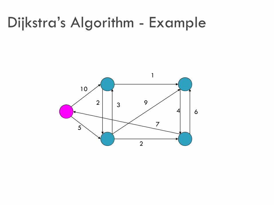
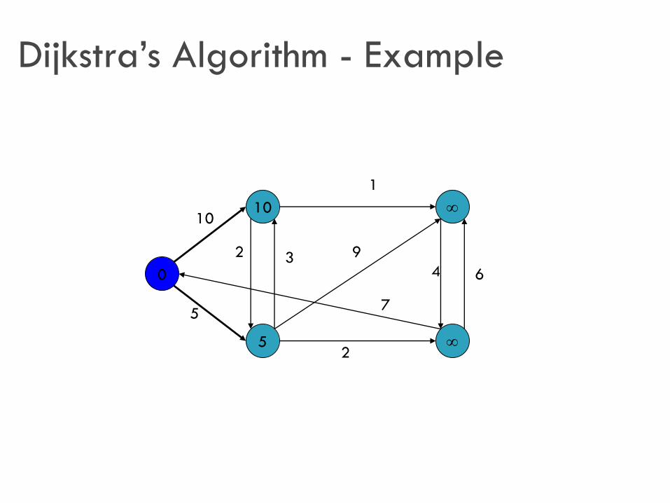
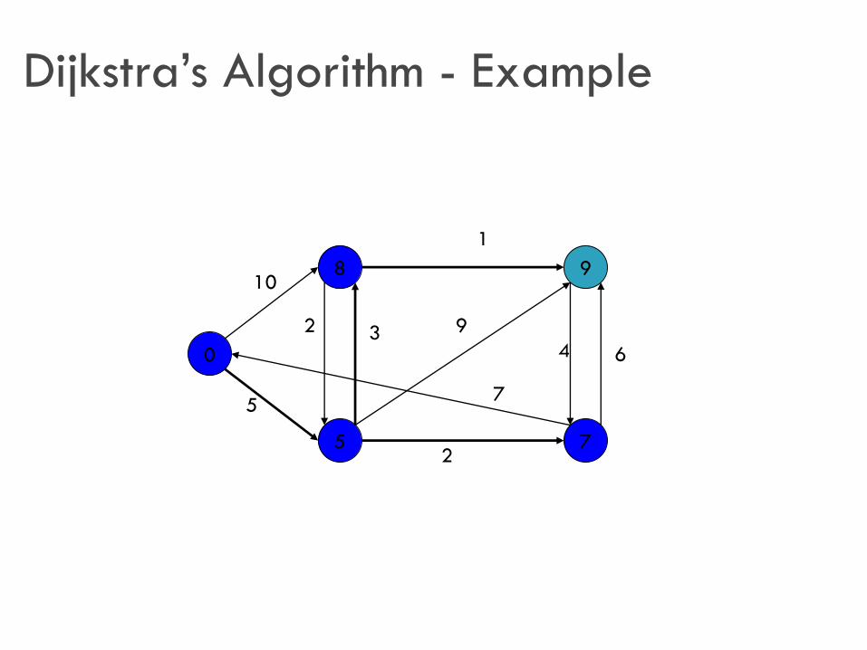
Dijkstra’s Algorithm - Example
10
1
5
2
64
9
7
2 3
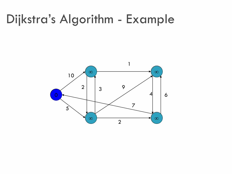
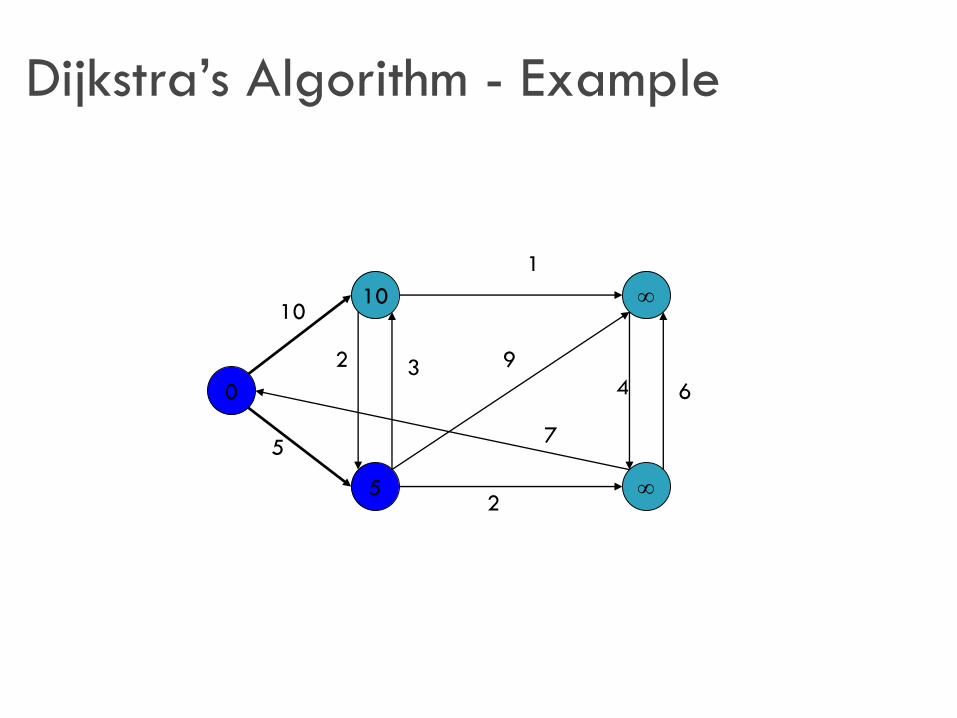
Dijkstra’s Algorithm - Example
0
10
1
5
2
64
9
7
2 3
Dijkstra’s Algorithm - Example
0
5
10
10
1
5
2
64
9
7
2 3
Dijkstra’s Algorithm - Example
0
5
10
10
1
5
2
64
9
7
2 3
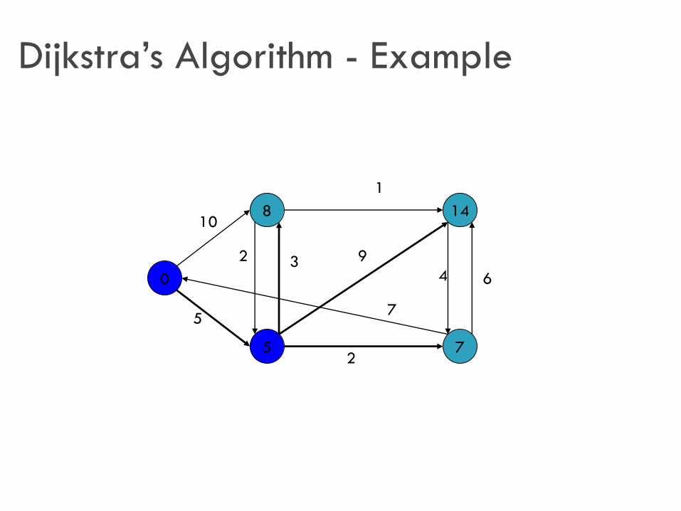
Dijkstra’s Algorithm - Example
0
5
8
7
1410
1
5
2
64
9
7
2 3
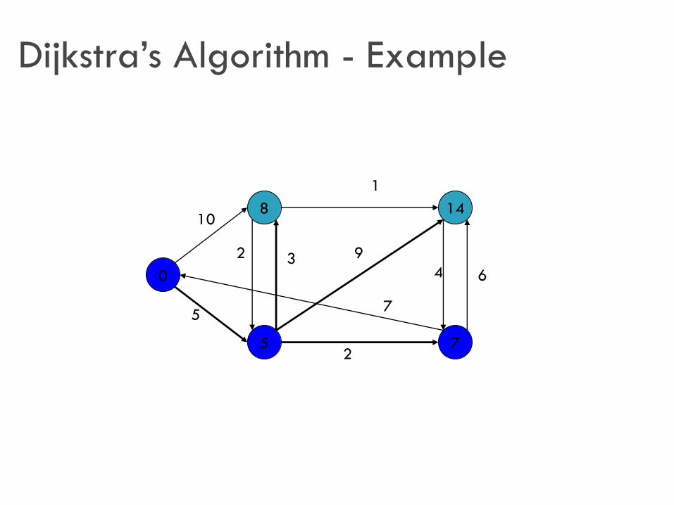
Dijkstra’s Algorithm - Example
0
5
8
7
1410
1
5
2
64
9
7
2 3

Dijkstra’s Algorithm - Example
0
5
8
7
1310
1
5
2
64
9
7
2 3

Dijkstra’s Algorithm - Example
0
5
8
7
1310
1
5
2
64
9
7
2 3
Dijkstra’s Algorithm - Example
0
5
8
7
910
1
5
2
64
9
7
2 3
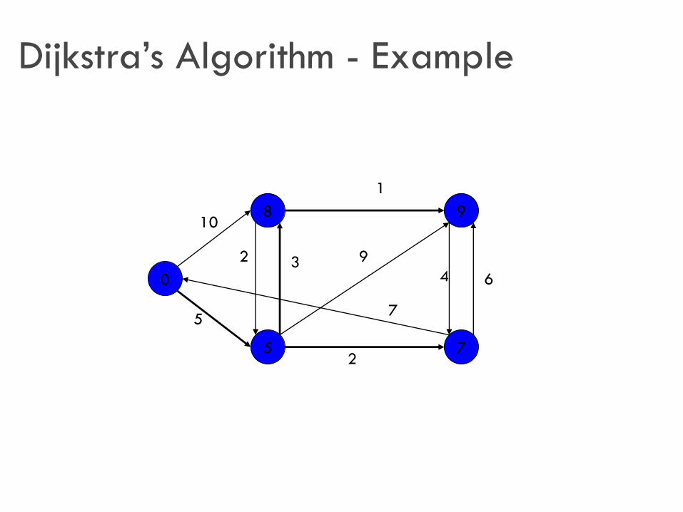
Dijkstra’s Algorithm - Example
0
5
8
7
910
1
5
2
64
9
7
2 3

Bellman-Ford Algorithm
BellmanFord(graph (G,w), vertex s)
InitializeSingleSource(G, s)
for i 1 to |V[G] 1| do
for (u,v) E[G] do
Relax(u,v,w)
for (u,v) E[G] do
if d[v] > d[u] + w(u,v) then
return false
return true
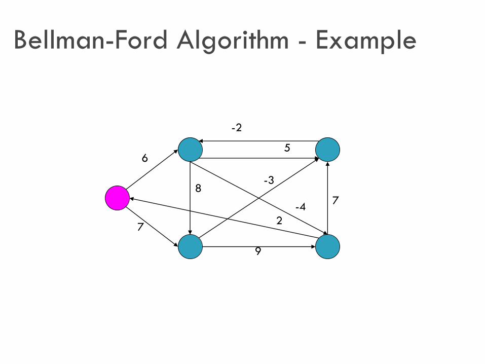
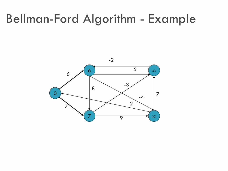
Bellman-Ford Algorithm - Example
6
7
7
-3
2
8
-4
9
5
-2
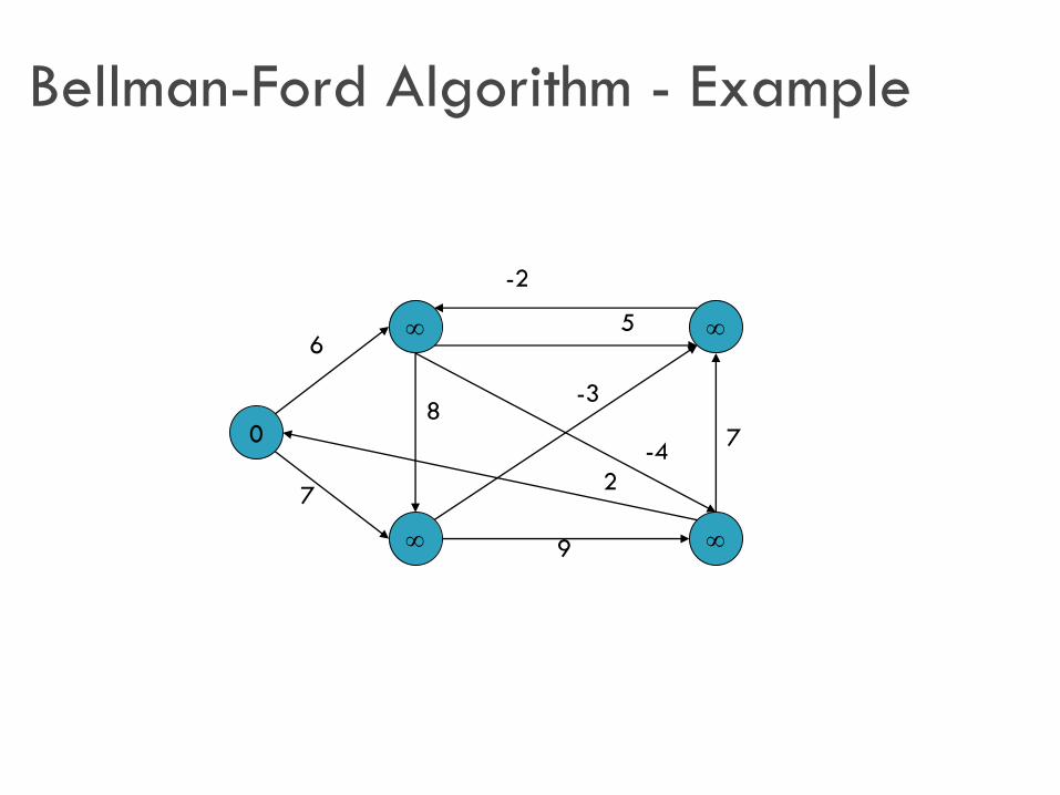
Bellman-Ford Algorithm - Example
0
6
7
7
-3
2
8
-4
9
5
-2
Bellman-Ford Algorithm - Example
0
7
6
6
7
7
-3
2
8
-4
9
5
-2
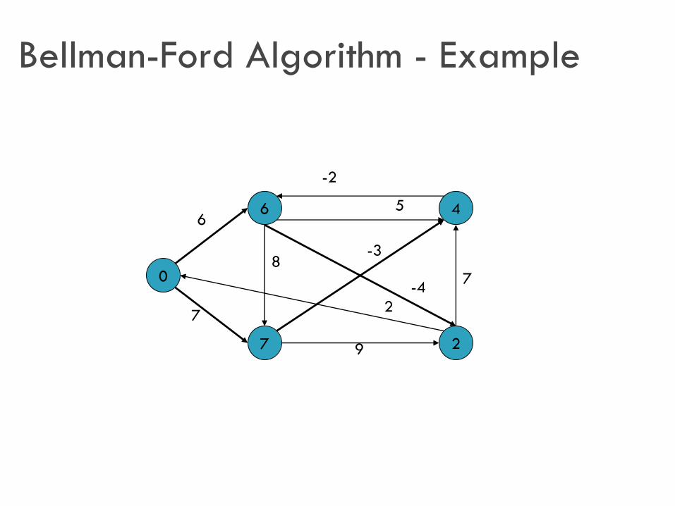
Bellman-Ford Algorithm - Example
0
7
6
2
46
7
7
-3
2
8
-4
9
5
-2
Bellman-Ford Algorithm - Example
0
7
2
2
46
5
7
7
-3
2
8
-2
-4
9

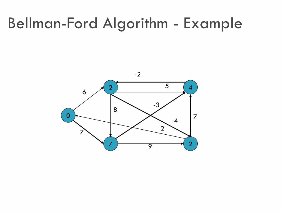
Bellman-Ford Algorithm - Example
0
7
2
-2
46
5
7
7
-3
2
8
-2
-4
9
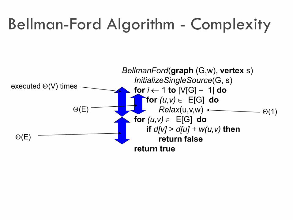
Bellman-Ford Algorithm - Complexity
BellmanFord(graph (G,w), vertex s)
InitializeSingleSource(G, s)
for i 1 to |V[G] 1| do
for (u,v) E[G] do
Relax(u,v,w)
for (u,v) E[G] do
if d[v] > d[u] + w(u,v) then
return false
return true
executed (V) times
(E)
(E)
(1)
Networks: Routing
89
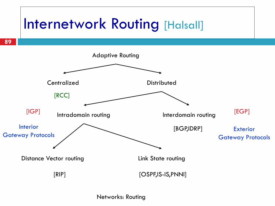
Internetwork Routing [Halsall]
Adaptive Routing
Centralized Distributed
Intradomain routing Interdomain routing
Distance Vector routing Link State routing
[IGP] [EGP]
[BGP,IDRP]
[OSPF,IS-IS,PNNI][RIP]
[RCC]
Interior
Gateway ProtocolsExterior
Gateway Protocols
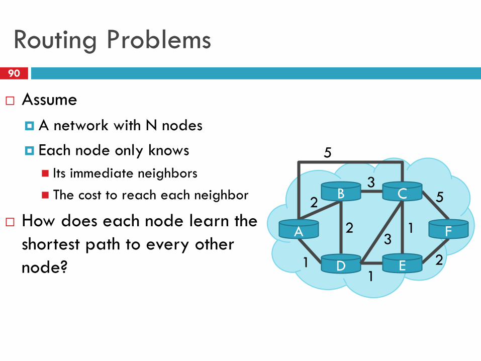
Routing Problems
Assume
A network with N nodes
Each node only knows
Its immediate neighbors
The cost to reach each neighbor
How does each node learn the
shortest path to every other
node?
A
B C
D E
F
5
2
35
21
1
23
1
90
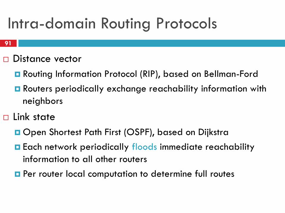
Intra-domain Routing Protocols
Distance vector
Routing Information Protocol (RIP), based on Bellman-Ford
Routers periodically exchange reachability information with
neighbors
Link state
Open Shortest Path First (OSPF), based on Dijkstra
Each network periodically floods immediate reachability
information to all other routers
Per router local computation to determine full routes
91
91
Distance Vector Routing
RIP
Link State Routing
OSPF
IS-IS
Outline92
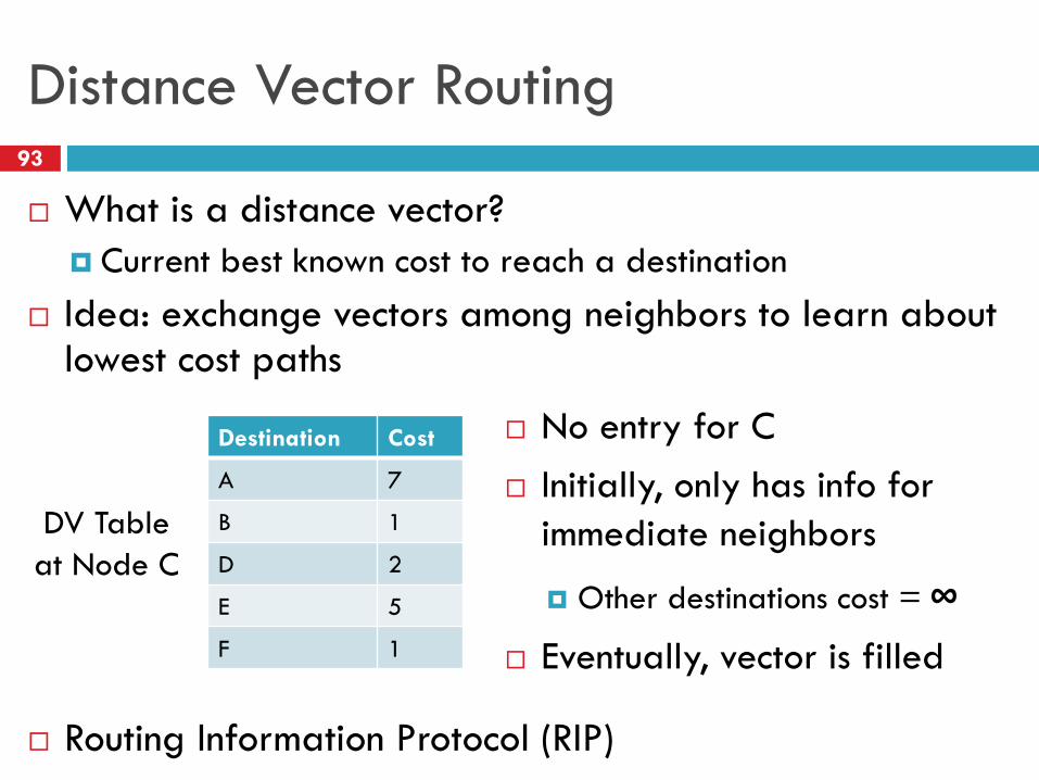
Distance Vector Routing93
What is a distance vector?
Current best known cost to reach a destination
Idea: exchange vectors among neighbors to learn about lowest cost paths
Routing Information Protocol (RIP)
Destination Cost
A 7
B 1
D 2
E 5
F 1
DV Table
at Node C
No entry for C
Initially, only has info for
immediate neighbors
Other destinations cost = ∞
Eventually, vector is filled
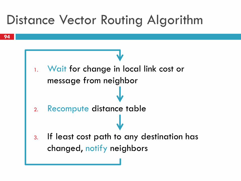
Distance Vector Routing Algorithm94
1. Wait for change in local link cost or
message from neighbor
2. Recompute distance table
3. If least cost path to any destination has
changed, notify neighbors
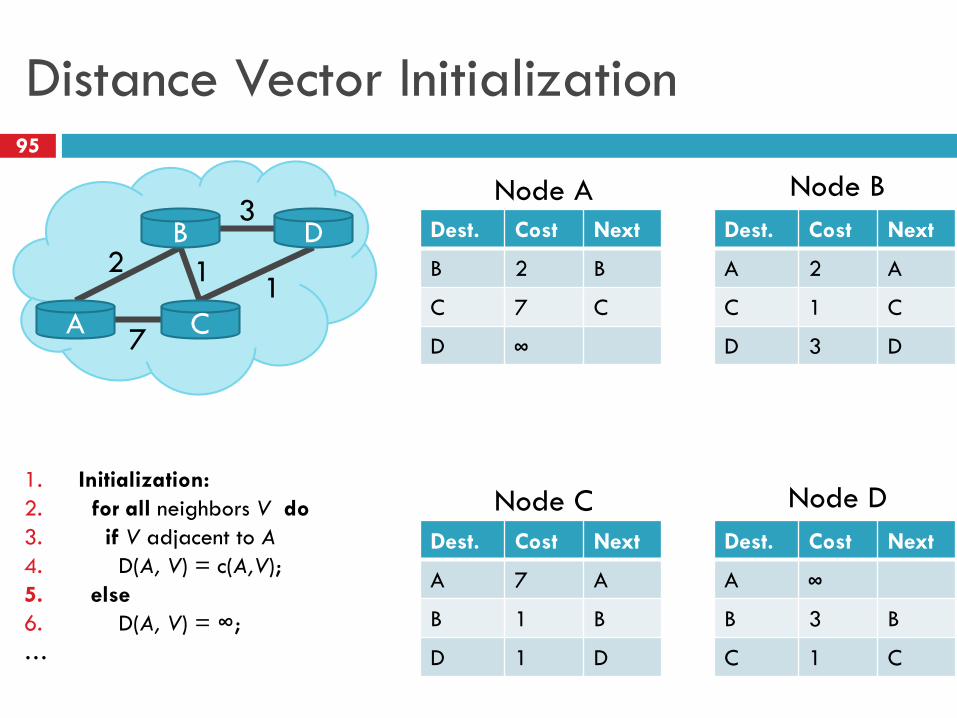
Distance Vector Initialization95
Dest. Cost Next
B 2 B
C 7 C
D ∞
2
3
1
A
B
C
D
1
7
Node A
Dest. Cost Next
A 2 A
C 1 C
D 3 D
Node B
Dest. Cost Next
A 7 A
B 1 B
D 1 D
Node C
Dest. Cost Next
A ∞
B 3 B
C 1 C
Node D1. Initialization:
2. for all neighbors V do
3. if V adjacent to A
4. D(A, V) = c(A,V);
5. else
6. D(A, V) = ∞;
…
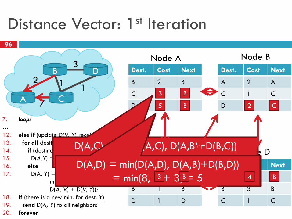
Distance Vector: 1st Iteration96
Dest. Cost Next
B 2 B
C 7 C
D ∞
2
3
1
A
B
C
D
1
7
Node A
Dest. Cost Next
A 2 A
C 1 C
D 3 D
Node B
Dest. Cost Next
A 7 A
B 1 B
D 1 D
Node C
Dest. Cost Next
A ∞
B 3 B
C 1 C
Node D
…
7. loop:
…
12. else if (update D(V, Y) received from V)
13. for all destinations Y do
14. if (destination Y through V)
15. D(A,Y) = D(A,V) + D(V, Y);
16. else
17. D(A, Y) =
min(D(A, Y),
D(A, V) + D(V, Y));
18. if (there is a new min. for dest. Y)
19. send D(A, Y) to all neighbors
20. forever
8 C
D(A,D) = min(D(A,D), D(A,C)+D(C,D))
= min(∞, 7 + 1) = 8
3 B
5 B
D(A,C) = min(D(A,C), D(A,B)+D(B,C))
= min(7, 2 + 1) = 3D(A,D) = min(D(A,D), D(A,B)+D(B,D))
= min(8, 2 + 3) = 5
2 C
4 B3 B

Distance Vector: End of 3rd Iteration97
Dest. Cost Next
B 2 B
C 3 B
D 4 B
2
3
1
A
B
C
D
1
7
Node A
Dest. Cost Next
A 2 A
C 1 C
D 2 C
Node B
Dest. Cost Next
A 3 B
B 1 B
D 1 D
Node C
Dest. Cost Next
A 4 C
B 2 C
C 1 C
Node D
…
7. loop:
…
12. else if (update D(V, Y) received from V)
13. for all destinations Y do
14. if (destination Y through V)
15. D(A,Y) = D(A,V) + D(V, Y);
16. else
17. D(A, Y) =
min(D(A, Y),
D(A, V) + D(V, Y));
18. if (there is a new min. for dest. Y)
19. send D(A, Y) to all neighbors
20. forever
• Nothing changes, algorithm terminates
• Until something changes…
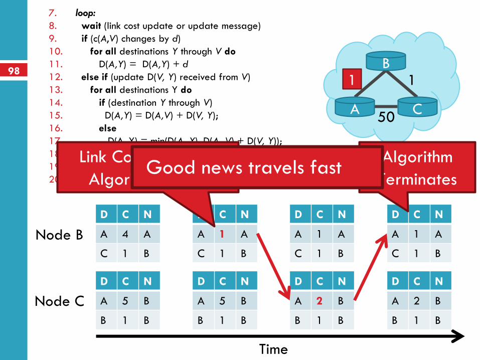
984 1
A
B
C50
7. loop:
8. wait (link cost update or update message)
9. if (c(A,V) changes by d)
10. for all destinations Y through V do
11. D(A,Y) = D(A,Y) + d
12. else if (update D(V, Y) received from V)
13. for all destinations Y do
14. if (destination Y through V)
15. D(A,Y) = D(A,V) + D(V, Y);
16. else
17. D(A, Y) = min(D(A, Y), D(A, V) + D(V, Y));
18. if (there is a new minimum for destination Y)
19. send D(A, Y) to all neighbors
20. forever
1
Node B
Node C
Time
D C N
A 4 A
C 1 B
D C N
A 5 B
B 1 B
D C N
A 1 A
C 1 B
D C N
A 5 B
B 1 B
D C N
A 1 A
C 1 B
D C N
A 2 B
B 1 B
D C N
A 1 A
C 1 B
D C N
A 2 B
B 1 B
Link Cost Changes,
Algorithm Starts
Algorithm
TerminatesGood news travels fast
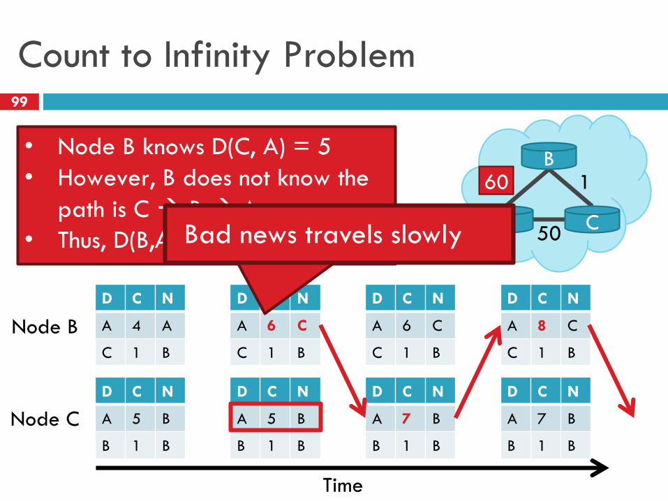
Count to Infinity Problem99
4 1
A
B
C50
60
Node B
Node C
Time
D C N
A 4 A
C 1 B
D C N
A 5 B
B 1 B
D C N
A 6 C
C 1 B
D C N
A 5 B
B 1 B
D C N
A 6 C
C 1 B
D C N
A 7 B
B 1 B
D C N
A 8 C
C 1 B
D C N
A 7 B
B 1 B
• Node B knows D(C, A) = 5
• However, B does not know the
path is C B A
• Thus, D(B,A) = 6 !Bad news travels slowly
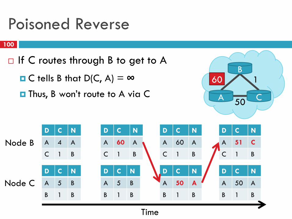
Poisoned Reverse100
4 1
A
B
C50
60
Node B
Node C
Time
D C N
A 4 A
C 1 B
D C N
A 5 B
B 1 B
D C N
A 60 A
C 1 B
D C N
A 5 B
B 1 B
D C N
A 60 A
C 1 B
D C N
A 50 A
B 1 B
D C N
A 51 C
C 1 B
D C N
A 50 A
B 1 B
If C routes through B to get to A
C tells B that D(C, A) = ∞ Thus, B won’t route to A via C