Data communication and computer networks Introduction
46
Data communication and computer networks Introduction What is computer network? A computer network is a group of computer systems and other computing hardware devices that are linked together through communication channels to facilitate communication and resource- sharing among a wide range of users. Networks are commonly categorized based on their characteristics. Reasons for setting up networks Networks are used to: Facilitate communication via email, video conferencing, instant messaging, etc. Enable multiple users to share a single hardware device like a printer or scanner Enable file sharing across the network Allow for the sharing of software or operating programs on remote systems Make information easier to access and maintain among network users Different types of Networks There are many types of networks, including: Local Area Networks (LAN) Personal Area Networks (PAN) Home Area Networks (HAN) Wide Area Networks (WAN) Campus Networks
-
Upload
cavendishug -
Category
Documents
-
view
1 -
download
0
Transcript of Data communication and computer networks Introduction

Data communication and computer networks
Introduction
What is computer network?
A computer network is a group of computer systems and othercomputing hardware devices that are linked together throughcommunication channels to facilitate communication and resource-sharing among a wide range of users. Networks are commonlycategorized based on their characteristics.
Reasons for setting up networks
Networks are used to:
Facilitate communication via email, video conferencing,instant messaging, etc.
Enable multiple users to share a single hardware device likea printer or scanner
Enable file sharing across the network Allow for the sharing of software or operating programs on
remote systems Make information easier to access and maintain among network
users
Different types of NetworksThere are many types of networks, including:
Local Area Networks (LAN) Personal Area Networks (PAN) Home Area Networks (HAN) Wide Area Networks (WAN) Campus Networks
Metropolitan Area Networks (MAN) Enterprise Private Networks Internetworks Backbone Networks (BBN) Global Area Networks (GAN) The Internet
Differences between WANs, LANs & MANsCoverage Area LANs cover a small area, typically a room or building MANs cover a larger area, typically a city or county WANs have no limit on size or area covered
Difference in ownership LANs are private - not owned MANs can be private or public WANS can be private or public
Difference in Transmission Rates (Speed) LANs typically have high data rates compared to WANs MANs have higher rates than LANs WANs have low data rates
Network topologies
Network topology refers to the physical or logical layout of anetwork. It defines the way different nodes are placed andinterconnected with each other; alternately, network topology maydescribe how the data is transferred between these nodes. There are two types of network topologies: physical and logical.
Physical topology emphasizes the physical layout of the connecteddevices and nodes, while the Logical topology focuses the pattern of data transfer betweennetwork nodes.Physical and network topologies can be categorized into fivebasic models:
Bus Topology: All the devices/nodes are connectedsequentially to the same backbone or transmission line. Thisis a simple, low-cost topology, but its single point offailure presents a risk.
Star Topology: All the nodes in the network are connected toa central device like a hub or switch via cables. Failure ofindividual nodes or cables does not necessarily createdowntime in the network but the failure of a central devicecan. This topology is the most preferred and popular model.
Ring Topology: All network devices are connected sequentiallyto a backbone as in bus topology except that the backboneends at the starting node, forming a ring. Ring topologyshares many of bus topology's disadvantages so its use islimited to networks that demand high throughput.
Tree Topology: A root node is connected to two or more sub-level nodes, which themselves are connected hierarchically tosub-level nodes. Physically, the tree topology is similar tobus and star topologies; the network backbone may have a bustopology, while the low-level nodes connect using startopology.
Mesh Topology: The topology in each node is directlyconnected to some or all the other nodes present in thenetwork. This redundancy makes the network highly faulttolerant but the escalated costs may limit this topology tohighly critical networks.
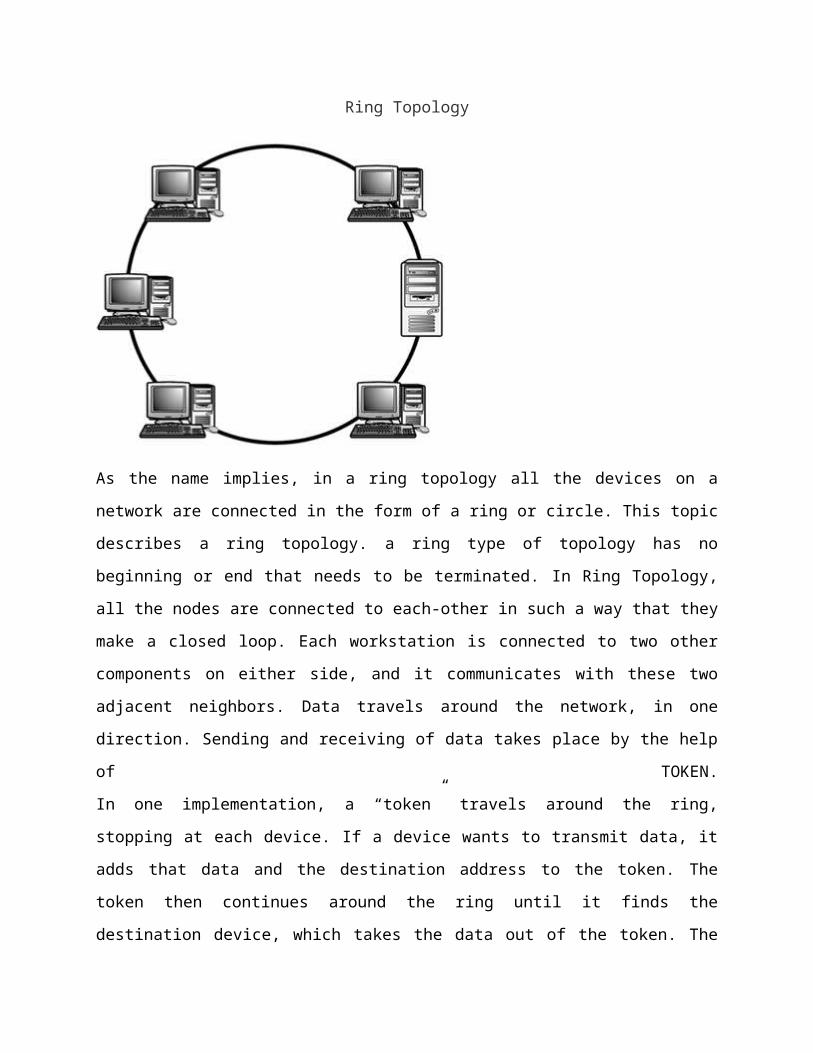
Ring Topology
As the name implies, in a ring topology all the devices on a
network are connected in the form of a ring or circle. This topic
describes a ring topology. a ring type of topology has no
beginning or end that needs to be terminated. In Ring Topology,
all the nodes are connected to each-other in such a way that they
make a closed loop. Each workstation is connected to two other
components on either side, and it communicates with these two
adjacent neighbors. Data travels around the network, in one
direction. Sending and receiving of data takes place by the help
of TOKEN.
In one implementation, a “token” travels around the ring,
stopping at each device. If a device wants to transmit data, it
adds that data and the destination address to the token. The
token then continues around the ring until it finds the
destination device, which takes the data out of the token. The
advantage of using this type of method is that there are no
collisions of data packets.
What is a token
Token contains a piece of information which along with data is
sent by the source computer. This token then passes to next node,
which checks if the signal is intended to it. If yes, it receives
it and passes the empty to into the network, otherwise passes
token along with the data to next node. This process continues
until the signal reaches its intended destination. The nodes with
token are the ones only allowed to send data. Other nodes have to
wait for an empty token to reach them. This network is usually
found in offices, schools and small buildings.
Advantages of Ring Topology
1) This type of network topology is very organized. Each node
gets to send the data when it receives an empty token. This
helps to reduces chances of collision. Also in ring topology all
the traffic flows in only one direction at very high speed.
2) Even when the load on the network increases, its performance
is better than that of Bus topology.
3) There is no need for network server to control the
connectivity between workstations.
4) Additional components do not affect the performance of
network.
5) Each computer has equal access to resources.
Disadvantages of Ring Topology
1) Each packet of data must pass through all the computers
between source and destination. This makes it slower than Star
topology.
2) If one workstation or port goes down, the entire network
gets affected.
3) Network is highly dependent on the wire which connects
different components.
4) Network cards are expensive as compared to Ethernet cards
and hubs.
What is Tree Topology?
Tree Topology integrates the characteristics of Star and Bus
Topology. Earlier we saw how in Physical Star network Topology,
computers (nodes) are connected by each other through central
hub. And we also saw in Bus Topology, work station devices are
connected by the common cable called Bus. After understanding
these two network configurations, we can understand tree topology
better. In Tree Topology, the number of Star networks are
connected using Bus. This main cable seems like a main stem of a
tree, and other star networks as the branches. It is also called

Expanded Star Topology. Ethernet protocol is commonly used in
this type of topology. The diagram below will make it clear.
Tree Topology
.Advantages of Tree Topology
1. It is an extension of Star and bus Topologies, so in networks
where these topologies can't be implemented individually for
reasons related to scalability, tree topology is the best
alternative.
2. Expansion of Network is possible and easy.
3. Here, we divide the whole network into segments (star
networks), which can be easily managed and maintained.
4. Error detection and correction is easy.
5. Each segment is provided with dedicated point-to-point wiring
to the central hub.
6. If one segment is damaged, other segments are not affected.
Disadvantages of Tree Topology
1. Because of its basic structure, tree topology, relies heavily
on the main bus cable, if it breaks whole network is crippled.
2. As more and more nodes and segments are added, the maintenance
becomes difficult.
3. Scalability of the network depends on the type of cable used.
Hybrid Topology
Hybrid, as the name suggests, is mixture of two different
things. Similarly in this type of topology we integrate two or
more different topologies to form a resultant topology which has
good points (as well as weaknesses) of all the constituent basic
topologies rather than having characteristics of one specific
topology. This combination of topologies is done according to the
requirements of the organization.
For example, if there exists a ring topology in one office
department while a bus topology in another department, connecting
these two will result in Hybrid topology. Remember connecting two
similar topologies cannot be termed as Hybrid topology. Star-Ring
and Star-Bus networks are most common examples of hybrid network.
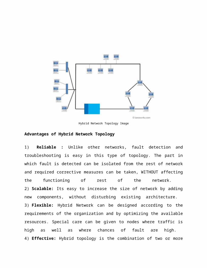
Hybrid Network Topology Image
Advantages of Hybrid Network Topology
1) Reliable : Unlike other networks, fault detection and
troubleshooting is easy in this type of topology. The part in
which fault is detected can be isolated from the rest of network
and required corrective measures can be taken, WITHOUT affecting
the functioning of rest of the network.
2) Scalable: Its easy to increase the size of network by adding
new components, without disturbing existing architecture.
3) Flexible: Hybrid Network can be designed according to the
requirements of the organization and by optimizing the available
resources. Special care can be given to nodes where traffic is
high as well as where chances of fault are high.
4) Effective: Hybrid topology is the combination of two or more
topologies, so we can design it in such a way that strengths of
constituent topologies are maximized while there weaknesses are
neutralized. For example we saw Ring Topology has good data
reliability (achieved by use of tokens) and Star topology has
high tolerance capability (as each node is not directly connected
to other but through central device), so these two can be used
effectively in hybrid star-ring topology.
Disadvantages of Hybrid Topology
1) Complexity of Design: One of the biggest drawbacks of hybrid
topology is its design. Its not easy to design this type of
architecture and its a tough job for designers. Configuration and
installation process needs to be very efficient.
2) Costly Hub: The hubs used to connect two distinct networks,
are very expensive. These hubs are different from usual hubs as
they need to be intelligent enough to work with different
architectures and should be function even if a part of network is
down.
3) Costly Infrastructure: As hybrid architectures are usually
larger in scale, they require a lot of cables, cooling systems,
sophisticate network devices, etc.
Bus topology
Bus Topology is the simplest of network topologies. In this type
of topology, all the nodes (computers as well as servers) are

connected to the single cable (called bus), by the help of
interface connectors. This central cable is the backbone of the
network and is known as Bus (thus the name). Every workstation
communicates with the other device through this Bus.
A signal from the source is broadcasted and it travels to all
workstations connected to bus cable. Although the message is
broadcasted but only the intended recipient, whose MAC address or
IP address matches, accepts it. If the MAC /IP address of machine
doesn’t match with the intended address, machine discards the
signal.
A terminator is added at ends of the central cable, to prevent
bouncing of signals. A barrel connector can be used to extend it.
Advantages Bus Topology
1) It is easy to set-up and extend bus network.
2) Cable length required for this topology is the least compared
to other networks.
3) Bus topology costs very less.
4) Linear Bus network is mostly used in small networks. Good for
LAN.
Disadvantages Bus Topology
1) There is a limit on central cable length and number of
nodes that can be connected.
2) Dependency on central cable in this topology has its
disadvantages. If the main cable (i.e. bus) encounters some
problem, whole network breaks down.
3) Proper termination is required to dump signals. Use of
terminators is must.
4) It is difficult to detect and troubleshoot fault at
individual station.
5) Maintenance costs can get higher with time.
6) Efficiency of Bus network reduces, as the number of
devices connected to it increases.
7) It is not suitable for networks with heavy traffic.
8) Security is very low because all the computers receive the
sent signal from the source.
Star topology
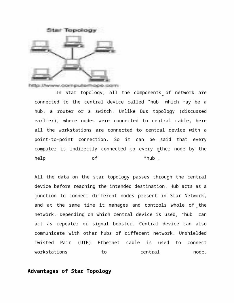
In Star topology, all the components of network are
connected to the central device called “hub” which may be a
hub, a router or a switch. Unlike Bus topology (discussed
earlier), where nodes were connected to central cable, here
all the workstations are connected to central device with a
point-to-point connection. So it can be said that every
computer is indirectly connected to every other node by the
help of “hub”.
All the data on the star topology passes through the central
device before reaching the intended destination. Hub acts as a
junction to connect different nodes present in Star Network,
and at the same time it manages and controls whole of the
network. Depending on which central device is used, “hub” can
act as repeater or signal booster. Central device can also
communicate with other hubs of different network. Unshielded
Twisted Pair (UTP) Ethernet cable is used to connect
workstations to central node.
Advantages of Star Topology
1) As compared to Bus topology it gives far much better
performance, signals don’t necessarily get transmitted to all the
workstations. A sent signal reaches the intended destination
after passing through no more than 3-4 devices and 2-3 links.
Performance of the network is dependent on the capacity of
central hub.
2) Easy to connect new nodes or devices. In star topology new
nodes can be added easily without affecting rest of the network.
Similarly components can also be removed easily.
3) Centralized management. It helps in monitoring the network.
4) Failure of one node or link doesn’t affect the rest of
network. At the same time its easy to detect the failure and
troubleshoot it.
Disadvantages of Star Topology
1) Too much dependency on central device has its own drawbacks.
If it fails whole network goes down.
2) The use of hub, a router or a switch as central device
increases the overall cost of the network.
3) Performance and as well number of nodes which can be added
in such topology is depended on capacity of central device.
What is Mesh Topology?
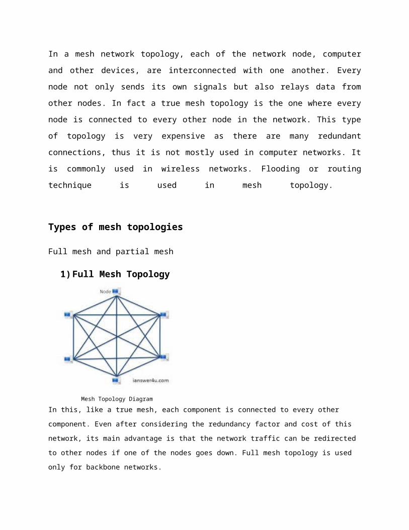
In a mesh network topology, each of the network node, computer
and other devices, are interconnected with one another. Every
node not only sends its own signals but also relays data from
other nodes. In fact a true mesh topology is the one where every
node is connected to every other node in the network. This type
of topology is very expensive as there are many redundant
connections, thus it is not mostly used in computer networks. It
is commonly used in wireless networks. Flooding or routing
technique is used in mesh topology.
Types of mesh topologies
Full mesh and partial mesh
1)Full Mesh Topology
Mesh Topology DiagramIn this, like a true mesh, each component is connected to every other
component. Even after considering the redundancy factor and cost of this
network, its main advantage is that the network traffic can be redirected
to other nodes if one of the nodes goes down. Full mesh topology is used
only for backbone networks.
2) Partial Mesh Topology:- This is far more practical as compared to full mesh topology. Here, some
of the systems are connected in similar fashion as in mesh topology while
rests of the systems are only connected to 1 or 2 devices. It can be said
that in partial mesh, the workstations are ‘indirectly’ connected to other
devices. This one is less costly and also reduces redundancy.
Advantages of Mesh topology
1) Data can be transmitted from different devices simultaneously. This
topology can withstand high traffic.
2) Even if one of the components fails there is always an alternative
present. So data transfer doesn’t get affected.
3) Expansion and modification in topology can be done without disrupting
other nodes.
Disadvantages of Mesh topology
1) There are high chances of redundancy in many of the network
connections.
2) Overall cost of this network is way too high as compared to
3) Set-up and maintenance of this topology is very difficult. Even
administration of the network is tough.

Chapter two
Communication Architectures

Definition - What does Data Communications (DC) mean?
Data communications (DC) is the process of using computing and
communication technologies to transfer data from one place to
another, and vice versa. It enables the movement of electronic or
digital data between two or more nodes, regardless of
geographical location, technological medium or data contents OR
Data communication is the transmission of electronic data over
some media. The media may be cables, microwaves.
Data communications incorporates several techniques and
technologies with the primary objective of enabling any form of
electronic communication. These technologies include
telecommunications, computer networking and radio/satellite
communication. Data communication usually requires existence of a
transportation or communication medium between the nodes wanting
to communicate with each other, such as copper wire, fiber optic
cables or wireless signals.
For example, a common example of data communications is a
computer connected to the Internet via a Wi-Fi connection, which
uses a wireless medium to send and receive data from one or more
remote servers. Some devices/technologies used in data
communications are known as data communication equipment (DCE)
and data terminal equipment ( DTE). DCE is used at the sending
node, and DTE is used at the receiving node.
Elements of Data CommunicationFour basic elements are needed for any communication system.
1. Sender. The computer or device that is used forsending data is called sender, source or transmitter. In moderndigital communication system, the source is usually a computer.
2. Medium. The means through which data is sent from onelocation to another is called transmission medium. If thereceiver and transmitter are within a building, a wire connectsthem. If they are located at different locations, they may beconnected by telephone lines, fiber optics or microwaves.
Receiver. The device or computer that receives the data is called receiver. The receiver can be a computer, printer or a faxmachine.
4. Protocols. There are rules under which data transmission takes place between sender and receiver. The data communication s/w are used to transfer data from one computer to another. The s/w follows same communication protocols can communicate and exchange data.
What does Communication Media mean?
Communication media refers to the means of delivering andreceiving data or information. In telecommunication, these meansare transmission and storage tools or channels for data storageand transmission.
The term is also commonly used in place of mass media or newsmedia.
Different media are employed for transmitting data from onecomputer terminal to the central computer or to other computersystems inside some kind of network.
Forms of communication media
1) Analog2) Digital
Analog Signal. The transfer of data in the form of electrical signals orcontinuous waves is called analog signal or analog datatransmission. An analog signal is measured in volts and itsfrequency is in hertz (Hz).
Advantages of Analog Signaling
Allows multiple transmissions across the cable. Suffers less from attenuation.Disadvantages of Analog Signaling
Suffers from EMI. Can only be transmitted in one direction without
sophisticated equipment.
Digital Signal
The transfer of data in the form of digit is called digitalsignal or digital data transmission. Digital signals consist ofbinary digits 0 & 1. Electrical pulses are used to representbinary digits. Data transmission between computers is in the formof digital signals.
Advantages of Digital Signaling
Equipment is cheaper and simpler than analog equipment. Signals can be transmitted on a cable bidirectional. Digital signals suffer less from EMI.
Disadvantages Digital Signaling
Only one signal can be sent at a time. Digital signals suffer from attenuation.
Techniques of Data Communication
There are two possible techniques of sending data from the senderto receiver, i.e.:-
(1) Parallel transmission.
(2) Serial transmission.
Parallel Transmission. In parallel transmission each bit ofcharacter / data has a separate channel and all bits of acharacter are transmitted simultaneously. Here the transmissionis parallel character by character.
Serial Transmission. In serial transmission, the data is sent asone bit at a time having a signal channel for all the bit.
What does Media mean?
Media refers to the tools used to store and deliver information
or data. The term media can refer to advertising, digital media,
electronic media, hypermedia, mass media and multimedia, among
many others.
Digital media is an electronic medium where data is stored in
digital form. It refers to the technical aspect of the storage

and transmission of information, or to the end product consumed
by a user, such as digital video, digital art or virtual reality.
Transformation of an analog signal to digital information through
an analog-to-digital converter is called sampling.
The majority of digital media is based on translating analog
signals to digital data and vice versa. Digital media can be
processed in a number of ways using standard computer hardware
and software, where the performance is critical in high-
performance digital hardware such as an application-specific
integrated circuit (ASIC). The processing process involves
editing, content creation and filtering.
Electronic media use electronics or electro-mechanical energy to
enable end users to access content. This is different from static
media, which is often accessed by end users in printed form.
Broadcasting is the distribution of audio and video content to a
dispersed audience via radio, television, or other methods.
Receiving parties may include the general public or a relatively
large subset thereof. Electronic broadcasting includes telephone
broadcasting, radio broadcasting, television broadcasting, cable
radio, satellite television and webcasting.

Communication channel The communication channel is used to link various computing
devices so that they may interact with each other.
The most commonly used data communication channels
Wire pairs
Coaxial cable
Microwave transmission
Communication satellites
Fiber optics
Contemporary communication media facilitate communication and
data exchange among a large number of individuals across long
distances via email, teleconferencing, Internet forums, etc.
Traditional mass media channels such as TV, radio and magazines,
on the other hand, promote one-to-many communication.
Problems associated with communication
The task of a communication is very complex. To give an
understanding of the complexity, below is a small sample of the
type of problems which must be solved by the communications
software:-
How to connect two users together - communications channel.
How to represent signals on a communications channel.
How to detect and correct errors on channel to ensure error
free transmission.
How to allow users to gain access to the communications
channel.
How to route data to the correct user across a network.
How to ensure the receiver interprets the data correctly - the
receiving machine may differ from the sending machine.
How to allow the user to run applications over the channel.
Transmission Modes
There are two transmission modes:-
Asynchronous Transmission Synchronous Transmission
Fundamental difference between the two modes is :-
Asynchronous Transmission With asynchronous transmission signal timing is not required;
signals are sent in an agreed pattern of bits and if both ends
are agreed on the pattern then communication can take place.
Bits are grouped together and consist of both data and control
bits. If the signal is not synchronised the receiver will not be
able to distinguish when the next group of bits will arrive. To
overcome this the data is preceded by a start bit, usually binary
0, the byte is then sent and a stop bit or bits are added to the
end. Each byte to be sent now incorporates extra control data. In

addition to the control data small gaps are inserted between each
chunk to distinguish each group. In asynchronous transmission
each bit remains timed in the usual way. Therefore, at bit level
the transmission is still synchronous (timed). However, the
asynchronous transmission is applied at byte level, once the
receiver realises that there is a chunk of incoming data timing
synchronization takes place for the chunk of data.
Asynchronous transmission is relatively slow due to the increased
number of bits and gaps. It is a cheap and effective form of
serial transmission and is particularly suited for low speed
connections such as keyboard and mouse.
Synchronous Transmission
Synchronous transmission sends data as one long bit stream orblock of data. There are no gaps in transmission; each bit issent one after the other. The receiver counts the bits andreconstructs bytes. It is essential that timing is maintained asthere are no start and stop bits and no gaps. Accuracy isdependent on the receiver keeping an accurate count of the bitsas they come in. Synchronous transmission is faster thanasynchronous because fewer bits have to be transmitted; ie: onlydata bits and no extra control bits. For this reason it is thechoice for network communications links
Modes of Data Communication.
The manner in which data is transmitted from one location toanother location is called data transmission mode.
There are three ways or modes for transmitting data from onelocation to another. These are:
(1) Simplex.
(2) Half duplex.
(3) Full duplex.
Half Duplex.
In half duplex mode, data can be transmitted in both directionsbut only in one direction at a time. During any transmission, oneis the transmitter and the other is receiver. So each time forsending or receiving data, direction of data communication isreversed, this slow down data transmission rate. In half duplexmodes, transmission of data can be confirmed.
Half Duplex ModeWireless communication is an example of half duplex.
Advantages of Half Duplex
Costs less than full duplex. Enables for two way communications.Disadvantages of Half Duplex
Costs more than simplex. Only one device can transmit at a time.
Simplex ModeIn simplex mode, data is transmitted in only one direction. Aterminal can only send data and cannot receive it or it can onlyreceive data but cannot send it. Simplex mode is usually used fora remote device that is meant only to receive data. It is notpossible to confirm successful transmission of data in simplexmode.
This mode is not widely used. Speaker, radio and televisionbroadcasting are examples of simplex transmission, on which thesignal is send from the transmission to your TV antenna. There isno return signal.
Simplex ModeAdvantages of Simplex
Cheapest communication method.Disadvantage of Simplex
Only allows for communication in one direction.
Full Duplex.
Full-duplex data transmission means that data can be transmitted in both directions on a signal carrier at the same time. For example, on a local area network with a technology that has full-duplex transmission, one workstation can be sending data on the line while another workstation is receiving data. Full-duplex transmission necessarily implies a bidirectional line (one that can move data in both directions).
Advantages of full duplex
Speed
Speed is a big advantage of a full duplex network infrastructure.
When a device is set at half duplex, it can receive and transmit
data, but not at the same time. With a full duplex network
environment, that data can be sent and received at the same time.
That can result in faster throughput speeds, fewer network
bottlenecks and a marked increase in network performance
Homogeneous Environment
It can be much easier for network administrators to work with a
single homogeneous environment. Troubleshooting is easier when
every piece of network equipment, from the servers, switches and
hubs in the data room to the terminals and computers on the
floor, are set to full duplex. When a problem does occur, network
personnel can run reports to identify problem clients and make
the changes necessary to bring them back online.
Compatibility
Not all network equipment supports a full duplex setting. Many older
routers, switches, hubs and network clients do not support full duplex, so
network administrators need to check all their equipment carefully before
moving forward with a full duplex network environment. Once the network is
moved to full duplex, any devices that do not support full duplex will no
longer be able to connect. The cost of replacing that old equipment can be
quite high, and that expense should play a role in any decision to upgrade
the network.
Stability
You may find that you have network clients that are capable of
full duplexing, even if the underlying network infrastructure is
not. If this is the case, switching that network client to a full
duplex mode could cause instability across the entire local or
wide area network. It can sometimes be difficult for network
administrators to diagnose these types of issues, since they can
be sporadic, occurring only when the problem terminal is sending
or receiving data.
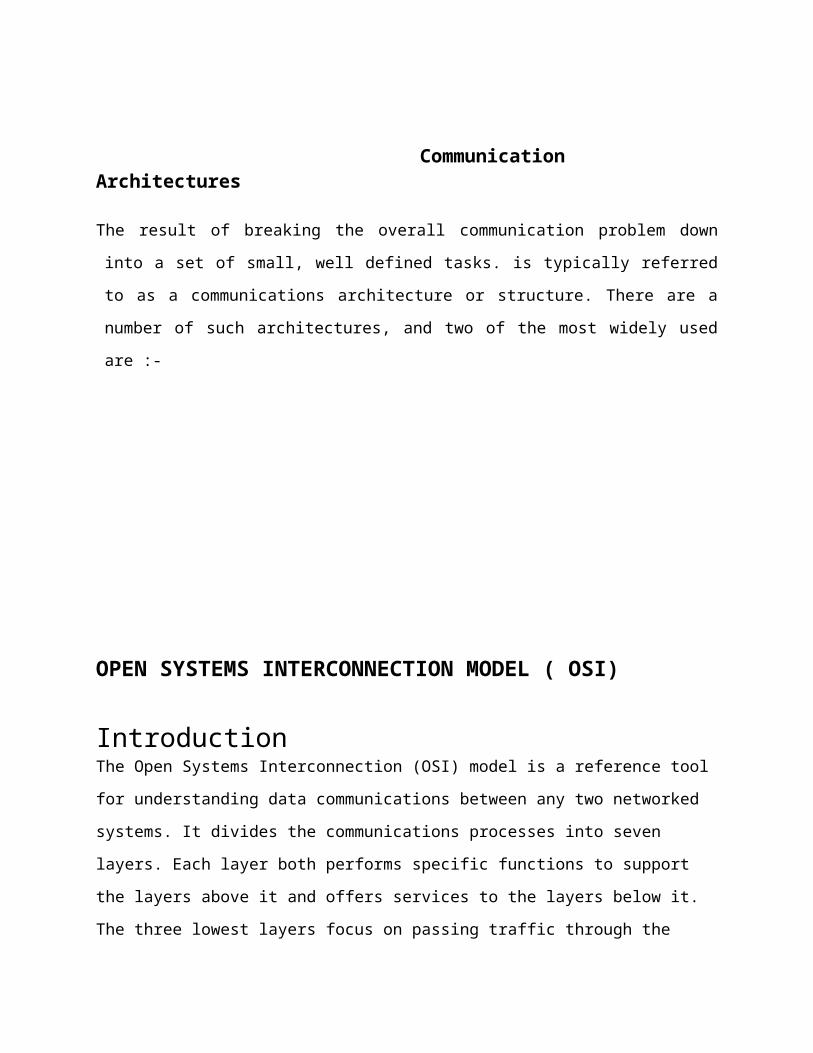
Communication Architectures
The result of breaking the overall communication problem down
into a set of small, well defined tasks. is typically referred
to as a communications architecture or structure. There are a
number of such architectures, and two of the most widely used
are :-
OPEN SYSTEMS INTERCONNECTION MODEL ( OSI)
IntroductionThe Open Systems Interconnection (OSI) model is a reference tool
for understanding data communications between any two networked
systems. It divides the communications processes into seven
layers. Each layer both performs specific functions to support
the layers above it and offers services to the layers below it.
The three lowest layers focus on passing traffic through the
network to an end system. The top four layers come into play in
the end system to complete the process. This white paper will
provide you with an understanding of each of the seven layers,
including their functions and their relationships to each other.
This will provide you with an overview of the network process,
which can then act as a framework for understanding the details
of computer networking. Since the discussion of networking often
includes talk of “extra layers”, this paper will address these
unofficial layers as well.
Finally, this paper will draw comparisons between the theoretical
OSI model and the functional TCP/IP model. Although TCP/IP has
been used for network communications before the adoption of the
OSI model, it supports the same functions and features in a
differently layered arrangement.
An Overview of the OSI Model
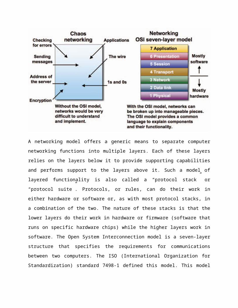
A networking model offers a generic means to separate computer
networking functions into multiple layers. Each of these layers
relies on the layers below it to provide supporting capabilities
and performs support to the layers above it. Such a model of
layered functionality is also called a “protocol stack” or
“protocol suite”. Protocols, or rules, can do their work in
either hardware or software or, as with most protocol stacks, in
a combination of the two. The nature of these stacks is that the
lower layers do their work in hardware or firmware (software that
runs on specific hardware chips) while the higher layers work in
software. The Open System Interconnection model is a seven-layer
structure that specifies the requirements for communications
between two computers. The ISO (International Organization for
Standardization) standard 7498-1 defined this model. This model

allows all network elements to operate together, no matter who
created the
Protocols and what computer vendor supports them.
The main benefits of the OSI model include the following:• Helps users understand the big picture of networking
• Helps users understand how hardware and software elements
function together
• Makes troubleshooting easier by separating networks into
manageable pieces
• Defines terms that networking professionals can use to compare
basic functional relationships on different networks
• Helps users understand new technologies as they are developed
• Aids in interpreting vendor explanations of product
functionality
Layer 1 – The Physical Layer
The physical layer of the OSI model defines connector and
interface specifications, as well as the medium (cable)
requirements. Electrical, mechanical, functional, and procedural
specifications are provided for sending a bit stream on a
computer network.
Components of the physical layer include:
• Cabling system components
• Adapters that connect media to physical interfaces
• Connector design and pin assignments

• Hub, repeater, and patch panel specifications
• Wireless system components
• Parallel SCSI (Small Computer System Interface)
• Network Interface Card (NIC)
In a LAN environment, Category 5e UTP (Unshielded Twisted Pair)
cable is generally used for the physical layer for individual
device connections. Fiber optic cabling is often used for the
physical layer in a vertical or riser backbone link. The IEEE,
EIA/TIA, ANSI, and other similar standards bodies developed
standards for this layer.
Note: The Physical Layer of the OSI model is only part of a LAN
(Local Area Network).
Layer 2 – The Data Link LayerLayer 2 of the OSI model provides the following functions:
• Allows a device to access the network to send and receive
messages
• Offers a physical address so a device’s data can be sent on the
network
• Works with a device’s networking software when sending and
receiving messages
• Provides error-detection capability
Common networking components that function at layer 2 include:
• Network interface cards
• Ethernet and Token Ring switches
• Bridges
NICs have a layer 2 or MAC address. A switch uses this address to
filter and forward traffic, helping relieve congestion and
collisions on a network segment.
Bridges and switches function in a similar fashion; however,
bridging is normally a software program on a CPU, while switches
use Application-Specific Integrated Circuits (ASICs) to perform
the task in dedicated hardware, which is much faster.
Layer 3 – The Network Layer
Layer 3, the network layer of the OSI model, provides an end-to-
end logical addressing system so that a packet of data can be
routed across several layer 2 networks (Ethernet, Token Ring,
Frame Relay, etc.). Note that network layer addresses can also be
referred to as logical addresses. Initially, software
manufacturers, such as Novell, developed proprietary layer 3
addressing. However, the networking industry has evolved to the
point that it requires a common layer 3 addressing system. The
Internet Protocol (IP) addresses make networks easier to both set
up and connect with one another. The Internet uses IP addressing
to provide connectivity to millions of networks around the world.
To make it easier to manage the network and control the flow of
packets, many organizations separate their network layer
addressing into smaller parts known as subnets. Routers use the
network or subnet portion of the IP addressing to route traffic
between different networks. Each router must be configured
specifically for
the networks or subnets that will be connected to its interfaces.
Routers communicate with one another using routing protocols,
such as Routing Information Protocol (RIP) and Open version of
Shortest Path First (OSPF), to learn of other networks that are
present and to calculate the best way to reach each network based
on a variety of criteria (such as the path with the fewest
routers). Routers and other networked systems make these routing
decisions at the network layer. When passing packets between
different networks, it may become necessary to adjust their
outbound size to one that is compatible with the layer 2 protocol
that is being used. The network layer accomplishes this via a
process known as fragmentation. A router’s network layer is
usually responsible for doing the fragmentation.
All reassembly of fragmented packets happens at the network layer
of the final destination system.
Two of the additional functions of the network layer are
diagnostics and the reporting of logical variations in normal
network operation. While the network layer diagnostics may be
initiated by any networked system, the system discovering the
variation reports it to the original sender of the packet that is
found to be outside normal network operation.
The variation reporting exception is content validation
calculations. If the calculation done by the receiving system
does not match the value sent by the originating system, the
receiver discards the related packet with no report to the
sender. Retransmission is left to a higher layer’s protocol.
Some basic security functionality can also be set up by filtering
traffic using layer 3 addressing on routers or other similar
devices.
Layer 4 – The Transport LayerLayer 4, the transport layer of the OSI model, offers end-to-end
communication between end devices through a network. Depending on
the application, the transport layer either offers reliable,
connection-oriented or connectionless, best-effort
communications.
Some of the functions offered by the transport layer include:
• Application identification
• Client-side entity identification
• Confirmation that the entire message arrived intact
• Segmentation of data for network transport
• Control of data flow to prevent memory overruns
• Establishment and maintenance of both ends of virtual circuits
• Transmission-error detection
• Realignment of segmented data in the correct order on the
receiving side
• Multiplexing or sharing of multiple sessions over a single
physical link
The most common transport layer protocols are the connection-
oriented TCP Transmission Control Protocol (TCP) and the
connectionless UDP User Datagram Protocol (UDP).
Layer 5 – The Session LayerLayer 5, the session layer, provides various services, including
tracking the number of bytes that each end of the session has
acknowledged receiving from the other end of the session. This session
layer allows applications functioning on devices to establish, manage,
and terminate a dialog through a network.
Session layer functionality includes:• Virtual connection between application entities
• Synchronization of data flow
• Creation of dialog units
• Connection parameter negotiations
• Partitioning of services into functional groups
• Acknowledgements of data received during a session
• Retransmission of data if it is not received by a device
Layer 6 – The Presentation Layer
Layer 6, the presentation layer, is responsible for how an
application formats the data to be sent out onto the network. The

presentation layer basically allows an application to read (or
understand) the message.
Examples of presentation layer functionality include:
• Encryption and decryption of a message for security
• Compression and expansion of a message so that it travels
efficiently
• Graphics formatting
• Content translation
• System-specific translation
Layer 7 – The Application LayerLayer 7, the application layer, provides an interface for the end
user operating a device connected to a network. This layer is
what the user sees, in terms of loading an application (such as
Web browser or e-mail); that is, this application layer is the
data the user views while using these applications.
Examples of application layer functionality include:
• Support for file transfers
• Ability to print on a network
• Electronic mail
• Electronic messaging
• Browsing the World Wide Web
TCP/IP MODEL OVERVIEW
The OSI model describes computer networking in seven layers.
While there have been implementations of networking protocol that
use those seven layers, most networks today use TCP/IP. But,
networking professionals continue to describe networking
functions in relation to the OSI layer that performs those tasks.
The TCP/IP model uses four layers to perform the functions of the
seven-layer OSI model.
The network access layer is functionally equal to a combination
of OSI physical and data link layers (1 and 2). The Internet
layer performs the same functions as the OSI network layer (3).
Things get a bit more complicated at the host-to-host layer of
the TCP/IP model. If the host-to-host protocol is TCP, the
matching functionality is found in the OSI transport and session
layers (4 and 5). Using UDP equates to the functions of only the
transport layer of the OSI model.
The TCP/IP process layer, when used with TCP, provides the
functions of the OSI model’s presentation and application layers
(6 and 7). When the TCP/IP transport layer protocol is UDP, the
process layer’s functions are equivalent to OSI session,
presentation, and application layers (5, 6, and 7).
SWITCHING
Switched network is made up of a series of interconnected nodes
called switches.There are 3 types of switching methods
a. Circuit switchingb. Packet switchingc. message switching
Circuit switchingCircuit Switching is generally used in the public networks. It
came into existence for handling voice traffic in addition to
digital data. How ever digital data handling by the use of
circuit switching methods are proved to be inefficient.
Packet switchingIn Packet Switching, messages are broken up into packets and each
of which includes a header with source, destination and
intermediate node address information. Individual Packets in
packet switching technique take different routes to reach their
respective destination. Independent routing of packets is done in
this case for following reasons: Bandwidth is reduced by the
splitting of data onto different routes for a busy circuit. For a
certain link in the network, the link goes down during
transmission the remaining packet can be sent through another
route.
Advantages switching methods
Private
Secure
Not subject to congestion
Disadvantages of circuit switching
Inefficient use of bandwidth, pay for time call is connected
regardless of amount of data
Packet switchingShared use of high cost components
Efficient use of bandwidth,
Only pay for data in transit
Disadvantages of circuit switching
But not secure or private, subject to congestion

DELAYS ASSOCIATED WITH NETWORKS
1) Propagation Delay
Time taken for a signal to travel from the transmitter to the
receiver
Speed of light is the fastest a signal will propagate
3 X 10⁸ m/sec through space
2 X 10⁸ m/sec through copper
2) Transmission Delay (Time)
Time taken to put the bits on the transmission media
Transmission speed of 2Mbps means
2 X 106 bits can be transmitted in 1 second
3) Processing Delay
Time taken to execute protocols
check for errors
Send Acks etc.
4) Queuing Delay
Time spent waiting in buffer for transmission
Only in packet switched networks
Increases as load on network increases
5) Round Trip Delay
Round trip delay is defined as the time between the first bit of
the message being put onto the
Transmission medium, and the last bit the acknowledgement being
received back by the
Transmitter. It is the sum of the all the delays detailed above.
The round trip delay is a critical factor in the performance of
packet switched protocols and networks. Indeed, it has been
stated that a good algorithm for estimating the round trip delay
is at the heart of a good packet switch protocol.
PROPERTIES OF SIGNALS
BandwidthCapacity for a given system to transfer data over a connection.
Bandwidth is a measurement of the width of a range of frequencies and is measured in hertz (Hz).
In data networks bandwidth is normally specified as bits per second (BPS)
Shannon-Hartley Theorem states thatDmax = Blog2(1 + S/N)where Dmax is the maximum bit rateB is the bandwidth in Hzand S/N is the signal to noise ratio
All transmission mediums are degraded by ‘noise’. If the average powerof the signal is given by S, and the average power of the noise is given by N, then the signal to noise ratio is given by S/N. The greater the value of S/N then the greater is the theoretical transmission rate of that medium.
Signal distortion
Attenuation
Attenuation is gradual loss of signal strength over either wired or
wireless network connections or decrease in the amplitude of the transmitted signal.
Solution
Attenuation increases with distance, repeaters must be used to
restore signal to transmitted level.
Attenuation increases with frequency, repeaters must also take this
into consideration.
Propagation delay
The time required for a signal to travel from one point to
another, generally from a transmitter through a medium to a
receiver. Propagation delay is dependent on the nature of the
electromagnetic signal, as not all signals travel at the same
speed through a medium. Propagation delay also is influenced
by the distance between the two points, the density of the
medium, and the presence of passive devices such as loading
coils that might increase the impedance of the medium
Propagation delay varies with frequency.
So various frequencies of a signal propagate at different rates.
Clearly they will incur different amounts of delay.
As bit rate increases, so does the probability of frequencies from
one signal interfering with the next.
The longer the transmission media then the more is the ‘spread’ of
the component frequencies of the original transmitted square wave.
Noise
Noise is unwanted sound in signal in transmission
Types of noise that affect media
Thermal noise.
All electronic components generate ‘noise’ internally; the levelof this noise is related to the temperature of the electroniccomponents, thus the term ‘thermal noise’
Atmospheric noise.
This is electrical interference induced into the electronics as aresult of external electromagnetic radiation. This includesinterference from nearby electrical equipment, such ascomputers, mains switches and CRTs, and also interference fromradio waves. These sources of interference are also known asRFI, or Radio Frequency Interference, and EMC, or Electro-Magnetic Coupling.
RFI/EMC can be reduced by ‘good wiring practice’. This meansensuring that there are quality connections between cables, thatgood earth connections are made , and that protective shields arewrapped around transmission cables.
Ringing. If cables are incorrectly terminated, then some of theenergy in the transmitted signal is reflected back down thecable from which it came. This results in an effect that issimilar to an optical interference pattern, with acharacteristic ‘ringing’ distortion of the received signal. It

is a major cause of distortion in high speed networks that arenot correctly terminated, or have used the wrong (typicallycheaper) cables.