Module 1 Introduction to computer networks - e-PG Pathshala
12
Computer Networks and ITCP/IP Protocols 1 Prof. Bhushan Trivedi Module1 Module 1 Introduction to computer networks Introduction In this module, we will look at different components of a computer network, popularly known as layers, and discuss their functions. There are two basic models used to describe computer networks, OSI and TCP/IP. The TCP/IP model is the prevalent model and will be the center of discussion throughout this course. Why study computer networks We need to generate and disseminate information. Following are some of the daily objects of information exchange of user community. 1. Music files 2. Emails 3. Phone Calls 4. Blogs 5. Remote Database Servers 6. Facebook Posts 7. Skype Calls, audio, and Video Consider the services that are listed above or a few other similar services that you may think of yourself. You will find one common thread that binds all of them together - the network; either a local network or the Internet. In all above cases, the resources are being shared and the network is the media for sharing. For people like us, who regularly use services like above, the major need is the networking infrastructure. An interesting question that we would like to get an answer of during these course is, how this network infrastructure work, and how we put it to use for providing services like above. Layers One of the most common strategies to solve a problem is "Divide and Conquer". Computer networks follow this strategy. The entire networking problem is solved in pieces. These solution pieces are independent to a large extent. More importantly, they can evolve independently of each other without much trouble. Each piece, in networking parlance, is known as a layer. We will look at each piece, now onwards referred to as a layer, one after another during this course. Layers are arranged in hierarchical order, lower layer provides a service to a layer above and that layer provides service another layer above it and so on.
-
Upload
khangminh22 -
Category
Documents
-
view
1 -
download
0
Transcript of Module 1 Introduction to computer networks - e-PG Pathshala
Computer Networks and ITCP/IP Protocols 1
Prof. Bhushan Trivedi Module1
Module 1 Introduction to computer networks Introduction In this module, we will look at different components of a computer network, popularly
known as layers, and discuss their functions. There are two basic models used to describe
computer networks, OSI and TCP/IP. The TCP/IP model is the prevalent model and will be
the center of discussion throughout this course.
Why study computer networks
We need to generate and disseminate information. Following are some of the daily objects
of information exchange of user community.
1. Music files
2. Emails
3. Phone Calls
4. Blogs
5. Remote Database Servers
6. Facebook Posts
7. Skype Calls, audio, and Video
Consider the services that are listed above or a few other similar services that you may think
of yourself. You will find one common thread that binds all of them together - the network;
either a local network or the Internet. In all above cases, the resources are being shared and
the network is the media for sharing.
For people like us, who regularly use services like above, the major need is the networking
infrastructure. An interesting question that we would like to get an answer of during these
course is, how this network infrastructure work, and how we put it to use for providing
services like above.
Layers
One of the most common strategies to solve a problem is "Divide and Conquer". Computer
networks follow this strategy. The entire networking problem is solved in pieces. These
solution pieces are independent to a large extent. More importantly, they can evolve
independently of each other without much trouble. Each piece, in networking parlance, is
known as a layer. We will look at each piece, now onwards referred to as a layer, one after
another during this course. Layers are arranged in hierarchical order, lower layer provides a
service to a layer above and that layer provides service another layer above it and so on.

Computer Networks and ITCP/IP Protocols 2
Prof. Bhushan Trivedi Module1
There are some reasons for designing networks in form of hierarchical components; i.e. the
layers. Here is the list
1. A component’s work is clearly defined. For example, a layer known as network layer
is assigned a job of deciding where to send the outgoing packet. Irrespective of what
others do and how others do their job, the network layer continues to make
decisions about sending packets on their right route. Similar is the case with other
layers.
2. When each layer is working independently, it becomes easier to replace that layer by
another, more suitable for changed situation or faster or smarter version. For
example, IPv4, a typical network layer used by the Internet is being replaced by IPv6.
Both are network layer protocols. If you want your computer to start using IPv6 and
replace IPv4, nothing on the computer needs to change, neither your FTP program,
nor your Ethernet or Wi-Fi card.
3. Each layer is designed to take a specific service or providing a service or both. That
means, each layer’s functions and interfaces are clearly defined. Different vendors
competing for designing products get a fair market and thus can produce best
products at reasonable prices.
4. These layers help the designers divide the service into small manageable
components and thus, help them evolve independently. A company researching on
Gigabit Ethernet and Terabit Ethernet does not need to bother about what IETF
(Internet Engineering Task Force, a standardization body for Internet) is doing for
Internet standards. The Ethernet card technically works at lower two layers,
popularly known as Physical and Data Link Layers and do not need to worry about
network, transport and application layers where IETF works (standardizes). Similarly,
other companies which design clients and servers are operating at the application
layer, they have nothing to do with Ethernet and other cards however their data, in
bits are carried by those cards to the other end.
5. Layering enables standardization of specific layers and thus make sure that
companies who design their products can interoperate. For example, if we design a
new browser and we have followed IETF guidelines for developing a browser, our
browser can communicate with any web server of this world.
6. If a component is to be replaced, for example, I bought a new 10Gb Ethernet card for
my laptop, do I need to upgrade my browser? Should I reinstall my TCP/IP software?
Nothing else needs to be changed. It is because when the interface is standardized,
replacing a component with another, providing identical service but otherwise
different component, is easy and even seamless in most cases.
7. This layering and standardization together provide one more advantage. When I
develop a browser, and my users start using it, I do not need to compel them to use
a specific card or operating system. They can use any brand they like.
Computer Networks and ITCP/IP Protocols 3
Prof. Bhushan Trivedi Module1
However, Layering has some disadvantages as well. Let us look at few major ones.
1. The first disadvantage of layering architecture is that it is inefficient when applied to
small problems. It is like dividing a small work into pieces. That usually adds to and
not reduces the overall work.
2. The second problem is to synchronize and regulate the function of all the layers.
When synchronization overhead is not acceptable, layering should not be called for.
Demand for synchronization reduces the speed too. For example, a data link layer
has many incoming packets which it passes on to a network layer. However fast the
data link layer works, it cannot work faster than the network layer consumes the
data it produces. Another way round, if a transport layer provides data to a network
layer for sending it to another network, and the network is congested (there is a
traffic jam), the network layer cannot work as fast as the transport layer expects it to
and thus it has to slow down.
3. Based on above discussion, it is clear that each layer has some speed of processing
and the overall speed of the system is equal to the slowest component, i.e. the layer
which processes data in the slowest manner.
4. When inter-layer communication is minimized to preserve the independence of
layers, it becomes more time consuming for a layer to judge the environment.
5. The memory usage, in the layered architecture, is more than a normal. In a
multilayered architecture, different stages of a process running at different layers
(for example, on the Internet, the applications like SMTP, FTP, Telnet, etc. run at the
application layer; at the same point of time, the TCP and UDP run at the transport
layer and IP runs at the network layer) have to be stored and retrieved repeatedly as
and when a particular process running at a specific layer starts, stops, and resumes
their operation. Therefore, the system requires more storage space (memory) to
execute a large number of processes. When the memory, as well as the processing
power, is limited, layering is not a good solution. IoT devices like car sensors,
implantable medical devices like insulin pumps, garage door sensors, etc. have very
small amount of memory and thus they do not prefer to have layers like
conventional networks.
Two models, OSI and TCP/IP
Let us try see how these layers are organized. There are two ways described in the
literature, the first one being used for pedagogy but never used in practice and another is
normally used but one has to retrofit like the first one to study it. We will introduce both of
them here.
The OSI layering mechanism was designed by Open System Interconnection group from ISO,
hence the name OSI. The OSI model employed a seven-layer scheme which was heavily
influenced by a model known as SNA (System Network Architecture) from IBM. The TCP-IP
Computer Networks and ITCP/IP Protocols 4
Prof. Bhushan Trivedi Module1
model is a retrofit to a practical solution provided by the Internet community. The OSI
model is almost non-existent in terms of its implementation. Our discussion in the course
follows the TCP/IP model for discussion and whenever necessary, we may consider the OSI
model as well.
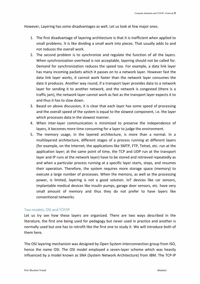
Figure 1.1 OSI and TCP/IP models
The OSI Model
This model was designed by International Standards Organization in 1983. Some of the
leading companies at that time and some of the governments thought of having a standard
solution for the network and the services provided.
The layering mechanism of OSI model contained seven layers. They are detailed in Figure
1.1. It contains two extra layers as compared to the TCP/IP model, i.e., the presentation
layer and the session layer. One may like to have them, though having other things are
much more important.
The presentation layer is designed to check minor differences in the way the data is
presented by the sender and the receiver. For example, the sender and the receiver may
have different ways of storing integer values in the memory. Some machines store an
integer starting with the most significant bit to the least significant bit, while other machines
store it starting from the least significant bit to the most significant bit. The role of
presentation layer is to convert the data to ensure that it is presented according to the
native representation scheme of the sender or the receiver machines.
The session layer is designed to manage sessions between the sender and the receiver. Both
the functionalities (of the presentation and session layers) are too small to deserve a layer.
The TCP/IP model does not have either of them.
Computer Networks and ITCP/IP Protocols 5
Prof. Bhushan Trivedi Module1
Additionally, the TCP/IP model does not even mention anything about the data link or the
physical layer (which exists in OSI model), but all the network cards used for networking
have them, so they are mentioned here.
The TCP-IP Model
This model is used by the networks that we use and the internet that we access. That means
it is the real world network. TCP/IP network is based on an approach known as connection
oriented service over a connectionless delivery model. Let us try to understand that.
The connection-oriented service demands connection to be established before any
communication can begin. The opposite, called connectionless, works in a way that does not
require to establish a connection before any data transfer.
The connection-oriented mechanism ‘s best example is the telephone system. When we call
somebody, the call is established first and then the communication begins. The line remains
occupied during the call, irrespective of the case that we use the line or otherwise.
The best example of the connectionless system is sending SMS. The sender and receiver do
not need to remain sync, the connection is not established, before sender starts sending,
the connection is not required to be terminated once the SMS is sent, the receiver might
receive multiple SMS sent by the sender in some other order than it is sent.
The TCP/IP model combines the connectionless and connection-oriented approaches in its
design. Applications like Telnet, FTP, Web browsing uses a model where connection
oriented service is provided by TCP/IP model over a delivery design which is connectionless.
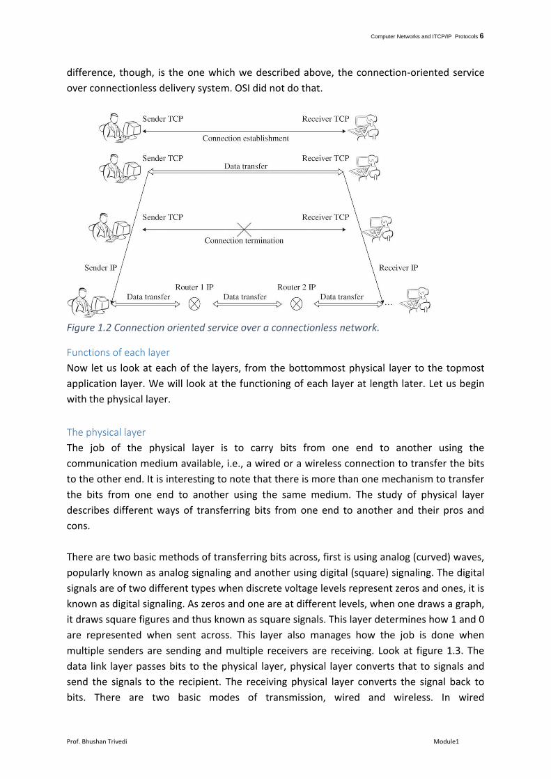
Let us try to understand. Look at Figure 1.2.
Sender's TCP layer (transport layer in OSI Parlance), wants to communicate with receiver's
TCP layer. This happens in most of the applications that we use daily. The process demands
the establishment of the connection beforehand and terminating the connection afterward.
We will study how this happens when we look at how TCP functions later in module 24,25
and 26. Interestingly, the TCP gets the job done by instructing a layer below, the IP layer. IP
layer, unlike TCP, does not establish a connection but just sends the packet to next router,
next router sends it further to next to next router and so on till the receiver accepts the
same. Like SMS messages, the receiver might receive the message in any order, might not
receive the message without sender learning about the failure and so on. Thus, the IP is said
to deploy connectionless delivery mechanism. The combined work of these two protocols,
TCP and IP, describes the connection-oriented service over the connectionless delivery
system. In fact, the TCP/IP model also provides an option to have Connectionless service
over the connectionless delivery system, deployed using UDP/IP protocol. We will brief
about UDP in module 25. The TCP/IP and OSI models differ in many ways, the major
Computer Networks and ITCP/IP Protocols 6
Prof. Bhushan Trivedi Module1
difference, though, is the one which we described above, the connection-oriented service
over connectionless delivery system. OSI did not do that.
Figure 1.2 Connection oriented service over a connectionless network.
Functions of each layer
Now let us look at each of the layers, from the bottommost physical layer to the topmost
application layer. We will look at the functioning of each layer at length later. Let us begin
with the physical layer.
The physical layer
The job of the physical layer is to carry bits from one end to another using the
communication medium available, i.e., a wired or a wireless connection to transfer the bits
to the other end. It is interesting to note that there is more than one mechanism to transfer
the bits from one end to another using the same medium. The study of physical layer
describes different ways of transferring bits from one end to another and their pros and
cons.
There are two basic methods of transferring bits across, first is using analog (curved) waves,
popularly known as analog signaling and another using digital (square) signaling. The digital
signals are of two different types when discrete voltage levels represent zeros and ones, it is
known as digital signaling. As zeros and one are at different levels, when one draws a graph,
it draws square figures and thus known as square signals. This layer determines how 1 and 0
are represented when sent across. This layer also manages how the job is done when
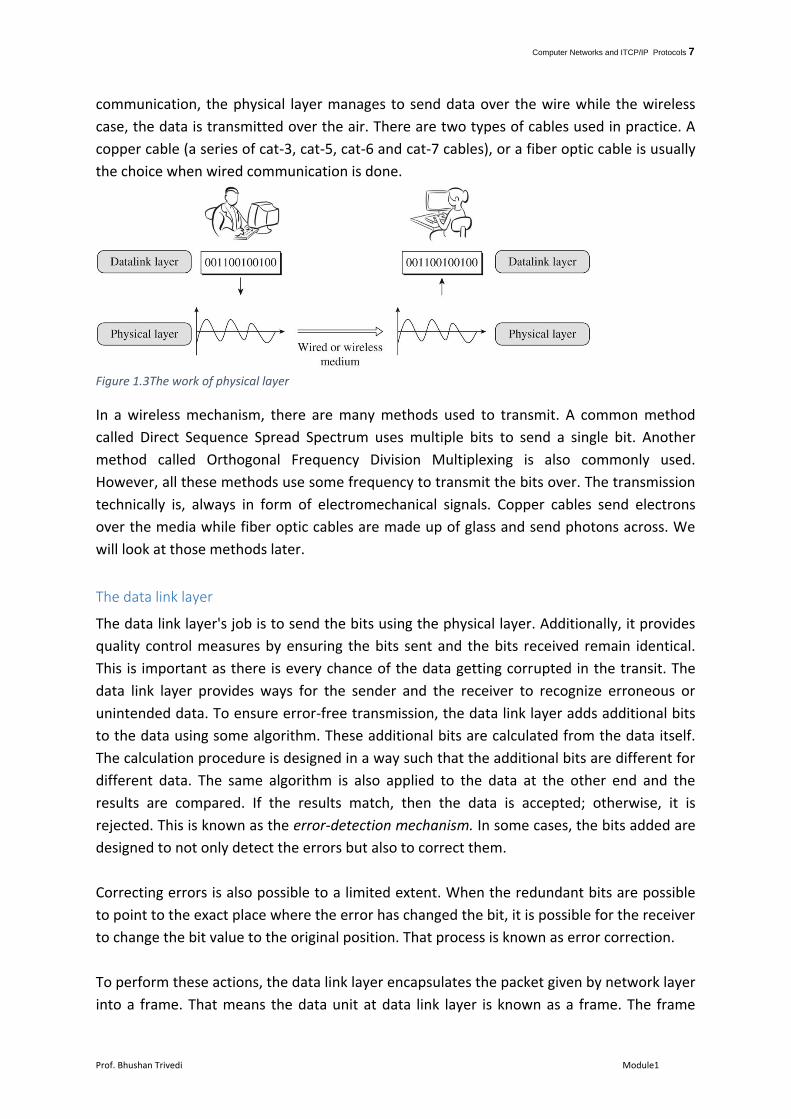
multiple senders are sending and multiple receivers are receiving. Look at figure 1.3. The
data link layer passes bits to the physical layer, physical layer converts that to signals and
send the signals to the recipient. The receiving physical layer converts the signal back to
bits. There are two basic modes of transmission, wired and wireless. In wired
Computer Networks and ITCP/IP Protocols 7
Prof. Bhushan Trivedi Module1
communication, the physical layer manages to send data over the wire while the wireless
case, the data is transmitted over the air. There are two types of cables used in practice. A
copper cable (a series of cat-3, cat-5, cat-6 and cat-7 cables), or a fiber optic cable is usually
the choice when wired communication is done.
Figure 1.3The work of physical layer
In a wireless mechanism, there are many methods used to transmit. A common method
called Direct Sequence Spread Spectrum uses multiple bits to send a single bit. Another
method called Orthogonal Frequency Division Multiplexing is also commonly used.
However, all these methods use some frequency to transmit the bits over. The transmission
technically is, always in form of electromechanical signals. Copper cables send electrons
over the media while fiber optic cables are made up of glass and send photons across. We
will look at those methods later.
The data link layer
The data link layer's job is to send the bits using the physical layer. Additionally, it provides
quality control measures by ensuring the bits sent and the bits received remain identical.
This is important as there is every chance of the data getting corrupted in the transit. The
data link layer provides ways for the sender and the receiver to recognize erroneous or
unintended data. To ensure error-free transmission, the data link layer adds additional bits
to the data using some algorithm. These additional bits are calculated from the data itself.
The calculation procedure is designed in a way such that the additional bits are different for
different data. The same algorithm is also applied to the data at the other end and the
results are compared. If the results match, then the data is accepted; otherwise, it is
rejected. This is known as the error-detection mechanism. In some cases, the bits added are
designed to not only detect the errors but also to correct them.
Correcting errors is also possible to a limited extent. When the redundant bits are possible
to point to the exact place where the error has changed the bit, it is possible for the receiver
to change the bit value to the original position. That process is known as error correction.
To perform these actions, the data link layer encapsulates the packet given by network layer
into a frame. That means the data unit at data link layer is known as a frame. The frame
Computer Networks and ITCP/IP Protocols 8
Prof. Bhushan Trivedi Module1
contains many fields including sender’s and receiver’s unique address. Those addresses help
the system to determine who is the recipient of the frame and route the frame to that node.
On the other hand, the sender address enables the receiver to understand who has sent this
frame and so can respond back if need be. Another important part of the frame is collection
of fields which can help detect or correct errors.
It is also possible that the receiving data link layer sends back the confirmation in form of
some type of acknowledgment. An acknowledgment (or ack for short) indicates that frame
is received properly at the other end. Many Data link layers have explicit mechanisms to
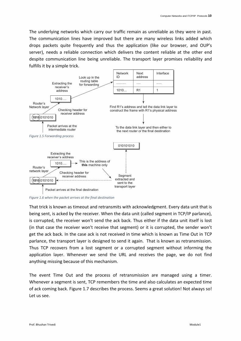
provide sending and receiving acks and taking appropriate actions based on that. Look at
figure 1.4. The data coming from network layer is divided into multiple chunks1. The data
link layer generates the frame out of it. The frame contains some header as well as the
trailer.
Another critical issue is the mismatch in the speeds of the sender and the receiver. The
sender might send faster than the receiver can process and thus it is possible that some
data is lost due to this problem. Data link layer deploys some mechanisms by which it can
request the sender to slow down. That mechanism is popularly known as flow control.
The Network layer
The network layer’s job is to look at the packet, decide where it is heading to (i.e. what is
the value in the recipient’s address field of the packet), decide the best path to that
destination requires it to forward it to which neighbor. That means, the network layer’s job
is to find next immediate destination based on final destination.
In fact, this requirement demands two distinct jobs to be done. First, every router2 must
know where every other network in the world is, and how to reach to each and every
network. Once the router learns that, it can always judge the nearest next immediate
neighbor for any destination. The routers store that information in a tabular form, popularly
known as a routing table and this process, therefore, is known as routing. The algorithm
deployed by the router is known as the routing algorithm3.
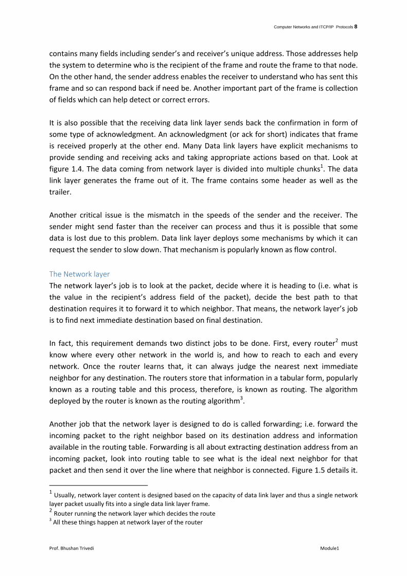
Another job that the network layer is designed to do is called forwarding; i.e. forward the
incoming packet to the right neighbor based on its destination address and information
available in the routing table. Forwarding is all about extracting destination address from an
incoming packet, look into routing table to see what is the ideal next neighbor for that
packet and then send it over the line where that neighbor is connected. Figure 1.5 details it.
1 Usually, network layer content is designed based on the capacity of data link layer and thus a single network
layer packet usually fits into a single data link layer frame. 2 Router running the network layer which decides the route 3 All these things happen at network layer of the router

Computer Networks and ITCP/IP Protocols 9
Prof. Bhushan Trivedi Module1
Simple! Isn’t it? However simple it looks like, forwarding is an extremely complex process as
it is to happen in real time. That means the packets are to be processed as fast as they
arrive. Consider router having five incoming lines each of which having a capacity of 10Gb.
In the worst case, when each of the lines is blasting at the full speed, a router has to process
packets 50 Gb/sec which sounds phenomenal but common across routers. Consider the
capacity of CISCO CRS -3 type of router's high-end version can crunch 322 Terabits per
second.
Forwarding, like many other things in networks, can be done in two different ways.
Connection-oriented and connectionless. In the connection-oriented fashion forwarding,
the sender network layer establishes a connection with receiver's network layer before
transmission and tears off once it is done. Every packet belonging to that connection travels
over that path decided and does not roam around anywhere else. Connectionless
forwarding just sends the packets across and hope for the best!
The Transport Layer
The transport layer is working as per instructions by the application layer. Suppose we type
www.oup.com in our browser. The browser, which is technically a client process running
HTTP (Hypertext Transfer Protocol) client, then communicates with the web server located
at Oxford University Press website. How does it do it? It instructs the TCP (Transmission
Control Protocol) running on your machine to establish the connection with the server at
www.oup.com and once the connection is established, sends this URL to that server. The
server sends back the home page of the website and the browser displays it in return.
0101010 10101111000 0000000000…..
The receiver data link layer receives the frame from the physical layer
Packets from network layer
010101010 101111000 0000000000
Sender Data Link layer
10100101010100101
Framing
Adding header and footer
Frames sent to the physical layer
10100101010100101
010101010
Packet to network layer
Removing header and footer after checking the error and order
Figure 1.4. How data link layer works, at sender as well as receiver
Computer Networks and ITCP/IP Protocols 10
Prof. Bhushan Trivedi Module1
The underlying networks which carry our traffic remain as unreliable as they were in past.
The communication lines have improved but there are many wireless links added which
drops packets quite frequently and thus the application (like our browser, and OUP's
server), needs a reliable connection which delivers the content reliable at the other end
despite communication line being unreliable. The transport layer promises reliability and
fulfills it by a simple trick.
Figure 1.5 Forwarding process
Figure 1.6 when the packet arrives at the final destination
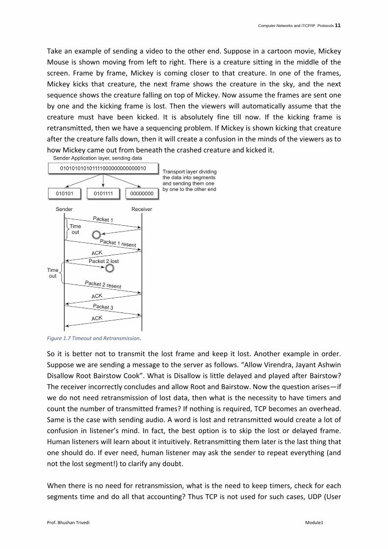
That trick is known as timeout and retransmits with acknowledgment. Every data unit that is
being sent, is acked by the receiver. When the data unit (called segment in TCP/IP parlance),
is corrupted, the receiver won't send the ack back. Thus either if the data unit itself is lost
(in that case the receiver won't receive that segment) or it is corrupted, the sender won’t
get the ack back. In the case ack is not received in time which is known as Time Out in TCP
parlance, the transport layer is designed to send it again. That is known as retransmission.
Thus TCP recovers from a lost segment or a corrupted segment without informing the
application layer. Whenever we send the URL and receives the page, we do not find
anything missing because of this mechanism.
The event Time Out and the process of retransmission are managed using a timer.
Whenever a segment is sent, TCP remembers the time and also calculates an expected time
of ack coming back. Figure 1.7 describes the process. Seems a great solution! Not always so!
Let us see.
Computer Networks and ITCP/IP Protocols 11
Prof. Bhushan Trivedi Module1
Take an example of sending a video to the other end. Suppose in a cartoon movie, Mickey
Mouse is shown moving from left to right. There is a creature sitting in the middle of the
screen. Frame by frame, Mickey is coming closer to that creature. In one of the frames,
Mickey kicks that creature, the next frame shows the creature in the sky, and the next
sequence shows the creature falling on top of Mickey. Now assume the frames are sent one
by one and the kicking frame is lost. Then the viewers will automatically assume that the
creature must have been kicked. It is absolutely fine till now. If the kicking frame is
retransmitted, then we have a sequencing problem. If Mickey is shown kicking that creature
after the creature falls down, then it will create a confusion in the minds of the viewers as to
how Mickey came out from beneath the crashed creature and kicked it.
Figure 1.7 Timeout and Retransmission.
So it is better not to transmit the lost frame and keep it lost. Another example in order.
Suppose we are sending a message to the server as follows. “Allow Virendra, Jayant Ashwin
Disallow Root Bairstow Cook”. What is Disallow is little delayed and played after Bairstow?
The receiver incorrectly concludes and allow Root and Bairstow. Now the question arises—if
we do not need retransmission of lost data, then what is the necessity to have timers and
count the number of transmitted frames? If nothing is required, TCP becomes an overhead.
Same is the case with sending audio. A word is lost and retransmitted would create a lot of
confusion in listener’s mind. In fact, the best option is to skip the lost or delayed frame.
Human listeners will learn about it intuitively. Retransmitting them later is the last thing that
one should do. If ever need, human listener may ask the sender to repeat everything (and
not the lost segment!) to clarify any doubt.
When there is no need for retransmission, what is the need to keep timers, check for each
segments time and do all that accounting? Thus TCP is not used for such cases, UDP (User
Computer Networks and ITCP/IP Protocols 12
Prof. Bhushan Trivedi Module1
Datagram Protocol) is a better choice where there is no such formality is maintained. It is a
transport protocol with the only option for sending the segment across and forget
afterward. In fact, there is one more alternative called SCTP (Stream Control Transfer
Protocol) which is more suited for such cases but most of the installations do not provide
SCTP. The great thing about TCP/IP model is that it provides all these options while older OSI
model did not have any such options.
Application Layer
All applications, when run, talk to the application layer for all their communication
requirements. Consider FTP. When we run an FTP client on our machine and download or
upload a file, our client communicates the FTP server at the other end and download and
upload files, we execute commands like cd, get, put, mput, mget etc. The commands are
processed at the application layer. The client program and the server program both runs at
the application layer. When the user types command, the application layer realizes that the
communication is to be made and ask TCP to send that command (get) across. TCP uses all
its ability to send that command on the server's side. When the FTP server receives that
command from its TCP, it processes that command, decide to send that specific file (if
exists) and ask the TCP to send that file across.
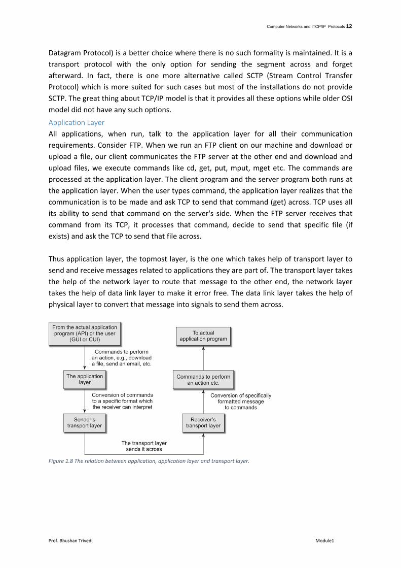
Thus application layer, the topmost layer, is the one which takes help of transport layer to
send and receive messages related to applications they are part of. The transport layer takes
the help of the network layer to route that message to the other end, the network layer
takes the help of data link layer to make it error free. The data link layer takes the help of
physical layer to convert that message into signals to send them across.
Figure 1.8 The relation between application, application layer and transport layer.