First evaluation of a novel tactile Shear Force Display
18
________________________________________________________________________ This work is part of the TOUCH-HapSys project financially supported by the 5th Framework IST Program of the European Union, action line IST-2002-6.1.1., contract number IST-2002-38040. For the content of this paper the authors are solely responsible for, it does not necessarily represent the opinion of the European Community. Authors' addresses: Knut Drewing (corresponding author) is now at the Institute of Psychology, Giessen University, Otto-Behaghel-Str. 10F, 35393 Gießen, Germany; e-mail: [email protected] , Regine Zopf, Marc Ernst, Max Planck Institute for Biological Cybernetics, Spemannstraße 38, 72076 Tübingen, Germany; e-mails: {regine.zopf, marc.ernst}@tuebingen.mpg.de, Michael Fritschi, Martin Buss, Institute of Automatic Control Engineering (LSR) Technische Universität München, 80290 München, Germany, e-mails: {michael.fritschi, martin.buss}@ei.tum.de. Permission to make digital/hard copy of part of this work for personal or classroom use is granted without fee provided that the copies are not made or distributed for profit or commercial advantage, the copyright notice, the title of the publication, and its date of appear, and notice is given that copying is by permission of the ACM, Inc. To copy otherwise, to republish, to post on servers, or to redistribute to lists, requires prior specific permission and/or a fee. © 200X ACM 0000-0000/00/0000-0000 $5.00 First evaluation of a novel tactile Shear Force Display KNUT DREWING 1 , MICHAEL FRITSCHI 2 , REGINE ZOPF 1 , MARC O. ERNST 1 AND MARTIN BUSS 2 1 Max Planck Institute for Biological Cybernetics, Tübingen, Germany 2 Institute of Automatic Control Engineering, Technische Universität München, Germany ________________________________________________________________________ Based on existing knowledge on human movement perception we constructed a prototype of a novel multi-pin Shear Force Display (SFD). Two experiments, presented in this article, focus on the question of whether the prototype SFD generates tactile stimulation that is appropriate for the sensitivity of human tactile perception. In particular, Experiment I studied human resolution for distinguishing between different directions of pin movement and Experiment II explored the perceptual integration of multi-pin movements. Both experiments demonstrated that humans can well discriminate between directions of the shear forces displayed, and also that technically realized resolution of the device exceeds the perceptual resolution (> 14°). In Experiment II we further found evidence that the human brain does not process stimulation from the different pins of the SFD independent of another at least concerning movement direction. The acquired psychophysical knowledge based on this new technology will in return be used to improve the design of the shear force display. Categories and Subject Descriptors: H1.2 [Models and Principles]: User/Machine Systems – Human Information Processing; H5.2 [Information Interfaces and Presentation]: User Interfaces - Evaluation/methodology; Haptic I/O; Theory and methods General Terms: Design, Experimentation, Human Factors Additional Key Words and Phrases: Haptic interfaces, psychophysics, tactile movement perception, shear force ________________________________________________________________________ 1. INTRODUCTION Human tactile perception is a complex integration of various sensations evoked by forces acting on our skin. Tactile displays are the fundamental technical component of a virtual tactile environment that tries to recreate these sensations by generating forces. For a long time tactile displays have usually been constructed either as shape or as vibrotactile displays. Shape displays follow the idea to render the 3D-shape of an object to the skin. This goal in many cases is achieved with an array of small pins that are
-
Upload
independent -
Category
Documents
-
view
1 -
download
0
Transcript of First evaluation of a novel tactile Shear Force Display

________________________________________________________________________ This work is part of the TOUCH-HapSys project financially supported by the 5th Framework IST Program of the European Union, action line IST-2002-6.1.1., contract number IST-2002-38040. For the content of this paper the authors are solely responsible for, it does not necessarily represent the opinion of the European Community. Authors' addresses: Knut Drewing (corresponding author) is now at the Institute of Psychology, Giessen University, Otto-Behaghel-Str. 10F, 35393 Gießen, Germany; e-mail: [email protected], Regine Zopf, Marc Ernst, Max Planck Institute for Biological Cybernetics, Spemannstraße 38, 72076 Tübingen, Germany; e-mails: {regine.zopf, marc.ernst}@tuebingen.mpg.de, Michael Fritschi, Martin Buss, Institute of Automatic Control Engineering (LSR) Technische Universität München, 80290 München, Germany, e-mails: {michael.fritschi, martin.buss}@ei.tum.de. Permission to make digital/hard copy of part of this work for personal or classroom use is granted without fee provided that the copies are not made or distributed for profit or commercial advantage, the copyright notice, the title of the publication, and its date of appear, and notice is given that copying is by permission of the ACM, Inc. To copy otherwise, to republish, to post on servers, or to redistribute to lists, requires prior specific permission and/or a fee. © 200X ACM 0000-0000/00/0000-0000 $5.00
First evaluation of a novel tactile Shear Force Display KNUT DREWING1, MICHAEL FRITSCHI2, REGINE ZOPF1, MARC O. ERNST1 AND MARTIN BUSS2 1Max Planck Institute for Biological Cybernetics, Tübingen, Germany 2Institute of Automatic Control Engineering, Technische Universität München, Germany ________________________________________________________________________ Based on existing knowledge on human movement perception we constructed a prototype of a novel multi-pin Shear Force Display (SFD). Two experiments, presented in this article, focus on the question of whether the prototype SFD generates tactile stimulation that is appropriate for the sensitivity of human tactile perception. In particular, Experiment I studied human resolution for distinguishing between different directions of pin movement and Experiment II explored the perceptual integration of multi-pin movements. Both experiments demonstrated that humans can well discriminate between directions of the shear forces displayed, and also that technically realized resolution of the device exceeds the perceptual resolution (> 14°). In Experiment II we further found evidence that the human brain does not process stimulation from the different pins of the SFD independent of another at least concerning movement direction. The acquired psychophysical knowledge based on this new technology will in return be used to improve the design of the shear force display. Categories and Subject Descriptors: H1.2 [Models and Principles]: User/Machine Systems – Human Information Processing; H5.2 [Information Interfaces and Presentation]: User Interfaces - Evaluation/methodology; Haptic I/O; Theory and methods General Terms: Design, Experimentation, Human Factors Additional Key Words and Phrases: Haptic interfaces, psychophysics, tactile movement perception, shear force ________________________________________________________________________
1. INTRODUCTION
Human tactile perception is a complex integration of various sensations evoked by
forces acting on our skin. Tactile displays are the fundamental technical component of a
virtual tactile environment that tries to recreate these sensations by generating forces. For
a long time tactile displays have usually been constructed either as shape or as
vibrotactile displays. Shape displays follow the idea to render the 3D-shape of an object
to the skin. This goal in many cases is achieved with an array of small pins that are

Evaluation of Shear Force Display 2
mutually independent and move normal to the contact surface [Lee et al. 1999; Shinohara
et al. 1998; Summers et al. 2001]. Then, the pins create a 3D-pattern of indentation into
the skin. Vibrotactile displays, in contrast, use a pin array to display patterns of normal
forces with high frequency (about 200Hz), but very small amplitude. Vibrotactile
displays create rather 2D- than 3D-patterns on the skin and have been used as aid for the
blind as well as for research [e.g., Essick, 1998; Ikei 2002; Ikei et al. 1997]. Both types
of displays are usually based on forces that are normal to the contact surface. However, in
order to generate a realistic impression of the environment it is probably as important to
provide forces lateral to the human skin, so called shear forces. Meanwhile, there are a
few prototypes or experimental displays that provide shear force in differing ways to the
human finger [Konyo et al. 2000, 2003; Salada et al. 2002, 2004; Hayward and Cruz-
Hernandez 2000].
The display of shear force is particularly reasonable when considering movements of
the skin relative to the environment, e.g. when stroking with the finger across a surface.
Tactile movement perception plays an important role in haptics and haptically guided
action. To give an example, imagine gripping and lifting a fragile object like an egg: grip
forces should be sufficiently large to avoid slip of the object, but also sufficiently small to
avoid damage to the object. Immediate tactile sensation of skin slip has been
demonstrated to be crucial for a precise grip force control [Johannson and Westling,
1990]. As well, movement perception on the skin is an always present effect of every
active exploration with the fingers.
We are specifically interested in tactile movement perception and the development of
an appropriate multi-pin Shear Force Display (SFD) for moving stimuli. Previous results
demonstrate that the quality of tactile displays depends strongly on the demands of the
application [Kammermeier and Schmidt 2002]. The scientific work we conducted
followed this concept. Based on existing knowledge on human movement perception we
constructed a prototype of a novel multi-pin SFD. However, there are still many
unanswered questions related to tactile perception because the technology was not yet
available. Our approach is to use the prototype SFD to obtain additional psychophysical
knowledge that in turn will be used to improve the design of the display.
In this article, we first present the existing psychophysical background and, then, the
design of our multi-pin SFD. Two own experiments focus on the question of whether the
current SFD generates tactile stimulation that is appropriate for the sensitivity of human
tactile perception. In particular, Experiment I studied human sensitivity for distinguishing

Evaluation of Shear Force Display 3
between different directions of horizontal 2D pin movement and Experiment II explored
the perceptual effect resulting from the integration of movement information from
multiple pins.
2. PSYCHOPHYSICS OF TACTILE MOVEMENT PERCEPTION
The perception of movement across the skin has been demonstrated to rely upon two
distinguishable cues, which in most natural situations co-occur: the spatio-temporally
ordered translation of a stimulation across the skin and lateral stretch of the skin [Essick
1998]. An impressive tactile movement illusion can be easily generated attaching a comb
to the finger and sliding a pencil along its teeth [Hayward and Cruz-Hernandez 2000]. In
this illusion probably both translation and stretch cues are effective: The teeth
sequentially stimulate adjacent areas and, thereby, stretch the skin. Translation without
stretch – inter alia – has been investigated and can be mimicked by pin displays when
sequentially producing indentation at neighbouring skin areas [Gardner and Sklar 1994,
1996; Olausson 1994]. “Pure” stretch was investigated using a small probe glued to the
skin [Gould et al. 1979] or a sliding glass plate [Srinivasan et al. 1990]. Research
suggests that human movement perception is noticeably more sensitive to the stretch than
to the translation component, e.g. when comparing the minimal path traversed to detect
movement (e.g., 0.6 mm for stretch vs 4.4 mm for translation on the forearm [Gould et al.
1979; cf. also Essick 1998]). This holds as long as surrounding skin is not prevented from
the spreading influence of stretch [Essick 1998]. Likewise, our display has been
constructed to provide full stretch cues.
Neurally, movement perception relates particularly to two out of four
mechanoreceptor types in the skin [review in Greenspan and Bolanowski 1996].
Translation mainly corresponds to a sequential activation of adjacent fast adapting FA 1
receptors [Essick 1998], whereas stretch evokes an initial pattern of response in fast
adapting FA 1 receptors and a persisting one in slow adapting SA 2 receptors [LaMotte
and Srinivasan, 1991; Srinivasan et al. 1990]. A couple of characteristics of these
receptor types have been reported [Johnson 2002, Mountcastle et al. 1972]: In the finger,
FA1 receptors have a receptive field area of about 5 mm² and an estimated spatial
resolution of about 3 mm. FA1 receptors respond very sensitively to single rapid
indentations and are, for vibrations, most sensitive in the range of 40 to 60 Hz. SA2
receptors have a larger receptive field (25-60 mm²), a lower spatial resolution of 7 mm or
above and respond on frequencies up to 100Hz. They are quite insensitive to skin

Evaluation of Shear Force Display 4
indentation [Johansson and Vallbo, 1979a], but rather sensitive to stretch [Edin 1992].
The number of both FA 1 and SA 2 units seems to increase in more distal directions of
the finger, particularly at the fingernail [Johansson and Vallbo, 1976, 1979b]. In display
design we took into account the above basic knowledge on human neural bandwidths.
On a higher perceptual level, psychophysical studies demonstrated that tactile
movement detection and discrimination between movements in opposing directions
depend on various factors – such as the length of the movement path [Essick and
McGuire, 1986; Olausson 1994], or the innervation density of the stimulated skin area
[Loomis and Collins 1978; Whitsel et al. 1979]. However, not much is known on
humans’ resolution of movement direction, which is an important parameter for display
design. To our knowledge there is only a single study on this topic. Keyson and Houtsma
[1995] displayed movements on the distal phalanx of the finger via a 0.8 mm diameter
Braille point that was fixed to a trackball. The trackball could be moved in any horizontal
direction. A single stimulus consisted of a forward-backward movement traversing twice
a straight path of 3.25 mm with a velocity of 41 mm/s. For these stimuli, Keyson and
Houtsma [1995] report discrimination thresholds for movement direction of about 14°
with the lowest thresholds for paths that went down to the wrist.
However, for different reasons these results are not applicable to our multi-pin
display. From the technical point of view it is a common problem in tactile display design
to realize high pin density at concurrently large excursion and high frequency of pin
movement. Our SFD was designed as a multi-pin device rather than to display movement
of a length and velocity that was investigated in the study from Keyson and Houtsma
[1995]. Further, in the study skin friction – and, thus, skin stretch as an important cue to
movement perception – was reduced, but our SFD allows for full stretch.
Consequently, we tested in Experiment I human directional resolution for movements
provided by our SFD. The questions were whether, on one hand, the SFD is able to
provide stimuli that humans can discriminate and, on the other hand, whether its
directional resolution satisfies human perceptual resolution. Moreover, the SFD is a
multi-pin device. Because the technology, was not yet available, so far no knowledge
exists on the perceptual aspects of multiple movement signals. Experiment II, hence,
explored the perceptual integration of movement information from multi-pin stimulation.
3. TECHNICAL REALIZATION OF THE SHEAR FORCE DISPLAY
3.1 Design and hardware setup

Evaluation of Shear Force Display 5
The fundamental concept of the display is based on a quadratically arranged 2 X 2
pin array. To exert shear force to the area of the finger, each pin is movable laterally to
the skin. It is possible to move each pin independently along both axes of their two-
dimensional horizontal directions. A pin diameter of 1 mm, a center-to-center pin spacing
of 3 mm (zero position of lateral movement) and a lateral movement of 2 mm along each
axis and for each pin are realized.
Fig. 1. Mechanical design of the Shear Force Display for two pins in one axis. The human finger is in contact
with the pins through a gap in the base plate covering the device. The depicted optional rubber layer between
the pins and the finger was not used in the present study.
The mechanical design of the SFD is schematically shown in Figure 1. The four pins are
in direct contact with the finger (optional filtered by an elastic rubber layer). Two rods
orthogonal attached to the upper region of each pin transmit two-dimensional movement
of the pins. To allow for this movement the four pin bodies are attached with universal-
joint shafts that are screwed to the ground plate of the chassis. Tuning screws between the
base plate and the joints enable a justification along the z-axis in a small range to vary the
indentation offset normal to the finger. The rods are connected over reduction rocker
arms to the servo motor levers. To reduce pin motion normal to the skin down to a
tolerable value, the length of the pin raised to 69 mm. In case of a pin diameter of 1 mm a
realization of a pin with these dimensions would be unusable because of bending.
Furthermore, it would be difficult to attach the two steering rods providing the tangential

Evaluation of Shear Force Display 6
motion. To avoid this problem, the length of the pin has been reduced to 6 mm and
attached to a prismatic body (Figure 2, left). The right picture of Figure 2 shows the top
view of the mechanical design. The pins are fitted to the inner edge of the bodies (black
points) to provide a large motion workspace for the pins. On the actuator side, we use of-
the-shelf servo motors, selected on criteria such as high performance, small deviations,
and light weight. The servo motors come with a position control circuit, accessed by a
pulse-width modulated signal, which contains the commanded position information.
Fig. 2. Pin-body design in side view and pin arrangement in top view. The pins are attached to a prismatic body
and fitted to the inner edge of the bodies.
The left picture in Figure 3 shows the SFD in use with a close-up view of the pin area
that is in contact with the finger through a gap in the cover plate. A more detailed view in
the right picture of Figure 3 shows the mechanical details of the display like the pin
bodies, the control rods, and the servo motors.
Fig. 3. Hardware Setup of the Shear Force Display. The left picture depicts the SFD in use and a close-up view
of the pin area; the right picture shows the mechanical details.

Evaluation of Shear Force Display 7
3.2 Computer Interface and Technical Data
Figure 4 shows the schematic design of the computer interface. A real-time task generates
the required signals for the eight servo motors at the printer-port of the computer, whose
data lines are connected to the corresponding servo motors. In the application process the
position information for the servo motors are calculated and communicated to the real-
time task. To provide sufficient power for the servo motors an external power supply is
used.
Fig. 4. Computer interface. The SFD is connected to a computer via the parallel port, and controlled via a real-
time task.
The SFD reaches a positioning resolution of 10 µm in a work space of 2 X 2 mm. It
works with a maximum velocity of 22.8 mm/s applying maximum forces of 4.23 N per
pin axis. The SFD weighs 1100 g and has a total size of 150 X 150 X 90 mm.
4. EXPERIMENT I: DISCRIMINATION OF SHEAR FORCE DIRECTION
In Experiment I we studied human discrimination performance for different directions
of tactile movement displayed with the SFD. To our knowledge there is just a single
study on thresholds for movement direction on the finger [Keyson and Houtsma 1995].
This study, however, investigated pin movements of a length and a velocity that our
multi-pin device has not been designed to display and in that study skin stretch was
reduced. We measured direction thresholds for single-pin movement of the SFD while
allowing for full skin stretch. We did this for eight different directions of movement (up,
Evaluation of Shear Force Display 8
up-right, right, down-right, down, down-left, left, up-left) using a two-interval forced
choice task and the method of constant stimuli.
4.1 Method
4.1.1 Participants. 14 right-handed participants (9 female and 5 male) took part for
pay. Their age ranged from 21 to 40 years (average 26 years). None of them reported any
known tactile deficit due to accident or illness concerning the left index finger. With the
exception of two staff members of the laboratory, the participants were not familiar with
the SFD and naïve to the purpose of the experiment.
4.1.2 Apparatus and Stimuli. In a quiet room participants sat at a table with their left
elbow resting comfortably on a custom-made support. By using robust tape their left hand
was attached to the SFD, so that the distal phalanx of their left index finger was reliably
centered at the midpoint of the pin display. Adjustable paperboard stabilizers on the left
and right side of the finger further warranted the central finger position.
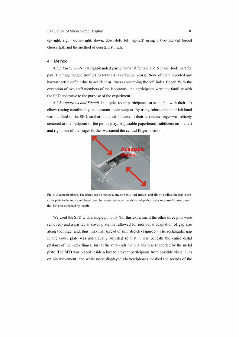
1 pin
Adaptable plates
Fig. 5. Adaptable plates. The plates can be moved along one axis (red arrows) and allow to adjust the gap in the
cover plate to the individual finger size. In the present experiments the adaptable plates were used to maximize
the skin area stretched by the pin.
We used the SFD with a single pin only (for this experiment the other three pins were
removed) and a particular cover plate that allowed for individual adaptation of gap size
along the finger and, thus, maximal spread of skin stretch (Figure 5). The rectangular gap
in the cover plate was individually adjusted so that it was beneath the entire distal
phalanx of the index finger. Just at the very ends the phalanx was supported by the metal
plate. The SFD was placed inside a box to prevent participants from possible visual cues
on pin movement, and white noise displayed via headphones masked the sounds of the

Evaluation of Shear Force Display 9
SFD. A custom-made program on an IBM-compatible PC controlled the stimulus
presentation and collected responses, which were entered via a keyboard.
Tactile stimuli were unidirectional single strokes of the single pin with a length of 1
mm and a velocity of 10 mm/s. Each stroke started at the center of the SFD. Stroke
directions are defined by their circular deviation in degree from the direction center-to-
upper part of the phalanx (0°, cf. Figure 6, left).
4.1.3 Design and Procedure. The design comprised one within-participant variable:
Stroke Direction realized by 8 standard stimuli of different directions (separated by 45°,
Figure 6, left). For each standard stimulus we measured the 84 %-discrimination
threshold for movement direction – using the method of constant stimuli in a two-interval
forced choice paradigm:
Each standard was paired with 19 comparison strokes, the directions of which were
distributed in 10° steps around the corresponding standard within a range of +/- 90°
(Figure 6, right). In each of two experimental sessions each pair of standard and
comparison stroke was presented six times (order of pairs randomized). The sessions
were on different days, lasted two hours each (including practice trials in the first and
three breaks in each session) and included 1824 trials overall.
0° (up)
270°(left)
215°180° (down)
135°
90°(right)
45°305° 1 mm
Standard directions Comparison directions
pin +90°
+60°
+30°
Standard direction-30°
-60°
-90°
Fig. 6. The left part of the figure depicts the eight standard directions for pin movements in Experiment I
(orange arrows) and their length (1mm). The right part depicts the comparison directions (gray arrows including
the orange standard) in respect to the standard direction.
A single trial consisted of the sequential presentation of a standard and a comparison
stimulus (order balanced between repetitions). Participants self-initiated a trial via a key
press, 1600 ms later the first stimulus was presented, 2800ms thereafter the second
stimulus. Immediately after each stimulus a 100 ms high pitch tone signaled the
participant to lift his finger until 1.1 s later another 100 ms low pitch tone signaled to

Evaluation of Shear Force Display 10
lower the finger back onto the device. In this time the pin was driven back to the center of
the display without stimulating the finger. Starting 100 ms before each stimulus
presentation and ending with the low pitch tone white noise was displayed on the
earphones. 1600 ms after the second stimulus participants had to decide by a key press if
the direction of the second stimulus had been more in clock- or counterclock-wise
direction with respect to the first stimulus. Participants were instructed to envision the
different directions as being drawn on a clock. No error feedback was given.
4.1.4 Data Analysis. Using the psignifit toolbox for Matlab [Wichmann and Hill
2001a, b] we fitted individual psychometric functions (cumulative Gaussians, Maximum-
Likelihood procedure) to the proportion of trials in which the comparison stroke was
perceived as more in clock-wise direction than the standard stroke - against the direction
of the comparison. In the fit the point of subjective equality was fixed to the direction of
the standard. We estimated the 84%-discrimination threshold and a percentage of
stimulus-independent errors (lapse rate; constrained to 0 to 10%), the additional
estimation of which reduces biases in the threshold estimate [Wichmann and Hill 2001a].
The individual values per Stroke Direction entered further analyses. Statistics were done
using non-parametric methods in order to include threshold estimates that fell outside the
reliably measured range of the present task (1% estimates < 10° and 4.5% > 90°, i.e., the
maximal deviation of comparison stimuli from the standard).
4.2 Results and Discussion
Figure 7 depicts medians and quartiles of the individual discrimination thresholds by
Stroke Direction. Median thresholds ranged from 23° (for direction 0°) to 35° (for
direction 270°). The individual thresholds per Stroke Direction entered a Friedman test.
The test reached significance, χ²(7)=20.7, p <.01, indicating a perceptual anisotropy.
Bonferroni-adjusted post-hoc comparisons (Wilcoxon-tests) between pairs of directions
in no case reached significance. But, the descriptive data (cf. Figure 7) suggest that
discrimination performance is somewhat better for upward- as compared to other
directions.
Between participants median thresholds (across Stroke Direction) ranged from 21° to
78°. A Friedman test confirmed that these individual differences were also reliable,
χ²(13)=52.4, p <.001. These differences may point to pronounced individual differences
in human resolution of tactile movement direction. But they may also reflect individual

Evaluation of Shear Force Display 11
difficulties with the use of the display, particularly given that the thresholds of most
participants (11 out of 14) fell in the – almost halved – range between 21° and 40°.
0°10°20°30°40°50°
0° (up)
45°
90° (right)
135°
180° (down)
225°
270°
315°
Median
75th percentile
25th percentile
Fig. 7. Medians and quartiles of individual 84% -thresholds for direction discrimination by Stroke Direction
conditions of Experiment I.
At first glance, the direction of the observed perceptual anisotropy seems to be in
contrast with Keyson and Houtsma’s [1995] previous results who observed the lowest
thresholds for movements in down-direction. However, our results match well with the
increasing densities of FA 1 and SA 2 receptors towards the more distal parts of the
finger [Johansson and Vallbo, 1976], because these receptors types are crucial for
movement perception. And, Keyson and Houtsma [1995] argue quite similar, namely that
their downward movement caused tension in the finger tip where the finger is anchored to
the fingernail and where humans are particular sensitive. It may well be that by the long
movement path in their study (3.25 mm in one direction) a tension component came into
play, which with the present shorter path (1 mm) did not considerably contribute to
movement perception.
In general, we observed larger thresholds for direction discrimination than Keyson
and Houtsma [1995]. But this difference was to be expected: In Keyson and Houtsma’s
study 70.7 % correct responses defined the discrimination threshold, whereas we used a
less liberal 84 % - criterion. Moreover, in their study the movements were considerably
longer and faster than in the present experiment (6.5 vs. 1 mm, and 41 vs. 10 mm/sec,
respectively). Tactile movement detection is known to improve both with increasing path
length [Essick and McGuire, 1986; Olausson 1994] and – up to a peak – with increasing

Evaluation of Shear Force Display 12
velocity [Whitsel et al. 1979]. Corresponding relations for discrimination performance
are reasonable.
Most importantly here, the magnitude of the present discrimination thresholds
demonstrated that almost all participants were able to discriminate well between the
movements displayed by our SFD. It is also important to note that the technical
directional resolution of the SFD clearly exceeds the perceptual thresholds we observed
(> 20°). Further development of the SFD may take advantage of the obtained knowledge
on the range and the optimum of human directional resolution. Of rather theoretical than
technological interest are the reliable, but small differences between Stroke Directions.
5. EXPERIMENT II: PERCPTUAL INTEGRATION OF MULTI-PIN PATTERNS
Experiment I demonstrated that the SFD is appropriate for the perception of different
directions of movement on the human finger. In a second step, Experiment II studied the
integration of perceived movement direction displayed by multiple pins. That is, we
tested whether discrimination performance improves from one to two and four pins (all
moving in the same direction) due to the integration of movement information across the
pins. According to well-established models on human signal-integration [Ernst and Banks
2002; Ernst and Bülthoff 2004], the human brain integrates independent redundant
signals from the same physical property such that the integrated signal is less noisy and
thus more reliable than each individual signal. This is, metaphorically spoken, because
independent errors in the signals, partially, cancel each other. More reliable signals, of
course, can be better discriminated than less reliable signals.
From these theories, we predict that movement direction discrimination threshold
should profit from multi- as compared to single-pin presentation – if the pins provide at
least partially independent signals on movement direction to the brain [Oruç et al. 2003].
Movements were displayed with either one, two or four pins, in parallel. We measured
discrimination thresholds for movements in up and down-direction – using, again, a two-
interval forced choice task and the method of constant stimuli.
5.1 Method
5.1.1 Participants. Twelve right-handed participants (6 female, 6 male) took part for
pay. Their age ranged from 19 to 40 years (average 27 years). None of them reported any
known tactile deficit due to accident or illness concerning the left index finger. Eight of

Evaluation of Shear Force Display 13
the participants were familiar with the SFD from Experiment I. With the exception of two
staff members of the laboratory, participants were naïve to the purpose of the experiment.
5.1.2 Apparatus and Stimuli. Apparatus and stimuli were similar to Experiment I.
However, we provided the tactile stimuli with one, two or four pins, in parallel (other
pins removed from the SFD). That is, in multi-pin conditions all pins moved
simultaneously and with identical velocity and direction; the pins were separated by 3
mm center-to-center distance (Figure 8, left).
5.1.3 Design and Procedure. The design comprised two within-participant variables:
Stroke Direction realized by 2 standard stimuli (0° [up] vs. 180° [down]), and Pin
Number (1, 2, vs. 4 pins). For each condition we measured the 84%-discrimination
threshold for movement direction – using the identical procedure as in Experiment I.
Pin number andarrangement
four pinstwo pinsone pin
3 mm
3 m
m3 mm
Fig. 8. The left part of the figure depicts the two standard directions for movements in Experiment II (orange
arrows) and their length (1mm). The right part depicts the spatial arrangement of pins in the different Pin
Number conditions (3 mm center-to-center distance).
Thus, the experiment consisted of 1368 trials (=2 directions X 3 pin numbers X 19
comparisons X 12 repetitions). Trials with identical pin number were blocked in one of
three 1-hour sessions (on different days within one week); otherwise trials were
randomized. The six possible orders of blocks were randomly assigned to the six female
as well as to the six male participants.
5.1.4 Data Analysis. Data were analyzed similarly to Experiment I.
5.2 Results and Discussion
Analyzed by Stroke Direction X Pin Number conditions median thresholds (see
Figure 9) in this experiment were rather uniform, ranging from 19° to 23°. Threshold
quartiles ranged from a maximal 75%-percentile of 33° down to a minimal 25%-
percentile of 16°. The individual thresholds per condition entered a Friedman test. The
test clearly failed to reach significance, χ²(5)=6.7, p >.20, demonstrating that participants'

Evaluation of Shear Force Display 14
discrimination performance did not differ between any combinations of movement
direction and pin number. This means we were not able to replicate the advantage of up-
directions observed in Experiment I. Further, it means that we did not find an effect of
Pin Number on discrimination performance.
0°
5°
10°
15°
20°
25°
30°
35°
1 pin 2 pins 4 pins
84%
dis
crim
inat
ion
thre
shol
d0° (up)
180° (down)
Fig. 9. Medians of individual 84%-thresholds for direction discrimination by Pin Number and Stroke Direction;
error bars indicate 25%- and 75%-percentiles, respectively.
Estimates of individual discrimination thresholds per condition ranged from 8° to 57°
in Experiment II. Individual median thresholds across conditions ranged between 14° and
34°. A Friedman-test between individuals, again, reached significance, χ²(11)=38.0, p
<.001. However, as compared to Experiment I individual differences were less
pronounced and thresholds tended to be lower. One reason for both observations may be
that most participants were already familiar with the SFD reducing individual difficulties
with its use. For the lower thresholds also memory effects may have played a role: There
were substantially less different Stroke Directions in the present as compared to
Experiment I. However, the magnitude of discrimination thresholds in Experiment II
confirmed that humans well discriminate between the directions of the movements
displayed and that the perceptual resolution (> 14°) did not exceed the technical
resolution of the SFD.
Importantly, we did not find an effect of Pin Number on humans’ discrimination
performance. Well-established models on human signal-integration [Ernst and Bülthoff
2004] predict that the human brain integrates independent redundant signals on the same

Evaluation of Shear Force Display 15
physical property such that the integrated signal is less noisy. The lack of an integration
benefit in the present study, then, indicates that the movements of the different pins of the
SFD were not independently processed in the perceptual system: Tactile movement
processing is believed to rely upon FA 1 receptors with a spatial resolution of about 3
mm and upon SA 2 receptors with a resolution of 7 mm or above [Essick, 1998; Johnson
2002]. Thus, the 3 mm center-to-center distance of the pins reaches the resolution of the
FA 1 receptors, so that at least some additional information on movement should have
been provided by the additional pins. However, it was also discussed that regarding skin
stretch particularly the SA 2 receptors display directional sensitivity in their responses
[Westling and Johansson 1987; Srinivasan et al. 1990]. If direction discrimination of the
stimuli provided by the SFD primarily relies upon stretch and less on translation cues –
e.g., because of the limited length of the movement path of a single pin –, then the low
resolution of the SA 2 receptors can explain why additional pins did not deliver
independent additional information to the brain.
Future evaluation will have to explore the role of stretch and translation cues
regarding the stimuli provided by the SFD. As well, it is an interesting question to what
degree non-simultaneous, differential multi-pin patterns of movement are able to evoke
discriminable percepts. Future development of the SFD will have to include mechanisms
that allow for an increased pin distance, which enables to obtain independent signals from
the different pins.
6. CONCLUSION
In this article we presented the buildup and evaluation of a novel multi-pin Shear
Force Display. The design profited from basic knowledge on human psychophysics. But
because the technology was not yet available, there are a couple of unanswered questions
on the perceptual side. In two experiments we evaluated whether the SFD produces
tactile stimuli that are appropriate for human sensitivity in tactile movement perception.
Both experiments demonstrated that humans can well discriminate between directions
of the shear forces displayed, and also that their perceptual resolution does not exceed the
already realized technical resolution of the device. In this sense, we demonstrated that the
SFD is able to produce tactile movement stimuli that are appropriate for human
perception, and that shear forces can be used to mediate a differentiated impression of at
least one environmental aspect. Future development of the device may take advantage of
the obtained magnitude for the human direction threshold, which for no individual in any

Evaluation of Shear Force Display 16
experiment exceeded 14°. In Experiment II we further found evidence that the human
brain does not process stimulation from the different pins of the SFD independent of
another at least concerning movement direction. From this evidence combined with
further existing psychophysical knowledge, we concluded that the pin distance of the
SFD can and should be increased. An increased pin distance provides also the option to
implement an increased pin excursion.
Beyond evaluation, we made some observations that might be interesting from a
psychophysical point of view: In Experiment I we observed a perceptual anisotropy for
movement direction, namely an advantage for the perception of movement in up-
directions. Consistent with the explanation of an anisotropy reported by Keyson and
Houtsma’s [1995] this can be explained by particular high density of movement receptors
in the distal parts of the finger [Johansson and Vallbo, 1976, 1979b]. Further, the lack of
integration benefit for multi-pin movements observed in Experiment II may argue for a
particular role of SA 2 receptors in direction perception via stretch [cf. Srinivasan et al.
1990]. The SFD will allow to follow-up these observations more thoroughly in future
research.
Taken together, the approach to couple display design tightly with psychophysics
proved successful from a theoretical as well as a technological point of view.
Psychophysics helped to design a display that mediates a differentiated impression of one
environmental aspect and to provide recommendations for future development of the
display. In turn, the prototype of the SFD allowed to investigate certain psychophysical
questions for the first time and to increase theoretical knowledge.
ACKNOWLEDGMENTS
We wish to thank Christoph Lange for his assistance in computer programming.
REFERENCES EDIN, B.B. 1992. Quantitative analysis of static strain sensitivity in human mechanoreceptors from hairy skin. Journal of Neurophysiology 67, 1105-1113. ERNST, M. O., AND BANKS, M. S. 2002. Humans integrate visual and haptic information in a statistically optimal fashion. Nature 415, 429-433. ERNST, M. O., AND BÜLTHOFF, H. H. 2004. Merging the senses into a robust percept. Trends in Cognitive Sciences 8, 162-169. ESSICK, G.K. 1998. Factors Affecting Direction Discrimination of Moving Tactile Stimuli. In Neural Aspects of tactile sensation, J.W. MORLEY, Ed. Elsevier, Amsterdam, 1-54. ESSICK, G.K., AND MCGUIRE, M.H. 1986. Role of kinetic and static cues in human subjects evaluation of direction of cutaneous stimulus motion. Society for Neuroscience Abstracts 12, 14. GARDNER, E.P., AND SKLAR, B.F. 1994. Discrimination of the direction of motion on the human hand: A psychophysical study of stimulation parameters. Journal of Neurophysiology, 71, 2414-2429.

Evaluation of Shear Force Display 17
GARDNER, E.P., AND SKLAR, B.F. 1996. Factors influencing discrimination of direction of motion on the human hand. Society for Neuroscience Abstracts 12, 798. GOULD, W.R., VIERCK, C.J., AND LUCK, M.M. 1979. Cues supporting recognition of the orientation or direction of movement of tactile stimuli. In Sensory function of the skin of humans. Proceedings of the second international Symposium on the skin senses, D.R. KENSHALO, Ed. Plenum Press: New York, 63-73. GREENSPAN, J.D., AND BOLANOWSKI, S.J. 1996. The psychophysics of tactile perception and its peripheral physiological basis. In Pain and Touch (2nd ed.), L. KRUGER, Ed. Academic Press, San Diego, CA, 25-103. HAYWARD, V., AND CRUZ-HERNANDEZ, J.M. 2000. Tactile display device using distributed lateral skin stretch. In Proc. of the Haptic Interfaces for Virtual Environment and Teleoperator Systems Symposium, ASME IMECE2000, Orlando, Florida, November 2000, Proc. ASME Vol. DSC-69-2, 1309-1314. IKEI, Y. 2002. TextureExplorer: A tactile and force display for virtual textures. In Proceedings of the 10th International HAPTICS’02 Symposium, Orlando, Florida, March 2002, IEEE, 327. IKEI, Y., WAKAMATSU, K., AND FUKUDA, S. 1997. Texture presentation by vibratory tactile display-image based presentation of a tactile texture. In Virtual Reality Annual International Symposium, Albuquerque, NM, March 1997, IEEE, 199 – 205. JOHANSSON, R.S., AND VALLBO, A.B. 1976. Skin receptors in the human hand: An inference of some population properties. In Sensory functions of the skin with special reference to man, Y. ZOTTERMAN, Ed. Pergamon Press, Oxford, UK, 171-183. JOHANSSON, R.S., AND VALLBO, A.B. 1979a. Detection of tactile stimuli. Thresholds of afferent units related to psychophysical thresholds in the human hand. Journal of Physiology 297, 405-422. JOHANSSON, R.S., AND VALLBO, A.B. 1979b. Tactile sensibility in the human hand: Relative and absolute densities of four types of mechanoreceptive units in glabrous skin. Journal of Physiology 286, 283-300. JOHANSSON, R.S., AND WESTLING, G. 1990. Tactile afferent signals in control of precision grip. In Attention and Performance XIII, M. JEANNEROD, Ed. Erlbaum, Mahwah, 677-713. JOHNSON, K. O. 2002. Neural basis of haptic perception. In Stevens handbook of experimental psychology (Vol. 1. Sensation and Perception), H. PASHLER AND S. YANTIS, Eds. Wiley: New York, 537-583. KAMMERMEIER, P., AND SCHMIDT, G. 2002. Application-Specific Evaluation of Tactile Array Displays for the Human Fingertip. In Proceedings of the 2002 IEEE/RSJ International Conference on Intelligent Robots and Systems IROS, Lausanne, Switzerland, October 2002, 2937–2942. KEYSON, D. V., AND HOUTSMA, A. J. M. 1995. Directional sensitivity to a tactile point stimulus moving across the fingerpad. Perception and Psychophysics 57, 738-744. KONYO, M., AKAZAWA, K., TADOKORO, S. AND TAKAMORI, T. 2003. Tactile feel display for virtual active touch. In Proceedings of the 2003 IEEE/RSJ Intl. Conference on Intelligent Robots and Systems, Vol. 3, Las Vegas, Nevada, October 2003, 3744-3750. KONYO, M., TADOKORO, S., AND TAKAMORI, T. 2000. Artificial tactile feel display using soft gel actuators. In Proceedings of the 2000 IEEE International Conference on Robotics & Automation, San Francisco, CA, April 2000, 3416–3421. LAMOTTE, R.H., AND SRINIVASAN, M.A. 1991. Surface microgeometry: Tactile perception and neural encoding. In Information Processing in the somatosensory system,O. FRANZEN AND J. WESTMAN, Eds. Macmillan Press, London, 49-58. LEE, J.-H. AHN, I.-S. AND PARK, J.-O. 1999. Design and implementation of tactile feedback device using electromagnetic type. In Intelligent Robots and Systems IROS ’99, Vol. 3, Korea, October 1999, 1549 – 1554. LOOMIS, J.M., AND COLLINS, C.C. 1978. Sensitivity to shifts of a point stimulus: An instance of tactile hyperacuity. Perception and Psychophysics 24, 487-492. MOUNTCASTLE, V.B., LAMOTTE, R.H., AND CARLI, G. 1972. Detection thresholds for stimuli in humans and monkeys: comparison with threshold events in mechanoreceptive afferent nerve fibers innervating the monkey hand. Journal of Neurophysiology 35, 122-136. OLAUSSON, H. 1994. The influence of spatial summation on human tactile directional sensibility. Somatosensory and Motor Research 11, 305-310. ORUÇ, I., MALONEY, T.M., AND LANDY, M.S. 2003. Weighted linear cue combination with possibly correlated error. Vision Research 43, 2451-2468. SALADA, M., COLGATE, J., LEE, M., AND VISHTON, P. 2002. Validating a novel approach to rendering fingertip contact sensations. In Proceedings of the 10th International HAPTICS’02 Symposium, Orlando, Florida, March 2002, IEEE, 217–224. SALADA, M., COLGATE, J.E., VISHTON, P., AND FRANKEL, E.. 2004. Two experiments on the perception of slip at the fingertip. In Proceedings of the 12th International HAPTICS’04 Symposium, Chicago, Illinois, March 2004, IEEE, 146-153. SHINOHARA, M., SHIMIZU, Y., AND MOCHIZUKI, A. 1998. Three-dimensional tactile display for the blind. IEEE Transactions on Rehabilitation Engineering 6, pp. 249 – 256. SRINIVASAN, M.A., WHITEHOUSE, J.M., AND LAMOTTE, R.H. 1990. Tactile detection of slip: Surface microgeometry and peripheral neural codes. Journal of Neurophysiology 63, 1323-1332.

Evaluation of Shear Force Display 18
SUMMERS, I., CHANTER, C., SOUTHALL, A., AND BRADY, A. 2001. Results from a tactile array on the fingertip, In Eurohaptics 2001: Conference Proceedings, Birmingham, UK, July 2001, C. BABER, M. FAINT, S. WALL, AND A.M. WING, Eds., University of Birmingham, 26-28. WESTLING, AND JOHANSSON, 1987; Responses in glabrous skin mechanoreceptors during precision grip in humans. Experimental Brain Research 66, 128-140. WHITSEL, B.L., DREYER, D.A., HOLLINS, M., AND YOUNG, M.G. 1979. The coding of direction of tactile stimulus movement: Correlative psychophysical and electrophysiological data. In Sensory functions of the skin of humans, J.R. KENSHALO, Ed. Plenum Press, New York, NY, 79-107. WICHMANN, F. A., AND HILL, N. J. 2001a. The psychometric function: I. Fitting, sampling, and goodness of fit. Perception and Psychophysics 63, 1293-1313. WICHMANN, F. A., AND HILL, N. J. 2001b. The psychometric function: II. Bootstrap-based confidence intervals and sampling. Perception and Psychophysics 63, 1314-1329.