TACTILE DISPLAY DEVICE USING DISTRIBUTED LATERAL SKIN STRETCH
6
TACTILE DISPLAY DEVICE USING DISTRIBUTED LATERAL SKIN STRETCH Vincent Hayward Juan Manuel Cruz-Hern ´ andez Department of Electrical Engineering and Center for Intelligent Machines McGill University 3480 University Street, Montr ´ eal, Qc, H3A 2A7, Canada {hayward|manuel}@cim.mcgill.ca ABSTRACT In the past, tactile displays were of one of two kinds: they were either shape displays, or relied on distributed vibrotactile stimulation. A tactile display device is described in this paper which is distinguished by the fact that it relies exclusively on lat- eral skin stretch stimulation. It is constructed from an array of 64 closely packed piezoelectric actuators connected to a membrane. The deformations of this membrane cause an array of 112 skin contactors to create programmable lateral stress fields in the skin of the finger pad. Some preliminary observations are reported with respect to the sensations that this kind of display can pro- duce. INTRODUCTION Tactile displays are devices used to provide subjects with the sensation of touching objects directly with the skin. Previ- ously reported tactile displays portray distributed tactile stimu- lation as a one of two possibilities [1]. One class of displays, termed “shape displays”, typically consists of devices having a dense array of skin contactors which can move orthogonally to the surface of the skin in an attempt to display the shape of ob- jects via its spatially sampled approximation. There exist numer- ous examples of such displays, for recent designs see [2; 3; 4; 5]. In the interest of brevity, the distinction between “pressure displays” and shape displays is not made here. However, an im- portant distinction with regard to the focus of this paper must be made between displays intended to cause no slip between the contactors and the skin and those intended for the opposite case. 1 Displays which are intended to be used without slip can be mounted on a carrier device [6; 2]. 1 Braille displays can be found in this later category. Another class of displays takes advantage of vibrotactile stimulation. With this technique, an array of tactilly active sites stimulates the skin using an array of contactors vibrating at a fixed frequency. This frequency is selected to maximize the loud- ness of the sensation (200–300 Hz). Tactile images are associ- ated, not to the quasi-static depth of indentation, but the ampli- tude of the vibration [7]. 2 Figure 1. Typical Tactile Display. Shape displays control the rising move- ment of the contactors (resp. the force applied to). In a vibrotactile display, the contactors oscillate at a fixed frequency. Devices intended to be used as general purpose tactile dis- plays cause stimulation by independently and simultaneously ac- tivated skin contactors according to patterns that depend both on space and on time. Such patterns may be thought of as “tac- tile images”, but because of the rapid adaptation of the skin mechanoreceptors, the images should more accurately be de- scribed as “tactile movies”. It is also accepted that the separation between these contactors needs to be of the order of one millime- ter so that the resulting percept fuse into one single continuous image. In addition, when contactors apply vibratory signals to the skin at a frequency, which may range from a few Hertz to a few kiloHertz, a perception is derived which may be described 2 The Optacon device is a well known example [8]. Proceedings of the Haptic Interfaces for Virtual Environment and Teleoperator Systems Symposium, ASME International Mechanical Engineering Congress & Exposition 2000, Orlando, Florida, USA . pp. 1309-1314
-
Upload
independent -
Category
Documents
-
view
4 -
download
0
Transcript of TACTILE DISPLAY DEVICE USING DISTRIBUTED LATERAL SKIN STRETCH

TACTILE DISPLAY DEVICE USING DISTRIBUTED LATERAL SKIN STRETCH
Vincent Hayward Juan Manuel Cruz-Hernandez
Department of Electrical Engineering and Center for Intelligent MachinesMcGill University
3480 University Street, Montreal, Qc, H3A 2A7, Canada{hayward|manuel}@cim.mcgill.ca
ABSTRACTIn the past, tactile displays were of one of two kinds: they
were either shape displays, or relied on distributed vibrotactilestimulation. A tactile display device is described in this paperwhich is distinguished by the fact that it relies exclusively on lat-eral skin stretch stimulation. It is constructed from an array of 64closely packed piezoelectric actuators connected to a membrane.The deformations of this membrane cause an array of 112 skincontactors to create programmable lateral stress fields in the skinof the finger pad. Some preliminary observations are reportedwith respect to the sensations that this kind of display can pro-duce.
INTRODUCTIONTactile displays are devices used to provide subjects with
the sensation of touching objects directly with the skin. Previ-ously reported tactile displays portray distributed tactile stimu-lation as a one of two possibilities [1]. One class of displays,termed “shape displays”, typically consists of devices having adense array of skin contactors which can move orthogonally tothe surface of the skin in an attempt to display the shape of ob-jects via its spatially sampled approximation. There exist numer-ous examples of such displays, for recent designs see [2; 3; 4;5].
In the interest of brevity, the distinction between “pressuredisplays” and shape displays is not made here. However, an im-portant distinction with regard to the focus of this paper mustbe made between displays intended to cause no slip betweenthe contactors and the skin and those intended for the oppositecase.1 Displays which are intended to be used without slip canbe mounted on a carrier device [6; 2].
1Braille displays can be found in this later category.
Another class of displays takes advantage of vibrotactilestimulation. With this technique, an array of tactilly active sitesstimulates the skin using an array of contactors vibrating at afixed frequency. This frequency is selected to maximize the loud-ness of the sensation (200–300 Hz). Tactile images are associ-ated, not to the quasi-static depth of indentation, but the ampli-tude of the vibration [7].2
Figure 1. Typical Tactile Display. Shape displays control the rising move-
ment of the contactors (resp. the force applied to). In a vibrotactile display,
the contactors oscillate at a fixed frequency.
Devices intended to be used as general purpose tactile dis-plays cause stimulation by independently and simultaneously ac-tivated skin contactors according to patterns that depend both onspace and on time. Such patterns may be thought of as “tac-tile images”, but because of the rapid adaptation of the skinmechanoreceptors, the images should more accurately be de-scribed as “tactile movies”. It is also accepted that the separationbetween these contactors needs to be of the order of one millime-ter so that the resulting percept fuse into one single continuousimage. In addition, when contactors apply vibratory signals tothe skin at a frequency, which may range from a few Hertz toa few kiloHertz, a perception is derived which may be described
2The Optacon device is a well known example [8].
Proceedings of the Haptic Interfaces for Virtual Environment and Teleoperator Systems Symposium, ASME International Mechanical Engineering Congress & Exposition 2000, Orlando, Florida, USA . pp. 1309-1314
Vincent Hayward
Vincent Hayward
as “buzzing” and which depends strongly on the waveform of thestimulating signal [9].
The purpose of this paper is to describe initial explorationin a third direction. It is known that the skin’s mechanoreceptorsresponds to a wide variety of stimuli, again for brevity see [10].Of particular interest is the ability of the skin to respond to lateralstretch (resp. lateral compression), both physiologically and me-chanically [11]. In the next section, we will observe that stretchcorresponds to sensations that differ from what might be ex-pected. In order words, mechanical stretch does not correspondto a sensation of stretch.
An important consideration which motivates our approachis purely of technological nature. The practical realization oftactile displays based either on shape or vibrotactile sensationsis a considerable technical challenge. Difficulties arise (1) fromfabricating micro-scale actuators (millimeter scale) which can bepacked in dense arrays, and provide for displacements commen-surate to their form factors. They must also provide high levelsof energy densities, which implies low levels of dissipation; (2)from the necessity to fabricate large quantities of such actuatorspreferably in an integrated manner; and (3) from operation in en-vironmental conditions resulting from the contact with humans.
PRINCIPLESome of the sensations which can be caused by the device
to be described later in this paper may be directly experienced bythe reader.
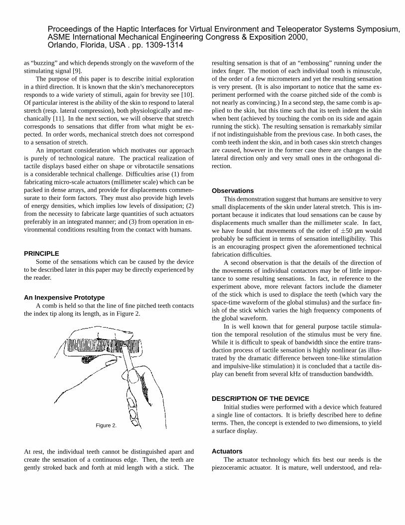
An Inexpensive PrototypeA comb is held so that the line of fine pitched teeth contacts
the index tip along its length, as in Figure 2.
Figure 2.
At rest, the individual teeth cannot be distinguished apart andcreate the sensation of a continuous edge. Then, the teeth aregently stroked back and forth at mid length with a stick. The
resulting sensation is that of an “embossing” running under theindex finger. The motion of each individual tooth is minuscule,of the order of a few micrometers and yet the resulting sensationis very present. (It is also important to notice that the same ex-periment performed with the coarse pitched side of the comb isnot nearly as convincing.) In a second step, the same comb is ap-plied to the skin, but this time such that its teeth indent the skinwhen bent (achieved by touching the comb on its side and againrunning the stick). The resulting sensation is remarkably similarif not indistinguishable from the previous case. In both cases, thecomb teeth indent the skin, and in both cases skin stretch changesare caused, however in the former case there are changes in thelateral direction only and very small ones in the orthogonal di-rection.
ObservationsThis demonstration suggest that humans are sensitive to very
small displacements of the skin under lateral stretch. This is im-portant because it indicates that loud sensations can be cause bydisplacements much smaller than the millimeter scale. In fact,we have found that movements of the order of ±50 µm wouldprobably be sufficient in terms of sensation intelligibility. Thisis an encouraging prospect given the aforementioned technicalfabrication difficulties.
A second observation is that the details of the direction ofthe movements of individual contactors may be of little impor-tance to some resulting sensations. In fact, in reference to theexperiment above, more relevant factors include the diameterof the stick which is used to displace the teeth (which vary thespace-time waveform of the global stimulus) and the surface fin-ish of the stick which varies the high frequency components ofthe global waveform.
In is well known that for general purpose tactile stimula-tion the temporal resolution of the stimulus must be very fine.While it is difficult to speak of bandwidth since the entire trans-duction process of tactile sensation is highly nonlinear (as illus-trated by the dramatic difference between tone-like stimulationand impulsive-like stimulation) it is concluded that a tactile dis-play can benefit from several kHz of transduction bandwidth.
DESCRIPTION OF THE DEVICEInitial studies were performed with a device which featured
a single line of contactors. It is briefly described here to defineterms. Then, the concept is extended to two dimensions, to yielda surface display.
ActuatorsThe actuator technology which fits best our needs is the
piezoceramic actuator. It is mature, well understood, and rela-
Proceedings of the Haptic Interfaces for Virtual Environment and Teleoperator Systems Symposium, ASME International Mechanical Engineering Congress & Exposition 2000, Orlando, Florida, USA . pp. 1309-1314

tively practical to implement. For the purpose at hand, its majorlimitation is a small strain. For both the line display and the sur-face display, we used actuators available from SensorTech Inc.derived from the standard process.3 Several alternatives includ-ing stacked type actuators were examined. Eventually we settledon a sandwiched actuator operating in the d31 mode which meansthat strain is exploited in a direction orthogonal to the electricfield applied. The actuators are manufactured in plates consist-ing of four 0.25 mm layers coated with electrodes. Once cut,the plates yield actuators with a 1×1×20 mm form factor. Theelectrode arrangement makes it possible to apply voltage at bothends. They provide a displacement of ±5 µm for an applied volt-age of ±200 V. Several engineering improvements are possible,however these are left to further developments.
Line DisplayConsider a single part flexure element that we call a ‘crown’
to perform several functions.
Crown
Actuators
PC Board
gi
aj
Figure 3. Contactors swing laterally when the actuators are activated:
here, the fifth from the left is shown stretching.
Referring to Figure 3, a series of features provide for actu-ator bonding surfaces on the bottom side of the crown. Beingmetallic, the crown also form an electric circuit which groundsall the actuators and guarantees protection for the subject. Theactuators are connected electrically to an array of pads etched ona conventional printed circuit board for individual addressing ofthe actuators. Mechanically, the actuators are grounded at thebottom, but are free to move at the top due to the flexural designof the crown. The skin contactors arise from the crown so as torespond to the differential displacement of two neighboring ac-tuators by swinging laterally. Assuming a perfect hinge behavior
3http://www.sensortech.ca
of the flexural regions, a mechanical movement amplification ofan order of magnitude can be expected for contactors 10 timestaller than the pitch of the array.
Note that it is possible to relate the gap distances gi to actua-tor lengths a j, provided that two extra constraints are given sincethere are two fewer gaps than there are actuators. We have usethe constraint of conservation of length ∑gi = cst for an infinitearray (which is equivalent to considering dummy fixed half gapsat the boundaries).
Surface DisplayThe extension from a line display to a surface display is not
completely straightforward. To gain some insight, consider Fig-ure 4. The shapes at the top of the figure symbolize the entries ofthe deformation tensor for an element of skin. These deforma-tions could in principle be specified independently at the cost ofusing more than one actuator per “stimulation site” (each squarestands for an ‘element of skin’).
Skin ElementalsoActuator
S11
Contactors
S22 S12 S21
Figure 4. Relationship between each finite skin elements (squares) and
contactors (circles). The arrows indicate their movements orientation.
A minimal requirement is to associate one actuator per skinfinite element (for an infinite array). This yields the necessityto provide for twice as many contactors as there are actuators(and finite skin elements), as illustrated on Figure 4. Thus, toeach actuator length change, there corresponds a skin elementarea change (s11 = s22;s21 = −s12 = 0). The application of theconstraint of conservation of area over an infinite array, yields arelationship between 2D strain patterns and the actuator lengths.Note that the vertical and horizontal alignments of actuators andcontactors correspond to the case of line display case.
Proceedings of the Haptic Interfaces for Virtual Environment and Teleoperator Systems Symposium, ASME International Mechanical Engineering Congress & Exposition 2000, Orlando, Florida, USA . pp. 1309-1314

PROTOTYPETo date, three “64 actuator/112 contactor/36 gap” surface
displays has been manufactured. Figure 5 shows a complete pro-totype. The actuators are addressed individually via 64 opticalswitches. For the time being they are driven row-by-row by abank of eight voltage amplifiers (refresh rate 1 kHz).
Figure 5. To give scale, the active area is 12×12 mm.
The counterpart of the crown in the line display is now a mem-brane. The top face (Figure 6) has an array of stumps to attach112 skin contactors. An array of holes is needed to provide flexi-bility. In effect, a thin plate cannot deform according to arbitrarypatterns without special provisions. The membrane is micro-machined out of brass and its thickness in the present prototypeis 200 µm.
Figure 6. 12×12 mm membrane.
The bottom face of the membrane in shown Figure 7. Italso has an array of features to allow for the actuators to bondfirmly to it. A micrograph of a cut-away sacrificial test assemblyis shown in Figure 8. Two four-layer actuators are seen bonded.The corresponding stump is seen on the other side. The featuresfor inserting the actuators are designed to provide for a signifi-cant bonding area working in shear stress.
Figure 7. The geometry of the features to bond the actuators is better
seen on Figure 8.
Figure 8. Two four-layer actuators (1 mm) are seen bonded to the bottom
of the membrane. The corresponding 1 mm tall stump is seen at the top.
Proceedings of the Haptic Interfaces for Virtual Environment and Teleoperator Systems Symposium, ASME International Mechanical Engineering Congress & Exposition 2000, Orlando, Florida, USA . pp. 1309-1314

A partial assembly is shown Figure 9, where the membraneis seen attached to the 64 actuators. Figure 10 shows the finalassembly with 112 skin contactors made of Ø 0.7 mm aluminiumalloy tubes, attached to the top face of the membrane.
Figure 9.
Figure 10.
Finally, Figure 11 shows the array of skin contactors tips.The assembly is encased in a protective cover.
Figure 11.
PRELIMINARY PERCEPTUAL OBSERVATIONSIt was verified that the sensations caused by the “comb ex-
periment” could in fact be reproduced by a single line displaywhich was built in 1997 [12]. Later, a graphical interface waswritten to specify patterns of stimulation that could depend bothon space (using a mouse input) and on time (using a variety ofperiodic and impulsive signals), both for the line display and thesurface display.
A number of curious sensations could be experienced. Forexample, a stimulus in the form of a “traveling wave” patterndid not always elicit a sensation of motion as it would have beenexpected. They are sometimes experienced as “pulses”. Only un-der certain conditions one could experience what Sherrick called“good motion” [13]. The travelling speed seems to be a deter-mining factor as well as the spatial extend of the travelling wave-form. On the other hand, when the display is attached to a com-puter mouse and the interface programmed such that the stimu-lus becomes linked to the user’s movement, it is easy to have afeeling of “stationarity”. It is possible that these phenomena arerelated to what was later called time and space mutability on theskin [14].
Also, random temporal signals were applied to many gapsat once. The resulting sensations are difficult to describe and donot relate to everyday experience. One experiences a sensationof activity, but without signification, a tactile “can of worms”, soto speak.
Perhaps more importantly, it was possible to experience sen-sation specificity for a number of the characters of the stim-uli. Two are particularly noteworthy. If a line of the displayis activated to create a stress line that varies with time but notwith space, then the spatial sharpness of the sensation seems tovary greatly with the rate of change. Alternatively, the sensa-tion sharpness for a given rate depends noticeably on orientation,reaching a maximum in the longitudinal direction of the fingerpad.
CONCLUSION AND FUTURE WORKOur immediate objectives include a more systematic explo-
ration of the kind of sensations this kind of displays can cre-ate, in the form of behavioral studies. It is hoped that a carefulspecification of the stimulation patterns will result in sensationsof texture, although for a variety of reasons, we have not beenable to obtain them to date. In the longer term, it is plannedto carry out a variety of studies ranging from task-oriented userperformance studies (such as locating features, discrimination),to determining the conditions under which specific populationsof mechanoreceptors might be responding.
In the meantime, work is under way to develop metrology tocharacterize the existing prototypes more precisely. For exampleit appears that the device is capable of transducing signals to theskin from DC to several kHz, but how well this happens needs
Proceedings of the Haptic Interfaces for Virtual Environment and Teleoperator Systems Symposium, ASME International Mechanical Engineering Congress & Exposition 2000, Orlando, Florida, USA . pp. 1309-1314

to be verified. A finite element model of the device is also underdevelopment to evaluate more systematically the factors whichinfluence static performance [15].
ACKNOWLEDGMENTThe authors would like to thank Christophe Ramstein from
Haptic Technologies Inc., Roberta Klatzky from Carnegie Mel-lon University, and Susan Lederman from Queen’s University formany initial discussions which eventually led to the constructionof these devices, as well as Gabriel Robles-De-La-Torre for help-ful comments.
The authors would also like to acknowledge the contributionof Don Pavlasek, Laboratory Superintendent (Mechanical Work-shop) of the Department of Electrical and Computer Engineeringat McGill for technical support.
This research is funded by project “Core Issues in HapticInterfaces for Virtual Environments and Communication” sup-ported by IRIS-III, the Institute for Robotics and Intelligent Sys-tems which is part of Canada’s National Centers of Excellenceprogram (NCE). Additional funding is provided by NSERC, theNatural Sciences and Engineering Council of Canada, in the formof an operating grant for the first author.
REFERENCES1. Shimoga, K. B. 1993. A Survey of Perceptual Feed-
back Issues in Dexterous Telemanipulation: Part 2. Finger TouchFeedback, Proc. IEEE Annual Virtual Reality International Sym-posium (VRAIS), pp. 271-279.
2. Caldwell G., Tasgarakis,, N., Giesler, C. An integratedshear feedback array for simulation of finger mechanoreceptors.Proc. IEEE Int. Conf. on Robotics and Automation. pp. 1287–292.
3. Wellman, P. S., Peine, W. J., Favalora, Howe, R.D. 1998. Mechanical design and control of a high bandwidthshape memory allow tactile display. In Experimental RoboticsV, Casals, A., de Almeida, A. T. (eds.), Lecture Notes in Controland Information Science 232, pp. 35-45.
4. Pawluck, D. T. V., van Buskirk, C. P., Killebrew, J. H.,Hsiao, S. S., Johnson, K. O. 1998. Control and Pattern Specifi-cation for a High Density Tactile Array. 7th Symp. on Haptic In-terfaces for Virtual Environment and Teleoperator Systems. Proc.ASME Dyn. Systems and Control Division, DSC-Vol 6, pp. 97–102.
5. Hasser, C. J., Weisenberger, J. M. 1993. PreliminaryEvaluation of shape memory alloy tactile feedback display. InAdvances in robotics, Mechatronics and Haptic interfaces. Proc.ASME Dyn. Systems and Control Division, DSC-Vol 49.
6. Ramstein, C. Combining Haptic and Braille Technolo-gies: Design Issues and Pilot Study. 1996. Proc. ASSETS’96,ACM, pp. 37–44, Vancouver, Canada,
7. Ikei Y. Yamada M., Fukuda, S. 1999. Tactile texture pre-sentation by vibratory pin arrays based on surface height maps.8th Symp. on Haptic Interfaces for Virtual Environment and Tele-operator Systems. Proc. ASME Dyn. Systems and Control Divi-sion, DSC-Vol 67, pp. 97–102.
8. Hislop, D. W, Zuber, B. L., Trimble, J. L. (1983). Char-acteristics of reading rate and manual scanning patterns of blindOptacon readers. Human Factors, 25(4), 379.
9. Rovan, B., Hayward, V. 2000. Typology of tactilesounds and their synthesis in gesture driven computer music per-formance. In Trends in Gestural Control of Music. Wanderley,M., Battier, M., (eds). Editions IRCAM: Paris, pp. 297–320.
10. Darian-Smith. I. 1984. The sense of touch: perfor-mance and peripheral neural processes. In Handbook of Physi-ology. The Nervous System. Sensory Processes. Bethesda, MD:A. Physiology Soc., Sect.1, Vol III, pp. 739-788.
11. Moy, G., Fearing, R. 1998. Effect of Shear Stress inTeletaction and Human Perception. 7th Symp. on Haptic Inter-faces for Virtual Environment and Teleoperator Systems. Proc.ASME Dyn. Systems and Control Division, DSC-Vol 64, pp.265–272.
12. Desmarais, C. 1997. Skin Stretch Tactile Display, Hon-ours Thesis, Dept. of Mechanical Eng., McGill University.
13. Sherrick, C. E. 1964. Studies of apparent tactual move-ment. in The Skin Senses. (Details unknown, to be recovered).
14. Geldard, F. A. 1985. The mutability of time and spaceon the skin. J. Acoust. Soc. Am., 77(1):233–237.
15. Teodori, E. 2000. McGill University. Dept. of Mech.Eng. Honours Thesis under preparation.
Proceedings of the Haptic Interfaces for Virtual Environment and Teleoperator Systems Symposium, ASME International Mechanical Engineering Congress & Exposition 2000, Orlando, Florida, USA . pp. 1309-1314