Tax Implications On Financial Instruments Resulting From ...
Excess Pore Pressure Resulting from Methane Hydrate Dissociation in Marine Sediments
– a Theoretical Approach
Wenyue Xu (School of Earth & Atmospheric Sciences, Georgia Institute of Technology,
Atlanta, GA 30332)
Leonid N. Germanovich (School of Civil & Environmental Engineering, Georgia
Institute of Technology, Atlanta, GA 30332)
1
Abstract
This study quantifies the excess pore pressure resulting from gas hydrate dissociation in marine sediment. The excess pore pressure magnitude in confined pore spaces can be up to several tens of MPa due to the tendency for volume expansion associated with gas hydrate dissociation. On the other hand, the magnitude of excess pore pressure in well-connected sediment is generally smaller, depending primarily on the hydrate dissociation rate and the sediment permeability. Volume expansion due to gas hydrate dissociation in well-connected pore spaces is related via Darcy’s Law to an increase in pore pressure and its gradient in sediment. The magnitude of this excess pore pressure is found to be proportional to the rate of gas hydrate dissociation and the depth below seafloor, and inversely proportional to sediment permeability and the depth below sea level. The excess pore pressure is the greatest at low pressures and decreases rapidly with increasing pressure. Excess pore pressure may be the result of gas hydrate dissociation due to continuous sedimentation, tectonic uplift, sea level fall, heating or inhibitor injection. The excess pore pressure is found to be potentially able to (1) facilitate or trigger submarine landslides in shallow water environments, (2) result in the formation of vertical columns of focused fluid flow and gas transport, and (3) cause the failure of a sediment layer confined by low permeability barriers in relatively deep water environments. [Insert Keywords up to 5 ]
Introduction
It has long been suggested that gas hydrate dissociation in marine sediment may lead to excess pore pressure resulting in sediment deformation or failure, such as submarine landslides [Field, 1990; Kayen, 1988; Kayen and Lee, 1991; McIver, 1982; Mienert et al., 2005; Paull et al., 1996; Rothwell et al., 1998], sediment slumping [Dillon et al., 2001; Vogt et al., 1994], pockmarks and mud volcanoes [Van Rensbergen et al., 2002; Vogt et al., 1994; Vogt et al., 1999; Zuhlsdorff and Spiess, 2004], soft-sediment deformation [Kennett and Fackler-Adams, 2000] and giant hummocks [Davies et al., 1999]. Rapid release of a large amount of methane gas from dissociating submarine gas hydrates to the atmosphere may drastically impact the global climate [Dickens et al., 1995; Kennett et al., 2003; MacDonald, 1990; Nisbet, 1990]. However, it is shown [Xu et al., 2001] that, without invoking additional mechanisms, an enhanced transport of methane gas through marine sediment due to gas hydrate dissociation resulting from a falling sea level or an increase in seafloor temperature is probably not sufficient to cause the drastic increase in greenhouse gas released from dissociating gas hydrates suggested by Dickens and coworkers [Dickens et al., 1997a; Dickens et al., 1995]. On the other hand, the creation or reactivation of fault zones and fluid flow channels or other types of sediment deformation and failure caused by excess pore pressure as the result of gas hydrate dissociation may provide pathways that are highly efficient in transporting gas [Paull et al., 2003; Zuhlsdorff and Spiess, 2004]. A careful quantification of expected excess pore pressure levels related to various environmental changes is needed.
Efforts to quantify excess pore pressures related to gas hydrates in marine sediments have been made using several different approaches. Flemings et al. [2003] tried to estimate the magnitude of excess pore pressure beneath the gas hydrate layer at Ocean
2
Drilling Program Site 997, Blake Ridge offshore North Carolina. However, they used an empirical interpretation of measured porosity data. Therefore, it is not guaranteed that the dynamic feedback between sediment compaction and pore pressure is adequately accounted for.
Hornbach et al. [2004] suggested that a critically pressured layer of free gas is present below most gas hydrate provinces. Aside from the general lack of evidence supporting their suggestion, how such a critical pressure may be maintained is questionable. First, the volume fraction of gas bubbles in sediment pore space is estimated to be less than 5% in most cases with a higher value of up to 12% at Blake Ridge [e.g., Dickens et al., 1997b; Holbrook et al., 1996; Singh and Minshull, 1994; Yuan et al., 1996]. At these volume fractions, the formation of an inter-connected gas column can still be difficult because of the capillary effect [Henry et al., 1999]. Moreover, the fact that BSR locations of many gas hydrate provinces are consistent with the gas hydrate stability boundary predicted by assuming a normal temperature gradient and hydrostatic pressure is in contradiction with the suggested critical pressure at the top of such a gas column.
Sultan et al. [2004] are among the first efforts to more accurately quantifying the excess pore pressure related to gas hydrate dissociation. However, their work considers only the maximum excess pore pressure when gas hydrate dissociation occurs in confined pore spaces. It does not distinguish gas hydrate dissolution from dissociation and inappropriately uses experimental data of CO2 hydrate dissolution as a proxy for methane hydrate dissolution. These simplifications lead to the conclusion that excess pore pressure can result from methane hydrate dissolution near the top of the gas hydrate layer and contribute to the large scale Storegga submarine landslide offshore mid-Norway.
Here we address this problem by first quantifying the volume expansion associated with gas hydrate dissociation. The resultant excess pore pressure is then calculated either based on the amount of dissociated gas hydrate in a confined pore space or according to the rate of gas hydrate dissociation in the interconnected pore space of an incompressible sediment by relating dissociation-released fluids to an enhanced upward fluid flow away from the horizon where gas hydrate dissociation takes place. The cases of sea level fall, tectonic uplift, heating and inhibitor injection in a horizontal layer of gas hydrate-bearing sediment are also analyzed to obtain the associated rate of gas hydrate dissociation. Finally, implications of the excess pore pressure caused by gas hydrate dissociation to marine sediment deformation or failure are discussed.
Previous studies [Clennell et al., 1999; Xu and Ruppel, 1999; Zatsepina and Buffett, 1998] suggest that a three-phase zone in which gas hydrate, water and free gas coexist may occur in marine gas hydrate systems. Further investigations [Xu, 2002; Xu, 2004] indicate that at conditions close to thermodynamic equilibrium, gas hydrate dissociation takes place within the three-phase zone until all gas hydrates are dissociated. This equilibrium can be dynamic in the sense that the equilibrium conditions may change with time. This idea is fundamentally different from earlier concepts of gas hydrate dissociation along a three-phase interface separating an overlying zone of coexisting water and gas hydrate from an underlying zone of coexisting water and free gas. Unless explicitly stated otherwise, gas hydrate dissociation and related processes considered through out this study are assumed to occur at local conditions close to thermodynamic equilibrium. All calculations of phase equilibrium and thermodynamic properties of free
3

gas, liquid solution and gas hydrate are done according to the methods described by [Xu, 2002; Xu, 2004; Xu and Ruppel, 1999]. All calculations are done for structure-I methane hydrate, the dominant component in natural gas hydrate systems.
For simplicity, calculations are done assuming a constant salinity of 3.5% and effects of a varying salinity on phase equilibrium and transition are neglected. In general, salinity of the liquid phase decreases as gas hydrates dissociate. This change raises the equilibrium temperature and, consequently, stabilizes gas hydrates. It can also lower the solubility of methane in liquid water. Dissociation of a small amount, say less then 10% of pore volume, of gas hydrates in a mixture of gas hydrate and liquid solution results in a rather small, in the order of 10% or less, change in liquid salinity and, thus, has little effect on the processes studied in this work.
Parameters and properties used in this study are listed in Table 1.
Volume expansion due to gas hydrate dissociation
To avoid misconceptions, we preface our gas hydrate dissociation discussion whit a clarification of the distinction between gas hydrate dissolution and dissociation. The former can take place within the whole gas hydrate stability zone as gas solubility of the coexistent liquid phase increases. In general, no free gas is produced during the course of gas hydrate dissolution and, since the density of methane hydrates is lower than that of the coexistent liquid water-gas solution, gas hydrate dissolution does not result in excess pore pressure in natural environments. Sultan et al. [2004] suggest that gas hydrate dissolution near the top of the gas hydrate occurrence zone might have caused considerable excess pore pressure and thus contributed to the occurrence of the Storegga Slide offshore mid-Norway. Their speculation is based on laboratory experiments done on CO2 hydrate [for example, Zhang, 2003], which has a higher density than the coexistent liquid water-gas solution, and may not be applicable to natural environments where methane is the most abundant gas component of gas hydrates. In contrast, gas hydrate dissociation takes place near its stability boundary, produces water plus free gas and, therefore, results in excess pore pressure due to the volume expansion associated with the dissociation. Though there are certain exceptions [Xu, 2004], in natural environments, gas hydrate dissociation occurs much more frequently near the base of a gas hydrate stability zone within a dynamically evolving natural gas hydrate system in a changing environment. Here we analysis that volume change resulting from gas hydrate dissociation.
Suppose that a mixture of liquid water, free gas and gas hydrate resides in pore volume Vp, which is
DAVp ∆= φ (1) for a porous sediment column of cross sectional area A, length ∆D and porosity φ. The volume of gas hydrates inside the pore space is
, (2) hph SVV =where Sh is the volume fraction of gas hydrate averaged over Vp. The total volume change dV resulting from the dissociation of a small dVh gas hydrates, which releases dVw water and dVg free gas, includes the volume change due to the fact that the densities of released water and free gas are different from that of the dissociated gas hydrate and the volume change due to the compressibility of extant free gas, liquid and gas hydrate.
4
The first volume change, (dV)1, related to density differences is hgw dVdVdVdV ++=1)( . (3)
Compared to that of gas released by dissociating gas hydrate, the amount of gas dissolved in the released water is small. As long as the gas solubility of water does not change rapidly, the dissolved gas to the volume change is usually negligible. Therefore, for a fixed gas mass fraction rg of the gas hydrate,
hghgghgggg dVrdMrdMdV )/(// ρρρρ −=−== (4) and
hwhgwhgwww dVrdMrdMdV )/)(1(/)1(/ ρρρρ −−=−−== , (5) where ρw, ρg, ρh and Mw, Mg, Mh denote the densities and the masses of the liquid water, the free gas and the gas hydrate, respectively. Thus, the volume change relative to pore volume Vp is
hvp
hv
p
dSRVdV
RVdV
−=−=1)( , (6)
where 1//)1( −+−= ghgwhgv rrR ρρρρ (7)
is the factor of volume expansion resulting from the gas hydrate dissociation. Variations in ρw, ρh and rg are usually negligible. Rv is only weakly dependent on
temperature, controlled instead by density changes of the gas, which is usually highly compressible. Gas hydrate dissociation leads to volume expansion when Rv>0, whereas a volume contraction results if Rv<0. This fact is depicted in Figure 1 for structure-I methane hydrate, which is calculated using Setzmann and Wagner’s [1991] equation of state and shows a dramatic increase in the tendency of expansion as pressure decreases. For example, the dissociation of methane hydrate equilibrating with pure water or sea water at a pressure near 34 MPa results in a volume expansion of ~30% compared to a ~210% volume expansion if the dissociation takes place at 6.5 MPa, and ~500% for dissociation at 2.5 MPa. Because of higher pressures in marine sediment, the volume expansion due to gas hydrate dissociation in marine sediment in general is much smaller than that at standard pressure and temperature conditions. Therefore, referring to a much larger volume expansion at standard conditions when discussing the dissociation of gas hydrates in marine sediments can be misleading.
The second part of the total volume change is related to the compressibility of existing free gas, gas hydrate and liquid solution. When volume compression resulting from the increasing pore pressure is considered, the magnitude of volume expansion becomes even smaller than what would be when pore pressure is kept constant. Assuming thermodynamic equilibrium, the effective compressibility, κ, of the mixture of free gas, gas hydrate and liquid solution along the gas hydrate stability P-T boundary may be calculated as
)()()(
)(1
dPdT
TPS
dPdT
TPS
dPdT
TPS
dPdT
TV
PV
V
ehh
h
heww
w
wegg
g
g
e
∂∂
+∂∂
+∂∂
+∂∂
+∂
∂+
∂
∂=
∂∂
+∂∂
−=
ρρρ
ρρρ
ρρρ
κ,(8)
5
where Te is the stability temperature of sI methane hydrate corresponding to the given pressure and Sg, Sh and Sw are the pore space volume fractions of free gas, gas hydrate and liquid solution, respectively. Compared to that of free gas, the compressibility of liquid solution or gas hydrate can usually be neglected. However, the latter becomes significant when the volume fraction of free gas is small. The effective compressibility is larger when the pressure is lower and the volume fraction of free gas is higher (Figure 2). When there is no pressure change other than the excess pore pressure Pex resulting from gas hydrate dissociation, the relevant volume change is
exp
dPV
dVκ−=2)( . (9)
Therefore the total volume change is
exhvppp
dPdSRV
dVVdV
VdV κ−−=+= 21 )()( . (10)
Note that dV≠0 when the pore space is not completely closed. Excess pore pressure resulting from gas hydrate dissociation in confined pore space
When host sediment permeability is sufficiently low or gas hydrates dissociate rapidly, the dissociation process may be treated as taking place in a constant pore volume. This may lead to a large excess pore pressure because fluids released by dissociating gas hydrates do not have time to escape the pore space. Since the pore space is confined, the total volume change is zero and equation (10) becomes
0=+ exhv dPdSR κ . (11) The magnitude of excess pore pressure can be calculated by integrating equation (11) over the whole dissociation process, which gives
∫∆−
= hS
hv
ex dSR
P0 κ
, (12)
where ∆Sh is the change in volume fraction of gas hydrate in pore space, which is a negative number for gas hydrate dissociation. The excess pore pressure, as calculated using equation (12), is plotted in Figure 3 as a function of ∆Sh and the initial pore pressure before gas hydrate dissociation starts. The excess pore pressure can be tens of MPa even when only a small amount of gas hydrate dissociates. Excess pore pressure in interconnected pore space
In the following studies, fluid flow is assumed to take place in rigid or incompressible porous sediments and obey Darcy’s law with a relatively constant effective permeability. To avoid the possibility of nonlinear fluid flow behavior as pointed out by Clennell et al. [2000], the following analyses do not apply to conditions close to capillary leakage pressures or pressures sufficiently high to cause sediment fracturing. In addition, downward flow is assumed negligible compared to upward fluid flow associated with excess pore pressure resulting from gas hydrate dissociation. This is usually true when fluids outside of the dissociation layer are nearly incompressible and because the seafloor is the only place for fluid discharge. The downward flow may be significant under certain
6
circumstances, particularly when an underlain sediment layer containing large amount of free gas is present, as can occur at some BSRs. Then the compressibility of the free gas contained in sediment under the dissociation layer will need to be accounted for.
Considering a vertical one-dimensional system with a closed lower end, the volume increase resulting from the dissociating gas hydrates is mostly accounted for by an increase in the rate of upward fluid flow ∆qf away from the gas hydrate dissociation area
)(dt
dPdt
dSRDA
dtdVqA exh
vfff κφρρ +∆−==∆ , (13)
where ρf is the density of the upward-flowing fluid. The flow rate increase can be directly
related to a corresponding pressure gradient increase ⎟⎠⎞
⎜⎝⎛
∂∂
−∆zP across the overlain
sediment layer according to Darcy’s law
DPAk
zPAk
qAf
exf
f
ff µ
ρµρ
≈⎟⎠⎞
⎜⎝⎛
∂∂
−∆=∆ , (14)
where k denotes the permeability of the overlain sediment and µf is the fluid viscosity and D is the depth of the top of the dissociation area below the seafloor. Note that the simplification for the right-hand side of equation (14) is made based on the fact that, in most circumstances, pressure equilibrium re-establishes itself in accordance to any introduced change in a relatively short time period. See figures 5 and 6 of Xu [2004] for examples. The pressure re-establishment process may be slower for very low permeability sediments. In that case, gas hydrate dissociation and pore pressure increase can be viewed approximately as occurring in confined space.
Combining equations (13) and (14) yields
dt
dSDRP
Dk
dtdP
D hvex
f
ex ∆−=+∆ φµ
κφ , (15)
which can be rewritten as
dtdSR
b
DDka
baPdt
dP
hv
f
exex
κ
φκµ
−=
∆=
=−+ 0
. (16)
By assuming a constant dissociation rate, the solution of equation (16) is
)1( atex e
abP −−= . (17)
Solution (17) indicates that Pex increases with a characteristic time 1/a and its maximum is
dt
dSk
DDRabP hvf
ex
∆−==
φµmax . (18)
The magnitude of excess pore pressure Pex resulting from gas hydrate dissociation is proportional to the factor of volume increase Rv, the rate of dissociation φ∆DdSh/dt and the depth below seafloor D, and inversely proportional to the permeability k. Figure 4
7

plots the excess pore pressure Pexmax as a function of initial pore pressure and a grouped parameter (φD∆DdSh/dt) calculated for k=10-16 m2 and µf=10-3 kg/m/s. Effect of permeability on Pexmax is the most significant (Figures 5 and 6). Unless explicitly specified otherwise, these values of k and µf are used for the calculations thereafter. Note that ρf and µf are in general the density and viscosity, respectively, of a fluid mixture of free gas and liquid solution. However, if the volume fraction of free gas is sufficiently small, say a few percent of the pore space, which is likely true within deeper parts of most natural gas hydrate systems, then it is probably safe to assume that free gas released from the dissociating gas hydrates tends to stay in the pores as individual gas bubbles [Henry et al., 1999] and the only mobile phase is liquid solution. Consequently, ρf and µf can be approximated as those of liquid water, which do not vary much within natural gas hydrate systems. In this case, only the methane dissolved in liquid water is transported into the overlain sediments. Since methane hydrate formation via this type of processes is usually slow [Rempel and Buffett, 1997; Xu and Ruppel, 1999] compared to the time scales of the processes considered here, the effect of methane hydrate formation in overlain sediments may be neglected.
If either a or b varies with time, then equation (16) usually does not have a simple analytical solution and the excess pore pressure at t=t0+∆t may be approximately calculated for a sufficiently small time step ∆t
ta
tbPtaP ex
ex ∆+∆+∆−
=2
2)2( 0
, (19)
where is the excess pore pressure at time t=t0. Solution (19) reveals that Pex decays with time when the dissociation rate decreases so that b becomes small or even reduces to zero after the dissociation ends.
0exP
Above analyses are done for excess pore pressure resulting from a given rate of gas hydrate dissociation. The rate of dissociation is further investigated for gas hydrate dissociation in marine sediments due to various geological or operational processes.
Excess pore pressure due to continuous sedimentation at seafloor
Continuous sedimentation at the seafloor causes gas hydrate near the base of hydrate stability zone to move downwards with the host sediment and start dissociating when the stability boundary is reached. We want to know the magnitude of excess pore pressure caused by hydrate dissociation after the whole process has reached a steady state. Assuming that ∆Sh amount of gas hydrates dissociates completely in time period ∆t while getting buried an additional depth ∆D, which is the thickness of the dissociation layer with an average gas hydrate volume fraction of approximately ∆Sh/2, and according to equation (18), the excess pore pressure is
k
SvDRP hsvf
ex
∆≈
φµ, (20)
where vs=∆D/∆t is the rate of sedimentation. For example, at a sedimentation rate of vs=1 m/kyr, φ=0.5, k=10-16 m2, D=100 m and ∆Sh=1, (φD∆DdSh/dt)<10-9 m2/s, and Pex can be found approximately on figure 4 to be <0.01 MPa, except for shallow water depths. Excess pore pressure due to sea level dropping or tectonic uplifting
8
In cases of sea level fall or tectonic uplift, the pore pressure in sediment in general decreases and the excess pore pressure is thus calculated relative to the decreasing pore pressure as if no gas hydrate dissociation is involved )( 0 DgPPP fex ∆−−= ρ , (21) where P0 is the pore pressure before the sea level dropping or tectonic uplifting at t=0, ∆D is the magnitude of the sea level dropping or tectonic uplifting at time t and g is the gravitational acceleration.
The dissociation of gas hydrates near the base of the hydrate stability zone takes certain amount of heat. Except for situations where fluid flow is relatively focused and fast, heat transport within natural gas hydrate systems is usually dominated by thermal conduction. Consequently, the amount of heat consumed by gas hydrate dissociation is supplied via the cooling of the dissociation area and thermal conduction to the dissociation front. As the dissociation region cools, heat flow from surrounding sediments provides the heat consumed by further hydrate dissociation. This heat balance can be described as
dtdTDc
DT
dtdSDH h
dish ∆−∆∆
−=∆∆− αα
λφαρ , (22)
where ∆Hdis is the heat of gas hydrate dissociation, λ and c are the effective thermal conductivity and the effective heat capacity, respectively, both consisting of contributions from the individual phases and the host sediment, averaged over the dissociation layer. For example, the c can be expressed as
sslllggghhh ccScScSc ρφρρρφ )1()( −+++= , (23) where ρs and cs are the density and the specific heat, respectively, of the sediment host, and ρh, ch, Sh, ρg, cg, Sg, and ρl, cl and Sl are the density, the specific heat and the volume fraction of gas hydrate, free gas and liquid solution, respectively. The thickness of the dissociation layer is α∆D, where α can be calculated in accordance with the pressure and temperature regimes of the dissociation area. Inserting equation (15) into equation (22) results in
dtdTDc
DTP
Dk
dtdP
DRH
exf
ex
v
dish ∆−∆∆
−=+∆∆
αα
λµ
κφαρ
][ . (24)
∆D is proportional to the time since the geologic event began
, (25) tvD sd=∆where vsd is the rate of sea level drop or tectonic uplift. Since the phase transition occurs along the phase boundary, the changes in temperature can be expressed approximately as
)(
)()( 0
sdfexee
fexee
gvdt
dPdPdT
dtdP
dPdT
dtdT
DgPdPdT
PPdPdT
T
ρ
ρ
−==
∆−=−=∆. (26)
Substituting equations (26) into equation (24) gives
9
⎟⎠⎞
⎜⎝⎛ +∆=
⎟⎠⎞
⎜⎝⎛ +∆=
⎟⎠⎞
⎜⎝⎛ +∆=
⎟⎠⎞
⎜⎝⎛ +∆∆=
=+−++
)(
)(
)(
0)()(
4
3
222
1
432
21
dPdT
cRHvdPdT
gRC
dPdT
cRHdPdT
cgvRC
dPdT
cRHvdPdT
RC
dPdT
cRHvDkHC
tCCP
tC
tC
dtdP
evdishsd
efv
evdish
esdfv
evdishsd
ev
evdishsdfdish
exex
κφραλρ
κφρρ
κφραλ
κφρµαρ
. (27)
The solution to equation (27) is
∫−
+=t
xC
tC
Cex dxe
tx
xCCP
04
3
22
1))(( . (28)
This excess pore pressure is plotted as a function of time and initial pore pressure in Figure 7. Its magnitude is negligible when the initial pressure and, hence, the water depth is large compared to that in shallower water environments. In the context of paleoclimate, a sea level fall is usually accompanied with a cooling at sea floor. However, such a cooling would tend to stabilize the methane hydrate at a different time scale. The characteristic time scale of heat conduction is D2/λ/(ρc), with λ/(ρc)~10-6 m2/s for typical marine sediments. For instance, if the undisturbed base of methane hydrate stability zone is D~100 m below the sea floor, a thermal signal would need ~300 years to have a considerable effect on hydrate stability at that depth. Therefore, when the base of methane hydrate stability is located at depths on the order of hundreds of meters or greater, the excess pore pressure due to the sea level fall would stabilize well before the cooling signal would reach the same depth. On the other hand, for a much shallower depth of the base of methane hydrate stability, the thermal effect can be significant. A quantitative analysis of the effect of a sea floor cooling or warming is mathematically more complicated and is not dealt with in this study.
Excess pore pressure caused by heating
Heating is one of the primary methods proposed for extracting natural gas from natural gas hydrate reservoirs. The basic idea is to induce gas hydrate dissociation by heating and collect the natural gas released by the dissociating gas hydrates. To a certain degree, gas hydrate dissociation caused by a rapid increase in seafloor temperature may also be similarly considered. However, it requires a much more complicated analysis and is beyond the scope of this study.
For simplicity, here we consider a horizontal heating plane within or immediately below a gas hydrate layer such that the whole system can be viewed as one-dimensional vertically. A heating rate of Qe is provided to dissociate gas hydrates in a layer of ∆D thick while heating up the hydrate-bearing sediment within and near the dissociation area, namely
10
dt
dSDHDT
dtdTDcQ h
dishe ∆∆−∆∆
+∆= φρλ . (29)
Assuming thermodynamic equilibrium and neglecting salinity changes, temperature T is a function of pore pressure within the hydrate dissociation area. Therefore,
dt
dSDHP
dPdT
DdtdP
dPdT
DcQ hdishex
eexee ∆∆−
∆+∆= φρλ . (30)
Combining equation (30) with equation (15) leads to a first-order ordinary differential equation of Pex in the same form of equation (16) but with differing coefficients
⎟⎠⎞
⎜⎝⎛ ∆+
∆=
⎟⎠⎞
⎜⎝⎛ ∆+⎟
⎟⎠
⎞⎜⎜⎝
⎛ ∆+
∆∆=
=−+
dishe
vve
H
dishe
vf
dishevH
HexHex
HdPdT
cRDRQ
b
HdPdT
cRD
HkdPdT
DR
Da
bPadt
dP
φκρ
φκρµ
ρλ1
0
. (31)
The solution of equation (31) is of the same form of solution (17) and the maximum excess pore pressure is
⎟⎟⎠
⎞⎜⎜⎝
⎛ ∆+
∆==
fv
dishee
H
Hex DR
HkdPdT
DQ
ab
Pµ
ρλmax . (32)
Figure 8 plots the maximum excess pore pressure estimated using equation (32) as a function of the heating rate Qe. For an order of magnitude estimation, using k~10-16 m2, Rv~1, D~102 m, λ~1 W/m/K, ∆D~10 m, c~106 J/(m3K) and dTe/dP~1 K/MPa, the characteristic time 1/aH is ~106 sec. Therefore, a couple of weeks after the start of heating, the increase in pore pressure slows down as the excess pore pressure approaching its final maximum value. For relatively high permeabilities (k>10-16 m2), the second term of the denominator in equation (32) is usually larger than the first term and therefore
dish
efvex Hk
DQRP
∆≈
ρµ
max . (33)
Compared to the maximum excess pore pressure (18), it is apparent that the rate of gas hydrate dissociation is now
dish
eh
HQ
dtdSD
∆=∆−ρ
φ . (34)
Thus, the magnitude of excess pore pressure may also be estimated from solution (18) using the rate of gas hydrate dissociation calculated according to equation (34). When the permeability k is low (k<10-18 m2) or ∆D is small during the initial stage of gas hydrate dissociation, the first term of the denominator may be larger than the second one and, hence,
⎟⎠⎞
⎜⎝⎛∆
≈dPdT
DQP e
eexλ
max . (35)
Again, this maximum excess pore pressure can be found using solution (18), but with
11

( )dPdTDRDkQ
dtdS
Defv
eh
/λµφ
∆=∆− . (36)
Excess pore pressure caused by inhibitor injection
Gas hydrate inhibition is another method proposed for introducing gas hydrate dissociation via injection of alcohols or glycols to destabilize of gas hydrate. For example, addition of 10 wt% methanol can lead to a ~5 °C decrease in stability temperature of pure methane hydrate at any given pressure, or an increase of several MPa in stability pressure at a given temperature [Sloan, 1998]. Considering an inhibitor injection within a layer of thickness ∆D near the base of gas hydrate stability, as gas hydrates in contact with the inhibitor start to dissociate spontaneously, local temperature decreases while pressure increases as the result of dissociation. Assume that the rate of gas hydrate dissociation may be described by [Kamath, 1984]
s)K(mkg10227.2
)(
224
2
−×=
−≅∆−
r
TTrAdt
dSD es
hhφρ
, (37)
where As is the total surface area of dissociation interfaces between hydrates and water within the vertical column with a unit section area and Te is the lowered stability temperature due to the addition of inhibitor. Although equation (37) could be overly simplified and may or may not be applied to the field, it is still worth to using it as an example to demonstrate how the method developed in this study may be applied to problems in industrial operations.
Since the dissociation of gas hydrates takes place away from the three-phase equilibrium, it is difficult to relate the change in temperature to the excess pore pressure. However, we can directly solve equation (15) for Pex, assuming κ may be calculated approximately using (8), and equation (22) for T separately and numerically (similar to equation (19)) using equation (37) for the rate of hydrate dissociation. At time t=t0+∆t the solutions are
DTTrAR
b
DDka
tatbPta
P
h
esvIP
fIP
IP
IPexIPex
∆−
=
∆=
∆+∆+∆−
=
κφρ
φκµ2
0
)(
22)2(
(38)
and
12
DcTTrAH
Tab
Dca
tatbTtaT
esdisITIT
IT
IT
ITIT
∆−∆
−=
∆=
∆+∆+∆−
=
2
0
2
0
)()(
22)2(
λ , (39)
where T0 and T0 are temperatures at t=0 and t=t0, respectively. Figure 9 shows the excess pore pressure and the temperature calculated for an initial pressure of P0=20 MPa and a Te0-T0=-1 °C shifting of gas hydrate stability temperature due to the injection. Initially the dissociation of gas hydrates causes a rapid increase in pore pressure and a rapid decrease in temperature. Consequently, the temperature decrease and an increase in gas hydrate stability temperature resulting from the rising pore pressure lead to a decrease in the rate of dissociation as defined by equation (37). At some point in time, the dissociation rate becomes so low that the pore pressure starts to decrease. Eventually, the excess pore pressure approaches its steady-state value, which is small since the heat needed for gas hydrate dissociation is solely supplied by a slow conductive heating by the surrounding sediment.
Heating may be applied together with inhibitor injection to enhance the recovery of natural gas from gas hydrates. In this case, instead of equation (22) as used before, equation (29) is used to solve for the temperature and the solution becomes
DcTTrAHQ
Tab
Dca
tatbTtaT
esdiseITIT
IT
IT
ITIT
∆−∆−
+=
∆=
∆+∆+∆−
=
2
0
2
0
)()(
22)2(
λ . (40)
Solution (40) reduces to equation (39) when Qe=0. The effect of an additional heating of Qe=5 W/m2 is demonstrated in Figure 10. Because of the heating, the initial decrease in temperature due to a rapid dissociation is eventually reversed and the pore pressure continues to increase until reaches its final steady state. Implications to marine sediment deformation or failure
The calculations so far have shown that gas hydrate dissociation induced by various geological or operational processes may lead to excess pore pressure in marine environments. The magnitude of the excess pore pressure varies for different processes that cause the dissociation of gas hydrate and depends on the properties of the marine sediment, particularly the permeability (Figures 4 to 6). In general, the excess pore pressure is high in sediments with low permeability (lower than, say, k=10-18 m2) and reaches it maximum in the extreme case of a confined pore space.
Sufficiently elevated excess pore pressure can lead to growth of cracks or de-cementation and even liquefaction, which may form a weak or unstable zone within the host sediment. Still higher excess pore pressure, such as that in nearly confined pore
13
spaces, may cause rapid and extensive mechanical failure of the sediment. These effects may be related to events of marine sediment deformation or failure observed over geologic history. Below we provide a brief discussion of potential geologic consequences of this type of excess pore pressure. Detailed analysis and quantification of failure mechanisms of marine sediment related to gas hydrate dissociation are beyond the scope of this study and will be dealt with in another publication. (1) Submarine landslides
Gas hydrate dissociation tends to take place near the base of hydrate stability zone within natural gas hydrate systems. The excess pore pressure due to gas hydrate dissociation can lower the effective stress and, hence, the strength of sediment along the base of hydrate stability zone. If hydrate-bearing pores are well connected and the permeability of the host sediment is not too low (k~10-16 m2 or higher), the magnitude of excess pore pressure is usually moderate and by itself is unlikely to trigger, but could facilitate, a submarine landslide. When sediment permeability is sufficiently low (k<10-18 m2) or if pores in sediment with k=10-18 m2 are already over-pressured to within several MPa from lithostatic before gas hydrate dissociation takes place due to, say, under-consolidation of the sediment, excess pore pressure resulting from gas hydrate dissociation may be able to trigger a landslide.
Submarine landslides can reach lengths of ~100 km, with a length-to-thickness ratio as large as ~1000. Puzrin and Germanovich [2005] reasoned that gas hydrate dissociation may form an initial weakened zone approximately parallel to the seafloor extending sub-horizontally from tens of meters up to ~1 km. They explained the evolution of a landslide on submarine slope by a catastrophic shear band propagation of this flaw. Our calculations suggest that the growth of fractures and sediment de-cementation or liquefaction resulting from the excess pore pressure due to gas hydrate dissociation may indeed have lead to submarine landslide events.
Figures 3 to 10 indicate that the magnitude of excess pore pressure decreases rapidly with increasing initial pore pressure and, hence, the seafloor depth. Therefore, this type of sediment weakening is more relevant to marine gas hydrate systems with a shallow seafloor depth of hundreds of meters. The lower boundary of hydrate-bearing sediment in these systems is usually no deeper than several tens of meters. Consequently, this type of gas-hydrate-dissociation-related submarine landslides should most frequently take place in shallow water environments (less then 1000 meters of water depth) and involve a relatively thin sediment layer (usually ~100 m or less). The thickness of the landslide sediment layer is proportional to the depth of seafloor. (2) Soft sediment deformation and vertical columns of focused flow and transport
As excess pore pressure builds up due to continuous gas hydrate dissociation, the host sediment within the dissociation area can be liquefied. In some circumstances the required pore pressure may be significantly lower than the lithostatic pressure. Since the horizontal stress sustained by sediment is usually smaller than the vertical stress due to overburden pressure, a partial liquefaction of sediment occurs first when the increasing pore pressure reduces the effective horizontal stress to zero. On the other hand, the dissociation of gas hydrates residing in pore spaces can also lead to an inter-pore shear stress because the excess pore pressure is essentially non-uniformly distributed. This may result in localized deformation or failure of the host sediment. Sediment that has undergone such an internal disturbance has consequently a much lower shear strength
14
compared to the undisturbed sediment, and the result is very similar to sediment liquefaction. The soft-sediment deformation observed by Kennett and Fackler-Adams [2000] might be related to this process.
The same excess pore pressure may also initiate hydraulic fractures above the dissociation area [Zuhlsdorff and Spiess, 2004] and, since the area of gas hydrate dissociation often has a lower density than the surrounding sediment, the liquefied sediment material tends to fill and further pressurize the fracture. In this scenario, the pressure decrease due to fracturing further enhances gas hydrate dissociation and fluid supply. Furthermore, such fractures are likely to migrate along closely spaced trajectories. Eventually, a quasi-vertical elongated region of disturbed sediment forms and appears on seismic profiles as a vertical column and as a pockmark at the seafloor. The gas-charged soft sediment might provide a mechanism of gravitational instability that leads to the formation of giant hummocks [Davies et al., 1999]. Note that a temporary liquefaction of sediment caused by traveling seismic waves is probably irrelevant in this case since the duration of liquefaction is probably too short. (3) Seafloor collapse
Compared to that in the case of well-connected sediment pores, excess pore pressure resulting from dissociation of gas hydrates in confined space can be as high as several tens of MPa (Figure 3). For instance, such a large excess pore pressure may build up underneath a horizontally extended massive gas hydrate layer, which serves as a seal or cap-rock of the dissociation zone. The dissociation of gas hydrate taking place underneath such a layer may be viewed as occurring in a more or less confined environment and, in certain circumstances, may result in a very high excess pore pressure that is sufficient to overcome the load of the overlying sediment. For instance, the range of pressures near the BSR at the Blake Ridge collapse is ~33 MPa hydrostatic to ~41 MPa lithostatic. A dissociation of gas hydrates by just ~1% of the pore space would lead to a ~10 MPa excess pore pressure and a pore pressure that exceeds the lithostatic pressure.
Acknowledgements
This study is funded by NSF (USA) grant OCE-0242163. WX acknowledges support of the Chinese Academy of Sciences (project KZCX3-SW-224) and NSF (China) grants 40074033 and 40274026. LNG’s work is also supported by NSF (USA) grant CMC-0421090. Constructive comments by Dr. Ben Clennell, an anonymous reviewer and the associate editor Dr. William Waite helped improving the manuscript significantly.
References List
Clennell, M.B., A.G. Judd, and M. Hovland, Movement and accumulation of methane in marine sediments: Relation to Gas Hydrate Systems. In: Natural Gas Hydrate in Oceanic and Permafrost Environments, Max M.D. (ed.), Kluwer Acad., Norwell, Mass., 105-122, 2000.
Clennell, M.B., M. Hovland, J.S. Booth, P. Henry, and W.J. Winters, Formation of natural gas hydrates in marine sediments 1: Conceptual model of gas hydrate
15
growth conditioned by host sediment properties. J. Geophys. Res., 104, 22,985–23,003, 1999.
Davies, R., J. Cartwright, and J. Rana, Giant hummocks in deep-water marine sediments: Evidence for large-scale differential compaction and density inversion during early burial, Geology, 27(10), 907-910, 1999.
Dickens, G.R, C. Paull, and P. Wallace, Direct measurement of in situ methane quantities in a large gas-hydrate reservoir, Nature, 385, 426, 1997b.
Dickens, G.R., J.R. O'Neil, D.K. Rea, and R.M. Owen, Dissociation of oceanic methane hydrates as a cause of the carbon isotope excursion at the end of the Paleocene, Paleoceanography, 10(6), 965-971, 1995.
Dickens, G.R., M.M. Castillo, and J.C. Wlakern, A blast of gas in the Latest Paleocene: Simulating first order effect of massive dissociation of oceanic methane hydrate, Geology, 25(3), 259-262, 1997a.
Dillon, W., J. Nealon, M. Taylor, M. Lee, R. Drury, and C. Anton, Seafloor collapse and methane venting associated with gas hydrate on the Blake Ridge - Causes and implications to seafloor stability and methane release, in Natural Gas Hydrates, Occurrence, Distribution and Detection, edited by C.K. Paull and W.P. Dillon, pp. 211-233, American Geophysical Union, Washington, D.C., 2001.
Field, M.E., Submarine landslides associated with shallow seafloor gas and gas hydrates off northern California, AAPG Bulletin, 74(6), 971-2, 1990.
Flemings, P.B., X.L. Liu, and W.J. Winters, Critical pressure and multiphase flow in Blake Ridge gas hydrates, Geology, 31, 1057-1060, 2003.
Henry, P., M. Thomas, and M.B. Clennell, Formation of natural gas hydrates in marine sediments 2: Thermodynamic calculations of stability conditions in porous sediments, J. Geophys. Res., 104, 23,005-23,022, 1999.
Holbrook, W.S., H. Hoskins, W.T. Wood, R.A. Stephen, and D. Lizarralde, Methane hydrate and free gas on the Blake Ridge from vertical seismic profiling, Science, 273, 1840-1843, 1996.
Hornbach, M.J., D.A. Saffer, and W.S. Holbrook, Critically pressured free-gas reservoirs below gas-hydrate provinces, Nature, 427, 142-144, 2004.
Kamath, V.A., Study of heat transfer characteristics during dissociation of gas hydrates in porous media, PhD thesis, University of Pittsburgh, Pittsburgh, PA, 1984.
Kayen, R., Arctic ocean landslides by sea level fall-induced gas hydrate decomposition, MS thesis, California State University, Hayward, CA, 1988.
Kayen, R.E., and H.J. Lee, Pleistocene slope instability of gas hydrate-laden sediment on the Beaufort Sea margin, Marine Geotechnology, 10, 125-141, 1991.
Kennett, J.P., K.G. Cannariato, I.L. Hendy, and R.J. Behl, Methane hydrates in Quaternary climate change: The clathrate gun hypothesis, 224 pp., American Geophysical Union, Washington DC, 2003.
Kennett, J.P., and B.N. Fackler-Adams, Relationship of clathrate instability to sediment deformation in the upper Neogene of California, Geology, 28 (3), 215-218, 2000.
MacDonald, G.J., Role of methane clathrates in past and future climates, Climatic Change, 16, 247, 1990.
McIver, R.D., Role of naturally occurring gas hydrates in sediment transport, AAPGBull, 66(6), 789-792, 1982.
16
Mienert, J., M. Vanneste, S. Bünz, K. Andreassen, H. Haflidason, H.P. Sejrup, Ocean warming and gas hydrate stability on the mid-Norwegian margin at the Storegga Slide, Marine and Petroleum Geology, 22 (1-2): 233-244, 2005.
Nisbet, E., The end of the ice-age, Can J Earth Sci, 27, 148-157, 1990. Paull, C., W.J. Buelow, W. Ussler, and W.S. Borowski, Increased continental-margin
slumping frequency during sea-level lowstands above gas hydrate- bearing sediments, Geology, 24, 143, 1996.
Paull, C.K., P.G. Brewer, W. Ussler, E.T. Peltzer, G. Rehder, and D. Clague, An experiment demonstrating that marine slumping is a mechanism to transfer methane from seafloor gas-hydrate deposits into the upper ocean and atmosphere, Geo-Marine Lett., 22 (4), 198-203, 2003.
Puzrin, A.M., and L.N. Germanovich, The growth of shear bands in the catastrophic failure of soils, Proceedings of the Royal Society: Mathematical, Physical and Engineering Sciences, 461(2056), 1199-1228, 2005.
Rempel, A. and B.A. Buffett, Formation and accumulation of gas hydrate in porous media, J. Geophys. Res., 102, 10,151-10,164, 1997.
Rothwell, R.G., J. Thomson, and G. Kahler, Low-sea-level emplacement of a very large Late Pleistocene 'megaturbidite' in the western Mediterranean Sea, Nature, 392 (6674), 377-380, 1998.
Setzmann, U., and W. Wagner, A new equation of state and tables of thermodynamic properties for methane covering the range from the melting line to 625 K at pressures up to 1000 MPa, Journal of Physical and Chemical Reference Data, 20, 1061-1151, 1991.
Singh, S.C., and T.A. Minshull, Velocity structure of a gas hydrate reflector at Ocean Drilling Program Site 889 from a global seismic waveform inversion. J. Geophys. Res., 99, 24,221-24, 1994.
Sloan, E.D., Jr., Clathrate Hydrates of Natural Gases, Second Edition, Revised and Expanded, 754 pp. pp., Marcel Dekker, NY, 1998.
Sultan, N., P. Cochonat, J.P Foucher, and J. Mienert, Effect of gas hydrates melting on seafloor slope instability. Marine Geology, 213(1-4): 379-401, 2004.
Van Rensbergen, P., M. De Batist, J. Klerkx, R. Hus, J. Poort, M. Vanneste, N. Granin, O. Khlystov, and P. Krinitsky, Sublacustrine mud volcanoes and methane seeps caused by dissociation of gas hydrates in Lake Baikal, Geology, 30 (7), 631-634, 2002.
Vogt, P.R., K. Crane, E. Sundvor, M.D. Max, and S.L. Pfirman, Methane-generated pockmarks on young, thickly sedimented oceanic crust in the Arctic: Vestnesa ridge, Fram strait, Geology, 22 (3), 255-258, 1994.
Vogt, P.R., J. Gardner, and K. Crane, The Norwegian-Barents-Svalbard (NBS) continental margin: introducing a natural laboratory of mass wasting, hydrates, and ascent of sediment, pore water, and methane, Geo-Marine Letters, 19 (1/2), 2-21, 1999.
Xu, W., Phase balance and dynamic equilibrium during formation and dissociation of methane gas hydrate, in Proc. 4th International Conference on Gas Hydrates, pp. 195-200, Yokohama, Japan, 2002.
Xu, W., Modeling dynamic marine gas hydrate systems, American Mineralogist, 89, 1271-1279, 2004.
17
Xu, W., R.P. Lowell, and E.T. Peltzer, Effect of seafloor temperature and pressure variations on methane flux from a gas hydrate layer: Comparison between current and Late Paleocene climate conditions, J. Geophys. Res., 106, 26413-26423, 2001.
Xu, W., and C. Ruppel, Predicting the occurrence, distribution, and evolution of methane gas hydrate in porous marine sediments, J. Geophys. Res., 104, 5081, 1999.
Yuan, T., R.D. Hyndman, G.D. Spence, and B. Desmons, Seismic velocity increase and deep-sea hydrate concentration above a bottom simulating reflector on the northern Cascadia continental slope, J. Geophys. Res., 101, 13655-13671, 1996.
Zatsepina, O.Y., and B.A. Buffett, Thermodynamic conditions for the stability of gas hydrate in the seafloor, J. Geophys. Res., 103, 24127-24139, 1998.
Zhang, Y., Formation of hydrate from single-phase aqueous solutions. Internal report, University of Pittsburgh, 77 pp., 2003.
Zuhlsdorff, L., and V. Spiess, Three-dimensional seismic characterization of a venting site reveals compelling indications of natural hydraulic fracturing, Geology, 32 (2), 101-104, 2004.
18
Figure/Table Captions
Figure 1. Volume expansion factor Rv calculated as a function of pressure and temperature. The stability boundary of methane hydrate in pure water and sea water environments is also shown. Assuming thermodynamic equilibrium, the dissociation of gas hydrate takes place along the stability boundary. Figure 2. Effective compressibility of the mixture of liquid, free gas and gas hydrate along the stability boundary. Calculations are for fixed 20% volume fraction of gas hydrate. The sum of volume fractions of liquid and free gas phases is 80%. Figure 3. Excess pore pressure caused by dissociation of gas hydrates (initially 20% of pore space) in confined, initially gas-free pore space plotted as a function of the initial pore pressure and the amount of dissociated gas hydrate expressed as the volume fraction of pore space. Figure 4. Excess pore pressure caused by dissociation of gas hydrates (initially 20% of pore space) sediments with interconnected pores. The maximum excess pore pressure is plotted as a function of the initial pore pressure and a grouped parameter including the rate of dissociation (left). The time-dependent excess pore pressure calculated for initial pore pressure of 20 MPa, (φD∆DdSh/dt)=2×10-8 m/s and dSh/dt=4×10-10 1/s is also plotted (right). Calculations are done for permeability k=10-16 m2. Figure 5. Same as Figure 4, but for k=10-17 m2. Figure 6. Same as Figure 4, but for k=10-18 m2. Figure 7. Excess pore pressure, as defined by equation (21), caused by dissociation of gas hydrates (initially 20% of pore space) resulting from a sea level dropping or a tectonic uplifting of 30 m/kyr plotted as a function of the time and the initial pore pressure (left) and as a function of time for an initial pore pressure of 20 MPa (right). Figure 8. Excess pore pressure caused by dissociation of gas hydrates (initially 20% of pore space) resulting from heating from a horizontal plane plotted as a function of the rate of heating and the initial pore pressure (left) and as a function of time for a heating of 0.5 W/m2 and initial pore pressure of 20 MPa (right). Figure 9. Excess pore pressure (left) and temperature variation (right) caused by dissociation of gas hydrates (initially 20% of pore space) resulting from inhibitor injection plotted as a function of time. The dashed lines are the temperatures of gas hydrate stability and the dotted lines are the temperatures and the excess pore pressures at the corresponding steady states. Figure 10. Same as Figure 9, but with an additional heating of Qe=5 W/m2. Table 1. Parameters and properties used in this study.
19
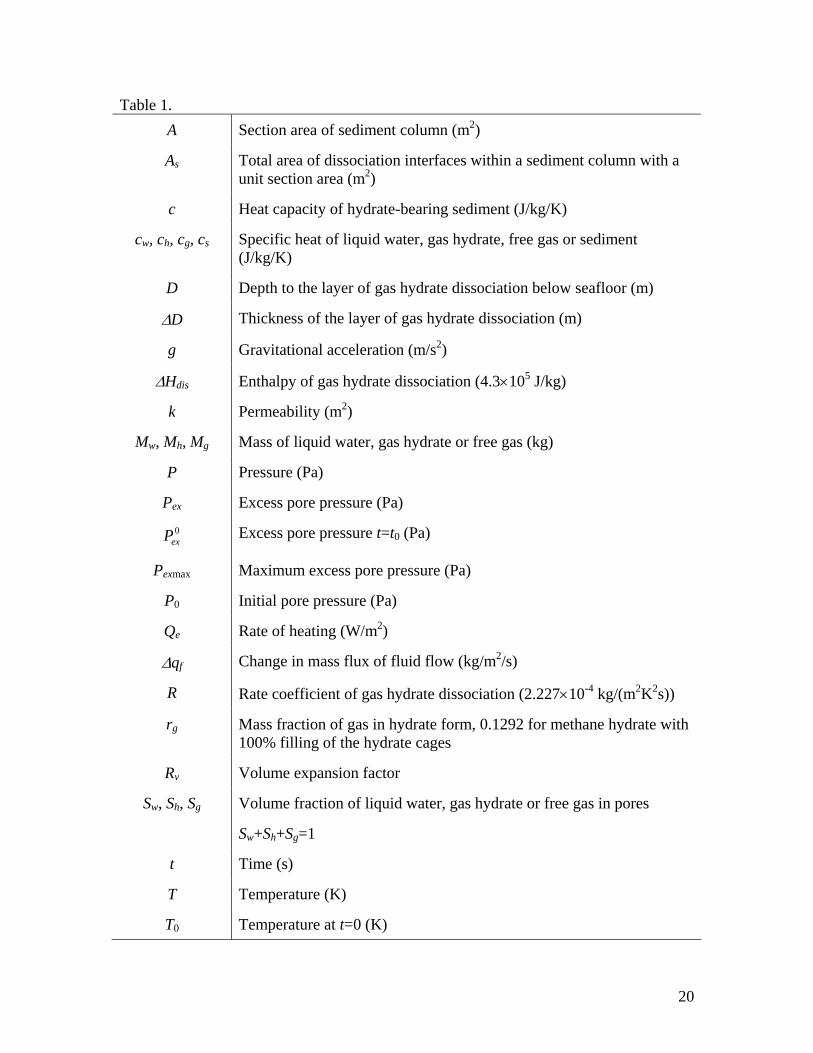
Table 1. A Section area of sediment column (m2)
As Total area of dissociation interfaces within a sediment column with a unit section area (m2)
c Heat capacity of hydrate-bearing sediment (J/kg/K)
cw, ch, cg, cs Specific heat of liquid water, gas hydrate, free gas or sediment (J/kg/K)
D Depth to the layer of gas hydrate dissociation below seafloor (m)
∆D Thickness of the layer of gas hydrate dissociation (m)
g Gravitational acceleration (m/s2)
∆Hdis Enthalpy of gas hydrate dissociation (4.3×10⁵ J/kg)
k Permeability (m2)
Mw, Mh, Mg Mass of liquid water, gas hydrate or free gas (kg)
P Pressure (Pa)
Pex Excess pore pressure (Pa) 0
exP Excess pore pressure t=t0 (Pa)
Pexmax Maximum excess pore pressure (Pa)
P0 Initial pore pressure (Pa)
Qe Rate of heating (W/m2)
∆qf Change in mass flux of fluid flow (kg/m2/s)
R Rate coefficient of gas hydrate dissociation (2.227×10⁻⁴ kg/(m2K2s))
rg Mass fraction of gas in hydrate form, 0.1292 for methane hydrate with 100% filling of the hydrate cages
Rv Volume expansion factor
Sw, Sh, Sg Volume fraction of liquid water, gas hydrate or free gas in pores
Sw+Sh+Sg=1
t Time (s)
T Temperature (K)
T0 Temperature at t=0 (K)
20
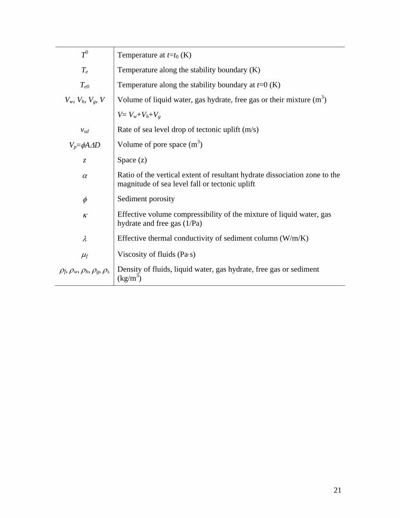
T0 Temperature at t=t0 (K)
Te Temperature along the stability boundary (K)
Te0 Temperature along the stability boundary at t=0 (K)
Vw, Vh, Vg, V Volume of liquid water, gas hydrate, free gas or their mixture (m3)
V= Vw+Vh+Vg
vsd Rate of sea level drop of tectonic uplift (m/s)
Vp=φA∆D Volume of pore space (m3)
z Space (z)
α Ratio of the vertical extent of resultant hydrate dissociation zone to the magnitude of sea level fall or tectonic uplift
φ Sediment porosity
κ Effective volume compressibility of the mixture of liquid water, gas hydrate and free gas (1/Pa)
λ Effective thermal conductivity of sediment column (W/m/K)
µf Viscosity of fluids (Pa⋅s)
ρf, ρw, ρh, ρg, ρs Density of fluids, liquid water, gas hydrate, free gas or sediment (kg/m3)
21
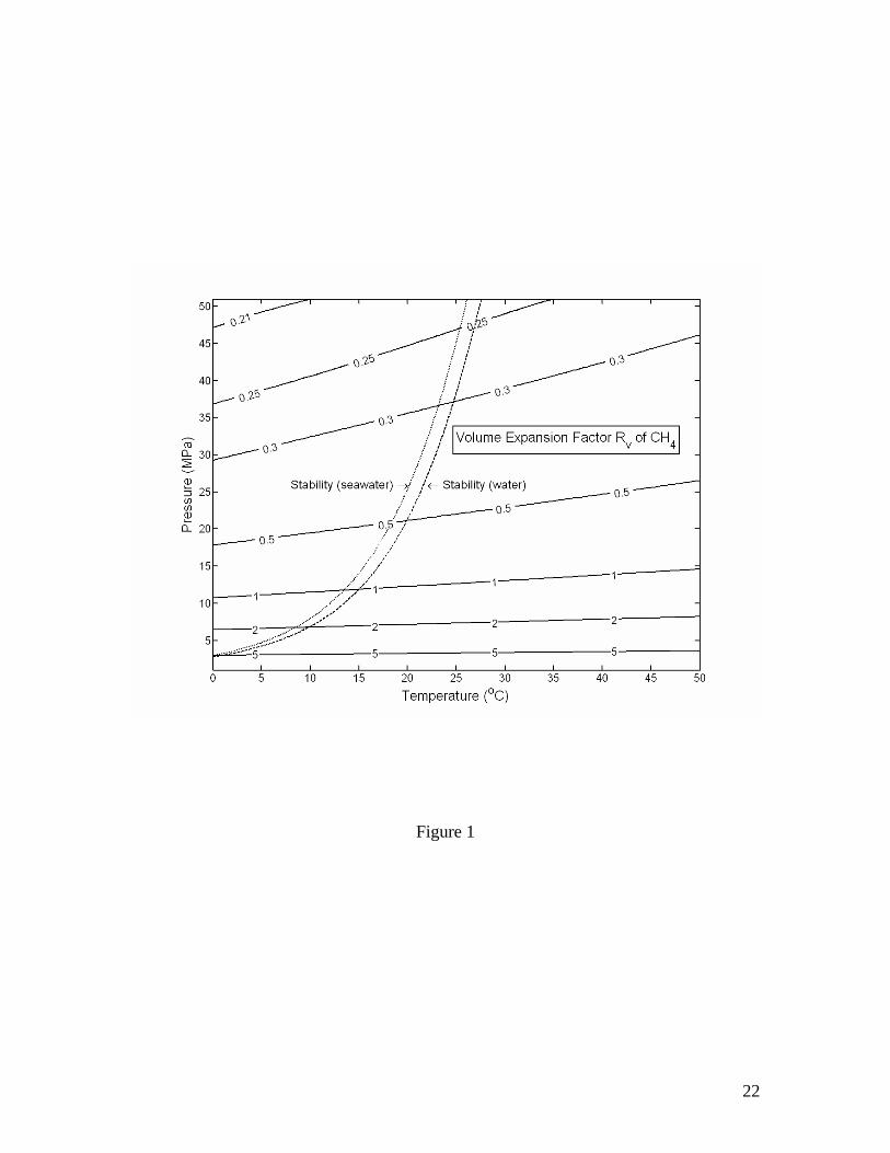
Figure 1
22
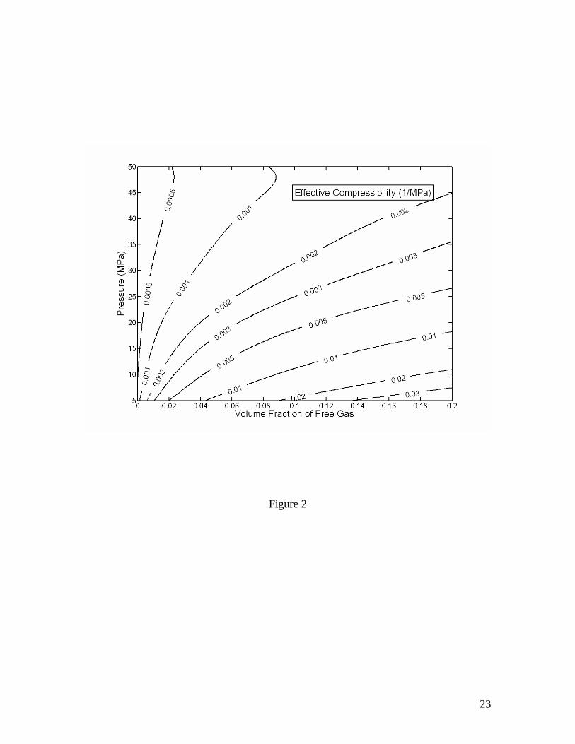
Figure 2
23
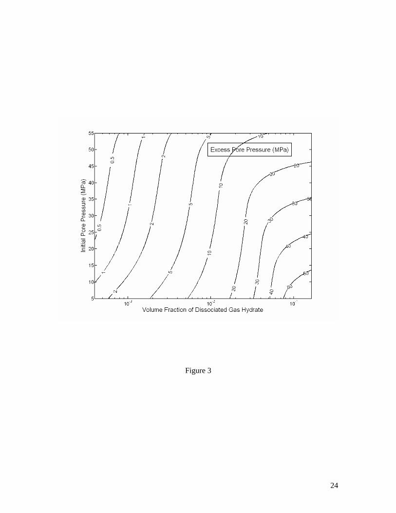
Figure 3
24
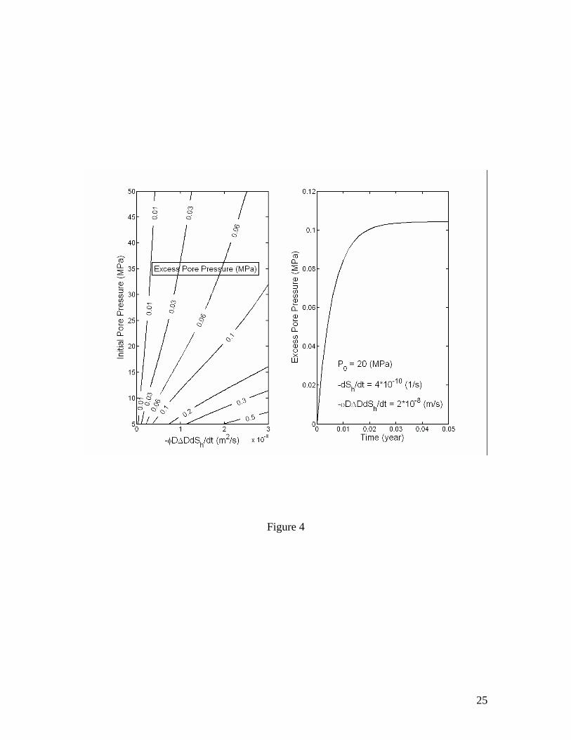
Figure 4
25
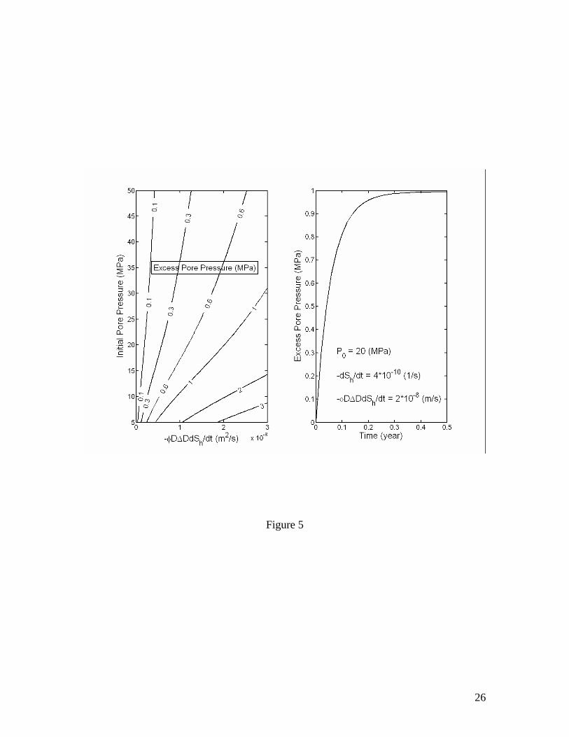
Figure 5
26
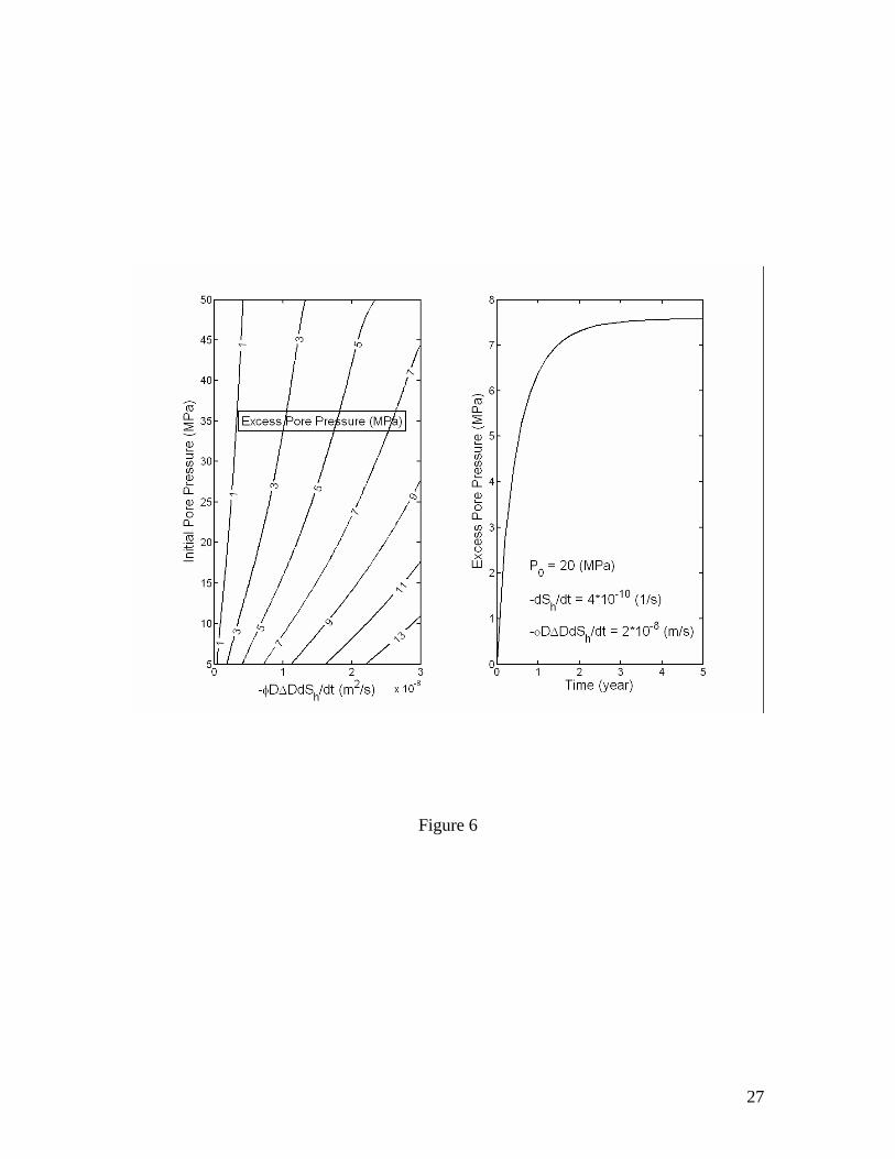
Figure 6
27
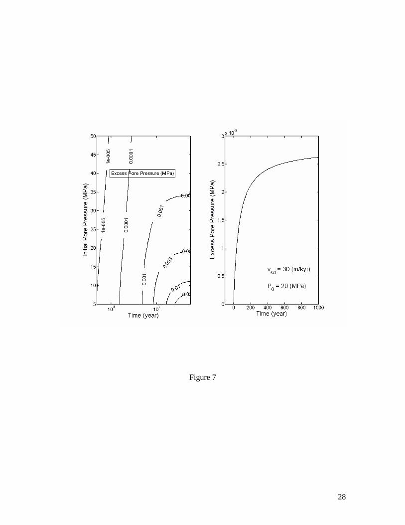
Figure 7
28
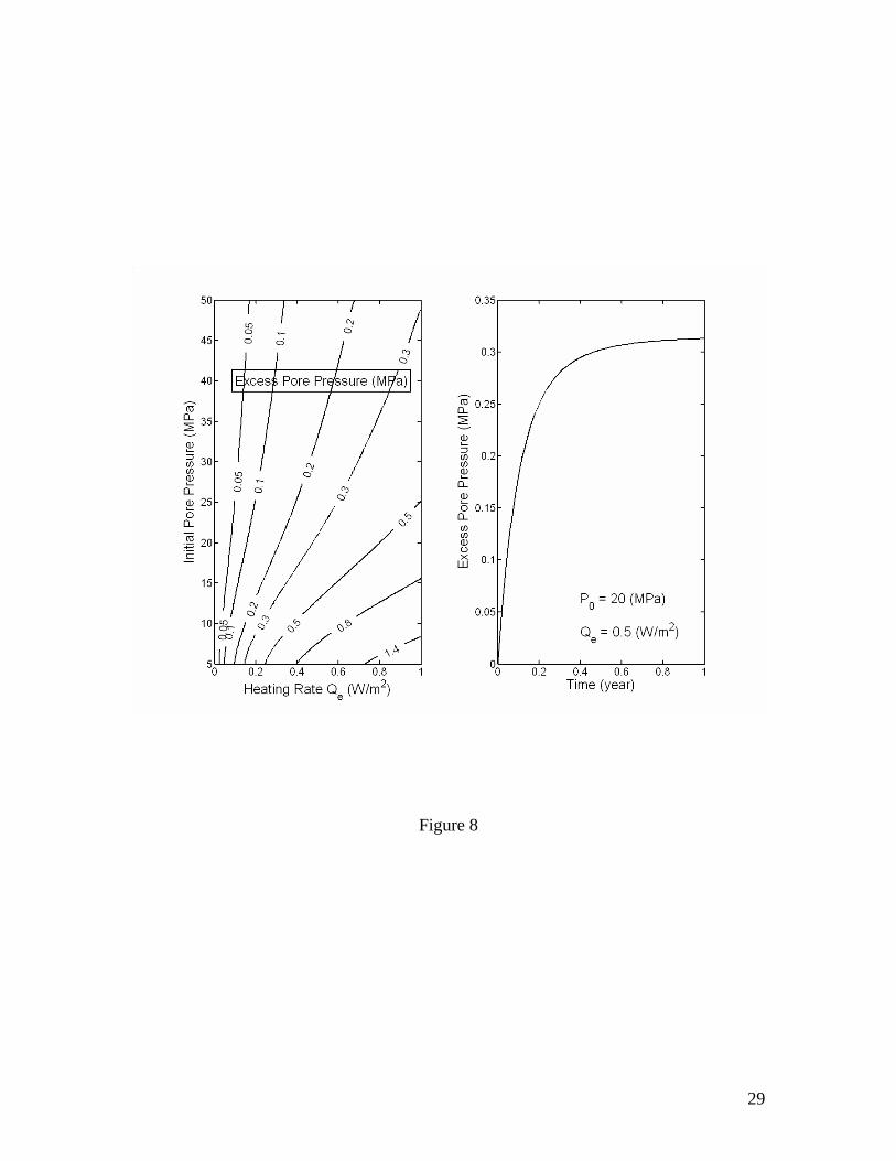
Figure 8
29

Figure 9
30
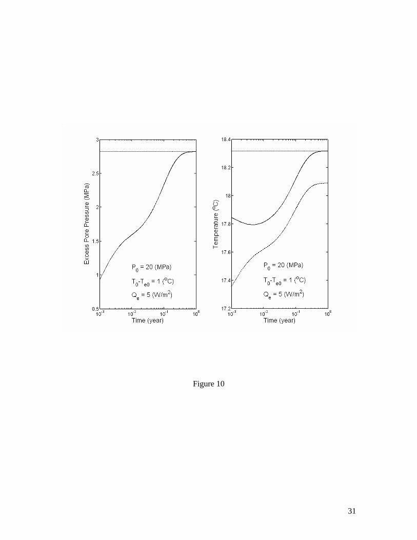
Figure 10
31
Copyright © 2022 FDOKUMEN