Hydrate-Bearing Structures in the Sea of Okhotsk
7
Eos, Vol. 86, No. 2,11 January 2005 EOS, TRANSACTIONS, AMERICAN GEOPHYSICAL UNION VOLUME 86 NUMBER 2 11 JANUARY 2005 PAGES 13-24 Hydrate-Bearing Structures in the Sea of Okhotsk PAGES 13,18 Gas hydrates are natural gas reservoirs in ice-like crystalline solids, and are stable in pore spaces of submarine sediments in water depths greater than about 300-500 m.They have been recovered in many of the world's oceans, both at larger sub-bottom depths (up to 450 m) by drilling and near the seafloor in shallow cores by gravity-coring. In the latter case, the gas hydrates are related to the sites of enhanced seepage such as cold seeps and mud volcanoes [Ginsburg and Soloviev, 1998]. Multidisciplinary field investigations during the two cruises have revealed new, large hydrate-bearing seepage structures in the Sea of Okhotsk, a northwestern marginal sea of the Pacific Ocean (Figure l).The Derugin Basin at the central part of the Sea of Okhotsk, the zone of intensive gas seepage and hydrate accumulation, was studied during two cruises of the R/V Akademik M.A. Lavrentyev (LV) of the Russian Academy of Sciences (RAS), in August and October 2003 within the framework of the CHAOS project (hydroCarbon Hydrate Accumulations in the Okhotsk Sea) supported by funding agencies in five nations. The aim of the project was to clarify the distribution, the amount, and the nature of near-sea-bottom hydrate deposits and explain the role of the gas and fluid discharge for the hydrate formation. In an area of 200 km 2 , a side-scan-sonar survey identified more than 40 seepage structures. Intensive coring in three of these structures suggested that these seepage structures reflect the zones of hydrate accumulation due to fluid discharge.The successful mapping of near-sea- bottom hydrates allows better understanding of the formation mechanisms of these hydrates, and a more precise estimation of the total amount of shallow hydrates over a relatively large study area. Seepage Structures by Side-Scan-Sonar Survey The Derugin Basin is one of the major struc- tural features in the Sea of Okhotsk, and is BY H. SHOJI,V SOLOVIEV, T. MATVEEVA, L . MAZURENKO, H. MINAMI, A . HACHIKUBO, H. SAKAGAMI, K . HYAKUTAKE, V KAULIO,V GLADYSCH, E . LOGVINA, A . OBZHIROV, B. BARANOV, O. KHLYSTOV, N. BIEBOW, J . POORT, Y K. JIN,Y KIM characterized by a thick Cenozoic sedimentary cover (up to 3 km), intensive normal faulting, and favorable conditions for gas generation and accumulation. Two target areas were investigated (Figure 1). Area 1 is located at the western flank of the basin in the northeastern Sakhalin margin, where intensive gas seepage is documented with numerous acoustic anomalies in the water column [Obzhirov, 1992; Ginsburg et al., 1993; Biebow and Hutten, 1999; Biebow et al., 2000,2003]. Gas hydrates have been repeatedly recovered from a seep at 800 m water depth 168% 132% 48°N 138 8 44*N 144% Fig. 1. Studied areas in the Sea of Okhotsk (areas 1 and 2). Original color image appears at back of this volume.
-
Upload
independent -
Category
Documents
-
view
1 -
download
0
Transcript of Hydrate-Bearing Structures in the Sea of Okhotsk
Eos, Vol. 86, No. 2,11 January 2005
EOS, TRANSACTIONS, AMERICAN GEOPHYSICAL UNION
VOLUME 86 NUMBER 2
11 JANUARY 2005
PAGES 13-24
Hydrate-Bearing Structures in the Sea of Okhotsk PAGES 13 ,18
Gas hydrates are natural gas reservoirs in ice-like crystalline solids, and are stable in pore spaces of submarine sediments in water depths greater than about 300-500 m.They have been recovered in many of the world's oceans, both at larger sub-bottom depths (up to 450 m) by drilling and near the seafloor in shallow cores by gravity-coring. In the latter case, the gas hydrates are related to the sites of enhanced seepage such as cold seeps and mud volcanoes [Ginsburg and Soloviev, 1998].
Multidisciplinary field investigations during the two cruises have revealed new, large hydrate-bearing seepage structures in the Sea of Okhotsk, a northwestern marginal sea of the Pacific Ocean (Figure l ) .The Derugin Basin at the central part of the Sea of Okhotsk, the zone of intensive gas seepage and hydrate accumulation, was studied during two cruises of the R/V Akademik M.A. Lavrentyev (LV) of the Russian Academy of Sciences (RAS), in August and October 2003 within the framework of the CHAOS project (hydroCarbon Hydrate Accumulations in the Okhotsk Sea) supported by funding agencies in five nations.
The aim of the project was to clarify the distribution, the amount, and the nature of near-sea-bottom hydrate deposits and explain the role of the gas and fluid discharge for the hydrate formation.
In an area of 200 km2, a side-scan-sonar survey identified more than 40 seepage structures. Intensive coring in three of these structures suggested that these seepage structures reflect the zones of hydrate accumulation due to fluid discharge.The successful mapping of near-sea-bottom hydrates allows better understanding of the formation mechanisms of these hydrates, and a more precise estimation of the total amount of shallow hydrates over a relatively large study area.
Seepage Structures by Side-Scan-Sonar Survey
The Derugin Basin is one of the major structural features in the Sea of Okhotsk, and is
B Y H. SHOJI,V SOLOVIEV, T. MATVEEVA, L. MAZURENKO,
H. MINAMI, A . HACHIKUBO, H. SAKAGAMI, K. HYAKUTAKE,
V KAULIO,V GLADYSCH, E . LOGVINA, A . OBZHIROV,
B . BARANOV, O. KHLYSTOV, N. BIEBOW, J . POORT,
Y K. JIN,Y KIM
characterized by a thick Cenozoic sedimentary cover (up to 3 km), intensive normal faulting, and favorable conditions for gas generation and accumulation.
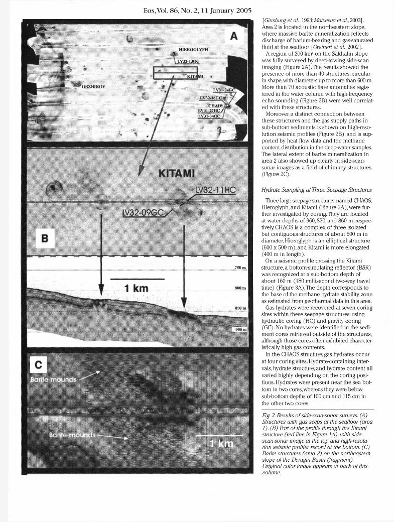
Two target areas were investigated (Figure 1). Area 1 is located at the western flank of the basin in the northeastern Sakhalin margin, where intensive gas seepage is documented with numerous acoustic anomalies in the water column [Obzhirov, 1992; Ginsburg et al., 1993; Biebow and Hutten, 1999; Biebow et al., 2000,2003] . Gas hydrates have been repeatedly recovered from a seep at 800 m water depth
168%
132% 48°N 1 3 8 8 44*N 144% Fig. 1. Studied areas in the Sea of Okhotsk (areas 1 and 2). Original color image appears at back of this volume.
Eos, Vol. 86, No. 2,11 January 2005
HIEROGLYPH
7 KITAf
7 5 0 m
[Ginsburg et al., \993;Matveeva etal.,2003]. Area 2 is located in the northeastern slope, where massive barite mineralization reflects discharge of barium-bearing and gas-saturated fluid at the seafloor [Greinert et al, 2002] .
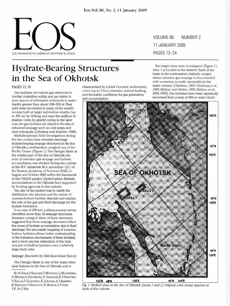
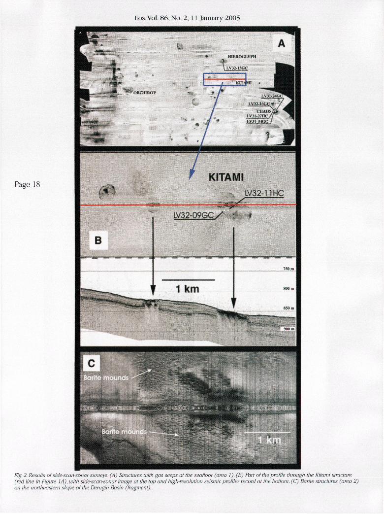
A region of 200 km 2 on the Sakhalin slope was fully surveyed by deep-towing side-scan imaging (Figure 2A).The results showed the presence of more than 40 structures, circular in shape, with diameters up to more than 600 m. More than 70 acoustic flare anomalies registered in the water column with high-frequency echo sounding (Figure 3B) were well correlated with these structures.
Moreover, a distinct connect ion between these structures and the gas supply paths in sub-bottom sediments is shown on high-resolution seismic profiles (Figure 2B) ,and is supported by heat flow data and the methane content distribution in the deep-water samples. The lateral extent of barite mineralization in area 2 also showed up clearly in side-scan-sonar images as a field of chimney structures (Figure 2C).
Hydrate Sampling at Three Seepage Structures
Three large seepage structures, named CHAOS, Hieroglyph, and Kitami (Figure 2A),were further investigated by coring.They are located at water depths of 960,830, and 860 m, respectively. CHAOS is a complex of three isolated but contiguous structures of about 600 m in diameter. Hieroglyph is an elliptical structure (600 x 500 m) ,and Kitami is more elongated (400 m in length).
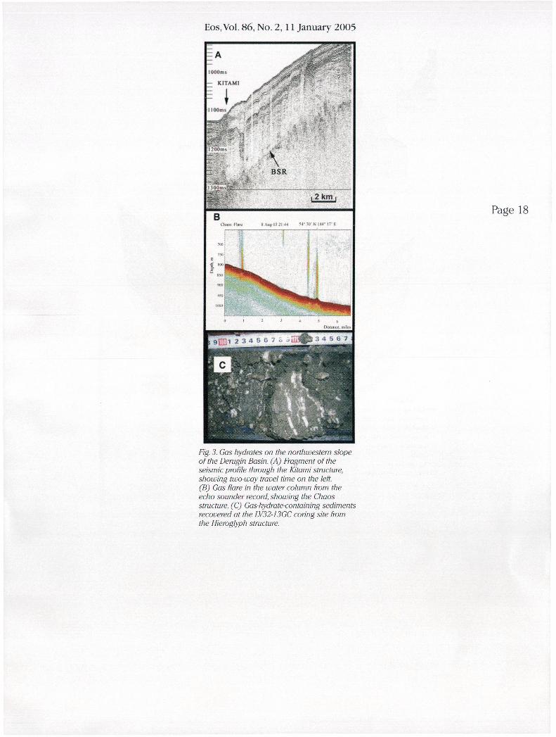
On a seismic profile crossing the Kitami structure, a bottom-simulating reflector (BSR) was recognized at a sub-bottom depth of about 160 m (180 millisecond two-way travel time) (Figure 3A).The depth corresponds to the base of the methane hydrate stability zone as estimated from geothermal data in this area.
Gas hydrates were recovered at seven coring sites within these seepage structures, using hydraulic coring (HC) and gravity coring (GC).No hydrates were identified in the sediment cores retrieved outside of the structures, although those cores often exhibited characteristically high gas contents.
In the CHAOS structure, gas hydrates occur at four coring sites. Hydrate-containing intervals, hydrate structure, and hydrate content all varied highly depending on the coring positions. Hydrates were present near the sea bottom in two cores, whereas they were below sub-bottom depths of 100 cm and 115 cm in the other two cores.
Fig. 2. Results of side-scan-sonar surveys. (A) Structures with gas seeps at the seafloor (area 1). (B) Part of the profile through the Kitami structure (red line in Figure I A), with side-scan-sonar image at the top and high-resolution seismic profiler record at the bottom. (C) Barite structures (area 2) on the northeastern slope of the Derugin Basin (fragment). Original color image appears at back of this volume.

Eos, Vol. 86, No. 2,11 January 2005
B Chaos Flare 8 Aug 03 21:44 54° 30* N 144° IT E
7001
7501
Fig. 3. Gas hydrates on the northwestern slope of the Derugin Basin. (A) Fragment of the seismic profile through the Kitami structure, showing two-way travel time on the left. (B) Gas flare in the water column from the echo sounder record, showing the Chaos structure. (C) Gas-hydrate-containing sediments recovered at the LV32-13GC coring site from the Hieroglyph structure. Original color image appears at back of this volume.
In cores LV31-27HC,LV31-34GC,and LV32-16GC, hydrates formed a typical lenticular-bedded sediment structure.The thickness of hydrate layers and lenses varied from 2-3 mm to 3 cm, and inclined hydrate layers connected adjacent sub-horizontal layers in some cases. Hydrates also occurred as small pieces <0.5 cm (LV31-24GC) or as large aggregates up to 6 cm (LV32-16GC).The total hydrate content varied from 10 to over 50%, according to visual estimations.
Within the Kitami structure, gas hydrates were recovered at two coring sites. Again, thin hydrate layers ( 2 - 3 mm thick) and large aggregates up to 9 cm both were present. In core LV32-
09GC, hydrates were identified at sub-bottom depths of 70 cm and deeper, and the hydrate content was visually estimated as 30 -40%.
During retrieval of core LV32-1 lHC,the echo sounder profiling revealed a significant amount of gas blowout from the corer due to the hydrate dissociation, detected as a flare image spread around the corer position in the water.The largest one was observed within 100 m depth from the sea surface.
In the Hieroglyph structure, one core with gas hydrates was recovered. At the two other coring sites at Hieroglyph, the deeper core intervals showed low chlorine anomaly in pore water, which suggests gas hydrates. In core LV32-13GC, lenticular-bedded hydrate layers (0.5-0.7 mm thick) and isometric hydrate inclusions (a few millimeters to 3 4 c m ) both were found at sub-bottom depth intervals between 100 and 170 cm (Figure 3C).The bottom of the hydrate-bearing sediment was not reached.The hydrate content in the deeper part of the core portion below 145 cm depth was visually estimated to be 40% of the sediment volume.
Gas Amount Estimation in the Seepage Structures
Although the recovered hydrates show a variety of characteristic shapes, lenticular-bedded hydrate layering appears to be the main formation type. Such layering is similar to ice lens forming in ground freezing, which suggests hydrate formation under gas diffusion [Ginsburg and Soloviev, 1998].
The visual estimate of total hydrate content varied between 10 and 40%. Gas hydrate occurs generally at sub-bottom depths below 1 m.
These observations, combined with the fact that hydrates were sampled in all seepage structures on the seafloor revealed by side-scan sonar, allow for a preliminary estimate of total hydrate amount as follows.The total area of all structures is about 4.36 km 2 (area of all structures at the seafloor revealed by side-scan sonar). Assuming a density of about 8 x 10 8
m 3/km 2 [Soloviev, 2002] , the total gas reserves in all structures may be as high as 3.5 x 10 9 m 3.
For the CHAOS structure as an example of a single structure, the gas reserve is estimated as 2.3 x 10 8 rnlThis value for the CHAOS structure seems to be comparable to those of the mud volcanoes: Buzdag in the Caspian Sea (8 x 10 7
m 3 ) and Milano in the Mediterranean Sea (2.5 x 10 9 m 3 ) [Soloviev, 2002] , and of the Southern Hydrate Ridge summit (1 .5 -2 x 10 8 m 3 ) [Trehu et al, 2004] .
The outcome of the CHAOS cruises suggests once more that any deep-water fluid discharge areas, including gas seeps, can be considered as potential hydrate-producing districts where any part of gas dissolved in water or free gas will be stabilized in the form of near-sea-bottom gas hydrate accumulations. Further investigation is needed to define the depth zone of near-sea-bottom hydrate occurrence and the
distribution of seepage structures outside this study area.
Acknowledgments
This work has been supported by funding agencies in Japan: The Japan Society for the Promotion of Sc ience KAKENHI 14254003 and 15550060, the Ministry of Education, Culture, Sports, Science and Technology KAKENHI 15760640, and the Kitami Institute of Technology (Presidential grant 2003) ; Russia: the All Russia Research Institute for Geology and Mineral Resources of the Ocean (RFBR grant 02-05-64346) and RAS; Belgium: Ghent University grant FWO-Vlaanderen; Germany: the Federal Ministry of Education and Research KOMEX grant 03G0568; and Korea: Ministry of Maritime Affairs and Fisheries research and development grant PM21700.
We also thank for many-sided support of Kitami Institute of Technology (H.S.,H.M., A.H.,H.S.,K.H.),the all Russia Research Institute for Geology and Mineral Resources of the Ocean (VS.,T.M., L.M.,VK.,VG., E.L.),the VI. Il'ichev Pacific Oceanological Institute (A.O.), the RPShirshov Institute of Oceanology (B.B.) , the Limnological Institute (O.K.),IFM-GEOMAR (N.B.),the Renard Centre of Marine Geology (J.P),and the Korea Polar Research Institute (YJ. ,YK.) .
The Pacific Oceanological Institute of the Russian Academy of Sciences organized the R/V cruises.
References
Biebow, N., and E.Hutten (Eds.) (1999) , Cruise reports: KOMEX I and II: RV Professor Gagarinsky Cruise 22, RV Akademik M.A. Lavrentyev Cruise 28, GEOMAR Rep. 82,188 pp., GEOMAR, Kiel, Germany.
Biebow, N.,T. Ludmann, B. Karp, and R. Kulinich (2000) , Cruise reports: KOMEXV and VI: RV Professor Gagarinsky Cruise 26, MV Marshal Gelovany Cruise 1, GEOMAR Rep. 88,296 pp., GEOMAR, Kiel, Germany
Biebow, N., R. Kulinich,and B. Baranov ( 2 0 0 3 ) , Cruise reports: RV Akademik M.A. Lavrentyev Cruise 29, Leg 1 and Leg 2, GEOMAR Rep. 110,305 pp., GEOMAR, Kiel, Germany.
Ginsburg, G. D., et al. ( 1 9 9 3 ) , Gas hydrates from the continental slope, offshore Sakhalin Island, Okhotsk Sea, Geo Mar. Lett., 7 5 , 4 1 - 4 8 .
Ginsburg, G , and V Soloviev ( 1 9 9 8 ) , S u b m a r i n e Gas Hydrates, 216 pp.,VNIIOkeangeologia, St. Petersburg, Russia.
Greinert,J. ,et al. ( 2 0 0 2 ) , Massive barite deposits and carbonate mineralization in the Derugin Basin, Sea of Okhotsk: Precipitation processes at cold seep sites,Earth Planet Sci. Lett., 203,165-180.
Matveeva,T, et al. ( 2 0 0 3 ) , Geochemistry of gas hydrate accumulat ion offshore NE Sakhalin Island (the Sea of Okhotsk): Results from the KOMEX-2002 cruise, Geo Mar. Lett., 2 5 ( 3 - 4 ) , 2 7 8 - 2 8 8 .
Obzhirov,A. I. ( 1992) ,Gasogeochemica l manifestations of gas-hydrates in the Sea of Okhotsk, Alaska Geol, 2 / ( 7 ) , 1-7.
Soloviev,V. A. (2002) ,Globa l estimation of gas content in submarine gas hydrate accumulat ions, Russ. Geol. Geophys., 43(7), 6 0 9 - 6 2 4 .

Eos,Vol. 86, No. 2,11 January 2005 Trehu,A.M.,et al. (2004),Three-dimensional distribu
tion of gas hydrate beneath southern Hydrate Ridge: Constraints from ODP Leg 204, Earth Planet. Sci. Lett., 222,845-862.
Author Information
Hitoshi Shoji,Hirotsugu Minami,Akihiro Hachikubo, Hirotoshi Sakagami,and Kinji Hyakutake, Kitami Institute of Technology, Kitami, Japan; Valery Soloviev,
Tatiana Matveeva, Leonid Mazurenko,Vitaly Kaulio, Vyacheslav Gladysch,and Elizaveta Logvina,All Russia Research Institute for Geology and Mineral Resources of the Ocean, St. Petersburg, Russia; Anatoly Obzhirov, Vl . I l ' i chev Pacific Oceanologica l Institute FEB RAS, Vladivostok, Russia; Boris Baranov, PPShirshov Institute of Oceanology RAS, Moscow, Russia; Oleg Khlystoy Limnological Institute S B RAS, Irkutsk, Russia; Nicole Biebow, Leibniz Institute of Marine Sc iences at Kiel University (IFM- GEOMAR), Kiel, Germany; Jeffrey
Poort, Renard Centre of Marine Geology, Ghent University Gent, Belgium; and Young Keun Jin andYeadong Kim, Korea Polar Research Institute, KORDI, Ansan, Korea
For additional information, contact H.Shoji, E-mail: [email protected], or V Soloviev. E-mail: soloviev@gashyd. spb.ru.
A Research Park for Studying Processes in Unsaturated Fractured Media PAGES 15,19
A field research site has been developed to explore the combined use of physical experiments and mathematical modeling to analyze large-scale infiltration and chemical transport through the unsaturated media overlying the Snake River Plain Aquifer in southeastern Idaho. This site offers opportunities to observe water and contaminant migration influenced by fluid dynamics and microbial activity through heterogeneous-porous and fractured media.
At many waste disposal facilities, the presence of toxic or radioactive wastes between the land surface and underlying aquifers poses a serious and ongoing threat to public health and safety.To reduce the risk associated with these industrial and Cold War by-products, a combination of remediation and long-term monitoring will be required.
To make scientifically valid decisions, the difficult questions of where these waste products are, how fast they are moving, and how potential environmental impacts may be mitigated must be addressed. Simple answers to such questions rarely exist, due to the complexities associated with flow and transport processes that occur through variably saturated, thick, heterogeneous, and fractured media.
To better understand these mechanisms, a field research site has been established near an operational waste disposal facility at the U. S. Department of Energy's (DOE) Idaho National Engineering and Environmental Laboratory (INEEL).The Vadose Zone Research Park was developed to enable the collection and analysis of a wide variety of information, including geophysical, biological, geochemical, hydrologic, climatologic, and geologic data. The research park encompasses a wide range of operational and geologic conditions that contribute to highly dynamic flow and transport.
These conditions include continual discharge to two surface ponds and underflow from the nearby ephemeral Big Lost River; cyclic changes in discharge water chemistry; variable surface and subsurface biologic activity; and lithology
B Y K. BAKER, T. MCLING, L . STREET, A . SCHAFER,
S. ANSLEY, L. HULL, R . HOLT, R . ROBACK,
AND C.JONES
characterized by fractured basalt flows interspersed with sedimentary units.
Research Park Description
The research park is located in southeastern Idaho, approximately 3 km southwest of INEEL's Idaho Nuclear Technology and Engineering Center (INTEC) in a contaminant-free area. Service wastewater from INTEC is pumped continually into one of two research park infiltration ponds at roughly 1 Mgal/day with the ability to alternate between ponds based on research needs.
Although discharge rates and temperature are relatively constant, the water chemistry varies significantly with INTEC's active industrial processes. The makeup of the discharge water is non-radioactive, nonhazardous facility cooling water, and it includes components generated from the flushing of ion exchange columns and reverse osmosis equipment.This discharge infiltrates through the complex, 150-m-thick assemblage of basalt flows and sedimentary interbeds (Figure 1).
Understanding fluid and contaminant transport at the INEEL has been problematic because of the heterogeneous subsurface geology in combination with high-volume and transient surface-water discharges.To better understand the mechanisms by which water and contaminants are transported to the aquifer, a network of 37 instrumented monitoring wells was installed.
These wells were placed around the perimeter of the ponds, along a north trending transect and along both sides of the Big Lost River, water wells and four aquifer wells, and electrical conductivity probes were emplaced in three shallow monitoring wells around the pond perimeters and near the discharge pipes. Nine boreholes were instrumented with nested bundles of sensors and samplers inside access tubes that also enable neutron logging.
Water level sensors provide information on the redistribution of water in perched and aquifer regions, conductivity probes provide information on tracer and water chemistry and instrumented borehole sensors provide moisture content and water potential information.
In addition, most of these wells were equipped with an electrode array for cross-borehole electrical resistivity tomography, providing a three-dimensional view of water distribution. To complement the subsurface informat ions weather station is being installed to monitor evapotranspiration and other atmospheric conditions.
Data are automatically collected hourly and uploaded weekly to a Web-based server for long-term storage and management. The Web-based system provides on-demand access to data and graphical and statistical analysis, and allows acquisition control through user-defined alerts. The Web site will be accessible to the public in early spring 2005.
Observations
Field data collected in the first 2 years of operation at the research park show complex fluid transport behavior. Some of the more interesting observations include the following:
• Perched water was present at multiple locations prior to the onset of wastewater discharge. Water had not flowed for the 2 previous years in the Big Lost River, and other sources of recharge were not evident.
• Water depth between the two ponds was significantly different. Discharge to the north pond resulted in nearly uniform, laterally extensive coverage, while only localized coverage was observed during discharge to the south pond.
• The water and tracer arrived nonsequen-tially laterally and vertically in both sediment and fractured media. Infiltration reached 100 m in depth and 900 m laterally within a few weeks of initial discharge.
• Hydraulic-pressure and colloid-concentration changes appear to indicate the flushing of fine particles and the formation of new pathways following transient discharges.
It is hypothesized that fluid transport is dominated by extreme contrasts in hydraulic properties of geologic materials, and that hydraulic properties vary a great deal spatially and temporally These dynamic conditions result in more rapid and tortuous transport over more extensive volumes than initially conceptualized. From the existence of the initial perched-water zones, it is apparent that highly variable water conditions can exist in the absence of local recharge for extended time periods.
To better understand these observations, it will be necessary to investigate the following:
• subsurface lithology.The subsurface lithology consists of fractured, dense, and rubbled
Eos, Vol. 86, No. 2,11 January 2005
Page 13
132°E 48'N 138°E 449N 144'E
Fig. 1. Studied areas in the Sea of Okhotsk (areas 1 and 2).
Eos,Vol. 86, No. 2,11 January 2005
Page 18 KITAMI
LV32-11HC
B
L V 3 2 - 0 9 G C / -
750 m
Fig. 2. Results of side-scan-sonar surveys. (A) Structures with gas seeps at the sea floor (area 1). (B) Part of the profile through the Kitami structure (red line in Figure 1A), with side-scan-sonar image at the top and high-resolution seismic profiler record at the bottom. (CJ Barite structures (area 2) on the northeastern slope of the Derugin Basin (fragment).
Eos, Vol. 86, No. 2, 11 January 2005
1000 ms
- K I T A M I
I lOOmsj
\ B S R
12 km
B Page 18
Fig. 3. Gas hydrates on the northwestern slope of the Derugin Basin. (A) Fragment of the seismic profile through the Kitami structure, showing two-way travel time on the left. (B) Gas flare in the water column from the echo sounder record, showing the Chaos structure. (C) Gas-hydrate-containing sediments recovered at the LV32-13GC coring site from the Hieroglyph structure.