Evaluation of the maximized power of a regenerative endoreversible Stirling cycle using the...
11
This article appeared in a journal published by Elsevier. The attached copy is furnished to the author for internal non-commercial research and education use, including for instruction at the authors institution and sharing with colleagues. Other uses, including reproduction and distribution, or selling or licensing copies, or posting to personal, institutional or third party websites are prohibited. In most cases authors are permitted to post their version of the article (e.g. in Word or Tex form) to their personal website or institutional repository. Authors requiring further information regarding Elsevier’s archiving and manuscript policies are encouraged to visit: http://www.elsevier.com/authorsrights
-
Upload
independent -
Category
Documents
-
view
3 -
download
0
Transcript of Evaluation of the maximized power of a regenerative endoreversible Stirling cycle using the...

This article appeared in a journal published by Elsevier. The attachedcopy is furnished to the author for internal non-commercial researchand education use, including for instruction at the authors institution
and sharing with colleagues.
Other uses, including reproduction and distribution, or selling orlicensing copies, or posting to personal, institutional or third party
websites are prohibited.
In most cases authors are permitted to post their version of thearticle (e.g. in Word or Tex form) to their personal website orinstitutional repository. Authors requiring further information
regarding Elsevier’s archiving and manuscript policies areencouraged to visit:
http://www.elsevier.com/authorsrights

Author's personal copy
Evaluation of the maximized power of a regenerative endoreversibleStirling cycle using the thermodynamic analysis
Mohammad H. Ahmadi a,⇑, Amir H. Mohammadi b,c,⇑, Saeed Dehghani a
a Faculty of Mechanical Engineering, K.N Toosi University, Tehran, Iranb Institut de Recherche en Génie Chimique et Pétrolier (IRGCP), Paris Cedex, Francec Thermodynamics Research Unit, School of Engineering, University of KwaZulu-Natal, Howard College Campus, King George V Avenue, Durban 4041, South Africa
a r t i c l e i n f o
Article history:Received 16 February 2013Accepted 30 July 2013
Keywords:Ideal regenerativeStirling enginePowerThermal efficiencyMulti-objective optimization
a b s t r a c t
In this communication, the optimal power of an endoreversible Stirling cycle with perfect regeneration isinvestigated. In the endoreversible cycle, external heat transfer processes are irreversible. Optimal tem-perature of the heat source leading to a maximum power for the cycle is detained. Moreover, effect ofdesign parameters of the Stirling engine on the maximized power of the engine and its correspondingthermal efficiency is studied.
� 2013 Elsevier Ltd. All rights reserved.
1. Introduction
Security of sustainable energy is one of the most important con-cerns for world societies [1]. A number of commercial enterprisesare required for supplying climate-friendly energy technologiesin future [2–5], including electricity produced from solar and windenergy [6–9], bio-fuels, and carbon dioxide (CO2) capture and stor-age (CCS) [10–15]. In this regard, scrutinized planning with respectto the prospect plays an essential role toward better future. Green-house gases emission is one of the restrictions of utilizing fossilfuels which encourages development of higher efficiency and max-imal electric [13–16] in energy production systems. Use of Stirlingengines results in green house gases emissions reduction into theatmosphere. The Stirling engine has a high potential to be appliedfor converting heat into the mechanical work with a high thermalefficiency. In theory its thermal efficiency might be as high as theCarnot efficiency when it is ideal regenerator, reversible, and hav-ing isothermal compression and expansion processes. Stirling en-gine is an external combustion engine, so it can be powered byvarious heat sources and waste heat [17–24]. Blank et al. [20] stud-ied the power optimization of an endoreversible Stirling cycle andprovided an estimate of potential performance for a real engine.Thombare and Verma [21] gathered the available technologies
and obtained achievements with regard to the analysis of Stirlingengines and, at the end, presented some suggestions for theirapplications. Formosa and Despesse [23] conducted the modelingby means of the isotherm model in order to investigate the effectsof dead volumes on the engine’s output power and efficiency.
The Stirling engine cycle can be defined as a closed regenerativethermodynamic cycle consists of compression and expansion of theworking fluid at different temperatures [25–35]. Tlili et al. [33] devel-oped a first law model with additional consideration for an internalirreversibility parameter to examine the effects of irreversibility onnet work, heat addition, and thermal efficiency. Their irreversibilityparameter originates from the second law of thermodynamics for areal cycle. Their results regarding dead volume and regeneration ef-fects support the observations of Kongtragool and Wongwises [35].They also reported that larger irreversibilities in the Stirling cyclethermodynamic processes lead to smaller maximum network outputand thermal efficiency. However, they did not quantify the roles ofthe heat exchangers, regenerator, and dead volume irreversibilitieson the overall system irreversibility.
The enhancement of finite-time thermodynamics [36–40], layson a useful tool for performance analysis of real engineering prob-lems. The finite-time thermodynamic performance of the Stirlingengine has been scrutinized by a great number of investigators[39–46]. The effect of heat transfer on the power output of a Stirlingengine has been inquired by many researchers [4,23–30]. An optimalefficiency for maximum power output of a solar Stirling engine con-sidering imperfect regeneration is achieved by Petrescu et al.[39,41]. Moreover, finite-time thermodynamics analysis of heat
0196-8904/$ - see front matter � 2013 Elsevier Ltd. All rights reserved.http://dx.doi.org/10.1016/j.enconman.2013.07.082
⇑ Corresponding authors. Address: Institut de Recherche en Génie Chimique etPétrolier (IRGCP), Paris Cedex, France (A.H. Mohammadi).
E-mail addresses: [email protected] (M.H. Ahmadi),[email protected] (A.H. Mohammadi).
Energy Conversion and Management 76 (2013) 561–570
Contents lists available at ScienceDirect
Energy Conversion and Management
journal homepage: www.elsevier .com/ locate /enconman
Author's personal copy
engines is often limited to systems having linear heat transfer lawwhich depends on the temperature differential both the reservoirsand engine working fluids [22,44–50]. Yagi et al. developed a math-ematical model for the overall thermal efficiency of solar poweredhigh temperature differential dish Stirling engine with finite heattransfer and irreversibility of regenerator and optimized the absor-ber temperature and corresponding thermal efficiency [42]. Tliliinvestigated effects of regenerating effectiveness and heat capaci-tance rate of external fluids in heat source/sink at maximum powerand efficiency [44]. Kaushik and Kumar studied the effects of irrever-sibilities of regeneration and heat transfer of heat/sink sources [46].
Solution of the multi-objective optimization problems is an ex-tremely difficult goal which requires the simultaneous satisfactionof a number of different and even conflicting objectives. Evolution-ary algorithms (EA) were initially extended and employed duringthe mid-eighties in an attempt to stochastically solve problemsof this generic class [47]. A reasonable solution to a multi-objectiveproblem is to investigate a set of solutions, each of which satisfiesthe objectives at an acceptable level without being dominated byany other solution [48]. Multi-objective optimization issues illus-trate a possibly uncountable set of solutions which is named Paretofrontier, whose evaluated vectors depict the best possible trade-offs in the objective function space. In turn, multi-objective optimi-zation of various thermodynamic and energy systems have beenconcentrated recently [49–56].
In real model on Stirling engines, heat regeneration is supposedbe considered imperfect. The optimal power theory design of theStirling engine may be complex in this case. Assuming an idealStirling engine can lead to acceptable results in power outputand thermal efficiency. This article concentrates on these elementsusing two scenarios.
2. Scenarios
2.1. Thermodynamic modeling
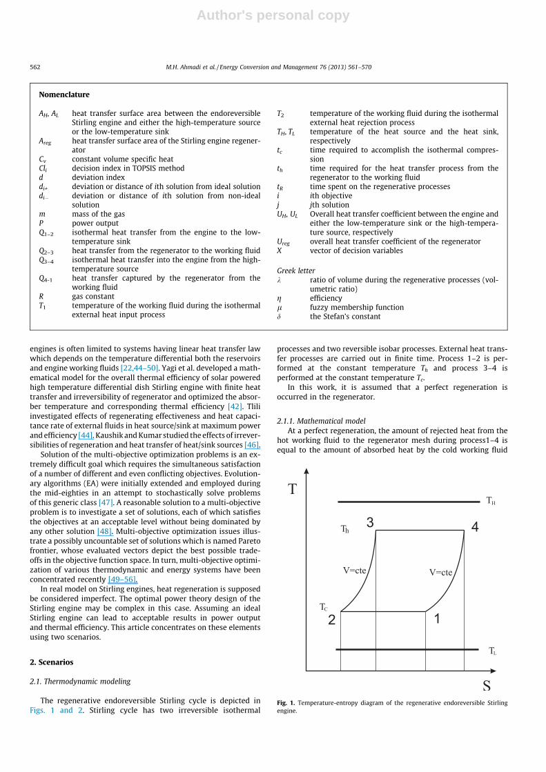
The regenerative endoreversible Stirling cycle is depicted inFigs. 1 and 2. Stirling cycle has two irreversible isothermal
processes and two reversible isobar processes. External heat trans-fer processes are carried out in finite time. Process 1–2 is per-formed at the constant temperature Th and process 3–4 isperformed at the constant temperature Tc.
In this work, it is assumed that a perfect regeneration isoccurred in the regenerator.
2.1.1. Mathematical modelAt a perfect regeneration, the amount of rejected heat from the
hot working fluid to the regenerator mesh during process1–4 isequal to the amount of absorbed heat by the cold working fluid
Nomenclature
AH, AL heat transfer surface area between the endoreversibleStirling engine and either the high-temperature sourceor the low-temperature sink
Areg heat transfer surface area of the Stirling engine regener-ator
Cv constant volume specific heatCli decision index in TOPSIS methodd deviation indexdi+ deviation or distance of ith solution from ideal solutiondi� deviation or distance of ith solution from non-ideal
solutionm mass of the gasP power outputQ1–2 isothermal heat transfer from the engine to the low-
temperature sinkQ2–3 heat transfer from the regenerator to the working fluidQ3–4 isothermal heat transfer into the engine from the high-
temperature sourceQ4-1 heat transfer captured by the regenerator from the
working fluidR gas constantT1 temperature of the working fluid during the isothermal
external heat input process
T2 temperature of the working fluid during the isothermalexternal heat rejection process
TH, TL temperature of the heat source and the heat sink,respectively
tc time required to accomplish the isothermal compres-sion
th time required for the heat transfer process from theregenerator to the working fluid
tR time spent on the regenerative processesi ith objectivej jth solutionUH, UL Overall heat transfer coefficient between the engine and
either the low-temperature sink or the high-tempera-ture source, respectively
Ureg overall heat transfer coefficient of the regeneratorX vector of decision variables
Greek letterk ratio of volume during the regenerative processes (vol-
umetric ratio)g efficiencyl fuzzy membership functiond the Stefan’s constant
Fig. 1. Temperature-entropy diagram of the regenerative endoreversible Stirlingengine.
562 M.H. Ahmadi et al. / Energy Conversion and Management 76 (2013) 561–570
Author's personal copy
during process 2–3. This assumption is acceptable, as regeneratorswith effectiveness of 98% and 99% have been reported [17,20].Therefore, we have;jQ 2�3j ¼ jQ 4�1j ð1Þ
Q H ¼ UHAHðTH � ThÞth ¼ mRThLnðkÞ ð2Þ
Q L ¼ ULALðTc � TLÞtc ¼ mRTcLnðkÞ ð3Þ
Thus, it can be shown that the net work of the cycle is obtained asfollow [17,20,42–46];
Wnet ¼ mRðTh � TcÞLnðkÞ ð4Þ
where m is the mass of the working fluid, R is the gas constant, T isthe temperature of working fluid in each state of the cycle as de-scribed by subscripts and k is the compression ratio. The outputpower is obtained by dividing the net work to the time period ofthe cycle [17,20,42–46];
P ¼Wnet
t¼ mRðTh � TcÞLnðkÞ
th þ tc þ tRð5Þ
where tR is the total time spent for the regeneration processes and th
and tc are the times spent for isothermal expansion and compres-sion processes respectively. These time periods are defined asfollows;
th ¼mRThLnðkÞ
UHAHðTH � ThÞð6Þ
tc ¼mRTcLnðkÞ
ULALðTc � TLÞð7Þ
tR ¼2mcvðTh � TcÞ
UregAregðLMTDÞregð8Þ
where UH and AH are the overall heat transfer coefficient and theheat transfer surface area for the hot side heat exchanger, respec-tively. Similarly, UL, AL and Ureg, Areg, similar values for cold side heatexchanger and regenerator. TH and TL are the temperature of heatsource and heat sink respectively. CV is the specific heat at constantvolume in kJ kg�1 K�1 and is assumed to be constant.
Assuming the ideal regenerative, (LMTD)reg = 1 K. [4]. Substitu-tion of Eqs. (6)–(8) into Eq. (5) leads to the following expression:
P¼ Th
UHAHðTH�ThÞðTh�TcÞþ Tc
UHAHwARðTc�TLÞðTh�TcÞþ 2CV
RUregAregLnðkÞ
� ��1
ð9Þ
w ¼ UL
UHð9aÞ
AR ¼AL
AHð9bÞ
For simplicity, we considered the x ¼ TcTh
and M ¼ CVRLnk, so Eq. (9) can
be written as follow;
P¼ 1UHAHðTH�ThÞð1�xÞþ
xUHAHwARðxTh�TLÞð1�xÞþ
2MUregAreg
� ��1
ð10Þ
To determine the maximum power output, take the derivative of Pwith respect to T1 and obtain the optimum temperature of workingfluid at state 1;
@P@T1¼ �
So;
Thopt ¼ffiffiffiffiffiffiffiffiffiwAR
pTL þ xTH
xðffiffiffiffiffiffiffiffiffiwAR
pþ 1Þ
ð11Þ
Therefore, the thermal efficiency is calculated as follow;
gt ¼P
QHð12Þ
Substituting Eq. (11) into Eq. (10);
Pmax ¼1
UHAHðTH�ThoptÞð1�xÞþx
UHAHwARðxThopt�TLÞð1�xÞþ2M
UregAreg
� ��1
ð13Þ
For the maximum power output it should be considered UHAH = UA[4]. So Eq. (13) can be written as follow;
Pmax ¼1
UAðTH�ThoptÞð1�xÞþx
UAwARðxThopt�TLÞð1�xÞþ2M
UregAreg
� ��1
ð14Þ
Also, the corresponding maximum net work is obtained as follow;
Wnet;opt ¼ mRThoptð1� xÞLnðkÞ ð15Þ
2.1.2. First scenario resultsTo have a numerical appreciation of the result, we consider the
heat source temperature and cold source temperature 1300 K and320 K respectively. Also UHAH = ULAL = 2 kW K�1, x = 0.5, k ¼ 2,w = 1, AR = 1, and UregAreg = 1000 kW K�1 [20]. We consider stan-dard air as a working fluid with R = 0.287 kJ K�1kg�1, CV = 0.718 -kJ K�1kg�1 and m = 9.3 g, as a total mass of the working fluid.
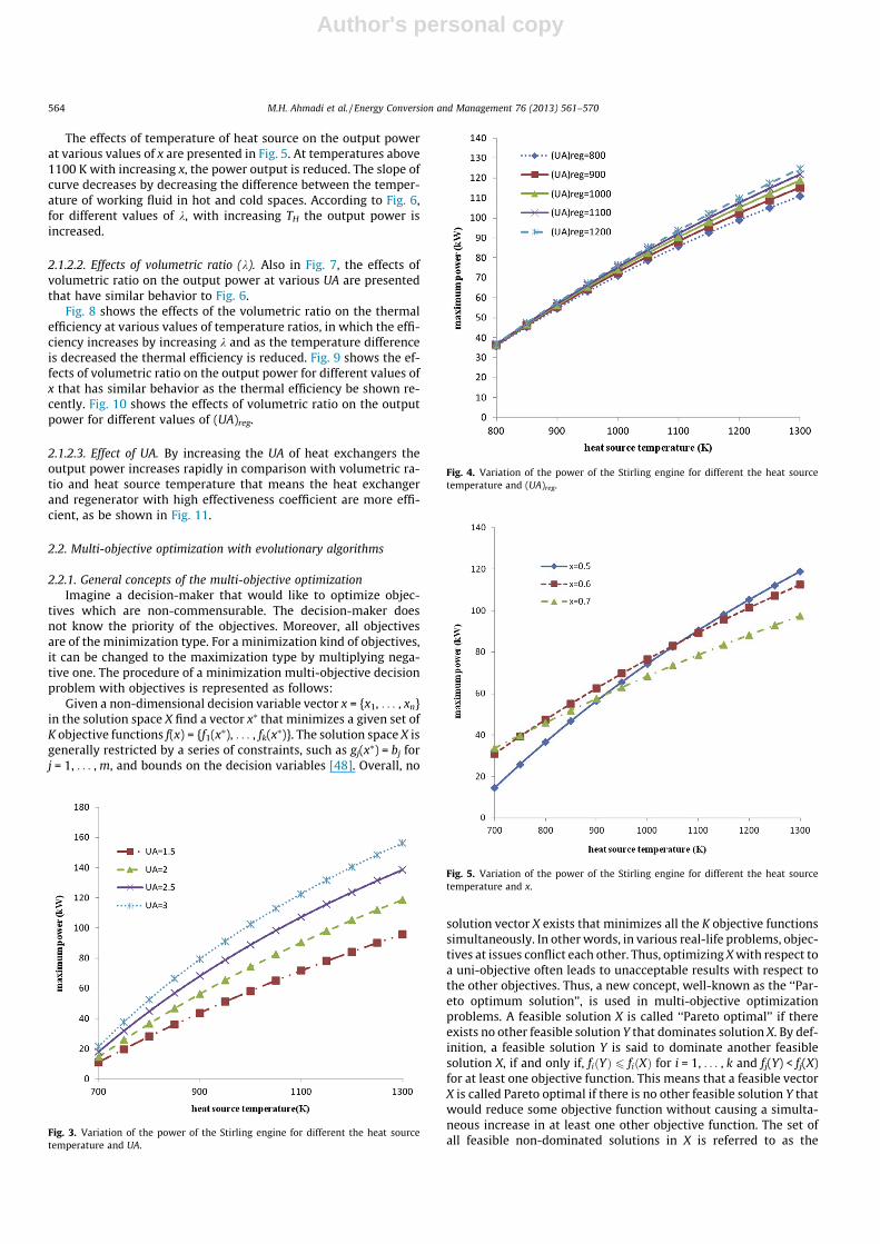
2.1.2.1. The effects of TH. As be shown in Fig. 3, in various UA, byincreasing TH the output power increases. Also, in the certain TH,by increasing UA, output power increases too. As is clear in Fig. 4,in various (UA)reg, by increasing TH the output power increases, alsoin certain TH, with increasing (UA)reg, output power is increased.
Regenerator
Heater
Cooler
TH
TL
TC
Th
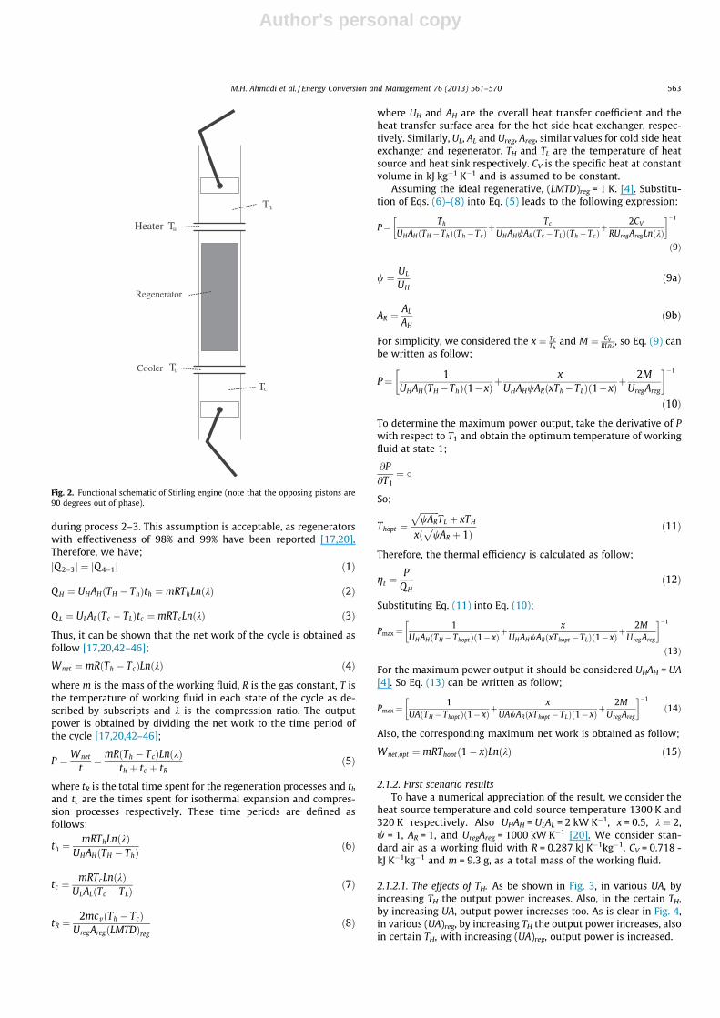
Fig. 2. Functional schematic of Stirling engine (note that the opposing pistons are90 degrees out of phase).
M.H. Ahmadi et al. / Energy Conversion and Management 76 (2013) 561–570 563
Author's personal copy
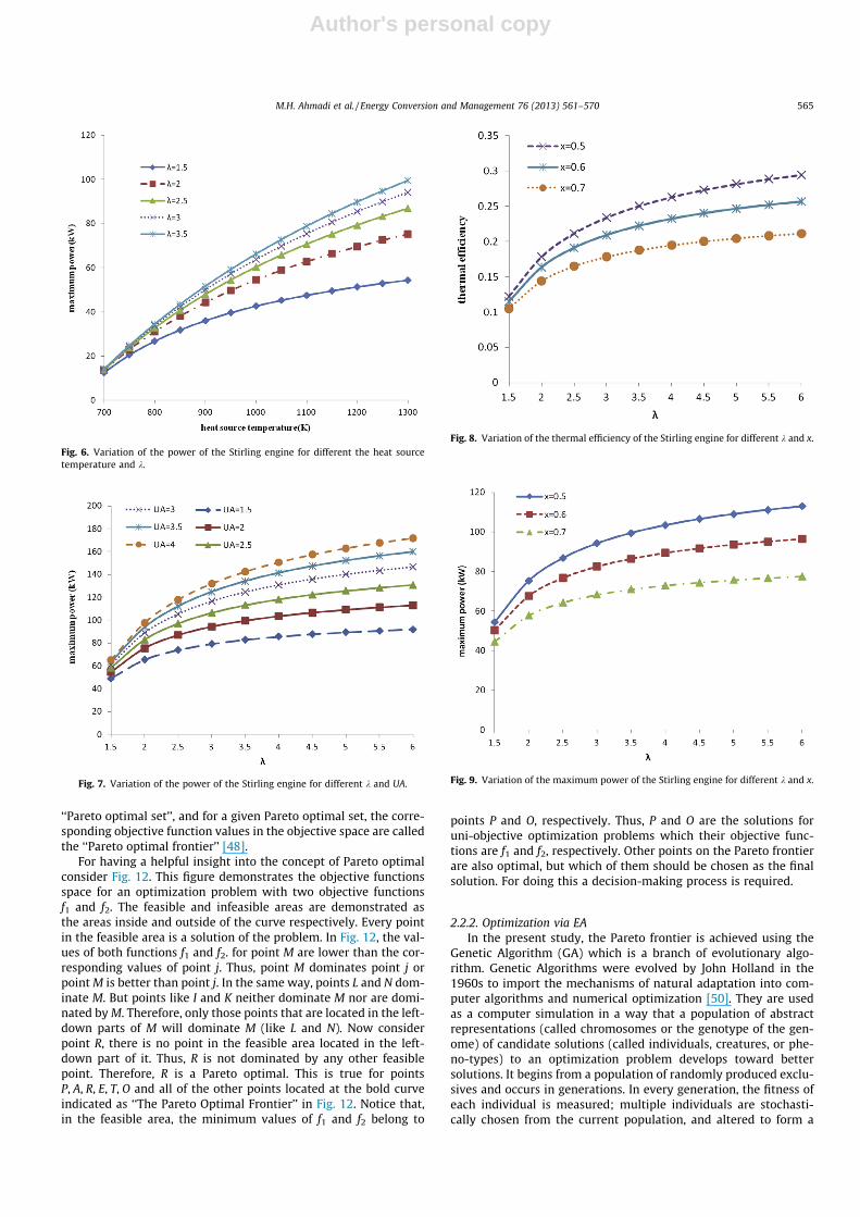
The effects of temperature of heat source on the output powerat various values of x are presented in Fig. 5. At temperatures above1100 K with increasing x, the power output is reduced. The slope ofcurve decreases by decreasing the difference between the temper-ature of working fluid in hot and cold spaces. According to Fig. 6,for different values of k, with increasing TH the output power isincreased.
2.1.2.2. Effects of volumetric ratio (k). Also in Fig. 7, the effects ofvolumetric ratio on the output power at various UA are presentedthat have similar behavior to Fig. 6.
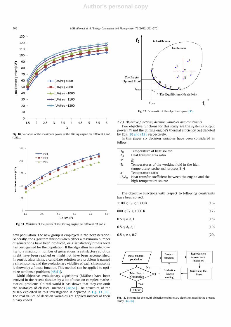
Fig. 8 shows the effects of the volumetric ratio on the thermalefficiency at various values of temperature ratios, in which the effi-ciency increases by increasing k and as the temperature differenceis decreased the thermal efficiency is reduced. Fig. 9 shows the ef-fects of volumetric ratio on the output power for different values ofx that has similar behavior as the thermal efficiency be shown re-cently. Fig. 10 shows the effects of volumetric ratio on the outputpower for different values of (UA)reg.
2.1.2.3. Effect of UA. By increasing the UA of heat exchangers theoutput power increases rapidly in comparison with volumetric ra-tio and heat source temperature that means the heat exchangerand regenerator with high effectiveness coefficient are more effi-cient, as be shown in Fig. 11.
2.2. Multi-objective optimization with evolutionary algorithms
2.2.1. General concepts of the multi-objective optimizationImagine a decision-maker that would like to optimize objec-
tives which are non-commensurable. The decision-maker doesnot know the priority of the objectives. Moreover, all objectivesare of the minimization type. For a minimization kind of objectives,it can be changed to the maximization type by multiplying nega-tive one. The procedure of a minimization multi-objective decisionproblem with objectives is represented as follows:
Given a non-dimensional decision variable vector x = {x1, . . . , xn}in the solution space X find a vector x⁄ that minimizes a given set ofK objective functions f(x) = {f1(x⁄), . . . , fk(x⁄)}. The solution space X isgenerally restricted by a series of constraints, such as gj(x⁄) = bj forj = 1, . . . , m, and bounds on the decision variables [48]. Overall, no
solution vector X exists that minimizes all the K objective functionssimultaneously. In other words, in various real-life problems, objec-tives at issues conflict each other. Thus, optimizing X with respect toa uni-objective often leads to unacceptable results with respect tothe other objectives. Thus, a new concept, well-known as the ‘‘Par-eto optimum solution’’, is used in multi-objective optimizationproblems. A feasible solution X is called ‘‘Pareto optimal’’ if thereexists no other feasible solution Y that dominates solution X. By def-inition, a feasible solution Y is said to dominate another feasiblesolution X, if and only if, fiðYÞ 6 fiðXÞ for i = 1, . . . , k and fj(Y) < fj(X)for at least one objective function. This means that a feasible vectorX is called Pareto optimal if there is no other feasible solution Y thatwould reduce some objective function without causing a simulta-neous increase in at least one other objective function. The set ofall feasible non-dominated solutions in X is referred to as the
Fig. 3. Variation of the power of the Stirling engine for different the heat sourcetemperature and UA.
Fig. 4. Variation of the power of the Stirling engine for different the heat sourcetemperature and (UA)reg.
Fig. 5. Variation of the power of the Stirling engine for different the heat sourcetemperature and x.
564 M.H. Ahmadi et al. / Energy Conversion and Management 76 (2013) 561–570
Author's personal copy
‘‘Pareto optimal set’’, and for a given Pareto optimal set, the corre-sponding objective function values in the objective space are calledthe ‘‘Pareto optimal frontier’’ [48].
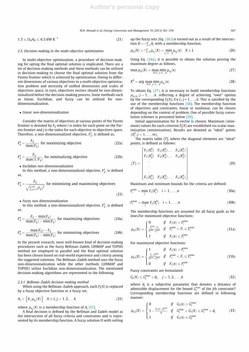
For having a helpful insight into the concept of Pareto optimalconsider Fig. 12. This figure demonstrates the objective functionsspace for an optimization problem with two objective functionsf1 and f2. The feasible and infeasible areas are demonstrated asthe areas inside and outside of the curve respectively. Every pointin the feasible area is a solution of the problem. In Fig. 12, the val-ues of both functions f1 and f2. for point M are lower than the cor-responding values of point j. Thus, point M dominates point j orpoint M is better than point j. In the same way, points L and N dom-inate M. But points like I and K neither dominate M nor are domi-nated by M. Therefore, only those points that are located in the left-down parts of M will dominate M (like L and N). Now considerpoint R, there is no point in the feasible area located in the left-down part of it. Thus, R is not dominated by any other feasiblepoint. Therefore, R is a Pareto optimal. This is true for pointsP, A, R, E, T, O and all of the other points located at the bold curveindicated as ‘‘The Pareto Optimal Frontier’’ in Fig. 12. Notice that,in the feasible area, the minimum values of f1 and f2 belong to
points P and O, respectively. Thus, P and O are the solutions foruni-objective optimization problems which their objective func-tions are f1 and f2, respectively. Other points on the Pareto frontierare also optimal, but which of them should be chosen as the finalsolution. For doing this a decision-making process is required.
2.2.2. Optimization via EAIn the present study, the Pareto frontier is achieved using the
Genetic Algorithm (GA) which is a branch of evolutionary algo-rithm. Genetic Algorithms were evolved by John Holland in the1960s to import the mechanisms of natural adaptation into com-puter algorithms and numerical optimization [50]. They are usedas a computer simulation in a way that a population of abstractrepresentations (called chromosomes or the genotype of the gen-ome) of candidate solutions (called individuals, creatures, or phe-no-types) to an optimization problem develops toward bettersolutions. It begins from a population of randomly produced exclu-sives and occurs in generations. In every generation, the fitness ofeach individual is measured; multiple individuals are stochasti-cally chosen from the current population, and altered to form a
Fig. 6. Variation of the power of the Stirling engine for different the heat sourcetemperature and k.
Fig. 7. Variation of the power of the Stirling engine for different k and UA.
Fig. 8. Variation of the thermal efficiency of the Stirling engine for different k and x.
Fig. 9. Variation of the maximum power of the Stirling engine for different k and x.
M.H. Ahmadi et al. / Energy Conversion and Management 76 (2013) 561–570 565
Author's personal copy
new population. The new group is employed in the next iteration.Generally, the algorithm finishes when either a maximum numberof generations have been produced, or a satisfactory fitness levelhas been gained for the population. If the algorithm has ended ow-ing to a maximum number of generations, a satisfactory solutionmight have been reached or might not have been accomplished.In genetic algorithms, a candidate solution to a problem is nameda chromosome, and the evolutionary viability of each chromosomeis shown by a fitness function. This method can be applied to opti-mize nonlinear problems [48,51].
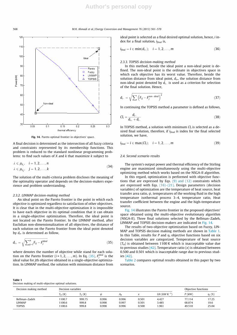
Multi-objective evolutionary algorithms (MOEAs) have beenevolved in the recent decades by a lot of tests on complex mathe-matical problems. On real-world it has shown that they can omitthe obstacles of classical methods [48,51]. The structure of theMOEA exploited in this investigation is depicted in Fig. 13 [50].The real values of decision variables are applied instead of theirbinary coded.
2.2.3. Objective functions, decision variables and constraintsTwo objective functions for this study are the system’s output
power (P) and the Stirling engine’s thermal efficiency (gt) denotedby Eqs. (9) and (12), respectively.
In this paper six decision variables have been considered asfollow:
TH Temperature of heat sourceAR Heat transfer area ratiow UL
UH
Th Temperatures of the working fluid in the hightemperature isothermal process 3–4
x Temperature ratioUHAH Heat transfer coefficient between the engine and the
high-temperature source
The objective functions with respect to following constraintshave been solved:
1100 6 TH 6 1300 K ð16Þ
800 6 Th 6 1000 K ð17Þ
0:5 6 w 6 1 ð18Þ
0:5 6 AR 6 1 ð19Þ
0:5 6 x 6 0:7 ð20Þ
Fig. 10. Variation of the maximum power of the Stirling engine for different k and(UA)reg.
Fig. 11. Variation of the power of the Stirling engine for different UA and x .
Fig. 12. Schematic of the objectives space [35].
Fig. 13. Scheme for the multi-objective evolutionary algorithm used in the presentstudy [34–36].
566 M.H. Ahmadi et al. / Energy Conversion and Management 76 (2013) 561–570
Author's personal copy
1:5 6 UHAH 6 6:5 kW K�1 ð21Þ
2.3. Decision-making in the multi-objective optimization
In multi-objective optimization, a procedure of decision-mak-ing for opting the final optimal solution is implicated. There are alot of decision-making methods and these methods can be utilizedin decision-making to choose the final optimal solution from thePareto frontier which is achieved by optimization. Owing to differ-ent dimensions of various objectives in a multi-objective optimiza-tion problem and necessity of unified dimensions and scales ofobjectives space, in turn, objectives vectors should be non-dimen-sionalized before the decision-making process. Some methods suchas linear, Euclidian, and fuzzy can be utilized for non-dimensionalization.
� Linear non-dimensionalization
Consider the matrix of objectives at various points of the Paretofrontier is denoted by Fij where i is index for each point on the Par-eto frontier and j is the index for each objective in objectives space.Therefore, a non-dimensionalized objective, Fn
ij; is defined as,
Fnij ¼
Fij
maxðFijÞfor maximizing objective ð22aÞ
Fnij ¼
Fij
maxð1=FijÞfor minimalizing objective ð22bÞ
� Euclidian non-dimensionalizationIn this method, a non-dimensionalized objective, Fn
ij; is definedas,
Fnij ¼
FijffiffiffiffiffiffiffiffiffiffiffiffiffiffiffiffiffiffiffiffiffiPmi¼1ðFijÞ2
q for minimizing and maximizing objectives
ð23Þ
� Fuzzy non-dimensionalizationIn this method, a non-dimensionalized objective, Fn
ij; is definedas,
Fnij ¼
Fij �minðFijÞmaxðFijÞ �minðFijÞ
for maximizing objectives ð24aÞ
Fnij ¼
maxðFijÞ � Fij
maxðFijÞ �minðFijÞfor minimizing objectives ð24bÞ
In the present research, most well-known kind of decision-makingprocedures such as the fuzzy Bellman–Zadeh, LINMAP and TOPSISmethod are employed in parallel and the final optimal solutionhas been chosen based on real-world experience and criteria amongthe suggested solutions. The Bellman–Zadeh method uses the fuzzynon-dimensionalization while the other methods (LINMAP andTOPSIS) utilize Euclidian non-dimensionalization. The mentioneddecision-making algorithms are represented in the following.
2.3.1. Bellman–Zadeh decision-making methodWhen using the Bellman–Zadeh approach, each Fj(X) is replaced
by a fuzzy objective function or a fuzzy set,
Aj ¼ X;lAjðXÞ
n oX 2 L; j ¼ 1;2; . . . k ð25Þ
where lAjðXÞ is a membership function of Aj [57].
A final decision is defined by the Bellman and Zadeh model asthe intersection of all fuzzy criteria and constraints and is repre-sented by its membership function. A fuzzy solution D with setting
up the fuzzy sets (Eq. (26)) is turned out as a result of the intersec-tion D ¼ \k
j¼1Aj with a membership function,
lDðXÞ ¼ \kj¼1lAj
ðXÞ ¼ minj¼1;...;k
lAjðxÞ X 2 L ð26Þ
Using Eq. (24a), it is possible to obtain the solution proving themaximum degree as follows,
maxlDðXÞ ¼maxX2L
minj¼1;...;k
lAjðxÞ ð27Þ
X0 ¼ arg maxX2L
minj¼1;...;k
lAjðxÞ ð28Þ
To obtain Eq. (27), it is necessary to build membership functionslAjðXÞ; j ¼ 1; . . . ; k; reflecting a degree of achieving ‘‘own’’ optimaby the corresponding Fj(X), X e L; j = 1, . . ., k. This is satisfied by theuse of the membership functions [58]. The membership functionof objectives and constraints, linear or nonlinear, can be chosendepending on the context of problem. One of possible fuzzy convo-lution schemes is presented below [59].
Initial approximation for X-vector is chosen. Maximum (mini-mum) values for each criterion Fj(X) are established via scalar max-imization (minimization). Results are denoted as ‘‘ideal’’ pointsfX0
j ; j ¼ 1; . . . ;mg.The matrix table {T}, where the diagonal elements are ‘‘ideal’’
points, is defined as follows:
fTg ¼
F1ðX01Þ F2ðX0
1Þ . . . FnðX01Þ
F1ðX02Þ F2ðX0
2Þ . . . FnðX02Þ
���
F1ðX0nÞ F2ðX0
nÞ . . . FnðX0nÞ
26666666664
37777777775
ð29Þ
Maximum and minimum bounds for the criteria are defined:
Fmini ¼min
jFjðX0
j Þ i ¼ 1; . . . ;n ð30aÞ
Fmaxi ¼max
jFjðX0
j Þ i ¼ 1; . . . ;n ð30bÞ
The membership functions are assumed for all fuzzy goals as fol-lows.For minimized objective functions:
lFiðXÞ ¼
0 if FiðxÞ > Fmaxi
Fmaxi �Fi
Fmaxi �Fmin
iif Fmin
i < Fi 6 Fmaxi
1 if FiðxÞ 6 Fmini
8>><>>:
ð31aÞ
For maximized objective functions:
lFiðXÞ ¼
1 if FiðxÞ > Fmaxi
Fi�Fmini
Fmaxi �Fmin
iif Fmin
i < Fi 6 Fmaxi
0 if FiðxÞ 6 Fmini
8>><>>:
ð31bÞ
Fuzzy constraints are formulated:
GjðXÞ 6 Gmaxj þ dj; j ¼ 1;2; . . . ; k ð32Þ
where dj is a subjective parameter that denotes a distance ofadmissible displacement for the bound Gmax
j of the jth constraint?Corresponding membership functions are defined in followingmanner:
lGiðXÞ ¼
0 if GiðxÞ > Gmaxi
1� GjðxÞ�Gmaxj
djif Gmax
i < GiðXÞ 6 Gmaxi þ dj
1 if GiðxÞ 6 Gmaxi
8>><>>:
ð33Þ
M.H. Ahmadi et al. / Energy Conversion and Management 76 (2013) 561–570 567
Author's personal copy
A final decision is determined as the intersection of all fuzzy criteriaand constraints represented by its membership functions. Thisproblem is reduced to the standard nonlinear programming prob-lems: to find such values of X and k that maximize k subject to
k 6 lFi; i ¼ 1;2; . . . ;n
k 6 lGj; j ¼ 1;2; . . . ; k
ð34Þ
The solution of the multi-criteria problem discloses the meaning ofthe optimality operator and depends on the decision-makers expe-rience and problem understanding.
2.3.2. LINMAP decision-making methodAn ideal point on the Pareto frontier is the point in which each
objective is optimized regardless to satisfaction of other objectives.It is clear that in the multi-objective optimization it is impossibleto have each objective in its optimal condition that it can obtainin a single-objective optimization. Therefore, the ideal point isnot located on the Pareto frontier. In the LINMAP method, afterEuclidian non-dimensionalization of all objectives, the distance ofeach solution on the Pareto frontier from the ideal point denotedby di+ is determined as follow,
diþ ¼ffiffiffiffiffiffiffiffiffiffiffiffiffiffiffiffiffiffiffiffiffiffiffiffiffiffiffiffiffiffiffiffiffiXn
j¼1Fij � FIdeal
j
rð35Þ
where denotes the number of objective while stand for each solu-tion on the Pareto frontier (i = 1, 2, . . . , m). In Eq. (35), FIdeal
j is theideal value for jth objective obtained in a single-objective optimiza-tion. In LINMAP method, the solution with minimum distance from
ideal point is selected as a final desired optimal solution, hence, i in-dex for a final solution, ifinal is,
ifinal ¼ i 2minðdiþÞ; i ¼ 1;2; . . . ;m ð36Þ
2.3.3. TOPSIS decision-making methodIn this method, beside the ideal point a non-ideal point is de-
fined. The non-ideal point is the ordinate in objectives space inwhich each objective has its worst value. Therefore, beside thesolution distance from ideal point, di+, the solution distance fromnon-ideal point denoted by di� is used as a criterion for selectionof the final solution. Hence,
di� ¼ffiffiffiffiffiffiffiffiffiffiffiffiffiffiffiffiffiffiffiffiffiffiffiffiffiffiffiffiffiffiffiffiffiffiffiffiffiffiffiffiffiffiffiffiX
Fij � Fnon�idealj
� �2r
ð37Þ
In continuing the TOPSIS method a parameter is defined as follows,
Cli ¼di�
diþ þ di�ð38Þ
In TOPSIS method, a solution with minimum Cli is selected as a de-sired final solution, therefore, if ifinal is index for the final selectedsolution, we have,
ifinal ¼ i 2maxðCliÞ; i ¼ 1;2; . . . ;m ð39Þ
2.4. Second scenario results
The system’s output power and thermal efficiency of the Stirlingengine are maximized simultaneously using the multi-objectiveoptimizing method which works based on the NSGA-II algorithm.
In this regard, optimization is performed with objective func-tions that are expressed by Eqs. (9) and (12) constraints whichare expressed with Eqs. (16)–(21). Design parameters (decisionvariables) of optimization are the temperature of heat source, heattransfer area ratio, w, temperatures of the working fluid in the hightemperature isothermal process 3–4, temperature ratio, Heattransfer coefficient between the engine and the high-temperaturesource.
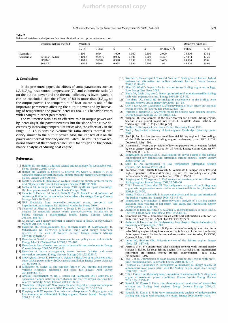
Fig. 14 illustrates the Pareto frontier in the proposed objectives’space obtained using the multi-objective evolutionary algorithm(NSGA-II). Three final solutions selected by the Bellman–Zadeh,LINMAP and TOPSIS decision-makers are indicated in Fig. 14.
The results of two-objective optimization based on Fuzzy, LIN-MAP and TOPSIS decision making methods are shown in Table 1.In this Table, results for P and gt objective functions based on sixdecision variables are categorized. Temperature of heat source(TH) is obtained between 1100 K which is inacceptable value dueto previous studies [42]. Temperature ratio (x) is obtained between0.500 and 0.501 which is inacceptable range due to previous stud-ies [42].
Table 2 compares optimal results obtained in this paper by twoscenarios.
Fig. 14. Pareto optimal frontier in objectives’ space.
Table 1Decision making of multi-objective optimal solutions.
Decision making method Decision variables Objective functions
TH (K) Th (K) w AR x UA (kW K�1) P (kW) gt (%)
Bellman–Zadeh 1100.7 999.75 0.996 0.996 0.501 4.427 77.114 17.25LINMAP 1100.6 999.8 0.998 0.997 0.501 3.485 68.874 19.6TOPSIS 1100.6 999.8 0.998 0.996 0.500 1.961 49.510 25.04
568 M.H. Ahmadi et al. / Energy Conversion and Management 76 (2013) 561–570
Author's personal copy
3. Conclusions
In the presented paper, the effects of some parameters such asUA, (UA)reg, heat source temperature (TH) and volumetric ratio (k)on the output power and the thermal efficiency is investigated. Itcan be concluded that the effects of UA is more than (UA)reg onthe output power. The temperature of heat source is one of theimportant parameters affecting the output power and by increas-ing of temperature the power increases too. This behavior varieswith changes in other parameters.
The volumetric ratio has an effective role in output power andby increasing it, the power increases, but the slope of the curve de-creases by increasing temperature ratio; Also, the effects of k in therange 1.5–3.5 is sensible. Volumetric ratio affects thermal effi-ciency similar to the output power. Also, the impacts of x on thepower and thermal efficiency are evaluated. The results of two sce-narios show that the theory can be useful for design and the perfor-mance analysis of Stirling heat engine.
References
[1] Holdren JP. Presidential address: science and technology for sustainable well-being. Science 2008;319:424.
[2] Hoffert MI, Caldeira K, Benford G, Criswell DR, Green C, Herzog H, et al.Advanced technology paths to global climate stability: energy for a greenhouseplanet. Science 2002;298:981.
[3] Pacala S, Socolow R. Stabilization wedges: solving the climate problem for thenext 50 years with current technologies. Science 2004;305:968.
[4] Pachauri RK, Reisinger A. Climate change 2007: synthesis report. Cambridge,UK: Intergovernmental Panel on Climate Change; 2007.
[5] Calinoiu D, Paulescu M, Ionel I, Stefu N, Pop N, Boata R, et al. Influence ofaerosols pollution on the amount of collectable solar energy. Energy ConversManage 2013;70:76–82.
[6] NAS. Electricity from renewable resources: status, prospects, andimpediments. Washington, DC: National Academies Press; 2010.
[7] Colantoni A, Allegrini E, Boubaker K, Longo L, Di Giacinto S, Biondi P. Newinsights for renewable energy hybrid photovoltaic/wind installations inTunisia through a mathematical model. Energy Convers Manage2013;75:398–401.
[8] Alsaad MA. Wind energy potential in selected areas in Jordan. Energy ConversManage 2013;65:704–8.
[9] Bagiorgas HS, Assimakopoulos MN, Theoharopoulos D, Matthopoulos D,Mihalakakou GK. Electricity generation using wind energy conversionsystems in the area of Western Greece. Energy Convers Manage2007;48(5):1640–55.
[10] Demirbas A. Social, economic, environmental and policy aspects of bio-fuels.Energy Educ Sci Technol Part B 2009;1:75–109.
[11] Demirbas A. Bio-refineries: current activities and future developments. EnergyConvers Manage 2009;50:2782–801.
[12] Demirbas A. Waste management, waste resource facilities and wasteconversion processes. Energy Convers Manage 2011;52:1280–7.
[13] Stepczynska-Drygas K, Łukowicz H, Dykas S. Calculation of an advanced ultra-supercritical power unit with CO2 capture installation. Energy Convers Manage2013;74:201–8.
[14] Middleton RS, Eccles JK. The complex future of CO2 capture and storage:Variable electricity generation and fossil fuel power. Appl Energy2013;108:66–73.
[15] Amouei Torkmahalleh M, Lin L, Holsen TM, Rasmussen DH, Hopke PK. Crspeciation changes in the presence of ozone and reactive oxygen species at lowrelative humidity. Atmos Environ 2013;71:92–4.
[16] Yanovskiy LS, Baykov AV. New prospects for ecologically clean power and purewater generation units with SOFC. Renewable Energy 2013;56:72–6.
[17] Kongtragool B, Wongwises S. A review of solar-powered Stirling engines andlow temperature differential Stirling engines. Renew Sustain Energy Rev2003;7:131–54.
[18] Sanchez D, Chacartegui R, Torres M, Sanchez T. Stirling based fuel cell hybridsystems: an alternative for molten carbonate fuel cell. Power Sources2009;192:84–93.
[19] Allan SD. World’s largest solar installation to use Stirling engine technology.Pure Energy Syst News 2005.
[20] Blank DA, Davis GW, Wu C. Power optimization of an endoreversible Stirlingcycle with regeneration. Int J Energy 1994;19:125–33.
[21] Thombare DG, Verma SK. Technological development in the Stirling cycleengines. Renew Sustain Energy Rev 2008;12:1–38.
[22] Chen J, Yan Z, Chen L, Andresen B. Efficiency bound of solar-driven Stirling heatengine system. Int J Energy Res 1998;22:805–12.
[23] Formosa F, Despesse G. Analytical model for Stirling cycle machine designs.Energy Convers Manage 2010;51:1855–63.
[24] Walpita SH. Development of the solar receiver for a small Stirling engine,Special study project report no. ET-83-1. Bangkok: Asian Institute ofTechnology; 1983. p. 33 [see also p. 35].
[25] Walker G. Stirling-cycle machines. Oxford University Press; 1973.[26] Senft J. Mechanical efficiency of heat engines. Cambridge University press;
2007.[27] Senft JR. An ultra low temperature differential Stirling engine. In: Proceedings
of the fifth international Stirling engine conference, paper ISEC 91032.Dubrovnik; May 1991.
[28] Haneman D. Theory and principles of low-temperature hot air engines fuelledby solar energy. Report Prepared for US Atomic Energy Comm. Contract W-7405-Eng-48; 1975.
[29] Kongtragool B, Wongwises C. Investigation on power output of the gammaconfiguration low temperature differential Stirling engines. Renew Energy2005;30:465–76.
[30] Senft JR. An introduction to low temperature differential Stirlingengines. USA: Moriya Press; 2004.
[31] Iwamoto I, Toda F, Hirata K, Takeuchi M, Yamamoto T. Comparison of low-andhigh-temperature differential Stirling engines. In: Proceedings of eighthinternational Stirling engine conference; 1997. p. 29–38.
[32] Kongtragool B, Wongwises S. Performance of low-temperature differentialStirling engines. Renew Energy 2007;32:547–66.
[33] Tlili I, Timoumi Y, Nasrallah SB. Thermodynamic analysis of the Stirling heatengine with regenerative losses and internal irreversibilities. Int J Engine Res2008;9(1):45–56.
[34] Martaj N, Grosu L, Rochelle P. Exergetical analysis and design optimisation ofthe Stirling engine. Int J Exergy 2006;3(1):45–67.
[35] Kongtragool B, Wongwises S. Thermodynamic analysis of a Stirling engineincluding dead volumes of hot space, cold space, and regenerator. RenewEnergy 2006;31(3):345–59.
[36] Andresen B, Berry RS, Nitzan A, Salamon P. Thermodynamics in finite time. I.The step Carnot cycle. Phys Rev A 1977;15:2086–93.
[37] Comment on Yan Z. Comment on an ecological optimization criterion forfinite-time heat engines. J Appl Phys 1993;73(7):3583.
[38] Andresen B. Finite-time thermodynamics. Copenhagen: Physics Laboratory II,University of Copenhagen; 1983.
[39] Petrescu S, Costea M, Stanescu G. Optimization of a cavity type receiver for asolar Stirling engine taking into account the influence of the pressure losses,finite speed losses, friction losses and convective heat transfer, ENSEC’93,Cracow, Poland; 1993.
[40] Ladas HG, Ibrahim OM. Finite-time view of the Stirling engine. Energy1994;19(8):837–43.
[41] Petrescu S, et al. Concentrated solar radiation receiver with thermal energystorage in NaNO3 for solar Stirling engine, Thermastock’91. In: Internationalconference on thermal energy storage, Scheveningen, 13±16 May,Netherlands; 1991.
[42] Yaqi L et al. Optimization of solar-powered Stirling heat engine with finite-time thermodynamics. Renewable Energy 2010;36:421–7.
[43] Trukhow VS, Tursunbaev IA, Lezhebokov IA, Kenzhaev IG. Energy balance ofautonomous solar power plant with the Stirling engine. Appl Solar Energy1997;33(1):17–23.
[44] Tlili I. Finite time thermodynamic evaluation of endoreversible Stirling heatengine at maximum power conditions. Renew Sustain Energy Review2012;16(4):2234–41.
[45] Kaushik SC, Kumar S. Finite time thermodynamic evaluation of irreversibleericsson and Stirling heat engines. Energy Convers Manage 2001;42:295–312.
[46] Kaushik SC, Kumar S. Finite time thermodynamic analysis of endoreversibleStirling heat engine with regenerative losses. Energy 2000;25:989–1003.
Table 2Values of variables and objective functions obtained in two optimization scenarios.
Decision making method Variables Objective functions
TH (K) Th (K) w AR x UA (kW K�1) P (kW) gt (%)
Scenario 1 – 1300 970 1.000 1.000 0.500 2.000 75.306 17.82Scenario 2 Bellman–Zadeh 1100.7 999.75 0.996 0.996 0.501 4.427 77.114 17.25
LINMAP 1100.6 999.8 0.998 0.997 0.501 3.485 68.874 19.6TOPSIS 1100.6 999.8 0.998 0.996 0.500 1.961 49.510 25.04
M.H. Ahmadi et al. / Energy Conversion and Management 76 (2013) 561–570 569

Author's personal copy
[47] Veldhuizen DAV, Lamont GB. Multiobjective evolutionary algorithms:analyzing the state-of-the-art. Evol Comput 2000;8:125–47.
[48] Konak A, Coit DW, Smith AE. Multi-objective optimization using geneticalgorithms: A tutorial. Reliab Eng Syst Safety 2006;91:992–1007.
[49] Bck T, Fogel D, Michalewicz Z. Handbook of evolutionary computation. OxfordUniv Press; 1997.
[50] Ahmadi MH, Hosseinzade H, Sayyaadi H, Mohammadi AH, Kimiaghalam F.Application of the multi-objective optimization method for designing apowered Stirling heat engine: design with maximized power, thermalefficiency and minimized pressure loss. Renew Energy 2013;60:313–22.
[51] Ahmadi MH, Sayyaadi H, Mohammadi AH, Marco A, Barranco-Jimenez.Thermo-economic multi-objective optimization of solar dish-Stirling engineby implementing evolutionary algorithm. Energy Convers Manage2013;73:370–80.
[52] Ahmadi MH, Sayyaadi H, Dehghani S, Hosseinzade H. Designing a solarpowered Stirling heat engine based on multiple criteria: Maximized thermalefficiency and power. Energy Convers Manage 2013;75:282–91.
[53] Ahmadi MH, Mohammadi AH, Dehghani S, Marco A, Barranco-Jimenez. Multi-objective thermodynamic-based optimization of output power of Solar Dish-
Stirling engine by implementing an evolutionary algorithm. Energy ConversManage 2013;75:438–45.
[54] Toffolo A, Lazzaretto A. Evolutionary algorithms for multi-objective energeticand economic optimization in thermal system design. Energy2002;27:549–67.
[55] Gacto MJ, Alcala R, Herrera F. A multi-objective evolutionary algorithm for aneffective tuning of fuzzy logic controllers in heating, ventilating and airconditioning systems. Appl Intell 2012;36(2):330–47.
[56] Korkmaz EE. Multi-objective genetic algorithms for grouping problems. ApplIntell 2010;33(2):179–92.
[57] Mazur V. Fuzzy thermoeconomic optimization of energy-transformingsystems. Appl Energy 2007;84:749–62.
[58] Olson DL. Decision aids for selection problems. New York: Springer; 1996.[59] Taal M, Bulatov I, Klemeš J, Stehlık P. Cost estimation and energy price
forecasts for economic evaluation of retrofit projects. Appl Therm Eng2003;23:1819–35.
570 M.H. Ahmadi et al. / Energy Conversion and Management 76 (2013) 561–570