Bioinspired Polymeric Nanocomposites for Regenerative Medicine
Upload
khangminh22Category
view
5download
0
Int. J. Nonlinear Anal. Appl.Volume 12, Special Issue, Winter and Spring 2021, 1807-1825ISSN: 2008-6822 (electronic)http://dx.doi.org/10.22075/ijnaa.2021.5892
Development of regenerative shock absorber usingthe piezoelectric patch for electric vehicles
N. G. Bathrinatha, M. Yuvarajab,
aME-Engineering Design, PSG College of Technology, Coimbatore, IndiabMechanical Department, PSG College of Technology, India
(Communicated by Madjid Eshaghi Gordji)
Abstract
In the era of electric vehicles, a regenerative shock absorber can be equipped in the place of normalshock absorbers which continuously produces electricity and can be amplified and fed to the battery,a piezoelectric generator can be used that harvests mechanical vibrations energy available on anelectric vehicle. The piezoelectric material can be placed in shock absorber housing above the pistonhead. Due to bumps and pits on road, continuous generation of electricity is possible. It can bethen amplified and fed back to the battery regeneratively. The 3D cad model of piezo housing wasmodelled and the force acting on the housing of piezoelectric materials was analyzed and found tobe 103.5KN and equivalent power produced was calculated. Various Piezoelectric materials werestudied and PZT 5A was found to be the best to act as transducer and quartz was the best materialto act as Actuator. A proof of concept developed showed the power produced by piezo material andcomparison study of that with PZT 5A was done and power produced was 19J which is 9% of powerproduced by the charger of electric vehicles. The calculation for mileage showed an increase of 3 kmwhich is 4% of the maximum distance covered by the average electric bike.
Keywords: Electric vehicle (EV’s), Regenerative, Shock absorber, Transducer, Quartz, Actuator
1. Introduction
Most of the fuel present in the earth is depleted and gasoline engine causes many problems tothe environment like SOx and NOx emission. The automotive industry is changing rapidly fromgasoline to electric powered vehicles. So as a remedy for this several people like scientists’ engineersused several equipment’s charge the car like, Solar panels, Wind turbines, Dynamos, Shock absorber.
Email addresses: [email protected] (N. G. Bathrinath ), [email protected] (M. Yuvaraja)
Received: August 2021 Accepted: November 2021

1808 Bathrinath, Yuvaraja
Since these devises were used individually, they have to afford an external source to charge the carwhich again results in some economic as well as resource problem that led to the failure of the model.Re-generatively charging the battery by harvesting energy from shock absorber through piezoelectricmaterials is one of the ways to increase the energy efficiency, mileage and discharge capacity of thebattery. Vibration in vehicle is undesirable so shock absorber acts as a damping element reducingthe vibration but these vibrations are nowhere used in the vehicles. Energy loss from shock absorberis nowhere utilized in electric vehicles. The energy losses that occur during driving of vehicles andsubsequently for the reduction of these losses to the possible lowest level [2]. In order to increase thedischarging time, if battery capacity is increased it eventually increases the size of the battery, spaceoccupied and weight. This reduces the mileage of electric vehicles. Overall Cost of vehicle increasesif battery with high capacity is used. Charging time increases with big batteries so fast chargingtechnology has to be incorporated, which again increases the cost.
A. Why India needs a switch to electric vehicles
There is a need to make people understand that electric vehicle holds a permanent solution forcleaner, sustainable India. Many countries formulated many technologies in electric vehicles but Indiais still lagging in it. By incorporating many technologies in EV’s mobility sector one can promotefor greener ecology. China is the leading producer and stake holder of EV mobility and US standsthe next as shown in Fig1. India has an aim to become electrical vehicle manufacturing spot asper information given by Nitin Gadkari, Union Minister of Road Transporting sector and Highways.Even in the outbreak of COVID people tend to avoid public transport and prefer individual vehicles.This led to increase in price of gasoline engine and many people cannot afford such price hike. So,EV will be a solution for such problem. This can travel the same distance with reduced cost whencompared to gasoline vehicles. So, advancements and technologies in EV sector is of most important.Though there are EV, many localities don’t have enough charging hubs. So regeneratively harvestingthe power from the vehicle will be the possible solution to increasing the mileage. This paper showsone of the methods of regeneratively harvesting the power from shock absorber and storing it inbattery dynamically.
Figure 1: The global E-vehicle market stake
India has to become a sustainable green ecosystem for this a constant pull towards cleaner mobilityis much needed. Only electric vehicles can do this. Well known fact is that the fossil-fuel enginescontribute to 60 percent of particulate matters atmospheric pollution, and over 20 percent of CO2.

Development of regenerative shock absorber using the piezoelectric patch for electric vehicles 1809
The Electric vehicles, , is smoke free. They don’t choke India with hydrocarbon pollutions, theUNICEF aptly said as “danger in the air.” The petrol and diesel vehicles are hugely in-efficient asthey nearly 70% of the precious fuel is simply wasted. It can neither be recycled nor be recovered orreused. Well known that it takes millions of years to create the natural fossil fuel again, unlike thebattery that is made and used when needed. On the other hand, the Electric vehicles are rechargeableand involving zero wastage of energy. They don’t even have a single (a few) harmful effects on humanhealth and ecology. The heavy petrol and diesel trucks alone cause over 30% of vehicular particulatepollution. However, government support to promote electric vehicles is dismal and disappointing. Ithas to be promoted as far as possible.
Various researchers have proposed different models to regeneratively harvest power from vehiclessome of them are discussed below. B.lafarge et al. [4] states low power output from the piezo plate isconverted to high power. Piezoelectric material is mounted on the surface of the shock absorber LeadZirconate Titanate (PZT-5H) is the power harvester used to generate electricity. a bond graph modelof piezoelectric patch placed in the quarter vehicle system is proposed. Power is produced when thecar is travelling at 30kmph on road and the Results show that approximately 0.5-milliwatt electricalpower is harvested regeneratively while varying the key parameters like location, characteristics ofthe piezoelectric device.
Albert Chawanda et al. [6] states that COMSOL Multiphysics finite element analysis software wasused to study the piezoelectric effect. an external load is applied on the free end of a composite beam.single crystal lead magnesium niobate-lead titanate (PMN32) is the material used and three otherlead zirconate titanate ceramics PZT-5A, PZT-5H, and PZT-4. For each material three analyseshas been performed they are static, eigenfrequency and transient analysis. A common geometry forall materials and similar excitation conditions were given. results clearly says that the new crystalmaterial PMN32 is superior than other existing PZT material. The COMSOL analysis procedureand method was studied from this paper.
Sivani Mohapatra et al. [5] states that design methods of piezo electric transducer. From theproperty of PZT and BNN air displacement, compliances and polar graph are simulated. COMSOLMultiphysics software is used to simulate this. It is concluded that the air displacement and com-pliance shown by PZT is higher than the BNN material. PZT is most preferred as a piezoelectrictransducer material. An investigation with the lead contact PZT with lead free BNN materials isalso carried out.
Doaa Al Yafeai et al. [1] states That piezoelectric material is mounted on different locations suchas suspension springs, dampers, and tires. The technique which is to be used for harvester and themaximum amount of power harvested from each location are studied. The evaluation of the electricalpower converting and amplifying circuits and various storage devices like capacitor, battery for theharvested power are also discussed.
Min Wang et al. [8] Describes a power harvesting circuit for piezoelectric energy harvestingfrom suspension system. 8 pairs of piezo electric patches were attached to either surfaces of leafspring. This can magnify the force from working condition to load acting on the surface of piezoelectric patches. The results indicate that the resonance frequency 25.2 Hz experiment is close to thesimulation result 26.1 Hz. Impedance correlation experiments show that sum of output power is 1.7mW, and the max single layer reach 0.6 mW with impedance matching 610 KW & power density is3.82 mW/cm3.
Bia lkowski et.al. [3] States the damage to shock absorbers of a passenger car at normal roadoperation condition with the use of vibration response FFT and PSD measurement is described.Accelerometers are mounted on the CG point of car. The test was carried for several variety of shockabsorber damages. The resonance frequency was studied from the obtained results.

1810 Bathrinath, Yuvaraja
From the literatures, various possible methods of power amplification circuit to convert low poweroutput to high power output was studied. Methodology to proceed in COMSOL and Randomvibrational analysis in ANSYS with various materials and various possible locations where a PZTpatches can be placed are studied.
2. Selection of piezo material and ITS shape
A. Selection of piezo electric material
Best suitable piezoelectric material was chosen by studying various materials. Analysis of circularand square plater was carried out and square plate made of PZT 5A was found to be optimum forpower extraction. Some crystals generate electrical energy when mechanical stress is applied anddeform when electrical field is applied. Such behavior is called piezoelectric property. The chargethus produced can be called as piezoelectricity.
Piezo-electricity can be defined as the electrical polarization produced by mechanical strain oncertain class of crystals. The factors determining the selection of piezoelectric material are theelectromechanical coupling factor k, Piezoelectric strain constant d, Piezoelectric voltage constantg, Mechanical quality factor QM, Acoustic Impedance Z. These properties are studied for variousmaterials like PZT5A, PZT5H, Quartz and barium Titanate. The properties of the PZT5A are givenin table 1.
Table 1: Properties of PZT5A
DATA Lead Zirconate TitanateSp-4 SP-8 SP-5A SP-5J SP-5H
Piezoelectric coupling coefficient Kp 0.6 0.5 0.61 0.63 0.63K33 0.68 0.63 0.70 0.71 0.73
Piezoelectric charge constants D33(x10−12C/N) 300 215 400 460 550D31(x10−12C/N) -122 -97 -170 -195 -247G(x10−12V m/N) 27 24 26 22 20G(x10−12V m/N) -11 -11 -11 -9 -9
Relative dielectric constant KT 1250 1000 1750 2450 3100Dissipation factor tanδ 0.004 0.004 0.02 0.02 0.02
Density ρ(kg/m3) 7600 7600 7650 7500 7500Curie Temperature T (◦C) 325 330 360 260 190
Mechanical Quality Factor Qm 500 1000 75 70 65Figure of Merit dh x gh (x10−15) 150 110 65 150 07
Elastic constantsSE11(x10−12m2/N) 12 12 16 14 15
SE33(x10−12m2/N) 18 13 21 19 21
Frequency Cnstants (Hz-m)Np 2200 2270 1950 2000 1950Nt 1905 2032 1800 1950 2000
Ageing Rate, % change er time decadeKT
3 -2.5 -4.6 -0.1 -0.4 -0.4Kp 1.6 -2.0 -0.7 -1.5 -0.9NP 1.0 0.8 0.1 0.2 0.15
Development of regenerative shock absorber using the piezoelectric patch for electric vehicles 1811
Ceramic lead zirconate titanate also known as PZT Due to the larger electromechanical couplingcoefficient, PZT is used in an application where mechanical stress has to be converted to electricalenergy. Three parameters to be considered for selecting piezoelectric materials for applicationsworking under mechanical resonance are the mechanical quality factor, electromechanical couplingfactor, dielectric constant. Higher the magnitude of these parameters best is the material for theapplication. So PZT finds application in this area. Based on the properties of various materials PZT5A has the properties suitable to act as a transducer. Quartz should be selected in applications wereelectric input has to be converted into equivalent mechanical motions or vibrations. Coupling factor,charge constants are high for PZT when compared to barium Titanate.
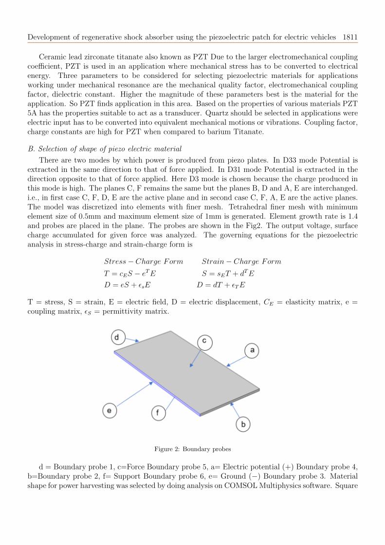
B. Selection of shape of piezo electric material
There are two modes by which power is produced from piezo plates. In D33 mode Potential isextracted in the same direction to that of force applied. In D31 mode Potential is extracted in thedirection opposite to that of force applied. Here D3 mode is chosen because the charge produced inthis mode is high. The planes C, F remains the same but the planes B, D and A, E are interchanged.i.e., in first case C, F, D, E are the active plane and in second case C, F, A, E are the active planes.The model was discretized into elements with finer mesh. Tetrahedral finer mesh with minimumelement size of 0.5mm and maximum element size of 1mm is generated. Element growth rate is 1.4and probes are placed in the plane. The probes are shown in the Fig2. The output voltage, surfacecharge accumulated for given force was analyzed. The governing equations for the piezoelectricanalysis in stress-charge and strain-charge form is
Stress− Charge Form Strain− Charge Form
T = cES − eTE S = sET + dTE
D = eS + ϵsE D = dT + ϵTE
T = stress, S = strain, E = electric field, D = electric displacement, CE = elasticity matrix, e =coupling matrix, ϵS = permittivity matrix.
Figure 2: Boundary probes
d = Boundary probe 1, c=Force Boundary probe 5, a= Electric potential (+) Boundary probe 4,b=Boundary probe 2, f= Support Boundary probe 6, e= Ground (−) Boundary probe 3. Materialshape for power harvesting was selected by doing analysis on COMSOL Multiphysics software. Square

1812 Bathrinath, Yuvaraja
of dimension 40 * 40 * 2 mm and circle of diameter 45mm was initially chosen for analysis such thatit has same area. The boundary conditions were set initially such that bottom of the plate is fixedbecause the bottom seats into the housing of shock absorber. The force is given in perpendiculardirection to that of power output. Analysis is carried per unit newton of force. Two pairs ofperpendicular faces are there for which individually analysis was performed given as case1 and case2as shown in Fig3.
Figure 3: Voltage produced by various materials of rectangular cross sections
Figure 4: Voltage produced by various materials of circular cross sections
Surface charges are accumulated on the outer most area so placing the output terminals on theedges would extract the maximum charges possible. The voltage on the probes 3, 4, 6 remained 0in both the case irrespective of the plane in which force applied but the charge was accumulated inthe probe 3 and 4. Since the fixed face is f, the voltage in that plane is 0 but opposite face showed apotential difference. The surface charge produced in square plate made of PZT acting in case 2 hasthe maximum charge produced per unit square area so it is chosen such that C, F, A, E are the activeplanes. Rectangular BaTiO3 piezo plate produces more voltage for applied force when compared tocircular disk of same cross section as shown in Fig4 but the charge developed is more in PZT and itsvoltage is also nearer to BaTiO3 so PZT of rectangular cross section is chosen.

Development of regenerative shock absorber using the piezoelectric patch for electric vehicles 1813
3. Development of proof of concept
A proof of concept was developed and calculation of efficiency of piezoelectric plate and increasein mileage due to regeneration on power from shock absorber was observed. The current output fromthe piezoelectric plate is AC it should be converted to DC before storing it into the battery. So, thebridge rectifier does this job. When AC is given in one pair of nodes it is rectified and DC is givenon the other pair of nodes. Diode IN4007 is used for bridge rectifier and the circuit diagram is shownin Figure5. The output from the rectifier is not uniform. It produces intermittent DC current so toget a constant voltage it is connect to capacitor of 25V and 100 micro farads. Since the diode is aunidirectional device that allows the current flow in one direction only. With this configuration ofdiodes in the rectifier, it doesn’t allow the power to vary depending on the load requirement. So,this type of rectifier is used in constant or fixed power supplies. The constant output is shown inFig5 along with capacitor.
Figure 5: Bridge rectifier with capacitor circuit
A. Construction and working
The shock absorber consists of 4 piezo plates two are placed on the top end of shock absorber andtwo are at bottom as shown in Fig 6. The output from the piezo is rectified from AC to DC throughdiode bridge rectifier and voltage is made constant with capacitor then stored in battery. Piezo platein shape of circular disk and size 30 mm was used. It is continuously tapped which is analogues tothe force produced in shock absorber through vibration. The AC current from the piezo is rectifiedand stored in capacitor. It is connected to LED to show the constant current from the piezo plate.The piezo gradually charges the capacitor. 5V LED is used to check the circuit. The output fromthe piezo material is found using a multi meter.

1814 Bathrinath, Yuvaraja
Figure 6: Position of PZT inside the housing in shock absorber
Figure 7: Position of PZT inside the housing in shock hardware amplification circuit
Power from the piezoelectric material is small which is to be amplified before giving it to battery.Amplification with electric circuit is not feasible because an additional voltage has to be given tocompensate the drop in current during amplification so amplification with hardware components withparallel and series connection were performed as shown in Fig 7. Circuit when connected in parallel,current adds up and voltage remains constant and Circuit when connected in series, voltage adds upand current remains constant. With this method, the 2 piezo plate on the top end and bottom endindividually are connected in parallel. The piezo plates in the top and bottom end of shock absorbersare connected in series. Thus, making possible of increasing both current and voltage.
B. Calculation of efficiency of quartz
When two plates are connected in parallel maximum voltage produced = 2.7 V, maximum currentproduced = 0.061 A. Piezo plates on the upper and lower end of shock absorber are connected inseries.
V = V1 + V2 = 2.7 + 2.7 = 5.4V (1)

Development of regenerative shock absorber using the piezoelectric patch for electric vehicles 1815
Figure 8: Testing of Quartz piezo plate
Current Remains constant
I = I1 = I2 = 0.061A (2)
Power produced from 1 shock absorber = V ∗ I
P = 5.4 ∗ 0.061 = 0.33J/s (3)
Power produced from 2 shock absorber = 2P = 0.66J/s Power given by charger of electric of ElectricVehicle Minimum output from the charger required is 3 A and 48V
P = V ∗ I = 3 ∗ 48 = 144J/s
If144J/s = 100%then0.66J/s = 0.47%. (4)
The same procedure for PZT5A is carried out using ABAQUS and COMSOL software. The electricpotential value and surface charge were taken from the results as shown in Fig 9 and Fig 10. Thecurrent produced is 70 micro amp and 25.8 volts by single PZT 5A patch of 40 ∗ 40 ∗ 2 mm for apressure of 170 pa. Bore diameter of shock absorber will be 60 mm the maximum area that can befitted is 1800.3 mm2.
Maximum voltage and current produced = 25 V & 0.14 A Piezo plates on the upper and lowerend of shock absorber are connected in series.
I = I1 = I2 = 0.14A and
V = V1 + V2 = 25 + 25 = 50V
Power produced from 1 shock absorber = V * I = 7 J/sPower produced from 2 shock absorber = 2P = 14 J/sIf 144 J/s = 100 % then 14 J/s = 9.72 %.Hence with PZT 5A there will be an output of 9%.The sample material available was quarts which is poor material as a transducer but it can
produce a power of 0.47 % of output from charger. If the material is replaced with PZT 5A therewill be an output of 9%. Amplification with circuit is not feasible because it needs additional voltagefrom battery to amplify and to compensate the drop in voltage while amplification.

1816 Bathrinath, Yuvaraja
Figure 9: Electric potential of PZT patch
Figure 10: Charge produced by PZT patch
4. Modelling of housing for PZT plate
A. Modified piston rod and guide cylinder
The housing for piezo plates was modelled in Solidworks software. The existing shock absorberhead is slightly modified to place the piezo plate inside. Two plates were introduced on both endof shock absorber. The grove for wire output is taken to facilitate the design. The model of topend and bottom end modified are shown in Fig 11 and Fig 12. This plate has threads which can bescrewed easily into the existing shock absorber end plates without any major modifications. Theirdimensions were given in Fig 13, Fig 14 and the exploded view is given in Fig15. The standarddimension for the shock absorbers was taken from the literature survey [7].
Figure 11: Modified top end in piston rod

Development of regenerative shock absorber using the piezoelectric patch for electric vehicles 1817
Figure 12: Modified bottom end in piston rod
B. Dimension of top and bottom housing for the PZT plate
Figure 13: Dimension of plate for housing piezo electric material on top end
Figure 14: Dimensions of plate for housing piezo electric material on bottom end

1818 Bathrinath, Yuvaraja
Figure 15: Exploded view of piezoelectric plate assembly at top end
5. Analysis
A. Analysis of force acting on housing of PZT plate
The analysis of force in housing was carried in Ansys software. The probe is placed on the housing.Bottom end of the shock absorber is given cylindrical support and the other end has force actingaxially on the shock absorber. Lateral deflections were arrested by giving displacement support andonly compression is permitted. 89.393MPa of stress was induced on the housing of PZT material onarea of 2336.56 mm2 shown in Fig16 and Fig17. So, the force which is acting on the plate on oneside is 103.5kN.
Figure 16: Boundary conditions
Figure 17: Total Displacement
B. FFT transform and Random vibration analysis
Random vibration of shock absorber is carried using the vibration data of a truck. The data iscaptured by using accelerometer placed on the chassis of the truck. Vibration data Collected fromTruck at Sampling Frequency of 1000 Hz. The accelerometer should be placed at shock absorber for

Development of regenerative shock absorber using the piezoelectric patch for electric vehicles 1819
accurate results. Raw data consist of time domain data as shown in Fig 18, which is to be convertedto frequency domain data as shown in Fig 20. Here MATLAB is used as a tool to do FFT andPSD analysis. Natural frequency of the shock absorber is calculated by doing modal analysis inANSYS it was ranging from 64 Hz to 330 Hz. This is the prerequisite for random vibration analysis.Mode super position method is followed. The Frequency Vs G-acceleration data is given as input toRandom vibration analysis and PSD load data can be taken as output. From the PSD load curve,the average load can be obtained from rms as shown in Fig19. For that average load, voltage andcurrent that can be produced from PZT is studied using ABAQUS software further.
Figure 18: Time domain Data
Figure 19: Rms Acceleration
Figure 20: Frequency domain data
The values obtained from the PSD Curve is given as input to Random vibration analysis along xdirection after solving for results we can get a response PSD curve in the same direction at desiredlocation. Here the response PSD is taken at the point where is PZT is to be placed. The stressproduced on the housing of shock absorber is 7.25MPa and in random vibration the results are givenas probability distribution function and for 68.29% of time the stress is below the above value.

1820 Bathrinath, Yuvaraja
6. Results and discussiom
The current produced is 70 micro amp and 25.8 volts by single PZT 5A patch of 40*40*2 mm fora pressure of 170 Pa. The storage capacity of the battery varies from 3200 mAh to 3500mAh and thetime taken to charge the battery is 4 hours on average. 144 J/s takes 4 hours to charge completely.
144∗ (4∗3600) = 2073600 J this energy is stored in battery. The energy supplied by piezoelectricplates are 9J/s. 144/9 = 16. This takes 16*4 hours to charge the battery only by piezoelectricmaterial without supply from main power charger. Mostly electric vehicles have 60-75 kilometersper charge and maximum speed varies from 25 to 40 kmph. In average considering 70 km per chargeand vehicle and speed as 25 kmph for calculation. It takes 2.8 hours to cover the maximum milageof vehicle I.e.,70 km. If a piezoelectric plate produces a power Continuously for 2.8 hours 9*2.8*3600= 90720 J energy is produced.
If 2073600 J of energy can cover a distance of 70 km then 90720 J of energy would cover
(90720 ∗ 70) = (x ∗ 2073600)
X = 3.0625km
When compared to maximum range of 75km that an electric vehicle can travel 3.0625 km in additionwhich is 4% increase in terms of mileage per charge.
Figure 21: Stress produced due to random excitation
The resonance conditions for all the components were analyzed and the natural frequency is farapart from the induced frequency. To obtain the response it has been probed at the location ofPZT plate for accurate values. The input PSD curve and the Response PSD curve is obtained tobe similar for both top and bottom plate. which shows there is no induced frequency in the naturalfrequency range. There is one resonance condition occurring at the spring at 171 Hz. Since therandom vibration is unpredictable and occurs for a very short period of time this can be overcomeon accelerating the vehicle.
A. Analysis of PZT 5 A from random vibration analysis
For a PZT 5A material Elasticity property is orthotropic, Dielectric permittivity is anisotropic,Piezoelectric property is orthotropic. These properties are specified so that the stiffness matrix isgenerated for FEA calculations. Boundary conditions are specified Bottom face of the PZT is fixedas it rests on the housing. 7.25MPa of stress which is produced in the housing as shown in Fig 21is divided to top and bottom faces and applied on the surface of PZT material as shown in Fig22.The element size of 2mm was used to mesh.
When 2 plates are connected in parallel Maximum voltage produced = 17 V as shown in Fig 23.Maximum current produced = 0.07 A Piezo plate on the upper and lower end of shock absorber are

Development of regenerative shock absorber using the piezoelectric patch for electric vehicles 1821
Figure 22: Load and support
Figure 23: Electric potential plot
connected in series. Current Remains constant I = I1 = I2 = 0.14A. Total voltage V = V1 + V2 =17 + 17 = 34V . Thus, the power produced from shock absorber is 6.6% when compared to the powerproduced on power adapter by using the vibrational data of truck. Since the truck is heavier thanvehicles, g load Is also higher and it can be expected that power produced will be less than 6%.
B. Comparision of various material at different locations
A comparative study of various materials like PZT-5A, PZT-5H, PZT-4 and PZT-8 was studiedby placing it in different locations like top and bottom surface of the shock absorber, housing whichwas designed previously and outer surface of piston guiding cylinder.
Figure 24: PZT on guide surface of piston rod

1822 Bathrinath, Yuvaraja
PZT on guide surface of piston rod. The Fig 24 shows the PZT patch placed on the surface ofpiston rod. It is bent to a curved shape and bonded to the surface of guide cylinder. One end of theshock absorber was fixed and the stress values obtained from the random vibration analysis was givenon the other end to find corresponding voltage and surface charge density produced. Tetrahedralelement with 5mm mesh size was used. Displacement support on all the direction except compressingdirection was given as boundary condition. Lateral displacements were arrested in this way. Theelectric potential plot Fig25 shows 1.5 V of potential.
Figure 25: Electric potential plot
Electric potential: 1.5VSurface charge = 10 ∗ 0.040 ∗ 0.040A = 0.016mASurface energy density: 14J/m3
Figure 26: PZT on Top &andbottom housing
PZT on Top & bottom housing. The Fig26 shows the PZT patch placed inside the top andbottom housing. The dimension and exploded view are shown previously. In all the cases maximumvoltage was produced on the extreme edge of PZT which shows placing the probes at that positionwill extract maximum potential and surface charge density. The electric potential plot Fig27 shows21V of potential.

Development of regenerative shock absorber using the piezoelectric patch for electric vehicles 1823
Figure 27: Electric potential plot
Electric potential = 21 VSurface charge = 35*0.040*0.040 = 0.056mASurface energy density = 10J/m3
Figure 28: Pzt on top & bottom surface
PZT on top & bottom surface. The Fig 28 shows the PZT patch placed on the top and bottomsurface of Shock absorber. PZT is split into 2 halves in order to accommodate the piston rod whichis at the centre. In real time the potential output leads are exposed to ambient when PZT is placedon the surface of shock absorber which cause reduction in potential developed due disturbances. Theelectric potential plot Fig 29 shows 3V of potential.
Electric potential= 3 VSurface charge = 24*0.040*0.040 = 0.0384mASurface energy density = 0.06J/m3
Upon studying voltage, surface charge, surface energy density of PZT 5H & PZT 5A, PZT5Hshows maximum voltage and surface energy density of 21V and 10J/m3 on placing it inside the topand bottom housing as shown in graphical comparison Fig30. The PZT 5A is more stable thanPZT5H while generating electric potential for longer period of time. Probing the output leads atextreme ends results in harvesting maximum possible power from the system as shown in previousanalysis results.

1824 Bathrinath, Yuvaraja
Figure 29: Electric potential plot
Figure 30: graphical representation of electric potential, surface charge and surface energy density for various materials.
7. Conclusion
The regenerative from shock absorber will be able to Recover energy from suspension vibrationand charge the battery, increasing the mileage by 4%. Space for additional gadgets like mobilecharging hub, health monitoring system. The weight of the system is not much high it does notaffect the load carrying capacity Energy is produced near the speed breakers as well as on evenslightly uneven roads. The power output from two shock absorbers of electric vehicles is 14 J/swhich is 9% of power produced from charger. 90.720 kJ of energy from shock absorbers travelsfor a distance of 3 Km therefore mileage can be increased by 4 %. Rectangular PZT piezo plateproduces more charge for applied force when compared to circular disk of same cross section PZTof Rectangular cross section is chosen. Amplification with circuit is not Feasible because it needsadditional voltage from battery to amplify and to compensate the drop in voltage while amplificationso hardware amplification was done. For the housing of piezo plate, the top and bottom plate ofshock absorbers has to be modified which was designed and modeled.
References
[1] D. Al-Yafeai, T. Darabseh and A. Mourad, A state-Of-the-art review of car suspension-Based piezoelectric energyharvesting systems, Energies 13 (9) (2020).
[2] U. Aks and r. Halicioglu, A review study on energy harvesting systems for vehicles. Tehnicki Glasnik 12(4) (2018)251–259.
[3] P. Bialkowski and B. Krezel, Diagnostic of shock absorbers during road test with the use Of vibration FFT Andcross-sSpectrum analysis, Artykul-Szczegoly 18(1) (2017) 79–86.

Development of regenerative shock absorber using the piezoelectric patch for electric vehicles 1825
[4] B. Lafarge, C. Delebarre, S. Grondel, O. Curea and A. Hacala, Analysis and optimization Of a piezoelectricharvester On a car damper, Int. Cong. Ultrasonics, 2015 ICU Metz. Elsevier. (2015) pp.970–973.
[5] S. Mohapatra, S.K. Kamilla, P. Pattnaik and G.Bose, Comparative study of different piezo-electric materialsbased ultrasonic transducer model, COMSOL Conf. 1 (2011).
[6] A. Nechibvute, A. Chawanda and Pearson Luhanga, Finite element modeling of a piezoelectric composite beam& comparative performance study of piezoelectric materials for voltage generation, ISRN Materials Sci. 4 (2012).
[7] P. Poornamohan and T. Lakshmana Kishore, Design and analysis of a shock absorber, Int. J. Eng. Res. Technol.1(4)(2012) 578–592.
[8] M. Wang, Y. Xia, H. Pu, Y. Sun, J. Ding, J. Luo, Sh. Xie, Y. Peng, Q. Zhang and Z.Zh. Li. Piezoelectric energyharvesting from suspension structures with piezoelectric layers, Sensors. 20(13) (2020) .
Copyright © 2022 FDOKUMEN