Quantification and description of braking during mountain ...
Upload
khangminh22Category
view
4download
0
HAL Id: hal-03440607https://hal.archives-ouvertes.fr/hal-03440607
Submitted on 22 Nov 2021
HAL is a multi-disciplinary open accessarchive for the deposit and dissemination of sci-entific research documents, whether they are pub-lished or not. The documents may come fromteaching and research institutions in France orabroad, or from public or private research centers.
L’archive ouverte pluridisciplinaire HAL, estdestinée au dépôt et à la diffusion de documentsscientifiques de niveau recherche, publiés ou non,émanant des établissements d’enseignement et derecherche français ou étrangers, des laboratoirespublics ou privés.
Designing regenerative braking strategies for electricvehicles with an efficiency map
Didier Mammosser, Maxime Boisvert, Philippe Micheau
To cite this version:Didier Mammosser, Maxime Boisvert, Philippe Micheau. Designing regenerative braking strategiesfor electric vehicles with an efficiency map. CFM 2013 - 21ème Congrès Français de Mécanique, Aug2013, Bordeaux, France. �hal-03440607�

21eme Congres Francais de Mecanique Bordeaux, 26 au 30 aout 2013
Designing regenerative braking strategies for electric
vehicles with an efficiency map
D. MAMMOSSERa, M. BOISVERTa, P. MICHEAUb
a. Centre de Technologies Avancees BRP - Universite de Sherbrooke, 3000 boulevard de l’Universite,Batiment P1, Sherbrooke (Quebec), J1K 0A5, Canada
b. Universite de Sherbrooke, 2500 boulevard de l’Universite, faculte de genie mecanique,Sherbrooke (Quebec), J1K 2R1, Canada
Resume :
Cette etude porte sur la recherche de toutes les strategies efficaces de freinage regeneratif sur la rouearriere d’un vehicule hybride recreatif a 3 roues. La strategie optimale est elaboree en minimisant lespertes energetiques durant la recapture de l’energie cinetique a l’aide d’une carte d’efficacite globale.D’autres strategies peuvent etre considerees comme acceptables et obtenue en respectant un critere deperformance. Deux modeles (avec et sans consideration du glissement) ont ete utilises pour valider lamethodologie developpee. Les simulations montrent que le critere de minimisation des pertes permetd’obtenir une strategie de regeneration plus performante que celles habituellement proposees. Ellesmontrent egalement l’influence du glissement sur la strategie optimale. Les mesures experimentales etles simulations (sur asphalte sec) montrent egalement que le couple regeneratif peut etre module touten gardant un niveau de recuperation quasiment optimal et effectuer un freinage normal.
Abstract :
This study focuses on defining all the efficient regenerative braking strategies for a recreational 3-wheelrear-wheel drive hybrid vehicle. The optimal regenerative braking strategy is deduced from a globalefficiency map by minimizing the transfer loss during the kinetic energy recapture. Other strategies canbe considered acceptable when the amount of regenerated energy is almost optimal and obtained withrespect of a performance criteria. Two models (with and without slip consideration) have been used tovalidate the regenerative braking design methodology. Simulations show that the optimal regenerativestrategy criterion recaptures more energy than other commonly proposed strategies. They also showthe impact of the slip losses on the design of the optimal strategy. Experimental measurements andsimulations (on dry asphalt) also prove that the regenerative torque can be modified while maintainingan acceptable recapturing efficiency level and operate a regular braking maneuver.
Mots clefs : regenerative braking ; optimal strategy ; efficiency map ; design
1 Introduction
Regenerative braking recaptures the kinetic energy of a vehicle instead of dissipating it with the brakepads. This can lead to an extension of 10 to 25% of a vehicle’s range in urban driving where the brakesare frequently used [1]. The lowest energy consumption is obtained when the loss during the energyrecapture is minimized. This means that the mechanical brakes should not be used. This work focuseson defining all the efficient regenerative braking strategies for the recreational 3-wheel rear-wheel drivehybrid vehicle presented on figure 1.
A specific regenerative braking command, distinct from the regular brake command, is used to applya regenerative torque to the electrical motor and is transmitted to the rear wheel (Tregen). Duringthe deceleration some of the rear-wheel weight is transferred to the front wheels and reduces the rear-wheel adherence. The rear wheel locks if Tregen is chosen too high. The vehicle is then unstable and
1

21eme Congres Francais de Mecanique Bordeaux, 26 au 30 aout 2013
Figure 1 – Prototype of a 3-wheel rear-wheel drive vehicle
the regenerative performance is reduced. This means that the choice of strategy is really a concern forrear-wheel regenerative braking.The main regenerative braking strategies described in the literature maximize the extracted power[2, 3], maximize the incoming battery power [4, 5] or maximize the electrical efficiency [4, 6]. Thesestrategies have been elaborated without taking into account road friction coefficient and the impact ofthe mechanical loss on energy regeneration. A new regenerative braking strategy design methodology,based on a global efficiency map (where the mechanical and slip loss are included), has then beendeveloped. Another originality of this work is to extend the design methodology to define the set ofacceptable regenerative strategies. The regenerative braking torque boundaries, for a dry asphalt road,are obtained with a given performance criterion. Within the acceptable torque range the amount ofrecaptured energy is almost optimal and it gives the driver the opportunity to change the dynamic ofthe vehicle.
2 Solving the optimization problem
2.1 Slip versus no slip model
For this study only straight driving and light cornering on a flat road are considered. A longitudinalmodel is then used. The resistive force Fres represents the action of the aerodynamic drag and tirerolling resistance that have to be taken into account for the dynamic of the vehicle [7]. Fres leads tosome mechanical loss. Some other loss can appear such as the slip (s) between the tire and the road.When a high regenerative torque is applied it is possible to lock the wheel and then it is not possible toneglect these slip losses anymore. This means that a road/tire contact model has to be included in theMatlab/Simulink simulator. The Burckhardt road/tire friction coefficient µ(s) = c1(1 − e−c2s) − c3smodel [8] has been chosen for the simulator with slip consideration.
When Tregen is low, the rear-wheel speed is almost equal to the vehicle speed. This means that the sliplosses become very low compared to the mechanical losses and that they can then be neglected. Thusa simulator without slip consideration is realistic for low Tregen. In this model the rear-wheel speed isimposed equal to the vehicle speed. The advantage of this simplified simulator is that the impact ofthe mechanical loss on the optimal strategy can be isolated. This model also allows the study of theimpact of regenerative torque above the lockup limit on the amount of recaptured energy.
The two models (with and without slip consideration) are also used to compare the optimal regenera-tive braking strategy obtained in each case.
2.2 Optimization criteria
The amount of regenerated energy (Eregen) is linked to the recapture losses and explains the need todefine the global efficiency such as :
ηglobal =Pin batt
Pkin(1)
2
21eme Congres Francais de Mecanique Bordeaux, 26 au 30 aout 2013
where Pin batt and Pkin are respectively the incoming battery power and the kinetic power extractedfrom the vehicle. This global efficiency includes the mechanical and electrical losses. The slip lossesare included in this ratio if the slip model is considered. ηglobal depends on the values of Tregen and onthe rear-wheel rotational speed Nwheel.
The regenerated energy is maximized when the losses are minimized. This means that ηglobal (Tregen,Nwheel)
has to be maximized for each speed. The optimal control law is then defined by :
Tregen(Nwheel) such that ηglobal (Tregen,Nwheel) is maximized (2)
Small variations of the optimal strategy defined in equation 2 also regenerate almost the maximalamount of energy that can be recaptured [9]. The torque variations on the control law can be largerif the efficiency of the applied strategy is almost at the maximal global efficiency for each Nwheel. Thedifference of recaptured power is given by the performance criteria :
Perf =ηglobal
max(ηglobal)(3)
This criteria evaluates the intensity of the losses during the energy recapture compared to the minimallosses obtained when the optimal control law is applied. As long as Perf is close to “1”, there are noadditional losses and the amount of energy recaptured is almost optimal. When Perf → 0, there area lot of additional losses and it means that this strategy is no longer acceptable. Thus by defining aminimal allowed performance (for example Perf ≥ 70%), the set of acceptable regenerative brakingstrategies is then defined.
3 Simulation results
3.1 Validation of the simulation parameter
Several decelerations have been performed on a flat dry asphalt road with Tregen = 0. The experimentalCAN bus speed has been compared to simulated speed (with the slip and no slip models). A goodcorrelation has been observed with the parameters of table 1 and validates the dynamic modeling.
Parameter Description
m = 643 kg Mass of the vehicle with the driver
Fres(v) = 100 + 5v + 0.5v2 Resistive force [7] in Newton function of the speed v (m.s−1)
Pnom = 19 kW Regeneration power limit
Table 1 – Simulation parameters
Several decelerations have been performed at different Tregen constant values and some data havebeen recorded from the CAN bus (Nwheel, the applied torque Tregen, the incoming battery currentand the voltage of the battery). Those data have been used to adjust the electrical parameters of thesimulators.
3.2 Design methodology without slip consideration
Figure 2 represents the global efficiency map obtained with the NS (“No Slip”) model. ηglobal(Tregen, Nwheel)is computed by applying different constant regenerative braking torques Tregen up to 670 Nm (torquejust above the maximal friction coefficient on a dry asphalt road). The maximal efficiency is of 77%and is obtained when the maximal allowed power is regenerated. When the braking power demandis higher than Pnom, the extra power is dissipated by the mechanical brakes and explains why theefficiency decreases above the regeneration power limit (=“Regen limit”).
Three optimal regenerative braking strategies are represented on figure 2. “Strategy 1” is the optimalstrategy as defined at equation 2 (for example the optimal torque Tregen = 480 Nm when Nwheel =
3

21eme Congres Francais de Mecanique Bordeaux, 26 au 30 aout 2013
Figure 2 – ηglobal map without slip considerationand regenerative braking strategies
Figure 3 – Perf map without slip considerationand regenerative braking strategies
220 rpm). This strategy is compared to two others : “Strategy 2” (which maximizes the Pin batt foreach Nwheel) and “Strategy 3” (which maximizes the electrical efficiency ηel for each Nwheel).
Table 2 shows that the designed strategy (“Strategy 1”) regenerates more energy than the others. Thisconfirms that the mechanical losses have to be included to design the optimal regenerative brakingstrategy. Strategies 2 and 3 regenerate over 95% of the optimal amount of energy. This means thatthey are not always the optimal strategy but they are acceptable.
Strategy 1 Strategy 2 Strategy 3
Eregen
E∗kin
74.7 % 73.3 % 71.5%
∗ Ekin : kinetic energy of the vehicle
Table 2 – Performance comparison of different regenerative braking strategies wihout slip considera-tion (vi = 35 km.h−1 & vf = 0 km.h−1)
Figure 3 represents the performance map defined by equation 3. As the performance parameter ofstrategies 2 & 3 is over 0.95 most of the time, it is logical to obtain an amount of regenerated energywhich is almost optimal. These strategies are then defined as acceptable. A regenerative braking torqueTregen chosen between 200 Nm to 670 Nm is also acceptable for Nwheel ≤ 300 rpm as those strategieshave Perf ≥ 90%. This shows a large range of acceptable strategies.
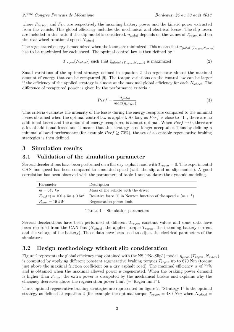
3.3 Design methodology with slip consideration
In this section the slip losses are considered by using the simulator with slip consideration on a dryasphalt road (the Burckhardt road/tire friction coefficients are c1 = 1.3, c2 = 24 and c3 = 0.5). Figure4 represents the dry asphalt road ηglobal map. The global efficiency map is not exactly the same as forthe NS model. Here the maximal efficiency is equal to 74%. It is 3% lower than the maximal ηglobalof the model without slip consideration. This shows that the slip losses for a dry asphalt road are nottoo high and that the NS model can give a good estimation of Eregen. The gray curve (“Strategy slipmodel”) on figure 4 represents the optimal strategy obtained with the dry asphalt ηglobal map andequation 2. This strategy is different from the NS optimal strategy (defined on figure 3 as “Strategy1”). The optimal regenerative torque has decreased (compared to the NS optimal strategy) to limitthe slip losses. The use of the slip model then changes the optimal strategy and it also depends on thekind of road considered. Figure 4 shows that ηglobal = 0 when Tregen > 630 Nm and this leads to noregenerated energy .
Figure 5 represents the performance map with the upper and lower boundaries of a dry asphalt road.Let us define an acceptable strategy as when at least 70% of the optimal energy regeneration levelis reached. This means that Perf = 0.70. The lower boundaries of the models with and without slipconsideration are almost the same because Tregen is low for both cases ; the slip losses can then be
4
21eme Congres Francais de Mecanique Bordeaux, 26 au 30 aout 2013
Figure 4 – Dry asphalt road ηglobal map withoptimal regenerative braking strategy
Figure 5 – Dry asphalt road Perf map withTregen boundaries
neglected. A minimal braking torque of Tregen = 110 Nm should be applied and the upper brakingtorque depends on the road’s maximal friction coefficient µ(s). In the case of the dry asphalt road,Tregen = 630 Nm is the maximal value allowed.
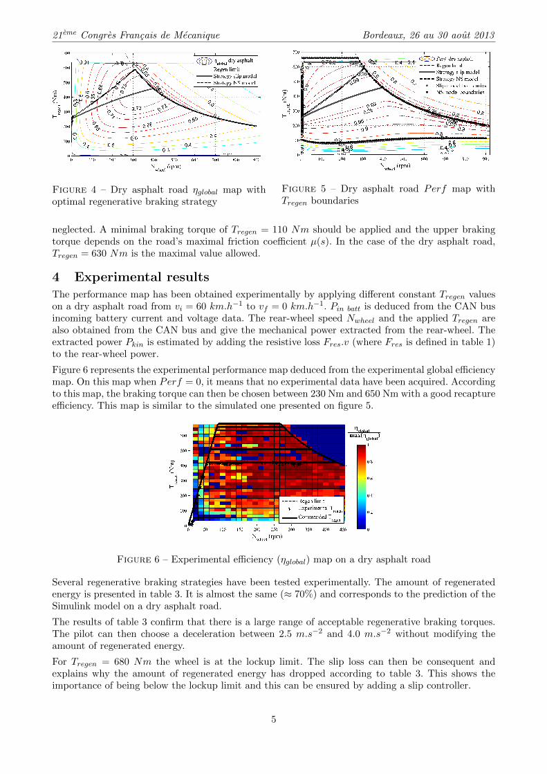
4 Experimental resultsThe performance map has been obtained experimentally by applying different constant Tregen valueson a dry asphalt road from vi = 60 km.h−1 to vf = 0 km.h−1. Pin batt is deduced from the CAN busincoming battery current and voltage data. The rear-wheel speed Nwheel and the applied Tregen arealso obtained from the CAN bus and give the mechanical power extracted from the rear-wheel. Theextracted power Pkin is estimated by adding the resistive loss Fres.v (where Fres is defined in table 1)to the rear-wheel power.
Figure 6 represents the experimental performance map deduced from the experimental global efficiencymap. On this map when Perf = 0, it means that no experimental data have been acquired. Accordingto this map, the braking torque can then be chosen between 230 Nm and 650 Nm with a good recaptureefficiency. This map is similar to the simulated one presented on figure 5.
Figure 6 – Experimental efficiency (ηglobal) map on a dry asphalt road
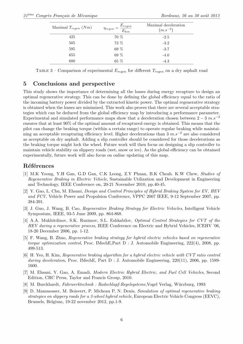
Several regenerative braking strategies have been tested experimentally. The amount of regeneratedenergy is presented in table 3. It is almost the same (≈ 70%) and corresponds to the prediction of theSimulink model on a dry asphalt road.
The results of table 3 confirm that there is a large range of acceptable regenerative braking torques.The pilot can then choose a deceleration between 2.5 m.s−2 and 4.0 m.s−2 without modifying theamount of regenerated energy.
For Tregen = 680 Nm the wheel is at the lockup limit. The slip loss can then be consequent andexplains why the amount of regenerated energy has dropped according to table 3. This shows theimportance of being below the lockup limit and this can be ensured by adding a slip controller.
5
21eme Congres Francais de Mecanique Bordeaux, 26 au 30 aout 2013
Maximal Tregen (Nm) ηregen =Eregen
Ekin
Maximal deceleration(m.s−2
)425 70 % -2.5
505 73 % -3.2
595 69 % -3.7
655 69 % -4.0
680 65 % -4.3
Table 3 – Comparison of experimental Eregen for different Tregen on a dry asphalt road
5 Conclusions and perspective
This study shows the importance of determining all the losses during energy recapture to design anoptimal regenerative strategy. This can be done by defining the global efficiency equal to the ratio ofthe incoming battery power divided by the extracted kinetic power. The optimal regenerative strategyis obtained when the losses are minimized. This work also proves that there are several acceptable stra-tegies which can be deduced from the global efficiency map by introducing a performance parameter.Experimental and simulated performance maps show that a deceleration chosen between 2− 3 m.s−2
ensures that at least 90% of the optimal amount of recaptured energy is obtained. This means that thepilot can change the braking torque (within a certain range) to operate regular braking while maintai-ning an acceptable recapturing efficiency level. Higher decelerations than 3 m.s−2 are also consideredas acceptable on dry asphalt. Adding a slip controller should be considered for those decelerations asthe braking torque might lock the wheel. Future work will then focus on designing a slip controller tomaintain vehicle stability on slippery roads (wet, snow or ice). As the global efficiency can be obtainedexperimentally, future work will also focus on online updating of this map.
References
[1] M.K Yoong, Y.H Gan, G.D Gan, C.K Leong, Z.Y Phuan, B.K Cheah. K.W Chew, Studies ofRegenerative Braking in Electric Vehicle, Sustainable Utilization and Development in Engineeringand Technology, IEEE Conference on, 20-21 November 2010, pp.40-45.
[2] Y. Gao, L. Chu, M. Ehsani, Design and Control Principles of Hybrid Braking System for EV, HEVand FCV, Vehicle Power and Propulsion Conference, VPPC 2007 IEEE, 9-12 September 2007, pp.384-391.
[3] J. Guo, J. Wang, B. Cao, Regenerative Braking Strategy for Electric Vehicles, Intelligent VehicleSymposium, IEEE, 93-5 June 2009, pp. 864-868.
[4] A.A. Mukhitdinov, S.K. Ruzimov, S.L. Eshkabilov, Optimal Control Strategies for CVT of theHEV during a regenerative process, IEEE Conference on Electric and Hybrid Vehicles, ICEHV ’06,18-20 December 2006, pp. 1-12.
[5] F. Wang, B. Zhuo, Regenerative braking strategy for hybrid electric vehicles based on regenerativetorque optimization control, Proc. IMechE,Part D : J. Automobile Engineering, 222(4), 2008, pp.499-513.
[6] H. Yeo, H. Kim, Regenerative braking algorithm for a hybrid electric vehicle with CVT ratio controlduring deceleration, Proc. IMechE, Part D : J. Automobile Engineering, 220(11), 2006, pp. 1589-1600.
[7] M. Ehsani, Y. Gao, A. Emadi, Modern Electric Hybrid Electric, and Fuel Cell Vehicles, SecondEdition, CRC Press, Taylor and Francis Group, 2010.
[8] M. Burckhardt, Fahrwerktechnik : Radschlupf-Regelsysteme,Vogel Verlag, Wurzburg, 1993
[9] D. Mammosser, M. Boisvert, P. Micheau P, N. Denis, Simulation of optimal regenerative brakingstrategies on slippery roads for a 3-wheel hybrid vehicle, European Electric Vehicle Congress (EEVC),Brussels, Belgium, 19-22 november 2012, pp.1-9.
6
Copyright © 2022 FDOKUMEN