The Physics of Braking Systems The Conservation of Energy
11
Centric Parts 21046 South Figueroa Street Carson, CA 90745 Phone: 310.218.1091 [email protected] 8/17/2018 1 TECHNICAL WHITEPAPER: The Physics of Braking Systems The Conservation of Energy The braking system exists to convert the energy of a vehicle in motion into thermal energy, more commonly referred to as heat. From basic physics, the kinetic energy of a body in motion is defined as: • where mv = the mass (commonly thought of as weight) of the vehicle in motion • where vv = the velocity (commonly known as speed) of the vehicle in motion Ideally, this energy is completely absorbed by the braking system. While this is not entirely the case, for a stopping event at maximum deceleration most of the vehicle’s kinetic energy is converted into thermal energy as defined by: • where mb = the mass of the braking system components which absorb energy • where Cp = the specific heat of the braking system components which absorb energy (a constant based on material properties) • where ∆Tb = the temperature rise experienced by the braking system components which absorb energy Note that for most single-stop events, the rotors serve as the primary energy absorbing components. It follows then that the temperature rise of the braking system is directly proportional to the mass of the vehicle in motion. More importantly perhaps, the temperature
-
Upload
khangminh22 -
Category
Documents
-
view
1 -
download
0
Transcript of The Physics of Braking Systems The Conservation of Energy
Centric Parts 21046 South Figueroa Street Carson, CA 90745 Phone: 310.218.1091 [email protected]
8/17/2018 1
TECHNICAL WHITEPAPER:
The Physics of Braking Systems
The Conservation of Energy
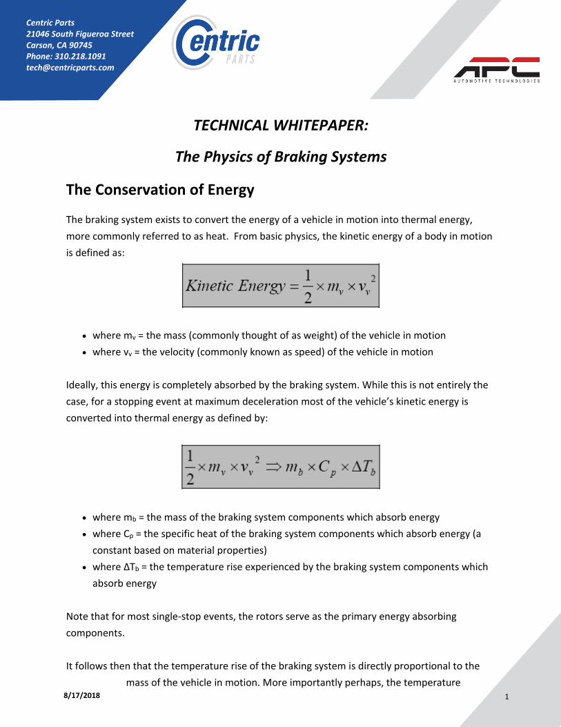
The braking system exists to convert the energy of a vehicle in motion into thermal energy,
more commonly referred to as heat. From basic physics, the kinetic energy of a body in motion
is defined as:
• where mv = the mass (commonly thought of as weight) of the vehicle in motion
• where vv = the velocity (commonly known as speed) of the vehicle in motion
Ideally, this energy is completely absorbed by the braking system. While this is not entirely the
case, for a stopping event at maximum deceleration most of the vehicle’s kinetic energy is
converted into thermal energy as defined by:
• where mb = the mass of the braking system components which absorb energy
• where Cp = the specific heat of the braking system components which absorb energy (a
constant based on material properties)
• where ∆Tb = the temperature rise experienced by the braking system components which
absorb energy
Note that for most single-stop events, the rotors serve as the primary energy absorbing
components.
It follows then that the temperature rise of the braking system is directly proportional to the
mass of the vehicle in motion. More importantly perhaps, the temperature

8/17/2018 2
rise of the braking system is directly proportional to the square of the velocity of the vehicle in
motion. In other words, doubling speed will theoretically quadruple brake temperatures.
In practical application, tire rolling resistance, aerodynamic drag, grade resistance, and other
mechanical losses will also play an energy-absorbing role, but value is still placed in establishing
this fundamental relationship as a limiting condition.
The Brake Pedal
The brake pedal exists to multiply the force exerted by the driver’s foot. From elementary
statics, the force increase will be equal to the driver’s applied force multiplied by the lever ratio
of the brake pedal assembly:
• where Fbp = the force output of the brake pedal assembly
• where Fd = the force applied to the pedal pad by the driver
• where L1 = the distance from the brake pedal arm pivot to the output rod clevis
attachment
• where L2 = the distance from the brake pedal arm pivot to the brake pedal pad
Note that this relationship assumes 100% mechanical efficiency of all components in the brake
pedal assembly. In practical application, the mechanical deflection of components and friction
present in physical interfaces prevents this condition.
The Master Cylinder
It is the functional responsibility of the master cylinder to translate the force from the brake
pedal assembly into hydraulic fluid pressure. Assuming incompressible liquids and infinitely
rigid hydraulic vessels, the pressure generated by the master cylinder will be equal to:
• where Pmc = the hydraulic pressure generated by the master cylinder
• where Amc = the effective area of the master cylinder hydraulic piston
8/17/2018 3
Note that this relationship assumes 100% hydraulic efficiency of all components in the master
cylinder assembly. In practical application, fluid properties, seal friction, and compliance the
physical components prevents this condition.
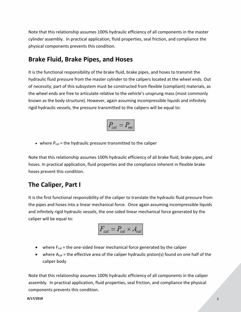
Brake Fluid, Brake Pipes, and Hoses
It is the functional responsibility of the brake fluid, brake pipes, and hoses to transmit the
hydraulic fluid pressure from the master cylinder to the calipers located at the wheel ends. Out
of necessity, part of this subsystem must be constructed from flexible (compliant) materials, as
the wheel ends are free to articulate relative to the vehicle’s unsprung mass (most commonly
known as the body structure). However, again assuming incompressible liquids and infinitely
rigid hydraulic vessels, the pressure transmitted to the calipers will be equal to:
• where Pcal = the hydraulic pressure transmitted to the caliper
Note that this relationship assumes 100% hydraulic efficiency of all brake fluid, brake pipes, and
hoses. In practical application, fluid properties and the compliance inherent in flexible brake
hoses prevent this condition.
The Caliper, Part I
It is the first functional responsibility of the caliper to translate the hydraulic fluid pressure from
the pipes and hoses into a linear mechanical force. Once again assuming incompressible liquids
and infinitely rigid hydraulic vessels, the one-sided linear mechanical force generated by the
caliper will be equal to:
• where Fcal = the one-sided linear mechanical force generated by the caliper
• where Acal = the effective area of the caliper hydraulic piston(s) found on one half of the
caliper body
Note that this relationship assumes 100% hydraulic efficiency of all components in the caliper
assembly. In practical application, fluid properties, seal friction, and compliance the physical
components prevents this condition.
8/17/2018 4
The Caliper, Part II
It is the second functional responsibility of the caliper to react the one-sided linear mechanical
force in such a way that a clamping force is generated between the two halves of the caliper
body. Regardless of caliper design (fixed body or floating body), the clamping force will be
equal to, in theory, twice the linear mechanical force as follows:
• where Fclamp = the clamp force generated by the caliper
Note that this relationship assumes 100% mechanical efficiency of all components in the caliper
assembly. In practical application, mechanical deflection and, in the case of floating caliper
bodies, the friction in the caliper slider assembly components prevents this condition.
The Brake Pads
It is the functional responsibility of the brake pads to generate a frictional force which opposes
the rotation of the spinning rotor assembly. This frictional force is related to the caliper clamp
force as follows:
• where Ffriction = the frictional force generated by the brake pads opposing the rotation of
the rotor
• where µbp = the coefficient of friction between the brake pad and the rotor
Note that this relationship assumes 100% mechanical efficiency of all components at the brake
pad interface. In practical application, mechanical deflection (compressibility) of the brake pad
materials and friction found between the brake pad and the caliper body components prevents
this condition. In addition, it should be noted that the coefficient of friction between the brake
pad and the rotor is not a single fixed value, but rather changes dynamically with time,
temperature, pressure, wear, and such.
8/17/2018 5
The Rotor
While the rotor serves as the primary heat sink in the braking system, it is the functional
responsibility of the rotor to generate a retarding torque as a function of the brake pad
frictional force. This torque is related to the brake pad frictional force as follows:
• where Tr = the torque generated by the rotor
• where Reff = the effective radius (effective moment arm) of the rotor (measured from
the rotor center of rotation to the center of pressure of the caliper pistons)
Because the rotor is mechanically coupled to the hub and wheel assembly, and because the tire
is assumed to be rigidly attached to the wheel, the torque will be constant throughout the
entire rotating assembly as follows:
• where Tt = the torque found in the tire
• where Tw = the torque found in the wheel
Note that this relationship assumes 100% mechanical efficiency of all components at the wheel
end. In practical application, mechanical deflection and relative motion between the rotating
components prevents this condition.
The Tire
Assuming that there is adequate traction (friction) between the tire and the road to
accommodate the driver’s braking request, the tire will develop slip in order to react the torque
found in the rotating assembly. The amount of slip generated will be a function of the tire’s
output characteristics (the mu-slip relationship), but the force reacted at the ground will be
equal to:
8/17/2018 6
• where Ftire = the force reacted between the tire and the ground (assuming friction exists
to support the force)
• where Rt = the effective rolling radius (moment arm) of the loaded tire
Up to this point our analysis has consisted of a single wheel brake assembly; however, because
modern vehicles have one wheel brake assembly at each corner of the car, there are actually
four tire forces being reacted during a typical stopping event. Because of this condition, the
total braking force generated is defined as the sum of the four contact patch forces as follows:
• where Ftotal = the total braking force reacted between the vehicle and the ground
(assuming adequate traction exists)
Deceleration of a Vehicle in Motion
Based on the work of Sir Isaac Newton, if a force is exerted on a body it will experience a
commensurate acceleration. Convention dictates that accelerations which oppose the
direction of travel are called decelerations. In the case of a vehicle experiencing a braking
force, the deceleration of the vehicle will be equal to:
• where av = the deceleration of the vehicle
Kinematics Relationships of Vehicles Experiencing
Deceleration
Integrating the deceleration of a body in motion with respect to time allows for the
determination of speed. Integrating yet again allows for the determination of position.
8/17/2018 7
Applying this relationship to a vehicle experiencing a linear deceleration, the theoretical
stopping distance of a vehicle in motion can be calculated as follows:
• where SDv = the stopping distance of the vehicle
Note that this equation assumes a step-input deceleration from a fixed speed followed by a
linear and constant rate of deceleration until the vehicle comes to rest. In practical application,
deceleration cannot be achieved instantaneously, nor can deceleration be assumed to be
constant for the duration of a stopping event.
Determining Parameters Related to Vehicle Static Weight
Distribution
When either at rest or under conditions of zero acceleration, a vehicle will have a fixed
distribution of mass (more commonly referred to as weight) which results in the four corners of
the vehicle each suspending a fixed percentage of the total. In the side view, the sum of the
left front and right front weights will equal the front axle weight and the sum of the left rear
and right rear weights will equal the rear axle weight. If these values are known, then one can
quickly calculate the static weight distribution as follows:
and
• where Vf = the front axle vertical force (weight)
• where Vr = the rear axle vertical force (weight)
• where Vt = the total vehicle vertical force (weight)
8/17/2018 8
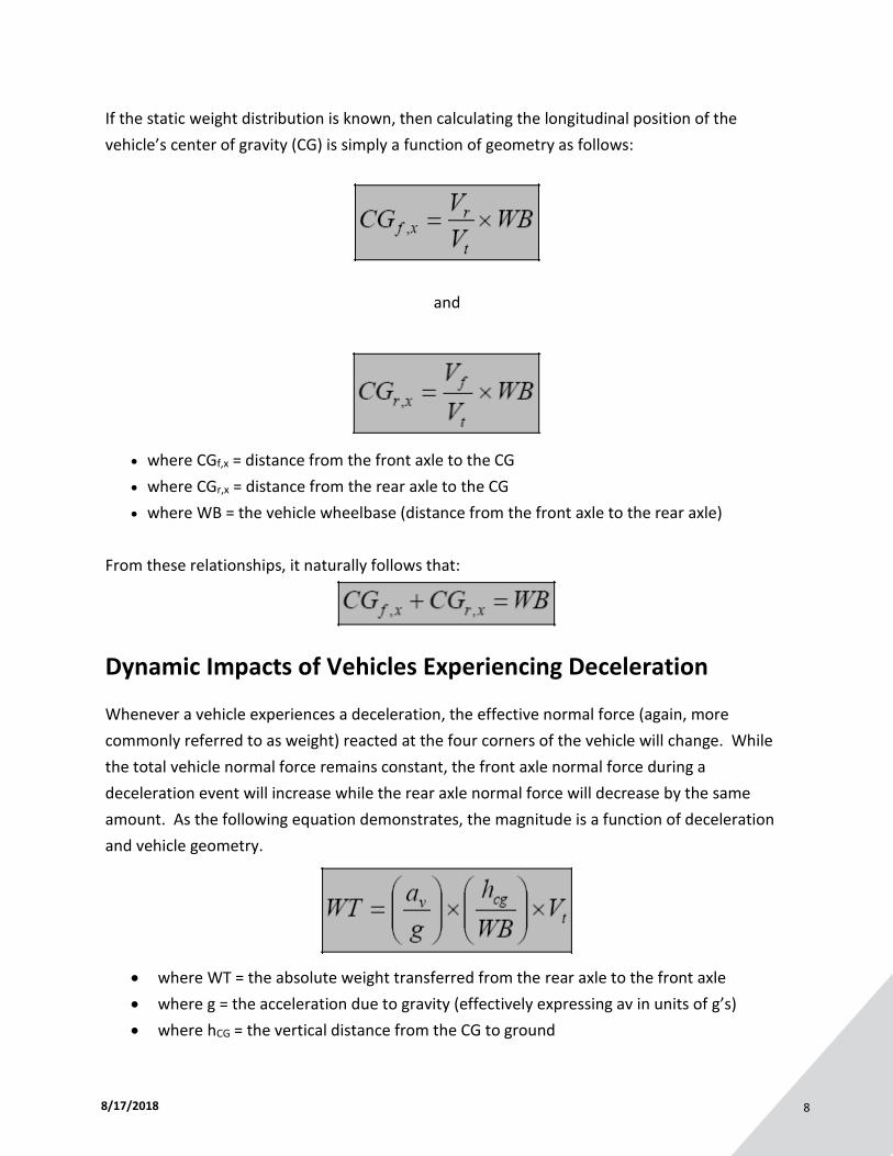
If the static weight distribution is known, then calculating the longitudinal position of the
vehicle’s center of gravity (CG) is simply a function of geometry as follows:
and
• where CGf,x = distance from the front axle to the CG
• where CGr,x = distance from the rear axle to the CG
• where WB = the vehicle wheelbase (distance from the front axle to the rear axle)
From these relationships, it naturally follows that:
Dynamic Impacts of Vehicles Experiencing Deceleration
Whenever a vehicle experiences a deceleration, the effective normal force (again, more
commonly referred to as weight) reacted at the four corners of the vehicle will change. While
the total vehicle normal force remains constant, the front axle normal force during a
deceleration event will increase while the rear axle normal force will decrease by the same
amount. As the following equation demonstrates, the magnitude is a function of deceleration
and vehicle geometry.
• where WT = the absolute weight transferred from the rear axle to the front axle
• where g = the acceleration due to gravity (effectively expressing av in units of g’s)
• where hCG = the vertical distance from the CG to ground

8/17/2018 9
In order to calculate the steady-state vehicle axle vertical forces during a given stopping event,
the weight transferred must be added to the front axle static weight and subtracted from the
rear axle static weight as follows:
and
• where Vf,d = the front axle dynamic vertical force for a given deceleration
• where Vr,d = the rear axle dynamic vertical force for a given deceleration
From these relationships, it naturally follows that for any given deceleration:
Effects of Weight Transfer on Tire Output
As a vehicle experiences dynamic weight transfer, the ability of each axle to provide braking
force is altered. Under static conditions, the maximum braking force that an axle is capable of
producing is defined by the following relationships:
and
• where Ftires,f = the combined front tire braking forces
• where Ftires,r = the combined rear tire braking forces
• where µpeak,f = the maximum effective coefficient of friction between the front tires and
the road
• where µpeak,r = the maximum effective coefficient of friction between the rear tires and
the road
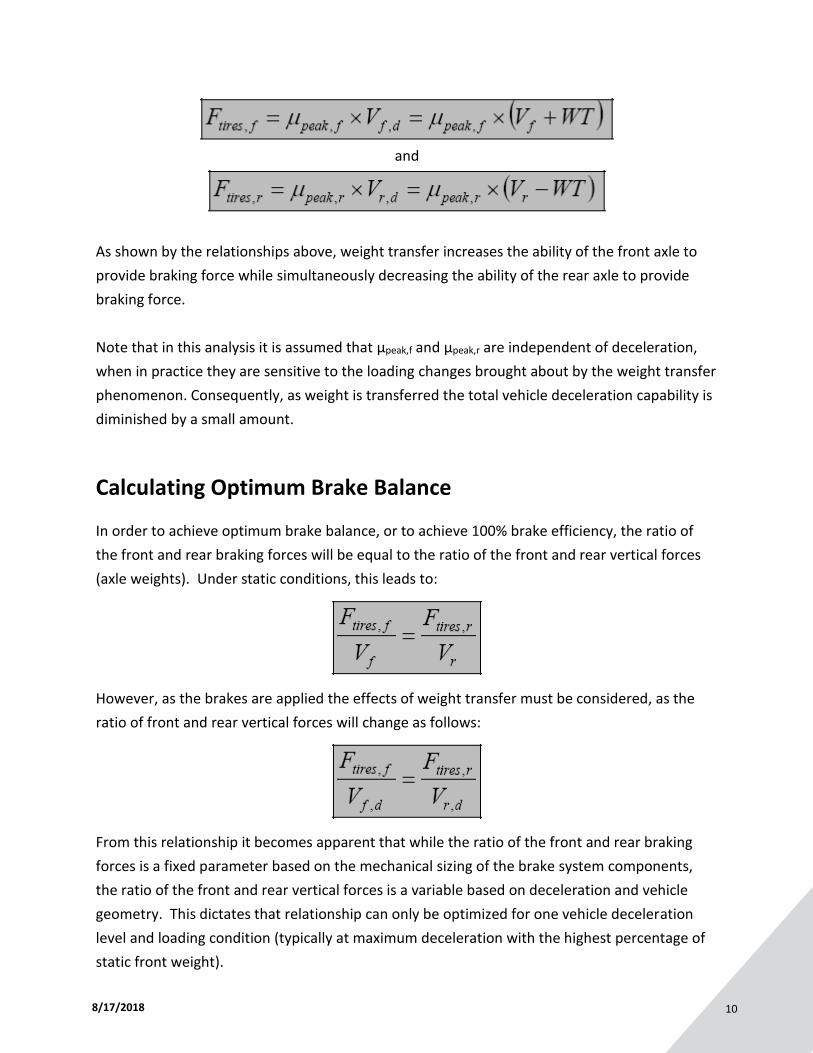
However, as a result of weight transfer during a deceleration event, the maximum braking force
that an axle is capable of producing is modified as follows:
8/17/2018 10
and
As shown by the relationships above, weight transfer increases the ability of the front axle to
provide braking force while simultaneously decreasing the ability of the rear axle to provide
braking force.
Note that in this analysis it is assumed that µpeak,f and µpeak,r are independent of deceleration,
when in practice they are sensitive to the loading changes brought about by the weight transfer
phenomenon. Consequently, as weight is transferred the total vehicle deceleration capability is
diminished by a small amount.
Calculating Optimum Brake Balance
In order to achieve optimum brake balance, or to achieve 100% brake efficiency, the ratio of
the front and rear braking forces will be equal to the ratio of the front and rear vertical forces
(axle weights). Under static conditions, this leads to:
However, as the brakes are applied the effects of weight transfer must be considered, as the
ratio of front and rear vertical forces will change as follows:
From this relationship it becomes apparent that while the ratio of the front and rear braking
forces is a fixed parameter based on the mechanical sizing of the brake system components,
the ratio of the front and rear vertical forces is a variable based on deceleration and vehicle
geometry. This dictates that relationship can only be optimized for one vehicle deceleration
level and loading condition (typically at maximum deceleration with the highest percentage of
static front weight).
8/17/2018 11
Author’s disclaimer:
Mechanical systems operating in the physical world are neither 100% efficient nor are they capable of
instantaneous changes in state. Consequently, the equations and relationships presented herein are
approximations of these braking system components as best as we understand their mechanizations
and physical attributes. Where appropriate, several examples of limiting conditions and primary
inefficiencies have been identified, but please do not assume these partial lists to be all-encompassing
or definitive in their qualification.
By James Walker, Jr. of scR motorsports, exclusively for StopTech
James Walker, Jr. is currently the supervisor of vehicle performance development for brake control
systems at Delphi Energy & Chassis. His prior professional experience includes brake control system
development, design, release, and application engineering at Kelsey-Hayes, Saturn Corporation, General
Motors, Bosch, and the Ford Motor Company. Mr. Walker created scR motorsports consulting in 1997,
and subsequently competed in seven years of SCCA Club Racing in the Showroom Stock and Improved
Touring categories.
Through scR motorsports, he has been actively serving as an industry advisor to Kettering University in
the fields of brake system design and brake control systems. He also serves as a brake control system
consultant for StopTech, a manufacturer of high-performance racing brake systems. In addition, Mr.
Walker contributes regularly to several automotive publications focusing on brake system analysis,
design, and modification for racing and other high-performance applications. He is a recipient of the SAE
Forest R. McFarland Award for distinction in professional development/education. Mr. Walker has a B.S.
in mechanical engineering from GMI Engineering & Management Institute.
To find out more about Mr. Walker and scR Motorsports, visit their website at www.teamscR.com
Stoptech is the performance engineering and manufacturing division of Centric Parts. It is the leader in
Balanced Brake Upgrades for production cars and has three patents in basic brake technology and one
other pending. With a worldwide network of resellers, StopTech’s product line includes Balanced Brake
Upgrades for approximately 450 applications featuring StopTech’s own six-, four- and two-piston
calipers, two-piece AeroRotor Direct Replacement Kits, braided stainless steel brake lines and slotted
and drilled original-dimension rotors. StopTech also stocks a wide range of performance brake pads. The
company’s website, www.stoptech.com, is a clearinghouse of performance brake information, and
provides details on StopTech products.
####