design of regenerative anti−lock braking system controller for ...
16
DESIGN OF REGENERATIVE ANTI−LOCK BRAKING SYSTEM CONTROLLER FOR 4 IN−WHEEL−MOTOR DRIVE ELECTRIC VEHICLE WITH ROAD SURFACE ESTIMATION Andrei Aksjonov 1) , Valery Vodovozov 2)* , Klaus Augsburg 3) and Eduard Petlenkov 4) 1) SKODA AUTO a.s., Tr. Vaclava Klementa 869, Mlada Boleslav 29301, Czech Republic 2) Department of Electrical Power Engineering and Mechatronics, School of Engineering, Tallinn University of Technology, Tallinn 19086, Estonia 3) Automotive Engineering Group, Department of Mechanical Engineering, Technische Universität Ilmenau, Ilmenau 98693, Germany 4) Department of Computer Systems, School of Information Technologies, Tallinn University of Technology, Tallinn 19086, Estonia (Received date ; Revised date ; Accepted date ) ABSTRACTThis paper presents a regenerative anti−lock braking system control method with road detection capability. The aim of the proposed methodology is to improve electric vehicle safety and energy economy during braking maneuvers. Vehicle body longitudinal deceleration is used to estimate a road surface. Based on the estimation results, the controller generates an appropriate braking torque to keep an optimal for various road surfaces wheel slip and to regenerate for a given motor the maximum possible amount of energy during vehicle deceleration. A fuzzy logic controller is applied to fulfill the task. The control method is tested on a four in−wheel−motor drive sport utility electric vehicle model. The model is constructed and parametrized according to the specifications provided by the vehicle manufacturer. The simulation results conducted on different road surfaces, including dry, wet and icy, are introduced. KEY WORDS : Fuzzy control, Anti-lock braking system, Electric vehicles, Vehicle dynamics, Vehicle safety NOMENCLATURE ω : wheel angular speed, rad/s a vx : vehicle longitudinal acceleration, m/s 2 p b : braking pressure, bar r : wheel radius, m m : mass of the quarter vehicle, g g : gravitational acceleration, m/s 2 Td : driving torque, Nm Tt : tire torque, Nm Tb : total braking torque, Nm TRB : regenerative brake torque, Nm TFB : friction brake torque, Nm I w : inertia about the wheel rotational axis, gm 2 k b : braking coefficient Tj : phase torque of motor, Nm I j : phase current of motor, A θ : rotor aligned position of motor, ° L : phase bulk inductance of motor, H N : number of phases of motor v vx : vehicle longitudinal velocity, m/s vwx : wheel longitudinal velocity, m/s λ : wheel slip, % μ : tire −road friction coefficient μ* : estimated road surface Fx : longitudinal force, N Fz : vertical force, N Ec : net energy consumption, kJ Pd : power spent on driving, W Pb : power recovered via regenerative braking area, W * Corresponding author. e-mail: [email protected]
-
Upload
khangminh22 -
Category
Documents
-
view
2 -
download
0
Transcript of design of regenerative anti−lock braking system controller for ...

DESIGN OF REGENERATIVE ANTI−LOCK BRAKING SYSTEM
CONTROLLER FOR 4 IN−WHEEL−MOTOR DRIVE ELECTRIC
VEHICLE WITH ROAD SURFACE ESTIMATION
Andrei Aksjonov1), Valery Vodovozov2)*, Klaus Augsburg3) and Eduard Petlenkov4)
1)SKODA AUTO a.s., Tr. Vaclava Klementa 869, Mlada Boleslav 29301, Czech Republic 2)Department of Electrical Power Engineering and Mechatronics, School of Engineering, Tallinn University of
Technology, Tallinn 19086, Estonia 3)Automotive Engineering Group, Department of Mechanical Engineering, Technische Universität Ilmenau, Ilmenau
98693, Germany 4)Department of Computer Systems, School of Information Technologies, Tallinn University of Technology, Tallinn
19086, Estonia
(Received date ; Revised date ; Accepted date )
ABSTRACTThis paper presents a regenerative anti−lock braking system control method with road detection
capability. The aim of the proposed methodology is to improve electric vehicle safety and energy economy during
braking maneuvers. Vehicle body longitudinal deceleration is used to estimate a road surface. Based on the
estimation results, the controller generates an appropriate braking torque to keep an optimal for various road surfaces
wheel slip and to regenerate for a given motor the maximum possible amount of energy during vehicle deceleration.
A fuzzy logic controller is applied to fulfill the task. The control method is tested on a four in−wheel−motor drive
sport utility electric vehicle model. The model is constructed and parametrized according to the specifications
provided by the vehicle manufacturer. The simulation results conducted on different road surfaces, including dry, wet
and icy, are introduced.
KEY WORDS : Fuzzy control, Anti-lock braking system, Electric vehicles, Vehicle dynamics, Vehicle safety
NOMENCLATURE
ω : wheel angular speed, rad/s
avx : vehicle longitudinal acceleration, m/s2
pb : braking pressure, bar
r : wheel radius, m
m : mass of the quarter vehicle, g
g : gravitational acceleration, m/s2
Td : driving torque, Nm
Tt : tire torque, Nm
Tb : total braking torque, Nm
TRB : regenerative brake torque, Nm
TFB : friction brake torque, Nm
Iw : inertia about the wheel rotational axis, gm2
kb : braking coefficient
Tj : phase torque of motor, Nm
Ij : phase current of motor, A
θ : rotor aligned position of motor, °
L : phase bulk inductance of motor, H
N : number of phases of motor
vvx : vehicle longitudinal velocity, m/s
vwx : wheel longitudinal velocity, m/s
λ : wheel slip, %
µ : tire−road friction coefficient
µ* : estimated road surface
Fx : longitudinal force, N
Fz : vertical force, N
Ec : net energy consumption, kJ
Pd : power spent on driving, W
Pb : power recovered via regenerative braking area, W
* Corresponding author. e-mail: [email protected]

ηm : electric motor efficiency, %
s : distance, m
aaverage : average deceleration, m/s2
ABSIP : ABS operation index of performance
λaverage : average wheel slip, %
λe : actual and optimal wheel slip difference absolute value, %
Preg : regenerated power comparing to the total power required
for deceleration, %
SUBSCRIPTS
i : subscript for each wheel; i ϵ [front left (FL), front right (FR),
rear left (RL), rear right (RR)]
j : switched reluctance motor phase number
ABBREVIATIONS
4WD 4 in-Wheel-motor Drive
ABS Antilock Braking System
ASM Automotive Simulation Models™
DOF Degree of Freedom
ESP Electronic Stability Program
EV Electric Vehicle
FLC Fuzzy Logic Controller
ICE Internal Combustion Engine
MF Membership Function
MISO Multiple Input, Single Output
PID Proportional−Integral−Derivative
SRM Switched Reluctance Motor
SUV Sport Utility Vehicle
UOD Universe of Discourse
1. INTRODUCTION
Modern life cannot be imagined without personal
vehicles. As the cities grow bigger and business spread
wider, people daily pass long distances to their work
places or to meet with their business partners in other
cities or even other countries. On−ground vehicles have
become indispensable machines helping people in
overcoming distances and saving time on transportation.
The world population increases every year and a
demand for personal vehicles grows in parallel. Within
only few past decades the number of internal
combustion engine (ICE) cars has dramatically enlarged
on the roads. It brings in this connection the biggest
disadvantage of a developed industry: the risk of
accidents and consequent human fatalities. Thus, a
vehicle safety and driving assistance systems’
improvement and development is needful. Moreover,
the problems related to energy management, oil crisis,
greenhouse gases, pollution and environment protection
have brought a necessity to create a new type of
environmental friendly transport. One of the promising
alternatives are the electric vehicles (EV), where an ICE
is replaced with an electric motor propulsion system
(Bansal, 2005). EVs are not only less polluting, efficient
and cheap to operate, but also very quiet (Dhameja,
2002).
The EV batteries’ long recharging time, poor
durability, weight, cost and short lifetime are causing
the largest resistance to the EV mobility infrastructure
development (Dhameja, 2002). The biggest drawback of
the commercial EVs is their short range due to a small
charge capacity.
One of the subtypes of an EV has four
in−wheel−motor drives (4WD) powertrain. The
technology was already available in 1900, when the
great inventor and engineer Ferdinand Porsche
introduced a vehicle with wheel hub motors built into
steered front wheels. Unfortunately, the mass
production failed due to the invention technical
complexity.
With the technologies available today, the 4WD
powertrain EVs once again deserve an attention,
because they turn out to be perfect candidates for future
mobility. Each of the individual 4WD motors’ angular
velocity and torque can be directly measured.
Furthermore, the electric actuator works faster than a
conventional hydraulic system used nowadays in ICE
vehicles. It opens an opportunity to design a very rapid,
efficient and accurate algorithm to control vehicle
dynamics via 4WD powertrain (Xiong and Yu, 2011).
The well−known safety systems are an antilock
braking system (ABS) and an electronic stability
program (ESP). The ABS avoids wheel lock and
maintains vehicle steerability (Koch−Dücker and Papert,
2014). The ESP assists in vehicle stability control (Ehret,
2014). The ABS available in commercial vehicles
requires a wheel slip threshold that guarantees energy
efficient deceleration only on a dry asphalt surface
(Koch−Dücker and Papert, 2014). Consequently, it
leads to power losses on lower adhesive coefficient
surfaces, because the wheel slip requirements are lower
on a slippery surface than on a dry road (Doumiati et al.,
2013).
In EV, the negative torque from braking inertia
rotates the motor in opposite to traction direction. The
motor works as a generator and charges an energy

storage device by converting kinetic energy created by
the vehicle mass into an electric power, instead of
wasting it as a heat on the brake pads or into the
atmosphere (Miller, 2005; El−Garhz et al., 2013). This
process is known as regenerative braking or energy
recuperation (Dhameja, 2002). Kinetic energy recycled
from braking maneuvers increases the EV driving
distance. Thus, an ABS for EVs has a benefit for safety
and efficiency improvement via regenerative braking
and a challenge for more complex braking control
methods design.
This work’s aim is to combine the torque blending
technique together with a control of robust to different
road surfaces ABS. The generators use maximum power
as the actuators for the ABS system. The controller
recognizes the road surface to maintain energy efficient
and safe braking performance for a specific road. Hence,
the controller recuperates maximum possible kinetic
energy from braking and simultaneously supports robust
to various roads vehicle safety deceleration.
The paper is organized as follows. In next Section,
the related to this studies works are analyzed and the
current paper contribution is discussed. The 4WD EV
powertrain modelling and parameterization are
introduced in Section 3. The detailed explanation of the
road detection algorithm as well as the control method
description are presented in Section 4. In Section 5, the
control results for different road adhesions are
introduced. A comparative analysis of the controller
performance for electric and hydraulic actuators is also
reported. The research is discussed and concluded in
Sections 6 and 7, respectively.
2. RELATED WORKS
Many different conventional control methods were
proposed for EV energy regeneration. For instance, in
(Long et al., 2014), the sliding mode controller (SMC)
and the proportional−integral−derivative (PID)
controllers were compared. There, the SMC
outperformed the PID. In (Ye et al., 2010), H2 optimal
control and H∞ robust control were combined to
guarantee EV recuperation performance and stability.
Those methods require very complex numerical models.
Mathematical models are computationally intensive and
have complex stability problems. Moreover, models are
often not accurate due to approximations, uncertainty,
and lack of perfect knowledge. Fuzzy logic has an
advantage over conventional control techniques (e.g.
PID, SMC, H∞), because it does not require a complex
dynamic model development. Hereupon, it has a benefit
in processing and mapping ill-defined and uncertain
variables. Consequently, within few last decades, a
fuzzy logic controller (FLC) deserved special attention
in complex, imprecise nonlinear control (Passino and
Yurkovich, 1998 (pp. 1−22); Reznik, 1997).
One of the first EV regenerative antiskid braking and
traction control system applying FLC with the tire−road
adhesive characteristic estimation was proposed in
(Cikanek, 1994). The controller was designed for a
single-axle drive EV architecture. Since then, many
other rule−base approaches were proposed for
regenerative braking enhancement.
An FLC was applied to control an EV ABS with
optimal wheel slip for varying road surfaces (Kathun et
al., 2003; Chen et al., 2010). In addition to robust ABS,
the authors in (Pusca et al., 2004; Tahami et al., 2003)
also studied an ESP regulation. Although the controller
showed precise road adhesive coefficient estimation, the
authors did not investigate regenerative braking and
torque blending.
Vehicle stability control for a 4WD hybrid EV was
stressed in (Kim et al., 2008). The FLC compensated
the yaw dynamics control and recycled kinetic energy.
Nevertheless, the simulation results are limited to the
yaw rate and side slip angle compensation.
Fuzzy set theory also deserved an attention in kinetic
energy recuperation. The scholars in (Paterson and
Ramsay, 1993; Peng, 2006; Li et al., 2008) proposed an
electric motor and friction braking torque blending
based on FLC. Furthermore, in (Nian, 2014), the FLC
and PID control were combined to distribute the
mechanical and electrical braking forces. Even so, the
authors neither consider braking torque between rear
and front wheels distribution nor ABS control design.
On the contrary, in (Zhang et al., 2016; Jianyao et al.,
2015; Xu et al., 2011), the authors examine both EV
torque blending and braking force allocation between
EV wheels. Nevertheless, the slip control and ABS
safety investigation were not presented. Further, in
(Zhang et al., 2016), the researchers demonstrated
effectiveness and strong robustness in EV energy
recuperation of the Takagi−Sugeno fuzzy SMC over
conventional PID and Mamdani's type FLC. The results
were verified in simulation and experimentation.
Though, vehicle safety was not stressed. Optimal
braking torque distribution with regenerative capability
was examined on vehicle stability for a single line
change in (Kim et al., 2007) but an ABS controller was
not designed there.
A regenerative ABS controller was built by
combining FLC and SMC in (Guo et al., 2014). The
intelligent regulator requires a reference slip threshold,
which likewise in modern industrial vehicles lead to
energy losses on other than dry road surfaces.
Fuzzy set theory is also widely used as an estimator
of vehicle states, for instance, linear velocity, battery
performance, vehicle side slip angle, tire−road
interaction parameters (Ivanov, 2015) and tire forces

(Acosta and Kanarachos, 2017). Tire−road surface
estimation with ABS control based on FLC was
designed in (Layne et al., 1993). The goal of the
controllers was to keep the slip ratio to 20% despite
road friction characteristics.
In (Paul et al., 2016), the researchers went further and
offered, first, to estimate the road surface with fuzzy
logic, and therefore to provide a braking torque
distribution. The controller was tested on a single motor
EV model. The wheel slip and vehicle steerability were
not studied on different road surfaces, because the
controller is designed with a fixed slip value.
Advanced FLCs for road type detection and thus
optimal braking pressure generation were designed in
(Ivanov et al., 2006; Aly, 2010; Castillo et al., 2016).
Although the experimental results showed perfect
performance on varying road surfaces, the control
algorithms are very complex. What is more, the FLCs
were not tested on EV decoupled braking system, but
only on conventional hydraulic brakes.
Other efficient techniques for vehicle states
estimation were proposed before. Kalman filtering is
widely used in vehicle longitudinal force estimation
(Doumiati et al., 2013). Lyapunov stability theory (Xia
et al., 2016), a combination of stiffness based estimation
and least squares (Han et al., 2015) and a combination
of nonlinear Lipschitz observer and modified super-
twisting algorithm (Rath, et al., 2015) were designed for
road friction coefficient estimation. Those methods,
however, require complicated nonlinear models or
additional sensors, what multiply system’s cost and
complexity.
In this paper, a simple method for road surface
recognition is presented. The estimation is based only
on vehicle body maximum deceleration rate. The
proposed technique is fulfilled with FLC and, unlike
other methods mentioned in this Section, requires
neither complicated mathematical model nor additional
sensors, because the longitudinal acceleration
measurement sensors are already in use in modern
vehicles (Zabler, 2014). What is more, the FLC is able
to compensate the lack of knowledge about many other
road surfaces that are not preliminary considered.
Previously, the road surface estimation strategy and
ABS control were tested on hydraulic brake model
(Aksjonov et al., 2016). On the contrary, in this paper,
the FLCs are designed for both electric and hydraulic
actuators that are interacted together. The proposed
controllers’ task is to maximize energy recuperation
from the vehicle deceleration maneuver. Hereupon, the
same FLCs ensure the robustness to different road
surfaces by maintaining an optimal wheel slip during
the whole braking process and by avoiding a reference
slip control. Therefore, an energy efficient torque
blending and road surface estimation are implemented
in the same controller without complex vehicle models.
In short, the following problems are solved:
• road surface detection from vehicle body
longitudinal acceleration with vehicle energy
efficient deceleration due to optimal wheel slip
control and maximum energy regeneration
capability using fuzzy set theory;
• controller implementation on ten degree of
freedom (10DOF) 4WD EV model;
• control method robustness to different road
surfaces demonstration and comparison with only
friction and braking with blocked wheels.
3. VEHICLE MODELLING
3.1. Dynamics of a Braked Wheel
The 3DOF single−wheel vehicle model for the EV
longitudinal motion (Figure 1) is described by the
following system of equations (Kiencke and Nielsen,
2005):
gmF
vmF
TTTI
z
vxx
btdw
(1)
where the tire torque Tt is expressed as:
xt FrT (2)
Due to its small influence comparing to the braking
and friction forces during braking maneuvers, other
forces, like aerodynamic drag and lateral wind force, are
neglected.
Figure 1. Vehicle single–wheel model of a braked
wheel schematic drawing.

A distinctive feature of the 4WD EV: total braking
torque Tb is a sum of regenerative brake TRB and friction
brake TFB torques:
FBRBb TTT (3)
where the friction brake torque is determined as
(Kiencke and Nielsen, 2005):
bbFB pkrT (4)
In turn, the friction braking coefficient kb depends on
brake disc friction area, mechanical efficiency of brake
components, and braking factor. Tire deformation
(change of the wheel radius r) due to its small impact is
neglected. Thus, both variables r and kb are assumed as
constants. The friction braking torque changes
proportionally to the brake pressure pb.
Finally, in case of a saturated phase, a torque Tj
equation for switched reluctance motor (SRM) can be
given as (Ehsani et al., 2005) (pp. 204−232):
jj
I
j
j dIIIL
T
j
0
,
(5)
The output torque of an SRM in traction or
regenerative modes Td/RB is the summation of torques in
all the phases (Ehsani et al., 2005) (pp. 204−232):
N
j
jRBd TT1
/ (6)
The input to the SRM drive is direct current voltage.
However, a convertor controls phase current Ij flow.
Therefore, control of the phase torque depends directy
on Ij (Ehsani et al., 2005) (pp. 204−232).
In modern vehicles, the torque of the vehicle wheel
cannot be measured, but only estimated. On the contrary,
both pb and Ij can be measured by appropriate sensors
(Zabler, 2014). In this paper, the wheel torques are
controlled by influencing on pb and Ij. The variables
serve as the controller correcting variables. Nevertheless,
they will be directly expressed as the relevant torques.
For the braking maneuver the longitudinal wheel slip
λ is expressed as (Kiencke and Nielsen, 2005):
%100
vx
wxvx
v
vv (7)
where the longitudinal wheel velocity vwx is:
rvwx (8)
Tire deformation depends on a normal force Fz
(Pacejka, 2006). The wheel radius r is assumed as
constant.
Tire−road adhesive coefficient µ is determined as a
ratio between longitudinal Fx and vertical Fz forces
applied on a wheel (Kiencke and Nielsen, 2005):
z
x
F
Fµ (9)
From the single−wheel dynamics, Eq. (1), µ can be
simplified as:
g
v
gm
vm
F
Fµ vxvx
z
x
(10)
Two main variables, the vehicle longitudinal
acceleration avx and the wheel angular velocity ωi, serve
as the controller inputs. The input signals are measured
by the available on board sensors (Zabler, 2014). In this
paper, µ is connected to maximum vehicle acceleration
rate avx (Eq. (10)) for road surface recognition. The
detected road surface is defined as µ*.
An overall motor power Pd/b with motor efficiency ηm
expended on driving or braking is as follows (Ehsani et
al., 2005) (pp. 277−298):
ibdmbd TP // (11)
Electric motor net energy consumption EC is
described by an equation of power spent on driving and
recycled during the regenerative braking, if the last one
is applied (Ehsani et al., 2005) (pp. 99−116):
dtPdtPEbraking
btraction
dC (12)
The index of performance ABSIP is introduced to
evaluate the effectiveness of the ABS control. It
describes the ratio between vehicle deceleration with
and without the applied controller:
skid
ABSIP
a
aABS (13)

3.2. Vehicle Modelling and Parametrization
Full 10DOF vehicle mathematical model Automotive
Simulation Models™ (ASM) 2014−B (64−bit) is
supplied by the dSPACE® GmbH (Paderborn,
Germany). The ASM allow a vehicle model
parameterization according to the user’s needs. The
ASM interaction with the MATLAB®/Simulink®
(Natick, MA, USA) R2013b (64 Bit) allows removing
or substitution of the vehicle component models, if
necessary. Furthermore, the control algorithm can be
easily designed and simulated in MATLAB®
environment without any supplementary software
requirements. A multibody vehicle model simulation is
accompanied with a visual interface, what help user to
understand vehicle behavior in details. The EV and its
powertrain system configurations are provided by a
vehicle manufacturer and presented in Table 1.
The studied EV model was parametrized as a sport
utility vehicle (SUV). Its total body weight is 2117 kg.
Each 4WD powertrain motor is connected to the wheel
through a gearbox and a half−shaft transmission. In
Figure 2, a simplified in−wheel motor architecture and a
controller are introduced. The EV has a decoupled
electro−hydraulic brake system. Friction and electric
motor brakes impacting on braking pressure and the
motor phase current can be controlled independently.
Vehicle deceleration is a very fast process. In
regenerative braking, huge amount of energy is released
within a very short time. Most of the EV batteries are
not able to save this energy. Despite, ultracapacitors are
characterized by very high power, excellent life cycle,
but represent a low−capacity energy storage.
Consequently, most of the modern EVs are also
Figure 2. In–wheel motor architecture scheme: black
– hardware; blue – software.
Table 1. Electric vehicle configurations.
Components Parameters Desription
Vehicle
Type
Vehicle overall mass
Front axle suspension spring constant stiffness
Rear axle suspension spring constant stiffness
Front axle suspension stabilizer stiffness
Rear axle suspension stabilizer stiffness
Tire type
Tire numerical model
Sport utility vehicle
2117 kg
26700 N/m
23000 N/m
2851.4 N/m
6833.5 N/m
235/55 R19
Pacejka’s Magic Formula
Electric motor
Type
Peak torque at 800V (+/− 10%)
Peak power at 800V (+/− 10%)
Nominal torque at 800V (+/− 10%)
Nominal power at 800V (+/− 10%)
Maximum speed
Motor inertia (without gearbox)
Mass
Motor dimension
Liquid cooling system
Switched reluctance
200 Nm (30 sec)
100 kW (30 sec)
125 Nm
42 kW
15000 rpm
21087 kgmm2
50 kg
215x265 mm
Water 10 l/min, 50º C max inlet
Transmission (in−wheel motor)
Type
Overall motor−gear ratio
Estimated torsion stiffness of half−shaft
Two stage reducer with helical gear and half−shaft
1:10.5
6500 Nm/rad
Battery pack
Voltage
Peak power
Nominal power
Mass
Volume
Energy capacity
Module type
Modules number
400 V DC
160 kW
80 kW
274 kg
0.235 m3
15 Ah (6 kWh)
12 lithium−titanate oxide anode cells
15
Figure 3. Torque – rotational speed characteristic for
SRM in motoring and regeneration modes.

equipped with ultracapacitors used in regenerative
braking for fast energy storing (Bansal, 2005). The
power electronics losses are neglected in the model.
Lithium−titanate battery is used as an energy storage
device. Its maximum energy capacity is 6 kWh and a
peak power reaches 160 kW. Wheels are equipped with
a SRM. The SRM’s maximum torque that can be
applied during 30 seconds at 800 V voltage in both
motor and generator modes is 200 Nm. The torque
versus angular speed relation for the studied SRM is
shown in Figure 3. Taking into consideration the
in−wheel motor overall transmission gear ratio, the
maximum torque applied directly to the wheel reaches
2100 Nm (Savitski et al., 2016).
A first−order transfer function describes the electric
motor dynamics as follows (Savitski et al., 2014, 2016):
s
ref
d
act
d esT
T 002,0
10022,0
1
(14)
whereas the motor transfer function in generator mode
while braking is as follows:
s
ref
b
act
b esT
T 025,0
102,0
1
(15)
The tires are modelled with the Pacejka’s Magic
Formula (Pacejka, 2006). Before designing the
controller, the tire characteristics were studied. To this
regard, the vehicle model was simulated on dry, damp,
wet, and icy road surfaces. An ABS control was not
applied. The vehicle decelerates under heavy braking
conditions with locked wheels.
The tire−road friction µ versus the wheel slip λ are
plotted (Figure 4) to specify the stable working range
for the given tire. Since the meaning of the vehicle body
deceleration curves on different road surfaces is the
same as the µ – λ curves, they are not introduced in this
paper. Only the straight road braking maneuver is
studied, a slip angle effect on tire dynamics is omitted.
Tire dynamics have an exponential behavior (Figure
4). The optimal slip lays on the curve’s peak, where the
adhesive coefficient has its maximum rate. The plot
region from 0 to optimal slip value is called stable for
each road surface, where the vehicle maintains
steerability. The rest of the curve from optimal to 100%
slip is called unstable zone, where the vehicle lateral
control (steerability) is impossible. Moreover, the
vehicle maximum deceleration on a given road surface
is achieved only with the optimal wheel slip. Braking
with the slip ratios higher or lower than the optimum
value leads to braking force reduction (Rajamani, 2012).
Although the vehicle velocity and tire models are the
same for the front and rear wheels, the µ – λ curves are
slightly different (Figure 4). This can be explained by
unequal body mass and, therefore, normal force
distribution between the front and rear wheels
(Rajamani, 2012). Vehicle vertical load has an impact
on a tire dynamic behavior (Pacejka, 2006), because
friction coefficient depends on a normal force, Eq. (9).
Each road surface for the front and rear wheels of the
EV has its own optimal slip. The optimal value
maintenance leads to the most effective and energy
efficient braking performance. Due to the forces balance,
the vehicle decelerates as fast as feasible at the same
time presuming the lateral control (Koch−Dücker and
Papert, 2014). With the reference to the plots in Figure 4,
the optimal slip values are concluded in Table 2. The
peak vehicle deceleration values on different roads are
also introduced in Table 2. The data are essential details
for the control method design described in next Section.
4. CONTROL METHOD
4.1. Control Method Description
Regenerative ABS control algorithm has several
requirements: (i) fast vehicle deceleration, (ii) vehicle
steerability preservation, (iii) maximum energy
recuperation rate. First two requirements are fulfilled
with the wheel slip control. Efficiency of the ABS can
be dramatically improved by holding an optimal wheel
Table 2. Optimal wheel slip values and vehicle body
maximum deceleratin rate for different road
surfaces.
λ [%] Dry
road
Damp
road
Wet
road
Icy
road
Front wheels 13.18 10.66 8.34 6.14
Rear wheels 12.31 9.54 7.12 5.82
Peak deceleration [m/s2] 11.78 8.79 5.89 2.96
Figure 4. Tire–road friction – slip curves of the
studied tire model for various road surfaces using
Magic Formula model (Pacejka, 2006).
slip for a given tire on different road surfaces. The third
requirement is satisfied by braking using the torque
generated by an SRM only. This torque may not be
enough to preserve the required slip and fast vehicle
deceleration. Hence, the controller must involve a
friction braking system in series while using the electric
motor as a generator.
In this work, an improvement of ABS performance is
proposed for the 4WD EV by keeping the wheel slip on
its optimal level for various roads. For this, the
algorithm uses vehicle body longitudinal deceleration to
comprehend which kind of road is behind the tires.
Additionally, the controller employs the electric motor
for energy recuperation on its maximum power and
therefore recycles as much energy as possible.
The regenerative−friction decoupled ABS control
block scheme for a single wheel is presented in Figure 5.
The idea is very simple: the controller uses electric
motor torque and retains vehicle deceleration with an
optimal slip ratio for a given road. The mechanical
friction brake system is activated only when the
generator’s torque is not enough to maintain the optimal
slip. In fact, the controlled parameters are phase current
for the regenerative brakes and the brake caliper
pressure for the friction brakes. For better understanding,
the outputs are expressed directly as appropriate torques.
Displacement of a braking pedal activates the ABS
controller. The safety feature is deactivated when the
braking pedal is released or vehicle velocity is smaller
than 8 km/h, because a distance travelled with the
locked wheels from 8 km/h is not critical for vehicle
safety (Koch−Dücker and Papert, 2014).
An integrated signal transmitted from a vehicle
longitudinal acceleration avx sensor and a signal from a
wheel speed ωi sensor are used to estimate a tire slip for
each wheel λi. The same estimation approach is used in
modern vehicles (Koch−Dücker and Papert, 2014). The
method is assumed to be enough accurate as the sensors
offset, noise, and integration drift have no dramatic
influence on λ calculation. A side slip influence can be
also neglected, because only straight braking maneuver
is performed (Pacejka, 2006).
The avx cannot provide the peak friction coefficient
directly (Figure 4). However, if the maximum possible
acceleration on a given road surface is known, the
information may be utilized to understand the road
surface μ* and to specify the optimal wheel slip
accordingly (Table 2).
In heavy braking maneuver, the driver requests a
peak braking torque by slamming on a brake pedal.
During the first time lapse of the braking maneuver, the
ABS is not yet activated, and this interval is used for
maximum avx detection. Therefore, the peak measured
deceleration rate is referred to an appropriate road
surface from Table 2. As soon as the road is estimated,
the controller identifies an optimal wheel slip for a
given road surface (Table 2), and the ABS control is
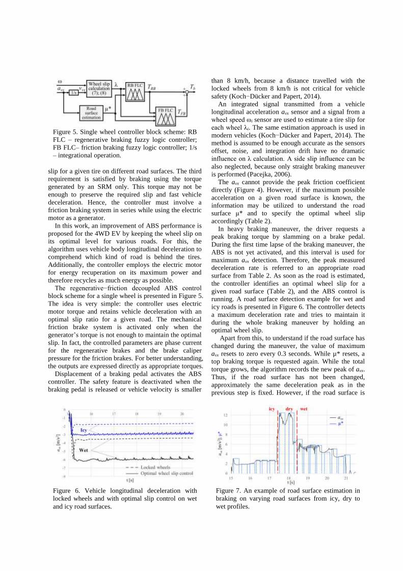
running. A road surface detection example for wet and
icy roads is presented in Figure 6. The controller detects
a maximum deceleration rate and tries to maintain it
during the whole braking maneuver by holding an
optimal wheel slip.
Apart from this, to understand if the road surface has
changed during the maneuver, the value of maximum
avx resets to zero every 0.3 seconds. While µ* resets, a
top braking torque is requested again. While the total
torque grows, the algorithm records the new peak of avx.
Thus, if the road surface has not been changed,
approximately the same deceleration peak as in the
previous step is fixed. However, if the road surface is
Figure 5. Single wheel controller block scheme: RB
FLC – regenerative braking fuzzy logic controller;
FB FLC– friction braking fuzzy logic controller; 1/s
– integrational operation.
Figure 6. Vehicle longitudinal deceleration with
locked wheels and with optimal slip control on wet
and icy road surfaces.
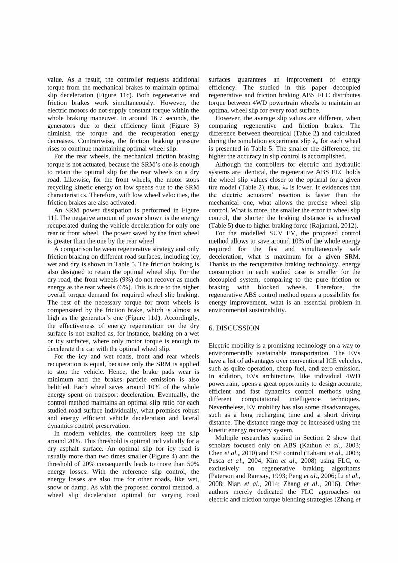
Figure 7. An example of road surface estimation in
braking on varying road surfaces from icy, dry to
wet profiles.

different from the one in previous step, a new maximum
value of avx is noted.
Figure 7 illustrates the principle of the proposed
technique for braking performance. The black line
represents vehicle avx. The blue dotted line indicates
estimated road surface µ* for varying roads from icy to
dry and to wet. More information about the controller
performance on varying road surfaces can be found in
(Aksjonov et al., 2016). In next Section, where the
simulation results are presented, it can be seen that the
wheel slip do not rise significantly while the µ* resets.
Consequently, the road surface estimation method has
no effect on the vehicle lateral control maintenance.
To guarantee controller robustness to other roads, it is
not enough to have the information about λ and μ*
exclusively on dry, wet and icy surfaces. In reality, the
drivers deal with a variety of different environment
conditions. For instance, the optimal slips for dry
concrete or snow roads are not the same as for the dry or
icy surfaces, respectively (Doumiati et al., 2013).
Besides, the tire forces for the worn and new tire on the
same road have different behavior (Pacejka, 2006).
In our case, it is not necessary to collect a huge
amount of data for different road surfaces. It is enough
to study the most common ones (e.g. dry, wet, icy).
Based on their tendency, the controller can be designed
as an artificial decision making system using fuzzy logic.
On the contrary, the conventional control applications
are not suitable for nonlinear plant control with
uncertain knowledge and measurement or without
mathematical model (Passino and Yurkovich, 1998;
Reznik, 1997).
The fuzzy set theory allows to cover the unknown
workspace of the road surfaces and their optimal slip
rates (Figures 4). For example, if the road surface is
neither wet nor icy, but has a tire behavior somewhere
in the middle, it is not efficient to maintain optimal slip
exactly for wet or for icy roads. In this case, the amount
of braking torque must be applied to hold the optimal
slip value also somewhere between wet and icy surfaces.
The FLC, rather than conventional controllers, is
capable to deal with the type of information that is
partly true and partly false to any degree at the same
time (partly icy and partly wet). It is easily
understandable to human due to its attempt to model
humans’ sense of words, decision making and common
sense (Negnevitsky, 2005). Its linguistic reasoning may
be applied as follows: IF a vehicle peak deceleration
rate is somewhere between wet and icy road, THEN
hold an optimal wheels slip value somewhere between
wet and icy road.
In this work, the FLC is chosen due to its ability to
discern vague information about other possible road
surfaces. The FLC is designed for both the friction and
the regenerative ABS controllers with wheel slip λ and
estimated road surface µ* as the input signals. The FLC
design is described below.
4.2. Fuzzy Logic Controller Design
An FLC may have multiple inputs and outputs. The
input numerical signals are traditionally called ’’crisp’’
and translated into the fuzzy sets through the
fuzzification process. The fuzzy set, in its turn, is a pair
consisting of an element in universe of discourse (UOD)
and a degree of membership function (MF). The
rule−base block stores a linguistic knowledge, which is
used to convert the fuzzy input sets into the fuzzy output
sets by the inference engine. The fuzzy set outputs are
then turned back to the real numbers via defuzzification.
An electric motor is faster than a hydraulic actuator.
Thus, for the electric motor FLC, Gaussian
(exponential) shape MFs are applied. The regenerative
braking control variables MFs are presented in Figure 8.
The MFs overlap between each other over the whole
UOD. A symmetric dispersion guarantees equal
sensitivity of the controllers. The triangular MFs chosen
(a) (b)
(c) (d)
Figure 9. Friction braking FLC MFs: (a) λ input; (b)
µ* input; (c) TRB input; (d) TFB output with a set of
MF values {zero (Z), very small (VS), small (S),
medium (M), high (H), very high (VH)}.
(a) (b)
(c)
Figure 8. Regenerative braking fuzzy logic
controller MFs: (a) λ input; (b) µ* input; (c) TRB
output with a set of MF values {zero (Z), very small
(VS), small (S), medium (M), high (H), very high
(VH)}.

for the mechanical system control are qualified by fast
response because of their narrow shape (Figure 9). In the FLC design, the input and output variables of
the controllers must have a closed frontier [min, max] of
the UOD. For the λ inputs the bounds for the front and
rear wheels are chosen according to the tire stable
region (Figure 4). This approach is valid because it
affords an optimal slip control for almost every studied
road surface. The road friction µ* UOD limitations
obtained during the vehicle parameterization are
described in Section 3.
The µ* input has 4 MFs (Figure 8b, 9b) with UOD
restriction narrowed in [3, 12]. An additional input of
the friction braking controller acquires an activation
signal, which has only 2 MFs (Figure 9c). This input
turns on the friction braking system, when the
regenerative braking FLC output signal reaches its
maximum value.
The maximum pressure of the friction brake and the
maximum torque of the generator are known from the
EV datasheet. Thus, the UODs of the output variables
lay between [0, 151] and [0, 200], correspondingly.
Each output variable has 6 MFs (Figure 8c, 9d).
The controllers have a multiple input, single output
(MISO) structure. Taken from (Passino and Yurkovich,
1998) MISO pattern of the FLC linguistic rules in
modus ponens form (If−Then) for the regenerative ABS
is as follows:
If u1 is Aj1 and u2 is Ak
2 Then yq is Bpq, (16)
where u1 and u2 denote the FLC inputs λ and µ*,
respectively; yq denotes the controller output torque; Aj1
and Ak2 relate to the jth and kth linguistic value related to
wheel slip and road surface, respectively; and Bpq is the
linguistic value of the output torque.
Table 3 shows the linguistic relation between the
controller inputs and output. The rules are true for both
the friction and the regenerative braking FLCs. In total,
24 rules are used for regenerative braking control, while
25 rules are utilized for mechanical friction brake. A
controller activation signal represents an additional rule
in the friction actuator. The Mamdani’s inference
mechanism is applied.
The rule−base is designed to keep an optimal wheel
slip by providing a necessary braking torque on every
road surface. When the slip is higher than its optimal
value, the torque diminishes. When the slip value is
lower, the torque increases. For example, for the wet
road the optimal wheel slip is between 7 − 8%, which is
somewhere between MF2 and MF3 depending on the
front or rear wheels. A preliminary study (Section 3) has
shown that to hold this value, approximately 1300 Nm
and 750 Nm torques are required for front and rear
wheels, respectively. The torque corresponds to “small
(S)” and “very small (VS)” output MFs. When the slip
value is higher, the torque decreases. When the slip
value is lower, the torque rises. The same logic in
linguistic rules is true for other road surfaces.
Fuzzy reasoning ends up with defuzzification
procedure. The decoupled ABS controller
defuzzification is calculated using the center−of−gravity
approach. This method is chosen based on the authors’
experience and good continuity and plausibility. The
three−dimensional surface of the designed FLC is
expressed in Figure 10.
Each of the 4WDs is controlled independently.
Altogether, four controllers are designed for the
regenerative braking ABS: front and rear wheels
regenerative braking, front and rear wheels friction
Table 4. Fuzzy logic controller design outlook.
Parameter Regenerative braking Friction braking
Structure MISO MISO
Crisp input
Slip λ (6 MFs)
Road condition µ*
(4 MFs)
Slip λ (6 MFs)
Road condition µ* (4 MFs)
Regenerative brake torque
TRB (2 MFs)
Crisp output Regenerative brake
torque TRB (6 MFs)
Friction brake torque TFB
(6 MFs)
Fuzzy
conjunction AND = min (λ, µ*) AND = min (λ, µ*, TRB)
MFs Gaussian Symmetric Linear Symmetric
Inference
method Mamdani´s Mamdani´s
Rule−base 24 Modus Ponens 25 Modus Ponens
Implication
operation min (TRB) min (TFB)
Aggregation
method max (TRB) max (TFB)
Defuzzification Geometric centre Geometric centre
Figure 10. Regenerative ABS FLC surface.
Table 3. Fuzzy regenerative ABS control rule-base.
λ
µ* MF1 MF2 MF3 MF4 MF5 MF6
Icy VS Z Z Z Z Z
Wet M S VS Z Z Z
Damp VH H M S VS Z
Dry VH VH VH H S Z

braking FLCs. The outlook of the designed for the
regenerative and friction braking ABS FLCs is
summarized in Table 4.
5. RESULTS
Simulation results conducted on a straight road are
presented in this section. The vehicle is accelerated to
100 km/h and then the heavy braking is applied. The
results are introduced as a comparison between
decoupled regenerative ABS control, only mechanical
friction ABS control, and pure wheel blocking
deceleration. Different road surfaces (i.e. dry, wet, icy)
are examined to study the control method ability to
maintain an optimal wheel slip ratio.
The regenerative ABS control simulation results on
the straight dry asphalt road are studied in this section in
details (Figure 11). The road surface estimation is
introduced in Figure 11a. At around 15.1 seconds, the
controller measures the first peak of avx. This value is
almost 12 m/s2. Referring to Table 2 (peak avx for dry
road is 11.78 m/s2), the controller reveals vehicle
deceleration on a dry road. Herewith, the optimal slip
value for each wheel for a dry asphalt is detected
(Table 2). The road surface estimation procedure
continues upon the fixed frequency until the ABS
deactivation.
(a) (b)
(c) (d)
(e) (f)
Figure 11. Regenerative braking on a straight dry asphalt road surface: (a) road surface estimation; (b) velocity
curves; (c) wheel longitudinal slip curves; (d) front wheels braking torque curves; (e) rear wheels braking torque
curves; (f) power dissipation curves.

The wheels and vehicle speed curves are viewed in
Figure 11b. At the time about 17.2 seconds the ABS
control is turned off, because the vehicle speed reaches
8 km/h. The road estimation also stops. The maximum
mechanical braking pressure is then applied and the
wheels are immediately locked for an insignificantly
short period.
The wheel slip plots are shown in Figure 11c. The
difference in the slip value for the front and the rear
wheels can be easily recognized. Optimal slip
deceleration on the dry surface is maintained during the
whole braking process, because the road surface is
uniform.
Braking torque curves for front and rear wheels are
introduced in Figure 11d and Figure 11e, accordingly.
Both the regenerative and mechanical friction torque
curves are shown in the same charts. At 15.1 seconds,
the total braking torque (a sum of regenerative and
mechanical torques) on both wheels is maximum,
because the controller measures peak vehicle
deceleration, and the ABS is not yet turned on.
For the front wheels, the torque generated by the
SRMs is not enough to retain the optimal wheel slip
Table 5. ABS braking performance comparison on different road surfaces.
Criterion
Road Type s [m]
aaverage
[m/s2] ABSIP i λaverage [%] λe [%] Preg [%] Ec[kJ]
Dry
Regenerative
brake 32.99 −11.40 1.50
FL 11.79 1.39 6.24 27.19
FR 11.79 1.39 6.10 27.19
RL 11.32 0.99 9.25 32.83
RR 11.32 0.99 9.26 32.83
Friction brake 33.15 −11.37 1.49
FL 11.53 1.65 0 40.31
FR 11.52 1.65 0 40.31
RL 10.87 1.44 0 40.31
RR 10.94 1.37 0 40.31
Pure wheel
blocking 51.30 −7.62 −
FL 100 - 0 40.31
FR 100 - 0 40.31
RL 100 - 0 40.31
RR 100 - 0 40.31
Wet
Regenerative
brake 64.48 −5.92 1.93
FL 8.70 0.36 9.47 22.57
FR 8.70 0.36 9.47 22.57
RL 8.13 1.01 9.52 29.45
RR 8.13 1.01 9.52 28.82
Friction brake 66.15 −5.83 1.90
FL 9.04 0.70 0 40.31
FR 9.03 0.69 0 40.31
RL 8.51 1.39 0 40.31
RR 8.51 1.39 0 40.31
Pure wheel
blocking 110.04 −3.07 −
FL 100 - 0 40.31
FR 100 - 0 40.31
RL 100 - 0 40.31
RR 100 - 0 40.31
Icy
Regenerative
brake 130.97 −2.85 1.74
FL 6.28 0.14 10.27 24.14
FR 6.28 0.14 10.27 24.14
RL 5.82 0 9.75 27.36
RR 5.82 0 9.75 27.36
Friction brake 132.29 −2.80 1.70
FL 6.43 0.29 0 40.31
FR 6.43 0.29 0 40.31
RL 5.58 0.24 0 40.31
RR 5.59 0.23 0 40.31
Pure wheel
blocking 226.03 −1.64 −
FL 100 - 0 40.31
FR 100 - 0 40.31
RL 100 - 0 40.31
RR 100 - 0 40.31
value. As a result, the controller requests additional
torque from the mechanical brakes to maintain optimal
slip deceleration (Figure 11c). Both regenerative and
friction brakes work simultaneously. However, the
electric motors do not supply constant torque within the
whole braking maneuver. In around 16.7 seconds, the
generators due to their efficiency limit (Figure 3)
diminish the torque and the recuperation energy
decreases. Contrariwise, the friction braking pressure
rises to continue maintaining optimal wheel slip.
For the rear wheels, the mechanical friction braking
torque is not actuated, because the SRM’s one is enough
to retain the optimal slip for the rear wheels on a dry
road. Likewise, for the front wheels, the motor stops
recycling kinetic energy on low speeds due to the SRM
characteristics. Therefore, with low wheel velocities, the
friction brakes are also activated.
An SRM power dissipation is performed in Figure
11f. The negative amount of power shown is the energy
recuperated during the vehicle deceleration for only one
rear or front wheel. The power saved by the front wheel
is greater than the one by the rear wheel.
A comparison between regenerative strategy and only
friction braking on different road surfaces, including icy,
wet and dry is shown in Table 5. The friction braking is
also designed to retain the optimal wheel slip. For the
dry road, the front wheels (9%) do not recover as much
energy as the rear wheels (6%). This is due to the higher
overall torque demand for required wheel slip braking.
The rest of the necessary torque for front wheels is
compensated by the friction brake, which is almost as
high as the generator’s one (Figure 11d). Accordingly,
the effectiveness of energy regeneration on the dry
surface is not exalted as, for instance, braking on a wet
or icy surfaces, where only motor torque is enough to
decelerate the car with the optimal wheel slip.
For the icy and wet roads, front and rear wheels
recuperation is equal, because only the SRM is applied
to stop the vehicle. Hence, the brake pads wear is
minimum and the brakes particle emission is also
belittled. Each wheel saves around 10% of the whole
energy spent on transport deceleration. Eventually, the
control method maintains an optimal slip ratio for each
studied road surface individually, what promises robust
and energy efficient vehicle deceleration and lateral
dynamics control preservation.
In modern vehicles, the controllers keep the slip
around 20%. This threshold is optimal individually for a
dry asphalt surface. An optimal slip for icy road is
usually more than two times smaller (Figure 4) and the
threshold of 20% consequently leads to more than 50%
energy losses. With the reference slip control, the
energy losses are also true for other roads, like wet,
snow or damp. As with the proposed control method, a
wheel slip deceleration optimal for varying road
surfaces guarantees an improvement of energy
efficiency. The studied in this paper decoupled
regenerative and friction braking ABS FLC distributes
torque between 4WD powertrain wheels to maintain an
optimal wheel slip for every road surface.
However, the average slip values are different, when
comparing regenerative and friction brakes. The
difference between theoretical (Table 2) and calculated
during the simulation experiment slip λe for each wheel
is presented in Table 5. The smaller the difference, the
higher the accuracy in slip control is accomplished.
Although the controllers for electric and hydraulic
systems are identical, the regenerative ABS FLC holds
the wheel slip values closer to the optimal for a given
tire model (Table 2), thus, λe is lower. It evidences that
the electric actuators’ reaction is faster than the
mechanical one, what allows the precise wheel slip
control. What is more, the smaller the error in wheel slip
control, the shorter the braking distance is achieved
(Table 5) due to higher braking force (Rajamani, 2012).
For the modelled SUV EV, the proposed control
method allows to save around 10% of the whole energy
required for the fast and simultaneously safe
deceleration, what is maximum for a given SRM.
Thanks to the recuperative braking technology, energy
consumption in each studied case is smaller for the
decoupled system, comparing to the pure friction or
braking with blocked wheels. Therefore, the
regenerative ABS control method opens a possibility for
energy improvement, what is an essential problem in
environmental sustainability.
6. DISCUSSION
Electric mobility is a promising technology on a way to
environmentally sustainable transportation. The EVs
have a list of advantages over conventional ICE vehicles,
such as quite operation, cheap fuel, and zero emission.
In addition, EVs architecture, like individual 4WD
powertrain, opens a great opportunity to design accurate,
efficient and fast dynamics control methods using
different computational intelligence techniques.
Nevertheless, EV mobility has also some disadvantages,
such as a long recharging time and a short driving
distance. The distance range may be increased using the
kinetic energy recovery system.
Multiple researches studied in Section 2 show that
scholars focused only on ABS (Kathun et al., 2003;
Chen et al., 2010) and ESP control (Tahami et al., 2003;
Pusca et al., 2004; Kim et al., 2008) using FLC, or
exclusively on regenerative braking algorithms
(Paterson and Ramsay, 1993; Peng et al., 2006; Li et al.,
2008; Nian et al., 2014; Zhang et al., 2016). Other
authors merely dedicated the FLC approaches on
electric and friction torque blending strategies (Zhang et

al., 2009; Xu et al., 2011; Jianyao et al., 2015). In (Guo
et al., 2014), the solution depends on a wheel slip
threshold. In all these cases, unlike for the FLC
described in this paper, the controller robustness and
energy efficient deceleration are not proved.
The regenerative braking ABS control method
proposed here is directed to illustrate both energy
recuperation and vehicle efficient safety fulfilments.
The control method has the series architecture, in which
electric motor torque is used maximally. The power
gained from kinetic energy of the decelerated vehicle is
directed to recycle the power back to the storage devices,
such as ultracapacitors or directly to the battery cell.
Tire−road adhesive coefficient estimation was
performed using fuzzy set theory in (Layne et al., 1993;
Sharkawy, 2006). The controllers were designed with
the slip threshold of 20%. In (Paul et al., 2016), the
ABS performance was not presented, hence, the vehicle
safety is not demonstrated. In this paper, the
recuperation braking control method is accompanied
with ABS. The control method is designed to identify
road adhesion and then to hold the optimal for various
road surfaces wheel slip. The controller dependence on
reference slip threshold is avoided.
The proposed controller has a certain advantage over
earlier introduced similar methods. Namely, in (Paul et
al., 2016), likewise in this paper, the authors substituted
a complex mathematical model for tire-road friction
coefficient estimation with simple FLC. However,
despite the high energy recuperation the controller did
not hold an optimal for various road surfaces wheel slip.
Thus, unlike inherent to the FLC described in this paper,
a maximum possible efficient deceleration with
steerability maintenance is not preserved.
In (Castillo et al., 2016), a road type was detected by
Kalman filter, FLC, and artificial neural network
models combination. In (Ivanov et al., 2006), road
surface was estimated using eight variables applying
three different FLCs. Lastly, another intelligent ABS
FLC was described in (Aly, 2010), where three different
FLCs (i.e. road identifier, optimal wheel slip estimator,
and ABS controller) were connected in series. These
controllers show good robustness to varying road
surfaces. However, they are, unlike the controller
proposed in this paper, where a road surface
comprehension is accomplished referring to only single
variable, vehicle body peak deceleration, very complex
and computationally expansive. In addition, the
algorithms were designed only for on a conventional
hydraulic braking system. The appliance on the electric
actuators and decoupled system were not stressed.
In suggested in this paper FLC, when the torque
generated by the SRM is not enough to keep an optimal
slip for a given surface, the controller runs the
conventional friction brakes. Torque blending as well as
regenerative energy capability are embodied based on
fuzzy sets theory for each wheel separately. The
controller outcomes are studied on a different road
surfaces and are compared with the ABS control
without regenerative possibility and with locked wheels
deceleration.
A 10DOF vehicle model with a visual simulation
interface helps to comprehend the vehicle behavior
under various conditions. Analyzing the simulation
outcomes in Section 5, it is concluded:
• the proposed solution recovers in average 8% of
power for each wheel, when on the wet and icy
surfaces the energy consumption is lower;
• the control method maintains the optimal wheel
slip value for varying road surfaces (Figure 4);
• electric actuators are faster than mechanical one,
what enables them to maintain more accurate
wheel slip control.
Additionally, the results have shown that with the
designed control method the friction brakes are used
less in EV. The time of friction between pads and discs
is decreased, and thus the brake pads wear is minimized.
It reduces at the same time the vehicle maintenance cost,
brake components wear, and brake pads particles
emission (El−Garhz et al., 2013).
7. CONCLUSION
In short, the research innovations in recuperation ABS
control stressed in this paper are listed as follows:
• road surface recognition from vehicle longitudinal
deceleration with optimal wheel slip for different
road surface braking performance and high
efficiency kinetic energy recovery based on FLC;
• control method verification on 10DOF SUV EV
mathematical model parametrized according to
the vehicle manufacturer;
• simulation comparison between decoupled
regenerative, pure friction, and locked wheels
braking performance on different road surfaces.
The results obtained in current research are limited
with numerical simulation. Hence, the additional
advantage of the present work is that it opens a great
opportunity for further research. For instance, the
controller could be tested on a hardware−in−the−loop
system or on a real vehicle, because different behavior
is expected for simulation and real world environments.
Due to missing information, state−of−charge, battery
temperature, and some other aspects of power
consumption are neglected in the model described in
this paper. The future research will cover a study of the
controller effectiveness on an extended model, where
the mentioned characteristics have to be taken into
consideration. Similarly, different maneuvers, for
example, braking while cornering, may be also studied.

Finally, although the controller outputs are restricted
by the system physical parameters (maximum motor
current and maximum pressure), the controller nonlinear
stability analysis may be performed, such as the
Lyapunov’s direct method proved to be very efficient in
FLC stability analysis (Passino and Yurkovich, 1998)
(pp. 187−232).
ACKNOWLEDGEMENTThis work was supported by the
European Community Horizon 2020 Framework Programme
under the Marie Skłodowska−Curie grant agreement (grant
number 675999); and the Deutschen Bundesstiftung Umwelt
(DBU) exchange scholarship.
REFERENCES
Acosta, M. and Kanarachos, S. (2017). Tire lateral force
estimation and grip potential identification using
neural networks, extended Kalman filter, and
recursive least square. Neural. Comput. & Appilc.,
1−21.
Aksjonov, A., Augsburg, K. and Vodovozov, V. (2016).
Design and simulation of the robust ABS and ESP
fuzzy logic controller on the complex braking
maneuvers. Appl. Sci. 6, 12, 382−390.
Aly, A. A. (2010). Intelligent fuzzy control for antilock
brake system with road−surfaces identifier. Proc. of
2010 IEEE Intern. Conf. on Mechat. & Automation
(ICMA), Xi'an, China.
Bansal, R. C. (2005). Electric Vehicles, in: Emadi, A.
(Ed.) Handbook of Automotive Power Electronics
and Motor Drives. Taylor and Francis Group, Boca
Raton, FL, USA, 55−96.
Castillo, J. J., Cabrera, J. A., Guerra, A. J. and Simon, A.
A. (2016). Novel electrohydraulic brake system with
tire−road friction estimation and continuous brake
pressure control. IEEE Trans. on Ind. Elec. 63, 3,
1863−1875.
Chen, H., Yang, J., Du, Z. and Wang, W. (2010).
Adhesion control method based on fuzzy logic
control for four−wheel driven electric vehicle. SAE
Inter. J. Passeng. Cars − Mech. Syst. 3, 1, 217−225.
Cikanek, S. R. (1994). Fuzzy Logic Electric Vehicle
Regenerative Antiskid Braking and Traction Control
System. U.S. Patent 5,358,317.
Dhameja, S. (2002). Electric Vehicle Battery Systems.
Butterworth−Heinemann, Woburn, MA, USA, 1−42.
Doumiati, M., Charara, A., Victorino, A., Lechner, D.
(2013). Vehicle Dynamics Estimation using Kalman
Filtering: Experimental Validation. 2nd ed. ISTE Ltd
and John Wiley & Sons, Inc.: Hobokene, UK, 37−61.
Ehret, T. (2014). Electronic Stability Program (ESP),
in: Reif, K. (Ed.), Brakes, Brake Control and Driver
Assistance Systems: Function, Regulation and
Components. Springer, Friedrichshafen, Germany,
102−123.
Ehsani, M., Gao, Y., Gay, S. E. and Emadi, A. (2005).
Modern Electric, Hybrid Electric, and Fuel Cell
Vehicles. CRC Press LLC, Boca Raton, FL, USA,
99−116, 204−232, 277−298.
El−Garhy, A. M., El−Sheikh, G. A. and El−Saify, M. H.
(2013). Fuzzy life−extending control of anti−lock
braking system. Ain Shams Eng. J. 4, 4, 735−751.
Guo, J., Jian, X. and Lin, G. (2014). Performance
evaluation of an anti−lock braking system for electric
vehicles with a fuzzy sliding mode controller.
Energies 7, 10, 6459−6476.
Han, K., Hwang, Y., Lee, E. and Choi, S. (2015).
Robust estimation of maximum tire-road friction
coefficient considering road surface irregularity. Inter.
J. of Automotive Technology 17, 3, 415−425.
Ivanov, V. G., Algin, V. B. and Shyrokau, B. N. (2006).
Intelligent control for ABS application with
identification of road and environmental properties.
Inter. J. of Vehic. Autom. Sys. 4, 1, 44−67.
Ivanov, V. (2015). A review of fuzzy methods in
automotive engineering applications. Eur. Transp.
Res. Rev. 7, 29, 19−29.
Jianyao, H., Huawei, X., Zhiyuan, H., Linyi, H. and
Qunxing, L. (2015). Study on braking force
distribution based on fuzzy control algorithm. Proc.
of the 2015 IEEE Advanced Inform. Techn.,
Electronic and Autom. Cont. Conf. (IAEAC).
Chongqing, China.
Khatun, P., Bingham, C. M., Schofield, N. and Mellor,
P. H. (2003). Application of fuzzy control algorithm
for electric vehicle antilock braking/traction control
systems. IEEE Trans. on Veh. Tech. 52, 5,
1356−1364.
Kiencke, U. and Nielsen, L. (2005). Automotive Control
Systems: For Engine, Driveline, and Vehicle. 2nd ed.
Springer−Verlag Berlin Heidelberg, Berlin, Germany,
301−350.
Kim, D., Hwang, S. and Kim, H. (2008). Vehicle
stability enhancement of four−wheel−drive hybrid
electric vehicle using rear motor control. IEEE Veh.
Tech. Soc. 57, 2, 727−735.
Kim, D.−H., Kim, J.−M., Hwang, S.−H. and Kim, H.−S.
(2007). Optimal brake torque distribution for a
four−wheel−drive hybrid electric vehicle stability
enhancement. Proc. IMechE., Part D: J. of
Automobile Engineering 221, 11, 1357−1366.
Koch−Dücker, H.−J. and Papert, U. (2014). Antilock
Braking System (ABS), in: Reif, K. (Ed.), Brakes,
Brake Control and Driver Assistance Systems:
Function, Regulation and Components. Springer,
Friedrichshafen, Germany, 74−93.
Layne, J. R., Passino, K. M. and Yurkovich, S. (1993).
Fuzzy learning control for antiskid braking systems.
IEEE Trans. on Cont. Syst. Tech. 1, 2, 122−129.

Li, X., Xu, L., Hua, J., Li, J. and Ouyang M. (2008).
Regenerative braking control strategy for fuel cell
hybrid vehicle using fuzzy logic. Proc. of the 11th
Intern. Conf. on Electrical Mach. & Syst., 2008
(ICEM 2008), Wuhan, China.
Long, B., Lim, S. T., Ryu, J. H. and Chong, K. T.
(2014). Energy-regenerative braking control of
electric vehicles using three-phase brushless direct-
current motors. Energies 7, 1, 99−114.
Miller, J. M. (2005). Hybrid Electric Vehicles, in:
Emadi, A. (Ed.), Handbook of Automotive Power
Electronics and Motor Drives. Taylor and Francis
Group, Boca Raton, FL, USA, 21−36.
Negnevitsky, M. (2005). Artificial Intelligence: A guide
to intelligent systems. 2nd ed. Addison−Wesley:
Harlow, UK, 87−131.
Nian, X., Peng, F. and Zhang, H. (2014). Regenerative
braking system of electric vehicle driven by brushless
DC motor. IEEE Trans. on Ind. Elec. 61, 10,
5798−5808.
Pacejka, H. B. (2006). Tyre and Vehicle Dynamics. 2nd
ed. Butterworth−Heinemann: Oxford, UK, 156−215.
Passino, K. M. and Yurkovich, S. (1998). Fuzzy Control.
Addison−Wesley Longman, Inc.: Menlo Park,
California, CA, USA, 1−22, 23−118, 187−232.
Paterson, J. and Ramsay, M. (1993). Electric vehicle
braking by fuzzy logic control. Proc. of the Conf.
Record of the 1993 IEEE Industry Applic. Soc.
Annual Meeting, Toronto, Canada.
Paul, D., Velenis, E., Cao, D. and Dobo, T. (2016).
Optimal µ−estimation based regenerative braking
strategy for an AWD HEV. IEEE Trans. on Transp.
Elect. 3, 1, 1−10.
Peng, D., Zhang, J. and Yin, C. (2006). Regenerative
braking control system improvement for parallel
hybrid electric vehicle. Proc. of the Intern. Techn.
and Innov. Conf. (ITIC 2006), Hangzhou, China.
Pusca, R., Ait−Amirat, Y., Berthon, A. and Kauffmann,
J. M. (2004). Fuzzy−logic−based control applied to a
hybrid electric vehicle with four separate wheel
drives. IEE Proc. Con. Theo. and Appl. 151, 1, 73−81.
Rajamani, R. (2012). Vehicle Dynamics and Control.
2nd ed. Springer: New York, USA, 87−112.
Rath, J. J., Veluvolu, K. C. and Defoort, M. (2015).
Simultaneous estimation of road profile and tire road
friction for automotive vehicle. IEEE Trans. on Veh.
Tech. 64, 10, 4461−4471.
Reznik, L. (1997). Fuzzy Controllers. Butterworth-
Heinemann Newnes: Oxford, UK, 1−18.
Savitski, D., Augsburg, K. and Ivanov, V. (2014).
Enhancement of energy efficiency, vehicle safety and
ride comfort for all−wheel drive full electric vehicles.
Proc. of the Euro. Braking Techn. Conf. & Exhib.
(EuroBrake 2014), Lille, France.
Savitski, D., Ivanov, V., Shyrokau, B., Pütz, T., De
Smet, J. and Theunissen, J. (2016). Experimental
investigations on continuous regenerative anti−lock
braking system of full electric vehicle. Inter. J. of
Automotive Technology 17, 2, 327−338.
Sharkawy, A. B. (2006). Genetic fuzzy self−tuning PID
controllers for antilock braking systems. Alexandria
Eng. J. 45, 6, 657−673.
Tahami, F., Kazemi, R. and Farhanghi, S. (2003). A
novel driver assist stability system for
all−wheel−drive electric vehicles. IEEE Veh. Tech.
Soc. 52, 3, 683−692.
Xia, X., Xiong, L., Sun, K. and Yu, Z. P. (2016).
Estimation of maximum road friction coefficient
based on Lyapunov method. Inter. J. of Automotive
Technology 17, 6, 991−1002.
Xiong, L. and Yu, Z. (2011). Vehicle Dynamics Control
of 4 In−Wheel−Motor Drived Electric Vehicle, in:
Soylu, S., (Ed.) Electric Vehicles − Modelling and
Simulation. InTech, Rijeka, Croatia, 67−106.
Xu, G., Li, W., Xu, K. and Song, Z. (2011). An
intelligent regenerative braking strategy for electric
vehicles. Energies 4, 9, 1461−1477.
Ye, M., Jiao, S. and Cao, B. (2010). Energy recovery for
the main and auxiliary sources of electric vehicles.
Energies 3, 10, 1673−1690.
Zabler, E. (2014). Sensors for Brake Control, in: Reif, K.
(Ed.), Brakes, Brake Control and Driver Assistance
Systems: Function, Regulation and Components.
Springer, Friedrichshafen, Germany, 142−153.
Zhang, J., Song, B., Cui, S. and Ren, D. (2009). Fuzzy
logic approach to regenerative braking system. Proc.
of the 2009 Intern. Conf. on Intellig. Hum.−Mach.
Sys. & Cybern., Hangzhou, China.
Zhang, X., Wang, Y., Liu, G. and Yuan, X. (2016).
Robust regenerative charging control based on T−S
fuzzy sliding−mode approach for advanced electric
vehicle. IEEE Trans. on Transp. Elect. 2, 1, 52−65.