Electronic safe lock - dormakaba
96
Electronic safe lock Axessor USB V28 - 08/2019 EN Technical Manual
-
Upload
khangminh22 -
Category
Documents
-
view
1 -
download
0
Transcript of Electronic safe lock - dormakaba

Electronic safe lock
Axessor USB
V28 - 08/2019
EN
Technical Manual
dormakaba Schweiz AGMühlebühlstrasse 23 8620 Wetzikon Switzerland T: +41 (0)44 931 61 11
www.dormakaba.com
Copyright © dormakaba 2019All rights reserved.
No part of this document may be reproduced or used in any form or by any means without prior written permis-sion of dormakaba Schweiz AG.
All names and logos of third-party products and services are the property of their respective owners.
Subject to technical changes.
V28 - 08/2019

Version notesTechnical Manual
3V28 - 08/2019 Electronic safe lock
Version notes
Document version Date Reason
02 2019-08 New functionalities included
01 2018-03 New functionalities included
00 2017-10 New document created
Firmware version Date Reason
V28 2019-08 New functionalities and optimizations:
• Setting up Axessor CONNECT safe lock sys-tems with up to 10 locks, 2 input units and 1eBox
• Extended functionality of the safe locks: theDevice Manager being able to manage safelock systems
• Operating the safe lock system via the inputunit or via AS284-USBW / NETW
• Motorized latchbolt locks
• Worldwide DST function
• GUI texts of AS280-INSW and AS284-USBW / NETW and audit added and revised
• Several issues of AS284-USBW / NETWadded and revised
V27 2018-03 New functionalities and optimizations:
• Keep arrow keys pressed while automaticallychanging the adjusting value to a higher orlower value
• Changing or creating codes without using aworkaround
• Setting the time in AM/PM without using aworkaround
• Texts revised GUI of AS284-USBW and audit
• Several issues revised of AS284-USBW
V26 2017-10 New functionalities and optimizations:
• Adjustable maximum value of time lockingperiods while activating the Immediate TimeLock
• Local language selection in the menu "info"
• Stabilized "Line off" behavior
• No special characters in the audit function
• Operating system compatibility of AS284-Wprogramming software
• AS284-W programming software with ex-tended function

Version notes Technical Manual
4 V28 - 08/2019Electronic safe lock
Firmware version Date Reason
V24 2017-06 New functionality:
• The Master Code can override the ImmediateTime Lock
V23 2017-02 New functionalities:
• Special function: User Code 41 is fix set inAS284-USBW programming software as Au-dit and Battery Code
• Special function: User Code 47 is fix set inAS284-USBW programming software asTime, Audit and Battery Code
• Immediate Time Lock when the safe is closed
• Setting the beeper via input unit
• Dual Mode timeout is configurable

Table of ContentsTechnical Manual
5V28 - 08/2019 Electronic safe lock
Table of Contents
Glossary 7
1 About this document 81.1 Purpose and objective 81.2 Target group 81.3 Compliance with safety and standards 8
2 Safety information 92.1 Intended use 92.2 Hazard category 9
3 Norms, standards and regulations 10
4 Certificates 11
5 System overview 12
6 System description 146.1 The Axessor USB electronic safe locks 146.2 Product variants 14
6.2.1 Standalone variant with a single lock 146.2.2 Standalone variant with multiple locks 15
7 Software applications 17
8 Scope of application 18
9 Technical data 199.1 Hardware 199.2 Interfaces 199.3 Mechanical components 209.4 Conditions 20
10 Factory settings 21
11 Functionality 2511.1 Display elements of the input unit 2511.2 Information menu 2511.3 Beep signals 2611.4 Status messages 26
11.4.1 Bank Mode 2611.5 Access codes 29
11.5.1 Code hierarchy and code formats 2911.5.2 Code types 30
12 Access rights 34
13 Unpacking and checking delivery 4013.1 Checks before installation 40
14 Installation 4114.1 Drilling templates 4114.2 Installing the input unit 4214.3 Installing the lock 48

Table of Contents Technical Manual
6 V28 - 08/2019Electronic safe lock
14.4 External connections on the lock 5014.5 Wiring 52
14.5.1 Cold plugging 5214.5.2 Hot plugging 5314.5.3 Wiring options 55
14.6 Wiring check of the lock 55
15 Configuration 5715.1 Programming Mode 57
15.1.1 Menu overview of the master lock 5715.1.2 Accessing the Programming Mode 5815.1.3 Changing and saving settings 5815.1.4 Exiting the Programming Mode 5915.1.5 Menu TIME 5915.1.6 Menu PROG 6115.1.7 Menu DELAY 6415.1.8 Menu CODE 6615.1.9 Menu MISC 71
16 Operation 8116.1 Code entry 8116.2 Lock opening procedure 8116.3 Lock closing procedure 83
17 Troubleshooting 8417.1 Status messages on LCD 8417.2 Identification of the lowest serial number 87
18 Service 8818.1 Cleaning 8818.2 Replacing batteries 88
19 Maintenance 9019.1 Replacing a defect lock 90
19.1.1 Removing the defect lock from the safe lock system 9019.2 Adding a new lock to the safe lock system 91
19.2.1 Adding a new lock with Freeze OFF 9119.2.2 Adding a new lock with Freeze ON 92
19.3 Removing the error message of lock position -16- 93
20 Disposal 95
21 Spare parts and accessories 96

GlossaryTechnical Manual
7V28 - 08/2019 Electronic safe lock
Glossary
Terms Meaning
A-CIT 28 Axessor CIT, version 28
A-IP 28 Axessor IP, version 28
A-IP N 28 Axessor IP NOT version 28
AS284-USBW AS284 Universal Serial Bus and Wibu dongle (programmingsoftware)
ATM Automated Teller Machine
A-USB Axessor USB, version 28
BAT-CMP Battery Compartment
BLT OPN Bolt Open Time
CDE DEN Code Denial
CNF WIN Confirmation Window
CNF WIN beep Confirmation Window beep
CONF Confirmation
D-ALARM Door Alarm
DEL key Key used to delete entry or to close the lock.
DEVICE Device Manager used to manage the safe lock system.
DM Dual Mode
DST Daylight Saving Time
ENTER key Key used to enter codes or to confirm parameterization.
GDPR General Data Protection and Regulation
IMM-TL Immediate Time Lock
INFO/ESC key Key used to activate the info display, to escape or to go to ahigher level.
LANG Language
LCD Liquid Crystal Display
LED Light-Emitting Diode
LEFT and RIGHT keys Keys used to select and adjust settings.
MISC Miscellaneous
MOT FLT Motion Fault
PRG-MOD Programming Mode
RMT-DIS Remote Disabling
SM Single Mode
TST BGN Test beginA wiring test will be executed.
TST END Test endThe wiring test is finished.
0 ... 9 Numeric keys 0 ... 9

About this document Technical Manual
8 V28 - 08/2019Electronic safe lock
1 About this document
1.1 Purpose and objective
This Technical Manual describes the Axessor USB electronic safe locks.
It gives information on:
• The system and components
• Technical data
• Functionality
• Installation
• Configuration
• Operation
• Troubleshooting
• Service
• Maintenance
• Disposal
• Spare parts and accessories.
1.2 Target group
This document exclusively addresses itself to skilled personnel (technicians) trained and au-thorized by the manufacturer.
1.3 Compliance with safety and standards
For safety and warranty reasons all actions described in this document must only be carriedout by skilled personnel (technicians). Skilled personnel must comply with the respective regu-lations on work safety and prevention of accidents.

Safety informationTechnical Manual
9V28 - 08/2019 Electronic safe lock
2 Safety information
2.1 Intended use
The purpose of the electronic safe lock is to lock and unlock the mechanical blocking point of asafe, vault, data cabinet or ATM which is usually activated manually by bolt work.Do not modify the electronic safe lock since it will impair the security and safety of the unit.The electronic safe lock is only designed for indoor applications. It must be applied in environ-mentally protected areas.
2.2 Hazard category
NOTICEInformation on how to handle the product correctly.
Failure to observe this information may result in malfunctions. The device or something in itsvicinity could be damaged.

Norms, standards and regulations Technical Manual
10 V28 - 08/2019Electronic safe lock
3 Norms, standards andregulations
Europe
Name Title
EMC Directive 2014/30/EUElectromagnetic compatibility
EN 1300:2013 Classification for high-security locks according totheir resistance to unauthorized opening
RoHS 2 Directive 2011/65/EURestriction of hazardous substances
GDPR Regulation EU 2016/679General Data Protection Regulation
America
Name Description
UL Subject 2058Outline of investigation of high-securityelectronic locks
High-security electronic locks, type 1 - modelAxessor CIT, consisting of keypad P/N3310300310 and lock assembly P/N 3582701302
CertificatesTechnical Manual
11V28 - 08/2019 Electronic safe lock
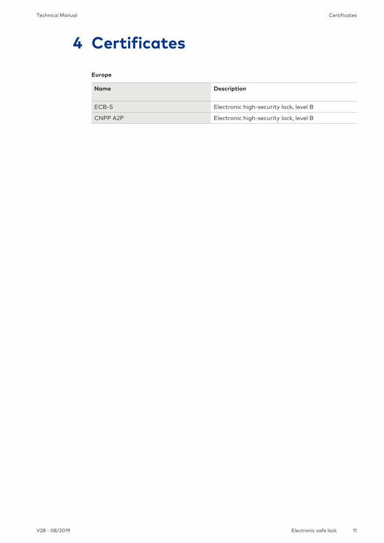
4 Certificates
Europe
Name Description
ECB-S Electronic high-security lock, level B
CNPP A2P Electronic high-security lock, level B

System overview Technical Manual
12 V28 - 08/2019Electronic safe lock
5 System overview
12345678
Input unit
3
2
5
4
1
11
12
10
9
6
8
7
1 Housing 7 MODE key
2 Connecting cable for lock unit 8 LEFT/RIGHT key
3 Interface (USB) for PC connection 9 NUMERIC keys 0...9
4 ENTER key 10 DEL key
5 INFO/ESC key 11 LCD
6 Battery compartment 12 Beeper

System overviewTechnical Manual
13V28 - 08/2019 Electronic safe lock
Lock and optional external power supply
12
34
56
78
Type
Part No.
Serial No.
Version
Certs.
Axessor
XXXXXXXXXX
XXXXX.XXXXXX/XXX
xxxxx.xx
2008
18
17
20
16
15
13
14
13 Lock housing 17 Warranty seal
14 Inputs/outputs 18 Type label
15 Pin for cable tie 19
16 Connection sockets X1 and X2 20 External power supply (optional),6 VDC, 2 A

System description Technical Manual
14 V28 - 08/2019Electronic safe lock
6 System description
6.1 The Axessor USB electronic safe locks
The Axessor USB are motorized deadbolt and latchbolt locks with standard dimensions andintegrated terminals.It is possible to connect the safe locks to an alarm center. The locks comply with all relevantsafety standards.
The electronic safe locks have the following functions:
• Single and multiple safe lock applications
• Code hierarchy with user group management
• Courier Code
• Dual Mode
• Duress Code
• Time Delay
• Time Locking Function
• Remote Disabling
• Code Denial for user
There are 2 options to configure the safe locks:
• Via input unit
• Via AS284-USBW programming software installed on a computer which is connected tothe input unit via a USB cable
Requirements:
When working with AS284-USBW programming software, make sure to comply with mini-mum requirements for the computer and monitor.
• Operating system of the computer: Windows 7 or higher
• Minimum resolution of the monitor: 1280x1024 pixel
6.2 Product variants
6.2.1 Standalone variant with a single lock
12345678
The standalone variant is battery-powered consisting of:
• Input unit
• Lock
• Connecting cable

System descriptionTechnical Manual
15V28 - 08/2019 Electronic safe lock
The lock provides:
• 2 inputs
• 2 outputs
A further option is to connect an external power supply (6V DC/500mA) to the connectionsockets X1 or X2.
Requirements:
• Only use the original Axessor power supply, 6 VDC, 2 A.
• Only use non-rechargeable AA alkaline or AA lithium batteries.
• Batteries must always remain in the battery compartment, even if the external powersupply is connected as they serve as energy source in case of power failure.
6.2.2 Standalone variant with multiple locks
NOTICEBattery discharge and heating up
Operating a safe lock system with 2 input units being powered with batteries will cause a bat-tery discharge due to potential equalization.The battery discharge is faster than in normal conditions and requires an earlier replacementof batteries.Batteries can heat up due to potential equalization.
• Only put batteries in the battery compartment of 1 input unit of a safe lock system.
• Use external power supplies for a safe lock system to support the batteries of the singleequipped input unit with additional energy.
Not more than 10 locks to be connected in a safe lock system.Not more than 4 bolts to be moved at a time. There is a high risk that a motion fault can becaused.
12345678
12345678
12345678
10.1. 2.
It is highly recommended to place the additional external power supply in the last position ofthe locking system. In that way the units will be powered from both sides of the connectionbus.
The standalone variant with multiple locks is battery powered consisting of:
• Up to 2 input units
• Up to 10 locks
• Connecting cables
The locks provide:

System description Technical Manual
16 V28 - 08/2019Electronic safe lock
• 2 inputs
• 2 outputs
The maximum length of the lock bus is 30 meters.
The connection between AS284-USBW programming software and the locking system will beestablished with lock -1- (master lock) via the USB interface. The established connection willbe used from all slave locks.The locks are clearly identified and administered by their serial number and their system ad-dress. The master lock assigns the system addresses to the slave locks and manages the Lockinfo.
Software applicationsTechnical Manual
17V28 - 08/2019 Electronic safe lock
7 Software applications
The AS280 and AS284 software products were not evaluated by UL 2058 and are only forsupplementary use.
Do not use third party USB hubs.
AS284-USBW programming software for the Windows©operating system is applied to con-figure basic settings of the lock such as language, opening time delay, inputs and outputs.

Scope of application Technical Manual
18 V28 - 08/2019Electronic safe lock
8 Scope of application
When using software products, personal data can be recorded and processed.
The provision of art. 6 (1) lit b from EU 2016/679 General Data Protection Regulation (GDPR)shall be applicable if processing of personal data aims to the fulfillment of a contractual orpre-contractual obligation
The electronic safe locks have the following functions for applications in the high security sec-tor:
• Configuring codes and code combinations
• Time functions
• Recall of a detailed event log (audit trail)
• One Time Code operation (optional).
The electronic safe locks are suitable and applicable for:
• Single and multiple safe lock applications
• Multiple users
• Traceability
• Flexibility.

Technical dataTechnical Manual
19V28 - 08/2019 Electronic safe lock
9 Technical data
9.1 Hardware
Hardware type Hardware property Description
Power supply 3 alkaline AA batteries 1.5 V - LR6or 3 lithium AA batteries 1.5 V - FR6
Service life of alkaline batteries:approximately 1-2 years with 1opening/closing cycle per work day
Service life of lithium batteries: ap-proximately twice as long as alka-line batteries
Memory Non-volatile Memory is protected against powerfailure.
Display Iconographic LCD with high con-trast
Display language is selectable bythe user (German, English, French,Italian, Spanish, Portuguese, Dutch,Polish, Hungarian and Turkish).
Keypad Silicone keys (10 numeric, 4 func-tion, 2 navigation keys).
9.2 Interfaces
Interface type Interface property Description
Outputs 2 potential-free contacts for alarm(30VDC/2A, 50VAC/0.5A with re-sistive load)
Output 1: Duress Alarm (factorysetting)
Output 2: Bolt or motor open (fac-tory setting)
It is possible to configure the out-puts via AS284-USBW program-ming software for the followingfunctions:
• Lock open
• Activated Time Delay
• Activated penalty time
• Entry of Duress Code
• Battery compartment open
Inputs Input 1 (signal-triggered 12VDCmin. 13mA, max. 20mA ): not con-figured (factory setting)
Input 2 (contact triggered; poten-tial-free contact only)Do not apply any voltage.
It is possible to configure the inputsvia AS284-USBW programmingsoftware for the following func-tions:
• Remote Disabling
• Door contact
USB USB for data exchange with acomputer
Connection to a computer for theconfiguration with AS284-USBWprogramming software
Axessor bus For connection of the input unit,lock or external power supply.
Max. length is 30 meters
dormakaba proprietary bus system

Technical data Technical Manual
20 V28 - 08/2019Electronic safe lock
9.3 Mechanical components
Lock Component property
Dimensions 85 x 61 x 33 mm
Weight 495 g
Motor bolt Dead bolt or optionally a spring bolt
Relocker Integrated lock relocker
Cycle times Opening/closing: approximately 2 seconds
Static resistance force Maximum: 1000 N in all directions (in end posi-tions)
Moving force Maximum: 5 N in both directions
Service life 50 000 cycles
PCB designation A21-P-01-05_L
Input unit Component property
Dimensions 128 (193) x 90 x 40 mm
Weight 660 g (including connecting cable and batteries)
PCB designation A08-P-03-04
9.4 Conditions
During operation Termperature range
Lock 0 ... +50°C
Input unit 0 ... +50°C
Storage Termperature range
Lock -10 ... +60°C
Input unit -10 ... +60°C

Factory settingsTechnical Manual
21V28 - 08/2019 Electronic safe lock
10 Factory settings
It is possible to select the following display languages:
• English
• French
• German
• Dutch
• Italian
• Spanish
• Hungarian
• Polish
• Portuguese
• Turkish
Function Factory setting Possible to change with
Input unit AS284-USBW
Display Language andInfo Menu Language
English
All languages in the infomenu
On
Master Code 0 0 1 2 3 4 5 6
Master Code opens thelock
On -
Master Code overridesImmediate Time lock(closed state)
On -
Manager Codes (maxi-mum 2 codes)
Off
Functions when ManagerCodes are activated:
Activating the ImmediateTime Lock
On
-
User Codes (except forspecial User Codes)
Off
User Code 41 as Audit andBattery Code
Off -
User code 47 as TimeCode (including Audit andBattery Code)
Off -
Courier Code Off

Factory settings Technical Manual
22 V28 - 08/2019Electronic safe lock
Function Factory setting Possible to change with
Input unit AS284-USBW
Functions when CourierCode is activated:
Bypassing Time Delay andopening the lock only withCourier Code when inDual Mode
On
-
Beep Signal Volume High
A Beep Signal every 30seconds when the lock isopen
On
A Beep Signal every 60seconds while (Duress)Time Delay counts
On
A Beep Signal every 60seconds while the Confir-mation Window counts
On
Number of wrong codesentries before penalty
4 - -
Penalty for wrong codeentries
5 min. - -
Code denial:
Temporary lockout ofManager Codes and usergroups
Temporary lockout of sin-gle users
Off
-
Duress Code Off
Duress Code criterion(last digit)
+/- 1 -
Dual Mode Off
Functions when DualMode is activated:
Any 2 codes On
-
Time Delay 0 min.

Factory settingsTechnical Manual
23V28 - 08/2019 Electronic safe lock
Function Factory setting Possible to change with
Input unit AS284-USBW
Duress Time Delay inBank Mode (per usergroup)
1 min. -
Time Delay and DuressTime Delay
Countdown -
Non Return Time Delay 0 min.
Bolt open time 6 sec.
Process time 2 min. 30 sec.
Confirmation Window 5 min.
Immediate Time Lock Pe-riod
0 min.
Maximum adjustablevalue of the ImmediateTime Lock Period
144 h -
Weekly Locking Period Off
Holiday Locking Period Off
Repeated Holiday LockingPeriod
Off
Date/time JAN 012017
0:00
Time format (12 or 24 h,AM/PM)
24 hours
Change from summer towinter time (DST)and time zone
On(Central European Time)
Remote Disabling viasoftware
Off
Input 1:
One function optionallyassignable:
1. Remote Disabling
2. Controlled Disabling
3. Remote Enabling
4. Cancelling NRTD
Off -

Factory settings Technical Manual
24 V28 - 08/2019Electronic safe lock
Function Factory setting Possible to change with
Input unit AS284-USBW
Input 2:
One function optionallyassignable:
1. Door contact
2. Skipping Time Delay
4. Remote Disabling
5. Controlled Disabling
Off -
Output 1:
Duress alarm
On -
Output 2:
Lock opening (OR Bool-ean operation with lock ormotor open)
On -

FunctionalityTechnical Manual
25V28 - 08/2019 Electronic safe lock
11 Functionality
11.1 Display elements of the input unit
9
8
7
1
16
17
11 12 13
1918 20
14 15
3
4
5
6
210
1 LCD 11 Menu TIME
2 Beeper 12 Menu PROG
3 DEL key 13 Menu DELAY
4 NUMERIC keys 0 ... 9 14 Menu CODE
5 LEFT key 15 Menu MISC
6 MODE key 16 Symbol "lock open", "lock closed"
7 RIGHT key 17 Symbol "replace batteries"
8 INFO/ESC key 18 Symbol "warning"
9 ENTER key 19 Time format (12/24 h)
10 USB port 20 Text lines
11.2 Information menu
By pressing the INFO/ESC key, it is possible to change the display language in the informationmenu any time, even if the lock is closed.
By pressing the INFO/ESC key the information menu is accessible while the display shows ei-ther "OPEN" or "LOCKED".
By pressing several times the INFO/ESC key or the arrow keys, it is possible to query the fol-lowing information in the information menu:
• Display language
• Battery condition (in percent of the nominal capacity)
• Opening counter
• Serial number
• Wait 000:00 (if this setting was chosen).The numbers 000:00 stand for "hours:minutes".

Functionality Technical Manual
26 V28 - 08/2019Electronic safe lock
11.3 Beep signals
It is possible to deactivate the beep signal via AS284-USBW programming software when thedisplay shows "OPEN" (for open lock), "WAIT" (for Time Delay) and "CONF" (for Confirma-tion Window).It is also possible to set the beep signal volume to high/low or to deactivate it.
Type of beep signal Duration Display Cause
1 short beep Key stroke
1 short, low-fre-quency beep
REFUSED Action refused
1 short beep Every 60 seconds WAIT Time Delay or DuressTime Delay is activated.
3 short beeps Every 60 seconds CONF The Confirmation Win-dow is activated.After the Time Delay isover, it is possible to enterthe confirmation code.
10 short beeps Every 10 seconds BAT-CMP OPEN The Battery Compart-ment was opened.
10 short beeps Every 10 seconds OPEN The lock is open.
11.4 Status messages
11.4.1 Bank Mode
Bank Mode
• Bank Mode is the factory setting and standard operating mode for all products.
• In Bank Mode the unit runs standalone according to the configuration.
Locked -3- (Bank Mode)
The lock -3- is mechanically closed.It is possible to connect up to 10 locks in a safe lock system.After 3 seconds the current time will be displayed instead of the lock position.
Locked
The lock is mechanically closed.The current time is displayed.It is possible to open the lock by entering a valid code.
Open

FunctionalityTechnical Manual
27V28 - 08/2019 Electronic safe lock
The lock is mechanically open.The status message "OPEN" is displayed.It is possible to unlock the bolt work or safe door during the set Bolt Open Time.Factory setting for Bolt Open Time: 6 seconds.If the bolt work was not unlocked, the lock closes automatically after the set Bolt Open Timehas elapsed.
Immediate Time Lock
The lock is closed with the Immediate Time Lock function.It is not possible to open the lock. The current time is displayed.It is only possible to open the lock by entering a valid code once the set locking period haselapsed.
Weekly Time Locking
The lock is in a weekly locking period. It is not possible to open the lock, unless it was configured that the "Master can bypass TimeLock".The current time is displayed.It is only possible to open the lock by entering a valid code once the set locking period haselapsed.
Holiday Time Locking
The lock is in a holiday locking period.It is not possible to open the lock.The current time is displayed.It is only possible to open the lock by entering a valid code once the set locking period haselapsed.
Opening Time Delay
After entering a valid code to open the lock, the set Time Delay starts counting.The remaining time is displayed.Every 60 seconds a beep signal sounds.After the counter has elapsed, the end of the Time Delay is indicated with another beep sig-nal.The Courier Code overrides a Time Delay, if not otherwise defined.
Confirmation after elapsed Time Delay
After the Time Delay has elapsed, a valid code must be entered as confirmation within a settime period .It is possible to enter 2 different valid codes before and after the Time Delay.The remaining time window is displayed to enter the code.After entering the Courier Code, the CONF display is shown.If the Courier Code opens the lock, but skips Time Delay, the opening procedure will start dur-ing the countdown.

Functionality Technical Manual
28 V28 - 08/2019Electronic safe lock
Every 60 seconds a beep signal sounds.If the code is not confirmed, the lock will return automatically to the closed status once thecounter reached 00:00.
By pressing the DEL key, the lock automatically returns to the LOCKED status.If the Dual Mode is activated, 2 codes must be entered as confirmation, the sequence is irrele-vant.The codes must comply with the settings made via AS284-USBW programming software:„any two codes“.
Entering second code - Dual Mode activated
If the Dual Mode is activated, 2 codes must be entered to open the lock.The message shown on the display prompts the user to enter a second code.
Master Code and Courier Code override the Dual Mode.It is possible to open the lock without any additional code, if not otherwise defined.
Penalty after wrong codes
After having entered 4 times an incorrect code, a time penalty of 5 minutes is initiated.During this time period it is not possible to enter a code, neither to bypass nor to cancel theprocedure.The remaining penalty time is displayed.
Remote Disabling
It is possible to deactivate the local opening of the lock by a remote disabling signal.There are 3 options to deactivate the lock opening:
1 By a constant input signal
2 Via AS284-USBW programming software or
3 the status message RMT-DIS is displayed when Remote Disabling is activated.During that time the lock is closed.
In case of a failure caused by a device (a broken alarm interface or an alarm interface withoutpower) transmitting an input signal, the Master Code is able to override Remote Disabling toprevent a total lock-out when the external signal fails.
Identification with denied code
It is possible to deny codes with a superior code.These codes are declared invalid for a certain time period until these codes are permittedagain.When identifying with a denied code, the status message DENIED will be displayed.The selected function will not be executed, the lock condition remains unchanged.

FunctionalityTechnical Manual
29V28 - 08/2019 Electronic safe lock
The same status message will be displayed when trying to open the lock by using the MasterCode which was set to "cannot open".
The battery compartment was opened
The status message BAT-CMP is displayed if:
1 the lock is open while the battery compartment was opened
2 the lock is closed and the battery compartment was opened and closed again.
It is possible to delete the status message by entering a valid Manager, Master or BatteryCode (User Codes 41 or 47).
Connection to a programming software
The input unit is not operative and all keys are deactivated when the lock is connected to acomputer via USB cable and data exchange with AS284-USBW programming software is inprogress.
External power supply available
A dot is shown on the display if an external power supply is available for the lock.This status message is updated every full hour.The graphic only shows the dot icon and no other information.
Active input unit
An input unit with asterisk indicates an active device with version number 28.
Passive input unit
An input unit without asterisk indicates a passive device with version number 28.
11.5 Access codes
11.5.1 Code hierarchy and code formats
Several codes are available for configuring and operating:
• Master Code
• Manager Code
• User Codes
• Courier Code
Each code consists of:
• An 8-digit number which is composed of an ID and a PIN.

Functionality Technical Manual
30 V28 - 08/2019Electronic safe lock
• The ID consists of 2 digits which are predefined and identify the code
• The PIN consists of the remaining 6 digits. It is possible to choose the PIN individually
Code type Possible person in charge Description
1 Master Code (8 digits) Safety officer, head of se-curity
With the Master Code it is possibleto open the lock without using anyadditional code, even if Dual Modeis configured.
it is possible to set the MasterCode as "can open lock" via AS284-USBW programming software
2 Manager Codes (8 dig-its)
Head cashier, shift man-ager
In the AS284-USB programmingsoftware the Manager Codes arefix set as "can open the lock".
18 User Codes (8 digits) Cashier, sales assistant There are 2 user groups with 9users each assigned to a respectiveManager Code.
It is possible to activate/deactivatethe lock opening via AS284-USBWprogramming software.
1 Courier Code (8 digits) Auditor, CIT (Cash InTransit service provider)
With the Courier Code it is possibleto open the lock in Dual Mode.
It is possible to set the lock as"does not open but skips Time De-lay" for the next opening viaAS284-USBW programming soft-ware.
Special code function Description
Duress Code If this function is activated, it is possible to exe-cute the Duress Code by any of the code types.
Dual Mode For the Dual Mode 2 codes are needed to openthe lock.
When opening the lock with Master Code orCourier Code, no second code is needed.
Code Denial With this function it is possible to activate or de-activate individual codes or entire code groups.
11.5.2 Code types
The factory set Master Code 0 0 1 2 3 4 5 6 is identical for all locks of this type.This code must not be used for operation.Upon initialization and testing the Master Code must be changed.

FunctionalityTechnical Manual
31V28 - 08/2019 Electronic safe lock
Master Code
0 0 x x x x x x
Manager 1
1 0 x x x x x x
User 15
1 5 x x x x x x
User 11
1 1 x x x x x x
User 14
1 4 x x x x x x
User 12
1 2 x x x x x x
User 13
1 3 x x x x x x
User 18
1 8 x x x x x x
User 19
1 9 x x x x x x
Use
r G
rou
p 1
User 16
1 6 x x x x x x
User 17
1 7 x x x x x x
Manager 2
2 0 x x x x x x
User 25
2 5 x x x x x x
User 21
2 1 x x x x x x
User 24
2 4 x x x x x x
User 22
2 2 x x x x x x
User 23
2 3 x x x x x x
User 28
2 8 x x x x x x
User 29
2 9 x x x x x x
Use
r G
rou
p 2
User 16
2 6 x x x x x x
User 17
2 7 x x x x x x
Courier Code
9 0 x x x x x x
11.5.2.1 Master Code
It is important to personalize all codes of the unit during commissioning and start-up.Do not use easy number combinations such as 11223344, 12345678 or personal data (for exam-ple birthdays).For safety reasons it is important to change codes at regular intervals.
The Master Code is the highest code in the code hierarchy.It cannot be deleted.
Factory setting 0 0 1 2 3 4 5 6
Function Opening the lock (even if only in Dual Mode)Changing all codesAccess to all functions
It is only possible to delete and redefine lost codes with a higher codeKeep in mind that it is neither possible to retrieve nor to restore a lost Master Code.There is no super code.
Master Code func-tion
Description Displayed statusmessage
Result
"Can open lock" The Master Code is en-tered to open the lock.
DENIED The lock does notopen.
"Can override Imme-diate Time Lock"
The Master Code is en-tered and the function"can override ImmediateTime Lock" is activated.The Master Code is ableto reset the ImmediateTime Lock even during anactivated ImmediateTime Locking period.
The lock opens.

Functionality Technical Manual
32 V28 - 08/2019Electronic safe lock
"Can override the re-mote disabling signalor remote disabledstate"
The Master Code is en-tered. The Master Code is ableto override a remote dis-abling signal or disabledstate if a remote enablingsignal is missing.
This prevents a com-plete lock-out.
11.5.2.2 Manager Codes
There are 2 Manager Codes available:
• Manager Code ID 10
• Manager Code ID 20
Each Manager Code is able to administrate a group of User Codes.
Factory setting No code assigned
Function Opening the lock Changing the Manager CodeActivating, changing and deleting subordinated User CodesAllowing and denying subordinated user groupsChanging the subordinated Time Delay and Confirmation Win-dowActivating the Immediate Time Lock function
Manager Codefunction
Description Displayed status message Result
"Can open thelock"
The ManagerCode is entered.
DENIED The lock does not open.
"Cannot acti-vate the Imme-diate TimeLock"
The Program-ming Mode isentered with adefined Man-ager Code set-ting.
The corresponding sub-menus are not accessibleany more.
"Can changeTime Delays"
This setting is fixset in AS284-USBW program-ming software.
"Can changeConfirmation"
This setting is fixset in AS284-USBW program-ming software.
11.5.2.3 User Codes with special functions
User Code Description Result
All User Codes It is possible to define the UserCodes as "can activate the Im-mediate Time Lock".
If this function is activated, allusers have access to the submenuIMM-TL.
User Code 41 In AS284-USBW programmingsoftware the User Code 41 isfix set as Audit Code and Bat-tery Code.
The User Code 41 cannot beused to open the lock.
The user can get an audit of thelock.
When trying to open the lock withthe User Code 41, the message"DENIED" will be displayed.

FunctionalityTechnical Manual
33V28 - 08/2019 Electronic safe lock
User Code Description Result
The user can reset the batterymessage after the battery com-partment had been opened.
User Code 47 In AS284-USBW programmingsoftware the User Code 47 isfix set as Time, Audit and Bat-tery Code.
The User Code 47 has access to allfunctions relating time, date,weekly and holiday programs.
It is not possible to open the lockwith User Code 47.
The user can either read the auditor reset the battery message afterthe battery compartment had beenopened.
11.5.2.4 Courier Code
There is only 1 Courier Code (Courier Code ID 90) which is provided for special staff fromCash-In Transit services (CIT) responsible for filling or emptying secured containers withoutany configured Time Delays.
Factory setting: No code assigned
Functions: Opening the lock, even in Dual Mode by bypassing aTime DelayAlteration of Courier Code
11.5.2.5 Duress Code
To activate a duress alarm, the value 1 must be added to or deducted from the last digit of acode.It is possible to activate a duress alarm with all code types at any time.
Example for generating a Duress Code:
Code Duress Code
00123456 00123457 or 00123455
00000000 00000001 or 00000009
00999999 00999990 or 00999998
After entering a Duress Code, the duress status remains until the Duress Time Delay haselapsed and the lock will be opened with 1 Non-Duress Code and closed again.
11.5.2.5.1 Shelve Function
The Shelve Function is only available if the Programming Mode is accessed with the MasterCode.With the Shelve Function it is possible to reset all codes, parameters and data for examplelocking periods, time delays etc. to factory default settings.
The following settings remain unchanged:
• Audit Trail
• Opening Counter and
• Time/Date.

Access rights Technical Manual
34 V28 - 08/2019Electronic safe lock
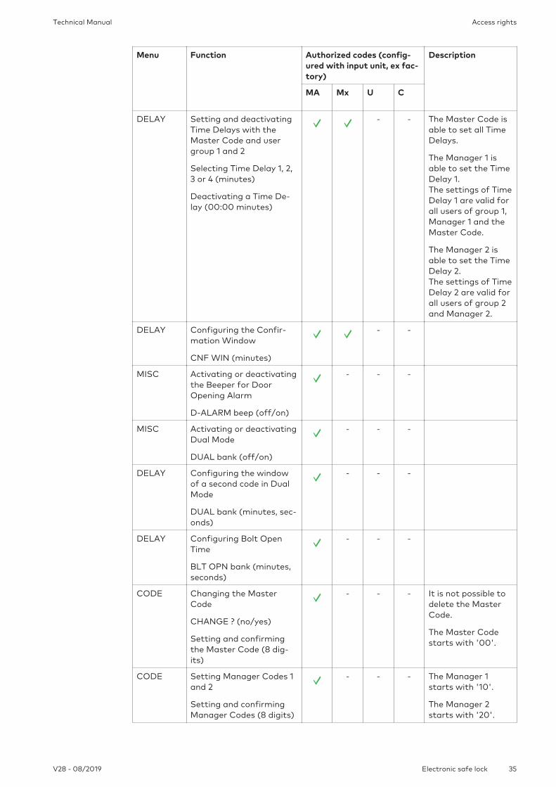
12 Access rights
Authorization is given to:
• MA (Master)
• Mx (Manager 1 and 2)
• U (User)
• C (Courier)
Menu Function Authorized codes (config-ured with input unit, ex fac-tory)
Description
MA Mx U C
TIME Setting the time (hours,minutes)
Setting the date (month,day, year)
Setting the time formatAM/PM (off: 24 hours /on: AM/PM)
Setting DST (off/on: Cen-tral European Time)
- - -
PROG Activating or deactivatingthe Immediate Time Lock(00:00 minutes)
Duration (hours, minutes)
- - - -
PROG Adding, changing ordeleting Weekly LockingPeriods
Defining a starting andendpoint for WeeklyLocking Periods (week-days, hours, minutes)
- - -
PROG Adding, changing anddeleting Holiday LockingPeriods
Defining a starting andendpoint for HolidayLocking Periods (week-days, hours, minutes)
- - -
Access rightsTechnical Manual
35V28 - 08/2019 Electronic safe lock
Menu Function Authorized codes (config-ured with input unit, ex fac-tory)
Description
MA Mx U C
DELAY Setting and deactivatingTime Delays with theMaster Code and usergroup 1 and 2
Selecting Time Delay 1, 2,3 or 4 (minutes)
Deactivating a Time De-lay (00:00 minutes)
- - The Master Code isable to set all TimeDelays.
The Manager 1 isable to set the TimeDelay 1. The settings of TimeDelay 1 are valid forall users of group 1,Manager 1 and theMaster Code.
The Manager 2 isable to set the TimeDelay 2.The settings of TimeDelay 2 are valid forall users of group 2and Manager 2.
DELAY Configuring the Confir-mation Window
CNF WIN (minutes)
- -
MISC Activating or deactivatingthe Beeper for DoorOpening Alarm
D-ALARM beep (off/on)
- - -
MISC Activating or deactivatingDual Mode
DUAL bank (off/on)
- - -
DELAY Configuring the windowof a second code in DualMode
DUAL bank (minutes, sec-onds)
- - -
DELAY Configuring Bolt OpenTime
BLT OPN bank (minutes,seconds)
- - -
CODE Changing the MasterCode
CHANGE ? (no/yes)
Setting and confirmingthe Master Code (8 dig-its)
- - - It is not possible todelete the MasterCode.
The Master Codestarts with '00'.
CODE Setting Manager Codes 1and 2
Setting and confirmingManager Codes (8 digits)
- - - The Manager 1starts with '10'.
The Manager 2starts with '20'.

Access rights Technical Manual
36 V28 - 08/2019Electronic safe lock
Menu Function Authorized codes (config-ured with input unit, ex fac-tory)
Description
MA Mx U C
CODE Changing Manager Codes1 and 2
CHANGE ? (no/yes)
Confirming a ManagerCode (8 digits)
- - The Manager 1starts with '10'.
The Manager 2starts with '20'.
PROG Deleting Manager Codesof Manager 1 and 2
CLEAR ? (no/yes)
- - - It is only possible todelete ManagerCodes with theMaster Code.
PROG Setting User Codes ofuser group 1 and 2
Setting and confirming aUser Code (8 digits)
- - User group 1 in-cludes users '11' ...19'
User group 2 in-cludes users '21'…'29'
CODE Changing User Codes ofuser group 1 and 2
CHANGE ? (no/yes)
Setting and confirmingUser Codes (8 digits)
-
CODE Deleting User Codes ofuser group 1
CLEAR ? (no/yes)
- - It is only possible todelete User Codeswith a higher code.
CODE Setting the Courier Code
Setting and confirmingthe Courier Code (8 dig-its) (8 digits)
- - - The Courier Codestarts with '90'.
CODE Changing the CourierCode
CHANGE ? (no/yes)
Setting and confirmingthe Courier Code (8 dig-its)
- -
CODE Deleting the Courier Code
CLEAR ? (no/yes)
- - - It is only possible todelete Courier Codewith the MasterCode.
CODE Resetting the electronicsafe lock (shelve)
SURE ? (no/yes)
- - -
MISC Setting the Display Lan-guage
- -
MISC Managing the safe locksystem with the DeviceManager
- - - Slave locks have alimited range offunctions comparedto the master lock.

Access rightsTechnical Manual
37V28 - 08/2019 Electronic safe lock
Menu Function Authorized codes (config-ured with input unit, ex fac-tory)
Description
MA Mx U C
MISC Activating or deactivatingRemote Disabling
RMT-DIS (off/on)
- - -
MISC Setting the Beeper Vol-ume
VOLUME (off = 000 /medium = 001 / loud =002)
- - -
MISC Activating or deactivatingthe Open Beeper
OPEN beep (off/on)
- - -
MISC Activating or deactivatingthe Beeper for Confirma-tion Window
CNF WIN beep (off/on)
- - -
MISC Activating or deactivatingthe Beeper Time Delay
DELAY beep (off/on)
- - -
MISC Activating or deactivatingthe Waiting Time
WAIT info (off/on)
- - -
MISC Activating or deactivatingthe Language Info
LANG info (each of the 10languages is off/on)
- - - When a language isset to "on", the re-spective languagewill be displayed inthe Info Menu.
MISC Setting the Lock Info
LOCK info (off/on)
- - - It is only possiblethe set the Lock infowith the masterlock.
MISC Activating or deactivatingthe Code Denial
GROUP 1 (off/on)MANAG 1 (off/on)
GROUP 2 (off/on)MANAG 2 (off/on)
- - - The Master Code isable to activate ordeactivate eachManager or usergroup.
MISC Activating or deactivatingthe Code Denial
GROUP 1 (off/on)
- - The Manager 1 isonly able to activateor deactivate usergroup 1.When the Code De-nial is set to "on",the codes of usergroup 1 will be deac-tivated.

Access rights Technical Manual
38 V28 - 08/2019Electronic safe lock
Menu Function Authorized codes (config-ured with input unit, ex fac-tory)
Description
MA Mx U C
MISC Activating or deactivatingCode Denial Bank Mode
GROUP 2 (off/on)
- - The Manager 2 isonly able to activateor deactivate usergroup 2.When the Code De-nial is set to "on",the codes of usergroup 2 will be de-activated.
MISC Activating or deactivatingthe Duress Code
DURESS bank (off/on)
- - -
MISC Setting the functionFreeze
FREEZE (off/on)
- - - It is only possible toset the functionFreeze with themaster lock.
Resetting the batterymessage "BAT-CMPopen"
- - The Master or aManager Code mustbe entered to resetthe battery mes-sage.
Reading Audits in AS284-USBW
- - - The Master Codemust be entered inAS284-USBW toread an Audit.
Menu Function Authorized codes (set inAS284-USBW program-ming software)
Description
Mx U
TIME Setting the time (hours,minutes)
Setting the date (month,day, year)
Setting the time formatAM/PM (off: 24hours/on:AM/PM)
Setting DST (off/on: Cen-tral European Time)
- User Code 47 is setfix as Time Code inAS284-USBW pro-gramming software.
PROG Activating or deactivatingthe Immediate Time Lock(00:00 minutes)
Duration (hours, minutes)
- The Immediate TimeLock is activatedwhen users are en-abled to activate thisfunction.

Access rightsTechnical Manual
39V28 - 08/2019 Electronic safe lock
Menu Function Authorized codes (set inAS284-USBW program-ming software)
Description
Mx U
PROG Adding, changing ordeleting Weekly LockingPeriods
Defining a starting andendpoint for WeeklyLocking Periods (week-days, hours, minutes)
- User Code 47 is setfix as Time Code inAS284-USBW pro-gramming software.
PROG Adding, changing anddeleting Holiday LockingPeriods
Defining a starting andendpoint for HolidayLocking Periods (week-days, hours, minutes)
- User Code 47 is setfix as Time Code inAS284-USBW pro-gramming software.
Resetting the batterymessage "BAT-CMPopen"
- User Codes 41 and 47are set fix as BatteryCode in AS284-USBW programmingsoftware.
Reading Audits viaAS284-USBW
- User Codes 41 and 47are set fix as AuditCode in AS284-USBW programmingsoftware.

Unpacking and checking delivery Technical Manual
40 V28 - 08/2019Electronic safe lock
13 Unpacking and checking delivery
13.1 Checks before installation
Requirements:
• Unpack the delivery.
• Make sure that the content is complete.
Make sure that the delivery includes:
• Input unit
• Lock
• Connecting cable
• Plastic bag with installation material
• 3 professional alkaline batteries, industrial by DURACELL®
• Instruction leaflet with further information and reference to the website
Make sure that the optional computer software packages include:
• AS284-USBW: USB cable, 1 operator dongle (blue), 1 instruction page

InstallationTechnical Manual
41V28 - 08/2019 Electronic safe lock
14 Installation
NOTICELockout of secure storage units
Closing the door of a secure storage unit while lock installation is not fully completed, willcause a lockout of secure storage units.
• Do not close the door of a secure storage unit until all installation steps are successfullycompleted.
14.1 Drilling templates
Input unit template
40
41.3
55
10
4 x M4
1
3
2
6
10
65
4
19
3
90
mm
inch
50
10
0
12
34
00

Installation Technical Manual
42 V28 - 08/2019Electronic safe lock
Lock template
1 2 3 4 5 6 7 8
mm
inch
50
10
0
12
34
00
66
.77
.9
11
.5
41.33 x Ø5
25.217.9 17.9
14.2 Installing the input unit
NOTICEImproper installation of the input unit
Changing the installation sequence will cause damage to the input unit
• Do not skip installation steps.
• Follow the described installation sequence.
As a requirement of EN 1300 the input unit must be installed onto the safe.

InstallationTechnical Manual
43V28 - 08/2019 Electronic safe lock
40
41.3
55
10
4 x M4
1
3
2
6
106
5
4
19
3
90
Installing the base plate
If the lock is installed directly behind the spindle hole and no other measure was chosen, a drillprotection plate is required for UL approved retrofit installation.
Fastening screws must be secured against loosening, e.g. by using threadlocking adhesivesuch as Loctite 243 (medium strength, blue).
1. Use the drilling template.
2. Mark either fixation holes 3 and 5 or 2 and 4 plus fixation hole 1 .
3. Also mark the fixation hole 6 for the cable feed-through.
4. Drill 3 fixation holes Ø3.2x14 mm.
5. Drill 1 hole Ø10 mm for the cable feed-through.
6. Remove burrs.

Installation Technical Manual
44 V28 - 08/2019Electronic safe lock
7. Install M4 threads into the fixation holes.
8. Remove the 3 screws from the bottom of the cover (1 installed in the battery compart-ment, 2 installed in the housing).
9. Remove the cover from the base plate.
10. Carefully remove the battery compartment.
11. Install the base plate with the special M4x12 flat-head screws onto the door.
ð The input unit must be installed onto the door with at least 2 oppositely positionedscrews.
ð The third screw is recommended (position 1).

InstallationTechnical Manual
45V28 - 08/2019 Electronic safe lock
NOTICEExcessive mechanical stress on cables
Excessive mechanical stress on cables will cause damage to the insulation and conductor.
• Keep cables away from moving parts.
• Do not squeeze cables.
• Do not fold cables.
• Do not route cables along sharp edges.
Connecting cables
1. Carefully route the connecting cable through the Ø10mm cable feed-through in the door.
2. Carefully feed the connecting cable into the lock chamber.
Installing the battery compartment
Requirements:
• Make sure not to squeeze the cable.
• Make sure that the battery compartment is freemoving.
• Make sure that the spiral cable is flattened when moving the battery compartment.
• Make sure that the spiral cable does not move in other directions when it is extended andcompressed.
1. Install the battery compartment in place.

Installation Technical Manual
46 V28 - 08/2019Electronic safe lock
2. Carefully route the battery cable through the strain relief guides of the battery compart-ment and the base plate.
3. Place the cover on top of the base plate in an angle >90°.
4. Plug the battery cable into the 2-pole connector terminal and the connecting cable intothe 6-pole connector terminal.
5. Make sure that the position of the plugs is correct before connecting the plugs.
6. Do not use excessive force to plug-in, but make sure that proper connection is given.

InstallationTechnical Manual
47V28 - 08/2019 Electronic safe lock
Installing the cover
1. Engage the cover in the notch on top of base plate.
2. Slowly hinge down the cover onto the base plate while carefully routing the connectingcable to the lock chamber.
3. Leave a spare loop.
4. Make sure that the cables will not be squeezed.
5. Make sure that the battery compartment is freemoving.
6. Carefully place the battery compartment in the right position.
7. Remove it again.
8. Install the cover onto the base plate using 2 M3x6 countersunk screws.

Installation Technical Manual
48 V28 - 08/2019Electronic safe lock
9. Make sure that the battery compartment is freemoving.
10. Carefully place the battery compartment in the right position.
11. Remove it again.
12. Do not put the batteries into the battery compartment.
13. Do not install the screw for the battery compartment yet.
14.3 Installing the lock
Do neither remove nor damage the warranty seal.This voids warranty.
Do neither remove nor damage the VdS label.This voids VdS approval.
The fixation holes of the drilling template are standardized.
1. Mark 3 fixation holes (A) according to the drilling template for input unit.
12
34
56
78
66.7 7.9
11.5
41
.33
x Ø
5
25
.21
7.9
17
.9
A A
A
2. Drill fixation holes with Ø5mm.

InstallationTechnical Manual
49V28 - 08/2019 Electronic safe lock
3. Remove the burrs.
4. Install M6 threads into the fixation holes.
5. Install the lock with the three M6x10 screws (it is also possible to use similar inch screws).
6. Make sure that the screw heads rest on the base of the shouldered fixation hole.
7. Make sure to keep the space underneath the lock free for a re-closable system or a con-necting cable.
8. If the lock is to be operated in spring bolt function, remove the retainer screw (B) under-neath the VdS label.
12
34
56
78 Type
Part No.
Serial No.
Version
Certs.
AXESSOR
XXXXXXXXXX
XXXXX.XXXXXX/XXX
xxxxx.xx2017
VdS
B
Pay attention that the operating mode in spring bolt function voids VdS approval.
9. If needed, use two M4 threads in the front end of the lock bolt to fasten an extension.
15
2 x
M4
13
2.5
25
.2
7.8
10. Observe the maximum force of 5N in both directions.
Installation Technical Manual
50 V28 - 08/2019Electronic safe lock
12
34
56
78
ma
x. 1
00
0N
max. 5N
ma
x. 1
00
0N
max. 1000N
Type
Part No.
Serial No.
Version
Certs.
AXESSOR
XXXXXXXXXX
XXXXX.XXXXXX/XXX
xxxxx.xx2017
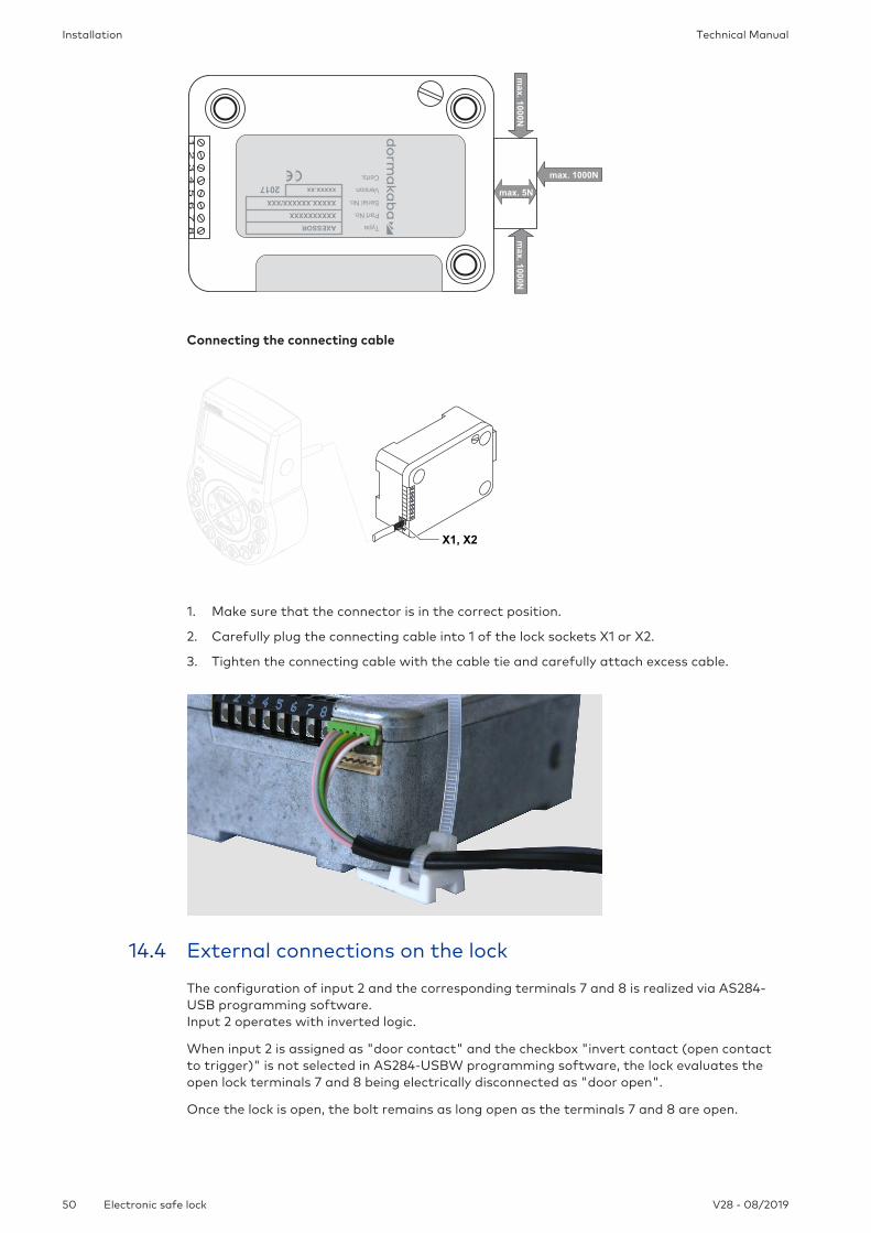
Connecting the connecting cable
12345678
X1, X2
1. Make sure that the connector is in the correct position.
2. Carefully plug the connecting cable into 1 of the lock sockets X1 or X2.
3. Tighten the connecting cable with the cable tie and carefully attach excess cable.
14.4 External connections on the lock
The configuration of input 2 and the corresponding terminals 7 and 8 is realized via AS284-USB programming software.Input 2 operates with inverted logic.
When input 2 is assigned as "door contact" and the checkbox "invert contact (open contactto trigger)" is not selected in AS284-USBW programming software, the lock evaluates theopen lock terminals 7 and 8 being electrically disconnected as "door open".
Once the lock is open, the bolt remains as long open as the terminals 7 and 8 are open.

InstallationTechnical Manual
51V28 - 08/2019 Electronic safe lock
When a micro switch is connected to input 2 and the closed micro switch indicates the status"door open", both checkboxes "Invert input (open contact to trigger)" and "door contact"must be selected in AS284-USBW programming software for a smooth operation.
It is possible to connect additional external signals to the lock terminal block.
It is possible to change the function and polarity of inputs and outputs with AS284-USBWprogramming software.
12
34
56
78
IN2
GND
IN1+
IN1-
OUT1 A
OUT1 B
OUT2 A
OUT2 B
Terminals Description Unit Remarks
1/2 Output 2Factory setting: lock open (ORBoolean operation with boltand motor )
30VDC/2A Relay with potential-freeworking contacts NO(normally open). Contactis open when lock isclosed.
3/4 Output 1Factory setting duress alarm
50VAC/0.5Awith resistiveload
Relay with potential-freeworking contacts NO(normally open). Contactis closed when duressalarm is activated.
5(-)/6(+) Input 1Factory setting not assignedOptional: remote disabling orcontrolled disabling
9 ...18VDC (mini-mum 13mA andmaximum20mA)
7/8 Input 2Factory setting: not assigned,configurable via AS284-USBWprogramming software
Optional:
• Door contact
• Skip Time Delay
• Time Locking Interruptionand
• external input event A - F
Potential-freecontact
Do not apply any voltage,potential-free contactonly.
Use a suitable microswitch with gold-platedcontacts 12VDC/50mA (e.g. DB se-ries by Cherry).
If input 2 is assigned as"door contact" and notinverted, an open switchcontact is used as "dooropen".The bolt is as long open asterminals 7 / 8 are electri-cally disconnected.

Installation Technical Manual
52 V28 - 08/2019Electronic safe lock
1 2 3 4 5 6 7 8 X1
X2
Sockets Description Remarks
X1, X2 Connection for input unit or connec-tion for power supply
Use the enclosed connecting cable.Only use the original Axessor powersupply.
14.5 Wiring
There are 2 options to set up a safe lock system:
– Cold plugging
– Hot plugging
The higher the number of used components and the bigger the distances between the compo-nents, it is important to follow this rule:
– To create a wiring loop if the distance between the components is rather high.
– To connect the power supply with a maximum distance from the input unit.
14.5.1 Cold plugging
When wiring a safe lock system neither put batteries in the battery compartment nor connectan external power supply to the last position of the safe lock system.
The following instruction describes the setting up of a standard safe lock system with all op-tional devices (a second input unit and an external power supply).
It is assumed that the locks have only factory settings.The functions Freeze and Lock info are set to OFF on the master lock.
Connecting an input unit and locks
1. Connect the connecting cable from the 6-pole connector terminal of the input unit to ter-minal X1 of the first lock.
2. Connect the connecting cable from terminal X2 of the first lock to terminal X1 of the sec-ond lock.
3. Repeat the step before for the remaining locks.
Connecting an optional external power supply
1. Plug the external 6 VDC power supply to terminal X2 of the last lock.
2. Do not connect the power supply to the line voltage.
Connecting a second optional input unit
1. Connect the connecting cable from terminal X2 of the last lock to the 6-pole connectorterminal of the second input unit.
2. Do not put batteries in battery compartment of the second input unit.
InstallationTechnical Manual
53V28 - 08/2019 Electronic safe lock
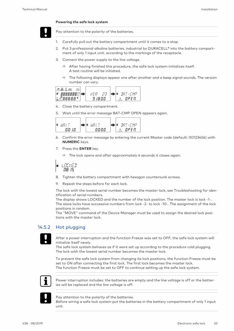
Powering the safe lock system
Pay attention to the polarity of the batteries.
1. Carefully pull out the battery compartment until it comes to a stop.
2. Put 3 professional alkaline batteries, industrial by DURACELL® into the battery compart-ment of only 1 input unit. according to the markings of the receptacle.
3. Connect the power supply to the line voltage.
ð After having finished this procedure, the safe lock system initializes itself.A test routine will be initiated.
ð The following displays appear one after another and a beep signal sounds. The versionnumber can vary.
4. Close the battery compartment.
5. Wait until the error message BAT-CMP OPEN appears again.
6. Confirm the error message by entering the current Master code (default: 00123456) withNUMERIC keys.
7. Press the ENTER key.
ð The lock opens and after approximately 6 seconds it closes again.
8. Tighten the battery compartment with hexagon countersunk screws.
9. Repeat the steps before for each lock.
The lock with the lowest serial number becomes the master lock, see Troubleshooting for iden-tification of serial numbers.The display shows LOCKED and the number of the lock position. The master lock is lock -1-.The slave locks have successive numbers from lock -2- to lock -10-. The assignment of the lockpositions is random.The "MOVE" command of the Device Manager must be used to assign the desired lock posi-tions with the master lock.
14.5.2 Hot plugging
After a power interruption and the function Freeze was set to OFF, the safe lock system willinitialize itself newly.The safe lock system behaves as if it were set up according to the procedure cold plugging.The lock with the lowest serial number becomes the master lock.
To prevent the safe lock system from changing its lock positions, the function Freeze must beset to ON after connecting the first lock. The first lock becomes the master lock. The function Freeze must be set to OFF to continue setting up the safe lock system.
Power interruption includes: the batteries are empty and the line voltage is off or the batter-ies will be replaced and the line voltage is off.
Pay attention to the polarity of the batteries. Before wiring a safe lock system put the batteries in the battery compartment of only 1 inputunit.

Installation Technical Manual
54 V28 - 08/2019Electronic safe lock
It is assumed that the locks have only factory settings.The functions Freeze and Lock info are set to OFF on the master lock.
Connecting the input unit and the master lock
1. Carefully pull out the battery compartment until it comes to a stop.
2. Put 3 professional alkaline batteries, industrial by DURACELL® into the battery compart-ment according to the markings in the receptacle.
3. Connect the connecting cable from the 6-pole connector terminal of the input unit to ter-minal X1 of lock -1-.
ð The lock -1- becomes the master lock.
ð After connecting the lock, a test routine will be initiated.The following displays appear one after another and a beep signal sounds. The versionnumber can vary.
4. Close the battery compartment.
5. Wait until the error message BAT-CMP OPEN appears again.
6. Confirm the error message by entering the current Master Code (default: 00123456) withNUMERIC keys.
7. Press the ENTER key.
ð The lock opens. After approximately 6 seconds it closes again.
8. Tighten the battery compartment with hexagon countersunk screws.
Connecting the slave locks
1. Connect the connecting cable from terminal X2 of lock -1- to terminal X1 of lock -2- .
2. Repeat the step before for the remaining slave locks.
ð A test routine will be initiated. When the error message BAT-CMP OPEN appears, the Master Code must be entered.
Connecting an optional external power supply
1. Plug the external 6 VDC power supply to terminal X2 of the last lock.
2. Connect the power supply to the line voltage.
Connecting a second optional input unit
1. Connect the connecting cable from terminal X2 of the last lock to the 6-pole connectorterminal of the second input unit.
2. Do not put batteries in battery compartment of the second input unit.
Safe lock system after finalized hot plugging procedureThe display shows LOCKED and the number of the lock position. The master lock is lock -1-.The slave locks have successive numbers from lock -2- to lock -10-. The assignment of the lockpositions corresponds to the sequence of the connected locks.

InstallationTechnical Manual
55V28 - 08/2019 Electronic safe lock
14.5.3 Wiring options
Wiring the door contact
12345678
Interlocking of multiple locksExample for 1 lock opens at a time within a safe lock system with 3 locks.
The following settings must be entered in AS284-USBW or AS284- NETW programming soft-ware:
• Output 2 = bolt or motor open
• Input 1 = controlled disabling
12
34
56
78
12
34
56
78
12
34
56
78
GND
+12V / 20mA
...
14.6 Wiring check of the lock
Requirements:
To perform a wiring check, all doors and drawers must be open.If during the wiring check the error message LINE OFF appears continuously:
• Make sure that all connecting cables are connected correctly.
• Make sure that no connecting cable is damaged.
• Disconnect the connecting cables and replace them, if necessary.
• Connect the connecting cables again.
Installation Technical Manual
56 V28 - 08/2019Electronic safe lock
• Make sure that new batteries were put into the battery compartment, see Device Man-ager (bus system test).
• If another error message appears, see Troubleshooting.

ConfigurationTechnical Manual
57V28 - 08/2019 Electronic safe lock
15 Configuration
15.1 Programming Mode
The Programming Mode changes factory set parameters, settings, codes and other functions.It depends on the programming level which codes are required.
15.1.1 Menu overview of the master lock
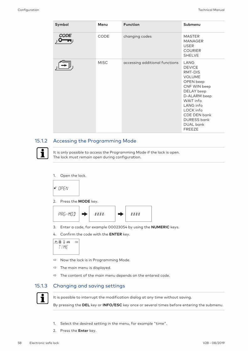
Symbol Menu Function Submenu
TIME setting time, date and timeformat
TIMEDATEAM/PMDST
PROG configuring locking periods IMM-TLWEEKLYHOLIDAY
DELAY configuring time delay DELAY 1DELAY 2DELAY 3DELAY 4CNF WIND-ALARMDUAL bankBLT OPN bank
Configuration Technical Manual
58 V28 - 08/2019Electronic safe lock
Symbol Menu Function Submenu
CODE changing codes MASTERMANAGERUSERCOURIERSHELVE
MISC accessing additional functions LANGDEVICERMT-DISVOLUMEOPEN beepCNF WIN beepDELAY beepD-ALARM beepWAIT infoLANG infoLOCK infoCDE DEN bankDURESS bankDUAL bankFREEZE
15.1.2 Accessing the Programming Mode
It is only possible to access the Programming Mode if the lock is open.The lock must remain open during configuration.
1. Open the lock.
2. Press the MODE key.
3. Enter a code, for example 00023054 by using the NUMERIC keys.
4. Confirm the code with the ENTER key.
ð Now the lock is in Programming Mode.
ð The main menu is displayed.
ð The content of the main menu depends on the entered code.
15.1.3 Changing and saving settings
It is possible to interrupt the modification dialog at any time without saving.
By pressing the DEL key or INFO/ESC key once or several times before entering the submenu.
1. Select the desired setting in the menu, for example "time".
2. Press the Enter key.

ConfigurationTechnical Manual
59V28 - 08/2019 Electronic safe lock
3. Select the desired subsetting and change the subsetting.
4. Press the ENTER key to confirm the subsetting.
5. Select "YES" in the "SAVE?" dialog by using the LEFT or RIGHT arrow key.
6. Press the ENTER key.
ð The message "Accepted" appears shortly and the input unit switches to the correspond-ing subsetting.
15.1.4 Exiting the Programming Mode
1. Press several times the DEL key or INFO/ESC key to return to operating mode.
15.1.5 Menu TIME
15.1.5.1 Setting the time
Authorization: Master code
To enable programming, the lock must be open during the entire programming process.
1. Select the submenu TIME.
2. Press the ENTER key.
ð The currently set time will be displayed.
3. Use the LEFT or RIGHT key to select the current hour and enter a new time.
4. Press the ENTER key to confirm.
5. Use the LEFT or RIGHT arrow key to adjust the minutes.
6. Select "YES" in the "SAVE?" dialog by using the LEFT or RIGHT arrow key.
7. Press the ENTER key.
15.1.5.2 Setting the date
Authorization: Master code
The respective weekdays and leap years are automatically calculated with the internal calen-dar (calendar range: Jan-1-2000 ... Dec-31-2099).
1. Select the submenu DATE.

Configuration Technical Manual
60 V28 - 08/2019Electronic safe lock
2. Press the ENTER key.
ð The currently set date will be displayed.
3. Use the LEFT or RIGHT key to select the current month.
4. Press the ENTER key to confirm and move to the day.
5. Use the LEFT or RIGHT key to select the day.
6. Press the ENTER key to confirm and move to the year.
7. Use the LEFT or RIGHT key to select the year.
8. Press the ENTER key to confirm.
9. Select "YES" in the "SAVE?" dialog by using the LEFT or RIGHT arrow key.
10. Press the ENTER key.
ð The message ACCEPTED appears for a short time period and the input unit returns to thesubmenu DATE.
15.1.5.3 Setting the time format AM/PM
Authorization: Master code
With „AM/PM ON“ the time is displayed in 12 hour format (1:00 until 12:59).With „AM/PM OFF” the time is displayed in 24 hour format (00:00 until 23:59).
1. Select submenu AM/PM.
2. Press the ENTER key.
ð The currently set time format will be displayed.
3. Select either ON or OFF by pressing the LEFT or RIGHT arrow key
4. Select "YES" in the "SAVE?" dialog by using the LEFT or RIGHT arrow key.
5. Press the ENTER key.
15.1.5.4 Setting DST
Authorization: Master code
1. Select the submenu DST.
2. Press the ENTER key.
ð The automatic DST will be displayed.
3. Select either ON or OFF by pressing the LEFT or RIGHT arrow key.

ConfigurationTechnical Manual
61V28 - 08/2019 Electronic safe lock
4. Select "YES" in the "SAVE?" dialog by using the LEFT or RIGHT arrow key.
5. Press the ENTER key.
15.1.6 Menu PROG
15.1.6.1 Activating the Immediate Time Lock
With this function it is possible to activate a locking period with immediate effect.When the lock is closed it is not possible to open it for the set time period.The Immediate Time Lock is not related to time / date.It is not possible to bypass the Immediate Time Lock, unless the Master was set to "Mastercan override the Immediate Time Lock".
The maximum duration of an Immediate Time Lock is 144 hours.The duration of the Immediate Time Lock can be limited in the AS284-USBW programmingsoftware.Changing hours and minutes to 000:00 will deactivate the Immediate Time Lock.
The factory setting for Manager Codes "can activate Immediate Time Lock" is ON.The setting Manager Codes "can activate Immediate Time Lock" can be set in AS284-USBWprogramming software.
1. Select the submenu IMM-TL.
2. Press the ENTER key.
3. Use the LEFT or RIGHT arrow key to set the duration of time in hours and minutes to de-fine the locking period of the Immediate Time Lock.
4. Select "YES" in the "SURE?" dialog by using the LEFT or RIGHT arrow key.
5. Press the ENTER key.
15.1.6.2 Configuring Weekly Locking Periods
Depending on the configuration of the lock, Weekly Locking Periods can last from 1 minute upto 6 days, 23 hours and 59 minutes.
It is possible to define up to 16 locking periods (with repetition).During these locking periods it is not possible to open the lock (for example outside businesshours).
15.1.6.2.1 Adding a Weekly Locking Period
If the maximum of 16 defined locking periods is reached, no further entries are possible.The display does not react any more.
The entry of day and time depends on the AM/PM setting.If the time format is set to 12 hours (AM/PM On), the weekdays are numbered: Sunday = 1,Monday = 2 ... Saturday = 7.If the time format is set to 24 hours (AM/PM Off), the weekdays are numbered: Monday = 1,Tuesday = 2 … Sunday = 7.

Configuration Technical Manual
62 V28 - 08/2019Electronic safe lock
1. Select the submenu WEEKLY.
2. Press the ENTER key.
ð The count will be displayed.
3. Press the ENTER key to enter a new time period.
4. Use the LEFT or RIGHT arrow key to set the day and time for the starting point of thelocking period.
5. Press the ENTER key to confirm the setting.
6. Use the LEFT or RIGHT arrow key to set the day and time for the endpoint of the lockingperiod.
7. Select "YES" in the "SAVE?" dialog by using the LEFT or RIGHT arrow key.
8. Press the ENTER key.
9. Repeat steps 2 to 8 to define other locking periods or press the INFO/ESC key to exit themenu.
15.1.6.2.2 Changing an existing Weekly Locking Period
It must be possible to open the lock between 2 Weekly Locking Periods.Weekly Locking Periods are saved in a chronological order, starting with Monday.
1. Proceed as in the described sequence "Adding a Weekly Locking Period".
2. Instead of pressing the ENTER key to select a new time period, use the RIGHT or LEFT ar-row key to select the Weekly Locking Period to be changed.
3. Press the ENTER key to confirm the selection.
4. Overwrite the Weekly Locking Period.
15.1.6.2.3 Deleting an existing Weekly Locking Period
1. Select the submenu WEEKLY.
2. Press the ENTER key.
ð The count will be displayed.
3. Use the RIGHT or LEFT arrow key to select the starting point of the Weekly Locking Pe-riod to be deleted.
4. Press the DEL key.
5. Select "YES" in the "CLEAR?" dialog by using the LEFT or RIGHT arrow key.

ConfigurationTechnical Manual
63V28 - 08/2019 Electronic safe lock
6. Press the ENTER key to confirm the deletion.
ð The count will be displayed.
15.1.6.3 Configuring Holiday Locking Periods
It is possible to define up to 22 date-related locking periods with this function.During these locking periods it is not possible to open the lock (for example holidays or publicholidays).
15.1.6.3.1 Adding a Holiday Locking Period
Requirements:
• There must be a time gap of at least 1 day between 2 Holiday Locking Periods.
• It is only possible to configure 2 Holiday Locking Periods without time gaps, if 1 HolidayLocking Period is repetitive and the other one is non-repetitive.
If repetitive and non-repetitive Holiday Locking Periods are configured without time gaps,there will be a high risk of a lock-out.
If the maximum of 22 defined Holiday Locking Periods is reached, no further entries are possi-ble. The display does not react any more.
1. Select the submenu HOLIDAY.
2. Press the ENTER key.
ð The count will be displayed.
3. Press the ENTER key to define a new time period.
4. Use the LEFT or RIGHT arrow key to set the month, day and year for the starting point ofthe Holiday Locking Period.
5. Press the ENTER key to confirm the settings.
6. Use the LEFT or RIGHT arrow key to set the month, day and year for the endpoint of theHoliday Locking Period.
7. Select "YES" in the "SAVE?" dialog by using the LEFT or RIGHT arrow key.
8. Press the ENTER key.
15.1.6.3.2 Changing an existing Holiday Locking Period
1. Proceed as in the described sequence "Adding a Holiday Locking Period".
2. Instead of pressing the ENTER key to define a new time period, use the RIGHT or LEFT ar-row key to select the Holiday Locking Period to be changed.
3. Overwrite the Holiday Locking Period.

Configuration Technical Manual
64 V28 - 08/2019Electronic safe lock
15.1.6.3.3 Deleting an existing Holiday Locking Period
1. Select the submenu HOLIDAY.
2. Press the ENTER key.
3. Use the RIGHT or LEFT arrow key to select a starting point for the Holiday Locking Periodto be deleted.
4. Press the DEL key.
5. Select "YES" in the "CLEAR" dialog by using the LEFT or RIGHT key .
6. Press the ENTER key to confirm the setting.
15.1.7 Menu DELAY
15.1.7.1 Setting and deactivating Time Delays
Submenu DELAY 1 ... 2
Once a valid code is entered, the lock will only open after the configured Time Delay haselapsed.It is possible to set a Time Delay for each user group between 0 (deactivated, no time delay)and 99 minutes.
Ex factory Time Delays are deactivated (set to 00:00).
The maximum configurable value of a Time Delay must be shorter than the shortest time gapbetween any 2 Weekly Locking Periods.
By entering a Courier Code it is possible to open the lock without a time delay.
Time Delays
Valid for
Time Delay 1 Master Manager 1 Users 11 ... 19
Time Delay 2 - Manager 2 Users 21 ... 29
1. Select the submenu DELAY 1, DELAY 2.
2. Press the ENTER key.
ð The currently set Time Delay will be displayed.
3. Use the LEFT or RIGHT arrow key to set the defined Time Delay.
4. Press the ENTER key.
5. Select "YES" in the "SAVE?" dialog by using the LEFT or RIGHT arrow key.

ConfigurationTechnical Manual
65V28 - 08/2019 Electronic safe lock
6. Press the ENTER key to confirm the setting.
It is possible to configure a Duress Time Delay for each user group via AS284-USBW program-ming software.
In contrast to normal Time Delays it is possible to set a shorter or longer time period for theDuress Time Delay.
It is also possible to suppress Time Delays with an external signal. This option allows to openthe lock without a Time Delay (for example to empty ATMs).
Duress Time Delays
Valid for
Duress Time Delay 1 Master Manager 1 Users 11 ... 19
Duress Time Delay 2 - Manager 2 Users 21 ... 29
15.1.7.2 Configuring the Confirmation Window
Submenu CNF WIN
To prevent the lock from opening automatically after a defined Time Delay has elapsed, aConfirmation Window will start in which a valid code must be entered within a limited timeframe.
Ex factory the Confirmation Window is set to 5 minutes.
The minimum value is 1 minute.
The maximum configurable value of a Time Delay must be shorter than the shortest time gapbetween any 2 Weekly Locking Periods.
It is not possible to deactivate the Confirmation Window.
1. Select the submenu CNF WIN.
2. Press the ENTER key.
ð The currently set confirmation time will be displayed.
3. Use the LEFT or RIGHT arrow key to set the defined confirmation time (setting from 1:00to 99:00 minutes).
4. Press the ENTER key.
5. Select "YES" in the "SAVE?" dialog by using the LEFT or RIGHT arrow key.
6. Press the ENTER key to confirm the settings.
15.1.7.3 Configuring Bolt Open Time
Submenu BLT OPN bankAuthorization: Master Code

Configuration Technical Manual
66 V28 - 08/2019Electronic safe lock
Ex factory the Bolt Open Time is set to 6 seconds.
When the lock is opened, it will close automatically when the Bolt Open Time has elapsed.It is possible to prevent the lock from closing automatically either when a door contact is con-nected or the bolt work is kept open..
1. Select the submenu BLT OPN bank.
2. Press the ENTER key.
ð The current Bolt Open Time will be displayed (minutes:seconds).
3. Use the LEFT or RIGHT arrow key to set the desired Bolt Open Time (setting from 00:06to 99:00 minutes).
4. Press the ENTER key.
5. Select "YES" in the "SAVE?" dialog by using the LEFT or RIGHT arrow key.
6. Press the ENTER key to confirm the setting.
15.1.8 Menu CODE
15.1.8.1 Authorization of codes
Each of the 4 code types (Master, Manager, User and Courier) has a different authorization.
There are 3 options to make changes:
• To activate (A) a code
• To modify (M) a code or
• to delete (D) codes.
Changes to be made by owner of
MasterCode
Resp. Manager Code Resp. User Codes Courier Code
MasterCode
M - - -
ManagerCode
AMD
M - -
User Code AMD
AMD
M -
CourierCode
AMD
- - M
15.1.8.2 Changing the Master Code
Submenu MASTERAuthorization: Master Code

ConfigurationTechnical Manual
67V28 - 08/2019 Electronic safe lock
1. Select the submenu MASTER.
2. Press the ENTER key.
3. Select "YES" by using the LEFT or RIGHT arrow key.
4. Press the ENTER key.
5. Use the NUMERIC keys to enter a new code.
6. Press the ENTER key to confirm the setting.
7. CONFIRM will be displayed shortly to ask the user to enter the same code to confirm thesetting.
8. USE the NUMERIC keys to enter the same code again.
9. Press the ENTER key to confirm the setting.
15.1.8.3 Setting Manager Codes
Submenu MANAGERAuthorization: Master Code
1. Select the submenu MANAGER.
2. Press the ENTER key.
It is only required to select the submenu Manager, if the Programming Mode was entered withMaster or Manager Code.
3. Use the LEFT or RIGHT arrow key to select the Manager Code to be set.
ð Manager Codes, which have already been activated, will be displayed as "USED", notactivated codes will be displayed as "- - - -").
4. Press the ENTER key.
5. Use the NUMERIC keys to enter a new code.
6. Press the ENTER key to confirm the setting.
ð CONFIRM will be displayed shortly to ask the user to enter the same code again.
7. Use the NUMERIC keys to enter the same code again.
8. Press the ENTER key to confirm the setting.
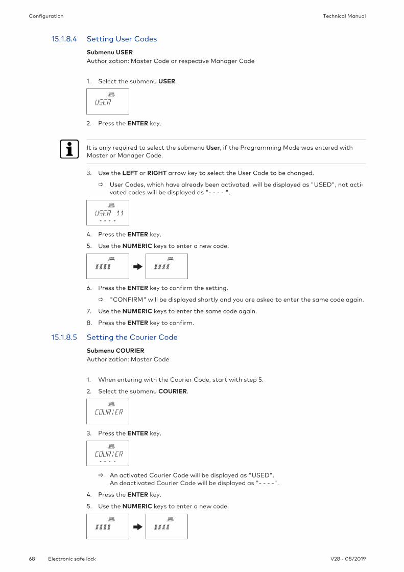
Configuration Technical Manual
68 V28 - 08/2019Electronic safe lock
15.1.8.4 Setting User Codes
Submenu USERAuthorization: Master Code or respective Manager Code
1. Select the submenu USER.
2. Press the ENTER key.
It is only required to select the submenu User, if the Programming Mode was entered withMaster or Manager Code.
3. Use the LEFT or RIGHT arrow key to select the User Code to be changed.
ð User Codes, which have already been activated, will be displayed as "USED", not acti-vated codes will be displayed as "- - - - ".
4. Press the ENTER key.
5. Use the NUMERIC keys to enter a new code.
6. Press the ENTER key to confirm the setting.
ð "CONFIRM" will be displayed shortly and you are asked to enter the same code again.
7. Use the NUMERIC keys to enter the same code again.
8. Press the ENTER key to confirm.
15.1.8.5 Setting the Courier Code
Submenu COURIERAuthorization: Master Code
1. When entering with the Courier Code, start with step 5.
2. Select the submenu COURIER.
3. Press the ENTER key.
ð An activated Courier Code will be displayed as "USED". An deactivated Courier Code will be displayed as "- - - -".
4. Press the ENTER key.
5. Use the NUMERIC keys to enter a new code.
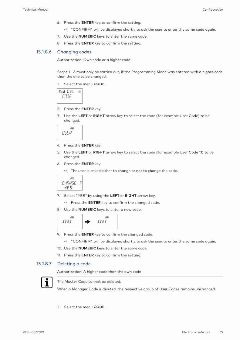
ConfigurationTechnical Manual
69V28 - 08/2019 Electronic safe lock
6. Press the ENTER key to confirm the setting.
ð "CONFIRM" will be displayed shortly to ask the user to enter the same code again.
7. Use the NUMERIC keys to enter the same code.
8. Press the ENTER key to confirm the setting.
15.1.8.6 Changing codes
Authorization: Own code or a higher code
Steps 1 - 6 must only be carried out, if the Programming Mode was entered with a higher codethan the one to be changed.
1. Select the menu CODE.
2. Press the ENTER key.
3. Use the LEFT or RIGHT arrow key to select the code (for example User Code) to bechanged.
4. Press the ENTER key.
5. Use the LEFT or RIGHT arrow key to select the code (for example User Code 11) to bechanged.
6. Press the ENTER key.
ð The user is asked either to change or not to change the code.
7. Select "YES" by using the LEFT or RIGHT arrow key.
ð Press the ENTER key to confirm the changed code.
8. Use the NUMERIC keys to enter a new code.
9. Press the ENTER key to confirm the changed code.
ð "CONFIRM" will be displayed shortly to ask the user to enter the same code again.
10. Use the NUMERIC keys to enter the same code.
11. Press the ENTER key to confirm the setting.
15.1.8.7 Deleting a code
Authorization: A higher code than the own code
The Master Code cannot be deleted.
When a Manager Code is deleted, the respective group of User Codes remains unchanged.
1. Select the menu CODE.

Configuration Technical Manual
70 V28 - 08/2019Electronic safe lock
2. Press the ENTER key.
3. Use the LEFT or RIGHT arrow key to select the code type (for example "user") to bechanged.
4. Press the ENTER key.
5. Use the LEFT or RIGHT arrow key to select the code (for example "User Code 11") to bechanged.
6. Press the DEL key.
ð The user is asked either to delete or not to delete the code.
7. Select "YES" by using the LEFT or RIGHT arrow key.
8. Press the ENTER key to confirm the deletion.
15.1.8.8 Resetting the electronic safe lock
Submenu SHELVE
With the Shelve Function it is possible to reset the electronic safe lock to factory settings.
All codes will be deleted and all parameters such as Time Delay, Time Locking Function, DualMode will be set to factory settings.
Time/date, opening counter and audit trail remain unchanged.
Keep in mind that all data is lost when the electronic safe lock will be reset to factory settings.It is recommended to save all data via AS284-USBW programming software prior to shelving.Keep in mind that codes cannot be saved.
Authorization: Master Code
1. Select the submenu SHELVE.
2. Press the ENTER key.
ð The user is asked either to reset or not to reset all data to factory settings.
3. Select "YES" by using the LEFT or RIGHT arrow key.
4. Press ENTER key.
ð All data is reset to factory settings.

ConfigurationTechnical Manual
71V28 - 08/2019 Electronic safe lock
15.1.9 Menu MISC
15.1.9.1 Setting the Display Language
By default the display language is English.It is possible to set the display language either with the input unit or via AS284-USB program-ming software.
It is possible to change the display language in the information menu without entering an ac-cess code.
Authorization: Master Code or any Manager Code
1. Select the submenu LANG.
2. Press the ENTER key.
ð The currently set display language will be displayed.
3. Use the LEFT or RIGHT arrow key to select the desired display language.
4. Press the ENTER key to confirm the selected display language.
5. Select "YES" in the "SAVE?" dialog by using the LEFT or RIGHT arrow key.
6. Press the ENTER key to confirm the setting.
15.1.9.2 Managing the safe lock system with the Device Manager
The range of functions of the master lock differs from the functions of the slave locks.The Device Manager of a slave lock only displays 2 connected devices: the input unit and therespective slave lock.The slave lock is only able to check the type, version, the last 8 digits of the serial number anda customized 5-digit number of the respective slave lock.A bus system test of the respective slave lock and the input unit can be conducted.
The Device Manager comprises several functions:
• Checking the number of connected devices (locks and input units)
• Conducting a simple bus system test
• Moving selected locks to another lock position
Authorization: Master Code
1. Select the Submenu DEVICE on the master lock.
2. Press the ENTER key.
ð The Device Manager displays the number of all connected devices of the safe lock sys-tem.

Configuration Technical Manual
72 V28 - 08/2019Electronic safe lock
3. Press the Right arrow key to select the desired device.
ð The selected devices will be displayed.
ð Up to 10 connected slave locks will be displayed.
4. Press the ENTER key to confirm the setting.
15.1.9.2.1 Entering the lock parameters and testing the bus system
There are 2 options:
• Checking the lock parameters by selecting a desired lock from the lock list
• Conducting a bus system test of the safe lock system
Any counter number over 040 is a good result of a bus system test. There is a connection to the tested device.
If the counter numbers are between 000 and 040 it is recommended to check the wiring.
The Device Manager of the master lock displays the number of all connected devices of thesafe lock system.
The Device Manager of the slave locks displays the number 002 (the respective slave lock andinput unit).
Authorization: Master Code
1. Select the submenu DEVICE.
2. Press the ENTER key.
ð The Device Manager displays the number of all connected devices of the safe lock sys-tem.

ConfigurationTechnical Manual
73V28 - 08/2019 Electronic safe lock
3. Press the Right arrow key to select the desired device.
ð The selected device will be displayed.
4. Press the ENTER key.
ð The safe lock type and the version number will be displayed.
5. Press the Right arrow key.
ð The last 8 digits of the serial number of the selected lock will be displayed.
6. Press the Right arrow key.
ð The customized 5-digit number will be displayed. By default, these are the last 5 digitsof the serial number.
7. Press the Right arrow key.
ð A bus system test of the selected device can be started.
8. Press the ENTER key.
ð The bus system test starts.The counter starts from 000 and can count up to the maximum value of 360.
ð The test result will be displayed.
15.1.9.2.2 Moving the selected lock
Authorization: Master Code
1. Select the submenu DEVICE on the master lock.
2. Press the ENTER key.
ð The Device Manager displays the number of all connected devices of the safe lock sys-tem.
3. Press the Right arrow key to select the desired device.
ð The selected device will be displayed.
4. Press the ENTER key.

Configuration Technical Manual
74 V28 - 08/2019Electronic safe lock
ð The safe lock type and the version number will be displayed.
5. Press the Right arrow key.
ð The last 8 digits of the serial number of the selected lock will be displayed.
6. Press the Right arrow key.
ð The customized 5-digit number will be displayed.These are the last 5 digits of the serial number.
7. Press the Right arrow key.
ð The selected lock -3- can be moved to another lock position.
8. Press the ENTER key.
ð "MOVE TO" and the current lock position will be displayed.
9. Use the LEFT or RIGHT arrow key to select the new lock position.
10. Press the ENTER key to confirm the new lock position.
11. Select "YES" in the "SAVE?" dialog by using the LEFT or RIGHT arrow key.
12. Press the ENTER key to confirm the setting.
15.1.9.3 Activating or deactivating Remote Disabling
It is possible to deactivate the opening of a closed lock with an external signal.This function is used when an additional identification is required (for example badge, biomet-rics) or when it is necessary to prevent the lock from opening (for example when the alarmsystem is activated).
One of the inputs must be configured with AS284-USBW programming software to use theRemote Disabling function.
Remote Disabling is not activated when the lock is open. The lock can be operated normally.
It is possible to override the Remote Disabling function with the Master code to avoid a totallock-out if the external signal fails.
Authorization: Master Code
1. Select the submenu RMT-DIS.
2. Press the ENTER key.
ð RMT-DIS will be displayed.
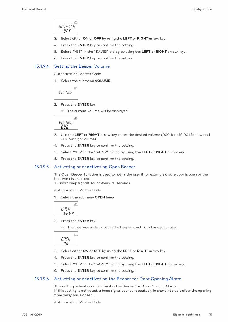
ConfigurationTechnical Manual
75V28 - 08/2019 Electronic safe lock
3. Select either ON or OFF by using the LEFT or RIGHT arrow key.
4. Press the ENTER key to confirm the setting.
5. Select "YES" in the "SAVE?" dialog by using the LEFT or RIGHT arrow key.
6. Press the ENTER key to confirm the setting.
15.1.9.4 Setting the Beeper Volume
Authorization: Master Code
1. Select the submenu VOLUME.
2. Press the ENTER key.
ð The current volume will be displayed.
3. Use the LEFT or RIGHT arrow key to set the desired volume (000 for off, 001 for low and002 for high volume).
4. Press the ENTER key to confirm the setting.
5. Select "YES" in the "SAVE?" dialog by using the LEFT or RIGHT arrow key.
6. Press the ENTER key to confirm the setting.
15.1.9.5 Activating or deactivating Open Beeper
The Open Beeper function is used to notify the user if for example a safe door is open or thebolt work is unlocked.10 short beep signals sound every 20 seconds.
Authorization: Master Code
1. Select the submenu OPEN beep.
2. Press the ENTER key.
ð The message is displayed if the beeper is activated or deactivated.
3. Select either ON or OFF by using the LEFT or RIGHT arrow key.
4. Press the ENTER key to confirm the setting.
5. Select "YES" in the "SAVE?" dialog by using the LEFT or RIGHT arrow key.
6. Press the ENTER key to confirm the setting.
15.1.9.6 Activating or deactivating the Beeper for Door Opening Alarm
This setting activates or deactivates the Beeper for Door Opening Alarm.If this setting is activated, a beep signal sounds repeatedly in short intervals after the openingtime delay has elapsed.
Authorization: Master Code

Configuration Technical Manual
76 V28 - 08/2019Electronic safe lock
1. Select the submenu D-ALARM beep.
2. Press the ENTER key.
ð The message is displayed if the beeper is activated or deactivated.
3. Select either ON or OFF by using the LEFT or RIGHT arrow key.
4. Press the ENTER key to confirm the setting.
5. Select "YES" in the "SAVE?" dialog by using the LEFT or RIGHT arrow key.
6. Press the ENTER key to confirm the setting.
15.1.9.7 Activating or deactivating the Beeper Time Delay
This setting defines if an opening Time Delay is indicated with 1 beep signal every 60 seconds.
Authorization: Master Code
1. Select the submenu DELAY beep.
2. Press the ENTER key.
ð The message is displayed if the beeper is activated or deactivated.
3. Select either ON or OFF by using the LEFT or RIGHT arrow key.
4. Press the ENTER key to confirm the setting.
5. Select "YES" in the "SAVE?" dialog by using the LEFT or RIGHT arrow key.
6. Press the ENTER key to confirm the setting.
15.1.9.8 Activating or deactivating Waiting Time
Authorization: Master Code
1. Select the submenu WAIT info.
2. Press the ENTER key.
ð The message WAIT will be displayed.
3. Select either ON or OFF by using the LEFT or RIGHT arrow key.
4. Press the ENTER key to confirm the setting.
5. Select "YES" in the "SAVE?" dialog by using the LEFT or RIGHT arrow key.
6. Press the ENTER key to confirm the setting.
15.1.9.9 Activating or deactivating Language
This function defines which menu language is available.
Authorization: Master Code

ConfigurationTechnical Manual
77V28 - 08/2019 Electronic safe lock
1. Select the submenu LANG info.
2. Press the ENTER key.
3. Select either ON or OFF by using the LEFT or RIGHT arrow key.
4. Press the ENTER key to move to the next language.
5. After having defined the "last" language, select "YES" in the "SAVE?" dialog by using theLEFT or RIGHT arrow key.
6. Press the ENTER key to confirm the setting.
15.1.9.10 Setting the Lock Info
Authorization: Master Code
With the function Lock Info it is either possible to display the lock position (LOCK -1-) of thesafe lock system or the customized 5-digit number. By default, these are the last 5 digits ofthe serial number.
1. Select the submenu LOCK INFO on the master lock.
2. Press the ENTER key.
ð The message LOCK INFO will be displayed.
3. Select OFF by using the RIGHT arrow key to display the lock position (LOCK -1-).
4. Press the ENTER key.
5. Select "YES" in the "SAVE?" dialog by using the LEFT or RIGHT arrow key.
6. Press the ENTER key to confirm the setting.
15.1.9.11 Activating or deactivating Code Denial
With a higher code it is possible to deny access to a selected number of lower codes.An example for Code Denial is "off duty shifts". In this case a selected number of users is locked out during a defined time period and reas-signed when starting to work.
It is also possible to deny access to a defined user group (with or without the respective Man-ager Code).
Authorization: Master Code or any Manager Code
1. Select the submenu CDE DEN bank.
2. Press the ENTER key.
ð The Code Denial status of the user group 1 will be displayed.
3. Use the LEFT or RIGHT arrow key to select a user group or manager.
4. Press the ENTER key to confirm the setting.

Configuration Technical Manual
78 V28 - 08/2019Electronic safe lock
5. Use the LEFT or RIGHT arrow key to activate (CDE DEN ON, access denied) or deactivate(CDE DEN OFF, access allowed) the Code Denial for the selected user group or manager.
6. Press the ENTER key to confirm the setting.
7. Repeat steps 2 to 5 for the selected user groups and managers.
15.1.9.12 Activating or deactivating the Duress Code Function
Submenu DURESS bank
After recognizing a duress, the output will change from sleep mode to operating mode. Theoutput remains as long in operating mode (indicator for a duress) as a valid code without in-formation of a duress is entered. The lock opens.The output only goes back to sleep mode after lock opening.
It is possible to set the duration of a duress time delay (a longer or shorter time period) irre-spectively from a time delay.
If the lock is connected to an external alarm system, a silent duress alarm will be activatedwhen a Duress Code is entered.The alarm signal is not perceptible for the aggressor.If the Duress Code function is activated, duress codes will be recognized.If the lock is opened with a Duress Code, the defined Duress Time Delay will start.
Authorization: Master Code
1. Select the submenu DURESS bank.
2. Press the ENTER key.
ð The currently set status of the Duress Code will be displayed. By default the Duress Code is set to off.
3. Use the LEFT or RIGHT arrow key to activate (DURESS ON) or deactivate (DURESS OFF)the Duress Code.
4. Press the ENTER key to confirm the setting.
15.1.9.13 Activating or deactivating Dual Mode
It is possible to configure the lock in a way that 2 codes are required for lock opening.Dual Mode is applied when only 2 persons are authorized to open the lock.
Authorization: Master Code
1. Select the submenu DUAL bank.
2. Press the ENTER key.
ð The currently set status of the Dual Mode will be displayed.By default Dual Mode is set to off.

ConfigurationTechnical Manual
79V28 - 08/2019 Electronic safe lock
3. Use the LEFT or RIGHT arrow key to activate (DUAL ON) or deactivate (DUAL OFF) theDual Mode.
4. Press the ENTER key to confirm the setting.
15.1.9.14 Setting the Freeze function
15.1.9.14.1 Setting Freeze Off
The lock with the lowest serial number will be lock -1- (the master lock). When the functionFreeze Off is activated, further devices (locks or input units) will be searched and connectedautomatically to the lock list.
If more than 15 locks are connected to the safe lock system, the error message ERROR -16-will be displayed.
Authorization: Master Code
1. Select the submenu FREEZE on the master lock.
2. Press the ENTER key.
3. Select OFF by using the LEFT or RIGHT arrow key.
4. Press the ENTER key to confirm the setting.
5. Select "YES" in the "SAVE?" dialog by using the LEFT or RIGHT arrow key.
6. Press the ENTER key to confirm the setting.
15.1.9.14.2 Setting Freeze On
To guarantee that the selected lock remains lock -1- (master lock), it is possible to set thefunction Freeze for a short moment to ON and then switch to Freeze OFF. The selected lockwill be set as the master lock and even after a power interruption remains the master lock.Locks with lower serial numbers than the master lock will be added to the lock list as slavelocks.
Lock -1- is the master lock. When the function Freeze ON is activated, no further locks will beadded to the lock list. The error message ERROR -16- will be displayed when a new lock isadded.
Authorization: Master Code
1. Select the submenu FREEZE.
2. Press the ENTER key.
3. Select ON by using the LEFT or RIGHT arrow key.
4. Press the ENTER key to confirm the setting.
5. Select "YES" in the "SAVE?" dialog by using the LEFT or RIGHT arrow key.

Configuration Technical Manual
80 V28 - 08/2019Electronic safe lock
6. Press the ENTER key to confirm the setting.

OperationTechnical Manual
81V28 - 08/2019 Electronic safe lock
16 Operation
16.1 Code entry
It is possible to distract a potential observer's attention from memorizing a code during codeentry.
Only the first 7 and the last entered digit is considered as code.
Requirements:
To distract a potential observer's attention from memorizing a code, the following proceduremust be carried out:
1. Enter at least the first 7 digits and continue adding any possible number combination.
2. Enter the last digit of the code, for example 00123458921031 ... 256.
3. Press the ENTER key.
Codes are entered in 2 groups of 4 digits.The following procedure is carried out to open the lock or to enter the Programming Mode:
1. If necessary, press any key to wake up the display.
ð The lock status appears, for example "LOCKED".
2. Enter the code, for example 11123456 by using the NUMERIC keys
ð For every entered digit an asterisk appears.
3. Press the ENTER key to confirm the code.
16.2 Lock opening procedure
The desired lock must be selected with the LEFT or RIGHT arrow key.
It is not possible to open the lock during the following conditions:
• Penalty after wrong trials
• During active locking periods (Immediate Time Lock, Weekly or Holiday Locking Periods)
• When the battery compartment is open
• When Remote Disabling is in process
• During an active connection with the programming software
The opening procedure is valid for the activated functions Dual Mode and Time Delay.If neither Dual Mode nor Time Delay are set, the lock will open sooner.
If no key has been pressed for 1 minute, the display switches off automatically.
1. If necessary, press any key to wake up the display.
ð The lock status is displayed.

Operation Technical Manual
82 V28 - 08/2019Electronic safe lock
2. Enter a code, for example 11123456 by using the NUMERIC keys.
ð For every entered digit an asterisk appears.
3. Press the ENTER key to confirm the code.
4. If the input unit is set to Dual Mode, a second code must be entered.
5. Press the ENTER key to confirm the code.
6. If an opening code with Time Delay was defined, the window for Opening Time Delay ap-pears and the timer starts counting the set Time Delay.
ð The remaining time will be displayed.
ð Every 60 seconds a beep signal sounds while the Time Delay is counted.If the timer has elapsed, another beep signal indicates the end of the Opening TimeDelay.
7. After the Opening Time Delay has elapsed, the Confirmation Window appears.The timer starts counting the set confirmation time.The remaining time for lock opening must be confirmed.
8. Enter the opening code.
9. Press the ENTER key to confirm the code.
10. If the input unit is set to Dual Mode, a second code must be entered.
11. Press the ENTER key to confirm the code.
ð The lock opens.
12. Open the safe.
ð If desired, continue in Programming Mode.

OperationTechnical Manual
83V28 - 08/2019 Electronic safe lock
16.3 Lock closing procedure
The lock closes automatically when the bolt work is locked.
Depending on the safe design, there are additional factors which have an impact on the clos-ing procedure.

Troubleshooting Technical Manual
84 V28 - 08/2019Electronic safe lock
17 Troubleshooting
17.1 Status messages on LCD
If various causes lead to more than 1 error message REFUSED xx, the number of error mes-sages will be summed up.
Example: REFUSED 12 = REFUSED 04 + REFUSED 08REFUSED 50 = REFUSED 02 + REFUSED 16 + REFUSED 32
Statusmessage onLCD
Cause Solution Menu Submenu
BAT-CMPOPEN
Battery compartmentwas opened.
1. Make sure that the bat-tery compartment isclosed.
2. Make sure that nobodymanipulated the inputunit.
3. Enter the Master, anyManager or a User Codewith special function(Battery Code) to deletethe status message.
n/a n/a

TroubleshootingTechnical Manual
85V28 - 08/2019 Electronic safe lock
Statusmessage onLCD
Cause Solution Menu Submenu
LINE OFF The connection betweenlock and input unit is tem-porarily interrupted.
1. Wait until the lock is insleep mode; wake up thelock by pressing the infokey.
2. If the message does notdisappear automatically,remove the batteries andput the batteries in thebattery compartmentagain.
3. If the message does notdisappear automatically,disconnect the connectingcable.Make sure that the con-necting cable is not dam-aged.If necessary, replace it.
4. Reconnect the connect-ing cable. Make sure that the con-necting cable is con-nected correctly.
5. If the message doesnot disappear automati-cally, make sure that newbatteries were put in thebattery compartment.
6. If the message stilldoes not disappear, callthe vendor for technicalsupport.
n/a n/a
ID ERROR ID for Master Code is notOO
Make sure that the first 2digits of the code reflectthe ID.
CODE MASTER
ID for Manager Code isnot 10 or 20
MANAGER
ID for User Code is not11 ... 19, 21 ... 29, 41, 47
USER
ID for Courier Code is not90
COURIER
REFUSED Code change:The entered code doesnot match with the codeentered before.
Make sure to enter thesame code twice.
CODE MASTER
MANAGER
USER
COURIER
REFUSED02
Unknown command:The desired function isnot available.The installed componentsare not compatible.
Call the vendor for tech-nical support.
n/a n/a
REFUSED04
Lock was closed duringconfiguration.
Make sure that the lockremains open during con-figuration.
PROG Any sub-menu

Troubleshooting Technical Manual
86 V28 - 08/2019Electronic safe lock
Statusmessage onLCD
Cause Solution Menu Submenu
REFUSED08
Invalid date (for exampleSept. 31st)Date out of time limit(Jan. 31st 2000 until Dec.31st 2099)
Enter a valid date withinthe time limit.
TIME DATE
Time window out of per-mitted range (a maxi-mum of 6 days, 23 hoursand 59 minutes)
Enter a shorter time win-dow.
PROG WEEK
Time window out of per-mitted range (a maxi-mum of 35 days)Invalid date (for exampleSept. 31st)Date out of time limit(Jan. 1st 2000 until Dec.31st 2099)
Enter a shorter time win-dow
PROG HOLIDAY
REFUSED16
The minimum interval (aninterrupt) of all delaysplus 1 minute was ignoredbefore the next WeeklyLocking Period hadstarted.
Enter a valid date withinthe time limit.
PROG WEEK
The minimum interval (aninterrupt) of all delaysplus 1 minute was ignoredbefore the next WeeklyLocking Period hadstarted.
Increase the interval du-ration.
PROG HOLIDAY
The minimum period oftime was ignored.
Enter a valid time period.
The minimum period oftime is calculated byadding the ConfirmationWindow and 1 additionalminute to the highervalue of 2 time delays(Time Delay or DuressTime Delay)
PROG DELAY
REFUSED32
The memory is full (themaximum of 16 WeeklyLocking Periods were de-fined and entered).
Make sure not to entermore than 16 WeeklyLocking Periods.
PROG WEEK
The memory is full (themaximum of 22 HolidayLocking Periods were de-fined and entered)
Make sure not to entermore than 22 HolidayLocking Periods.
PROG HOLIDAY
REFUSED64
Unexpected data error. 1. Try again.
2. Call the vendor fortechnical support.
n/a n/a

TroubleshootingTechnical Manual
87V28 - 08/2019 Electronic safe lock
Statusmessage onLCD
Cause Solution Menu Submenu
REFUSED128
Lock is no longer in Pro-gramming Mode.After having navigatedfor more than 5 minutesin the menu without con-figuring the lock, the Pro-gramming Mode will beclosed.
Leave the ProgrammingMode before 5 minuteshave passed and enterthe Programming Modeagain.
any any
MOT FLT A motion fault occuredduring bolt movement.
1. Reboot the input unitby removing the bat-teries.
2. Wait for 1 hour beforeinserting new batter-ies.
3. Make sure that thebolt moves smoothly.
4. Make sure that thebolt is not mechani-cally blocked.
5. Call the vendor fortechnical support, ifthe status messagedoes not disappear.
n/a n/a
HDW FLT A hardware fault Proceed as in steps 1 to 5for MOT FLT.
n/a n/a
17.2 Identification of the lowest serial number
The serial number of the locks is a hexadecimal number.The decimal number system uses 10 digits: 0, 1, 2, 3, 4, 5, 6, 7, 8, 9
The hexadecimal number system uses 16 digits: 0, 1, 2, 3, 4, 5, 6, 7, 8, 9, A, B, C, FThe conversion of the hexadecimal digits A ... F to the decimal numeral system corresponds to:A equals to 10 and F equals to 15.
For the identification of the lowest serial number of a lock, the serial number must be readfrom left to right and must be compared with the serial number of other locks.
Examples of dual lock systems
Serial number Result
Lock 1 43177 30B05 00A Serial number 1 is lower than serial number 2
Lock 2 43375 32FB3 023
Serial number Result
Lock 1 42984 2EA70 003
Lock 2 42984 2EA6F 003 Serial number 2 is lower than serial number 1
Serial number Result
Lock 1 43375 30B05 00A Serial number 1 is lower than serial number 2
Lock 2 43375 30B05 0A0

Service Technical Manual
88 V28 - 08/2019Electronic safe lock
18 Service
18.1 Cleaning
NOTICEDamage to surface and interior of the input unit
Cleaning the input unit with aggressive cleaning agents, solvents, abrasive agents or sprays,will cause damage to the surface and interior of the input unit.
• Do not use cleaning agents containing hydrogen peroxide.
• Do not use solvents or abrasive agents.
• Do not use aerosol sprays.
• Do not spray liquids directly onto the surface.
• Avoid getting moisture in the interior of the input unit.
To clean the input unit, use a damp, soft and lint-free cloth and apply a mild cleaning agent.
18.2 Replacing batteries
The input unit is powered by 3 alkaline AA batteries 1.5 V - LR6 or 3 lithium AA batteries 1.5 V -FR6.
Keep in mind that batteries must be changed as soon as the symbol "battery low" appears onthe display.
Batteries must be changed latest when the status message "CHANGE BATT" is displayed.
Re-adjust the time and date after replacing the batteries.
After a power interruption (no batteries were inserted or the batteries are empty and the linevoltage is off), the function Freeze was set to OFF, the safe lock system will initialize itselfnewly.The safe lock system behaves as if it were set up according to the procedure cold plugging.The lock with the lowest serial number becomes the master lock.
To prevent the safe lock system from changing its lock positions, the function Freeze must beset to ON after connecting the first lock. The current master lock will be saved in the system.The function Freeze must be set to OFF.
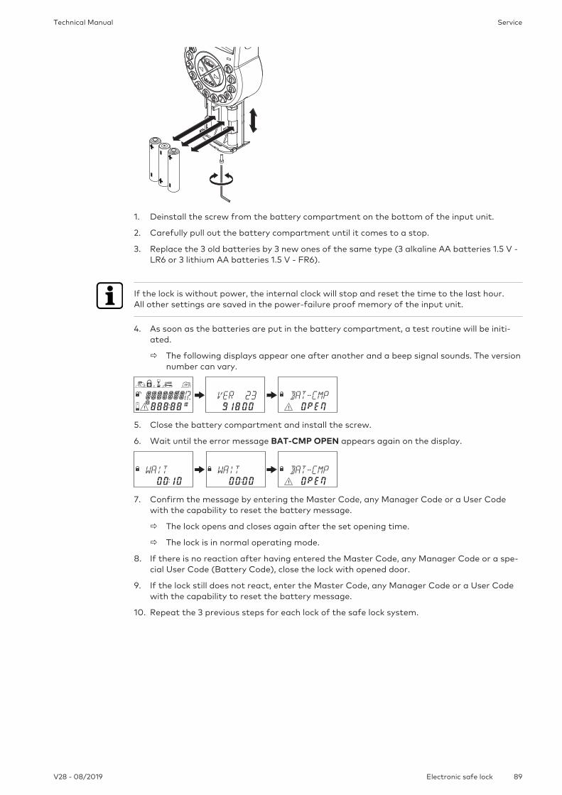
ServiceTechnical Manual
89V28 - 08/2019 Electronic safe lock
1. Deinstall the screw from the battery compartment on the bottom of the input unit.
2. Carefully pull out the battery compartment until it comes to a stop.
3. Replace the 3 old batteries by 3 new ones of the same type (3 alkaline AA batteries 1.5 V -LR6 or 3 lithium AA batteries 1.5 V - FR6).
If the lock is without power, the internal clock will stop and reset the time to the last hour.All other settings are saved in the power-failure proof memory of the input unit.
4. As soon as the batteries are put in the battery compartment, a test routine will be initi-ated.
ð The following displays appear one after another and a beep signal sounds. The versionnumber can vary.
5. Close the battery compartment and install the screw.
6. Wait until the error message BAT-CMP OPEN appears again on the display.
7. Confirm the message by entering the Master Code, any Manager Code or a User Codewith the capability to reset the battery message.
ð The lock opens and closes again after the set opening time.
ð The lock is in normal operating mode.
8. If there is no reaction after having entered the Master Code, any Manager Code or a spe-cial User Code (Battery Code), close the lock with opened door.
9. If the lock still does not react, enter the Master Code, any Manager Code or a User Codewith the capability to reset the battery message.
10. Repeat the 3 previous steps for each lock of the safe lock system.

Maintenance Technical Manual
90 V28 - 08/2019Electronic safe lock
19 Maintenance
19.1 Replacing a defect lock
19.1.1 Removing the defect lock from the safe lock system
It is assumed that e.g. lock -9- is defect. The lock must be removed from the bus.The functions Freeze and Lock info are set to OFF on lock -1- (the master lock).
Authorization: Master Code
Checking the defect lock
1. Press the Right arrow key to navigate to lock -9-.
ð The display shows that the selected lock -9- is not applicable. It is possible that the error message LINE OFF will be displayed.After a few seconds the error message will disappear.
Removing the defect lock from the device list
1. Open lock -1- and prevent the lock from closing.
2. Enter the programming mode.
3. Select the menu MISC.
4. Press the ENTER key.
5. Select the submenu DEVICE
6. Press the ENTER key.
ð The Device Manager displays the number of all connected devices of the safe lock sys-tem.
7. Press the Right arrow key to select the defect device.
ð The defect device will be displayed.
8. Press the ENTER key.
ð The type of safe lock with the version number will be displayed.
9. Press the Right arrow key.

MaintenanceTechnical Manual
91V28 - 08/2019 Electronic safe lock
ð The last 8 digits of the serial number of the defect lock will be displayed.
10. Press the Right arrow key.
ð The customized 5-digit number will be displayed. By default, these are the last 5 digitsof the serial number.
11. Press the Right arrow key.
ð A bus system test of the selected device can be started.
12. Press the Right arrow key.
ð The defect lock -9- can be removed.
13. Press the ENTER key.
14. Select "YES" in the "SURE?" dialog by using the LEFT or RIGHT arrow key.
15. Press the ENTER key to confirm the setting.
ð The display shows ACCEPTED. The defect lock is removed from the device list.
Removing the defect lock from secure storage unit
1. Remove the defect lock.
19.2 Adding a new lock to the safe lock system
19.2.1 Adding a new lock with Freeze OFF
If more than 1 lock must be replaced, it is necessary to apply the function MOVE TO in orderto add a new lock to the desired lock position.
It is assumed that e.g. lock -9- was defect and the lock was removed from the safe lock sys-tem. The safe lock systems indicates that lock position -9- is vacant.
The functions Freeze and Lock info are set to OFF on lock -1-(the master lock).A new lock will be added to lock position -9-.
Authorization: Master Code
1. Add the new lock to the secure storage unit.
2. Connect the bus cable from terminal X2 of the previous lock to terminal X1 of the newlyadded lock.
3. Connect the bus cable from terminal X2 of the newly added lock to terminal X1 of the sub-sequent lock.

Maintenance Technical Manual
92 V28 - 08/2019Electronic safe lock
ð After a few seconds the new lock will be placed automatically to the vacant lock posi-tion -9-.The display shows a warning that the battery compartment of the newly added lockwas opened.
4. Enter a Battery Code to be able to operate the lock.
19.2.2 Adding a new lock with Freeze ON
The function Freeze is set to ON and the Lock info is set to OFF on lock -1- (master lock).
It is assumed that e.g. lock -9- was defect and the lock was removed from the safe lock sys-tem. The safe lock systems indicates that lock position -9- is vacant.A new lock will be added to lock position -9-.
Authorization: Master Code
Adding a new lock
1. Add the new lock to the secure storage unit.
2. Connect the bus cable from terminal X2 of the previous lock to terminal X1 of the newlyadded lock.
3. Connect the bus cable from terminal X2 of the newly added lock to terminal X1 of the sub-sequent lock.
ð After a few seconds the new lock will be assigned to position -16-.The display shows a warning with an error message for the newly assigned lock.
4. Press the LEFT or RIGHT arrow key as long as the error message with the lock position-16- will be displayed.
Changing the function Freeze to OFF
1. Open lock -1- and prevent the lock from closing.
2. Enter the programming mode.
3. Select the menu MISC.
4. Press the ENTER key.
5. Select the submenu FREEZE
6. Press the ENTER key.
7. Select OFF by using the LEFT or RIGHT arrow key.
8. Press the ENTER key to confirm the setting.
9. Select "YES" in the "SAVE?" dialog by using the LEFT or RIGHT arrow key.
10. Press the ENTER key to confirm the setting.

MaintenanceTechnical Manual
93V28 - 08/2019 Electronic safe lock
11. Press the DEL key several times to exit the programming mode.
Assigning the new lock to the vacant position
1. Wait until the new lock will be placed automatically to the vacant lock position -9-.
2. Press the LEFT or RIGHT arrow key several times.
ð The new lock has been assigned to the vacant lock position, when the display shows awarning with battery compartment open.
Changing the function Freeze to ON
1. Open lock -1- and prevent the lock from closing.
2. Enter the programming mode.
3. Select the menu MISC.
4. Press the ENTER key.
5. Select the submenu FREEZE
6. Press the ENTER key.
7. Select ON by using the LEFT or RIGHT arrow key.
8. Press the ENTER key to confirm the setting.
9. Select "YES" in the "SAVE?" dialog by using the LEFT or RIGHT arrow key.
10. Press the ENTER key to confirm the setting.
11. Press the DEL key several times to exit the programming mode.
Enabling the new lock for operation
1. Enter a Battery Code to be able to operate the lock.
19.3 Removing the error message of lock position -16-
1. Open lock -1- and prevent the lock from closing.
2. Enter the programming mode.
3. Select the menu MISC.
4. Press the ENTER key.
5. Select the submenu DEVICE.
6. Press the ENTER key.

Maintenance Technical Manual
94 V28 - 08/2019Electronic safe lock
ð The Device Manager displays the number of all connected devices of the safe lock sys-tem.
7. Press the Right arrow key to select Lock -16-.
ð Lock -16- will be displayed.
8. Press the ENTER key.
ð The type of safe lock with the version number will be displayed.
9. Press the Right arrow key.
ð Dashes will be displayed instead of the last 8 digits of the serial number.The lock was not accepted in the lock list.
10. Press the Right arrow key.
ð Dashes will be displayed instead of the customized 5-digit number.The lock was not in the lock list.
11. Press the Right arrow key.
ð The message with the bus system test will be displayed.
12. Press the Right arrow key.
ð Lock -16- can be removed.
13. Select "YES" in the "SURE?" dialog by using the LEFT or RIGHT arrow key.
14. Press the ENTER key to confirm the setting.
ð The display shows ACCEPTED.Lock -16- is removed from the device list.

DisposalTechnical Manual
95V28 - 08/2019 Electronic safe lock
20 Disposal
Do not dispose used batteries in domestic waste.Dispose batteries according to the local or national regulations.
Packaging material must be disposed or recycled according to national or local regulations.
At the end of the service life, the unit and its components must be returned to the manufac-turer or must be disposed at a collecting point.

Spare parts and accessories Technical Manual
96 V28 - 08/2019Electronic safe lock
21 Spare parts and accessories
Spare part Part number
Axessor USB input unit AXESSOR-USBIU
Axessor USB lock unit AXESSOR-USBLOCK
Axessor USB latchbolt lock unit without VdS certification AXESSOR-USBLLOCK
Replacement WiBu dongle for AS284-W Administrator dongle AS284-AW
Replacement WiBu dongle for AS284 Operator dongle AS284-OW
Axessor installation kit 52 INST-S
USB data cable 1364-8
Connecting cable for lock/input unit/eBox55 cm
52X+CAB55
Accessory Part number
Axessor power supply100-240 VAC / 6 VDC
52XVDC6
AS284-USB programming software AS284-USBW