DORMA GmbH + Co. KG DORMA Platz 1 58256 ... - Dormakaba
104
DORMA GmbH + Co. KG DORMA Platz 1 58256 ENNEPETAL DEUTSCHLAND Tel. +49 2333 793-0 Fax +49 2333 793-4950 www.dorma.de DORMA-Glas GmbH Max-Planck-Straße 33–45 32107 BAD SALZUFLEN DEUTSCHLAND Tel. +49 5222 924-100 Fax +49 5222 924-3100 www.dorma.de WN 05414751532 · 12/13 · HSW/FSW · GB · x · XX· xx/13
-
Upload
khangminh22 -
Category
Documents
-
view
0 -
download
0
Transcript of DORMA GmbH + Co. KG DORMA Platz 1 58256 ... - Dormakaba

DORMA GmbH + Co. KGDORMA Platz 158256 ENNEPETALDEUTSCHLANDTel. +49 2333 793-0Fax +49 2333 793-4950www.dorma.de
DORMA-Glas GmbH Max-Planck-Straße 33–45 32107 BAD SALZUFLENDEUTSCHLAND Tel. +49 5222 924-100 Fax +49 5222 924-3100www.dorma.de
WN
05
4147
515
32
· 1
2/1
3 ·
HS
W/F
SW
· G
B ·
x ·
XX·
xx/
13

HORIZONTAL SLIDING WALLS—
HSWFSW

HSW – TRANSPARENT VERSATILITY—
HSW - Horizontal Sliding WallsPanels slide individually – stacking track required
HSW-GFully glazed with door rails
HSW-MRPanel types and functions
HSW-GPSingle-point fi xings with standard track rail
HSW Horizontal Sliding Walls, fully framedPanels slide individually – stacking track required
HSW-RFully framed for toughened safety glass, laminated safety glass or double glazing
HSW-ISOFully framed with thermal-break frame profi les
FSW-G
FSW-C
FSW Folding Sliding WallsPanels slide individually – stacking track required
FSW-GFully glazed with door rails
FSW-CRoller carrier position at door rail centre
FSW-C plusRoller carrier position at door rail centre plus full-width sliding folding panel
Horizontal sliding walls are used in a wide range of different pro-ject types, and for both internal and external applications. These partitions can be fl exibly designed to suit the site of
installation, structural conditions and design concept. They can satisfy a broad spectrum of requirements in relation to styling, material and fi nish or colour, and can also be equipped
with individually fabricated panels to perform special func-tions. Additional utilisation of the DORMA substructure ensures fl exible planning in the case of all system variants as
well as providing for the simple installation, maximum reliability and outstanding safety of the entire system.
FSW-C plus
HSW / FSW HORIZONTAL SLIDING WALLS
2 DORMA

CONTENT—
HSWSupport and Guide Elements
Parking And StackingExample Stacking ArrangementsStacking Arrangement CalculationsTrack RailsSubstructure
4 – 9
10 – 1314 – 19
HSW / FSWPanel Systems
HSW-GHSW-MRHSW-GPFSW-GFSW-C/C PlusHSW-RHSW-ISO
20 – 3436 – 4244 – 4950 – 5556 – 6364 – 7274 – 82
Accessories Vertical Seals OverviewVertical Sealing Profi lesFloor Track
86 – 8788 – 9596 – 97
General Information Measuring UpGeneral Information
100101 – 102
Subject to change without notice
DORMA 3
HSW / FSW HORIZONTAL SLIDING WALLS

STACKING SYSTEMS—Perfect parking every timeExisting structures or unusual layouts often require special solutions, particularly in the design of the stacking area. DORMA HSW systems can be parked in a range of different positions. The stack of panels can be aligned parallel or square to the frontage, be readily visible for effect or hidden behind columns etc.
Another possibility is that of parking the system in line but out of the way, whether behind a wall or in a niche (see also pages 5 – 9).The panels can also perform certain functions when the fron-tage is open, such as providing the sides of internal store windows and showcases, or, if provided with the appropriate printing on the glass, for adding artistic value to a wall. The following pages show some system solutions devised in answer to a wide range of diffe-rent problems.
4 DORMA
HSW / FSW SUPPORT AND GUIDE ELEMENTS
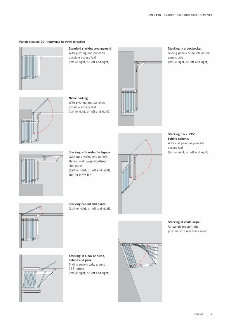
Panels stacked 90° transverse to travel direction
Standard stacking arrangement.With pivoting end panel as possible access leaf (left or right, or left and right).
Niche parking. With pivoting end panel as possible access leaf (left or right, or left and right).
Stacking with reshuffl e bypass(without pivoting end panel). Behind wall projection/fi xed side panel(Left or right, or left and right).Not for HSW-MR.
Stacking behind end panel.(Left or right, or left and right).
Stacking in a box or niche,behind end panel.Sliding panels only, around 135° offset (left or right, or left and right).
Stacking in a box/pocket.Sliding panels or double action panels only (left or right, or left and right).
Stacking track 135° behind column.With end panel as possible access leaf (left or right, or left and right).
Stacking at acute angle.All panels brought into position with rear track roller.
DORMA 5
HSW / FSW EXAMPLE STACKING ARRANGEMENTS
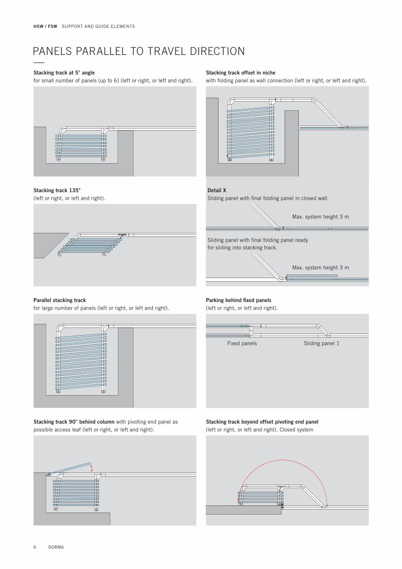
Stacking track 90° behind column with pivoting end panel as possible access leaf (left or right, or left and right).
Stacking track beyond offset pivoting end panel(left or right, or left and right). Closed system
PANELS PARALLEL TO TRAVEL DIRECTION—
Stacking track offset in niche with folding panel as wall connection (left or right, or left and right).
X
Max. system height 3 m
Detail XSliding panel with fi nal folding panel in closed wall.
Sliding panel with fi nal folding panel ready for sliding into stacking track.
Parking behind fi xed panels (left or right, or left and right).
Fixed panels Sliding panel 1
Stacking track 135°(left or right, or left and right).
Parallel stacking trackfor large number of panels (left or right, or left and right).
Stacking track at 5° anglefor small number of panels (up to 6) (left or right, or left and right).
Max. system height 3 m
6 DORMA
HSW / FSW SUPPORT AND GUIDE ELEMENTS

Stacking in front of 90° wall with 90° angle section without closing pivoting end panel
Stacking panels of varying width
Closed wallStacking without stacking track with 4 panels (2 pivoting end panels / 2 sliding panels)
Stacking at the wall in closed compartment behind pivoting end panel
Stacking at the wall in closed compartment without pivoting end panel
SPECIAL STACKING ARRANGEMENTS—
DORMA 7
HSW / FSW EXAMPLE STACKING ARRANGEMENTS

Straight track rail with stacking position transverse to travel direction
Straight track rail with stacking track parallel to direction of travel (135°)
T1
T2 = T1–36
150100100 a b b b 65
65
10
09
2B
2 =
B1
– 1
92
95°*92 T3 = T4 – 92
T4 = T1
Wid
th o
f st
acki
ng tra
ckB1
= Pan
el w
idth
– 1
20
mm
– (
0.0
87 x
T1)
B1
B2 = B1 – 41
T1T2 = T1 – 41
100 41100
T3
bb
bb
a1
00 135°
a = depending on pull handle depth
b = 65 mm for HSW-G 80 mm for HSW-R and HSW-GP 90 mm for HSW-ISO
B1 = Panel width – 130 mm T1 = T3 x 1.414 mm
a = depending on pull handle depth or 75 mm where profi le cylinder provided at front-mounted slide bolt
b = 65 mm for HSW-G80 mm for HSW-R90 mm for HSW-ISO
* HSW-GP cannot be provi-ded with a 95° branch
STACKING ARRANGEMENT CALCULATIONS—
8 DORMA
HSW / FSW SUPPORT AND GUIDE ELEMENTS

Straight track rail with stacking position parallel to travel direction (90°) with up to approx. 10 panels
Straight track rail with stacking position parallel to travel direction (90°) with more than 10 panels
B1100100
B2 = B1 – 128 923695°*
13
0a
bb
bb
80
T1
T2 =
T1
– 1
00
100
B1100100
B2 = B1 – 136 10036
T1
90°
130
5°
T2 =
T1
– 1
00
10
0
ab
bb
bb
b8
0
a = depending on pull handle depth or 75 mm where profi le cylinder provided at front-mounted slide bolt
b = 65 mm for HSW-G80 mm for HSW-R90 mm for HSW-ISO
* HSW-GP cannot be provided with a 95° branch
B1 = Panel width – 130 mm – ([T1 – 80] x 0.087)
a = depending on pull handle depth or 75 mm where profi le cylinder provided at front-mounted slide bolt
b = 65 mm for HSW-G80 mm for HSW-R and HSW-GP 90 mm for HSW-ISO
B1 = Panel width – 130 mm
DORMA 9
HSW / FSW STACKING ARRANGEMENT CALCULATIONS

HSW SUPPORT AND GUIDE ELEMENTS—Track Rails12 - 13Substructure 14 – 19
10 DORMA

DORMA 11

TRACK RAILS AND MODULES—Flexible and stableHorizontal sliding walls can be constructed in a wide range of different confi gurations to suit the site of installation, prevailing struc-tural conditions and the planning concept. With DORMA HSW systems, a variety of designs can be implemented with ease. Straight, segmented and curved track rails can be combined to produce virtually any serpentine shape required. The track rails in the form of hollow sections combine all the virtues of light weight, stability and torsional stiffness. And when combined with the HSW substructure, installation becomes even easier.Flexibility and stability mean that even unusual system confi gurations can be implemented without problem to give maximum functional reliability.
Straight track railFor a straight-line system confi guration, a drill hole interval of 300 mm in the track rail is suffi cient, while the stacking area requires an interval of 150 mm. Where the track assumes an angle of 161 – 179°, the track rail is mitred, while at angles between 90 and 160°, a segment is incorporated. The standard modules available are indica-ted in the adjacent illustrations.
72
75
l 9
50 150 150
50 300
75
Stacking track rail
Track rail at closed wall position
22.5°
45°90°
136
136
Straight track rail
20
0
40
36
400
40 60 60 40
l 9
90° T-piece
36
40030 30
l 9
80 36
135° T-piece
Leftor right
20
0
60
40
200364060
l 9
90°
90° L-piece
36136
85°/90°
3613
6
Modul 07/09 for 90°/95° angle Modul 06 for 45° angle 90° angle left/right
12 DORMA
HSW / FSW SUPPORT AND GUIDE ELEMENTS

Segmented track railWith the segmented track rail, it is possible to implement the DORMA HSW as a polygonal partition or frontage. In so doing, it is essential to note the following requirements:
. the panel width and segment chord length must be properly coordinated; . segment panels are provided at the bottom with locks or face-mounted fl oor bolts and the end cap are equipped with additional buffers for col-lision protection; . it is important to ensure that the opening sweep of single action and double action panels does not give rise to collisions.
Curved track railA curved track rail is also available where a curved DORMA HSW system confi guration is required. The most important technical prerequisites for this are as follows:
. only non-pivoting sliding panels may be installed in the curved track rail section; . the track rail must be straight in the parking or stacking area; . no top locking element can be installed; . each panel is provided with two face-mounted fl oor bolts; . a 100 mm straight track section (1) is necessary as the transition from the curved track rail to the straight stacking track rail; . blends from the curved confi -guration to a straight line can be implemented using standard modules (2); . the smallest curve radius is 3,500 mm (smaller radii on application) (3); . the feasibility of elliptic system confi gurations must be considered on a case-by-case basis – for this, drawings will be necessary; . the start and end points of the curve are always provided with a 90° saw cut (radial saw cut).
l 9
200
5030
030
0
300
300
12
3
1
Rminof the neutral fi bre = 3500 mm
Countersunk screw DIN 7991 M6x10. A2
72
75
Curved track rail, bolted double shell construction
DORMA 13
HSW / FSW TRACK RAILS

SUBSTRUCTURE - THE SYSTEM—SolutionsInstalling a horizontal sliding wall system invariably requires a certain set of structural condi-tions to be established. The system will need to be precisely aligned vertically – usually sub-sequent to installation – as well as being exactly confi gured and securely located. Because DORMA HSW systems do not use fl oor-level supports and fl oor tracks, the system require-ments and all their technical properties must be taken into account when designing the substructure and its incorpora-tion within the ceiling. This often very costly planning pro-cess is normally undertaken by the fabricator as the installation company, and alongside the calculations there are many indi-vidual structural and installation procedures involved. The new DORMA substructure system is of modular construction and is designed to signifi cantly reduce on-site installation cost and time. This concept also offers the particular fl exibility required to overcome structural constraints, such as the presence of air con-ditioning shafts or pre-existing electrical systems in the ceiling.
System designThe DORMA substructure con-sists primarily of the following components: substructure pro-fi le with modules for branching to the stacking area, threaded rods for suspension of the profi le(s), and standard square section tubes with appropriate fi xings and ceiling brackets for bracing and stiffening the construction.
Standard square section tubes
Pivot fi xing
Substructure profi le
Upper bolting channel
Pivoting angle bracket
Milled “U” recess
Centre channel
M10 threaded rod
Fixing plate
Lateral bolting channel
14 DORMA
HSW / FSW SUPPORT AND GUIDE ELEMENTS

Safety and fl exibilityThe DORMA substructure has been developed on the basis of extensive practical experience of the requirements involved in this kind of system. Conse-quently, the profi le incorporates features that greatly facilitate installation and ensure that pre-existing structural factors can be accommodated with maximum fl exibility. Various bolting channels run the whole length of the profi le, allowing bolts to be inserted easily at any location within the system confi guration. So there is no need for pre-drilling and thread cutting in order to mount the track rails onto the substructure. Bolted connections can be made directly through the lower bolting channel. The problem of removing drillings and fi lings from the track rails is thus also a thing of the past.Bolting channels on both sides of the profi le can be used e.g. for fi xing the brackets needed for attaching the ceiling retention elements. In addition, centering grooves on all main profi le surfaces facilitate overhead drilling, e.g. for accessory attachment. Welding brackets designed for bolting onto the profi le provide another option, allowing the DORMA system to be utilised for additional customer-specifi c applications.The substructure profi le is suspended from threaded rods. These are fi rst placed in the U-recesses using fi xing plates that lock into the upper bolting channel. Each pair of threaded rods is regarded as constituting one suspension point. Here again the system remains excep-tionally fl exible: the staggered U-recesses positioned at inter-vals of 100 mm enhance the ability of the system to accom-modate structural constraints. Depending on the weight of the system and the permitted
defl ection, it is possible to span a distance of up to 2,100 mm between two suspension points.The centre channel can be fi tted with two fl at aluminium bars to provide additional rigidity in the area of butt joints between profi les In this case it is possible to dispense with the dual sus-pension arrangement – with one suspension point either side of the joint – which is otherwise necessary. So existing building installations of all types can be effectively bypassed.Once the substructure has been installed, the HSW system is vertically aligned and fi xed directly via the threaded rods. Subsequent adjustments, e.g. after the building has settled into its foundations, can also be carried out by the same means.The standard square section tubes offer extra safety, espe-cially where the sliding panels deviate from a straight line. Panel sway must be effectively countered by the structural design adopted at such locations. Diagonal struts that counteract the pressure load stabilise the system in the area of the stacked panels. The telescopic square section tubes are connected as additional bracing elements (struts) to the sub-structure by a pivot fi xing. The struts are bolted to the ceiling using the appropriate angle brackets.The modular design of the DORMA substructure is pre-cisely matched to the modules of the DORMA HSW track rail. The structural elements can be mixed and matched as desired with the result that a small number of component types is suffi cient to create a complex, fl exible system that conforms fully to all safety requirements.A drawing of the required sub-structure can be requested from DORMA to supplement the HSW system drawing always supplied with the quotation.
The forces (shown by arrows) that occur during opening and closing of the sliding wall system must be absorbed by appropriately located bracing elements.
DORMA 15
HSW / FSW SUBSTRUCTURE

PLANNING DETAILS—
With a maximum load (panel weight) of 150 kg/m and a permitted defl ection of the substructure with track rail of 2 mm, the interval between two suspension points must be no greater than 1450 mm. The table below shows other values for different loads.
HSW-G characteristic valuesFormula for calculating the:Glazing height= system height – 309 mm= panel height – 193 mmGlazing weightGlass 10 mm = 25.00 kg/m2
Glass 12 mm = 30.00 kg/m2
Door rail weightAluminium = 12.00 kg/mBrass = 14.50 kg/mStainl. steel = 13.25 kg/m
Example systemHSW-G system in stainless steelSystem height 3,500 mmGlazing thickness 12 mm CalculationLoad= glazing weight x glazing
height + door track weight= 30 kg/m22 x (3,500 mm –
309 mm) + 13.25 kg/m= 30 kg/m2 x 3,191 mm +
13.25 kg/m= 108.98 kg/m
In order to prevent system sway, every second suspension point must be reinforced by a strut. The substructureprofi le ends (travel path and stacking area) should ideallybe directly connected to the masonry or to existingstructural members.
Max. 2 mm defl ectionbetween two suspension points
Table for the calculation of the max. distance dimension
F = ForceAM = Distance dimension
Force example:The distance dimension of 108,98 kg/m = 1,710 mm(can be linearly interpolated)
Front AM Parking area
F
Distance dimension max.depending on carrying function
F AM
60 kg/m 2,050 mm
75 kg/m 1,900 mm
90 kg/m 1,750 mm
105 kg/m 1,750 mm
120 kg/m 1,600 mm
135 kg/m 1,600 mm
150 kg/m 1,450 mm
160 kg/m 1,450 mm
Calculating the suspension intervals
Illustrative example of load values
1450 mm
16 DORMA
HSW / FSW SUPPORT AND GUIDE ELEMENTS

View from above
STACKING AREA DESIGN—
The construction of the stacking area, assembled from substruc-ture and track rail modules, provides a good illustration of how this well-designed system can be utilised. The individual components are coordinated to ensure safe integration. Joints in the substructure are offset to those in the track rails so that individual joints coincide with continuous material in all cases.Provided that the track rails are adequately bolted to the sub-structure, gaps of up to 40 cm measured from one suspension point to the next are permitted in the substructure.
Joints reinforced by central steel bar only require one local suspension point.
View from below
View from below
Substructure Track rail Detachable section
90° branch module
95° branch module
Strut
Joint area reinforced using fl at steel bars inserted in the centre channelStrut
Suspension points either side of joints not reinforced by central steel bar
L-piece for95° branch
1 suspension point= 2 threaded rods
90° T-piece
DORMA 17
HSW / FSW SUBSTRUCTURE

VARIANTS OF CONNECTION / DETAILS—
Profi le connection with connection lug
Art. No. 815.442.001.40
Wall connection with angeled connection lugs.Bending of connection lug on site according to need
Art. No. 815.442.001.40
Connection opportunities to existing bearing structure like ceilings, balks, steel girder by dint of adapter plate
Art. No. 815.435.001.40
30
30.5
50
Welding connection to steel girder
Connection to steel constructionFlexible connection to ceiling
30.5
Direct connection to ceiling
UK-Profi le
18 DORMA
HSW / FSW SUPPORT AND GUIDE ELEMENTS

COMPONENT PARTS, ACCESSORIES—
Component parts1 Pivoting angle bracket Art. No. 815.437.001.402 Fixing plate Art. No. 815.434.001.403 Pivot fi xing Art. No. 815.436.001.404 Adapter plate Art. No. 815.435.001.405 Basic substructure profi le,
stock length 6000 mm Art. No. 815.658.000.99Fixed length Art. No. 815.659.000.99
DIN and standard parts by others or on requestCSN = Company standard no.
A Threaded rod M10 x 1,000CSN 800.01.470.3.30
B Hex nut DIN 439-2 M10CSN 800.03.001.3.30
C Washer ISO 7089-10CSN 800.04.009.3.30
D Hex nut DIN 934-M6CSN 800.03.005.3.30
E Hex socket screwDIN 933-M6x35CSN 800.01.337.3.30
F Telescopic strut top section, square section tube,galvanised steel 20x20x2CSN 800.16.025.4.32
G Drilling screw DIN 7504 ST4 8x16CSN 800.01.286.3.30
H Telescopic strut bottom section, square section tube,galvanised steel 25x25x2CSN 800.16.026.4.32
I Hex nut DIN 934-M6CSN 800.03.005.3.30
J Hex socket screwDIN 933-M6x40 CSN 800.01.319.3.30
K Self-tapping screwISO 7049-St4.8 x 13-C-HCSN 800.01.493.3.30
L Cylinder head screw for fi xing track rail to substructure profi leDIN 912-M8x25CSN 800.01.018.3.30
17+
0.2
100 100 100
11+0.2
0.5 A
200
72
49
75
Stock length 6000 mm
L
5
J
G
H
G
F
E
D
1
A
B
B
2
C
I
K3
4
Adapter plate for neutral connection
DORMA 19
HSW / FSW SUBSTRUCTURE

HSW / FSW PANEL SYSTEM—HSW-G22 – 34
20 DORMA

DORMA 21

PANEL TYPES—In the case of the fully glazed HSW-G / HSW-MR systems, the panels create a continuous, transparent surface without any lateral framing. For a more sophisticated or intricate appea-rance, single-point fi xings (HSW-GP) are also available.
This folding system with top and bottom glazing rails coordi-nates perfectly with the HSW-G variant. The FSW-G operates without a separate stacking area, and instead folds together within the main frontage or partition zone.
HSW-G / HSW-MR / FSW-G / FSW-C/C plusFully glazed with door rails
HSW-GPFully glazed with single-point fi xings
22 DORMA
HSW / FSW PANEL SYSTEM

The all-round framing provided on the individual panels of an HSW-R system not only offers high stability but also an excel-lent barrier to keep out external infl uences. The panels can be constructed with laminated or toughened safety glass as required.
HSW-RFully framed
HSW-ISOFully framed with double glazing
DORMA 23
HSW / FSW HSW-G

PANEL TYPES AND FUNCTIONS —Horizontal sliding wallsFully glazed with glazing rails (100 mm) top and bottom
Within an HSW-G system, the individual panels can be designed to perform certain special functions. These range from simple sliding panels to
integrated doors with a variety of door closers, or special panels for unusual installation situations. And each system can be assembled to suit individual
requirements.The standard glass thickness is 10 or 12 mm. Further glass thicknesses on request.
Max. panel sizes and weights
Single action / double action end panelNon-sliding.Single action panel with fl oor pivot and TS 92 / TS 73 door closer.Double action panel with fl oor pivot or BTS fl oor spring.
Sliding panel
Fixed when frontage closed.
Single actionsliding panel
Single action sliding panel with TS 92 cam-action door closer, operational when frontage closed. Alternatively with ITS 961).
Double action sliding panel *
With RTS transom door closer, operational when frontage closed. Alternatively with ITS 962).
Double action sliding panel *
With RTS transom door closer, operational when frontage closed. Alternatively with ITS 962).
Max. system height 4,000 mm 4,000 mm 3,600 mm 3,600 mm 3,600 mm
Max. panel width 1,250 mm 1,250 mm 1,250 mm1)1,100 mm
1,250 mm2)1,100 mm
1,250 mm2)1,100 mm
Max. panel weight 150 kg 150 kg 100 kg** 100 kg** 100 kg**
The individual panels can also be of differing widths. The largest width should not exceed max. 115% of the smallest width.* For these panel types please consider our notes on portal systems on page 101.** Note: The maximum permissible weight relates to the complete door assembly, including handles.
24 DORMA
HSW / FSW PANEL SYSTEM

SYSTEM DESIGN —
Irrespective of the function of the individual panels, an HSW-G system comprises the following basic components:
1 Installation-effi cient DORMA substructure to accommodate track rail mounting require-ments (optional)
2 Track rail for bolting to the substructure.
3 Carrier4 Suspension assembly and5 bearing profi le for safe and
easy sliding of the panels. 6 Top door rail and 7 bottom door rail, both
comprising base profi les with clip-on face and side covers.
8 Toughened safety glass (by others).
Toughened laminated safety glass on request.
7
8
6
8
4
5
2
3
1
100
7
20
10
32
25
3510
033
±575
75
72
2,5
Floor surface
Bottom door rail designsAll depicted combinations are also available as mirror arrangements
End-mounted pin bolt at wall
End-mounted slide bolt
End-mounted pin bolt at wall
Face-mounted slide bolt
End-mounted pin bolt at wall
Deadlock
Recess for end-mounted slide bolt
Face-mounted slide bolt
Recess for end-mounted slide bolt
End-mounted slide bolt
Recess for end-mounted slide bolt
Deadlock
Deadlock End-mounted slide bolt
Face-mounted slide bolt
End-mounted slide bolt
Face-mounted slide bolt
Face-mounted slide bolt
Face-mounted slide bolt
Deadlock
DORMA 25
HSW / FSW HSW-G
634
c
d
ab
4
2,5
4 63
634
45 19
65 36
36,5 27
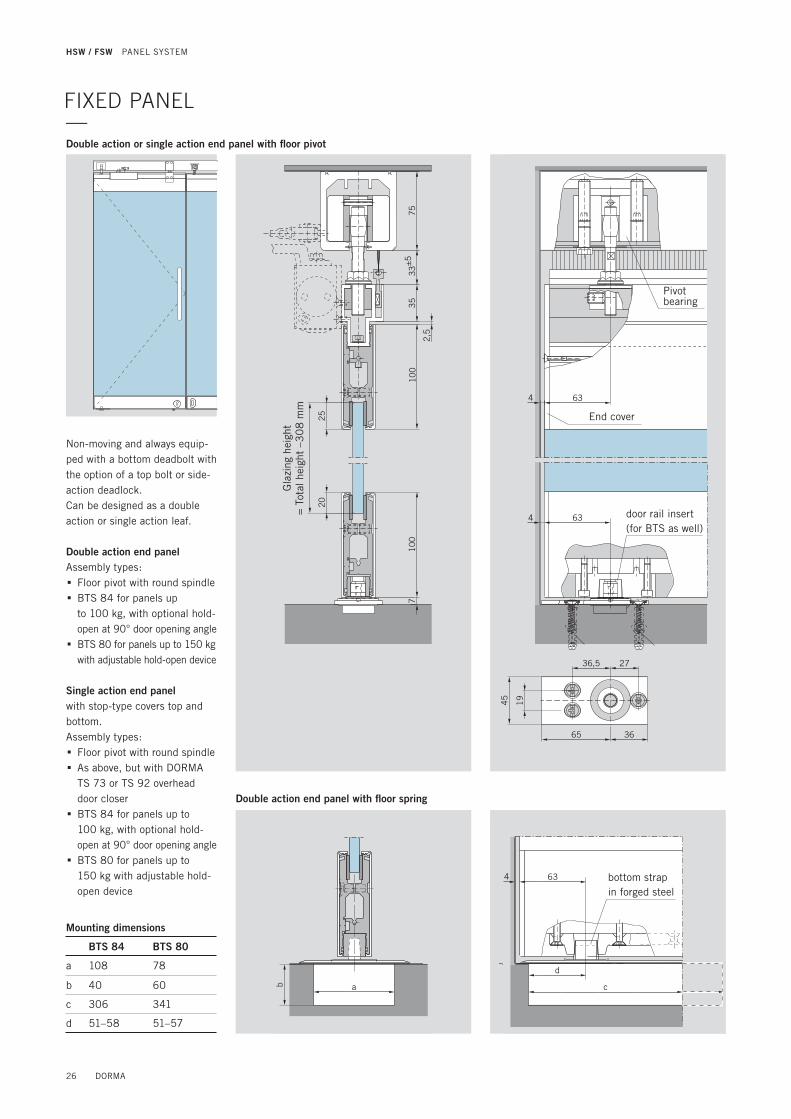
Double action or single action end panel with fl oor pivot
100
100
3575
33±5
2,5
2520
7
Gla
zing
hei
ght
= T
otal
hei
ght
–30
8 m
m
Double action end panel with fl oor spring
Non-moving and always equip-ped with a bottom deadbolt with the option of a top bolt or side-action deadlock. Can be designed as a double action or single action leaf.
Double action end panelAssembly types: . Floor pivot with round spindle . BTS 84 for panels up to 100 kg, with optional hold-open at 90° door opening angle . BTS 80 for panels up to 150 kg with adjustable hold-open device
Single action end panelwith stop-type covers top and bottom.Assembly types: . Floor pivot with round spindle . As above, but with DORMA TS 73 or TS 92 overhead door closer . BTS 84 for panels up to 100 kg, with optional hold-open at 90° door opening angle . BTS 80 for panels up to 150 kg with adjustable hold-open device
Mounting dimensions
BTS 84 BTS 80
a 108 78
b 40 60
c 306 341
d 51–58 51–57
FIXED PANEL—
Pivot bearing
End cover
door rail insert (for BTS as well)
bottom strap in forged steel
26 DORMA
HSW / FSW PANEL SYSTEM

45222
205 160 140
63 193,5
17
23
63
145,5 199 140
375
67
Single action end panel with TS 73 overhead door closer and additional locking device
Single action end panel with TS 92 overhead door closer and additional locking device
Additional locking device
min. panel width 870 mm
Data and features TS 73 V TS 92
Closing strength/size EN 2–4 EN 2–4
Closing strength, variable via adjusting screw and arm hinge
via adjusting screw and arm hinge
Closing speed adjustment via valve via valve
Non-handed x x
Latching speed adjustment via arm via arm
Cushioned stay limit adjustment 75°–180° 80°–120°
Hold-open adjustment 75°–160° 75°–150°
Weight 1.8 kg 1.9 kg
Length 233 mm 281 mm
Overall depth 42.50 mm 47 mm
Height 60 mm 65 mm
max. 14
DORMA 27
HSW / FSW HSW-G

75
35
33
±5
25
10
0
2,5
7
20
10
0
32
Stationary when the frontage or partition is closed.
Sliding panelThe sliding panels are the moving elements. Once in their closed position, they are locked down. The components availa-ble for this are provided in the bottom door rail in the form of face-mounted slide bolts, end-mounted slide bolts, end pin bolts or deadlocks.
Gla
zing
hei
ght
= T
otal
hei
ght
– 3
08
mm
250250
Bottom door rail
Panel width
Base profi le with integral functional element (here: face-mounted slide bolt)
Base profi le with functional element
(here: deadlock)
SLIDING PANEL—
65 65
4
Track roller
End cover
Sliding panelSliding panel
End-mounted slide bolt
Turn grub screw to adjust locking pin
Eccentric bushing
28 DORMA
HSW / FSW PANEL SYSTEM

Swing panel with TS 92 cam-action door closer for operation as a single action door when the frontage is closed.
With DORMA TS 92 cam-action door closerThis panel type is installed where doors only need to be opened in one direction. The pivoting sliding panels can be fi tted open inwardly or outwardly. In both cases, the cam-action door closer is fi xed to the inside face.
Standard assemblytop: Pivot bearing, TS 92
with slide channel, one locking device
bottom: Face-mounted slide bolt as pivot (released for sliding function) and lock
Optional equipmenttop: Second locking device
(for reshuffl e bypass)bottom: Optional second face-
mounted slide bolt instead of deadlock
Top pivot
4
65
75
35
33
±5
10
0
4TS 92
25
20
10
07
81
5
73129
13.5
11060
4
M6
l 7
l 1
0
Gla
zing
hei
ght
= T
otal
hei
ght
– 3
08
mm
Sliding panel Single action sliding panel
Face-mounted slide bolt
Pivot bearing
Track roller
Eccentric bushing
Locking device
max
. 2.5
SINGLE ACTION SLIDING PANEL—
DORMA 29
HSW / FSW PANEL TYPES HSW-G

Top pivot
With integral DORMA RTS transom door closerDouble action sliding panels with DORMA RTS transom door closers (patented design) are characterised by their excep-tional ease of installation and operation; an excellent alterna-tive to the solution with the BTS fl oor spring because the RTS does not require a large recess in the fl oor. These panels are generally equipped with a bottom deadlock and top locking device plus a bottom face-mounted slide bolt operating as the pivot bearing (released for the sliding function).The standard solution takes the form of the RTS 85 without hold-open, or as a special option, with a 90° hold-open.
For these panel types please consider our notes on portal systems on page 101.
3
10
0
7
20
20
46
32
56
33
±5
75
RTS 85
58
8
73129
11060
14,5 3
l 7
M6
l 7
Gla
zing
hei
ght
= T
otal
hei
ght
– 31
2 m
m
Locking device
max
. 2.5
65
RTS 85
4
Sliding panel
Double action sliding panel
RTS insert
Track roller
Eccentric bushing
Face-mounted slide bolt
Pivoting panel with RTS transom door closer for opera-tion as a double action door when the frontage is closed.
Max. Sliding panel weight 100 kg
DOUBLE ACTION SLIDING PANEL—
30 DORMA
HSW / FSW PANEL SYSTEM

10
02
,57
53
53
3±5
10
07
45
45
65
4
2,5
75
35
33
±5
10
0
20
25
10
07
Bottomdoor arm
Top centre lower part
Top centre upper part
4
2
180° opening angleOffset pivoting end panel at fi xed panel
Position 90° and 180° opening angle at wall, position 180° opening angle at fi xed panel
4
21
End cover
Fixed panel fi xing arrangement
Sliding panel Fixed panel
End cover
End-mounted slide bolt with fi xed pin
Gla
zing
hei
ght
= T
otal
hei
ght
– 3
08
mm
Offset hung end panelSingle action panel, non-sliding, operates independently of the rest of the system.The single action door with offset pivoting arm assembly can be swung around 180°, so leaving the entire operating zone free. A bottom deadlock secures the closed leaf.
Fixed side panelNon-moving side panel, inde-pendent of the rest of the system.The fi xed side panel is of the same basic design as the sliding panels. And if required, the fi xings can be replaced by a carrier system to convert such a panel into a sliding panel.
FIXED PANEL—
Pivoting end panel views as seen from below
Max. panel weight 100 kg
DORMA 31
HSW / FSW HSW-G
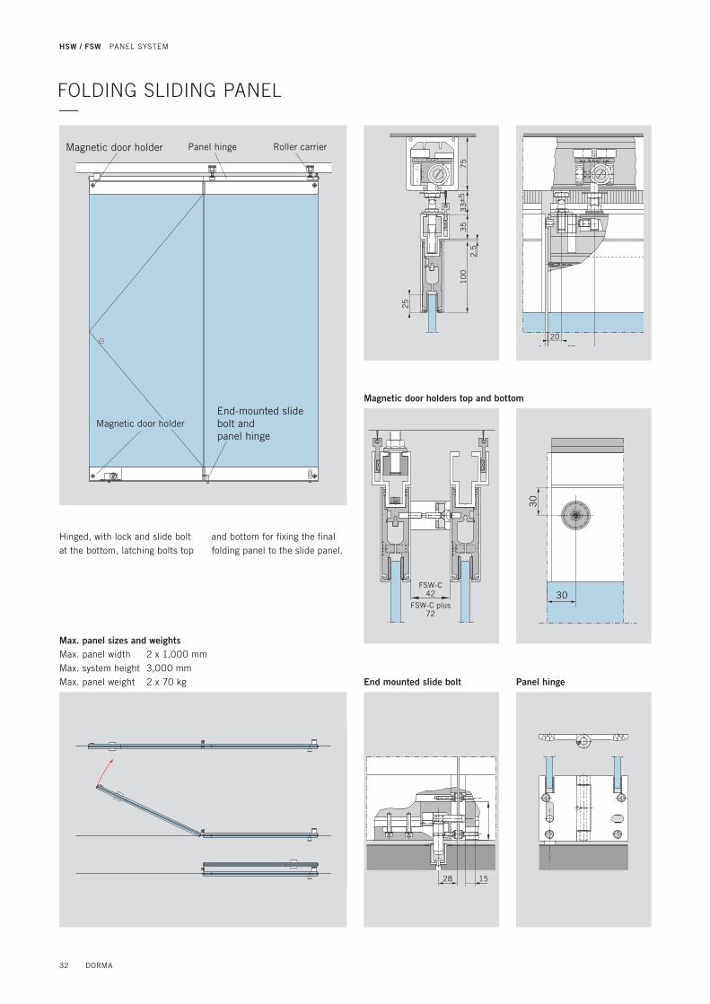
FOLDING SLIDING PANEL—
Max. panel sizes and weightsMax. panel width 2 x 1,000 mmMax. system height 3,000 mmMax. panel weight 2 x 70 kg
Magnetic door holder Panel hinge Roller carrier
Magnetic door holderEnd-mounted slide bolt and panel hinge
30
30
28 15
2.5
25
75
35
33
±5
10
0
20
654
Magnetic door holders top and bottom
End mounted slide bolt Panel hinge
Hinged, with lock and slide bolt at the bottom, latching bolts top
and bottom for fi xing the fi nal folding panel to the slide panel.
FSW-C42
FSW-C plus72
32 DORMA
HSW / FSW PANEL SYSTEM

SLIDING PANEL WITH ITS—
Data and features: ITS 96 Gr. 2 – 4
Closing strength / size EN 2 – 4 Max. opening angle ca. 120°
Max. panel width ≤ 1,100 mm Hold-open variable yes
Max. panel height ≤ 100 kg Weight 1.3 kg
Closing strenght continuously variable Adjusting screw Length 277 mm
Closing speed continuously variable Valve Overall depth 32 mm
Same design for DIN-L and DIN-R yes Height 42 mm
Latching speed continuously variable yes Door closer tested according to EN 1154 yes
Cushioned stay limit mechanically variable yes
129 75
81
5
4
15
11060
l 7
l 7
M6
7
4
32
10
0
25
20
37
75
35
33
±5
10
0
Gla
zing
hei
ght
= T
otal
hei
ght
– 3
08
mm
max
. 2.5
Single action sliding panelinward opening S
top
Slid
ing
pane
l
65
4
RollercarrierSliding track
Pivot point
Front mounted slide bolt
Single action sliding panel
Eccentric bushing
Max. panel weight 100 kg
Single action sliding panel with integral door closerITS 96 Gr. 2 – 4This panel variant is used where the door element is required to only open in one direction. Single action sliding panels can be either inward or outward opening.
Standard equipmentpivot at the top, ITS 96 with slide channel, 1 locking device at the bottom in the form of a face-mounted slide bolt (released in sliding mode) and deadbolt lock.
Optional equipment top2nd locking device (to facilitate disengaging); bottom: 2nd face-mounted slide bolt instead of deadbolt lock.
DORMA 33
HSW / FSW PANEL TYPES HSW-G

Double action sliding panel with integral DORMA door closerDouble action sliding panels with DORMA ITS 96 Gr. 2–4offer exceptional ease of instal-lation and operation, making them a good alternative to the variant with the BTS fl oors spring – particularly as the ITS 96 does not need a large recess in the fl oor. Being virtually invisible, its presence has no effect on the overall appearance of the partition. These panels come equipped as standard with a bottom dead-bolt lock and a locking device at the tope, together with a face-mounted slide bolt as the bottom pivot point (released in the sliding mode).In its standard form, ITS 96 is provided with a 90° hold-open.If you care considering this panel type, please note our advisories relating to portal systems on page 101.
4
11060
15
15
8
75129
l 7
M6
l 7
max
. 2.5
4
65
Roller carrier
Sliding track
Pivot point
front mounted slide bolt
Double action sliding panel
Eccentric bushing
33
±5
75
4
37
32
35
10
0
25
20
10
07
Gla
zing
hei
ght
= T
otal
hei
ght
– 3
08
mm
Data and features: ITS 96 Gr. 2 – 4
Closing strength / size EN 2 – 4 Max. opening angle ca. 120°
Max. panel width ≤ 1,100 mm Hold-open variable yes
Max. panel height ≤ 100 kg Weight 1.3 kg
Closing strenght continuously variable Adjusting screw Length 277 mm
Closing speed continuously variable Valve Overall depth 32 mm
Same design for DIN-L and DIN-R yes Height 42 mm
Latching speed continuously variable yes Door closer tested according to EN 1154 yes
Cushioned stay limit mechanically variable yes
DOUBLE ACTION SLIDING PANEL WITH INTEGRAL DOOR CLOSER—
34 DORMA
HSW / FSW PANEL SYSTEM

DORMA 35
HSW / FSW HSW-G

HSW / FSW PANEL SYSTEMS—HSW-MR38 - 42
36 DORMA

DORMA 37

TYPES AND FUNCTIONS —
Max. panel sizes and weights
Double action / single action end panelNon-sliding.Doubel action end panel with fl oor bearing and top pivot. Optional with fl oor spring BTS 80 / 84. Or as single action end panel with stop and BTS 80 / 84 orTS 92 / TS 73.
Sliding panel
Fixed when frontage closed.
Sliding panel
Fixed when frontage closed.
Fixed panel
Non-sliding.Fixed side panel with retaining pins at the top and door rail with bottom spacer pro-fi le at the bottom.
Max. system height 3,000 mm 3,000 mm 3,000 mm 3,000 mm
Max. panel width 1,250 mm 1,250 mm 1,250 mm 1,250 mm
Max. panel weight 100 kg 100 kg 100 kg 100 kg
Horizontal sliding wallsFully glazed with glazing rails (75 mm high) top and bottom.
Designed to meet the minimum essential requirements of a shop-front, the HSW-MR constitutes
a cost-effi cient alternative to the classic HSW-G.
The HSW-MR assemblies are available for 10 or 12 mm glass thickness.
38 DORMA
HSW / FSW PANEL SYSTEM

SYSTEM DESIGN —
Irrespective of the function of the individual panels, an HSW-MR system comprises the following basic components:
1 Installation-effi cient DORMA substructure to accommodate track rail mounting require-ments (optional).
2 Track rail for bolting to the substructure.
3 Carrier4 Suspension assembly and5 bearing profi le for safe and
easy sliding of the panels. 6 Top door rail and 7 bottom door rail, both compri-
sing base profi les with velcro technique and side covers.
8 Toughened safety glass or toughened laminated safety glass (by others) 10 / 12 mm.
2
3
4
5
1
6
8
8
7
36
72
3
19
19
75
75
75
73
53
3±5
75
End-mounted pin bolt at wall
End-mounted slide bolt
Bottom door rail designsAll depicted combinations are also available as mirror arrangements
End-mounted pin bolt at wall
Deadlock
Recess for end-mounted slide bolt
End-mounted slide bolt
Recess for end-mounted slide bolt
Deadlock
Deadlock End-mounted slide bolt
DORMA 39
HSW / FSW HSW-MR

7
19
19
75
75
75
75
727
63
45
94
36
19
36,5
13065
65
b
a
Gla
zing
hei
ght
= T
otal
hei
ght
– 26
5 m
m
Tota
l hei
ght
Double action end panel with fl oor spring
Double action end panelAssembly types: . Floor pivot with round spindle . BTS 80 / 84 for panels up to 100 kg, with optional hold-open at 90° door opening angle
Single action end panelwith stop top or stop-type covers top and bottom.Assembly types: . Floor pivot with round spindle . BTS 80 / 84 for panels up to 100 kg, with optional hold-open at 90° door opening angle
The choice of door closer will depend on the installation situation in each case.
Mounting dimensions
BTS 84 BTS 80
a 108 78
b 40 60
c 306 341
d 51–58 51–57
d
4
c
63
FIXED PANEL—
Double action or single action end panel with fl oor pivot
Non-moving and always equipped with a bottom deadbolt with the option of a top bolt or side-action deadlock. Can be designed as a double action or single action leaf.
40 DORMA
HSW / FSW PANEL SYSTEM

Sliding panelStationary when the frontage or partition is closed.The sliding panels are the moving elements. Once in their closed position, they are locked down. The components available for this are provided in the bottom door rail in the form of end-mounted slide bolts, end pin bolts or deadlocks.
250250
75
19
19
7
75
4 67G
lazi
ng h
eigh
t= T
otal
hei
ght
– 26
5 m
m
Tota
l hei
ght
Bottom door rail
Base profi le with integral functional element (here: end-mounted slide bolt)
Base profi le withfunctional element(here: deadlock)
Panel width
SLIDING PANEL—
DORMA 41
HSW / FSW HSW-MR

36
19
77
51
9
3
75
35
33
±5
75
Gla
zing
hei
ght
= T
otal
hei
ght
– 26
5 m
m
Fixed side panelNon-moving side panel, independent of the rest of the system.The fi xed side panel is of the same basic design as the sliding panels. And if required, the fi xings can be replaced by a carrier system to convert such a panel into a sliding panel.
FIXED PANEL—
4
6767
42 DORMA
HSW / FSW PANEL SYSTEM

DORMA 43
HSW / FSW HSW-MR

HSW / FSW PANEL SYSTEMS—HSW-GP46 - 49
44 DORMA
DORMA 45

HSW-GP PANELS AND FUNCTIONS —
The position of the track is not adjustable. The width of all panels must be uniform.
Fully glazed sliding walls with point-fi xed track roller carriers engaging in standard track rail.The characteristic features of HSW-GP systems are the single-point fi xings of the glass panels in combination with a conventio-nal track rail profi le. The design, featuring a high-grade stainless steel fi nish and the distinctive fl ush-mounted or clamping disc attachments, coordinates perfectly with contemporary architecture. Even curved glazing can be securely held by this system. And this can also be combined with curved track rail profi les to produce unique confi gurations. The standard glass thickness is 10/12 mm. Further glass thicknesses on request.
Max. panel sizes and weights
Double / single action end panelNon-sliding.With full-length pivot rod and offset pivot.Single action panel with fl oor pivot, round spindle and stop.Double action panel with fl oor pivot or BTS fl oor spring.
Sliding panel
Fixed when frontage closed.
Double / single action end panelNon-sliding.With centre pivot top and bottom.Single action panel with fl oor pivot, round spindle and stop.Double action panel with fl oor pivot.
Fixed panel
Non-sliding.Fixed side panel with retaining pins at the top and fi xed panel straps at the bot-tom.
Max. system height 3,000 mm 3,000 mm 3,000 mm 3,000 mm
Max. panel width 1,200 mm 1,200 mm 1,200 mm 1,200 mm
Max. panel weight 100 kg 100 kg 100 kg 100 kg
46 DORMA
HSW / FSW PANEL SYSTEM

SYSTEM DESIGN—
The HSW-GP system consists of the following basic components:
1 installation-effi cient DORMA substructure to accommodate track rail mounting require-ments (optional).
2 track rail for bolting to the substructure.
3 roller,4 suspension assembly,5 strap with single-point fi xings,6 toughened safety glass or
toughened laminated safety glass (by others),
7 bottom strap with end-mounted pin,
8 bottom strap with face-mounted slide bolt.
8
8,5
15,5
72
39
4
11
74
4
75
11
9
64
55
29
75
50
55
Sliding panel with bottom face-mounted slide bolt
Tota
l hei
ght
Gla
zing
hei
ght
= T
otal
hei
ght
– 12
6 m
m
Inside
2
3
4
5
1
6
7
411
74
4
75
11
9
64
55
29
72
75
50
55
Tota
l hei
ght
Sliding panel with bottom end-mounted pin
Gla
zing
hei
ght
= T
otal
hei
ght
– 12
6 m
m
Inside
Floor surface
DORMA 47
HSW / FSW HSW-GP

TYPES AND GLASS DRILLING REQUIREMENTS —
52
0 ±
0,3
15
60
± 0
,3 10
40
± 0
,3
65
11
365
15
07
115
0
65
50
55
64 8
49
55
52
0 ±
0,3
15
60
± 0
,3 10
40
± 0
,3
65
65
41 50
55
55
64
41
Double / single action end panel with pivot rod
Double / single action end panel
Glass drilling pattern
Glass drilling pattern
Glass bore centres for pull handle/back-to-back pull handles
Glass bore centres for pull handle/back-to-back pull handles
min. 65 mm
min. 65 mm
Strap with single-point fi xings
Pull handle/Back-to-back pull handles
Pivot strap with fl oor pivot
Deadlock
Gla
zing
hei
ght
= T
otal
hei
ght
– 12
6 m
mG
lazi
ng h
eigh
t = T
otal
hei
ght
– 12
6 m
m
Glazing width
Countersunk bores
Countersunk bores
l 55
for deadlock
Glazing width
Countersunk bores
Countersunk bores
l 55
for deadlock
73
150
71
7
8
Pivot pin
Pivot rod, short type with single-
point fi xings
Pull handle withsingle-point fi xings/Back-to-back pull handles
Pivot rod connecting tube
Pivot rod, short type with single-
point fi xings
Bottom bearing bush
Deadlock
Leng
th o
f co
nnec
ting
tube
= G
lazi
ng h
eigh
t –
535
mm
Visible corner notch
48 DORMA
HSW / FSW PANEL SYSTEM
l 2
6
10/12
Bores for clamping disc single-point fi xings
l 2
2
10/12
Bores for pull handle pairs
l 5
5
10/12
Bores for locks
10/12
l 3
2+0
,2
3-0,2
l 2
6
90
°
Countersunk bores for single-point fi xings for the pull handles and straps
55
8
55
8
4164
50
50
41
55
55
64
50
4141
55
64
55
41
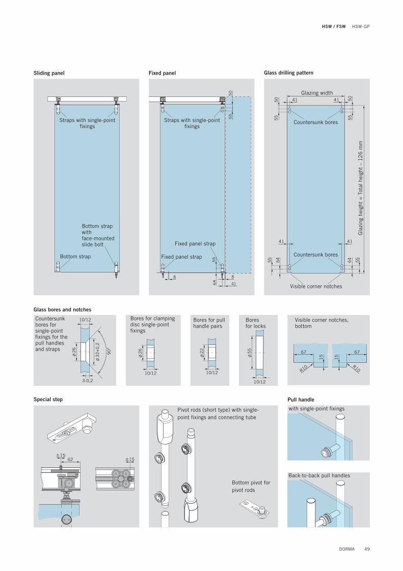
Sliding panel Fixed panel
Straps with single-point fi xings
Straps with single-point fi xings
Bottom strap with face-mounted slide bolt Fixed panel strap
Bottom strap Fixed panel strap
Glazing width
Visible corner notches
Countersunk bores
Countersunk bores
Gla
zing
hei
ght
= T
otal
hei
ght
– 12
6 m
m
Glass drilling pattern
R10 R10
67
15
67
15
Visible corner notches, bottom
± 1562 ± 15
Special stop
Pivot rods (short type) with single-point fi xings and connecting tube
Bottom pivot for pivot rods
with single-point fi xings
Back-to-back pull handles
Pull handle
Glass bores and notches
DORMA 49
HSW / FSW HSW-GP

HSW / FSW PANEL SYSTEMS
FSW-G52 - 55
50 DORMA

DORMA 51

TYPES AND FUNCTIONS —FSW folding sliding walls as fully glazed partitions and fron-tages, with door rails top and bottom, track roller position at the end of every second panel.Folding sliding walls are ideal for a straight-line system confi guration. In an FSW-G
partition, there are either 2 or 4 interlinked panels (1 base panel and 1 or 3 folding panels). With double assemblies moving counter to each other (bi-parting), therefore, it is possible to create frontages comprising up to 8 FSW panels. As the panels of
an FSW system are visually compatible with those of the HSW-G line and both systems use the same track construction, the two can be ideally combined as a single shopfront or transpa-rent partition, with the FSW system mating at its free end
with a free HSW single-action or double-action access panel (types 4 + 5).
For assembly types see pages 60 – 63.
1 4
6
2
7
2
655
3
1 Track rail2 Folding panel3 Folding hinge4 Roller5 FSW base panel6 Top locking device7 Bottom locking device
The standard glass thickness is 10/12 mm. Further glass thicknesses on request.
Example: assembly with 2 x 2 panels (type 1c) moving counter to each other
Max. panel sizes and weights
Base panelwith top pivot and bottom fl oor pivot.
Folding panelwith carrier and locking device top and bottom.
Folding panelwith carrier and locking device top and bottom.
Folding panelwith carrier and locking device top and bottom.
Max. system height 3,000 mm 3,000 mm 3,000 mm 3,000 mm
Max. panel width 1,000 mm 1,000 mm 1,000 mm 1,000 mm
Max. panel weight 70 kg 70 kg 70 kg 70 kg
52 DORMA
HSW / FSW PANEL SYSTEM

83
5
8,5 4,5
SYSTEM DESIGN—
The FSW-G system consists of the following basic components:
1 installation-effi cient DORMA substructure to accommodate track rail mounting requirements (optional).
2 track rail for bolting to the substructure.
3 top pivot,4 roller,5 top locking device,6 suspension assembly and7 carrier profi le for safe and
easy sliding of the panels.8 folding hinge,9 top door rail and
10 bottom door rail, both comprising base profi les with clip-on face and side covers.
11 toughened safety glass or toughened laminated safety glass (by others),
12 fl oor pivot,13 face-mounted slide bolt.
1
2
3
6
7
8
8
12
10
11
9
4
5
13
72
35
10
0
2,5
71
00
75
33
±5
75
25
20
32
10
Base panel Folding panel
Floorsurface
Door rails cut to size
DORMA 53
HSW / FSW FSW-G

ASSEMBLY TYPES —
Type 1a 2 panels left, as drawnType 1b 2 panels right, mirror arrangementType 1c 4 panels (2 panels left and 2 panels right), bi-parting
Type 2a 4 panels left, as drawnType 2b 4 panels right, mirror arrangementType 2c 8 panels (4 panels left and 4 panels right), bi-parting
Type 1
Type 2
Type 3
min
. 12
0 m
m
Type 3a 6 panels as drawn (4 panels left and 2 panels right)Type 3b 6 panels mirror arrangement (2 panels left and 4 panels right)
min
. 12
0 m
m
54 DORMA
HSW / FSW PANEL SYSTEM
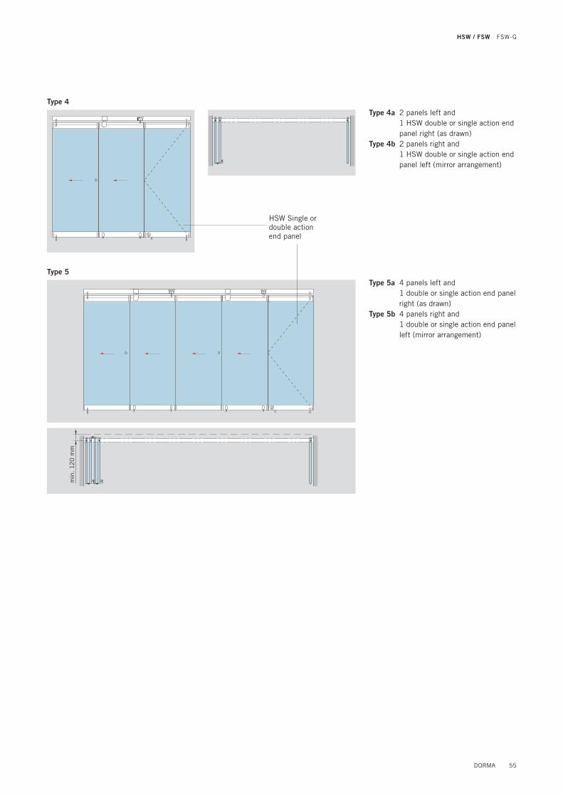
Type 4a 2 panels left and 1 HSW double or single action end
panel right (as drawn)Type 4b 2 panels right and 1 HSW double or single action end
panel left (mirror arrangement)
Type 4
min
. 12
0 m
m
HSW Single or double action end panel
Type 5Type 5a 4 panels left and 1 double or single action end panel
right (as drawn)Type 5b 4 panels right and 1 double or single action end panel
left (mirror arrangement)
DORMA 55
HSW / FSW FSW-G
HSW / FSW PANEL SYSTEMS—FSW-C/C-Plus58 - 63
56 DORMA

DORMA 57

TYPES AND FUNCTIONS —Folding sliding walls, fully glazed, with door rails top and bottom, track roller position in the panel centre.Large spans can be implemented with the FSW-C. Such a system consists of 1 base panel with up to 6 interlinked folding panels connected to it, plus one fi nal folding panel as the access leaf
(or alternatively 1 free single-action or double-action door panel). Hence the number of panels can range from 3 to 8. Because the track rollers are located at the centre of the folding panels, the base panel has to be of half width (+ pivot offset of 63 mm). For reasons of symmetry, the fi nal folding
panel without guide roller is usually also of half-width design.The folding hinges have a small degree of pivot offset, which means the panels take up less room when stacked and also gives added stability to the system.The hinges exhibit a slight pivot offset. This ensures that the
folded assembly is particularly compact while at the same time providing for good stability.The standard glass thickness is 10/12 mm. Further glass thicknesses on request.
For assembly types see pages 60 – 63.
Example: assembly type C2 (symmetrical with narrow folding panel)
Max. panel sizes and weights
Final fol-ding panelaccess leaf with locking devices top and bottom.
Folding panel
with carrier, locking devices top and bottom.
Folding panel
with carrier and locking device bottom.
Folding panel
with carrier and locking device bottom.
Base panel
with top and bottom pivot bearingand locking device bottom.
Max. assembly height 3,000 mm 3,000 mm 3,000 mm 3,000 mm 3,000 mm
Max. panel width 1,000 mm 1,000 mm 1,000 mm 1,000 mm 1/2 panel width + 63 mm
Max. panel weight – 70 kg 70 kg 70 kg 70 kg
4
1
4
3 3
3 3
25
5
8
4 8
7
4
61 Track rail2 Final folding panel3 Folding hinge4 Locking device5 Folding panel6 Base panel7 Top and bottom pivot bearing8 Roller
58 DORMA
HSW / FSW PANEL SYSTEM

35
35
30
30
1
2
3
4
5
6
9
8
7
10
72
75
33
±5
75
FSW-C42
FSW-C plus72
32
10
FSW-C42
FSW-Cplus 72
10
02
0
71
00
25
35
2,5
SYSTEM DESIGN —
28 15
20
Latching bolts top and bottom
Latching bolts top and bottomFolding panel with locking bolt
Floor surface
The FSW-C system consists of the following basic components:
1 installation-effi cient DORMA substructure to accommodate track rail mounting requirements (optional),
2 track rail for bolting to the substructure,
3 roller,4 suspension assembly and5 carrier profi le for safe and
easy sliding of the panels,6 top door rail and7 bottom door rail, both
comprising base profi les with clip-on face and side covers,
8 magnetic holder,9 toughened safety glass or
toughened laminated safety glass (by others),
10 bottom latching bolt.
End-mounted slide bolt, bottomBottom hinge
Glass panels
Face-mountedslide bolt
DORMA 59
HSW / FSW FSW-C

ASSEMBLY TYPES —
4 4 4 4
1 fi nal folding panel (here of narrow design for reasons of symmetry), 1 – 6 folding panels, 1 base panel (narrow)
FB FB FB1/2 FB+ 63
1/2 FB
74 mmbetween axes
Inside
Inside
between the door rails 42 mm
74 mmbetween axes
Inside
Inside
1 HSW single action end panel as access leaf (here of narrow design for reasons of symmetry), 1 – 6 folding panels, 1 base panel (narrow)
FB = Panel width
Type C1
Type C2
between the door rails 42 mm
60 DORMA
HSW / FSW PANEL SYSTEM

4 4 4
1 fi nal folding panel as access leaf, 1 – 6 folding panels, 1 base panel (narrow)
74 mmbetween axes
Inside
Inside
between the door rails 42 mm
FB = Panel width
1/2 FB
74 mm between axes
between the door rails 42 mm
Type C3
Type C3, double (bi-parting) systemLeft:1 base panel (narrow), 1 – 6 folding panels, 1 fi nal folding panel as access leaf
Right:1 fi nal folding panel as access leaf, 2 folding panels, 1 base panel (narrow)
FB FB FB1/2 FB+ 63
DORMA 61
HSW / FSW FSW-C

Inside
between the door rails 42
Dimensions between axes 104between the door rails 72
PANEL TYPES, FUNCTIONS, ASSEMBLY TYPES—Access with convenience – the plus with the FSW-C.Based on the design of the FSW-C, the alternative FSW-C plus offers the added benefi t that the connected fi nal folding panel can also function as a fully fl edged access leaf when the partition is closed – with all the convenience of the DORMA
TS 93 G door closer.In this case, the special bottom locking device and the top clamp-mounted stop stabilise the fi rst folding panel, while the top angle stop ensures that the closed fi nal folding panel is in the correct position.The folding hinges connecting the access leaf to the folding
panel have a large pivot point offset in order to create room for the door closer and pull handles. All the other folding panels are equipped with a standard folding hinge and roller.
Max. panel sizes and weights . Max. system height 3,000 mm . Max. width of fi nal folding panel and folding panel 1,000 mm . Width of the base panel= half panel width + 63 mm . Max. weight of fi nal folding panel and folding panel 70 kg . Number of panels 3 to 8
104 Dimensions between axes72 between the door rails
Inside42 mm between the door rails
Type Cp1 double (bi-parting) system
Left:1 base panel (narrow)1 folding panel1 – 6 fi nal folding panel as access leaf with TS 93 G door closerRight:1 fi nal folding panel as access
leaf with TS 93 G door closer1 – 6 folding panel1 base panel (narrow)
4 4
FB FB 1/2 FB+ 63
1/2 FB
FB = Panel width
Inside
Type Cp11 fi nal folding panel as access
leaf with TS 93 G door closer1 – 6 folding panel1 base panel (narrow)
62 DORMA
HSW / FSW PANEL SYSTEM

Type Cp21 fi nal folding panel as access
leaf with TS 93 G door closer1 – 6 folding panel1 base panel (narrow)
Inside
Inside
between the door rails 42 mm
between axes 104 mmbetween the door rails 72 mm
444
FB FB FB 1/2 FB+ 63
1/2 FB
FB = Panel width
Type Cp2 double (bi-parting) systemLeft:1 base panel (narrow)2 folding panels1 fi nal folding panel as access leaf with TS 93 G door closerRight:1 fi nal folding panel as access
leaf with TS 93 G door closer1 – 6 folding panel1 base panel (narrow)
Inside
42 mm between the door rails
104 mm between axes72 mm between the door rails
Data and features TS 93
Closing strength/size EN 2 – 5 EN 5 – 7Closing force, variable via adjusting screw via adjusting screwClosing speed adjustment via valve via valveNon-handed yes yesLatching speed adjustment via valve via valve Cushioned stay limit adjustment 80° – 120° 80° – 120°Hold-open adjustment 75° – 50° 75° – 150°Weight 3.5 kg 5.2 kgLength 275 mm 285 mmOverall depth 53 mm 62 mmHeight 60 mm 71 mm
DORMA 63
HSW / FSW FSW-C PLUS

HSW / FSW PANEL SYSTEMS—HSW-R66 - 72
64 DORMA

DORMA 65

TYPES AND FUNCTIONS —
Max. panel sizes and weights
Single / double action end panelNon-sliding.Doubel action end panel with fl oor bearing and top pivot. Optional with fl oor spring BTS 80 / 84. Or as single action end panel with stop and BTS 80 / 84 or TS 92 / TS 73.
Sliding panel
Fixed when frontage closed.
Single action sliding panelWith integrated con-cealed door closer type ITS 96, Size 3–6; operational when frontage closed.Minimal panel width 870 mm.
Double action sliding panel *With integrated con-cealed door closer type ITS 96, Size 3–6; operational when frontage closed.Minimal panel width 870 mm.
Max. system height 3,000 mm 3,000 mm 3,000 mm 3,000 mm
Max. panel width 1,100 mm 1,100 mm 1,100 mm 1,100 mm
Max. panel weight 100 kg 100 kg 100 kg 100 kg
The individual panels can also be of differing widths. The largest width should not exceed max. 115% of the smallest width.* For these panel types please consider our notes on portal systems on page 101.
Horizontal sliding walls, fully framed, for toughened safety glass, laminated safety glass or double glazing.Robust profi le frames with top, bottom brush seals and side rubber seals for elevated resis-tance to mechanical loading and decrease of weathering, heat loss and draughts. Prepared for toughened safety glass, lamina-ted safety glass, double glazing or special glazing; standard fi xing profi le for 8 to 22 mm, other glazing thicknesses on application.
66 DORMA
HSW / FSW PANEL SYSTEM

SYSTEM DESIGN—
Irrespective of the function of the individual panels, an HSW-R system comprises the following components:
1 Installation-effi cient DORMA substructure to accommodate track rail mounting requirements (optional)
2 Track rail for bolting to the substructure
3 Carrier4 Suspension assembly5 Adapter frame 6 Glazing frame profi le,
horizontal7 Glazing rail8 Glazing frame profi le,
vertical9 Toughened safety glass, la-
minated safety glass or sealed double glazing units (by others)
10 Bottom frame profi le.
72
50
60
75
33
±5
75
19
15
50
22 8
1915
75
06
0
11
6
9
8
4
3
2
2
7
5
10
6
7
8
Floorsurface
Toughened safetyglass version
DORMA 67
HSW / FSW HSW-R

50
60
77
55
07
53
3±5
15
15
a
b
8 63
d
c
Gla
zing
hei
ght
= T
otal
hei
ght
– 32
9 m
m
Double action end panel with fl oor spring
Single action or double action end panel with fl oor pivotNon-moving and always equipped with bottom deadbolt with the option of a top bolt or side action deadlock. Single action or double action options.
Double action end panelAssembly types: . Floor pivot with round spindle . BTS 84 for panels up to 100 kg, with optional hold-open at 90° door opening angle . BTS 80 for panels of 100–150 kg, provided with hold-open as standard
Single action end panelwith stop plates at the top bolt.Assembly types: . Floor pivot with round spindle . As above, but with DORMA TS 73 or TS 92 overhead door closer . BTS 84 for panels up to 100 kg, with optional hold-open at 90° door opening angle . BTS 80 for panels of 100–150 kg, provided with hold-open as standard
638
8 63
2736.5
1945
3665
Pivot bearing
BTS 80
BTS 84
a 78 108
b 60 40
c 341 306
d 51–57 51–58
Mounting dimensions
BTS 84 BTS 80
FIXED PANEL—
68 DORMA
HSW / FSW PANEL SYSTEM

145.5
63 199
375
89
205 160 140
63 193.5
222
45
50
l1
0
3.5
l7
M6
Single action end panel with TS 73 overhead door closer and additional locking device and door stop
Single action end panel with TS 92 overhead door closer and additional locking device
Additional locking device
min. panel width 870 mm
Data and features TS 73 V TS 92
Closing strength/size EN 2–4 EN 2–4
Closing strength, variable via adjusting screw and arm hinge
via adjusting screw and arm hinge
Closing speed adjustment via valve via valve
Non-handed x x
Latching speed adjustment via arm via arm
Cushioned stay limit adjustment 75°–180° 80°–120°
Hold-open adjustment 75°–160° 75°–150°
Weight 1.8 kg 1.9 kg
Length 233 mm 281 mm
Overall depth 42.50 mm 47 mm
Height 60 mm 65 mm
DORMA 69
HSW / FSW HSW-R

Panel to wall connection
SLIDING PANELS AND CONNECTIONS—
48
l8
67
±5l25
15
15
50
60
8–1
0
75
50
75
33
±5
Sliding panel
Engaging the panel in the strike plate
Gla
zing
hei
ght
= T
otal
hei
ght
–32
9 m
m
Sliding panelFixed when partition is closed.The sliding panels are moving elements. Once in their closed position, they are locked down. The components available for this are provided in the bottom rail in the form of face-mounted fl oor bolts or deadlocks.
Sliding panel
Strike plate
Engaging the panel in eccentric bushing
l8 l25
±2,5
Sliding panel
Sliding panel
Eccentric bushing
min
.3
0
Sliding panel to panel connections
Slinding panel
Brush profi le
Sliding panel / double or single action end panel
51 6 51
Panel widthGlass width =Panel width–75 mmSeal
Slinding panel Slinding panel
Wall connection profi le withbrush profi le
Slinding panel
Brush profi le
Single actionSliding panel
90–170°6
Abutment with articulated joint
67
610
51 51
Slinding panel Double actionSliding panel
70 DORMA
HSW / FSW PANEL SYSTEM

+ 2,5
l25
l8
50
75
33
±5
75
61
5
60
50
15
8–1
0
Gla
zing
hei
ght
== T
otal
hei
ght
–32
9 m
m
l7
l1
0
3,5
M6
50
129 73
110
4
60
15
8
13,5
Locking device
Single action sliding panel with integrated DORMA ITS 96 concealed door closer, size 3 – 6This panel type is used where passdoors only need to be opened in one direction.The single action sliding panel can be confi gured for either inward or outward opening.
Standard assemblytop: Pivot bearing, ITS 96,
size 3 – 6, one locking device
bottom: Face-mounted fl oor bolt as pivot (released for sliding function)
Optional equipmenttop: Second locking device
(for reshuffl e bypass stacking)
bottom: Optional second face-mounted fl oor bolt or deadlock
Track roller
Single actionSliding panel
Top pivot
Face-mounted fl oor bolt
Eccentric bushing
min
.3
0
SLIDING PANEL WITH ITS—
DORMA 71
HSW / FSW HSW-R

Double action sliding panel with integrated DORMA ITS 96 concealed door closer, size 3 – 6Double action sliding panels with DORMA ITS 96, size 3 – 6 door closers are characterised by their exceptional ease of installation and operation.These passdoor panels are generally equipped with a bottom deadlock and top locking device plus a bottom fl oor bolt operating as the pivot bearing (released for the sliding function).The ITS 96 does not feature a hold-open function as standard.
For these panel types please consider our notes on portal systems on page 101.
50
75
33
±5
75
61
5
60
50
15
8–1
0
Gla
zing
hei
ght
== T
otal
hei
ght
–32
9 m
m
l7
l1
0
3,5
M6
50
129 73
110
4
60
15
8
13,5
Locking device
SLIDING PANEL WITH ITS—
+ 2,5
l25
l8
Track roller
Single actionSliding panel
Top pivot
Face-mounted fl oor bolt
Eccentric bushing
min
.3
0
72 DORMA
HSW / FSW PANEL SYSTEM

DORMA 73
HSW / FSW HSW-R

HSW / FSW PANEL SYSTEMS—HSW-ISO76 - 82
74 DORMA

DORMA 75

PANEL TYPES AND FUNCTIONS —Panel typesThese double-glazed panels with their frames of thermal-break profi les (frame material group 2.1) offer outstanding protection
against the infl uences of the weather, effective thermal insulation and comfortable temperatures – even close to the frontage surface – during seasonal
changes and in the winter months. And all these effects are ideally enhanced by laterally arranged, interlocking multiple-lip seals plus automatically extending top
and bottom rubber seals that are pressed against the track rail and fl oor when the frontage is closed. Double glazing thickness 24 – 49 mm.
The individual panels can also be of differing widths. The largest width should not exceed max. 115% of the smallest width.
Max. panel sizes and weights
Single action door
Single action panel, non-sliding, equipped with TS 92/93 door closer(optional)
Sliding panel
Fixed when frontage closed.
Single action sliding panelfor door access when frontage closed; with ITS 96 EN 3 – 6 concealed cam-action door closer, or with TS 92/TS 93 cam-action door closers if required.
Fixed panel
Non-sliding side panel with top retaining brackets and bottom rail.
Max. system height 3,000 mm 3,000 mm 3,000 mm 3,000 mm
Max. panel width 1,100 mm 1,100 mm 1,100 mm 1,100 mm
Max. panel weight 120 kg 120 kg 120 kg 120 kg
76 DORMA
HSW / FSW PANEL SYSTEM

SYSTEM DESIGN —
Irrespective of the function of the individual panels, an HSW-ISO system comprises the following basic components:
1 Installation-effi cient DORMA substructure to accommodate track rail mounting require-ments (optional)
2 Track rail for bolting to the substructure
3 Carrier4 Suspension assembly and be-
aring profi le for safe and easy sliding of the panels
5 Glazing rail6 Sealed double glazing unit
(by others). Glass thickness 8–49 mm
7 Automatically extending rubber seal
8 Insulating strips in the thermal-break profi le
9 Bottom frame profi le
72
75
75
16
59
67
64
8–49
16
8
10
6 12
8
7
22
10
4
45
37
33
±5
22
7
8
9
7
6
5
6
5
1
2
3
4
Floorsurface
DORMA 77
HSW / FSW HSW-ISO

140
428150
160
5959
16
5
22
64
81
22
375
6
Inward opening
Offet hung end panel with wall connection profi leSingle action panel, non-sliding, operates independently of the rest of the system.The single action door with wall connection arm assembly can be swung round 170°, so leaving the entire operating zone free. The closed panel is secured by a mortise centre lock.
In order to provisionally determine the glazing area per panel, please apply the following formula:Approx. glazing area per panel = Panel width x total height x 0.78
The precise dimensions of the sealed double glazing units to be ordered should be exclusively taken from the approval drawing released by DORMA-Glas.
Outside
Inside
59 5 59
22
64
22
81
59
37 5
16
Outward opening
Outside
Inside
Fram
e he
ight
Glaz
ing
heig
ht
Pan
el h
eigh
t in
side
Tota
l hei
ght
SINGLE ACTION DOOR WITH WALL CONNECTION—
78 DORMA
HSW / FSW PANEL SYSTEM

Fixed panelNon-sliding side panel that decouples from the rest of the system. The fi xed panel has the same appearance as the sliding panels.Instead of the automatically extending bottom rubber seal, it features a bottom rail. In order to provisionally deter-
mine the glazing area per panel, please apply the following formula:Approx. glazing area per panel = Panel width x total height x 0.78
The precise dimensions of the sealed double glazing units to be ordered should be exclusively taken from the approval drawing released by DORMA-Glas.
Fixed panel with wall connection profi le
7622
59
16
59Outside
Inside
22
59 54
5
16
77 37Outside
Inside
Fram
e he
ight
Glaz
ing
heig
ht
Pan
el h
eigh
t in
side
Tota
l hei
ght
Sound protectionMeasurements performed by the Institute for Window Technology (Institut für Fenstertechnik e.V., Rosenheim), revealed a sound protection value of min. 27 dB based on a four-panel installation.
Thermal protectionThe heat transfer coefficient Uw will be calculated according to DIN EN 10077-1.Example value: Panel B 900 x H 2,500, Ug (glass) = 1.1 W/m2K, Uf (frame) = 2.6 W/m2K, Uw = 1.9 W/m2K
The values necessary for calcula-ting the Uw value are indicated in DIN EN ISO 10077-1:2006.
Data and features TS 92 TS 93
Closing strength/size EN 2-4 EN 2-5 EN 5-7
Closing force, variable via adjusting screw via adjusting screw via adjusting screw
Closing speed adjustment via valve via valve via valve
Non-handed yes yes yes
Latching speed adjustment via valve via valve via valve
Cushioned stay limit adjustment 80°–120° 80°–120° 80°–120°
Hold-open adjustment 75°–150° 75°–150° 75°–150°
Weight 1.9 kg 3.5 kg 5.2 kg
Length 281 mm 275 mm 285 mm
Overall depth 47 mm 53 mm 62 mm
Height 65 mm 60 mm 71 mm
FIXED PANEL WITH WALL CONNECTION—
DORMA 79
HSW / FSW HSW-ISO

Sliding panelFixed when the frontage or partition is closed.The sliding panels are the moving elements. Once in their closed position, they are locked down. Face-mounted fl oor bolts are available as an option for the bottom glazing rail.
6
In order to provisionally deter-mine the glazing area per panel, please apply the following formula:Approx. glazing area per panel = Panel width x total height x 0.78
The precise dimensions of the sealed double glazing units to be ordered should be exclusively taken from the approval drawing released by DORMA-Glas.
Fram
e he
ight
Glaz
ing
heig
ht
Pan
el h
eigh
t in
side
Tota
l hei
ght
Horizontal sections of the sliding panels with connection detailsSliding panel to wall connection profi le Sliding panel to sliding panel
5
16
3777
64
59 6 54
22
Outside
Inside
5
16
5977
16
64
59 6 76
22 22
Outside
Inside
SLIDING PANEL—
80 DORMA
HSW / FSW PANEL SYSTEM
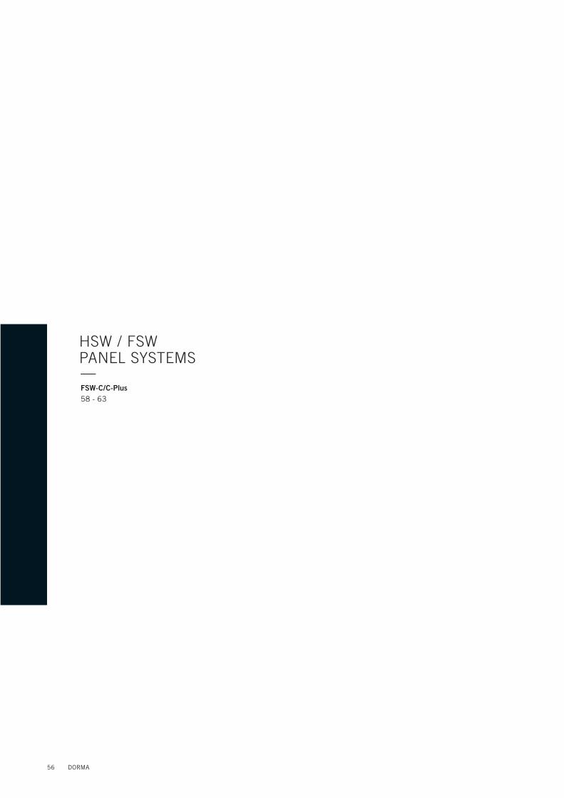
Single action sliding panel with integrated ITS 96 3-6This panel type is installed where doors need to be opened in one direction. The cam-action door closer can be fi tted so that the single action panel is either inward or outward opening.
Standard assemblytop: Pivot bearing, ITS 96, size
3–6 one locking devicebottom: Face-mounted slide
bolt as pivot (released for sliding function)
Optional equipmenttop: Second locking device
(for reshuffl e bypass stacking)
bottom: Optional second face-mounted slide bolt
129129
Function of the top locking device
Status of locking device for door operation
Status of locking device for sliding5 5981
2216 16
64
59 5 81
222222
Horizontal section of single action panels, inward or outward opening
Inward opening
Outward opening
6
300 184
ITS 96 door closer integrated in the profi le (concealed installation)
Fram
e he
ight
Glaz
ing
heig
ht
Pan
el h
eigh
t ou
tsid
e
Tota
l hei
ght
SLIDING PANEL WITH ITS—
DORMA 81
HSW / FSW HSW-ISO

Sliding panel in bypass travel mode (sliding end panel)
Single action sliding panel in bypass travel mode (outward opening only)
RESHUFFLE BYPASS CONFIGURATION—Stacking in the reshuffl e bypass confi gurationThis special stacking arrange-ment is applied when the panels should be parked in a niche and no single action end panel should be visible in the frontage.Please also see the following illustrations.
82 DORMA
HSW / FSW PANEL SYSTEM

DORMA 83
HSW / FSW HSW-ISO

ACCESSORIES—Vertical Seals Overview86 - 87Vertical Sealing Profi les88 - 95Floor Track96 - 97
84 DORMA

DORMA 85

4
10
(12
)
4
The following retrofi ttable profi les are available to provide the necessary lateral sealing so that the horizontal sliding can be made draught-proof for winter operation.
Glass joint gasketfor 10 – 12 mm glass,adhesive, milky transparent
Clear plastics profi le(not for single/double action end panels or double action sliding panels)
for 10 and 12 mm glass
RETROFITTABLE PROFILES—
86 DORMA
HSW / FSW ACCESSORIES

The vertical sealing profi les provide protection of the exposed lateral glass edges of the HSW panels. In addition, the integral double brush seals ensure
excellent draft-proofi ng. The sealing profi les are individually tailored to the requirements of the bottom glazing rails, so they are already prepared for the
locking devices such as fl oor bolts, end pins and vertically engaging deadlocks. At the top, a degree of extra length is provided to enable precise
sealing profi le adaptation to the exact panel height once the system has been vertically aligned.
Vertical Sealing Profi le
Vertical Sealing Profi le
13
5.5
1
2
10
(12
)
33
13
5.5
2
33
VERTICAL SEALING PROFILES—
DORMA 87
HSW / FSW VERTICAL SEALS OVERVIEW

VERTICAL SEALING PROFILES—
End panelNon-sliding, always fi tted with a bottom deadlock. With additional top bolt or side-action deadlock as options either as single action or double action end panel.
As-delivered condition of the vertical sealing profi les: Cut lengths supplied from factory = Partition height – 110 mm.
Holes and recesses are pre-machined in the profi le for the bottom glazing rail only.Any further machining work required for connection to the top glazing rail has to be performed on site.
M4
20
25
32.5
58.5
58.53
3
5.5 110 (12
)
5.5
Bottom drill hole or recess for end-mounted fl oor bolt machined by DORMA-Glas
As-
deliv
ered
leng
th (
tota
l hei
ght
– 11
0 m
m)
Ada
pt p
rofi l
e le
ngth
on
site
Installation instructionsWhen fi tting the glazing rails, please ensure that the glass protrusion is even over the full length.Prior to profi le machining, fi rst hang the panels from the overhead track and then align.
88 DORMA
HSW / FSW ACCESSORIES

33
2
1
5.5
Sliding panelsStationary once frontage closed and secured. Sliding panels are fi xed in position when the partition is closed. Face-mounted sliding bolts and deadlocks are available for incorporation in the bottom glazing rail.
As-delivered condition of the vertical sealing profi les: Cut lengths supplied from factory = Partition height – 110 mm.
Holes and recesses are pre-machined in the profi le for the bottom glazing rail only.Any further machining work required for connection to the top glazing rail has to be performed on site. Installation instructions
When fi tting the glazing rails, please ensure that the glass protrusion is even over the full length.Prior to profi le machining, fi rst hang the panels from the overhead track and then align.
M4
20
25
32
.5
Bottom drill hole or recess for end-mounted fl oor bolt machined by DORMA-Glas
As-
deliv
ered
leng
th (
tota
l hei
ght
– 11
0 m
m)
Ada
pt p
rofi l
e le
ngth
on
site
Sliding panel
DORMA 89
HSW / FSW VERTICAL SEALING PROFILES

25
32
,5
20
Sliding panels in segmented confi gurationsStationary once frontage closed and secured.Sliding panels are fi xed in position when the partition is closed.Face-mounted sliding bolts and deadlocks are available for incorporation in the bottom glazing rail.
As-delivered condition of the vertical sealing profi les: Cut lengths supplied from factory = Partition height – 110 mm.
Holes and recesses are pre-machined in the profi le for the bottom glazing rail only.Any further machining work required for connection to the top glazing rail has to be performed on site.
12°
33
5.51
25°
33
5.51
331
5.5
90°
Installation instructionsWhen fi tting the glazing rails, please ensure that the glass protrusion is even over the full length.Prior to profi le machining, fi rst hang the panels from the overhead track and then align.
Profi le to upper face of brush carrier
As-
deliv
ered
leng
th (
tota
l hei
ght
– 11
0 m
m)
Ada
pt p
rofi l
e le
ngth
on
site Sliding panel
VERTICAL SEALING PROFILES—
90 DORMA
HSW / FSW ACCESSORIES

RTS double action sliding panelDouble action sliding panel with RTS transom-concealed door closer in closed frontage.Face-mounted sliding bolts and deadlocks are available for incorporation in the bottom glazing rail.
As-delivered condition of the vertical sealing profi les: Cut lengths supplied from factory = Partition height – 110 mm.
Holes and recesses are pre-machined in the profi le for the bottom glazing rail only.Any further machining work required for connection to the top glazing rail has to be performed on site.
Installation instructionsWhen fi tting the glazing rails, please ensure that the glass protrusion is even over the full length.Prior to profi le machining, fi rst hang the panels from the overhead track and then align.
RTS 85
20
20
33
As-
deliv
ered
leng
th (
tota
l hei
ght
– 11
0 m
m)
Ada
pt p
rofi l
e le
ngth
on
site
60.5
33
2
1
5.5
Sliding panel
Double action sliding panel with RTS
Bottom drilling and machining work for end-mounted sliding bolt performed by DORMA-Glas GmbH
DORMA 91
HSW / FSW VERTICAL SEALING PROFILES

Double action sliding panel with ITS 96Double action sliding panel with ITS 96 integrated door closer in closed frontage. Face-mounted sliding bolts and deadlocks are available for incorporation in the bottom glazing rail.
As-delivered condition of the vertical sealing profi les: Cut lengths supplied from factory = Partition height – 110 mm.
Holes and recesses are pre-machined in the profi le for the bottom glazing rail only.Any further machining work required for connection to the top glazing rail has to be performed on site.
2
1
5.5
32
VERTICAL SEALING PROFILES—
33
25
20
As-
deliv
ered
leng
th (
tota
l hei
ght
– 11
0 m
m)
Ada
pt p
rofi l
e le
ngth
on
site
Bottom drilling and machining work for end-mounted sliding bolt performed by DORMA-Glas GmbH
60.5
Door rail
Installation instructionsWhen fi tting the glazing rails, please ensure that the glass protrusion is even over the full length.Prior to profi le machining, fi rst hang the panels from the overhead track and then align.
92 DORMA
HSW / FSW ACCESSORIES

80
57
7
l50
10
50
33
17
5
Installation instructionsWhen fi tting the glazing rails, please ensure that the glass protrusion is even over the full length.Prior to profi le machining, fi rst hang the panels from the overhead track and then align.
Lock with lever handle and strike box optional.
Folding sliding panelHinged, with lock and magnetic fi xing devices top and bottom for securing the folding panel to the sliding panel ready for transfer.
As-delivered condition of the vertical sealing profi les: Cut lengths supplied from factory = Partition height – 110 mm.
Holes and recesses are pre-machined in the profi le for the bottom glazing rail only.Any further machining work required for connection to the top glazing rail has to be performed on site.
OKFF
DORMA 93
HSW / FSW VERTICAL SEALING PROFILES

ITS 96 single action or double action sliding panels with Universal centre lock and Universal keeperDouble action sliding panel with ITS 96 integrated door closer in closed frontage.Face-mounted sliding bolts and deadlocks are available for incorporation in the bottom glazing rail.
As-delivered condition of the vertical sealing profi les: Cut lengths supplied from factory = Partition height – 110 mm.
Holes and recesses are pre-machined in the profi le for the bottom glazing rail only.Any further machining work required for connection to the top glazing rail has to be performed on site.
VERTICAL SEALING PROFILES—
13
2
13
27
43
16
,5
33
64
OKFF
Installation instructionsWhen fi tting the glazing rails, please ensure that the glass protrusion is even over the full length.Prior to profi le machining, fi rst hang the panels from the overhead track and then align.
94 DORMA
HSW / FSW ACCESSORIES

Profi le machiningFor end-mounted and face-mounted sliding bolts performed by DORMA-Glas GmbH.
Preparation of vertical sealing profi le for face-mounted sliding bolt and mounting
32
.7
21
11
44
11
5.5
1
2
60 30
41
M4x18
20.5
M4x10
5.51
2
105,5 30
60,5
66
20
32
.7
Vertical sealing profi les with end-mounted slide bolt
Vertical sealing profi les with face-mounted slide bolt
Latching pin
Tool for preparing vertical sealing profi les
Preparation of vertical sealing profi le for face-mounted sliding bolt
Tool for preparing the top of vertical sealing profi les
Article number 828.231.000.99
DORMA 95
HSW / FSW VERTICAL SEALING PROFILES

FLOOR TRACK FOR SLIDING PANELS—
A fl oor track in the form of a stainless steel channel section (U-profi le) is also available as an option. This can be used for HSW-G and HSW-R sliding panels irrespective of the parti-tion layout. In special cases and after technical clarifi cation, it may also be used with HSW-GP sliding panels. For this, the end-mounted fl oor bolt usually applied for straight-line partition confi gurations is replaced by a combination of guide pin and end pin.The guide pin must be vertically below the track roller and is adjus-table in the range +/– 10 mm.For abutment to single action/double action end panels and also in the case of angled confi -gurations, a face-mounted fl oor bolt is replaced by a bottom deadlock.
The fl oor track is available in three designs: . Straight . 90° curve . 135° curve.
The individual track sections are abutted and fi xed in place by means of a stainless steel connector. In its as-delivered condition, the fl oor track comes with a welded fl ange for fi xing to the unfi nished fl oor. This can be removed if not required.
35
14.5
10
07
5
9
33
±5
20
25
10
0
2.5
7
21
65
65
4
Sliding panel
Straight90° curve
135° curve
Hex head boltM6 x 35, 10 mm A/F
Sliding panel
Gla
zing
hei
ght
= T
otal
hei
ght
– 3
08
mm
96 DORMA
HSW / FSW ACCESSORIES

FLOOR TRACK – STACKING TRACK DETAIL—
R100
90°
40
214
40
214
276
40
120
40 135°
R100
(19)
1
20
(10.5
)
R112.5
±1
90°
max. length 3000 mm
Floor track
10
1
11
(14
.5)
R1
12.5
±0,3
91°
50
Floor track connector
HSW fl oor track confi guration with a 90° stacking track arrangement
HSW fl oor track confi guration with a 135° stacking track arrangement
HSW fl oor track confi guration with a parallel stacking track arrangement
Floor track
Floor track connector
Floor fi xing fl angeCan be removed if not required
DORMA 97
HSW / FSW FLOOR TRACK

GENERAL INFORMATION—Measuring Up100General Information101 -102
98 DORMA

DORMA 99

MEASURING UP—Important site measurements
Wall frontage/closed wall system
Reshuffl e bypass
Stackingtrack depth
Sta
ckin
g tr
ack
wid
th
Clear width (fi nished wall)
Height ofstructural ceiling
FFLTop surface of fi nished fl oor
Top surfaceof structural fl oor
1-metre datum line (site reference dimension)
HSW system heighttrack height
Height of suspended ceiling
Track
Substructureheight
100 DORMA
HSW / FSW GENERAL INFORMATION
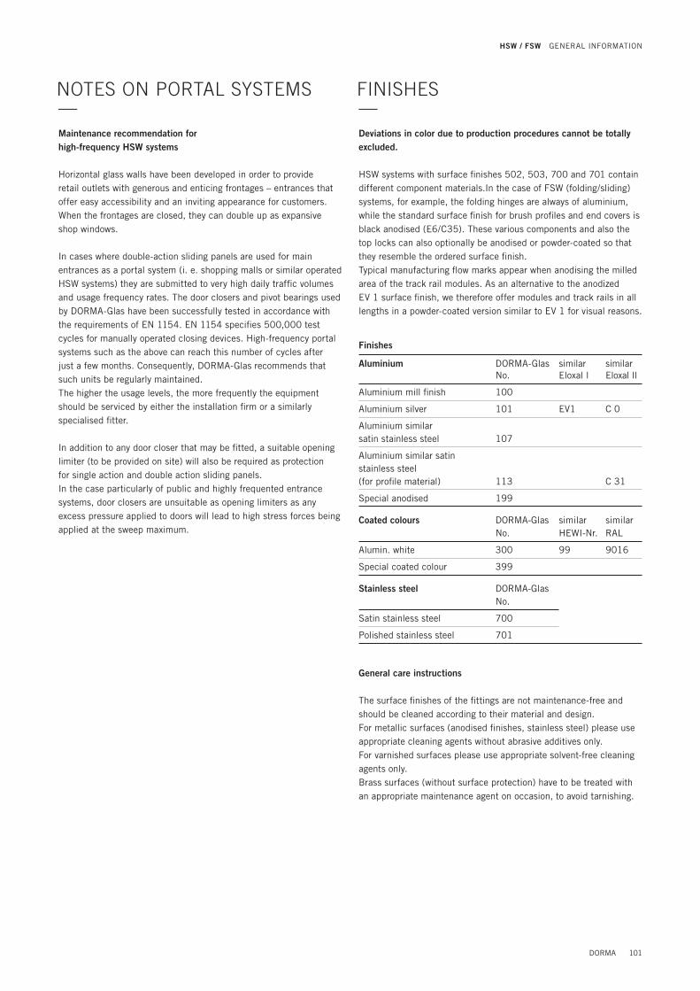
NOTES ON PORTAL SYSTEMS—
FINISHES—
Maintenance recommendation for high-frequency HSW systems
Horizontal glass walls have been developed in order to provide retail outlets with generous and enticing frontages – entrances that offer easy accessibility and an inviting appearance for customers. When the frontages are closed, they can double up as expansive shop windows.
In cases where double-action sliding panels are used for main entrances as a portal system (i. e. shopping malls or similar operated HSW systems) they are submitted to very high daily traffi c volumes and usage frequency rates. The door closers and pivot bearings used by DORMA-Glas have been successfully tested in accordance with the requirements of EN 1154. EN 1154 specifi es 500,000 test cycles for manually operated closing devices. High-frequency portal systems such as the above can reach this number of cycles after just a few months. Consequently, DORMA-Glas recommends that such units be regularly maintained. The higher the usage levels, the more frequently the equipment should be serviced by either the installation fi rm or a similarly specialised fi tter.
In addition to any door closer that may be fi tted, a suitable opening limiter (to be provided on site) will also be required as protection for single action and double action sliding panels. In the case particularly of public and highly frequented entrance systems, door closers are unsuitable as opening limiters as any excess pressure applied to doors will lead to high stress forces being applied at the sweep maximum.
Deviations in color due to production procedures cannot be totally excluded.
HSW systems with surface fi nishes 502, 503, 700 and 701 contain different component materials.In the case of FSW (folding/sliding) systems, for example, the folding hinges are always of aluminium, while the standard surface finish for brush profiles and end covers is black anodised (E6/C35). These various components and also the top locks can also optionally be anodised or powder-coated so that they resemble the ordered surface finish. Typical manufacturing fl ow marks appear when anodising the milled area of the track rail modules. As an alternative to the anodized EV 1 surface fi nish, we therefore offer modules and track rails in all lengths in a powder-coated version similar to EV 1 for visual reasons.
General care instructions
The surface fi nishes of the fi ttings are not maintenance-free and should be cleaned according to their material and design. For metallic surfaces (anodised fi nishes, stainless steel) please use appropriate cleaning agents without abrasive additives only.For varnished surfaces please use appropriate solvent-free cleaning agents only.Brass surfaces (without surface protection) have to be treated with an appropriate maintenance agent on occasion, to avoid tarnishing.
Finishes
Aluminium DORMA-GlasNo.
similarEloxal l
similarEloxal Il
Aluminium mill fi nish 100
Aluminium silver 101 EV1 C 0
Aluminium similar satin stainless steel 107
Aluminium similar satin stainless steel (for profi le material) 113 C 31
Special anodised 199
Coated colours DORMA-GlasNo.
similarHEWI-Nr.
similarRAL
Alumin. white 300 99 9016
Special coated colour 399
Stainless steel DORMA-GlasNo.
Satin stainless steel 700
Polished stainless steel 701
DORMA 101
HSW / FSW GENERAL INFORMATION

For planning of intelligent glass solutions we offer you several planning tools which allow you to create secure and professional solutions for any kinds of glass doors and toughend glass assemblies.
The planning tools DGES and MANET COMPACT enable you to prepare designs and cost calculations quickly, reliably and professio-nally. The software provides you with all necessary documentation such as dimensioned technical drawings, glass sizes and preparation measures.
Your benefi ts:Easy to operateProfessional and error-free preparation of offersRapid response to incoming requests for quotationsHighly reduced planning costs for time and money savings
DGES Fittings (for internal doors and toughend glass assemblies),DGES HSW (for horizontal sliding walls), MANET COMPACT planning tool (for MANET pivoting and sliding doors).
PLANNING TOOLS—
Subject to change without notice.
For practical planning, please use our drawings DORMA-Glas DETAIL.
Mounting1. Only properly qualifi ed and specially trained staff is authorised to
mount DORMA glass fi ttings.2. Never use glass with conchoidal fractures and/or damaged edges.3. Due to crushing hazards – among others in the area of the
secondary closing edge – and possible injury caused by breakage of glass during mounting, corresponding protective clothing (especially gloves and protective goggles) is required.
4. Clean clamping area with fat solvent (standard commercial cleaning agent) before mounting the glass fi tting.
5. Never use clamping shoes on structured glass surfaces (except on satined glass) or glass of heavily varying thickness unless with a corresponding levelling layer.
6. Never use clamping shoes on self-cleaning coatings.7. When adjusting glass elements, always stick to the required
clearance for the respective fi tting. Adjust clearance so that the glass does not touch hart components such as glass, metal or concrete.
8. Make sure not to use excessive force when installing the glass (avoid local stress resulting from very tight screws).
Maintenance Check fi ttings at regular intervals for proper positioning and smooth running and door for correct adjustment. Especially highly- frequented door systems require inspection by properly qualifi ed staff (specialised companies or installation fi rms). Immediately replace damaged class elements (no glass fl aking and/or conchoidal fractures)!
Important safety-related information for the mounting and use of DORMA glass fi ttings (Follow these instructions in addition to the mounting and operating instructions in order to avoid damage of product and damage to person or property.)Important: All users have to be informed about relevant points mentioned in these safety-related information and the mounting and operating instructions!
General information1. DORMA recommends using TSG-H (heat soaked toughened safety
glass) to DIN EN 12150-1.2. DORMA glass fi ttings are not suitable for application in rooms
where chemicals (e. g. chlorine) are used such as indoor swim-ming pools, saunas or salt-water pools.
3. Never move sliding panels faster than walking speed and always stop the door manually before it reaches end position.
4. Do not shut swing doors with excessive force. Install door stop to prevent door from opening too far.
SAFETY-RELATED INFORMATION—
102 DORMA
HSW / FSW GENERAL INFORMATION

DORMA 103
HSW / FSW NOTES