VEHICLE THEFT ALERT AND ENGINE LOCK SYSTEM ...
10
94 | Page VEHICLE THEFT ALERT AND ENGINE LOCK SYSTEM USING GSM & GPS Komal Gupta 1, Pushpa Gupta 2, Deelip Bharti 3 , Deepak Jaiswal 4 , Mr. Sachidanand Jaiswal 5 1, 2, 3, 4(E&C Deptt., BIT, GIDA, Gorakhpur, India) 5, 6(Asst. Prof., E&C Deptt., BIT, GIDA, Gorakhpur, India) ABSTRACT: The main aim of this paper is to use vehicle theft alert and engine lock system using GSM & GPS to intimate the owner of the vehicle about each and every unauthorized attempt of entry to his/her vehicle. Currently almost of the public having an own vehicle, theft is happening on parking and sometimes driving insecurity places. The safe of vehicles is extremely essential for public vehicles. At the present time, the rate of crime is increasing rapidly because it is a kind of evident from the actual fact that thefts became a matter of routine. Particularly these vehicles may incur huge losses on the amount invested on these vehicles. To overcome this problem, there are numerous technologies are available in the market such as GPS, GSM and GPRS systems. The auto-generated Short Message Service by system is used to give information to the owner’s cell phone. And one more advantage of this project is that a back Short Message Service can be send by vehicle’s owner which will disable the ignition of t he vehicle system and vehicle will be stopped. If system is active and if any unauthorized person tries to start the vehicle, the microcontroller used in system gets an interrupt through a switch which is connected to the security system. In the present days, most of the vehicles are designed with GSM based vehicle theft control systems, which provides the protection from thefts even if they are parked in the parking area. Vehicle tracking and locking system installed in the vehicle, to track the place and locking engine motor. The place of the vehicle identified using Global Positioning system (GPS) and Global system mobile communication (GSM). These systems constantly watch a moving Vehicle and report the status on demand. When the theft identified, the responsible person send SMS to the microcontroller, then microcontroller issue the control signals to stop the engine motor. Authorized person need to send the password to controller to restart the vehicle and open the door. This is more secured, reliable and low cost. Keywords: GSM, GPS, Microcontroller, Vehicle Locking and Tracking, Short Message Service (SMS). I.INTRODUCTION: In the last few decades, India has progressed at such an enormous rate that many companies have strongly established themselves here. These companies bring a huge amount of workforce with them. Arranging transportation to such a huge mass is a cumbersome task involving many intricacies. Generally, this transport is arranged through the local transport vendors on a yearly contract basis, recently happen mishaps such as burglary,
-
Upload
khangminh22 -
Category
Documents
-
view
1 -
download
0
Transcript of VEHICLE THEFT ALERT AND ENGINE LOCK SYSTEM ...
94 | P a g e
VEHICLE THEFT ALERT AND ENGINE LOCK
SYSTEM USING GSM & GPS
Komal Gupta1, Pushpa Gupta
2, Deelip Bharti
3, Deepak Jaiswal
4,
Mr. Sachidanand Jaiswal5
1, 2, 3, 4(E&C Deptt., BIT, GIDA, Gorakhpur, India)
5, 6(Asst. Prof., E&C Deptt., BIT, GIDA, Gorakhpur, India) ABSTRACT: The main aim of this paper is to use vehicle theft alert and engine lock system using GSM & GPS to intimate the
owner of the vehicle about each and every unauthorized attempt of entry to his/her vehicle. Currently almost of the
public having an own vehicle, theft is happening on parking and sometimes driving insecurity places. The safe of
vehicles is extremely essential for public vehicles. At the present time, the rate of crime is increasing rapidly
because it is a kind of evident from the actual fact that thefts became a matter of routine. Particularly these vehicles
may incur huge losses on the amount invested on these vehicles. To overcome this problem, there are numerous
technologies are available in the market such as GPS, GSM and GPRS systems. The auto-generated Short Message
Service by system is used to give information to the owner’s cell phone. And one more advantage of this project is
that a back Short Message Service can be send by vehicle’s owner which will disable the ignition of the vehicle
system and vehicle will be stopped. If system is active and if any unauthorized person tries to start the vehicle, the
microcontroller used in system gets an interrupt through a switch which is connected to the security system. In the
present days, most of the vehicles are designed with GSM based vehicle theft control systems, which provides the
protection from thefts even if they are parked in the parking area. Vehicle tracking and locking system installed in
the vehicle, to track the place and locking engine motor. The place of the vehicle identified using Global Positioning
system (GPS) and Global system mobile communication (GSM). These systems constantly watch a moving Vehicle
and report the status on demand. When the theft identified, the responsible person send SMS to the microcontroller,
then microcontroller issue the control signals to stop the engine motor. Authorized person need to send the
password to controller to restart the vehicle and open the door. This is more secured, reliable and low cost.
Keywords: GSM, GPS, Microcontroller, Vehicle Locking and Tracking, Short Message Service (SMS).
I.INTRODUCTION:
In the last few decades, India has progressed at such an enormous rate that many companies have strongly
established themselves here. These companies bring a huge amount of workforce with them. Arranging
transportation to such a huge mass is a cumbersome task involving many intricacies. Generally, this transport is
arranged through the local transport vendors on a yearly contract basis, recently happen mishaps such as burglary,

95 | P a g e
rape cases etc. The development of satellite communication technology is easy to identify the vehicle locations.
Vehicle tracking systems have brought this technology to the day-to-day life of the common person. Today GPS
used in cars, ambulances, fleets and police vehicles are common sights on the roads of developed countries. All the
existing technology support tracking the vehicle place and status.
The GPS/GSM Based System is one of the most important systems, which integrate both GSM and GPS
technologies. It is necessary due to the many of applications of both GSM and GPS systems and the wide usage of
them by millions of people throughout the world. This system designed for users in land construction and transport
business, provides real-time information such as location, speed and expected arrival time of the user is moving
vehicles in a concise and easy-to-read format. This system may also useful for communication process among the
two points.
Currently GPS vehicle tracking ensures their safety as travelling. This vehicle tracking system found in clients
vehicles as a theft prevention and rescue device. Vehicle owner or Police follow the signal emitted by the tracking
system to locate a robbed vehicle in parallel the stolen vehicle engine speed going to decreased and pushed to off.
After switch of the engine, motor cannot restart without permission of password. This system installed for the four
wheelers, Vehicle tracking usually used in navy operators for navy management functions, routing, send off, on
board information and security. The applications include monitoring driving performance of a parent with a teen
driver. Vehicle tracking systems accepted in consumer vehicles as a theft prevention and retrieval device. If the theft
identified, the system sends the SMS to the vehicle owner. After that vehicle owner sends the SMS to the controller,
issue the necessary signals to stop the motor.
II. SURVEY OF THE RELATED WORK:
In [2], the hardware and software of the GPS and GSM network were developed. The proposed GPS/GSM based
System has the two parts, first is a mobile unit and another is controlling station. The system processes, interfaces,
connections, data transmission and reception of data among the mobile unit and control stations are working
successfully. These results are compatible with GPS technologies.
In [3], a vehicle tracking system is an electronic device, installed in a vehicle to enable the owner or a third party to
track the vehicle's place. This paper proposed to design a vehicle tracking system that works using GPS and GSM
technology. This system built based on embedded system, used for tracking and positioning of any vehicle by using
Global Positioning System (GPS) and Global system for mobile communication (GSM). This design will
continuously watch a moving Vehicle and report the status of the Vehicle on demand.
96 | P a g e
In [5], this system provided vehicle cabin safety, security based on embedded system by modifying the existing
modules. This method monitors the level of the toxic gases such as CO, LPG and alcohol within the vehicle
provided alert information as alarm during the dangerous situations. The SMS sends to the authorized person
through the GSM. In this method, the IR Sensor used to detect the static obstacle in front of the vehicle and the
vehicle stopped if any obstacle detected. This is avoiding accidents due to collision of vehicles with any static
obstacles.
In [6], Kai-Tai Song and Chih-Chieh Yang have a designed and built on a real-time visual tracking system for
vehicle safety applications. In this paper built a novel feature-based vehicle-tracking algorithm, automatically detect
and track several moving objects, like cars and motorcycles, ahead of the tracking vehicle. Joint with the concept of
focus of expansion (FOE) and view analysis, the built system can segment features of moving objects from moving
background and offer a collision word of warning on real-time. The proposed algorithm using a CMOS image
sensor and NMOS embedded processor architecture. The constructed stand-alone visual tracking system validated in
real road tests. The results provided information of collision warning in urban artery with speed about 60 km/hour
both at night and day times.
In [7], the remote monitoring system based on SMS and GSM was implemented. Based on the total design of the
system, the hardware and software designed. In this paper, the GSM network is a medium for transmitting the
remote signal. This includes two parts that are the monitoring center and the remote monitoring station. The
monitoring centers consist of a computer and communication module of GSM. The software-monitoring center and
the remote monitoring station implemented by using VB. The result of this demonstration shows that the system can
watch and control the remote communication between the monitoring center and the remote monitoring station.
In [8] this paper, the proposed tracking system based on cloud computing infrastructure. The sensors are used to
monitor the fuel level, driver conditions, and speed of the vehicle. All the data transferred to cloud server-using
GSM enabled device. All the vehicles equipped with GPS antenna to locate the place. To avoid the drunk and drive,
the alcohol sensor installed to monitor the driver status. The proposed technology significantly avoids the accident in
highways.
III. PROPOSED METHOD:
In this proposed work, a novel method of vehicle tracking and locking system used to track the theft vehicle by
using GPS and GSM technology. This system puts into sleeping mode while the vehicle handled by the owner or
authorized person otherwise goes to active mode, the mode of operation changed by in person or remotely. If any
interruption occurred in any side of the door, then the IR sensor senses the signals and SMS sends to the
microcontroller. The controller issues the message about the place of the vehicle to the car owner or authorized
person. When send SMS to the controller, issues the control signals to the engine motor. Engine motor speeds are
97 | P a g e
gradually decreases and come to the off place. After that all the doors locked. To open the door or restart the engine,
authorized person needs to enter the passwords. In this method, tracking of vehicle place easy and doors locked
automatically, thereby thief cannot get away from the car.
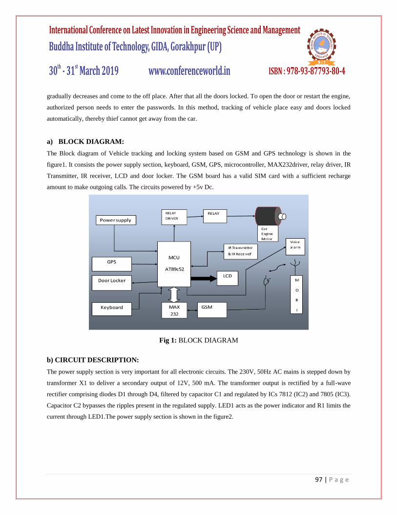
a) BLOCK DIAGRAM:
The Block diagram of Vehicle tracking and locking system based on GSM and GPS technology is shown in the
figure1. It consists the power supply section, keyboard, GSM, GPS, microcontroller, MAX232driver, relay driver, IR
Transmitter, IR receiver, LCD and door locker. The GSM board has a valid SIM card with a sufficient recharge
amount to make outgoing calls. The circuits powered by +5v Dc.
Fig 1: BLOCK DIAGRAM
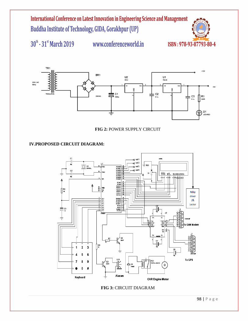
b) CIRCUIT DESCRIPTION:
The power supply section is very important for all electronic circuits. The 230V, 50Hz AC mains is stepped down by
transformer X1 to deliver a secondary output of 12V, 500 mA. The transformer output is rectified by a full-wave
rectifier comprising diodes D1 through D4, filtered by capacitor C1 and regulated by ICs 7812 (IC2) and 7805 (IC3).
Capacitor C2 bypasses the ripples present in the regulated supply. LED1 acts as the power indicator and R1 limits the
current through LED1.The power supply section is shown in the figure2.
98 | P a g e
FIG 2: POWER SUPPLY CIRCUIT
IV.PROPOSED CIRCUIT DIAGRAM:
FIG 3: CIRCUIT DIAGRAM

99 | P a g e
The circuit diagram of the vehicle tracking and locking embedded system using GPS and GSM technology is shown
in Fig.3.The compact circuitry is built around Atmel AT89C52 microcontroller. The AT89C52 is a low power; high
performance CMOS 8-bit microcomputer with 8 kB of Flash programmable and erasable read only memory
(PEROM). It has 256 bytes of RAM, 32 input/output (I/O) lines, three 16-bit timers/ counters, a six-vector two-level
interrupt architecture a full-duplex serial port, an on-chip oscillator and clock circuit. The system clock also plays a
significant role in operation of the microcontroller. An 11.0592MHz quartz crystal connected to pins 18 and 19
provides basic clock to the microcontroller. Power-on reset is provided by the combination of electrolytic capacitor
C3 and resistor R1. Port pins P2.0 through P2.7 of the microcontroller are connected to data port pins D0 through D7
of the LCD, respectively. Port pins P0.5, P0.6 and P0.7 of the microcontroller are connected to Register-select (RS),
Read / write (RW) and enable (E) pins of the LCD, respectively. All the data is sent to the LCD in ASCII format for
display. Only the commands are sent in hex form. Register-select (RS) signal is used to distinguish between data
(RS=1) and command (RS=0). Preset RV1 is used to control the contrast of the LCD. Resistor 10k limits the current
through the backlight of the LCD. Port pins P3.0 (RXD) and P3.1 (TXD) of the microcontroller are used to interface
with the RFID reader through Max232 and GSM Modem are used to interface through Max232. Port pins from P1.0
to P2.7 of the microcontroller are connected to keyboard. The GPS and GSM are used to connect through RXD and
TXD pins of the microcontroller for further processing.
FIG 4: DOOR SENSOR CIRCUIT
100 | P a g e
The port pins of P0.0 to P0.3 are used to connect the 4 IR sensors for detecting the unauthorized person. Port1.7 is
used to connect the alarm through transistor BC547, Pin number P3.3 is used to connect the engine motor. If
unauthorized person enter into the car, the IR sensor sense the signals if any interruption occurs in any side of the
door and send to the microcontroller, then the controller issue the message about the location of the vehicle to car
owner or authorized person which is shown in fig.4. When send the SMS to controller, issues the control signals to
the engine motor. Engine motor speed is gradually decreases and comes to the off position. After that all the doors are
locked. Pin P0.4 is used to connect the door locker through relay. To open the door or to restart the engine authorized
person needs to enter the passwords. In this method, tracking of vehicle location easy and also doors are locked
automatically thereby thief cannot get away from the car. Pin P0.4, transistor Q3 drives into saturation, and relay RL2
energizes to close or open the door lock.
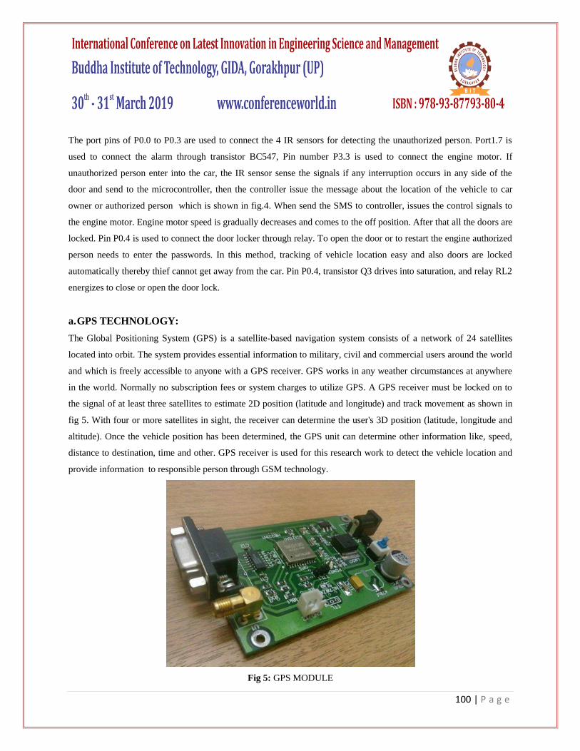
a. GPS TECHNOLOGY:
The Global Positioning System (GPS) is a satellite-based navigation system consists of a network of 24 satellites
located into orbit. The system provides essential information to military, civil and commercial users around the world
and which is freely accessible to anyone with a GPS receiver. GPS works in any weather circumstances at anywhere
in the world. Normally no subscription fees or system charges to utilize GPS. A GPS receiver must be locked on to
the signal of at least three satellites to estimate 2D position (latitude and longitude) and track movement as shown in
fig 5. With four or more satellites in sight, the receiver can determine the user's 3D position (latitude, longitude and
altitude). Once the vehicle position has been determined, the GPS unit can determine other information like, speed,
distance to destination, time and other. GPS receiver is used for this research work to detect the vehicle location and
provide information to responsible person through GSM technology.
Fig 5: GPS MODULE
101 | P a g e
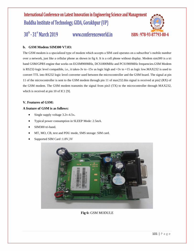
b. GSM Modem SIM300 V7.03:
The GSM modem is a specialized type of modem which accepts a SIM card operates on a subscriber’s mobile number
over a network, just like a cellular phone as shown in fig 6. It is a cell phone without display. Modem sim300 is a tri
band GSM/GPRS engine that works on EGSM900MHz, DCS1800MHz and PCS1900MHz frequencies.GSM Modem
is RS232-logic level compatible, i.e., it takes-3v to -15v as logic high and +3v to +15 as logic low.MAX232 is used to
convert TTL into RS232 logic level converter used between the microcontroller and the GSM board. The signal at pin
11 of the microcontroller is sent to the GSM modem through pin 11 of max232.this signal is received at pin2 (RX) of
the GSM modem. The GSM modem transmits the signal from pin3 (TX) to the microcontroller through MAX232,
which is received at pin 10 of IC1 [9].
V. Features of GSM:
A feature of GSM is as follows:
Single supply voltage 3.2v-4.5v.
Typical power consumption in SLEEP Mode: 2.5mA.
SIM300 tri-band.
MT, MO, CB, text and PDU mode, SMS storage: SIM card.
Supported SIM Card :1.8V,3V
Fig 6: GSM MODULE

102 | P a g e
VI. DEBUGGING AND TESTING PROCESS:
A microcontroller-based system is a complex activity that involves hardware and software interfacing with the
external world. Doing well design of a microcontroller-based system requires skills to use the variety of debugging
and testing tools available. The debugging and testing of microcontroller-based systems divided into two groups:
software-only tools and software-hardware tools. Software-only tools come as monitors and simulators, which are
independent of the hardware under development. Software-hardware tools are usually hardware dependent, more
expensive and range from in-circuit emulators and in-circuit simulators to in-circuit debuggers. In general, the higher
the level of integration with the target hardware, the greater the benefit of a tool, resulting in a shorter development
time, but the greater the cost as well. The factors to consider when choosing a debugging tool are cost, ease of use and
the features offered during the debugging process.
A software simulator is a computer program running on an independent hardware and it simulates the CPU, the
instruction set and the I/O of the target microcontroller. Simulators offer the lowest-cost development tools for
microcontroller-based systems and most companies offer their simulator programs free of charge.
The user program operated in a simulated environment where the user can insert breakpoints within the code to stop
the code and then analyze the internal registers and memory, display and change the values of program variables and
so on. Incorrect logic or errors in computations can analyze by stepping through the code in simulation. Simulators
run at speeds 100 to 1000 times slower than the actual micro controller hardware and, thus, long time delays should
avoid when simulating a program. Micro controller-based systems usually have interfaces to various external devices
such as motors, I/O ports, timers, A/D converters, displays, push buttons, sensors and signal generators, which are
usually difficult to simulate. Some advanced simulators, such as the Proteus from Labcenter Electronics allow the
simulation of various peripheral devices such as motors, LCDs, 7-segment displays and keyboards, and users can
create new peripheral devices. Inputs to the simulator can come from files that may store complex digital I/O signals
and waveforms. Outputs can be as form of digital data or waveforms, usually stored in a file, or displayed on a screen.
Some simulators accept only the assembly language of the target microcontroller. Most of the microcontroller
software has written a high-level language such as C, Pascal or Basic, and it has become necessary to simulate a
program has written in a high-level language.
The software program has written in C or assembly language and compiled using Keil software. After compiler
operation, the hex code generated and stored in the computer. The hex code of the program should be loaded into the
AT89C52 by using Top win Universal programmer.
a. HARDWARE ASSEMBLING AND TESTING:
First step, we need to make single side PCB layout for the given circuit diagram. After made the PCB the following
process is required to complete the project:-
103 | P a g e
1. Assemble all the components on the PCB based on circuit diagram. TX and RX pins of the GSM modem to pins
13 and 14 of MAX 232 and insert a valid SIM in the GSM modem.
2. Connect the GPS module according to circuit diagram.
3. This projects implemented and tested successfully by us.
4. This system is very useful and secure for car owners.
VII. CONCLUSION:
In this paper, we have proposed a novel method of vehicle tracking and locking systems used to track the theft vehicle
by using GPS and GSM technology. This system puts into the sleeping mode vehicle handled by the owner or
authorized persons; otherwise goes to active mode. The mode of operations changed by persons or remotely. When
the theft identified, the responsible people send SMS to the micro controller, then issue the control signals to stop the
engine motor. After that all the doors locked. To open the doors or to restart the engine authorized person needs to
enter the passwords. In this method, easily track the vehicle place and doors locked.
REFERENCES:
[1] Chen, H., Chiang, Y. Chang, F., H. Wang, H. (2010). Toward Real-Time Precise Point Positioning: Differential GPS Based on
IGS Ultra Rapid Product,SICE Annual Conference, The Grand Hotel, Taipei, Taiwan August 18-21.
[2] Asaad M. J. Al-Hindawi, Ibraheem Talib, “Experimentally Evaluation of GPS/GSM Based System Design”, Journal of
Electronic Systems Volume 2 Number 2 June 2012 .
[3] Kunal Maurya , Mandeep Singh, Neelu Jain, “Real Time Vehicle Tracking System using GSM and GPS Technology- An
Anti-theft Tracking System,” International Journal of Electronics and Computer Science Engineering. ISSN 2277-
1956/V1N3-1103-1107 .
[4] Vikram Kulkarni & Viswaprakash Babu, “embedded smart car security system on face detection’, special issue of IJCCT,
ISSN(Online):2231-0371, ISSN(Print):0975-7449,volume-3, issue-1.
[5] V.Ramya, B. Palaniappan, K. Karthick, “Embedded Controller for Vehicle In-Front Obstacle Detection and Cabin Safety
Alert System”, International Journal of Computer Science & Information Technology (IJCSIT) Vol 4, No 2, April 2012.
[6] Kai-Tai Song, Chih-Chieh Yang, of National Chiao Tung University, Taiwan, “Front Vehicle Tracking Using Scene
Analysis”, Proceedings of the IEEE International Conference on Mechatronics & Automation 2005.
[7] Chen Peijiang, Jiang Xuehua, “Design and Implementation of Remote monitoring system based on GSM,” vol.42, pp.167-
175. 2008.
[8] Albert Alexe, R.Ezhilarasie, “Cloud Computing Based Vehicle Tracking Information Systems”, ISSN: 2229 - 4333 ( Print) |
ISSN: 0976 - 8491 (Online ) IJCST Vol. 2, Iss ue 1, March 2011.
[9] R.Ramani, S.Selvaraju, S.Valarmathy, R.Thangam B.Rajasekaran, “water-level monitor for bore well and water tank based
on GSM”, International Journal of engineering science and technology (IJEST), ISSN: 0975-5462, volume4-N0:10,
october2012.