AN AUTOMATED TSUNAMI ALERT SYSTEM
14
International Journal of Embedded Systems and Applications (IJESA) Vol.1, No.2, December 2011 DOI : 10.5121/ijesa.2011.1206 65 AN AUTOMATED TSUNAMI ALERT SYSTEM V.Ramya 1 , B.Palaniappan 2 1 Assistant Professor, Department of CSE, Annamalai University, Chidambaram,Tamilnadu. [email protected] 2 Dean, FEAT, HOD, Department of CSE, Annamalai university, Chidambaram,Tamilnadu. [email protected] ABSTRACT The tsunami waves cause considerable destruction and kills people. The detection section of the proposed system consists of a microcontroller and a capacitive sensor to detect the Tsunami occurrence. The principle is as follows, on the onslaught of Tsunami or any other natural calamity of this type, there is an abnormal pressure rise in the seafloor. Here a proximity capacitive sensor is used which gives an output depending on capacitance variations, and a microcontroller is used to announce the oncoming of Tsunami event to a concerned person, through mobile computing. Mobile is used to send warning messages. KEYWORDS: Cross Compiler, Embedded System, Microcontroller, Sensors, Transmitter. 1. INTRODUCTION A Tsunami is a very long-wavelength wave of water that is generated by earthquakes that causes displacement of the seafloor, but Tsunami can also be generated by volcanic eruptions, landslides and underwater explosions. Earthquakes of M > 6.5 are critical for tsunami generation. On the average, there are two tsunamis per year somewhere in the world. Approximately every 15 years a destructive, Pacific wide tsunami occurs. Tsunami velocity is dependent on the depth of water through which it travels Tsunamis travel approximately 700 kmph in 4000 m depth of sea water. The velocity drops to about 36 kmph at 10 m of water depth which cause damage near the shore. Tsunami often occurs suddenly without warning and they are extremely dangerous to the coastal communities. To protect ourselves from such disaster some automated warning systems should be made. The proposed Tsunami warning system is basically an Embedded Systems. An embedded System is a microcontroller based system that is incorporated into a device to monitor and control the functions of the components of the device. Embedded systems are designed to perform specific tasks. An Embedded system is designed to perform a specific function, in which the software rules the entire hardware. The end user cannot alter the software. Reliability, responsiveness, specialized hardware, low cost, robustness are some of the important features of
-
Upload
independent -
Category
Documents
-
view
1 -
download
0
Transcript of AN AUTOMATED TSUNAMI ALERT SYSTEM

International Journal of Embedded Systems and Applications (IJESA) Vol.1, No.2, December 2011
DOI : 10.5121/ijesa.2011.1206 65
AN AUTOMATED TSUNAMI ALERT SYSTEM
V.Ramya1, B.Palaniappan
2
1Assistant Professor, Department of CSE, Annamalai University,
Chidambaram,Tamilnadu. [email protected]
2Dean, FEAT, HOD, Department of CSE, Annamalai university,
Chidambaram,Tamilnadu. [email protected]
ABSTRACT
The tsunami waves cause considerable destruction and kills people. The detection section of the proposed
system consists of a microcontroller and a capacitive sensor to detect the Tsunami occurrence. The
principle is as follows, on the onslaught of Tsunami or any other natural calamity of this type, there is an
abnormal pressure rise in the seafloor. Here a proximity capacitive sensor is used which gives an output
depending on capacitance variations, and a microcontroller is used to announce the oncoming of Tsunami
event to a concerned person, through mobile computing. Mobile is used to send warning messages.
KEYWORDS:
Cross Compiler, Embedded System, Microcontroller, Sensors, Transmitter.
1. INTRODUCTION
A Tsunami is a very long-wavelength wave of water that is generated by earthquakes that causes
displacement of the seafloor, but Tsunami can also be generated by volcanic eruptions, landslides
and underwater explosions. Earthquakes of M > 6.5 are critical for tsunami generation. On the
average, there are two tsunamis per year somewhere in the world. Approximately every 15 years
a destructive, Pacific wide tsunami occurs. Tsunami velocity is dependent on the depth of water
through which it travels Tsunamis travel approximately 700 kmph in 4000 m depth of sea water.
The velocity drops to about 36 kmph at 10 m of water depth which cause damage near the shore.
Tsunami often occurs suddenly without warning and they are extremely dangerous to the coastal
communities. To protect ourselves from such disaster some automated warning systems should be
made. The proposed Tsunami warning system is basically an Embedded Systems. An embedded
System is a microcontroller based system that is incorporated into a device to monitor and control
the functions of the components of the device. Embedded systems are designed to perform
specific tasks. An Embedded system is designed to perform a specific function, in which the
software rules the entire hardware. The end user cannot alter the software. Reliability,
responsiveness, specialized hardware, low cost, robustness are some of the important features of

International Journal of Embedded Systems and Applications (IJESA) Vol.1, No.2, December 2011
66
an embedded system. To make such embedded applications, microcontrollers are needed. In this
work microcontroller is programmed to send and receive the signals.
1.1. Physical Characteristics of Tsunami
All types of waves, including tsunami, have a wavelength, a wave height, amplitude, a frequency
or period, and a velocity. The physical characteristic of Tsunami is shown in figure 1.
• Wavelength: The distance between two identical points on a wave (i.e. between wave
crests or wave troughs) is called as wavelength. Normal ocean waves have wavelengths
of about 100 meters. Tsunami is usually having the longer wavelengths and up to 500
kilometers.
• Wave height: The distance between the trough of the wave and the crest or peak of the
wave is usually referred as wave height.
• Wave amplitude: The height of the wave above the still water line, usually this is equals
to 1/2 the wave height. Tsunami can have variable wave height and amplitude that
depends on water depth as we shall see in a moment
• Wave frequency: The amount of time it takes for one full wavelength to pass a
stationary point is called as wave frequency or wave period.
• Wave velocity is the speed of the wave. Velocities of normal ocean waves are about
90km/hr while tsunami have velocities up to 950 km/hr (about as fast as jet airplanes),
and thus move much more rapidly across ocean basins. The velocity of any wave is equal
to the wavelength divided by the wave period. V = λ/P
1.2. Increase and decrease in the wavelength of shallow waters
Tsunami is characterized as shallow-water waves. These are different from the waves most of us
have observed on a beach, which are caused by the wind blowing across the ocean's surface. A
tsunami can have a period in the range of ten minutes to two hours and wavelengths greater than
Figure 1: Physical Characteristics of Tsunami

International Journal of Embedded Systems and Applications (IJESA) Vol.1, No.2, December 2011
67
500 km. When the ratio of the water depth and wavelength is very small then the wave is
characterized as a shallow-water wave. The velocity of a shallow-water wave is also equal to the
square root of the product of the acceleration of gravity, g, (10m/sec2) and the depth of the water.
The rate at which a wave loses its energy is inversely related to its wavelength. Since the tsunami
loses little energy as it propagates and it has very large wavelength. Thus, in very deep water, a
tsunami will travel at high speeds with little loss of energy. As a tsunami leaves the deep water of
the open sea and arrives at the shallow waters near the coast, it undergoes a transformation. As
the depth of the water decreases, the velocity of the tsunami decreases and the change of total
energy of the tsunami remain constant.
The tsunami size ranges from few centimeters to over 30 m height and most of the tsunamis are
less than 3 m in height. Tsunamis are rarely over 1m high in deep water and will not be noticed
by ships due to their long period (time between crests). The wave height of the tsunami can
increase by over 10 times as it propagates into shallow water. A tsunami wave is different from a
wind-generated wave that is the period of the wind-generated waves usually 5 to 20 seconds,
whereas tsunami periods are usually between 5 minutes and an hour.
1.3. Impact of tsunami on salinity levels of drinking water
The freshwater and saltwater equilibrium were disturbed by the underground wave pressure
caused by tsunami wave. The pressure of the wave may cause mixing of the fresh groundwater
with saline water and this could result in a reduction of the volume of the freshwater lens. The
salinity in the flooded wells decreased significantly from an estimated average salinity at the time
of the flooding. The initial well salinity just after the tsunami was important to know as it would
give a measure of the maximum level which would be expected to occur immediately after the
tsunami.
Figure 2: Increase and decrease in the wavelength of shallow waters

International Journal of Embedded Systems and Applications (IJESA) Vol.1, No.2, December 2011
68
1.4. Generation of tsunami
In the Pacific basin, an average of two destructive tsunamis happens in every year. Pacific wide
tsunamis are a rare phenomenon, occurring every 10 - 12 years on the average. The tsunamis are
generated by earthquakes, volcanic eruptions, landslides, underwater explosions, and meteorite
impacts. The tsunamis generated by landslides tend to be relatively localized and do less damage
than the Tsunami generated by earthquakes. 1.4.1. Earthquakes
A sudden release of energy in the Earth's crust is known as Earthquake. A rupture of geological
faults, volcanic activity, landslides, Earthquake, mine blasts, and nuclear tests are the major
causes for tsunami. An earthquake with the Richter magnitude level 7 and above is very
disastrous, whereas the Richter magnitude level 3 and below is very meager. Earthquakes occur
in the crust or upper mantle, which ranges from the earth's surface to about 800 kilometers deep.
Earthquake is classified in to two types; one is Inter-plate earthquake, in which earthquakes occur
along the boundaries of tectonic plates. The second one is Intra-plate Earthquakes that is
earthquakes occur within the plate itself but away from the plate boundaries. Earthquakes are
recorded with the help of seismogram. Due to earthquakes or landslides a series of sea waves
called as tsunami is caused at beneath the sea floor. Due to large submarine earthquakes and
landslides the displacement of the sea floor occurs and intern causes displacement of large
volumes of the sea water above it producing large, fast moving waves.
1. 4.2. Volcanic Eruptions
A rupture or an opening on the crust of a planet like earth is called as volcano. The most common
and serious volcanic hazards are namely, Lava, ash, and debris flow. Severe eruptions can also
cause tsunamis, volcanic earthquakes which create serious threats to both life and property. It is
very difficult to predict the occurrence of volcano eruption, since some of the volcanoes are
sleeping volcanoes.
2. Design Concepts Of Proposed System
The objective of this work is to reduce the false alarm which threatens the public and the
government. Prototype of Tsunami warning system is developed here. This is divided into two
modules:
Module 1: Tsunami detection
Module 2: Tsunami warning
2.1 . Tsunami Detection
To detect the Tsunami occurrence, capacitive sensor is used. On varying the capacitance value,
the capacitive sensor sends the signal to the transmitter side microcontroller. The receiver side
receives the transmitted signal.

International Journal of Embedded Systems and Applications (IJESA) Vol.1, No.2, December 2011
69
2.2 Tsunami Warning
The receiver side microcontroller is interfaced with buzzer and PC. The microcontroller invokes
the PC, which in turn invokes the mobile interfaced with it. At this stage, PC sends message to mobile numbers specified in the form. Simultaneously the Pc raises alarm to alert the people in
the coastal area. The block diagram of Tsunami Warning System is shown in figure 3.
Figure 3: Block Diagram of Tsunami Warning system
In this Tsunami warning system, by varying the capacitance value of proximity capacitive sensor,
signals are sent to the microcontroller in the transmitter side. Microcontroller passes infrared
signals from an IR transmitter. These IR rays are received by the receiver. The signal is passed to
the PC through the serial port. Immediately, after the signal is received by the PC, it sends alert
message to the mobile attached and simultaneously it raises an alarm.
3. HARDWARE DESCRIPTION
3.1. Microcontroller
In this work, the pressure is induced using piston pump. The pressure is sensed using capacitive
proximity sensor and the raise in the pressure which is above the threshold value is send as signal
to the transmitter side microcontroller. Microcontroller used in this work is AT89C2051. It is a 20
pin DIP. The AT89C2051 is a low voltage, high performance CMOS 8-bit microcomputer with
2K bytes flash programmable and erasable read only memory (PEROM). By combining a
versatile 8-bit CPU with flash on a monolithic chip, the Atmel AT89C2051 is a powerful
microcomputer which provides a highly flexible and cost-effective solution to many embedded
control applications. The AT89C2051 provides the following standard features: 2K bytes of
flash, 18 bytes of RAM, 15 I/O lines, two 16 bit timer/counters, and five vector low levels
interrupt architecture, a full duplex serial port, a precision analog comparator, on-chip oscillator
and clock circuitry. In addition, the AT89C2051 is designed with static logic for operation down
to zero frequency and supports two software selectable power saving modes. The idle mode stops
the CPU while allowing the RAM, timer/counters, serial port and interrupt system to continue
functioning. The power down mode saves the RAM content but disables all other chip functions
until the next hardware reset.
International Journal of Embedded Systems and Applications (IJESA) Vol.1, No.2, December 2011
70
3.2. Transmitter
The light source LED produces a light beam across the bottom of the coil. IR (infrared) rays are
chosen because there is less noise and ambient light than at normal optical wavelengths. LED is
used as transmitter and it uses Infrared rays to transmit the signals. The transmitter module
diagram is shown in figure 4.
Figure 4: Transmitter Module Diagram Figure 5: Receiver Module Diagram
In the transmitter module, the capacitive sensor senses the change in capacitance. If the actual
value exceeds the target value then it considers that there is some abnormal condition. The value
is given as interrupt signal on the port P3.2 of AT89C2051 microcontroller. As a result, the data
signal and carrier signal are generated by the microcontroller. Data signal is pulse code
modulated with the carrier wave. Negative pulse code modulation is performed. The signal is
passed to receiver in the form of IR rays with the help of LED.
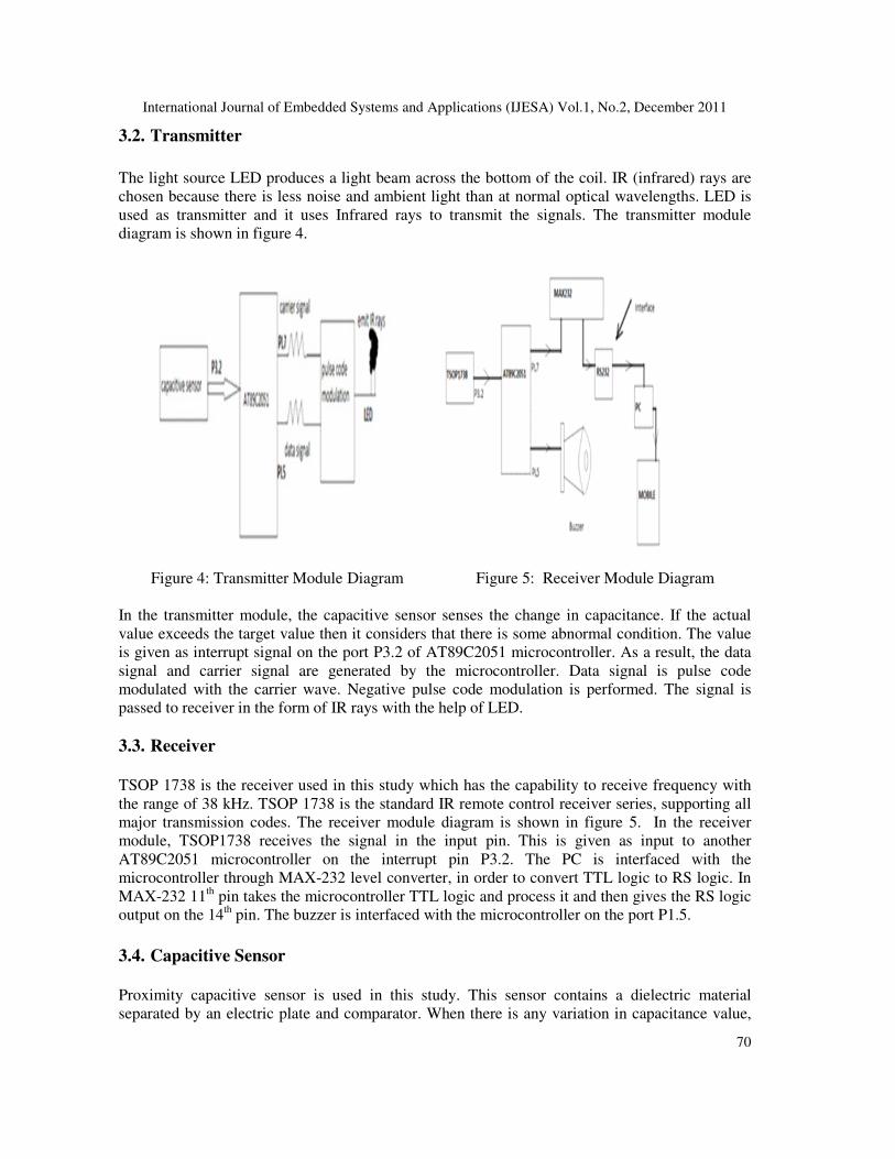
3.3. Receiver
TSOP 1738 is the receiver used in this study which has the capability to receive frequency with
the range of 38 kHz. TSOP 1738 is the standard IR remote control receiver series, supporting all
major transmission codes. The receiver module diagram is shown in figure 5. In the receiver
module, TSOP1738 receives the signal in the input pin. This is given as input to another
AT89C2051 microcontroller on the interrupt pin P3.2. The PC is interfaced with the
microcontroller through MAX-232 level converter, in order to convert TTL logic to RS logic. In
MAX-232 11th pin takes the microcontroller TTL logic and process it and then gives the RS logic
output on the 14th pin. The buzzer is interfaced with the microcontroller on the port P1.5.
3.4. Capacitive Sensor
Proximity capacitive sensor is used in this study. This sensor contains a dielectric material
separated by an electric plate and comparator. When there is any variation in capacitance value,

International Journal of Embedded Systems and Applications (IJESA) Vol.1, No.2, December 2011
71
the comparator compares the actual value with the target value. Based on this principle,
capacitive sensor gets operated.
3.5. MAX-232 Level Converter
The MAX-232 level converter is a 16 pin DIP. It contains dual charge pump DC-DC voltage
converters, RS 232 drivers, RS 232 receivers and receiver and transmitter enable control inputs.
3.6. RS232
RS232 devices can be plugged straight into the computers serial port. This is referred to as COM
port. The data acquisition device used here is capacitive sensors. Its output is fed through
microcontroller. In warning phase mobile is connected to PC through the RS232 port.
4. SOFTWARE DESCRIPTION
4.1. KEILµVISION2
This is used to compile the code written for the microcontroller. The microcontroller code is
written using embedded C. It encapsulates the following components:
• A project manager.
• A make facility.
• Tool configuration.
• Editor.
• A powerful debugger.
4.1.1. Project Manager
A project is composed of all source files, development, tool options and directions necessary to
create a program. A single µVISION2 project can generate one or more target programs. The
source files used to create a target are organized into groups. The development tools can be set at
target, group, or file level.
4.1. 2. Integrated Utilities
The tools menu is used to start the user utilities within the µVISION2 IDE. A configurable
interface provides access to version control systems.
4.1.3. Editor
The µVISION2 editor includes all the editing features, color syntax, highlighting and text
indentation for the C source code. The editor is available while debugging the program and this
gives a natural debugging environment that lets to quickly test the application.
4.1. 4. Debugger
The debugging is performed through breakpoints. Its sets program breakpoints while editing.
Breakpoints are activated while starting the debugger. It may be set on conditional expressions,

International Journal of Embedded Systems and Applications (IJESA) Vol.1, No.2, December 2011
72
or variable and memory access. Debug functions can be executed when the breakpoints are
triggered.
4.2. PROGRAMING MICROCONTROLLER IN KEIL
The complex problems faced by the embedded software developers are solved by the keil
developing tools.
• When starting a new project, microcontroller to be used from the device database should
be selected and the µVISION IDE sets all compiler, assembler, linker and memory
options.
• The keilµVISION debugger accurately simulates on chip peripherals.
• To test the software with target hardware some adapter are used to download and test
program code on the target system.
4.2.1. Cross Assembling
On writing programs for microcontrollers, cross assembler or cross compilers are used. A cross
assembler is an assembler that runs on the host system, but produces binary instructions which is
suitable for the target system. And a cross compiler works similar to the cross assembler.
4.3. VB .NET
VB.NET is the most productive tool for creating .NET applications. It provides the following
features:
• Common Language Runtime.
• Language Interoperability.
• Enhanced security.
• Simplified deployment.
• Improved versioning support.
The controls used in this project include,
1. Microsoft Communication Control
2. Oxygen Mobile SMS Control
4.3.1. Microsoft Communication Control
The Microsoft communication control provides serial communications for the application by
allowing the transmission and reception of data through a serial port. The Microsoft
communication control provides the following two ways for handling communications:
(a) Event Driven
Event driven communication is a very powerful method for handling serial port interaction.
When a character arrives or a change occurs in the Carrier Detect (CD) or Request to Send
(RTS) lines then they are notified immediately. In such cases, the Microsoft communication

International Journal of Embedded Systems and Applications (IJESA) Vol.1, No.2, December 2011
73
control’s On Communication events are used to trap and handle these communication events.
The On Communication event also detects and handles communications errors.
(b) Polling for Events
Polling for events and errors are done by checking the value of the COM Event property after
each critical function of the program. This may be preferable if the application is small and self-
contained.
4.3.2. Oxygen Mobile SMS ActiveX control
This project uses the oxygen mobile SMS control OCX to send SMS to the destination user via
Simple Message Service. Oxygen Mobile ActiveX Control is designed to give an access to
various Nokia phone capabilities from a Windows program. Oxygen Mobile ActiveX Control
has modules messaging and are independent to each other and can be used together or separately
from each other. Each module or their combination has methods for establishing phone
connection and retrieving basic phone parameters like model internal name, software and
hardware versions, signal and battery levels of the phone. To work with Oxygen Mobile
ActiveX Control Com Number should be set and Connection Mode properties, call Open
method should also be specified. When connection is established phone is ready to work. To
close connection to the phone, call Close method must be used. The following flowcharts
illustrate the Tsunami warning system.
Figure 6:Transmitter Side Flow during Detection Figure 7: Receiver Side Flow during Detection

International Journal of Embedded Systems and Applications (IJESA) Vol.1, No.2, December 2011
74
Figure 8: basic steps followed during initiation Figure 9: “UPDATE SETTINGS” command button
Figure 10: operations performed during form load

International Journal of Embedded Systems and Applications (IJESA) Vol.1, No.2, December 2011
75
5. MOBILE COMPUTING
A mobile computing deal with the activation of mobile to send messages that is interfaced with
PC or through modems. Message can be sent either
• Through a modem, using a dial-up SMS center
• Through the internet, having an account with an internet SMS center.
• Through a mobile interfaced with the computer.
5.1. Working Principle
It accesses through modem, the internet or the mobile phone a SMSC and submits the message to
be sent. Then the message is send to the desired mobile phone. Messages sent through the mobile
phone will use the parameters of the phone. Sending will work the same as when sending
messages from phone, except that messages are typed on the computer. Mobile communication
with personal computer is done by
• Data Cable
• Wireless Devices
6. RESULTS AND DISCUSSIONS
The various output screens while executing Tsunami warning system are depicted in the
following figures:
Figure 11: Form Design in dot net

International Journal of Embedded Systems and Applications (IJESA) Vol.1, No.2, December 2011
76
a) Update Settings
Executing this program at the initial stage, "UPDATE SETTING" button should be clicked. This
automatically adds the values in the textbox to the corresponding files.
b) Initiate Tsunami Warning System
When this button is clicked it checks for the mobile phone interfaced. If it finds the mobile phone
attached, the message displayed is as follows:
If not, then it displays the message boxes as follows:
Figure 12: message box displayed if the mobile is found.
Figure 13: message boxes displayed when the mobile is not found.

International Journal of Embedded Systems and Applications (IJESA) Vol.1, No.2, December 2011
77
If it finds a phone and if the PC receives signal from the receiver side microcontroller then it
activates the mobile to send messages to the specified mobile numbers.
c) Close
If the close button is clicked the mobile phone connected to the Pc gets disconnected.
d) During Form Load
It checks all the files created during initiation. If there is information inside the file, it transfers
the content of the files to corresponding text boxes. If there is no information inside the file, then
it displays the message box as follows:
The prototype of the developed system is shown in the figure 15
Figure 15: Prototype of the Developed System
Figure 14: message box displayed to update setting.
International Journal of Embedded Systems and Applications (IJESA) Vol.1, No.2, December 2011
78
7. CONCLUSION
The microcontroller is programmed with embedded C language, compiled using keil compiler
and the verified program was fused into microcontroller using the microcontroller burner. Then
the pressure variations are sensed using capacitive proximity sensor and then providing warnings
using mobile by means of oxygen Mobile SMS Control. Based on the pressure changes under the
sea, Tsunami could be detected in advance, that is before five hours.
REFERENCES
[1] Kenneth Jamaal,“8051 Microcontroller “, West Publishing Company, 1991.
[2] R.S.Sedha, B.L.Theraja, ”Principles of Electronics Devices and Circuits”, International Book
distributing CO, India, 1998.
[3] Steven Roman, Ron Petrusha, Paul Lomax, “VB.Net Language In a nutshell”, O’Reilly, 2002.
[4] F.I.Gonneuman, Jalez, H.B.milburn, E.N.Bernard, Journalfrom “Oceanic and Atmospheric
Administration”, WA98115, 2003.
[5] Wayne, A.Morrissey, Journal from “Science and Technology Information Resources, Science and
Industry Division”, 2005.
[6] Macrander , ”PACT-a bottom pressure based .Compact Deep ocean Tsunameter with Acoustic
surface Coupling.” 2009 IEEE.
[7] YasuakiTeshirogi, Jun Sawamoto, NorihisaSegawa, EijiSugino, “A proposal of Tsunami warning
system Using Area Mail Disaster Information Service on mobile Phones.”2009 International
Conference on Advanced Information networking and application workshops.
[8] USAID|ASIA –“How do seismometers contribute to a Tsunami Warning System”