Insight Instruction Manual X2-200 Thank You! - Nautic Alert
67
Page 1 Insight Instruction Manual X2-200 Thank You! Thank you for choosing Nautic Alert® Insight X2. Proudly engineered and assembled in the USA. We are confident your new purchase will provide an outstanding experience of edge-based precision engineered technology. Please take a few minutes to read through the instruction manual and familiarize yourself with the installation and setup process. In the unlikely event your Insight encounters technical issues, please consult the warranty section of this manual. This manual is based on Insight Firmware V3.4. Not all features described herein are available in previous firmware levels. Please ensure your Insight is up to date, and see the firmware update section for reference.
-
Upload
khangminh22 -
Category
Documents
-
view
4 -
download
0
Transcript of Insight Instruction Manual X2-200 Thank You! - Nautic Alert

Page 1
Insight Instruction Manual X2-200
Thank You!
Thank you for choosing Nautic Alert® Insight X2. Proudly engineered and assembled in the USA. We are confident your new purchase will provide an outstanding experience of edge-based precision engineered technology. Please take a few minutes to read through the instruction manual and familiarize yourself with the installation and setup process. In the unlikely event your Insight encounters technical issues, please consult the warranty section of this manual. This manual is based on Insight Firmware V3.4. Not all features described herein are available in previous firmware levels. Please ensure your Insight is up to date, and see the firmware update section for reference.

Page 2
Contents Technical Specifications ................................................................................................................................ 6
Product Labeling Requirements .................................................................................................................... 6
Getting Started .............................................................................................................................................. 7
Reporting Services ........................................................................................................................................ 8
Cloud Watch .............................................................................................................................................. 8
Global Geofencing ..................................................................................................................................... 8
Anti-Theft .................................................................................................................................................. 8
Remote Access .............................................................................................................................................. 9
Overages ....................................................................................................................................................... 9
Terms and Conditions ................................................................................................................................... 9
Nautic Alert Web Portal .............................................................................................................................. 10
Remote Text Message Commands ............................................................................................................. 11
General Commands ................................................................................................................................ 11
Security Commands ................................................................................................................................ 11
Nevata Commands .................................................................................................................................. 11
Vessel Location Commands .................................................................................................................... 11
Geofence Commands .............................................................................................................................. 11
DC Commands ......................................................................................................................................... 11
Nautic Alert Mobile App ............................................................................................................................. 12
Vessel Tracking ........................................................................................................................................ 13
Insight Applications ..................................................................................................................................... 14
Insight Home Screen Overview ................................................................................................................... 14
Alarm Indicator and Siren ....................................................................................................................... 14
Warning Dashboard ................................................................................................................................ 15
Insight Settings and User Roles ............................................................................................................... 15
Security Application ................................................................................................................................ 16
Security Passcode ................................................................................................................................ 17
Alerts ................................................................................................................................................... 17
Mobile App Security Management ..................................................................................................... 18
Emergency Application ........................................................................................................................... 19
GEOS and GEOS360 Reference ................................................................................................................... 19

Page 3
Messaging Application ................................................................................................................................ 21
Nevata Application ...................................................................................................................................... 22
The Nevata Display ................................................................................................................................. 22
Nevata Pre-Freeze and Freeze Alerts .................................................................................................. 23
High Pump Activity Settings .................................................................................................................... 24
Nevata Remote View Settings................................................................................................................. 25
Nevata Faults and Counters ................................................................................................................ 26
Mobile App Nevata Analytics .................................................................................................................. 27
Geofence Application .................................................................................................................................. 28
Geofence/GPS Display ............................................................................................................................ 28
Geofence Settings ................................................................................................................................... 29
Geofence User Acces .......................................................................................................................... 29
Geofence Auto-Arm/Disarm ............................................................................................................... 29
Geofence/Reset Position/Alert Distance ............................................................................................ 29
Global Geofencing ....................................................................................................................................... 30
Mobile App Geofence and Global Geofencing ....................................................................................... 31
Energy Application ...................................................................................................................................... 32
DC Monitoring ......................................................................................................................................... 32
AC Shore Power Monitoring ................................................................................................................... 33
Mobile App Energy Monitoring/Trending ............................................................................................... 34
Tender Watch Application .......................................................................................................................... 35
Tender Watch on Mothership................................................................................................................. 35
Tender Watch on Tender ........................................................................................................................ 36
Daily Status Messages ................................................................................................................................. 37
Nautic Alert Insight Manager ...................................................................................................................... 38
System Settings ....................................................................................................................................... 38
Alert Notifications ............................................................................................................................... 38
Add New Wireless Sensor ................................................................................................................... 38
Vessel Name ........................................................................................................................................ 38
System Password ................................................................................................................................ 38
Daily Status Reporting ......................................................................................................................... 39
Receive Public Texts/Messaging ......................................................................................................... 39

Page 4
Received Message Beep ...................................................................................................................... 39
LCD Settings And Inactivity Timeout ................................................................................................... 39
Siren Settings ...................................................................................................................................... 40
Bilge Discharge Zone Settings ............................................................................................................. 41
Wireless Sync Settings ........................................................................................................................ 42
Sensors List.............................................................................................................................................. 43
Range Extender Usage ........................................................................................................................ 43
Event Log ................................................................................................................................................. 44
Alert Recipients ....................................................................................................................................... 45
Adding an Alert Contact ...................................................................................................................... 45
Firmware Updates ................................................................................................................................... 46
System Info ............................................................................................................................................. 47
Installer Reference ...................................................................................................................................... 48
Mounting, Wiring, and Antenna Options.................................................................................................... 49
Insight Mount Bracket and Wiring Description .......................................................................................... 50
Insight Dimensions and Flush Mounting ..................................................................................................... 51
Cable Wire Description and Powering On .............................................................................................. 52
Optional Power Path Redundancy and Battery Backup ......................................................................... 52
Antenna Placement Verification ................................................................................................................. 53
Pairing Sensors ............................................................................................................................................ 54
Anti-Theft Tamper-Proofing ........................................................................................................................ 55
XPulse Reference ........................................................................................................................................ 56
Zone and Battery Bank Descriptions ....................................................................................................... 57
Exterior Lights/Siren................................................................................................................................ 57
Global Security Settings .......................................................................................................................... 58
Security Settings and Testing .................................................................................................................. 58
Security Zone Settings ............................................................................................................................. 59
Security Supervisory Settings .................................................................................................................. 60
XPulse Battery Bank Settings and Descriptions ...................................................................................... 61
Nevata Reference........................................................................................................................................ 63
Nevata Quick Configure and Viewing Settings ....................................................................................... 63
Nevata Setup ........................................................................................................................................... 64

Page 5
Nevata Remote View Settings................................................................................................................. 64
Nevata Advanced Settings ...................................................................................................................... 65

Page 6
Technical Specifications Operating Voltage: 12V and 24V DC systems. Absolute min/max 10V-36V Operating Current: Screen full bright: 200mA @ 12V Screen half bright: 150mA @ 12V Screen off: 100mA @ 12V Max with integrated siren active: 300mA @ 12V Operating Temperature: -20 to 55C Enclosure: Watertight Patents: US8531316 B2, USD687733 S1, US20140266793 A1
Iridium-Insight is an Iridium Certified Solution
Product Labeling Requirements
Device Contains FCC ID: MCQ-PS2CTH, MCQ-XBS6B
AND (For US Verizon LTE option) R17LE910SV OR (For Iridium Satellite Connectivity option) Q639603 This device complies with Part 15 of the FCC Rules. Operation is subject to the following two conditions: (1) This device may not cause harmful interferences, and (2) this device must accept any interference received, including interference that may cause undesired operation.
The cellular and/or satellite antenna must be located at a distance greater than 20cm from the device and any persons under normal operating conditions to be compliant with FCC SAR limits.

Page 7
Getting Started - Mount and wire Insight to the DC system.
- Mount and wire the GPS and Cellular/Satellite antennas if required.
- Configure wireless sensors, zone descriptions, battery bank descriptions, and properly test
sensors.
- Activate Insight by going to https://www.nauticalert.com and click on Activate Nautic Alert in
the menu. You will be required to enter the modem IMEI present on the info view of the
system settings and select a Reporting Service.
- Once service is active, add your cell number to Insight’s alert contacts screen. This gives you
access to Insight’s text message interface.
- Go to https://www.portal.nauticalert.com and create an account to enable email notifications
- Download the Nautic Alert Mobile App from the Apple or Google Play Store, and use your same
login credentials to login and automatically enable mobile push notifications.

Page 8
Reporting Services Insight supports various options for cellular and satellite connectivity. Two-way communications give
you instant access to sensor data, location, and much more, either over Insight’s Text Message Interface
or Nautic Alert’s Mobile App. OnDemand requests includes requests from the text message interface
and mobile app, as well messages sent and received via the Messaging Application.
Each subscription contains different limits for OnDemand requests, as well as different location update
rates for automatic vessel tracking updates.
Events (alerts) are not considered part of OnDemand data, and do not have a limit assigned with varying
subscriptions. However, they do incur data and data usage estimates can be viewed via the Nautic Alert
Web Portal and Nautic Alert Mobile App.
For a description of all available Reporting Services, visit https://nauticalert.com/nautic-alert-
platform/reporting-services/#Insight
To activate service, visit www.nauticalert.com, then click on Activate Services. You will need your
modem IMEI information, which is visible under the System Settings Info category.
Cloud Watch Cloud Watch is an optional Reporting Service anti-theft feature that will notify within minutes of a
communication loss. This ensures that any attempt to compromise system communications is detected
quickly.
Global Geofencing Global Geofencing is an anti-theft feature that comes with Enhanced plans and higher, which allows the
owner of a vessel to establish multiple Geofence boundaries wherein the device will notify in real-time
as it enters and exits those boundaries. This feature is useful for ensuring a vessel does not go where it
is prohibited, and/or stays where it is permissible.
Anti-Theft Nautic Alert Insight can be setup with tamper-proofing, ensuring that any attempt to remove it from the
installed vessel is reported. For additional details, contact Nautic Alert for best practices to enable this
feature.

Page 9
Remote Access The Nautic Alert Web Portal must be used to create a user account before the Nautic Alert Mobile App
can be used.
There are two ways to remotely access an Insight. A cellular number is assigned to each Insight,
allowing direct text messaging (sms) access from user’s phone with simple text commands. In addition
to this, the Nautic Alert Mobile App provides a more feature rich experience for charts and
visualizations. (The Nautic Alert Web Portal can also be used, however, the Nautic Alert Mobile App is
recommended).
The cellular numbers assigned to your Insight can be viewed from the device info in the Nautic Alert
Web Portal or the Nautic Alert Mobile App.
Text messaging is only available in the US. It is strongly recommended to create an account and login to
the Nautic Alert Mobile App to automatically enable global push notifications and email alerts. Until a
user account is created, text messaging is the only way Insight can communicate with you.
Overages Occasionally, and with heavy usage, monthly data overages can occur. The Nautic Alert Web Portal and
Nautic Alert Mobile App provides a real-time estimate of incurred data usage.
Terms and Conditions Any Nautic Alert user must agree and accept all terms and conditions as outlined in the terms and
conditions available at https://nauticalert.com/terms/ and as required by optional third party
subscriptions.

Page 10
Nautic Alert Web Portal The web portal should be used to create and manage user accounts. The web portal can also be used to
display sensor data on demand, view vessel tracking data, and events, from any web-enabled phone,
tablet, or PC, however, the Nautic Alert Mobile App provides more up-to-date features.
To access the Nautic Alert Web Portal, go to www.nauticalert.com, then click login at the top, or go to
portal.nauticalert.com.
Before creating an account, ensure that your cell number is present in an Insight’s alert contact list.
When logging in, all devices that contain your cell phone will show up in real-time.

Page 11
Remote Text Message Commands The following are text commands you can send directly to Insight. The Nautic Alert Mobile App can also
be used to obtain data and set settings.
General Commands - “?” Displays list of common commands available - “Alerts on” enables sending alerts - “Alerts off” disables sending alerts - “Mute on” disables the integrated siren - “Mute off” enables the integrated siren - “Status” Returns on-demand system status summary
o “Status on” sets daily status alerts for time of day when this command is sent o “Status off” disables daily status alerts
- “Password” Returns the system password set - “sms” Sends the message following the command to the message terminal, ie “sms hello”
Security Commands - “Arm” Arms system, resets latched alarms, sets geofence to current position if geofence auto-
arm setting enabled - “Disarm” Disarms system, resets latched alarm - “Clear” Clears latched alarms
Nevata Commands - “Water #” Returns the water level for the Nevata instance specified, ie: “Nevata 2”
- “Discharge on” Enables the global discharge status
- “Discharge off” Disables the global discharge status
Vessel Location Commands - “Map” Returns Google Maps link to on-demand current location - “GPS” Returns on-demand coordinates, heading, and speed
Geofence Commands - “Geofence” Returns on-demand geofence status and drift distance
o “Geoefence Reset” – resets current center point of geofence o “Geofence set 50”—sets geofence radius to 50’. Mimimum radius of 250 is
recommended for stock antennas, 50’ is possible with high-performance antennas mounted properly externally and free of obstructions.
o “Geofence on”—enables the geofence and resets the center point if the geofence is currently disabled
o “Geofence off”—disables the geofence
DC Commands - “DC #” Returns the voltage for the specified battery bank. “DC” by itself is the integrated bank
on Insight.

Page 12
Nautic Alert Mobile App Once an account is created, the Nautic Alert Mobile App can be used for remote management of your
device, including fleet view for seeing all of your devices and much more.
Device View

Page 13
Vessel Tracking The Nautic Alert Mobile App provides the easiest experience for current vessel location, automatic route
playback, and fleet management.
From the device view, all devices can be viewed in the fleet view by selecting “Fleet View” from the
toolbar.
To view individual tracks, the device location application can be selected. All routes are automatically
calculated and displayed from the “View Tracks” toolbar selection. Each waypoint in a route can display
additional information by pressing on that waypoint on the map.

Page 14
Insight Applications The following sections outline Insight applications and applicable Nautic Alert Mobile App screens. For
an installer reference, see the Installer Reference Section of this document.
Insight Home Screen Overview
Home Navigation Tab
The Scrollable Home Navigation Tab is how you quickly navigate into the different categories and then
into the relevant sensor views. Pressing a selected view a second time will display the settings for the
selected entity, if the system password is disabled. Otherwise, the system password prevents
modifying any application and sensor settings. See System Password.
The active view functions independent of the selected category in the nav bar. In other words, it is
possible to view a Nevata in the active view while also viewing security zone status in the nav bar.
Alarm Indicator and Siren A solid alarm indicator can be caused by any of the following: Nevata fault present, sensor offline, GPS
position unknown (if geofence is enabled), a DC alert, a AC Shore Power alert, or a received message. A
solid alarm indicator will also activate the LCD screen automatically, and will not activate the integrated
siren.
System Settings
Alarm Indicator Mute Siren Enable Display
Scrollable Home
Navigation Tab
Warnings Dashboard

Page 15
A blinking alarm indicator can be caused by a Nevata high water condition, a Geofence alert, a DC critical
event, a security zone alert, or a Tender Watch alert. Any of these conditions will also activate the
integrated siren (if not muted). The applicable application nav bar items will turn red to indicate an alert
is present.
Warning Dashboard The warnings dashboard may contain one or more red warning notifications as shown below:
Insight Settings and User Roles Insight is designed to support onboard users and applications independent of simultaneous remote
users.
Insight contains global system settings as well as individual application settings. These settings can only
be accessed when the system password is disabled. Application settings, in general, are accessible by
double tapping the application view on the bottom nav bar.
GPS position unknown
Alerts are disabled
Integrated siren muted
No alert recipients programmed
Enter at least one alert recipient in
the alert system settings menu
Sensor pairing enabled or system password disabled. Sensor pairing should normally be disabled.
Range extender offline. See sensor list in system settings to get more info.
Modem warning, connectivity lost.
Shore power lost.

Page 16
Security Application Insight supports two security operating modes, onboard and away, as shown below.
Each operating mode can operate the siren with different settings—continuous, chirp, or stealth mode.
When entering the security category, the zones and supervisory status can be seen across the bottom of
the nav bar as shown below. Security settings can be changed from the security settings options.
When the system password is not set, global alarm settings, zone settings, and supervisory settings can
be accessed by double-tapping the relevant nav button.

Page 17
Security Passcode
The following show the global security settings screen details, which are only accessible when the
system password is not set and the system is disarmed.
It is highly recommended to set the security passcode to require an authorized person to be able to
disarm the security application from Insight.
Alerts
Zones setup as security types will only send if the system is in an armed state and the zone for a sensor
is enabled for that armed state.
If a zone is setup as a miscellenous type, smoke, or carbon monoxide type, that zone will report an event
regardless of the system armed state. Additionally, smoke and carbon monoxide zone types will
automatically unmute the siren if it is in a muted state.
In order for alerts to send, the global system alert setting must be enabled, and the security test mode
must be disabled.

Page 18
Mobile App Security Management
Insight’s zones will display under the security
category of the mobile app.
If a zone is being used for intrusion, it is necessary to
arm Insight first as shown below.
Once an alarm is present, it is necessary to clear the
active alert or re-arm Insight for subsequent alarm
events to occur.
High-water and emergency events will send regardless
of the system armed state.
By default, arming Insight will also arm the geofence.
To change this, modify the system settings under the
Device Info category.

Page 19
Emergency Application GEOS and GEOS360 are optional 3rd party subscriptions that can be used with your Nautic Alert Insight.
By default, activating the emergency interface will notify all alert recipients assigned to your Insight.
When activated, location updates will be sent to all recipients every 10 minutes.
GEOS and GEOS360 Reference GEOS Global Emergency and Response and GEOS360 Hostage monitoring subscriptions are available at
www.geos.com, and enable emergency reporting from Insight.
Initially, the emergency subscription will show inactive on devices, denoted by the “Alert Contacts Only”
in each emergency category.
Once a GEOS and/or GEOS360 subscription is purchased from GEOS, the administrator, or first cellular
contact in the alert settings, is responsible for entering required device registration information in the
Nautic Alert Web Portal, see Nautic Alert Web Portal.

Page 20
Once this information is submitted, the subcription information will activate on Insight as shown below.
The customer must ensure the emergency subscription displays “Active” on the device after completing
the registration procedures. The registration link will only be visible if the user is an administrator of the
system and a GEOS subscription has been purchased.
MyInsights portal: Insight Emergency Application View:
Insight contains a 2-way text
message intereface for
communicating with GEOS
directly when the emergency
interface is activated.

Page 21
Messaging Application Insight can text any US mobile number, as well as receive text messages from any number if “Receive
Public Texts/Messaging” is enabled in the system settings. This setting prevents spam messages from
utilizing subscription fees, especially over satellite. However, even if this setting is disabled, any user of
the system can send a message from their phone by texting “sms “ followed by the message. For
details of obtaining the cellular number assigned to your Insight, see text message commands.
Insight can also send private messages to another Insight by texting the cellular number assigned to that
Insight. In this case, the message console displays the vessel name.
When a message is received, the integrated siren will chirp every few minutes until the message is read
if the message received setting is enabled, and the alarm indicator on the Insight display will light solid.
This chirp setting can be changed in the system settings, and can be set to chirp only once, or not chirp
at all.

Page 22
Nevata Application Nevata is the marine industry’s first autonomous Bilge Pump Management Controller. It can help
protect your yacht by giving you redundancy and cloud analytics well in advance of a high-water
condition.
The Nevata Display
The values assigned to the pump turn on level (green horizontal line), alert level (green horizontal line),
and critical alert level (red horizontal line), can be changed from within the Nevata Remote View
Settings screen below.
If water level increases to an alert or critical stage, the alarm indicator will activate and so will the siren
(if not muted).
The depth reading shows the number of inches between the Nevata and target it is measuring. Once
Nevata is calibrated, the water level shows the number of inches of water present in the bilge.
The values next to the pump activity buttons show the individual pump counters. These pump counters
can be reset in the remote Nevata view to see accumulated cycles over a small period of time. Total
pump cycles and runtime stats are available in the Nevata Advanced Settings view.
The pump buttons display the High Pump Activity Settings for the selected Nevata. Each pump status is
indicated next to the pump icon.
Any messages or faults will display in red, as shown here.
Pump faults can be cleared by remedying the pump issue, and activating the pump manual override in
the Nevata Remote View. This will automatically clear the condition.

Page 23
Nevata Pre-Freeze and Freeze Alerts
The bilge temperature is shown in the circle located at the center of the screen. For enabling pre-freeze
and freeze notifications, see the Nevata freeze system settings.

Page 24
High Pump Activity Settings Your Insight will keep track of pump usage statistics, and notify you in the event a bilge pump is being
used more than nominal. This is very useful for detecting a leak in the early stages of development.
To view and access the pump activity settings, press a pump icon as shown in The Nevata Display section
above. This screen is only accessible if the system password is disabled.
Here, the displayed settings mean that if 3 pump activations occur within an hour timeframe, a high
pump activity fault will be detected. The Reset Observed Activation Stats on the bottom displays the
observed number of activations over the selected time period.
If the Pump Activity Period is changed, the max observed activations will reset and start over. Resetting
the observed activations also clears a high pump activity fault.

Page 25
You can always access the Nevata Remote View settings from the home screen by selecting the Nevata
you wish you view from the Navigation Tab, then pressing the corresponding tab a second time to
access the settings as shown below (if the system password is disabled):
Nevata Remote View Settings In order to calibrate your Nevata, or change any Nevata settings, including the manual override switch
for your Nevata’s attached pumps, the Nevata Remote View enables remote control over your Nevata.
The Nevata display operates equivalently to the display on the physical unit. See your Nevata
instruction manual for a detailed description of the settings, clearing faults, and clearing pump
counters.
Pressing here a second time enters the Nevata remote view settings

Page 26
Note: Modifying settings are only possible if the system password is disabled, otherwise, the manual
override is the only button accessible.
Note: The “Pump” indicator shows if the pump is actually active and working.
Note: The “FLT” indicator will turn off when a pump fault is removed.
Note: A single light next to “Manual Override” indicates the primary pump override is active. A blinking
light indicates the backup pump is active.
The runtime fault is the number of minutes a pump must run continuously before a pump runtime fault
is generated.
The critical alert setting is the number of inches of water that must be present before a critical alert is
generated. If you have an emergency contact listed in your alert settings, they will only receive a critical
alert based on this setting.
Any changes made to the Nevata display will automatically sync with the physical unit via the wireless
sync feature, and vice versa.
Nevata Faults and Counters
Clearing Nevata faults and pump counters follow the same procedures outlined in the Nevata
instruction manual, but can be done either using the Remote Nevata Display or on the Nevata itself.
Clearing Nevata Faults
If a fault is present, use the manual override shown above on the Remote Nevata Display to manually
run the pump and clear the fault indicator. The fault indicator will clear automatically, and then the
manual override should be turned off.
Short Term Pump Cycle Counter Reset
To clear the short-term pump cycle counters displayed above, use the Remote Nevata Display and press the depth/water/counter button until the counter mode is selected (indicated by a yellow and blue LED next to the button). At this point, activate the manual override to clear the pump counters. Accept the message box prompt, and then turn the manual override button off.
Advanced Settings and Troubleshooting
See the Nevata Reference in the Installer Reference section of this document.

Page 27
Mobile App Nevata Analytics
A developing leak can be observed over time, and
quickly compared to when the boat is moving versus
stationary.
Cycle time and current draw can be used to pinpoint
a blockage or pump getting ready to fail.
Each Nevata displays real-time water level and statistics
when an On-Demand data request is made via the “Poll
Data” button.
Nevata analytics provide vital insight into developing
issues. Unlike the data above, the analytical data does
not need to be requested and is automatically
uploaded.
Page 28
Geofence Application The geofence feature will help keep you notified of unexpected yacht movement, both onboard and
away, so you can get a good night’s sleep. Whether your anchor starts to slip or your mooring ball
breaks, your Insight will detect and notify you with precision data.
The geofence feature is designed to provide both state-of-the-art precision, as well as advanced false-
positive rejection.
Geofence/GPS Display The following shows an example of what the geofence display looks like when enabled.
Here, the geofence has been set to a circumference of 100 feet. It will actually detect 100 feet of
movement in as much as 123 feet worse case due to the current signal strength conditions.
As the signal strength increases, so does the positional accuracy. This helps ensure that as the real-time
positional accuracy changes, Insight establishes rules for how accurately movement can be detected,
which results in greatly reduced false positives. As the positional accuracy degrades, the geofence will
automatically resize to prevent false-positives. It is up to the end-user to ensure the optimal location
has been selected for antenna placement in combination with how small the geofence needs to operate.
Receiving FAA based WAAS correctional data can also increase positional accuracy. WAAS correctional
data is being received if “DGPS” is shown on the upper right of the display. WAAS corrections will be
received automatically if the WAAS satellite is in view with a good signal strength.
If a geofence alert occurs, the visual alarm indicator will flash, and the siren will be activated (if it is not
muted).

Page 29
After Insight is initially turned on, or if the GPS position has just been determined, the Geofence may
take several minutes to activate due to waiting for the GPS to warm up and confidently acquire a more
precise position.
When setting the Geofence as an anchor alarm, it is recommended to consider the total anchor length
and swing in a 360 degree pattern, then provide about 2x margin for the size of the Geofence.
Geofence Settings The geofence view can be selected from the Navigation Tab on the home screen. Pressing this tab a
second time will display the geofence settings as shown below, if the system password is disabled or
Geofence User Access is enabled.
The geofence settings allow you to enable and disable the geofence, set the alert distance, and reset the
current geofence position to the current location.
Geofence User Acces Gives an onboard user access to the geofence settings even if the system
password is enabled. This setting is only visible when the system password is disabled.
Geofence Auto-Arm/Disarm
If enabled, arming the security system will automatically reset the geofence position and enable it. If
disabled, the geofence must be controlled separately from the security state of the system.
Geofence/Reset Position/Alert Distance
Controls the active state, size, and center point of the geofence

Page 30
Global Geofencing Global Geofencing is an optional anti-theft application that comes with enhanced subscriptions. This
allows the owner of a vessel to create multiple circular geofence boundaries on a map, that then upload
to the device, so the device can notify in real time as it enters or exits a boundary.
This feature is useful for ensuring vessels do not travel where they are prohibited, or being able to
always ensure they are located where they should be.
The Nautic Alert Mobile App or Nautic Alert Web Portal provides a simple way to create and view
multiple Global Geofence boundaries as described below.

Page 31
Mobile App Geofence and Global Geofencing
Insight’s high-precision ultra-reliable anchor alarm/geofence can
be set to as little as 50 feet, and intelligently auto adjusts as the
signal degrades to prevent false alerts, where other products
show movement. In addition, an optional Cloud Watch
subscription enables fail-safe detection of a compromised system,
notifying in minutes of an intentional communications jamming or
removal attempt.
Insight’s built-in geofence/anchor alarm is available for all
subscription levels.
The geofence radius can be adjusted via the geofence settings
button shown here.
Global Geofencing is a separate feature useful for managing
fleet movement, where the owner needs to be notified
when a device goes in or out of a geofence boundary. This
feature can be accessed from the security, Anti-Theft,
Global Geofence setting, and requires an Enhanced
subscription.
This application allows the owner of a vessel to setup
multiple geofence boundaries on a map. This geofence
data uploads to the device, meaning it can notify in real-
time without any dependency on vessel tracking data and
increased data usage.
Global geofence alerts are only sent to the device
administrator.

Page 32
Energy Application The energy application consists of both DC banks and AC monitoring.
DC Monitoring Each DC bank and its settings are accessible from under the Energy Category:
If the battery bank has not been configured for monitoring, it is marked as “Available”.
Only actively monitoring banks are displayed in the Nautic Alert Mobile App. The Alert and Critical levels
are visually shown, however, can be adjusted under the battery bank settings.

Page 33
AC Shore Power Monitoring Shore power inlets are displayed after DC battery banks under the Energy Category.
Monitoring and the bank description can be accessed under the AC bank settings.

Page 34
Mobile App Energy Monitoring/Trending
Battery bank monitoring can be enabled or disabled
from the energy settings in the app, however,
detailed settings need to be done from the device.
Any battery bank can be trended and visualized;
however, only one can be requested and displayed at
a time.
To request a trend for a particular battery bank,
simply swipe the Trend History toggle switch and pull
the screen down to refresh the view.
“Poll Data” can be used to request all battery bank
voltage data.

Page 35
Tender Watch Application Tender Watch is useful for monitoring vitals on a tender under tow, getting an immediate unexpected
tow disconnect, being able to obtain tender position when off the grid, and using the messaging
application for Insight to Insight communications.
Tender Watch on Mothership Before Tender Watch can be used, an Insight must be located on the Tender and wireless paired to the
Insight on the mothership. See pairing.
Tender Watch is located next to the Energy Category of the Nav Bar, and can be accessed by dragging
the nav bar to the left if it is off screen.
The GPS position data on the right includes the GPS position of the Tender, positional accuracy, and
location time. To access Tender Watch geofence settings, press the “Tender” nav bar button a second
time (requires system password to be disabled).
Tender Cloud Location On Demand is used to obtain the location of the tender over satellite when the
tender is out of wireless range. The location will update on the Tender Geofence screen above.

Page 36
The Geofence and Geofence Alert Distance is the moving geofence around the mothership when the
tender is under tow.
Stale Location Detect is the amount of elapsed time from the tender’s location reporting before an alert
is generated. It is recommended to leave this setting disabled.
Tender Watch on Tender An Insight must be located on the tender and paired to Insight, see pairing. However, before pairing can
occur, the Insight must be configured to operate as a Tender Role in the system settings, see Tender
Role for how to set the Insight in this mode.

Page 37
Daily Status Messages Every day, a status message can send to all non-emergency alert contacts, which is very useful in
ensuring your Insight is powered on and communicating correctly. This message will send out at the
same time every day that it is enabled. To enable, enable “Daily Status Reporting” in the system
settings. Alternatively, text “status on” or “status off” to the Remote Text Interface to enable or disable
status reports remotely.
To set the time of day this message sends, simply disable status messages and re-enable them at the
time of day you wish to receive the messages.

Page 38
Nautic Alert Insight Manager To access the manager, press the system settings button located on the home screen. For a description
of this, see the Insight Home Screen Overview section. Access to the Insight Manager requires system
password entry if the system password is enabled. See the password text command for how to recover
a forgotten password.
System Settings The following shows the first of three system settings screen:
Alert Notifications
Enable or disable remote alert notifications. Requires at least one alert recipient. See Alert Recipients
for more details.
Add New Wireless Sensor
Permits pairing of a sensor (Nevata, XPulse, XPulse Plus or range extender). This should only be enabled
when adding a new sensor, otherwise, it should remain disabled to prevent unintended sensors from
pairing to your network. If this is enabled, it will automatically be disabled after about 30 minutes.
Vessel Name
Name that distinguishes your Insight. This is especially useful if you have more than one Insight, as it
will tell you which Insight is generating the incoming message.
System Password
When set, access to system settings requires a password, and all application settings are inaccessible. A
password can be recovered with the “password” sms command, see Remote Text Message Commands.
The system password is disabled by entering a blank password.

Page 39
Daily Status Reporting
See Daily Status Messages section for details.
Receive Public Texts/Messaging
See Messaging Application section for details.
Received Message Beep
When a message is received via the Messaging Application or VMS Messaging (See VMS Appliance
Instruction Manual), then the siren can chirp as a notification.
LCD Settings And Inactivity Timeout
Controls the brightness of the LCD and how long the LCD will stay on after a user touch event. The LCD
will automatically turn on if an alert is present. See Alarm Indicator and Siren for additional details.

Page 40
Siren Settings
Test Siren
Holding down this button activates the integrated siren.
Wireless Siren Sync
Determines when the siren interface on one or more XPulse sensors activates. This can be set to
disabled, security events only, or all critical events (including security).
For example, one may want XPulse is to drive external lights and sirens on a security intrusion event
only, but not on a geofence or critical DC event. In this case, setting this setting to security only will
allow this behavior.
On a large vessel, it may be advantageous to have audible alerts in a captain’s quarters in the event of
an unexpected geofence, intrusion, or tender watch event. A range extender can easily be a portable
siren that fulfills this requirement if all critical events are selected.
Page 41
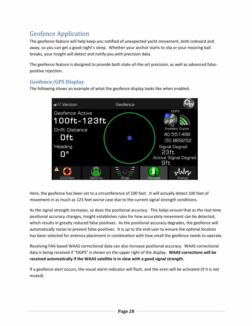
Bilge Discharge Zone Settings
The following are global settings for controlling bilge discharge.
In No Bilge Discharge Zone
If regulations prohibit bilge discharge, this setting will tell all Nevatas not to operate their primary pump.
Dual pump Nevatas can be setup to use the secondary pump to discharge bilge water into an onboard
holding tank (See Nevata advanced settings for how to set this up on a individualized Nevata basis).
This setting can be changed remotely with the “discharge” sms command. See SMS commands.
Auto-Disable No Discharge On High-Water
If discharge is disabled, and a Nevata reports a high-water condition, it is possible to have Insight
automatically re-enable discharge in an emergency scenario, if this setting is enabled.
Bilge Freeze Alerts
Sets the global pre-freeze and freeze alert levels for all Nevatas if enabled.

Page 42
Wireless Sync Settings
Insight Role
Under normal operations, coordinator should be selected. If the Insight is being used on the tender of a
Tender Watch Application, then the Insight Role should be changed to tender, allowing Insight to
wirelessly pair and communicate with the Insight on the mothership.
Auto Scan Channels
Under normal operations, this should be set to “Rescan on sensor offline event”, which allows for
automatic error recovery in the event wireless interference is present from other wireless networks.
If Insight is being used in a Tender Watch Application, however, it is recommended to disable this setting
because the Insight on the tender will periodically go in and out of wireless range as the tender is used
for shuttle purposes.

Page 43
Sensors List All sensors (Nevatas, XPulse, and Range Extenders) are viewable from the sensors tab of the Nautic Alert
Manager.
See Pairing Sensors for how to pair sensors.
If any range extenders are used, the signal strength reported for each sensor corresponds to its link to
the next node in the communication path, thus, if one or more range extenders are used between your
Insight and Nevata or XPulse, then the Nevata or XPulse will report its signal strength to the closest
range extender, and that range extender will report its signal strength to the Insight. In taking this
scheme into account, sensor placement can be observed to yield the most optimal communication path
from end-to-end devices.
Removing a sensor from the list will put the sensor back into pairing mode, where it is looking for an
Insight to communicate with.
Range Extender Usage
In most cases, a range extender will not be necessary. However, in certain circumstances where large
distances are present between a Nevata and an Insight, or metal walls are present, such as an engine
room, one or more range extenders may be necessary to bridge the Nevata to Insight connection.
Adding one or more range extenders between a Nevata/XPulse and Insight will automatically heal the
communication connection once the router is paired to the Insight.
Nevatas and XPulse sensors will also provide mesh networking, so if a Nevata is located in a metal-
enclosed engine room, for example, locating an XPulse adjacent to the engine room will allow a better
communication path from the engine room Nevata to Insight by leveraging XPulse as a range extender in
the middle.

Page 44
Event Log The event log keeps track of all outgoing alert messages, as well as system generated events and
Remote Text Message Interface commands. The following is an example of the event log with multiple
events present:
Pressing an event will show additional details about the event, in particular, if the event was sent or why
it was not sent, and any issues that were observed in sending the event.
The event log will hold up to about 50 event messages. Once the event log is full, a new message will
cause the oldest message to be discarded.

Page 45
Alert Recipients Up to three alert recipients can be added. The first entry added is considered the system administrator.
See GEOS Reference sections for more on administrator usage. In addition, an admin can add
additional users via the Nautic Alert Mobile App.
Adding an Alert Contact
To add a new alert contact, simply press the “+” button shown here. Next, you will be prompted for the
cell phone number, and a verification code will be sent to that number. It’s necessary to enter the
correct verification code when prompted, as this ensures a complete communication path to the
intended recipient is present. At this time, any user account associated with this cell number can access
the MyInsights web portal. See Nautic Alert Web Portal section for more details.
Once a contact is added, it will show up in the list like shown below:
In this case, the alert contact will receive all alerts. Pressing the globe will change this contact to an
emergency contact. The contact can be removed by pressing the “X”. The first entry in this list must be
a normal user and administrator.

Page 46
At any point, a test message can be sent to all alert contacts in the list by pressing the send message
icon.
Emergency contacts will only receive emergency and critical messages, such as an emergency/SOS
activation or critical high water, and cannot access the remote SMS interface. They can, however,
access read-only data available in the MyInsights web portal. See Nautic Alert Web Portal section for
more details.
Firmware Updates From time to time, firmware updates may be required. In order to update the device firmware, it is
necessary to connect Insight to the internet via the built-in WiFi, then use the Firmware update
application to automatically detect and apply newer firmware updates.
Enter the WiFi application, then select “Select Access Point” to display available SSIDs and connect.
The easiest way to facilitate connecting to the internet may be to enable your phone’s hot spot then
connect Insight to your phone. The firmware image is typically less than 3MB, which is extremely small
and will not have any noticeable impact to cellular data usage.
Once connected, press the “Update” tab to enter the firmware update application as shown here:

Page 47
Pressing on “Check For Updates” will check if any updates are available. If there are, it will display info
and allow you to download the update.
The download process typically takes several minutes, and once complete, you will be prompted to
install the update. Once the update is installed, Insight will automatically reboot. Do not interrupt this
process by removing system power.
System Info
The system info contains the firmware version of your Insight, and mobile cell number assigned to the
Insight, as well as the modem MEID. The cell number is the number you should use to text the Insight
via the Remote Text Message Interface.

Page 48
Installer Reference The following few sections are specifically for installers and changing global and application
configuration settings.

Page 49
Mounting, Wiring, and Antenna Options Insight can be either bracket or flush mounted.
External antennas, mounting options, and 25’ or 50’ cables are available as options, see
www.nauticalert.com for additional details. The external antennas are relatively small, about 3 inches in
diameter, and can be flush mounted, bracket mounted, and/or located beneath most fiberglass
surfaces.
Once a mounting location is chosen, see sections Insight Mount Bracket and Wiring Description and/or
Insight Dimensions and Flush Mounting.

Page 50
Insight Mount Bracket and Wiring Description Insight can be flush mounted by removing the front cover, and using the 4 underlying mount holes as
shown below.
The front cover is held in place by machine screws that screw in from the top and bottom of the
assembly. The 4 mounting holes behind the front cover used to flush mount are also used to attach the
mounting bracket legs as shown below:
If using the mounting bracket, attach the two side mounts to Insight prior to attaching to the mating
bracket assembly. 4 4-40 x ¾ machine screws hold the side brackets to Insight. DO NOT OVERTIGHTEN.
If using the bracket and mounting in a vertical configuration, the bracket mates together every 18
degrees, including 90 degrees, and use 2 M4 machine screws to fasten the side mounts to the main
mount. At least 2 #4 screws are recommended for attaching the base of the main mount to the yacht
mounting location. The base of the main mount can be rotated and locked in place.
When flush mounting, 4 #4 x 1 inch screws can be used to attach the Insight to the panel. DO NOT
OVERTIGHTEN.
Page 51
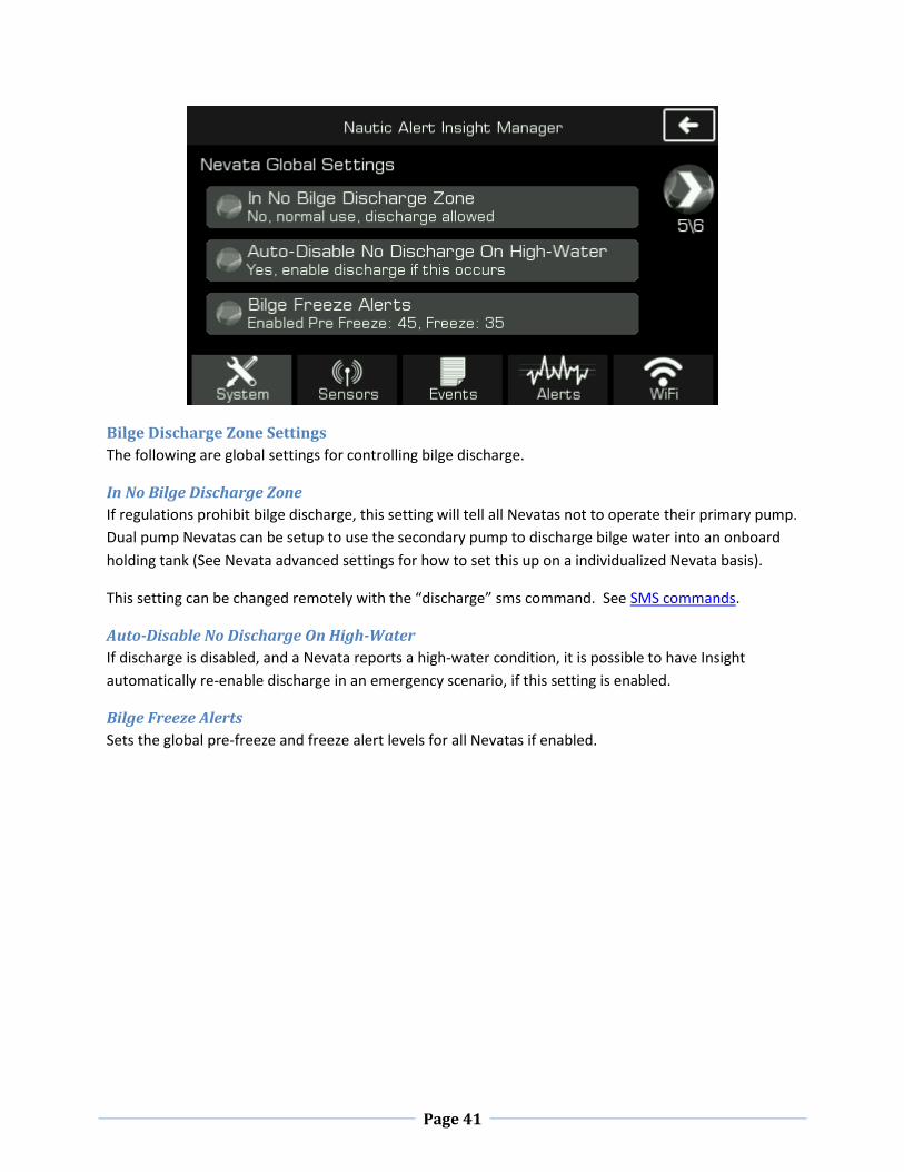
Insight Dimensions and Flush Mounting
Insight dimensions are shown in inches below. Additional margin is needed for Insight cabling exit strain
relief on the back side, in addition to the depth dimension shown below.
Recommended panel cutout dimensions for flush mounting

Page 52
Cable Wire Description and Powering On - Red - Power (+)
- Black - Ground (-)
Use with 12 and 24V DC systems.
Note: Your Insight will not startup if your DC voltage is insufficient and depleted. This feature allows
your battery charger to bring your DC battery to a sufficient level before power is drawn, as well as
prevent cycling of the Insight. At least 11 volts is required for your Insight to power on, otherwise, the
Mute and Display buttons will blink red to indicate a low voltage is present. This feature is
particularly useful in solar panel moored installations, where it’s necessary to charge the boat’s batteries
to a sufficient level prior to putting an additional load on the batteries.
Always follow ABYC wiring standards and use an inline fuse or breaker appropriately rated.
Optional Power Path Redundancy and Battery Backup XPulse units support power-path redundancy for Insight (See XPulse documentation), where one or
more battery banks can be used to power Insight and security sensors. With XPulse, a dedicated 12V
regulated output can power wired security sensors and Insight, optionally, if this power redundancy
scheme is required.

Page 53
Antenna Placement Verification Once antenna placement is determined, it should be verified by viewing the GPS/Geofence screen on
Insight as shown here:
An “Excellent Signal” should be observed for the GPS signal.
If a satellite Insight is being used, “Iridium” should display on the upper left of the screen, with 5 bars
being observed about once a minute. It is normal for the bars to drop down to one or zero bars then
ramp up quickly. An active Reporting Service subscription is not required to view signal strength of the
Iridium network.
If a cellular Insight is being used, an active Reporting Service Subscription is required to view the signal
strength of the network, however, simply ensuring the modem IMEI is displayed under the system
settings validates the cellular modem is operational as shown here:

Page 54
Pairing Sensors Before you can use a Nevata or XPulse, they must pair with Insight. To enable pairing, enable the “Add
New Wireless Sensor” system setting.
As sensors pair, they will display under the sensors tab as shown below.
If a sensor does not pair after a minute or so, verify the sensor is in pairing mode. On a Nevata, this is
accomplished by pressing “Set” while holding down “Mode”, and on an XPulse and Range Extender, this
is accomplished by pressing the “Repair” button.
It is highly recommended to set the name of each sensor to a meaningful location description so alerts
can contain meaningful sensor details.
Page 55
It is required to validate signal strength of each sensor before installation. Sensors provide mesh
network capabilities, which can extend the reach of otherwise distant sensors. A range extender can
be added if necessary. See the Sensors List section for a description of how to validate this.
Anti-Theft Tamper-Proofing It is possible to tamper-proof a Nautic Alert Insight installation such that it cannot be removed without
being detected. For details on how to do this, contact Nautic Alert.

Page 56
XPulse Reference
XPulse and XPulse Plus add additional applications to Insight, which includes 4 battery banks, AC Shore
power monitoring, a 4-zone security (XPulse) wired or (XPulse Plus) wireless sensor interface, and
wireless siren sync which can be used to drive external lights and sirens.
Insight supports up to 4 combinations of XPulse and XPulse Plus, for a total of 16 zones, 16 battery
banks, 4 dedicated shore power inputs, and 64 wireless sensors.
XPulse is designed to operate with existing or Nautic Alert pre-certified hardwired 12V tolerant N.O or
N.C. standard security sensors. Sensors can be wired together in a single zone. See the XPulse
installation manual for max current requirements.
Security and safety sensors include outdoor and indoor motion, smoke, door/hatch contacts, beam
intrusion, carbon monoxide, and allow for custom sensors and zone descriptors which can be driven by a
relay switch.
Examples of non-security sensors can include one or more high-water floats and AC relay switches for
monitoring gensets.
Sensor interoperability is not limited to Nautic Alert sensors, and any sensor that supports a Form C
relay interface can be used with XPulse.

Page 57
Zone and Battery Bank Descriptions It is highly recommended to set the desription of each zone so alerts can contain meaningful details.
This includes zone descriptions, dc bank descriptions, and ac bank descriptions.
Exterior Lights/Siren XPulse contains a siren block terminal output connected to the through-hole siren included. However, it
may be desired to drive an external light/siren. In this case, this 12V relay output should drive an
external relay to control the device desired.
Additionally, wireless siren sync system settings should be set appropriately for the desired siren output
type--all critical events or only security events. This setting is accessable by going into the Nautic Alert
Insight Manager then going to page 4 of the system settings.

Page 58
Global Security Settings The global security settings should be setup by going into the Security category, then double tapping the
status navigation button to view security settings.
Security Settings and Testing The following show the global security settings screen details, which are only accessible when the
system password is not set and the system is disarmed.
The away mode entry delay is only relevant if setting the system into away mode from the device.
When using the text interface or Nautic Alert Mobile App, away mode is entered instantly.
A passcode is highly recommended, however, there may be times when this is not wanted, such as
when occupants are using the boat and wish to detect approaching intruders onboard. A passcode can
be recovered with the “password” text command.

Page 59
Security zones should be tested onboard when the Siren Test Mode setting is enabled. Activating a
zone’s sensor will cause the integrated siren to chirp. Always disable this setting when it is not being
used.
Security Zone Settings
Each zone can be customized with a description, type, and arming mode. These settings are only
accessible when the system password is disabled and the system is disarmed. It is necessary to give a
meaningful description to each zone description so that outgoing alerts can contain meaningful data
about the zone the event originated from.
If wireless sensors are being used, Nautic Alert has pre-configured the zones/sensors already. If you are
configuring wireless sensors, however, contact Nautic Alert for instructions to pair wireless sensors to
XPulse Plus zones.

Page 60
Security Supervisory Settings
These settings are only accessible when the system password is disabled and the system is disarmed.
XPulse supports optional hardwired supervisory inputs whereas XPulse Plus is preconfigured for wireless
sensors.

Page 61
XPulse Battery Bank Settings and Descriptions Each battery bank connected to an XPulse should have its bank description set to something meaningful
so that alerts can contain meaningful descriptions about the bank the event originated from.
To set battery bank parameters, enter the Energy Category and double tap the battery bank displayed
on the bottom nav bar. The system password must be disabled to access the battery bank settings.
Insight implores advanced load filtering-based DC voltage monitoring. In many cases, periodic cycling of
a bilge pump, water pump, starting an engine, or any number of electronic devices can put an active
load on your DC battery system, which results in a short term drop in battery voltage. Your Insight is
designed such that a consistent voltage level must be reported for about a minute before an alert will be
generated, or cleared. Depending on the peripherals present on each battery bank, the DC Filter may
need to be adjusted.
Before DC voltage monitoring can be used, your Insight must be properly configured for your yacht’s DC
battery type and voltage. The DC settings view can be selected from the Navigation Tab on the home
screen.

Page 62
In most cases, a 12V lead-acid battery is used, however, your Insight also supports 24V and lithium
types. In the event the preset battery curve used to determine battery percentage is not optimal for
your arrangement, a custom battery type can be specified.
Pressing the forward arrow of the DC Settings screen displays the alert settings for the selected battery
type and voltage, as shown here:
Alerts will only be generated for the “Alert” and “Critical” thresholds. Additionally, the integrated siren
will only be activated for a critical DC level.
The DC filter value is used to prevent false alerts due to periodic loads on the DC battery. The
calibration offset can be used to adjust any voltage reading inaccuracies.

Page 63
Nevata Reference
Nevata Quick Configure and Viewing Settings Once your Nevata(s) is powered on and in range, it will automatically pair with your Insight if sensor
pairing is enabled. Once your Nevata pairs, if it is uncalibrated, you will see a quick configure prompt:
Pressing “OK” assumes your Nevata is properly mounted over a flat bottom and wired to the attached
pumps. If this is the case, hit “OK” to continue, and the Nevata will automatically calibrate itself and
apply default settings. See next section for details on the Nevata Remote View Settings.
You can always skip this step and calibrate your Nevata from the Nevata Remove View at a later time,
and as shown in the next few steps.
If a flat bottom is not being used, or an unusual circumstance exists, see the Nevata Advanced Settings
section for how to properly calibrate.

Page 64
Nevata Setup To access Nevata configuration settings, enter the Bilge Category then double tap the Nevata to be
configured from the bottom Nav bar.
Nevata Remote View Settings In order to calibrate your Nevata, or change any Nevata settings, including the manual override switch
for your Nevata’s attached pumps, the Nevata Remote View enables remote control over your Nevata.
The Nevata display operates equivalently to the display on the physical unit. See your Nevata
instruction manual for a detailed description of the settings, clearing faults, and clearing pump
counters.
Pressing here a second time enters the Nevata remote view settings

Page 65
Nevata Advanced Settings From the remote Nevata view, pressing the settings button on the top left of the screen will display the
Nevata Advanced Settings, as shown below. This view is only accessible if the system password is
disabled.
Pumps Controlled- Can be used to set a dual-pump Nevata to act as a single-pump Nevata, where the
backup pump wires are simply terminated and unused. A single-pump Nevata must remain set to
disabled or single-pump operation.
Force Calibration Depth can be used to set the calibrated depth for non-flat bottom bilges, or if the
bottom of the bilge should not be considered the zero inch mark of water level readings. Forcing
calibration will also enable the “Ignore Acoustic Loss” setting discussed below.
Pump Stats show the total pump cycles, runtime, and max current stats. The pump cycles and runtime
can be set by the user using options discussed below. These cycles can vary from those shown on the
Nevata Display and Nevata Remote View screen, as the cycles shown there can be reset anytime to
make it easy to gauge how often the pumps have cycled in a smaller duration of time. These values are
used in combination with Nautic Alert’s Advanced Cloud Solution to enable advanced pump analytics
and additional notifications, such as premature pump failure detection, and pump degradation
detection (See the Nevata manual and www.nauticalert.com for more details).

Page 66
Invalid Readings Threshold can be used when a backup float switch is connected to Nevata. Setting this
to the water level at which the float switch activates will prevent the Nevata from also trying to drive
the pump, and create a pump fault event. This is an optional setting.
Ignore Acoustic Loss can be used for non-flat bottoms. If Nevata cannot read the water level, by default
it will periodically run the pump(s) and auto-sense if water is present. It will also notify of a signal loss
event. If this setting is enabled, Nevata will not auto-run the pump(s) or notify for a signal loss event.
Pump Discharge Zone Setting determines if Nevata should enable or disable automatic pump cycling if
the global discharge disabled setting is enabled, see discharge setting.
Dual pump Nevatas can use the secondary pump to pump water into a dedicated onboard holding tank.

Page 67
Pump Runtime Seconds and Pump Cycles Settings sets the total runtime or cycles for each attached
pump. External voltage sense features in Nevata will detect the presence of an optional external float or
manual override driving a pump, and increment the runtime totals.
If a dual pump Nevata is used, an additional page is available for accessing pump 2 runtime seconds and
cycles.
If a new bilge pump is installed, the runtime seconds and cycles should be reset such that these values
reflect the lifetime runtime and cycle stats of the new pump. If a new bilge pump is being installed, it is
necessary to re-calibrate Nevata as well.