Lateral Vehicle Dynamics Control and Vehicle State Estimation
Upload
khangminh22Category
view
0download
0
JOURNAL OF ALGEBRAIC STATISTICS
Volume 13, No. 2, 2022, p. 1936 - 1945
https://publishoa.com ISSN: 1309-3452
1936
ABSTRACT
Nowadays Road accident causes serious issues and many people's lives are at risk in their day-to-day life. Due to the rapid
growth in science and technology, every problem which arises in today's world can be easily tackled. Road accidents are
occurring at a high rate in today's world. India ranks 1st in the number of road accidents death across 199 countries
followed by the U.S and China. In 2019 alone India accounts for a total of 4,49,002 road accidents reported by state union
territory. Most death cases are mainly due to a lack of medical support. Even if they ended up causing accidents in remote
areas, they never get medical support immediately. Due to the delay in reporting the accident, there is always some delay in
ambulance arrival at the location of the accident. Thus, to prevent the delay and to get proper medical support, there must be
an emergency working model which would send an exact location of the accidental zone to the nearby hospitals and police
stations. With the use of modern technology, developing an automatic alert system that sends the location of the accidental
zone to the nearby hospitals through GPS/GSM can be achieved and can save precious time and provide a sustainable
environment where no lives can be at risk. The camera captures the accident, which can be later analyzed for investigation.
The effectiveness of the proposed project is examined using PROTEUS software and simulation results are analysed.
Index Terms— Accelerometer, Global Positioning System (GPS), Global System for Mobiles (GSM), Raspberry pi,
PROTEUS, SIM900A GSM.
I. INTRODUCTION
Road accidents are an immense concern in today's world, with over 1.3 million people killed or injured. In today's world,
population growth is accelerating, and accidents are occurring at an alarming rate, resulting in a high number of casualties.
Over speeding, rushing, carelessness, traffic law violations, Drunk and Drive, and other factors contribute to the accident.
Many lives are at risk because of the aforementioned factors. If an accident occurs, minor injuries can be treated using a
first aid kit; but, if the injury is severe, the victim should seek medical attention immediately. When individuals are there,
they will aid the person and promptly take care of their requirements. But, if they are not present, medical treatment will be
required. They can only survive if they receive medical assistance at the precise moment, they require it. They will be put in
jeopardy if such support is delayed. Many victims died while on their way to the hospital. Many individuals are dying while
being transported to hospitals due to delays in ambulance arrival. Many individuals may suffer because of this. The current
technology uses a smartphone app that uses a GPS (Global Positioning System) and accelerometer to identify an accident
and alert the ambulance. When an accident happens, the controller activates the sensors, and the corresponding readings are
recorded. The readings include the car's speed and position, which are received via GPS. The appropriate readings are
delivered to the emergency system or hospitals by establishing an application on the individual's mobile phone. Even if a
minor accident occurs, if the individual survives with only minor injuries, they should not require any extra medical
assistance, they should be able to manage their wounds on their own or simply contact the emergency services they require.
This system should not issue an emergency alert notification to adjacent hospitals in that circumstance. These flaws should
be used to characterize the system.
Smart Vehicle Accident Alert System
[1]Dr.M.Nirmala, [2]Arjun K, [3]Sunil Kumar R, [4]Karthikeyan S
[1] Assistant professor-III, EEE, Kumaraguru College of Technology, coimbatore-641042, [2] Student, EEE, Kumaraguru College of Technology, coimbatore-641042, [3] Student, EEE, Kumaraguru College of Technology, coimbatore-641042,
[4] Student, EEE, Kumaraguru College of Technology, coimbatore-641042
[1] [email protected],[2] [email protected], [3] [email protected], [4] [email protected]

JOURNAL OF ALGEBRAIC STATISTICS
Volume 13, No. 2, 2022, p. 1936 - 1945
https://publishoa.com ISSN: 1309-3452
1937
If any external disturbance is made over the vehicle when a system employs piezo-electric sensors to detect accidents, the
piezoelectric sensor determines the disturbance or pressure created on the vehicle and the system should transmit messages
depending on the specified values. If the sensed value is higher than the typical value, the system should send out an
emergency alert. Some systems employ piezoelectric sensors to detect accidents, while others use GSM (Global System for
Mobiles) to send signals.
II. EXISTING SYSTEM
The existing system has a piezoelectric sensor mounted on all sides of the car. When a collision happens, the piezoelectric
sensor generates a higher voltage, and the microcontroller senses the higher voltage and sends a message to the specified
Phone number. In some systems, there is also an accelerometer included to detect the rolling of the vehicle after a collision.
The location of the accident is detected by the GPS and sent to the specified phone number. There is an application
developed for detecting the accident and sending the location of the accidental zone through an SMS. The application is
called SOSmart application [1]. This app can access the inbuilt sensor and obtain the location of the accidental area with the
help of the GPS in the Mobile phones. After installing the app on the mobile phone, it will request to pre-select the contact
of the important or close family circle members. After that, the app stays intact with GPS. If an accident occurs the app
trigger an emergency notification to the pre-selected contact members or the emergency unit. This notification contains the
location details of the accidental area which is obtained from the GPS in the mobile phones. This application is also tested
in real-time application on the National Highway Traffic Safety Administration. The results are characterized based on the
normal, mild, and serious accidents.[1] There is also a solution developed by Kaladevi et al. through Android Smartphones.
In this system, a Heartbeat sensor is implemented in the Smartphones. The normal Heartbeat rate ranges from 60 to 100
beats per minutes BPM. If there is a variation in the normal heartbeat, then the system checks for the accident or not cases.
If it is an accident, then the system will trigger an alert or emergency message. There is also a system that differs from all
the existing systems. [2] Sane et al developed a system that is entirely different from other systems. This system uses push
button switches. These switches are mounted or integrated on the front and rear ends of the bonnet. In case of any accidents
occur, the Collison rate is monitored by the accident detection system and sensors. Then these data are transmitted to the
interrupt pins of the micro-controller. There is an access key provided to the drivers, which will be used by the driver alone.
If it is a minor accident, then the notification triggered will not send to the emergency units or members. If it is a major
accident and the driver does not use the key, then the notification containing the location details is triggered. In addition to
this system, there is also another method which will work as same as the mentioned above methods. [3] Anupriya et al also
proposed a system Smart Accident Notification and Collision Avoidance System which uses ZIGBEE for the other
instruction. [4] Vardhini et all developed a Smart accident alert system that also uses a Vibration sensor alone to detect the
accident and a GSM module to send the message of GPS coordinates.[6] Sampoornam et al developed an Intelligent
Expeditious Accident Detection and Prevention System which uses an accelerometer sensor to detect the accident and the
same GSM module for message communication to the Family members. All these will be useful for developed countries
which use automated traffic systems and Radio Frequency systems, which also ultimately decreased the mortality rate.
III. OBJECTIVE
The main objective of the proposed project is as follows:
• To provide proper emergency medical assistance by sending the location of the accidental zone. Through the image
captured by the camera, the microcontroller can identify the other accident vehicle, if any crime occurs it should be
monitored and helps the police in the investigation.
• The project aims to send the exact location and photos of the accidental zone to the nearby hospitals and police stations.
• By getting inputs from the camera and sensor, the microcontroller will characterize the input and after proper
observation, the microcontroller will send the location using GPRS/GSM. If there are small accidents, the microcontroller
will not trigger the notification.
• In a smart vehicle accident alert system, it consists of a vibration sensor, which detects vibration, when an accident
happens, and it will be finely tuned to cancel false alarms. To detect the force of the collision, an accelerometer is used and
a gyro sensor to detect the rotation of the vehicle. In this system there are 4 cameras connected to the microcontroller, when
a collision happens, the cameras will capture the surroundings to detect the other vehicle with which the collision
happened. The collision location is detected by GPS and the picture of the other vehicle will be sent to the specified number

JOURNAL OF ALGEBRAIC STATISTICS
Volume 13, No. 2, 2022, p. 1936 - 1945
https://publishoa.com ISSN: 1309-3452
1938
IV. BLOCK DIAGRAM
Fig. 1. Block diagram of the proposed smart system
Fig. 1. shows a block diagram of the proposed smart vehicle accident detection system. When a vehicle collides,
immediately the vibration sensor calculates the vibration, if the value is greater than 0.5 IPS (Inches Per Second), the
microcontroller takes it as an accident. The normal car vibrations are under 0.5 IPS. Accelerometer thresholds are 0-4 g for
no accident if it goes beyond that the microcontroller takes it as an accident. 4-8 g indicates a mild accident and 8-12 g
indicates a medium accident and 12-16 g indicates a severe accident. The g force created by the accident detected by the
accelerometer are sent to the microcontroller.
The gyroscope sensor detects the rotation of the vehicle. If the car rolls and ends facing upside down, the gyroscope sensor
will sense the degree (180 or 360 deg) of the vehicle and give the input to the microcontroller. As soon as the collision
happens the cameras on four sides with the help of image processing will capture the surroundings of the vehicle and detect
the other vehicle with which the collision happened and sent it to the microcontroller. The GPS would detect the longitude
and latitude of the location and send it to the microcontroller. The microcontroller could process all the information from
various modules and send the data through the GSM module to the specified phone number.
V. SIMULATION MODULE FOR VARIOUS SENSORS
A. VIBRATION SENSOR
Fig.2. Vibration sensor
Vibration sensor and the in-built circuit of the vibration sensor. Vibration sensor 801S is a digital vibration sensor, which
has 3 pins, a VCC, a GND, and a digital output pin. The threshold value can be adjusted using a potentiometer that is

JOURNAL OF ALGEBRAIC STATISTICS
Volume 13, No. 2, 2022, p. 1936 - 1945
https://publishoa.com ISSN: 1309-3452
1939
available on the vibration sensor. It gives a vibration indication to raspberry pi when the accident occurs. It is connected to
GPIO 4 pin in the microcontroller.
B. ACCELEROMETER SENSOR:
Fig. 3. Accelerometer
Accelerometer sensor inbuild circuit connections. ADXL335 is a 3-axis accelerometer sensor. The bandwidth ranges for
the X AND Y-axis range from 0.5Hz to 1600Hz and the Z-axis range from 0.5Hz to 600Hz. There is an x, y, and z-axis in
the accelerometer, which are connected to Raspberry pi’s input pins. The accelerometer is used to calculate the G-force of
the accident and indicate the microcontroller. It is connected to ADC (Analog to Digital Converter) through ADC0, ADC1,
and ADC2, and then it is connected to the microcontroller.
C. GYROSCOPE:
Fig. 4. Gyroscope
Fig 4 shows the Gyroscope’s inbuilt circuit connections. GY-521 is a 3-axis gyroscope module, which determines the angle
the vehicle is in and sends the information to the microcontroller. It is connected to the ADC through ADC3, ADC4, and
ADC5 and it is connected to the microcontroller. It transfers from the highest to 400KHz of I2C or even up to 20MHz of
SPI.
VI. CIRCUIT DIAGRAM
Fig. 5. Circuit diagram of the proposed system
Fig 5 shows the circuit diagram. An accelerometer is used to measure acceleration.[1] A g-force is a measure of
acceleration. A g-force of 1 g is equal to the conventional value of gravitational acceleration on Earth, g, of about 9.8 m/s².

JOURNAL OF ALGEBRAIC STATISTICS
Volume 13, No. 2, 2022, p. 1936 - 1945
https://publishoa.com ISSN: 1309-3452
1940
TABLE I
Acceleration for different g forces
The analog voltage is converted to digital from the acceleration
sensor by the formula.
The Digital value is the axis values x, y, z of the accelerometer.
The acceleration g force can be calculated by above formula. 801S vibration sensor can detect till 1 IPS (Inches Per
Second). The potentiometer of the vibration sensor is tuned to half of the value.[16] Whenever a vehicle is driven, its
maximum vibration is within 0.5 IPS. Setting the potentiometer at half the value, the vibration sensor is set at 0.5 IPS
threshold. Whenever there is a trigger greater than 0.5 IPS then the vibration sensor sent the signal to the microcontroller.
VII. FLOWCHART
Fig. 6. Flowchart
Fig. 6 shows the flowchart of the working process of the system. At first, there should some parameters be implemented
for processing the micro-controller. Then the system should initialize the values of the parameters. If any collision occurs in
the vehicle, then the vibration sensor, accelerometer sensor, and gyroscopic sensor should active. Once the sensor is
activated then the sensors should start to record the sudden change of values. The obtained values are then transmitted to
0 g – 4 g No accident
4 g – 8 g Mild accident
8 g – 12 g Medium accident
12 g – 16 g Severe accident

JOURNAL OF ALGEBRAIC STATISTICS
Volume 13, No. 2, 2022, p. 1936 - 1945
https://publishoa.com ISSN: 1309-3452
1941
the micro-controller. The micro-controller then processes the obtained value with the specified values of the individual
sensors. If the vibration sensor and accelerometer sensor value are greater than the specified value, then these will tend to
activate the camera. Once the camera is activated by the vibration and accelerometer sensors value by the micro-controller
it starts to capture the images of the accidental zone. These images can be useful for police investigations. These images are
also pushed to the cloud storage for further process. By these, the causes of the
accident can be identified. After the time when the camera has activated the location of the accidental zone is obtained with
the help of a GPS. Once these parameters are obtained with help of the GSM these parameter values are shared with the
nearby hospitals and police stations. After the message is triggered when the system will get back to its initial position.
ALGORITHM:
STEP1: START.
STEP2: Collison happens.
STEP3: The values are generated in all the 3 sensors.
STEP4: Values transmitted to the microcontroller.
STEP5: Compare the values of the three sensors.
STEP6: If the values are lesser than the specified value.
STEP7: Minor accident.
STEP8: If values are greater than the threshold value.
STEP9: Cameras are activated to capture images.
STEP10: Images are pushed to the cloud storage.
STEP11: GPS activates to locate the location.
STEP12: Reads the GPS values and other data.
STEP13: GSM transmits the message to a specified number.
STEP14: STOP.
VIII. SIMULATION RESULT
Fig. 7. Overall simulation diagram for the proposed system
The simulation consists of Raspberry Pi 3 as its microcontroller. UART (Universal Asynchronous Receiver-Transmitter)
is used for serial communication. A TFT (Thin Film Transistor) display with a resolution of 320*240 is used for displaying
sensor values and the image captured by the camera. The accelerometer and gyroscope are designed using 3 potentiometers
for 3 axes (x, y, z). The accelerometer and gyroscope are connected to the Raspberry pi 3 using an MCP3008 analog to
digital converter. The vibration sensor is designed by keeping a threshold value with a potentiometer. The GSM, GPS, and
camera module are connected to the raspberry pi 3.
JOURNAL OF ALGEBRAIC STATISTICS
Volume 13, No. 2, 2022, p. 1936 - 1945
https://publishoa.com ISSN: 1309-3452
1942
Fig. 8. Simulation circuit under normal condition
Fig 8 shows the Simulation circuit under normal conditions and the output for no impact conditions. Before the accident,
all the sensor readings are monitored by Raspberry pi 3 and displayed in the TFT display. The vibration sensor and
accelerometer are below their threshold values. The Vibration Sensor is less than 0.5 IPS. An accelerometer is less than 4 g
force.
Fig. 9. Simulation circuit under mild accident
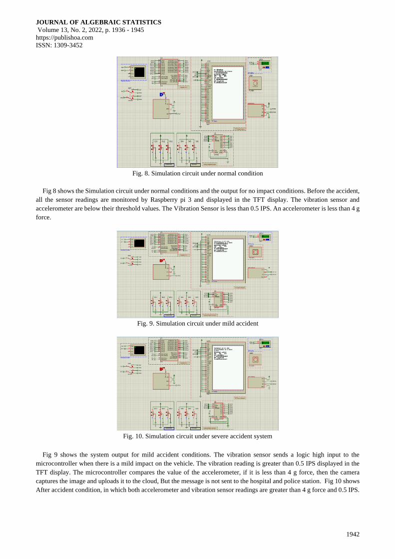
Fig. 10. Simulation circuit under severe accident system
Fig 9 shows the system output for mild accident conditions. The vibration sensor sends a logic high input to the
microcontroller when there is a mild impact on the vehicle. The vibration reading is greater than 0.5 IPS displayed in the
TFT display. The microcontroller compares the value of the accelerometer, if it is less than 4 g force, then the camera
captures the image and uploads it to the cloud, But the message is not sent to the hospital and police station. Fig 10 shows
After accident condition, in which both accelerometer and vibration sensor readings are greater than 4 g force and 0.5 IPS.

JOURNAL OF ALGEBRAIC STATISTICS
Volume 13, No. 2, 2022, p. 1936 - 1945
https://publishoa.com ISSN: 1309-3452
1943
The GPS latitude and longitude are read by the microcontroller. The GSM is made to send a message to the hospital and
police station with location coordinates.
Fig. 11. Image capturing and message sending under a severe accident system
Fig 11 shows the image captured by the camera connected to the microcontroller once the accident happens. The
message is sent to the hospital and police station and the vibration sensor, accelerometer, gyroscope, GPS, and image is
uploaded to the cloud.
TABLE II
Result for Different Condition
Vibration sensor
output
Accelero
meter
Camera Message
Indicator
Cloud Action
Greater than
0.5IPS
Greater than
4 G-force
Camera
captures
image
Message sent to
specified
number
Sensor data
uploaded to the
cloud
Greater than
0.5IPS
Less than 4
G-force
Camera
captures
image
Message not
sent
Sensor data
uploaded to the
cloud
Less than 0.5IPS Greater than
4 G-force
Camera
captures
image
Message not
sent
Sensor data
uploaded to the
cloud
Less than 0.5IPS Less than 4
G-force
Does not
capture an
image
Message not
sent
Sensor data not
uploaded to the
cloud
If the vibration sensor and accelerometer are less than their threshold values, the camera does not capture and the
message is not sent and sensor data is not uploaded. If the vibration sensor and accelerometer are less than their threshold
values, the camera captures the image, the message is sent, and the sensor data is uploaded. If only one senor is greater than
the threshold value, then the only camera captures the image, the message is not sent and sensor data is not uploaded. The
entire process of getting the data from sensors and sending messages is completed 500 milliseconds.
CONCLUSION
Before developing a real-time working system, a prototype based on a detection system would be developed and tested
for various test cases and operations to examine the proper functioning of the prototype. And we have tested the various test
cases by using PROTEUS software. The various results were also updated in the above Simulation Results. By lowering
the time, it takes for an ambulance to arrive, this proposed solution can avert numerous accidents and save many lives. It

JOURNAL OF ALGEBRAIC STATISTICS
Volume 13, No. 2, 2022, p. 1936 - 1945
https://publishoa.com ISSN: 1309-3452
1944
can also be used in future technologies to ensure that every car is completely safe. Everything that man has created
contributes to the universe's stability and environmental friendliness. This proposed technology can guarantee safety at
whatever cost, allowing individuals to drive without worry. The use of suitable sensors and integrated circuits and a
microcontroller and GPRS/GSM module can ensure human safety and security. This system can function flawlessly, and
any future implementation and modification that is required for the next generation can be accomplished with some future
study. The proposed system is a low-cost efficient, extreme performance, and highly effective and ensures the system's
proper operation
FUTURE SCOPE
This prototype can pinpoint the exact location of an accident and send the information to hospitals and police stations.
The use of a camera mounted on the vehicle's exterior layers can capture and record photographs of the accident, allowing
the causes of the event to be determined. This system can be further customized to meet future requirements. This system
can also be developed without external error by utilizing numerous updated sensors already available on the market. The
MAX30100 PULSE SENSOR can be used to detect the victim's pulses, which will aid in the diagnostic process in
hospitals. This system can also use breath-detecting sensors like the PIEZORESISTIVE breathing system. The system can
also be enhanced by using these sensors. Ambulance navigators can also be included in this system, which will be valuable
for ambulance drivers in determining the quickest route. Alcohol sensors MQ135 can be used in this system for patient
diagnostic purposes, as they are already used in the car vehicle industry. When a vehicle uses a gas-based fuel system, gas
leakage can be detected with MQ-6 gas sensors. As a result, using these sensors to make this system work effectively
without any flaws will be beneficial to future generations and society.
REFERENCE
[1] P. Kaladevi, T. Kokila, S. Narmatha, and V. Janani, “Accident Detection Using Android Smart Phone”, International
Journal of Innov. Res. Comput. Commun.Eng,2(1),pp.2367-2372,2014.
[2] N. H. Sane, D. S. Patil, S. D. Thakare, and A. V. Rokade, “Real-Time Vehicle Accident Detection and Tracking Using
GPS and GSM”, International Journal on Recent and Innovation Trends in Computing and Communication, 4(4), pp.
479-482, 2016.
[3] V. Anupriya, B. Lissy Roy, V. Dheepthi, and F. Masood. “Smart Accident Notification and Collision Avoidance
System,” International Journal of Engineering Research and Technology, 4(4), pp.11481152, 2015.
[4] Vardhini Radhakrishnan, “Smart Vehicle Accident Detection System”, Published by: my gov innovation, November
12, 2018.
[5] Md. Saeed Abdul Hadi, Abhijit Saha, Faysal Ahmad, Mohammad Shahriyar Hasan, Mehebub Hasan Milon, “A Smart
Accident Detection and Control System in Vehicular Networks”, 5th International Conference on Networking, Systems
and Security(NSysS). Published in: 2018.
[6] P Sampoornam, “Intelligent Expeditious Accident Detection and Prevention System”, Published: et al 2021 IOP Conf.
Ser.: Mater. Sci. Eng. 1059 012012.
[7] Jayabarathi D. (Sri Krishna College of Technology, India), Kesavaraja D.(Dr. Sivanthi Aditanar College of
Engineering, India), Sasireka D. (V. V. College of Engineering, India) and Barkath Nisha S. (Sri Krishna College of
Technology, India), “Smart Accident Detection and Prevention System (SADPS)”, Published in IGI Global publisher of
timely knowledge, 2019
[8] Arsalan Khan, Farzana Bibi, Muhammad Dilshad, Salman Ahmed, Zia Ullah, “Accident Detection and Smart Rescue
System using Android Smartphone with Real-Time Location Tracking”, Published by: IJACSA (International Journal of
Advanced Computer Science and Applications), Vol. 9, No. 6, 2018.
[9] Scott J. Weiner, “Feasibility of an 802.11 VANET Based Car Accident Alert System”, Published in IEEE, 2010
[10] A Kushwaha, G. Katiyar, H. Katiyar, H. Yadav, S. Saxena, “GPS and GSM based Accident Alarm System”, National
Student Conference On AEICT (Advances in Electrical & Information Communication Technology) -2014.
[11] V. Goud, V.Padmaja, “Vehicle Accident Automatic Detection and Remote Alarm Device”, IJRES (International
Journal of Reconfigurable and Embedded Systems), Vol. 1, No. 2, July 2012, pp. 49~54, ISSN: 2089-4864.

JOURNAL OF ALGEBRAIC STATISTICS
Volume 13, No. 2, 2022, p. 1936 - 1945
https://publishoa.com ISSN: 1309-3452
1945
[12] K. C. Varma, Poornesh, T. Varma, Harsha, “Automatic Vehicle Accident Detection and Messaging System Using
GPS and GSM Modems”, IJSER (International Journal of Scientific & Engineering Research), Volume 4, Issue 8,
August-2013, ISSN 2229-5518.
[13] V. O. Matthews, E. Adetiba, “Vehicle Accident Alert and Locator (VAAL)”, (International Journal of Electrical &
Computer Sciences) IJECS-IJENS Vol: 11 No: 02, 2011
[14] K. Akhavan, S. Jagadeeshwaran, G. Balasubramaniam, N. Dinesh, G. Abhilash, G. Gokul, “Automatic Ambulance
Rescue System”, International Journal of Advanced Technology and Engineering Research (IJATER), Vol. 2, Issue 2, May
2012, ISSN No. 2250-3536.
[15] Y. Zhao, “Efficient and reliable data transmission for cellular-and-GPS based mayday system”, in Proc. IEEE
Intelligent Transportation Systems Conf. Boston, MA: IEEE, 1997, pp. 555–559.
[16] VIBESCorp, “Learn about vibration”,Volume 1:Basics of vibration, pages 1-10, published on oct 11, 2019.
Copyright © 2022 FDOKUMEN