Reconstruction model of vehicle impact speed in pedestrian–vehicle accident
6
Reconstruction model of vehicle impact speed in pedestrian–vehicle accident Jun Xu a, * , Yibing Li a , Guangquan Lu b,1 , Wei Zhou a a State Key Laboratory of Automotive Safety and Energy, Department of Automotive Engineering, Tsinghua University, Beijing 100084, China b School of Transportation Science and Engineering, Beihang University, Beijing 100191, China article info Article history: Received 21 May 2008 Received in revised form 11 November 2008 Accepted 12 November 2008 Available online 27 November 2008 Keywords: Accident reconstruction Pedestrian–vehicle accident Impact speed PVB windshield glazing Deflection abstract Reconstruction of pedestrian–vehicle accident is a worldwide problem. Numerous previous studies have been carried out on accidents with vehicular skid marks or definite pedestrian throw distances. However, little could be done if marks or throw distances cannot be obtained in accident reconstruction. This paper first describes the physical model of dynamic process of pedestrian head impact on windshield glazing. Some simplifications are made to obtain a better and more practical model, including discussing the support boundary conditions. Firstly, the paper modeled the relations between pedestrian impact speed and deflection of windshield glazing based on the impact dynamics and thin plate theory. Later, the relations of vehicle impact speed and deflection are discussed. Therefore, a model of vehicle impact speed versus deflection of windshield glazing is developed. The model is then verified by ten real-world accident cases to demonstrate its accuracy and reliability. This model provides investigators a new method to reconstruct pedestrian–vehicle accidents. Ó 2008 Elsevier Ltd. All rights reserved. 1. Introduction Worldwide significant efforts have been made to improve the protection of vulnerable road users against injuries and deaths, especially for pedestrians. However, the situation of pedestrian safety is still severe and worrying. China has been consistently ranked as a country with high percentage of pedestrian fatality rates because of its mixed traffic and transportation ways. According to the Road Traffic Accident Annual Census Report of China [1], more than 89,455 persons died in at least 378,781 acci- dent cases in 2006, among which, pedestrian accounted for 26.01%, the highest proportion of all traffic fatalities. On the average, in China, a pedestrian is injured in every 5 min and one is killed in every 17 min. Even in a country where the traffic management is comparatively well organized, for example, the US, pedestrian safety is also the focus of public safety. In 1999 in the US, there were 4907 pedestrian killed, weighting 12% of all traffic fatalities [2]. While the age and state of health of the pedestrian, the nature of the impact and the vehicle shape all affect the outcome of injury, the prime factor in injury/fatality risk is the vehicle impact speed [3–5]. Vehicle impact speed is the prior focus of accident investigators. At the very beginning, the reconstruction model used in vehicle speed estimation is based on energy conservation law: first a coef- ficient is determined by the pattern of skid mark according to previous experience and then the coefficient and the length of skid mark are employed to decide the initial velocity at the beginning of the mark [6–8], see Eq. (1) v c ¼ ffiffiffiffiffiffiffiffiffiffi 2mgs p (1) where mis the coefficient of tyre-to-road; s is the length of the skid mark; g is the acceleration of gravity; v c refers to the velocity of vehicle. However, many pedestrian–vehicle accidents are without skid marks. As the ABS (Antilock Break System) is widely used nowa- days, fewer marks would be left when the vehicle breaks. In addition, the road surface under certain weather conditions, such as snow and rain, would have no marks left on it. Aiming to solve this problem, a pedestrian throw distance model to estimate the vehicle initial impact speed based on kinematics law was developed by Schmidt–Nageld [9]. Several passenger cars with different vehicle masses, dimensions and initial impact velocities were tested. The following empirical formula was obtained through data fitting: X ¼ 0:0178mgv c þ 0:0271v 2 c =mg (2) where X is the throwing distance. Many authors have done numerous tests to determine the coefficients in the throw distance model and made some changes to the parameters [10–16]. What’s more, along with the model, comes * Corresponding author. Tel./fax: þ86 10 62772721. E-mail addresses: [email protected] (J. Xu), [email protected] hua.edu.cn (Y. Li), [email protected] (G. Lu), [email protected] (W. Zhou). 1 Tel.: þ86 10 82317350 Contents lists available at ScienceDirect International Journal of Impact Engineering journal homepage: www.elsevier.com/locate/ijimpeng 0734-743X/$ – see front matter Ó 2008 Elsevier Ltd. All rights reserved. doi:10.1016/j.ijimpeng.2008.11.008 International Journal of Impact Engineering 36 (2009) 783–788
-
Upload
independent -
Category
Documents
-
view
1 -
download
0
Transcript of Reconstruction model of vehicle impact speed in pedestrian–vehicle accident

lable at ScienceDirect
International Journal of Impact Engineering 36 (2009) 783–788
Contents lists avai
International Journal of Impact Engineering
journal homepage: www.elsevier .com/locate/ i j impeng
Reconstruction model of vehicle impact speed in pedestrian–vehicle accident
Jun Xu a,*, Yibing Li a, Guangquan Lu b,1, Wei Zhou a
a State Key Laboratory of Automotive Safety and Energy, Department of Automotive Engineering, Tsinghua University, Beijing 100084, Chinab School of Transportation Science and Engineering, Beihang University, Beijing 100191, China
a r t i c l e i n f o
Article history:Received 21 May 2008Received in revised form11 November 2008Accepted 12 November 2008Available online 27 November 2008
Keywords:Accident reconstructionPedestrian–vehicle accidentImpact speedPVB windshield glazingDeflection
* Corresponding author. Tel./fax: þ86 10 62772721.E-mail addresses: [email protected]
hua.edu.cn (Y. Li), [email protected] (G. Lu), zw9Zhou).
1 Tel.: þ86 10 82317350
0734-743X/$ – see front matter � 2008 Elsevier Ltd.doi:10.1016/j.ijimpeng.2008.11.008
a b s t r a c t
Reconstruction of pedestrian–vehicle accident is a worldwide problem. Numerous previous studies havebeen carried out on accidents with vehicular skid marks or definite pedestrian throw distances. However,little could be done if marks or throw distances cannot be obtained in accident reconstruction. This paperfirst describes the physical model of dynamic process of pedestrian head impact on windshield glazing.Some simplifications are made to obtain a better and more practical model, including discussing thesupport boundary conditions. Firstly, the paper modeled the relations between pedestrian impact speedand deflection of windshield glazing based on the impact dynamics and thin plate theory. Later, therelations of vehicle impact speed and deflection are discussed. Therefore, a model of vehicle impactspeed versus deflection of windshield glazing is developed. The model is then verified by ten real-worldaccident cases to demonstrate its accuracy and reliability. This model provides investigators a newmethod to reconstruct pedestrian–vehicle accidents.
� 2008 Elsevier Ltd. All rights reserved.
1. Introduction
Worldwide significant efforts have been made to improve theprotection of vulnerable road users against injuries and deaths,especially for pedestrians. However, the situation of pedestriansafety is still severe and worrying. China has been consistentlyranked as a country with high percentage of pedestrian fatalityrates because of its mixed traffic and transportation ways.According to the Road Traffic Accident Annual Census Report ofChina [1], more than 89,455 persons died in at least 378,781 acci-dent cases in 2006, among which, pedestrian accounted for 26.01%,the highest proportion of all traffic fatalities. On the average, inChina, a pedestrian is injured in every 5 min and one is killed inevery 17 min. Even in a country where the traffic management iscomparatively well organized, for example, the US, pedestriansafety is also the focus of public safety. In 1999 in the US, there were4907 pedestrian killed, weighting 12% of all traffic fatalities [2].While the age and state of health of the pedestrian, the nature ofthe impact and the vehicle shape all affect the outcome of injury,the prime factor in injury/fatality risk is the vehicle impact speed[3–5]. Vehicle impact speed is the prior focus of accidentinvestigators.
n (J. Xu), [email protected]@mails.tsinghua.edu.cn (W.
All rights reserved.
At the very beginning, the reconstruction model used in vehiclespeed estimation is based on energy conservation law: first a coef-ficient is determined by the pattern of skid mark according toprevious experience and then the coefficient and the length of skidmark are employed to decide the initial velocity at the beginning ofthe mark [6–8], see Eq. (1)
vc ¼ffiffiffiffiffiffiffiffiffiffi2mgs
p(1)
where mis the coefficient of tyre-to-road; s is the length of the skidmark; g is the acceleration of gravity; vc refers to the velocity ofvehicle.
However, many pedestrian–vehicle accidents are without skidmarks. As the ABS (Antilock Break System) is widely used nowa-days, fewer marks would be left when the vehicle breaks. Inaddition, the road surface under certain weather conditions, such assnow and rain, would have no marks left on it. Aiming to solve thisproblem, a pedestrian throw distance model to estimate the vehicleinitial impact speed based on kinematics law was developed bySchmidt–Nageld [9]. Several passenger cars with different vehiclemasses, dimensions and initial impact velocities were tested. Thefollowing empirical formula was obtained through data fitting:
X ¼ 0:0178mgvc þ 0:0271v2c =mg (2)
where X is the throwing distance.Many authors have done numerous tests to determine the
coefficients in the throw distance model and made some changes tothe parameters [10–16]. What’s more, along with the model, comes
-5
0
)
Free support boundarySimply support boundary
J. Xu et al. / International Journal of Impact Engineering 36 (2009) 783–788784
another problem: it is a difficult task to determine the pedestrianthrowing distance because traces or marks that indicate the contactpoint of vehicle and pedestrian are not easy to acquire in theaccident scene. Therefore, Braun and Strobl [16,17] used throwdistance of spinning fragment from windshield and lamp to esti-mate the impact velocity of vehicle. Following this work, Xu [8,18–20] put forward a generalised fragment throw distance model tocalculate the impact speed of vehicle by employing the dimensionsof the glass fragment field, based on the kinematics law. Accordingto authors’ accidents investigation experiences, exact values ofparameters describing the glass fragments are difficult to gain.Windshield glazing on modern vehicle consisting of two soda limeglass plies adhered by a polymer interlayer. PVB (polyvinyl butyryl),a widely used windshield interlayer, has two major advantages overmonolithic glass: energy-absorbing and fragment–glutinosity,indicating fewer fragments would spin on the ground. Therefore,the above-mentioned methods are limited in investigation andreconstruction.
There are three phases in pedestrian–vehicle accidents accord-ing to the motion of pedestrian: vehicle bumper first impacts withpedestrian’s leg, defined as ‘‘contact phase’’; and then, pedestrian’shead impacts with windshield, engine hood or A-pillar, called‘‘impact phase’’; pedestrian slides down onto the ground at last,named as ‘‘fall-over phase’’. 237 pedestrian–vehicle accidents werepicked out from National Traffic Accident Database of TsinghuaUniversity (NTADTU), among which, head impact on the wind-screen accounted for 81.02% of all the vehicle part contacted withpedestrian head. It is obvious that windshield of vehicle containsmuch information about accidents.
In this paper, a proper impact dynamics model is put forwarddescribing impact between pedestrian head and windshield. Amathematical model characterizing the deflection of the impactedpoint and impact speed of pedestrian head is suggested. Aftercombining the two models, a complete reconstruction model ofvehicle impact speed calculation is developed. Finally, in order todemonstrate the validity of the model, ten real-world accidents arechosen to compare the results.
2. Methods
2.1. Abstract physical model
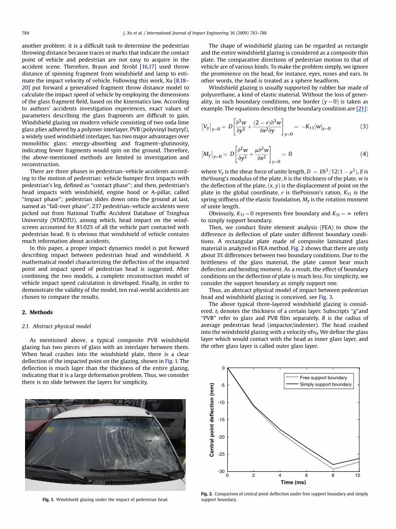
As mentioned above, a typical composite PVB windshieldglazing has two pieces of glass with an interlayer between them.When head crashes into the windshield plate, there is a cleardeflection of the impacted point on the glazing, shown in Fig. 1. Thedeflection is much lager than the thickness of the entire glazing,indicating that it is a large deformation problem. Thus, we considerthere is no slide between the layers for simplicity.
Fig. 1. Windshield glazing under the impact of pedestrian head.
The shape of windshield glazing can be regarded as rectangleand the entire windshield glazing is considered as a composite thinplate. The comparative directions of pedestrian motion to that ofvehicle are of various kinds. To make the problem simply, we ignorethe prominence on the head, for instance, eyes, noses and ears. Inother words, the head is treated as a sphere headform.
Windshield glazing is usually supported by rubber bar made ofpolyurethane, a kind of elastic material. Without the loss of gener-ality, in such boundary conditions, one border (y¼ 0) is taken asexample. The equations describing the boundary condition are [21]:
�Vy�
y¼0¼ D
"v3wvy3 þ
ð2� nÞv3wvx2vy
#y¼0
¼ �K11½w�y¼0 (3)
�My�
y¼0¼ D
"v2wvy2þ mv2w
vx2
#y¼0
¼ 0 (4)
where Vy is the shear force of unite length, D ¼ Eh3=12ð1� m2Þ, E istheYoung’s modulus of the plate, h is the thickness of the plate, w isthe deflection of the plate, (x, y) is the displacement of point on theplate in the global coordinate, n is thePoisson’s ration, K11 is thespring stiffness of the elastic foundation, My is the rotation momentof unite length.
Obviously, K11¼0 represents free boundary and K11¼N refersto simply support boundary.
Then, we conduct finite element analysis (FEA) to show thedifference in deflection of plate under different boundary condi-tions. A rectangular plate made of composite laminated glassmaterial is analyzed in FEA method. Fig. 2 shows that there are onlyabout 3% differences between two boundary conditions. Due to thebrittleness of the glass material, the plate cannot bear muchdeflection and bending moment. As a result, the effect of boundaryconditions on the deflection of plate is much less. For simplicity, weconsider the support boundary as simply support one.
Thus, an abstract physical model of impact between pedestrianhead and windshield glazing is conceived, see Fig. 3.
The above typical three-layered windshield glazing is consid-ered. ti denotes the thickness of a certain layer. Subscripts ‘‘g’’and‘‘PVB’’ refer to glass and PVB film separately. R is the radius ofaverage pedestrian head (impactor/indenter). The head crashedinto the windshield glazing with a velocity ofv0. We define the glasslayer which would contact with the head as inner glass layer, andthe other glass layer is called outer glass layer.
0 2 4 6 8 10-30
-25
-20
-15
-10
Time (ms)
Cen
tral p
oin
t d
eflectio
n (m
m
Fig. 2. Comparison of central point deflection under free support boundary and simplysupport boundary.

R
tg
tg
tP
v0
Windshieldglazing
Headform
Inner glass layer
PVB film
Outer glass layer
Fig. 3. Schematic illustration of a sphere pedestrian headform impacting on a wind-shield glazing.
S
δ pWindshield
Head form
Fig. 4. Headform impact on the windshield glazing.
J. Xu et al. / International Journal of Impact Engineering 36 (2009) 783–788 785
2.2. Material model
The stress–strain relations of PVB are influenced by timebecause PVB is a viscoelastic material. Ref. [22] pointed out that thetime period of impact between pedestrian head and windshieldglazing is comparatively short, about 0.1 s. In such a short timeperiod, the shear modulus G(t) of PVB would not change a lot. Thus,we consider PVB is a linear elastic material during the impact. Bothinner glass layer and outer glass layer are common float glass, sorelations between shear modulus G(t), bulk modulus K, Young’smodulus E and Poisson’s ratio n are [24]:
G ¼ E2ð1þ nÞ (5)
K ¼ E3ð1� 2nÞ (6)
Same formulae could be used on calculating PVB material.Glass and PVB film both can be treated as orthotropic materials
according to their physical and material properties. Therefore, weassume that each layer of composite windshield is orthotropic withrespect to its material symmetry lines and obeys Hooke’s law. Itthen becomes reasonable to consider the composite windshield asintegrity. As a result, an equivalent elastic modulus and Poisson’sration should be introduced as follows [24]:
E ¼ 2tgEg þ tpEp
2tg þ tp(7)
n ¼ 2tgng þ tpnp
2tg þ tp(8)
where E and n are equivalent Young’s modulus and equivalentPoisson’s ration of windshield glazing.
We are concerned about the dynamic response of windshield inthis paper. Consequently, we don’t have to investigate many detailsabout pedestrian head. Only values of physical parameters fromreferences are substituted into the featureless spherical headformused in this study.
2.3. Dynamics model
2.3.1. Deflection versus pedestrian head impact speed modelUsually, pedestrian head would intrude into the windshield and
cause the glazing plate curving or even broken, shown in Fig. 4.Denoting the time period during the impact t, the impact force
of the pedestrian head is
F ¼ �Mdv0
dt(9)
where M is the mass of headform; v0 is initial speed of headform.
If we denote by s the distance that the headform approaches thewindshield, it is obvious to see that:
_s ¼ v0 (10)
Greszczuk [25] showed that if the contact duration between theimpactor and the target is very long in comparison with theirnatural periods, vibrations of the system can be neglected. It canthen be assumed that the impact force according to the Hertzcontact law could be described as follows:
Fc ¼ ns2=3 (11)
where n is the contact stiffness defined by the shape of the impactor.Headform is sphere-shaped object, and then n can be written as
n ¼ 4ffiffiffiRp
3pðk1 þ k2Þ(12)
where
k1 ¼1� n2
1pE1
¼ 1� n2
pE(13)
k2 ¼1� n2
2pE2
(14)
When studying the contact behavior of composite material,Sankar [26] indicated that Eq. (14) can be rewritten as follows:
k02 ¼1
pE2(15)
Impact force and the corresponding deflection have a certainrelation in impact problem:
Fp ¼ Kpdp (16)
where Fp represents contact force; Kp is the ‘‘elastic property’’ of thewindshield glazing, depending on the material of the glazing; dp isthe curvature of the glazing.
The governing equation can be acquired according to the systemenergy conservation law:
12
Mv20 ¼
Z dmax
0Fpddp þ
Z s
0Fcds (17)
Substitution of (11) and (16) into (17) yields:
12
Mv20 ¼
12
Kpd2p þ
25
ns2=5 (18)
Considering Fc¼ Fp¼ F, we are able to rewrite (18):
12
Mv20 ¼
12
F2
Kp
!þ 2
5
F3=5
n2=3
!(19)
Young [27] suggested that when a rectangular plate is simplysupported, the above-mentioned ‘‘elastic property’’ can bedetermined:
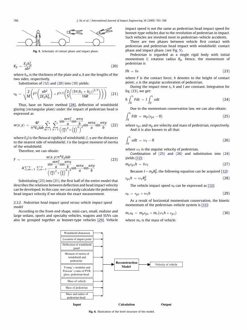
Fig. 5. Schematic of contact phase and impact phase.
J. Xu et al. / International Journal of Impact Engineering 36 (2009) 783–788786
Kp ¼E2h3
w (20)
ab2where hw is the thickness of the plate and a, b are the lengths of thetwo sides, respectively.
Substitution of (12) and (20) into (19) yields:
v0 ¼
ffiffiffiffiffiffiffiffiffiffiffiffiffiffiffiffiffiffiffiffiffiffiffiffiffiffiffiffiffiffiffiffiffiffiffiffiffiffiffiffiffiffiffiffiffiffiffiffiffiffiffiffiffiffiffiffiffiffiffiffiffiffiffiffiffiffiffiffiffiffiffiffiffiffiffiffiffiffiffiffiffiffiffiffiffiffiffiffiffiffiffiffiffiffiffiffiffiffiffiffiffiffiffiffiffiffi2M
F2
ab2
2E2h3w
!þ F3=5
25
ð3pðk1 þ k2ÞÞ2=3
16R
!!!vuut (21)
Thus, base on Navier method [28], deflection of windshieldglazing (rectangular plate) under the impact of pedestrian head isexpressed as
wðx; yÞ ¼ 4Fp4E2Iab
XNm¼1
XNn¼1
sinmpx
asin
nph
b��ma
�2þ�
nb
�2�2sinmpx
asin
npyb
(22)
where E2I is the flexural rigidity of windshield; x, h are the distancesto the nearest side of windshield; I is the largest moment of inertiaof the windshield.
Therefore, we can obtain:
F ¼ wðx; yÞp4E2Iab
4PN
m¼1PN
n¼1
sinmpx
asin
nph
b��ma
�2þ�
nb
�2�2sinmpx
asin
npyb
(23)
Substituting (23) into (21), the first half of the entire model thatdescribes the relations between deflection and head impact velocitycan be developed. In this case, we can easily calculate the pedestrianhead impact velocity if we obtain the exact measurement.
2.3.2. Pedestrian head impact speed versus vehicle impact speedmodel
According to the front-end shape, mini-cars, small, midsize andlarge sedans, sports and specialty vehicles, wagons and SUVs canalso be grouped together as bonnet-type vehicles [29]. Vehicle
Windshield dimension
Location of impact point
Deflection of windshieldpanel
Moment of inertia ofwindshield and
pedestrian
Young’ s modulus andPoisson’ s ratio of PVB,glass, pedestrian head
Mass of vehicle
Mass of pedestrian
Mass and radius ofpedestrian head
ReconM
Input Calc
Fig. 6. Illustration of the brie
impact speed is not the same as pedestrian head impact speed forbonnet-type vehicles due to the revolution of pedestrian in impact.Such vehicles are involved most in pedestrian–vehicle accidents.
There are two phases between vehicle first contact withpedestrian and pedestrian head impact with windshield: contactphase and impact phase. (see Fig. 5).
Pedestrian is regarded as a single rigid body with initialmomentum I; rotation radius Rp. Hence, the momentum ofpedestrian is
Fh ¼ Ia (23)
where F is the contact force; h denotes to the height of contactpoint; a is the angular acceleration of pedestrian.
During the impact time ti, h and I are constant. Integration forEq. (23), we get:
hZ ti
0Fdt ¼ I
Z ti
0adt (24)
Due to the momentum conservation law, we can also obtain:Z ti
0Fdt ¼ mp
�vp1 � 0
�(25)
where vp1 and mp are velocity and mass of pedestrian, respectively.And it is also known to all that:
Z ti
0adt ¼ u1 � 0 (26)
where u1 is the angular velocity of pedestrian.Combination of (25) and (26) and substitution into (24)
yields [12]:
mpvp1h ¼ Iu1 (27)
Because I¼mpRp2, the following equation can be acquired [12]:
vp1h ¼ u1R2p (28)
The vehicle impact speed v0 can be expressed as [12]:
v0 ¼ vp1 þ u1h (29)
As a result of horizontal momentum conservation, the kineticmomentum of the pedestrian–vehicle system is [12]:
mvv0 ¼ mpvp1 þmv
�u1hþ vp1
�(30)
where mv is the mass of vehicle.
structionodel
Velocity of vehicle
ulation Output
f structure of the model.

30 40 50 60 70 804
5
6
7
8
9
10
11
12
13
14
Speed (km/h)
Differen
ce(%
)
Fig. 7. Differences increase if the vehicle impact speed increases.
Table 1Parameters used in both constitutive relations and finite element analysis.
Components Parameters and values
Headform [23] E¼ 6.5 GPa, r¼ 1412 kg/m3, n¼ 0.22Glass [30] E¼ 74 GPa, r¼ 2500 kg/m3, n¼ 0.25, tg¼ 2 mmPVB film [31] K¼ 20 GPa, r¼ 1100 kg/m3, tp¼ 0.76 mmWindshield dimension Panel dimensions (a� b): 1320 mm� 630 mm
J. Xu et al. / International Journal of Impact Engineering 36 (2009) 783–788 787
Substitute (27) into (28) and then into (30), the pedestrianimpact speed vi is [12]:
v0 ¼mvvp1h2�
mv þmp�R2
p þmvh2 (31)
Combination of (21) and (23) and (31) yields:
v0¼
ffiffiffiffiffiffiffiffiffiffiffiffiffiffiffiffiffiffiffiffiffiffiffiffiffiffiffiffiffiffiffiffiffiffiffiffiffiffiffiffiffiffiffiffiffiffiffiffiffiffiffiffiffiffiffiffiffiffiffiffiffiffiffiffiffiffiffiffiffiffiffiffiffiffiffiffiffiffiffiffiffi2M
�F2�
ab2
2E2hw
�þF3=5
�25
�ð3pðk1þk2ÞÞ2=3
16R
���r �mvþmp
�R2
pþmvh2
mvh2
(32)
where
F ¼ wðx; yÞp4E2Iab
4PN
m¼1PN
n¼1
sinmpx
asin
nph
b��ma
�2þ�
nb
�2�2 sinmpx
asin
npyb
2.4. Model summary
Let’s summarize the model for convenience. The whole modelcan be illustrated as Fig. 6. One may not worry about the burden toinput so many values of different variables. Some of them are ofconstant values.
Table 2Comparison of exact speed with speed calculated from the model.
Case I Case II Case III Case IV
Length of skid mark (m) 11.23 7.80 9.30 15.40Road–tyre adhesion coefficient 0.841 0.790 0.690 0.740Deflection of windshield on the
impacted point (mm)37 23 19 42
Location of impacted point(x mm, h mm)
(�145, �650) (350, 600) (�230, 100) (250, �400
Dimensions of windshield(a mm, b mm)
(1320, 620) (1310, 730) (1350, 730) (1280, 630)
Bumper height (mm) 505 495 525 495Weight of pedestrian (kg) 46 53 75 65Mass of vehicle (kg) 1325 1880 1225 1480Stature of pedestrian (cm) 175 168 172 166Exact speed (km/h) 48.98 39.56 40.37 53.80Result of the model (km/h) 45.94 37.42 38.18 50.20Difference (%) 6.20 5.40 5.42 6.70
3. Results and discussion
3.1. Determination of parameters in the model
In real-world accident reconstruction, we are quite easy toattain the stature and weight of pedestrian from police investiga-tion files. Based on Ref. [32], masses, center of masses, inertias, anddistance between inertias of every body part can be acquired.Parallel axis theorem is employed to calculate the rotation radiusand inertia of entire pedestrian. PVB material properties in wind-shield glazing are almost the same, in accident reconstruction, thenwe consider nPVB¼ const¼ 0.49for simplicity. The parameters ofPVB and glass are determined in Table 1.
3.2. Real-world accidents for comparison
Because the exact impact velocity cannot be obtained in real-world traffic accidents, we had to choose the real-world pedes-trian–vehicle accidents with skid marks and consider speed calcu-lated by skid marks is the exact one. We picked up ten real-worldaccidents from NTADTU which have both skid marks and wind-shield deflection. Results after comparison are listed as Table 2.
3.3. Results discussion
First of all, the differences, among which the maximum value is10.78% and average value is 7.56%, showing us that this newlydeveloped model is accurate and reliable enough for us to employ itin pedestrian–vehicle accidents without skid marks or pedestrianthrow distances. Using this model to further verify the results ofaccidents reconstruction are able to enhance the accuracy and reli-ability of the reconstruction results. This model provides us a newand convenient method to investigate pedestrian–vehicle accidents.
Secondly, ten speed values computed from the model are a littlebit smaller than the exact speed values. One reason is that thesimplicity of the supporting boundary is responsible for it. Exactdeflection is larger than the deflection occurred with simply sup-ported boundary plate, leading the results of model smaller. It can beconcluded safely that if more exact elastic condition is employed, theresults would be better. Another reason is that in relative high speed
Case V Case VI Case VII Case VIII Case IX Case X
23.00 8.40 15.30 21.10 19.80 24.000.862 0.766 0.760 0.812 0.820 0.76049 27 41 47 45 48
) (240, 470) (135, 460) (735, 160) (�135, 695) (�635, 395) (715, 480)
(1200, 680) (1310, 670) (1400, 710) (1350, 660) (1295, 625) (1380, 690)
505 499 530 512 501 51078 69 79 76 69 741290 1340 2105 1890 1450 1655173 158 176 173 166 16970.97 40.42 54.34 65.97 64.22 68.0763.72 37.31 51.29 60.99 57.81 60.7310.22 7.69 5.61 7.55 9.98 10.78

J. Xu et al. / International Journal of Impact Engineering 36 (2009) 783–788788
accidents windshield is broken because of large deformation in mostcases. Measurements of deflection cannot be accurate enough,usually smaller than the exact measurements. Therefore, the resultswould be smaller in some extent. Moreover, the effective mass ofhead would increase a lot if pedestrian is impacted by vehicle in highspeed and then rotated a lot. To conclude, this model may not besuitable to reconstruct high speed pedestrian–vehicle accident.
Thirdly, this model excludes the consideration for curvature andthickness of the windshield as well as the windshield angle. In mostcases, curvature in windshield is small so we treat the windshield asa plate, not a shell. Most of the windshields on modern passengervehicles have the same thickness according to the automotiveindustrial standard. Actually, the windshield angle may vary fromone vehicle to another. Thus, the impact speed of the pedestrianhead would decrease slightly according to the exact angle, affectingthe accuracy of the model.
In addition, the comparison results show that with the speedincreasing, the differences increase. Fig. 7 shows that the relationbetween the speed and difference may be: speed¼ differencea. Thisrelation suggests that this vehicle impact speed reconstructionmodel might not be suitable for high-speed accidents. Deflection ofwindshield is difficult to measure and difficulty in determining thedeflection of windshield in high-speed accidents suggesting themodel not suitable for such cases as well.
Last but not the least, in some cases, not only did the pedestrianhead impact on the windshield glazing, but also the shoulder ofpedestrian impacted on the glazing. In the latter scenario, should-er’s impact on the windshield would add the deflection of wind-shield that is hard to distinguish. It is suggested not to employ thismodel under such circumstances.
4. Conclusion
In this paper, we first constructed the abstract physical modeldescribing dynamic process that the pedestrian head impacts onthe composite PVB windshield glazing. Some necessary simplifi-cations were made. Material model was then chosen. The mostimportant part of the paper is the development of the dynamicmodel of vehicle impact speed versus windshield deflection. Basedon impact dynamics and rectangular plate theory, the entire processof pedestrian–vehicle accident excluding the slide down phase wasdiscussed. The results of new model showed good agreement withthose calculated from skid marks considered as exact speed in tenreal-world accidents. Therefore, a new and reliable method ofaccident reconstruction method is established. However, this newmodel may not be suitable to calculate the vehicle impact velocity inhigh speed collision accident between pedestrian and vehicle asmentioned above. In addition, one should check the impact point toensure that it is head not should impacting on the windshield beforeusing this new calculation method.
Acknowledgement
This work is a part of the project titled ‘‘Road Traffic AccidentReconstruction Analysis Platform’’ (No. 20052DGGBJSJ002) insupport of Police Ministry of People’s Republic of China and a partof the project titled ‘‘Dynamic response of PVB laminated wind-shield subjected to head impact’’ supported by State Key Laboratoryof Automotive Safety & Energy, Tsinghua University.
The authors also thank the anonymous referees’ usefulcomments and suggestions.
References
[1] Traffic management bureau of Police Ministry. Road traffic accident annualcensus report of China. Beijing; 2007.
[2] Ballesteros MF, Dischinger PC, Langenberg P. Pedestrian injuries and vehicle typein Marylan, 1995–1999. Accident Analysis and Prevention 2004;36(5):73–81.
[3] Walz FH, Hoefliger M, Fehlmann W. Speed limit reduction from 60 to 50 km/hand pedestrian injuries. 27th Stapp Car Crash Conference. Detroit: SAE Inter-national; 1983. p. 311–8.
[4] Howard M, Thomas A, Koch W, Watson J, Hardy R. Validation and applicationof a finite element pedestrian humanoid model for use in pedestrian accidentsimulations. International Research Committee on Biokinetics of ImpactsConference. Lisbon, Portugal: IRCOBI; 2000. p. 101–19.
[5] Wood DP, Simms CK, Walsh DG. Vehicle–pedestrian collisions: validated modelsfor pedestrian impact and projection. Proceedings of the institution of Mechan-ical Engineers Part D: Journal of Automotive Engineering 2005;219:183–95.
[6] Yibing L. Study on the road traffic accident reconstruct analysis theory. Auto-motive Engineering. Doctoral dissertation, Beijing: Tsinghua University; 2004.
[7] Han, Brach RM. Impact throw model for vehicle–pedestrian collision reconstruc-tion. Proceedings of the Institution of Mechanical Engineers 2002;216(6):443–53.
[8] Xu HG. Automotive accident engineering. Beijing: People’s Traffic Press; 2004.[9] Schmidt DN. and Nagel DA. Pedestrian impact case study. Proceedings of the
15th conference association for automobile medicine; 1971.[10] Hill GS. Calculations of vehicle speed from pedestrian throw. Impact 1994 [J.
Inst. Traffic Accid. Invest.].[11] Severy D. Auto pedestrian impact experiments. Detroit: Society of Automotive
Engineers; 1963. Paper No 1963-12-0025.[12] Wood D. Impact and movement of pedestrian in frontal collisions with
vehicles. Proceedings of Institute of Mechanical Engineers, Part D, AutomobileEngineering 1998;202:101–10.
[13] The Institute of Traffic Accident Investigator, Impact results of pedestrian crashtests, The first conference of ITAI. Hull, UK: 1993.
[14] Fugger T, Randles B, Eubanks J. Comparison of pedestrian accident recon-struction models to experimental test data for wrap trajectories. IMechEConference Transactions 2000(2); 2000.
[15] Wood DP, Walsh DG. A hybrid model for pedestrian impact and projection.International Journal of Crashworthiness 2002;7(3):285–305.
[16] Braun H. Splitterwurfweiten: eine experimentelle Untersuchung. Der Ver-kehrsunfall 1980;(2):37–43 [in German].
[17] Strobl H. Betrachung zum Thema Steinschlag. Verkehrsunfall und Fahrzeug-technik 1996;(9):15–20 [in German].
[18] Xu HG, Ren Y, Wang LF. Determination on mechanics parameters of collidingon roadway for throwing object of traffic accident. Journal of Highway andTransportation Research and Development 2003;20(2):100–4.
[19] Xu HG, Gao W, Su J, Gao YL, Chen LF. Multi-value problem of collision velocity inmotor vehicle accident. China Journal of Highway and Transport 1996;9(1):87–93.
[20] Xu HG, Gao YL, Chen LF, Apeil H. China Journal of Highway and Transport1994;7(2):75–81.
[21] Li WL. Vibration analysis of rectangular plates with general elastic boundarysupports. Journal of Sound and Vibration 2004;273(9):619–37.
[22] Dharani LR, Mettu SR, Zhao S, Barbat SD, Chai L. Modelling fracture in lami-nated automotive glazing impacted by spherical featureless headform. SAE2003 World Congress. Detroit: SAE International; 2003.
[23] Mencik J. Strength and fracture of glass and ceramics. Tokyo: Elsevier SciencePublishing Company, Inc.; 1992.
[24] Zhao S, Dharani LR, Chai L, Barbat SD. Analysis of damage in laminatedautomotive glazing subjected to simulated head impact. Engineering FailureAnalysis 2006;13(4):582–97.
[25] Zukas JA, Nicholas T, Swift HF, Greszczuk LB, Curran DR, editors. Impactdynamics. New York: John Wiley & Sons; 1982. p. 96.
[26] Sankar BV. Low-velocity impact response and damage in composite materials.Key Engineering Materials 1996;121(122):549–82.
[27] Young WC, Budynas RG. Roark’s strain–stress formula. Beijing: TsinghuaUniversity Press; 2003.
[28] Ventsel E, Krauthammer T. Thin plates and shells theory, analysis, and appli-cation. New York: Marcel Dekker, Inc.; 2001.
[29] Maki T, Kajzer J, Mizuno K, Sekine Y. Comparative analysis of vehicle–bicyclistand vehicle–pedestrian accidents in Japan. Accident Analysis and Prevention2003;35(6):927–40.
[30] Ruan JS. Impact biomechanics of head injury by mathematical modelling.Mechanical Engineering. Detroit: Wayne State University; 1994.
[31] Yang JJ, Mo J, Shi XY. In: Committee NASGST, editor. Automotive safety glass.Beijing, China: China Standard Press; 2003.
[32] Cao Q. Man–machine design engineering. Chengdu: Southwest JiaotongUniversity; 1988.
Jun Xu: Graduate student of Department of Automotive Engineering, TsinghuaUniversity. Research interests: vehicle impact safety, traffic accident reconstructionand driver behavior.
Yibing Li: Professor of Department of Automotive Engineering, Tsinghua University.Research interests: traffic accident reconstruction and measurement technology.
Guangquan Lu: Associate professor of School of Transportation Science and Engi-neering, Beihang University, China. Research interests include road traffic safety, driverbehavior, accident reconstruction, and application of computer vision in road trafficsystem.
Wei Zhou: Master, graduated from Department of Automotive Engineering, TsinghuaUniversity. Research interests: traffic accident reconstruction and simulation.