BODY, LOCK & SECURITY SYSTEM - PDF Text Files
178
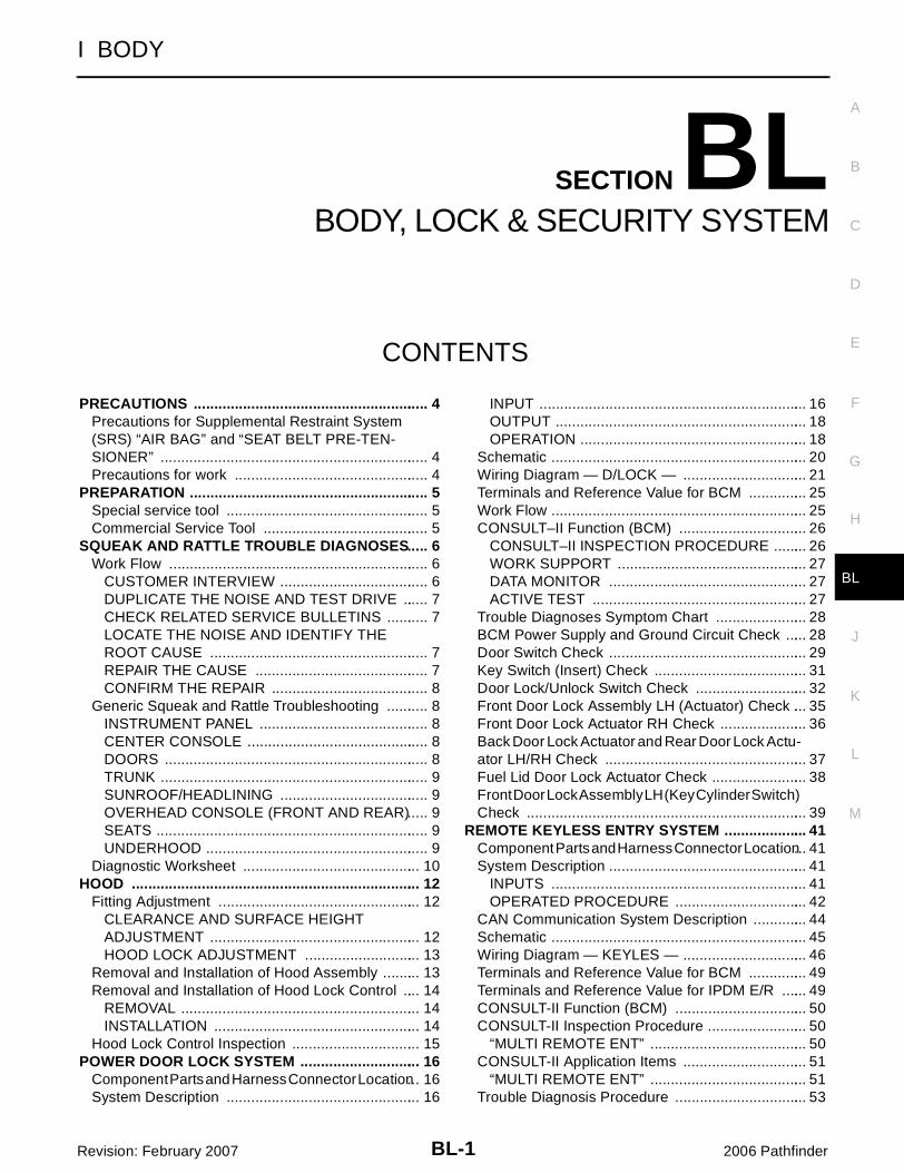
BL-1 BODY, LOCK & SECURITY SYSTEM I BODY CONTENTS C D E F G H J K L M SECTION BL A B BL Revision: February 2007 2006 Pathfinder PRECAUTIONS ......................................................... 4 Precautions for Supplemental Restraint System (SRS) “AIR BAG” and “SEAT BELT PRE-TEN- SIONER” ................................................................. 4 Precautions for work ............................................... 4 PREPARATION .......................................................... 5 Special service tool ................................................. 5 Commercial Service Tool ........................................ 5 SQUEAK AND RATTLE TROUBLE DIAGNOSES ..... 6 Work Flow ............................................................... 6 CUSTOMER INTERVIEW .................................... 6 DUPLICATE THE NOISE AND TEST DRIVE ...... 7 CHECK RELATED SERVICE BULLETINS .......... 7 LOCATE THE NOISE AND IDENTIFY THE ROOT CAUSE ..................................................... 7 REPAIR THE CAUSE .......................................... 7 CONFIRM THE REPAIR ...................................... 8 Generic Squeak and Rattle Troubleshooting .......... 8 INSTRUMENT PANEL ......................................... 8 CENTER CONSOLE ............................................ 8 DOORS ................................................................ 8 TRUNK ................................................................. 9 SUNROOF/HEADLINING .................................... 9 OVERHEAD CONSOLE (FRONT AND REAR) ..... 9 SEATS .................................................................. 9 UNDERHOOD ...................................................... 9 Diagnostic Worksheet ........................................... 10 HOOD ...................................................................... 12 Fitting Adjustment ................................................. 12 CLEARANCE AND SURFACE HEIGHT ADJUSTMENT ................................................... 12 HOOD LOCK ADJUSTMENT ............................ 13 Removal and Installation of Hood Assembly ......... 13 Removal and Installation of Hood Lock Control .... 14 REMOVAL .......................................................... 14 INSTALLATION .................................................. 14 Hood Lock Control Inspection ............................... 15 POWER DOOR LOCK SYSTEM ............................. 16 Component Parts and Harness Connector Location ... 16 System Description ............................................... 16 INPUT ................................................................. 16 OUTPUT ............................................................. 18 OPERATION ....................................................... 18 Schematic .............................................................. 20 Wiring Diagram — D/LOCK — .............................. 21 Terminals and Reference Value for BCM .............. 25 Work Flow .............................................................. 25 CONSULT–II Function (BCM) ............................... 26 CONSULT–II INSPECTION PROCEDURE ........ 26 WORK SUPPORT .............................................. 27 DATA MONITOR ................................................ 27 ACTIVE TEST .................................................... 27 Trouble Diagnoses Symptom Chart ...................... 28 BCM Power Supply and Ground Circuit Check ..... 28 Door Switch Check ................................................ 29 Key Switch (Insert) Check ..................................... 31 Door Lock/Unlock Switch Check ........................... 32 Front Door Lock Assembly LH (Actuator) Check ... 35 Front Door Lock Actuator RH Check ..................... 36 Back Door Lock Actuator and Rear Door Lock Actu- ator LH/RH Check ................................................. 37 Fuel Lid Door Lock Actuator Check ....................... 38 Front Door Lock Assembly LH (Key Cylinder Switch) Check .................................................................... 39 REMOTE KEYLESS ENTRY SYSTEM .................... 41 Component Parts and Harness Connector Location ... 41 System Description ................................................ 41 INPUTS .............................................................. 41 OPERATED PROCEDURE ................................ 42 CAN Communication System Description ............. 44 Schematic .............................................................. 45 Wiring Diagram — KEYLES — .............................. 46 Terminals and Reference Value for BCM .............. 49 Terminals and Reference Value for IPDM E/R ...... 49 CONSULT-II Function (BCM) ................................ 50 CONSULT-II Inspection Procedure ........................ 50 “MULTI REMOTE ENT” ...................................... 50 CONSULT-II Application Items .............................. 51 “MULTI REMOTE ENT” ...................................... 51 Trouble Diagnosis Procedure ................................ 53
-
Upload
khangminh22 -
Category
Documents
-
view
0 -
download
0
Transcript of BODY, LOCK & SECURITY SYSTEM - PDF Text Files
BL-1
BODY, LOCK & SECURITY SYSTEM
I BODY
CONTENTS
C
D
E
F
G
H
J
K
L
M
SECTION BLA
B
BL
Revision: February 2007 2006 Pathfinder
PRECAUTIONS .......................................................... 4Precautions for Supplemental Restraint System (SRS) “AIR BAG” and “SEAT BELT PRE-TEN-SIONER” .................................................................. 4Precautions for work ................................................ 4
PREPARATION ........................................................... 5Special service tool .................................................. 5Commercial Service Tool ......................................... 5
SQUEAK AND RATTLE TROUBLE DIAGNOSES ..... 6Work Flow ................................................................ 6
CUSTOMER INTERVIEW ..................................... 6DUPLICATE THE NOISE AND TEST DRIVE ....... 7CHECK RELATED SERVICE BULLETINS ........... 7LOCATE THE NOISE AND IDENTIFY THE ROOT CAUSE ...................................................... 7REPAIR THE CAUSE ........................................... 7CONFIRM THE REPAIR ....................................... 8
Generic Squeak and Rattle Troubleshooting ........... 8INSTRUMENT PANEL .......................................... 8CENTER CONSOLE ............................................. 8DOORS ................................................................. 8TRUNK .................................................................. 9SUNROOF/HEADLINING ..................................... 9OVERHEAD CONSOLE (FRONT AND REAR) ..... 9SEATS ................................................................... 9UNDERHOOD ....................................................... 9
Diagnostic Worksheet ............................................ 10HOOD ....................................................................... 12
Fitting Adjustment .................................................. 12CLEARANCE AND SURFACE HEIGHT ADJUSTMENT .................................................... 12HOOD LOCK ADJUSTMENT ............................. 13
Removal and Installation of Hood Assembly .......... 13Removal and Installation of Hood Lock Control ..... 14
REMOVAL ........................................................... 14INSTALLATION ................................................... 14
Hood Lock Control Inspection ................................ 15POWER DOOR LOCK SYSTEM .............................. 16
Component Parts and Harness Connector Location ... 16System Description ................................................ 16
INPUT .................................................................. 16OUTPUT .............................................................. 18OPERATION ........................................................ 18
Schematic ............................................................... 20Wiring Diagram — D/LOCK — ............................... 21Terminals and Reference Value for BCM ............... 25Work Flow ............................................................... 25CONSULT–II Function (BCM) ................................ 26
CONSULT–II INSPECTION PROCEDURE ......... 26WORK SUPPORT ............................................... 27DATA MONITOR ................................................. 27ACTIVE TEST ..................................................... 27
Trouble Diagnoses Symptom Chart ....................... 28BCM Power Supply and Ground Circuit Check ...... 28Door Switch Check ................................................. 29Key Switch (Insert) Check ...................................... 31Door Lock/Unlock Switch Check ............................ 32Front Door Lock Assembly LH (Actuator) Check .... 35Front Door Lock Actuator RH Check ...................... 36Back Door Lock Actuator and Rear Door Lock Actu-ator LH/RH Check .................................................. 37Fuel Lid Door Lock Actuator Check ........................ 38Front Door Lock Assembly LH (Key Cylinder Switch) Check ..................................................................... 39
REMOTE KEYLESS ENTRY SYSTEM ..................... 41Component Parts and Harness Connector Location ... 41System Description ................................................. 41
INPUTS ............................................................... 41OPERATED PROCEDURE ................................. 42
CAN Communication System Description .............. 44Schematic ............................................................... 45Wiring Diagram — KEYLES — ............................... 46Terminals and Reference Value for BCM ............... 49Terminals and Reference Value for IPDM E/R ....... 49CONSULT-II Function (BCM) ................................. 50CONSULT-II Inspection Procedure ......................... 50
“MULTI REMOTE ENT” ....................................... 50CONSULT-II Application Items ............................... 51
“MULTI REMOTE ENT” ....................................... 51Trouble Diagnosis Procedure ................................. 53

BL-2Revision: February 2007 2006 Pathfinder
Pre-Diagnosis Inspection ........................................ 53BCM POWER SUPPLY AND GROUND CIRCUIT INSPECTION ....................................................... 53
Trouble Diagnoses .................................................. 54SYMPTOM CHART ............................................. 54
Key Switch (Insert) Check ...................................... 56Door Switch Check ................................................. 57Keyfob Battery and Function Check ....................... 59Remote Keyless Entry Receiver System Check ..... 60ACC Power Check .................................................. 61IPDM E/R Operation Check .................................... 62Check Hazard Function .......................................... 62Check Horn Function .............................................. 62Check Headlamp Function ..................................... 62Check Room Lamp Illumination Function ............... 63ID Code Entry Procedure ....................................... 64
KEYFOB ID SET UP WITH CONSULT-II ............ 64KEYFOB ID SET UP WITHOUT CONSULT-II ..... 66
Keyfob Battery Replacement .................................. 67VEHICLE SECURITY (THEFT WARNING) SYSTEM ... 68
Component Parts and Harness Connector Location ... 68System Description ................................................. 69
DESCRIPTION .................................................... 69POWER SUPPLY AND GROUND CIRCUIT ....... 69INITIAL CONDITION TO ACTIVATE THE SYS-TEM ..................................................................... 70VEHICLE SECURITY SYSTEM ALARM OPER-ATION .................................................................. 70VEHICLE SECURITY SYSTEM DEACTIVATION ... 70PANIC ALARM OPERATION ............................... 70
CAN Communication System Description .............. 71Schematic ............................................................... 72Wiring Diagram — VEHSEC — .............................. 73Terminals and Reference Value for BCM ................ 77Terminals and Reference Value for IPDM E/R ........ 78CONSULT-II Function (BCM) .................................. 79
CONSULT-II INSPECTION PROCEDURE .......... 79CONSULT-II APPLICATION ITEM ....................... 80
Trouble Diagnosis ................................................... 81WORK FLOW ...................................................... 81
Preliminary Check .................................................. 82Symptom Chart ....................................................... 83Diagnostic Procedure 1 .......................................... 84Diagnostic Procedure 2 .......................................... 86Diagnostic Procedure 3 .......................................... 87Diagnostic Procedure 4 .......................................... 89Diagnostic Procedure 5 .......................................... 89Diagnostic Procedure 6 .......................................... 89
DOOR ........................................................................ 90Fitting Adjustment ................................................... 90
FRONT DOOR .................................................... 90REAR DOOR ....................................................... 90BACK DOOR ....................................................... 91STRIKER ADJUSTMENT .................................... 92
Removal and Installation ........................................ 92FRONT DOOR .................................................... 92REAR DOOR ....................................................... 93BACK DOOR ....................................................... 93
FRONT DOOR LOCK ............................................... 95
Component Structure ..............................................95Removal and Installation .........................................95
REMOVAL ............................................................95INSTALLATION ....................................................97
Disassembly and Assembly ....................................97DOOR KEY CYLINDER ASSEMBLY ...................97
REAR DOOR LOCK ..................................................98Component Structure ..............................................98Removal and Installation .........................................98
REMOVAL ............................................................98INSTALLATION ....................................................98
BACK DOOR LOCK ..................................................99Component Structure ..............................................99
NVIS(NISSAN VEHICLE IMMOBILIZER SYSTEM-NATS) ......................................................................100
Component Parts and Harness Connector Location .100System Description ...............................................101System Composition .............................................101ECM Re-communicating Function ........................102Wiring Diagram — NATS — ..................................103Terminals and Reference Value for BCM ..............104CONSULT-II ..........................................................104
CONSULT-II INSPECTION PROCEDURE ........104CONSULT-II DIAGNOSTIC TEST MODE FUNC-TION ..................................................................105HOW TO READ SELF-DIAGNOSTIC RESULTS .105NVIS (NATS) SELF-DIAGNOSTIC RESULTS ITEM CHART .....................................................106
Work Flow .............................................................107Trouble Diagnoses ................................................108
SYMPTOM MATRIX CHART 1 ..........................108SYMPTOM MATRIX CHART 2 ..........................109DIAGNOSTIC SYSTEM DIAGRAM ...................109
Diagnostic Procedure 1 ......................................... 110Diagnostic Procedure 2 ......................................... 111Diagnostic Procedure 3 ......................................... 112Diagnostic Procedure 4 ......................................... 113Diagnostic Procedure 5 ......................................... 114Diagnostic Procedure 6 ......................................... 117How to Replace NATS Antenna Amp. .................. 118
HOMELINK UNIVERSAL TRANSCEIVER .............119Wiring Diagram — TRNSCV — ............................ 119Trouble Diagnoses ................................................120
DIAGNOSTIC PROCEDURE .............................120CAB AND REAR BODY ..........................................122
Body Mounting ......................................................122BODY REPAIR ........................................................123
Body Exterior Paint Color ......................................123Body Component Parts .........................................124
UNDERBODY COMPONENT PARTS ...............124BODY COMPONENT PARTS ............................126FRAME COMPONENT PARTS .........................128
Corrosion Protection .............................................130DESCRIPTION ..................................................130ANTI-CORROSIVE WAX ...................................131UNDERCOATING ..............................................132
Body Sealing .........................................................133DESCRIPTION ..................................................133
Body Construction .................................................136
BL-3
C
D
E
F
G
H
J
K
L
M
A
B
BL
Revision: February 2007 2006 Pathfinder
BODY CONSTRUCTION .................................. 136Body Alignment .................................................... 137
BODY CENTER MARKS .................................. 137PANEL PARTS MATCHING MARKS ................ 138DESCRIPTION .................................................. 139ENGINE COMPARTMENT ............................... 140UNDERBODY ................................................... 142PASSENGER COMPARTMENT ....................... 145REAR BODY ..................................................... 150
Handling Precautions for Plastics ........................ 152HANDLING PRECAUTIONS FOR PLASTICS .. 152LOCATION OF PLASTIC PARTS ..................... 153
Precautions in Repairing High Strength Steel ...... 155HIGH STRENGTH STEEL (HSS) USED IN NIS-SAN VEHICLES ................................................ 155
Foam Repair ......................................................... 157URETHANE FOAM APPLICATIONS ................ 157FILL PROCEDURES ......................................... 158
Replacement Operations ...................................... 161DESCRIPTION .................................................. 161HOODLEDGE ................................................... 164FRONT PILLAR ................................................. 166CENTER PILLAR .............................................. 167OUTER SILL ..................................................... 169REAR FENDER ................................................. 170REAR FENDER EXTENSION ........................... 171REAR FENDER REINFORCEMENT ................ 173REAR FLOOR REAR ........................................ 174REAR CROSSMEMBER ................................... 175CRUSH HORN .................................................. 176

BL-4
PRECAUTIONS
Revision: February 2007 2006 Pathfinder
PRECAUTIONS PFP:00001
Precautions for Supplemental Restraint System (SRS) “AIR BAG” and “SEAT BELT PRE-TENSIONER” EIS007O2
The Supplemental Restraint System such as “AIR BAG” and “SEAT BELT PRE-TENSIONER”, used alongwith a front seat belt, helps to reduce the risk or severity of injury to the driver and front passenger for certaintypes of collision. This system includes seat belt switch inputs and dual stage front air bag modules. The SRSsystem uses the seat belt switches to determine the front air bag deployment, and may only deploy one frontair bag, depending on the severity of a collision and whether the front occupants are belted or unbelted.Information necessary to service the system safely is included in the SRS and SB section of this Service Man-ual.WARNING:� To avoid rendering the SRS inoperative, which could increase the risk of personal injury or death
in the event of a collision which would result in air bag inflation, all maintenance must be per-formed by an authorized NISSAN/INFINITI dealer.
� Improper maintenance, including incorrect removal and installation of the SRS, can lead to per-sonal injury caused by unintentional activation of the system. For removal of Spiral Cable and AirBag Module, see the SRS section.
� Do not use electrical test equipment on any circuit related to the SRS unless instructed to in thisService Manual. SRS wiring harnesses can be identified by yellow and/or orange harnesses orharness connectors.
Precautions for work EIS007O3
� After removing and installing the opening/closing parts, be sure to carry out fitting adjustments to checktheir operation.
� Check the lubrication level, damage, and wear of each part. If necessary, grease or replace it.

PREPARATION
BL-5
C
D
E
F
G
H
J
K
L
M
A
B
BL
Revision: February 2007 2006 Pathfinder
PREPARATION PFP:00002
Special service tool EIS007O5
The actual shapes of Kent-Moore tools may differ from those of special service tools illustrated here.
Commercial Service Tool EIS007O6
Tool number(Kent-Moore No.)Tool name
Description
—(J-39570)Chassis ear
Locating the noise
—(J-43980)NISSAN Squeak and Rat-tle Kit
Repairing the cause of noise
—(J-43241)Remote Keyless Entry Tester
Testing keyfobs
SIIA0993E
SIIA0994E
LEL946A
(Kent-Moore No.)Tool name
Description
(J-39565)Engine ear
Locating the noise
SIIA0995E

BL-6
SQUEAK AND RATTLE TROUBLE DIAGNOSES
Revision: February 2007 2006 Pathfinder
SQUEAK AND RATTLE TROUBLE DIAGNOSES PFP:00000
Work Flow EIS007O7
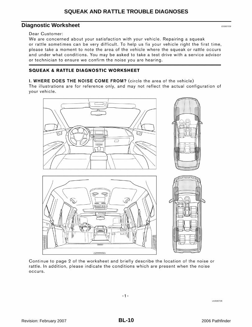
CUSTOMER INTERVIEWInterview the customer if possible, to determine the conditions that exist when the noise occurs. Use the Diag-nostic Worksheet during the interview to document the facts and conditions when the noise occurs and anycustomer's comments; refer to GW-9, "Diagnostic Worksheet" . This information is necessary to duplicate theconditions that exist when the noise occurs.� The customer may not be able to provide a detailed description or the location of the noise. Attempt to
obtain all the facts and conditions that exist when the noise occurs (or does not occur).� If there is more than one noise in the vehicle, be sure to diagnose and repair the noise that the customer
is concerned about. This can be accomplished by test driving the vehicle with the customer. � After identifying the type of noise, isolate the noise in terms of its characteristics. The noise characteristics
are provided so the customer, service adviser and technician are all speaking the same language whendefining the noise.
� Squeak —(Like tennis shoes on a clean floor)Squeak characteristics include the light contact/fast movement/brought on by road conditions/hard sur-faces = higher pitch noise/softer surfaces = lower pitch noises/edge to surface = chirping.
� Creak—(Like walking on an old wooden floor)Creak characteristics include firm contact/slow movement/twisting with a rotational movement/pitchdependent on materials/often brought on by activity.
� Rattle—(Like shaking a baby rattle)Rattle characteristics include the fast repeated contact/vibration or similar movement/loose parts/missingclip or fastener/incorrect clearance.
� Knock —(Like a knock on a door)Knock characteristics include hollow sounding/sometimes repeating/often brought on by driver action.
� Tick—(Like a clock second hand)Tick characteristics include gentle contacting of light materials/loose components/can be caused by driveraction or road conditions.
� Thump—(Heavy, muffled knock noise)Thump characteristics include softer knock/dead sound often brought on by activity.
� Buzz—(Like a bumble bee)Buzz characteristics include high frequency rattle/firm contact.
� Often the degree of acceptable noise level will vary depending upon the person. A noise that you mayjudge as acceptable may be very irritating to the customer.
� Weather conditions, especially humidity and temperature, may have a great effect on noise level.
SBT842

SQUEAK AND RATTLE TROUBLE DIAGNOSES
BL-7
C
D
E
F
G
H
J
K
L
M
A
B
BL
Revision: February 2007 2006 Pathfinder
DUPLICATE THE NOISE AND TEST DRIVEIf possible, drive the vehicle with the customer until the noise is duplicated. Note any additional information onthe Diagnostic Worksheet regarding the conditions or location of the noise. This information can be used toduplicate the same conditions when you confirm the repair.If the noise can be duplicated easily during the test drive, to help identify the source of the noise, try to dupli-cate the noise with the vehicle stopped by doing one or all of the following:1) Close a door.2) Tap or push/pull around the area where the noise appears to be coming from.3) Rev the engine.4) Use a floor jack to recreate vehicle “twist”.5) At idle, apply engine load (electrical load, half-clutch on M/T model, drive position on A/T model).6) Raise the vehicle on a hoist and hit a tire with a rubber hammer.� Drive the vehicle and attempt to duplicate the conditions the customer states exist when the noise occurs.� If it is difficult to duplicate the noise, drive the vehicle slowly on an undulating or rough road to stress the
vehicle body.
CHECK RELATED SERVICE BULLETINSAfter verifying the customer concern or symptom, check ASIST for Technical Service Bulletins (TSBs) relatedto that concern or symptom.If a TSB relates to the symptom, follow the procedure to repair the noise.
LOCATE THE NOISE AND IDENTIFY THE ROOT CAUSE1. Narrow down the noise to a general area.To help pinpoint the source of the noise, use a listening tool
(Chassis Ear: J-39570, Engine Ear: J-39565 and mechanic's stethoscope).2. Narrow down the noise to a more specific area and identify the cause of the noise by:� removing the components in the area that you suspect the noise is coming from.
Do not use too much force when removing clips and fasteners, otherwise clips and fasteners can be bro-ken or lost during the repair, resulting in the creation of new noise.
� tapping or pushing/pulling the component that you suspect is causing the noise.Do not tap or push/pull the component with excessive force, otherwise the noise will be eliminated onlytemporarily.
� feeling for a vibration with your hand by touching the component(s) that you suspect is (are) causing thenoise.
� placing a piece of paper between components that you suspect are causing the noise.� looking for loose components and contact marks.
Refer to GW-7, "Generic Squeak and Rattle Troubleshooting" .
REPAIR THE CAUSE � If the cause is a loose component, tighten the component securely.� If the cause is insufficient clearance between components:– separate components by repositioning or loosening and retightening the component, if possible.– insulate components with a suitable insulator such as urethane pads, foam blocks, felt cloth tape or ure-
thane tape. A NISSAN Squeak and Rattle Kit (J-43980) is available through your authorized NISSANParts Department.
CAUTION:Do not use excessive force as many components are constructed of plastic and may be damaged.Always check with the Parts Department for the latest parts information.The following materials are contained in the NISSAN Squeak and Rattle Kit (J-43980). Each item can beordered separately as needed.URETHANE PADS [1.5 mm (0.059 in) thick]Insulates connectors, harness, etc.76268-9E005: 100×135 mm (3.94×5.31 in)/76884-71L01: 60×85 mm (2.36×3.35 in)/76884-71L02: 15×25mm (0.59×0.98 in)INSULATOR (Foam blocks)Insulates components from contact. Can be used to fill space behind a panel.73982-9E000: 45 mm (1.77 in) thick, 50×50 mm (1.97×1.97 in)/73982-50Y00: 10 mm (0.39 in) thick,50×50 mm (1.97×1.97 in)INSULATOR (Light foam block)
BL-8
SQUEAK AND RATTLE TROUBLE DIAGNOSES
Revision: February 2007 2006 Pathfinder
80845-71L00: 30 mm (1.18 in) thick, 30×50 mm (1.18×1.97 in)FELT CLOTH TAPEUsed to insulate where movement does not occur. Ideal for instrument panel applications.68370-4B000: 15×25 mm (0.59×0.98 in) pad/68239-13E00: 5 mm (0.20 in) wide tape roll. The followingmaterials not found in the kit can also be used to repair squeaks and rattles.UHMW (TEFLON) TAPE Insulates where slight movement is present. Ideal for instrument panel applications.SILICONE GREASEUsed instead of UHMW tape that will be visible or not fit.Note: Will only last a few months.SILICONE SPRAYUse when grease cannot be applied.DUCT TAPEUse to eliminate movement.
CONFIRM THE REPAIRConfirm that the cause of a noise is repaired by test driving the vehicle. Operate the vehicle under the sameconditions as when the noise originally occurred. Refer to the notes on the Diagnostic Worksheet.
Generic Squeak and Rattle Troubleshooting EIS007O8
Refer to Table of Contents for specific component removal and installation information.
INSTRUMENT PANELMost incidents are caused by contact and movement between:1. The cluster lid A and instrument panel2. Acrylic lens and combination meter housing3. Instrument panel to front pillar garnish4. Instrument panel to windshield5. Instrument panel mounting pins6. Wiring harnesses behind the combination meter 7. A/C defroster duct and duct jointThese incidents can usually be located by tapping or moving the components to duplicate the noise or bypressing on the components while driving to stop the noise. Most of these incidents can be repaired by apply-ing felt cloth tape or silicone spray (in hard to reach areas). Urethane pads can be used to insulate wiring har-ness.CAUTION:Do not use silicone spray to isolate a squeak or rattle. If you saturate the area with silicone, you willnot be able to recheck the repair.
CENTER CONSOLEComponents to pay attention to include:1. Shifter assembly cover to finisher2. A/C control unit and cluster lid C3. Wiring harnesses behind audio and A/C control unitThe instrument panel repair and isolation procedures also apply to the center console.
DOORSPay attention to the:1. Finisher and inner panel making a slapping noise2. Inside handle escutcheon to door finisher3. Wiring harnesses tapping 4. Door striker out of alignment causing a popping noise on starts and stopsTapping or moving the components or pressing on them while driving to duplicate the conditions can isolatemany of these incidents. You can usually insulate the areas with felt cloth tape or insulator foam blocks fromthe NISSAN Squeak and Rattle Kit (J-43980) to repair the noise.

SQUEAK AND RATTLE TROUBLE DIAGNOSES
BL-9
C
D
E
F
G
H
J
K
L
M
A
B
BL
Revision: February 2007 2006 Pathfinder
TRUNKTrunk noises are often caused by a loose jack or loose items put into the trunk by the owner.In addition look for:1. Trunk lid bumpers out of adjustment2. Trunk lid striker out of adjustment 3. The trunk lid torsion bars knocking together4. A loose license plate or bracketMost of these incidents can be repaired by adjusting, securing or insulating the item(s) or component(s) caus-ing the noise.
SUNROOF/HEADLININGNoises in the sunroof/headlining area can often be traced to one of the following:1. Sunroof lid, rail, linkage or seals making a rattle or light knocking noise2. Sun visor shaft shaking in the holder3. Front or rear windshield touching headliner and squeaking Again, pressing on the components to stop the noise while duplicating the conditions can isolate most of theseincidents. Repairs usually consist of insulating with felt cloth tape.
OVERHEAD CONSOLE (FRONT AND REAR)Overhead console noises are often caused by the console panel clips not being engaged correctly. Most ofthese incidents are repaired by pushing up on the console at the clip locations until the clips engage.In addition look for:1. Loose harness or harness connectors.2. Front console map/reading lamp lense loose.3. Loose screws at console attachment points.
SEATSWhen isolating seat noise it's important to note the position the seat is in and the load placed on the seat whenthe noise is present. These conditions should be duplicated when verifying and isolating the cause of thenoise.Cause of seat noise include: 1. Headrest rods and holder 2. A squeak between the seat pad cushion and frame 3. The rear seatback lock and bracket These noises can be isolated by moving or pressing on the suspected components while duplicating the con-ditions under which the noise occurs. Most of these incidents can be repaired by repositioning the componentor applying urethane tape to the contact area.
UNDERHOODSome interior noise may be caused by components under the hood or on the engine wall. The noise is thentransmitted into the passenger compartment.Causes of transmitted underhood noise include:1. Any component mounted to the engine wall2. Components that pass through the engine wall3. Engine wall mounts and connectors4. Loose radiator mounting pins5. Hood bumpers out of adjustment 6. Hood striker out of adjustmentThese noises can be difficult to isolate since they cannot be reached from the interior of the vehicle. The bestmethod is to secure, move or insulate one component at a time and test drive the vehicle. Also, engine RPMor load can be changed to isolate the noise. Repairs can usually be made by moving, adjusting, securing, orinsulating the component causing the noise.
BL-10
SQUEAK AND RATTLE TROUBLE DIAGNOSES
Revision: February 2007 2006 Pathfinder
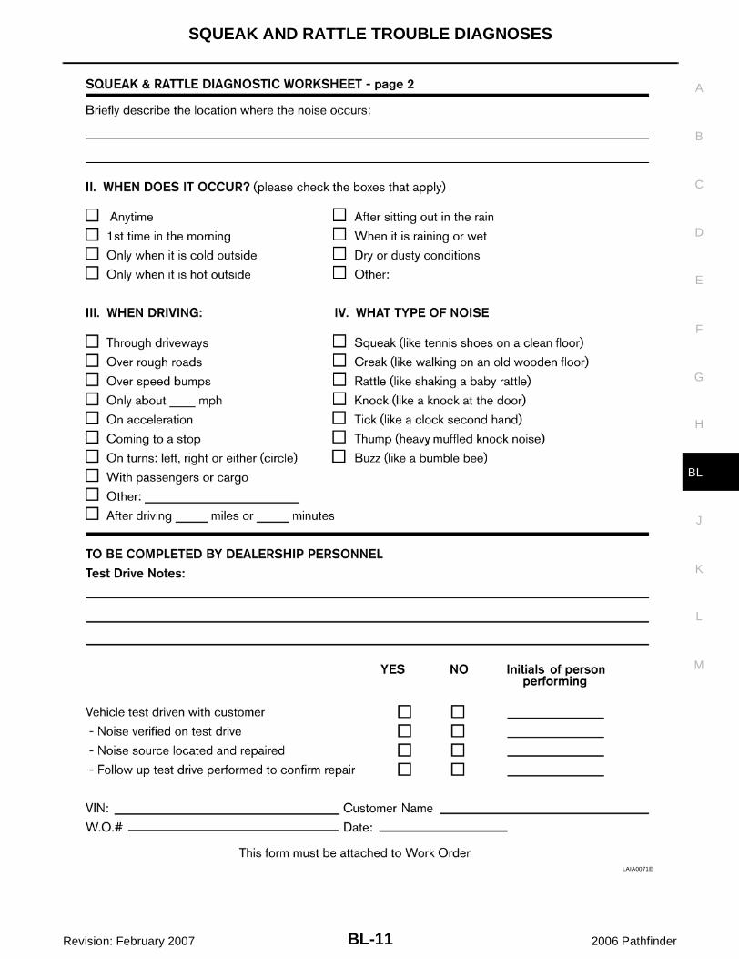
Diagnostic Worksheet EIS007O9
LAIA0072E
SQUEAK AND RATTLE TROUBLE DIAGNOSES
BL-11
C
D
E
F
G
H
J
K
L
M
A
B
BL
Revision: February 2007 2006 Pathfinder
LAIA0071E

BL-12
HOOD
Revision: February 2007 2006 Pathfinder
HOOD PFP:F5100
Fitting Adjustment EIS007OA
CLEARANCE AND SURFACE HEIGHT ADJUSTMENT1. Remove the front grille. Refer to EI-16, "FRONT GRILLE" .2. Loosen the hood lock assembly and adjust the rubber bumpers until the surface height of the hood
becomes 1 mm (0.04 in) lower than the fender.3. Engage the hood striker and temporarily tighten. 4. Check the lock and striker for looseness.
1. Hood 2. Front grille 3. Front fender
4. Headlamp assembly A. 6.0 mm (0.24 in) B. 0.7 mm (0.03 in)
C. 4.5 mm (0.18 in) D. 0.0 mm (0.0 in) E. 6.0 mm (0.24 in)
F. 0.7 mm (0.03 in)
WIIA0774E

HOOD
BL-13
C
D
E
F
G
H
J
K
L
M
A
B
BL
Revision: February 2007 2006 Pathfinder
5. Tighten the bolts to specification.6. Adjust the surface height of the hood according to the fitting standard dimension by rotating right and left
rubber bumpers.7. Install the front grille. Refer to EI-16, "FRONT GRILLE" .
HOOD LOCK ADJUSTMENT1. Remove the front grille. Refer to EI-16, "FRONT GRILLE" .2. Move the hood lock to the left or right so that striker center is vertically aligned with hood lock center
(when viewed from vehicle front).3. Make sure the secondary latch is properly engaged with the sec-
ondary striker with hood's own weight by dropping it fromapprox. 200 mm (7.87 in) height or by pressing it lightly approx.3 kg (29 N, 7lb).CAUTION:Do not drop the hood from 300 mm (11.81 in) height orhigher.
4. After adjusting hood lock, tighten the lock bolts to the specifiedtorque.
5. Install the front grille. Refer to EI-16, "FRONT GRILLE" .
Removal and Installation of Hood Assembly EIS007OB
1. Support the hood striker with suitable tool to prevent it from falling.2. Remove the hinge nuts from the hood to remove the hood assembly.CAUTION:Operate with two workers, because of its heavy weight.Installation is in the reverse order of removal.
LIIA1696E
LIIA1701E
WIIA1055E

BL-14
HOOD
Revision: February 2007 2006 Pathfinder
Removal and Installation of Hood Lock Control EIS007OC
REMOVAL1. Remove the front grille. Refer to EI-16, "FRONT GRILLE" .2. Remove the front fender protector (LH). Refer to EI-20, "FENDER PROTECTOR" .3. Disconnect the hood lock cable from the hood lock, and unclip it from the radiator core support upper and
hoodledge.4. Remove the bolts, and the hood release handle.5. Separate the grommet from the lower dash panel. Pull the hood lock cable out through the passenger
compartment.CAUTION:While pulling, be careful not to damage the outside of the hood lock cable.
INSTALLATION1. Pull the hood lock cable through the lower dash panel hole into the engine room.
1. Hood lock assembly 2. Hood lock cable
WIIA0775E

HOOD
BL-15
C
D
E
F
G
H
J
K
L
M
A
B
BL
Revision: February 2007 2006 Pathfinder
Be careful not to bend the cable too much, keep the radius100mm (3.94 in) or more.
2. Make sure the cable is not offset from the grommet, and pushthe grommet into the lower dash panel hole securely.
3. Apply sealant around the grommet at * mark.
4. Install the cable securely to the lock.5. Adjust the hood lock. Refer to BL-13, "HOOD LOCK ADJUST-
MENT" .
6. Install the front grille. Refer to EI-16, "FRONT GRILLE" .
Hood Lock Control Inspection EIS007OD
CAUTION:If the hood lock cable is bent or deformed, replace it.1. Remove the front grille. Refer to EI-16, "FRONT GRILLE" .2. Make sure the secondary latch is properly engaged with the sec-
ondary striker with hood's own weight by dropping it fromapprox. 200 mm (7.87 in) height.
3. While operating the hood opener, carefully make sure the frontend of the hood is raised by approx. 20 mm (0.79 in). Also makesure the hood opener returns to the original position.
4. Check the hood lock lubrication condition. If necessary, apply“body grease” to the points shown.
5. Install the front grille. Refer to EI-16, "FRONT GRILLE" .
LIIA1698E
LIIA1699E
PIIA1086E
PIIA0176E

BL-16
POWER DOOR LOCK SYSTEM
Revision: February 2007 2006 Pathfinder
POWER DOOR LOCK SYSTEM PFP:24814
Component Parts and Harness Connector Location EIS007OE
System Description EIS007OF
Power is supplied at all times� through 50A fusible link (letter g, located in the fuse and fusible link box)� to BCM (body control module) terminal 70 and� through 10A fuse (No. 25, located in the fuse and fusible link box)� to key switch terminal 2� through 10A fuse [No. 18, located in the fuse block (J/B)]� to BCM terminal 57.Ground is supplied to terminal 67 of BCM through body grounds M57, M61 and M79.
INPUTWith the key in the ignition key cylinder, power is supplied� through key switch terminal 1� to BCM terminal 37.With front door LH open, ground is supplied
LIIA2411E
1. BCM M18, M19, M20(view with instrument lower panel LH removed)
2. Key switch M27 3. Front door lock assembly LH (key cyl-inder switch) D14Front door lock actuator RH D114
4. Main power window and door lock/unlock switch D7 and D8Power window and door lock/unlock switch RH D105
5. Front door switchLH B8RH B108
6. Back door switch D502Back door lock actuator D508
7. Fuel lid door lock actuator B79 8. Rear door lock actuatorLH D205RH D305
9. Rear door switchLH B18RH B116

POWER DOOR LOCK SYSTEM
BL-17
C
D
E
F
G
H
J
K
L
M
A
B
BL
Revision: February 2007 2006 Pathfinder
� to BCM terminal 47� through front door switch LH terminal 2� through front door switch LH case ground.With front door RH open, ground is supplied� to BCM terminal 12� through front door switch RH terminal 2� through front door switch RH case ground.With rear door LH open, ground is supplied� to BCM terminal 48� through rear door switch LH terminal 2� through rear door switch LH case ground.With rear door RH open, ground is supplied� to BCM terminal 13� through rear door switch RH terminal 2� through rear door switch RH case ground.With back door open, ground is supplied� to BCM terminal 43� through back door switch terminal 3� through back door switch terminal 1� through body grounds D406 and D504.With the key inserted in the key cylinder LH and turned to LOCK, ground is supplied� to BCM terminal 8� through front door lock assembly LH (key cylinder switch) terminal 5� through front door lock assembly LH (key cylinder switch) terminal 4� through body grounds M57, M61 and M79.With the key inserted in the key cylinder LH and turned to UNLOCK, ground is supplied� to BCM terminal 7� through front door lock assembly LH (key cylinder switch) terminal 3� through front door key cylinder switch LH terminal 4� through body grounds M57, M61 and M79.With the main power window and door lock/unlock switch pressed to LOCK, ground is supplied� to BCM terminal 45� through main power window and door lock/unlock switch terminal 18� through main power window and door lock/unlock switch terminal 17� through body grounds M57, M61 and M79.With the power window and door lock/unlock switch RH pressed to LOCK, ground is supplied� to BCM terminal 45� through power window and door lock/unlock switch RH terminal 1� through power window and door lock/unlock switch RH terminal 3� through body grounds M57, M61 and M79.With the main power window and door lock/unlock switch pressed to UNLOCK, ground is supplied� to BCM terminal 46� through main power window and door lock/unlock switch terminal 6� through main power window and door lock/unlock switch terminal 17� through body grounds M57, M61 and M79.With the power window and door lock/unlock switch RH pressed to UNLOCK, ground is supplied� to BCM terminal 46� through power window and door lock/unlock switch RH terminal 2� through power window and door lock/unlock switch RH terminal 3

BL-18
POWER DOOR LOCK SYSTEM
Revision: February 2007 2006 Pathfinder
� through body grounds M57, M61 and M79.
OUTPUTUnlockGround is supplied� to front door lock assembly LH (actuator) terminal 1, front door lock actuator RH terminal 2, rear door lock
actuator LH and RH terminal 2, back door lock actuator terminal 4 and fuel lid door lock actuator terminal1
� through BCM terminal 65.FRONT DOOR LH AND FUEL LIDPower is supplied� to front door lock assembly LH (actuator) terminal 2 and� fuel lid door lock actuator terminal 2� through BCM terminal 59.FRONT DOOR RHPower is supplied� to front door lock actuator RH terminal 1� through BCM terminal 66.REAR DOOR LH AND RHPower is supplied� to rear door lock actuator LH and RH terminal 1� through BCM terminal 66.BACK DOORPower is supplied� to back door lock actuator terminal 2� through BCM terminal 66.With power and ground applied as described, the doors and fuel lid are unlocked.
LockGround is supplied� to front door lock assembly LH (actuator) and fuel lid door lock actuator terminal 2� through BCM terminal 59 and� to front door lock actuator RH terminal 1, rear door lock actuator LH and RH terminal 1 and back door lock
actuator terminal 2� through BCM terminal 66.Power is supplied� to front door lock assembly LH (actuator) terminal 1� fuel lid door lock actuator terminal 1� front door lock actuator RH terminal 2� rear door lock actuator LH and RH terminal 2� back door lock actuator terminal 4� through BCM terminal 65.With power and ground applied as described, the doors and fuel lid are locked.
OPERATION� The main power window and door lock/unlock switch on front door LH trim and door lock/unlock switch
RH on front door RH trim can lock and unlock all doors.� With the key inserted in the front door key cylinder LH, turning it to LOCK locks all doors; turning it to
UNLOCK once unlocks the front door LH and fuel lid; turning it to UNLOCK again within 5 seconds of thefirst unlock operation unlocks all other doors [signal from door key cylinder switch (part of front door lockassembly LH)].
POWER DOOR LOCK SYSTEM
BL-19
C
D
E
F
G
H
J
K
L
M
A
B
BL
Revision: February 2007 2006 Pathfinder
Key ReminderWhen performing a door locking operation using either the main power window and door lock/unlock switch orthe power window and door lock/unlock switch RH, all the doors will lock and then will immediately unlock if� the key switch is in INSERTED position (key is in ignition key cylinder) and� the ignition switch is in the OFF position and� any door is open.
BL-20
POWER DOOR LOCK SYSTEM
Revision: February 2007 2006 Pathfinder
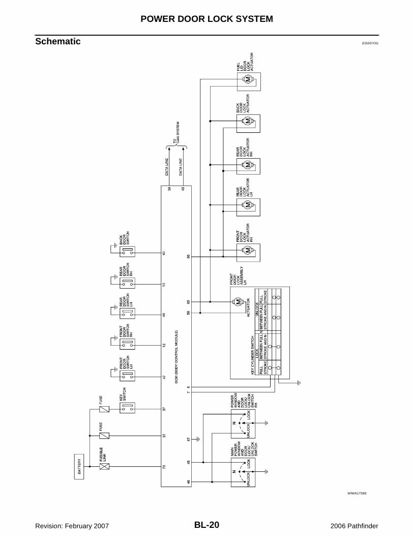
Schematic EIS007OG
WIWA1759E

POWER DOOR LOCK SYSTEM
BL-21
C
D
E
F
G
H
J
K
L
M
A
B
BL
Revision: February 2007 2006 Pathfinder
Wiring Diagram — D/LOCK — EIS007OH
WIWA1760E

BL-22
POWER DOOR LOCK SYSTEM
Revision: February 2007 2006 Pathfinder
WIWA1683E

POWER DOOR LOCK SYSTEM
BL-23
C
D
E
F
G
H
J
K
L
M
A
B
BL
Revision: February 2007 2006 Pathfinder
WIWA1761E

BL-24
POWER DOOR LOCK SYSTEM
Revision: February 2007 2006 Pathfinder
WIWA1762E

POWER DOOR LOCK SYSTEM
BL-25
C
D
E
F
G
H
J
K
L
M
A
B
BL
Revision: February 2007 2006 Pathfinder
Terminals and Reference Value for BCM EIS007OI
Refer to BCS-12, "Terminals and Reference Values for BCM" .
Work Flow EIS007OJ
1. Check the symptom and customer's requests.2. Understand the outline of system. Refer to BL-16, "System Description" .3. According to the trouble diagnosis chart, repair or replace the cause of the malfunction. Refer to BL-28,
"Trouble Diagnoses Symptom Chart" .4. Does power door lock system operate normally? OK: GO TO 5, NG: GO TO 3.5. Inspection End.

BL-26
POWER DOOR LOCK SYSTEM
Revision: February 2007 2006 Pathfinder
CONSULT–II Function (BCM) EIS007OK
CONSULT-II can display each diagnostic item using the diagnostic test modes shown following.
CONSULT–II INSPECTION PROCEDURE"DOOR LOCK"CAUTION:If CONSULT-II is used with no connection of CONSULT-II CONVERTER, malfunctions might bedetected in self-diagnosis depending on control unit which carries out CAN communication.1. Turn ignition switch OFF.2. Connect CONSULT-II and CONSULT-II CONVERTER to the
data link connector.
3. Turn ignition switch ON.4. Touch “START (NISSAN BASED VHCL)”.
5. Touch “BCM”.If "BCM" is not indicated, refer to GI-40, "CONSULT-II Data LinkConnector (DLC) Circuit" .
BCM diagnostic test item
Diagnostic mode Description
Inspection by part
WORK SUPPORTSupports inspections and adjustments. Commands are transmitted to the BCM for setting the status suitable for required operation, input/output signals are received from the BCM and received data is displayed.
DATA MONITOR Displays BCM input/output data in real time.
ACTIVE TEST Operation of electrical loads can be checked by sending drive signal to them.
SELF-DIAG RESULTS Displays BCM self-diagnosis results.
CAN DIAG SUPPORT MNTR The result of transmit/receive diagnosis of CAN communication can be read.
ECU PART NUMBER BCM part number can be read.
CONFIGURATION Performs BCM configuration read/write functions.
BBIA0538E
BCIA0029E
BCIA0030E
POWER DOOR LOCK SYSTEM
BL-27
C
D
E
F
G
H
J
K
L
M
A
B
BL
Revision: February 2007 2006 Pathfinder
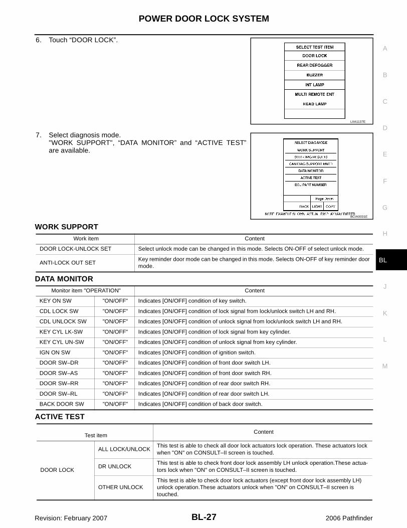
6. Touch “DOOR LOCK”.
7. Select diagnosis mode."WORK SUPPORT", “DATA MONITOR” and “ACTIVE TEST”are available.
WORK SUPPORT
DATA MONITOR
ACTIVE TEST
LIIA1137E
BCIA0031E
Work item Content
DOOR LOCK-UNLOCK SET Select unlock mode can be changed in this mode. Selects ON-OFF of select unlock mode.
ANTI-LOCK OUT SETKey reminder door mode can be changed in this mode. Selects ON-OFF of key reminder door mode.
Monitor item "OPERATION" Content
KEY ON SW "ON/OFF" Indicates [ON/OFF] condition of key switch.
CDL LOCK SW "ON/OFF" Indicates [ON/OFF] condition of lock signal from lock/unlock switch LH and RH.
CDL UNLOCK SW "ON/OFF" Indicates [ON/OFF] condition of unlock signal from lock/unlock switch LH and RH.
KEY CYL LK-SW "ON/OFF" Indicates [ON/OFF] condition of lock signal from key cylinder.
KEY CYL UN-SW "ON/OFF" Indicates [ON/OFF] condition of unlock signal from key cylinder.
IGN ON SW "ON/OFF" Indicates [ON/OFF] condition of ignition switch.
DOOR SW–DR "ON/OFF" Indicates [ON/OFF] condition of front door switch LH.
DOOR SW–AS "ON/OFF" Indicates [ON/OFF] condition of front door switch RH.
DOOR SW–RR "ON/OFF" Indicates [ON/OFF] condition of rear door switch RH.
DOOR SW–RL "ON/OFF" Indicates [ON/OFF] condition of rear door switch LH.
BACK DOOR SW "ON/OFF" Indicates [ON/OFF] condition of back door switch.
Test itemContent
DOOR LOCK
ALL LOCK/UNLOCKThis test is able to check all door lock actuators lock operation. These actuators lock when "ON" on CONSULT–II screen is touched.
DR UNLOCKThis test is able to check front door lock assembly LH unlock operation.These actua-tors lock when "ON" on CONSULT–II screen is touched.
OTHER UNLOCKThis test is able to check door lock actuators (except front door lock assembly LH) unlock operation.These actuators unlock when "ON" on CONSULT–II screen is touched.
BL-28
POWER DOOR LOCK SYSTEM
Revision: February 2007 2006 Pathfinder
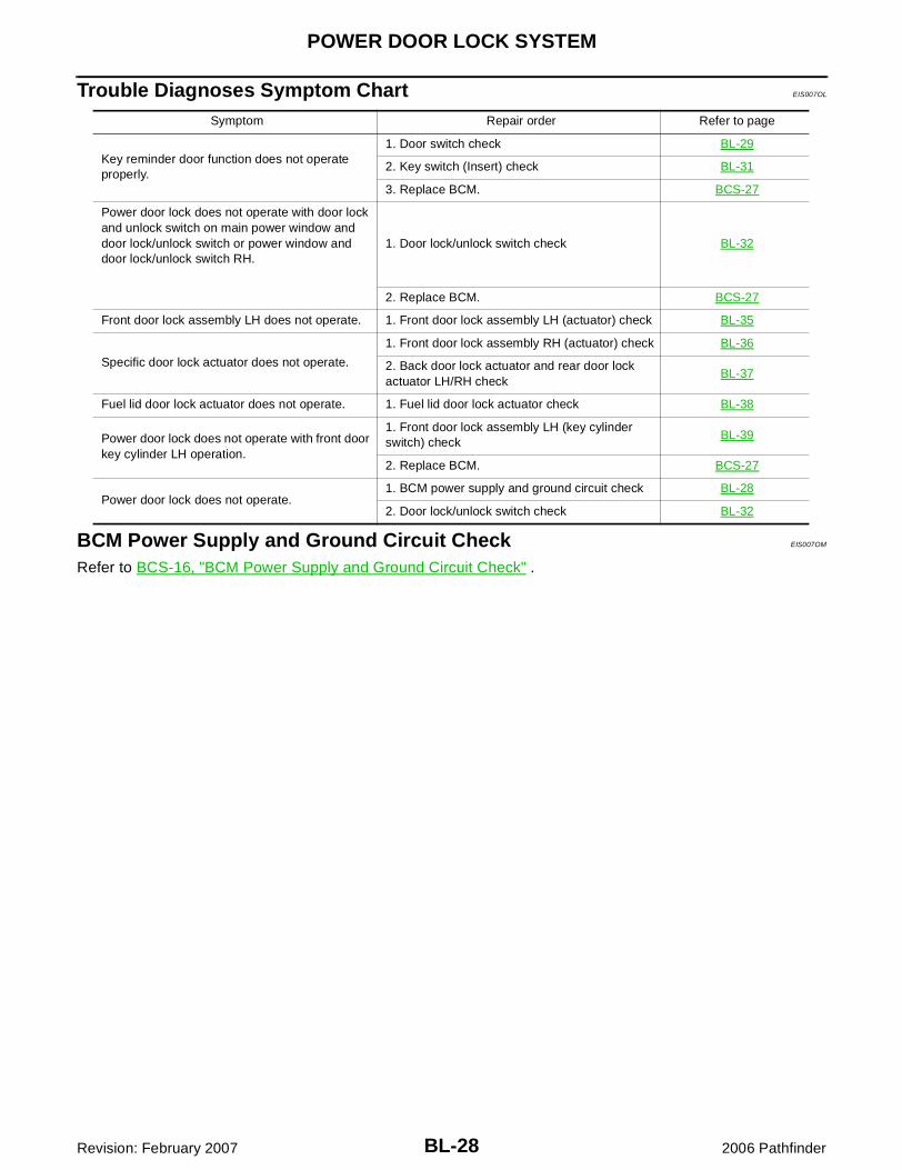
Trouble Diagnoses Symptom Chart EIS007OL
BCM Power Supply and Ground Circuit Check EIS007OM
Refer to BCS-16, "BCM Power Supply and Ground Circuit Check" .
Symptom Repair order Refer to page
Key reminder door function does not operate properly.
1. Door switch check BL-29
2. Key switch (Insert) check BL-31
3. Replace BCM. BCS-27
Power door lock does not operate with door lock and unlock switch on main power window and door lock/unlock switch or power window and door lock/unlock switch RH.
1. Door lock/unlock switch check BL-32
2. Replace BCM. BCS-27
Front door lock assembly LH does not operate. 1. Front door lock assembly LH (actuator) check BL-35
Specific door lock actuator does not operate.
1. Front door lock assembly RH (actuator) check BL-36
2. Back door lock actuator and rear door lock actuator LH/RH check
BL-37
Fuel lid door lock actuator does not operate. 1. Fuel lid door lock actuator check BL-38
Power door lock does not operate with front door key cylinder LH operation.
1. Front door lock assembly LH (key cylinder switch) check
BL-39
2. Replace BCM. BCS-27
Power door lock does not operate.1. BCM power supply and ground circuit check BL-28
2. Door lock/unlock switch check BL-32

POWER DOOR LOCK SYSTEM
BL-29
C
D
E
F
G
H
J
K
L
M
A
B
BL
Revision: February 2007 2006 Pathfinder
Door Switch Check EIS007ON
1. CHECK DOOR SWITCHES INPUT SIGNAL
With CONSULT-IICheck door switches ("DOOR SW-DR", "DOOR SW-AS", "DOOR SW-RL", "DOOR SW-RR", "BACK DOORSW") in DATA MONITOR mode with CONSULT–II. Refer to BL-27, "DATA MONITOR" .� When doors are open:
� When doors are closed:
Without CONSULT-IICheck voltage between BCM connector M18 or M19 terminals 12, 13, 42, 43, 47, 48 and ground.
OK or NGOK >> Door switch circuit is OK.NG >> GO TO 2.
DOOR SW-DR : ON
DOOR SW-AS : ON
DOOR SW-RL : ON
DOOR SW-RR : ON
BACK DOOR SW : ON
DOOR SW-DR : OFF
DOOR SW-AS : OFF
DOOR SW-RL : OFF
DOOR SW-RR : OFF
BACK DOOR SW : OFF
LIIA0665E
Connec-tor
ItemTerminals
ConditionVoltage (V)(Approx.)(+) (–)
M19
Back door switch
43
GroundOpen
↓Closed
0↓
Battery voltage
Front door switch LH
47
Rear door switch LH
48
M18
Front door switch RH
12
Rear door switch RH
13
LIIA1041E
BL-30
POWER DOOR LOCK SYSTEM
Revision: February 2007 2006 Pathfinder
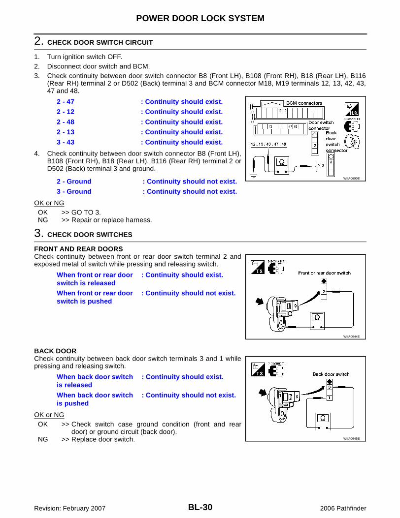
2. CHECK DOOR SWITCH CIRCUIT
1. Turn ignition switch OFF.2. Disconnect door switch and BCM.3. Check continuity between door switch connector B8 (Front LH), B108 (Front RH), B18 (Rear LH), B116
(Rear RH) terminal 2 or D502 (Back) terminal 3 and BCM connector M18, M19 terminals 12, 13, 42, 43,47 and 48.
4. Check continuity between door switch connector B8 (Front LH),B108 (Front RH), B18 (Rear LH), B116 (Rear RH) terminal 2 orD502 (Back) terminal 3 and ground.
OK or NGOK >> GO TO 3.NG >> Repair or replace harness.
3. CHECK DOOR SWITCHES
FRONT AND REAR DOORSCheck continuity between front or rear door switch terminal 2 andexposed metal of switch while pressing and releasing switch.
BACK DOORCheck continuity between back door switch terminals 3 and 1 whilepressing and releasing switch.
OK or NGOK >> Check switch case ground condition (front and rear
door) or ground circuit (back door).NG >> Replace door switch.
2 - 47 : Continuity should exist.
2 - 12 : Continuity should exist.
2 - 48 : Continuity should exist.
2 - 13 : Continuity should exist.
3 - 43 : Continuity should exist.
2 - Ground : Continuity should not exist.
3 - Ground : Continuity should not exist.
WIIA0690E
When front or rear door switch is released
: Continuity should exist.
When front or rear door switch is pushed
: Continuity should not exist.
WIIA0644E
When back door switch is released
: Continuity should exist.
When back door switch is pushed
: Continuity should not exist.
WIIA0645E

POWER DOOR LOCK SYSTEM
BL-31
C
D
E
F
G
H
J
K
L
M
A
B
BL
Revision: February 2007 2006 Pathfinder
Key Switch (Insert) Check EIS007OO
1. CHECK KEY SWITCH INPUT SIGNAL
With CONSULT-IICheck key switch "KEY ON SW" in DATA MONITOR mode with CONSULT–II. Refer to BL-27, "DATA MONI-TOR" .� When key is inserted to ignition key cylinder:
� When key is removed from ignition key cylinder:
Without CONSULT-IICheck voltage between BCM connector M18 terminal 37 andground.
OK or NGOK >> Key switch (insert) circuit is OK.NG >> GO TO 2.
2. CHECK KEY SWITCH (INSERT)
1. Turn ignition switch OFF.2. Disconnect key switch connector.3. Check continuity between key switch terminals.
OK or NGOK >> Repair or replace harness or fuse.NG >> Replace key switch.
KEY ON SW : ON
KEY ON SW : OFF
LIIA0169E
Connec-tor
TerminalCondition Voltage (V)
(+) (–)
M18 37 GroundKey is inserted. Battery voltage
Key is removed. 0
LIIA0567E
Terminals Condition Continuity
1 – 2Key is inserted. Yes
Key is removed. No
WIIA0559E

BL-32
POWER DOOR LOCK SYSTEM
Revision: February 2007 2006 Pathfinder
Door Lock/Unlock Switch Check EIS007OP
1. CHECK DOOR LOCK/UNLOCK SWITCH INPUT SIGNAL
With CONSULT-IICheck door lock/unlock switch ("CDL LOCK SW", "CDL UNLOCK SW") in DATA MONITOR mode in CON-SULT–II. Refer to BL-27, "DATA MONITOR" .� When door lock/unlock switch is turned to LOCK:
� When door lock/unlock switch is turned to UNLOCK:
Without CONSULT-IICheck voltage between BCM connector M19 terminals 45, 46 and ground.
OK or NGOK >> Door lock/unlock switch circuit is OK.NG >> GO TO 2.
CDL LOCK SW : ON
CDL UNLOCK SW : ON
PIIA6538E
Connec-tor
TerminalCondition
Voltage (V)(Approx.)(+) (–)
M19
46 Ground
Door lock/unlock switch is neutral.
Battery voltage
Door lock/unlock switch is turned to UNLOCK.
0
45 Ground
Door lock/unlock switch is neutral.
Battery voltage
Door lock/unlock switch is turned to LOCK.
0 LIIA1351E

POWER DOOR LOCK SYSTEM
BL-33
C
D
E
F
G
H
J
K
L
M
A
B
BL
Revision: February 2007 2006 Pathfinder
2. CHECK DOOR LOCK/UNLOCK SWITCH
1. Turn ignition switch OFF.2. Disconnect door lock/unlock switch.3. Check continuity between main power window and door lock/
unlock switch connectors D7 and D8 terminals 6, 18 and 17.
4. Check continuity between power window and door lock/unlockswitch RH connector D105 terminals 1, 2 and 3.
OK or NGOK >> GO TO 3.NG >> Replace door lock/unlock switch.
3. CHECK DOOR LOCK/UNLOCK SWITCH GROUND HARNESS
1. Disconnect main power window and door lock/unlock switch or power window and door lock/unlock switchRH.
2. Check continuity between main power window and door lock/unlock switch connector D8 terminal 17 and ground.
3. Check continuity between power window and door lock/unlockswitch RH connector D105 terminal 3 and ground
OK or NGOK >> GO TO 4.NG >> Repair or replace harness.
Terminal Condition Continuity
18
17
Lock Yes
Unlock/Neutral No
6Unlock Yes
Lock/Neutral No
WIIA1439E
Terminal Condition Continuity
1
3
Lock Yes
Unlock/Neutral No
2Unlock Yes
Lock/Neutral No
WIIA1108E
17 - Ground : Continuity should exist.
WIIA1109E
3 - Ground : Continuity should exist.
WIIA0450E
BL-34
POWER DOOR LOCK SYSTEM
Revision: February 2007 2006 Pathfinder
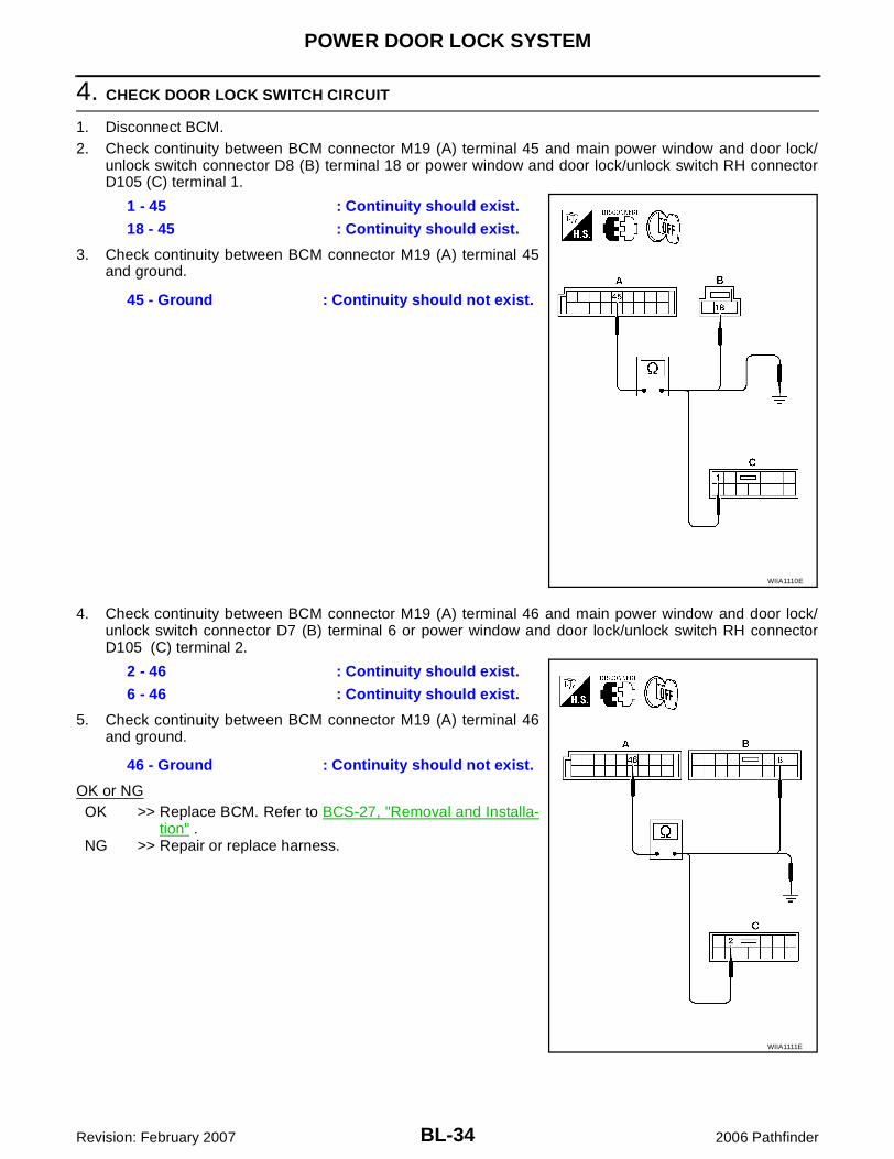
4. CHECK DOOR LOCK SWITCH CIRCUIT
1. Disconnect BCM.2. Check continuity between BCM connector M19 (A) terminal 45 and main power window and door lock/
unlock switch connector D8 (B) terminal 18 or power window and door lock/unlock switch RH connectorD105 (C) terminal 1.
3. Check continuity between BCM connector M19 (A) terminal 45and ground.
4. Check continuity between BCM connector M19 (A) terminal 46 and main power window and door lock/unlock switch connector D7 (B) terminal 6 or power window and door lock/unlock switch RH connectorD105 (C) terminal 2.
5. Check continuity between BCM connector M19 (A) terminal 46and ground.
OK or NGOK >> Replace BCM. Refer to BCS-27, "Removal and Installa-
tion" .NG >> Repair or replace harness.
1 - 45 : Continuity should exist.
18 - 45 : Continuity should exist.
45 - Ground : Continuity should not exist.
WIIA1110E
2 - 46 : Continuity should exist.
6 - 46 : Continuity should exist.
46 - Ground : Continuity should not exist.
WIIA1111E
POWER DOOR LOCK SYSTEM
BL-35
C
D
E
F
G
H
J
K
L
M
A
B
BL
Revision: February 2007 2006 Pathfinder
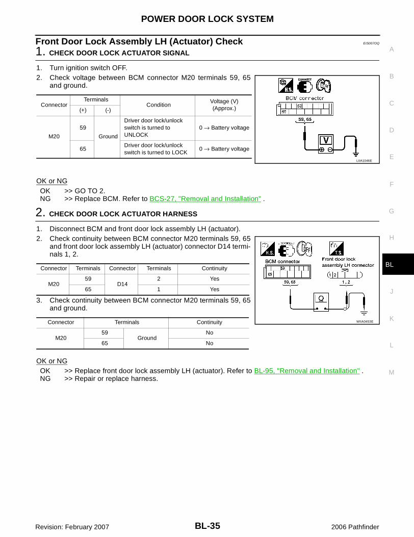
Front Door Lock Assembly LH (Actuator) Check EIS007OQ
1. CHECK DOOR LOCK ACTUATOR SIGNAL
1. Turn ignition switch OFF.2. Check voltage between BCM connector M20 terminals 59, 65
and ground.
OK or NGOK >> GO TO 2.NG >> Replace BCM. Refer to BCS-27, "Removal and Installation" .
2. CHECK DOOR LOCK ACTUATOR HARNESS
1. Disconnect BCM and front door lock assembly LH (actuator).2. Check continuity between BCM connector M20 terminals 59, 65
and front door lock assembly LH (actuator) connector D14 termi-nals 1, 2.
3. Check continuity between BCM connector M20 terminals 59, 65and ground.
OK or NGOK >> Replace front door lock assembly LH (actuator). Refer to BL-95, "Removal and Installation" .NG >> Repair or replace harness.
ConnectorTerminals
ConditionVoltage (V)(Approx.)(+) (-)
M20
59
Ground
Driver door lock/unlock switch is turned to UNLOCK
0 → Battery voltage
65Driver door lock/unlock switch is turned to LOCK
0 → Battery voltage
LIIA1046E
Connector Terminals Connector Terminals Continuity
M2059
D142 Yes
65 1 Yes
Connector Terminals Continuity
M2059
GroundNo
65 No
WIIA0453E
BL-36
POWER DOOR LOCK SYSTEM
Revision: February 2007 2006 Pathfinder
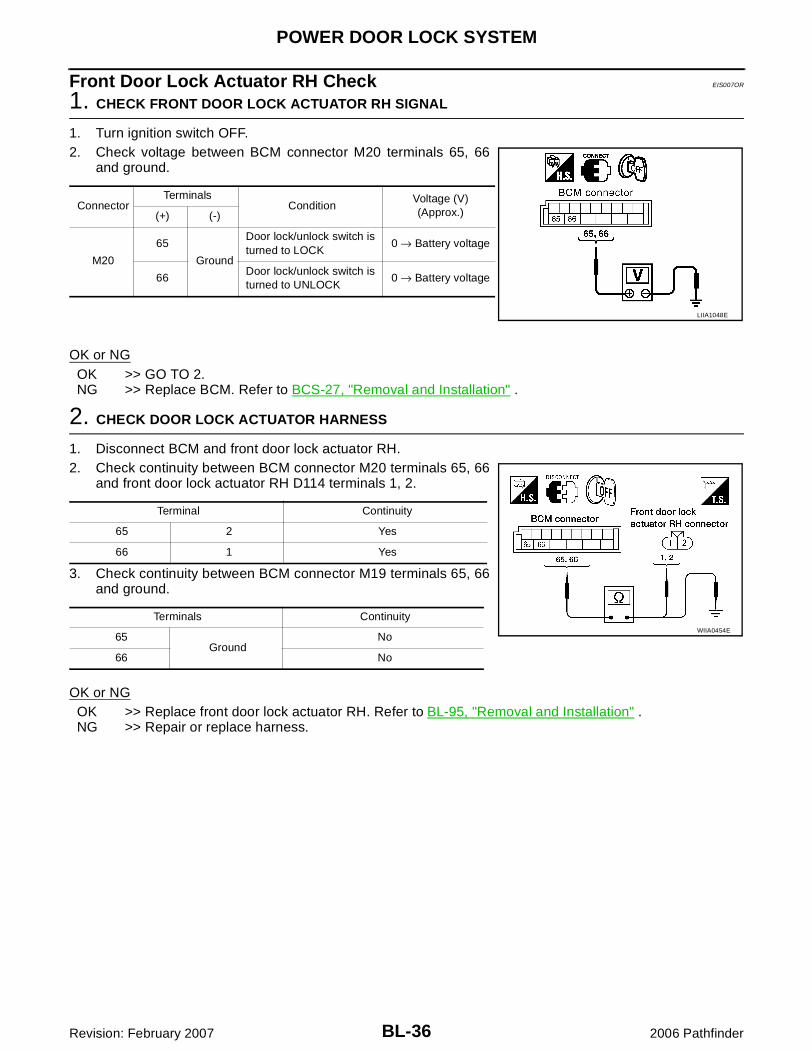
Front Door Lock Actuator RH Check EIS007OR
1. CHECK FRONT DOOR LOCK ACTUATOR RH SIGNAL
1. Turn ignition switch OFF.2. Check voltage between BCM connector M20 terminals 65, 66
and ground.
OK or NGOK >> GO TO 2.NG >> Replace BCM. Refer to BCS-27, "Removal and Installation" .
2. CHECK DOOR LOCK ACTUATOR HARNESS
1. Disconnect BCM and front door lock actuator RH.2. Check continuity between BCM connector M20 terminals 65, 66
and front door lock actuator RH D114 terminals 1, 2.
3. Check continuity between BCM connector M19 terminals 65, 66and ground.
OK or NGOK >> Replace front door lock actuator RH. Refer to BL-95, "Removal and Installation" .NG >> Repair or replace harness.
ConnectorTerminals
ConditionVoltage (V)(Approx.)(+) (-)
M20
65
Ground
Door lock/unlock switch is turned to LOCK
0 → Battery voltage
66Door lock/unlock switch is turned to UNLOCK
0 → Battery voltage
LIIA1048E
Terminal Continuity
65 2 Yes
66 1 Yes
Terminals Continuity
65Ground
No
66 No
WIIA0454E
POWER DOOR LOCK SYSTEM
BL-37
C
D
E
F
G
H
J
K
L
M
A
B
BL
Revision: February 2007 2006 Pathfinder
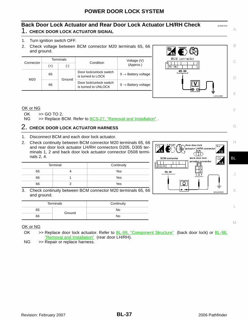
Back Door Lock Actuator and Rear Door Lock Actuator LH/RH Check EIS007OS
1. CHECK DOOR LOCK ACTUATOR SIGNAL
1. Turn ignition switch OFF.2. Check voltage between BCM connector M20 terminals 65, 66
and ground.
OK or NGOK >> GO TO 2.NG >> Replace BCM. Refer to BCS-27, "Removal and Installation" .
2. CHECK DOOR LOCK ACTUATOR HARNESS
1. Disconnect BCM and each door lock actuator.2. Check continuity between BCM connector M20 terminals 65, 66
and rear door lock actuator LH/RH connectors D205, D305 ter-minals 1, 2 and back door lock actuator connector D508 termi-nals 2, 4.
3. Check continuity between BCM connector M20 terminals 65, 66and ground.
OK or NGOK >> Replace door lock actuator. Refer to BL-99, "Component Structure" (back door lock) or BL-98,
"Removal and Installation" (rear door LH/RH).NG >> Repair or replace harness.
ConnectorTerminals
ConditionVoltage (V)(Approx.)(+) (-)
M20
65
Ground
Door lock/unlock switch is turned to LOCK
0 → Battery voltage
66Door lock/unlock switch is turned to UNLOCK
0 → Battery voltage
LIIA1048E
Terminal Continuity
65 4 Yes
66 1 Yes
66 2 Yes
Terminals Continuity
65Ground
No
66 No
WIIA0455E

BL-38
POWER DOOR LOCK SYSTEM
Revision: February 2007 2006 Pathfinder
Fuel Lid Door Lock Actuator Check EIS007OT
1. CHECK FUEL LID DOOR LOCK ACTUATOR SIGNAL
1. Turn ignition switch OFF.2. Check voltage between BCM connector M20 terminals 59, 65
and ground.
OK or NGOK >> GO TO 2.NG >> Replace BCM. Refer to BCS-27, "Removal and Installation" .
2. CHECK FUEL LID DOOR LOCK ACTUATOR HARNESS
1. Disconnect BCM and fuel lid door lock actuator.2. Check continuity between BCM connector M20 terminals 59, 65
and fuel door lock actuator connector B79 terminals 1, 2.
3. Check continuity between BCM connector M20 terminals 59, 65and ground.
OK or NGOK >> Replace fuel lid door lock actuator.NG >> Repair or replace harness.
ConnectorTerminals
ConditionVoltage (V)(Approx.)(+) (-)
M20
59
Ground
Driver door lock/unlock switch is turned to UNLOCK
0 → Battery voltage
65Driver door lock/unlock switch is turned to LOCK
0 → Battery voltage
LIIA1046E
Connector Terminals Connector Terminals Continuity
M2059
B792 Yes
65 1 Yes
Connector Terminals Continuity
M2059
GroundNo
65 No
WIIA0456E

POWER DOOR LOCK SYSTEM
BL-39
C
D
E
F
G
H
J
K
L
M
A
B
BL
Revision: February 2007 2006 Pathfinder
Front Door Lock Assembly LH (Key Cylinder Switch) Check EIS007OU
1. CHECK DOOR KEY CYLINDER SWITCH LH
With CONSULT-IICheck front door lock assembly LH (key cylinder switch) ("KEY CYL LK-SW") and ("KEY CYL UN-SW") inDATA MONITOR mode in CONSULT–II. Refer to BL-27, "DATA MONITOR" .� When key inserted in front key cylinder is turned to LOCK:
� When key inserted in front key cylinder is turned to UNLOCK:
Without CONSULT-IICheck voltage between BCM connector M18 terminals 7, 8 andground.
OK or NGOK >> Front door lock assembly LH (key cylinder switch) signal is OK.NG >> GO TO 2.
2. CHECK FRONT DOOR LOCK ASSEMBLY LH (KEY CYLINDER SWITCH)
1. Turn ignition switch OFF.2. Disconnect front door lock assembly LH (key cylinder switch).3. Check continuity between front door lock assembly LH (key cyl-
inder switch) connector terminals 3, 4 and 5.
OK or NGOK >> GO TO 3.NG >> Replace front door lock assembly LH (key cylinder switch). Refer to BL-95, "Removal and Installa-
tion" .
KEY CYL LK-SW : ON
KEY CYL UN-SW : ON
LIIA0188E
ConnectorTerminals
ConditionVoltage (V)(Approx.)(+) (–)
M18
7
Ground
Neutral/Lock 5
Unlock 0
8Neutral/Unlock 5
Lock 0WIIA0457E
Terminals Condition Continuity
4 – 5
Key is turned to LOCK. Yes
Key is in N position or turned to UNLOCK
No
3 – 4Key is turned to UNLOCK. Yes
Key is in N position or turned to LOCK No
WIIA0458E
BL-40
POWER DOOR LOCK SYSTEM
Revision: February 2007 2006 Pathfinder
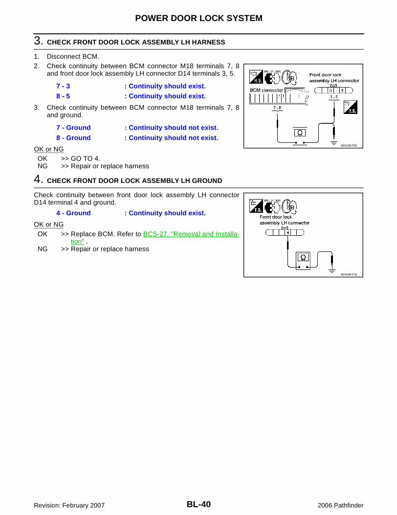
3. CHECK FRONT DOOR LOCK ASSEMBLY LH HARNESS
1. Disconnect BCM.2. Check continuity between BCM connector M18 terminals 7, 8
and front door lock assembly LH connector D14 terminals 3, 5.
3. Check continuity between BCM connector M18 terminals 7, 8and ground.
OK or NGOK >> GO TO 4.NG >> Repair or replace harness
4. CHECK FRONT DOOR LOCK ASSEMBLY LH GROUND
Check continuity between front door lock assembly LH connectorD14 terminal 4 and ground.
OK or NGOK >> Replace BCM. Refer to BCS-27, "Removal and Installa-
tion" .NG >> Repair or replace harness
7 - 3 : Continuity should exist.
8 - 5 : Continuity should exist.
7 - Ground : Continuity should not exist.
8 - Ground : Continuity should not exist.WIIA0676E
4 - Ground : Continuity should exist.
WIIA0677E
REMOTE KEYLESS ENTRY SYSTEM
BL-41
C
D
E
F
G
H
J
K
L
M
A
B
BL
Revision: February 2007 2006 Pathfinder
REMOTE KEYLESS ENTRY SYSTEM PFP:28596
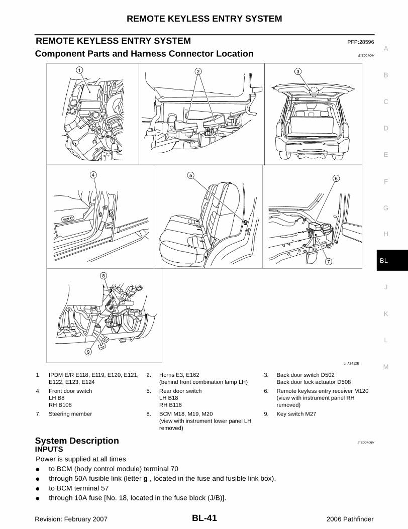
Component Parts and Harness Connector Location EIS007OV
System Description EIS007OW
INPUTSPower is supplied at all times� to BCM (body control module) terminal 70� through 50A fusible link (letter g , located in the fuse and fusible link box).� to BCM terminal 57� through 10A fuse [No. 18, located in the fuse block (J/B)].
LIIA2412E
1. IPDM E/R E118, E119, E120, E121, E122, E123, E124
2. Horns E3, E162(behind front combination lamp LH)
3. Back door switch D502Back door lock actuator D508
4. Front door switchLH B8RH B108
5. Rear door switchLH B18RH B116
6. Remote keyless entry receiver M120(view with instrument panel RH removed)
7. Steering member 8. BCM M18, M19, M20(view with instrument lower panel LH removed)
9. Key switch M27

BL-42
REMOTE KEYLESS ENTRY SYSTEM
Revision: February 2007 2006 Pathfinder
When the key is inserted in the ignition cylinder (key switch), power is supplied� to BCM terminal 37� through key switch terminals 1 and 2� through 10A fuse (No. 25, located in the fuse and fusible link box).When the ignition switch is ACC or ON, power is supplied� to BCM terminal 11� through 10A fuse [No. 4, located in the fuse block (J/B)].When the ignition switch is ON or START, power is supplied� to BCM terminal 38� through 10A fuse [No. 1, located in the fuse block (J/B)].When the front door switch LH is ON (door is OPEN), ground is supplied� to BCM terminal 47� through front door switch LH terminal 2� through front door switch LH case ground.When the front door switch RH is ON (door is OPEN), ground is supplied� to BCM terminal 12� through front door switch RH terminal 2� through front door switch RH case ground.When the rear door switch LH is ON (door is OPEN), ground is supplied� to BCM terminal 48� through rear door switch LH terminal 2� through rear door switch LH case ground.When the rear door switch RH is ON (door is OPEN), ground is supplied� to BCM terminal 13� through rear door switch RH terminal 2� through rear door switch RH case ground.When the back door switch is ON (door is OPEN), ground is supplied� to BCM terminal 43� through back door switch terminal 3,� through back door switch terminal 1,� through body grounds D406 and D504.Keyfob signal is inputted to BCM from the remote keyless entry receiver.The remote keyless entry system controls operation of the� power door lock� interior lamp and ignition keyhole illumination� panic alarm� hazard and horn reminder� auto door lock operation
OPERATED PROCEDURE� When the keyfob is operated, the signal from the keyfob is sent and the remote keyless entry receiver
receives the signal and sends it to the BCM. The BCM only locks/unlocks the doors if the ID numbermatches. (Remote control entry functions)
� Using the keyfob, the transmitter sends radio waves to the remote keyless entry receiver, which thensends the received waves to the BCM. Only if the ID number matches does the BCM lock/unlock thedoors. (Remote control door function)
� Unless the key is inserted into the ignition key cylinder or one of the doors is opened within 1 minute afterthe UNLOCK switch on the keyfob is pressed, all the doors are automatically locked. (Auto lock function)
� When a door is locked or unlocked, the vehicle turn signal lamps flash and the horn sounds to verify oper-ation. (Active check function)

REMOTE KEYLESS ENTRY SYSTEM
BL-43
C
D
E
F
G
H
J
K
L
M
A
B
BL
Revision: February 2007 2006 Pathfinder
� When the key is in the ignition key cylinder (when the key switch is ON) and one of the doors is open, thedoor lock function does not work even when the door lock is operated with the keyfob.
� Keyfob ID set up is available.� If a keyfob is lost, a new keyfob can be set up. A maximum of 5 IDs can be set up simultaneously.
Remote Control Entry FunctionsOperation Description� When a button on the keyfob is operated, the signal is sent from the keyfob and received by the remote
keyless entry receiver.� The received signal is sent to the BCM and compared with the registered ID number.� If the ID number matches, the BCM sends the lock/unlock signal to each door lock actuator. � When the door lock actuators receive this signal, each operates to lock/unlock its door.� BCM locks all doors with input of LOCK signal from keyfob.� When an UNLOCK signal is sent from keyfob once, driver's door will be unlocked.� Then, if an UNLOCK signal is sent from keyfob again within 5 seconds, all other doors will be unlocked.Remote control entry operation conditions
Auto Lock FunctionOperation Description� Unless the key is inserted into the ignition key cylinder, one of the doors is opened, or the keyfob is oper-
ated within 1 minute after a door lock is unlocked by keyfob operation, all the doors are automaticallylocked.The 1 minute timer count is executed by the BCM and after 1 minute, the BCM sends the lock signal to alldoors.NOTE:On vehicles with NAVI, this time can be adjusted via the display. Refer to Owner's Manual for instructions.
Lock operations are the same as for the remote control entry function.
Active Check FunctionOperation DescriptionWhen a door is locked or unlocked by keyfob operation, the vehicle turn signals flash and the horn sounds toverify operation.� When a button on the keyfob is operated, the signal is sent from the remote controller and received by the
keyless remote entry receiver.� The received signal is sent to the BCM and compared with the registered ID number.� If the ID number matches, the BCM uses communication to send the turn signal flashing and horn signal
to the IPDM E/R.� The IPDM E/R flashes the turn signal lamps and sounds the horn for each keyfob operation.
Operating function of hazard and horn reminder
Hazard and Horn ReminderBCM output to IPDM E/R for horn reminder signal as DATA LINE (CAN-H line and CAN-L line).The hazard and horn reminder has C mode (horn chirp mode) and S mode (non-horn chirp mode).How to change hazard and horn reminder mode
Keyfob operation Operation condition
Door lock operation (locking)� With key removed (key switch: OFF)
� Closing all doors (door switch: OFF)
Door lock operation (unlocking) With key removed (key switch: OFF)
C mode S mode
Keyfob operation Lock Unlock Lock Unlock
Hazard warning lamp flash
Twice Once Twice —
Horn sound Once — — —

BL-44
REMOTE KEYLESS ENTRY SYSTEM
Revision: February 2007 2006 Pathfinder
With CONSULT-IIHazard and horn reminder can be changed using “WORK SUPPORT” mode in “MULTI ANSWER BACK SET".
Without CONSULT-IIRefer to Owner's Manual for instructions.
Interior Lamp and Ignition Keyhole Illumination OperationWhen the following input signals are both supplied:� all door switches are in the OFF position. (when all the doors are closed);� interior lamp switch is in DOOR position.Remote keyless entry system turns on interior lamp and ignition keyhole illumination (for 30 seconds) withinput of UNLOCK signal from keyfob.For detailed description, refer to LT-118, "ROOM LAMP TIMER OPERATION" .
Panic Alarm OperationWhen key switch is OFF (when ignition key is not inserted in key cylinder), remote keyless entry system turnson and off horn and headlamp intermittently with input of PANIC ALARM signal from keyfob.The alarm automatically turns off after 25 seconds or when BCM receives any signal from keyfob.
CAN Communication System Description EIS007OX
Refer to LAN-25, "CAN COMMUNICATION" .
REMOTE KEYLESS ENTRY SYSTEM
BL-45
C
D
E
F
G
H
J
K
L
M
A
B
BL
Revision: February 2007 2006 Pathfinder
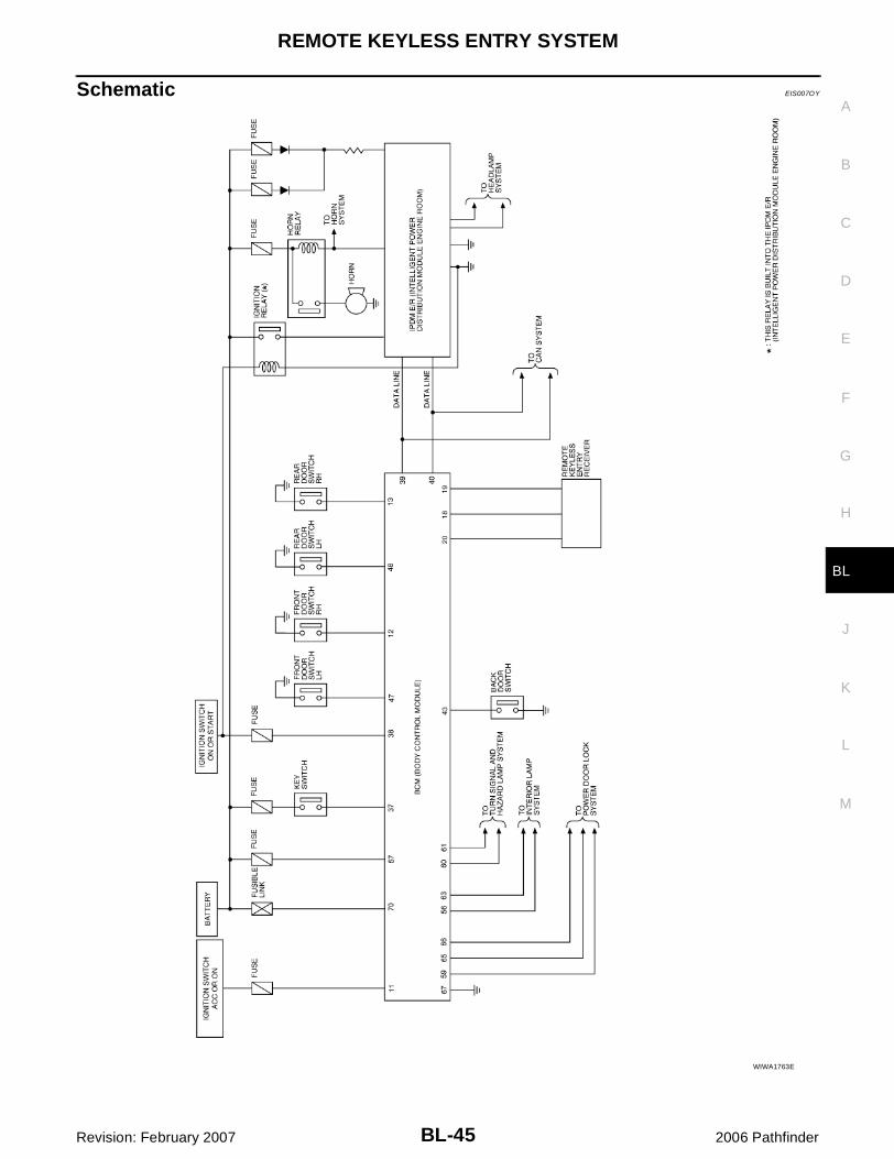
Schematic EIS007OY
WIWA1763E

BL-46
REMOTE KEYLESS ENTRY SYSTEM
Revision: February 2007 2006 Pathfinder
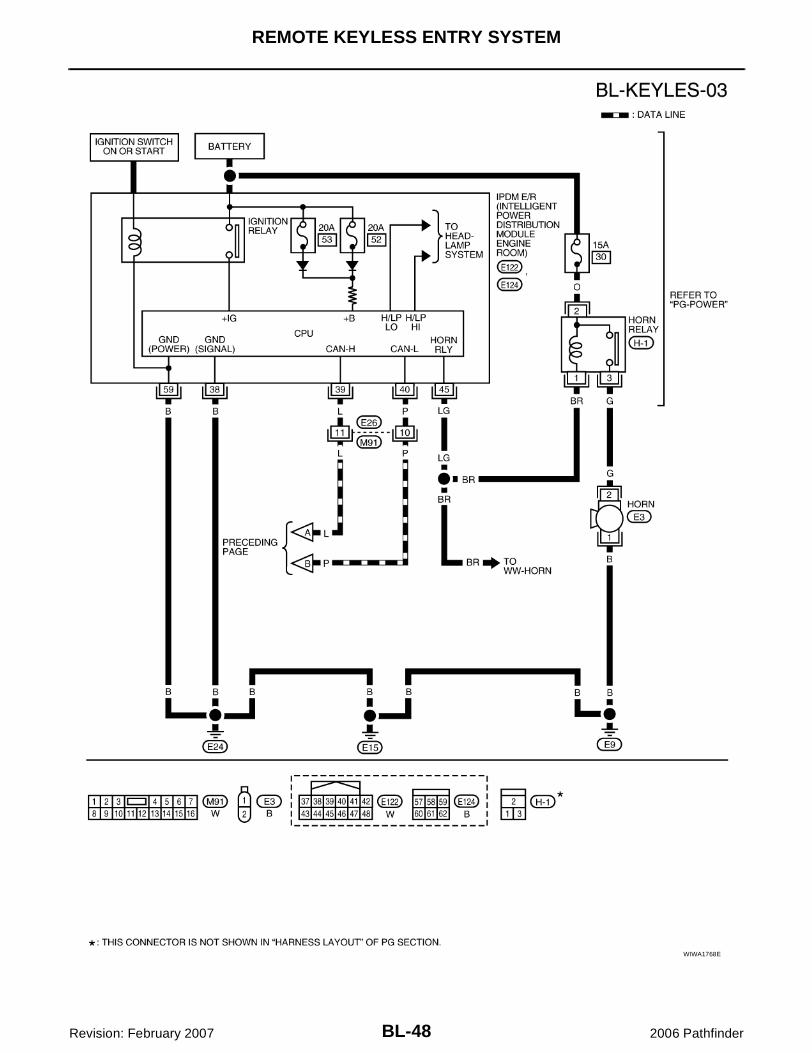
Wiring Diagram — KEYLES — EIS007OZ
WIWA1613E

REMOTE KEYLESS ENTRY SYSTEM
BL-47
C
D
E
F
G
H
J
K
L
M
A
B
BL
Revision: February 2007 2006 Pathfinder
WIWA1764E
BL-48
REMOTE KEYLESS ENTRY SYSTEM
Revision: February 2007 2006 Pathfinder
WIWA1768E

REMOTE KEYLESS ENTRY SYSTEM
BL-49
C
D
E
F
G
H
J
K
L
M
A
B
BL
Revision: February 2007 2006 Pathfinder
Terminals and Reference Value for BCM EIS007P0
Refer to BCS-12, "Terminals and Reference Values for BCM" .
Terminals and Reference Value for IPDM E/R EIS007P1
Refer to PG-29, "Terminals and Reference Values for IPDM E/R" .

BL-50
REMOTE KEYLESS ENTRY SYSTEM
Revision: February 2007 2006 Pathfinder
CONSULT-II Function (BCM) EIS007P2
CONSULT-II can display each diagnostic item using the diagnostic test modes shown following.
CONSULT-II Inspection Procedure EIS007P3
“MULTI REMOTE ENT”CAUTION:If CONSULT-II is used with no connection of CONSULT-II CONVERTER, malfunctions might bedetected in self-diagnosis depending on control unit which carries out CAN communication.1. Turn ignition switch OFF.2. Connect CONSULT-II and CONSULT-II CONVERTER to the
data link connector.
3. Turn ignition switch ON.4. Touch “START (NISSAN BASED VHCL)".
5. Touch “BCM”.If "BCM" is not indicated, refer to GI-40, "CONSULT-II Data LinkConnector (DLC) Circuit" .
BCM diagnostic test item
Diagnostic mode Description
Inspection by part
WORK SUPPORTSupports inspections and adjustments. Commands are transmitted to the BCM for setting the status suitable for required operation, input/output signals are received from the BCM and received data is displayed.
DATA MONITOR Displays BCM input/output data in real time.
ACTIVE TEST Operation of electrical loads can be checked by sending drive signal to them.
SELF-DIAG RESULTS Displays BCM self-diagnosis results.
CAN DIAG SUPPORT MNTR The result of transmit/receive diagnosis of CAN communication can be read.
ECU PART NUMBER BCM part number can be read.
CONFIGURATION Performs BCM configuration read/write functions.
BBIA0538E
BCIA0029E
BCIA0030E

REMOTE KEYLESS ENTRY SYSTEM
BL-51
C
D
E
F
G
H
J
K
L
M
A
B
BL
Revision: February 2007 2006 Pathfinder
6. Touch “MULTI REMOTE ENT”.
7. Select diagnosis mode.“DATA MONITOR”, “ACTIVE TEST” and “WORK SUPPORT”are available.
CONSULT-II Application Items EIS007P4
“MULTI REMOTE ENT”Data Monitor
Active Test
LIIA0194E
BCIA0031E
Monitored Item Description
DOOR SW-AS Indicates [ON/OFF] condition of front door switch RH.
DOOR SW-RR Indicates [ON/OFF] condition of rear door switch RH.
DOOR SW-RL Indicates [ON/OFF] condition of rear door switch LH.
DOOR SW-DR Indicates [ON/OFF] condition of front door switch LH.
BACK DOOR SW Indicates [ON/OFF] condition of back door switch.
KEY ON SW Indicates [ON/OFF] condition of key switch.
ACC ON SW Indicates [ON/OFF] condition of ignition switch in ACC position.
IGN ON SW Indicates [ON/OFF] condition of ignition switch in ON position.
KEYLESS PANIC Indicates [ON/OFF] condition of panic signal from keyfob.
KEYLESS UNLOCK Indicates [ON/OFF] condition of unlock signal from keyfob.
KEYLESS LOCK Indicates [ON/OFF] condition of lock signal from keyfob.
KEY CYL LK-SW Indicates [ON/OFF] condition of lock signal from door key cylinder switch.
CDL UNLOCK SW Indicates [ON/OFF] condition of unlock signal from lock/unlock switch.
CDL LOCK SW Indicates [ON/OFF] condition of lock signal from lock/unlock switch.
RKE LCK-UNLCK Indicates [ON/OFF] condition of lock/unlock signal at the same time from keyfob.
RKE KEEP UNLK Indicates [ON/OFF] condition of unlock signal from keyfob.
Test Item Description
FLASHER This test is able to check right and left hazard reminder operation. The right hazard lamp turns on when “RH” on CONSULT-II screen is touched and the left hazard lamp turns on when "LH" on CON-SULT-II screen is touched.
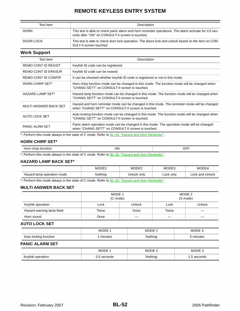
BL-52
REMOTE KEYLESS ENTRY SYSTEM
Revision: February 2007 2006 Pathfinder
Work Support
*: Perform this mode always in the state of C mode. Refer to BL-43, "Hazard and Horn Reminder" .
HORN CHIRP SET*
*: Perform this mode always in the state of C mode. Refer to BL-43, "Hazard and Horn Reminder" .
HAZARD LAMP BACK SET*
*: Perform this mode always in the state of C mode. Refer to BL-43, "Hazard and Horn Reminder" .
MULTI ANSWER BACK SET
AUTO LOCK SET
PANIC ALARM SET
HORN This test is able to check panic alarm and horn reminder operations. The alarm activate for 0.5 sec-onds after “ON” on CONSULT-II screen is touched.
DOOR LOCK This test is able to check door lock operation. The doors lock and unlock based on the item on CON-SULT-II screen touched.
Test Item Description
Test Item Description
REMO CONT ID REGIST Keyfob ID code can be registered.
REMO CONT ID ERASUR Keyfob ID code can be erased.
REMO CONT ID CONFIR It can be checked whether keyfob ID code is registered or not in this mode.
HORN CHIRP SET* Horn chirp function mode can be changed in this mode. The function mode will be changed when "CHANG SETT" on CONSULT-II screen is touched.
HAZARD LAMP SET* Hazard lamp function mode can be changed in this mode. The function mode will be changed when "CHANG SETT" on CONSULT-II screen is touched.
MULTI ANSWER BACK SETHazard and horn reminder mode can be changed in this mode. The reminder mode will be changed when “CHANG SETT” on CONSULT-II screen is touched.
AUTO LOCK SETAuto locking function mode can be changed in this mode. The function mode will be changed when "CHANG SETT" on CONSULT-II screen is touched.
PANIC ALRM SETPanic alarm operation mode can be changed in this mode. The operation mode will be changed when "CHANG SETT" on CONSULT-II screen is touched.
Horn chirp function ON OFF
MODE1 MODE2 MODE3 MODE4
Hazard lamp operation mode Nothing Unlock only Lock only Lock and Unlock
MODE 1(C mode)
MODE 2(S mode)
Keyfob operation Lock Unlock Lock Unlock
Hazard warning lamp flash Twice Once Twice —
Horn sound Once — — —
MODE 1 MODE 2 MODE 3
Auto locking function 1 minutes Nothing 5 minutes
MODE 1 MODE 2 MODE 3
Keyfob operation 0.5 seconds Nothing 1.5 seconds

REMOTE KEYLESS ENTRY SYSTEM
BL-53
C
D
E
F
G
H
J
K
L
M
A
B
BL
Revision: February 2007 2006 Pathfinder
Trouble Diagnosis Procedure EIS007P5
1. Check the symptom and customer's requests.2. Understand outline of system. Refer to BL-41, "System Description" .3. Confirm system operation.
� Check that the power door lock system operates normally. Refer to BL-16, "POWER DOOR LOCKSYSTEM" .
4. Perform pre-diagnosis inspection. Refer to BL-53, "Pre-Diagnosis Inspection" .5. Refer to trouble diagnosis chart by symptom, repair or replace any malfunctioning parts. Refer to BL-54,
"Trouble Diagnoses" .6. Inspection End.
Pre-Diagnosis Inspection EIS007P6
BCM POWER SUPPLY AND GROUND CIRCUIT INSPECTIONRefer to BCS-12, "Terminals and Reference Values for BCM" .

BL-54
REMOTE KEYLESS ENTRY SYSTEM
Revision: February 2007 2006 Pathfinder
Trouble Diagnoses EIS007P7
SYMPTOM CHARTNOTE:� Always check the "Trouble Diagnosis Procedure" before troubleshooting. Refer to BL-53, "Trouble Diag-
nosis Procedure" .� Always check keyfob battery before replacing keyfob. Refer to BL-59, "Keyfob Battery and Function
Check" .� The panic alarm operation of remote keyless entry system does not activate with the ignition key inserted
in the ignition key cylinder.� Use Remote Keyless Entry Tester J-43241 (follow instructions on tester) to check operation of keyfob
before replacing keyfob.
Symptom Diagnoses/service procedureReference
page
All functions of remote keyless entry system do not operate.
1. Keyfob battery and function check (use Remote Keyless Entry Tester J-43241)
NOTE:If the result of keyfob function check is OK, keyfob is not malfunc-tioning.
BL-59
2. Check BCM and remote keyless entry receiver. BL-60
The new ID of keyfob cannot be entered.
1. Keyfob battery and function check (use Remote Keyless Entry Tester J-43241)
NOTE:If the result of keyfob function check is OK, keyfob is not malfunc-tioning.
BL-59
2. Key switch (insert) check BL-56
3. Door switch check BL-57
4. ACC power check BL-61
5. Replace BCM. BCS-27
Door lock or unlock does not function.(If the power door lock system does not operate manually, check power door lock system. Refer to BL-16, "POWER DOOR LOCK SYSTEM" )
1. Keyfob battery and function check (use Remote Keyless Entry Tester J-43241)
NOTE:If the result of keyfob function check is OK, keyfob is not malfunc-tioning.
BL-59
2. Replace BCM. BCS-27
Hazard and horn reminder does not activate prop-erly when pressing lock or unlock button of keyfob.
1. Check hazard and horn reminder mode with CONSULT-II.
NOTE:Hazard and horn reminder mode can be changed.First check the hazard and horn reminder mode setting.
BL-51
2. Door switch check BL-57
3. Replace BCM. BCS-27
Hazard reminder does not activate properly when pressing lock or unlock button of keyfob.(Horn reminder OK)
1. Check hazard reminder mode with CONSULT-II.
NOTE:Hazard reminder mode can be changed.First check the hazard reminder mode setting.
BL-51
2. Check hazard function with hazard switch. —
3. Replace BCM. BCS-27
Horn reminder does not activate properly when pressing lock or unlock button of keyfob.(Hazard reminder OK)
1. Check horn reminder mode with CONSULT-II.
NOTE:Horn reminder mode can be changed.First check the horn reminder mode setting.
BL-51
2. Check horn function with horn switch. —
3. IPDM E/R operation check BL-62
4. Replace BCM. BCS-27

REMOTE KEYLESS ENTRY SYSTEM
BL-55
C
D
E
F
G
H
J
K
L
M
A
B
BL
Revision: February 2007 2006 Pathfinder
Room lamp and ignition keyhole illumination opera-tion do not activate properly.
1. Room lamp operation check BL-62
2. Ignition keyhole illumination operation check BL-63
3. Door switch check BL-57
4. Replace BCM. BCS-27
Panic alarm (horn and headlamp) does not activate when panic alarm button is continuously pressed.
1. Keyfob battery and function check (use Remote Keyless Entry Tester J-43241)
NOTE:If the result of keyfob function check is OK, keyfob is not malfunc-tioning.
BL-59
2. Key switch (insert) check BL-56
3. Replace BCM. BCS-27
Auto door lock operation does not activate properly.(All other remote keyless entry functions OK.)
1. Check auto door lock operation mode with CONSULT-II.
NOTE:Auto door lock operation mode can be changed.First check the auto door lock operation mode setting.
BL-52
2. Replace BCM. BCS-27
Symptom Diagnoses/service procedureReference
page
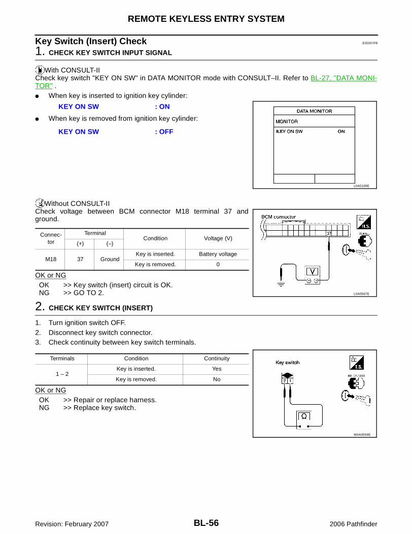
BL-56
REMOTE KEYLESS ENTRY SYSTEM
Revision: February 2007 2006 Pathfinder
Key Switch (Insert) Check EIS007P8
1. CHECK KEY SWITCH INPUT SIGNAL
With CONSULT-IICheck key switch "KEY ON SW" in DATA MONITOR mode with CONSULT–II. Refer to BL-27, "DATA MONI-TOR" .� When key is inserted to ignition key cylinder:
� When key is removed from ignition key cylinder:
Without CONSULT-IICheck voltage between BCM connector M18 terminal 37 andground.
OK or NGOK >> Key switch (insert) circuit is OK.NG >> GO TO 2.
2. CHECK KEY SWITCH (INSERT)
1. Turn ignition switch OFF.2. Disconnect key switch connector.3. Check continuity between key switch terminals.
OK or NGOK >> Repair or replace harness.NG >> Replace key switch.
KEY ON SW : ON
KEY ON SW : OFF
LIIA0169E
Connec-tor
TerminalCondition Voltage (V)
(+) (–)
M18 37 GroundKey is inserted. Battery voltage
Key is removed. 0
LIIA0567E
Terminals Condition Continuity
1 – 2Key is inserted. Yes
Key is removed. No
WIIA0559E

REMOTE KEYLESS ENTRY SYSTEM
BL-57
C
D
E
F
G
H
J
K
L
M
A
B
BL
Revision: February 2007 2006 Pathfinder
Door Switch Check EIS007P9
1. CHECK DOOR SWITCHES INPUT SIGNAL
With CONSULT-IICheck door switches ("DOOR SW-DR", "DOOR SW-AS", "DOOR SW-RL", "DOOR SW-RR", "BACK DOORSW") in DATA MONITOR mode with CONSULT–II. Refer to BL-27, "DATA MONITOR" .� When doors are open:
� When doors are closed:
Without CONSULT-IICheck voltage between BCM connector M18 or M19 terminals 12, 13, 43, 47, 48 and ground.
OK or NGOK >> Door switch circuit is OK.NG >> GO TO 2.
DOOR SW-DR : ON
DOOR SW-AS : ON
DOOR SW-RL : ON
DOOR SW-RR : ON
BACK DOOR SW : ON
DOOR SW-DR : OFF
DOOR SW-AS : OFF
DOOR SW-RL : OFF
DOOR SW-RR : OFF
BACK DOOR SW : OFF
LIIA0665E
Connec-tor
ItemTerminals
ConditionVoltage (V)(Approx.)(+) (–)
M19
Back door switch
43
GroundOpen
↓Closed
0↓
Battery voltage
Front door switch LH
47
Rear door switch LH
48
M18
Front door switch RH
12
Rear door switch RH
13
LIIA1041E

BL-58
REMOTE KEYLESS ENTRY SYSTEM
Revision: February 2007 2006 Pathfinder
2. CHECK DOOR SWITCH CIRCUIT
1. Turn ignition switch OFF.2. Disconnect door switch and BCM.3. Check continuity between door switch connector B8 (Front LH), B108 (Front RH), B18 (Rear LH), B116
(Rear RH) terminal 2 or D502 (Back) terminal 3 and BCM connector M18, M19 terminals 12, 13, 43, 47and 48.
4. Check continuity between door switch connector B8 (Front LH),B108 (Front RH), B18 (Rear LH), B116 (Rear RH) terminal 2 orD502 (Back) terminal 3 and ground.
OK or NGOK >> GO TO 3.NG >> Repair or replace harness.
3. CHECK DOOR SWITCHES
FRONT AND REAR DOORSCheck continuity between front or rear door switch terminal 2 andexposed metal of switch while pressing and releasing switch.
BACK DOORCheck continuity between back door switch terminals 3 and 1 whilepressing and releasing switch.
OK or NGOK >> Check switch case ground condition (front and rear
door) or ground circuit (back door).NG >> Replace door switch.
2 - 47 : Continuity should exist.
2 - 12 : Continuity should exist.
2 - 48 : Continuity should exist.
2 - 13 : Continuity should exist.
3 - 43 : Continuity should exist.
2 - Ground : Continuity should not exist.
3 - Ground : Continuity should not exist.
WIIA0690E
When front or rear door switch is released
: Continuity should exist.
When front or rear door switch is pushed
: Continuity should not exist.
WIIA0644E
When back door switch is released
: Continuity should exist.
When back door switch is pushed
: Continuity should not exist.
WIIA0645E
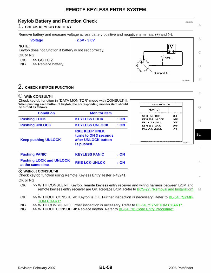
REMOTE KEYLESS ENTRY SYSTEM
BL-59
C
D
E
F
G
H
J
K
L
M
A
B
BL
Revision: February 2007 2006 Pathfinder
Keyfob Battery and Function Check EIS007PA
1. CHECK KEYFOB BATTERY
Remove battery and measure voltage across battery positive and negative terminals, (+) and (−).
NOTE:Keyfob does not function if battery is not set correctly.OK or NGOK >> GO TO 2.NG >> Replace battery.
2. CHECK KEYFOB FUNCTION
With CONSULT-IICheck keyfob function in “DATA MONITOR” mode with CONSULT-II.When pushing each button of keyfob, the corresponding monitor item shouldbe turned as follows.
Without CONSULT-IICheck keyfob function using Remote Keyless Entry Tester J-43241.OK or NGOK >> WITH CONSULT-II: Keyfob, remote keyless entry receiver and wiring harness between BCM and
remote keyless entry receiver are OK. Replace BCM. Refer to BCS-27, "Removal and Installation".
OK >> WITHOUT CONSULT-II: Keyfob is OK. Further inspection is necessary. Refer to BL-54, "SYMP-TOM CHART" .
NG >> WITH CONSULT-II: Further inspection is necessary. Refer to BL-54, "SYMPTOM CHART" .NG >> WITHOUT CONSULT-II: Replace keyfob. Refer to BL-64, "ID Code Entry Procedure" .
Voltage : 2.5V - 3.0V
SEL237W
Condition Monitor item
Pushing LOCK KEYLESS LOCK : ON
Pushing UNLOCK KEYLESS UNLOCK : ON
Keep pushing UNLOCK
RKE KEEP UNLK turns to ON 3 seconds after UNLOCK button is pushed.
Pushing PANIC KEYLESS PANIC : ON
Pushing LOCK and UNLOCK at the same time
RKE LCK-UNLCK : ON
LIIA1052E

BL-60
REMOTE KEYLESS ENTRY SYSTEM
Revision: February 2007 2006 Pathfinder
Remote Keyless Entry Receiver System Check EIS007PB
1. REMOTE KEYLESS ENTRY RECEIVER SIGNAL
Check signal voltage waveform between BCM connector M18 termi-nal 20 and ground using an oscilloscope.
OK or NGOK >> Remote keyless entry receiver signal power supply, ground and signal circuits are OK. Replace
BCM. Refer to BCS-27, "Removal and Installation" .NG >> GO TO 2.
2. REMOTE KEYLESS ENTRY RECEIVER POWER SUPPLY INSPECTION
Check signal voltage waveform between BCM connector M18 termi-nal 19 and ground using an oscilloscope.
OK or NGOK >> GO TO 3.NG >> Replace BCM. Refer to BCS-27, "Removal and Installa-
tion" .
3. REMOTE KEYLESS ENTRY RECEIVER GROUND CIRCUIT INSPECTION (BCM)
Check continuity between BCM connector M18 terminal 18 andground.
OK or NGOK >> GO TO 4.NG >> Replace BCM. Refer to BCS-27, "Removal and Installa-
tion" .
Condition:
Keyfob buttons released : Refer to BL-49, "Termi-nals and Reference Value for BCM" .
Keyfob buttons pressed : Refer to BL-49, "Termi-nals and Reference Value for BCM" . LIIA1275E
19 - Ground : Refer to BL-49, "Termi-nals and Reference Value for BCM" .
WIIA0433E
18 - Ground : Continuity should exist
WIIA0434E
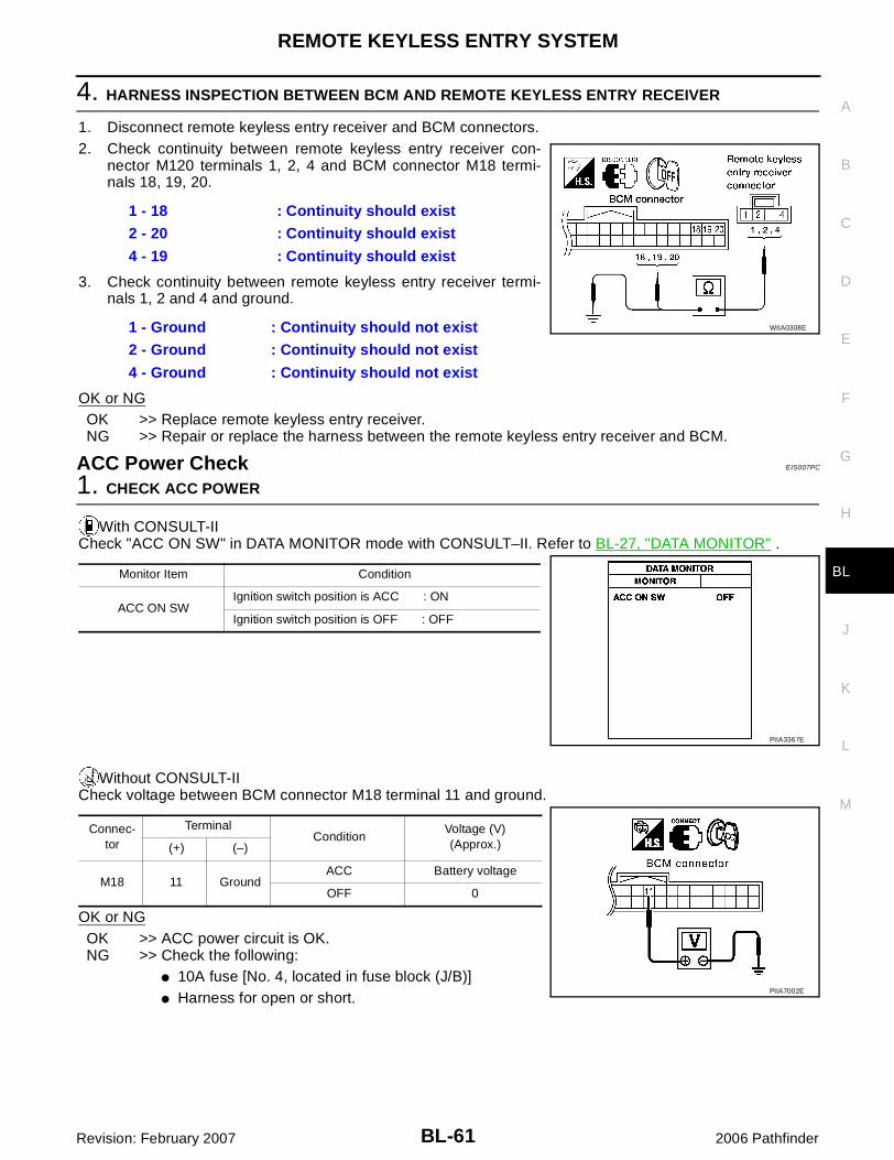
REMOTE KEYLESS ENTRY SYSTEM
BL-61
C
D
E
F
G
H
J
K
L
M
A
B
BL
Revision: February 2007 2006 Pathfinder
4. HARNESS INSPECTION BETWEEN BCM AND REMOTE KEYLESS ENTRY RECEIVER
1. Disconnect remote keyless entry receiver and BCM connectors.2. Check continuity between remote keyless entry receiver con-
nector M120 terminals 1, 2, 4 and BCM connector M18 termi-nals 18, 19, 20.
3. Check continuity between remote keyless entry receiver termi-nals 1, 2 and 4 and ground.
OK or NGOK >> Replace remote keyless entry receiver.NG >> Repair or replace the harness between the remote keyless entry receiver and BCM.
ACC Power Check EIS007PC
1. CHECK ACC POWER
With CONSULT-IICheck "ACC ON SW" in DATA MONITOR mode with CONSULT–II. Refer to BL-27, "DATA MONITOR" .
Without CONSULT-IICheck voltage between BCM connector M18 terminal 11 and ground.
OK or NGOK >> ACC power circuit is OK.NG >> Check the following:
� 10A fuse [No. 4, located in fuse block (J/B)]� Harness for open or short.
1 - 18 : Continuity should exist
2 - 20 : Continuity should exist
4 - 19 : Continuity should exist
1 - Ground : Continuity should not exist
2 - Ground : Continuity should not exist
4 - Ground : Continuity should not exist
WIIA0308E
Monitor Item Condition
ACC ON SWIgnition switch position is ACC : ON
Ignition switch position is OFF : OFF
PIIA3367E
Connec-tor
TerminalCondition
Voltage (V) (Approx.)(+) (–)
M18 11 GroundACC Battery voltage
OFF 0
PIIA7002E

BL-62
REMOTE KEYLESS ENTRY SYSTEM
Revision: February 2007 2006 Pathfinder
IPDM E/R Operation Check EIS007PD
1. CHECK IPDM E/R INPUT VOLTAGE
Check voltage between IPDM E/R connector E122 terminal 45 and ground.
OK or NGOK >> Replace IPDM E/R. Refer to PG-34, "Removal and
Installation of IPDM E/R" .NG >> GO TO 2.
2. CHECK IPDM E/R INPUT VOLTAGE CIRCUIT
1. Turn ignition switch OFF.2. Disconnect IPDM E/R and horn relay.3. Check continuity between IPDM E/R connector E122 terminal 45 and horn relay connector H-1 terminal 1.
4. Check continuity between IPDM E/R connector E122 terminal 45 and ground.
OK or NGOK >> Further inspection is necessary. Refer to BL-54, "SYMP-
TOM CHART" .NG >> Repair or replace harness.
Check Hazard Function EIS007PE
1. CHECK HAZARD WARNING LAMP
Does hazard indicator flash with hazard switch?Yes or No
Yes >> Hazard warning lamp circuit is OK.No >> Check hazard indicator. Refer toLT-64, "TURN SIGNAL AND HAZARD WARNING LAMPS" .
Check Horn Function EIS007PF
First, perform the "SELF-DIAG RESULTS" in "BCM" with CONSULT-II, then perform the trouble diagnosis ofmalfunction system indicated in "SELF-DIAG RESULTS" of "BCM".
1. CHECK HORN FUNCTION
Does horn sound with horn switch?Yes or No
Yes >> Horn circuit is OK.No >> Check horn circuit. Refer to WW-48, "HORN" .
Check Headlamp Function EIS007PG
First, perform the "SELF-DIAG RESULTS" in "BCM" with CONSULT-II, then perform the trouble diagnosis ofmalfunction system indicated in "SELF-DIAG RESULTS" of "BCM".
ConnectorTerminal Voltage (V)
(Approx.)(+) (–)
E122 45 Ground Battery voltage
LIIA1053E
45 - 1 : Continuity should exist.
45 - Ground : Continuity should not exist.
WIIA0679E
REMOTE KEYLESS ENTRY SYSTEM
BL-63
C
D
E
F
G
H
J
K
L
M
A
B
BL
Revision: February 2007 2006 Pathfinder
1. CHECK HEADLAMP OPERATION
Does headlamp come on when turning lighting switch ON?Yes or NoYes >> Headlamp operation circuit is OK.No >> Check headlamp circuit. Refer to LT-5, "HEADLAMP (FOR USA)" .
Check Room Lamp Illumination Function EIS007PH
1. CHECK ROOM LAMP ILLUMINATION FUNCTION
When room lamp switch is in DOOR position, open the front door LH or RH.
OK or NGOK >> System is OK.NG >> Check room lamp illumination circuit. Refer to LT-115, "INTERIOR ROOM LAMP" .
Room lamp and ignition keyhole illumination should illuminate.
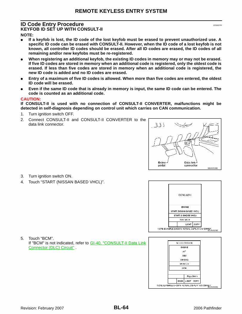
BL-64
REMOTE KEYLESS ENTRY SYSTEM
Revision: February 2007 2006 Pathfinder
ID Code Entry Procedure EIS007PI
KEYFOB ID SET UP WITH CONSULT-IINOTE:� If a keyfob is lost, the ID code of the lost keyfob must be erased to prevent unauthorized use. A
specific ID code can be erased with CONSULT-II. However, when the ID code of a lost keyfob is notknown, all controller ID codes should be erased. After all ID codes are erased, the ID codes of allremaining and/or new keyfobs must be re-registered.
� When registering an additional keyfob, the existing ID codes in memory may or may not be erased.If five ID codes are stored in memory when an additional code is registered, only the oldest code iserased. If less than five codes are stored in memory when an additional code is registered, thenew ID code is added and no ID codes are erased.
� Entry of a maximum of five ID codes is allowed. When more than five codes are entered, the oldestID code will be erased.
� Even if the same ID code that is already in memory is input, the same ID code can be entered. Thecode is counted as an additional code.
CAUTION:If CONSULT-II is used with no connection of CONSULT-II CONVERTER, malfunctions might bedetected in self-diagnosis depending on control unit which carries on CAN communication.1. Turn ignition switch OFF.2. Connect CONSULT-II and CONSULT-II CONVERTER to the
data link connector.
3. Turn ignition switch ON.4. Touch “START (NISSAN BASED VHCL)”.
5. Touch “BCM”.If "BCM" is not indicated, refer to GI-40, "CONSULT-II Data LinkConnector (DLC) Circuit" .
BBIA0538E
BCIA0029E
BCIA0030E

REMOTE KEYLESS ENTRY SYSTEM
BL-65
C
D
E
F
G
H
J
K
L
M
A
B
BL
Revision: February 2007 2006 Pathfinder
6. Touch “MULTI REMOTE ENT”.
7. Touch “WORK SUPPORT”.
8. The items are shown on the figure can be set up.� “REMO CONT ID REGIST”
Use this mode to register a keyfob ID code.NOTE:Register the ID code when keyfob or BCM is replaced, orwhen additional keyfob is required.
� “REMO CONT ID ERASUR”Use this mode to erase a keyfob ID code.
� “REMO CONT ID CONFIR”Use this mode to confirm if a keyfob ID code is registered ornot.
LIIA0194E
BCIA0031E
LIIA1147E

BL-66
REMOTE KEYLESS ENTRY SYSTEM
Revision: February 2007 2006 Pathfinder
KEYFOB ID SET UP WITHOUT CONSULT-II
LIIA1670E
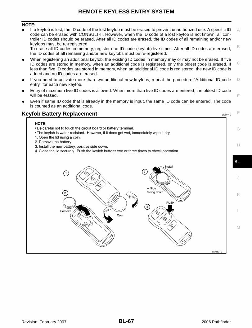
REMOTE KEYLESS ENTRY SYSTEM
BL-67
C
D
E
F
G
H
J
K
L
M
A
B
BL
Revision: February 2007 2006 Pathfinder
NOTE:� If a keyfob is lost, the ID code of the lost keyfob must be erased to prevent unauthorized use. A specific ID
code can be erased with CONSULT-II. However, when the ID code of a lost keyfob is not known, all con-troller ID codes should be erased. After all ID codes are erased, the ID codes of all remaining and/or newkeyfobs must be re-registered.To erase all ID codes in memory, register one ID code (keyfob) five times. After all ID codes are erased,the ID codes of all remaining and/or new keyfobs must be re-registered.
� When registering an additional keyfob, the existing ID codes in memory may or may not be erased. If fiveID codes are stored in memory, when an additional code is registered, only the oldest code is erased. Ifless than five ID codes are stored in memory, when an additional ID code is registered, the new ID code isadded and no ID codes are erased.
� If you need to activate more than two additional new keyfobs, repeat the procedure “Additional ID codeentry” for each new keyfob.
� Entry of maximum five ID codes is allowed. When more than five ID codes are entered, the oldest ID codewill be erased.
� Even if same ID code that is already in the memory is input, the same ID code can be entered. The codeis counted as an additional code.
Keyfob Battery Replacement EIS007PJ
LIIA1514E

BL-68
VEHICLE SECURITY (THEFT WARNING) SYSTEM
Revision: February 2007 2006 Pathfinder
VEHICLE SECURITY (THEFT WARNING) SYSTEM PFP:28491
Component Parts and Harness Connector Location EIS007PK
LIIA2413E
1. IPDM E/R E118, E119, E120, E121, E122, E123, E124
2. BCM M18, M19, M20(view with instrument lower panel LH removed)
3. Key switch M27
4. Horns E3, E162(Behind front combination lamp LH)
5. Front door lock assembly LH (key cylin-der switch) D14
6. Main power window and door lock/unlock switch D7 and D8Power window and door lock/unlock switch RH D105
7. Front door switchLH B8RH B108
8. Rear door switchLH B18RH B116
9. Back door switch D502Back door lock actuator D508
10. Combination meter M24 11. Glass hatch ajar switch D503
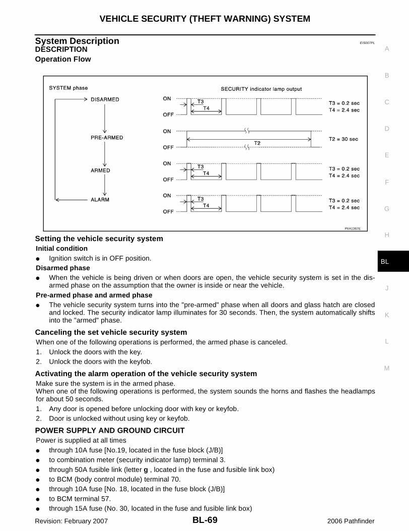
VEHICLE SECURITY (THEFT WARNING) SYSTEM
BL-69
C
D
E
F
G
H
J
K
L
M
A
B
BL
Revision: February 2007 2006 Pathfinder
System Description EIS007PL
DESCRIPTIONOperation Flow
Setting the vehicle security systemInitial condition� Ignition switch is in OFF position.Disarmed phase� When the vehicle is being driven or when doors are open, the vehicle security system is set in the dis-
armed phase on the assumption that the owner is inside or near the vehicle.Pre-armed phase and armed phase� The vehicle security system turns into the "pre-armed" phase when all doors and glass hatch are closed
and locked. The security indicator lamp illuminates for 30 seconds. Then, the system automatically shiftsinto the "armed" phase.
Canceling the set vehicle security systemWhen one of the following operations is performed, the armed phase is canceled.1. Unlock the doors with the key.2. Unlock the doors with the keyfob.
Activating the alarm operation of the vehicle security systemMake sure the system is in the armed phase.When one of the following operations is performed, the system sounds the horns and flashes the headlampsfor about 50 seconds.1. Any door is opened before unlocking door with key or keyfob.2. Door is unlocked without using key or keyfob.
POWER SUPPLY AND GROUND CIRCUITPower is supplied at all times� through 10A fuse [No.19, located in the fuse block (J/B)]� to combination meter (security indicator lamp) terminal 3.� through 50A fusible link (letter g , located in the fuse and fusible link box)� to BCM (body control module) terminal 70.� through 10A fuse [No. 18, located in the fuse block (J/B)]� to BCM terminal 57.� through 15A fuse (No. 30, located in the fuse and fusible link box)
PIIA1367E
BL-70
VEHICLE SECURITY (THEFT WARNING) SYSTEM
Revision: February 2007 2006 Pathfinder
� to horn relay terminal 2.� through 20A fuse (No. 52, located in the IPDM E/R) and� through 20A fuse (No. 53, located in the IPDM E/R),� to IPDM E/R internal CPU.With the ignition switch in the ACC or ON position, power is supplied� through 10A fuse [No. 4, located in the fuse block (J/B)]� to BCM terminal 11.Ground is supplied� to BCM terminal 67� through body grounds M57, M61 and M79 and� to IPDM E/R terminals 38 and 59� through body ground E9, E15 and E24.
INITIAL CONDITION TO ACTIVATE THE SYSTEMThe operation of the vehicle security system is controlled by the doors and glass hatch.To activate the vehicle security system, BCM must receive signals indicating the doors are closed and locked.When a door is open, BCM terminal 12, 13, 47 or 48 receives a ground signal from each door switch.When the glass hatch is open, BCM terminal 42 receives a ground signal from glass hatch ajar switch.When front door LH or RH is unlocked, BCM terminal 46 receives a signal from terminal 11 of main power win-dow and door lock/unlock switch or terminal 2 of power window and door lock/unlock switch RH.When the back door is open, BCM terminal 43 receives a ground signal� from terminal 3 of the back door switch� through terminal 1 of the back door switch� through body grounds D406 and D504.
VEHICLE SECURITY SYSTEM ALARM OPERATIONThe vehicle security system is triggered by� opening a door� unlocking door without using the key or keyfob.The vehicle security system will be triggered once the system is in armed phase,� when BCM receives a ground signal at terminals 12, 13, 47, 48 (door switch), terminal 43 (back door
switch), or terminal 42 (glass hatch ajar switch).When the vehicle security system is triggered, ground is supplied intermittently� from IPDM E/R CPU� to headlamp high relay and� from IPDM E/R terminal 45 � to horn relay terminal 1.The headlamps flash and the horn sounds intermittently.The alarm automatically turns off after 50 seconds, but will reactivate if the vehicle is tampered with again.
VEHICLE SECURITY SYSTEM DEACTIVATIONTo deactivate the vehicle security system, a door must be unlocked with the key or keyfob.When the key is used to unlock a door, BCM terminal 7 receives signal� from terminal 3 of front door lock assembly LH (key cylinder switch).When the BCM receives either one of these signals or unlock signal from keyfob or key cylinder switch, thevehicle security system is deactivated. (Disarmed phase)
PANIC ALARM OPERATIONRemote keyless entry system can operate vehicle security system (horn and headlamps) as required.When the remote keyless entry system is triggered, ground is supplied intermittently� from IPDM E/R CPU� to headlamp high relay and� from IPDM E/R terminal 45 � to horn relay terminal 1.

VEHICLE SECURITY (THEFT WARNING) SYSTEM
BL-71
C
D
E
F
G
H
J
K
L
M
A
B
BL
Revision: February 2007 2006 Pathfinder
The headlamp flashes and the horn sounds intermittently.The alarm automatically turns off after 25 seconds or when BCM receives any signal from keyfob.
CAN Communication System Description EIS007PM
Refer to LAN-25, "CAN COMMUNICATION" .

BL-72
VEHICLE SECURITY (THEFT WARNING) SYSTEM
Revision: February 2007 2006 Pathfinder
Schematic EIS007PN
WIWA1765E
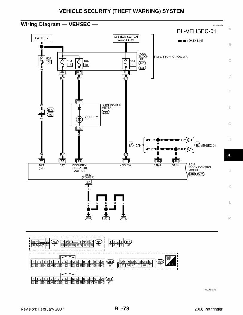
VEHICLE SECURITY (THEFT WARNING) SYSTEM
BL-73
C
D
E
F
G
H
J
K
L
M
A
B
BL
Revision: February 2007 2006 Pathfinder
Wiring Diagram — VEHSEC — EIS007PO
WIWA1616E

BL-74
VEHICLE SECURITY (THEFT WARNING) SYSTEM
Revision: February 2007 2006 Pathfinder
WIWA1764E

VEHICLE SECURITY (THEFT WARNING) SYSTEM
BL-75
C
D
E
F
G
H
J
K
L
M
A
B
BL
Revision: February 2007 2006 Pathfinder
WIWA1766E

BL-76
VEHICLE SECURITY (THEFT WARNING) SYSTEM
Revision: February 2007 2006 Pathfinder
WIWA1767E

VEHICLE SECURITY (THEFT WARNING) SYSTEM
BL-77
C
D
E
F
G
H
J
K
L
M
A
B
BL
Revision: February 2007 2006 Pathfinder
Terminals and Reference Value for BCM EIS007PP
Refer to BCS-12, "Terminals and Reference Values for BCM" .
WIWA1619E
BL-78
VEHICLE SECURITY (THEFT WARNING) SYSTEM
Revision: February 2007 2006 Pathfinder
Terminals and Reference Value for IPDM E/R EIS007PQ
Refer to PG-29, "Terminals and Reference Values for IPDM E/R" .
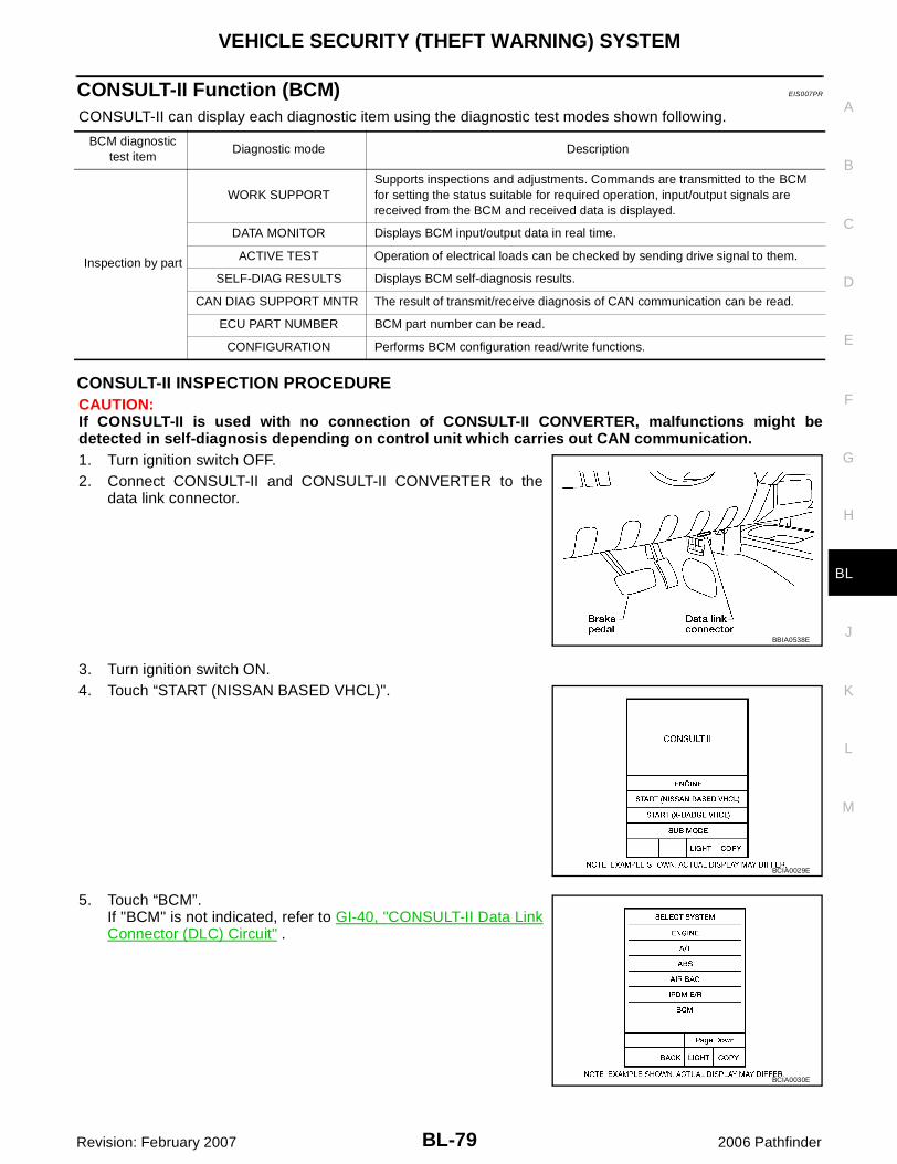
VEHICLE SECURITY (THEFT WARNING) SYSTEM
BL-79
C
D
E
F
G
H
J
K
L
M
A
B
BL
Revision: February 2007 2006 Pathfinder
CONSULT-II Function (BCM) EIS007PR
CONSULT-II can display each diagnostic item using the diagnostic test modes shown following.
CONSULT-II INSPECTION PROCEDURECAUTION:If CONSULT-II is used with no connection of CONSULT-II CONVERTER, malfunctions might bedetected in self-diagnosis depending on control unit which carries out CAN communication.1. Turn ignition switch OFF.2. Connect CONSULT-II and CONSULT-II CONVERTER to the
data link connector.
3. Turn ignition switch ON.4. Touch “START (NISSAN BASED VHCL)".
5. Touch “BCM”.If "BCM" is not indicated, refer to GI-40, "CONSULT-II Data LinkConnector (DLC) Circuit" .
BCM diagnostic test item
Diagnostic mode Description
Inspection by part
WORK SUPPORTSupports inspections and adjustments. Commands are transmitted to the BCM for setting the status suitable for required operation, input/output signals are received from the BCM and received data is displayed.
DATA MONITOR Displays BCM input/output data in real time.
ACTIVE TEST Operation of electrical loads can be checked by sending drive signal to them.
SELF-DIAG RESULTS Displays BCM self-diagnosis results.
CAN DIAG SUPPORT MNTR The result of transmit/receive diagnosis of CAN communication can be read.
ECU PART NUMBER BCM part number can be read.
CONFIGURATION Performs BCM configuration read/write functions.
BBIA0538E
BCIA0029E
BCIA0030E
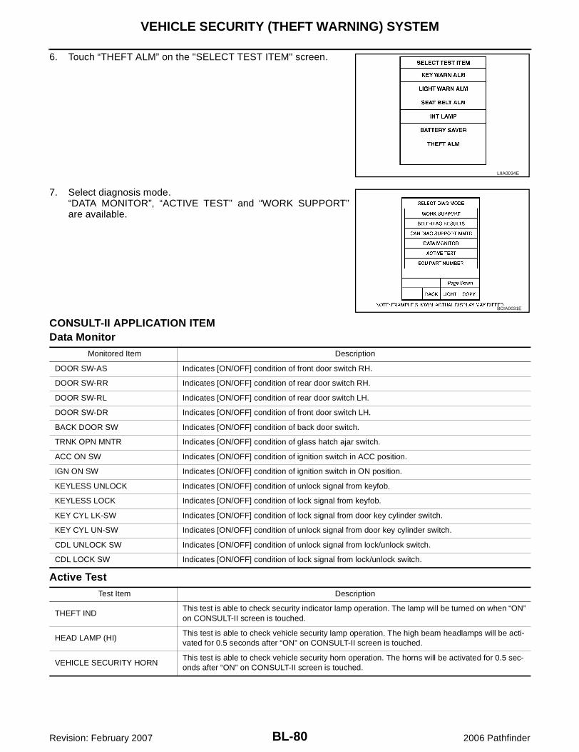
BL-80
VEHICLE SECURITY (THEFT WARNING) SYSTEM
Revision: February 2007 2006 Pathfinder
6. Touch “THEFT ALM” on the "SELECT TEST ITEM" screen.
7. Select diagnosis mode.“DATA MONITOR”, “ACTIVE TEST” and “WORK SUPPORT”are available.
CONSULT-II APPLICATION ITEMData Monitor
Active Test
LIIA0034E
BCIA0031E
Monitored Item Description
DOOR SW-AS Indicates [ON/OFF] condition of front door switch RH.
DOOR SW-RR Indicates [ON/OFF] condition of rear door switch RH.
DOOR SW-RL Indicates [ON/OFF] condition of rear door switch LH.
DOOR SW-DR Indicates [ON/OFF] condition of front door switch LH.
BACK DOOR SW Indicates [ON/OFF] condition of back door switch.
TRNK OPN MNTR Indicates [ON/OFF] condition of glass hatch ajar switch.
ACC ON SW Indicates [ON/OFF] condition of ignition switch in ACC position.
IGN ON SW Indicates [ON/OFF] condition of ignition switch in ON position.
KEYLESS UNLOCK Indicates [ON/OFF] condition of unlock signal from keyfob.
KEYLESS LOCK Indicates [ON/OFF] condition of lock signal from keyfob.
KEY CYL LK-SW Indicates [ON/OFF] condition of lock signal from door key cylinder switch.
KEY CYL UN-SW Indicates [ON/OFF] condition of unlock signal from door key cylinder switch.
CDL UNLOCK SW Indicates [ON/OFF] condition of unlock signal from lock/unlock switch.
CDL LOCK SW Indicates [ON/OFF] condition of lock signal from lock/unlock switch.
Test Item Description
THEFT INDThis test is able to check security indicator lamp operation. The lamp will be turned on when “ON” on CONSULT-II screen is touched.
HEAD LAMP (HI)This test is able to check vehicle security lamp operation. The high beam headlamps will be acti-vated for 0.5 seconds after “ON” on CONSULT-II screen is touched.
VEHICLE SECURITY HORNThis test is able to check vehicle security horn operation. The horns will be activated for 0.5 sec-onds after “ON” on CONSULT-II screen is touched.

VEHICLE SECURITY (THEFT WARNING) SYSTEM
BL-81
C
D
E
F
G
H
J
K
L
M
A
B
BL
Revision: February 2007 2006 Pathfinder
Work Support
Trouble Diagnosis EIS007PS
WORK FLOW
� “POWER DOOR LOCK SYSTEM” diagnosis refer to BL-16, "POWER DOOR LOCK SYSTEM" .� “REMOTE KEYLESS ENTRY SYSTEM” diagnosis refer to BL-41, "REMOTE KEYLESS ENTRY SYS-
TEM" .
Test Item Description
SECURITY ALARM SET This mode can confirm and change vehicle security alarm ON-OFF setting.
THEFT ALM TRGThe switch which triggered vehicle security alarm is recorded. This mode is able to confirm and erase the record of vehicle security alarm. The trigger data can be erased by touching “CLEAR” on CONSULT-II screen.
WIIA0599E

BL-82
VEHICLE SECURITY (THEFT WARNING) SYSTEM
Revision: February 2007 2006 Pathfinder
Preliminary Check EIS007PT
The system operation is canceled by turning ignition switch to ACC at any step between START and ARMEDin the following flow chart:
After performing preliminary check, go to symptom chart.WIIA0627E
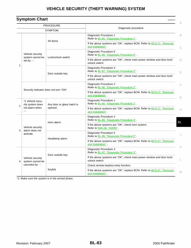
VEHICLE SECURITY (THEFT WARNING) SYSTEM
BL-83
C
D
E
F
G
H
J
K
L
M
A
B
BL
Revision: February 2007 2006 Pathfinder
Symptom Chart EIS007PU
*1: Make sure the system is in the armed phase.
PROCEDUREDiagnostic procedure
SYMPTOM
1
Vehicle security system cannot be set by ····
AII items
Diagnostic Procedure 1Refer to BL-84, "Diagnostic Procedure 1" .
If the above systems are “OK”, replace BCM. Refer to BCS-27, "Removal and Installation" .
Lock/unlock switch
Diagnostic Procedure 6Refer to BL-89, "Diagnostic Procedure 6" .
If the above systems are “OK”, check main power window and door lock/unlock switch.
Door outside key
Diagnostic Procedure 3Refer to BL-87, "Diagnostic Procedure 3" .
If the above systems are “OK”, check main power window and door lock/unlock switch.
Security indicator does not turn “ON”.
Diagnostic Procedure 2Refer to BL-86, "Diagnostic Procedure 2" .
If the above systems are “OK”, replace BCM. Refer to BCS-27, "Removal and Installation" .
2
*1 Vehicle secu-rity system does not alarm when ····
Any door or glass hatch is opened.
Diagnostic Procedure 1Refer to BL-84, "Diagnostic Procedure 1" .
If the above systems are “OK”, replace BCM. Refer to BCS-27, "Removal and Installation" .
3Vehicle security alarm does not activate.
Horn alarm
Diagnostic Procedure 4Refer to BL-89, "Diagnostic Procedure 4" .
If the above systems are “OK”, check horn system. Refer to WW-48, "HORN" .
Headlamp alarm
Diagnostic Procedure 5Refer to BL-89, "Diagnostic Procedure 5" .
If the above systems are “OK”, replace BCM. Refer to BCS-27, "Removal and Installation" .
4Vehicle security system cannot be canceled by ····
Door outside key
Diagnostic Procedure 3Refer to BL-87, "Diagnostic Procedure 3" .
If the above systems are “OK”, check main power window and door lock/unlock switch.
Keyfob
Check remote keyless entry function.
If the above systems are “OK”, replace BCM. Refer to BCS-27, "Removal and Installation" .

BL-84
VEHICLE SECURITY (THEFT WARNING) SYSTEM
Revision: February 2007 2006 Pathfinder
Diagnostic Procedure 1 EIS007PV
DOOR SWITCH AND GLASS HATCH AJAR SWITCH CHECK
1. CHECK DOOR SWITCHES INPUT SIGNAL
With CONSULT-IICheck door switches ("DOOR SW-DR", "DOOR SW-AS", "DOOR SW-RL", "DOOR SW-RR", "BACK DOORSW", "TRNK OPN MNTR") in DATA MONITOR mode with CONSULT–II. Refer to BL-27, "DATA MONITOR" .� When glass hatch or doors are open:
� When glass hatch or doors are closed:
Without CONSULT-IICheck voltage between BCM connector M18 or M19 terminals 12, 13, 42, 43, 47, 48 and ground.
OK or NGOK >> Door switch circuit is OK.NG >> GO TO 2.
DOOR SW-DR : ON
DOOR SW-AS : ON
DOOR SW-RL : ON
DOOR SW-RR : ON
BACK DOOR SW : ON
TRNK OPN MNTR : ON
DOOR SW-DR : OFF
DOOR SW-AS : OFF
DOOR SW-RL : OFF
DOOR SW-RR : OFF
BACK DOOR SW : OFF
TRNK OPN MNTR : OFF
WIIA0466E
Connec-tor
ItemTerminals
ConditionVoltage (V)(Approx.)(+) (–)
M19
Glass hatch ajar switch
42
GroundOpen
↓Closed
0 → 5
Back door switch
43
0↓
Battery voltage
Front door switch LH
47
Rear door switch LH
48
M18
Front door switch RH
12
Rear door switch RH
13
WIIA0444E
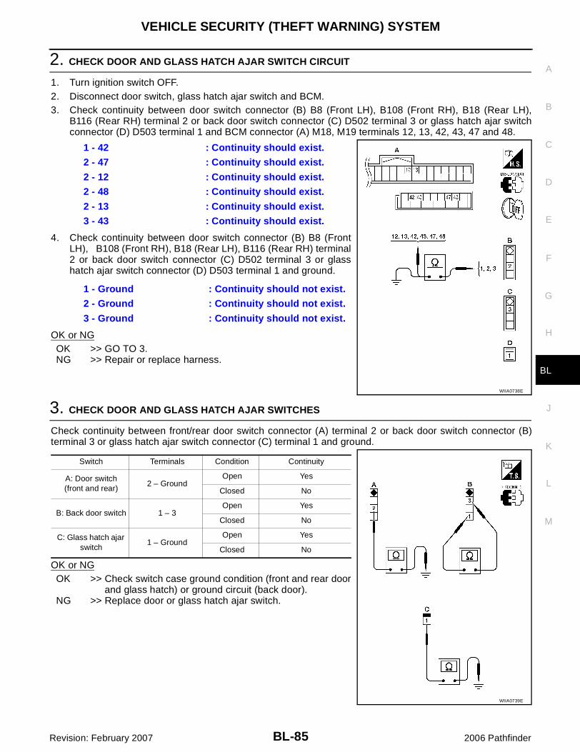
VEHICLE SECURITY (THEFT WARNING) SYSTEM
BL-85
C
D
E
F
G
H
J
K
L
M
A
B
BL
Revision: February 2007 2006 Pathfinder
2. CHECK DOOR AND GLASS HATCH AJAR SWITCH CIRCUIT
1. Turn ignition switch OFF.2. Disconnect door switch, glass hatch ajar switch and BCM.3. Check continuity between door switch connector (B) B8 (Front LH), B108 (Front RH), B18 (Rear LH),
B116 (Rear RH) terminal 2 or back door switch connector (C) D502 terminal 3 or glass hatch ajar switchconnector (D) D503 terminal 1 and BCM connector (A) M18, M19 terminals 12, 13, 42, 43, 47 and 48.
4. Check continuity between door switch connector (B) B8 (FrontLH), B108 (Front RH), B18 (Rear LH), B116 (Rear RH) terminal2 or back door switch connector (C) D502 terminal 3 or glasshatch ajar switch connector (D) D503 terminal 1 and ground.
OK or NGOK >> GO TO 3.NG >> Repair or replace harness.
3. CHECK DOOR AND GLASS HATCH AJAR SWITCHES
Check continuity between front/rear door switch connector (A) terminal 2 or back door switch connector (B)terminal 3 or glass hatch ajar switch connector (C) terminal 1 and ground.
OK or NGOK >> Check switch case ground condition (front and rear door
and glass hatch) or ground circuit (back door).NG >> Replace door or glass hatch ajar switch.
1 - 42 : Continuity should exist.
2 - 47 : Continuity should exist.
2 - 12 : Continuity should exist.
2 - 48 : Continuity should exist.
2 - 13 : Continuity should exist.
3 - 43 : Continuity should exist.
1 - Ground : Continuity should not exist.
2 - Ground : Continuity should not exist.
3 - Ground : Continuity should not exist.
WIIA0738E
Switch Terminals Condition Continuity
A: Door switch (front and rear)
2 – GroundOpen Yes
Closed No
B: Back door switch 1 – 3Open Yes
Closed No
C: Glass hatch ajar switch
1 – GroundOpen Yes
Closed No
WIIA0739E

BL-86
VEHICLE SECURITY (THEFT WARNING) SYSTEM
Revision: February 2007 2006 Pathfinder
Diagnostic Procedure 2 EIS007PW
SECURITY INDICATOR LAMP CHECK
1. SECURITY INDICATOR LAMP ACTIVE TEST
With CONSULT-IICheck "THEFT IND” in "ACTIVE TEST" mode with CONSULT-II.
Without CONSULT-II1. Turn ignition switch OFF.2. Check voltage between BCM harness connector M18 terminal
23 and ground.
OK or NGOK >> Security indicator lamp is OK.NG >> GO TO 2.
2. SECURITY INDICATOR LAMP CHECK
Check security indicator lamp condition. Refer to DI-11, "SELF-DIAGNOSIS FUNCTION" .OK or NG
OK >> GO TO 3.NG >> Replace combination meter. Refer to IP-14, "COMBINATION METER" .
LIIA0044E
ConnectorTerminal Security indi-
cator lamp condition
Voltage (V)(Approx.)(+) (-)
M18 23 Ground
Illuminated 0
Not illumi-nated
Battery volt-age
PIIA6230E
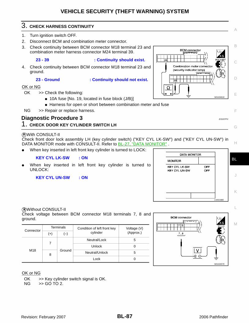
VEHICLE SECURITY (THEFT WARNING) SYSTEM
BL-87
C
D
E
F
G
H
J
K
L
M
A
B
BL
Revision: February 2007 2006 Pathfinder
3. CHECK HARNESS CONTINUITY
1. Turn ignition switch OFF.2. Disconnect BCM and combination meter connector.3. Check continuity between BCM connector M18 terminal 23 and
combination meter harness connector M24 terminal 39.
4. Check continuity between BCM connector M18 terminal 23 andground.
OK or NGOK >> Check the following:
� 10A fuse [No. 19, located in fuse block (J/B)]� Harness for open or short between combination meter and fuse
NG >> Repair or replace harness.
Diagnostic Procedure 3 EIS007PX
1. CHECK DOOR KEY CYLINDER SWITCH LH
With CONSULT-IICheck front door lock assembly LH (key cylinder switch) ("KEY CYL LK-SW") and ("KEY CYL UN-SW") inDATA MONITOR mode with CONSULT-II. Refer to BL-27, "DATA MONITOR" .� When key inserted in left front key cylinder is turned to LOCK:
� When key inserted in left front key cylinder is turned toUNLOCK:
Without CONSULT-IICheck voltage between BCM connector M18 terminals 7, 8 andground.
OK or NGOK >> Key cylinder switch signal is OK.NG >> GO TO 2.
23 - 39 : Continuity should exist.
23 - Ground : Continuity should not exist.
WIIA0461E
KEY CYL LK-SW : ON
KEY CYL UN-SW : ON
LIIA0188E
ConnectorTerminals Condition of left front key
cylinderVoltage (V)(Approx.)(+) (–)
M18
7
Ground
Neutral/Lock 5
Unlock 0
8Neutral/Unlock 5
Lock 0WIIA0457E

BL-88
VEHICLE SECURITY (THEFT WARNING) SYSTEM
Revision: February 2007 2006 Pathfinder
2. CHECK FRONT DOOR LOCK ASSEMBLY LH (KEY CYLINDER SWITCH)
1. Turn ignition switch OFF.2. Disconnect front door lock assembly LH (key cylinder switch).3. Check continuity between front door lock assembly LH (key cyl-
inder switch) connector terminals 3, 4 and 5.
OK or NGOK >> GO TO 3.NG >> Replace front door lock assembly LH (key cylinder switch). Refer to BL-95, "Removal and Installa-
tion" .
3. CHECK FRONT DOOR LOCK ASSEMBLY LH HARNESS
1. Disconnect BCM.2. Check continuity between BCM connector M18 terminals 7, 8
and front door lock assembly LH connector D14 terminals 3, 5.
3. Check continuity between BCM connector M18 terminals 7, 8and ground.
OK or NGOK >> GO TO 4.NG >> Repair or replace harness
4. CHECK FRONT DOOR LOCK ASSEMBLY LH GROUND
Check continuity between front door lock assembly LH connectorD14 terminal 4 and ground.
OK or NGOK >> Replace BCM. Refer to BCS-27, "Removal and Installa-
tion" .NG >> Repair or replace harness
Terminals Condition Continuity
4 – 5
Key is turned to LOCK. Yes
Key is in N position or turned to UNLOCK
No
3 – 4Key is turned to UNLOCK. Yes
Key is in N position or turned to LOCK No
WIIA0458E
7 - 3 : Continuity should exist.
8 - 5 : Continuity should exist.
7 - Ground : Continuity should not exist.
8 - Ground : Continuity should not exist.WIIA0676E
4 - Ground : Continuity should exist.
WIIA0677E
VEHICLE SECURITY (THEFT WARNING) SYSTEM
BL-89
C
D
E
F
G
H
J
K
L
M
A
B
BL
Revision: February 2007 2006 Pathfinder
Diagnostic Procedure 4 EIS007PY
VEHICLE SECURITY HORN ALARM CHECK
1. CHECK HORN OPERATION
Check if horn sounds with horn switch.Does horn operate?Yes >> Check harness for open or short between IPDM E/R and horn relay.No >> Check horn circuit. Refer to WW-48, "HORN" .
Diagnostic Procedure 5 EIS007PZ
VEHICLE SECURITY HEADLAMP ALARM CHECK
1. CHECK VEHICLE SECURITY HEADLAMP ALARM OPERATION
Check if headlamps operate with lighting switch.Do headlamps come on when turning switch ON?Yes >> Headlamp alarm is OK.No >> Check headlamp system. Refer to LT-5, "HEADLAMP (FOR USA)" .
Diagnostic Procedure 6 EIS007Q0
DOOR LOCK/UNLOCK SWITCH CHECK
1. CHECK DOOR LOCK/UNLOCK SWITCH INPUT SIGNAL
Check if power door lock operates with door lock/unlock switch.Do doors lock/unlock when using each door lock/unlock switch?Yes >> Door lock/unlock switch is OK.No >> Refer to BL-32, "Door Lock/Unlock Switch Check" .

BL-90
DOOR
Revision: February 2007 2006 Pathfinder
DOOR PFP:80100
Fitting Adjustment EIS007Q1
FRONT DOORLongitudinal clearance and surface height adjustment at front end1. Remove the fender. Refer to EI-18, "FRONT FENDER" .2. Loosen the hinge bolts. Raise or lower the front door at rear end to adjust.3. Install the fender. Refer to EI-18, "FRONT FENDER" .
REAR DOORLongitudinal clearance and surface height adjustment at front end1. Remove the center pillar upper finisher. Refer to EI-27, "BODY SIDE TRIM" .2. Loosen the lower hinge bolts.3. From inside the vehicle, loosen the upper hinge nuts. Open the door, and raise or lower the rear end of the
door to adjust.4. Install the center pillar lower finisher. Refer to EI-27, "BODY SIDE TRIM" .
A. 4.5 ± 1.0 mm (0.177 ± 0.039 in)
WIIA0732E

DOOR
BL-91
C
D
E
F
G
H
J
K
L
M
A
B
BL
Revision: February 2007 2006 Pathfinder
BACK DOORLongitudinal clearance and surface height adjustment
1. Open and support the back door.2. Slightly loosen the hinge nuts.3. Reposition the door as necessary and tighten the nuts.4. Confirm the adjustment. Repeat as necessary to obtain the desired fit.
1. Back door assembly 2. Back door hinge 3. Tail lamp assembly
4. Rear bumper fascia 5. Roof 6. Side window glass
a. 7.2 ± 2.0 mm (0.28 ± 0.06 in) b. 6.0 ± 1.5 mm (0.24 ± 0.06 in) c. 2.0 ± 2.0 mm ( 0.08 ± 0.08 in)
d. 1.0 ± 1.5 mm (0.04 ± 0.06 in) e. 8.0 ± 1.5 mm (0.31 ± 0.06 in) f. 5.3 ± 2.0 mm (0.21 ± 0.08 in)
g. 0.8 ± 2.0 mm (0.03 ± 0.08 in) h. 0.8 ± 1.0 mm (0.03 ± 0.04 in) j. 2.0 ± 1.0 mm (0.08 ± 0.04 in)
WIIA0733E

BL-92
DOOR
Revision: February 2007 2006 Pathfinder
STRIKER ADJUSTMENTBODY SIDE DOORS1. Adjust the striker so that it becomes parallel with the lock inser-
tion direction.
BACK DOOR1. Adjust the striker so that it becomes parallel with the lock inser-
tion direction.
Removal and Installation EIS007Q2
FRONT DOORCAUTION:� When removing and installing the door assembly, support the door with a jack and shop cloth to
protect the door and body.� When removing and installing door assembly, be sure to carry out the fitting adjustment.� Check the hinge rotating part for poor lubrication. If necessary, apply "body grease".1. Remove the front door glass and regulator. Refer to GW-57, "FRONT DOOR GLASS AND REGULATOR"
.2. Remove the door harness.3. Remove the check link bolt from the hinge pillar.
4. Remove the door-side hinge nuts, and the door assembly.
WIIA0734E
WIIA0735E
Check link to hinge pillar bolt
14.7 N·m (1.5 kg-m, 11 ft-lb)
LIIA1726E
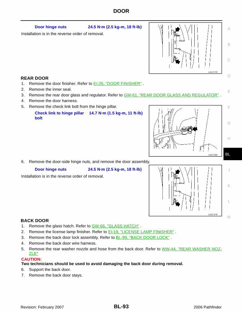
DOOR
BL-93
C
D
E
F
G
H
J
K
L
M
A
B
BL
Revision: February 2007 2006 Pathfinder
Installation is in the reverse order of removal.
REAR DOOR1. Remove the door finisher. Refer to EI-25, "DOOR FINISHER" .2. Remove the inner seal. 3. Remove the rear door glass and regulator. Refer to GW-61, "REAR DOOR GLASS AND REGULATOR" .4. Remove the door harness.5. Remove the check link bolt from the hinge pillar.
6. Remove the door-side hinge nuts, and remove the door assembly.
Installation is in the reverse order of removal.
BACK DOOR1. Remove the glass hatch. Refer to GW-66, "GLASS HATCH" .2. Remove the license lamp finisher. Refer to EI-19, "LICENSE LAMP FINISHER" .3. Remove the back door lock assembly. Refer to BL-99, "BACK DOOR LOCK" .4. Remove the back door wire harness.5. Remove the rear washer nozzle and hose from the back door. Refer to WW-44, "REAR WASHER NOZ-
ZLE"CAUTION:Two technicians should be used to avoid damaging the back door during removal.6. Support the back door.7. Remove the back door stays.
Door hinge nuts 24.5 N·m (2.5 kg-m, 18 ft-lb)
LIIA1727E
Check link to hinge pillar bolt
14.7 N·m (1.5 kg-m, 11 ft-lb)
LIIA1726E
Door hinge nuts 24.5 N·m (2.5 kg-m, 18 ft-lb)
LIIA1727E

BL-94
DOOR
Revision: February 2007 2006 Pathfinder
8. Remove the door side nuts and the back door assembly.
Installation is in the reverse order of removal.� Align the back door. Refer to BL-90, "Fitting Adjustment" .
WIIA1056E

FRONT DOOR LOCK
BL-95
C
D
E
F
G
H
J
K
L
M
A
B
BL
Revision: February 2007 2006 Pathfinder
FRONT DOOR LOCK PFP:80502
Component Structure EIS007Q3
Removal and Installation EIS007Q4
REMOVAL1. Remove the front door window regulator. Refer to GW-57, "Front Door Glass" .2. Remove door side grommet, and remove door key cylinder assembly (driver side) or outside handle
escutcheon (passenger side) bolts (TORX T30) from grommet hole.CAUTION:Do not forcibly remove the TORX bolts (T30).
3. Separate the key cylinder rod from the key cylinder assembly.
1. Grommet 2. Front door striker 3. Door lock assembly
4. Outside handle cable 5. Inside handle assembly 6. Inside handle cable
7. Door lock cable 8. Key cylinder rod (Driver side only) 9. Door key cylinder
10. Outside handle bracket 11. Front gasket 12. Outside handle
13. Door key cylinder assembly (Driver side) Outside handle escutcheon (Passenger side)
14. Rear gasket ⇐ Vehicle front
WIIA0736E
Torx bolt 5.3 N·m (0.54 kg-m, 47 in-lb)
PIIA3553E

BL-96
FRONT DOOR LOCK
Revision: February 2007 2006 Pathfinder
4. While pulling the outside handle, remove door key cylinderassembly or escutcheon.
5. While pulling outside handle, slide toward rear of vehicle toremove outside handle.
6. Remove the front gasket and rear gasket.
7. Remove the TORX bolts (T30), remove the door lock assembly.
8. While pulling outside handle bracket, slide toward rear of vehicleto remove outside handle bracket and door lock assembly.
PIIA3554E
LIIA0532E
PIIA3557E
Door lock assembly bolts 5.8 N·m (0.59 kg-m, 51 in-lb)
PIIA1090E
PIIA3558E

FRONT DOOR LOCK
BL-97
C
D
E
F
G
H
J
K
L
M
A
B
BL
Revision: February 2007 2006 Pathfinder
9. Disconnect the door lock actuator connector.10. Separate the outside handle cable connection from the outside
handle bracket.
INSTALLATIONInstallation in the reverse order of removal.CAUTION:To install each rod, be sure to rotate the rod holder until a click is felt.
Disassembly and Assembly EIS007Q5
DOOR KEY CYLINDER ASSEMBLY
Remove the key cylinder escutcheon pawl and remove the door key cylinder.
PIIA5059E
1. Door key cylinder assembly 2. Key cylinder escutcheon 3. Door key cylinder
⇐ Pawl
WIIA1057E

BL-98
REAR DOOR LOCK
Revision: February 2007 2006 Pathfinder
REAR DOOR LOCK PFP:82502
Component Structure EIS007Q6
Removal and Installation EIS007Q7
REMOVAL1. Remove the rear door window regulator. Refer to GW-61, "Rear Door Glass" .2. Remove door grommets, and remove outside handle nuts from the hole.3. Remove outside handle.4. Disconnect the outside handle cable connection.5. Remove the inside door handle.6. Disconnect the door lock and inside door handle cables from the inside door handle.7. Disconnect the door lock actuator connector and remove the assembly.
INSTALLATIONInstallation is in the reverse order of removal.
1. Outside door handle 2. Rear door striker 3. Rear door lock assembly
4. Outside door handle cable 5. Inside door handle cable 6. Inside door handle assembly
7. Door lock cable ⇐ Vehicle front
WIIA0737E

BACK DOOR LOCK
BL-99
C
D
E
F
G
H
J
K
L
M
A
B
BL
Revision: February 2007 2006 Pathfinder
BACK DOOR LOCK PFP:90504
Component Structure EIS007Q8
1. Glass hatch latch assembly 2. Emergency exit handle cable 3. Back door latch cable
4. Back door latch 5. Back door release handle 6. Back door striker
7. Glass hatch release handle 8. Emergency exit handle ⇐ Vehicle front
WIIA0776E

BL-100
NVIS(NISSAN VEHICLE IMMOBILIZER SYSTEM-NATS)
Revision: February 2007 2006 Pathfinder
NVIS(NISSAN VEHICLE IMMOBILIZER SYSTEM-NATS) PFP:28591
Component Parts and Harness Connector Location EIS007Q9
LIIA2414E
1. NATS antenna amplifier M21(View with cluster lid A removed)
2. BCM M18, M19, M20(View with instrument lower panel LH removed)
3. IPDM E/R E118, E119, E120, E121, E122, E123, E124
4. ECM E16 5. Combination meter M24

NVIS(NISSAN VEHICLE IMMOBILIZER SYSTEM-NATS)
BL-101
C
D
E
F
G
H
J
K
L
M
A
B
BL
Revision: February 2007 2006 Pathfinder
System Description EIS007QA
NVIS (Nissan Vehicle Immobilizer System-NATS) has the following immobilizer functions:� Since only NVIS (NATS) ignition keys, whose IDs have been registered into the ECM and BCM, allow the
engine to run, operation of a stolen vehicle without a NVIS (NATS) registered key is prevented by NVIS(NATS).NVIS (NATS) will immobilize the engine if someone tries to start it without the registered key of NVIS(NATS).
� All of the originally supplied ignition key IDs have been NVIS (NATS) registered.If requested by the vehicle owner, a maximum of five key IDs can be registered into the NVIS (NATS)components.
� The security indicator blinks when the ignition switch is in OFF or ACC position. NVIS (NATS) warns out-siders that the vehicle is equipped with the anti-theft system.
� When NVIS (NATS) detects a malfunction, the security indicator lamp lights up while ignition key is in theON position.
� NVIS (NATS) trouble diagnoses, system initialization and additional registration of other NVIS (NATS)ignition key IDs must be carried out using CONSULT-II hardware and CONSULT-II NVIS (NATS) software. When NVIS (NATS) initialization has been completed, the ID of the inserted ignition key is automaticallyNVIS (NATS) registered. Then, if necessary, additional registration of other NVIS (NATS) ignition key IDscan be carried out.Regarding the procedures of NVIS (NATS) initialization and NVIS (NATS) ignition key ID registration, referto CONSULT-II Operation Manual NATS-IVIS/NVIS.
� When servicing a malfunction of the NVIS (NATS) (indicated by lighting up of Security IndicatorLamp) or registering another NVIS (NATS) ignition key ID, it may be necessary to re-register origi-nal key identification. Therefore, be sure to receive ALL KEYS from vehicle owner.
System Composition EIS007QB
The immobilizer function of the NVIS (NATS) consists of the following:� NATS ignition key� NATS antenna amp. located in the ignition key cylinder� Body control module (BCM)� Engine control module (ECM)� Security indicatorNOTE:The communication between ECM and BCM uses the CAN communication system.
PIIA1121E
BL-102
NVIS(NISSAN VEHICLE IMMOBILIZER SYSTEM-NATS)
Revision: February 2007 2006 Pathfinder
ECM Re-communicating Function EIS007QC
The following procedure can automatically perform re-communication of ECM and BCM, but only when theECM has been replaced with a new one which has never been energized on-board.(In this step, initialization procedure by CONSULT-II is not necessary)NOTE:� When registering new key IDs or replacing the ECM other than brand new, refer to CONSULT-II
Operation Manual NATS-IVIS/NVIS.� If multiple keys are attached to the key holder, separate them before work.� Distinguish keys with unregistered key ID from those with registered ID.1. Install ECM.2. Using a registered key (*1), turn ignition switch to ON.
*1: To perform this step, use the key that has been used before performing ECM replacement.3. Maintain ignition switch in ON position for at least 5 seconds.4. Turn ignition switch to OFF.5. Start engine.
If engine can be started, procedure is completed.If engine cannot be started, refer to CONSULT-II Operation Manual NATS-IVIS/NVIS and initialize controlunit.

NVIS(NISSAN VEHICLE IMMOBILIZER SYSTEM-NATS)
BL-103
C
D
E
F
G
H
J
K
L
M
A
B
BL
Revision: February 2007 2006 Pathfinder
Wiring Diagram — NATS — EIS007QD
WIWA1620E

BL-104
NVIS(NISSAN VEHICLE IMMOBILIZER SYSTEM-NATS)
Revision: February 2007 2006 Pathfinder
Terminals and Reference Value for BCM EIS007QE
Refer to BCS-12, "Terminals and Reference Values for BCM" .
CONSULT-II EIS007QF
CONSULT-II INSPECTION PROCEDURECAUTION:If CONSULT-II is used with no connection of CONSULT-II CONVERTER, malfunctions might bedetected in self-diagnosis depending on control unit which carries out CAN communication.1. Turn ignition switch OFF.2. Insert NVIS (NATS) program card into CONSULT-II.
3. Connect CONSULT-II and CONSULT-II CONVERTER to datalink connector.
4. Turn ignition switch ON.5. Touch “START”.
6. Touch "OTHER".
7. Select “NATS V.5.0”.If “NATS V5.0” is not indicated, go to GI-40, "CONSULT-II DataLink Connector (DLC) Circuit" .
Program card : NATS (AEN04A-1) or later
BBIA0538E
PBR455D
LIIA0556E
SEL027X
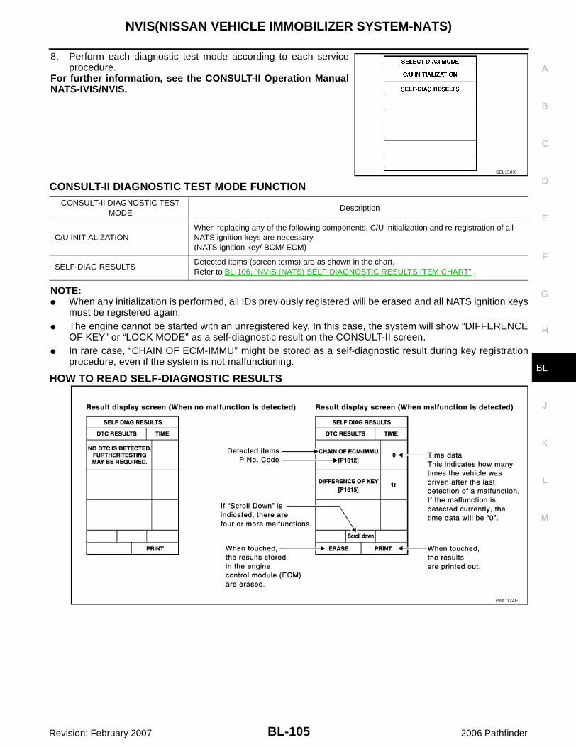
NVIS(NISSAN VEHICLE IMMOBILIZER SYSTEM-NATS)
BL-105
C
D
E
F
G
H
J
K
L
M
A
B
BL
Revision: February 2007 2006 Pathfinder
8. Perform each diagnostic test mode according to each serviceprocedure.
For further information, see the CONSULT-II Operation ManualNATS-IVIS/NVIS.
CONSULT-II DIAGNOSTIC TEST MODE FUNCTION
NOTE:� When any initialization is performed, all IDs previously registered will be erased and all NATS ignition keys
must be registered again.� The engine cannot be started with an unregistered key. In this case, the system will show “DIFFERENCE
OF KEY” or “LOCK MODE” as a self-diagnostic result on the CONSULT-II screen.� In rare case, “CHAIN OF ECM-IMMU” might be stored as a self-diagnostic result during key registration
procedure, even if the system is not malfunctioning.
HOW TO READ SELF-DIAGNOSTIC RESULTS
SEL150X
CONSULT-II DIAGNOSTIC TEST MODE
Description
C/U INITIALIZATIONWhen replacing any of the following components, C/U initialization and re-registration of all NATS ignition keys are necessary.(NATS ignition key/ BCM/ ECM)
SELF-DIAG RESULTSDetected items (screen terms) are as shown in the chart.Refer to BL-106, "NVIS (NATS) SELF-DIAGNOSTIC RESULTS ITEM CHART" .
PIIA1124E

BL-106
NVIS(NISSAN VEHICLE IMMOBILIZER SYSTEM-NATS)
Revision: February 2007 2006 Pathfinder
NVIS (NATS) SELF-DIAGNOSTIC RESULTS ITEM CHART
Detected items [NVIS (NATS) program card screen
terms]
P No. Code(Self-diagnostic
result of “ENGINE”)
Malfunction is detected when.....Reference
page
CHAIN OF ECM-IMMU[P1612]
NATS MAL-FUNCTIONP1612
Communication impossible between ECM and BCMIn rare case, “CHAIN OF ECM-IMMU” might be stored during key registration procedure, even if the system is not malfunctioning.
Refer to BL-110 .
DIFFERENCE OF KEY[P1615]
NATS MAL-FUNCTIONP1615
BCM can receive the key ID signal but the result of ID verification between key ID and BCM is NG.
Refer to BL-111 .
CHAIN OF IMMU-KEY[P1614]
NATS MAL-FUNCTIONP1614
BCM cannot receive the key ID signal.Refer to BL-114 .
ID DISCORD, IMM-ECM[P1611]
NATS MAL-FUNCTIONP1611
The result of ID verification between BCM and ECM is NG. System initialization is required.
Refer to BL-112 .
LOCK MODE[P1610]
NATS MAL-FUNCTIONP1610
When the starting operation is carried out five or more times consecutively under the following conditions, NVIS (NATS) will shift the mode to one which prevents the engine from being started.
� Unregistered ignition key is used.
� BCM or ECM malfunctioning.
Refer to BL-113 .
DON'T ERASE BEFORE CHECK-ING ENG DIAG
—All engine trouble codes except NVIS (NATS) trouble code has been detected in ECM.
Refer to BL-107 .

NVIS(NISSAN VEHICLE IMMOBILIZER SYSTEM-NATS)
BL-107
C
D
E
F
G
H
J
K
L
M
A
B
BL
Revision: February 2007 2006 Pathfinder
Work Flow EIS007QG
LIIA1152E

BL-108
NVIS(NISSAN VEHICLE IMMOBILIZER SYSTEM-NATS)
Revision: February 2007 2006 Pathfinder
Trouble Diagnoses EIS007QH
SYMPTOM MATRIX CHART 1Self-diagnosis related item
*: When NVIS (NATS) detects trouble, the security indicator lights up while ignition key is in the “ON” position.
SymptomDisplayed “SELF-DIAG
RESULTS” on CON-SULT-II screen.
Diagnostic Procedure(Reference page)
System(Malfunctioning part or
mode)
Reference Part No. Of Illustration On System
Diagram
� Security indicator lighting up*
� Engine cannot be started
CHAIN OF ECM-IMMU[P1612]
PROCEDURE 1(BL-110 )
In rare case, “CHAIN OF ECM-IMMU” might be stored during key regis-tration procedure, even if the system is not mal-functioning.
—
Open circuit in battery voltage line of BCM cir-cuit
C1
Open circuit in ignition line of BCM circuit
C2
Open circuit in ground line of BCM circuit
C3
Open or short circuit between BCM and ECM communication line
C4
ECM B
BCM A
DIFFERENCE OF KEY[P1615]
PROCEDURE 2(BL-111 )
Unregistered key D
BCM A
CHAIN OF IMMU-KEY[P1614]
PROCEDURE 5(BL-114 )
Malfunction of key ID chip
E5
Communication line between ANT/ AMP and BCM:Open circuit or short cir-cuit of battery voltage line or ground line
E1
E2
Open circuit in power source line of ANT/ AMP circuit
E3
Open circuit in ground line of ANT/ AMP circuit
E4
NATS antenna amp. E6
BCM A
ID DISCORD, IMM-ECM[P1611]
PROCEDURE 3(BL-112 )
System initialization has not yet been completed.
F
ECM B
LOCK MODE[P1610]
PROCEDURE 4(BL-113 )
LOCK MODE D
Security indicator light-ing up*
DON'T ERASE BEFORE CHECKING
ENG DIAG
WORK FLOW(BL-107 )
Engine trouble data and NVIS (NATS) trouble data have been detected in ECM
—

NVIS(NISSAN VEHICLE IMMOBILIZER SYSTEM-NATS)
BL-109
C
D
E
F
G
H
J
K
L
M
A
B
BL
Revision: February 2007 2006 Pathfinder
SYMPTOM MATRIX CHART 2Non self-diagnosis related item
*: CONSULT-II self-diagnostic results display screen “no malfunction is detected”.
DIAGNOSTIC SYSTEM DIAGRAM
SymptomDiagnostic Procedure
(Reference page)System
(Malfunctioning part or mode)Reference Part No. Of Illustra-
tion On System Diagram
Security indicator does not light up*.
PROCEDURE 6(BL-117 )
Combination meter (security indictor lamp)
—
Open circuit between Fuse and BCM
—
BCM A
WIIA0550E
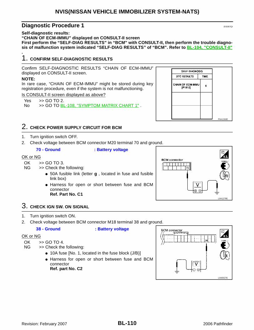
BL-110
NVIS(NISSAN VEHICLE IMMOBILIZER SYSTEM-NATS)
Revision: February 2007 2006 Pathfinder
Diagnostic Procedure 1 EIS007QI
Self-diagnostic results:“CHAIN OF ECM-IMMU” displayed on CONSULT-II screenFirst perform the “SELF-DIAG RESULTS” in “BCM” with CONSULT-II, then perform the trouble diagno-sis of malfunction system indicated “SELF-DIAG RESULTS” of “BCM”. Refer to BL-104, "CONSULT-II".
1. CONFIRM SELF-DIAGNOSTIC RESULTS
Confirm SELF-DIAGNOSTIC RESULTS “CHAIN OF ECM-IMMU”displayed on CONSULT-II screen.NOTE:In rare case, “CHAIN OF ECM-IMMU” might be stored during keyregistration procedure, even if the system is not malfunctioning.Is CONSULT-II screen displayed as above?
Yes >> GO TO 2.No >> GO TO BL-108, "SYMPTOM MATRIX CHART 1" .
2. CHECK POWER SUPPLY CIRCUIT FOR BCM
1. Turn ignition switch OFF.2. Check voltage between BCM connector M20 terminal 70 and ground.
OK or NGOK >> GO TO 3.NG >> Check the following:
� 50A fusible link (letter g , located in fuse and fusiblelink box)
� Harness for open or short between fuse and BCMconnectorRef. Part No. C1
3. CHECK IGN SW. ON SIGNAL
1. Turn ignition switch ON.2. Check voltage between BCM connector M18 terminal 38 and ground.
OK or NGOK >> GO TO 4.NG >> Check the following:
� 10A fuse [No. 1, located in the fuse block (J/B)]� Harness for open or short between fuse and BCM
connectorRef. part No. C2
PIIA1260E
70 - Ground : Battery voltage
LIIA1279E
38 - Ground : Battery voltage
LIIA0527E

NVIS(NISSAN VEHICLE IMMOBILIZER SYSTEM-NATS)
BL-111
C
D
E
F
G
H
J
K
L
M
A
B
BL
Revision: February 2007 2006 Pathfinder
4. CHECK GROUND CIRCUIT FOR BCM
1. Turn ignition switch OFF.2. Disconnect BCM.3. Check continuity between BCM connector M20 terminal 67 and ground.
OK or NGOK >> GO TO 5.NG >> Repair or replace harness. Ref. part No. C3
5. REPLACE BCM
1. Replace BCM. Ref. part No. A2. Perform initialization with CONSULT-II.
For initialization, refer to “CONSULT-II Operation Manual NATS-IVIS/NVIS”.Does the engine start?Yes >> BCM is malfunctioning.No >> ECM is malfunctioning.
� Replace ECM. Ref. part No. B� Perform initialization or re-communicating function.� For initialization, refer to “CONSULT-II Operation Manual NATS-IVIS/NVIS”.� For re-communicating function, refer to BL-102, "ECM Re-communicating Function" .
Diagnostic Procedure 2 EIS007QJ
Self-diagnostic results:“DIFFERENCE OF KEY” displayed on CONSULT-II screen
1. CONFIRM SELF-DIAGNOSTIC RESULTS
Confirm SELF-DIAGNOSTIC RESULTS “DIFFERENCE OF KEY”displayed on CONSULT-II screen.Is CONSULT-II screen displayed as above?Yes >> GO TO 2.No >> GO TO BL-108, "SYMPTOM MATRIX CHART 1" .
67 - Ground :Continuity should exist.
LIIA1040E
PIIA1261E

BL-112
NVIS(NISSAN VEHICLE IMMOBILIZER SYSTEM-NATS)
Revision: February 2007 2006 Pathfinder
2. PERFORM INITIALIZATION WITH CONSULT-II
Perform initialization with CONSULT-II. Re-register all NATS ignition key IDs.For initialization and registration of NATS ignition key IDs, refer to “CONSULT-II Operation Manual NATS-IVIS/NVIS”.NOTE:If the initialization is not completed or malfunctions, CONSULT-IIshows message on the screen.Can the system be initialized and can the engine be started with re-registered NATS ignition key?
Yes >> Ignition key ID was unregistered. Ref. part No. DNo >> BCM is malfunctioning.
� Replace BCM. Ref. part No. A� Perform initialization with CONSULT-II.� For initialization, refer to “CONSULT-II Operation
Manual NATS-IVIS/NVIS”.
Diagnostic Procedure 3 EIS007QK
Self-diagnostic results:“ID DISCORD, IMM-ECM” displayed on CONSULT-II screen
1. CONFIRM SELF-DIAGNOSTIC RESULTS
Confirm SELF-DIAGNOSTIC RESULTS “ID DISCORD, IMM-ECM” displayed on CONSULT-II screen.NOTE:“ID DISCORD IMM-ECM”:Registered ID of BCM is in discord with that of ECM.Is CONSULT-II screen displayed as above?
Yes >> GO TO 2.No >> GO TO BL-108, "SYMPTOM MATRIX CHART 1" .
2. PERFORM INITIALIZATION WITH CONSULT-II
Perform initialization with CONSULT-II. Re-register all NATS ignition key IDs.For initialization, refer to “CONSULT-II Operation Manual NATS-IVIS/NVIS”.NOTE:If the initialization is not completed or malfunctions, CONSULT-IIshows message on the screen.Can the system be initialized?
Yes >> � Start engine. (END)� (System initialization had not been completed. Ref.
part No. F )No >> ECM is malfunctioning.
� Replace ECM. Ref. part No. B� Perform initialization with CONSULT-II.
For initialization, refer to “CONSULT-II Operation Manual NATS-IVIS/NVIS”.
SEL297W
PIIA1262E
SEL297W

NVIS(NISSAN VEHICLE IMMOBILIZER SYSTEM-NATS)
BL-113
C
D
E
F
G
H
J
K
L
M
A
B
BL
Revision: February 2007 2006 Pathfinder
Diagnostic Procedure 4 EIS007QL
Self-diagnostic results:“LOCK MODE” displayed on CONSULT-II screen
1. CONFIRM SELF-DIAGNOSTIC RESULTS
Confirm SELF-DIAGNOSTIC RESULTS “LOCK MODE” is displayedon CONSULT-II screen.Is CONSULT-II screen displayed as above?Yes >> GO TO 2.No >> GO TO BL-108, "SYMPTOM MATRIX CHART 1" .
2. ESCAPE FROM LOCK MODE
1. Turn ignition switch OFF.2. Turn ignition switch ON with registered key. (Do not start engine.) Wait 5 seconds.3. Return the key to OFF position. Wait 5 seconds.4. Repeat steps 2 and 3 twice (total of three cycles).5. Start the engine.Does engine start?Yes >> System is OK (Now system is escaped from “LOCK MODE”). Clear all codes.No >> GO TO 3.
3. PERFORM INITIALIZATION WITH CONSULT-II
Perform initialization with CONSULT-II.For initialization, refer to “CONSULT-II Operation Manual NATS-IVIS/NVIS”.NOTE:If the initialization is not completed or malfunctions, CONSULT-IIshows the message on the screen.Can the system be initialized?Yes >> System is OK.No >> GO TO 4.
PIIA1264E
SEL297W
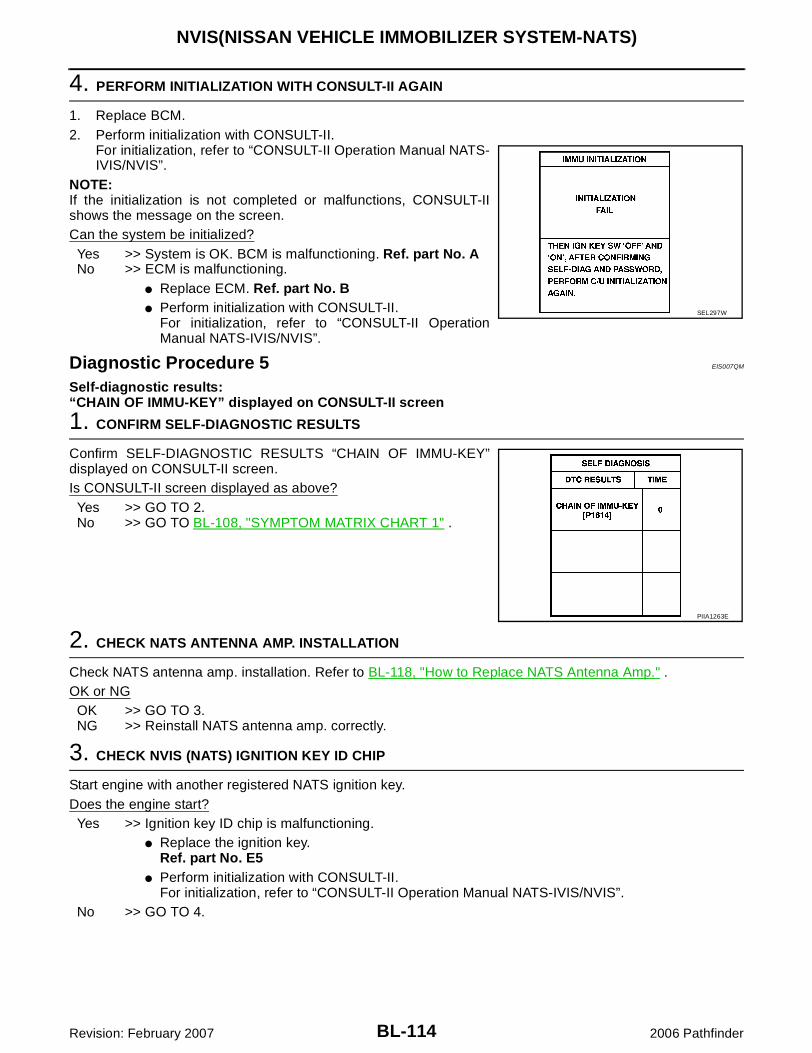
BL-114
NVIS(NISSAN VEHICLE IMMOBILIZER SYSTEM-NATS)
Revision: February 2007 2006 Pathfinder
4. PERFORM INITIALIZATION WITH CONSULT-II AGAIN
1. Replace BCM.2. Perform initialization with CONSULT-II.
For initialization, refer to “CONSULT-II Operation Manual NATS-IVIS/NVIS”.
NOTE:If the initialization is not completed or malfunctions, CONSULT-IIshows the message on the screen.Can the system be initialized?
Yes >> System is OK. BCM is malfunctioning. Ref. part No. ANo >> ECM is malfunctioning.
� Replace ECM. Ref. part No. B� Perform initialization with CONSULT-II.
For initialization, refer to “CONSULT-II OperationManual NATS-IVIS/NVIS”.
Diagnostic Procedure 5 EIS007QM
Self-diagnostic results:“CHAIN OF IMMU-KEY” displayed on CONSULT-II screen
1. CONFIRM SELF-DIAGNOSTIC RESULTS
Confirm SELF-DIAGNOSTIC RESULTS “CHAIN OF IMMU-KEY”displayed on CONSULT-II screen.Is CONSULT-II screen displayed as above?
Yes >> GO TO 2.No >> GO TO BL-108, "SYMPTOM MATRIX CHART 1" .
2. CHECK NATS ANTENNA AMP. INSTALLATION
Check NATS antenna amp. installation. Refer to BL-118, "How to Replace NATS Antenna Amp." .OK or NG
OK >> GO TO 3.NG >> Reinstall NATS antenna amp. correctly.
3. CHECK NVIS (NATS) IGNITION KEY ID CHIP
Start engine with another registered NATS ignition key.Does the engine start?
Yes >> Ignition key ID chip is malfunctioning.� Replace the ignition key.
Ref. part No. E5� Perform initialization with CONSULT-II.
For initialization, refer to “CONSULT-II Operation Manual NATS-IVIS/NVIS”.No >> GO TO 4.
SEL297W
PIIA1263E

NVIS(NISSAN VEHICLE IMMOBILIZER SYSTEM-NATS)
BL-115
C
D
E
F
G
H
J
K
L
M
A
B
BL
Revision: February 2007 2006 Pathfinder
4. CHECK POWER SUPPLY FOR NATS ANTENNA AMP.
1. Turn ignition switch OFF.2. Check voltage between NATS antenna amp. connector M21 terminal 1 and ground.
OK or NGOK >> GO TO 5.NG >> Repair or replace fuse or harness. Ref. part No. E3
5. CHECK NATS ANTENNA AMP. SIGNAL LINE- 1
Check voltage between NATS antenna amp. connector M21 terminal2 and ground with analog tester.
OK or NGOK >> GO TO 6.NG >> � Repair or replace harness. Ref. part No. E1
NOTE:If harness is OK, replace BCM, perform initialization with CONSULT-II. For initialization, refer to“CONSULT-II Operation Manual NATS-IVIS/NVIS”.
1 - Ground : Battery voltage
LIIA1280E
LIIA1642E
2 - Ground
Before inserting key into ignition key cylinder
: Battery voltage
After inserting key into ignition key cylinder
: Pointer of tester should move for 30 seconds, then return to battery voltage.
Just after turning ignition switch ON : Pointer of tester should move for approx. 1 second, then return to battery voltage.

BL-116
NVIS(NISSAN VEHICLE IMMOBILIZER SYSTEM-NATS)
Revision: February 2007 2006 Pathfinder
6. CHECK NATS ANTENNA AMP. SIGNAL LINE- 2
Check voltage between NATS antenna amp. connector M21 terminal4 and ground with analog tester.
OK or NGOK >> GO TO 7.NG >> � Repair or replace harness. Ref. part No. E2
NOTE:If harness is OK, replace BCM, perform initialization with CONSULT-II. For initialization, refer to“CONSULT-II Operation Manual NATS-IVIS/NVIS”.
7. CHECK NATS ANTENNA AMP. GROUND LINE CIRCUIT
1. Turn ignition switch OFF.2. Check continuity between NATS antenna amp. connector M21 terminal 3 and ground.
OK or NGOK >> NATS antenna amp. is malfunctioning. Ref. part No. E6NG >> � Repair or replace harness. Ref. part No. E4
NOTE:If harness is OK, replace BCM, perform initializationwith CONSULT-II. For initialization, refer to “CON-SULT-II Operation Manual NATS-IVIS/NVIS”.
LIIA1643E
4 - Ground
Before inserting key into ignition key cylinder
: Battery voltage
After inserting key into ignition key cylinder
: Pointer of tester should move for 30 seconds, then return to battery voltage.
Just after turning ignition switch ON : Pointer of tester should move for approx. 1 second, then return to battery voltage.
3 - Ground : Continuity should exist.
LIIA1283E

NVIS(NISSAN VEHICLE IMMOBILIZER SYSTEM-NATS)
BL-117
C
D
E
F
G
H
J
K
L
M
A
B
BL
Revision: February 2007 2006 Pathfinder
Diagnostic Procedure 6 EIS007QN
“SECURITY INDICATOR LAMP DOES NOT LIGHT UP”
1. CHECK FUSE
Check 10A fuse [No.19, located in the fuse block (J/B)].OK or NGOK >> GO TO 2.NG >> Replace fuse.
2. CHECK SECURITY INDICATOR LAMP
1. Install 10A fuse.2. Start engine and turn ignition switch OFF.3. Check the security indicator lamp lights up.
OK or NGOK >> Inspection End.NG >> GO TO 3.
3. CHECK SECURITY INDICATOR LAMP POWER SUPPLY CIRCUIT
1. Disconnect combination meter.2. Check voltage between combination meter connector M24 ter-
minal 3 and ground.
OK or NGOK >> GO TO 4.NG >> Repair or replace harness.
4. CHECK BCM (NATS CONTROL UNIT) FUNCTION
1. Connect combination meter.2. Disconnect BCM.3. Check voltage between BCM connector M18 terminal 23 and
ground.
OK or NGOK >> BCM is malfunctioning.
� Replace BCM.Ref. part No. A
� Perform initialization with CONSULT-II.� For initialization, refer to “CONSULT-II Operation
Manual NATS-IVIS/NVIS”.NG >> Check the following:
� Harness for open or short between combination meter and BCM (NATS control unit).� Combination meter
Security indicator lamp should light up.
3 - Ground : Battery voltage
WIIA0467E
23 - Ground : Battery voltage
LIIA0523E

BL-118
NVIS(NISSAN VEHICLE IMMOBILIZER SYSTEM-NATS)
Revision: February 2007 2006 Pathfinder
How to Replace NATS Antenna Amp. EIS007QO
NOTE:� If NATS antenna amp. is not installed correctly, NVIS (NATS)
system will not operate properly and SELF-DIAG RESULTSon CONSULT-II screen will show “LOCK MODE” or “CHAINOF IMMU-KEY”.
� Initialization is not necessary when only NATS antennaamp. is replaced with a new one.
SIIA1683E

HOMELINK UNIVERSAL TRANSCEIVER
BL-119
C
D
E
F
G
H
J
K
L
M
A
B
BL
Revision: February 2007 2006 Pathfinder
HOMELINK UNIVERSAL TRANSCEIVER PFP:96401
Wiring Diagram — TRNSCV — EIS007QP
WIWA1621E

BL-120
HOMELINK UNIVERSAL TRANSCEIVER
Revision: February 2007 2006 Pathfinder
Trouble Diagnoses EIS007QQ
DIAGNOSTIC PROCEDURESYMPTOM: Transmitter does not activate receiver.Before conducting the procedure given below, make sure that system receiver (garage door opener, etc.)operates with original, hand-held transmitter. If NG, receiver or hand-held transmitter is at fault, not vehiclerelated.
1. ILLUMINATION CHECK
1. Turn ignition switch OFF.2. Does red light (LED) of transmitter illuminate when any button is
pressed?YES or NO
YES >> GO TO 2.NO >> GO TO 3.
2. TRANSMITTER CHECK
Check transmitter with Tool*.*:For details, refer to Technical Service Bulletin.OK or NG
OK >> Receiver or hand-held transmitter malfunction, not vehicle related.NG >> Replace transmitter.
3. POWER SUPPLY CHECK
1. Disconnect transmitter.2. Check voltage between auto anti-dazzling inside mirror connector R7 terminal 10 and ground.
OK or NGOK >> GO TO 4.NG >> Repair or replace fuse or harness.
PIIA4815E
10 - Ground : Battery voltage
LIIA0839E

HOMELINK UNIVERSAL TRANSCEIVER
BL-121
C
D
E
F
G
H
J
K
L
M
A
B
BL
Revision: February 2007 2006 Pathfinder
4. GROUND CIRCUIT CHECK
Check continuity between auto anti-dazzling inside mirror connector R7 terminal 3 and body ground.
OK or NGOK >> Replace auto anti-dazzling inside mirror assembly.NG >> Repair or replace harness.
3 - Ground : Continuity should exist.
WIIA0464E
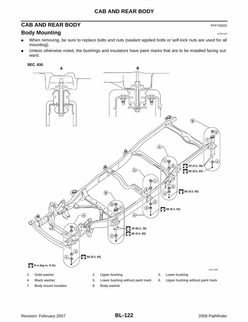
BL-122
CAB AND REAR BODY
Revision: February 2007 2006 Pathfinder
CAB AND REAR BODY PFP:93020
Body Mounting EIS007QR
� When removing, be sure to replace bolts and nuts (sealant applied bolts or self-lock nuts are used for allmounting).
� Unless otherwise noted, the bushings and insulators have paint marks that are to be installed facing out-ward.
1. Gold washer 2. Upper bushing 3. Lower bushing
4. Black washer 5. Lower bushing without paint mark 6. Upper bushing without paint mark
7. Body mount insulator 8. Body washer
LIIA1734E
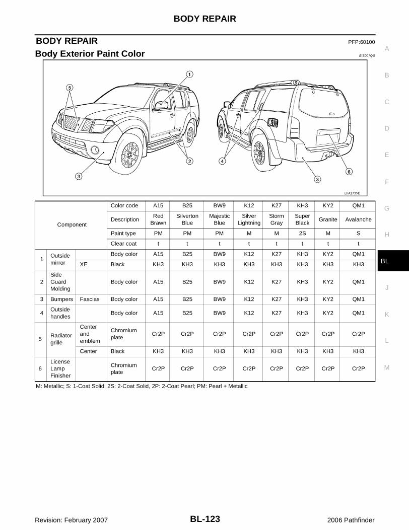
BODY REPAIR
BL-123
C
D
E
F
G
H
J
K
L
M
A
B
BL
Revision: February 2007 2006 Pathfinder
BODY REPAIR PFP:60100
Body Exterior Paint Color EIS007QS
M: Metallic; S: 1-Coat Solid; 2S: 2-Coat Solid, 2P: 2-Coat Pearl; PM: Pearl + Metallic
LIIA1735E
Component
Color code A15 B25 BW9 K12 K27 KH3 KY2 QM1
DescriptionRed
Brawn Silverton
BlueMajestic
BlueSilver
LightningStorm Gray
Super Black
Granite Avalanche
Paint type PM PM PM M M 2S M S
Clear coat t t t t t t t t
1Outside mirror
Body color A15 B25 BW9 K12 K27 KH3 KY2 QM1
XE Black KH3 KH3 KH3 KH3 KH3 KH3 KH3 KH3
2Side Guard Molding
Body color A15 B25 BW9 K12 K27 KH3 KY2 QM1
3 Bumpers Fascias Body color A15 B25 BW9 K12 K27 KH3 KY2 QM1
4Outside handles
Body color A15 B25 BW9 K12 K27 KH3 KY2 QM1
5Radiator grille
Center and emblem
Chromium plate
Cr2P Cr2P Cr2P Cr2P Cr2P Cr2P Cr2P Cr2P
Center Black KH3 KH3 KH3 KH3 KH3 KH3 KH3 KH3
6License Lamp Finisher
Chromium plate
Cr2P Cr2P Cr2P Cr2P Cr2P Cr2P Cr2P Cr2P

BL-124
BODY REPAIR
Revision: February 2007 2006 Pathfinder
Body Component Parts EIS007QT
UNDERBODY COMPONENT PARTS
LIIA1787E

BODY REPAIR
BL-125
C
D
E
F
G
H
J
K
L
M
A
B
BL
Revision: February 2007 2006 Pathfinder
1. Rear floor side RH 2. Rear floor 3. Storage bin4. Second seat mounting crossmember5. Rear floor front6. Center pillar crossmember assembly7. Front seat mounting rear crossmember8. Front floor9. Front seat mounting crossmember10. Second crossmember extension11. Front floor reinforcement 12. Side dash RH13. Lower dash14. Wash tank bracket15. Hoodledge reinforcement RH16. Hoodledge plate17. Hoodledge RH18. Hoodledge reinforcement assembly RH19. Rear lower hoodledge RH20. Battery tray21. Rear lower hoodledge LH22. Hoodledge LH23. Hoodledge reinforcement assembly LH24. Hoodledge reinforcement LH25. Side dash LH26. Second crossmember assembly (RH/LH)27. Inner sill (RH/LH)28. Front side member assembly (RH/LH)29. Center floor member assembly30. Rear side member rear (RH/LH)31. Rear crossmember32. Second seat mounting crossmember33. Third seat mounting bracket assembly34. Rope hook bracket35. Rear floor side LH36. Rear floor side upper extension assembly LH37. Third seat mounting rear crossmember assembly38. Trim mounting bracket39. Rear floor side upper extension assembly RH
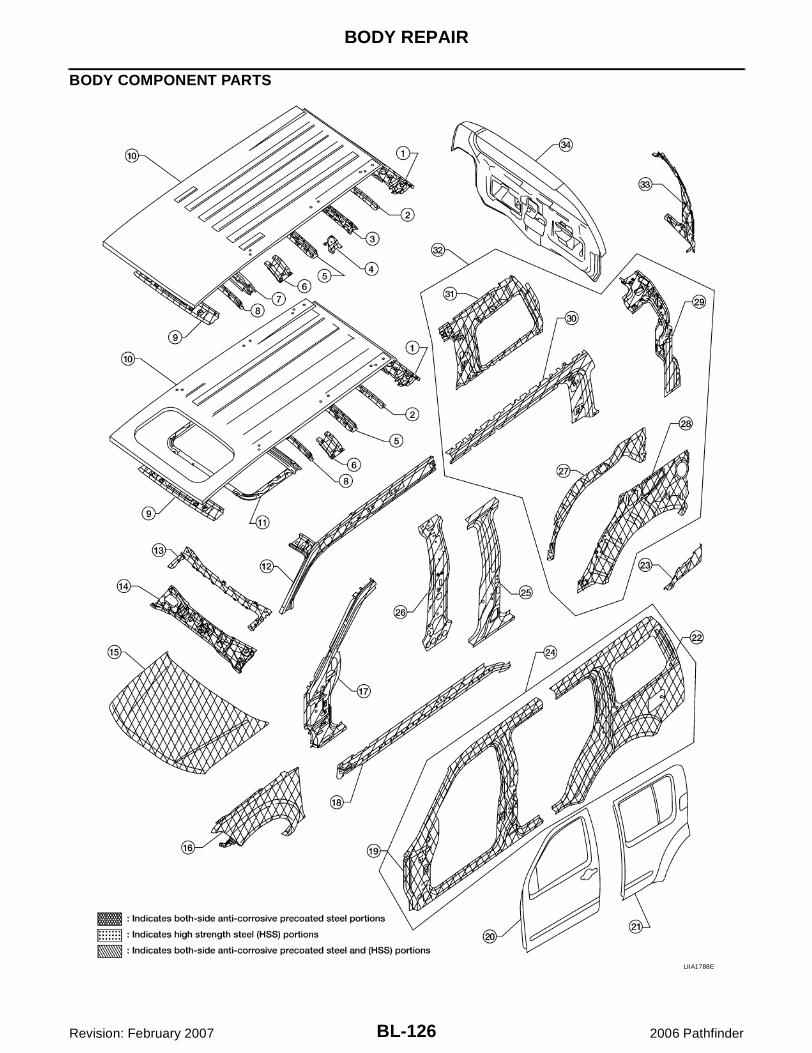
BL-126
BODY REPAIR
Revision: February 2007 2006 Pathfinder
BODY COMPONENT PARTS
LIIA1788E

BODY REPAIR
BL-127
C
D
E
F
G
H
J
K
L
M
A
B
BL
Revision: February 2007 2006 Pathfinder
1. Rear roof rail2. Roof bow No 53. Roof 4th bow4. Roof rack plate5. Roof 3rd bow6. Roof bow second bracket7. Roof 2nd bow8. Roof 1st bow9. Front roof rail10. Roof11. Sunroof reinforcement12. Front inner pillar upper (RH, LH)13. Dash upper crossmember assembly14. Dash upper assembly15. Hood assembly16. Front fender (RH, LH)17. Front pillar hinge brace (RH, LH)18. Outer sill reinforcement (RH, LH)19. Front body side outer (RH, LH)20. Front door assembly (RH, LH)21. Rear door assembly (RH, LH)22. Rear body side outer (RH, LH)23. Rear fender extension RH/LH24. Body side outer assembly25. Center pillar hinge brace26. Center inner pillar (RH, LH)27. Rear wheel housing inner (RH, LH)28. Rear wheel housing outer (RH, LH)29. Back pillar reinforcement (RH, LH)30. Outer roof side rail reinforcement (RH/LH)31. Rear inner side panel (RH, LH)32. Body side inner reinforcement assembly (RH, LH)33. Main back pillar (RH, LH)34. Lift gate assembly

BL-128
BODY REPAIR
Revision: February 2007 2006 Pathfinder
FRAME COMPONENT PARTS
LIIA1789E
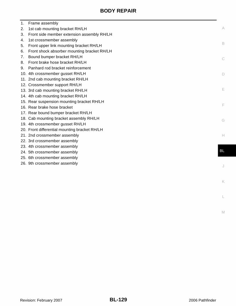
BODY REPAIR
BL-129
C
D
E
F
G
H
J
K
L
M
A
B
BL
Revision: February 2007 2006 Pathfinder
1. Frame assembly2. 1st cab mounting bracket RH/LH3. Front side member extension assembly RH/LH4. 1st crossmember assembly5. Front upper link mounting bracket RH/LH6. Front shock absorber mounting bracket RH/LH7. Bound bumper bracket RH/LH8. Front brake hose bracket RH/LH9. Panhard rod bracket reinforcement10. 4th crossmember gusset RH/LH11. 2nd cab mounting bracket RH/LH12. Crossmember support RH/LH13. 3rd cab mounting bracket RH/LH14. 4th cab mounting bracket RH/LH15. Rear suspension mounting bracket RH/LH16. Rear brake hose bracket17. Rear bound bumper bracket RH/LH18. Cab mounting bracket assembly RH/LH19. 4th crossmember gusset RH/LH20. Front differential mounting bracket RH/LH21. 2nd crossmember assembly22. 3rd crossmember assembly23. 4th crossmember assembly24. 5th crossmember assembly25. 6th crossmember assembly26. 9th crossmember assembly

BL-130
BODY REPAIR
Revision: February 2007 2006 Pathfinder
Corrosion Protection EIS007QU
DESCRIPTIONTo provide improved corrosion prevention, the following anti-corrosive measures have been implemented inNISSAN production plants. When repairing or replacing body panels, it is necessary to use the same anti-cor-rosive measures.
ANTI-CORROSIVE PRECOATED STEEL (GALVANNEALED STEEL)To improve repairability and corrosion resistance, a new type of anti-corrosive precoated steel sheet has been adopted replacing conven-tional zinc-coated steel sheet.Galvannealed steel is electroplated and heated to form Zinc-ironalloy, which provides excellent and long term corrosion resistancewith cationic electrode position primer.
Nissan Genuine Service Parts are fabricated from galvannealed steel. Therefore, it is recommended thatGENUINE NISSAN PARTS or equivalent be used for panel replacement to maintain the anti-corrosive perfor-mance built into the vehicle at the factory.
PHOSPHATE COATING TREATMENT AND CATIONIC ELECTRODEPOSITION PRIMERA phosphate coating treatment and a cationic electrode position primer, which provide excellent corrosion pro-tection, are employed on all body components.CAUTION:Confine paint removal during welding operations to an absoluteminimum.
Nissan Genuine Service Parts are also treated in the same manner. Therefore, it is recommended that GENU-INE NISSAN PARTS or equivalent be used for panel replacement to maintain anti-corrosive performance builtinto the vehicle at the factory.
PIIA0093E
PIIA0095E
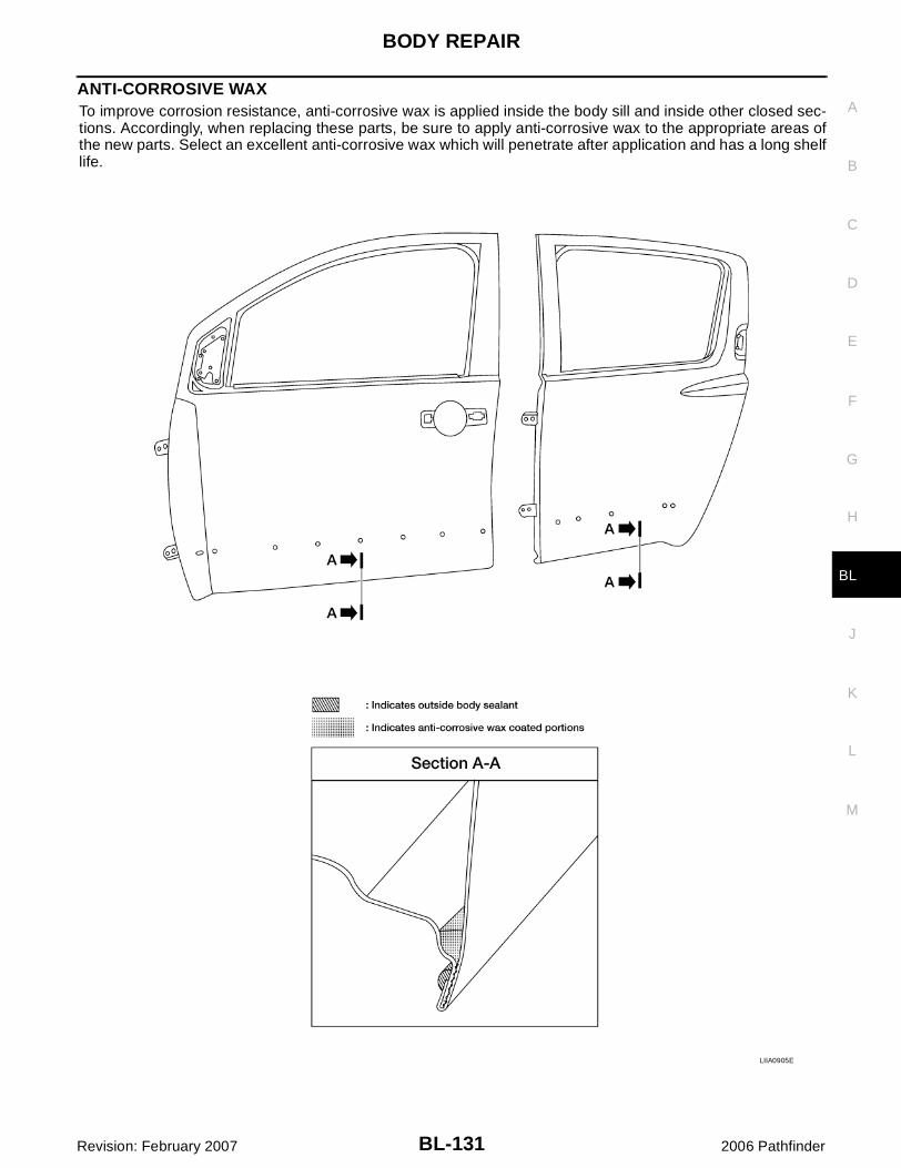
BODY REPAIR
BL-131
C
D
E
F
G
H
J
K
L
M
A
B
BL
Revision: February 2007 2006 Pathfinder
ANTI-CORROSIVE WAXTo improve corrosion resistance, anti-corrosive wax is applied inside the body sill and inside other closed sec-tions. Accordingly, when replacing these parts, be sure to apply anti-corrosive wax to the appropriate areas ofthe new parts. Select an excellent anti-corrosive wax which will penetrate after application and has a long shelflife.
LIIA0905E
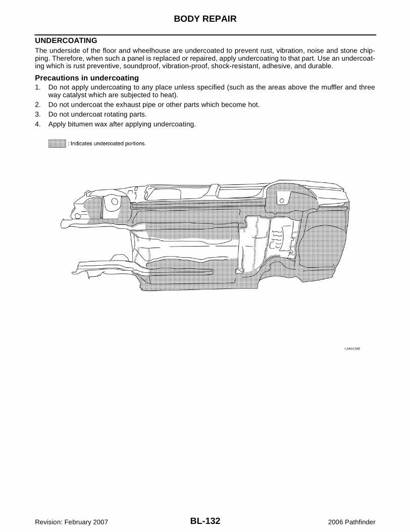
BL-132
BODY REPAIR
Revision: February 2007 2006 Pathfinder
UNDERCOATINGThe underside of the floor and wheelhouse are undercoated to prevent rust, vibration, noise and stone chip-ping. Therefore, when such a panel is replaced or repaired, apply undercoating to that part. Use an undercoat-ing which is rust preventive, soundproof, vibration-proof, shock-resistant, adhesive, and durable.
Precautions in undercoating1. Do not apply undercoating to any place unless specified (such as the areas above the muffler and three
way catalyst which are subjected to heat).2. Do not undercoat the exhaust pipe or other parts which become hot.3. Do not undercoat rotating parts.4. Apply bitumen wax after applying undercoating.
LIIA0129E

BODY REPAIR
BL-133
C
D
E
F
G
H
J
K
L
M
A
B
BL
Revision: February 2007 2006 Pathfinder
Body Sealing EIS007QV
DESCRIPTIONThe following figure shows the areas which are sealed at the factory. Sealant which has been applied to theseareas should be smooth and free from cuts or gaps. Care should be taken not to apply an excess amount ofsealant and not to allow other unaffected parts to come into contact with the sealant.
LIIA1736E

BL-134
BODY REPAIR
Revision: February 2007 2006 Pathfinder
WIIA0728E
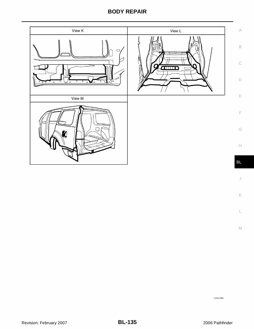
BODY REPAIR
BL-135
C
D
E
F
G
H
J
K
L
M
A
B
BL
Revision: February 2007 2006 Pathfinder
LIIA1738E

BL-136
BODY REPAIR
Revision: February 2007 2006 Pathfinder
Body Construction EIS007QW
BODY CONSTRUCTION
LIIA1739E
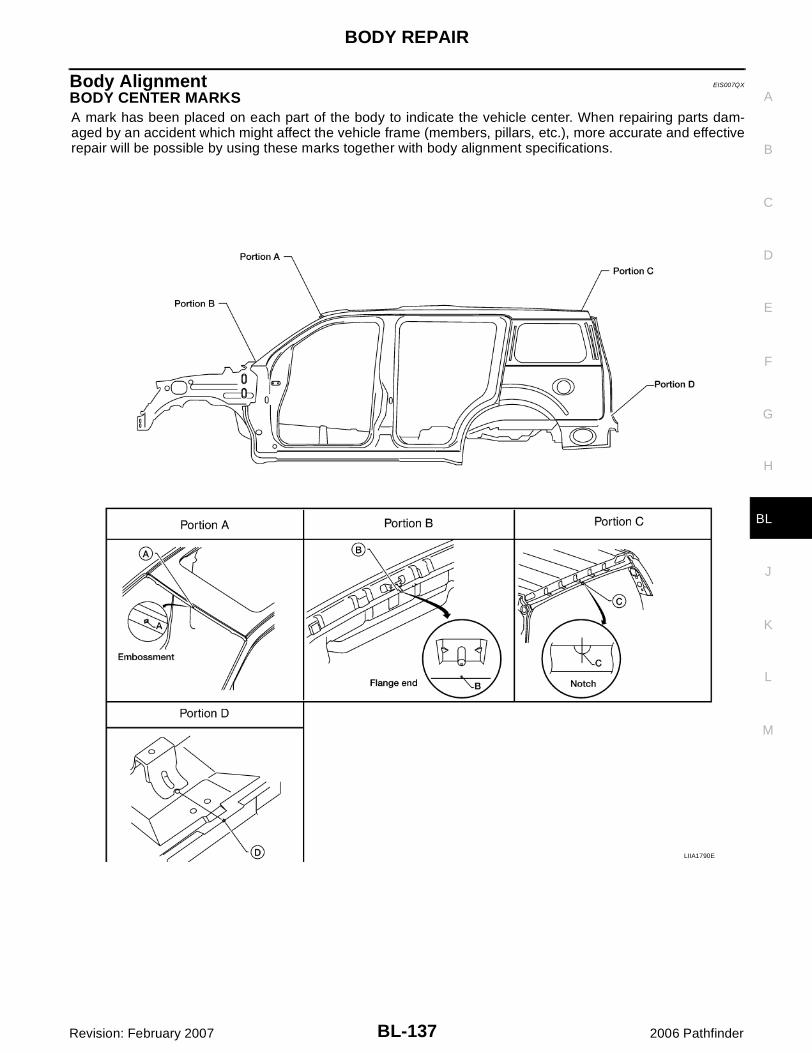
BODY REPAIR
BL-137
C
D
E
F
G
H
J
K
L
M
A
B
BL
Revision: February 2007 2006 Pathfinder
Body Alignment EIS007QX
BODY CENTER MARKSA mark has been placed on each part of the body to indicate the vehicle center. When repairing parts dam-aged by an accident which might affect the vehicle frame (members, pillars, etc.), more accurate and effectiverepair will be possible by using these marks together with body alignment specifications.
LIIA1790E

BL-138
BODY REPAIR
Revision: February 2007 2006 Pathfinder
PANEL PARTS MATCHING MARKSA mark has been placed on each body panel to indicate the parts matching positions. When repairing partsdamaged by an accident which might affect the vehicle structure (members, pillars, etc.), more accurate andeffective repair will be possible by using these marks together with body alignment specifications.
LIIA1791E

BODY REPAIR
BL-139
C
D
E
F
G
H
J
K
L
M
A
B
BL
Revision: February 2007 2006 Pathfinder
DESCRIPTION� All dimensions indicated in the figures are actual.� When using a tracking gauge, adjust both pointers to equal length. Then check the pointers and gauge
itself to make sure there is no free play.� When a measuring tape is used, check to be sure there is no elongation, twisting or bending.� Measurements should be taken at the center of the mounting holes.� An asterisk (*) following the value at the measuring point indicates that the measuring point on the other
side is symmetrically the same value.� The coordinates of the measurement points are the distances measured from the standard line of "X", "Y"
and "Z".
LIIA1506E
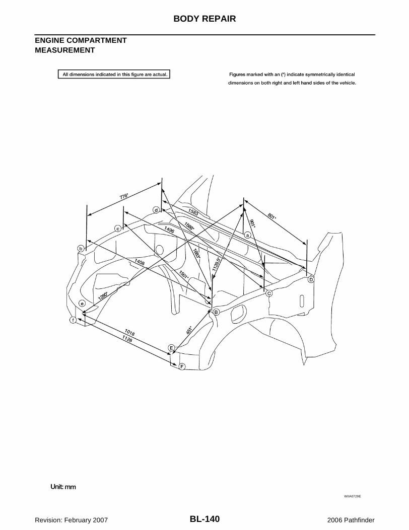
BL-140
BODY REPAIR
Revision: February 2007 2006 Pathfinder
ENGINE COMPARTMENTMEASUREMENT
WIIA0729E

BODY REPAIR
BL-141
C
D
E
F
G
H
J
K
L
M
A
B
BL
Revision: February 2007 2006 Pathfinder
MEASUREMENT POINTS
LIIA1793E

BL-142
BODY REPAIR
Revision: February 2007 2006 Pathfinder
UNDERBODYMEASUREMENT
LIIA1794E

BODY REPAIR
BL-143
C
D
E
F
G
H
J
K
L
M
A
B
BL
Revision: February 2007 2006 Pathfinder
MEASUREMENT POINTS
LIIA1795E

BL-144
BODY REPAIR
Revision: February 2007 2006 Pathfinder
LIIA1796E

BODY REPAIR
BL-145
C
D
E
F
G
H
J
K
L
M
A
B
BL
Revision: February 2007 2006 Pathfinder
PASSENGER COMPARTMENTMEASUREMENT
LIIA1798E

BL-146
BODY REPAIR
Revision: February 2007 2006 Pathfinder
LIIA1799E

BODY REPAIR
BL-147
C
D
E
F
G
H
J
K
L
M
A
B
BL
Revision: February 2007 2006 Pathfinder
MEASUREMENT POINTS
LIIA1800E
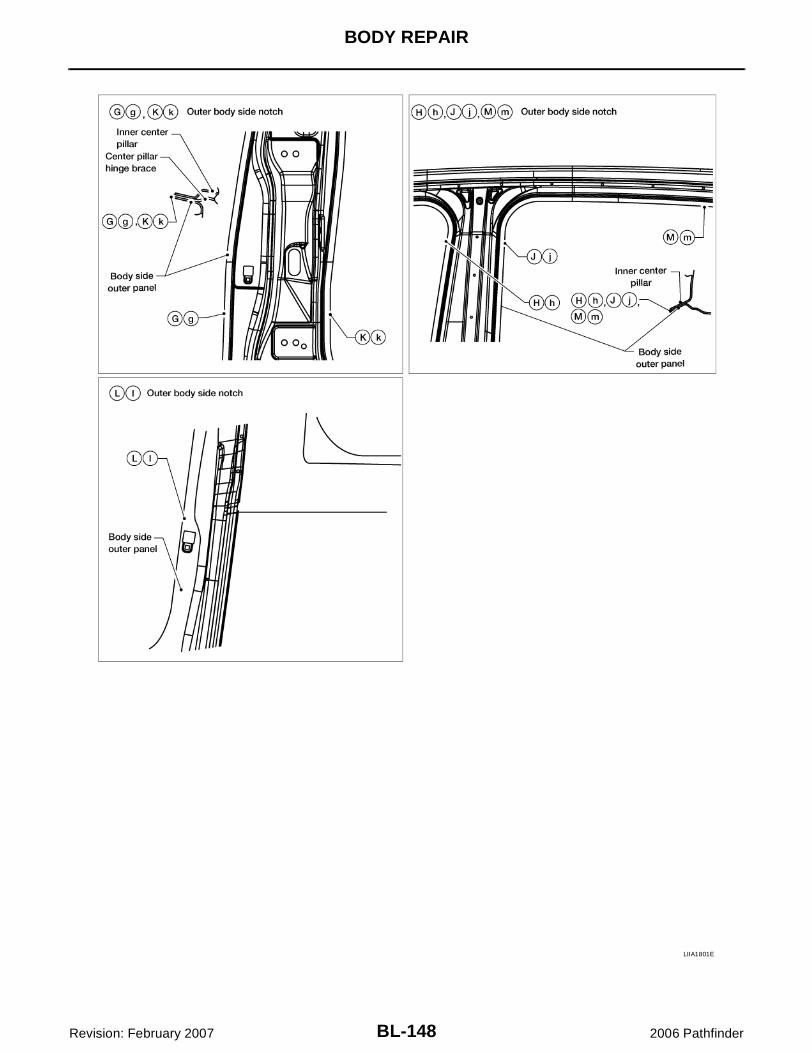
BL-148
BODY REPAIR
Revision: February 2007 2006 Pathfinder
LIIA1801E

BODY REPAIR
BL-149
C
D
E
F
G
H
J
K
L
M
A
B
BL
Revision: February 2007 2006 Pathfinder
LIIA1802E

BL-150
BODY REPAIR
Revision: February 2007 2006 Pathfinder
REAR BODYMEASUREMENT
LIIA1803E

BODY REPAIR
BL-151
C
D
E
F
G
H
J
K
L
M
A
B
BL
Revision: February 2007 2006 Pathfinder
MEASUREMENT POINTS
LIIA1804E

BL-152
BODY REPAIR
Revision: February 2007 2006 Pathfinder
Handling Precautions for Plastics EIS007QY
HANDLING PRECAUTIONS FOR PLASTICS
1. When repairing and painting a portion of the body adjacent to plastic parts, consider their characteristics(influence of heat and solvent) and remove them if necessary or take suitable measures to protect them.
2. Plastic parts should be repaired and painted using methods suiting the materials, characteristics.
Abbre-viation
Material nameHeat resisting temperature
°C (°F)
Resistance to gasoline and solvents
Other cautions
PE Polyethylene 60 (140)Gasoline and most solvents are harmless if applied for a very short time (wipe up quickly).
Flammable
PVC Polyvinyl Chloride 80 (176) Same as above.Poison gas is emitted when burned.
EPM/EPDM
Ethylene Propylene (Diene) rub-ber
80 (176) Same as above. Flammable
TPO/TPR
Thermoplastic Olefine/Thermoplastic Rubber
80 (176) Same as above. Flammable
PP Polypropylene 90 (194) Same as above.Flammable, avoid bat-tery acid.
UP Polyester thermoset 90 (194) Same as above. Flammable
PS Polystyrene 80 (176) Avoid solvents. Flammable
ABSAcrylonitrile Butadiene Styrene resin
80 (176) Avoid gasoline and solvents.
AES Acrylonitrile Ethylene Styrene 80 (176) Same as above.
PMMA Polymethyl Methacrylate 85 (185) Same as above.
AAS Acrylonitrile Acrylic Styrene 85 (185) Same as above.
AS Acrylonitrile Styrene 85 (185) Same as above.
EVA Polyvinyl Ethyl Acetate 90 (194) Same as above.
ASA Acrylonitrile Styrene Acrylate 100 (222) Same as above. Flammable
PPO/PPE
Polyphenylene Oxide/Polyphenylene Ether
110 (230) Same as above.
PC Polycarbonate 120 (248) Same as above.
PAR Polyacrylate 180 (356) Same as above.
L-LDPE
Lenear Low Density PE 45 (100)Gasoline and most solvents are harmless.
Flammable
PUR Polyurethane 90 (194) Same as above.
TPU Thermoplastic Urethane 110 (230) Same as above.
PPC Polypropylene Composite 115 (239) Same as above. Flammable
POM Polyacetal 120 (248) Same as above. Avoid battery acid.
PBT+PC
Polybutylene Terephtha-late+Polycarbonate
120 (248) Same as above. Flammable
PA Polyamide (Nylon) 140 (284) Same as above.Avoid immersing in wa-ter.
PBT Polybutylene Terephthalate 140 (284) Same as above.
FRP Fiber Reinforced Plastics 170 (338) Same as above. Avoid battery acid.
PET Polyethylene Terephthalate 180 (356) Same as above.
PEI Polyetherimide 200 (392) Same as above.
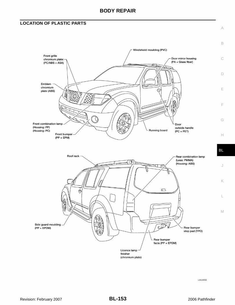
BODY REPAIR
BL-153
C
D
E
F
G
H
J
K
L
M
A
B
BL
Revision: February 2007 2006 Pathfinder
LOCATION OF PLASTIC PARTS
LIIA1805E

BL-154
BODY REPAIR
Revision: February 2007 2006 Pathfinder
LIIA1806E

BODY REPAIR
BL-155
C
D
E
F
G
H
J
K
L
M
A
B
BL
Revision: February 2007 2006 Pathfinder
Precautions in Repairing High Strength Steel EIS007QZ
High strength steel is used for body panels in order to reduce vehicle weight.Accordingly, precautions in repairing automotive bodies made of high strength steel are described below:
HIGH STRENGTH STEEL (HSS) USED IN NISSAN VEHICLES
SP130 is the most commonly used HSS.SP150 HSS is used only on parts that require much more strength.
Read the following precautions when repairing HSS:1. Additional points to consider
� The repair of reinforcements (such as side members) by heat-ing is not recommended since it may weaken the component.When heating is unavoidable, do not heat HSS parts above550°C (1,022°F).Verify heating temperature with a thermometer.(Crayon-type and other similar type thermometer are appro-priate.)
� When straightening body panels, use caution in pulling anyHSS panel. Because HSS is very strong, pulling may causedeformation in adjacent portions of the body. In this case,increase the number of measuring points, and carefully pullthe HSS panel.
� When cutting HSS panels, avoid gas (torch) cutting if possi-ble. Instead, use a saw to avoid weakening surrounding areasdue to heat. If gas (torch) cutting is unavoidable, allow a mini-mum margin of 50 mm (1.97in).
Tensile strength Nissan/Infiniti designation Major applicable parts
373 N/mm2
(38kg/mm2 ,54klb/sq in)SP130
� Front inner pillar upper
� Front pillar hinge brace
� Outer front pillar reinforcement
� Other reinforcements
785-981 N/mm2
(80-100kg/mm2
114-142klb/sq in)SP150
� Outer sill reinforcement
� Main back pillar
PIIA0115E
PIIA0116E
PIIA0117E
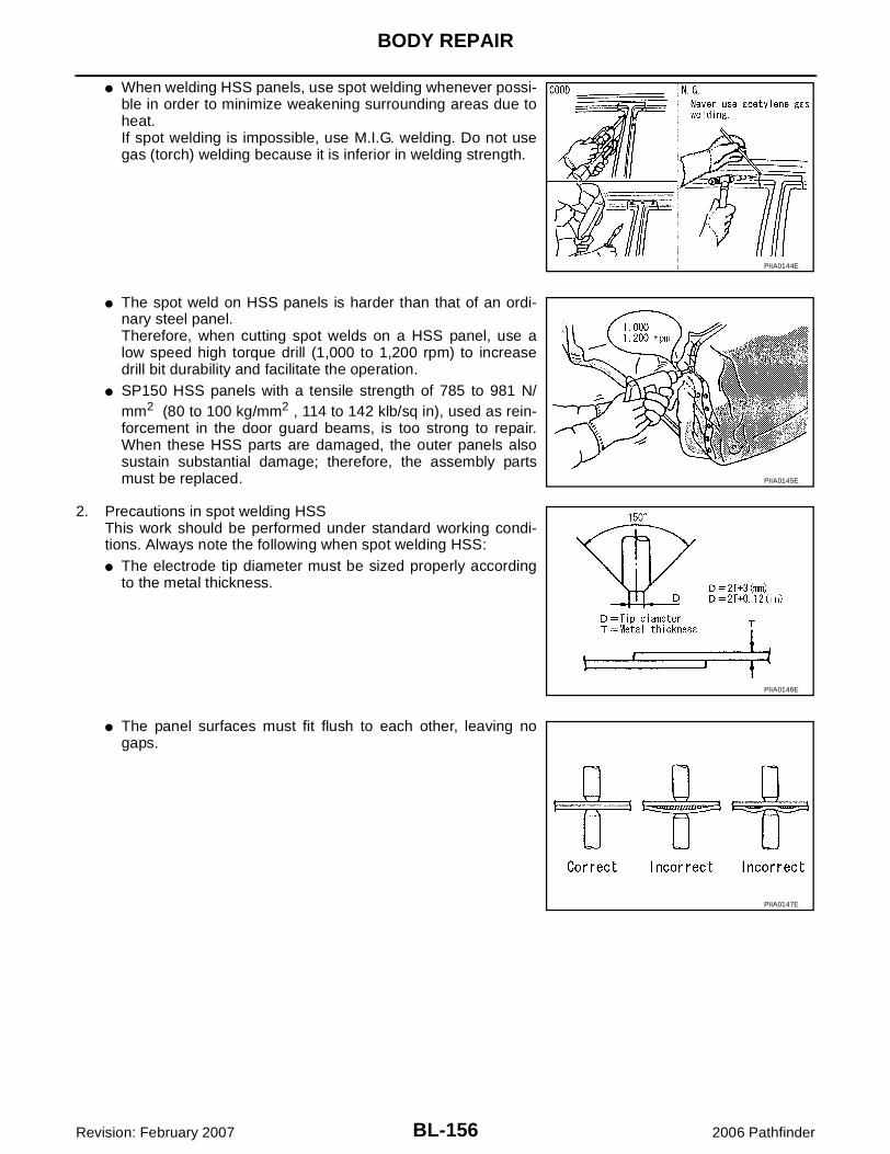
BL-156
BODY REPAIR
Revision: February 2007 2006 Pathfinder
� When welding HSS panels, use spot welding whenever possi-ble in order to minimize weakening surrounding areas due toheat.If spot welding is impossible, use M.I.G. welding. Do not usegas (torch) welding because it is inferior in welding strength.
� The spot weld on HSS panels is harder than that of an ordi-nary steel panel.Therefore, when cutting spot welds on a HSS panel, use alow speed high torque drill (1,000 to 1,200 rpm) to increasedrill bit durability and facilitate the operation.
� SP150 HSS panels with a tensile strength of 785 to 981 N/mm2 (80 to 100 kg/mm2 , 114 to 142 klb/sq in), used as rein-forcement in the door guard beams, is too strong to repair.When these HSS parts are damaged, the outer panels alsosustain substantial damage; therefore, the assembly partsmust be replaced.
2. Precautions in spot welding HSSThis work should be performed under standard working condi-tions. Always note the following when spot welding HSS:� The electrode tip diameter must be sized properly according
to the metal thickness.
� The panel surfaces must fit flush to each other, leaving nogaps.
PIIA0144E
PIIA0145E
PIIA0146E
PIIA0147E
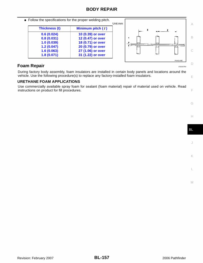
BODY REPAIR
BL-157
C
D
E
F
G
H
J
K
L
M
A
B
BL
Revision: February 2007 2006 Pathfinder
� Follow the specifications for the proper welding pitch.Unit:mm
Foam Repair EIS007R0
During factory body assembly, foam insulators are installed in certain body panels and locations around thevehicle. Use the following procedure(s) to replace any factory-installed foam insulators.
URETHANE FOAM APPLICATIONSUse commercially available spray foam for sealant (foam material) repair of material used on vehicle. Readinstructions on product for fill procedures.
Thickness (t) Minimum pitch ( )
0.6 (0.024)0.8 (0.031)1.0 (0.039)1.2 (0.047)1.6 (0.063)1.8 (0.071)
10 (0.39) or over12 (0.47) or over18 (0.71) or over20 (0.79) or over27 (1.06) or over31 (1.22) or over
PIIA0148E

BL-158
BODY REPAIR
Revision: February 2007 2006 Pathfinder
FILL PROCEDURES
1. Body side outer 2. Body side insulation (foam) 3. A-pillar lower hinge brace
4. Sill outer reinforcement 5. front sill outer reinforcement 6. Inner A-pillar upper
LIIA1807E

BODY REPAIR
BL-159
C
D
E
F
G
H
J
K
L
M
A
B
BL
Revision: February 2007 2006 Pathfinder
7. A-pillar inner bracket 8. A-pillar upper hinge brace 9. B-pillar hinge brace
10. Inner B-pillar 11. Inner sill extension
LIIA1817E

BL-160
BODY REPAIR
Revision: February 2007 2006 Pathfinder
1. Fill procedures after installation of service part.– Remove foam material remaining on vehicle side.– Clean area in which foam was removed.– Install service part.– Insert nozzle into hole near fill area and fill foam material or fill in enough to close gap with the service
part.
2. Fill procedures before installation of service part.– Remove foam material remaining on vehicle side.– Clean area in which foam was removed.– Fill foam material on wheelhouse outer side.
NOTE:Fill in enough to close gap with service part while avoidingflange area.
– Install service part.NOTE:Refer to label for information on working times.
1. Body side outer 2. Body side insulation (foam) 3. Rear wheel outer
4. Side panel inner 5. D-pillar inner reinforcement 6. D-pillar outer reinforcement
7. Roof 8. Front roof rail 9. Front roof rail brace
10. B-pillar inner 11. B-pillar hinge brace 12. Rear side inner extension
13. D-pillar mail lower
LIIA1081E
LIIA1082E
BODY REPAIR
BL-161
C
D
E
F
G
H
J
K
L
M
A
B
BL
Revision: February 2007 2006 Pathfinder
Replacement Operations EIS007R1
DESCRIPTIONThis section is prepared for technicians who have attained a high level of skill and experience in repairing col-lision-damaged vehicles and also use modern service tools and equipment. Persons unfamiliar with bodyrepair techniques should not attempt to repair collision-damaged vehicles by using this section.
Technicians are also encouraged to read Body Repair Manual (Fundamentals) in order to ensure that the orig-inal functions and quality of the vehicle can be maintained. The Body Repair Manual (Fundamentals) containsadditional information, including cautions and warnings, that are not including in this manual. Techniciansshould refer to both manuals to ensure proper repairs.
Please note that this information is prepared for worldwide usage, and as such, certain procedures may notapply in some regions or countries.
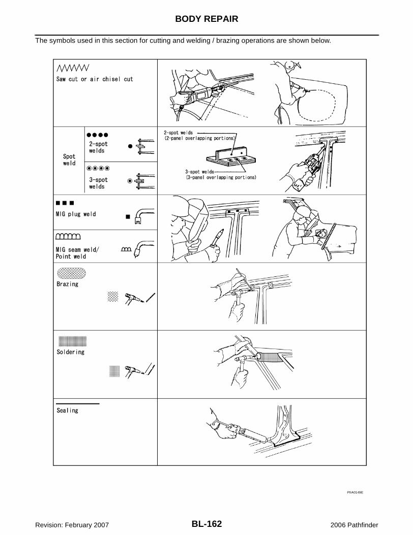
BL-162
BODY REPAIR
Revision: February 2007 2006 Pathfinder
The symbols used in this section for cutting and welding / brazing operations are shown below.
PIIA0149E

BODY REPAIR
BL-163
C
D
E
F
G
H
J
K
L
M
A
B
BL
Revision: February 2007 2006 Pathfinder
� Front pillar butt joint can be determined anywhere within shadedarea as shown in the figure. The best location for the butt joint isat position A due to the construction of the vehicle. Refer to thefront pillar section.
� Determine cutting position and record distance from the locatingindent. Use this distance when cutting the service part. Cut outerfront pillar over 60 mm above inner front pillar cut position.
� Prepare a cutting jig to make outer pillar easier to cut. Also, thiswill permit service part to be accurately cut at joint position.
� An example of cutting operation using a cutting jig is as follows.1. Mark cutting lines.
A: Cut position of outer pillarB: Cut position of inner pillar
2. Align cutting line with notch on jig. Clamp jig to pillar.3. Cut outer pillar along groove of jig. (At position A)4. Remove jig and cut remaining portions.5. Cut inner pillar at position B in same manner.
PIIA0150E
PIIA0151E
PIIA0152E
PIIA0153E

BL-164
BODY REPAIR
Revision: February 2007 2006 Pathfinder
HOODLEDGELH� Work after radiator core support has been removed.
LIIA2950E

BODY REPAIR
BL-165
C
D
E
F
G
H
J
K
L
M
A
B
BL
Revision: February 2007 2006 Pathfinder
RH� Work after radiator core support has been removed.
LIIA2951E

BL-166
BODY REPAIR
Revision: February 2007 2006 Pathfinder
FRONT PILLAR� Work after rear hoodledge reinforcement has been removed.
LIIA1810E

BODY REPAIR
BL-167
C
D
E
F
G
H
J
K
L
M
A
B
BL
Revision: February 2007 2006 Pathfinder
CENTER PILLAR
LIIA1811E

BL-168
BODY REPAIR
Revision: February 2007 2006 Pathfinder
LIIA1812E

BODY REPAIR
BL-169
C
D
E
F
G
H
J
K
L
M
A
B
BL
Revision: February 2007 2006 Pathfinder
OUTER SILL
LIIA1813E

BL-170
BODY REPAIR
Revision: February 2007 2006 Pathfinder
REAR FENDER
LIIA1814E

BODY REPAIR
BL-171
C
D
E
F
G
H
J
K
L
M
A
B
BL
Revision: February 2007 2006 Pathfinder
REAR FENDER EXTENSIONLH
LIIA1818E
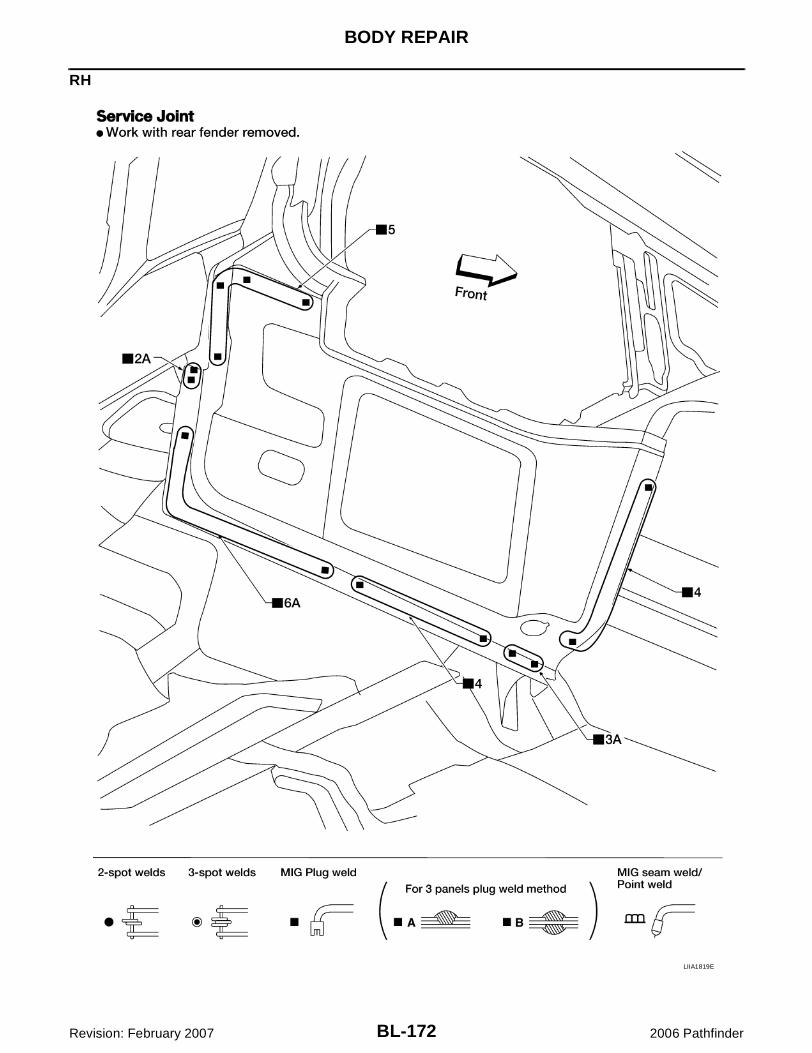
BL-172
BODY REPAIR
Revision: February 2007 2006 Pathfinder
RH
LIIA1819E
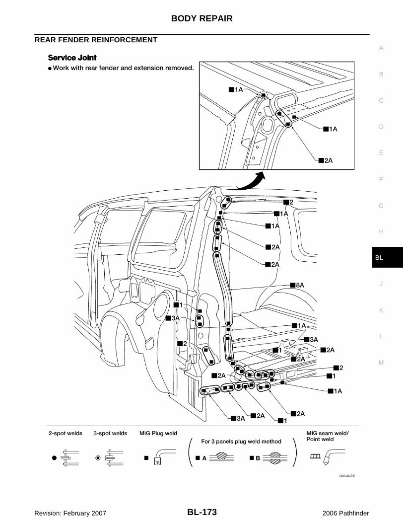
BODY REPAIR
BL-173
C
D
E
F
G
H
J
K
L
M
A
B
BL
Revision: February 2007 2006 Pathfinder
REAR FENDER REINFORCEMENT
LIIA1820E

BL-174
BODY REPAIR
Revision: February 2007 2006 Pathfinder
REAR FLOOR REAR
LIIA1815E

BODY REPAIR
BL-175
C
D
E
F
G
H
J
K
L
M
A
B
BL
Revision: February 2007 2006 Pathfinder
REAR CROSSMEMBER
LIIA1816E

BL-176
BODY REPAIR
Revision: February 2007 2006 Pathfinder
CRUSH HORNCAUTION:When replacing a damaged crush horn on N50 model, do not choose partial replacement method,such as cutting and butt-joint welding the crush horn.

BODY REPAIR
BL-177
C
D
E
F
G
H
J
K
L
M
A
B
BL
Revision: February 2007 2006 Pathfinder
Be sure to replace the entire crush horn when the crush horn has damage at the back of the bodymounting bracket.
LIIA2148E

BL-178
BODY REPAIR
Revision: February 2007 2006 Pathfinder