ELECTRICAL SYSTEM SECTION EL - PDF Text Files
394
ELECTRICAL SYSTEM SECTION EL CONTENTS PRECAUTIONS ...............................................................4 Supplemental Restraint System (SRS) ″AIR BAG″ and ″SEAT BELT PRE-TENSIONER″ ...............4 Wiring Diagrams and Trouble Diagnosis .....................4 HARNESS CONNECTOR................................................5 Description ...................................................................5 STANDARDIZED RELAY................................................7 Description ...................................................................7 POWER SUPPLY ROUTING...........................................9 Schematic ....................................................................9 Wiring Diagram - POWER - ......................................10 Inspection...................................................................16 GROUND........................................................................17 Ground Distribution ....................................................17 COMBINATION SWITCH ..............................................28 Check .........................................................................28 Replacement ..............................................................30 STEERING SWITCH......................................................31 Check .........................................................................31 HEADLAMP (FOR USA) ...............................................32 Component Parts and Harness Connector Location .....................................................................32 System Description ....................................................32 Schematic ..................................................................37 Wiring Diagram - H/LAMP - .......................................39 Trouble Diagnoses.....................................................46 Bulb Replacement .....................................................51 Aiming Adjustment .....................................................51 HEADLAMP (FOR CANADA) - DAYTIME LIGHT SYSTEM - ......................................................................53 Component Parts and Harness Connector Location .....................................................................53 System Description ....................................................53 Schematic ..................................................................60 Wiring Diagram - DTRL - ...........................................62 Trouble Diagnoses.....................................................72 Bulb Replacement .....................................................75 Aiming Adjustment .....................................................75 PARKING, LICENSE AND TAIL LAMPS .....................76 System Description ....................................................76 Schematic ..................................................................77 Wiring Diagram - TAIL/L - ..........................................78 Trouble Diagnoses.....................................................82 STOP LAMP ..................................................................83 Wiring Diagram - STOP/L - .......................................83 BACK-UP LAMP............................................................85 Wiring Diagram - BACK/L - .......................................85 FRONT FOG LAMP.......................................................86 System Description ....................................................86 Wiring Diagram - F/FOG - .........................................89 Aiming Adjustment .....................................................93 TURN SIGNAL AND HAZARD WARNING LAMPS .....94 System Description ....................................................94 Wiring Diagram - TURN - ..........................................96 Trouble Diagnoses.....................................................98 Electrical Components Inspection .............................98 ILLUMINATION..............................................................99 System Description ....................................................99 Schematic ................................................................101 Wiring Diagram - ILL - .............................................102 INTERIOR, SPOT, VANITY MIRROR AND LUGGAGE ROOM LAMPS .........................................108 System Description ..................................................108 Schematic ................................................................ 110 Wiring Diagram - INT/L - ......................................... 111 METERS AND GAUGES............................................. 114 Component Parts and Harness Connector Location ................................................................... 114 System Description .................................................. 114 Combination Meter .................................................. 116 Schematic ................................................................ 118 Wiring Diagram - METER - ..................................... 119 Meter/Gauge Operation and Odo/Trip Meter Segment Check in Diagnosis Mode ........................120 Trouble Diagnoses...................................................121 Electrical Components Inspection ...........................128 COMPASS AND THERMOMETER .............................130 System Description ..................................................130 GI MA EM LC EC FE CL MT AT TF PD AX SU BR ST RS BT HA SC IDX
-
Upload
khangminh22 -
Category
Documents
-
view
2 -
download
0
Transcript of ELECTRICAL SYSTEM SECTION EL - PDF Text Files

ELECTRICAL SYSTEM
SECTIONELCONTENTS
PRECAUTIONS ...............................................................4Supplemental Restraint System (SRS) ″AIRBAG″ and ″SEAT BELT PRE-TENSIONER″...............4Wiring Diagrams and Trouble Diagnosis.....................4
HARNESS CONNECTOR................................................5Description ...................................................................5
STANDARDIZED RELAY ................................................7Description ...................................................................7
POWER SUPPLY ROUTING...........................................9Schematic ....................................................................9Wiring Diagram - POWER - ......................................10Inspection...................................................................16
GROUND........................................................................17Ground Distribution....................................................17
COMBINATION SWITCH ..............................................28Check.........................................................................28Replacement..............................................................30
STEERING SWITCH......................................................31Check.........................................................................31
HEADLAMP (FOR USA) ...............................................32Component Parts and Harness ConnectorLocation .....................................................................32System Description....................................................32Schematic ..................................................................37Wiring Diagram - H/LAMP -.......................................39Trouble Diagnoses.....................................................46Bulb Replacement .....................................................51Aiming Adjustment .....................................................51
HEADLAMP (FOR CANADA) - DAYTIME LIGHTSYSTEM - ......................................................................53
Component Parts and Harness ConnectorLocation .....................................................................53System Description....................................................53Schematic ..................................................................60Wiring Diagram - DTRL -...........................................62Trouble Diagnoses.....................................................72Bulb Replacement .....................................................75Aiming Adjustment .....................................................75
PARKING, LICENSE AND TAIL LAMPS .....................76
System Description....................................................76Schematic ..................................................................77Wiring Diagram - TAIL/L -..........................................78Trouble Diagnoses.....................................................82
STOP LAMP ..................................................................83Wiring Diagram - STOP/L - .......................................83
BACK-UP LAMP ............................................................85Wiring Diagram - BACK/L - .......................................85
FRONT FOG LAMP .......................................................86System Description....................................................86Wiring Diagram - F/FOG - .........................................89Aiming Adjustment .....................................................93
TURN SIGNAL AND HAZARD WARNING LAMPS .....94System Description....................................................94Wiring Diagram - TURN - ..........................................96Trouble Diagnoses.....................................................98Electrical Components Inspection .............................98
ILLUMINATION ..............................................................99System Description....................................................99Schematic ................................................................101Wiring Diagram - ILL - .............................................102
INTERIOR, SPOT, VANITY MIRROR ANDLUGGAGE ROOM LAMPS .........................................108
System Description..................................................108Schematic ................................................................110Wiring Diagram - INT/L - ......................................... 111
METERS AND GAUGES .............................................114Component Parts and Harness ConnectorLocation ...................................................................114System Description..................................................114Combination Meter ..................................................116Schematic ................................................................118Wiring Diagram - METER - .....................................119Meter/Gauge Operation and Odo/Trip MeterSegment Check in Diagnosis Mode........................120Trouble Diagnoses...................................................121Electrical Components Inspection ...........................128
COMPASS AND THERMOMETER .............................130System Description..................................................130
GI
MA
EM
LC
EC
FE
CL
MT
AT
TF
PD
AX
SU
BR
ST
RS
BT
HA
SC
IDX

Wiring Diagram - COMPAS -...................................131Trouble Diagnoses...................................................132Calibration Procedure for Compass ........................133
WARNING LAMPS ......................................................134Schematic ................................................................134Wiring Diagram - WARN - .......................................135Fuel Warning Lamp Sensor Check .........................143Electrical Components Inspection ...........................143
WARNING CHIME .......................................................144Component Parts and Harness ConnectorLocation ...................................................................144System Description..................................................144Wiring Diagram - CHIME - ......................................146Trouble Diagnoses...................................................148
FRONT WIPER AND WASHER ..................................155System Description..................................................155Wiring Diagram - WIPER - ......................................157Removal and Installation .........................................158Washer Nozzle Adjustment .....................................159Washer Tube Layout ...............................................159
REAR WIPER AND WASHER ....................................160System Description..................................................160Wiring Diagram - WIP/R -........................................162Trouble Diagnoses...................................................164Removal and Installation .........................................164Washer Nozzle Adjustment .....................................165Washer Tube Layout ...............................................165Check Valve.............................................................165
HORN ...........................................................................166Wiring Diagram - HORN - .......................................166
CIGARETTE LIGHTER ................................................167Wiring Diagram - CIGAR -.......................................167
CLOCK .........................................................................169Wiring Diagram - CLOCK -......................................169
REAR WINDOW DEFOGGER.....................................170Component Parts and Harness ConnectorLocation ...................................................................170System Description..................................................170Wiring Diagram - DEF -...........................................172Trouble Diagnoses...................................................174Electrical Components Inspection ...........................176Filament Check........................................................176Filament Repair .......................................................177
AUDIO ..........................................................................179System Description..................................................179Wiring Diagram - AUDIO -/Base System ................180Schematic/BOSE System........................................182Wiring Diagram - AUDIO -/BOSE System...............183Trouble Diagnoses...................................................188Inspection.................................................................189Audio Unit Removal and Installation .......................189Wiring Diagram - REMOTE -...................................190
AUDIO ANTENNA .......................................................191System Description..................................................191Wiring Diagram - P/ANT - .......................................192Trouble Diagnoses...................................................193Location of Antenna.................................................193Antenna Rod Replacement .....................................193
POWER SUNROOF.....................................................195System Description..................................................195Wiring Diagram - SROOF - .....................................196Trouble Diagnoses...................................................198
DOOR MIRROR ...........................................................199Wiring Diagram - MIRROR - ...................................199
POWER SEAT .............................................................200Wiring Diagram - SEAT -.........................................200
HEATED SEAT ............................................................202Wiring Diagram - HSEAT - ......................................202Seatback Heating Unit.............................................203
AUTOMATIC DRIVE POSITIONER ............................204Component Parts and Harness ConnectorLocation ...................................................................204System Description..................................................205Schematic ................................................................208Wiring Diagram - AUT/DP - .....................................209On Board Diagnosis ................................................214Trouble Diagnoses...................................................216
AUTOMATIC SPEED CONTROL DEVICE (ASCD) ...239Component Parts and Harness ConnectorLocation ...................................................................239System Description..................................................240Schematic ................................................................242Wiring Diagram - ASCD - ........................................243Fail-safe System......................................................247Trouble Diagnoses...................................................248Electrical Component Inspection .............................257ASCD Wire Adjustment ...........................................258
POWER WINDOW .......................................................259System Description..................................................259Schematic ................................................................262Wiring Diagram - WINDOW - ..................................263Trouble Diagnoses...................................................268
POWER DOOR LOCK .................................................272Component Parts and Harness ConnectorLocation ...................................................................272System Description..................................................272Schematic ................................................................273Wiring Diagram - D/LOCK -.....................................274Trouble Diagnoses...................................................279
MULTI-REMOTE CONTROL SYSTEM .......................288Component Parts and Harness ConnectorLocation ...................................................................288System Description..................................................288Schematic ................................................................291
CONTENTS (Cont’d)
EL-2

Wiring Diagram - MULTI - .......................................292Trouble Diagnoses...................................................295ID Code Entry Procedure ........................................307Remote Controller Battery Replacement.................311
THEFT WARNING SYSTEM .......................................312Component Parts and Harness ConnectorLocation ...................................................................312System Description..................................................313Schematic ................................................................316Wiring Diagram - THEFT -.......................................320Trouble Diagnoses...................................................328
SMART ENTRANCE CONTROL UNIT .......................343Description ...............................................................343Schematic ................................................................346Smart Entrance Control Unit Inspection Table ........348
INTEGRATED HOMELINK TRANSMITTER ...............349Wiring Diagram - TRNSMT - ...................................349Trouble Diagnoses...................................................350
NVIS (NISSAN VEHICLE IMMOBILIZER SYSTEM- NATS) ........................................................................352
Component Parts and Harness ConnetorLocation ...................................................................352System Description..................................................353System Composition................................................353Wiring Diagram - NATS -.........................................354
CONSULT-II .............................................................355Trouble Diagnoses...................................................358How to Replace NVIS (NATS) IMMU......................371
ELECTRICAL UNITS LOCATION ...............................372Engine Compartment...............................................372Passenger Compartment.........................................374
HARNESS LAYOUT ....................................................376How to Read Harness Layout .................................376Outline......................................................................377Main Harness...........................................................378Engine Room Harness ............................................380Engine Control Harness ..........................................382Body Harness LH ....................................................384Body Harness RH....................................................385Back Door Harness .................................................386Engine and Transmission Harness..........................387Room Lamp Harness...............................................388Air Bag Harness ......................................................389Front Door Harness .................................................390Rear Door Harness..................................................391
BULB SPECIFICATIONS ............................................392Headlamp.................................................................392Exterior Lamp ..........................................................392Interior Lamp............................................................392
WIRING DIAGRAM CODES (CELL CODES) .............393
GI
MA
EM
LC
EC
FE
CL
MT
AT
TF
PD
AX
SU
BR
ST
RS
BT
HA
SC
IDX
CONTENTS (Cont’d)
EL-3

Supplemental Restraint System (SRS) “AIRBAG” and “SEAT BELT PRE-TENSIONER”
NAEL0001
The Supplemental Restraint System such as “AIR BAG” and “SEAT BELT PRE-TENSIONER” used along witha seat belt, helps to reduce the risk or severity of injury to the driver and front passenger for certain types ofcollision. The SRS system composition which is available to NISSAN MODEL R50 is as follows:I For a frontal collision
The Supplemental Restraint System consists of driver air bag module (located in the center of the steer-ing wheel), front passenger air bag module (located on the instrument panel on passenger side), seat beltpre-tensioners, a diagnosis sensor unit, warning lamp, wiring harness and spiral cable.
I For a side collisionThe Supplemental Restraint System consists of side air bag module (located in the outer side of front seat),satellite sensor, diagnosis sensor unit (one of components of air bags for a frontal collision), wiring harness,warning lamp (one of components of air bags for a frontal collision).
Information necessary to service the system safely is included in the RS section of this Service Manual.WARNING:I To avoid rendering the SRS inoperative, which could increase the risk of personal injury or death
in the event of a collision which would result in air bag inflation, all maintenance must be performedby an authorized NISSAN dealer.
I Improper maintenance, including incorrect removal and installation of the SRS, can lead to per-sonal injury caused by unintentional activation of the system. For removal of Spiral Cable and AirBag Module, see the RS section.
I Do not use electrical test equipment on any circuit related to the SRS unless instructed to in thisService Manual. Spiral cable and wiring harnesses covered with yellow insulation tape either justbefore the harness connectors or for the complete harness are related to the SRS.
Wiring Diagrams and Trouble DiagnosisNAEL0002
When you read wiring diagrams, refer to the following:I GI-11, “HOW TO READ WIRING DIAGRAMS”I EL-9, “POWER SUPPLY ROUTING” for power distribution circuitWhen you perform trouble diagnosis, refer to the following:I GI-35, “HOW TO FOLLOW TEST GROUPS IN TROUBLE DIAGNOSIS”I GI-24, “HOW TO PERFORM EFFICIENT DIAGNOSIS FOR AN ELECTRICAL INCIDENT”Check for any Service bulletins before servicing the vehicle.
PRECAUTIONSSupplemental Restraint System (SRS) “AIR BAG” and “SEAT BELT PRE-TENSIONER”
EL-4

DescriptionNAEL0003
HARNESS CONNECTOR (TAB-LOCKING TYPE)NAEL0003S01
I The tab-locking type connectors help prevent accidental looseness or disconnection.I The tab-locking type connectors are disconnected by pushing or lifting the locking tab(s). Refer to the
illustration below.Refer to the next page for description of the slide-locking type connector.CAUTION:Do not pull the harness when disconnecting the connector.[Example]
SEL769D
GI
MA
EM
LC
EC
FE
CL
MT
AT
TF
PD
AX
SU
BR
ST
RS
BT
HA
SC
IDX
HARNESS CONNECTORDescription
EL-5

HARNESS CONNECTOR (SLIDE-LOCKING TYPE)=NAEL0003S02
I A new style slide-locking type connector is used on certain systems and components, especially thoserelated to OBD.
I The slide-locking type connectors help prevent incomplete locking and accidental looseness or disconnec-tion.
I The slide-locking type connectors are disconnected by pushing or pulling the slider. Refer to the illustra-tion below.
CAUTION:I Do not pull the harness or wires when disconnecting the connector.I Be careful not to damage the connector support bracket when disconnecting the connector.[Example]
SEL769V
HARNESS CONNECTORDescription (Cont’d)
EL-6

DescriptionNAEL0004
NORMAL OPEN, NORMAL CLOSED AND MIXED TYPE RELAYSNAEL0004S01
Relays can mainly be divided into three types: normal open, normal closed and mixed type relays.
SEL881H
TYPE OF STANDARDIZED RELAYSNAEL0004S02
1M 1 Make 2M 2 Make
1T 1 Transfer 1M·1B 1 Make 1 Break
SEL882H
GI
MA
EM
LC
EC
FE
CL
MT
AT
TF
PD
AX
SU
BR
ST
RS
BT
HA
SC
IDX
STANDARDIZED RELAYDescription
EL-7
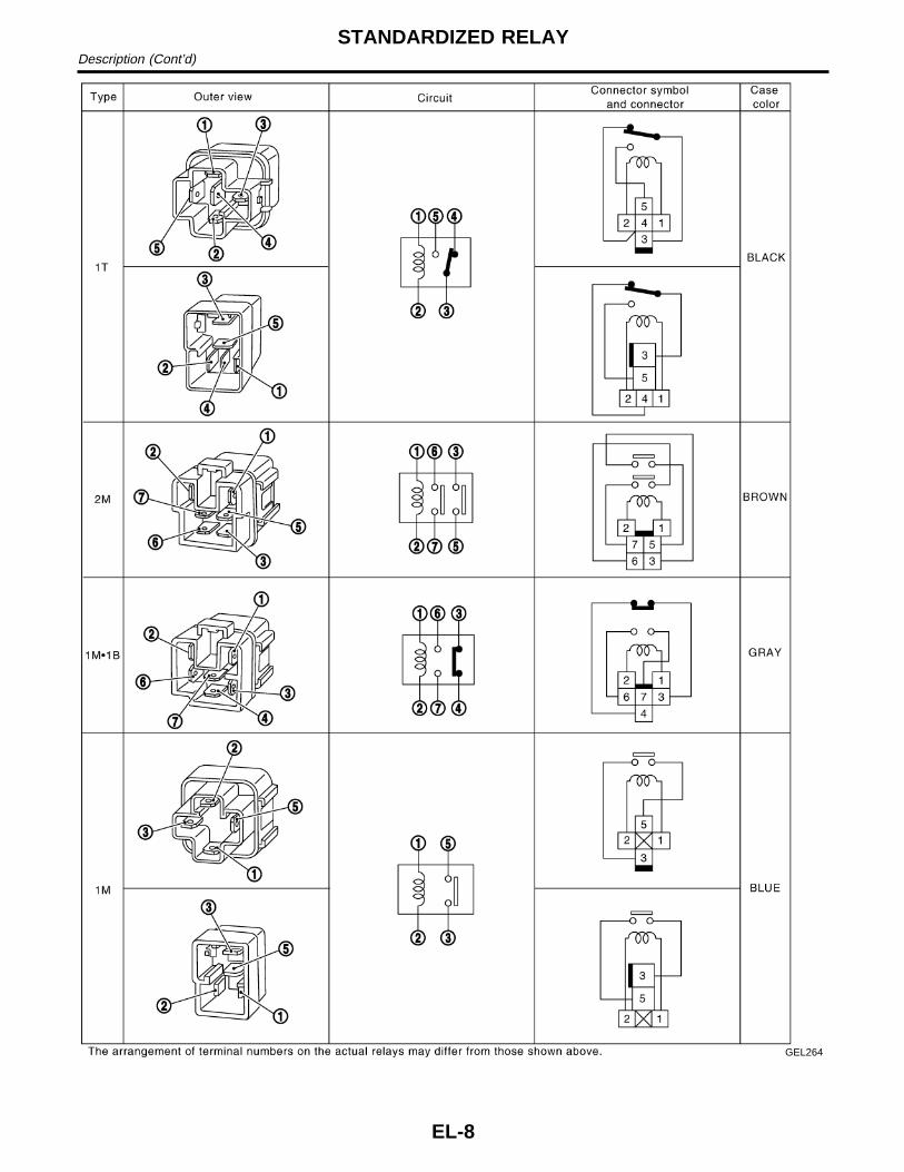
GEL264
STANDARDIZED RELAYDescription (Cont’d)
EL-8

SchematicNAEL0005
MEL973L
GI
MA
EM
LC
EC
FE
CL
MT
AT
TF
PD
AX
SU
BR
ST
RS
BT
HA
SC
IDX
POWER SUPPLY ROUTINGSchematic
EL-9

Wiring Diagram — POWER —NAEL0006
BATTERY POWER SUPPLY — IGNITION SW. IN ANY POSITIONNAEL0006S01
MEL974L
POWER SUPPLY ROUTINGWiring Diagram — POWER —
EL-10

MEL975L
GI
MA
EM
LC
EC
FE
CL
MT
AT
TF
PD
AX
SU
BR
ST
RS
BT
HA
SC
IDX
POWER SUPPLY ROUTINGWiring Diagram — POWER — (Cont’d)
EL-11

MEL976L
POWER SUPPLY ROUTINGWiring Diagram — POWER — (Cont’d)
EL-12

ACCESSORY POWER SUPPLY — IGNITION SW. IN “ACC” OR “ON”NAEL0006S02
MEL977L
GI
MA
EM
LC
EC
FE
CL
MT
AT
TF
PD
AX
SU
BR
ST
RS
BT
HA
SC
IDX
POWER SUPPLY ROUTINGWiring Diagram — POWER — (Cont’d)
EL-13

IGNITION POWER SUPPLY — IGNITION SW. IN “ON” AND/OR “START”NAEL0006S03
MEL978L
POWER SUPPLY ROUTINGWiring Diagram — POWER — (Cont’d)
EL-14

MEL979L
GI
MA
EM
LC
EC
FE
CL
MT
AT
TF
PD
AX
SU
BR
ST
RS
BT
HA
SC
IDX
POWER SUPPLY ROUTINGWiring Diagram — POWER — (Cont’d)
EL-15

CEL083
InspectionNAEL0007
FUSENAEL0007S01
I If fuse is blown, be sure to eliminate cause of problembefore installing new fuse.
I Use fuse of specified rating. Never use fuse of more thanspecified rating.
I Do not partially install fuse; always insert it into fuseholder properly.
I Remove fuse for “ELECTRICAL PARTS (BAT)” if vehicle isnot used for a long period of time.
MEL944F
FUSIBLE LINKNAEL0007S02
A melted fusible link can be detected either by visual inspection orby feeling with finger tip. If its condition is questionable, use circuittester or test lamp.CAUTION:I If fusible link should melt, it is possible that critical circuit
(power supply or large current carrying circuit) is shorted.In such a case, carefully check and eliminate cause ofproblem.
I Never wrap outside of fusible link with vinyl tape. Impor-tant: Never let fusible link touch any other wiring harness,vinyl or rubber parts.
SEL109W
CIRCUIT BREAKER (PTC THERMISTOR TYPE)NAEL0007S03
The PTC thermistor generates heat in response to current flow.The temperature (and resistance) of the thermistor element varieswith current flow. Excessive current flow will cause the element’stemperature to rise. When the temperature reaches a specifiedlevel, the electrical resistance will rise sharply to control the circuitcurrent.Reduced current flow will cause the element to cool. Resistancefalls accordingly and normal circuit current flow is allowed toresume.
POWER SUPPLY ROUTINGInspection
EL-16

Ground DistributionNAEL0008
MAIN HARNESSNAEL0008S01
MEL253M
GI
MA
EM
LC
EC
FE
CL
MT
AT
TF
PD
AX
SU
BR
ST
RS
BT
HA
SC
IDX
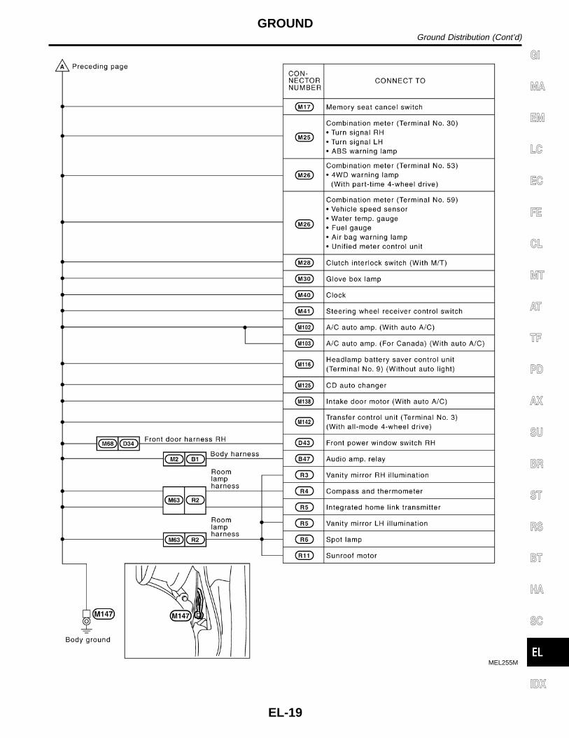
GROUNDGround Distribution
EL-17

MEL254M
GROUNDGround Distribution (Cont’d)
EL-18
MEL255M
GI
MA
EM
LC
EC
FE
CL
MT
AT
TF
PD
AX
SU
BR
ST
RS
BT
HA
SC
IDX
GROUNDGround Distribution (Cont’d)
EL-19

ENGINE ROOM HARNESSNAEL0008S02
MEL420N
GROUNDGround Distribution (Cont’d)
EL-20

MEL146M
GI
MA
EM
LC
EC
FE
CL
MT
AT
TF
PD
AX
SU
BR
ST
RS
BT
HA
SC
IDX
GROUNDGround Distribution (Cont’d)
EL-21

ENGINE CONTROL HARNESSNAEL0008S03
MEL257M
GROUNDGround Distribution (Cont’d)
EL-22

MEL233M
GI
MA
EM
LC
EC
FE
CL
MT
AT
TF
PD
AX
SU
BR
ST
RS
BT
HA
SC
IDX
GROUNDGround Distribution (Cont’d)
EL-23

BODY HARNESS RHNAEL0008S04
MEL258M
GROUNDGround Distribution (Cont’d)
EL-24

BODY HARNESS LHNAEL0008S05
MEL259M
GI
MA
EM
LC
EC
FE
CL
MT
AT
TF
PD
AX
SU
BR
ST
RS
BT
HA
SC
IDX
GROUNDGround Distribution (Cont’d)
EL-25

MEL260M
GROUNDGround Distribution (Cont’d)
EL-26
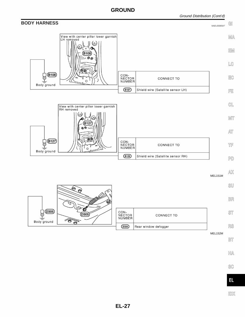
BODY HARNESSNAEL0008S07
MEL151M
MEL152M
GI
MA
EM
LC
EC
FE
CL
MT
AT
TF
PD
AX
SU
BR
ST
RS
BT
HA
SC
IDX
GROUNDGround Distribution (Cont’d)
EL-27

CheckNAEL0009
WITH AUTO LIGHT SYSTEMNAEL0009S01
MEL132M
COMBINATION SWITCHCheck
EL-28

WITHOUT AUTO LIGHT SYSTEMNAEL0009S02
MEL249M
GI
MA
EM
LC
EC
FE
CL
MT
AT
TF
PD
AX
SU
BR
ST
RS
BT
HA
SC
IDX
COMBINATION SWITCHCheck (Cont’d)
EL-29

MEL304D
ReplacementNAEL0010
For removal and installation of spiral cable, refer to RS-18,“Installation — Air Bag Module and Spiral Cable”.I Each switch can be replaced without removing combination
switch base.
MEL326G
I To remove combination switch base, remove base attachingscrew.
SEL151V
I Before installing the steering wheel, align the steering wheelguide pins with the screws which secure the combinationswitch as shown in the left figure.
COMBINATION SWITCHReplacement
EL-30

CheckNAEL0011
MEL133M
GI
MA
EM
LC
EC
FE
CL
MT
AT
TF
PD
AX
SU
BR
ST
RS
BT
HA
SC
IDX
STEERING SWITCHCheck
EL-31

Component Parts and Harness ConnectorLocation
NAEL0159
SEL460X
System DescriptionNAEL0188
WITH AUTO LIGHT SYSTEMNAEL0188S08
The headlamp operation is controlled by the lighting switch which is built into the combination switch andheadlamp battery saver control unit. And the headlamp battery saver system is controlled by the headlampbattery saver control unit and smart entrance control unit.
OutlineNAEL0188S0801
Power is supplied at all timesI to headlamp LH relay terminals 2 and 3I through 15A fuse (No. 60, located in the fuse and fusible link box), andI to headlamp RH relay terminals 2 and 3I through 15A fuse (No. 59, located in the fuse and fusible link box), andI to headlamp battery saver control unit terminal 7, andI to smart entrance control unit terminal 10I through 7.5A fuse [No. 24, located in the fuse block (J/B)].When the ignition switch is in the ON or START position, power is suppliedI to headlamp battery saver control unit terminal 1I through 10A fuse [No. 16, located in the fuse block (J/B)], andI to headlamp battery saver control unit terminal 10,I to auto light control unit terminal 1 andI to smart entrance control unit terminal 33I through 7.5A fuse [No. 11, located in the fuse block (J/B)].When the ignition switch is in the ACC or ON position, power is suppliedI to auto light control unit terminal 2I through 10A fuse [No. 9, located in the fuse block (J/B)]
HEADLAMP (FOR USA)Component Parts and Harness Connector Location
EL-32

Ground is suppliedI to headlamp battery saver control unit terminals 4 and 11I through body grounds M77 and M111, and M4, M66 and M147I to auto light control unit terminal 5I through body grounds M4, M66 and M147.Power Supply to Low Beam and High BeamWhen lighting switch is in 2ND or PASS position, ground is suppliedI to headlamp relay (LH and RH) terminal 2 from headlamp battery saver control unit terminals 2 and 8I through headlamp battery saver control unit terminals 3 and 9,I from lighting switch terminal 12.Headlamp relays (LH and RH) are energized and then power is supplied to headlamps (LH and RH).
Low Beam OperationNAEL0188S0802
When the lighting switch is turned to the 2ND position and placed in LOW (“B”) position, power is suppliedI from terminal 5 of each headlamp relayI to terminal 3 of each headlampGround is suppliedI to headlamp LH terminal 2I through lighting switch terminals 7 and 5I through body grounds E13 and E41.I to headlamp RH terminal 2I through lighting switch terminals 10 and 8I through body grounds E13 and 41.With power and ground supplied, the headlamp(s) will illuminate.
High Beam Operation/Flash-to-pass OperationNAEL0188S0803
When the lighting switch is turned to the 2ND position and placed in HIGH (“A”) position or PASS (“C”) position,power is suppliedI from terminal 5 of headlamp LH relayI to terminal 3 of headlamp LH andI to combination meter terminal 26 for the HIGH BEAM indicatorI from terminal 5 of headlamp RH relayI to terminal 3 of headlamp RH.Ground is suppliedI to headlamp LH terminal 1 andI to combination meter terminal 27 for the HIGH BEAM indicatorI through lighting switch terminals 6 and 5I through body grounds E13 and E41, andI to headlamp RH terminal 1I through lighting switch terminals 9 and 8I through body grounds E13 and E41.With power and ground supplied, the high beams and the high beam indicator illuminate.
Battery Saver ControlNAEL0188S0804
When the ignition switch is turned from ON (or START) to OFF (or ACC) positions while headlamps illuminate,the RAP signal is supplied to terminal 10 of the headlamp battery saver control unit from smart entrance con-trol unit terminal 5.After counting 45 seconds by the RAP signal from the smart entrance control unit to headlamp battery savercontrol unit, the ground supply to terminal 1 of the headlamp LH and RH relay from headlamp battery savercontrol unit terminals 2 and 8 is terminated.Then the headlamps are turned off.The headlamps are turned off when driver or passenger side door is opened even if 45 seconds have not
GI
MA
EM
LC
EC
FE
CL
MT
AT
TF
PD
AX
SU
BR
ST
RS
BT
HA
SC
IDX
HEADLAMP (FOR USA)System Description (Cont’d)
EL-33

passed after ignition switch is turned from ON (or START) to OFF (or ACC) positions while headlamps areilluminated.When the lighting switch is turned from OFF to 2ND after headlamps are turned to off by the battery savercontrol, ground is suppliedI to headlamp LH and RH relays terminal 1 from headlamp battery saver control unit terminals 2 and 8I through headlamp battery saver control unit terminals 3 and 9, andI through lighting switch terminal 12.Then headlamps illuminate again.
Auto Light OperationNAEL0188S0805
When lighting switch is in “AUTO” position, ground is suppliedI to auto light control unit terminal 10I from lighting switch terminal 42.When ignition switch is turn to “ON” or “START” position and outside brightness is darker than prescribed level.Ground is suppliedI to headlamp relay LH and RH terminals 1I through battery saver control unitI from auto light control unit terminal 6, andI to tail lamp relay terminal 1I through battery saver control unitI from auto light control unit terminal 7.Then both headlamp relays and tail lamp relay are energized, headlamps (low or high) and tail lamps are illu-minate according to switch position.Auto light operation allows headlamps and tail lamps to go off whenI Ignition switch is turned to “OFF” position orI Outside brightness is brighter than prescribed level.NOTE:The delay time varies up to maximum of 20 seconds as the outside brightness changes.For parking license and tail lamp auto operation, refer to “PARKING, LICENSE AND TAIL LAMPS”.
Theft Warning SystemNAEL0188S0806
The theft warning system will flash the low beams if the system is triggered. Refer to “THEFT WARNINGSYSTEM” (EL-314).
HEADLAMP (FOR USA)System Description (Cont’d)
EL-34

WITHOUT AUTO LIGHT SYSTEM=NAEL0188S09
The headlamp operation is controlled by the lighting switch which is built into the combination switch andheadlamp battery saver control unit. And the headlamp battery saver system is controlled by the headlampbattery saver control unit and smart entrance control unit.
OutlineNAEL0188S0901
Power is supplied at all timesI to headlamp LH relay terminals 2 and 3I through 15A fuse (No. 60, located in the fuse and fusible link box), andI to headlamp RH relay terminals 2 and 3I through 15A fuse (No. 59, located in the fuse and fusible link box), andI to headlamp battery saver control unit terminal 7I to smart entrance control unit terminal 10I through 7.5A fuse [No. 24, located in the fuse block (J/B)].When the ignition switch is in the ON or START position, power is suppliedI to headlamp battery saver control unit terminal 1I through 10A fuse [No. 16, located in the fuse block (J/B)], andI to headlamp battery saver control unit terminal 10, andI to smart entrance control unit terminal 33I through 7.5A fuse [No. 11, located in the fuse block (J/B)]Ground is suppliedI to headlamp battery saver control unit terminals 4, and 3, 9 and 11.I through body grounds M77 and M111, and M4, M66 and M147.When Ignition Switch is in ON or START PositionGround is suppliedI to headlamp LH relay terminal 1 from headlamp battery saver control unit terminal 2I through headlamp battery saver control unit terminals 3 and 11, andI through body grounds M4, M66 and M147, andI to headlamp RH relay terminal 1 from headlamp battery saver control unit terminal 8I through headlamp battery saver control unit terminals 4 and 9, andI through body grounds M77 and M111, and M4, M66 and M147.Headlamp relays (LH and RH) are then energized.When Ignition Switch is in OFF or ACC PositionWhen lighting switch is in 2ND (or 1ST) position, ground is suppliedI to headlamp battery saver control unit terminals 5 and 13I from lighting switch terminal 11.And then, ground is also supplied to headlamp LH and RH relays terminal 1 from headlamp battery savercontrol unit. Headlamp relays (LH and RH) are then energized.
Low Beam OperationNAEL0188S0902
When the lighting switch is turned to the 2ND position and placed in LOW (“B”) position, power is suppliedI from lighting switch terminal 10I to terminal 2 of the headlamp LH, andI from lighting switch terminal 7I to terminal 2 of the headlamp RH.Terminal 3 of each headlamp supplies ground through body grounds E13 and E41.With power and ground supplied, the headlamp(s) will illuminate.
High Beam Operation/Flash-to-pass OperationNAEL0188S0903
When the lighting switch is turned to the 2ND position and placed in HIGH (“A”) position or PASS (“C”) position,power is suppliedI from lighting switch terminal 6I to terminal 1 of the headlamp RH, andI from lighting switch terminal 9
GI
MA
EM
LC
EC
FE
CL
MT
AT
TF
PD
AX
SU
BR
ST
RS
BT
HA
SC
IDX
HEADLAMP (FOR USA)System Description (Cont’d)
EL-35

I to terminal 1 of the headlamp LH, andI to combination meter terminal 26 for the high beam indicator.Ground is supplied to terminal 27 of the combination meter terminal 3 of each headlamp through body groundsE13 and E41.With power and ground supplied, the high beams and the high beam indicator illuminate.
Battery Saver ControlNAEL0188S0904
When the ignition switch is turned from ON (or START) to OFF (or ACC) positions while headlamps illuminate,the RAP signal is supplied to terminal 10 of the headlamp battery saver control unit from smart entrance con-trol unit terminal 5.After counting 45 seconds by the RAP signal from the smart entrance control unit to headlamp battery savercontrol unit, the ground supply to terminal 1 of the headlamp LH and RH relay from headlamp battery savercontrol unit terminals 2 and 8 is terminated.Then the headlamps are turned off.The headlamps are turned off when driver or passenger side door is opened even if 45 seconds have notpassed after ignition switch is turned from ON (or START) to OFF (or ACC) positions while headlamps areilluminated.When the lighting switch is turned from OFF to 2ND after headlamps are turned to off by the battery savercontrol, ground is suppliedI to headlamp battery saver control unit terminals 5 and 13 from lighting switch terminal 11, andI to headlamp LH and RH relays terminal 1 from headlamp battery saver control unit terminals 2 and 8.Then headlamps illuminate again.
Theft Warning SystemNAEL0188S0905
The theft warning system will flash the high beams if the system is triggered. Refer to “THEFT WARNINGSYSTEM” (EL-313).
HEADLAMP (FOR USA)System Description (Cont’d)
EL-36

SchematicNAEL0160
WITH AUTO LIGHT SYSTEMNAEL0160S01
MEL980L
GI
MA
EM
LC
EC
FE
CL
MT
AT
TF
PD
AX
SU
BR
ST
RS
BT
HA
SC
IDX
HEADLAMP (FOR USA)Schematic
EL-37

WITHOUT AUTO LIGHT SYSTEMNAEL0160S02
MEL985L
HEADLAMP (FOR USA)Schematic (Cont’d)
EL-38

Wiring Diagram — H/LAMP —NAEL0013
WITH AUTO LIGHT SYSTEMNAEL0013S01
MEL011O
GI
MA
EM
LC
EC
FE
CL
MT
AT
TF
PD
AX
SU
BR
ST
RS
BT
HA
SC
IDX
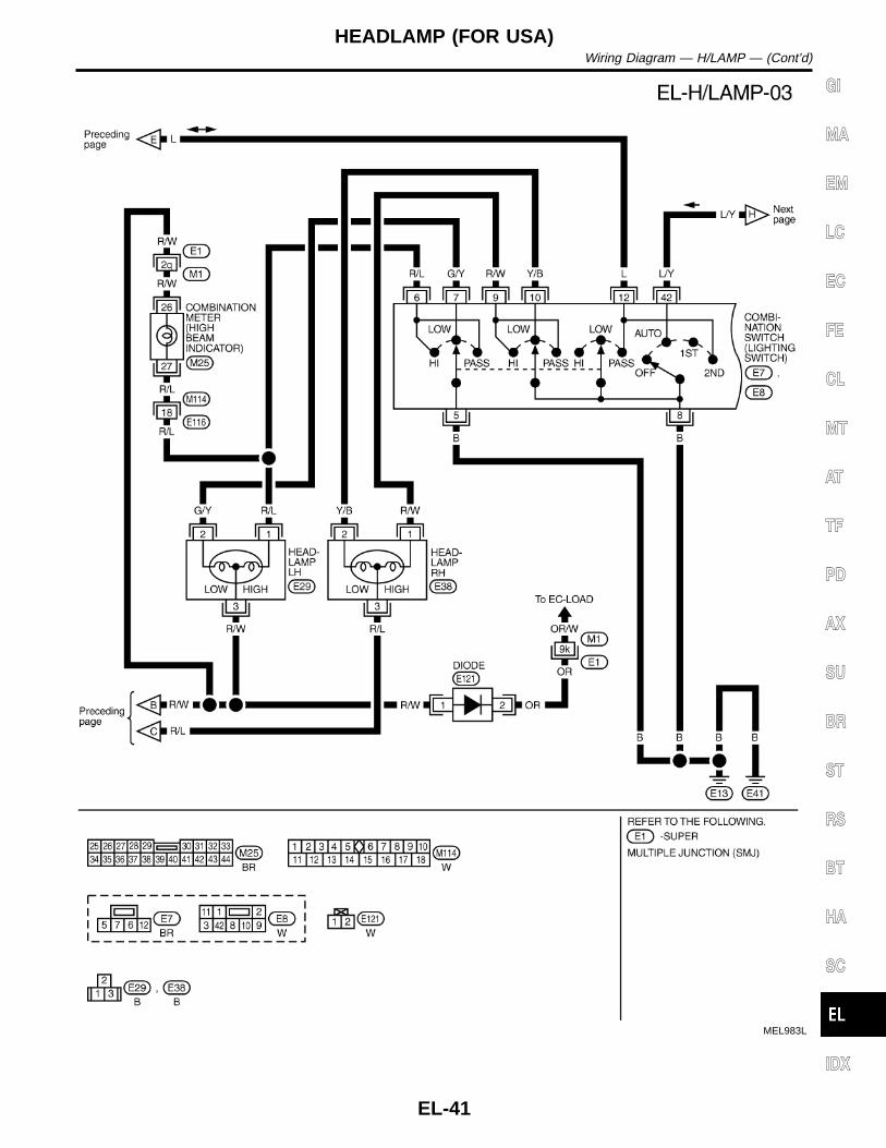
HEADLAMP (FOR USA)Wiring Diagram — H/LAMP —
EL-39

MEL982L
HEADLAMP (FOR USA)Wiring Diagram — H/LAMP — (Cont’d)
EL-40
MEL983L
GI
MA
EM
LC
EC
FE
CL
MT
AT
TF
PD
AX
SU
BR
ST
RS
BT
HA
SC
IDX
HEADLAMP (FOR USA)Wiring Diagram — H/LAMP — (Cont’d)
EL-41

MEL984L
HEADLAMP (FOR USA)Wiring Diagram — H/LAMP — (Cont’d)
EL-42

WITHOUT AUTO LIGHT SYSTEMNAEL0013S02
MEL012O
GI
MA
EM
LC
EC
FE
CL
MT
AT
TF
PD
AX
SU
BR
ST
RS
BT
HA
SC
IDX
HEADLAMP (FOR USA)Wiring Diagram — H/LAMP — (Cont’d)
EL-43

MEL987L
HEADLAMP (FOR USA)Wiring Diagram — H/LAMP — (Cont’d)
EL-44

MEL988L
GI
MA
EM
LC
EC
FE
CL
MT
AT
TF
PD
AX
SU
BR
ST
RS
BT
HA
SC
IDX
HEADLAMP (FOR USA)Wiring Diagram — H/LAMP — (Cont’d)
EL-45

Trouble DiagnosesNAEL0189
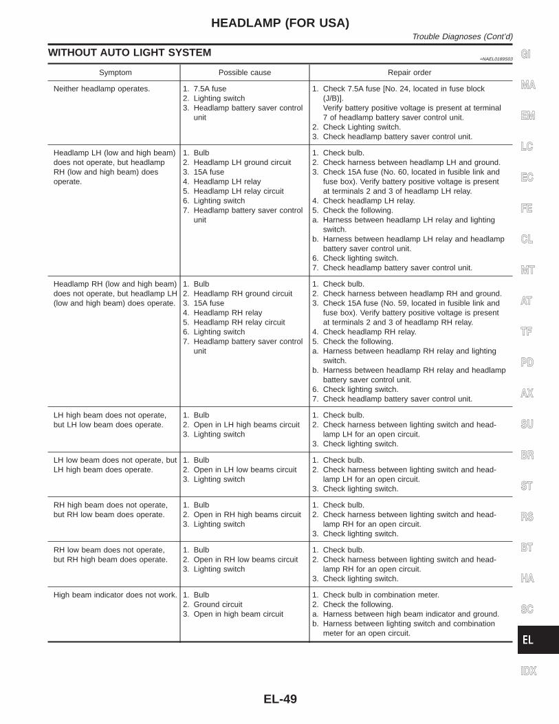
WITH AUTO LIGHT SYSTEMNAEL0189S02
Symptom Possible cause Repair order
Neither headlamp operates. 1. 7.5A fuse2. Headlamp relay circuit3. Lighting switch4. Lighting switch ground circuit5. Headlamp battery saver control
unit
1. Check 7.5A fuse [No. 24, located in fuse block(J/B)].Verify battery positive voltage is present at terminal7 of headlamp battery saver control unit.
2. Check between battery saver control unit and head-lamp relays (LH and RH).
3. Check Lighting switch.4. Check harness between lighting switch terminal 8
and ground.5. Check headlamp battery saver control unit.
Headlamp LH (low and high beam)does not operate, but headlampRH (low and high beam) doesoperate.
1. 15A fuse2. Headlamp LH relay3. Headlamp LH relay circuit
1. Check 15A fuse (No. 60, located in fusible link andfuse box). Verify battery positive voltage is presentat terminals 2 and 3 of headlamp LH relay.
2. Check headlamp LH relay.3. Check harness between headlamp LH relay and
headlamp battery saver control unit.
Headlamp RH (low and high beam)does not operate, but headlamp LH(low and high beam) does operate.
1. 15A fuse2. Headlamp RH relay3. Headlamp RH relay circuit
1. Check 15A fuse (No. 59, located in fusible link andfuse box). Verify battery positive voltage is presentat terminals 2 and 3 of headlamp RH relay.
2. Check headlamp RH relay.3. Check harness between headlamp RH relay and
headlamp battery saver control unit.
LH high beam does not operate,but LH low beam operates.
1. Bulb2. Open in the LH high beams cir-
cuit3. Lighting switch4. Lighting switch ground circuit
1. Check bulb.2. Check harness between headlamp LH and lighting
switch for open circuit.3. Check lighting switch.4. Check harness between lighting switch and ground.
LH low beam does not operate, butLH high beam operates.
1. Bulb2. Open in the LH low beam circuit3. Lighting switch4. Lighting switch ground circuit
1. Check bulb.2. Check harness between headlamp LH and lighting
switch for open circuit.3. Check lighting switch.4. Check harness between lighting switch and ground.
RH high beam does not operate,but RH low beam operates.
1. Bulb2. Open in the RH high beams
circuit3. Lighting switch4. Lighting switch ground circuit
1. Check bulb.2. Check harness between headlamp RH and lighting
switch for open circuit.3. Check lighting switch.4. Check harness between lighting switch and ground.
RH low beam does not operate,but RH high beam operates.
1. Bulb2. Open in the RH low beam cir-
cuit3. Lighting switch4. Lighting switch ground circuit
1. Check bulb.2. Check harness between headlamp RH and lighting
switch for open circuit.3. Check lighting switch.4. Check harness between lighting switch and ground.
High beam indicator does not work. 1. Bulb2. Open in high beam circuit
1. Check bulb in combination meter.2. Check the following.a. Harness between headlamp LH relay and combina-
tion meter for an open circuitb. Harness between high beam indicator and lighting
switch
HEADLAMP (FOR USA)Trouble Diagnoses
EL-46

Symptom Possible cause Repair order
Battery saver control does notoperate properly.
1. RAP signal circuit2. Door switch LH or RH circuit3. Lighting switch circuit4. Headlamp battery saver control
unit5. Smart entrance control unit
1. Check harness between headlamp battery savercontrol unit terminal 10 and smart entrance controlunit terminal 5 for open or short circuit.
2. Check the following.a. Harness between smart entrance control unit and
LH or RH door switch for open or short circuit.b. LH or RH door switch ground circuit.c. LH or RH door switch.3. Check the following.a. Harness between headlamp battery saver control
unit terminals 5 or 13 and lighting switch terminal 11for open or short circuit.
b. Harness between lighting switch terminal 5 andground.
c. Lighting switch.4. Check headlamp battery saver control unit.5. Check smart entrance control unit. (EL-348)
Battery Saver Control Unit Inspection TableNAEL0189S0201
Terminal No.Wirecolor
Item ConditionVoltage
(Approximate value)
1 B/W Ignition ON powersupply
Ignition switch OFF or ACC Less than 1V
ON or START Battery voltage
2 PU/W Headlamp relays(LH and RH)
Ignition switch(with lighting switchexcept OFF or 1ST)
OFF or ACC More than 45 sec-onds after ignitionswitch is turnedOFF or ACC
Battery voltage
Within 45 secondsafter ignition switchis turned OFF orACC
Less than 1V
ON or START Less than 1V
Headlamps illuminate by auto light control. Less than 1V
3 L Headlamp switch Ignition switch ON Lighting switch Except PASS or2ND
Battery voltage
PASS or 2ND Less than 1V
Headlamps illuminate by auto light control. Less than 1V
4 B Ground — —
5 G Tail lamp switch Lighting switch OFF Battery voltage
1ST or 2ND Less than 1V
6 R Tail lamp relay Ignition switch(with lighting switch1ST or 2ND)
OFF or ACC More than 45 sec-onds after ignitionswitch is turnedOFF or ACC
Battery voltage
Within 45 secondsafter ignition switchis turned OFF orACC
Less than 1V
ON or START Less than 1V
Headlamps illuminate by auto light control. Less than 1V
7 G/R Power supply — Battery voltage
GI
MA
EM
LC
EC
FE
CL
MT
AT
TF
PD
AX
SU
BR
ST
RS
BT
HA
SC
IDX
HEADLAMP (FOR USA)Trouble Diagnoses (Cont’d)
EL-47

Terminal No.Wirecolor
Item ConditionVoltage
(Approximate value)
8 PU/W Headlamp relays(LH and RH)
Ignition switch(with lighting switchexcept OFF or 1ST)
OFF or ACC More than 45 sec-onds after ignitionswitch is turnedOFF or ACC
Battery voltage
Within 45 secondsafter ignition switchis turned OFF orACC
Less than 1V
ON or START Less than 1V
Headlamps illuminate by auto light control. Less than 1V
9 L Headlamp switch Ignition switch ON Lighting switch Except PASS or2ND
Battery voltage
PASS or 2ND Less than 1V
Headlamps illuminate by auto light control. Less than 1V
10 R/Y RAP signal Ignition switch OFF or ACC(After more than 45 seconds with ignitionswitch turned OFF or ACC)
Less than 1V
ON or START Battery voltage
11 B Ground — —
13 G Tail lamp switch Lighting switch OFF Battery voltage
1ST or 2ND Less than 1V
14 R Tail lamp relay Ignition switch(with lighting switch1ST or 2ND)
OFF or ACC More than 45 sec-onds after ignitionswitch is turnedOFF or ACC
Battery voltage
Within 45 secondsafter ignition switchis turned OFF orACC
Less than 1V
ON or START Less than 1V
Headlamps illuminate by auto light control. Less than 1V
HEADLAMP (FOR USA)Trouble Diagnoses (Cont’d)
EL-48
WITHOUT AUTO LIGHT SYSTEM=NAEL0189S03
Symptom Possible cause Repair order
Neither headlamp operates. 1. 7.5A fuse2. Lighting switch3. Headlamp battery saver control
unit
1. Check 7.5A fuse [No. 24, located in fuse block(J/B)].Verify battery positive voltage is present at terminal7 of headlamp battery saver control unit.
2. Check Lighting switch.3. Check headlamp battery saver control unit.
Headlamp LH (low and high beam)does not operate, but headlampRH (low and high beam) doesoperate.
1. Bulb2. Headlamp LH ground circuit3. 15A fuse4. Headlamp LH relay5. Headlamp LH relay circuit6. Lighting switch7. Headlamp battery saver control
unit
1. Check bulb.2. Check harness between headlamp LH and ground.3. Check 15A fuse (No. 60, located in fusible link and
fuse box). Verify battery positive voltage is presentat terminals 2 and 3 of headlamp LH relay.
4. Check headlamp LH relay.5. Check the following.a. Harness between headlamp LH relay and lighting
switch.b. Harness between headlamp LH relay and headlamp
battery saver control unit.6. Check lighting switch.7. Check headlamp battery saver control unit.
Headlamp RH (low and high beam)does not operate, but headlamp LH(low and high beam) does operate.
1. Bulb2. Headlamp RH ground circuit3. 15A fuse4. Headlamp RH relay5. Headlamp RH relay circuit6. Lighting switch7. Headlamp battery saver control
unit
1. Check bulb.2. Check harness between headlamp RH and ground.3. Check 15A fuse (No. 59, located in fusible link and
fuse box). Verify battery positive voltage is presentat terminals 2 and 3 of headlamp RH relay.
4. Check headlamp RH relay.5. Check the following.a. Harness between headlamp RH relay and lighting
switch.b. Harness between headlamp RH relay and headlamp
battery saver control unit.6. Check lighting switch.7. Check headlamp battery saver control unit.
LH high beam does not operate,but LH low beam does operate.
1. Bulb2. Open in LH high beams circuit3. Lighting switch
1. Check bulb.2. Check harness between lighting switch and head-
lamp LH for an open circuit.3. Check lighting switch.
LH low beam does not operate, butLH high beam does operate.
1. Bulb2. Open in LH low beams circuit3. Lighting switch
1. Check bulb.2. Check harness between lighting switch and head-
lamp LH for an open circuit.3. Check lighting switch.
RH high beam does not operate,but RH low beam does operate.
1. Bulb2. Open in RH high beams circuit3. Lighting switch
1. Check bulb.2. Check harness between lighting switch and head-
lamp RH for an open circuit.3. Check lighting switch.
RH low beam does not operate,but RH high beam does operate.
1. Bulb2. Open in RH low beams circuit3. Lighting switch
1. Check bulb.2. Check harness between lighting switch and head-
lamp RH for an open circuit.3. Check lighting switch.
High beam indicator does not work. 1. Bulb2. Ground circuit3. Open in high beam circuit
1. Check bulb in combination meter.2. Check the following.a. Harness between high beam indicator and ground.b. Harness between lighting switch and combination
meter for an open circuit.
GI
MA
EM
LC
EC
FE
CL
MT
AT
TF
PD
AX
SU
BR
ST
RS
BT
HA
SC
IDX
HEADLAMP (FOR USA)Trouble Diagnoses (Cont’d)
EL-49

Symptom Possible cause Repair order
Battery saver control does notoperate properly.
1. RAP signal circuit2. Driver or passenger side door
switch circuit3. Lighting switch circuit4. Headlamp battery saver control
unit5. Smart entrance control unit
1. Check harness between headlamp battery savercontrol unit terminal 10 and smart entrance controlunit terminal 5 for open or short circuit.
2. Check the following.a. Harness between smart entrance control unit and
driver or passenger side door switch for open orshort circuit.
b. Driver or passenger side door switch ground circuit.c. Driver or passenger side door switch.3. Check the following.a. Harness between headlamp battery saver control
unit terminals 5 or 13 and lighting switch terminal 11for open or short circuit.
b. Harness between lighting switch terminal 12 andground.
c. Lighting switch.4. Check headlamp battery saver control unit.5. Check smart entrance control unit. (EL-348)
Battery Saver Control Unit Inspection TableNAEL0189S0301
Terminal No. Item ConditionVoltage
(Approximate value)
1 Ignition ON power supply Ignition switch OFF or ACC Less than 1V
ON or START Battery voltage
2 Headlamp LH relay Ignition switch(with lighting switchOFF)
OFF or ACC Battery voltage
ON or START Less than 1V
Lighting switch(with ignition switchOFF)
OFF Battery voltage
1ST or 2ND Less than 1V
3 Ground — —
4 Ground — —
5 Tail lamp switch Lighting switch OFF Battery voltage
1ST or 2ND Less than 1V
6 Tail lamp relay Ignition switch(with lighting switchOFF)
OFF or ACC Battery voltage
ON or START Less than 1V
Lighting switch(with ignition switchOFF)
OFF Battery voltage
1ST or 2ND Less than 1V
7 Power supply — Battery voltage
8 Headlamp RH relay Ignition switch(with lighting switchOFF)
OFF or ACC Battery voltage
ON or START Less than 1V
Lighting switch(with ignition switchOFF)
OFF Battery voltage
1ST or 2ND Less than 1V
9 Ground — —
HEADLAMP (FOR USA)Trouble Diagnoses (Cont’d)
EL-50

Terminal No. Item ConditionVoltage
(Approximate value)
10 RAP signal Ignition switch OFF or ACC(After more than 45 sec-onds with ignition switchturned OFF or ACC)
Less than 1V
ON or START Battery voltage
11 Ground — —
13 Tail lamp switch Lighting switch OFF Battery voltage
1ST or 2ND Less than 1V
14 Tail lamp relay Ignition switch(with lighting switchOFF)
OFF or ACC Battery voltage
ON or START Less than 1V
Lighting switch(with ignition switchOFF)
OFF Battery voltage
1ST or 2ND Less than 1V
SEL107X
Bulb ReplacementNAEL0190
The headlamp is a semi-sealed beam type which uses a replace-able halogen bulb. The bulb can be replaced from the engine com-partment side without removing the headlamp body.I Grasp only the plastic base when handling the bulb. Never
touch the glass envelope.1. Disconnect the battery cable.2. Disconnect the harness connector from the back side of the
bulb.3. Pull off the rubber cap.4. Remove the headlamp bulb carefully. Do not shake or rotate
the bulb when removing it.5. Install in the reverse order of removal.CAUTION:Do not leave headlamp reflector without bulb for a long periodof time. Dust, moisture, smoke, etc. entering headlamp bodymay affect the performance of the headlamp. Remove head-lamp bulb from the headlamp reflector just before a replace-ment bulb is installed.
Aiming AdjustmentNAEL0191
Before performing aiming adjustment, check the following.For details, refer to the regulations in your own country.1) Keep all tires inflated to correct pressures.2) Place vehicle flat surface.3) See that there is no-load in vehicle (coolant, engine oil filled up
to correct level and full fuel tank) other than the driver (orequivalent weight placed in driver’s position).
GI
MA
EM
LC
EC
FE
CL
MT
AT
TF
PD
AX
SU
BR
ST
RS
BT
HA
SC
IDX
HEADLAMP (FOR USA)Trouble Diagnoses (Cont’d)
EL-51

SEL578X
LOW BEAMNAEL0191S01
1. Turn headlamp low beam on.2. Use adjusting screws to perform aiming adjustment.I First tighten the adjusting screw all the way and then
make adjustment by loosening the screw.
SEL376X
If the vehicle front body has been repaired and/or the headlampassembly has been replaced, check aiming. Use the aiming chartshown in the figure.I Basic illuminating area for adjustment should be within
the range shown on the aiming chart. Adjust headlampsaccordingly.
HEADLAMP (FOR USA)Aiming Adjustment (Cont’d)
EL-52

Component Parts and Harness ConnectorLocation
NAEL0161
SEL460X
System DescriptionNAEL0192
WITH AUTO LIGHT SYSTEMNAEL0192S06
The headlamp system for Canada vehicles contains a daytime light control unit that activates the high beamheadlamps at approximately half illumination whenever the engine is running. If the parking brake is appliedbefore the engine is started the daytime lights will not be illuminated. The daytime lights will illuminate oncethe parking brake is released. Thereafter, the daytime lights will continue to operate when the parking brakeis applied.And battery saver system is controlled by the headlamp battery saver control unit and smart entrance controlunit.Power is supplied at all timesI to headlamp LH relay terminals 2 and 3I through 15A fuse (No. 60, located in the fuse and fusible link box), andI to headlamp RH relay terminals 2 and 3I through 15A fuse (No. 59, located in the fuse and fusible link box), andI to headlamp battery saver control unit terminal 7, andI to smart entrance control unit terminal 10I through 7.5A fuse [No. 24, located in the fuse block (J/B)].Ground is suppliedI to daytime light control unit terminal 16,I to auto light control unit terminal 5 andI to headlamp battery saver control unit terminals 4 and 11.When the ignition switch is in the ON or START position, power is also suppliedI to daytime light control unit terminal 3,I to auto light control unit terminal 1,I to headlamp battery saver control unit terminal 10, and
GI
MA
EM
LC
EC
FE
CL
MT
AT
TF
PD
AX
SU
BR
ST
RS
BT
HA
SC
IDX
HEADLAMP (FOR CANADA) — DAYTIME LIGHT SYSTEM —Component Parts and Harness Connector Location
EL-53

I to smart entrance control unit terminal 33I through 7.5A fuse [No. 11, located in the fuse block (J/B)], andI to headlamp battery saver control unit terminal 1I through 10A fuse [No. 16, located in the fuse block (J/B)].When the ignition switch is in the START position, power is suppliedI to daytime light control unit terminal 2I through 7.5A fuse [No. 26, located in the fuse block (J/B)].When the ignition switch is in the ACC or ON position, power is suppliedI to auto light control unit terminal 2I through 10A fuse [No. 9, located in the fuse block (J/B)].
Headlamp OperationNAEL0192S0601
Power Supply to Low Beam and High BeamWhen lighting switch is in 2ND or PASS position, ground is suppliedI to headlamp relay (LH and RH) terminal 1 from headlamp battery saver control unit terminals 2 and 8I through headlamp battery saver control unit terminal 3 and 9I from lighting switch terminal 12.Headlamp relays (LH and RH) are energized.Low Beam OperationWhen the lighting switch is turned to 2ND and LOW (“B”) positions, power is suppliedI to terminal 3 of headlamp LHI through daytime light control unit terminals 6 and 5I from headlamp relay LH terminal 5, andI to terminal 3 of headlamp RHI through daytime light control unit terminals 7 and 4I from headlamp relay RH terminal 5.Ground is suppliedI to terminal 2 of headlamp LHI through daytime light control unit terminals 11 and 12I through lighting switch terminals 10 and 8,I through body grounds E13 and E41, andI to terminal 2 of headlamp RHI through daytime light control unit terminals 8 and 15I through lighting switch terminals 9 and 8With power and ground supplied, the low beam headlamps illuminate.High Beam Operation/Flash-to-pass OperationWhen the lighting switch is turned to 2ND and HIGH (“A”) or PASS (“C”) positions, power is suppliedI to terminal 3 of headlamp LHI through daytime light control unit terminals 6 and 5I from headlamp relay LH terminal 5I to terminal 3 of headlamp RHI through daytime light control unit terminals 7 and 4I from headlamp relay RH terminal 5, andI to combination meter terminal 26 for HIGH BEAM indicatorI from headlamp LH relay terminal 5.Ground is suppliedI to terminal 1 of headlamp LHI through daytime light control unit terminals 10 and 13, andI to combination meter terminal 27 for the HIGH BEAM indicatorI through lighting switch terminals 6 and 5I through body grounds E13 and E41, andI to terminal 1 of headlamp RHI through daytime light control unit terminals 9 and 14
HEADLAMP (FOR CANADA) — DAYTIME LIGHT SYSTEM —System Description (Cont’d)
EL-54

I through lighting switch terminals 9 and 8I through body grounds E13 and E41.With power and ground supplied, the high beam headlamps and HIGH BEAM indicator illuminate.
Battery Saver ControlNAEL0192S0602
When the ignition switch is turned from ON (or START) to OFF (or ACC) positions while headlamps areilluminated, The RAP signal is supplied to terminal 10 of the headlamp battery saver control unit from smartentrance control unit terminal 5.After counting 45 seconds by the RAP signal from the smart entrance control unit to headlamp battery savercontrol unit, the ground supply to terminal 2 of headlamp LH and RH relays from headlamp battery saver con-trol unit terminals 2 and 8 is terminated.Then headlamps are turned off.The headlamps are turned off when LH or RH door is opened even if 45 seconds have not passed after theignition switch is turned from ON (or START) to OFF (or ACC) positions while headlamps are illuminated.When the lighting switch is turned from OFF to 2ND after headlamps are turned to off by the battery savercontrol, ground is supplyI to headlamp battery saver control unit terminals 5 and 13 from lighting switch terminal 11, andI to headlamp LH and RH relays terminal 2 from headlamp battery saver control unit terminals 2 and 8I through headlamp battery saver control unit terminals 3 and 9, andI through lighting switch terminal 12.Then headlamps illuminate again.
Auto Light OperationNAEL0192S0603
For auto light operation, refer to “HEADLAMP” (EL-34).
Daytime Light OperationNAEL0192S0604
With the engine running, the lighting switch in the OFF or 1ST position and parking brake released, power issuppliedI through daytime light control unit terminals 3 and 7I to terminal 3 of headlamp RHI through terminal 1 of headlamp RHI to daytime light control unit terminal 9I through daytime light control unit terminal 6I to terminal 3 of headlamp LH.Ground is supplied to terminal 1 of headlamp LH.I through daytime light control unit terminals 10 and 16I through body grounds E13 and E41.Because the high beam headlamps are now wired in series, they operate at half illumination.
GI
MA
EM
LC
EC
FE
CL
MT
AT
TF
PD
AX
SU
BR
ST
RS
BT
HA
SC
IDX
HEADLAMP (FOR CANADA) — DAYTIME LIGHT SYSTEM —System Description (Cont’d)
EL-55

Operation=NAEL0192S0605
After starting the engine with the lighting switch in the “OFF” or “1ST” position, the headlamp high beam auto-matically turns on. Lighting switch operations other than the above are the same as conventional light sys-tems.
Engine With engine stopped With engine running
Lighting switchOFF 1ST 2ND OFF 1ST 2ND
A B C A B C A B C A B C A B C A B C
HeadlampHigh beam X X O X X O O X O g* g* O g* g* O O X O
Low beam X X X X X X X O X X X X X X X X O X
Clearance and tail lamp X X X O O O O O O X X X O O O O O O
License and instrument illuminationlamp
X X X O O O O O O X X X O O O O O O
A: “HIGH BEAM” positionB: “LOW BEAM” positionC: “FLASH TO PASS” positionO : Lamp “ON”X : Lamp “OFF”g : Lamp dims. (Added functions)*: When starting the engine with the parking brake released, the daytime light will come ON.When starting the engine with the parking brake pulled, the daytime light won’t come ON.
HEADLAMP (FOR CANADA) — DAYTIME LIGHT SYSTEM —System Description (Cont’d)
EL-56

WITHOUT AUTO LIGHT SYSTEM=NAEL0192S07
The headlamp system for Canada vehicles contains a daytime light control unit that activates the high beamheadlamps at approximately half illumination whenever the engine is running. If the parking brake is appliedbefore the engine is started the daytime lights will not be illuminated. The daytime lights will illuminate oncethe parking brake is released. Thereafter, the daytime lights will continue to operate when the parking brakeis applied.And battery saver system is controlled by the headlamp battery saver control unit and smart entrance controlunit.Power is supplied at all timesI to daytime light control unit terminal 3, andI to headlamp LH relay terminals 2 and 3I through 15A fuse (No. 60, located in the fuse and fusible link box), andI to daytime light control unit terminal 2 andI to headlamp RH relay terminals 2 and 3I through 15A fuse (No. 59, located in the fuse and fusible link box), andI to headlamp battery saver control unit terminal 7 andI to smart entrance control unit terminal 10I through 7.5A fuse [No. 24, located in the fuse block (J/B)].Ground is suppliedI to daytime light control unit terminal 9I through body grounds E13 and E41, andI to headlamp battery saver control unit terminals 4, and 3, 9 and 11I through body grounds M77 and M111, and M4, M66 and M147.When the ignition switch is in the ON or START position, power is also suppliedI to daytime light control unit terminal 12,I to headlamp battery saver control unit terminal 10, andI to smart entrance control unit terminal 33I through 7.5A fuse [No. 11, located in the fuse block (J/B)], andI to headlamp battery saver control unit terminal 1I through 10A fuse [No. 16, located in the fuse block (J/B)].When the ignition switch is in the START position, power is suppliedI to daytime light control unit terminal 1I through 7.5A fuse [No. 26, located in the fuse block (J/B)].
Headlamp OperationNAEL0192S0701
When Ignition Switch is in ON or START PositionGround is suppliedI to headlamp LH relay terminal 1 from headlamp battery saver control unit terminal 2I through headlamp battery saver control unit terminal 3, andI to headlamp RH relay terminal 1 from headlamp battery saver control unit terminal 8I through headlamp battery saver control unit terminal 9, andI through body grounds M4, M66 and M147.Headlamp relays (LH and RH) are then energized.When Ignition Switch is in OFF or ACC PositionWhen lighting switch is in 1ST (or 2ND) position, ground is suppliedI to headlamp battery saver control unit terminals 5 and 13I from lighting switch terminal 11.And then, ground is also supplied to headlamp LH and RH relays terminal 1 from headlamp battery savercontrol unit. Headlamp relays (LH and RH) are then energized.Low Beam OperationWhen the lighting switch is turned to the 2ND position and placed in LOW (“B”) position, power is suppliedI from lighting switch terminal 7I to headlamp RH terminal 2I to daytime light control unit terminal 4.
GI
MA
EM
LC
EC
FE
CL
MT
AT
TF
PD
AX
SU
BR
ST
RS
BT
HA
SC
IDX
HEADLAMP (FOR CANADA) — DAYTIME LIGHT SYSTEM —System Description (Cont’d)
EL-57

Ground is supplied to headlamp RH terminal 3 through body grounds E13 and E41.Also, when the lighting switch is turned to the 2ND position and placed in LOW (“B”) position, power is sup-pliedI from lighting switch terminal 10I to headlamp LH terminal 2.Ground is suppliedI to headlamp LH terminal 3I from daytime light control unit terminal 7I through daytime light control unit terminal 9I through body grounds E13 and E41.With power and ground supplied, the low beam headlamps illuminate.High Beam Operation/Flash-to-pass OperationWhen the lighting switch is turned to the 2ND position and placed in HIGH (“A”) position, power is suppliedI from lighting switch terminal 6I to terminal 1 of RH headlamp, andI from lighting switch terminal 9I to daytime light control terminal 5I to combination meter terminal 26 for the high beam indicator, andI through daytime light control terminal 5I to terminal 1 of headlamp LH.Ground is supplied in the same manner as low beam operation.Ground is supplied to terminal 19 of the combination meter through body grounds M77 and M111.With power and ground supplied, the high beam headlamps and HI BEAM indicator illuminate.
Battery Saver ControlNAEL0192S0702
When the ignition switch is turned from ON (or START) to OFF (or ACC) positions while headlamps areilluminated, The RAP signal is supplied to terminal 10 of the headlamp battery saver control unit from smartentrance control unit terminal 5.After counting 45 seconds by the RAP signal from the smart entrance control unit to headlamp battery savercontrol unit, the ground supply to terminal 1 of headlamp LH and RH relays from headlamp battery saver con-trol unit terminals 2 and 8 is terminated.Then headlamps are turned off.The headlamps are turned off when driver or passenger side door is opened even if 45 seconds have notpassed after the ignition switch is turned from ON (or START) to OFF (or ACC) positions while headlamps areilluminated.When the lighting switch is turned from OFF to 2ND after headlamps are turned to off by the battery savercontrol, ground is supplyI to headlamp battery saver control unit terminals 5 and 13 from lighting switch terminal 11, andI to headlamp LH and RH relays terminal 1 from headlamp battery saver control unit terminals 2 and 8.Then headlamps illuminate again.
Daytime Light OperationNAEL0192S0703
With the engine running, the lighting switch in the OFF or 1ST position and parking brake released, power issuppliedI through daytime light control unit terminal 6I to terminal 1 of headlamp LH, andI through terminal 3 of headlamp LHI to daytime light control unit terminal 7, andI through daytime light control unit terminal 8I to terminal 1 of headlamp RH.Ground is supplied to terminal 3 of headlamp RH through body grounds E13 and E41.Because the high beam headlamps are now wired in series, they operate at half illumination.
HEADLAMP (FOR CANADA) — DAYTIME LIGHT SYSTEM —System Description (Cont’d)
EL-58

Operation=NAEL0192S0704
After starting the engine with the lighting switch in the “OFF” or “1ST” position, the headlamp high beam auto-matically turns on. Lighting switch operations other than the above are the same as conventional light sys-tems.
Engine With engine stopped With engine running
Lighting switchOFF 1ST 2ND OFF 1ST 2ND
A B C A B C A B C A B C A B C A B C
HeadlampHigh beam X X O X X O O X O g* g* O g* g* O O X O
Low beam X X X X X X X O X X X X X X X X O X
Clearance and tail lamp X X X O O O O O O X X X O O O O O O
License and instrument illu-mination lamp
X X X O O O O O O X X X O O O O O O
A: “HIGH BEAM” positionB: “LOW BEAM” positionC: “FLASH TO PASS” positionO : Lamp “ON”X : Lamp “OFF”g : Lamp dims. (Added functions)*: When starting the engine with the parking brake released, the daytime light will come ON.When starting the engine with the parking brake pulled, the daytime light won’t come ON.
GI
MA
EM
LC
EC
FE
CL
MT
AT
TF
PD
AX
SU
BR
ST
RS
BT
HA
SC
IDX
HEADLAMP (FOR CANADA) — DAYTIME LIGHT SYSTEM —System Description (Cont’d)
EL-59

SchematicNAEL0019
WITH AUTO LIGHT SYSTEMNAEL0019S01
MEL989L
HEADLAMP (FOR CANADA) — DAYTIME LIGHT SYSTEM —Schematic
EL-60

WITHOUT AUTO LIGHT SYSTEMNAEL0019S02
MEL994L
GI
MA
EM
LC
EC
FE
CL
MT
AT
TF
PD
AX
SU
BR
ST
RS
BT
HA
SC
IDX
HEADLAMP (FOR CANADA) — DAYTIME LIGHT SYSTEM —Schematic (Cont’d)
EL-61

Wiring Diagram — DTRL —NAEL0020
WITH AUTO LIGHT SYSTEMNAEL0020S01
MEL013O
HEADLAMP (FOR CANADA) — DAYTIME LIGHT SYSTEM —Wiring Diagram — DTRL —
EL-62

MEL990L
GI
MA
EM
LC
EC
FE
CL
MT
AT
TF
PD
AX
SU
BR
ST
RS
BT
HA
SC
IDX
HEADLAMP (FOR CANADA) — DAYTIME LIGHT SYSTEM —Wiring Diagram — DTRL — (Cont’d)
EL-63

MEL991L
HEADLAMP (FOR CANADA) — DAYTIME LIGHT SYSTEM —Wiring Diagram — DTRL — (Cont’d)
EL-64

MEL992L
GI
MA
EM
LC
EC
FE
CL
MT
AT
TF
PD
AX
SU
BR
ST
RS
BT
HA
SC
IDX
HEADLAMP (FOR CANADA) — DAYTIME LIGHT SYSTEM —Wiring Diagram — DTRL — (Cont’d)
EL-65

MEL993L
HEADLAMP (FOR CANADA) — DAYTIME LIGHT SYSTEM —Wiring Diagram — DTRL — (Cont’d)
EL-66

WITHOUT AUTO LIGHT SYSTEMNAEL0020S02
MEL014O
GI
MA
EM
LC
EC
FE
CL
MT
AT
TF
PD
AX
SU
BR
ST
RS
BT
HA
SC
IDX
HEADLAMP (FOR CANADA) — DAYTIME LIGHT SYSTEM —Wiring Diagram — DTRL — (Cont’d)
EL-67

MEL996L
HEADLAMP (FOR CANADA) — DAYTIME LIGHT SYSTEM —Wiring Diagram — DTRL — (Cont’d)
EL-68
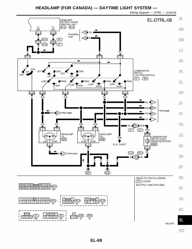
MEL997L
GI
MA
EM
LC
EC
FE
CL
MT
AT
TF
PD
AX
SU
BR
ST
RS
BT
HA
SC
IDX
HEADLAMP (FOR CANADA) — DAYTIME LIGHT SYSTEM —Wiring Diagram — DTRL — (Cont’d)
EL-69

MEL998L
HEADLAMP (FOR CANADA) — DAYTIME LIGHT SYSTEM —Wiring Diagram — DTRL — (Cont’d)
EL-70

MEL999L
GI
MA
EM
LC
EC
FE
CL
MT
AT
TF
PD
AX
SU
BR
ST
RS
BT
HA
SC
IDX
HEADLAMP (FOR CANADA) — DAYTIME LIGHT SYSTEM —Wiring Diagram — DTRL — (Cont’d)
EL-71
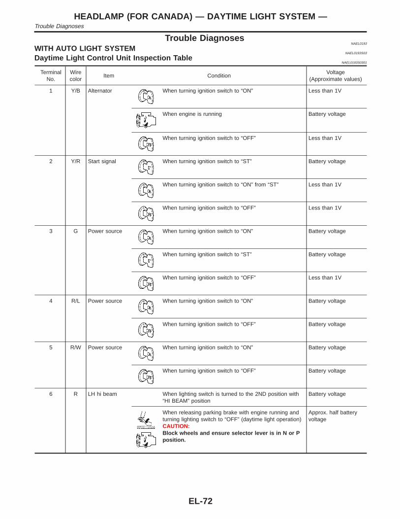
Trouble DiagnosesNAEL0193
WITH AUTO LIGHT SYSTEMNAEL0193S03
Daytime Light Control Unit Inspection TableNAEL0193S0301
TerminalNo.
Wirecolor
Item ConditionVoltage
(Approximate values)
1 Y/B Alternator When turning ignition switch to “ON” Less than 1V
When engine is running Battery voltage
When turning ignition switch to “OFF” Less than 1V
2 Y/R Start signal When turning ignition switch to “ST” Battery voltage
When turning ignition switch to “ON” from “ST” Less than 1V
When turning ignition switch to “OFF” Less than 1V
3 G Power source When turning ignition switch to “ON” Battery voltage
When turning ignition switch to “ST” Battery voltage
When turning ignition switch to “OFF” Less than 1V
4 R/L Power source When turning ignition switch to “ON” Battery voltage
When turning ignition switch to “OFF” Battery voltage
5 R/W Power source When turning ignition switch to “ON” Battery voltage
When turning ignition switch to “OFF” Battery voltage
6 R LH hi beam When lighting switch is turned to the 2ND position with“HI BEAM” position
Battery voltage
When releasing parking brake with engine running andturning lighting switch to “OFF” (daytime light operation)CAUTION:Block wheels and ensure selector lever is in N or Pposition.
Approx. half batteryvoltage
HEADLAMP (FOR CANADA) — DAYTIME LIGHT SYSTEM —Trouble Diagnoses
EL-72

TerminalNo.
Wirecolor
Item ConditionVoltage
(Approximate values)
7 L/R RH hi beam When lighting switch is turned to the 2ND position with“HI BEAM” position
Battery voltage
When releasing parking brake with engine running andturning lighting switch to “OFF” (daytime light operation)CAUTION:Block wheels and ensure selector lever is in N or Pposition.
Approx. half batteryvoltage
9 PU RH hi beam(ground)
When lighting switch is turned to the 2ND position with“HI BEAM” position
Less than 1V
When releasing parking brake with engine running andturning lighting switch to “OFF” (daytime light operation)CAUTION:Block wheels and ensure selector lever is in N or Pposition.
Approx. half batteryvoltage
10 GY LH hi beam(ground)
When lighting switch is turned to the 2ND position with“HI BEAM” position
Less than 1V
When releasing parking brake with engine running andturning lighting switch to “OFF” (daytime light operation)CAUTION:Block wheels and ensure selector lever is in N or Pposition.
Approx. half batteryvoltage
1314
L/WW/R
Lighting switch(Hi beam)
When turning lighting switch to “HI BEAM” Battery voltage
When turning lighting switch to “FLASH TO PASS” Battery voltage
16 B Ground — —
17 L/G Parking brakeswitch
When parking brake is released Battery voltage
When parking brake is set Less than 1.5V
Battery Saver Control Unit Inspection TableNAEL0193S0302
Refer to “HEADLAMP (FOR USA)” EL-47.
GI
MA
EM
LC
EC
FE
CL
MT
AT
TF
PD
AX
SU
BR
ST
RS
BT
HA
SC
IDX
HEADLAMP (FOR CANADA) — DAYTIME LIGHT SYSTEM —Trouble Diagnoses (Cont’d)
EL-73

WITHOUT AUTO LIGHT SYSTEM=NAEL0193S04
Daytime Light Control Unit Inspection TableNAEL0193S0401
TerminalNo.
Item ConditionVoltage
(Approximate val-ues)
1 Start signal When turning ignition switch to “ST” Battery voltage
When turning ignition switch to “ON” from “ST” Less than 1V
When turning ignition switch to “OFF” Less than 1V
2 Power source When turning ignition switch to “ON” Battery voltage
When turning ignition switch to “OFF” Battery voltage
3 Power source When turning ignition switch to “ON” Battery voltage
When turning ignition switch to “OFF” Battery voltage
4 Lighting switch(Lo beam)
When lighting switch is turned to the 2ND position with “LOWBEAM” position
Battery voltage
5 Lighting switch(Hi beam)
When turning lighting switch to “HI BEAM” Battery voltage
When turning lighting switch to “FLASH TO PASS” Battery voltage
6 LH hi beam When turning lighting switch to “HI BEAM” Battery voltage
When releasing parking brake with engine running and turninglighting switch to “OFF” (daytime light operation)CAUTION:Block wheels and ensure selector lever is in N or P posi-tion.
Battery voltage
7 LH headlampcontrol (ground)
When lighting switch is turned to the 2ND position with “LOWBEAM” position
Less than 1V
When releasing parking brake with engine running and turninglighting switch to “OFF” (daytime light operation)CAUTION:Block wheels and ensure selector lever is in N or P posi-tion.
Approx. half batteryvoltage
8 RH hi beam When lighting switch is turned to the 2ND position with “HIBEAM” position
Battery voltage
When releasing parking brake with engine running and turninglighting switch to “OFF” (daytime light operation)CAUTION:Block wheels and ensure selector lever is in N or P posi-tion.
Approx. half batteryvoltage
9 Ground — —
HEADLAMP (FOR CANADA) — DAYTIME LIGHT SYSTEM —Trouble Diagnoses (Cont’d)
EL-74

TerminalNo.
Item ConditionVoltage
(Approximate val-ues)
10 Parking brakeswitch
When parking brake is released Battery voltage
When parking brake is set Less than 1.5V
11 Alternator When turning ignition switch to “ON” Less than 1V
When engine is running Battery voltage
When turning ignition switch to “OFF” Less than 1V
12 Power source When turning ignition switch to “ON” Battery voltage
When turning ignition switch to “ST” Battery voltage
When turning ignition switch to “OFF” Less than 1V
Battery Saver Control Unit Inspection TableNAEL0193S0402
Refer to “HEADLAMP (FOR USA)” EL-50.
Bulb ReplacementNAEL0194
Refer to “HEADLAMP (FOR USA)” (EL-51).
Aiming AdjustmentNAEL0195
Refer to “HEADLAMP (FOR USA)” (EL-51).
GI
MA
EM
LC
EC
FE
CL
MT
AT
TF
PD
AX
SU
BR
ST
RS
BT
HA
SC
IDX
HEADLAMP (FOR CANADA) — DAYTIME LIGHT SYSTEM —Trouble Diagnoses (Cont’d)
EL-75

System DescriptionNAEL0162
The parking, license and tail lamp operation is controlled by the lighting switch which is built into the combi-nation switch and headlamp battery saver control unit. The battery saver system is controlled by the head-lamp battery saver control unit and smart entrance control unit.Power is supplied at all timesI to tail lamp relay terminals 2 and 3I through 10A fuse (No. 61, located in the fuse and fusible link box), andI to headlamp battery saver control unit terminal 7, andI to smart entrance control unit terminal 10I through 7.5A fuse [No. 24, located in the fuse block (J/B)].When ignition switch is in ON or START position, power is suppliedI to headlamp battery saver control unit terminal 1I through 10A fuse [No. 16, located in the fuse block (J/B)], andI to headlamp battery saver control unit terminal 10, andI to smart entrance control unit terminal 33I through 7.5A fuse [No. 11, located in the fuse block (J/B)].Ground is supplied to headlamp battery saver control unit terminals 4 and 11 (with auto light system) or head-lamp battery saver control unit terminals 4, and 3, 9 and 11 (without auto light system).
LIGHTING OPERATION BY LIGHTING SWITCHNAEL0162S01
When lighting switch is in 1ST (or 2ND) position, ground is suppliedI to tail lamp relay terminal 1 from headlamp battery saver control unit terminals 6 and 14I through headlamp battery saver control unit terminals 5 and 13, andI to lighting switch terminal 11I through lighting switch terminal 5 (with auto light system), or lighting switch terminal 12 (without auto light
system)I through body grounds E13 and E41.Tail lamp relay is then energized and the parking, license and tail lamps illuminate.
LIGHTING OPERATION BY AUTO LIGHT CONTROL SYSTEMNAEL0162S03
When auto light control system is operated, ground is suppliedI to tail lamp relay terminal 1 from headlamp battery saver control unit terminals 6 and 14I through headlamp battery saver control unit terminals 5 and 13, andI through auto light control unit terminal 7.Tail lamp relay is then energized and the parking, license and tail lamps illuminate.
BATTERY SAVER CONTROLNAEL0162S02
When the ignition switch is turned from ON (or START) to OFF (or ACC) positions while parking, license andtail lamps are illuminated, the RAP signal is supplied to terminal 10 of the headlamp battery saver control unitfrom smart entrance control unit terminal 5.After counting 45 seconds by the RAP signal from the smart entrance control unit to headlamp battery savercontrol unit, the ground supply to terminal 1 of the tail lamp relay from headlamp battery saver control unitterminals 6 and 14 is terminated.Then the parking, license and tail lamps are turned off.The parking, license and tail lamps are turned off when driver or passenger side door is opened even if 45seconds have not passed after the ignition switch is turned from ON (or START) to OFF (or ACC) positionswhile parking, license and tail lamps are illuminated.When the lighting switch is turned from OFF to 1ST (or 2ND) after the parking, license and tail lamps are turnedoff by the battery saver control, ground is supplied.I to headlamp battery saver control unit terminals 5 and 13 from lighting switch terminal 11, andI to tail lamp relay terminal 1 from headlamp battery saver control unit terminals 6 and 14.Then the parking, license and tail lamps illuminate again.
PARKING, LICENSE AND TAIL LAMPSSystem Description
EL-76
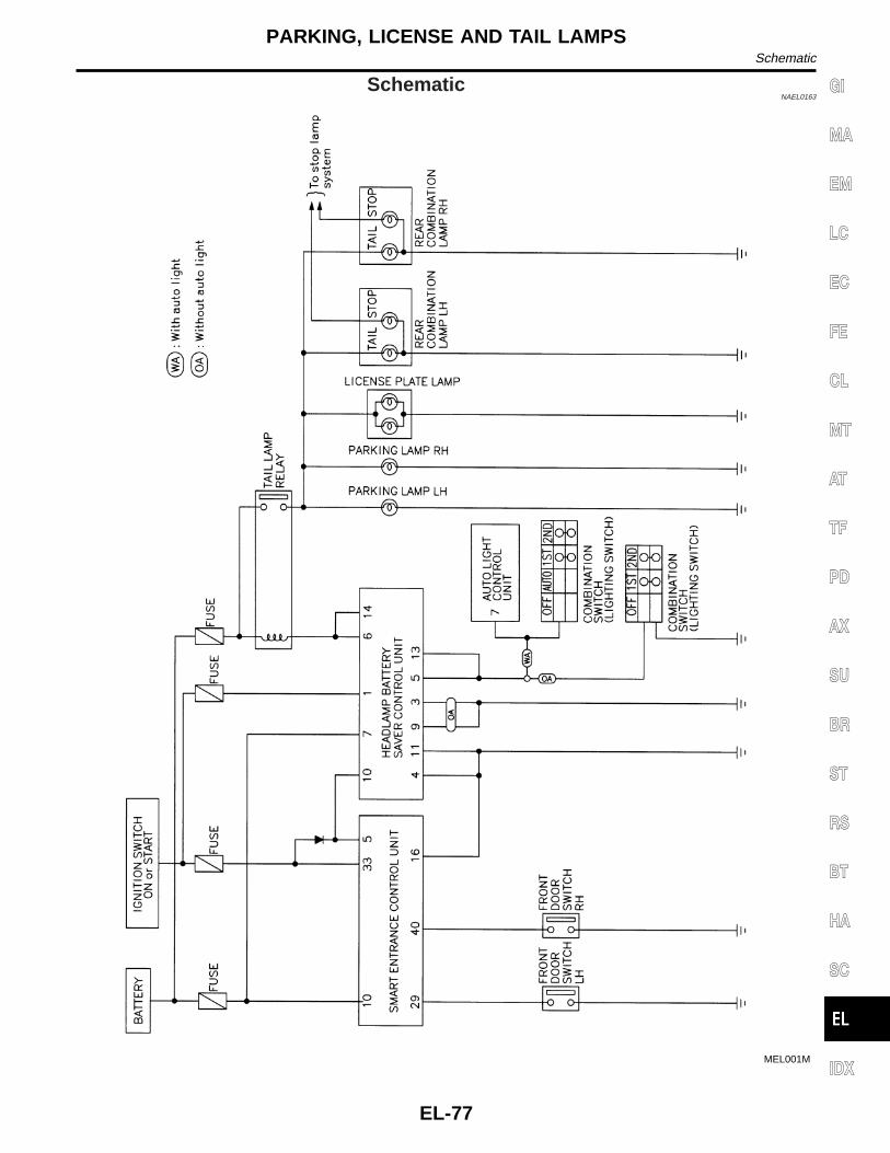
SchematicNAEL0163
MEL001M
GI
MA
EM
LC
EC
FE
CL
MT
AT
TF
PD
AX
SU
BR
ST
RS
BT
HA
SC
IDX
PARKING, LICENSE AND TAIL LAMPSSchematic
EL-77

Wiring Diagram — TAIL/L —NAEL0024
MEL015O
PARKING, LICENSE AND TAIL LAMPSWiring Diagram — TAIL/L —
EL-78

WITH AUTO LIGHT SYSTEMNAEL0024S01
MEL003M
GI
MA
EM
LC
EC
FE
CL
MT
AT
TF
PD
AX
SU
BR
ST
RS
BT
HA
SC
IDX
PARKING, LICENSE AND TAIL LAMPSWiring Diagram — TAIL/L — (Cont’d)
EL-79

WITHOUT AUTO LIGHT SYSTEMNAEL0024S02
MEL004M
PARKING, LICENSE AND TAIL LAMPSWiring Diagram — TAIL/L — (Cont’d)
EL-80

MEL005M
GI
MA
EM
LC
EC
FE
CL
MT
AT
TF
PD
AX
SU
BR
ST
RS
BT
HA
SC
IDX
PARKING, LICENSE AND TAIL LAMPSWiring Diagram — TAIL/L — (Cont’d)
EL-81

Trouble DiagnosesNAEL0164
Symptom Possible cause Repair order
No lamps operate (including head-lamps).
1. 7.5A fuse2. Lighting switch3. Headlamp battery saver control
unit
1. Check 7.5A fuse [No. 24, lacated in fuse block(J/B)]. Verify battery positive voltage is present atterminal 7 of headlamp battery saver control unit.
2. Check lighting switch.3. Check headlamp battery saver control unit. (EL-47)
No parking, license and tail lampsoperate, but headlamps do oper-ate.
1. 10A fuse2. Tail lamp relay3. Tail lamp relay circuit4. Lighting switch5. Lighting switch circuit6. Headlamp battery saver control
unit
1. Check 10A fuse (No. 61, located in fusible and fuseblock). Verify battery positive voltage is present atterminals 2 and 3 of tail lamp relay.
2. Check tail lamp relay.3. Check the following.a. Harness between headlamp battery saver control
unit terminals 6 and 14 and tail lamp relay terminal1
b. Harness between tail lamp relay terminal 5 and fuseblock
4. Check lighting switch.5. Check the following.a. Harness between lighting switch terminal 11 and
headlamp battery saver control unit terminals 5 and13
b. Harness between lighting switch terminal 5 (withauto light system) or lighting switch terminal 12(without auto light system) and ground
6. Check headlamp battery saver control unit. (EL-47)
Battery saver control does notoperate properly.
1. RAP signal circuit2. Driver or passenger side door
switch circuit3. Lighting switch circuit4. Headlamp battery saver control
unit5. Smart entrance control unit
1. Check harness between headlamp battery savercontrol unit terminal 10 and smart entrance controlunit terminal 5 for open or short circuit.
2. Check the following.a. Harness between smart entrance control unit and
driver or passenger side door switch for open orshort circuit
b. Driver or passenger side door switch ground circuitc. Driver or passenger side door switch.3. Check the following.a. Harness between headlamp battery saver control
unit terminals 5 or 13 and lighting switch terminal 11for open or short circuit
b. Harness between lighting switch terminal 5 andground
c. Lighting switch4. Check headlamp battery saver control unit. (EL-47)5. Check smart entrance control unit. (EL-348)
PARKING, LICENSE AND TAIL LAMPSTrouble Diagnoses
EL-82

Wiring Diagram — STOP/L —NAEL0025
MEL777L
GI
MA
EM
LC
EC
FE
CL
MT
AT
TF
PD
AX
SU
BR
ST
RS
BT
HA
SC
IDX
STOP LAMPWiring Diagram — STOP/L —
EL-83

MEL262M
STOP LAMPWiring Diagram — STOP/L — (Cont’d)
EL-84

Wiring Diagram — BACK/L —NAEL0026
MEL006M
GI
MA
EM
LC
EC
FE
CL
MT
AT
TF
PD
AX
SU
BR
ST
RS
BT
HA
SC
IDX
BACK-UP LAMPWiring Diagram — BACK/L —
EL-85

System DescriptionNAEL0027
WITH AUTO LIGHT SYSTEMNAEL0027S04
OutlineNAEL0027S0401
Power is supplied at all timesI to headlamp RH relay terminals 1 and 3I through 15A fuse (No. 59, located in the fuse and fusible link box), andI to headlamp battery saver control unit terminal 7I to smart entrance control unit terminal 10I through 7.5A fuse [No. 24, located in the fuse block (J/B)], andI to front fog lamp relay terminal 3I through 15A fuse (No. 53, located in the fuse and fusible link box).When ignition switch is in ON or START position, power is suppliedI to headlamp battery saver control unit terminal 1I through 10A fuse [No. 16, located in the fuse block (J/B)], andI to headlamp battery saver control unit terminal 10, andI to smart entrance control unit terminal 33I through 7.5A fuse [No. 11, located in the fuse block (J/B)].Ground is supplied to headlamp battery saver control unit terminals 4 and 11.When lighting system is in 2ND position, ground is suppliedI to headlamp RH relay terminal 2 from headlamp battery saver control unit terminals 2 and 8I through headlamp battery saver control unit terminals 3 and 9,I through lighting switch terminal 11, andI through body grounds E13 and E41.Headlamp RH relay is then energized.
Fog Lamp OperationNAEL0027S0402
The fog lamp switch is built into the combination switch. The lighting switch must be in the 2ND position andLOW (“B”) position for fog lamp operation.With the fog lamp switch in the ON position, ground is suppliedI to fog lamp relay terminal 2I through the fog lamp switch, lighting switch and body grounds E13 and E41.The fog lamp relay is energized and power is suppliedI from fog lamp relay terminal 5I to terminal 1 of each fog lamp.Ground is supplied to terminal 2 of each fog lamp through body grounds E13 and E41.With power and ground supplied, the fog lamps illuminate.
Battery Saver ControlNAEL0027S0403
When the ignition switch is turned from ON (or START) to OFF (or ACC) positions while fog lamps areilluminated, the RAP signal is supplied to terminal 10 of the headlamp battery saver control unit from smartentrance control unit terminal 5.After counting 45 seconds by the RAP signal from the smart entrance control unit to headlamp battery savercontrol unit, the ground supply to terminal 2 of headlamp RH relay from headlamp battery saver control unitteminals 2 and 8 are terminated. Then fog lamps are turned to off.Fog lamps are turned off when driver or passenger side door is opened even if 45 seconds have not passedafter the ignition switch is turned from ON (or START) to OFF (or ACC) positions while fog lamps are illumi-nated.When the lighting switch is turned from OFF to 2ND after fog lamps are turned off by the battery saver control,ground is suppliedI to headlamp battery saver control unit terminals 5 and 13 from lighting switch terminal 11, andI to headlamp RH relay terminal 2 from headlamp battery saver control unit terminals 2 and 8I through headlamp battery saver control unit terminals 3 and 9, andI through lighting switch terminal 11.Then the fog lamps illuminate again.
FRONT FOG LAMPSystem Description
EL-86

NOTE:For Trouble Diagnoses for battery saver control, refer to “HEADLAMP (FOR USA)” EL-46.
WITHOUT AUTO LIGHT SYSTEMNAEL0027S05
OutlineNAEL0027S0501
Power is supplied at all timesI to headlamp RH relay terminals 2 and 3I through 15A fuse (No. 59, located in the fuse and fusible link box), andI to headlamp battery saver control unit terminal 7I through 7.5A fuse [No. 24, located in the fuse block (J/B)], andI to front fog lamp relay terminal 3I through 15A fuse (No. 53, located in the fuse and fusible link box).When ignition switch is in ON or START position, power is suppliedI to headlamp battery saver control unit terminal 1I through 10A fuse [No. 16, located in the fuse block (J/B)], andI to headlamp battery saver control unit terminal 10, andI to smart entrance control unit terminal 33I through 7.5A fuse [No. 11, located in the fuse block (J/B)].Ground is supplied to headlamp battery saver control unit terminals 3, 4, 9 and 11.When Ignition Switch is in ON or START PositionGround is suppliedI to headlamp RH relay terminal 1 from headlamp battery saver control unit terminal 8.I through headlamp battery saver control unit terminal 9, andI through body grounds M4, M66 and M147.Headlamp RH relay is then energized.When Ignition Switch is in OFF or ACC PositionWhen lighting switch is in 2ND (or 1ST) position, ground is suppliedI to headlamp battery saver control unit terminals 5 and 13I from lighting switch terminal 11.And then, ground is also supplied to headlamp RH relay terminal 1 from the headlamp battery saver controlunit. The headlamp RH relay is then energized.
Fog Lamp OperationNAEL0027S0502
The fog lamp switch is built into the combination switch. The lighting switch must be in the 2ND position andLOW (“B”) position for fog lamp operation.With the fog lamp switch in the ON position, ground is suppliedI to fog lamp relay terminal 2I through the fog lamp switch and body grounds E13 and E41.The fog lamp relay is energized and power is suppliedI from fog lamp relay terminal 5I to terminal 1 of each fog lamp.Ground is supplied to terminal 2 of each fog lamp through body grounds E13 and E41.With power and ground supplied, the fog lamps illuminate.
Battery Saver ControlNAEL0027S0503
When the ignition switch is turned from ON (or START) to OFF (or ACC) positions while fog lamps areilluminated, the RAP signal is supplied to terminal 10 of the headlamp battery saver control unit from smartentrance control unit terminal 5.After counting 45 seconds by the RAP signal from the smart entrance control unit to headlamp battery savercontrol unit, the ground supply to terminal 1 of headlamp RH relay from headlamp battery saver control unitteminal 8 is terminated.Then fog lamps are turned to off.Fog lamps are turned off when driver or passenger side door is opened even if 45 seconds have not passed
GI
MA
EM
LC
EC
FE
CL
MT
AT
TF
PD
AX
SU
BR
ST
RS
BT
HA
SC
IDX
FRONT FOG LAMPSystem Description (Cont’d)
EL-87

after the ignition switch is turned from ON (or START) to OFF (or ACC) positions while fog lamps are illumi-nated.When the lighting switch is turned from OFF to 2ND after fog lamps are turned off by the battery saver control,ground is suppliedI to headlamp battery saver control unit terminals 5 and 13 from lighting switch terminal 11, andI to headlamp RH relay terminal 1 from headlamp battery saver control unit terminal 8.Then the fog lamps illuminate again.NOTE:For Trouble Diagnoses for battery saver control, refer to “HEADLAMP (FOR USA)” (EL-49).
FRONT FOG LAMPSystem Description (Cont’d)
EL-88

Wiring Diagram — F/FOG —NAEL0028
WITH AUTO LIGHT SYSTEMNAEL0028S01
MEL016O
GI
MA
EM
LC
EC
FE
CL
MT
AT
TF
PD
AX
SU
BR
ST
RS
BT
HA
SC
IDX
FRONT FOG LAMPWiring Diagram — F/FOG —
EL-89

MEL421N
FRONT FOG LAMPWiring Diagram — F/FOG — (Cont’d)
EL-90

WITHOUT AUTO LIGHT SYSTEMNAEL0028S02
MEL017O
GI
MA
EM
LC
EC
FE
CL
MT
AT
TF
PD
AX
SU
BR
ST
RS
BT
HA
SC
IDX
FRONT FOG LAMPWiring Diagram — F/FOG — (Cont’d)
EL-91

MEL422N
FRONT FOG LAMPWiring Diagram — F/FOG — (Cont’d)
EL-92

SEL158W
Aiming AdjustmentNAEL0029
Before performing aiming adjustment, make sure of the following.1) Keep all tires inflated to correct pressure.2) Place vehicle on level ground.3) See that vehicle is unloaded (except for full levels of coolant,
engine oil and fuel, and spare tire, jack, and tools). Have thedriver or equivalent weight placed in driver’s seat.
Adjust aiming in the vertical direction by turning the adjustingscrew.
MEL327G
1. Set the distance between the screen and the center of the foglamp lens as shown at left.
2. Turn front fog lamps ON.
MEL328GA
3. Adjust front fog lamps so that the top edge of the high inten-sity zone is 200 mm (7.9 in) below the height of the fog lampcenters as shown at left.
I When performing adjustment, if necessary, cover the head-lamps and opposite fog lamp.
GI
MA
EM
LC
EC
FE
CL
MT
AT
TF
PD
AX
SU
BR
ST
RS
BT
HA
SC
IDX
FRONT FOG LAMPAiming Adjustment
EL-93

System DescriptionNAEL0030
TURN SIGNAL OPERATIONNAEL0030S01
With the hazard switch in the OFF position and the ignition switch in the ON or START position, power is sup-pliedI through 7.5A fuse [No. 12, located in the fuse block (J/B)]I to hazard switch terminal 2I through terminal 1 of the hazard switchI to combination flasher unit terminal 1I through terminal 3 of the combination flasher unitI to turn signal switch terminal 1.Ground is supplied to combination flasher unit terminal 2 through body grounds M4, M66 and M147.
LH TurnNAEL0030S0101
When the turn signal switch is moved to the LH position, power is supplied from turn signal switch terminal 3I to front turn signal lamp LH terminal 3I to combination meter terminal 25I to rear combination lamp LH terminal 5.Ground is supplied to the turn signal lamp LH terminal 1 through body grounds E13 and E41.Ground is supplied to the rear combination lamp LH terminal 6 through body grounds B11, B22 and D210.Ground is supplied to combination meter terminal 30 through body grounds M4, M66 and M147.With power and ground supplied, the combination flasher unit controls the flashing of the LH turn signal lamps.
RH TurnNAEL0030S0102
When the turn signal switch is moved to the RH position, power is supplied from turn signal switch terminal2I to front turn signal lamp RH terminal 3I to combination meter terminal 29I to rear combination lamp RH terminal 5.Ground is supplied to turn signal terminal 3 through body grounds E13 and E41.Ground is supplied to the rear combination lamp RH terminal 6 through body grounds B55 and B75.Ground is supplied to combination meter terminal 30 through body grounds M4, M66 and M147.With power and ground supplied, the combination flasher unit controls the flashing of the RH turn signal lamps.
HAZARD LAMP OPERATIONNAEL0030S02
Power is supplied at all timesI to hazard switch terminal 3I through 15A fuse [No. 20, located in the fuse block (J/B)].With the hazard switch in the ON position, power is suppliedI through terminal 1 of the hazard switchI to combination flasher unit terminal 1I through terminal 3 of the combination flasher unitI to hazard switch terminal 4.Ground is suppliedI to combination flasher unit terminal 2I through body grounds M4, M66 and M147.Power is suppliedI through terminal 5 of the hazard switchI to front turn signal lamp LH terminal 3I combination meter terminal 25I rear combination lamp LH terminal 5, andI through terminal 6 of the hazard switchI to front turn signal lamp RH terminal 3I combination meter terminal 29I rear combination lamp RH terminal 5.
TURN SIGNAL AND HAZARD WARNING LAMPSSystem Description
EL-94

Ground is supplied to terminal 3 of each front turn signal lamp through body grounds E13 and E41.Ground is supplied to terminal 6 of the rear combination lamp LH through body grounds B11, B22 and D210.Ground is supplied to terminal 6 of the rear combination lamp RH through body grounds B55 and B75.Ground is supplied to combination meter terminal 30 through body grounds M4, M66 and M147.With power and ground supplied, the combination flasher unit controls the flashing of the hazard warninglamps.
MULTI-REMOTE CONTROL SYSTEM OPERATIONNAEL0030S03
Power is supplied at all timesI through 15A fuse [No. 20, located in the fuse block (J/B)]I to multi-remote control relay terminals 1, 3 and 6.Ground is supplied to multi-remote control relay terminal 2, when the multi-remote control system is triggeredthrough the smart entrance control unit.Refer to “MULTI-REMOTE CONTROL SYSTEM”, EL-288.The multi-remote control relay is energized.Power is supplied through terminal 7 of the multi-remote control relayI to front turn signal lamp LH terminal 2I to combination meter terminal 25I to rear combination lamp LH terminal 5.Power is supplied through terminal 5 of the multi-remote control relayI to front turn signal lamp RH terminal 2I to combination meter terminal 29I to rear combination lamp RH terminal 5.Ground is supplied to terminal 3 of each front turn signal lamp through body grounds E13 and E41.Ground is supplied to terminal 6 of the rear combination lamp LH through body grounds B11, B22 and D210.Ground is supplied to terminal 6 of the rear combination lamp RH through body grounds B55 and B75.Ground is supplied to combination meter terminal 30 through body grounds M4, M66 and M147.With power and ground supplied, the smart entrance control unit controls the flashing of the hazard warninglamps.
GI
MA
EM
LC
EC
FE
CL
MT
AT
TF
PD
AX
SU
BR
ST
RS
BT
HA
SC
IDX
TURN SIGNAL AND HAZARD WARNING LAMPSSystem Description (Cont’d)
EL-95
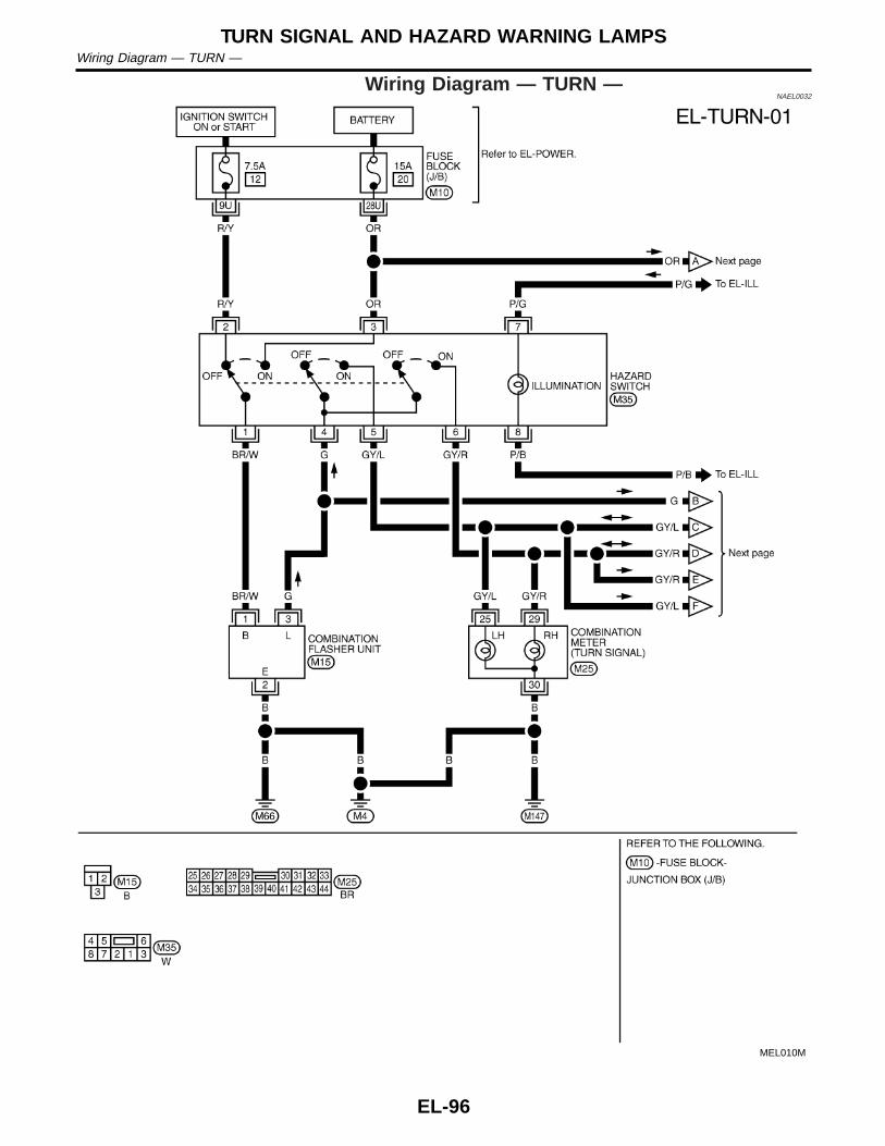
Wiring Diagram — TURN —NAEL0032
MEL010M
TURN SIGNAL AND HAZARD WARNING LAMPSWiring Diagram — TURN —
EL-96

MEL011M
GI
MA
EM
LC
EC
FE
CL
MT
AT
TF
PD
AX
SU
BR
ST
RS
BT
HA
SC
IDX
TURN SIGNAL AND HAZARD WARNING LAMPSWiring Diagram — TURN — (Cont’d)
EL-97

Trouble DiagnosesNAEL0033
Symptom Possible cause Repair order
Turn signal and hazard warninglamps do not operate.
1. Hazard switch2. Combination flasher unit3. Open in combination flasher
unit circuit
1. Check hazard switch.2. Refer to combination flasher unit check.3. Check wiring to combination flasher unit for open
circuit.
Turn signal lamps do not operatebut hazard warning lamps operate.
1. 7.5A fuse2. Hazard switch3. Combination switch (turn signal)4. Open in combination switch
(turn signal) circuit
1. Check 7.5A fuse [No. 12, located in fuse block(J/B)]. Turn ignition switch ON and verify batterypositive voltage is present at terminal 2 of hazardswitch.
2. Check hazard switch.3. Check combination switch (turn signal).4. Check the wire between combination flasher unit
terminal 3 and combination switch (turn signal) ter-minal 1 for open circuit.
Hazard warning lamps do not oper-ate but turn signal operate.
1. 15A fuse2. Hazard switch3. Open in hazard switch circuit
1. Check 15A fuse [No. 20, located in fuse block (J/B)].Verify battery positive voltage is present at terminal3 of hazard switch.
2. Check hazard switch.3. Check the wire between combination flasher unit
terminal 3 and hazard switch terminal 4 for open cir-cuit.
Front turn signal lamp LH or RHdoes not operate.
1. Bulb2. Grounds E13 and E413. Open in front turn signal lamp
circuit
1. Check bulb.2. Check grounds E13 and E41.3. Check harness between front turn signal lamp and
combination switch.
Rear combination lamp LH doesnot operate.
1. Bulb2. Grounds B11, B22 and D2103. Open in rear combination lamp
LH circuit
1. Check bulb.2. Check grounds B11, B22 and D210.3. Check harness between rear combination lamp LH
and hazard switch.
Rear combination lamp RH doesnot operate.
1. Bulb2. Grounds B55 and B753. Open in rear combination lamp
RH circuit
1. Check bulb.2. Check grounds B55 and B75.3. Check harness between rear combination lamp RH
and hazard switch.
LH and RH turn indicators do notoperate.
1. Ground 1. Check grounds M4, M66 and M147.
LH or RH turn indicator does notoperate.
1. Bulb2. Open in turn indicator circuit
1. Check bulb in combination meter.2. Check harness between combination meter and haz-
ard switch.
SEL122E
Electrical Components InspectionNAEL0034
COMBINATION FLASHER UNIT CHECKNAEL0034S01
I Before checking, ensure that bulbs meet specifications.I Connect a battery and test lamp to the combination flasher
unit, as shown. Combination flasher unit is properly function-ing if it blinks when power is supplied to the circuit.
TURN SIGNAL AND HAZARD WARNING LAMPSTrouble Diagnoses
EL-98

System DescriptionNAEL0035
The illumination lamp operation is controlled by the lighting switch which is built into the combination switchand headlamp battery saver control unit. The battery saver system is controlled by the headlamp battery savercontrol unit and smart entrance control unit.Power is supplied at all timesI to tail lamp relay terminals 2 and 3I through 10A fuse (No. 61, located in the fuse and fusible link box), andI to headlamp battery saver control unit terminal 7, andI to smart entrance control unit terminal 10I through 7.5A fuse [No. 24, located in the fuse block (J/B)].When ignition switch is in ON or START position, power is suppliedI to headlamp battery saver control unit terminal 1I through 10A fuse [No. 16, located in the fuse block (J/B)], andI to headlamp battery saver control unit terminal 10, andI to smart entrance control unit terminal 33I through 7.5A fuse [No. 11, located in the fuse block (J/B)].Ground is supplied to headlamp battery saver control unit terminals 4 and 11.
LIGHTING OPERATION BY LIGHTING SWITCHNAEL0035S01
When lighting switch is 1ST (or 2ND) position, ground is suppliedI to tail lamp relay terminal 1 from headlamp battery saver control unit terminals 6 and 14I through headlamp battery saver control unit terminals 5 and 13, andI through body grounds E13 and E41.Tail lamp relay is then energized and illumination lamps illuminate.The lighting switch must be in the 1ST or 2ND position for illumination.
LIGHTING OPERATION BY AUTO LIGHT CONTROL SYSTEMNAEL0035S03
When auto light operation is operated, ground is suppliedI to tail lamp relay terminal 1 from headlamp battery saver control unit terminals 6 and 14I through headlamp battery saver control unit terminals 5 and 13, andI through auto light control unit terminal 7.Tail lamp relay is then energized and the illumination lamps illuminate.The illumination control switch that controls the amount of current to the illumination system. As the amountof current increases, the illumination becomes brighter.The following chart shows the power and ground connector terminals for the components included in the illu-mination system.
Component Connector No. Power terminal Ground terminal
Illumination control switch M19 1 3
A/C switch M45 2 1
4WD shift switch M141 7 8
Ashtray M54 1 2
A/T indicator B59 3 4
Cigarette lighter M57 3 4
Audio unit M48 8 7
CD player M92, M93 3 5
Compass and thermometer R4 5 2
Hazard switch M35 7 8
Rear window defogger switch M36 5 6
CD auto changer M125 2 9
GI
MA
EM
LC
EC
FE
CL
MT
AT
TF
PD
AX
SU
BR
ST
RS
BT
HA
SC
IDX
ILLUMINATIONSystem Description
EL-99
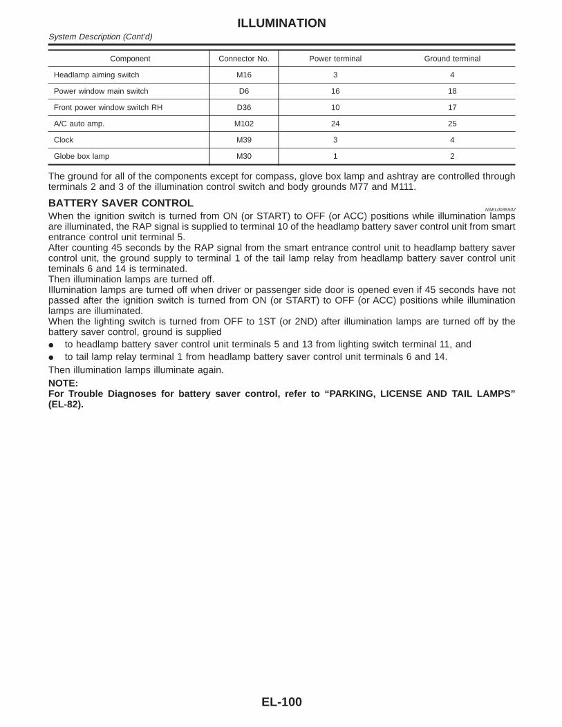
Component Connector No. Power terminal Ground terminal
Headlamp aiming switch M16 3 4
Power window main switch D6 16 18
Front power window switch RH D36 10 17
A/C auto amp. M102 24 25
Clock M39 3 4
Globe box lamp M30 1 2
The ground for all of the components except for compass, glove box lamp and ashtray are controlled throughterminals 2 and 3 of the illumination control switch and body grounds M77 and M111.
BATTERY SAVER CONTROLNAEL0035S02
When the ignition switch is turned from ON (or START) to OFF (or ACC) positions while illumination lampsare illuminated, the RAP signal is supplied to terminal 10 of the headlamp battery saver control unit from smartentrance control unit terminal 5.After counting 45 seconds by the RAP signal from the smart entrance control unit to headlamp battery savercontrol unit, the ground supply to terminal 1 of the tail lamp relay from headlamp battery saver control unitteminals 6 and 14 is terminated.Then illumination lamps are turned off.Illumination lamps are turned off when driver or passenger side door is opened even if 45 seconds have notpassed after the ignition switch is turned from ON (or START) to OFF (or ACC) positions while illuminationlamps are illuminated.When the lighting switch is turned from OFF to 1ST (or 2ND) after illumination lamps are turned off by thebattery saver control, ground is suppliedI to headlamp battery saver control unit terminals 5 and 13 from lighting switch terminal 11, andI to tail lamp relay terminal 1 from headlamp battery saver control unit terminals 6 and 14.Then illumination lamps illuminate again.NOTE:For Trouble Diagnoses for battery saver control, refer to “PARKING, LICENSE AND TAIL LAMPS”(EL-82).
ILLUMINATIONSystem Description (Cont’d)
EL-100

SchematicNAEL0036
MEL012M
GI
MA
EM
LC
EC
FE
CL
MT
AT
TF
PD
AX
SU
BR
ST
RS
BT
HA
SC
IDX
ILLUMINATIONSchematic
EL-101

Wiring Diagram — ILL —NAEL0037
MEL018O
ILLUMINATIONWiring Diagram — ILL —
EL-102

WITH AUTO LIGHT SYSTEMNAEL0037S01
MEL014M
GI
MA
EM
LC
EC
FE
CL
MT
AT
TF
PD
AX
SU
BR
ST
RS
BT
HA
SC
IDX
ILLUMINATIONWiring Diagram — ILL — (Cont’d)
EL-103

WITHOUT AUTO LIGHT SYSTEMNAEL0037S02
MEL015M
ILLUMINATIONWiring Diagram — ILL — (Cont’d)
EL-104

MEL016M
GI
MA
EM
LC
EC
FE
CL
MT
AT
TF
PD
AX
SU
BR
ST
RS
BT
HA
SC
IDX
ILLUMINATIONWiring Diagram — ILL — (Cont’d)
EL-105

MEL017M
ILLUMINATIONWiring Diagram — ILL — (Cont’d)
EL-106

MEL018M
GI
MA
EM
LC
EC
FE
CL
MT
AT
TF
PD
AX
SU
BR
ST
RS
BT
HA
SC
IDX
ILLUMINATIONWiring Diagram — ILL — (Cont’d)
EL-107

System DescriptionNAEL0038
POWER SUPPLY AND GROUNDNAEL0038S06
Power is supplied at all times:I through 7.5A fuse [No. 24, located in the fuse block (J/B)]I to key switch terminal 2 andI to smart entrance control unit terminal 10.When the key is removed from ignition key cylinder, power is interrupted:I through key switch terminal 1I to smart entrance control unit terminal 32.With the ignition key switch in the ON or START position, power is supplied:I through 7.5A fuse [No. 11, located in the fuse block (J/B)]I to smart entrance control unit terminal 33.Ground is supplied:I to smart entrance control unit terminal 16I through body grounds terminals M77 and M111.When the front driver side door is opened, ground is supplied:I through body grounds B11, B22 and D210I to front door switch (LH) terminal 2I from front door switch (LH) terminal 1I to smart entrance control unit terminal 29.When the front passenger side door is opened, ground is supplied:I through case ground of front door switch (RH)I from front door switch (RH) terminal 1I to smart entrance control unit terminal 40.When any other door (except front door) is opened, ground is supplied to smart entrance control unit termi-nal 28 in the same manner as the front door switch (front passenger side).When the front driver side door is unlocked, the smart entrance control unit receives a ground signal:I through body grounds terminals M77 and M111I to front door lock actuator (driver side unlock sensor) terminal 2I from front door lock actuator (driver side unlock sensor) terminal 4I to smart entrance control unit terminal 36.When a signal, or combination of signals is received by the smart entrance control unit, ground is supplied:I through smart entrance control unit terminal 8I to interior lamp terminal 2.With power and ground supplied, the interior lamp illuminates.
SWITCH OPERATIONNAEL0038S07
When interior lamp switch is ON, ground is supplied:I through case grounds of interior lampI to interior lamp.And power is supplied:I to interior lamp terminal 1I from smart entrance control unit terminal 17.When spot lamp (LH and/or RH) is ON, ground is supplied:I through body grounds M4, M66 and M147I to spot lamp terminal 2.And power is supplied:I to spot lamp terminal 1I from smart entrance control unit terminal 17.When vanity mirror illumination (LH and/or RH) is ON, ground is supplied:I through body grounds M4, M66 and M147I to vanity mirror illuminations (LH and RH) terminals 2.
INTERIOR, SPOT, VANITY MIRROR AND LUGGAGE ROOM LAMPSSystem Description
EL-108

And power is supplied:I to vanity mirror illuminations (LH and RH) terminals 1I from smart entrance control unit terminal 17.With power and ground supplied, interior lamps turn ON.
INTERIOR LAMP TIMER OPERATIONNAEL0038S08
When interior lamp switch is in the “DOOR” position, the smart entrance control unit keeps the interior lampilluminated for about 30 seconds when:I unlock signal is supplied from driver’s door unlock sensor while all doors are closed and key is removed
from ignition key cylinderI unlock signal is supplied from multi-remote controller while all doors are closed and driver’s door is lockedI key is removed from ignition key cylinder while all doors are closedI driver’s door is opened and then closed while key is removed from the iginition key cylinder. (However, if
the driver’s door is closed with the key insered in the ignition key cylinder after the driver’s door is openedwith the key removed, the timer is operated.)
The timer is canceled when:I driver’s door is locked,I driver’s door is opened, orI ignition switch is turned ON.
ON-OFF CONTROLNAEL0038S09
When the driver side door, front passenger door, rear LH, RH door or back door is opened, the interior roomlamp turns on while the interior room lamp switch is in the “DOOR” position.
BATTERY SAVERNAEL0038S10
The lamp turns off automatically when interior lamp, luggage room lamp, spot lamp and/or vanity mirror illu-mination is illuminated with the ignition key is in OFF position, if the lamp remains lit by the door switch opensignal or if the lamp switch is in ON position for more than 10 minutes.After lamps turn OFF by the battery saver system, the lamps illuminate again when:I driver’s door is locked or unlocked,I door is opened or closed,I key is inserted or removed in ignition key cylinder.
GI
MA
EM
LC
EC
FE
CL
MT
AT
TF
PD
AX
SU
BR
ST
RS
BT
HA
SC
IDX
INTERIOR, SPOT, VANITY MIRROR AND LUGGAGE ROOM LAMPSSystem Description (Cont’d)
EL-109

SchematicNAEL0158
MEL209M
INTERIOR, SPOT, VANITY MIRROR AND LUGGAGE ROOM LAMPSSchematic
EL-110

Wiring Diagram — INT/L —NAEL0040
MEL789L
GI
MA
EM
LC
EC
FE
CL
MT
AT
TF
PD
AX
SU
BR
ST
RS
BT
HA
SC
IDX
INTERIOR, SPOT, VANITY MIRROR AND LUGGAGE ROOM LAMPSWiring Diagram — INT/L —
EL-111

MEL790L
INTERIOR, SPOT, VANITY MIRROR AND LUGGAGE ROOM LAMPSWiring Diagram — INT/L — (Cont’d)
EL-112

MEL791L
GI
MA
EM
LC
EC
FE
CL
MT
AT
TF
PD
AX
SU
BR
ST
RS
BT
HA
SC
IDX
INTERIOR, SPOT, VANITY MIRROR AND LUGGAGE ROOM LAMPSWiring Diagram — INT/L — (Cont’d)
EL-113

Component Parts and Harness ConnectorLocation
NAEL0041
SEL351X
System DescriptionNAEL0042
UNIFIED CONTROL METERNAEL0042S06
I Speedometer, odo/trip meter, tachometer, fuel gauge and water temperature gauge are controlled totallyby control unit.
I Digital meter is adopted for odo/trip meter.**The record of the odo meter is kept even if the battery cable is disconnected. The record of the trip meteris erased when the battery cable is disconnected.
I Odo/trip meter is indicated for about 30 seconds after ignition switch has been turned OFF.I Odo/trip meter segment can be checked in diagnosis mode.I Meter/gauge can be checked in diagnosis mode.
HOW TO CHANGE THE DISPLAY FOR ODO/TRIP METERNAEL0042S07
SEL175W
NOTE:Turn ignition switch to the “ON” position to operate odo/trip meter.
METERS AND GAUGESComponent Parts and Harness Connector Location
EL-114

POWER SUPPLY AND GROUND CIRCUITNAEL0042S08
Power is supplied at all timesI through 7.5A fuse [No. 24, located in the fuse block (J/B)]I to combination meter terminal 62.With the ignition switch in the ON or START position, power is suppliedI through 10A fuse [No. 8, located in the fuse block (J/B)]I to combination meter terminal 66.Ground is suppliedI to combination meter terminal 59I through body grounds M4, M66 and M147.
WATER TEMPERATURE GAUGENAEL0042S01
The water temperature gauge indicates the engine coolant temperature. The reading on the gauge is basedon the resistance of the thermal transmitter.As the temperature of the coolant increases, the resistance of the thermal transmitter decreases. A variableground is supplied to terminal 18 of the combination meter for the water temperature gauge. The needle onthe gauge moves from “C” to “H”.
TACHOMETERNAEL0042S02
The tachometer indicates engine speed in revolutions per minute (rpm).The tachometer is regulated by a signalI from terminal 25 of the ECMI to combination meter terminal 16 for the tachometer.
FUEL GAUGENAEL0042S03
The fuel gauge indicates the approximate fuel level in the fuel tank.The fuel gauge is regulated by a variable ground signal suppliedI to combination meter terminal 17 for the fuel gaugeI from terminal 3 of the fuel level sensor unitI through terminal 2 of the fuel level sensor unit andI through body grounds B11, B22 and D210.
SPEEDOMETERNAEL0042S04
The vehicle speed sensor provides a voltage signal to the combination meter for the speedometer.The voltage is suppliedI from combination meter terminal 15 for the speedometerI to terminal 2 of the vehicle speed sensor.The speedometer converts the voltage into the vehicle speed displayed.
GI
MA
EM
LC
EC
FE
CL
MT
AT
TF
PD
AX
SU
BR
ST
RS
BT
HA
SC
IDX
METERS AND GAUGESSystem Description (Cont’d)
EL-115
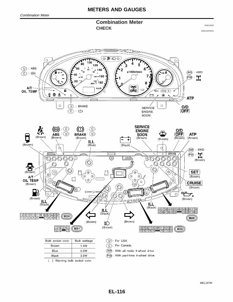
Combination MeterNAEL0043
CHECKNAEL0043S01
MEL247M
METERS AND GAUGESCombination Meter
EL-116

CONSTRUCTIONNAEL0043S02
SEL390X
GI
MA
EM
LC
EC
FE
CL
MT
AT
TF
PD
AX
SU
BR
ST
RS
BT
HA
SC
IDX
METERS AND GAUGESCombination Meter (Cont’d)
EL-117

SchematicNAEL0199
MEL248M
METERS AND GAUGESSchematic
EL-118

Wiring Diagram — METER —NAEL0045
MEL020M
GI
MA
EM
LC
EC
FE
CL
MT
AT
TF
PD
AX
SU
BR
ST
RS
BT
HA
SC
IDX
METERS AND GAUGESWiring Diagram — METER —
EL-119

Meter/Gauge Operation and Odo/Trip MeterSegment Check in Diagnosis Mode
NAEL0200
DIAGNOSIS FUNCTIONNAEL0200S01
I Odo/trip meter segment can be checked in diagnosis mode.I Meters/gauges can be checked in diagnosis mode.
HOW TO ALTERNATE DIAGNOSIS MODENAEL0200S02
1. Turn ignition switch to ON and change odo/trip meter to “TRIPA” or “TRIP B”.
2. Turn ignition switch to OFF.3. Turn ignition switch to ON when pushing odo/trip meter switch.4. Push odo/trip meter switch 1 second.5. Release odo/trip meter switch.6. Push odo/trip meter switch more than three times within 7
seconds.
SEL176W
7. All odo/trip meter segments should be turned on.NOTE:If some segments are not turned on, unified meter control unit withodo/trip meter should be replaced.
At this point, the unified control meter is turned to diagnosismode.
SEL177W
8. Push odo/trip meter switch. Indication of each meter/gaugeshould be as shown left during pushing odo/trip meter switchif it is no malfunctioning.
NOTE:It takes about a few seconds for indication of fuel gauge and watertemperature gauge to become stable.
METERS AND GAUGESMeter/Gauge Operation and Odo/Trip Meter Segment Check in Diagnosis Mode
EL-120

Trouble DiagnosesNAEL0201
PRELIMINARY CHECKNAEL0201S01
SEL361W
*1: Meter/Gauge Operation and Odo/Trip Meter Segment Check inDiagnosis Mode (EL-120)
*2: METER/GAUGE RESISTANCECHECK (EL-128)
*3: POWER SUPPLY AND GROUNDCIRCUIT CHECK (EL-123)
*4: Symptom Chart 1 (EL-122)
*5: Symptom Chart 2 (EL-122)
GI
MA
EM
LC
EC
FE
CL
MT
AT
TF
PD
AX
SU
BR
ST
RS
BT
HA
SC
IDX
METERS AND GAUGESTrouble Diagnoses
EL-121
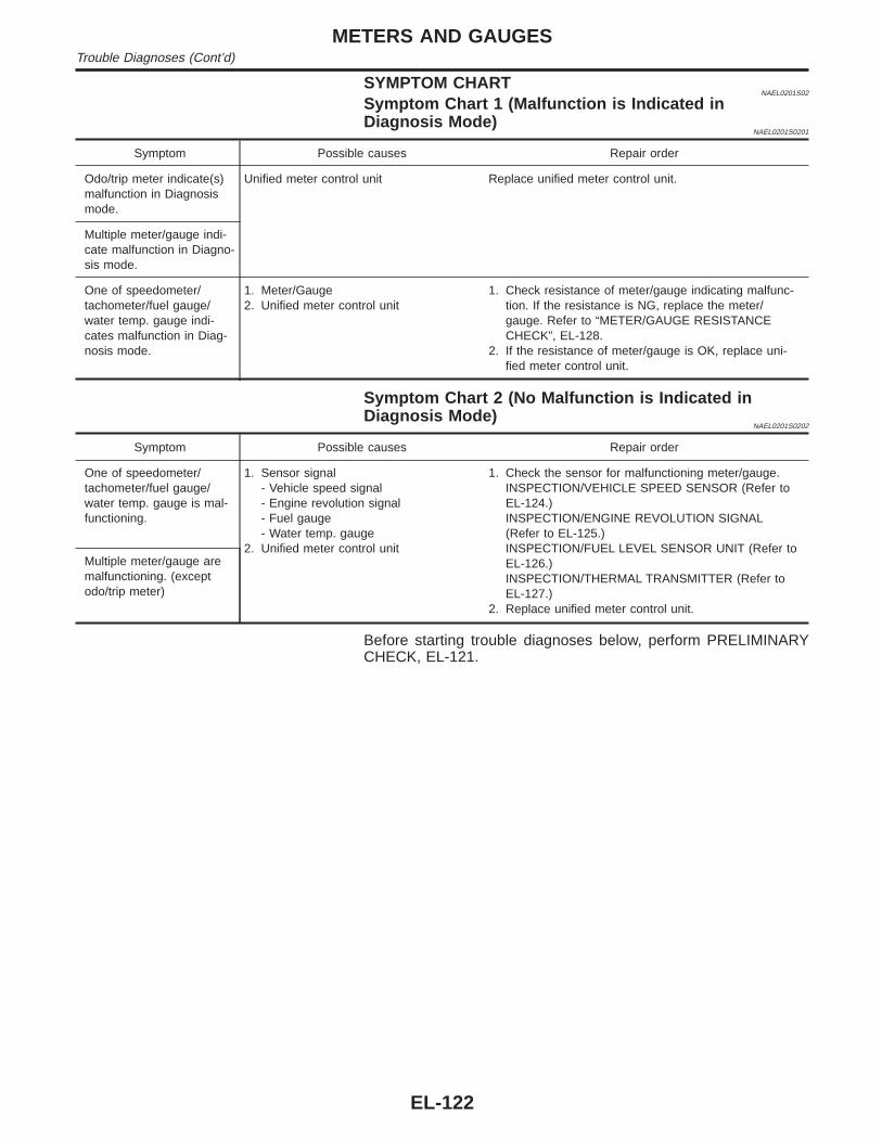
SYMPTOM CHARTNAEL0201S02
Symptom Chart 1 (Malfunction is Indicated inDiagnosis Mode)
NAEL0201S0201
Symptom Possible causes Repair order
Odo/trip meter indicate(s)malfunction in Diagnosismode.
Unified meter control unit Replace unified meter control unit.
Multiple meter/gauge indi-cate malfunction in Diagno-sis mode.
One of speedometer/tachometer/fuel gauge/water temp. gauge indi-cates malfunction in Diag-nosis mode.
1. Meter/Gauge2. Unified meter control unit
1. Check resistance of meter/gauge indicating malfunc-tion. If the resistance is NG, replace the meter/gauge. Refer to “METER/GAUGE RESISTANCECHECK”, EL-128.
2. If the resistance of meter/gauge is OK, replace uni-fied meter control unit.
Symptom Chart 2 (No Malfunction is Indicated inDiagnosis Mode)
NAEL0201S0202
Symptom Possible causes Repair order
One of speedometer/tachometer/fuel gauge/water temp. gauge is mal-functioning.
1. Sensor signal- Vehicle speed signal- Engine revolution signal- Fuel gauge- Water temp. gauge
2. Unified meter control unit
1. Check the sensor for malfunctioning meter/gauge.INSPECTION/VEHICLE SPEED SENSOR (Refer toEL-124.)INSPECTION/ENGINE REVOLUTION SIGNAL(Refer to EL-125.)INSPECTION/FUEL LEVEL SENSOR UNIT (Refer toEL-126.)INSPECTION/THERMAL TRANSMITTER (Refer toEL-127.)
2. Replace unified meter control unit.
Multiple meter/gauge aremalfunctioning. (exceptodo/trip meter)
Before starting trouble diagnoses below, perform PRELIMINARYCHECK, EL-121.
METERS AND GAUGESTrouble Diagnoses (Cont’d)
EL-122

SEL179WB
POWER SUPPLY AND GROUND CIRCUIT CHECK=NAEL0201S03
Power Supply Circuit CheckNAEL0201S0301
Terminals Ignition switch position
(+) (−) OFF ACC ON
62 GroundBatteryvoltage
Batteryvoltage
Batteryvoltage
66 Ground 0V 0VBatteryvoltage
If NG, check the following.I 10A fuse [No. 12, located in fuse block (J/B)]I 10A fuse [No. 30, located in fuse block (J/B)]I Harness for open or short between fuse and combination
meter
SEL180WA
Ground Circuit CheckNAEL0201S0302
Terminals Continuity
59 - Ground Yes
GI
MA
EM
LC
EC
FE
CL
MT
AT
TF
PD
AX
SU
BR
ST
RS
BT
HA
SC
IDX
METERS AND GAUGESTrouble Diagnoses (Cont’d)
EL-123

INSPECTION/VEHICLE SPEED SENSOR=NAEL0201S04
1 CHECK VEHICLE SPEED SENSOR OUTPUT
1. Remove vehicle speed sensor from transmission.2. Check voltage between combination meter terminals 15 and 63 while quickly turning speed sensor pinion.
SEL297X
OK or NG
OK © Vehicle speed sensor is OK.
NG © GO TO 2.
2 CHECK VEHICLE SPEED SENSOR
Check resistance between vehicle speed sensor terminals 1 and 2.
SEL298X
OK or NG
OK © Check harness or connector between speedometer and vehicle speed sensor.
NG © Replace vehicle speed sensor.
METERS AND GAUGESTrouble Diagnoses (Cont’d)
EL-124
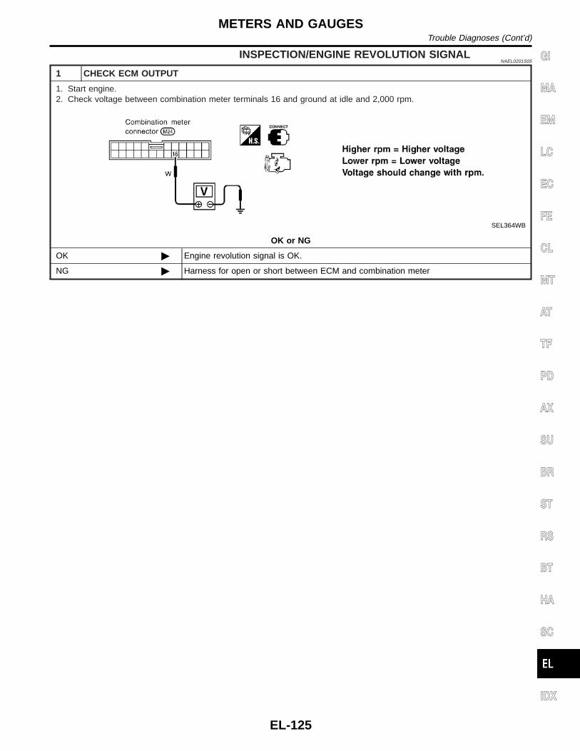
INSPECTION/ENGINE REVOLUTION SIGNALNAEL0201S05
1 CHECK ECM OUTPUT
1. Start engine.2. Check voltage between combination meter terminals 16 and ground at idle and 2,000 rpm.
SEL364WB
OK or NG
OK © Engine revolution signal is OK.
NG © Harness for open or short between ECM and combination meter
GI
MA
EM
LC
EC
FE
CL
MT
AT
TF
PD
AX
SU
BR
ST
RS
BT
HA
SC
IDX
METERS AND GAUGESTrouble Diagnoses (Cont’d)
EL-125

INSPECTION/FUEL LEVEL SENSOR UNIT=NAEL0201S06
1 CHECK GROUND CIRCUIT FOR FUEL LEVEL SENSOR UNIT
Check harness continuity between fuel level sensor unit terminal 2 and ground.
SEL299X
OK or NG
OK © GO TO 2.
NG © Repair harness or connector.
2 CHECK FUEL LEVEL SENSOR UNIT
Refer to “FUEL LEVEL SENSOR UNIT CHECK” (EL-128).
OK or NG
OK © GO TO 3.
NG © Replace fuel level sensor unit.
3 CHECK HARNESS FOR OPEN OR SHORT
1. Disconnect combination meter connector and fuel level sensor unit connector.2. Check continuity between combination meter terminal 17 and fuel level sensor unit terminal 3.3. Check continuity between combination meter terminal 17 and ground.
SEL300X
OK or NG
OK © Fuel level sensor unit is OK.
NG © Repair harness or connector.
METERS AND GAUGESTrouble Diagnoses (Cont’d)
EL-126

INSPECTION/THERMAL TRANSMITTER=NAEL0201S07
1 CHECK THERMAL TRANSMITTER
Refer to “THERMAL TRANSMITTER CHECK” (EL-128).
OK or NG
OK © GO TO 2.
NG © Replace.
2 CHECK HARNESS FOR OPEN OR SHORT
1. Disconnect combination meter connector and thermal transmitter connector.2. Check continuity between combination meter terminal 18 and thermal transmitter terminal 1.
Continuity should exist.3. Check continuity between combination meter terminal 18 and ground.
Continuity should not exist.
SEL184WA
OK or NG
OK © Thermal transmitter is OK.
NG © Repair harness or connector.
GI
MA
EM
LC
EC
FE
CL
MT
AT
TF
PD
AX
SU
BR
ST
RS
BT
HA
SC
IDX
METERS AND GAUGESTrouble Diagnoses (Cont’d)
EL-127

Electrical Components Inspection=NAEL0202
METER/GAUGE RESISTANCE CHECKNAEL0202S01
Check resistance between installation screws of meter/gauge.
Screws ResistanceΩTacho/Speedometer Fuel/Temp. gauge
A - C A - C Approx. 190 - Approx. 260
B - D B - C Approx. 230 - Approx. 310
SEL391X
YEL066K
FUEL LEVEL SENSOR UNIT CHECKNAEL0202S02
I For removal, refer to FE-4, “FUEL SYSTEM”.Check the resistance between terminals 3 and 2.
OhmmeterFloat position mm (in)
Resistancevalue Ω(+) (−)
3 2
*1 Full 95 (3.74) Approx. 4 - 6
*2 1/2 184 (7.24) 31 - 34
*3 Empty 265 (10.43) 80 - 83
*1 and *3: When float rod is in contact with stopper.
MEL424F
THERMAL TRANSMITTER CHECKNAEL0202S03
Check the resistance between the terminals of thermal transmitterand body ground.
Water temperature Resistance
60°C (140°F) Approx. 170 - 210Ω
100°C (212°F) Approx. 47 - 53Ω
METERS AND GAUGESElectrical Components Inspection
EL-128

MEL005H
VEHICLE SPEED SENSOR SIGNAL CHECKNAEL0202S04
1. Remove vehicle speed sensor from transmission.2. Turn vehicle speed sensor pinion quickly and measure voltage
across a and b.
GI
MA
EM
LC
EC
FE
CL
MT
AT
TF
PD
AX
SU
BR
ST
RS
BT
HA
SC
IDX
METERS AND GAUGESElectrical Components Inspection (Cont’d)
EL-129

System DescriptionNAEL0153
SEL713U
This unit displays following items:I Earth magnetism and heading direction of vehicle.I Outside air temperature.I Caution for frozen road surfaces.
OUTSIDE TEMPERATURE DISPLAYNAEL0153S01
Push the switch when the ignition key is in the “ACC” or “ON” position. The outside temperature will be dis-played in “°F”.I Selecting the indication range
Push the switch to change from “°F” to “°C”.I When the outside temperature drops below freezing point, ICE is displayed on the unit.I When the outside temperature is between 55°C (130°F) and 70°C (158°F), the display shows 55°C
(130°F).I When the outside temperature is lower than −30°C (−20°F) or higher than 70°C (158°F), the display shows
only “---” though it is operating. This is not a problem.I The indicated temperature on the thermometer is not readily affected by engine heat. It changes only when
one of the following conditions is present.a) The temperature detected by the ambient air temperature sensor is lower than the indicated temperature
on the thermometer.b) The difference in temperature detected during a period of 40 seconds is less than 1°C (1.8°F) when vehicle
speed has been greater than 24 km/h (15 MPH) for more than 100 seconds.(This is to prevent the indicated temperature from being affected by engine heat or cooling fan operationduring low-speed driving.)
c) The ignition key has been turned to the “OFF” position for more than 4 hours. (The engine is cold.)
DIRECTION DISPLAYNAEL0153S02
Push the switch when the ignition key is in the “ACC” or “ON” position. The direction will be displayed.
COMPASS AND THERMOMETERSystem Description
EL-130

Wiring Diagram — COMPAS —NAEL0154
MEL029M
GI
MA
EM
LC
EC
FE
CL
MT
AT
TF
PD
AX
SU
BR
ST
RS
BT
HA
SC
IDX
COMPASS AND THERMOMETERWiring Diagram — COMPAS —
EL-131

Trouble DiagnosesNAEL0048
PRELIMINARY CHECK FOR THERMOMETERNAEL0048S02
1 COOL DOWN CHECK
1. Turn the ignition key switch to the “ACC” position.2. Cool down the ambient air temperature sensor with water or ice, so that the indicated temperature falls.
Does the indicated temperature fall?
Yes © GO TO 2.
No © The system is malfunctioning. Check the system following “INSPECTION/COMPASSAND THERMOMETER”.
2 WARM UP CHECK
1. Leave the vehicle for 10 minutes, so that the indicated temperature rises.2. With the ignition key in the “ACC” position, disconnect and reconnect the ambient air temperature sensor connector.
Does the indicated temperature rise?
Yes © The system is OK.
No © The system is malfunctioning. Check the system following “INSPECTION/COMPASSAND THERMOMETER”.
NOTE:I When the outside temperature is between 55°C (130°F) and 70°C (158°F), the display shows 55°C
(130°F). When the outside temperature is lower than −30°C (−20°F) or higher than 70°C (158°F), the dis-play shows only “---”.
I The indicated temperature on the thermometer is not readily affected by engine heat. It changes only whenone of the following conditions is present.
a) The temperature detected by the ambient air temperature sensor is lower than the indicated temperatureon the thermometer.
b) The difference in temperature detected during a period of 40 seconds is less than 1°C (1.8°F) when vehiclespeed has been greater than 24 km/h (15 MPH) for more than 100 seconds.(This is to prevent the indicated temperature from being affected by engine heat or cooling fan operationduring low-speed driving.)
c) The ignition key has been turned to the “OFF” position for more than 4 hours. (The engine is cold.)
INSPECTION/COMPASS AND THERMOMETERNAEL0048S01
Symptom Possible causes Repair order
No display at all 1. 10A fuse2. Ground circuit3. Compass and thermometer
1. Check 10A fuse [No. 9, located in fuse block (J/B)].Turn the ignition switch ON and verify that battery positivevoltage is at terminal 7 of compass and thermometer.
2. Check ground circuit for compass and thermometer.3. Replace compass and thermometer.
Forward direction indi-cation slips off themark or incorrect.
1. In manual correction mode (Barand display vanish.)
2. Zone variation change is not done.
1. Drive the vehicle and turn at an angle of 90°.2. Perform the zone variation change.
Compass readingremains unchanged.
1. Vehicle speed sensor is notentered.
2. Compass and thermometer
1. Check harness for open or short between combination meterterminal 13 and compass and thermometer terminal 1.
2. Replace compass and thermometer.
Displays wrong tem-perature when ambienttemperature is between−30°C (−20°F) and55°C (130°F). (SeeNOTE above.)
1. Check operation2. Ambient air temperature sensor
circuit3. Vehicle speed sensor is not
entered.4. Ambient air temperature sensor5. Compass and thermometer
1. Perform preliminary check shown above.2. Check harness for open or short between ambient air tem-
perature sensor and compass and thermometer.3. Check harness for open or short between combination meter
terminal 13 and compass and thermometer terminal 1.4. Replace ambient air temperature sensor.5. Replace compass and thermometer.
COMPASS AND THERMOMETERTrouble Diagnoses
EL-132

Calibration Procedure for Compass=NAEL0155
The difference between magnetic North and geographical Northcan sometimes be great enough to cause false compass readings.In order for the compass to operate accurately in a particular zone,it must be calibrated using the following procedure.
SEL738UA
SEL065V
CORRECTION FUNCTIONS OF COMPASSNAEL0155S01
The direction display is equipped with automatic correction func-tion. If the direction is not shown correctly, carry out initial correc-tion.
INITIAL CORRECTION PROCEDURE FOR COMPASSNAEL0155S02
1. Pushing the “Mode” switch for about 10 seconds will enter theinitial correction mode. The direction bar starts blinking.
2. Turn the vehicle slowly in an open, safe place. The initial cor-rection is completed in one or two turns.
NOTE:In places where the terrestrial magnetism is extremely disturbed,the initial correction may start automatically.
GI
MA
EM
LC
EC
FE
CL
MT
AT
TF
PD
AX
SU
BR
ST
RS
BT
HA
SC
IDX
COMPASS AND THERMOMETERCalibration Procedure for Compass
EL-133

SchematicNAEL0049
MEL021M
WARNING LAMPSSchematic
EL-134

Wiring Diagram — WARN —NAEL0050
MEL022M
GI
MA
EM
LC
EC
FE
CL
MT
AT
TF
PD
AX
SU
BR
ST
RS
BT
HA
SC
IDX
WARNING LAMPSWiring Diagram — WARN —
EL-135

MEL023M
WARNING LAMPSWiring Diagram — WARN — (Cont’d)
EL-136

MEL019O
GI
MA
EM
LC
EC
FE
CL
MT
AT
TF
PD
AX
SU
BR
ST
RS
BT
HA
SC
IDX
WARNING LAMPSWiring Diagram — WARN — (Cont’d)
EL-137

MEL025M
WARNING LAMPSWiring Diagram — WARN — (Cont’d)
EL-138

MEL246M
GI
MA
EM
LC
EC
FE
CL
MT
AT
TF
PD
AX
SU
BR
ST
RS
BT
HA
SC
IDX
WARNING LAMPSWiring Diagram — WARN — (Cont’d)
EL-139

MEL026M
WARNING LAMPSWiring Diagram — WARN — (Cont’d)
EL-140
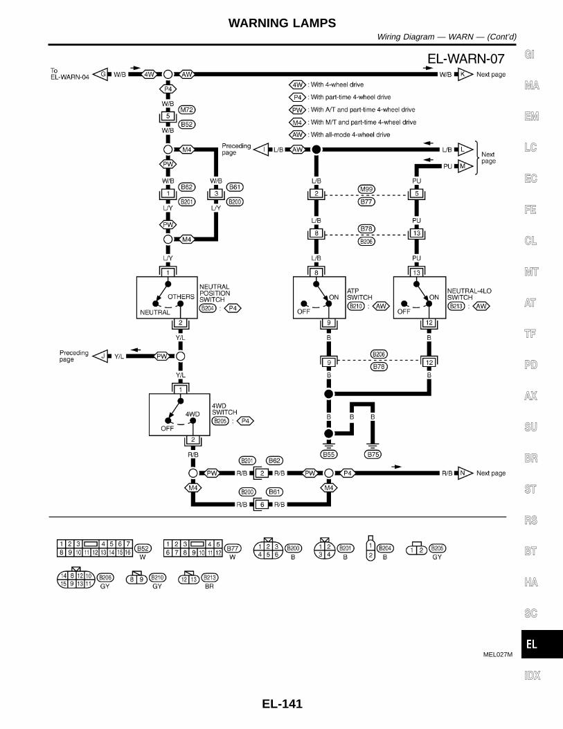
MEL027M
GI
MA
EM
LC
EC
FE
CL
MT
AT
TF
PD
AX
SU
BR
ST
RS
BT
HA
SC
IDX
WARNING LAMPSWiring Diagram — WARN — (Cont’d)
EL-141

MEL028M
WARNING LAMPSWiring Diagram — WARN — (Cont’d)
EL-142

SEL062WA
Fuel Warning Lamp Sensor CheckNAEL0166
1. Turn ignition switch “OFF”.2. Disconnect fuel level sensor unit harness connector B12.3. Connect a resistor (80Ω) between fuel tank gauge unit harness
connector terminals 2 and 3.4. Turn ignition switch “ON”.The fuel warning lamp should come on.NOTE:ECM might store the 1st trip DTC P0180 during this inspection.If the DTC is stored in ECM memory, erase the DTC after recon-necting fuel tank gauge unit harness connector.Refer to EC-73, “HOW TO ERASE EMISSION-RELATED DIAG-NOSTIC INFORMATION”.
MEL425F
Electrical Components InspectionNAEL0051
OIL PRESSURE SWITCH CHECKNAEL0051S02
Oil pressurekPa (kg/cm2, psi)
Continuity
Engine startMore than 10 - 20(0.1 - 0.2, 1 - 3)
NO
Engine stopLess than 10 - 20(0.1 - 0.2, 1 - 3)
YES
Check the continuity between the terminals of oil pressure switchand body ground.
SEL901F
DIODE CHECKNAEL0051S03
I Check continuity using an ohmmeter.I Diode is functioning properly if test results are as shown in the
figure at left.I Check diodes at the combination meter harness connector
instead of checking them on the combination meter assembly.Refer to EL-135, “WARNING LAMP” wiring diagrams.
NOTE:Specification may vary depending on the type of tester. Beforeperforming this inspection, be sure to refer to the instructionmanual for the tester to be used.
GI
MA
EM
LC
EC
FE
CL
MT
AT
TF
PD
AX
SU
BR
ST
RS
BT
HA
SC
IDX
WARNING LAMPSFuel Warning Lamp Sensor Check
EL-143

Component Parts and Harness ConnectorLocation
NAEL0052
SEL046W
System DescriptionNAEL0053
The warning chime is controlled by the smart entrance control unit.The warning chime is located in the smart entrance control unit.Power is supplied at all timesI through 7.5A fuse [No. 24, located in the fuse block (J/B)]I to smart entrance control unit terminal 10, andI to key switch terminal 2, andI through 10A fuse [No. 61, located in the fuse block (J/B)]I to tail lamp relay terminals 2 and 3.With the ignition switch in the ON or START position, power is suppliedI through 7.5A fuse [No. 11, located in the fuse block (J/B)]I to smart entrance control unit terminal 33.Ground is supplied to smart entrance control unit terminal 16 through body grounds M77 and M111.
IGNITION KEY WARNING CHIMENAEL0053S01
With the key in the ignition switch in the OFF or ACC position, and the driver’s door open, the warning chimewill sound. Power is suppliedI from key switch terminal 1I to smart entrance control unit terminal 32.Ground is suppliedI from front door switch LH terminal 1I to smart entrance control unit terminal 29.Front door switch LH terminal 2 is grounded through body grounds B11, B22 and D210.
LIGHT WARNING CHIMENAEL0053S02
With ignition switch OFF or ACC, driver’s door open, warning chime will sound. [Except when headlamp bat-tery saver control operates (for 45 seconds after ignition switch is turned to OFF or ACC position) and head-lamps do not illuminate.] Power is supplied.I from tail lamp relay terminal 5I to smart entrance control unit terminal 34.Ground is suppliedI from front door switch LH terminal 1
WARNING CHIMEComponent Parts and Harness Connector Location
EL-144

I to smart entrance control unit terminal 29.Front door switch LH terminal 2 is grounded through body grounds B11, B22 and D210.
SEAT BELT WARNING CHIMENAEL0053S03
With ignition switch turned ON and seat belt unfastened (seat belt switch ON), warning chime will sound forapproximately 6 seconds.Ground is suppliedI from seat belt switch terminal 1I to smart entrance control unit terminal 22.Seat belt switch terminal 2 is grounded through body grounds B11, B22 and D210.
GI
MA
EM
LC
EC
FE
CL
MT
AT
TF
PD
AX
SU
BR
ST
RS
BT
HA
SC
IDX
WARNING CHIMESystem Description (Cont’d)
EL-145

Wiring Diagram — CHIME —NAEL0054
MEL804L
WARNING CHIMEWiring Diagram — CHIME —
EL-146

MEL030M
GI
MA
EM
LC
EC
FE
CL
MT
AT
TF
PD
AX
SU
BR
ST
RS
BT
HA
SC
IDX
WARNING CHIMEWiring Diagram — CHIME — (Cont’d)
EL-147

Trouble DiagnosesNAEL0055
SYMPTOM CHARTNAEL0055S01
REFERENCE PAGE (EL- ) 148 150 152 153 154
SYMPTOM
PO
WE
RS
UP
PLY
AN
DG
RO
UN
DC
IRC
UIT
CH
EC
K
LIG
HT
ING
SW
ITC
HIN
PU
TS
IGN
AL
CH
EC
K
KE
YS
WIT
CH
(IN
SE
RT
)C
HE
CK
SE
AT
BE
LTB
UC
KLE
SW
ITC
HC
HE
CK
DR
IVE
RS
IDE
DO
OR
SW
ITC
HC
HE
CK
Light warning chime does not acti-vate.
X X X
Ignition key warning chime does notactivate.
X X X
Seat belt warning chime does notactivate.
X X
All warning chimes do not activate. X
SEL301X
POWER SUPPLY AND GROUND CIRCUIT CHECKNAEL0055S02
Power Supply Circuit CheckNAEL0055S0201
Terminals Ignition switch position
(+) (−) OFF ACC ON
10 GroundBatteryvoltage
Batteryvoltage
Batteryvoltage
33 Ground 0V 0VBatteryvoltage
WARNING CHIMETrouble Diagnoses
EL-148

SEL013W
Ground Circuit CheckNAEL0055S0202
Terminals Continuity
16 - Ground Yes
GI
MA
EM
LC
EC
FE
CL
MT
AT
TF
PD
AX
SU
BR
ST
RS
BT
HA
SC
IDX
WARNING CHIMETrouble Diagnoses (Cont’d)
EL-149

LIGHTING SWITCH INPUT SIGNAL CHECK=NAEL0055S03
1 CHECK LIGHTING SWITCH INPUT SIGNAL
Check voltage between smart entrance control unit terminal 34 and ground.
SEL377X
OK or NG
OK © Lighting switch is OK.
NG © GO TO 2.
2 CHECK FUSE
Is 10A fuse (No. 61, located in the fuse and fusible link box) OK?
OK or NG
OK © GO TO 3.
NG © Replace fuse.
3 CHECK TAIL LAMP RELAY CIRCUIT
Check voltage between headlamp battery saver control unit terminal 6, 14 and ground.
SEL378X
OK or NG
OK © Check the following.I Tail lamp relayI Harness for open or short between smart entrance control unit and tail lamp relay.
NG © GO TO 4.
WARNING CHIMETrouble Diagnoses (Cont’d)
EL-150

4 CHECK TAIL LAMP SWITCH GROUND CIRCUIT
1. Disconnect headlamp battery saver control unit connector.2. Check continuity between headlamp battery saver control unit terminal 5, 13 and ground.
SEL379X
OK or NG
OK © Check headlamp battery saver control unit. Refer to EL-47.
NG © Check the following.I Lighting switchI Harness for open or short between headlamp battery saver control unit terminal 5, 13
and lighting switch terminal 11I Harness between lighting switch terminal 5 (with auto light system) or lighting switch
terminal 12 (without auto light system) and ground
GI
MA
EM
LC
EC
FE
CL
MT
AT
TF
PD
AX
SU
BR
ST
RS
BT
HA
SC
IDX
WARNING CHIMETrouble Diagnoses (Cont’d)
EL-151

KEY SWITCH (INSERT) CHECK=NAEL0055S04
1 CHECK KEY SWITCH INPUT SIGNAL
Check voltage between smart entrance control unit terminal 32 and ground.
SEL307X
OK or NG
OK © Key switch is OK.
NG © GO TO 2.
2 CHECK KEY SWITCH (INSERT)
Check continuity between terminals 1 and 2.
SEL308X
OK or NG
OK © Check the following.I 7.5A fuse [No. 24, located in fuse block (J/B)]I Harness for open or short between key switch and fuseI Harness for open or short between smart entrance control unit and key switch
NG © Replace key switch.
WARNING CHIMETrouble Diagnoses (Cont’d)
EL-152
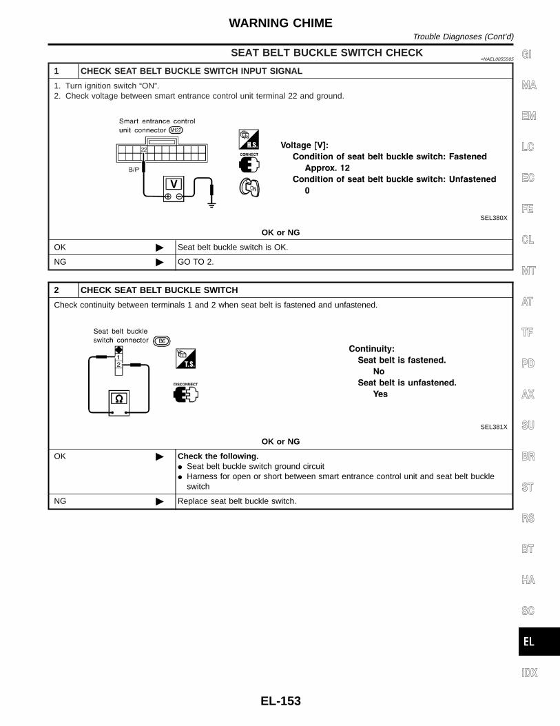
SEAT BELT BUCKLE SWITCH CHECK=NAEL0055S05
1 CHECK SEAT BELT BUCKLE SWITCH INPUT SIGNAL
1. Turn ignition switch “ON”.2. Check voltage between smart entrance control unit terminal 22 and ground.
SEL380X
OK or NG
OK © Seat belt buckle switch is OK.
NG © GO TO 2.
2 CHECK SEAT BELT BUCKLE SWITCH
Check continuity between terminals 1 and 2 when seat belt is fastened and unfastened.
SEL381X
OK or NG
OK © Check the following.I Seat belt buckle switch ground circuitI Harness for open or short between smart entrance control unit and seat belt buckle
switch
NG © Replace seat belt buckle switch.
GI
MA
EM
LC
EC
FE
CL
MT
AT
TF
PD
AX
SU
BR
ST
RS
BT
HA
SC
IDX
WARNING CHIMETrouble Diagnoses (Cont’d)
EL-153

DRIVER SIDE DOOR SWITCH CHECKNAEL0055S06
1 CHECK DOOR SWITCH INPUT SIGNAL
Check voltage between smart entrance control unit terminal 29 and ground.
SEL382X
OK or NG
OK © Front door switch LH is OK.
NG © GO TO 2.
2 CHECK DRIVER SIDE DOOR SWITCH
Check continuity between terminals 1 and 2.
SEL383X
OK or NG
OK © Check the following.I Door switch ground circuitI Harness for open or short between smart entrance control unit and door switch
NG © Replace front door switch LH.
WARNING CHIMETrouble Diagnoses (Cont’d)
EL-154

System DescriptionNAEL0057
WIPER OPERATIONNAEL0057S01
The front wiper switch is controlled by a lever built into the combination switch.There are three wiper switch positions:I LO speedI HI speedI INT (Intermittent)With the ignition switch in the ACC or ON position, power is suppliedI through 20A fuse [No. 19, located in the fuse block (J/B)]I to front wiper motor terminal 4, andI to front wiper switch terminal 15.
Low and High Speed Wiper OperationNAEL0057S0101
Ground is supplied to front wiper switch terminal 17 through body grounds E13 and E41.When the wiper switch is placed in the LO position, ground is suppliedI through terminal 14 of the front wiper switchI to front wiper motor terminal 3.With power and ground supplied, the front wiper motor operates at low speed.When the front wiper switch is placed in the HI position, ground is suppliedI through terminal 16 of the front wiper switchI to front wiper motor terminal 1.With power and ground supplied, the front wiper motor operates at high speed.
Auto Stop OperationNAEL0057S0102
With front wiper switch turned OFF, front wiper motor will continue to operate until wiper arms reach windshieldbase.When wiper arms are not located at base of windshield with front wiper switch OFF, ground is providedI from terminal 14 of the front wiper switchI to front wiper motor terminal 3, in order to continue front wiper motor operation at low speed.Ground is also suppliedI to terminal 13 of the front wiper switchI through front wiper motor terminal 2I through terminal 6 of the front wiper motor, andI through body grounds M77 and M111.When wiper arms reach base of windshield, front wiper motor terminals 2 and 4 are connected instead of ter-minals 2 and 6. Wiper motor will then stop wiper arms at the PARK position.
Intermittent OperationNAEL0057S0103
The front wiper motor operates the wiper arms one time at low speed at a set interval of approximately 2 to13 seconds. This feature is controlled by the wiper amplifier built in the front wiper switch.When the front wiper switch is placed in the INT position, ground is suppliedI to wiper amplifier (INT SW)I from front wiper switch terminal 17I through body grounds E13 and E41, andI to front wiper motor terminal 3I through the front wiper switch terminal 14I through wiper amplifier (OUTPUT)
WASHER OPERATIONNAEL0057S02
With the ignition switch in the ACC or ON position, power is suppliedI through 20A fuse [No. 19, located in the fuse block (J/B)]I to front washer motor terminal 1.When the lever is pulled to the WASH position, ground is suppliedI to front washer motor terminal 2I through terminal 18 of the front wiper switch
GI
MA
EM
LC
EC
FE
CL
MT
AT
TF
PD
AX
SU
BR
ST
RS
BT
HA
SC
IDX
FRONT WIPER AND WASHERSystem Description
EL-155
I through terminal 17 of the front wiper switch, andI through body grounds E13 and E41.With power and ground supplied, the front washer motor operates.When the lever is pulled to the WASH position for one second or more, the front wiper motor operates at lowspeed for approximately 3 seconds to clean windshield. This feature is controlled by the wiper amplifier in thesame manner as the intermittent operation.
FRONT WIPER AND WASHERSystem Description (Cont’d)
EL-156

Wiring Diagram — WIPER —NAEL0058
MEL806L
GI
MA
EM
LC
EC
FE
CL
MT
AT
TF
PD
AX
SU
BR
ST
RS
BT
HA
SC
IDX
FRONT WIPER AND WASHERWiring Diagram — WIPER —
EL-157

SEL543TA
Removal and InstallationNAEL0060
WIPER ARMSNAEL0060S01
1. Prior to wiper arm installation, turn on wiper switch to operatewiper motor and then turn it “OFF” (Auto Stop).
2. Lift the blade up and then set it down onto glass surface to setthe blade center to clearance “L1” & “L2” immediately beforetightening nut.
3. Eject washer fluid. Turn on wiper switch to operate wiper motorand then turn it “OFF”.
4. Ensure that wiper blades stop within clearance “L1” & “L2”.Clearance “L 1”: 29 - 30 mm (1.14 - 1.18 in)Clearance “L 2”: 32 - 42 mm (1.26 - 1.65 in)
I Tighten wiper arm nuts to specified torque.Front wiper: 21 - 26 N·m (2.1 - 2.7 kg-m, 15 - 20 ft-lb)
SEL024J
I Before reinstalling wiper arm, clean up the pivot area asillustrated. This will reduce possibility of wiper arm loose-ness.
WIPER LINKAGENAEL0060S02
MEL840F
FRONT WIPER AND WASHERRemoval and Installation
EL-158

RemovalNAEL0060S0201
1. Remove 4 bolts that secure wiper motor.2. Detach wiper motor from wiper linkage at ball joint.3. Remove wiper linkage.Be careful not to break ball joint rubber boot.
InstallationNAEL0060S0202
I Grease ball joint portion before installation.1. Installation is the reverse order of removal.
MEL137M
Washer Nozzle AdjustmentNAEL0061
I Adjust washer nozzle with suitable tool as shown in the figureat left.
Adjustable range: ±10°
MEL540M
Unit: mm (in)
*1 251 (9.88) *6 459 (18.07)
*2 351 (13.82) *7 256 (10.08)
*3 165 (6.50) *8 67 (2.64)
*4 269 (10.59) *9 42 (1.65)
*5 167 (6.57)
*A: The diameters of these circles are less than 80 mm (3.15 in).*B: The diameter of this circle is less than 138 × 80 mm (5.43 × 3.15 in).*C: The diameter of this circle is less than 96 × 80 mm (3.78 × 3.15 in).
MEL074H
Washer Tube LayoutNAEL0062
GI
MA
EM
LC
EC
FE
CL
MT
AT
TF
PD
AX
SU
BR
ST
RS
BT
HA
SC
IDX
FRONT WIPER AND WASHERRemoval and Installation (Cont’d)
EL-159

System DescriptionNAEL0063
WIPER OPERATIONNAEL0063S01
Power Supply and GroundNAEL0063S0101
With ignition switch in the ACC or ON position, power is suppliedI through 10A fuse [No. 29, located in the fuse block (J/B)]I to rear wiper amp. terminal 6.When the glass hatch switch is OPEN, ground is suppliedI to rear wiper amp. terminal 3I through glass hatch switch terminal 1 and 2I through body grounds B11, B22 and D210.Ground is suppliedI to rear wiper amp. terminal 9I through body grounds B11, B22 and D210.
Low Speed Wiper OperationNAEL0063S0103
When the rear wiper switch is turned ON, ground is suppliedI to rear wiper amp. terminal 2I through combination switch terminals 22 and 24I through body grounds E13 and E41.Then, power is suppliedI through rear wiper amp. terminal 11I to rear wiper motor terminal 4.Ground is suppliedI to rear wiper motor terminal 3I through rear wiper amp. terminal 8.With power and ground supplied, the wiper motor operates at low speed.
Auto Stop OperationNAEL0063S0104
With rear wiper switch turned OFF, rear wiper motor will continue to operate until wiper arm reaches rear wiperstopper.When rear wiper arm is not located at bottom with wiper switch OFF, ground is suppliedI to rear wiper amp. terminal 10I through wiper motor terminals 7 and 8I through body grounds B11, B22 and D210.Then rear wiper motor continues to operate until wiper arm reaches bottom.When wiper arm reaches bottom, power is suppliedI through 10A fuse [No. 29, located in the fuse block (J/B)]I through rear wiper motor terminals 6 and 7 andI through rear wiper amp. terminals 10 and 8I to rear wiper motor terminal 3.Ground is suppliedI to rear wiper motor 4I through rear wiper amp. terminal 11.Then wiper motor turns the other way and wiper arm moves once until wiper arm reaches stopper.
Intermittent OperationNAEL0063S0105
The rear wiper motor operates the wiper arms at low speed approximately every 7 seconds. This feature iscontrolled by the wiper amp.When the wiper switch is placed in the INT position, ground is suppliedI to wiper amp. terminal 4I through rear combination switch terminal 21 and 24I through body grounds E13 and E41.Then, power is suppliedI through rear wiper amp. terminal 11
REAR WIPER AND WASHERSystem Description
EL-160

I to rear wiper motor terminal 4.Ground is suppliedI to rear wiper motor terminal 3I through rear wiper amp. terminal 8.With power and ground supplied, rear wiper operates at low speed intermittent.
WIPER OPERATION PROHIBIT CONTROLNAEL0063S03
When glass hatch is open with back door key cylinder while rear wiper is operated, wiper operation is stopped.(Wiper operation prohibit control)When glass hatch is closed and rear wiper switch turns from OFF and then rear wiper switch is turned to ON,wiper operation prohibit control is canceled.
WASHER OPERATIONNAEL0063S02
When the rear wiper switch is turned to WASH position, ground is suppliedI to rear wiper amp. terminal 1I through terminals 23 and 24I through body grounds E13 and E41.Then, power is suppliedI through rear wiper amp. terminal 7I to rear washer motor terminal 2.Ground is suppliedI to rear washer motor terminal 1I through body grounds E13 and E41.With power and ground supplied, the rear washer motor operates.When the rear wiper switch is turned to WASH position for one second or more, the rear wiper motor oper-ates at low speed for approximately 3 seconds after the rear wiper switch is released. This feature is controlledby the rear wiper amp. in the same manner as the low speed operation.
GI
MA
EM
LC
EC
FE
CL
MT
AT
TF
PD
AX
SU
BR
ST
RS
BT
HA
SC
IDX
REAR WIPER AND WASHERSystem Description (Cont’d)
EL-161

Wiring Diagram — WIP/R —NAEL0065
MEL031M
REAR WIPER AND WASHERWiring Diagram — WIP/R —
EL-162

MEL032M
GI
MA
EM
LC
EC
FE
CL
MT
AT
TF
PD
AX
SU
BR
ST
RS
BT
HA
SC
IDX
REAR WIPER AND WASHERWiring Diagram — WIP/R — (Cont’d)
EL-163

Trouble DiagnosesNAEL0066
REAR WIPER AMP. INSPECTION TABLENAEL0066S01
(Data are reference values.)
Terminal No. Item Condition Voltage(Approximate value)
1 Washer switch Rear wiper switch WASH Less than 1V
OFF, ON or INT Battery voltage
2 Low switch Rear wiper switch ON Less than 1V
OFF or INT Battery voltage
3 Glass hatch switch Glass hatch Open Less than 1V
Closed Battery voltage
4 Intermittent switch Rear wiper switch INT Less than 1V
OFF, ON or WASH Battery voltage
6 Power supply (ACC) — Battery voltage
7 Washer motor Rear washer switch WASH Battery voltage
OFF, ON or INT Less than 1V
8 Rear wiper motor Wiper is moving (except final drive) Less than 1V
Wiper stop Less than 1V
During wiper final drive Battery voltage
9 Ground — —
10 Auto stop switch Rear wiper switchshould be at “INT” toinspect the value forwiper movement.
Wiper is moving Less than 1V
Wiper stop Battery voltage
11 Rear wiper motor Wiper is moving (except final drive) Battery voltage
Wiper stop Battery voltage
During wiper final drive Less than 1V
NOTE:Power to the rear wiper amp. will be interrupted when the rear glass hatch is opened. In that case, conductthe inspection of the rear wiper amp. with the rear glass hatch closed, unless otherwise indicated.
MEL066G
Removal and InstallationNAEL0067
WIPER ARMSNAEL0067S01
1. Prior to wiper arm installation, turn on wiper switch to operatewiper motor and then turn it “OFF” (Auto Stop).
2. Install wiper arm to portion A as in figure below and tightenwiper arm nut to specification.
3. Then, set wiper arm to portion B.: 13 - 18 N·m (1.3 - 1.8 kg-m , 9 - 13 ft-lb)
REAR WIPER AND WASHERTrouble Diagnoses
EL-164

SEL024J
I Before reinstalling wiper arm, clean up the pivot area asillustrated. This will reduce possibility of wiper arm loose-ness.
SEL241P
MEL034G
Washer Nozzle AdjustmentNAEL0068
I Adjust washer nozzle with suitable tool as shown in the figureat left.
Adjustable range: ±10° (In any direction)
MEL067G
Washer Tube LayoutNAEL0069
SEL411H
Check ValveNAEL0070
I A check valve is provided in the washer fluid line. Be carefulnot to connect check valve to washer tube in the wrong direc-tion.
GI
MA
EM
LC
EC
FE
CL
MT
AT
TF
PD
AX
SU
BR
ST
RS
BT
HA
SC
IDX
REAR WIPER AND WASHERRemoval and Installation (Cont’d)
EL-165

Wiring Diagram — HORN —NAEL0071
MEL033M
HORNWiring Diagram — HORN —
EL-166

Wiring Diagram — CIGAR —NAEL0156
MEL812L
GI
MA
EM
LC
EC
FE
CL
MT
AT
TF
PD
AX
SU
BR
ST
RS
BT
HA
SC
IDX
CIGARETTE LIGHTERWiring Diagram — CIGAR —
EL-167

MEL034M
CIGARETTE LIGHTERWiring Diagram — CIGAR — (Cont’d)
EL-168

Wiring Diagram — CLOCK —NAEL0204
MEL035M
GI
MA
EM
LC
EC
FE
CL
MT
AT
TF
PD
AX
SU
BR
ST
RS
BT
HA
SC
IDX
CLOCKWiring Diagram — CLOCK —
EL-169

Component Parts and Harness ConnectorLocation
NAEL0072
SEL465XA
System DescriptionNAEL0073
The rear window defogger system is controlled by the smart entrance control unit. The rear window defoggeroperates only for approximately 15 minutes.Power is supplied at all timesI to rear window defogger relay terminal 3I through 20A fuse (No. 56, located in the fuse and fusible link box) andI to rear window defogger relay terminal 6I through 20A fuse (No. 57, located in the fuse and fusible link box)I to smart entrance control unit terminal 10I through 7.5A [No. 24, located in fuse block (J/B)]With the ignition switch in the ON or START position, power is suppliedI through 7.5A fuse [No. 11, located in the fuse block (J/B)]I to the rear window defogger relay terminal 1, andI to smart entrance control unit terminal 33.Ground is suppliedI to terminal 1 of the rear window defogger switchI through body grounds M4, M66 and M147I to smart entrance control unit terminal 16I through body grounds M77 and M111.When the rear window defogger switch is turned ON, ground is supplied
REAR WINDOW DEFOGGERComponent Parts and Harness Connector Location
EL-170

I through terminal 2 of the rear window defogger switchI to smart entrance control unit terminal 39.Terminal 2 of the smart entrance control unit then supplies ground to the rear window defogger relay termi-nal 2.With power and ground supplied, the rear window defogger relay is energized.Power is suppliedI through terminals 5 and 7 of the rear window defogger relayI to the rear window defogger.The rear window defogger has an independent ground.With power and ground supplied, the rear window defogger filaments heat and defog the rear window.When the system is activated, the rear window defogger indicator illuminates in the rear window defoggerswitch.Power is suppliedI to terminal 3 of the rear window defogger switchI from terminal 7 of the rear window defogger relay.Terminal 4 of the rear window defogger switch is grounded through body grounds M4, M66 and M147.
GI
MA
EM
LC
EC
FE
CL
MT
AT
TF
PD
AX
SU
BR
ST
RS
BT
HA
SC
IDX
REAR WINDOW DEFOGGERSystem Description (Cont’d)
EL-171

Wiring Diagram — DEF —NAEL0074
MEL036M
REAR WINDOW DEFOGGERWiring Diagram — DEF —
EL-172

MEL816L
GI
MA
EM
LC
EC
FE
CL
MT
AT
TF
PD
AX
SU
BR
ST
RS
BT
HA
SC
IDX
REAR WINDOW DEFOGGERWiring Diagram — DEF — (Cont’d)
EL-173
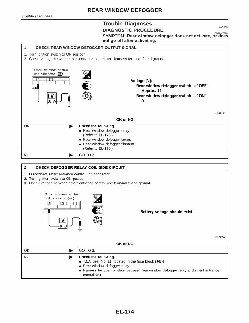
Trouble DiagnosesNAEL0075
DIAGNOSTIC PROCEDURENAEL0075S01
SYMPTOM: Rear window defogger does not activate, or doesnot go off after activating.
1 CHECK REAR WINDOW DEFOGGER OUTPUT SIGNAL
1. Turn ignition switch to ON position.2. Check voltage between smart entrance control unit harness terminal 2 and ground.
SEL384X
OK or NG
OK © Check the following.I Rear window defogger relay
(Refer to EL-176.)I Rear window defogger circuitI Rear window defogger filament
(Refer to EL-176.)
NG © GO TO 2.
2 CHECK DEFOGGER RELAY COIL SIDE CIRCUIT
1. Disconnect smart entrance control unit connector.2. Turn ignition switch to ON position.3. Check voltage between smart entrance control unit terminal 2 and ground.
SEL385X
OK or NG
OK © GO TO 3.
NG © Check the following.I 7.5A fuse [No. 11, located in the fuse block (J/B)]I Rear window defogger relayI Harness for open or short between rear window defogger relay and smart entrance
control unit
REAR WINDOW DEFOGGERTrouble Diagnoses
EL-174

3 CHECK REAR WINDOW DEFOGGER SWITCH INPUT SIGNAL
Check continuity between smart entrance control unit terminal 39 and ground.
SEL386X
OK or NG
OK © GO TO 4.
NG © Check the following.I Rear window defogger switch (with navigation system)
(Refer to EL-176.)I Harness for open or short between smart entrance control unit and rear window defog-
ger switchI Rear window defogger switch ground circuit
4 CHECK IGNITION INPUT SIGNAL
Check voltage between smart entrance control unit terminal 33 and ground.
SEL387X
OK or NG
OK © GO TO 5.
NG © Check the following.I 7.5A fuse [No. 11, located in the fuse block (J/B)]I Harness for open or short between smart entrance control unit and fuse
GI
MA
EM
LC
EC
FE
CL
MT
AT
TF
PD
AX
SU
BR
ST
RS
BT
HA
SC
IDX
REAR WINDOW DEFOGGERTrouble Diagnoses (Cont’d)
EL-175

5 CHECK SMART ENTRANCE CONTROL UNIT GROUND CIRCUIT
Check continuity between smart entrance control unit terminal 16 and ground.
SEL388X
OK or NG
OK © Replace smart entrance control unit.
NG © Repair harness or connectors.
SEC202B
Electrical Components InspectionNAEL0076
REAR WINDOW DEFOGGER RELAYNAEL0076S01
Check continuity between terminals 3 and 5, 6 and 7.
Condition Continuity
12V direct current supply between ter-minals 1 and 2
Yes
No current supply No
SEL430TB
REAR WINDOW DEFOGGER SWITCHNAEL0076S02
Check continuity between terminals when rear window defoggerswitch is pushed and released.
Terminals Condition Continuity
1 - 2
Rear window defoggerswitch is pushed
Yes
Rear window defoggerswitch is released
No
SEL263
Filament CheckNAEL0077
1. Attach probe circuit tester (in volt range) to middle portion ofeach filament.
REAR WINDOW DEFOGGERTrouble Diagnoses (Cont’d)
EL-176
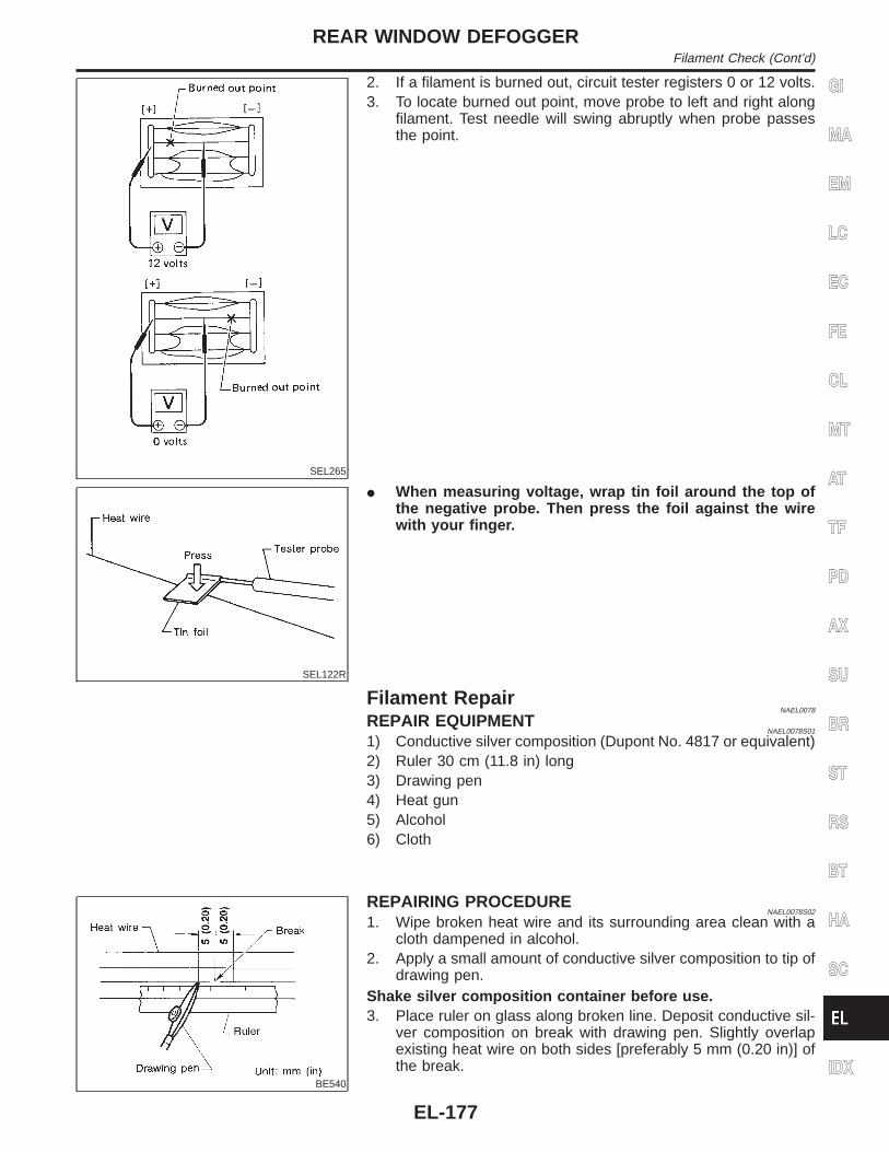
SEL265
2. If a filament is burned out, circuit tester registers 0 or 12 volts.3. To locate burned out point, move probe to left and right along
filament. Test needle will swing abruptly when probe passesthe point.
SEL122R
I When measuring voltage, wrap tin foil around the top ofthe negative probe. Then press the foil against the wirewith your finger.
Filament RepairNAEL0078
REPAIR EQUIPMENTNAEL0078S01
1) Conductive silver composition (Dupont No. 4817 or equivalent)2) Ruler 30 cm (11.8 in) long3) Drawing pen4) Heat gun5) Alcohol6) Cloth
BE540
REPAIRING PROCEDURENAEL0078S02
1. Wipe broken heat wire and its surrounding area clean with acloth dampened in alcohol.
2. Apply a small amount of conductive silver composition to tip ofdrawing pen.
Shake silver composition container before use.3. Place ruler on glass along broken line. Deposit conductive sil-
ver composition on break with drawing pen. Slightly overlapexisting heat wire on both sides [preferably 5 mm (0.20 in)] ofthe break.
GI
MA
EM
LC
EC
FE
CL
MT
AT
TF
PD
AX
SU
BR
ST
RS
BT
HA
SC
IDX
REAR WINDOW DEFOGGERFilament Check (Cont’d)
EL-177

SEL012D
4. After repair has been completed, check repaired wire for con-tinuity. This check should be conducted 10 minutes after silvercomposition is deposited.
Do not touch repaired area while test is being conducted.
SEL013D
5. Apply a constant stream of hot air directly to the repaired areafor approximately 20 minutes with a heat gun. A minimum dis-tance of 3 cm (1.2 in) should be kept between repaired areaand hot air outlet. If a heat gun is not available, let the repairedarea dry for 24 hours.
REAR WINDOW DEFOGGERFilament Repair (Cont’d)
EL-178

System DescriptionNAEL0226
Refer to Owner’s Manual for audio system operating instructions.
BASE SYSTEMNAEL0226S01
Power is supplied at all timesI through 15A fuse [No. 4, located in the fuse block (J/B)]I to audio unit terminal 6.With the ignition switch in the ACC or ON position, power is suppliedI through 10A fuse [No. 10, located in the fuse block (J/B)]I to audio unit terminal 10.Ground is supplied through the case of the audio unit.When the audio unit power knob is pushed to the ON position, audio signals are suppliedI through audio unit terminals 1, 2, 3, 4, 13, 14, 15 and 16I to the front and rear speakers.
BOSE SYSTEMNAEL0226S02
Power is supplied at all timesI through 15A fuse [No. 4, located in the fuse block (J/B)]I to audio unit terminal 6,I to audio amp. relay terminal 3 andI to rear speaker amp. terminal 11.With the ignition switch in the ACC or ON position, power is suppliedI through 10A fuse [No. 10, located in the fuse block (J/B)]I to audio unit terminal 10.Ground is supplied through the case of the audio unit.Ground is suppliedI to audio amp. relay terminal 2,I through body grounds M4, M66 and M147I to front door speaker LH terminal 5 andI to front door speaker RH terminal 5I through body grounds M77 and M111I to rear speaker amp. terminal 24I through body grounds B11, B22 and D210.When the audio unit POWER button is pressed, power is supplied to rear speaker amp. terminal 9 and audioamp. relay terminal 1 from audio unit terminal 12. Then audio amp. relay is energized and power is suppliedI to front door speaker LH terminal 4 andI to front door speaker RH terminal 4.Audio signals are suppliedI through audio unit terminals 1, 2, 3, 4, 13, 14, 15 and 16I to terminals 2 and 6 of the LH and RH front speakers and terminals 5, 7, 18 and 20 of the rear speaker
amp.I to LH and RH tweeters through terminals 1 and 3 of the front speakersI to rear LH and RH speakers through terminals 1, 2, 25 and 26 of the rear speaker amp.
GI
MA
EM
LC
EC
FE
CL
MT
AT
TF
PD
AX
SU
BR
ST
RS
BT
HA
SC
IDX
AUDIOSystem Description
EL-179

Wiring Diagram — AUDIO —/Base SystemNAEL0227
MEL037M
AUDIOWiring Diagram — AUDIO —/Base System
EL-180

MEL038M
GI
MA
EM
LC
EC
FE
CL
MT
AT
TF
PD
AX
SU
BR
ST
RS
BT
HA
SC
IDX
AUDIOWiring Diagram — AUDIO —/Base System (Cont’d)
EL-181

Schematic/BOSE SystemNAEL0080
MEL039M
AUDIOSchematic/BOSE System
EL-182

Wiring Diagram — AUDIO —/BOSE SystemNAEL0081
MEL040M
GI
MA
EM
LC
EC
FE
CL
MT
AT
TF
PD
AX
SU
BR
ST
RS
BT
HA
SC
IDX
AUDIOWiring Diagram — AUDIO —/BOSE System
EL-183

MEL041M
AUDIOWiring Diagram — AUDIO —/BOSE System (Cont’d)
EL-184

MEL042M
GI
MA
EM
LC
EC
FE
CL
MT
AT
TF
PD
AX
SU
BR
ST
RS
BT
HA
SC
IDX
AUDIOWiring Diagram — AUDIO —/BOSE System (Cont’d)
EL-185

MEL043M
AUDIOWiring Diagram — AUDIO —/BOSE System (Cont’d)
EL-186

MEL044M
GI
MA
EM
LC
EC
FE
CL
MT
AT
TF
PD
AX
SU
BR
ST
RS
BT
HA
SC
IDX
AUDIOWiring Diagram — AUDIO —/BOSE System (Cont’d)
EL-187

Trouble DiagnosesNAEL0228
AUDIO UNITNAEL0228S01
Symptom Possible causes Repair order
Audio unit inoperative (nodigital display and nosound from speakers).
1. 10A fuse2. Poor audio unit case ground3. Audio unit
1. Check 10A fuse [No. 10, located in fuse block (J/B)].Turn ignition switch ON and verify that battery posi-tive voltage is present at terminal 10 of audio unit.
2. Check audio unit case ground.3. Remove audio unit for repair.
Audio unit presets are lostwhen ignition switch isturned OFF.
1. 15A fuse2. Audio unit
1. Check 15A fuse [No. 4, located in fuse block (J/B)]and verify that battery positive voltage is present atterminal 6 of audio unit.
2. Remove audio unit for repair.
AM stations are weak ornoisy (FM stations OK).
1. Antenna2. Poor audio unit ground3. Audio unit
1. Check antenna.2. Check audio unit ground.3. Remove audio unit for repair.
FM stations are weak ornoisy (AM stations OK).
1. Window antenna2. Audio unit
1. Check window antenna.2. Remove audio unit for repair.
Audio unit generates noisein AM and FM modes withengine running.
1. Poor audio unit ground2. Loose or missing ground bonding
straps3. Ignition condenser or rear window
defogger noise suppressor condenser4. Alternator5. Ignition coil or secondary wiring6. Audio unit
1. Check audio unit ground.2. Check ground bonding straps.3. Replace ignition condenser or rear window defogger
noise suppressor condenser.4. Check alternator.5. Check ignition coil and secondary wiring.6. Remove audio unit for repair.
Audio unit generates noisein AM and FM modes withaccessories on (switchpops and motor noise).
1. Poor audio unit ground2. Antenna3. Accessory ground4. Faulty accessory
1. Check audio unit ground.2. Check antenna.3. Check accessory ground.4. Replace accessory.
BASE SYSTEMNAEL0228S02
Symptom Possible causes Repair order
Individual speaker is noisyor inoperative.
1. Speaker2. Audio unit output3. Speaker circuit4. Audio unit
1. Check speaker.2. Check audio unit output voltages.3. Check wires for open or short between audio unit
and speaker.4. Remove audio unit for repair.
BOSE SYSTEMNAEL0228S03
Symptom Possible causes Repair order
Audio unit controls areoperational, but no soundis heard from any speaker.
1. 15A fuse2. Audio unit output3. Audio unit
1. Check 15A fuse [No. 4, located in fuse block (J/B)].Verify battery positive voltage is present at terminal 2of audio amp. relay.
2. Check audio unit output voltage (Terminal 12).3. Remove audio unit for repair.
All front speakers are inop-erative.
1. Audio amp. relay2. Audio amp. relay ground3. Amp. ON signal
1. Check audio amp. relay.2. Check audio amp. relay ground (Terminal 3).3. Turn ignition switch ACC and audio unit ON. Verify
battery positive voltage is present at terminal 1 ofaudio amp. relay.
Individual front speaker isnoisy or inoperative.
1. Speaker ground2. Power supply3. Audio unit output4. Speaker
1. Check speaker ground (Terminal 5).2. Check power supply for speaker (Terminal 4).3. Check audio unit output voltage for speaker.4. Replace speaker.
AUDIOTrouble Diagnoses
EL-188

Symptom Possible causes Repair order
Both rear speakers areinoperative.
1. Poor rear speaker amp. ground2. Power supply3. Amp. ON signal4. Rear speaker amp.
1. Check rear speaker amp. ground circuit.2. Check power supply for rear speaker amp. (Terminal
11).3. Turn ignition switch ACC and audio unit ON. Verify
battery positive voltage is present at terminal 9 ofrear speaker amp.
4. Remove rear speaker amp. for repair.
Individual rear speaker isnoisy or inoperative.
1. Speaker2. Audio unit/amp. output3. Speaker circuit4. Audio unit
1. Check speaker.2. Check audio unit/amp. output.3. Check wires for open or short between audio unit/
amp. and speakers.4. Remove audio unit for repair.
InspectionNAEL0229
AUDIO UNIT AND AMP.NAEL0229S01
All voltage inspections are made with:I Ignition switch ON or ACCI Audio unit ONI Audio unit and amps. connected (If audio unit or amp. is removed for inspection, supply a ground to the
case using a jumper wire.)
ANTENNANAEL0229S02
1. Using a jumper wire, clip an auxiliary ground between antenna and body.I If reception improves, check antenna ground (at body surface).I If reception does not improve, check main feeder cable for short circuit or open circuit.
Audio Unit Removal and InstallationNAEL0230
1. Lock the CD changer unit mechanism (if so equipped) prior to removing a malfunctioning CD changer unit.Refer to “LOCKING CD CHANGER UNIT MECHANISM”, EL-189.
2. Remove CD changer unit. Refer to BT-22, “INSTRUMENT PANEL ASSEMBLY”.
LOCKING CD CHANGER UNIT MECHANISMNAEL0230S01
CAUTION:I Prior to removing a malfunctioning CD changer unit that will be shipped for repair, the changer
mechanism MUST BE LOCKED to prevent the mechanism from being damaged during shipping.I If a CD is jammed or unable to be removed from the unit, do NOT lock the changer mechanism. If
the unit is to be shipped for repair, carefully package the unit to prevent vibration and shock.1. Eject and remove any CDs from the CD changer unit.2. Turn ignition switch OFF. Wait until CD changer unit display is off and mechanism stops moving (mecha-
nism sound stops).3. Press any one of the disc selection buttons once. When a display shows on the CD changer unit, press
the same disc selection button again within 5 seconds.I The changer mechanism will lock itself within 10 seconds.4. After mechanism stops moving (mechanism sound stops), disconnect the CD changer unit connectors.NOTE:After installing a new or remanufactured CD changer unit, switching the CD changer unit ON will automati-cally unlock the mechanism. A special unlocking procedure is not required.
GI
MA
EM
LC
EC
FE
CL
MT
AT
TF
PD
AX
SU
BR
ST
RS
BT
HA
SC
IDX
AUDIOTrouble Diagnoses (Cont’d)
EL-189

Wiring Diagram — REMOTE —NAEL0205
MEL822L
AUDIOWiring Diagram — REMOTE —
EL-190

System DescriptionNAEL0084
Power is supplied at all timesI through 7.5A fuse [No. 24, located in the fuse block (J/B)]I to power antenna terminal 6.Ground is supplied to the power antenna terminal 2 through body grounds M4, M66 and M147.When the audio unit is turned to the ON position, battery positive voltage is suppliedI through audio unit terminal 5I to power antenna terminal 4.The antenna raises and is held in the extended position.When the audio unit is turned to the OFF position, battery positive voltage is interruptedI from audio unit terminal 5I to power antenna terminal 4.The antenna retracts.
GI
MA
EM
LC
EC
FE
CL
MT
AT
TF
PD
AX
SU
BR
ST
RS
BT
HA
SC
IDX
AUDIO ANTENNASystem Description
EL-191

Wiring Diagram — P/ANT —NAEL0085
MEL824L
AUDIO ANTENNAWiring Diagram — P/ANT —
EL-192

Trouble DiagnosesNAEL0086
POWER ANTENNANAEL0086S01
Symptom Possible causes Repair order
Power antenna does notoperate.
1. 7.5A fuse2. Audio unit signal3. Grounds M4, M66 and M147
1. Check 7.5A fuse [No. 24, located in fuse block(J/B)]. Verify that battery positive voltage is presentat terminal 6 of power antenna.
2. Turn ignition switch and audio unit ON. Verify thatbattery positive voltage is present at terminal 4 ofpower antenna.
3. Check grounds M4, M66 and M147.
Location of AntennaNAEL0087
YEL067K
MEL036G
Antenna Rod ReplacementNAEL0088
REMOVALNAEL0088S01
1. Remove antenna nut and antenna base.
GI
MA
EM
LC
EC
FE
CL
MT
AT
TF
PD
AX
SU
BR
ST
RS
BT
HA
SC
IDX
AUDIO ANTENNATrouble Diagnoses
EL-193

MEL037G
2. Withdraw antenna rod while raising it by operating antennamotor.
MEL038G
INSTALLATIONNAEL0088S02
1. Lower antenna rod by operating antenna motor.2. Insert gear section of antenna rope into place with it facing
toward antenna motor.3. As soon as antenna rope is wound on antenna motor, stop
antenna motor. Insert antenna rod lower end into antennamotor pipe.
4. Retract antenna rod completely by operating antenna motor.5. Install antenna nut and base.
AUDIO ANTENNAAntenna Rod Replacement (Cont’d)
EL-194

System DescriptionNAEL0206
OUTLINENAEL0206S01
Electric sunroof system consists ofI Sunroof switchI Sunroof motorI Power window relayI Smart entrance control unitSmart entrance control unit controls retained power operation.
OPERATIONNAEL0206S02
The sunroof can be opened or closed and tilted up or down with the sunroof switch.
AUTO OPERATIONNAEL0206S03
The power sunroof AUTO feature makes it possible to open and close the sunroof without holding the sunroofswitch in the down or up position.
RETAINED POWER OPERATIONNAEL0206S04
When the ignition switch is turned to OFF position from ON or START position, power is supplied for 45 sec-ondsI to power window relay terminal 2I from smart entrance control unit terminal 5.Ground is always suppliedI to power window relay terminal 1I through body grounds.When power and ground are supplied, power window relay continues to be energized, and the electrical sun-roof can be operated.The retained power operation is canceled when the driver or passenger side door is opened.
INTERRUPTION DETECTION FUNCTIONNAEL0206S05
The CPU of sunroof motor monitors the sunroof motor operation and the sunroof position (full closed or other)for sunroof by the signals from encoder and limit switch in sunroof motor.When sunroof motor detects interruption during the following close operation,I automatic close operation when ignition switch is in the “ON” positionI automatic close operation during retained power operationsunroof switch controls the motor for open and the sunroof will operate about 150 mm (5.91 in).
GI
MA
EM
LC
EC
FE
CL
MT
AT
TF
PD
AX
SU
BR
ST
RS
BT
HA
SC
IDX
POWER SUNROOFSystem Description
EL-195

Wiring Diagram — SROOF —NAEL0089
MEL020O
POWER SUNROOFWiring Diagram — SROOF —
EL-196

MEL826L
GI
MA
EM
LC
EC
FE
CL
MT
AT
TF
PD
AX
SU
BR
ST
RS
BT
HA
SC
IDX
POWER SUNROOFWiring Diagram — SROOF — (Cont’d)
EL-197

Trouble DiagnosesNAEL0207
Symptom Possible cause Repair order
Power sunroof cannot be operatedusing any switch.
1. 7.5A fuse, 40A fusible link andM145 circuit breaker
2. Power window relay ground cir-cuit
3. Sunroof motor ground circuit4. Power window relay5. Sunroof motor circuit6. Sunroof switch7. Sunroof switch circuit8. Sunroof motor
1. Check 7.5A fuse [No. 11, located in fuse block(J/B)], 40A fusible link (letter f, located in fuse andfusible link box) and M145 circuit breaker. Turn igni-tion switch “ON” and verify battery positive voltageis present at terminals 2 and 3 of power windowrelay and terminal 1 of sunroof motor.
2. Check power window relay ground circuit.3. Check sunroof motor ground circuit.4. Check power window relay.5. Check the wire between power window relay and
sunroof motor.6. Check sunroof switch.7. Check harness between sunroof switch and sunroof
motor.8. Check sunroof motor.
Power sunroof cannot be operatedusing one of the sunroof switches.
1. Sunroof switch2. Sunroof switch circuit
1. Check sunroof switch.2. Check the harness between sunroof motor and sun-
roof switch.
Power sunroof auto function cannotbe operated properly.
1. Sunroof slide mechanism2. Sunroof switch3. Sunroof switch circuit4. Sunroof motor
1. Check the following.a. Check obstacles in sunroof, etc.b. Check worn or deformed sunroof.c. Check sunroof sash tilted too far inward or outward.2. Check sunroof switch.3. Check harness between sunroof motor and sunroof
switch.4. Replace sunroof motor.
Retained power operation does notoperate properly.
1. RAP signal circuit2. Driver or passenger side door
switch circuit3. Smart entrance control unit
1. Check harness between power window relay termi-nal 2 and smart entrance control unit terminal 5.
2. Check the following.a. Harness between smart entrance control unit and
driver or passenger side door switch for short circuitb. Driver or passenger side door switch ground circuitc. Driver or passenger side door switch3. Check smart entrance control unit. (EL-348)
POWER SUNROOFTrouble Diagnoses
EL-198
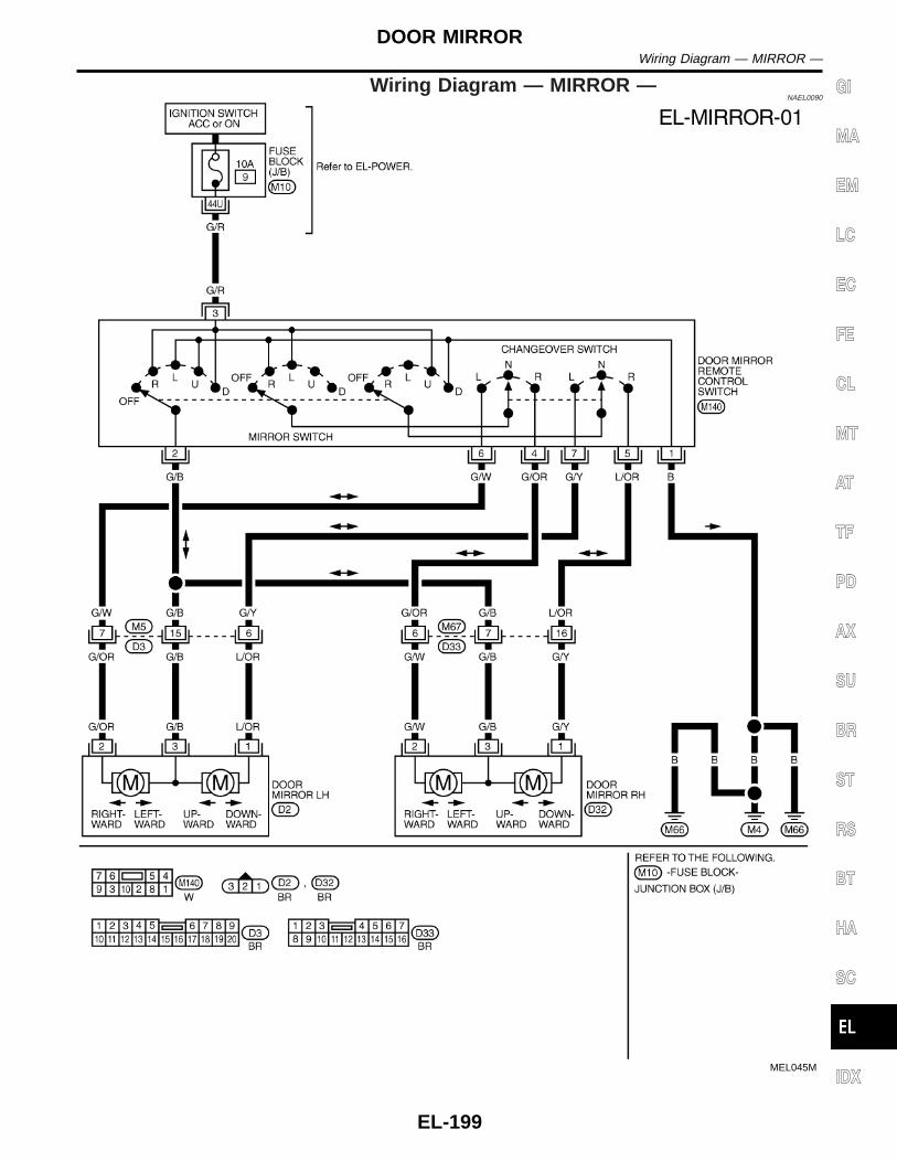
Wiring Diagram — MIRROR —NAEL0090
MEL045M
GI
MA
EM
LC
EC
FE
CL
MT
AT
TF
PD
AX
SU
BR
ST
RS
BT
HA
SC
IDX
DOOR MIRRORWiring Diagram — MIRROR —
EL-199

Wiring Diagram — SEAT —NAEL0092
MEL830L
POWER SEATWiring Diagram — SEAT —
EL-200

MEL601F
GI
MA
EM
LC
EC
FE
CL
MT
AT
TF
PD
AX
SU
BR
ST
RS
BT
HA
SC
IDX
POWER SEATWiring Diagram — SEAT — (Cont’d)
EL-201

Wiring Diagram — HSEAT —NAEL0093
MEL046M
HEATED SEATWiring Diagram — HSEAT —
EL-202

Seatback Heating UnitNAEL0215
SBT314
GI
MA
EM
LC
EC
FE
CL
MT
AT
TF
PD
AX
SU
BR
ST
RS
BT
HA
SC
IDX
HEATED SEATSeatback Heating Unit
EL-203

Component Parts and Harness ConnectorLocation
NAEL0209
SEL353X
AUTOMATIC DRIVE POSITIONERComponent Parts and Harness Connector Location
EL-204

System Description=NAEL0210
OPERATIVE CONDITIONNAEL0210S01
The drive position can be set in 2 ways, manually and automatically.
Manual OperationNAEL0210S0101
The driver’s seat can be adjusted for sliding, reclining, front cushion height and rear cushion height with theLH power seat switches. The manual operation can be adjusted with the IGN key in any position.
Automatic OperationNAEL0210S0102
The driver’s seat is adjusted to the proper positions for the driver automatically, in 3 different ways: MEMORYAUTOMATIC SET, AUTOMATIC EXITING SETTING and AUTOMATIC SET RETURN. (Automatic Drive Posi-tioner = ADP)
CONDITIONS INHIBITING AUTOMATIC OPERATIONNAEL0210S02
Automatic memory setting procedures are suspended under any of the following conditions:1) When vehicle speed is more than 7 km/h (4 MPH).2) When driver’s side power seat switch is turned on.3) When any two of the switches (set switch and memory switches 1 and 2) are turned ON.4) When cancel switch is turned on.5) When selector lever is in any position other than “P”.6) When ignition switch is turned to “START” position.
(Operation resumes when ignition switch is returned to “ON”.)7) When detention switch malfunction is detected:I Detention switch failure is sensed when detention switch remains off for at least 2 seconds at a vehicle
speed of greater than 7 km/h (4 MPH).
FAIL-SAFE SYSTEMNAEL0210S03
Output FailureNAEL0210S0301
When the ignition switch is in the ON position, if any of the parts (indicated in the following chart) move morethan the specified amount within a period “T2” when no “ON” input is sent from any of the switches (indicatedin the following chart), or an output from the automatic drive positioner is not produced, an output failure issensed. Motor operation will be suspended automatically, and all automatic operations will be ineffective. (Inthis case, the motor will not operate manually.)
OPERATED PORTION T2 Allowable measurement
Seat sliding Approx. 2.5 sec. Within 6 mm (0.24 in)
Seat reclining Same as above Change angle within 1°
AbsolvingNAEL0210S0302
When moving selector lever back to “P” position after having moved it to any position except “P”, fail-safeoperation will be canceled.
INITIALIZATIONNAEL0210S04
After reconnecting battery cable, perform initialization procedure A or B. If initialization has not been performed,automatic drive positioner will not operate.PROCEDURE A1) Insert key in the ignition key cylinder. (Ignition switch is in “OFF” position.)2) Open , close , open driver side door. (Do not perform with the door switch operation.)3) EndPROCEDURE B1) Drive the vehicle at more than 25 km/h (16 MPH).2) End
GI
MA
EM
LC
EC
FE
CL
MT
AT
TF
PD
AX
SU
BR
ST
RS
BT
HA
SC
IDX
AUTOMATIC DRIVE POSITIONERSystem Description
EL-205

MEMORY AUTOMATIC SET=NAEL0210S05
Two drive positions can be retained in the memory. Press memory switch to set driver’s seat to preset posi-tion.
SEL592W
NOTE:I When memory switch for which driver’s seat positions are already retained in memory is pressed, new seat
positions will be retained in memory in place of the previously set positions.I Drive position is erased from the memory when battery cable is disconnected more than 30 seconds. After
connecting battery cable, perform initialization procedures.
SEL593W
AUTOMATIC DRIVE POSITIONERSystem Description (Cont’d)
EL-206

NOTE:1) Do not keep cancel switch pressed as it will not operate.2) Automatic exiting setting will be performed.3) The driver’s seat position (see the following Table) operates in the order of priority.
The order of priority Operated portion
1 Seat sliding
2 Seat reclining
3 Seat front lifting
4 Seat rear lifting
AUTOMATIC EXITING SETTINGNAEL0210S06
“Exiting” positions:Driver’s seat ... Slides about 40 mm (1.57 in) rear from normal sitting position.
SEL594W
AUTOMATIC SET RETURNNAEL0210S07
With driver’s seat set to the “exiting” position, operating one of the following procedures moves it to the posi-tion previously retained in memory.
SEL595W
GI
MA
EM
LC
EC
FE
CL
MT
AT
TF
PD
AX
SU
BR
ST
RS
BT
HA
SC
IDX
AUTOMATIC DRIVE POSITIONERSystem Description (Cont’d)
EL-207

SchematicNAEL0211
MEL833L
AUTOMATIC DRIVE POSITIONERSchematic
EL-208

Wiring Diagram — AUT/DP —NAEL0212
MEL834L
GI
MA
EM
LC
EC
FE
CL
MT
AT
TF
PD
AX
SU
BR
ST
RS
BT
HA
SC
IDX
AUTOMATIC DRIVE POSITIONERWiring Diagram — AUT/DP —
EL-209

MEL835L
AUTOMATIC DRIVE POSITIONERWiring Diagram — AUT/DP — (Cont’d)
EL-210

MEL836L
GI
MA
EM
LC
EC
FE
CL
MT
AT
TF
PD
AX
SU
BR
ST
RS
BT
HA
SC
IDX
AUTOMATIC DRIVE POSITIONERWiring Diagram — AUT/DP — (Cont’d)
EL-211

MEL186M
AUTOMATIC DRIVE POSITIONERWiring Diagram — AUT/DP — (Cont’d)
EL-212

MEL187M
GI
MA
EM
LC
EC
FE
CL
MT
AT
TF
PD
AX
SU
BR
ST
RS
BT
HA
SC
IDX
AUTOMATIC DRIVE POSITIONERWiring Diagram — AUT/DP — (Cont’d)
EL-213

On Board DiagnosisNAEL0213
SEL354X
HOW TO PERFORM SELF-DIAGNOSISNAEL0213S01
SEL596W
*1: If no malfunction is indicated, self-diagnosis will end after the vehicle speed sensor diagnosis is performed.*2: Diagnosis ends after self-diagnostic results have been indicated for 10 minutes if left unattended.
AUTOMATIC DRIVE POSITIONEROn Board Diagnosis
EL-214

MALFUNCTION CODE TABLE=NAEL0213S02
In this mode, a malfunction code is indicated by the number of flashes from the automatic drive positionerindicator lamps (indicator lamp 1, indicator lamp 2) as shown below.
SEL597W
CodeNo.
Detecteditems
Diagnostic procedureRefer-encepage
CodeNo.
Detecteditems
Diagnostic procedureRefer-encepage
1Seat
sliding
PROCEDURE 2(Sliding encoder check)
PROCEDURE 6(Sliding motor check)
EL-221EL-229
4Seatliftingrear
PROCEDURE 5[Lifting encoder (rear) check]
PROCEDURE 9[Lifting motor (rear) check]
EL-227EL-232
2Seat
reclining
PROCEDURE 3(Reclining encoder check)
PROCEDURE 7(Reclining motor check)
EL-223EL-230
9Vehiclespeedsensor
PROCEDURE 12(Vehicle speed sensor check)
EL-235
3Seatliftingfront
PROCEDURE 4[Lifting encoder (front) check]
PROCEDURE 8[Lifting motor (front) check]
EL-225EL-231
GI
MA
EM
LC
EC
FE
CL
MT
AT
TF
PD
AX
SU
BR
ST
RS
BT
HA
SC
IDX
AUTOMATIC DRIVE POSITIONEROn Board Diagnosis (Cont’d)
EL-215

Trouble DiagnosesNAEL0214
WORK FLOWNAEL0214S01
SEL599W
*1 EL-214 *2 EL-215
AUTOMATIC DRIVE POSITIONERTrouble Diagnoses
EL-216
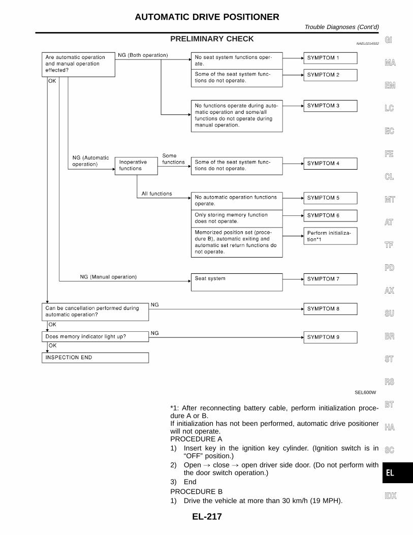
PRELIMINARY CHECKNAEL0214S02
SEL600W
*1: After reconnecting battery cable, perform initialization proce-dure A or B.If initialization has not been performed, automatic drive positionerwill not operate.PROCEDURE A1) Insert key in the ignition key cylinder. (Ignition switch is in
“OFF” position.)2) Open , close , open driver side door. (Do not perform with
the door switch operation.)3) EndPROCEDURE B1) Drive the vehicle at more than 30 km/h (19 MPH).
GI
MA
EM
LC
EC
FE
CL
MT
AT
TF
PD
AX
SU
BR
ST
RS
BT
HA
SC
IDX
AUTOMATIC DRIVE POSITIONERTrouble Diagnoses (Cont’d)
EL-217

2) EndAfter performing preliminary check, go to symptom chartbelow.
Before starting trouble diagnoses below, perform preliminarycheck, EL-217. Symptom numbers in the symptom chart cor-respond with those of preliminary check.
SYMPTOM CHARTNAEL0214S03
PROCEDURE Diagnostic procedure
REFERENCE PAGE (EL- ) 220 221 223 225 227 229 230
SYMPTOM
DIA
GN
OS
TIC
PR
OC
ED
UR
E1
(Pow
ersu
pply
and
grou
ndci
rcui
tfo
rD
river
’sse
atco
ntro
luni
t)
DIA
GN
OS
TIC
PR
OC
ED
UR
E2
(Slid
ing
enco
der
chec
k)
DIA
GN
OS
TIC
PR
OC
ED
UR
E3
(Rec
linin
gen
code
rch
eck)
DIA
GN
OS
TIC
PR
OC
ED
UR
E4
[Lift
ing
enco
der
(fro
nt)
chec
k]
DIA
GN
OS
TIC
PR
OC
ED
UR
E5
[Lift
ing
enco
der
(rea
r)ch
eck]
DIA
GN
OS
TIC
PR
OC
ED
UR
E6
(Slid
ing
mot
orch
eck)
DIA
GN
OS
TIC
PR
OC
ED
UR
E7
(Rec
linin
gm
otor
chec
k)
1 No seat system functions operate. X
2
Some of the seatsystem functionsdo not operateduring automatic/manual operation.
Sliding X
Reclining X
Lifting (Front)
Lifting (Rear)
3
No functions operate during auto-matic operation, and some/all func-tions do not during manual opera-tion.
4
Some of the seatsystem functionsdo not operateduring automaticoperation.
Sliding X
Reclining X
Lifting (Front) X
Lifting (Rear) X
5No automatic operation functionsoperate.
6Drive position cannot be retained inthe memory.
7
Does not operateduring manualoperation. (Oper-ates during auto-matic operation.)
Sliding
Reclining
Lifting (Front)
Lifting (Rear)
8Automatic operation cannot be can-celed.
9 Memory indicator does not light up.
X : Applicable
AUTOMATIC DRIVE POSITIONERTrouble Diagnoses (Cont’d)
EL-218

PROCEDURE Diagnostic procedure
REFERENCE PAGE (EL- ) 231 232 233 234 235 238 238
SYMPTOM
DIA
GN
OS
TIC
PR
OC
ED
UR
E8
[Lift
ing
mot
or(f
ront
)ch
eck]
DIA
GN
OS
TIC
PR
OC
ED
UR
E9
[Lift
ing
mot
or(r
ear)
chec
k]
DIA
GN
OS
TIC
PR
OC
ED
UR
E10
(Pow
erse
atsw
itch
chec
k)
DIA
GN
OS
TIC
PR
OC
ED
UR
E11
(Can
cels
witc
hch
eck)
DIA
GN
OS
TIC
PR
OC
ED
UR
E12
(Key
,pa
rkpo
sitio
n,do
orsw
itch
and
vehi
cle
spee
dse
nsor
chec
k)
DIA
GN
OS
TIC
PR
OC
ED
UR
E13
(Sea
tm
emor
ysw
itch
chec
k)
DIA
GN
OS
TIC
PR
OC
ED
UR
E14
(Mem
ory
indi
cato
rch
eck)
1 No seat system functions operate.
2
Some of the seatsystem functionsdo not operateduring automatic/manual operation.
Sliding
Reclining
Lifting (Front) X
Lifting (Rear) X
3
No functions operate during auto-matic operation, and some/all func-tions do not during manual opera-tion.
X
X(ACC, ON
STARTsignal)
4
Some of the seatsystem functionsdo not operateduring automaticoperation.
Sliding
Reclining
Lifting (Front)
Lifting (Rear)
5No automatic operation functionsoperate.
X X
6Drive position cannot be retained inthe memory.
X(IGN ONsignal)
X
7
Does not operateduring manualoperation. (Oper-ates during auto-matic operation.)
Sliding X
Reclining X
Lifting (Front) X
Lifting (Rear) X
8Automatic operation cannot be can-celed.
X
9 Memory indicator does not light up. X
X : Applicable
GI
MA
EM
LC
EC
FE
CL
MT
AT
TF
PD
AX
SU
BR
ST
RS
BT
HA
SC
IDX
AUTOMATIC DRIVE POSITIONERTrouble Diagnoses (Cont’d)
EL-219

SEL601W
DIAGNOSTIC PROCEDURE 1=NAEL0214S04
(Power supply and ground circuit for driver’s seat control unit)
Power Supply Circuit CheckNAEL0214S0401
Check voltage between seat control unit LH terminal 1 and ground.
TerminalsIgnition switch position
OFF ACC ON START
1 - Ground Battery voltage
If NG, check the following.I 40A fusible link (letter f, located in the fuse and fusible link box)I Circuit breakerI Harness for open or short between circuit breaker and seat
control unit LH
SEL602W
Ground Circuit CheckNAEL0214S0402
Check continuity between seat control unit LH terminal 33 andground.
Terminals Continuity
33 - Ground Yes
AUTOMATIC DRIVE POSITIONERTrouble Diagnoses (Cont’d)
EL-220

DIAGNOSTIC PROCEDURE 2=NAEL0214S05
(Sliding encoder check)
1 CHECK SLIDING ENCODER OUTPUT SIGNAL
Measure voltage between seat control unit LH terminal 18 and ground with CONSULT-II or oscilloscope when power seatslide is operated.
SEL603W
OK or NG
OK © Sliding encoder is OK.
NG © GO TO 2.
2 CHECK SLIDING ENCODER INPUT SIGNAL
Check voltage between seat control unit LH terminal 17 and ground.
SEL604W
OK or NG
OK © GO TO 3.
NG © Replace seat control unit LH.
GI
MA
EM
LC
EC
FE
CL
MT
AT
TF
PD
AX
SU
BR
ST
RS
BT
HA
SC
IDX
AUTOMATIC DRIVE POSITIONERTrouble Diagnoses (Cont’d)
EL-221

3 CHECK SLIDING ENCODER OPEN CIRCUIT
1. Disconnect seat control unit LH connector and sliding device LH connector.2. Check harness continuity between seat control unit LH connector and sliding device LH connector.
SEL605WA
OK or NG
OK © GO TO 4.
NG © Repair harness.
4 CHECK SLIDING ENCODER SHORT CIRCUIT
Check harness continuity between seat control unit LH connector and ground.
SEL606W
OK or NG
OK © Replace sliding encoder.
NG © Repair harness.
AUTOMATIC DRIVE POSITIONERTrouble Diagnoses (Cont’d)
EL-222

DIAGNOSTIC PROCEDURE 3=NAEL0214S06
(Reclining encoder check)
1 CHECK RECLINING ENCODER OUTPUT SIGNAL
Measure voltage between seat control unit LH terminal 29 and ground with CONSULT-II or oscilloscope when power seatreclining is operated.
SEL607W
OK or NG
OK © Reclining encoder is OK.
NG © GO TO 2.
2 CHECK RECLINING ENCODER INPUT SIGNAL
Check voltage between seat control unit LH terminal 17 and ground.
SEL608W
OK or NG
OK © GO TO 3.
NG © Replace seat control unit LH.
GI
MA
EM
LC
EC
FE
CL
MT
AT
TF
PD
AX
SU
BR
ST
RS
BT
HA
SC
IDX
AUTOMATIC DRIVE POSITIONERTrouble Diagnoses (Cont’d)
EL-223

3 CHECK RECLINING ENCODER OPEN CIRCUIT
1. Disconnect seat control unit LH connector and reclining device LH connector.2. Check harness continuity between seat control unit LH connector and reclining LH connector.
SEL609WA
OK or NG
OK © GO TO 4.
NG © Repair harness.
4 CHECK RECLINING ENCODER SHORT CIRCUIT
Check harness continuity between seat control unit LH connector and ground.
SEL610W
OK or NG
OK © Replace reclining encoder.
NG © Repair harness.
AUTOMATIC DRIVE POSITIONERTrouble Diagnoses (Cont’d)
EL-224
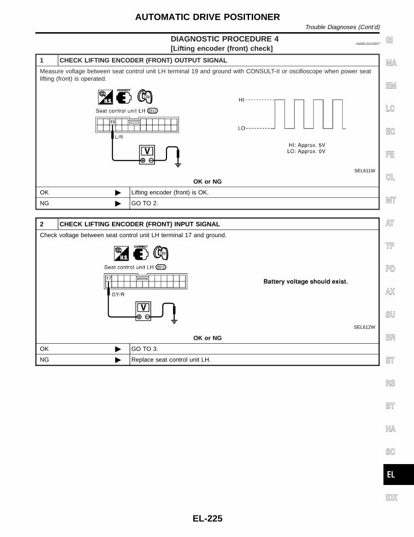
DIAGNOSTIC PROCEDURE 4=NAEL0214S07
[Lifting encoder (front) check]
1 CHECK LIFTING ENCODER (FRONT) OUTPUT SIGNAL
Measure voltage between seat control unit LH terminal 19 and ground with CONSULT-II or oscilloscope when power seatlifting (front) is operated.
SEL611W
OK or NG
OK © Lifting encoder (front) is OK.
NG © GO TO 2.
2 CHECK LIFTING ENCODER (FRONT) INPUT SIGNAL
Check voltage between seat control unit LH terminal 17 and ground.
SEL612W
OK or NG
OK © GO TO 3.
NG © Replace seat control unit LH.
GI
MA
EM
LC
EC
FE
CL
MT
AT
TF
PD
AX
SU
BR
ST
RS
BT
HA
SC
IDX
AUTOMATIC DRIVE POSITIONERTrouble Diagnoses (Cont’d)
EL-225

3 CHECK LIFTING ENCODER (FRONT) OPEN CIRCUIT
1. Disconnect seat control unit LH connector and front lifting device LH connector.2. Check harness continuity between seat control unit LH connector and front lifting device LH connector.
SEL613WA
OK or NG
OK © GO TO 4.
NG © Repair harness.
4 CHECK LIFTING ENCODER (FRONT) SHORT CIRCUIT
Check harness continuity between seat control unit LH connector and ground.
SEL614W
OK or NG
OK © Replace lifting encoder (front).
NG © Repair harness.
AUTOMATIC DRIVE POSITIONERTrouble Diagnoses (Cont’d)
EL-226

DIAGNOSTIC PROCEDURE 5=NAEL0214S08
[Lifting encoder (rear) check]
1 CHECK LIFTING ENCODER (REAR) OUTPUT SIGNAL
Measure voltage between seat control unit LH terminal 30 and ground with CONSULT-II or oscilloscope when power seatlifting (rear) is operated.
SEL615W
OK or NG
OK © Lifting encoder (rear) is OK.
NG © GO TO 2.
2 CHECK LIFTING ENCODER (REAR) INPUT SIGNAL
Check voltage between seat control unit LH terminal 17 and ground.
SEL616W
OK or NG
OK © GO TO 3.
NG © Replace seat control unit LH.
GI
MA
EM
LC
EC
FE
CL
MT
AT
TF
PD
AX
SU
BR
ST
RS
BT
HA
SC
IDX
AUTOMATIC DRIVE POSITIONERTrouble Diagnoses (Cont’d)
EL-227

3 CHECK LIFTING ENCODER (REAR) OPEN CIRCUIT
1. Disconnect seat control unit LH connector and rear lifting device LH connector.2. Check harness continuity between seat control unit LH connector and rear lifting device LH connector.
SEL617WA
OK or NG
OK © GO TO 4.
NG © Repair harness.
4 CHECK LIFTING ENCODER (REAR) SHORT CIRCUIT
Check harness continuity between seat control unit LH connector and ground.
SEL618W
OK or NG
OK © Replace lifting encoder (rear).
NG © Repair harness.
AUTOMATIC DRIVE POSITIONERTrouble Diagnoses (Cont’d)
EL-228

DIAGNOSTIC PROCEDURE 6=NAEL0214S09
(Sliding motor check)
1 CHECK OUTPUT SIGNAL TO SLIDING MOTOR
Check voltage between seat control unit LH terminals 3 or 10 and ground.
SEL619W
OK or NG
OK © GO TO 2.
NG © Replace seat control unit LH.
2 CHECK SLIDING MOTOR
1. Disconnect sliding device LH connector.2. Apply 12V DC direct current to motor and check operation.
SEL620WA
OK or NG
OK © Check harness for operation between seat control unit LH and sliding motor.
NG © Replace sliding motor.
GI
MA
EM
LC
EC
FE
CL
MT
AT
TF
PD
AX
SU
BR
ST
RS
BT
HA
SC
IDX
AUTOMATIC DRIVE POSITIONERTrouble Diagnoses (Cont’d)
EL-229

DIAGNOSTIC PROCEDURE 7=NAEL0214S10
(Reclining motor check)
1 CHECK OUTPUT SIGNAL TO RECLINING MOTOR
Check voltage between seat control unit LH terminals 4 or 12 and ground.
SEL621W
OK or NG
OK © GO TO 2.
NG © Replace seat control unit LH.
2 CHECK RECLINING MOTOR
1. Disconnect reclining device LH connector.2. Apply 12V DC direct current to motor and check operation.
SEL622WA
OK or NG
OK © Check harness for operation between seat control unit LH and reclining motor.
NG © Replace reclining motor.
AUTOMATIC DRIVE POSITIONERTrouble Diagnoses (Cont’d)
EL-230

DIAGNOSTIC PROCEDURE 8=NAEL0214S11
[Lifting motor (front) check]
1 CHECK OUTPUT SIGNAL TO LIFTING MOTOR (FRONT)
Check voltage between seat control unit LH terminals 5 or 13 and ground.
SEL623W
OK or NG
OK © GO TO 2.
NG © Replace seat control unit LH.
2 CHECK LIFTING MOTOR (FRONT)
1. Disconnect front lifting device LH connector.2. Apply 12V DC direct current to motor and check operation.
SEL624WA
OK or NG
OK © Check harness for operation between seat control unit LH and lifting motor (front).
NG © Replace lifting motor (front).
GI
MA
EM
LC
EC
FE
CL
MT
AT
TF
PD
AX
SU
BR
ST
RS
BT
HA
SC
IDX
AUTOMATIC DRIVE POSITIONERTrouble Diagnoses (Cont’d)
EL-231

DIAGNOSTIC PROCEDURE 9=NAEL0214S12
[Lifting motor (rear) check]
1 CHECK OUTPUT SIGNAL TO LIFTING MOTOR (REAR)
Check voltage between seat control unit LH terminals 6 or 7 and ground.
SEL625W
OK or NG
OK © GO TO 2.
NG © Replace seat control unit LH.
2 CHECK LIFTING MOTOR (REAR)
1. Disconnect rear lifting device LH connector.2. Apply 12V DC direct current to motor and check operation.
SEL626WA
OK or NG
OK © Check harness for operation between seat control unit LH and lifting motor (rear).
NG © Replace lifting motor (rear).
AUTOMATIC DRIVE POSITIONERTrouble Diagnoses (Cont’d)
EL-232

DIAGNOSTIC PROCEDURE 10=NAEL0214S13
(Power seat switch check)
1 CHECK POWER SEAT SWITCH
1. Disconnect power seat switch LH connector.2. Check continuity between power seat switch terminals.
SEL569X
OK or NG
OK © Check the following.I Ground circuit for power seat switchI Harness for open or short between seat control unit LH and power seat switch
NG © Replace power seat switch.
GI
MA
EM
LC
EC
FE
CL
MT
AT
TF
PD
AX
SU
BR
ST
RS
BT
HA
SC
IDX
AUTOMATIC DRIVE POSITIONERTrouble Diagnoses (Cont’d)
EL-233

DIAGNOSTIC PROCEDURE 11=NAEL0214S14
(Cancel switch check)
1 CHECK CANCEL SWITCH
1. Disconnect cancel switch connector.2. Check continuity between cancel switch terminals.
SEL628WA
OK or NG
OK © Check the following.I Ground circuit for cancel switchI Harness for open or short between seat control unit LH and cancel switch
NG © Replace cancel switch.
AUTOMATIC DRIVE POSITIONERTrouble Diagnoses (Cont’d)
EL-234

DIAGNOSTIC PROCEDURE 12=NAEL0214S15
(Key, detention, door switch and vehicle speed sensor check)
1 CHECK KEY SWITCH INPUT SIGNAL
Check voltage between seat control unit LH terminal 2 and ground.
SEL629W
OK or NG
OK © GO TO 2.
NG © Check the following.I 7.5A fuse [No. 24, located in fuse block (J/B)]I Key switchI Harness for open or short between key switch and fuseI Harness for open or short between seat control unit LH and key switch
2 CHECK IGNITION SWITCH INPUT SIGNAL (ON AND START)
Check voltage between seat control unit LH terminals and ground.
SEL630W
OK or NG
OK © GO TO 3.
NG © Check the following.I 7.5A fuse [No. 11, located in fuse block (J/B)]I 7.5A fuse [No. 26, located in fuse block (J/B)]I Harness for open or short between seat control unit LH and fuse
GI
MA
EM
LC
EC
FE
CL
MT
AT
TF
PD
AX
SU
BR
ST
RS
BT
HA
SC
IDX
AUTOMATIC DRIVE POSITIONERTrouble Diagnoses (Cont’d)
EL-235

3 CHECK PARK POSITION SWITCH INPUT SIGNAL
Check voltage between seat control unit LH terminal 21 and ground.
SEL631W
OK or NG
OK © GO TO 4.
NG © Check the following.I Park position switchI Park position switch ground circuitI Harness for open or short between seat control unit LH and park position switch
4 CHECK DRIVER DOOR SWITCH INPUT SIGNAL
Check voltage between seat control unit LH terminal 9 and ground.
SEL632W
OK or NG
OK © GO TO 5.
NG © Check the following.I Driver door switchI Driver door switch ground circuitI Harness for open or short between seat control unit LH and driver door switch
5 CHECK VEHICLE SPEED SENSOR
Does speedometer operate normally?
Yes or No
OK © GO TO 6.
NG © Check speedometer and vehicle speed sensor circuit. Refer to EL-124.
AUTOMATIC DRIVE POSITIONERTrouble Diagnoses (Cont’d)
EL-236

6 CHECK VEHICLE SPEED SENSOR PULL UP VOLTAGE
1. Turn ignition switch “ON”.2. Check voltage between seat control unit LH terminal 32 and ground.
SEL633W
OK or NG
OK © Harness for open or short between seat control unit LH and combination meter.
NG © Repair harness.
GI
MA
EM
LC
EC
FE
CL
MT
AT
TF
PD
AX
SU
BR
ST
RS
BT
HA
SC
IDX
AUTOMATIC DRIVE POSITIONERTrouble Diagnoses (Cont’d)
EL-237

DIAGNOSTIC PROCEDURE 13=NAEL0214S16
(Seat memory switch check)
1 CHECK SEAT MEMORY SWITCH
1. Disconnect seat memory switch connector.2. Check continuity between seat memory switch terminals.
SEL634WA
OK or NG
OK © Check the following.I Ground circuit for seat memory switchI Harness for open or short between seat control unit LH and seat memory switch
NG © Replace seat memory switch.
DIAGNOSTIC PROCEDURE 14NAEL0214S17
(Memory indicator check)
1 CHECK INDICATOR LAMP
Check indicator lamp illumination.
OK or NG
OK © GO TO 2.
NG © Replace seat memory switch (indicator lamp).
2 CHECK POWER SUPPLY CIRCUIT FOR INDICATOR LAMP
1. Disconnect seat memory switch connector.2. Check voltage between seat memory switch terminal and ground.
SEL635WA
OK or NG
OK © Check harness for open or short between seat control unit LH and seat memory switch
NG © Check the following.I 7.5A fuse [No. 24 located in the fuse block (J/B)]I Harness for open or short between fuse and indicator lamp
AUTOMATIC DRIVE POSITIONERTrouble Diagnoses (Cont’d)
EL-238

Component Parts and Harness ConnectorLocation
NAEL0094
SEL634X
GI
MA
EM
LC
EC
FE
CL
MT
AT
TF
PD
AX
SU
BR
ST
RS
BT
HA
SC
IDX
AUTOMATIC SPEED CONTROL DEVICE (ASCD)Component Parts and Harness Connector Location
EL-239

System DescriptionNAEL0216
Refer to Owner’s Manual for ASCD operating instructions.
POWER SUPPLY AND GROUNDNAEL0216S01
Power is supplied at all times:I through 10A fuse [No. 14, located in the fuse block (J/B)]I to the stop lamp switch terminal 1, andI through 7.5A fuse (No. 52, located in fuse and fusible link box)I to the horn relay terminals 1 and 3.When ignition switch is in the ON or START position, power is supplied:I through 7.5A fuse [No. 11, located in the fuse block (J/B)]I to ASCD brake switch terminal 1 andI to ASCD control unit terminal 5,I through 10A fuse [No. 18, located in the fuse block (J/B)]I to park/neutral position relay terminal 1,I through 10A fuse [No. 8, located in the fuse block (J/B)]I to combination meter terminal 66, andWhen park/neutral position switch is in the P or N position (A/T models), ground is supplied:I to park/neutral position relay terminal 2I through park/neutral position switch and body grounds B55 and B75.When ASCD main switch is depressed (ON), ground is supplied:I to ASCD control unit terminal 9I from ASCD steering switch terminal 4I to ASCD steering switch terminal 5I through body grounds M4, M66 and M147then ASCD control unit holds CRUISE condition and illuminates CRUISE indicator.Ground is supplied:I from ASCD control unit terminal 15I to combination meter terminal 46.
OPERATIONNAEL0216S02
Set OperationNAEL0216S0201
To activate the ASCD, all following conditions must exist.I Ground is supplied to ASCD control unit terminal 9 (Main switch is in ON position.)I Power is supplied to ASCD control unit terminal 8 [Brake pedal and clutch pedal are released (M/T mod-
els) and brake pedal is released and A/T selector lever is in other than P and N position (A/T models)].I Vehicle speed is between 40 km/h (25 MPH) and 144 km/h (89 MPH). (Signal from combination meter)When the SET/COAST switch is depressed, power is supplied:I from ASCD steering switch terminal 2I to ASCD control unit terminal 11.And then ASCD pump is activated to control throttle wire and ASCD control unit supply groundI to combination meter terminals 51 to illuminate SET indicator.
A/T Overdrive Control during Cruise Control Driving (A/T models)NAEL0216S0202
When the vehicle speed is approximately 3 km/h (2 MPH) below set speed, a signal is sentI from ASCD control unit terminal 10I to TCM (transmission control module) terminal 24.When this occurs, the TCM (transmission control module) cancels overdrive.After vehicle speed is approximately 1 km/h (1 MPH) below set speed, overdrive is reactivated.
ASCD Shifting Control (A/T models)NAEL0216S0203
During ASCD cruise, ASCD control unit controls A/T shifting to avoid uncomfortable shifting.This is used to control the signals below.I Throttle position sensor from ECM
AUTOMATIC SPEED CONTROL DEVICE (ASCD)System Description
EL-240

I A/T shift solenoid valve A
Coast OperationNAEL0216S0204
When the SET/COAST switch is depressed during cruise control driving, ASCD actuator returns the throttlecable to decrease vehicle set speed until the switch is released. And then ASCD will keep the new set speed.
Accel OperationNAEL0216S0205
When the RESUME/ACCEL switch is depressed, power is suppliedI from ASCD steering switch terminal 3I to ASCD control unit terminal 24.If the RESUME/ACCEL switch is depressed during cruise control driving, ASCD actuator pulls the throttle cableto increase the vehicle speed until the switch is released or vehicle speed is reached to maximum controlledspeed by the system. And then ASCD will keep the new set speed.
Cancel OperationNAEL0216S0206
When any of following condition exists, cruise operation will be canceled.I CANCEL switch is depressed. (Power supply to ASCD control unit terminals 11 and 24)I Brake pedal is depressed. (Power supply to ASCD control unit terminal 23 from stop lamp switch)I Brake pedal or clutch pedal is depressed (M/T models)/brake pedal is depressed or A/T selector lever is
shifted to P or N position (A/T models). (Power supply to ASCD control unit terminal 8 is interrupted.)If MAIN switch is turned to OFF during ASCD is activated, all of ASCD operation will be canceled and vehiclespeed memory will be erased.
Resume OperationNAEL0216S0207
When the RESUME/ACCEL switch is depressed after cancel operation other than depressing MAIN switch isperformed, vehicle speed will return to last set speed. To resume vehicle set speed, vehicle condition mustmeet following conditions.I Brake pedal is released.I Clutch pedal is released (M/T models).I A/T selector lever is in other than P and N position (A/T models).I Vehicle speed is between 40 km/h (25 MPH) and 144 km/h (89 MPH).
ASCD PUMP OPERATIONNAEL0216S03
The ASCD pump consists of a vacuum motor, an air valve and a release valve. When the ASCD activates,power is suppliedI from terminal 12 of ASCD control unitI to ASCD pump terminal 1.Ground is supplied to vacuum motor, air valve and release valve from ASCD control unit depending on theoperated condition as shown in the below table.The pump is connected to ASCD actuator by vacuum hose. When the ASCD pump is activated, the ASCDpump vacuum the diaphragm of ASCD actuator to control throttle cable.
Air valve (*1) Release valve (*1) Vacuum motorActuator inner pres-sure
ASCD not operating Open Open Stopped Atmosphere
ASCD operating
Releasing throttlecable
Open Closed Stopped Vacuum
Holding throttleposition
Closed Closed Stopped Vacuum (*2)
Pulling throttle cable Closed Closed Operated Vacuum
*1: When power and ground is supplied, valve is closed.*2: Set position held.
GI
MA
EM
LC
EC
FE
CL
MT
AT
TF
PD
AX
SU
BR
ST
RS
BT
HA
SC
IDX
AUTOMATIC SPEED CONTROL DEVICE (ASCD)System Description (Cont’d)
EL-241

SchematicNAEL0096
MEL047M
AUTOMATIC SPEED CONTROL DEVICE (ASCD)Schematic
EL-242

Wiring Diagram — ASCD —NAEL0097
FIG. 1NAEL0097S01
MEL048M
GI
MA
EM
LC
EC
FE
CL
MT
AT
TF
PD
AX
SU
BR
ST
RS
BT
HA
SC
IDX
AUTOMATIC SPEED CONTROL DEVICE (ASCD)Wiring Diagram — ASCD —
EL-243

FIG. 2NAEL0097S02
MEL839L
AUTOMATIC SPEED CONTROL DEVICE (ASCD)Wiring Diagram — ASCD — (Cont’d)
EL-244

FIG. 3NAEL0097S03
MEL049M
GI
MA
EM
LC
EC
FE
CL
MT
AT
TF
PD
AX
SU
BR
ST
RS
BT
HA
SC
IDX
AUTOMATIC SPEED CONTROL DEVICE (ASCD)Wiring Diagram — ASCD — (Cont’d)
EL-245
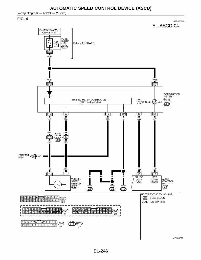
FIG. 4NAEL0097S04
MEL050M
AUTOMATIC SPEED CONTROL DEVICE (ASCD)Wiring Diagram — ASCD — (Cont’d)
EL-246

SEL255W
Fail-safe SystemNAEL0217
DESCRIPTIONNAEL0217S01
When the fail-safe system senses a malfunction, it deactivatesASCD operation. The SET indicator in the combination meter willthen flash.
MALFUNCTION DETECTION CONDITIONSNAEL0217S02
Detection conditionsASCD operation during malfunc-
tion detection
I ASCD steering (RESUME/ACCEL, CANCEL, SET/COAST) switch is stuck.I Vacuum motor ground circuit or power circuit is open or shorted.I Air valve ground circuit or power circuit is open or shorted.I Release valve ground circuit or power circuit is open or shorted.I Vehicle speed sensor is faulty.I ASCD control unit internal circuit is malfunctioning.
I ASCD is deactivated.I Vehicle speed memory is can-
celed.
I ASCD brake switch or stop lamp switch is faulty. I ASCD is deactivated.I Vehicle speed memory is not
canceled.
GI
MA
EM
LC
EC
FE
CL
MT
AT
TF
PD
AX
SU
BR
ST
RS
BT
HA
SC
IDX
AUTOMATIC SPEED CONTROL DEVICE (ASCD)Fail-safe System
EL-247

Trouble DiagnosesNAEL0218
SYMPTOM CHARTNAEL0218S01
PROCEDURE Diagnostic procedure
REFERENCE PAGE (EL- ) 249 250 251 252 253 253 255
SYMPTOM
FAIL
-SA
FE
SY
ST
EM
CH
EC
K
PO
WE
RS
UP
PLY
AN
DG
RO
UN
DC
IRC
UIT
CH
EC
K
AS
CD
BR
AK
E/S
TO
PLA
MP
SW
ITC
HC
HE
CK
AS
CD
ST
EE
RIN
GS
WIT
CH
CH
EC
K
VE
HIC
LES
PE
ED
SE
NS
OR
CH
EC
K
AS
CD
PU
MP
CIR
CU
ITC
HE
CK
AS
CD
AC
TU
AT
OR
/PU
MP
CH
EC
K
ASCD cannot be set. (“CRUISE” indica-tor lamp does not ON.)
X X3
ASCD cannot be set. (“SET” indicatorlamp does not blink.)
X X X
ASCD cannot be set. (“SET” indicatorlamp blinks.1)
X X X X X
Vehicle speed does not decrease afterSET/COAST switch has been pressed.
X X
Vehicle speed does not return to the setspeed after RESUME/ACCEL switch hasbeen pressed.2
X X
Vehicle speed does not increase afterRESUME/ACCEL switch has beenpressed.
X X
System is not released after CANCELswitch (steering) has been pressed.
X X
Large difference between set speed andactual vehicle speed.
X X X
Deceleration is greatest immediatelyafter ASCD has been set.
X X X
1: It indicates that system is in fail-safe. After completing diagnostic procedures, perform “FAIL-SAFE SYSTEM CHECK” (EL-249) toverify repairs.2: If vehicle speed is greater than 40 km/h (25 MPH) after system has been released, pressing RESUME/ACCEL switch returns vehiclespeed to the set speed previously achieved. However, doing so when the ASCD main switch is turned to “OFF”, vehicle speed will notreturn to the set speed since the memory is canceled.3: Check only main switch built-in steering switch.
AUTOMATIC SPEED CONTROL DEVICE (ASCD)Trouble Diagnoses
EL-248

SEL417V
FAIL-SAFE SYSTEM CHECK=NAEL0218S02
1. Turn ignition switch to ON position.2. Turn ASCD main switch to ON and check if the SET indicator
blinks.If the indicator lamp blinks, check the following.
I ASCD steering switch. Refer to EL-252.
SEL767P
3. Drive the vehicle at more than 40 km/h (25 MPH) and pushSET/COAST switch.If the indicator lamp blinks, check the following.
I Vehicle speed sensor. Refer to EL-253.I ASCD pump circuit. Refer to EL-253.I Replace control unit.
SAT797A
4. Depress brake pedal slowly (brake pedal should be depressedmore than 5 seconds).If the indicator lamp blinks, check the following.
I ASCD brake/stop lamp switch. Refer to EL-251.
5. END. (System is OK.)
GI
MA
EM
LC
EC
FE
CL
MT
AT
TF
PD
AX
SU
BR
ST
RS
BT
HA
SC
IDX
AUTOMATIC SPEED CONTROL DEVICE (ASCD)Trouble Diagnoses (Cont’d)
EL-249

POWER SUPPLY AND GROUND CIRCUIT CHECK=NAEL0218S03
1 CHECK POWER SUPPLY CIRCUIT FOR ASCD CONTROL UNIT
1. Disconnect ASCD control unit harness connector.2. Turn ignition switch ON.3. Check voltage between ASCD control unit harness connector terminal 5 and ground.
SEL256WB
Refer to wiring diagram in EL-245.
Yes © GO TO 2.
No © Check the following.I 7.5A fuse (No. 11 located in the fuse block)I Harness for open or short
2 CHECK GROUND CIRCUIT FOR ASCD CONTROL UNIT
Check continuity between ASCD control unit harness connector terminal 17 and body ground.
SEL257WB
Refer to wiring diagram in EL-245.
Yes © Power supply and ground circuit is OK.
No © Repair harness.
AUTOMATIC SPEED CONTROL DEVICE (ASCD)Trouble Diagnoses (Cont’d)
EL-250
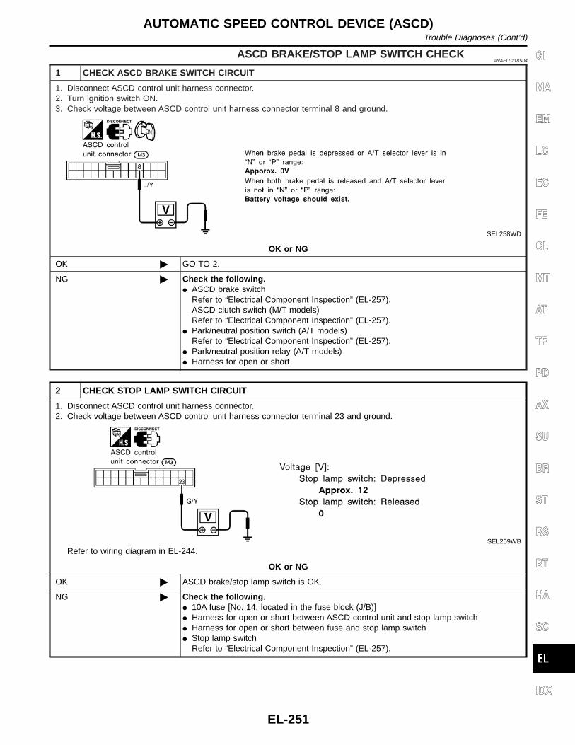
ASCD BRAKE/STOP LAMP SWITCH CHECK=NAEL0218S04
1 CHECK ASCD BRAKE SWITCH CIRCUIT
1. Disconnect ASCD control unit harness connector.2. Turn ignition switch ON.3. Check voltage between ASCD control unit harness connector terminal 8 and ground.
SEL258WD
OK or NG
OK © GO TO 2.
NG © Check the following.I ASCD brake switch
Refer to “Electrical Component Inspection” (EL-257).ASCD clutch switch (M/T models)Refer to “Electrical Component Inspection” (EL-257).
I Park/neutral position switch (A/T models)Refer to “Electrical Component Inspection” (EL-257).
I Park/neutral position relay (A/T models)I Harness for open or short
2 CHECK STOP LAMP SWITCH CIRCUIT
1. Disconnect ASCD control unit harness connector.2. Check voltage between ASCD control unit harness connector terminal 23 and ground.
SEL259WB
Refer to wiring diagram in EL-244.
OK or NG
OK © ASCD brake/stop lamp switch is OK.
NG © Check the following.I 10A fuse [No. 14, located in the fuse block (J/B)]I Harness for open or short between ASCD control unit and stop lamp switchI Harness for open or short between fuse and stop lamp switchI Stop lamp switch
Refer to “Electrical Component Inspection” (EL-257).
GI
MA
EM
LC
EC
FE
CL
MT
AT
TF
PD
AX
SU
BR
ST
RS
BT
HA
SC
IDX
AUTOMATIC SPEED CONTROL DEVICE (ASCD)Trouble Diagnoses (Cont’d)
EL-251

ASCD STEERING SWITCH CHECK=NAEL0218S05
1 CHECK ASCD STEERING SWITCH CIRCUIT FOR ASCD CONTROL UNIT
Check voltage between ASCD control unit harness connector terminals and ground.
SEL260WC
Refer to wiring diagram in EL-244.
OK or NG
OK © ASCD steering switch is OK.
NG © GO TO 2.
2 CHECK POWER SUPPLY FOR ASCD STEERING SWITCH
Does horn work?
Yes © GO TO 3.
No © Check the following.I 7.5A fuse (No. 52, located in the relay box)I Horn relayI Horn circuit
3 CHECK ASCD STEERING SWITCH
1. Disconnect ASCD steering switch.2. Check continuity between terminals by pushing each switch.
SEL764WA
OK or NG
OK © Check harness for open or short between ASCD steering switch and ASCD control unit.
NG © Replace ASCD steering switch.
AUTOMATIC SPEED CONTROL DEVICE (ASCD)Trouble Diagnoses (Cont’d)
EL-252

VEHICLE SPEED SENSOR CHECK=NAEL0218S06
1 CHECK SPEEDOMETER OPERATION
Does speedometer operate normally?
Yes © GO TO 2.
No © Check speedometer and vehicle speed sensor circuit. Refer to wiring diagram in EL-246.
2 CHECK VEHICLE SPEED INPUT
1. Apply wheel chocks and jack up drive wheel.2. Disconnect ASCD control unit harness connector.3. Check voltage between control unit terminal 22 and ground with turning drive wheel slowly by hand.
SEL263WB
Refer to wiring diagram in EL-245.
Yes © Vehicle speed sensor is OK.
No © Check harness for open or short between ASCD control unit terminal 22 and combinationmeter terminal 13.
ASCD PUMP CIRCUIT CHECKNAEL0218S07
1 CHECK ASCD PUMP
1. Disconnect ASCD pump connector.2. Measure resistance between ASCD pump terminals 1 and 2, 3, 4.
SEL262WB
Refer to wiring diagram in EL-245.
OK or NG
OK © GO TO 2.
NG © Replace ASCD pump.
GI
MA
EM
LC
EC
FE
CL
MT
AT
TF
PD
AX
SU
BR
ST
RS
BT
HA
SC
IDX
AUTOMATIC SPEED CONTROL DEVICE (ASCD)Trouble Diagnoses (Cont’d)
EL-253

2 CHECK ASCD PUMP CIRCUIT
1. Disconnect ASCD control unit harness connector.2. Check harness for open or short between ASCD control unit and ASCD pump.
SEL269WB
OK or NG
OK © GO TO 3.
NG © Repair harness.
3 CHECK ASCD PUMP POWER SUPPLY
1. Jack-up the drive wheels.2. Maintain the conditions below.I Vehicle speed is more than 40 km/h (25 MPH).I Main switch (CRUISE lamp) is ON.I Set/coast switch (SET lamp) is ON.Check voltage between ASCD control unit harness connector terminal 12 and ground.
SEL381WB
OK or NG
OK © ASCD pump power supply is OK.
NG © Replace ASCD control unit.
AUTOMATIC SPEED CONTROL DEVICE (ASCD)Trouble Diagnoses (Cont’d)
EL-254

ASCD ACTUATOR/PUMP CHECK=NAEL0218S08
1 CHECK VACUUM HOSE
Check vacuum hose (between ASCD actuator and ASCD pump) for breakage, cracks or fracture.
MEL402G
OK or NG
OK © GO TO 2.
NG © Repair or replace hose.
2 CHECK ASCD WIRE
Check wire for improper installation, rust formation or breaks.
OK or NG
OK © GO TO 3.
NG © Repair or replace wire. Refer to “ASCD Wire Adjustment” (EL-258).
3 CHECK ASCD ACTUATOR
1. Disconnect vacuum hose from ASCD actuator.2. Connect the hose of hand vacuum pump to ASCD actuator.
SEL264W
OK or NG
OK © GO TO 4.
NG © Replace ASCD actuator.
GI
MA
EM
LC
EC
FE
CL
MT
AT
TF
PD
AX
SU
BR
ST
RS
BT
HA
SC
IDX
AUTOMATIC SPEED CONTROL DEVICE (ASCD)Trouble Diagnoses (Cont’d)
EL-255

4 CHECK ASCD PUMP
1. Disconnect vacuum hose from ASCD pump and ASCD pump connector.2. If necessary remove ASCD pump.3. Connect vacuum gauge to ASCD pump.4. Apply 12V direct current to ASCD pump and check operation.
SEL265WB
OK or NG
OK © INSPECTION END
NG © Replace ASCD pump.
AUTOMATIC SPEED CONTROL DEVICE (ASCD)Trouble Diagnoses (Cont’d)
EL-256

SEL302X
Electrical Component Inspection=NAEL0219
ASCD BRAKE SWITCH AND STOP LAMP SWITCHNAEL0219S02
Condition
Continuity
ASCD brakeswitch
Stop lamp switch
When brake pedal is depressed No Yes
When brake pedal is released Yes No
Check each switch after adjusting brake pedal — refer to BR-14,“BRAKE PEDAL AND BRACKET”.
SEL303X
PARK/NEUTRAL POSITION SWITCH (FOR A/TMODELS)
NAEL0219S03
A/T selector lever positionContinuity
Between terminals 1 and 2
“P” Yes
“N” Yes
Except “P” and “N” No
SEL635X
ASCD CLUTCH SWITCH (FOR M/T MODELS)NAEL0219S05
Condition Continuity
When clutch pedal is depressed No
When clutch pedal is released Yes
GI
MA
EM
LC
EC
FE
CL
MT
AT
TF
PD
AX
SU
BR
ST
RS
BT
HA
SC
IDX
AUTOMATIC SPEED CONTROL DEVICE (ASCD)Electrical Component Inspection
EL-257

ASCD Wire Adjustment=NAEL0220
MEL383K
CAUTION:I Be careful not to twist ASCD wire when removing it.I Do not tense ASCD wire excessively during adjustment.Adjust the tension of ASCD wire in the following manner.1. Loosen lock nut and adjusting nut.2. Make sure that accelerator wire is properly adjusted. Refer to
FE-3, “ACCELERATOR CONTROL SYSTEM”.3. Tighten adjusting nut just until throttle drum starts to move.4. Loosen adjusting nut again 1/2 to 1 turn.5. Tighten lock nut.
AUTOMATIC SPEED CONTROL DEVICE (ASCD)ASCD Wire Adjustment
EL-258

System DescriptionNAEL0102
Power is supplied at all timesI from 40A fusible link (letter f, located in the fuse and fusible link box)I to circuit breaker terminal 1I through circuit breaker terminal 2I to power window relay terminal 3,I to front power window main switch terminal 4, andI to front power window switch RH terminal 6.With ignition switch in ON or START position, power is suppliedI through 7.5A fuse [No. 11, located in the fuse block (J/B)]I to power window relay terminal 2, andI to smart entrance control unit terminal 33.Ground is supplied to power window relay terminal 1I through body grounds M4, M66 and M147.The power window relay is energized and power is suppliedI through power window relay terminal 5I to front power window main switch terminal 11,I to front power window switch RH terminal 13,I to rear power window switch LH and RH terminals 5.
MANUAL OPERATIONNAEL0102S01
Front Door LHNAEL0102S0101
Ground is suppliedI to front power window main switch terminal 5I through body grounds M77 and M111.WINDOW UPWhen the front LH switch in the front power window main switch is pressed in the up position, power is sup-pliedI to front power window regulator LH terminal 1I through front power window main switch terminal 2.Ground is suppliedI to front power window regulator LH terminal 3I through front power window main switch terminal 3.Then, the motor raises the window until the switch is released.WINDOW DOWNWhen the LH switch in the front power window main switch is pressed in the down position, power is suppliedI to front power window regulator LH terminal 3I through front power window main switch terminal 3.Ground is suppliedI to front power window regulator LH terminal 1I through front power window main switch terminal 2.Then, the motor lowers the window until the switch is released.
Front Door RHNAEL0102S0102
Ground is suppliedI to front power window main switch terminal 5I through body grounds M77 and M111.NOTE:Numbers in parentheses are terminal numbers, when power window switch is pressed in the UP and DOWNpositions respectively.FRONT POWER WINDOW MAIN SWITCH OPERATIONWhen front RH switch in the front power window main switch is pressed UP or DOWN position, a signal issupplied
GI
MA
EM
LC
EC
FE
CL
MT
AT
TF
PD
AX
SU
BR
ST
RS
BT
HA
SC
IDX
POWER WINDOWSystem Description
EL-259
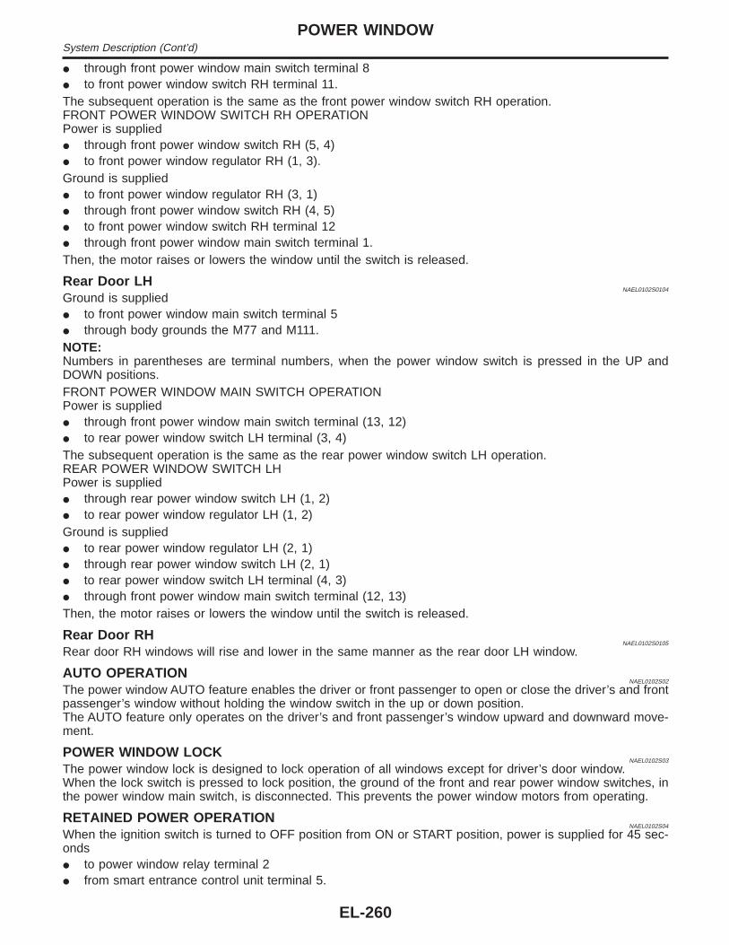
I through front power window main switch terminal 8I to front power window switch RH terminal 11.The subsequent operation is the same as the front power window switch RH operation.FRONT POWER WINDOW SWITCH RH OPERATIONPower is suppliedI through front power window switch RH (5, 4)I to front power window regulator RH (1, 3).Ground is suppliedI to front power window regulator RH (3, 1)I through front power window switch RH (4, 5)I to front power window switch RH terminal 12I through front power window main switch terminal 1.Then, the motor raises or lowers the window until the switch is released.
Rear Door LHNAEL0102S0104
Ground is suppliedI to front power window main switch terminal 5I through body grounds the M77 and M111.NOTE:Numbers in parentheses are terminal numbers, when the power window switch is pressed in the UP andDOWN positions.FRONT POWER WINDOW MAIN SWITCH OPERATIONPower is suppliedI through front power window main switch terminal (13, 12)I to rear power window switch LH terminal (3, 4)The subsequent operation is the same as the rear power window switch LH operation.REAR POWER WINDOW SWITCH LHPower is suppliedI through rear power window switch LH (1, 2)I to rear power window regulator LH (1, 2)Ground is suppliedI to rear power window regulator LH (2, 1)I through rear power window switch LH (2, 1)I to rear power window switch LH terminal (4, 3)I through front power window main switch terminal (12, 13)Then, the motor raises or lowers the window until the switch is released.
Rear Door RHNAEL0102S0105
Rear door RH windows will rise and lower in the same manner as the rear door LH window.
AUTO OPERATIONNAEL0102S02
The power window AUTO feature enables the driver or front passenger to open or close the driver’s and frontpassenger’s window without holding the window switch in the up or down position.The AUTO feature only operates on the driver’s and front passenger’s window upward and downward move-ment.
POWER WINDOW LOCKNAEL0102S03
The power window lock is designed to lock operation of all windows except for driver’s door window.When the lock switch is pressed to lock position, the ground of the front and rear power window switches, inthe power window main switch, is disconnected. This prevents the power window motors from operating.
RETAINED POWER OPERATIONNAEL0102S04
When the ignition switch is turned to OFF position from ON or START position, power is supplied for 45 sec-ondsI to power window relay terminal 2I from smart entrance control unit terminal 5.
POWER WINDOWSystem Description (Cont’d)
EL-260

Ground is always suppliedI to power window relay terminal 1I through body grounds.When power and ground are supplied, the power window relay continues to be energized, and the power win-dow can be operated.The retained power operation is canceled when the driver or passenger side door is opened.
INTERRUPTION DETECTION FUNCTIONNAEL0102S05
Front power window main switch and front power window switch RH monitor the power window regulator motoroperation and the power window position (full closed or other) for driver’s and passenger’s power window bythe signals from encoder and limit switch in front power window regulator LH or RH.When front power window main switch or front power window switch RH detects interruption during the fol-lowing close operation in the driver’s or front passenger’s side door,I automatic close operation when ignition switch is in the “ON” positionI automatic close operation during retained power operationfront power window main switch or front power window switch RH controls driver’s or front passenger’s powerwindow regulator motor for open and the power window will be lowered about 150 mm (5.91 in).
GI
MA
EM
LC
EC
FE
CL
MT
AT
TF
PD
AX
SU
BR
ST
RS
BT
HA
SC
IDX
POWER WINDOWSystem Description (Cont’d)
EL-261

SchematicNAEL0103
MEL842L
POWER WINDOWSchematic
EL-262

Wiring Diagram — WINDOW —NAEL0104
MEL021O
GI
MA
EM
LC
EC
FE
CL
MT
AT
TF
PD
AX
SU
BR
ST
RS
BT
HA
SC
IDX
POWER WINDOWWiring Diagram — WINDOW —
EL-263

MEL844L
POWER WINDOWWiring Diagram — WINDOW — (Cont’d)
EL-264

MEL845L
GI
MA
EM
LC
EC
FE
CL
MT
AT
TF
PD
AX
SU
BR
ST
RS
BT
HA
SC
IDX
POWER WINDOWWiring Diagram — WINDOW — (Cont’d)
EL-265

MEL846L
POWER WINDOWWiring Diagram — WINDOW — (Cont’d)
EL-266

MEL847L
GI
MA
EM
LC
EC
FE
CL
MT
AT
TF
PD
AX
SU
BR
ST
RS
BT
HA
SC
IDX
POWER WINDOWWiring Diagram — WINDOW — (Cont’d)
EL-267
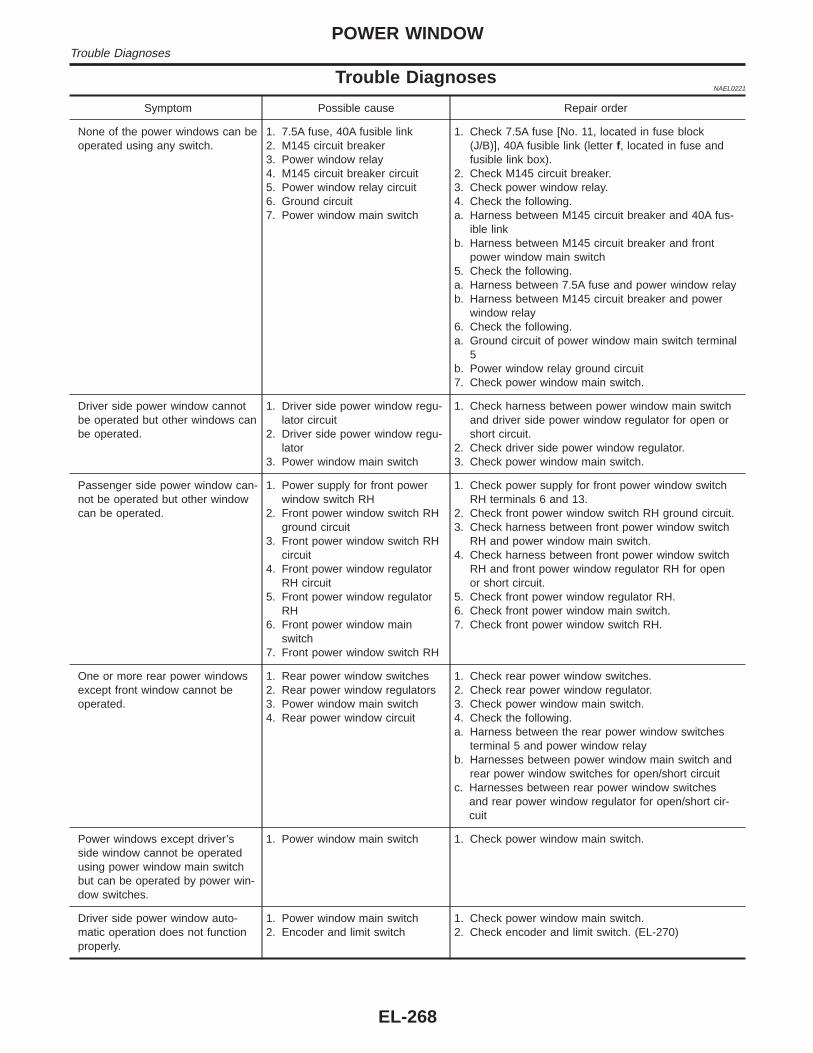
Trouble DiagnosesNAEL0221
Symptom Possible cause Repair order
None of the power windows can beoperated using any switch.
1. 7.5A fuse, 40A fusible link2. M145 circuit breaker3. Power window relay4. M145 circuit breaker circuit5. Power window relay circuit6. Ground circuit7. Power window main switch
1. Check 7.5A fuse [No. 11, located in fuse block(J/B)], 40A fusible link (letter f, located in fuse andfusible link box).
2. Check M145 circuit breaker.3. Check power window relay.4. Check the following.a. Harness between M145 circuit breaker and 40A fus-
ible linkb. Harness between M145 circuit breaker and front
power window main switch5. Check the following.a. Harness between 7.5A fuse and power window relayb. Harness between M145 circuit breaker and power
window relay6. Check the following.a. Ground circuit of power window main switch terminal
5b. Power window relay ground circuit7. Check power window main switch.
Driver side power window cannotbe operated but other windows canbe operated.
1. Driver side power window regu-lator circuit
2. Driver side power window regu-lator
3. Power window main switch
1. Check harness between power window main switchand driver side power window regulator for open orshort circuit.
2. Check driver side power window regulator.3. Check power window main switch.
Passenger side power window can-not be operated but other windowcan be operated.
1. Power supply for front powerwindow switch RH
2. Front power window switch RHground circuit
3. Front power window switch RHcircuit
4. Front power window regulatorRH circuit
5. Front power window regulatorRH
6. Front power window mainswitch
7. Front power window switch RH
1. Check power supply for front power window switchRH terminals 6 and 13.
2. Check front power window switch RH ground circuit.3. Check harness between front power window switch
RH and power window main switch.4. Check harness between front power window switch
RH and front power window regulator RH for openor short circuit.
5. Check front power window regulator RH.6. Check front power window main switch.7. Check front power window switch RH.
One or more rear power windowsexcept front window cannot beoperated.
1. Rear power window switches2. Rear power window regulators3. Power window main switch4. Rear power window circuit
1. Check rear power window switches.2. Check rear power window regulator.3. Check power window main switch.4. Check the following.a. Harness between the rear power window switches
terminal 5 and power window relayb. Harnesses between power window main switch and
rear power window switches for open/short circuitc. Harnesses between rear power window switches
and rear power window regulator for open/short cir-cuit
Power windows except driver’sside window cannot be operatedusing power window main switchbut can be operated by power win-dow switches.
1. Power window main switch 1. Check power window main switch.
Driver side power window auto-matic operation does not functionproperly.
1. Power window main switch2. Encoder and limit switch
1. Check power window main switch.2. Check encoder and limit switch. (EL-270)
POWER WINDOWTrouble Diagnoses
EL-268

Symptom Possible cause Repair order
Front passenger side power win-dow automatic operation does notfunction properly.
1. Front power window switch RH2. Encoder and limit switch
1. Check front power window switch RH.2. Check encoder and limit switch. (EL-270)
Retained power operation does notoperate properly.
1. RAP signal circuit2. Driver or passenger side door
switch circuit3. Smart entrance control unit
1. Check harness between power window relay termi-nal 2 and smart entrance control unit terminal 5 foropen or short circuit.
2. Check the following.a. Harness between smart entrance control unit and
driver or passenger side door switch for short circuitb. Driver or passenger side door switch ground circuitc. Driver or passenger side door switch3. Check smart entrance control unit. (EL-348)
GI
MA
EM
LC
EC
FE
CL
MT
AT
TF
PD
AX
SU
BR
ST
RS
BT
HA
SC
IDX
POWER WINDOWTrouble Diagnoses (Cont’d)
EL-269

ENCODER AND LIMIT SWITCH CHECK=NAEL0221S01
1 CHECK DOOR WINDOW SLIDE MECHANISM
Check the following.I Obstacles in window, glass molding, etc.I Worn or deformed glass moldingI Door sash tilted too far inward or outwardI Door window regulator
OK or NG
OK © GO TO 2.
NG © Remove obstacles or repair door window slide mechanism.
2 CHECK POWER SUPPLY TO LIMIT SWITCH
1. Disconnect front power window regulator LH or RH harness connector.2. Check voltage between front power window main switch terminal 15 or front power window switch RH terminal 16 and
ground.
SEL725WA
OK or NG
OK © GO TO 3.
NG © Replace power window main switch or front power window switch RH.
3 CHECK LIMIT SWITCH OPERATION
1. Connect front power window regulator LH or RH harness connector.2. Check voltage between front power window main switch terminal 15 or front power window switch RH terminal 16 and
ground during power window closing operation.
SEL726WA
OK or NG
OK © GO TO 5.
NG © GO TO 4.
POWER WINDOWTrouble Diagnoses (Cont’d)
EL-270

4 RESET LIMIT SWITCH
Reset limit switch. Refer to BT-20, “Front Door Glass Limit Switch Reset”. Then check voltage between front power win-dow main switch terminal 15 or front power window switch RH terminal 16 and ground during power window closingoperation at least ten times.
SEL726WA
OK or NG
OK © GO TO 5.
NG © Replace power window regulator motor.
5 CHECK ENCODER
Measure voltage between front power window main switch terminal 14 or front power window switch RH terminal 19 andground with oscilloscope when power window is in automatic closing operation.
SEL727WA
OK or NG
OK © Replace power window main switch.
NG © Replace power window regulator motor.
GI
MA
EM
LC
EC
FE
CL
MT
AT
TF
PD
AX
SU
BR
ST
RS
BT
HA
SC
IDX
POWER WINDOWTrouble Diagnoses (Cont’d)
EL-271

Component Parts and Harness ConnectorLocation
NAEL0106
SEL065W
System DescriptionNAEL0107
OPERATIONNAEL0107S04
I The lock/unlock switch (LH and RH) on door trim can lock and unlock all doors.I With the door key inserted in the key cylinder on front LH, RH or back door, turning it to “LOCK”, will lock
all doors; turning it to “UNLOCK” once unlocks the corresponding door; turning it to “UNLOCK” again within5 seconds after the first unlock operation unlocks all of the other doors. (Signals from door key cylinderswitch)
I If the ignition key is in the ignition key cylinder and one or more of doors are open, setting the lock/unlockswitch to “LOCK” locks the doors once but then immediately unlock them. (Combination signals from keyswitch and door switches) - (KEY REMINDER DOOR SYSTEM)
POWER DOOR LOCKComponent Parts and Harness Connector Location
EL-272

SchematicNAEL0108
MEL211M
GI
MA
EM
LC
EC
FE
CL
MT
AT
TF
PD
AX
SU
BR
ST
RS
BT
HA
SC
IDX
POWER DOOR LOCKSchematic
EL-273

Wiring Diagram — D/LOCK —NAEL0109
FIG. 1NAEL0109S01
MEL848L
POWER DOOR LOCKWiring Diagram — D/LOCK —
EL-274

FIG. 2NAEL0109S02
MEL849L
GI
MA
EM
LC
EC
FE
CL
MT
AT
TF
PD
AX
SU
BR
ST
RS
BT
HA
SC
IDX
POWER DOOR LOCKWiring Diagram — D/LOCK — (Cont’d)
EL-275

FIG. 3NAEL0109S03
MEL850L
POWER DOOR LOCKWiring Diagram — D/LOCK — (Cont’d)
EL-276

FIG. 4NAEL0109S04
MEL851L
GI
MA
EM
LC
EC
FE
CL
MT
AT
TF
PD
AX
SU
BR
ST
RS
BT
HA
SC
IDX
POWER DOOR LOCKWiring Diagram — D/LOCK — (Cont’d)
EL-277
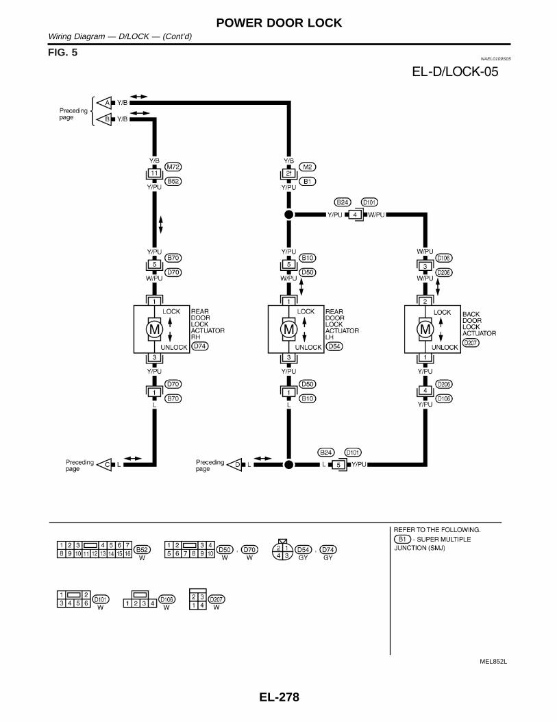
FIG. 5NAEL0109S05
MEL852L
POWER DOOR LOCKWiring Diagram — D/LOCK — (Cont’d)
EL-278

Trouble DiagnosesNAEL0110
SYMPTOM CHARTNAEL0110S01
REFERENCE PAGE (EL- ) 280 281 282 283 284 285 286
SYMPTOM
MA
INP
OW
ER
SU
PP
LYA
ND
GR
OU
ND
CIR
CU
ITC
HE
CK
DO
OR
SW
ITC
HC
HE
CK
KE
YS
WIT
CH
(IN
SE
RT
)C
HE
CK
DO
OR
LOC
K/U
NLO
CK
SW
ITC
HC
HE
CK
FR
ON
TD
OO
RK
EY
CY
LIN
DE
RS
WIT
CH
CH
EC
K
BA
CK
DO
OR
KE
YC
YLI
ND
ER
SW
ITC
HC
HE
CK
DO
OR
LOC
KA
CT
UA
TO
RC
HE
CK
Key reminder door system does not operateproperly.
X X X X
Specific door lock actuator does not operate. X X
Power door lock does not operate with doorlock and unlock switch (LH and RH) on doortrim.
X X
Power door lock does not operate with frontdoor key cylinder operation.
X X
Power door lock does not operate with backdoor key cylinder operation.
X X
GI
MA
EM
LC
EC
FE
CL
MT
AT
TF
PD
AX
SU
BR
ST
RS
BT
HA
SC
IDX
POWER DOOR LOCKTrouble Diagnoses
EL-279

SEL304X
MAIN POWER SUPPLY AND GROUND CIRCUIT CHECK=NAEL0110S02
Main Power Supply Circuit CheckNAEL0110S0201
Terminal Ignition switch
(+) (−) OFF ACC ON
10Ground
Batteryvoltage
Batteryvoltage
Batteryvoltage11
SEL013W
Ground Circuit CheckNAEL0110S0202
Terminals Continuity
16 - Ground Yes
POWER DOOR LOCKTrouble Diagnoses (Cont’d)
EL-280

DOOR SWITCH CHECK=NAEL0110S05
1 CHECK DOOR SWITCH INPUT SIGNAL
Check voltage between smart entrance control unit terminals 28, 29 or 40 and ground.
SEL305X
Refer to wiring diagram in EL-274.
OK or NG
OK © Door switch is OK.
NG © GO TO 2.
2 CHECK DOOR SWITCH
1. Disconnect door switch connector.2. Check continuity between door switch terminals.
SEL306X
OK or NG
OK © Check the following.I Door switch ground circuit (Front LH, back door) or door switch ground conditionI Harness for open or short between smart entrance control unit and door switch
NG © Replace door switch.
GI
MA
EM
LC
EC
FE
CL
MT
AT
TF
PD
AX
SU
BR
ST
RS
BT
HA
SC
IDX
POWER DOOR LOCKTrouble Diagnoses (Cont’d)
EL-281

KEY SWITCH (INSERT) CHECK=NAEL0110S06
1 CHECK KEY SWITCH INPUT SIGNAL
Check voltage between smart entrance control unit terminal 32 and ground.
SEL307X
Refer to wiring diagram in EL-275.
OK or NG
OK © Key switch is OK.
NG © GO TO 2.
2 CHECK KEY SWITCH (INSERT)
Check continuity between terminals 1 and 2.
SEL308X
OK or NG
OK © Check the following.I 7.5A fuse [No. 24, located in fuse block (J/B)]I Harness for open or short between key switch and fuseI Harness for open or short between smart entrance control unit and key switch
NG © Replace key switch.
POWER DOOR LOCKTrouble Diagnoses (Cont’d)
EL-282

DOOR LOCK/UNLOCK SWITCH CHECK=NAEL0110S03
1 CHECK DOOR LOCK/UNLOCK SWITCH INPUT SIGNAL
1. Disconnect smart entrance control unit connector.2. Check continuity between control unit terminal 23 or 35 and ground.
SEL309X
Refer to wiring diagram in EL-275.
OK or NG
OK © Door lock/unlock switch is OK.
NG © GO TO 2.
2 CHECK DOOR LOCK/UNLOCK SWITCH
1. Disconnect door lock/unlock switch connector.2. Check continuity between each door lock/unlock switch terminals.I Power window main switch (Door lock/unlock switch LH)
SEL310X
I Door lock/unlock switch RH
SEL311X
OK or NG
OK © Check the following.I Ground circuit for door lock/unlock switchI Harness for open or short between door lock/unlock switch and smart entrance control
unit connector
NG © Replace door lock/unlock switch.
GI
MA
EM
LC
EC
FE
CL
MT
AT
TF
PD
AX
SU
BR
ST
RS
BT
HA
SC
IDX
POWER DOOR LOCKTrouble Diagnoses (Cont’d)
EL-283

FRONT DOOR KEY CYLINDER SWITCH CHECK=NAEL0110S07
1 CHECK DOOR KEY CYLINDER SWITCH INPUT SIGNAL (LOCK/UNLOCK SIGNAL)
Check voltage between smart entrance control unit terminals 30 or 41 and ground.
SEL312X
Refer to wiring diagram in EL-276.
OK or NG
OK © Door key cylinder switch is OK.
NG © GO TO 2.
2 CHECK DOOR KEY CYLINDER SWITCH
1. Disconnect door key cylinder switch connector.2. Check continuity between door key cylinder switch terminals.
SEL313X
OK or NG
OK © Check the following.I Door key cylinder switch ground circuitI Harness for open or short between smart entrance control unit and door key cylinder
switch
NG © Replace door key cylinder switch.
POWER DOOR LOCKTrouble Diagnoses (Cont’d)
EL-284

BACK DOOR KEY CYLINDER SWITCH CHECK=NAEL0110S08
1 CHECK BACK DOOR KEY CYLINDER SWITCH INPUT SIGNAL (LOCK/UNLOCK SIGNAL)
Check voltage between smart entrance control unit terminals 30 or 41 and ground.
SEL314X
Refer to wiring diagram in EL-276.
OK or NG
OK © Back door key cylinder switch is OK.
NG © GO TO 2.
2 CHECK BACK DOOR KEY CYLINDER SWITCH
1. Disconnect back door key cylinder switch connector.2. Check continuity between back door key cylinder switch terminals.
SEL315X
OK or NG
OK © Check the following.I Back door key cylinder switch ground circuitI Harness for open or short between smart entrance control unit and back door key cyl-
inder switch
NG © Replace back door key cylinder switch.
GI
MA
EM
LC
EC
FE
CL
MT
AT
TF
PD
AX
SU
BR
ST
RS
BT
HA
SC
IDX
POWER DOOR LOCKTrouble Diagnoses (Cont’d)
EL-285

DOOR LOCK ACTUATOR CHECK=NAEL0110S04
1 CHECK DOOR LOCK ACTUATOR CIRCUIT
Check voltage for door lock actuator.I Door lock actuator front LH
SEL316X
I Door lock actuator front RH, rear and back
SEL317X
Refer to wiring diagram in EL-277.
OK or NG
OK © GO TO 2.
NG © Replace smart entrance control unit. (Before replacing smart entrance control unit, per-form “DOOR LOCK/UNLOCK SWITCH CHECK”.)
POWER DOOR LOCKTrouble Diagnoses (Cont’d)
EL-286

2 CHECK DOOR LOCK ACTUATOR
1. Disconnect door lock actuator connector.2. Apply 12V direct current to door lock actuator and check operation.
SEL318X
SEL319X
OK or NG
OK © Check harness for open or short between smart entrance control unit connector and doorlock actuator.
NG © Replace door lock actuator.
GI
MA
EM
LC
EC
FE
CL
MT
AT
TF
PD
AX
SU
BR
ST
RS
BT
HA
SC
IDX
POWER DOOR LOCKTrouble Diagnoses (Cont’d)
EL-287

Component Parts and Harness ConnectorLocation
NAEL0111
SEL355X
System DescriptionNAEL0112
INPUTSNAEL0112S01
Power is supplied at all timesI to smart entrance control unit terminal 11I through circuit breakerI through 40A fusible link (letter f located in the fuse and fusible link box),I to key switch terminal 2, andI to smart entrance control unit terminal 10I through 7.5A fuse [No. 24, located in the fuse block (J/B)].I to multi-remote control relay terminals 1, 3 and 6I through 15A fuse [No. 20, located in the fuse block (J/B)].I to horn relay terminals 1 and 3I through 7.5A fuse [No. 52, located in the fuse block (J/B)].I to horn relay terminal 6I through 10A fuse [No. 54, located in the fuse block (J/B)].When the ignition switch is in the ACC or ON position, power is supplied to smart entrance control unit termi-nal 21.When the key switch is ON (ignition key is inserted in key cylinder), power is suppliedI through key switch terminal 1I to smart entrance control unit terminal 32.
MULTI-REMOTE CONTROL SYSTEMComponent Parts and Harness Connector Location
EL-288

When the front door switch LH is OPEN, ground is suppliedI to smart entrance control unit terminal 29I through front door switch LH terminal 1I to front door switch LH terminal 2I through body grounds B11, B22 and D210.When the front door switch RH is OPEN, ground is suppliedI to smart entrance control unit terminal 40I through front door switch RH body ground.When the other door switches are OPEN, ground is suppliedI to smart entrance control unit terminal 28I through other door switches body grounds.Remote controller signal is inputted to smart entrance control unit (The antenna of the system is combinedwith smart entrance control unit).
OPERATIONNAEL0112S03
The multi-remote control system controls operation of theI power door lockI interior lampI panic alarmI hazard and horn reminder
OPERATED PROCEDURENAEL0112S02
Power Door Lock OperationNAEL0112S0201
Smart entrance control unit receives a LOCK signal from remote controller. Smart entrance control unit locksall doors with input of LOCK signal from remote controller.When an UNLOCK signal is sent from remote controller once, driver’s door will be unlocked.Then, if an UNLOCK signal is sent from remote controller again within 5 seconds, all other door will beunlocked.
Hazard and Horn ReminderNAEL0112S0204
When smart entrance control unit receives LOCK or UNLOCK signal from remote controller with all doorsclosed, ground is suppliedI to multi-remote control relay terminal 2I through smart entrance control unit terminal 7, andI to horn relay terminal 2I through smart entrance control unit terminal 19Multi-remote control relay and horn relay are now energized, and hazard warning lamp flashes and hornsounds as a reminder.The hazard and horn reminder has a horn chirp mode (C mode) and a non-horn chirp mode (S mode).Operating function of hazard and horn reminder
Horn chirp mode (C mode) Non-horn chirp mode (S mode)
Hazard warning lampflash
Horn soundHazard warning lamp
flashHorn sound
Lock Twice Once Twice —
Unlock Once — — —
How to change hazard and horn reminder modeWhen LOCK and UNLOCK signals are sent from the remote controller for more than 2 seconds at the sametime, the hazard and horn reminder mode is changed and hazard warning lamp flashes and horn sounds asfollows:
GI
MA
EM
LC
EC
FE
CL
MT
AT
TF
PD
AX
SU
BR
ST
RS
BT
HA
SC
IDX
MULTI-REMOTE CONTROL SYSTEMSystem Description (Cont’d)
EL-289

SEL153WB
Interior Lamp OperationNAEL0112S0202
When the following input signals are both supplied:I door switch CLOSED (when all the doors are closed);I driver’s door LOCKED;multi-remote control system turns on interior lamp (for 30 seconds) with input of UNLOCK signal from remotecontroller.For detailed description, refer to “INTERIOR, SPOT, VANITY MIRROR AND LUGGAGE ROOM LAMPS” (EL-108).
Panic Alarm OperationNAEL0112S0203
When key switch is OFF (when ignition key is not inserted in key cylinder), multi-remote control system turnson and off horn and headlamp intermittently with input of PANIC ALARM signal from remote controller.For detailed description, refer to “THEFT WARNING SYSTEM” (EL-315).
MULTI-REMOTE CONTROL SYSTEMSystem Description (Cont’d)
EL-290
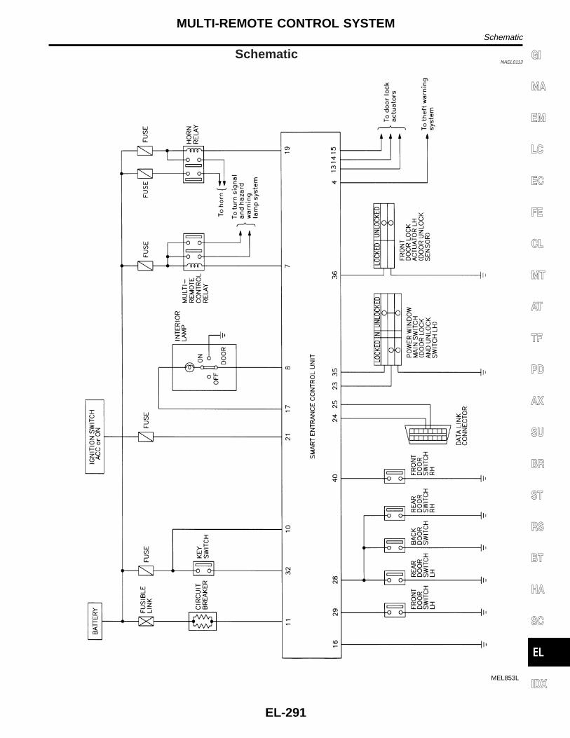
SchematicNAEL0113
MEL853L
GI
MA
EM
LC
EC
FE
CL
MT
AT
TF
PD
AX
SU
BR
ST
RS
BT
HA
SC
IDX
MULTI-REMOTE CONTROL SYSTEMSchematic
EL-291

Wiring Diagram — MULTI —NAEL0114
FIG. 1NAEL0114S01
MEL854L
MULTI-REMOTE CONTROL SYSTEMWiring Diagram — MULTI —
EL-292

FIG. 2NAEL0114S02
MEL855L
GI
MA
EM
LC
EC
FE
CL
MT
AT
TF
PD
AX
SU
BR
ST
RS
BT
HA
SC
IDX
MULTI-REMOTE CONTROL SYSTEMWiring Diagram — MULTI — (Cont’d)
EL-293

FIG. 3NAEL0114S03
MEL051M
MULTI-REMOTE CONTROL SYSTEMWiring Diagram — MULTI — (Cont’d)
EL-294

Trouble DiagnosesNAEL0115
SYMPTOM CHARTNAEL0115S01
NOTE:I Always check remote controller battery before replacing
remote controller.I The panic alarm operation of multi-remote control system does
not activate with the ignition key inserted in the ignition keycylinder.
Symptom Diagnoses/service procedureReference
page(EL- )
All function of multi-remote control system do notoperate.
1. Remote controller battery check 296
2. Power supply and ground circuit for control unit check 297
3. Replace romote controller. Refer to ID Code Entry Procedure. 309
The new ID of remote controller cannot beentered.
1. Remote controller battery check 296
2. Key switch (insert) check 300
3. Door switch check 299
4. Door lock/unlock switch LH check 301
5. Power supply and ground circuit for control unit check 297
6. Replace romote controller. Refer to ID Code Entry Procedure. 309
Door lock or unlock does not function.(If the power door lock system does not operatemanually, check power door lock system. Refer toEL-279.)
1. Replace remote controller. Refer to ID Code Entry Procedure. 309
Hazard and horn reminder does not activate prop-erly when pressing lock or unlock button of remotecontroller.
1. Harzard reminder check 303
2. Horn reminder check**: Horn chirp can be activated or deactivated.First check the horn chirp setting. Refer to “System Description”,EL-288.
305
3. Door switch check 299
4. Replace remote controller. Refer to ID Code Entry Procedure. 309
Interior lamp operation does not activate properly. 1. Interior room lamp operation check 306
2. Door switch check 299
3. Front LH door unlock sensor check 302
Panic alarm (horn and headlamp) does not acti-vate when panic alarm button is continuouslypressed.
1. Theft warning operation check. Refer to “PRELIMINALYCHECK” in “THEFT WARNING SYSTEM”.
328
2. Key switch (insert) check 300
3. Replace remote controller. Refer to ID Code Entry Procedure. 309
GI
MA
EM
LC
EC
FE
CL
MT
AT
TF
PD
AX
SU
BR
ST
RS
BT
HA
SC
IDX
MULTI-REMOTE CONTROL SYSTEMTrouble Diagnoses
EL-295

REMOTE CONTROLLER BATTERY CHECK=NAEL0115S02
1 CHECK REMOTE CONTROLLER BATTERY
Remove battery (refer to EL-311) and measure voltage across battery positive and negative terminals, (+) and (−).Voltage [V]:
2.5 - 3.0NOTE:Remote controller does not function if battery is not set correctly.
SEL277V
OK or NG
OK © Check remote controller battery terminals for corrosion or damage.
NG © Replace battery.
MULTI-REMOTE CONTROL SYSTEMTrouble Diagnoses (Cont’d)
EL-296

POWER SUPPLY AND GROUND CIRCUIT CHECK=NAEL0115S04
1 CHECK MAIN POWER SUPPLY CIRCUIT FOR CONTROL UNIT
1. Disconnect connector from control unit.2. Check voltage between smart entrance control unit terminal 10 or 11 and ground.
SEL320X
Refer to wiring diagram in EL-292.
OK or NG
OK © GO TO 2.
NG © Check the following.I 40A fusible link (letter f, located in fuse and fusible link box)I 7.5A fuse [No. 24, located in fuse block (J/B)]I M145 circuit breakerI Harness for open or short between smart entrance control unit and fuse
2 CHECK IGNITION SWITCH “ACC” CIRCUIT
1. Disconnect smart entrance control unit connector.2. Check voltage between control unit terminal 21 and ground while ignition switch is “ACC”.
SEL321X
Refer to wiring diagram in EL-292.
OK or NG
OK © GO TO 3.
NG © Check the following.I 10A fuse [No. 10, located in fuse block (J/B)]I Harness for open or short between smart entrance control unit and fuse
GI
MA
EM
LC
EC
FE
CL
MT
AT
TF
PD
AX
SU
BR
ST
RS
BT
HA
SC
IDX
MULTI-REMOTE CONTROL SYSTEMTrouble Diagnoses (Cont’d)
EL-297

3 CHECK GROUND CIRCUIT FOR CONTROL UNIT
Check continuity between terminal 16 and ground.
SEL322X
Refer to wiring diagram in EL-292.
OK or NG
OK © Power supply and ground circuits are OK.
NG © Check ground harness.
MULTI-REMOTE CONTROL SYSTEMTrouble Diagnoses (Cont’d)
EL-298

DOOR SWITCH CHECK=NAEL0115S05
1 CHECK DOOR SWITCH INPUT SIGNAL
Check voltage between smart entrance control unit terminals 28, 29 or 40 and ground.
SEL305X
Refer to wiring diagram in EL-293.
OK or NG
OK © Door switch is OK.
NG © GO TO 2.
2 CHECK DOOR SWITCH
1. Disconnect door switch connector.2. Check continuity between door switch terminals.
SEL306X
OK or NG
OK © Check the following.I Door switch ground circuit (Front, back door) or door switch ground conditionI Harness for open or short between smart entrance control unit and door switch
NG © Replace door switch.
GI
MA
EM
LC
EC
FE
CL
MT
AT
TF
PD
AX
SU
BR
ST
RS
BT
HA
SC
IDX
MULTI-REMOTE CONTROL SYSTEMTrouble Diagnoses (Cont’d)
EL-299

KEY SWITCH (INSERT) CHECK=NAEL0115S07
1 CHECK KEY SWITCH INPUT SIGNAL
Check voltage between smart entrance control unit terminal 32 and ground.
SEL307X
Refer to wiring diagram in EL-292.
OK or NG
OK © Key switch is OK.
NG © GO TO 2.
2 CHECK KEY SWITCH (INSERT)
Check continuity between terminals 1 and 2.
SEL308X
OK or NG
OK © Check the following.I 7.5A fuse [No. 24, located in fuse block (J/B)]I Harness for open or short between key switch and fuseI Harness for open or short between smart entrance control unit and key switch
NG © Replace key switch.
MULTI-REMOTE CONTROL SYSTEMTrouble Diagnoses (Cont’d)
EL-300
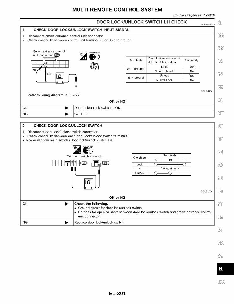
DOOR LOCK/UNLOCK SWITCH LH CHECK=NAEL0115S10
1 CHECK DOOR LOCK/UNLOCK SWITCH INPUT SIGNAL
1. Disconnect smart entrance control unit connector.2. Check continuity between control unit terminal 23 or 35 and ground.
SEL309X
Refer to wiring diagram in EL-292.
OK or NG
OK © Door lock/unlock switch is OK.
NG © GO TO 2.
2 CHECK DOOR LOCK/UNLOCK SWITCH
1. Disconnect door lock/unlock switch connector.2. Check continuity between each door lock/unlock switch terminals.I Power window main switch (Door lock/unlock switch LH)
SEL310X
OK or NG
OK © Check the following.I Ground circuit for door lock/unlock switchI Harness for open or short between door lock/unlock switch and smart entrance control
unit connector
NG © Replace door lock/unlock switch.
GI
MA
EM
LC
EC
FE
CL
MT
AT
TF
PD
AX
SU
BR
ST
RS
BT
HA
SC
IDX
MULTI-REMOTE CONTROL SYSTEMTrouble Diagnoses (Cont’d)
EL-301

FRONT LH DOOR UNLOCK SENSOR CHECK=NAEL0115S06
1 CHECK FRONT LH DOOR UNLOCK SENSOR INPUT SIGNAL
Check voltage between smart entrance control unit terminal 36 and ground.
SEL323X
Refer to wiring diagram in EL-293.
OK or NG
OK © Door unlock sensor is OK.
NG © GO TO 2.
2 CHECK FRONT LH DOOR UNLOCK SENSOR
1. Disconnect front LH door unlock sensor connector.2. Check continuity between door unlock sensor terminals.
SEL324X
OK or NG
OK © Check the following.I Door unlock sensor ground circuitI Harness for open or short between smart entrance control unit and door unlock sensor
NG © Replace door unlock sensor.
MULTI-REMOTE CONTROL SYSTEMTrouble Diagnoses (Cont’d)
EL-302

HAZARD REMINDER CHECK=NAEL0115S08
1 CHECK HAZARD INDICATOR
Check if hazard indicator flashes with hazard switch.
Does hazard indicator operate?
Yes © GO TO 2.
No © Check “hazard indicator” circuit.
2 CHECK HAZARD REMINDER OPERATION
1. Disconnect smart entrance control unit connector.2. Apply ground to control unit terminal 7.
SEL325X
Refer to wiring diagram in EL-294.
OK or NG
OK © Replace smart entrance control unit.
NG © GO TO 3.
3 CHECK MULTI-REMOTE CONTROL RELAY
Check multi-remote control relay.
OK or NG
OK © GO TO 4.
NG © Replace.
GI
MA
EM
LC
EC
FE
CL
MT
AT
TF
PD
AX
SU
BR
ST
RS
BT
HA
SC
IDX
MULTI-REMOTE CONTROL SYSTEMTrouble Diagnoses (Cont’d)
EL-303

4 CHECK POWER SUPPLY FOR MULTI-REMOTE CONTROL RELAY
1. Disconnect multi-remote control relay connector.2. Check voltage between terminal 1 and ground.
SEL326X
OK or NG
OK © GO TO 5.
NG © Check the following.I 15A fuse [No. 20, located in fuse block (J/B)]I Harness for open or short between multi-remote control relay and fuse
5 CHECK MULTI-REMOTE CONTROL RELAY CIRCUIT
1. Disconnect multi-remote control relay connector.2. Check voltage between terminals 3 and 5.3. Check voltage between terminals 6 and 7.
SEL327X
OK or NG
OK © Check harness for open or short between smart entrance control unit and multi-remotecontrol relay.
NG © Check the following.I Harness for open or short between multi-remote control relay and fuseI Harness for open or short between multi-remote control relay and turn signal lamps
MULTI-REMOTE CONTROL SYSTEMTrouble Diagnoses (Cont’d)
EL-304

HORN REMINDER CHECK=NAEL0115S11
1 CHECK HORN
Check if horn sounds with horn switch.
Does horn operate?
Yes © GO TO 2.
No © Check horn circuit.
2 CHECK HORN REMINDER OPERATION
1. Disconnect smart entrance control unit connector.2. Apply ground to smart entrance control unit terminal 19.
SEL328X
Refer to wiring diagram in EL-294.
OK or NG
OK © Replace smart entrance control unit.
NG © Check harness for open or short between smart entrance control unit and horn relay.
GI
MA
EM
LC
EC
FE
CL
MT
AT
TF
PD
AX
SU
BR
ST
RS
BT
HA
SC
IDX
MULTI-REMOTE CONTROL SYSTEMTrouble Diagnoses (Cont’d)
EL-305

INTERIOR ROOM LAMP OPERATION CHECK=NAEL0115S09
1 CHECK INTERIOR ROOM LAMP
Check if the interior room lamp switch is in the “ON” position and the lamp illuminates.
Does interior room lamp illuminate?
Yes © GO TO 2.
No © Check the following.I Harness for open or short between smart entrance control unit and interior room lampI Interior room lamp
2 CHECK INTERIOR ROOM LAMP CIRCUIT
When interior room lamp switch is “DOOR” position, check voltage across smart entrance control unit terminal 8 andground.
SEL329X
Refer to wiring diagram in EL-292.
OK or NG
OK © GO TO 3.
NG © Repair harness between smart entrance control unit and interior room lamp.
3 CHECK CONTROL UNIT OUTPUT
Push unlock button of remote controller with key removed and all doors closed, and check voltage across smart entrancecontrol unit terminal 8 and ground.
SEL330X
OK or NG
OK © Check system again.
NG © Replace smart entrance control unit.
MULTI-REMOTE CONTROL SYSTEMTrouble Diagnoses (Cont’d)
EL-306

ID Code Entry Procedure=NAEL0222
REMOTE CONTROLLER ID SET UP WITH CONSULT-IINAEL0222S01
NOTE:If a remote controller is lost, the ID code of the lost remotecontroller must be erased to prevent unauthorized use. Whenthe ID code of a lost remote controller is not known, all con-troller ID codes should be erased. After all ID codes areerased, the ID codes of all remaining and/or new remote con-trollers must be re-registered.
SEL331X
1. Turn ignition switch “OFF”.2. Connect CONSULT-II to the data link connector.
PBR455D
3. Turn ignition switch “ON”.4. Touch “START”.
SEL332X
5. Touch “SMART ENTRANCE”.
SEL333X
6. Touch “MULTI REMOTE ENT”.
GI
MA
EM
LC
EC
FE
CL
MT
AT
TF
PD
AX
SU
BR
ST
RS
BT
HA
SC
IDX
MULTI-REMOTE CONTROL SYSTEMID Code Entry Procedure
EL-307

SEL334X
7. Touch “WORK SUPPORT”.
SEL335X
8. The items are shown on the figure at left can be set up.I “REMO CONT ID CONFIR”
Use this mode to confirm if a remote controller ID code is reg-istered or not.
I “REMO CONT ID REGIST”Use this mode to register a remote controller ID code.
NOTE:Register the ID code when remote controller or smart entrancecontrol unit is replaced, or when additional remote controlleris required.I “REMO CONT ID ERASUR”
Use this mode to erase a remote controller ID code.
MULTI-REMOTE CONTROL SYSTEMID Code Entry Procedure (Cont’d)
EL-308

REMOTE CONTROLLER ID SET UP WITHOUTCONSULT-II
NAEL0222S03
SEL332WA
GI
MA
EM
LC
EC
FE
CL
MT
AT
TF
PD
AX
SU
BR
ST
RS
BT
HA
SC
IDX
MULTI-REMOTE CONTROL SYSTEMID Code Entry Procedure (Cont’d)
EL-309
NOTE:I If a remote controller is lost, the ID code of the lost remote
controller must be erased to prevent unauthorized use. A spe-cific ID code can be erased with CONSULT-II. However, whenthe ID code of a lost remote controller is not known, all con-troller ID codes should be erased. After all ID codes areerased, the ID codes of all remaining and/or new remote con-trollers must be re-registered.To erase all ID codes in memory, register one ID code (remotecontroller) four times. After all ID codes are erased, the IDcodes of all remaining and/or new remote controllers must bere-registered.
I When registering an additional remote controller, the existingID codes in memory may or may not be erased. If four IDcodes are stored in memory, when an additional code isregistered, only the oldest code is erased. If less than four IDcodes are stored in memory, when an additional ID code isregistered, the new ID code is added and no ID codes areerased.
I If you need to activate more than two additional new remotecontrollers, repeat the procedure “Additional ID code entry” foreach new remote controller.
I Entry of maximum four ID codes is allowed. When more thanfour ID codes are entered, the oldest ID code will be erased.
I Even if the same ID code that is already in the memory is input,the same ID code can be entered. The code is counted as anadditional code.
MULTI-REMOTE CONTROL SYSTEMID Code Entry Procedure (Cont’d)
EL-310
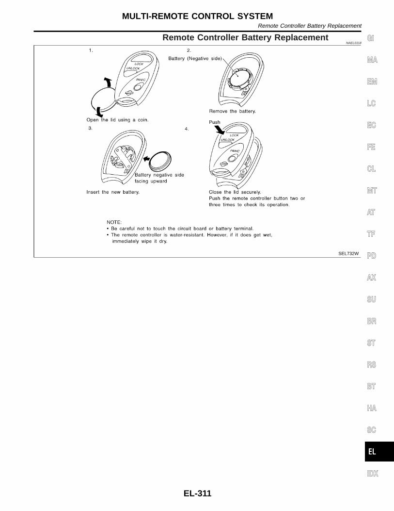
Remote Controller Battery ReplacementNAEL0118
SEL732W
GI
MA
EM
LC
EC
FE
CL
MT
AT
TF
PD
AX
SU
BR
ST
RS
BT
HA
SC
IDX
MULTI-REMOTE CONTROL SYSTEMRemote Controller Battery Replacement
EL-311

Component Parts and Harness ConnectorLocation
NAEL0119
SEL572X
THEFT WARNING SYSTEMComponent Parts and Harness Connector Location
EL-312

System DescriptionNAEL0120
DESCRIPTIONNAEL0120S01
1. Operation FlowNAEL0120S0101
SEL334W
2. Setting The Theft Warning SystemNAEL0120S0102
Initial condition1) Close all doors.2) Close hood and glass hatch.Disarmed phaseWhen the theft warning system is in the disarmed phase, the security indicator lamp blinks every 2.6 seconds.Pre-armed phase and armed phaseThe theft warning system turns into the “pre-armed” phase when hood, glass hatch and all doors are closedand the doors are locked by key or multi-remote controller. (The security indicator lamp illuminates.)After about 30 seconds, the system automatically shifts into the “armed” phase (the system is set). (Thesecurity indicator lamp blinks every 2.6 seconds.)
3. Canceling The Set Theft Warning SystemNAEL0120S0103
When the following 1) or 2) operation is performed, the armed phase is canceled.1) Unlock the doors with the key or multi-remote controller.2) Open the glass hatch with the key.
4. Activating The Alarm Operation of The Theft Warning SystemNAEL0120S0104
Make sure the system is in the armed phase. (The security indicator lamp blinks every 2.6 seconds.)When any of the following operations is performed, the system sounds the horns and flashes the headlampsfor about 50 seconds.1) Engine hood, glass hatch or any door is opened before unlocking door with key or multi-remote control-
ler.2) Door is unlocked without using key or multi-remote controller.3) Disconnecting and connecting the battery connector before canceling armed phase.
POWER SUPPLY AND GROUNDNAEL0120S07
Power is supplied at all timesI through 7.5A fuse [No. 24, located in the fuse block (J/B)]I to security indicator lamp terminal 1, andI to smart entrance control unit terminal 10.With the ignition switch in the ON or START position, power is suppliedI through 7.5A fuse [No. 11, located in the fuse block (J/B)]
GI
MA
EM
LC
EC
FE
CL
MT
AT
TF
PD
AX
SU
BR
ST
RS
BT
HA
SC
IDX
THEFT WARNING SYSTEMSystem Description
EL-313

I to smart entrance control unit terminal 33.With the ignition switch in the ACC or ON position, power is suppliedI through 10A fuse [No. 10, located in the fuse block (J/B)]I to smart entrance control unit terminal 21.Ground is suppliedI to smart entrance control unit terminal 16I through body grounds M77 and M111.
INITIAL CONDITION TO ACTIVATE THE SYSTEMNAEL0120S02
The operation of the theft warning system is controlled by the doors, hood and glass hatch.To activate the theft warning system, the smart entrance control unit must receive signals indicating the doors,hood and glass hatch are closed and the doors are locked.When a door is open, smart entrance control unit terminal 28, 29 or 40 receives a ground signal from eachdoor switch.When a door is unlocked, smart entrance control unit terminal 26, 36 or 37 receives a ground signal from ter-minal 4 of each door unlock sensor or terminal 1 of back door unlock sensor.When the hood is open, smart entrance control unit terminal 27 receives a ground signalI from terminal 1 of the hood switchI through body grounds E13 and E41.When the glass hatch is open, smart entrance control unit terminal 38 receives a ground signalI from terminal 1 of the glass hatch switchI through body grounds D210, B11 and B22.When the doors are locked with key or multi-remote controller and none of the described conditions exist, thetheft warning system will automatically shift to armed mode.
THEFT WARNING SYSTEM ACTIVATION (WITH KEY OR REMOTE CONTROLLER USED TOLOCK DOORS)
NAEL0120S03
If the key is used to lock doors, terminal 41 receives a ground signalI from terminal 3 of the key cylinder switch LHI through back grounds M77 and M111I from terminal 1 of the back door key cylinder switchI through body grounds B11, B22 and D210.If this signal or lock signal from remote controller is received by the smart entrance control unit, the theftwarning system will activate automatically.Once the theft warning system has been activated, smart entrance control unit terminal 31 supplies ground toterminal 2 of the security indicator lamp.The security lamp will illuminate for approximately 30 seconds and then blink.Now the theft warning system is in armed phase.
THEFT WARNING SYSTEM ALARM OPERATIONNAEL0120S04
The theft warning system is triggered byI opening a doorI opening the hood or the glass hatchI unlocking door without using the key or multi-remote controller.Once the theft warning system is in armed phase, if the smart entrance control unit receives a ground signalat terminal 26, 36, 37 (door unlock sensor), 28, 29, 40 (door switch), 38 (glass hatch switch) or 27 (hoodswitch), the theft warning system will be triggered. The headlamps flash and the horn sounds intermittently.Power is supplied at all timesI through 7.5A fuse (No. 52, located in fuse and fusible link box)I to horn relay terminals 1 and 3 andI to theft warning lamp relay terminal 1 (without auto light system)I through 10A fuse (No. 54, located in fuse and fusible link box)I to horn relay terminal 6.When the theft warning system is triggered, ground is supplied intermittentlyI from terminal 4 of the smart entrance control unitI to headlamp relay LH and RH terminal 2 (with auto light system), or
THEFT WARNING SYSTEMSystem Description (Cont’d)
EL-314

I to theft warning lamp relay terminal 2 (without auto light system) andI from terminal 19 of the smart entrance control unitI to horn relay terminal 2.The headlamps flash and the horn sounds intermittently.The alarm automatically turns off after 50 seconds but will reactivate if the vehicle is tampered with again.
THEFT WARNING SYSTEM DEACTIVATIONNAEL0120S05
To deactivate the theft warning system, a door, the back door or the glass hatch must be unlocked with thekey or remote controller.When the key is used to unlock the door, smart entrance control unit terminal 30 receives a ground signalI from terminal 1 of the LH key cylinder switchI from terminal 2 of the back door key cylinder switch.When the key is used to open the glass hatch, smart entrance control unit terminal 42 receives a ground sig-nal from terminal 3 of the back door key cylinder switch.When the smart entrance control unit receives either one of these signals or unlock signal from remotecontroller, the theft warning system is deactivated. (Disarmed phase)
PANIC ALARM OPERATIONNAEL0120S06
Multi-remote control system may or may not operate theft warning system (horn and headlamps) as required.When the multi-remote control system is triggered, ground is supplied intermittently.I from smart entrance control unit terminal 4I to headlamp relay LH and RH terminal 2 (with auto light system), orI to theft warning lamp relay terminal 2 (without auto light system) andI from terminal 19 of the smart entrance control unitI to horn relay terminal 2.The headlamp flashes and the horn sounds intermittently.The alarm automatically turns off after 30 seconds or when smart entrance control unit receives any signalfrom multi-remote controller.
GI
MA
EM
LC
EC
FE
CL
MT
AT
TF
PD
AX
SU
BR
ST
RS
BT
HA
SC
IDX
THEFT WARNING SYSTEMSystem Description (Cont’d)
EL-315

SchematicNAEL0121
WITH AUTO LIGHT SYSTEMNAEL0121S01
MEL054M
THEFT WARNING SYSTEMSchematic
EL-316
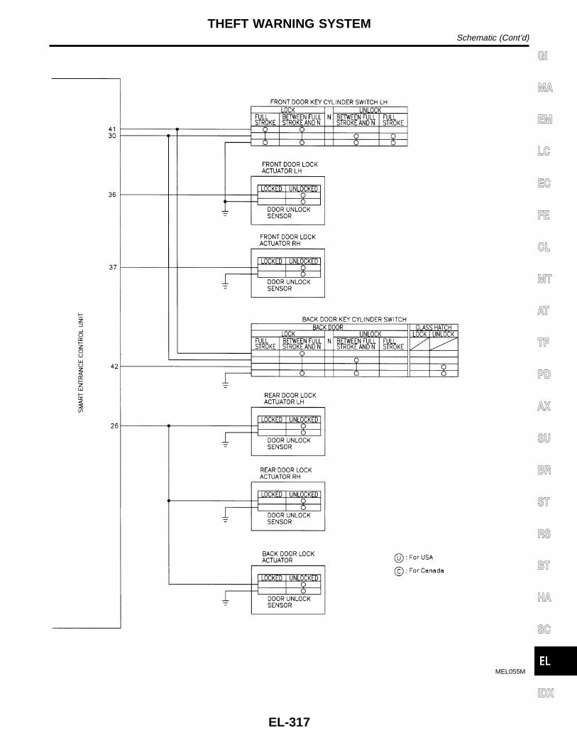
MEL055M
GI
MA
EM
LC
EC
FE
CL
MT
AT
TF
PD
AX
SU
BR
ST
RS
BT
HA
SC
IDX
THEFT WARNING SYSTEMSchematic (Cont’d)
EL-317

WITHOUT AUTO LIGHT SYSTEMNAEL0121S02
MEL059M
THEFT WARNING SYSTEMSchematic (Cont’d)
EL-318

MEL055M
GI
MA
EM
LC
EC
FE
CL
MT
AT
TF
PD
AX
SU
BR
ST
RS
BT
HA
SC
IDX
THEFT WARNING SYSTEMSchematic (Cont’d)
EL-319

Wiring Diagram — THEFT —NAEL0122
FIG. 1NAEL0122S01
MEL022O
THEFT WARNING SYSTEMWiring Diagram — THEFT —
EL-320

FIG. 2NAEL0122S02
MEL859L
GI
MA
EM
LC
EC
FE
CL
MT
AT
TF
PD
AX
SU
BR
ST
RS
BT
HA
SC
IDX
THEFT WARNING SYSTEMWiring Diagram — THEFT — (Cont’d)
EL-321
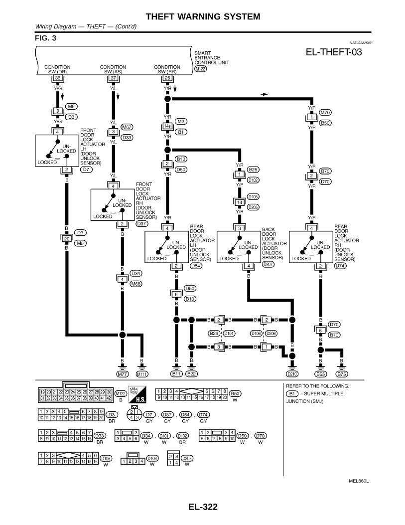
FIG. 3NAEL0122S03
MEL860L
THEFT WARNING SYSTEMWiring Diagram — THEFT — (Cont’d)
EL-322

FIG. 4NAEL0122S04
MEL861L
GI
MA
EM
LC
EC
FE
CL
MT
AT
TF
PD
AX
SU
BR
ST
RS
BT
HA
SC
IDX
THEFT WARNING SYSTEMWiring Diagram — THEFT — (Cont’d)
EL-323

FIG. 5NAEL0122S05
MEL064M
THEFT WARNING SYSTEMWiring Diagram — THEFT — (Cont’d)
EL-324

FIG. 6/WITH AUTO LIGHT SYSTEMNAEL0122S06
MEL057M
GI
MA
EM
LC
EC
FE
CL
MT
AT
TF
PD
AX
SU
BR
ST
RS
BT
HA
SC
IDX
THEFT WARNING SYSTEMWiring Diagram — THEFT — (Cont’d)
EL-325

FIG. 7/WITH AUTO LIGHT SYSTEMNAEL0122S07
MEL058M
THEFT WARNING SYSTEMWiring Diagram — THEFT — (Cont’d)
EL-326

FIG. 8/WITHOUT AUTO LIGHT SYSTEMNAEL0122S08
MEL065M
GI
MA
EM
LC
EC
FE
CL
MT
AT
TF
PD
AX
SU
BR
ST
RS
BT
HA
SC
IDX
THEFT WARNING SYSTEMWiring Diagram — THEFT — (Cont’d)
EL-327

Trouble DiagnosesNAEL0123
PRELIMINARY CHECKNAEL0123S01
The system operation is canceled by turning ignition switch to“ACC” at any step between START and ARMED in the followingflow chart.
SEL733WC
After performing preliminary check, go to symptom chart innext page.
THEFT WARNING SYSTEMTrouble Diagnoses
EL-328

SYMPTOM CHARTNAEL0123S02
REFERENCE PAGE (EL- ) 328 330 331 334 335 336 337 338 340 341 295
SYMPTOMP
RE
LIM
INA
RY
CH
EC
K
PO
WE
RS
UP
PLY
AN
DG
RO
UN
DC
IRC
UIT
CH
EC
K
DO
OR
,H
OO
DA
ND
GLA
SS
HA
TC
HS
WIT
CH
CH
EC
K
SE
CU
RIT
YIN
DIC
AT
OR
LAM
PC
HE
CK
DO
OR
UN
LOC
KS
EN
SO
RC
HE
CK
DO
OR
KE
YC
YLI
ND
ER
SW
ITC
HC
HE
CK
BA
CK
DO
OR
KE
YC
YLI
ND
ER
SW
ITC
HC
HE
CK
HO
RN
ALA
RM
CH
EC
K
TH
EF
TW
AR
NIN
GH
EA
DLA
MP
ALA
RM
CH
EC
K(W
ithau
tolig
htsy
stem
)
TH
EF
TW
AR
NIN
GH
EA
DLA
MP
ALA
RM
CH
EC
K(W
ithou
tau
tolig
htsy
stem
)
Che
ck“M
ULT
I-R
EM
OT
EC
ON
TR
OL”
syst
em.
1
Theft warning indicatordoes not illuminate for 30seconds.
X X X X
The
ftw
arni
ngsy
stem
cann
otbe
set
by...
.
All items X X X X
Door outside key X X
Back door key X X
Multi-remote con-trol
X X
2
*1T
heft
war
ning
syst
emdo
esno
tal
arm
whe
n...
Any door isopened.
X X
Any door isunlocked withoutusing key ormulti-remote con-troller
X X
3
The
ftw
arni
ngal
arm
does
not
activ
ate.
All function X X X
Horn alarm X X
Headlamp alarm X X X
4
The
ftw
arni
ngsy
stem
cann
otbe
canc
eled
by...
. Door outside key X X
Back door key X X
Multi-remote con-trol
X X
X : Applicable*1: Make sure the system is in the armed phase.
Before starting trouble diagnoses above, perform preliminarycheck, EL-328.Symptom numbers in the symptom chart correspond with those ofpreliminary check.
GI
MA
EM
LC
EC
FE
CL
MT
AT
TF
PD
AX
SU
BR
ST
RS
BT
HA
SC
IDX
THEFT WARNING SYSTEMTrouble Diagnoses (Cont’d)
EL-329

SEL336X
POWER SUPPLY AND GROUND CIRCUIT CHECKNAEL0123S03
Power Supply Circuit CheckNAEL0123S0301
Terminals Ignition switch position
(+) (−) OFF ACC ON
10 GroundBatteryvoltage
Batteryvoltage
Batteryvoltage
21 Ground 0VBatteryvoltage
Batteryvoltage
33 Ground 0V 0VBatteryvoltage
SEL013W
Ground Circuit CheckNAEL0123S0302
Terminals Continuity
16 - Ground Yes
THEFT WARNING SYSTEMTrouble Diagnoses (Cont’d)
EL-330

DOOR, HOOD AND GLASS HATCH SWITCH CHECK=NAEL0123S04
Door Switch CheckNAEL0123S0401
1 CHECK DOOR SWITCH INPUT SIGNAL
Check voltage between smart entrance control unit terminals 28, 29 or 40 and ground.
SEL305X
Refer to wiring diagram in EL-321.
OK or NG
OK © Door switch is OK, and go to hood switch check.
NG © GO TO 2.
2 CHECK DOOR SWITCH
1. Disconnect door switch connector.2. Check continuity between door switch terminals.
SEL306X
OK or NG
OK © Check the following.I Door switch ground circuit (Front LH, back door) or door switch ground conditionI Harness for open or short between smart entrance control unit and door switch
NG © Replace door switch.
GI
MA
EM
LC
EC
FE
CL
MT
AT
TF
PD
AX
SU
BR
ST
RS
BT
HA
SC
IDX
THEFT WARNING SYSTEMTrouble Diagnoses (Cont’d)
EL-331

Hood Switch Check=NAEL0123S0402
1 CHECK HOOD SWITCH FITTING CONDITION
OK or NG
OK © GO TO 2.
NG © Adjust installation of hood switch or hood.
2 CHECK HOOD SWITCH INPUT SIGNAL
Check voltage between smart entrance control unit terminal 27 and ground.
SEL337X
Refer to wiring diagram in EL-320.
OK or NG
OK © Hood switch is OK, and go to glass hatch switch check.
NG © GO TO 3.
3 CHECK HOOD SWITCH
1. Disconnect hood switch connector.2. Check continuity between hood switch terminals 1 and 2.
SEL338X
OK or NG
OK © Check the following.I Hood switch ground circuitI Harness for open or short between smart entrance control unit and hood switch
NG © Replace hood switch.
THEFT WARNING SYSTEMTrouble Diagnoses (Cont’d)
EL-332

Glass Hatch Switch Check=NAEL0123S0403
1 CHECK GLASS HATCH SWITCH INPUT SIGNAL
Check voltage between smart entrance control unit terminal 38 and ground.
SEL339X
Refer to wiring diagram in EL-320.
OK or NG
OK © Glass hatch switch is OK.
NG © GO TO 2.
2 CHECK GLASS HATCH SWITCH
1. Disconnect glass hatch switch connector.2. Check continuity between glass hatch switch terminals 1 and 2.
SEL340X
OK or NG
OK © Check the following.I Glass hatch switch ground circuitI Harness for open or short between smart entrance control unit and glass hatch switch
NG © Replace glass hatch switch.
GI
MA
EM
LC
EC
FE
CL
MT
AT
TF
PD
AX
SU
BR
ST
RS
BT
HA
SC
IDX
THEFT WARNING SYSTEMTrouble Diagnoses (Cont’d)
EL-333

SECURITY INDICATOR LAMP CHECK=NAEL0123S05
1 CHECK INDICATOR LAMP OUTPUT SIGNAL
1. Disconnect smart entrance control unit connector.2. Check voltage between control unit terminal 31 and ground.
SEL341X
Refer to wiring diagram in EL-320.
OK or NG
OK © Security indicator lamp is OK.
NG © GO TO 2.
2 CHECK INDICATOR LAMP
OK or NG
OK © GO TO 3.
NG © Replace indicator lamp.
3 CHECK POWER SUPPLY CIRCUIT FOR INDICATOR LAMP
1. Disconnect security lamp connector.2. Check voltage between indicator lamp terminal 1 and ground.
SEL342X
OK or NG
OK © Check harness for open or short between security indicator lamp and control unit.
NG © Check the following.I 7.5A fuse [No. 24, located in fuse block (J/B)]I Harness for open or short between security indicator lamp and fuse
THEFT WARNING SYSTEMTrouble Diagnoses (Cont’d)
EL-334

DOOR UNLOCK SENSOR CHECK=NAEL0123S06
1 CHECK DOOR UNLOCK SENSOR INPUT SIGNAL
Check voltage between smart entrance control unit terminals 26, 36 or 37 and ground.
SEL343X
Refer to wiring diagram in EL-324.
OK or NG
OK © Door unlock sensor is OK.
NG © GO TO 2.
2 CHECK DOOR UNLOCK SENSOR
1. Disconnect door unlock sensor connector.2. Check continuity between door unlock sensor terminals.
SEL344X
OK or NG
OK © Check the following.I Door unlock sensor ground circuitI Harness for open or short between smart entrance control unit and door unlock sensor
NG © Replace door unlock sensor.
GI
MA
EM
LC
EC
FE
CL
MT
AT
TF
PD
AX
SU
BR
ST
RS
BT
HA
SC
IDX
THEFT WARNING SYSTEMTrouble Diagnoses (Cont’d)
EL-335

FRONT DOOR KEY CYLINDER SWITCH CHECK=NAEL0123S07
1 CHECK DOOR KEY CYLINDER SWITCH INPUT SIGNAL (LOCK/UNLOCK SIGNAL)
Check voltage between smart entrance control unit terminals 30 or 41 and ground.
SEL312X
Refer to wiring diagram in EL-323.
OK or NG
OK © Door key cylinder switch is OK.
NG © GO TO 2.
2 CHECK DOOR KEY CYLINDER SWITCH
1. Disconnect door key cylinder switch connector.2. Check continuity between door key cylinder switch terminals.
SEL313X
OK or NG
OK © Check the following.I Door key cylinder switch ground circuitI Harness for open or short between smart entrance control unit and door key cylinder
switch
NG © Replace door key cylinder switch.
THEFT WARNING SYSTEMTrouble Diagnoses (Cont’d)
EL-336
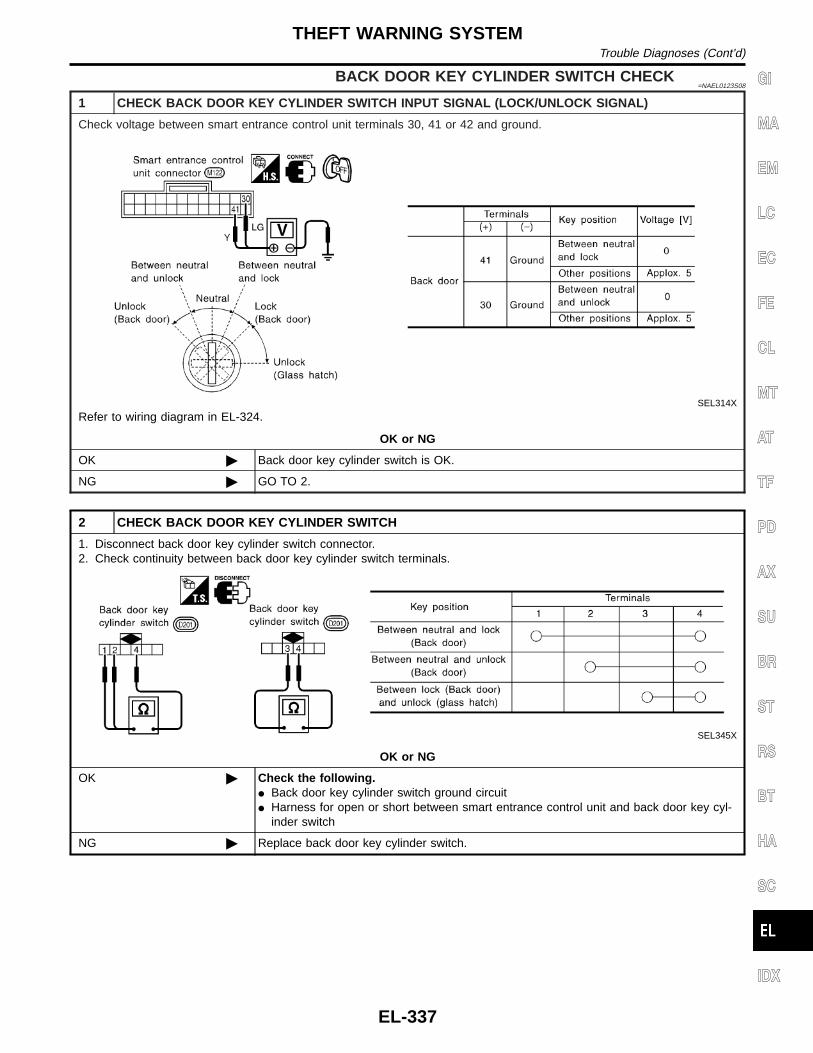
BACK DOOR KEY CYLINDER SWITCH CHECK=NAEL0123S08
1 CHECK BACK DOOR KEY CYLINDER SWITCH INPUT SIGNAL (LOCK/UNLOCK SIGNAL)
Check voltage between smart entrance control unit terminals 30, 41 or 42 and ground.
SEL314X
Refer to wiring diagram in EL-324.
OK or NG
OK © Back door key cylinder switch is OK.
NG © GO TO 2.
2 CHECK BACK DOOR KEY CYLINDER SWITCH
1. Disconnect back door key cylinder switch connector.2. Check continuity between back door key cylinder switch terminals.
SEL345X
OK or NG
OK © Check the following.I Back door key cylinder switch ground circuitI Harness for open or short between smart entrance control unit and back door key cyl-
inder switch
NG © Replace back door key cylinder switch.
GI
MA
EM
LC
EC
FE
CL
MT
AT
TF
PD
AX
SU
BR
ST
RS
BT
HA
SC
IDX
THEFT WARNING SYSTEMTrouble Diagnoses (Cont’d)
EL-337

HORN ALARM CHECK=NAEL0123S09
1 CHECK HORN ALARM OPERATION
1. Disconnect smart entrance control unit connector.2. Apply ground to smart entrance control unit terminal 19.
SEL346X
Refer to wiring diagram in EL-324.
OK or NG
OK © Horn alarm is OK.
NG © GO TO 2.
2 CHECK HORN RELAY
Check horn relay.
OK or NG
OK © GO TO 3.
NG © Replace horn relay.
3 CHECK POWER SUPPLY FOR HORN RELAY
1. Disconnect horn relay connector.2. Check voltage between terminal 2 and ground.
SEL347X
OK or NG
OK © GO TO 4.
NG © Check the following.I 7.5A fuse (No. 52, located in the fuse and fusible link box)I Harness for open or short between horn relay and fuse
THEFT WARNING SYSTEMTrouble Diagnoses (Cont’d)
EL-338

4 CHECK HORN RELAY CIRCUIT
1. Disconnect horn relay connector.2. Check voltage between terminals 3 and 5.3. Check voltage between terminals 6 and 7.
SEL348X
OK or NG
OK © Check harness for open or short between horn relay and smart entrance control unit.
NG © Check harness for open or short.
GI
MA
EM
LC
EC
FE
CL
MT
AT
TF
PD
AX
SU
BR
ST
RS
BT
HA
SC
IDX
THEFT WARNING SYSTEMTrouble Diagnoses (Cont’d)
EL-339

THEFT WARNING HEADLAMP ALARM CHECK/WITHAUTO LIGHT SYSTEM
=NAEL0123S10
1 CHECK THEFT WARNING HEADLAMP ALARM OPERATION
1. Disconnect smart entrance control unit connector.2. Apply ground to smart entrance control unit terminal 4.
SEL570X
Refer to wiring diagram in EL-325.
OK or NG
OK © Headlamp alarm is OK.
NG © GO TO 2.
2 CHECK HEADLAMP OPERATION
Does headlamp come on when turning lighting switch “ON”?
Yes © Check harness for open or short between headlamp relay and smart entrance controlunit.
No © Check headlamp system. Refer to “HEADLAMP”.
THEFT WARNING SYSTEMTrouble Diagnoses (Cont’d)
EL-340

THEFT WARNING HEADLAMP ALARMCHECK/WITHOUT AUTO LIGHT SYSTEM
=NAEL0123S13
1 CHECK THEFT WARNING HEADLAMP ALARM OPERATION
1. Disconnect control unit connector.2. Apply ground to control unit terminal 4.
SEL570X
Refer to wiring diagram in EL-327.
Yes © Headlamp alarm is OK.
No © GO TO 2.
2 CHECK HEADLAMP OPERATION
Does headlamp come on when turning lighting switch “ON”?
Yes © GO TO 3.
No © Check headlamp system. Refer to “HEADLAMP”.
3 CHECK THEFT WARNING LAMP RELAY
Check theft warning lamp relay.
OK or NG
OK © GO TO 4.
NG © Replace theft warning lamp relay.
GI
MA
EM
LC
EC
FE
CL
MT
AT
TF
PD
AX
SU
BR
ST
RS
BT
HA
SC
IDX
THEFT WARNING SYSTEMTrouble Diagnoses (Cont’d)
EL-341

4 CHECK POWER SUPPLY FOR THEFT WARNING LAMP RELAY
1. Disconnect theft warning lamp relay connector.2. Check voltage between terminal 1 and ground.
SEL573X
Refer to wiring diagram in EL-327.
Does battery voltage exist?
Yes © GO TO 5.
No © Check the following.I 7.5A fuse (No. 52, located in the fuse and fusible link box)I Harness for open or short between theft warning lamp relay and fuse
5 CHECK THEFT WARNING LAMP RELAY CIRCUIT
1. Disconnect theft warning lamp relay connector.2. Check voltage between terminals 3 and 5.3. Check voltage between terminals 6 and 7.
SEL574X
OK or NG
OK © Check harness for open or short between theft warning lamp relay and control unit.
NG © Check the following.I Harness for open or short between fuse and theft warning lamp relayI Harness for open or short between theft warning lamp relay and headlamps
THEFT WARNING SYSTEMTrouble Diagnoses (Cont’d)
EL-342

DescriptionNAEL0124
The following systems are controlled by the smart entrance control unit.I Warning chimeI Rear window defogger and door mirror defogger timerI Power door lockI Multi-remote control systemI Theft warning systemI Interior lamp timerI Electric sunroof and power window timerI Headlamp battery saverI Battery saverFor detailed description and wiring diagrams, refer to the relevant pages for the each system.The smart entrance control unit receives data from the switches and sensors to control their correspondingsystem relays and actuators.
INPUT/OUTPUTNAEL0124S01
System Input Output
Power door lock
Door lock and unlock switch LH and RHKey switch (Insert)Door switchesDoor key cylinder switches
Door lock actuator
Multi-remote control
Key switch (Insert)Ignition switch (ACC)Door switchesFront door unlock sensor LHDoor lock and unlock switch LHRemote controller signal
Horn relayHeadlamp relay (LH and RH)Interior lampMulti-remote control relayDoor lock actuator
Warning chime
Key switch (Insert)Ignition switch (ON)Lighting switch (1st)Seat belt switchFront door switch LH
Warning chime (located in smart entrancecontrol unit)
Rear window defogger anddoor mirror defogger timer
Ignition switch (ON)Rear window defogger switch
Rear window defogger relay
Theft warning
Ignition switch (ACC, ON)Door switchesHood switchGlass hatch switchDoor key cylinder switches (lock/unlock)Door unlock sensores
Horn relayHeadlamp relay (LH and RH) (With autolight system)Theft warning lamp relay (Without auto lightsystem)Security indicator
Interior lamp timer
Door switchesFront door unlock sensor LHIgnition switch (ON)Key switch (Insert)
Interior lamp
Electric sunroof and powerwindow timer
Front door switchesIgnition switch (ON)
Power window relay
Headlamp battery saver timerFront door switchesIgnition switch (ON)
Headlamp battery saver control unit
Battery saver
Ignition switch (ON)Door switchesDriver’s door unlock sensorKey switch (Insert)
Interior lampLuggage room lampSpot lampVanity mirror illumination lamp
GI
MA
EM
LC
EC
FE
CL
MT
AT
TF
PD
AX
SU
BR
ST
RS
BT
HA
SC
IDX
SMART ENTRANCE CONTROL UNITDescription
EL-343

BATTERY SAVERNAEL0124S02
The lamp turns off automatically when the interior lamp, luggage room lamp, spot lamp or/and vanity mirrorillumination is illuminated with the ignition key in the OFF position, if the lamp remains lit by the door switchopen signal or if the lamp switch is in the ON position for more than 10 minutes.After lamps turn off by the battery saver system, the lamps illuminate again when:I driver’s door is locked or unlocked,I door is opened or closed,I key is inserted in ignition key cylinder.
SMART ENTRANCE CONTROL UNITDescription (Cont’d)
EL-344

NOTE: GI
MA
EM
LC
EC
FE
CL
MT
AT
TF
PD
AX
SU
BR
ST
RS
BT
HA
SC
IDX
SMART ENTRANCE CONTROL UNITDescription (Cont’d)
EL-345

SchematicNAEL0125
MEL052M
SMART ENTRANCE CONTROL UNITSchematic
EL-346

MEL053M
GI
MA
EM
LC
EC
FE
CL
MT
AT
TF
PD
AX
SU
BR
ST
RS
BT
HA
SC
IDX
SMART ENTRANCE CONTROL UNITSchematic (Cont’d)
EL-347

Smart Entrance Control Unit Inspection TableNAEL0126
TerminalNo.
Wirecolor
Connections Operated conditionVoltage
(Approximatevalues)
2 G/B Rear window defogger relay OFF , ON (Ignition key is in “ON” position) 0V , 12V
4 PU/W Theft warning lamp relay When panic alarm is operated using remote controller 12V , 0V
5 R/YHeadlamp battery saver controlunit
When headlamp battery saver timer is operated 12V
7 P Multi-remote control relay When doors are locked using remote controller 12V , 0V
8 R/B Interior lampWhen interior lamp is operated using remote controller.(Lamp switch in “DOOR” position)
0V , 12V
10 G/R Power source (Fuse) — 12V
11 W/R Power source (C/B) — 12V
13 W/PU Driver door lock actuatorDoor lock & unlock switch
Free 0V
14 Y/B Passenger door lock actuator Unlocked 12V
15 L Door lock actuators Door lock & unlock switchFree 0V
Locked 12V
16 B Ground — —
17 R/W Battery saver (Interior lamp) Battery saver is not operate , Operate 12V , 0V
19 LG/B Horn relayWhen doors are locked using remote controller with hornchirp mode.
12V , 0V
21 G/W Ignition switch (ACC) “ACC” position 12V
22 B/P Seat belt buckle switch Unfasten , Fasten (Ignition key is in “ON” position) 0V , 12V
23 BR Door lock & unlock switches Neutral , Locks 5V , 0V
26 Y/RRear and back door unlock sen-sors
All doors are locked , One or more doors are unlocked 5V , 0V
27 Y/B Hood open signal ON (Open) , OFF (Closed) 0V , 5V
28 R/L Rear and back door switches OFF (Closed) , ON (Open) 5V , 0V
29 G/R Driver door switch OFF (Closed) , ON (Open) 5V , 0V
30 LG Door key cylinder unlock switch OFF (Neutral) , ON (Unlocked) 12V , 0V
31 BR/Y Theft warning indicator Goes off , Illuminates 12V , 0V
32 W/R Ignition key switch (Insert) key inserted , key removed from IGN key cylinder 12V , 0V
33 W/B Ignition switch (ON) Ignition key is in “ON” position 12V
35 LG/R Door lock & unlock switches Neutral , Unlocks 5V , 0V
36 Y/G Driver door unlock sensor Driver door: Locked , Unlocked 5V , 0V
37 Y/L Passenger door unlock sensor Passenger door: Locked , Unlocked 5V , 0V
38 L/W Glass hatch switch ON (Open) , OFF (Closed) 0V , 12V
39 OR Rear window defogger switch OFF , ON 5V , 0V
40 Y Passenger door switch OFF (Closed) , ON (Open) 5V , 0V
41 Y Door key cylinder lock switch OFF (Neutral) , ON (Locked) 5V , 0V
42 G/B Back door key unlock switch OFF (Neutral) , ON (Unlock) 5V , 0V
SMART ENTRANCE CONTROL UNITSmart Entrance Control Unit Inspection Table
EL-348

Wiring Diagram — TRNSMT —NAEL0127
MEL866L
GI
MA
EM
LC
EC
FE
CL
MT
AT
TF
PD
AX
SU
BR
ST
RS
BT
HA
SC
IDX
INTEGRATED HOMELINK TRANSMITTERWiring Diagram — TRNSMT —
EL-349

Trouble DiagnosesNAEL0128
DIAGNOSTIC PROCEDURENAEL0128S01
SYMPTOM: Transmitter does not activate receiver.Before conducting the procedure given below, make sure that sys-tem receiver (garage door opener, etc.) operates with original,hand-held transmitter. If NG, receiver or hand-held transmitter is atfault, not vehicle related.
1 PRELIMINARY CHECK
1. Turn ignition switch “OFF”.2. Does red light (LED) of transmitter illuminate when any button is pressed?
SEL442U
Yes or No
Yes © GO TO 2.
No © GO TO 3.
2 CHECK TRANSMITTER FUNCTION
Check transmitter with Tool.For details, refer to Technical Service Bulletin.
OK or NG
OK © Receiver or handheld transmitter fault, not vehicle related.
NG © Replace transmitter with sun visor assembly.
3 CHECK POWER SUPPLY
1. Disconnect transmitter connector.2. Turn ignition switch “OFF”.3. Check voltage between terminal 1 and body ground.
SEL358X
OK or NG
OK © GO TO 4.
NG © GO TO 5.
INTEGRATED HOMELINK TRANSMITTERTrouble Diagnoses
EL-350

4 CHECK GROUND CIRCUIT
Check continuity between terminal 2 and ground.
SEL359X
OK or NG
OK © Replace transmitter with sun visor assembly.
NG © Repair harness.
5 CHECK MAIN POWER SUPPLY FOR SMART ENTRANCE CONTROL UNIT
1. Disconnect smart entrance control unit.2. Check voltage between smart entrance control unit terminal 10 and ground.
SEL360X
OK or NG
OK © GO TO 6.
NG © Check the following.I 7.5A fuse No. 24, located in fuse block (J/B)
6 CHECK GROUND CIRCUIT FOR SMART ENTRANCE CONTROL UNIT
Check continuity between terminal 16 and ground.
SEL361X
OK or NG
OK © Power supply and ground circuits are OK.
NG © Check ground harness.
GI
MA
EM
LC
EC
FE
CL
MT
AT
TF
PD
AX
SU
BR
ST
RS
BT
HA
SC
IDX
INTEGRATED HOMELINK TRANSMITTERTrouble Diagnoses (Cont’d)
EL-351

Component Parts and Harness ConnetorLocation
NAEL0170
SEL357X
NOTE:If customer reports a “No Start” condition, request ALL KEYSto be brought to the Dealer in case of an NVIS (NATS) malfunc-tion.
NVIS (NISSAN VEHICLE IMMOBILIZER SYSTEM — NATS)Component Parts and Harness Connetor Location
EL-352

System Description=NAEL0171
NATS (Nissan Anti-Theft System) has the following immobilizer functions:I Since only NVIS (NATS) ignition keys, whose ID nos. have been registered into the ECM and IMMU of
NVIS (NATS), allow the engine to run, operation of a stolen vehicle without an NVIS (NATS) registeredkey is prevented by NVIS (NATS).That is to say, NVIS (NATS) will immobilise the engine if someone tries to start it without the registeredkey of NVIS (NATS).
I All of the originally supplied ignition key IDs (except for card plate key) have been NVIS (NATS) regis-tered.If requested by the vehicle owner, a maximum of five key IDs can be registered into the NVIS (NATS)components.
I The security indicator blinks when the ignition switch is in “OFF” or “ACC” position. Therefore, NVIS (NATS)warns outsiders that the vehicle is equipped with the anti-theft system.
I When NVIS (NATS) detects trouble, the security indicator lamp lights up while ignition key is in the “ON”position.
I NVIS (NATS) trouble diagnoses, system initialization and additional registration of other NVIS (NATS)ignition key IDs must be carried out using CONSULT-II hardware and CONSULT-II NVIS (NATS) software.When NVIS (NATS) initialization has been completed, the ID of the inserted ignition key is automaticallyNVIS (NATS) registered. Then, if necessary, additional registration of other NVIS (NATS) ignition key IDscan be carried out.Regarding the procedures of NVIS (NATS) initialization and NVIS (NATS) ignition key ID registration, referto CONSULT-II operation manual, IVIS/NVIS.
I When servicing a malfunction of the NVIS (NATS) (indicated by lighting up of Security IndicatorLamp) or registering another NVIS (NATS) ignition key ID no., it is necessary to re-register originalkey identification. Therefore, be sure to receive ALL KEYS from vehicle owner.
System CompositionNAEL0172
The immobiliser function of the NVIS (NATS) consists of the following:I NVIS (NATS) ignition keyI NVIS (NATS) immobilizer control unit (IMMU) located in the ignition key cylinderI Engine control module (ECM)I Security indicator
SEL085WF
GI
MA
EM
LC
EC
FE
CL
MT
AT
TF
PD
AX
SU
BR
ST
RS
BT
HA
SC
IDX
NVIS (NISSAN VEHICLE IMMOBILIZER SYSTEM — NATS)System Description
EL-353

Wiring Diagram — NATS —NAEL0173
MEL865L
NVIS (NISSAN VEHICLE IMMOBILIZER SYSTEM — NATS)Wiring Diagram — NATS —
EL-354

SEL331X
CONSULT-IINAEL0223
CONSULT-II INSPECTION PROCEDURENAEL0223S01
1. Turn ignition switch OFF.2. Insert NVIS (NATS) program card into CONSULT-II.
: Program cardNATS (UEN99A)
3. Connect CONSULT-II to data link connector.
SEL762W
4. Turn ignition switch ON.5. Touch “START”.
SEL851W
6. Select “NATS V.5.0”.
SEL363X
7. Perform each diagnostic test mode according to each serviceprocedure.
For further information, see the CONSULT-II OperationManual, IVIS/NVIS.
CONSULT-II DIAGNOSTIC TEST MODE FUNCTIONNAEL0223S02
CONSULT-II DIAGNOSTIC TESTMODE
Description
C/U INITIALIZATION When replacing any of the following three components, C/U initialization and re-registrationof all NVIS (NATS) ignition keys are necessary.[NVIS (NATS) ignition key/IMMU/ECM]
SELF-DIAG RESULTS Detected items (screen terms) are as shown in the chart EL-356.
GI
MA
EM
LC
EC
FE
CL
MT
AT
TF
PD
AX
SU
BR
ST
RS
BT
HA
SC
IDX
NVIS (NISSAN VEHICLE IMMOBILIZER SYSTEM — NATS)CONSULT-II
EL-355

NOTE:I When any initialization is performed, all ID previously reg-
istered will be erased and all NVIS (NATS) ignition keysmust be registered again.
I The engine cannot be started with an unregistered key. In thiscase, the system will show “DIFFERENCE OF KEY” or “LOCKMODE” as a self-diagnostic result on the CONSULT-II screen.
I In rare case, “CHAIN OF ECM-IMMU” might be stored as aself-diagnostic result during key registration procedure, even ifthe system is not malfunctioning.
HOW TO READ SELF-DIAGNOSTIC RESULTSNAEL0223S03
SEL364X
NVIS (NATS) SELF-DIAGNOSTIC RESULTS ITEMCHART
NAEL0223S04
Detected items (NATS program cardscreen terms)
P No. Code(Self-diag-
nosticresult of
“ENGINE”
Malfunction is detected when .....
Reference page
ECM INT CIRC-IMMUNATS MAL-FUNCTIONP1613
The malfunction of ECM internal circuit of IMMU com-munication line is detected. EL-360
CHAIN OF ECM-IMMUNATS MAL-FUNCTIONP1612
Communication impossible between ECM and IMMU(In rare case, “CHAIN OF ECM-IMMU” might be storedduring key registration procedure, even if the system isnot malfunctioning.)
EL-361
DIFFERENCE OF KEYNATS MAL-FUNCTIONP1615
IMMU can receive the key ID signal but the result of IDverification between key ID and IMMU is NG. EL-365
CHAIN OF IMMU-KEYNATS MAL-FUNCTIONP1614
IMMU cannot receive the key ID signal.EL-366
ID DISCORD, IMM-ECMNATS MAL-FUNCTIONP1611
The result of ID verification between IMMU and ECM isNG. System initialization is required. EL-367
NVIS (NISSAN VEHICLE IMMOBILIZER SYSTEM — NATS)CONSULT-II (Cont’d)
EL-356

Detected items (NATS program cardscreen terms)
P No. Code(Self-diag-
nosticresult of
“ENGINE”
Malfunction is detected when .....
Reference page
LOCK MODENATS MAL-FUNCTIONP1610
When the starting operation is carried out five or moretimes consecutively under the following conditions,NVIS (NATS) will shift the mode to one which preventsthe engine from being started.I Unregistered ignition key is used.I IMMU or ECM’s malfunctioning.
EL-370
DON’T ERASE BEFORECHECKING ENG DIAG
—All engine trouble codes except NVIS (NATS) troublecode has been detected in ECM.
EL-358
GI
MA
EM
LC
EC
FE
CL
MT
AT
TF
PD
AX
SU
BR
ST
RS
BT
HA
SC
IDX
NVIS (NISSAN VEHICLE IMMOBILIZER SYSTEM — NATS)CONSULT-II (Cont’d)
EL-357

Trouble DiagnosesNAEL0224
WORK FLOWNAEL0224S01
SEL004XA
NVIS (NISSAN VEHICLE IMMOBILIZER SYSTEM — NATS)Trouble Diagnoses
EL-358

SYMPTOM MATRIX CHART 1NAEL0224S02
(Self-diagnosis related item)
SYMPTOMDisplayed “SELF-DIAG
RESULTS” on CON-SULT-II screen.
DIAGNOSTIC PROCE-DURE
(Reference page)
SYSTEM(Malfunctioning part or
mode)
REFERENCE PART NO.OF ILLUSTRATION ON
NEXT PAGE
I Security indicatorlighting up*
I Engine cannot bestarted.
ECM INT CIRC-IMMUPROCEDURE 1
(EL-360)ECM B
CHAIN OF ECM-IMMUPROCEDURE 2
(EL-361)
In rare case, “CHAINOF ECM-IMMU” mightbe stored during keyregistration procedure,even if the system isnot malfunctioning.
—
Open circuit in batteryvoltage line of IMMUcircuit
C1
Open circuit in ignitionline of IMMU circuit
C2
Open circuit in groundline of IMMU circuit
C3
Open circuit in commu-nication line betweenIMMU and ECM
C4
Short circuit betweenIMMU and ECM com-munication line and bat-tery voltage line
C4
Short circuit betweenIMMU and ECM com-munication line andground line
C4
ECM B
IMMU A
DIFFERENCE OF KEYPROCEDURE 3
(EL-365)
Unregistered key D
IMMU A
CHAIN OF IMMU-KEYPROCEDURE 4
(EL-366)
Malfunction of key IDchip
E
IMMU A
ID DISCORD, IMM-ECM
PROCEDURE 5(EL-367)
System initialization hasnot yet been com-pleted.
F
ECM F
LOCK MODEPROCEDURE 7
(EL-370)LOCK MODE D
I MIL staying ONI Security indicator
lighting up*
DON’T ERASEBEFORE CHECKINGENG DIAG
WORK FLOW(EL-358)
Engine trouble data andNVIS (NATS) troubledata have beendetected in ECM
—
*: When NVIS (NATS) detects trouble, the security indicator lights up while ignition key is in the “ON” position.
GI
MA
EM
LC
EC
FE
CL
MT
AT
TF
PD
AX
SU
BR
ST
RS
BT
HA
SC
IDX
NVIS (NISSAN VEHICLE IMMOBILIZER SYSTEM — NATS)Trouble Diagnoses (Cont’d)
EL-359

SYMPTOM MATRIX CHART 2NAEL0224S03
(Non self-diagnosis related item)
SYMPTOMDIAGNOSTIC PROCEDURE
(Reference page)SYSTEM
(Malfunctioning part or mode)
Security ind. does not light up.PROCEDURE 6
(EL-368)
Security ind.
Open circuit between Fuse and IMMU
Continuation of initialization mode
IMMU
DIAGNOSTIC SYSTEM DIAGRAMNAEL0224S04
SEL087WF
SEL365X
DIAGNOSTIC PROCEDURE 1NAEL0224S05
Self-diagnostic results:“ECM INT CIRC-IMMU” displayed on CONSULT-II screen1. Confirm SELF-DIAGNOSTIC RESULTS “ECM INT CIRC-
IMMU” displayed on CONSULT-II screen. Ref. part No. B.2. Replace ECM.3. Perform initialization with CONSULT-II.
For initialization, refer to “CONSULT-II operation manualIVIS/NVIS”.
NVIS (NISSAN VEHICLE IMMOBILIZER SYSTEM — NATS)Trouble Diagnoses (Cont’d)
EL-360

DIAGNOSTIC PROCEDURE 2=NAEL0224S06
Self-diagnostic results:“CHAIN OF ECM-IMMU” displayed on CONSULT-II screen
1 CONFIRM SELF-DIAGNOSTIC RESULTS
Confirm SELF-DIAGNOSTIC RESULTS “CHAIN OF ECM-IMMU” displayed on CONSULT-II screen.NOTE:In rare case, “CHAIN OF ECM-IMMU” might be stored during key registration procedure, even if the system is not mal-functioning.
SEL366X
Is CONSULT-II screen displayed as above?
Yes © GO TO 2.
No © GO TO SYMPTOM MATRIX CHART 1.
2 CHECK POWER SUPPLY CIRCUIT FOR IMMU
1. Disconnect IMMU connector.2. Check voltage between terminal 8 of IMMU and ground with CONSULT-II or tester.
SEL302WD
OK or NG
OK © GO TO 3.
NG © Check the followingI 7.5A fuse (No. 62, located in the fuse and fusible link box)I Harness for open or short between fuse and IMMU connector
Ref. Part No. C1
GI
MA
EM
LC
EC
FE
CL
MT
AT
TF
PD
AX
SU
BR
ST
RS
BT
HA
SC
IDX
NVIS (NISSAN VEHICLE IMMOBILIZER SYSTEM — NATS)Trouble Diagnoses (Cont’d)
EL-361

3 CHECK IGN SW. ON SIGNAL
1. Turn ignition switch ON.2. Check voltage between terminal 7 of IMMU and ground with CONSULT-II or tester.
SEL303WF
OK or NG
OK © GO TO 4.
NG © Check the followingI 10A fuse [No. 16, located in the fuse block (J/B)]I Harness for open or short between fuse and IMMU connector
Ref. part No. C2
4 CHECK GROUND CIRCUIT FOR IMMU
1. Turn ignition OFF.2. Check harness continuity between IMMU terminal 4 and ground.
SEL304WD
OK or NG
OK © GO TO 5.
NG © Repair harness. Ref. part No. C3
NVIS (NISSAN VEHICLE IMMOBILIZER SYSTEM — NATS)Trouble Diagnoses (Cont’d)
EL-362

5 CHECK COMMUNICATION LINE OPEN CIRCUIT
1. Disconnect ECM connector.2. Check harness continuity between ECM terminal 116 and IMMU terminal 1.
SEL305WD
OK or NG
OK © GO TO 6.
NG © Repair harness or connector.Ref. part No. C4
6 CHECK COMMUNICATION LINE BATTERY SHORT CIRCUIT
1. Turn ignition ON.2. Check voltage between ECM terminal 116 or IMMU terminal 1 and ground.
SEL306WD
OK or NG
OK © GO TO 7.
NG © Communication line is short-circuited with battery voltage line or ignition switch ON line.Repair harness or connectors.Ref. part No. C4
GI
MA
EM
LC
EC
FE
CL
MT
AT
TF
PD
AX
SU
BR
ST
RS
BT
HA
SC
IDX
NVIS (NISSAN VEHICLE IMMOBILIZER SYSTEM — NATS)Trouble Diagnoses (Cont’d)
EL-363

7 CHECK COMMUNICATION LINE GROUND SHORT CIRCUIT
1. Turn ignition switch OFF.2. Check continuity between ECM terminal 116 or IMMU terminal 1 and ground.
SEL307WD
OK or NG
OK © GO TO 8.
NG © Communication line is short-circuited with ground line.Repair harness or connectors.Ref. part No. C4
8 SIGNAL FROM ECM TO IMMU CHECK
1. Check the signal between ECM terminal 116 and ground with CONSULT-II or oscilloscope when ignition switch isturned “ON”.
2. Make sure signals which are shown in the figure below can be detected during 750 msec. just after ignition switch isturned “ON”.
SEL730W
OK or NG
OK © IMMU is malfunctioning.Replace IMMU. Ref. part No. APerform initialization with CONSULT-II.For the operation of initialization, refer to “CONSULT-II Operation Manual IVIS/NVIS”.
NG © ECM is malfunctioning.Replace ECM. Ref. part No. BPerform initialization with CONSULT-II.For the operation of initialization, refer to “CONSULT-II Operation Manual IVIS/NVIS”.
NVIS (NISSAN VEHICLE IMMOBILIZER SYSTEM — NATS)Trouble Diagnoses (Cont’d)
EL-364

DIAGNOSTIC PROCEDURE 3=NAEL0224S07
Self-diagnostic results:“DIFFERENCE OF KEY” displayed on CONSULT-II screen
1 CONFIRM SELF-DIAGNOSTIC RESULTS
Confirm SELF-DIAGNOSTIC RESULTS “DIFFERENCE OF KEY” displayed on CONSULT-II screen.
SEL367X
Is CONSULT-II screen displayed as above?
Yes © GO TO 2.
No © GO TO SYMPTOM MATRIX CHART 1.
2 PERFORM INITIALIZATION WITH CONSULT-II
Perform initialization with CONSULT-II. Re-register all NVIS (NATS) ignition key IDs.For initialization and registration of NVIS (NATS) ignition key IDs, refer to “CONSULT-II operation manual NVIS/NVIS”.
SEL297W
NOTE:If the initialization is not completed or fails, CONSULT-II shows above message on the screen.
Can the system be initialized and can the engine be started with re-registered NVIS (NATS) ignition key?
Yes © Ignition key ID was unregistered. Ref. part No. D
No © IMMU is malfunctioning.Replace IMMU. Ref. part No. APerform initialization with CONSULT-II.For initialization, refer to “CONSULT-II operation manual IVIS/NVIS”.
GI
MA
EM
LC
EC
FE
CL
MT
AT
TF
PD
AX
SU
BR
ST
RS
BT
HA
SC
IDX
NVIS (NISSAN VEHICLE IMMOBILIZER SYSTEM — NATS)Trouble Diagnoses (Cont’d)
EL-365

DIAGNOSTIC PROCEDURE 4=NAEL0224S08
Self-diagnostic results:“CHAIN OF IMMU-KEY” displayed on CONSULT-II screen
1 CONFIRM SELF-DIAGNOSTIC RESULTS
Confirm SELF-DIAGNOSTIC RESULTS “CHAIN OF IMMU-KEY” displayed on CONSULT-II screen.
SEL368X
Is CONSULT-II screen displayed as above?
Yes © GO TO 2.
No © GO TO SYMPTOM MATRIX CHART 1.
2 CHECK NVIS (NATS) IGNITION KEY ID CHIP
Start engine with another registered NVIS (NATS) ignition key.
Does the engine start?
Yes © Ignition key ID chip is malfunctioning.Replace the ignition key.Ref. part No. EPerform initialization with CONSULT-II.For initialization, refer to “CONSULT-II Operation Manual IVIS/NVIS”.
No © GO TO 3.
3 CHECK IMMU INSTALLATION
Check IMMU installation.Refer to “How to Replace IMMU” in EL-371.
OK or NG
OK © IMMU is malfunctioning.Replace IMMU. Ref. part No. APerform initialization with CONSULT-II.For initialization, refer to “CONSULT-II Operation Manual IVIS/NVIS”.
NG © Reinstall IMMU correctly.
NVIS (NISSAN VEHICLE IMMOBILIZER SYSTEM — NATS)Trouble Diagnoses (Cont’d)
EL-366

DIAGNOSTIC PROCEDURE 5=NAEL0224S09
Self-diagnostic results:“ID DISCORD, IMM-ECM” displayed on CONSULT-II screen
1 CONFIRM SELF-DIAGNOSTIC RESULTS
Confirm SELF-DIAGNOSTIC RESULTS “ID DISCORD, IMM-ECM” displayed on CONSULT-II screen.
SEL369X
NOTE:“ID DISCORD IMMU-ECM”:Registered ID of IMMU is in discord with that of ECM.
Is CONSULT-II screen displayed as above?
Yes © GO TO 2.
No © GO TO SYMPTOM MATRIX CHART 1.
2 PERFORM INITIALIZATION WITH CONSULT-II
Perform initialization with CONSULT-II. Re-register all NVIS (NATS) ignition key IDs.For initialization, refer to “CONSULT-II operation manual IVIS/NVIS”.
SEL297W
NOTE:If the initialization is not completed or fails, CONSULT-II shows above message on the screen.
Can the system be initialized?
Yes © Start engine. (END)(System initialization had not been completed. Ref. part No. F )
No © ECM is malfunctioning.Replace ECM. Ref. part No. FPerform initialization with CONSULT-II.For initialization, refer to “CONSULT-II operation manual IVIS/NVIS”.
GI
MA
EM
LC
EC
FE
CL
MT
AT
TF
PD
AX
SU
BR
ST
RS
BT
HA
SC
IDX
NVIS (NISSAN VEHICLE IMMOBILIZER SYSTEM — NATS)Trouble Diagnoses (Cont’d)
EL-367

DIAGNOSTIC PROCEDURE 6=NAEL0224S10
“SECURITY INDICATOR LAMP DOES NOT LIGHT UP”
1 CHECK FUSE
Check 10A fuse [No. 12, located in the fuse block (J/B)].
Is 10A fuse OK?
Yes © GO TO 2.
No © Replace fuse.
2 CHECK SECURITY INDICATOR LAMP
1. Install 10A fuse.2. Perform initialization with CONSULT-II.
For initialization, refer to “CONSULT-II Operation Manual IVIS/NVIS”.3. Turn ignition switch OFF.4. Start engine and turn ignition switch OFF.5. Check the security indicator lamp lighting.Security indicator lamp should be blinking.
OK or NG
OK © INSPECTION END
NG © GO TO 3.
3 CHECK SECURITY INDICATOR LAMP POWER SUPPLY CIRCUIT
1. Disconnect security indicator lamp connector.2. Check voltage between security indicator lamp connector terminal 1 and ground.
SEL370X
OK or NG
OK © GO TO 4.
NG © Check harness for open or short between fuse and security indicator lamp.
4 CHECK SECURITY INDICATOR LAMP
Check security Indicator Lamp.
Is security indicator lamp OK?
Yes © GO TO 5.
No © Replace security indicator lamp.
NVIS (NISSAN VEHICLE IMMOBILIZER SYSTEM — NATS)Trouble Diagnoses (Cont’d)
EL-368

5 CHECK IMMU FUNCTION
1. Connect IMMU connector.2. Disconnect security indicator lamp connector.3. Check continuity between IMMU terminal 5 and ground.
SEL300WC
OK or NG
OK © Check harness for open or short between security indicator lamp and IMMU.
NG © IMMU is malfunctioning.Replace IMMU.Perform initialization with CONSULT-II.For initialization, refer to “CONSULT-II operation manual IVIS/NVIS”.
GI
MA
EM
LC
EC
FE
CL
MT
AT
TF
PD
AX
SU
BR
ST
RS
BT
HA
SC
IDX
NVIS (NISSAN VEHICLE IMMOBILIZER SYSTEM — NATS)Trouble Diagnoses (Cont’d)
EL-369

DIAGNOSTIC PROCEDURE 7=NAEL0224S11
Self-diagnostic results:“LOCK MODE” displayed on CONSULT-II screen
1 CONFIRM SELF-DIAGNOSTIC RESULTS
Confirm SELF-DIAGNOSTIC RESULTS “LOCK MODE” is displayed on CONSULT-II screen.
SEL371X
Is CONSULT-II screen displayed as above?
Yes © GO TO 2.
No © GO TO SYMPTOM MATRIX CHART 1.
2 ESCAPE FROM LOCK MODE
1. Turn ignition switch OFF.2. Turn ignition switch ON with registered key. (Do not start engine.) Wait 5 seconds.3. Return the key to OFF position.4. Repeat steps 2 and 3 twice (total of three cycles).5. Start the engine.
Does engine start?
Yes © System is OK.(Now system is escaped from “LOCK MODE”.)
No © GO TO 3.
3 CHECK IMMU ILLUSTRATION
Check IMMU installation. Refer to “How to Replace IMMU” in EL-371.
OK or NG
OK © GO TO 4.
NG © Reinstall IMMU correctly.
NVIS (NISSAN VEHICLE IMMOBILIZER SYSTEM — NATS)Trouble Diagnoses (Cont’d)
EL-370

4 PERFORM INITIALIZATION WITH CONSULT-II
Perform initialization with CONSULT-II.For initialization, refer to “CONSULT-II operation manual IVIS/NVIS”.
SEL297W
NOTE:If the initialization is not completed or fails, CONSULT-II shows the above message on the screen.
Can the system be initialized?
Yes © System is OK.
No © GO TO DIAGNOSTIC PROCEDURE 4 to check “CHAIN OF IMMU-KEY”, refer toEL-366.
SEL096WA
How to Replace NVIS (NATS) IMMUNAEL0225
NOTE:I If NVIS (NATS) IMMU is not installed correctly, NVIS
(NATS) system will not operate properly and SELF-DIAGRESULTS on CONSULT-II screen will show “LOCKMODE”.
GI
MA
EM
LC
EC
FE
CL
MT
AT
TF
PD
AX
SU
BR
ST
RS
BT
HA
SC
IDX
NVIS (NISSAN VEHICLE IMMOBILIZER SYSTEM — NATS)Trouble Diagnoses (Cont’d)
EL-371

Engine CompartmentNAEL0129
MEL250M
ELECTRICAL UNITS LOCATIONEngine Compartment
EL-372

NOTE: GI
MA
EM
LC
EC
FE
CL
MT
AT
TF
PD
AX
SU
BR
ST
RS
BT
HA
SC
IDX
ELECTRICAL UNITS LOCATIONEngine Compartment (Cont’d)
EL-373

Passenger CompartmentNAEL0130
MEL251M
ELECTRICAL UNITS LOCATIONPassenger Compartment
EL-374
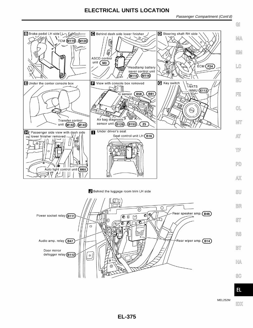
MEL252M
GI
MA
EM
LC
EC
FE
CL
MT
AT
TF
PD
AX
SU
BR
ST
RS
BT
HA
SC
IDX
ELECTRICAL UNITS LOCATIONPassenger Compartment (Cont’d)
EL-375

How to Read Harness LayoutNAEL0131
SEL252V
The following Harness Layouts use a map style grid to help locate connectors on the drawings:I Main HarnessI Engine Room Harness (Engine Compartment)I Engine Control Harness
TO USE THE GRID REFERENCENAEL0131S01
1. Find the desired connector number on the connector list.2. Find the grid reference.3. On the drawing, find the crossing of the grid reference letter column and number row.4. Find the connector number in the crossing zone.5. Follow the line (if used) to the connector.
CONNECTOR SYMBOLNAEL0131S02
Main symbols of connector (in Harness Layout) are indicated in the below.
Connector typeWater proof type Standard type
Male Female Male Female
I Cavity: Less than 4I Relay connector
I Cavity: From 5 to 8
I Cavity: More than 9— —
I Ground terminal etc.—
HARNESS LAYOUTHow to Read Harness Layout
EL-376

OutlineNAEL0132
MEL072M
GI
MA
EM
LC
EC
FE
CL
MT
AT
TF
PD
AX
SU
BR
ST
RS
BT
HA
SC
IDX
HARNESS LAYOUTOutline
EL-377

Main HarnessNAEL0133
MEL234M
HARNESS LAYOUTMain Harness
EL-378

MEL023O
GI
MA
EM
LC
EC
FE
CL
MT
AT
TF
PD
AX
SU
BR
ST
RS
BT
HA
SC
IDX
HARNESS LAYOUTMain Harness (Cont’d)
EL-379

Engine Room HarnessNAEL0134
MEL236M
HARNESS LAYOUTEngine Room Harness
EL-380

MEL237M
GI
MA
EM
LC
EC
FE
CL
MT
AT
TF
PD
AX
SU
BR
ST
RS
BT
HA
SC
IDX
HARNESS LAYOUTEngine Room Harness (Cont’d)
EL-381

Engine Control HarnessNAEL0135
MEL077M
HARNESS LAYOUTEngine Control Harness
EL-382

MEL238M
GI
MA
EM
LC
EC
FE
CL
MT
AT
TF
PD
AX
SU
BR
ST
RS
BT
HA
SC
IDX
HARNESS LAYOUTEngine Control Harness (Cont’d)
EL-383

Body Harness LHNAEL0136
MEL239M
HARNESS LAYOUTBody Harness LH
EL-384

Body Harness RHNAEL0137
MEL240M
GI
MA
EM
LC
EC
FE
CL
MT
AT
TF
PD
AX
SU
BR
ST
RS
BT
HA
SC
IDX
HARNESS LAYOUTBody Harness RH
EL-385

Back Door HarnessNAEL0138
MEL241M
HARNESS LAYOUTBack Door Harness
EL-386

Engine and Transmission HarnessNAEL0139
MEL242M
GI
MA
EM
LC
EC
FE
CL
MT
AT
TF
PD
AX
SU
BR
ST
RS
BT
HA
SC
IDX
HARNESS LAYOUTEngine and Transmission Harness
EL-387

Room Lamp HarnessNAEL0140
MEL243M
HARNESS LAYOUTRoom Lamp Harness
EL-388

Air Bag HarnessNAEL0141
MEL244M
GI
MA
EM
LC
EC
FE
CL
MT
AT
TF
PD
AX
SU
BR
ST
RS
BT
HA
SC
IDX
HARNESS LAYOUTAir Bag Harness
EL-389

Front Door HarnessNAEL0142
MEL245M
HARNESS LAYOUTFront Door Harness
EL-390

Rear Door HarnessNAEL0143
MEL261M
GI
MA
EM
LC
EC
FE
CL
MT
AT
TF
PD
AX
SU
BR
ST
RS
BT
HA
SC
IDX
HARNESS LAYOUTRear Door Harness
EL-391

NAEL0144
HeadlampNAEL0144S03
Item Wattage W
High/Low (Semi-sealed beam) 60/55 (HB2)
Exterior LampNAEL0144S01
Item Wattage W
Front fog lamp 55
Front turn signal lamp 21
Parking lamp 5
Rear combination lamp
Turn signal lamp 27
Stop/Tail lamp 21/5
Back-up lamp 18
License plate lamp 5
High-mounted stop lamp 5
Interior LampNAEL0144S02
Item Wattage W
Interior lamp 10
Spot lamp 8
Luggage room lamp 10
BULB SPECIFICATIONSHeadlamp
EL-392

NAEL0145
Use the chart below to find out what each wiringdiagram code stands for.Refer to the wiring diagram code in the alphabeticalindex to find the location (page number) of eachwiring diagram.
Code Section Wiring Diagram Name
1STSIG AT A/T 1ST Signal
2NDSIG AT A/T 2ND Signal
3RDSIG AT A/T 3RD Signal
4THSIG AT A/T 4TH Signal
A/C, A HA Auto Air Conditioner
AAC/V EC IACV-AAC Valve
ABS BR Anti-lock Brake System
AP/SEN EC Absolute Pressure Sensor
ASCD EL Automatic Speed Control Device
AT/C EC A/T Control
ATDIAG EC A/T Diagnosis CommunicationLine
AUDIO EL Audio
AUT/DP EL Automatic Drive Positioner
BA/FTS AT A/T Fluid Temperature Sensorand TCM Power Supply
BACK/L EL Back-up Lamp
BYPS/V EC Vacuum Cut Valve Bypass Valve
CHARGE SC Charging System
CHIME EL Warning Chime
CIGAR EL Cigarette Lighter
CLOCK EL Clock
COMPAS EL Compass and Thermometer
D/LOCK EL Power Door Lock
DEF EL Rear Window Defogger
DTRL EL Headlamp — With Daytime LightSystem —
ECTS EC Engine Coolant TemperatureSensor
ENGSS AT Engine Speed Signal
F/FOG EL Front Fog Lamp
F/PUMP EC Fuel Pump Control
FICD EC IACV-FICD Solenoid Valve
FLS1 EC Fuel Gauge
FLS2 EC Fuel Gauge
FLS3 EC Fuel Gauge
Code Section Wiring Diagram Name
FTS AT A/T Fluid Temperature Sensor
FUELLH EC Fuel Injection System Function(Left Bank)
FUELRH EC Fuel Injection System Function(Right Bank)
H/LAMP EL Headlamp
HORN EL Horn
HSEAT EL Heated Seat
IATS EC Intake Air Temperature Sensor
IGN/SG EC Ignition Signal
ILL EL Illumination
INJECT EC Injector
INT/L EL Interior, Spot, Vanity Mirror, andLuggage Room Lamps
IVC-L EC Intake Valve Timing Control Sole-noid Valve LH
IVC-R EC Intake Valve Timing Control Sole-noid Valve RH
IVCS-L EC Intake Valve Timing Control Posi-tion Sensor LH
IVCS-R EC Intake Valve Timing Control Posi-tion Sensor RH
KS EC Knock Sensor
LAN AT A/T Communication Line
LOAD EC Electrical Load Signal
LPSV AT Line Pressure Solenoid Valve
MAFS EC Mass Air Flow Sensor
MAIN AT Main Power Supply and GroundCircuit
MAIN EC Main Power Supply and GroundCircuit
METER EL Speedometer, Tachometer,Temp., Oil, and Fuel Gauges
MIL/DL EC MIL and Data Link Connectors
MIRROR EL Door Mirror
MULTI EL Multi-remote Control System
NATS EL NVIS (NISSAN Vehicle Immobi-lizer System)
NONDTC AT Non-detectable Items
O2H1B1 EC Heated Oxygen Sensor 1 Heater(Front) (Bank 1)
O2H1B2 EC Heated Oxygen Sensor 1 Heater(Front) (Bank 2)
GI
MA
EM
LC
EC
FE
CL
MT
AT
TF
PD
AX
SU
BR
ST
RS
BT
HA
SC
IDX
WIRING DIAGRAM CODES (CELL CODES)
EL-393

Code Section Wiring Diagram Name
O2H2B1 EC Heated Oxygen Sensor 2 Heater(Rear) (Bank 1)
O2H2B2 EC Heated Oxygen Sensor 2 Heater(Rear) (Bank 2)
O2S1B1 EC Heated Oxygen Sensor 1 (Front)(Bank 1)
O2S1B2 EC Heated Oxygen Sensor 1 (Front)(Bank 2)
O2S2B1 EC Heated Oxygen Sensor 2 (Rear)(Bank 1)
O2S2B2 EC Heated Oxygen Sensor 2 (Rear)(Bank 2)
OVRCSV AT Overrun Clutch Solenoid Valve
P/ANT EL Power Antenna
PGC/V EC EVAP Canister Purge VolumeControl Solenoid Valve
PHASE EC Camshaft Position Sensor(PHASE)
PNP/SW EC Park/Neutral Position Switch
PNP/SW AT Park/Neutral Position Switch
POS EC Crankshaft Position Sensor(CKPS) (POS)
POWER EL Power Supply Routing
PRE/SE EC EVAP Control System PressureSensor
PST/SW EC Power Steering Oil PressureSwitch
REF EC Crankshaft Position Sensor(CKPS) (REF)
REMOTE EL Audio (Remote Control Switch)
RP/SEN EC Refrigerant Pressure
S/SIG EC Start Signal
S/VCSW EC Swirl Control Valve ControlVacuum Check Switch
SEAT EL Power Seat
SHIFT AT A/T Shift Lock System
SROOF EL Sunroof
SRS RS Supplemental Restraint System
SSV/A AT Shift Solenoid Valve A
SSV/B AT Shift Solenoid Valve B
START SC Starting System
STOP/L EL Stop lamp
SWL/V EC Swirl Control Valve Control Sole-noid Valve
Code Section Wiring Diagram Name
TAIL/L EL Parking, License and Tail Lamps
TCCSIG AT A/T TCC Signal (Lock up)
TCV AT Torque Converter Clutch SolenoidValve
T/F TF Transfer
TFTS EC Tank Fuel Temperature Sensor
THEFT EL Theft Warning System
TP/SW EC Throttle Position Switch
TPS AT Throttle Position Sensor
TPS EC Throttle Position Sensor
TRNSMT EL Integrated HOMELINKY Trans-mitter
TRSA/T AT Turbine Revolution Sensor
TURN EL Turn Signal and Hazard WarningLamps
VIAS/V EC Variable Induction Air ControlSystem
VSS EC Vehicle Speed Sensor
VSSA/T AT Vehicle Speed Sensor A/T (Revo-lution Sensor)
VSSMTR AT Vehicle Speed Sensor MTR
WARN EL Warning Lamps
WINDOW EL Power Window
WIP/R EL Rear Wiper and Washer
WIPER EL Front Wiper and Washer
WIRING DIAGRAM CODES (CELL CODES)
EL-394