Appendix 1 Resistor colour code and schematic diagram code ...
Upload
khangminh22Category
view
0download
0
制動ユニット CDBR-制動抵抗器ユニット LKEB-
制動ユニット,制動抵抗器ユニット安川インバータオプション
取扱説明書
BRAKING UNIT CDBR-BRAKING RESISTOR UNIT LKEB-
Braking unit,Braking resistor unit
YASKAWA AC Drive Option
Installation Manual
To properly use the product, read this manual thoroughly and retain for easy reference, inspection, and maintenance. Ensure the end user receives this manual.
MANUAL NO. TOBP C720600 00F
製品を安全にお使い頂くために,本書を必ずお読みください。また,本書をお手元に保管していただくとともに,最終的に本製品をご使用になるユーザー様のお手元に確実に届けられるよう,お取り計らい願います。

3
PREFACE
Braking resistor unit and braking unit are used to con-sume regenerative energy from motor in the braking resistor unit at deceleration and to improve the transis-tor inverter braking ability.
Before using the braking resistor unit and braking unit, a thorough under-standing of this manual is recom-mended. This instruction manual will be of great help for daily maintenance, inspection and troubleshoot-ing.
Inverters to which the braking resistor unit and braking unit can be con-nected are of the following series:
• YASKAWA AC Drive 1000 Series• Varispeed Series
Wiring sequence should shut off power to the drive when a braking resistor Overload Relay Trip Contact (Thermal Protector Contact) output is triggered.
NOTENOTE

4
General Precautions
S Some drawings in this manual are shown with the protective cover or shieldsremoved, in order to describe with more clarity. Make sure all covers andshields are replaced before operating this product.
S Since the drawings in this manual are represented examples, some are subjectto differ from delivered products.
S This manual may bemodified when necessary because of improvement of theproduct, modification or changes in specifications. Such modifications aredenoted by a revised manual No.
S To order a copy of this manual, if your copy has been damaged or lost, contactyour YASKAWA representative.
S YASKAWAis not responsible for anymodification of the productmadeby theuser since that will void your guarantee.

5
NOTES FOR SAFE OPERATION
Read this instruction manual thoroughly before installation, operation,maintenance or inspection of the braking unit and the braking resistor unit. In this manual, NOTES FOR SAFE OPERATION are classified as “WARNING” or “CAUTION.”
Indicates a potentially hazardous situation which, if not avoided, could result indeath or serious injury to personnel.
Indicates a potentially hazardous situation which, if not avoided, may result in minor or moderate injury to personnel and damage to equipment.It may also be used to alert against unsafe practices.
Even items described in CAUTION may result in a vital acci-dent in some situations. In either case, follow these important notes.
: These are steps to be taken to insure proper operation.
WARNING
CAUTION
CAUTION
NOTENOTE


7
WIRING
(Ref. page)• Only commence wiring after verifying that the power sup-
ply is turned OFF.Failure to observe this warning can result in an electrical shock or a fire.
27
• High voltage exists at all terminals of braking unit and braking resistor unit.Failure to observe this warning can result in an electrical shock.
27
• Wiring should be performed only by qualified personnel.Failure to observe this warning can result in an electrical shock or a fire.
27
• Wiring sequence should shut off power to the drive when a braking resistor Overload Relay Trip Contact (Thermal Protector Contact) output is triggered.Failure to observe this warning can result in a fire.
27
• When wiring the emergency stop circuit, check the wiring thoroughly before operation.Failure to observe this warning can result in personal injury.
27
• Make sure to ground the ground terminal.
(Ground resistance200V class: 100Ω. or less, 400V class: 10Ω. or less)Failure to observe this warning can result in an electrical shock.
27
• Short Circuit Current Rating (SCCR)Install adequate branch short circuit protection according to applicable codes. Failure to comply could result in damage to the drive. The device is suitable for circuits capable of delivering 31,000 RMS symmet-rical Amperes, 240 Vac maximum (200V Class), 480 Vac maximum (400V Class) and 575Vac (600V Class) or the SCCR rating of the drive it is connected to, which ever is greater.
WARNING

8
CAUTION(Ref. page)
S Verify that the rated voltageof thebrakingunit and thebrakingresistor unit coincides with the AC power supply voltage.Failure to observe this caution can result in personal injury or a fire.
27
S Donot performawithstand voltage test of the braking unit andbraking resistor unit.It may cause semi−conductor elements to be damaged.
27
S Connect braking resistors, braking resistor units, and brakingunits as shown in the I/Owiring examples. Use properly ratedwire in accordance with table 2 on page 31.Otherwise, a fire can occur.
27
S Tighten terminal screws to the specified tightening torque.Failure to observe this caution can result in a fire.
27
S Be sure to connect braking resistors or braking resistor unitsto the braking units.If neither braking resistor nor braking resistor unit is connected to abraking unit, the fault contact may instantaneously turn ON whenthe power is turned ON, resulting in malfunction of the inverter.
27
9
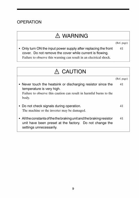
OPERATION
WARNING(Ref. page)
S Only turn ON the input power supply after replacing the frontcover. Do not remove the cover while current is flowing.Failure to observe this warning can result in an electrical shock.
41
CAUTION(Ref. page)
S Never touch the heatsink or discharging resistor since thetemperature is very high.Failure to observe this caution can result in harmful burns to thebody.
41
S Do not check signals during operation.The machine or the inverter may be damaged.
41
S All theconstantsof thethebrakingunitandthebrakingresistorunit have been preset at the factory. Do not change thesettings unnecessarily.
41


11
CAUTION(Ref. page)
S The control PC board employs CMOS ICs. Do not touch theCMOS elements.They are easily damaged by static electricity.
46
S Donot connectordisconnectwiresorconnectorswhilepoweris applied to the circuit.Failure to observe this caution can result in personal injury.
46
OTHERS
WARNINGS Never modify the product.Failure to observe this warning can result in an electrical shock orpersonal injury and will invalidate the guarantee.

12
WARNING INDICATION
A warning label is displayed on the front cover of the braking unit, as shown below. Follow these instructions when handling the braking unit and the braking resistor unit.
Exampleof BrakingUnit Model CDBR−4045B
WarningIndication

13
Warning Indication

14
CONTENTSNOTES FOR OPERATION - - - - - - - - - - - - - - - - - - - - - - - - - - - - - - - - - - 5
1 RECEIVING - - - - - - - - - - - - - - - - - - - - - - - - - - - - - - - - - - -151.1 NAMEPLATE - - - - - - - - - - - - - - - - - - - - - - - - - - - - - - - - - 15
2 INSTALLATION - - - - - - - - - - - - - - - - - - - - - - - - - - - - - - - -162.1 LOCATION - - - - - - - - - - - - - - - - - - - - - - - - - - - - - - - - - - - 162.2 INSTALLATION - - - - - - - - - - - - - - - - - - - - - - - - - - - - - - - - 162.3 REPLACEMENT OF CONVENTIONAL BRAKING UNITS
WITH NEW UNITS - - - - - - - - - - - - - - - - - - - - - - - - - - - - - 253 WIRING - - - - - - - - - - - - - - - - - - - - - - - - - - - - - - - - - - - - -27
3.1 REMOVING AND REPLACING THE COVERS OF THE BRAKING UNIT (MODELS CDBR-2015B, -2015C, -2022B, -2022C, -4030B, -4045B) - - - - - - - - - - - - - - - - - - - 27
3.2 SECTION NAMES - - - - - - - - - - - - - - - - - - - - - - - - - - - - - - 283.3 CIRCUITS AND WIRING SPECIFICATIONS - - - - - - - - - - - 313.4 WIRING PRECAUTIONS - - - - - - - - - - - - - - - - - - - - - - - - - 323.5 INTERCONNECTION - - - - - - - - - - - - - - - - - - - - - - - - - - - 33
4 OPERATION - - - - - - - - - - - - - - - - - - - - - - - - - - - - - - - - - -414.1 ADJUSTMENT - - - - - - - - - - - - - - - - - - - - - - - - - - - - - - - - 414.2 POWER SUPPLY VOLTAGE SELECTION CONNECTOR
SETTING - - - - - - - - - - - - - - - - - - - - - - - - - - - - - - - - - - - - 414.3 MASTER/SLAVE SELECTION CONNECTOR SETTING - - 444.4 PARALLEL CONNECTION OF BRAKING UNIT - - - - - - - - - 444.5 OPERATION - - - - - - - - - - - - - - - - - - - - - - - - - - - - - - - - - - 45
5 TROUBLESHOOTING - - - - - - - - - - - - - - - - - - - - - - - - - - -466 SPECIFICATIONS - - - - - - - - - - - - - - - - - - - - - - - - - - - - - -47
6.1 BRAKING UNIT AND BRAKING RESISTOR UNIT APPLICATION LIST - - - - - - - - - - - - - - - - - - - - - - - - - - - - - 47
6.2 BRAKING UNIT FOR 575V CLASS APPLICATION LIST - - 496.3 LIST OF APPLICABLE/NOT APPLICABLE COMBINATIONS
WITH CONVENTIONAL MODELS (VS-616HII/H3, VS-616GII/G3, VS-676) - - - - - - - - - - - - - - - - - - - - - - - - - - 50
6.4 BRAKING UNIT SPECIFICATIONS - - - - - - - - - - - - - - - - - - 516.5 BRAKING RESISTOR UNIT SPECIFICATIONS - - - - - - - - - 526.6 MODELS AND CODE NOS. OF BRAKING UNIT AND
BRAKING RESISTOR UNIT - - - - - - - - - - - - - - - - - - - - - - - 53

1 RECEIVING
15
1 RECEIVING
The braking resistor unit and braking unit have been put through severe tests at the factory before shipment. After unpacking, however, check and see the follow-ing. If any malfunctions are found, contact your YASKAWA representative.
• Their nameplate data meet your requirements.• They have sustained no damage while in transit.• Fastening bolts and screws are not loose.
1.1 NAMEPLATE(1) NAMEPLATE INFORMATION (BRAKING UNIT)
(2) NAMEPLATE INFORMATION (BRAKING RESISTER UNIT)
• Do not install and attempt to use a braking resistor or braking resis-tor unit If there are any damaged or missing components. Failure to comply can result in personal injury.
For long term storage, the unit should be kept in a clean area indoors.
CAUTION
NOTENOTE
Braking UnitModel Number
DesignRevisionOrder
Braking ResistorUnit Model Number

16
2 INSTALLATION
2.1 LOCATION
If the units are temporarily stored or machine stops for an extended length of time, the following precautions should be taken. Store the units at pollution level 2 or less (UL standard) and under the following conditions.
• Free from rainfall and drops of water.• Clean and dry.• Free from corrosive gases and liquids.• Free from dirt and dust.• Ambient temperature: 14 to 104°F, 10 to 40°C.• Humidity: 90% RH or less (no condensation)• Free from vibration.
2.2 INSTALLATION
For full use of the braking resistor unit or braking unit functions, install the units at pollution level 2 or less (UL standard) and in a location to satisfy the following conditions:
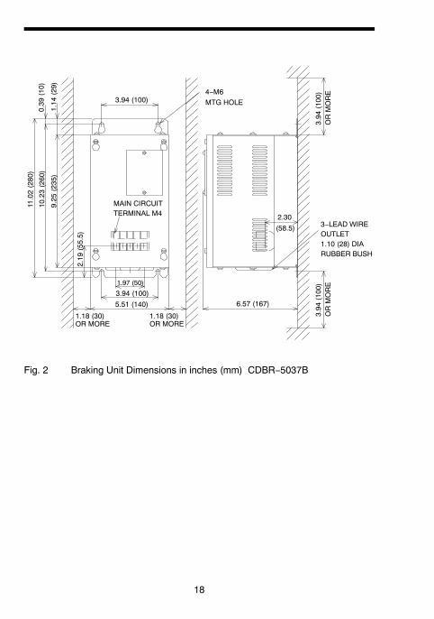
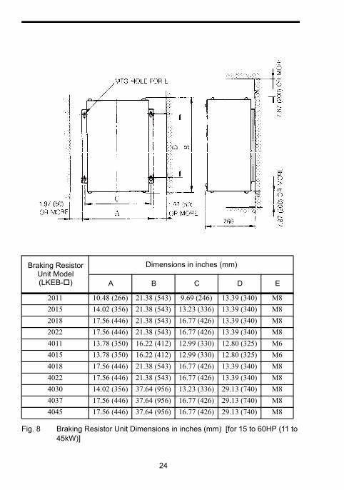
Figs. 1 to 8 show the external dimensions and the spaces from the periphery.
• Provide the spaces shown in Figs. 1 to 8 between the units and the periphery.
• Since the braking resistor unit generates heat, provide sufficient spaces from devices which are weak against heat.
• Install the units at such locations that all requirements described in Par. 2.1 “LOCATION” are satisfied.

2 INSTALLATION
17
• Install the units in the directions shown in Figs. 1 to 8. There will be no problem if they are installed vertically.
Fig. 1 Braking Unit Dimensions in inches (mm) CDBR-2015B, -2015C, -2022B,-2022C,-4030B, -4045B
4−M4 MTG HOLE
1.5 (38) 1.5 (38)
1.18 (30)OR MORE
3−LEAD WIRE OUTLET[0.87 (20) DIA RUBBER BUSH]
5.04 (128)5.51 (140)
2.83 (72) 2.73 (66.5)
4.51 (114.5)
5.45 (138.5)1.18 (30)OR MORE
5.43
(138
)
5.91
(150
)
3.94
(100
)OR
MO
RE
3.94
(100
)OR
MO
RE
18
6.57 (167)
3.94
(100)
ORMORE
5.51 (140)
3.94 (100)1.97 (50)
1.18 (30)OR MORE
(58.5)
2.19
(55.5)
11.02(280)
10.23(260)
9.25
(235)
0.39
(10)
1.14
(29)
3.94 (100)
MAIN CIRCUITTERMINAL M4
3−LEAD WIREOUTLET1.10 (28) DIARUBBER BUSH
4−M6MTG HOLE
2.30
1.18 (30)OR MORE
3.94
(100)
ORMORE
Fig. 2 Braking Unit Dimensions in inches (mm) CDBR−5037B

2 INSTALLATION
19
Fig. 3 Braking Unit Dimensions in inches (mm) CDBR-2045B
5.51 (140)(59)
7.09 (180)
4.37 (111)
6.14 (156)7.87 (200)
3.86 (98)
3.94 (100)
2.95
(75)
12.4
8(3
17)
13.7
8(3
50)
14.5
7(3
70)
1.44
(36.
5)
0.47
(12)
5.51 (140)
MAIN CIRCUITTERMINAL M5
2−LEAD WIRE OUTLET1.38 (35) DIA RUBBERBUSH
4−M6MTG HOLE
3.94
(100
)O
RM
OR
E
WIRE OUTLET 1.10 (28)DIA RUBBER BUSH
3.94
(100
)O
RM
OR
E2.32 1.97 (50)
1.18 (30)OR MORE
1.18 (30)OR MORE

20
MAIN CIRCUITTERMINAL M6
2−LEAD WIRE OUTLET1.38 (35) DIA RUBBERBUSH
4−M6MTG HOLE
3.94
(100)
ORMORE
WIRE OUTLET 1.10 (28)DIA RUBBER BUSH
3.94
(100)
ORMORE
12.48(317)
13.78(350)
14.57(370)
1.44
(36.5)
0.47
(12)
3.94 (100)
2.87
(73)
5.51 (140)
5.51 (140)(59)
7.09 (180)
2.32 1.97 (50)
1.18 (30)OR MORE
1.18 (30)OR MORE
4.37 (111)
6.14 (156)7.87 (200)
4.09(104)
Fig. 4 Braking Unit Dimensions in inches (mm) CDBR−2110B

21
MAIN CIRCUITTERMINAL M5
4−M6MTG HOLE
1.44
(36.5)
0.35
(9)
7.09 (180)12.48(317)
13.98(355)
14.57(370)
5.45 (138.5)
2.95
(75)
8.66 (220)
(68.5) 7.09 (180)2.70 1.97 (50)
1.18 (30)OR MORE
1.18 (30)OR MORE
2−LEAD WIRE OUTLET1.38 (35) DIA RUBBERBUSH
WIRE OUTLET 1.10 (28)DIA RUBBER BUSH
3.94
(100)
ORMORE4.37 (111)
6.14 (156)
7.87 (200)
3.94
(100)
ORMORE
3.86 (98)
Fig. 5 Braking Unit Dimensions in inches (mm) CDBR−4090B, −5110B
2. INSTALLATION

22
MAIN CIRCUITTERMINAL M6
4−M6MTG HOLE
1.44
(36.5)
0.35
(9)
8.27 (210)
12.48(317)
13.98(355)
14.57(370)
2.76
(70)
6.16 (156.5)
8.27 (210)
4.67 (118.5) 1.97 (50)
1.18 (30)OR MORE
9.84 (250)
1.18 (30)OR MORE
2−LEAD WIRE OUTLET1.38 (35) DIA RUBBERBUSH
WIRE OUTLET 1.10 (28)DIA RUBBER BUSH
3.94
(100)
ORMORE4.37 (111)
6.14 (156)7.87 (200)
3.94
(100)
ORMORE
4.09(104)
Fig. 6 Braking Unit Dimensions in inches (mm) CDBR−4220B, −5300B

2 INSTALLATION
23
Fig. 7 Braking Resistor Unit Dimensions in inches (mm) [for 0.5 to 10HP (0.4 to 7.5kW)]
ab b
Braking Resistor Unit Model (LKEB- )
Dimensions in inches (mm)
A B C D E
20P7 4.13 (105) 10.83 (275) 1.97 (50) 10.24 (260) M521P5 5.12 (130) 13.78 (350) 2.95 (75) 13.19 (335) M522P2 5.12 (130) 13.78 (350) 2.95 (75) 13.19 (335) M523P7 5.12 (130) 13.78 (350) 2.95 (75) 13.19 (335) M525P5 9.84 (250) 13.78 (350) 7.87 (200) 13.19 (335) M627P5 9.84 (250) 13.78 (350) 7.87 (200) 13.19 (335) M640P7 4.13 (105) 10.83 (275) 1.97 (50) 10.24 (260) M541P5 5.12 (130) 13.78 (350) 2.95 (75) 13.19 (335) M542P2 5.12 (130) 13.78 (350) 2.95 (75) 13.19 (335) M543P7 5.12 (130) 13.78 (350) 2.95 (75) 13.19 (335) M545P5 9.84 (250) 13.78 (350) 7.87 (200) 13.19 (335) M647P5 9.84 (250) 13.78 (350) 7.87 (200) 13.19 (335) M6
24
Fig. 8 Braking Resistor Unit Dimensions in inches (mm) [for 15 to 60HP (11 to 45kW)]
Braking Resistor Unit Model (LKEB- )
Dimensions in inches (mm)
A B C D E
2011 10.48 (266) 21.38 (543) 9.69 (246) 13.39 (340) M82015 14.02 (356) 21.38 (543) 13.23 (336) 13.39 (340) M82018 17.56 (446) 21.38 (543) 16.77 (426) 13.39 (340) M82022 17.56 (446) 21.38 (543) 16.77 (426) 13.39 (340) M84011 13.78 (350) 16.22 (412) 12.99 (330) 12.80 (325) M64015 13.78 (350) 16.22 (412) 12.99 (330) 12.80 (325) M64018 17.56 (446) 21.38 (543) 16.77 (426) 13.39 (340) M84022 17.56 (446) 21.38 (543) 16.77 (426) 13.39 (340) M84030 14.02 (356) 37.64 (956) 13.23 (336) 29.13 (740) M84037 17.56 (446) 37.64 (956) 16.77 (426) 29.13 (740) M84045 17.56 (446) 37.64 (956) 16.77 (426) 29.13 (740) M8

2 INSTALLATION
25
2.3 REPLACEMENT OF CONVENTIONAL BRAKING UNITS WITH NEW UNITS
To replace conventional braking units (models CDBR-2015, -2022, -4030, -4045) with new units (CDBR-2015B, -2015C, -2022B, -2022C, -4030B, -4045B), an exclusive-use attachment is required. Contact your YASKAWA representative.
Fig. 9 Mounting Dimensions of Attachment in inches (mm)
0.39
(10)0.28(7)
3.94 (100)
11.0
2(2
80)
5.51 (140)
10.2
4(2
60)
ATTACHMENT
5.45 (138.5) 0.39 (10)
0.98
(25)
5.91
(150
)4.
13(1
05)
4−M6 MTG HOLE
Code No.: DACT32732−AD
3.94 (100)0.79(20)
0.28(7)
0.79(20)
26
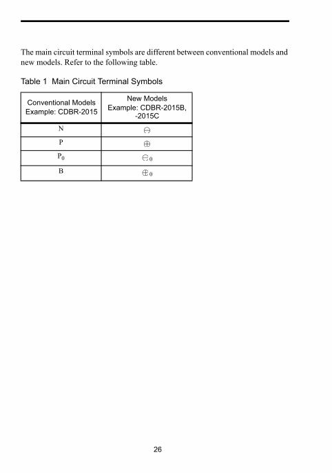
The main circuit terminal symbols are different between conventional models and new models. Refer to the following table.
Table 1 Main Circuit Terminal Symbols
Conventional ModelsExample: CDBR-2015
New ModelsExample: CDBR-2015B,
-2015C
N
P
P0 0
B 0

3 WIRING
27
3 WIRING
3.1 REMOVING AND REPLACING THE COVERS OF THE BRAKING UNIT (MODELS CDBR-2015B, -2015C, -2022B, -2022C,-4030B, -4045B)
(1) Romoving and Replacing the Terminal Cover
For removing, grasp the terminal cover at on borh sides and then lift in the direciton of . For replacing, reverse the method.
(2) Removing and Replacing the lndicating Cover
Remove the terminal cover first. Push down on the lever in the direction of and lift the cover in the direction of . For replacing, reverse the
method.
TerminalCover
Indicating Cover
Lever

28
3.2 SECTION NAMES
Figs. 10, 11 and 12 show appearance and each section name of braking unit and braking resistor unit respectively.
Thermal overload relay protects the braking resistor unit for models LKEB-20P7 to -27P5 and -40P7 to -4015. Thermal protector protects the braking resistor unit for models LKEB-2011 to -2022 and -4018 to -4045.
Fig. 10 Braking Resistor Unit Model CDBR-2015B (Terminal Cover and Indicat-ing Cover Removed)
Remove the label on the terminal block before using the braking unit.
Charge Indicator(Charge Lamp)
Master/SlaveSelection Connector
Operation Indicator(Lights when Dis-charging.)
Control CircuitTerminals 1 to 6
Control Circuit Terminals 0 0
Calibration Resistor(Adjusted Prior toShipment)
Power Supply SelectionConnector
NOTENOTE

3 WIRING
29
Fig. 11 Braking Resistor Unit Model LKEB-20P7 SPEC: B (Front Cover Removed)
Note: 1. External terminals for SPEC: B models LKEB-20P7 and 40P7 are located up to 20 mm further inside the unit when compared to the same models for SPEC: A.
2. External terminals for SPEC:B models LKEB-21P5 to 27P5 and LKEB-41P5 to 47P5 are located up to 15 mm higher on the unit when compared to the same models for SPEC: A.
Thermal Overload Relay(Automatically Reset)
Top Side
Bottom Side
Control Circuit TerminalsB P 1 2
Lead Wire Outlet(Rubber Bush)
30
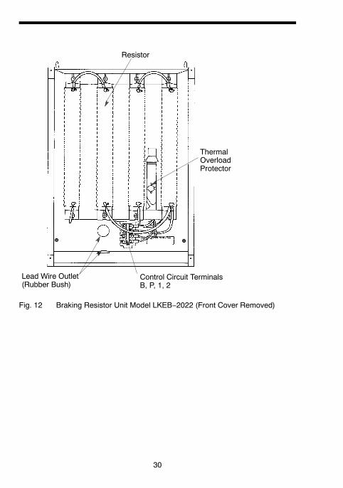
Resistor
ThermalOverloadProtector
Control Circuit TerminalsB, P, 1, 2
Lead Wire Outlet(Rubber Bush)
Fig. 12 Braking Resistor Unit Model LKEB−2022 (Front Cover Removed)

3 WIRING
31
3.3 CIRCUITS AND WIRING SPECIFICATIONS
* 1. For wire size of 8-6(8-14), use UL Listed copper wires (rated at 75°C).* 2. M4 for Models LKEB-20P7 to -27P5 or -40P7 to -4015.
M5 for Models LKEB-2011 to -2022 or -4018 to -4045.* 3. Models-5037B, -5100B, and -5300B can reach an operating voltage of 1040 VDC.
Please select wire which is suitable for the operating voltage.
Table 2 Circuits and Wiring Specifications
Name Circuit Termi-nals
Wire Size AWG (mm2)
Wire Type Terminal Screw
Max. Torque
lb.in (N·m)
Braking Unit (Models CDBR-2015B, -2015C-2022B, -2022C-4030B, -4045B-5037B)
Main 0
0
12-10 (3.5-5.5)
600V(HighVoltage)*3 vinylsheathedwire orequivalent
M4 13.3 (1.50)Con-trol
1 2 34 5 6
18-14 (0.75-2)
Braking Unit (Model CDBR-2045B, -4090B, -5110B)
Main 0
0
10-8 (5.5-8) M5 21.7 (2.45)
Con-trol
1 2 34 5 6
18-14 (0.75-2) M4 15.6 (1.76)
Braking Unit (ModelCDBR-2110B, -4220B, -5300B)
Main 0
0
4 (22)8-6
(8-14)*1M6 43.4 (4.90)
Con-trol
1 2 34 5 6
18-14 (0.75-2) M4 15.6 (1.76)
Braking Resistor Unit(Model LKEB- )
Main B P 12-10 (3.5-5.5)
M4(M5)*2
15.6 (1.76) (21.7(2.45))
Con-trol 1 2 18-14
(0.75-2) M4 15.6 (1.76)

32
3.4 WIRING PRECAUTIONS
(1) Wiring Leading-in Method
Lead in the wire through the knockout hole on the unit bottom. Since the knockout hole is provided with a rubber bush, cut the rubber bush central crosswise with a blade and lead the wire through.
(2) Separation from Signal Lines
Since strong noise component is superimposed on the braking resistor unit and braking unit wiring, separate the units from signal lines which are weak against noise.
(3) Wiring Distance
• Wiring distance between the braking resistor unit and braking unit or braking unit and inverter must be provided as shown in Fig. 13. Make sure to bundle the wires between the units.
• When connecting two or more braking units in parallel, refer to 4.4, “Parallel Connection of Braking Unit” for details.
Fig. 13 Wiring Distance
Braking ResistorUnit
Braking Unit Inverter
32.8ft(10 m)or less
16.4ft(5 m)or less

3 WIRING
33
(4) Grounding Method
• Mount the braking resistor unit on a grounded metallic plate. When it cannot be mounted on a grounded metallic plate, pull out the lead wire from the mounting screw section to ground.
• Braking unit grounding terminal must be provided with the ground resistance of 100Ω or less in 200V class ,or 10Ω or less in 400V class.
• Use the sizes specified in “INTERNAL CONNECTION SPECIFICA-TIONS” for grounding cables.
3.5 INTERCONNECTION
Figs. 14 to 20 show the interconnecting diagrams of the braking unit or braking resistor unit and VS-616G5.
Refer to Par. 3.3, “Wiring Precautions” for proper wiring in actual wiring design and work.
Be sure to connect braking resistors or braking resistor units to the braking units.
Connect only braking resistors or Braking Resistor Units (LKEB-XXXX) to Braking Units.
1. If using another braking resistor instead of YASKAWA braking resistor unit, wiring sequence should shut off power to the drive when a braking resistor Overload Relay Trip Contact (Thermal Protector Contact) output is triggered.
2. Faulty wiring can result in fire. Make sure the interconnecting diagrams are followed correctly.
NOTENOTE

34
1
VS
−616
G5
R
MC
S T
THR
XO
FFO
NM
C
∗∗
SA
12
MC
TRX
TRX
2018
2B
1B
2
SA
SA
THR
X
U(T
1)
V(T
2)
W(T
3)
IM
12
BP
MC
≈≈
Mot
or
Ove
rload
Rel
ayTr
ipC
onta
ct
Bra
king
Res
isto
rUni
t#
#
Gro
und
(200
VC
lass
:100Ω
orle
ss40
0VC
lass
:10Ω
orle
ss)
3−P
hase
Pow
erS
uppl
y20
0to
230
V50
/60
Hz
or 380
to46
0V
50/6
0H
z
L1(R
)
L2(S
)
L3(T
)40
0/20
0V
Ove
rload
Rel
ayTr
ipC
onta
ctof
Bra
king
Res
isto
rUni
t
Faul
tC
onta
ct
DC
Rea
ctor
(Opt
ion)
Sho
rt−ci
rcui
tB
ar
Use
sequ
ence
rto
brea
kpo
wer
supp
lysi
deon
over
-lo
adre
lay
trip
cont
acto
fbr
akin
gre
sist
orun
it.Fa
ilure
to o
bser
ve th
is c
anre
sult
in a
fire
.
The
trans
form
eris
not n
eces
sary
for2
00V
clas
s.
Whe
reis
“E”o
r“V
”.
Whe
nin
stal
ling
aD
Cre
acto
r(op
tion)
,rem
ove
the
com
mon
barb
etw
een
1an
d2
term
inal
s(p
rovi
ded
asst
anda
rd)a
ndco
nnec
taD
Cre
acto
rwith
the
term
inal
s.
Whe
nus
ing
the
brak
ing
resi
stor
unit,
setc
onst
antL
3−04
to“0
”(st
allp
reve
ntio
nse
lect
ion
durin
gde
celi
sdi
sabl
ed).
Ifit
isno
tcha
nged
,the
inve
rterm
ayno
tsto
pw
ithin
setd
ecel
time.
MC
CB
Fig.
14
For M
odel
s C
IMR
-G5∗
20P
4 to
-G5∗
27P
5 (2
00 V
Cla
ss 0
.55
to 7
.5 k
W),
Mod
els
CIM
R-G
5∗40
P4
to -G
5∗40
15 (4
00 V
Cla
ss 0
.4 to
15
kW)

3 WIRING
35
U(T
1)
V(T
2)
W(T
3)
MC
S T
THR
X
THR
X
OFF
ON
MC
SA
12
MC
TRX
TRX
1820
SA SA
IM
12
3
P0
0
12
34
VS
−616
G5
MC
≈≈
Mot
or
Bra
king
Res
isto
rUni
t
L1(R
)
L2(S
)
L3(T
)
Ove
rload
Rel
ayTr
ipC
onta
ctof
Bra
king
Res
isto
rUni
t
Faul
tC
onta
ct
MC
CB
Ove
rload
Rel
ayTr
ipC
onta
ct
DC
Rea
ctor
(Opt
ion)
Leve
lD
etec
tion
Bra
king
Uni
t
R
B
3−P
hase
Pow
erS
uppl
y20
0to
230
V50
/60
Hz
Sho
rt−ci
rcui
tB
ar
Gro
und
(200
VC
lass
:100Ω
orle
ss40
0VC
lass
:10Ω
orle
ss)
∗∗
Whe
reis
“E”o
r“V
”.
Whe
nin
stal
ling
aD
Cre
acto
r(op
tion)
,rem
ove
the
com
mon
barb
etw
een
1an
d2
term
inal
s(p
rovi
ded
asst
anda
rd)a
ndco
nnec
taD
Cre
acto
rwith
the
term
inal
s.
Whe
nus
ing
the
brak
ing
resi
stor
unit,
setc
onst
antL
3−04
to“0
”(st
allp
reve
ntio
nse
lect
ion
durin
gde
celi
sdi
sabl
ed).
Ifit
isno
tcha
nged
,the
inve
rterm
ayno
tsto
pw
ithin
setd
ecel
time.
Use
sequ
ence
rto
brea
kpo
wer
supp
lysi
deon
over
-lo
adre
lay
trip
cont
acto
fbr
akin
gre
sist
orun
it.Fa
ilure
to o
bser
ve th
is c
anre
sult
in a
fire
.
Fig.
15
For M
odel
s C
IMR
-G5∗
2011
to -G
5∗20
15 (2
00 V
Cla
ss 1
1, 1
5 kW
)

36
RM
C
S T
MTH
RX
OFF
ON
MC
SA
12
MC
TRX
TRX
2018
SA
SA
THR
IM
12
3
P 12
34
VS
−616
G5
B
MC
≈≈
0
0
Ove
rload
Rel
ayTr
ipC
onta
ct
Leve
lD
etec
tion
Bra
king
Uni
t
Mot
orL1
(R)
L2(S
)
L3(T
)
MC
CB
Ove
rload
Rel
ayTr
ipC
onta
ctof
Bra
king
Res
isto
rUni
t
Faul
tC
onta
ct
Bra
king
Res
isto
rU
nit(
Opt
ion)
Sho
rt−ci
rcui
tB
ar(P
rovi
ded
asS
tand
ard)
Coo
ling
Fan
(2)
r(1)
U(T
1)
V(T
2)
W(T
3)
3−P
hase
Pow
erS
uppl
y20
0to
230
V50
/60
Hz
Use
sequ
ence
rto
brea
kpo
wer
supp
lysi
deon
over
-lo
adre
lay
trip
cont
acto
fbr
akin
gre
sist
orun
it.Fa
ilure
to o
bser
ve th
is c
anre
sult
in a
fire
.
∗∗
Whe
reis
“E”o
r“V
”.
Whe
nus
ing
the
brak
ing
resi
stor
unit,
setc
onst
antL
3−04
to“0
”(st
allp
reve
ntio
nse
lect
ion
durin
gde
celi
sdi
sabl
ed).
Ifit
isno
tcha
nged
,the
inve
rterm
ayno
tsto
pw
ithin
setd
ecel
time.
Gro
und
(200
VC
lass
:100Ω
orle
ss40
0VC
lass
:10Ω
orle
ss)
Fig.
16
For M
odel
s C
IMR
-G5∗
2018
to -G
5∗20
22 (2
00 V
Cla
ss 1
8.5,
22
kW)
3 WIRING
37
RM
C
S T
THR
XO
FFO
NM
C
SA
12
MC
TRX
TRX
2018
SA
SA
THR
X
IM
VS
−616
G5
M
12
3
P 12
34
B
MC
≈≈
0
0
Ove
rload
Rel
ayTr
ipC
onta
ct
Leve
lD
etec
tion
Bra
king
Uni
t
Bra
king
Res
isto
rU
nit(
Opt
ion)
Mot
or
Coo
ling
Fan
L1(R
)
L2(S
)
L3(T
)
Sho
rt−ci
rcui
tB
ar(P
rovi
ded
asS
tand
ard)
(2)
r(1)
MC
CB
3−P
hase
Pow
erS
uppl
y38
0to
460
V50
/60
Hz
Ove
rload
Rel
ayTr
ipC
onta
ctof
Bra
king
Res
isto
rUni
t
Faul
tC
onta
ct
Vol
tage
Sel
ectio
n
460/
440/
415/
400/
380V
400/
200V
U(T
1)
V(T
2)
W(T
3)
Gro
und
(200
VC
lass
:100Ω
orle
ss40
0VC
lass
:10Ω
orle
ss)
∗∗
Whe
reis
“E”o
r“V
”.
Whe
nus
ing
the
brak
ing
resi
stor
unit,
setc
onst
antL
3−04
to“0
”(st
allp
reve
ntio
nse
lect
ion
durin
gde
celi
sdi
sabl
ed).
Ifit
isno
tcha
nged
,the
inve
rterm
ayno
tsto
pw
ithin
setd
ecel
time.
Use
sequ
ence
rto
brea
kpo
wer
supp
lysi
deon
over
-lo
adre
lay
trip
cont
acto
fbr
akin
gre
sist
orun
it.Fa
ilure
to o
bser
ve th
is c
anre
sult
in a
fire
.
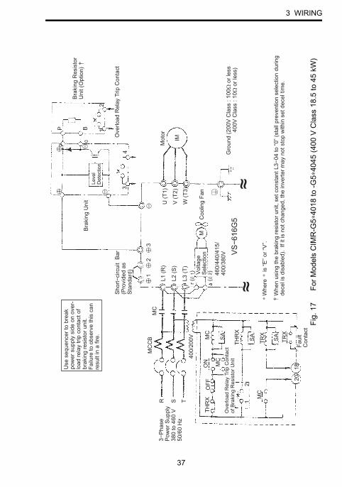
Fig.
17
For M
odel
s C
IMR
-G5∗
4018
to -G
5∗40
45 (4
00 V
Cla
ss 1
8.5
to 4
5 kW
)

38
RM
C
S T40
0/20
0VM
VS−6
16G
5
3
IM
THR
XO
FFO
NM
C
SA
12
MC
TRX
TRX
2018
SA SA
THR
X
MC
P B 12
34
≈≈
Ove
rload
Rel
ayTr
ipC
onta
ct(T
herm
alP
rote
ctor
Con
tact
:23
0VA
C,1
Aor
less
)
Leve
lD
etec
tion
Bra
king
Uni
t
Bra
king
Res
isto
rU
nit(
Opt
ion)
Coo
ling
Fan
r(1) Vo
ltage
Sel
ectio
n
Mot
or
MC
CB
3−P
hase
Pow
erS
uppl
y38
0to
460
V50
/60
Hz
Ove
rload
Rel
ayTr
ipC
onta
ctof
Bra
king
Res
isto
rUni
t
Faul
tC
onta
ct
400
(2
400)
Coo
ling
Fin
Ove
rhea
tC
onta
ct(T
herm
osw
itch
Con
tact
:25
0VA
C,1
Aor
less
30V
DC
,1A
orle
ss)
U(T
1)
V(T
2)
W(T
3)
L1(R
)
L2(S
)
L3(T
)
0
0
460/
440/
415/
400/
380V
Use
sequ
ence
rto
brea
kpo
wer
supp
lysi
deon
over
-lo
adre
lay
trip
cont
acto
fbr
akin
gre
sist
orun
it.Fa
ilure
to o
bser
ve th
is c
anre
sult
in a
fire
.
∗∗
Whe
reis
“E”o
r“V
”.
Whe
nus
ing
the
brak
ing
resi
stor
unit,
setc
onst
antL
3−04
to“0
”(st
allp
reve
ntio
nse
lect
ion
durin
g de
celi
sdi
sabl
ed).
Ifit
isno
tcha
nged
,the
inve
rterm
ayno
tsto
pw
ithin
setd
ecel
time.
Gro
und
(200
VC
lass
:100Ω
orle
ss40
0VC
lass
:10Ω
orle
ss)
Fig.
18
For M
odel
s C
IMR
-G5∗
4055
to -G
5∗41
60 (4
00 V
Cla
ss 5
5 to
160
kW
)

3 WIRING
39
R
MC
S T
IM
M
3 VS−6
16G
5
THR
XO
FFO
NM
C
SA
12
MC
TRX
TRX
1820
SA
SA
THR
X
P
34
B 12
MC
≈≈
U(T
1)
V(T
2)
W(T
3)
Ove
rload
Rel
ayTr
ipC
onta
ct(T
herm
alP
rote
ctor
Con
tact
:23
0VA
C,1
Aor
less
)
Bra
king
Res
isto
rU
nit(
Opt
ion)
Mot
or
Coo
ling
Fin
Ove
rhea
tC
onta
ct(T
herm
osw
itch
Con
tact
:25
0VA
C,1
Aor
less
30V
DC
,1A
orle
ss)
Leve
lD
etec
tion
Bra
king
Uni
t
Coo
ling
Fan
r(1)
MC
CB
L1(R
)
L2(S
)
L3(T
)
Ove
rload
Rel
ayTr
ipC
onta
ctof
Bra
king
Res
isto
rUni
t
Faul
tC
onta
ct
(2)
3−P
hase
Pow
erS
uppl
y20
0to
230
V50
/60
Hz
0
0
Gro
und
(200
VC
lass
:100Ω
orle
ss40
0VC
lass
:10Ω
orle
ss)
∗∗
Whe
reis
“E”o
r“V
”.W
hen
usin
gth
ebr
akin
gre
sist
orun
it,se
tcon
stan
tL3−
04to
“0”(
stal
lpre
vent
ion
sele
ctio
ndu
ring
dece
lis
disa
bled
).If
itis
notc
hang
ed,t
hein
verte
rmay
nots
top
with
inse
tdec
eltim
e.
Use
sequ
ence
rto
brea
kpo
wer
supp
lysi
deon
over
-lo
adre
lay
trip
cont
acto
fbr
akin
gre
sist
orun
it.Fa
ilure
to o
bser
ve th
is c
anre
sult
in a
fire
. Fig.
19
For M
odel
s C
IMR
-G5∗
2030
to -G
5∗20
75 (2
00 V
Cla
ss 3
0 to
75
kW)

40
RM
C
S T40
0/20
0V
M
VS−6
16G
5
3
IM
1
THR
XO
FFO
NM
C
SA
12
MC
TRX
TRX
2018
SA
SA
THR
X
MC
P
34
B 12
≈≈
U(T
1)
V(T
2)
W(T
3)
Ove
rload
Rel
ayTr
ipC
onta
ct(T
herm
alP
rote
ctor
Con
tact
:23
0VA
C,1
Aor
less
)
Bra
king
Res
isto
rU
nit(
Opt
ion)
Mot
or
Coo
ling
Fin
Ove
rhea
tC
onta
ct(T
herm
osw
itch
Con
tact
:25
0VA
C,1
Aor
less
30V
DC
,1A
orle
ss)
Leve
lD
etec
tion
Bra
king
Uni
t
Coo
ling
Fan
L1(R
)
L2(S
)
L3(T
)r(
1)
MC
CB
Volta
geS
elec
tion
400
(2
400)
3−P
hase
Pow
erS
uppl
y38
0to
460
V50
/60
Hz
Ove
rload
Rel
ayTr
ipC
onta
ctof
Bra
king
Res
isto
rUni
t
Faul
tC
onta
ct
0
0
460/
440/
415/
400/
380V
Gro
und
(200
VC
lass
:100Ω
orle
ss40
0VC
lass
:10Ω
orle
ss)
∗∗
Whe
reis
“E”o
r“V
”.
Whe
nus
ing
the
brak
ing
resi
stor
unit,
setc
onst
antL
3−04
to“0
”(st
allp
reve
ntio
nse
lect
ion
durin
g de
celi
sdi
sabl
ed).
Ifit
isno
tcha
nged
,the
inve
rterm
ayno
tsto
pw
ithin
setd
ecel
time.
Use
sequ
ence
rto
brea
kpo
wer
supp
lysi
deon
over
-lo
adre
lay
trip
cont
acto
fbr
akin
gre
sist
orun
it.Fa
ilure
to o
bser
ve th
is c
anre
sult
in a
fire
.
Fig.
20
For M
odel
s C
IMR
-G5∗
4185
to -G
5∗42
20 (4
00 V
Cla
ss 1
85 to
220
kW
)

41
4. OPERATION
4.1 ADJUSTMENT
The braking resistor unit and braking unit do not have to be adjusted.
Especially, do not readjust the braking unit except in the case described in Par. 4.2,“Power Supply Voltage Selection Connector Setting.”
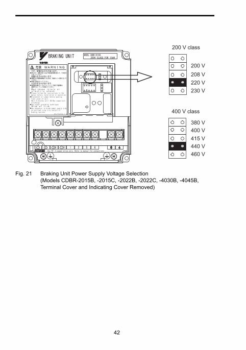
4.2 POWER SUPPLY VOLTAGE SELECTION CON-NECTOR SETTING
It may be necessary to select power supply voltage selection connector for brakingunit according to main circuit power supply type. Table 3 shows the relationshipbetween the power supply voltage selection connector and braking start voltage.
The following is the setting prior to shipment:
S 200V class : 220V
S 400V class : 440V
S 575V class : 575V
For removing the terminal cover and the indicating cover, refer to Par. 3.1.
4.OPERATION
42
Fig. 21 Braking Unit Power Supply Voltage Selection (Models CDBR-2015B, -2015C, -2022B, -2022C, -4030B, -4045B, Terminal Cover and Indicating Cover Removed)
200 V208 V220 V230 V
400 V415 V440 V460 V
380 V
200 V class
400 V class

4 OPERATION
43
Fig. 22 Braking Unit Power Supply Voltage Selection(Models CDBR-2045B, -2110B, -4090B, -5037B, -5110B, -5300B,Indicating Cover Removed)
* Allowable voltage fluctuation is ±10%
200 V208 V220 V230 V
400 V380 V
440 V415 V
460 V
500 V
575 V
575 V class
200 V class 400 V class
Table 3 Power Supply Voltage Selection Connector and Braking Start Voltage
200 VClass*PowerSupplyVoltage
Braking StartVoltage
(PN Bus-barVoltage)
400 VClass*PowerSupplyVoltage
Braking Start Voltage
(PN Bus-barVoltage)
575 VClass*PowerSupplyVoltage
Braking StartVoltage
(PN Bus-barVoltage)
230 V 380 V (TYP) 460 V 760 V (TYP) 575 V 950 V (TYP)
220 V 365 V (TYP) 440 V 730 V (TYP) – –
208 V 345 V (TYP) 415 V 690 V (TYP) – –
200 V 330 V(TYP) 400 V 660 V (TYP) 500 V 825 V (TYP)
– – 380 V 630 V(TYP) – –

44
4.3 MASTER/SLAVE SELECTION CONNECTOR SETTING
Selection Connector Setting MASTER side is selected prior to shipment. Use the units without changing the setting.
SLAVE side is selected when more than one braking unit is combined to use and braking start levels must coincide. Refer to Par. 4.4, “Parallel Connection of Brak-ing Unit” for details.
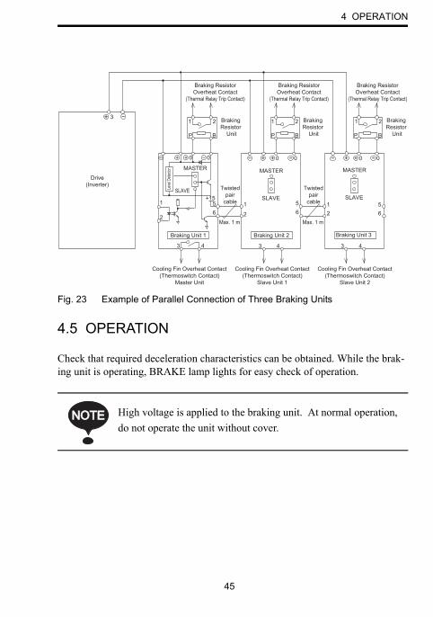
4.4 PARALLEL CONNECTION OF BRAKING UNIT
For using more than one parallel-connected braking unit, connect and select the connectors as follows. (See Fig. 23.)
• Braking units have a MASTER/SLAVE selection connector. (See Fig. 10.) Select MASTER side only for braking unit 1 and select SLAVE side for braking units 2 and 3.
• Properly connect the MASTER output to the SLAVE input. Refer to Fig. 23 for details.
• Use properly rated wire in accordance with table 2 on page 31.• Use twisted-pair wires of 1mm or less for connection between 5, 6
and 1, 2 of the braking units.• Parallel connection of braking unit is possible up to a maximum of
10 units.
Failure to use the wiring and connectors specified above can dam-age the braking resistor, braking resistor unit, and the drive itself.
NOTENOTE
4 OPERATION
45
Fig. 23 Example of Parallel Connection of Three Braking Units
4.5 OPERATION
Check that required deceleration characteristics can be obtained. While the brak-ing unit is operating, BRAKE lamp lights for easy check of operation.
Drive(Inverter)
Braking ResistorOverheat Contact
(Thermal Relay Trip Contact)
Braking ResistorOverheat Contact
(Thermal Relay Trip Contact)
Braking ResistorOverheat Contact
(Thermal Relay Trip Contact)
Braking Resistor
Unit
Braking Resistor
Unit
Braking Resistor
Unit
Braking Unit 2
+155 1
26
SLAVE
MASTERLe
vel D
etecto
r
Cooling Fin Overheat Contact(Thermoswitch Contact)
Master Unit
Cooling Fin Overheat Contact(Thermoswitch Contact)
Slave Unit 1
Cooling Fin Overheat Contact(Thermoswitch Contact)
Slave Unit 2
Braking Unit 3Braking Unit 1
1
3 4 3 4 3
56
56
12
4
2
31
P
2
B
−
− 0+ 0+− +− +− + 0 − 0+ 0 − 0
BP BP
1 2 1 2
MASTER
SLAVE
MASTER
SLAVE
+
Twistedpair
cable
Max. 1 m
Twistedpair
cable
Max. 1 m
High voltage is applied to the braking unit. At normal operation, do not operate the unit without cover.
NOTENOTE

46
5 TROUBLESHOOTING
Only authorized personnel should be permitted to perform maintenance and inspections or replace parts.
No. Fault Status Cause Corrective Action
1
Braking resistor unit overload relay (or thermal over-load protector) trips when not decelerat-ing.
• Without braking unitInverter built-in main circuit dis-charging transistor short circuited
Replace the inverter.
• With braking unitBraking unit main circuit discharg-ing transistor short circuited
Replace the unit.
Improper braking unit power supply voltage selection connector setting(Power supply voltage > power sup-ply voltage selection position)
Set it again.
2 Inverter trips at overvoltage (ov).
Insufficient braking resistor unit capacity
Examine the braking conditions again.
Improper wiring Check and repair.Braking unit fault Replace the unit.
3
Braking resistor unit overload relay (or thermal protec-tor) sometimes trips.
Insufficient braking resistor unit capacity
Examine the braking conditions again.
4Braking unit trips by heat sink over-heat.
Excessive start/stop switching fre-quency Examine the operat-
ing conditions again.Excessive load inertiaImproper combination of braking unit and braking resistor unit Reset.
Ambient temperature 104°F (40°C) Reduce it.Braking unit fault Replace the unit.
5
The fault contact of a braking unit instantaneously turned ON when the power was turned ON.
Neither a braking resistor nor a braking resistor unit is connected to the braking unit.
Connect a braking resistor or braking resistor unit to the braking unit.

6 SPECIFICATIONS
47
6 SPECIFICATIONS
6.1 BRAKING UNIT AND BRAKING RESISTOR UNIT APPLICATION LIST
The applicable braking unit and braking resistor unit models differ depending on the inverter model. Refer to the catalog of the relevant inverter.
Note: The above table lists the applicable braking unit and braking resistor unit models for the 200-V class inverter model CIMR-G5 . For other inverter models, refer to the catalog of the relevant inverter.
Example: 200-V Class Inverter Model CIMR-G5
Inverter Braking Unit Braking Resistor Unit Approx. Braking Torque
(10%ED) %
Max. Applicable Motor Capacity
HP(kW)
Model (CDBR
- )Unit Q’ty
Model (LKEB
- )Resistor Spec.
(per unit)Unit Q’ty
0.5 (0.4) – – 20P7 70W 200Ω 1 2201 (0.75) – – 20P7 70W 200Ω 1 1252 (1.5) – – 21P5 260W 100Ω 1 1253 (2.2) – – 22P2 260W 70Ω 1 1205 (3.7) – – 23P7 390W 40Ω 1 125
7.5 (5.5) – – 25P5 520W 30Ω 1 11510 (7.5) – – 27P5 780W 20Ω 1 125
15 (11) 2015B,2015C 1 2011 2400W 13.6Ω 1 125
20 (15) 2015B,2015C 1 2015 3000W 10Ω 1 125
25 (18.5) 2022B,2022C 1 2018 4800W 8Ω 1 125
30 (22) 2022B,2022C 1 2022 4800W 6.8Ω 1 125
40 (30) 2015B,2015C 2 2015 3000W 10Ω 2 125
50 (37) 2015B,2015C 2 2015 3000W 10Ω 2 100
60 (45) 2022B,2022C 2 2022 4800W 6.8Ω 2 120
75 (55) 2022B,2022C 2 2022 4800W 6.8Ω 2 100
100 (75) 2110B 1 2022 4800W 6.8Ω 3 110120 (90) 2110B 1 2022 4800W 6.8Ω 4 120150 (110) 2110B 1 2022 4800W 6.8Ω 5 100

48
Example: 400−V Class Inverter Model CIMR−G5j
Inverter Braking Unit Braking Resistor Unit Approx.Braking
Max ApplicableMotor Capacity
HP(kW)
Model(CDBR−j)
UnitQ’ty
Model(LKEB−j)
Resistor Spec.(per unit)
UnitQ’ty
BrakingTorque(10%ED)
%
0.5 (0.4) − − 40P7 70W 750Ω 1 2301 (0.75) − − 40P7 70W 750Ω 1 1302 (1.5) − − 41P5 260W 400Ω 1 1253 (2.2) − − 42P2 260W 250Ω 1 1355 (3.7) − − 43P7 390W 150Ω 1 1357.5 (5.5) − − 45P5 520W 100Ω 1 13510 (7.5) − − 47P5 780W 75Ω 1 13015 (11) − − 4011 1040W 50Ω 1 13520 (15) − − 4015 1560W 40Ω 1 12525 (18.5) 4030B 1 4018 4800W 32Ω 1 12530 (22) 4030B 1 4022 4800W 27.2Ω 1 12540 (30) 4030B 1 4030 6000W 20Ω 1 12550 (37) 4045B 1 4037 9600W 16Ω 1 12560 (45) 4045B 1 4045 9600W 13.6Ω 1 12575 (55) 4030B 2 4030 6000W 20Ω 2 135100 (75) 4045B 2 4045 9600W 13.6Ω 2 145150 (110) 4030B 3 4030 6000W 20Ω 3 100200 (160) 4220B 1 4045 9600W 13.6Ω 4 140300 (220) 4220B 1 4037 9600W 16Ω 5 110400 (300) 4220B 2 4045 9600W 13.6Ω 6 110800 (600) 4220B 4 4045 9600W 13.6Ω 12 110
Note: The above table lists the applicable braking unit and braking resistor unitmodels for the 400−Vclassinverter model CIMR−G5j. For other inverter models, refer to the catalog of the relevant inverter.

6 SPECIFICATIONS
49
6.2 BRAKING UNIT FOR 575V CLASS APPLICATION LIST
Example: 575-V Class Inverter Model CIMR-G5
Note: The above table lists the applicable braking unit and braking resistor unit models for the 575-V class inverter model CIMR-G5 . For other inverter models, refer to the catalog of the relevant inverter.
Inverter Braking Unit Braking Resistor Unit Approx.BrakingTorque
(10%ED)%
Max ApplicableMotor Capacity
HP(kW)
Model(CDBR- ) Unit Q’ty Resistor Spec.
5 (3.7) – – 560W 150Ω 180
7.5 (5.5) – – 560W 150Ω 125
10 (7.5) – – 750W 100Ω 140
15 (11) – – 1100W 75Ω 125
20 (15) – – 1500W 50Ω 140
25 (18.5) – – 2300W 40Ω 140
30 (22) 5037B 1 2800W 38Ω 125
40 (30) 5037B 1 3900W 33Ω 110
50 (37) 5037B 1 4900W 27Ω 110
60 (45) 5037B 2 5900W 22Ω 110
75 (55) 5037B 2 7200W 18Ω 110
100 (75) 5110B 1 9800W 13.6Ω 105
120 (90) 5110B 1 12000W 11Ω 110
150 (110) 5110B 1 15000W 9Ω 110
200 (160) 5300B 1 21000W 6.8Ω 100

50
6.3 LIST OF APPLICABLE/NOT APPLICABLE COMBINA-TIONS WITH CONVENTIONAL MODELS (VS−616HII/H3, VS−616GII/G3, VS−676)
ConventionalModel
BrakingUnit
Braking Re-sistor Unit
Applicable/Not Appli-cable
Remarks
VS−616HII/H3VS−616GII/G3VS−676
−ModelLKEB−20P7etc.
Applicable See connection exam-ples of Fig 14.
VS−616HII/H3VS−616GII/G3VS−676
ModelCDBR−15Hetc.
ModelLKEB−2015etc.
Applicable
Use sequencer to breakpower supply side onthermal protector ofthe braking resistorunit side.
VS−616HII/H3VS−616GII/G3VS−676
ModelsCDBR−2015,−2015B etc.
ModelLKEB−4.8Ketc.
Not applica-ble
No thermal protectivefunction of braking re-sistor unit.
VS−616HII/H3VS−616GII/G3VS−676
ModelsCDBR−2015,−2015B etc.
ModelLKEB−2015etc.
Applicable See connection exam-ples of Figs. 15 to 18.
6 SPECIFICATIONS
51
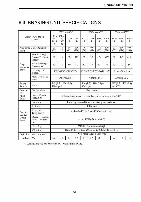
6.4 BRAKING UNIT SPECIFICATIONS
* Loading time rate can be used below 10% ED (max. 10 sec.)
Braking Unit ModelCDBR-
200V to 300V 380V to 460V 500V to 575V2015
B,2015
C
2022B,
2022C
2045B
2110B
4030B
4045B
4090B
4220B
5037B
5110B
5300B
Applicable Motor Output HP (kW)
20 (15)
30 (22)
60 (45)
150 (110)
40 (30)
60 (45)
120 (90)
300 (220)
57 (37)
150 (110)
400 (300)
Output charac-ter-istics
Max. Discharge Current(A) (peak value) *
40 60 100 250 40 60 100 250 40 100 250
Rated Discharge Current (A)
15 20 30 80 15 18 30 80 15 30 80
Braking Start Voltage
330/345/365/380V±3V 630/660/690/730/760V ±6V 825V/ 950V ±8V
Max. Hysteresis Error
Approx. 8V Approx. 16V Approx. 20V
Power Supply VDC 243 (1.35×200×0.9) to
400V peak460 (1.35×380×0.9) to 800V peak
607 (1.35×500×0.9) to 1000V
Protec-tiveFunc-tions
Fin Overheat Thermostat
Power Charge Indication
Charge lamp stays ON until bus voltage drops below 50V.
Envion-mental Condi-tions
Location Indoor (protected from corrosive gases and dust)
Altitude 1000m max.
AmbientTemperature
+14 to 104°F (-10 to +40°C) (not frozen)
Storage Transpor-tation Tempera-ture
-4 to 140°F (-20 to +60°C)
Humidity 90%RH (non-condensing)
Vibration 1G at 10 to less than 20Hz, up to 0.2G at 20 to 50 Hz
Protective Configuration Wall-mounted enclosed type
Heat Loss (W) 32 38 31 64 54 59 35 71 22 53 116

52
6.5 BRAKING RESISTOR UNIT SPECIFICATIONS
Model(LKEB
- )Specifications
Allowable Average
Dissipated Power
(W)
Allowable AverageCurrent
(Effective Value)(A)
Allowable Ambient
Temperature
20P7B
200to
230V
70W 200Ω 30 0.39
+14 to 122°F(-10 to +50°C)
21P5B 260W 100Ω 60 0.7722P2B 260W 70Ω 89 1.123P7B 390W 40Ω 150 1.925P5B 520W 30Ω 220 2.727P5B 780W 20Ω 300 3.92011 2400W 13.6Ω 440 5.72015 3000W 10Ω 600 7.72018 4800W 8Ω 740 9.62022 4800W 6.8Ω 880 11.4
40P7B
380to
460V
70W 750Ω 30 0.2041P5B 260W 400Ω 60 0.3942P2B 260W 250Ω 89 0.6043P7B 390W 150Ω 150 1.045P5B 520W 100Ω 220 1.547P5B 780W 75Ω 300 2.04011B 1040W 50Ω 440 3.04015B 1560W 40Ω 600 3.94018 4800W 32Ω 740 4.84022 4800W 27.2Ω 880 5.74030 6000W 20Ω 1200 7.74037 9600W 16Ω 1500 9.74045 9600W 13.6Ω 1800 11.5

6 SPECIFICATIONS
53
6.6 MODELS AND CODE NOS. OF BRAKING UNIT AND BRAKING RESISTOR UNIT
(1) Braking Unit
InverterModel Code No.
Voltage HP (kW)
200 to230 V
20 (15)CDBR-2015B 72600-R2150B
CDBR-2015C 72600-R2150C
30 (22)CDBR-2022B 72600-R2220B
CDBR-2022C 72600-R2220C
60 (45) CDBR-2045B 72600-R2450B
150 (110) CDBR-2110B 72600-R21100B
380 to460 V
40 (30) CDBR-4030B 72600-R4300B
60 (45) CDBR-4045B 72600-R4450B
120 (90) CDBR-4090B 72600-R4900B
300 (220) CDBR-4220B 72600-R42200B
500 to575 V
50 (37) CDBR-5037B 72600-R5370B
150 (110) CDBR-5110B 72600-R51100B
400 (300) CDBR.5300B 72600-R53000B

54
(2) Braking Resistor Unit
Inverter Resistor Spec. (per unit) Model Code No.
Voltage HP(kW)
200 to230V
1 (0.75) 70W 200Ω LKEB-20P7 72600-K2P70B2 (1.5) 260W 100Ω LKEB-21P5 72600-K2010B3 (2.2) 260W 70Ω LKEB-22P2 72600-K2020B5 (3.7) 390W 40Ω LKEB-23P7 72600-K2030B
7.5 (5.5) 520W 30Ω LKEB-25P5 72600-K2050B10 (7.5) 780W 20Ω LKEB-27P5 72600-K2070B15 (11) 2400W 13.6Ω LKEB-2011 72600-K211020 (15) 3000W 10Ω LKEB-2015 72600-K2150
25 (18.5) 4800W 8Ω LKEB-2018 72600-K218030 (22) 4800W 6.8Ω LKEB-2022 72600-K2220
380 to460V
1 (0.75) 70W 750Ω LKEB-40P7 72600-K4P70B2 (1.5) 260W 400Ω LKEB-41P5 72600-K4010B3 (2.2) 260W 250Ω LKEB-42P2 72600-K4020B5 (3.7) 390W 150Ω LKEB-43P7 72600-K4030B
7.5 (5.5) 520W 100Ω LKEB-45P5 72600-K4050B10 (7.5) 780W 75Ω LKEB-47P5 72600-K4070B15 (11) 1040W 50Ω LKEB-4011 72600-K4110B20 (15) 1560W 40Ω LKEB-4015 72600-K4150B
25 (18.5) 4800W 32Ω LKEB-4018 72600-K418030 (22) 4800W 27.2Ω LKEB-4022 72600-K422040 (30) 6000W 20Ω LKEB-4030 72600-K430050 (37) 9600W 16Ω LKEB-4037 72600-K437060 (45) 9600W 13.6Ω LKEB-4045 72600-K4450

DRIVE CENTER (INVERTER PLANT)2-13-1, Nishimiyaichi, Yukuhashi, Fukuoka, 824-8511, JapanPhone: 81-930-25-3844 Fax: 81-930-25-4369http://www.yaskawa.co.jp
YASKAWA ELECTRIC CORPORATIONNew Pier Takeshiba South Tower, 1-16-1, Kaigan, Minatoku, Tokyo, 105-6891, JapanPhone: 81-3-5402-4502 Fax: 81-3-5402-4580http://www.yaskawa.co.jp
YASKAWA AMERICA, INC.2121 Norman Drive South, Waukegan, IL 60085, U.S.A.Phone: 1-800-YASKAWA (927-5292) or 1-847-887-7000 Fax: 1-847-887-7310http://www.yaskawa.com
YASKAWA ELÉTRICO DO BRASIL LTDA.Avenida Piraporinha 777, Diadema, São Paulo, 09950-000, BrasilPhone: 55-11-3585-1100 Fax: 55-11-3585-1187http://www.yaskawa.com.br
YASKAWA EUROPE GmbHHauptstrasse 185, 65760 Eschborn, GermanyPhone: 49-6196-569-300 Fax: 49-6196-569-398http://www.yaskawa.eu.com
YASKAWA ELECTRIC KOREA CORPORATION9F, Kyobo Securities Bldg., 26-4, Yeouido-dong, Yeongdeungpo-gu, Seoul, 150-737, KoreaPhone: 82-2-784-7844 Fax: 82-2-784-8495http://www.yaskawa.co.kr
YASKAWA ELECTRIC (SINGAPORE) PTE. LTD.151 Lorong Chuan, #04-02A, New Tech Park, 556741, SingaporePhone: 65-6282-3003 Fax: 65-6289-3003http://www.yaskawa.com.sg
YASKAWA ELECTRIC (CHINA) CO., LTD.12F, Carlton Bld., No.21 HuangHe Road, HuangPu District, Shanghai 200003, ChinaPhone: 86-21-5385-2200 Fax: 86-21-5385-3299http://www.yaskawa.com.cn
YASKAWA ELECTRIC (CHINA) CO., LTD. BEIJING OFFICERoom 1011, Tower W3 Oriental Plaza, No. 1 East Chang An Ave., Dong Cheng District, Beijing, 100738, ChinaPhone: 86-10-8518-4086 Fax: 86-10-8518-4082
YASKAWA ELECTRIC TAIWAN CORPORATION9F, 16, Nanking E. Rd., Sec. 3, Taipei, 104, TaiwanPhone: 886-2-2502-5003 Fax: 886-2-2505-1280
YASKAWA INDIA PRIVATE LIMITED#17/A Electronics City, Hosur Road Bangalore 560 100 (Karnataka), IndiaPhone: 91-80-4244-1900 Fax: 91-80-4244-1901http://www.yaskawaindia.in
In the event that the end user of this product is to be the military and said product is to be employed in any weapons systems or the manufacture thereof, the export will fall under the relevant regulations as stipulated in the Foreign Exchange and Foreign Trade Regulations. Therefore, be sure to follow all procedures and submit all relevant documentation according to any and all rules, regulations and laws that may apply.
Specifications are subject to change without notice for ongoing product modifications and improvements.
© 2005-2013 YASKAWA ELECTRIC CORPORATION. All rights reserved.
Published in Japan December 2013 05-3
MANUAL NO. TOBP C720600 00F
13-7-1113 -0
YASKAWA ELECTRIC CORPORATION
Braking unit,Braking resistor unit
YASKAWA AC Drive Option
Installation Manual
Copyright © 2022 FDOKUMEN