1433 SERIES High-Accuracy Decade Resistor User ... - EMIN
16
♦ PRECISION INSTRUMENTS FOR TEST AND MEASUREMENT ♦ Email: [email protected] TEL: (516) 334-5959 • FAX: (516) 334-5988 www.ietlabs.com IET LABS, INC. 1433 SERIES High-Accuracy Decade Resistor User and Service Manual Copyright © 2013 IET Labs, Inc. Visit www.ietlabs.com for manual revision updates 1433 im/November 2014 Effective for serial numbers beginning with “E”
-
Upload
khangminh22 -
Category
Documents
-
view
1 -
download
0
Transcript of 1433 SERIES High-Accuracy Decade Resistor User ... - EMIN

♦ PRECISION INSTRUMENTS FOR TEST AND MEASUREMENT ♦
Email: [email protected]: (516) 334-5959 • FAX: (516) 334-5988
www.ietlabs.comIET LABS, INC.
1433 SERIES
High-AccuracyDecade Resistor
User and Service Manual
Copyright © 2013 IET Labs, Inc.Visit www.ietlabs.com for manual revision updates
1433 im/November 2014Effective for serial numbers beginning with “E”

iTable of Contents
1433 Series
WARRANTY
We warrant that this product is free from defects in material and workmanship and, when properly used, will perform in accordance with applicable IET specifi cations. If within one year after original shipment, it is found not to meet this standard, it will be repaired or, at the option of IET, replaced at no charge when returned to IET. Changes in this product not approved by IET or application of voltages or currents greater than those allowed by the specifi cations shall void this warranty. IET shall not be liable for any indirect, special, or consequential damages, even if notice has been given to the possibility of such damages.
THIS WARRANTY IS IN LIEU OF ALL OTHER WARRANTIES, EXPRESSED OR IMPLIED, INCLUDING BUT NOT LIMITED TO, ANY IMPLIED WARRANTY OF MERCHANTABILITY OR FITNESS FOR ANY PARTICULAR PURPOSE.

ii Table of Contents
1433 Series
WARNING
OBSERVE ALL SAFETY RULESWHEN WORKING WITH HIGH VOLTAGES OR LINE VOLTAGES.
Dangerous voltages may be present inside this instrument. Do not open the caseRefer servicing to qualifi ed personnel
HIGH VOLTAGES MAY BE PRESENT AT THE TERMINALS OF THIS INSTRUMENT
WHENEVER HAZARDOUS VOLTAGES (> 45 V) ARE USED, TAKE ALL MEASURES TOAVOID ACCIDENTAL CONTACT WITH ANY LIVE COMPONENTS.
USE MAXIMUM INSULATION AND MINIMIZE THE USE OF BARECONDUCTORS WHEN USING THIS INSTRUMENT.
Use extreme caution when working with bare conductors or bus bars.
WHEN WORKING WITH HIGH VOLTAGES, POST WARNING SIGNS AND KEEP UNREQUIRED PERSONNEL SAFELY AWAY.
CAUTION
DO NOT APPLY ANY VOLTAGES OR CURRENTS TO THE TERMINALS OF THISINSTRUMENT IN EXCESS OF THE MAXIMUM LIMITS INDICATED ON
THE FRONT PANEL OR THE OPERATING GUIDE LABEL.

iiiTable of Contents
1433 Series
ContentsChapter 1 Introduction ..............................................................................1
1.1 Product Overview ................................................................................................. 1
Chapter 2 Specifi cations ...........................................................................2
Decade Specifi cations .................................................................................................... 2
Chapter 3 Operation ..................................................................................5
3.1 Initial Inspection and Setup .................................................................................. 5
3.2 Connection ............................................................................................................ 5
3.2.1 General Considerations ............................................................................... 5
3.2.2 Electrical Considerations ............................................................................ 5
3.2.3 Four-Wire Kelvin-Lead Connections ......................................................... 6
3.2.4 Thermal emf Considerations ....................................................................... 6
3.3 Dial Setting ........................................................................................................... 6
Chapter 4 Maintanence ..............................................................................7
4.1 Preventative Maintenance ..................................................................................... 7
4.2 Calibration Interval ............................................................................................... 7
4.3 General Considerations ......................................................................................... 7
4.4 Calibration Procedure ........................................................................................... 8
4.5 Schematic .............................................................................................................. 8
4.6 Replaceable Parts List ........................................................................................... 9

iv Table of Contents
1433 Series
Tables and FiguresFigure 1-1: 1433 Series High Accuracy Decade Resistor .......................................1
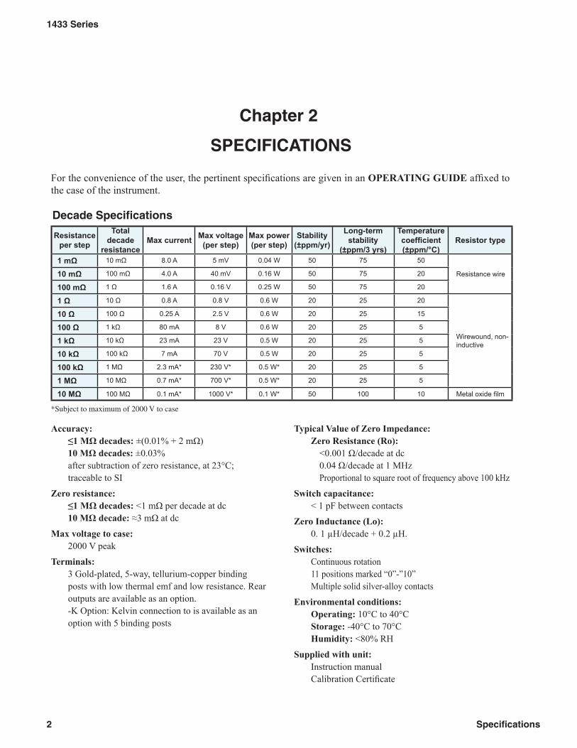
Figure 2-1: Sample operating guide affi xed to unit .................................................4
Figure 3-1: Optimal 4-Wire Kelvin Lead Connection ...............................................6
Figure 4-1: 1433 Series Schematic Diagram ..........................................................8
Table 4-1: Replacement List ....................................................................................9
Figure 4-2: 1433 Replaceable Parts .......................................................................9

1
1433 Series
Introduction
Chapter 1
INTRODUCTION
High-quality gold-plated, tellurium-copper binding posts serve to minimize the thermal emf effects which can introduce errors into dc resistance measurements. All other conductors within the instrument, as well as the solder employed, contain no metals or junctions that contribute to thermal emf problems.
With a minimum resistance as low as 1 mΩ and a maximum available resistance of over 111 MΩ, the 1433 series may be used for exacting precision mea-surement applications requiring high accuracy, good stability, and low zero-resistance. They can be used as components of dc and ac bridges, for calibration, as transfer standards, and as RTD simulators.
The 1433 Series may be rack-mounted to serve as components in measurement and control systems.
This series is part of a family of resistance substitut-ers suitable for fi lling many engineering and testing needs. Consult IET for:
HPRS High-power substituters - up to >400 WHRRS High-resistance substituters - to 1 TΩRTD simulatorsHARS-LX Laboratory-standard-grade substitut-ers - to 1 ppm accuracyPRS Programmable substituters - IEEE-488 or BCD; SCPI protocol.
Figure 1-1: 1433 Series High Accuracy Decade Resistor
1.1 Product Overview
The 1433 Decade Resistors are a family of instru-ments providing a very broad choice of high-perfor-mance resistance sources. Any number of decades from one to eleven is available.
The 1433 is a precision resistance source with ex-cellent characteristics of stability, temperature coef-fi cient, power coeffi cient, and frequency response.
There are over 30 models available covering a wide resistance range from 1 mΩ to over 111 MΩ. The 1433 Series employs stable, very-low-resistance switches with silver-alloy contacts. A special design keeps zero-resistance to less than 1 mΩ per decade. Self-cleaning keeps the silver contacts from becoming tarnished when unused, or when only low currents are passed through them. This is most often the case when only minute test currents are drawn by digital multimeters or other test instruments. Contact resis-tance is stable and remains low and repeatable.
The dials, marked “0” to “10”, offer smooth rotation from position to position with no stops. Each dial has an overlap “10” position for maximum convenience and fl exibility in setting and adjusting resistance values. The resistance per step and maximum cur-rent of each dial are clearly shown on the front panel. Electrical shielding is provided by an attractive alumi-num cabinet and front panel. The resistance elements have no electrical connection to the cabinet and panel; a separate shield terminal is provided.
2
1433 Series
Specifi cations
Decade Specifi cations
Resistance per step
Total decade
resistance Max current Max voltage
(per step) Max power(per step)
Stability(±ppm/yr)
Long-term stability
(±ppm/3 yrs)
Temperature coeffi cient(±ppm/°C)
Resistor type
1 mΩ 10 mΩ 8.0 A 5 mV 0.04 W 50 75 50
Resistance wire 10 mΩ 100 mΩ 4.0 A 40 mV 0.16 W 50 75 20
100 mΩ 1 Ω 1.6 A 0.16 V 0.25 W 50 75 20
1 Ω 10 Ω 0.8 A 0.8 V 0.6 W 20 25 20
Wirewound, non-inductive
10 Ω 100 Ω 0.25 A 2.5 V 0.6 W 20 25 15
100 Ω 1 kΩ 80 mA 8 V 0.6 W 20 25 5
1 kΩ 10 kΩ 23 mA 23 V 0.5 W 20 25 5
10 kΩ 100 kΩ 7 mA 70 V 0.5 W 20 25 5
100 kΩ 1 MΩ 2.3 mA* 230 V* 0.5 W* 20 25 5
1 MΩ 10 MΩ 0.7 mA* 700 V* 0.5 W* 20 25 5
10 MΩ 100 MΩ 0.1 mA* 1000 V* 0.1 W* 50 100 10 Metal oxide fi lm
*Subject to maximum of 2000 V to case
Chapter 2
SPECIFICATIONS
For the convenience of the user, the pertinent specifi cations are given in an OPERATING GUIDE affi xed to the case of the instrument.
Accuracy: ≤1 MΩ decades: ±(0.01% + 2 mΩ) 10 MΩ decades: ±0.03% after subtraction of zero resistance, at 23°C; traceable to SI
Zero resistance: ≤1 MΩ decades: <1 mΩ per decade at dc 10 MΩ decade: ≈3 mΩ at dc
Max voltage to case: 2000 V peak
Terminals: 3 Gold-plated, 5-way, tellurium-copper binding posts with low thermal emf and low resistance. Rear outputs are available as an option. -K Option: Kelvin connection to is available as an option with 5 binding posts
Typical Value of Zero Impedance:Zero Resistance (Ro):
<0.001 Ω/decade at dc0.04 Ω/decade at 1 MHzProportional to square root of frequency above 100 kHz
Switch capacitance: < 1 pF between contacts
Zero Inductance (Lo):0. 1 μH/decade + 0.2 μH.
Switches: Continuous rotation 11 positions marked “0”-”10” Multiple solid silver-alloy contacts
Environmental conditions: Operating: 10°C to 40°C Storage: -40°C to 70°C Humidity: <80% RH
Supplied with unit: Instruction manual Calibration Certifi cate

3
1433 Series
Specifi cations
Mechanical:
Model Dimensions Weight
3 decade 31 cm W x 8.9 cm H x 10.2 cm D (12.2" x 3.5" x 4")
1.7 kg 3.8 lb
4-5 decade 37.6 cm W x 8.9 cm H x 10.2 cm D (14.8" x 3.5" x 4") 2.0 kg 4.3 lb
6-7 decades 43.9 cm W x 8.9 cm H x 10.2 cm D (17.3" x 3.5" x 4") 2.4 kg 5.3 lb
8-9 decades 48.3 cm W x 17.8 cm H x 17.8 cm D
(19" x 7" x 7")
3.5 kg 7.7 lb
10-11 decades 3.7 kg 8.1 lb
Ordering Information:
Model Total resistance Number of decades Resolution
Historic GR model numbers
1433-01 1.11 Ω 3 0.001 Ω
1433-00 111.1 Ω 4 0.01 Ω 1433-U
1433-02 1.111 kΩ 4 0.1 Ω 1433-K
1433-04 11.11 k Ω 4 1 Ω 1433-J
1433-06 111.1 k Ω 4 10 Ω 1433-L
1433-08 1.111 MΩ 4 100 Ω 1433-Q
1433-09 11.11 MΩ 4 1 kΩ
1433-09A 111.1 MΩ 4 10 kΩ
1433-10 1.1111 kΩ 5 0.01 Ω 1433-T
1433-12 11.111 kΩ 5 0.1 Ω 1433-N
1433-14 111.11 kΩ 5 1 Ω 1433-M
1433-16 1.1111 M Ω 5 10 Ω 1433-P
1433-18 11.111 MΩ 5 100 Ω 1433-Y
1433-18A 111.11 MΩ 5 1 kΩ
1433-19 1.111 11 kΩ 6 0.001 Ω
1433-20 11.1111 kΩ 6 0.01 Ω 1433-W
1433-22 111.111 kΩ 6 0.1 Ω 1433-X
1433-24 1.111 11 MΩ 6 1 Ω 1433-B
1433-26 11.1111 MΩ 6 10 Ω 1433-Z
1433-27 111.111 MΩ 6 100 Ω
1433-28 11.111 11 kΩ 7 0.001 Ω
1433-29 111.1111 k Ω 7 0.01 Ω 1433-F
1433-31 1.111 111 MΩ 7 0.1 Ω 1433-G
1433-33 11.111 11 MΩ 7 1 Ω 1433-H
Model Total resistance Number of decades Resolution
Historic GR model numbers
1433-34 111.1111 MΩ 7 10 Ω
1433-35 111.111 11 kΩ 8 0.001 Ω
1433-36 1.111 111 1 MΩ 8 0.01 Ω
1433-37 11.111 111 MΩ 8 0.1 Ω
1433-38 111.111 11 MΩ 8 1 Ω
1433-39 1.111 111 11 MΩ 9 0.001 Ω
1433-39A 11.111 111 1 MΩ 9 0.01 Ω
1433-39B 111.111 111 MΩ 9 0.1 Ω
1433-40A 11.111 111 11 MΩ 10 0.001 Ω
1433-40 111.111 111 1 MΩ 10 0.01 Ω
1433-41 111.111 111 11 MΩ 11 0.001 Ω
OPTIONS: 1433-50: Rack Mount Kit (4-dial) 1433-51: Rack Mount Kit (5-dial) 1433-52: Rack Mount Kit (6 and 7-dial) 1433-XX-RO: Rear output binding posts 1433-XX-K: Kelvin-type 4-terminal posts

4
1433 Series
Specifi cations
1 m
10 m
8.0
A5
mV
0.04
W±5
0 pp
m/y
r±7
5 pp
m/3
yrs
± 50
ppm
/°C
10 m
100
m4.
0 A
40 m
V0.
16 W
±50
ppm
/yr
±75
ppm
/3 y
rs±
20 p
pm/°
C10
0 m
1 1.
6 A
0.16
V0.
25 W
±50
ppm
/yr
±75
ppm
/3 y
rs±
20 p
pm/°
C1
10
0.8
A0.
8 V
0.6
W±2
0 pp
m/y
r±2
5 pp
m/3
yrs
± 20
ppm
/°C
10
100
0.25
A2.
5 V
0.6
W±2
0 pp
m/y
r±2
5 pp
m/3
yrs
± 15
ppm
/°C
100
1 k
80 m
A8
V0.
6 W
±20
ppm
/yr
±25
ppm
/3 y
rs±
5 pp
m/°
C1
k10
k23
mA
23 V
0.5
W±2
0 pp
m/y
r±2
5 pp
m/3
yrs
± 5
ppm
/°C
10 k
100
k7
mA
70 V
0.5
W±2
0 pp
m/y
r±2
5 pp
m/3
yrs
± 5
ppm
/°C
100
k1
M2.
3 m
A*
230
V*
0.5
W*
±20
ppm
/yr
±25
ppm
/3 y
rs±
5 pp
m/°
C1
M10
M0.
7 m
A*
700
V*
0.5
W*
±20
ppm
/yr
±25
ppm
/3 y
rs±
5 pp
m/°
C10
M10
0 M
0.1
mA
*10
00 V
*0.
1 W
*±5
0 pp
m/y
r±1
00 p
pm/3
yrs
± 10
ppm
/°C
Met
al o
xide
film
*Su
bje
ct to
max
imu
m o
f 200
0 V
to c
ase
Wire
wou
nd,
non-
indu
ctiv
e
Sta
bili
tyL
on
g-t
erm
stab
ility
Tem
p.
coef
fieie
nt
Res
isto
rty
pe
To
tal
dea
cde
resi
stan
ce
Max
curr
ent
Res
ista
nce
per
ste
pP
ow
er
per
/ste
pM
axvo
ltag
e
Res
ista
nce
Wire
1433
SE
RIE
S
PR
EC
ISIO
N D
EC
AD
E R
ES
ISTO
RS
Acc
ura
cy:
≤≤≤≤ ≤1
MΩ
Ω
Ω
Ω
Ω
ste
ps:
±(0
.01%
+ 2
mΩ
)10
MΩ
Ω
Ω
Ω
Ω
ste
ps:
±0.
03%
At 2
3°C
, afte
r su
btra
ctio
n of
zer
o re
sist
ance
Tra
ceab
le to
SI
Zer
o R
esis
tan
ce: ≤≤≤≤ ≤
1 M
ΩΩΩΩ Ω s
tep
s: ≤
1 m
Ω p
er d
ecad
e10
MΩ
Ω
Ω
Ω
Ω
ste
ps:
app
rox.
3 m
Ω
Max
Vo
ltag
e to
Cas
e:20
00 V
pea
k
Sw
itch
Typ
e:M
ultip
le s
olid
silv
er a
lloy
cont
acts
; co
ntin
uous
-ro
tatio
n; 1
1 po
sitio
ns m
arke
d "0
" to
"10
".
Op
erat
ion
: If
sw
itche
s ha
ve n
ot b
een
ope
rate
d fo
r a
n ex
tend
edpe
riod,
they
sho
uld
be r
otat
ed a
few
tim
es in
bot
h di
rect
ions
tore
stor
e co
ntac
t res
ista
nce
to s
peci
ficat
ions
.O
per
atin
g C
on
dit
ion
s: +
10 to
+ 4
0°C
, <50
% R
H.
WA
RN
ING
1433
lbl/1
433
genl
/p4/
48%
/02-
07-2
013
IET
LA
BS,
IN
C.
• 5
34 M
ain
Str
eet,
Wes
tbur
y, N
Y 1
1590
• (
516)
334
-595
9 •
Fax
: (51
6) 3
34-5
988
CA
GE
CO
DE
: 620
15
form
erly
mad
e by
ww
w.ie
tlab
s.co
m
Obs
erve
all s
afet
y ru
les
whe
n w
orki
ng w
ith h
igh
volta
ges
or lin
e vo
ltage
s. C
onne
ct th
e (G
) ter
min
al to
ear
th g
roun
d in
ord
er to
mai
ntai
n th
e ca
se a
t a s
afe
volta
ge. W
hene
ver h
azar
dous
volta
ges
(>45
V) a
re u
sed,
take
all
mea
sure
s to
avo
id a
ccid
enta
l con
tact
with
any
live
com
pone
nts:
a) U
se m
axim
um in
sula
tion
and
min
imiz
e th
e us
e of
bar
e co
nduc
tors
. b) R
emov
epo
wer
whe
n ad
just
ing
switc
hes.
c)
Pos
t war
ning
sig
ns a
nd k
eep
pers
onne
l saf
ely
away
.
MO
DE
L:1
433-
26S
N:E
1-13
0137
57
Fig
ure
2-1
: S
amp
le o
per
atin
g g
uid
e af
fi xe
d t
o u
nit

5
1433 Series
Operation
3.1 Initial Inspection and Setup
This instrument was carefully inspected before ship-ment. It should be in proper electrical and mechanical order upon receipt.
An OPERATING GUIDE is attached to the case of the instrument to provide ready reference to specifi cations.
3.2 Connection
3.2.1 General Considerations
The 1433 Series Decade unit provides three terminals labeled H (high), L (low), and G (ground). The H and L terminals are connected to the set resistance; the G terminal is connected to the case. The G terminal may be used as a guard or shield terminal. It may also be connected (using a shorting link) to the L terminal to allow two-terminal as opposed to three-terminal measurements.
In order to make the most stable measurements, de-termine which is the more sensitive of the two user leads, i.e. the one going into a higher impedance. This lead should be connected to the more protected of the two terminals: H (high) or L (low). That would either be the terminal that is shorted to the case, or the L terminal if neither is connected to the G (case).
If switches have not been operated for an extended period, they should be rotated a few times to assure that contact resistance is within specifi cations.
3.2.2 Electrical Considerations
In order to make proper use of the full performance capabilities of the 1433 unit, especially if low resis-tance or low-resistance increments are important, take care when connecting to the terminals. In particular, in order to keep contact resistance to a minimum, make the most substantial and secure connection to the binding posts. They accept banana plugs, tele-phone tips, spade lugs, alligator clips, and bare wire. The largest or heaviest mating connection should be made, and, where applicable, the binding posts should be securely tightened.
These considerations may be relaxed whenever single milliohms are considered insignifi cant for the task being performed.
Chapter 3
OPERATION

6
1433 Series
Operation
Figure 3-2: 4-Wire connection to a 5-terminal unit
HIGHCURRENT
LOWCURRENT
GND
I+ I-
V+ V-
Ground
HIGHSENSE
LOWSENSE
3.2.3 Four-Wire Kelvin-Lead Connections
Whenever possible, 4-wire Kelvin leads (the best connection) should be employed. Such a connection minimizes the effects of contact resistance and ap-proaches ideal performance.
If the four terminals are available as clamps similar to alligator clips, they may be connected to the necks of the binding posts on a 3-terminal unit. If the four-wire connections are available separately, the optimal connections are shown in Figure 3-1 and Figure3-2.
HIGH LOW GND
I+ I-
V+ V-
Ground
Figure 3-1: 4-Wire connection to a 3-terminal unit

7
1433 Series
Operation
3.2.4 Thermal emf Considerations
The highest-quality low-emf components are used in the 1433 Series. There nevertheless may be some minute thermal emf generated at the test leads where they contact the gold-plated binding posts.
This emf will not manifest itself if an ac measurement instrument is employed. It will also be eliminated if a meter with a “True Ohm” capability is used. Otherwise it may appear as a false component of the dc resistance measurement. It is possible to eliminate this component of the reading error by taking a second measurement with the leads reversed and averaging the readings.
3.3 Dial Setting
Whenever the dials are used in positions 0-9, the resulting resistance is read directly. The decimal point and the steps are clearly marked on the panel. For additional fl exibility and range, each decade provides a “10” position setting. This “10” position on any one decade equals the “1” position on the next higher decade. It adds about 11% to the nominal total decade resistance.
To determine the resistance obtained when one or more “10” settings are used, simply add “1” to the next higher decade. For example, a setting of 3-6-10-0-10 Ω becomes:
� � � � � � � � � � �
� � � � � � � � � � � � �
� � � � � � � � � � � � �
� � � � � � � � � � �
� � ��� � � � � � � � � � � � � �
����������������������������
� �TOT 3 7 0 1 0
and a setting of 10-10-10-l0-10.10 Ω becomes:
10 1 0 0 0 0 0.0 10 1 0 0 0 0.0 10 1 0 0 0.0 10 1 0 0.0 10 1 0.0 .10 1.0����������������������������������� TOT 1 1 1 1 1 1.0

8
1433 Series
Maintanence
Chapter 4
MAINTANENCE
4.1 Preventative Maintenance
Keep the unit in a clean environment. This will help prevent possible contamination.
The 1433 is packaged in a closed case, which limits the entry of contaminants and dust to the inside of the instrument. If it is maintained in a clean or air-conditioned environment, cleaning will seldom be required. In a contaminated atmosphere, cleaning may be required.
Should cleaning be needed, do the following:
1. Remove the 4 screws from the sides of the housing, and remove the housing.
2. Remove any dust or debris using optical grade dry compressed air or a clean brush.
3. Should switch contact cleaning or lubrica-tion be required, as may be indicated by an increase in the zero resistance, this may be done be spraying the switch contacts with a conditioning compound such as WD-40 or Deoxit from Caig Laboratories, or Super Lube with PTFE from Synco Chemical Corp.
4. Replace the housing and reinstall the 4 hous-ing screws.
The front panel should be periodically cleaned to eliminate any leakage paths around the binding posts. To do this wipe the front panel clean using alcohol and a lint-free cloth.
4.2 Calibration Interval
The recommended calibration interval for 1433 Series decade substituters is twelve (12) months. The calibration procedure may be carried out by the user if a calibration capability is available, by IET Labs, or by a certifi ed calibration laboratory. If the user should choose to perform this procedure, then the considerations below should be observed.
4.3 General Considerations
It is important, whenever testing the 1433 Series Decade Units, to be very aware of the capabili-ties and limitations of the test instruments used. A resistance bridge may be employed, and there are direct-reading resistance meters or digital multimeters available that can verify the accuracy of these units, especially when used in conjunction with standards that can serve to confi rm or improve the accuracy of the testing instrument
Such test instruments must be signifi cantly more accu-rate than ±(l00 ppm+2 mΩ) for all applicable ranges, allowing for a band of uncertainty of the instrument itself. A number of commercial bridges and meters exist that can perform this task; consult IET Labs.
It is important to allow both the testing instrument and the 1433 to stabilize for a number of hours at the nominal operating temperature of 23°C, and at nominal laboratory conditions of humidity <80% RH. There should be no temperature gradients across the unit under test.

9
1433 Series
Maintanence
Substantial Kelvin-type 4-wire test terminals should be used to obtain accurate low-resistance readings. It is convenient, once the zero resistance has been determined, to subtract it from the remaining mea-surements. This can be automatically done in many in-struments which have an offset subtraction capability.
4.4 Calibration Procedure
1. Employ proper metrological practices.Allow a confi dence band for the uncer-tainty of the measuring instrument and setup.
2. Confi rm the zero resistance of the unit.3. Determine the allowable upper and lower
limits for each resistance setting of each de-cade based on the specifi ed accuracy.
For the 1433 series, these limits for any resistance “R” are [R±(0.0001 R + 2 mΩ)].
4. Confi rm that the resistances fall within these limits after subtraction of the zero resistance.
5. If any resistances fall outside these limits, the associated switch assembly may require trimming or replacement.
4.5 Schematic
Figure 4-1 gives the schematic of the 1433 decade unit.
Figure 4-1: 1433 Series Schematic Diagram

10
1433 Series
Maintanence
4.6 Replaceable Parts List
Model Ref IET Pt No Description1 BP-1000-RD Binding Post, Red2 BP-1000-BK Binding Post, Black3 BP-1000-GN Binding Post, Green4 1433-4300-KNB Knob Assembly
Not Shown 1433-3100 Foot
Not Shown 1433-4000-X-.001 1 mΩ/step Decade Switch AssemblyNot Shown 1433-4000-X-0.01 10 mΩ/step Decade Switch AssemblyNot Shown 1433-4000-X-0.1 100 mΩ/step Decade Switch AssemblyNot Shown 1433-4000-X-1 1 Ω/step Decade Switch AssemblyNot Shown 1433-4000-X-10 10 Ω/step Decade Switch AssemblyNot Shown 1433-4000-X-100 100 Ω/step Decade Switch AssemblyNot Shown 1433-4000-X-1k 1 kΩ/step Decade Switch AssemblyNot Shown 1433-4000-X-10k 10 kΩ/step Decade Switch AssemblyNot Shown 1433-4000-X-100k 100 kΩ/step Decade Switch AssemblyNot Shown 1433-4000-X-1M 1 MΩ/step Decade Switch AssemblyNot Shown 1433-4000-X-10M 10 MΩ/step Decade Switch Assembly
Table 4-1: Replacement List
Figure 4-2: 1433 Replaceable Parts
1
2
3
4