
The ALPHA Resistor Collection Catalogue - Danotherm
64
The ALPHA Resistor Collection Catalogue - Resistors for Filter, Brake and High Energy Dump applications • Compact aluminium housed construction; small dimensions • Fully insulated; no external live parts • High IP Classes • Low thermal drift, 100ppm/K • Low noise • Resistor components are UL approved • Thermal models for all types available on request
-
Upload
khangminh22 -
Category
Documents
-
view
0 -
download
0
Transcript of The ALPHA Resistor Collection Catalogue - Danotherm

The ALPHA Resistor Collection Catalogue
- Resistors for Filter, Brake and High Energy Dump applications
• Compact aluminium housed construction; small dimensions• Fully insulated; no external live parts• High IP Classes• Low thermal drift, 100ppm/K• Low noise• Resistor components are UL approved• Thermal models for all types available on request


3
Welcome to the world of power resistors

4
Content
Overview tables 5-8
CCH / CCR / CAH / CAV / CAR 9-18
CBH / CBV / CBR 19-26
CBT 27-34
CBS / CMQ / CVS / HVBS 35-48
CBW 49-55
Applications 56
E6 57-63
Danotherm support your request The very start is your specification of the application, the load and environmental conditions Ideally, a power-time graph is presented which forms the basis of the thermal simulation If such graph is not available, the electrical circuit of the application is build in the simulation software It is also possible to use a data file as input for the load Such file can be build by measurements on the site or they come from ano-ther simulation software program Each resistor which its physical properties gets its own, unique, thermal mo-del The next step is to feed the generated power losses into the thermal mo-del With simulations the temperatures inside the resistor and of the outside housing surface, are computed Here, the maximum temperature values are observed and at the same time care is taken not to over dimension the resi-stor When the type and internal construction of the resistor is defined, the resi-stor will be further tailored to the customers needs Connection boxes, con-nection cable sizes, cable glands, IP ratings, mounting brackets, metal surface treatment, auxiliary circuits, such as Pt100 sensors and thermal switches, are all considered Finally, packing and shipping is an important topic The resistors should be safely packed to prevent damage during transport and at the same time the costs for shipping and packing must be considered Together with our custo-mers the best option is chosen

5
TypePn W @
40°C
Temp max
°C
R [Ω]min-max
Pulse load kW Temp amb 40°C cycle 120s
duty 1 second
duty 5 seconds
duty 10 seconds
duty 20 seconds
duty 40 seconds
Page 8-19
CCH 110 100 260 2 - 1000 2 5 1 2 0 8 0 5 0 3
CCH 166 160 265 4 - 1200 5 7 2 4 1 6 0 9 0 5
CCH 216 200 275 6 - 1500 10 5 3 8 2 4 1 2 0 6
CCH 270 260 280 9 - 1700 14 2 5 1 3 1 1 5 0 8
CCH 320 300 285 10 - 2000 18 6 6 3 3 6 1 8 0 9
CCH 420 390 295 13 - 2000 24 7 8 4 4 6 2 3 1 2
CCH 520 480 305 16 - 2000 30 3 9 7 5 8 2 9 1 4
CCH 620 570 315 20 - 2000 38 1 11 9 6 9 3 4 1 7
CCH 145 CT 80 210 2 - 1000 2 5 1 2 0 9 0 6 0 3
CCH 201 CT 120 215 4 - 1200 5 8 2 5 1 7 0 9 0 5
CCH 251 CT 160 220 6 - 1500 10 6 3 9 2 3 1 1 0 6
CCH 305 CT 200 225 9 - 1700 14 5 5 2 2 8 1 4 0 7
CCH 355 CT 230 230 10 - 2000 19 1 6 6 3 3 1 6 0 8
CCH 455 CT 300 235 13 - 2000 25 3 8 3 4 2 2 1 1
CCH 555 CT 370 245 16 - 2000 30 9 10 5 2 2 6 1 3
CCH 655 CT 440 250 20 - 2000 38 8 11 8 5 9 3 1 5
CAH / CAV 120 C 70 260 0 15 - 300 1 1 0 4 0 3 0 2 0 2
CAH / CAV 150 C 90 260 0 3 - 600 2 4 0 8 0 6 0 4 0 3
CAH / CAV 165 C 100 265 0 3 - 800 3 6 1 1 0 8 0 5 0 3
CAH / CAV 210 C 125 270 0 6 - 1200 7 1 8 1 1 0 8 0 4
CAH / CAV 240 C 145 275 0 7 - 1500 9 5 2 4 1 4 0 9 0 4
CAH / CAV 300 C 185 290 1 - 1200 12 8 3 2 1 9 1 1 0 6
CAH / CAV 360 C 220 305 1 2 - 2500 16 7 4 1 2 5 1 3 0 7
CAR 85 C 115 260 0 1 - 300 1 1 0 4 0 3 0 3 0 2
CAR 115 C 150 265 0 25 - 600 2 5 0 9 0 6 0 5 0 3
CAR 130 C 170 265 0 3 - 800 3 8 1 2 0 8 0 6 0 4
CAR 175 C 225 275 0 5 - 1200 7 4 1 9 1 2 0 8 0 6
CAR 205 C 260 285 0 7 - 1400 10 2 2 5 1 6 1 1 0 7
CAR 265 C 335 300 1 0 - 2000 13 8 3 5 2 1 1 4 0 9
CAR 325 C 410 320 1 2 - 2500 18 1 4 5 2 8 1 8 1 2
CAH / CAV 145 CT 60 210 0 15 - 300 1 1 0 4 0 3 0 2 0 2
CAH / CAV 175 CT 75 210 0 3 - 600 2 4 0 8 0 6 0 4 0 2
CAH / CAV 190 CT 80 215 0 3 - 800 3 6 1 1 0 8 0 5 0 2
CAH / CAV 235 CT 100 220 0 6 - 1200 7 1 8 1 1 0 6 0 3
CAH / CAV 265 CT 110 220 0 7 - 1500 9 5 2 4 1 3 0 7 0 3
CAH / CAV 325 CT 140 230 1 - 1200 12 8 3 2 1 7 0 8 0 4
CAH / CAV 385 CT 165 235 1 2 - 2500 16 7 4 2 1 0 5

6
TypePn W @
40°C
Temp max
°C
R [Ω]min-max
Pulse load kW Temp amb 40°C cycle 120s
duty 1 second
duty 5 seconds
duty 10 seconds
duty 20 seconds
duty 40 seconds
CAR 110 C/K/D T 105 210 0 1 - 300 1 1 0 4 0 3 0 3 0 2
CAR 140 C/K/D T 135 210 0 25 - 600 2 5 0 9 0 7 0 5 0 3
CAR 155 C/K/D T 150 215 0 3 - 800 3 8 1 2 0 8 0 6 0 4
CAR 200 C/K/D T 190 220 0 5 - 1200 7 4 1 9 1 2 0 9 0 6
CAR 230 C/K/D T 210 225 0 7 - 1400 10 2 2 6 1 6 1 1 0 6
CAR 290 C/K/D T 265 235 1 0 - 2000 13 8 3 5 2 2 1 4 0 8
CAR 350 C/K/D T 310 250 1 2 - 2500 18 1 4 5 2 8 1 8 0 9
CCR-V 116 C 185 250 2 - 1000 2 2 1 0 7 0 5 0 4
CCR-V 172 C 260 250 4 - 1200 4 7 2 1 1 5 1 0 7
CCR-V 222 C 330 255 6 - 1500 7 1 3 1 2 2 1 5 1
CCR-V 276 C 400 260 9 - 1700 10 8 5 1 3 5 2 3 1 4
CCR-V 326 C 500 265 10 - 2000 18 1 7 4 4 9 3 1 1 7
CCR-V 426 C 635 275 13 - 2000 29 7 11 1 7 4 3 2 3
CCR-V 526 C 815 285 16 - 2000 30 6 12 7 7 4 8 2 9
CCR-V 626 C 1045 290 20 - 2000 46 3 16 3 10 2 6 2 3 7
CCR-V 145 CT 140 230 2 - 1000 2 2 1 0 7 0 5 0 4
CCR-V 201 CT 190 250 4 - 1200 4 7 2 1 1 5 1 0 7
CCR-V 251 CT 250 255 6 - 1500 7 1 3 2 2 2 1 5 0 9
CCR-V 305 CT 300 260 9 - 1700 13 8 5 9 3 9 2 2 1 1
CCR-V 355 CT 380 265 10 - 2000 18 3 7 5 4 9 2 8 1 4
CCR-V 455 CT 480 275 13 - 2000 29 7 11 1 7 3 5 1 8
CCR-V 555 CT 620 285 16 - 2000 17 8 7 1 4 7 2 9 1 9
CCR-V 655 CT 790 290 20 - 2000 40 6 15 9 10 5 6 6 4 1
Page 19-26
CBH / CBV 165 C 110 265 0 5 - 1000 5 1 4 0 9 0 3
CBH / CBV 215 C 155 270 0 8 - 1500 9 8 2 5 1 6 0 5
CBH / CBV 265 C 200 270 1 5 - 2000 16 6 4 2 4 0 6
CBH / CBV 335 C 270 280 1 8 - 2000 26 6 6 2 3 4 0 9
CBH / CBV 405 C 330 285 2 0 - 2000 34 1 8 5 4 3 1
CBR-V / H 175 C 311 265 0 8 - 1500 10 5 2 7 1 8 0 9
CBR-V / H 225 C 400 270 1 5 - 2000 18 3 4 5 2 8 1 2
CBR-V / H 295 C 525 275 1 8 - 2000 29 7 7 1 4 2 1 8
CBR-V / H 365 C 650 280 2 0 - 2000 38 4 11 3 6 7 2 4
CBR-V / H 426 C 980 285 2 4 - 2000 39 1 12 9 7 9 2 9
CBR-V / H 526 C 1220 295 3 0 - 2000 49 1 16 1 9 9 3 6
CBR-V / H 626 C 1460 305 3 5 - 2000 60 6 19 7 12 4 4
CBR-V / H 726 C 1700 310 4 0 - 2000 73 1 23 4 14 3 5 2
CBR-V 175 K 235 210 0 8 - 1500 10 5 2 7 1 8 0 8
CBR-V 225 K 305 215 1 5 - 2000 18 3 4 5 2 8 1 1
CCH CAH CBH CAR CBR CBT CVS

7
TypePn W @
40°C
Temp max
°C
R [Ω]min-max
Pulse load kW Temp amb 40°C cycle 120s
duty 1 second
duty 5 seconds
duty 10 seconds
duty 20 seconds
duty 40 seconds
CBR-V 295 K 400 220 1 8 - 2000 29 7 7 1 4 2 1 5
CBR-V 365 K 495 225 2 0 - 2000 38 4 11 3 6 7 1 9
CBR-V 426 K 750 230 2 4 - 40 39 1 12 9 7 9 2 3
CBR-V 526 K 930 235 3 0 - 45 49 1 16 1 9 9 2 9
CBR-V 626 K 1100 240 3 5 - 50 60 6 19 7 12 3 6
CBR-V 726 K 1300 250 4 0 - 55 73 1 23 4 14 3 4 3
Page 27-34
CBT-H 180 C 455 270 0 04 - 13 18 4 5 1 3 1 9 1 1
CBT-H 210 C 585 270 0 05 - 2000 24 7 6 1 3 8 2 5 1 7
CBT-H 260 C 830 280 0 07 - 2000 44 10 7 6 4 4 2 7
CBT-H 330 C 1350 280 0 09 - 2000 71 22 13 8 4 3
CBT-H 400 C 1650 290 0 11 - 2000 105 30 18 10 7 5 4
CBT-H 460 C 1900 300 0 14 - 2000 128 36 21 12 6 2
CBT-H 560 C 2310 310 0 18 - 110 190 50 28 15 7 6
CBT-H 660 C 2720 320 0 22 - 130 257 64 36 18 9 2
CBT-H 760 C 3200 330 0 27 - 150 315 78 43 21 5 10 7
CBT-H 860 C 3640 340 0 31– 180 370 89 50 25 12 4
CBT-H 960 C 4070 350 0 35 - 220 480 110 56 28 14
Page 35-48
CBS 210 C 580 270 0 05 - 20 16 11 7 6 5 5
CBS 260 C 850 280 0 07 - 35 27 19 13 1 9 5
CBS 330 C 1135 280 0 09 - 50 45 31 21 3 15 5
CBS 400 C 1375 290 0 11 - 65 68 44 31 21 6
CBS 460 C 1585 300 0 14 - 85 92 59 40 28
CBS 560 C 1925 310 0 18 - 110 120 77 52 36
CBS 660 C 2270 320 0 22 - 130 160 100 66 46
CBS 760 C 2770 330 0 27 - 150 205 125 83 56
CBS 860 C 3190 340 0 31 - 180 255 155 100 67
CBS 960 C 3565 350 0 35 - 220 250 160 105 73
CMQ 210 C 800 270 0 07 - 35 23 16 11 8
CMQ 260 C 1100 280 0 07 - 50 46 31 21 15
CMQ 330 C 1500 280 0 07 - 80 71 47 32 23
CMQ 400 C 1900 290 0 10 - 110 120 75 49 34
CMQ 460 C 2200 300 0 12 - 130 150 93 61 42
CMQ 560 C 2700 310 0 15 - 160 210 130 83 57
CMQ 660 C 3100 320 0 19 - 200 260 160 100 69
CMQ 760 C 3500 330 0 23 - 240 350 210 130 88
CMQ 860 C 3850 340 0 27 - 280 350 215 140 95
CMQ 960 C 4150 350 0 30 - 320 460 275 175 115
CBS CMQ/HVBS CBW

8
TypePn W @
40°C
Temp max
°C
R [Ω]min-max
Pulse load kW Temp amb 40°C cycle 120s
duty 1 second
duty 5 seconds
duty 10 seconds
duty 20 seconds
duty 40 seconds
CVS 400 C 1995 290 0 10 - 70 135 83 52 35
CVS 460 C 2310 300 0 12 - 85 190 115 71 46
CVS 560 C 2830 310 0 15 - 105 265 155 97 63
CVS 660 C 3250 320 0 19 - 130 340 200 120 79
CVS 760 C 3670 330 0 23 - 150 440 255 155 99
CVS 860 C 4040 340 0 27 - 180 500 290 175 115
CVS 960 C 4350 350 0 30 - 210 510 300 180 120
HVBS 300 C 850 280 0 05 - 30 22 4 15 4 11 8
HVBS 370 C 1050 280 0 07 - 50 41 3 27 8 19 3 13 9
HVBS 440 C 1250 290 0 09 - 70 66 43 6 29 3 20 6
HVBS 520 C 1365 300 0 10 - 90 81 54 37 1 26 6
HVBS 620 C 1950 310 0 13 - 110 120 77 51 35 8
HVBS 720 C 2500 320 0 15 - 140 155 98 65 45 1
HVBS 820 C 2900 330 0 19 - 170 185 115 77 53
HVBS 920 C 3200 340 0 22 - 200 270 165 105 69
HVBS 1000 C 3500 350 0 25 - 220 300 180 115 77
Page 49-55
CBW-H 180 C 1050 170 0 04 - 13 17 5 5 5 3 4 2 1 1 3
CBW-H 210 C 1450 180 0 05 - 2000 19 4 5 3 3 6 2 6 1 8
CBW-H 260 C 2050 180 0 07 - 2000 46 11 3 6 9 4 5 3
CBW-H 330 C 2600 180 0 09 - 2000 78 24 4 15 9 3 5 7
CBW-H 400 C 3100 180 0 11 - 2000 115 34 20 8 12 7 7 8
CBW-H 460 C 3600 180 0 14 - 2000 140 41 25 15 4 9 4
CBW-H 560 C 4350 180 0 18 - 110 215 58 34 20 4 12 3
CBW-H 660 C 5200 180 0 22 - 130 295 76 44 26 1 15 4
CBW-H 760 C 5900 180 0 27 - 150 370 92 52 30 7 18
CBW-H 860 C 6750 180 0 31 - 180 440 105 61 35 5 20 8
CBW-H 960 C 7450 180 0 35 - 220 580 135 75 42 4 23 2
CAH C CAV C CAR K CAR DT CAR C

9
CCH / CAH / CAV / CAR / CCR

10
CCH without thermal switch
TypePn W @
40°C
Temp max
°C
R [Ω]min-max
Pulse load W, Temp amb 40°C, cycle 120s
duty 1 second
duty 5 seconds
duty 10 seconds
duty 20 seconds
duty 40 seconds
CCH 110 100 260 2 - 1000 2500 1150 800 540 295
CCH 166 160 265 4 - 1200 5700 2380 1600 930 470
CCH 216 200 275 6 - 1500 10500 3760 2350 1180 590
CCH 270 260 280 9 - 1700 14200 5050 3080 1540 770
CCH 320 300 285 10 - 2000 18600 6320 3550 1780 890
CCH 420 390 295 13 - 2000 24700 8390 4590 2290 1160
CCH 520 480 305 16 - 2000 30300 9710 5760 2880 1440
CCH 620 570 315 20 - 2000 38100 11900 6890 3440 1720
CCH with internal thermal switchCCH 145 CT 80 210 2 - 1000 2540 1210 850 580 345
CCH 201 CT 120 215 4 - 1200 5780 2480 1690 920 460
CCH 251 CT 160 220 6 - 1500 10600 3940 2280 1140 570
CCH 305 CT 200 225 9 - 1700 14500 5220 2820 1410 700
CCH 355 CT 230 230 10 - 2000 19100 6550 3280 1640 820
CCH 455 CT 300 235 13 - 2000 25300 8310 4150 2080 1040
CCH 555 CT 370 245 16 - 2000 30900 10000 5170 2590 1290
CCH 655 CT 440 250 20 - 2000 38800 11800 5900 2950 1500
Construction and salient properties• UL approved• Compact dimensions• Nominal power range from 60W—1045W • Energy levels from 2kJ-60J (5s duty,120s cycle),
depending on ohmic value• Aluminium case housing for high IP rating • IP50-IP65• Nickel-Chrome 8020 alloy for low thermal drift• Mica insulated for high dielectric strength• MgO or SiO2 filled for high thermal capacity/high
power overload capability
• Low surface temperature• Low noise level• High vibration withstand capability• Thermal relief expansion mounting feet (CAR
type)• Optional thermal switch for thermal protection• Cable 300mm (AWG 18—AWG10) with sleeves or
box connection up to 10mm2• Customized to your needs and application (OEM
versions available)
CCH 110 C

11
TypePn W @
40°C
Temp max
°C
R [Ω]min-max
Pulse load W, Temp amb 40°C, cycle 120s
duty 1 second
duty 5 seconds
duty 10 seconds
duty 20 seconds
duty 40 seconds
CAH / CAV 120 C 55 260 0 15 - 300 1070 410 320 240 170
CAH / CAV 150 C 65 260 0 3 - 600 2420 820 600 435 255
CAH / CAV 165 C 75 265 0 3 - 800 3630 1120 780 540 285
CAH / CAV 210 C 100 270 0 6 - 1200 7030 1800 1120 750 375
CAH / CAV 240 C 120 275 0 7 - 1500 9530 2350 1440 850 435
CAH / CAV 300 C 155 290 1 - 1200 12800 3150 1920 1100 550
CAH / CAV 360 C 190 305 1 2 - 2500 16700 4080 2460 1320 660
CAR 85 C 110 260 0 1 - 300 1090 420 330 250 180
CAR 115 C 155 265 0 25 - 600 2480 860 640 470 330
CAR 130 C 175 265 0 3 - 800 3750 1170 830 600 405
CAR 175 C 240 275 0 5 - 1200 7420 1910 1230 830 570
CAR 205 C 280 285 0 7 - 1400 10200 2540 1590 1050 700
CAR 265 C 367 300 1 0 - 2000 13800 3460 2140 1420 940
CAR 325 C 450 320 1 2 - 2500 18100 4460 2750 1810 1170
CAH/CAV/CAR cable connection
TypePn W @
40°C
Temp max
°C
R [Ω]min-max
Pulse load W, Temp amb 40°C, cycle 120s
duty 1 second
duty 5 seconds
duty 10 seconds
duty 20 seconds
duty 40 seconds
CAH / CAV 145 CT 42 230 0 15 - 300 1070 410 320 240 170
CAH / CAV 175 CT 50 230 0 3 - 600 2420 820 600 435 255
CAH / CAV 190 CT 57 230 0 3 - 800 3630 1120 780 540 285
CAH / CAV 235 CT 76 230 0 6 - 1200 7030 1800 1120 750 375
CAH / CAV 265 CT 92 240 0 7 - 1500 9530 2350 1440 850 435
CAH / CAV 325 CT 118 250 1 - 1200 12800 3150 1920 1100 550
CAH / CAV 385 CT 145 270 1 2 - 2500 16700 4080 2460 1320 660
CAR 110 CT/K/DT 100 260 0 1 - 300 1090 420 330 250 180
CAR 140 CT/K/DT 125 270 0 25 - 600 2480 860 640 470 330
CAR 155 CT/K/DT 130 272 0 3 - 800 3750 1170 830 600 405
CAR 200 CT/K/DT 165 265 0 5 - 1200 7420 1910 1230 830 570
CAR 230 CT/K/DT 190 265 0 7 - 1400 10200 2540 1590 1050 700
CAR 290 CT/K/DT 230 268 1 0 - 2000 13800 3460 2140 1420 940
CAR 350 CT/K/DT 275 270 1 2 - 2500 18100 4460 2750 1810 1170
Cable and connection boxwith and without thermal switch
Pulse ratings for short pulses depend on the ohm value Resistors with lower resistance value have more wire than resistors with higher resistance values The ratings in this table refer to resistors of about 40R

12
TypePn W @
40°C
Temp max
°C
R [Ω]min-max
Pulse load kW, Temp amb 40°C, cycle 120s
duty 1 second
duty 5 seconds
duty 10 seconds
duty 20 seconds
duty 40 seconds
CCR-V 116 C 185 250 2 - 1000 2 2 1 0 7 0 5 0 4
CCR-V 172 C 260 250 4 - 1200 4 7 2 1 1 5 1 0 7
CCR-V 222 C 330 255 6 - 1500 7 1 3 1 2 2 1 5 1
CCR-V 276 C 400 260 9 - 1700 10 8 5 1 3 5 2 3 1 4
CCR-V 326 C 500 265 10 - 2000 18 1 7 4 4 9 3 1 1 7
CCR-V 426 C 635 275 13 - 2000 29 7 11 1 7 4 3 2 3
CCR-V 526 C 815 285 16 - 2000 30 6 12 7 7 4 8 2 9
CCR-V 626 C 1045 290 20 - 2000 46 3 16 3 10 2 6 2 3 7
TypePn W @
40°C
Temp max
°C
R [Ω]min-max
Pulse load kW, Temp amb 40°C, cycle 120s
duty 1 second
duty 5 seconds
duty 10 seconds
duty 20 seconds
duty 40 seconds
CCR-V 135 CT 140 230 2 - 1000 2 2 1 0 7 0 5 0 4
CCR-V 191 CT 190 250 4 - 1200 4 7 2 1 1 5 1 0 7
CCR-V 241 CT 250 255 6 - 1500 7 1 3 2 2 2 1 5 0 9
CCR-V 295 CT 300 260 9 - 1700 13 8 5 9 3 9 2 2 1 1
CCR-V 345 CT 380 265 10 - 2000 18 3 7 5 4 9 2 8 1 4
CCR-V 445 CT 480 275 13 - 2000 29 7 11 1 7 3 5 1 8
CCR-V 545 CT 620 285 16 - 2000 17 8 7 1 4 7 2 9 1 9
CCR-V 645 CT 790 290 20 - 2000 40 6 15 9 10 5 6 6 4 1
Cable connectionwith thermal switch
CCR-V cable connection
TypePn W @
40°C
Temp max
°C
R [Ω]min-max
Pulse load kW, Temp amb 40°C, cycle 120s
duty 1 second
duty 5 seconds
duty 10 seconds
duty 20 seconds
duty 40 seconds
CCR-V 135 B/D T 140 230 2 - 1000 2 2 1 0 7 0 5 0 4
CCR-V 191 B/D T 190 250 4 - 1200 4 7 2 1 1 5 1 0 7
CCR-V 241 B/D T 250 255 6 - 1500 7 1 3 2 2 2 1 5 0 9
CCR-V 295 B/D T 300 260 9 - 1700 13 8 5 9 3 9 2 2 1 1
CCR-V 345 B/D T 380 265 10 - 2000 18 3 7 5 4 9 2 8 1 4
CCR-V 445 B/D T 480 275 13 - 2000 29 7 11 1 7 3 5 1 8
CCR-V 545 B/D T 620 285 16 - 2000 17 8 7 1 4 7 2 9 1 9
CCR-V 645 B/D T 790 290 20 - 2000 40 6 15 9 10 5 6 6 4 1
Box connectionwith thermal switch
13
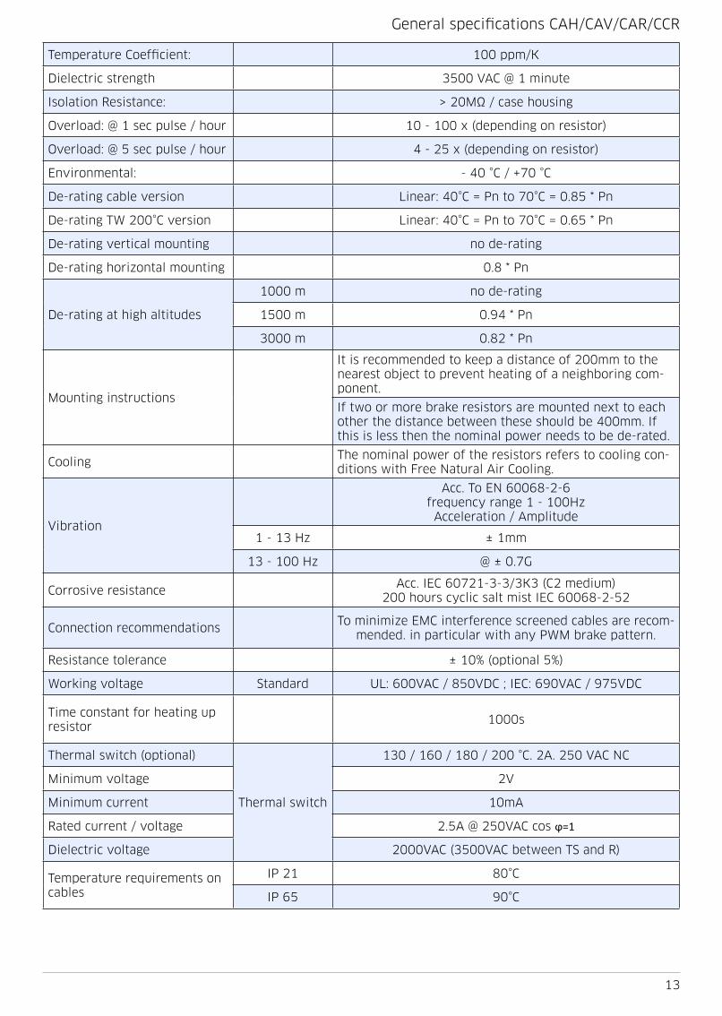
General specifications CAH/CAV/CAR/CCR
Temperature Coefficient: 100 ppm/K
Dielectric strength 3500 VAC @ 1 minute
Isolation Resistance: > 20MΩ / case housing
Overload: @ 1 sec pulse / hour 10 - 100 x (depending on resistor)
Overload: @ 5 sec pulse / hour 4 - 25 x (depending on resistor)
Environmental: - 40 °C / +70 °C
De-rating cable version Linear: 40°C = Pn to 70°C = 0 85 * Pn
De-rating TW 200°C version Linear: 40°C = Pn to 70°C = 0 65 * Pn
De-rating vertical mounting no de-rating
De-rating horizontal mounting 0 8 * Pn
De-rating at high altitudes
1000 m no de-rating
1500 m 0 94 * Pn
3000 m 0 82 * Pn
Mounting instructions
It is recommended to keep a distance of 200mm to the nearest object to prevent heating of a neighboring com-ponent
If two or more brake resistors are mounted next to each other the distance between these should be 400mm If this is less then the nominal power needs to be de-rated
CoolingThe nominal power of the resistors refers to cooling con-ditions with Free Natural Air Cooling
Vibration
Acc To EN 60068-2-6 frequency range 1 - 100Hz
Acceleration / Amplitude
1 - 13 Hz ± 1mm
13 - 100 Hz @ ± 0 7G
Corrosive resistanceAcc IEC 60721-3-3/3K3 (C2 medium)
200 hours cyclic salt mist IEC 60068-2-52
Connection recommendationsTo minimize EMC interference screened cables are recom-
mended in particular with any PWM brake pattern
Resistance tolerance ± 10% (optional 5%)
Working voltage Standard UL: 600VAC / 850VDC ; IEC: 690VAC / 975VDC
Time constant for heating up resistor
1000s
Thermal switch (optional)
Thermal switch
130 / 160 / 180 / 200 °C 2A 250 VAC NC
Minimum voltage 2V
Minimum current 10mA
Rated current / voltage 2 5A @ 250VAC cos φ=1
Dielectric voltage 2000VAC (3500VAC between TS and R)
Temperature requirements on cables
IP 21 80°C
IP 65 90°C

14
TypeL ± 2 mm
L1 ± 2 mm
Weight g
CCH 110 110 98 220
CCH 166 166 154 350
CCH 216 216 204 480
CCH 270 270 258 620
CCH 320 320 2x154 790
CCH 420 420 2x204 1050
CCH 520 520 2x241 5 1300
CCH 620 620 2x291 5 1550
TypeL ± 2 mm
L1 ± 2 mm
Weight g
CCH 145 CT 145 98 270
CCH 201 CT 201 154 410
CCH 251 CT 251 204 540
CCH 305 CT 305 258 620
CCH 355 CT 355 2x154 850
CCH 455 CT 455 2x204 1110
CCH 555 CT 555 2x241 5 1360
CCH 655 CT 655 2x291 5 1610
TypeL ± 2 mm
L1 ± 2 mm
Weight g
CCH 145 W(T) 145 98 270
CCH 201 W(T) 201 154 410
CCH 251 W(T) 251 204 540
CCH 305 W(T) 305 258 620
CCH 355 W(T) 355 2x154 850
CCH 455 W(T) 455 2x204 1110
CCH 555 W(T) 555 2x241 5 1360
CCH 655 W(T) 655 2x291 5 1610
TypeL ± 2 mm
L1 ± 2 mm
Weight g
CAH / CAV 120 C 120 102 160
CAH / CAV 150 C 150 132 185
CAH / CAV 165 C 165 147 220
CAH / CAV 210 C 210 192 315
CAH / CAV 240 C 240 222 370
CAH / CAV 300 C 300 282 460
CAH / CAV 360 C 360 342 550
with thermal switch (T)
CAH / CAV 145 CT 145 127 130
CAH / CAV 175 CT 175 157 160
CAH / CAV 190 CT 190 172 190
CAH / CAV 235 CT 235 217 280
CAH / CAV 265 CT 265 247 335
CAH / CAV 325 CT 325 307 425
CAH / CAV 385 CT 385 367 515
CCH cable connection IP54Mechanical drawings
CCH with thermal switch, cable connection IP54
CCH with thermal switch, cable connection IP65
CCH cable connection IP54

15
TypeL ± 2 mm
L1 ± 2 mm
Weight g
CAR 85 C 85 115 200
CAR 115 C 115 145 280
CAR 130 C 130 160 300
CAR 175 C 175 205 380
CAR 205 C 205 235 530
CAR 265 C 265 295 600
CAR 325 C 325 355 740
with thermal switch (T)
CAR 110 CT 110 140 155
CAR 140 CT 140 170 230
CAR 155 CT 155 185 250
CAR 200 CT 200 230 335
CAR 230 CT 230 260 470
CAR 290 CT 290 320 550
CAR 350 CT 350 380 685
TypeL ± 2 mm
L1 ± 2 mm
Weight g
CAR 115 K/-D 115 85 450/650
CAR 130 K/-D 130 100 470/700
CAR 175 K/-D 175 145 550/750
CAR 205 K/-D 205 175 700/900
CAR 265 K/-D 265 235 800/950
CAR 325 K/-D 325 195 900/1100
TypeL ± 2 mm
L1 ± 2 mm
Weight g
CAR 140 KT/-DT 140 110 510/720
CAR 155 KT/-DT 155 125 540/760
CAR 200 KT/-DT 200 170 610/810
CAR 230 KT/-DT 230 200 760/960
CAR 290 KT/-DT 290 260 860/1010
CAR 350 KT/-DT 350 320 970/1160
CAR box connection IP00/IP20/IP21
CAR cable connection IP54 Mechanical drawings
CAR with thermal switch, box connection IP00/IP20/IP21

16
TypeL ± 2 mm
L1 ± 2 mm
Weight g
CCR-V 116 C 116 - 0 85
CCR-V 172 C 172 72 1 15
CCR-V 222 C 222 122 1 35
CCR-V 276 C 276 176 1 65
CCR-V 326 C 326 226 1 95
CCR-V 426 C 426 326 2 45
CCR-V 526 C 526 426 2 95
CCR-V 626 C 626 526 3 45
TypeL ± 2 mm
L1 ± 2 mm
Weight g
CCR-V 145 CT 145 - 0 95
CCR-V 201 CT 201 91 1 25
CCR-V 251 CT 251 141 1 45
CCR-V 305 CT 305 195 1 75
CCR-V 355 CT 355 245 2 05
CCR-V 455 CT 455 345 2 55
CCR-V 555 CT 555 445 3 05
CCR-V 655 CT 655 545 3 55
TypeL ± 2 mm
L1 ± 2 mm
Weight g
CCR-V 145 DT 145 - 1 45
CCR-V 201 DT 201 91 1 75
CCR-V 251 DT 251 141 1 95
CCR-V 305 DT 305 195 2 25
CCR-V 355 DT 355 245 2 55
CCR-V 445 DT 455 345 3 05
CCR-V 555 DT 555 445 3 55
CCR-V 665 DT 655 545 4 05
TypeL ± 2 mm
L1 ± 2 mm
Weight g
CCR-V 145 BT 145 - 1 46
CCR-V 201 BT 201 91 1 76
CCR-V 251 BT 251 141 1 96
CCR-V 305 BT 305 195 2 26
CCR-V 355 BT 355 245 2 56
CCR-V 455 BT 455 345 3 06
CCR-V 555 BT 555 445 3 56
CCR-V 655 BT 655 545 4 06
CCR xxx C, cable connection IP54
CCR xxx CT, cable connection IP54with thermal switch
CCR-V xxx DT, box connection IP20/IP21with thermal switch
CCR-V xxx BT, box connection IP54with thermal switch
Mechanical drawings

17
Connection box
IP rating Cable gland
Clamping mm
Braidmm
Connection TS gland Clampingmm
Connectionmm2
D-box IP21 M25 9-16 6 7 5 0 75-10 M12 3-7 0 5-4
K-box IP00 - - - 0 75-10 - - 0 5-4
B-box* IP65 M25 9-16 6 7 5 0 75-10 M12 3-7 0 5-4
D-box B-box* K-box
CCH 110 C
CCR 355 CT
CAH 120 C CAR 175 C
Connection boxes (optional)
* Only for CCR type available

18
Ingress Protection
The Ingress Protection rating (IP) value depends on the resistor and on the connection sty-le The basic IP rating for resistors is IP50 but by the addition of gaskets, they can be in-creased to IP54 or IP65 which is also possible for resistors with flying leads For resistors with connection box type B, the maximal IP value is 65 Resistors with connection boxes D and G have an IP21 rating when mounted vertically and IP20 when mounted horizontally
IP values and their type-tests are well defined; for instance “IP65” means dust cannot pe-netrate the box or if dust occurs internally, it will not influence the electrical properties It should be able to withstand water jets from any direction with a certain pressure during 3 minutes; however, it does not mean that it can withstand continuous rain If the resistor is used outdoors, then it should be protected against direct rain
IP65 rated resistors can be cleaned with a high pressure hose, but this can only be done when the resistor has cooled down to the ambient temperature, otherwise the water will cool the housing causing a partial vacuum inside, drawing in water
Danotherm offers standard solutions for one to four cases combined into one compact configuration with pulse-withstand capability of 1MW (5MJ) and also OEM versions with a maximum of 20 resistors Depending on the electrical connection, the IP-class ranges from IP00 to IP65 Connections can be via a terminal box, DIN-rail terminals or cable lugs The-se resistor types are also offered in high voltage versions and with higher ohmic values
The salient features of Alpha resistors are that they have:
• Small dimensions
• Cool surfaces in operation
• High pulse load capabilities
• High vibration capabilities
• No external electrically-live parts
• High IP classes
• Intrinsically safe capabilities (on request)
• Low noise levels
Danotherm Electric A/S
is a NIBE company

19
CBH / CBV / CBR-H / CBR-V

20
TypePn W @
40°CTemp
max °CR [Ω]
min-max
Pulse load kW, Temp amb 40°C, cycle 120s
duty 1 second
duty 5 seconds
duty 10 seconds
duty 40 seconds
CBH / CBV 165 C 110 265 0 5 - 1000 5 1 4 0 9 0 3
CBH / CBV 215 C 155 270 0 8 - 1500 9 8 2 5 1 6 0 5
CBH / CBV 265 C 200 270 1 5 - 2000 16 6 4 0 2 4 0 6
CBH / CBV 335 C 270 280 1 8 - 2000 26 6 6 2 3 4 0 9
CBH / CBV 405 C 330 285 2 0 - 2000 34 1 8 5 4 3 1
CBR-V / H 175 C 311 265 0 8 - 1500 10 5 2 7 1 8 0 9
CBR-V / H 225 C 400 270 1 5 - 2000 18 3 4 5 2 8 1 2
CBR-V / H 295 C 525 275 1 8 - 2000 29 7 7 1 4 2 1 8
CBR-V / H 365 C 650 280 2 0 - 2000 38 4 11 3 6 7 2 4
CBR-V / H 426 C 980 285 2 4 - 2000 39 1 12 9 7 9 2 9
CBR-V / H 526 C 1220 295 3 0 - 2000 49 1 16 1 9 9 3 6
CBR-V / H 626 C 1460 305 3 5 - 2000 60 6 19 7 12 4 4
CBR-V / H 726 C 1700 310 4 0 - 2000 73 1 23 4 14 3 5 2
Construction and salient properties• UL approved
• Compact dimensions
• Nominal power range from 110W—1700W
• Energy levels from 9kJ-150kJ per case housing (5s duty,120s cycle), depending on ohmic value
• Aluminium case housing for high IP rating
• IP50-IP65
• Internal ceramic supported wirewound spirals for lower ohmic values
• Nickel-Chrome 8020 alloy for low thermal drift
• Mica insulated for high dielectric strength
• Al2O3 or SiO2 filled for high thermal capacity/high power overload capability
• Low surface temperature
• Low noise level
• High vibration withstand capability
• Thermal relief expansion mounting feet (CAR type)
• Optional thermal switch or PT100 element for thermal protection
• Cable 300mm (AWG 18—AWG10) with sleeves or box connection up to 10mm2
• Customized to your needs and application (OEM versions available)
CBR-V 225 KT
CBH / CBV / CBR Cable cable connection IP54

21
* Pulse ratings for short pulses depend on the ohm value Resistors with lower resistance value have more wire than resistors with higher resistance values The ratings in this table refer to resistors of about 40R
TypePn W @
40°CTemp
max °CR [Ω]
min-max
Pulse load kW*, Temp amb 40°C, cycle 120s
duty 1 second
duty 5 seconds
duty 10 seconds
duty 40 seconds
CBH / CBV 190 xT 85 210 0 5 - 1000 5 1 4 0 9 0 3
CBH / CBV 240 xT 120 215 0 8 - 1500 9 8 2 5 1 5 0 4
CBH / CBV 290 xT 150 220 1 5 - 2000 16 6 3 8 1 9 0 5
CBH / CBV 360 xT 200 225 1 8 - 2000 25 6 5 2 2 6 0 7
CBH / CBV 430 xT 250 230 2 0 - 2000 32 5 6 5 3 2 0 8
CBR-V / H 160 xT 160 210 0 5 - 1000 5 4 1 5 1 0 5
CBR-V / H 210 xT 230 210 0 8 - 1500 10 6 2 8 1 8 0 9
CBR-V / H 260 xT 300 225 1 5 - 2000 18 4 4 6 2 8 1 3
CBR-V / H 330 xT 390 230 1 8 - 2000 30 7 1 4 2 1 7
CBR-V / H 400 xT 490 230 2 0 - 2000 38 8 11 4 6 8 2 1
CBR-V / H 460 xT 740 240 2 4 - 2000 39 4 12 9 8 2 4
CBR-V / H 560 xT 920 250 3 0 - 2000 49 4 16 2 10 3 1
CBR-V / H 660 xT 1110 260 3 5 - 2000 60 6 19 7 12 1 3 8
CBR-V / H 760 xT 1290 260 4 0 - 2000 73 8 23 3 14 2 4 3
CBH / CBV / CBR Cable cable connection IP54, with thermal switch
TypePn W @
40°CTemp
max °CR [Ω]
min-max
Pulse load kW*, Temp amb 40°C, cycle 120s
duty 1 second
duty 5 seconds
duty 10 seconds
duty 40 seconds
CBRK 160 xT 180 210 0 5 - 1000 5 4 1 5 1 0 5
CBRK 210 xT 250 210 0 8 - 1500 10 6 2 8 1 8 0 9
CBRK 260 xT 330 225 1 5 - 2000 18 4 4 6 2 8 1 3
CBRK 330 xT 440 230 1 8 - 2000 30 7 1 4 2 1 7
CBRK 400 xT 540 230 2 0 - 2000 38 8 11 4 6 8 2 1
CBRK 460 xT 610 240 2 4 - 2000 39 4 12 9 8 2 4
CBRK 560 xT 780 250 3 0 - 2000 49 4 16 2 10 3 1
CBRK 660 xT 950 260 3 5 - 2000 60 6 19 7 12 1 3 8
CBRK 760 xT 1100 260 4 0 - 2000 73 8 23 3 14 2 4 3
CBRK 1000V, without thermal switch cable connection IP54
TypePn W @
40°CTemp
max °CR [Ω]
min-max
Pulse load kW*, Temp amb 40°C, cycle 120s
duty 1 second
duty 5 seconds
duty 10 seconds
duty 40 seconds
CBRK 125 C 135 210 0 5 - 1000 5 4 1 5 1 0 5
CBRK 175 C 210 210 0 8 - 1500 10 6 2 8 1 8 0 9
CBRK 225 C 280 225 1 5 - 2000 18 4 4 6 2 8 1 3
CBRK 295 C 400 230 1 8 - 2000 30 7 1 4 2 1 7
CBRK 365 C 500 230 2 0 - 2000 38 8 11 4 6 8 2 1
CBRK 426 C 650 240 2 4 - 2000 39 4 12 9 8 2 4
CBRK 526 C 800 250 3 0 - 2000 49 4 16 2 10 3 1
CBRK 626 C 1000 260 3 5 - 2000 60 6 19 7 12 1 3 8
CBRK 726 C 1200 260 4 0 - 2000 73 8 23 3 14 2 4 3
CBRK 1000V, with thermal switch cable or box connection

22
General specifications
Temperature Coefficient: 100 ppm/K
Dielectric strength 3500 VAC @ 1 minute
Isolation Resistance: > 20MΩ / case housing
Overload: @ 1 sec pulse / hour 10 - 100 x (depending on resistor)
Overload: @ 5 sec pulse / hour 4 - 25 x (depending on resistor)
Environmental: - 40 °C / +70 °C
De-rating cable version Linear: 40°C = Pn to 70°C = 0 85 * Pn
De-rating TW 200°C version Linear: 40°C = Pn to 70°C = 0 65 * Pn
De-rating vertical mounting no de-rating
De-rating horizontal mounting 0 8 * Pn
De-rating at high altitudes
1000 m no de-rating
1500 m 0 94 * Pn
3000 m 0 82 * Pn
Mounting instructions
It is recommended to keep a distance of 200mm to the nearest object to prevent heating of a neighboring com-ponent
If two or more brake resistors are mounted next to each other the distance between these should be 400mm If this is less then the nominal power needs to be de-rated
CoolingThe nominal power of the resistors refers to cooling con-ditions with Free Natural Air Cooling
Vibration
Acc To EN 60068-2-6 frequency range 1 - 100Hz
Acceleration / Amplitude
1 - 13 Hz ± 1mm
13 - 100 Hz @ ± 0 7G
Corrosive resistanceAcc IEC 60721-3-3/3K3 (C2 medium)
200 hours cyclic salt mist IEC 60068-2-52
Connection recommendationsTo minimize EMC interference screened cables are recom-
mended in particular with any PWM brake pattern
Resistance tolerance ± 10% (optional 5%)
Working voltageStandard UL: 600VAC / 850VDC ; IEC: 690VAC / 975VDC
On request 1000VAC / 1400VDC
Time constant for heating up resistor
1000s
Thermal switch (optional)
Thermal switch
130 / 160 / 180 / 200 °C 2A 250 VAC NC
Minimum voltage 2V
Minimum current 10mA
Rated current / voltage 2 5A @ 250VAC cos φ=1
Dielectric voltage 2000VAC (3500VAC between TS and R)
Temperature requirements on cables
IP 21 80°C
IP 65 90°C

23
Connection box
IP rating Cable gland
Clamping mm
Braidmm
Connectionmm2
TS gland Clampingmm
Connectionmm2
B-box IP65 M25 9-16 6 7 5 0 75-10 M12 3-7 0 5-4
D-box IP21 M25 9-16 6 7 5 0 75-10 M12 3-7 0 5-4
K-box IP00 - - - 0 75-10 - - 0 5-4*
D-box B-box K-box
Connection boxes (optional)*Thermal switch with
K-box optional
TypeL ± 2 mm
L1 ± 2 mm
Weight g
CBH / CBV 165 C 165 146 0 39
CBH / CBV 215 C 215 196 0 63
CBH / CBV 265 C 265 246 0 88
CBH / CBV 335 C 335 316 1 2
CBH / CBV 405 C 405 386 1 5
CBH / CBV with cable connection IP 54
TypeL ± 2 mm
L1 ± 2 mm
Weight g
CBH/CBV 190 CT 190 171 0 5
CBH/CBV 240 CT 240 221 0 71
CBH/CBV 290 CT 290 271 0 97
CBH/CBV 360 CT 360 341 1 3
CBH/CBV 430 CT 430 411 1 6
CBH / CBV with cable connection IP 54with thermal switch

24
CBR-H C cable connection IP54Mechanical drawings
TypeL ± 2 mm
L1 ± 2 mm
Weight g
CBR-V/CBR-H 175 C 001 175 75 1 5
CBR-V/CBR-H 225 C 001 225 125 1 8
CBR-V/CBR-H 295 C 001 295 195 2 3
CBR-V/CBR-H 365 C 001 365 265 2 8
CBR-V/CBR-H 426 C 001 426 326 3 2
CBR-V/CBR-H 526 C 001 526 426 3 8
CBR-V/CBR-H 626 C 001 626 526 4 5
CBR-V/CBR-H 726 C 001 726 626 5 2
TypeL ± 2 mm
L1 ± 2 mm
Weight g
CBR-H/CBR-V 160 CT 081 160 70 1 5
CBR-H/CBR-V 210 CT 081 210 110 1 8
CBR-H/CBR-V 260 CT 081 260 160 2 1
CBR-H/CBR-V 330 CT 081 330 230 2 6
CBR-H/CBR-V 400 CT 081 400 300 3 1
CBR-H/CBR-V 460 CT 081 460 360 3 5
CBR-H/CBR-V 560 CT 081 560 460 4 1
CBR-H/CBR-V 660 CT 081 660 560 4 8
CBR-H/CBR-V 760 CT 081 760 660 5 5
TypeL ± 2 mm
L1 ± 2 mm
Weight g
CBR-V 160 B T 281 160 70 1 3
CBR-V 210 B T 281 210 110 1 8
CBR-V 260 B T 281 260 160 2 4
CBR-V 330 B T 281 330 230 3 0
CBR-V 400 B T 281 400 300 3 5
CBR-V 460 B T 281 460 360 3 9
CBR-V 560 B T 281 560 460 4 6
CBR-V 660 B T 281 660 560 5 4
CBR-V 760 B T 281 760 660 6 1
CBR-V CT cable connection IP 54with thermal switch
CBR-V BT box connection IP 54with thermal switch

25
TypeL ± 2 mm
L1 ± 2 mm
Weight g
CBR-H/CBR-V 160 WX 081 160 70 1 5
CBR-H/CBR-V 210 WX 081 210 110 1 8
CBR-H/CBR-V 260 WX 081 260 160 2 1
CBR-H/CBR-V 330 WX 081 330 230 2 6
CBR-H/CBR-V 400 WX 081 400 300 3 1
CBR-H/CBR-V 460 WX 081 460 360 3 5
CBR-H/CBR-V 560 WX 081 560 460 4 1
CBR-H/CBR-V 660 WX 081 660 560 4 8
CBR-H/CBR-V 760 WX 081 760 660 5 5
CBR-V W cable connection IP65 with or without thermal switch
TypeL ± 2 mm
L1 ± 2 mm
Weight g
CBR-V 160 D T 281 160 70 1 3
CBR-V 210 D T 281 210 110 1 8
CBR-V 260 D T 281 260 160 2 4
CBR-V 330 D T 281 330 230 3 0
CBR-V 400 D T 281 400 300 3 5
CBR-V 460 D T 281 460 360 3 9
CBR-V 560 D T 281 560 460 4 6
CBR-V 660 D T 281 660 560 5 4
CBR-V 760 D T 281 760 660 6 1
CBR-V DT box connection IP 20/IP21with thermal switch
TypeL ± 2 mm
L1 ± 2 mm
Weight g
CBR-V 175 K 201 175 75 1 3
CBR-V 225 K 201 225 125 1 8
CBR-V 295 K 201 295 195 2 4
CBR-V 365 K 201 365 265 3 0
CBR-V 426 K 201 426 326 3 5
CBR-V 526 K 201 526 426 3 9
CBR-V 626 K 201 626 526 4 6
CBR-V 726 K 201 726 626 5 4
CBR-V KT box connection IP 00

26
Danotherm has developed a thermal simulation method by which it is possible to optimize a resistor to a specified application This gives following benefits:
• Short and fast engineering time, saving engineering costs
• Individual thermic model simulations can be done by Danotherm or handled by the customer Individual thermic models are available on request
• Simulation software for electrical circuits can be used for thermal simulations (PSpice, Matlab, Plecs or any other)
• For more complex loads a data file (like csv) can be used for input
• Optimizing the design, reducing overall size and costs
• Proof of capability is given without even building and testing samples
Measured on site: Brake Power saved in cvs file
Other possibilities could be a description of a ty-pical or worst case brake pulse and a repeat cycle
Simulation made by Danotherm
Results of temperature simulation of specified load in a suggested resistor type

27
CBT-H / CBT-V

28
# Housings Nominal power [W] @ 40°C according UL0508
Single housing 2 housings 3 housings 4 housingsSingle housing
no thermal switch thermal switch no thermal switch
Length / Type CBT * CBT CBT * CBT CBT CBT CBTR [Ω]
min-max
CBT 180 380 455 380 380 0 04 - 13
CBT 210 520 585 520 520 0 05 - 2000
CBT 260 760 850 750 750 0 07 - 2000
CBT 330 1100 1350 1100 1100 0 09 - 2000
CBT 400 1440 1650 1440 1440 1920 2610 3490 0 11 - 2000
CBT 460 1730 1900 1725 1725 2540 3810 5080 0 14 - 2000
CBT 560 2310 2095 3170 4710 6250 0 18 - 110
CBT 660 2720 2470 3810 5720 7620 0 22 - 130
CBT 760 3200 2905 4530 6530 8710 0 27 - 150
CBT 860 3640 3305 4990 7260 9800 0 31– 180
CBT 960 4070 3695 6260 8170 10890 0 35 - 220
* CBT for high Ohm valuesSee nomenclature page 64
Construction and salient properties• Compact dimensions• Nominal power range from 380W—4070W• Energy levels from 25kJ-550kJ per case housing
(5s duty,120s cycle), depending on ohmic value• Aluminium case housing for high IP rating • IP50-IP65• Internal ceramic supported wirewound spirals for
lower ohmic values• Internal mica supported wirewound elements for
higher ohmic values• Nickel-Chrome 8020 alloy for low thermal drift• Mica insulated for high dielectric strength
• Al2O3 or SiO2 filled for high thermal capacity/high power overload capability
• Low surface temperature• Low noise level• High vibration withstand capability• Thermal relief expansion mounting feet• Optional thermal switch or PT100 element for
thermal protection• Cable 300mm (AWG 14—AWG4) with cable slee-
ves or box connection up to 50mm2• Multiple case housings (from 2-4 housings)• Customized to your needs and application (OEM
versions available)• For UL approval, consult Danotherm

29
Temperature Coefficient: 100 ppm/K
Dielectric strength 3500 VAC @ 1 minute
Isolation Resistance: > 20MΩ / case housing
Overload: @ 1 sec pulse / hour 10 - 100 x (depending on resistor)
Overload: @ 5 sec pulse / hour 4 - 25 x (depending on resistor)
Environmental: - 40 °C / +70 °C
De-rating cable version Linear: 40°C = Pn to 70°C = 0 85 * Pn
De-rating TW 200°C version Linear: 40°C = Pn to 70°C = 0 65 * Pn
De-rating vertical mounting no de-rating
De-rating horizontal mounting 0 8 * Pn
De-rating at high altitudes
1000 m no de-rating
1500 m 0 94 * Pn
3000 m 0 82 * Pn
Mounting instructions
It is recommended to keep a distance of 200mm to the nearest object to prevent heating of a neighboring component
If two or more brake resistors are mounted next to each other the distance between these should be 400mm If this is less then the nominal power needs to be de-rated
CoolingThe nominal power of the resistors refers to cooling conditions with Free Natural Air Cooling
Vibration
Acc To EN 60068-2-6 frequency range 1 - 100Hz
Acceleration / Amplitude
1 - 13 Hz ± 1mm
13 - 100 Hz @ ± 0 7G
Corrosive resistanceAcc IEC 60721-3-3/3K3 (C2 medium)
200 hours cyclic salt mist IEC 60068-2-52
Connection recommendationsTo minimize EMC interference screened cables are recommen-
ded in particular with any PWM brake pattern
Resistance tolerance ± 10% (optional 5%)
Working voltageStandard UL: 600VAC / 850VDC ; IEC: 690VAC / 975VDC
On request 1000VAC / 1400VDC
Time constant for heating up resistor
1000s
Thermal switch (optional)
Thermal switch
130 / 160 / 180 / 200 °C 2A 250 VAC NC
Minimum voltage 2V
Minimum current 10mA
Rated current / voltage 2 5A @ 250VAC cos φ=1
Dielectric voltage 2000VAC (3500VAC between TS and R)
Temperature requirements on cables
IP 21 80°C
IP 65 90°C

30
TypeL ± 2 mm
L1 ± 2 mm
Weight g
CBT-H 180 C(H/E)(T) 0X1 180 70 3 1
CBT-H 210 C(H/E)(T) 0X1 210 110 3 6
CBT-H 260 C(H/E)(T) 0X1 260 160 4 5
CBT-H 330 C(H/E)(T) 0X1 330 230 5 9
CBT-H 400 C(H/E)(T) 0X1 400 300 7 3
CBT-H 460 C(H/E)(T) 0X1 460 360 8 5
CBT-H 560 C(H/E)(T) 0X1 560 460 10
CBT-H 660 C(H/E)(T) 0X1 660 560 12
CBT-H 760 C(H/E)(T) 0X1 760 660 13 8
CBT-H 860 C(H/E)(T) 0X1 860 760 16
CBT-H 960 C(H/E)(T) 0X1 960 860 17 8
TypeL ± 2 mm
L1 ± 2 mm
Weight g
CBT-V 180 C(H/E)(T) 0X1 180 70 3 1
CBT-V 210 C(H/E)(T) 0X1 210 110 3 6
CBT-V 260 C(H/E)(T) 0X1 260 160 4 5
CBT-V 330 C(H/E)(T) 0X1 330 230 5 9
CBT-V 400 C(H/E)(T) 0X1 400 300 7 3
CBT-V 460 C(H/E)(T) 0X1 460 360 8 5
CBT-V 560 C(H/E)(T) 0X1 560 460 10
CBT-V 660 C(H/E)(T) 0X1 660 560 12
CBT-V 760 C(H/E)(T) 0X1 760 660 13 8
CBT-V 860 C(H/E)(T) 0X1 860 760 16
CBT-V 960 C(H/E)(T) 0X1 960 860 17 8
TypeL ± 2 mm
L1 ± 2 mm
Weight g
CBT-H 180 D(H/E)(T) 2X1 180 70 3 9
CBT-H 210 D(H/E)(T) 2X1 210 110 4 2
CBT-H 260 D(H/E)(T) 2X1 260 160 5 1
CBT-H 330 D(H/E)(T) 2X1 330 230 6 7
CBT-H 400 D(H/E)(T) 2X1 400 300 8 2
CBT-H 460 D(H/E)(T) 2X1 460 360 9 2
CBT-H 560 D(H/E)(T) 2X1 560 460 11
CBT-H 660 D(H/E)(T) 2X1 660 560 12 8
CBT-H 760 D(H/E)(T) 2X1 760 660 14 6
CBT-H 860 D(H/E)(T) 2X1 860 760 16 8
CBT-H 960 D(H/E)(T) 2X1 960 860 18 6
CBT-V CT cable connection IP50with and without thermal switch
CBT-H CT cable connection IP50with and without thermal switch
CBT-H D box connection IP54with thermal switch
Mechanical drawings

31
TypeL ± 2 mm
L1 ± 2 mm
Weight g
CBT-H 180 G(H/E)(T) 2X1 180 70 3 9
CBT-H 210 G(H/E)(T) 2X1 210 110 4 2
CBT-H 260 G(H/E)(T) 2X1 260 160 5 1
CBT-H 330 G(H/E)(T) 2X1 330 230 6 7
CBT-H 400 G(H/E)(T) 2X1 400 300 8 2
CBT-H 460 G(H/E)(T) 2X1 460 360 9 2
CBT-H 560 G(H/E)(T) 2X1 560 460 11
CBT-H 660 G(H/E)(T) 2X1 660 560 12 8
CBT-H 760 G(H/E)(T) 2X1 760 660 14 6
CBT-H 860 G(H/E)(T) 2X1 860 760 16 8
CBT-H 960 G(H/E)(T) 2X1 960 860 18 6
TypeL ± 2 mm
L1 ± 2 mm
Weight g
CBT-V 400 G(H/E)(T) 2X2 400 370 18
CBT-V 460 G(H/E)(T) 2X2 460 430 20 5
CBT-V 560 G(H/E)(T) 2X2 560 530 23 5
CBT-V 660 G(H/E)(T) 2X2 660 630 27
CBT-V 760 G(H/E)(T) 2X2 760 730 30 5
CBT-V 860 G(H/E)(T) 2X2 860 830 34 0
CBT-V 960 G(H/E)(T) 2X2 960 930 37 5
TypeL ± 2 mm
L1 ± 2 mm
Weight g
CBT-V 400 G(H/E)(T) 2X3 400 370 25 5
CBT-V 460 G(H/E)(T) 2X3 460 430 29
CBT-V 560 G(H/E)(T) 2X3 560 530 33 5
CBT-V 660 G(H/E)(T) 2X3 660 630 39
CBT-V 760 G(H/E)(T) 2X3 760 730 44 5
CBT-V 860 G(H/E)(T) 2X3 860 830 51
CBT-V 960 G(H/E)(T) 2X3 960 930 57
CBT-V G box connection IP20/IP21with thermal switch
CBT-V G box connection IP20/IP21with thermal switch
CBT-H G box connection IP20/IP21with thermal switch

32
TypeL ± 2 mm
L1 ± 2 mm
Weight g
CBT-H 180 B(H)(T) 2X1 180 70 3 9
CBT-H 210 B(H)(T) 2X1 210 110 4 2
CBT-H 260 B(H)(T) 2X1 260 160 5 1
CBT-H 330 B(H)(T) 2X1 330 230 6 7
CBT-H 400 B(H)(T) 2X1 400 300 8 2
CBT-H 460 B(H)(T) 2X1 460 360 9 2
CBT-H 560 B(H)(T) 2X1 560 460 11 0
CBT-H 660 B(H)(T) 2X1 660 560 12 8
CBT-H 760 B(H)(T) 2X1 760 660 14 6
CBT-H 860 B(H)(T) 2X1 860 760 16 8
CBT-H 960 B(H)(T) 2X1 960 860 18 6
TypeL ± 2 mm
L1 ± 2 mm
Weight g
CBT-V 400 B(H)(T) 2X2 400 370 18 0
CBT-V 460 B(H)(T) 2X2 460 430 20 5
CBT-V 560 B(H)(T) 2X2 560 530 23 5
CBT-V 660 B(H)(T) 2X2 660 630 27 0
CBT-V 760 B(H)(T) 2X2 760 730 30 5
CBT-V 860 B(H)(T) 2X2 860 830 35 5
CBT-V 960 B(H)(T) 2X2 960 930 39 0
TypeL ± 2 mm
L1 ± 2 mm
Weight g
CBT-V 400 B(H/E(T) 2X3 400 370 25 5
CBT-V 460 B(H/E)(T) 2X3 460 430 29 0
CBT-V 560 B(H/E)(T) 2X3 560 530 33 5
CBT-V 660 B(H/E)(T) 2X3 660 630 39 0
CBT-V 760 B(H/E)(T) 2X3 760 730 44 5
CBT-V 860 B(H/E)(T) 2X3 860 830 51 0
CBT-V 960 B(H/E)(T) 2X3 960 930 57 0
CBT-V B 2 2 cable connection IP65with thermal switch
CBT-H B 2 1 cable connection IP65with thermal switch
CBT-V B 2 3 box connection IP65with thermal switch
Mechanical drawings

TypeL ± 2 mm
L1 ± 2 mm
Weight g
CBT-V 400 B(H/E)(T) 2X4 400 370 25 5
CBT-V 460 B(H/E)(T) 2X4 460 430 29 0
CBT-V 560 B(H/E)(T) 2X4 560 530 33 5
CBT-V 660 B(H/E)(T) 2X4 660 630 39 0
CBT-V 760 B(H/E)(T) 2X4 760 730 44 5
CBT-V 860 B(H/E)(T) 2X4 860 830 51 0
CBT-V 960 B(H/E)(T) 2X4 960 930 57 0
CBT-V B box connection IP65with thermal switch
Connection box IP rating Cable gland
Clamping mm
Braidmm
Connectionmm2
TS gland
Clampingmm
Connectionmm2
B-box single IP65 M25 9-16 6 7 5 1 5-50 M12 3-7 0 5-4
B-box multiple IP65 M40 19-28 15 1 5-50 M12 3-7 0 5-4
D-box IP21 M25 9-16 6 7 5 0 75-10 M12 3-7 0 5-4
G-box IP21 M40 19-28 15 1 5-50 M12 3-7 0 5-4
K-type IP00 - - - 0 75-10 - - -
D-box G-box
B-box B-box multiple housings

34
Type Square pulse each 120seconds, ambient temperature 40°C
duty 1 second
kW
Max temp
°C
duty 5 seconds
kW
Max temp
°C
duty 10 seconds
kW
Max temp
°C
duty 20 seconds
kW
Max temp
°C
duty 40 seconds
kW
Max temp
°C
CBT-H 180 15R 18 4 110 5 1 140 3 160 1 9 180 1 1 220
CBT-H 210 100R 24 7 110 6 1 130 3 8 150 2 5 190 1 7 240
CBT-H 260 60R 44 130 10 7 150 6 4 180 4 210 2 7 270
CBT-H 330 40R 71 140 22 190 13 220 8 260 4 3 280
CBT-H 400 30R 105 160 30 210 18 250 10 7 290 5 4 280
CBT-H 460 20R 128 170 36 220 21 250 12 290 6 2 290
CBT-H 560 15R 190 200 50 250 28 280 15 300 7 6 300
CBT-H 660 14R 257 230 64 270 36 300 18 300 9 2 310
CBT-H 760 12R 315 240 78 290 43 310 21 5 310 10 7 310
CBT-H 860 10R 370 250 89 300 50 320 25 320 12 4 320
CBT-H 960 9R0 480 290 110 330 56 330 28 330 14 330
Type Triangular pulse each 120seconds, ambient temperature 40°C
duty 1 second
kW
Max temp
°C
duty 5 seconds
kW
Max temp
°C
duty 10 seconds
kW
Max temp
°C
duty 20 seconds
kW
Max temp
°C
duty 40 seconds
kW
Max temp
°C
CBT-H 180 15R 39 110 10 7 140 6 3 160 3 8 190 2 3 220
CBT-H 210 100R 50 110 12 7 130 7 7 150 4 9 180 3 2 230
CBT-H 260 60R 90 140 22 160 13 180 8 210 5 250
CBT-H 330 40R 148 140 46 200 27 230 16 260 8 5 280
CBT-H 400 30R 217 160 63 220 37 250 21 280 10 6 280
CBT-H 460 20R 265 170 74 230 44 260 25 290 12 3 290
CBT-H 560 15R 390 200 103 260 58 290 30 300 15 300
CBT-H 660 14R 530 230 134 280 73 310 37 310 18 310
CBT-H 760 12R 645 240 160 290 86 310 43 310 22 310
CBT-H 860 10R 578 260 183 300 98 320 50 320 25 320
CBT-H 960 9R0 983 290 226 330 113 330 57 330 28 330
The table above shows pulse power ratings for typical resistor sizes/lengths and typical Ohm values
Pulse loadThe ability to withstand pulse-loads varies according to resistor size, length and diameter of the internal resistor wire As such, it is impossible to create standard graphs that would apply to all customer appli-cations In some cases, the load-profile will be the combination of a square and a triangular pulse, such as is the case with Low Voltage Ride Through (LVRT) and Emergency Brake situations, as encountered in the Wind Power industry On request, Danotherm performs simulations based on the actual application and for guidance, has pro-duced tables for various load-profiles for resistors with standard wire The above table shown is based on a resistor with indicated ohm value and standard wire thickness Depending on the application, resistor construction can be adapted to optimally match the application In the tables above, the peak powers of trains of rectangular and triangular pulses of 120 second periods are shown for durations of 1 to 40 seconds

35
CBS / CMQ / CVS / HVBS / HVS

36
Nominal power [W] @ 40°C
Housing length
Single housingwithout thermal switch
cable version
Single housingwith thermal switchand/or box version
Ohm range R [Ω]min-max
CBS* CBS CMQ CVS CBS CMQ CVS CBS CMQ CVS
210 450 580 800 - 445 555 - 0 05-20 0 07-35 -
260 610 850 1100 - 610 855 - 0 07-35 0 07-50 -
330 840 1135 1500 - 840 1090 - 0 09-50 0 07-80 -
400 1060 1375 1900 1995 1055 1320 1390 0 11-65 0 10-110 0 10-12
460 1260 1585 2200 2310 1215 1520 1600 0 14-85 0 12-130 0 12-14
560 1925 2700 2830 1480 1850 1940 0 18-110 0 15-160 0 15-20
660 2270 3100 3250 1745 2180 2290 0 22-130 0 19-200 0 19-24
760 2770 3500 3670 2130 2660 2790 0 27-150 0 23-240 0 23-28
860 3190 3850 4040 2450 3060 3210 0 31-180 0 27-280 0 27-32
960 3565 4150 4350 2740 3420 3590 0 35-220 0 30-320 0 30-36
Housing length
Double housing Triple housing Quadruple housing
without thermal switch, cable version
CBS* CBS CMQ CVS CBS CMQ CVS CBS CMQ CVS
400 2340 2970 3070 2850 4350 4560 3800 5500 5830
460 2700 3370 3540 3400 5000 5250 4600 6500 6820
560 3270 4090 4290 4750 6050 6350 6300 8000 8400
660 3860 4820 5050 5400 7100 7450 7200 9100 9550
760 4700 5870 6160 6700 8500 8900 9000 11000 11500
860 5400 6750 7080 7660 10000 10500 10200 13000 13650
960 6060 7570 7950 8500 11200 11750 11300 14000 14700
TypePn [W] @
40°C
Ohm range R [Ω]
min-max
Double housing
Triple hou-sing
Quadruple housing
HVBS 300 850 0 05 - 30 1500
HVBS 370 1050 0 07 - 50 1800
HVBS 440 1250 0 09 - 70 2100 2900 3500
HVBS 520 1365 0 10 - 90 2500 3700 5000
HVBS 620 1950 0 13 - 110 3200 4800 6400
HVBS 720 2500 0 15 - 140 3600 5400 7200
HVBS 820 2900 0 19 - 170 4800 7100 9600
HVBS 920 3200 0 22 - 200 5300 7900 10600
HVBS 1000 3500 0 25 - 220 6000 8800 12000
Housing length
Double housing Triple housing Quadruple housing
with thermal switch and/or connection box
CBS* CBS CMQ CVS CBS CMQ CVS CBS CMQ CVS
400 1790 1630 1710 2180 2390 2530 2910 3020 4430
460 2060 1980 1960 2600 2940 3000 3520 3820 5180
560 2510 2310 2450 3650 3420 4060 4840 4530 6380
660 2960 2680 3230 4150 3940 4470 5530 5050 7250
760 3610 3350 3690 5150 4850 5590 6920 6280 8740
860 4140 3790 4450 5880 5620 6580 7830 7310 10370
960 4650 4340 4960 6530 6420 7310 8680 8030 11170
*High Ohm values

37
Temperature Coefficient: 100 ppm/K
Dielectric strength HVBS 7000 VAC @ 1 minute
HVS 10000 VAC @ 1 minute
other types 3500 VAC @ 1 minute
Insulation Resistance: > 20MΩ / case housing
Overload: @ 1 sec pulse / hour 70 - 250 x (depending on resistor)
Overload: @ 5 sec pulse / hour 20 - 60 x (depending on resistor)
Environmental: - 40 °C / +70 °C
De-rating cable version Linear: 40°C = Pn to 70°C = 0 85 * Pn
De-rating TW 200°C version Linear: 40°C = Pn to 70°C = 0 65 * Pn
De-rating vertical mounting no de-rating
De-rating horizontal mounting 0 8 * Pn
De-rating at high altitudes
1000 m no de-rating
1500 m 0 94 * Pn
3000 m 0 82 * Pn
Mounting instructions
It is recommended to keep a distance of 200mm to the ne-arest object to prevent heating of a neighboring component
If two or more brake resistors are mounted next to each other the distance between these should be 400mm If this is less then the nominal power needs to be de-rated
CoolingThe nominal power of the resistors refers to cooling condi-tions with Free Natural Air Cooling
Vibration
Acc To EN 60068-2-6 frequency range 1 - 100Hz
Acceleration / Amplitude
1 - 13 Hz ± 1mm
13 - 100 Hz @ ± 0 7G
Corrosive resistanceAcc IEC 60721-3-3/3K3 (C2 medium)
200 hours cyclic salt mist IEC 60068-2-52
Connection recommendationsTo minimize EMC interference screened cables are recommen-
ded in particular with any PWM brake pattern
Resistance tolerance ± 10% (optional 5%)
Working voltage
box version UL: 600VAC / 850VDC ; IEC: 690VAC / 975VDC
cable version 1000VAC / 1400VDC
HVBS cable version IEC: 3000VAC / 4200VDC
HVS cable and box IEC: 3000VAC / 4200VDC
Time constant for heating up resistor
1000-3000s
Thermal switch (optional*)
Thermal switch
130 / 160 / 180 / 200 °C 2A 250 VAC NC
Minimum voltage 2V
Minimum current 10mA
Rated current / voltage 2 5A @ 250VAC cos φ=1
Dielectric voltage 2000VAC (3500VAC between TS and R)
Temperature requirements on cables
IP 21 80°C
IP 65 90°C
*Optional for CBS / CMQ and CVS

38
Construction and salient properties• Compact dimensions
• Nominal power range from 455W—4070W
• Energy levels from 80kJ-2 5MJ per case housing (5s single pulse), depending on ohmic value
• Aluminium case housing for high IP rating
• IP50-IP65
• Internal ceramic supported wirewound spirals for lower ohmic values
• Nickel-Chrome 8020 alloy for low thermal drift
• Mica insulated for high dielectric strength
• Al2O3 or SiO2 filled for high thermal capacity/high power overload capability
• Low surface temperature
• Low noise level
• High vibration withstand capability
• Thermal relief expansion mounting feet
• Optionally thermal switch or PT100 element for thermal protection guard
• Cable 300mm (AWG 10—AWG4) with sleeves or box connection up to 50mm2
• Multiple case housings (from 2-4 housings)
• Customized to your needs and application (OEM versions available)
Connection box IP rating Cable gland
Clamping mm
Braidmm
Connectionmm2
TS gland Clampingmm
Connectionmm2
B-box single IP56 M25 9-16 6 7 5 0 75-10 M12 3-7 0 5-4
B-box multiple IP56 M40 19-28 15 1 5-50 M12 3-7 0 5-4
K-type IP00 - - - 0 75-10 - - 0 5-4*
B-box multiple housingsB-box single housings
CVS-V 560 KH 003 xxR
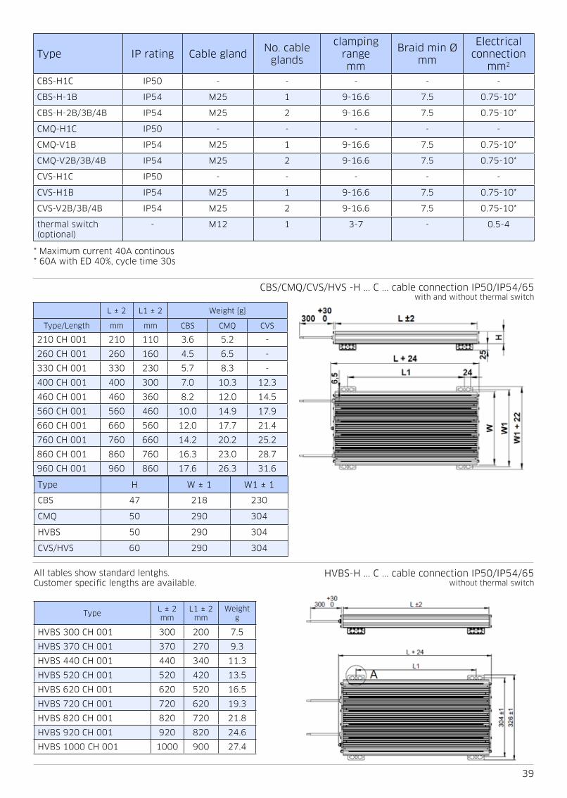
39
L ± 2 L1 ± 2 Weight [g]
Type/Length mm mm CBS CMQ CVS
210 CH 001 210 110 3 6 5 2 -
260 CH 001 260 160 4 5 6 5 -
330 CH 001 330 230 5 7 8 3 -
400 CH 001 400 300 7 0 10 3 12 3
460 CH 001 460 360 8 2 12 0 14 5
560 CH 001 560 460 10 0 14 9 17 9
660 CH 001 660 560 12 0 17 7 21 4
760 CH 001 760 660 14 2 20 2 25 2
860 CH 001 860 760 16 3 23 0 28 7
960 CH 001 960 860 17 6 26 3 31 6
Type H W ± 1 W1 ± 1
CBS 47 218 230
CMQ 50 290 304
HVBS 50 290 304
CVS/HVS 60 290 304
TypeL ± 2 mm
L1 ± 2 mm
Weight g
HVBS 300 CH 001 300 200 7 5
HVBS 370 CH 001 370 270 9 3
HVBS 440 CH 001 440 340 11 3
HVBS 520 CH 001 520 420 13 5
HVBS 620 CH 001 620 520 16 5
HVBS 720 CH 001 720 620 19 3
HVBS 820 CH 001 820 720 21 8
HVBS 920 CH 001 920 820 24 6
HVBS 1000 CH 001 1000 900 27 4
CBS/CMQ/CVS/HVS -H C cable connection IP50/IP54/65with and without thermal switch
HVBS-H C cable connection IP50/IP54/65without thermal switch
Type IP rating Cable glandNo cable
glands
clamping rangemm
Braid min Ømm
Electrical connection
mm2
CBS-H1C IP50 - - - - -
CBS-H-1B IP54 M25 1 9-16 6 7 5 0 75-10*
CBS-H-2B/3B/4B IP54 M25 2 9-16 6 7 5 0 75-10*
CMQ-H1C IP50 - - - - -
CMQ-V1B IP54 M25 1 9-16 6 7 5 0 75-10*
CMQ-V2B/3B/4B IP54 M25 2 9-16 6 7 5 0 75-10*
CVS-H1C IP50 - - - - -
CVS-H1B IP54 M25 1 9-16 6 7 5 0 75-10*
CVS-V2B/3B/4B IP54 M25 2 9-16 6 7 5 0 75-10*
thermal switch (optional)
- M12 1 3-7 - 0 5-4
* Maximum current 40A continous* 60A with ED 40%, cycle time 30s
All tables show standard lentghs Customer specific lengths are available

40
TypeL ± 2 mm
L1 ± 2 mm
Weight g
CBS-V 400 BGH 2x2 400 365 16 0
CBS-V 460 BGH 2x2 460 425 18 4
CBS-V 560 BGH 2x2 560 525 22 0
CBS-V 660 BGH 2x2 660 625 26 0
CBS-V 760 BGH 2x2 760 725 30 4
CBS-V 860 BGH 2x2 860 825 34 6
CBS-V 960 BGH 2x2 960 925 37 2
TypeL ± 2 mm
L1 ± 2 mm
Weight g
CBS-V 400 C(H/E) 0x3 400 365 22 0
CBS-V 460 C(H/E) 0x3 460 425 25 6
CBS-V 560 C(H/E) 0x3 560 525 31 0
CBS-V 660 C(H/E) 0x3 660 625 37 0
CBS-V 760 C(H/E) 0x3 760 725 43 6
CBS-V 860 C(H/E) 0x3 860 825 50
CBS-V 960 C(H/E) 0x3 960 925 54
CBS-V B 2 2 box connection IP54with and without thermal switch
CBS-V B 2 3 cable connection IP50/IP54with and without thermal switch
TypeNo
hou-sings
L ± 2 mm
Hmm
Weight g
CBS-H 420 KH 201 1 420 160 13 0
CBS-H 520 KH 201 1 520 160 13 5
CBS-H 420 KH 202 2 420 160 20 5
CBS-H 520 KH 202 2 520 160 22 5
CBS-H 420 KH 203 3 420 300 32 5
CBS-H 520 KH 203 3 520 300 34 5
CBS-H 420 KH 204 4 420 300 40 5
CBS-H 520 KH 204 4 520 300 42 5
CBS-H K 2 box connection IP00with and without thermal switch

41
TypeL ± 2 mm
L1 ± 2 mm
Weight g
CMQ-V 400 KH 2x3 400 365 22 0
CMQ-V 460 KH 2x3 460 425 25 6
CMQ-V 560 KH 2x3 560 525 31 0
CMQ-V 660 KH 2x3 660 625 37 0
CMQ-V 760 KH 2x3 760 725 43 6
CMQ-V 860 KH 2x3 860 825 49 9
CMQ-V 960 KH 2x3 960 925 53 8
TypeL ± 2 mm
L1 ± 2 mm
Weight g
CMQ-V 400 BHT 2x4 400 365 31 0
CMQ-V 460 BHT 2x4 460 425 35 8
CMQ-V 560 BHT 2x4 560 525 43 0
CMQ-V 660 BHT 2x4 660 625 51
CMQ-V 760 BHT 2x4 760 725 60
CMQ-V 860 BHT 2x4 860 825 68
CMQ-V 960 BHT 2x4 960 925 73
CMQ-V K 2 3 box connection IP00with and without thermal switch
CMQ-V B 2 4 box connection IP54with and without thermal switch
TypeL ± 2 mm
L1 ± 2 mm
Weight g
CMQ-V 400 B(H/E)T 2x2 400 365 22 6
CMQ-V 460 B(H/E)T 2x2 460 425 26 0
CMQ-V 560 B(H/E)T 2x2 560 525 31 8
CMQ-V 660 B(H/E)T 2x2 660 625 37 4
CMQ-V 760 B(H/E)T 2x2 760 725 42 4
CMQ-V 860 B(H/E)T 2x2 860 825 48 0
CMQ-V 960 B(H/E)T 2x2 960 925 55
CMQ-V B 2 2 box connection IP54with thermal switch

42
TypeL ± 2 mm
L1 ± 2 mm
Weight g
CVS-V 460 B(H/E)T 2x2 460 425 31 5
CVS-V 560 B(H/E)T 2x2 560 525 37
CVS-V 660 B(H/E)T 2x2 660 625 42
CVS-V 760 B(H/E)T 2x2 760 725 47 5
CVS-V 860 B(H/E)T 2x2 860 825 54
CVS-V 960 B(H/E)T 2x2 960 925 59
TypeL ± 2 mm
L1 ± 2 mm
Weight g
CVS-V 460 B(H/E)T 2x3 460 425 47 5
CVS-V 560 B(H/E)T 2x3 560 525 57
CVS-V 660 B(H/E)T 2x3 660 625 65
CVS-V 760 B(H/E)T 2x3 760 725 73
CVS-V 860 B(H/E)T 2x3 860 825 80
CVS-V 960 B(H/E)T 2x3 960 925 89
CVS-V B 2 2 box connection IP54with thermal switch
CVS-V B 2 3 box connection IP54with thermal switch
TypeL ± 2 mm
L1 ± 2 mm
Weight g
CVS-V 460 B(H/E)T 2x4 460 425 60
CVS-V 560 B(H/E)T 2x4 560 525 71
CVS-V 660 B(H/E)T 2x4 660 625 82
CVS-V 760 B(H/E)T 2x4 760 725 85
CVS-V 860 B(H/E)T 2x4 860 825 103
CVS—-V 960 B(H/E)T 2x4 960 925 114
CVS-V B 4 box connection IP54with thermal switch

43
CMQ / HVBS type with cable leads, IP50 CMQ triple type with DIN rail terminals IP00
CMQ type with long connection box, IP54 CMQ double type with connection box, IP54
CMQ double type with DIN rail terminals, IP00 CMQ quadruple type with connection box, IP54
CMQ types with B-box IP54, quadruple, triple and double housings2 cable glands M25 for resistor connection, 1 cable gland M12 for thermal switch

44
Type One single square pulse each 1800s
duty 5 se-conds
kW
Max temp
°C
duty 10 seconds
kW
Max temp °C
duty 20 seconds
kW
Max temp °C
duty 40 seconds
kW
Max temp °C
CBS 210 22R 16 45 11 70 7 6 85 5 5 100
CBS 260 18R 27 65 19 75 13 1 90 9 5 120
CBS 330 13R 45 60 31 85 21 3 100 15 5 130
CBS 400 10R 68 70 44 90 31 110 21 6 140
CBS 460 6R5 92 85 59 100 40 120 28 150
CBS 560 6R0 120 85 77 100 52 120 36 150
CBS 660 4R5 160 70 100 110 66 130 46 160
CBS 760 3R5 205 95 125 110 83 130 56 170
CBS 860 2R5 255 85 155 120 100 140 67 170
CBS 960 2R0 250 95 160 110 105 140 73 170
Type One single triangular pulse each 1800s
duty 5 se-conds
kW
Max temp
°C
duty 10 seconds
kW
Max temp °C
duty 20 seconds
kW
Max temp °C
duty 40 seconds
kW
Max temp °C
CBS 210 22R 34 65 23 75 16 85 11 4 110
CBS 260 18R 57 70 40 80 27 95 20 120
CBS 330 13R 96 75 64 85 44 100 32 130
CBS 400 10R 145 80 95 95 64 110 45 140
CBS 460 6R5 195 90 125 100 83 120 57 150
CBS 560 6R0 255 90 160 100 110 120 75 160
CBS 660 4R5 340 95 215 110 140 130 95 170
CBS 760 3R5 440 100 270 120 175 140 120 170
CBS 860 2R5 540 110 330 120 210 140 140 180
CBS 960 2R0 540 100 340 120 225 140 150 180
Type One single exponential pulse each 1800s
τ = 5 seconds
kW
Max temp
°C
τ = 10 seconds
kW
Max temp °C
τ = 20 seconds
kW
Max temp °C
τ = 40 seconds
kW
Max temp °C
CBS 210 22R 34 65 23 75 16 85 11 4 110
CBS 260 18R 57 70 40 80 27 95 20 120
CBS 330 13R 96 75 64 85 44 100 32 130
CBS 400 10R 145 80 95 95 64 110 45 140
CBS 460 6R5 195 90 125 100 83 120 57 150
CBS 560 6R0 255 90 160 100 110 120 75 160
CBS 660 4R5 340 95 215 110 140 130 95 170
CBS 760 3R5 440 100 270 120 175 140 120 170
CBS 860 2R5 540 110 330 120 210 140 140 180
CBS 960 2R0 540 100 340 120 225 140 150 180

45
Formulas for e-curve:
Type One single square pulse each 1800s
duty 5 se-conds
kW
Max temp
°C
duty 10 seconds
kW
Max temp °C
duty 20 seconds
kW
Max temp °C
duty 40 seconds
kW
Max temp °C
CMQ 210 22R 23 65 16 70 11 85 8 110
CMQ 260 18R 46 75 31 85 21 100 15 130
CMQ 330 13R 71 75 47 90 32 110 23 140
CMQ 400 10R 120 85 75 100 49 120 34 150
CMQ 460 6R5 150 90 93 100 61 120 42 160
CMQ 560 6R0 210 100 130 110 83 130 57 160
CMQ 660 4R5 260 100 160 120 100 140 69 170
CMQ 760 3R5 350 110 210 120 130 150 88 180
CMQ 860 2R5 350 100 215 120 140 140 95 180
CMQ 960 2R0 460 120 275 130 175 150 115 190
Type One single triangular pulse each 1800s
duty 5 se-conds
kW
Max temp
°C
duty 10 seconds
kW
Max temp °C
duty 20 seconds
kW
Max temp °C
duty 40 seconds
kW
Max temp °C
CMQ 210 22R 50 65 34 75 23 85 17 110
CMQ 260 18R 100 75 66 85 44 100 31 130
CMQ 330 13R 150 80 99 90 67 110 47 140
CMQ 400 10R 250 90 160 100 105 120 71 160
CMQ 460 6R5 320 95 200 110 130 130 87 160
CMQ 560 6R0 450 100 275 120 175 140 120 170
CMQ 660 4R5 560 100 340 120 215 140 145 180
CMQ 760 3R5 740 120 450 130 280 150 185 190
CMQ 860 2R5 750 110 460 120 295 150 200 180
CMQ 960 2R0 970 120 590 140 370 160 245 200
Type One single exponential pulse each 1800s
τ = 5 seconds
kW
Max temp
°C
τ = 10 seconds
kW
Max temp °C
τ = 20 seconds
kW
Max temp °C
τ = 40 seconds
kW
Max temp °C
CMQ 210 22R 50 65 34 75 23 85 17 110
CMQ 260 18R 100 75 66 85 44 100 31 130
CMQ 330 13R 150 80 99 90 67 110 47 140
CMQ 400 10R 250 90 160 100 105 120 71 160
CMQ 460 6R5 320 95 200 110 130 130 87 160
CMQ 560 6R0 450 100 275 120 175 140 120 170
CMQ 660 4R5 560 100 340 120 215 140 145 180
CMQ 760 3R5 740 120 450 130 280 150 185 190
CMQ 860 2R5 750 110 460 120 295 150 200 180
CMQ 960 2R0 970 120 590 140 370 160 245 200
The tables above show pulse power ratings for typical resistor sizes/lengths and typical ohmic values

46
Type One single square pulse each 1800s
duty 5 se-conds
kW
Max temp
°C
duty 10 seconds
kW
Max temp °C
duty 20 seconds
kW
Max temp °C
duty 40 seconds
kW
Max temp °C
HVBS 300 15R 22 4 60 15 4 65 11 75 8 90
HVBS 370 12R 41 3 65 27 8 75 19 3 85 13 9 110
HVBS 440 10R 66 70 43 6 80 29 3 95 20 6 120
HVBS 520 8R0 81 75 54 85 37 1 100 26 6 130
HVBS 620 6R0 120 80 77 90 51 110 35 8 130
HVBS 720 5R0 155 80 98 90 65 110 45 1 140
HVBS 820 4R0 185 85 115 95 77 110 53 140
HVBS 920 3R5 270 95 165 110 105 120 69 150
HVBS 1000 3R0 300 95 180 110 115 130 77 150
Type One single triangular pulse each 1800s
duty 5 se-conds
kW
Max temp
°C
duty 10 seconds
kW
Max temp °C
duty 20 seconds
kW
Max temp °C
duty 40 seconds
kW
Max temp °C
HVBS 300 15R 48 60 33 65 23 75 16 95
HVBS 370 12R 88 65 59 75 41 90 29 110
HVBS 440 10R 145 75 93 85 62 100 43 120
HVBS 520 8R0 175 75 115 85 77 100 54 130
HVBS 620 6R0 255 80 165 90 110 110 74 140
HVBS 720 5R0 330 85 210 95 135 110 94 140
HVBS 820 4R0 400 85 250 95 160 120 110 140
HVBS 920 3R5 570 100 350 110 220 130 145 160
HVBS 1000 3R0 640 100 390 110 245 130 160 160
Type One single exponential pulse each 1800s
τ = 5 seconds
kW
Max temp
°C
τ = 10 seconds
kW
Max temp °C
τ = 20 seconds
kW
Max temp °C
τ = 40 seconds
kW
Max temp °C
HVBS 300 15R 59 65 41 70 28 85 20 100
HVBS 370 12R 110 75 73 85 50 100 35 120
HVBS 440 10R 175 85 115 95 76 120 52 140
HVBS 520 8R0 215 85 140 100 95 120 67 150
HVBS 620 6R0 310 90 200 100 135 120 91 160
HVBS 720 5R0 400 95 255 110 170 130 115 160
HVBS 820 4R0 480 95 300 110 200 130 135 170
HVBS 920 3R5 690 110 420 120 270 150 180 180
HVBS 1000 3R0 770 110 470 130 300 150 200 190

47
Type One single square pulse each 1800s
duty 5 se-conds
kW
Max temp
°C
duty 10 seconds
kW
Max temp °C
duty 20 seconds
kW
Max temp °C
duty 40 seconds
kW
Max temp °C
HVS 360 9R0 65 85 39 95 25 110 17 135
HVS 430 8R0 85 85 52 95 33 110 22 135
HVS 490 7R0 121 95 72 105 45 125 30 150
HVS 590 6R0 174 105 102 115 62 130 41 160
HVS 690 5R0 300 130 168 140 98 155 61 185
HVS 790 4R0 320 110 180 115 107 130 67 155
HVS 890 3R5 455 140 252 150 146 165 89 195
HVS 990 3R0 605 155 331 165 189 185 112 210
Type One single triangular pulse each 1800s
duty 5 se-conds
kW
Max temp
°C
duty 10 seconds
kW
Max temp °C
duty 20 seconds
kW
Max temp °C
duty 40 seconds
kW
Max temp °C
HVS 360 9R0 139 90 84 100 52 115 35 140
HVS 430 8R0 181 90 110 100 70 115 46 140
HVS 490 7R0 258 100 153 110 95 125 62 155
HVS 590 6R0 366 105 215 120 133 135 85 165
HVS 690 5R0 621 130 354 145 208 165 128 190
HVS 790 4R0 668 110 381 120 226 135 141 160
HVS 890 3R5 945 140 531 155 307 175 187 200
HVS 990 3R0 1260 160 694 170 396 190 238 220
Type One single exponential pulse each 1800s
duty 5 se-conds
kW
Max temp
°C
duty 10 seconds
kW
Max temp °C
duty 20 seconds
kW
Max temp °C
duty 40 seconds
kW
Max temp °C
HVS 360 9R0 167 100 102 110 65 130 43 160
HVS 430 8R0 219 100 135 115 85 135 57 165
HVS 490 7R0 307 110 185 125 117 150 77 180
HVS 590 6R0 435 120 262 135 162 155 105 190
HVS 690 5R0 729 150 421 165 250 190 156 225
HVS 790 4R0 778 125 456 135 274 155 173 190
HVS 890 3R5 1088 160 629 175 371 200 229 240
HVS 990 3R0 1429 175 815 195 474 220 289 260
The table above shows pulse power ratings for typical resistor sizes/lengths and typical ohmic values
Formulas for e-curve:

48
Type One single square pulse each 1800s
duty 5 se-conds
kW
Max temp
°C
duty 10 seconds
kW
Max temp °C
duty 20 seconds
kW
Max temp °C
duty 40 seconds
kW
Max temp °C
CVS 400 10R 135 80 83 90 52 100 35 120
CVS 460 6R5 190 90 115 95 71 110 46 130
CVS 560 6R0 265 95 155 100 97 120 63 140
CVS 660 4R5 340 100 200 110 120 120 79 150
CVS 760 3R5 440 100 255 120 155 130 99 160
CVS 860 2R5 500 110 290 120 175 130 115 160
CVS 960 2R0 510 100 300 110 180 130 120 160
Type One single triangular pulse each 1800s
duty 5 se-conds
kW
Max temp
°C
duty 10 seconds
kW
Max temp °C
duty 20 seconds
kW
Max temp °C
duty 40 seconds
kW
Max temp °C
CVS 400 10R 290 85 180 95 110 110 74 130
CVS 460 6R5 410 90 245 100 150 120 98 140
CVS 560 6R0 560 95 330 110 205 120 130 150
CVS 660 4R5 720 100 420 110 260 130 165 150
CVS 760 3R5 930 110 550 120 330 140 210 160
CVS 860 2R5 1050 110 620 120 370 140 235 160
CVS 960 2R0 1050 100 630 120 390 130 250 160
Type One single exponential pulse each 1800s
τ = 5 seconds
kW
Max temp
°C
τ = 10 seconds
kW
Max temp °C
τ = 20 seconds
kW
Max temp °C
τ = 40 seconds
kW
Max temp °C
CVS 400 10R 350 95 220 100 140 120 92 150
CVS 460 6R5 490 100 295 120 185 130 120 160
CVS 560 6R0 670 110 410 120 250 140 160 170
CVS 660 4R5 860 110 510 130 320 150 205 180
CVS 760 3R5 1100 120 660 140 400 160 255 190
CVS 860 2R5 1250 120 740 140 460 160 295 200
CVS 960 2R0 1250 120 760 130 480 150 310 190
The tables above show pulse power ratings for typical resistor sizes/lengths and typical ohmic values
Pulse load
The ability to withstand pulse-loads varies according to resistor size, length and diameter of the internal resistor wire As such, it is impossible to create standard graphs that would apply to all customer applications In some cases, the load-profile will be the combination of a square and a triangular pulse, such as is the case with Low Voltage Ride Through (LVRT) and Emergency Brake situations, as encountered in the Wind Power industry
On request, Danotherm performs simulations based on the actual application and for guidance, has produced tables for various load-profiles for resistors with standard wire The above table shown is based on a resistor with indicated ohmic value and standard wire thickness Depending on the application, resistor construction can be adapted to optimal-ly match the application In the tables above, the peak powers of single rectangular, triangular and exponential pulses durations of 5 to 40 seconds

49
CBW

50
TypeOhm range R
[Ω]min-max
Nominal power at inlet temperature and delta T, hotspot surface temp 190°C
20°C inlet temperature 40°C inlet temperature 50°C inlet temperature
10 20 40 10 20 40 10 20 40
CBW 180 0 04 - 13 1200 1150 1050 1050 1000 930 960 930 860
CBW 210 0 05 - 2000 1650 1600 1500 1450 1400 1300 1350 1300 1200
CBW 260 0 07 - 2000 2350 2300 2150 2050 2000 1850 1950 1850 1700
CBW 330 0 09 - 2000 2950 2850 2700 2600 2500 2300 2400 2300 2150
CBW 400 0 11 - 2000 3550 3450 3200 3100 3000 2800 2900 2800 2550
CBW 460 0 14 - 2000 4100 4000 3750 3600 3500 3250 3400 3250 3000
CBW 560 0 18 - 110 4950 4800 4500 4350 4200 3900 4050 3900 3600
CBW 660 0 22 - 130 5900 5700 5350 5200 5000 4650 4800 4650 4300
CBW 760 0 27 - 150 6700 6500 6100 5900 5700 5300 5500 5300 4900
CBW 860 0 31 - 180 7650 7450 6950 6750 6500 6050 6250 6050 5550
CBW 960 0 35 - 220 8500 8250 7700 7450 7200 6700 6950 6700 6150
Construction and salient properties• Compact dimensions• Nominal power range from 1200W—8500W• Energy levels from 27kJ-675kJ per case housing
(5s duty,120s cycle), depending on ohmic value• Aluminium case housing for high IP rating • IP50-IP65• Internal ceramic supported wirewound spirals for
lower ohmic values• Internal mica supported wirewound elements for
higher ohmic values• Nickel-Chrome 8020 alloy for low thermal drift• Mica insulated for high dielectric strength• Al2O3 or SiO2 filled for high thermal capacity/high
power overload capability• Low surface temperature• Low noise level• High vibration withstand capability• Thermal relief expansion mounting feet• Optional thermal switch or PT100 element for
thermal protection guard • Cable 300mm (AWG 14—AWG4) with sleeves or
box connection up to 50mm2• Multiple case housings ( 2 or 3 housings)• Customized to your needs and application (OEM
versions available)• For UL approval, consult Danotherm

51
Temperature Coefficient: 100 ppm/K
Dielectric strength 3500 VAC @ 1 minute
Insulation Resistance: > 20MΩ / case housing
Overload: @ 1 sec pulse / hour 70 - 250 x (depending on resistor)
Overload: @ 5 sec pulse / hour 20 - 60 x (depending on resistor)
Environmental: - 40 °C / +70 °C
De-rating cable version Linear: 40°C = Pn to 70°C = 0 85 * Pn
De-rating TW 200°C version Linear: 40°C = Pn to 70°C = 0 65 * Pn
De-rating vertical mounting no de-rating
De-rating horizontal mounting 0 8 * Pn
De-rating at high altitudes
1000 m no de-rating
1500 m 0 94 * Pn
3000 m 0 82 * Pn
Mounting instructions
It is recommended to keep a distance of 200mm to the nearest object to prevent heating of a neighboring component
If two or more brake resistors are mounted next to each other the distance between these should be 400mm If this is less then the nominal power needs to be de-rated
CoolingThe nominal power of the resistors refers to cooling conditions with Free Natural Air Cooling
Vibration
Acc To EN 60068-2-6 frequency range 1 - 100Hz
Acceleration / Amplitude
1 - 13 Hz ± 1mm
13 - 100 Hz @ ± 0 7G
Corrosive resistanceAcc IEC 60721-3-3/3K3 (C2 medium)
200 hours cyclic salt mist IEC 60068-2-52
Connection recommendationsTo minimize EMC interference screened cables are recommen-
ded in particular with any PWM brake pattern
Resistance tolerance ± 10% (optional 5%)
Working voltagebox version UL: 600VAC / 850VDC ; IEC: 690VAC / 975VDC
cable version 1000VAC / 1400VDC
Time constant 1000-3000s
Thermal switch (optional*)
Thermal switch
130 / 160 / 180 / 200 °C 2A 250 VAC NC
Minimum voltage 2V
Minimum current 10mA
Rated current / voltage 2 5A @ 250VAC cos φ=1
Dielectric voltage 2000VAC (3500VAC between TS and R)
Temperature requirements on cables
IP 21 80°C
IP 65 90°C
52
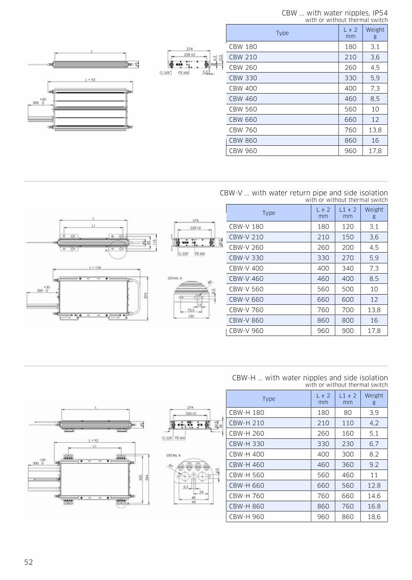
TypeL ± 2 mm
Weightg
CBW 180 180 3,1
CBW 210 210 3,6
CBW 260 260 4,5
CBW 330 330 5,9
CBW 400 400 7,3
CBW 460 460 8,5
CBW 560 560 10
CBW 660 660 12
CBW 760 760 13,8
CBW 860 860 16
CBW 960 960 17,8
TypeL ± 2 mm
L1 ± 2 mm
Weight g
CBW-V 180 180 120 3,1
CBW-V 210 210 150 3,6
CBW-V 260 260 200 4,5
CBW-V 330 330 270 5,9
CBW-V 400 400 340 7,3
CBW-V 460 460 400 8,5
CBW-V 560 560 500 10
CBW-V 660 660 600 12
CBW-V 760 760 700 13,8
CBW-V 860 860 800 16
CBW-V 960 960 900 17,8
TypeL ± 2 mm
L1 ± 2 mm
Weight g
CBW-H 180 180 80 3,9
CBW-H 210 210 110 4,2
CBW-H 260 260 160 5,1
CBW-H 330 330 230 6,7
CBW-H 400 400 300 8 2
CBW-H 460 460 360 9 2
CBW-H 560 560 460 11
CBW-H 660 660 560 12 8
CBW-H 760 760 660 14 6
CBW-H 860 860 760 16 8
CBW-H 960 960 860 18,6
CBW with water nipples, IP54with or without thermal switch
CBW-V with water return pipe and side isolationwith or without thermal switch
CBW-H with water nipples and side isolationwith or without thermal switch

53
TypeL ± 2 mm
L1 ± 2 mm
Weight g
CBW-H 180 180 70 3,9
CBW-H 210 210 110 4,2
CBW-H 260 260 160 5,1
CBW-H 330 330 230 6,7
CBW-H 400 400 300 8 2
CBW-H 460 460 360 9 2
CBW-H 560 560 460 11
CBW-H 660 660 560 12 8
CBW-H 760 760 660 14 6
CBW-H 860 860 760 16 8
CBW-V 960 960 900 17,8
TypeL ± 2 mm
L1 ± 2 mm
Weight g
CBW-V 400 400 340 23 0
CBW-V 460 460 400 26 5
CBW-V 560 560 500 31 0
CBW-V 660 660 600 37 0
CBW-V 760 760 700 42 5
CBW-V 860 860 800 49 0
CBW-V 960 960 900 54 5
TypeL ± 2 mm
L1 ± 2 mm
Weight g
CBW-V 400 400 340 46 5
CBW-V 460 460 400 50 1
CBW-V 560 560 500 54 6
CBW-V 660 660 600 60 6
CBW-V 760 760 700 66 0
CBW-V 860 860 800 72 6
CBW-V 960 960 900 78 0
CBW-V B 2 3 box connection, with water manifold and nippleswith or without thermal switch
CBW-V C 0 3 cable connection with water series connectionwith or without thermal switch
3-in-1 CBW-H cable connection with water nippleswith or without thermal switch

54
Flow L/h ∆ T water ∆ T water/glycol 60/40
10 15 20 25 30 10 15 20 25 30
7 kW 710 470 350 280 240 1070 710 530 420 360
6 kW 610 400 300 240 200 920 600 450 360 300
5 kW 510 340 250 200 170 770 510 380 300 260
4 kW 400 270 200 160 130 600 410 300 240 200
3 kW 300 200 150 120 100 450 300 230 180 150
2 kW 200 130 100 80 70 300 200 150 120 110
1 kW 100 65 50 40 35 150 100 80 60 50
ApplicationsCBW water cooled power resistors are used in applications where there are high power pulse loads and or high average power The resistor elements are embedded in sand This functions as a high thermal capacitor that can absorb high en-ergy peaks The energy is conducted by the sand and absorbed into the water About 90% of the total dissipation will be captured by the water, the rest is expelled into the air It is very well possible to isolate the aluminium housing and by that forcing almost all power dissipation into the water
CBW resistors are used in wind turbine applications as filter resistor and on board of medium power traction, like trams, as brake resistor In some tram systems, the re-generated power is used for heating up the inside of the tram during cold days
Maximum power dissipation The maximum continuous power depends on the absolute value of the water inlet temperature and also on the increase of the water temperature which is directly dependent of the water flow Table 3 shows the maximum continuous power at given water inlet temperatures and different ΔT
Pressure drop The pressure drop depends strongly on the used water nipples Many customers use their own water nipples so it is dif-ficult to give standard values For resistor CBW460 with SW22x45,5 and a flow of 120 liters per hour the pressure drop is 55mBar per channel, 110mBar in total for 2 cooling tubes in series
Water connectionsThe aluminium housing has treaded wire hole G 3/8” for the water connections The resistor housing can be fitted with water connection nipples
P 97551 P97552 P97448 P36383
Water return connection back Water inlet manifold front Series water connections front

55
Type Square pulse each 120seconds, ambient temperature 40°C
duty 1 second
kW
Max temp
°C
duty 5 seconds
kW
Max temp
°C
duty 10 seconds
kW
Max temp
°C
duty 20 seconds
kW
Max temp
°C
duty 40 seconds
kW
Max temp
°C
CBW-H 180 13R 17 5 60 5 5 70 3 4 80 2 1 90 1 3 100
CBW-H 210 100R 19 4 55 5 3 60 3 6 70 2 6 85 1 8 100
CBW-H 260 60R 46 65 11 3 75 6 9 80 4 5 95 3 110
CBW-H 330 40R 78 75 24 4 100 15 110 9 3 130 5 7 150
CBW-H 400 30R 115 85 34 110 20 8 120 12 7 140 7 8 160
CBW-H 460 20R 140 90 41 110 25 130 15 4 150 9 4 170
CBW-H 560 15R 215 100 58 120 34 140 20 4 160 12 3 180
CBW-H 660 14R 295 110 76 130 44 150 26 1 170 15 4 190
CBW-H 760 12R 370 120 92 140 52 160 30 7 180 18 200
CBW-H 860 10R 440 120 105 140 61 160 35 5 180 20 8 200
CBW-H 960 9R0 580 140 135 160 75 170 42 4 190 23 2 200
Type Triangular pulse each 120seconds, ambient temperature 40°C
duty 1 second
kW
Max temp
°C
duty 5 seconds
kW
Max temp
°C
duty 10 seconds
kW
Max temp
°C
duty 20 seconds
kW
Max temp
°C
duty 40 seconds
kW
Max temp
°C
CBW-H 180 13R 37 60 12 75 7 80 4 3 90 2 7 100
CBW-H 210 100R 40 55 11 65 7 70 4 8 80 3 2 95
CBW-H 260 60R 94 70 23 75 14 80 8 8 95 5 7 110
CBW-H 330 40R 165 80 51 100 30 9 120 18 9 130 11 3 150
CBW-H 400 30R 240 90 71 110 43 130 25 9 140 15 5 160
CBW-H 460 20R 295 90 85 110 51 130 30 8 150 18 5 170
CBW-H 560 15R 450 110 120 130 70 140 41 5 160 24 3 180
CBW-H 660 14R 620 120 160 140 91 150 53 170 30 9 190
CBW-H 760 12R 760 120 190 140 110 160 63 180 36 3 200
CBW-H 860 10R 900 130 225 150 125 160 73 180 41 5 200
CBW-H 960 9R0 1200 140 280 160 155 180 87 190 46 1 200
*The table above shows pulse power ratings for typical resistor sizes/lengths and typical ohmic values
Pulse load
The ability to withstand pulse-loads varies according to resistor size, length and diameter of the internal resistor wire As such, it is impossible to create standard graphs that would apply to all customer applications In some cases, the load-profile will be the combination of a square and a triangular pulse, such as is the case with Low Voltage Ride Through (LVRT) and Emergency Brake situations, as encountered in the Wind Power industry
On request, Danotherm performs simulations based on the actual application and for guidance, has produced tables for various load-profiles for resistors with standard wire The above table shown is based on a resistor with indicated ohm value and standard wire thickness Depending on the application, resistor construction can be adapted to optimally match the application In the tables above, the peak powers of trains of rectangular and triangular pulses of 120 second periods are shown for durations of 1 to 40 seconds
Pulse load table*

56
Danotherm supports your request The very start is your specification of the application, the load and environmental conditions Ideally, a power-time graph is presented which forms the basis of the thermal simulation If such graph is not available, the electrical circuit of the application is build in the simulation software It is also possible to use a data file as input for the load Such file can be build by measurements on the site or they come from another simulation software program
The next step is to feed the generated power losses into the thermal mo-del Each resistor which its physical properties has its own, unique, thermal model With the simulation the temperatures inside the resistor and of the outside housing surface, are simulated Here, the maximum temperature va-lues are observed and at the same time care is taken not to over dimension the resistor
When the type and internal construction of the resistor is defined, the resistor will be further tailored to the customers needs Connection boxes, connection cable sizes, cable glands, IP ratings, mounting brackets, metal surface treatment, auxiliary circuits, such as PT100 sensors and thermal switches, are all considered
Finally, packing and shipping is an important topic The resistors should be safely packed to prevent damage during transport and at the same time the costs for shipping and packing must be considered Together with our custo-mers the best option is chosen
Danotherm resistors are used as: • Pre-charge for DC-link (super) capacitors
• Pre-magnetization of power transformers
• Brake resistors for industrial drive systems
• Emergency stops in (gas) turbines
Danotherm resistors are used in:
• Elevators
• Escalators
• Cranes
• Vessels
• Wind turbines
• (Trolly)busses
• Trams / Metros / Trains (auxiliary circuits)
• Conveyer belts
• Transformers
• Turbines
• Excavation machines

57
CCH / CAH / CBH / CBR-V
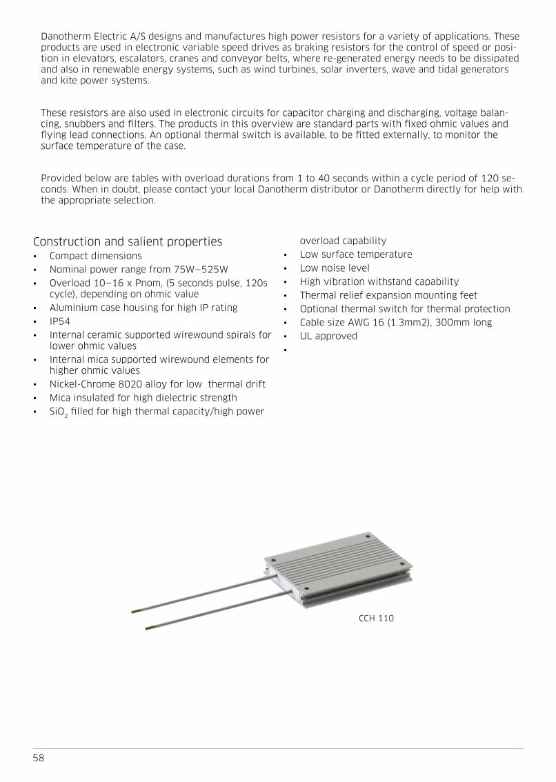
58
Danotherm Electric A/S designs and manufactures high power resistors for a variety of applications These products are used in electronic variable speed drives as braking resistors for the control of speed or posi-tion in elevators, escalators, cranes and conveyor belts, where re-generated energy needs to be dissipated and also in renewable energy systems, such as wind turbines, solar inverters, wave and tidal generators and kite power systems
These resistors are also used in electronic circuits for capacitor charging and discharging, voltage balan-cing, snubbers and filters The products in this overview are standard parts with fixed ohmic values and flying lead connections An optional thermal switch is available, to be fitted externally, to monitor the surface temperature of the case
Provided below are tables with overload durations from 1 to 40 seconds within a cycle period of 120 se-conds When in doubt, please contact your local Danotherm distributor or Danotherm directly for help with the appropriate selection
Construction and salient properties• Compact dimensions• Nominal power range from 75W—525W• Overload 10—16 x Pnom, (5 seconds pulse, 120s
cycle), depending on ohmic value• Aluminium case housing for high IP rating • IP54• Internal ceramic supported wirewound spirals for
lower ohmic values• Internal mica supported wirewound elements for
higher ohmic values• Nickel-Chrome 8020 alloy for low thermal drift• Mica insulated for high dielectric strength• SiO2 filled for high thermal capacity/high power
overload capability• Low surface temperature• Low noise level• High vibration withstand capability• Thermal relief expansion mounting feet• Optional thermal switch for thermal protection• Cable size AWG 16 (1 3mm2), 300mm long• UL approved•
CCH 110

59
TypeP nom
{W]
Max hou-sing temp
@ 40°C6R8 10R 15R 22R 33R 47R 68R 100R 150R 220R 330R 470R
CCH 110 C 100 260 X X X X X X X
CAH 165 C 75 270 X X X X X X X X X
CBH 165 C 110 270 X X X X X X X X X
CBH 265 C 200 280 X X X X X X X X X
CBR 225 C 400 280 X X X X X
CBR 295 C 525 290 X X X X X
Duty time /Brake power
Duty time square impuls load / 120 s cycle time
1s [kW] 5s [kW] 10s [W] 20s [W] 40s [W]
CCH 110 1 55 - 1 9 0 87 - 0 98 660 460 290
CAH 165 1 5 - 4 3 0 775 - 1 050 630 440 220
CBH 165 2 3 - 6 7 1 0 - 1 6 840 570 330
CBH 265 7 5 - 16 2 2 8 - 4 6 2,200 1,250 620
CBR-V 225 12 - 17 8 3 2 - 5 2 2,800 1,750 1,100
CBR-V 295 22 5 - 30 3 5 6 - 8 3 4,200 2,500 1,550
Part number Part description Housing type Temperature [°C] Mounting concept
P36425 CAH thermostat kit 180 deg CAH 180 Clip
P36426 CBH thermostat kit 180 deg CBH 180 Clip
P363911 CBR thermostat kit 180 deg CBR 180 Screw
Optionally, an external thermal switch can be mounted on the resistor body When fixing this thermal switch in the middle (hot spot), the surface temperature will be limited to the thermal switch temperature (180⁰C) When fixing the thermal switch towards the end of the resistor body, the maximum surface temperature (in the same hot spot) will be higher before tripping Surface temperature reaching 250⁰C is technically not a problem for the resistor All materials used are selected to comply with such a high value The temperature switch can detect the surface temperature of the resistor It will not protect the internal active resistor-wire from excessive impulse load
To protect the internal resistor-wire when applying an impulse load, the thermal model which is available for each resistor can be used to calculate the internal temperature Consult your Danotherm distributor for assistance

60
Temperature Coefficient: 100 ppm/K
Dielectric strength 3500 VAC @ 1 minute
Isolation Resistance: > 20MΩ / case housing
Overload: @ 1 sec pulse / hour 10 - 100 x (depending on resistor)
Overload: @ 5 sec pulse / hour 4 - 25 x (depending on resistor)
Environmental: - 40 °C / +70 °C
De-rating cable version Linear: 40°C = Pn to 70°C = 0 85 * Pn
De-rating TW 200°C version Linear: 40°C = Pn to 70°C = 0 65 * Pn
De-rating vertical mounting no de-rating
De-rating horizontal mounting 0 8 * Pn
De-rating at high altitudes
1000 m no de-rating
1500 m 0 94 * Pn
3000 m 0 82 * Pn
Mounting instructions
It is recommended to keep a distance of 200mm to the nearest object to prevent heating of a neighboring com-ponent
If two or more brake resistors are mounted next to each other the distance between these should be 400mm If this is less then the nominal power needs to be de-rated
CoolingThe nominal power of the resistors refers to cooling con-ditions with Free Natural Air Cooling
Vibration
Acc To EN 60068-2-6 frequency range 1 - 100Hz Acceleration / Amplitude
1 - 13 Hz ± 1mm
13 - 100 Hz @ ± 0 7G
Corrosive resistanceAcc IEC 60721-3-3/3K3 (C2 medium)
200 hours cyclic salt mist IEC 60068-2-52
Connection recommendationsTo minimize EMC interference screened cables are recom-
mended in particular with any PWM brake pattern
Resistance tolerance ± 10% (optional 5%)
Working voltageUL: 600VAC / 850VDCIEC: 690VAC / 975VDC
Time constant for heating up resistor
1000s
Thermal switch (optional)
Thermal switch
130 / 160 / 180 / 200 °C 2A 250 VAC NC
Minimum voltage 2V
Minimum current 10mA
Rated current / voltage 2 5A @ 250VAC cos φ=1
Dielectric voltage 2000VAC (3500VAC between TS and R)

61
Part number part descriptionOhm value
Ω
Pulse load [W] ambient temp 40°C, cycle time 120s
Duty 1s Duty 5s Duty 10s Duty 20s Duty 40s
Z5113247777 CCH 110 C 777 47R KT 47 1900 975 700 475 290
Z5113268777 CCH 110 C 777 68R KT 68 1700 910 660 460 290
Z5113310777 CCH 110 C 777 100R KT 100 1650 895 660 460 295
Z5113315777 CCH 110 C 777 150R KT 150 1700 920 665 465 290
Z5113322777 CCH 110 C 777 220R KT 220 1600 875 645 455 290
Z5113333777 CCH 110 C 777 330R KT 330 1550 880 645 455 290
Z5113347777 CCH 110 C 777 470R KT 470 1600 910 660 460 290
TypeNominal
power [W]
Weight[g]
CCH 110 100 250
TypeNominal
power [W]
Weight[g]
CAH 165 75 220
Part number part descriptionOhm value
Ω
Pulse load [W] ambient temp 40°C, cycle time 120s
Duty 1s Duty 5s Duty 10s Duty 20s Duty 40s
Z1163210777 CAH 165 C 777 10R KT 10 4300 1050 660 435 225
Z1163215777 CAH 165 C 777 15R KT 15 3600 965 625 420 225
Z1163222777 CAH 165 C 777 22R KT 22 3800 980 630 425 225
Z1163233777 CAH 165 C 777 33R KT 33 2900 935 675 440 220
Z1163247777 CAH 165 C 777 47R KT 47 2200 845 635 445 220
Z1163268777 CAH 165 C 777 68R KT 68 1850 805 620 445 225
Z1163310777 CAH 165 C 777 100R KT 100 1700 785 615 440 220
Z1163315777 CAH 165 C 777 150R KT 150 1650 780 615 445 220
Z1163322777 CAH 165 C 777 220R KT 220 1500 775 610 440 220

62
TypePnom W
L ± 2 mm
L1 ± 2 mm
Weightg
CBH 165 110 165 143 5 390
CBH 265 200 265 243 5 880
Part number part descriptionOhm value
Ω
Pulse load [W] ambient temp 40°C, cycle time 120s
Duty 1s Duty 5s Duty 10s Duty 20s Duty 40s
Z3163210777 CBH 165 C 777 10R KT 10 6700 1600 940 590 330
Z3163215777 CBH 165 C 777 15R KT 15 6100 1500 895 580 335
Z3163222777 CBH 165 C 777 22R KT 22 5200 1300 835 555 335
Z3163233777 CBH 165 C 777 33R KT 33 4000 1150 760 535 335
Z3163247777 CBH 165 C 777 47R KT 47 3400 1150 840 590 330
Z3163268777 CBH 165 C 777 68R KT 68 3100 1100 825 585 330
Z3163310777 CBH 165 C 777 100R KT 100 2600 1050 805 575 330
Z3163315777 CBH 165 C 777 150R KT 150 2400 1050 800 575 330
Z3163322777 CBH 165 C 777 220R KT 220 2300 1050 790 570 330
ZH3263210777 CBH 265 CH 777 10R KT 10 15900 4600 2400 1200 610
ZH3263215777 CBH 265 CH 777 15R KT 15 15800 4600 2500 1250 615
Z3263222777 CBH 265 C 777 22R KT 22 14600 3500 2100 1200 630
Z3263233777 CBH 265 C 777 33R KT 33 16200 3800 2200 1250 625
Z3263247777 CBH 265 C 777 47R KT 47 13900 3400 2100 1250 620
Z3263268777 CBH 265 C 777 68R KT 68 11200 3000 1900 1250 620
Z3263310777 CBH 265 C 777 100R KT 100 10200 3100 2100 1250 615
Z3263315777 CBH 265 C 777 150R KT 150 8400 2900 2000 1250 615
Z3263322777 CBH 265 C 777 220R KT 220 7500 2800 2000 1200 610
CBH 265 + thermal switch CBH 165

63
TypePnom W
L ± 2 mm
L1 ± 2 mm
Weightg
CBR-V 400 225 125 1800
CBR-V 525 295 195 2300
Part number part descriptionOhm value
Ω
Pulse load [W] ambient temp 40°C, cycle time 120s
Duty 1s Duty 5s Duty 10s Duty 20s Duty 40s
ZH9223168777 CBR-V 225 CH 777 6R8 KT 6 8 17200 5200 3100 1900 1150
ZH9223210777 CBR-V 225 CH 777 10R KT 10 17300 5200 3100 1900 1150
ZH9223215777 CBR-V 225 CH 777 15R KT 15 17200 5200 3200 1900 1150
Z9223233777 CBR-V 225 C 777 33R KT 33 17800 4200 2600 1650 1050
Z9223268777 CBR-V 225 C 777 68R KT 68 12000 3200 2200 1500 1000
ZH9293168777 CBR-V 295 CH 777 6R8 KT 6 8 30300 8300 4800 2800 1600
ZH9293210777 CBR-V 295 CH 777 10R KT 10 25000 7400 4500 2700 1600
ZH9293222777 CBR-V 295 CH 777 22R KT 22 25000 7600 4600 2700 1600
Z9293247777 CBR-V 295 C 777 47R KT 47 25000 6000 3600 2300 1450
Z9293310777 CBR-V 295 C 777 100R KT 100 22500 5600 3400 2200 1450
CBR-V 225 + thermal switch

Overview of the ALPHA resistor family (IP00-IP65)
Power: 60-410W Power: 85W - 1 7kW Power: 410W - 12kW Power: 445W-15kW Power: 860W-25kW
9-150kJ @5s 25-550kJ @5s 80kJ-2 5MJ @5s 6 4kJ-1 1MJ @5s
- Applications - Applications - Applications - Applications - Applications
Charge / Discharge High Pulse load High Pulse load High Pulse load Short recovery time
Brake Brake Brake Brake Brake
Filter Filter Filter Medium voltage Filter
Charge / Discharge Charge / High Pulse Charge / High Pulse Charge / High Pulse High Pulse
Other resistor types from Danotherm (IP00-IP65)
Multi purpurse Outdoor & Marine Filter Medium & HV Filter & load
Power: 100W-5kW Power: 1-500kW Power: 4-200kW Power: 500W-> Power: 5kW-1MW
Ceramic wirewound Steel tube Wirewound Steel grid Steel tube
Danotherm Electric A/SNaesbyvej 20DK-2610 RoedovreDenmarkCVR 1012 6061
DAN EN 18 506131MAY2021
CCH / CAV / CAH / CAR CBH / CBV / CBR CBT-V / CBT-H CBS / CMQ / CVS / HVBS CBW-V / CBW-Hwater cooled
Sigma Ohmega - Air WHHB / WHBS / WHB TERA Ohmegawater cooled
- Thermal drift; standard T=100ppm, - Tolerance; standard K=± 10%
- Ohm value (Example 2R2=2 2Ω, / 22R = 22Ω)
- Number of case style housings (1, 2, 3 or 4)- Thermal switch temp; 5=130°C / 6=160°C / 7=180°C / 8=200°C- 0=cable connection, 2=connection box type- T=Thermal switch, optional, (normally closed)- H=Helix, Low Ohm values (defined by Danotherm) - Connection style; C=cable / D=IP20 box / B=IP65 box / K=DIN rail IP00
- Length of resistor housing in mm
- H=horizontal mounting feet / V=vertical mounting feet
- Housing case style; CCH/CAV/CAH/CCR/CAR/CBV/CBH/CBR/CBT/CMQ/HVBS/CVS/CBW
CM
Q-H
40
0 C
H(T
) 2
81
22
R K
T