Topic 3 - Resistors & Resistor circuits.pptx
14
Topic 3 - Slide 1 PYKC 5 May 2020 DE1.3 - Electronics Topic 3 Resistors & Resistor Circuits Prof Peter Y K Cheung Dyson School of Design Engineering URL: www.ee.ic.ac.uk/pcheung/teaching/DE1_EE/ E-mail: [email protected]
-
Upload
khangminh22 -
Category
Documents
-
view
0 -
download
0
Transcript of Topic 3 - Resistors & Resistor circuits.pptx

Topic 3 - Slide 1 PYKC 5 May 2020 DE1.3 - Electronics
Topic 3
Resistors & Resistor Circuits
Prof Peter Y K Cheung Dyson School of Design Engineering
URL: www.ee.ic.ac.uk/pcheung/teaching/DE1_EE/ E-mail: [email protected]

Topic 3 - Slide 2 PYKC 5 May 2020 DE1.3 - Electronics
Resistor parameters and identification ◆ Resistors are usually colour
coded with their values and other characteristics as shown here.
◆ They also come in different tolerances (e.g. ±0.1% to ±10%).
◆ Other important parameters are: • Power rating (in Watts) • Temperature coefficient in parts
per million (ppm) per degree C • Stability over time (also in ppm) • Inductance (don’t worry about this
for now) ◆ Resistors can be made of
different materials: carbon composite (most common), enamel, ceramic etc.

Topic 3 - Slide 3 PYKC 5 May 2020 DE1.3 - Electronics
Resistor – Preferred values ◆ In theory, resistor values is a continuous quantity with
infinite different values. ◆ In reality, resistor as a component exists within some
tolerance (say, ±5% is common) ◆ Therefore there is NO reason to provide more than
selected number of different resistor values for a given tolerance.
◆ The standard “preferred values” for resistors are given in this table for ±5% (most common), ±10% and ±20%, respectively designated as the E24, E12, E6 series.
◆ For example, if you need a 31.3kΩ resistor with tolerance of ±10%, you could use a 30kΩ E24 resistor (±5%) instead and still stay within the allowable tolerance.
◆ Therefore, when computing solutions resistor values for electronic circuits, it is silly to use precision with many digits.

Topic 3 - Slide 4 PYKC 5 May 2020 DE1.3 - Electronics
Units and Multipliers
Topic 3 - Slide 5 PYKC 5 May 2020 DE1.3 - Electronics
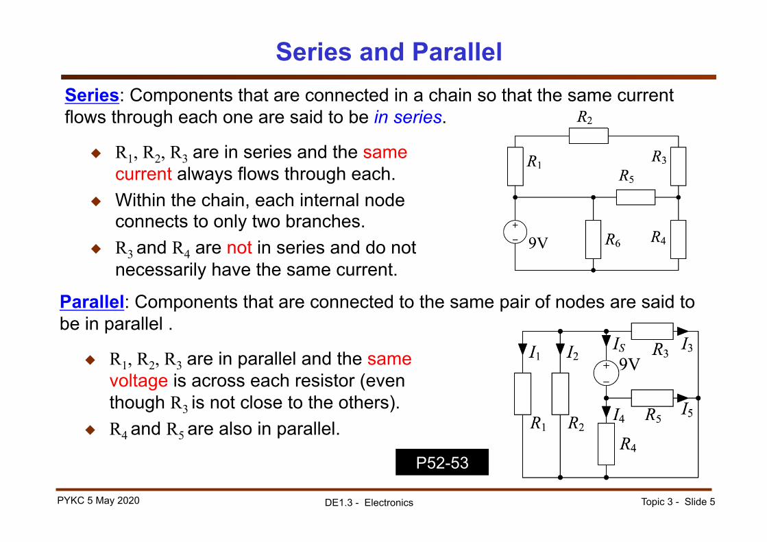
Series and Parallel Series: Components that are connected in a chain so that the same current flows through each one are said to be in series.
◆ R1, R2, R3 are in series and the same current always flows through each.
◆ Within the chain, each internal node connects to only two branches.
◆ R3 and R4 are not in series and do not necessarily have the same current.
◆ R1, R2, R3 are in parallel and the same voltage is across each resistor (even though R3 is not close to the others).
◆ R4 and R5 are also in parallel.
Parallel: Components that are connected to the same pair of nodes are said to be in parallel .
P52-53

Topic 3 - Slide 6 PYKC 5 May 2020 DE1.3 - Electronics
Series Resistors: Voltage Divider
Vx =V1 +V2 +V3= I R1 + I R2 + I R3= I (R1 + R2 + R3)
V1Vx
=I R1
I (R1 + R2 + R3)
=R1
R1 + R2 + R3=R1RT
RT = R1 + R2 + R3Where RT is the total resistance of the chain
VX is divided into V1 : V2 : V3 in the proportions R1 : R2 : R3
P56-57

Topic 3 - Slide 7 PYKC 5 May 2020 DE1.3 - Electronics
Parallel Resistors: Current Divider
◆ Parallel resistors all share the same V.
where is the conductance of R1. I1 =VR1=V G1 G1 =
1R1
Ix = I1 + I2 + I3 =VG1 +VG2 +VG3 =V (G1 +G2 +G3)
where is the total conductance of the parallel resistors. IX is divided into I1 : I2 : I3 in the proportions G1 : G2 : G3.
I1IX =
VG1V (G1+G2+G3)
= G1
G1+G2+G3 =
G1GP
GP =G1 +G2 +G3

Topic 3 - Slide 8 PYKC 5 May 2020 DE1.3 - Electronics
Equivalent Resistance: Series
◆ We know that
V =V1 +V2 +V3 = I (R1 + R2 + R3) = I RT
◆ Replacing series resistors by their equivalent resistor will not affect any of the voltages or currents in the rest of the circuit.
◆ However the individual voltages V1, V2 and V3 are no longer accessible.
◆ So we can replace the three resistors by a single equivalent resistor of value RT without affecting the relationship between V and I.
Topic 3 - Slide 9 PYKC 5 May 2020 DE1.3 - Electronics
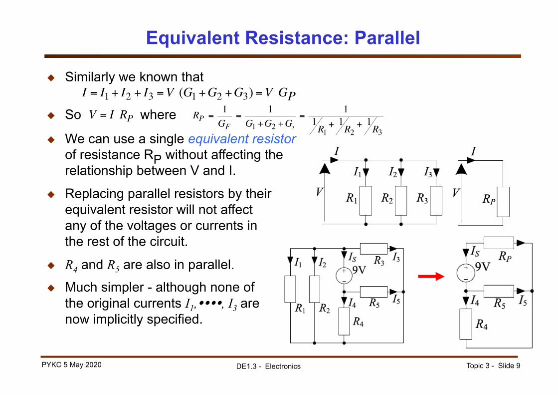
Equivalent Resistance: Parallel
◆ Similarly we known that
◆ So where
◆ We can use a single equivalent resistor of resistance RP without affecting the relationship between V and I.
I = I1 + I2 + I3 =V (G1 +G2 +G3) =V GP
◆ Replacing parallel resistors by their equivalent resistor will not affect any of the voltages or currents in the rest of the circuit.
◆ R4 and R5 are also in parallel.
◆ Much simpler - although none of the original currents I1,����, I3 are now implicitly specified.
V = I RP RP = 1GF
= 1G1 +G2 +G3
= 11R1+ 1R2
+ 1R3

Topic 3 - Slide 10 PYKC 5 May 2020 DE1.3 - Electronics
Equivalent Resistance: Parallel Formulae ◆ For parallel resistors
or equivalently
◆ These formulae work for any number of resistors.
GP =G1 +G2 +G3RP = R1 R2 R3 =
11R1+ 1R2
+ 1R3
◆ For the special case of two parallel resistors (“product over sum”)
◆ If one resistor is a multiple of the other
Suppose R2 = kR1, then
RP = 1
1R1+ 1R2
= R1R2R1 + R2
RP = R1R2R1 + R2
= kR12
(k +1)R1=
kk +1
R1 = (1 − 1k +1
) R1
◆ Important: The equivalent resistance of parallel resistors is always less than any of them.
1 kΩ 99 kΩ = 99100
kΩ = (1− 1100
) kΩ◆ Example:
Topic 3 - Slide 11 PYKC 5 May 2020 DE1.3 - Electronics
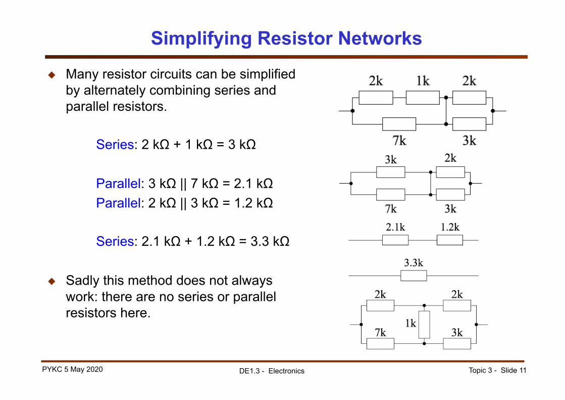
Simplifying Resistor Networks
◆ Many resistor circuits can be simplified by alternately combining series and parallel resistors.
Series: 2 kΩ + 1 kΩ = 3 kΩ
Parallel: 3 kΩ || 7 kΩ = 2.1 kΩ Parallel: 2 kΩ || 3 kΩ = 1.2 kΩ
Series: 2.1 kΩ + 1.2 kΩ = 3.3 kΩ
◆ Sadly this method does not always work: there are no series or parallel resistors here.

Topic 3 - Slide 12 PYKC 5 May 2020 DE1.3 - Electronics
Example of a voltage divider
◆ Using two resistors R1 and R2, connected to a voltage source 9V, we can produce any voltage between 0V and the battery source voltage of 9V
◆ In this example, R1 and R2 are connected in series. The total resistance is 3kΩ
◆ The current I through the two resistors is therefore 9V/3k = 3mA.
◆ Therefore the voltage across R2 is: V2 = I x R2 = 6V
◆ The voltage across R1 is 3V
◆ This is called a voltage divider because R1 and R2 effectively divide the 9V into two parts!
P55

Topic 3 - Slide 13 PYKC 5 May 2020 DE1.3 - Electronics
Non-ideal Voltage Source
◆ An ideal battery has a characteristic that is vertical: battery voltage does not vary with current.
◆ Normally a battery is supplying energy so V and I have opposite signs, so I ≤ 0.
◆ An real battery has a characteristic that has a slight positive slope: battery voltage decreases as the (negative) current increases.
◆ Model this by including a small resistor in series. V = VB + IRB.
◆ The equivalent resistance for a battery increases at low temperatures.

Topic 3 - Slide 14 PYKC 5 May 2020 DE1.3 - Electronics
Summary
q Identify resistor values q Series and Parallel components q Voltage and Current Dividers q Simplifying Resistor Networks q Battery Internal Resistance