Pro/LEGACY Help Topic Collection
106
Pro/ENGINEER ® Wildfire™ 2.0 Pro/LEGACY TM Help Topic Collection Parametric Technology Corporation
-
Upload
khangminh22 -
Category
Documents
-
view
3 -
download
0
Transcript of Pro/LEGACY Help Topic Collection

Pro/ENGINEER®
Wildfire™ 2.0
Pro/LEGACYTM
Help Topic Collection
Parametric Technology Corporation

Copyright © 2004 Parametric Technology Corporation. All Rights Reserved.
User and training documentation from Parametric Technology Corporation (PTC) is subject to the copyright laws of the United States and other countries and is provided under a license agreement that restricts copying, disclosure, and use of such documentation. PTC hereby grants to the licensed user the right to make copies in printed form of this documentation if provided on software media, but only for internal/personal use and in accordance with the license agreement under which the applicable software is licensed. Any copy made shall include the PTC copyright notice and any other proprietary notice provided by PTC. This documentation may not be disclosed, transferred, modified, or reduced to any form, including electronic media, or transmitted or made publicly available by any means without the prior written consent of PTC and no authorization is granted to make copies for such purposes.
Information described herein is furnished for general information only, is subject to change without notice, and should not be construed as a warranty or commitment by PTC. PTC assumes no responsibility or liability for any errors or inaccuracies that may appear in this document.
The software described in this document is provided under written license agreement, contains valuable trade secrets and proprietary information, and is protected by the copyright laws of the United States and other countries. It may not be copied or distributed in any form or medium, disclosed to third parties, or used in any manner not provided for in the software licenses agreement except with written prior approval from PTC. UNAUTHORIZED USE OF SOFTWARE OR ITS DOCUMENTATION CAN RESULT IN CIVIL DAMAGES AND CRIMINAL PROSECUTION.
Registered Trademarks of Parametric Technology Corporation or a Subsidiary Advanced Surface Design, Behavioral Modeling, CADDS, Computervision, CounterPart, EPD, EPD.Connect, Expert Machinist, Flexible Engineering, HARNESSDESIGN, Info*Engine, InPart, MECHANICA, Optegra, Parametric Technology, Parametric Technology Corporation, PartSpeak, PHOTORENDER, Pro/DESKTOP, Pro/E, Pro/ENGINEER, Pro/HELP, Pro/INTRALINK, Pro/MECHANICA, Pro/TOOLKIT, Product First, PTC, PT/Products, Shaping Innovation, and Windchill.
Trademarks of Parametric Technology Corporation or a Subsidiary 3DPAINT, Associative Topology Bus, AutobuildZ, CDRS, Create � Collaborate � Control, CV, CVact, CVaec, CVdesign, CV-DORS, CVMAC, CVNC, CVToolmaker, DataDoctor, DesignSuite, DIMENSION III, DIVISION, e/ENGINEER, eNC Explorer, Expert MoldBase, Expert Toolmaker, GRANITE, ISSM, KDiP, Knowledge Discipline in Practice, Knowledge System Driver, ModelCHECK, MoldShop, NC Builder, Pro/ANIMATE, Pro/ASSEMBLY, Pro/CABLING, Pro/CASTING, Pro/CDT, Pro/CMM, Pro/COLLABORATE, Pro/COMPOSITE, Pro/CONCEPT, Pro/CONVERT, Pro/DATA for PDGS, Pro/DESIGNER, Pro/DETAIL, Pro/DIAGRAM, Pro/DIEFACE, Pro/DRAW, Pro/ECAD, Pro/ENGINE, Pro/FEATURE, Pro/FEM-POST, Pro/FICIENCY, Pro/FLY-THROUGH, Pro/HARNESS, Pro/INTERFACE, Pro/LANGUAGE, Pro/LEGACY, Pro/LIBRARYACCESS, Pro/MESH, Pro/Model.View, Pro/MOLDESIGN, Pro/NC-ADVANCED, Pro/NC-CHECK, Pro/NC-MILL, Pro/NCPOST, Pro/NC-SHEETMETAL, Pro/NC-TURN, Pro/NC-WEDM, Pro/NC-Wire EDM, Pro/NETWORK ANIMATOR, Pro/NOTEBOOK, Pro/PDM, Pro/PHOTORENDER, Pro/PIPING, Pro/PLASTIC ADVISOR, Pro/PLOT, Pro/POWER DESIGN, Pro/PROCESS, Pro/REPORT, Pro/REVIEW, Pro/SCAN-TOOLS, Pro/SHEETMETAL, Pro/SURFACE, Pro/VERIFY, Pro/Web.Link, Pro/Web.Publish, Pro/WELDING, Product Development Means Business, ProductView, PTC Precision, Shrinkwrap, Simple � Powerful � Connected, The Product Development Company, The Way to Product First, Wildfire, Windchill DynamicDesignLink, Windchill PartsLink, Windchill PDMLink, Windchill ProjectLink, and Windchill SupplyLink.
Patents of Parametric Technology Corporation or a Subsidiary Registration numbers and issue dates follow. Additionally, equivalent patents may be issued or pending outside of the United States. Contact PTC for further information. 6,665,569 B1 16-December-2003 6,625,607 B1 23-September-2003 6,580,428 B1 17-June-2003 GB2354684B 02-July-2003 GB2384125 15-October-2003 GB2354096 12-November-
6,608,623 B1 19 August 2003 6,473,673 B1 29-October-2002 GB2354683B 04-June-2003 6,447,223 B1 10-Sept-2002 6,308,144 23-October-2001 5,680,523 21-October-1997 5,838,331 17-November-1998 4,956,771 11-September-1990
4,310,615 21-December-1998 4,310,614 30-April-1996 4,310,614 22-April-1999 5,297,053 22-March-1994 5,513,316 30-April-1996 5,689,711 18-November-1997 5,506,950 09-April-1996 5,428,772 27-June-1995

2003 6,608,623 B1 19 August 2003 GB2353376 05-November-2003 GB2354686 15-October-2003 6,545,671 B1 08-April-2003 GB2354685B 18-June-2003
5,058,000 15-October-1991 5,140,321 18-August-1992 5,423,023 05-June-1990
5,850,535 15-December-1998 5,557,176 09-November-1996 5,561,747 01-October-1996
Third-Party Trademarks Adobe is a registered trademark of Adobe Systems. Advanced ClusterProven, ClusterProven, and the ClusterProven design are trademarks or registered trademarks of International Business Machines Corporation in the United States and other countries and are used under license. IBM Corporation does not warrant and is not responsible for the operation of this software product. AIX is a registered trademark of IBM Corporation. Allegro, Cadence, and Concept are registered trademarks of Cadence Design Systems, Inc. Apple, Mac, Mac OS, and Panther are trademarks or registered trademarks of Apple Computer, Inc. AutoCAD and Autodesk Inventor are registered trademarks of Autodesk, Inc. Baan is a registered trademark of Baan Company. CADAM and CATIA are registered trademarks of Dassault Systemes. COACH is a trademark of CADTRAIN, Inc. DOORS is a registered trademark of Telelogic AB. FLEXlm is a trademark of Macrovision Corporation. Geomagic is a registered trademark of Raindrop Geomagic, Inc. EVERSYNC, GROOVE, GROOVEFEST, GROOVE.NET, GROOVE NETWORKS, iGROOVE, PEERWARE, and the interlocking circles logo are trademarks of Groove Networks, Inc. Helix is a trademark of Microcadam, Inc. HOOPS is a trademark of Tech Soft America, Inc. HP-UX is a registered trademark and Tru64 is a trademark of the Hewlett-Packard Company. I-DEAS, Metaphase, Parasolid, SHERPA, Solid Edge, and Unigraphics are trademarks or registered trademarks of Electronic Data Systems Corporation (EDS). InstallShield is a registered trademark and service mark of InstallShield Software Corporation in the United States and/or other countries. Intel is a registered trademark of Intel Corporation. IRIX is a registered trademark of Silicon Graphics, Inc. LINUX is a registered trademark of Linus Torvalds. MatrixOne is a trademark of MatrixOne, Inc. Mentor Graphics and Board Station are registered trademarks and 3D Design, AMPLE, and Design Manager are trademarks of Mentor Graphics Corporation. MEDUSA and STHENO are trademarks of CAD Schroer GmbH. Microsoft, Microsoft Project, Windows, the Windows logo, Windows NT, Visual Basic, and the Visual Basic logo are registered trademarks of Microsoft Corporation in the United States and/or other countries. Netscape and the Netscape N and Ship's Wheel logos are registered trademarks of Netscape Communications Corporation in the U.S. and other countries. Oracle is a registered trademark of Oracle Corporation. OrbixWeb is a registered trademark of IONA Technologies PLC. PDGS is a registered trademark of Ford Motor Company. RAND is a trademark of RAND Worldwide. Rational Rose is a registered trademark of Rational Software Corporation. RetrievalWare is a registered trademark of Convera Corporation. RosettaNet is a trademark and Partner Interface Process and PIP are registered trademarks of “RosettaNet,” a nonprofit organization. SAP and R/3 are registered trademarks of SAP AG Germany. SolidWorks is a registered trademark of SolidWorks Corporation. All SPARC trademarks are used under license and are trademarks or registered trademarks of SPARC International, Inc. in the United States and in other countries. Products bearing SPARC trademarks are based upon an architecture developed by Sun Microsystems, Inc. Sun, Sun Microsystems, the Sun logo, Solaris, UltraSPARC, Java and all Java based marks, and “The Network is the Computer” are trademarks or registered trademarks of Sun Microsystems, Inc. in the United States and in other countries. TIBCO, TIBCO Software, TIBCO ActiveEnterprise, TIBCO Designer, TIBCO Enterprise for JMS, TIBCO Rendezvous, TIBCO Turbo XML, TIBCO Business Works are the trademarks or registered trademarks of TIBCO Software Inc. in the United States and other countries. WebEx is a trademark of WebEx Communications, Inc. Third-Party Technology Information Certain PTC software products contain licensed third-party technology: Rational Rose 2000E is copyrighted software of Rational Software Corporation. RetrievalWare is copyrighted software of Convera Corporation. VisTools library is copyrighted software of Visual Kinematics, Inc. (VKI) containing confidential trade secret information belonging to VKI. HOOPS graphics system is a proprietary software product of, and is copyrighted by, Tech Soft America, Inc. G-POST is copyrighted software and a registered trademark of Intercim. VERICUT is copyrighted software and a registered trademark of CGTech. Pro/PLASTIC ADVISOR is powered by Moldflow technology. Moldflow is a registered trademark of Moldflow Corporation. The JPEG image output in the Pro/Web.Publish module is based in part on the work of the independent JPEG Group. DFORMD.DLL is copyrighted software

from Compaq Computer Corporation and may not be distributed. METIS, developed by George Karypis and Vipin Kumar at the University of Minnesota, can be researched at http://www.cs.umn.edu/~karypis/metis. METIS is © 1997 Regents of the University of Minnesota. LightWork Libraries are copyrighted by LightWork Design 1990–2001. Visual Basic for Applications and Internet Explorer is copyrighted software of Microsoft Corporation. Parasolid © Electronic Data Systems (EDS). Windchill Info*Engine Server contains IBM XML Parser for Java Edition and the IBM Lotus XSL Edition. Pop-up calendar components Copyright © 1998 Netscape Communications Corporation. All Rights Reserved. TECHNOMATIX is copyrighted software and contains proprietary information of Technomatix Technologies Ltd. Technology "Powered by Groove" is provided by Groove Networks, Inc. Technology "Powered by WebEx" is provided by WebEx Communications, Inc. Oracle 8i run-time and Oracle 9i run-time, Copyright © 2002–2003 Oracle Corporation. Oracle programs provided herein are subject to a restricted use license and can only be used in conjunction with the PTC software they are provided with. Apache Server, Tomcat, Xalan, and Xerces are technologies developed by, and are copyrighted software of, the Apache Software Foundation (http://www.apache.org) – their use is subject to the terms and limitations at: http://www.apache.org/LICENSE.txt. Acrobat Reader is copyrighted software of Adobe Systems Inc. and is subject to the Adobe End-User License Agreement as provided by Adobe with those products. UnZip (© 1990-2001 Info-ZIP, All Rights Reserved) is provided “AS IS” and WITHOUT WARRANTY OF ANY KIND. For the complete Info-ZIP license see ftp://ftp.info-zip.org/pub/infozip/license.html. Gecko and Mozilla components are subject to the Mozilla Public License Version 1.1 at http://www.mozilla.org/MPL. Software distributed under the MPL is distributed on an "AS IS" basis, WITHOUT WARRANTY OF ANY KIND, either expressed or implied. See the MPL for the specific language governing rights and limitations. The Java™ Telnet Applet (StatusPeer.java, TelnetIO.java, TelnetWrapper.java, TimedOutException.java), Copyright © 1996, 97 Mattias L. Jugel, Marcus Meißner, is redistributed under the GNU General Public License. This license is from the original copyright holder and the Applet is provided WITHOUT WARRANTY OF ANY KIND. You may obtain a copy of the source code for the Applet at http://www.mud.de/se/jta (for a charge of no more than the cost of physically performing the source distribution), by sending e-mail to [email protected] or [email protected]—you are allowed to choose either distribution method. The source code is likewise provided under the GNU General Public License. GTK+The GIMP Toolkit are licensed under the GNU LGPL. You may obtain a copy of the source code at http://www.gtk.org, which is likewise provided under the GNU LGPL. zlib software Copyright © 1995-2002 Jean-loup Gailly and Mark Adler. OmniORB is distributed under the terms and conditions of the GNU General Public License and GNU Library General Public License. The Java Getopt.jar, copyright 1987-1997 Free Software Foundation, Inc.; Java Port copyright 1998 by Aaron M. Renn ([email protected]), is redistributed under the GNU LGPL. You may obtain a copy of the source code at http://www.urbanophile.com/arenn/hacking/download.html. The source code is likewise provided under the GNU LGPL. Mozilla Japanese localization components are subject to the Netscape Public License Version 1.1 (at http://www.mozilla.org/NPL). Software distributed under NPL is distributed on an "AS IS" basis, WITHOUT WARRANTY OF ANY KIND, either expressed or implied (see the NPL for the specific language governing rights and limitations). The Original Code is Mozilla Communicator client code, released March 31, 1998 and the Initial Developer of the Original Code is Netscape Communications Corporation. Portions created by Netscape are Copyright © 1998 Netscape Communications Corporation. All Rights Reserved. Contributors: Kazu Yamamoto ([email protected]), Ryoichi Furukawa ([email protected]), Tsukasa Maruyama ([email protected]), Teiji Matsuba ([email protected]). UNITED STATES GOVERNMENT RESTRICTED RIGHTS LEGEND This document and the software described herein are Commercial Computer Documentation and Software, pursuant to FAR 12.212(a)-(b) (OCT’95) or DFARS 227.7202-1(a) and 227.7202-3(a) (JUN’95), is provided to the US Government under a limited commercial license only. For procurements predating the above clauses, use, duplication, or disclosure by the Government is subject to the restrictions set forth in subparagraph (c)(1)(ii) of the Rights in Technical Data and Computer Software Clause at DFARS 252.227-7013 (OCT’88) or Commercial Computer Software-Restricted Rights at FAR 52.227-19(c)(1)-(2) (JUN’87), as applicable. 012304 Parametric Technology Corporation, 140 Kendrick Street, Needham, MA 02494 USA

v
Table Of Contents Pro/LEGACY ................................................................................................... 1
Using Pro/LEGACY........................................................................................ 1
About Pro/LEGACY .................................................................................... 1
To Enter Pro/LEGACY................................................................................. 2
To Finish a Pro/LEGACY Session .................................................................. 2
Configuring Pro/LEGACY ............................................................................... 3
About Configuring Pro/LEGACY.................................................................... 3
To Set Pro/LEGACY Configuration Options .................................................... 3
drawing_file_editor.................................................................................... 3
drawing_setup_file .................................................................................... 3
pro_crosshatch_dir.................................................................................... 4
pro_surface_finish_dir ............................................................................... 4
tol_display ............................................................................................... 4
tol_mode ................................................................................................. 4
Working with Parts....................................................................................... 4
About Pro/LEGACY Part Mode...................................................................... 4
To Enter Pro/LEGACY Part Mode to Work with an Existing Part......................... 5
To Enter Pro/LEGACY Part Mode to Create a Part ........................................... 5
Interface Functions in Pro/LEGACY Part Mode................................................ 6
About Adding New Features........................................................................ 6
Pro/LEGACY Part Modeling Functions............................................................ 6
Creating New Wireframe Entities.................................................................... 8
To Add a New Entity to a Wireframe ............................................................ 8
To Create Wireframe Entities by Sketching ................................................... 9
Using the Get Point Menu ........................................................................... 9
To Set the Origin......................................................................................10
To Create a Copy of a Wireframe Entity by Offsetting....................................10
To Add a Fillet Between Two Wireframe Entities ...........................................10
To Create a Wireframe Entity by Connecting Points.......................................10

Table of Contents
vi
Modifying Existing Wireframe Entities ............................................................11
About Modifying Existing Wireframe Entities ................................................11
To Trim or Extend a Wireframe Entity .........................................................11
To Split a Wireframe Entity........................................................................12
To Translate Wireframe Entities .................................................................12
To Rotate Wireframe Entities .....................................................................12
To Mirror Wireframe Entities ......................................................................12
To Modify the Diameter of Wireframe Entities ..............................................13
To Delete a Wireframe Entity .....................................................................13
Modifying Spline Points ................................................................................13
About Modifying Spline Points ....................................................................13
To Add a Point to a Spline .........................................................................14
To Add an Endpoint at a Selected Datum Point or Vertex ...............................14
To Add an Endpoint on a Second Curve or Edge ...........................................15
Example: Using In Osc Plane to Add an Endpoint on a Second Curve...............15
To Decrease the Number of Spline Points by Deleting One or More Points ........16
To Move an Endpoint to a Second Curve or Edge ..........................................16
Example: Using 2nd Crv/Edge to Move an Endpoint to a Second Curve............16
To Move an Endpoint to a Selected Datum Point or Vertex .............................17
To Move an Interpolation Point in a Specified Plane.......................................17
To Make a Spline Tangent to a Reference ....................................................17
Example: Making a Spline Tangent to a Curve Using the Crv/Edge/Axis Option.19
Working with Imported Surfaces ...................................................................19
To Remove Selected Imported Surfaces ......................................................19
Removing Imported Surfaces.....................................................................20
To Restore Selected Imported Surfaces.......................................................20
Working with Assemblies .............................................................................20
About Working with Assemblies in Pro/LEGACY ............................................20
To Enter Pro/LEGACY Assembly Mode to Work with an Existing Assembly .......21
To Enter Pro/LEGACY Assembly Mode to Create an Assembly .........................22
To Import an Assembly from Another System ..............................................22

Table of Contents
vii
To Output the Current Assembly to Another System .....................................22
To Remove Surfaces.................................................................................22
Manipulating Imported Objects ..................................................................23
Working with Drawings ................................................................................26
About Working with Drawings in Pro/LEGACY ...............................................26
To Enter Pro/LEGACY Drawing Mode to Work with an Existing Drawing............26
To Enter Pro/LEGACY Drawing Mode to Create a Drawing ..............................26
To Add or Replace a Format in an Existing Drawing.......................................27
About Using the Grid ................................................................................27
To Move the Origin of the Grid ...................................................................28
About Using Sheets in a Pro/LEGACY Drawing ..............................................28
To Obtain Information About Your Pro/LEGACY Drawing ................................29
To Import a Drawing from Another System..................................................29
To Export a Drawing to Another System......................................................29
To Plot a Drawing.....................................................................................29
Using Layers ...........................................................................................29
About Using Overlays ...............................................................................30
Setting Up Drawing Setup File Options ........................................................30
Working with 2D Views ................................................................................30
About Working with 2D Views ....................................................................30
To Create a 2D View.................................................................................31
To Change the View Scale .........................................................................31
To Set a Current View...............................................................................31
To Associate Items with a View ..................................................................32
To Move a View .......................................................................................32
To Delete a 2D View .................................................................................32
To Reset the Border .................................................................................32
Working with 2D Geometry ..........................................................................33
About 2D Geometry..................................................................................33
To Create a Construction Line ....................................................................33
To Create a Construction Circle ..................................................................34

Table of Contents
viii
To Create a Spline and Specify Tangency ....................................................34
To Create a Point .....................................................................................34
To Offset an Entity ...................................................................................35
To Delete Entities.....................................................................................35
Creating Ellipses ......................................................................................36
Creating Chamfers ...................................................................................38
Working with Dimensions.............................................................................40
About Dimensions ....................................................................................40
To Create a Dimension..............................................................................41
To Align a Dimension with Any Point on the Screen.......................................42
To Create Ordinate Dimensions..................................................................42
Adding Text to a Dimension.......................................................................42
To Change an Ordinate Dimension into Standard..........................................43
To Change the Direction of Dimension Arrows ..............................................43
Changing Arrow Style ...............................................................................43
About Changing the Tolerance Format ........................................................43
To Change a Dimension Symbol .................................................................43
To Modify a Dimension Value .....................................................................44
About Modifying the Number of Digits .........................................................44
To Control the Placement of Dual Dimensions (Primary and Secondary)...........44
To Convert a Standard Dimension to Ordinate..............................................44
Updating Draft Dimensions........................................................................45
Creating Gaps in Lines ..............................................................................45
Increasing the Gap between a Dimension Line and Geometry.........................45
Adding a Jog ...........................................................................................45
Sketching Lines ..........................................................................................45
About Sketching Lines ..............................................................................45
To Create a Line Using 2 Points..................................................................46
To Create a Line Using Horiz Line ...............................................................46
To Create a Line Using Vert Line ................................................................46
To Create a Line Using Angle .....................................................................47

Table of Contents
ix
To Create a Line Using Pnt/Tang ................................................................47
To Create a Line Using Parl Line .................................................................48
To Create a Line Using Perp Line ................................................................48
To Create a Line Using Norm At Point .........................................................49
To Create a Line Using Tang Line ...............................................................49
To Create a Line Using 2 Tang Line.............................................................49
To Create a Line Using Ref Tan/Para ...........................................................50
To Create a Line Using Ref Tan/Norm .........................................................50
Sketching Circles ........................................................................................51
To Create a Circle Using Center/Pnt ............................................................51
To Create a Circle Using Center/Tang..........................................................51
To Create a Circle Using Center/Rad ...........................................................52
To Create a Circle Using Center/Dia............................................................52
To Create a Circle Using 3 Tangent.............................................................52
To Create a Circle Using Fillet ....................................................................53
To Create a Circle Using 3 Points................................................................53
Sketching Arcs ...........................................................................................54
To Create an Arc Using Tang End ...............................................................54
To Create an Arc Using 3 Points .................................................................54
To Create an Arc Using Center and Ends .....................................................54
To Create an Arc Using Pnt/Ctr/Ang............................................................55
To Create an Arc Using 3 Tangent ..............................................................55
To Create an Arc Using Fillet......................................................................56
Working with Cross-Sections ........................................................................57
About Cross-Sections................................................................................57
To Create a Hatched Cross-Section.............................................................57
To Create a Filled Cross-Section.................................................................58
To Modify the Cross-Hatching Pattern .........................................................58
To Modify the Spacing ..............................................................................58
To Modify the Angle of Hatching.................................................................58
To Modify the Line Style............................................................................58

Table of Contents
x
To Modify the Offset of a Parallel Line Pattern ..............................................59
To Add a Line to a Pattern .........................................................................59
To Delete a Line.......................................................................................59
To Save a Cross-Hatch Pattern...................................................................59
To Retrieve a Pattern................................................................................59
Modifying Geometry ....................................................................................60
About Modifying Geometry ........................................................................60
To Translate Entities.................................................................................61
To Rotate Entities.....................................................................................61
To Create Copies by Translating .................................................................61
To Create Copies by Rotating.....................................................................62
To Mirror Entities .....................................................................................62
To Trim or Extend an Entity by a Specified Amount.......................................63
About Trimming Entities to a Specified Bounding Entity or Point .....................63
To Trim or Extend an Entity to a Specified Bounding Entity or Point ................63
To Trim or Extend an Entity to a Specified Length.........................................64
To Trim or Extend to Make a Corner ...........................................................64
To Intersect Geometry..............................................................................64
About Stretching Entities...........................................................................64
To Stretch Entities....................................................................................65
To Divide an Entity ...................................................................................65
To Resize an Entity...................................................................................66
About Using Groups..................................................................................66
To Measure the Distance Between Two Entities ............................................67
To Measure the Angle Between Two Lines....................................................67
To Move Geometry ...................................................................................68
To Delete Geometry in Pro/LEGACY ............................................................68
To Modify the Diameter of an Arc or Circle...................................................68
To Change Line Style................................................................................68
Modifying Splines .....................................................................................68
Working with Text in Drawings .....................................................................71

Table of Contents
xi
About Text in Drawings.............................................................................71
To Add a Note with a Leader to a Drawing ...................................................72
To Add a Note without a Leader .................................................................73
To Enter Notes.........................................................................................74
Working with Geometric Tolerances...............................................................74
About Geometric Tolerances ......................................................................74
To Set a Reference Datum.........................................................................74
Tip: Setting a Reference Datum .................................................................75
To Transform Dimensions into Basic Dimensions ..........................................75
To Set Inspection Dimensions According to the DIN Standard ........................75
To Add a Gtol to a Pro/LEGACY Drawing ......................................................76
Specifying Geometric Tolerances ................................................................76
To Delete a Geometric Tolerance................................................................77
To Create a Datum Target .........................................................................77
Working with Symbols .................................................................................77
About User Symbols .................................................................................77
To Define a Symbol ..................................................................................78
Tip: To Redefine a Symbol.........................................................................78
To Add An Instance ..................................................................................78
To Delete an Instance...............................................................................79
To Modify an Instance...............................................................................79
To Add a Surface Finish Symbol .................................................................79
Adding Surface Finish Symbols ..................................................................80
To Create a Datum Plane ..........................................................................80
To Create and Name a Datum Axis .............................................................80
To Add a Balloon Note ..............................................................................81
Adding Balloons .......................................................................................81
Working with Details ...................................................................................81
About Details...........................................................................................81
To Move a Dimension, Unattached Note, or Symbol ......................................82
To Move Dimension Text ...........................................................................82

Table of Contents
xii
To Move An Attachment Point ....................................................................82
To Reattach a Symbol with Multiple Attachments..........................................82
To Re-Attach a Symbol with a Single Attachment .........................................83
To Add Another Leader Line to a Detail Item................................................83
To Delete a Group ....................................................................................83
Index...........................................................................................................85

1
Pro/LEGACY
Using Pro/LEGACY
About Pro/LEGACY
Pro/LEGACY is an optional module designed for importing and updating three-
dimensional (3D) data and two-dimensional (2D) drawings in Pro/ENGINEER. Using
Pro/LEGACY tools, you can easily create, modify, and delete individual geometric
entities within imported 3D data, as well as work with geometry and detail
information contained in 2D drawings.
You can import a Pro/LEGACY file into Pro/LEGACY using one of the supported
formats, then use Pro/LEGACY tools to make some changes to this object. When
extensive redesign is required to update the object, you should continue working in
basic Pro/ENGINEER. The following figure presents a chart showing the most typical
use of Pro/LEGACY.
A Typical Pro/LEGACY Session

Pro/LEGACY – Help Topic Collection
2
Pro/LEGACY Tasks
You can perform the following tasks using Pro/LEGACY:
• Transfer data between different CAD systems and maintain Pro/LEGACY objects
in Pro/ENGINEER format.
• Modify imported wireframe objects by adding, redefining, and deleting curves.
• Add parametric features, including solid and datum features, to a Pro/LEGACY
object.
• Create new and modify existing surfaces. Remove selected imported surfaces
from the display.
• Modify existing and create new drawings containing 2D geometry with all
required annotations.
• Retrieve Pro/LEGACY objects in Pro/ENGINEER and vice versa.
• Use complete plotting functions
Pro/LEGACY Objects
Pro/LEGACY data may include 2D drawings or 3D parts and assemblies consisting of
surfaces and/or wireframe geometry. Pro/LEGACY operates in three modes: Part,
Assembly, and Drawing. Filenames follow the same naming convention and have the
same extension as corresponding Pro/ENGINEER objects.
To Enter Pro/LEGACY
1. Either open or create a Pro/ENGINEER object.
2. From the Pro/ENGINEER menu bar, click Applications > Legacy. The LEGACY
PRT menu appears.
To Finish a Pro/LEGACY Session
1. From the Pro/ENGINEER menu bar, click File > Save. The changes made to the
object are saved.
Note: Pro/ENGINEER does not save changes automatically when you exit.
2. Click Window > Close to close the current object and continue working with
another object.
Note: Click File > Exit to quit Pro/ENGINEER.

Pro/LEGACY
3
Configuring Pro/LEGACY
About Configuring Pro/LEGACY
You can customize the way Pro/LEGACY operates by entering config.pro
configuration file options and their values in the Options dialog box (Tools >
Options).
Pro/LEGACY Help provides a list of configuration options arranged in alphabetical
order. Each option contains the following information:
• Configuration option name.
• Default and available variables or values. All default values are in italic.
• Brief description and notes describing the configuration option.
To Set Pro/LEGACY Configuration Options
1. Click Tools > Options. The Options dialog box opens.
2. Click the Show only options loaded from file check box to see currently
loaded configuration options or clear this check box to see all configuration
options.
3. Select the configuration option from the list or type the configuration option
name in the Option box.
4. In the Value box type or select a value.
Note: The default value is followed by an asterisk (*).
5. Click Add/Change. The configuration option and its value appear in the list.
A green status icon confirms the change.
6. When you finish configuring, click Apply or OK.
drawing_file_editor
editor, protab
Specifies the default text editor for editing the drawing setup file. If you do not set
this variable, the default editor is used.
• protab—The system uses Pro/TABLE.
• editor—The system uses the system editor.
drawing_setup_file
filename.dtl
Establishes the default drawing setup file option values for any drawing that you
create during a Pro/ENGINEER session. If you do not set this option, the default

Pro/LEGACY – Help Topic Collection
4
drawing setup file option values are used. Certain parameters in the file are valid
only if you have a license for Pro/DETAIL.
pro_crosshatch_dir
<directory name>
Specifies a default directory for your cross-hatch library in which you can save cross-
hatching patterns for later retrieval. Its value is the full path name of the default
directory. For example, pro_dtl_setup_dir.
pro_surface_finish_dir
<directory name>, loadpoint/symbols/surffins
Sets the default directory for your user-defined surface finish symbols. Use the full
pathname to avoid problems. For example, /home/users/library/surf_finish.
tol_display
yes, no
Displays dimensions with or without tolerances.
yes—Makes tolerances visible in the drawing.
tol_mode
nominal, limits, plusminus, plusminussym
Sets the default display for dimension tolerances.
• nominal—Displays dimensions without tolerances.
• limits—Displays dimensions as upper and lower limits.
• plusminus—Displays dimensions as nominal with plus-minus tolerances (the
positive and negative values are independent).
• plusminussym—Displays dimensions as nominal with a single value for both the
positive and the negative tolerance.
Note: Groups brought in from other models carry the tolerance display mode that
was in effect when they were created.
Working with Parts
About Pro/LEGACY Part Mode
In Pro/ENGINEER format, you can maintain old 3D files that were created in other
CAD systems. When you need to use Pro/LEGACY parts to update existing parts, you
can retrieve them in Pro/LEGACY Part mode and make some changes either by
modifying the old wireframe or surface data or adding new parametric features. For

Pro/LEGACY
5
extensive redesign, use basic Pro/ENGINEER. You can transfer Pro/LEGACY parts
back and forth between Pro/LEGACY and Pro/ENGINEER.
You can retrieve old 3D data files in Pro/LEGACY Part mode by importing them
through the supported formats.
With Pro/LEGACY, you can make modifications to your part in the following ways:
• Add, modify, or delete splines in a wireframe representation of an imported
object.
• Using the surface functionality, manipulate imported surface data, as well as
create and modify new surfaces. You can merge and intersect surfaces with
surfaces created in Pro/ENGINEER and with other imported surfaces. In addition,
you can copy, translate, rotate, mirror, and remove (from the display) imported
surfaces.
• Create and manipulate solid features.
• Create and redefine datum features.
• Interface with other.
• Output a screen image to a plotter.
To Enter Pro/LEGACY Part Mode to Work with an Existing Part
1. From the Pro/ENGINEER menu bar, click File > Open.
2. Select the appropriate file from the File Open dialog box. The specified part is
displayed.
3. From the Pro/ENGINEER menu bar, click Applications > Legacy. The LEGACY
PRT menu appears.
To Enter Pro/LEGACY Part Mode to Create a Part
1. From the Pro/ENGINEER menu bar, click File > New.
2. In the New dialog box, specify the type of Pro/LEGACY object by clicking Part in
the Type box.
3. Type a name for the part in the Name box or accept the default.
4. Click OK.
5. From the Pro/ENGINEER menu bar, click Applications > Legacy. The LEGACY
PRT menu appears.
6. Select one of the following:
o Feature—Creates a new feature.
o Wireframe—Alters the wireframe object.
o Surface—Creates or modifies an existing surface, as well as removes
selected imported surfaces.

Pro/LEGACY – Help Topic Collection
6
Interface Functions in Pro/LEGACY Part Mode
In Pro/LEGACY Part mode, you can import parts from other systems and output parts
to other formats.
When you are in Pro/LEGACY Part mode, you can import parts from other systems
using File > Open. In the Type list, select the format of the part you want to
import.
When you are working with an existing part, click Insert > Shared Data > From
File to add an imported object as a feature. In the Type list, select the format of the
imported object you want to append to the part.
To export parts to other formats click File > Save a Copy. In the Type list, select
the format in which you want to save the part.
About Adding New Features
To create and modify new features, you can use the same method you would use in
basic Pro/ENGINEER.
You can add new parametric features using Feature or Surface from the Legacy
Prt menu. In Pro/LEGACY you can create the following types of new features using
standard Pro/ENGINEER functions:
• Solid construction features that are available with regular Pro/ENGINEER. To
create a construction feature, click Feature from the Legacy Prt menu,
Create from the Feature menu, and Solid from the Feat Class menu.
• New surfaces using imported surfaces or wireframe entities. To access the
surface functionality, click Surface from the Legacy Prt menu.
• Datum features, including datum planes, datum axes, datum points, and
coordinate systems. To access datums, click Feature from the Legacy Prt
menu, Create from the Feature menu, and Datum from the Feat Class
menu.
• Cosmetic features, including sketched features, threads, grooves, and areas.
To access cosmetic features, click Feature from the Legacy Prt menu,
Create from the Feature menu, and Cosmetic from the Feat Class menu.
Pro/LEGACY Part Modeling Functions
The following table lists Pro/LEGACY part modeling functions that are comparable to
those provided in basic Pro/ENGINEER.
Menu Item Menu
Name
Description
Axis Datum Creates a datum axis.
Coord Sys Datum Creates a coordinate system.
Copy Feature Copies a feature or group of features.

Pro/LEGACY
7
Menu Item Menu
Name
Description
Cosmetic Feat Class Creates a cosmetic feature.
Create Feature Creates a solid, datum, or cosmetic feature.
Curve Datum Creates a construction curve.
Datum Feat Class Creates a datum feature.
Delete Feature Deletes a selected feature.
ECAD
Areas
Cosmetic Creates ECAD areas (keep in, keep out, etc.).
Evaluate Datum Creates an evaluate feature.
Graph Datum Creates a two-dimensional graphical relation.
Group Feature Creates a group of features you can
manipulate (copy, suppress, etc.)
simultaneously.
Info Main Provides information on measurement, mass
properties, surface analysis, layer information,
feature information, etc.
Interface Legacy Prt Accesses interface functions for import and
export.
Layer Legacy Prt Accesses the layer functionality to set layers
and control their display.
Modify Legacy Prt Modifies dimensions of parametrically created
features.
Plane Datum Creates a datum plane.
Point Datum Creates a datum point.
Redefine Feature Redefines a datum, solid, or surface feature.
Regenerate Legacy Prt Regenerates an object after you have made a
change to parametrically created features.
Reorder Feature Changes the order of feature creation.
Reroute Feature Breaks parent/child relationships by selecting
new sketching, placement, and dimensioning
references.
Resume Feature Restores features or a group of features that

Pro/LEGACY – Help Topic Collection
8
Menu Item Menu
Name
Description
were previously suppressed.
Set Up Legacy Prt Defines material, part accuracy, and units for
the part. Assigns mass properties to the part.
Sets dimension bounds. Specifies geometric
tolerances and surface finish.
Solid Feat Class Creates a solid feature.
Suppress Feature Blanks a selected feature or a group of
features.
Surface Legacy Prt Creates a surface feature.
UDF
Library
Feature Accesses commands to create and modify
user-defined features.
Creating New Wireframe Entities
To Add a New Entity to a Wireframe
You can create wireframe entities and fillets by selecting edges and vertices in a
three-dimensional view.
Note: New wireframe entities added to an imported feature are nonparametric.
1. Click Wireframe on the LEGACY PRT menu.
2. Pick a Pro/LEGACY wireframe feature. This is the object that you imported into
Pro/LEGACY from another CAD system.
3. Click New on the LEGACYWIRE menu.
4. Select one of the following from the NEW WIRE menu:
o Line—Creates a wireframe curve between two vertices or datum points in a
3D view of the model.
o 3D Fillet—Connects two wireframe curves with a fillet.
o Planar Sketch—Creates wireframe entities by sketching on a planar view of
the model.
o 3D Spline—Creates a spline by connecting vertices or datum.

Pro/LEGACY
9
To Create Wireframe Entities by Sketching
In Pro/LEGACY you can add new wireframe entities to an imported model by
sketching them in a planar view of the model using common drafting techniques.
In contrast to Sketcher mode, new wireframe entities are nonparametric, so you do
not dimension them.
1. Click New from the LEGACYWIRE menu.
2. Click Planar Sketch on the NEW WIRE menu.
3. Select or create a sketching plane and specify its orientation. You are placed in
the Drafting mode.
4. Sketch the necessary geometry using the SKETCH GEOM menu which displays
the following:
o Line—Sketches a line using the LINE menu.
o Arc—Sketches an arc using the ARC menu.
o Spline—Sketches a spline.
o Circle—Sketches a circle using the CIRCLE menu.
o Use Edge—Creates an entity using existing geometry.
o Offset—Creates entities by offsetting existing entities.
o Delete—Deletes selected entities.
o Set Origin—Sets the origin of the sketching plane. Pro/ENGINEER uses this
origin to calculate coordinates when you use Abs Coords in the GET
POINT menu.
5. Click Done/Return on the SKETCH GEOM menu. The new entities are
added to the existing wireframe. For a better view, you may want to display
the object in default orientation.
Using the Get Point Menu
While sketching, you can use the following location filters available in the Get Point
menu:
• Pick Point—Picks a point anywhere on the screen.
• Vertex—Locates a point at the endpoint as well as midpoint of an open curve
(line, arc, or spline), the center of an arc or circle, or the intersection between
two entities.
• On Entity—Locates a point by picking anywhere along an entity or model
edge.

Pro/LEGACY – Help Topic Collection
10
• Rel Coords—Locates a point relative to the last point selected by using X-
and Y-coordinate values that you type. Rel Coords is available only after you
specify the first pick point from which to measure.
• Abs Coords—Locates a point by entering X- and Y-coordinates relative to the
current coordinate system.
• On Axis—Creates a point at the intersection of an axis and the sketching
plane.
To Set the Origin
1. Click Set Origin on the SKETCH GEOM menu.
2. Using the GET POINT menu, pick a point to be the origin. The coordinate
system, indicating the sketch origin, appears on the screen.
To Create a Copy of a Wireframe Entity by Offsetting
1. Click Offset on the SKETCH GEOM menu.
2. Select entities from which to offset.
3. Click Done Sel. A red arrow indicates the direction of offset.
4. Specify the offset distance in the indicated direction.
To Add a Fillet Between Two Wireframe Entities
1. Click New on the LEGACYWIRE menu.
2. Click 3D Fillet on the NEW WIRE menu.
3. Pick two coplanar entities and specify the radius. A fillet is added without
trimming the specified entities.
To Create a Wireframe Entity by Connecting Points
1. Click New on the LEGACYWIRE menu. The NEW WIRE menu appears.
2. Click 3D Spline. The Through Points dialog box opens.
3. Click Curve Points in the Elements box.
4. Click Define. The 3D SPLINE menu appears.
5. Specify how you want to connect points as follows:
o Single Point—Selects vertices, individual datum points, or points from a
datum point array.
o Whole Array—Selects all the points in a datum point array in consecutive
order.

Pro/LEGACY
11
6. While connecting points, you can interactively add, delete, or insert points in
the spline being created by using Add Point, Delete Point, and Insert
Point, respectively.
7. When you have finished creating the spline, click Done.
8. Click Tangency in the Elements box.
9. Click Define. The DEF TAN menu displays the following:
o Start—Creates the spline curve tangent at the startpoint.
o End—Creates the spline curve tangent at the endpoint.
o Crv/Edge/Axis—Selects an axis, curve, or edge to specify tangent direction.
o Create Axis—Creates a datum axis to specify tangent direction.
o Tan Surf—Selects a surface to specify tangent direction.
o Srf Nrm Edge—Selects a surface and an edge to specify tangent direction.
o Clear—Clears the tangent constraint.
10. Specify the tangency at the endpoints.
11. Select the direction for the curve at this tangency. An arrow then appears at
the end of the curve.
12. Point the arrow outward from the curve.
Modifying Existing Wireframe Entities
About Modifying Existing Wireframe Entities
To modify existing wireframe entities, use Trim/Extend, Split, Move, and Mod
Entity on the Legacywire menu.
Note: If you attempt to modify a curve with child features in a way that may cause
regeneration failure, a warning is issued.
To Trim or Extend a Wireframe Entity
1. Click Trim/Extend on the LEGACYWIRE menu.
2. Select a point, curve, or surface to which to trim or extend, or both.
3. Select a curve to be trimmed. When trimming, the portion of the curve you
selected is retained.

Pro/LEGACY – Help Topic Collection
12
To Split a Wireframe Entity
1. Click Split on the LEGACYWIRE menu.
2. Select a point, curve, or surface to be used as the intersecting entity.
3. Select a curve to be split.
To Translate Wireframe Entities
1. Click Move on the LEGACYWIRE menu. The MOVE OPTION menu appears.
2. Click Translate.
3. Click Copy to retain the original entities or No Copy to translate the selected
entities.
4. Click Done.
5. Pick wireframe entities to be moved.
6. Click Done Sel on the GET SELECT menu.
7. Select a straight wireframe or model edge, or a coordinate system. If you select
an edge, an arrow appears on the edge in the positive direction.
8. Specify a positive or negative number for the displacement value. If you select a
coordinate system, specify displacement values for each axis.
To Rotate Wireframe Entities
1. Click Move on the LEGACYWIRE menu. The MOVE OPTION menu appears.
2. Click Rotate.
3. Click Copy to retain the original entities or No Copy to translate the selected
entities.
4. Click Done.
5. Pick wireframe entities to be rotated.
6. Click Done Sel on the GET SELECT menu.
7. Select a straight wireframe or model edge, or an axis. An arrow shows positive
angle direction according to the "right-hand rule."
8. Specify the rotation angle.
To Mirror Wireframe Entities
1. Click Move on the LEGACYWIRE menu. The MOVE OPTION menu appears.
2. Click Mirror.

Pro/LEGACY
13
3. Click Copy to retain the original entities or No Copy to translate the selected
entities.
4. Click Done.
5. Pick wireframe entities to be mirrored.
6. Click Done Sel on the GET SELECT menu.
7. Select or create a plane about which to mirror the entity.
To Modify the Diameter of Wireframe Entities
1. Click Mod Entity on the LEGACYWIRE menu. The LEGACY MOD menu
appears.
2. Click Arc Diameter.
3. Select arcs or circles.
4. Click Done Sel on the GET SELECT menu.
5. Specify a new value for the diameter.
To Delete a Wireframe Entity
1. Click Delete on the Legacywire menu.
2. Click Entities.
Modifying Spline Points
About Modifying Spline Points
Using Spline on the Legacy Mod menu, you can change the shape of an existing
spline by manipulating the points through which it passes (spline points). When you
choose Spline, the Splinepnts menu appears.
Adding Spline Interpolation Points and Endpoints
You can add interpolation points to a spline by selecting locations with the mouse.
You can also extend a spline by adding an endpoint at a selected datum point or
vertex, or by adding an endpoint on a second curve or edge.
Moving Spline Interpolation Points and Endpoints
Using Move, you can move an endpoint to a second curve or edge, or to a selected
datum point or vertex, as well as move an interpolation point in a specified plane.

Pro/LEGACY – Help Topic Collection
14
To Add a Point to a Spline
1. Click Wireframe on the LEGACY PRT menu. The LEGACYWIRE menu
appears.
2. Click Mod Entity. The LEGACY MOD menu appears.
3. Click Spline. The SPLINEPNTS menu appears.
4. Click Add. The PNT LOCATION menu appears. It displays the following:
o Select Spline—Specifies a spline to modify.
o On Spline—Adds interpolation points to a spline by selecting locations with
the mouse.
o In Plane—Moves spline interpolation points or endpoints in a specified plane.
o Dtm Pnt/Vrtx—Uses a specified datum point or vertex as a location to which
to add or move endpoints.
o 2nd Crv/Edge—Uses a specified curve or edge as a reference on which to
add or move endpoints.
5. Click Select Spline.
6. Pick the spline. The spline highlights in red and its points highlight in white.
7. Click On Spline.
8. Click to pick the interior of the spline. A new point is added at the pick point
and is highlighted in white. Repeat as many times as is required.
9. Click Done Sel on the GET SELECT menu. The points are added.
To Add an Endpoint at a Selected Datum Point or Vertex
1. After you pick the spline, click Dtm Pnt/Vrtx on the PNT LOCATION menu.
2. Pick a datum point or vertex at which to add a spline endpoint. The new spline
highlights in green, and the old spline highlights in red.
3. Click Confirm on the CONFIRMATION menu to accept the new spline shape.
4. Click Cancel to return to the SPLINEPNTS menu.

Pro/LEGACY
15
Using Dtm Pnt/Vrtx to Add an Endpoint to a Selected Vertex
1 New spline
2 Old spline
3 Selected vertex
To Add an Endpoint on a Second Curve or Edge
1. After you pick the spline, click 2nd Crv/Edge on the PNT LOCATION menu.
The 2ND CRV/EDGE menu appears.
2. Click one of the following:
o Pick Point—Adds a spline endpoint at a selected point on a curve or edge.
o Nearest Pnt—Uses the point on a curve or edge nearest an end of the
current spline as a reference.
o In Osc Plane—Uses the intersection of a curve or edge and the osculating
plane at the spline end as a reference (the osculating plane is the plane
defined by the curve’s normal and tangent vectors).
3. Pick a location for the point. The new spline highlights in green and the old
spline highlights in red.
4. Click Confirm on the CONFIRMATION menu to accept the new spline shape.
5. Click Cancel to return to the SPLINEPNTS menu.
Example: Using In Osc Plane to Add an Endpoint on a Second Curve
1 Point of intersection of the curve and the osculating plane

Pro/LEGACY – Help Topic Collection
16
2 Old spline
3 New spline
To Decrease the Number of Spline Points by Deleting One or More Points
1. Click Remove on the SPLINEPNTS menu.
2. Select the spline.
3. Pick the point you want to delete.
4. Click Done Sel on the GET SELECT menu. The spline that results from the
removal of this point highlights in green.
5. Click Confirm on the CONFIRMATION menu.
To Move an Endpoint to a Second Curve or Edge
1. Click Move on the SPLINEPNTS menu. The PNT LOCATION menu appears.
2. Pick the spline and click 2nd Crv/Edge. The 2ND CRV/EDGE menu appears.
3. Select a command.
4. Select a curve or edge to which to move a spline endpoint. Select another spline
point to limit the adjustment range of the spline.
5. The new spline highlights in green and the old spline highlights in red.
6. Click Confirm on the CONFIRMATION menu to accept the new spline shape.
7. Click Cancel to return to the SPLINEPNTS menu.
Example: Using 2nd Crv/Edge to Move an Endpoint to a Second Curve
1 Old spline
2 New spline
3 Selected curve

Pro/LEGACY
17
To Move an Endpoint to a Selected Datum Point or Vertex
1. After picking the spline, click Dtm Pnt/Vrtx on the PNT LOCATION menu.
2. Select a datum point or vertex to which to move a spline endpoint.
3. Select another spline point to limit the adjustment range of the spline. The
new spline highlights in green and the old spline highlights in red.
4. Click Confirm on the CONFIRMATION menu to accept the new spline shape.
Click Cancel to return to the SPLINEPNTS menu.
Note: When changing a 2D spline into a 3D spline, if the spline has child features
such as sweeps or swept blends, you must move spline points only within the
plane passing through the spline to avoid regeneration failure. Before altering the
spline, create a datum plane through it and use it as the movement plane.
To Move an Interpolation Point in a Specified Plane
1. Click Move on the SPLINEPNTS menu. The PNT LOCATION menu appears.
2. Click Select Spline.
3. Pick the spline. It is highlighted in red. The REF PLANE TYPE menu appears with
Select highlighted and the SETUP PLANE menu appears with Plane highlighted.
4. Click In Plane on the PNT LOCATION menu (it is the default if you have
selected a spline).
5. Select one of the following on the REF PLANE TYPE menu:
o View Plane—Specifies a reference plane that is parallel to the screen.
o Select—Specifies any planar surface or datum plane.
o OscPlnAtPnt—Specifies the reference plane that passes through the point
being moved. The plane is constructed using the tangent to the spline and
principal normal vector at the selected point.
6. Pick a point to move.
7. Select another spline point to limit the adjustment range of the spline. The
new spline highlights in green and the old spline highlights in red.
8. Click Done Move on the MOVE SPL PN menu to accept the new spline.
To Make a Spline Tangent to a Reference
Using Tangent, you can make a spline tangent to a curve, an edge, an axis, or a
surface without having to create additional geometry.
1. Click Tangency on the SPLINEPNTS menu. The TAN SPL menu appears with
the following:
o Select Spline—Selects the spline that you want to modify.

Pro/LEGACY – Help Topic Collection
18
o Start—Defines the tangency at the start of the spline. The start vertex
highlights.
o End—Defines the tangency at the end of the spline. The end vertex
highlights.
o Crv/Edge/Axis—Selects a curve, edge, or axis to specify tangency direction
at the startpoint or endpoint.
o Create Axis—Creates an axis to specify tangency direction at the startpoint
or endpoint, using the DATUM AXIS menu (for more information, see
Datum Axes in the chapter Datums in the Part Modeling User’s Guide.)
o Tan Surf—Selects a surface on which the startpoint or endpoint of the spline
is to lie and to which the spline is to be tangent. The spline pivots to follow
its natural direction while remaining tangent to the surface.
o Srf Nrm Edge—Makes the spline tangent to a selected surface and normal to
one of the surface boundaries.
o Clear—Removes the current tangency constraint at the selected end. To have
no tangency constraint at either end, click Clear for both ends.
2. Using Select Spline, pick the spline that you want to make tangent.
3. Click Start or End to specify the end that you initially want to control.
4. Click Crv/Edge/Axis, Create Axis, Tan Surf, or Srf Nrm Edge to specify
the kind of tangency that you want at the selected end of the spline.
5. Pick the reference entity. An arrow appears at the selected end of the spline
to indicate the direction of the tangent curve.
6. Click Flip or Okay on the DIRECTION menu to reverse or accept the
direction. If necessary, specify the tangency at the other end of the spline.
7. Click Done on the TAN SPL menu. The spline displays in its modified form.

Pro/LEGACY
19
Example: Making a Spline Tangent to a Curve Using the Crv/Edge/Axis Option
The following figure is an example of how to make an existing spline tangent to a
curve using Crv/Edge/Axis. The reference curve is shown.
1 Start point of the spline
2 Spline
3 Tangency created at this curve
Working with Imported Surfaces
To Remove Selected Imported Surfaces
1. Click Surface on the LEGACY PRT menu. The LEGACY SURF menu appears.
2. Click Remove Surfs. The REMOVE SURFS menu appears.
3. Click Remove.
4. Select the imported surfaces to be removed. The selected surfaces highlight in
blue.
5. Click Done Sel.
6. Click Done. The removed surface feature is created. It blocks the selected
surfaces.

Pro/LEGACY – Help Topic Collection
20
Removing Imported Surfaces
Using Remove Surfs, you can block, or suppress, imported surfaces from the model
even if other parametric features reference them. It creates a new remove surface
feature in the model that blocks the required surfaces until you choose to restore
them by deleting or redefining the feature.
Each remove surface feature that you have created is assigned a feature ID and
number that are visible in the Information Window. Because you can selectively
control the removed surfaces within the same removed surface feature, a
Pro/LEGACY object should have as few removed surface features as possible.
Note: You can delete imported surfaces from the model irrevocably by redefining
their imported feature and clicking Delete on the REDEF IMPT menu.
To Restore Selected Imported Surfaces
1. Click Feature on the LEGACY PRT menu. The FEATURE menu appears.
2. Click Redefine.
3. Specify the removed surface feature using Sel By Menu on the GET SELECT
menu. The surfaces that were blocked using the specified removed surface
feature highlight in red.
4. Click References and Done on the REDEFINE menu.
5. Select one of the following on the REMOVE SURFS menu:
o Restore—Restores selected surfaces. Select any of the surfaces highlighted
in blue (notice that the blue surface turns yellow when you select it).
o Restore All—Restores all previously removed surfaces.
6. Click Done on the REMOVE SURFS menu.
Working with Assemblies
About Working with Assemblies in Pro/LEGACY
Functionally, the Assembly mode in Pro/LEGACY is similar to the Assembly mode in
Pro/ENGINEER. It is intended to be used for creating assemblies as well as
manipulating their components. Using the available interface functions, you can also
import assemblies into Pro/LEGACY from other systems or output them to other
formats. Pro/LEGACY Assembly mode is unique in its ability to manipulate wireframe
entities of imported objects. Wireframe manipulation tools in Pro/LEGACY Assembly
mode are the same as those found in Pro/LEGACY Part mode. Pro/LEGACY
assemblies may include components created in Pro/LEGACY or in basic
Pro/ENGINEER. You can also retrieve and manipulate them in Pro/ENGINEER
Assembly mode.

Pro/LEGACY
21
The following Assembly mode functions are available in the Legacy Asm menu:
• Component—Assembles parts and subassemblies in an assembly and performs
other procedures on assembly components, such as copying, merging, replacing,
and deleting components. Also creates new parts and subassemblies.
• Feature—Creates and manipulates parametric assembly features.
• Wireframe—Manipulates wireframe entities of an imported object. This
functionality is the same as in Pro/LEGACY Part mode.
• Surface—Creates, modifies, and removes assembly surface features.
• Modify—Modifies an assembly or its components. This includes modifying
dimensions, moving components in the assembly, manipulating layers, and so
on.
• Restructure—Restructures the assembly tree by moving components between
subassemblies.
• Simplfd Rep—Specifies which members of an assembly are to be retrieved into
session and displayed. Creates, modifies, or sets a simplified representation.
• Regenerate—Updates modified part and assembly dimensions (also reassembles
after exploding).
• Interface—Outputs the current assembly to another system or imports a 3D
object from another format.
• Layer—Performs layer functions.
You can use Pro/LEGACY parts in any Pro/ENGINEER assembly as well as use
Pro/ENGINEER parts in Pro/LEGACY assemblies.
To Enter Pro/LEGACY Assembly Mode to Work with an Existing Assembly
1. From the Pro/ENGINEER menu bar, click File > Open.
2. Select the appropriate file from the File Open dialog box. The specified assembly
is displayed.
3. From the Pro/ENGINEER menu bar, click Applications > Legacy. The LEGACY
ASM menu appears.
4. Select one or all of the following, as necessary:
o Component—Assembles or manipulates components.
o Feature— Creates an assembly feature.
o Wireframe—Alters the existing wireframe object.
o Surface—Creates new surfaces, as well as modifies and removes existing
surfaces.
o Modify—Changes dimensions.

Pro/LEGACY – Help Topic Collection
22
o Restructure—Moves components between subassemblies.
o Simplfd Rep—Specifies which members of an assembly the system should
retrieve into session and display.
o Regenerate—Updates the geometry of the assembly.
o Layer—Sets layers and controls their display.
To Enter Pro/LEGACY Assembly Mode to Create an Assembly
1. From the Pro/ENGINEER menu bar, click File > New.
2. In the New dialog box, specify the type of Pro/LEGACY object by clicking
Assembly in the Type box.
3. Type a name for the assembly in the Name box or accept the default.
4. Click OK.
5. From the Pro/ENGINEER menu bar, click Applications > Legacy. The
LEGACY ASM menu appears.
6. Click Component > Assemble.
7. Using the Component Placement dialog box, create your assembly.
To Import an Assembly from Another System
1. From the Pro/ENGINEER menu bar, click File > Open.
2. In Type list ,select the format of the assembly you want to import.
To Output the Current Assembly to Another System
1. From the Pro/ENGINEER menu bar, click File > Save a Copy.
2. In the Type list, select the format to which you want to export the assembly.
To Remove Surfaces
1. Click Surface on the LEGACY ASM menu.
2. Select an imported model.
3. Click Remove Surfs on the LEGACY SURF menu. The REMOVE SURFS menu
appears.
4. Click Remove.
5. Select imported surfaces to be removed. The selected surfaces highlight in blue.
6. Click Done Sel on the GET SELECT menu.

Pro/LEGACY
23
7. Click Done on the REMOVE SURFS menu. The removed surface feature is
created. It blocks the selected surfaces.
To restore selected surfaces, you must redefine the removed surface feature as
you would in Part.
Manipulating Imported Objects
In Pro/LEGACY Assembly mode, you can modify imported wireframe objects and
remove surfaces.
Working with Imported Wireframe Objects
To modify the geometry of assemblies and parts that are imported into Pro/LEGACY,
you can modify their wireframe entities using Wireframe from the Legacy Asm
menu just as you would in Pro/LEGACY Part. The planar sketch functionality is
especially useful in an assembly environment because you can use edges and
vertices from other components in the assembly to easily create nonparametric
wireframe entities.
Removing Surfaces in Imported Objects
As with parts, in Assembly mode you can remove surfaces from an imported object
(an assembly or its components) using Remove Surfs on the Legacy Surf menu.
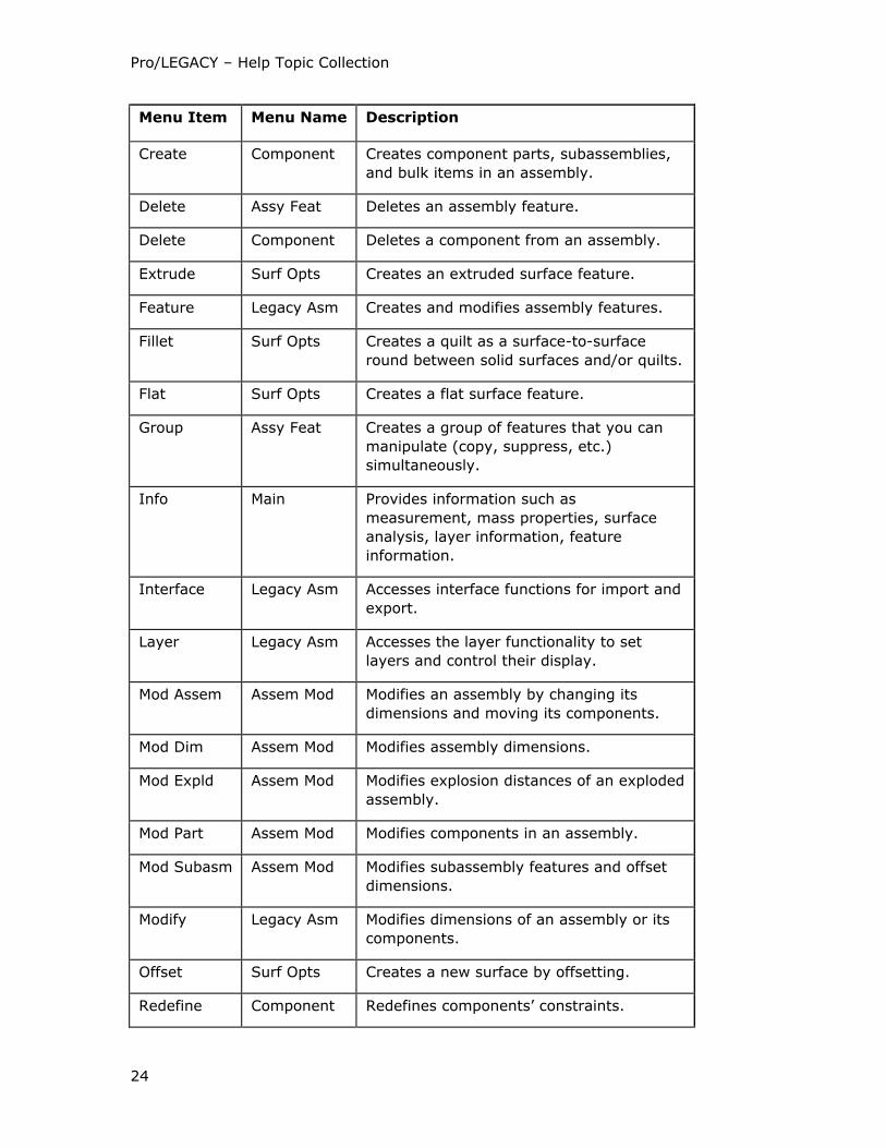
The following table lists Pro/LEGACY assembly modeling functions that are
comparable to those provided in basic Pro/ENGINEER.
Menu Item Menu Name Description
Advanced Surf Opts Creates a surface feature using advanced
tools.
Adv Utils Component Replaces, copies, groups, merges, or cuts
out components, as well as creates and
modifies user-defined features.
Assemble Component Assembles parts into an assembly.
Blend Surf Opts Creates a blended surface feature.
Component Legacy Asm Assembles parts and subassemblies in an
assembly and performs other procedures
on assembly components.
Copy Assy Feat Copies an assembly feature.
Copy Surf Opts Creates a new surface by copying another
surface.
Create Assy Feat Creates an assembly feature.
Pro/LEGACY – Help Topic Collection
24
Menu Item Menu Name Description
Create Component Creates component parts, subassemblies,
and bulk items in an assembly.
Delete Assy Feat Deletes an assembly feature.
Delete Component Deletes a component from an assembly.
Extrude Surf Opts Creates an extruded surface feature.
Feature Legacy Asm Creates and modifies assembly features.
Fillet Surf Opts Creates a quilt as a surface-to-surface
round between solid surfaces and/or quilts.
Flat Surf Opts Creates a flat surface feature.
Group Assy Feat Creates a group of features that you can
manipulate (copy, suppress, etc.)
simultaneously.
Info Main Provides information such as
measurement, mass properties, surface
analysis, layer information, feature
information.
Interface Legacy Asm Accesses interface functions for import and
export.
Layer Legacy Asm Accesses the layer functionality to set
layers and control their display.
Mod Assem Assem Mod Modifies an assembly by changing its
dimensions and moving its components.
Mod Dim Assem Mod Modifies assembly dimensions.
Mod Expld Assem Mod Modifies explosion distances of an exploded
assembly.
Mod Part Assem Mod Modifies components in an assembly.
Mod Subasm Assem Mod Modifies subassembly features and offset
dimensions.
Modify Legacy Asm Modifies dimensions of an assembly or its
components.
Offset Surf Opts Creates a new surface by offsetting.
Redefine Component Redefines components’ constraints.

Pro/LEGACY
25
Menu Item Menu Name Description
Redefine Assy Feat Redefines a datum, solid, or surface
feature.
Regenerate Legacy Asm Regenerates an assembly to update
geometry.
Reorder Assy Feat Reorders the occurrence of a component in
an assembly. The procedure is the same as
for feature reorder.
Reroute Component Reassigns component references.
Reroute Assy Feat Breaks parent/child relationships by
selecting new sketching, placement, and
dimensioning references.
Restructure Legacy Asm Moves components from one subassembly
to another, or from the top-level assembly
to a subassembly or vice versa.
Resume Assy Feat Restores components and assembly
features that were previously suppressed.
Revolve Surf Opts Creates a revolved surface feature.
Retrieve Rep Enterassy Retrieves an assembly in a predefined
simplified representation without bringing
into session excluded or substituted
components.
Simplfd Rep Legacy Asm Specifies which components of an assembly
are retrieved into session and displayed.
Suppress Assy Feat Suppresses components from active
memory. When the system retrieves an
assembly, it does not retrieve suppressed
components.
Surface Legacy Asm Creates a surface feature in an assembly.
Sweep Surf Opts Creates a swept surface feature.
UDF Library Assy Feat Accesses commands to create and modify
user-defined features.

Pro/LEGACY – Help Topic Collection
26
Working with Drawings
About Working with Drawings in Pro/LEGACY
You can use Pro/LEGACY Drawing mode to import drawings created in other CAD
systems and maintain them in Pro/ENGINEER format, modify existing geometry or
add new geometry and annotations, output drawings to other formats, and plot an
entire or clipped drawing.
Pro/LEGACY drawings can contain 2D geometry and annotations. You can use various
drafting tools to sketch view geometry. To assign all geometry and items that pertain
to a particular view, you can use Pro/LEGACY 2D views. These are different from
Pro/ENGINEER model views that reference the 3D model. They enable you to group
entities that act as one entity when you perform procedures such as scaling,
deleting, or moving a view about the drawing. You can retrieve Pro/ENGINEER
drawings in Pro/LEGACY and vice versa. When you retrieve a drawing in
Pro/ENGINEER, you can move Pro/LEGACY 2D views as model views, and manipulate
view geometry individually as draft entities.
To Enter Pro/LEGACY Drawing Mode to Work with an Existing Drawing
1. Click File > Open.
2. Select the appropriate file from the File Open dialog box. The specified drawing
is displayed.
3. Click Applications > Legacy.
To Enter Pro/LEGACY Drawing Mode to Create a Drawing
1. Click File > New. The New dialog box opens.
2. Click Drawing in the Type box to specify the type of Pro/LEGACY object.
3. Type a name for the drawing in the Name box or accept the default.
4. Click OK. The New Drawing dialog box opens.
5. Click any of the following to specify the template:
o Use template
o Empty with format
o Empty
6. Click OK.
7. Click File > Page Setup The Page Setup dialog box opens.
8. To specify the size, from the Size box select Inches or Millimeters and
type values in the Width and Height boxes.

Pro/LEGACY
27
9. Select one of the following from the Orientation box:
o Portrait—Makes the height larger than the width and selects a standard size.
o Landscape—Makes the width larger than the height and selects a standard
size.
10. Click OK. The drawing is displayed as specified.
11. Click Applications > Legacy.
To Add or Replace a Format in an Existing Drawing
Pro/ENGINEER stores drawing formats in a separate file. To use one with a drawing,
it must be located in the same directory as the drawing. You can change the current
drawing size using Format.
1. Click File > Page Setup. The Page Setup dialog box opens.
2. Click Sheet on the Page Setup menu.
3. Click Format on the Page Setup menu. Select a standard or variable size format
from the list.
4. Click OK.
About Using the Grid
To access the grid functionality, click View > Draft Grid. The GRID MODIFY menu
displays the following:
• Show Grid—Displays the grid.
• Hide Grid—Blanks the grid.
• Type—Changes the grid type to Cartesian or Polar.
• Origin—Relocates the grid origin.
• Grid Params—Modifies the grid spacing and angle.
Modifying Grid Spacing
To modify the spacing and angle of the grid, use Grid Params in the Grid Modify
menu. The commands available depend on the type of grid. The values for the grid
spacing are saved and retrieved with the drawing.
For a Cartesian grid, the following are available in the Cart Params menu:
• X&Y Spacing—Sets the spacing in both X- and Y- directions to the same value.
• X Spacing—Sets the X-spacing only.
• Y Spacing—Sets the Y-spacing only.
• Angle—Modifies the angle between a horizontal and the X-direction of the grid.

Pro/LEGACY – Help Topic Collection
28
For a Polar grid, the following are available in the Polar Params menu:
• Ang Spacing—Sets the angular spacing between radial lines. The value
entered must divide evenly into 360.
• Num Lines—Sets the number of lines to use. The angular spacing is
360/number of lines.
• Rad Spacing—Modifies the radial spacing of the circular grid.
• Angle—Modifies the angle between a horizontal and the 0−degree radial line.
To Move the Origin of the Grid
You can locate the grid origin at one of the following:
• Sketched entity endpoint or center
• Sketched point
• Datum point
1. Click View > Draft Grid. The GRID MODIFY menu appears.
2. Click Origin on the GRID MODIFY menu.
3. Select the type of entity to set the origin:
o Get Point—Enables you to pick a point to be the origin.
o Edge/Entity—Picks a point on an entity.
o Default—Uses the default grid origin.
4. Locate the origin of the grid.
When moving the grid origin, keep in mind the following:
o The grid origin and angle affect the coordinate values entered for a geometry
point, for instance, when you use the Get Point menu. The X-axis is always
along one direction of the grid; the Y-axis is always along the other.
o The grid origin affects the coordinate values displayed in the Message
Window when sketching.
About Using Sheets in a Pro/LEGACY Drawing
You can create drawings with multiple sheets and move items from one sheet to
another. When there is more than one sheet in a drawing, an additional tag,
"SHEET...OF...", appears at the bottom of the window.
• Click Insert > Sheet to add a new sheet to the drawing and set the sheet to be
current.
• Click Edit > Remove > Sheet to remove a specified sheet or sheets.
• Click Edit > Move Sheet. The Move Sheet dialog box opens. Use the Move
Sheet dialog box to change the order of sheets in the drawing.

Pro/LEGACY
29
• Click View > Go To Sheet. The Go To Sheet dialog box opens. Type the sheet
number and select one of the following:
o Previous—Opens the previous sheet.
o Next—Opens the next sheet.
• Click Edit > Move Item To Sheet to move individual detail items or 2D views
from one sheet to another.
• Format—Changes the drawing size.
Using New Window on the Main View menu, you can show multiple drawing
sheets in multiple windows (or the same sheet in multiple windows) and pick in any
one simultaneously).
To Obtain Information About Your Pro/LEGACY Drawing
• Click Info > Draft Entity to output geometric and cosmetic information about an
entity.
• Click Info > Draft Grid to display grid angle and spacing values.
• Click Info > Save Note to write a note to a file.
To Import a Drawing from Another System
1. Click File > Open.
2. Select the format for the drawing in the Type list.
To Export a Drawing to Another System
1. Click File > Save a Copy.
2. Select the format to which you want to export the drawing in the Type list.
To Plot a Drawing
Click Print on the File menu to access plotting functions.
Using Layers
You can use layers to group geometry and annotations in a drawing. After you have
associated items with a layer, you can blank them or display them by changing the
display status of the layer. It may be useful to blank selected layers to plot, export to
other formats, or work with the drawing.

Pro/LEGACY – Help Topic Collection
30
About Using Overlays
Using Overlay on the Legacy Dwg menu, you can superimpose selected views or
an entire sheet of the specified drawing over the current drawing sheet. The Overlay
Dwg menu displays the following:
• Add Overlay—Places an overlay (a drawing sheet or an individual model view)
on the current drawing.
• Del Overlay—Deletes an overlay from the drawing.
• Move Overlay—Moves an overlay about the drawing.
When using overlays, keep in mind the following:
• Overlays are read-only in the current drawing.
• Overlays update to changes in the source drawing.
• Overlaid views display with all detail items.
• Overlays cannot be selected for any drawing operation.
• If the size of the current drawing is different from the size of the source drawing,
the overlays brought into the current drawing maintain the same screen size as
they had in the source drawing. That is, they take up the same portion of the
graphics window
Setting Up Drawing Setup File Options
Pro/ENGINEER saves drawing setup file options with each individual drawing and
drawing format. These setup options determine the height of the dimension and the
note text, text orientation, geometric tolerance standards, font properties, drafting
standards, arrow lengths, and so on. They are given default values, but you can
modify them to customize a drawing and save them to be used in other drawings.
The drawing setup file values are saved and retrieved in a drawing setup file named
filename.dtl. The file specified in the drawing_setup_file configuration option
establishes the default drawing setup option values for any drawing created during a
Pro/ENGINEER session. If you do not use this option, the default drawing setup
option values are provided.
To work with the drawing setup file, click Settings > Setup File. You can edit a
drawing setup file using either Pro/TABLE or the system editor. To specify the type of
editor, set the value of the drawing_file_editor configuration option to editor or
protab.
Working with 2D Views
About Working with 2D Views
A Pro/LEGACY drawing may contain imported views, which are Pro/LEGACY views
transferred from another system, as well as new views added in Pro/LEGACY. Both

Pro/LEGACY
31
types are 2D drafting views and are indicated in the drawing with a dashed border. A
view box is visible only if you click Insert > 2D Views.
In Pro/LEGACY, 2D views are nonparametric. They are used to organize the process
of creating and manipulating geometry. After you select a view, it automatically
selects geometry associated with it for an operation. You can access the view
functionality using the Views Manager dialog box.
All views in a Pro/LEGACY drawing are general views. You can scale and manipulate
them independently of each other. If you want all new geometry to belong to a
particular view, you must specify this view as the current view.
To Create a 2D View
1. Click Insert > 2D Views.
2. Select the origin for the view.
3. Specify the scale. A dashed box indicating a view appears on the screen.
To Change the View Scale
You can express view scales in a decimal or fractional format. Specify the required
format by resetting the view_scale_format drawing setup file option. Note that
decimal format is the default. Using the view_scale_denominator drawing setup file
option, you can establish the pattern of fractional scales.
When you change the view scale, geometry in that view updates correspondingly.
However, changing the view scale affects the visible size of the geometry in the
drawing. Dimension values remain unchanged.
1. Click Insert > 2D Views.
2. Pick the view to be changed.
3. Specify the required scale.
To Set a Current View
The current view in the drawing is indicated with a yellow dashed box if 2D Views in
the Environment menu is selected. When you add a view, it does not automatically
become current. To specify the view to which all new entities are to belong, you
must set it using Set Cur View in the Views or Draft menu.
1. Click Set Cur View on the DRAFT or VIEWS menu.
2. Click Set Current on the CURRENT VIEW menu.
3. Pick the view that you want to set. The dashed box, indicating the view, turns
yellow.
4. Click Unset Cur on the CURRENT VIEW menu to unset the current view. The
yellow dashed box, indicating the view, turns gray.

Pro/LEGACY – Help Topic Collection
32
To Associate Items with a View
Using Relate to View, you can associate items with a view and dissociate them.
1. Click Edit > Group > Relate to View.
2. Pick the view with which you want to associate items.
3. Pick the detail items that you want to add.
To dissociate items from the view, click Edit > Group > Unrelate and pick the
detail items to be removed. The removed items are not associated with any view.
To Move a View
1. Click 2D Views on the LEGACY DWG menu.
2. Click Move View on the VIEWS menu.
3. Pick the view that you want to move.
4. Select one of the following in the GET VECTOR menu to indicate the "from" and
"to" locations for the translation vector:
o Horiz—Specifies an offset along the X-axis.
o Vert—Specifies an offset along the Y-axis.
o Ang/Length—Specifies the translation vector in polar coordinates using an
angle of the vector measured from a horizontal and offset along the vector in
the indicated direction.
o From-To—Specifies the "from" and "to" points.
To Delete a 2D View
1. Click 2D Views on the LEGACY DWG menu.
2. Click Delete View on the VIEWS menu.
3. Pick the view that you want to delete.
To Reset the Border
Using Reset Border on the Views menu, you can set a new border defining a view.
1. Click 2D Views on the LEGACY DWG menu.
2. Click Reset Border on the VIEWS menu.
3. Pick a view. The view highlights in red.
4. Click to pick a location from where you want to start the view box.
5. With the rubberband box attached to the cursor, extend the box as necessary
and click again.

Pro/LEGACY
33
Working with 2D Geometry
About 2D Geometry
When locating points for sketched geometry (using View > Draft Grid > GRID
MODIFY > Origin), the GET POINT menu displays the following:
• Pick Point—Locates any point on the screen.
• Vertex—Locates a point at the endpoint as well as midpoint of an open curve
(line, arc, spline), the center of an arc or circle, or the intersection between two
entities.
• On Entity—Locates a point anywhere along an entity.
• Rel Coords—Locates a point relative to the last point selected by using X- and Y-
coordinate values that you specify. The coordinate values are in drawing units.
• Abs Coords—Locates a point relative to the current coordinate system. By
default, it is the drawing coordinate system located in the lower-left corner of the
drawing.
If you set a 2D view to be the current draft view, the coordinates are measured
relative to the current draft view origin.
While you are sketching, as you move the cursor, the X- and Y-coordinates of a
current point on the screen display at the bottom of the Message Window. When you
create an entity using two points, the following data is reported in the Message
Window:
• X-coordinate
• Y-coordinate
• DX (distance between two points along the X-axis)
• DY (distance between two points along the Y-axis)
• L (shortest distance between two points)
To Create a Construction Line
You can create construction lines and construction circles.
1. Click Sketch > Construction Line.
2. Create a line using one of the following:
o Horiz—Creates a horizontal construction line at a point.
o Vert—Creates a vertical construction line at a point.
o Crossed Pair—Creates two construction lines perpendicular to each other at
a given angle through a point.

Pro/LEGACY – Help Topic Collection
34
o Angle—Creates a line at the point picked at an angle measured from the X-
axis in the counterclockwise direction.
o Offset—Creates a line offset at a specified distance from another line.
To Create a Construction Circle
Click Sketch > Construction Circle.
To Create a Spline and Specify Tangency
1. Click Sketch > Spline.
2. Specify a tangency condition for the ends of the spline. The angle of tangency is
measured from the horizontal in the counterclockwise direction.
3. Select one of the following on the TANGENCY menu:
o None—Creates a spline curve with no tangency specified at its endpoints.
o Start—Creates a spline curve with tangency specified at its startpoint.
o End—Creates a spline curve with tangency specified at its endpoint.
o Both—Creates a spline curve with tangency specified at both ends.
4. Pick the startpoint for the spline.
5. Specify the tangency angle, if necessary.
6. Continue to select spline points.
7. Middle-click to end the spline at the last selected point..
8. Specify a tangency angle, if necessary.
A Spline
1 Endpoint
2 Intermediate pick points
To Create a Point
1. Click Sketch > Point.
2. Click Adv Geom on the DFT CREATE menu. The ADV DRAFT menu appears.
3. Click Point > Pick Pnt.
4. Pick a point anywhere on the drawing. The point is indicated by an "X."
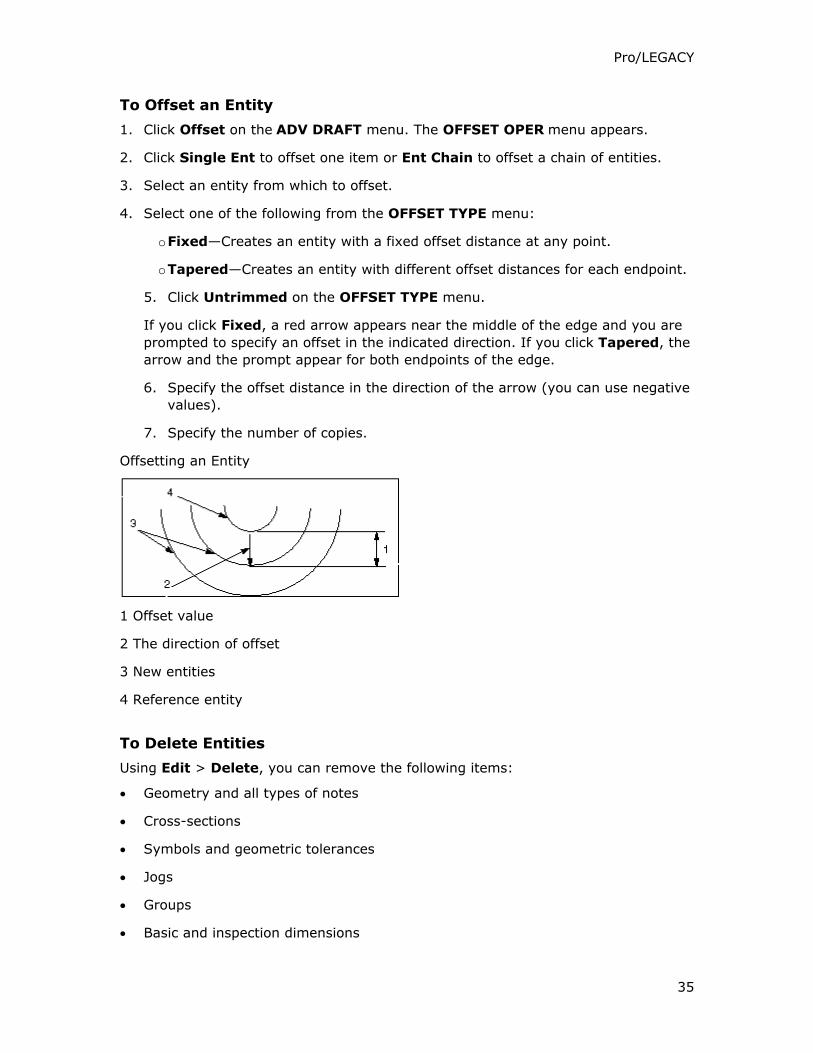
Pro/LEGACY
35
To Offset an Entity
1. Click Offset on the ADV DRAFT menu. The OFFSET OPER menu appears.
2. Click Single Ent to offset one item or Ent Chain to offset a chain of entities.
3. Select an entity from which to offset.
4. Select one of the following from the OFFSET TYPE menu:
o Fixed—Creates an entity with a fixed offset distance at any point.
o Tapered—Creates an entity with different offset distances for each endpoint.
5. Click Untrimmed on the OFFSET TYPE menu.
If you click Fixed, a red arrow appears near the middle of the edge and you are
prompted to specify an offset in the indicated direction. If you click Tapered, the
arrow and the prompt appear for both endpoints of the edge.
6. Specify the offset distance in the direction of the arrow (you can use negative
values).
7. Specify the number of copies.
Offsetting an Entity
1 Offset value
2 The direction of offset
3 New entities
4 Reference entity
To Delete Entities
Using Edit > Delete, you can remove the following items:
• Geometry and all types of notes
• Cross-sections
• Symbols and geometric tolerances
• Jogs
• Groups
• Basic and inspection dimensions

Pro/LEGACY – Help Topic Collection
36
1. Click Edit > Delete.
2. Pick the entities that you want to delete.
3. Click Done Sel.
Creating Ellipses
About Creating Ellipses
To create an ellipse, you can use Ctr/Pnt/Ang, Pnt/Pnt/Ang, Ctr/Pnt/Pnt, and
3 Points. When you use Ctr/Pnt/Ang and Pnt/Pnt/Ang, specify a rotation angle
about the major axis. The angle represents what you see of a circle after it is
rotated; the more it rotates it, the less you see of it.
To Create an Ellipse Using Ctr/Pnt/Ang
Ctr/Pnt/Ang creates an ellipse by picking the center, a point to locate the major
axis, and an angle that rotates the geometry about the major axis.
1. Click Draft on the LEGACY DWG menu. The DFT CREATE menu appears.
2. Cllick Adv Geom on the DFT CREATE menu. The ADV DRAFT menu appears.
3. Click ELLIPSE > Ctr/Pnt/Ang.
4. Pick a point to be the center of the ellipse.
5. Pick the location of the major axis.
6. Specify an angle of rotation about the major axis.
The length of the ellipse along the major axis is twice the distance of the selected
points.
1 Pick 1
2 Pick 2
3 Pick 3
To Create an Ellipse Using Ctr/Pnt/Pnt
Ctr/Pnt/Pnt creates an ellipse by locating the center, then the major and minor
axes.
1. Click Draft on the LEGACY DWG menu. The DFT CREATE menu appears.

Pro/LEGACY
37
2. Click Adv Geom on the DFT CREATE menu. The ADV DRAFT menu appears.
3. Click ELLIPSE > Ctr/Pnt/Pnt.
4. Pick a point to be the center of the ellipse.
5. Orient and size the ellipse by selecting points on the ellipse along the major and
minor axes.
1 Pick 1
2 Pick 2
3 Pick 3
To Create an Ellipse Using Pnt/Pnt/Ang
Pnt/Pnt/Ang creates an ellipse by defining the length and orientation of the major
axis, then specifying a rotation angle about the major axis.
1. Click Draft on the LEGACY DWG menu. The DFT CREATE menu appears.
2. Click Adv Geom on the DFT CREATE menu. The ADV DRAFT menu appears.
3. Click ELLIPSE > Pnt/Pnt/Ang.
4. Pick two points on the ellipse that define the major axis. The center of the ellipse
is drawn halfway between the selected points.
5. Specify an angle of rotation about the major axis.
1 Pick 1
2 Pick 2
To Create an Ellipse Using 3 Points
3 Points creates an ellipse by picking two points to define the major axis, and a
third point anywhere on the ellipse.
1. Click Draft on the LEGACY DWG menu. The DFT CREATE menu appears.
2. Click Adv Geom on the DFT CREATE menu. The ADV DRAFT menu appears.
3. Click ELLIPSE > 3 Points.
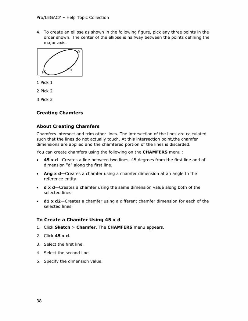
Pro/LEGACY – Help Topic Collection
38
4. To create an ellipse as shown in the following figure, pick any three points in the
order shown. The center of the ellipse is halfway between the points defining the
major axis.
1 Pick 1
2 Pick 2
3 Pick 3
Creating Chamfers
About Creating Chamfers
Chamfers intersect and trim other lines. The intersection of the lines are calculated
such that the lines do not actually touch. At this intersection point,the chamfer
dimensions are applied and the chamfered portion of the lines is discarded.
You can create chamfers using the following on the CHAMFERS menu :
• 45 x d—Creates a line between two lines, 45 degrees from the first line and of
dimension "d" along the first line.
• Ang x d—Creates a chamfer using a chamfer dimension at an angle to the
reference entity.
• d x d—Creates a chamfer using the same dimension value along both of the
selected lines.
• d1 x d2—Creates a chamfer using a different chamfer dimension for each of the
selected lines.
To Create a Chamfer Using 45 x d
1. Click Sketch > Chamfer. The CHAMFERS menu appears.
2. Click 45 x d.
3. Select the first line.
4. Select the second line.
5. Specify the dimension value.

Pro/LEGACY
39
1 Pick 1
2 Pick 2
3 45 degrees
To Create a Chamfer Using Ang x d
1. Click Sketch > Chamfer. The CHAMFERS menu appears.
2. Click Ang x d.
3. Select a reference line.
4. Select the other line.
5. Specify a chamfer dimension and angle.
1 Pick 1
2 Angle
3 Pick 2
4 Reference line
To Create a Chamfer Using d x d
1. Click Sketch > Chamfer. The CHAMFERS menu appears.
2. Click d x d.
3. Select two lines to be chamfered.
4. Specify a chamfer dimension.

Pro/LEGACY – Help Topic Collection
40
1 Pick 1
2 Pick 2
To Create a Chamfer Using d1 x d2
1. Click Sketch > Chamfer. The CHAMFERS menu appears.
2. Click d1 x d2.
3. Select two lines to be chamfered.
4. Specify a chamfer dimension for each line corresponding to the order selected.
1 Pick 1
2 d1
3 d2
4 Pick 2
5 Reference line
Working with Dimensions
About Dimensions
Using Insert > Dimensions, you can create standard or ordinate dimensions. You
can also perform various procedures on dimensions (such as aligning, clipping, or
breaking).
Draft Dimensions
Using drawing setup file options, you can make draft dimensions associative, specify
the character marking the decimal point in secondary dimensions, and control the
positioning of dimension text relative to the leader lines.

Pro/LEGACY
41
Associative Dimensions
If you want draft dimensions in the drawing to be associative, set the drawing setup
file option associative_dimensioning to yes. You cannot reset the associativity
status of existing draft dimensions; changing the option affects only new dimensions.
To update associative draft dimensions with changes in geometry, use Regen Draft
on the Legacy Dwg menu.
Decimal Point
The drawing setup file option decimal_marker specifies the character marking the
decimal point in secondary dimensions.
Text Orientation
Using the drawing setup file option text_orientation, you can control the
positioning of dimension text relative to the leader lines. For parallel placement, you
can set the drawing setup file option parallel_dim_placement to specify whether
the dimension values display above or below the leaders. This option does not apply
to dual dimensions.
To Create a Dimension
1. Click Insert > Dimension.
2. Click New References or Common Reference. The ATTACH TYPE menu
appears.
3. Pick entities to be dimensioned.
4. Middle-click to locate the dimension.
5. To indicate endpoints of the dimension, select one of the following from the
ATTACH TYPE menu:
o On Entity—Attaches the dimension to the entity at the pick point, according
to the rules for creating regular dimensions.
o Midpoint—Attaches the dimension to the midpoint of the selected entity.
o Center—Attaches the dimension to the center of a circular edge.
o Intersect—Attaches the dimension to the closest intersection point of two
selected entities.
o Make Line—Creates a line for the dimension to reference.
Note: You can change the attachment type while making a dimension. For
example, select one point using Midpoint and select On Entity and make the
second pick.
When there is more than one way to create a dimension, the DIM ORIENT menu
displays the following to define the orientation:
o Horizontal—Measures the horizontal distance between the points.

Pro/LEGACY – Help Topic Collection
42
o Vertical—Measures the vertical distance between points.
o Slanted—Measures the shortest distance between points.
o Parallel—Creates a dimension parallel to a reference line.
o Normal—Creates a dimension normal to a reference line.
When dimensioning between two arcs or an arc and a line, to place a dimension
you must select one of the following from the ARC PNT TYPE menu:
o Center—Measures to the center of an arc.
o Tangent—Measures to an imaginary tangent drawn at the point you have
picked on the arc.
To Align a Dimension with Any Point on the Screen
You can align dimensions in the horizontal or vertical direction.
1. Click Edit > Align Dimensions.
2. Pick a dimension to be moved.
3. Click Done Sel.
4. Pick a point on the screen with which to align the selected dimension.
To Create Ordinate Dimensions
1. Click Insert > Dimension > Ordinate. The ORD MAKE menu appears.
2. Click Create Base to establish a baseline for the related dimensions.
o If there is an existing baseline, pick it.
o If you need to create a baseline, pick a line and indicate where you want to
extend the baseline.
3. Start creating dimensions using the established baseline. Click to pick the
geometry to which you are dimensioning, and middle-click to place the
dimension.
Control the orientation of the ordinate dimension text by setting the
orddim_text_orientation drawing setup file optionto to parallel or
horizontal.
Adding Text to a Dimension
You can add text to a dimension using Text Line or Full Note in the Modify Text
menu.
Pro/LEGACY
43
To Change an Ordinate Dimension into Standard
1. Click Dim Type on the DIM PARAMS menu. The DIM TYPE menu appears.
2. Click Ordinate Dim.
3. Click Ord to Lin.
4. Select a dimension.
To Change the Direction of Dimension Arrows
1. Click Draft on the LEGACY DWG menu.
2. Click Flip Arrows on the DRAFT menu.
3. Pick the dimension. The arrows change direction.
Changing Arrow Style
Using Arrow Style on the Dim Params menu, you can modify styles of dimension
arrows at each end of an ISO-standard ordinate or linear dimension independently.
About Changing the Tolerance Format
You can set the tolerance format using the tol_mode configuration option. To modify
the tolerance format for individual dimensions, use the Value and Tolerance portion
of the Modify Dimension dialog box. The following tolerance formats are available:
Nominal Value, Upper Tolerance, and Lower Tolerance.
To make tolerances visible in the drawing, set the tol_display drawing setup file
option to yes. Tolerance values correspond to those given in the table at the bottom
of the window.
To Change a Dimension Symbol
Dimension symbols are the text symbols you enter to replace the Pro/ENGINEER
default dimension symbol @D.
1. Click Modify on the LEGACY DWG menu.
2. Click Dimension on the MODIFY DRAW menu.
3. Select the dimension. The Modify Dimension dialog box opens.
4. Click Dimension Text.
5. Type text in the Name text box without spaces as the new dimension symbol.
For example, for d1 you can type [LENGTH].
6. To display a dimension in its symbolic form, edit the dimension text using Text
Line or Full Note in the MODIFY TEXT menu.

Pro/LEGACY – Help Topic Collection
44
7. Replace the @D symbol or the @O symbol (used for draft dimensions) with the @S
symbol.
8. To switch back, do the opposite.
To Modify a Dimension Value
Using Value on the Modify Draw menu, you can change the value of all dimensions
except imported dimensions.
1. Click Modify on the LEGACY DWG menu.
2. Click Value on the MODIFY DRAW menu.
3. Select a dimension value to modify and specify a new value.
About Modifying the Number of Digits
You can modify the number of digits using Num Digits on the Modify Draw menu
or the Number of Digits text box in the Modify Dimension dialog box. To access
Num Digits, click Modify on the Legacy Dwg or Draft menu.
To Control the Placement of Dual Dimensions (Primary and Secondary)
You can specify the location of dual dimensions using the Modify Dimension dialog
box.
1. Click Modify on the LEGACY DWG menu.
2. Select a dimension.
3. Click Done Sel on the GET SELECT menu. The Modify Dimension dialog box
opens.
4. In Dual Dimensioning, click Below to place the secondary dimension below the
primary dimension or click Beside to place it on the same line as the primary
one.
To Convert a Standard Dimension to Ordinate
After you have created the dimension, you can change its type from standard to
ordinate, and vice versa.
1. Click Insert > Dimension > Ordinate. The ORD MAKE menu appears.
2. Click Create Base to establish a baseline for related dimensions.
If the baseline already exists in the drawing, set it using Set Base.
3. After you have converted the first standard dimension into ordinate and
established the baseline, continue to convert other related dimensions using
Lin to Ord.
Pro/LEGACY
45
Updating Draft Dimensions
To update draft geometry to the changes made to associative dimensions, use Edit
> Regenerate > Draft.
Creating Gaps in Lines
To create gaps in dimension witness lines and in leader lines of notes, symbols, and
radial dimensions, you can use Insert > Break.
Note: You cannot break leaders of diameter dimensions.
To access Break, click Draft on the Legacy Dwg menu.
Increasing the Gap between a Dimension Line and Geometry
The system creates dimensions with a gap between the dimension extension lines
and the geometry. If you want to increase the gap, use Clip on the Draft menu. You
can erase witness lines by using Wit Line Disp on the Dim Params menu, making
them look like clipped dimensions.
Adding a Jog
You can add jogs to linear (standard and ordinate) and angular dimension witness
lines, note leaders, and symbol leaders using Insert > Jog.
When creating standard dimensions, you can add a jog to a dimension using the Jog
Line menu:
• No Jogs—Creates an ordinate dimension with no jog line.
• One Jog—Creates an ordinate dimension with one jog line. Select One Jog
before picking the dimension for modification.
Sketching Lines
About Sketching Lines
To access the line sketching commands, use Line in the Dft Create menu. You can
sketch lines continuously as a chain or as individual entities.
To specify the required drafting mode, select one of the following from the Line
menu:
• Chain Mode—Sketches entities continuously.
• No Chain—Sketches individual lines.
• Break Chain—Breaks the chain at the current point; this interrupts the current
chain, enabling you to create another chain of entities.

Pro/LEGACY – Help Topic Collection
46
To Create a Line Using 2 Points
2 Points creates a line between two points.
1. Click Line on the DFT CREATE menu.
2. Click 2 Points on the LINE menu.
3. Pick any two points. A line connects the specified points.
To Create a Line Using Horiz Line
Horiz Line creates a horizontal line between two points.
1. Click Line on the DFT CREATE menu.
2. Click Horiz Line on the LINE menu.
3. Pick the startpoint and endpoint. If Chain is selected, elements of the chain
consist of horizontal and vertical lines alternately.
1 Pick 1
2 Pick 2
3 Pick 3
To Create a Line Using Vert Line
Vert Line creates a vertical line between any two points.
1. Click Line on the DFT CREATE menu.
2. Click Vert Line on the LINE menu.
3. Pick the startpoint and endpoint. If Chain is selected, elements of the chain
consist of horizontal and vertical lines alternately.
1 Pick 1
2 Pick 2
3 Pick 3

Pro/LEGACY
47
To Create a Line Using Angle
Angle creates a line at an angle measured from the reference line.
1. Click Line on the DFT CREATE menu.
2. Click Angle on the LINE menu.
3. Select a reference line for measuring the angle.
4. Pick a startpoint.
5. Pick a reference line.
6. Enter the required angle.
7. Pick an endpoint of the line.
1 Pick 1
2 Pick 2
3 Angle
To Create a Line Using Pnt/Tang
Pnt/Tang creates a line that is tangent to a curve at its second endpoint.
1. Click Line on the DFT CREATE menu.
2. Click Pnt/Tang from the LINE menu.
3. Pick the startpoint for the line.
4. Select a curve to which the line is to be tangent. The line ends at the point of
tangency.
1 Pick 1
2 Pick 2

Pro/LEGACY – Help Topic Collection
48
To Create a Line Using Parl Line
Parl Line creates a line that is parallel to a specified line.
1. Click Line on the DFT CREATE menu.
2. Click Parl Line on the LINE menu.
3. Pick the startpoint for the line and another line to set the direction.
4. Pick or specify the endpoint.
1. Pick 3
2 Pick 1
3 Existing line
4 Pick 2
To Create a Line Using Perp Line
Perp Line creates a line that is perpendicular to a specified line.
1. Click Line on the DFT CREATE menu.
2. Click Perp Line on the LINE menu.
3. Pick the startpoint for the line.
4. Select another line to set the direction.
5. Pick or specify the endpoint.
1 Pick 3
2 Pick 1
3 Existing line
4 Pick 2

Pro/LEGACY
49
To Create a Line Using Norm At Point
Use Norm At Pt to create a line that is normal to a curve.
1. Click Line on the DFT CREATE menu.
2. Click Norm At Pnt on the LINE menu.
3. Pick a point on the curve to which the line is normal (you can select any draft
geometry).
4. Select the startpoint and endpoint for the line.; Both points must lie on
existing draft entities.
1 Picks 1 and 2
2 Line created normal to arc
3 Pick 3 on existing line
To Create a Line Using Tang Line
Use Tang Line to create a tangent at the endpoint of an arc or spline.
1. Click Line on the DFT CREATE menu.
2. Click Tang Line on the LINE menu.
3. Pick the endpoint of an arc or a spline.
4. Locate the second endpoint.
1 Pick 1
2 Pick 2
To Create a Line Using 2 Tang Line
Use 2 Tang Line to create a line that is tangent to two circles or splines.
1. Click Line on the DFT CREATE menu.
2. Click 2 Tang Line on the LINE menu.
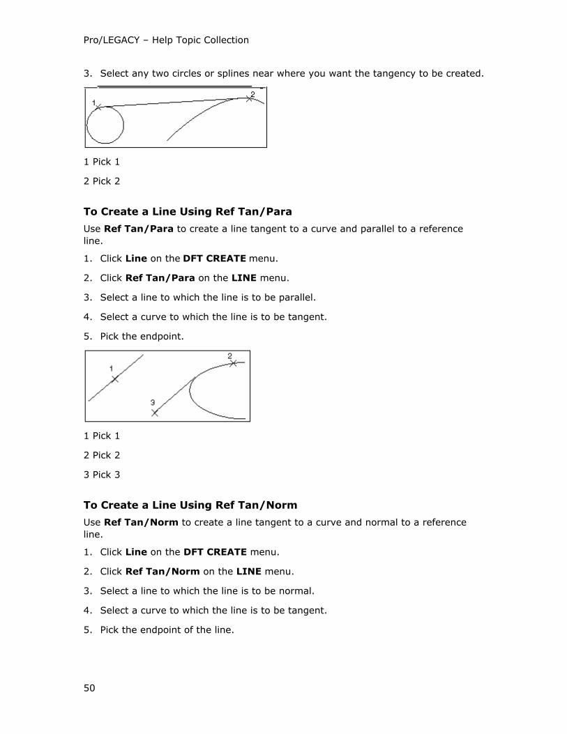
Pro/LEGACY – Help Topic Collection
50
3. Select any two circles or splines near where you want the tangency to be created.
1 Pick 1
2 Pick 2
To Create a Line Using Ref Tan/Para
Use Ref Tan/Para to create a line tangent to a curve and parallel to a reference
line.
1. Click Line on the DFT CREATE menu.
2. Click Ref Tan/Para on the LINE menu.
3. Select a line to which the line is to be parallel.
4. Select a curve to which the line is to be tangent.
5. Pick the endpoint.
1 Pick 1
2 Pick 2
3 Pick 3
To Create a Line Using Ref Tan/Norm
Use Ref Tan/Norm to create a line tangent to a curve and normal to a reference
line.
1. Click Line on the DFT CREATE menu.
2. Click Ref Tan/Norm on the LINE menu.
3. Select a line to which the line is to be normal.
4. Select a curve to which the line is to be tangent.
5. Pick the endpoint of the line.

Pro/LEGACY
51
1 Pick 1
2 Pick 3
3 Pick 2
Sketching Circles
To Create a Circle Using Center/Pnt
To access the circle sketching commands, use Circle on the Dft Create menu.
Center/Pnt creates a circle by locating its center and a point on the circle.
1. Click Circle on the DFT CREATE menu.
2. Click Center/Pnt on the CIRCLE menu.
3. Pick the circle center.
4. Pick a point that lies on the circle.
1 Pick 1
2 Pick 2
To Create a Circle Using Center/Tang
Center/Tang creates a circle by locating its center and defining a point as the
tangency with another entity.
1. Click Circle on the DFT CREATE menu.
2. Click Center/Tang on the CIRCLE menu.
3. Pick the circle center.
4. Select another entity near where you want the tangency to be created.

Pro/LEGACY – Help Topic Collection
52
1 Pick 1
2 Pick 2
To Create a Circle Using Center/Rad
Center/Rad creates a circle by specifying its center and radius.
1. Click Circle on the DFT CREATE menu.
2. Click Center/Rad on the CIRCLE menu.
3. Pick the circle center.
4. Specify the radius of the circle.
To Create a Circle Using Center/Dia
Center/Dia creates a circle by specifying its center and diameter.
1. Click Circle on the DFT CREATE menu.
2. Click Center/Dia on the CIRCLE menu.
3. Pick the circle center.
4. Specify the diameter of the circle.
To Create a Circle Using 3 Tangent
3 Tangent creates a circle tangent to three other entities.
1. Click Circle on the DFT CREATE menu.
2. Click 3 Tangent on the CIRCLE menu.
3. Select any three entities to which the circle is to be tangent.

Pro/LEGACY
53
1 Pick 1
2 Pick 2
3 Pick 3
To Create a Circle Using Fillet
Fillet creates a circle with a specified radius tangent to two other entities.
1. Click Circle on the DFT CREATE menu.
2. Click Fillet on the CIRCLE menu.
3. Select two entities to which the circle is to be tangent.
4. Specify the radius for the circle.
1 Pick 1
2 Pick 2
To Create a Circle Using 3 Points
3 Points creates a circle using any three points that lie on the circle.
1. Click Circle on the DFT CREATE menu.
2. Click 3 Points on the CIRCLE menu.
3. Pick the three points in the order shown.
1 Pick 1
2 Pick 2
3 Pick 3

Pro/LEGACY – Help Topic Collection
54
Sketching Arcs
To Create an Arc Using Tang End
Tang End creates an arc with its first endpoint tangent to another open entity, not a
circle or an ellipse.
1. Click Sketch > Arc > 3 Points/Tangent End.
2. Select the endpoint of another entity. An arc attaches at the endpoint of the
entity.
3. Pick the endpoint of the arc.
Creating an Arc Using Tang End
1 Pick 1
2 Pick 2
3 Line determining tangency direction
To Create an Arc Using 3 Points
3 Points creates an arc between any three points that lie on the arc.
1. Click Sketch > Arc > 3 Points/Tangent End.
2. Pick the three points in the order shown.
Creating an Arc Using 3 Points
1. Pick 3
2 Pick 2
3 Pick 1
To Create an Arc Using Center and Ends
Center and Ends creates an arc using the arc center and two endpoints.
1. Click Sketch > Arc > Center and Ends.

Pro/LEGACY
55
2. Pick the center for the arc.
3. Indicate two endpoints.
To Create an Arc Using Pnt/Ctr/Ang
Pnt/Ctr/Ang creates an arc using a startpoint, the arc center, and an angle that
strokes the arc from the startpoint in a counterclockwise direction.
1. Click Arc on the DFT CREATE menu.
2. Click Pnt/Ctr/Ang on the ARC menu.
3. Pick the startpoint of the arc.
4. Pick the arc center.
5. Specify an angle for the arc in the counterclockwise direction.
Creating an Arc Using Pnt/Ctr/Ang
1 Pick 1
2 Pick 1
3 Enter angle
To Create an Arc Using 3 Tangent
3 Tangent creates an arc tangent to three other entities.
1. Click Arc on the DFT CREATE menu.
2. Click 3 Tangent on the ARC menu.
3. Select any three entities to which the arc is to be tangent. The order in which you
select the entities defines the direction of the arc.
Creating an Arc Using 3 Tangent

Pro/LEGACY – Help Topic Collection
56
1 Pick 1
2 Pick 2
3 Pick 3
To Create an Arc Using Fillet
Fillet creates an arc with a specified radius tangent to two other entities.
1. Click Arc on the DFT CREATE menu.
2. Click Fillet on the ARC menu.
3. Specify the radius for the arc.
4. Select any two entities to which the circle is to be tangent. The lines are
automatically trimmed when they connect with the arc.
Creating an Arc Using Fillet
1 Pick 1
2 Pick 2
Filleting between two arcs, circles, splines, or all of them, can result in any number
of fillets. The size and location of the fillet are both dependent upon the pick
locations. The following figure shows the approximate pick locations to achieve
certain concave or convex, or both variations in the fillets.
Pick Locations

Pro/LEGACY
57
Working with Cross-Sections
About Cross-Sections
Using the Draft Xsec menu (by choosing X-Section on the Dft Create menu), you
can create hatched or filled cross-sections. To modify the spacing angle, offset, and
line style of the cross-hatching pattern lines, use the Mod Xhatch menu. You can
also add and delete lines, as well as save and retrieve patterns.
Boundaries for Hatched and Filled Cross-Sections
1 Outer boundary for hatched cross-section
2 Inner boundary for hatched cross-section
3 Outer boundary for filled cross-section
4 Inner boundary for filled cross-section
Creating a Cross-Section
In a drawing, cross-section boundaries are defined by a closed loop of geometry
according to the following rules:
• A cross-section can contain clear areas (islands) defined by a closed loop.
• Any number of islands can be defined within a cross-section.
• Inner boundaries, defining islands, cannot cross the outer boundary, nor can they
cross each other.
• A cross-section belongs to the view in which its boundary was created.
To delete a cross-section, use Delete on the Draft menu. To modify it, use
Xhatching on the Modify Draw menu.
To Create a Hatched Cross-Section
1. Click X-section on the DFT CREATE menu.
2. Click Hatch on the DRAFT XSEC menu.
3. Define the outer and inner boundaries of the cross-sectioned area by selecting
entities forming a loop.
4. Click Done Sel on the GET SELECT menu.
5. Type a name for the cross-section.
6. Specify cross-hatching parameters using the MOD XHATCH menu.

Pro/LEGACY – Help Topic Collection
58
To Create a Filled Cross-Section
1. Click X-section on the DFT CREATE menu.
2. Click Fill on the DRAFT XSEC menu.
3. Define the outer and inner boundaries of the cross-sectioned area by selecting
entities forming a loop.
4. Click Done Sel on the GET SELECT menu.
5. Type a name for the cross-section. The system fills in the cross-section with the
color corresponding to the current line style.
To Modify the Cross-Hatching Pattern
1. Click Modify on the LEGACY DWG menu.
2. Click Xhatching on the MODIFY DRAW menu.
3. Pick inside the cross-section to be modified. The MOD XHATCH menu appears.
Use the MOD XHATCH menu to modify the selected cross-hatching.
You may apply changes to an individual pattern line or to all pattern lines by
selecting either Individual or Overall on the Modify Mode menu before you effect
the changes.
To Modify the Spacing
1. Click Spacing on the MOD XHATCH menu. The MODIFY MODE menu appears.
2. Click Individual or Overall.
3. Select one of the following:
o Half—Reduces the spacing between lines by half.
o Double—Doubles the spacing between lines.
o Value—Prompts you to enter a value (in drawing units) as the spacing
between lines.
To Modify the Angle of Hatching
1. Click Angle on the MOD XHATCH menu. The MODIFY MODE menu appears.
2. Click Individual or Overall.
3. Select one of the angles from the menu (0, 30, 45, 60, 90, 120, 135, 150,
Value). If you select Value, you can type a value for the angle.
To Modify the Line Style
To modify the line style, use Line Style on the Mod Xhatch menu. The Line Style
dialog box opens.

Pro/LEGACY
59
To Modify the Offset of a Parallel Line Pattern
1. Click Offset on the MOD XHATCH menu.
2. Specify a value for the offset (in drawing units).
To Add a Line to a Pattern
1. Click Add Line on the MOD XHATCH menu.
2. Specify an angle for cross-hatching.
3. Type the offset value.
4. Type the spacing value.
After you add the second pattern line, you can modify parameters of each pattern
line by selecting the required pattern line using Next Line and Prev Line.
To Delete a Line
To delete a line from a pattern, use Delete Line on the Mod Xhatch menu.
To Save a Cross-Hatch Pattern
1. Click Save on the MOD XHATCH menu.
2. Type a name for the cross-hatch pattern.
A file is created with the name you typed and the extension ".xch," and stores it
in your current directory. You can then move it to a special area containing other
cross-hatch patterns.
To Retrieve a Pattern
1. Click Retrieve on the MOD XHATCH menu. The LIST menu displays the
following:
o Cross-hatch patterns in the current directory
o Cross-hatch patterns in the default cross-hatch directory if you set the
pro_crosshatch_dir configuration option
o Nine standard system-supplied cross-hatch patterns
2. Select a cross-hatch pattern. The selected pattern replaces the existing one.

Pro/LEGACY – Help Topic Collection
60
Standard System-Supplied Cross-Hatch Patterns
1 Aluminium
2 Copper
3 Electric
4 Glass
5 Iron
6 Plastic
7 Steel
8 Titanium
9 Zinc
Modifying Geometry
About Modifying Geometry
You can modify geometry in the following ways:
• Move selected entities from one location to another along the translation vector
• Rotate selected entities by a specified angle
• Create copies of selected entities

Pro/LEGACY
61
• Mirror selected entities about a mirror line
• Trim the length of selected entities
• Divide two entities at their intersection point
• Stretch a draft entity
• Divide entities into equal segments
• Resize geometry items
• Group entities together
• Measure the distance between two entities
• Measure the angle between two lines
• Add or remove draft entities to or from a related view
To Translate Entities
You can move entities from one location to another along the translation vector using
Translate.
1. Click Edit > Transform > Translate.
2. Pick draft entities to be translated.
3. Click Done Sel on the GET SELECT menu when you have finished.
4. Indicate the "from" position. The translation vector appears.
5. Indicate the "to" position.
To Rotate Entities
You can rotate entities by a specified angle using Rotate.
1. Click Edit > Transform > Rotate.
2. Select all the entities to be rotated.
3. Click Done Sel on the GET SELECT menu.
4. Enter a rotation angle for the entities. The angle is measured from the horizontal
line in the counterclockwise direction.
5. Select the center point for the rotation.
To Create Copies by Translating
You can create copies of selected entities either by translating (creating linear
patterns) or by rotating (creating rotational patterns).
1. Click Edit > Transform > Translate and Copy.
2. Pick entities to copy.

Pro/LEGACY – Help Topic Collection
62
3. Click Done Sel on the GET SELECT menu.
4. Indicate the "from" position. The translation vector appears.
5. Indicate the "to" position.
6. Specify the number of copies.
If you specify more than one, a pattern of selected entities is created using the
direction and displacement distance specified by the translation vector.
Creating Copies by Translating
1 Before translation
2 After translation
3 Translation vector
To Create Copies by Rotating
1. Click Edit > Transform > Rotate and Copy.
2. Pick entities to copy.
3. Click Done Sel on the GET SELECT menu.
4. Type a rotation angle for the entities in the counterclockwise direction.
5. Select the center point for the rotation.
6. Type the number of copies.
To Mirror Entities
You can create a copy of selected entities (geometry and unattached notes) by
mirroring about a mirror line.
1. Click Edit > Transform > Mirror.
2. Pick the entities that you want to mirror.
3. Click Done Sel on the GET SELECT menu.

Pro/LEGACY
63
4. Pick a line about which entities are to be mirrored. The entities mirrored about
the line are displayed.
Mirroring
1 Original
2 Mirrored copy
3 Mirror line
To Trim or Extend an Entity by a Specified Amount
1. Click Edit > Trim > Increment.
2. Type the required increment value (positive or negative).
3. Select the entity to modify.
4. Click Done Sel on the GET SELECT menu.
About Trimming Entities to a Specified Bounding Entity or Point
To adjust the length of selected entities, use Trim. The geometry definition is used
to find the intersection of the entity with the bounding entity. If an intersection
cannot be calculated, the entity is not trimmed. Trim does not work in the following
instances:
• When a spline does not intersect the bounding entity
• When the continuation of an arc does not intersect the bounding geometry
Note: You cannot trim construction geometry. However, you can use it to
intersect other entities.
To Trim or Extend an Entity to a Specified Bounding Entity or Point
1. Click Edit > Trim > Bound.
2. Select the bounding entity.
3. Select the entity to be trimmed. If the entity is to be shortened, pick the portion
of the entity that you want to remain in the drawing. If the entity is to be
lengthened, pick anywhere on the entity.
4. Click Done Sel on the GET SELECT menu.

Pro/LEGACY – Help Topic Collection
64
To Trim or Extend an Entity to a Specified Length
1. Click Edit > Trim > Length.
2. Type the required entity length.
3. Select the entity to be modified.
4. Click Done Sel on the GET SELECT menu.
To Trim or Extend to Make a Corner
1. Click Edit > Trim > Corner.
2. Select two entities to trim. The two entities are trimmed and joined at one point
to form a corner.
To Intersect Geometry
You can divide two entities at their intersection using Intersect. Intersecting two
entities creates four entities unless one of the entities is a construction line. If there
is more than one possible intersection, such as a spline crossing a line in several
places, the intersection closest to your pick point is calculated. You can select a point
entity as one of the entities to be intersected.
Note: You cannot intersect construction geometry. However, you can use it to
intersect other entities.
1. Click Edit > Trim > Divide at Intersect.
2. Select the two entities.
About Stretching Entities
You can stretch entities using Stretch. When stretching entities, keep in mind the
following rules:
• Location of entities outside the selection box is not affected.
• Circles and arcs with centers outside the box are not affected.
• Lines that cross the selection box stretch so that the their locating point within
the box is translated along the translation vector.
• Tangency may not be preserved in the process of stretching.

Pro/LEGACY
65
Stretching Entities
1 Before
2 After
3 Enclose items in the selection box
4 Translation vector
To Stretch Entities
1. Click Edit > Transform > Stretch.
2. Click to enclose entities to be stretched within the pick box.
3. If you need to edit your selection, pick individual entities that you want to
exclude from the selection.
4. Middle-click to accept the selection.
5. Define the translation vector by picking the first location—the "from" location.
6. Pick the final destination point—the "to" location.
To Divide an Entity
You can divide entities into equal segments. You can divide more than one entity at
the same time.
1. Click Edit > Trim > Divide by Equal Segments.
2. Pick entities to divide.
3. Click Done Sel on the GET SELECT menu.
4. Specify the number of equal segments.
5. The entities ar divided and the break points are highlighted.

Pro/LEGACY – Help Topic Collection
66
Dividing Entities
1 The point at which the circle begins dividing
To Resize an Entity
You can rescale geometry items using Rescale.
1. Click Edit > Transform > Rescale.
2. Pick entities to rescale.
3. Click Done Sel on the GET SELECT menu.
4. Select the origin relative to which the entity is to be rescaled.
5. Specify the scale.
Scaling Geometry Items
1 Before
2 After
3 Pick box
4 Origin
About Using Groups
You can group entities together to perform the same procedures on a collection of
them. For procedures such as translate, move, resize, copy, or mirror, grouped
entities act as one.
When using groups, keep in mind the following:
• A group may include all kinds of detail items such as draft entities, notes,
symbols, geometric tolerances.
• You can dimension grouped entities individually.

Pro/LEGACY
67
Pro/ENGINEER creates a cross-section as a group automatically. The group contains
the cross-hatch and the bounding entities. You cannot explode the cross-hatching;
you can only delete it. After you complete procedures on the group, you can explode
it (dissociate all entities).
To access the group functionality, click Edit > Group > Draft Group. The Draft
Group menu displays the following:
• Create—Creates a group by assigning entities and specifying its name.
• Suppress—Suppresses a group by removing it from the display.
• Resume—Redisplays a suppressed group.
• Explode—Ungroups entities associated with a group.
• Edit—Adds entities to a group or removes them from a group.
To Measure the Distance Between Two Entities
You can measure the distance between the following:
• Two points
• Two parallel lines
• A point and a line
1. Click Draft on the LEGACY DWG menu.
2. Click Tools on the DRAFT menu.
3. Click Meas Dist on the TOOLS menu.
4. Pick two entities.
5. Use Query Sel on the GET SELECT menu, if necessary. The Message Window
displays the measured distance between them, as well as the distance in the X-
and Y-direction, where appropriate.
To Measure the Angle Between Two Lines
1. Click Draft on the LEGACY DWG menu.
2. Click Tools on the DRAFT menu.
3. Click Meas Angle on the TOOLS menu.
4. Pick two lines. The angle measured depends on where you select the edges, as
shown in the following figure. The selected geometry highlights in red, and the
system displays the angle in the Message Window.

Pro/LEGACY – Help Topic Collection
68
Measuring the Angle Between Two Lines
To Move Geometry
Using the Draft menu, you can move an entity or delete entities. You can also use
Modify on the Legacy Dwg menu.
You can move an entity using Move on the Draft menu. Notice that when you select
the entity to be moved, it attaches to and moves with the cursor. A group of items is
selected as one entity.
To Delete Geometry in Pro/LEGACY
To delete geometric entities, you can use Edit > Delete.
To Modify the Diameter of an Arc or Circle
Using the pop-up menu or the EDIT ACTIONS menu, you can modify a spline or the
diameter of a draft arc or circle.
1. Click Mod Arc Diam on the EDIT ACTIONS menu or the pop-up menu.
2. Pick an arc or circle.
3. Type a new value for the diameter.
To Change Line Style
You can control the line style in a drawing using Format > Line Style. Click Modify
Lines on the LINE STYLES menu.
Modifying Splines
To Move a Point
1. Click Modify Spline on the EDIT ACTIONS menu or the pop-up menu. The
MOD SPLINE menu displays the following:
o Move Pnts—Moves spline points.
o Add Pnts—Adds spline points.
o Delete Pnts—Deletes selected spline points.
Pro/LEGACY
69
o Control Poly—Moves spline control points.
o Sparse—Decreases the number of spline points by specifying the deviation
value.
o Smooth—Smooths the spline by averaging the specified number of spline
points.
2. Select the spline that you want to modify. The spline points display.
3. Click Move Pnts on the MOD SPLINE menu. The MOVE PNTS menu
appears.
4. Click Single Pnt.
5. Pick a spline point to be moved. The point highlights in red.
6. Pick a new location for the point. The spline updates accordingly.
Alternatively, you can choose Point Range to move a range of spline points by
picking two limiting points for the range to be adjusted. When the limiting points
highlight in green, pick any point within this range; then pick its new position. The
resulting spline is displayed in green.
Click Done Move on the Done Move menu.
To Modify a Spline by Adding Points
1. Click Add Pnts on the MOD SPLINE menu. The NEW POINTS menu displays
the following:
o Interior—Adds points to the interior of the spline.
o Exterior—Extends the spline by adding points beyond its current endpoints.
2. Click Interior.
3. Pick any location on the spline between any two existing points.or click
Exterior.
4. Pick the spline endpoint to extend.
5. Pick additional points.
To Delete a Point from a Spline
1. Click Delete Pnts on the MOD SPLINE menu.
2. Pick a spline point to be removed. The point disappears.

Pro/LEGACY – Help Topic Collection
70
To Modify a Spline Using Control Poly
1. Click Control Poly. The spline’s control polygon appears, displayed in white.
2. To adjust the shape of the spline, pick a point on the control polygon and drag it
to a new location. You cannot pick endpoints. The spline rubberbands to its new
shape as you move the point.
3. Place the control point by clicking in the required location for the point.
Modifying the Shape of a Spline
Using Control Poly, you can modify the shape of a spline. When you click Control
Poly, spline control points display with line segments between them on the spline.
The line segments begin and end at the startpoints and endpoints of the spline, and
intermediate segments always remain tangent to the spline. These line segments are
visual aids for modifying the shape of the spline.
You can move the spline control points by picking them and dragging them to a new
location. The spline curve rubberbands with the point movement to display how the
spline shape changes with movement of the points.
Note: You cannot use Control Poly to move a spline endpoint, or to modify a spline
that has a tangency condition defined for one end only.
To Decrease the Number of Spline Points with a Deviation Value
1. Click Sparse on the MOD SPLINE menu.
2. Type any positive value for a deviation that causes the spline to be redrawn
without one or more of its points.
The resulting spline is displayed in green, and you are informed of the number of
points removed.
3. To accept the changed spline, click Confirm on the CONFIRMATION menu.
To reject the changes, click Cancel and type a different deviation value. For each
spline, you may need to type several different deviation values before achieving
the required result.
To Smooth a Spline in Pro/LEGACY
1. Click Smooth on the MOD SPLINE menu.
2. Type any positive value for a number of points that are to be averaged together
to smooth the spline. The centermost point on the spline and the appropriate
number of points on each side of it are averaged.
3. To accept the changed spline, click Confirm on the CONFIRMATION menu.
To reject it, click Cancel and specify a different number of points.

Pro/LEGACY
71
Working with Text in Drawings
About Text in Drawings
You can add text to a drawing in the form of a note using Insert > Note. To
manipulate notes in other ways, such as rotating, mirroring, and copying, you can
use the same commands that you use to manipulate detail items.
To specify the note type, select from the following displayed in the NOTE TYPES
menu:
• No Leader—Creates a note without a leader.
• Leader—Creates a note with a leader. You can attach a leader to an entity or to
any point on the drawing.
• ISO Leader—Creates a note with an ISO-standard leader.
• On Item—Creates a note on an edge, datum point, or axis.
• Enter—Prompts you to type text from the keyboard. When typing notes,
conclude each line of text with <CR>; to end the note, type <CR><CR>. To
include a blank line in the note text, type <SPACE><CR>.
• File—Prompts you to enter text from a text file.
• Horizontal—Creates a horizontal note.
• Vertical—Creates a vertical note.
• Angular—Creates a note at an angle. Specify a positive angular value between 0
and 359 degrees.
• Standard—Attaches more than one leader to a note.
• Normal Ldr—Places a leader normal to the specified entity; in this case, the note
can have only one leader.
• Tangent Ldr—Places a leader tangent to the specified entity; in this case, the
note can have only one leader.
• Left—Left-justifies text.
• Center—Centers text.
• Right—Right-justifies text.
• Default—Justifies text using the default justification. The justification selected for
the first note becomes the default for all successive notes added during the
current session.
• Style Lib—Creates or modifies text styles.
• Cur Style—Sets the current text style.
• Make Note—Begins the notemaking process.

Pro/LEGACY – Help Topic Collection
72
Editing a Note
You can create, modify, and delete text styles of drawing notes using Text on the
Modify Draw menu. When you click Text, the Modify Text menu displays the
following:
• Text Line—Modifies a single line of text in a note.
• Full Note—Enters the editor, allowing you to modify any portion of the note text.
• Text Height—Modifies text height of multiple dimensions or notes.
• Text Style—Modifies the style of existing text. The Text Style dialog box opens.
• Style Lib—Adds, deletes, or edits named text styles. The Text Style Library
dialog box opens.
• Cur Style—Displays a list of existing styles, prompting you to select one as the
current style. If you select Default, the style that is defined by the
drawing_text_height, text_width_factor, and text_thickness drawing
setup file options is used.
• Leader Type—Toggles a note leader between ISO-standard and non-ISO-
standard leader styles.
Procedures on Notes
You can perform the following procedures on notes using options for manipulating
detail items:
• Move an unattached note using Move in the Draft menu.
• Reattach notes with leaders using Mod Attach in the Draft menu.
• Rotate a note using Rotate in the Tools menu.
• Mirror a note about a mirror line using Mirror in the Tools menu.
• Add a jog to a note leader using Make Jog in the Draft menu.
• Copy a note using Copy in the Tools menu.
• Switch a note to another sheet using Switch Sheet in the Sheets menu.
To Add a Note with a Leader to a Drawing
1. Click Insert > Note. The NOTE TYPES menu appears.
2. Click Leader and any other valid command, including the type of leader
(Standard, Normal Ldr, or Tangent Ldr).
3. Click Make Note.
4. If Leader is selected, the ATTACH TYPE menu displays the following:
o Arrow Head—Ends a leader with an arrow.
o Dot—Ends a leader with a dot.

Pro/LEGACY
73
o Filled Dot—Ends a leader with a filled dot.
o No Arrow—Ends a leader without an arrow.
o Slash—Ends a leader with a slash.
o Integral—Ends a leader with an integral.
o Box—Ends a leader with a box.
o Filled Box—Ends a leader with a filled box.
Leader Types
1 Arrow head
2 Dot
3 Filled dot
4 No arrow
5 Slash
6 Integral
7 Box
8 Filled box
Note: The arrow styles are controlled by the drawing setup file.
5. Select any of the above commands.
6. Pick an entity to which to attach the leader.
7. Click Done Sel.
8. Select the location for the note.
9. Type the note text and conclude with <CR><CR>.
To Add a Note without a Leader
Using the NOTE TYPES menu, you can create notes with or without a leader, and
you can enter a note from a file.
1. Click Insert > Note. The NOTE TYPES menu appears.
2. Click No Leader and any other commands that are necessary.
3. Click Make Note.

Pro/LEGACY – Help Topic Collection
74
4. Select the location for the note.
5. Type the note text and conclude with <CR><CR>.
To Enter Notes
1. Click Insert > Note. The NOTE TYPES menu appears.
2. Click File and any other necessary commands.
3. Click Make Note.
4. Select the location for the note.
5. Type the name of the file with its extension. The note appears in the specified
location.
Note: You cannot specify the information for text height, text width, text angle,
slant angle, and so on, from a file. You must change it manually using Text Style
on the Modify Text menu.
Working with Geometric Tolerances
About Geometric Tolerances
When you add a geometric tolerance (gtol) to a drawing, you may choose the model
in which to place the gtol, or instead create a nonparametric graphical gtol within the
drawing itself. However, before you can add a gtol to a drawing, you must have set
datums and basic dimensions.
To access the geometric tolerance functionality, click Insert > Geometric
Tolerance. The Geom Tol menu displays the following:
• Set Datum—Sets a datum to be used as a reference for geometric
tolerances.
• Basic Dim—Creates basic dimensions.
• Inspect Dim—Creates inspection dimensions.
• Specify Tol—Creates a geometric tolerance.
• Make Target—Sets a datum target.
You can set a reference datum by selecting either Draft or Modify on the Legacy
Dwg menu.
To Set a Reference Datum
1. Click Insert > Geometric Tolerance.
2. Click Set Datum on the GEOM TOL menu.
3. Select the datum plane or axis to be set. The datum is enclosed in a feature
control frame.

Pro/LEGACY
75
To place a set datum in a note or dimension, edit its text and type: @[-D-.
This produces the following:
Tip: Setting a Reference Datum
1. Click Insert > Datum > Axis. The Axis dialog box opens.
2. Select the datum on the screen.
3. Click A. The datum is enclosed in a feature control frame.
4. Click OK.
To Transform Dimensions into Basic Dimensions
1. Click Draft on the LEGACY DWG menu.
2. Click Geom Tol on the DFT CREATE menu.
3. Click Basic Dim on the GEOM TOL menu.
4. Pick dimensions to be converted.
5. Click Done fon the EXIT menu.
Note: Text added to a dimension appears inside the box indicating a basic
dimension. To have text appear outside the box, add a box by editing dimension
text.
To clear basic dimensions, click Delete on the Draft menu. This removes the
frame, leaving the dimensions intact.
To Set Inspection Dimensions According to the DIN Standard
1. Click Draft on the LEGACY DWG menu.
2. Click Geom Tol on the DFT CREATE menu.
3. Click Inspect Dim on the GEOM TOL menu.
4. Select the dimensions.
5. Click Done Sel on the GET SELECT menu
6. Click Done on the EXIT menu.
Setting Inspection Dimensions
To clear inspection dimensions, click Delete on the Draft menu.

Pro/LEGACY – Help Topic Collection
76
To Add a Gtol to a Pro/LEGACY Drawing
1. Click Insert > Geometric Tolerance. The Geometric Tolerance dialog box
opens. Model Refs is selected.
2. Specify the model to which the gtol is to be added. By default, the current gtol
model is the current drawing model.
3. Select the gtol type.
4. Specify the reference entity (the type of entity to which the gtol applies).
5. Click Place Gtol. If the gtol is attached directly to a datum, it is displayed
(Datum is selected in the Type menu). Otherwise, make a selection on the Type
menu.
6. Specify the datum references and material conditions, if applicable.
7. Specify a tolerance value and material condition, if applicable.
8. Specify symbols and modifiers, the profile direction, and the projected tolerance
zone, if applicable. The complete gtol now displays in the drawing.
9. To adjust the placement, click Move.
10. Select the gtol in the drawing. The gtol moves dynamically with the cursor until
you place it in a new location.
11. Click OK to close the dialog box and save the changes or click New Gtol to
continue.
The reference entity selection and placement information is cleared from the
dialog box, but all other data is retained. When you enter the gtol creation mode
again, it retains all options in the previous session of gtol creation for the object
in the current window (model or drawing).
To quit out of the gtol creation mode and cancel the changes, click Cancel.
Specifying Geometric Tolerances
This section contains basic information on how to create a gtol. To add a gtol to a
Pro/LEGACY drawing, use the Geometric Tolerance dialog box. You may use two,
three, or all four of the Geometric Tolerance dialog box displays, depending on the
specific characteristics of the gtol you are creating. This section explains the general
process for creating all gtols.
Specifying Compound Datum Features
You can specify a compound datum as the reference datum for geometric tolerances.
In a compound datum, two datum features act as a reference datum.

Pro/LEGACY
77
Compound Datum
1 First datum feature
2 Second datum feature
To Delete a Geometric Tolerance
To remove a geometric tolerance, use Edit > Delete.
To Create a Datum Target
You can modify a gtol by changing the value of an individual material condition
symbol, or by adding, removing, or replacing a datum reference.
When you click Insert > Geometric Tolerance, the Geometric Tolerance dialog
box opens.
1. Click Make Target on the GEOM TOL menu.
2. Select a "set" reference datum in the drawing that the datum targets are
defining. You can also select draft datum planes and axes.
3. Select one of the following from the TARGET menu:
o Simple—Contains the name of the referenced datum in the lower half of the
datum target symbol.
o Diameter—Selects a dimension for each datum point, and displays it in the
top half of the datum target symbol.
The GET DTM PNT menu appears.
4. Click Select Point.
5. Pick a datum point in the drawing or click Create Point and create a point as
needed.
6. Pick the location for the target.
Working with Symbols
About User Symbols
You can define a user symbol, create datum planes and axes, and add surface finish
symbols and balloons.

Pro/LEGACY – Help Topic Collection
78
A user symbol is a collection of draft geometry and text. When used in a drawing, a
symbol becomes a single entity or instance. You can add as many instances of a
symbol as you like. Symbols, stored in a specified directory, create a standard
symbol library specific to a discipline, project, or company. This section contains
basic information on how to use symbols in drawings.
To Define a Symbol
1. Click Format > Symbol Gallery. The SYMBOL GALLERY menu displays the
following:
o Define—Defines a new symbol.
o Redefine—Redefines an existing symbol.
o Delete—Deletes a symbol definition from the drawing.
o Write—Stores a symbol to disk.
o Symbol Dir—Changes a symbol directory.
o Show Name—Shows the name and directory path of a symbol whose
instance you picked on a drawing.
2. Click Define.
3. Specify the name of the symbol.
4. Specify geometry to be included in the symbol.
5. For generic symbols, create a tree definition structure.
6. Define symbol attributes.
7. Specify the origin or leader attachment point.
8. If variable text is present, type the default text.
9. Store the symbol to disk.
Tip: To Redefine a Symbol
You can redefine a symbol using Redefine on the SYMBOL GALLERY menu.
To Add An Instance
When you add a symbol to a drawing, it creates an instance.
1. Click Insert > Drawing Symbol.
2. Click From Palette or Custom.
3. Click User Symbol on the DRAFT SYMS menu. The SYMBOL TYPE menu
appears.
4. Click Instance. The Symbol Instance dialog box opens.

Pro/LEGACY
79
5. Click Retrieve to retrieve a symbol.
6. Specify how the instance is to be placed and attached to geometry in the
drawing.
7. Pick the location of the instance.
8. Specify the instance height in the Height text box.
9. Select groups and subgroups through a series of menu picks (only for instances
of generic symbols).
10. If prompted for variable text, type text.
To Delete an Instance
You can delete symbol instances using Edit > Delete. Note that when you delete an
instance in the drawing, the symbol definition in the drawing is not deleted. To
remove it, you must use Delete on the DRAWING SYMBOL menu.
To Modify an Instance
1. Click Modify on the Legacy Dwg menu.
2. Click Symbol on the Modify Draw menu. The Symbol Instance dialog box
opens.
You can change the height and the rotation angle, as well as select groups or
explode the symbol. You can also change variable text if the symbol has been
defined with variable text using Value on the Modify Draw menu.
To Add a Surface Finish Symbol
1. Click Insert > Surface Finish. The GET SYMBOL menu appears.
2. Select one of the following:
o Name—Selects a symbol from the SYMBOL NAMES menu containing a list of
symbols that are currently in the drawing.
o Pick Inst—Selects a symbol by picking an instance of the symbol in the
drawing.
o Retrieve—Retrieves a symbol definition from disk by picking the name from
the namelist menu. Move along the directory tree, when needed, to select
the symbol.
3. Select one of these from the INST ATTACH menu:
o Leader—Creates the symbol with a leader. Select a command from the
ATTACH TYPE menu.
o Entity—Attaches the symbol to an entity.

Pro/LEGACY – Help Topic Collection
80
o Normal—Places the symbol normal to an entity. The symbol is positioned
with the vertical reference pointing up. A yellow arrow, normal to the
entity, indicates the symbol positioning.
o No Leader—Creates a symbol without a leader.
4. Respond to the prompts for the commands you have selected.
5. Specify a value for the surface roughness. The symbol is placed on the
drawing with the size relative to the default text height.
To modify the value of a surface finish, use Value on the Modify Draw menu.
Note: You can also add surface finish symbols as user-symbols by creating an
instance of a generic surface finish symbol stored in the surface finish symbols
library.
Adding Surface Finish Symbols
A set of standard surface finish symbols is available in the directory
<loaddirectory>/symbols/surffins. The following table presents the standard
surface finish symbols that are available.
Generic Machined Unmachined
no_value
standard value
value
value
When you want to use your own symbols for surface finishes, indicate their location
by setting the pro_surface_finish_dir configuration option. When you set this
option, the system retrieves symbols only from this area.
To Create a Datum Plane
You can create datum planes and axes.
1. Click Insert > Draft Datum > Plane. The DRAFT SYMS menu appears.
2. Click Datum.
3. Draw a line indicating a datum plane by picking the startpoint and endpoint.
4. Type a name for the datum plane.
To Create and Name a Datum Axis
1. Click Insert > Draft Datum > Axis.
2. Draw a line indicating a datum axis by picking the startpoint and endpoint.
3. Type a name.

Pro/LEGACY
81
To Add a Balloon Note
1. Click Insert > Balloon.
2. Select the required commands on the NOTE TYPES menu.
3. Click Make Note.
4. If Leader is selected, select the leader type from the ATTACH TYPE menu.
5. Pick the leader attachment point.
6. Click Done Sel.
7. Pick the location of the balloon note.
8. Type the balloon note text.
Adding Balloons
Balloon notes consist of text enclosed in a circle. Pro/ENGINEER adds them to a
drawing as a regular note. When you enter multiple lines of text for the balloon note,
it encloses each line within a balloon, and stacks the balloons horizontally.
You can restrict the size of a balloon using the max_balloon_radius and
min_balloon_radius drawing setup file options to set the maximum and minimum
allowable balloon radii.
Balloon Notes
1 Single balloon note
2 Horizontally stacked balloon notes
Working with Details
About Details
Using the Draft menu, you can move unattached edit text with text in dimensions,
reattach items with leaders, add leader lines, and delete detail items. To move an
item, choose one of the move commands on the Draft menu and pick the text
associated with the item. Locate the new position.
You can use Move on the Draft menu to move items, clip dimension witness lines,
move text of detail items, and modify the attachment of detail items. The kind of
movement is determined by where you pick the item. You can also use Clip, Move
Text, and Mod Attach to perform the same operations.

Pro/LEGACY – Help Topic Collection
82
To Move a Dimension, Unattached Note, or Symbol
To select a dimension, pick on the dimension text.
1. Click Move on the DRAFT menu.
2. Pick a dimension.
3. The dimension moves with the cursor. Click to place the dimension.
You can move ordinate dimensions using Move or Move Text.
To Move Dimension Text
Using Move Text, you can move a dimension, note, or symbol text along the
dimension line or along the leader elbow, if any. You can also move dimension text
for angular dimensions.
1. Click Move Text or Move on the DRAFT menu. The dimension moves with the
cursor.
2. Click to place the dimension.
To Move An Attachment Point
Using Move or Mod Attach in the Draft menu, you can move the attachment point
of radial and diameter dimensions, as well as note and symbol leaders.
1. Click Draft on the LEGACY DWG menu. The DRAFT menu appears.
2. Click Mod Attach. The MOD OPTIONS menu appears.
3. Click Same Ref to select a new attachment point on the same entity or click
Change Ref to select a new attachment point on another entity.
4. Pick a new attachment point.
To Reattach a Symbol with Multiple Attachments
You can reattach a symbol instance with leaders by doing either of the following:
• Reattach it to a new point on geometry in a drawing.
• Change the leader origin in a symbol.
1. Click Mod Attach on the DRAFT menu.
2. Pick on a symbol instance in a drawing.
3. Select one of the following on the ATTACH OPT menu:
o On Drawing—Selects a new attachment point on geometry in the drawing.
o On Symbol—Selects a new leader origin.
4. Pick a new attachment point.

Pro/LEGACY
83
To Re-Attach a Symbol with a Single Attachment
1. Click Mod Attach on the DRAFT menu.
2. Pick a new attachment point.
To Add Another Leader Line to a Detail Item
Using the Mod Options menu, you can add leader lines to a detail item and delete
them from it.
1. Click Mod Attach on the DRAFT menu.
2. Pick the symbol to which you want to add the leader. The MOD OPTIONS menu
appears.
3. Click Add Ref.
4. Pick a reference point on the view for the leader.
5. Click Done Sel on the GET SELECT menu.
6. Click Done on the ATTACH TYPE menu. The additional leader is added.
To add more than one leader, repeat steps 3 and 4 above. To delete a leader from a
symbol, use Delete Ref on the Mod Options menu.
To Delete a Group
1. Click Edit > Delete.
2. Pick any entity that belongs to the group that you want to delete.
3. Click Done Sel.
4. Select one of these from the DEL GROUP menu:
o Delete—Deletes all entities in the group.
o Explode—Explodes the group. All entities are dissociated.
You can use Delete to delete a cross-section by doing one of the following:
• Delete a cross-section without deleting boundaries by picking inside the cross-
section.
• Delete a cross-section with its boundaries by clicking on the boundaries of the
cross-section.


85
Index
2
2D View command
LEGACY DWG menu 31
2D View command 31
2D views
creating in Pro/LEGACY 31
in Pro/LEGACY overview 31
2D views 31
3
3D Fillet command
NEW WIRE menu in Pro/LEGACY 10
3D Fillet command 10
3D Spline 10
A
adding a fillet
between two wireframe entities in
Pro/LEGACY 10
adding a fillet 10
adding a format in an existing drawing
in Pro/LEGACY 27
adding a format in an existing drawing
27
adding a point to a spline
in Pro/LEGACY 14
adding a point to a spline 14
adding entities to a wireframe
in Pro/LEGACY 8
adding entities to a wireframe 8
adding gtols
in Pro/LEGACY 78
adding gtols 78
adding jog
in Pro/LEGACY 46
adding jog 46
aligning dimensions
in Pro/LEGACY 43
aligning dimensions 43
Arc Diameter command
LEGACY MOD meny 13
Arc Diameter command 13
assemblies
in Pro/LEGACY overview 20
assemblies 20
assembly
exporting in Pro/LEGACY 22
importing in Pro/LEGACY 22
assembly 22
assembly mode
creating a Pro/LEGACY assembly 22
entering in Pro/LEGACY 21
working with an existing Pro/LEGACY
part 21
assembly mode 21, 22
assembly modeling functions
in Pro/LEGACY 23
assembly modeling functions 23
associating items
with a view in Pro/LEGACY 32
associating items 32

Pro/LEGACY – Help Topic Collection
86
B
border
resetting in Pro/LEGACY 33
border 33
C
changing dimension symbols
in Pro/LEGACY 45
changing dimension symbols 45
changing the view scale
in Pro/LEGACY 32
changing the view scale 32
Component command
Legacy ASM menu 20
Component command 20
construction circle
creating in Pro/LEGACY 34
construction circle 34
construction line
creating in Pro/LEGACY 34
construction line 34
controlling the placement of dual
dimentions
in Pro/LEGACY 45
controlling the placement of dual
dimentions 45
converting standard dimensions
in Pro/LEGACY 46
converting standard dimensions 46
copies
creating by rotating in Pro/LEGACY
64
copies 64
creating 2D views
in Pro/LEGACY 31
creating 2D views 31
creating a construction circle
in Pro/LEGACY 34
creating a construction circle 34
creating a construction line
in Pro/LEGACY 34
creating a construction line 34
creating a dimension
in Pro/LEGACY 42
creating a dimension 42
creating copies by rotating
in Pro/LEGACY 64
creating copies by rotating 64
creating copies by translating
in Pro/LEGACY 64
creating copies by translating 64
creating ordinate dimensions
in Pro/LEGACY 43
creating ordinate dimensions 43
creating wireframe entities
in Pro/LEGACY 8
in Pro/LEGACY by connecting points
10
creating wireframe entities 8, 10
current view
setting in Pro/LEGACY 32
unsetting in Pro/LEGACY 32
current view 32

Index
87
D
Delete command
LEGACYWIRE meny 13
Delete command 13
deleting a view
in Pro/LEGACY 33
deleting a view 33
deleting a wireframe entities
in Pro/LEGACY 13
deleting a wireframe entities 13
dimenions
aligning in Pro/LEGACY 43
transforming to basic in Pro/LEGACY
78
dimenions 43, 78
dimension
creating in Pro/LEGACY 42
dimension 42
dimension arrows
changing the dimension in
Pro/LEGACY 44
dimension arrows 44
dimension symbols
changing in Pro/LEGACY 45
dimension symbols 45
dimensions
in Pro/LEGACY overview 42
dimensions 42
dividing entities
in Pro/LEGACY 68
dividing entities 68
Draft command
LEGACY DWG menu 33, 46
Draft command 33, 46
draft dimensions
updating in Pro/LEGACY 46
draft dimensions 46
drawing
adding a format in Pro/LEGACY 27
replacing a format in Pro/LEGACY 27
drawing 27
drawing information
obtaining in Pro/LEGACY 29
drawing information 29
drawing mode
creating a new Pro/LEGACY drawing
26
entering in Pro/LEGACY 26
working with an existing Pro/LEGACY
drawing 26
drawing mode 26
drawing setup file options
setting up from Pro/LEGACY 31
drawing setup file options 31
drawings
exporting in Pro/LEGACY 30
importing in Pro/LEGACY 30
text in Pro/LEGACY 73
working with in Pro/LEGACY
overview 26
drawings 26, 30, 73
dual dimensions
controlling the placement of in
Pro/LEGACY 45

Pro/LEGACY – Help Topic Collection
88
dual dimensions 45
E
entities
dividing in Pro/LEGACY 68
extending to a bounding entity in
Pro/LEGACY 66
resizing in Pro/LEGACY 68
rotating in Pro/LEGACY 63
stretching in Pro/LEGACY 67
translating in Pro/LEGACY 63
trimming to a bounding entity in
Pro/LEGACY 66
entities 63, 66, 67, 68
exporting
drawings in Pro/LEGACY 30
exporting 30
exporting an assembly
in Pro/LEGACY 22
exporting an assembly 22
extending entities to a bounding entity
or point
in Pro/LEGACY 66
extending entities to a bounding entity
or point 66
F
feature
adding in Pro/LEGACY 6
feature 6
Feature command
Legacy ASM menu 20
LEGACY PRT menu 20
Feature command 20
G
geometric tolerances
in Pro/LEGACY overview 77
geometric tolerances 77
geometry
intersecting in Pro/LEGACY 66
modifying in Pro/LEGACY 63
geometry 63, 66
grid
using in Pro/LEGACY 27
grid 27
grid origin
moving in Pro/LEGACY 28
grid origin 28
gtols
adding in Pro/LEGACY 78
gtols 78
I
imported surfaces
removing in Pro/LEGACY 19
restoring in Pro/LEGACY 20
imported surfaces 19, 20
importing an assembly
in Pro/LEGACY 22
importing an assembly 22
importing drawings
in Pro/LEGACY 30
importing drawings 30
inspection dimensions
setting in Pro/LEGACY 78
inspection dimensions 78
Index
89
Interface
Legacy ASM menu 20
Interface 20
interface functions
in Pro/LEGACY 6
interface functions 6
intersecting geometry
in Pro/LEGACY 66
intersecting geometry 66
J
jog
adding in Pro/LEGACY 46
jog 46
L
Layer
Legacy ASM menu 20
Layer 20
Layer command
LEGACY DWG menu 30
Layer command 30
layers
using in Pro/LEGACY 30
layers 30
line style
modifying in Pro/LEGACY 71
line style 71
M
measuring the angle between two lines
in Pro/LEGACY 70
measuring the angle between two lines
70
mirroring wireframe entities
in Pro/LEGACY 13
mirroring wireframe entities 13
Mod Entity command
LEGACYWIRE menu 13
Mod Entity command 13
Modify command
Legacy ASM menu 20
LEGACY DWG menu 27
Modify command 20, 27
modifying geometry
in Pro/LEGACY 63
modifying geometry 63
modifying line style
in Pro/LEGACY 71
modifying line style 71
modifying the diameter of wireframe
entities
in Pro/LEGACY 13
modifying the diameter of wireframe
entities 13
modifyng existing wireframe entities
in Pro/LEGACY overview 11
modifyng existing wireframe entities
11
Move command
LEGACYWIRE menu 12
Move command 12
moving a view
in Pro/LEGACY 33
moving a view 33
moving the grid origin

Pro/LEGACY – Help Topic Collection
90
in Pro/LEGACY 28
moving the grid origin 28
N
New command
LEGACY WIRE menu 8
New command 8
O
ordinate dimensions
creating in Pro/LEGACY 43
ordinate dimensions 43
Overlay command
LEGACY DWG menu 30
Overlay command 30
overlays
using in Pro/LEGACY 30
overlays 30
P
part mode
creating a new Pro/LEGACY part 5
entering in Pro/LEGACY 5
in Pro/LEGACY 4
working with an existing Pro/LEGACY
part 5
part mode 4, 5
part modeling functions
in Pro/LEGACY 6
part modeling functions 6
Planar Sketch command
LEGACYWIRE menu 8
Planar Sketch command 8
Pro/LEGACY
entering 2
finishing a session 2
overview 1
Pro/LEGACY 1, 2
R
reference datum
setting in Pro/LEGACY 77
reference datum 77
Regen Draft command
LEGACY DWG menu 46
Regen Draft command 46
Regenerate
Legacy ASM menu 20
Regenerate 20
Remove Surfs command
LEGACY SURF menu 19
Remove Surfs command 19
removing imported surfaces
in Pro/LEGACY 19
removing imported surfaces 19
removing surfaces
in Pro/LEGACY 23
removing surfaces 23
replacing a format in an existing
drawing
in Pro/LEGACY 27
replacing a format in an existing
drawing 27
resetting the border
in Pro/LEGACY 33
resetting the border 33
resizing entities

Index
91
in Pro/LEGACY 68
resizing entities 68
restoring imported surfaces
in Pro/LEGACY 20
restoring imported surfaces 20
Restructure command
Legacy ASM menu 20
Restructure command 20
rotating entities
in Pro/LEGACY 63
rotating entities 63
rotating wireframe entites
in Pro/LEGACY 12
rotating wireframe entites 12
S
Set Up command
LEGACY DWG menu 31
Set Up command 31
setting a reference datum
in Pro/LEGACY 77
setting a reference datum 77
setting inspection dimensions
in Pro/LEGACY 78
setting inspection dimensions 78
setting the current view
in Pro/LEGACY 32
setting the current view 32
sheets
using in Pro/LEGACY 29
sheets 29
Sheets command
LEGACY DWG menu 27
Sheets command 27
Simplfd Rep
Legacy ASM menu 20
Simplfd Rep 20
sketching lines
in Pro/LEGACY overview 47
sketching lines 47
spline
adding a point to in Pro/LEGACY 14
spline 14
Spline command
Legacy Mod menu 13
Spline command 13
spline points
modifying in Pro/LEGACY overview
13
spline points 13
Split command
LEGACYWIRE menu 12
Split command 12
splitting wireframe entities
in Pro/LEGACY 12
splitting wireframe entities 12
standard dimensions
creating in Pro/LEGACY 46
standard dimensions 46
stretching entites
in Pro/LEGACY 67
stretching entites 67
Surface command

Pro/LEGACY – Help Topic Collection
92
Legacy ASM menu 20
LEGACY PRT menu 19
Surface command 19, 20
surfaces
removing in Pro/LEGACY 23
surfaces 23
T
text in drawings
in Pro/LEGACY 73
text in drawings 73
transforming dimensions
to basic dimensions in Pro/LEGACY
78
transforming dimensions 78
translating
by creating copies in Pro/LEGACY 64
translating 64
translating entities
in Pro/LEGACY 63
translating entities 63
translating wireframe entities
in Pro/LEGACY 12
translating wireframe entities 12
Trim/Extend command
LEGACYWIRE menu 11
Trim/Extend command 11
trimming entities to a bounding entity
or point
in Pro/LEGACY 66
trimming entities to a bounding entity
or point 66
U
unsetting the current view
in Pro/LEGACY 32
unsetting the current view 32
using layers
in Pro/LEGACY 30
using layers 30
using overlays
in Pro/LEGACY 30
using overlays 30
using the grid
in Pro/LEGACY 27
using the grid 27
V
view
deleting in Pro/LEGACY 33
moving in Pro/LEGACY 33
view 33
view scale
changing in Pro/LEGACY 32
view scale 32
W
Wireframe
adding new entities to in
Pro/LEGACY 8
Wireframe 8
Wireframe command
Legacy ASM menu 20
LEGACY PRT menu 8
Wireframe command 8, 20
wireframe entities

Index
93
adding a fillet between in
Pro/LEGACY 10
creating in Pro/LEGACY by
connecting points 10
creating in Pro/LEGACY by sketching
8
deleting in Pro/LEGACY 13
mirroring in Pro/LEGACY 13
modifying in Pro/LEGACY overview
11
modifying the diameter of in
Pro/LEGACY 13
rotating in Pro/LEGACY 12
splitting in Pro/LEGACY 12
translating in Pro/LEGACY 12
wireframe entities 8, 10, 11, 12, 13