An Electric Scooter with Super-Capacitor Drive and Regenerative Braking
9
Abstract This paper presents a smart electric scooter system consisting of a microprocessor based vehicle controller (integrating an embedded regenerative braking controller), a 300W Permanent Magnet (PM) DC motor, two low-power DC-DC converters to form a higher power DC-DC converter pack, a motor controller, a supercapacitor bank and a capacitor cell balancing sub- system. During acceleration or forward motoring mode, the vehicle controller sets the DC motor into motoring mode to further utilizing motor controller regulate wheel speed and acceleration torque, whereas during deceleration or forward braking mode, sets the DC motor into braking mode and further utilizing regenerative braking controller regulate wheel speed and braking torque, as well as functions as a constant current (whose reference value is adjustable via a potentiometer) generator to charge the supercapacitor bank in a controllable fashion, hence not only successfully replacing frictional braking to certain degree, but also increasing the total energy efficiency dramatically owing to the low internal resistance and larger capacitance of the supercapacitor compared with other conventional regenerative braking systems via batteries. General structure of the smart system, control principle of the controllers, realization of measurement platform, experimental test setup as well as validation with results are all presented within this paper. Introduction Regenerative Braking has long been used in electric trains or trams, and nowadays, electric vehicles (EV) or hybrid electric vehicles (HEV), to save energy [1][2]. For the former, dynamic braking via resistor dissipation outweighs a bi-directional implementation, whereas for the latter, a battery pack is more suitable and normally is used to recover braking energy under low or medium load torque conditions at high speed. This is partly due to the lower EMF(Electromotive Force) produced while motor is operating within lower rpm range, from which the back EMF produced by the motor alone is too low to charge back the high-voltage battery pack; on the other hand, conventional electro-chemical battery cells are susceptible to heat loss under higher current charging conditions and most battery manufacturers require the charging current to be regulated under 3C rating to ensure safety [3]. Also, high power seen by the battery is detrimental to battery lifecycle hence deteriorates its performance. Supercapacitor seems to be a better option to address this issue, while maintaining many of the positive electrochemical battery characteristics. From literature research supercapacitors, especially larger-capacitance supercapacitors, seem to offer an effective way to reduce peak battery currents, hence enhancing the battery life. Such feature discussed in the article [4] has intrigued the author developing and testing a small-scale drive system - a scooter capable of taking bi-directional power flow between a supercapacitor bank and a DC motor. Compared with a regenerative braking circuit described in [5], a new approach, in aids of modern power electronics and more robust control, is described within this paper. Besides, quantitative analysis and performance evaluation is carried out to further enhance lucidity. Component Sizing An electric scooter, as shown in Figure 1, has been acquired from a local manufacturer for further conversion and development. Its parameters are listed in table 1 [6]. An Electric Scooter with Super-Capacitor Drive and Regenerative Braking 2014-01-1878 Published 04/01/2014 Li Sun, Mohamed Awadallah, Lianhua Chi, and Nong Zhang Univ. of Technology Sydney CITATION: Sun, L., Awadallah, M., Chi, L., and Zhang, N., "An Electric Scooter with Super-Capacitor Drive and Regenerative Braking," SAE Technical Paper 2014-01-1878, 2014, doi:10.4271/2014-01-1878. Copyright © 2014 SAE International Downloaded from SAE International by Mohamed Awadallah, Sunday, March 23, 2014 11:18:10 PM
Transcript of An Electric Scooter with Super-Capacitor Drive and Regenerative Braking
AbstractThis paper presents a smart electric scooter system consisting of a microprocessor based vehicle controller (integrating an embedded regenerative braking controller), a 300W Permanent Magnet (PM) DC motor, two low-power DC-DC converters to form a higher power DC-DC converter pack, a motor controller, a supercapacitor bank and a capacitor cell balancing sub-system.
During acceleration or forward motoring mode, the vehicle controller sets the DC motor into motoring mode to further utilizing motor controller regulate wheel speed and acceleration torque, whereas during deceleration or forward braking mode, sets the DC motor into braking mode and further utilizing regenerative braking controller regulate wheel speed and braking torque, as well as functions as a constant current (whose reference value is adjustable via a potentiometer) generator to charge the supercapacitor bank in a controllable fashion, hence not only successfully replacing frictional braking to certain degree, but also increasing the total energy efficiency dramatically owing to the low internal resistance and larger capacitance of the supercapacitor compared with other conventional regenerative braking systems via batteries.
General structure of the smart system, control principle of the controllers, realization of measurement platform, experimental test setup as well as validation with results are all presented within this paper.
IntroductionRegenerative Braking has long been used in electric trains or trams, and nowadays, electric vehicles (EV) or hybrid electric vehicles (HEV), to save energy [1][2]. For the former, dynamic braking via resistor dissipation outweighs a bi-directional
implementation, whereas for the latter, a battery pack is more suitable and normally is used to recover braking energy under low or medium load torque conditions at high speed. This is partly due to the lower EMF(Electromotive Force) produced while motor is operating within lower rpm range, from which the back EMF produced by the motor alone is too low to charge back the high-voltage battery pack; on the other hand, conventional electro-chemical battery cells are susceptible to heat loss under higher current charging conditions and most battery manufacturers require the charging current to be regulated under 3C rating to ensure safety [3]. Also, high power seen by the battery is detrimental to battery lifecycle hence deteriorates its performance.
Supercapacitor seems to be a better option to address this issue, while maintaining many of the positive electrochemical battery characteristics. From literature research supercapacitors, especially larger-capacitance supercapacitors, seem to offer an effective way to reduce peak battery currents, hence enhancing the battery life. Such feature discussed in the article [4] has intrigued the author developing and testing a small-scale drive system - a scooter capable of taking bi-directional power flow between a supercapacitor bank and a DC motor.
Compared with a regenerative braking circuit described in [5], a new approach, in aids of modern power electronics and more robust control, is described within this paper. Besides, quantitative analysis and performance evaluation is carried out to further enhance lucidity.
Component SizingAn electric scooter, as shown in Figure 1, has been acquired from a local manufacturer for further conversion and development. Its parameters are listed in table 1 [6].
An Electric Scooter with Super-Capacitor Drive and Regenerative Braking
2014-01-1878
Published 04/01/2014
Li Sun, Mohamed Awadallah, Lianhua Chi, and Nong ZhangUniv. of Technology Sydney
CITATION: Sun, L., Awadallah, M., Chi, L., and Zhang, N., "An Electric Scooter with Super-Capacitor Drive and Regenerative Braking," SAE Technical Paper 2014-01-1878, 2014, doi:10.4271/2014-01-1878.
Copyright © 2014 SAE International
Downloaded from SAE International by Mohamed Awadallah, Sunday, March 23, 2014 11:18:10 PM
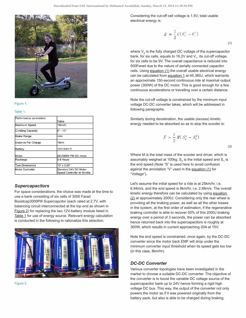
Figure 1.
Table 1.
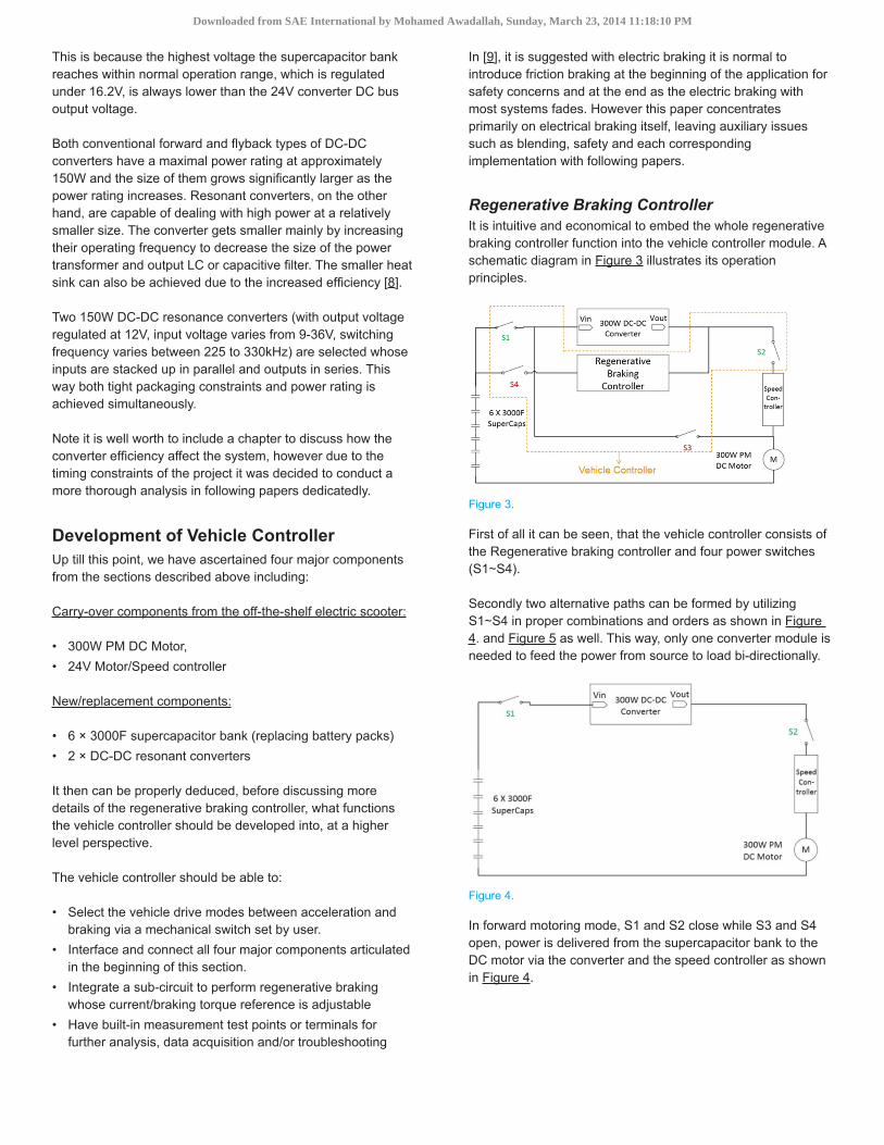
SupercapacitorsFor space considerations, the choice was made at the time to use a bank consisting of six cells of 3000 Farad Boostcap3000P® Supercapcitor (each rated at 2.7V, with balancing circuit interconnected at the top end as shown in Figure 2) for replacing the two 12V-battery module listed in Table 1 for use of energy source. Relevant energy calculation is conducted in the following to rationalize this selection.
Figure 2.
Considering the cut-off cell voltage is 1.5V, total usable electrical energy is:
(1)
where V2 is the fully charged DC voltage of the supercapacitor bank, for six cells, equals to 16.2V and V1, its cut-off voltage, for six cells to be 9V. The overall capacitance is reduced into 500Farad due to the nature of serially connected capacitor cells. Using equation (1) the overall usable electrical energy can be calculated from equation 1 at 45,360J, which warrants an approximate 150-second continuous ride at maximal output power (300W) of the DC motor. This is good enough for a few continuous accelerations or travelling over a certain distance.
Note the cut-off voltage is constrained by the minimum input voltage DC-DC converter takes, which will be addressed in following paragraphs.
Similarly during deceleration, the usable (excess) kinetic energy needed to be absorbed so as to stop the scooter is:
(2)
Where M is the total mass of the scooter and driver, which is assumably weighed at 100kg; S2 is the initial speed and S1 is the end speed (Note “S” is used here to avoid confusion against the annotation “V” used in the equation (1) for “Voltage”).
Let's assume the initial speed for a ride is at 25km/hr, i.e. 6.94m/s, and the end speed is 8km/hr, i.e. 2.88m/s. The overall kinetic energy therefore can be calculated by using equation (2) at approximately 2000J. Considering only the rear wheel is providing all the braking power, as well as all the other losses in the system, at the first order of estimation, if the regenerative braking controller is able to recover 50% of this 2000J braking energy over a period of 3 seconds, the power can be absorbed hence returned back into the supercapacitors is roughly at 300W, which results in current approaching 20A at 15V.
Note the end speed is constrained, once again, by the DC-DC converter since the motor back EMF will drop under the minimum converter input threshold when its speed gets too low (in this case, 8km/hr).
DC-DC ConverterVarious converter topologies have been investigated in the market to choose a suitable DC-DC converter. The objective of the converter is to boost the variable DC voltage source of the supercapacitor bank up to 24V hence forming a rigid high voltage DC bus. This way, the output of the converter not only powers the motor as if it was powered originally from the battery pack, but also is able to be charged during braking.
Downloaded from SAE International by Mohamed Awadallah, Sunday, March 23, 2014 11:18:10 PM
This is because the highest voltage the supercapacitor bank reaches within normal operation range, which is regulated under 16.2V, is always lower than the 24V converter DC bus output voltage.
Both conventional forward and flyback types of DC-DC converters have a maximal power rating at approximately 150W and the size of them grows significantly larger as the power rating increases. Resonant converters, on the other hand, are capable of dealing with high power at a relatively smaller size. The converter gets smaller mainly by increasing their operating frequency to decrease the size of the power transformer and output LC or capacitive filter. The smaller heat sink can also be achieved due to the increased efficiency [8].
Two 150W DC-DC resonance converters (with output voltage regulated at 12V, input voltage varies from 9-36V, switching frequency varies between 225 to 330kHz) are selected whose inputs are stacked up in parallel and outputs in series. This way both tight packaging constraints and power rating is achieved simultaneously.
Note it is well worth to include a chapter to discuss how the converter efficiency affect the system, however due to the timing constraints of the project it was decided to conduct a more thorough analysis in following papers dedicatedly.
Development of Vehicle ControllerUp till this point, we have ascertained four major components from the sections described above including:
Carry-over components from the off-the-shelf electric scooter:
• 300W PM DC Motor, • 24V Motor/Speed controller
New/replacement components:
• 6 × 3000F supercapacitor bank (replacing battery packs) • 2 × DC-DC resonant converters
It then can be properly deduced, before discussing more details of the regenerative braking controller, what functions the vehicle controller should be developed into, at a higher level perspective.
The vehicle controller should be able to:
• Select the vehicle drive modes between acceleration and braking via a mechanical switch set by user.
• Interface and connect all four major components articulated in the beginning of this section.
• Integrate a sub-circuit to perform regenerative braking whose current/braking torque reference is adjustable
• Have built-in measurement test points or terminals for further analysis, data acquisition and/or troubleshooting
In [9], it is suggested with electric braking it is normal to introduce friction braking at the beginning of the application for safety concerns and at the end as the electric braking with most systems fades. However this paper concentrates primarily on electrical braking itself, leaving auxiliary issues such as blending, safety and each corresponding implementation with following papers.
Regenerative Braking ControllerIt is intuitive and economical to embed the whole regenerative braking controller function into the vehicle controller module. A schematic diagram in Figure 3 illustrates its operation principles.
Figure 3.
First of all it can be seen, that the vehicle controller consists of the Regenerative braking controller and four power switches (S1∼S4).
Secondly two alternative paths can be formed by utilizing S1∼S4 in proper combinations and orders as shown in Figure 4. and Figure 5 as well. This way, only one converter module is needed to feed the power from source to load bi-directionally.
Figure 4.
In forward motoring mode, S1 and S2 close while S3 and S4 open, power is delivered from the supercapacitor bank to the DC motor via the converter and the speed controller as shown in Figure 4.
Downloaded from SAE International by Mohamed Awadallah, Sunday, March 23, 2014 11:18:10 PM
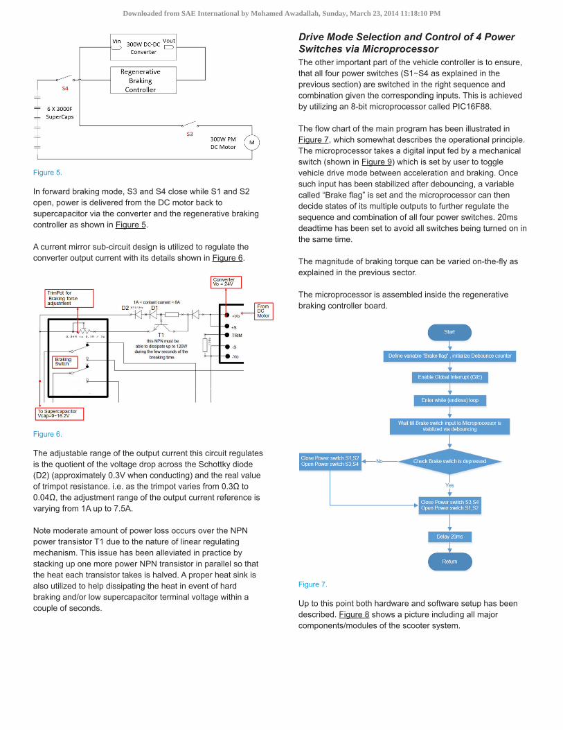
Figure 5.
In forward braking mode, S3 and S4 close while S1 and S2 open, power is delivered from the DC motor back to supercapacitor via the converter and the regenerative braking controller as shown in Figure 5.
A current mirror sub-circuit design is utilized to regulate the converter output current with its details shown in Figure 6.
Figure 6.
The adjustable range of the output current this circuit regulates is the quotient of the voltage drop across the Schottky diode (D2) (approximately 0.3V when conducting) and the real value of trimpot resistance. i.e. as the trimpot varies from 0.3Ω to 0.04Ω, the adjustment range of the output current reference is varying from 1A up to 7.5A.
Note moderate amount of power loss occurs over the NPN power transistor T1 due to the nature of linear regulating mechanism. This issue has been alleviated in practice by stacking up one more power NPN transistor in parallel so that the heat each transistor takes is halved. A proper heat sink is also utilized to help dissipating the heat in event of hard braking and/or low supercapacitor terminal voltage within a couple of seconds.
Drive Mode Selection and Control of 4 Power Switches via MicroprocessorThe other important part of the vehicle controller is to ensure, that all four power switches (S1∼S4 as explained in the previous section) are switched in the right sequence and combination given the corresponding inputs. This is achieved by utilizing an 8-bit microprocessor called PIC16F88.
The flow chart of the main program has been illustrated in Figure 7, which somewhat describes the operational principle. The microprocessor takes a digital input fed by a mechanical switch (shown in Figure 9) which is set by user to toggle vehicle drive mode between acceleration and braking. Once such input has been stabilized after debouncing, a variable called “Brake flag” is set and the microprocessor can then decide states of its multiple outputs to further regulate the sequence and combination of all four power switches. 20ms deadtime has been set to avoid all switches being turned on in the same time.
The magnitude of braking torque can be varied on-the-fly as explained in the previous sector.
The microprocessor is assembled inside the regenerative braking controller board.
Figure 7.
Up to this point both hardware and software setup has been described. Figure 8 shows a picture including all major components/modules of the scooter system.
Downloaded from SAE International by Mohamed Awadallah, Sunday, March 23, 2014 11:18:10 PM
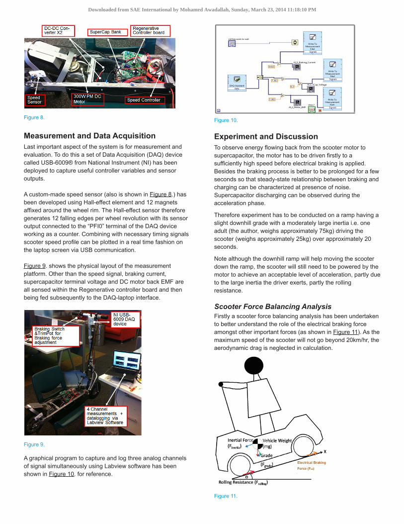
Figure 8.
Measurement and Data AcquisitionLast important aspect of the system is for measurement and evaluation. To do this a set of Data Acquisition (DAQ) device called USB-6009® from National Instrument (NI) has been deployed to capture useful controller variables and sensor outputs.
A custom-made speed sensor (also is shown in Figure 8.) has been developed using Hall-effect element and 12 magnets affixed around the wheel rim. The Hall-effect sensor therefore generates 12 falling edges per wheel revolution with its sensor output connected to the “PFI0” terminal of the DAQ device working as a counter. Combining with necessary timing signals scooter speed profile can be plotted in a real time fashion on the laptop screen via USB communication.
Figure 9. shows the physical layout of the measurement platform. Other than the speed signal, braking current, supercapacitor terminal voltage and DC motor back EMF are all sensed within the Regenerative controller board and then being fed subsequently to the DAQ-laptop interface.
Figure 9.
A graphical program to capture and log three analog channels of signal simultaneously using Labview software has been shown in Figure 10. for reference.
Figure 10.
Experiment and DiscussionTo observe energy flowing back from the scooter motor to supercapacitor, the motor has to be driven firstly to a sufficiently high speed before electrical braking is applied. Besides the braking process is better to be prolonged for a few seconds so that steady-state relationship between braking and charging can be characterized at presence of noise. Supercapacitor discharging can be observed during the acceleration phase.
Therefore experiment has to be conducted on a ramp having a slight downhill grade with a moderately large inertia i.e. one adult (the author, weighs approximately 75kg) driving the scooter (weighs approximately 25kg) over approximately 20 seconds.
Note although the downhill ramp will help moving the scooter down the ramp, the scooter will still need to be powered by the motor to achieve an acceptable level of acceleration, partly due to the large inertia the driver exerts, partly the rolling resistance.
Scooter Force Balancing AnalysisFirstly a scooter force balancing analysis has been undertaken to better understand the role of the electrical braking force amongst other important forces (as shown in Figure 11). As the maximum speed of the scooter will not go beyond 20km/hr, the aerodynamic drag is neglected in calculation.
Figure 11.
Downloaded from SAE International by Mohamed Awadallah, Sunday, March 23, 2014 11:18:10 PM
The Inertial Force (Fi) as shown in Figure 11 can be calculated by:
(3)
where θ represents the inclined angle of the ramp.
The equivalent force representing rolling resistance can be calculated by:
(4)
where fr is the rolling resistance coefficient, which is a function of tire material, tire structure, tire temperature, tire inflation pressure, tread geometry, road roughness, road material, and presence or absence of liquids on the road. [10]
In vehicle performance calculation, it is sufficient to consider the rolling resistance coefficient as a linear function of speed. For the most common range of inflation pressure, the following equation can be used on a concrete road [8]:
(5)
where S is the scooter speed in km/hr. This equation predicts the values of fr with acceptable accuracy for speeds up to 128km/hr.
The force balancing model will be used and discussed more in details when a known load torque can be applied to the system on a stationery test rig set up in future papers.
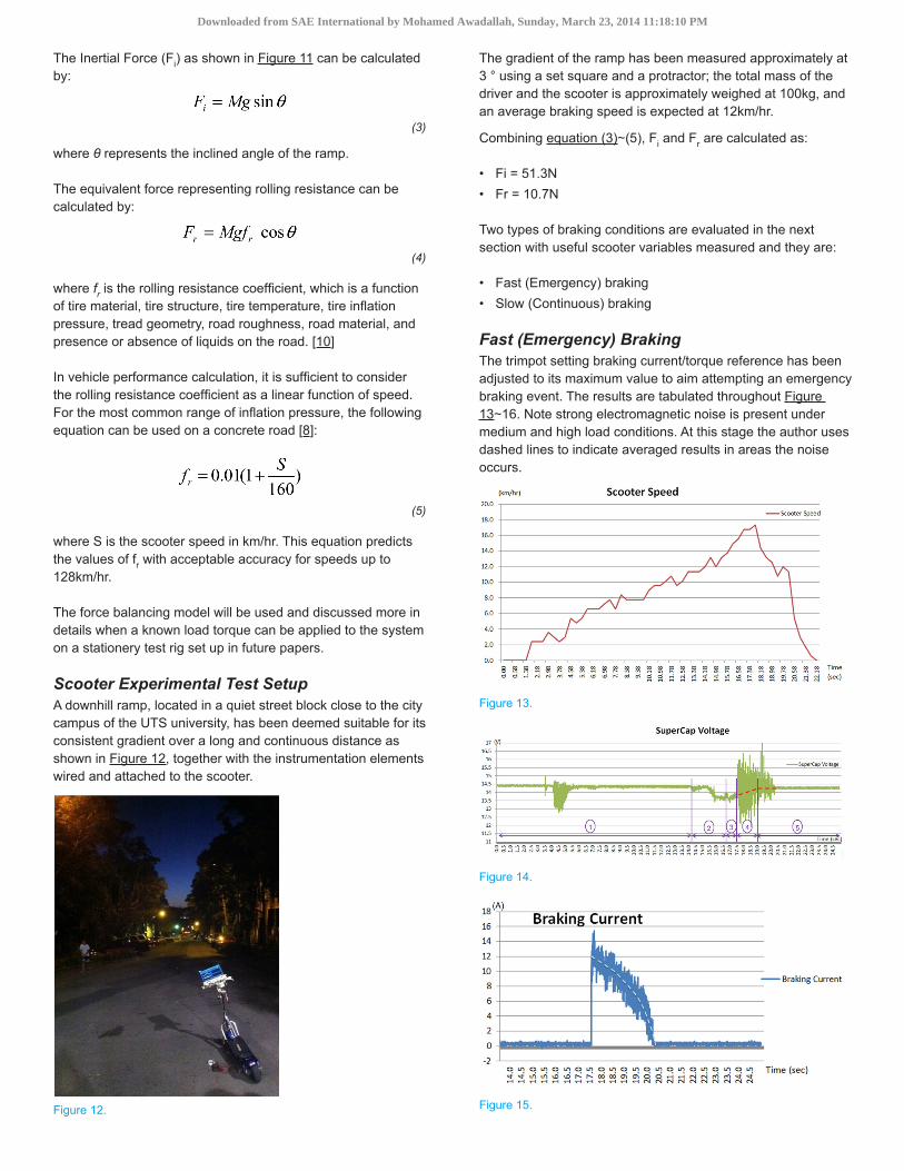
Scooter Experimental Test SetupA downhill ramp, located in a quiet street block close to the city campus of the UTS university, has been deemed suitable for its consistent gradient over a long and continuous distance as shown in Figure 12, together with the instrumentation elements wired and attached to the scooter.
Figure 12.
The gradient of the ramp has been measured approximately at 3 ° using a set square and a protractor; the total mass of the driver and the scooter is approximately weighed at 100kg, and an average braking speed is expected at 12km/hr.
Combining equation (3)∼(5), Fi and Fr are calculated as:
• Fi = 51.3N • Fr = 10.7N
Two types of braking conditions are evaluated in the next section with useful scooter variables measured and they are:
• Fast (Emergency) braking • Slow (Continuous) braking
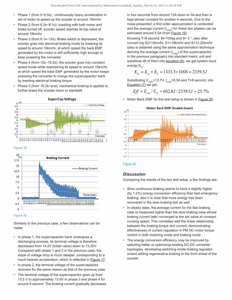
Fast (Emergency) BrakingThe trimpot setting braking current/torque reference has been adjusted to its maximum value to aim attempting an emergency braking event. The results are tabulated throughout Figure 13∼16. Note strong electromagnetic noise is present under medium and high load conditions. At this stage the author uses dashed lines to indicate averaged results in areas the noise occurs.
Figure 13.
Figure 14.
Figure 15.
Downloaded from SAE International by Mohamed Awadallah, Sunday, March 23, 2014 11:18:10 PM

Figure 16.
Five phases are present throughout the event as indicated in Figure 14 and they are:
• Phase 1 (from 0∼14.2s) : light acceleration in aid of motor to speed up the scooter to around 12km/hr
• Phase 2 (from 14.2s∼16.7s): further heavier acceleration in aid of motor to around 18km/hr
• Phase 3 (from 16.7s∼17.5s): coasting with both motor and brake turned off, scooter speed increased very slightly due to its inertia force
• Phase 4 (from 17.5s∼19s): Brake switch is depressed, the scooter goes into electrical braking mode by lowering its speed to around 11km/hr, at which speed the back EMF generated by the motor starts to become too low to keep powering the converter
• Phase 5 (from 19s∼end): the braking force gradually diminishes as a result of diminishing motor back EMF for around one second (hence the scooter is lightly accelerated) before mechanical braking is applied to further brake the scooter down to standstill
Amongst all the phases, a few observations can be made:
• In phase 1 and 2, the supercapacitor bank undergoes discharging process, its terminal voltage is therefore decreased from 14.48V (initial value) down to 14.20V (in phase 1) and from 14.20V down to 13.60V (in phase 2). The terminal voltage drop of the supercapacitor is reasonably proportional to the magnitude of acceleration.
• In phase 3, the terminal voltage of the supercapacitor goes up from 13.60V to 13.75V. This is because the supercapacitor regains the voltage drop across its internal resistance when it's put back to open circuit condition.
• The terminal voltage of the supercapacitor goes up from 13.8 V to approximately 14.2V in phase 4 for approximately 1.5 second. The average current (Iscap) measured for this 1.5 second in phase 4 is around 10A (from Figure 15). The system input energy Ein consisting both kinetic energy Ek and potential energy Ep has therefore been converted into electrical energy, altogether they can be calculated by:
(6)
where S2 and S1 is respectively the end speed and initial speed within phase 4 and S, the average scooter speed. T is the overall time consumed during phase 4.
Knowing T=1.5 second, M=100kg and θ= 3 °, also substituting into equation (6) with S2=17.4km/hr, S1=12.2km/hr and S=14.8km/hr and converting them into standard metric unit we get:
The system output energy (Eout), in our case is the energy recuperated back into the supercapacitor bank (Escap). The overall conversion efficiency can then be calculated by equation (7):
(7)
where Vscap and Iscap are the average terminal voltage and current of the supercapacitor bank during the period of electrical braking. Taking Vscap as 14V, Iscap as 10A and substituting them into equation (8) we get:
• Motor Back EMF is shown in Figure 17, whose magnitude (scaled down due to measurement limit) is linearly proportional to the motor/scooter speed, which agrees well with theory over PM DC motor.[1]
Slow (Continuous) BrakingFor the second part of testing, the trimpot setting the braking current/torque reference has been adjusted to a medium value to aim attempting a slow braking event. It is also desirable to prolong the electrical braking period before the scooter speed drops below the regeneration threshold. The expectation is by varying the braking current reference, which from PM DC motor theory, behaves somehow linearly proportional to the electrical braking torque [1], the longitudinal force exerted on the scooter along the ramp is cancelled out (refer to Figure 11) hence longer electrical braking period can be obtained with important system variables measured out.
Figure 17.
Figure 17∼20 illustrate measurement results after conducting a few trials to calibrate the position of the trimpot.
There are once again, five major phases in the ride as indicated in Figure 18. But they are moderately different to those of the previous test setup:
Downloaded from SAE International by Mohamed Awadallah, Sunday, March 23, 2014 11:18:10 PM
• Phase 1 (from 0∼6.5s) : continuously heavy acceleration in aid of motor to speed up the scooter to around 15km/hr
• Phase 2 (from 6.2s∼8.1s): coasting with both motor and brake turned off, scooter speed reaches its top value at around 19km/hr
• Phase 3 (from 8.1s∼12s): Brake switch is depressed, the scooter goes into electrical braking mode by lowering its speed to around 10km/hr, at which speed the back EMF generated by the motor is still sufficiently high enough to keep powering the converter
• Phase 4 (from 12s∼16.2s): the scooter goes into constant speed mode while maintaining its speed to around 10km/hr, at which speed the back EMF generated by the motor keeps powering the converter to charge the supercapacitor bank by exerting electrical braking torque
• Phase 5 (from 16.2s∼end): mechanical braking is applied to further brake the scooter down to standstill
Figure 18.
Figure 19.
Similarly to the previous case, a few observations can be made:
• In phase 1, the supercapacitor bank undergoes a discharging process, its terminal voltage is therefore decreased from 14.2V (initial value) down to 13.25V. Compared with phase 1 and 2 in the previous case, the slope of voltage drop is much steeper, corresponding to a much heavier acceleration, which is reflected in Figure 17.
• In phase 2, the terminal voltage of the supercapacitor recovers for the same reason as that of the previous case.
• The terminal voltage of the supercapacitor goes up from 13.5 V to approximately 13.9V in phase 3 and phase 4 for around 8 second. The braking current gradually decreases
in four seconds from around 13A down to 3A and then is kept almost constant for another 4 seconds. Due to the noise presented, a first order approximation is conducted and the average current (Iscap) for these two phases can be estimated around 5.5A (from Figure 19).Knowing T=8 second, M=100kg and θ= 3 °, also after convert ing S2=10km/hr, S1=19km/hr and S=12.25km/hr (also is obtained using the same approximation technique deriving the average current (Iscap) of the supercapacitor in the previous paragraph) into standard metric unit and substitute all of them into equation (6), we get system input energy Ein:
Substituting Vscap=13.7V, Iscap=5.5A and T=8 second, into Equation (7) we get:
• Motor Back EMF for this test setup is shown in Figure 20.
Figure 20.
DiscussionComparing the results of the two test setup, a few findings are:
• Slow continuous braking seems to have a slightly higher (by 1.2%) energy conversion efficiency than fast emergency braking, also it is clear that more energy has been recovered in the slow braking test as well.
• In steady state, the average current for the fast braking case is measured higher than the slow braking case whose braking current later converged to the set value at constant cruising speed. This correlates well the linear relationship between the braking torque and current, demonstrating effectiveness of current regulation in PM DC motor torque control in both motoring mode and braking mode.
• The energy conversion efficiency may be improved by selecting better or optimizing existing DC-DC converter topologies, developing switching-mode braking regulator, or/and adding regenerative braking to the front wheel of the scooter.
Downloaded from SAE International by Mohamed Awadallah, Sunday, March 23, 2014 11:18:10 PM

Summary/ConclusionsIn this paper, an integrated regenerative braking controller has been developed and evaluated under various load conditions using supercapacitors. The supercapacitor bank is proved effective to absorb and release large current via an intermediate DC-DC converter at medium or high speed. Magnitude of both braking torque and regenerative power can be adjusted by user input hence is fully controllable on demand.
It is therefore expected that such/similar systems will be used more and more widely in the near future under the more and more stringent environmental policies and higher society pressure. Working in conjunction with frictional braking at lower speed enables user a continuous braking process across all motor speed range without compromising its performance, while contributing to a cleaner environment and lower carbon emission in the same time.
References1. Wildi Theodore, “Electrical Machines, Drives, and Power
Systems,” Fifth Edition, Prentice Hall, ISBN 0-13-093083-0, 96-118, 2001.
2. Meinert Michael, “New mobile energy storage system for rolling stock” presented at EPE '09. 13th European Conference on Power Electronics and Applications, 2009. 8-10 Sept. 2009.
3. Yang Ming-Ji, Jhou Hong-Lin, Ma Bin-Yen, and Shyu Kuo-Kai, “A Cost-Effective Method of Electric Brake With Energy Regeneration for Electric Vehicles”, IEEE Transactions on Industrial Electronics, Vol. 56, No. 6, June 2009, doi:10.1016/j.proci.2006.07.231.
4. Carter Rebecca, Cruden Andrew, and Hall Peter J., “Optimizing for Efficiency or Battery Life in a Battery/Supercapacitor Electric Vehicle” IEEE Transactions on Vehicular Technology, (Volume:61, Issue: 4) doi:10.1109/TVT.2012.2188551.
5. Lambert Joe C., “Regenerative Braking Circuit Utilizing Separately Excited Motor”, U.S. Patent 5 598 072, Jan.28, 1997.
6. “Hawkcart - Electric Scooter” on http://www.hawkcarts.com.au/products/electric-scooter Oct.2013.
7. Li Zheng and Ruan Yi, “A Novel Energy Saving Control System for Elevator Based on Supercapacitor Bank Using Fuzzy Logic” International Conference on Electrical Machines and Systems, 2008. ICEMS 2008. 17-20 Oct. 2008.
8. Pressman Abraham, Billings Keith and Morey Taylor, “Switching Power Supply Design” 3rd Ed, McGraw-Hill Professional, ISBN 0-07-148272-5, 607-628, 2009.
9. Broadbent H.R., “An Introduction to Railway Braking” ISBN 0-41-209350-2, 63-68, 1969.
10. Ehsani Mehrdad, Gao Yimin and Emadi Ali, “Modern Electric, Hybrid Electric, and Fuel Cell Vehicles, Fundamentals, Theory and Design,” Second Edition, ISBN 1-42-005398-1, 21-24, 2010.
Contact InformationContact information of the main author is as follows:
Faculty of Engineering and IT, University of Technology, Sydney15 Broadway, Ultimo NSW [email protected]@gmail.comPhone: 61-2-95142517
AcknowledgmentsThis original research was proudly supported by GLYN Ltd (Australia and New Zealand) for donating supercapacitors and their balancing circuits, as well as Commonwealth of Australia, through the Automotive Australia 2020 Cooperative Research Centre”.
The Engineering Meetings Board has approved this paper for publication. It has successfully completed SAE’s peer review process under the supervision of the session organizer. The process requires a minimum of three (3) reviews by industry experts.
All rights reserved. No part of this publication may be reproduced, stored in a retrieval system, or transmitted, in any form or by any means, electronic, mechanical, photocopying, recording, or otherwise, without the prior written permission of SAE International.
Positions and opinions advanced in this paper are those of the author(s) and not necessarily those of SAE International. The author is solely responsible for the content of the paper.
ISSN 0148-7191
http://papers.sae.org/2014-01-1878
Downloaded from SAE International by Mohamed Awadallah, Sunday, March 23, 2014 11:18:10 PM