Complete-Product-Catalog-Regenerative-Blowers.pdf - Fluid ...
194
-
Upload
khangminh22 -
Category
Documents
-
view
1 -
download
0
Transcript of Complete-Product-Catalog-Regenerative-Blowers.pdf - Fluid ...
140107_Regen.indd 2 1/12/2010 9:07:07 AM
____
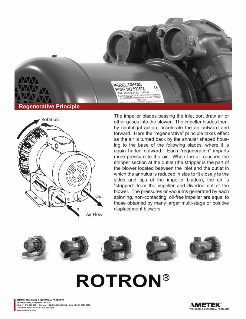
Regenerative PrincipleThe impeller blades passing the inlet port draw air or other gases into the blower. The impeller blades then, by centrifigal action, accelerate the air outward and forward. Here the “regenerative” principle takes effect as the air is turned back by the annular shaped hous-ing to the base of the following blades, where it is again hurled outward. Each “regeneration” imparts more pressure to the air. When the air reaches the stripper section at the outlet (the stripper is the part of the blower located between the inlet and the outlet in which the annulus is reduced in size to fit closely to the sides and tips of the impeller blades), the air is “stripped” from the impeller and diverted out of the blower. The pressures or vacuums generated by each spinning, non-contacting, oil-free impeller are equal to those obtained by many larger multi-stage or positive displacement blowers.
Out
In
Rotation
Air Flow
AMETEK TECHNICAL & INDUSTRIAL PRODUCTS75 North Street, Saugerties, NY 12477USA: +1 215-256-6601 - Europe: +44 (0) 845 366 9664 - Asia: +86 21 5763 1258Customer Service Fax: +1 215.256.1338www.ametektip.com
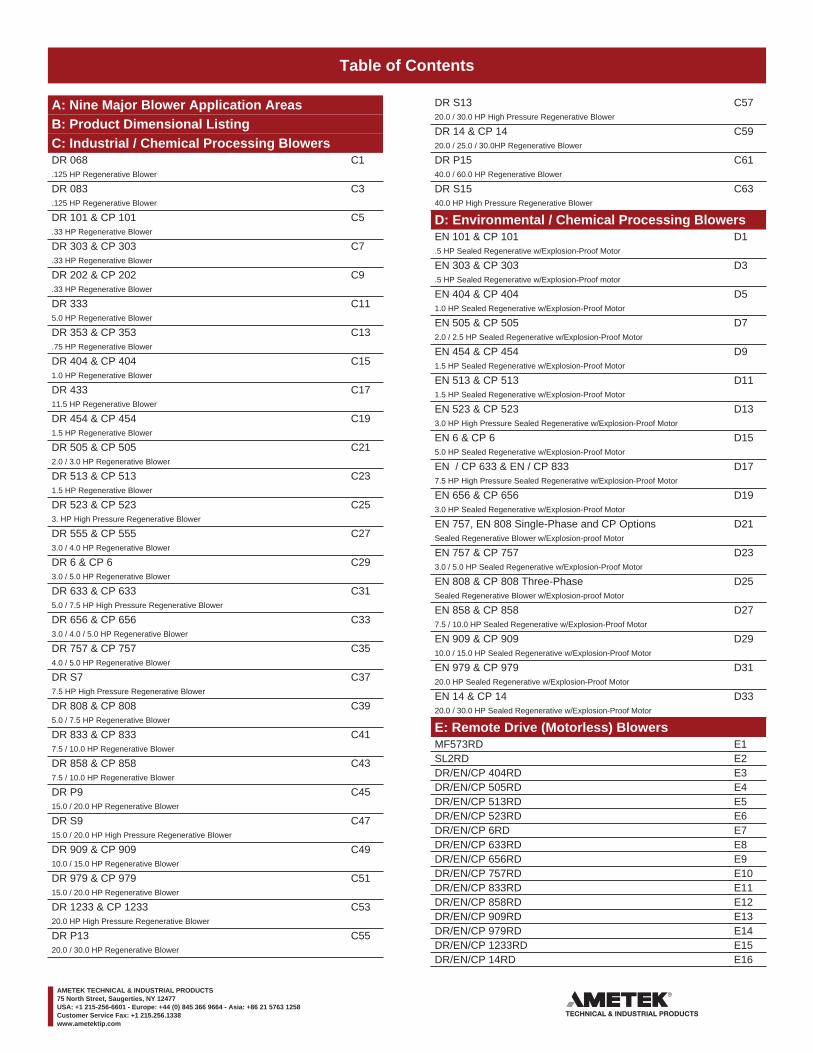
Table of Contents
A: Nine Major Blower Application AreasB: Product Dimensional ListingC: Industrial / Chemical Processing BlowersDR 068 C1.125 HP Regenerative Blower
DR 083 C3.125 HP Regenerative Blower
DR 101 & CP 101 C5.33 HP Regenerative Blower
DR 303 & CP 303 C7.33 HP Regenerative Blower
DR 202 & CP 202 C9.33 HP Regenerative Blower
DR 333 C115.0 HP Regenerative Blower
DR 353 & CP 353 C13.75 HP Regenerative Blower
DR 404 & CP 404 C151.0 HP Regenerative Blower
DR 433 C1711.5 HP Regenerative Blower
DR 454 & CP 454 C191.5 HP Regenerative Blower
DR 505 & CP 505 C212.0 / 3.0 HP Regenerative Blower
DR 513 & CP 513 C231.5 HP Regenerative Blower
DR 523 & CP 523 C253. HP High Pressure Regenerative Blower
DR 555 & CP 555 C273.0 / 4.0 HP Regenerative Blower
DR 6 & CP 6 C293.0 / 5.0 HP Regenerative Blower
DR 633 & CP 633 C315.0 / 7.5 HP High Pressure Regenerative Blower
DR 656 & CP 656 C333.0 / 4.0 / 5.0 HP Regenerative Blower
DR 757 & CP 757 C354.0 / 5.0 HP Regenerative Blower
DR S7 C377.5 HP High Pressure Regenerative Blower
DR 808 & CP 808 C395.0 / 7.5 HP Regenerative Blower
DR 833 & CP 833 C417.5 / 10.0 HP Regenerative Blower
DR 858 & CP 858 C437.5 / 10.0 HP Regenerative Blower
DR P9 C4515.0 / 20.0 HP Regenerative Blower
DR S9 C4715.0 / 20.0 HP High Pressure Regenerative Blower
DR 909 & CP 909 C4910.0 / 15.0 HP Regenerative Blower
DR 979 & CP 979 C5115.0 / 20.0 HP Regenerative Blower
DR 1233 & CP 1233 C5320.0 HP High Pressure Regenerative Blower
DR P13 C5520.0 / 30.0 HP Regenerative Blower
DR S13 C5720.0 / 30.0 HP High Pressure Regenerative Blower
DR 14 & CP 14 C5920.0 / 25.0 / 30.0HP Regenerative Blower
DR P15 C6140.0 / 60.0 HP Regenerative Blower
DR S15 C6340.0 HP High Pressure Regenerative Blower
D: Environmental / Chemical Processing BlowersEN 101 & CP 101 D1.5 HP Sealed Regenerative w/Explosion-Proof Motor
EN 303 & CP 303 D3.5 HP Sealed Regenerative w/Explosion-Proof motor
EN 404 & CP 404 D51.0 HP Sealed Regenerative w/Explosion-Proof Motor
EN 505 & CP 505 D72.0 / 2.5 HP Sealed Regenerative w/Explosion-Proof Motor
EN 454 & CP 454 D91.5 HP Sealed Regenerative w/Explosion-Proof Motor
EN 513 & CP 513 D111.5 HP Sealed Regenerative w/Explosion-Proof Motor
EN 523 & CP 523 D133.0 HP High Pressure Sealed Regenerative w/Explosion-Proof Motor
EN 6 & CP 6 D155.0 HP Sealed Regenerative w/Explosion-Proof Motor
EN / CP 633 & EN / CP 833 D177.5 HP High Pressure Sealed Regenerative w/Explosion-Proof Motor
EN 656 & CP 656 D193.0 HP Sealed Regenerative w/Explosion-Proof Motor
EN 757, EN 808 Single-Phase and CP Options D21Sealed Regenerative Blower w/Explosion-proof Motor
EN 757 & CP 757 D233.0 / 5.0 HP Sealed Regenerative w/Explosion-Proof Motor
EN 808 & CP 808 Three-Phase D25Sealed Regenerative Blower w/Explosion-proof Motor
EN 858 & CP 858 D277.5 / 10.0 HP Sealed Regenerative w/Explosion-Proof Motor
EN 909 & CP 909 D2910.0 / 15.0 HP Sealed Regenerative w/Explosion-Proof Motor
EN 979 & CP 979 D3120.0 HP Sealed Regenerative w/Explosion-Proof Motor
EN 14 & CP 14 D3320.0 / 30.0 HP Sealed Regenerative w/Explosion-Proof Motor
E: Remote Drive (Motorless) BlowersMF573RD E1SL2RD E2DR/EN/CP 404RD E3DR/EN/CP 505RD E4DR/EN/CP 513RD E5DR/EN/CP 523RD E6DR/EN/CP 6RD E7DR/EN/CP 633RD E8DR/EN/CP 656RD E9DR/EN/CP 757RD E10DR/EN/CP 833RD E11DR/EN/CP 858RD E12DR/EN/CP 909RD E13DR/EN/CP 979RD E14DR/EN/CP 1233RD E15DR/EN/CP 14RD E16
AMETEK TECHNICAL & INDUSTRIAL PRODUCTS75 North Street, Saugerties, NY 12477USA: +1 215-256-6601 - Europe: +44 (0) 845 366 9664 - Asia: +86 21 5763 1258Customer Service Fax: +1 215.256.1338www.ametektip.com
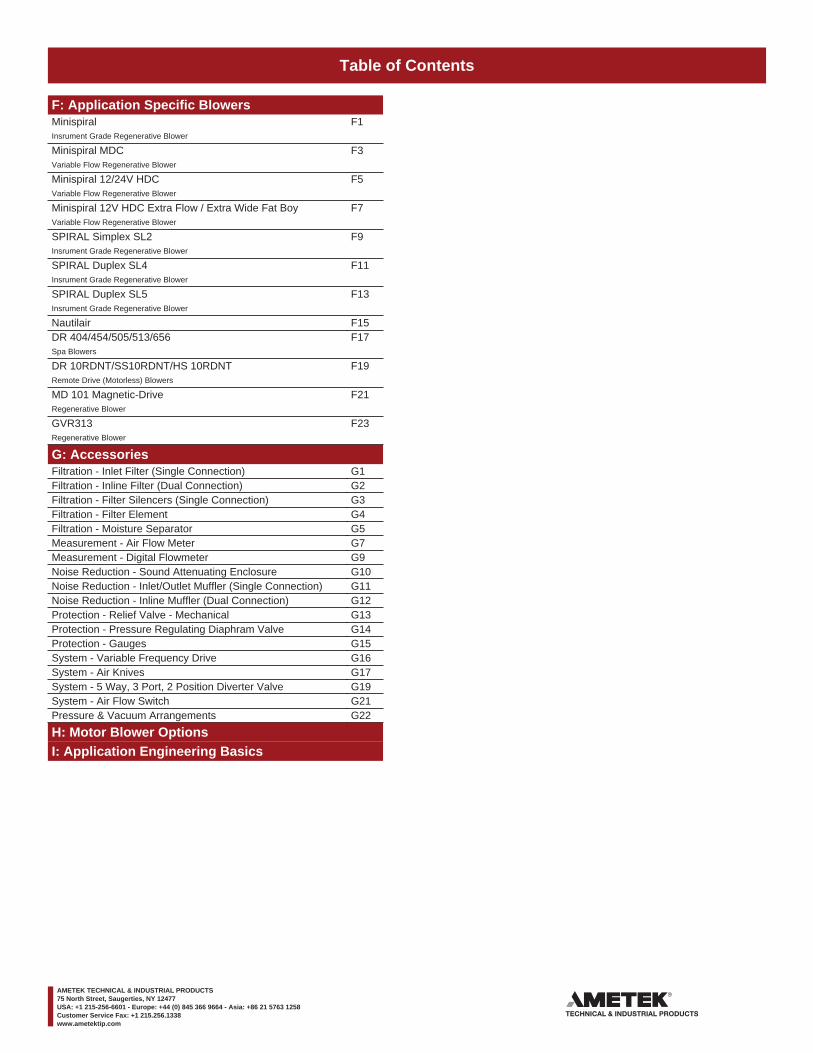
Table of Contents
F: Application Specific BlowersMinispiral F1Insrument Grade Regenerative Blower
Minispiral MDC F3Variable Flow Regenerative Blower
Minispiral 12/24V HDC F5Variable Flow Regenerative Blower
Minispiral 12V HDC Extra Flow / Extra Wide Fat Boy F7Variable Flow Regenerative Blower
SPIRAL Simplex SL2 F9Insrument Grade Regenerative Blower
SPIRAL Duplex SL4 F11Insrument Grade Regenerative Blower
SPIRAL Duplex SL5 F13Insrument Grade Regenerative Blower
Nautilair F15DR 404/454/505/513/656 F17Spa Blowers
DR 10RDNT/SS10RDNT/HS 10RDNT F19Remote Drive (Motorless) Blowers
MD 101 Magnetic-Drive F21Regenerative Blower
GVR313 F23Regenerative Blower
G: AccessoriesFiltration - Inlet Filter (Single Connection) G1Filtration - Inline Filter (Dual Connection) G2Filtration - Filter Silencers (Single Connection) G3Filtration - Filter Element G4Filtration - Moisture Separator G5Measurement - Air Flow Meter G7Measurement - Digital Flowmeter G9Noise Reduction - Sound Attenuating Enclosure G10Noise Reduction - Inlet/Outlet Muffler (Single Connection) G11Noise Reduction - Inline Muffler (Dual Connection) G12Protection - Relief Valve - Mechanical G13Protection - Pressure Regulating Diaphram Valve G14Protection - Gauges G15System - Variable Frequency Drive G16System - Air Knives G17System - 5 Way, 3 Port, 2 Position Diverter Valve G19System - Air Flow Switch G21Pressure & Vacuum Arrangements G22
H: Motor Blower OptionsI: Application Engineering Basics
AMETEK TECHNICAL & INDUSTRIAL PRODUCTS75 North Street, Saugerties, NY 12477USA: +1 215-256-6601 - Europe: +44 (0) 845 366 9664 - Asia: +86 21 5763 1258Customer Service Fax: +1 215.256.1338www.ametektip.com
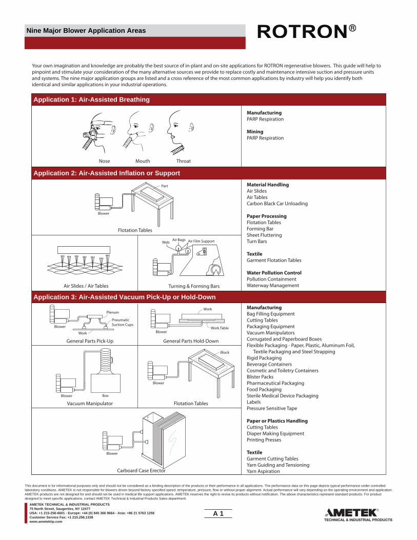
Nine Major Blower Application Areas
Application 1: Air-Assisted Breathing
Your own imagination and knowledge are probably the best source of in-plant and on-site applications for ROTRON regenerative blowers. This guide will help to pinpoint and stimulate your consideration of the many alternative sources we provide to replace costly and maintenance intensive suction and pressure units and systems. The nine major application groups are listed and a cross reference of the most common applications by industry will help you identify both identical and similar applications in your industrial operations.
Nose
Part
Blower
Blower
Blower
Blower
Blower
Block
Box
BlowerWork Table
Work
Work
Plenum
PneumaticSuction Cups
Mouth
Flotation Tables
Air Slides / Air Tables Turning & Forming Bars
Air Film SupportAir BagsWeb
General Parts Pick-Up General Parts Hold-Down
Vacuum Manipulator Flotation Tables
Throat
ManufacturingPARP Respiration
MiningPARP Respiration
Application 2: Air-Assisted Inflation or SupportMaterial HandlingAir SlidesAir TablesCarbon Black Car Unloading
Paper ProcessingFlotation TablesForming BarSheet FlutteringTurn Bars
TextileGarment Flotation Tables
Water Pollution ControlPollution ContainmentWaterway Management
Application 3: Air-Assisted Vacuum Pick-Up or Hold-DownManufacturingBag Filling EquipmentCutting TablesPackaging EquipmentVacuum ManipulatorsCorrugated and Paperboard BoxesFlexible Packaging - Paper, Plastic, Aluminum Foil, Textile Packaging and Steel StrappingRigid PackagingBeverage ContainersCosmetic and Toiletry ContainersBlister PacksPharmaceutical PackagingFood PackagingSterile Medical Device PackagingLabelsPressure Sensitive Tape
Paper or Plastics HandlingCutting TablesDiaper Making EquipmentPrinting Presses
TextileGarment Cutting TablesYarn Guiding and TensioningYarn AspirationCarboard Case Erector
A 1____
This document is for informational purposes only and should not be considered as a binding description of the products or their performance in all applications. The performance data on this page depicts typical performance under controlledlaboratory conditions. AMETEK is not responsible for blowers driven beyond factory specified speed, temperature, pressure, flow or without proper alignment. Actual performance will vary depending on the operating environment and application.AMETEK products are not designed for and should not be used in medical life support applications. AMETEK reserves the right to revise its products without notification. The above characteristics represent standard products. For productdesigned to meet specific applications, contact AMETEK Technical & Industrial Products Sales department.
AMETEK TECHNICAL & INDUSTRIAL PRODUCTS75 North Street, Saugerties, NY 12477USA: +1 215-256-6601 - Europe: +44 (0) 845 366 9664 - Asia: +86 21 5763 1258Customer Service Fax: +1 215.256.1338www.ametektip.com

Nine Major Blower Application Areas
Application 4: Air & Gas Sampling, Boosting, or Circulating
Fluid Bed Regeneration Transmissometer Lens Purging
Natural Gas Boost Air & Gas Sampling
Combustion Air Boost
Pressurized Cabinet Vacuum Pull-Through Cabinet
Soil Vapor Extraction &Land�ll Gas Recovery Vent Header O�-Gassing
Fume & Smoke Removal Digester Gas Collection
Air Pollution ControlAir SamplingAir Stream Release MonitoringFire Prevention Air SamplingFlue Gas Sampling
FoundryCombustion Air Boost
InstrumentationGlove Box PressurizingIncubator Air CirculationWeather Measurement Sampling
ManufacturingCombustion Air BoostNatural Gas BoostOil Demisting
PharmaceuticalClean Room Air CirculationOxygen Generator
Plastics HandlingDesiccant Dryer Bed Regeneration
Application 5: Electronic CoolingInstrumentationEngine/Motor CoolingFilm Development System CoolingLamp Bank CoolingSmall Enclosure Cooling
Application 6: Gas, Vapor, & Fume Recovery, Venting, & TreatmentPharmaceuticalSterilization Gas (ETO) Recovery
Re�neriesCentrifuge Venting
Water Pollution ControlDigester Gas Collection
AgriculturalMethane Gas RecoveryChemical ProcessingVent Header O�-Gassing
EnvironmentalGasoline Vapor RecoveryLagoon Gas RecoveryLand�ll Gas RecoveryRadon Gas CollectionSoil Vapor Extraction
FoundryLost Foam O�-Gassing
Manufacturing - Plant ServicesCabinet Fume VentingEnvironmental Test Chamber VentingLaser Smoke RemovalWeld Smoke Removal
Natural Gas
Blower
Blower
Blower
Blower
BlowerFilter
Blower
Blower Flame
Digester
Scrubber ChemicalTank
Treatment System
Electronics
Gas
CombustionChamber
BlowerBlower Blower
Light Beam
Lens
Stack
Lens
Natural GasFurnace
Minispiral
Instrument
Blower
Electronics
A 2____
This document is for informational purposes only and should not be considered as a binding description of the products or their performance in all applications. The performance data on this page depicts typical performance under controlledlaboratory conditions. AMETEK is not responsible for blowers driven beyond factory specified speed, temperature, pressure, flow or without proper alignment. Actual performance will vary depending on the operating environment and application.AMETEK products are not designed for and should not be used in medical life support applications. AMETEK reserves the right to revise its products without notification. The above characteristics represent standard products. For productdesigned to meet specific applications, contact AMETEK Technical & Industrial Products Sales department.
AMETEK TECHNICAL & INDUSTRIAL PRODUCTS75 North Street, Saugerties, NY 12477USA: +1 215-256-6601 - Europe: +44 (0) 845 366 9664 - Asia: +86 21 5763 1258Customer Service Fax: +1 215.256.1338www.ametektip.com

Nine Major Blower Application Areas
Application 7: Solid Material Transporting, Separation, & CollectionFoundrySand Reclamation
Manufacturing - Waste ControlChip, Dust, & Particle RemovalLiquid & Solvent RemovalPaper, Plastic Film, & Textile (Trim) Removal
Material HandlingAir SlidesBlast CleaningDilute Phase ConveyingPneumatic Tube
PackagingBag Filling
Application 8: Parts Blow-Off & Drying
Application 9: Solution & Media Agitation & AerationAquacultureAquarium Fish Farm, Hatchery, & Pond Aeration
Groundwater Sparging
ManufacturingConcrete Fluid Bed AerationElectroplating Tank Agitation
Material HandlingFluidized Beds
RecreationCommercial Spa Aeration
Water ManagementBoat, Dock, & Dam Face Deicing
Water Pollution ControlUV Tube AgitationWatewater Filter BackwashWastewater Treatment Tank Aeration
ManufacturingConveyor Belt Blow-O�Electroplating Fume GuidingElectroplating Parts DryingElectroplating Solution Blow-BackFlat or Irregular Metal Parts DryingWire Drying
Aqueous Precision CleaningAutomotive Parts DryingSemiconductor Board Drying
Food ProcessingBatter Blow-O�Bottle & Can DryingLabel DryingSalt, Spice, & Flour Blow-O�
Dilute Phase Pneumatic Conveying Pneumatic Tube
Paper, Plastic, Film, & Textile (Trim) Removal
General Parts Blow-O� & Drying Solution Blow-Back
Wastewater Treatment Tank Aeration Groundwater Sparging
Electroplating Tank Aeration Commercial Spa Aeration
Bin Pad & Fluidized Bed Aeration Boat & Dock Deicing
General Material Separation & Collection
PressureBlower
Blower
Blower CollectionChamber
Blower
Blower
Blower
Blower
Blower
ProductBin Aerator
(Air Pads)
Blower
Blower Dock
Water
Hot Tub
Plating Bath
Spargers
Blower
Blower Ground Level
Soil
Water Table
Plating Tank
Air Knife
Hoist
Blower
Air Knife
TubeCarrier
Ejector
Bin
RotaryAirlock
DischargeTo Process
Cyclone
A 3____
This document is for informational purposes only and should not be considered as a binding description of the products or their performance in all applications. The performance data on this page depicts typical performance under controlledlaboratory conditions. AMETEK is not responsible for blowers driven beyond factory specified speed, temperature, pressure, flow or without proper alignment. Actual performance will vary depending on the operating environment and application.AMETEK products are not designed for and should not be used in medical life support applications. AMETEK reserves the right to revise its products without notification. The above characteristics represent standard products. For productdesigned to meet specific applications, contact AMETEK Technical & Industrial Products Sales department.
AMETEK TECHNICAL & INDUSTRIAL PRODUCTS75 North Street, Saugerties, NY 12477USA: +1 215-256-6601 - Europe: +44 (0) 845 366 9664 - Asia: +86 21 5763 1258Customer Service Fax: +1 215.256.1338www.ametektip.com
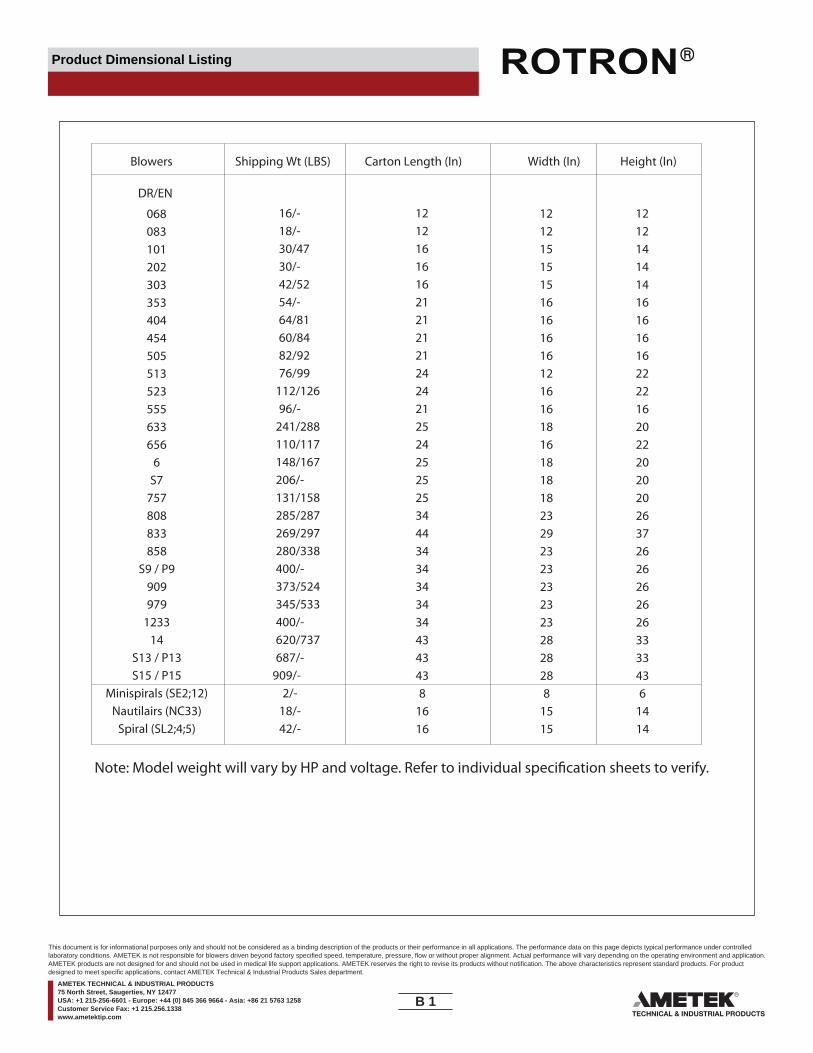
Product Dimensional Listing
Blowers Shipping Wt (LBS) Carton Length (In) Width (In) Height (In)
DR/EN
068 16/- 12 12 12
083 18/- 12 12 12
101 30/47 16 15 14
202 30/- 16 15 14
303 42/52 16 15 14
353 54/- 21 16 16
404 64/81 21 16 16
454 60/84 21 16 16
505 82/92 21 16 16
513 76/99 24 12 22
523 112/126 24 16 22
555 96/- 21 16 16
633 241/288 25 18 20
656 110/117 24 16 22
6 148/167 25 18 20
S7 206/- 25 18 20
757 131/158 25 18 20
808 285/287 34 23 26
833 269/297 44 29 37
858 280/338 34 23 26
S9 / P9 400/- 34 23 26
909 373/524 34 23 26
979 345/533 34 23 26
1233 400/- 34 23 26
14 620/737 43 28 33
S13 / P13 687/- 43 28 33
S15 / P15 909/- 43 28 43
Minispirals (SE2;12) 2/- 8 8 6
Nautilairs (NC33) 18/- 16 15 14
Spiral (SL2;4;5) 42/- 16 15 14
Note: Model weight will vary by HP and voltage. Refer to individual speci�cation sheets to verify.
B 1____
This document is for informational purposes only and should not be considered as a binding description of the products or their performance in all applications. The performance data on this page depicts typical performance under controlledlaboratory conditions. AMETEK is not responsible for blowers driven beyond factory specified speed, temperature, pressure, flow or without proper alignment. Actual performance will vary depending on the operating environment and application.AMETEK products are not designed for and should not be used in medical life support applications. AMETEK reserves the right to revise its products without notification. The above characteristics represent standard products. For productdesigned to meet specific applications, contact AMETEK Technical & Industrial Products Sales department.
AMETEK TECHNICAL & INDUSTRIAL PRODUCTS75 North Street, Saugerties, NY 12477USA: +1 215-256-6601 - Europe: +44 (0) 845 366 9664 - Asia: +86 21 5763 1258Customer Service Fax: +1 215.256.1338www.ametektip.com
____
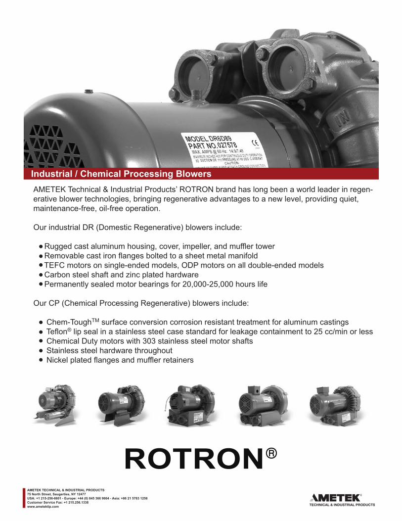
Industrial / Chemical Processing BlowersAMETEK Technical & Industrial Products’ ROTRON brand has long been a world leader in regen-erative blower technologies, bringing regenerative advantages to a new level, providing quiet, maintenance-free, oil-free operation.
Our industrial DR (Domestic Regenerative) blowers include:
Rugged cast aluminum housing, cover, impeller, and muffler tower Removable cast iron flanges bolted to a sheet metal manifold TEFC motors on single-ended models, ODP motors on all double-ended models Carbon steel shaft and zinc plated hardware Permanently sealed motor bearings for 20,000-25,000 hours life
Our CP (Chemical Processing Regenerative) blowers include:
Chem-ToughTM surface conversion corrosion resistant treatment for aluminum castings Teflon® lip seal in a stainless steel case standard for leakage containment to 25 cc/min or less Chemical Duty motors with 303 stainless steel motor shafts Stainless steel hardware throughout Nickel plated flanges and muffler retainers
AMETEK TECHNICAL & INDUSTRIAL PRODUCTS75 North Street, Saugerties, NY 12477USA: +1 215-256-6601 - Europe: +44 (0) 845 366 9664 - Asia: +86 21 5763 1258Customer Service Fax: +1 215.256.1338www.ametektip.com
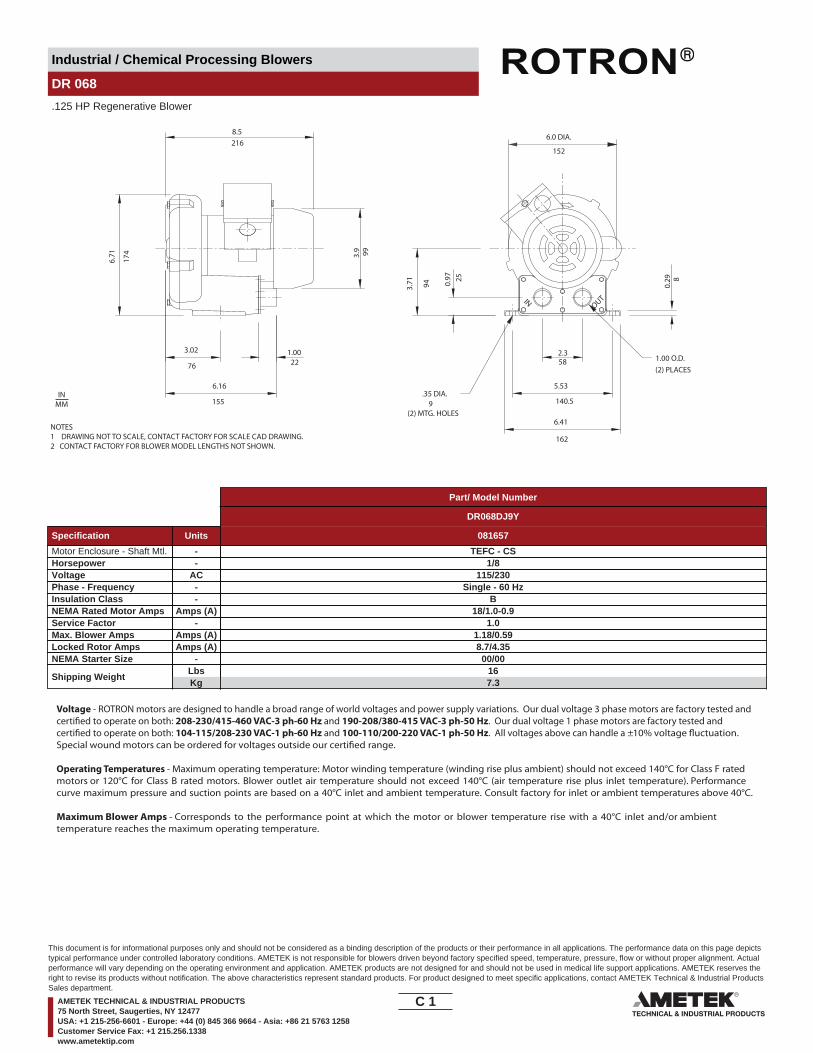
Industrial / Chemical Processing Blowers
DR 068
.125 HP Regenerative Blower
OUTIN
(2) PLACES
8.5
6.71 99
3.02 1.00
6.16
155
0.29
3.9
2.3
6.41
0.97
3.71 94
152
6.0 DIA.
.35 DIA.
(2) MTG. HOLES
162
5876
174
216
9
5.53
140.5
1.00 O.D.
8
22
25
NOTES1 DRAWING NOT TO SCALE, CONTACT FACTORY FOR SCALE CAD DRAWING.2 CONTACT FACTORY FOR BLOWER MODEL LENGTHS NOT SHOWN.
INMM
Part/ Model Number
DR068DJ9Y
Specification Units 081657
Motor Enclosure - Shaft Mtl. - TEFC - CSHorsepower - 1/8Voltage AC 115/230Phase - Frequency - Single - 60 HzInsulation Class - BNEMA Rated Motor Amps Amps (A) 18/1.0-0.9Service Factor - 1.0Max. Blower Amps Amps (A) 1.18/0.59Locked Rotor Amps Amps (A) 8.7/4.35NEMA Starter Size - 00/00
Shipping WeightLbsKg
167.3
Voltage - ROTRON motors are designed to handle a broad range of world voltages and power supply variations. Our dual voltage 3 phase motors are factory tested and certi�ed to operate on both: 208-230/415-460 VAC-3 ph-60 Hz and 190-208/380-415 VAC-3 ph-50 Hz. Our dual voltage 1 phase motors are factory tested and certi�ed to operate on both: 104-115/208-230 VAC-1 ph-60 Hz and 100-110/200-220 VAC-1 ph-50 Hz. All voltages above can handle a ±10% voltage �uctuation. Special wound motors can be ordered for voltages outside our certi�ed range.
Operating Temperatures - Maximum operating temperature: Motor winding temperature (winding rise plus ambient) should not exceed 140°C for Class F rated motors or 120°C for Class B rated motors. Blower outlet air temperature should not exceed 140°C (air temperature rise plus inlet temperature). Performance curve maximum pressure and suction points are based on a 40°C inlet and ambient temperature. Consult factory for inlet or ambient temperatures above 40°C.
Maximum Blower Amps - Corresponds to the performance point at which the motor or blower temperature rise with a 40°C inlet and/or ambient temperature reaches the maximum operating temperature.
C 1____
This document is for informational purposes only and should not be considered as a binding description of the products or their performance in all applications. The performance data on this page depictstypical performance under controlled laboratory conditions. AMETEK is not responsible for blowers driven beyond factory specified speed, temperature, pressure, flow or without proper alignment. Actualperformance will vary depending on the operating environment and application. AMETEK products are not designed for and should not be used in medical life support applications. AMETEK reserves theright to revise its products without notification. The above characteristics represent standard products. For product designed to meet specific applications, contact AMETEK Technical & Industrial ProductsSales department.
AMETEK TECHNICAL & INDUSTRIAL PRODUCTS75 North Street, Saugerties, NY 12477USA: +1 215-256-6601 - Europe: +44 (0) 845 366 9664 - Asia: +86 21 5763 1258Customer Service Fax: +1 215.256.1338www.ametektip.com

Industrial / Chemical Processing Blowers
DR 068
.125 HP Regenerative Blower
FEATURES• Manufactured in the USA - ISO 9001 and NAFTA compliant• CE compliant - Declaration of Conformity on file• Maximum flow: 13 SCFM• Maximum pressure: 13.5 IWG• Maximum vacuum: 13.5 IWG• Standard motor: 1/8 HP, TEFC• Cast aluminum blower housing, impeller & cover; slip-on steel flanges• UL & CSA approved motor with permanently sealed ball bearings• Inlet & outlet internal muffling• Quiet operation within OSHA standards
MOTOR OPTIONS• International voltage & frequency (Hz)• Various horsepowers for application-specific needs
BLOWER OPTIONS• Corrosion resistant surface treatments & sealing options• Cast iron (threaded) or face flanges for application-specific needs
ACCESSORIES• FLowmeters reading in SCFM• Filters & moisture separators• Pressure gauges, vacuum gauges, & relief valves• Switches - air flow, pressure, vacuum, or temperature• External mufflers for additional silencing• Air knives (used on blow-off applications)• Variable frequency drive package
Blower Performance at Standard Conditions60 Hz 50 Hz
Inch
es o
f Wat
er
mba
r
mba
r
Mot
or W
indi
ngTe
mp
Ris
e °C
Air Flow Rate - SCFMAir Flow Rate - SCFM
Air Flow Rate - m3/hourAir Flow Rate - m3/hour
Inch
es o
f Wat
erM
otor
Win
ding
Tem
p R
ise
°C
Blo
wer
Air
Tem
p R
ise
°C
Blo
wer
Air
Tem
p R
ise
°C
LegendPressure:Suction:
LegendPressure:Suction:
DR068 DR068
0 1.5 3.0 4.5 6.0 7.5 9.0 10.5 12.0 13.5 15.0 16.5
0 2.6 5.1 7.7 10.2 12.7 15.3 17.8 20.4 22.9 25.5 28.0
0
3
6
9
12
15
18
0
7.5
14.9
22.4
29.9
37.3
44.8
Temperature curves are based on standard model0
50
100
0
50
100
0 1.5 3.0 4.5 6.0 7.5 9.0 10.5 12.0 13.5 15.0 16.5
0 2.6 5.1 7.7 10.2 12.7 15.3 17.8 20.4 22.9 25.5 28.0
0
3
6
9
12
15
18
0
7.5
14.9
22.4
29.9
37.3
44.8
Temperature curves are based on standard model0
50
100
0
50
100
C 2____
This document is for informational purposes only and should not be considered as a binding description of the products or their performance in all applications. The performance data on this page depictstypical performance under controlled laboratory conditions. AMETEK is not responsible for blowers driven beyond factory specified speed, temperature, pressure, flow or without proper alignment. Actualperformance will vary depending on the operating environment and application. AMETEK products are not designed for and should not be used in medical life support applications. AMETEK reserves theright to revise its products without notification. The above characteristics represent standard products. For product designed to meet specific applications, contact AMETEK Technical & Industrial ProductsSales department.
AMETEK TECHNICAL & INDUSTRIAL PRODUCTS75 North Street, Saugerties, NY 12477USA: +1 215-256-6601 - Europe: +44 (0) 845 366 9664 - Asia: +86 21 5763 1258Customer Service Fax: +1 215.256.1338www.ametektip.com
Industrial / Chemical Processing Blowers
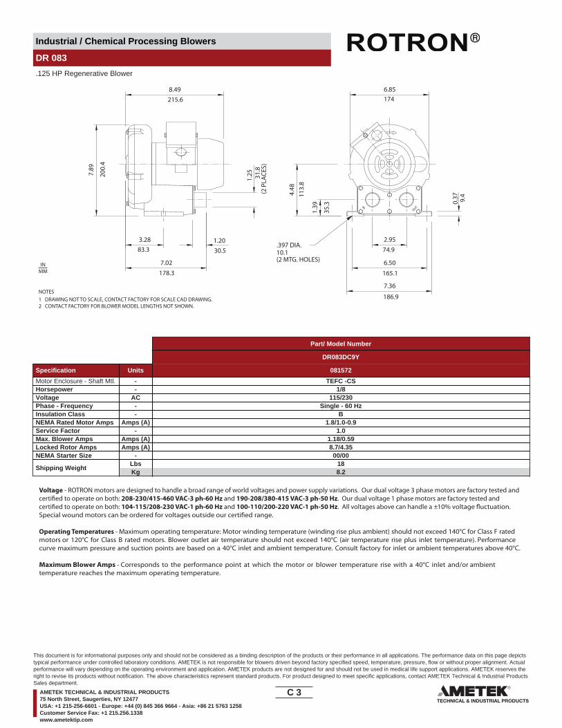
DR 083
.125 HP Regenerative Blower
7.89
200.
4
1.25
8.49215.6
7.02
3.28 1.2083.3
178.3
INOUT
4.48
113.
8
1.39
6.85174
0.37
2.95
6.50
74.9
165.1
7.36
DR083DC9Y - 036862
10.1(2 MTG. HOLES)
.397 DIA.30.5
31.8
(2 P
LACE
S)
9.4
35.3
186.9NOTES1 DRAWING NOT TO SCALE, CONTACT FACTORY FOR SCALE CAD DRAWING.2 CONTACT FACTORY FOR BLOWER MODEL LENGTHS NOT SHOWN.
INMM
Part/ Model Number
DR083DC9Y
Specification Units 081572
Motor Enclosure - Shaft Mtl. - TEFC -CSHorsepower - 1/8Voltage AC 115/230Phase - Frequency - Single - 60 HzInsulation Class - BNEMA Rated Motor Amps Amps (A) 1.8/1.0-0.9Service Factor - 1.0Max. Blower Amps Amps (A) 1.18/0.59Locked Rotor Amps Amps (A) 8.7/4.35NEMA Starter Size - 00/00
Shipping WeightLbsKg
188.2
Voltage - ROTRON motors are designed to handle a broad range of world voltages and power supply variations. Our dual voltage 3 phase motors are factory tested and certi�ed to operate on both: 208-230/415-460 VAC-3 ph-60 Hz and 190-208/380-415 VAC-3 ph-50 Hz. Our dual voltage 1 phase motors are factory tested and certi�ed to operate on both: 104-115/208-230 VAC-1 ph-60 Hz and 100-110/200-220 VAC-1 ph-50 Hz. All voltages above can handle a ±10% voltage �uctuation. Special wound motors can be ordered for voltages outside our certi�ed range.
Operating Temperatures - Maximum operating temperature: Motor winding temperature (winding rise plus ambient) should not exceed 140°C for Class F rated motors or 120°C for Class B rated motors. Blower outlet air temperature should not exceed 140°C (air temperature rise plus inlet temperature). Performance curve maximum pressure and suction points are based on a 40°C inlet and ambient temperature. Consult factory for inlet or ambient temperatures above 40°C.
Maximum Blower Amps - Corresponds to the performance point at which the motor or blower temperature rise with a 40°C inlet and/or ambient temperature reaches the maximum operating temperature.
C 3____
This document is for informational purposes only and should not be considered as a binding description of the products or their performance in all applications. The performance data on this page depictstypical performance under controlled laboratory conditions. AMETEK is not responsible for blowers driven beyond factory specified speed, temperature, pressure, flow or without proper alignment. Actualperformance will vary depending on the operating environment and application. AMETEK products are not designed for and should not be used in medical life support applications. AMETEK reserves theright to revise its products without notification. The above characteristics represent standard products. For product designed to meet specific applications, contact AMETEK Technical & Industrial ProductsSales department.
AMETEK TECHNICAL & INDUSTRIAL PRODUCTS75 North Street, Saugerties, NY 12477USA: +1 215-256-6601 - Europe: +44 (0) 845 366 9664 - Asia: +86 21 5763 1258Customer Service Fax: +1 215.256.1338www.ametektip.com

Industrial / Chemical Processing Blowers
DR 083
.125 HP Regenerative Blower
FEATURES• Manufactured in the USA - ISO 9001 and NAFTA compliant
• Maximum pressure: 24 IWG• Maximum vacuum: 23.2 IWG• Standard motor: 1/8 HP, TEFC
• UL & CSA approved motor with permanently sealed ball bearings• Inlet & outlet internal mu�ing• Quiet operation within OSHA standards
MOTOR OPTIONS• International voltage & frequency (Hz)
BLOWER OPTIONS• Corrosion resistant surface treatments & sealing options• Cast iron (threaded) or face �anges for application-speci�c needs
ACCESSORIES• Flowmeters reading in SCFM• Filters & moisture separators• Pressure gauges, vacuum gauges, & relief valves
• External mu�ers for additional silencing• Air knives (used on blow-o� applications)• Variable frequency drive package
Blower Performance at Standard Conditions60 Hz 50 Hz
Temperature curves are based on standard model Temperature curves are based on standard model
Inch
es o
f Wat
er
mba
r
mba
r
Mot
or W
indi
ngTe
mp
Rise
° C
Air Flow Rate - SCFMAir Flow Rate - SCFM
Air Flow Rate - m3/hourAir Flow Rate - m3/hour
Inch
es o
f Wat
erM
otor
Win
ding
Tem
p Ri
se ° C
Blow
er A
irTe
mp
Rise
° C
Blow
er A
irTe
mp
Rise
° C
LegendPressure:Suction:
LegendPressure:Suction:
DR083 DR083
0 2 4 6 8 10 12 14 16 18 20 22
0 3.4 6.8 10.2 13.6 17.0 20.4 23.8 27.2 30.6 34.0 37.4
0
4
8
12
16
20
24
0
10
20
30
40
50
60
0 2 4 6 8 10 12 14 16 18 20 22
0 3.4 6.8 10.2 13.6 17.0 20.4 23.8 27.2 30.6 34.0 37.4
0
4
8
12
16
20
24
0
10
20
30
40
50
60
0
50
100
0
50
100
0
50
100
0
50
100
C 4____
This document is for informational purposes only and should not be considered as a binding description of the products or their performance in all applications. The performance data on this page depictstypical performance under controlled laboratory conditions. AMETEK is not responsible for blowers driven beyond factory specified speed, temperature, pressure, flow or without proper alignment. Actualperformance will vary depending on the operating environment and application. AMETEK products are not designed for and should not be used in medical life support applications. AMETEK reserves theright to revise its products without notification. The above characteristics represent standard products. For product designed to meet specific applications, contact AMETEK Technical & Industrial ProductsSales department.
AMETEK TECHNICAL & INDUSTRIAL PRODUCTS75 North Street, Saugerties, NY 12477USA: +1 215-256-6601 - Europe: +44 (0) 845 366 9664 - Asia: +86 21 5763 1258Customer Service Fax: +1 215.256.1338www.ametektip.com
Industrial / Chemical Processing Blowers
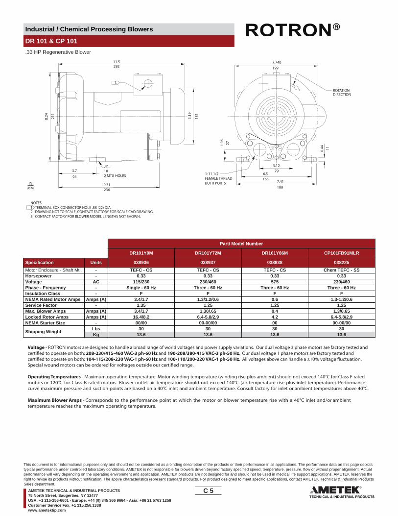
DR 101 & CP 101
.33 HP Regenerative Blower
11.5292
211
94
236
131
8.24 5.19
3.7
9.31
.41102 MTG HOLES
3.12
6.579
1657.41188
1.06 27
11
1997.740
0.44
1.
ROTATIONDIRECTION
1-11 1/2FEMALE THREADBOTH PORTS
NOTES1 TERMINAL BOX CONNECTOR HOLE .88 (22) DIA.2 DRAWING NOT TO SCALE, CONTACT FACTORY FOR SCALE CAD DRAWING.3 CONTACT FACTORY FOR BLOWER MODEL LENGTHS NOT SHOWN.
INMM
Part/ Model Number
DR101Y9M DR101Y72M DR101Y86M CP101FB91MLR
Specification Units 038936 038937 038938 038225
Motor Enclosure - Shaft Mtl. - TEFC - CS TEFC - CS TEFC - CS Chem TEFC - SSHorsepower - 0.33 0.33 0.33 0.33Voltage AC 115/230 230/460 575 230/460Phase - Frequency - Single - 60 Hz Three - 60 Hz Three - 60 Hz Three - 60 HzInsulation Class - F F F FNEMA Rated Motor Amps Amps (A) 3.4/1.7 1.3/1.2/0.6 0.6 1.3-1.2/0.6Service Factor - 1.35 1.25 1.25 1.25Max. Blower Amps Amps (A) 3.4/1.7 1.30/.65 0.4 1.3/0.65Locked Rotor Amps Amps (A) 16.4/8.2 6.4-5.8/2.9 4.2 6.4-5.8/2.9NEMA Starter Size - 00/00 00-00/00 00 00-00/00
Shipping WeightLbsKg
3013.6
3013.6
3013.6
3013.6
Voltage - ROTRON motors are designed to handle a broad range of world voltages and power supply variations. Our dual voltage 3 phase motors are factory tested and certi�ed to operate on both: 208-230/415-460 VAC-3 ph-60 Hz and 190-208/380-415 VAC-3 ph-50 Hz. Our dual voltage 1 phase motors are factory tested and certi�ed to operate on both: 104-115/208-230 VAC-1 ph-60 Hz and 100-110/200-220 VAC-1 ph-50 Hz. All voltages above can handle a ±10% voltage �uctuation. Special wound motors can be ordered for voltages outside our certi�ed range.
Operating Temperatures - Maximum operating temperature: Motor winding temperature (winding rise plus ambient) should not exceed 140°C for Class F rated motors or 120°C for Class B rated motors. Blower outlet air temperature should not exceed 140°C (air temperature rise plus inlet temperature). Performance curve maximum pressure and suction points are based on a 40°C inlet and ambient temperature. Consult factory for inlet or ambient temperatures above 40°C.
Maximum Blower Amps - Corresponds to the performance point at which the motor or blower temperature rise with a 40°C inlet and/or ambient temperature reaches the maximum operating temperature.
C 5____
This document is for informational purposes only and should not be considered as a binding description of the products or their performance in all applications. The performance data on this page depictstypical performance under controlled laboratory conditions. AMETEK is not responsible for blowers driven beyond factory specified speed, temperature, pressure, flow or without proper alignment. Actualperformance will vary depending on the operating environment and application. AMETEK products are not designed for and should not be used in medical life support applications. AMETEK reserves theright to revise its products without notification. The above characteristics represent standard products. For product designed to meet specific applications, contact AMETEK Technical & Industrial ProductsSales department.
AMETEK TECHNICAL & INDUSTRIAL PRODUCTS75 North Street, Saugerties, NY 12477USA: +1 215-256-6601 - Europe: +44 (0) 845 366 9664 - Asia: +86 21 5763 1258Customer Service Fax: +1 215.256.1338www.ametektip.com
Industrial / Chemical Processing Blowers
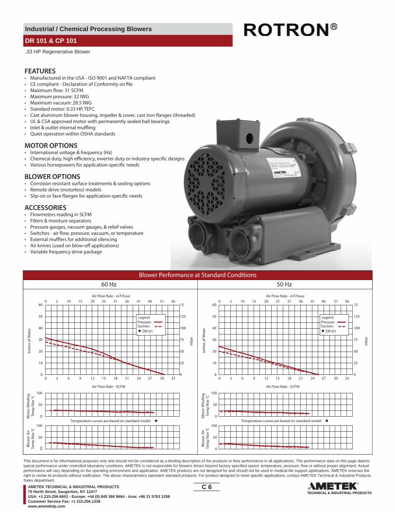
DR 101 & CP 101
.33 HP Regenerative Blower
FEATURES• Manufactured in the USA - ISO 9001 and NAFTA compliant
• Maximum pressure: 32 IWG• Maximum �ow: 31 SCFM
• Maximum vacuum: 28.5 IWG• Standard motor: 0.33 HP, TEFC
• UL & CSA approved motor with permanently sealed ball bearings• Inlet & outlet internal mu�ing• Quiet operation within OSHA standards
MOTOR OPTIONS• International voltage & frequency (Hz)
BLOWER OPTIONS• Corrosion resistant surface treatments & sealing options• Remote drive (motorless) models
ACCESSORIES• Flowmeters reading in SCFM• Filters & moisture separators• Pressure gauges, vacuum gauges, & relief valves
• External mu�ers for additional silencing• Air knives (used on blow-o� applications)• Variable frequency drive package
Blower Performance at Standard Conditions60 Hz 50 Hz
Inch
es o
f Wat
er
mba
r
mba
r
Mot
or W
indi
ngTe
mp
Rise
° C
Air Flow Rate - SCFMAir Flow Rate - SCFM
Air Flow Rate - m3/hourAir Flow Rate - m3/hour
Inch
es o
f Wat
erM
otor
Win
ding
Tem
p Ri
se ° C
Blow
er A
irTe
mp
Rise
° C
Blow
er A
irTe
mp
Rise
° C
LegendPressure:Suction:
LegendPressure:Suction:
DR101 DR101
0 3 6 9 12 15 18 21 24 27 30 33
0 5 10 15 20 25 31 36 41 46 51 56
0
10
20
30
40
50
60
0
25
50
75
100
125
15
0 3 6 9 12 15 18 21 24 27 30 33
0 5 10 15 20 25 31 36 41 46 51 56
0
10
20
30
40
50
60
0
25
50
75
100
125
15
Temperature curves are based on standard model Temperature curves are based on standard model0
50
100
0
50
100
0
50
100
0
50
100
C 6____
This document is for informational purposes only and should not be considered as a binding description of the products or their performance in all applications. The performance data on this page depictstypical performance under controlled laboratory conditions. AMETEK is not responsible for blowers driven beyond factory specified speed, temperature, pressure, flow or without proper alignment. Actualperformance will vary depending on the operating environment and application. AMETEK products are not designed for and should not be used in medical life support applications. AMETEK reserves theright to revise its products without notification. The above characteristics represent standard products. For product designed to meet specific applications, contact AMETEK Technical & Industrial ProductsSales department.
AMETEK TECHNICAL & INDUSTRIAL PRODUCTS75 North Street, Saugerties, NY 12477USA: +1 215-256-6601 - Europe: +44 (0) 845 366 9664 - Asia: +86 21 5763 1258Customer Service Fax: +1 215.256.1338www.ametektip.com
Industrial / Chemical Processing Blowers
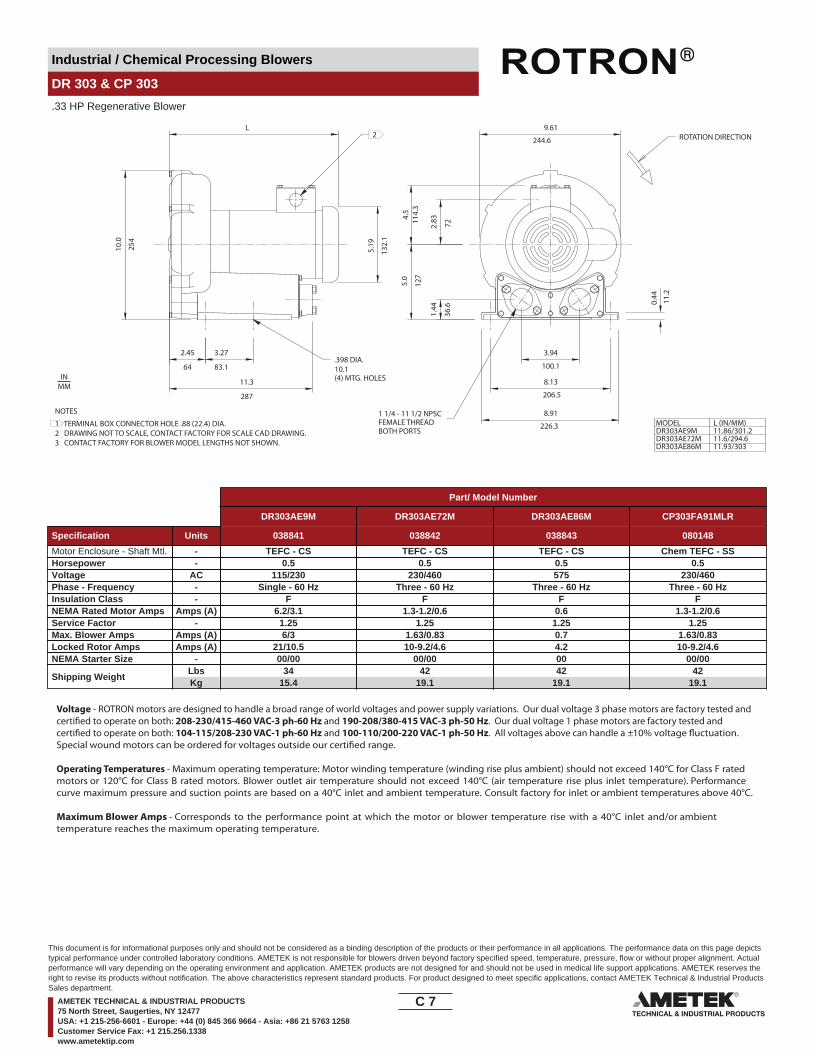
DR 303 & CP 303
.33 HP Regenerative Blower
10.1(4) MTG. HOLES
3.94
100.1
206.5
8.13
L10
.0
254
5.19
132.
1
2.45
64
3.27
83.1
11.3
287
9.61
244.6
4.5
2.83
5.0
127
114.
3
72
1.44
36.6
11.2
0.44
DR303AE9MDR303AE72MDR303AE86M
MODEL L (IN/MM)11.86/301.211.6/294.611.93/303
8.91
226.3
2 ROTATION DIRECTION
.398 DIA.
FEMALE THREADBOTH PORTS
1 1/4 - 11 1/2 NPSCNOTES
1 TERMINAL BOX CONNECTOR HOLE .88 (22.4) DIA.2 DRAWING NOT TO SCALE, CONTACT FACTORY FOR SCALE CAD DRAWING.3 CONTACT FACTORY FOR BLOWER MODEL LENGTHS NOT SHOWN.
INMM
Part/ Model Number
DR303AE9M DR303AE72M DR303AE86M CP303FA91MLR
Specification Units 038841 038842 038843 080148
Motor Enclosure - Shaft Mtl. - TEFC - CS TEFC - CS TEFC - CS Chem TEFC - SSHorsepower - 0.5 0.5 0.5 0.5Voltage AC 115/230 230/460 575 230/460Phase - Frequency - Single - 60 Hz Three - 60 Hz Three - 60 Hz Three - 60 HzInsulation Class - F F F FNEMA Rated Motor Amps Amps (A) 6.2/3.1 1.3-1.2/0.6 0.6 1.3-1.2/0.6Service Factor - 1.25 1.25 1.25 1.25Max. Blower Amps Amps (A) 6/3 1.63/0.83 0.7 1.63/0.83Locked Rotor Amps Amps (A) 21/10.5 10-9.2/4.6 4.2 10-9.2/4.6NEMA Starter Size - 00/00 00/00 00 00/00
Shipping WeightLbsKg
3415.4
4219.1
4219.1
4219.1
Voltage - ROTRON motors are designed to handle a broad range of world voltages and power supply variations. Our dual voltage 3 phase motors are factory tested and certi�ed to operate on both: 208-230/415-460 VAC-3 ph-60 Hz and 190-208/380-415 VAC-3 ph-50 Hz. Our dual voltage 1 phase motors are factory tested and certi�ed to operate on both: 104-115/208-230 VAC-1 ph-60 Hz and 100-110/200-220 VAC-1 ph-50 Hz. All voltages above can handle a ±10% voltage �uctuation. Special wound motors can be ordered for voltages outside our certi�ed range.
Operating Temperatures - Maximum operating temperature: Motor winding temperature (winding rise plus ambient) should not exceed 140°C for Class F rated motors or 120°C for Class B rated motors. Blower outlet air temperature should not exceed 140°C (air temperature rise plus inlet temperature). Performance curve maximum pressure and suction points are based on a 40°C inlet and ambient temperature. Consult factory for inlet or ambient temperatures above 40°C.
Maximum Blower Amps - Corresponds to the performance point at which the motor or blower temperature rise with a 40°C inlet and/or ambient temperature reaches the maximum operating temperature.
C 7____
This document is for informational purposes only and should not be considered as a binding description of the products or their performance in all applications. The performance data on this page depictstypical performance under controlled laboratory conditions. AMETEK is not responsible for blowers driven beyond factory specified speed, temperature, pressure, flow or without proper alignment. Actualperformance will vary depending on the operating environment and application. AMETEK products are not designed for and should not be used in medical life support applications. AMETEK reserves theright to revise its products without notification. The above characteristics represent standard products. For product designed to meet specific applications, contact AMETEK Technical & Industrial ProductsSales department.
AMETEK TECHNICAL & INDUSTRIAL PRODUCTS75 North Street, Saugerties, NY 12477USA: +1 215-256-6601 - Europe: +44 (0) 845 366 9664 - Asia: +86 21 5763 1258Customer Service Fax: +1 215.256.1338www.ametektip.com

Industrial / Chemical Processing Blowers
DR 303 & CP 303
.33 HP Regenerative Blower
FEATURES• Manufactured in the USA - ISO 9001 and NAFTA compliant
• Maximum pressure: 48 IWG• Maximum vacuum: 45 IWG• Standard motor: 0.5 HP, TEFC
(threaded)• UL & CSA approved motor with permanently sealed ball bearings• Inlet & outlet internal mu�ing• Quiet operation within OSHA standards
MOTOR OPTIONS• International voltage & frequency (Hz)
BLOWER OPTIONS• Corrosion resistant surface treatments & sealing options• Remote drive (motorless) models
ACCESSORIES• Flowmeters reading in SCFM• Filters & moisture separators• Pressure gauges, vacuum gauges, & relief valves
• External mu�ers for additional silencing• Air knives (used on blow-o� applications)• Variable frequency drive package
Blower Performance at Standard Conditions60 Hz 50 Hz
Inch
es o
f Wat
er
mba
r
mba
r
Mot
or W
indi
ngTe
mp
Ris
e °C
Air Flow Rate - SCFMAir Flow Rate - SCFM
Air Flow Rate - m3/hourAir Flow Rate - m3/hour
Inch
es o
f Wat
erM
otor
Win
ding
Tem
p R
ise
°C
Blo
wer
Air
Tem
p R
ise
°C
Blo
wer
Air
Tem
p R
ise
°C
LegendPressure:Suction:
LegendPressure:Suction:
DR303 DR303
0 5 10 15 20 25 30 35 40 45 50 550
10
20
30
40
50
60
0
25
50
75
100
125
150
0 5 10 15 20 25 30 35 40 45 50 550
10
20
30
40
50
60
25
50
75
100
125
150
Temperature curves are based on standard model Temperature curves are based on standard model0
50
100
0
50
100
0
50
100
0
50
100
0 9 17 25 34 42 51 59 68 76 85 93 0 9 17 25 34 42 51 59 68 76 85 93
C 8____
This document is for informational purposes only and should not be considered as a binding description of the products or their performance in all applications. The performance data on this page depictstypical performance under controlled laboratory conditions. AMETEK is not responsible for blowers driven beyond factory specified speed, temperature, pressure, flow or without proper alignment. Actualperformance will vary depending on the operating environment and application. AMETEK products are not designed for and should not be used in medical life support applications. AMETEK reserves theright to revise its products without notification. The above characteristics represent standard products. For product designed to meet specific applications, contact AMETEK Technical & Industrial ProductsSales department.
AMETEK TECHNICAL & INDUSTRIAL PRODUCTS75 North Street, Saugerties, NY 12477USA: +1 215-256-6601 - Europe: +44 (0) 845 366 9664 - Asia: +86 21 5763 1258Customer Service Fax: +1 215.256.1338www.ametektip.com
Industrial / Chemical Processing Blowers
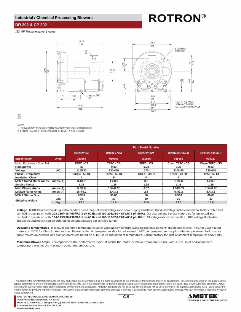
DR 202 & CP 202
.33 HP Regenerative Blower
11.78299
10.0
0
64 83
11.30
9.63
3.94100
72
39
127
114
254
5.18
2.52 3.27
286
22
131
2.83
0.44
245
4.5
5.031.53
8.12206.28.91226.3
STANDARDROTATION.88
.398 DIA. 10
1 1/4-11 1/2 NPSCSTRAIGHT THREAD(2X) CAST IRON FLANGES
(4X)
NOTES1 DRAWING NOT TO SCALE, CONTACT FACTORY FOR SCALE CAD DRAWING.2 CONTACT FACTORY FOR BLOWER MODEL LENGTHS NOT SHOWN.
INMM
Part/ Model Number
DR202Y9M DR202Y72M DR202Y86M CP202AE72MLR CP202FA91MLR
Specification Units 080564 080565 080566 038953 038227
Motor Enclosure - Shaft Mtl. - TEFC - CS TEFC - CS TEFC - CS Chem TEFC - CS Chem TEFC - SSHorsepower - .33 0.33 0.33 0.33 0.33Voltage AC 115/230 230/460 575 230/460 230/460Phase - Frequency - Single - 60 Hz Three - 60 Hz Three - 60 Hz Three - 60 Hz Three - 60 HzInsulation Class - F F F F FNEMA Rated Motor Amps Amps (A) 3.4/1.7 1.2/0.6 0.5 1.2/0.6 1.2/0.6Service Factor - 1.35 1.35 1.35 1.35 1.35Max. Blower Amps Amps (A) 5.2/2.6 1.54/0.77 0.57 1.54/0.77 1.54/0.77Locked Rotor Amps Amps (A) 16.4/8.2 6.4/3.2 2.6 6.4/3.2 6.4/3.2NEMA Starter Size - 00/00 00/00 00 00/00 00/00
Shipping WeightLbsKg
3013.6
3013.6
3013.6
3013.6
3013.6
Voltage - ROTRON motors are designed to handle a broad range of world voltages and power supply variations. Our dual voltage 3 phase motors are factory tested and certi�ed to operate on both: 208-230/415-460 VAC-3 ph-60 Hz and 190-208/380-415 VAC-3 ph-50 Hz. Our dual voltage 1 phase motors are factory tested and certi�ed to operate on both: 104-115/208-230 VAC-1 ph-60 Hz and 100-110/200-220 VAC-1 ph-50 Hz. All voltages above can handle a ±10% voltage �uctuation. Special wound motors can be ordered for voltages outside our certi�ed range.
Operating Temperatures - Maximum operating temperature: Motor winding temperature (winding rise plus ambient) should not exceed 140°C for Class F rated motors or 120°C for Class B rated motors. Blower outlet air temperature should not exceed 140°C (air temperature rise plus inlet temperature). Performance curve maximum pressure and suction points are based on a 40°C inlet and ambient temperature. Consult factory for inlet or ambient temperatures above 40°C.
Maximum Blower Amps - Corresponds to the performance point at which the motor or blower temperature rise with a 40°C inlet and/or ambient temperature reaches the maximum operating temperature.
C 9____
This document is for informational purposes only and should not be considered as a binding description of the products or their performance in all applications. The performance data on this page depictstypical performance under controlled laboratory conditions. AMETEK is not responsible for blowers driven beyond factory specified speed, temperature, pressure, flow or without proper alignment. Actualperformance will vary depending on the operating environment and application. AMETEK products are not designed for and should not be used in medical life support applications. AMETEK reserves theright to revise its products without notification. The above characteristics represent standard products. For product designed to meet specific applications, contact AMETEK Technical & Industrial ProductsSales department.
AMETEK TECHNICAL & INDUSTRIAL PRODUCTS75 North Street, Saugerties, NY 12477USA: +1 215-256-6601 - Europe: +44 (0) 845 366 9664 - Asia: +86 21 5763 1258Customer Service Fax: +1 215.256.1338www.ametektip.com

Industrial / Chemical Processing Blowers
DR 202 & CP 202
.33 HP Regenerative Blower
FEATURES• Manufactured in the USA - ISO 9001 and NAFTA compliant
• Maximum pressure: 40 IWG• Maximum vacuum: 35 IWG• Standard motor: 0.33 HP, TEFC
• UL & CSA approved motor with permanently sealed ball bearings• Inlet & outlet internal mu�ing• Quiet operation within OSHA standards
MOTOR OPTIONS• International voltage & frequency (Hz)
BLOWER OPTIONS• Corrosion resistant surface treatments & sealing options• Remote drive (motorless) models• Cast iron (threaded) or face �anges for application-speci�c needs
ACCESSORIES• Flowmeters reading in SCFM• Filters & moisture separators• Pressure gauges, vacuum gauges, & relief valves
• External mu�ers for additional silencing• Air knives (used on blow-o� applications)• Variable frequency drive package
Blower Performance at Standard Conditions60 Hz 50 Hz
Inch
es o
f Wat
er
mba
r
mba
r
Mot
or W
indi
ngTe
mp
Rise
° C
Air Flow Rate - SCFMAir Flow Rate - SCFM
Air Flow Rate - m3/hourAir Flow Rate - m3/hour
Inch
es o
f Wat
erM
otor
Win
ding
Tem
p Ri
se ° C
Blow
er A
irTe
mp
Rise
° C
Blow
er A
irTe
mp
Rise
° C
LegendPressure:Suction:
LegendPressure:Suction:
DR202 DR202
0 5 10 15 20 25 30 35 40 45 50 55
0 9 17 25 34 42 51 59 68 76 85 93 0 9 17 25 34 42 51 59 68 76 85 93
0
10
20
30
40
50
60
0
25
50
75
100
125
150
0 5 10 15 20 25 30 35 40 45 50 550
10
20
30
40
50
60
0
25
50
75
100
125
150
Temperature curves are based on standard model Temperature curves are based on standard model0
50
100
0
50
100
0
50
100
0
50
100
C 10____
This document is for informational purposes only and should not be considered as a binding description of the products or their performance in all applications. The performance data on this page depictstypical performance under controlled laboratory conditions. AMETEK is not responsible for blowers driven beyond factory specified speed, temperature, pressure, flow or without proper alignment. Actualperformance will vary depending on the operating environment and application. AMETEK products are not designed for and should not be used in medical life support applications. AMETEK reserves theright to revise its products without notification. The above characteristics represent standard products. For product designed to meet specific applications, contact AMETEK Technical & Industrial ProductsSales department.
AMETEK TECHNICAL & INDUSTRIAL PRODUCTS75 North Street, Saugerties, NY 12477USA: +1 215-256-6601 - Europe: +44 (0) 845 366 9664 - Asia: +86 21 5763 1258Customer Service Fax: +1 215.256.1338www.ametektip.com

Industrial / Chemical Processing Blowers
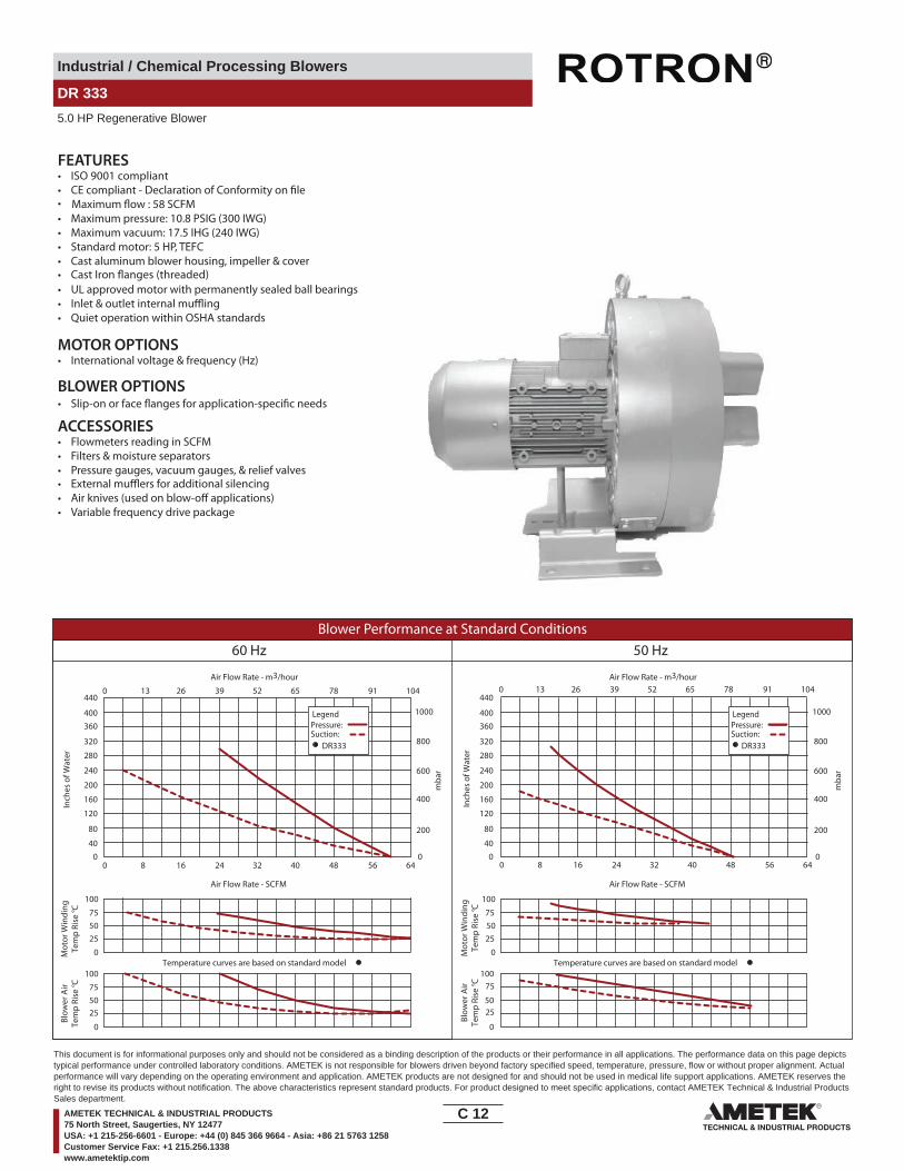
DR 333
5.0 HP Regenerative Blower
13.585.56 8.31
14.7
7
NPT
5.04
16.3
0
12.6
4
7.65
1.26M25X1.5
FEMALE
M16X1.5
12.40
144X %C [14]
.16
.55
13.78
4.97
5.00
5.72
5.12
5.44
12.95
21.85
NOTES:
CONTACT FACTORY FOR LATEST REVISION1. DRAWING SUBJECT TO CHANGE WITHOUT NOTICE
2.03
Filter 515254 included
4.99
[ %c 167]%c 6.57
Part/ Model Number
DR333D89M
Specification Units 081959
Motor Enclosure - Shaft Mtl. - TEFC-CSHorsepower - 5.0Voltage AC 230/460Phase - Frequency - Three - 50/60 HzInsulation Class - FNEMA Rated Motor Amps Amps (A) 13.8/8Service Factor - 1.0Locked Rotor Amps Amps (A) 94/47Max. Blower Amps Amps (A) 15/7.5Recommended NEMA Starter Size- 1/0
Shipping WeightLbsKg
128 58.1
Voltage - ROTRON motors are designed to handle a broad range of world voltages and power supply variations. Our dual voltage 3 phase motors are factory tested and certi�ed to operate on both: 208-230/415-460 VAC-3 ph-60 Hz and 190-208/380-415 VAC-3 ph-50 Hz. Our dual voltage 1 phase motors are factory tested and certi�ed to operate on both: 104-115/208-230 VAC-1 ph-60 Hz and 100-110/200-220 VAC-1 ph-50 Hz. All voltages above can handle a ±10% voltage �uctuation. Special wound motors can be ordered for voltages outside our certi�ed range.
Operating Temperatures - Maximum operating temperature: Motor winding temperature (winding rise plus ambient) should not exceed 140°C for Class F rated motors or 120°C for Class B rated motors. Blower outlet air temperature should not exceed 140°C (air temperature rise plus inlet temperature). Performance curve maximum pressure and suction points are based on a 40°C inlet and ambient temperature. Consult factory for inlet or ambient temperatures above 40°C.
Maximum Blower Amps - Corresponds to the performance point at which the motor or blower temperature rise with a 40°C inlet and/or ambient temperature reaches the maximum operating temperature.
C 11____
This document is for informational purposes only and should not be considered as a binding description of the products or their performance in all applications. The performance data on this page depictstypical performance under controlled laboratory conditions. AMETEK is not responsible for blowers driven beyond factory specified speed, temperature, pressure, flow or without proper alignment. Actualperformance will vary depending on the operating environment and application. AMETEK products are not designed for and should not be used in medical life support applications. AMETEK reserves theright to revise its products without notification. The above characteristics represent standard products. For product designed to meet specific applications, contact AMETEK Technical & Industrial ProductsSales department.
AMETEK TECHNICAL & INDUSTRIAL PRODUCTS75 North Street, Saugerties, NY 12477USA: +1 215-256-6601 - Europe: +44 (0) 845 366 9664 - Asia: +86 21 5763 1258Customer Service Fax: +1 215.256.1338www.ametektip.com
Industrial / Chemical Processing Blowers
DR 333
5.0 HP Regenerative Blower
FEATURES• ISO 9001 compliant
• Cast Iron �anges (threaded)
• Maximum pressure: 10.8 PSIG (300 IWG)• Maximum vacuum: 17.5 IHG (240 IWG)• Standard motor: 5 HP, TEFC
• UL approved motor with permanently sealed ball bearings• Inlet & outlet internal mu�ing• Quiet operation within OSHA standards
MOTOR OPTIONS• International voltage & frequency (Hz)
BLOWER OPTIONS
ACCESSORIES• Flowmeters reading in SCFM• Filters & moisture separators• Pressure gauges, vacuum gauges, & relief valves• External mu�ers for additional silencing• Air knives (used on blow-o� applications)• Variable frequency drive package
Maximum �ow : 58 SCFM
Blower Performance at Standard Conditions60 Hz 50 Hz
Inch
es o
f Wat
er
mba
r
mba
r
Mot
or W
indi
ngTe
mp
Rise
° C
Air Flow Rate - SCFMAir Flow Rate - SCFM
Air Flow Rate - m3/hourAir Flow Rate - m3/hour
Inch
es o
f Wat
erM
otor
Win
ding
Tem
p Ri
se ° C
Blow
er A
irTe
mp
Rise
° C
Blow
er A
irTe
mp
Rise
° C
LegendPressure:Suction:
LegendPressure:Suction:
DR333 DR333
0 8 16 24 32 40 48 56 64 0 8 16 24 32 40 48 56 640
40
80
120
160
200
240
280
320
360400
440
040
80
120
160
200
240
280
320
360400
440
0
200
400
600
800
1000
0
200
400
600
800
1000
Temperature curves are based on standard model Temperature curves are based on standard model0
50
100
0
5075
75
25
75
25
75
2525
100
0
50
100
0
50
100
0 13 26 39 52 65 78 91 104 0 13 26 39 52 65 78 91 104
C 12____
This document is for informational purposes only and should not be considered as a binding description of the products or their performance in all applications. The performance data on this page depictstypical performance under controlled laboratory conditions. AMETEK is not responsible for blowers driven beyond factory specified speed, temperature, pressure, flow or without proper alignment. Actualperformance will vary depending on the operating environment and application. AMETEK products are not designed for and should not be used in medical life support applications. AMETEK reserves theright to revise its products without notification. The above characteristics represent standard products. For product designed to meet specific applications, contact AMETEK Technical & Industrial ProductsSales department.
AMETEK TECHNICAL & INDUSTRIAL PRODUCTS75 North Street, Saugerties, NY 12477USA: +1 215-256-6601 - Europe: +44 (0) 845 366 9664 - Asia: +86 21 5763 1258Customer Service Fax: +1 215.256.1338www.ametektip.com

Industrial / Chemical Processing Blowers
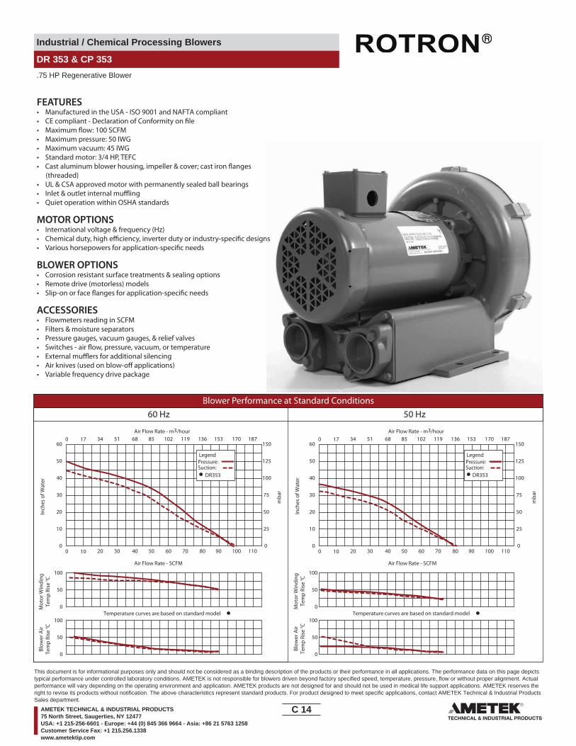
DR 353 & CP 353
.75 HP Regenerative Blower
IN
OU
T
L12
.22
311
3.1579
3.7595
12(4) MTG HOLES
12.75324
5.13
6.22
11.5
5.55
5.12130
10.18
Ø6.13
0.41
10
3.56
1.75
292
141
130
90
158 44
156
258BOTH PORTS MODEL
DR353BR9M
DR353BR72M
L (IN/MM)
13.97/355
12.5/317
8.93226.8
.47 DIA.
1 1/2 - 11 1/2 NPSC THREAD
ROTATION DIRECTION1
NOTES1 TERMINAL BOX CONNECTOR HOLE .88 (22) DIA.2 DRAWING NOT TO SCALE, CONTACT FACTORY FOR SCALE CAD DRAWING.3 CONTACT FACTORY FOR BLOWER MODEL LENGTHS NOT SHOWN.
INMM
Part/ Model Number
DR353BR9M DR353BR72M DR353BR86M CP353BR72MLR CP353FD72MLR
Specification Units 080554 080555 080556 081612
Motor Enclosure - Shaft Mtl. - TEFC - CS TEFC - CS TEFC - CS Chem TEFC - CS Chem TEFC - SSHorsepower - 0.75 0.75 0.75 0.75 0.75Voltage AC 115/230 230/460 575 230/460 230/460Phase - Frequency - Single - 60 Hz Three - 60 Hz Three - 60 Hz Three 60 Hz Three 60 HzInsulation Class - F F F F FNEMA Rated Motor Amps Amps (A) 10.0/5.0 3.0/1.5 0.96 3.0/1.5 3.0/1.5Service Factor - 1.15 1.25 1.25 1.25 1.25Max. Blower Amps Amps (A) 12/6 3.5/1.75 1.0 3.5/1.75 3.5/1.75Locked Rotor Amps Amps (A) 59.6/29.8 15.2/7.6 6.1 15.2/7.6 15.2/7.6NEMA Starter Size - 00/00 00/00 00 00/00 00/00
Shipping WeightLbsKg
6027.2
5424.5
5424.5
5424.5
5424.5
Voltage - ROTRON motors are designed to handle a broad range of world voltages and power supply variations. Our dual voltage 3 phase motors are factory tested and certi�ed to operate on both: 208-230/415-460 VAC-3 ph-60 Hz and 190-208/380-415 VAC-3 ph-50 Hz. Our dual voltage 1 phase motors are factory tested and certi�ed to operate on both: 104-115/208-230 VAC-1 ph-60 Hz and 100-110/200-220 VAC-1 ph-50 Hz. All voltages above can handle a ±10% voltage �uctuation. Special wound motors can be ordered for voltages outside our certi�ed range.
Operating Temperatures - Maximum operating temperature: Motor winding temperature (winding rise plus ambient) should not exceed 140°C for Class F rated motors or 120°C for Class B rated motors. Blower outlet air temperature should not exceed 140°C (air temperature rise plus inlet temperature). Performance curve maximum pressure and suction points are based on a 40°C inlet and ambient temperature. Consult factory for inlet or ambient temperatures above 40°C.
Maximum Blower Amps - Corresponds to the performance point at which the motor or blower temperature rise with a 40°C inlet and/or ambient temperature reaches the maximum operating temperature.
C 13____
This document is for informational purposes only and should not be considered as a binding description of the products or their performance in all applications. The performance data on this page depictstypical performance under controlled laboratory conditions. AMETEK is not responsible for blowers driven beyond factory specified speed, temperature, pressure, flow or without proper alignment. Actualperformance will vary depending on the operating environment and application. AMETEK products are not designed for and should not be used in medical life support applications. AMETEK reserves theright to revise its products without notification. The above characteristics represent standard products. For product designed to meet specific applications, contact AMETEK Technical & Industrial ProductsSales department.
AMETEK TECHNICAL & INDUSTRIAL PRODUCTS75 North Street, Saugerties, NY 12477USA: +1 215-256-6601 - Europe: +44 (0) 845 366 9664 - Asia: +86 21 5763 1258Customer Service Fax: +1 215.256.1338www.ametektip.com
Industrial / Chemical Processing Blowers
DR 353 & CP 353
.75 HP Regenerative Blower
FEATURES• Manufactured in the USA - ISO 9001 and NAFTA compliant
• Maximum pressure: 50 IWG• Maximum vacuum: 45 IWG• Standard motor: 3/4 HP, TEFC
(threaded)• UL & CSA approved motor with permanently sealed ball bearings• Inlet & outlet internal mu�ing• Quiet operation within OSHA standards
MOTOR OPTIONS• International voltage & frequency (Hz)
BLOWER OPTIONS• Corrosion resistant surface treatments & sealing options• Remote drive (motorless) models
ACCESSORIES• Flowmeters reading in SCFM• Filters & moisture separators• Pressure gauges, vacuum gauges, & relief valves
• External mu�ers for additional silencing• Air knives (used on blow-o� applications)• Variable frequency drive package
Blower Performance at Standard Conditions60 Hz 50 Hz
Inch
es o
f Wat
er
mba
r
mba
r
Mot
or W
indi
ngTe
mp
Rise
° C
Air Flow Rate - SCFMAir Flow Rate - SCFM
Air Flow Rate - m3/hourAir Flow Rate - m3/hour
Inch
es o
f Wat
erM
otor
Win
ding
Tem
p Ri
se ° C
Blow
er A
irTe
mp
Rise
° C
Blow
er A
irTe
mp
Rise
° C
LegendPressure:Suction:
LegendPressure:Suction:
DR353 DR353
0 10 20 30 40 50 60 70 80 90 100 110
0 17 34 51 68 85 102 119 136 153 170 187
0
10
20
30
40
50
60
0
25
50
75
100
125
150
0 10 20 30 40 50 60 70 80 90 100 110
0 17 34 51 68 85 102 119 136 153 170 187
0
10
20
30
40
50
60
0
25
50
75
100
125
150
Temperature curves are based on standard model Temperature curves are based on standard model0
50
100
0
50
100
0
50
100
0
50
100
C 14____
This document is for informational purposes only and should not be considered as a binding description of the products or their performance in all applications. The performance data on this page depictstypical performance under controlled laboratory conditions. AMETEK is not responsible for blowers driven beyond factory specified speed, temperature, pressure, flow or without proper alignment. Actualperformance will vary depending on the operating environment and application. AMETEK products are not designed for and should not be used in medical life support applications. AMETEK reserves theright to revise its products without notification. The above characteristics represent standard products. For product designed to meet specific applications, contact AMETEK Technical & Industrial ProductsSales department.
AMETEK TECHNICAL & INDUSTRIAL PRODUCTS75 North Street, Saugerties, NY 12477USA: +1 215-256-6601 - Europe: +44 (0) 845 366 9664 - Asia: +86 21 5763 1258Customer Service Fax: +1 215.256.1338www.ametektip.com

Industrial / Chemical Processing Blowers
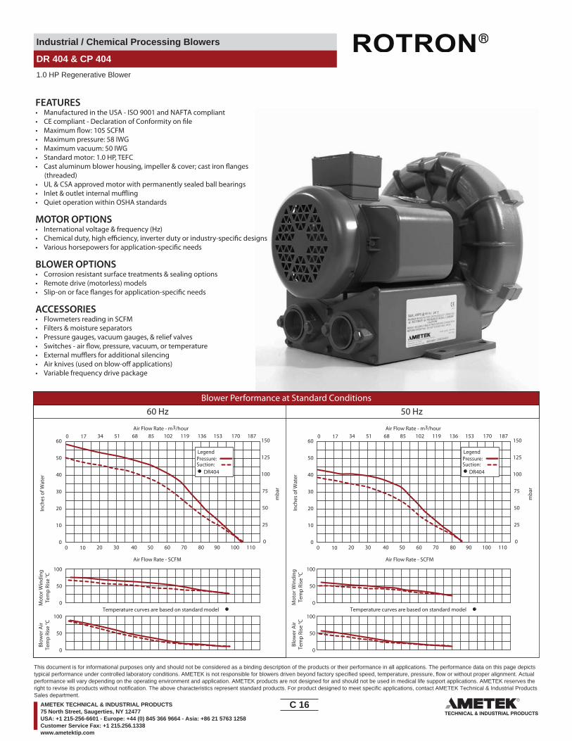
DR 404 & CP 404
1.0 HP Regenerative Blower
3.75
1.67
42.4
11.9(4) MTG. HOLES
292.111.5
5.12
8.93
130
226.8
L
4.125.
046.
2816
0
12.1
830
9.4
7.18
182.
4
3.0579.2 95.3
12.63320.8
0.41 8.9
DR404AL58MDR404AL72MDR404AL86M
MODEL L (IN/MM)14.41/366.014.18/360.213.38/339.9
FEMALE THREADBOTH PORTS
10.3261.6
1
1 1/2 - 11 1/2 NPSC
.47 DIA.
NOTES1 TERMINAL BOX CONNECTOR HOLE .88 (22.4) DIA. KNOCK-OUT2 DRAWING NOT TO SCALE, CONTACT FACTORY FOR SCALE CAD DRAWING.3 CONTACT FACTORY FOR BLOWER MODEL LENGTHS NOT SHOWN.
INMM
Part/ Model Number
DR404AL58M DR404AL72M DR404AL86M CP404CU72MLR
Specification Units 037407 037406 037408 038233
Motor Enclosure - Shaft Mtl. - TEFC - CS TEFC - CS TEFC - CS Chem TEFC - SSHorsepower - 1.0 1.0 1.0 1.0Voltage AC 115/230 230/460 575 230/460Phase - Frequency - Single - 60 Hz Three - 60 Hz Three - 60 Hz Three - 60 HzInsulation Class - F F F FNEMA Rated Motor Amps Amps (A) 11.4/5.7 3.0/1.5 1.2 3.0/1.5Service Factor - 1.15 1.15 1.15 1.15Max. Blower Amps Amps (A) 14.5/7.25 4.0/2.0 1.4 4.0/2.0Locked Rotor Amps Amps (A) 70/35 21.0/10.5 7.6 21.0/10.5NEMA Starter Size - 00/00 00/00 00 00/00
Shipping WeightLbsKg
6931.3
6429
6429
6429
Voltage - ROTRON motors are designed to handle a broad range of world voltages and power supply variations. Our dual voltage 3 phase motors are factory tested and certi�ed to operate on both: 208-230/415-460 VAC-3 ph-60 Hz and 190-208/380-415 VAC-3 ph-50 Hz. Our dual voltage 1 phase motors are factory tested and certi�ed to operate on both: 104-115/208-230 VAC-1 ph-60 Hz and 100-110/200-220 VAC-1 ph-50 Hz. All voltages above can handle a ±10% voltage �uctuation. Special wound motors can be ordered for voltages outside our certi�ed range.
Operating Temperatures - Maximum operating temperature: Motor winding temperature (winding rise plus ambient) should not exceed 140°C for Class F rated motors or 120°C for Class B rated motors. Blower outlet air temperature should not exceed 140°C (air temperature rise plus inlet temperature). Performance curve maximum pressure and suction points are based on a 40°C inlet and ambient temperature. Consult factory for inlet or ambient temperatures above 40°C.
Maximum Blower Amps - Corresponds to the performance point at which the motor or blower temperature rise with a 40°C inlet and/or ambient temperature reaches the maximum operating temperature.
C 15____
This document is for informational purposes only and should not be considered as a binding description of the products or their performance in all applications. The performance data on this page depictstypical performance under controlled laboratory conditions. AMETEK is not responsible for blowers driven beyond factory specified speed, temperature, pressure, flow or without proper alignment. Actualperformance will vary depending on the operating environment and application. AMETEK products are not designed for and should not be used in medical life support applications. AMETEK reserves theright to revise its products without notification. The above characteristics represent standard products. For product designed to meet specific applications, contact AMETEK Technical & Industrial ProductsSales department.
AMETEK TECHNICAL & INDUSTRIAL PRODUCTS75 North Street, Saugerties, NY 12477USA: +1 215-256-6601 - Europe: +44 (0) 845 366 9664 - Asia: +86 21 5763 1258Customer Service Fax: +1 215.256.1338www.ametektip.com
Industrial / Chemical Processing Blowers
DR 404 & CP 404
1.0 HP Regenerative Blower
FEATURES• Manufactured in the USA - ISO 9001 and NAFTA compliant
• Maximum pressure: 58 IWG• Maximum vacuum: 50 IWG• Standard motor: 1.0 HP, TEFC
(threaded)• UL & CSA approved motor with permanently sealed ball bearings• Inlet & outlet internal mu�ing• Quiet operation within OSHA standards
MOTOR OPTIONS• International voltage & frequency (Hz)
BLOWER OPTIONS• Corrosion resistant surface treatments & sealing options• Remote drive (motorless) models
ACCESSORIES• Flowmeters reading in SCFM• Filters & moisture separators• Pressure gauges, vacuum gauges, & relief valves
• External mu�ers for additional silencing• Air knives (used on blow-o� applications)• Variable frequency drive package
Blower Performance at Standard Conditions60 Hz 50 Hz
Inch
es o
f Wat
er
mba
r
mba
r
Mot
or W
indi
ngTe
mp
Rise
° C
Air Flow Rate - SCFMAir Flow Rate - SCFM
Air Flow Rate - m3/hourAir Flow Rate - m3/hour
Inch
es o
f Wat
erM
otor
Win
ding
Tem
p Ri
se ° C
Blow
er A
irTe
mp
Rise
° C
Blow
er A
irTe
mp
Rise
° C
LegendPressure:Suction:
LegendPressure:Suction:
DR404 DR404
0 10 20 30 40 50 60 70 80 90 100 1100
10
20
30
40
50
60
0
25
50
75
100
125
1500 17 34 51 68 85 102 119 136 153 170 187
0 10 20 30 40 50 60 70 80 90 100 1100
10
20
30
40
50
60
0
25
50
75
100
125
1500 17 34 51 68 85 102 119 136 153 170 187
Temperature curves are based on standard model Temperature curves are based on standard model0
50
100
0
50
100
0
50
100
0
50
100
C 16____
This document is for informational purposes only and should not be considered as a binding description of the products or their performance in all applications. The performance data on this page depictstypical performance under controlled laboratory conditions. AMETEK is not responsible for blowers driven beyond factory specified speed, temperature, pressure, flow or without proper alignment. Actualperformance will vary depending on the operating environment and application. AMETEK products are not designed for and should not be used in medical life support applications. AMETEK reserves theright to revise its products without notification. The above characteristics represent standard products. For product designed to meet specific applications, contact AMETEK Technical & Industrial ProductsSales department.
AMETEK TECHNICAL & INDUSTRIAL PRODUCTS75 North Street, Saugerties, NY 12477USA: +1 215-256-6601 - Europe: +44 (0) 845 366 9664 - Asia: +86 21 5763 1258Customer Service Fax: +1 215.256.1338www.ametektip.com

Industrial / Chemical Processing Blowers
DR 433
11.5 HP Regenerative Blower
16.42 10.54
17.9
9
17.405.52
19.4
9 6.57"
15.3
1
5.75
9.29
1.65
.55 DIA
2.47
14.61
.19
15.98
6.02
NPTFEMALE
M32 X 1.5
1 /14
6.125.9813.35
27.95
21.18
Filter 515254 included 8.98
6.02
Part/ Model Number
DR433GE72M
Specification Units 081958
Motor Enclosure - Shaft Mtl. - TEFC-CSHorsepower - 11.5Voltage AC 208-230/460Phase - Frequency - Three - 60 HzInsulation Class - FNEMA Rated Motor Amps Amps (A) 17.3/10Service Factor - 1.0Locked Rotor Amps Amps (A) 294/147Max. Blower Amps Amps (A) 22/11Recommended NEMA Starter Size- 3/2
Shipping WeightLbsKg
300136.1
Voltage - ROTRON motors are designed to handle a broad range of world voltages and power supply variations. Our dual voltage 3 phase motors are factory tested and certi�ed to operate on both: 208-230/415-460 VAC-3 ph-60 Hz and 190-208/380-415 VAC-3 ph-50 Hz. Our dual voltage 1 phase motors are factory tested and certi�ed to operate on both: 104-115/208-230 VAC-1 ph-60 Hz and 100-110/200-220 VAC-1 ph-50 Hz. All voltages above can handle a ±10% voltage �uctuation. Special wound motors can be ordered for voltages outside our certi�ed range.
Operating Temperatures - Maximum operating temperature: Motor winding temperature (winding rise plus ambient) should not exceed 140°C for Class F rated motors or 120°C for Class B rated motors. Blower outlet air temperature should not exceed 140°C (air temperature rise plus inlet temperature). Performance curve maximum pressure and suction points are based on a 40°C inlet and ambient temperature. Consult factory for inlet or ambient temperatures above 40°C.
Maximum Blower Amps - Corresponds to the performance point at which the motor or blower temperature rise with a 40°C inlet and/or ambient temperature reaches the maximum operating temperature.
C 17____
This document is for informational purposes only and should not be considered as a binding description of the products or their performance in all applications. The performance data on this page depictstypical performance under controlled laboratory conditions. AMETEK is not responsible for blowers driven beyond factory specified speed, temperature, pressure, flow or without proper alignment. Actualperformance will vary depending on the operating environment and application. AMETEK products are not designed for and should not be used in medical life support applications. AMETEK reserves theright to revise its products without notification. The above characteristics represent standard products. For product designed to meet specific applications, contact AMETEK Technical & Industrial ProductsSales department.
AMETEK TECHNICAL & INDUSTRIAL PRODUCTS75 North Street, Saugerties, NY 12477USA: +1 215-256-6601 - Europe: +44 (0) 845 366 9664 - Asia: +86 21 5763 1258Customer Service Fax: +1 215.256.1338www.ametektip.com
Industrial / Chemical Processing Blowers
DR 433
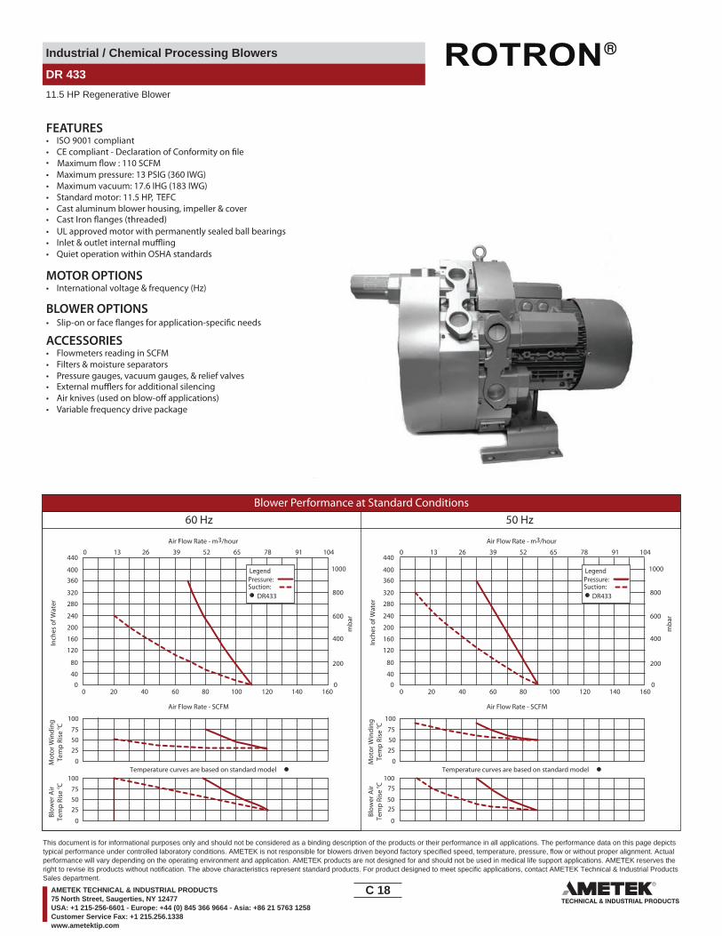
11.5 HP Regenerative Blower
FEATURES• ISO 9001 compliant
• Cast Iron �anges (threaded)
• Maximum pressure: 13 PSIG (360 IWG)• Maximum vacuum: 17.6 IHG (183 IWG)• Standard motor: 11.5 HP, TEFC
• UL approved motor with permanently sealed ball bearings• Inlet & outlet internal mu�ing• Quiet operation within OSHA standards
MOTOR OPTIONS• International voltage & frequency (Hz)
BLOWER OPTIONS
ACCESSORIES• Flowmeters reading in SCFM• Filters & moisture separators• Pressure gauges, vacuum gauges, & relief valves• External mu�ers for additional silencing• Air knives (used on blow-o� applications)• Variable frequency drive package
Maximum �ow : 110 SCFM
Blower Performance at Standard Conditions60 Hz 50 Hz
Inch
es o
f Wat
er
mba
r
mba
r
Mot
or W
indi
ngTe
mp
Rise
° C
Air Flow Rate - SCFMAir Flow Rate - SCFM
Air Flow Rate - m3/hourAir Flow Rate - m3/hour
Inch
es o
f Wat
erM
otor
Win
ding
Tem
p Ri
se ° C
Blow
er A
irTe
mp
Rise
° C
Blow
er A
irTe
mp
Rise
° C
LegendPressure:Suction:
LegendPressure:Suction:
DR433 DR433
0 20 40 60 80 100 120 140 160 0 20 40 60 80 100 120 140 1600
40
80
120
160
200
240
280
320
360400
440
040
80
120
160
200
240
280
320
360400
440
0
200
400
600
800
1000
0
200
400
600
800
1000
Temperature curves are based on standard model Temperature curves are based on standard model0
50
100
0
5075
75
25
75
25
75
2525
100
0
50
100
0
50
100
0 13 26 39 52 65 78 91 104 0 13 26 39 52 65 78 91 104
C 18____
This document is for informational purposes only and should not be considered as a binding description of the products or their performance in all applications. The performance data on this page depictstypical performance under controlled laboratory conditions. AMETEK is not responsible for blowers driven beyond factory specified speed, temperature, pressure, flow or without proper alignment. Actualperformance will vary depending on the operating environment and application. AMETEK products are not designed for and should not be used in medical life support applications. AMETEK reserves theright to revise its products without notification. The above characteristics represent standard products. For product designed to meet specific applications, contact AMETEK Technical & Industrial ProductsSales department.
AMETEK TECHNICAL & INDUSTRIAL PRODUCTS75 North Street, Saugerties, NY 12477USA: +1 215-256-6601 - Europe: +44 (0) 845 366 9664 - Asia: +86 21 5763 1258Customer Service Fax: +1 215.256.1338www.ametektip.com
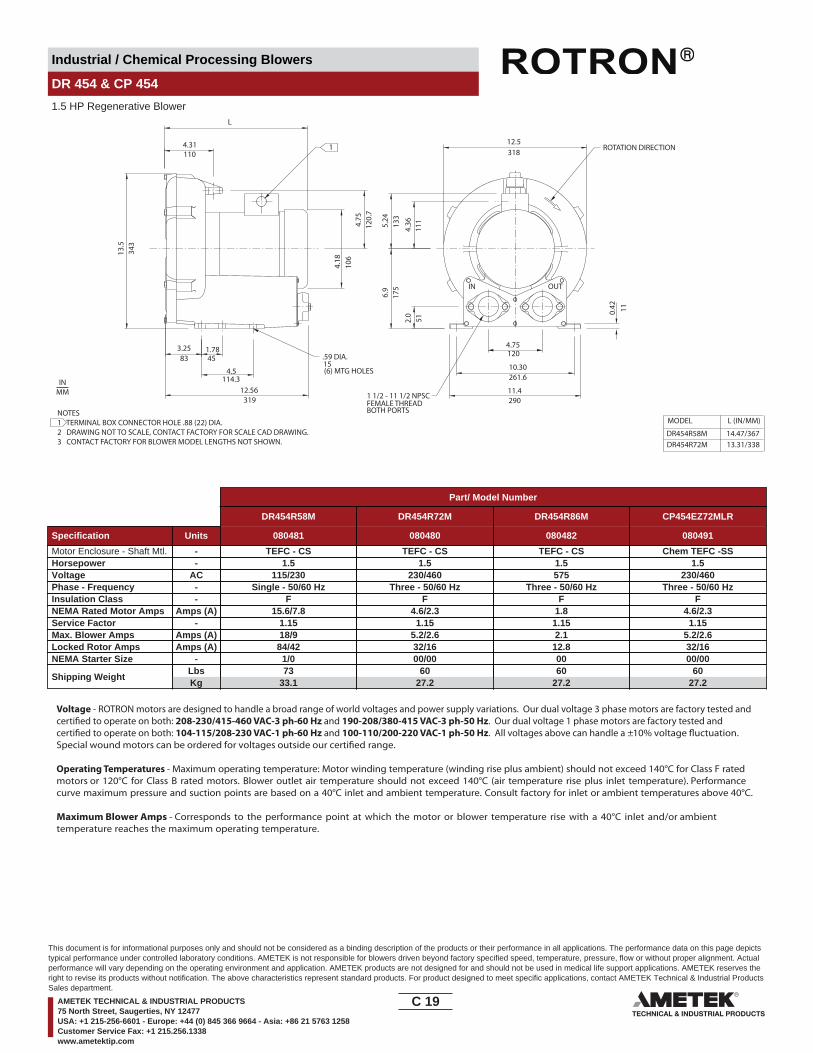
Industrial / Chemical Processing Blowers
DR 454 & CP 454
1.5 HP Regenerative Blower
IN OUT
4.75
3.25 1.78
12.56
15
4.31
13.5
L
120.
7
4.18
106
4.36
1115.24
133
2.0
6.9
175
11.4
4.75120
290
51
318
0.42 11
FEMALE THREAD
(6) MTG HOLES
MODEL
DR454R58MDR454R72M
L (IN/MM)
14.47/36713.31/338
83 45
110
319
343
BOTH PORTS
12.5
10.30261.6
4.5114.3
.59 DIA.
ROTATION DIRECTION
1 1/2 - 11 1/2 NPSC
1
NOTES1 TERMINAL BOX CONNECTOR HOLE .88 (22) DIA.2 DRAWING NOT TO SCALE, CONTACT FACTORY FOR SCALE CAD DRAWING.3 CONTACT FACTORY FOR BLOWER MODEL LENGTHS NOT SHOWN.
INMM
Part/ Model Number
DR454R58M DR454R72M DR454R86M CP454EZ72MLR
Specification Units 080481 080480 080482 080491
Motor Enclosure - Shaft Mtl. - TEFC - CS TEFC - CS TEFC - CS Chem TEFC -SSHorsepower - 1.5 1.5 1.5 1.5Voltage AC 115/230 230/460 575 230/460Phase - Frequency - Single - 50/60 Hz Three - 50/60 Hz Three - 50/60 Hz Three - 50/60 HzInsulation Class - F F F FNEMA Rated Motor Amps Amps (A) 15.6/7.8 4.6/2.3 1.8 4.6/2.3Service Factor - 1.15 1.15 1.15 1.15Max. Blower Amps Amps (A) 18/9 5.2/2.6 2.1 5.2/2.6Locked Rotor Amps Amps (A) 84/42 32/16 12.8 32/16NEMA Starter Size - 1/0 00/00 00 00/00
Shipping WeightLbsKg
7333.1
6027.2
6027.2
6027.2
Voltage - ROTRON motors are designed to handle a broad range of world voltages and power supply variations. Our dual voltage 3 phase motors are factory tested and certi�ed to operate on both: 208-230/415-460 VAC-3 ph-60 Hz and 190-208/380-415 VAC-3 ph-50 Hz. Our dual voltage 1 phase motors are factory tested and certi�ed to operate on both: 104-115/208-230 VAC-1 ph-60 Hz and 100-110/200-220 VAC-1 ph-50 Hz. All voltages above can handle a ±10% voltage �uctuation. Special wound motors can be ordered for voltages outside our certi�ed range.
Operating Temperatures - Maximum operating temperature: Motor winding temperature (winding rise plus ambient) should not exceed 140°C for Class F rated motors or 120°C for Class B rated motors. Blower outlet air temperature should not exceed 140°C (air temperature rise plus inlet temperature). Performance curve maximum pressure and suction points are based on a 40°C inlet and ambient temperature. Consult factory for inlet or ambient temperatures above 40°C.
Maximum Blower Amps - Corresponds to the performance point at which the motor or blower temperature rise with a 40°C inlet and/or ambient temperature reaches the maximum operating temperature.
C 19____
This document is for informational purposes only and should not be considered as a binding description of the products or their performance in all applications. The performance data on this page depictstypical performance under controlled laboratory conditions. AMETEK is not responsible for blowers driven beyond factory specified speed, temperature, pressure, flow or without proper alignment. Actualperformance will vary depending on the operating environment and application. AMETEK products are not designed for and should not be used in medical life support applications. AMETEK reserves theright to revise its products without notification. The above characteristics represent standard products. For product designed to meet specific applications, contact AMETEK Technical & Industrial ProductsSales department.
AMETEK TECHNICAL & INDUSTRIAL PRODUCTS75 North Street, Saugerties, NY 12477USA: +1 215-256-6601 - Europe: +44 (0) 845 366 9664 - Asia: +86 21 5763 1258Customer Service Fax: +1 215.256.1338www.ametektip.com
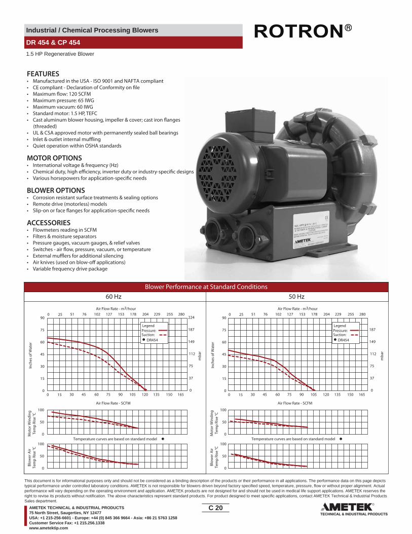
Industrial / Chemical Processing Blowers
DR 454 & CP 454
1.5 HP Regenerative Blower
FEATURES• Manufactured in the USA - ISO 9001 and NAFTA compliant
• Maximum pressure: 65 IWG• Maximum vacuum: 60 IWG• Standard motor: 1.5 HP, TEFC
(threaded)• UL & CSA approved motor with permanently sealed ball bearings• Inlet & outlet internal mu�ing• Quiet operation within OSHA standards
MOTOR OPTIONS• International voltage & frequency (Hz)
BLOWER OPTIONS• Corrosion resistant surface treatments & sealing options• Remote drive (motorless) models
ACCESSORIES• Flowmeters reading in SCFM• Filters & moisture separators• Pressure gauges, vacuum gauges, & relief valves
• External mu�ers for additional silencing• Air knives (used on blow-o� applications)• Variable frequency drive package
Blower Performance at Standard Conditions60 Hz 50 Hz
Inch
es o
f Wat
er
mba
r
mba
r
Mot
or W
indi
ngTe
mp
Rise
° C
Air Flow Rate - SCFMAir Flow Rate - SCFM
Air Flow Rate - m3/hourAir Flow Rate - m3/hour
Inch
es o
f Wat
erM
otor
Win
ding
Tem
p Ri
se ° C
Blow
er A
irTe
mp
Rise
° C
Blow
er A
irTe
mp
Rise
° C
LegendPressure:Suction:
LegendPressure:Suction:
DR454 DR454
0 15 30 45 60 75 90 105 120 135 150 1650
15
30
45
60
75
90
0
15
30
45
60
75
90
0
37
75
112
149
187
2240 25 51 76 102 127 153 178 204 229 255 280
15 30 45 60 75 90 105 120 135 150 165
37
75
112
149
187
25 51 76 102 127 153 178 204 229 255 280
00
0
Temperature curves are based on standard model Temperature curves are based on standard model0
50
100
0
50
100
0
50
100
0
50
100
C 20____
This document is for informational purposes only and should not be considered as a binding description of the products or their performance in all applications. The performance data on this page depictstypical performance under controlled laboratory conditions. AMETEK is not responsible for blowers driven beyond factory specified speed, temperature, pressure, flow or without proper alignment. Actualperformance will vary depending on the operating environment and application. AMETEK products are not designed for and should not be used in medical life support applications. AMETEK reserves theright to revise its products without notification. The above characteristics represent standard products. For product designed to meet specific applications, contact AMETEK Technical & Industrial ProductsSales department.
AMETEK TECHNICAL & INDUSTRIAL PRODUCTS75 North Street, Saugerties, NY 12477USA: +1 215-256-6601 - Europe: +44 (0) 845 366 9664 - Asia: +86 21 5763 1258Customer Service Fax: +1 215.256.1338www.ametektip.com

Industrial / Chemical Processing Blowers
DR 505 & CP 505
2.0 / 3.0 HP Regenerative Blower
IN
L
14.4
3
3.56
14.18
.59 DIA.
(4) MTG HOLES
4.75
10.30
11.70 REF.
7.25
1.91
.37
REF.
C B
13.59 DIA.
15
MODEL DR505AS58M
DR505AS72MDR505AS86MDR505K58MDR505K72M
15.63/397
15.63/397
14.75/37414.38/36517.0/431
L (IN/MM)
4.25/1084.37/111
4.37/111
4.63/117
4.63/117
B (IN/MM)5.64/143
5.25/133
5.64/1435.18/131
C (IN/MM)
5.18/131
FEMALE THREADBOTH PORTS
OUT
4.5
114.390.4
360.2
366.
5
184.
2
48.5
120.7
261.6
297.2
9.4
182.4
345.2
1 1/2 - 11 1/2 NPSC
ROTATION DIRECTION
1
7.18 DIA.
NOTES1 TERMINAL BOX CONNECTOR HOLE .88 (22) DIA.2 DRAWING NOT TO SCALE, CONTACT FACTORY FOR SCALE CAD DRAWING.3 CONTACT FACTORY FOR BLOWER MODEL LENGTHS NOT SHOWN.
INMM
Part/ Model Number
DR505AS58M DR505AS72M DR505AS86M DR505K58M DR505K72M CP505FE72MLR CP505CT72MLR
Specification Units 037542 037543 037544 081882 037551 038239 038237
Motor Enclosure - Shaft Mtl. - TEFC - CS TEFC - CS TEFC - CS TEFC - CS TEFC - CS Chem TEFC - SS Chem TEFC - SSHorsepower - 2.0 2.0 2.0 3.0 3.0 3.0 2.0Voltage AC 115/230 230/460 575 115/230 230/460 230/460 230/460Phase - Frequency - Single - 60 Hz Three - 60 Hz Three - 60 Hz Single - 60 Hz Three - 60 Hz Three - 60 Hz Three - 60 HzInsulation Class - F F F F F F FNEMA Rated Motor Amps Amps (A) 18.2/9.1 5.4/2.7 2.3 25.6/12.8 7.6/3.8 7.6/3.8 5.4/2.7Service Factor - 1.15 1.15 1.15 1.15 1.15 1.15 1.15Max. Blower Amps Amps (A) 24/11.5 6.8/3.4 3.0 28/14 8.8/4.4 8.8/4.4 6.8/3.4Locked Rotor Amps Amps (A) 138/69 38/19 21 194/97 88/44 88/44 38/19NEMA Starter Size - 1/0 00/00 00 1.5/0 0/0 0/0 00/00
Shipping WeightLbsKg
9744
8237.2
8438.1
9141.3
8639
8639
8237.2
Voltage - ROTRON motors are designed to handle a broad range of world voltages and power supply variations. Our dual voltage 3 phase motors are factory tested and certi�ed to operate on both: 208-230/415-460 VAC-3 ph-60 Hz and 190-208/380-415 VAC-3 ph-50 Hz. Our dual voltage 1 phase motors are factory tested and certi�ed to operate on both: 104-115/208-230 VAC-1 ph-60 Hz and 100-110/200-220 VAC-1 ph-50 Hz. All voltages above can handle a ±10% voltage �uctuation. Special wound motors can be ordered for voltages outside our certi�ed range.
Operating Temperatures - Maximum operating temperature: Motor winding temperature (winding rise plus ambient) should not exceed 140°C for Class F rated motors or 120°C for Class B rated motors. Blower outlet air temperature should not exceed 140°C (air temperature rise plus inlet temperature). Performance curve maximum pressure and suction points are based on a 40°C inlet and ambient temperature. Consult factory for inlet or ambient temperatures above 40°C.
Maximum Blower Amps - Corresponds to the performance point at which the motor or blower temperature rise with a 40°C inlet and/or ambient temperature reaches the maximum operating temperature.
C 21____
This document is for informational purposes only and should not be considered as a binding description of the products or their performance in all applications. The performance data on this page depictstypical performance under controlled laboratory conditions. AMETEK is not responsible for blowers driven beyond factory specified speed, temperature, pressure, flow or without proper alignment. Actualperformance will vary depending on the operating environment and application. AMETEK products are not designed for and should not be used in medical life support applications. AMETEK reserves theright to revise its products without notification. The above characteristics represent standard products. For product designed to meet specific applications, contact AMETEK Technical & Industrial ProductsSales department.
AMETEK TECHNICAL & INDUSTRIAL PRODUCTS75 North Street, Saugerties, NY 12477USA: +1 215-256-6601 - Europe: +44 (0) 845 366 9664 - Asia: +86 21 5763 1258Customer Service Fax: +1 215.256.1338www.ametektip.com

Industrial / Chemical Processing Blowers
DR 505 & CP 505
2.0 / 3.0 HP Regenerative Blower
FEATURES• Manufactured in the USA - ISO 9001 and NAFTA compliant
• Maximum pressure: 65 or 88 IWG• Maximum vacuum: 73 IWG• Standard motor: 2.0 or 3.0 HP, TEFC
(threaded)• UL & CSA approved motor with permanently sealed ball bearings• Inlet & outlet internal mu�ing• Quiet operation within OSHA standards
MOTOR OPTIONS• International voltage & frequency (Hz)
BLOWER OPTIONS• Corrosion resistant surface treatments & sealing options• Remote drive (motorless) models
ACCESSORIES• Flowmeters reading in SCFM• Filters & moisture separators• Pressure gauges, vacuum gauges, & relief valves
• External mu�ers for additional silencing• Air knives (used on blow-o� applications)• Variable frequency drive package
Blower Performance at Standard Conditions60 Hz 50 Hz
Inch
es o
f Wat
er
mba
r
mba
r
Mot
or W
indi
ngTe
mp
Rise
° C
Air Flow Rate - SCFMAir Flow Rate - SCFM
Air Flow Rate - m3/hourAir Flow Rate - m3/hour
Inch
es o
f Wat
erM
otor
Win
ding
Tem
p Ri
se ° C
Blow
er A
irTe
mp
Rise
° C
Blow
er A
irTe
mp
Rise
° C
Temperature curves are based on standard model Temperature curves are based on standard model
LegendPressure:Suction:
DR505K72MDR505AS72MDR505K58MDR505AS58M
LegendPressure:Suction:
DR505K72MDR505AS72MDR505K58MDR505AS58M
0 15 30 45 60 75 90 105 120 135 150 16515 30 45 60 75 90 105 120 135 150 165 0
0
50
100
0
15
30
45
60
75
90
0
15
30
45
60
75
90
0
50
100
0
50
100
0
50
100
0
37
75
112
149
187
224 2240 25 51 76 102 127 153 178 204 229 255 280
37
75
112
149
187
25 51 76 102 127 153 178 204 229 255 280
0
0
C 22____
This document is for informational purposes only and should not be considered as a binding description of the products or their performance in all applications. The performance data on this page depictstypical performance under controlled laboratory conditions. AMETEK is not responsible for blowers driven beyond factory specified speed, temperature, pressure, flow or without proper alignment. Actualperformance will vary depending on the operating environment and application. AMETEK products are not designed for and should not be used in medical life support applications. AMETEK reserves theright to revise its products without notification. The above characteristics represent standard products. For product designed to meet specific applications, contact AMETEK Technical & Industrial ProductsSales department.
AMETEK TECHNICAL & INDUSTRIAL PRODUCTS75 North Street, Saugerties, NY 12477USA: +1 215-256-6601 - Europe: +44 (0) 845 366 9664 - Asia: +86 21 5763 1258Customer Service Fax: +1 215.256.1338www.ametektip.com

Industrial / Chemical Processing Blowers
DR 513 & CP 513
1.5 HP Regenerative Blower
OUTIN
182
14.21
16.0
6
15
408
5.07
4.13
8.8
2.4
4.8
12.8
0.5
ROTATION
(4) MTG HOLES
106
61
224
122
BOTH PORTSFEMALE THREAD 325
360
937.
18
13.69346
3.72
129
11.4289.6
5.50139.7
13.88
352.61
.59 DIA.
1 1/2 - 11 1/2 NPSC
13
NOTES1 TERMINAL BOX CONNECTOR HOLE .88 (22) DIA.2 DRAWING NOT TO SCALE, CONTACT FACTORY FOR SCALE CAD DRAWING.3 CONTACT FACTORY FOR BLOWER MODEL LENGTHS NOT SHOWN.
INMM
Part/ Model Number
DR513R72 DR513R58 DR513R86 CP513EZ72LR
Specification Units 037217 037209 037773 038241
Motor Enclosure - Shaft Mtl. - TEFC - CS TEFC - CS TEFC - CS Chem TEFC -SSHorsepower - 1.5 1.5 1.5 1.5Voltage AC 230/460 115/230 575 230/460Phase - Frequency - Three - 60 Hz Single - 60 Hz Three - 60 Hz Three - 60 HzInsulation Class - F F F FNEMA Rated Motor Amps Amps (A) 4.6/2.3 16.8/8.4 1.8 4.6/2.3Service Factor - 1.15 1.15 1.15 1.15Max. Blower Amps Amps (A) 5/2.5 19/9.5 1.85 5/2.5Locked Rotor Amps Amps (A) 43/21 120/60 13 43/21NEMA Starter Size - 00/00 1/0 00 00/00
Shipping WeightLbsKg
7634.5
9543.1
7634.5
7634.5
Voltage - ROTRON motors are designed to handle a broad range of world voltages and power supply variations. Our dual voltage 3 phase motors are factory tested and certi�ed to operate on both: 208-230/415-460 VAC-3 ph-60 Hz and 190-208/380-415 VAC-3 ph-50 Hz. Our dual voltage 1 phase motors are factory tested and certi�ed to operate on both: 104-115/208-230 VAC-1 ph-60 Hz and 100-110/200-220 VAC-1 ph-50 Hz. All voltages above can handle a ±10% voltage �uctuation. Special wound motors can be ordered for voltages outside our certi�ed range.
Operating Temperatures - Maximum operating temperature: Motor winding temperature (winding rise plus ambient) should not exceed 140°C for Class F rated motors or 120°C for Class B rated motors. Blower outlet air temperature should not exceed 140°C (air temperature rise plus inlet temperature). Performance curve maximum pressure and suction points are based on a 40°C inlet and ambient temperature. Consult factory for inlet or ambient temperatures above 40°C.
Maximum Blower Amps - Corresponds to the performance point at which the motor or blower temperature rise with a 40°C inlet and/or ambient temperature reaches the maximum operating temperature.
C 23____
This document is for informational purposes only and should not be considered as a binding description of the products or their performance in all applications. The performance data on this page depictstypical performance under controlled laboratory conditions. AMETEK is not responsible for blowers driven beyond factory specified speed, temperature, pressure, flow or without proper alignment. Actualperformance will vary depending on the operating environment and application. AMETEK products are not designed for and should not be used in medical life support applications. AMETEK reserves theright to revise its products without notification. The above characteristics represent standard products. For product designed to meet specific applications, contact AMETEK Technical & Industrial ProductsSales department.
AMETEK TECHNICAL & INDUSTRIAL PRODUCTS75 North Street, Saugerties, NY 12477USA: +1 215-256-6601 - Europe: +44 (0) 845 366 9664 - Asia: +86 21 5763 1258Customer Service Fax: +1 215.256.1338www.ametektip.com
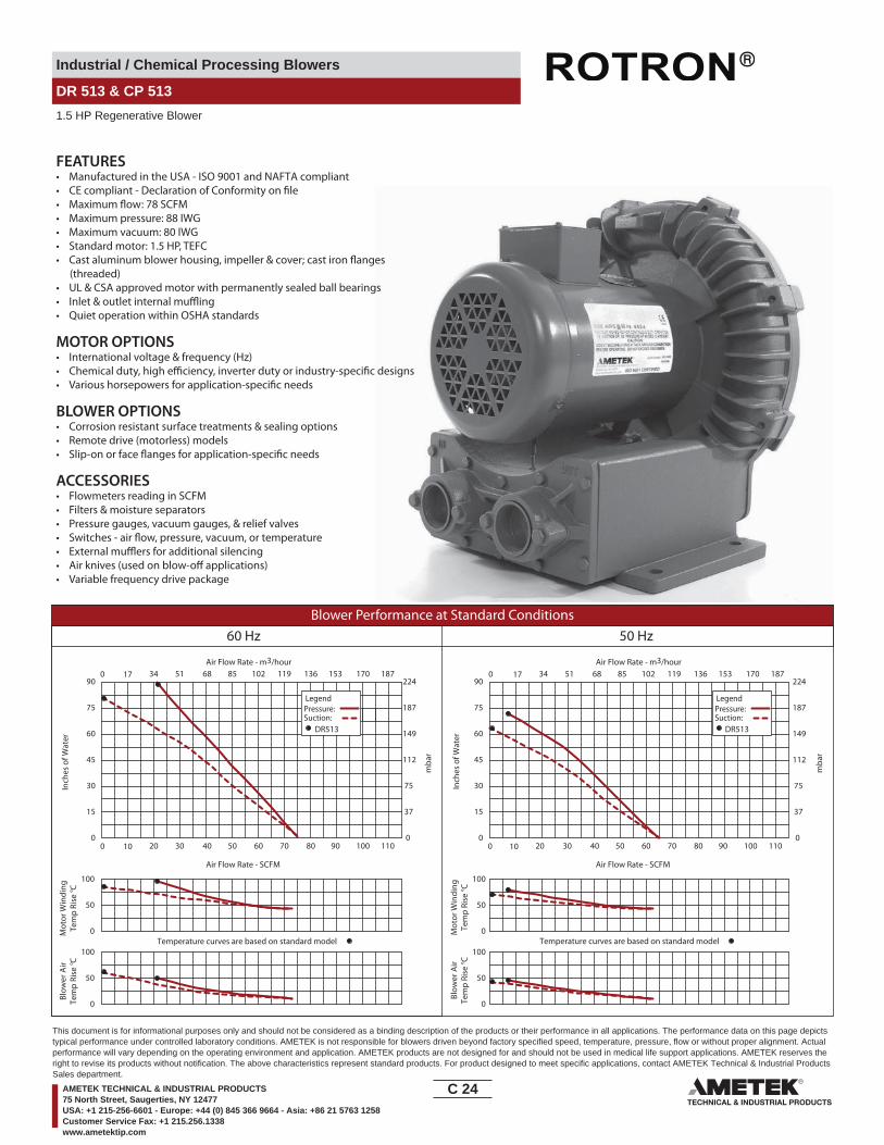
Industrial / Chemical Processing Blowers
DR 513 & CP 513
1.5 HP Regenerative Blower
FEATURES• Manufactured in the USA - ISO 9001 and NAFTA compliant
• Maximum pressure: 88 IWG• Maximum vacuum: 80 IWG• Standard motor: 1.5 HP, TEFC
(threaded)• UL & CSA approved motor with permanently sealed ball bearings•• Quiet operation within OSHA standards
MOTOR OPTIONS• International voltage & frequency (Hz)
BLOWER OPTIONS• Corrosion resistant surface treatments & sealing options• Remote drive (motorless) models
ACCESSORIES• Flowmeters reading in SCFM• Filters & moisture separators• Pressure gauges, vacuum gauges, & relief valves
••• Variable frequency drive package
Blower Performance at Standard Conditions60 Hz 50 Hz
Inch
es o
f Wat
er
mba
r
mba
r
Mot
or W
indi
ngTe
mp
Rise
° C
Air Flow Rate - SCFMAir Flow Rate - SCFM
Air Flow Rate - m3/hourAir Flow Rate - m3/hour
Inch
es o
f Wat
erM
otor
Win
ding
Tem
p Ri
se ° C
Blow
er A
irTe
mp
Rise
° C
Blow
er A
irTe
mp
Rise
° C
LegendPressure:Suction:
LegendPressure:Suction:
DR513 DR513
0 10 20 30 40 50 60 70 80 90 100 110 0 10 20 30 40 50 60 70 80 90 100 110
0 17 34 51 68 85 102 119 136 153 170 187 0
0
15
30
45
60
75
90
0
15
30
45
60
75
90
0
37
75
112
149
187
22417 34 51 68 85 102 119 136 153 170 187
37
75
112
149
187
224
0
Temperature curves are based on standard model Temperature curves are based on standard model0
50
100
0
50
100
0
50
100
0
50
100
C 24____
This document is for informational purposes only and should not be considered as a binding description of the products or their performance in all applications. The performance data on this page depictstypical performance under controlled laboratory conditions. AMETEK is not responsible for blowers driven beyond factory specified speed, temperature, pressure, flow or without proper alignment. Actualperformance will vary depending on the operating environment and application. AMETEK products are not designed for and should not be used in medical life support applications. AMETEK reserves theright to revise its products without notification. The above characteristics represent standard products. For product designed to meet specific applications, contact AMETEK Technical & Industrial ProductsSales department.
AMETEK TECHNICAL & INDUSTRIAL PRODUCTS75 North Street, Saugerties, NY 12477USA: +1 215-256-6601 - Europe: +44 (0) 845 366 9664 - Asia: +86 21 5763 1258Customer Service Fax: +1 215.256.1338www.ametektip.com
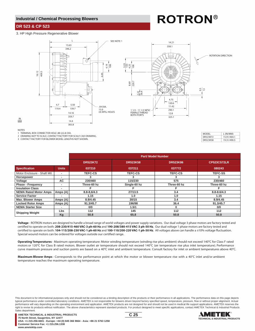
Industrial / Chemical Processing Blowers
DR 523 & CP 523
3. HP High Pressure Regenerative Blower
IN OUT
346.2
139.7
359.7
(4) MTG. HOLES
56.4
220.
7
120.6
290.1
325.1
FEMALE THREADBOTH PORTS
13.63
5.50
2.22
8.69
4.75
12.8
11.42
L16
.12
409.
5
4.19 10
8
4.7
119.4
14.16
14.4365.8
15.0
0.5
13
14.21
358.1
6.95
4.25
108
5.23
133
MODELDR523K72DR523K58
15.91/404.119.31/490.5
L (IN/MM)
1 1/2 - 11 1/2 NPSC
ROTATION DIRECTION
.59 DIA.
SEE NOTE 1
NOTES1 TERMINAL BOX CONNECTOR HOLE .88 (22.4) DIA.2 DRAWING NOT TO SCALE, CONTACT FACTORY FOR SCALE CAD DRAWING.3 CONTACT FACTORY FOR BLOWER MODEL LENGTHS NOT SHOWN.
INMM
Part/ Model Number
DR523K72 DR523K58 DR523K86 CP523CS72LR
Specification Units 037210 037211 037772 080243
Motor Enclosure - Shaft Mtl. - TEFC-CS TEFC-CS TEFC-CS TEFC-SSHorsepower - 3 3 3 3Voltage AC 230/460 115/230 575 230/460Phase - Frequency - Three-60 hz Single-60 hz Three-60 hz Three-60 hz Insulation Class - F F F FNEMA Rated Motor Amps Amps (A) 8.8-8,6/4.3 27/13.5 3.4 8.8-8.6/4.3Service Factor - 1.15 1.0 1.0 1.15Max. Blower Amps Amps (A) 8.9/4.45 30/15 3.4 8.9/4.45Locked Rotor Amps Amps (A) 91.3/45.7 196/98 36.4 91.3/45.7NEMA Starter Size - 0/0 1.5/1 0 0/0
Shipping WeightLbsKg
11250.8
14565.8
11250.8
11250.8
Voltage - ROTRON motors are designed to handle a broad range of world voltages and power supply variations. Our dual voltage 3 phase motors are factory tested and certi�ed to operate on both: 208-230/415-460 VAC-3 ph-60 Hz and 190-208/380-415 VAC-3 ph-50 Hz. Our dual voltage 1 phase motors are factory tested and certi�ed to operate on both: 104-115/208-230 VAC-1 ph-60 Hz and 100-110/200-220 VAC-1 ph-50 Hz. All voltages above can handle a ±10% voltage �uctuation. Special wound motors can be ordered for voltages outside our certi�ed range.
Operating Temperatures - Maximum operating temperature: Motor winding temperature (winding rise plus ambient) should not exceed 140°C for Class F rated motors or 120°C for Class B rated motors. Blower outlet air temperature should not exceed 140°C (air temperature rise plus inlet temperature). Performance curve maximum pressure and suction points are based on a 40°C inlet and ambient temperature. Consult factory for inlet or ambient temperatures above 40°C.
Maximum Blower Amps - Corresponds to the performance point at which the motor or blower temperature rise with a 40°C inlet and/or ambient temperature reaches the maximum operating temperature.
C 25____
This document is for informational purposes only and should not be considered as a binding description of the products or their performance in all applications. The performance data on this page depictstypical performance under controlled laboratory conditions. AMETEK is not responsible for blowers driven beyond factory specified speed, temperature, pressure, flow or without proper alignment. Actualperformance will vary depending on the operating environment and application. AMETEK products are not designed for and should not be used in medical life support applications. AMETEK reserves theright to revise its products without notification. The above characteristics represent standard products. For product designed to meet specific applications, contact AMETEK Technical & Industrial ProductsSales department.
AMETEK TECHNICAL & INDUSTRIAL PRODUCTS75 North Street, Saugerties, NY 12477USA: +1 215-256-6601 - Europe: +44 (0) 845 366 9664 - Asia: +86 21 5763 1258Customer Service Fax: +1 215.256.1338www.ametektip.com
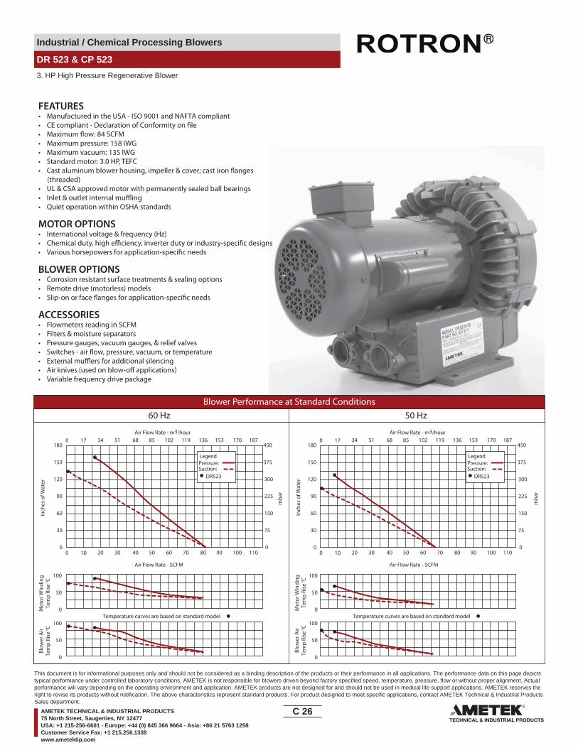
Industrial / Chemical Processing Blowers
DR 523 & CP 523
3. HP High Pressure Regenerative Blower
FEATURES• Manufactured in the USA - ISO 9001 and NAFTA compliant
• Maximum pressure: 158 IWG• Maximum vacuum: 135 IWG• Standard motor: 3.0 HP, TEFC
(threaded)• UL & CSA approved motor with permanently sealed ball bearings•• Quiet operation within OSHA standards
MOTOR OPTIONS• International voltage & frequency (Hz)
BLOWER OPTIONS• Corrosion resistant surface treatments & sealing options• Remote drive (motorless) models
ACCESSORIES• Flowmeters reading in SCFM• Filters & moisture separators• Pressure gauges, vacuum gauges, & relief valves
••• Variable frequency drive package
Blower Performance at Standard Conditions60 Hz 50 Hz
Inch
es o
f Wat
er
mba
r
mba
r
Mot
or W
indi
ngTe
mp
Rise
° C
Air Flow Rate - SCFMAir Flow Rate - SCFM
Air Flow Rate - m3/hourAir Flow Rate - m3/hour
Inch
es o
f Wat
erM
otor
Win
ding
Tem
p Ri
se ° C
Blow
er A
irTe
mp
Rise
° C
Blow
er A
irTe
mp
Rise
° C
LegendPressure:Suction:
LegendPressure:Suction:
DR523 DR523
0 10 20 30 40 50 60 70 80 90 100 110
0 17 34 51 68 85 102 119 136 153 170 187
0
30
60
90
120
150
180
0
75
150
225
300
375
450
0 10 20 30 40 50 60 70 80 90 100 110
0 17 34 51 68 85 102 119 136 153 170 187
0
30
60
90
120
150
180
0
75
150
225
300
375
450
Temperature curves are based on standard model Temperature curves are based on standard model0
50
100
0
50
100
0
50
100
0
50
100
C 26____
This document is for informational purposes only and should not be considered as a binding description of the products or their performance in all applications. The performance data on this page depictstypical performance under controlled laboratory conditions. AMETEK is not responsible for blowers driven beyond factory specified speed, temperature, pressure, flow or without proper alignment. Actualperformance will vary depending on the operating environment and application. AMETEK products are not designed for and should not be used in medical life support applications. AMETEK reserves theright to revise its products without notification. The above characteristics represent standard products. For product designed to meet specific applications, contact AMETEK Technical & Industrial ProductsSales department.
AMETEK TECHNICAL & INDUSTRIAL PRODUCTS75 North Street, Saugerties, NY 12477USA: +1 215-256-6601 - Europe: +44 (0) 845 366 9664 - Asia: +86 21 5763 1258Customer Service Fax: +1 215.256.1338www.ametektip.com

Industrial / Chemical Processing Blowers
DR 555 & CP 555
3.0 / 4.0 HP Regenerative Blower
383
327
106 139
15(4X) MTGHOLES
4.92
182
125
327
MODEL
DR555K72DR555K58
L15
.06
4.14 5.510
0.59
12.87
5.25
7.62
133
194
2.31
59
4.46
113
14.93379
0.72
18
12.81
DR555CK72
L (IN/MM)
17.44/443
16.12/40917.38/441
11.420290.1
STD. DIRECTIONOF ROTATION
1.5" NPSCSTRAIGHT THDSBOTH PORTS
1
7.19 DIA
NOTES1 TERMINAL BOX CONNECTOR HOLE .88 (22) DIA.2 DRAWING NOT TO SCALE, CONTACT FACTORY FOR SCALE CAD DRAWING.3 CONTACT FACTORY FOR BLOWER MODEL LENGTHS NOT SHOWN.
INMM
Part/ Model Number
DR555CK72 DR555CK86 DR555K72 DR555K58 DR555K86 CP555CS72MLR
Specification Units 081100 081102 081099 081098 081101 038245
Motor Enclosure - Shaft Mtl. - TEFC - CS TEFC - CS TEFC - CS TEFC - CS TEFC - CS Chem TEFC - SSHorsepower - 4.0 4.0 3.0 3.0 3.0 3.0Voltage AC 230/460 575 230/460 115/230 575 230/460Phase - Frequency - Three - 60 Hz Three - 60 Hz Three - 60 Hz Single - 60 Hz Three - 60 Hz Three - 60 HzInsulation Class - F F F F F FNEMA Rated Motor Amps Amps (A) 10/5 4.1 7.6/3.8 25.6/12.8 3 7.6/3.8Service Factor - 1.15 1.15 1.15 1.0 1.0 1.15Max. Blower Amps Amps (A) 13/6.5 4.2 8.8/4.4 28/14 3.4 8.8/4.4Locked Rotor Amps Amps (A) 94/47 80 88/44 194/97 70 88/44NEMA Starter Size - 1/0 0 0/0 1.5/1 0 0/0
Shipping WeightLbsKg
11351.3
13762.1
9643.5
9141.3
9040.8
9040.8
Voltage - ROTRON motors are designed to handle a broad range of world voltages and power supply variations. Our dual voltage 3 phase motors are factory tested and certi�ed to operate on both: 208-230/415-460 VAC-3 ph-60 Hz and 190-208/380-415 VAC-3 ph-50 Hz. Our dual voltage 1 phase motors are factory tested and certi�ed to operate on both: 104-115/208-230 VAC-1 ph-60 Hz and 100-110/200-220 VAC-1 ph-50 Hz. All voltages above can handle a ±10% voltage �uctuation. Special wound motors can be ordered for voltages outside our certi�ed range.
Operating Temperatures - Maximum operating temperature: Motor winding temperature (winding rise plus ambient) should not exceed 140°C for Class F rated motors or 120°C for Class B rated motors. Blower outlet air temperature should not exceed 140°C (air temperature rise plus inlet temperature). Performance curve maximum pressure and suction points are based on a 40°C inlet and ambient temperature. Consult factory for inlet or ambient temperatures above 40°C.
Maximum Blower Amps - Corresponds to the performance point at which the motor or blower temperature rise with a 40°C inlet and/or ambient temperature reaches the maximum operating temperature.
C 27____
This document is for informational purposes only and should not be considered as a binding description of the products or their performance in all applications. The performance data on this page depictstypical performance under controlled laboratory conditions. AMETEK is not responsible for blowers driven beyond factory specified speed, temperature, pressure, flow or without proper alignment. Actualperformance will vary depending on the operating environment and application. AMETEK products are not designed for and should not be used in medical life support applications. AMETEK reserves theright to revise its products without notification. The above characteristics represent standard products. For product designed to meet specific applications, contact AMETEK Technical & Industrial ProductsSales department.
AMETEK TECHNICAL & INDUSTRIAL PRODUCTS75 North Street, Saugerties, NY 12477USA: +1 215-256-6601 - Europe: +44 (0) 845 366 9664 - Asia: +86 21 5763 1258Customer Service Fax: +1 215.256.1338www.ametektip.com

Industrial / Chemical Processing Blowers
DR 555 & CP 555
3.0 / 4.0 HP Regenerative Blower
FEATURES• Manufactured in the USA - ISO 9001 and NAFTA compliant
• Maximum pressure: 115 IWG• Maximum vacuum: 92 IWG• Standard motor: 4.0 HP, TEFC
(threaded)• UL & CSA approved motor with permanently sealed ball bearings•• Quiet operation within OSHA standards
MOTOR OPTIONS• International voltage & frequency (Hz)
BLOWER OPTIONS• Corrosion resistant surface treatments & sealing options• Remote drive (motorless) models
ACCESSORIES• Flowmeters reading in SCFM• Filters & moisture separators• Pressure gauges, vacuum gauges, & relief valves
••• Variable frequency drive package
Blower Performance at Standard Conditions60 Hz 50 Hz
Inch
es o
f Wat
er
mba
r
mba
r
Mot
or W
indi
ngTe
mp
Rise
° C
Air Flow Rate - SCFMAir Flow Rate - SCFM
Air Flow Rate - m3/hourAir Flow Rate - m3/hour
Inch
es o
f Wat
erM
otor
Win
ding
Tem
p Ri
se ° C
Blow
er A
irTe
mp
Rise
° C
Blow
er A
irTe
mp
Rise
° C
LegendPressure:Suction:
DR555CK72DR555K72DR555K58
LegendPressure:Suction:
DR555CK72DR555K72DR555K58
0 20 40 60 80 100 120 140 160 180 200 220 0 20 40 60 80 100 120 140 160 180 200 220
0 34 68 102 136 170 204 238 272 306 340 374 0 34 68 102 136 170 204 238 272 306 340 374
0
20
40
60
80
100
120
0
20
40
60
80
100
120
0
50
100
150
200
250
300
0
50
100
150
200
250
300
Temperature curves are based on standard model Temperature curves are based on standard model0
50
100
0
50
100
0
50
100
0
50
100
C 28____
This document is for informational purposes only and should not be considered as a binding description of the products or their performance in all applications. The performance data on this page depictstypical performance under controlled laboratory conditions. AMETEK is not responsible for blowers driven beyond factory specified speed, temperature, pressure, flow or without proper alignment. Actualperformance will vary depending on the operating environment and application. AMETEK products are not designed for and should not be used in medical life support applications. AMETEK reserves theright to revise its products without notification. The above characteristics represent standard products. For product designed to meet specific applications, contact AMETEK Technical & Industrial ProductsSales department.
AMETEK TECHNICAL & INDUSTRIAL PRODUCTS75 North Street, Saugerties, NY 12477USA: +1 215-256-6601 - Europe: +44 (0) 845 366 9664 - Asia: +86 21 5763 1258Customer Service Fax: +1 215.256.1338www.ametektip.com

Industrial / Chemical Processing Blowers
DR 6 & CP 6
3.0 / 5.0 HP Regenerative Blower
OUTIN
4.86
24.1
123.4L
.95
16.5
16.3
441
5
14.63
6.98 7.0 2.0050.8
4.0
215.
98.
50
84.83.34 4.0101.6
FEMALE THREADBOTH PORTS
3.20101.6
203.28.00
MODEL
DR6D89
DR6K72
L (IN/MM)
18.00/457.2
18.00/457.2
MUFFLER
2 - 11 1/2 NPSC
1
.562 DIA.
ROTATION DIRECTION
419
177 178
8.50
215.
9
102
141.
75.
58(4) MTG. HOLES
NOTES1 TERMINAL BOX CONNECTOR HOLE 1.06 (26.9) DIA.2 DRAWING NOT TO SCALE, CONTACT FACTORY FOR SCALE CAD DRAWING.3 CONTACT FACTORY FOR BLOWER MODEL LENGTHS NOT SHOWN.
INMM
Part/ Model Number
DR6D89 DR6D5 DR6D86 DR6K72 CP6FF72LR HiE6D89
Specification Units 027578 036212 027579 027600 038253 038071
Motor Enclosure - Shaft Mtl. - TEFC-CS TEFC-CS TEFC-CS TEFC-CS Chem TEFC-SS TEFC-CSHorsepower - 5.0 5.0 5.0 3.0 5.0 5.0Voltage AC 230/460 230 575 230/460 230/460 230/460Phase - Frequency - Three - 60 Hz Single - 60 Hz Three - 60 Hz Three - 60 Hz Three - 60 Hz Three - 60 HzInsulation Class - F F F F F FNEMA Rated Motor Amps Amps (A) 17.3-15.6/7.8 21 4.8 13.3-12/6 17.3-15.6/7.8 17.3-15.6/7.8Service Factor - 1.15 1.0 1.15 1.15 1.15 1.15Max. Blower Amps Amps (A) 15-14.8/7.4 25 5.4 12/6 15-14.8/7.4 15-14.8/7.4Locked Rotor Amps Amps (A) 165-155/76 124 60 106/53 165-155/76 165-155/76NEMA Starter Size - 1/1 1.5 1 1/0 1/1 1/1
Shipping WeightLbsKg
14867.1
15670.8
14867.1
13259.9
14867.1
14867.1
Voltage - ROTRON motors are designed to handle a broad range of world voltages and power supply variations. Our dual voltage 3 phase motors are factory tested and certi�ed to operate on both: 208-230/415-460 VAC-3 ph-60 Hz and 190-208/380-415 VAC-3 ph-50 Hz. Our dual voltage 1 phase motors are factory tested and certi�ed to operate on both: 104-115/208-230 VAC-1 ph-60 Hz and 100-110/200-220 VAC-1 ph-50 Hz. All voltages above can handle a ±10% voltage �uctuation. Special wound motors can be ordered for voltages outside our certi�ed range.
Operating Temperatures - Maximum operating temperature: Motor winding temperature (winding rise plus ambient) should not exceed 140°C for Class F rated motors or 120°C for Class B rated motors. Blower outlet air temperature should not exceed 140°C (air temperature rise plus inlet temperature). Performance curve maximum pressure and suction points are based on a 40°C inlet and ambient temperature. Consult factory for inlet or ambient temperatures above 40°C.
Maximum Blower Amps - Corresponds to the performance point at which the motor or blower temperature rise with a 40°C inlet and/or ambient temperature reaches the maximum operating temperature.
C 29____
This document is for informational purposes only and should not be considered as a binding description of the products or their performance in all applications. The performance data on this page depictstypical performance under controlled laboratory conditions. AMETEK is not responsible for blowers driven beyond factory specified speed, temperature, pressure, flow or without proper alignment. Actualperformance will vary depending on the operating environment and application. AMETEK products are not designed for and should not be used in medical life support applications. AMETEK reserves theright to revise its products without notification. The above characteristics represent standard products. For product designed to meet specific applications, contact AMETEK Technical & Industrial ProductsSales department.
AMETEK TECHNICAL & INDUSTRIAL PRODUCTS75 North Street, Saugerties, NY 12477USA: +1 215-256-6601 - Europe: +44 (0) 845 366 9664 - Asia: +86 21 5763 1258Customer Service Fax: +1 215.256.1338www.ametektip.com
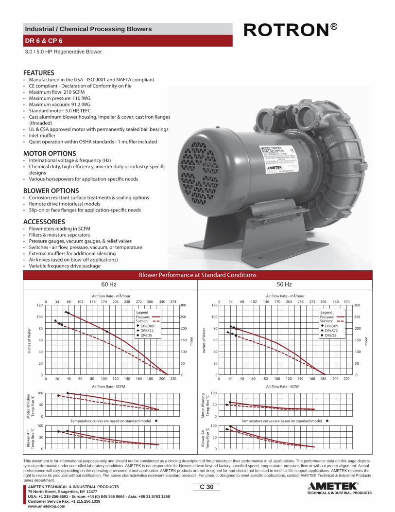
Industrial / Chemical Processing Blowers
DR 6 & CP 6
3.0 / 5.0 HP Regenerative Blower
FEATURES• Manufactured in the USA - ISO 9001 and NAFTA compliant
• Maximum pressure: 110 IWG• Maximum vacuum: 91.2 IWG• Standard motor: 5.0 HP, TEFC
(threaded)• UL & CSA approved motor with permanently sealed ball bearings••
MOTOR OPTIONS• International voltage & frequency (Hz)
designs
BLOWER OPTIONS• Corrosion resistant surface treatments & sealing options• Remote drive (motorless) models
ACCESSORIES• Flowmeters reading in SCFM• Filters & moisture separators• Pressure gauges, vacuum gauges, & relief valves
••• Variable frequency drive package
Blower Performance at Standard Conditions60 Hz 50 Hz
Temperature curves are based on standard model Temperature curves are based on standard model
Inch
es o
f Wat
er
mba
r
mba
r
Mot
or W
indi
ngTe
mp
Rise
° C
Air Flow Rate - SCFMAir Flow Rate - SCFM
Air Flow Rate - m3/hourAir Flow Rate - m3/hour
Inch
es o
f Wat
erM
otor
Win
ding
Tem
p Ri
se ° C
Blow
er A
irTe
mp
Rise
° C
Blow
er A
irTe
mp
Rise
° C
LegendPressure:Suction:
DR6D89DR6K72DR6D5
LegendPressure:Suction:
DR6D89DR6K72DR6D5
0 20 40 60 80 100 120 140 160 180 200 220 0 20 40 60 80 100 120 140 160 180 200 220
0 34 68 102 136 170 204 238 272 306 340 374 0 34 68 102 136 170 204 238 272 306 340 374
0
20
40
60
80
100
120
0
20
40
60
80
100
120
0
50
100
150
200
250
300
0
50
100
150
200
250
300
0
50
100
0
50
100
0
50
100
0
50
100
C 30____
This document is for informational purposes only and should not be considered as a binding description of the products or their performance in all applications. The performance data on this page depictstypical performance under controlled laboratory conditions. AMETEK is not responsible for blowers driven beyond factory specified speed, temperature, pressure, flow or without proper alignment. Actualperformance will vary depending on the operating environment and application. AMETEK products are not designed for and should not be used in medical life support applications. AMETEK reserves theright to revise its products without notification. The above characteristics represent standard products. For product designed to meet specific applications, contact AMETEK Technical & Industrial ProductsSales department.
AMETEK TECHNICAL & INDUSTRIAL PRODUCTS75 North Street, Saugerties, NY 12477USA: +1 215-256-6601 - Europe: +44 (0) 845 366 9664 - Asia: +86 21 5763 1258Customer Service Fax: +1 215.256.1338www.ametektip.com

Industrial / Chemical Processing Blowers
DR 633 & CP 633
5.0 / 7.5 HP High Pressure Regenerative Blower
NOTES
1 DRAWING NOT TO SCALE, CONTACT FACTORY FOR SCALE CAD DRAWING.2 CONTACT FACTORY FOR BLOWER MODEL LENGTHS NOT SHOWN.
.98 (2X)24.9
11.811300.0
.20
.5.1
3.22
10.50266.7
81.8
6.10154.9
6.22158.0
IN OUT
DIRECTIONOFROTATION
1.0326.2
18.9
448
1.1
4.88124.0
2.6667.6 18.41
467.6
17.244 438.0
18.06 458.7
13.16334.3
10.5
9 26
9.0
16.68423.7
2" - 11 1/2 NPSCFEMALE THREADBOTH PORTS
INMM
INCLUDES INLET FILTER
Part/ Model Number
DR633AY72M DR633AY86M DR633D89M CP633FG72LRM
Specification Units 081691 081693 081689 081695
Motor Enclosure - Shaft Mtl. - TEFC-CS TEFC-CS TEFC-CS CHEM TEFC-SSHorsepower - 7.5 7.5 5 7.5Voltage AC 230/460 575 230/460 230/460Phase - Frequency - Three - 60 Hz Three - 60 Hz Three - 60 Hz Three - 60 HzInsulation Class - F F F FNEMA Rated Motor Amps Amps (A) 23-21/10.5 8.4 16.9-15.3/76 23-21/10.5Service Factor - 1.15 1.15 1.15 1.15Max. Blower Amps Amps (A) 19.8-18/9 7.9 15-13.6/6.8 19.8-18/9Locked Rotor Amps Amps (A) 170/85 55 165-155/76 170/85NEMA Starter Size - 2/1 1 1-1/0 2/1
Shipping WeightLbsKg
241109.3
241109.3
223101.2
241109.3
Voltage - ROTRON motors are designed to handle a broad range of world voltages and power supply variations. Our dual voltage 3 phase motors are factory tested and certi�ed to operate on both: 208-230/415-460 VAC-3 ph-60 Hz and 190-208/380-415 VAC-3 ph-50 Hz. Our dual voltage 1 phase motors are factory tested and certi�ed to operate on both: 104-115/208-230 VAC-1 ph-60 Hz and 100-110/200-220 VAC-1 ph-50 Hz. All voltages above can handle a ±10% voltage �uctuation. Special wound motors can be ordered for voltages outside our certi�ed range.
Operating Temperatures - Maximum operating temperature: Motor winding temperature (winding rise plus ambient) should not exceed 140°C for Class F rated motors or 120°C for Class B rated motors. Blower outlet air temperature should not exceed 140°C (air temperature rise plus inlet temperature). Performance curve maximum pressure and suction points are based on a 40°C inlet and ambient temperature. Consult factory for inlet or ambient temperatures above 40°C.
Maximum Blower Amps - Corresponds to the performance point at which the motor or blower temperature rise with a 40°C inlet and/or ambient temperature reaches the maximum operating temperature.
C 31____
This document is for informational purposes only and should not be considered as a binding description of the products or their performance in all applications. The performance data on this page depictstypical performance under controlled laboratory conditions. AMETEK is not responsible for blowers driven beyond factory specified speed, temperature, pressure, flow or without proper alignment. Actualperformance will vary depending on the operating environment and application. AMETEK products are not designed for and should not be used in medical life support applications. AMETEK reserves theright to revise its products without notification. The above characteristics represent standard products. For product designed to meet specific applications, contact AMETEK Technical & Industrial ProductsSales department.
AMETEK TECHNICAL & INDUSTRIAL PRODUCTS75 North Street, Saugerties, NY 12477USA: +1 215-256-6601 - Europe: +44 (0) 845 366 9664 - Asia: +86 21 5763 1258Customer Service Fax: +1 215.256.1338www.ametektip.com
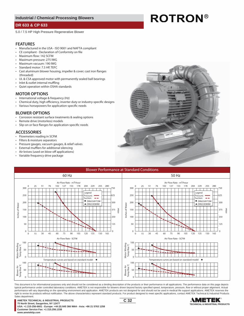
Industrial / Chemical Processing Blowers
DR 633 & CP 633
5.0 / 7.5 HP High Pressure Regenerative Blower
FEATURES• Manufactured in the USA - ISO 9001 and NAFTA compliant
• Maximum pressure: 275 IWG•
• Maximum vacuum: 190 IWG• Standard motor: 7.5 HP, TEFC
(threaded)• UL & CSA approved motor with permanently sealed ball bearings•• Quiet operation within OSHA standards
MOTOR OPTIONS• International voltage & frequency (Hz)
BLOWER OPTIONS• Corrosion resistant surface treatments & sealing options• Remote drive (motorless) models
ACCESSORIES• Flowmeters reading in SCFM• Filters & moisture separators• Pressure gauges, vacuum gauges, & relief valves••• Variable frequency drive package
Blower Performance at Standard Conditions60 Hz 50 Hz
Inch
es o
f Wat
er
mba
r
mba
r
Mot
or W
indi
ngTe
mp
Rise
° C
Air Flow Rate - SCFMAir Flow Rate - SCFM
Air Flow Rate - m3/hourAir Flow Rate - m3/hour
Inch
es o
f Wat
erM
otor
Win
ding
Tem
p Ri
se ° C
Blow
er A
irTe
mp
Rise
° C
Blow
er A
irTe
mp
Rise
° C
LegendPressure:Suction:
DR633AY72MDR633D89M
LegendPressure:Suction:
DR633AY72MDR633D89M
0 15 30 45 60 75 90 105 120 135 150 165
0 25 51 76 102 127 153 178 204 229 255 280
0
50
100
150
200
250
300
0
125
250
375
500
625
750
0 15 30 45 60 75 90 105 120 135 150 165
0 25 51 76 102 127 153 178 204 229 255 280
0
50
100
150
200
250
300
0
125
250
375
500
625
750
Temperature curves are based on standard model Temperature curves are based on standard model0
50
100
0
50
100
0
50
100
0
50
100
C 32____
This document is for informational purposes only and should not be considered as a binding description of the products or their performance in all applications. The performance data on this page depictstypical performance under controlled laboratory conditions. AMETEK is not responsible for blowers driven beyond factory specified speed, temperature, pressure, flow or without proper alignment. Actualperformance will vary depending on the operating environment and application. AMETEK products are not designed for and should not be used in medical life support applications. AMETEK reserves theright to revise its products without notification. The above characteristics represent standard products. For product designed to meet specific applications, contact AMETEK Technical & Industrial ProductsSales department.
AMETEK TECHNICAL & INDUSTRIAL PRODUCTS75 North Street, Saugerties, NY 12477USA: +1 215-256-6601 - Europe: +44 (0) 845 366 9664 - Asia: +86 21 5763 1258Customer Service Fax: +1 215.256.1338www.ametektip.com

Industrial / Chemical Processing Blowers
DR 656 & CP 656
3.0 / 4.0 / 5.0 HP Regenerative Blower
4.14
15.1
738
2.5
0.59
105.2 140
15.12384
L
5.56
141
(4X) MTGHOLES
15
15.42390.5
7.46
190
4.56
116
Ø7.19182.6
2.25 0.
6417
.3
11.420289.6
4.92125
57.2
Ø2.23STRAIGHT THDSBOTH PORTS
MODEL L (IN/MM)
DR656CK72XDR656K72X
17.50/444.516.00/406.4
12.81325.4
5.51
1
STD. DIRECTIONOF ROTATION
NOTES1 TERMINAL BOX CONNECTOR HOLE .88 (22) DIA.2 DRAWING NOT TO SCALE, CONTACT FACTORY FOR SCALE CAD DRAWING.3 CONTACT FACTORY FOR BLOWER MODEL LENGTHS NOT SHOWN.
INMM
Part/ Model Number
DR656CK72X DR656CK86X DR656CK5X DR656K72X DR656K58X DR656D72X DR656D86X CP656CR72XLR
Specification Units 080582 080583 080584 080602 080603 080585 080604 080065
Motor Enclosure - Shaft Mtl. - TEFC - CS TEFC - CS TEFC-CS TEFC - CS TEFC - CS TEFC - CS TEFC - CS Chem TEFC-SSHorsepower - 4.0 4.0 4.0 3.0 3.0 5.0 5.0 4.0Voltage AC 230/460 575 230 230/460 115/230 230/460 575 230/460Phase - Frequency - Three - 60 Hz Three - 60 Hz Single - 60 Hz Three - 60 Hz Single - 60 Hz Three - 60 Hz Three - 60 Hz Three - 60 HzInsulation Class - F F F F F F F FNEMA Rated Motor Amps Amps (A) 10.0/5.0 4.0 18 7.4/3.7 29/14.5 12.8/6.4 4.8 10.0/5.0Service Factor - 1.15 1.0 1.15 1.15 1.0 1.0 1.15 1.15Max. Blower Amps Amps (A) 11.4/5.7 5.2 18 9/4.5 27.8/13.9 13.0/6.5 5.2 11.4/5.7Locked Rotor Amps Amps (A) 94/47 80 115 54/27 172/86 160/80 60 94/47NEMA Starter Size - 1/0 0 1 0/0 1.5/1.0 1/1 1.0 1/0
Shipping WeightLbsKg
11049.9
11451.7
10145.8
10346.7
11451.7
11451.7
11451.7
11049.9
Voltage - ROTRON motors are designed to handle a broad range of world voltages and power supply variations. Our dual voltage 3 phase motors are factory tested and certi�ed to operate on both: 208-230/415-460 VAC-3 ph-60 Hz and 190-208/380-415 VAC-3 ph-50 Hz. Our dual voltage 1 phase motors are factory tested and certi�ed to operate on both: 104-115/208-230 VAC-1 ph-60 Hz and 100-110/200-220 VAC-1 ph-50 Hz. All voltages above can handle a ±10% voltage �uctuation. Special wound motors can be ordered for voltages outside our certi�ed range.
Operating Temperatures - Maximum operating temperature: Motor winding temperature (winding rise plus ambient) should not exceed 140°C for Class F rated motors or 120°C for Class B rated motors. Blower outlet air temperature should not exceed 140°C (air temperature rise plus inlet temperature). Performance curve maximum pressure and suction points are based on a 40°C inlet and ambient temperature. Consult factory for inlet or ambient temperatures above 40°C.
Maximum Blower Amps - Corresponds to the performance point at which the motor or blower temperature rise with a 40°C inlet and/or ambient temperature reaches the maximum operating temperature.
C 33____
This document is for informational purposes only and should not be considered as a binding description of the products or their performance in all applications. The performance data on this page depictstypical performance under controlled laboratory conditions. AMETEK is not responsible for blowers driven beyond factory specified speed, temperature, pressure, flow or without proper alignment. Actualperformance will vary depending on the operating environment and application. AMETEK products are not designed for and should not be used in medical life support applications. AMETEK reserves theright to revise its products without notification. The above characteristics represent standard products. For product designed to meet specific applications, contact AMETEK Technical & Industrial ProductsSales department.
AMETEK TECHNICAL & INDUSTRIAL PRODUCTS75 North Street, Saugerties, NY 12477USA: +1 215-256-6601 - Europe: +44 (0) 845 366 9664 - Asia: +86 21 5763 1258Customer Service Fax: +1 215.256.1338www.ametektip.com

Industrial / Chemical Processing Blowers
DR 656 & CP 656
3.0 / 4.0 / 5.0 HP Regenerative Blower
FEATURES• Manufactured in the USA - ISO 9001 and NAFTA compliant
• Maximum pressure: 110 IWG•
• Maximum vacuum: 89 IWG• Standard motor: 4.0 HP, TEFC•
• UL & CSA approved motor with permanently sealed ball bearings•• Quiet operation within OSHA standards
MOTOR OPTIONS• International voltage & frequency (Hz)
BLOWER OPTIONS• Corrosion resistant surface treatments & sealing options• Remote drive (motorless) models
• Cast iron cover for additional noise resonance
ACCESSORIES• Flowmeters reading in SCFM• Filters & moisture separators• Pressure gauges, vacuum gauges, & relief valves
••
Blower Performance at Standard Conditions60 Hz 50 Hz
Inch
es o
f Wat
er
mba
r
mba
r
Mot
or W
indi
ngTe
mp
Rise
° C
Air Flow Rate - SCFMAir Flow Rate - SCFM
Air Flow Rate - m3/hourAir Flow Rate - m3/hour
Inch
es o
f Wat
erM
otor
Win
ding
Tem
p Ri
se ° C
Blow
er A
irTe
mp
Rise
° C
Blow
er A
irTe
mp
Rise
° C
LegendPressure:Suction:
DR656D72XDR656K58XDR656K72XDR656CK72XDR656CK5X
LegendPressure:Suction:
DR656D72XDR656K58XDR656K72XDR656CK72XDR656CK5X
0 20 40 60 80 100 120 140 160 180 200 220 0 20 40 60 80 100 120 140 160 180 200 220
0 34 68 102 136 170 204 238 272 306 340 374 0 34 68 102 136 170 204 238 272 306 340 374
0
20
40
60
80
100
120
0
20
40
60
80
100
120
0
50
100
150
200
250
300
0
50
100
150
200
250
300
Temperature curves are based on standard model Temperature curves are based on standard model0
50
100
0
50
100
0
50
100
0
50
100
C 34____
This document is for informational purposes only and should not be considered as a binding description of the products or their performance in all applications. The performance data on this page depictstypical performance under controlled laboratory conditions. AMETEK is not responsible for blowers driven beyond factory specified speed, temperature, pressure, flow or without proper alignment. Actualperformance will vary depending on the operating environment and application. AMETEK products are not designed for and should not be used in medical life support applications. AMETEK reserves theright to revise its products without notification. The above characteristics represent standard products. For product designed to meet specific applications, contact AMETEK Technical & Industrial ProductsSales department.
AMETEK TECHNICAL & INDUSTRIAL PRODUCTS75 North Street, Saugerties, NY 12477USA: +1 215-256-6601 - Europe: +44 (0) 845 366 9664 - Asia: +86 21 5763 1258Customer Service Fax: +1 215.256.1338www.ametektip.com

Industrial / Chemical Processing Blowers
DR 757 & CP 757
4.0 / 5.0 HP Regenerative Blower
17.4
444
3
L
5.04
16
2.0
5.71
7.02
2.0
2.81
15.3389
167
426
0.63
R0.317.9
CL OF BLOWER9.
23
2.77 5.75
.84
6.57
16.75
128
50
50
71
145
178
ROTATIONDIRECTION
234
70 146 21
MODEL
DR757CK72X
DR757CK86X
DR757D89XDR757D86X
DR757D5MX
18.55/471
18.55/47118.55/471
18.55/471
L (IN/MM)
5.60142.2
26210.31
16.3414
12.73323.3
1
2 1/2" NPSCFEMALE THREADSBOTH PORTS
18.55/471
NOTES1 TERMINAL BOX CONNECTOR HOLE 1.06 (26) DIA.2 DRAWING NOT TO SCALE, CONTACT FACTORY FOR SCALE CAD DRAWING.3 CONTACT FACTORY FOR BLOWER MODEL LENGTHS NOT SHOWN.
INMM
Part/ Model Number
DR757CK72X DR757CK86X DR757D89X CP757FF72XLR CP757CR72XLR
Specification Units 081172 081173 081169 081178 081179
Motor Enclosure - Shaft Mtl. - TEFC-CS TEFC-CS TEFC-CS Chem TEFC-SS Chem TEFC-SSHorsepower - 4.0 4.0 5.0 5.0 4.0Voltage AC 230/460 575 230/460 230/460 230/460Phase - Frequency - Three-60 hz Three-60 hz Three - 60 hz Three - 60 hz Three-60 hzInsulation Class - F F F F FNEMA Rated Motor Amps Amps (A) 10/5 4.0 12/6 12/6 10/5Service Factor - 1.15 1.15 1.15 1.15 1.15Max. Blower Amps Amps (A) 12/6 4.2 15.5/7.6 15.5/7.6 12/6Locked Rotor Amps Amps (A) 94/47 80 194/97 194/97 94/47NEMA Starter Size - 1/0 0 1/0 1/0 1/0
Shipping WeightLbsKg
13159.4
12858.1
14063.5
14063.5
13159.4
Voltage - ROTRON motors are designed to handle a broad range of world voltages and power supply variations. Our dual voltage 3 phase motors are factory tested and certi�ed to operate on both: 208-230/415-460 VAC-3 ph-60 Hz and 190-208/380-415 VAC-3 ph-50 Hz. Our dual voltage 1 phase motors are factory tested and certi�ed to operate on both: 104-115/208-230 VAC-1 ph-60 Hz and 100-110/200-220 VAC-1 ph-50 Hz. All voltages above can handle a ±10% voltage �uctuation. Special wound motors can be ordered for voltages outside our certi�ed range.
Operating Temperatures - Maximum operating temperature: Motor winding temperature (winding rise plus ambient) should not exceed 140°C for Class F rated motors or 120°C for Class B rated motors. Blower outlet air temperature should not exceed 140°C (air temperature rise plus inlet temperature). Performance curve maximum pressure and suction points are based on a 40°C inlet and ambient temperature. Consult factory for inlet or ambient temperatures above 40°C.
Maximum Blower Amps - Corresponds to the performance point at which the motor or blower temperature rise with a 40°C inlet and/or ambient temperature reaches the maximum operating temperature.
C 35____
This document is for informational purposes only and should not be considered as a binding description of the products or their performance in all applications. The performance data on this page depictstypical performance under controlled laboratory conditions. AMETEK is not responsible for blowers driven beyond factory specified speed, temperature, pressure, flow or without proper alignment. Actualperformance will vary depending on the operating environment and application. AMETEK products are not designed for and should not be used in medical life support applications. AMETEK reserves theright to revise its products without notification. The above characteristics represent standard products. For product designed to meet specific applications, contact AMETEK Technical & Industrial ProductsSales department.
AMETEK TECHNICAL & INDUSTRIAL PRODUCTS75 North Street, Saugerties, NY 12477USA: +1 215-256-6601 - Europe: +44 (0) 845 366 9664 - Asia: +86 21 5763 1258Customer Service Fax: +1 215.256.1338www.ametektip.com

Industrial / Chemical Processing Blowers
DR 757 & CP 757
4.0 / 5.0 HP Regenerative Blower
FEATURES• Manufactured in the USA - ISO 9001 and NAFTA compliant
• Maximum pressure: 83 IWG•
• Maximum vacuum: 75 IWG• Standard motor: 4.0 HP, TEFC
(threaded)• UL & CSA approved motor with permanently sealed ball bearings•• Quiet operation within OSHA standards
MOTOR OPTIONS• International voltage & frequency (Hz)
BLOWER OPTIONS• Corrosion resistant surface treatments & sealing options• Remote drive (motorless) models
ACCESSORIES• Flowmeters reading in SCFM• Filters & moisture separators• Pressure gauges, vacuum gauges, & relief valves••• Variable frequency drive package
Blower Performance at Standard Conditions60 Hz 50 Hz
Inch
es o
f Wat
er
mba
r
mba
r
Mot
or W
indi
ngTe
mp
Rise
° C
Air Flow Rate - SCFMAir Flow Rate - SCFM
Air Flow Rate - m3/hourAir Flow Rate - m3/hour
Inch
es o
f Wat
erM
otor
Win
ding
Tem
p Ri
se ° 0
C
Blow
er A
irTe
mp
Rise
° C
Blow
er A
irTe
mp
Rise
° C
LegendPressure:Suction:
DR757D89XDR757CK72X
LegendPressure:Suction:
DR757D89XDR757CK72X
0 30 60 90 120 150 180 210 240 270 300 330 0 30 60 90 120 150 180 210 240 270 300 330
0 51 102 153 204 255 306 357 408 459 510 561 0
0
15
30
45
60
75
90
0
15
30
45
60
75
90
0
37
75
112
149
187
22451 102 153 204 255 306 357 408 459 510 561
37
75
112
149
187
224
0
0
50
100
0
50
100
0
50
100
0
50
100
C 36____
This document is for informational purposes only and should not be considered as a binding description of the products or their performance in all applications. The performance data on this page depictstypical performance under controlled laboratory conditions. AMETEK is not responsible for blowers driven beyond factory specified speed, temperature, pressure, flow or without proper alignment. Actualperformance will vary depending on the operating environment and application. AMETEK products are not designed for and should not be used in medical life support applications. AMETEK reserves theright to revise its products without notification. The above characteristics represent standard products. For product designed to meet specific applications, contact AMETEK Technical & Industrial ProductsSales department.
AMETEK TECHNICAL & INDUSTRIAL PRODUCTS75 North Street, Saugerties, NY 12477USA: +1 215-256-6601 - Europe: +44 (0) 845 366 9664 - Asia: +86 21 5763 1258Customer Service Fax: +1 215.256.1338www.ametektip.com

Industrial / Chemical Processing Blowers
DR S7
7.5 HP High Pressure Regenerative Blower
23.03
7.00
11.00
2.00
OUTIN
4.00
8.00
4.94
11.50
3.22
6.44
16.38
5.88
177.8 50.8
279.4
81.8
101.
6
125.5
203.2
292.1
163.6
149.4
14.3(4) MTG. HOLES
A
A
FEMALE THREADBOTH PORTS
FEMALE THREADBOTH PORTS
SECTION VIEW A-A
585
16.4
441
7.6
8.03204
416.1
8.25
5.58
147.
820
9.6
.563 DIA.
2 - 11 1/2 NPT
2 - 11 1/2 NPT
NOTE 1
NOTES1 TERMINAL BOX CONNECTOR HOLE 1.06 (26.9) DIA.2 DRAWING NOT TO SCALE, CONTACT FACTORY FOR SCALE CAD DRAWING.3 CONTACT FACTORY FOR BLOWER MODEL LENGTHS NOT SHOWN.
INMM
Part/ Model Number
DRS7X72 DRS7X86
Specification Units 036085 036144
Motor Enclosure - Shaft Mtl. - ODP-CS ODP-CSHorsepower - 7.5 7.5Voltage AC 230/460 575Phase - Frequency - Three-60 Hz Three-60 HzInsulation Class - F FNEMA Rated Motor Amps Amps (A) 19.4/9.7 7.8Service Factor - 1.15 1.0Maximum Blower Amps Amps (A) 24/12 9.6Locked Rotor Amps Amps (A) 166/83 66NEMA Starter Size - 1/1 1
Shipping WeightLbsKg
20693.4
20693.4
Voltage - ROTRON motors are designed to handle a broad range of world voltages and power supply variations. Our dual voltage 3 phase motors are factory tested and certi�ed to operate on both: 208-230/415-460 VAC-3 ph-60 Hz and 190-208/380-415 VAC-3 ph-50 Hz. Our dual voltage 1 phase motors are factory tested and certi�ed to operate on both: 104-115/208-230 VAC-1 ph-60 Hz and 100-110/200-220 VAC-1 ph-50 Hz. All voltages above can handle a ±10% voltage �uctuation. Special wound motors can be ordered for voltages outside our certi�ed range.
Operating Temperatures - Maximum operating temperature: Motor winding temperature (winding rise plus ambient) should not exceed 140°C for Class F rated motors or 120°C for Class B rated motors. Blower outlet air temperature should not exceed 140°C (air temperature rise plus inlet temperature). Performance curve maximum pressure and suction points are based on a 40°C inlet and ambient temperature. Consult factory for inlet or ambient temperatures above 40°C.
Maximum Blower Amps - Corresponds to the performance point at which the motor or blower temperature rise with a 40°C inlet and/or ambient temperature reaches the maximum operating temperature.
C 37____
This document is for informational purposes only and should not be considered as a binding description of the products or their performance in all applications. The performance data on this page depictstypical performance under controlled laboratory conditions. AMETEK is not responsible for blowers driven beyond factory specified speed, temperature, pressure, flow or without proper alignment. Actualperformance will vary depending on the operating environment and application. AMETEK products are not designed for and should not be used in medical life support applications. AMETEK reserves theright to revise its products without notification. The above characteristics represent standard products. For product designed to meet specific applications, contact AMETEK Technical & Industrial ProductsSales department.
AMETEK TECHNICAL & INDUSTRIAL PRODUCTS75 North Street, Saugerties, NY 12477USA: +1 215-256-6601 - Europe: +44 (0) 845 366 9664 - Asia: +86 21 5763 1258Customer Service Fax: +1 215.256.1338www.ametektip.com
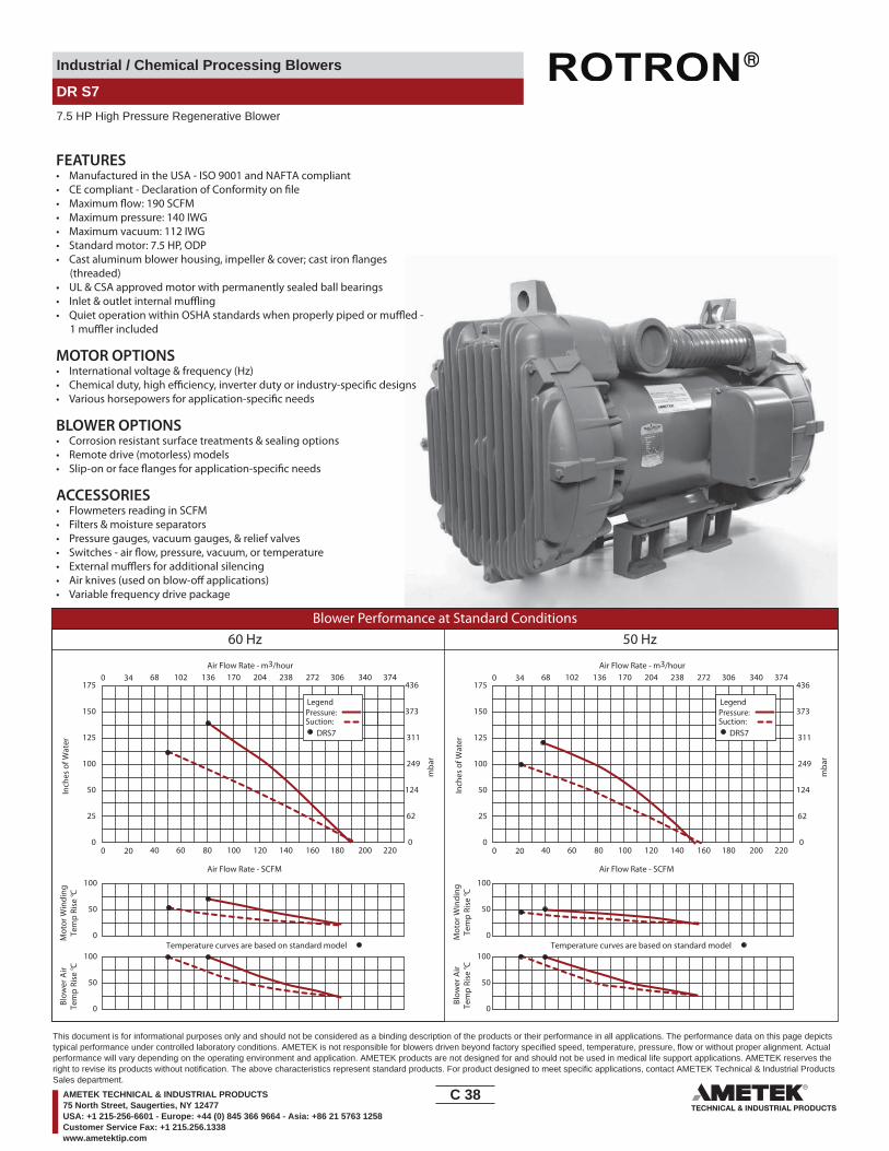
Industrial / Chemical Processing Blowers
DR S7
7.5 HP High Pressure Regenerative Blower
FEATURES• Manufactured in the USA - ISO 9001 and NAFTA compliant
• Maximum pressure: 140 IWG• Maximum vacuum: 112 IWG• Standard motor: 7.5 HP, ODP
(threaded)• UL & CSA approved motor with permanently sealed ball bearings••
MOTOR OPTIONS• International voltage & frequency (Hz)
BLOWER OPTIONS• Corrosion resistant surface treatments & sealing options• Remote drive (motorless) models
ACCESSORIES• Flowmeters reading in SCFM• Filters & moisture separators• Pressure gauges, vacuum gauges, & relief valves
••• Variable frequency drive package
Blower Performance at Standard Conditions60 Hz 50 Hz
Inch
es o
f Wat
er
mba
r
mba
r
Mot
or W
indi
ngTe
mp
Rise
° C
Air Flow Rate - SCFMAir Flow Rate - SCFM
Temperature curves are based on standard model
Air Flow Rate - m3/hourAir Flow Rate - m3/hour
Inch
es o
f Wat
erM
otor
Win
ding
Tem
p Ri
se ° C
Blow
er A
irTe
mp
Rise
° C
Blow
er A
irTe
mp
Rise
° C
Temperature curves are based on standard model
LegendPressure:Suction:
DRS7
LegendPressure:Suction:
DRS7
0 20 40 60 80 100 120 140 160 180 200 220
0 34 68 102 136 170 204 238 272 306 340 374
0
50
100
0
25
50
100
125
150
175
0
62
124
249
311
373
436
0 20 40 60 80 100 120 140 160 180 200 220
0 34 68 102 136 170 204 238 272 306 340 374
0
25
50
100
125
150
175
0
62
124
249
311
373
436
0
50
100
0
50
100
0
50
100
C 38____
This document is for informational purposes only and should not be considered as a binding description of the products or their performance in all applications. The performance data on this page depictstypical performance under controlled laboratory conditions. AMETEK is not responsible for blowers driven beyond factory specified speed, temperature, pressure, flow or without proper alignment. Actualperformance will vary depending on the operating environment and application. AMETEK products are not designed for and should not be used in medical life support applications. AMETEK reserves theright to revise its products without notification. The above characteristics represent standard products. For product designed to meet specific applications, contact AMETEK Technical & Industrial ProductsSales department.
AMETEK TECHNICAL & INDUSTRIAL PRODUCTS75 North Street, Saugerties, NY 12477USA: +1 215-256-6601 - Europe: +44 (0) 845 366 9664 - Asia: +86 21 5763 1258Customer Service Fax: +1 215.256.1338www.ametektip.com
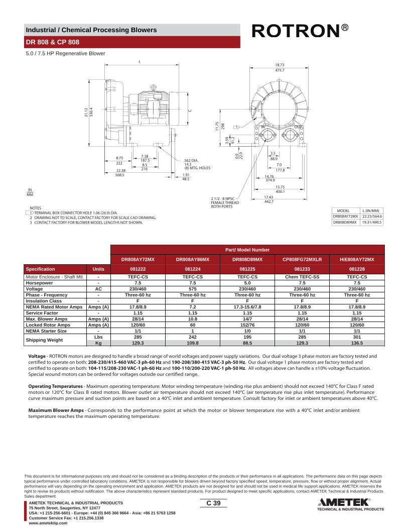
Industrial / Chemical Processing Blowers
DR 808 & CP 808
5.0 / 7.5 HP Regenerative Blower
IN OUT
L
536.
421
.12
14.3(8) MTG. HOLES
8.75222
1.9148.5
18.73475.7
0.9
22.9
3.59
91.2
11.7
529
8
C
3.588.9
177.87.0
FEMALE THREADBOTH PORTS
MODEL
DR808D89MXDR808AY72MX
L (IN/MM)22.23/564.619.31/490.5
17.43442.7
15.75
14.76374.9
400.1
7.38187.58.5
21622.38568.5
.562 DIA.
1
2 1/2 - 8 NPSC
NOTES1 TERMINAL BOX CONNECTOR HOLE 1.06 (26.9) DIA.2 DRAWING NOT TO SCALE, CONTACT FACTORY FOR SCALE CAD DRAWING.3 CONTACT FACTORY FOR BLOWER MODEL LENGTHS NOT SHOWN.
INMM
Part/ Model Number
DR808AY72MX DR808AY86MX DR808D89MX CP808FG72MXLR HiE808AY72MX
Specification Units 081222 081224 081225 081233 081228
Motor Enclosure - Shaft Mtl. - TEFC-CS TEFC-CS TEFC-CS Chem TEFC-SS TEFC-CSHorsepower - 7.5 7.5 5.0 7.5 7.5Voltage AC 230/460 575 230/460 230/460 230/460Phase - Frequency - Three-60 hz Three-60 hz Three-60 hz Three-60 hz Three-60 hzInsulation Class - F F F F FNEMA Rated Motor Amps Amps (A) 17.8/8.9 7.2 17.3-15.6/7.8 17.8/8.9 17.8/8.9Service Factor - 1.15 1.15 1.15 1.15 1.15Max. Blower Amps Amps (A) 28/14 10.8 14/7 28/14 28/14Locked Rotor Amps Amps (A) 120/60 60 152/76 120/60 120/60NEMA Starter Size - 1/1 1 1/0 1/1 1/1
Shipping WeightLbsKg
285129.3
242109.8
19588.5
285129.3
301136.5
Voltage - ROTRON motors are designed to handle a broad range of world voltages and power supply variations. Our dual voltage 3 phase motors are factory tested and certi�ed to operate on both: 208-230/415-460 VAC-3 ph-60 Hz and 190-208/380-415 VAC-3 ph-50 Hz. Our dual voltage 1 phase motors are factory tested and certi�ed to operate on both: 104-115/208-230 VAC-1 ph-60 Hz and 100-110/200-220 VAC-1 ph-50 Hz. All voltages above can handle a ±10% voltage �uctuation. Special wound motors can be ordered for voltages outside our certi�ed range.
Operating Temperatures - Maximum operating temperature: Motor winding temperature (winding rise plus ambient) should not exceed 140°C for Class F rated motors or 120°C for Class B rated motors. Blower outlet air temperature should not exceed 140°C (air temperature rise plus inlet temperature). Performance curve maximum pressure and suction points are based on a 40°C inlet and ambient temperature. Consult factory for inlet or ambient temperatures above 40°C.
Maximum Blower Amps - Corresponds to the performance point at which the motor or blower temperature rise with a 40°C inlet and/or ambient temperature reaches the maximum operating temperature.
C 39____
This document is for informational purposes only and should not be considered as a binding description of the products or their performance in all applications. The performance data on this page depictstypical performance under controlled laboratory conditions. AMETEK is not responsible for blowers driven beyond factory specified speed, temperature, pressure, flow or without proper alignment. Actualperformance will vary depending on the operating environment and application. AMETEK products are not designed for and should not be used in medical life support applications. AMETEK reserves theright to revise its products without notification. The above characteristics represent standard products. For product designed to meet specific applications, contact AMETEK Technical & Industrial ProductsSales department.
AMETEK TECHNICAL & INDUSTRIAL PRODUCTS75 North Street, Saugerties, NY 12477USA: +1 215-256-6601 - Europe: +44 (0) 845 366 9664 - Asia: +86 21 5763 1258Customer Service Fax: +1 215.256.1338www.ametektip.com
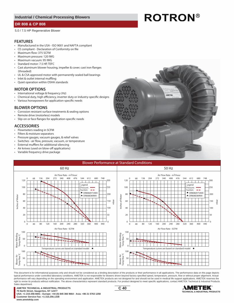
Industrial / Chemical Processing Blowers
DR 808 & CP 808
5.0 / 7.5 HP Regenerative Blower
FEATURES• Manufactured in the USA - ISO 9001 and NAFTA compliant
• Maximum pressure: 120 IWG•
• Maximum vacuum: 95 IWG• Standard motor: 7.5 HP, TEFC
(threaded)• UL & CSA approved motor with permanently sealed ball bearings•• Quiet operation within OSHA standards
MOTOR OPTIONS• International voltage & frequency (Hz)
BLOWER OPTIONS• Corrosion resistant surface treatments & sealing options• Remote drive (motorless) models
ACCESSORIES• Flowmeters reading in SCFM• Filters & moisture separators• Pressure gauges, vacuum gauges, & relief valves
••• Variable frequency drive package
Blower Performance at Standard Conditions60 Hz 50 Hz
Inch
es o
f Wat
er
mba
r
mba
r
Mot
or W
indi
ngTe
mp
Rise
° C
Air Flow Rate - SCFMAir Flow Rate - SCFM
Air Flow Rate - m3/hourAir Flow Rate - m3/hour
Inch
es o
f Wat
erM
otor
Win
ding
Tem
p Ri
se ° C
Blow
er A
irTe
mp
Rise
° C
Blow
er A
irTe
mp
Rise
° C
LegendPressure:Suction:
DR808AY72MXDR808D89MX
LegendPressure:Suction:
DR808AY72MXDR808D89MX
0 40 80 120 160 200 240 280 320 360 400 440
0 68 136 204 272 340 408 476 544 612 680 748
0
20
40
60
80
100
120
0
50
100
150
200
250
300
0 40 80 120 160 200 240 280 320 360 400 440
0 68 136 204 272 340 408 476 544 612 680 748
0
20
40
60
80
100
120
0
50
100
150
200
250
300
Temperature curves are based on standard model Temperature curves are based on standard model0
50
100
0
50
100
0
50
100
0
50
100
C 40____
This document is for informational purposes only and should not be considered as a binding description of the products or their performance in all applications. The performance data on this page depictstypical performance under controlled laboratory conditions. AMETEK is not responsible for blowers driven beyond factory specified speed, temperature, pressure, flow or without proper alignment. Actualperformance will vary depending on the operating environment and application. AMETEK products are not designed for and should not be used in medical life support applications. AMETEK reserves theright to revise its products without notification. The above characteristics represent standard products. For product designed to meet specific applications, contact AMETEK Technical & Industrial ProductsSales department.
AMETEK TECHNICAL & INDUSTRIAL PRODUCTS75 North Street, Saugerties, NY 12477USA: +1 215-256-6601 - Europe: +44 (0) 845 366 9664 - Asia: +86 21 5763 1258Customer Service Fax: +1 215.256.1338www.ametektip.com

Industrial / Chemical Processing Blowers
DR 833 & CP 833
7.5 / 10.0 HP Regenerative Blower
NOTES
FILTER 515255 INCLUDED1 DRAWING NOT TO SCALE, CONTACT FACTORY FOR SCALE CAD DRAWING.2 CONTACT FACTORY FOR BLOWER MODEL LENGTHS NOT SHOWN.
INMM
MTG. HOLEDETAIL
(4X)
.20
5.1
6.10154.9
6.22158.0.98 (2X)
24.9
.51213.0
.591
15.0
11.811300.0
DIRECTIONOFROTATION
3.22
81.8
19.3
849
2.3
.8421.3
5.24133.1
ROTA
TION
2" - 11 1/2 NPSCFEMALE THREADBOTH PORTS
IN OUT
18.81 477.8
17.638 448.01
10.4
426
5.2
19.13485.9
10.50 DIA266.7
13.98355.1
24.0609.6
8.71221.2
Part/ Model Number
DR833BB72M DR833BB86M DR833AY72M DR833AY86M CP833FH72MLR
Specification Units 081702 081704 081699 081701 081710
Motor Enclosure - Shaft Mtl. - TEFC-CS TEFC-CS TEFC-CS TEFC-CS CHEM TEFC-SSHorsepower - 10 10 7.5 7.5 10Voltage AC 230/460 575 230/460 575 230/460Phase - Frequency - Three - 60 Hz Three - 60 Hz Three - 60 Hz Three - 60 Hz Three - 60 HzInsulation Class - F F F F FNEMA Rated Motor Amps Amps (A) 31-28/14 11.2 23-21/10.5 8.4 31-28/14Service Factor - 1.15 1.15 1.15 1.15 1.15Locked Rotor Amps Amps (A) 190/95 73 170/85 68 190/95Max. Blower Amps Amps (A) 26-24/12 8.9 21.2-19.2/9.6 7.7 26-24/12NEMA Starter Size - 2/1 1 2/1 1 2/1
Shipping WeightLbsKg
269122
269122
260117.9
260117.9
269122
Voltage - ROTRON motors are designed to handle a broad range of world voltages and power supply variations. Our dual voltage 3 phase motors are factory tested and certi�ed to operate on both: 208-230/415-460 VAC-3 ph-60 Hz and 190-208/380-415 VAC-3 ph-50 Hz. Our dual voltage 1 phase motors are factory tested and certi�ed to operate on both: 104-115/208-230 VAC-1 ph-60 Hz and 100-110/200-220 VAC-1 ph-50 Hz. All voltages above can handle a ±10% voltage �uctuation. Special wound motors can be ordered for voltages outside our certi�ed range.
Operating Temperatures - Maximum operating temperature: Motor winding temperature (winding rise plus ambient) should not exceed 140°C for Class F rated motors or 120°C for Class B rated motors. Blower outlet air temperature should not exceed 140°C (air temperature rise plus inlet temperature). Performance curve maximum pressure and suction points are based on a 40°C inlet and ambient temperature. Consult factory for inlet or ambient temperatures above 40°C.
Maximum Blower Amps - Corresponds to the performance point at which the motor or blower temperature rise with a 40°C inlet and/or ambient temperature reaches the maximum operating temperature.
C 41____
This document is for informational purposes only and should not be considered as a binding description of the products or their performance in all applications. The performance data on this page depictstypical performance under controlled laboratory conditions. AMETEK is not responsible for blowers driven beyond factory specified speed, temperature, pressure, flow or without proper alignment. Actualperformance will vary depending on the operating environment and application. AMETEK products are not designed for and should not be used in medical life support applications. AMETEK reserves theright to revise its products without notification. The above characteristics represent standard products. For product designed to meet specific applications, contact AMETEK Technical & Industrial ProductsSales department.
AMETEK TECHNICAL & INDUSTRIAL PRODUCTS75 North Street, Saugerties, NY 12477USA: +1 215-256-6601 - Europe: +44 (0) 845 366 9664 - Asia: +86 21 5763 1258Customer Service Fax: +1 215.256.1338www.ametektip.com
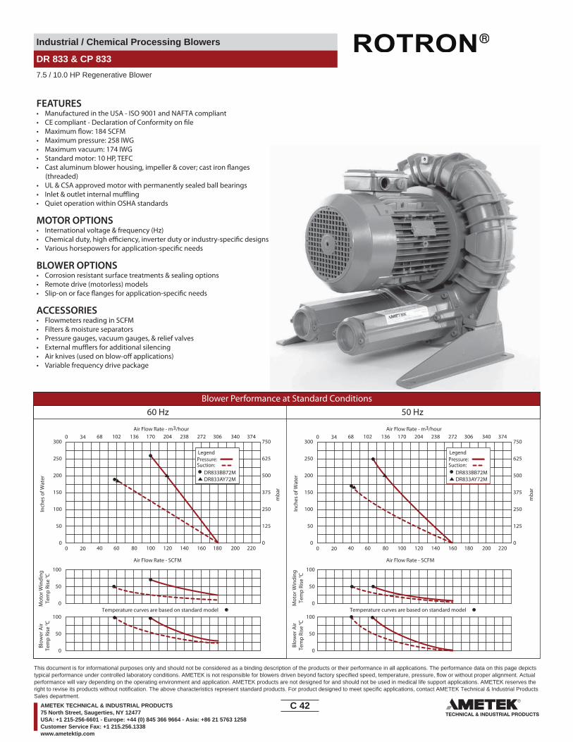
Industrial / Chemical Processing Blowers
DR 833 & CP 833
7.5 / 10.0 HP Regenerative Blower
FEATURES• Manufactured in the USA - ISO 9001 and NAFTA compliant
• Maximum pressure: 258 IWG•
• Maximum vacuum: 174 IWG• Standard motor: 10 HP, TEFC
(threaded)• UL & CSA approved motor with permanently sealed ball bearings•• Quiet operation within OSHA standards
MOTOR OPTIONS• International voltage & frequency (Hz)
BLOWER OPTIONS• Corrosion resistant surface treatments & sealing options• Remote drive (motorless) models
ACCESSORIES• Flowmeters reading in SCFM• Filters & moisture separators• Pressure gauges, vacuum gauges, & relief valves••• Variable frequency drive package
Blower Performance at Standard Conditions60 Hz 50 Hz
Inch
es o
f Wat
er
mba
r
mba
r
Mot
or W
indi
ngTe
mp
Rise
° C
Air Flow Rate - SCFMAir Flow Rate - SCFM
Air Flow Rate - m3/hourAir Flow Rate - m3/hour
Inch
es o
f Wat
erM
otor
Win
ding
Tem
p Ri
se ° C
Blow
er A
irTe
mp
Rise
° C
Blow
er A
irTe
mp
Rise
° C
LegendPressure:Suction:
DR833BB72MDR833AY72M
LegendPressure:Suction:
DR833BB72MDR833AY72M
0 20 40 60 80 100 120 140 160 180 200 220
0 34 68 102 136 170 204 238 272 306 340 374
0
50
100
150
200
250
300
0
125
250
375
500
625
750
0 20 40 60 80 100 120 140 160 180 200 220
0 34 68 102 136 170 204 238 272 306 340 374
0
50
100
150
200
250
300
0
125
250
375
500
625
750
Temperature curves are based on standard model Temperature curves are based on standard model0
50
100
0
50
100
0
50
100
0
50
100
C 42____
This document is for informational purposes only and should not be considered as a binding description of the products or their performance in all applications. The performance data on this page depictstypical performance under controlled laboratory conditions. AMETEK is not responsible for blowers driven beyond factory specified speed, temperature, pressure, flow or without proper alignment. Actualperformance will vary depending on the operating environment and application. AMETEK products are not designed for and should not be used in medical life support applications. AMETEK reserves theright to revise its products without notification. The above characteristics represent standard products. For product designed to meet specific applications, contact AMETEK Technical & Industrial ProductsSales department.
AMETEK TECHNICAL & INDUSTRIAL PRODUCTS75 North Street, Saugerties, NY 12477USA: +1 215-256-6601 - Europe: +44 (0) 845 366 9664 - Asia: +86 21 5763 1258Customer Service Fax: +1 215.256.1338www.ametektip.com

Industrial / Chemical Processing Blowers
DR 858 & CP 858
7.5 / 10.0 HP Regenerative Blower
90.2
OUT IN
FEMALE THREADBOTH PORTS
3.55
18.60
4.00
(4) PLACES
1.9750
2.00
101.6
472.4
6.81175.3
13.53343.7
22.34567.4
1.19
21.8
155
3.9
10.1
825
9.1
10.00
13.00330.2
256.3
7.09180.3
8.31
211.
111.6
829
6.7
10.1
325
7.3
6.4162.6
9.99252.5
19.05 X 50.8
L
MODEL DR858AY72WDR858BB72W
L (IN/MM)23.06/585.723.19/589
8.49215.6
1.759.50
241.3
ROTATION DIRECTION
2 1/2 - 8 NPSC
.75 X 2.00 SLOT
50.8
44.5
NOTE 1
NOTES1 TERMINAL BOX CONNECTOR HOLE 1.06 (26.9) DIA.2 DRAWING NOT TO SCALE, CONTACT FACTORY FOR SCALE CAD DRAWING.3 CONTACT FACTORY FOR BLOWER MODEL LENGTHS NOT SHOWN.
INMM
Part/ Model Number
DR858BB72W DR858BB86W DR858AY72W CP858FH72WLR HiE858BB72W
Specification Units 038740 038742 038738 038749 038743
Motor Enclosure - Shaft Mtl. - TEFC-CS TEFC-CS TEFC-CS Chem TEFC-SS TEFC-CSHorsepower - 10 10 7.5 10 10Voltage AC 230/460 575 230/460 230/460 230/460Phase - Frequency - Three-60 hz Three-60 hz Three-60 hz Three-60 hz Three-60 hz Insulation Class - F F F F FNEMA Rated Motor Amps Amps (A) 26/13 10.5 17.8/8.9 26/13 26/13Service Factor - 1.15 1.15 1.15 1.15 1.15Max. Blower Amps Amps (A) 28/14 12 28/14 28/14 28/14Locked Rotor Amps Amps (A) 162/81 65 120/60 162/81 162/81NEMA Starter Size - 2/1 1 1/1 2/1 2/1
Shipping WeightLbsKg
280127
280127
264119.7
280127
280127
Model (Base Mount) - DR858BB72X DR858BB86X DR858AY72XPart Number (Base Mount) - 038735 038737 038736
Voltage - ROTRON motors are designed to handle a broad range of world voltages and power supply variations. Our dual voltage 3 phase motors are factory tested and certi�ed to operate on both: 208-230/415-460 VAC-3 ph-60 Hz and 190-208/380-415 VAC-3 ph-50 Hz. Our dual voltage 1 phase motors are factory tested and certi�ed to operate on both: 104-115/208-230 VAC-1 ph-60 Hz and 100-110/200-220 VAC-1 ph-50 Hz. All voltages above can handle a ±10% voltage �uctuation. Special wound motors can be ordered for voltages outside our certi�ed range.
Operating Temperatures - Maximum operating temperature: Motor winding temperature (winding rise plus ambient) should not exceed 140°C for Class F rated motors or 120°C for Class B rated motors. Blower outlet air temperature should not exceed 140°C (air temperature rise plus inlet temperature). Performance curve maximum pressure and suction points are based on a 40°C inlet and ambient temperature. Consult factory for inlet or ambient temperatures above 40°C.
Maximum Blower Amps - Corresponds to the performance point at which the motor or blower temperature rise with a 40°C inlet and/or ambient temperature reaches the maximum operating temperature.
C 43____
This document is for informational purposes only and should not be considered as a binding description of the products or their performance in all applications. The performance data on this page depictstypical performance under controlled laboratory conditions. AMETEK is not responsible for blowers driven beyond factory specified speed, temperature, pressure, flow or without proper alignment. Actualperformance will vary depending on the operating environment and application. AMETEK products are not designed for and should not be used in medical life support applications. AMETEK reserves theright to revise its products without notification. The above characteristics represent standard products. For product designed to meet specific applications, contact AMETEK Technical & Industrial ProductsSales department.
AMETEK TECHNICAL & INDUSTRIAL PRODUCTS75 North Street, Saugerties, NY 12477USA: +1 215-256-6601 - Europe: +44 (0) 845 366 9664 - Asia: +86 21 5763 1258Customer Service Fax: +1 215.256.1338www.ametektip.com

Industrial / Chemical Processing Blowers
DR 858 & CP 858
7.5 / 10.0 HP Regenerative Blower
FEATURES• Manufactured in the USA - ISO 9001 and NAFTA compliant
• Maximum pressure: 125 IWG• Maximum vacuum: 104.8 IWG• Standard motor: 10 HP, TEFC
(threaded)• UL & CSA approved motor with permanently sealed ball bearings•• Quiet operation within OSHA standards
MOTOR OPTIONS• International voltage & frequency (Hz)
BLOWER OPTIONS• Corrosion resistant surface treatments & sealing options• Remote drive (motorless) models
ACCESSORIES• Flowmeters reading in SCFM• Filters & moisture separators• Pressure gauges, vacuum gauges, & relief valves
••• Variable frequency drive package
Blower Performance at Standard Conditions60 Hz 50 Hz
Inch
es o
f Wat
er
mba
r
mba
r
Mot
or W
indi
ngTe
mp
Rise
° C
Air Flow Rate - SCFMAir Flow Rate - SCFM
Air Flow Rate - m3/hourAir Flow Rate - m3/hour
Inch
es o
f Wat
erM
otor
Win
ding
Tem
p Ri
se ° C
Blow
er A
irTe
mp
Rise
° C
Blow
er A
irTe
mp
Rise
° C
LegendPressure:Suction:
DR858BB72WDR858AY72W
LegendPressure:Suction:
DR858BB72WDR858AY72W
0 40 80 120 160 200 240 280 320 360 400 440
0 68 136 204 272 340 408 476 544 612 680 748
0
25
50
75
100
125
150
0
62
124
187.
249
311
373
0 40 80 120 160 200 240 280 320 360 400 440
0 68 136 204 272 340 408 476 544 612 680 748
0
25
50
75
100
125
150
0
62
124
187.
249
311
373
Temperature curves are based on standard model Temperature curves are based on standard model0
50
100
0
50
100
0
50
100
0
50
100
C 44____
This document is for informational purposes only and should not be considered as a binding description of the products or their performance in all applications. The performance data on this page depictstypical performance under controlled laboratory conditions. AMETEK is not responsible for blowers driven beyond factory specified speed, temperature, pressure, flow or without proper alignment. Actualperformance will vary depending on the operating environment and application. AMETEK products are not designed for and should not be used in medical life support applications. AMETEK reserves theright to revise its products without notification. The above characteristics represent standard products. For product designed to meet specific applications, contact AMETEK Technical & Industrial ProductsSales department.
AMETEK TECHNICAL & INDUSTRIAL PRODUCTS75 North Street, Saugerties, NY 12477USA: +1 215-256-6601 - Europe: +44 (0) 845 366 9664 - Asia: +86 21 5763 1258Customer Service Fax: +1 215.256.1338www.ametektip.com
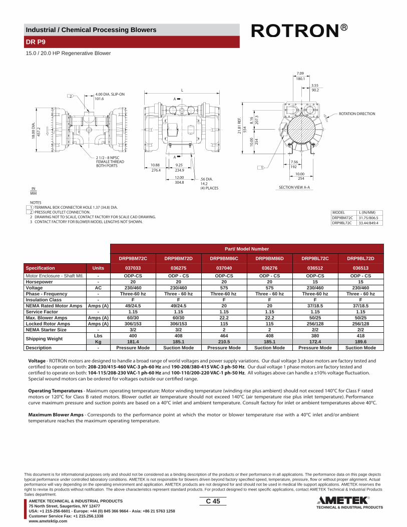
Industrial / Chemical Processing Blowers
DR P9
15.0 / 20.0 HP Regenerative Blower
9.25
12.00304.8
A
A
8.16
207.
3
21.8
1 RE
F.
10.00
7.09180.1
3.5590.2
FEMALE THREADBOTH PORTS
(4) PLACES
18.0
0 D
IA.
457.
2
4.00 DIA. SLIP-ON101.6
L
234.9
14.2
10.88276.4
554
10.0
025
4
254
7.56192
SECTION VIEW A-A
MODEL DRP9BM72CDRP9BL72C
L (IN/MM)31.75/806.533.44/849.4
2
1
2 1/2 - 8 NPSC
ROTATION DIRECTION
.56 DIA.
NOTES1 TERMINAL BOX CONNECTOR HOLE 1.37 (34.8) DIA.2 PRESSURE OUTLET CONNECTION.2 DRAWING NOT TO SCALE, CONTACT FACTORY FOR SCALE CAD DRAWING.3 CONTACT FACTORY FOR BLOWER MODEL LENGTHS NOT SHOWN.
INMM
Part/ Model Number
DRP9BM72C DRP9BM72D DRP9BM86C DRP9BM86D DRP9BL72C DRP9BL72D
Specification Units 037033 036275 037040 036276 036512 036513
Motor Enclosure - Shaft Mtl. - ODP-CS ODP - CS ODP-CS ODP - CS ODP-CS ODP - CSHorsepower - 20 20 20 20 15 15Voltage AC 230/460 230/460 575 575 230/460 230/460Phase - Frequency - Three-60 hz Three - 60 hz Three-60 hz Three - 60 hz Three-60 hz Three - 60 hzInsulation Class - F F F F F FNEMA Rated Motor Amps Amps (A) 49/24.5 49/24.5 20 20 37/18.5 37/18.5Service Factor - 1.15 1.15 1.15 1.15 1.15 1.15Max. Blower Amps Amps (A) 60/30 60/30 22.2 22.2 50/25 50/25Locked Rotor Amps Amps (A) 306/153 306/153 115 115 256/128 256/128NEMA Starter Size - 3/2 3/2 2 2 2/2 2/2
Shipping WeightLbsKg
400181.4
408185.1
464210.5
408185.1
380172.4
418189.6
Description - Pressure Mode Suction Mode Pressure Mode Suction Mode Pressure Mode Suction Mode
Voltage - ROTRON motors are designed to handle a broad range of world voltages and power supply variations. Our dual voltage 3 phase motors are factory tested and certi�ed to operate on both: 208-230/415-460 VAC-3 ph-60 Hz and 190-208/380-415 VAC-3 ph-50 Hz. Our dual voltage 1 phase motors are factory tested and certi�ed to operate on both: 104-115/208-230 VAC-1 ph-60 Hz and 100-110/200-220 VAC-1 ph-50 Hz. All voltages above can handle a ±10% voltage �uctuation. Special wound motors can be ordered for voltages outside our certi�ed range.
Operating Temperatures - Maximum operating temperature: Motor winding temperature (winding rise plus ambient) should not exceed 140°C for Class F rated motors or 120°C for Class B rated motors. Blower outlet air temperature should not exceed 140°C (air temperature rise plus inlet temperature). Performance curve maximum pressure and suction points are based on a 40°C inlet and ambient temperature. Consult factory for inlet or ambient temperatures above 40°C.
Maximum Blower Amps - Corresponds to the performance point at which the motor or blower temperature rise with a 40°C inlet and/or ambient temperature reaches the maximum operating temperature.
C 45____
This document is for informational purposes only and should not be considered as a binding description of the products or their performance in all applications. The performance data on this page depictstypical performance under controlled laboratory conditions. AMETEK is not responsible for blowers driven beyond factory specified speed, temperature, pressure, flow or without proper alignment. Actualperformance will vary depending on the operating environment and application. AMETEK products are not designed for and should not be used in medical life support applications. AMETEK reserves theright to revise its products without notification. The above characteristics represent standard products. For product designed to meet specific applications, contact AMETEK Technical & Industrial ProductsSales department.
AMETEK TECHNICAL & INDUSTRIAL PRODUCTS75 North Street, Saugerties, NY 12477USA: +1 215-256-6601 - Europe: +44 (0) 845 366 9664 - Asia: +86 21 5763 1258Customer Service Fax: +1 215.256.1338www.ametektip.com
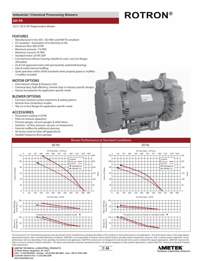
Industrial / Chemical Processing Blowers
DR P9
15.0 / 20.0 HP Regenerative Blower
FEATURES• Manufactured in the USA - ISO 9001 and NAFTA compliant
• Maximum pressure: 116 IWG• Maximum vacuum: 95 IWG• Standard motor: 20 HP, ODP
(threaded)• UL & CSA approved motor with permanently sealed ball bearings••
MOTOR OPTIONS• International voltage & frequency (Hz)
BLOWER OPTIONS• Corrosion resistant surface treatments & sealing options• Remote drive (motorless) models
ACCESSORIES• Flowmeters reading in SCFM• Filters & moisture separators• Pressure gauges, vacuum gauges, & relief valves
••• Variable frequency drive package
Blower Performance at Standard Conditions60 Hz 50 Hz
Inch
es o
f Wat
er
mba
r
mba
r
Mot
or W
indi
ngTe
mp
Rise
° C
Air Flow Rate - SCFMAir Flow Rate - SCFM
Air Flow Rate - m3/hourAir Flow Rate - m3/hour
Inch
es o
f Wat
erM
otor
Win
ding
Tem
p Ri
se ° C
Blow
er A
irTe
mp
Rise
° C
Blow
er A
irTe
mp
Rise
° C
LegendPressure:Suction:
DRP9BM72CDRP9BL72C
LegendPressure:Suction:
DRP9BM72CDRP9BL72C
0 80 160 240 320 400 480 560 640 720 800 880 0
0 136 272 408 544 680 816 951 1087 1223 1359 1495
80 160 240 320 400 480 560 640 720 800 880
136 272 408 544 680 816 951 1087 1223 1359 14950
0
20
40
60
80
100
120
0
20
40
60
80
100
120
0
50
100
150
200
250
300
0
50
100
150
200
250
300
Temperature curves are based on standard model Temperature curves are based on standard model0
50
100
0
50
100
0
50
100
0
50
100
C 46____
This document is for informational purposes only and should not be considered as a binding description of the products or their performance in all applications. The performance data on this page depictstypical performance under controlled laboratory conditions. AMETEK is not responsible for blowers driven beyond factory specified speed, temperature, pressure, flow or without proper alignment. Actualperformance will vary depending on the operating environment and application. AMETEK products are not designed for and should not be used in medical life support applications. AMETEK reserves theright to revise its products without notification. The above characteristics represent standard products. For product designed to meet specific applications, contact AMETEK Technical & Industrial ProductsSales department.
AMETEK TECHNICAL & INDUSTRIAL PRODUCTS75 North Street, Saugerties, NY 12477USA: +1 215-256-6601 - Europe: +44 (0) 845 366 9664 - Asia: +86 21 5763 1258Customer Service Fax: +1 215.256.1338www.ametektip.com
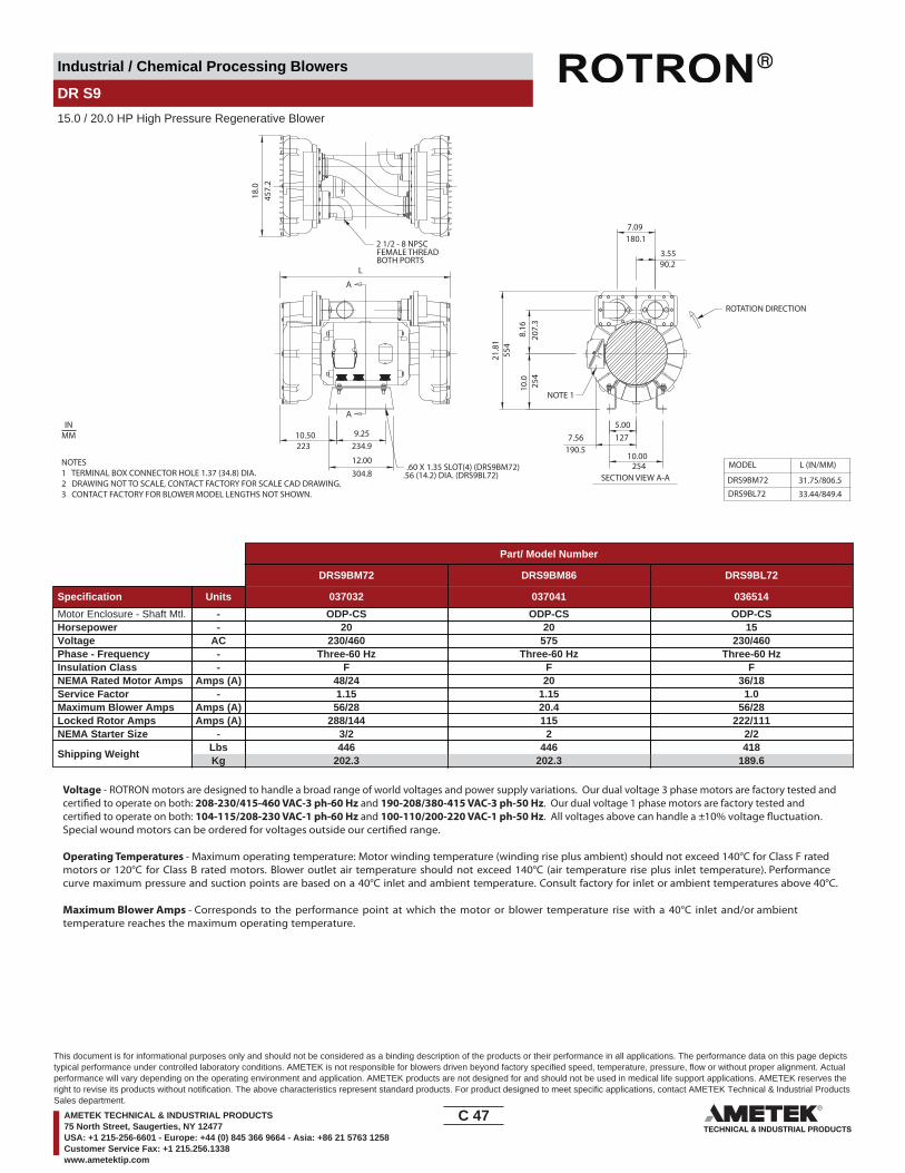
Industrial / Chemical Processing Blowers
DR S9
15.0 / 20.0 HP High Pressure Regenerative Blower
10.50 9.25
12.00
223
304.8
A
A
21.8
1
7.09180.1
3.5590.2
XXXXXXXXXXXXXXXXXXXXX XXXXXXXXXXXXXXXXXXXXX XXXXXXXXXXXXXXXXXXXXX
FEMALE THREADBOTH PORTS
L
234.9
10.0
554
254
8.16
207.
3
.56 (14.2) DIA. (DRS9BL72)
5.001277.56
190.510.00
254SECTION VIEW A-A
L (IN/MM)
31.75/806.5
33.44/849.4
MODEL
DRS9BM72
DRS9BL72
18.0
457.
2
2 1/2 - 8 NPSC
.60 X 1.35 SLOT(4) (DRS9BM72)
ROTATION DIRECTION
NOTE 1
NOTES1 TERMINAL BOX CONNECTOR HOLE 1.37 (34.8) DIA.2 DRAWING NOT TO SCALE, CONTACT FACTORY FOR SCALE CAD DRAWING.3 CONTACT FACTORY FOR BLOWER MODEL LENGTHS NOT SHOWN.
INMM
Part/ Model Number
DRS9BM72 DRS9BM86 DRS9BL72
Specification Units 037032 037041 036514
Motor Enclosure - Shaft Mtl. - ODP-CS ODP-CS ODP-CSHorsepower - 20 20 15Voltage AC 230/460 575 230/460Phase - Frequency - Three-60 Hz Three-60 Hz Three-60 HzInsulation Class - F F FNEMA Rated Motor Amps Amps (A) 48/24 20 36/18Service Factor - 1.15 1.15 1.0Maximum Blower Amps Amps (A) 56/28 20.4 56/28Locked Rotor Amps Amps (A) 288/144 115 222/111NEMA Starter Size - 3/2 2 2/2
Shipping WeightLbsKg
446202.3
446202.3
418189.6
Voltage - ROTRON motors are designed to handle a broad range of world voltages and power supply variations. Our dual voltage 3 phase motors are factory tested and certi�ed to operate on both: 208-230/415-460 VAC-3 ph-60 Hz and 190-208/380-415 VAC-3 ph-50 Hz. Our dual voltage 1 phase motors are factory tested and certi�ed to operate on both: 104-115/208-230 VAC-1 ph-60 Hz and 100-110/200-220 VAC-1 ph-50 Hz. All voltages above can handle a ±10% voltage �uctuation. Special wound motors can be ordered for voltages outside our certi�ed range.
Operating Temperatures - Maximum operating temperature: Motor winding temperature (winding rise plus ambient) should not exceed 140°C for Class F rated motors or 120°C for Class B rated motors. Blower outlet air temperature should not exceed 140°C (air temperature rise plus inlet temperature). Performance curve maximum pressure and suction points are based on a 40°C inlet and ambient temperature. Consult factory for inlet or ambient temperatures above 40°C.
Maximum Blower Amps - Corresponds to the performance point at which the motor or blower temperature rise with a 40°C inlet and/or ambient temperature reaches the maximum operating temperature.
C 47____
This document is for informational purposes only and should not be considered as a binding description of the products or their performance in all applications. The performance data on this page depictstypical performance under controlled laboratory conditions. AMETEK is not responsible for blowers driven beyond factory specified speed, temperature, pressure, flow or without proper alignment. Actualperformance will vary depending on the operating environment and application. AMETEK products are not designed for and should not be used in medical life support applications. AMETEK reserves theright to revise its products without notification. The above characteristics represent standard products. For product designed to meet specific applications, contact AMETEK Technical & Industrial ProductsSales department.
AMETEK TECHNICAL & INDUSTRIAL PRODUCTS75 North Street, Saugerties, NY 12477USA: +1 215-256-6601 - Europe: +44 (0) 845 366 9664 - Asia: +86 21 5763 1258Customer Service Fax: +1 215.256.1338www.ametektip.com

Industrial / Chemical Processing Blowers
DR S9
15.0 / 20.0 HP High Pressure Regenerative Blower
FEATURES• Manufactured in the USA - ISO 9001 and NAFTA compliant
• Maximum pressure: 206 IWG• Maximum vacuum: 157 IWG• Standard motor: 60 HP, ODP
(threaded)• UL & CSA approved motor with permanently sealed ball bearings••
MOTOR OPTIONS• International voltage & frequency (Hz)
BLOWER OPTIONS• Corrosion resistant surface treatments & sealing options• Remote drive (motorless) models
ACCESSORIES• Flowmeters reading in SCFM• Filters & moisture separators• Pressure gauges, vacuum gauges, & relief valves
••• Variable frequency drive package
Blower Performance at Standard Conditions60 Hz 50 Hz
Inch
es o
f Wat
er
mba
r
mba
r
Mot
or W
indi
ngTe
mp
Rise
° C
Air Flow Rate - SCFMAir Flow Rate - SCFM
Temperature curves are based on standard model
Air Flow Rate - m3/hourAir Flow Rate - m3/hour
Inch
es o
f Wat
erM
otor
Win
ding
Tem
p Ri
se ° C
Blow
er A
irTe
mp
Rise
° C
Blow
er A
irTe
mp
Rise
° C
Temperature curves are based on standard model
LegendPressure:Suction:
DRS9BL72CDRS9BM72C
LegendPressure:Suction:
DRS9BL72CDRS9BM72C
0 40 80 120 160 200 240 280 320 360 400 440
0 34 68 102 136 170 204 238 272 306 340 374
0
50
100
0
35
70
105
140
175
210
0
50
100
150
200
250
300
0 40 80 120 160 200 240 280 320 360 400 440
0 34 68 102 136 170 204 238 272 306 340 374
0
35
70
105
140
175
210
0
50
100
150
200
250
300
0
50
100
0
50
100
0
50
100
C 48____
This document is for informational purposes only and should not be considered as a binding description of the products or their performance in all applications. The performance data on this page depictstypical performance under controlled laboratory conditions. AMETEK is not responsible for blowers driven beyond factory specified speed, temperature, pressure, flow or without proper alignment. Actualperformance will vary depending on the operating environment and application. AMETEK products are not designed for and should not be used in medical life support applications. AMETEK reserves theright to revise its products without notification. The above characteristics represent standard products. For product designed to meet specific applications, contact AMETEK Technical & Industrial ProductsSales department.
AMETEK TECHNICAL & INDUSTRIAL PRODUCTS75 North Street, Saugerties, NY 12477USA: +1 215-256-6601 - Europe: +44 (0) 845 366 9664 - Asia: +86 21 5763 1258Customer Service Fax: +1 215.256.1338www.ametektip.com

Industrial / Chemical Processing Blowers
DR 909 & CP 909
10.0 / 15.0 HP Regenerative Blower
OUT IN
FEMALE THREADBOTH PORTS
241.3
330.2
(4) MTG. SLOTS
9.50
13.00
20.50514.48.34
211.1
8.75
222
10.2
526
0
7.23184.9
15.99408.7
19.05 X 50.8
11.6294.6
L
1.2531.8
8.56217
MODELDR909BE72WDR909BB72W
L(IN/MM)23.57/598.723.38/593.8
8.50215.9
10.00254
5.00127
4 - 8 NPSC
1
.75 X 2.00 SLOT
ROTATION DIRECTION
NOTES1 TERMINAL BOX CONNECTOR HOLE 1.25 (31.8) DIA.2 DRAWING NOT TO SCALE, CONTACT FACTORY FOR SCALE CAD DRAWING.3 CONTACT FACTORY FOR BLOWER MODEL LENGTHS NOT SHOWN.
INMM
Part/ Model Number
DR909BE72W DR909BE86W DR909BB72W DR909BB86W CP909FJ72WLR HiE909BE72W
Specification Units 081737 081739 081738 081744 038632 081735
Motor Enclosure - Shaft Mtl. - TEFC-CS TEFC-CS TEFC-CS TEFC-CS Chem TEFC-SS TEFC-CSHorsepower - 15 15 10 10 15 10Voltage AC 208-230/460 575 230/460 575 208-230/460 208-230/460Phase - Frequency - Three-60 hz Three-60 hz Three - 60 Hz Three-60 hz Three-60 hz Three-60 hzInsulation Class - F F F F F FNEMA Rated Motor Amps Amps (A) 41.5-37.6/18.8 14.6 26/13 10.5 41.5-37.6/18.8 41.5-37.6/18.8Service Factor - 1.15 1.15 1.15 1.15 1.15 1.15Max. Blower Amps Amps (A) 42/21 17 34/17 13.0 42/21 42/21Locked Rotor Amps Amps (A) 318/159 164 162/81 65 318/159 318/159NEMA Starter Size - 2/2 2 2/1 1 2/2 2/2
Shipping WeightLbsKg
400181.4
400181.4
400181.4
400181.4
400181.4
400181.4
Model (Base Mount) - DR909BE72X DR909BE86X DR909BB72X DR909BB86XPart Number (Base Mount) - 038622 038626 038623 080183
Voltage - ROTRON motors are designed to handle a broad range of world voltages and power supply variations. Our dual voltage 3 phase motors are factory tested and certi�ed to operate on both: 208-230/415-460 VAC-3 ph-60 Hz and 190-208/380-415 VAC-3 ph-50 Hz. Our dual voltage 1 phase motors are factory tested and certi�ed to operate on both: 104-115/208-230 VAC-1 ph-60 Hz and 100-110/200-220 VAC-1 ph-50 Hz. All voltages above can handle a ±10% voltage �uctuation. Special wound motors can be ordered for voltages outside our certi�ed range.
Operating Temperatures - Maximum operating temperature: Motor winding temperature (winding rise plus ambient) should not exceed 140°C for Class F rated motors or 120°C for Class B rated motors. Blower outlet air temperature should not exceed 140°C (air temperature rise plus inlet temperature). Performance curve maximum pressure and suction points are based on a 40°C inlet and ambient temperature. Consult factory for inlet or ambient temperatures above 40°C.
Maximum Blower Amps - Corresponds to the performance point at which the motor or blower temperature rise with a 40°C inlet and/or ambient temperature reaches the maximum operating temperature.
C 49____
This document is for informational purposes only and should not be considered as a binding description of the products or their performance in all applications. The performance data on this page depictstypical performance under controlled laboratory conditions. AMETEK is not responsible for blowers driven beyond factory specified speed, temperature, pressure, flow or without proper alignment. Actualperformance will vary depending on the operating environment and application. AMETEK products are not designed for and should not be used in medical life support applications. AMETEK reserves theright to revise its products without notification. The above characteristics represent standard products. For product designed to meet specific applications, contact AMETEK Technical & Industrial ProductsSales department.
AMETEK TECHNICAL & INDUSTRIAL PRODUCTS75 North Street, Saugerties, NY 12477USA: +1 215-256-6601 - Europe: +44 (0) 845 366 9664 - Asia: +86 21 5763 1258Customer Service Fax: +1 215.256.1338www.ametektip.com

Industrial / Chemical Processing Blowers
DR 909 & CP 909
10.0 / 15.0 HP Regenerative Blower
FEATURES• Manufactured in the USA - ISO 9001 and NAFTA compliant
• Maximum pressure: 137 IWG• Maximum vacuum: 106 IWG• Standard motor: 15 HP, TEFC
(threaded)• UL & CSA approved motor with permanently sealed ball bearings•• Quiet operation within OSHA standards when properly piped and
MOTOR OPTIONS• International voltage & frequency (Hz)
BLOWER OPTIONS• Corrosion resistant surface treatments & sealing options• Remote drive (motorless) models
ACCESSORIES• Flowmeters reading in SCFM• Filters & moisture separators• Pressure gauges, vacuum gauges, & relief valves
••• Variable frequency drive package
Blower Performance at Standard Conditions60 Hz 50 Hz
Inch
es o
f Wat
er
mba
r
mba
r
Mot
or W
indi
ngTe
mp
Rise
° C
Air Flow Rate - SCFMAir Flow Rate - SCFM
Air Flow Rate - m3/hourAir Flow Rate - m3/hour
Inch
es o
f Wat
erM
otor
Win
ding
Tem
p Ri
se ° C
Blow
er A
irTe
mp
Rise
° C
Blow
er A
irTe
mp
Rise
° C
LegendPressure:Suction:
DR909BE72WDR909BB72W
LegendPressure:Suction:
DR909BE72WDR909BB72W
0 60 120 180 240 300 360 420 480 540 600 660
0 102 204 306 408 510 612 714 816 918 1020 1122
0
30
60
90
120
150
180
0
75
150
225
300
375
450
0
30
60
90
120
150
180
0
75
150
225
300
375
450
0 60 120 180 240 300 360 420 480 540 600 660
0 102 204 306 408 510 612 714 816 918 1020 1122
Temperature curves are based on standard model Temperature curves are based on standard model0
50
100
0
50
100
0
50
100
0
50
100
C 50____
This document is for informational purposes only and should not be considered as a binding description of the products or their performance in all applications. The performance data on this page depictstypical performance under controlled laboratory conditions. AMETEK is not responsible for blowers driven beyond factory specified speed, temperature, pressure, flow or without proper alignment. Actualperformance will vary depending on the operating environment and application. AMETEK products are not designed for and should not be used in medical life support applications. AMETEK reserves theright to revise its products without notification. The above characteristics represent standard products. For product designed to meet specific applications, contact AMETEK Technical & Industrial ProductsSales department.
AMETEK TECHNICAL & INDUSTRIAL PRODUCTS75 North Street, Saugerties, NY 12477USA: +1 215-256-6601 - Europe: +44 (0) 845 366 9664 - Asia: +86 21 5763 1258Customer Service Fax: +1 215.256.1338www.ametektip.com

Industrial / Chemical Processing Blowers
DR 979 & CP 979
15.0 / 20.0 HP Regenerative Blower
OUT IN
ROTATIONDIRECTION
13.0330.2
9.5241.3
L
11.25285.8
19.3490.29.8
248.9
20.4
518.
216
.88
428.
8B
C D
E
L (IN/MM)MODEL
DR979BH72W
DR979BE86W
D (IN/MM) E (IN/MM)29.0/736.6
25.38/644.6
25.81/655.6
13.19/335
9.88/250.9
9.88/250.9
B (IN/MM) C (IN/MM)
12.25/311.2
10.25/260.4
10.25/260.4
8.38/212.9
8.38/212.9
8.09/205.5
6.88/174.8
6.88/174.8
11.50/292.1
DR979BE72W
1.
4" NPSCPORTS
2
NOTES1 TERMINAL BOX CONNECTOR HOLE 1.09 DIA. (DR979BE72W) 1.375 DIA. (DR979BH72W).2 .75 (19.1) X 2.00 (50.8) 4X MOUNTING SLOTS.2 DRAWING NOT TO SCALE, CONTACT FACTORY FOR SCALE CAD DRAWING.3 CONTACT FACTORY FOR BLOWER MODEL LENGTHS NOT SHOWN.
INMM
Part/ Model Number
DR979BH72W DR979BE72W DR979BE86W DR979BH86W CP979FJ72WLR HiE979BE72W
Specification Units 080718 080704 080702 080719 081777
Motor Enclosure - Shaft Mtl. - TEFC-CS TEFC-CS TEFC-CS TEFC-CS Chem TEFC-SS TEFC-CSHorsepower - 20 15 15 20 20 20Voltage AC 230/460 230/460 575 575 230/460 230/460Phase - Frequency - Three-60 hz Three-60 hz Three-60 hz Three-60 hz Three-60 hz Three-60 hzInsulation Class - H H H H H HNEMA Rated Motor Amps Amps (A) 46/23 44/22 14.6 46/23 44/22 44/22Service Factor - 1.15 1.25 1.15 1.15 1.25 1.25Max. Blower Amps Amps (A) 60/30 52/26 21 66/33 52/26 52/26Locked Rotor Amps Amps (A) 294/147 290/145 93 294/147 290/145 290/145NEMA Starter Size - 3/2 2/2 2 3/2 2/2 2/2
Shipping WeightLbsKg
350158.8
300136.1
300136.1
350158.8
300136.1
300136.1
Voltage - ROTRON motors are designed to handle a broad range of world voltages and power supply variations. Our dual voltage 3 phase motors are factory tested and certi�ed to operate on both: 208-230/415-460 VAC-3 ph-60 Hz and 190-208/380-415 VAC-3 ph-50 Hz. Our dual voltage 1 phase motors are factory tested and certi�ed to operate on both: 104-115/208-230 VAC-1 ph-60 Hz and 100-110/200-220 VAC-1 ph-50 Hz. All voltages above can handle a ±10% voltage �uctuation. Special wound motors can be ordered for voltages outside our certi�ed range.
Operating Temperatures - Maximum operating temperature: Motor winding temperature (winding rise plus ambient) should not exceed 140°C for Class F rated motors or 120°C for Class B rated motors. Blower outlet air temperature should not exceed 140°C (air temperature rise plus inlet temperature). Performance curve maximum pressure and suction points are based on a 40°C inlet and ambient temperature. Consult factory for inlet or ambient temperatures above 40°C.
Maximum Blower Amps - Corresponds to the performance point at which the motor or blower temperature rise with a 40°C inlet and/or ambient temperature reaches the maximum operating temperature.
C 51____
This document is for informational purposes only and should not be considered as a binding description of the products or their performance in all applications. The performance data on this page depictstypical performance under controlled laboratory conditions. AMETEK is not responsible for blowers driven beyond factory specified speed, temperature, pressure, flow or without proper alignment. Actualperformance will vary depending on the operating environment and application. AMETEK products are not designed for and should not be used in medical life support applications. AMETEK reserves theright to revise its products without notification. The above characteristics represent standard products. For product designed to meet specific applications, contact AMETEK Technical & Industrial ProductsSales department.
AMETEK TECHNICAL & INDUSTRIAL PRODUCTS75 North Street, Saugerties, NY 12477USA: +1 215-256-6601 - Europe: +44 (0) 845 366 9664 - Asia: +86 21 5763 1258Customer Service Fax: +1 215.256.1338www.ametektip.com
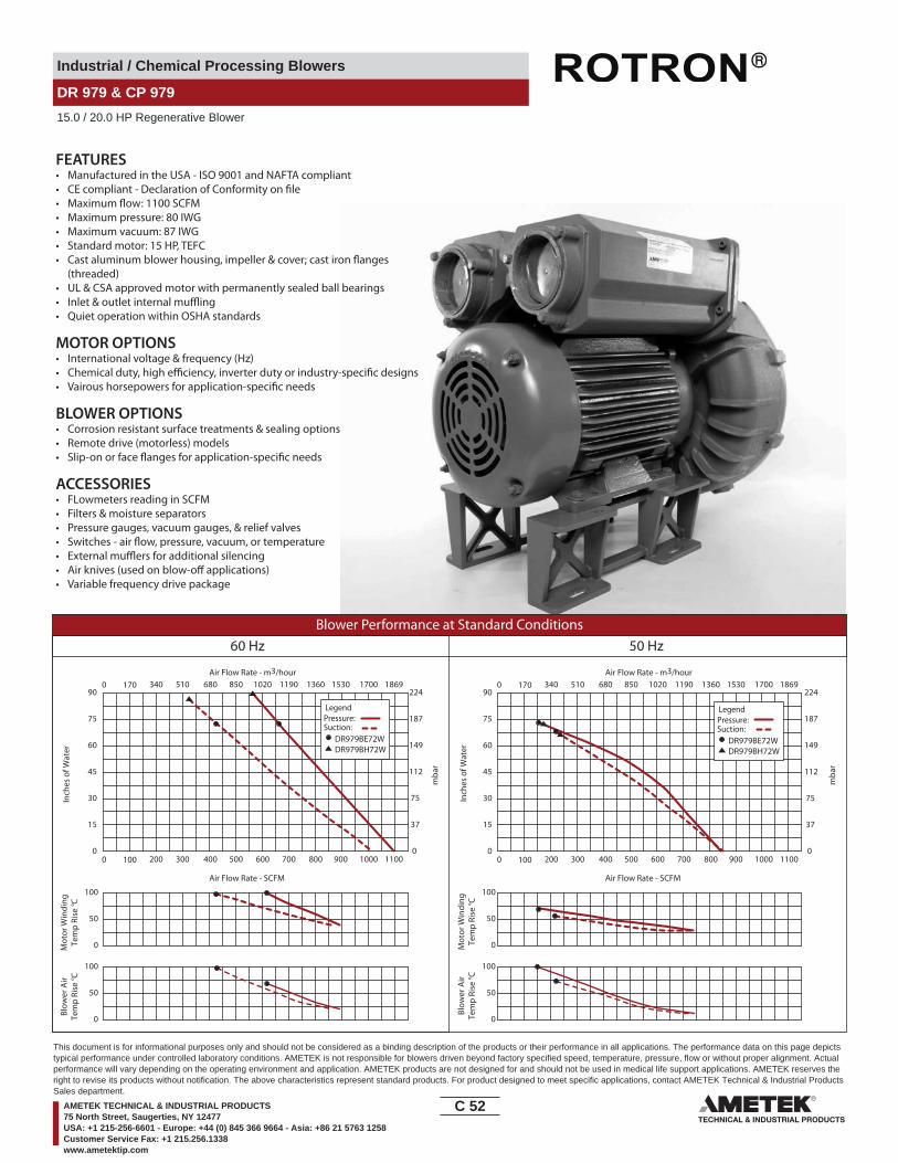
Industrial / Chemical Processing Blowers
DR 979 & CP 979
15.0 / 20.0 HP Regenerative Blower
FEATURES• Manufactured in the USA - ISO 9001 and NAFTA compliant• CE compliant - Declaration of Conformity on file• Maximum flow: 1100 SCFM• Maximum pressure: 80 IWG• Maximum vacuum: 87 IWG• Standard motor: 15 HP, TEFC• Cast aluminum blower housing, impeller & cover; cast iron flanges
(threaded)• UL & CSA approved motor with permanently sealed ball bearings• Inlet & outlet internal muffling• Quiet operation within OSHA standards
MOTOR OPTIONS• International voltage & frequency (Hz)• Chemical duty, high efficiency, inverter duty or industry-specific designs• Vairous horsepowers for application-specific needs
BLOWER OPTIONS• Corrosion resistant surface treatments & sealing options• Remote drive (motorless) models• Slip-on or face flanges for application-specific needs
ACCESSORIES• FLowmeters reading in SCFM• Filters & moisture separators• Pressure gauges, vacuum gauges, & relief valves• Switches - air flow, pressure, vacuum, or temperature• External mufflers for additional silencing• Air knives (used on blow-off applications)• Variable frequency drive package
Blower Performance at Standard Conditions60 Hz 50 Hz
Inch
es o
f Wat
er
mba
r
mba
r
Mot
or W
indi
ngTe
mp
Rise
° C
Air Flow Rate - SCFMAir Flow Rate - SCFM
Air Flow Rate - m3/hourAir Flow Rate - m3/hour
Inch
es o
f Wat
erM
otor
Win
ding
Tem
p Ri
se ° C
Blow
er A
irTe
mp
Rise
° C
Blow
er A
irTe
mp
Rise
° C
LegendPressure:Suction:
DR979BE72WDR979BH72W
LegendPressure:Suction:
DR979BE72WDR979BH72W
0 100 200 300 400 500 600 700 800 900 1000 1100
0 170 340 510 680 850 1020 1190 1360 1530 1700 1869
0
50
100
0
15
30
45
60
75
90
0
37
75
112
149
187
224
0 100 200 300 400 500 600 700 800 900 1000 1100
0 170 340 510 680 850 1020 1190 1360 1530 1700 1869
0
15
30
45
60
75
90
0
37
75
112
149
187
224
0
50
100
0
50
100
0
50
100
C 52____
This document is for informational purposes only and should not be considered as a binding description of the products or their performance in all applications. The performance data on this page depictstypical performance under controlled laboratory conditions. AMETEK is not responsible for blowers driven beyond factory specified speed, temperature, pressure, flow or without proper alignment. Actualperformance will vary depending on the operating environment and application. AMETEK products are not designed for and should not be used in medical life support applications. AMETEK reserves theright to revise its products without notification. The above characteristics represent standard products. For product designed to meet specific applications, contact AMETEK Technical & Industrial ProductsSales department.
AMETEK TECHNICAL & INDUSTRIAL PRODUCTS75 North Street, Saugerties, NY 12477USA: +1 215-256-6601 - Europe: +44 (0) 845 366 9664 - Asia: +86 21 5763 1258Customer Service Fax: +1 215.256.1338www.ametektip.com
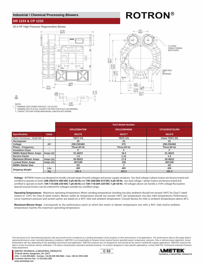
Industrial / Chemical Processing Blowers
DR 1233 & CP 1233
20.0 HP High Pressure Regenerative Blower
INOUT
DIRECTIONOFROTATION
4"-8 NPSCFEMALE THREADBOTH PORTS
22.13562.1
27.44697.0
18.90480.16.41
162.8
26.1
366
3.7
13.29337.6
11.38289.1
5.69144.5
7.87199.9
21.6
354
9.4
12.8
832
7.2
9.00228.6
2.0050.8 0.
7619
.3
NOTE 1
NOTES1 TERMINAL BOX CONNECTOR HOLE 1.38 (35) DIA.2 DRAWING NOT TO SCALE, CONTACT FACTORY FOR SCALE CAD DRAWING.3 CONTACT FACTORY FOR BLOWER MODEL LENGTHS NOT SHOWN.
INMM
Part/ Model Number
DR1233BH72W DR1233BH86W CP1233GD72LRW
Specification Units 081375 081377 081379
Motor Enclosure - Shaft Mtl. - TEFC-CS TEFC-CS Chem TEFC-SSHorsepower - 20 20 20Voltage AC 208-230/460 575 208-230/460Phase - Frequency - Three-60 Hz Three-60 Hz Three-60 HzInsulation Class - F F FNEMA Rated Motor Amps Amps (A) 51-46/23 18.4 51-46/23Service Factor - 1.5 1.15 1.5Maximum Blower Amps Amps (A) 50-46/23 17.8 50-46/23Locked Rotor Amps Amps (A) 397/199 159 397/199NEMA Starter Size - 3/2 2 3/2
Shipping WeightLbsKg
400181.4
400181.4
400181.4
Voltage - ROTRON motors are designed to handle a broad range of world voltages and power supply variations. Our dual voltage 3 phase motors are factory tested and certi�ed to operate on both: 208-230/415-460 VAC-3 ph-60 Hz and 190-208/380-415 VAC-3 ph-50 Hz. Our dual voltage 1 phase motors are factory tested and certi�ed to operate on both: 104-115/208-230 VAC-1 ph-60 Hz and 100-110/200-220 VAC-1 ph-50 Hz. All voltages above can handle a ±10% voltage �uctuation. Special wound motors can be ordered for voltages outside our certi�ed range.
Operating Temperatures - Maximum operating temperature: Motor winding temperature (winding rise plus ambient) should not exceed 140°C for Class F rated motors or 120°C for Class B rated motors. Blower outlet air temperature should not exceed 140°C (air temperature rise plus inlet temperature). Performance curve maximum pressure and suction points are based on a 40°C inlet and ambient temperature. Consult factory for inlet or ambient temperatures above 40°C.
Maximum Blower Amps - Corresponds to the performance point at which the motor or blower temperature rise with a 40°C inlet and/or ambient temperature reaches the maximum operating temperature.
C 53____
This document is for informational purposes only and should not be considered as a binding description of the products or their performance in all applications. The performance data on this page depictstypical performance under controlled laboratory conditions. AMETEK is not responsible for blowers driven beyond factory specified speed, temperature, pressure, flow or without proper alignment. Actualperformance will vary depending on the operating environment and application. AMETEK products are not designed for and should not be used in medical life support applications. AMETEK reserves theright to revise its products without notification. The above characteristics represent standard products. For product designed to meet specific applications, contact AMETEK Technical & Industrial ProductsSales department.
AMETEK TECHNICAL & INDUSTRIAL PRODUCTS75 North Street, Saugerties, NY 12477USA: +1 215-256-6601 - Europe: +44 (0) 845 366 9664 - Asia: +86 21 5763 1258Customer Service Fax: +1 215.256.1338www.ametektip.com
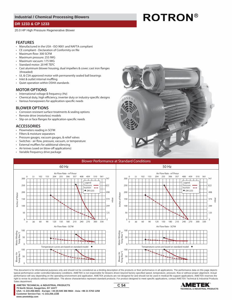
Industrial / Chemical Processing Blowers
DR 1233 & CP 1233
20.0 HP High Pressure Regenerative Blower
FEATURES• Manufactured in the USA - ISO 9001 and NAFTA compliant
• Maximum pressure: 255 IWG• Maximum vacuum: 175 IWG• Standard motor: 20 HP, TEFC
(threaded)• UL & CSA approved motor with permanently sealed ball bearings•• Quiet operation within OSHA standards
MOTOR OPTIONS• International voltage & frequency (Hz)
BLOWER OPTIONS• Corrosion resistant surface treatments & sealing options• Remote drive (motorless) models
ACCESSORIES• Flowmeters reading in SCFM• Filters & moisture separators• Pressure gauges, vacuum gauges, & relief valves
••• Variable frequency drive package
Blower Performance at Standard Conditions60 Hz 50 Hz
Inch
es o
f Wat
er
mba
r
mba
r
Mot
or W
indi
ngTe
mp
Rise
° C
Air Flow Rate - SCFMAir Flow Rate - SCFM
Air Flow Rate - m3/hourAir Flow Rate - m3/hour
Inch
es o
f Wat
erM
otor
Win
ding
Tem
p Ri
se ° C
Blow
er A
irTe
mp
Rise
° C
Blow
er A
irTe
mp
Rise
° C
LegendPressure:Suction:
DR1233
LegendPressure:Suction:
DR1233
0 30 60 90 120 150 180 210 240 270 300 330
0 51 102 153 204 255 306 357 408 459 510 561
0
50
100
150
200
250
300
0
125
249
374
498
622
747
0 30 60 90 120 150 180 210 240 270 300 330
0 51 102 153 204 255 306 357 408 459 510 561
0
50
100
150
200
250
300
0
125
249
374
498
622
747
Temperature curves are based on standard model Temperature curves are based on standard model0
50
100
0
50
100
0
50
100
0
50
100
C 54____
This document is for informational purposes only and should not be considered as a binding description of the products or their performance in all applications. The performance data on this page depictstypical performance under controlled laboratory conditions. AMETEK is not responsible for blowers driven beyond factory specified speed, temperature, pressure, flow or without proper alignment. Actualperformance will vary depending on the operating environment and application. AMETEK products are not designed for and should not be used in medical life support applications. AMETEK reserves theright to revise its products without notification. The above characteristics represent standard products. For product designed to meet specific applications, contact AMETEK Technical & Industrial ProductsSales department.
AMETEK TECHNICAL & INDUSTRIAL PRODUCTS75 North Street, Saugerties, NY 12477USA: +1 215-256-6601 - Europe: +44 (0) 845 366 9664 - Asia: +86 21 5763 1258Customer Service Fax: +1 215.256.1338www.ametektip.com
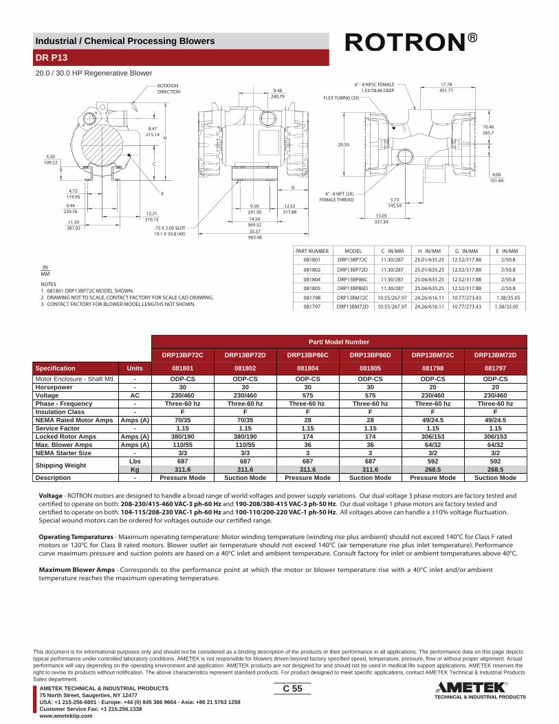
Industrial / Chemical Processing Blowers
DR P13
20.0 / 30.0 HP Regenerative Blower
NOTES1 081801 DRP13BP72C MODEL SHOWN.2 DRAWING NOT TO SCALE, CONTACT FACTORY FOR SCALE CAD DRAWING.3 CONTACT FACTORY FOR BLOWER MODEL LENGTHS NOT SHOWN.
PART NUMBER
081801
11.30287.02
9.44239.76
4.72119.95
4.30109.22
8.47215.14
C
E
12.21310.13
35.57903.48
14.54369.32
9.50241.30
9.48240.79
13.05331.34
5.73145.54
4.00101.60
20.50
10.46265.7
17.78451.71
FLEX TUBING (2X)
4” - 8 NPT (2X)FEMALE THREAD
6” - 8 NPSC FEMALE1.53/38.86 DEEP
12.52317.88
G
.75 X 2.00 SLOT19.1 X 50.8 (4X)
H
ROTATIONDIRECTION
081802
081804
081805
081798
081797
DRP13BP72C
DRP13BP72D
DRP13BP86C
DRP13BP86D
DRP13BM72C
DRP13BM72D
11.30/287
11.30/287
11.30/287
11.30/287
10.55/267.97
10.55/267.97
25.01/635.25
25.01/635.25
25.04/635.25
25.04/635.25
24.26/616.11
24.26/616.11
12.52/317.88
12.52/317.88
12.52/317.88
12.52/317.88
10.77/273.43
10.77/273.43
2/50.8
2/50.8
2/50.8
2/50.8
1.38/35.05
1.38/35.05
MODEL C IN/MM H IN/MM G IN/MM E IN/MM
INMM
Part/ Model Number
DRP13BP72C DRP13BP72D DRP13BP86C DRP13BP86D DRP13BM72C DRP13BM72D
Specification Units 081801 081802 081804 081805 081798 081797
Motor Enclosure - Shaft Mtl. - ODP-CS ODP-CS ODP-CS ODP-CS ODP-CS ODP-CSHorsepower - 30 30 30 30 20 20Voltage AC 230/460 230/460 575 575 230/460 230/460Phase - Frequency - Three-60 hz Three-60 hz Three-60 hz Three-60 hz Three-60 hz Three-60 hzInsulation Class - F F F F F FNEMA Rated Motor Amps Amps (A) 70/35 70/35 28 28 49/24.5 49/24.5Service Factor - 1.15 1.15 1.15 1.15 1.15 1.15Locked Rotor Amps Amps (A) 380/190 380/190 174 174 306/153 306/153Max. Blower Amps Amps (A) 110/55 110/55 36 36 64/32 64/32NEMA Starter Size - 3/3 3/3 3 3 3/2 3/2
Shipping WeightLbsKg
687311.6
687311.6
687311.6
687311.6
592268.5
592268.5
Description - Pressure Mode Suction Mode Pressure Mode Suction Mode Pressure Mode Suction Mode
Voltage - ROTRON motors are designed to handle a broad range of world voltages and power supply variations. Our dual voltage 3 phase motors are factory tested and certi�ed to operate on both: 208-230/415-460 VAC-3 ph-60 Hz and 190-208/380-415 VAC-3 ph-50 Hz. Our dual voltage 1 phase motors are factory tested and certi�ed to operate on both: 104-115/208-230 VAC-1 ph-60 Hz and 100-110/200-220 VAC-1 ph-50 Hz. All voltages above can handle a ±10% voltage �uctuation. Special wound motors can be ordered for voltages outside our certi�ed range.
Operating Temperatures - Maximum operating temperature: Motor winding temperature (winding rise plus ambient) should not exceed 140°C for Class F rated motors or 120°C for Class B rated motors. Blower outlet air temperature should not exceed 140°C (air temperature rise plus inlet temperature). Performance curve maximum pressure and suction points are based on a 40°C inlet and ambient temperature. Consult factory for inlet or ambient temperatures above 40°C.
Maximum Blower Amps - Corresponds to the performance point at which the motor or blower temperature rise with a 40°C inlet and/or ambient temperature reaches the maximum operating temperature.
C 55____
This document is for informational purposes only and should not be considered as a binding description of the products or their performance in all applications. The performance data on this page depictstypical performance under controlled laboratory conditions. AMETEK is not responsible for blowers driven beyond factory specified speed, temperature, pressure, flow or without proper alignment. Actualperformance will vary depending on the operating environment and application. AMETEK products are not designed for and should not be used in medical life support applications. AMETEK reserves theright to revise its products without notification. The above characteristics represent standard products. For product designed to meet specific applications, contact AMETEK Technical & Industrial ProductsSales department.
AMETEK TECHNICAL & INDUSTRIAL PRODUCTS75 North Street, Saugerties, NY 12477USA: +1 215-256-6601 - Europe: +44 (0) 845 366 9664 - Asia: +86 21 5763 1258Customer Service Fax: +1 215.256.1338www.ametektip.com
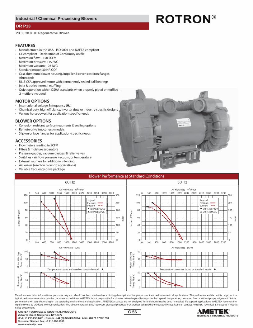
Industrial / Chemical Processing Blowers
DR P13
20.0 / 30.0 HP Regenerative Blower
FEATURES• Manufactured in the USA - ISO 9001 and NAFTA compliant
• Maximum pressure: 115 IWG• Maximum vacuum: 103 IWG• Standard motor: 30 HP, ODP
(threaded)• UL & CSA approved motor with permanently sealed ball bearings••
MOTOR OPTIONS• International voltage & frequency (Hz)
BLOWER OPTIONS• Corrosion resistant surface treatments & sealing options• Remote drive (motorless) models
ACCESSORIES• Flowmeters reading in SCFM• Filters & moisture separators• Pressure gauges, vacuum gauges, & relief valves
••• Variable frequency drive package
Blower Performance at Standard Conditions60 Hz 50 Hz
Inch
es o
f Wat
er
mba
r
Mot
or W
indi
ngTe
mp
Rise
° C
Air Flow Rate - SCFM
Temperature curves are based on standard model
Air Flow Rate - m3/hour
Blow
er A
irTe
mp
Rise
° C
Inch
es o
f Wat
er
mba
r
Mot
or W
indi
ngTe
mp
Rise
° C
Air Flow Rate - SCFM
Temperature curves are based on standard model
Air Flow Rate - m3/hour
Blow
er A
irTe
mp
Rise
° C
LegendPressure:Suction:
DRP13BP72CVDRP13BM72C
LegendPressure:Suction:
DRP13BP72CVDRP13BM72C
0 200 400 600 800 1000 1200 1400 1600 1800 2000 2200
0 340 680 1019 1359 1699 2039 2379 2718 3058 3398 3738
0
20
40
60
80
100
120
0
50
100
150
200
250
300
0
50
100
0
50
100
0 200 400 600 800 1000 1200 1400 1600 1800 2000 2200
0 340 680 1019 1359 1699 2039 2379 2718 3058 3398 3738
0
20
40
60
80
100
120
0
50
100
150
200
250
300
0
50
100
0
50
100
C 56____
This document is for informational purposes only and should not be considered as a binding description of the products or their performance in all applications. The performance data on this page depictstypical performance under controlled laboratory conditions. AMETEK is not responsible for blowers driven beyond factory specified speed, temperature, pressure, flow or without proper alignment. Actualperformance will vary depending on the operating environment and application. AMETEK products are not designed for and should not be used in medical life support applications. AMETEK reserves theright to revise its products without notification. The above characteristics represent standard products. For product designed to meet specific applications, contact AMETEK Technical & Industrial ProductsSales department.
AMETEK TECHNICAL & INDUSTRIAL PRODUCTS75 North Street, Saugerties, NY 12477USA: +1 215-256-6601 - Europe: +44 (0) 845 366 9664 - Asia: +86 21 5763 1258Customer Service Fax: +1 215.256.1338www.ametektip.com
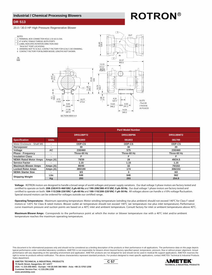
Industrial / Chemical Processing Blowers
DR S13
20.0 / 30.0 HP High Pressure Regenerative Blower
9.44
11.30
4.72
11.2
8
10.774.3
8.47
14.54
9.501.
0813.63
OUT
IN
12.33
273.6
239.8
287.0
119.9
286.
525
.04
63621
5.1
109.
2
SECTION VIEW A-A
35.57903.5
19.7
950
2.7
369.3
27.4
346.2 241.3
4.24107.7
313.2
20.4
952
0.4
BOTHPORTS
1
SLOTS.75x2.00(19x50.8)(4) PLACES
3
2
NOTES1 TERMINAL BOX CONNECTOR HOLE 2.50 (63.5) DIA.2 4”-8 NPSC FEMALE THREAD, BOTH PORTS3 LABEL INDICATES ROTATION DIRECTION AND “IN & OUT” PORT LOCATIONS.5 DRAWING NOT TO SCALE, CONTACT FACTORY FOR SCALE CAD DRAWING.6 CONTACT FACTORY FOR BLOWER MODEL LENGTHS NOT SHOWN.
INMM
Part/ Model Number
DRS13BP72 DRS13BP86 DRS13BM72
Specification Units 081800 081803 081799
Motor Enclosure - Shaft Mtl. - ODP-CS ODP-CS ODP-CSHorsepower - 30 30 20Voltage AC 230/460 575 230/460Phase - Frequency - Three-60 Hz Three-60 Hz Three-60 HzInsulation Class - F F FNEMA Rated Motor Amps Amps (A) 78/39 28 49/24.5Service Factor - 1.15 1.15 1.15Maximum Blower Amps Amps (A) 80/40 32 70/153Locked Rotor Amps Amps (A) 380/190 174 306/153NEMA Starter Size - 3/3 3 3/2
Shipping WeightLbsKg
646293
646293
562254.9
Voltage - ROTRON motors are designed to handle a broad range of world voltages and power supply variations. Our dual voltage 3 phase motors are factory tested and certi�ed to operate on both: 208-230/415-460 VAC-3 ph-60 Hz and 190-208/380-415 VAC-3 ph-50 Hz. Our dual voltage 1 phase motors are factory tested and certi�ed to operate on both: 104-115/208-230 VAC-1 ph-60 Hz and 100-110/200-220 VAC-1 ph-50 Hz. All voltages above can handle a ±10% voltage �uctuation. Special wound motors can be ordered for voltages outside our certi�ed range.
Operating Temperatures - Maximum operating temperature: Motor winding temperature (winding rise plus ambient) should not exceed 140°C for Class F rated motors or 120°C for Class B rated motors. Blower outlet air temperature should not exceed 140°C (air temperature rise plus inlet temperature). Performance curve maximum pressure and suction points are based on a 40°C inlet and ambient temperature. Consult factory for inlet or ambient temperatures above 40°C.
Maximum Blower Amps - Corresponds to the performance point at which the motor or blower temperature rise with a 40°C inlet and/or ambient temperature reaches the maximum operating temperature.
C 57____
This document is for informational purposes only and should not be considered as a binding description of the products or their performance in all applications. The performance data on this page depictstypical performance under controlled laboratory conditions. AMETEK is not responsible for blowers driven beyond factory specified speed, temperature, pressure, flow or without proper alignment. Actualperformance will vary depending on the operating environment and application. AMETEK products are not designed for and should not be used in medical life support applications. AMETEK reserves theright to revise its products without notification. The above characteristics represent standard products. For product designed to meet specific applications, contact AMETEK Technical & Industrial ProductsSales department.
AMETEK TECHNICAL & INDUSTRIAL PRODUCTS75 North Street, Saugerties, NY 12477USA: +1 215-256-6601 - Europe: +44 (0) 845 366 9664 - Asia: +86 21 5763 1258Customer Service Fax: +1 215.256.1338www.ametektip.com

Industrial / Chemical Processing Blowers
DR S13
20.0 / 30.0 HP High Pressure Regenerative Blower
FEATURES• Manufactured in the USA - ISO 9001 and NAFTA compliant
• Maximum pressure: 195 IWG• Maximum vacuum: 132 IWG• Standard motor: 30 HP, ODP
(threaded)• UL & CSA approved motor with permanently sealed ball bearings••
MOTOR OPTIONS• International voltage & frequency (Hz)
BLOWER OPTIONS• Corrosion resistant surface treatments & sealing options• Remote drive (motorless) models
ACCESSORIES• Flowmeters reading in SCFM• Filters & moisture separators• Pressure gauges, vacuum gauges, & relief valves
••• Variable frequency drive package
Blower Performance at Standard Conditions60 Hz 50 Hz
Inch
es o
f Wat
er
mba
r
Mot
or W
indi
ngTe
mp
Rise
° C
Air Flow Rate - SCFM
Temperature curves are based on standard model
Air Flow Rate - m3/hour
Blow
er A
irTe
mp
Rise
° C
Inch
es o
f Wat
er
mba
r
Mot
or W
indi
ngTe
mp
Rise
° C
Air Flow Rate - SCFM
Temperature curves are based on standard model
Air Flow Rate - m3/hour
Blow
er A
irTe
mp
Rise
° C
LegendPressure:Suction:
DRS13
LegendPressure:Suction:
DRS13
0 80 160 240 320 400 480 560 640 720 800 880
0 136 272 408 544 680 816 952 1087 1223 1359 1495
0
35
70
105
140
175
210
0
87
174
261
348
436
523
0
50
100
0
50
100
0 80 160 240 320 400 480 560 640 720 800 880
0 136 272 408 544 680 816 952 1087 1223 1359 1495
0
35
70
105
140
175
210
0
87
174
261
348
436
523
0
50
100
0
50
100
C 58____
This document is for informational purposes only and should not be considered as a binding description of the products or their performance in all applications. The performance data on this page depictstypical performance under controlled laboratory conditions. AMETEK is not responsible for blowers driven beyond factory specified speed, temperature, pressure, flow or without proper alignment. Actualperformance will vary depending on the operating environment and application. AMETEK products are not designed for and should not be used in medical life support applications. AMETEK reserves theright to revise its products without notification. The above characteristics represent standard products. For product designed to meet specific applications, contact AMETEK Technical & Industrial ProductsSales department.
AMETEK TECHNICAL & INDUSTRIAL PRODUCTS75 North Street, Saugerties, NY 12477USA: +1 215-256-6601 - Europe: +44 (0) 845 366 9664 - Asia: +86 21 5763 1258Customer Service Fax: +1 215.256.1338www.ametektip.com

Industrial / Chemical Processing Blowers
DR 14 & CP 14
20.0 / 25.0 / 30.0HP Regenerative Blower
11.0013.11
12.8
8
17.00431.8
MODELDR14DW72MW
L (IN/MM) D (IN/MM)1.98/50.331.55/801.4
L
7.5190.5
29.25743.0
27.6
701.
09.72
247.7
3.0076.2
279.4
17.57446.3
23.4
659
5.9
327.
2
333
9.65245.1
11.57293.9
ROTATIONDIRECTION
SLOTS .75 x 2.00(19.1 x 50.8) 4X PLACES
4"-8 NPSCFEMALE THREADBOTH PORTS(CAST IRON)
D
SEE NOTE 1
23.32 DIA592.3
15.31 DIA388.9
SEE NOTEOUT IN 1
NOTES1 LIFTING SLOT: 1.00 X 1.70 (25.4 X 43.2)2 DRAWING NOT TO SCALE, CONTACT FACTORY FOR SCALE CAD DRAWING.3 CONTACT FACTORY FOR BLOWER MODEL LENGTHS NOT SHOWN.
INMM
Part/ Model Number
DR14DW72MW DR14DW86MW DR14DT72MW DR14BH72MW CP14FK72MWLR HiE14DW72MW
Specification Units 081476 081479 081483 081480 081490 081497
Motor Enclosure - Shaft Mtl. - TEFC-CS TEFC-CS TEFC-CS TEFC-CS Chem TEFC-SS TEFC-CSHorsepower - 30 30 25 20 30 30Voltage AC 230/460 575 230/460 230/460 230/460 230/460Phase - Frequency - Three-60 hz Three-60 hz Three-60 hz Three-60 hz Three-60 hz Three-60 hzInsulation Class - F F F F F FNEMA Rated Motor Amps Amps (A) 66/33 26.5 58/29 46/23 66/33 66/33Service Factor - 1.15 1.15 1.15 1.15 1.15 1.15Max. Blower Amps Amps (A) 90/45 32.8 90/45 60/30 90/45 90/45Locked Rotor Amps Amps (A) 430/215 172 304/152 294/147 430/215 430/215NEMA Starter Size - 3/3 3 3/3 3/2 3/3 3/3
Shipping WeightLbsKg
696315.7
694314.8
650294.8
600272.2
696315.7
696315.7
Voltage - ROTRON motors are designed to handle a broad range of world voltages and power supply variations. Our dual voltage 3 phase motors are factory tested and certi�ed to operate on both: 208-230/415-460 VAC-3 ph-60 Hz and 190-208/380-415 VAC-3 ph-50 Hz. Our dual voltage 1 phase motors are factory tested and certi�ed to operate on both: 104-115/208-230 VAC-1 ph-60 Hz and 100-110/200-220 VAC-1 ph-50 Hz. All voltages above can handle a ±10% voltage �uctuation. Special wound motors can be ordered for voltages outside our certi�ed range.
Operating Temperatures - Maximum operating temperature: Motor winding temperature (winding rise plus ambient) should not exceed 140°C for Class F rated motors or 120°C for Class B rated motors. Blower outlet air temperature should not exceed 140°C (air temperature rise plus inlet temperature). Performance curve maximum pressure and suction points are based on a 40°C inlet and ambient temperature. Consult factory for inlet or ambient temperatures above 40°C.
Maximum Blower Amps - Corresponds to the performance point at which the motor or blower temperature rise with a 40°C inlet and/or ambient temperature reaches the maximum operating temperature.
C 59____
This document is for informational purposes only and should not be considered as a binding description of the products or their performance in all applications. The performance data on this page depictstypical performance under controlled laboratory conditions. AMETEK is not responsible for blowers driven beyond factory specified speed, temperature, pressure, flow or without proper alignment. Actualperformance will vary depending on the operating environment and application. AMETEK products are not designed for and should not be used in medical life support applications. AMETEK reserves theright to revise its products without notification. The above characteristics represent standard products. For product designed to meet specific applications, contact AMETEK Technical & Industrial ProductsSales department.
AMETEK TECHNICAL & INDUSTRIAL PRODUCTS75 North Street, Saugerties, NY 12477USA: +1 215-256-6601 - Europe: +44 (0) 845 366 9664 - Asia: +86 21 5763 1258Customer Service Fax: +1 215.256.1338www.ametektip.com
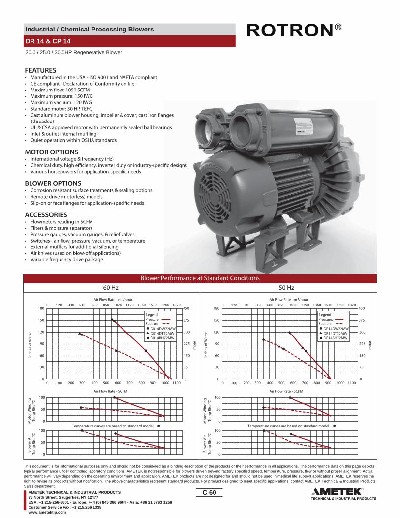
Industrial / Chemical Processing Blowers
DR 14 & CP 14
20.0 / 25.0 / 30.0HP Regenerative Blower
FEATURES• Manufactured in the USA - ISO 9001 and NAFTA compliant
• Maximum pressure: 150 IWG• Maximum vacuum: 120 IWG• Standard motor: 30 HP, TEFC
(threaded)• UL & CSA approved motor with permanently sealed ball bearings•• Quiet operation within OSHA standards
MOTOR OPTIONS• International voltage & frequency (Hz)
BLOWER OPTIONS• Corrosion resistant surface treatments & sealing options• Remote drive (motorless) models
ACCESSORIES• Flowmeters reading in SCFM• Filters & moisture separators• Pressure gauges, vacuum gauges, & relief valves
••• Variable frequency drive package
Blower Performance at Standard Conditions60 Hz 50 Hz
Inch
es o
f Wat
er
mba
r
Mot
or W
indi
ngTe
mp
Rise
° C
Air Flow Rate - SCFM
Air Flow Rate - m3/hour
Blow
er A
irTe
mp
Rise
° C
Inch
es o
f Wat
er
mba
r
Mot
or W
indi
ngTe
mp
Rise
° C
Air Flow Rate - SCFM
Air Flow Rate - m3/hour
Blow
er A
irTe
mp
Rise
° C
LegendPressure:Suction:
DR14DW72MWDR14DT72MWDR14BH72MW
LegendPressure:Suction:
DR14DW72MWDR14DT72MWDR14BH72MW
0 100 200 300 400 500 600 700 800 900 1000 1100
170 340 510 680 850 1020 1190 1360 1530 1700 18700
0
30
60
90
120
150
180
0
75
150
225
300
375
450
0 100 200 300 400 500 600 700 800 900 1000 1100
170 340 510 680 850 1020 1190 1360 1530 1700 18700
0
30
60
90
120
150
180
0
75
150
225
300
375
450
Temperature curves are based on standard model0
50
100
0
50
100Temperature curves are based on standard model
0
50
100
0
50
100
C 60____
This document is for informational purposes only and should not be considered as a binding description of the products or their performance in all applications. The performance data on this page depictstypical performance under controlled laboratory conditions. AMETEK is not responsible for blowers driven beyond factory specified speed, temperature, pressure, flow or without proper alignment. Actualperformance will vary depending on the operating environment and application. AMETEK products are not designed for and should not be used in medical life support applications. AMETEK reserves theright to revise its products without notification. The above characteristics represent standard products. For product designed to meet specific applications, contact AMETEK Technical & Industrial ProductsSales department.
AMETEK TECHNICAL & INDUSTRIAL PRODUCTS75 North Street, Saugerties, NY 12477USA: +1 215-256-6601 - Europe: +44 (0) 845 366 9664 - Asia: +86 21 5763 1258Customer Service Fax: +1 215.256.1338www.ametektip.com

Industrial / Chemical Processing Blowers
DR P15
40.0 / 60.0 HP Regenerative Blower
14.1
411
.42
5.88
A
24.04 REF
9.69
29.6
4
15.62
12.50
10.34
OUT IN
SECTION VIEW A-A
12.38
29.5
3
1011.4
23.3
0 D
IA.
12.1
2 32.0
1 RE
F.
OU
T IN
359.
2
149.
4
290.
1
752.
9
246.1
610.6
314.5
396.7
317.5
262.6
750.
1
591.
8
307.
8
813.
1
A
11.29
14.29363
17.25
11.25285.8
438.2286.8
39.8239.8271.42.81 DIA.
(2 PLACES)
19(4) PLACES
50.8
3.0076.2
1
2
3
.75 X 2.00 SLOTNOTES1 TERMINAL BOX CONNECTOR HOLE 2.50 (63.5) DIA.2 4-8 NPSC FEMALE THREAD, BOTH PORTS3 PRESSURE CONNECTION 6-8 NPSC FEMALE THREAD.2 DRAWING NOT TO SCALE, CONTACT FACTORY FOR SCALE CAD DRAWING.3 CONTACT FACTORY FOR BLOWER MODEL LENGTHS NOT SHOWN.
INMM
Part/ Model Number
DRP15EE72C DRP15EE72D DRP15BQ72C DRP15BQ72D DRP15BQ86C DRP15BQ86D
Specification Units 081499 081629 081501 081500 TBD TBD
Motor Enclosure - Shaft Mtl. - ODP-CS ODP - CS ODP - CS ODP - CS ODP - CS ODP - CSHorsepower - 60 60 40 40 40 40Voltage AC 230/460 230/460 230/460 230/460 575 575Phase - Frequency - Three-60 hz Three - 60 hz Three - 60 hz Three - 60 hz Three - 60 hz Three - 60 hzInsulation Class - F F F F F FNEMA Rated Motor Amps Amps (A) 140/70 140/70 96/48 96/48 38.4 38.4Service Factor - 1.15 1.15 1.15 1.15 1.15 1.15Locked Rotor Amps Amps (A) 870/435 870/435 630/315 630/315 540/270 540/270Max. Blower Amps Amps (A) 170/85 170/85 160/80 160/80 64 64NEMA Starter Size - 5/4 5/4 4/3 4/3 3 3
Shipping WeightLbsKg
1025464.9
1025464.9
923418.7
923418.7
923418.7
923418.7
Description - Pressure Mode Suction Mode Pressure Mode Suction Mode Pressure Mode Suction Mode
Voltage - ROTRON motors are designed to handle a broad range of world voltages and power supply variations. Our dual voltage 3 phase motors are factory tested and certi�ed to operate on both: 208-230/415-460 VAC-3 ph-60 Hz and 190-208/380-415 VAC-3 ph-50 Hz. Our dual voltage 1 phase motors are factory tested and certi�ed to operate on both: 104-115/208-230 VAC-1 ph-60 Hz and 100-110/200-220 VAC-1 ph-50 Hz. All voltages above can handle a ±10% voltage �uctuation. Special wound motors can be ordered for voltages outside our certi�ed range.
Operating Temperatures - Maximum operating temperature: Motor winding temperature (winding rise plus ambient) should not exceed 140°C for Class F rated motors or 120°C for Class B rated motors. Blower outlet air temperature should not exceed 140°C (air temperature rise plus inlet temperature). Performance curve maximum pressure and suction points are based on a 40°C inlet and ambient temperature. Consult factory for inlet or ambient temperatures above 40°C.
Maximum Blower Amps - Corresponds to the performance point at which the motor or blower temperature rise with a 40°C inlet and/or ambient temperature reaches the maximum operating temperature.
C 61____
This document is for informational purposes only and should not be considered as a binding description of the products or their performance in all applications. The performance data on this page depictstypical performance under controlled laboratory conditions. AMETEK is not responsible for blowers driven beyond factory specified speed, temperature, pressure, flow or without proper alignment. Actualperformance will vary depending on the operating environment and application. AMETEK products are not designed for and should not be used in medical life support applications. AMETEK reserves theright to revise its products without notification. The above characteristics represent standard products. For product designed to meet specific applications, contact AMETEK Technical & Industrial ProductsSales department.
AMETEK TECHNICAL & INDUSTRIAL PRODUCTS75 North Street, Saugerties, NY 12477USA: +1 215-256-6601 - Europe: +44 (0) 845 366 9664 - Asia: +86 21 5763 1258Customer Service Fax: +1 215.256.1338www.ametektip.com

Industrial / Chemical Processing Blowers
DR P15
40.0 / 60.0 HP Regenerative Blower
FEATURES• Manufactured in the USA - ISO 9001 and NAFTA compliant
• Maximum pressure: 150 IWG• Maximum vacuum: 115 IWG• Standard motor: 60 HP, ODP
(threaded)• UL & CSA approved motor with permanently sealed ball bearings••
MOTOR OPTIONS• International voltage & frequency (Hz)
BLOWER OPTIONS• Corrosion resistant surface treatments & sealing options• Remote drive (motorless) models
ACCESSORIES• Flowmeters reading in SCFM• Filters & moisture separators• Pressure gauges, vacuum gauges, & relief valves
••• Variable frequency drive package
Blower Performance at Standard Conditions60 Hz 50 Hz
Inch
es o
f Wat
er
mba
r
Mot
or W
indi
ngTe
mp
Rise
° C
Air Flow Rate - SCFM
Temperature curves are based on standard model
Air Flow Rate - m3/hour
Blow
er A
irTe
mp
Rise
° C
Inch
es o
f Wat
er
mba
r
Mot
or W
indi
ngTe
mp
Rise
° C
Air Flow Rate - SCFM
Temperature curves are based on standard model
Air Flow Rate - m3/hour
Blow
er A
irTe
mp
Rise
° C
LegendPressure:Suction:
DRP15EE72DDRP15BQ72C
LegendPressure:Suction:
DRP15EE72DDRP15BQ72C
0
0
0
25
50
75
100
125
150
0
62
124
187
249
311
373
0
50
100
0
50
100
200 400 600 800 1000 1200 1400 1600 1800 2000 2200
340 680 1019 1359 1699 2039 2379 2718 3058 3398 3738
0
0
0
25
50
75
100
125
150
0
62
124
187
249
311
373
0
50
100
0
50
100
200 400 600 800 1000 1200 1400 1600 1800 2000 2200
340 680 1019 1359 1699 2039 2379 2718 3058 3398 3738
C 62____
This document is for informational purposes only and should not be considered as a binding description of the products or their performance in all applications. The performance data on this page depictstypical performance under controlled laboratory conditions. AMETEK is not responsible for blowers driven beyond factory specified speed, temperature, pressure, flow or without proper alignment. Actualperformance will vary depending on the operating environment and application. AMETEK products are not designed for and should not be used in medical life support applications. AMETEK reserves theright to revise its products without notification. The above characteristics represent standard products. For product designed to meet specific applications, contact AMETEK Technical & Industrial ProductsSales department.
AMETEK TECHNICAL & INDUSTRIAL PRODUCTS75 North Street, Saugerties, NY 12477USA: +1 215-256-6601 - Europe: +44 (0) 845 366 9664 - Asia: +86 21 5763 1258Customer Service Fax: +1 215.256.1338www.ametektip.com
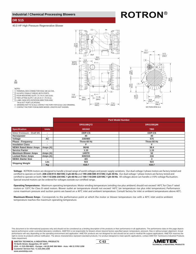
Industrial / Chemical Processing Blowers
DR S15
40.0 HP High Pressure Regenerative Blower
246.9
A
OU
T
IN
IN
OUT
A
SECTION VIEW A-A
9.72
BOTHPORTS
1
4
2
5
3
10.8274.3
12.50317.5
15.6396.2
6.00
152.
4
28.6
726.
4
13.1332.7
14.0
355.
610
.626
9.2
13.4340.4 10.4
264.2
17.25438.2
284.011.18
11.6294.6
12.9327.7
39.2995.7
23.4
594.
4
NOTES1 TERMINAL BOX CONNECTOR HOLE .88 (22) DIA.2 4-8 NPSC FEMALE THREAD, BOTH PORTS.3 FOUR MOUNTING SLOTS .75 (19) X 2.00 (50.8).4 TWO LIFTING SLOTS 1.00 (25.4) X 1.70 (43.2).5 LABEL INDICATES ROTATION DIRECTION AND “IN & OUT” PORT LOCATIONS.6 DRAWING NOT TO SCALE, CONTACT FACTORY FOR SCALE CAD DRAWING.7 CONTACT FACTORY FOR BLOWER MODEL LENGTHS NOT SHOWN.
INMM
Part/ Model Number
DRS15BQ72 DRS15BQ86
Specification Units 081502 TBD
Motor Enclosure - Shaft Mtl. - ODP-CS ODP-CSHorsepower - 40 40Voltage AC 230/460 575Phase - Frequency - Three-60 Hz Three-60 HzInsulation Class - F FNEMA Rated Motor Amps Amps (A) 96/48 38.4Service Factor - 1.15 1.15Maximum Blower Amps Amps (A) 140/70 52Locked Rotor Amps Amps (A) 630/315 216NEMA Starter Size - 4/3 3
Shipping WeightLbsKg
923418.7
923418.7
Voltage - ROTRON motors are designed to handle a broad range of world voltages and power supply variations. Our dual voltage 3 phase motors are factory tested and certi�ed to operate on both: 208-230/415-460 VAC-3 ph-60 Hz and 190-208/380-415 VAC-3 ph-50 Hz. Our dual voltage 1 phase motors are factory tested and certi�ed to operate on both: 104-115/208-230 VAC-1 ph-60 Hz and 100-110/200-220 VAC-1 ph-50 Hz. All voltages above can handle a ±10% voltage �uctuation. Special wound motors can be ordered for voltages outside our certi�ed range.
Operating Temperatures - Maximum operating temperature: Motor winding temperature (winding rise plus ambient) should not exceed 140°C for Class F rated motors or 120°C for Class B rated motors. Blower outlet air temperature should not exceed 140°C (air temperature rise plus inlet temperature). Performance curve maximum pressure and suction points are based on a 40°C inlet and ambient temperature. Consult factory for inlet or ambient temperatures above 40°C.
Maximum Blower Amps - Corresponds to the performance point at which the motor or blower temperature rise with a 40°C inlet and/or ambient temperature reaches the maximum operating temperature.
C 63____
This document is for informational purposes only and should not be considered as a binding description of the products or their performance in all applications. The performance data on this page depictstypical performance under controlled laboratory conditions. AMETEK is not responsible for blowers driven beyond factory specified speed, temperature, pressure, flow or without proper alignment. Actualperformance will vary depending on the operating environment and application. AMETEK products are not designed for and should not be used in medical life support applications. AMETEK reserves theright to revise its products without notification. The above characteristics represent standard products. For product designed to meet specific applications, contact AMETEK Technical & Industrial ProductsSales department.
AMETEK TECHNICAL & INDUSTRIAL PRODUCTS75 North Street, Saugerties, NY 12477USA: +1 215-256-6601 - Europe: +44 (0) 845 366 9664 - Asia: +86 21 5763 1258Customer Service Fax: +1 215.256.1338www.ametektip.com

Industrial / Chemical Processing Blowers
DR S15
40.0 HP High Pressure Regenerative Blower
FEATURES• Manufactured in the USA - ISO 9001 and NAFTA compliant
• Maximum pressure: 200 IWG• Maximum �ow: 925 SCFM
• Maximum vacuum: 134.7 IWG• Standard motor: 40 HP, ODP
(threaded)• UL & CSA approved motor with permanently sealed ball bearings• Quiet operation within OSHA standards when properly piped or mu�ed -
1 inlet mu�er included
MOTOR OPTIONS• International voltage & frequency (Hz)
BLOWER OPTIONS• Corrosion resistant surface treatments & sealing options• Remote drive (motorless) models
ACCESSORIES• Flowmeters reading in SCFM• Filters & moisture separators• Pressure gauges, vacuum gauges, & relief valves
• External mu�ers for additional silencing• Air knives (used on blow-o� applications)• Variable frequency drive package
Blower Performance at Standard Conditions60 Hz
Inch
es o
f Wat
er
mba
r
Mot
or W
indi
ngTe
mp
Rise
° C
Air Flow Rate - SCFM
Air Flow Rate - m3/hour
Blow
er A
irTe
mp
Rise
° C
LegendPressure:Suction:
DRS15
0 100 200 300 400 500 600 700 800 900 1000 1100
0 170 340 510 680 850 1020 1190 1360 1530 1700 1870
0
40
80
120
160
200
240
0
100
200
300
400
500
600
0
50
100
0
50
100Temperature curves are based on standard model
C 64____
This document is for informational purposes only and should not be considered as a binding description of the products or their performance in all applications. The performance data on this page depictstypical performance under controlled laboratory conditions. AMETEK is not responsible for blowers driven beyond factory specified speed, temperature, pressure, flow or without proper alignment. Actualperformance will vary depending on the operating environment and application. AMETEK products are not designed for and should not be used in medical life support applications. AMETEK reserves theright to revise its products without notification. The above characteristics represent standard products. For product designed to meet specific applications, contact AMETEK Technical & Industrial ProductsSales department.
AMETEK TECHNICAL & INDUSTRIAL PRODUCTS75 North Street, Saugerties, NY 12477USA: +1 215-256-6601 - Europe: +44 (0) 845 366 9664 - Asia: +86 21 5763 1258Customer Service Fax: +1 215.256.1338www.ametektip.com
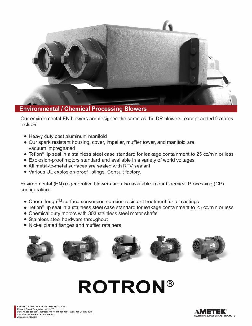
____
Environmental / Chemical Processing BlowersOur environmental EN blowers are designed the same as the DR blowers, except added features include:
Heavy duty cast aluminum manifold Our spark resistant housing, cover, impeller, muffler tower, and manifold are vacuum impregnated Teflon® lip seal in a stainless steel case standard for leakage containment to 25 cc/min or less Explosion-proof motors standard and available in a variety of world voltages All metal-to-metal surfaces are sealed with RTV sealant Various UL explosion-proof listings. Consult factory.
Environmental (EN) regenerative blowers are also available in our Chemical Processing (CP) configuration:
Chem-ToughTM surface conversion corrsion resistant treatment for all castings Teflon® lip seal in a stainless steel case standard for leakage containment to 25 cc/min or less Chemical duty motors with 303 stainless steel motor shafts Stainless steel hardware throughout Nickel plated flanges and muffler retainers
AMETEK TECHNICAL & INDUSTRIAL PRODUCTS75 North Street, Saugerties, NY 12477USA: +1 215-256-6601 - Europe: +44 (0) 845 366 9664 - Asia: +86 21 5763 1258Customer Service Fax: +1 215.256.1338www.ametektip.com

Environmental / Chemical Processing Blowers
EN 101 & CP 101
.5 HP Sealed Regenerative w/Explosion-Proof Motor
IN OUT
7.74195.6
6.13155.7
13.75349.3
8.62219.0
4.65118.1
9.63
244.
6
14.0
1
3.1279.33.25
82.6
6.50
7.52 165.1
191.0
4.13104.9
12.5
1
5.53
1 - 11 1/2 NPSCFEMALE THREADBOTH PORTS
1
ROTATIONDIRECTION
.38 (9.6) DIA2X MTG. HOLES
1.00
355.
9
317.
8
140.
5
25.4
0.40
10.2
NOTES1 TERMINAL BOX CONNECTOR HOLE .75” NPT2 DRAWING NOT TO SCALE, CONTACT FACTORY FOR SCALE CAD DRAWING.3 CONTACT FACTORY FOR BLOWER MODEL LENGTHS NOT SHOWN.
INMM
Part/Model Number
EN101AG58L EN101AG91L CP101FN58LR CP101FN91LR
Specification Units 038171 038019 080622 038950
Motor Enclosure - Shaft Mtl. - .5 .5 .5 .5Horsepower - Explosion-proof-CS Explosion-proof-CS Chem XP-SS Chem XP-SSPhase - Frequency - Single-60 hz Three-60 hz Single-60 hz Three-60 hzVoltage AC 115/230 230/460 115/230 230/460Motor Nameplate Amps Amps (A) 7.4/3.7 .90/.45 7.4/3.7 .90/.45Max. Blower Amps Amps (A) 6/3 1.5/.75 6/3 1.5/.75Inrush Amps Amps (A) 38/19 8.9/4.5 38/19 8.9/4.5Service Factor - 0/00 00/00 0/00 00/00Starter Size - 1.0 1.0 1.0 1.0Thermal Protection - Not Required Not Required Not Required Not RequiredXP Motor Class - Group - I-D I-D I-D I-D
Shipping WeightLbsKg
4721.3
4721.3
4721.3
4721.3
Voltage - ROTRON motors are designed to handle a broad range of world voltages and power supply variations. Our dual voltage 3 phase motors are factory tested and certi�ed to operate on both: 208-230/415-460 VAC-3 ph-60 Hz and 190-208/380-415 VAC-3 ph-50 Hz. Our dual voltage 1 phase motors are factory tested and certi�ed to operate on both: 104-115/208-230 VAC-1 ph-60 Hz and 100-110/200-220 VAC-1 ph-50 Hz. All voltages above can handle a ±10% voltage �uctuation. Special wound motors can be ordered for voltages outside our certi�ed range.
Operating Temperatures - Maximum operating temperature: Motor winding temperature (winding rise plus ambient) should not exceed 140°C for Class F rated motors or 120°C for Class B rated motors. Blower outlet air temperature should not exceed 140°C (air temperature rise plus inlet temperature). Performance curve maximum pressure and suction points are based on a 40°C inlet and ambient temperature. Consult factory for inlet or ambient temperatures above 40°C.
Maximum Blower Amps - Corresponds to the performance point at which the motor or blower temperature rise with a 40°C inlet and/or ambient temperature reaches the maximum operating temperature.
XP Motor Class - Group - See Explosive Atmosphere Classi�cation Chart in Section I
D 1____
This document is for informational purposes only and should not be considered as a binding description of the products or their performance in all applications. The performance data on this page depicts typical performance under controlledlaboratory conditions. AMETEK is not responsible for blowers driven beyond factory specified speed, temperature, pressure, flow or without proper alignment. Actual performance will vary depending on the operating environment and application.AMETEK products are not designed for and should not be used in medical life support applications. AMETEK reserves the right to revise its products without notification. The above characteristics represent standard products. For productdesigned to meet specific applications, contact AMETEK Technical & Industrial Products Sales department.
AMETEK TECHNICAL & INDUSTRIAL PRODUCTS75 North Street, Saugerties, NY 12477USA: +1 215-256-6601 - Europe: +44 (0) 845 366 9664 - Asia: +86 21 5763 1258Customer Service Fax: +1 215.256.1338www.ametektip.com
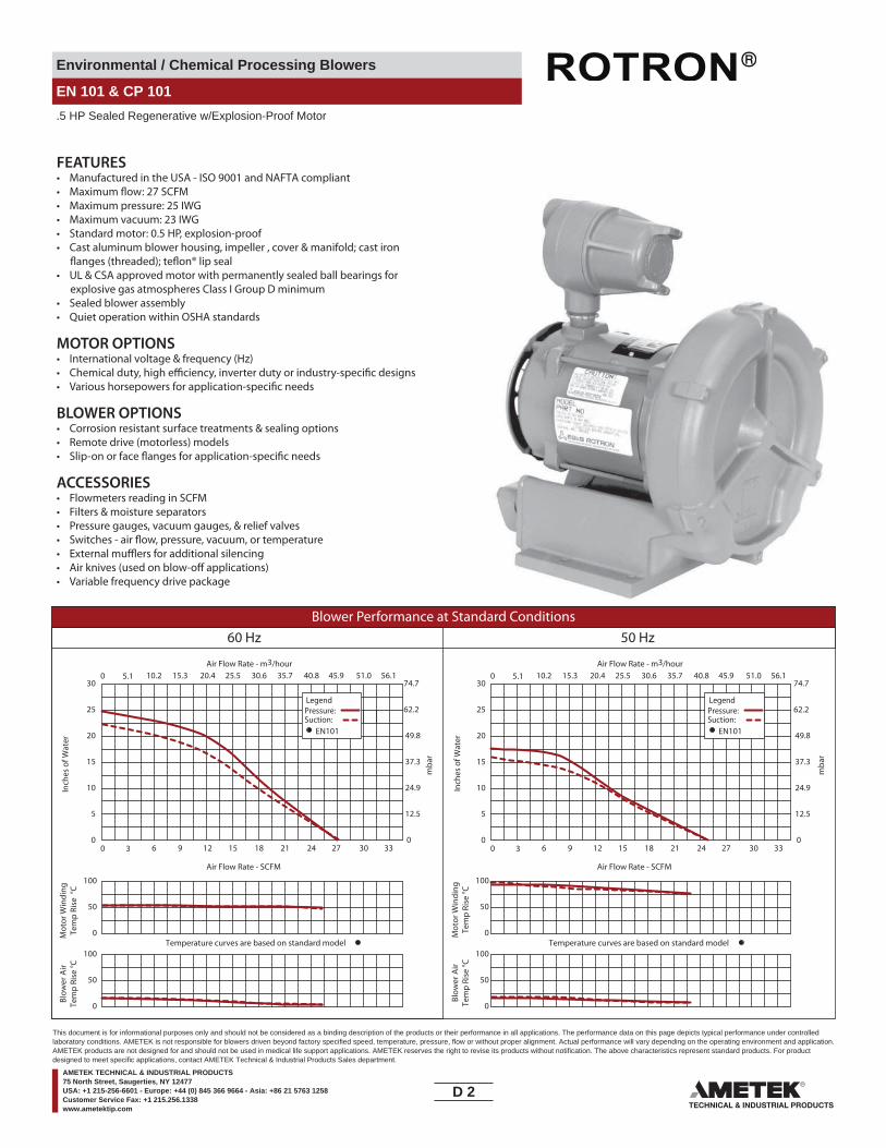
Environmental / Chemical Processing Blowers
EN 101 & CP 101
.5 HP Sealed Regenerative w/Explosion-Proof Motor
FEATURES• Manufactured in the USA - ISO 9001 and NAFTA compliant
• Maximum pressure: 25 IWG• Maximum vacuum: 23 IWG• Standard motor: 0.5 HP, explosion-proof• Cast aluminum blower housing, impeller , cover & manifold; cast iron
• UL & CSA approved motor with permanently sealed ball bearings for explosive gas atmospheres Class I Group D minimum
• Sealed blower assembly• Quiet operation within OSHA standards
MOTOR OPTIONS• International voltage & frequency (Hz)
BLOWER OPTIONS• Corrosion resistant surface treatments & sealing options• Remote drive (motorless) models
ACCESSORIES• Flowmeters reading in SCFM• Filters & moisture separators• Pressure gauges, vacuum gauges, & relief valves
• External mu�ers for additional silencing• Air knives (used on blow-o� applications)• Variable frequency drive package
Blower Performance at Standard Conditions60 Hz 50 Hz
Inch
es o
f Wat
er
mba
r
mba
r
Mot
or W
indi
ngTe
mp
Rise
°C
Air Flow Rate - SCFMAir Flow Rate - SCFM
Temperature curves are based on standard model
Air Flow Rate - m3/hourAir Flow Rate - m3/hour
Inch
es o
f Wat
erM
otor
Win
ding
Tem
p Ri
se °C
Blow
er A
irTe
mp
Rise
°C
Blow
er A
irTe
mp
Rise
°C
Temperature curves are based on standard model
LegendPressure:Suction:
EN101
LegendPressure:Suction:
EN101
0 3 6 9 12 15 18 21 24 27 30 33
0 5.1 10.2 15.3 20.4 25.5 30.6 35.7 40.8 45.9 51.0 56.1
0
50
100
0
5
10
15
20
25
30
0
12.5
24.9
37.3
49.8
62.2
74.7
0 3 6 9 12 15 18 21 24 27 30 33
0 5.1 10.2 15.3 20.4 25.5 30.6 35.7 40.8 45.9 51.0 56.1
0
5
10
15
20
25
30
0
12.5
24.9
37.3
49.8
62.2
74.7
0
50
100
0
50
100
0
50
100
D 2____
This document is for informational purposes only and should not be considered as a binding description of the products or their performance in all applications. The performance data on this page depicts typical performance under controlledlaboratory conditions. AMETEK is not responsible for blowers driven beyond factory specified speed, temperature, pressure, flow or without proper alignment. Actual performance will vary depending on the operating environment and application.AMETEK products are not designed for and should not be used in medical life support applications. AMETEK reserves the right to revise its products without notification. The above characteristics represent standard products. For productdesigned to meet specific applications, contact AMETEK Technical & Industrial Products Sales department.
AMETEK TECHNICAL & INDUSTRIAL PRODUCTS75 North Street, Saugerties, NY 12477USA: +1 215-256-6601 - Europe: +44 (0) 845 366 9664 - Asia: +86 21 5763 1258Customer Service Fax: +1 215.256.1338www.ametektip.com
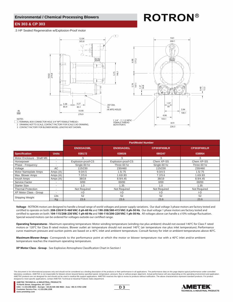
Environmental / Chemical Processing Blowers
EN 303 & CP 303
.5 HP Sealed Regenerative w/Explosion-Proof motor
OUTIN
3.38 3.27
5.75
10.8
2
85.9 83.1
274.
8
0.48
1.97
4.06
8.91
3.9450
103.1
10(4) MTG HOLES
12.04305.8
1.37
34.85.
7914
7.1
6.98
177.
3
9.61
10.90
.397 DIA.
1
12.2
244.1
100.1
226.3
1 1/4" - 11 1/2 NPSCFEMALE THREADBOTH PORTS
146.
1276.9
NOTES1 TERMINAL BOX CONNECTOR HOLE 3/4” NPT FEMALE THREAD>2 DRAWING NOT TO SCALE, CONTACT FACTORY FOR SCALE CAD DRAWING.3 CONTACT FACTORY FOR BLOWER MODEL LENGTHS NOT SHOWN.
INMM
Part/Model Number
EN303AG58L EN303AG91L CP303FN58LR CP303FN91LR
Specification Units 038172 038026 080247 038954
Motor Enclosure - Shaft Mtl. - .5 .5 .5 .5Horsepower - Explosion-proof-CS Explosion-proof-CS Chem XP-SS Chem XP-SSPhase - Frequency - Single-60 hz Three-60 hz Single-60 hz Three-60 hzVoltage AC 115/230 230/460 115/230 230/460Motor Nameplate Amps Amps (A) 9.0/4.5 1.5/.75 9.0/4.5 1.5/.75Max. Blower Amps Amps (A) 7.2/3.6 1.63/.83 7.2/3.6 1.63/.83Inrush Amps Amps (A) 38/19 8.9/4.45 38/19 8.9/4.45Service Factor - 0/00 00/00 0/00 00/00Starter Size - 1.0 1.35 1.0 1.35Thermal Protection - Not Required Not Required Not Required Not RequiredXP Motor Class - Group - I-D I-D I-D I-D
Shipping WeightLbsKg
5223.6
5223.6
5223.6
5223.6
Voltage - ROTRON motors are designed to handle a broad range of world voltages and power supply variations. Our dual voltage 3 phase motors are factory tested and certi�ed to operate on both: 208-230/415-460 VAC-3 ph-60 Hz and 190-208/380-415 VAC-3 ph-50 Hz. Our dual voltage 1 phase motors are factory tested and certi�ed to operate on both: 104-115/208-230 VAC-1 ph-60 Hz and 100-110/200-220 VAC-1 ph-50 Hz. All voltages above can handle a ±10% voltage �uctuation. Special wound motors can be ordered for voltages outside our certi�ed range.
Operating Temperatures - Maximum operating temperature: Motor winding temperature (winding rise plus ambient) should not exceed 140°C for Class F rated motors or 120°C for Class B rated motors. Blower outlet air temperature should not exceed 140°C (air temperature rise plus inlet temperature). Performance curve maximum pressure and suction points are based on a 40°C inlet and ambient temperature. Consult factory for inlet or ambient temperatures above 40°C.
Maximum Blower Amps - Corresponds to the performance point at which the motor or blower temperature rise with a 40°C inlet and/or ambient temperature reaches the maximum operating temperature.
XP Motor Class - Group - See Explosive Atmosphere Classi�cation Chart in Section I
D 3____
This document is for informational purposes only and should not be considered as a binding description of the products or their performance in all applications. The performance data on this page depicts typical performance under controlledlaboratory conditions. AMETEK is not responsible for blowers driven beyond factory specified speed, temperature, pressure, flow or without proper alignment. Actual performance will vary depending on the operating environment and application.AMETEK products are not designed for and should not be used in medical life support applications. AMETEK reserves the right to revise its products without notification. The above characteristics represent standard products. For productdesigned to meet specific applications, contact AMETEK Technical & Industrial Products Sales department.
AMETEK TECHNICAL & INDUSTRIAL PRODUCTS75 North Street, Saugerties, NY 12477USA: +1 215-256-6601 - Europe: +44 (0) 845 366 9664 - Asia: +86 21 5763 1258Customer Service Fax: +1 215.256.1338www.ametektip.com
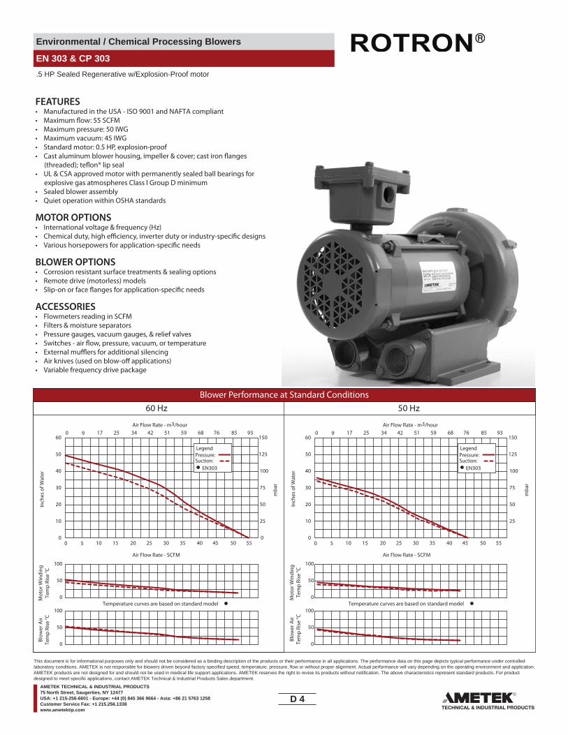
Environmental / Chemical Processing Blowers
EN 303 & CP 303
.5 HP Sealed Regenerative w/Explosion-Proof motor
FEATURES• Manufactured in the USA - ISO 9001 and NAFTA compliant
• Maximum pressure: 50 IWG• Maximum vacuum: 45 IWG• Standard motor: 0.5 HP, explosion-proof
• UL & CSA approved motor with permanently sealed ball bearings for explosive gas atmospheres Class I Group D minimum
• Sealed blower assembly• Quiet operation within OSHA standards
MOTOR OPTIONS• International voltage & frequency (Hz)
BLOWER OPTIONS• Corrosion resistant surface treatments & sealing options• Remote drive (motorless) models
ACCESSORIES• Flowmeters reading in SCFM• Filters & moisture separators• Pressure gauges, vacuum gauges, & relief valves
••• Variable frequency drive package
Blower Performance at Standard Conditions60 Hz 50 Hz
Inch
es o
f Wat
er
mba
r
mba
r
Mot
or W
indi
ngTe
mp
Rise
°C
Air Flow Rate - SCFMAir Flow Rate - SCFM
Air Flow Rate - m3/hourAir Flow Rate - m3/hour
Inch
es o
f Wat
erM
otor
Win
ding
Tem
p Ri
se °C
Blow
er A
irTe
mp
Rise
°C
Blow
er A
irTe
mp
Rise
°C
LegendPressure:Suction:
LegendPressure:Suction:
EN303 EN303
0 5 10 15 20 25 30 35 40 45 50 550
10
20
30
40
50
60
0
25
50
75
100
125
150
0 5 10 15 20 25 30 35 40 45 50 550
10
20
30
40
50
60
25
50
75
100
125
150
Temperature curves are based on standard model Temperature curves are based on standard model0
50
100
0
50
100
0
50
100
0
50
100
0 9 17 25 34 42 51 59 68 76 85 93 0 9 17 25 34 42 51 59 68 76 85 93
D 4____
This document is for informational purposes only and should not be considered as a binding description of the products or their performance in all applications. The performance data on this page depicts typical performance under controlledlaboratory conditions. AMETEK is not responsible for blowers driven beyond factory specified speed, temperature, pressure, flow or without proper alignment. Actual performance will vary depending on the operating environment and application.AMETEK products are not designed for and should not be used in medical life support applications. AMETEK reserves the right to revise its products without notification. The above characteristics represent standard products. For productdesigned to meet specific applications, contact AMETEK Technical & Industrial Products Sales department.
AMETEK TECHNICAL & INDUSTRIAL PRODUCTS75 North Street, Saugerties, NY 12477USA: +1 215-256-6601 - Europe: +44 (0) 845 366 9664 - Asia: +86 21 5763 1258Customer Service Fax: +1 215.256.1338www.ametektip.com

Environmental / Chemical Processing Blowers
EN 404 & CP 404
1.0 HP Sealed Regenerative w/Explosion-Proof Motor
6.28
3.75
4.92
6.66
5.12
8.93
159.
5
11.2
169.2
125
226.8
130(4) MTG. HOLES
L12
.23
311.
2
3.0476.2 95.3
11.63295.4
11.9
7.18
182.
4
292.1
0.44
10.13257.3
EN404AR72MLEN404AR58MLMODEL L (IN/MM)
16.41/416.815.50/393.7
ROTATION DIRECTION
1
.47 DIA.
11.5 DIA
FEMALE THREADBOTH PORTS
1 1/2 - 11 1/2 NPSC
NOTES1 TERMINAL BOX CONNECTOR HOLE 3/4” NPT.2 DRAWING NOT TO SCALE, CONTACT FACTORY FOR SCALE CAD DRAWING.3 CONTACT FACTORY FOR BLOWER MODEL LENGTHS NOT SHOWN.
INMM
Part/Model Number
EN404AR58ML EN404AR72ML CP404FQ58MLR CP404FQ72MLR
Specification Units 038173 038174 080075 038958
Motor Enclosure - Shaft Mtl. - 1.0 1.0 1.0 1.0Horsepower - Explosion-proof-CS Explosion-proof-CS Chem XP-SS Chem XP-SSPhase - Frequency - Single-60 hz Three-60 hz Single-60 hz Three-60 hzVoltage AC 115/230 208-230/460 115/230 208-230/460Motor Nameplate Amps Amps (A) 11.4/5.69 3.2/1.6 11.4/5.69 3.2/1.6Max. Blower Amps Amps (A) 14.4/7.2 3.6/1.8 14.4/7.2 3.6/1.8Inrush Amps Amps (A) 72/36 20.2/10.1 72/36 20.2/10.1Service Factor - 0/00 00/00 0/00 00/00Starter Size - 1.0 1.0 1.0 1.0Thermal Protection - Class B - Pilot Duty Class B - Pilot Duty Class B - Pilot Duty Class B - Pilot DutyXP Motor Class - Group - I-D, II-F&G I-D, II-F&G I-D, II-F&G I-D, II-F&G
Shipping WeightLbsKg
8136.7
6429
8136.7
6429
Voltage - ROTRON motors are designed to handle a broad range of world voltages and power supply variations. Our dual voltage 3 phase motors are factory tested and certi�ed to operate on both: 208-230/415-460 VAC-3 ph-60 Hz and 190-208/380-415 VAC-3 ph-50 Hz. Our dual voltage 1 phase motors are factory tested and certi�ed to operate on both: 104-115/208-230 VAC-1 ph-60 Hz and 100-110/200-220 VAC-1 ph-50 Hz. All voltages above can handle a ±10% voltage �uctuation. Special wound motors can be ordered for voltages outside our certi�ed range.
Operating Temperatures - Maximum operating temperature: Motor winding temperature (winding rise plus ambient) should not exceed 140°C for Class F rated motors or 120°C for Class B rated motors. Blower outlet air temperature should not exceed 140°C (air temperature rise plus inlet temperature). Performance curve maximum pressure and suction points are based on a 40°C inlet and ambient temperature. Consult factory for inlet or ambient temperatures above 40°C.
Maximum Blower Amps - Corresponds to the performance point at which the motor or blower temperature rise with a 40°C inlet and/or ambient temperature reaches the maximum operating temperature.
XP Motor Class - Group - See Explosive Atmosphere Classi�cation Chart in Section I
D 5____
This document is for informational purposes only and should not be considered as a binding description of the products or their performance in all applications. The performance data on this page depicts typical performance under controlledlaboratory conditions. AMETEK is not responsible for blowers driven beyond factory specified speed, temperature, pressure, flow or without proper alignment. Actual performance will vary depending on the operating environment and application.AMETEK products are not designed for and should not be used in medical life support applications. AMETEK reserves the right to revise its products without notification. The above characteristics represent standard products. For productdesigned to meet specific applications, contact AMETEK Technical & Industrial Products Sales department.
AMETEK TECHNICAL & INDUSTRIAL PRODUCTS75 North Street, Saugerties, NY 12477USA: +1 215-256-6601 - Europe: +44 (0) 845 366 9664 - Asia: +86 21 5763 1258Customer Service Fax: +1 215.256.1338www.ametektip.com
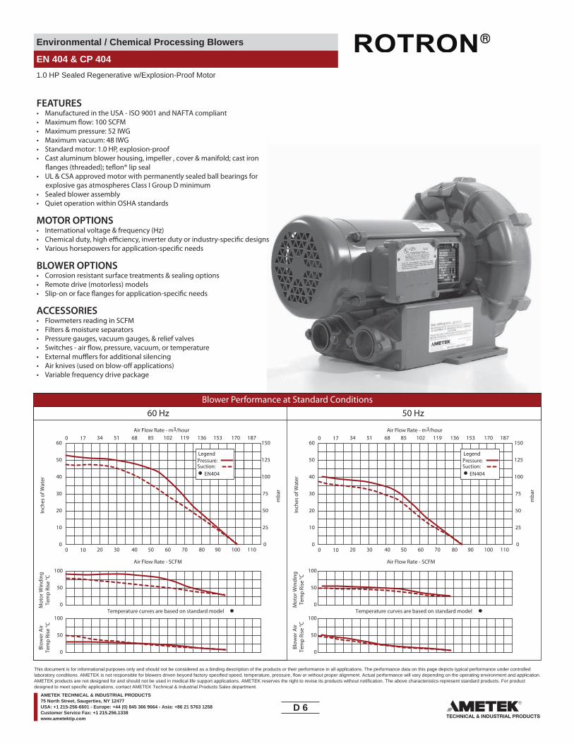
Environmental / Chemical Processing Blowers
EN 404 & CP 404
1.0 HP Sealed Regenerative w/Explosion-Proof Motor
FEATURES• Manufactured in the USA - ISO 9001 and NAFTA compliant
• Maximum pressure: 52 IWG• Maximum vacuum: 48 IWG• Standard motor: 1.0 HP, explosion-proof• Cast aluminum blower housing, impeller , cover & manifold; cast iron
• UL & CSA approved motor with permanently sealed ball bearings for explosive gas atmospheres Class I Group D minimum
• Sealed blower assembly• Quiet operation within OSHA standards
MOTOR OPTIONS• International voltage & frequency (Hz)
BLOWER OPTIONS• Corrosion resistant surface treatments & sealing options• Remote drive (motorless) models
ACCESSORIES• Flowmeters reading in SCFM• Filters & moisture separators• Pressure gauges, vacuum gauges, & relief valves
••• Variable frequency drive package
Blower Performance at Standard Conditions60 Hz 50 Hz
Inch
es o
f Wat
er
mba
r
mba
r
Mot
or W
indi
ngTe
mp
Rise
°C
Air Flow Rate - SCFMAir Flow Rate - SCFM
Temperature curves are based on standard model
Air Flow Rate - m3/hourAir Flow Rate - m3/hour
Inch
es o
f Wat
erM
otor
Win
ding
Tem
p Ri
se °C
Blow
er A
irTe
mp
Rise
°C
Blow
er A
irTe
mp
Rise
°C
Temperature curves are based on standard model
LegendPressure:Suction:
EN404
LegendPressure:Suction:
EN404
0 10 20 30 40 50 60 70 80 90 100 110
0 17 34 51 68 85 102 119 136 153 170 187
0
50
100
0
10
20
30
40
50
60
0
25
50
75
100
125
150
0 10 20 30 40 50 60 70 80 90 100 110
0 17 34 51 68 85 102 119 136 153 170 187
0
10
20
30
40
50
60
0
25
50
75
100
125
150
0
50
100
0
50
100
0
50
100
D 6____
This document is for informational purposes only and should not be considered as a binding description of the products or their performance in all applications. The performance data on this page depicts typical performance under controlledlaboratory conditions. AMETEK is not responsible for blowers driven beyond factory specified speed, temperature, pressure, flow or without proper alignment. Actual performance will vary depending on the operating environment and application.AMETEK products are not designed for and should not be used in medical life support applications. AMETEK reserves the right to revise its products without notification. The above characteristics represent standard products. For productdesigned to meet specific applications, contact AMETEK Technical & Industrial Products Sales department.
AMETEK TECHNICAL & INDUSTRIAL PRODUCTS75 North Street, Saugerties, NY 12477USA: +1 215-256-6601 - Europe: +44 (0) 845 366 9664 - Asia: +86 21 5763 1258Customer Service Fax: +1 215.256.1338www.ametektip.com
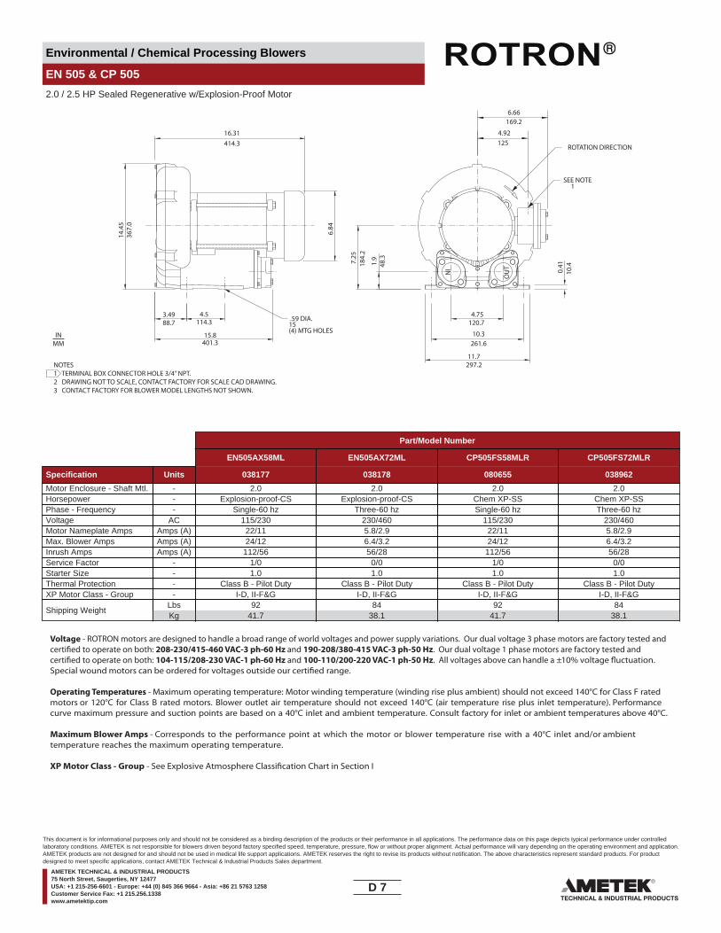
Environmental / Chemical Processing Blowers
EN 505 & CP 505
2.0 / 2.5 HP Sealed Regenerative w/Explosion-Proof Motor
OU
TIN 0.41
10.4
4.92125
16.31414.3
6.84
6.66169.2
4.75120.7
11.7
14.4
536
7.0
(4) MTG HOLES15
3.4988.7 114.3
15.8401.3
7.25
184.
2
1.9
48.3
297.2
4.5
10.3261.6
ROTATION DIRECTION
.59 DIA.
SEE NOTE 1
NOTES1 TERMINAL BOX CONNECTOR HOLE 3/4” NPT.2 DRAWING NOT TO SCALE, CONTACT FACTORY FOR SCALE CAD DRAWING.3 CONTACT FACTORY FOR BLOWER MODEL LENGTHS NOT SHOWN.
INMM
Part/Model Number
EN505AX58ML EN505AX72ML CP505FS58MLR CP505FS72MLR
Specification Units 038177 038178 080655 038962
Motor Enclosure - Shaft Mtl. - 2.0 2.0 2.0 2.0Horsepower - Explosion-proof-CS Explosion-proof-CS Chem XP-SS Chem XP-SSPhase - Frequency - Single-60 hz Three-60 hz Single-60 hz Three-60 hzVoltage AC 115/230 230/460 115/230 230/460Motor Nameplate Amps Amps (A) 22/11 5.8/2.9 22/11 5.8/2.9Max. Blower Amps Amps (A) 24/12 6.4/3.2 24/12 6.4/3.2Inrush Amps Amps (A) 112/56 56/28 112/56 56/28Service Factor - 1/0 0/0 1/0 0/0Starter Size - 1.0 1.0 1.0 1.0Thermal Protection - Class B - Pilot Duty Class B - Pilot Duty Class B - Pilot Duty Class B - Pilot DutyXP Motor Class - Group - I-D, II-F&G I-D, II-F&G I-D, II-F&G I-D, II-F&G
Shipping WeightLbsKg
9241.7
8438.1
9241.7
8438.1
Voltage - ROTRON motors are designed to handle a broad range of world voltages and power supply variations. Our dual voltage 3 phase motors are factory tested and certi�ed to operate on both: 208-230/415-460 VAC-3 ph-60 Hz and 190-208/380-415 VAC-3 ph-50 Hz. Our dual voltage 1 phase motors are factory tested and certi�ed to operate on both: 104-115/208-230 VAC-1 ph-60 Hz and 100-110/200-220 VAC-1 ph-50 Hz. All voltages above can handle a ±10% voltage �uctuation. Special wound motors can be ordered for voltages outside our certi�ed range.
Operating Temperatures - Maximum operating temperature: Motor winding temperature (winding rise plus ambient) should not exceed 140°C for Class F rated motors or 120°C for Class B rated motors. Blower outlet air temperature should not exceed 140°C (air temperature rise plus inlet temperature). Performance curve maximum pressure and suction points are based on a 40°C inlet and ambient temperature. Consult factory for inlet or ambient temperatures above 40°C.
Maximum Blower Amps - Corresponds to the performance point at which the motor or blower temperature rise with a 40°C inlet and/or ambient temperature reaches the maximum operating temperature.
XP Motor Class - Group - See Explosive Atmosphere Classi�cation Chart in Section I
D 7____
This document is for informational purposes only and should not be considered as a binding description of the products or their performance in all applications. The performance data on this page depicts typical performance under controlledlaboratory conditions. AMETEK is not responsible for blowers driven beyond factory specified speed, temperature, pressure, flow or without proper alignment. Actual performance will vary depending on the operating environment and application.AMETEK products are not designed for and should not be used in medical life support applications. AMETEK reserves the right to revise its products without notification. The above characteristics represent standard products. For productdesigned to meet specific applications, contact AMETEK Technical & Industrial Products Sales department.
AMETEK TECHNICAL & INDUSTRIAL PRODUCTS75 North Street, Saugerties, NY 12477USA: +1 215-256-6601 - Europe: +44 (0) 845 366 9664 - Asia: +86 21 5763 1258Customer Service Fax: +1 215.256.1338www.ametektip.com

Environmental / Chemical Processing Blowers
EN 505 & CP 505
2.0 / 2.5 HP Sealed Regenerative w/Explosion-Proof Motor
FEATURES• Manufactured in the USA - ISO 9001 and NAFTA compliant
• Maximum pressure: 75 IWG• Maximum vacuum: 70 IWG• Standard motor: 2.0 HP, explosion-proof• Cast aluminum blower housing, impeller , cover & manifold; cast iron
• UL & CSA approved motor with permanently sealed ball bearings for explosive gas atmospheres Class I Group D minimum
• Sealed blower assembly• Quiet operation within OSHA standards
MOTOR OPTIONS• International voltage & frequency (Hz)
BLOWER OPTIONS• Corrosion resistant surface treatments & sealing options• Remote drive (motorless) models
ACCESSORIES• Flowmeters reading in SCFM• Filters & moisture separators• Pressure gauges, vacuum gauges, & relief valves
••• Variable frequency drive package
Blower Performance at Standard Conditions60 Hz 50 Hz
Inch
es o
f Wat
er
mba
r
mba
r
Mot
or W
indi
ngTe
mp
Rise
°C
Air Flow Rate - SCFMAir Flow Rate - SCFM
Temperature curves are based on standard model
Air Flow Rate - m3/hourAir Flow Rate - m3/hour
Inch
es o
f Wat
erM
otor
Win
ding
Tem
p Ri
se °C
Blow
er A
irTe
mp
Rise
°C
Blow
er A
irTe
mp
Rise
°C
Temperature curves are based on standard model
LegendPressure:Suction:
EN505AX72MLEN505AX58ML
LegendPressure:Suction:
EN505AX72MLEN505AX58ML
0
50
100
0
50
100
0
50
100
0
50
100
0 15 30 45 60 75 90 105 120 135 150 165
0 26 51 77 102 127 153 178 204 229 255 280
0
15
30
45
60
75
90
0
37
75
112
149
187
224
0 15 30 45 60 75 90 105 120 135 150 165
0 26 51 77 102 127 153 178 204 229 255 280
0
15
30
45
60
75
90
0
37
75
112
149
187
224
D 8____
This document is for informational purposes only and should not be considered as a binding description of the products or their performance in all applications. The performance data on this page depicts typical performance under controlledlaboratory conditions. AMETEK is not responsible for blowers driven beyond factory specified speed, temperature, pressure, flow or without proper alignment. Actual performance will vary depending on the operating environment and application.AMETEK products are not designed for and should not be used in medical life support applications. AMETEK reserves the right to revise its products without notification. The above characteristics represent standard products. For productdesigned to meet specific applications, contact AMETEK Technical & Industrial Products Sales department.
AMETEK TECHNICAL & INDUSTRIAL PRODUCTS75 North Street, Saugerties, NY 12477USA: +1 215-256-6601 - Europe: +44 (0) 845 366 9664 - Asia: +86 21 5763 1258Customer Service Fax: +1 215.256.1338www.ametektip.com

Environmental / Chemical Processing Blowers
EN 454 & CP 454
1.5 HP Sealed Regenerative w/Explosion-Proof Motor
IN OUT
177.
3
48.8
317.5
120.
7
6.98
12.5
4.75
4.75120.6
10.7
4.50114.3
3.27
83.1 45.2
(6) MTG. HOLES
332.7
1.78
1.92
0.42
13.5
3
13.10
15
136.7
289.6
261.6
5.38
11.4 REF.
10.30
343.
7
18.70475.0
1
ROTATION DIRECTION
.59 DIA.
FEMALE THREADBOTH PORTS
1 1/2 - 11 1/2 NPSC
NOTES1 TERMINAL BOX CONNECTOR HOLE 3/4” NPT.2 DRAWING NOT TO SCALE, CONTACT FACTORY FOR SCALE CAD DRAWING.3 CONTACT FACTORY FOR BLOWER MODEL LENGTHS NOT SHOWN.
INMM
Part/Model Number
EN454W58ML EN454W72ML CP454W72MLR CP454FR72MLR
Specification Units 080487 080488 080490 080494
Motor Enclosure - Shaft Mtl. - 1.5 1.5 1.5 1.5Horsepower - Explosion-proof-CS Explosion-proof-CS Chem XP-CS Chem XP-SSPhase - Frequency - Single-60 hz Three-60 hz Three-60 hz Three-60 hzVoltage AC 115/208-230 230/460 230/460 230/460Motor Nameplate Amps Amps (A) 15/7.9-7.5 4.6/2.3 4.5/2.3 4.6/2.3Max. Blower Amps Amps (A) 19/10.9-9.5 5.6/2.8 5.6/2.8 5.6/2.8Inrush Amps Amps (A) 96-48 32/16 32/16 32/16Service Factor - 1/0 00/00 00/00 00/00Starter Size - 1.0 1.0 1.0 1.0Thermal Protection - Class B - Pilot Duty Class B - Pilot Duty Class B - Pilot Duty Class B - Pilot DutyXP Motor Class - Group - I-D, II-F&G I-D, II-F&G I-D, II-F&G I-D, II-F&G
Shipping WeightLbsKg
9040.8
8438.1
8438.1
8438.1
Voltage - ROTRON motors are designed to handle a broad range of world voltages and power supply variations. Our dual voltage 3 phase motors are factory tested and certi�ed to operate on both: 208-230/415-460 VAC-3 ph-60 Hz and 190-208/380-415 VAC-3 ph-50 Hz. Our dual voltage 1 phase motors are factory tested and certi�ed to operate on both: 104-115/208-230 VAC-1 ph-60 Hz and 100-110/200-220 VAC-1 ph-50 Hz. All voltages above can handle a ±10% voltage �uctuation. Special wound motors can be ordered for voltages outside our certi�ed range.
Operating Temperatures - Maximum operating temperature: Motor winding temperature (winding rise plus ambient) should not exceed 140°C for Class F rated motors or 120°C for Class B rated motors. Blower outlet air temperature should not exceed 140°C (air temperature rise plus inlet temperature). Performance curve maximum pressure and suction points are based on a 40°C inlet and ambient temperature. Consult factory for inlet or ambient temperatures above 40°C.
Maximum Blower Amps - Corresponds to the performance point at which the motor or blower temperature rise with a 40°C inlet and/or ambient temperature reaches the maximum operating temperature.
XP Motor Class - Group - See Explosive Atmosphere Classi�cation Chart in Section I
D 9____
This document is for informational purposes only and should not be considered as a binding description of the products or their performance in all applications. The performance data on this page depicts typical performance under controlledlaboratory conditions. AMETEK is not responsible for blowers driven beyond factory specified speed, temperature, pressure, flow or without proper alignment. Actual performance will vary depending on the operating environment and application.AMETEK products are not designed for and should not be used in medical life support applications. AMETEK reserves the right to revise its products without notification. The above characteristics represent standard products. For productdesigned to meet specific applications, contact AMETEK Technical & Industrial Products Sales department.
AMETEK TECHNICAL & INDUSTRIAL PRODUCTS75 North Street, Saugerties, NY 12477USA: +1 215-256-6601 - Europe: +44 (0) 845 366 9664 - Asia: +86 21 5763 1258Customer Service Fax: +1 215.256.1338www.ametektip.com

Environmental / Chemical Processing Blowers
EN 454 & CP 454
1.5 HP Sealed Regenerative w/Explosion-Proof Motor
FEATURES• Manufactured in the USA - ISO 9001 and NAFTA compliant
• Maximum pressure: 65 IWG• Maximum vacuum: 59 IWG• Standard motor: 1.5 HP, explosion-proof• Cast aluminum blower housing, impeller , cover & manifold; cast iron
• UL & CSA approved motor with permanently sealed ball bearings for explosive gas atmospheres Class I Group D minimum
• Sealed blower assembly• Quiet operation within OSHA standards
MOTOR OPTIONS• International voltage & frequency (Hz)
BLOWER OPTIONS• Corrosion resistant surface treatments & sealing options• Remote drive (motorless) models
ACCESSORIES• Flowmeters reading in SCFM• Filters & moisture separators• Pressure gauges, vacuum gauges, & relief valves
••• Variable frequency drive package
Blower Performance at Standard Conditions60 Hz 50 Hz
Inch
es o
f Wat
er
mba
r
mba
r
Mot
or W
indi
ngTe
mp
Ris
e °C
Air Flow Rate - SCFMAir Flow Rate - SCFM
Temperature curves are based on standard model
Air Flow Rate - m3/hourAir Flow Rate - m3/hour
Inch
es o
f Wat
erM
otor
Win
ding
Tem
p R
ise
°C
Blo
wer
Air
Tem
p R
ise
°C
Blo
wer
Air
Tem
p R
ise
°C
Temperature curves are based on standard model
LegendPressure:Suction:
LegendPressure:Suction:
EN454 EN454
0 15 30 45 60 75 90 105 120 135 150 165
0 26 51 77 102 127 153 178 204 229 255 280
0
50
100
0
15
30
45
60
75
90
0
37
75
112
149
187
224
0 15 30 45 60 75 90 105 120 135 150 165
0 26 51 77 102 127 153 178 204 229 255 280
0
15
30
45
60
75
90
0
37
75
112
149
187
224
0
50
100
0
50
100
0
50
100
D 10____
This document is for informational purposes only and should not be considered as a binding description of the products or their performance in all applications. The performance data on this page depicts typical performance under controlledlaboratory conditions. AMETEK is not responsible for blowers driven beyond factory specified speed, temperature, pressure, flow or without proper alignment. Actual performance will vary depending on the operating environment and application.AMETEK products are not designed for and should not be used in medical life support applications. AMETEK reserves the right to revise its products without notification. The above characteristics represent standard products. For productdesigned to meet specific applications, contact AMETEK Technical & Industrial Products Sales department.
AMETEK TECHNICAL & INDUSTRIAL PRODUCTS75 North Street, Saugerties, NY 12477USA: +1 215-256-6601 - Europe: +44 (0) 845 366 9664 - Asia: +86 21 5763 1258Customer Service Fax: +1 215.256.1338www.ametektip.com
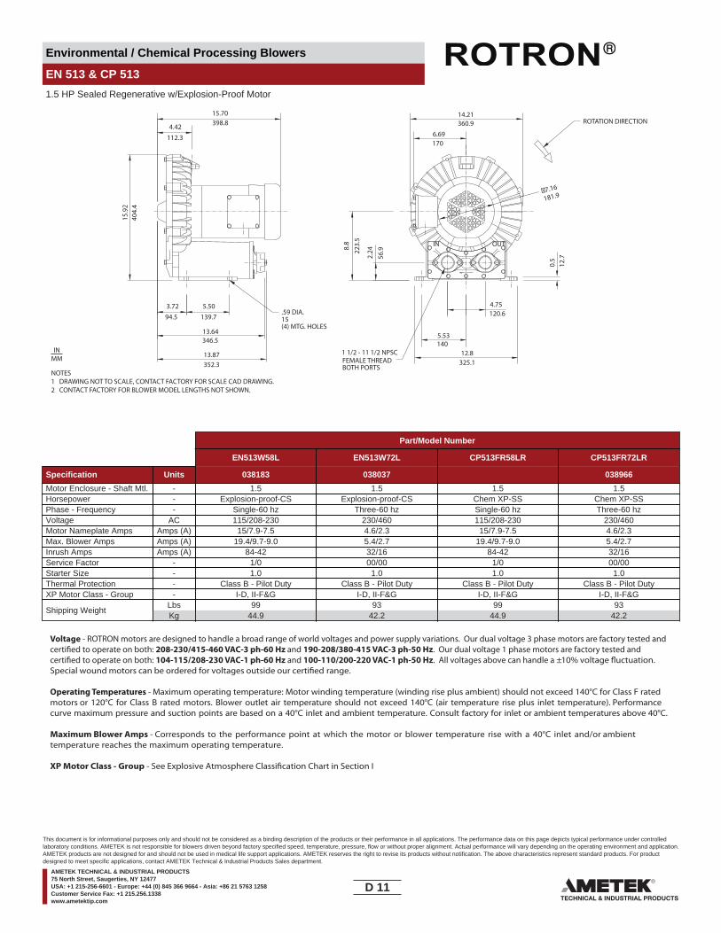
Environmental / Chemical Processing Blowers
EN 513 & CP 513
1.5 HP Sealed Regenerative w/Explosion-Proof Motor
OUTIN
4.42
112.340
4.4
3.72 5.50
13.64
13.87
139.794.5
346.5
(4) MTG. HOLES
2.248.
822
3.5
56.9
4.75
12.8
120.6
140
325.1
0.5
12.7
181.9
14.21360.9
6.69170
5.53
15.70398.8
15.9
2
352.3
15
ROTATION DIRECTION
.59 DIA.
FEMALE THREADBOTH PORTS
1 1/2 - 11 1/2 NPSC
NOTES1 DRAWING NOT TO SCALE, CONTACT FACTORY FOR SCALE CAD DRAWING.2 CONTACT FACTORY FOR BLOWER MODEL LENGTHS NOT SHOWN.
INMM
Part/Model Number
EN513W58L EN513W72L CP513FR58LR CP513FR72LR
Specification Units 038183 038037 038966
Motor Enclosure - Shaft Mtl. - 1.5 1.5 1.5 1.5Horsepower - Explosion-proof-CS Explosion-proof-CS Chem XP-SS Chem XP-SSPhase - Frequency - Single-60 hz Three-60 hz Single-60 hz Three-60 hzVoltage AC 115/208-230 230/460 115/208-230 230/460Motor Nameplate Amps Amps (A) 15/7.9-7.5 4.6/2.3 15/7.9-7.5 4.6/2.3Max. Blower Amps Amps (A) 19.4/9.7-9.0 5.4/2.7 19.4/9.7-9.0 5.4/2.7Inrush Amps Amps (A) 84-42 32/16 84-42 32/16Service Factor - 1/0 00/00 1/0 00/00Starter Size - 1.0 1.0 1.0 1.0Thermal Protection - Class B - Pilot Duty Class B - Pilot Duty Class B - Pilot Duty Class B - Pilot DutyXP Motor Class - Group - I-D, II-F&G I-D, II-F&G I-D, II-F&G I-D, II-F&G
Shipping WeightLbsKg
9944.9
9342.2
9944.9
9342.2
Voltage - ROTRON motors are designed to handle a broad range of world voltages and power supply variations. Our dual voltage 3 phase motors are factory tested and certi�ed to operate on both: 208-230/415-460 VAC-3 ph-60 Hz and 190-208/380-415 VAC-3 ph-50 Hz. Our dual voltage 1 phase motors are factory tested and certi�ed to operate on both: 104-115/208-230 VAC-1 ph-60 Hz and 100-110/200-220 VAC-1 ph-50 Hz. All voltages above can handle a ±10% voltage �uctuation. Special wound motors can be ordered for voltages outside our certi�ed range.
Operating Temperatures - Maximum operating temperature: Motor winding temperature (winding rise plus ambient) should not exceed 140°C for Class F rated motors or 120°C for Class B rated motors. Blower outlet air temperature should not exceed 140°C (air temperature rise plus inlet temperature). Performance curve maximum pressure and suction points are based on a 40°C inlet and ambient temperature. Consult factory for inlet or ambient temperatures above 40°C.
Maximum Blower Amps - Corresponds to the performance point at which the motor or blower temperature rise with a 40°C inlet and/or ambient temperature reaches the maximum operating temperature.
XP Motor Class - Group - See Explosive Atmosphere Classi�cation Chart in Section I
D 11____
This document is for informational purposes only and should not be considered as a binding description of the products or their performance in all applications. The performance data on this page depicts typical performance under controlledlaboratory conditions. AMETEK is not responsible for blowers driven beyond factory specified speed, temperature, pressure, flow or without proper alignment. Actual performance will vary depending on the operating environment and application.AMETEK products are not designed for and should not be used in medical life support applications. AMETEK reserves the right to revise its products without notification. The above characteristics represent standard products. For productdesigned to meet specific applications, contact AMETEK Technical & Industrial Products Sales department.
AMETEK TECHNICAL & INDUSTRIAL PRODUCTS75 North Street, Saugerties, NY 12477USA: +1 215-256-6601 - Europe: +44 (0) 845 366 9664 - Asia: +86 21 5763 1258Customer Service Fax: +1 215.256.1338www.ametektip.com
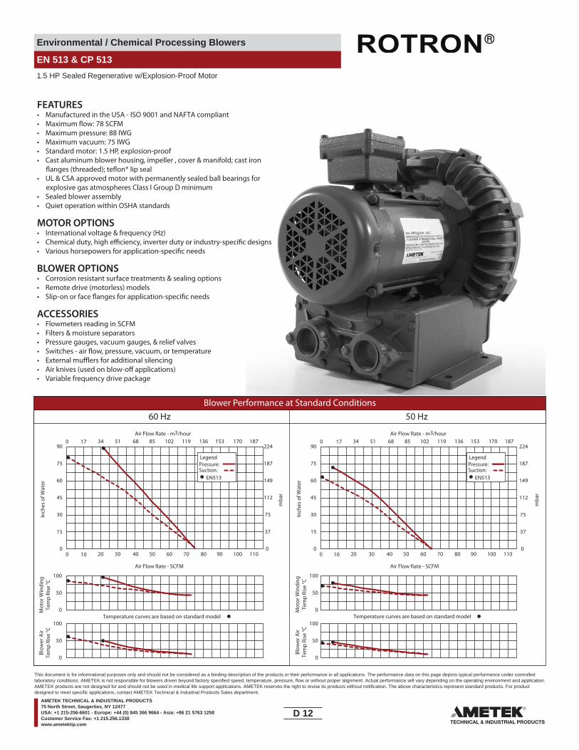
Environmental / Chemical Processing Blowers
EN 513 & CP 513
1.5 HP Sealed Regenerative w/Explosion-Proof Motor
FEATURES• Manufactured in the USA - ISO 9001 and NAFTA compliant
• Maximum pressure: 88 IWG• Maximum vacuum: 75 IWG• Standard motor: 1.5 HP, explosion-proof• Cast aluminum blower housing, impeller , cover & manifold; cast iron
• UL & CSA approved motor with permanently sealed ball bearings for explosive gas atmospheres Class I Group D minimum
• Sealed blower assembly• Quiet operation within OSHA standards
MOTOR OPTIONS• International voltage & frequency (Hz)
BLOWER OPTIONS• Corrosion resistant surface treatments & sealing options• Remote drive (motorless) models
ACCESSORIES• Flowmeters reading in SCFM• Filters & moisture separators• Pressure gauges, vacuum gauges, & relief valves
••• Variable frequency drive package
Blower Performance at Standard Conditions60 Hz 50 Hz
Inch
es o
f Wat
er
mba
r
mba
r
Mot
or W
indi
ngTe
mp
Rise
°C
Air Flow Rate - SCFMAir Flow Rate - SCFM
Air Flow Rate - m3/hourAir Flow Rate - m3/hour
Inch
es o
f Wat
erM
otor
Win
ding
Tem
p Ri
se °C
Blow
er A
irTe
mp
Rise
°C
Blow
er A
irTe
mp
Rise
°C
LegendPressure:Suction:
LegendPressure:Suction:
EN513 EN513
0 10 20 30 40 50 60 70 80 90 100 110 0 10 20 30 40 50 60 70 80 90 100 110
0 17 34 51 68 85 102 119 136 153 170 187 0
0
15
30
45
60
75
90
0
15
30
45
60
75
90
0
37
75
112
149
187
22417 34 51 68 85 102 119 136 153 170 187
37
75
112
149
187
224
0
Temperature curves are based on standard model Temperature curves are based on standard model0
50
100
0
50
100
0
50
100
0
50
100
D 12____
This document is for informational purposes only and should not be considered as a binding description of the products or their performance in all applications. The performance data on this page depicts typical performance under controlledlaboratory conditions. AMETEK is not responsible for blowers driven beyond factory specified speed, temperature, pressure, flow or without proper alignment. Actual performance will vary depending on the operating environment and application.AMETEK products are not designed for and should not be used in medical life support applications. AMETEK reserves the right to revise its products without notification. The above characteristics represent standard products. For productdesigned to meet specific applications, contact AMETEK Technical & Industrial Products Sales department.
AMETEK TECHNICAL & INDUSTRIAL PRODUCTS75 North Street, Saugerties, NY 12477USA: +1 215-256-6601 - Europe: +44 (0) 845 366 9664 - Asia: +86 21 5763 1258Customer Service Fax: +1 215.256.1338www.ametektip.com
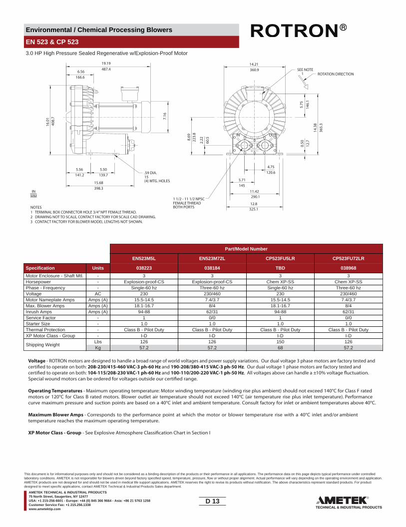
Environmental / Chemical Processing Blowers
EN 523 & CP 523
3.0 HP High Pressure Sealed Regenerative w/Explosion-Proof Motor
OUTIN
5.50139.7
(4) MTG. HOLES
360.9
5.71
11.42
12.8
4.75120.6
145
290.1
325.1
19.19487.4
6.56166.6
16.0
140
8.7 7.
165.56
141.2
15.68398.3
15
14.21
5.75
146.
10.
5012
.7
14.3
836
5.3
2.22
60.58.
6922
3.8
ROTATION DIRECTION
.59 DIA.
FEMALE THREADBOTH PORTS
1 1/2 - 11 1/2 NPSC
SEE NOTE 1
NOTES1 TERMINAL BOX CONNECTOR HOLE 3/4” NPT FEMALE THREAD.2 DRAWING NOT TO SCALE, CONTACT FACTORY FOR SCALE CAD DRAWING.3 CONTACT FACTORY FOR BLOWER MODEL LENGTHS NOT SHOWN.
INMM
Part/Model Number
EN523M5L EN523M72L CP523FU5LR CP523FU72LR
Specification Units 038223 038184 TBD 038968
Motor Enclosure - Shaft Mtl. - 3 3 3 3Horsepower - Explosion-proof-CS Explosion-proof-CS Chem XP-SS Chem XP-SSPhase - Frequency - Single-60 hz Three-60 hz Single-60 hz Three-60 hzVoltage AC 230 230/460 230 230/460Motor Nameplate Amps Amps (A) 15.5-14.5 7.4/3.7 15.5-14.5 7.4/3.7Max. Blower Amps Amps (A) 18.1-16.7 8/4 18.1-16.7 8/4Inrush Amps Amps (A) 94-88 62/31 94-88 62/31Service Factor - 1 0/0 1 0/0Starter Size - 1.0 1.0 1.0 1.0Thermal Protection - Class B - Pilot Duty Class B - Pilot Duty Class B - Pilot Duty Class B - Pilot DutyXP Motor Class - Group - I-D I-D I-D I-D
Shipping WeightLbsKg
12657.2
12657.2
15068
12657.2
Voltage - ROTRON motors are designed to handle a broad range of world voltages and power supply variations. Our dual voltage 3 phase motors are factory tested and certi�ed to operate on both: 208-230/415-460 VAC-3 ph-60 Hz and 190-208/380-415 VAC-3 ph-50 Hz. Our dual voltage 1 phase motors are factory tested and certi�ed to operate on both: 104-115/208-230 VAC-1 ph-60 Hz and 100-110/200-220 VAC-1 ph-50 Hz. All voltages above can handle a ±10% voltage �uctuation. Special wound motors can be ordered for voltages outside our certi�ed range.
Operating Temperatures - Maximum operating temperature: Motor winding temperature (winding rise plus ambient) should not exceed 140°C for Class F rated motors or 120°C for Class B rated motors. Blower outlet air temperature should not exceed 140°C (air temperature rise plus inlet temperature). Performance curve maximum pressure and suction points are based on a 40°C inlet and ambient temperature. Consult factory for inlet or ambient temperatures above 40°C.
Maximum Blower Amps - Corresponds to the performance point at which the motor or blower temperature rise with a 40°C inlet and/or ambient temperature reaches the maximum operating temperature.
XP Motor Class - Group - See Explosive Atmosphere Classi�cation Chart in Section I
D 13____
This document is for informational purposes only and should not be considered as a binding description of the products or their performance in all applications. The performance data on this page depicts typical performance under controlledlaboratory conditions. AMETEK is not responsible for blowers driven beyond factory specified speed, temperature, pressure, flow or without proper alignment. Actual performance will vary depending on the operating environment and application.AMETEK products are not designed for and should not be used in medical life support applications. AMETEK reserves the right to revise its products without notification. The above characteristics represent standard products. For productdesigned to meet specific applications, contact AMETEK Technical & Industrial Products Sales department.
AMETEK TECHNICAL & INDUSTRIAL PRODUCTS75 North Street, Saugerties, NY 12477USA: +1 215-256-6601 - Europe: +44 (0) 845 366 9664 - Asia: +86 21 5763 1258Customer Service Fax: +1 215.256.1338www.ametektip.com

Environmental / Chemical Processing Blowers
EN 523 & CP 523
3.0 HP High Pressure Sealed Regenerative w/Explosion-Proof Motor
FEATURES• Manufactured in the USA - ISO 9001 and NAFTA compliant
• Maximum pressure: 140 IWG• Maximum vacuum: 135 IWG• Standard motor: 3.0 HP, explosion-proof• Cast aluminum blower housing, impeller , cover & manifold; cast iron
• UL & CSA approved motor with permanently sealed ball bearings for explosive gas atmospheres Class I Group D minimum
• Sealed blower assembly• Quiet operation within OSHA standards
MOTOR OPTIONS• International voltage & frequency (Hz)
BLOWER OPTIONS• Corrosion resistant surface treatments & sealing options• Remote drive (motorless) models
ACCESSORIES• Flowmeters reading in SCFM• Filters & moisture separators• Pressure gauges, vacuum gauges, & relief valves
••• Variable frequency drive package
Blower Performance at Standard Conditions60 Hz 50 Hz
Inch
es o
f Wat
er
mba
r
mba
r
Mot
or W
indi
ngTe
mp
Rise
°C
Air Flow Rate - SCFMAir Flow Rate - SCFM
Temperature curves are based on standard model
Air Flow Rate - m3/hourAir Flow Rate - m3/hour
Inch
es o
f Wat
erM
otor
Win
ding
Tem
p Ri
se °C
Blow
er A
irTe
mp
Rise
°C
Blow
er A
irTe
mp
Rise
°C
Temperature curves are based on standard model
LegendPressure:Suction:
LegendPressure:Suction:
EN523 EN523
0
50
100
0
50
100
0
50
100
0
50
100
0 10 20 30 40 50 60 70 80 90 100 110
0 17 34 51 68 85 102 119 136 153 170 187
0
30
60
90
120
150
180
0
75
150
225
300
375
450
0 10 20 30 40 50 60 70 80 90 100 110
0 17 34 51 68 85 102 119 136 153 170 187
0
30
60
90
120
150
180
0
75
150
225
300
375
450
D 14____
This document is for informational purposes only and should not be considered as a binding description of the products or their performance in all applications. The performance data on this page depicts typical performance under controlledlaboratory conditions. AMETEK is not responsible for blowers driven beyond factory specified speed, temperature, pressure, flow or without proper alignment. Actual performance will vary depending on the operating environment and application.AMETEK products are not designed for and should not be used in medical life support applications. AMETEK reserves the right to revise its products without notification. The above characteristics represent standard products. For productdesigned to meet specific applications, contact AMETEK Technical & Industrial Products Sales department.
AMETEK TECHNICAL & INDUSTRIAL PRODUCTS75 North Street, Saugerties, NY 12477USA: +1 215-256-6601 - Europe: +44 (0) 845 366 9664 - Asia: +86 21 5763 1258Customer Service Fax: +1 215.256.1338www.ametektip.com

Environmental / Chemical Processing Blowers
EN 6 & CP 6
5.0 HP Sealed Regenerative w/Explosion-Proof Motor
OUT IN
8.50
2.00
4.00
5.58
16.38
5.98
8.00
11.50
215.
9
50.8
141.
7
101.
6
416.1
151.9
203.2
292.1
14.3(4) MTG. HOLES
423.
916
.69
FEMALE THREADBOTH PORTS4.19
106.416
.222
8.25
209.
6
7.18182.4
7.00177.8
L
16.18411.0
7.75196.9
0.9524.6
6.37161.8
MODEL L (IN/MM)
.562 DIA.
2 - 11 1/2 NPSC
NOTE 1
20.5/520.7EN6F72L20.84/529.2EN6F5L
NOTES1 TERMINAL BOX CONNECTOR HOLE 3/4” NPT FEMALE THREAD POSITIONED AT 12 O’CLOCK.2 DRAWING NOT TO SCALE, CONTACT FACTORY FOR SCALE CAD DRAWING.3 CONTACT FACTORY FOR BLOWER MODEL LENGTHS NOT SHOWN.
INMM
Part/Model Number
EN6F5L EN6F72L EN6F86L CP6FW5LR CP6FW72LR
Specification Units 038361 038180 038438 TBD 038978
Motor Enclosure - Shaft Mtl. - 5.0 5.0 5.0 5.0 5.0Horsepower - Explosion-proof-CS Explosion-proof-CS Explosion-proof-CS Chem XP-SS Chem XP-SSPhase - Frequency - Single-60 hz Three-60 hz Three-60 hz Single-60 hz Three-60 hzVoltage AC 230 230/460 575 230 230/460Motor Nameplate Amps Amps (A) 19.5 14/7 5.7 19.5 14/7Max. Blower Amps Amps (A) 23 14/7 6.3 23 14/7Inrush Amps Amps (A) 175 152/76 38 175 152/76Service Factor - 2 1/0 0 2 1/0Starter Size - 1.0 1.0 1.0 1.0 1.0Thermal Protection - Class B - Pilot Duty Class B - Pilot Duty Class B - Pilot Duty Class B - Pilot Duty Class B - Pilot DutyXP Motor Class - Group - I-D, II-F&G I-D, II-F&G I-D, II-F&G I-D, II-F&G I-D, II-F&G
Shipping WeightLbsKg
19086.2
16775.7
16775.7
19086.2
16775.7
Voltage - ROTRON motors are designed to handle a broad range of world voltages and power supply variations. Our dual voltage 3 phase motors are factory tested and certi�ed to operate on both: 208-230/415-460 VAC-3 ph-60 Hz and 190-208/380-415 VAC-3 ph-50 Hz. Our dual voltage 1 phase motors are factory tested and certi�ed to operate on both: 104-115/208-230 VAC-1 ph-60 Hz and 100-110/200-220 VAC-1 ph-50 Hz. All voltages above can handle a ±10% voltage �uctuation. Special wound motors can be ordered for voltages outside our certi�ed range.
Operating Temperatures - Maximum operating temperature: Motor winding temperature (winding rise plus ambient) should not exceed 140°C for Class F rated motors or 120°C for Class B rated motors. Blower outlet air temperature should not exceed 140°C (air temperature rise plus inlet temperature). Performance curve maximum pressure and suction points are based on a 40°C inlet and ambient temperature. Consult factory for inlet or ambient temperatures above 40°C.
Maximum Blower Amps - Corresponds to the performance point at which the motor or blower temperature rise with a 40°C inlet and/or ambient temperature reaches the maximum operating temperature.
XP Motor Class - Group - See Explosive Atmosphere Classi�cation Chart in Section I
D 15____
This document is for informational purposes only and should not be considered as a binding description of the products or their performance in all applications. The performance data on this page depicts typical performance under controlledlaboratory conditions. AMETEK is not responsible for blowers driven beyond factory specified speed, temperature, pressure, flow or without proper alignment. Actual performance will vary depending on the operating environment and application.AMETEK products are not designed for and should not be used in medical life support applications. AMETEK reserves the right to revise its products without notification. The above characteristics represent standard products. For productdesigned to meet specific applications, contact AMETEK Technical & Industrial Products Sales department.
AMETEK TECHNICAL & INDUSTRIAL PRODUCTS75 North Street, Saugerties, NY 12477USA: +1 215-256-6601 - Europe: +44 (0) 845 366 9664 - Asia: +86 21 5763 1258Customer Service Fax: +1 215.256.1338www.ametektip.com

Environmental / Chemical Processing Blowers
EN 6 & CP 6
5.0 HP Sealed Regenerative w/Explosion-Proof Motor
FEATURES• Manufactured in the USA - ISO 9001 and NAFTA compliant
• Maximum pressure: 110 IWG• Maximum vacuum: 85 IWG• Standard motor: 5.0 HP, explosion-proof• Cast aluminum blower housing, impeller , cover & manifold; cast iron
• UL & CSA approved motor with permanently sealed ball bearings for explosive gas atmospheres Class I Group D minimum
• Sealed blower assembly• Quiet operation within OSHA standards
MOTOR OPTIONS• International voltage & frequency (Hz)
BLOWER OPTIONS• Corrosion resistant surface treatments & sealing options• Remote drive (motorless) models
ACCESSORIES• Flowmeters reading in SCFM• Filters & moisture separators• Pressure gauges, vacuum gauges, & relief valves
• External mu�ers for additional silencing• Air knives (used on blow-o� applications)• Variable frequency drive package
Blower Performance at Standard Conditions60 Hz 50 Hz
Inch
es o
f Wat
er
mba
r
mba
r
Mot
or W
indi
ngTe
mp
Rise
°C
Air Flow Rate - SCFMAir Flow Rate - SCFM
Temperature curves are based on standard model
Air Flow Rate - m3/hourAir Flow Rate - m3/hour
Inch
es o
f Wat
erM
otor
Win
ding
Tem
p Ri
se °C
Blow
er A
irTe
mp
Rise
°C
Blow
er A
irTe
mp
Rise
°C
Temperature curves are based on standard model
LegendPressure:Suction:
EN6F72LEN6F5L
LegendPressure:Suction:
EN6F72LEN6F5L
0 20 40 60 80 100 120 140 160 180 200 220 0 20 40 60 80 100 120 140 160 180 200 220
0 34 68 102 136 170 204 238 272 306 340 374 0 34 68 102 136 170 204 238 272 306 340 374
0
20
40
60
80
100
120
0
50
100
0
20
40
60
80
100
120
0
50
100
150
200
250
300
0
50
100
150
200
250
300
0
50
100
0
50
100
0
50
100
D 16____
This document is for informational purposes only and should not be considered as a binding description of the products or their performance in all applications. The performance data on this page depicts typical performance under controlledlaboratory conditions. AMETEK is not responsible for blowers driven beyond factory specified speed, temperature, pressure, flow or without proper alignment. Actual performance will vary depending on the operating environment and application.AMETEK products are not designed for and should not be used in medical life support applications. AMETEK reserves the right to revise its products without notification. The above characteristics represent standard products. For productdesigned to meet specific applications, contact AMETEK Technical & Industrial Products Sales department.
AMETEK TECHNICAL & INDUSTRIAL PRODUCTS75 North Street, Saugerties, NY 12477USA: +1 215-256-6601 - Europe: +44 (0) 845 366 9664 - Asia: +86 21 5763 1258Customer Service Fax: +1 215.256.1338www.ametektip.com
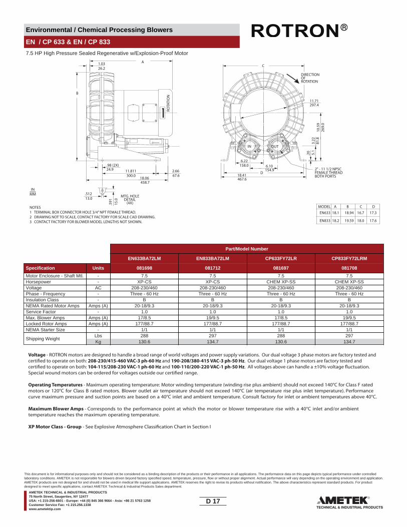
Environmental / Chemical Processing Blowers
EN / CP 633 & EN / CP 833
7.5 HP High Pressure Sealed Regenerative w/Explosion-Proof Motor
MTG. HOLEDETAIL
(4X)
.20 5.1
6.10154.9
6.22158.0.98 (2X)
24.9
.51213.0
.591
15.0
11.811300.0
DIRECTIONOFROTATION
3.22
81.8
1.0326.2
11.71297.4
ROTA
TIO
N
IN OUT
2.6667.6
AC
D
B
18.41467.6
10.5
9 26
9.0
18.06 458.7
EN633 18.1 18.94 16.7 17.3
MODEL A B C D
EN833 18.2 19.59 18.0 17.6
2" - 11 1/2 NPSCFEMALE THREADBOTH PORTS
NOTES1 TERMINAL BOX CONNECTOR HOLE 3/4” NPT FEMALE THREAD.2 DRAWING NOT TO SCALE, CONTACT FACTORY FOR SCALE CAD DRAWING.3 CONTACT FACTORY FOR BLOWER MODEL LENGTHS NOT SHOWN.
INMM
Part/Model Number
EN633BA72LM EN833BA72LM CP633FY72LR CP833FY72LRM
Specification Units 081698 081712 081697 081708
Motor Enclosure - Shaft Mtl. - 7.5 7.5 7.5 7.5Horsepower - XP-CS XP-CS CHEM XP-SS CHEM XP-SSVoltage AC 208-230/460 208-230/460 208-230/460 208-230/460Phase - Frequency - Three - 60 Hz Three - 60 Hz Three - 60 Hz Three - 60 HzInsulation Class - B B B BNEMA Rated Motor Amps Amps (A) 20-18/9.3 20-18/9.3 20-18/9.3 20-18/9.3Service Factor - 1.0 1.0 1.0 1.0Max. Blower Amps Amps (A) 17/8.5 19/9.5 17/8.5 19/9.5Locked Rotor Amps Amps (A) 177/88.7 177/88.7 177/88.7 177/88.7NEMA Starter Size - 1/1 1/1 1/1 1/1
Shipping WeightLbsKg
288130.6
297134.7
288130.6
297134.7
Voltage - ROTRON motors are designed to handle a broad range of world voltages and power supply variations. Our dual voltage 3 phase motors are factory tested and certi�ed to operate on both: 208-230/415-460 VAC-3 ph-60 Hz and 190-208/380-415 VAC-3 ph-50 Hz. Our dual voltage 1 phase motors are factory tested and certi�ed to operate on both: 104-115/208-230 VAC-1 ph-60 Hz and 100-110/200-220 VAC-1 ph-50 Hz. All voltages above can handle a ±10% voltage �uctuation. Special wound motors can be ordered for voltages outside our certi�ed range.
Operating Temperatures - Maximum operating temperature: Motor winding temperature (winding rise plus ambient) should not exceed 140°C for Class F rated motors or 120°C for Class B rated motors. Blower outlet air temperature should not exceed 140°C (air temperature rise plus inlet temperature). Performance curve maximum pressure and suction points are based on a 40°C inlet and ambient temperature. Consult factory for inlet or ambient temperatures above 40°C.
Maximum Blower Amps - Corresponds to the performance point at which the motor or blower temperature rise with a 40°C inlet and/or ambient temperature reaches the maximum operating temperature.
XP Motor Class - Group - See Explosive Atmosphere Classi�cation Chart in Section I
D 17____
This document is for informational purposes only and should not be considered as a binding description of the products or their performance in all applications. The performance data on this page depicts typical performance under controlledlaboratory conditions. AMETEK is not responsible for blowers driven beyond factory specified speed, temperature, pressure, flow or without proper alignment. Actual performance will vary depending on the operating environment and application.AMETEK products are not designed for and should not be used in medical life support applications. AMETEK reserves the right to revise its products without notification. The above characteristics represent standard products. For productdesigned to meet specific applications, contact AMETEK Technical & Industrial Products Sales department.
AMETEK TECHNICAL & INDUSTRIAL PRODUCTS75 North Street, Saugerties, NY 12477USA: +1 215-256-6601 - Europe: +44 (0) 845 366 9664 - Asia: +86 21 5763 1258Customer Service Fax: +1 215.256.1338www.ametektip.com

Environmental / Chemical Processing Blowers
EN / CP 633 & EN / CP 833
7.5 HP High Pressure Sealed Regenerative w/Explosion-Proof Motor
FEATURES• Manufactured in the USA - ISO 9001 and NAFTA compliant
• Maximum pressure: 200/195 IWG•
• Maximum vacuum: 155/155 IWG• Standard motor: 7.5 HP, explosion-proof• Cast aluminum blower housing, impeller , cover & manifold; cast iron
• UL & CSA approved motor with permanently sealed ball bearings for explosive gas atmospheres Class I Group D minimum
• Sealed blower assembly• Quiet operation within OSHA standards
MOTOR OPTIONS• International voltage & frequency (Hz)
BLOWER OPTIONS• Corrosion resistant surface treatments & sealing options• Remote drive (motorless) models
ACCESSORIES• Flowmeters reading in SCFM• Filters & moisture separators• Pressure gauges, vacuum gauges, & relief valves
••• Variable frequency drive package
Blower Performance at Standard Conditions60 Hz
Inch
es o
f Wat
er
mba
r
Mot
or W
indi
ngTe
mp
Rise
°C
Air Flow Rate - SCFM
Air Flow Rate - m3/hour
Blow
er A
irTe
mp
Rise
°C
LegendPressure:Suction:
EN633BA72LMEN833BA72LM
0 20 40 60 80 100 120 140 160 180 200 220
0 34 68 102 136 170 204 238 272 306 340 374
0
50
100
150
200
250
300
0
125
250
375
500
625
750
Temperature curves are based on standard model0
50
100
0
50
100
D 18____
This document is for informational purposes only and should not be considered as a binding description of the products or their performance in all applications. The performance data on this page depicts typical performance under controlledlaboratory conditions. AMETEK is not responsible for blowers driven beyond factory specified speed, temperature, pressure, flow or without proper alignment. Actual performance will vary depending on the operating environment and application.AMETEK products are not designed for and should not be used in medical life support applications. AMETEK reserves the right to revise its products without notification. The above characteristics represent standard products. For productdesigned to meet specific applications, contact AMETEK Technical & Industrial Products Sales department.
AMETEK TECHNICAL & INDUSTRIAL PRODUCTS75 North Street, Saugerties, NY 12477USA: +1 215-256-6601 - Europe: +44 (0) 845 366 9664 - Asia: +86 21 5763 1258Customer Service Fax: +1 215.256.1338www.ametektip.com

Environmental / Chemical Processing Blowers
EN 656 & CP 656
3.0 HP Sealed Regenerative w/Explosion-Proof Motor
4.14
7.46
15.42
6.96
5.38
105.2
391.7
176.
818
9.5
STRAIGHT THDS2.23
BOTH PORTS
136.
7
(4X) MTGHOLES
19.37492.0
15.1
738
2.5
5.51140
0.5915
15.12
182.67.19
2.31
58.7
0.64
17.3 4.92
125
382.512.81325.4
11.420290.1
1
STD. DIRECTIONOF ROTATION
NOTES1 TERMINAL BOX CONNECTOR HOLE 3/4” NPT.2 DRAWING NOT TO SCALE, CONTACT FACTORY FOR SCALE CAD DRAWING.3 CONTACT FACTORY FOR BLOWER MODEL LENGTHS NOT SHOWN.
INMM
Part/Model Number
EN656M5XL EN656M72XL EN656M86XL CP656FU72XLR
Specification Units 080060 080059 080058 080142
Motor Enclosure - Shaft Mtl. - 3 3 3 3Horsepower - Explosion-proof-CS Explosion-proof-CS Explosion-proof-CS Chem XP-SSPhase - Frequency - Single-60 hz Three-60 hz Three-60 hz Three-60 hzVoltage AC 208-230 208-230/460 575 208-230/460Motor Nameplate Amps Amps (A) 15.5-14.5 7.4/3.7 3.0 7.4/3.7Max. Blower Amps Amps (A) 17 10/5 4.1 10/5Inrush Amps Amps (A) 95-86 54/27 21.6 54/27Service Factor - 1 0/0 0 0/0Starter Size - 1.0 1.0 1.0 1.0Thermal Protection - Class B - Pilot Duty Class B - Pilot Duty Class B - Pilot Duty Class B - Pilot DutyXP Motor Class - Group - I-D, II-F&G I-D, II-F&G I-D, II-F&G I-D, II-F&G
Shipping WeightLbsKg
14264.4
11753.1
11753.1
11753.1
Voltage - ROTRON motors are designed to handle a broad range of world voltages and power supply variations. Our dual voltage 3 phase motors are factory tested and certi�ed to operate on both: 208-230/415-460 VAC-3 ph-60 Hz and 190-208/380-415 VAC-3 ph-50 Hz. Our dual voltage 1 phase motors are factory tested and certi�ed to operate on both: 104-115/208-230 VAC-1 ph-60 Hz and 100-110/200-220 VAC-1 ph-50 Hz. All voltages above can handle a ±10% voltage �uctuation. Special wound motors can be ordered for voltages outside our certi�ed range.
Operating Temperatures - Maximum operating temperature: Motor winding temperature (winding rise plus ambient) should not exceed 140°C for Class F rated motors or 120°C for Class B rated motors. Blower outlet air temperature should not exceed 140°C (air temperature rise plus inlet temperature). Performance curve maximum pressure and suction points are based on a 40°C inlet and ambient temperature. Consult factory for inlet or ambient temperatures above 40°C.
Maximum Blower Amps - Corresponds to the performance point at which the motor or blower temperature rise with a 40°C inlet and/or ambient temperature reaches the maximum operating temperature.
XP Motor Class - Group - See Explosive Atmosphere Classi�cation Chart in Section I
D 19____
This document is for informational purposes only and should not be considered as a binding description of the products or their performance in all applications. The performance data on this page depicts typical performance under controlledlaboratory conditions. AMETEK is not responsible for blowers driven beyond factory specified speed, temperature, pressure, flow or without proper alignment. Actual performance will vary depending on the operating environment and application.AMETEK products are not designed for and should not be used in medical life support applications. AMETEK reserves the right to revise its products without notification. The above characteristics represent standard products. For productdesigned to meet specific applications, contact AMETEK Technical & Industrial Products Sales department.
AMETEK TECHNICAL & INDUSTRIAL PRODUCTS75 North Street, Saugerties, NY 12477USA: +1 215-256-6601 - Europe: +44 (0) 845 366 9664 - Asia: +86 21 5763 1258Customer Service Fax: +1 215.256.1338www.ametektip.com
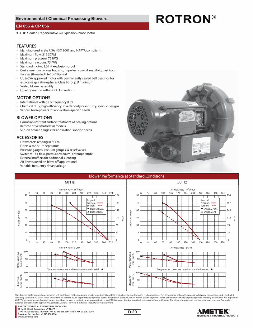
Environmental / Chemical Processing Blowers
EN 656 & CP 656
3.0 HP Sealed Regenerative w/Explosion-Proof Motor
FEATURES• Manufactured in the USA - ISO 9001 and NAFTA compliant
• Maximum pressure: 75 IWG•
• Maximum vacuum: 73 IWG• Standard motor: 3.0 HP, explosion-proof• Cast aluminum blower housing, impeller , cover & manifold; cast iron
• UL & CSA approved motor with permanently sealed ball bearings for explosive gas atmospheres Class I Group D minimum
• Sealed blower assembly• Quiet operation within OSHA standards
MOTOR OPTIONS• International voltage & frequency (Hz)
BLOWER OPTIONS• Corrosion resistant surface treatments & sealing options• Remote drive (motorless) models
ACCESSORIES• Flowmeters reading in SCFM• Filters & moisture separators• Pressure gauges, vacuum gauges, & relief valves
••• Variable frequency drive package
Blower Performance at Standard Conditions60 Hz 50 Hz
Inch
es o
f Wat
er
mba
r
mba
r
Mot
or W
indi
ngTe
mp
Rise
°C
Air Flow Rate - SCFMAir Flow Rate - SCFM
Temperature curves are based on standard model
Air Flow Rate - m3/hourAir Flow Rate - m3/hour
Inch
es o
f Wat
erM
otor
Win
ding
Tem
p Ri
se °C
Blow
er A
irTe
mp
Rise
°C
Blow
er A
irTe
mp
Rise
°C
Temperature curves are based on standard model
LegendPressure:Suction:
EN656M72XLEN656M5XL
LegendPressure:Suction:
EN656M72XLEN656M5XL
0 20 40 60 80 100 120 140 160 180 200 220
0 34 68 102 136 170 204 238 272 306 340 374
0
50
100
0
15
30
45
60
75
90
0
37
75
112
149
187
224
0 20 40 60 80 100 120 140 160 180 200 220
0 34 68 102 136 170 204 238 272 306 340 374
0
15
30
45
60
75
90
0
37
75
112
149
187
224
0
50
100
0
50
100
0
50
100
D 20____
This document is for informational purposes only and should not be considered as a binding description of the products or their performance in all applications. The performance data on this page depicts typical performance under controlledlaboratory conditions. AMETEK is not responsible for blowers driven beyond factory specified speed, temperature, pressure, flow or without proper alignment. Actual performance will vary depending on the operating environment and application.AMETEK products are not designed for and should not be used in medical life support applications. AMETEK reserves the right to revise its products without notification. The above characteristics represent standard products. For productdesigned to meet specific applications, contact AMETEK Technical & Industrial Products Sales department.
AMETEK TECHNICAL & INDUSTRIAL PRODUCTS75 North Street, Saugerties, NY 12477USA: +1 215-256-6601 - Europe: +44 (0) 845 366 9664 - Asia: +86 21 5763 1258Customer Service Fax: +1 215.256.1338www.ametektip.com
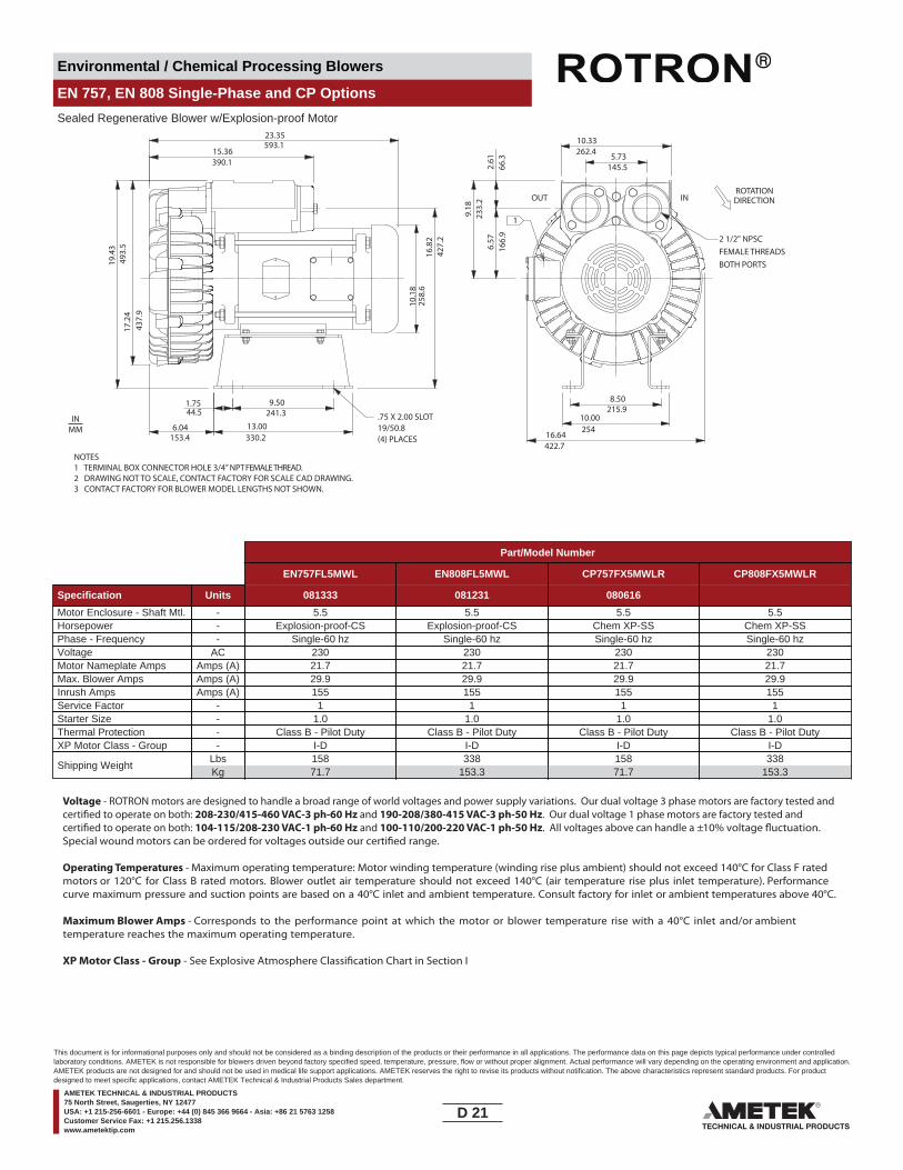
Environmental / Chemical Processing Blowers
EN 757, EN 808 Single-Phase and CP Options
Sealed Regenerative Blower w/Explosion-proof Motor
NOTES1 TERMINAL BOX CONNECTOR HOLE 3/4” NPT FEMALE THREAD.2 DRAWING NOT TO SCALE, CONTACT FACTORY FOR SCALE CAD DRAWING.3 CONTACT FACTORY FOR BLOWER MODEL LENGTHS NOT SHOWN.
15.36390.1
23.3517
.24
437.
9
19.4
349
3.5
593.1
9.50
6.04
241.3
13.00330.2153.4
44.51.75
16.8
242
7.2
258.
610
.18
5.73145.5
10.33262.4
8.50215.9
16.64422.7
10.00254
166.
9
233.
2
66.3
6.57
2.61
9.18
ROTATIONDIRECTIONOUT IN
2 1/2" NPSCFEMALE THREADSBOTH PORTS
1
.75 X 2.00 SLOT19/50.8(4) PLACES
INMM
Part/Model Number
EN757FL5MWL EN808FL5MWL CP757FX5MWLR CP808FX5MWLR
Specification Units 081333 081231 080616
Motor Enclosure - Shaft Mtl. - 5.5 5.5 5.5 5.5Horsepower - Explosion-proof-CS Explosion-proof-CS Chem XP-SS Chem XP-SSPhase - Frequency - Single-60 hz Single-60 hz Single-60 hz Single-60 hzVoltage AC 230 230 230 230Motor Nameplate Amps Amps (A) 21.7 21.7 21.7 21.7Max. Blower Amps Amps (A) 29.9 29.9 29.9 29.9Inrush Amps Amps (A) 155 155 155 155Service Factor - 1 1 1 1Starter Size - 1.0 1.0 1.0 1.0Thermal Protection - Class B - Pilot Duty Class B - Pilot Duty Class B - Pilot Duty Class B - Pilot DutyXP Motor Class - Group - I-D I-D I-D I-D
Shipping WeightLbsKg
15871.7
338153.3
15871.7
338153.3
Voltage - ROTRON motors are designed to handle a broad range of world voltages and power supply variations. Our dual voltage 3 phase motors are factory tested and certi�ed to operate on both: 208-230/415-460 VAC-3 ph-60 Hz and 190-208/380-415 VAC-3 ph-50 Hz. Our dual voltage 1 phase motors are factory tested and certi�ed to operate on both: 104-115/208-230 VAC-1 ph-60 Hz and 100-110/200-220 VAC-1 ph-50 Hz. All voltages above can handle a ±10% voltage �uctuation. Special wound motors can be ordered for voltages outside our certi�ed range.
Operating Temperatures - Maximum operating temperature: Motor winding temperature (winding rise plus ambient) should not exceed 140°C for Class F rated motors or 120°C for Class B rated motors. Blower outlet air temperature should not exceed 140°C (air temperature rise plus inlet temperature). Performance curve maximum pressure and suction points are based on a 40°C inlet and ambient temperature. Consult factory for inlet or ambient temperatures above 40°C.
Maximum Blower Amps - Corresponds to the performance point at which the motor or blower temperature rise with a 40°C inlet and/or ambient temperature reaches the maximum operating temperature.
XP Motor Class - Group - See Explosive Atmosphere Classi�cation Chart in Section I
D 21____
This document is for informational purposes only and should not be considered as a binding description of the products or their performance in all applications. The performance data on this page depicts typical performance under controlledlaboratory conditions. AMETEK is not responsible for blowers driven beyond factory specified speed, temperature, pressure, flow or without proper alignment. Actual performance will vary depending on the operating environment and application.AMETEK products are not designed for and should not be used in medical life support applications. AMETEK reserves the right to revise its products without notification. The above characteristics represent standard products. For productdesigned to meet specific applications, contact AMETEK Technical & Industrial Products Sales department.
AMETEK TECHNICAL & INDUSTRIAL PRODUCTS75 North Street, Saugerties, NY 12477USA: +1 215-256-6601 - Europe: +44 (0) 845 366 9664 - Asia: +86 21 5763 1258Customer Service Fax: +1 215.256.1338www.ametektip.com

Environmental / Chemical Processing Blowers
EN 757, EN 808 Single-Phase and CP Options
Sealed Regenerative Blower w/Explosion-proof Motor
FEATURES• Manufactured in the USA - ISO 9001 and NAFTA compliant
• Maximum pressure: 80 IWG• Maximum vacuum: 75 IWG• Standard motor: 5.0 HP, explosion-proof• Cast aluminum blower housing, impeller , cover & manifold; cast iron
• UL & CSA approved motor with permanently sealed ball bearings for explosive gas atmospheres Class I Group D minimum
• Sealed blower assembly• Quiet operation within OSHA standards
MOTOR OPTIONS• International voltage & frequency (Hz)
BLOWER OPTIONS• Corrosion resistant surface treatments & sealing options• Remote drive (motorless) models
ACCESSORIES• Flowmeters reading in SCFM• Filters & moisture separators• Pressure gauges, vacuum gauges, & relief valves
••• Variable frequency drive package
Blower Performance at Standard ConditionsEN757 60 Hz EN808 60 Hz
Inch
es o
f Wat
er
mba
r
mba
r
Mot
or W
indi
ngTe
mp
Rise
°C
Air Flow Rate - SCFMAir Flow Rate - SCFM
Temperature curves are based on standard model
Air Flow Rate - m3/hourAir Flow Rate - m3/hour
Inch
es o
f Wat
erM
otor
Win
ding
Tem
p Ri
se °C
Blow
er A
irTe
mp
Rise
°C
Blow
er A
irTe
mp
Rise
°C
Temperature curves are based on standard model
LegendPressure:Suction:
EN757FL5WL
LegendPressure:Suction:
EN808FL5MWL
0120
0
0
50
100
0
20
40
60
80
100
120
0
50
100
150
200
250
300
0 40 80 120 160 200 240 260 300 340 380 42040 80 120 160 200 240 260 300 340 380 420
0 68 136 204 272 340 408 442 510 578 546 71468 136 204 272 340 408 442 510 578 546 714
0
20
40
60
80
100
120
0
50
100
150
200
250
300
0
50
100
0
50
100
0
50
100
D 22____
This document is for informational purposes only and should not be considered as a binding description of the products or their performance in all applications. The performance data on this page depicts typical performance under controlledlaboratory conditions. AMETEK is not responsible for blowers driven beyond factory specified speed, temperature, pressure, flow or without proper alignment. Actual performance will vary depending on the operating environment and application.AMETEK products are not designed for and should not be used in medical life support applications. AMETEK reserves the right to revise its products without notification. The above characteristics represent standard products. For productdesigned to meet specific applications, contact AMETEK Technical & Industrial Products Sales department.
AMETEK TECHNICAL & INDUSTRIAL PRODUCTS75 North Street, Saugerties, NY 12477USA: +1 215-256-6601 - Europe: +44 (0) 845 366 9664 - Asia: +86 21 5763 1258Customer Service Fax: +1 215.256.1338www.ametektip.com
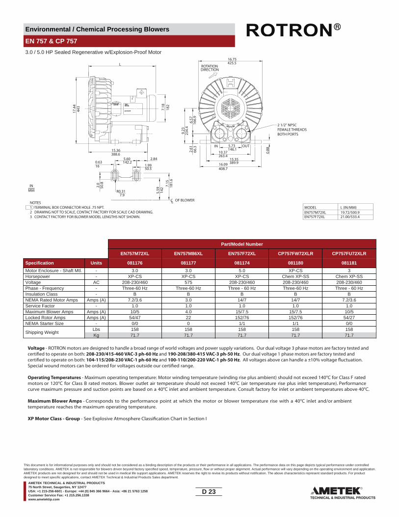
Environmental / Chemical Processing Blowers
EN 757 & CP 757
3.0 / 5.0 HP Sealed Regenerative w/Explosion-Proof Motor
R0.31
CL OF BLOWER7.9
1.990.6316
50.5
6.57
2.61
166.
966
.3
ROTATIONDIRECTION
L
17.4
444
3
182
7.18
MODELEN757M72XLEN757F72XL
L (IN/MM)19.72/500.921.00/533.4
15.36388.6
2.84
2.0
50.8
5.59
142
7.15
181.
6
16.75425.5
9.23
234.
4
16.09408.7
IN OUT
0.88
5.60142.2
5.73146.1
10.37263.4
15.35389.9
2 1/2" NPSCFEMALE THREADSBOTH PORTS
NOTES1 TERMINAL BOX CONNECTOR HOLE .75 NPT.2 DRAWING NOT TO SCALE, CONTACT FACTORY FOR SCALE CAD DRAWING.3 CONTACT FACTORY FOR BLOWER MODEL LENGTHS NOT SHOWN.
IN
MODEL:PART NO.
NAMEPLATEMOTOR
INMM
Part/Model Number
EN757M72XL EN757M86XL EN757F72XL CP757FW72XLR CP757FU72XLR
Specification Units 081176 081177 081174 081180 081181
Motor Enclosure - Shaft Mtl. - 3.0 3.0 5.0 XP-CS 3Horsepower - XP-CS XP-CS XP-CS Chem XP-SS Chem XP-SSVoltage AC 208-230/460 575 208-230/460 208-230/460 208-230/460Phase - Frequency - Three-60 Hz Three-60 Hz Three - 60 Hz Three-60 Hz Three - 60 HzInsulation Class - B B B B BNEMA Rated Motor Amps Amps (A) 7.2/3.6 3.0 14/7 14/7 7.2/3.6Service Factor - 1.0 1.0 1.0 1.0 1.0Maximum Blower Amps Amps (A) 10/5 4.0 15/7.5 15/7.5 10/5Locked Rotor Amps Amps (A) 54/47 22 152/76 152/76 54/27NEMA Starter Size - 0/0 0 1/1 1/1 0/0
Shipping WeightLbsKg
15871.7
15871.7
15871.7
15871.7
15871.7
Voltage - ROTRON motors are designed to handle a broad range of world voltages and power supply variations. Our dual voltage 3 phase motors are factory tested and certi�ed to operate on both: 208-230/415-460 VAC-3 ph-60 Hz and 190-208/380-415 VAC-3 ph-50 Hz. Our dual voltage 1 phase motors are factory tested and certi�ed to operate on both: 104-115/208-230 VAC-1 ph-60 Hz and 100-110/200-220 VAC-1 ph-50 Hz. All voltages above can handle a ±10% voltage �uctuation. Special wound motors can be ordered for voltages outside our certi�ed range.
Operating Temperatures - Maximum operating temperature: Motor winding temperature (winding rise plus ambient) should not exceed 140°C for Class F rated motors or 120°C for Class B rated motors. Blower outlet air temperature should not exceed 140°C (air temperature rise plus inlet temperature). Performance curve maximum pressure and suction points are based on a 40°C inlet and ambient temperature. Consult factory for inlet or ambient temperatures above 40°C.
Maximum Blower Amps - Corresponds to the performance point at which the motor or blower temperature rise with a 40°C inlet and/or ambient temperature reaches the maximum operating temperature.
XP Motor Class - Group - See Explosive Atmosphere Classi�cation Chart in Section I
D 23____
This document is for informational purposes only and should not be considered as a binding description of the products or their performance in all applications. The performance data on this page depicts typical performance under controlledlaboratory conditions. AMETEK is not responsible for blowers driven beyond factory specified speed, temperature, pressure, flow or without proper alignment. Actual performance will vary depending on the operating environment and application.AMETEK products are not designed for and should not be used in medical life support applications. AMETEK reserves the right to revise its products without notification. The above characteristics represent standard products. For productdesigned to meet specific applications, contact AMETEK Technical & Industrial Products Sales department.
AMETEK TECHNICAL & INDUSTRIAL PRODUCTS75 North Street, Saugerties, NY 12477USA: +1 215-256-6601 - Europe: +44 (0) 845 366 9664 - Asia: +86 21 5763 1258Customer Service Fax: +1 215.256.1338www.ametektip.com
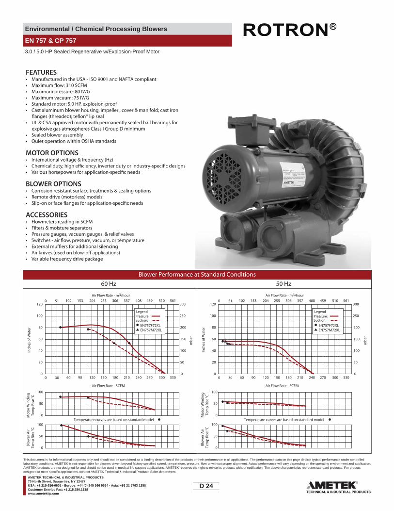
Environmental / Chemical Processing Blowers
EN 757 & CP 757
3.0 / 5.0 HP Sealed Regenerative w/Explosion-Proof Motor
FEATURES• Manufactured in the USA - ISO 9001 and NAFTA compliant
• Maximum pressure: 80 IWG• Maximum vacuum: 75 IWG• Standard motor: 5.0 HP, explosion-proof• Cast aluminum blower housing, impeller , cover & manifold; cast iron
• UL & CSA approved motor with permanently sealed ball bearings for explosive gas atmospheres Class I Group D minimum
• Sealed blower assembly• Quiet operation within OSHA standards
MOTOR OPTIONS• International voltage & frequency (Hz)
BLOWER OPTIONS• Corrosion resistant surface treatments & sealing options• Remote drive (motorless) models
ACCESSORIES• Flowmeters reading in SCFM• Filters & moisture separators• Pressure gauges, vacuum gauges, & relief valves
••• Variable frequency drive package
Blower Performance at Standard Conditions60 Hz 50 Hz
Inch
es o
f Wat
er
mba
r
mba
r
Mot
or W
indi
ngTe
mp
Rise
°C
Air Flow Rate - SCFMAir Flow Rate - SCFM
Temperature curves are based on standard model
Air Flow Rate - m3/hourAir Flow Rate - m3/hour
Inch
es o
f Wat
erM
otor
Win
ding
Tem
p Ri
se °C
Blow
er A
irTe
mp
Rise
°C
Blow
er A
irTe
mp
Rise
°C
Temperature curves are based on standard model
LegendPressure:Suction:
EN757F72XLEN757M72XL
LegendPressure:Suction:
EN757F72XLEN757M72XL
0 30 60 90 120 150 180 210 240 270 300 330
0 51 102 153 204 255 306 357 408 459 510 561
0
50
100
0
20
40
60
80
100
120
0
50
100
150
200
250
300
0 30 60 90 120 150 180 210 240 270 300 330
0 51 102 153 204 255 306 357 408 459 510 561
0
20
40
60
80
100
120
0
50
100
150
200
250
300
0
50
100
0
50
100
0
50
100
D 24____
This document is for informational purposes only and should not be considered as a binding description of the products or their performance in all applications. The performance data on this page depicts typical performance under controlledlaboratory conditions. AMETEK is not responsible for blowers driven beyond factory specified speed, temperature, pressure, flow or without proper alignment. Actual performance will vary depending on the operating environment and application.AMETEK products are not designed for and should not be used in medical life support applications. AMETEK reserves the right to revise its products without notification. The above characteristics represent standard products. For productdesigned to meet specific applications, contact AMETEK Technical & Industrial Products Sales department.
AMETEK TECHNICAL & INDUSTRIAL PRODUCTS75 North Street, Saugerties, NY 12477USA: +1 215-256-6601 - Europe: +44 (0) 845 366 9664 - Asia: +86 21 5763 1258Customer Service Fax: +1 215.256.1338www.ametektip.com
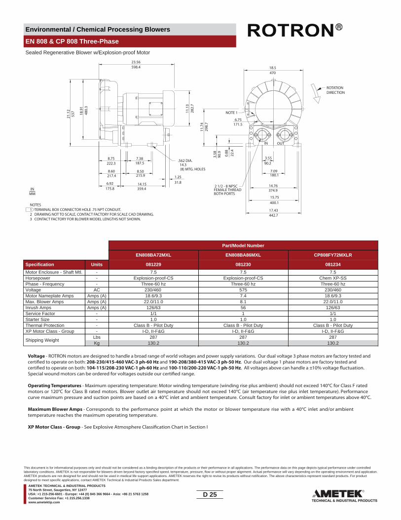
Environmental / Chemical Processing Blowers
EN 808 & CP 808 Three-Phase
Sealed Regenerative Blower w/Explosion-proof Motor
(8) MTG. HOLES
IN OUT
6.92
8.50
7.38 3.55
14.15
7.09
0.88
22.4
11.1
3
18.9
1
90.2
180.1
3.58
90.9
282.
7
480.
3
187.5
215.9
359.4175.8
14.3
23.56598.4
21.1
253
7
8.75222.3
8.60217.4 1.25
31.8
6.75171.5
11.7
429
8.7
18.5470
374.9
15.75400.1
14.76
17.43442.7
.562 DIA.
ROTATIONDIRECTION
FEMALE THREADBOTH PORTS
2 1/2 - 8 NPSC
NOTE 1
NOTES1 TERMINAL BOX CONNECTOR HOLE .75 NPT CONDUIT.2 DRAWING NOT TO SCALE, CONTACT FACTORY FOR SCALE CAD DRAWING.3 CONTACT FACTORY FOR BLOWER MODEL LENGTHS NOT SHOWN.
INMM
Part/Model Number
EN808BA72MXL EN808BA86MXL CP808FY72MXLR
Specification Units 081229 081230 081234
Motor Enclosure - Shaft Mtl. - 7.5 7.5 7.5Horsepower - Explosion-proof-CS Explosion-proof-CS Chem XP-SSPhase - Frequency - Three-60 hz Three-60 hz Three-60 hzVoltage AC 230/460 575 230/460Motor Nameplate Amps Amps (A) 18.6/9.3 7.4 18.6/9.3Max. Blower Amps Amps (A) 22.0/11.0 8.1 22.0/11.0Inrush Amps Amps (A) 126/63 56 126/63Service Factor - 1/1 1 1/1Starter Size - 1.0 1.0 1.0Thermal Protection - Class B - Pilot Duty Class B - Pilot Duty Class B - Pilot DutyXP Motor Class - Group - I-D, II-F&G I-D, II-F&G I-D, II-F&G
Shipping WeightLbsKg
287130.2
287130.2
287130.2
Voltage - ROTRON motors are designed to handle a broad range of world voltages and power supply variations. Our dual voltage 3 phase motors are factory tested and certi�ed to operate on both: 208-230/415-460 VAC-3 ph-60 Hz and 190-208/380-415 VAC-3 ph-50 Hz. Our dual voltage 1 phase motors are factory tested and certi�ed to operate on both: 104-115/208-230 VAC-1 ph-60 Hz and 100-110/200-220 VAC-1 ph-50 Hz. All voltages above can handle a ±10% voltage �uctuation. Special wound motors can be ordered for voltages outside our certi�ed range.
Operating Temperatures - Maximum operating temperature: Motor winding temperature (winding rise plus ambient) should not exceed 140°C for Class F rated motors or 120°C for Class B rated motors. Blower outlet air temperature should not exceed 140°C (air temperature rise plus inlet temperature). Performance curve maximum pressure and suction points are based on a 40°C inlet and ambient temperature. Consult factory for inlet or ambient temperatures above 40°C.
Maximum Blower Amps - Corresponds to the performance point at which the motor or blower temperature rise with a 40°C inlet and/or ambient temperature reaches the maximum operating temperature.
XP Motor Class - Group - See Explosive Atmosphere Classi�cation Chart in Section I
D 25____
This document is for informational purposes only and should not be considered as a binding description of the products or their performance in all applications. The performance data on this page depicts typical performance under controlledlaboratory conditions. AMETEK is not responsible for blowers driven beyond factory specified speed, temperature, pressure, flow or without proper alignment. Actual performance will vary depending on the operating environment and application.AMETEK products are not designed for and should not be used in medical life support applications. AMETEK reserves the right to revise its products without notification. The above characteristics represent standard products. For productdesigned to meet specific applications, contact AMETEK Technical & Industrial Products Sales department.
AMETEK TECHNICAL & INDUSTRIAL PRODUCTS75 North Street, Saugerties, NY 12477USA: +1 215-256-6601 - Europe: +44 (0) 845 366 9664 - Asia: +86 21 5763 1258Customer Service Fax: +1 215.256.1338www.ametektip.com
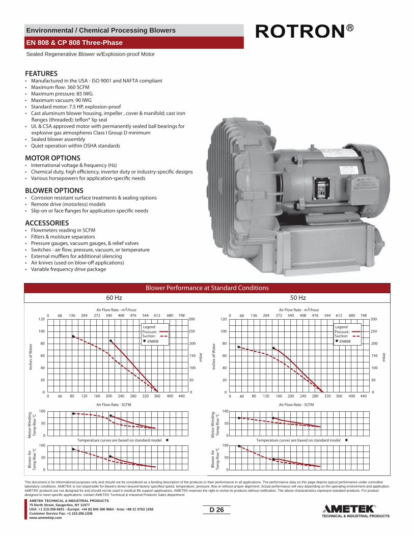
Environmental / Chemical Processing Blowers
EN 808 & CP 808 Three-Phase
Sealed Regenerative Blower w/Explosion-proof Motor
FEATURES• Manufactured in the USA - ISO 9001 and NAFTA compliant
• Maximum pressure: 85 IWG• Maximum vacuum: 90 IWG• Standard motor: 7.5 HP, explosion-proof• Cast aluminum blower housing, impeller , cover & manifold; cast iron
• UL & CSA approved motor with permanently sealed ball bearings for explosive gas atmospheres Class I Group D minimum
• Sealed blower assembly• Quiet operation within OSHA standards
MOTOR OPTIONS• International voltage & frequency (Hz)
BLOWER OPTIONS• Corrosion resistant surface treatments & sealing options• Remote drive (motorless) models
ACCESSORIES• Flowmeters reading in SCFM• Filters & moisture separators• Pressure gauges, vacuum gauges, & relief valves
• External mu�ers for additional silencing• Air knives (used on blow-o� applications)• Variable frequency drive package
Blower Performance at Standard Conditions60 Hz 50 Hz
Inch
es o
f Wat
er
mba
r
mba
r
Mot
or W
indi
ngTe
mp
Rise
°C
Air Flow Rate - SCFMAir Flow Rate - SCFM
Temperature curves are based on standard model
Air Flow Rate - m3/hourAir Flow Rate - m3/hour
Inch
es o
f Wat
erM
otor
Win
ding
Tem
p Ri
se °C
Blow
er A
irTe
mp
Rise
°C
Blow
er A
irTe
mp
Rise
°C
Temperature curves are based on standard model
LegendPressure:Suction:
LegendPressure:Suction:
EN808 EN808
0 40 80 120 160 200 240 280 320 360 400 440
0 68 136 204 272 340 408 476 544 612 680 748
0
50
100
0
20
40
60
80
100
120
0
50
100
150
200
250
300
0 40 80 120 160 200 240 280 320 360 400 440
0 68 136 204 272 340 408 476 544 612 680 748
0
20
40
60
80
100
120
0
50
100
150
200
250
300
0
50
100
0
50
100
0
50
100
D 26____
This document is for informational purposes only and should not be considered as a binding description of the products or their performance in all applications. The performance data on this page depicts typical performance under controlledlaboratory conditions. AMETEK is not responsible for blowers driven beyond factory specified speed, temperature, pressure, flow or without proper alignment. Actual performance will vary depending on the operating environment and application.AMETEK products are not designed for and should not be used in medical life support applications. AMETEK reserves the right to revise its products without notification. The above characteristics represent standard products. For productdesigned to meet specific applications, contact AMETEK Technical & Industrial Products Sales department.
AMETEK TECHNICAL & INDUSTRIAL PRODUCTS75 North Street, Saugerties, NY 12477USA: +1 215-256-6601 - Europe: +44 (0) 845 366 9664 - Asia: +86 21 5763 1258Customer Service Fax: +1 215.256.1338www.ametektip.com

Environmental / Chemical Processing Blowers
EN 858 & CP 858
7.5 / 10.0 HP Sealed Regenerative w/Explosion-Proof Motor
18.9
56.92
13.00
8.17
10.5
0
21.8
1
24.5
6.75
10.96
8.21
7.09
15.48
18.60
481.
3175.8
622.
3
554.
0
207.
526
6.7
171.4
208.5
278.4
472.4
393.2
180.1
330.2
FEMALE THREADBOTH PORTS
1.9148.5
13.53343.7
23.34592.8
9.46240.3
9.50241.3
1.7510.75273.1
MODEL EN858BA72WL
L (IN/MM)23.65/600.7
EN858BD72WL 26.00/660.4
L
ROTATION DIRECTION
2 1/2" NPSC
NOTE 1
OUT IN
44.5
NOTES1 TERMINAL BOX CONNECTOR HOLE 3/4” NPT.2 DRAWING NOT TO SCALE, CONTACT FACTORY FOR SCALE CAD DRAWING.3 CONTACT FACTORY FOR BLOWER MODEL LENGTHS NOT SHOWN.
INMM
Part/Model Number
EN858BD72WL EN858BD86WL EN858BA72WL CP858FZ72WLR
Specification Units 038744 038745 080070 038980
Motor Enclosure - Shaft Mtl. - 10.0 10.0 7.5 10.0Horsepower - Explosion-proof-CS Explosion-proof-CS Explosion-proof-CS Chem XP-SSPhase - Frequency - Three-60 hz Three-60 hz Three-60 hz Three-60 hzVoltage AC 230/460 575 230/460 230/460Motor Nameplate Amps Amps (A) 24/12 9.6 18.6/9.3 24/12Max. Blower Amps Amps (A) 30/15 11.6 26/13 30/15Inrush Amps Amps (A) 234/117 93 126/63 234/117Service Factor - 2/1 1 1/1 2/1Starter Size - 1.0 1.0 1.0 1.0Thermal Protection - Class B - Pilot Duty Class B - Pilot Duty Class B - Pilot Duty Class B - Pilot DutyXP Motor Class - Group - I-D, II-F&G I-D, II-F&G I-D, II-F&G I-D, II-F&G
Shipping WeightLbsKg
338153.3
338153.3
326147.9
338153.3
Voltage - ROTRON motors are designed to handle a broad range of world voltages and power supply variations. Our dual voltage 3 phase motors are factory tested and certi�ed to operate on both: 208-230/415-460 VAC-3 ph-60 Hz and 190-208/380-415 VAC-3 ph-50 Hz. Our dual voltage 1 phase motors are factory tested and certi�ed to operate on both: 104-115/208-230 VAC-1 ph-60 Hz and 100-110/200-220 VAC-1 ph-50 Hz. All voltages above can handle a ±10% voltage �uctuation. Special wound motors can be ordered for voltages outside our certi�ed range.
Operating Temperatures - Maximum operating temperature: Motor winding temperature (winding rise plus ambient) should not exceed 140°C for Class F rated motors or 120°C for Class B rated motors. Blower outlet air temperature should not exceed 140°C (air temperature rise plus inlet temperature). Performance curve maximum pressure and suction points are based on a 40°C inlet and ambient temperature. Consult factory for inlet or ambient temperatures above 40°C.
Maximum Blower Amps - Corresponds to the performance point at which the motor or blower temperature rise with a 40°C inlet and/or ambient temperature reaches the maximum operating temperature.
XP Motor Class - Group - See Explosive Atmosphere Classi�cation Chart in Section I
D 27____
This document is for informational purposes only and should not be considered as a binding description of the products or their performance in all applications. The performance data on this page depicts typical performance under controlledlaboratory conditions. AMETEK is not responsible for blowers driven beyond factory specified speed, temperature, pressure, flow or without proper alignment. Actual performance will vary depending on the operating environment and application.AMETEK products are not designed for and should not be used in medical life support applications. AMETEK reserves the right to revise its products without notification. The above characteristics represent standard products. For productdesigned to meet specific applications, contact AMETEK Technical & Industrial Products Sales department.
AMETEK TECHNICAL & INDUSTRIAL PRODUCTS75 North Street, Saugerties, NY 12477USA: +1 215-256-6601 - Europe: +44 (0) 845 366 9664 - Asia: +86 21 5763 1258Customer Service Fax: +1 215.256.1338www.ametektip.com
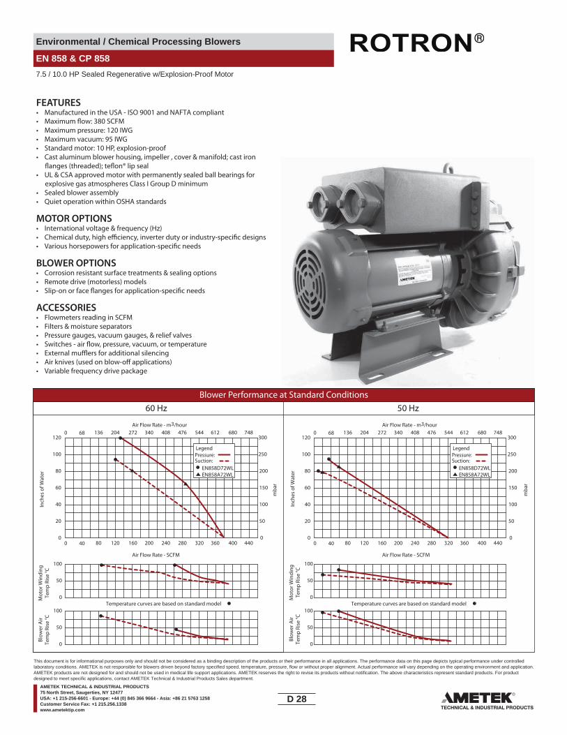
Environmental / Chemical Processing Blowers
EN 858 & CP 858
7.5 / 10.0 HP Sealed Regenerative w/Explosion-Proof Motor
FEATURES• Manufactured in the USA - ISO 9001 and NAFTA compliant
• Maximum pressure: 120 IWG•
• Maximum vacuum: 95 IWG• Standard motor: 10 HP, explosion-proof• Cast aluminum blower housing, impeller , cover & manifold; cast iron
• UL & CSA approved motor with permanently sealed ball bearings for explosive gas atmospheres Class I Group D minimum
• Sealed blower assembly• Quiet operation within OSHA standards
MOTOR OPTIONS• International voltage & frequency (Hz)
BLOWER OPTIONS• Corrosion resistant surface treatments & sealing options• Remote drive (motorless) models
ACCESSORIES• Flowmeters reading in SCFM• Filters & moisture separators• Pressure gauges, vacuum gauges, & relief valves
••• Variable frequency drive package
Blower Performance at Standard Conditions60 Hz 50 Hz
Inch
es o
f Wat
er
mba
r
mba
r
Mot
or W
indi
ngTe
mp
Rise
°C
Air Flow Rate - SCFMAir Flow Rate - SCFM
Temperature curves are based on standard model
Air Flow Rate - m3/hourAir Flow Rate - m3/hour
Inch
es o
f Wat
erM
otor
Win
ding
Tem
p Ri
se °C
Blow
er A
irTe
mp
Rise
°C
Blow
er A
irTe
mp
Rise
°C
Temperature curves are based on standard model
LegendPressure:Suction:
EN858D72WLEN858A72WL
LegendPressure:Suction:
EN858D72WLEN858A72WL
0 40 80 120 160 200 240 280 320 360 400 440
0 68 136 204 272 340 408 476 544 612 680 748
0
50
100
0
20
40
60
80
100
120
0
50
100
150
200
250
300
0 40 80 120 160 200 240 280 320 360 400 440
0 68 136 204 272 340 408 476 544 612 680 748
0
20
40
60
80
100
120
0
50
100
150
200
250
300
0
50
100
0
50
100
0
50
100
D 28____
This document is for informational purposes only and should not be considered as a binding description of the products or their performance in all applications. The performance data on this page depicts typical performance under controlledlaboratory conditions. AMETEK is not responsible for blowers driven beyond factory specified speed, temperature, pressure, flow or without proper alignment. Actual performance will vary depending on the operating environment and application.AMETEK products are not designed for and should not be used in medical life support applications. AMETEK reserves the right to revise its products without notification. The above characteristics represent standard products. For productdesigned to meet specific applications, contact AMETEK Technical & Industrial Products Sales department.
AMETEK TECHNICAL & INDUSTRIAL PRODUCTS75 North Street, Saugerties, NY 12477USA: +1 215-256-6601 - Europe: +44 (0) 845 366 9664 - Asia: +86 21 5763 1258Customer Service Fax: +1 215.256.1338www.ametektip.com
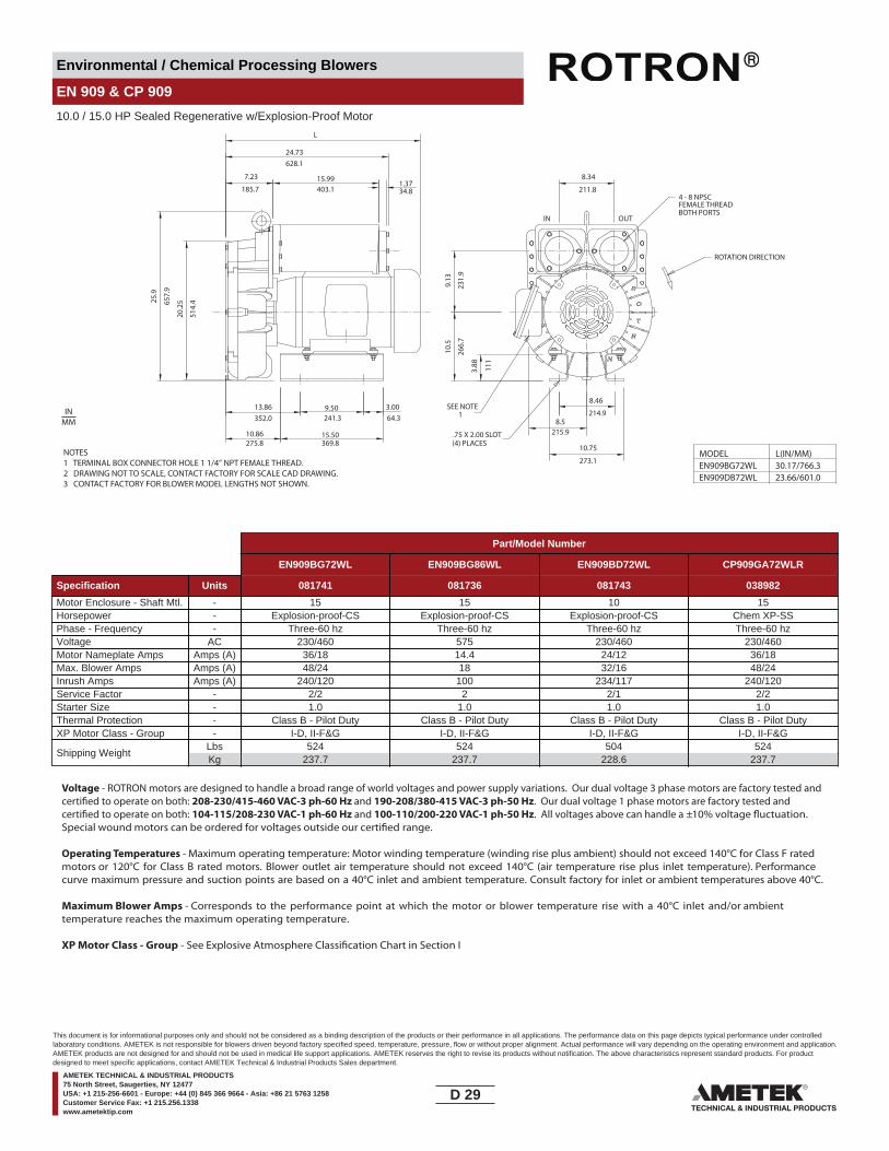
Environmental / Chemical Processing Blowers
EN 909 & CP 909
10.0 / 15.0 HP Sealed Regenerative w/Explosion-Proof Motor
NOTES1 TERMINAL BOX CONNECTOR HOLE 1 1/4” NPT FEMALE THREAD. 2 DRAWING NOT TO SCALE, CONTACT FACTORY FOR SCALE CAD DRAWING.3 CONTACT FACTORY FOR BLOWER MODEL LENGTHS NOT SHOWN.
8.34
211.8
IN OUT
EN909BG72WL - 038629
FEMALE THREADBOTH PORTS
9.50241.3
24.73628.1
7.23
185.715.99403.1
1.3734.8
25.9
657.
9
20.2
5
15.50369.8
3.0064.3
9.13
231.
9
10.5
266.
7
3.88 11
1
8.5215.9
10.75
273.1
8.46
214.913.86352.0
10.86275.8
MODEL EN909BG72WL
L(IN/MM)30.17/766.3
EN909DB72WL 23.66/601.0
L
ROTATION DIRECTION
4 - 8 NPSC
(4) PLACES.75 X 2.00 SLOT
SEE NOTE 1
514.
4
INMM
Part/Model Number
EN909BG72WL EN909BG86WL EN909BD72WL CP909GA72WLR
Specification Units 081741 081736 081743 038982
Motor Enclosure - Shaft Mtl. - 15 15 10 15Horsepower - Explosion-proof-CS Explosion-proof-CS Explosion-proof-CS Chem XP-SSPhase - Frequency - Three-60 hz Three-60 hz Three-60 hz Three-60 hzVoltage AC 230/460 575 230/460 230/460Motor Nameplate Amps Amps (A) 36/18 14.4 24/12 36/18Max. Blower Amps Amps (A) 48/24 18 32/16 48/24Inrush Amps Amps (A) 240/120 100 234/117 240/120Service Factor - 2/2 2 2/1 2/2Starter Size - 1.0 1.0 1.0 1.0Thermal Protection - Class B - Pilot Duty Class B - Pilot Duty Class B - Pilot Duty Class B - Pilot DutyXP Motor Class - Group - I-D, II-F&G I-D, II-F&G I-D, II-F&G I-D, II-F&G
Shipping WeightLbsKg
524237.7
524237.7
504228.6
524237.7
Voltage - ROTRON motors are designed to handle a broad range of world voltages and power supply variations. Our dual voltage 3 phase motors are factory tested and certi�ed to operate on both: 208-230/415-460 VAC-3 ph-60 Hz and 190-208/380-415 VAC-3 ph-50 Hz. Our dual voltage 1 phase motors are factory tested and certi�ed to operate on both: 104-115/208-230 VAC-1 ph-60 Hz and 100-110/200-220 VAC-1 ph-50 Hz. All voltages above can handle a ±10% voltage �uctuation. Special wound motors can be ordered for voltages outside our certi�ed range.
Operating Temperatures - Maximum operating temperature: Motor winding temperature (winding rise plus ambient) should not exceed 140°C for Class F rated motors or 120°C for Class B rated motors. Blower outlet air temperature should not exceed 140°C (air temperature rise plus inlet temperature). Performance curve maximum pressure and suction points are based on a 40°C inlet and ambient temperature. Consult factory for inlet or ambient temperatures above 40°C.
Maximum Blower Amps - Corresponds to the performance point at which the motor or blower temperature rise with a 40°C inlet and/or ambient temperature reaches the maximum operating temperature.
XP Motor Class - Group - See Explosive Atmosphere Classi�cation Chart in Section I
D 29____
This document is for informational purposes only and should not be considered as a binding description of the products or their performance in all applications. The performance data on this page depicts typical performance under controlledlaboratory conditions. AMETEK is not responsible for blowers driven beyond factory specified speed, temperature, pressure, flow or without proper alignment. Actual performance will vary depending on the operating environment and application.AMETEK products are not designed for and should not be used in medical life support applications. AMETEK reserves the right to revise its products without notification. The above characteristics represent standard products. For productdesigned to meet specific applications, contact AMETEK Technical & Industrial Products Sales department.
AMETEK TECHNICAL & INDUSTRIAL PRODUCTS75 North Street, Saugerties, NY 12477USA: +1 215-256-6601 - Europe: +44 (0) 845 366 9664 - Asia: +86 21 5763 1258Customer Service Fax: +1 215.256.1338www.ametektip.com
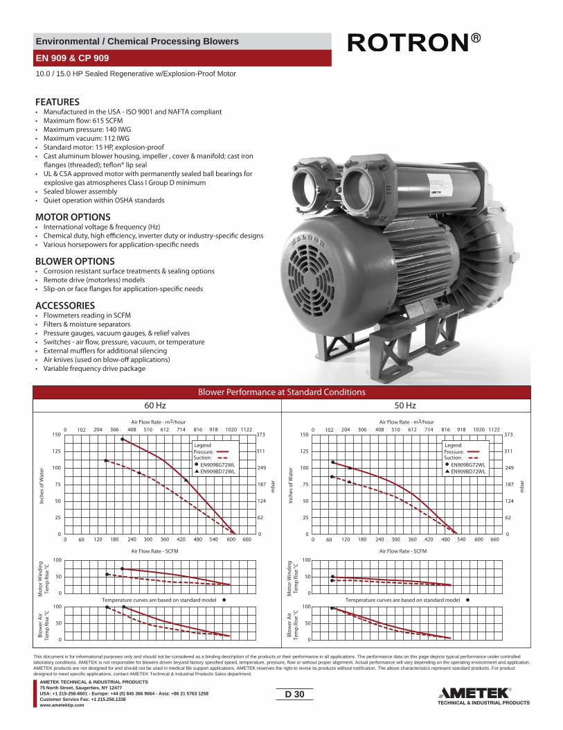
Environmental / Chemical Processing Blowers
EN 909 & CP 909
10.0 / 15.0 HP Sealed Regenerative w/Explosion-Proof Motor
FEATURES• Manufactured in the USA - ISO 9001 and NAFTA compliant
• Maximum pressure: 140 IWG• Maximum vacuum: 112 IWG• Standard motor: 15 HP, explosion-proof• Cast aluminum blower housing, impeller , cover & manifold; cast iron
• UL & CSA approved motor with permanently sealed ball bearings for explosive gas atmospheres Class I Group D minimum
• Sealed blower assembly• Quiet operation within OSHA standards
MOTOR OPTIONS• International voltage & frequency (Hz)
BLOWER OPTIONS• Corrosion resistant surface treatments & sealing options• Remote drive (motorless) models
ACCESSORIES• Flowmeters reading in SCFM• Filters & moisture separators• Pressure gauges, vacuum gauges, & relief valves
••• Variable frequency drive package
Blower Performance at Standard Conditions60 Hz 50 Hz
Inch
es o
f Wat
er
mba
r
mba
r
Mot
or W
indi
ngTe
mp
Rise
°C
Air Flow Rate - SCFMAir Flow Rate - SCFM
Air Flow Rate - m3/hourAir Flow Rate - m3/hour
Inch
es o
f Wat
erM
otor
Win
ding
Tem
p Ri
se °C
Blow
er A
irTe
mp
Rise
°C
Blow
er A
irTe
mp
Rise
°C
LegendPressure:Suction:
EN909BG72WLEN909BD72WL
LegendPressure:Suction:
EN909BG72WLEN909BD72WL
0 60 120 180 240 300 360 420 480 540 600 660
0 102 204 306 408 510 612 714 816 918 1020 1122
0
50
100
0
25
50
75
100
125
150
0
62
124
187
249
311
373
0 60 120 180 240 300 360 420 480 540 600 660
0 102 204 306 408 510 612 714 816 918 1020 1122
0
25
50
75
100
125
150
0
62
124
187
249
311
373
0
50
100
0
50
100
0
50
100Temperature curves are based on standard model Temperature curves are based on standard model
D 30____
This document is for informational purposes only and should not be considered as a binding description of the products or their performance in all applications. The performance data on this page depicts typical performance under controlledlaboratory conditions. AMETEK is not responsible for blowers driven beyond factory specified speed, temperature, pressure, flow or without proper alignment. Actual performance will vary depending on the operating environment and application.AMETEK products are not designed for and should not be used in medical life support applications. AMETEK reserves the right to revise its products without notification. The above characteristics represent standard products. For productdesigned to meet specific applications, contact AMETEK Technical & Industrial Products Sales department.
AMETEK TECHNICAL & INDUSTRIAL PRODUCTS75 North Street, Saugerties, NY 12477USA: +1 215-256-6601 - Europe: +44 (0) 845 366 9664 - Asia: +86 21 5763 1258Customer Service Fax: +1 215.256.1338www.ametektip.com

Environmental / Chemical Processing Blowers
EN 979 & CP 979
20.0 HP Sealed Regenerative w/Explosion-Proof Motor
OUT IN
ROTATIONDIRECTION
4" NPSCPORTS
1.50 DIA. (38.1)LIFTING LUG
1.
9.00228.6
31.25793.8
11.38289.1
5.69114.5
9.75247.7
19.25489.0
8.75222.3 11.11
282.2
13.06331.7
10.37263.4
25.
3264
3.1
21.7
755
3.0
12.2
531
1.2
2.4
762
.7
2.0050.8
1.9148.5
0.7
619
.3NOTES1 TERMINAL BOX CONNECTOR HOLE 1 1/4” NPT FEMALE THREAD.2 DRAWING NOT TO SCALE, CONTACT FACTORY FOR SCALE CAD DRAWING.3 CONTACT FACTORY FOR BLOWER MODEL LENGTHS NOT SHOWN.
INMM
Part/Model Number
EN979BK72WL EN979BK86WL CP979GB72WLR
Specification Units 080724 081778
Motor Enclosure - Shaft Mtl. - 20 20 20Horsepower - Explosion-proof-CS Explosion-proof-CS Chem XP-SSPhase - Frequency - Three-60 hz Three-60 hz Three-60 hzVoltage AC 230/460 575 230/460Motor Nameplate Amps Amps (A) 46/23 18.4 46/23Max. Blower Amps Amps (A) 60/30 24 60/30Inrush Amps Amps (A) 334/167 118 334/167Service Factor - 3/2 2 3/2Starter Size - 1.0 1.0 1.0Thermal Protection - Class B - Pilot Duty Class B - Pilot Duty Class B - Pilot DutyXP Motor Class - Group - I-D, II-F&G I-D, II-F&G I-D, II-F&G
Shipping WeightLbsKg
533241.8
533241.8
533241.8
Voltage - ROTRON motors are designed to handle a broad range of world voltages and power supply variations. Our dual voltage 3 phase motors are factory tested and certi�ed to operate on both: 208-230/415-460 VAC-3 ph-60 Hz and 190-208/380-415 VAC-3 ph-50 Hz. Our dual voltage 1 phase motors are factory tested and certi�ed to operate on both: 104-115/208-230 VAC-1 ph-60 Hz and 100-110/200-220 VAC-1 ph-50 Hz. All voltages above can handle a ±10% voltage �uctuation. Special wound motors can be ordered for voltages outside our certi�ed range.
Operating Temperatures - Maximum operating temperature: Motor winding temperature (winding rise plus ambient) should not exceed 140°C for Class F rated motors or 120°C for Class B rated motors. Blower outlet air temperature should not exceed 140°C (air temperature rise plus inlet temperature). Performance curve maximum pressure and suction points are based on a 40°C inlet and ambient temperature. Consult factory for inlet or ambient temperatures above 40°C.
Maximum Blower Amps - Corresponds to the performance point at which the motor or blower temperature rise with a 40°C inlet and/or ambient temperature reaches the maximum operating temperature.
XP Motor Class - Group - See Explosive Atmosphere Classi�cation Chart in Section I
D 31____
This document is for informational purposes only and should not be considered as a binding description of the products or their performance in all applications. The performance data on this page depicts typical performance under controlledlaboratory conditions. AMETEK is not responsible for blowers driven beyond factory specified speed, temperature, pressure, flow or without proper alignment. Actual performance will vary depending on the operating environment and application.AMETEK products are not designed for and should not be used in medical life support applications. AMETEK reserves the right to revise its products without notification. The above characteristics represent standard products. For productdesigned to meet specific applications, contact AMETEK Technical & Industrial Products Sales department.
AMETEK TECHNICAL & INDUSTRIAL PRODUCTS75 North Street, Saugerties, NY 12477USA: +1 215-256-6601 - Europe: +44 (0) 845 366 9664 - Asia: +86 21 5763 1258Customer Service Fax: +1 215.256.1338www.ametektip.com

Environmental / Chemical Processing Blowers
EN 979 & CP 979
20.0 HP Sealed Regenerative w/Explosion-Proof Motor
FEATURES• Manufactured in the USA - ISO 9001 and NAFTA compliant
• Maximum pressure: 90 IWG• Maximum vacuum: 90 IWG• Standard motor: 20 HP, explosion-proof• Cast aluminum blower housing, impeller , cover & manifold; cast iron
• UL & CSA approved motor with permanently sealed ball bearings for explosive gas atmospheres Class I Group D minimum
• Sealed blower assembly• Quiet operation within OSHA standards
MOTOR OPTIONS• International voltage & frequency (Hz)
BLOWER OPTIONS• Corrosion resistant surface treatments & sealing options• Remote drive (motorless) models
ACCESSORIES• Flowmeters reading in SCFM• Filters & moisture separators• Pressure gauges, vacuum gauges, & relief valves
••• Variable frequency drive package
Blower Performance at Standard Conditions60 Hz 50 Hz
Inch
es o
f Wat
er
mba
r
mba
r
Mot
or W
indi
ngTe
mp
Rise
°C
Air Flow Rate - SCFMAir Flow Rate - SCFM
Air Flow Rate - m3/hourAir Flow Rate - m3/hour
Inch
es o
f Wat
erM
otor
Win
ding
Tem
p Ri
se °C
Blow
er A
irTe
mp
Rise
°C
Blow
er A
irTe
mp
Rise
°C
Temperature curves are based on standard model Temperature curves are based on standard model
LegendPressure:Suction:
EN979
LegendPressure:Suction:
EN979
0 100 200 300 400 500 600 700 800 900 1000 1100
0 170 340 510 680 850 1020 1190 1360 1530 1700 1870
0
50
100
0
20
40
60
80
100
120
0
50
100
150
200
250
300
0 100 200 300 400 500 600 700 800 900 1000 1100
0 170 340 510 680 850 1020 1190 1360 1530 1700 1870
0
20
40
60
80
100
120
0
50
100
150
200
250
300
0
50
100
0
50
100
0
50
100
D 32____
This document is for informational purposes only and should not be considered as a binding description of the products or their performance in all applications. The performance data on this page depicts typical performance under controlledlaboratory conditions. AMETEK is not responsible for blowers driven beyond factory specified speed, temperature, pressure, flow or without proper alignment. Actual performance will vary depending on the operating environment and application.AMETEK products are not designed for and should not be used in medical life support applications. AMETEK reserves the right to revise its products without notification. The above characteristics represent standard products. For productdesigned to meet specific applications, contact AMETEK Technical & Industrial Products Sales department.
AMETEK TECHNICAL & INDUSTRIAL PRODUCTS75 North Street, Saugerties, NY 12477USA: +1 215-256-6601 - Europe: +44 (0) 845 366 9664 - Asia: +86 21 5763 1258Customer Service Fax: +1 215.256.1338www.ametektip.com
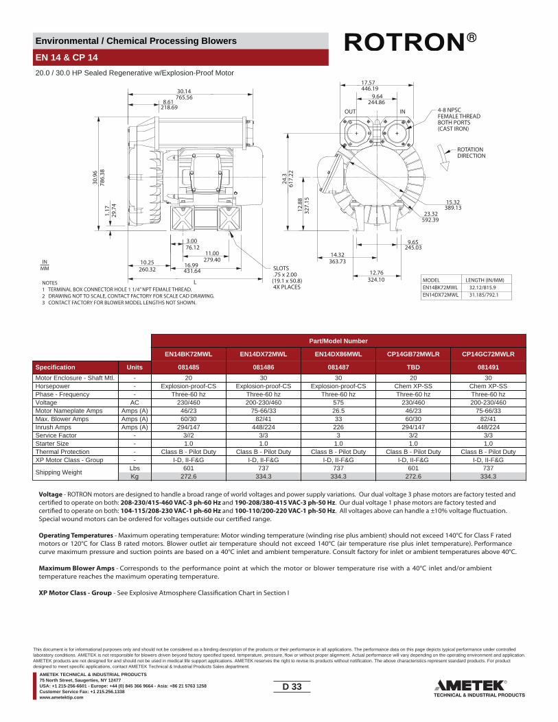
Environmental / Chemical Processing Blowers
EN 14 & CP 14
20.0 / 30.0 HP Sealed Regenerative w/Explosion-Proof Motor
NOTES1 TERMINAL BOX CONNECTOR HOLE 1 1/4” NPT FEMALE THREAD.2 DRAWING NOT TO SCALE, CONTACT FACTORY FOR SCALE CAD DRAWING.3 CONTACT FACTORY FOR BLOWER MODEL LENGTHS NOT SHOWN.
1.17
29.7
4
30.9
678
6.38
11.00279.40
16.99431.64260.32
10.25
3.0076.12
23.32592.39
9.64244.86
446.19
OUT IN
17.57
9.65245.03
12.76324.10
327.
15
24.3
617.
22
8.61218.69
30.14765.56
L
14.32363.73
12.8
8 15.32389.13
ROTATIONDIRECTION
SLOTS .75 x 2.00(19.1 x 50.8) 4X PLACES
4-8 NPSCFEMALE THREADBOTH PORTS(CAST IRON)
INMM
MODEL LENGTH (IN/MM)EN14BK72MWL 32.12/815.9EN14DX72MWL 31.185/792.1
Part/Model Number
EN14BK72MWL EN14DX72MWL EN14DX86MWL CP14GB72MWLR CP14GC72MWLR
Specification Units 081485 081486 081487 TBD 081491
Motor Enclosure - Shaft Mtl. - 20 30 30 20 30Horsepower - Explosion-proof-CS Explosion-proof-CS Explosion-proof-CS Chem XP-SS Chem XP-SSPhase - Frequency - Three-60 hz Three-60 hz Three-60 hz Three-60 hz Three-60 hzVoltage AC 230/460 200-230/460 575 230/460 200-230/460Motor Nameplate Amps Amps (A) 46/23 75-66/33 26.5 46/23 75-66/33Max. Blower Amps Amps (A) 60/30 82/41 33 60/30 82/41Inrush Amps Amps (A) 294/147 448/224 226 294/147 448/224Service Factor - 3//2 3/3 3 3/2 3/3Starter Size - 1.0 1.0 1.0 1.0 1.0Thermal Protection - Class B - Pilot Duty Class B - Pilot Duty Class B - Pilot Duty Class B - Pilot Duty Class B - Pilot DutyXP Motor Class - Group - I-D, II-F&G I-D, II-F&G I-D, II-F&G I-D, II-F&G I-D, II-F&G
Shipping WeightLbsKg
601272.6
737334.3
737334.3
601272.6
737334.3
Voltage - ROTRON motors are designed to handle a broad range of world voltages and power supply variations. Our dual voltage 3 phase motors are factory tested and certi�ed to operate on both: 208-230/415-460 VAC-3 ph-60 Hz and 190-208/380-415 VAC-3 ph-50 Hz. Our dual voltage 1 phase motors are factory tested and certi�ed to operate on both: 104-115/208-230 VAC-1 ph-60 Hz and 100-110/200-220 VAC-1 ph-50 Hz. All voltages above can handle a ±10% voltage �uctuation. Special wound motors can be ordered for voltages outside our certi�ed range.
Operating Temperatures - Maximum operating temperature: Motor winding temperature (winding rise plus ambient) should not exceed 140°C for Class F rated motors or 120°C for Class B rated motors. Blower outlet air temperature should not exceed 140°C (air temperature rise plus inlet temperature). Performance curve maximum pressure and suction points are based on a 40°C inlet and ambient temperature. Consult factory for inlet or ambient temperatures above 40°C.
Maximum Blower Amps - Corresponds to the performance point at which the motor or blower temperature rise with a 40°C inlet and/or ambient temperature reaches the maximum operating temperature.
XP Motor Class - Group - See Explosive Atmosphere Classi�cation Chart in Section I
D 33____
This document is for informational purposes only and should not be considered as a binding description of the products or their performance in all applications. The performance data on this page depicts typical performance under controlledlaboratory conditions. AMETEK is not responsible for blowers driven beyond factory specified speed, temperature, pressure, flow or without proper alignment. Actual performance will vary depending on the operating environment and application.AMETEK products are not designed for and should not be used in medical life support applications. AMETEK reserves the right to revise its products without notification. The above characteristics represent standard products. For productdesigned to meet specific applications, contact AMETEK Technical & Industrial Products Sales department.
AMETEK TECHNICAL & INDUSTRIAL PRODUCTS75 North Street, Saugerties, NY 12477USA: +1 215-256-6601 - Europe: +44 (0) 845 366 9664 - Asia: +86 21 5763 1258Customer Service Fax: +1 215.256.1338www.ametektip.com

Environmental / Chemical Processing Blowers
EN 14 & CP 14
20.0 / 30.0 HP Sealed Regenerative w/Explosion-Proof Motor
FEATURES• Manufactured in the USA - ISO 9001 and NAFTA compliant
• Maximum pressure: 144 IWG•
• Maximum vacuum: 115 IWG• Standard motor: 30 HP, explosion-proof• Cast aluminum blower housing, impeller , cover & manifold; cast iron
• UL & CSA approved motor with permanently sealed ball bearings for explosive gas atmospheres Class I Group D minimum
• Sealed blower assembly• Quiet operation within OSHA standards
MOTOR OPTIONS• International voltage & frequency (Hz)
BLOWER OPTIONS• Corrosion resistant surface treatments & sealing options• Remote drive (motorless) models
ACCESSORIES• Flowmeters reading in SCFM• Filters & moisture separators• Pressure gauges, vacuum gauges, & relief valves
••• Variable frequency drive package
Blower Performance at Standard Conditions60 Hz 50 Hz
Inch
es o
f Wat
er
mba
r
Mot
or W
indi
ngTe
mp
Rise
°C
Air Flow Rate - SCFM
Air Flow Rate - m3/hour
Blow
er A
irTe
mp
Rise
°C
Inch
es o
f Wat
er
mba
r
Mot
or W
indi
ngTe
mp
Rise
°C
Air Flow Rate - SCFM
Air Flow Rate - m3/hour
Blow
er A
irTe
mp
Rise
°C
LegendPressure:Suction:
EN14BX72MWLEN14BK72MWL
LegendPressure:Suction:
EN14BX72MWLEN14BK72MWL
0 100 200 300 400 500 600 700 800 900 1000 1100
170 340 510 680 850 1020 1190 1360 1530 1700 18700
0
30
60
90
120
150
180
0
75
150
225
300
375
450
0 100 200 300 400 500 600 700 800 900 1000 1100
170 340 510 680 850 1020 1190 1360 1530 1700 18700
0
30
60
90
120
150
180
0
75
150
225
300
375
450
Temperature curves are based on standard model0
50
100
0
50
100Temperature curves are based on standard model
0
50
100
0
50
100
D 34____
This document is for informational purposes only and should not be considered as a binding description of the products or their performance in all applications. The performance data on this page depicts typical performance under controlledlaboratory conditions. AMETEK is not responsible for blowers driven beyond factory specified speed, temperature, pressure, flow or without proper alignment. Actual performance will vary depending on the operating environment and application.AMETEK products are not designed for and should not be used in medical life support applications. AMETEK reserves the right to revise its products without notification. The above characteristics represent standard products. For productdesigned to meet specific applications, contact AMETEK Technical & Industrial Products Sales department.
AMETEK TECHNICAL & INDUSTRIAL PRODUCTS75 North Street, Saugerties, NY 12477USA: +1 215-256-6601 - Europe: +44 (0) 845 366 9664 - Asia: +86 21 5763 1258Customer Service Fax: +1 215.256.1338www.ametektip.com
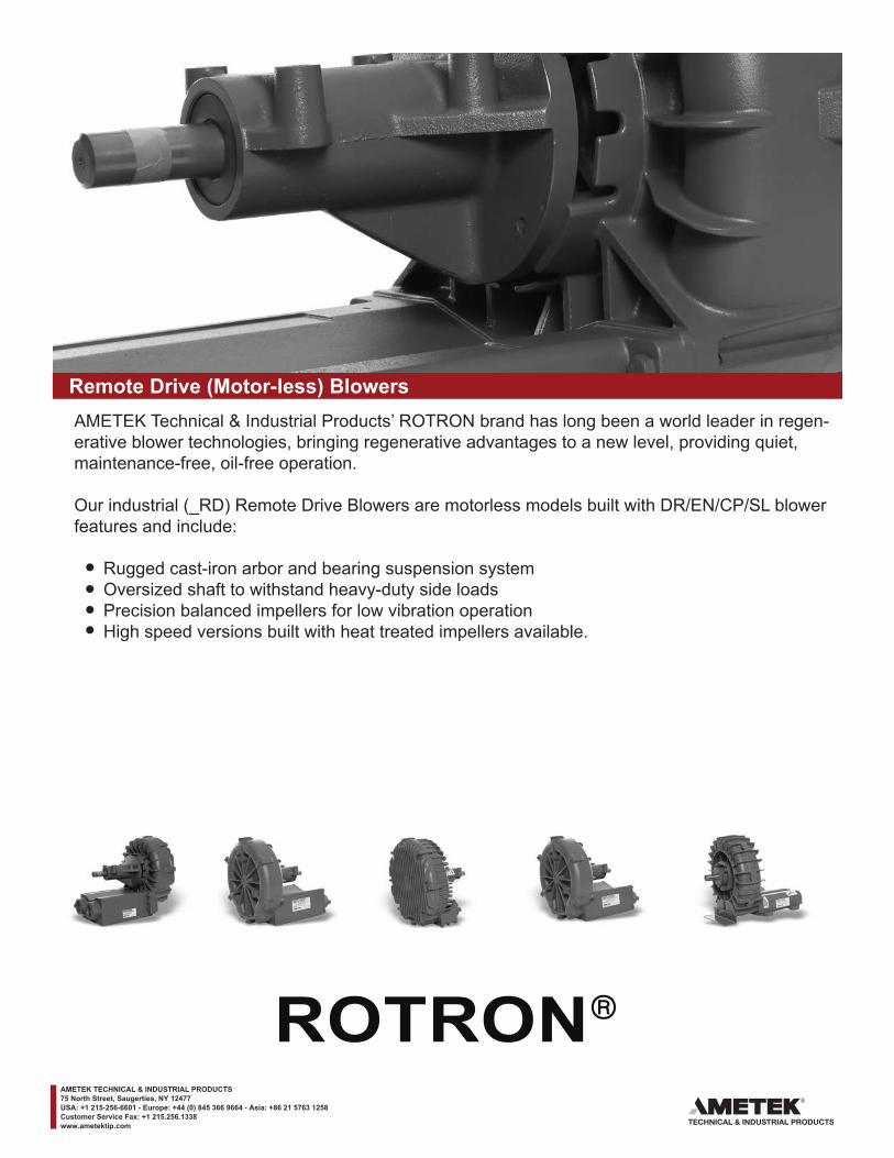
____
Remote Drive (Motor-less) BlowersAMETEK Technical & Industrial Products’ ROTRON brand has long been a world leader in regen-erative blower technologies, bringing regenerative advantages to a new level, providing quiet, maintenance-free, oil-free operation.
Our industrial (_RD) Remote Drive Blowers are motorless models built with DR/EN/CP/SL blower features and include:
Rugged cast-iron arbor and bearing suspension system Oversized shaft to withstand heavy-duty side loads Precision balanced impellers for low vibration operation High speed versions built with heat treated impellers available.
AMETEK TECHNICAL & INDUSTRIAL PRODUCTS75 North Street, Saugerties, NY 12477USA: +1 215-256-6601 - Europe: +44 (0) 845 366 9664 - Asia: +86 21 5763 1258Customer Service Fax: +1 215.256.1338www.ametektip.com
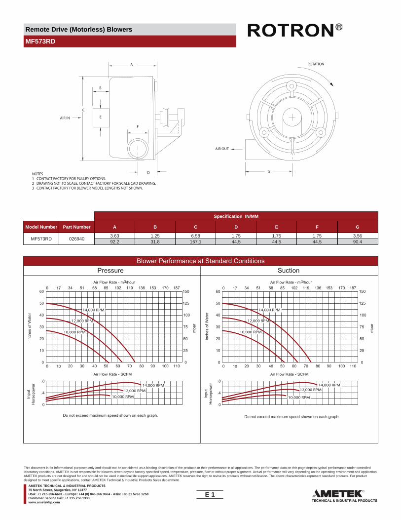
Remote Drive (Motorless) Blowers
MF573RD
NOTES1 CONTACT FACTORY FOR PULLEY OPTIONS.2 DRAWING NOT TO SCALE, CONTACT FACTORY FOR SCALE CAD DRAWING.3 CONTACT FACTORY FOR BLOWER MODEL LENGTHS NOT SHOWN.
AIR OUT
ROTATION
AIR IN
C
E
B
A
F
D G
Specification IN/MM
Model Number Part Number A B C D E F G
MF573RD 0269403.6392.2
1.2531.8
6.58167.1
1.7544.5
1.7544.5
1.7544.5
3.5690.4
Blower Performance at Standard ConditionsPressure Suction
Inch
es o
f Wat
er
mba
r
mba
r
Inpu
tH
orse
pow
er
Air Flow Rate - SCFMAir Flow Rate - SCFM
Air Flow Rate - m3/hourAir Flow Rate - m3/hour
Inch
es o
f Wat
erIn
put
Hor
sepo
wer
10,000 RPM
12,000 RPM
14,000 RPM
10,000 RPM12,000 RPM
14,000 RPM
10,000 RPM
12,000 RPM14,000 RPM
14,000 RPM
10,000 RPM
12,000 RPM
0 10 20 30 40 50 60 70 80 90 100 110
0 17 34 51 68 85 102 119 136 153 170 187
0
10
20
30
40
50
60
0
25
50
75
100
125
150
0 10 20 30 40 50 60 70 80 90 100 110
0 17 34 51 68 85 102 119 136 153 170 187
0
10
20
30
40
50
60
0
25
50
75
100
125
150
Do not exceed maximum speed shown on each graph.
0
.4
.8
Do not exceed maximum speed shown on each graph.
0
.4
.8
E 1____
This document is for informational purposes only and should not be considered as a binding description of the products or their performance in all applications. The performance data on this page depicts typical performance under controlledlaboratory conditions. AMETEK is not responsible for blowers driven beyond factory specified speed, temperature, pressure, flow or without proper alignment. Actual performance will vary depending on the operating environment and application.AMETEK products are not designed for and should not be used in medical life support applications. AMETEK reserves the right to revise its products without notification. The above characteristics represent standard products. For productdesigned to meet specific applications, contact AMETEK Technical & Industrial Products Sales department.
AMETEK TECHNICAL & INDUSTRIAL PRODUCTS75 North Street, Saugerties, NY 12477USA: +1 215-256-6601 - Europe: +44 (0) 845 366 9664 - Asia: +86 21 5763 1258Customer Service Fax: +1 215.256.1338www.ametektip.com
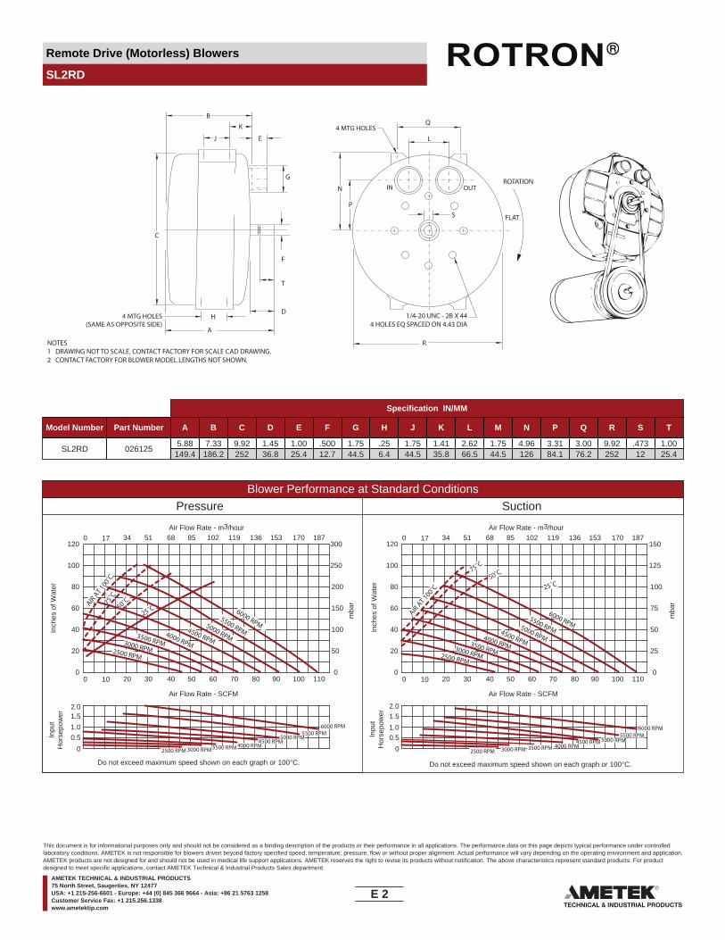
Remote Drive (Motorless) Blowers
SL2RD
NOTES1 DRAWING NOT TO SCALE, CONTACT FACTORY FOR SCALE CAD DRAWING.2 CONTACT FACTORY FOR BLOWER MODEL LENGTHS NOT SHOWN.
ROTATION
FLAT
1/4-20 UNC - 2B X 444 HOLES EQ SPACED ON 4.43 DIA
N
B
J
K
E
G
F
T
D
C
H
A
PS
Q
L
4 MTG HOLES
4 MTG HOLES(SAME AS OPPOSITE SIDE)
IN OUT
R
Specification IN/MM
Model Number Part Number A B C D E F G H J K L M N P Q R S T
SL2RD 0261255.88
149.47.33
186.29.92252
1.4536.8
1.0025.4
.50012.7
1.7544.5
.256.4
1.7544.5
1.4135.8
2.6266.5
1.7544.5
4.96126
3.3184.1
3.0076.2
9.92252
.47312
1.0025.4
Blower Performance at Standard ConditionsPressure Suction
Inch
es o
f Wat
er
mba
r
mba
r
Inpu
tH
orse
pow
er
Air Flow Rate - SCFMAir Flow Rate - SCFM
Air Flow Rate - m3/hourAir Flow Rate - m3/hour
Inch
es o
f Wat
erIn
put
Hor
sepo
wer
AIR AT 1
00˚C
25˚C50˚C75˚C
6000 RPM5500 RPM
5000 RPM4000 RPM3500 RPM3000 RPM2500 RPM
4500 RPM
6000 RPM5500 RPM
5000 RPM4500 RPM
4000 RPM3500 RPM3000 RPM2500 RPM
6000 RPM5500 RPM5000 RPM4000 RPM3500 RPM3000 RPM2500 RPM
25˚C50˚C75˚C
AIR AT 100˚C
6000 RPM5500 RPM
5000 RPM4500 RPM4000 RPM3500 RPM3000 RPM2500 RPM
4500 RPM
0 10 20 30 40 50 60 70 80 90 100 110
0 17 34 51 68 85 102 119 136 153 170 187
0
20
40
60
80
100
120
0
50
100
150
200
250
300
0 10 20 30 40 50 60 70 80 90 100 110
0 17 34 51 68 85 102 119 136 153 170 187
0
20
40
60
80
100
120
0
25
50
75
100
125
150
Do not exceed maximum speed shown on each graph or 100°C.
0
1.0
2.0
Do not exceed maximum speed shown on each graph or 100°C.
0
1.0
2.01.5
0.5
0.5
1.5
E 2____
This document is for informational purposes only and should not be considered as a binding description of the products or their performance in all applications. The performance data on this page depicts typical performance under controlledlaboratory conditions. AMETEK is not responsible for blowers driven beyond factory specified speed, temperature, pressure, flow or without proper alignment. Actual performance will vary depending on the operating environment and application.AMETEK products are not designed for and should not be used in medical life support applications. AMETEK reserves the right to revise its products without notification. The above characteristics represent standard products. For productdesigned to meet specific applications, contact AMETEK Technical & Industrial Products Sales department.
AMETEK TECHNICAL & INDUSTRIAL PRODUCTS75 North Street, Saugerties, NY 12477USA: +1 215-256-6601 - Europe: +44 (0) 845 366 9664 - Asia: +86 21 5763 1258Customer Service Fax: +1 215.256.1338www.ametektip.com
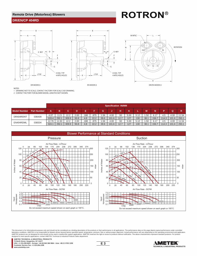
Remote Drive (Motorless) Blowers
DR/EN/CP 404RD
NOTES1 DRAWING NOT TO SCALE, CONTACT FACTORY FOR SCALE CAD DRAWING.2 CONTACT FACTORY FOR BLOWER MODEL LENGTHS NOT SHOWN.
J TYP
DR MODELS EN MODELS DR/EN MODELS
K
C
A
B
F
G
P
NOUT IN
Q
R
L
ROTATION
M NPSC
DE KEY
H DIA. TYP4 MTG HOLES J TYPK
C
A
B
F
G
D E KEY
H DIA. TYP4 MTG HOLES
Specification IN/MM
Model Number Part Number A B C D E F G J H K L M N P Q R
DR404RDNT 0364394.07
103.411.5
292.112.2
309.92.0050.8
.1884.8
.87522.2
1.5639.6
4.00101.6
.5012.7
5.00127
5.12130
1.5038.1
6.17156.7
4.5114.3
4.00101.6
11.54293.1
EN404RDML 03833412.76324.1
11.50292.1
12.2309.9
2.0050.8
.1884.8
.87522.2
1.5639.6
4.00101.6
.5012.7
5.00127
5.12130
1.5038.1
6.17156.7
4.5114.3
4.00101.6
11.54293.1
Blower Performance at Standard ConditionsPressure Suction
Inch
es o
f Wat
er
mba
r
mba
r
Inpu
tH
orse
pow
er
Air Flow Rate - SCFMAir Flow Rate - SCFM
Air Flow Rate - m3/hourAir Flow Rate - m3/hour
Inch
es o
f Wat
erIn
put
Hor
sepo
wer
75˚CAIR AT 100˚C
50˚C
25˚C
2500 RPM
1750 RPM
5500 RPM
6500 RPM
4500 RPM
3500 RPM
25˚C 6500 RPM
5500 RPM4500 RPM
3500 RPM
2500 RPM1750 RPM
AIR AT 100˚C
75˚C
50˚C
55004500350025001750
65006500
55004500350025001750
0 20 40 60 80 100 120 140 160 180 200 220
0 34 68 102 136 170 204 238 272 306 340 374
0
20
40
60
80
100
120
0
50
100
150
200
250
300
0 20 40 60 80 100 120 140 160 180 200 220
0 34 68 102 136 170 204 238 272 306 340 374
0
20
40
60
80
100
120
0
50
100
150
200
250
300
Do not exceed maximum speed shown on each graph or 100°C.
0.1
0.8
7.0
Do not exceed maximum speed shown on each graph or 100°C.
2.0
0.4
4.0
0.1
0.8
7.0
2.0
0.4
4.0
E 3____
This document is for informational purposes only and should not be considered as a binding description of the products or their performance in all applications. The performance data on this page depicts typical performance under controlledlaboratory conditions. AMETEK is not responsible for blowers driven beyond factory specified speed, temperature, pressure, flow or without proper alignment. Actual performance will vary depending on the operating environment and application.AMETEK products are not designed for and should not be used in medical life support applications. AMETEK reserves the right to revise its products without notification. The above characteristics represent standard products. For productdesigned to meet specific applications, contact AMETEK Technical & Industrial Products Sales department.
AMETEK TECHNICAL & INDUSTRIAL PRODUCTS75 North Street, Saugerties, NY 12477USA: +1 215-256-6601 - Europe: +44 (0) 845 366 9664 - Asia: +86 21 5763 1258Customer Service Fax: +1 215.256.1338www.ametektip.com

Remote Drive (Motorless) Blowers
DR/EN/CP 505RD
NOTES1 DRAWING NOT TO SCALE, CONTACT FACTORY FOR SCALE CAD DRAWING.2 CONTACT FACTORY FOR BLOWER MODEL LENGTHS NOT SHOWN.
J TYP
DR MODELS EN MODELS DR/EN MODELS
K
C
A
B
F
G
P
NOUT IN
Q
R
L
ROTATION
M NPSC
DE KEY
H DIA. TYP4 MTG HOLES J TYPK
C
A
B
F
G
D E KEY
H DIA. TYP4 MTG HOLES
Specification IN/MM
Model Number Part Number A B C D E F G J H K L M N P Q R
DR505RDNT 0364375.68
144.311.82300.2
14.45367
2.0050.8
.1884.8
.87522.2
1.5639.6
4.00101.6
.5012.7
5.31134.9
4.75120.7
1.5038.1
7.31185.7
5.33135.4
4.00101.6
13.53343.7
EN505RDML 03833614.58370.3
11.82300.2
14.45367
2.0050.8
.1884.8
.87522.2
1.5639.6
4.00101.6
.5012.7
5.31134.9
4.75120.7
1.5038.1
7.31185.7
5.33135.4
4.00101.6
13.53343.7
Blower Performance at Standard ConditionsPressure Suction
Inch
es o
f Wat
er
mba
r
mba
r
Inpu
tH
orse
pow
er
Air Flow Rate - SCFM
Air Flow Rate - m3/hourAir Flow Rate - m3/hour
Inch
es o
f Wat
erIn
put
Hor
sepo
wer
6000550045003500
2500
1750
75˚C
AIR AT 100˚C
50˚C
25˚C
2500 RPM1750 RPM
5500 RPM
6500 RPM
4500 RPM
3500 RPM25˚C
6500 RPM
5500 RPM4500 RPM
3500 RPM
2500 RPM1750 RPM
AIR AT 100˚C
75˚C
50˚C
60005500
450035002500
1750
0 25 50 75 100 125 150 175 200 225 250 275
0 42 85 127 170 212 255 297 340 382 425 467
0
30
60
90
120
150
180
0
75
149
224
299
373
448
0 25 50 75 100 125 150 175 200 225 250 275
0 42 85 127 170 212 255 297 340 382 425 467
0
30
60
90
120
150
180
0
75
149
224
299
373
448
Do not exceed maximum speed shown on each graph or 100°C.
.15
2.0
10
Do not exceed maximum speed shown on each graph or 100°C.
4.0
0.8 0.4
.15
2.0
104.0
0.8 0.4
Air Flow Rate - SCFM
E 4____
This document is for informational purposes only and should not be considered as a binding description of the products or their performance in all applications. The performance data on this page depicts typical performance under controlledlaboratory conditions. AMETEK is not responsible for blowers driven beyond factory specified speed, temperature, pressure, flow or without proper alignment. Actual performance will vary depending on the operating environment and application.AMETEK products are not designed for and should not be used in medical life support applications. AMETEK reserves the right to revise its products without notification. The above characteristics represent standard products. For productdesigned to meet specific applications, contact AMETEK Technical & Industrial Products Sales department.
AMETEK TECHNICAL & INDUSTRIAL PRODUCTS75 North Street, Saugerties, NY 12477USA: +1 215-256-6601 - Europe: +44 (0) 845 366 9664 - Asia: +86 21 5763 1258Customer Service Fax: +1 215.256.1338www.ametektip.com

Remote Drive (Motorless) Blowers
DR/EN/CP 513RD
NOTES1 DRAWING NOT TO SCALE, CONTACT FACTORY FOR SCALE CAD DRAWING.2 CONTACT FACTORY FOR BLOWER MODEL LENGTHS NOT SHOWN.
J TYP
DR MODELS EN MODELS DR/EN MODELS
K
C
A
B
F
G
P
NOUT IN
Q
R
L
ROTATION
M NPSC
DE KEY
H DIA. TYP4 MTG HOLES J TYPK
C
A
B
F
G
D E KEY
H DIA. TYP4 MTG HOLES
Specification IN/MM
Model Number Part Number A B C D E F G J H K L M N P Q R
DR513RDNT 03807613.66347
6.07154.2
16.12409.4
2.0050.8
.1884.8
.87522.2
1.5639.6
.51613.1
4.00101.6
5.29134.4
4.75120.7
1.5038.1
7.31185.7
6.45163.8
4.00101.6
14.21360.9
EN513RDL 03834111.90302.3
13.66347
16.12409.4
2.0050.8
.1884.8
.87522.2
1.5639.6
.51613.1
4.00101.6
5.29134.4
4.75120.7
1.5038.1
7.31185.7
6.45163.8
4.00101.6
14.21360.9
Blower Performance at Standard ConditionsPressure Suction
Inch
es o
f Wat
er
mba
r
mba
r
Inpu
tH
orse
pow
er
Air Flow Rate - SCFMAir Flow Rate - SCFM
Air Flow Rate - m3/hourAir Flow Rate - m3/hour
Inch
es o
f Wat
erIn
put
Hor
sepo
wer
6000 RPM
5500 RPM
4500 RPM
3500 RPM
2500 RPM
100˚C75˚C
50˚C
25˚C
60005500
450035002500
60005500
450035002500
2500 RPM
6000 RPM
5500 RPM
3500 RPM
100˚C75˚C
50˚C
25˚C
4500 RPM
0 20 40 60 80 100 120 140 160 180 200 220
0 34 68 102 136 170 204 238 272 306 340 374
0
30
60
90
120
150
180
0
75
150
224
299
373
448
0 20 40 60 80 100 120 140 160 180 200 220
0 34 68 102 136 170 204 238 272 306 340 374
0
30
60
90
120
150
180
0
75
150
224
299
373
448
Do not exceed maximum speed shown on each graph or 100°C. Do not exceed maximum speed shown on each graph or 100°C.
0
4
8
0
4
8
E 5____
This document is for informational purposes only and should not be considered as a binding description of the products or their performance in all applications. The performance data on this page depicts typical performance under controlledlaboratory conditions. AMETEK is not responsible for blowers driven beyond factory specified speed, temperature, pressure, flow or without proper alignment. Actual performance will vary depending on the operating environment and application.AMETEK products are not designed for and should not be used in medical life support applications. AMETEK reserves the right to revise its products without notification. The above characteristics represent standard products. For productdesigned to meet specific applications, contact AMETEK Technical & Industrial Products Sales department.
AMETEK TECHNICAL & INDUSTRIAL PRODUCTS75 North Street, Saugerties, NY 12477USA: +1 215-256-6601 - Europe: +44 (0) 845 366 9664 - Asia: +86 21 5763 1258Customer Service Fax: +1 215.256.1338www.ametektip.com
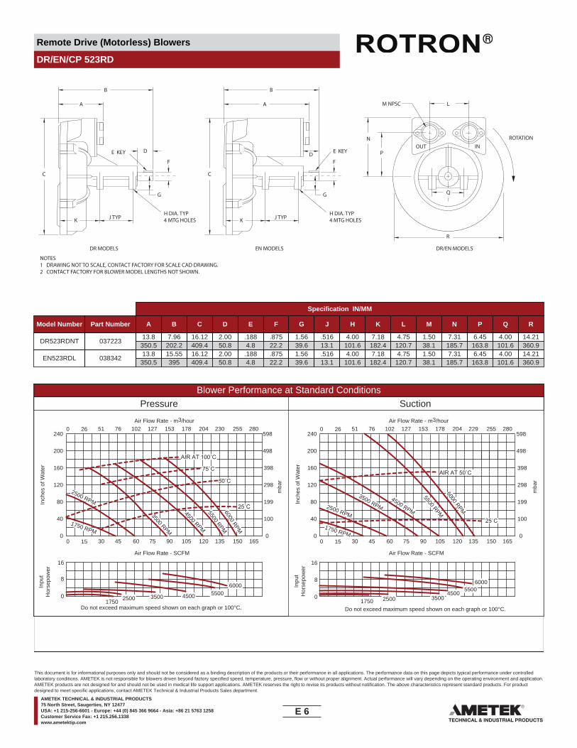
Remote Drive (Motorless) Blowers
DR/EN/CP 523RD
NOTES1 DRAWING NOT TO SCALE, CONTACT FACTORY FOR SCALE CAD DRAWING.2 CONTACT FACTORY FOR BLOWER MODEL LENGTHS NOT SHOWN.
J TYP
DR MODELS EN MODELS DR/EN MODELS
K
C
A
B
F
G
P
NOUT IN
Q
R
L
ROTATION
M NPSC
DE KEY
H DIA. TYP4 MTG HOLES J TYPK
C
A
B
F
G
D E KEY
H DIA. TYP4 MTG HOLES
Specification IN/MM
Model Number Part Number A B C D E F G J H K L M N P Q R
DR523RDNT 03722313.8
350.57.96
202.216.12409.4
2.0050.8
.1884.8
.87522.2
1.5639.6
.51613.1
4.00101.6
7.18182.4
4.75120.7
1.5038.1
7.31185.7
6.45163.8
4.00101.6
14.21360.9
EN523RDL 03834213.8
350.515.55395
16.12409.4
2.0050.8
.1884.8
.87522.2
1.5639.6
.51613.1
4.00101.6
7.18182.4
4.75120.7
1.5038.1
7.31185.7
6.45163.8
4.00101.6
14.21360.9
Blower Performance at Standard ConditionsPressure Suction
Inch
es o
f Wat
er
mba
r
mba
r
Inpu
tH
orse
pow
er
Air Flow Rate - SCFMAir Flow Rate - SCFM
Air Flow Rate - m3/hourAir Flow Rate - m3/hour
Inch
es o
f Wat
erIn
put
Hor
sepo
wer
4500 RPM
3500 RPM
2500 RPM
AIR AT 100˚C
75˚C
50˚C
1750 RPM
25˚C
AIR AT 50˚C
45003500250017505500
6000
5500 RPM6000 RPM
25˚C4500 RPM
3500 RPM2500 RPM
1750 RPM
5500 RPM6000 RPM
4500350025001750
55006000
0 15 30 45 60 75 90 105 120 135 150 165
0 26 51 76 102 127 153 178 204 230 255 280
0
40
80
120
160
200
240
0
100
199
298
398
498
598
0 15 30 45 60 75 90 105 120 135 150 165
0 26 51 76 102 127 153 178 204 229 255 280
0
40
80
120
160
200
240
0
100
199
298
398
498
598
Do not exceed maximum speed shown on each graph or 100°C. Do not exceed maximum speed shown on each graph or 100°C.
0
8
16
0
8
16
E 6____
This document is for informational purposes only and should not be considered as a binding description of the products or their performance in all applications. The performance data on this page depicts typical performance under controlledlaboratory conditions. AMETEK is not responsible for blowers driven beyond factory specified speed, temperature, pressure, flow or without proper alignment. Actual performance will vary depending on the operating environment and application.AMETEK products are not designed for and should not be used in medical life support applications. AMETEK reserves the right to revise its products without notification. The above characteristics represent standard products. For productdesigned to meet specific applications, contact AMETEK Technical & Industrial Products Sales department.
AMETEK TECHNICAL & INDUSTRIAL PRODUCTS75 North Street, Saugerties, NY 12477USA: +1 215-256-6601 - Europe: +44 (0) 845 366 9664 - Asia: +86 21 5763 1258Customer Service Fax: +1 215.256.1338www.ametektip.com
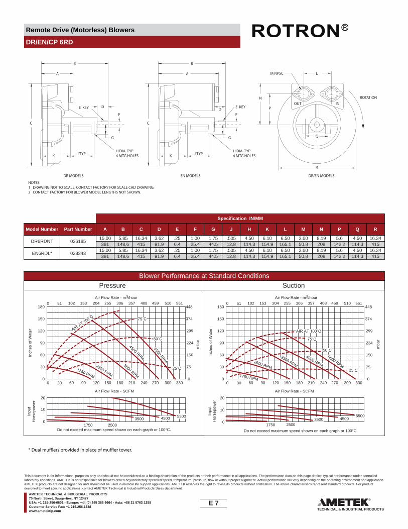
Remote Drive (Motorless) Blowers
DR/EN/CP 6RD
NOTES1 DRAWING NOT TO SCALE, CONTACT FACTORY FOR SCALE CAD DRAWING.2 CONTACT FACTORY FOR BLOWER MODEL LENGTHS NOT SHOWN.
J TYP
DR MODELS EN MODELS DR/EN MODELS
K
C
A
B
F
G
P
NOUT IN
Q
R
L
ROTATION
M NPSC
DE KEY
H DIA. TYP4 MTG HOLES J TYPK
C
A
B
F
G
D E KEY
H DIA. TYP4 MTG HOLES
Specification IN/MM
Model Number Part Number A B C D E F G J H K L M N P Q R
DR6RDNT 03618515.00381
5.85148.6
16.34415
3.6291.9
.256.4
1.0025.4
1.7544.5
.50512.8
4.50114.3
6.10154.9
6.50165.1
2.0050.8
8.19208
5.6142.2
4.50114.3
16.34415
EN6RDL* 03834315.00381
5.85148.6
16.34415
3.6291.9
.256.4
1.0025.4
1.7544.5
.50512.8
4.50114.3
6.10154.9
6.50165.1
2.0050.8
8.19208
5.6142.2
4.50114.3
16.34415
Blower Performance at Standard ConditionsPressure Suction
Inch
es o
f Wat
er
mba
r
mba
r
Inpu
tH
orse
pow
er
Air Flow Rate - SCFMAir Flow Rate - SCFM
Air Flow Rate - m3/hourAir Flow Rate - m3/hour
Inch
es o
f Wat
erIn
put
Hor
sepo
wer
5500 RPM
4500 RPM
3500 RPM1750 RPM
AIR AT 100˚C
50˚C
25˚C
55004500350025001750
2500 RPM 1750 RPM
2500 RPM
5500 RPM
4500 RPM
3500 RPM
AIR AT 100˚C
75˚C
550045003500
25001750
75˚C
25˚C
50˚C
0 30 60 90 120 150 180 210 240 270 300 330
0 51 102 153 204 255 306 357 408 459 510 561
0
30
60
90
120
150
180
0
75
150
224
299
374
448
0 30 60 90 120 150 180 210 240 270 300 330
0 51 102 153 204 255 306 357 408 459 510 561
0
30
60
90
120
150
180
0
75
150
224
299
374
448
Do not exceed maximum speed shown on each graph or 100°C. Do not exceed maximum speed shown on each graph or 100°C.
0
10
20
0
10
20
* Dual mu�ers provided in place of mu�er tower.
E 7____
This document is for informational purposes only and should not be considered as a binding description of the products or their performance in all applications. The performance data on this page depicts typical performance under controlledlaboratory conditions. AMETEK is not responsible for blowers driven beyond factory specified speed, temperature, pressure, flow or without proper alignment. Actual performance will vary depending on the operating environment and application.AMETEK products are not designed for and should not be used in medical life support applications. AMETEK reserves the right to revise its products without notification. The above characteristics represent standard products. For productdesigned to meet specific applications, contact AMETEK Technical & Industrial Products Sales department.
AMETEK TECHNICAL & INDUSTRIAL PRODUCTS75 North Street, Saugerties, NY 12477USA: +1 215-256-6601 - Europe: +44 (0) 845 366 9664 - Asia: +86 21 5763 1258Customer Service Fax: +1 215.256.1338www.ametektip.com

Remote Drive (Motorless) Blowers
DR/EN/CP 633RD
NOTES1 DRAWING NOT TO SCALE, CONTACT FACTORY FOR SCALE CAD DRAWING.2 CONTACT FACTORY FOR BLOWER MODEL LENGTHS NOT SHOWN.
ROTATION
J +/- .12
A
Q +/- .12E
G +/- .25
D
SEEDETAIL AA
DETAIL AA
C +/- .06
2.3659.9
0.3910
B
(4X) F
(4X) R
(2X) H
(2X) T
OUTINK +/- .12
L +/- .12
M +/- .25
N +/- .25
(2X) PNPSC THD
Specification IN/MM
Model Number Part Number A B C D E F G J H K L M N P Q R T
DR633RD 0818491.2632
9.65245.1
2.9173.9
5.91150.1
7.28184.9
.39410
19.31490.5
0.399.9
10.63270
2.1755.1
9.25235
17.32439.9
16.53419.9
2.0050.8
4.13104.9
0.9824.9
1.5739.9
EN633RDL 0818501.2632
9.65245.1
2.9173.9
5.91150.1
7.28184.9
.39410
19.31490.5
0.399.9
10.63270
2.1755.1
9.25235
17.32439.9
16.53419.9
2.0050.8
4.13104.9
0.9824.9
1.5739.9
Blower Performance at Standard ConditionsPressure Suction
Inch
es o
f Wat
er
mba
r
mba
r
Inpu
tH
orse
pow
er
Air Flow Rate - SCFMAir Flow Rate - SCFM
Air Flow Rate - m3/hourAir Flow Rate - m3/hour
Inch
es o
f Wat
erIn
put
Hor
sepo
wer
3500 RPM
2850 RPM
AIR AT 100˚C
50˚C
4000 RPM
4500 RPM
400035002850
450040003500
2850
4500
3500 RPM
2850 RPM
AIR AT 100˚C
50˚C4000 RPM
4500 RPM
0 15 30 45 60 75 90 105 120 135 150 165
0 26 51 76 102 127 153 178 204 230 255 280
0
50
100
150
200
250
300
0
125
249
374
498
622
747
0 15 30 45 60 75 90 105 120 135 150 165
0 26 51 76 102 127 153 178 204 230 255 280
0
50
100
150
200
250
300
0
125
249
374
498
622
747
Do not exceed maximum speed shown on each graph or 100°C. Do not exceed maximum speed shown on each graph or 100°C.
0
5
10
0
5
10
E 8____
This document is for informational purposes only and should not be considered as a binding description of the products or their performance in all applications. The performance data on this page depicts typical performance under controlledlaboratory conditions. AMETEK is not responsible for blowers driven beyond factory specified speed, temperature, pressure, flow or without proper alignment. Actual performance will vary depending on the operating environment and application.AMETEK products are not designed for and should not be used in medical life support applications. AMETEK reserves the right to revise its products without notification. The above characteristics represent standard products. For productdesigned to meet specific applications, contact AMETEK Technical & Industrial Products Sales department.
AMETEK TECHNICAL & INDUSTRIAL PRODUCTS75 North Street, Saugerties, NY 12477USA: +1 215-256-6601 - Europe: +44 (0) 845 366 9664 - Asia: +86 21 5763 1258Customer Service Fax: +1 215.256.1338www.ametektip.com

Remote Drive (Motorless) Blowers
DR/EN/CP 656RD
NOTES1 DRAWING NOT TO SCALE, CONTACT FACTORY FOR SCALE CAD DRAWING.2 CONTACT FACTORY FOR BLOWER MODEL LENGTHS NOT SHOWN.
J TYP
DR MODELS EN MODELS DR/EN MODELS
K
C
A
B
F
G
P
NOUT IN
Q
R
L
ROTATION
M NPSC
DE KEY
H DIA. TYP4 MTG HOLES J TYPK
C
A
B
F
G
D E KEY
H DIA. TYP4 MTG HOLES
Specification IN/MM
Model Number Part Number A B C D E F G J H K L M N P Q R
DR656RDNT 08061012.44316
7.35186.7
15.17385.3
2.0050.8
.1884.8
.87522.2
1.5639.6
.5012.7
4.00101.6
5.83148.1
4.92125
2.0050.8
7.46189.5
5.51140
4.00101.6
15.42391.7
EN656RDL 08006114.6
370.815.12384
15.17385.3
2.0050.8
.1884.8
.87522.2
1.5639.6
.5012.7
4.00101.6
5.83148.1
4.92125
2.0050.8
7.46189.5
5.51140
4.00101.6
15.42391.7
Blower Performance at Standard ConditionsPressure Suction
Inch
es o
f Wat
er
mba
r
mba
r
Inpu
tH
orse
pow
er
Air Flow Rate - SCFMAir Flow Rate - SCFM
Air Flow Rate - m3/hourAir Flow Rate - m3/hour
Inch
es o
f Wat
erIn
put
Hor
sepo
wer
6000 RPM
5500 RPM
4500 RPM
3500 RPM1750 RPM
100˚C
50˚C
25˚C
600055004500
350025001750
2500 RPM
1750 RPM
2500 RPM
6000 RPM
5500 RPM
4500 RPM
3500 RPM
100˚C
50˚C
600055004500
350025001750
0 40 80 120 160 200 240 280 320 360 400 440
0 68 136 204 272 340 408 476 544 612 680 748
0
30
60
90
120
150
180
0
75
150
224
299
374
448
0 40 80 120 160 200 240 280 320 360 400 440
0 68 136 204 272 340 408 476 544 612 680 748
0
30
60
90
120
150
180
0
75
150
224
299
374
448
Do not exceed maximum speed shown on each graph or 100°C. Do not exceed maximum speed shown on each graph or 100°C.
0
15
30
0
15
30
E 9____
This document is for informational purposes only and should not be considered as a binding description of the products or their performance in all applications. The performance data on this page depicts typical performance under controlledlaboratory conditions. AMETEK is not responsible for blowers driven beyond factory specified speed, temperature, pressure, flow or without proper alignment. Actual performance will vary depending on the operating environment and application.AMETEK products are not designed for and should not be used in medical life support applications. AMETEK reserves the right to revise its products without notification. The above characteristics represent standard products. For productdesigned to meet specific applications, contact AMETEK Technical & Industrial Products Sales department.
AMETEK TECHNICAL & INDUSTRIAL PRODUCTS75 North Street, Saugerties, NY 12477USA: +1 215-256-6601 - Europe: +44 (0) 845 366 9664 - Asia: +86 21 5763 1258Customer Service Fax: +1 215.256.1338www.ametektip.com
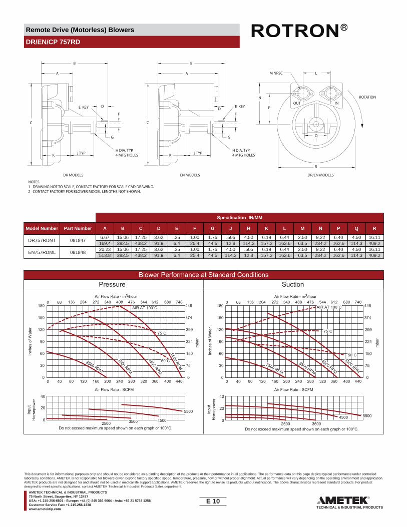
Remote Drive (Motorless) Blowers
DR/EN/CP 757RD
NOTES1 DRAWING NOT TO SCALE, CONTACT FACTORY FOR SCALE CAD DRAWING.2 CONTACT FACTORY FOR BLOWER MODEL LENGTHS NOT SHOWN.
J TYP
DR MODELS EN MODELS DR/EN MODELS
K
C
A
B
F
G
P
NOUT IN
Q
R
L
ROTATION
M NPSC
DE KEY
H DIA. TYP4 MTG HOLES J TYPK
C
A
B
F
G
D E KEY
H DIA. TYP4 MTG HOLES
Specification IN/MM
Model Number Part Number A B C D E F G J H K L M N P Q R
DR757RDNT 0818476.67
169.415.06382.5
17.25438.2
3.6291.9
.256.4
1.0025.4
1.7544.5
.50512.8
4.50114.3
6.19157.2
6.44163.6
2.5063.5
9.22234.2
6.40162.6
4.50114.3
16.11409.2
EN757RDML 08184820.23513.8
15.06382.5
17.25438.2
3.6291.9
.256.4
1.0025.4
1.7544.5
4.50114.3
.50512.8
6.19157.2
6.44163.6
2.5063.5
9.22234.2
6.40162.6
4.50114.3
16.11409.2
Blower Performance at Standard ConditionsPressure Suction
Inch
es o
f Wat
er
mba
r
mba
r
Inpu
tH
orse
pow
er
Air Flow Rate - SCFMAir Flow Rate - SCFM
Air Flow Rate - m3/hourAir Flow Rate - m3/hour
Inch
es o
f Wat
erIn
put
Hor
sepo
wer
5500 RPM
4500 RPM
3500 RPM
AIR AT 100˚C
75˚C
50˚C
5500
450035002500
2500 RPM2500 RPM
5500 RPM
4500 RPM
3500 RPM
5500450035002500
75˚C
50˚C
0 40 80 120 160 200 240 280 320 360 400 440
0 68 136 204 272 340 408 476 544 612 680 748
0
30
60
90
120
150
180
0
75
150
224
299
374
448
0 40 80 120 160 200 240 280 320 360 400 440
0 68 136 204 272 340 408 476 544 612 680 748
0
30
60
90
120
150
180
0
75
150
224
299
374
448
Do not exceed maximum speed shown on each graph or 100°C. Do not exceed maximum speed shown on each graph or 100°C.
0
20
40
0
20
40
AIR AT 100˚C
E 10____
This document is for informational purposes only and should not be considered as a binding description of the products or their performance in all applications. The performance data on this page depicts typical performance under controlledlaboratory conditions. AMETEK is not responsible for blowers driven beyond factory specified speed, temperature, pressure, flow or without proper alignment. Actual performance will vary depending on the operating environment and application.AMETEK products are not designed for and should not be used in medical life support applications. AMETEK reserves the right to revise its products without notification. The above characteristics represent standard products. For productdesigned to meet specific applications, contact AMETEK Technical & Industrial Products Sales department.
AMETEK TECHNICAL & INDUSTRIAL PRODUCTS75 North Street, Saugerties, NY 12477USA: +1 215-256-6601 - Europe: +44 (0) 845 366 9664 - Asia: +86 21 5763 1258Customer Service Fax: +1 215.256.1338www.ametektip.com
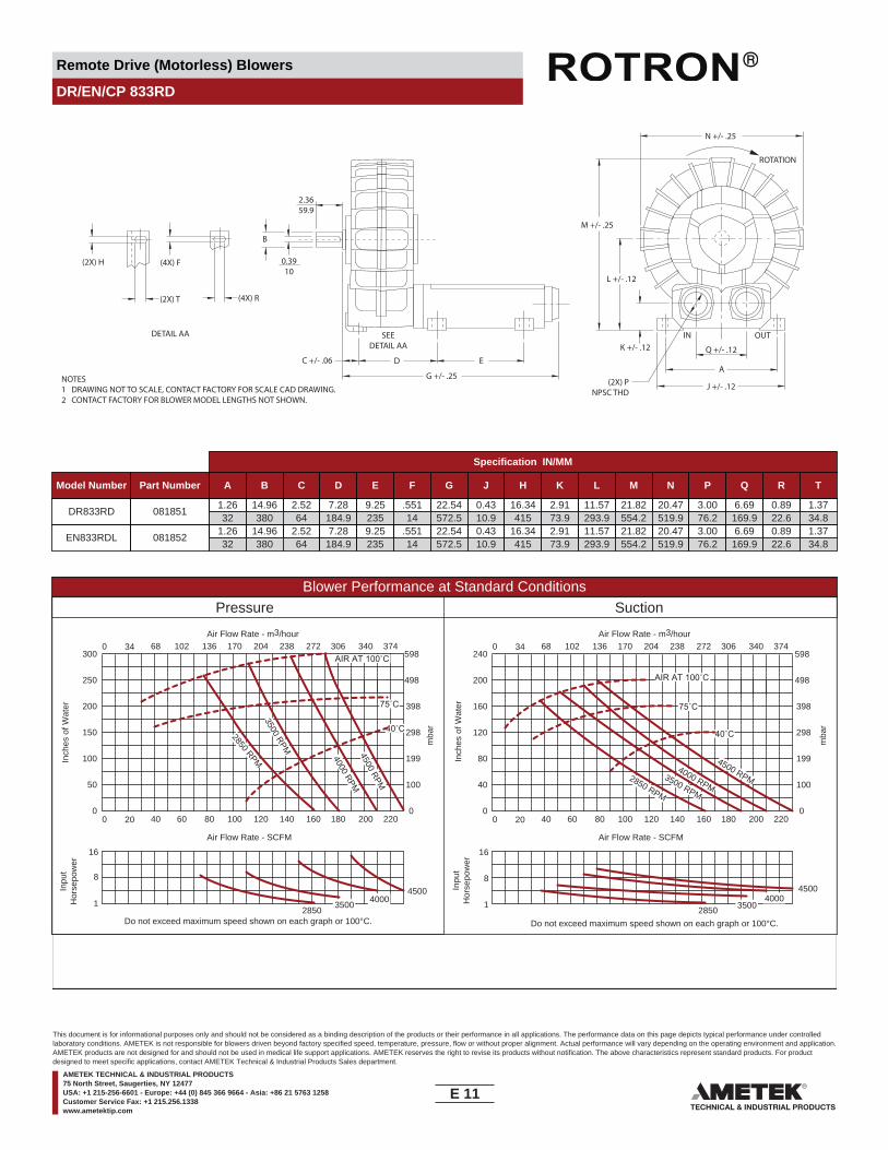
Remote Drive (Motorless) Blowers
DR/EN/CP 833RD
NOTES1 DRAWING NOT TO SCALE, CONTACT FACTORY FOR SCALE CAD DRAWING.2 CONTACT FACTORY FOR BLOWER MODEL LENGTHS NOT SHOWN.
ROTATION
J +/- .12
A
Q +/- .12E
G +/- .25
D
SEEDETAIL AA
DETAIL AA
C +/- .06
2.3659.9
0.3910
B
(4X) F
(4X) R
(2X) H
(2X) T
OUTINK +/- .12
L +/- .12
M +/- .25
N +/- .25
(2X) PNPSC THD
Specification IN/MM
Model Number Part Number A B C D E F G J H K L M N P Q R T
DR833RD 0818511.2632
14.96380
2.5264
7.28184.9
9.25235
.55114
22.54572.5
0.4310.9
16.34415
2.9173.9
11.57293.9
21.82554.2
20.47519.9
3.0076.2
6.69169.9
0.8922.6
1.3734.8
EN833RDL 0818521.2632
14.96380
2.5264
7.28184.9
9.25235
.55114
22.54572.5
0.4310.9
16.34415
2.9173.9
11.57293.9
21.82554.2
20.47519.9
3.0076.2
6.69169.9
0.8922.6
1.3734.8
Blower Performance at Standard ConditionsPressure Suction
Inch
es o
f Wat
er
mba
r
mba
r
Inpu
tH
orse
pow
er
Air Flow Rate - SCFMAir Flow Rate - SCFM
Air Flow Rate - m3/hourAir Flow Rate - m3/hour
Inch
es o
f Wat
erIn
put
Hor
sepo
wer
3500 RPM
2850 RPM
AIR AT 100˚C
40˚C
4000 RPM4500 RPM
400035002850
4500400035002850
4500
3500 RPM
2850 RPM
4000 RPM
4500 RPM
75˚C
AIR AT 100˚C
40˚C
75˚C
0 20 40 60 80 100 120 140 160 180 200 220
0 34 68 102 136 170 204 238 272 306 340 374
0
50
100
150
200
250
300
0
100
199
298
398
498
598
0 20 40 60 80 100 120 140 160 180 200 220
0 34 68 102 136 170 204 238 272 306 340 374
0
40
80
120
160
200
240
0
100
199
298
398
498
598
Do not exceed maximum speed shown on each graph or 100°C. Do not exceed maximum speed shown on each graph or 100°C.
1
8
16
1
8
16
E 11____
This document is for informational purposes only and should not be considered as a binding description of the products or their performance in all applications. The performance data on this page depicts typical performance under controlledlaboratory conditions. AMETEK is not responsible for blowers driven beyond factory specified speed, temperature, pressure, flow or without proper alignment. Actual performance will vary depending on the operating environment and application.AMETEK products are not designed for and should not be used in medical life support applications. AMETEK reserves the right to revise its products without notification. The above characteristics represent standard products. For productdesigned to meet specific applications, contact AMETEK Technical & Industrial Products Sales department.
AMETEK TECHNICAL & INDUSTRIAL PRODUCTS75 North Street, Saugerties, NY 12477USA: +1 215-256-6601 - Europe: +44 (0) 845 366 9664 - Asia: +86 21 5763 1258Customer Service Fax: +1 215.256.1338www.ametektip.com
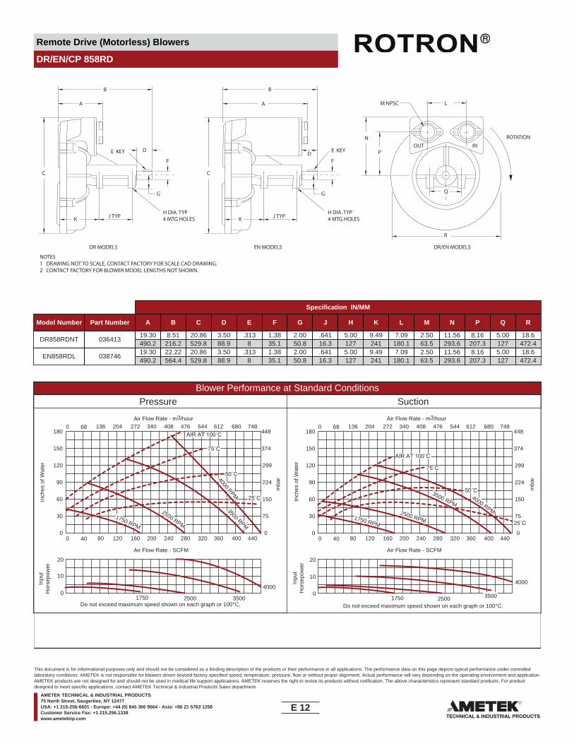
Remote Drive (Motorless) Blowers
DR/EN/CP 858RD
NOTES1 DRAWING NOT TO SCALE, CONTACT FACTORY FOR SCALE CAD DRAWING.2 CONTACT FACTORY FOR BLOWER MODEL LENGTHS NOT SHOWN.
J TYP
DR MODELS EN MODELS DR/EN MODELS
K
C
A
B
F
G
P
NOUT IN
Q
R
L
ROTATION
M NPSC
DE KEY
H DIA. TYP4 MTG HOLES J TYPK
C
A
B
F
G
D E KEY
H DIA. TYP4 MTG HOLES
Specification IN/MM
Model Number Part Number A B C D E F G J H K L M N P Q R
DR858RDNT 03641319.30490.2
8.51216.2
20.86529.8
3.5088.9
.3138
1.3835.1
2.0050.8
.64116.3
5.00127
9.49241
7.09180.1
2.5063.5
11.56293.6
8.16207.3
5.00127
18.6472.4
EN858RDL 03874619.30490.2
22.22564.4
20.86529.8
3.5088.9
.3138
1.3835.1
2.0050.8
.64116.3
5.00127
9.49241
7.09180.1
2.5063.5
11.56293.6
8.16207.3
5.00127
18.6472.4
Blower Performance at Standard ConditionsPressure Suction
Inch
es o
f Wat
er
mba
r
mba
r
Inpu
tH
orse
pow
er
Air Flow Rate - SCFMAir Flow Rate - SCFM
Air Flow Rate - m3/hourAir Flow Rate - m3/hour
Inch
es o
f Wat
erIn
put
Hor
sepo
wer
4000 RPM
3500 RPM
2500 RPM
AIR AT 100˚C
75˚C
50˚C
1750 RPM
4000
350025001750
75˚C
50˚C25˚C
AIR AT 100˚C
25˚C
4000 RPM
3500 RPM
2500 RPM1750 RPM
4000
350025001750
0 40 80 120 160 200 240 280 320 360 400 440
0 68 136 204 272 340 408 476 544 612 680 748
0
30
60
90
120
150
180
0
75
150
224
299
374
448
0 40 80 120 160 200 240 280 320 360 400 440
0 68 136 204 272 340 408 476 544 612 680 748
0
30
60
90
120
150
180
0
75
150
224
299
374
448
Do not exceed maximum speed shown on each graph or 100°C. Do not exceed maximum speed shown on each graph or 100°C.
0
10
20
0
10
20
E 12____
This document is for informational purposes only and should not be considered as a binding description of the products or their performance in all applications. The performance data on this page depicts typical performance under controlledlaboratory conditions. AMETEK is not responsible for blowers driven beyond factory specified speed, temperature, pressure, flow or without proper alignment. Actual performance will vary depending on the operating environment and application.AMETEK products are not designed for and should not be used in medical life support applications. AMETEK reserves the right to revise its products without notification. The above characteristics represent standard products. For productdesigned to meet specific applications, contact AMETEK Technical & Industrial Products Sales department.
AMETEK TECHNICAL & INDUSTRIAL PRODUCTS75 North Street, Saugerties, NY 12477USA: +1 215-256-6601 - Europe: +44 (0) 845 366 9664 - Asia: +86 21 5763 1258Customer Service Fax: +1 215.256.1338www.ametektip.com

Remote Drive (Motorless) Blowers
DR/EN/CP 909RD
NOTES1 DRAWING NOT TO SCALE, CONTACT FACTORY FOR SCALE CAD DRAWING.2 CONTACT FACTORY FOR BLOWER MODEL LENGTHS NOT SHOWN.
J TYP
DR MODELS EN MODELS DR/EN MODELS
K
C
A
B
F
G
P
NOUT IN
Q
R
L
ROTATION
M NPSC
DE KEY
H DIA. TYP4 MTG HOLES J TYPK
C
A
B
F
G
D E KEY
H DIA. TYP4 MTG HOLES
Specification IN/MM
Model Number Part Number A B C D E F G J H K L M N P Q R
DR909RDNT 03692122.8
579.18.53
216.723.22589.8
3.5088.9
.50012.7
1.37534.9
2.0050.8
.76519.4
5.00127
9.70246.4
8.34211.8
3.0176.5
12.97329.4
9.02229.1
5.00127
19.8502.9
EN909RDL 03870222.8
579.124.51622.6
23.22589.8
3.5088.9
.50012.7
1.37534.9
2.0050.8
.76519.4
5.00127
9.70246.4
8.34211.8
4.00101.6
12.97329.4
9.02229.1
5.00127
19.8502.9
Blower Performance at Standard ConditionsPressure Suction
Inch
es o
f Wat
er
mba
r
mba
r
Inpu
tH
orse
pow
er
Air Flow Rate - SCFMAir Flow Rate - SCFM
Air Flow Rate - m3/hourAir Flow Rate - m3/hour
Inch
es o
f Wat
erIn
put
Hor
sepo
wer
4500 RPM
3500 RPM
2500 RPM
AIR AT 100˚C
75˚C
50˚C
1750 RPM
4500350025001750
75˚C
50˚C
AIR AT 100˚C
4500 RPM
3500 RPM2500 RPM1750 RPM
4500350025001750
0 80 160 240 320 400 480 560 640 720 800 880
0 136 272 408 544 680 816 952 1088 1224 1360 1496
0
30
60
90
120
150
180
0
75
150
224
299
374
448
0 80 160 240 320 400 480 560 640 720 800 880
0 136 272 408 544 680 816 952 1088 1224 1360 1496
0
30
60
90
120
150
180
0
75
150
224
299
374
448
Do not exceed maximum speed shown on each graph or 100°C. Do not exceed maximum speed shown on each graph or 100°C.
0
20
40
0
20
40
E 13____
This document is for informational purposes only and should not be considered as a binding description of the products or their performance in all applications. The performance data on this page depicts typical performance under controlledlaboratory conditions. AMETEK is not responsible for blowers driven beyond factory specified speed, temperature, pressure, flow or without proper alignment. Actual performance will vary depending on the operating environment and application.AMETEK products are not designed for and should not be used in medical life support applications. AMETEK reserves the right to revise its products without notification. The above characteristics represent standard products. For productdesigned to meet specific applications, contact AMETEK Technical & Industrial Products Sales department.
AMETEK TECHNICAL & INDUSTRIAL PRODUCTS75 North Street, Saugerties, NY 12477USA: +1 215-256-6601 - Europe: +44 (0) 845 366 9664 - Asia: +86 21 5763 1258Customer Service Fax: +1 215.256.1338www.ametektip.com
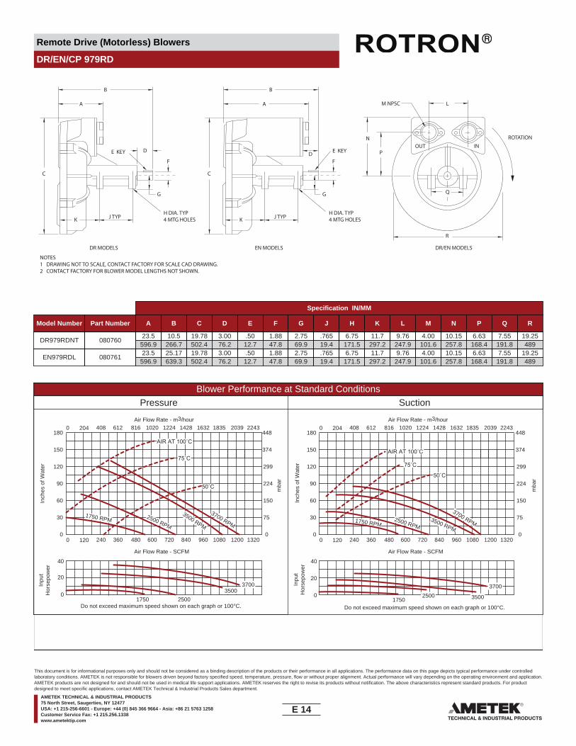
Remote Drive (Motorless) Blowers
DR/EN/CP 979RD
NOTES1 DRAWING NOT TO SCALE, CONTACT FACTORY FOR SCALE CAD DRAWING.2 CONTACT FACTORY FOR BLOWER MODEL LENGTHS NOT SHOWN.
J TYP
DR MODELS EN MODELS DR/EN MODELS
K
C
A
B
F
G
P
NOUT IN
Q
R
L
ROTATION
M NPSC
DE KEY
H DIA. TYP4 MTG HOLES J TYPK
C
A
B
F
G
D E KEY
H DIA. TYP4 MTG HOLES
Specification IN/MM
Model Number Part Number A B C D E F G J H K L M N P Q R
DR979RDNT 08076023.5
596.910.5
266.719.78502.4
3.0076.2
.5012.7
1.8847.8
2.7569.9
.76519.4
6.75171.5
11.7297.2
9.76247.9
4.00101.6
10.15257.8
6.63168.4
7.55191.8
19.25489
EN979RDL 08076123.5
596.925.17639.3
19.78502.4
3.0076.2
.5012.7
1.8847.8
2.7569.9
.76519.4
6.75171.5
11.7297.2
9.76247.9
4.00101.6
10.15257.8
6.63168.4
7.55191.8
19.25489
Blower Performance at Standard ConditionsPressure Suction
Inch
es o
f Wat
er
mba
r
mba
r
Inpu
tH
orse
pow
er
Air Flow Rate - SCFMAir Flow Rate - SCFM
Air Flow Rate - m3/hourAir Flow Rate - m3/hour
Inch
es o
f Wat
erIn
put
Hor
sepo
wer
3700 RPM
3500 RPM2500 RPM
AIR AT 100˚C
75˚C
50˚C
1750 RPM
3700
350025001750
75˚C
50˚C
AIR AT 100˚C
3700 RPM3500 RPM2500 RPM
1750 RPM
37003500
25001750
0 120 240 360 480 600 720 840 960 1080 1200 1320
0 204 408 612 816 1020 1224 1428 1632 1835 2039 2243
0
30
60
90
120
150
180
0
75
150
224
299
374
448
0 120 240 360 480 600 720 840 960 1080 1200 1320
0 204 408 612 816 1020 1224 1428 1632 1835 2039 2243
0
30
60
90
120
150
180
0
75
150
224
299
374
448
Do not exceed maximum speed shown on each graph or 100°C. Do not exceed maximum speed shown on each graph or 100°C.
0
20
40
0
20
40
E 14____
This document is for informational purposes only and should not be considered as a binding description of the products or their performance in all applications. The performance data on this page depicts typical performance under controlledlaboratory conditions. AMETEK is not responsible for blowers driven beyond factory specified speed, temperature, pressure, flow or without proper alignment. Actual performance will vary depending on the operating environment and application.AMETEK products are not designed for and should not be used in medical life support applications. AMETEK reserves the right to revise its products without notification. The above characteristics represent standard products. For productdesigned to meet specific applications, contact AMETEK Technical & Industrial Products Sales department.
AMETEK TECHNICAL & INDUSTRIAL PRODUCTS75 North Street, Saugerties, NY 12477USA: +1 215-256-6601 - Europe: +44 (0) 845 366 9664 - Asia: +86 21 5763 1258Customer Service Fax: +1 215.256.1338www.ametektip.com
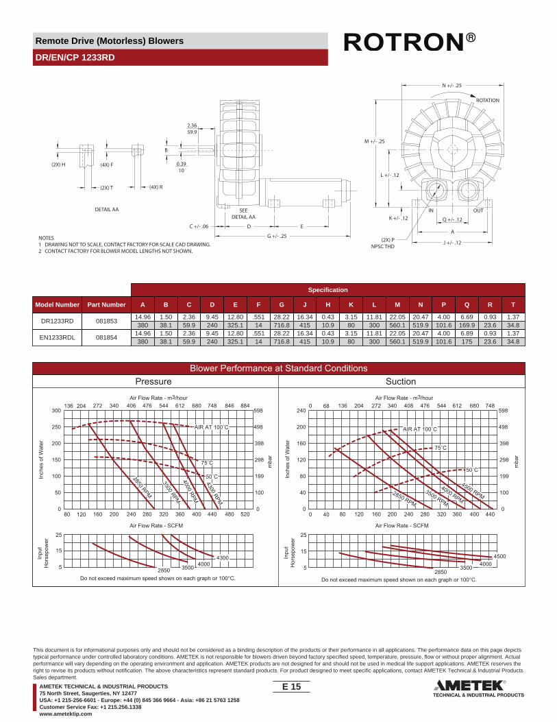
Remote Drive (Motorless) Blowers
DR/EN/CP 1233RD
NOTES1 DRAWING NOT TO SCALE, CONTACT FACTORY FOR SCALE CAD DRAWING.2 CONTACT FACTORY FOR BLOWER MODEL LENGTHS NOT SHOWN.
ROTATION
J +/- .12
A
Q +/- .12E
G +/- .25
D
SEEDETAIL AA
DETAIL AA
C +/- .06
2.3659.9
0.3910
B
(4X) F
(4X) R
(2X) H
(2X) T
OUTINK +/- .12
L +/- .12
M +/- .25
N +/- .25
(2X) PNPSC THD
Specification
Model Number Part Number A B C D E F G J H K L M N P Q R T
DR1233RD 08185314.96380
1.5038.1
2.3659.9
9.45240
12.80325.1
.55114
28.22716.8
16.34415
0.4310.9
3.1580
11.81300
22.05560.1
20.47519.9
4.00101.6
6.69169.9
0.9323.6
1.3734.8
EN1233RDL 08185414.96380
1.5038.1
2.3659.9
9.45240
12.80325.1
.55114
28.22716.8
16.34415
0.4310.9
3.1580
11.81300
22.05560.1
20.47519.9
4.00101.6
6.89175
0.9323.6
1.3734.8
Blower Performance at Standard ConditionsPressure Suction
Inch
es o
f Wat
er
mba
r
mba
r
Inpu
tH
orse
pow
er
Air Flow Rate - SCFMAir Flow Rate - SCFM
Air Flow Rate - m3/hourAir Flow Rate - m3/hour
Inch
es o
f Wat
erIn
put
Hor
sepo
wer
3500 RPM
2850 RPM
AIR AT 100˚C
50˚C4000 RPM
4300 RPM
40003500
2850
4500400035002850
4300
3500 RPM
2850 RPM
4000 RPM
4500 RPM
75˚C
AIR AT 100˚C
50˚C
75˚C
80 120 160 200 240 280 320 360 400 440 480 520
136 204 272 340 406 476 544 612 680 748 846 884
0
50
100
150
200
250
300
0
100
199
298
398
498
598
0 40 80 120 160 200 240 280 320 360 400 440
0 68 136 204 272 340 408 476 544 612 680 748
0
40
80
120
160
200
240
0
100
199
298
398
498
598
Do not exceed maximum speed shown on each graph or 100°C. Do not exceed maximum speed shown on each graph or 100°C.
5
15
25
5
15
25
E 15____
This document is for informational purposes only and should not be considered as a binding description of the products or their performance in all applications. The performance data on this page depictstypical performance under controlled laboratory conditions. AMETEK is not responsible for blowers driven beyond factory specified speed, temperature, pressure, flow or without proper alignment. Actualperformance will vary depending on the operating environment and application. AMETEK products are not designed for and should not be used in medical life support applications. AMETEK reserves theright to revise its products without notification. The above characteristics represent standard products. For product designed to meet specific applications, contact AMETEK Technical & Industrial ProductsSales department.
AMETEK TECHNICAL & INDUSTRIAL PRODUCTS75 North Street, Saugerties, NY 12477USA: +1 215-256-6601 - Europe: +44 (0) 845 366 9664 - Asia: +86 21 5763 1258Customer Service Fax: +1 215.256.1338www.ametektip.com

Remote Drive (Motorless) Blowers
DR/EN/CP 14RD
NOTES1 DRAWING NOT TO SCALE, CONTACT FACTORY FOR SCALE CAD DRAWING.2 CONTACT FACTORY FOR BLOWER MODEL LENGTHS NOT SHOWN.
J TYP
DR MODELS EN MODELS DR/EN MODELS
K
C
A
B
F
G
P
NOUT IN
Q
R
L
ROTATION
M NPSC
DE KEY
H DIA. TYP4 MTG HOLES J TYPK
C
A
B
F
G
D E KEY
H DIA. TYP4 MTG HOLES
Specification IN/MM
Model Number Part Number A B C D E F G J H K L M N P Q R
DR14RDNT 08147522.24564.9
9.87250.7
26.54674.1
4.00101.6
.5012.7
1.87547.6
2.7569.9
.76519.4
6.75171.5
10.24260.1
9.69246.1
4.00101.6
15.50393.7
11.41289.8
7.55191.8
23.32592.3
EN14RDL 08148822.24564.9
30.14765.6
26.54674.1
4.00101.6
.5012.7
1.87547.6
2.7569.9
.76519.4
6.75171.5
10.24260.1
9.69246.1
4.00101.6
15.50393.7
11.41289.8
7.55191.8
23.32592.3
Blower Performance at Standard ConditionsPressure Suction
Inch
es o
f Wat
er
mba
r
mba
r
Inpu
tH
orse
pow
er
Air Flow Rate - SCFMAir Flow Rate - SCFM
Air Flow Rate - m3/hourAir Flow Rate - m3/hour
Inch
es o
f Wat
erIn
put
Hor
sepo
wer
3700 RPM
3500 RPM
2500 RPM
AIR AT 100˚C
75˚C
50˚C
1750 RPM
450035002500
1750
75˚C
50˚C
AIR AT 100˚C
3700 RPM3500 RPM
2500 RPM1750 RPM
4500
350025001750
0 80 160 240 320 400 480 560 640 720 800 880
0 136 272 408 544 680 816 952 1088 1224 1360 1496
0
30
60
90
120
150
180
0
75
150
224
299
374
448
0 80 160 240 320 400 480 560 640 720 800 880
0 136 272 408 544 680 816 952 1088 1224 1360 1496
0
30
60
90
120
150
180
0
75
150
224
299
374
448
Do not exceed maximum speed shown on each graph or 100°C. Do not exceed maximum speed shown on each graph or 100°C.
0
30
60
0
30
60
E 16____
This document is for informational purposes only and should not be considered as a binding description of the products or their performance in all applications. The performance data on this page depicts typical performance under controlledlaboratory conditions. AMETEK is not responsible for blowers driven beyond factory specified speed, temperature, pressure, flow or without proper alignment. Actual performance will vary depending on the operating environment and application.AMETEK products are not designed for and should not be used in medical life support applications. AMETEK reserves the right to revise its products without notification. The above characteristics represent standard products. For productdesigned to meet specific applications, contact AMETEK Technical & Industrial Products Sales department.
AMETEK TECHNICAL & INDUSTRIAL PRODUCTS75 North Street, Saugerties, NY 12477USA: +1 215-256-6601 - Europe: +44 (0) 845 366 9664 - Asia: +86 21 5763 1258Customer Service Fax: +1 215.256.1338www.ametektip.com

____
Application Specific Regenerative BlowersSpecialty blowers for Commercial Spa, High Temperature, Natural Gas, and Gasoline Vapor Recovery applications.
Our industrial NC (NautilairTM Centraxial) blowers include: Fiberglass or aluminum housing Aluminum impellers Permanently sealed bearings for 50,000 hours life
Our instrument grade and variable flow SE (MinispiralTM Regenerative) blowers include: AC and DC versions available for world voltages and maximum flow variability Glass filled molded phenolic impeller; aluminum and phenolic case 30,000 hour bearing life Small size and lightweight construction Quiet to NC-47 office equipment standards
Our instrument grade SL (Spiral Regenerative) blowers include: Rugged diecast aluminum housing, endbells, and impellers Compact size with encased muffler for maximum noise reduction Low amp draw with highly efficient motor Permanently sealed bearings for 40,000 hours life Hermetically sealed models designed for glovebox use
AMETEK TECHNICAL & INDUSTRIAL PRODUCTS75 North Street, Saugerties, NY 12477USA: +1 215-256-6601 - Europe: +44 (0) 845 366 9664 - Asia: +86 21 5763 1258Customer Service Fax: +1 215.256.1338www.ametektip.com

Application Specific Blowers
Minispiral
Insrument Grade Regenerative Blower
NOTES1 DRAWING NOT TO SCALE, CONTACT FACTORY FOR SCALE CAD DRAWING.2 CONTACT FACTORY FOR BLOWER MODEL LENGTHS NOT SHOWN.
1.54
1.75 2.03
3.50
4.06
.67
.09
TYP.
.25
REF.
17.02
44.45 51.56
88.9
103.12
6.35
2.29
39.1
2
(2) MTG. HOLES5.38
14.2
2
19.0
5
.56
.75
O.D
. TYP
.
1.13
.5313.46
28.7.68 MAX.17.27
11.1
80.32
1.80 REF.
8.13
45.72
.44
REF.
TYP.
4.11 DIA.104.41.65
41.91
Ø2.24 DIA.
56.9
2.10
53.3
4
4.16
REF
.
105.
66
.212 DIA.
1
2
OUT
IN
INMM
Part/Model Number
SE2B21 SE3B21 SE62B21 SE2B21A
Specification Units 036258 036283 037395 080694
Phase - Frequency - Single-50/60 Hz Single-50/60 Hz - Single-50/60 HzVoltage AC 110/115 220/230 24 110/115RPM RPM 2850/3400 2850/3400 2850/3400 2850/3400Insulation Class - B B B BFull - Load Amps Amps (A) .17/.14 .07/.07 - .17/.14Locked Rotor Amps Amps (A) .17/.15 .08/.08 - .17/.15
Shipping WeightLbsKg
1.90.9
1.90.9
1.90.9
1.90.9
1 Maximum operating temperature: Motor winding temperature (winding rise plus ambient) should not exceed 140°C for Class F rated motorsor 120°C for Class B rated motors. Blower outlet air temperature should not exceed 140°C (air temperature rise plus inlet temperature).Performance curve maximum pressure and suction points are based on a 40°C inlet and ambient temperature. Consult factory for inlet orambient temperatures above 40°C.
2 Maximum blower amps corresponds to the performance point at which the motor or blower temperature rise with a 40°C inlet and/orambient temperature reaches the maximum operating temperature.
F 1____
This document is for informational purposes only and should not be considered as a binding description of the products or their performance in all applications. The performance data on this page depicts typical performance under controlledlaboratory conditions. AMETEK is not responsible for blowers driven beyond factory specified speed, temperature, pressure, flow or without proper alignment. Actual performance will vary depending on the operating environment and application.AMETEK products are not designed for and should not be used in medical life support applications. AMETEK reserves the right to revise its products without notification. The above characteristics represent standard products. For productdesigned to meet specific applications, contact AMETEK Technical & Industrial Products Sales department.
AMETEK TECHNICAL & INDUSTRIAL PRODUCTS75 North Street, Saugerties, NY 12477USA: +1 215-256-6601 - Europe: +44 (0) 845 366 9664 - Asia: +86 21 5763 1258Customer Service Fax: +1 215.256.1338www.ametektip.com

Application Specific Blowers
Minispiral
Insrument Grade Regenerative Blower
60
50
40
30
50
40
30
2063 125 250 500 1000 2000 4000 8000
SOUN
D PO
WER
LEVE
L —db
(re
10-1
2 Wat
ts)
OCTAVE BAND CENTER FREQUENCY Hz
EQUI
VALE
NT S
OUND
PRE
SSUR
E LE
VEL –
db (r
e 0.
0002
micr
obar
)3
FEET
(0.9
1 M
ETER
S) F
ROM
NOI
SE S
OURC
E
50
40
30
NC
FEATURES• Manufactured in the USA - ISO 9001 and NAFTA compliant
• Maximum pressure: 3.5 IWG• Maximum vacuum: 3.5 IWG• Maximum ambient: 40°C
• Shaded pole motor with ball bearings
• B10 bearing life: 30,000 hours• Weight: 1.1 lb (0.5 kg)• Envelope size: 4.18 x 1.83 inches (106.2 x 46.5 mm)
OPTIONS• Sealed units• International voltage and frequency (Hz)
Blower Performance at Standard Conditions60 Hz 50 Hz
Inch
es o
f Wat
er
mba
r
Air Flow Rate - SCFM
Air Flow Rate - m3/hour
Inch
es o
f Wat
er
mba
r
Air Flow Rate - SCFM
Air Flow Rate - m3/hour
4.0
00
1.0 2.0 3.0 4.0
0 1.7 3.4 5.1 6.8
3.0
2.0
1.0
10.0
0
7.5
5.0
2.5
4.0
00
1.0 2.0 3.0 4.0
0 1.7 3.4 5.1 6.8
3.0
2.0
1.0
10.0
0
7.5
5.0
2.5
LegendPressure:Suction:
Minispiral
LegendPressure:Suction:
Minispiral
F 2____
This document is for informational purposes only and should not be considered as a binding description of the products or their performance in all applications. The performance data on this page depicts typical performance under controlledlaboratory conditions. AMETEK is not responsible for blowers driven beyond factory specified speed, temperature, pressure, flow or without proper alignment. Actual performance will vary depending on the operating environment and application.AMETEK products are not designed for and should not be used in medical life support applications. AMETEK reserves the right to revise its products without notification. The above characteristics represent standard products. For productdesigned to meet specific applications, contact AMETEK Technical & Industrial Products Sales department.
AMETEK TECHNICAL & INDUSTRIAL PRODUCTS75 North Street, Saugerties, NY 12477USA: +1 215-256-6601 - Europe: +44 (0) 845 366 9664 - Asia: +86 21 5763 1258Customer Service Fax: +1 215.256.1338www.ametektip.com
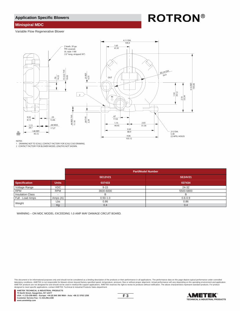
Application Specific Blowers
Minispiral MDC
Variable Flow Regenerative Blower
2 leads. 20 ga.TFE covered.UL style 1180 (12" long, stripped 50")
1.54
1.75 2.03
3.50
4.06
.67
.09
TYP.
.25
REF.
17.02
44.45 51.56
88.9
103.12
6.35
2.29
39.1
2
(2) MTG. HOLES5.38
14.2
2
19.0
5
.56
.75
O.D
. TYP
.
1.13
.5313.46
28.7.68 MAX.17.27
.44
REF.
TYP.
11.1
8
0.328.13
1.80 REF.45.72
4.11 DIA.104.4
1.6541.91
Ø2.24 DIA.
56.9
2.10
53.3
4
4.16
REF
.10
5.66
.212 DIA.
2
OUT
IN
NOTES1 DRAWING NOT TO SCALE, CONTACT FACTORY FOR SCALE CAD DRAWING.2 CONTACT FACTORY FOR BLOWER MODEL LENGTHS NOT SHOWN.
INMM
Part/Model Number
SE12V21 SE24V21
Specification Units 037433 037434
Voltage Range VDC 9-15 24-32RPM RPM 3600-6000 5500-6800Insulation Class - B BFull - Load Amps Amps (A) 0.50-1.0 0.6-0.9
WeightLbsKg
0.860.4
0.860.4
WARNING – ON MDC MODEL: EXCEEDING 1.0 AMP MAY DAMAGE CIRCUIT BOARD.
F 3____
This document is for informational purposes only and should not be considered as a binding description of the products or their performance in all applications. The performance data on this page depicts typical performance under controlledlaboratory conditions. AMETEK is not responsible for blowers driven beyond factory specified speed, temperature, pressure, flow or without proper alignment. Actual performance will vary depending on the operating environment and application.AMETEK products are not designed for and should not be used in medical life support applications. AMETEK reserves the right to revise its products without notification. The above characteristics represent standard products. For productdesigned to meet specific applications, contact AMETEK Technical & Industrial Products Sales department.
AMETEK TECHNICAL & INDUSTRIAL PRODUCTS75 North Street, Saugerties, NY 12477USA: +1 215-256-6601 - Europe: +44 (0) 845 366 9664 - Asia: +86 21 5763 1258Customer Service Fax: +1 215.256.1338www.ametektip.com
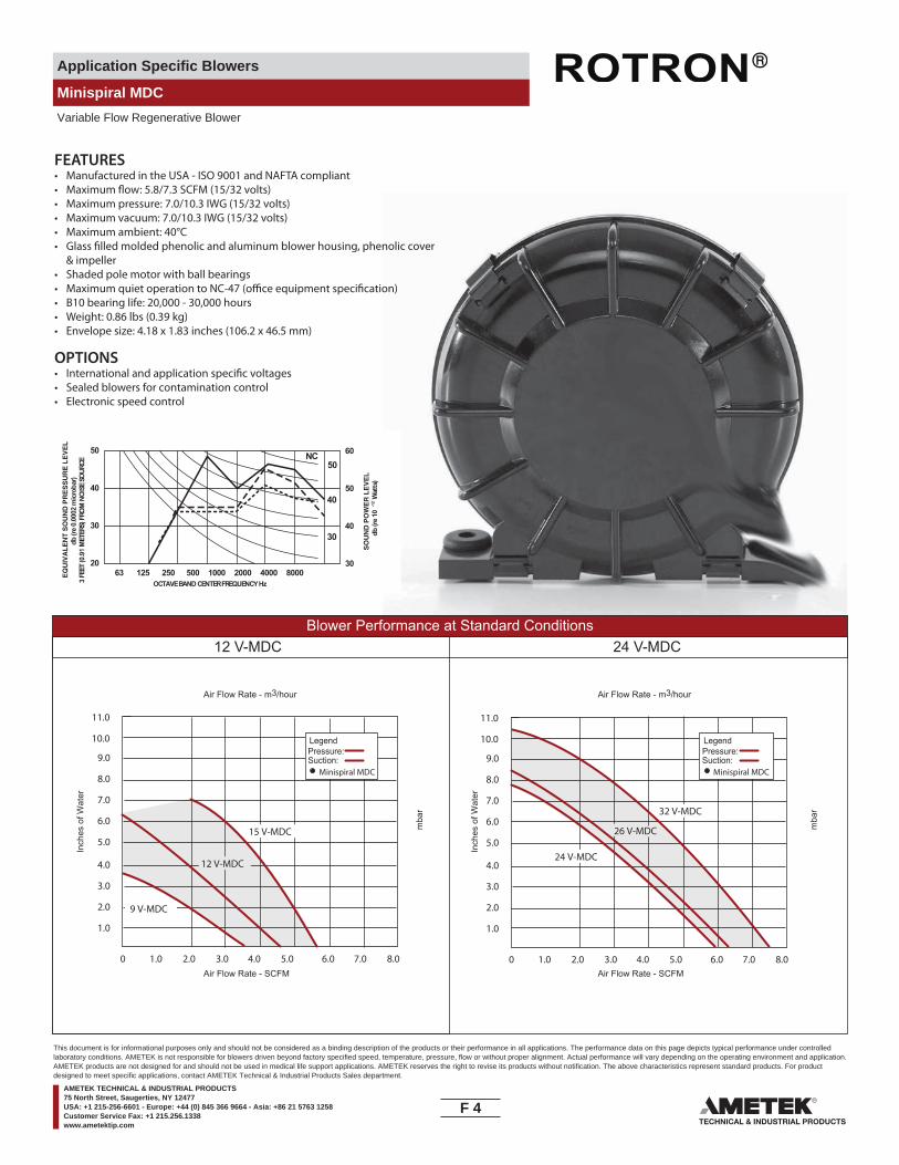
Application Specific Blowers
Minispiral MDC
Variable Flow Regenerative Blower
60
50
40
30
50
40
30
2063 125 250 500 1000 2000 4000 8000
db (r
e 10
-12 W
atts
)
OCTAVE BAND CENTER FREQUENCY Hz
db (r
e 0.
0002
micr
obar
)3
FEET
(0.9
1 M
ETER
S) F
ROM
NOI
SE S
OURC
E
50
40
30
NC
FEATURES• Manufactured in the USA - ISO 9001 and NAFTA compliant
• Maximum pressure: 7.0/10.3 IWG (15/32 volts)• Maximum vacuum: 7.0/10.3 IWG (15/32 volts)• Maximum ambient: 40°C
& impeller• Shaded pole motor with ball bearings
• B10 bearing life: 20,000 - 30,000 hours• Weight: 0.86 lbs (0.39 kg)• Envelope size: 4.18 x 1.83 inches (106.2 x 46.5 mm)
OPTIONS
• Sealed blowers for contamination control• Electronic speed control
Blower Performance at Standard Conditions12 V-MDC 24 V-MDC
Inch
es o
f Wat
er
mba
r
Air Flow Rate - SCFM
Air Flow Rate - m3/hour
Inch
es o
f Wat
er
mba
r
Air Flow Rate - SCFM
Air Flow Rate - m3/hour
11.0
0 1.0 2.0 3.0 4.0 5.0 6.0 7.0 8.0
10.0
9.0
8.0
7.0
6.0
5.0
4.0
3.0
2.0
1.0
11.0
0 1.0 2.0 3.0 4.0 5.0 6.0 7.0 8.0
10.0
9.0
8.0
7.0
6.0
5.0
4.0
3.0
2.0
1.0
15 V-MDC
12 V-MDC
9 V-MDC
32 V-MDC
26 V-MDC
24 V-MDC
LegendPressure:Suction:
Minispiral MDC
LegendPressure:Suction:
Minispiral MDC
F 4____
This document is for informational purposes only and should not be considered as a binding description of the products or their performance in all applications. The performance data on this page depicts typical performance under controlledlaboratory conditions. AMETEK is not responsible for blowers driven beyond factory specified speed, temperature, pressure, flow or without proper alignment. Actual performance will vary depending on the operating environment and application.AMETEK products are not designed for and should not be used in medical life support applications. AMETEK reserves the right to revise its products without notification. The above characteristics represent standard products. For productdesigned to meet specific applications, contact AMETEK Technical & Industrial Products Sales department.
AMETEK TECHNICAL & INDUSTRIAL PRODUCTS75 North Street, Saugerties, NY 12477USA: +1 215-256-6601 - Europe: +44 (0) 845 366 9664 - Asia: +86 21 5763 1258Customer Service Fax: +1 215.256.1338www.ametektip.com

Application Specific Blowers
Minispiral 12/24V HDC
Variable Flow Regenerative Blower
BOTH PORTS
0.57
OD
14.5
1.1429.0
1.9950.5
2.17
55.2
2.26
57.4
1.1629.5
0.256.40.63
16.0
0.9223.4
0.5413.7
0.8321.1 0.
75 O
D19
.1
Ø1.
8346
.5
1.1930.2
2.8271.6
0.6616.8
3.5088.9
4.21
106.
9
Ø 4.20106.7
2.11
53.6
1.86
47.2
0.57
14.5
0.44
11.2
1.6541.9
0.6717.0
4.07103.4
20 GA. TFE COVEREDUL STYLE 1180
14" LONG, STRIPPED 1/2"
NOTES1 DRAWING NOT TO SCALE, CONTACT FACTORY FOR SCALE CAD DRAWING.2 CONTACT FACTORY FOR BLOWER MODEL LENGTHS NOT SHOWN.
INMM
Part/Model Number
SE12RE21 SE24RE21
Specification Units 081548 080847
Voltage Range VDC 7.5-15 24-32RPM RPM 4400-8750 4400-8750Insulation Class - B BFull - Load Amps Amps (A) 1.2-2.5 1.2-1.6
WeightLbsKg
1.00.5
1.00.5
WARNING – ON HDC MODEL: MOTOR IS NOT POLARITY PROTECTED. CHECK POLARITY CAREFULLY BEFORE ENERGIZING BLOWER.
F 5____
This document is for informational purposes only and should not be considered as a binding description of the products or their performance in all applications. The performance data on this page depicts typical performance under controlledlaboratory conditions. AMETEK is not responsible for blowers driven beyond factory specified speed, temperature, pressure, flow or without proper alignment. Actual performance will vary depending on the operating environment and application.AMETEK products are not designed for and should not be used in medical life support applications. AMETEK reserves the right to revise its products without notification. The above characteristics represent standard products. For productdesigned to meet specific applications, contact AMETEK Technical & Industrial Products Sales department.
AMETEK TECHNICAL & INDUSTRIAL PRODUCTS75 North Street, Saugerties, NY 12477USA: +1 215-256-6601 - Europe: +44 (0) 845 366 9664 - Asia: +86 21 5763 1258Customer Service Fax: +1 215.256.1338www.ametektip.com
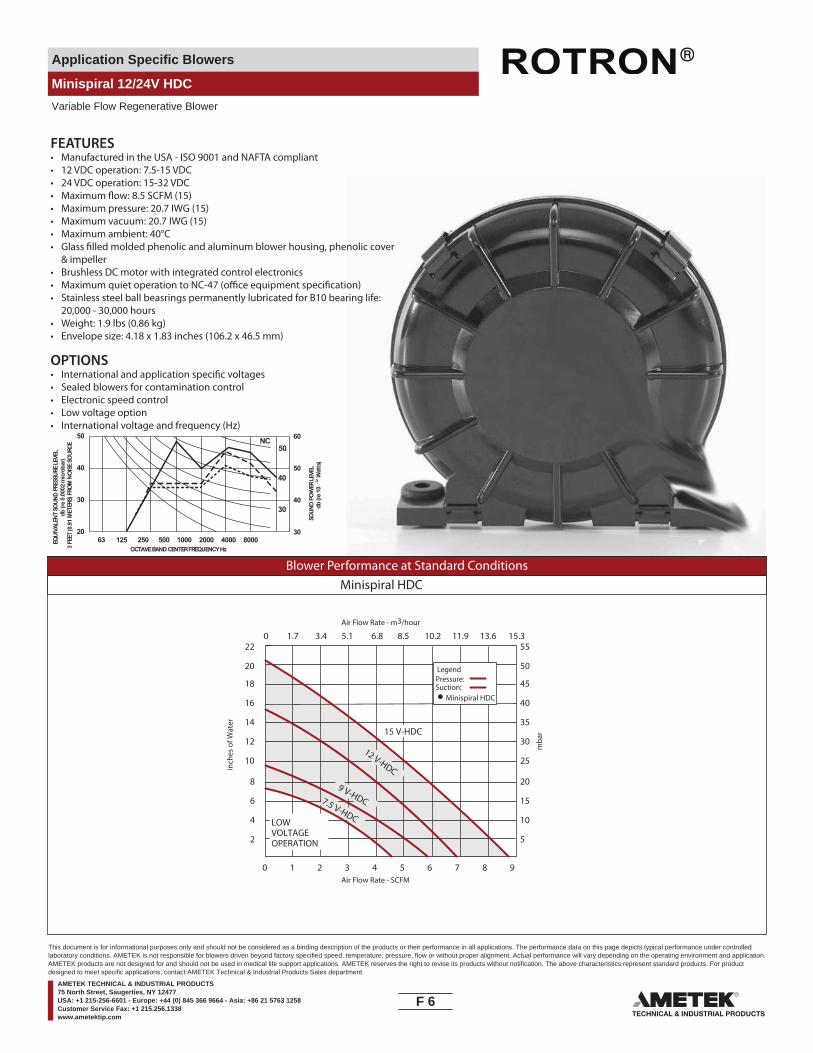
Application Specific Blowers
Minispiral 12/24V HDC
Variable Flow Regenerative Blower
60
50
40
30
50
40
30
2063 125 250 500 1000 2000 4000 8000
SOUN
D PO
WER
LEVE
L db
(re
10-1
2 Wat
ts)
OCTAVE BAND CENTER FREQUENCY Hz
EQUI
VALE
NT S
OUND
PRE
SSUR
E LE
VEL
db (r
e 0.
0002
micr
obar
)3
FEET
(0.9
1 M
ETER
S) F
ROM
NOI
SE S
OURC
E
50
40
30
NC
FEATURES• Manufactured in the USA - ISO 9001 and NAFTA compliant• 12 VDC operation: 7.5-15 VDC• 24 VDC operation: 15-32 VDC
• Maximum pressure: 20.7 IWG (15)• Maximum vacuum: 20.7 IWG (15)• Maximum ambient: 40°C
& impeller• Brushless DC motor with integrated control electronics
• Stainless steel ball beasrings permanently lubricated for B10 bearing life: 20,000 - 30,000 hours
• Weight: 1.9 lbs (0.86 kg)• Envelope size: 4.18 x 1.83 inches (106.2 x 46.5 mm)
OPTIONS
• Sealed blowers for contamination control• Electronic speed control• Low voltage option• International voltage and frequency (Hz)
Blower Performance at Standard ConditionsMinispiral HDC
Inch
es o
f Wat
er
mba
r
Air Flow Rate - SCFM
Air Flow Rate - m3/hour
220 1.7 3.4 5.1 6.8 8.5 10.2 11.9 13.6 15.3
0 1 2 3 4 5 6 7 8 9
20
18
16
14
12
10
8
6
4
2
55
50
45
40
35
30
25
20
15
10
5
15 V-HDC
12 V-HDC
9 V-HDC7.5 V-HDCLOWVOLTAGEOPERATION
LegendPressure:Suction:
Minispiral HDC
F 6____
This document is for informational purposes only and should not be considered as a binding description of the products or their performance in all applications. The performance data on this page depicts typical performance under controlledlaboratory conditions. AMETEK is not responsible for blowers driven beyond factory specified speed, temperature, pressure, flow or without proper alignment. Actual performance will vary depending on the operating environment and application.AMETEK products are not designed for and should not be used in medical life support applications. AMETEK reserves the right to revise its products without notification. The above characteristics represent standard products. For productdesigned to meet specific applications, contact AMETEK Technical & Industrial Products Sales department.
AMETEK TECHNICAL & INDUSTRIAL PRODUCTS75 North Street, Saugerties, NY 12477USA: +1 215-256-6601 - Europe: +44 (0) 845 366 9664 - Asia: +86 21 5763 1258Customer Service Fax: +1 215.256.1338www.ametektip.com
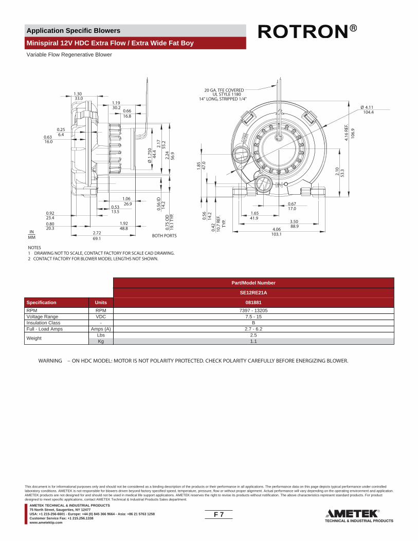
Application Specific Blowers
Minispiral 12V HDC Extra Flow / Extra Wide Fat Boy
Variable Flow Regenerative Blower
BOTH PORTS
0.56
ID14
.2
1.0626.9
1.9248.8
2.17
55.2
2.24
56.9
1.3033.0
0.256.40.63
16.0
0.9223.4
0.5313.5
0.8020.3 0.
75 O
D19
.1 T
YP.
Ø1.
750
44.4
1.1930.2
2.7269.1
0.6616.8
3.5088.9
4.16
REF
.10
6.9
Ø 4.11104.4
2.10
53.31.
8547
.00.
5614
.20.
4210
.7 R
EF.
T
YP.
1.6541.9
0.6717.0
4.06103.1
20 GA. TFE COVEREDUL STYLE 1180
14" LONG, STRIPPED 1/4"
NOTES1 DRAWING NOT TO SCALE, CONTACT FACTORY FOR SCALE CAD DRAWING.2 CONTACT FACTORY FOR BLOWER MODEL LENGTHS NOT SHOWN.
INMM
Part/Model Number
SE12RE21A
Specification Units 081881
RPM RPM 7397 - 13205Voltage Range VDC 7.5 - 15Insulation Class - BFull - Load Amps Amps (A) 2.7 - 6.2
WeightLbsKg
2.51.1
WARNING – ON HDC MODEL: MOTOR IS NOT POLARITY PROTECTED. CHECK POLARITY CAREFULLY BEFORE ENERGIZING BLOWER.
F 7____
This document is for informational purposes only and should not be considered as a binding description of the products or their performance in all applications. The performance data on this page depicts typical performance under controlledlaboratory conditions. AMETEK is not responsible for blowers driven beyond factory specified speed, temperature, pressure, flow or without proper alignment. Actual performance will vary depending on the operating environment and application.AMETEK products are not designed for and should not be used in medical life support applications. AMETEK reserves the right to revise its products without notification. The above characteristics represent standard products. For productdesigned to meet specific applications, contact AMETEK Technical & Industrial Products Sales department.
AMETEK TECHNICAL & INDUSTRIAL PRODUCTS75 North Street, Saugerties, NY 12477USA: +1 215-256-6601 - Europe: +44 (0) 845 366 9664 - Asia: +86 21 5763 1258Customer Service Fax: +1 215.256.1338www.ametektip.com

Application Specific Blowers
Minispiral 12V HDC Extra Flow / Extra Wide Fat Boy
Variable Flow Regenerative Blower
60
50
40
30
50
40
30
2063 125 250 500 1000 2000 4000 8000
SOU
ND
PO
WER
LEV
EL
db (r
e 10
-12 W
atts
)
OCTAVE BAND CENTER FREQUENCY Hz
EQU
IVA
LEN
T SO
UN
D P
RES
SUR
E LE
VEL
db (r
e 0.
0002
mic
roba
r)3
FEET
(0.9
1 M
ETER
S) F
RO
M N
OIS
E SO
UR
CE
50
40
30
NC
FEATURES• Manufactured in the USA - ISO 9001 and NAFTA compliant
• Maximum pressure: 26 IWG (15)• Maximum vacuum: 26 IWG (15)• Maximum ambient: 40°C
• Brushless DC motor with integrated control electronics• Stainless steel ball beasrings permanently lubricated for B10 bearing life:
20,000 - 30,000 hours• Weight: 1.9 lbs (0.86 kg)• Compact high performance design: 4.18 x 1.83 inches (106.2 x 46.5 mm)
OPTIONS
• Sealed blowers for contamination control• Electronic speed control• Low voltage option• Speed semsing output (FPS)
Blower Performance at Standard ConditionsMinispiral HDC
Inch
es o
f Wat
er
mba
r
Air Flow Rate - SCFM
Air Flow Rate - m3/hour
24
260 1.7 3.4 5.1 6.8 8.5 10.2 11.9 13.6 15.3 17.0 18.7 20.4 22.1
0 1 2 3 4 5 6 7 8 9 10 11 12 13
22
20
18
16
14
12
10
8
6
4
2
0
50
55
60
65
45
40
35
30
25
20
15
10
5
0
15 V-HDC
12 V-HDC
7.5 V-HDC
LOWVOLTAGEOPERATION
LegendPressure:Suction:
Minispiral HDC
F 8____
This document is for informational purposes only and should not be considered as a binding description of the products or their performance in all applications. The performance data on this page depicts typical performance under controlledlaboratory conditions. AMETEK is not responsible for blowers driven beyond factory specified speed, temperature, pressure, flow or without proper alignment. Actual performance will vary depending on the operating environment and application.AMETEK products are not designed for and should not be used in medical life support applications. AMETEK reserves the right to revise its products without notification. The above characteristics represent standard products. For productdesigned to meet specific applications, contact AMETEK Technical & Industrial Products Sales department.
AMETEK TECHNICAL & INDUSTRIAL PRODUCTS75 North Street, Saugerties, NY 12477USA: +1 215-256-6601 - Europe: +44 (0) 845 366 9664 - Asia: +86 21 5763 1258Customer Service Fax: +1 215.256.1338www.ametektip.com
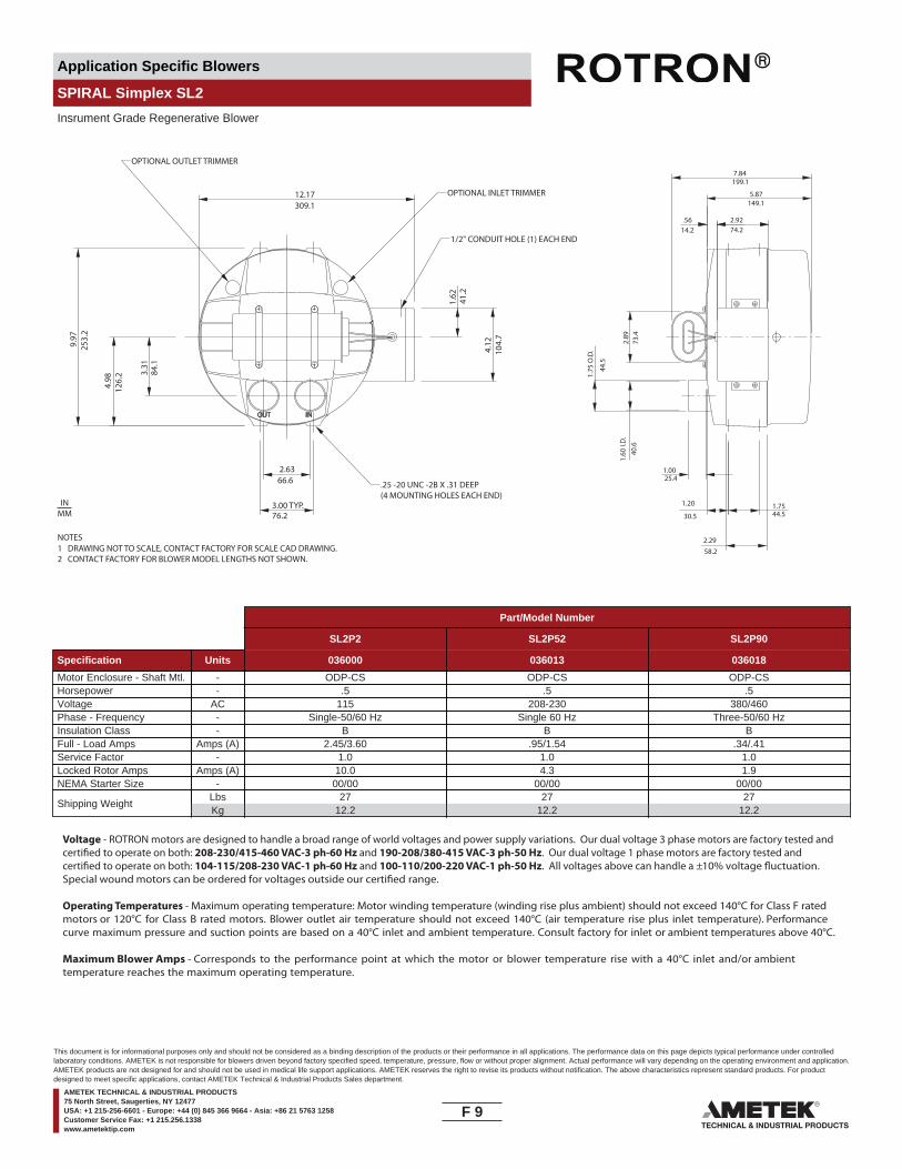
Application Specific Blowers
SPIRAL Simplex SL2
Insrument Grade Regenerative Blower
OUT IN
84.1
66.6
41.2
104.
7
44.5
73.4
74.214.2
1.75
O.D
.
3.31
1.62
4.12
5.87
2.92
2.89
309.1
199.1
1.00
1.20 1.75
25.4
30.5 44.5
12.17
3.00 TYP.76.2
7.84
149.1
.25 -20 UNC -2B X .31 DEEP(4 MOUNTING HOLES EACH END)
9.97
4.98
2.63
1.60
I.D
.
253.
2
126.
2
40.6
2.2958.2
OPTIONAL OUTLET TRIMMER
OPTIONAL INLET TRIMMER
1/2" CONDUIT HOLE (1) EACH END
.56
NOTES1 DRAWING NOT TO SCALE, CONTACT FACTORY FOR SCALE CAD DRAWING.2 CONTACT FACTORY FOR BLOWER MODEL LENGTHS NOT SHOWN.
INMM
Part/Model Number
SL2P2 SL2P52 SL2P90
Specification Units 036000 036013 036018
Motor Enclosure - Shaft Mtl. - ODP-CS ODP-CS ODP-CSHorsepower - .5 .5 .5Voltage AC 115 208-230 380/460Phase - Frequency - Single-50/60 Hz Single 60 Hz Three-50/60 HzInsulation Class - B B BFull - Load Amps Amps (A) 2.45/3.60 .95/1.54 .34/.41Service Factor - 1.0 1.0 1.0Locked Rotor Amps Amps (A) 10.0 4.3 1.9NEMA Starter Size - 00/00 00/00 00/00
Shipping WeightLbsKg
2712.2
2712.2
2712.2
Voltage - ROTRON motors are designed to handle a broad range of world voltages and power supply variations. Our dual voltage 3 phase motors are factory tested and certi�ed to operate on both: 208-230/415-460 VAC-3 ph-60 Hz and 190-208/380-415 VAC-3 ph-50 Hz. Our dual voltage 1 phase motors are factory tested and certi�ed to operate on both: 104-115/208-230 VAC-1 ph-60 Hz and 100-110/200-220 VAC-1 ph-50 Hz. All voltages above can handle a ±10% voltage �uctuation. Special wound motors can be ordered for voltages outside our certi�ed range.
Operating Temperatures - Maximum operating temperature: Motor winding temperature (winding rise plus ambient) should not exceed 140°C for Class F rated motors or 120°C for Class B rated motors. Blower outlet air temperature should not exceed 140°C (air temperature rise plus inlet temperature). Performance curve maximum pressure and suction points are based on a 40°C inlet and ambient temperature. Consult factory for inlet or ambient temperatures above 40°C.
Maximum Blower Amps - Corresponds to the performance point at which the motor or blower temperature rise with a 40°C inlet and/or ambient temperature reaches the maximum operating temperature.
F 9____
This document is for informational purposes only and should not be considered as a binding description of the products or their performance in all applications. The performance data on this page depicts typical performance under controlledlaboratory conditions. AMETEK is not responsible for blowers driven beyond factory specified speed, temperature, pressure, flow or without proper alignment. Actual performance will vary depending on the operating environment and application.AMETEK products are not designed for and should not be used in medical life support applications. AMETEK reserves the right to revise its products without notification. The above characteristics represent standard products. For productdesigned to meet specific applications, contact AMETEK Technical & Industrial Products Sales department.
AMETEK TECHNICAL & INDUSTRIAL PRODUCTS75 North Street, Saugerties, NY 12477USA: +1 215-256-6601 - Europe: +44 (0) 845 366 9664 - Asia: +86 21 5763 1258Customer Service Fax: +1 215.256.1338www.ametektip.com

Application Specific Blowers
SPIRAL Simplex SL2
Insrument Grade Regenerative Blower
FEATURES• Manufactured in the USA - ISO 9001 and NAFTA compliant
• Maximum pressure: 32 IWG• Maximum vacuum: 31.3 IWG• Standard motor: 0.5 HP, ODP
• Motor with permanently sealed ball bearings•• Quiet operation within OSHA standards • Thermal overload protection
OPTIONS• International voltage & frequency (Hz)• Hermetically sealed• UL & CSA approved motor• Remote drive (motorless) model
ACCESSORIES• Flowmeters reading in SCFM• Filters & moisture separators• Pressure gauges, vacuum gauges, & relief valves
••
Blower Performance at Standard Conditions60 Hz 50 Hz
Inch
es o
f Wat
er
mba
r
mba
r
Mot
or W
indi
ngTe
mp
Ris
e °C
Air Flow Rate - SCFMAir Flow Rate - SCFM
Air Flow Rate - m3/hourAir Flow Rate - m3/hour
Inch
es o
f Wat
erM
otor
Win
ding
Tem
p R
ise
°C
Blo
wer
Air
Tem
p R
ise
°C
Blo
wer
Air
Tem
p R
ise
°C
LegendPressure:Suction:
LegendPressure:Suction:
Spiral SL2 Spiral SL2
0 6 12 18 24 30 36 42 48 54 60 66
0 10 20 31 41 51 61 71 82 92 102 112
0
6
12
18
24
30
36
0
15
30
45
60
75
90
0 6 12 18 24 30 36 42 48 54 60 66
0 10 20 31 41 51 61 71 82 92 102 112
0
6
12
18
24
30
36
0
15
30
45
60
75
90
Temperature curves are based on standard model0
50
100
0
50
100Temperature curves are based on standard model
0
50
100
0
50
100
F 10____
This document is for informational purposes only and should not be considered as a binding description of the products or their performance in all applications. The performance data on this page depicts typical performance under controlledlaboratory conditions. AMETEK is not responsible for blowers driven beyond factory specified speed, temperature, pressure, flow or without proper alignment. Actual performance will vary depending on the operating environment and application.AMETEK products are not designed for and should not be used in medical life support applications. AMETEK reserves the right to revise its products without notification. The above characteristics represent standard products. For productdesigned to meet specific applications, contact AMETEK Technical & Industrial Products Sales department.
AMETEK TECHNICAL & INDUSTRIAL PRODUCTS75 North Street, Saugerties, NY 12477USA: +1 215-256-6601 - Europe: +44 (0) 845 366 9664 - Asia: +86 21 5763 1258Customer Service Fax: +1 215.256.1338www.ametektip.com

Application Specific Blowers
SPIRAL Duplex SL4
Insrument Grade Regenerative Blower
NOTES1 DRAWING NOT TO SCALE, CONTACT FACTORY FOR SCALE CAD DRAWING.2 CONTACT FACTORY FOR BLOWER MODEL LENGTHS NOT SHOWN.
INMM
6.56 MAX.166.6
7.21183.1
1/2” CONDUIT HOLE(1) EACH END
IN
OUT
152.46.00
13.0
3 M
AX.
331
9.97
253.
2
3.00 TYP.76.2
9.24
5.76146.3
234.7
4.12
104.
7
41.2
1.62
1.3835.1
2.92
2.8772.9
3.1780.5
.25-20 UNC-2B X .31 DEEP(6) MOUNTING HOLES EACH END74.2
1.60
I.D
.
1.75
O.D
.
44.5
40.6
66.6
2.62
9.89
DIA
.
251.
2
4.56 MAX.115.8
CAPACITORS ON SINGLEPHASE MODELS ONLY
Part/Model Number
SL4P2 SL4P52
Specification Units 036009 036027
Motor Enclosure - Shaft Mtl. - ODP-CS ODP-CSHorsepower - .75 .75Voltage AC 115 208-230Phase - Frequency - Single-50/60 Hz Single 60 HzInsulation Class - B BFull - Load Amps Amps (A) 3.70/3.80 2.29/2.20Service Factor - 1.0 1.0Locked Rotor Amps Amps (A) 14.0 7.0NEMA Starter Size - 00/00 00/00
Shipping WeightLbsKg
4219.1
4219.1
Voltage - ROTRON motors are designed to handle a broad range of world voltages and power supply variations. Our dual voltage 3 phase motors are factory tested and certi�ed to operate on both: 208-230/415-460 VAC-3 ph-60 Hz and 190-208/380-415 VAC-3 ph-50 Hz. Our dual voltage 1 phase motors are factory tested and certi�ed to operate on both: 104-115/208-230 VAC-1 ph-60 Hz and 100-110/200-220 VAC-1 ph-50 Hz. All voltages above can handle a ±10% voltage �uctuation. Special wound motors can be ordered for voltages outside our certi�ed range.
Operating Temperatures - Maximum operating temperature: Motor winding temperature (winding rise plus ambient) should not exceed 140°C for Class F rated motors or 120°C for Class B rated motors. Blower outlet air temperature should not exceed 140°C (air temperature rise plus inlet temperature). Performance curve maximum pressure and suction points are based on a 40°C inlet and ambient temperature. Consult factory for inlet or ambient temperatures above 40°C.
Maximum Blower Amps - Corresponds to the performance point at which the motor or blower temperature rise with a 40°C inlet and/or ambient temperature reaches the maximum operating temperature.
F 11____
This document is for informational purposes only and should not be considered as a binding description of the products or their performance in all applications. The performance data on this page depicts typical performance under controlledlaboratory conditions. AMETEK is not responsible for blowers driven beyond factory specified speed, temperature, pressure, flow or without proper alignment. Actual performance will vary depending on the operating environment and application.AMETEK products are not designed for and should not be used in medical life support applications. AMETEK reserves the right to revise its products without notification. The above characteristics represent standard products. For productdesigned to meet specific applications, contact AMETEK Technical & Industrial Products Sales department.
AMETEK TECHNICAL & INDUSTRIAL PRODUCTS75 North Street, Saugerties, NY 12477USA: +1 215-256-6601 - Europe: +44 (0) 845 366 9664 - Asia: +86 21 5763 1258Customer Service Fax: +1 215.256.1338www.ametektip.com
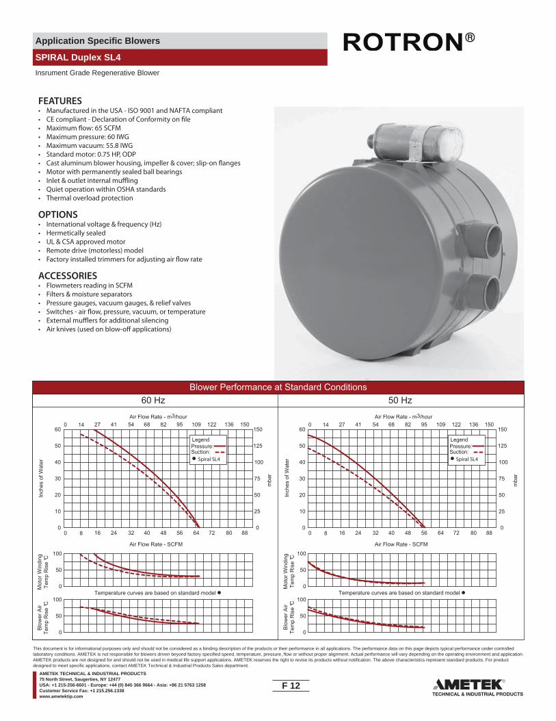
Application Specific Blowers
SPIRAL Duplex SL4
Insrument Grade Regenerative Blower
FEATURES• Manufactured in the USA - ISO 9001 and NAFTA compliant
• Maximum pressure: 60 IWG• Maximum vacuum: 55.8 IWG• Standard motor: 0.75 HP, ODP
• Motor with permanently sealed ball bearings•• Quiet operation within OSHA standards • Thermal overload protection
OPTIONS• International voltage & frequency (Hz)• Hermetically sealed• UL & CSA approved motor• Remote drive (motorless) model
ACCESSORIES• Flowmeters reading in SCFM• Filters & moisture separators• Pressure gauges, vacuum gauges, & relief valves
••
Blower Performance at Standard Conditions60 Hz 50 Hz
Inch
es o
f Wat
er
mba
r
mba
r
Mot
or W
indi
ngTe
mp
Ris
e °C
Air Flow Rate - SCFMAir Flow Rate - SCFM
Air Flow Rate - m3/hourAir Flow Rate - m3/hour
Inch
es o
f Wat
erM
otor
Win
ding
Tem
p R
ise
°C
Blo
wer
Air
Tem
p R
ise
°C
Blo
wer
Air
Tem
p R
ise
°C
LegendPressure:Suction:
LegendPressure:Suction:
Spiral SL4 Spiral SL4
0 8 16 24 32 40 48 56 64 72 80 88
0 14 27 41 54 68 82 95 109 122 136 150
0
10
20
30
40
50
60
0
25
50
75
100
125
150
0 8 16 24 32 40 48 56 64 72 80 88
0 14 27 41 54 68 82 95 109 122 136 150
0
10
20
30
40
50
60
0
25
50
75
100
125
150
Temperature curves are based on standard model0
50
100
0
50
100Temperature curves are based on standard model
0
50
100
0
50
100
F 12____
This document is for informational purposes only and should not be considered as a binding description of the products or their performance in all applications. The performance data on this page depicts typical performance under controlledlaboratory conditions. AMETEK is not responsible for blowers driven beyond factory specified speed, temperature, pressure, flow or without proper alignment. Actual performance will vary depending on the operating environment and application.AMETEK products are not designed for and should not be used in medical life support applications. AMETEK reserves the right to revise its products without notification. The above characteristics represent standard products. For productdesigned to meet specific applications, contact AMETEK Technical & Industrial Products Sales department.
AMETEK TECHNICAL & INDUSTRIAL PRODUCTS75 North Street, Saugerties, NY 12477USA: +1 215-256-6601 - Europe: +44 (0) 845 366 9664 - Asia: +86 21 5763 1258Customer Service Fax: +1 215.256.1338www.ametektip.com
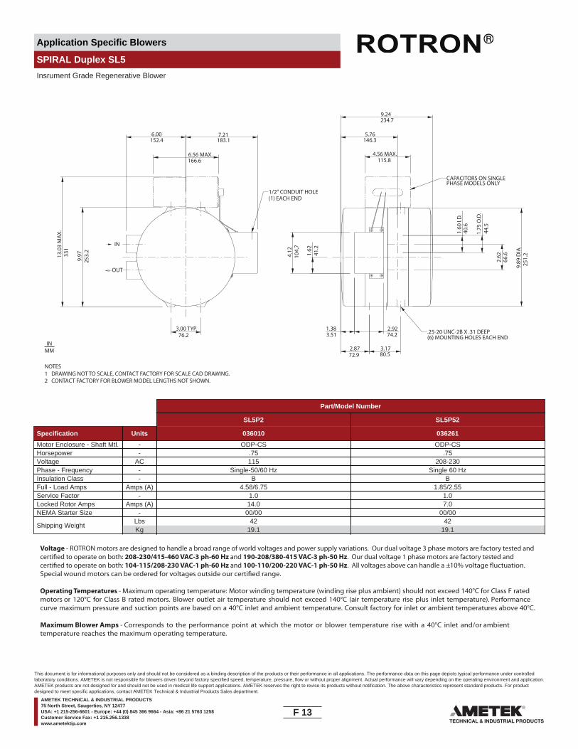
Application Specific Blowers
SPIRAL Duplex SL5
Insrument Grade Regenerative Blower
IN
OUT
76.2
183.1
331
80.572.9
74.23.51
41.2
66.6
PHASE MODELS ONLY
(6) MOUNTING HOLES EACH END
(1) EACH END
6.00152.4
166.66.56 MAX.
7.21
13.0
3 M
AX.
3.00 TYP.
4.12 1.62
1.75
O.D
.
1.38 2.92
2.87 3.17
104.
7
44.5
4.56 MAX.115.8
2.629.97
253.
2
9.24234.7
5.76146.3
1.60
I.D
.40
.6
9.89
DIA
.25
1.2
CAPACITORS ON SINGLE
.25-20 UNC-2B X .31 DEEP
1/2" CONDUIT HOLE
NOTES1 DRAWING NOT TO SCALE, CONTACT FACTORY FOR SCALE CAD DRAWING.2 CONTACT FACTORY FOR BLOWER MODEL LENGTHS NOT SHOWN.
INMM
Part/Model Number
SL5P2 SL5P52
Specification Units 036010 036261
Motor Enclosure - Shaft Mtl. - ODP-CS ODP-CSHorsepower - .75 .75Voltage AC 115 208-230Phase - Frequency - Single-50/60 Hz Single 60 HzInsulation Class - B BFull - Load Amps Amps (A) 4.58/6.75 1.85/2.55Service Factor - 1.0 1.0Locked Rotor Amps Amps (A) 14.0 7.0NEMA Starter Size - 00/00 00/00
Shipping WeightLbsKg
4219.1
4219.1
Voltage - ROTRON motors are designed to handle a broad range of world voltages and power supply variations. Our dual voltage 3 phase motors are factory tested and certi�ed to operate on both: 208-230/415-460 VAC-3 ph-60 Hz and 190-208/380-415 VAC-3 ph-50 Hz. Our dual voltage 1 phase motors are factory tested and certi�ed to operate on both: 104-115/208-230 VAC-1 ph-60 Hz and 100-110/200-220 VAC-1 ph-50 Hz. All voltages above can handle a ±10% voltage �uctuation. Special wound motors can be ordered for voltages outside our certi�ed range.
Operating Temperatures - Maximum operating temperature: Motor winding temperature (winding rise plus ambient) should not exceed 140°C for Class F rated motors or 120°C for Class B rated motors. Blower outlet air temperature should not exceed 140°C (air temperature rise plus inlet temperature). Performance curve maximum pressure and suction points are based on a 40°C inlet and ambient temperature. Consult factory for inlet or ambient temperatures above 40°C.
Maximum Blower Amps - Corresponds to the performance point at which the motor or blower temperature rise with a 40°C inlet and/or ambient temperature reaches the maximum operating temperature.
F 13____
This document is for informational purposes only and should not be considered as a binding description of the products or their performance in all applications. The performance data on this page depicts typical performance under controlledlaboratory conditions. AMETEK is not responsible for blowers driven beyond factory specified speed, temperature, pressure, flow or without proper alignment. Actual performance will vary depending on the operating environment and application.AMETEK products are not designed for and should not be used in medical life support applications. AMETEK reserves the right to revise its products without notification. The above characteristics represent standard products. For productdesigned to meet specific applications, contact AMETEK Technical & Industrial Products Sales department.
AMETEK TECHNICAL & INDUSTRIAL PRODUCTS75 North Street, Saugerties, NY 12477USA: +1 215-256-6601 - Europe: +44 (0) 845 366 9664 - Asia: +86 21 5763 1258Customer Service Fax: +1 215.256.1338www.ametektip.com
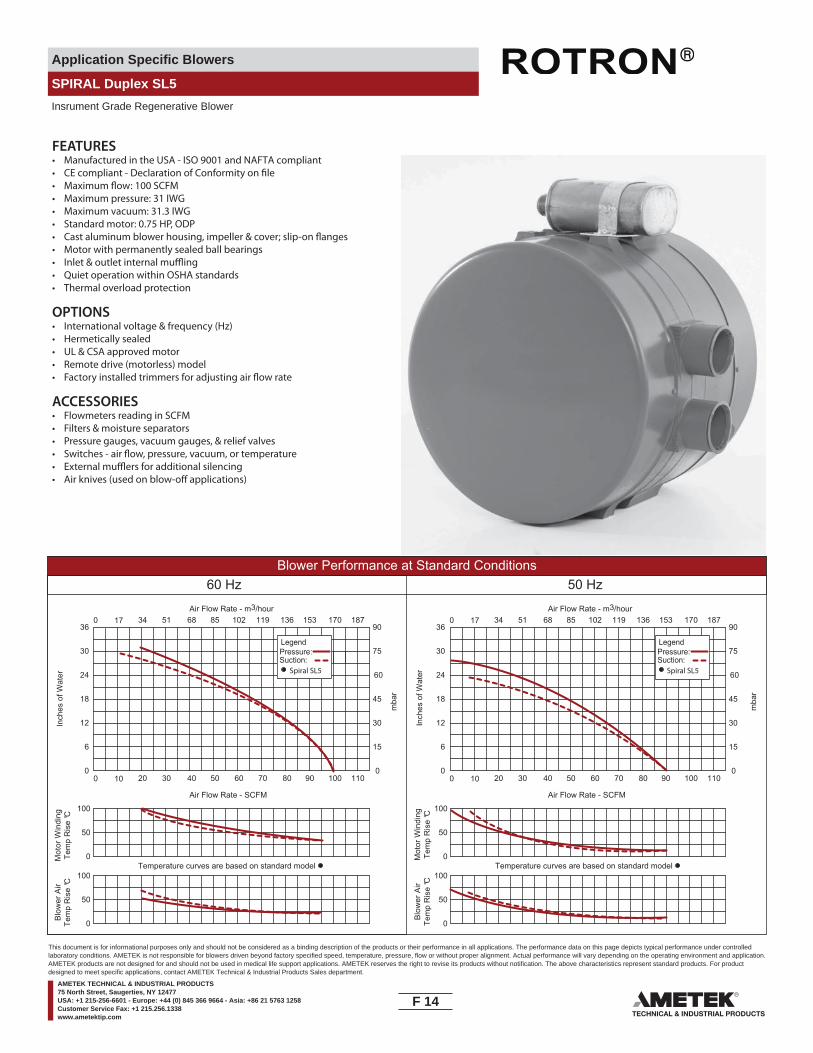
Application Specific Blowers
SPIRAL Duplex SL5
Insrument Grade Regenerative Blower
FEATURES• Manufactured in the USA - ISO 9001 and NAFTA compliant
• Maximum pressure: 31 IWG• Maximum vacuum: 31.3 IWG• Standard motor: 0.75 HP, ODP
• Motor with permanently sealed ball bearings•• Quiet operation within OSHA standards • Thermal overload protection
OPTIONS• International voltage & frequency (Hz)• Hermetically sealed• UL & CSA approved motor• Remote drive (motorless) model
ACCESSORIES• Flowmeters reading in SCFM• Filters & moisture separators• Pressure gauges, vacuum gauges, & relief valves
••
Blower Performance at Standard Conditions60 Hz 50 Hz
Inch
es o
f Wat
er
mba
r
mba
r
Mot
or W
indi
ngTe
mp
Ris
e °C
Air Flow Rate - SCFMAir Flow Rate - SCFM
Air Flow Rate - m3/hourAir Flow Rate - m3/hour
Inch
es o
f Wat
erM
otor
Win
ding
Tem
p R
ise
°C
Blo
wer
Air
Tem
p R
ise
°C
Blo
wer
Air
Tem
p R
ise
°C
LegendPressure:Suction:
LegendPressure:Suction:
Spiral SL5 Spiral SL5
0 10 20 30 40 50 60 70 80 90 100 110
0 17 34 51 68 85 102 119 136 153 170 187
0
6
12
18
24
30
36
Temperature curves are based on standard model0
50
100
0
50
100Temperature curves are based on standard model
0
50
100
0
50
100
0
15
30
45
60
75
90
0 10 20 30 40 50 60 70 80 90 100 110
0 17 34 51 68 85 102 119 136 153 170 187
0
6
12
18
24
30
36
0
15
30
45
60
75
90
F 14____
This document is for informational purposes only and should not be considered as a binding description of the products or their performance in all applications. The performance data on this page depicts typical performance under controlledlaboratory conditions. AMETEK is not responsible for blowers driven beyond factory specified speed, temperature, pressure, flow or without proper alignment. Actual performance will vary depending on the operating environment and application.AMETEK products are not designed for and should not be used in medical life support applications. AMETEK reserves the right to revise its products without notification. The above characteristics represent standard products. For productdesigned to meet specific applications, contact AMETEK Technical & Industrial Products Sales department.
AMETEK TECHNICAL & INDUSTRIAL PRODUCTS75 North Street, Saugerties, NY 12477USA: +1 215-256-6601 - Europe: +44 (0) 845 366 9664 - Asia: +86 21 5763 1258Customer Service Fax: +1 215.256.1338www.ametektip.com

Application Specific Blowers
Nautilair
NOTES1 DRAWING NOT TO SCALE, CONTACT FACTORY FOR SCALE CAD DRAWING.2 CONTACT FACTORY FOR BLOWER MODEL LENGTHS NOT SHOWN.
INMM
AB
B
CX
W
R S
L
F
PU
M N O11
.3 (2
86.9
6)
J
(4X) MTG HOLES0.28 DIA
KG
VZ
T
2.50 (63.50)AA
Ø.40HOLE (4X)
1.75 (44.45)3.5 (88.90)
TEFC MODEL
D (R
EF)
5.38
(136
.65)
E
Y
Ø5.
19 (1
31.8
3)
.495 (12.57)
.495 (12.57)
KNOCKOUT FORAIRFLOW SWITCH(BOTH SIDES)
A
CX
W
Ø7.69 (195.28)
R S
L
P (DIA. INLET)F
U
M N O
J
(4X) MTG HOLES0.28 DIA
KG
VZ
H (TYP.)
T2.53 (64.31)
HOLES FOR ELECTRICAL CONNECTIONS
1/4-20 UNC-2B X .50 DP.(4) MTG HOLES EQUALLYSPACED ON A 3.625 DIA. B.C.
1/4-20 UNC-2B X .50 DP.(4) MTG HOLES
1.75 (44.45)3.50 (88.90)
STANDARD MODEL
D3.
49 (8
8.75
)
1.23
(31.
35)
E
Y
1.50 (38.10)
KNOCKOUT FORAIRFLOW SWITCH(BOTH SIDES)
A
B
C
D
E
F
G
H
J
K
L
M
N
O
P
R
S
T
U
V
W
X
Y
Z
AA
11.55(293.2)
6.07(154.2)
0.495(12.6)
6.04(153.4)
10.76(273.3)
5.19(131.8)
4.25(108)
0.25(6.4)
1.75(44.5)
5.10(129.5)
3.13(79.5)
4.75(120.7)
5.59(142)
5.90(149.9)
6.0(152.4)
1.97(50)
2.78(70.6)
7.26(184.4)
2.38(60.5)
2.13(54.1)
2.96(75.2)
0.84(21.3)
4.0(101.6)
2.5(63.5)
---
11.55(293.2)
NC33AG58(XP)
NC33AE9(TEFC)
NC33A(STD)
6.07(154.2)
0.495(12.6)
6.04(153.4)
10.76(273.3)
5.19(131.8)
4.25(108)
0.25(6.4)
1.75(44.5)
5.10(129.5)
3.13(79.5)
4.75(120.7)
5.59(142)
5.90(149.9)
6.0(152.4)
4.20(106.7)
2.78(70.6)
13.94(354.1)
2.38(60.5)
2.13(54.1)
2.96(75.2)
0.84(21.3)
4.0(101.6)
2.5(63.5)
---
11.55(293.2)
6.07(154.2)
0.495(12.6)
6.04(153.4)
10.76(273.3)
5.19(131.8)
4.25(108)
0.25(6.4)
1.75(44.5)
5.10(129.5)
3.13(79.5)
4.75(120.7)
5.59(142)
5.90(149.9)
6.0(152.4)
3.52(89.4)
2.78(70.6)
13.35(339.1)
2.38(60.5)
2.13(54.1)
2.96(75.2)
0.84(21.3)
4.0(101.6)
2.5(63.5)7.13
(181.1)
Part/Model Number
NC33A2G NC33A3G NC33A33G NC33AE9 NC33AG58
Specification Units 037791 037792 037793 080114 080113
Phase - Frequency - Single-50/60 Hz Single-50/60 Hz Three-50/60 Hz Single-50/60 Hz Single-50/60 HzVoltage AC 115 220/230 208-230 115/230 115/230RPM on 50/60 Hz - 2900/3500 2900/3500 2900/3500 2900/3500 2900/3500Insulation Class - B B B F FFull - Load Amps Amps (A) 3.44/3.84 1.47/1.82 1.10/1.18 6.0/3.0 4.4Locked Rotor Amps Amps (A) 8.25 4.0 5.0 21/10.5 38/19
Shipping WeightLbsKg
188.2
188.2
188.2
2812.7
3013.6
Motor Enclosure - Standard Standard Standard TEFC XP
F 15____
This document is for informational purposes only and should not be considered as a binding description of the products or their performance in all applications. The performance data on this page depicts typical performance under controlledlaboratory conditions. AMETEK is not responsible for blowers driven beyond factory specified speed, temperature, pressure, flow or without proper alignment. Actual performance will vary depending on the operating environment and application.AMETEK products are not designed for and should not be used in medical life support applications. AMETEK reserves the right to revise its products without notification. The above characteristics represent standard products. For productdesigned to meet specific applications, contact AMETEK Technical & Industrial Products Sales department.
AMETEK TECHNICAL & INDUSTRIAL PRODUCTS75 North Street, Saugerties, NY 12477USA: +1 215-256-6601 - Europe: +44 (0) 845 366 9664 - Asia: +86 21 5763 1258Customer Service Fax: +1 215.256.1338www.ametektip.com

Application Specific Blowers
Nautilair
80
70
60
50
40
90
80
70
60
50
EQUI
VALE
NT S
OUND
PRE
SSUR
E LE
VEL –
db (r
e 0.
0002
micr
obar
)3
FEET
(0.9
1 M
ETER
S) F
ROM
NOI
SE S
OURC
E
SOUN
D PO
WER
LEVE
L –db
(re
10
Wat
ts)
2075
75150
150300
300600
6001200
12002400
24004800
4,80010,000
OCTAVE BAND CENTER FREQUENCY Hz
-12
NC33
FEATURES• Manufactured in the USA - ISO 9001 and NAFTA compliant
• Maximum pressure: 3.5 IWG • Thermoset plastic blower housing with aluminum impeller• Permanently seal ball bearings in motor - L10 bearing life: 50,000 hours• Quiet operation within OSHA standards• Shipping weight: 18 lbs (8.2 kg) for standard model 28 lbs (12.7 kg) for TEFC model 30 lbs (13.6 kg) for XP model• Designed for UL and CSA• Automatic thermal overload protection on standard motor enclosures
Blower Performance at Standard Conditions60 Hz 50 Hz
Inch
es o
f Wat
er
mba
r
mba
r
Air Flow Rate - SCFMAir Flow Rate - SCFM
Air Flow Rate - m3/hourAir Flow Rate - m3/hour
Inch
es o
f Wat
er
LegendPressure:Suction:
LegendPressure:Suction:
NC33 NC33
0 50 100 150 200 250 300 350 400 450 500 550
0 85 170 255 340 425 510 595 680 765 850 935
0
1
2
3
4
5
6
0
2.5
5.0
7.5
10.0
12.5
15.0
0 50 100 150 200 250 300 350 400 450 500 550
0 85 170 255 340 425 510 595 680 765 850 935
0
1
2
3
4
5
6
0
2.5
5.0
7.5
10.0
12.5
15.0
F 16____
This document is for informational purposes only and should not be considered as a binding description of the products or their performance in all applications. The performance data on this page depicts typical performance under controlledlaboratory conditions. AMETEK is not responsible for blowers driven beyond factory specified speed, temperature, pressure, flow or without proper alignment. Actual performance will vary depending on the operating environment and application.AMETEK products are not designed for and should not be used in medical life support applications. AMETEK reserves the right to revise its products without notification. The above characteristics represent standard products. For productdesigned to meet specific applications, contact AMETEK Technical & Industrial Products Sales department.
AMETEK TECHNICAL & INDUSTRIAL PRODUCTS75 North Street, Saugerties, NY 12477USA: +1 215-256-6601 - Europe: +44 (0) 845 366 9664 - Asia: +86 21 5763 1258Customer Service Fax: +1 215.256.1338www.ametektip.com
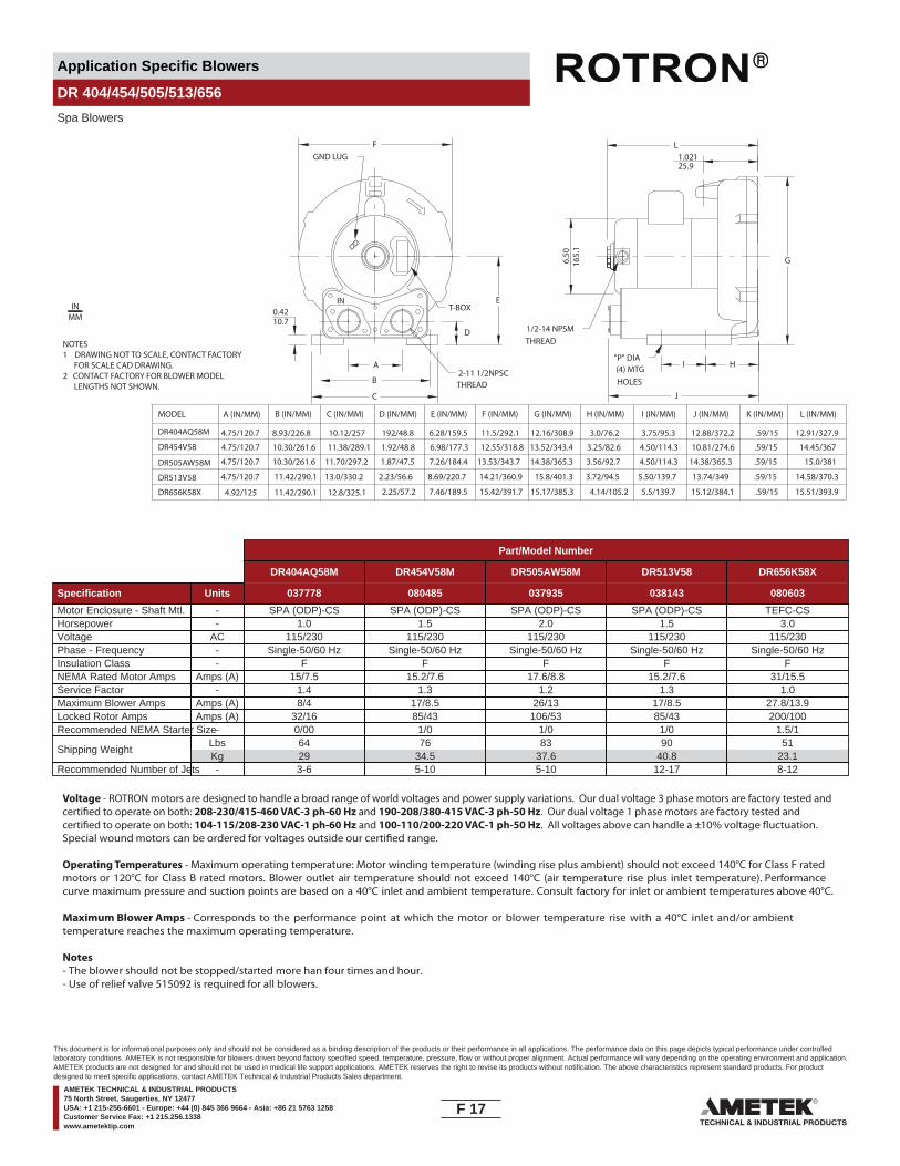
Application Specific Blowers
DR 404/454/505/513/656
Spa Blowers
G6.50
165.
1
B
C
E0.4210.7
1.02125.9
LF
I HA
J
D
(4) MTGHOLES
THREAD
THREAD
MODEL
DR404AQ58M
DR454V58
DR505AW58M
DR513V58
DR656K58X
A (IN/MM) B (IN/MM) C (IN/MM) D (IN/MM) E (IN/MM) F (IN/MM) G (IN/MM) H (IN/MM) I (IN/MM) J (IN/MM) K (IN/MM) L (IN/MM)
8.93/226.8 10.12/257
4.75/120.7
4.75/120.7 192/48.8 6.28/159.5 11.5/292.1 12.16/308.9 3.0/76.2 3.75/95.3 12.88/372.2 .59/15 12.91/327.9
2.25/57.2 7.46/189.5 15.42/391.7 15.17/385.3 4.14/105.2 5.5/139.7 15.12/384.1 .59/15 15.51/393.9
4.75/120.7
10.30/261.6 11.38/289.1 1.92/48.8 6.98/177.3 12.55/318.8 3.25/82.6 4.50/114.3 10.81/274.6 .59/15 14.45/367
10.30/261.6 11.70/297.2 1.87/47.5 7.26/184.4 13.53/343.7
13.52/343.4
14.38/365.3 3.56/92.7 4.50/114.3 14.38/365.3 .59/15 15.0/381
11.42/290.14.75/120.7 2.23/56.6 8.69/220.7 14.21/360.9 15.8/401.3 3.72/94.5 5.50/139.7 13.74/349 .59/15 14.58/370.3
4.92/125 11.42/290.1 12.8/325.1
13.0/330.2
1/2-14 NPSM
T-BOX
GND LUG
"P" DIA
2-11 1/2NPSC
IN
NOTES1 DRAWING NOT TO SCALE, CONTACT FACTORY FOR SCALE CAD DRAWING.2 CONTACT FACTORY FOR BLOWER MODEL LENGTHS NOT SHOWN.
INMM
Part/Model Number
DR404AQ58M DR454V58M DR505AW58M DR513V58 DR656K58X
Specification Units 037778 080485 037935 038143 080603
Motor Enclosure - Shaft Mtl. - SPA (ODP)-CS SPA (ODP)-CS SPA (ODP)-CS SPA (ODP)-CS TEFC-CSHorsepower - 1.0 1.5 2.0 1.5 3.0Voltage AC 115/230 115/230 115/230 115/230 115/230Phase - Frequency - Single-50/60 Hz Single-50/60 Hz Single-50/60 Hz Single-50/60 Hz Single-50/60 HzInsulation Class - F F F F FNEMA Rated Motor Amps Amps (A) 15/7.5 15.2/7.6 17.6/8.8 15.2/7.6 31/15.5Service Factor - 1.4 1.3 1.2 1.3 1.0Maximum Blower Amps Amps (A) 8/4 17/8.5 26/13 17/8.5 27.8/13.9Locked Rotor Amps Amps (A) 32/16 85/43 106/53 85/43 200/100Recommended NEMA Starter Size- 0/00 1/0 1/0 1/0 1.5/1
Shipping WeightLbsKg
6429
7634.5
8337.6
9040.8
5123.1
Recommended Number of Jets - 3-6 5-10 5-10 12-17 8-12
Voltage - ROTRON motors are designed to handle a broad range of world voltages and power supply variations. Our dual voltage 3 phase motors are factory tested and certi�ed to operate on both: 208-230/415-460 VAC-3 ph-60 Hz and 190-208/380-415 VAC-3 ph-50 Hz. Our dual voltage 1 phase motors are factory tested and certi�ed to operate on both: 104-115/208-230 VAC-1 ph-60 Hz and 100-110/200-220 VAC-1 ph-50 Hz. All voltages above can handle a ±10% voltage �uctuation. Special wound motors can be ordered for voltages outside our certi�ed range.
Operating Temperatures - Maximum operating temperature: Motor winding temperature (winding rise plus ambient) should not exceed 140°C for Class F rated motors or 120°C for Class B rated motors. Blower outlet air temperature should not exceed 140°C (air temperature rise plus inlet temperature). Performance curve maximum pressure and suction points are based on a 40°C inlet and ambient temperature. Consult factory for inlet or ambient temperatures above 40°C.
Maximum Blower Amps - Corresponds to the performance point at which the motor or blower temperature rise with a 40°C inlet and/or ambient temperature reaches the maximum operating temperature.
Notes- The blower should not be stopped/started more han four times and hour.- Use of relief valve 515092 is required for all blowers.
F 17____
This document is for informational purposes only and should not be considered as a binding description of the products or their performance in all applications. The performance data on this page depicts typical performance under controlledlaboratory conditions. AMETEK is not responsible for blowers driven beyond factory specified speed, temperature, pressure, flow or without proper alignment. Actual performance will vary depending on the operating environment and application.AMETEK products are not designed for and should not be used in medical life support applications. AMETEK reserves the right to revise its products without notification. The above characteristics represent standard products. For productdesigned to meet specific applications, contact AMETEK Technical & Industrial Products Sales department.
AMETEK TECHNICAL & INDUSTRIAL PRODUCTS75 North Street, Saugerties, NY 12477USA: +1 215-256-6601 - Europe: +44 (0) 845 366 9664 - Asia: +86 21 5763 1258Customer Service Fax: +1 215.256.1338www.ametektip.com
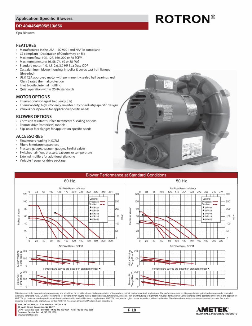
Application Specific Blowers
DR 404/454/505/513/656
Spa Blowers
FEATURES• Manufactured in the USA - ISO 9001 and NAFTA compliant
• Maximum pressure: 56, 58, 74, 69 or 88 IWG• Standard motor: 1.0, 1.5, 2.0, 3.0 HP, Spa Duty ODP
(threaded)•
Class B rated thermal protection•• Quiet operation within OSHA standards
MOTOR OPTIONS• International voltage & frequency (Hz)
BLOWER OPTIONS• Corrosion resistant surface treatments & sealing options• Remote drive (motorless) models
ACCESSORIES• Flowmeters reading in SCFM• Filters & moisture separators• Pressure gauges, vacuum gauges, & relief valves
•• Variable frequency drive package
UL & CSA approved motor with permanently sealed ball bearings and
Blower Performance at Standard Conditions60 Hz 50 Hz
Inch
es o
f Wat
er
mba
r
mba
r
Mot
or W
indi
ngTe
mp
Ris
e °C
Air Flow Rate - SCFMAir Flow Rate - SCFM
Air Flow Rate - m3/hourAir Flow Rate - m3/hour
Inch
es o
f Wat
erM
otor
Win
ding
Tem
p R
ise
°C
Blo
wer
Air
Tem
p R
ise
°C
Blo
wer
Air
Tem
p R
ise
°C
LegendPressure:Suction:
DR404DR454DR505DR513DR656
LegendPressure:Suction:
DR404DR454DR505DR513DR656
0 20 40 60 80 100 120 140 160 180 200 220 0 20 40 60 80 100 120 140 160 180 200 220
0 34 68 102 136 170 204 238 272 306 340 374 0 34 68 102 136 170 204 238 272 306 340 374
0
20
40
60
80
100
120
0
20
40
60
80
100
120
0
50
100
150
200
250
300
0
50
100
150
200
250
300
Temperature curves are based on standard model Temperature curves are based on standard model0
100
200
0
100
200
0
100
200
0
100
200
F 18____
This document is for informational purposes only and should not be considered as a binding description of the products or their performance in all applications. The performance data on this page depicts typical performance under controlledlaboratory conditions. AMETEK is not responsible for blowers driven beyond factory specified speed, temperature, pressure, flow or without proper alignment. Actual performance will vary depending on the operating environment and application.AMETEK products are not designed for and should not be used in medical life support applications. AMETEK reserves the right to revise its products without notification. The above characteristics represent standard products. For productdesigned to meet specific applications, contact AMETEK Technical & Industrial Products Sales department.
AMETEK TECHNICAL & INDUSTRIAL PRODUCTS75 North Street, Saugerties, NY 12477USA: +1 215-256-6601 - Europe: +44 (0) 845 366 9664 - Asia: +86 21 5763 1258Customer Service Fax: +1 215.256.1338www.ametektip.com
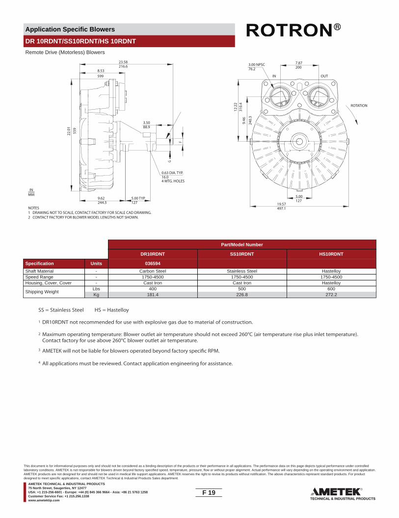
Application Specific Blowers
DR 10RDNT/SS10RDNT/HS 10RDNT
Remote Drive (Motorless) Blowers
NOTES1 DRAWING NOT TO SCALE, CONTACT FACTORY FOR SCALE CAD DRAWING.2 CONTACT FACTORY FOR BLOWER MODEL LENGTHS NOT SHOWN.
F
G
8.5322
.01
559
12.2
231
0.4
9.46
240.
3
216.623.58
88.93.50
1275.00 TYP
244.39.62
76.23.00 NPSC
2007.87
497.119.57
1275.00
16.00.63 DIA. TYP.
4 MTG. HOLES
599
ROTATION
OUTIN
INMM
Part/Model Number
DR10RDNT SS10RDNT HS10RDNT
Specification Units 036594
Shaft Material - Carbon Steel Stainless Steel HastelloySpeed Range - 1750-4500 1750-4500 1750-4500Housing, Cover, Cover - Cast Iron Cast Iron Hastelloy
Shipping WeightLbsKg
400181.4
500226.8
600272.2
SS = Stainless Steel HS = Hastelloy
1 DR10RDNT not recommended for use with explosive gas due to material of construction.
2
3
4
Maximum operating temperature: Blower outlet air temperature should not exceed 260°C (air temperature rise plus inlet temperature).Contact factory for use above 260°C blower outlet air temperature.
AMETEK will not be liable for blowers operated beyond factory speci�c RPM.
All applications must be reviewed. Contact application engineering for assistance.
F 19____
This document is for informational purposes only and should not be considered as a binding description of the products or their performance in all applications. The performance data on this page depicts typical performance under controlledlaboratory conditions. AMETEK is not responsible for blowers driven beyond factory specified speed, temperature, pressure, flow or without proper alignment. Actual performance will vary depending on the operating environment and application.AMETEK products are not designed for and should not be used in medical life support applications. AMETEK reserves the right to revise its products without notification. The above characteristics represent standard products. For productdesigned to meet specific applications, contact AMETEK Technical & Industrial Products Sales department.
AMETEK TECHNICAL & INDUSTRIAL PRODUCTS75 North Street, Saugerties, NY 12477USA: +1 215-256-6601 - Europe: +44 (0) 845 366 9664 - Asia: +86 21 5763 1258Customer Service Fax: +1 215.256.1338www.ametektip.com

Application Specific Blowers
DR 10RDNT/SS10RDNT/HS 10RDNT
Remote Drive (Motorless) Blowers
FEATURES• Manufactured in the USA - ISO 9001 and NAFTA compliant
BLOWER OPTIONS• Corrosion resistant surface treatments & sealing options
• Packaged on baseplate with V-belts or coupling, guard & motor• High temperature Viton® seals• Krytox® grease high temperature bearings
PACKAGE/MOTOR OPTIONS• International voltage & frequency (Hz)
• Packing gland or double faced seal options
ACCESSORIES• Flowmeters reading in SCFM• Filters & moisture separators• Pressure gauges, vacuum gauges, & relief valves
• External mu�ers for additional silencing• Variable frequency drive package
Note: For accessories, special high temperature models may be required
Blower Performance at Standard ConditionsPressure Suction
Inch
es o
f Wat
er
mba
r
mba
r
Inpu
tH
orse
pow
er
Inpu
tH
orse
pow
er
Air Flow Rate - SCFMAir Flow Rate - SCFM
Air Flow Rate - m3/hourAir Flow Rate - m3/hour
Inch
es o
f Wat
er
0 75 150 225 300 375 450 525 600 675 750 825
0 127 255 382 510 637 765 892 1019 1147 1274 1402
0
30
60
90
120
150
180
0
75
150
225
300
375
450
0 75 150 225 300 375 450 525 600 675 750 825
0 127 255 382 510 637 765 892 1019 1147 1274 1402
0
30
60
90
120
150
180
0
75
150
225
300
375
450
0
20
40
0
20
40
AIR T 100 ºC
75 ºC
50 ºC
4500 RPM3500 RPM2500 RPM
1750 RPM
4500
3500
25001750
AIR T 100 º C
75 º C
50 º C
4500 RPM3500 RPM
2500 RPM
1750 RPM
4500
3500
25001750
F 20____
This document is for informational purposes only and should not be considered as a binding description of the products or their performance in all applications. The performance data on this page depicts typical performance under controlledlaboratory conditions. AMETEK is not responsible for blowers driven beyond factory specified speed, temperature, pressure, flow or without proper alignment. Actual performance will vary depending on the operating environment and application.AMETEK products are not designed for and should not be used in medical life support applications. AMETEK reserves the right to revise its products without notification. The above characteristics represent standard products. For productdesigned to meet specific applications, contact AMETEK Technical & Industrial Products Sales department.
AMETEK TECHNICAL & INDUSTRIAL PRODUCTS75 North Street, Saugerties, NY 12477USA: +1 215-256-6601 - Europe: +44 (0) 845 366 9664 - Asia: +86 21 5763 1258Customer Service Fax: +1 215.256.1338www.ametektip.com
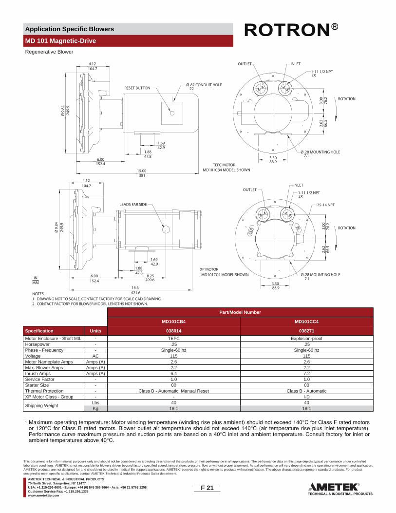
Application Specific Blowers
MD 101 Magnetic-Drive
Regenerative Blower
MD101CB4 MODEL SHOWNTEFC MOTOR
MD101CC4 MODEL SHOWNXP MOTOR
Ø9.
8424
9.9
249.
9
1.8847.8
47.8
1.6942.9
42.9
4.12104.7
104.7
15.00381
6.00152.4
152.4
RESET BUTTONØ .87 CONDUIT HOLE
22
3.5088.9
88.9
3.00
76.2
76.2
2.62
66.5
66.5
OUTLET INLET
1-11 1/2 NPT2X
Ø .28 MOUNTING HOLE7.1
7.1
Ø9.
84
1.88
1.69
8.25209.6
4.12
16.6421.6
6.00
LEADS FAR SIDE
3.50
3.00
2.62
OUTLETINLET
1-11 1/2 NPT2X
Ø .28 MOUNTING HOLE
.75-14 NPT
NOTES1 DRAWING NOT TO SCALE, CONTACT FACTORY FOR SCALE CAD DRAWING.2 CONTACT FACTORY FOR BLOWER MODEL LENGTHS NOT SHOWN.
INMM
ROTATION
ROTATION
Part/Model Number
MD101CB4 MD101CC4
Specification Units 038014 038271
Motor Enclosure - Shaft Mtl. - TEFC Explosion-proofHorsepower - .25 .25Phase - Frequency - Single-60 hz Single-60 hzVoltage AC 115 115Motor Nameplate Amps Amps (A) 2.6 2.6Max. Blower Amps Amps (A) 2.2 2.2Inrush Amps Amps (A) 6.4 7.2Service Factor - 1.0 1.0Starter Size - 00 00Thermal Protection - Class B - Automatic, Manual Reset Class B - AutomaticXP Motor Class - Group - - I-D
Shipping WeightLbsKg
4018.1
4018.1
1 Maximum operating temperature: Motor winding temperature (winding rise plus ambient) should not exceed 140°C for Class F rated motorsor 120°C for Class B rated motors. Blower outlet air temperature should not exceed 140°C (air temperature rise plus inlet temperature).Performance curve maximum pressure and suction points are based on a 40°C inlet and ambient temperature. Consult factory for inlet orambient temperatures above 40°C.
Rev. 2/04
F 21____
This document is for informational purposes only and should not be considered as a binding description of the products or their performance in all applications. The performance data on this page depicts typical performance under controlledlaboratory conditions. AMETEK is not responsible for blowers driven beyond factory specified speed, temperature, pressure, flow or without proper alignment. Actual performance will vary depending on the operating environment and application.AMETEK products are not designed for and should not be used in medical life support applications. AMETEK reserves the right to revise its products without notification. The above characteristics represent standard products. For productdesigned to meet specific applications, contact AMETEK Technical & Industrial Products Sales department.
AMETEK TECHNICAL & INDUSTRIAL PRODUCTS75 North Street, Saugerties, NY 12477USA: +1 215-256-6601 - Europe: +44 (0) 845 366 9664 - Asia: +86 21 5763 1258Customer Service Fax: +1 215.256.1338www.ametektip.com

Application Specific Blowers
MD 101 Magnetic-Drive
Regenerative Blower
FEATURES• Hermetically designed seal-less blower• Continuous operation• Manufactured in the USA
• Maximum pressure: 28 IWG• Maximum vacuum: 26.5 IWG• Standard motor: 0.25 HP, TEFC or XP• Disconnect motor without disassembling from piping
• Permanently sealed ball bearings in housing and motor• Quiet operation within OSHA standards
BLOWER OPTIONS• Corrosion resistant surface treatments & sealing options
ACCESSORIES• Flowmeters reading in SCFM• Filters & moisture separators• Pressure gauges, vacuum gauges, & relief valves•
Blower Performance at Standard ConditionsPressure Suction
Inch
es o
f Wat
er
mba
r
mba
r
Mot
or W
indi
ngTe
mp
Ris
e °C
Air Flow Rate - SCFMAir Flow Rate - SCFM
Air Flow Rate - m3/hourAir Flow Rate - m3/hour
Inch
es o
f Wat
erM
otor
Win
ding
Tem
p R
ise
°C
Blo
wer
Air
Tem
p R
ise
°C
Blo
wer
Air
Tem
p R
ise
°C
0 3 6 9 12 15 18 21 24 27 30 330
5
10
15
20
25
30
0
12
25
37
50
62
750 5 10 15 20 25 30 35 40 45 50 55
0 3 6 9 12 15 18 21 24 27 30 330
5
10
15
20
25
30
0
12
25
37
50
62
750 5 10 15 20 25 30 35 40 45 50 55
Temperature curves are based on standard model Temperature curves are based on standard model0
50
100
0
50
100
0
50
100
0
50
100
AIRSG = 1.0
NATURAL GASSG = 0.56
NATURAL GASSG = 0.56
AIRSG = 1.0
F 22____
This document is for informational purposes only and should not be considered as a binding description of the products or their performance in all applications. The performance data on this page depicts typical performance under controlledlaboratory conditions. AMETEK is not responsible for blowers driven beyond factory specified speed, temperature, pressure, flow or without proper alignment. Actual performance will vary depending on the operating environment and application.AMETEK products are not designed for and should not be used in medical life support applications. AMETEK reserves the right to revise its products without notification. The above characteristics represent standard products. For productdesigned to meet specific applications, contact AMETEK Technical & Industrial Products Sales department.
AMETEK TECHNICAL & INDUSTRIAL PRODUCTS75 North Street, Saugerties, NY 12477USA: +1 215-256-6601 - Europe: +44 (0) 845 366 9664 - Asia: +86 21 5763 1258Customer Service Fax: +1 215.256.1338www.ametektip.com

Application Specific Blowers
GVR313
Regenerative Blower
NOTES1 DRAWING NOT TO SCALE, CONTACT FACTORY FOR SCALE CAD DRAWING.2 CONTACT FACTORY FOR BLOWER MODEL LENGTHS NOT SHOWN.3 GVR313AK4H MODELS SHOWN
10.50266.7
ROTA
TIO
N
3.75
95.3
14.19360.4
11.3
8 (T
YP.)
289.
1
1 1/2" NPTF (2) PLACES (GVR313)
1 1/4" NPTF (2) PLACES (GVR312)
2.255.9
4.00101.6
IN OUT
6.875174.6
4.2106.7
.348.6.88
22.4 4.9
124.
5
6.5
165.
1
BOTTOM VIEW
INMM
Part/Model Number
GVR313AK4H GVR313AK58H GVR313AK72HA GVR313AK91H GVR313AE4HA
Specification Units 038584 081531 081470 081524 080274
Motor Enclosure - Shaft Mtl. - Explosion-proof - CS Explosion proof - CS Explosion proof - CS ATEX - CS TEFCHorsepower - 0.5 0.5 0.5 0.75 0.5Phase - Frequency - Single-60 hz Single-50/60 Hz Three-60 Hz Three-50 Hz Single-60 HzVoltage AC 115 110/220 230/460 400 115Motor Nameplate Amps Amps (A) 9.4 8.4/4.2 1.4/0.7 1.4 7.4Max. Blower Amps Amps (A) 7.6 6.8/3.4 1.4/0.7 1.1 7.4Inrush Amps Amps (A) 45 45 10.2/5.1 9 47Service Factor - 1.0 1.0 1.15 1.0 1.0Starter Size - 0 0 00 0 0Thermal Protection - Class B - Automatic Class B - Automatic Class B - Automatic Thermistors Class B - AutomaticXP Motor Class - Group - I-D 1-D 1-D EExd IIB 1-D
Shipping WeightLbsKg
3917.7
3917.7
3917.7
4520.4
3917.7
1 115 voltage, 1 phase motors are standard. 230 volt motors available. As an option, a transformer could be used.2 Maximum operating temperature: Motor winding temperature (winding rise plus ambient) should not exceed 140°C for Class F rated motors
or 120°C for Class B rated motors. Blower outlet air temperature should not exceed 140°C (air temperature rise plus inlet temperature).Performance curve maximum pressure and suction points are based on a 40°C inlet and ambient temperature. Consult factory for inlet orambient temperatures above 40°C.
3 Maximum blower amps corresponds to the performance point at which the motor or blower temperature rise with a 40°C inlet and/orambient temperature reaches the maximum operating temperature.
Rev. 2/04
F 23____
This document is for informational purposes only and should not be considered as a binding description of the products or their performance in all applications. The performance data on this page depicts typical performance under controlledlaboratory conditions. AMETEK is not responsible for blowers driven beyond factory specified speed, temperature, pressure, flow or without proper alignment. Actual performance will vary depending on the operating environment and application.AMETEK products are not designed for and should not be used in medical life support applications. AMETEK reserves the right to revise its products without notification. The above characteristics represent standard products. For productdesigned to meet specific applications, contact AMETEK Technical & Industrial Products Sales department.
AMETEK TECHNICAL & INDUSTRIAL PRODUCTS75 North Street, Saugerties, NY 12477USA: +1 215-256-6601 - Europe: +44 (0) 845 366 9664 - Asia: +86 21 5763 1258Customer Service Fax: +1 215.256.1338www.ametektip.com
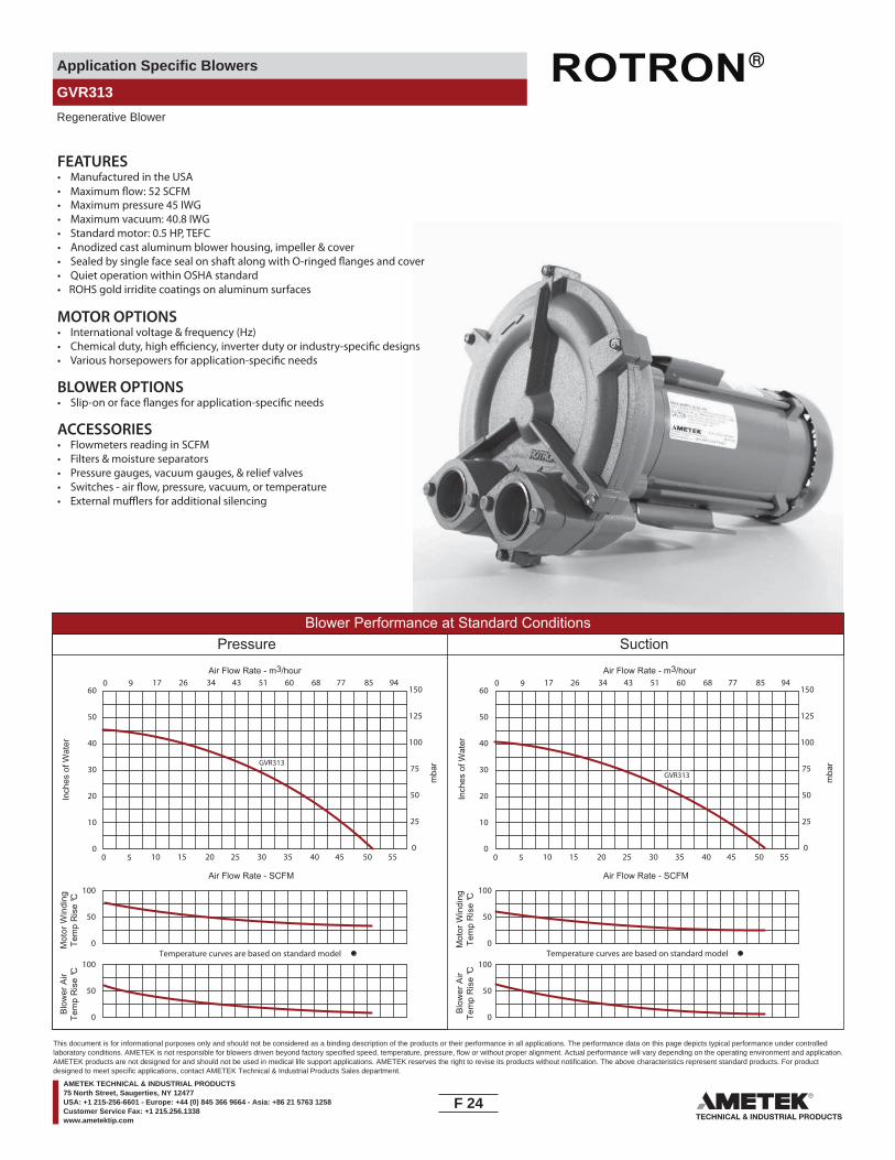
Application Specific Blowers
GVR313
Regenerative Blower
FEATURES• Manufactured in the USA
• Maximum pressure 45 IWG • Maximum vacuum: 40.8 IWG• Standard motor: 0.5 HP, TEFC• Anodized cast aluminum blower housing, impeller & cover
• Quiet operation within OSHA standard• ROHS gold irridite coatings on aluminum surfaces
MOTOR OPTIONS• International voltage & frequency (Hz)
BLOWER OPTIONS
ACCESSORIES• Flowmeters reading in SCFM• Filters & moisture separators• Pressure gauges, vacuum gauges, & relief valves
•
Blower Performance at Standard ConditionsPressure Suction
Inch
es o
f Wat
er
mba
r
mba
r
Mot
or W
indi
ngTe
mp
Ris
e °C
Air Flow Rate - SCFMAir Flow Rate - SCFM
Air Flow Rate - m3/hourAir Flow Rate - m3/hour
Inch
es o
f Wat
erM
otor
Win
ding
Tem
p R
ise
°C
Blo
wer
Air
Tem
p R
ise
°C
Blo
wer
Air
Tem
p R
ise
°C
0 5 10 15 20 25 30 35 40 45 50 550
10
20
30
40
50
60
0
25
50
75
100
125
1500 9 17 26 34 43 51 60 68 77 85 94
0 5 10 15 20 25 30 35 40 45 50 550
10
20
30
40
50
60
0
25
50
75
100
125
1500 9 17 26 34 43 51 60 68 77 85 94
Temperature curves are based on standard model Temperature curves are based on standard model0
50
100
0
50
100
0
50
100
0
50
100
GVR313
GVR313
F 24____
This document is for informational purposes only and should not be considered as a binding description of the products or their performance in all applications. The performance data on this page depicts typical performance under controlledlaboratory conditions. AMETEK is not responsible for blowers driven beyond factory specified speed, temperature, pressure, flow or without proper alignment. Actual performance will vary depending on the operating environment and application.AMETEK products are not designed for and should not be used in medical life support applications. AMETEK reserves the right to revise its products without notification. The above characteristics represent standard products. For productdesigned to meet specific applications, contact AMETEK Technical & Industrial Products Sales department.
AMETEK TECHNICAL & INDUSTRIAL PRODUCTS75 North Street, Saugerties, NY 12477USA: +1 215-256-6601 - Europe: +44 (0) 845 366 9664 - Asia: +86 21 5763 1258Customer Service Fax: +1 215.256.1338www.ametektip.com
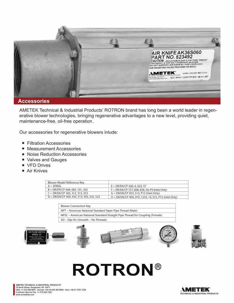
____
AccessoriesAMETEK Technical & Industrial Products’ ROTRON brand has long been a world leader in regen-erative blower technologies, bringing regenerative advantages to a new level, providing quiet, maintenance-free, oil-free operation.
Our accessories for regenerative blowers inlude:
Filtration Accessories Measurement Accessories Noise Reduction Accessories Valves and Gauges VFD Drives Air Knives
AMETEK TECHNICAL & INDUSTRIAL PRODUCTS75 North Street, Saugerties, NY 12477USA: +1 215-256-6601 - Europe: +44 (0) 845 366 9664 - Asia: +86 21 5763 1258Customer Service Fax: +1 215.256.1338www.ametektip.com
Blower Model Reference KeyA = SPIRAL E = DR/EN/CP 656, 6, 633, S7B = DR/EN/CP 068, 083, 101, 202C = DR/EN/CP 303, 312, 313, 353 G = DR/EN/CP 833, S13, P13 (Inlet Only)D = DR/EN/CP 404, 454, 513, 505, 555, 523 H = DR/EN/CP 909, 979, 1233, 14, S15, P15 (Inlet Only)
Blower Connection KeyNPT – American National Standard Taper Pipe Thread (Male)NPSC – American National Standard Straight Pipe Thread for Coupling (Female) SO – Slip On (Smooth – No Threads)
F = DR/EN/CP 757, 808, 858, S9, P9 (Inlet Only)

Accessories
Filtration - Inlet Filter (Single Connection)
Inlet Filters protect the blower and the air distributionsystem from dust, and other airborne particles and contaminants. Normally used in pressure systems.
SPECIFICATIONS:HOUSING – SteelMEDIA – PolyesterEFFICIENCY – 97-98% (8 to 10 micron particle size)FILTER ELEMENT – Replaceable (see �lter elements)NOTE: “Z” MEDIA (1 to 3 micron particle size) available
A Ø
B
C Ø
Part/Model Number
Specification Units 477411 516466 515122 515123 515124 515125 515145 515151 516511
Filter Element - A B C, D E E F G H HRef Blower Model - 271078 515132 515132 515133 515134 515134 515134 515135 516515Outlet Connection - 2.00 SO 1.00 NPT 1.50 NPT 2.00 NPT 2.00 NPT 2.50 NPT 3.00 NPT 4.00 NPT 6.00 NPT
Dimension AInches
mm4.56
115.86.00
152.46.00
152.47.75
196.910.00254
10.00254
10.00254
10.00254
16.00406.4
Dimension BInches
mm6.12
155.46.50
165.16.50
165.17.25
184.212.25311.2
12.50317.5
13.00330.2
14.00355.6
15.00381
Dimension CInches
mm2.0050.8
1.0025.4
1.538.1
2.0050.8
2.0050.8
2.5063.5
3.0076.2
4.00101.6
6.00152.4
Z Media Filter PN - 517865 517866 517867 517868 517869 517870 517871 517872
A = SPIRAL E = DR/EN/CP 656, 6, 633, S7B = DR/EN/CP 068, 083, 101, 202C = DR/EN/CP 303, 312, 313, 353 G = DR/EN/CP 833, S13, P13 (Inlet Only)D = DR/EN/CP 404, 454, 513, 505, 555, 523 H = DR/EN/CP 909, 979, 1233, 14, S15, P15 (Inlet Only)
F = DR/EN/CP 757, 808, 858, S9, P9 (Inlet Only)
Blower Model Reference Key
G 1____
This document is for informational purposes only and should not be considered as a binding description of the products or their performance in all applications. The performance data on this page depicts typical performance under controlledlaboratory conditions. AMETEK is not responsible for blowers driven beyond factory specified speed, temperature, pressure, flow or without proper alignment. Actual performance will vary depending on the operating environment and application.AMETEK products are not designed for and should not be used in medical life support applications. AMETEK reserves the right to revise its products without notification. The above characteristics represent standard products. For productdesigned to meet specific applications, contact AMETEK Technical & Industrial Products Sales department.
AMETEK TECHNICAL & INDUSTRIAL PRODUCTS75 North Street, Saugerties, NY 12477USA: +1 215-256-6601 - Europe: +44 (0) 845 366 9664 - Asia: +86 21 5763 1258Customer Service Fax: +1 215.256.1338www.ametektip.com

Accessories
Filtration - Inline Filter (Dual Connection)
Inline Filters protect the blower from harmful dust andother particles that may be drawn into the blowerthrough the air distribution system. Normally used invacuum systems.
SPECIFICATIONS:HOUSING – SteelMEDIA – PolyesterEFFICIENCY – 97-98% (8 to 10 micron particle size)FILTER ELEMENT – Replaceable (see �lter elements)NOTE: “Z” MEDIA (1 to 3 micron particle size) available
* Feature 1/4" threaded tap for gauge connection on inlet and outlet
Inline �lter PN 271200 is a straight through designInlet is directly opposite of outlet
D DIA.
B
A
C DIA.
Part/Model Number
Specification Units 271200 516461 515254 515255 515256 516463* 516465* 517611*
Filter Element - 271078 516434 516434 516435 516435 515135 515135 516515Ref Blower Model - A B C, D E F G H HInlet Connection - 1.75 SO 1.00 NPSC-F 1.50 NPSC-F 2.00 NPSC-F 2.50 NPSC-F 3.00 NPT-M 4.00 NPT-M 6.00 NPT-MOutlet Connection - 2.00 SO 1.00 NPSC-F 1.50 NPSC-F 2.00 NPSC-F 2.50 NPSC-F 3.00 NPT-M 4.00 NPT-M 6.00 NPT-M
Dimension AInches
mm5.25
133.47.25
184.27.00
177.88.00
203.28.00
203.214.00355.6
14.00355.6
18.00457.2
Dimension BInches
mm8.31
211.16.50
165.16.50
165.110.25260.4
10.25260.4
26.50673.1
27.00685.8
28.00711.2
Dimension CInches
mm2.0050.8
1.0025.4
1.5038.1
2.0050.8
2.5063.5
3.0076.2
4.00101.6
6.00152.4
Dimension DInches
mm1.7544.5
1.0025.4
1.5038.1
2.0050.8
2.5063.5
3.0076.2
4.00101.6
6.00152.4
Z Media Filter PN - 517886 517887 517888 517889 517890 517891 517892
A = SPIRAL E = DR/EN/CP 656, 6, 633, S7B = DR/EN/CP 068, 083, 101, 202C = DR/EN/CP 303, 312, 313, 353 G = DR/EN/CP 833, S13, P13 (Inlet Only)D = DR/EN/CP 404, 454, 513, 505, 555, 523 H = DR/EN/CP 909, 979, 1233, 14, S15, P15 (Inlet Only)
F = DR/EN/CP 757, 808, 858, S9, P9 (Inlet Only)
Blower Model Reference Key
G 2____
This document is for informational purposes only and should not be considered as a binding description of the products or their performance in all applications. The performance data on this page depicts typical performance under controlledlaboratory conditions. AMETEK is not responsible for blowers driven beyond factory specified speed, temperature, pressure, flow or without proper alignment. Actual performance will vary depending on the operating environment and application.AMETEK products are not designed for and should not be used in medical life support applications. AMETEK reserves the right to revise its products without notification. The above characteristics represent standard products. For productdesigned to meet specific applications, contact AMETEK Technical & Industrial Products Sales department.
AMETEK TECHNICAL & INDUSTRIAL PRODUCTS75 North Street, Saugerties, NY 12477USA: +1 215-256-6601 - Europe: +44 (0) 845 366 9664 - Asia: +86 21 5763 1258Customer Service Fax: +1 215.256.1338www.ametektip.com
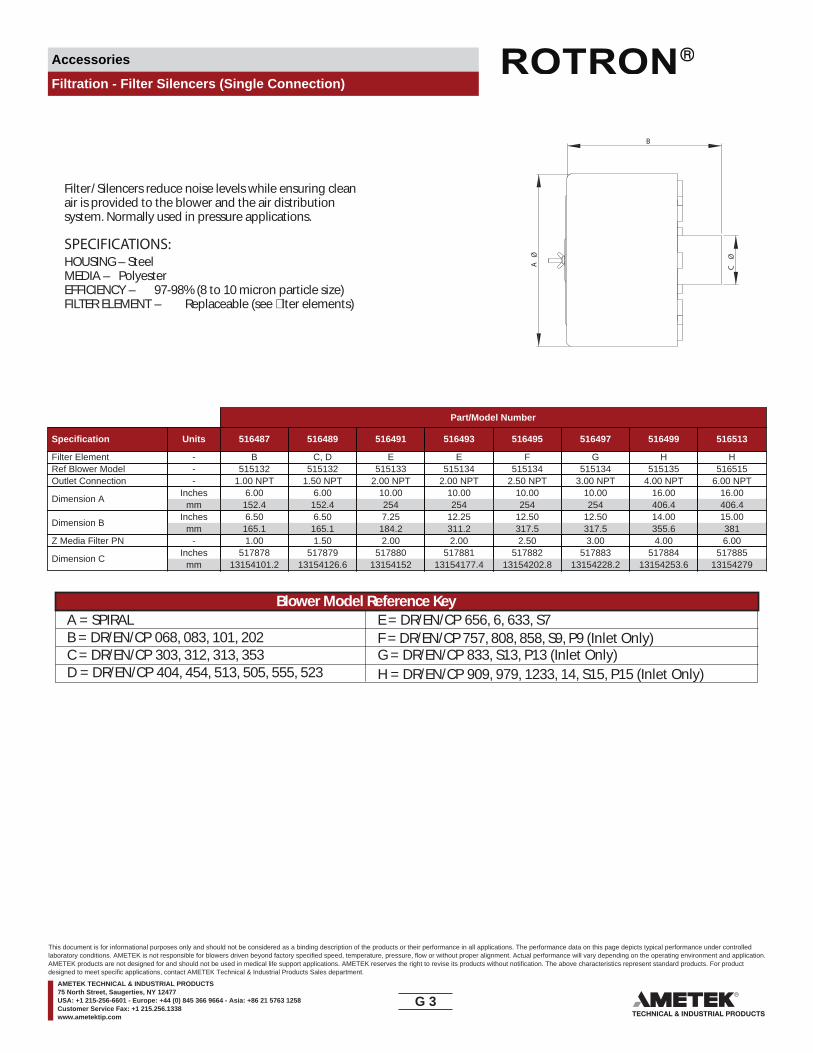
Accessories
Filtration - Filter Silencers (Single Connection)
Filter/Silencers reduce noise levels while ensuring cleanair is provided to the blower and the air distributionsystem. Normally used in pressure applications.
SPECIFICATIONS:HOUSING – SteelMEDIA – PolyesterEFFICIENCY – 97-98% (8 to 10 micron particle size)FILTER ELEMENT – Replaceable (see �lter elements)
A
Ø
B
C Ø
Part/Model Number
Specification Units 516487 516489 516491 516493 516495 516497 516499 516513
Filter Element - B C, D E E F G H HRef Blower Model - 515132 515132 515133 515134 515134 515134 515135 516515Outlet Connection - 1.00 NPT 1.50 NPT 2.00 NPT 2.00 NPT 2.50 NPT 3.00 NPT 4.00 NPT 6.00 NPT
Dimension AInches
mm6.00
152.46.00
152.410.00254
10.00254
10.00254
10.00254
16.00406.4
16.00406.4
Dimension BInches
mm6.50
165.16.50
165.17.25
184.212.25311.2
12.50317.5
12.50317.5
14.00355.6
15.00381
Z Media Filter PN - 1.00 1.50 2.00 2.00 2.50 3.00 4.00 6.00
Dimension CInches
mm517878
13154101.2517879
13154126.6517880
13154152517881
13154177.4517882
13154202.8517883
13154228.2517884
13154253.6517885
13154279
A = SPIRAL E = DR/EN/CP 656, 6, 633, S7B = DR/EN/CP 068, 083, 101, 202C = DR/EN/CP 303, 312, 313, 353 G = DR/EN/CP 833, S13, P13 (Inlet Only)D = DR/EN/CP 404, 454, 513, 505, 555, 523 H = DR/EN/CP 909, 979, 1233, 14, S15, P15 (Inlet Only)
F = DR/EN/CP 757, 808, 858, S9, P9 (Inlet Only)
Blower Model Reference Key
G 3____
This document is for informational purposes only and should not be considered as a binding description of the products or their performance in all applications. The performance data on this page depicts typical performance under controlledlaboratory conditions. AMETEK is not responsible for blowers driven beyond factory specified speed, temperature, pressure, flow or without proper alignment. Actual performance will vary depending on the operating environment and application.AMETEK products are not designed for and should not be used in medical life support applications. AMETEK reserves the right to revise its products without notification. The above characteristics represent standard products. For productdesigned to meet specific applications, contact AMETEK Technical & Industrial Products Sales department.
AMETEK TECHNICAL & INDUSTRIAL PRODUCTS75 North Street, Saugerties, NY 12477USA: +1 215-256-6601 - Europe: +44 (0) 845 366 9664 - Asia: +86 21 5763 1258Customer Service Fax: +1 215.256.1338www.ametektip.com
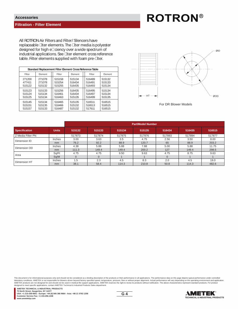
Accessories
Filtration - Filter Element
All ROTRON Air Filters and Filter/Silencers havereplaceable �lter elements. The �lter media is polyesterdesigned for high e�ciency over a wide spectrum ofindustrial applications. See �lter element cross referencetable. Filter elements supplied with foam pre-�lter.
Standard Replacement Filter Element Cross Reference Table
271200 271078 515158 515134 516489 515132477411 271078 515254 516434 516491 515133515122 515132 515255 516435 516493 515134
515123 515133 515256 516435 516495 515134515124 515134 516461 516434 516497 515134515125 515134 516463 515135 516499 515135
515145 515134 516465 515135 516511 516515515151 515135 516466 515132 516513 516515515157 515133 516487 515132 517611 516515
HT
For DR Blower Models
ØID
ØOD
Filter Filter FilterElement Element Element
Part/Model Number
Specification Units 515132 515133 515134 515135 516434 516435 516515
Z Media Filter PN - 517873 517874 517875 517876 517893 517894 517877
Dimension IDInches
mm3.0076.2
3.6392.2
3.588.9
4.75120.7
2.5665
3.5088.9
8.00203.2
Dimension ODInches
mm4.38111.3
5.88149.4
5.88149.4
7.88200.2
5.00127
5.88149.4
11.75298.5
AreaSq/FtSq/M
4.750
4.750
9.501
9.631
4.750
8.751
9.631
Dimension HTInches
mm1.5
38.12.3
58.44.5
114.38.3
210.82.050.8
4.5114.3
19.0482.6
G 4____
This document is for informational purposes only and should not be considered as a binding description of the products or their performance in all applications. The performance data on this page depicts typical performance under controlledlaboratory conditions. AMETEK is not responsible for blowers driven beyond factory specified speed, temperature, pressure, flow or without proper alignment. Actual performance will vary depending on the operating environment and application.AMETEK products are not designed for and should not be used in medical life support applications. AMETEK reserves the right to revise its products without notification. The above characteristics represent standard products. For productdesigned to meet specific applications, contact AMETEK Technical & Industrial Products Sales department.
AMETEK TECHNICAL & INDUSTRIAL PRODUCTS75 North Street, Saugerties, NY 12477USA: +1 215-256-6601 - Europe: +44 (0) 845 366 9664 - Asia: +86 21 5763 1258Customer Service Fax: +1 215.256.1338www.ametektip.com
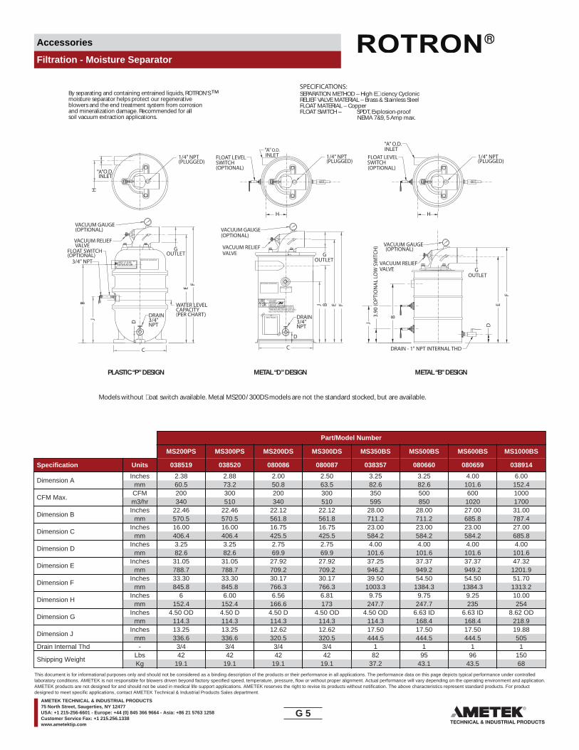
Accessories
Filtration - Moisture Separator
™By separating and containing entrained liquids, ROTRON’Smoisture separator helps protect our regenerativeblowers and the end treatment system from corrosionand mineralization damage. Recommended for allsoil vacuum extraction applications.
PLASTIC “P” DESIGN METAL “D” DESIGN METAL “B” DESIGN
SPECIFICATIONS:SEPARATION METHOD – High E�ciency CyclonicRELIEF VALVE MATERIAL – Brass & Stainless SteelFLOAT MATERIAL – CopperFLOAT SWITCH – SPDT, Explosion-proof
NEMA 7&9, 5 Amp max.
Models without �oat switch available. Metal MS200 / 300DS models are not the standard stocked, but are available.
(OPTIONAL)
VALVE
(OPTIONAL)
O.D.INLET
(PLUGGED) SWITCH(OPTIONAL)
G
D
H
H
(PLUGGED)
C
J
B
3/4"NPT
CAPACITY(PER CHART)
EF
3.90
(OPT
ION
AL
LOW
SW
ITCH
)
SWITCH(OPTIONAL)
INLET
H
B
DJ
E
F
(OPTIONAL)
(PLUGGED)
B
VALVE
(OPTIONAL)
J
D
C
E F
G
VALVE
3/4"NPT
INLETO.D.
FLOAT SWITCH
3/4" NPT
VACUUM RELIEF
VACUUM GAUGE
1/4" NPT FLOAT LEVEL 1/4" NPT
DRAIN
WATER LEVEL
DRAIN - 1" NPT INTERNAL THD
FLOAT LEVEL
O.D.
VACUUM GAUGE
1/4" NPT
VACUUM RELIEF
VACUUM GAUGE
VACUUM RELIEF
DRAIN
TMMOISTURE SEPARATOR
RAP AT ORI SO T U R E
EM
S
"A"
"A"
INSTALL FLOAT SW.
INFO PACKET
MOISTURE SEPARATOR
TM CYCLONICACTIONCAUTION:FREEZING MAY CAUSE DAMAGE.MOISTURE SEPARATORS USED IN TEMPERATURES BELOW 32øF (0øC)MUST BE PROPERLY WINTERIZED.
"A"
T ORURE
G
OUTLETOUTLET
OUTLET
Part/Model Number
MS200PS MS300PS MS200DS MS300DS MS350BS MS500BS MS600BS MS1000BS
Specification Units 038519 038520 080086 080087 038357 080660 080659 038914
Dimension AInches
mm2.3860.5
2.8873.2
2.0050.8
2.5063.5
3.2582.6
3.2582.6
4.00101.6
6.00152.4
CFM Max.CFMm3/hr
200340
300510
200340
300510
350595
500850
6001020
10001700
Dimension BInches
mm22.46570.5
22.46570.5
22.12561.8
22.12561.8
28.00711.2
28.00711.2
27.00685.8
31.00787.4
Dimension CInches
mm16.00406.4
16.00406.4
16.75425.5
16.75425.5
23.00584.2
23.00584.2
23.00584.2
27.00685.8
Dimension DInches
mm3.2582.6
3.2582.6
2.7569.9
2.7569.9
4.00101.6
4.00101.6
4.00101.6
4.00101.6
Dimension EInches
mm31.05788.7
31.05788.7
27.92709.2
27.92709.2
37.25946.2
37.37949.2
37.37949.2
47.321201.9
Dimension FInches
mm33.30845.8
33.30845.8
30.17766.3
30.17766.3
39.501003.3
54.501384.3
54.501384.3
51.701313.2
Dimension HInches
mm6
152.46.00
152.46.56
166.66.81173
9.75247.7
9.75247.7
9.25235
10.00254
Dimension GInches
mm4.50 OD
114.34.50 D114.3
4.50 D114.3
4.50 OD114.3
4.50 OD114.3
6.63 ID168.4
6.63 ID168.4
8.62 OD218.9
Dimension JInches
mm13.25336.6
13.25336.6
12.62320.5
12.62320.5
17.50444.5
17.50444.5
17.50444.5
19.88505
Drain Internal Thd - 3/4 3/4 3/4 3/4 1 1 1 1
Shipping WeightLbsKg
4219.1
4219.1
4219.1
4219.1
8237.2
9543.1
9643.5
15068
G 5____
This document is for informational purposes only and should not be considered as a binding description of the products or their performance in all applications. The performance data on this page depicts typical performance under controlledlaboratory conditions. AMETEK is not responsible for blowers driven beyond factory specified speed, temperature, pressure, flow or without proper alignment. Actual performance will vary depending on the operating environment and application.AMETEK products are not designed for and should not be used in medical life support applications. AMETEK reserves the right to revise its products without notification. The above characteristics represent standard products. For productdesigned to meet specific applications, contact AMETEK Technical & Industrial Products Sales department.
AMETEK TECHNICAL & INDUSTRIAL PRODUCTS75 North Street, Saugerties, NY 12477USA: +1 215-256-6601 - Europe: +44 (0) 845 366 9664 - Asia: +86 21 5763 1258Customer Service Fax: +1 215.256.1338www.ametektip.com

Accessories
Filtration - Moisture Separator
404
ForDR/EN/CP
BlowerModel
SelectorMoistureSeparator
Model
Liquid-holdingCapacity(gallons)
Inlet(OD)
Outlet
MaxVacuum
Allow(IHG)
454 MS200PS
MS200DS
7
10
2.38 12
2.0 224.5 OD
MS300PS 7 2.88 12
MS300DS 10 2.5MS350BS
MS500BS 403.25
MS600BS 4.06.63 ID 22
MS1000BS
Pres
sure
Dro
p (IW
G)
0 100 200 300 400 500 600 700 800 900 1000 1100 1200
1
2
3
4
5
6
Flow Rate (SCFM)
65 6.0 8.62 OD
505513523555633833656
6757808
909
8581233
97914
The moisture separator shall be designed for use in a soil vapor extraction system capable of continuous operation with a pressure drop of less than six inches of water at the rated �ow of _____ SCFM. The separator shall be capable of operation under various inlet conditions randing from a �ne mist to slugs of water with high e�ciency.
The moisture separator shall incorporate cyclonic separation to remove entrained water. The separator must protect against an over�ow by fail safe mechanical means. An electrical switch or contact(s) alone is not an acceptable means of protection against over�ow, but is a good backup.
The body of the moisture separator shall be constructed of heavy wall plastic or heavy gauge cold rolled steel. The steel interior and exterior shall be epoxy (powder) coated to resist abrasion, corrosion, and chipping that might expose the surface. The inlet shall be tangentially located and welded to the body. The outlet port shall be constructed of PVC or cast aluminum alloy, �anged and sealed to the center of the top of the separator. The separator shall incorporate a non-sparking copper �oat ball and an adjustable relief valve to protect against over�ow and overheating the blower.
The moisture separator must have a liquid capacity of _____ gallons. The inlet shall be _____ inch OD slip-on type. The outlet shall be _____ inch OD slip-on type.
2.0 Moisture SeparatorTM Speci�cations
2.1 Duty
2.2 Principle of Operation
2.3 Construction
2.4 Capacity and Dimension
2.5 Pressure Drop
MS2
00P/
DS
MS3
00P/
DS
MS3
50BS
MS5
00BS
MS6
00BS
MS1
000BS
G 6____
This document is for informational purposes only and should not be considered as a binding description of the products or their performance in all applications. The performance data on this page depicts typical performance under controlledlaboratory conditions. AMETEK is not responsible for blowers driven beyond factory specified speed, temperature, pressure, flow or without proper alignment. Actual performance will vary depending on the operating environment and application.AMETEK products are not designed for and should not be used in medical life support applications. AMETEK reserves the right to revise its products without notification. The above characteristics represent standard products. For productdesigned to meet specific applications, contact AMETEK Technical & Industrial Products Sales department.
AMETEK TECHNICAL & INDUSTRIAL PRODUCTS75 North Street, Saugerties, NY 12477USA: +1 215-256-6601 - Europe: +44 (0) 845 366 9664 - Asia: +86 21 5763 1258Customer Service Fax: +1 215.256.1338www.ametektip.com
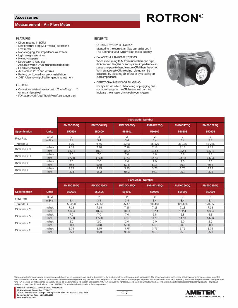
Accessories
Measurement - Air Flow Meter
FEATURES• Direct reading in SCFM• Low pressure drop (2-4" typical) across the
�ow meter• Non-clogging, low impedance air stream• Light weight aluminum• No moving parts• Large easy-to-read dial• Accurate within 2% at standard conditions• Good repeatability• Available in 2", 3" and 4" sizes• Factory con�gured for quick installation• .048" Allen key supplied for gauge adjustment
OPTIONS• Corrosion-resistant version with Chem-Tough ™
or in stainless steel• FDA-approved Food Tough™ surface conversion
BENEFITS
• OPTIMIZE SYSTEM EFFICIENCYMeasuring the correct air �ow can assist you in �ne-tuning to your system’s optimal e�ciency.
• BALANCE MULTI-PIPING SYSTEMSWhen evacuating CFM from more than one pipe, di�erent run lengths or end system impedance can cause one pipe to handle more CFM than the other. With an accurate CFM reading, piping can be balanced by bleeding air in/out or by creating an extra impedance.
• DETECT CHANNELING OR PLUGGINGFor systems in which channeling or plugging can occur, a change in the CFM measured can help indicate the unseen changes in your system.
Part/Model Number
FM20C030Q FM20C045Q FM20C065Q FM20C125Q FM20C175Q FM20C225Q
Specification Units 550599 550600 550601 550602 550603 550604
Flow RateCFMm3/hr
23.4
23.4
23.4
23.4
23.4
23.4
Threads B - 6-30 9-45 13-65 25-125 35-175 45-225
Dimension CInches
mm7.18
182.47.18
182.47.18
182.47.18
182.47.18
182.47.18
182.4
Dimension DInches
mm7.0
177.87.0
177.87.0
177.85.8
147.35.8
147.35.8
147.3
Dimension EInches
mm2.0
50.82.050.8
2.050.8
2.050.8
2.050.8
2.050.8
Dimension FInches
mm3.7595.3
3.7595.3
3.7595.3
3.7595.3
3.7595.3
3.7595.3
Part/Model Number
FM30C250Q FM30C350Q FM30C475Q FM40C450Q FM40C600Q FM40C850Q
Specification Units 550605 550606 550607 550608 550609 550610
Flow RateCFMm3/hr
23.4
23.4
23.4
23.4
23.4
23.4
Threads B - 50-250 70-350 95-475 90-450 120-600 170-850
Dimension CInches
mm7.18
182.47.18
182.47.18
182.47.18
182.47.18
182.47.18
182.4
Dimension DInches
mm7.0
177.87.0
177.87.0
177.85.8
147.35.8
147.35.8
147.3
Dimension EInches
mm2.0
50.82.050.8
2.050.8
2.050.8
2.050.8
2.050.8
Dimension FInches
mm3.7595.3
3.7595.3
3.7595.3
3.7595.3
3.7595.3
3.7595.3
G 7____
This document is for informational purposes only and should not be considered as a binding description of the products or their performance in all applications. The performance data on this page depicts typical performance under controlledlaboratory conditions. AMETEK is not responsible for blowers driven beyond factory specified speed, temperature, pressure, flow or without proper alignment. Actual performance will vary depending on the operating environment and application.AMETEK products are not designed for and should not be used in medical life support applications. AMETEK reserves the right to revise its products without notification. The above characteristics represent standard products. For productdesigned to meet specific applications, contact AMETEK Technical & Industrial Products Sales department.
AMETEK TECHNICAL & INDUSTRIAL PRODUCTS75 North Street, Saugerties, NY 12477USA: +1 215-256-6601 - Europe: +44 (0) 845 366 9664 - Asia: +86 21 5763 1258Customer Service Fax: +1 215.256.1338www.ametektip.com

Accessories
Measurement - Air Flow Meter
HOW IT WORKSHIGH TEMPERATURE/ PRESSURE CORRECTION
TYPICAL FLOW METER ARRANGEMENT
ROTRON’S �ow meter is a venturi style design. Afterair enters the inlet, the pressure is measured in theP1 tap. The second tap, P2, measures the pressure atthe throat. The di�erential between P1 and P2 registersacross a special calibrated CFM gauge to provideaccurate readings. The throat is then expanded backto the original size to keep pressure loss to under2-4 IWG.
SCFM 1SCFM 2 =
14.7 x 530
Pf 2 Tf2 + 460√( ) ( )Pf 2 = Absolute Pressure in PSIA
Tf 2 = Temperature in °F
• Use on inlet to limit need to correct for high pressureor elevated outlet temperature
• Standard model limits = 140°F and 30 PSIG
TYPICAL GAUGE FACE
REGENERATIVE BLOWER GROUP
P R E S S U R E 3 0 P S I G....
XAM
014070
210 280
350
MINIHELIC II
FLOW DIRECTION
3.75
3.75
2.0
2.87DIA.
5.56
1.75
3.5REGENERATIVE BLOWER GROUP
C
P R E S S U R E 3 0 P S I G....
XAM
014070
210 280
350
MINIHELIC II
�B
ØF
TMMOISTURE SEPARATOR
R A PATORIS OTURE
EM
S
BLOWER
INLET FLOWMETER SYSTEM UNDER VACUUM
SYSTEM PIPING
P RE S SUR E 3 0
P S I G....XAM
014070
210 280
350
MINIHELIC II
AMETEKROTRON T.I.P.TECHNICAL & INDUSTRIAL PRODUCTS
IN OUT
P1 P2
G 8____
This document is for informational purposes only and should not be considered as a binding description of the products or their performance in all applications. The performance data on this page depicts typical performance under controlledlaboratory conditions. AMETEK is not responsible for blowers driven beyond factory specified speed, temperature, pressure, flow or without proper alignment. Actual performance will vary depending on the operating environment and application.AMETEK products are not designed for and should not be used in medical life support applications. AMETEK reserves the right to revise its products without notification. The above characteristics represent standard products. For productdesigned to meet specific applications, contact AMETEK Technical & Industrial Products Sales department.
AMETEK TECHNICAL & INDUSTRIAL PRODUCTS75 North Street, Saugerties, NY 12477USA: +1 215-256-6601 - Europe: +44 (0) 845 366 9664 - Asia: +86 21 5763 1258Customer Service Fax: +1 215.256.1338www.ametektip.com
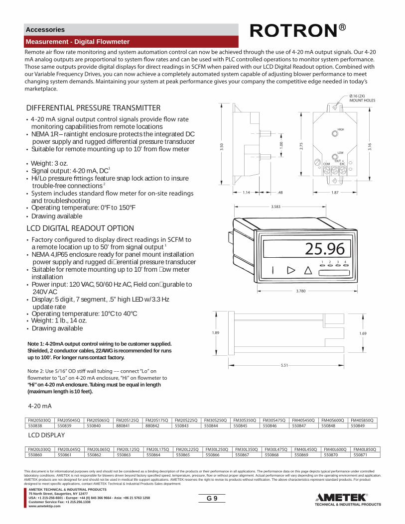
Accessories
Measurement - Digital Flowmeter
DIFFERENTIAL PRESSURE TRANSMITTER•
monitoring capabilities from remote locations• NEMA 1R – raintight enclosure protects the integrated DC
power supply and rugged di erential pressure transducer• Suitable for remote mounting up to 10’ from meter
• Weight: 3 oz.• Signal output: 4-20 mA, DC 1
• Hi/Lo pressure feature snap lock action to insuretrouble-free connections 2
•and troubleshooting
• Operating temperature: 0°F to 150°F• Drawing available
LCD DIGITAL READOUT OPTION•
a remote location up to 50’ from signal output 1
• NEMA 4,IP65 enclosure ready for panel mount installationpower supply and rugged di�erential pressure transducer
• Suitable for remote mounting up to 10’ from �ow meter installation
• Power input: 120 VAC, 50/60 Hz AC, Field con�gurable to V 240V AC
• Display: 5 digit, 7 segment, .5” high LED w/3.3 Hz update rate
• Operating temperature: 10°C to 40°C• Weight: 1 lb., 14 oz.
Note 1: 4-20mA output control wiring to be customer supplied.Shielded, 2 conductor cables, 22AWG is recommended for runsup to 100’. For longer runs contact factory.
“Hi” on 4-20 mA enclosure. Tubing must be equal in length(maximum length is 10 feet).
3.16
1.87
3.583
3.780
1 2 3 4
25.96
2.75
.481.14
3.50 1.00
Ø.16 (2X)MOUNT HOLES
OUT
LOW
HIGH
-COM
+EXC
1.89 1.69
5.51
Remote air �ow rate monitoring and system automation control can now be achieved through the use of 4-20 mA output signals. Our 4-20 mA analog outputs are proportional to system �ow rates and can be used with PLC controlled operations to monitor system performance. Those same outputs provide digital displays for direct readings in SCFM when paired with our LCD Digital Readout option. Combined with our Variable Frequency Drives, you can now achieve a completely automated system capable of adjusting blower performance to meet changing system demands. Maintaining your system at peak performance gives your company the competitive edge needed in today’s marketplace.
• Drawing available
4-20 mA FM20S030Q FM20S045Q FM20S065Q FM20S125Q FM20S175Q FM20S225Q FM30S250Q FM30S350Q FM30S475Q FM40S450Q FM40S600Q FM40S850Q 550838 550839 550840 880841 880842 550843 550844 550845 550846 550847 550848 550849
LCD DISPLAY FM20L030Q FM20L045Q FM20L065Q FM20L125Q FM20L175Q FM20L225Q FM30L250Q FM30L350Q FM30L475Q FM40L450Q FM40L600Q FM40L850Q 550860 550861 550862 550863 550864 550865 550866 550867 550868 550869 550870 550871
G 9____
This document is for informational purposes only and should not be considered as a binding description of the products or their performance in all applications. The performance data on this page depicts typical performance under controlledlaboratory conditions. AMETEK is not responsible for blowers driven beyond factory specified speed, temperature, pressure, flow or without proper alignment. Actual performance will vary depending on the operating environment and application.AMETEK products are not designed for and should not be used in medical life support applications. AMETEK reserves the right to revise its products without notification. The above characteristics represent standard products. For productdesigned to meet specific applications, contact AMETEK Technical & Industrial Products Sales department.
AMETEK TECHNICAL & INDUSTRIAL PRODUCTS75 North Street, Saugerties, NY 12477USA: +1 215-256-6601 - Europe: +44 (0) 845 366 9664 - Asia: +86 21 5763 1258Customer Service Fax: +1 215.256.1338www.ametektip.com
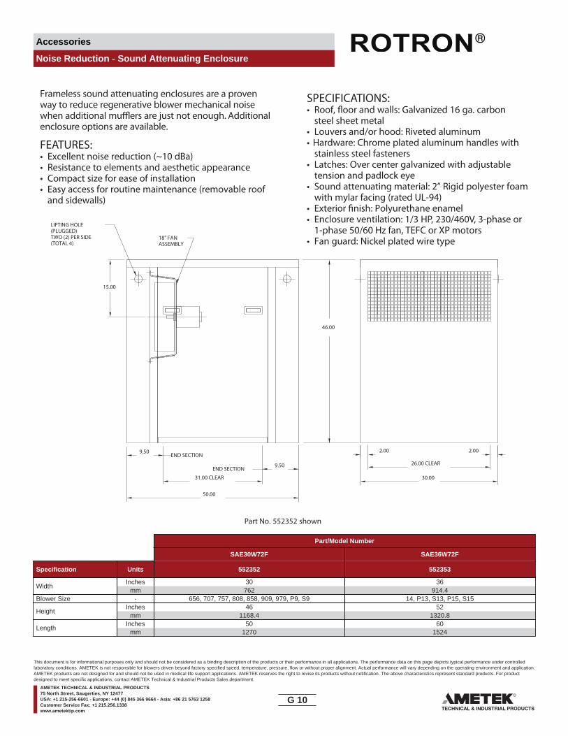
Accessories
Noise Reduction - Sound Attenuating Enclosure
Part No. 552352 shown
Frameless sound attenuating enclosures are a provenway to reduce regenerative blower mechanical noisewhen additional mu are just not enough. Additionalenclosure options are available.
FEATURES:• Excellent noise reduction (~10 dBa)• Resistance to elements and aesthetic appearance• Compact size for ease of installation • Easy access for routine maintenance (removable roof
and sidewalls)
SPECIFICATIONS:• Roof, and walls: Galvanized 16 ga. carbon
steel sheet metal• Louvers and/or hood: Riveted aluminum• Hardware: Chrome plated aluminum handles with
stainless steel fasteners• Latches: Over center galvanized with adjustable
tension and padlock eye• Sound attenuating material: 2” Rigid polyester foam
with mylar facing (rated UL-94)• Exterior Polyurethane enamel• Enclosure ventilation: 1/3 HP, 230/460V, 3-phase or
1-phase 50/60 Hz fan, TEFC or XP motors• Fan guard: Nickel plated wire type
30.00
50.00
46.00
LIFTING HOLE(PLUGGED)TWO (2) PER SIDE(TOTAL 4)
9.50
9.50
END SECTION
END SECTION
31.00 CLEAR
15.00
18" FANASSEMBLY
2.00 2.00
26.00 CLEAR
Part/Model Number
SAE30W72F SAE36W72F
Specification Units 552352 552353
WidthInches
mm30
76236
914.4Blower Size - 656, 707, 757, 808, 858, 909, 979, P9, S9 14, P13, S13, P15, S15
HeightInches
mm46
1168.452
1320.8
LengthInches
mm50
127060
1524
G 10____
This document is for informational purposes only and should not be considered as a binding description of the products or their performance in all applications. The performance data on this page depicts typical performance under controlledlaboratory conditions. AMETEK is not responsible for blowers driven beyond factory specified speed, temperature, pressure, flow or without proper alignment. Actual performance will vary depending on the operating environment and application.AMETEK products are not designed for and should not be used in medical life support applications. AMETEK reserves the right to revise its products without notification. The above characteristics represent standard products. For productdesigned to meet specific applications, contact AMETEK Technical & Industrial Products Sales department.
AMETEK TECHNICAL & INDUSTRIAL PRODUCTS75 North Street, Saugerties, NY 12477USA: +1 215-256-6601 - Europe: +44 (0) 845 366 9664 - Asia: +86 21 5763 1258Customer Service Fax: +1 215.256.1338www.ametektip.com

Accessories
Noise Reduction - Inlet/Outlet Muffler (Single Connection)
Mu�ers lower blower noise in areas where reduced sound levels are required.
SPECIFICATIONS:HOUSING – SteelMEDIA – Acoustical Material
D
C
B
A
Part/Model Number
Specification Units 523627 516838 523626 523625 523624 523623 523622
Ref Blower Model - B B C D E E EInlet Connection - 1.0 NPT Male 1.0 SO Slip on 1.25 NPT Male 1.50 NPT Male 2.00 NPT Male 2.00 NPSC Female 2.00 NPT Male
Dimension AInches
mm4.00101.6
1.9048.3
4.00101.6
4.00101.6
4.00101.6
4.00101.6
4.00101.6
Dimension BInches
mm10.93277.6
5.16131.1
10.93277.6
10.93277.6
10.93277.6
10.93277.6
15.75400.1
Dimension CInches
mm13.98355.1
6.23158.2
14.07357.4
14.57370.1
12.16308.9
12.43315.7
16.95430.5
Dimension DInches
mm1.0025.4
1.0025.4
1.2531.8
1.5038.1
2.0050.8
2.0050.8
2.0050.8
A = SPIRAL E = DR/EN/CP 656, 6, 633, S7B = DR/EN/CP 068, 083, 101, 202C = DR/EN/CP 303, 312, 313, 353 G = DR/EN/CP 833, S13, P13 (Inlet Only)D = DR/EN/CP 404, 454, 513, 505, 555, 523 H = DR/EN/CP 909, 979, 1233, 14, S15, P15 (Inlet Only)
F = DR/EN/CP 757, 808, 858, S9, P9 (Inlet Only)
Blower Model Reference Key
G 11____
This document is for informational purposes only and should not be considered as a binding description of the products or their performance in all applications. The performance data on this page depicts typical performance under controlledlaboratory conditions. AMETEK is not responsible for blowers driven beyond factory specified speed, temperature, pressure, flow or without proper alignment. Actual performance will vary depending on the operating environment and application.AMETEK products are not designed for and should not be used in medical life support applications. AMETEK reserves the right to revise its products without notification. The above characteristics represent standard products. For productdesigned to meet specific applications, contact AMETEK Technical & Industrial Products Sales department.
AMETEK TECHNICAL & INDUSTRIAL PRODUCTS75 North Street, Saugerties, NY 12477USA: +1 215-256-6601 - Europe: +44 (0) 845 366 9664 - Asia: +86 21 5763 1258Customer Service Fax: +1 215.256.1338www.ametektip.com

Accessories
Noise Reduction - Inline Muffler (Dual Connection)
Inline Mu�ers are utilized for noise reduction inapplications where piping systems are connected directlyto both ends of the mu�er. Mu�er may be used on inletor outlet of blower.
SPECIFICATIONS:HOUSING – SteelMEDIA – Acoustical Material
C
B
A OUTLETCONNECTION
INLETCONNECTION
Part/Model Number
Specification Units 550888 522948 529900 551377 515185 511569 515210 551565 516264 516265
Ref Blower Model - D E E E F G G G H HInlet Connection - 1.5 NPT-M 2.0 NPT-M 2.0 NPSC-F 2.0 NPT-M 2.5 NPT-M 3.0 NPT-M 4.0 NPT-M 4.0 NPT-M 4.0 NPT-M 6.0 NPT-MOutlet Connection - 2.0 NPT-F 2.0 NPSC-F 2.0 NPSC-F 2.0 NPT-M 2.5 NPT-F 3.0 NPT-F 4.0 NPT-F 4.0 NPT-M 4.0 NPT-F 6.0 NPT-F
Dimension AInches
mm4.00
101.64.00
101.64.38
111.34.00
101.66.12
155.47.00
177.810.00254
10.00254
8.00203.2
12.00304.8
Dimension BInches
mm7.75
196.915.75400.1
15.75400.1
15.75400.1
15.00381
18.00457.2
24.00609.6
24.00609.6
22.00558.8
30.00762
Dimension CInches
mm15.5
393.718.45468.6
18.45468.6
18.15461
19.00482.6
22.25565.2
30.00762
30.00762
27.75704.9
36.75933.5
A = SPIRAL E = DR/EN/CP 656, 6, 633, S7B = DR/EN/CP 068, 083, 101, 202C = DR/EN/CP 303, 312, 313, 353 G = DR/EN/CP 833, S13, P13 (Inlet Only)D = DR/EN/CP 404, 454, 513, 505, 555, 523 H = DR/EN/CP 909, 979, 1233, 14, S15, P15 (Inlet Only)
F = DR/EN/CP 757, 808, 858, S9, P9 (Inlet Only)
Blower Model Reference Key
G 12____
This document is for informational purposes only and should not be considered as a binding description of the products or their performance in all applications. The performance data on this page depicts typical performance under controlledlaboratory conditions. AMETEK is not responsible for blowers driven beyond factory specified speed, temperature, pressure, flow or without proper alignment. Actual performance will vary depending on the operating environment and application.AMETEK products are not designed for and should not be used in medical life support applications. AMETEK reserves the right to revise its products without notification. The above characteristics represent standard products. For productdesigned to meet specific applications, contact AMETEK Technical & Industrial Products Sales department.
AMETEK TECHNICAL & INDUSTRIAL PRODUCTS75 North Street, Saugerties, NY 12477USA: +1 215-256-6601 - Europe: +44 (0) 845 366 9664 - Asia: +86 21 5763 1258Customer Service Fax: +1 215.256.1338www.ametektip.com
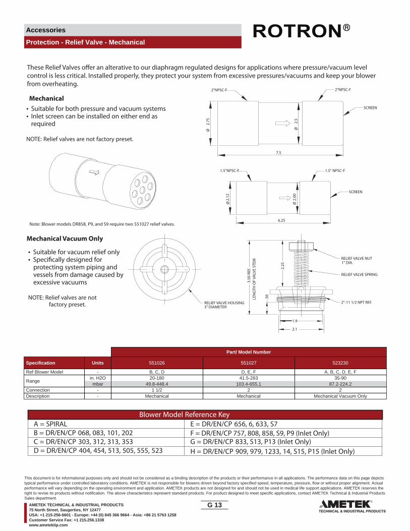
Accessories
Protection - Relief Valve - Mechanical
• Suitable for both pressure and vacuum systems • Inlet screen can be installed on either end as
required
NOTE: Relief valves are not factory preset.
Note: Blower models DR858, P9, and S9 require two 551027 relief valves.
Ø2.
00
6.25
Ø2.
12
1.5"NPSC-F 1.5" NPSC-F
SCREEN
7.5
Ø2.
75
Ø2.
5
2"NPSC-F 2"NPSC-F
SCREEN
• Suitable for vacuum relief only • Speci�cally designed for
protecting system piping and vessels from damage caused by excessive vacuums
NOTE: Relief valves are not factory preset.
LEN
GTH
OF
VALV
E ST
EM3.
50 R
EF.
3" DIAMETER
1" DIA.
2.25
.56
RELIEF VALVE HOUSING
RELIEF VALVE SPRING
2"-11 1/2 NPT REF.
RELIEF VALVE NUT
1.9
2.1
These Relief Valves o�er an alterative to our diaphragm regulated designs for applications where pressure/vacuum level control is less critical. Installed properly, they protect your system from excessive pressures/vacuums and keep your blower from overheating.
Mechanical
Mechanical Vacuum Only
Part/ Model Number
Specification Units 551026 551027 523230
Ref Blower Model - B, C, D D, E, F A, B, C, D, E, F
Rangein. H2Ombar
20-18049.8-448.4
41.5-263103.4-655.1
35-9087.2-224.2
Connection - 1 1/2 2 2Description - Mechanical Mechanical Mechanical Vacuum Only
A = SPIRAL E = DR/EN/CP 656, 6, 633, S7B = DR/EN/CP 068, 083, 101, 202C = DR/EN/CP 303, 312, 313, 353 G = DR/EN/CP 833, S13, P13 (Inlet Only)D = DR/EN/CP 404, 454, 513, 505, 555, 523 H = DR/EN/CP 909, 979, 1233, 14, S15, P15 (Inlet Only)
F = DR/EN/CP 757, 808, 858, S9, P9 (Inlet Only)
Blower Model Reference Key
G 13____
This document is for informational purposes only and should not be considered as a binding description of the products or their performance in all applications. The performance data on this page depictstypical performance under controlled laboratory conditions. AMETEK is not responsible for blowers driven beyond factory specified speed, temperature, pressure, flow or without proper alignment. Actualperformance will vary depending on the operating environment and application. AMETEK products are not designed for and should not be used in medical life support applications. AMETEK reserves theright to revise its products without notification. The above characteristics represent standard products. For product designed to meet specific applications, contact AMETEK Technical & Industrial ProductsSales department.
AMETEK TECHNICAL & INDUSTRIAL PRODUCTS75 North Street, Saugerties, NY 12477USA: +1 215-256-6601 - Europe: +44 (0) 845 366 9664 - Asia: +86 21 5763 1258Customer Service Fax: +1 215.256.1338www.ametektip.com
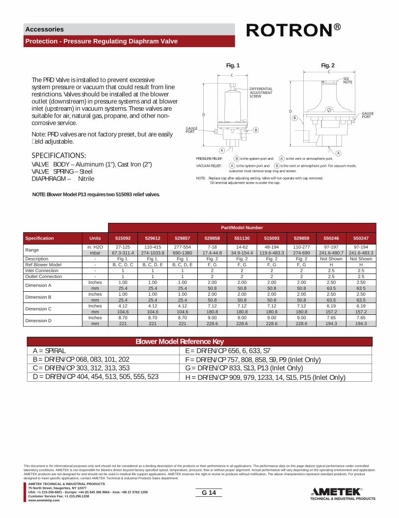
Accessories
Protection - Pressure Regulating Diaphram Valve
PRESSURE RELIEF: B is the system port and A is the vent or atmospheric port.
VACUUM RELIEF: A is the system port and B is the vent or atmospheric port. For vacuum mode,customer must remove snap ring and screen.
NOTE: Replace cap after adjusting setting. Valve will not operate with cap removed. Di�erential adjustment screw is under the cap.
Fig. 1 Fig. 2
NOTE: Blower Model P13 requires two 515093 relief valves.
The PRD Valve is installed to prevent excessive system pressure or vacuum that could result from linerestrictions. Valves should be installed at the blower outlet (downstream) in pressure systems and at blowerinlet (upstream) in vacuum systems. These valves are suitable for air, natural gas, propane, and other non-corrosive service.
Note: PRD valves are not factory preset, but are easily�eld adjustable.
SPECIFICATIONS:VALVE BODY – Aluminum (1"), Cast Iron (2")VALVE SPRING – SteelDIAPHRAGM – Nitrile
D
C
DIFFERENTIALADJUSTMENTSCREW
A
BGAUGEPORT
SEENOTE
GAUGEPORT
A
B
D
C
Part/Model Number
Specification Units 515092 529612 529857 529858 551130 515093 529859 550246 550247
Rangein. H2Ombar
27-12567.3-311.4
110-415274-1033.8
277-554690-1380
7-1817.4-44.8
14-6234.9-154.4
48-194119.6-483.3
110-277274-690
97-197241.6-490.7
97-194241.6-483.3
Description - Fig 1. Fig 1. Fig. 1 Fig. 2 Fig. 2 Fig. 2 Fig. 2 Not Shown Not ShownRef Blower Model - B, C, D, C B, C, D, E B, C, D, E F, G F, G F, G F, G H HInlet Connection - 1 1 1 2 2 2 2 2.5 2.5Outlet Connection - 1 1 1 2 2 2 2 2.5 2.5
Dimension AInches
mm1.0025.4
1.0025.4
1.0025.4
2.0050.8
2.0050.8
2.0050.8
2.0050.8
2.5063.5
2.5063.5
Dimension BInches
mm1.0025.4
1.0025.4
1.0025.4
2.0050.8
2.0050.8
2.0050.8
2.0050.8
2.5063.5
2.5063.5
Dimension CInches
mm4.12
104.64.12
104.64.12
104.67.12
180.87.12
180.87.12
180.87.12
180.86.19
157.26.19
157.2
Dimension DInches
mm8.70221
8.70221
8.70221
9.00228.6
9.00228.6
9.00228.6
9.00228.6
7.65194.3
7.65194.3
A = SPIRAL E = DR/EN/CP 656, 6, 633, S7B = DR/EN/CP 068, 083, 101, 202C = DR/EN/CP 303, 312, 313, 353 G = DR/EN/CP 833, S13, P13 (Inlet Only)D = DR/EN/CP 404, 454, 513, 505, 555, 523 H = DR/EN/CP 909, 979, 1233, 14, S15, P15 (Inlet Only)
F = DR/EN/CP 757, 808, 858, S9, P9 (Inlet Only)
Blower Model Reference Key
G 14____
This document is for informational purposes only and should not be considered as a binding description of the products or their performance in all applications. The performance data on this page depicts typical performance under controlledlaboratory conditions. AMETEK is not responsible for blowers driven beyond factory specified speed, temperature, pressure, flow or without proper alignment. Actual performance will vary depending on the operating environment and application.AMETEK products are not designed for and should not be used in medical life support applications. AMETEK reserves the right to revise its products without notification. The above characteristics represent standard products. For productdesigned to meet specific applications, contact AMETEK Technical & Industrial Products Sales department.
AMETEK TECHNICAL & INDUSTRIAL PRODUCTS75 North Street, Saugerties, NY 12477USA: +1 215-256-6601 - Europe: +44 (0) 845 366 9664 - Asia: +86 21 5763 1258Customer Service Fax: +1 215.256.1338www.ametektip.com
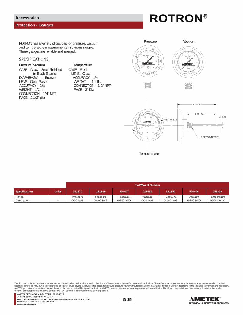
Accessories
Protection - Gauges
ROTRON has a variety of gauges for pressure, vacuumand temperature measurements in various ranges.These gauges are reliable and rugged.
SPECIFICATIONS:Pressure/ Vacuum TemperatureCASE – Drawn Steel Finished CASE – Steel
in Black Enamel LENS – GlassDIAPHRAGM – Bronze ACCURACY – 1%LENS – Clear Plastic WEIGHT – 1/4 lb.ACCURACY – 2% CONNECTION – 1/2" NPTWEIGHT – 1/2 lb. FACE – 3" DialCONNECTION – 1/4" NPTFACE – 2 1/2" dia.
Pressure Vacuum
Temperature
200
180
160
140
120100
80
60
40
20
100
50
150
200 250
350
400
300
°F
°C
10
0
1
2
3
4
5
6
PRESSURE
0
2040
60
80 100
120140
160
P S INCHE S OF WAT E RI
.25 ±.03Ø 3.18 ±.12
2.50 ±.06
3.38 ±.12
1/2 NPT CONNECTION
Part/Model Number
Specification Units 551376 271949 550407 529428 271950 550408 551368
Range - Pressure Pressure Pressure Vacuum Vacuum Vacuum TemperatureDescription - 0-60 IWG 0-160 IWG 0-280 IWG 0-60 IWG 0-160 IWG 0-280 IWG 0-200 Deg C
G 15____
This document is for informational purposes only and should not be considered as a binding description of the products or their performance in all applications. The performance data on this page depicts typical performance under controlledlaboratory conditions. AMETEK is not responsible for blowers driven beyond factory specified speed, temperature, pressure, flow or without proper alignment. Actual performance will vary depending on the operating environment and application.AMETEK products are not designed for and should not be used in medical life support applications. AMETEK reserves the right to revise its products without notification. The above characteristics represent standard products. For productdesigned to meet specific applications, contact AMETEK Technical & Industrial Products Sales department.
AMETEK TECHNICAL & INDUSTRIAL PRODUCTS75 North Street, Saugerties, NY 12477USA: +1 215-256-6601 - Europe: +44 (0) 845 366 9664 - Asia: +86 21 5763 1258Customer Service Fax: +1 215.256.1338www.ametektip.com

Accessories
System - Variable Frequency Drive
A Variable Frequency Drive (VFD) is an adjustablespeed AC motor control designed to speed the blowerRPM up or down. Our VFDs are designed to minimizelosses and deliver increased ciency, low maintenance,and the long life expected from the ROTRON product line.
FEATURES•
ncy by controlling motor RPMs• Accepts 3Ø or 1Ø inputs to drive 3Ø motor blower
assemblies• Accepts 4-20 mA, 0-5 VDC or 0-10 VDC inputs for
system automation control and intregation• Provides dynamic breaking capabilities• Replaces motor starter function• Digital readout in either Hz or RPMs• Keypad enclosure (NEMA 4X - Indoor) can be
mounted up to 100' from controller with cable assembly (optional)
SYSTEM REQUIREMENTS• In cases where the distance between the controller
and motor exceed 50', the use of a line reactor on load side is needed.
• XP motors must be UL listed for use with a Variable tedFrequency Drive.
VARIABLE FREQUENCY DRIVE SELECTIONThere are some common guidelines in sizing a VFD for use on a AMETEK ROTRON blowers such as the allowable
equired RPMmust fall within the allowable rate of the motor being used.
Motor Allowable Turndown Allowable Speedup
Standard 3600 RPM to 1800 RPM —3600 RPM to 900 RPM —
Inverter Motor 3600 RPM to 360 RPM* 3600 RPM to 7200 RPM
* Turndown of 10:1 is not typically done with regenerative blower designs.For all applications above 3600 RPM, contact your Field Sales Engineer for proper horsepower sizing.
TABLE 1
Specification
Part Number Model Number Description
IV101AE58 551529 115/1, Up to 0.5 HP, DR068-DR303IV102AE58 551530 230/1, Up to 0.5 HP, DR068-DR303IV101AL58 551531 115/1, 0.75 to 1.0 HP, DR353-DR404IV102AL58 551532 230/1 or 3, 0.75 to 1.0 HP, DR353-DR404IV103AL72 551533 460/3, 0.75 to 1.0 HP, DR353-DR404IV102AS58 551534 230/1 or 3, 1.5 to 2.0 HP, DR454-DR505IV103AS72 551535 460/3, 1.5 to 2 HP DR454-DR505IV102K58 551536 230/1 or 3, 2.5 to 3 HP, DR505-DR555IV103K72 551537 460/3, 2.5 to 3.0 HP, DR505-DR555IV102D58 551538 230/1 or 3, 3.5 to 5 HP, DR555-DR808DIV103D72 551539 460/3, 3.5 to 5 HP DR555 to DR808D
IV152AY58 551540 230/3, 5.5 to 7.5 HP, DR808-DR858IV152AY72 551541 460/3 5.5 to 7.5, DR808 – DR858IV152BB58 551542 230/3, 8 to 10 HP, DR858-DR909IV153BB72 551543 460/3, 8 to 10 HP, DR858-DR909IV152BC58 551544 230/3, 10.5 to 15 HP, DR909IV153BC72 551545 460/3, 10.5 to 15 HP, DR909IV152BH58 551546 230/3, 15.5 to 20 HP, DR9, DR14BHIV153BH72 551547 460/3, 15.5 to 20 HP, DR9, DR14BHIV152BP58 551548 230/3, 20.5 to 30 HP, DR13, DR14IV153BP72 551549 460/3, 20.5 to 30 HP, DR13, DR14IV152BQ58 551550 230/3, 30.5 to 40 HP, DR15IV153BQ72 551551 460/3, 30.5 to 40 HP, DR15IV153ED72 551552 460/3, 50.5 to 60 HP, DR15
G 16____
This document is for informational purposes only and should not be considered as a binding description of the products or their performance in all applications. The performance data on this page depicts typical performance under controlledlaboratory conditions. AMETEK is not responsible for blowers driven beyond factory specified speed, temperature, pressure, flow or without proper alignment. Actual performance will vary depending on the operating environment and application.AMETEK products are not designed for and should not be used in medical life support applications. AMETEK reserves the right to revise its products without notification. The above characteristics represent standard products. For productdesigned to meet specific applications, contact AMETEK Technical & Industrial Products Sales department.
AMETEK TECHNICAL & INDUSTRIAL PRODUCTS75 North Street, Saugerties, NY 12477USA: +1 215-256-6601 - Europe: +44 (0) 845 366 9664 - Asia: +86 21 5763 1258Customer Service Fax: +1 215.256.1338www.ametektip.com
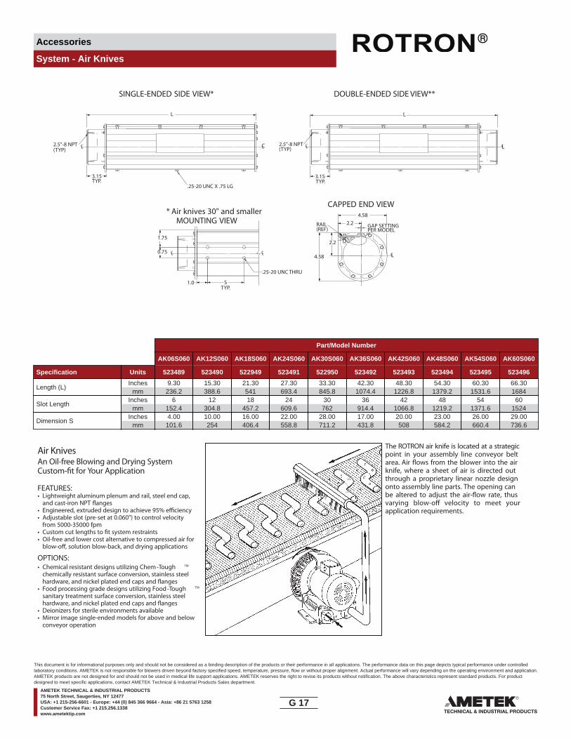
Accessories
System - Air Knives
SINGLE-ENDED SIDE VIEW* DOUBLE-ENDED SIDE VIEW**
* Air knives 30" and smallerMOUNTING VIEW
CAPPED END VIEW
CL CL2.5"-8 NPT(TYP)
CL CL2.5"-8 NPT(TYP)
GAP SETTINGRAIL(REF)
CL
PER MODEL
CL CL
.25-20 UNC THRU
.25-20 UNC X .75 LG
3.15 TYP.
3.15TYP.
L
4.58
4.58
2.2
2.2
0.75
1.75
1.0 STYP.
L
Part/Model Number
AK06S060 AK12S060 AK18S060 AK24S060 AK30S060 AK36S060 AK42S060 AK48S060 AK54S060 AK60S060
Specification Units 523489 523490 522949 523491 522950 523492 523493 523494 523495 523496
Length (L)Inches
mm9.30
236.215.30388.6
21.30541
27.30693.4
33.30845.8
42.301074.4
48.301226.8
54.301379.2
60.301531.6
66.301684
Slot LengthInches
mm6
152.412
304.818
457.224
609.630
76236
914.442
1066.848
1219.254
1371.660
1524
Dimension SInches
mm4.00
101.610.00254
16.00406.4
22.00558.8
28.00711.2
17.00431.8
20.00508
23.00584.2
26.00660.4
29.00736.6
The ROTRON air knife is located at a strategicpoint in your assembly line conveyor beltarea. Air �ows from the blower into the airknife, where a sheet of air is directed outthrough a proprietary linear nozzle designonto assembly line parts. The opening canbe altered to adjust the air-�ow rate, thusvarying blow-o� velocity to meet yourapplication requirements.
Air KnivesAn Oil-free Blowing and Drying SystemCustom-�t for Your Application
FEATURES:• Lightweight aluminum plenum and rail, steel end cap,
and cast-iron NPT �anges• Engineered, extruded design to achieve 95% e�ciency• Adjustable slot (pre-set at 0.060") to control velocity
from 5000-35000 fpm• Custom cut lengths to �t system restraints• Oil-free and lower cost alternative to compressed air for
blow-o�, solution blow-back, and drying applications
OPTIONS:• Chemical resistant designs utilizing Chem-Tough TM
chemically resistant surface conversion, stainless steel hardware, and nickel plated end caps and �anges
• Food processing grade designs utilizing Food-Tough TM
sanitary treatment surface conversion, stainless steel hardware, and nickel plated end caps and �anges
• Deionizers for sterile environments available• Mirror image single-ended models for above and below
conveyor operation
G 17____
This document is for informational purposes only and should not be considered as a binding description of the products or their performance in all applications. The performance data on this page depicts typical performance under controlledlaboratory conditions. AMETEK is not responsible for blowers driven beyond factory specified speed, temperature, pressure, flow or without proper alignment. Actual performance will vary depending on the operating environment and application.AMETEK products are not designed for and should not be used in medical life support applications. AMETEK reserves the right to revise its products without notification. The above characteristics represent standard products. For productdesigned to meet specific applications, contact AMETEK Technical & Industrial Products Sales department.
AMETEK TECHNICAL & INDUSTRIAL PRODUCTS75 North Street, Saugerties, NY 12477USA: +1 215-256-6601 - Europe: +44 (0) 845 366 9664 - Asia: +86 21 5763 1258Customer Service Fax: +1 215.256.1338www.ametektip.com

Accessories
System - Air Knives
0 100 200 300 400 500 600 700 800 900 1000 1100 1200 1300 1400 1500 1600 1700 1800SCFM
Air Velocity
Precision Cleaning Air Knife and Blower Selection Chart
DR656
DR757
DR808 DR858
DR909
DRP9
DR979
DRP13
DR14
DRP15
6" knife
12" knife
18" knife
24" knife 30"
knife 36" knife
42" knife
48" knife 54"
knife60"
knife
40,000 FPM
35,000 FPM
30,000 FPM
25,000 FPM
20,000 FPM
15,000 FPM
G 18____
This document is for informational purposes only and should not be considered as a binding description of the products or their performance in all applications. The performance data on this page depicts typical performance under controlledlaboratory conditions. AMETEK is not responsible for blowers driven beyond factory specified speed, temperature, pressure, flow or without proper alignment. Actual performance will vary depending on the operating environment and application.AMETEK products are not designed for and should not be used in medical life support applications. AMETEK reserves the right to revise its products without notification. The above characteristics represent standard products. For productdesigned to meet specific applications, contact AMETEK Technical & Industrial Products Sales department.
AMETEK TECHNICAL & INDUSTRIAL PRODUCTS75 North Street, Saugerties, NY 12477USA: +1 215-256-6601 - Europe: +44 (0) 845 366 9664 - Asia: +86 21 5763 1258Customer Service Fax: +1 215.256.1338www.ametektip.com

Accessories
System - 5 Way, 3 Port, 2 Position Diverter Valve
These unique solenoid actuated diverter valves automati-cally change air piping from pressure to suction; greatlyenhancing blower versatility and productivity. This valveis e�ective in blower applications that require frequentswitching of air from pressure to suction and vice-versa.They are cost e�ective as applications normally requiringtwo blowers and/or intricate piping systems may beaccomplished with one blower.
Diverter valves may be purchased as blower/valveassemblies, or as separate stand-alone valve assembliesfor use in other switched air applications.
SPECIFICATIONS:• Aluminum body and spool assembly• 303 stainless steel shaft• 115 V-60 Hz solenoid valve • Over 1,000,000 cycle life expectancyOPTIONS• Corrosion resistant surface treatments• International voltage and frequency (Hz)• Application speci�c designs
DR 505 BLOWER WITH DIVERTER VALVE
The principle behind ROTRON’S diverter valve system is asimple one: Some applications such as vacuum part pick-up, air tables, and pneumatic tube systems require bothvacuum and pressure in their equipment’s operation, butnot simultaneously. They eliminate the need for two sep-arate blowers, and elaborate valving system, or cycling/reversing a spinning blower impeller. ROTRON’S divertervalve changes the air passageways. By utilizing the sidevent ports for incoming or outgoing air, the equipment/piping side of the valve changes from vacuum to pressureand back again by a signal sent to the solenoid coil.
Part/Model Number
Specification Units 515554 037435 037482
Description - DR404, DR454, DR505 DR6, DR808, DR858 DR6, DR808, DR858Ref Blower Model - Small Large LargePiping Flange - Threads Threads ThreadsBlower Flange - Face Threads Face
Dimension AInches
mm7.65
194.39.25235
9.25235
Dimension BInches
mm14.22361.2
23.39594.1
23.39594.1
Dimension CInches
mm7.14
181.410.93277.6
10.93277.6
Dimension DInches
mm2.5063.5
3.5590.2
3.5590.2
Dimension EInches
mm5.00127
7.10180.3
7.10180.3
Dimension FInches
mm1.5038.1
2.5063.5
2.5063.5
Dimension GInches
mm1.5038.1
2.5063.5
2.5063.5
Consult factory for proper selection and application.
SOLENOID
ENERGIZED POSITION"SUCTION" AIR PATH
SOLENOID
DE-ENERGIZED POSITION"PRESSURE" AIR PATH
A
D
BF
C
EG
EQUIPMENT/PIPING SIDE ISO VALVE DRAWING
BLOWER SIDE
WORKING PART
SUCTION PRESSURE
BlowerBlower
IN OUT IN OUT
G 19____
This document is for informational purposes only and should not be considered as a binding description of the products or their performance in all applications. The performance data on this page depicts typical performance under controlledlaboratory conditions. AMETEK is not responsible for blowers driven beyond factory specified speed, temperature, pressure, flow or without proper alignment. Actual performance will vary depending on the operating environment and application.AMETEK products are not designed for and should not be used in medical life support applications. AMETEK reserves the right to revise its products without notification. The above characteristics represent standard products. For productdesigned to meet specific applications, contact AMETEK Technical & Industrial Products Sales department.
AMETEK TECHNICAL & INDUSTRIAL PRODUCTS75 North Street, Saugerties, NY 12477USA: +1 215-256-6601 - Europe: +44 (0) 845 366 9664 - Asia: +86 21 5763 1258Customer Service Fax: +1 215.256.1338www.ametektip.com
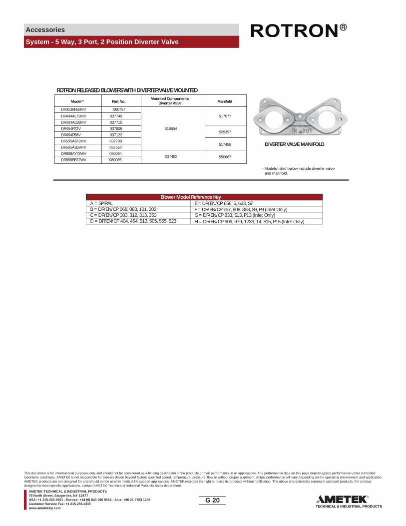
Accessories
System - 5 Way, 3 Port, 2 Position Diverter Valve
ROTRON RELEASED BLOWERS WITH DIVERTER VALVE MOUNTEDMounted Components
Model * Part No. Diverter Valve Manifold
DR353BR58MV 080757
DR404AL72MV 037749 517077
DR404AL58MV 037715
DR454R72V 037605 515554529397
DR454R58V 037122
DR505AS72MV 037709517459
DR505AS58MV 037554
037482 DR808AY72WV 080084
550667DR858BB72WV 080085
DIVERTER VALVE MANIFOLD
• Models listed below include diverter valve and manifold.
A = SPIRAL E = DR/EN/CP 656, 6, 633, S7B = DR/EN/CP 068, 083, 101, 202C = DR/EN/CP 303, 312, 313, 353 G = DR/EN/CP 833, S13, P13 (Inlet Only)D = DR/EN/CP 404, 454, 513, 505, 555, 523 H = DR/EN/CP 909, 979, 1233, 14, S15, P15 (Inlet Only)
F = DR/EN/CP 757, 808, 858, S9, P9 (Inlet Only)
Blower Model Reference Key
G 20____
This document is for informational purposes only and should not be considered as a binding description of the products or their performance in all applications. The performance data on this page depicts typical performance under controlledlaboratory conditions. AMETEK is not responsible for blowers driven beyond factory specified speed, temperature, pressure, flow or without proper alignment. Actual performance will vary depending on the operating environment and application.AMETEK products are not designed for and should not be used in medical life support applications. AMETEK reserves the right to revise its products without notification. The above characteristics represent standard products. For productdesigned to meet specific applications, contact AMETEK Technical & Industrial Products Sales department.
AMETEK TECHNICAL & INDUSTRIAL PRODUCTS75 North Street, Saugerties, NY 12477USA: +1 215-256-6601 - Europe: +44 (0) 845 366 9664 - Asia: +86 21 5763 1258Customer Service Fax: +1 215.256.1338www.ametektip.com

Accessories
System - Air Flow Switch
FEATURES• 8 air velocity ratings available in single pole double
throw design• Interchangeable stainless steel actuating vanes, black
enameled aluminum housing and cover,copper spring and pure silver contacts
• SPDT 5 amp 250 VAC• Mounts on round and �at ducts with single screw• 500,000 operations life expectancy• Operates reliably in ambient temperatures of -35°C
to +85°C.• Weight: 4.5 oz (0.13 kg)
DETERMINATOR KIT - PART NO. 041100In order to determine the best sensitivity rating, use theROTRON “Determinator Kit.” The kit consists of a switchtogether with a complete set of 8 actuating vanes. Byinterchanging these vanes on the switch it is possible to
quickly determine which vane size has the sensitivityrating required in any particular experimental set-up.
HOW IT WORKSThe ROTRON Air Flow Switch is actuated by air velocityrather than air pressure. It is designed for easy mountingon the outside of an air duct with a small lightweightstainless steel vane protruding through a hole in theduct into the airstream. A snap action switch is actuatedwhen the velocity pressure against the vane moves itin the direction of the air �ow. As the velocity of theairstream decreases for any reason the vane movesback towards its original position and the switchdeactuates.
The switch can be used as an interlock for on-o�purposes, or as a marginal safety device where theelectrical contacts are operated at a predeterminedminimum �ow rate.
0.75
TERMINALS
COVER IS REMOVABLEIN EITHER DIRECTION
CUT HOLE .625DIA +.008/-.00
TAP HOLE #10-32
NYLON BUSHING ACCOMMODATES ANY SHAPE FROM .12 TO .58
PART TWO EDGESFOR REMOVING COVER
35°.50 DIA. +.005/-.00
#10-32 X 1/4 SOCKET SCREW (5.5) PACKED WITH EACH SWITCH
DIRECTION OFAIRFLOW
N. CLO
SED
N. O
PEN
COM
MO
N
MAX.
2.00
1.45
0.12
0.60
L
0.23
0.73
0.28
0.67
THROUGH HOLE.205+\ - .008 DIA.
PLASTIC SHOULDER
Part/Model Number
AFS2C/1003 AFS2C/1353 AFS2C/1603 AFS2C/1803 AFS2C/2003 AFS2C/2453 AFS2C/3003 AFS2C/4003
Specification Units 041101 041102 041103 041104 041105 041106 041107 041108
Max LengthInches
mm2.5063.5
1.9148.5
1.6341.4
1.4135.8
1.0927.7
0.9123.1
0.7819.8
0.7218.3
Arm – Horizontal Arm – Vertical Vane Down Arm – Horizontal Arm – HorizontalAirstream – Horizontal Airstream – Horizontal Airstream – Vertical-Up Airstream – Vertical-Down
Model Part No. Actuate Deactuate Actuate Deactuate Actuate Deactuate Actuate Deactuate
AFS 2C/1003 041101 735 630 750 615* 785 700 NOT NOT(3.73) (3.20) (3.81) (3.12) (3.99) (3.55) USABLE USABLE
AFS 2C/1353 041102 1025 970 1000 890 1125 1030 720* 685*(5.21) (4.93) (5.08) (4.52) (5.71) (5.23) (3.66) (3.48)
AFS 2C/1603 041103 1215 1095 1225 1130 1340 1212 1040 865*(6.17) (5.56) (6.22) (5.74) (6.81) (6.16) (5.28) (4.39)
AFS 2C/1803 041104 1460 1335 1500 1375 1550 1450 1280 1115*(7.42) (6.78) (7.62) (6.98) (7.87) (7.37) (6.50) (5.66)
AFS 2C/2003 041105 1790 1580 1760 1580 1800 1675 1595* 1425*(9.09) (8.02) (8.94) (8.02) (9.14) (8.51) (8.10) (7.24)
AFS 2C/2453 041106 2120 1867 2270 2035 2340 2120 2125 1950(10.77) (9.48) (11.53) (10.34) (11.89) (10.77) (10.79) (9.91)
AFS 2C/3003 041107 2690 2420 2880 2570 2925 2700 2780 2395(13.66) (12.29) (14.63) (13.05) (14.86) (13.71) (14.12) (12.17)
AFS 2C/4003 041108 3720 3485 3870 3520 4000 3680 3760 3565(18.90) (17.70) (19.66) (17.88) (20.32) (18.69) (19.10) (18.11)
Actuation/Deactuation Velocities (FPM / M/S)
NOTE: All figures are ±15% except: * denotes ±20%.
G 21____
This document is for informational purposes only and should not be considered as a binding description of the products or their performance in all applications. The performance data on this page depicts typical performance under controlledlaboratory conditions. AMETEK is not responsible for blowers driven beyond factory specified speed, temperature, pressure, flow or without proper alignment. Actual performance will vary depending on the operating environment and application.AMETEK products are not designed for and should not be used in medical life support applications. AMETEK reserves the right to revise its products without notification. The above characteristics represent standard products. For productdesigned to meet specific applications, contact AMETEK Technical & Industrial Products Sales department.
AMETEK TECHNICAL & INDUSTRIAL PRODUCTS75 North Street, Saugerties, NY 12477USA: +1 215-256-6601 - Europe: +44 (0) 845 366 9664 - Asia: +86 21 5763 1258Customer Service Fax: +1 215.256.1338www.ametektip.com

Accessories
Pressure & Vacuum Arrangements
Pressure or vacuum guages should be located in the delivery line, oriented as shown. Assure that the guage is approxi-mately three pipe diameters from the blower delivery �ange and that the relief valve is located at the same spacing from the guage. 90° elbows should be located at least �ve pipe diameters from the blower delivery �ange. Elbows, taps, tees, valves, or other restrictions to air �ow should not be located between the blower delivery �ange and accessories described above.
Failure to observe these precautions can result in false readings of guages and failure of the relief mechanism to protect the blower from overload.
In order to avoid overheating or distortion of PVC pipe, the �rst �ve to eight feet from the blower delivery �ange on pressure systems should be metal.
Typical Pressure System
Typical Vacuum System
G 22____
This document is for informational purposes only and should not be considered as a binding description of the products or their performance in all applications. The performance data on this page depicts typical performance under controlledlaboratory conditions. AMETEK is not responsible for blowers driven beyond factory specified speed, temperature, pressure, flow or without proper alignment. Actual performance will vary depending on the operating environment and application.AMETEK products are not designed for and should not be used in medical life support applications. AMETEK reserves the right to revise its products without notification. The above characteristics represent standard products. For productdesigned to meet specific applications, contact AMETEK Technical & Industrial Products Sales department.
AMETEK TECHNICAL & INDUSTRIAL PRODUCTS75 North Street, Saugerties, NY 12477USA: +1 215-256-6601 - Europe: +44 (0) 845 366 9664 - Asia: +86 21 5763 1258Customer Service Fax: +1 215.256.1338www.ametektip.com
Motor Blower Options
Motor Options
ROTRON strives to provide the most complete variety of desired options on our products including on our motors. By using motor vendors of high quality and versatility, we can provide motor features from multiple released designs to meet your needs (i.e., a Chem Processing Inverter Duty Explosion-proof motor with space heaters and drains wound for 380 V-50 Hz service).
Design Consistency
ROTRON motors are engineered for us to integrally mount with our blower and maximize blower performance. Our vendors are quali�ed by ROTRON (per motor part number) to ensure the blowers’ mechanical and electrical needs merge with your required features. The basic motor requirements on our DR/EN/CP/HiE products include:
• NEMA approved
• CE conformity (non-XP models)
• UL & CSA approved with symbol and file on nameplate
• C-face mount
• Permanently sealed bearings
• Shaft end play, run out and perpendicularity requirements above NEMA standards
• Dual voltage and dual frequency (some models not feasible) to maximize use worldwide
• Single Shafted Totally Enclosed Fan Cooled (TEFC) and Explosion-proof (XP) models
• Double Shafted Open Drip Proof (ODP) models with dual internal fans for circulation
• Class I Group D minimum on explosion-proof motors; many are Class I Group D, Class II F & G
• Commercial Spa (SPA-ODP) motors with automatic thermal overload protection and industry speci�ed terminal strip
Standard Motor Variations
Chemical Processing (CP) features are added to TEFC, XP or HiE designs for corrosive gas service, Marine Duty service and sanitary (food/pharmaceutical) service.
• 303 stainless steel shaft
• Cast iron and steel frame epoxy painted or zinc plated
• Zinc plated hardware
• Stainless steel nameplate
• Non-hygroscopic insulation; double dipped and baked stator
• Epoxy coating on rotor
• Gaskets and joint sealers on all metal-to-metal surfaces
• Oversized conduit box
High Efficiency (HiE) features are added to TEFC, ODP, XP or CP motors for maximum motor e�ciency and life. ROTRON HiE motors carry extra phase-to-phase protection for use with inverters between a 1750-3500 RPM range.
Inverter Duty features are added to TEFC, ODP, XP or CP for use with Inverters/Variable Speed Drive Controllers. A wide range of RPM can be handled and should be specified at time of quote. For best compatibility, an inverter should be matched to the motor manufacturers design.
Project Speci�c Motor Variations
There are no limits to the options you can select or request for your product. Routine motor options include:
• International voltage & frequency (Hz)
• Different shaft material
• Oversized and/or Nema 4 intent T-box
• Space heaters
• Drains
• Regreasable bearings
• Tropicalized windings
H 1____
This document is for informational purposes only and should not be considered as a binding description of the products or their performance in all applications. The performance data on this page depicts typical performance under controlledlaboratory conditions. AMETEK is not responsible for blowers driven beyond factory specified speed, temperature, pressure, flow or without proper alignment. Actual performance will vary depending on the operating environment and application.AMETEK products are not designed for and should not be used in medical life support applications. AMETEK reserves the right to revise its products without notification. The above characteristics represent standard products. For productdesigned to meet specific applications, contact AMETEK Technical & Industrial Products Sales department.
AMETEK TECHNICAL & INDUSTRIAL PRODUCTS75 North Street, Saugerties, NY 12477USA: +1 215-256-6601 - Europe: +44 (0) 845 366 9664 - Asia: +86 21 5763 1258Customer Service Fax: +1 215.256.1338www.ametektip.com
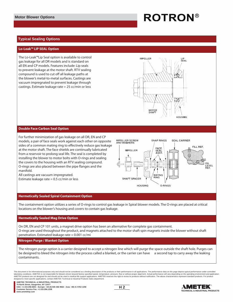
Motor Blower Options
Typical Sealing Options
Lo-Leak™ LIP SEAL Option
The Lo-Leak™Lip Seal option is available to control gas leakage for all DR models and is standard on all EN and CP models. Features include: Lip seals to prevent leakage at the motor shaft. RTV sealing compound is used to cut o� all leakage paths at the blower’s metal-to-metal surfaces. Castings are vacuum impregnated to prevent leakage through castings. Estimate leakage rate = 25 cc/min or less
Double Face Carbon Seal Option
For further minimization of gas leakage on all DR, EN and CP models, a pair of face seals work against each other on opposite sides of a common mating ring to e�ectively reduce gas leakage at the motor shaft. The face shields are continually lubricated from a reservoir to prolong seal life. The seal is completed by installing the blower to motor bolts with O-rings and sealing the covers to the housing with an RTV sealing compound. O-rings are also placed between the pipe �anges and the manifold. All castings are vacuum impregnated.Estimate leakage rate = 0.5 cc/min or less
Hermetically Sealed Spiral Containment Option
The containment option utilizes a series of O-rings to control gas leakage in Spiral blower models. The O-rings are placed at critical locations on the blower’s housing and covers to contain gas leakage.
Hermetically Sealed Mag Drive Option
On DR, EN and CP 101 units, a magnet drive option has been an alternative for complete gas containment. O-rings are used throughout the product, and magnets attached to the motor shaft spin magnets inside the blower without shaft penetration. Estimated leakage rate = 0.001 cc/mi
Nitrogen Purge / Blanket Option
The nitrogen purge option is a carrier designed to accept a nitrogen line which will purge the space outside the shaft hole. Purges can be designed to bleed the nitrogen into the process called a blanket, or the carrier can have a second tap to carry away the leaking contaminants.
H 2____
This document is for informational purposes only and should not be considered as a binding description of the products or their performance in all applications. The performance data on this page depicts typical performance under controlledlaboratory conditions. AMETEK is not responsible for blowers driven beyond factory specified speed, temperature, pressure, flow or without proper alignment. Actual performance will vary depending on the operating environment and application.AMETEK products are not designed for and should not be used in medical life support applications. AMETEK reserves the right to revise its products without notification. The above characteristics represent standard products. For productdesigned to meet specific applications, contact AMETEK Technical & Industrial Products Sales department.
AMETEK TECHNICAL & INDUSTRIAL PRODUCTS75 North Street, Saugerties, NY 12477USA: +1 215-256-6601 - Europe: +44 (0) 845 366 9664 - Asia: +86 21 5763 1258Customer Service Fax: +1 215.256.1338www.ametektip.com
Motor Blower Options
Chem-Tough™ Chemical Resistance
To stand up in corrosive and hazardous environments, chemical processing blowers have to be tough. That’s why Ametek ROTRON routinely applies Chem-Tough™, ROTRON’S own engineered and proprietary process, whenever it builds blowers for handling chemical (vapor) streams. Chem-Tough™ combines the advantages of aluminum oxide ceramic and selected �uorocarbons to give ROTRON blowers unheard-of levels of chemical resistance, hardness, abrasion resistance, permanent lubricity and more.
Chem-Tough™ Brings You the Rotron Advantage
Through this unique proprietary process, Chem-Tough™ gives ROTRON blowers these advantages:
• Outstanding Chemical Resistance Time after time, Chem-Tough™ �nishing shows extremely high resistance to most common chemicals, as well as dramatically improved corrosion resistance over regular hard anodizing. Chem-Tough™ allows aluminum to achieve equivalent corrosion resistance as te�on®. 90-day immersion in acid or alkaline solution (pH 4.0-8.5) has no e�ect; neither does prolonged exposure to salt water. Far exceeds military speci�cation requirements for salt spray.
• Abrasion Resistance Equivalent to Steel Excellent for smooth surfaces, Chem-Tough™ surface conversion provides higher wear resistance than either case-hardened steel or hard-chrome plate. Rub any other metal against the Chem-Tough™ �nish, and the metal will show nothing but the slightest wear. Chem-Tough™ provides a perfect bond to the parent metal.
• Increased Hardness With an equivalent hardness of Rc 40-60, Chem-Tough™ is approximately �le-hard – the hardness of nitrated steel. Because the Chem-Tough™ surface becomes an integral part of the metal, it simply cannot peel or chip – neither can it be scratched, �aked or nicked under ordinary conditions.
• Permanent Dry Lubricity By infusing polymers into aluminum, Chem-Tough™ gives the resulting surface a high degree of permanent lubricity and resistance to moisture. The polymers also level o� surface asperities, signi�cantly reducing surface tension. The result: blowers converted with Chem-Tough™ have a longer life, operate more e�ciently and call for less maintenance.
• Other Proprietary Processes Food-Tough™ uses the same unique process as Chem-Tough™, and is designed for the food processing, medical and pharmaceutical markets. Food-Tough™ has USDA approval and meets FDA guidelines.
Chem-Tough™ at Work
Chem-Tough™ employs the advantages of anodizing, hardcoat plating, low-friction polymers and dry lubricants to become an integral part of the blower’s molecular structure.
Speci�cally, Chem-Tough™ �rst converts the aluminum surface to aluminum oxide, forming a new ceramic-like surface. The water in the ceramic is replaced with Te�on®, adding a multi-functional dimension to the surface; in the process, the aluminum crystals expand and form anchor crystals that remain hygroscopic for a short time. Then, under controlled conditions, particles of the speci�ed polymer are infused to interlock with these anchor crystals. The new surface extends .5 mil above and below the original aluminum surface – and forms a permanent molecular bond with the metal.
The result: a plastic/ceramic surface that’s harder than steel, is continuously lubricating, and resists damage from chemicals like no other. The kind of protection you need for your chemical processing blowers.
H 3____
This document is for informational purposes only and should not be considered as a binding description of the products or their performance in all applications. The performance data on this page depicts typical performance under controlledlaboratory conditions. AMETEK is not responsible for blowers driven beyond factory specified speed, temperature, pressure, flow or without proper alignment. Actual performance will vary depending on the operating environment and application.AMETEK products are not designed for and should not be used in medical life support applications. AMETEK reserves the right to revise its products without notification. The above characteristics represent standard products. For productdesigned to meet specific applications, contact AMETEK Technical & Industrial Products Sales department.
AMETEK TECHNICAL & INDUSTRIAL PRODUCTS75 North Street, Saugerties, NY 12477USA: +1 215-256-6601 - Europe: +44 (0) 845 366 9664 - Asia: +86 21 5763 1258Customer Service Fax: +1 215.256.1338www.ametektip.com
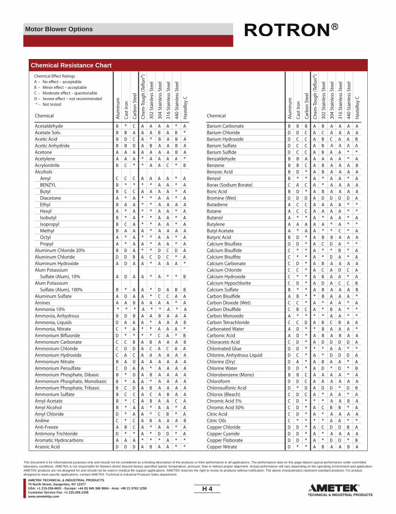
Motor Blower Options
Acetaldehyde B * C A A A A * AAcetate Solv. B B A A A B A B *Acetic Acid B D C A * B A B AAcetic Anhydride B B D A B A A B AAcetone A A A A A A A B AAcetylene A A A * A A A A *Acrylonitrile B C * * A A C * BAlcohols
Amyl C C C A A A A * ABENZYL B * * * * A A * AButyl B C C A A A A * ADiacetone A * A * * A A * AEthyl B A A * * A A A AHexyl A * A * * A A * AIsobutyl B * A * * A A * AIsopropyl B C A * * A A * AMethyl B A A A * A A A AOctyl A * A * * A A * APropyl A * A A * A A * A
Aluminum Chloride 20% B D A * * D C D AAluminum Chloride D D B A C D C * AAluminum Hydroxide A D A A * A A A *Alum Potassium
Sulfate (Alum), 10% A D A A * A * * BAlum Potassium
Sulfate (Alum), 100% B * A A * D A B BAluminum Sulfate A D A A * C C A AAmines A A B A A A A * AAmmonia 10% * * * A * * A * AAmmonia, Anhydrous B D B A A B A A AAmmonia, Liquids D A A A * A A A BAmmonia, Nitrate C * A * * A A A *Ammonium Bi�uoride D * * * * C A * BAmmonium Carbonate C C B A B A A A BAmmonium Chloride C D D A C A C A AAmmonium Hydroxide C A C A A A A A AAmmonium Nitrate B A D A A A A A AAmmonium Persulfate C D A A * A A A AAmmonium Phosphate, Dibasic A A A AB * D A BAmmonium Phosphate, Monobasic A A A AB * A A *Ammonium Phosphate, Tribasic A A A AB C D A BAmmonium Sulfate B C C A C A B A AAmyl-Acetate B * C A B A A C AAmyl Alcohol B * A A * A A * AAmyl Chloride D * A A * C B * AAniline C * C A B A A A BAnti-Freeze A B C A * A A * AAntimony Trichloride D * * A * D D * AAromatic Hydrocarbons A A A * * * A * *Arsenic Acid D D D A B A A * *
Chemical E�ect RatingsA – No e�ect – acceptableB – Minor e�ect – acceptableC – Moderate e�ect – questionableD – Severe e�ect – not recommended* – Not tested
Alum
inum
Cast
Iron
Carb
on S
teel
Chem
-Tou
gh (T
e�on
®)30
2 St
ainl
ess
Stee
l
304
Stai
nles
s St
eel
316
Stai
nles
s St
eel
440
Stai
nles
s St
eel
Has
tello
y C
Chemical
Barium Carbonate B B B A B A A A ABarium Chloride D D C A C A A A ABarium Hydroxide D C C A B C A A BBarium Sulfate D C C A B A A A ABarium Sul�de D C C A B A A * *Benzaldehyde B B A A A A A * ABenzene B B C A B A A A BBenzoic Acid B D * A B A A A ABenzol B * * A * A A * ABorax (Sodium Borate) C A C A * A A A ABoric Acid B D * A B A A A ABromine (Wet) D D D A D D D D AButadiene A C C A A A A * *Butane A C C A A A A * *Butanol A * * A * A A * AButylene A A A A A * A * *Butyl Acetate A * A A * * C * AButyric Acid B D * A B B A A ACalcium Bisulfate D D * A C D A * *Calcium Bisul�de C * * A * * B * ACalcium Bisul�te C * * A * D A * ACalcium Carbonate C D * A B A A A ACalcium Chloride C C * A C A D C ACalcium Hydroxide C * * A B A A * ACalcium Hypochlorite C D * A D A C C BCalcium Sulfate B * * A B A A A BCarbon Bisul�de A B * * B A A A *Carbon Dioxide (Wet) C C * A * A A * ACarbon Disul�de C B C A * B A * *Carbon Monoxide A * * * * A A * *Carbon Tetrachloride C C D A B C B A ACarbonated Water A D * * B A A A *Carbonic Acid A D * A B A B A AChloracetic Acid C D * A D D D D AChlorinated Glue D D * * * A A * *
D C * A * D D D AChlorine, Anhydrous LiquidChlorine (Dry) D A * A B A A * AChlorine Water D D * A D * D * BChlorobenzene (Mono) B B C A A A A * AChloroform D D C A A A A A AChlorosulfonic Acid D * D A D D * D BChlorox (Bleach) C D C A * A A * AChromic Acid 5% C D * * * A A B AChromic Acid 50% C D * A C B B * ACitric Acid C D * A * A A A ACitric Oils C * * * * A A * *Copper Chloride D D * A C D D B ACopper Cyanide D D * A * A A A ACopper Floborate D D * A * D D * BCopper Nitrate D * * A B A A B A
Alum
inum
Cast
Iron
Carb
on S
teel
Chem
-Tou
gh (T
e�on
®)30
2 St
ainl
ess
Stee
l
304
Stai
nles
s St
eel
316
Stai
nles
s St
eel
440
Stai
nles
s St
eel
Has
tello
y C
Chemical
Chemical Resistance Chart
H 4____
This document is for informational purposes only and should not be considered as a binding description of the products or their performance in all applications. The performance data on this page depicts typical performance under controlledlaboratory conditions. AMETEK is not responsible for blowers driven beyond factory specified speed, temperature, pressure, flow or without proper alignment. Actual performance will vary depending on the operating environment and application.AMETEK products are not designed for and should not be used in medical life support applications. AMETEK reserves the right to revise its products without notification. The above characteristics represent standard products. For productdesigned to meet specific applications, contact AMETEK Technical & Industrial Products Sales department.
AMETEK TECHNICAL & INDUSTRIAL PRODUCTS75 North Street, Saugerties, NY 12477USA: +1 215-256-6601 - Europe: +44 (0) 845 366 9664 - Asia: +86 21 5763 1258Customer Service Fax: +1 215.256.1338www.ametektip.com
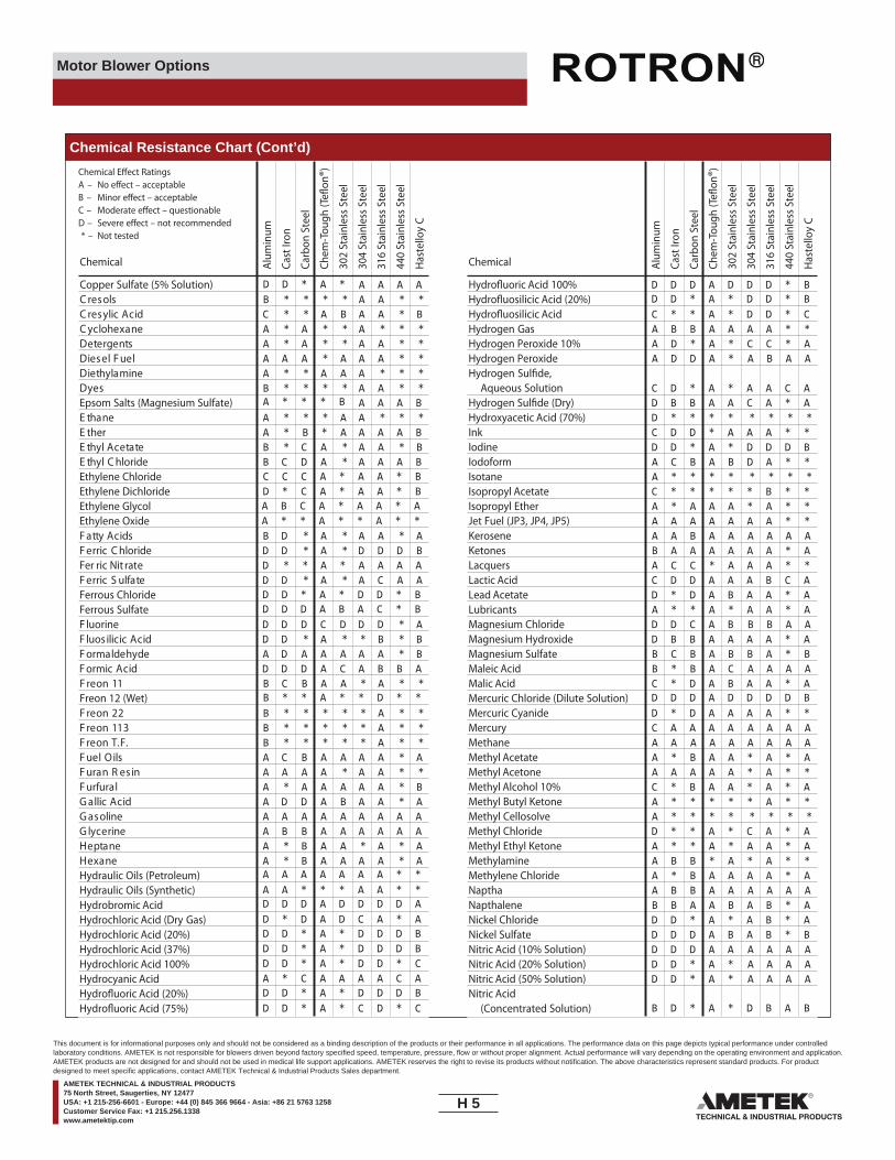
Motor Blower Options
Chemical Resistance Chart (Cont’d)
Copper Sulfate (5% Solution) A A A AD D * A ***AA****BsloserCB*AABA**CdicA cilyserC***A**A*AenaxeholcyC**AA**A*AstnegreteD**AAA*AAAleuFleseiD***AAA**AenimalyhteiD**AA****B
A * * * BseyD
Epsom Salts (Magnesium Sulfate) A A A B***AA***AenahtE
E the Ar * B * A A A A BB*AA*AC*BetatecA lyhtE
*ADCBC C C A * A A * BD * C A * A A * BA B C A * A A * AA * * A * * A * *
edirolhC lyhtE A A A BEthylene ChlorideEthylene DichlorideEthylene GlycolEthylene Oxide
A*AA*A*DBsdicA yttaFBDDD*A*DDedirolhC cirreF
Fer ric Nit rat De * * A * A A A AAACA*A*DD
D D * A * D D * BD D D A B A C * B
etafluS cirreFFerrous ChlorideFerrous Sulfate
A*DDDCDDDeniroulFB*B**A*DDdicA cicilisoulFB*AAAAADAedyhedlamroF
CADDDdicA cimroF A B B A**A*AABCB
B * * A * * D * *11 noerF
Freon 12 (Wet)**A*****B22 noerF**A*****B311 noerF**A*****B.F.T noerFA*AAAABCAsliO leuF**AA*AAAAniseR naruFB*AAAAA*AlarufruFA*AABADDAdicA cillaG
AAAAAenilosaG A A A AAABBAenirecylG A A A A
A*A*AAB*AenatpeHA*AAAAB*A
A A A A A A A * *A A * * * A A * *D D D A D D D D AD * D A D C A * AD D * A * D D D BD D * A * D D D BD D * A * D D * CA * C A A A A C AD D * A * D D D BD D * A * C D * C
enaxeHHydraulic Oils (Petroleum)Hydraulic Oils (Synthetic)Hydrobromic AcidHydrochloric Acid (Dry Gas)Hydrochloric Acid (20%)Hydrochloric Acid (37%)Hydrochloric Acid 100%Hydrocyanic AcidHydro�uoric Acid (20%)Hydro�uoric Acid (75%)
Hydro�uoric Acid 100% D D D A D D D * BD D * A * D D * BHydro�uosilicic Acid (20%)
Hydro�uosilicic Acid C * * A * D D * CHydrogen Gas A B B A A A A * *Hydrogen Peroxide 10% A D * A * C C * AHydrogen Peroxide A D D A * A B A AHydrogen Sul�de,
Aqueous Solution C D * A * A A C AHydrogen Sul�de (Dry) D B B A A C A * AHydroxyacetic Acid (70%) D * * * * * * * *Ink C D D * A A A * *Iodine D D * A * D D D BIodoform A C B A B D A * *Isotane A * * * * * * * *Isopropyl Acetate C * * * * * B * *Isopropyl Ether A * A A A * A * *Jet Fuel (JP3, JP4, JP5) A A A A A A A * *Kerosene A A B A A A A A AKetones B A A A A A A * ALacquers A C C * A A A * *Lactic Acid C D D A A A B C ALead Acetate D * D A B A A * ALubricants A * * A * A A * AMagnesium Chloride D D C A B B B A AMagnesium Hydroxide D B B A A A A * AMagnesium Sulfate B C B A B B A * BMaleic Acid B * B A C A A A AMalic Acid C * D A B A A * A
D D D A D D D D BMercuric Chloride (Dilute Solution)Mercuric Cyanide D * D A A A A * *Mercury C A A A A A A A AMethane A A A A A A A A AMethyl Acetate A * B A A * A * AMethyl Acetone A A A A A * A * *Methyl Alcohol 10% C * B A A * A * AMethyl Butyl Ketone A * * * * * A * *Methyl Cellosolve A * * * * * * * *Methyl Chloride D * * A * C A * AMethyl Ethyl Ketone A * * A * A A * AMethylamine A B B * A * A * *Methylene Chloride A * B A A A A * ANaptha A B B A A A A A ANapthalene B B A A B A B * ANickel Chloride D D * A * A B * ANickel Sulfate D D D A B A B * BNitric Acid (10% Solution) D D D A A A A A ANitric Acid (20% Solution) D D * A * A A A ANitric Acid (50% Solution) D D * A *
B D * A * D B A B
A A A ANitric Acid
(Concentrated Solution)
Chemical E�ect RatingsA – No e�ect – acceptableB – Minor e�ect – acceptableC – Moderate e�ect – questionableD – Severe e�ect – not recommended* – Not tested
Alum
inum
Cast
Iron
Carb
on S
teel
Chem
-Tou
gh (T
e�on
®)30
2 St
ainl
ess
Stee
l
304
Stai
nles
s St
eel
316
Stai
nles
s St
eel
440
Stai
nles
s St
eel
Has
tello
y C
Alum
inum
Cast
Iron
Carb
on S
teel
Chem
-Tou
gh (T
e�on
®)30
2 St
ainl
ess
Stee
l
304
Stai
nles
s St
eel
316
Stai
nles
s St
eel
440
Stai
nles
s St
eel
Has
tello
y C
Chemical Chemical
H 5____
This document is for informational purposes only and should not be considered as a binding description of the products or their performance in all applications. The performance data on this page depicts typical performance under controlledlaboratory conditions. AMETEK is not responsible for blowers driven beyond factory specified speed, temperature, pressure, flow or without proper alignment. Actual performance will vary depending on the operating environment and application.AMETEK products are not designed for and should not be used in medical life support applications. AMETEK reserves the right to revise its products without notification. The above characteristics represent standard products. For productdesigned to meet specific applications, contact AMETEK Technical & Industrial Products Sales department.
AMETEK TECHNICAL & INDUSTRIAL PRODUCTS75 North Street, Saugerties, NY 12477USA: +1 215-256-6601 - Europe: +44 (0) 845 366 9664 - Asia: +86 21 5763 1258Customer Service Fax: +1 215.256.1338www.ametektip.com

Motor Blower Options
Chemical Resistance Chart (Cont’d)
Nitrobenzene C B B A B A B * BOleum B * B A B * A * *Oxalic Acid (cold) C D D A C A B A BPentane A B B A A C C * BPerchloroethylene A B B A B A A * *Petrolatum B C C A A * A * *Phenol 10% A B D A B A A * BPhenol (Carbolic Acid) B D D A B A A A APhosphoric Acid
(to 40% Solution) D D * A * B A A APhosphoric Acid
(40%-100% Solution) D D * A * C B B APhosphoric Acid (Crude) D D D A * D C C A
D * * A * A A * *Phosphoric Anhydride (Molten)Photographic (Developer) C D * * * C A C APhthalic Anhydride B C C A B A B * APicric Acid C D D A B A A * APotash C B * * * A * A APotasium Bicarbonate C D * A * A * B BPotassium Bromide C D D A A A * B BPotassium Carbonate C B B A B A * A APotassium Chlorate B B B A B A A A BPotassium Chloride B B B A C A A B APotassium Chromate A A * * * * B B B
D B B A BPotassium Cyanide Solutions A B A APotassium Dichromate A B C A B A A A BPotassium Ferrocyanide C * C A B A * A B
D C A A APotassium Hydroxide (50%) B B B APotassium Nitrate B * B A B A B A BPotassium Permanganate B B B A B A B B BPotassium Sulfate A B B A B A B B APotassium Sul�de B B B A A A * A BPropane (Liqui�ed) A * B A A A * A *Propylene Glycol A B B A B B * A *Pyridine B B A A * C * B *Pyrogallic Acid B B B A B A A A ASilver Bromide D * * * * C C B *Silver Nitrate D D D A B A B A ASodium Acetate B C C A B A A B ASodium Aluminate C * C A B * * A BSodium Bicarbonate A C C A B A A A *Sodium Bisulfate D D D A A A * A BSodium Bisul�te A D * A * A * A BSodium Borate C C C A B A * A ASodium Carbonate C B B A B A B B ASodium Chlorate B * C A B A * A BSodium Chloride C B C A B A C B ASodium Chromate D B B A A A A * BSodium Cyanide D B B A B A * A *Sodium Fluoride C D D A B C * C A
Sodium Hydrosul�te A * * A * * * * ASodium Hydroxide (20%) D A * A *
D B * A * A B * AD C * A * A D * BD C * A * A D * B
A A A ASodium Hydroxide (50% Solution)Sodium Hydroxide (80% Solution)Sodium Hypochlorite (to 20%)Sodium Hypochlorite D D D A D * A * ASodium Hyposulfate D * * A * A A * *Sodium Metaphosphate A B B A A * A * *Sodium Metasilicate B C C A A * A * *Sodium Nitrate A A B A B A A A BSodium Perborate B B B A B * C * *Sodium Peroxide C D C A B A A * BSodium Polyphosphate
(Mono, Di, Tribasic) D * * A * A A * ASodium Silicate C * B A B A B A BSodium Sulfate B A B A B A A C BSodium Sul�de D A B A B A B * BSodium Sul�te C A * A * C C * A
B C B A A A A * *Sodium Thiosulphate (“Hypo”)Stannic Chloride D D D A D D D * BStannous Chloride D D D A D D C * AStearic Acid B C C A B A A A AStoddard Solvent A B B A A A A A AStyrene A * A A A A A * *Sulfate Liquors B * * * * C C * ASulfur Chloride D * * A * D D D *Sulfur Dioxide A * * A * A A C BSulfur Dioxide (Dry) A A B A A A A * ASulfur Trioxide (Dry) A B B A A A C * *Sulfuric Acid (to 10%) C D * A * D C C ASulfuric Acid (10%-75%) D D * A * D D D BSulfurous Acid C D D A C C B C BTannic Acid C C C A B A A A BTanning Liquors C * * A * A A * ATartaric Acid C D D A B A B B BTetrahydrofuran D D A A * A A * *Toluene, Toluol A A A A A A A * ATrichlorethane C C * A * C A * ATrichlorethylene B C B A B A A * AWater, Acid, Mine C C * * * A A * *
B D * A * A A * *Water, Distilled, Lab Grade 7Water, Fresh A B D A A A A * *Water, Salt B D * * * A A * *Weed Killers C * * * * A A * *Whiskey and Wines D D D A A A A A *Xylene A A B A A A A * AZinc Chloride D D D A D A B B BZinc Hydrosulphite D D * * * * A * *Zinc Sulfate D C D A B A A A B
Chemical E�ect RatingsA – No e�ect – acceptableB – Minor e�ect – acceptableC – Moderate e�ect – questionableD – Severe e�ect – not recommended* – Not tested
Alum
inum
Cast
Iron
Carb
on S
teel
Chem
-Tou
gh (T
e�on
®)30
2 St
ainl
ess
Stee
l
304
Stai
nles
s St
eel
316
Stai
nles
s St
eel
440
Stai
nles
s St
eel
Has
tello
y C
Alum
inum
Cast
Iron
Carb
on S
teel
Chem
-Tou
gh (T
e�on
®)30
2 St
ainl
ess
Stee
l
304
Stai
nles
s St
eel
316
Stai
nles
s St
eel
440
Stai
nles
s St
eel
Has
tello
y C
Chemical Chemical
H 6____
This document is for informational purposes only and should not be considered as a binding description of the products or their performance in all applications. The performance data on this page depicts typical performance under controlledlaboratory conditions. AMETEK is not responsible for blowers driven beyond factory specified speed, temperature, pressure, flow or without proper alignment. Actual performance will vary depending on the operating environment and application.AMETEK products are not designed for and should not be used in medical life support applications. AMETEK reserves the right to revise its products without notification. The above characteristics represent standard products. For productdesigned to meet specific applications, contact AMETEK Technical & Industrial Products Sales department.
AMETEK TECHNICAL & INDUSTRIAL PRODUCTS75 North Street, Saugerties, NY 12477USA: +1 215-256-6601 - Europe: +44 (0) 845 366 9664 - Asia: +86 21 5763 1258Customer Service Fax: +1 215.256.1338www.ametektip.com
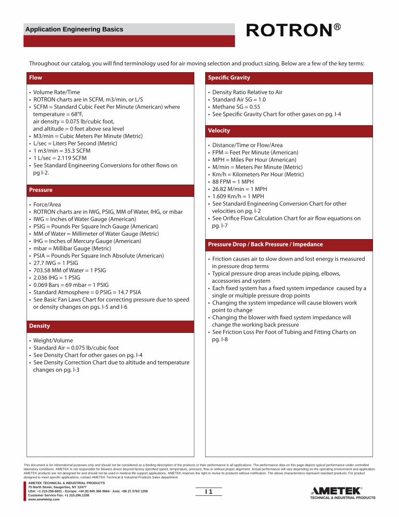
Application Engineering Basics
Flow
• Volume Rate/Time• ROTRON charts are in SCFM, m3/min, or L/S• SCFM = Standard Cubic Feet Per Minute (American) where temperature = 68°F, air density = 0.075 lb/cubic foot, and altitude = 0 feet above sea level• M3/min = Cubic Meters Per Minute (Metric)• L/sec = Liters Per Second (Metric)• 1 m3/min = 35.3 SCFM• 1 L/sec = 2.119 SCFM• See Standard Engineering Conversions for other flows on pg I-2.
Throughout our catalog, you will find terminology used for air moving selection and product sizing. Below are a few of the key terms:
Speci�c Gravity
• Density Ratio Relative to Air• Standard Air SG = 1.0• Methane SG = 0.55• See Specific Gravity Chart for other gases on pg. I-4
Pressure
• Force/Area• ROTRON charts are in IWG, PSIG, MM of Water, IHG, or mbar• IWG = Inches of Water Gauge (American)• PSIG = Pounds Per Square Inch Gauge (American)• MM of Water = Millimeter of Water Gauge (Metric)• IHG = Inches of Mercury Gauge (American)• mbar = Millibar Gauge (Metric)• PSIA = Pounds Per Square Inch Absolute (American)• 27.7 IWG = 1 PSIG• 703.58 MM of Water = 1 PSIG• 2.036 IHG = 1 PSIG• 0.069 Bars = 69 mbar = 1 PSIG• Standard Atmosphere = 0 PSIG = 14.7 PSIA• See Basic Fan Laws Chart for correcting pressure due to speed or density changes on pgs. I-5 and I-6
Density
• Weight/Volume• Standard Air = 0.075 lb/cubic foot• See Density Chart for other gases on pg. I-4• See Density Correction Chart due to altitude and temperature changes on pg. I-3
Velocity
• Distance/Time or Flow/Area• FPM = Feet Per Minute (American)• MPH = Miles Per Hour (American)• M/min = Meters Per Minute (Metric)• Km/h = Kilometers Per Hour (Metric)• 88 FPM = 1 MPH• 26.82 M/min = 1 MPH• 1.609 Km/h = 1 MPH• See Standard Engineering Conversion Chart for other velocities on pg. I-2• See Orifice Flow Calculation Chart for air flow equations on pg. I-7
Pressure Drop / Back Pressure / Impedance
• Friction causes air to slow down and lost energy is measured in pressure drop terms• Typical pressure drop areas include piping, elbows, accessories and system• Each fixed system has a fixed system impedance caused by a single or multiple pressure drop points• Changing the system impedance will cause blowers work point to change• Changing the blower with fixed system impedance will change the working back pressure• See Friction Loss Per Foot of Tubing and Fitting Charts on pg. I-8
I 1____
This document is for informational purposes only and should not be considered as a binding description of the products or their performance in all applications. The performance data on this page depicts typical performance under controlledlaboratory conditions. AMETEK is not responsible for blowers driven beyond factory specified speed, temperature, pressure, flow or without proper alignment. Actual performance will vary depending on the operating environment and application.AMETEK products are not designed for and should not be used in medical life support applications. AMETEK reserves the right to revise its products without notification. The above characteristics represent standard products. For productdesigned to meet specific applications, contact AMETEK Technical & Industrial Products Sales department.
AMETEK TECHNICAL & INDUSTRIAL PRODUCTS75 North Street, Saugerties, NY 12477USA: +1 215-256-6601 - Europe: +44 (0) 845 366 9664 - Asia: +86 21 5763 1258Customer Service Fax: +1 215.256.1338www.ametektip.com

Application Engineering Basics
Standard Engineering Conversion
MULTIPLY BY TO OBTAINAtmospheres 76.0 Cms. of MercuryAtmospheres 29.92 Inches of MercuryAtmospheres 33.90 Feet of WaterAtmospheres 10,333 Kgs./Sq. InchAtmospheres 1.013 x 10⁵ PascalsAtmospheres 14.70 Pounds/Sq. InchAtmospheres 760 TorrsBars 0.9869 AtmospheresBars 1. x 106 Dynes/Sq. Cm.Bars 1.020 x 10⁴ Kgs./Square MeterBars 14.50 Pounds/Sq. InchBritish Thermal Units 0.2520 Kilogram-CaloriesBritish Thermal Units 777.5 Foot-PoundsBritish Thermal Units 3.927 x 10⁻⁴ Horsepower-HoursBritish Thermal Units 1054 JoulesBritish Thermal Units 107.5 Kilogram-MetersBritish Thermal Units 2.928 x 10⁻⁴ Kilowatt-HoursCentimeters of Mercury 0.01316 AtmospheresCentimeters of Mercury 0.4461 Feet of WaterCentimeters of Mercury 136.0 Kgs./Square MeterCentimeters of Mercury 0.1934 Pounds/Sq. InchCentimeters/Second 1.969 Feet/MinuteCentimeters/Second 0.6 Meters/MinuteCubic Centimeters 3.531 x 10⁻⁵ Cubic FeetCubic Centimeters 6.102 x 10⁻² Cubic InchesCubic Centimeters 10-6 Cubic MetersCubic Centimeters 10-3 LitersCubic Feet 2.832 x 10⁴ Cubic Cms.Cubic Feet 1728 Cubic InchesCubic Feet 0.02832 Cubic MetersCubic Feet 0.03704 Cubic YardsCibic Feet 7.481 GallonsCubic Feet 28.32 LitersCu. Ft. of Water (60°F) 62.37 PoundsCubic Feet/Minute 472.0 Cubic Cms./Sec.Cubic Feet/Minute 0.4720 Liters/SecondCubic Feet/Minute 62.4 Lbs. of Water/Min.Cubic Inches 16.39 Cubic CentimetersCubic Inches 5.787 x 10⁻⁴ Cubic FeetCubic Inches 1.639 x 10⁻⁵ Cubic MetersCubic Inches 2.143 x 10⁻⁵ Cubic YardsCubic Meters 106 Cubic CentimetersCubic Meters 35.31 Cubic FeetCubic Meters 61,023 Cubic InchesCubic Meters 1.308 Cubic YardsCubic Yards 7.646 x 10⁵ Cubic CentimetersCubic Yards 27 Cubic FeetCubic Yards 46,656 Cubic InchesCubic Yards 0.7646 Cubic MetersFeet 30.48 CentimetersFeet 12 InchesFeet 0.3048 MetersFeet 1/3 YardsFeet of Air
(1 atmosphere 60°F) 5.30 x 10⁻⁴ Pounds/Square InchFeet/Minute 0.5080 Centimeters/Sec.Feet/Minute 0.01667 Feet/SecondFeet/Minute 0.01829 Kilometers/HourFeet/Minute 0.3048 Meters/MinuteFeet/Minute 0.01136 Miles/HourGrams/Cu. Cm. 62.43 Pounds/Cubic FootHorsepower 42.44 British Thermal Units/Min.Horsepower 33,000 Foot-Pounds/Min.Horsepower 10.70 Kg.-Calories/Min.Horsepower 745.7 WattsHorsepower-Hours 2547 British Thermal UnitsInches 2.540 CentimetersInches 103 MilsInches of Mercury 0.03342 AtmospheresInches of Mercury 13.60 Inches of WaterInches of Mercury 345.3 Kgs./Square MeterInches of Mercury 25.40 Mms. of MercuryInches of Mercury 0.4912 Pounds/Square In.Inches of Water 0.002458 AtmospheresInches of Water 0.07355 Inches of MercuryInches of Water 25.40 Kgs./Square MeterInches of Water 5.204 Pounds/Square Ft.Inches of Water 0.03613 Pounds/Square In.
MULTIPLY BY TO OBTAINKGS./Cubic Meter 0.06243 Pounds/Cubic FootKilometers 3281 FeetKilowatts 56.92 British Thermal Units/Min.Kilowatts 737.6 Foot-Pounds/Sec.Kilowatts 1.341 HorsepowerKilowatts 14.34 Kg.-Calories/Min.Kilowatt-Hours 3415 British Thermal UnitsLiters 103 Cubic CentimetersLiters 61.02 Cubic InchesLiters 10-3 Cubic MetersLog10N 2.303 LogEN or Ln NLog N or Ln N 0.4343 Log10NMeters 100 CentimetersMeters 3.2808 FeetMeters 39.37 InchesMeters 10-3 KilometersMeters/Minute 1.667 Centimeters/Sec.Meters/Minute 3.281 Feet/MinuteMeters/Minute 0.06 Kilometers/HourMeters/Minute 0.03728 Miles/HourMiles 5280 FeetMiles 1.6093 KilometersMiles 1760 YardsMiles/Hour 44.70 Centimeters/Sec.Miles/Hour 88 Feet/MinuteMiles/Hour 1,467 Feet/SecondMiles/Hour 1.6093 Kilometers/HourMiles/Hour 26.82 Meters/MinuteMms. of Mercury 0.0394 Inches of MercuryMms. of Mercury 1.3595-3 Kgs./Square Cm.Mms. of Mercury 0.01934 Pounds/Square InchPints (Liq.) 28.87 Cubic InchesPints (U.S. liquid) 473,179 Cubic CentimetersPints (U.S. liquid) 16 Ounces (U.S. fluid)Pounds 444,823 DynesPounds 453.6 GramsPounds 16 OuncesPounds of Carbon to CO2 14,544 British Thermal Units (mean)Pounds of Water 27.68 Cubic InchesPounds of Water 0.1198 GallonsPounds of Water
Evaporated at 212°F 970.3 British Thermal UnitsPounds/Cubic Foot 16.02 Kgs./Cubic MeterPounds/Square Foot 4,882 Kgs./Square MeterPounds/Square Inch 0.06804 AtmospheresPounds/Square Inch 27.7 Inches of WaterPounds/Square Inch 2.036 Inches of MercuryPounds/Square Inch 703.1 Kgs./Square MeterPounds/Square Inch 6.895 x 10³ PascalsPounds/Square Inch 51.715 Millimeters of Mercury at 0°CSquare Centimeters 1.973 x 10⁵ Circular MilsSquare Centimeters 1.076 x 10⁻³ Square FeetSquare Centimeters 0.1550 Square InchesSquare Feet 929.0 Square CentimetersSquare Feet 0.09290 Square MetersSquare Inches 1.273 x 10⁶ Circular MilsSquare Inches 6.452 Square CentimetersSquare Inches 6.944 x 10⁻³ Square FeetSquare Inches 106 Square MilsSquare Inches 645.2 Square MillimetersSquare Kilometers 10.76 x 10⁶ Square FeetSquare Kilometers 106 Square MetersSquare Kilometers 1.196 x 10⁶ Square YardsSquare Meters 10.764 Square FeetSquare Meters 1.196 Square YardsTemp. (Degs. C.) + 273 1 Abs. Temp. (Degs. C.)Temp. (Degs. C.) + 17.8 1.8 Temp. (Degs. Fahr.)Temp. (Degs. F.) + 460 1 Abs. Temp. (Degs. F.)Temp. (Degs. F.) -32 5/9 Temp. (Degs. Cent.)Watts 0.05692 British Thermal Units/Min.Watts 107 Ergs/SecondWatts 44.26 Foot-Pounds/Min.Watts 1.341 x 10⁻³ HorsepowerWatts 0.01434 Kg.-Calories/Min.Watts 10-3 KilowattsWatts-Hour 3.415 British Thermal UnitsWatts-Hour 1.341 x 10- Horsepower/HoursWatts-Hour 10-3 Kilowatt-Hours
I 2____
This document is for informational purposes only and should not be considered as a binding description of the products or their performance in all applications. The performance data on this page depicts typical performance under controlledlaboratory conditions. AMETEK is not responsible for blowers driven beyond factory specified speed, temperature, pressure, flow or without proper alignment. Actual performance will vary depending on the operating environment and application.AMETEK products are not designed for and should not be used in medical life support applications. AMETEK reserves the right to revise its products without notification. The above characteristics represent standard products. For productdesigned to meet specific applications, contact AMETEK Technical & Industrial Products Sales department.
AMETEK TECHNICAL & INDUSTRIAL PRODUCTS75 North Street, Saugerties, NY 12477USA: +1 215-256-6601 - Europe: +44 (0) 845 366 9664 - Asia: +86 21 5763 1258Customer Service Fax: +1 215.256.1338www.ametektip.com
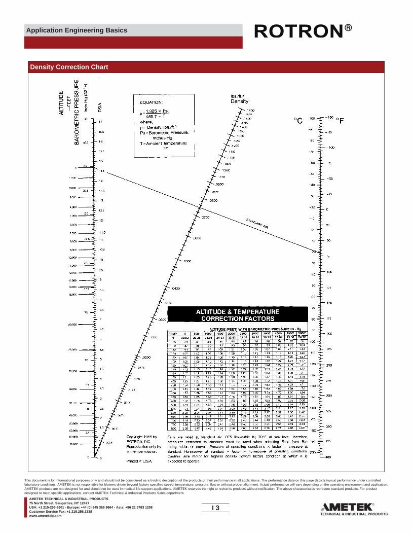
Application Engineering Basics
Density Correction Chart
I 3____
This document is for informational purposes only and should not be considered as a binding description of the products or their performance in all applications. The performance data on this page depicts typical performance under controlledlaboratory conditions. AMETEK is not responsible for blowers driven beyond factory specified speed, temperature, pressure, flow or without proper alignment. Actual performance will vary depending on the operating environment and application.AMETEK products are not designed for and should not be used in medical life support applications. AMETEK reserves the right to revise its products without notification. The above characteristics represent standard products. For productdesigned to meet specific applications, contact AMETEK Technical & Industrial Products Sales department.
AMETEK TECHNICAL & INDUSTRIAL PRODUCTS75 North Street, Saugerties, NY 12477USA: +1 215-256-6601 - Europe: +44 (0) 845 366 9664 - Asia: +86 21 5763 1258Customer Service Fax: +1 215.256.1338www.ametektip.com

Application Engineering Basics
Speci�c Gravity and Density of Various Gases at 60°F (1 ATM)
ChemicalFormula
Density(lbs./cu ft.)
Gas or Vapor Speci�c Gravity
Acetylene 0.899 .0686Air 1.00 .0763Ammonia 0.587 .0454Argon 1.377 .1053Benzene 2.70 .205Carbon Dioxide 1.539 .1166Chlorine 2.448 .0738Ethane 1.038 .0799Ethylene 0.969 .0739Helium 0.138 .01054Hydrogen 0.0695 .00531Hydrogen Sul�de 1.19 .0897Methane 0.555 .0424Methyl Chloride 1.785 .1356Nitrogen 0.967 .0738Oxygen 1.105 .0843Propane 1.55 .1180Sulfer Oxide 2.26 .1720Water Vapor 0.622
C2H2
-NH3
AC6H6
CO2
CI2
C2H6
C2H4
HeH2
H2SCH4
CH3CIN2
O2
C3H8
SO2
H2O .0373
Explosive Atmosphere Classi�cation
NEMA Classi�cations
North American European
Class I Zone 1Group A AcetyleneGroup B Group II C
Group II CHydrogen or equivalent hazard
Group C Group II B Ethyle ether vapors, ethylene orcyclopropane
Group D Group II A Gasoline, hexane, naptha, benzene,butane, alcohol, acetone, benzol, lacquer vapors or natural gas
Class IIGroup E Metal dustGroup F —
—Carbon black, coal or coke dust
Group G — Flour, starch or grain
Temperature Conversion Chart
°C Temp °F °C Temp °F °C Temp °F °C Temp °F-78.9 -110 -166 1.7 35 95.0 27.2 81 177.8 182 360 680-73.3 -100 -148 2.2 36 96.8 27.8 82 179.6 188 370 698-67.8 -90 -130 2.8 37 98.6 28.3 83 181.4 193 380 716-62.2 -80 -112 3.3 38 100.4 28.9 84 183.2 199 390 734-56.7 -70 -94 3.9 39 102.2 29.4 85 185.0 204 400 752-51.1 -60 -76 4.4 40 104.0 30.0 86 186.8 210 410 770-45.6 -50 -58 5.0 41 105.8 30.6 87 188.6 216 420 788-40.0 -40 -40 5.6 42 107.6 31.1 88 190.4 221 430 806-34.4 -30 -22 6.1 43 109.4 31.7 89 192.2 227 440 824-28.9 -20 -4 6.7 44 111.2 32.2 90 194.0 232 450 842-23.3 -10 14 7.2 45 113.0 32.8 91 195.8 238 460 860-17.8 0 32 7.8 46 114.8 33.3 92 197.6 243 470 878-17.2 1 33.8 8.3 47 116.6 33.9 93 199.4 249 480 896-16.7 2 35.6 8.9 48 118.4 34.4 94 201.2 254 490 914-16.1 3 37.4 9.4 49 120.2 35.0 95 203.0 260 500 932-15.6 4 39.2 10.0 50 122.0 35.6 96 204.8 266 510 950-15.0 5 41.0 10.6 51 123.8 36.1 97 206.6 271 520 968-14.4 6 42.8 11.1 52 125.6 36.7 98 208.4 277 530 986-13.9 7 44.6 11.7 53 127.4 37.2 99 210.2 282 540 1004-13.3 8 46.4 12.2 54 129.2 37.8 100 212.0 288 550 1022-12.8 9 48.2 12.8 55 131.0 43 110 230 293 560 1040-12.2 10 50.0 13.3 56 132.8 49 120 248 299 570 1058-11.7 11 51.8 13.9 57 134.6 54 130 266 304 580 1076-11.1 12 53.6 14.4 58 136.4 60 140 284 310 590 1094-10.6 13 55.4 15.0 59 138.2 66 150 302 316 600 1112-10.0 14 57.2 15.6 60 140.0 71 160 320 321 610 1130
-9.4 15 59.0 16.1 61 141.8 77 170 338 327 620 1148-8.9 16 60.8 16.7 62 143.6 82 180 356 332 630 1166-8.3 17 62.6 17.2 63 145.4 88 190 374 338 640 1184-7.8 18 64.4 17.8 64 147.2 93 200 392 343 650 1202-7.2 19 66.2 18.3 65 149.0 99 210 410 349 660 1220-6.7 20 68.0 18.9 66 150.8 100 212 413 354 670 1238-6.1 21 69.8 19.4 67 152.6 104 220 428 360 680 1256-5.6 22 71.6 20.0 68 154.4 110 230 446 366 690 1274-5.0 23 73.4 20.6 69 156.2 116 240 464 371 700 1292-4.4 24 75.2 21.1 70 158.0 121 250 482 377 710 1310-3.9 25 77.0 21.7 71 159.8 127 260 500 382 720 1328-3.3 26 78.8 22.2 72 161.6 132 270 518 388 730 1346-2.8 27 80.6 22.8 73 163.4 138 280 536 393 740 1364-2.2 28 82.4 23.3 74 165.2 143 290 554 399 750 1382-1.7 29 84.2 23.9 75 167.0 149 300 572 404 760 1400-1.1 30 86.0 24.4 76 168.8 154 310 590 410 770 1418-0.6 31 87.8 25.0 77 170.6 160 320 608 416 780 1436
0 32 89.6 25.6 78 172.4 166 330 626 421 790 14540.6 33 91.4 26.1 79 174.2 171 340 644 427 800 14721.1 34 93.2 26.7 80 176.0 177 350 662 432 810 1490
*In the center column, �nd the temperature to be converted. The equivalent temperature is in the left column, if converting to Celsius, and in the right column, if converting to Fahrenheit.
°F = 9/5C + 32 ABSOLUTE RANKIN (R) R = °F + 460°C = 5/9 (F - 32) ABSOLUTE KELVIN (K) K = °C + 273
Ref: NEMA Standards Publication, Pub. No. 1CS–1970
NEMA Type 1 – General Purpose – IndoorType 2 – Dripproof – IndoorType 3 – Dusttight, Raintight and Sleet (Ice)
Resistant – Outdoor3R – Rainproof and Sleet (Ice) Resistant
– Outdoor3S – Dusttight, Raintight and Sleet (Ice)
Proof – OutdoorType 4 – W atertight and Dusttight – Indoor
4X – W atertight, Dusttight and CorrosionResistant – Outdoor
Type 5 – Superseded by Type 12 for ControlApparatus
Type 6 – Submersible, Watertight, Dusttight andSleet Resistant – Indoor and Outdoor
Type 7 – Class I, Group A, B, C or D HazardousLocations; Air Break Equipment – Indoor
Type 8 – Class I, Group A, B, C or D Hazardous Locations; Oil-immersed Equipment – Indoor
Type 9 – Class II, Group E, F or G HazardousLocations; Air-break Equipment – Indoor
Type 10 – Bureau of MinesType 11 – Corrosion Resistant and Dripproof;
Oil-immersed – IndoorType 12 – Industrial Use, Dusttight and Driptight
– IndoorType 13 – Oiltight and Dusttight – Indoor
I 4____
This document is for informational purposes only and should not be considered as a binding description of the products or their performance in all applications. The performance data on this page depicts typical performance under controlledlaboratory conditions. AMETEK is not responsible for blowers driven beyond factory specified speed, temperature, pressure, flow or without proper alignment. Actual performance will vary depending on the operating environment and application.AMETEK products are not designed for and should not be used in medical life support applications. AMETEK reserves the right to revise its products without notification. The above characteristics represent standard products. For productdesigned to meet specific applications, contact AMETEK Technical & Industrial Products Sales department.
AMETEK TECHNICAL & INDUSTRIAL PRODUCTS75 North Street, Saugerties, NY 12477USA: +1 215-256-6601 - Europe: +44 (0) 845 366 9664 - Asia: +86 21 5763 1258Customer Service Fax: +1 215.256.1338www.ametektip.com

Application Engineering Basics
Physical Laws for Blower Applications
In the following formulae these symbols are used:
P – Pressure in pounds per square inch (PSI) or inches of mercury column (inches Hg)CFM – Volume in cubic feet per minuteRPM – Speed in revolutions per minuteD – Density in pounds per cubic foot (lbs./cu. ft.)H – Height of air or gas column (ft.)SG – Speci�c Gravity (ratio of density of gas to the density of air)
“Standard Air” – Air at 68°F (absolute temperature 528°) and 29.92” Hg. (barometric pressure at sea level). The density of such air is 0.075 lbs./cu. ft. and the speci�c volume is 13.29 cu. ft./lb. The speci�c gravity is 1.0.
The outlet pressure of a blower depends on the condition of the air or gas at the inlet. The inlet condition is in�uenced by:a – Speci�c gravity (The ratio of density of the gas to density of standard air)b – Altitude (location of blower)c – Temperature of inlet air
Volume
Pressure
The Volume changes in direct ratio to the speed.Example – A blower is operating at 3500 RPM and delivering 1000 cfm. If the speed is reduced to 3000 RPM, what is the new volume?
Basic Fan Laws Chart
V REWOPESROHERUSSERPEMULOVELBAIRA
WHEN SPEED CHANGES Varies DIRECT with Speed Ratio Varies with SQUARE of Speed Ratio
Varies DIRECT with Density Ratio Varies DIRECT with Density Ratio
Varies with CUBE of Speed Ratio
CFM 2 = CFM 1 ( RPM 2 ) P 2 = P 1 ( RPM 2 )2 HP 2 = HP 1 ( RPM 2 )3
RPM 1 RPM 1 RPM 1
WHEN DENSITY CHANGES Does Not Change
P 2 = P 1 ( D2 ) HP 2 = HP 1 ( D2 )D1 D1
V 1 = Original Volume (1000 CFM)V 2 = New VolumeRPM 1 = Original Speed (3500 RPM)RPM 2 = New Speed (3000 RPM)
V 2 = V 1 ( RPM 2 )1= 1000 x ( 3000 )1
= 1000 x .857 = 857 CFMRPM 1 3500
Pressure (barometric) varies in direct proportion toaltitude.Example – A blower is to operate at an elevation of 6000 feetand is to deliver 3 PSI pressure. What pressure (standard air)blower is required?
Pressure = 3 x 29.92
= 3.75 or 3 3/4 lb.23.98
If it is desired to determine what pressure a 3 lb. (standard air)blower will deliver at 6000 feet –
Pressure = 3 x 23.98
= 2.4 or about 2 1/2 lb.29.92
When a blower is to operate at a high altitude it is frequentlyspeci�ed that the blower be capable of handling a given vol-ume of “standard air”. It is then necessary to determine theequivalent volume of air at the higher altitude.Example – A blower is to operate 6000 feet altitude and is tohandle 1000 CFM of standard air. What is the CFM of air theblower must handle at 6000 feet altitude?
Let: V 1 = Volume of standard air (1000 CFM)V 2 = Volume of thinner airHg1 = Barometric pressure sea level (29.92)Hg2 = Barometric pressure 6000’ (23.98)
V 2 = V 1 x Hg
1 = 1000 x 29.92
= 1248 CFMHg 2 23.98
The pressure changes as the square of the speed ratio.
Example – A blower is operating at a speed of 3500 RPM anddelivering air at 5.0 pounds pressure. If the speed is reduced to3000 RPM, what is the new pressure?
P 1 = Original Pressure (5 lbs.)P 2 = New PressureRPM 1 = Original Speed (3500 RPM)RPM 2 = New Speed (3000 RPM)
P 2 = P 1 ( RPM 2 )2= 5 x ( 3000 )2
= 5 x .735 = 3.68 poundsRPM 1 3500
I 5____
This document is for informational purposes only and should not be considered as a binding description of the products or their performance in all applications. The performance data on this page depicts typical performance under controlledlaboratory conditions. AMETEK is not responsible for blowers driven beyond factory specified speed, temperature, pressure, flow or without proper alignment. Actual performance will vary depending on the operating environment and application.AMETEK products are not designed for and should not be used in medical life support applications. AMETEK reserves the right to revise its products without notification. The above characteristics represent standard products. For productdesigned to meet specific applications, contact AMETEK Technical & Industrial Products Sales department.
AMETEK TECHNICAL & INDUSTRIAL PRODUCTS75 North Street, Saugerties, NY 12477USA: +1 215-256-6601 - Europe: +44 (0) 845 366 9664 - Asia: +86 21 5763 1258Customer Service Fax: +1 215.256.1338www.ametektip.com

Application Engineering Basics
Pressure (Cont’d)
Horsepower
The Air Density varies in inverse proportion to theabsolute temperature.Example – A blower is to handle 200°F air at 3 PSI pressure.What pressure (standard air) blower is required?
Let: P 1 = Pressure hot air (3 PSI)P 2 = Pressure standard airAT 1 = Absolute temperature hot air (200+460=660°F)AT 2 = Absolute temperature standard air (68+460=528°F)
P 2 = P 1 x AT
1 = 3 x 660 = 3.75 or 3 3/4 lb.AT 2 528
A blower is capable of delivering 3 PSI pressure with standardair. What pressure will it develop handling 200°F inlet air?
P 1 = P 2 x AT
2 = 3 x 528 = 2.4 or about 2 1/2 lb.AT 1 660
Pressure varies in direct proportion to the density.Example – A 3 lb. (standard air) blower is to be used to handlegas having a speci�c gravity of 0.5. What pressure does theblower create when handling the gas?
Let: Pa = Air pressure (3 lb.)Pg = Gas pressureSG = Speci�c gravity of gas (0.5)
Pg = Pa x SG = 3 x .5 = 1.5 lb.
If we are required to handle a gas having a speci�c gravity of 0.5at 1.5 lb. pressure, we can determine the standard air pressureblower as follows:
Let: Pa = Pg
= 1.5
= 3 lb.SG .5
The following table gives the barometric pressure of various altitudes:Absolute Pressure At Altitudes Above Sea Level (Based on U.S. Standard Atmosphere)
Altitude
0500
Feet In. Hg. PSIA Feet In. Hg. PSIA Feet In. Hg. PSIA
600700800900
1,0001,5002,000
29.9229.3829.2829.1829.0728.9728.8628.3327.82
14.7014.4314.3814.3314.2814.2314.1813.9013.67
2,5003,0003,5004,0004,5005,0005,5006,0006,500
27.3126.8126.3225.8425.3624.8924.4323.9823.53
13.4113.1912.9212.7012.4512.2312.0011.7711.56
7,0007,5008,0008,5009,0009,500
10,000
23.0922.6522.2221.8021.3820.9820.58
11.3411.1210.9010.7010.5010.9010.10
Pressure Altitude Pressure Altitude Pressure
The horsepower changes as the cube of the speed ratio.Example – A blower is operating at a speed of 3500 RPM andrequiring 50 horsepower. If the speed is reduced to 3000 RPM,what is the new required horsepower?
HP 1 = Original Horsepower (50)HP 2 = New HorsepowerRPM 1 = Original Speed (3500 RPM)RPM 2 = New Speed (3000 RPM)
HP 2 = HP 1 x (RPM 2)3= 50 x (3000 )3
= 50 x .630 = 31.5 horsepowerRPM 1 3500
The above is known as the 1-2-3 rule of blowers.
Horsepower vs. Speci�c Gravity & Ratio of density.The horsepower varies in direct proportion to the speci�c gravity(ratio of density of gas to density of air).Example – A standard air blower requires a 10 HP motor. Whathorsepower is required when this blower is to handle a gaswhose speci�c gravity is 0.5?
HP = 10 x 0.5 = 5 horsepower
It is possible that several of the above modi�cations may berequired on one installation. Therefore, it may be necessary touse various combinations of these formulae.
I 6____
This document is for informational purposes only and should not be considered as a binding description of the products or their performance in all applications. The performance data on this page depicts typical performance under controlledlaboratory conditions. AMETEK is not responsible for blowers driven beyond factory specified speed, temperature, pressure, flow or without proper alignment. Actual performance will vary depending on the operating environment and application.AMETEK products are not designed for and should not be used in medical life support applications. AMETEK reserves the right to revise its products without notification. The above characteristics represent standard products. For productdesigned to meet specific applications, contact AMETEK Technical & Industrial Products Sales department.
AMETEK TECHNICAL & INDUSTRIAL PRODUCTS75 North Street, Saugerties, NY 12477USA: +1 215-256-6601 - Europe: +44 (0) 845 366 9664 - Asia: +86 21 5763 1258Customer Service Fax: +1 215.256.1338www.ametektip.com

Application Engineering Basics
Ori�ce Flow
Ori�ce Flow CalculationTo determine air �ow through an ori�ce:
V = CK √ P Q = AV VP = ( V ) 2K
Where:V = V elocity in feet per minute (fpm)C = Ori�ce Coe�cientK = Constant = 14,786 when P is expressed
in In. Hg21,094 when P is expressedin PSIG4,005 when P is expressedin In. of Water
(Above constants are based on an air densityof 0.075 lbs/ft 3)
P = Pressure di�erential across the ori�ceQ = Flow rate in cubic feet per minute (CFM)A = T otal ori�ce area expressed in square feetVP = Velocity pressure (units are those of pressure)
Coe�cient C for Ori�ces Under Vacuum or Pressure Flow
Area of Ori�cesOri�ce Diameter in Inches
Diameterin Inches Square Inches Square Feet
1/8 .01227 .0000853/16 .02761 .000191/4 .04908 .000343/8 .11044 .000761/2 .19634 .001365/8 .30679 .002137/8 .60132 .004171.0 .78539 .00545
Ori�ce area (in sq. inches) = .25 X π X (ori�ce diameter in inches) 2
Ori�ce area (in sq. feet) = Area in sq. inches ÷ 144
ORIFICE PRESSURE DROP AS A FUNCTION OF FLOW AND ORIFICE AREA (C=.65)
c-.98 c-.92 c-.82 c-.80
Pres
sure
Dro
pIn
ches
of W
ater
Pres
sure
Dro
pIn
ches
of W
ater
Pres
sure
Dro
pIn
ches
of W
ater
c-.72 c-.65 c-.80 c-.53
15
30
45
60
75
90
105
120
135
150
20
40
60
80
100
120
140
160
180
20
0 100 200 300Flow Rate SCFM
400 500
500 700 900 1100Flow Rate SCFM
1300 1500
1500 1700 1900 2100Flow Rate SCFM
2300 2500
40
60
80
100
200
I 7____
This document is for informational purposes only and should not be considered as a binding description of the products or their performance in all applications. The performance data on this page depicts typical performance under controlledlaboratory conditions. AMETEK is not responsible for blowers driven beyond factory specified speed, temperature, pressure, flow or without proper alignment. Actual performance will vary depending on the operating environment and application.AMETEK products are not designed for and should not be used in medical life support applications. AMETEK reserves the right to revise its products without notification. The above characteristics represent standard products. For productdesigned to meet specific applications, contact AMETEK Technical & Industrial Products Sales department.
AMETEK TECHNICAL & INDUSTRIAL PRODUCTS75 North Street, Saugerties, NY 12477USA: +1 215-256-6601 - Europe: +44 (0) 845 366 9664 - Asia: +86 21 5763 1258Customer Service Fax: +1 215.256.1338www.ametektip.com

Application Engineering Basics
Friction Loss Per Foot of Tubing
Friction Loss in Fittings
To calculate friction loss in �ttings use chart below. This chart will yield equivalentlengths (in feet) of tubing. Use this length with graph above to �nd friction loss ininches of water column.
NOMINAL PIPE SIZE (INCHES) EQUIVALENT TUBING LENGTH (FEET)
90° EL 45° EL
1 1/4 3 1.51 1/2 4 2
52 2.52 1/2 6 3
47314 0 515 2 616 5 7.528 0 10
I 8____
This document is for informational purposes only and should not be considered as a binding description of the products or their performance in all applications. The performance data on this page depicts typical performance under controlledlaboratory conditions. AMETEK is not responsible for blowers driven beyond factory specified speed, temperature, pressure, flow or without proper alignment. Actual performance will vary depending on the operating environment and application.AMETEK products are not designed for and should not be used in medical life support applications. AMETEK reserves the right to revise its products without notification. The above characteristics represent standard products. For productdesigned to meet specific applications, contact AMETEK Technical & Industrial Products Sales department.
AMETEK TECHNICAL & INDUSTRIAL PRODUCTS75 North Street, Saugerties, NY 12477USA: +1 215-256-6601 - Europe: +44 (0) 845 366 9664 - Asia: +86 21 5763 1258Customer Service Fax: +1 215.256.1338www.ametektip.com
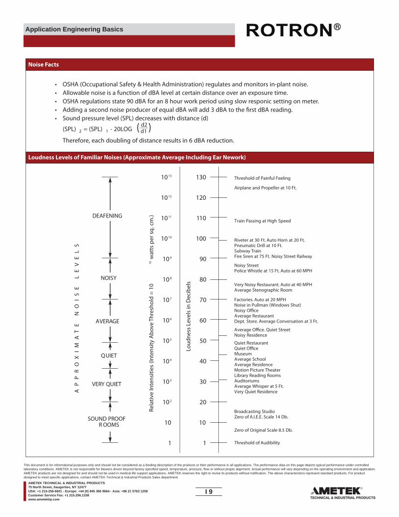
Application Engineering Basics
Noise Facts
Loudness Levels of Familiar Noises (Approximate Average Including Ear Nework)
• OSHA (Occupational Safety & Health Administration) regulates and monitors in-plant noise.• Allowable noise is a function of dBA level at certain distance over an exposure time.• OSHA regulations state 90 dBA for an 8 hour work period using slow responic setting on meter.• Adding a second noise producer of equal dBA will add 3 dBA to the �rst dBA reading.• Sound pressure level (SPL) decreases with distance (d)
(SPL) 2 = (SPL) 1 - 20LOG ( d2 )d1
Therefore, each doubling of distance results in 6 dBA reduction.
Threshold of Painful Feeling
Airplane and Propeller at 10 Ft.
Train Passing at High Speed
Riveter at 30 Ft. Auto Horn at 20 Ft.Pneumatic Drill at 10 Ft.Subway TrainFire Siren at 75 Ft. Noisy Street Railway
Noisy StreetPolice Whistle at 15 Ft. Auto at 60 MPH
Very Noisy Restaurant. Auto at 40 MPHAverage Stenographic Room
Factories. Auto at 20 MPHNoise in Pullman (Windows Shut)Noisy O�ceAverage RestaurantDept. Store. Average Conversation at 3 Ft.
Average O�ce. Quiet StreetNoisy Residence
Quiet RestaurantQuiet O�ceMuseumAverage SchoolAverage ResidenceMotion Picture TheaterLibrary Reading RoomsAuditoriumsAverage Whisper at 5 Ft.Very Quiet Residence
Broadcasting StudioZero of A.I.E.E. Scale 14 Db.
Zero of Original Scale 8.5 Db.
Threshold of Audibility
10 13 130
10 12 120
10 11 110
10 10 100
10 9 90
10 8 80
10 7 70
10 6 60
10 5 50
10 4 40
10 3 30
10 2 20
10 10
1 1
Loud
ness
Lev
els
in D
ecib
els
Rela
tive
Inte
nsiti
es (I
nten
sity
Abo
ve T
hres
hold
= 1
016
wat
ts p
er s
q.cm
.)
AP
PR
OX
IM
AT
E
NO
IS
E
LE
VE
LS
DEAFENING
NOISY
AVERAGE
QUIET
VERY QUIET
SOUND PROOFR OOMS
I 9____
This document is for informational purposes only and should not be considered as a binding description of the products or their performance in all applications. The performance data on this page depicts typical performance under controlledlaboratory conditions. AMETEK is not responsible for blowers driven beyond factory specified speed, temperature, pressure, flow or without proper alignment. Actual performance will vary depending on the operating environment and application.AMETEK products are not designed for and should not be used in medical life support applications. AMETEK reserves the right to revise its products without notification. The above characteristics represent standard products. For productdesigned to meet specific applications, contact AMETEK Technical & Industrial Products Sales department.
AMETEK TECHNICAL & INDUSTRIAL PRODUCTS75 North Street, Saugerties, NY 12477USA: +1 215-256-6601 - Europe: +44 (0) 845 366 9664 - Asia: +86 21 5763 1258Customer Service Fax: +1 215.256.1338www.ametektip.com

Application Engineering Basics
Industrial Blower Noise Chart* in dBA
dBA at Distance Conversion Chart
* Average at 1 meter, 4 places around the blower
Mode
Suction
SEMF
RDCSL2SL4SL5
60-6264-6576-7869-7272-7876-79
60-6264-6576-7869-7272-7876-79
101202303353404454
65-6767-6965-6772-7373-7476-77
66-6868-7067-6973-7474-7575-76
513505523555656
6
80-8177-7882-8380-8182-8385-86
80-8176-7782-8380-8182-8385-86
757808633S7
858833
83-8584-8581-8288-8984-8582-84
84-8684-8581-8288-8984-8582-84
S/P 9909
1233S/P 13
14S/P 15
90-9181-8284-8587-8886-8791-92
90-9184-8684-8590-9186-8791-92
Pressure Suction Pressure Suction Pressure Suction Pressure Suction Pressure
Mode Mode Mode ModeModel Model Model Model Model
To read, use straight edgeto connect blower distanceand dBA rating. A pivotpoint A will be developed.Use straight edge againwith new distance andpivot point A to read dBAat new distance.
I 10____
This document is for informational purposes only and should not be considered as a binding description of the products or their performance in all applications. The performance data on this page depicts typical performance under controlledlaboratory conditions. AMETEK is not responsible for blowers driven beyond factory specified speed, temperature, pressure, flow or without proper alignment. Actual performance will vary depending on the operating environment and application.AMETEK products are not designed for and should not be used in medical life support applications. AMETEK reserves the right to revise its products without notification. The above characteristics represent standard products. For productdesigned to meet specific applications, contact AMETEK Technical & Industrial Products Sales department.
AMETEK TECHNICAL & INDUSTRIAL PRODUCTS75 North Street, Saugerties, NY 12477USA: +1 215-256-6601 - Europe: +44 (0) 845 366 9664 - Asia: +86 21 5763 1258Customer Service Fax: +1 215.256.1338www.ametektip.com

Application Engineering Basics
Standard Regenerative Blower Nomenclature Reference
Special Features, 0 to 4 letters- see �gure 2
Voltage Code, up to 3 numbers - see �gure 1
Motor Description - see �gure 3(TEFC, XP, Chem, and ODP)
Describes which family the unit belongs to, 1 to 3 numbers
Option, for duplex units onlyP = Parallel con�gurationS = Series con�guration
DR = Domestic RegenerativeEN = EnvironmentalCP = Chemical ProcessHiE = Hi E�ciency Motor
Figure 1 Voltage Code
Figure 2 Special Features
This chart explains the nomenclature behind the catalogued blower model names. This tool can be used to explainto customers what the letters and numbers mean, and will also allow you to become familiar with our model names.This information should not a�ect the way orders are placed; please continue to use the model names shown in the catalog and price pages. Any special request should be noted on the order.
5 230 VAC 60 Hz, Single Phase9 115/230 VAC 50/60 Hz, Single Phase33 230 VAC 60 Hz, Three Phase58 115/230 VAC 60 Hz Single Phase60 200 VAC 50/60 Hz Single Phase72 230/460 VAC 60 Hz Three Phase75 380 VAC 50 Hz Three Phase86 575 VAC 60 Hz Three Phase89 200-230/460 VAC 60 Hz, Three Phase91 230/460 VAC 50/60 Hz, Three Phase92 415 VAC 50 Hz, Three Phase201 380 VAC 60 Hz
A SPECIAL (not covered by any other letter)BC Blower on pressure onlyD Blower on suction onlyEFGH Vapor recovery service - hydrocarbonJ Nasty Gas face sealKL Lo leak option (lip seal)M Die Cast or mu�er extensionPQR Chem-Tough™ constructionS Special manifoldTUV V alveW Rail mounted blowerX Base mounted blowerY Slip on �angeZ Package blower coupling driveAA Package blower belt drive, simplexBB Package blower drive belt, duplexRD Remote driveNT No Tower
I 11____
This document is for informational purposes only and should not be considered as a binding description of the products or their performance in all applications. The performance data on this page depicts typical performance under controlledlaboratory conditions. AMETEK is not responsible for blowers driven beyond factory specified speed, temperature, pressure, flow or without proper alignment. Actual performance will vary depending on the operating environment and application.AMETEK products are not designed for and should not be used in medical life support applications. AMETEK reserves the right to revise its products without notification. The above characteristics represent standard products. For productdesigned to meet specific applications, contact AMETEK Technical & Industrial Products Sales department.
AMETEK TECHNICAL & INDUSTRIAL PRODUCTS75 North Street, Saugerties, NY 12477USA: +1 215-256-6601 - Europe: +44 (0) 845 366 9664 - Asia: +86 21 5763 1258Customer Service Fax: +1 215.256.1338www.ametektip.com
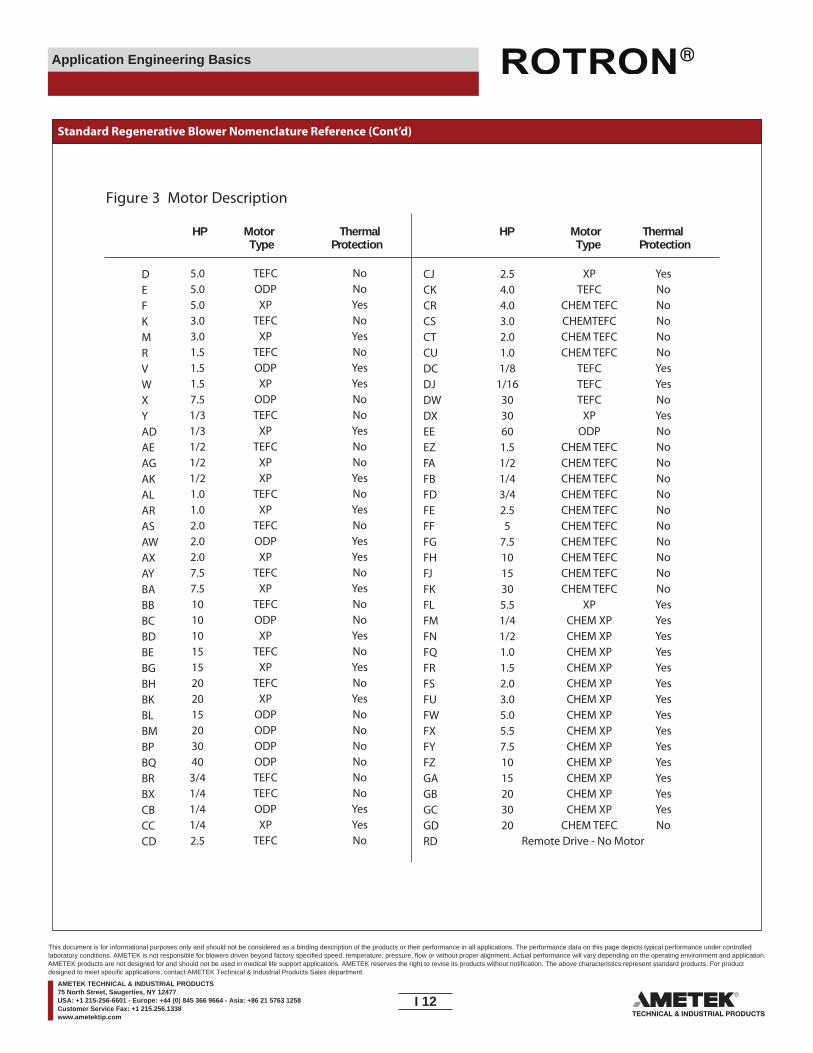
Application Engineering Basics
Standard Regenerative Blower Nomenclature Reference (Cont’d)
HP Motor ThermalType Protection
HP Motor ThermalType Protection
Figure 3 Motor Description
DEFKMRVWXYADAEAGAKALARASAWAXAYBABBBCBDBEBGBHBKBLBMBPBQBRBXCBCCCD
CJCKCRCSCTCUDCDJDWDXEEEZFAFBFDFEFFFGFHFJFKFLFMFNFQFRFSFUFWFXFYFZGAGBGCGDRD
2.54.04.03.02.01.01/8
1/163030601.51/21/43/42.55
7.51015305.51/41/21.01.52.03.05.05.57.51015203020
XPTEFC
CHEM TEFCCHEMTEFCCHEM TEFCCHEM TEFC
TEFCTEFCTEFC
XPODP
CHEM TEFCCHEM TEFCCHEM TEFCCHEM TEFCCHEM TEFCCHEM TEFCCHEM TEFCCHEM TEFCCHEM TEFCCHEM TEFC
XPCHEM XPCHEM XPCHEM XPCHEM XPCHEM XPCHEM XPCHEM XPCHEM XPCHEM XPCHEM XPCHEM XPCHEM XPCHEM XP
CHEM TEFC
YesNoNoNoNoNoYesYesNoYesNoNoNoNoNoNoNoNoNoNoNoYesYesYesYesYesYesYesYesYesYesYesYesYesYesNo
5.05.05.03.03.01.51.51.57.51/31/31/21/21/21.01.02.02.02.07.57.510101015152020152030403/41/41/41/42.5
TEFCODPXP
TEFCXP
TEFCODPXP
ODPTEFC
XPTEFC
XPXP
TEFCXP
TEFCODPXP
TEFCXP
TEFCODPXP
TEFCXP
TEFCXP
ODPODPODPODPTEFCTEFCODPXP
TEFC
NoNoYesNoYesNoYesYesNoNoYesNoNoYesNoYesNoYesYesNoYesNoNoYesNoYesNoYesNoNoNoNoNoNoYesYesNo Remote Drive - No Motor
I 12____
This document is for informational purposes only and should not be considered as a binding description of the products or their performance in all applications. The performance data on this page depicts typical performance under controlledlaboratory conditions. AMETEK is not responsible for blowers driven beyond factory specified speed, temperature, pressure, flow or without proper alignment. Actual performance will vary depending on the operating environment and application.AMETEK products are not designed for and should not be used in medical life support applications. AMETEK reserves the right to revise its products without notification. The above characteristics represent standard products. For productdesigned to meet specific applications, contact AMETEK Technical & Industrial Products Sales department.
AMETEK TECHNICAL & INDUSTRIAL PRODUCTS75 North Street, Saugerties, NY 12477USA: +1 215-256-6601 - Europe: +44 (0) 845 366 9664 - Asia: +86 21 5763 1258Customer Service Fax: +1 215.256.1338www.ametektip.com
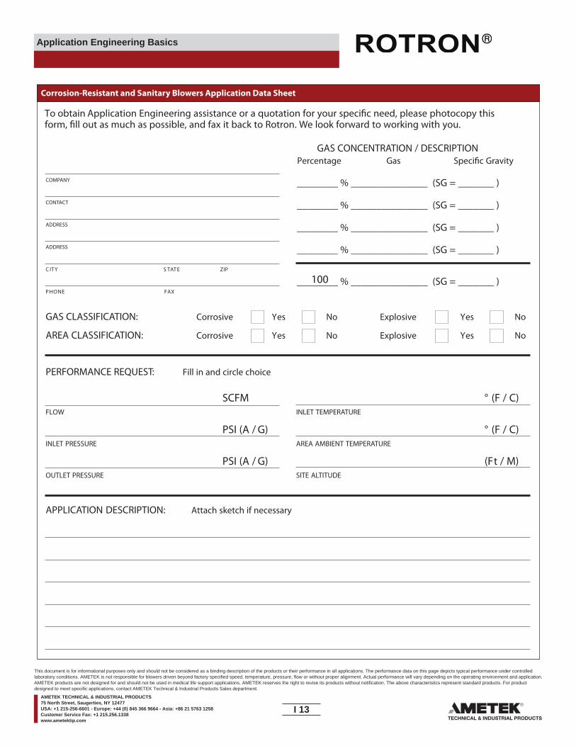
Application Engineering Basics
Corrosion-Resistant and Sanitary Blowers Application Data Sheet
To obtain Application Engineering assistance or a quotation for your speci�c need, please photocopy thisform, �ll out as much as possible, and fax it back to Rotron. We look forward to working with you.
COMPANY
CONTACT
ADDRESS
ADDRESS
PIZETATSYTIC
XAFENOHP
GAS CONCENTRATION / DESCRIPTIONPercentage Gas Speci�c Gravity
________ % _______________ (SG = _______ )
________ % _______________ (SG = _______ )
________ % _______________ (SG = _______ )
________ % _______________ (SG = _______ )
________ % _______________ (SG = _______ )
GAS CLASSIFICATION: Corrosive Yes No Explosive Yes No
AREA CLASSIFICATION: Corrosive Yes No Explosive Yes No
PERFORMANCE REQUEST: Fill in and circle choice
SCFM ° (F / C)FLOW INLET TEMPERATURE
PSI (A / G) ° (F / C)INLET PRESSURE AREA AMBIENT TEMPERATURE
PSI (A / G) (Ft / M)OUTLET PRESSURE SITE ALTITUDE
100
APPLICATION DESCRIPTION: Attach sketch if necessary
I 13____
This document is for informational purposes only and should not be considered as a binding description of the products or their performance in all applications. The performance data on this page depicts typical performance under controlledlaboratory conditions. AMETEK is not responsible for blowers driven beyond factory specified speed, temperature, pressure, flow or without proper alignment. Actual performance will vary depending on the operating environment and application.AMETEK products are not designed for and should not be used in medical life support applications. AMETEK reserves the right to revise its products without notification. The above characteristics represent standard products. For productdesigned to meet specific applications, contact AMETEK Technical & Industrial Products Sales department.
AMETEK TECHNICAL & INDUSTRIAL PRODUCTS75 North Street, Saugerties, NY 12477USA: +1 215-256-6601 - Europe: +44 (0) 845 366 9664 - Asia: +86 21 5763 1258Customer Service Fax: +1 215.256.1338www.ametektip.com
Application Engineering Basics
Warranty Statement
Warranty Statements
1. AMETEK ROTRON DR, EN, and HiE regenerative direct drive blowers are guaranteed for one full year from the date of installation (limited to 18 months from the date of shipment.) to the original purchaser only. Should blower fail, we will evaluate the failure. If failure is determined to be workmanship or material defect related,
2. Standard Products - AMETEK ROTRON moisture separators, remote drives, packaged units, CP blowers, Nasty GasTM models and special built (EO) products are guaranteed for one full year from the date of shipment for workmanship and material defect to the original purchaser only. Should the blower fail, we will evaluate the failure. If failure is determined to be workmanship or material defect related, we will at our option repair or replace the blower.
3. Parts Policy - AMETEK ROTRON spare parts and accessories are guaranteed for three months from the date of shipment for workmanship and material defect to the original purchaser only. If failure is determined to be workmanship or material defect related we will at our option repair or replace the part.
4. Non-Standard Products - Orders for specially-built products will be concidered as non-cancellable. Any requested changed by customer after order acceptance will result in additional charges.
Corrective Action - A written report will be provided indicating reason(s) for failure, with suggestions for corrective action. Subsequent customer failures due to abuse, misuse, misapplica-tion or repeat o�ense will not be covered. AMETEK ROTRON will then notify you or your options. Any failed unit that is tampered with by attempting repair or diagnosis will void the warranty unless authorized by the factory.
Terms and Conditions - Our warranty covers repairs or replace-ment or regenerative blowers only, and will not cover labor for installation, outbound and inbound shipping costs, accessories or other items not considered integral blower parts. Charges may be incurred on products returned for reasons other than failures covered by their appropriate warranty. Out-of-warranty product and in warranty product returned for failures deter-mined to be caused by abuse, misuse, or repeat o�ense will be subject to an evaluation charge. Maximum liability will in no case exceed the value of the product purchased. Damage resulting from mishandling during shipping is not covered by this warranty. It is the responsibility of the purchaser to �le claims with the carrier. Other terms and conditions of sale are stated on the back of the order acknowledgement.
Hazardous Locations Policy
AMETEK ROTRON will not knowingly specify, design or build any regenerative blower for installation in a hazardous, explosive location without proper NEMA motor enclosure. AMETEK ROTRON does not recognize sealed blowers as a substitue for explosion-proof motors. Sealed units with standard TEFC motors should never be utilized where local, state, and/or federal codes specify the use of explosion-proof equipment.
AMETEK ROTRON has a complete line of regenerative blowers with explosion-proof motors, Division 1 & 2, Class I, Group D; Class II, Groups F & G requirements are met with these standard explosion-proof blowers.
AMETEK ROTRON will not knowingly specify, design or build any regenerative blower for installation in a hazardous, corrosive environment without the proper surface treatment and sealing options.
AMETEK ROTRON has a complete line of Chemical Processing and Nasty GasTM regenerative blowers with Chem-ToughTM, stainless steel parts, and seals.
AMETEK ROTRON o�ers general application guidance, however, suitability of the particular blower selection is ultimately the responsibility of the purchaser, not the manufacturer of the blower.
I 14____
This document is for informational purposes only and should not be considered as a binding description of the products or their performance in all applications. The performance data on this page depicts typical performance under controlledlaboratory conditions. AMETEK is not responsible for blowers driven beyond factory specified speed, temperature, pressure, flow or without proper alignment. Actual performance will vary depending on the operating environment and application.AMETEK products are not designed for and should not be used in medical life support applications. AMETEK reserves the right to revise its products without notification. The above characteristics represent standard products. For productdesigned to meet specific applications, contact AMETEK Technical & Industrial Products Sales department.
AMETEK TECHNICAL & INDUSTRIAL PRODUCTS75 North Street, Saugerties, NY 12477USA: +1 215-256-6601 - Europe: +44 (0) 845 366 9664 - Asia: +86 21 5763 1258Customer Service Fax: +1 215.256.1338www.ametektip.com

AMETEK, Inc.
AMETEK is a leading global manufacturer of electronic instruments and electromechanical devices with
annualized sales of more than $2.5 billion. AMETEK has nearly 11,000 colleagues working at more than
80 manufacturing facilities and more than 60 sales and service centers in the United States and over 30
other countries around the world.
AMETEK Technical & Industrial Products (TIP)
AMETEK Technical & Industrial Products is a world leader in motors, blowers and pumps for mass-
transit, medical, business machine and computer applications. It also is a leader in regenerative blowers
for pressure and vacuum applications used by broad range of industries.
AMETEK supports its customers globally from its manufacturing facilities in Minnesota, New York, North
Carolina, Ohio, Pennsylvania, Italy and China. Our brushless DC motors, blowers, controllers, pumps,
and fans are ideally suited for a wide range of applications, including medical instruments, robotics,
pumps, compressors, offi ce equipment, fans, machine tools, tape drives, or any other precise rotary
motion/air delivery applications.
Technical & Industrial Products’ product line of regenerative blowers for pressure and vacuum
applications services the process, industrial, environmental, waste, and wastewater industrial industry.
Typical applications areas include solution agitation and aeration, pneumatic conveying, part hold-down
and pick up, part blow off, gas and fume extraction, and process gas handling.
AMETEK Technical & Industrial Products supplies the solution for unique performance, mounting,
environmental and agency requirements.
TECHNICAL & INDUSTRIAL PRODUCTS
627 Lake Street, Kent, OH 44240 U.S.A.Tel: +1 215-256-6601 • Fax: +1 330-677-3306 • www.ametektip.com
Europe: +44 (0) 845 366 9664 • Asia: +86 21 5763 1258