Complete AutoCAD Commands
35
4/1/2016 AutoCAD Commands http://academics.triton.edu/faculty/fheitzman/commands.html 1/35 Complete AutoCAD Commands Command Description Options ABOUT Displays a dialogue box with AutoCAD version & serial numbers can be transparent APERTURE Controls the size of the Object Snap "OSNAP") target box should set to 7 can be transparent ARC or A Draws an arc. The default method of drawing arcs is selecting three points (so called "3 point arc"), which are the two endpoints of the arc and some other point along its locus. Other methods of drawing an arc can be specified by three letters, such as SEA, which means "Start Point, End Point, and Included Angle." A Included angle C Center point of arc D Direction angle of a line tangent to the arc E Endpoint of arc L Length of chord passing thru both endpoints of the arc R Radius S Start point of arc <RET> uses the end of the last line or arc as the start point for the arc AREA Computes the area of any shape by selecting points at the corners of the shape, or by selecting a circle or polyline after typing or picking the "E" option A sets "Add" mode S sets "Subtract" mode E computes area of selected circle or polyline ARRAY Makes multiple copies of selected objects in a rectangular (parallel with the snap rotation) or circular pattern R rectangular array type P "polar" array type in circular pattern, you must indicate number of items and angle to fill, and whether the objects get rotated with the angle C "circular" array type in a circular pattern, you must indicate angle between items, angle to fill, and whether objects get rotated with the angle ATTDEF Creates an attribute definition entity for textual information to be associated with a block definition I Controls attribute visibility C Controls Constant/variable mode V Controls verify mode P Controls preset mode ATTDISP Controls the visibility of attribute entities can be transparent
-
Upload
khangminh22 -
Category
Documents
-
view
1 -
download
0
Transcript of Complete AutoCAD Commands

4/1/2016 AutoCAD Commands
http://academics.triton.edu/faculty/fheitzman/commands.html 1/35
Complete AutoCAD CommandsCommand Description Options
ABOUT Displays a dialogue box with AutoCADversion & serial numbers
can be transparent
APERTURE Controls the size of the Object Snap"OSNAP") target box should set to 7
can be transparent
ARC
or
A
Draws an arc. The default method ofdrawing arcs is selecting three points (socalled "3 point arc"), which are the twoendpoints of the arc and some other pointalong its locus. Other methods of drawingan arc can be specified by three letters,such as SEA, which means "Start Point,End Point, and Included Angle."
A Included angle
C Center point of arc
D Direction angle of a line tangent tothe arc
E Endpoint of arc
L Length of chord passing thru bothendpoints of the arc
R Radius
S Start point of arc
<RET> uses the end of the last line or arc asthe start point for the arc
AREA Computes the area of any shape byselecting points at the corners of theshape, or by selecting a circle or polylineafter typing or picking the "E" option
A sets "Add" mode
S sets "Subtract" mode
E computes area of selected circle orpolyline
ARRAY Makes multiple copies of selectedobjects in a rectangular (parallel with thesnap rotation) or circular pattern
R rectangular array type
P "polar" array type in circular pattern,you must indicate number of itemsand angle to fill, and whether theobjects get rotated with the angle
C "circular" array type in a circularpattern, you must indicate anglebetween items, angle to fill, andwhether objects get rotated with theangle
ATTDEF Creates an attribute definition entity fortextual information to be associated witha block definition
I Controls attribute visibility
C Controls Constant/variable mode
V Controls verify mode
P Controls preset mode
ATTDISP Controls the visibility of attribute entities can be transparent
4/1/2016 AutoCAD Commands
http://academics.triton.edu/faculty/fheitzman/commands.html 2/35
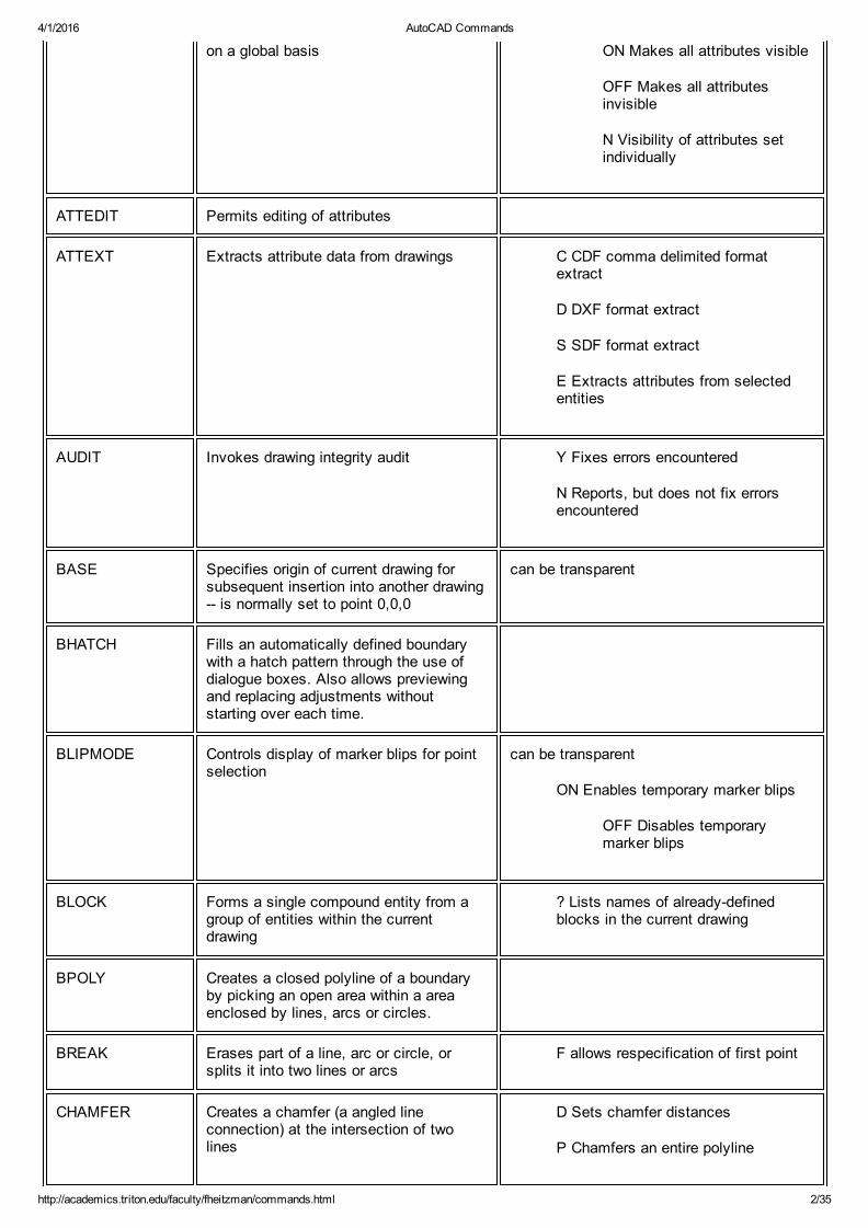
on a global basis ON Makes all attributes visible
OFF Makes all attributesinvisible
N Visibility of attributes setindividually
ATTEDIT Permits editing of attributes
ATTEXT Extracts attribute data from drawings C CDF comma delimited formatextract
D DXF format extract
S SDF format extract
E Extracts attributes from selectedentities
AUDIT Invokes drawing integrity audit Y Fixes errors encountered
N Reports, but does not fix errorsencountered
BASE Specifies origin of current drawing forsubsequent insertion into another drawing is normally set to point 0,0,0
can be transparent
BHATCH Fills an automatically defined boundarywith a hatch pattern through the use ofdialogue boxes. Also allows previewingand replacing adjustments withoutstarting over each time.
BLIPMODE Controls display of marker blips for pointselection
can be transparent
ON Enables temporary marker blips
OFF Disables temporarymarker blips
BLOCK Forms a single compound entity from agroup of entities within the currentdrawing
? Lists names of alreadydefinedblocks in the current drawing
BPOLY Creates a closed polyline of a boundaryby picking an open area within a areaenclosed by lines, arcs or circles.
BREAK Erases part of a line, arc or circle, orsplits it into two lines or arcs
F allows respecification of first point
CHAMFER Creates a chamfer (a angled lineconnection) at the intersection of twolines
D Sets chamfer distances
P Chamfers an entire polyline

4/1/2016 AutoCAD Commands
http://academics.triton.edu/faculty/fheitzman/commands.html 3/35
CHANGE A multifunctioning command which canbe used to alter the following:
1. location of individual endpointsof lines
2. radius of a circle
3. properties: layer, elevation,thickness, color and linetype oflines, polylines, arcs and circles
4. style, font, size, location,rotation, and wording of textentities
P Changes properties of objects
C Color
E Elevation
LA Layer
LT Linetype
T Thickness
CHPROP Modifies properties of selected objects:layer, thickness, color and linetype butnot elevation
C Color
LA Layer
LT Linetype
T Thickness
CIRCLE
or
C
Draws a circle of any size. The defaultmethod is to pick a center point and picka point on the radius or type the radiusdimension, but other methods can beselected.
2P Specifies circle by picking 2 pointson the diameter
3P Specifies circle by picking 3 pointsthrough which the circle will pass
D Allows entering the diameterdimension instead of radius dimension
TTR Specifies circle by pickingtwo lines, arcs or circles for thecircle to be tangent to, andentering the dimension of theradius
<RET> Enters radius of circle(the default)
COLOR
or COLOUR
Sets the current color for subsequentlydrawn objects (objects drawn after thecommand is invoked). The default currentcolor is a socalled "logical" color called"BYLAYER" which means that the colorof the object drawn will be the color whichthe current layer has been set to.
can be transparent
<number> sets currentcolor to color numberentered
<name> sets currentcolor to color nameentered
BYBLOCK sets floatingentity color
BYLAYER sets currentcolor to whatever coloris assigned to thecurrent layer
4/1/2016 AutoCAD Commands
http://academics.triton.edu/faculty/fheitzman/commands.html 4/35
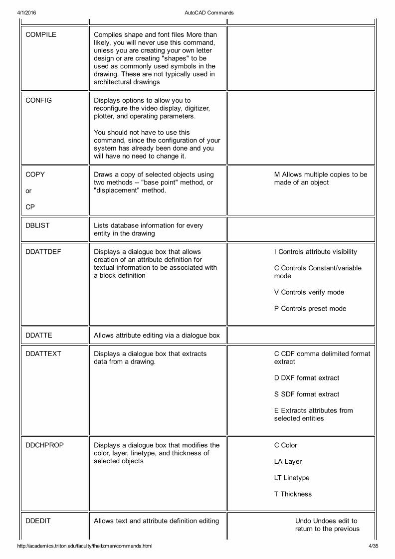
COMPILE Compiles shape and font files More thanlikely, you will never use this command,unless you are creating your own letterdesign or are creating "shapes" to beused as commonly used symbols in thedrawing. These are not typically used inarchitectural drawings
CONFIG Displays options to allow you toreconfigure the video display, digitizer,plotter, and operating parameters.
You should not have to use thiscommand, since the configuration of yoursystem has already been done and youwill have no need to change it.
COPY
or
CP
Draws a copy of selected objects usingtwo methods "base point" method, or"displacement" method.
M Allows multiple copies to bemade of an object
DBLIST Lists database information for everyentity in the drawing
DDATTDEF Displays a dialogue box that allowscreation of an attribute definition fortextual information to be associated witha block definition
I Controls attribute visibility
C Controls Constant/variablemode
V Controls verify mode
P Controls preset mode
DDATTE Allows attribute editing via a dialogue box
DDATTEXT Displays a dialogue box that extractsdata from a drawing.
C CDF comma delimited formatextract
D DXF format extract
S SDF format extract
E Extracts attributes fromselected entities
DDCHPROP Displays a dialogue box that modifies thecolor, layer, linetype, and thickness ofselected objects
C Color
LA Layer
LT Linetype
T Thickness
DDEDIT Allows text and attribute definition editing Undo Undoes edit toreturn to the previous

4/1/2016 AutoCAD Commands
http://academics.triton.edu/faculty/fheitzman/commands.html 5/35
value
DDEMODES Sets current entity properties (layer,linetype, elevation, thickness, and textstyle) via a dialogue box
can be transparent
DDGRIPS Allows you to enable grips and set theircolors and size via a dialogue box
can be transparent
DDIM Controls dimensioning variables through aseries of dialogue boxes
can be transparent
DDINSERT Allows you to insert a previously madeblock or file into the current drawing,select X and Y scale factors, rotationangle, preexplode the block, and selectthe insertion point, through a dialogue box
DDLMODES Sets layer properties and allows you toset the current layer, create a new layer,freeze and thaw layers, freeze and thawlayers in the current viewport, assign orreassign colors and linetypes to layers,through a dialogue box
can be transparent
DDOSNAP Allows you to set running OSNAPS andset the size of the target box aperturethrough a dialogue box.
can be transparent
DDRMODES Allows you to set drawing aids variablesthrough a dialogue box
can be transparent
DDRENAME Allows you to rename layers, text styles,linetypes, blocks, views, User CoordinateSystems, viewport configurations, anddimension styles
DDSELECT Allows you to set entity selection modes,size of the pickbox, and entity sortmethod through a dialogue box
can be transparent
DDUCS Allows you to save the current UserCoordinate System and give it a name forfuture retrieval, or to select a UCS that isalready saved
DDUNITS Allows you to set the unit type(Architectural or Decimal), angle displayformat (degreesminutesseconds, ordecimal degrees), and precision of theunits,
can be transparent
DELAY This command is used with SCRIPT files.It will delay the execution of the nextcommand for the time in millisecondsspecified after the DELAY command.
can be transparent
DIM Takes you out of the drawing editor andinto the semiautomatic dimensioningprogram built into AutoCAD. Will display a
4/1/2016 AutoCAD Commands
http://academics.triton.edu/faculty/fheitzman/commands.html 6/35
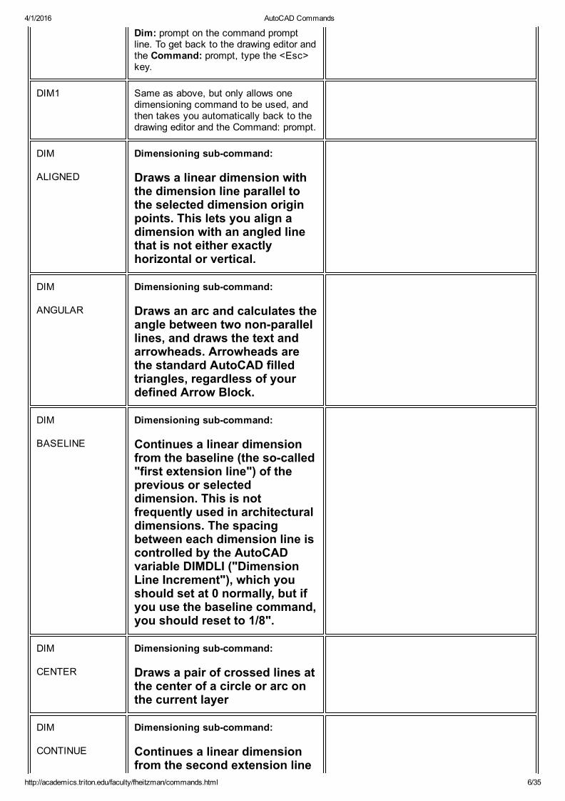
Dim: prompt on the command promptline. To get back to the drawing editor andthe Command: prompt, type the <Esc>key.
DIM1 Same as above, but only allows onedimensioning command to be used, andthen takes you automatically back to thedrawing editor and the Command: prompt.
DIM
ALIGNED
Dimensioning subcommand:
Draws a linear dimension withthe dimension line parallel tothe selected dimension originpoints. This lets you align adimension with an angled linethat is not either exactlyhorizontal or vertical.
DIM
ANGULAR
Dimensioning subcommand:
Draws an arc and calculates theangle between two nonparallellines, and draws the text andarrowheads. Arrowheads arethe standard AutoCAD filledtriangles, regardless of yourdefined Arrow Block.
DIM
BASELINE
Dimensioning subcommand:
Continues a linear dimensionfrom the baseline (the socalled"first extension line") of theprevious or selecteddimension. This is notfrequently used in architecturaldimensions. The spacingbetween each dimension line iscontrolled by the AutoCADvariable DIMDLI ("DimensionLine Increment"), which youshould set at 0 normally, but ifyou use the baseline command,you should reset to 1/8".
DIM
CENTER
Dimensioning subcommand:
Draws a pair of crossed lines atthe center of a circle or arc onthe current layer
DIM
CONTINUE
Dimensioning subcommand:
Continues a linear dimensionfrom the second extension line

4/1/2016 AutoCAD Commands
http://academics.triton.edu/faculty/fheitzman/commands.html 7/35
of the previous or selecteddimension. It is used to create asocalled "string" ofdimensions. This is used quitea bit in architectural drawings.
DIM
DIAMETER
Dimensioning subcommand:
Draws a dimension through thecenter of a circle or arc,calculating the diameter, withone of the arrow heads locatedat the point on the circle or arcwhich is picked.
DIM
EXIT
Dimensioning subcommand:
Exits the dimensioningprogram and returns from theDim: prompt to the normalCommand: prompt
DIM
HOMETEXT
Dimensioning subcommand:
Restores the text of anassociative dimension to itsdefault (home) location if youhave moved it.
DIM
HORIZONTAL
Dimensioning subcommand:
Draws a horizontal lineardimension line
DIM
LEADER
Dimensioning subcommand:
Draws an a line or series oflines with an arrow head(commonly called a "leader") topoint to an object to notate it.This command will also promptyou for the note at the end ofthe leader line, but it will allowonly one line of text. The mostuseful method of using thiscommand is to simply drawleaders between the object tobe notated and text that youcreate with the DTEXTcommand.
DIM
NEWTEXT
Dimensioning subcommand:
Permits changing text of anassociative dimension without
4/1/2016 AutoCAD Commands
http://academics.triton.edu/faculty/fheitzman/commands.html 8/35
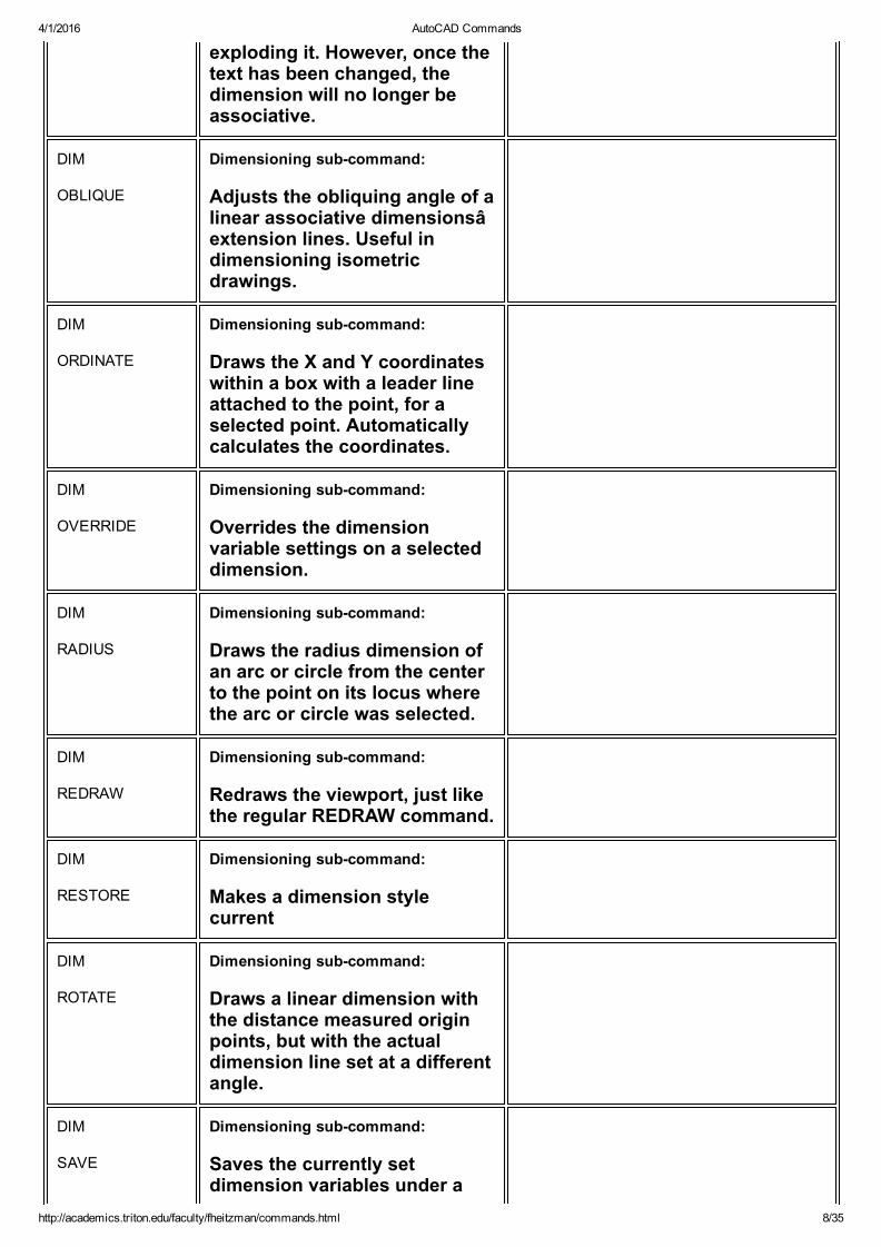
exploding it. However, once thetext has been changed, thedimension will no longer beassociative.
DIM
OBLIQUE
Dimensioning subcommand:
Adjusts the obliquing angle of alinear associative dimensionsâextension lines. Useful indimensioning isometricdrawings.
DIM
ORDINATE
Dimensioning subcommand:
Draws the X and Y coordinateswithin a box with a leader lineattached to the point, for aselected point. Automaticallycalculates the coordinates.
DIM
OVERRIDE
Dimensioning subcommand:
Overrides the dimensionvariable settings on a selecteddimension.
DIM
RADIUS
Dimensioning subcommand:
Draws the radius dimension ofan arc or circle from the centerto the point on its locus wherethe arc or circle was selected.
DIM
REDRAW
Dimensioning subcommand:
Redraws the viewport, just likethe regular REDRAW command.
DIM
RESTORE
Dimensioning subcommand:
Makes a dimension stylecurrent
DIM
ROTATE
Dimensioning subcommand:
Draws a linear dimension withthe distance measured originpoints, but with the actualdimension line set at a differentangle.
DIM
SAVE
Dimensioning subcommand:
Saves the currently setdimension variables under a
4/1/2016 AutoCAD Commands
http://academics.triton.edu/faculty/fheitzman/commands.html 9/35
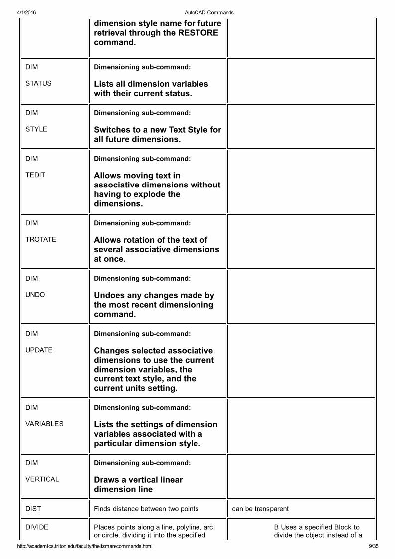
dimension style name for futureretrieval through the RESTOREcommand.
DIM
STATUS
Dimensioning subcommand:
Lists all dimension variableswith their current status.
DIM
STYLE
Dimensioning subcommand:
Switches to a new Text Style forall future dimensions.
DIM
TEDIT
Dimensioning subcommand:
Allows moving text inassociative dimensions withouthaving to explode thedimensions.
DIM
TROTATE
Dimensioning subcommand:
Allows rotation of the text ofseveral associative dimensionsat once.
DIM
UNDO
Dimensioning subcommand:
Undoes any changes made bythe most recent dimensioningcommand.
DIM
UPDATE
Dimensioning subcommand:
Changes selected associativedimensions to use the currentdimension variables, thecurrent text style, and thecurrent units setting.
DIM
VARIABLES
Dimensioning subcommand:
Lists the settings of dimensionvariables associated with aparticular dimension style.
DIM
VERTICAL
Dimensioning subcommand:
Draws a vertical lineardimension line
DIST Finds distance between two points can be transparent
DIVIDE Places points along a line, polyline, arc,or circle, dividing it into the specified
B Uses a specified Block todivide the object instead of a
4/1/2016 AutoCAD Commands
http://academics.triton.edu/faculty/fheitzman/commands.html 10/35
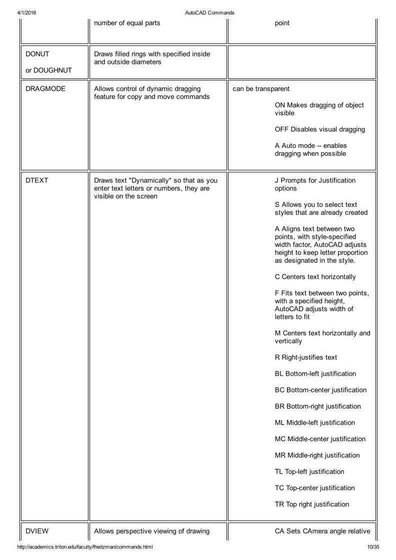
number of equal parts point
DONUT
or DOUGHNUT
Draws filled rings with specified insideand outside diameters
DRAGMODE Allows control of dynamic draggingfeature for copy and move commands
can be transparent
ON Makes dragging of objectvisible
OFF Disables visual dragging
A Auto mode enablesdragging when possible
DTEXT Draws text "Dynamically" so that as youenter text letters or numbers, they arevisible on the screen
J Prompts for Justificationoptions
S Allows you to select textstyles that are already created
A Aligns text between twopoints, with stylespecifiedwidth factor, AutoCAD adjustsheight to keep letter proportionas designated in the style.
C Centers text horizontally
F Fits text between two points,with a specified height,AutoCAD adjusts width ofletters to fit
M Centers text horizontally andvertically
R Rightjustifies text
BL Bottomleft justification
BC Bottomcenter justification
BR Bottomright justification
ML Middleleft justification
MC Middlecenter justification
MR Middleright justification
TL Topleft justification
TC Topcenter justification
TR Top right justification
DVIEW Allows perspective viewing of drawing CA Sets CAmera angle relative
4/1/2016 AutoCAD Commands
http://academics.triton.edu/faculty/fheitzman/commands.html 11/35
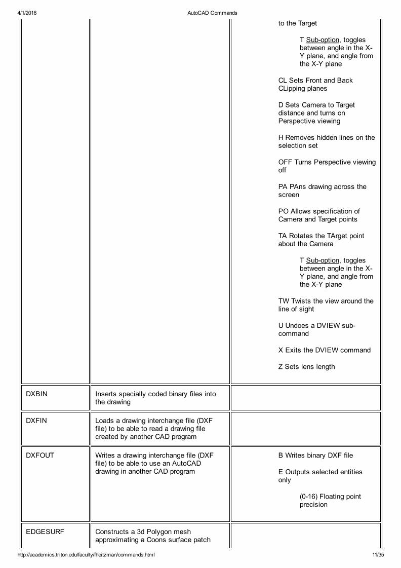
to the Target
T Suboption, togglesbetween angle in the XY plane, and angle fromthe XY plane
CL Sets Front and BackCLipping planes
D Sets Camera to Targetdistance and turns onPerspective viewing
H Removes hidden lines on theselection set
OFF Turns Perspective viewingoff
PA PAns drawing across thescreen
PO Allows specification ofCamera and Target points
TA Rotates the TArget pointabout the Camera
T Suboption, togglesbetween angle in the XY plane, and angle fromthe XY plane
TW Twists the view around theline of sight
U Undoes a DVIEW subcommand
X Exits the DVIEW command
Z Sets lens length
DXBIN Inserts specially coded binary files intothe drawing
DXFIN Loads a drawing interchange file (DXFfile) to be able to read a drawing filecreated by another CAD program
DXFOUT Writes a drawing interchange file (DXFfile) to be able to use an AutoCADdrawing in another CAD program
B Writes binary DXF file
E Outputs selected entitiesonly
(016) Floating pointprecision
EDGESURF Constructs a 3d Polygon meshapproximating a Coons surface patch
4/1/2016 AutoCAD Commands
http://academics.triton.edu/faculty/fheitzman/commands.html 12/35
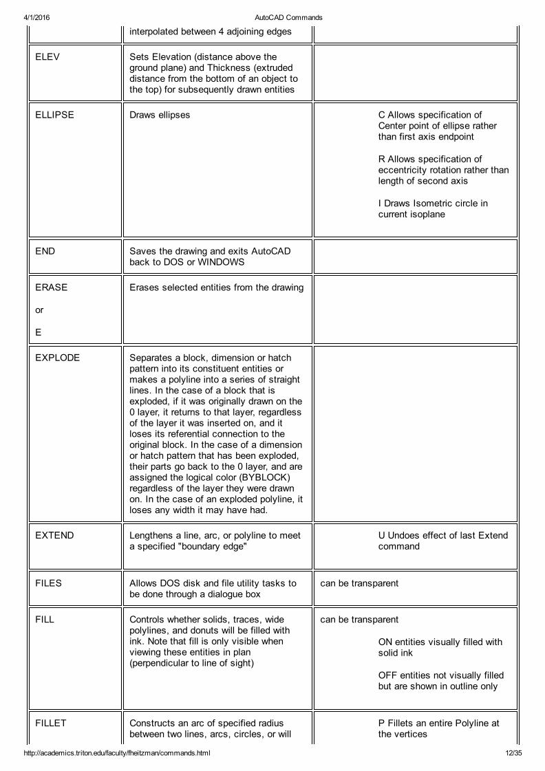
interpolated between 4 adjoining edges
ELEV Sets Elevation (distance above theground plane) and Thickness (extrudeddistance from the bottom of an object tothe top) for subsequently drawn entities
ELLIPSE Draws ellipses C Allows specification ofCenter point of ellipse ratherthan first axis endpoint
R Allows specification ofeccentricity rotation rather thanlength of second axis
I Draws Isometric circle incurrent isoplane
END Saves the drawing and exits AutoCADback to DOS or WINDOWS
ERASE
or
E
Erases selected entities from the drawing
EXPLODE Separates a block, dimension or hatchpattern into its constituent entities ormakes a polyline into a series of straightlines. In the case of a block that isexploded, if it was originally drawn on the0 layer, it returns to that layer, regardlessof the layer it was inserted on, and itloses its referential connection to theoriginal block. In the case of a dimensionor hatch pattern that has been exploded,their parts go back to the 0 layer, and areassigned the logical color (BYBLOCK)regardless of the layer they were drawnon. In the case of an exploded polyline, itloses any width it may have had.
EXTEND Lengthens a line, arc, or polyline to meeta specified "boundary edge"
U Undoes effect of last Extendcommand
FILES Allows DOS disk and file utility tasks tobe done through a dialogue box
can be transparent
FILL Controls whether solids, traces, widepolylines, and donuts will be filled withink. Note that fill is only visible whenviewing these entities in plan(perpendicular to line of sight)
can be transparent
ON entities visually filled withsolid ink
OFF entities not visually filledbut are shown in outline only
FILLET Constructs an arc of specified radiusbetween two lines, arcs, circles, or will
P Fillets an entire Polyline atthe vertices

4/1/2016 AutoCAD Commands
http://academics.triton.edu/faculty/fheitzman/commands.html 13/35
create arcs of the specified radius at thevertices of a polyline. Radius of the arc tobe constructed may be set to 0, whichwill make a sharp corner
R Allows setting of the filletradius. Default value is 0.Radius remains set untilchanged again
FILMROLL Generates a file for rendering byAutoShade, a separate program
GRAPHSCR A "toggle." Flips the display on singlescreen systems (most of them) from textscreen to graphicsscreen, and viceversa.
can be transparent
GRID Displays a rectangular grid of white dotson the screen at a specified X and Yspacing
can be transparent
ON Turns grid display on
OFF Turns grid display off
S Locks grid spacing to SNAPresolution
A Sets grid aspect (different Xand Y spacings
<number> Setsgrid spacing forboth X and Ycoordinates
<number X> Setsgrid spacing tomultiple "X" ofsnap spacing
HANDLES Assigns a unique, permanent number toeach entity of the drawing
ON Enables Handles
DESTROY Discards allentity Handles
HATCH Allows drawing of crosshatching andpattern filling
<patternname> uses hatchpattern name from library file tofill designated area with apseudoblock hatch entity can be reduced to individuallines and points byEXPLODEing it.
<*patternname> uses hatchpattern name from library file tofill designated area withindividual lines and points, nota block
U "Userdefined" hatch patterndrawn of parallel lines with aspecified distance between, ata specified angle, and eithersinglehatching or double

4/1/2016 AutoCAD Commands
http://academics.triton.edu/faculty/fheitzman/commands.html 14/35
(cross)hatching
? Lists names of availablehatch patterns
<patternname> or U can befollowed by a comma and thefollowing subcommands:
I Ignores any boundariesinside the outermostboundary
N Normal style ofselecting boundarieswith alternating hatchedand unhatched nestedareas
O Hatches outermostboundary area only
HELP
or
?
Displays a list of all valid commands anddata entry options, or obtains help for aspecific command or prompt
can be transparent
if invoked while another command is inprocess, it will assume that you want help onthat command
HIDE Regenerates a 3d visual image of thedrawing with hidden lines removed
ID Displays the X,Y, and Z coordinates of apoint selected
can be transparent
IGESIN Loads an IGES interchange file
IGESOUT Writes an IGES interchange file
INSERT Inserts a previously created block ordrawing file into the current drawing
<filename> Inserts afilename from thedefault directory into thecurrent drawing,assuming that there isno block by that name inthe current drawing
<blockname>=<filename> Creates ablock in the currentdrawing with the samename as the file
<*name> Inserts a blockin its constituent entitiesrather than as a block also called a "StarBlock" or Preexplodedblock
C Reply to X scale prompt allows scale to be specified bytwo points (Corner specification
4/1/2016 AutoCAD Commands
http://academics.triton.edu/faculty/fheitzman/commands.html 15/35
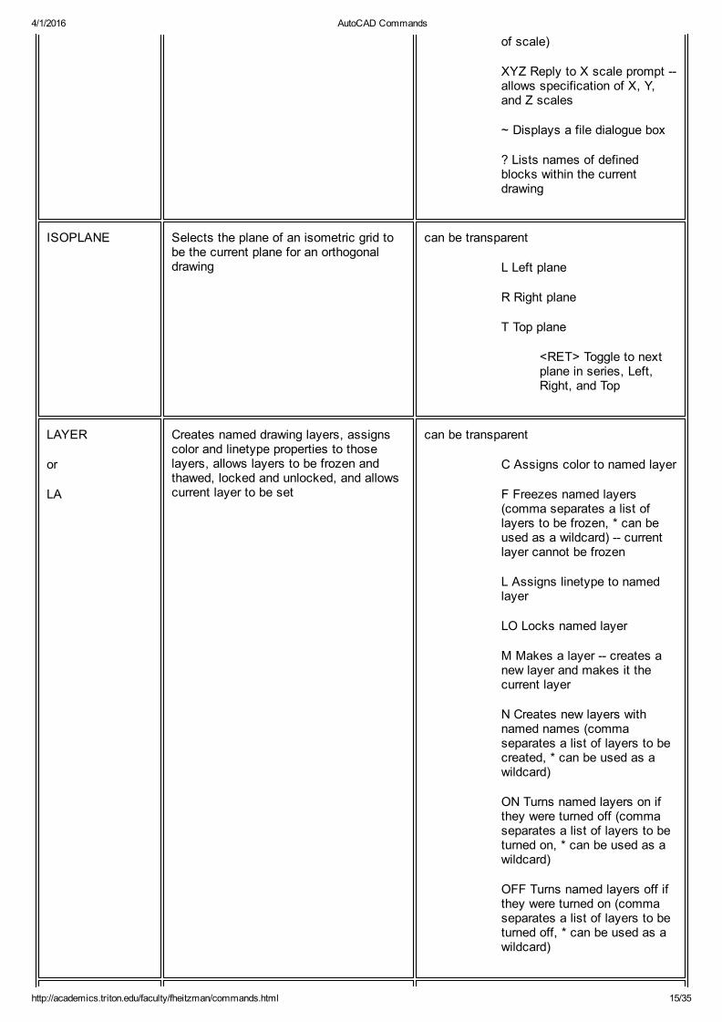
of scale)
XYZ Reply to X scale prompt allows specification of X, Y,and Z scales
~ Displays a file dialogue box
? Lists names of definedblocks within the currentdrawing
ISOPLANE Selects the plane of an isometric grid tobe the current plane for an orthogonaldrawing
can be transparent
L Left plane
R Right plane
T Top plane
<RET> Toggle to nextplane in series, Left,Right, and Top
LAYER
or
LA
Creates named drawing layers, assignscolor and linetype properties to thoselayers, allows layers to be frozen andthawed, locked and unlocked, and allowscurrent layer to be set
can be transparent
C Assigns color to named layer
F Freezes named layers(comma separates a list oflayers to be frozen, * can beused as a wildcard) currentlayer cannot be frozen
L Assigns linetype to namedlayer
LO Locks named layer
M Makes a layer creates anew layer and makes it thecurrent layer
N Creates new layers withnamed names (commaseparates a list of layers to becreated, * can be used as awildcard)
ON Turns named layers on ifthey were turned off (commaseparates a list of layers to beturned on, * can be used as awildcard)
OFF Turns named layers off ifthey were turned on (commaseparates a list of layers to beturned off, * can be used as awildcard)
4/1/2016 AutoCAD Commands
http://academics.triton.edu/faculty/fheitzman/commands.html 16/35
LAYER
or
LA
(Continued)
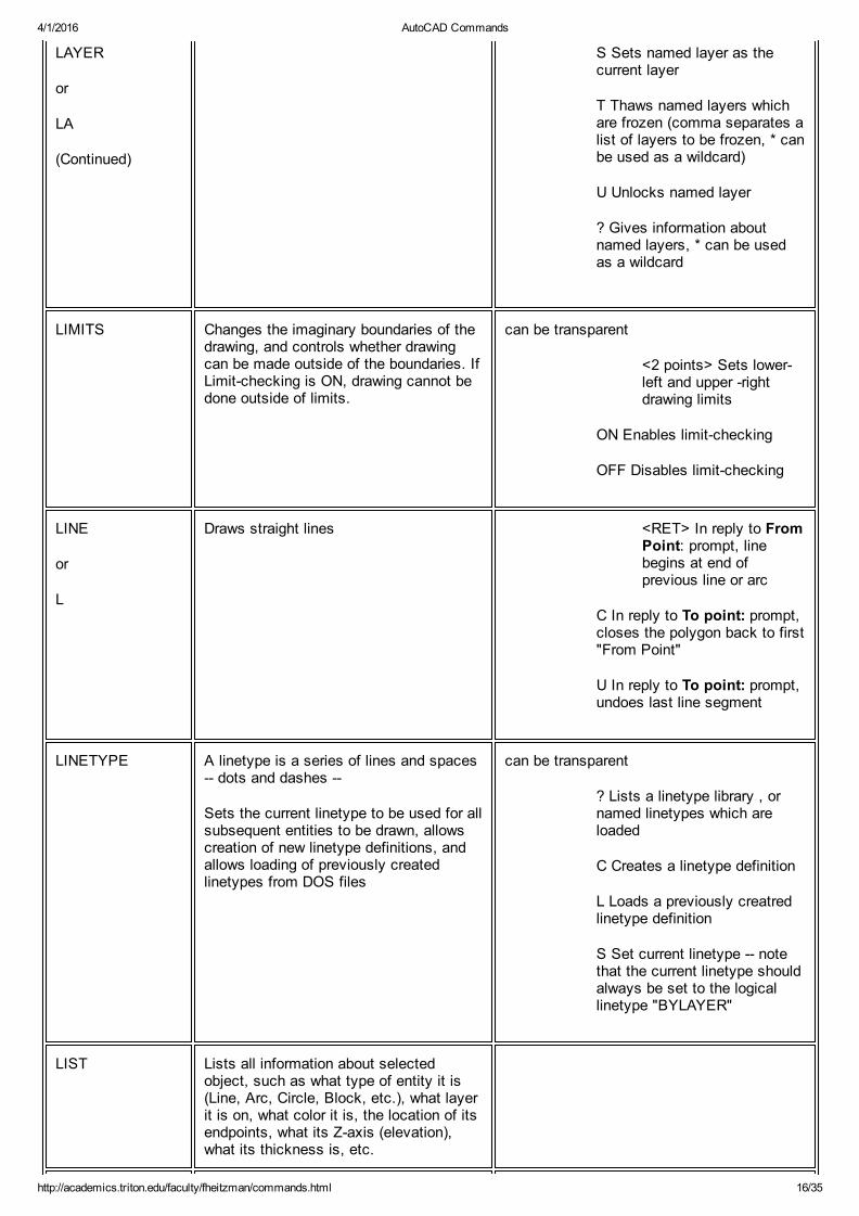
S Sets named layer as thecurrent layer
T Thaws named layers whichare frozen (comma separates alist of layers to be frozen, * canbe used as a wildcard)
U Unlocks named layer
? Gives information aboutnamed layers, * can be usedas a wildcard
LIMITS Changes the imaginary boundaries of thedrawing, and controls whether drawingcan be made outside of the boundaries. IfLimitchecking is ON, drawing cannot bedone outside of limits.
can be transparent
<2 points> Sets lowerleft and upper rightdrawing limits
ON Enables limitchecking
OFF Disables limitchecking
LINE
or
L
Draws straight lines <RET> In reply to FromPoint: prompt, linebegins at end ofprevious line or arc
C In reply to To point: prompt,closes the polygon back to first"From Point"
U In reply to To point: prompt,undoes last line segment
LINETYPE A linetype is a series of lines and spaces dots and dashes
Sets the current linetype to be used for allsubsequent entities to be drawn, allowscreation of new linetype definitions, andallows loading of previously createdlinetypes from DOS files
can be transparent
? Lists a linetype library , ornamed linetypes which areloaded
C Creates a linetype definition
L Loads a previously creatredlinetype definition
S Set current linetype notethat the current linetype shouldalways be set to the logicallinetype "BYLAYER"
LIST Lists all information about selectedobject, such as what type of entity it is(Line, Arc, Circle, Block, etc.), what layerit is on, what color it is, the location of itsendpoints, what its Zaxis (elevation),what its thickness is, etc.

4/1/2016 AutoCAD Commands
http://academics.triton.edu/faculty/fheitzman/commands.html 17/35
LOAD Loads a file of userdefined shapes to beused with the Shape command
? Lists the names of loadedShape files
LTSCALE Sets scale factor to be applied to alllinetypes within the drawing
can be transparent
MEASURE Places points (or, optionally, Blocks) atintervals along a selected line, polyline,arc or circle. The interval distance isgiven by the user. If points are used asthe marker to be placed along the entity,they are not visible unless the Point typeis set to type 3 with the PDMODEcommand.
B specifies that a definedBlock is to be used as amarker instead of a point.
MENU Loads a Menu file into the menu areas(Screen, pulldown, tablet, and button)
MINSERT Inserts multiple copies of a Block in arectangular pattern (word stands for"Multiple Insert." The entire array createdthen becomes a Block.
fname Loads fname andforms a rectangulararray of the resultingBlock
fname=f Creates Blockfname from file f andforms a rectangulararray
? Lists names of definedBlocks within the drawing
C (as a reply to X scaleprompt) specifies scale via twoselected points ("Corner"specification of scale)
XYZ (as a reply to X scaleprompt) readies Minsert for X,Y, and Z scales)
displays a file dialogue box
MIRROR Reflects designated entities about a userspecified axis
MOVE
or
M
Moves designated entities to anotherlocation
MSLIDE Makes a slide from the current display.Slide shows the drawing only, and not theUCSICON, the Toolbar, the Aerial View ormenus.
MSPACE Switches to Model Space
MULTIPLE Causes the next command to repeat until

4/1/2016 AutoCAD Commands
http://academics.triton.edu/faculty/fheitzman/commands.html 18/35
cancelled
MVIEW Creates and controls Viewports ON Turns selectedViewports on andcauses the Model to beregenerated in theselected Viewports.
OFF Turns selectedViewports off andcauses Model to be notdisplayed in theselected Viewports.
Hideplot Causes hiddenlines to be removed inselected Viewportsduring Paper Spaceplotting.
Fit Creates a singleViewport to fit thecurrent Paper Spaceview
2 Creates 2 Viewports inspecified area or fit tothe current Paper Spaceview.
3 Creates 3 Viewports inspecified area or fit tothe current Paper Spaceview.
4 Creates 4 Viewports inspecified area or fit tothe current Paper Spaceview.
Restore Translatesviewport configurationssaved with the VPORTScommand into individualViewport entities inPaper Space.
<first Point> Creates anew Viewport within thearea specified by 2points.
Suboptions to the "2" Option:
Horizontal Creates ahorizontal divisionbetween the 2 newViewports
Vertical Creates avertical division betweenthe 2 new Viewports.
Suboptions to the "3" Option:
4/1/2016 AutoCAD Commands
http://academics.triton.edu/faculty/fheitzman/commands.html 19/35
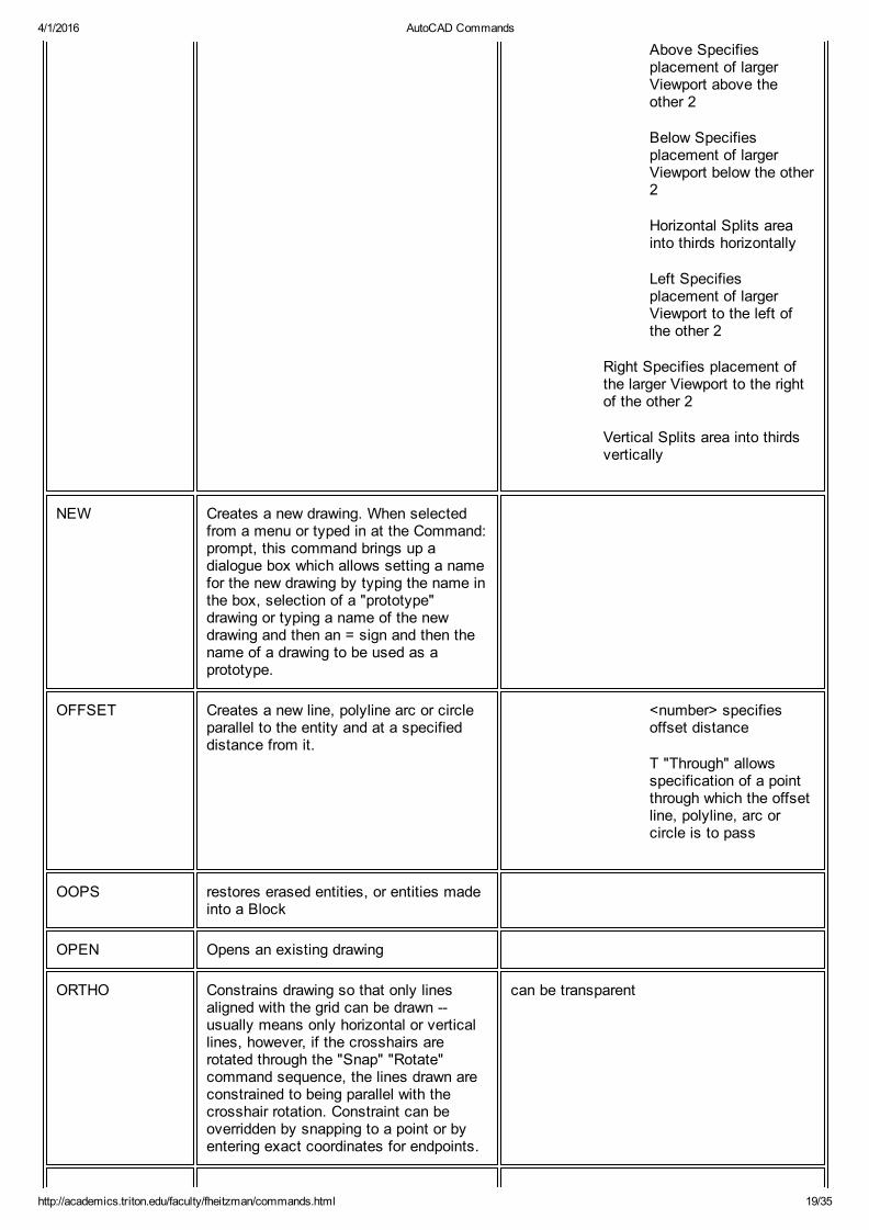
Above Specifiesplacement of largerViewport above theother 2
Below Specifiesplacement of largerViewport below the other2
Horizontal Splits areainto thirds horizontally
Left Specifiesplacement of largerViewport to the left ofthe other 2
Right Specifies placement ofthe larger Viewport to the rightof the other 2
Vertical Splits area into thirdsvertically
NEW Creates a new drawing. When selectedfrom a menu or typed in at the Command:prompt, this command brings up adialogue box which allows setting a namefor the new drawing by typing the name inthe box, selection of a "prototype"drawing or typing a name of the newdrawing and then an = sign and then thename of a drawing to be used as aprototype.
OFFSET Creates a new line, polyline arc or circleparallel to the entity and at a specifieddistance from it.
<number> specifiesoffset distance
T "Through" allowsspecification of a pointthrough which the offsetline, polyline, arc orcircle is to pass
OOPS restores erased entities, or entities madeinto a Block
OPEN Opens an existing drawing
ORTHO Constrains drawing so that only linesaligned with the grid can be drawn usually means only horizontal or verticallines, however, if the crosshairs arerotated through the "Snap" "Rotate"command sequence, the lines drawn areconstrained to being parallel with thecrosshair rotation. Constraint can beoverridden by snapping to a point or byentering exact coordinates for endpoints.
can be transparent
4/1/2016 AutoCAD Commands
http://academics.triton.edu/faculty/fheitzman/commands.html 20/35
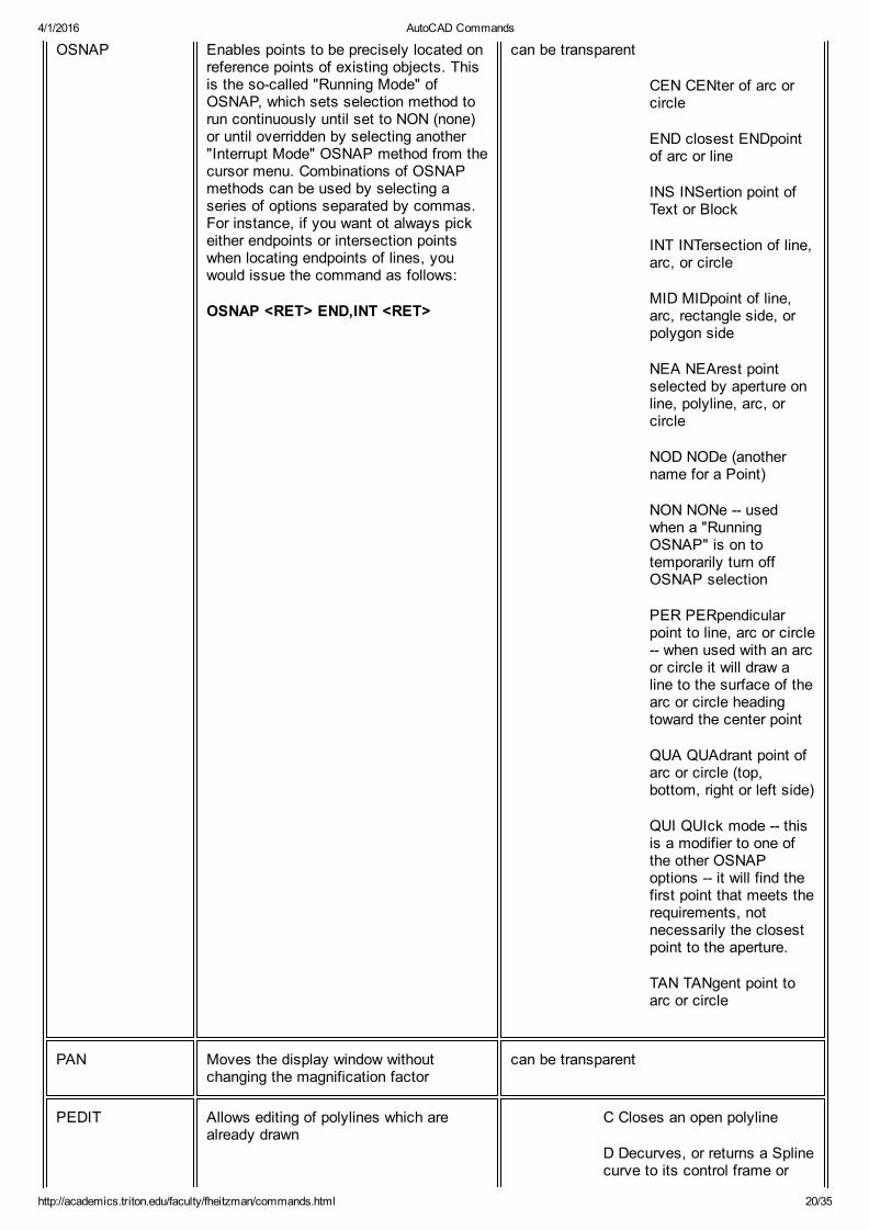
OSNAP Enables points to be precisely located onreference points of existing objects. Thisis the socalled "Running Mode" ofOSNAP, which sets selection method torun continuously until set to NON (none)or until overridden by selecting another"Interrupt Mode" OSNAP method from thecursor menu. Combinations of OSNAPmethods can be used by selecting aseries of options separated by commas.For instance, if you want ot always pickeither endpoints or intersection pointswhen locating endpoints of lines, youwould issue the command as follows:
OSNAP <RET> END,INT <RET>
can be transparent
CEN CENter of arc orcircle
END closest ENDpointof arc or line
INS INSertion point ofText or Block
INT INTersection of line,arc, or circle
MID MIDpoint of line,arc, rectangle side, orpolygon side
NEA NEArest pointselected by aperture online, polyline, arc, orcircle
NOD NODe (anothername for a Point)
NON NONe usedwhen a "RunningOSNAP" is on totemporarily turn offOSNAP selection
PER PERpendicularpoint to line, arc or circle when used with an arcor circle it will draw aline to the surface of thearc or circle headingtoward the center point
QUA QUAdrant point ofarc or circle (top,bottom, right or left side)
QUI QUIck mode thisis a modifier to one ofthe other OSNAPoptions it will find thefirst point that meets therequirements, notnecessarily the closestpoint to the aperture.
TAN TANgent point toarc or circle
PAN Moves the display window withoutchanging the magnification factor
can be transparent
PEDIT Allows editing of polylines which arealready drawn
C Closes an open polyline
D Decurves, or returns a Splinecurve to its control frame or

4/1/2016 AutoCAD Commands
http://academics.triton.edu/faculty/fheitzman/commands.html 21/35
series of connected straightlines
E Edit vertices
F Fits curve to a polyline makes a series of straight linesinto a curve which will passthrough the vertices
J Joins a line or arc or anotherpolyline to an open polyline
L Toggles linetype generationto be either a continuouspattern of dashes passingthrough the vertices, or apattern which starts and endsat each vertex
O Opens a closed polyline
S Uses the polyline vertices asa frame for a Spline Curve type of Spline Curve is set bythe Variable "Splinetype."
U Undoes one editing operation
W Sets a uniform width for thePolyline
PEDIT (Continued) Vertex Editing Options:
B Sets first vertex for Break
G "Go" performs a Break orStraighten operation
I Inserts a new vertex aftercurrent one
M Moves current vertex
N Makes the Next vertexcurrent
P Makes the Previous vertexcurrent
R Regenerates the Polyline
S Sets first vertex forStraighten
T Sets tangent direction forcurrent vertex
W Sets new width for thefollowing segment
X Exits vertex editing, orcancels Break and Straighten
4/1/2016 AutoCAD Commands
http://academics.triton.edu/faculty/fheitzman/commands.html 22/35
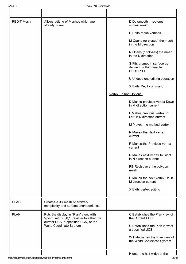
PEDIT Mesh Allows editing of Meshes which arealready drawn
D Desmooth restoresoriginal mesh
E Edits mesh vertices
M Opens (or closes) the meshin the M direction
N Opens (or closes) the meshin the N direction
S Fits a smooth surface asdefined by the VariableSURFTYPE
U Undoes one editing operation
X Exits Pedit command
Vertex Editing Options:
D Makes previous vertex Downin M direction current
L Makes previous vertex toLeft in N direction current
M Moves the marked vertex
N Makes the Next vertexcurrent
P Makes the Previous vertexcurrent
R Makes next vertex to Rightin N direction current
RE Redisplays the polygonmesh
U Makes the next vertex Up inM direction current
X Exits vertex editing
PFACE Creates a 3D mesh of arbitrarycomplexity and surface characteristics
PLAN Puts the display in "Plan" view, withVpoint set to 0,0,1, relative to either thecurrent UCS, a specified UCS, or theWorld Coordinate System
C Establishes the Plan view ofthe Current UCS
U Establishes the Plan view ofa specified UCS
W Establishes the Plan view ofthe World Coordinate System
H sets the halfwidth of the
4/1/2016 AutoCAD Commands
http://academics.triton.edu/faculty/fheitzman/commands.html 23/35
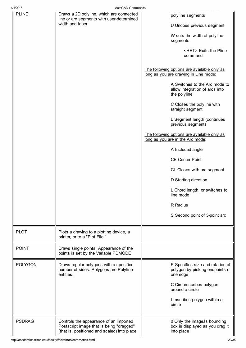
PLINE Draws a 2D polyline, which are connectedline or arc segments with userdeterminedwidth and taper
H sets the halfwidth of thepolyline segments
U Undoes previous segment
W sets the width of polylinesegments
<RET> Exits the Plinecommand
The following options are available only aslong as you are drawing in Line mode:
A Switches to the Arc mode toallow integration of arcs intothe polyline
C Closes the polyline withstraight segment
L Segment length (continuesprevious segment)
The following options are available only aslong as you are in the Arc mode:
A Included angle
CE Center Point
CL Closes with arc segment
D Starting direction
L Chord length, or switches toline mode
R Radius
S Second point of 3point arc
PLOT Plots a drawing to a plotting device, aprinter, or to a "Plot File."
POINT Draws single points. Appearance of thepoints is set by the Variable PDMODE
POLYGON Draws regular polygons with a specifiednumber of sides. Polygons are Polylineentities.
E Specifies size and rotation ofpolygon by picking endpoints ofone edge
C Circumscribes polygonaround a circle
I Inscribes polygon within acircle
PSDRAG Controls the appearance of an importedPostscript image that is being "dragged"(that is, positioned and scaled) into place
0 Only the imageâs boundingbox is displayed as you drag itinto place

4/1/2016 AutoCAD Commands
http://academics.triton.edu/faculty/fheitzman/commands.html 24/35
by the PSIN command 1 The complete renderedPostScript image is displayedas you drag it into place
PSFILL Fills 2D Polyline outlines with PostScriptfill patterns defined in the ACAD.PSF file
. Entering a period results in nofill pattern
? Lists the fill patterns definedin ACAD.PSF file
PSIN Imports Encapsulated PostScript (EPS)files
PSOUT Exports the current view of your drawingto an Encapsulated PostScript (EPS) file
PSPACE Switches to Paper Space this will workonly if the Variable TILEMODE is set to0.
PURGE Removes unused Blocks, Text Styles,Layers, Linetypes, and Dimension Stylesfrom current drawing
A Purges All unused namedobjects
B Purges unused Blocks
D Purges unused Dimstyles
LA Purges unused LAyers
LT Purges unused Linetypes
SH Purges unused Shape files
ST Purges unused Text Styles
QSAVE Saves the current drawing "Quickly"without requesting a filename (as long asfile has already been given a name)
QTEXT Controls display of text commandstands for "QuickTEXT"
ON Lines of textdisplayed as rectangles
OFF Lines of text displayed astext
QUIT Exits AutoCAD if the current drawinghas not been Saveds in its current state,a dialogue box will appear asking if youwant to Save the drawing, Discard thechanges, or Cancel the Exit command
RECOVER Attempts to recover damaged orcorrupted drawings
REDEFINE Restores a builtin command which mayhave been deleted by the commandUNDEFINE
4/1/2016 AutoCAD Commands
http://academics.triton.edu/faculty/fheitzman/commands.html 25/35
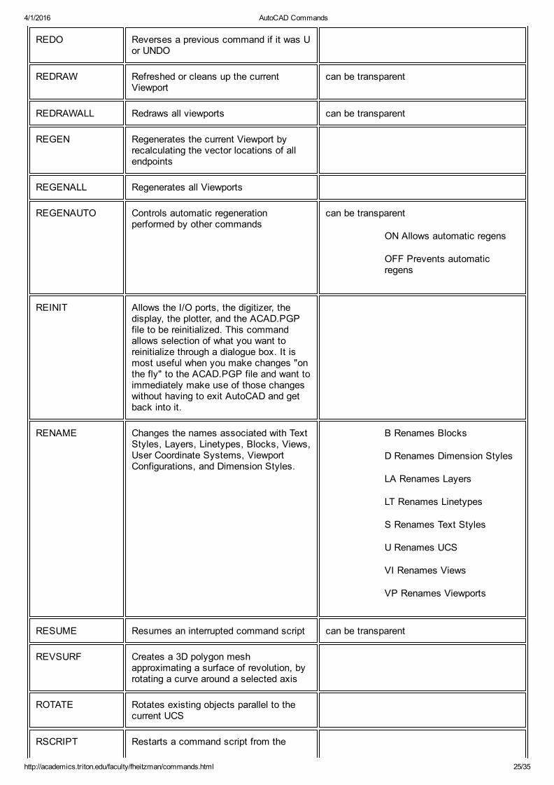
REDO Reverses a previous command if it was Uor UNDO
REDRAW Refreshed or cleans up the currentViewport
can be transparent
REDRAWALL Redraws all viewports can be transparent
REGEN Regenerates the current Viewport byrecalculating the vector locations of allendpoints
REGENALL Regenerates all Viewports
REGENAUTO Controls automatic regenerationperformed by other commands
can be transparent
ON Allows automatic regens
OFF Prevents automaticregens
REINIT Allows the I/O ports, the digitizer, thedisplay, the plotter, and the ACAD.PGPfile to be reinitialized. This commandallows selection of what you want toreinitialize through a dialogue box. It ismost useful when you make changes "onthe fly" to the ACAD.PGP file and want toimmediately make use of those changeswithout having to exit AutoCAD and getback into it.
RENAME Changes the names associated with TextStyles, Layers, Linetypes, Blocks, Views,User Coordinate Systems, ViewportConfigurations, and Dimension Styles.
B Renames Blocks
D Renames Dimension Styles
LA Renames Layers
LT Renames Linetypes
S Renames Text Styles
U Renames UCS
VI Renames Views
VP Renames Viewports
RESUME Resumes an interrupted command script can be transparent
REVSURF Creates a 3D polygon meshapproximating a surface of revolution, byrotating a curve around a selected axis
ROTATE Rotates existing objects parallel to thecurrent UCS
RSCRIPT Restarts a command script from the
4/1/2016 AutoCAD Commands
http://academics.triton.edu/faculty/fheitzman/commands.html 26/35
beginning
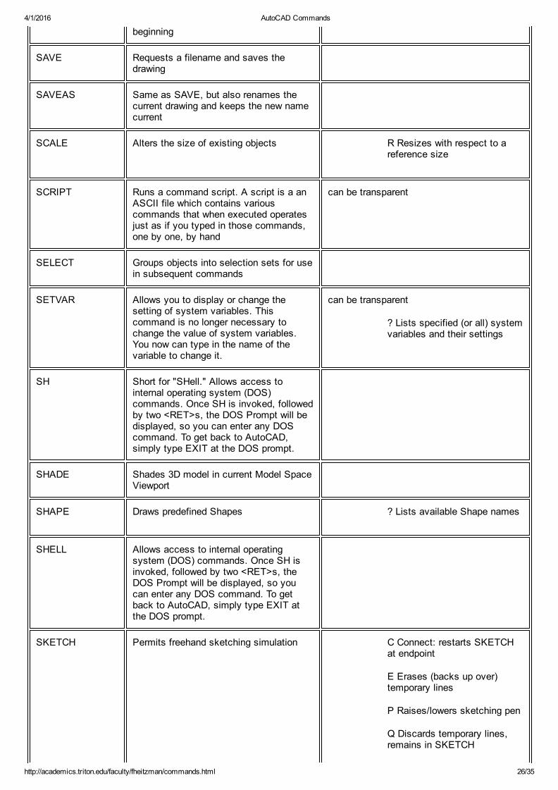
SAVE Requests a filename and saves thedrawing
SAVEAS Same as SAVE, but also renames thecurrent drawing and keeps the new namecurrent
SCALE Alters the size of existing objects R Resizes with respect to areference size
SCRIPT Runs a command script. A script is a anASCII file which contains variouscommands that when executed operatesjust as if you typed in those commands,one by one, by hand
can be transparent
SELECT Groups objects into selection sets for usein subsequent commands
SETVAR Allows you to display or change thesetting of system variables. Thiscommand is no longer necessary tochange the value of system variables.You now can type in the name of thevariable to change it.
can be transparent
? Lists specified (or all) systemvariables and their settings
SH Short for "SHell." Allows access tointernal operating system (DOS)commands. Once SH is invoked, followedby two <RET>s, the DOS Prompt will bedisplayed, so you can enter any DOScommand. To get back to AutoCAD,simply type EXIT at the DOS prompt.
SHADE Shades 3D model in current Model SpaceViewport
SHAPE Draws predefined Shapes ? Lists available Shape names
SHELL Allows access to internal operatingsystem (DOS) commands. Once SH isinvoked, followed by two <RET>s, theDOS Prompt will be displayed, so youcan enter any DOS command. To getback to AutoCAD, simply type EXIT atthe DOS prompt.
SKETCH Permits freehand sketching simulation C Connect: restarts SKETCHat endpoint
E Erases (backs up over)temporary lines
P Raises/lowers sketching pen
Q Discards temporary lines,remains in SKETCH
4/1/2016 AutoCAD Commands
http://academics.triton.edu/faculty/fheitzman/commands.html 27/35
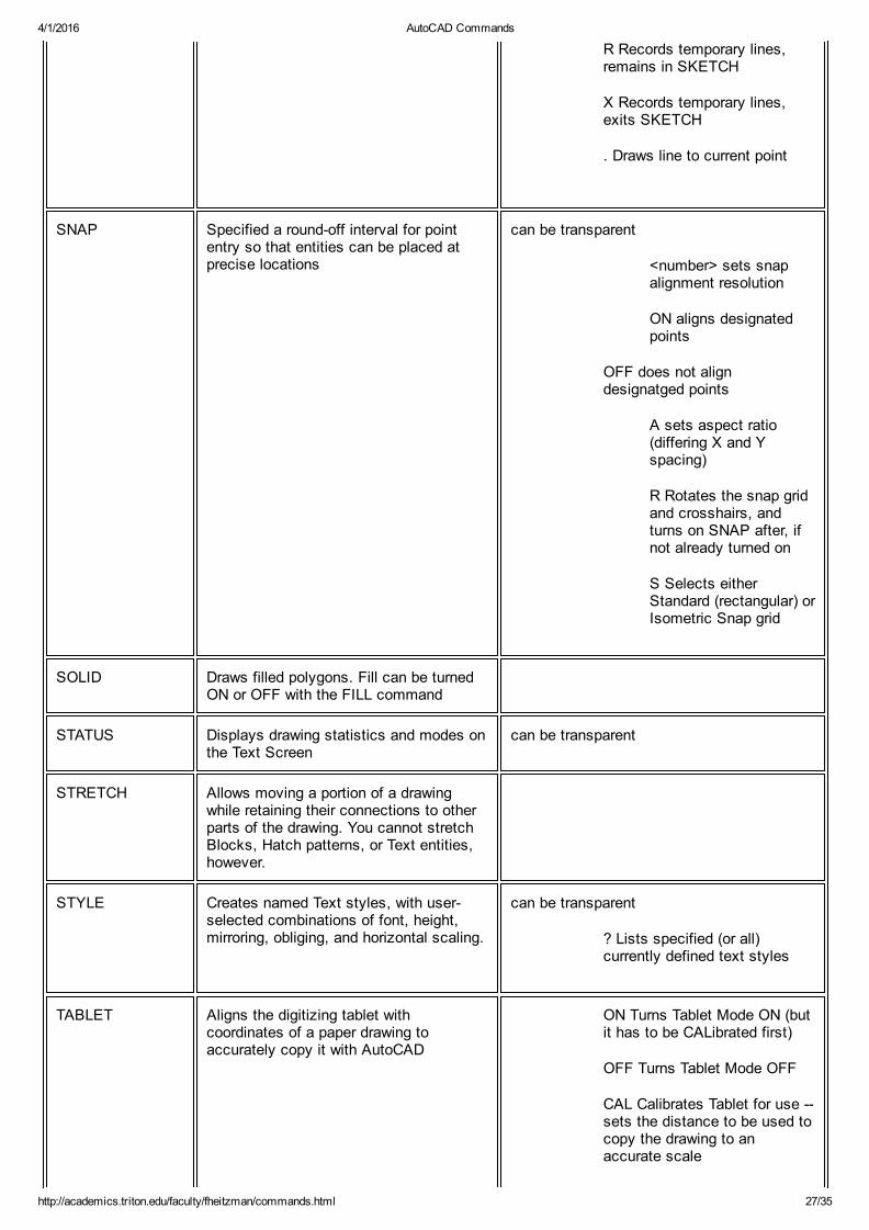
R Records temporary lines,remains in SKETCH
X Records temporary lines,exits SKETCH
. Draws line to current point
SNAP Specified a roundoff interval for pointentry so that entities can be placed atprecise locations
can be transparent
<number> sets snapalignment resolution
ON aligns designatedpoints
OFF does not aligndesignatged points
A sets aspect ratio(differing X and Yspacing)
R Rotates the snap gridand crosshairs, andturns on SNAP after, ifnot already turned on
S Selects eitherStandard (rectangular) orIsometric Snap grid
SOLID Draws filled polygons. Fill can be turnedON or OFF with the FILL command
STATUS Displays drawing statistics and modes onthe Text Screen
can be transparent
STRETCH Allows moving a portion of a drawingwhile retaining their connections to otherparts of the drawing. You cannot stretchBlocks, Hatch patterns, or Text entities,however.
STYLE Creates named Text styles, with userselected combinations of font, height,mirroring, obliging, and horizontal scaling.
can be transparent
? Lists specified (or all)currently defined text styles
TABLET Aligns the digitizing tablet withcoordinates of a paper drawing toaccurately copy it with AutoCAD
ON Turns Tablet Mode ON (butit has to be CALibrated first)
OFF Turns Tablet Mode OFF
CAL Calibrates Tablet for use sets the distance to be used tocopy the drawing to anaccurate scale
4/1/2016 AutoCAD Commands
http://academics.triton.edu/faculty/fheitzman/commands.html 28/35
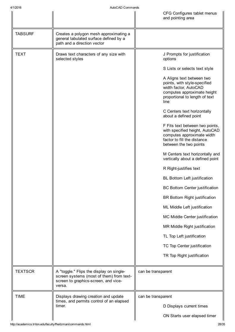
CFG Configures tablet menusand pointing area
TABSURF Creates a polygon mesh approximating ageneral tabulated surface defined by apath and a direction vector
TEXT Draws text characters of any size withselected styles
J Prompts for justificationoptions
S Lists or selects text style
A Aligns text between twopoints, with stylespecifiedwidth factor, AutoCADcomputes approximate heightproportional to length of textline
C Centers text horizontallyabout a defined point
F Fits text between two points,with specified height, AutoCADcomputes approximate widthfactor to fill the distancebetween the two points
M Centers text horizontally andvertically about a defined point
R Rightjustifies text
BL Bottom Left justification
BC Bottom Center justification
BR Bottom Right justification
ML Middle Left justification
MC Middle Center justification
MR Middle Right justification
TL Top Left justification
TC Top Center justification
TR Top Right justification
TEXTSCR A "toggle." Flips the display on singlescreen systems (most of them) from textscreen to graphicsscreen, and viceversa.
can be transparent
TIME Displays drawing creation and updatetimes, and permits control of an elapsedtimer.
can be transparent
D Displays current times
ON Starts user elapsed timer

4/1/2016 AutoCAD Commands
http://academics.triton.edu/faculty/fheitzman/commands.html 29/35
OFF Stops user elapsed timer
R Resets user elapsed timer
TRACE Draws solid filled lines of specified width.Has mostly been superseded by thePLINE command.
TREESTAT Displays information on the drawing'scurrent spatial index, such as the numberand depth of nodes in the drawingdatabase.
TRIM Erases a portion of selected entities thatcross a specified "cutting edge"
U Undoes last trim operation
U Reverses the effect of the previouscommand
UCS Defines or modifies the current UserCoordinate System
D ("Delete") Deletes one ormore saved coordinatesystems
E ("Entity") Sets a UCS withthe same extrusion direction asthat of the selected entity
O ("Origin") Shifts the origin ofthe current coordinate system
P ("Previous") Restores thePrevious UCS
R ("Restore") Restores apreviously saved UCS
S ("Save") Saves the currentUCS
V ("View") Establishes a newUCS whose Zaxis is parallel tothe current viewing direction
W ("World") Sets the currentUCS to the World CoordinateSystem
X Rotates the current UCSaround the Xaxis
Y Rotates the current UCSaround the Yaxis
Z Rotates the current UCSaround the Zaxis
ZA Defines a UCS using anorigin point and a point on thepositive portion of the Zaxis
3 Defines a UCS using anorigin point, a point on the
4/1/2016 AutoCAD Commands
http://academics.triton.edu/faculty/fheitzman/commands.html 30/35
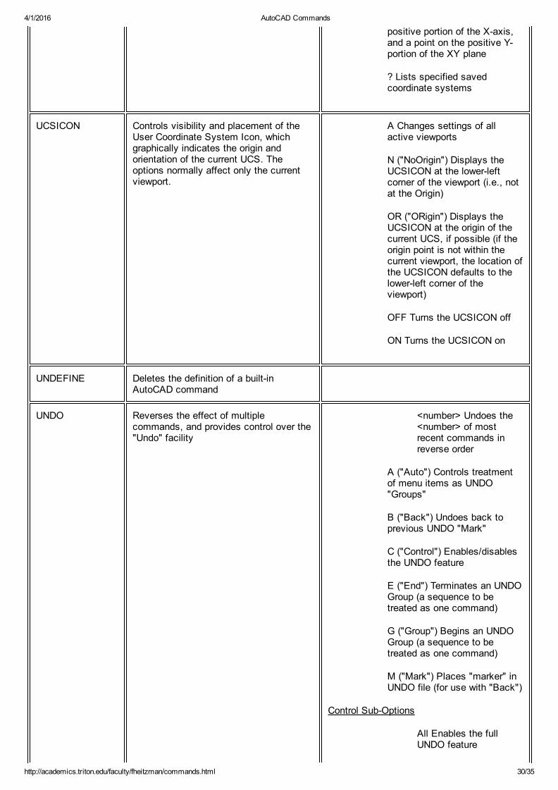
positive portion of the Xaxis,and a point on the positive Yportion of the XY plane
? Lists specified savedcoordinate systems
UCSICON Controls visibility and placement of theUser Coordinate System Icon, whichgraphically indicates the origin andorientation of the current UCS. Theoptions normally affect only the currentviewport.
A Changes settings of allactive viewports
N ("NoOrigin") Displays theUCSICON at the lowerleftcorner of the viewport (i.e., notat the Origin)
OR ("ORigin") Displays theUCSICON at the origin of thecurrent UCS, if possible (if theorigin point is not within thecurrent viewport, the location ofthe UCSICON defaults to thelowerleft corner of theviewport)
OFF Turns the UCSICON off
ON Turns the UCSICON on
UNDEFINE Deletes the definition of a builtinAutoCAD command
UNDO Reverses the effect of multiplecommands, and provides control over the"Undo" facility
<number> Undoes the<number> of mostrecent commands inreverse order
A ("Auto") Controls treatmentof menu items as UNDO"Groups"
B ("Back") Undoes back toprevious UNDO "Mark"
C ("Control") Enables/disablesthe UNDO feature
E ("End") Terminates an UNDOGroup (a sequence to betreated as one command)
G ("Group") Begins an UNDOGroup (a sequence to betreated as one command)
M ("Mark") Places "marker" inUNDO file (for use with "Back")
Control SubOptions
All Enables the fullUNDO feature
4/1/2016 AutoCAD Commands
http://academics.triton.edu/faculty/fheitzman/commands.html 31/35
None Disables U andUNDO entirely, anddiscards any previousUNDO informationsaved earlier in theediting session
One Limits U and UNDOto a single operation
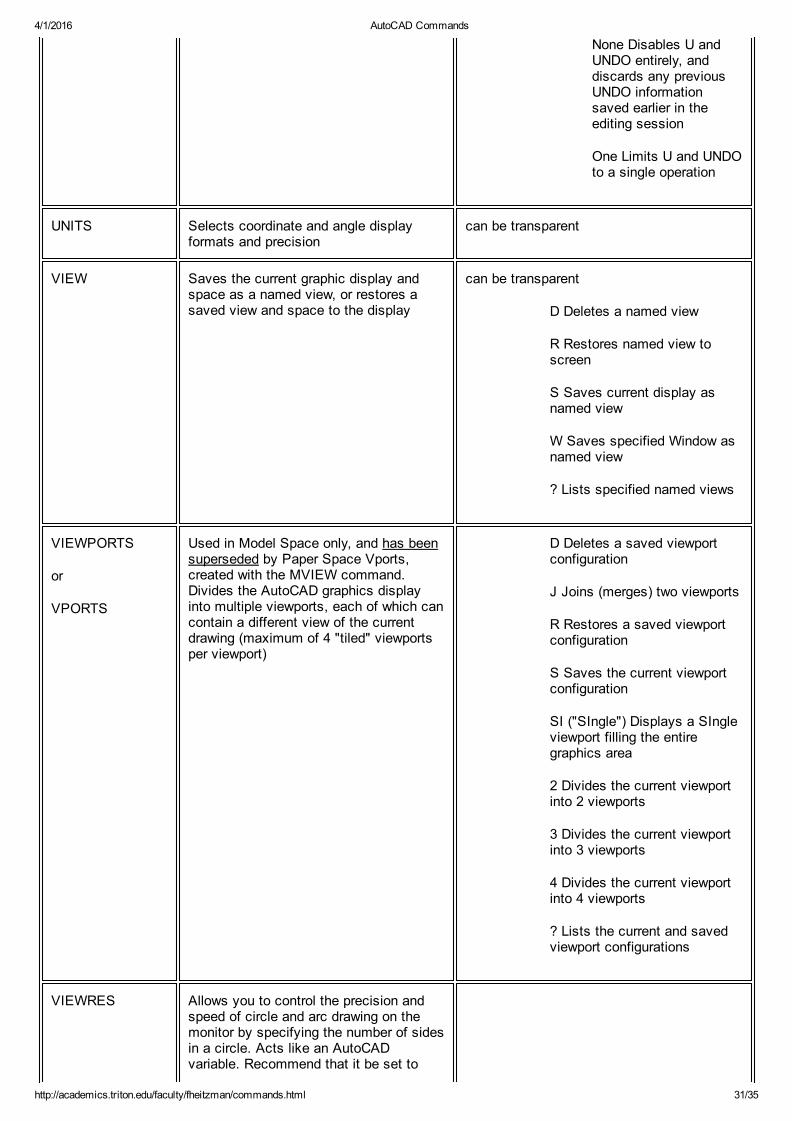
UNITS Selects coordinate and angle displayformats and precision
can be transparent
VIEW Saves the current graphic display andspace as a named view, or restores asaved view and space to the display
can be transparent
D Deletes a named view
R Restores named view toscreen
S Saves current display asnamed view
W Saves specified Window asnamed view
? Lists specified named views
VIEWPORTS
or
VPORTS
Used in Model Space only, and has beensuperseded by Paper Space Vports,created with the MVIEW command.Divides the AutoCAD graphics displayinto multiple viewports, each of which cancontain a different view of the currentdrawing (maximum of 4 "tiled" viewportsper viewport)
D Deletes a saved viewportconfiguration
J Joins (merges) two viewports
R Restores a saved viewportconfiguration
S Saves the current viewportconfiguration
SI ("SIngle") Displays a SIngleviewport filling the entiregraphics area
2 Divides the current viewportinto 2 viewports
3 Divides the current viewportinto 3 viewports
4 Divides the current viewportinto 4 viewports
? Lists the current and savedviewport configurations
VIEWRES Allows you to control the precision andspeed of circle and arc drawing on themonitor by specifying the number of sidesin a circle. Acts like an AutoCADvariable. Recommend that it be set to

4/1/2016 AutoCAD Commands
http://academics.triton.edu/faculty/fheitzman/commands.html 32/35
2000.
VPLAYER Sets viewport visibility for new andexisting layers
? Lists layers frozen in aselected viewport
F ("Freeze") Freezes specifiedlayers in selected viewports
T ("Thaw") Thaws specifiedlayers in selected viewports
R ("Reset") Resets specifiedlayers to their default visibility
N ("Newfrz") Creates newlayers that are frozen in allviewports
V ("Vpvisdflt") Sets the defaultviewport visibility for existinglayers
VPOINT Selects the viewpoint for a 3Dvisualization
R Selects viewpoint viatwo rotation angles
<RET> Selectsviewpoint via a graphiccompass and axis tripodwhich appears on thescreen
<x,y,z> Specifies x, y,and z relativecoordinates of viewpoint
VSLIDE Displays a previously created slide file <filename> viewsslide with nameof "filename.SLD"
*filenamepreloads slidewhich the nextcommandVSLIDE will view
WBLOCK Writes selected entities or previouslycreated Block to a drawing file
<filename> writesspecified entities to"filename.DWG"
= filename.DWG to becreated is same as theentities included in apreviously defined Blockby the same name
* writes entire drawing tothe filename.DWG andpurges all unreferencedblocks, layers,linetypes, text and
4/1/2016 AutoCAD Commands
http://academics.triton.edu/faculty/fheitzman/commands.html 33/35
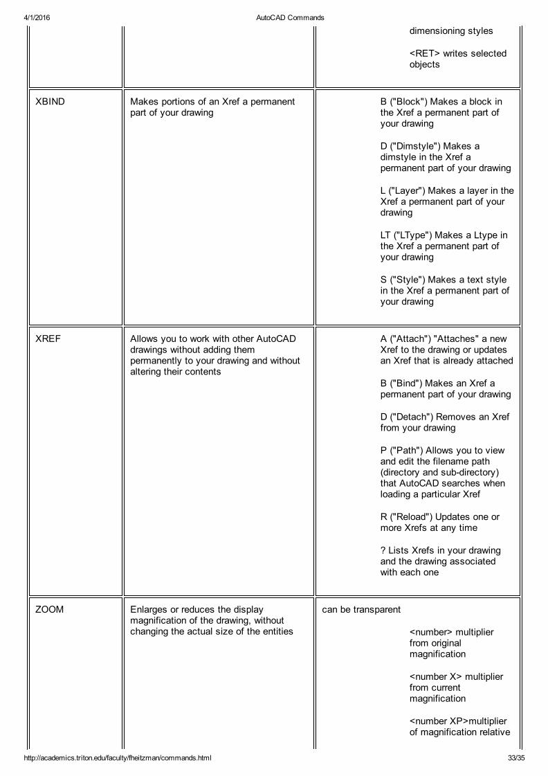
dimensioning styles
<RET> writes selectedobjects
XBIND Makes portions of an Xref a permanentpart of your drawing
B ("Block") Makes a block inthe Xref a permanent part ofyour drawing
D ("Dimstyle") Makes adimstyle in the Xref apermanent part of your drawing
L ("Layer") Makes a layer in theXref a permanent part of yourdrawing
LT ("LType") Makes a Ltype inthe Xref a permanent part ofyour drawing
S ("Style") Makes a text stylein the Xref a permanent part ofyour drawing
XREF Allows you to work with other AutoCADdrawings without adding thempermanently to your drawing and withoutaltering their contents
A ("Attach") "Attaches" a newXref to the drawing or updatesan Xref that is already attached
B ("Bind") Makes an Xref apermanent part of your drawing
D ("Detach") Removes an Xreffrom your drawing
P ("Path") Allows you to viewand edit the filename path(directory and subdirectory)that AutoCAD searches whenloading a particular Xref
R ("Reload") Updates one ormore Xrefs at any time
? Lists Xrefs in your drawingand the drawing associatedwith each one
ZOOM Enlarges or reduces the displaymagnification of the drawing, withoutchanging the actual size of the entities
can be transparent
<number> multiplierfrom originalmagnification
<number X> multiplierfrom currentmagnification
<number XP>multiplierof magnification relative
4/1/2016 AutoCAD Commands
http://academics.triton.edu/faculty/fheitzman/commands.html 34/35
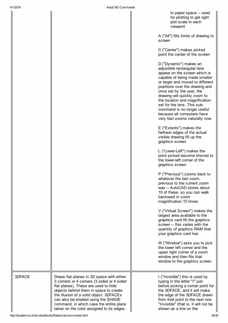
to paper space usedfor plotting to get rightplot scale in eachviewport
A ("All") fills limits of drawing toscreen
C ("Center") makes pickedpoint the center of the screen
D ("Dynamic") makes anadjustible rectangular lensappear on the screen which iscapable of being made smalleror larger and moved to differentpositions over the drawing andonce set by the user, thedrawing will quickly zoom tothe location and magnificationset for the lens. This subcommand is no longer usefulbecause all computers havevery fast zooms naturally now.
E ("Extents") makes thefarthest edges of the actualvisible drawing fill up thegraphics screen
L ("LowerLeft") makes thepoint picked become shoved tothe lowerleft corner of thegraphics screen
P ("Previous") zooms back towhatever the last zoom,previous to the current zoomwas AutoCAD stores about10 of these, so you can walkbackward in zoommagnification 10 times
V ("Virtual Screen") makes thelargest area available to thegraphics card fill the graphicsscreen this varies with thequantity of graphics RAM thatyour graphics card has
W ("Window") asks you to pickthe lower left corner and theupper right corner of a zoomwindow and then fits thatwindow to the graphics screen
3DFACE Draws flat planes in 3D space with either3 corners or 4 corners (3 sided or 4 sidedflat planes). These are used to hideobjects behind them in space to createthe illusion of a solid object. 3DFACEscan also be shaded using the SHADEcommand, in which case the entire planetakes on the color assigned to its edges.
I ("Invisible") this is used bytyping in the letter "I" justbefore picking a corner point forthe 3DFACE, and it will makethe edge of the 3DFACE drawnfrom that point to the next one"Invisible" (that is, it will not beshown as a line on the
4/1/2016 AutoCAD Commands
http://academics.triton.edu/faculty/fheitzman/commands.html 35/35
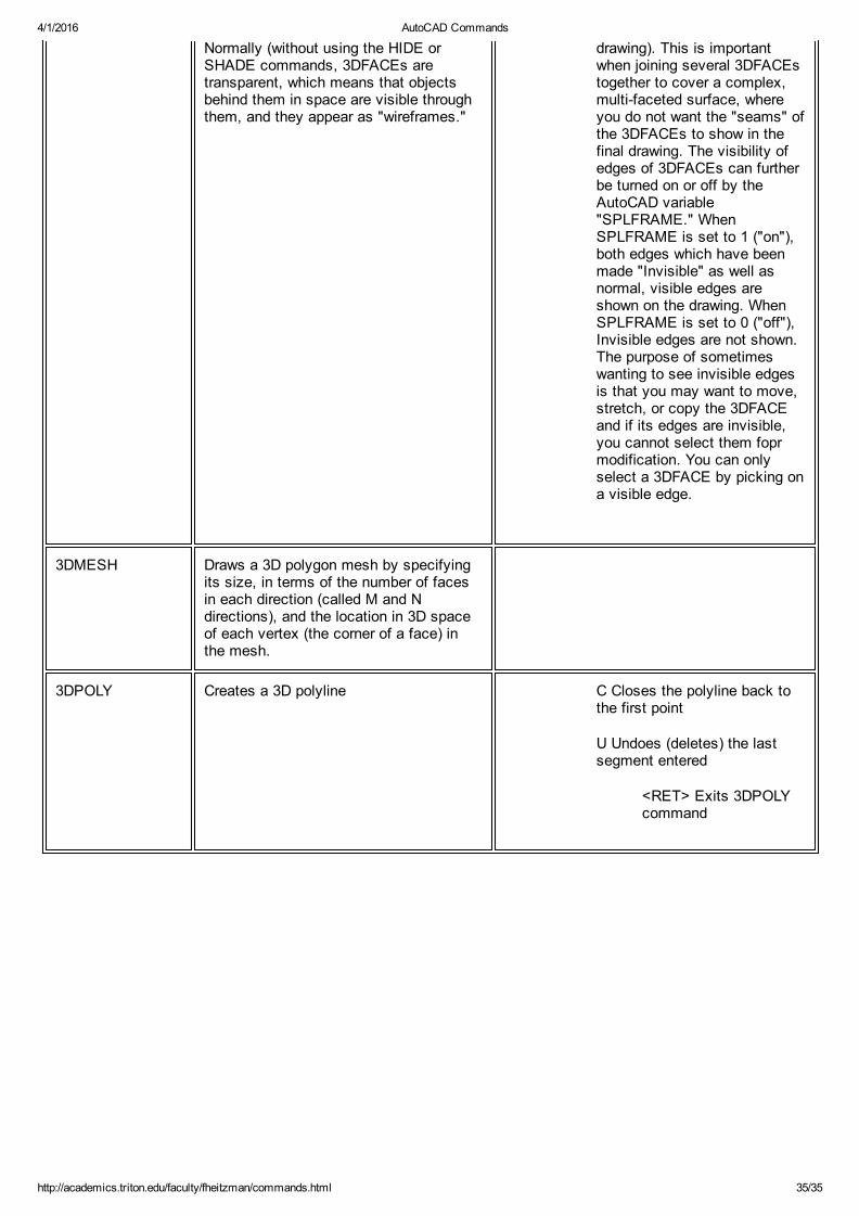
Normally (without using the HIDE orSHADE commands, 3DFACEs aretransparent, which means that objectsbehind them in space are visible throughthem, and they appear as "wireframes."
drawing). This is importantwhen joining several 3DFACEstogether to cover a complex,multifaceted surface, whereyou do not want the "seams" ofthe 3DFACEs to show in thefinal drawing. The visibility ofedges of 3DFACEs can furtherbe turned on or off by theAutoCAD variable"SPLFRAME." WhenSPLFRAME is set to 1 ("on"),both edges which have beenmade "Invisible" as well asnormal, visible edges areshown on the drawing. WhenSPLFRAME is set to 0 ("off"),Invisible edges are not shown.The purpose of sometimeswanting to see invisible edgesis that you may want to move,stretch, or copy the 3DFACEand if its edges are invisible,you cannot select them foprmodification. You can onlyselect a 3DFACE by picking ona visible edge.
3DMESH Draws a 3D polygon mesh by specifyingits size, in terms of the number of facesin each direction (called M and Ndirections), and the location in 3D spaceof each vertex (the corner of a face) inthe mesh.
3DPOLY Creates a 3D polyline C Closes the polyline back tothe first point
U Undoes (deletes) the lastsegment entered
<RET> Exits 3DPOLYcommand