
Table It in AutoCAD!
45
1 How Smart Are Your Tables? Jeanne Aarhus – Aarhus Associates, LLC AC2251-L Are you using tables in AutoCAD® software to their fullest potential? Do you still manually collect data from your AutoCAD file, manipulate it in some other application, and import it back into AutoCAD as plain text and linework objects? If so, you must attend this hands-on lab and discover all the possibilities available with tables. Take advantage of their linking and calculation functionality to streamline your data needs. Learn to use AutoCAD to create intelligent tables of data Learn to use the calculation and linking capabilities found in table objects. Learn to import data from other applications into intelligent AutoCAD tables. Learn to link tables to each other for more table data manipulation. About the Speaker: Jeanne is known for keeping her training sessions fast-moving and fun. She is a nationally- known speaker and expert in CAD and presents seminars and workshops on CAD productivity for managers and users in both corporations and colleges. She has more than 25 years of experience in production drafting, user support, standards coordination, programming, and training in various CAD applications. Jeanne is an independent consultant offering training and implementation services and is certified in several Autodesk and Bentley products. She has been a popular speaker at Autodesk University for several years and recently received a “Top Ten Class” award for her presentations at Autodesk University for the past 6 years. [email protected]
-
Upload
khangminh22 -
Category
Documents
-
view
6 -
download
0
Transcript of Table It in AutoCAD!

1
How Smart Are Your Tables? Jeanne Aarhus – Aarhus Associates, LLC
AC2251-L Are you using tables in AutoCAD® software to their fullest potential? Do you still manually collect data from your AutoCAD file, manipulate it in some other application, and import it back into AutoCAD as plain text and linework objects? If so, you must attend this hands-on lab and discover all the possibilities available with tables. Take advantage of their linking and calculation functionality to streamline your data needs.
Learn to use AutoCAD to create intelligent tables of data
Learn to use the calculation and linking capabilities found in table objects.
Learn to import data from other applications into intelligent AutoCAD tables.
Learn to link tables to each other for more table data manipulation.
About the Speaker: Jeanne is known for keeping her training sessions fast-moving and fun. She is a nationally-known speaker and expert in CAD and presents seminars and workshops on CAD productivity for managers and users in both corporations and colleges. She has more than 25 years of experience in production drafting, user support, standards coordination, programming, and training in various CAD applications. Jeanne is an independent consultant offering training and implementation services and is certified in several Autodesk and Bentley products. She has been a popular speaker at Autodesk University for several years and recently received a “Top Ten Class” award for her presentations at Autodesk University for the past 6 years.

Table It in AutoCAD!
2
What is a Table? A table is an object that contains information formatted into rows and columns. A table can be created as an empty table, or using a table style. The information in a table can be input manually, generated from objects in a drawing, extracted from block attributes, or linked to external data stored in a spreadsheet application such as Microsoft Excel®.
The Parts of a Table First, let’s look at the components of a simple table object.
Title
Header
Data
Row
Column
Cell
Gridline
Grips
Title
Header
Data

Table It in AutoCAD!
3
Row
Column
Gridline
Grips There are several grips provided for quick editing of the table graphics. Use the grips shown in the following image to modify the table linework as needed.
1 MOVE table – use this grip to move the entire table to a new location.
2 STRETCH column width – use this grip to widen each individual column.
3 STRETCH table width – use this grip to widen the entire table.
4 STRETCH table size – use this grip to lengthen the height and width of the entire table
simultaneously.
5 BREAK table length – use this grip to break the table into multiple parts (pagination).
6 STRETCH table height – use this grip to increase the table height.

Table It in AutoCAD!
4
Creating a Table Let’s begin by creating a simple table with user defined data.
Where is it?
Ribbon: Use the ANNOTATE ribbon tab to access these commands.
Menu: Draw Table
Toolbar: Draw
Command: TABLE
STEP 1: Select File Open…0-BLANK.DWG
STEP 2: Using the ribbon interface, select the ANNOTATE tab TABLES TABLE tool.
STEP 3: Modify the following table settings for COLUMN AND ROW SETTINGS as shown below. Columns: 3 Data Rows: 5
STEP 4: Pick OK to close the INSERT TABLE dialog.
STEP 5: <Left-Click> anywhere in the drawing to place a blank table in the drawing. The TITLE cell is automatically selected enabling you to enter data.

Table It in AutoCAD!
5
STEP 6: Key-in the value SCHEDULE for the TITLE cell and press <ENTER> to move to the next cell. The second row in the table can be used as either a HEADER row or a DATA ROW, depending on your needs.
STEP 7: Key-in the remaining fields as shown in the image.
Use the <ALT+ENTER> to input a hard line break inside a cell.

Table It in AutoCAD!
6
Modify a Table Next, we want to modify the size of a simple table using “grips”
Modify the Table Size STEP 1: Continue in the file….0-BLANK.DWG
STEP 2: Select the table by picking an “outside” edge. If you selected it as shown below, you will see a “spreadsheet like” appearance with column and row identifiers.
STEP 3: Using the STRETCH TABLE grip, stretch the width of the table as needed.
STEP 4: Using the STRETCH COLUMN grip, modify the width of the middle column.
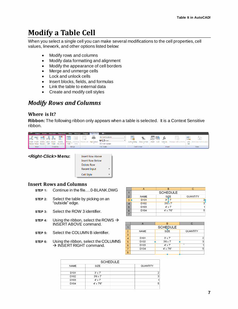
Table It in AutoCAD!
7
Modify a Table Cell When you select a single cell you can make several modifications to the cell properties, cell values, linework, and other options listed below:
Modify rows and columns
Modify data formatting and alignment
Modify the appearance of cell borders Merge and unmerge cells
Lock and unlock cells
Insert blocks, fields, and formulas Link the table to external data
Create and modify cell styles
Modify Rows and Columns
Where is It? Ribbon: The following ribbon only appears when a table is selected. It is a Context Sensitive ribbon.
<Right-Click> Menu:
Insert Rows and Columns STEP 1: Continue in the file….0-BLANK.DWG
STEP 2: Select the table by picking on an “outside” edge.
STEP 3: Select the ROW 3 identifier.
STEP 4: Using the ribbon, select the ROWS INSERT ABOVE command.
STEP 5: Select the COLUMN B identifier.
STEP 6: Using the ribbon, select the COLUMNS INSERT RIGHT command.

Table It in AutoCAD!
8
Delete Rows and Columns STEP 1: Continue in the file….0-BLANK.DWG
STEP 2: Select the table by picking on an “outside” line
STEP 3: Select the ROW 3 identifier.
STEP 4: Using the ribbon, select the ROWS DELETE ROW
command.
STEP 5: Select the COLUMN C identifier.
STEP 6: Using the ribbon, select the COLUMNS DELETE COLUMN command.

Table It in AutoCAD!
9
Modify Data Format and Alignment
Where is it? Ribbon: The following ribbon only appears when a table is selected. It is a Context Sensitive ribbon.
<Right-Click> Menu:
Modify Data Format Use the DATA FORMAT command to modify the cell content to any of the formats listed below.
STEP 1: Continue in the file….0-BLANK.DWG
STEP 2: Select the table by picking on an “outside” edge.
STEP 3: Select the A COLUMN identifier to select the entire A COLUMN.
STEP 4: Using the ribbon, select the CELL FORMAT DATA FORMAT TEXT command.
STEP 5: Repeat these steps to define the following data formats for columns B and C. Column B: General Column C: Whole Number
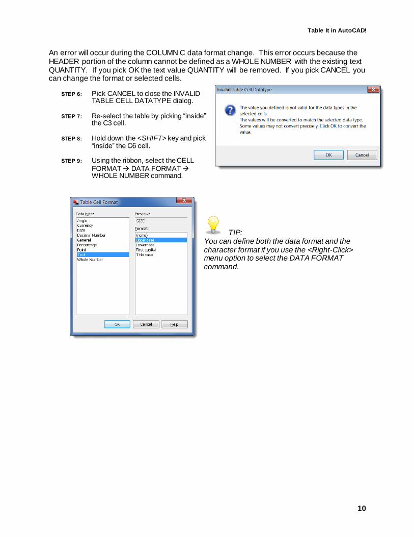
Table It in AutoCAD!
10
An error will occur during the COLUMN C data format change. This error occurs because the HEADER portion of the column cannot be defined as a WHOLE NUMBER with the existing text QUANTITY. If you pick OK the text value QUANTITY will be removed. If you pick CANCEL you can change the format or selected cells.
STEP 6: Pick CANCEL to close the INVALID TABLE CELL DATATYPE dialog.
STEP 7: Re-select the table by picking “inside” the C3 cell.
STEP 8: Hold down the <SHIFT> key and pick “inside” the C6 cell.
STEP 9: Using the ribbon, select the CELL FORMAT DATA FORMAT WHOLE NUMBER command.
TIP: You can define both the data format and the character format if you use the <Right-Click> menu option to select the DATA FORMAT command.

Table It in AutoCAD!
11
Modify Data Alignment STEP 1: continue in the file…0-BLANK.DWG
STEP 2: Select column C by selecting on the COLUMN C identifier.
STEP 3: Using the PROPERTIES palette, modify the CELL ALIGNMENT to MIDDLE CENTER to change the justification of the entire column.
TIP: You can also use the <Right-Click> menu to access the ALIGNMENT command.

Table It in AutoCAD!
12
Modify the Table Linework
Where is it? Ribbon: The following ribbon only appears when a table cell is selected. It is a Context Sensitive ribbon.
<Right-Click> Menu:
Edit Cell Borders Use the EDIT BORDERS command to modify any cell border properties.
1 Define LINEWEIGHT for border linework
2 Define LINETYPE for border linework
3 Define COLOR for border linework
4 Define a DOUBLE-LINE for border linework
5 Define line spacing for Double-Line linework
6 Use the table preview to assign individual border properties. The buttons around the table preview provide quick shortcuts for linework assignments.
TIP: You can remove all cell property modifications using the command REMOVE ALL CELL PROPERTY OVERRIDES available on the <Right-Click> menu.
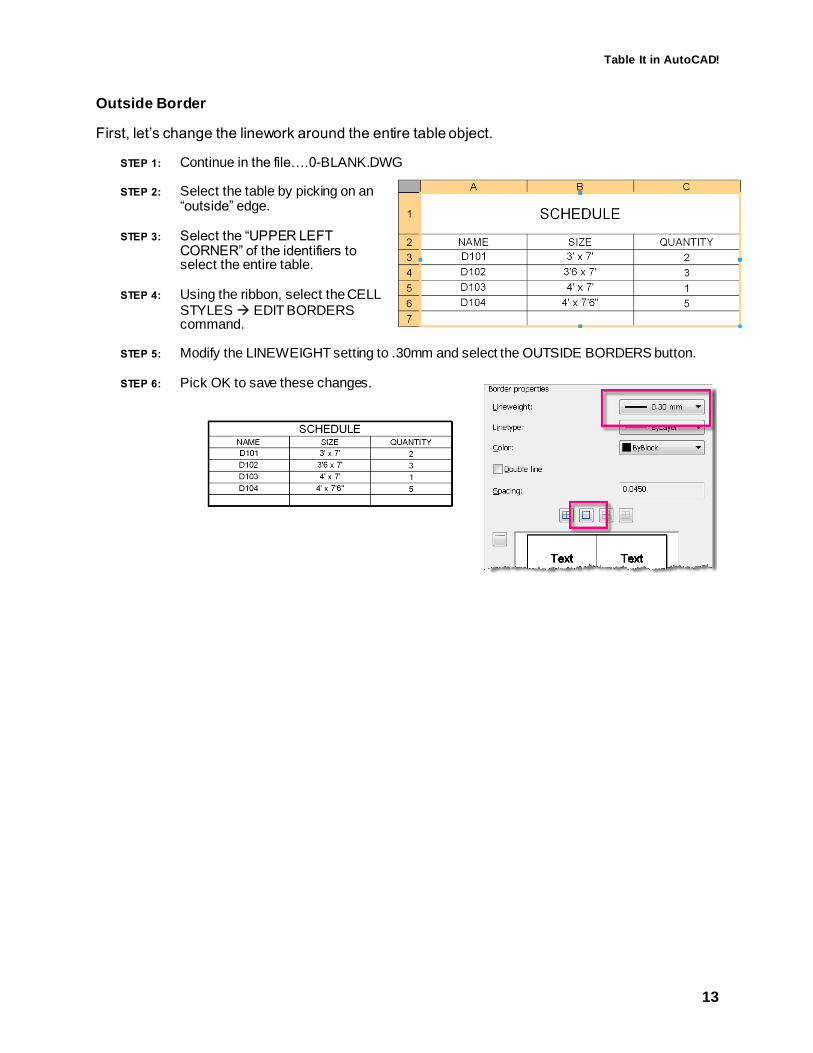
Table It in AutoCAD!
13
Outside Border
First, let’s change the linework around the entire table object.
STEP 1: Continue in the file….0-BLANK.DWG
STEP 2: Select the table by picking on an “outside” edge.
STEP 3: Select the “UPPER LEFT CORNER” of the identifiers to select the entire table.
STEP 4: Using the ribbon, select the CELL STYLES EDIT BORDERS command.
STEP 5: Modify the LINEWEIGHT setting to .30mm and select the OUTSIDE BORDERS button.
STEP 6: Pick OK to save these changes.

Table It in AutoCAD!
14
Title Border
Next, let’s change the linework between the title cell and the data cells.
STEP 1: Continue in the file…0-BLANK.DWG
STEP 2: Select the table by picking “inside” the TITLE cell “SCHEDULE”.
STEP 3: Using the ribbon, select the CELL STYLES EDIT BORDERS command.
STEP 4: TURN ON the DOUBLE LINE setting and define the spacing as 0.0500 and pick the BOTTOM BORDER button
STEP 5: Pick OK to save these changes.
Totals Border
Now, let’s change the linework between the data cells and the last row of cells.
STEP 1: Continue in the file…0-BLANK.DWG
STEP 2: Select the table by picking “inside” the A7 cell.
STEP 3: Hold down the <SHIFT> key and select INSIDE cells B7 and C7. This will select all three cells simultaneously.
STEP 4: Using the ribbon, select the CELL STYLES EDIT BORDERS command.
STEP 5: Modify the LINEWEIGHT setting to .30mm and pick the TOP BORDER button.
STEP 6: Pick OK to save these changes.
TIP: You can access the EDIT BORDERS command using the <Right-Click> menu.

Table It in AutoCAD!
15
Merge Cells for Totals
Where is it? The following ribbon only appears when more than one table cell is selected. It is a Context Sensitive ribbon.
<Right-Click> Menu:
Merge Cells Select more than one cell to activate the MERGE CELLS command. Use the following command options to control the merge type.
Cell Selection Methods
CROSSING – use a CROSSING window to easily select multiple cells.
SHIFT - use the <SHIFT> key to select the first and last cell and all cells in between.
TIP: Use the UNMERGE CELLS command to remove all cell merge overrides.

Table It in AutoCAD!
16
STEP 1: Continue in the file….0-BLANK.DWG
STEP 2: Select the table by picking “inside” the A7 cell.
STEP 3: Hold down the <SHIFT> key and pick “inside” the B7 cell. This will select both cells simultaneously.
STEP 4: Using the ribbon, select the MERGE MERGE CELLS MERGE ALL command.
STEP 5: Key-in the value TOTALS in the newly merged cell A7:B7.
TIP: You can use the <Right-Click> menu to access the MERGE ALL command.

Table It in AutoCAD!
17
Edit Cell Size for Title Use the following grips to modify the size of the cell row or column.
Modify and Populate Cell Values 1 Use this grip to modify the height of
a single row.
2 Use this grip to modify the width of a single cell
3 Use this grip to increment the value of a cell automatically using the following options:
.
STEP 1: Continue in the file….0-BLANK.DWG
STEP 2: Select the table by picking “inside” the TITLE cell.
STEP 3: Select the STRETCH grip at the top of the TITLE cell and drag it up to increase the height of the cell.

Table It in AutoCAD!
18
Cell Background Fills
Where is it? The following ribbon only appears when more than one table cell is selected. It is a Context Sensitive ribbon.
<Right-Click> Menu:
Add Background Fill STEP 1: Continue in the file….0-BLANK.DWG
STEP 2: Select the table by picking “inside” the TITLE cell.
STEP 3: Use the ribbon to access the CELL STYLES TABLE CELL BACKGROUND COLOR command.
STEP 4: Select the table by picking “inside” the cell A7:B7.
STEP 5: Use the ribbon to access the CELL STYLES TABLE CELL BACKGROUND COLOR command.
TIP: Use the <Right-Click> menu to access the BACKGROUND FILL command.

Table It in AutoCAD!
19
Copy and Increment Cell Data STEP 1: Select File Open…..1-SIMPLE TABLE.DWG
STEP 2: Select the table by picking “inside” the A3 cell.
STEP 3: Select the AUTO-INCREMENT grip and drag it to the bottom of the A COLUMN. This will COPY the value of the A3 cell to all cells in the A COLUMN.
STEP 4: Select the table by picking “inside” the B3 cell.
STEP 5: Select the AUTO-INCREMENT grip and drag it to the bottom of the B COLUMN. This will COPY AND INCREMENT the value of the B3 cell to all cells in the B COLUMN.
Why are they different? The INCREMENT AND COPY command only increments the value if the data format is defined as DECIMAL NUMBER, ANGLE, PERCENTAGE, and CURRENCY. All other data formats perform the COPY command.
You can avoid the increment of number fields using the following steps:
STEP 1: Select the table by selecting INSIDE the C3 cell.
STEP 2: Select the AUTO-INCREMENT grip and <Right-Click> to access the command options
STEP 3: Select COPY CELLS and drag the grip to the bottom of the C COLUMN. This will COPY the value of the B3 cell (no increment) to all cells in the C COLUMN.
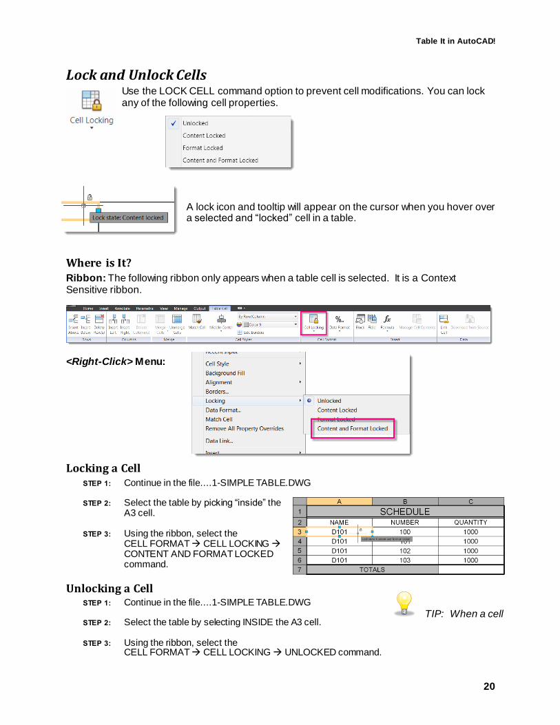
Table It in AutoCAD!
20
Lock and Unlock Cells Use the LOCK CELL command option to prevent cell modifications. You can lock any of the following cell properties.
A lock icon and tooltip will appear on the cursor when you hover over a selected and “locked” cell in a table.
Where is It? Ribbon: The following ribbon only appears when a table cell is selected. It is a Context Sensitive ribbon.
<Right-Click> Menu:
Locking a Cell STEP 1: Continue in the file....1-SIMPLE TABLE.DWG
STEP 2: Select the table by picking “inside” the A3 cell.
STEP 3: Using the ribbon, select the CELL FORMAT CELL LOCKING CONTENT AND FORMAT LOCKED command.
Unlocking a Cell STEP 1: Continue in the file....1-SIMPLE TABLE.DWG
STEP 2: Select the table by selecting INSIDE the A3 cell.
STEP 3: Using the ribbon, select the CELL FORMAT CELL LOCKING UNLOCKED command.
TIP: When a cell

Table It in AutoCAD!
21
Insert Blocks, Fields and Formulas You can insert a block into a table cell to create a Legend or Symbol table for your project. The size and appearance of the block can be set automatically or defined manually. Multiple blocks can be inserted using the Manage Cell Content dialog which can be accessed using the <Right-Click> menu with a cell selected.
TIP: The MANAGE CELL command is only available when there are two or more items inserted in a single cell.
Insert Blocks
Where is It? Ribbon: The following ribbon only appears when a table cell is selected. It is a Context Sensitive ribbon.
<Right-Click> Menu:
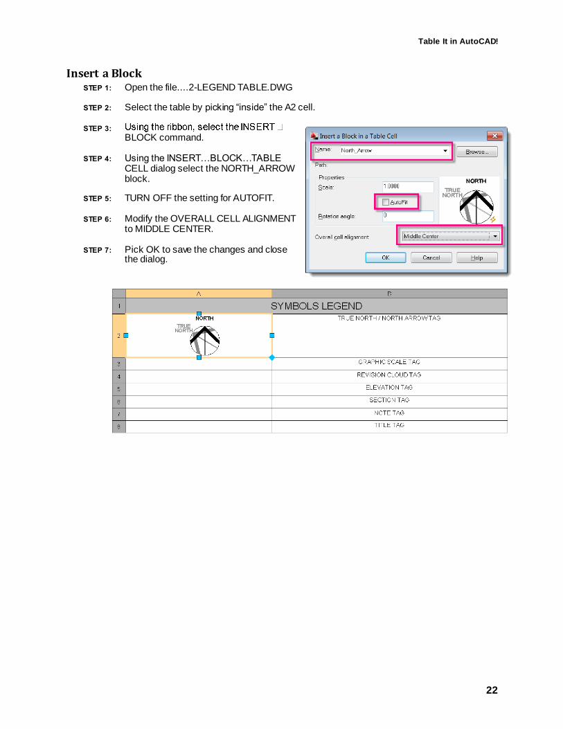
Table It in AutoCAD!
22
Insert a Block STEP 1: Open the file....2-LEGEND TABLE.DWG
STEP 2: Select the table by picking “inside” the A2 cell.
STEP 3:
BLOCK command.
STEP 4: Using the INSERT…BLOCK…TABLE CELL dialog select the NORTH_ARROW block.
STEP 5: TURN OFF the setting for AUTOFIT.
STEP 6: Modify the OVERALL CELL ALIGNMENT to MIDDLE CENTER.
STEP 7: Pick OK to save the changes and close the dialog.

Table It in AutoCAD!
23
Insert Fields
Where is It? Ribbon: The following ribbon only appears when a table cell is selected. It is a Context Sensitive ribbon.
<Right-Click> Menu:
Insert a Field For this exercise we will populate a table cell with a field that retrieves its value from the length of a piece of rebar.
STEP 1: Open the file....3-TABLE FIELDS-FORMULAS.DWG
STEP 2: Select the table by selecting INSIDE the C5 cell.
STEP 3: Using the ribbon, select the INSERT FIELD command.

Table It in AutoCAD!
24
STEP 4: Using the FIELD dialog define the following settings: Field Category: Objects Field Names: Object
STEP 5: Select the PICK OBJECT button for the OBJECT TYPE and select the RED REBAR (501)
STEP 6: Using the FIELD dialog define the remaining settings: Property: Length Format: Architectural
STEP 7: Pick OK to save these changes and close the dialog.
STEP 8: Press <ENTER> to complete the command
The table cell is populated with the 2’-0” length from the selected rebar in the drawing.
STEP 9: Modify the length of the 501 REBAR.
STEP 10: Key-in REGEN to force the FIELD objects in the table to update.

Table It in AutoCAD!
25
You can control the update methods for fields using the following system variable.
FIELDEVAL
Controls how fields are updated.
0 Not updated
1 Updated on open
2 Updated on save
4 Updated on plot
8 Updated on use of ETRANSMIT
16 Updated on regeneration.
Default 31 All of the above
TIP: You can update any individual FIELD object(s) using the UPDATEFIELD command and selecting objects.
Where is It?
Ribbon: The following ribbon only appears when a table cell is selected. It is a Context Sensitive ribbon.
Menu: Tools Update Fields
Command: UPDATEFIELD
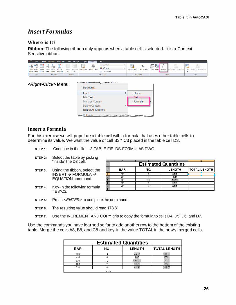
Table It in AutoCAD!
26
Insert Formulas
Where is It? Ribbon: The following ribbon only appears when a table cell is selected. It is a Context Sensitive ribbon.
<Right-Click> Menu:
Insert a Formula
For this exercise we will populate a table cell with a formula that uses other table cells to determine its value. We want the value of cell B3 * C3 placed in the table cell D3.
STEP 1: Continue in the file....3-TABLE FIELDS-FORMULAS.DWG
STEP 2: Select the table by picking “inside” the D3 cell.
STEP 3: Using the ribbon, select the INSERT FORMULA EQUATION command.
STEP 4: Key-in the following formula =B3*C3.
STEP 5: Press <ENTER> to complete the command.
STEP 6: The resulting value should read 178’8”
STEP 7: Use the INCREMENT AND COPY grip to copy the formula to cells D4, D5, D6, and D7.
Use the commands you have learned so far to add another row to the bottom of the existing table. Merge the cells A8, B8, and C8 and key-in the value TOTAL in the newly merged cells.

Table It in AutoCAD!
27
Next, we want to add another formula to calculate the sum total of all rebar lengths.
STEP 1: Select the table INSIDE the cell D8.
STEP 2: Using the ribbon, select the INSERT FORMULA SUM command.
STEP 3: Drag a crossing window across the table cells D3, D4, D5, D6, and D7.
STEP 4: The formula =SUM(D3:D7) is placed in the table cell.
STEP 5: Press <ENTER> to complete the command
The resulting value of 580’-8” is displayed in table cell D8.

Table It in AutoCAD!
28
Using a Table Link A table can be linked to data outside of AutoCAD if it is stored in a Microsoft Excel (XLS, .XLSX, or CSV) file. The table can be linked to an entire spreadsheet, individual row, column, cell, or cell range in Excel.
Linked data can be linked to an AutoCAD table using the following three methods:
1. As formulas with data formats attached
2. As calculations from formulas calculated in Excel (with data formats not attached)
3. As calculations from formulas calculated in Excel (with data formats attached)
A table that contains linked data displays “link indicators” around linked cells. Information about the linked data can be viewed by “hovering” the cursor over the data link “indicators”.

Table It in AutoCAD!
29
Link a Table to Excel For this section we will create a new table that reads block attributes from the active and referenced drawings, and links an attribute value to an external Excel spreadsheet.
STEP 1: Open the file....4-TABLE TO EXCEL LINKING.DWG
STEP 2: Select the desk in the conference room and <Right-Click> to access the EDIT XREF IN PLACE command.
STEP 3: <Double-Click> on the conference room desk to review the associated attributes. We will use the attribute CAPPN to link the attributes to an identical column in the spreadsheet.
STEP 4: Using the ribbon, select EDIT REFERENCE DISCARD CHANGES to return to the original file 4-TABLE TO EXCEL LINKING.DWG

Table It in AutoCAD!
30
Next, we want to use the PART NUMBER (CAPPN) attribute on the furniture blocks to link to the identical column in the Excel spreadsheet. We will also include additional information from the spreadsheet in our table object.
We want to place this table in paperspace, so first we need to toggle to the paperspace environment.
STEP 1: Select the MY LAYOUT tab in the file 4-TABLE TO EXCEL LINKING.DWG
STEP 2: Using the ANNOTATE ribbon, select TABLES TABLE command.
STEP 3: Using the INSERT TABLE dialog, select the setting to create a table FROM OBJECT DATA IN THE DRAWING (DATA EXTRACTION)
STEP 4: Pick the OK button to continue.
STEP 5: Select the option to CREATE A NEW DATA EXTRACTION
STEP 6: Pick NEXT and create the DATA EXTRACTION file (DXE) in the following folder C:\Training\AC2251-L\dwg\FURNITURE.DXE
STEP 7: Pick the SETTINGS button and TURN ON the option for INCLUDE XREFS IN BLOCK COUNTS.
STEP 8: Pick OK to close the ADDITIONAL SETTINGS dialog and to continue.
At this stage you can add additional drawings and folders to be included in the table object.

Table It in AutoCAD!
31
STEP 9: Pick the NEXT button to read all objects from the selected files.
STEP 10: TURN OFF the setting for DISPLAY ALL OBJECT TYPES.
STEP 11: TURN ON the setting for DISPLAY BLOCKS WITH ATTRIBUTES ONLY
STEP 12: Clear the “checkmark” for all blocks not named “P_*”. It may be necessary to re-sort the OBJECT column to enable the ability to “uncheck” the block COLUMN BUBBLE.

Table It in AutoCAD!
32
STEP 13: Pick the NEXT button to continue.
STEP 14: TURN OFF ALL PROPERTIES except CAPPN, and CAPMC.
STEP 15: Clear all CATEGORY FILTERS except ATTRIBUTE.
TIP: You can use a <Right-Click> menu in the dialog to access the UNCHECK ALL and CHECK ALL commands.
STEP 16: Pick the NEXT button to continue.
STEP 17: TURN OFF the setting for SHOW NAME COLUMN (it is duplicated in the spreadsheet data)
STEP 18: Pick the LINK EXTERNAL DATA button.
STEP 19: Pick the LAUNCH DATA LINK MANAGER button.
STEP 20: Select CREATE A NEW EXCEL DATA LINK
STEP 21: Key-in the name FURNITURE and pick OK to create the data link.
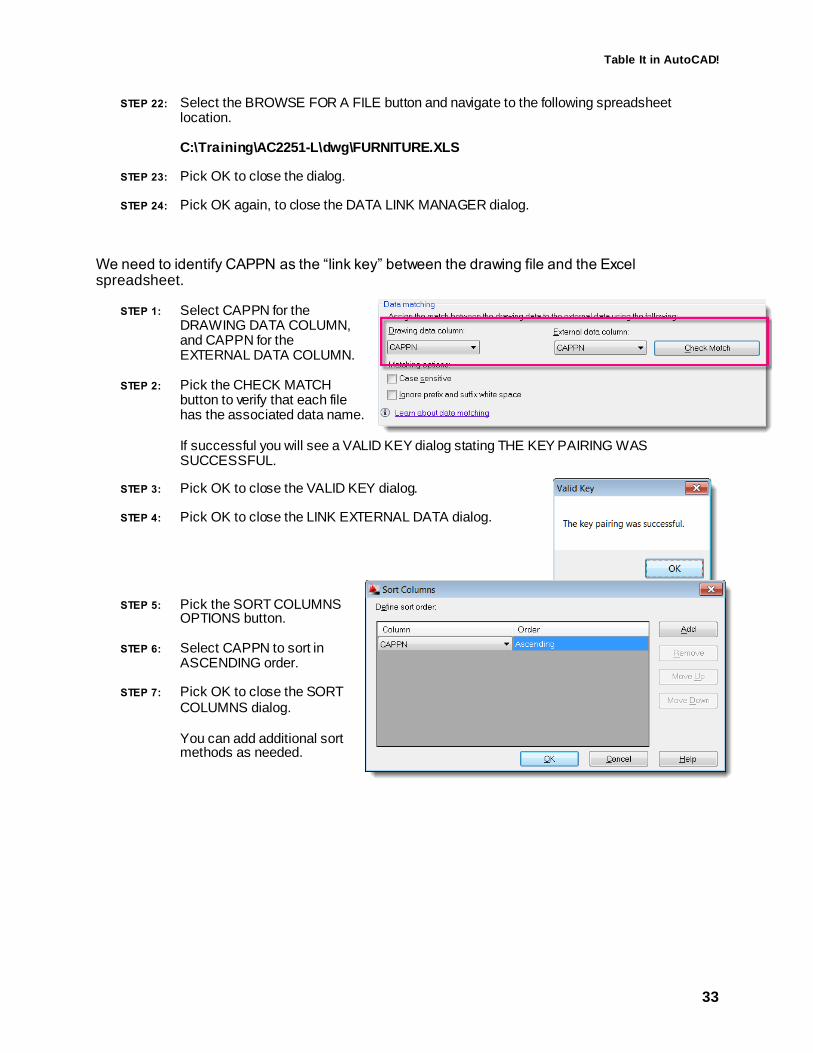
Table It in AutoCAD!
33
STEP 22: Select the BROWSE FOR A FILE button and navigate to the following spreadsheet location. C:\Training\AC2251-L\dwg\FURNITURE.XLS
STEP 23: Pick OK to close the dialog.
STEP 24: Pick OK again, to close the DATA LINK MANAGER dialog.
We need to identify CAPPN as the “link key” between the drawing file and the Excel spreadsheet.
STEP 1: Select CAPPN for the DRAWING DATA COLUMN, and CAPPN for the EXTERNAL DATA COLUMN.
STEP 2: Pick the CHECK MATCH button to verify that each file has the associated data name. If successful you will see a VALID KEY dialog stating THE KEY PAIRING WAS SUCCESSFUL.
STEP 3: Pick OK to close the VALID KEY dialog.
STEP 4: Pick OK to close the LINK EXTERNAL DATA dialog.
STEP 5: Pick the SORT COLUMNS OPTIONS button.
STEP 6: Select CAPPN to sort in ASCENDING order.
STEP 7: Pick OK to close the SORT COLUMNS dialog. You can add additional sort methods as needed.

Table It in AutoCAD!
34
STEP 8: Re-arrange the columns as shown below. Just <Drag-n-Drop> the column headers to the required order. The LINK ICON displays what data is coming from the spreadsheet.
STEP 9: Pick the NEXT button to continue.
TIP: You can rename the “(EXTERNAL)” columns during the extraction process.
STEP 10: TURN ON the setting for INSERT DATA EXTRACTION TABLE INTO DRAWING.
STEP 11: Pick the NEXT button to continue.
STEP 12: Key-in the value FURNITURE SCHEDULE for the title of the new table.
STEP 13: Pick the NEXT button to continue.
STEP 14: Pick the FINISH button to close the dialog and place the table object.
STEP 15: Snap the table object to the location show below:

Table It in AutoCAD!
35
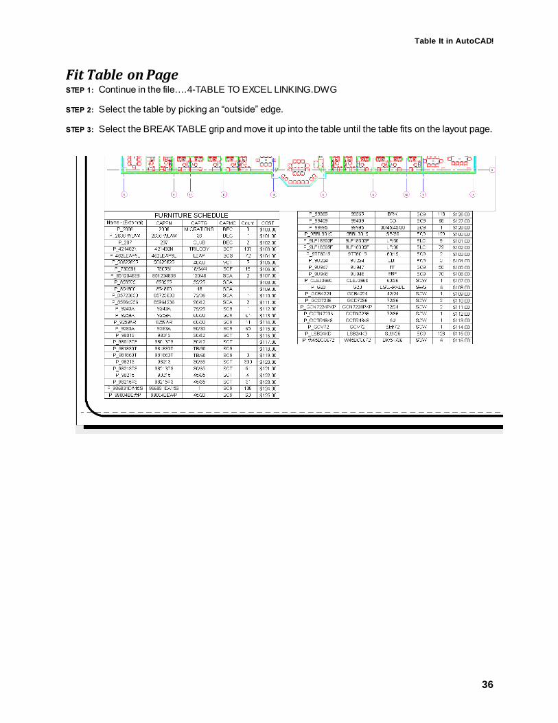
Table It in AutoCAD!
36
Fit Table on Page STEP 1: Continue in the file….4-TABLE TO EXCEL LINKING.DWG
STEP 2: Select the table by picking an “outside” edge.
STEP 3: Select the BREAK TABLE grip and move it up into the table until the table fits on the layout page.

Table It in AutoCAD!
37
Repeat Title Labels STEP 1: Continue in the file….4-TABLE TO EXCEL LINKING.DWG
STEP 2: Select the table by picking an “outside” edge.
STEP 3: Using the PROPERTIES palette, modify the TABLE BREAKS REPEAT TOP LABELS to YES.

Table It in AutoCAD!
38
Break a Table into Parts STEP 1: Continue in the file….4-TABLE TO EXCEL LINKING.DWG
STEP 2: Select the table by picking an “outside” edge.
STEP 3: Using the PROPERTIES palette, modify the TABLE BREAKS MANUAL POSITIONS to YES.

Table It in AutoCAD!
39
Update a Table Link
Where is It? Ribbon: Select the INSERT TAB.
<Right-Click> Menu:
STEP 1: Continue in the file …. 4-TABLE TO EXCEL LINKING.DWG
STEP 2: Select the table by picking an “outside” edge.
STEP 3: Using the INSERT ribbon to select the LINKING & EXTRACTION à DOWNLOAD FROM SOURCE command.
NOTE: A linked table cell is locked to prevent inadvertent changes from taking
place. You can unlock a data link using the UNLOCK command.
Remove a Link to an External Spreadsheet STEP 1: Continue if file….4-TABLE TO EXCEL LINKING.DWG
STEP 2: Select the table and <Right-Click> to access the DETACH DATA LINK command.
TIP: If the table for the data link no longer exists you can try to detach it using the External References palette. If this is unsuccessful, I recommend downloading a LISP routine called DICTEDIT.LSP and using that to detach the “stuck” data links. Use this LISP routine at your own risk! I have used it with no problems, however, I am not responsible for any issues that arise from your use!

Table It in AutoCAD!
40
Link a Table to Another Table You can also link a cell in one table to a cell in another table using the following technique.
STEP 1: Select File Open….5-TABLE TO TABLE LINKING.DWG
STEP 2: Select the table REBAR TOTAL COSTS by picking “inside” the E3 cell.
STEP 3: <Right-Click> to access the INSERT FIELD command.
STEP 4: Using the FIELD dialog, select FIELD NAME FORMULA
STEP 5: Pick the CELL button.
STEP 6: Pick “inside” the C5 cell in the ESTIMATED QUANTITIES table.
STEP 7: Modify the format and select FORMAT DECIMAL for the cell in the table REBAR TOTAL COSTS.

Table It in AutoCAD!
41
Using Table Styles Table Styles allow you to define parameters to control the format and appearance of commonly used drawing tables. Because tables are not yet annotative, you may also want to define text sizes for the appropriate scales for your drawings.
TIP: I recommend placing all tables in paperspace; then you don’t have to worry about drawing scale and the table styles are always defined at 1:1.
Table Settings 1 Used to specify an existing table in a drawing to use
as a “template” for a new table style.
2 Select the direction of the table either DOWN or UP. This determines if the Title is on
top or bottom of table layout.
3 Displays a preview of the table using the current table style settings.
General Tab
1 Define the background color of a cell. The default is NONE.
2 Define the cell justification of the table cell. The
default is TOP CENTER.
3 Define the data type format of the table cell.
4 Define the usage type of a cell; either DATA or
LABEL
5 Define the interior margins between the cell data
and borders.
6 Control if cell will automatically merge during
creation of new rows and columns.
7 Preview of cell style settings.

Table It in AutoCAD!
42
Text Tab 1 Define the text style used in the cell style.
2 Define the text height used in the cell style.
3 Define the text color used in the cell style.
4 Define the text angle used in the cell style.
5 Open the Text Style dialog to define or modify a
text style.
Borders Tab 1 Define the lineweight for border linework.
2 Define the linetype for border linework.
3 Define the color for border linework.
4 Define a Double-Line appearance for border
linework.
5 Define the spacing applied to the Double-Line
linework.
6 Apply defined linework to selected border
linework.
Using Table Styles
From Scratch STEP 1: Select File Open….6-TABLE STYLES.DWG
STEP 2: Using the ribbon, select the ANNOTATE TAB
STEP 3: Select the TABLE STYLE… command from the TABLES PANEL. You can use the PANEL DIALOG BOX LAUNCHER to access the TABLE STYLE… command
STEP 4: Select the table style and pick the MODIFY button.
STEP 5: Use the INSERT TABLE dialog to define the specifics for a table style.
From an Existing Table
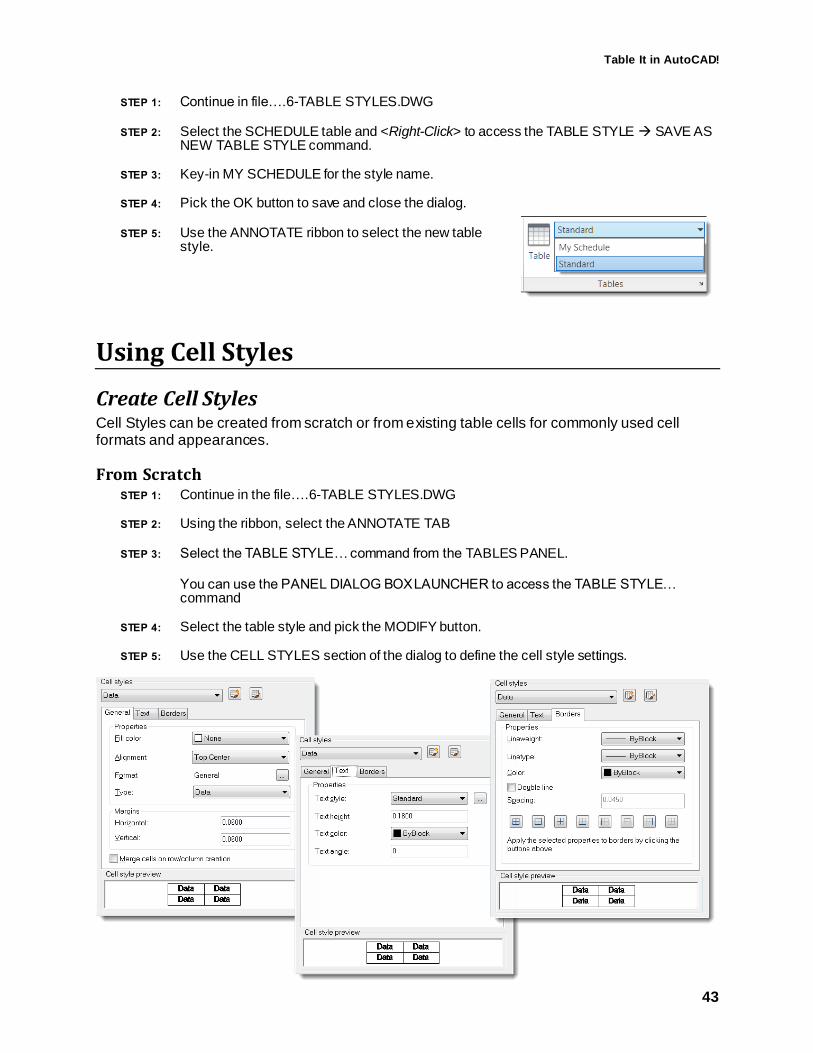
Table It in AutoCAD!
43
STEP 1: Continue in file….6-TABLE STYLES.DWG
STEP 2: Select the SCHEDULE table and <Right-Click> to access the TABLE STYLE SAVE AS NEW TABLE STYLE command.
STEP 3: Key-in MY SCHEDULE for the style name.
STEP 4: Pick the OK button to save and close the dialog.
STEP 5: Use the ANNOTATE ribbon to select the new table style.
Using Cell Styles
Create Cell Styles Cell Styles can be created from scratch or from existing table cells for commonly used cell formats and appearances.
From Scratch STEP 1: Continue in the file….6-TABLE STYLES.DWG
STEP 2: Using the ribbon, select the ANNOTATE TAB
STEP 3: Select the TABLE STYLE… command from the TABLES PANEL. You can use the PANEL DIALOG BOX LAUNCHER to access the TABLE STYLE… command
STEP 4: Select the table style and pick the MODIFY button.
STEP 5: Use the CELL STYLES section of the dialog to define the cell style settings.

Table It in AutoCAD!
44
From an Existing Cell STEP 6: Continue in file….6-TABLE STYLES.DWG
STEP 7: Select a cell and <Right-Click> to access the Cell Style Save as New Cell Style… command.
STEP 8: Key-in LEGEND TITLE for the style name.
STEP 9: Pick the OK button to save and close the dialog.
Placing Tables on a Tool Palette Once you have standard tables created, you will want to place them on your tool palettes. By default, you cannot add a table to a tool palette in the “normal” way. However, if you use this tip you can add tables to tool palettes.
Use the <SHIFT> key to place a table on a tool palette.
If you want to pre-define tables with headers and data, make the table into a block and place the block on the tool palette. When you define the properties of the tool on the tool palette; set the EXPLODE option to YES.

Table It in AutoCAD!
45
That's probably more than I have time for….but hopefully
not more that you wanted to know!
Thank you for your time Hope you enjoyed the session!
Looking for customized Training and Standards consulting using your company standards and procedures?
Call for affordable and flexible rates and schedules.
Contact:
AARHUS ASSOCIATES, LLC 12005 Quail Drive
Bellevue, NE 68123-1175 www.aarhusassociates.com
Jeanne Aarhus (402) 408-9696
Copyright © 2012 Aarhus Associates, LLC. Aarhus Associates and the Aarhus Associates Logo are registered trademarks of Aarhus Associates. All other product names are trademarks of their respective owners. Aarhus Associates believes the informati on in this document is accurate as
of its publication date. Such information is subject to change without notice and is subject to applicable technical product descriptions. Aarhus Associates is not responsible for inadvertent errors.
ASSOCIATES
aarhus
![AutoCAD Crack Free Registration Code 2022 [New]](https://static.fdokumen.com/doc/165x107/633ddc36d497af1eca0ff28c/autocad-crack-free-registration-code-2022-new.jpg)