AutoCAD 2005 for Dummies - X-Files
435
-
Upload
khangminh22 -
Category
Documents
-
view
0 -
download
0
Transcript of AutoCAD 2005 for Dummies - X-Files

by Mark Middlebrook
AutoCAD® 2005FOR
DUMmIES‰
571389 FM.qxd 4/13/04 3:53 PM Page iii

571389 FM.qxd 4/13/04 3:53 PM Page ii
AutoCAD® 2005FOR
DUMmIES‰
571389 FM.qxd 4/13/04 3:53 PM Page i

571389 FM.qxd 4/13/04 3:53 PM Page ii

by Mark Middlebrook
AutoCAD® 2005FOR
DUMmIES‰
571389 FM.qxd 4/13/04 3:53 PM Page iii

AutoCAD® 2005 For Dummies®
Published byWiley Publishing, Inc.111 River StreetHoboken, NJ 07030-5774
Copyright © 2004 by Wiley Publishing, Inc., Indianapolis, Indiana
Published by Wiley Publishing, Inc., Indianapolis, Indiana
Published simultaneously in Canada
No part of this publication may be reproduced, stored in a retrieval system or transmitted in any formor by any means, electronic, mechanical, photocopying, recording, scanning or otherwise, except as per-mitted under Sections 107 or 108 of the 1976 United States Copyright Act, without either the prior writtenpermission of the Publisher, or authorization through payment of the appropriate per-copy fee to theCopyright Clearance Center, 222 Rosewood Drive, Danvers, MA 01923, (978) 750-8400, fax (978) 646-8600.Requests to the Publisher for permission should be addressed to the Legal Department, Wiley Publishing,Inc., 10475 Crosspoint Blvd., Indianapolis, IN 46256, (317) 572-3447, fax (317) 572-4447, e-mail:[email protected].
Trademarks: Wiley, the Wiley Publishing logo, For Dummies, the Dummies Man logo, A Reference for theRest of Us!, The Dummies Way, Dummies Daily, The Fun and Easy Way, Dummies.com, and related tradedress are trademarks or registered trademarks of John Wiley & Sons, Inc. and/or its affiliates in the UnitedStates and other countries, and may not be used without written permission. AutoCAD is a registeredtrademark of Autodesk, Inc. All other trademarks are the property of their respective owners. WileyPublishing, Inc., is not associated with any product or vendor mentioned in this book.
LIMIT OF LIABILITY/DISCLAIMER OF WARRANTY: THE PUBLISHER AND THE AUTHOR MAKE NO REP-RESENTATIONS OR WARRANTIES WITH RESPECT TO THE ACCURACY OR COMPLETENESS OF THECONTENTS OF THIS WORK AND SPECIFICALLY DISCLAIM ALL WARRANTIES, INCLUDING WITHOUTLIMITATION WARRANTIES OF FITNESS FOR A PARTICULAR PURPOSE. NO WARRANTY MAY BE CRE-ATED OR EXTENDED BY SALES OR PROMOTIONAL MATERIALS. THE ADVICE AND STRATEGIES CON-TAINED HEREIN MAY NOT BE SUITABLE FOR EVERY SITUATION. THIS WORK IS SOLD WITH THEUNDERSTANDING THAT THE PUBLISHER IS NOT ENGAGED IN RENDERING LEGAL, ACCOUNTING, OROTHER PROFESSIONAL SERVICES. IF PROFESSIONAL ASSISTANCE IS REQUIRED, THE SERVICES OF ACOMPETENT PROFESSIONAL PERSON SHOULD BE SOUGHT. NEITHER THE PUBLISHER NOR THEAUTHOR SHALL BE LIABLE FOR DAMAGES ARISING HEREFROM. THE FACT THAT AN ORGANIZATIONOR WEBSITE IS REFERRED TO IN THIS WORK AS A CITATION AND/OR A POTENTIAL SOURCE OF FUR-THER INFORMATION DOES NOT MEAN THAT THE AUTHOR OR THE PUBLISHER ENDORSES THE INFOR-MATION THE ORGANIZATION OR WEBSITE MAY PROVIDE OR RECOMMENDATIONS IT MAY MAKE.FURTHER, READERS SHOULD BE AWARE THAT INTERNET WEBSITES LISTED IN THIS WORK MAY HAVECHANGED OR DISAPPEARED BETWEEN WHEN THIS WORK WAS WRITTEN AND WHEN IT IS READ.
For general information on our other products and services or to obtain technical support, please contactour Customer Care Department within the U.S. at 800-762-2974, outside the U.S. at 317-572-3993, or fax317-572-4002.
Wiley also publishes its books in a variety of electronic formats. Some content that appears in print maynot be available in electronic books.
Library of Congress Control Number: 2004102367
ISBN: 0-7645-7138-9
Manufactured in the United States of America
10 9 8 7 6 5 4 3 2 1
1O/SY/QU/QU/IN
571389 FM.qxd 4/13/04 3:53 PM Page iv

About the AuthorMark Middlebrook used to be an engineer but gave it up when he discoveredthat he couldn’t handle a real job. He is now principal of Daedalus Consulting,an independent CAD and computer consulting company in Oakland, California.(In case you wondered, Daedalus was the guy in ancient Greek legend whobuilt the labyrinth on Crete. Mark named his company after Daedalus beforehe realized that few of his clients would be able to pronounce it and evenfewer spell it.) Mark is also a contributing editor for CADALYST magazineand Webmaster of markcad.com. When he’s not busy being a cad, Mark sellsand writes about wine for Paul Marcus Wines in Oakland. He also teachesliterature and philosophy classes at St. Mary’s College of California — hence“Daedalus.” AutoCAD 2005 For Dummies is his sixth book on AutoCAD.
571389 FM.qxd 4/13/04 3:53 PM Page v

571389 FM.qxd 4/13/04 3:53 PM Page vi

DedicationTo Puck and Pretzel, two absolute AutoCAD dummies who never cease toinspire and amuse. It was during walks in the woods with them that I origi-nally worked out some of the details of these chapters. I’m pretty sure thatPuck could learn AutoCAD, if only he could figure out how to manipulate amouse. Pretzel, on the other hand, is too interested in squirrels to botherwith mice.
Author’s AcknowledgmentsThanks first of all to Bud Smith, who initiated this book five editions ago,brought me in on it along the way, and eventually handed it over to me intoto. I hope that I prove as good a steward as he was a midwife (or is thegender-neutral term “midspouse”?). Terri Varveris again shepherded the pro-ject through the development process; her enthusiasm and infectious energyhave helped make each new edition more than just an obligatory update. Itwas a genuine pleasure to work once again with Christine Berman, whosecombination of patience, persistence, and care make her a model projecteditor. As always, Dave Byrnes carried out his duties as tech editor with skilland verve; his diligence saved me from a few bloopers, and his thoughtfulsuggestions helped make the book perceptibly better,
571389 FM.qxd 4/13/04 3:53 PM Page vii

Publisher’s AcknowledgmentsWe’re proud of this book; please send us your comments through our online registration formlocated at www.dummies.com/register/.
Some of the people who helped bring this book to market include the following:
Acquisitions, Editorial, andMedia Development
Project Editor: Christine Berman
Acquisitions Editor: Terri Varveris
Copy Editor: Christine Berman
Technical Editor: David Byrnes
Editorial Manager: Carol Sheehan
Media Development Supervisor:Richard Graves
Editorial Assistant: Amanda Foxworth
Cartoons: Rich Tennant(www.the5thwave.com)
Production
Project Coordinator: Courtney MacIntyre
Layout and Graphics: Amanda Carter,Andrea Dahl, Lauren Goddard,Denny Hager, Michael Kruzil,Jacque Schneider, Melanee Wolven
Proofreaders: Laura Albert, Andy Hollandbeck,Carl Pierce, Brian H. Walls,TECHBOOKS Production Services
Indexer: TECHBOOKS Production Services
Publishing and Editorial for Technology Dummies
Richard Swadley, Vice President and Executive Group Publisher
Andy Cummings, Vice President and Publisher
Mary C. Corder, Editorial Director
Publishing for Consumer Dummies
Diane Graves Steele, Vice President and Publisher
Joyce Pepple, Acquisitions Director
Composition Services
Gerry Fahey, Vice President of Production Services
Debbie Stailey, Director of Composition Services
571389 FM.qxd 4/13/04 3:53 PM Page viii
Contents at a GlanceIntroduction .................................................................1
Part I: AutoCAD 101 ....................................................7Chapter 1: Introducing AutoCAD and AutoCAD LT 2005 ...............................................9Chapter 2: Le Tour de AutoCAD 2005 ............................................................................17Chapter 3: Setup for Success ..........................................................................................41
Part II: Let There Be Lines...........................................71Chapter 4: Get Ready to Draw ........................................................................................73Chapter 5: Where to Draw the Line..............................................................................101Chapter 6: Edit for Credit ..............................................................................................129Chapter 7: A Zoom with a View ....................................................................................167Chapter 8: On a 3D Spree...............................................................................................179
Part III: If Drawings Could Talk.................................203Chapter 9: Text with Character ....................................................................................205Chapter 10: Entering New Dimensions ........................................................................229Chapter 11: Down the Hatch .........................................................................................255Chapter 12: The Plot Thickens .....................................................................................267
Part IV: Share and Share Alike ..................................293Chapter 13: Playing Blocks and Rasteroids ................................................................295Chapter 14: Sheet Sets without Regrets ......................................................................321Chapter 15: CAD Standards Rule ..................................................................................337Chapter 16: Drawing on the Internet............................................................................347
Part V: The Part of Tens ............................................367Chapter 17: Ten Ways to Do No Harm .........................................................................369Chapter 18: Ten Ways to Swap Drawing Data with
Other People and Programs .......................................................................................373
Index .......................................................................383
571389 FM.qxd 4/13/04 3:53 PM Page ix

571389 FM.qxd 4/13/04 3:53 PM Page x
Table of ContentsIntroduction..................................................................1
What’s Not in This Book ...................................................................................1Who Are — and Aren’t — You?........................................................................2How This Book Is Organized............................................................................2
Part I: AutoCAD 101 .................................................................................3Part II: Let There Be Lines ......................................................................3Part III: If Drawings Could Talk...............................................................4Part IV: Share and Share Alike................................................................4Part V: The Part of Tens..........................................................................4
Icons Used in This Book ...................................................................................5A Few Conventions — Just in Case .................................................................5
Part I: AutoCAD 101 ......................................................7
Chapter 1: Introducing AutoCAD and AutoCAD LT 2005 . . . . . . . . . . . . . .9Why AutoCAD?.................................................................................................10The Importance of Being DWG ......................................................................11Seeing the LT ....................................................................................................13Staying Alive with 2005...................................................................................14
Chapter 2 : Le Tour de AutoCAD 2005 . . . . . . . . . . . . . . . . . . . . . . . . . . . .17AutoCAD Does Windows ................................................................................18AutoCAD’s Opening Screen Cuisine ..............................................................19
Standard Windows fare.........................................................................19Looking for Mr. Status Bar ....................................................................23Take an order: The command line area ..............................................26Main course: The drawing area ...........................................................30
A Palette-Cleanser ...........................................................................................33What Really Makes AutoCAD Cook? .............................................................35
Sizzling system variables......................................................................35Delicious dialog boxes ..........................................................................37
Fun with F1 .......................................................................................................38
Chapter 3 : Setup for Success . . . . . . . . . . . . . . . . . . . . . . . . . . . . . . . . . .41An Appetizing Setup Strategy ........................................................................42
Choosing your units ..............................................................................44Weighing your scales.............................................................................45Thinking about paper............................................................................47Defending your border..........................................................................50All system variables go .........................................................................50
571389 FM.qxd 4/13/04 3:53 PM Page xi

AutoCAD 2005 For Dummies xiiGetting Creative with Templates ...................................................................51The Main Course: Model Space .....................................................................54
Setting your units ..................................................................................54Telling your drawing its limits .............................................................55Making the drawing area snap-py (and grid-dy)................................57Setting linetype and dimension scales................................................59Entering drawing properties ................................................................61
Plot Layouts for Any Palate............................................................................62Creating a layout....................................................................................63Copying and changing layouts.............................................................66Lost in paper space ...............................................................................67
Cooking Up Terrific Templates ......................................................................68
Part II: Let There Be Lines ............................................71
Chapter 4: Get Ready to Draw . . . . . . . . . . . . . . . . . . . . . . . . . . . . . . . . . .73Drawing and Editing with AutoCAD ..............................................................73Managing Your Properties..............................................................................74
Putting it on a layer ...............................................................................75Accumulating properties ......................................................................77Creating new layers ...............................................................................80
Using AutoCAD DesignCenter........................................................................85Named objects .......................................................................................85Getting (Design) Centered....................................................................85Copying layers between drawings.......................................................87
Precise-liness Is Next to CAD-liness ..............................................................88Keyboard capers: Coordinate entry....................................................90Grab an object and make it snappy.....................................................92Other precision practices.....................................................................97
Chapter 5: Where to Draw the Line . . . . . . . . . . . . . . . . . . . . . . . . . . . . .101Introducing the AutoCAD Drawing Commands.........................................102The Straight and Narrow: Lines, Polylines, and Polygons .......................104
Toe the line...........................................................................................104Connect the lines with polyline .........................................................107Square off with rectangle....................................................................112Choose your sides with polygon .......................................................113
(Throwing) Curves........................................................................................115Going full circle ....................................................................................115Arc-y-ology............................................................................................116Ellipses (S. Grant?) ..............................................................................119Splines: The sketchy, sinuous curves ...............................................121Donuts: The circles with a difference ...............................................123Revision clouds on the horizon .........................................................124
Scoring Points................................................................................................126
571389 FM.qxd 4/13/04 3:53 PM Page xii
Chapter 6: Edit for Credit . . . . . . . . . . . . . . . . . . . . . . . . . . . . . . . . . . . . . .129Commanding and Selecting..........................................................................129
Command-first editing ........................................................................130Selection-first editing ..........................................................................130Choosing an editing style ...................................................................130
Grab It .............................................................................................................131One-by-one selection...........................................................................132Selection boxes left and right ............................................................132
Perfecting Selecting.......................................................................................134Ready, Get Set, Edit! ......................................................................................137
The Big Three: Move, CoPy, and Stretch ..........................................138More manipulations ............................................................................147Slicing and dicing.................................................................................151
Get a Grip........................................................................................................156About grips...........................................................................................156A gripping example..............................................................................157Move it! .................................................................................................160Copy, or a kinder, gentler Move .........................................................160A warm-up Stretch...............................................................................162
Chapter 7: A Zoom with a View . . . . . . . . . . . . . . . . . . . . . . . . . . . . . . . .167Zoom and Pan with Glass and Hand ...........................................................167
Out of the frying pan . . . .....................................................................169Time to zoom .......................................................................................170
A View by Any Other Name. . ......................................................................171Looking Around in Layout Land ..................................................................173Degenerating and Regenerating ..................................................................176
Chapter 8: On a 3D Spree . . . . . . . . . . . . . . . . . . . . . . . . . . . . . . . . . . . . . .179Is 3D for Me?...................................................................................................180Getting Your 3D Bearings .............................................................................184
Model space viewports left and right ...............................................184Seeing the world from new viewpoints.............................................185Dynamic viewpoints with 3DOrbit ....................................................187
A Cartesian Orientation................................................................................190Coordinate systems: The WCS and UCS ...........................................190Specifying coordinates in 3D..............................................................191
Drawing in 3D.................................................................................................193Drawing 3D lines and polylines..........................................................193Extruding from 2D to 3D .....................................................................194Meshing around with surface meshes ..............................................196A solid(s) foundation ..........................................................................197Editing in three dimensions ...............................................................199
Ending with Rendering .................................................................................200
xiiiTable of Contents
571389 FM.qxd 4/13/04 3:53 PM Page xiii

Part III: If Drawings Could Talk ..................................203
Chapter 9: Text with Character . . . . . . . . . . . . . . . . . . . . . . . . . . . . . . . . .205Getting Ready to Write..................................................................................206
Simply stylish text ...............................................................................206Taking your text to new heights ........................................................209One line or two?...................................................................................212Your text will be justified....................................................................212
Using the Same Old Line...............................................................................213Saying More in Multiline Text ......................................................................215
Making it with mText...........................................................................215New mText might in AutoCAD 2005 ..................................................218Keeping tabs (and indents) on your mText .....................................220Modifying mText ..................................................................................222
Setting the Text Table ...................................................................................223Tables have style, too .........................................................................223Creating and editing tables ................................................................224
Checking Out Your Spelling..........................................................................227
Chapter 10: Entering New Dimensions . . . . . . . . . . . . . . . . . . . . . . . . . .229Discovering New Dimensions ......................................................................231
Anatomy of a dimension.....................................................................231A field guide to dimensions................................................................232Dimension associativity......................................................................233Pulling out your dimension tools ......................................................234
Doing Dimensions with Style(s) ..................................................................235Borrowing existing dimension styles ................................................235Creating and managing dimension styles.........................................237Adjusting style settings.......................................................................239
Drawing Dimensions .....................................................................................242Lining up some linear dimensions.....................................................243Drawing other kinds of dimensions ..................................................246Trans-spatial dimensioning ................................................................246
Editing Dimensions .......................................................................................247Editing dimension geometry ..............................................................247Editing dimension text ........................................................................248Controlling and editing dimension associativity.............................249
Pointy-Headed Leaders.................................................................................250
Chapter 11: Down the Hatch . . . . . . . . . . . . . . . . . . . . . . . . . . . . . . . . . . .255Hatch . . . Hatch . . . Hatchoo........................................................................256Pushing the Boundary (of) Hatch ...............................................................258
Hatch from scratch..............................................................................259Getting it right: Hatch angle and scale..............................................261Do fence me in: Defining hatch boundaries .....................................262
AutoCAD 2005 For Dummies xiv
571389 FM.qxd 4/13/04 3:53 PM Page xiv

Hatching that knows its place............................................................264Have palette, will hatch ......................................................................264
Editing Hatch Objects ...................................................................................264
Chapter 12: The Plot Thickens . . . . . . . . . . . . . . . . . . . . . . . . . . . . . . . . .267You Say Printing, I Say Plotting....................................................................267
Get with the system.............................................................................268Configure it out ....................................................................................269
A Simple Plot..................................................................................................270Plotting success in 16 steps ...............................................................271Preview one, two .................................................................................274Instead of fit, scale it ...........................................................................275
Plotting the Layout of the Land...................................................................276About paper space layouts and plotting ..........................................276The path to paper space layout plotting success ...........................277
Plotting Lineweights and Colors .................................................................279Plotting with style................................................................................279Plotting through thick and thin .........................................................283Plotting in color ...................................................................................285
It’s a (Page) Setup!.........................................................................................287Continuing the Plot Dialog ...........................................................................288Troubles with Plotting ..................................................................................291
Part IV: Share and Share Alike....................................293
Chapter 13: Playing Blocks and Rasteroids . . . . . . . . . . . . . . . . . . . . . .295Rocking with Blocks......................................................................................296
Creating block definitions ..................................................................298Inserting blocks ...................................................................................301Attributes: Fill-in-the-blank blocks ....................................................304Exploding blocks .................................................................................308
Going External ...............................................................................................309Becoming attached to your xrefs ......................................................311Layer-palooza.......................................................................................312Creating and editing an external reference file................................313Forging an xref path ............................................................................313Managing xrefs .....................................................................................314
Blocks, Xrefs, and Drawing Organization ...................................................316Mastering the Raster.....................................................................................316
Attaching an image..............................................................................318Managing images .................................................................................319
Chapter 14: Sheet Sets without Regrets . . . . . . . . . . . . . . . . . . . . . . . . .321Taming Sheet Sets .........................................................................................322Using an Existing Sheet Set ..........................................................................323
xvTable of Contents
571389 FM.qxd 4/13/04 3:53 PM Page xv

The Sheet Set Setup ......................................................................................325Getting Your Sheets Together ......................................................................326
Adding existing sheets to a set ..........................................................327Sheet subsets .......................................................................................328Creating new sheets for a set .............................................................329Assembling sheet views from resource drawings ...........................330
Making an Automatic Sheet List ..................................................................333
Chapter 15: CAD Standards Rule . . . . . . . . . . . . . . . . . . . . . . . . . . . . . . .337Why CAD Standards? ....................................................................................338Which CAD Standards? .................................................................................339What Needs to Be Standardized? ................................................................341
Plotting..................................................................................................341Layers....................................................................................................342Other stuff ............................................................................................343
Cool Standards Tools ....................................................................................344
Chapter 16: Drawing on the Internet . . . . . . . . . . . . . . . . . . . . . . . . . . . .347The Internet and AutoCAD: An Overview ..................................................348Sending Strategies .........................................................................................350
Send it with ETRANSMIT ....................................................................351Rapid eTransmit ..................................................................................352Transmitting multiple drawings ........................................................354FTP for you and me .............................................................................355Bad reception? .....................................................................................355Help from the Reference Manager.....................................................356
Drawing Web Format — Not Just for the Web ...........................................358All about DWF ......................................................................................358ePlot, not replot ...................................................................................359Making DWFs with ePlot .....................................................................360Making DWFs (or Plots) with PUBLISH .............................................361Hand-y objects .....................................................................................363Autodesk Express Viewer ...................................................................363
The Drawing Protection Racket...................................................................364
Part V: The Part of Tens ..............................................367
Chapter 17: Ten Ways to Do No Harm . . . . . . . . . . . . . . . . . . . . . . . . . .369Be Precise.......................................................................................................369Control Properties by Layer ........................................................................369Know Your Drawing Scale Factor ................................................................370Know Your Space...........................................................................................370If Someone (Sheet) Set It, Don’t Forget It ...................................................370Explode with Care .........................................................................................370
AutoCAD 2005 For Dummies xvi
571389 FM.qxd 4/13/04 3:53 PM Page xvi
Don’t Cram Your Geometry..........................................................................371Freeze Instead of Erase.................................................................................371Use CAD Standards .......................................................................................371Save and Back Up Drawings Regularly .......................................................372
Chapter 18: Ten Ways to Swap Drawing Data with Other People and Programs . . . . . . . . . . . . . . . . . . . . . . . . . . . . . .373
DWG ................................................................................................................374DXF ..................................................................................................................376DWF.................................................................................................................376PDF ..................................................................................................................376WMF ................................................................................................................377BMP, JPEG, TIFF, and Other Raster Formats ..............................................377Windows Clipboard.......................................................................................379OLE..................................................................................................................379Screen Capture ..............................................................................................380TXT and RTF ..................................................................................................381
Index........................................................................383
xviiTable of Contents
571389 FM.qxd 4/13/04 3:53 PM Page xvii

AutoCAD 2005 For Dummies xviii
571389 FM.qxd 4/13/04 3:53 PM Page xviii
Introduction
It’s amazing to think that AutoCAD came into being over two decades ago,at a time when most people thought that personal computers weren’t
capable of industrial-strength tasks like CAD. (The acronym stands forComputer-Aided Drafting, Computer-Aided Design, or both, depending onwhom you talk to). It’s almost as amazing that, 20 years after its birth,AutoCAD remains the king of the microcomputer CAD hill by a tall margin.Many competing CAD programs have come to challenge AutoCAD, many havefallen, and a few are still around. One hears rumblings that the long-termfuture of CAD may belong to special-purpose, 3D-based software such as theAutodesk Inventor and Revit programs. Whether or not those rumblingsamplify into a roar remains to be seen, but for the present and the near futureanyway, AutoCAD is where the CAD action is.
In its evolution, AutoCAD has grown more complex, in part to keep up withthe increasing complexity of the design and drafting processes that AutoCADis intended to serve. It’s not enough just to draw nice-looking lines anymore.If you want to play CAD with the big boys and girls, you need to organize theobjects you draw, their properties, and the files in which they reside inappropriate ways. You need to coordinate your CAD work with other peoplein your office who will be working on or making use of the same drawings.You need to be savvy about shipping drawings around via the Internet.
AutoCAD 2005 provides the tools for doing all these things, but it’s not alwayseasy to figure out which hammer to pick up or which nail to bang on first.With this book, you have an excellent chance of creating a presentable,usable, printable, and sharable drawing on your first or second try withoutputting a T square through your computer screen in frustration.
What’s Not in This BookUnlike many other For Dummies books, this one does tell you to consult theofficial software documentation sometimes. AutoCAD is just too big and com-plicated for a single book to attempt to describe it completely.
This book focuses on AutoCAD 2005, and also addresses its slightly less-capable, much-lower-cost sibling, AutoCAD LT 2005. (AutoCAD LT 2005 ForDummies, a version of this book especially for LT users, comes out several
b571389 intro.qxd 4/12/04 9:43 AM Page 1
2 AutoCAD 2005 For Dummies
months later than the regular book.) I do occasionally mention differenceswith previous versions, going back to the highly popular AutoCAD Release 14,so that everyone has some context and upgraders can more readily under-stand the differences. I also mention the important differences between fullAutoCAD and AutoCAD LT, so that you’ll know what you — or your LT-usingcolleagues — are missing. This book does not cover the discipline-specificfeatures in AutoCAD-based products such as AutoCAD Architectural Desktop,except for some general discussion in Chapter 1, but most of the informationin this book applies to the general-purpose AutoCAD features in the AutoCAD2005-based versions of those programs as well.
Who Are — and Aren’t — You?AutoCAD has a large, loyal, and dedicated group of long-time users. Thisbook is not for the sort of people who have been using AutoCAD for a decade,who plan their vacation time around Autodesk University, or who consider1,000-page-plus technical tomes about AutoCAD as pleasure reading. Thisbook is for people who want to get going quickly with AutoCAD, but who also know the importance of developing proper CAD techniques from thebeginning.
However, you do need to have some idea of how to use your computersystem before tackling AutoCAD — and this book. You need to have a com-puter system with AutoCAD or AutoCAD LT (preferably the 2004 version). Aprinter or plotter and a connection to the Internet will be big helps, too.
You also need to know how to use Windows to copy and delete files, create afolder, and find a file. You need to know how to use a mouse to select (high-light) or to choose (activate) commands, how to close a window, and how tominimize and maximize windows. Make sure that you’re familiar with thebasics of your operating system before you start with AutoCAD.
How This Book Is OrganizedIf you saw the impressive and apparently random piles of stuff cluttering mydesk while I was writing this book, you’d wonder how I could organize achapter, never mind an entire book. Nevertheless, I hope you’ll find that thebook reflects some concerted thought about how to present AutoCAD in away that’s both easy-to-dip-into and smoothly-flowing-from-beginning-to-end.
b571389 intro.qxd 4/12/04 9:43 AM Page 2

The organization of this book into parts — collections of related chapters — isone of the most important, uh, parts of this book. You really can get to knowAutoCAD one piece at a time, and each part represents a group of closelyrelated topics. The order of parts also says something about priority; yes,you have my permission to ignore the stuff in later parts until you’ve mas-tered most of the stuff in the early ones. This kind of building-block approachcan be especially valuable in a program as powerful as AutoCAD.
The following sections describe the parts that the book breaks down into.
Part I: AutoCAD 101Need to know your way around the AutoCAD screen? Why does AutoCADeven exist, anyway? What are all the different AutoCAD-based products thatAutodesk sells, and should you be using one of them — for example,AutoCAD LT — instead of AutoCAD? Is everything so slooow because it’s sup-posed to be slow, or do I have too wimpy a machine to use this wonder ofmodern-day computing? And why am I doing this stuff in the first place?
Part I answers all these questions — and more. This part also includes whatmay seem like a great deal of excruciating detail about setting up a new draw-ing in AutoCAD. But what’s even more excruciating is to do your setup workincorrectly and then feel as though AutoCAD is fighting you every step of theway. With a little drawing setup work done in advance, it won’t.
Part II: Let There Be LinesIn this part, it’s time for some essential concepts, including object propertiesand CAD precision techniques. I know that you’re raring to make some draw-ings, but if you don’t get a handle on this stuff early on, you’ll be terminally(or is that monitor-ally? ) confused when you try to draw and edit objects. Ifyou want to make drawings that look good, plot good, and are good, read thisstuff!
After the concepts preamble, the bulk of this part covers the trio of activitiesthat you’ll probably spend most of your time in AutoCAD doing: drawingobjects, editing them, and zooming and panning to see them better on thescreen. These are the things that you do in order to create the geometry —that is, the CAD representations of the objects in the real world that you’redesigning. By the end of Part II, you should be pretty good at geometry, evenif your ninth-grade math teacher told you otherwise.
3Introduction
b571389 intro.qxd 4/12/04 9:43 AM Page 3

Part III: If Drawings Could TalkCAD drawings do not live on lines alone — most of them require quite a bit oftext, dimensioning, and hatching in order to make the design intent clear tothe poor chump who has to build your amazing creation. (Whoever said “apicture is worth a thousand words” must not have counted up the number ofwords on the average architectural drawing!) This part shows you how toadd these essential features to your drawings.
After you’ve gussied up your drawing with text, dimensions, and hatching,you’ll probably want to create a snapshot of it to show off to your client, con-tractor, or grandma. Normal people call this process “printing,” but CADpeople call it “plotting.” Whatever you decide to call it, I’ll show you how todo it.
Part IV: Share and Share AlikeA good CAD user, like a good kindergartner, plays well with others. AutoCADencourages this behavior with a host of drawing- and data-sharing features.Blocks, external reference files, and raster images encourage reuse of parts ofdrawings, entire drawings, and bitmap image files. The new sheet sets featurein AutoCAD 2005 opens up new possibilities for creating, organizing, and pub-lishing the many drawings that compose a typical CAD project. CAD stan-dards serve as the table manners of the CAD production process — theydefine and regulate how people create drawings so that sharing can be moreproductive and predictable. AutoCAD’s Internet features enable sharing ofdrawings well beyond your hard disk and local network.
The drawing and data sharing features in AutoCAD takes you way beyondold-style, pencil-and-paper design and drafting. After you’ve discovered howto apply the techniques in this part, you’ll be well on your way to full CAD-nerd-hood (you may want to warn your family beforehand).
Part V: The Part of TensThis part contains guidelines that minimize your chances of really messingup drawings (your own or others’), and techniques for swapping drawingswith other people and accessing them from other computer programs.There’s a lot of meat packed into these two chapters — juicy tidbits fromyears of drafting, experimentation, and fist-shaking at things that don’t workright — not to mention years of compulsive list-making. I hope that you findthese lists help you get on the right track quickly and stay there.
4 AutoCAD 2005 For Dummies
b571389 intro.qxd 4/12/04 9:43 AM Page 4

Icons Used in This BookThis icon tells you that herein lies a pointed insight that can save you timeand trouble as you use AutoCAD. In many cases, tip paragraphs act as afunnel on AutoCAD’s impressive but sometimes overwhelming flexibility:After telling you all the ways that you can do something, I tell you the waythat you should do it in most cases.
The Technical Stuff icon points out places where delving a little more deeplyinto AutoCAD’s inner workings or pointing out something that most peopledon’t need to know about most of the time. These paragraphs definitely arenot required reading the first time through, so if you come to one of them at atime when you’ve reached your techie detail threshold, feel free to skip overthem.
This icon tells you how to stay out of trouble when living a little close to theedge. Failure to heed its message may have unpleasant consequences for youand your drawing — or maybe for both of you.
There’s a lot to remember when you’re using AutoCAD, so I’ve rememberedto remind you about some those things that you should be remembering.These paragraphs usually refer to a crucial point earlier in the chapter or in aprevious chapter. So if you’re reading sequentially, a remember paragraphserves as a friendly reminder. If you’re not reading sequentially, this kind ofparagraph may help you realize that you need to review a central concept ortechnique before proceeding.
This icon points to new stuff in AutoCAD 2005. It’s mostly designed for thoseof you who are somewhat familiar with a previous version of AutoCAD andwant to be alerted to what’s new in this version. New AutoCAD users startingout their CAD working lives with AutoCAD 2005 will find this stuff interesting,too — especially when they can show off their new book-learnin’ to the griz-zled AutoCAD veterans in the office who don’t yet know about all the cool,new features.
This icon highlights differences between AutoCAD LT and AutoCAD. If you’reusing AutoCAD LT, you’ll find out what you’re missing compared to “full”AutoCAD. If your friend is using LT, you’ll know where to look to find stuff inAutoCAD to brag about.
A Few Conventions — Just in CaseYou probably can figure out for yourself all the information in this section,but here are the details just in case.
5Introduction
b571389 intro.qxd 4/12/04 9:43 AM Page 5

Text you type into the program at the command line, in a dialog box, in a textbox, and so on appears in boldface type. Examples of AutoCAD promptsappear in a special typeface, as does any other text in the book thatechoes a message, a word, or one or more lines of text that actually appearon-screen. Sequences of prompts that appear in the AutoCAD command linearea have a shaded background, like so:
Specify lower left corner or [ON/OFF] <0.0000,0.0000>:
(Many of the figures — especially in Chapters 5 and 6 — also show AutoCADcommand line sequences that demonstrate AutoCAD’s prompts and exampleresponses.)
Often in this book you see phrases such as “choose File➪Save As from themenu bar.” The funny little arrow (➪) separates the main menu name fromthe specific command on that menu. In this example, you open the File menuand choose the Save As command. If you know another way to start the samecommand (for example, in this example, type SAVEAS and press Enter),you’re welcome to do it that way instead.
Many AutoCAD commands have shortcut (fewer letter) versions for the bene-fit of those who like to type commands at the AutoCAD command prompt. Inthis book, I format command names with the shortcut letters in uppercaseand the other letters in lowercase, so that you become familiar with theshortcuts and can use them if you want to. So when you see an instructionlike “run the DimLInear command to draw a linear dimension,” it means “fora linear dimension, type DIMLINEAR, or DLI for short, at the command line,and then press the Enter key.”
6 AutoCAD 2005 For Dummies
b571389 intro.qxd 4/12/04 9:43 AM Page 6
Part IAutoCAD 101
c571389 PP01.qxd 4/12/04 9:43 AM Page 7

In this part . . .
AutoCAD is more than just another application pro-gram, it’s a complete environment for drafting and
design. So if you’re new to AutoCAD, you need to knowseveral things to get off to a good start — especially howto use the command line area and set up your drawingproperly. These key techniques are described in this partof the book.
If you’ve used earlier versions of AutoCAD, you’ll be mostinterested in the high points of the new release, includingsome newer interface components. The lowdown onwhat’s new is here, too.
c571389 PP01.qxd 4/12/04 9:43 AM Page 8
Chapter 1
Introducing AutoCAD andAutoCAD LT 2005
In This Chapter� Getting the AutoCAD advantage
� Using AutoCAD and DWG files
� Meeting the AutoCAD product family
� Using AutoCAD LT instead of AutoCAD
� Upgrading from a previous version
Welcome to the fraternity whose members are the users of one of theweirdest, wackiest, and most wonderful computer programs in the
world: AutoCAD. Maybe you’re one of the few remaining holdouts who con-tinues to practice the ancient art of manual drafting with pencil and vellum.Or maybe you’re completely new to drafting and yearn for the wealth andfame of the drafter’s life. Maybe you’re an engineer or architect who needs tocatch up with the young CAD hotshots in your office. Or maybe you’re a full-time drafter whose fingers haven’t yet been pried away from your beloveddrafting board. Maybe you tried to use AutoCAD a long time ago but gave upin frustration or just got rusty. Or maybe you currently use an older version,such as AutoCAD 2000 or even Release 14.
Whatever your current situation and motivation, I hope that you enjoy theprocess of becoming proficient with AutoCAD. Drawing with AutoCAD is chal-lenging at first, but it’s a challenge worth meeting. CAD rewards those whothink creatively about their work and look for ways to do it better. You canalways find out more, discover a new trick, or improve the efficiency andquality of your drawing production.
AutoCAD started as an MS-DOS-only program, when real men and womentyped commands and didn’t need toolbars or dialog boxes. Autodesk flirtedbriefly with the Macintosh and UNIX operating systems while moving AutoCADinto the GUI (graphical user interface) age, but the company eventually settledon Microsoft Windows as the sole operating system for AutoCAD. (AutoCAD2005 works with Windows XP — both the Professional and Home versions —
d571389 Ch01.qxd 4/12/04 9:43 AM Page 9
and Windows 2000.) Because of AutoCAD’s MS-DOS heritage and its emphasison efficiency for production drafters, it’s not the easiest program to master,but it’s gotten easier and more consistent. AutoCAD is pretty well integratedinto the Windows environment now, but you still bump into some vestiges ofits MS-DOS legacy — especially the command line (that text area lurking atthe bottom of the AutoCAD screen — see Chapter 2 for details). This bookguides you around the bumps and minimizes the bruises.
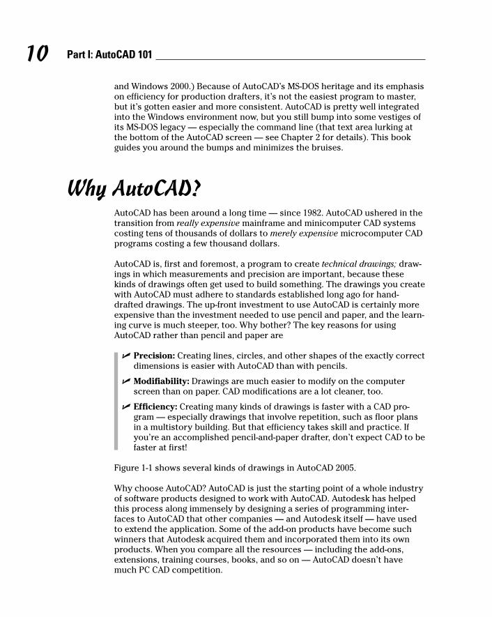
Why AutoCAD?AutoCAD has been around a long time — since 1982. AutoCAD ushered in thetransition from really expensive mainframe and minicomputer CAD systemscosting tens of thousands of dollars to merely expensive microcomputer CADprograms costing a few thousand dollars.
AutoCAD is, first and foremost, a program to create technical drawings; draw-ings in which measurements and precision are important, because thesekinds of drawings often get used to build something. The drawings you createwith AutoCAD must adhere to standards established long ago for hand-drafted drawings. The up-front investment to use AutoCAD is certainly moreexpensive than the investment needed to use pencil and paper, and the learn-ing curve is much steeper, too. Why bother? The key reasons for usingAutoCAD rather than pencil and paper are
� Precision: Creating lines, circles, and other shapes of the exactly correctdimensions is easier with AutoCAD than with pencils.
� Modifiability: Drawings are much easier to modify on the computerscreen than on paper. CAD modifications are a lot cleaner, too.
� Efficiency: Creating many kinds of drawings is faster with a CAD pro-gram — especially drawings that involve repetition, such as floor plansin a multistory building. But that efficiency takes skill and practice. Ifyou’re an accomplished pencil-and-paper drafter, don’t expect CAD to befaster at first!
Figure 1-1 shows several kinds of drawings in AutoCAD 2005.
Why choose AutoCAD? AutoCAD is just the starting point of a whole industryof software products designed to work with AutoCAD. Autodesk has helpedthis process along immensely by designing a series of programming inter-faces to AutoCAD that other companies — and Autodesk itself — have usedto extend the application. Some of the add-on products have become suchwinners that Autodesk acquired them and incorporated them into its ownproducts. When you compare all the resources — including the add-ons,extensions, training courses, books, and so on — AutoCAD doesn’t havemuch PC CAD competition.
10 Part I: AutoCAD 101
d571389 Ch01.qxd 4/12/04 9:43 AM Page 10
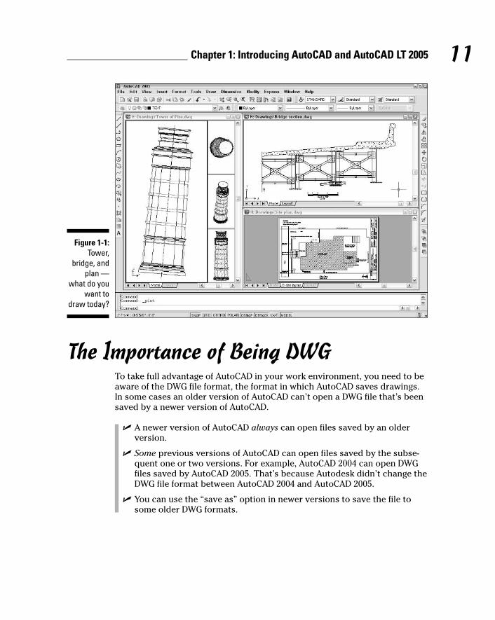
The Importance of Being DWGTo take full advantage of AutoCAD in your work environment, you need to beaware of the DWG file format, the format in which AutoCAD saves drawings.In some cases an older version of AutoCAD can’t open a DWG file that’s beensaved by a newer version of AutoCAD.
� A newer version of AutoCAD always can open files saved by an olderversion.
� Some previous versions of AutoCAD can open files saved by the subse-quent one or two versions. For example, AutoCAD 2004 can open DWGfiles saved by AutoCAD 2005. That’s because Autodesk didn’t change theDWG file format between AutoCAD 2004 and AutoCAD 2005.
� You can use the “save as” option in newer versions to save the file tosome older DWG formats.
Figure 1-1:Tower,
bridge, andplan —
what do youwant to
draw today?
11Chapter 1: Introducing AutoCAD and AutoCAD LT 2005
d571389 Ch01.qxd 4/12/04 9:43 AM Page 11

12 Part I: AutoCAD 101
Table 1-1 shows which versions (described later in this chapter) use whichDWG file formats.
Table 1-1 AutoCAD Versions and DWG File FormatsAutoCAD Version AutoCAD LT Version Release DWG File
Year Format
AutoCAD 2005 (“A2k5”) AutoCAD LT 2005 2004 Acad 2004
AutoCAD 2004 (“A2k4”) AutoCAD LT 2004 2003 Acad 2004
AutoCAD 2002 (“A2k2”) AutoCAD LT 2002 2001 Acad 2000
AutoCAD 2000i (“A2ki”) AutoCAD LT 2000i 2000 Acad 2000
AutoCAD 2000 (“A2k”) AutoCAD LT 2000 1999 Acad 2000
AutoCAD Release 14 (“R14”) AutoCAD LT 98 & 97 1997 Acad R14
AutoCAD Release 13 (“R13”) AutoCAD LT 95 1994 Acad R13
AutoCAD Release 12 (“R12”) AutoCAD LT Release 2 1992 Acad R12
Working with AutoCAD is easier when your co-workers and colleagues inother companies all use the same version of AutoCAD and AutoCAD-relatedtools. That way, your DWG files, add-on tools, and even the details of yourCAD knowledge can be mixed and matched among your workgroup and part-ners. In the real world, you’ll probably work with people — at least in othercompanies — who use AutoCAD versions as old as Release 14.
Many programs claim to be DWG-compatible — that is, capable of convertingdata to and from AutoCAD’s DWG format. But achieving this compatibility is adifficult thing to do well. Even a small error in file conversion can haveresults ranging in severity from annoying to appalling. If you exchange DWGfiles with people who use other CAD programs, be prepared to spend timefinding and fixing translation problems.
AutoCAD 2005 — like AutoCAD 2004 — does not include an option for savingfiles to the R14 DWG file format. This omission creates problems if you wantto send DWG files to clients or consultants who are still using AutoCADRelease 14. (And there are a surprising number of these folks — R14 was pop-ular, and AutoCAD 2000 through 2004 didn’t tempt everyone to upgrade.) Toget around this limitation, you can save to the R12 DXF format, which AutoCADRelease 14 will open — see Chapter 18 for instructions.
d571389 Ch01.qxd 4/12/04 9:43 AM Page 12

Seeing the LTAutoCAD LT is one of the best deals around, a shining example of the old80/20 rule: roughly 80 percent of the capabilities of AutoCAD for roughly 20percent of the money. Like AutoCAD, AutoCAD LT runs on mainstreamWindows computers and doesn’t require any additional hardware devices.With AutoCAD LT, you can be a player in the world of AutoCAD, the world’sleading CAD program, for a comparatively low starting cost.
AutoCAD LT is a very close cousin to AutoCAD. Autodesk creates AutoCAD LTby starting with the AutoCAD program, taking out a few features to justifycharging a lower price, adding a couple of features to enhance ease of useversus full AutoCAD, and testing the result.
As a result, AutoCAD LT looks and works much like AutoCAD. The openingscreen and menus of the two programs are nearly identical. (LT is missing afew commands from the AutoCAD menus.)
13Chapter 1: Introducing AutoCAD and AutoCAD LT 2005
AutoCAD-based applicationsAutodesk has expanded AutoCAD into a wholeproduct line of programs with AutoCAD as abase and specialized, discipline-specific add-ons built on top and included as one completeproduct. As an AutoCAD 2005 user, you’ll belooking for the 2005-compatible versions ofthese tools, which should appear a few monthsafter AutoCAD 2005 ships. These discipline-specific flavors of AutoCAD include AutodeskArchitectural Desktop and Autodesk BuildingSystems (mechanical, electrical, and plumbing),Autodesk Mechanical Desktop, Autodesk Map,AutoCAD Land Desktop, Autodesk Survey, andAutodesk Civil Design.
To make matters even more confusing, Autodesknow offers Autodesk Revit and AutodeskInventor, software applications that competewith Architectural Desktop and Mechanical
Desktop, respectively. Revit and Inventor arenot based on AutoCAD; they sacrifice AutoCADcompatibility in favor of a more fundamentallydesign- and 3D-oriented approach to CAD.Whether they ultimately will replace the tradi-tional AutoCAD-based applications remains tobe seen. Thus far, most companies seem to besticking with AutoCAD and the AutoCAD-basedDesktop applications.
In addition to the products from Autodesk, thou-sands of AutoCAD add-on products — both discipline-specific and general-purpose — areavailable from other software developers. Thesecompanion products are sometimes called third-party applications. Visit partnerproducts.autodesk.com/ for more information aboutwhat’s available.
d571389 Ch01.qxd 4/12/04 9:43 AM Page 13
In fact, the major difference between the programs has nothing to do with theprograms themselves. The major difference is that AutoCAD LT lacks supportfor several customization and programming languages that are used todevelop AutoCAD add-ons. So almost none of the add-on programs or utilitiesoffered by Autodesk and others are available to LT users.
AutoCAD LT also has only limited 3D support. You can view and edit 3Dobjects in AutoCAD LT, so you can work with drawings created in AutoCADthat contain 3D objects. However, you cannot create true 3D objects.
The lack of 3D object creation in LT is not as big a negative for many users asyou may think. Despite a lot of hype from the computer press and CAD ven-dors (including Autodesk), 3D CAD remains a relatively specialized activity.The majority of people use CAD programs to create 2D drawings.
Although you may hear claims that AutoCAD LT is easier to master and usethan AutoCAD, the truth is that they’re about equally difficult (or easy,depending on your nerd IQ). The LT learning curve doesn’t differ significantlyfrom that of AutoCAD. AutoCAD was originally designed for maximum powerand then modified somewhat to improve ease of use. AutoCAD LT shares thissame heritage.
Fortunately, the minimal differences between LT and AutoCAD mean thatafter you have climbed that learning curve, you’ll have the same great view.You’ll have almost the full range of AutoCAD’s 2D drafting tools, and you’ll beable to exchange DWG files with AutoCAD users without data loss.
This book covers AutoCAD 2005, but almost all the information in it appliesto AutoCAD LT 2005 as well. The icon that you see at the left of this para-graph highlights significant differences. If you’re an LT user, you may want tolook for AutoCAD LT 2005 For Dummies, which is aimed squarely at AutoCADLT and the types of people who use it instead of AutoCAD.
Staying Alive with 2005You should know this before you upgrade from a previous AutoCAD release:
� Wash those old Windows: AutoCAD 2005 does not support older ver-sions of Windows, such as Windows NT, 98, and Me. You must useWindows XP (Professional, Home, or Tablet PC) or Windows 2000.
� DWG file compatibility: AutoCAD 2005 uses the same DWG file formatas AutoCAD 2004, so you’ll be able to exchange files easily with users of
14 Part I: AutoCAD 101
d571389 Ch01.qxd 4/12/04 9:43 AM Page 14

AutoCAD 2004. You can use File➪Save As to create DWG files for usersof AutoCAD 2000, 2000i, and 2002, but not for AutoCAD Release 14 andearlier versions. (To get around this limitation, you can save to theRelease 12 DXF format — see Chapter 18 for instructions.)
� Application compatibility: If you use third-party applications with a pre-vious version of AutoCAD, they may not work with AutoCAD 2005. MostAutoCAD 2004 applications, including those developed with the ARX(AutoCAD Runtime eXtension) and VBA (Visual Basic for Applications)programming interfaces will work with AutoCAD 2005, but older ARXand VBA applications won’t work.
Many LSP (AutoLISP) programs written for the last several versions ofAutoCAD work with AutoCAD 2005.
� Increased computer system requirements: For AutoCAD 2005, Autodeskrecommends an 800 MHz Pentium III or better processor, at least 256MBof RAM, 1024 x 768 or higher display resolution, 300MB of available harddisk space, an Internet connection, and Microsoft Internet Explorer 6.0with Service Pack 1 or later.
AutoCAD 2005 comes out a mere year after AutoCAD 2004 and thus doesn’tsport quite as many new features as did some earlier upgrades, many ofwhich came out at two-year intervals. The new features and feature improve-ments in AutoCAD 2005, however, are well conceived and worthwhile. Mythree favorites are:
� Sheet sets — a radically new and much more sophisticated way of orga-nizing sets of drawings. (See Chapter 14.)
� Text tables, an enormously improved way to place tabular data on draw-ings quickly and uniformly — including the ability to import the datafrom Excel spreadsheets. (See Chapter 9.)
� An improved plotting interface, including background plotting. (SeeChapter 12.)
15Chapter 1: Introducing AutoCAD and AutoCAD LT 2005
No Express service?The AutoCAD 2005 CD-browser screen includesseparate links for installing the main AutoCAD2005 software and the Express Tools — a set ofhandy utilities for AutoCAD (but not available forAutoCAD LT). If your menu bar doesn’t includethe Express menu shown in Figure 1-1, you
should consider installing the Express Toolsfrom your AutoCAD 2005 CD. Just pop in the CDand, when the CD-browser page appears, clickthe AutoCAD Express Tools link and follow theinstallation instructions.
d571389 Ch01.qxd 4/12/04 9:43 AM Page 15

AutoCAD 2005 includes other goodies — look for the icon that you see at theleft of this paragraph.
If you’re using any version prior to AutoCAD 2004, the new version definitelyis worth upgrading to. You’ll enjoy a slew of improvements, including acleaner, more functional interface (Chapter 2), numbered and bulleted textlists (Chapter 9), and many xref enhancements (Chapters 13 and 16).
AutoCAD 2005 is a worthy new version. If you’ve been putting off upgrading,and especially if you’ve been hanging out with an old version such asAutoCAD 2000 or Release 14, this probably is a good time to take the plunge.
16 Part I: AutoCAD 101
d571389 Ch01.qxd 4/12/04 9:43 AM Page 16
Chapter 2
Le Tour de AutoCAD 2005In This Chapter� Touring the AutoCAD 2005 screen
� Going bar-hopping: title bars, the menu bar, toolbars, and the status bar
� Commanding the command line
� Discovering the drawing area
� Making the most of Model and Layout tabs
� Dabbling with palettes
� Setting system variables and using dialog boxes
� Using online help
AutoCAD 2005 is a full-fledged citizen of the Windows world, with tool-bars, dialog boxes, right-click menus, a multiple-document interface,
and all the other trappings of a real Windows program. But lurking beneaththat pretty face — and literally beneath the drawing area, right at the bottomof the AutoCAD program window — is a weird but essential holdover fromthe DOS days: the AutoCAD command line area. The command line is one ofthe few un-Windows-like things in AutoCAD that you’ll have to come to termswith, and this chapter shows you how.
Like the rest of the book, this chapter is written for someone who has usedother Windows programs but has little or no experience with AutoCAD. Ifyou’re experienced with Windows versions of AutoCAD, much of this chapteris old hat for you. Do make sure, though, that you’re familiar with the inter-face features that were added to AutoCAD 2004: palettes and the additionalbuttons on the right end of the status bar.
d571389 Ch02.qxd 4/12/04 9:43 AM Page 17
AutoCAD Does WindowsFinding your way around AutoCAD 2005 can be an odd experience. You recog-nize from other Windows applications much of the appearance and workingsof the program, such as its toolbars and pull-down menus, which you use forentering commands or changing system settings. But other aspects of theprogram’s appearance — and some of the ways in which you work with it —are quite different from other Windows programs. You can, in many cases, tellthe program what to do in at least four ways — pick a toolbar icon, pick fromthe pull-down menus, type at the command line, or pick from the right-clickmenus — none of which is necessarily the best method to use for every task.The experience is much like that of having to act as several different charac-ters in a play; you’re likely to forget your lines (whichever “you” you are atthe time!) every now and then.
As with other Windows programs, the menus at the top of the AutoCAD screenenable you to access most of the program’s functions and are the easiest-to-remember method of issuing commands. When you want to get real work done,you’ll need to combine the pull-down menus with other methods — especiallytyping options at the command line or choosing them from the right-clickmenu. I show you how throughout this book.
18 Part I: AutoCAD 101
Screen test yields high profileThe screen shots and descriptions in this chapterreflect the default configuration of AutoCAD —that is, the way the screen looks if you use thestandard version of AutoCAD (not a flavored ver-sion such as Architectural Desktop) and haven’tmessed with the display settings. You can changethe appearance of the screen with settings on theDisplay tab of the Options dialog box (chooseTools➪Options➪Display) and by dragging tool-bars and other screen components.
The change I’ve made is to configure the draw-ing area background to be white instead ofblack, because the figures in the book show upbetter that way. On your system, you’ll probablywant to leave your drawing area backgroundblack, because the normal range of colors thatappears in most drawings is easier to seeagainst a black background.
If you’re using a flavored version of AutoCAD, or ifsomeone has already changed your configurationor added a third-party program to your setup, yourscreen may look different than the figures in thisbook. You can restore the default configuration —including display settings — with the Reset buttonon the Options dialog box’s Profiles tab. (AutoCADLT doesn’t include the Profiles feature, so LT usersare out of luck here.) But before you click theReset button, consider whether the modified configuration may be useful to someone in thefuture — like you! If so, first click the Add to Listbutton to create a new profile. Enter a pithy namefor the new profile, such as AutoCAD default.Then select the new profile that you created, clickthe Set Current button to make it the current pro-file, and finally click the Reset button. In the future,you can switch between your modified anddefault configurations with the Set Current button.
d571389 Ch02.qxd 4/12/04 9:43 AM Page 18
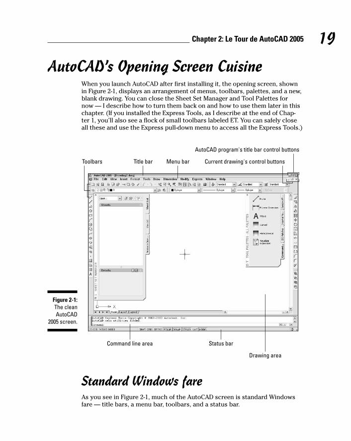
AutoCAD’s Opening Screen CuisineWhen you launch AutoCAD after first installing it, the opening screen, shown in Figure 2-1, displays an arrangement of menus, toolbars, palettes, and a new,blank drawing. You can close the Sheet Set Manager and Tool Palettes for now — I describe how to turn them back on and how to use them later in thischapter. (If you installed the Express Tools, as I describe at the end of Chap-ter 1, you’ll also see a flock of small toolbars labeled ET. You can safely closeall these and use the Express pull-down menu to access all the Express Tools.)
Standard Windows fareAs you see in Figure 2-1, much of the AutoCAD screen is standard Windowsfare — title bars, a menu bar, toolbars, and a status bar.
Title bar
Command line area Status bar
Drawing area
Menu barToolbars
AutoCAD program's title bar control buttons
Current drawing's control buttons
Figure 2-1:The cleanAutoCAD
2005 screen.
19Chapter 2: Le Tour de AutoCAD 2005
d571389 Ch02.qxd 4/12/04 9:43 AM Page 19

A hierarchy of title barsLike most Windows programs, AutoCAD has a title bar at the top of its pro-gram window that reminds you which program you’re in (not that you’d evermistake the AutoCAD window for, say, Microsoft Word!).
� At the right side of the title bar is the standard set of three Windowscontrol buttons: Minimize, Maximize/Restore, and Close.
� Each drawing window within the AutoCAD program window has its owntitle bar. You use the control buttons on a drawing window’s title bar tominimize, maximize/un-maximize, or close that drawing, not the entireAutoCAD program.
As in other Windows programs, if you maximize a drawing’s window, it expandsto fill the entire drawing area. (AutoCAD 2005 starts with the drawing maxi-mized in this way.) As shown in Figure 2-1, the drawing’s control buttons moveonto the menu bar, below the control buttons for the AutoCAD program win-dow; the drawing’s name appears in the AutoCAD title bar. To un-maximizethe drawing so you can see any other drawings that you have open, click thelower un-maximize button. The result is as shown in Figure 2-2: a separatetitle bar for each drawing with the name and controls for that drawing.
Figure 2-2:The
AutoCADscreen
with thedrawing un-maximized.
20 Part I: AutoCAD 101
d571389 Ch02.qxd 4/12/04 9:43 AM Page 20

Making choices from the menu barThe menu bar contains the names of all the primary menus in your version ofAutoCAD. As with any program that’s new to you, it’s worth spending a fewminutes perusing the menus in order to familiarize yourself with the com-mands and their arrangement. (If your menu bar doesn’t include the Expressmenu, see the end of Chapter 1 for installation instructions.)
Cruising the toolbarsAs in other Windows programs, the toolbars in AutoCAD 2005 provide rapidaccess to the most commonly used AutoCAD commands. AutoCAD ships withtoolbars in this default arrangement (as shown in Figure 2-3):
� Standard toolbar: Located on top, just below the menu bar; file manage-ment and other common Windows functions, plus some specializedAutoCAD stuff such as zooming and panning.
� Styles toolbar: To the right of the Standard toolbar; analogous to the left part of the Formatting toolbar in Microsoft programs, but formattingof AutoCAD’s text, dimension, and table styles. (Table styles are new inAutoCAD 2005.) Chapters 9 and 10 cover these features.
� Layers toolbar: Beneath the Standard toolbar; commands and a drop-down list for manipulating layers, which are AutoCAD’s fundamentaltools for organizing and formatting objects. Chapter 4 contains the layerlowdown.
� Properties toolbar: To the right of the Layers toolbar; analogous to theright part of the Formatting toolbar in Microsoft programs, but formattingof AutoCAD’s properties, such as colors, linetypes, and lineweights. SeeChapter 4 when you’re ready to play with AutoCAD’s object properties.
� Draw toolbar: Vertically down the far-left edge of the screen; the mostcommonly used commands from the Draw menu. Chapter 5 covers mostof the items on this toolbar.
21Chapter 2: Le Tour de AutoCAD 2005
Hot-wiring the menu barSome standard tips and tricks for Windows areespecially useful in AutoCAD. Control-key short-cuts for the most popular functions — Ctrl+S tosave, Ctrl+O to open a file, and Ctrl+P to print —work the same way in AutoCAD as in most otherWindows programs. Use them!
Also worth exploring are the Alt-key shortcuts,which are available for all menu choices, not just
the most popular ones. To fly around the menus,just press and hold the Alt key and then pressthe letters on your keyboard that correspond tothe underlined letters on the menu bar and in themenu choices. To bring up the SAVEAS com-mand, for example, just press and hold the Alt key,press F for File, and then press A for Save As.
d571389 Ch02.qxd 4/12/04 9:43 AM Page 21

� Modify toolbar: Vertically down the far-right edge of the screen; themost commonly used commands from the Modify menu. Chapter 8shows you how to use almost everything on this toolbar.
� Draw Order toolbar: Beneath the Modify toolbar; commands for con-trolling which objects appear on top of which other objects. Chapter 13mentions these features.
You can rearrange, open, and close toolbars as in other Windows programs:
� To move a toolbar, point to its border (the double-line control handle atthe leading edge of the toolbar is the easiest part to grab), click, and drag.
� To open or close toolbars, right-click on any toolbar button and choosefrom the list of available toolbars, as shown in Figure 2-3.
The AutoCAD screen in Figure 2-3 shows the default toolbar arrangement,which works fine for most people. Feel free to close the Draw Order toolbar;you aren’t likely to use its features frequently. You may want to turn on acouple of additional toolbars, such as Object Snap and Dimension, as you dis-cover and make use of additional features. Throughout this book, I point outwhen a particular toolbar may be useful.
Standard toolbar
Draw Order toolbar
Draw toolbar
Layer toolbar
Properties toolbar
Styles toolbar
Modify toolbar
Figure 2-3:A toolbar
tasting.
22 Part I: AutoCAD 101
d571389 Ch02.qxd 4/12/04 9:43 AM Page 22
If you’re not satisfied with just rearranging the stock AutoCAD toolbars, youcan customize their contents or even create new ones. The procedures arebeyond the scope of this book; they involve bouncing among the Commands,Toolbars, and Properties tabs on the Customize dialog box in not entirelyintuitive ways. Resist slicing and dicing the stock AutoCAD toolbars untilyou’re at least somewhat familiar with them. If you want to get creative there-after, go to the Contents tab of the AutoCAD 2005 online help and chooseCustomization Guide➪Basic Customization➪Create Custom Toolbars.
AutoCAD toolbar buttons provide ToolTips, those short text descriptions thatappear in little yellow boxes when you pause the cursor over a toolbar button.A longer description of the icon’s function appears in the status bar at thebottom of the screen.
Looking for Mr. Status BarThe status bar appears at the bottom of the AutoCAD screen, as shown inFigure 2-4. The status bar displays and allows you to change several impor-tant settings that affect how you draw and edit in the current drawing. Someof these settings won’t make complete sense until you’ve used the AutoCADcommands that they influence, but here’s a brief description, with pointers todetailed descriptions of how to use each setting elsewhere in this book:
� Coordinates of the cursor: The cursor coordinates readout displays thecurrent X,Y,Z location of the cursor in the drawing area, with respect tothe origin point (whose coordinates are 0,0,0). It’s a bit like having a GPS(Global Positioning System) device in your drawing. Chapter 4 describesAutoCAD’s coordinate conventions and how to use this area of thestatus bar.
23Chapter 2: Le Tour de AutoCAD 2005
The toolbars that ET AutoCADIf you’ve installed the Express Tools, you’ll alsosee a flock of Express Tools toolbars, whoselabels begin with “ET:”, floating over the draw-ing area. These four small toolbars collect someof the most popular Express Tools. You’ll proba-bly want to close most of these or at least dockany favorites along the margin of the AutoCADwindow.
The toolbars are extensions to AutoCAD, notpart of the core program, so turning them on is
a little more complicated than just using theright-click toolbars menu. Right-click on anytoolbar, choose Customize, click the Toolbarstab on the Customize dialog box, and choose theEXPRESS Menu Group. Now the Toolbars listdisplays the names of the four Express Toolstoolbars; click the check boxes next to thenames in order to toggle each toolbar on or off.
d571389 Ch02.qxd 4/12/04 9:43 AM Page 23
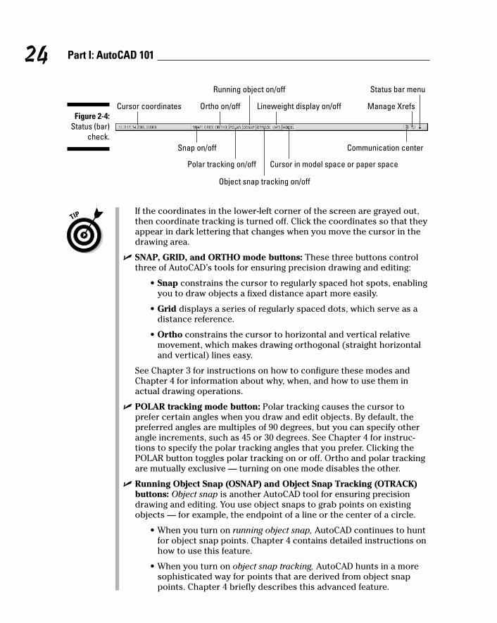
If the coordinates in the lower-left corner of the screen are grayed out,then coordinate tracking is turned off. Click the coordinates so that theyappear in dark lettering that changes when you move the cursor in thedrawing area.
� SNAP, GRID, and ORTHO mode buttons: These three buttons controlthree of AutoCAD’s tools for ensuring precision drawing and editing:
• Snap constrains the cursor to regularly spaced hot spots, enablingyou to draw objects a fixed distance apart more easily.
• Grid displays a series of regularly spaced dots, which serve as adistance reference.
• Ortho constrains the cursor to horizontal and vertical relativemovement, which makes drawing orthogonal (straight horizontaland vertical) lines easy.
See Chapter 3 for instructions on how to configure these modes andChapter 4 for information about why, when, and how to use them inactual drawing operations.
� POLAR tracking mode button: Polar tracking causes the cursor toprefer certain angles when you draw and edit objects. By default, thepreferred angles are multiples of 90 degrees, but you can specify otherangle increments, such as 45 or 30 degrees. See Chapter 4 for instruc-tions to specify the polar tracking angles that you prefer. Clicking thePOLAR button toggles polar tracking on or off. Ortho and polar trackingare mutually exclusive — turning on one mode disables the other.
� Running Object Snap (OSNAP) and Object Snap Tracking (OTRACK)buttons: Object snap is another AutoCAD tool for ensuring precisiondrawing and editing. You use object snaps to grab points on existingobjects — for example, the endpoint of a line or the center of a circle.
• When you turn on running object snap, AutoCAD continues to huntfor object snap points. Chapter 4 contains detailed instructions onhow to use this feature.
• When you turn on object snap tracking, AutoCAD hunts in a moresophisticated way for points that are derived from object snappoints. Chapter 4 briefly describes this advanced feature.
Cursor coordinates
Snap on/off
Ortho on/off
Running object on/off
Lineweight display on/off
Polar tracking on/off
Object snap tracking on/off
Cursor in model space or paper space
Manage Xrefs
Status bar menu
Communication center
Figure 2-4:Status (bar)
check.
24 Part I: AutoCAD 101
d571389 Ch02.qxd 4/12/04 9:43 AM Page 24

AutoCAD LT doesn’t include the object snap tracking feature, so youwon’t see an OTRACK button on its status bar.
� Lineweight (LWT) display mode button: One of the properties that youcan assign to objects in AutoCAD is lineweight — the thickness that linesappear when you plot the drawing. This button controls whether yousee the lineweights on the screen. (This button doesn’t control whetherlineweights appear on plots; that’s a separate setting in the Plot dialogbox.) Chapter 4 gives you the skinny (and the wide) on lineweights.
� MODEL/PAPER space button: As I describe in the section “Main course:The drawing area” later in this chapter, the drawing area is composed ofoverlapping tabbed areas labeled Model, Layout1, and Layout2 by default.The Model tab displays a part of the drawing called model space, whereyou create most of your drawing. Each of the remaining tabs displays apaper space layout, where you can compose a plotable view with a titleblock. A completed layout will include one or more viewports, whichreveal some or all the objects in model space at a particular scale.
The MODEL/PAPER status bar button (not to be confused with the Modeltab) comes into play after you click one of the paper space layout tabs.The MODEL/PAPER button provides a means for moving the cursorbetween model and paper space while remaining in the particular layout.
• When the MODEL/PAPER button says MODEL, drawing and editingoperations take place in model space, inside a viewport.
• When the button says PAPER, drawing and editing operations takeplace in paper space on the current layout.
Don’t worry if you find model space and paper space a little disorientingat first. The paper space layout setup information in Chapter 3 and plot-ting instructions in Chapter 12 will help you get your bearings and navi-gate with confidence.
� Maximize/Minimize Viewport button (paper space layouts only): Whenyou’re looking at one of the Layout tabs instead of the Model tab, thestatus bar displays an additional Maximize Viewport button. Click thisbutton to expand the current paper space viewport so that it fills theentire drawing area. Click the button — now called Minimize Viewport —again to restore the viewport to its normal size. (Chapter 3 describesviewports.)
� Communication Center: This button opens a dialog box containingrecent AutoCAD-related headlines that Autodesk thinks you may finduseful. The headlines are grouped into categories called channels: LiveUpdate Maintenance Patches, Articles and Tips, Product SupportInformation, and so on. Each headline is a link to a Web page with moreinformation, such as how to download a software update or fix a prob-lem. Click the Settings button to select channels you see in theCommunication Center window.
� Manage Xrefs: You won’t see this combination button and notificationsymbol until you open a drawing that contains xrefs (external DWG files
25Chapter 2: Le Tour de AutoCAD 2005
d571389 Ch02.qxd 4/12/04 9:43 AM Page 25

that are incorporated into the current drawing). Chapter 13 tells youhow to use xrefs and what the Manage Xrefs button does.
� Status Bar Menu: When you click the easy-to-miss downward-pointingarrow near the right edge of the status bar, you open a menu withoptions for toggling off or on each status bar button. Now you can deco-rate your status bar to your taste.
You can open dialog boxes for configuring many of the status bar buttonfunctions by right-clicking the status bar button and choosing Settings.Chapters 3 and 4 give you specific guidance about when and how to changethese settings.
A button’s appearance shows whether the setting is turned on or off.Depressed, or down, means on; raised, or up, means off. If you’re unclearwhether a setting is on or off, click its button; its mode will change and thenew setting will be reflected on the command line — <Osnap off>, for exam-ple. Click again to restore the previous setting.
Take an order: The command line areaIf the title bars, menu bar, and status bar are the Windows equivalent of com-fort food — familiar, nourishing, and unthreatening — then the command line area, shown in Figure 2-5, must be the steak tartare or blood sausage ofthe AutoCAD screen feast. It looks weird, turns the stomachs of newcomers,and delights AutoCAD aficionados. The hard truth is that you have to cometo like — or at least tolerate — the command line if you want to become at all comfortable using AutoCAD.
You need to get up close and personal with the command line for four reasons:
� The command line area is AutoCAD’s primary communications con-duit with you. This is the most important reason to pay attention to thecommand line. AutoCAD frequently displays prompts, warnings, anderror messages in the command line area. If you don’t keep an eye onthis area, you’ll miss a lot of vital information. You’ll continually be frus-trated, because you won’t “hear” what AutoCAD is trying to tell you.
� The command line is an efficient way to run some commands and theonly way to run a few others. Instead of clicking a toolbar button or a
Figure 2-5:Obey the
commandline.
26 Part I: AutoCAD 101
d571389 Ch02.qxd 4/12/04 9:43 AM Page 26

menu choice, you can start a command by typing its command name andthen pressing the Enter key. Even better, you can type the keyboard short-cut for a command name and press Enter. Most of the keyboard shortcutsfor command names are just one or two letters — for example, L for theLINE command and CP for the COPY command. Most people who dis-cover how to use the shortcuts for the commands that they run most fre-quently find that their AutoCAD productivity improves noticeably. Even ifyou’re not worried about increasing your productivity with this technique,there are some commands that aren’t on the toolbars or pull-down menus.If you want to run those commands, you have to type them!
� After you’ve started a command — whether from a toolbar, from amenu, or by typing — the command line is where AutoCAD promptsyou with options for that command.
You activate one of these options by typing the uppercase letter(s) inthe option and pressing Enter.
In many cases, you can activate a command’s options by right-clicking inthe drawing area and choosing the desired option from the right-clickmenu, instead of by typing the letter(s) for the option and pressingEnter. But if you don’t watch the command line, you probably won’t real-ize that there are any options!
� You sometimes need to type coordinates at the command line to specifyprecise points or distances. Chapter 4 describes this technique in detail.
You don’t have to click in the command line area to type command names,keyboard shortcuts, or command options there. AutoCAD knows that yourtyping is supposed to go to the command line. The only exception is whenyou’re within a text command (you’re adding a text note to the drawing itself);in that case, the text appears in the drawing, not in the command line area.
The following sequence demonstrates how you use the command line area torun commands, view and select options, and pay attention to messages fromAutoCAD:
1. Type L and press Enter.
AutoCAD starts the LINE command and displays the following prompt inthe command line area:
LINE Specify first point:
2. Click a point anywhere in the drawing area.
The command line prompt changes to:
Specify next point or [Undo]:
AutoCAD always displays command options in brackets. In this case, theUndo option appears in brackets. To activate the option, type the letter(s)shown in uppercase and press Enter. (You can type the option letter(s) inlowercase or uppercase.)
27Chapter 2: Le Tour de AutoCAD 2005
d571389 Ch02.qxd 4/12/04 9:43 AM Page 27
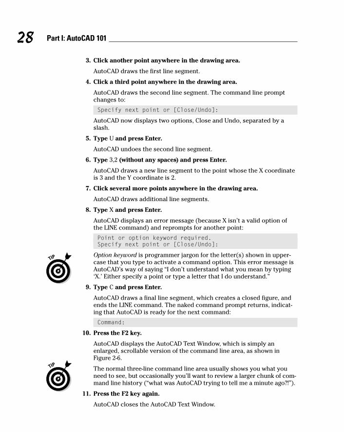
3. Click another point anywhere in the drawing area.
AutoCAD draws the first line segment.
4. Click a third point anywhere in the drawing area.
AutoCAD draws the second line segment. The command line promptchanges to:
Specify next point or [Close/Undo]:
AutoCAD now displays two options, Close and Undo, separated by aslash.
5. Type U and press Enter.
AutoCAD undoes the second line segment.
6. Type 3,2 (without any spaces) and press Enter.
AutoCAD draws a new line segment to the point whose the X coordinateis 3 and the Y coordinate is 2.
7. Click several more points anywhere in the drawing area.
AutoCAD draws additional line segments.
8. Type X and press Enter.
AutoCAD displays an error message (because X isn’t a valid option ofthe LINE command) and reprompts for another point:
Point or option keyword required.Specify next point or [Close/Undo]:
Option keyword is programmer jargon for the letter(s) shown in upper-case that you type to activate a command option. This error message isAutoCAD’s way of saying “I don’t understand what you mean by typing‘X.’ Either specify a point or type a letter that I do understand.”
9. Type C and press Enter.
AutoCAD draws a final line segment, which creates a closed figure, andends the LINE command. The naked command prompt returns, indicat-ing that AutoCAD is ready for the next command:
Command:
10. Press the F2 key.
AutoCAD displays the AutoCAD Text Window, which is simply anenlarged, scrollable version of the command line area, as shown inFigure 2-6.
The normal three-line command line area usually shows you what youneed to see, but occasionally you’ll want to review a larger chunk of com-mand line history (“what was AutoCAD trying to tell me a minute ago?!”).
11. Press the F2 key again.
AutoCAD closes the AutoCAD Text Window.
28 Part I: AutoCAD 101
d571389 Ch02.qxd 4/12/04 9:43 AM Page 28
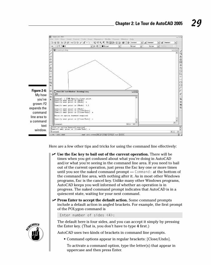
Here are a few other tips and tricks for using the command line effectively:
� Use the Esc key to bail out of the current operation. There will betimes when you get confused about what you’re doing in AutoCADand/or what you’re seeing in the command line area. If you need to bailout of the current operation, just press the Esc key one or more timesuntil you see the naked command prompt — Command: at the bottom ofthe command line area, with nothing after it. As in most other Windowsprograms, Esc is the cancel key. Unlike many other Windows programs,AutoCAD keeps you well informed of whether an operation is inprogress. The naked command prompt indicates that AutoCAD is in aquiescent state, waiting for your next command.
� Press Enter to accept the default action. Some command promptsinclude a default action in angled brackets. For example, the first promptof the POLygon command is
Enter number of sides <4>:
The default here is four sides, and you can accept it simply by pressingthe Enter key. (That is, you don’t have to type 4 first.)
AutoCAD uses two kinds of brackets in command line prompts.
• Command options appear in regular brackets: [Close/Undo].
To activate a command option, type the letter(s) that appear inuppercase and then press Enter.
Figure 2-6:My how
you’vegrown: F2
expands thecommand
line area toa command
textwindow.
29Chapter 2: Le Tour de AutoCAD 2005
d571389 Ch02.qxd 4/12/04 9:43 AM Page 29

• A Default value or option appears in angled brackets: <>.
To choose the default value or option, simply press Enter.
� Observe the command line. You’ll discover a lot about how to use thecommand line simply by watching it after each action that you take.When you click a toolbar button or menu choice, AutoCAD types thename of the command automatically, so if you’re watching the commandline, you’ll absorb the command names more-or-less naturally.
When AutoCAD types commands automatically in response to your tool-bar and menu clicks, it usually adds one or two extra characters to thefront of the command name.
• AutoCAD usually puts an underscore in front of the commandname (for example, _LINE instead of LINE). The underscore is anAutodesk programmers’ trick that enables non-English versions ofAutoCAD to understand the English command names that areembedded in the menus.
• AutoCAD sometimes puts an apostrophe in front of the commandname and any underscore (for example, ‘_ZOOM instead of ZOOM).The apostrophe indicates a transparent command; you can run thecommand in the middle of another command without canceling thefirst command. For example, you can start the LINE command, runthe ZOOM command transparently, and then pick up where youleft off with the LINE command.
� Leave the command line in the default configuration initially. The com-mand line area, like most other parts of the AutoCAD screen, is resizableand relocateable. The default location (docked at the bottom of theAutoCAD screen) and size (three lines deep) work well for most people.Resist the temptation to mess with the command line area’s appearance —at least until you’re comfortable with how to use the command line.
� Right-click in the command line area for options. If you right-click inthe command line area, you’ll see a menu with some useful choices,including Recent Commands — the last six commands that you ran.
� Press the up- and down-arrow keys to cycle through the stack of com-mands that you’ve typed recently. This is another handy way to recalland rerun a command. Press the left- and right-arrow keys to edit thecommand line text that you’ve typed or recalled.
Main course: The drawing areaAfter all these screen hors d’oeuvres, you’re probably getting hungry for themain course — the AutoCAD drawing area. This is where you do your draw-ing, of course. In the course of creating drawings, you click points to specifylocations and distances, click objects to select them for editing, and zoomand pan to get a better view of what you’re working on.
30 Part I: AutoCAD 101
d571389 Ch02.qxd 4/12/04 9:43 AM Page 30

Most of this book shows you how to interact with the drawing area, but youshould know a few things up front.
The Model and Layout tabs (Model and Paper Space)One of the initially disorienting things about AutoCAD is that finished draw-ings can be composed of objects drawn in different spaces, which AutoCADindicates with the tabs along the bottom of the drawing area (Model,Layout1, and Layout2 by default).
� Model space is where you create and modify the objects that representthings in the real world — walls, widgets, waterways, or whatever.
� Paper space is where you create particular views of these objects forplotting, usually with a title block around them. Paper space comprisesone or more layouts, each of which can contain a different arrangementof model space views and different title block information.
When you click the Model tab in the drawing area, you see pure, unadulteratedmodel space, as shown in Figure 2-7. When you click one of the paper spacelayout tabs (Layout1 or Layout2, unless someone has renamed or added tothem), you see a paper space layout, as shown in Figure 2-8. A completedlayout usually includes one or more viewports, which are windows that displayall or part of model space at a particular scale. A layout also usually includes atitle block or other objects that exist only in the layout and don’t appear whenyou click the Model tab. (Think of the viewport as a window looking into modelspace and the title block as a frame around the window.) Thus, a layout dis-plays model space and paper space objects together, and AutoCAD lets youdraw and edit objects in either space. See Chapter 3 for information about cre-ating paper space layouts and Chapter 12 for the lowdown on plotting them.
As I describe in the “Looking for Mr. Status Bar” section in this chapter, afteryou’ve clicked one of the layout tabs, the status bar’s MODEL/PAPER button
31Chapter 2: Le Tour de AutoCAD 2005
AutoCAD is no vin ordinaireThe back and forth needed to get AutoCAD todraw and complete a line is a great example ofAutoCAD’s power — and its power to confusenew users. It’s kind of like a wine that tastes abit harsh initially, but that ages better thansomething more immediately drinkable.
In other programs, if you want to draw a line,you just draw it. In AutoCAD, you have to pressEnter one extra time when you’re done just totell AutoCAD you really are finished drawing.
But the fact that the Line command remainsactive after you draw the first line segmentmakes it much faster to draw complicated,multisegment lines, which is a common activityin a complex drawing.
This is just one example of how AutoCAD favorsease of use for power users doing complexdrawings over ease of mastery for beginners,who frequently forget to hit Enter that extra timeto close out a command.
d571389 Ch02.qxd 4/12/04 9:43 AM Page 31

moves the cursor between model and paper space while remaining in theparticular layout. (As shown in Figures 2-7 and 2-8, the orientation icon at thelower-left corner of the AutoCAD drawing area changes between an X-Y axisfor model space and a drafting triangle for paper space as an additionalreminder of which space the cursor currently resides in.) Chapter 3 describesthe consequences of changing the MODEL/PAPER setting and advises you onhow to use it.
This back-and-forth with the MODEL/PAPER button or double-clicking is nec-essary only when you’re drawing things while viewing one of the paper spacelayouts. In practice, you probably won’t encounter that situation very often.Instead, you’ll do most of your drawing on the Model tab and, after you’ve setup a paper space layout, click its layout tab only when you want to plot.
Drawing on the drawing areaHere a few other things to know about the AutoCAD drawing area:
� Efficient, confident use of AutoCAD requires that you continuallyglance from the drawing area to the command line area (to see those all-important prompts!) and then back up to the drawing area. Thissequence is not a natural reflex for most people. Get in the habit oflooking at the command line after each action that you take, whetherpicking something on a toolbar, on a menu, or in the drawing area.
Figure 2-7:Our model
loungingaround in
modelspace.
32 Part I: AutoCAD 101
d571389 Ch02.qxd 4/12/04 9:43 AM Page 32
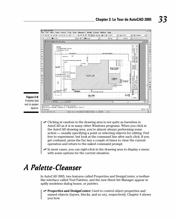
� Clicking at random in the drawing area is not quite as harmless inAutoCAD as it is in many other Windows programs. When you click inthe AutoCAD drawing area, you’re almost always performing someaction — usually specifying a point or selecting objects for editing. Feelfree to experiment, but look at the command line after each click. If youget confused, press the Esc key a couple of times to clear the currentoperation and return to the naked command prompt.
� In most cases, you can right-click in the drawing area to display a menuwith some options for the current situation.
A Palette-CleanserIn AutoCAD 2005, two features called Properties and DesignCenter, a toolbar-like interface called Tool Palettes, and the new Sheet Set Manager appear inspiffy modeless dialog boxes, or palettes.
� Properties and DesignCenter: Used to control object properties andnamed objects (layers, blocks, and so on), respectively. Chapter 4 showsyou how.
Figure 2-8:Freshly laid
out in paperspace.
33Chapter 2: Le Tour de AutoCAD 2005
d571389 Ch02.qxd 4/12/04 9:43 AM Page 33

� Tool Palettes: Resembles a stack of painter’s palettes, except that eachpalette holds content (drawing symbols and hatch patterns) and/or com-mands (toolbar-like macros — a new feature in AutoCAD 2005) instead ofpaints. Chapters 11, 13, and 15 help you unlock your inner Tool Paletteartistry.
� Sheet Set Manager: Provides tools for managing all of a project’s draw-ings as a sheet set. Chapter 14 gives you the lowdown on why you mightwant to and how to do so.
You toggle these palettes on and off by clicking three buttons near the end ofthe Standard toolbar or by pressing Ctrl+1 (Properties), Ctrl+2 DesignCenter),Ctrl+3 (Tool Palettes), or Ctrl+4 (Sheet Set Manager). Figure 2-9 shows all fourtoggled on.
Modeless is just a fancy way of saying that these dialog boxes don’t take overAutoCAD in the way that modal dialog boxes do. Modal dialog boxes demandyour undivided attention. You enter values, click buttons, or whatever, andthen click the OK or Cancel button to close the dialog box. While the modaldialog box is open, you can’t do anything else in AutoCAD. A modeless dialogbox, on the other hand, can remain open while you execute other commandsthat have nothing to do with the dialog box. You return to the modelessdialog box when or if you need its features.
Manipulating AutoCAD modeless dialog boxes — or palettes — is similar tomanipulating a regular Windows dialog box, except that the title bar is alongthe side instead of at the top. In other words, you click and drag the title stripalong the side to move the palette. If you experiment with the control buttonsat the bottom of this strip (or right-click anywhere on the strip), you’ll quicklyget the hang of what you can do with these palettes. In particular, turning onthe auto-hide feature causes the dialog box to “roll up” into the strip so thatit’s not taking up much screen space. When you point the cursor at the strip,the palette unfurls again.
Another cool feature — for the Tool Palettes but not the Properties andDesignCenter palettes — is transparency. Right-click the Tool Palettes’ title stripand choose Transparency to control this feature. With transparency turned on,you can see your drawing objects behind a faded version of the Tool Palettes.(According to my dictionary, that would make the palettes translucent, nottransparent, but whatever.) If you combine transparency with auto-hide, youend up with Tool Palettes that have a low impact on your drawing area. And ifyou’re bothered by the amount of screen space taken by the command linearea, you can make it transparent, too: Undock it, right-click the title bar andturn off Allow Docking, and then right-click again and choose Transparency.After you’ve set the transparency to your taste, click and drag the commandline area to where you want it.
34 Part I: AutoCAD 101
d571389 Ch02.qxd 4/12/04 9:43 AM Page 34

What Really Makes AutoCAD Cook?Knowing how to use the command line, as described in the section, “Take anorder: The command line area,” is one of the secrets of becoming a compe-tent AutoCAD user. In reading about and using AutoCAD, you encounter twoadditional topics frequently: system variables, which are AutoCAD’s basiccontrol levers, and dialog boxes, many of which put a friendlier face on thesystem variables.
Sizzling system variablesSystem variables are settings that AutoCAD checks before it decides how todo something. If you set the system variable SAVETIME to 10, AutoCAD auto-matically saves your drawing file every ten minutes; if you set SAVETIME to60, the time between saves is one hour. Hundreds of system variables controlAutoCAD’s operations.
Properties palette DesignCenter palette Tool palettes
Figure 2-9:A modelessmenagerie.
35Chapter 2: Le Tour de AutoCAD 2005
d571389 Ch02.qxd 4/12/04 9:43 AM Page 35
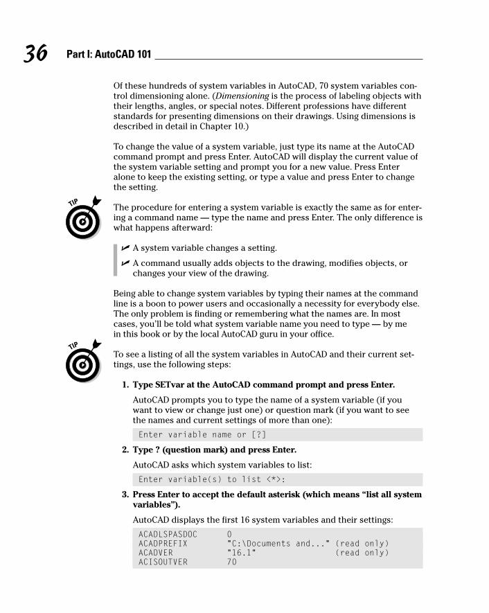
Of these hundreds of system variables in AutoCAD, 70 system variables con-trol dimensioning alone. (Dimensioning is the process of labeling objects withtheir lengths, angles, or special notes. Different professions have differentstandards for presenting dimensions on their drawings. Using dimensions isdescribed in detail in Chapter 10.)
To change the value of a system variable, just type its name at the AutoCADcommand prompt and press Enter. AutoCAD will display the current value ofthe system variable setting and prompt you for a new value. Press Enteralone to keep the existing setting, or type a value and press Enter to changethe setting.
The procedure for entering a system variable is exactly the same as for enter-ing a command name — type the name and press Enter. The only difference iswhat happens afterward:
� A system variable changes a setting.
� A command usually adds objects to the drawing, modifies objects, orchanges your view of the drawing.
Being able to change system variables by typing their names at the commandline is a boon to power users and occasionally a necessity for everybody else.The only problem is finding or remembering what the names are. In mostcases, you’ll be told what system variable name you need to type — by me in this book or by the local AutoCAD guru in your office.
To see a listing of all the system variables in AutoCAD and their current set-tings, use the following steps:
1. Type SETvar at the AutoCAD command prompt and press Enter.
AutoCAD prompts you to type the name of a system variable (if youwant to view or change just one) or question mark (if you want to seethe names and current settings of more than one):
Enter variable name or [?]
2. Type ? (question mark) and press Enter.
AutoCAD asks which system variables to list:
Enter variable(s) to list <*>:
3. Press Enter to accept the default asterisk (which means “list all systemvariables”).
AutoCAD displays the first 16 system variables and their settings:
ACADLSPASDOC 0ACADPREFIX “C:\Documents and...” (read only)ACADVER “16.1” (read only)ACISOUTVER 70
36 Part I: AutoCAD 101
d571389 Ch02.qxd 4/12/04 9:43 AM Page 36

AFLAGS 0ANGBASE 0ANGDIR 0APBOX 0APERTURE 10AREA 0.0000 (read only)ATTDIA 0ATTMODE 1ATTREQ 1AUDITCTL 0AUNITS 0AUPREC 0AUTOSNAP 63BACKGROUNDPLOT 2BACKZ 0.0000 (read only)BINDTYPE 0BLIPMODE 0Press ENTER to continue:
4. Press Enter repeatedly to scroll through the entire list, or press Esc tobail out.
AutoCAD returns to the command prompt:
Command:
If you want to find out more about what a particular system variable controls,see the System Variables chapter in the Command Reference in the AutoCADonline help.
Three kinds of system variables exist:
� Those saved in the Windows Registry. If you change this kind of systemvariable, it affects all drawings when you open them with AutoCAD onyour system.
� Those saved in the drawing. If you change this kind, the change affectsonly the current drawing.
� Those that aren’t saved anywhere. If you change this kind, the changelasts only for the current drawing session.
The System Variables chapter in the online Command Reference tells youwhich kind of system variable each one is.
Delicious dialog boxesFortunately, you don’t usually have to remember the system variable names.AutoCAD exposes most of the system variable settings in dialog boxes so that
37Chapter 2: Le Tour de AutoCAD 2005
d571389 Ch02.qxd 4/12/04 9:43 AM Page 37

you can change their values simply by clicking check boxes or typing valuesin edit boxes. This approach is a lot more user-friendly than remembering anobscure name like “ACADLSPASDOC.”
For example, many of the settings on the tabs in the Options dialog box, shownin Figure 2-10, are in fact system variables. If you use the dialog box quick help(click the question mark in the Options dialog box’s title bar, and then click anoption in the dialog box), the pop-up description not only describes the set-ting, but also tells which system variable it corresponds to.
Fun with F1The AutoCAD 2005 Help menu, shown in Figure 2-11, offers a slew of onlinehelp options. I describe most of them here:
Figure 2-11:Lots of
AutoCADhelp.
Figure 2-10:Options —
a handyway to
changesome
systemvariablesettings.
38 Part I: AutoCAD 101
d571389 Ch02.qxd 4/12/04 9:43 AM Page 38

� Help: The main AutoCAD 2005 online help system, shown in Figure 2-12,uses the same help engine as the Microsoft Office programs, InternetExplorer, and other modern Windows applications. Click the Contentstab to browse through the various online reference manuals, the Indextab to look up commands and concepts, and the Search tab to look forspecific words. In this book, I sometimes direct you to the AutoCADonline help system for information about advanced topics.
� Info Palette: This option opens a Quick Help Info Palette, which is theAutodesk version of the Microsoft paper clip guy who tries to tell youwhat to do in Word or Excel at each step along the way. Like paper-clipguy, Info Palette seems helpful — for 30 seconds. Then you get tired ofthe distraction and the wasted screen space.
� New Features Workshop: This describes the new and enhanced featuresin AutoCAD 2005. It’s especially useful for people who are upgradingfrom a previous AutoCAD version.
� Online Resources: Most of the choices in the Online Resources sub-menu connect you to various parts of Autodesk’s Web site. The mostuseful is Product Support. From the support Web page, you can searchthe Autodesk Knowledge Base, download software updates, and get helpfrom Web- and newsgroup-based discussion groups.
Figure 2-12:Help is at
your F1fingertip.
39Chapter 2: Le Tour de AutoCAD 2005
d571389 Ch02.qxd 4/12/04 9:43 AM Page 39

AutoCAD is one program with which you really need to take advantage of theonline help resources. AutoCAD contains many commands, options, andquirks, and everyone from the greenest beginner to the most seasoned expertcan find out something by using the AutoCAD online help. Take a moment toperuse the Contents tab of the main help system so that you know what’s avail-able. Throughout this book, I direct you to pages in the help system that I thinkare particularly useful, but don’t be afraid to explore on your own when youget stuck or feel curious.
40 Part I: AutoCAD 101
d571389 Ch02.qxd 4/12/04 9:43 AM Page 40

Chapter 3
Setup for SuccessIn This Chapter� Developing a setup strategy
� Starting a new drawing
� Setting up model space
� Setting up paper space layouts
� Creating and using drawing templates
Surprisingly, drawing setup is one of the trickier aspects of using AutoCAD.It’s an easy thing to do incompletely or wrong, and AutoCAD 2004 doesn’t
provide a dialog box or other simple, all-in-one-fell-swoop tool to help you doall of it right. And yet, drawing setup is a crucial thing to get right. Setup stepsthat you omit or don’t do right will come back to bite you — or at least gnawon your leg — later.
Sloppy setup really becomes apparent when you try to plot your drawing.Things that seemed more or less okay as you zoomed around on the screensuddenly are completely the wrong size or scale on paper. And nothingbrands someone as a naive AutoCAD wannabe as quickly as the inability toplot a drawing at the right size and scale. Chapter 12 covers plotting proce-dures, but the information in this chapter is a necessary prerequisite to suc-cessful plotting. If you don’t get this stuff right, there’s a good chance you’llfind that . . . the plot sickens.
This chapter describes the decisions you need to make before you set up anew drawing, shows the steps for doing a complete and correct setup, anddemonstrates how to save setup settings for reuse.
Don’t assume that you can just create a new blank DWG file and start drawingthings. In other words, do read this chapter before you get too deep into thelater chapters in this book. Many AutoCAD drawing commands and conceptsdepend on proper drawing setup, so you’ll have a much easier time of drawingand editing things if you’ve done your setup homework. A few minutes investedin setting up a drawing well can save hours of thrashing around later on.
d571389 Ch03.qxd 4/12/04 9:43 AM Page 41

After you’ve digested the detailed drawing setup procedures described inthis chapter, use the Drawing Setup Roadmap on the Cheat Sheet at the frontof this book to guide you through the process.
An Appetizing Setup StrategyYou need to set up AutoCAD correctly, partly because AutoCAD is so flexibleand partly because, well, you’re doing CAD — computer-aided drafting (ordesign). The computer can’t aid your drafting (or design) if you don’t clue itin on things like drawing scale, paper size, and units. In this context, the fol-lowing reasons help explain why AutoCAD drawing setup is important:
� Electronic paper: The most important thing you can do to make usingAutoCAD fun is to work on a correctly set up drawing so that your screenacts like paper, only smarter. When drawing on real paper, you constantlyhave to translate between units on the paper and the real-life units of the object you’re drawing. But when drawing in AutoCAD, you can drawdirectly in real-life units — feet and inches, millimeters, or whatever youtypically use on your projects. AutoCAD can then calculate distances and dimensions for you and add them to the drawing. You can make themouse pointer jump directly to hot spots on-screen, and a visible, resiz-able grid gives you a better sense of the scale of your drawing. However,this smart paper function works well only if you tell AutoCAD some cru-cial parameters for your specific drawing. AutoCAD can’t really do its jobuntil you tell it how to work.
� Dead-trees paper: Creating a great drawing on-screen that doesn’t fitwell on paper is all too easy. After you finish creating your drawing onthe smart paper AutoCAD provides on-screen, you usually must thenplot it on the good, old-fashioned paper that people have used for thou-sands of years. At that point, you must deal with the fact that people liketo use certain standard paper sizes and drawing scales. (Most peoplealso like everything to fit neatly on one sheet of paper.) If you set upAutoCAD correctly, good plotting results automatically; if not, plottingtime can become one colossal hassle.
� It ain’t easy: AutoCAD provides templates and Setup Wizards for you,but the templates don’t work well unless you understand them, andsome of the wizards don’t work well even if you do understand them.This deficiency is one of the major weaknesses in AutoCAD. You mustfigure out on your own how to make the program work right. If you justplunge in without carefully setting it up, your drawing and printingefforts are likely to wind up a real mess.
Fortunately, setting up AutoCAD correctly is a bit like cooking a soufflé:Although the steps for performing your setup are complex, you can masterthem with attention and practice. Even more fortunately, this chapter pro-vides a detailed and field-tested recipe.
42 Part I: AutoCAD 101
d571389 Ch03.qxd 4/12/04 9:43 AM Page 42

While you’re working in AutoCAD, always keep in mind what your final outputshould look like on real paper. Even your first printed drawings should lookjust like hand-drawn ones — only without all those eraser smudges.
Before you start the drawing setup process, you need to make decisionsabout your new drawing. These three questions are absolutely critical. If youdon’t answer them, or you answer them wrong, you’ll probably need to dolots of reworking of the drawing later:
� What drawing units will you use?
� At what scale — or scales — will you plot it?
� On what size paper does it need to fit?
In some cases, you can defer answering one additional question, but it’s usu-ally better to deal with it up front: What kind of border or title block doesyour drawing require?
If you’re in a hurry, it’s tempting to find an existing drawing that was set upfor the drawing scale and paper size that you want to use, make a copy ofthat DWG file, erase the objects, and start drawing. Use this approach withcare, though. When you start from another drawing, you inherit any setupmistakes in that drawing. Also, drawings that were created in much older ver-sions of AutoCAD may not take advantage of current program features andCAD practices. If you can find a suitable drawing that was set up in a recentversion of AutoCAD by an experienced person who is conscientious aboutdoing setup right, consider using it. Otherwise, you’re better off setting up anew drawing from scratch.
43Chapter 3: Setup for Success
AutoCAD and paperIn other Windows programs, you can use anyscaling factor you want to squeeze content ontopaper. You’ve probably printed an Excel spread-sheet or Web page at some odd scaling factor,such as 82.5 percent of full size, because that’swhat it took to squeeze the content onto a singlesheet of paper while keeping the text as largeas possible.
In drafting, your printout needs to use a specific,widely accepted scaling factor, such as 1⁄4” =1’–0”, to be useful and understandable to
others. But the AutoCAD screen does not auto-matically enforce any one scaling factor orpaper size. If you just start drawing stuff on theAutoCAD screen to fit your immediate needs, it’sunlikely that the final result will fit neatly on apiece of paper at a desirable scale.
This chapter tells you how to start your drawingin such a way that you’ll like how it ends up.With practice, this kind of approach willbecome second nature.
d571389 Ch03.qxd 4/12/04 9:43 AM Page 43
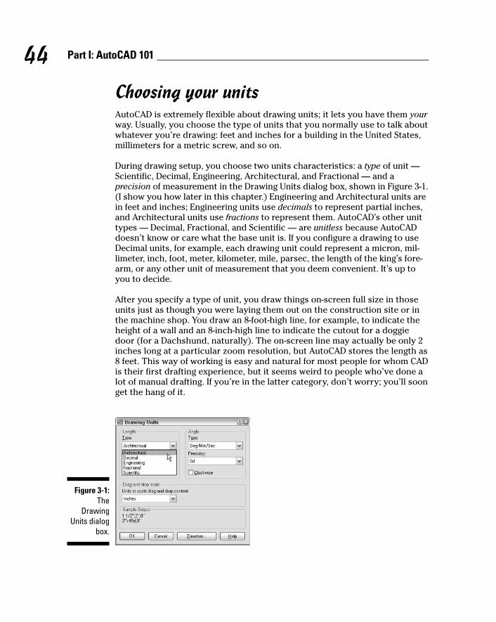
Choosing your unitsAutoCAD is extremely flexible about drawing units; it lets you have them yourway. Usually, you choose the type of units that you normally use to talk aboutwhatever you’re drawing: feet and inches for a building in the United States,millimeters for a metric screw, and so on.
During drawing setup, you choose two units characteristics: a type of unit —Scientific, Decimal, Engineering, Architectural, and Fractional — and a precision of measurement in the Drawing Units dialog box, shown in Figure 3-1.(I show you how later in this chapter.) Engineering and Architectural units arein feet and inches; Engineering units use decimals to represent partial inches,and Architectural units use fractions to represent them. AutoCAD’s other unittypes — Decimal, Fractional, and Scientific — are unitless because AutoCADdoesn’t know or care what the base unit is. If you configure a drawing to useDecimal units, for example, each drawing unit could represent a micron, mil-limeter, inch, foot, meter, kilometer, mile, parsec, the length of the king’s fore-arm, or any other unit of measurement that you deem convenient. It’s up toyou to decide.
After you specify a type of unit, you draw things on-screen full size in thoseunits just as though you were laying them out on the construction site or inthe machine shop. You draw an 8-foot-high line, for example, to indicate theheight of a wall and an 8-inch-high line to indicate the cutout for a doggiedoor (for a Dachshund, naturally). The on-screen line may actually be only 2inches long at a particular zoom resolution, but AutoCAD stores the length as8 feet. This way of working is easy and natural for most people for whom CADis their first drafting experience, but it seems weird to people who’ve done alot of manual drafting. If you’re in the latter category, don’t worry; you’ll soonget the hang of it.
Figure 3-1:The
DrawingUnits dialog
box.
44 Part I: AutoCAD 101
d571389 Ch03.qxd 4/12/04 9:43 AM Page 44
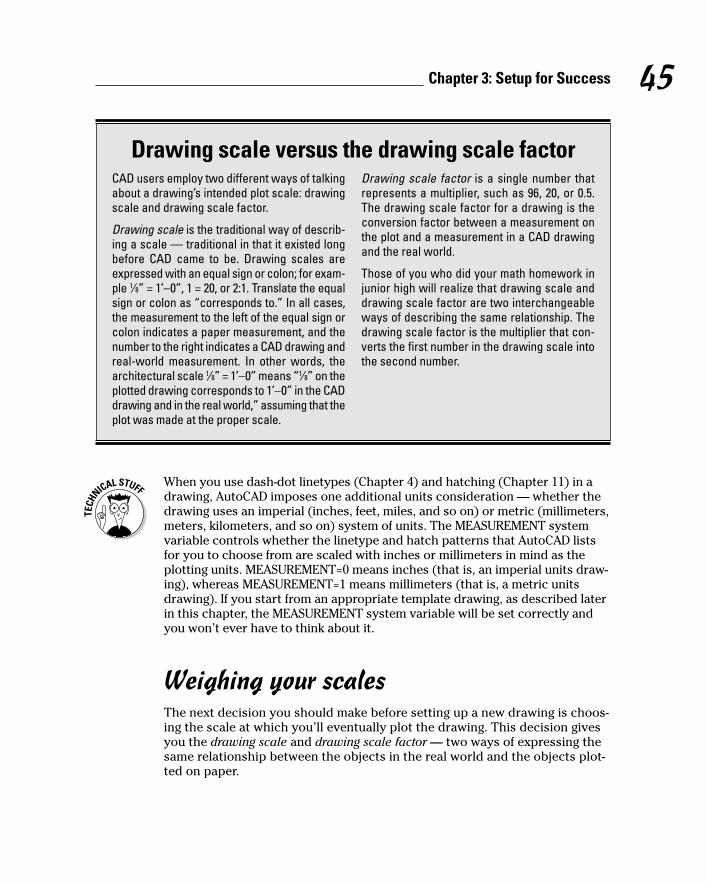
When you use dash-dot linetypes (Chapter 4) and hatching (Chapter 11) in adrawing, AutoCAD imposes one additional units consideration — whether thedrawing uses an imperial (inches, feet, miles, and so on) or metric (millimeters,meters, kilometers, and so on) system of units. The MEASUREMENT systemvariable controls whether the linetype and hatch patterns that AutoCAD listsfor you to choose from are scaled with inches or millimeters in mind as theplotting units. MEASUREMENT=0 means inches (that is, an imperial units draw-ing), whereas MEASUREMENT=1 means millimeters (that is, a metric unitsdrawing). If you start from an appropriate template drawing, as described laterin this chapter, the MEASUREMENT system variable will be set correctly andyou won’t ever have to think about it.
Weighing your scalesThe next decision you should make before setting up a new drawing is choos-ing the scale at which you’ll eventually plot the drawing. This decision givesyou the drawing scale and drawing scale factor — two ways of expressing thesame relationship between the objects in the real world and the objects plot-ted on paper.
45Chapter 3: Setup for Success
Drawing scale versus the drawing scale factorCAD users employ two different ways of talkingabout a drawing’s intended plot scale: drawingscale and drawing scale factor.
Drawing scale is the traditional way of describ-ing a scale — traditional in that it existed longbefore CAD came to be. Drawing scales areexpressed with an equal sign or colon; for exam-ple 1⁄8” = 1’–0”, 1 = 20, or 2:1. Translate the equalsign or colon as “corresponds to.” In all cases,the measurement to the left of the equal sign orcolon indicates a paper measurement, and thenumber to the right indicates a CAD drawing andreal-world measurement. In other words, thearchitectural scale 1⁄8” = 1’–0” means “1⁄8” on theplotted drawing corresponds to 1’–0” in the CADdrawing and in the real world,” assuming that theplot was made at the proper scale.
Drawing scale factor is a single number thatrepresents a multiplier, such as 96, 20, or 0.5.The drawing scale factor for a drawing is theconversion factor between a measurement onthe plot and a measurement in a CAD drawingand the real world.
Those of you who did your math homework injunior high will realize that drawing scale anddrawing scale factor are two interchangeableways of describing the same relationship. Thedrawing scale factor is the multiplier that con-verts the first number in the drawing scale intothe second number.
d571389 Ch03.qxd 4/12/04 9:43 AM Page 45

You shouldn’t just invent some arbitrary scale based on your CD-ROM speedor camera’s zoom lens resolution. Most industries work with a fairly small setof approved drawing scales that are related to one another by factors of 2 or10. If you use other scales, you’ll at best be branded a clueless newbie — andat worst have to redo all your drawings at an approved scale.
Table 3-1 lists some common architectural drawing scales, using both Englishand metric units. (Ratios such as 1:200 are unitless. Building plan and detailmeasurements often are expressed in millimeters, so you can think of 1:200as meaning “1 millimeter on the plotted drawing equals 200 millimeters inactual building.”) The table also lists the drawing scale factor correspondingto each drawing scale and the common uses for each scale. If you work inother industries than those listed here, ask drafters or coworkers what thecommon drawing scales are and for what kinds of drawings they’re used.
Table 3-1 Common Architectural Drawing ScalesDrawing Scale Drawing Scale Factor Common Uses
1⁄16” = 1’–0” 192 Large building plans
1⁄8” = 1’–0” 96 Building plans
1⁄4” = 1’–0” 48 House plans
1⁄2” = 1’–0” 24 Plan details
1” = 1’–0” 12 Details
1:200 200 Large building plans
1:100 100 Building plans
1:50 50 House plans
1:20 20 Plan details
1:10 10 Details
After you choose a drawing scale, engrave the corresponding drawing scalefactor on your desk, write it on your hand, and put it on a sticky note on yourmonitor. You need to know the drawing scale factor for many drawing tasks, aswell as for some plotting. You should be able to recite the drawing scale factorof any drawing you’re working on in AutoCAD without even thinking about it.
Even if you will use the Plot dialog box’s Fit to Paper option, rather than aspecific scale factor, to plot the drawing, you need to choose an artificialscale to make text, dimensions, and other annotations appear at a useful size.Choose a scale that’s in the neighborhood of the Fit to Paper plotting factor,which AutoCAD displays in the Plot Scale area of the Plot dialog box. Forexample, if you determine that you need to squeeze your drawing down
46 Part I: AutoCAD 101
d571389 Ch03.qxd 4/12/04 9:43 AM Page 46
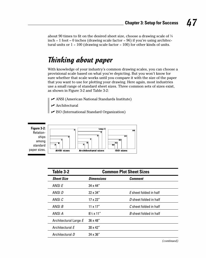
about 90 times to fit on the desired sheet size, choose a drawing scale of 1⁄8inch = 1 foot – 0 inches (drawing scale factor = 96) if you’re using architec-tural units or 1 = 100 (drawing scale factor = 100) for other kinds of units.
Thinking about paperWith knowledge of your industry’s common drawing scales, you can choose aprovisional scale based on what you’re depicting. But you won’t know forsure whether that scale works until you compare it with the size of the paperthat you want to use for plotting your drawing. Here again, most industriesuse a small range of standard sheet sizes. Three common sets of sizes exist,as shown in Figure 3-2 and Table 3-2:
� ANSI (American National Standards Institute)
� Architectural
� ISO (International Standard Organization)
Table 3-2 Common Plot Sheet SizesSheet Size Dimensions Comment
ANSI E 34 x 44”
ANSI D 22 x 34” E sheet folded in half
ANSI C 17 x 22” D sheet folded in half
ANSI B 11 x 17” C sheet folded in half
ANSI A 81⁄2 x 11” B sheet folded in half
Architectural Large E 36 x 48”
Architectural E 30 x 42”
Architectural D 24 x 36”
(continued)
Figure 3-2:Relation-
shipsamong
standardpaper sizes.
47Chapter 3: Setup for Success
d571389 Ch03.qxd 4/12/04 9:43 AM Page 47

Table 3-2 (continued)Sheet Size Dimensions Comment
Architectural C 18 x 24”
Architectural B 12 x 18”
Architectural A 9 x 12”
ISO A0 841 x 1189 mm
ISO A1 594 x 841 mm A0 sheet folded in half
ISO A2 420 x 594 mm A1 sheet folded in half
ISO A3 297 x 420 mm A2 sheet folded in half
ISO A4 210 x 297 mm A3 sheet folded in half
You select a particular set of sheet sizes based on the common practices inyour industry. You then narrow down your choice based on the area requiredby what you’re going to draw. For example, most architectural plans are plot-ted on Architectural D or E size sheets.
If you know the desired sheet size and drawing scale factor, you can calculatethe available drawing area easily. Simply multiply each of the sheet’s dimen-sions (X and Y) by the drawing scale factor. For example, if you choose an 11-x-17-inch sheet and a drawing scale factor of 96 (corresponding to a plotscale of 1⁄8” = 1’–0”), you multiply 17 times 96 and 11 times 96 to get an avail-able drawing area of 1,632 inches x 1,056 inches (or 136 feet x 88 feet). If yoursheet size is in inches but your drawing scale is in millimeters, you need tomultiply by an additional 25.4 to convert from inches to millimeters. Forexample, with an 11-x-17-inch sheet and a scale of 1:200 (drawing scale factor= 200), you multiply 17 times 200 times 25.4 and 11 times 200 times 25.4 to get86,360 x 55,880 mm or 86.36 x 55.88 m — not quite big enough for a footballfield (United States or European football).
Conversely, if you know the sheet size that you’re going to use and the real-world size of what you’re going to draw, and you want to find out the largestplot scale you can use, you have to divide, not multiply. Divide the neededreal-world drawing area dimensions (X and Y) by the sheet’s dimensions (Xand Y). Take the larger number — either X or Y — and round up to the near-est real drawing scale factor (that is, one that’s commonly used in your indus-try). For example, suppose you want to draw a 60-x-40-foot or, 720-x-480-inch,floor plan and print it on 11-x-17-inch paper. You divide 720 by 17 and 480 by11 to get 42.35 and 43.64, respectively. The larger number, 43.64, correspondsin this example to the short dimension of the house and the paper. The near-est larger common architectural drawing scale factor is 48 (corresponding to1⁄4” = 1’–0”), which leaves a little room for the plotting margin and title block.
48 Part I: AutoCAD 101
d571389 Ch03.qxd 4/12/04 9:43 AM Page 48
The Cheat Sheet at the front of this book includes two tables that list theavailable drawing areas for a range of sheet sizes and drawing scales. Usethose tables to help you decide on an appropriate paper size and drawingscale, and revert to the calculation method for situations that the tablesdon’t cover. (If you don’t keep a favorite old calculator on your physical desk-top, this may be a good time to put a shortcut to the Windows Calculator onyour virtual one.)
When you select a sheet size and drawing scale, always leave some extraroom for the following two reasons:
� Most plotters and printers can’t print all the way to the edge of the sheet — they require a small margin. For example, my trusty old Hewlett-Packard LaserJet III has a printable area of about 7.9 x 10.5 inches on an8.5-x-11-inch ANSI A size (letter size) sheet. (You’ll find this information in the Plot dialog box, as described in Chapter 12.) If you’re a stickler forprecision, you can use the printable area instead of the physical sheetarea in the calculations described earlier in this section.
� Most drawings require some annotations — text, grid bubbles, and so on — outside the objects you’re drawing, plus a title block surroundingthe objects and annotations. If you don’t leave some room for the annota-tions and title block, you’ll end up having to cram things together toomuch or to change to a different sheet size. Either way, you’ll be sloweddown later in the project when you can least afford it. Figure 3-3 shows anextreme example of selecting a sheet size that’s too small or, conversely, adrawing scale that’s too large. In this example, the building is too long forthe sheet, and it overlaps the title block on both the right and left sides.
Some industries deal with the “sheet-is-too-small/drawing-scale-is-too-large”problem by breaking drawings up onto multiple plotted sheets.
Don’t be afraid to start with paper. Experienced drafters often make a quick,throwaway pencil and paper sketch called a cartoon. A drawing cartoon usu-ally includes a rectangle indicating the sheet of paper you intend to plot on, asketch of the title block, and a very rough, schematic sketch of the thingyou’re going to draw. It helps to scribble down the dimensions of the sheet,the main title block areas, and the major objects to be drawn. By sketchingout a cartoon, you’ll often catch scale or paper size problems before you setup a drawing, when repairs only take a few minutes, not after you’ve createdthe drawing, when fixing the problem can take hours.
49Chapter 3: Setup for Success
d571389 Ch03.qxd 4/12/04 9:43 AM Page 49

Defending your borderThe next decision to make is what kind of border your drawing deserves. Theoptions include a full-blown title block, a simple rectangle, or nothing at allaround your drawing. If you need a title block, do you have one, can youborrow an existing one, or will you need to draw one from scratch? Althoughyou can draw title block geometry in an individual drawing, you’ll save timeby reusing the same title block for multiple drawings. Your company mayalready have a standard title block drawing ready to use, or someone elsewho’s working on your project may have created one for the project.
The right way to draw a title block is in a separate DWG file at its normal plot-ted size (for example, 36 inches long by 24 inches high for an architectural Dsize title block). You then insert or xref the title block drawing into each sheetdrawing. Chapter 13 describes how to insert and xref separate DWG files.
All system variables goAs Chapter 2 describes, AutoCAD includes a slew of system variables that con-trol the way your drawing and the AutoCAD program work. Much of the draw-ing setup process involves setting system variables based on the drawing
Figure 3-3:“This sheet
size is toosmall,” saidGoldilocks.
50 Part I: AutoCAD 101
d571389 Ch03.qxd 4/12/04 9:43 AM Page 50

scale, sheet size, and other desired properties of the drawing. You can setsome system variables in AutoCAD dialog boxes, but a few require that youtype at the command line. Table 3-3 shows the settings that you most com-monly need to change — or at least check — during drawing setup, alongwith the names of the corresponding system variables. Later in the chapter,in the section “The Main Course: Model Space,” I show you the procedure forchanging these settings.
Table 3-3 System Variables for Drawing SetupSetting Dialog Box System Variables
Linear units and precision Drawing Units LUNITS, LUPREC
Angular units and precision Drawing Units AUNITS, AUPREC
Grid spacing and visibility Drafting Settings GRIDUNIT, GRIDMODE
Snap spacing and on/off Drafting Settings SNAPUNIT, SNAPMODE
Drawing limits None (use LIMMIN, LIMMAXcommand line)
Linetype scale Linetype Manager LTSCALE, PSLTSCALE
Dimension scale Dimension Style DIMSCALEManager
Getting Creative with TemplatesWhen you start AutoCAD 2004 with its desktop shortcut or from the WindowsStart menu, AutoCAD creates a new, blank drawing based on the default tem-plate drawing (Acad.dwt). When you explicitly create a new drawing fromwithin AutoCAD, the Select Template dialog box, shown in Figure 3-4, appearsby default so that you can choose a template on which to base your newdrawing.
A template is simply a drawing whose name ends in the letters DWT, whichyou use as the starting point for another drawing. When you create a newdrawing from a template, AutoCAD makes a copy of the template file andopens the copy in a new drawing editor window. The first time you save thefile, you’re prompted for a new filename to save to; the original template filestays unchanged.
You may be familiar with the Microsoft Word or Excel template documents,and AutoCAD template drawings work pretty much the same way — becauseAutodesk stole the idea from them! (Encouraged, of course, by Microsoft.)
51Chapter 3: Setup for Success
d571389 Ch03.qxd 4/12/04 9:43 AM Page 51

Using a suitable template can save you time and worry because many of thesetup options are already set correctly for you. You know the drawing willprint correctly; you just have to worry about getting the geometry and textright. Of course, all this optimism assumes that the person who set up thetemplate knew what he or she was doing.
The stock templates that come with AutoCAD are okay as a starting point,but you’ll need to modify them to suit your purposes, or create your ownfrom scratch. In particular, the stock AutoCAD templates aren’t set up for thescales that you’ll want to use. The instructions in the rest of this chapter tellyou how to specify scale-dependent setup information.
So the only problems with templates are creating good ones and then laterfinding the right one to use when you need it. Later in this chapter, in the sec-tion “Cooking Up Terrific Templates,” I show you how to create templates fromyour own setup drawings. Here I show you how to use an already created tem-plate, such as one of the templates that comes with AutoCAD 2004 or from oneof your CAD-savvy colleagues. If you’re lucky, someone in your office will havecreated suitable templates that you can use to get going quickly.
Follow these steps to create a new drawing from a template drawing:
1. Run the NEW command by pressing Ctrl+N or choosing File➪New.
The Select Template dialog box appears.
The first button on the Standard toolbar runs the QNEW (“Quick NEW”)command instead of the ordinary NEW command. Unless you or some-one else has changed the Drawing Template Settings in the Optionsdialog box, QNEW does the same thing as NEW. See “Cooking Up TerrificTemplates,” later in this chapter, for information about how to takeadvantage of QNEW.
Figure 3-4:A plateful oftemplates to
contemplate.
52 Part I: AutoCAD 101
d571389 Ch03.qxd 4/12/04 9:43 AM Page 52
2. Click the name of the template that you want to use as the startingpoint for your new drawing.
3. Click the Open button.
A new drawing window with a temporary name, such as Drawing2.dwg,appears. (The template you opened remains unchanged on your harddisk.)
Depending on which template you choose, your new drawing may openwith a paper space layout tab, not the Model tab, selected. If that’s thecase, click the Model tab before changing the settings described in “TheMain Course: Model Space.” The section “Plot Layouts for Any Palate,”later in this chapter, describes how to set up and take advantage ofpaper space layouts.
4. Press Ctrl+S and save the file under a new name.
Take the time to save the drawing to the appropriate name and location now.
5. Make needed changes.
For most of the templates that come with AutoCAD, you need to con-sider changing the units, limits, grid and snap settings, linetype scale,and dimension scale. See the section, “The Main Course: Model Space,”for instructions.
6. Consider saving the file as a template.
If you’ll need other drawings in the future similar to the current one,consider saving your modified template as a template in its own right.See the section “Cooking Up Terrific Templates” later in this chapter.
The simplest, no-frills templates are Acad.dwt (for people who customar-ily work with sheet sizes expressed in inches) and Acadiso.dwt (forpeople who customarily work with sheet sizes expressed in millimeters).Most of the remaining templates that come with AutoCAD include titleblocks for various sizes of sheets. In addition, most templates come intwo versions — one for people who use color-dependent plot styles andone for people who use named plot styles. You probably want the color-dependent versions. (Chapter 12 describes the two kinds of plot stylesand why you probably want the color-dependent variety.) I warned youthat this drawing setup stuff would be complicated!
If you dig around in the Options dialog box, you may discover a setting thatturns on the old Startup dialog box, which offers several options other thanstarting with a template. Among these options are the enticingly named SetupWizards. These so-called wizards were lame when they first appeared; they’reno better now. Autodesk acknowledges as much by making them almostimpossible to find in AutoCAD 2005.
53Chapter 3: Setup for Success
d571389 Ch03.qxd 4/12/04 9:43 AM Page 53

The Main Course: Model SpaceMost drawings require a two-part setup:
1. First, set up the model space tab, where you’ll create most of your drawing.
2. Next, create one or more paper space layout tabs for plotting.
After you’ve decided on drawing scale and sheet size, you can perform modelspace setup as described in this section.
Setting your unitsFirst, you should set the linear and angular units that you want to use in yournew drawing. The following procedure describes how:
1. Choose Format➪Units from the menu bar.
The Drawing Units dialog box appears, as shown in Figure 3-5.
2. Choose a linear unit type from the Length Type drop-down list.
Choose the type of unit representation that’s appropriate for your work.Engineering and Architectural units are displayed in feet and inches; theother types of units aren’t tied to any particular unit of measurement.You decide whether each unit represents a millimeter, centimeter, meter,inch, foot, or something else. Decimal units usually are a good choice formetric drawings.
Figure 3-5:The default
unit-lessunits.
54 Part I: AutoCAD 101
d571389 Ch03.qxd 4/12/04 9:43 AM Page 54
AutoCAD can think in inches! If you’re using Engineering or Architecturalunits (feet and inches), AutoCAD understands any coordinate you enteras a number of inches. You use the ’ (apostrophe) character on your key-board to indicate a number in feet instead of inches.
3. From the Length Precision drop-down list, choose the degree of precision you want when AutoCAD displays coordinates and linearmeasurements.
The precision setting controls how precisely AutoCAD displays coordi-nates, distances, and prompts in some dialog boxes. In particular, theCoordinates box on the status bar displays the current cursor coordi-nates using the current precision. A grosser — that is, less precise — precision setting makes the numbers displayed in the status bar morereadable and less jumpy. So be gross for now; you can always act a littleless gross later.
The linear and angular precision settings only affect AutoCAD’s display ofcoordinates, distances, and angles on the status bar, in dialog boxes, andin the command line area. For drawings stored as DWG files, AutoCADalways uses maximum precision to store the locations and sizes of allobjects that you draw. In addition, AutoCAD provides separate settings forcontrolling the precision of dimension text — see Chapter 10 for details.
4. Choose an angular unit type from the Angle Type drop-down list.
Decimal Degrees and Deg/Min/Sec are the most common choices.
The Clockwise check box and the Direction button provide additionalangle measurement options, but you’ll rarely need to change the defaultsettings: Measure angles counterclockwise and use east as the 0 degreedirection.
5. From the Angle Precision drop-down list, choose the degree of preci-sion you want when AutoCAD displays angular measurements.
6. In the Drag-and-Drop Scale area, choose the units of measurement forthis drawing.
Choose your base unit for this drawing — that is, the real-world distancerepresented by one AutoCAD unit.
7. Click OK to exit the dialog box and save your settings.
Telling your drawing its limitsThe next model space setup task is to set your drawing’s limits. You wouldn’twant it staying out all night and hanging out with just anybody, would you?The limits represent the rectangular working area that you’ll draw on, whichusually corresponds to the paper size. Setting limits correctly gives you thefollowing advantages:
55Chapter 3: Setup for Success
d571389 Ch03.qxd 4/12/04 9:43 AM Page 55

� When you turn on the grid (described in the section, “Making the draw-ing snap-py (and grid-dy),” later in this chapter), the grid displays in therectangular limits area. With the grid on and the limits set correctly, youalways see the working area that corresponds to what you’ll eventuallybe plotting, so you won’t accidentally color outside the lines.
� The ZOOM command’s All option zooms to the greater of the limits orthe drawing extents. (The extents of a drawing consist of a rectangulararea just large enough to include all the objects in the drawing.) Whenyou set limits properly and color within the lines, ZOOM All gives you aquick way to zoom to your working area.
� If you plot from model space, you can choose to plot the limits area.This option gives you a quick, reliable way to plot your drawing, butonly if you’ve set limits correctly!
Many CAD drafters don’t set limits properly in their drawings. After you readthis section, you can smugly tell them why they should and how.
You can start the LIMITS command from a menu choice, but all subsequentaction takes place on the command line; despite the importance of the topic,AutoCAD has no dialog box for setting limits.
The following procedure shows you how to set your drawing limits:
1. Choose Format➪Drawing Limits from the menu bar to start the LIMITScommand; or type LIMITS on the command line and press Enter.
The LIMITS command appears on the command line, and the commandline displays the following prompt at the bottom of the screen:
Command: limitsReset Model space limits:Specify lower left corner or [ON/OFF] <0.000,0.0000>:
The value at the end of the last line of the prompt is the default value forthe lower-left corner of the drawing limits. It appears according to theunits and precision that you selected in the Drawing Units dialog box —for example, 0’–0” if you selected Architectural units with precision tothe nearest inch.
2. Type the lower-left corner of the limits you want to use and pressEnter.
The usual value to enter at this point is 0,0. (Type a zero, a comma, andthen another zero, with no spaces.) You can just press Enter to acceptthe default value.
AutoCAD now prompts you for the upper-right corner of the limits:
Specify upper right corner <12.0000,9.0000>:
56 Part I: AutoCAD 101
d571389 Ch03.qxd 4/12/04 9:43 AM Page 56

The initial units offered by AutoCAD correspond to an architectural A sizesheet of paper in landscape orientation. (Almost no one uses ArchitecturalA size paper; here’s a classic example of a programmer choosing a sillydefault that no one has bothered to change in 22 years!)
3. Type the upper-right corner of the limits you want to use and pressEnter.
You calculate the usual setting for the limits upper-right corner by multi-plying the paper dimensions by the drawing scale factor. For example, ifyou’re setting up a 1⁄8” = 1’–0” drawing (drawing scale factor = 96) to beplotted on a 24-x-36-inch sheet in landscape orientation, the upper-rightcorner of the limits should be 36 inches times 96, 24 inches times 96.Okay, pencils down. The correct answer is 3456,2304 (or 288 feet,192 feet).
Alternatively, you can cheat when specifying limits and read the limitsfrom the tables on the Cheat Sheet.
If you have the grid turned on, AutoCAD redisplays it in the new limitsarea after you press Enter.
If you’re using Architectural or Engineering units and you want to entermeasurements in feet and not inches, you must add the foot designatorafter the number, such as 6’; otherwise, AutoCAD assumes that youmean inches.
4. Choose View➪Zoom➪All.
AutoCAD zooms to the new limits.
Making the drawing area snap-py (and grid-dy)AutoCAD’s grid is a set of evenly spaced, visible dots that serve as a visualdistance reference. (As I describe in “Telling your drawing its limits,” earlierin this section, the grid also indicates how far the drawing limits extend.)AutoCAD’s snap feature creates a set of evenly spaced, invisible hot spots,which makes the cursor move in nice, even increments. Both grid and snapare like the intersection points of the lines on a piece of grid paper, but grid issimply a visual reference, whereas snap constrains the points that you canpick with the mouse. You can — and usually will — set the grid and snapspacing to different distances.
Set the grid and the snap intervals in the Drafting Settings dialog box withthese steps:
1. Right-click the Snap or Grid button in the status bar and choose Settings.
The Drafting Settings dialog box appears with the Snap and Grid tabselected, as shown in Figure 3-6.
57Chapter 3: Setup for Success
d571389 Ch03.qxd 4/12/04 9:43 AM Page 57

The Snap and Grid tab has four parts, but the Snap and Grid sections areall you need to worry about for most drafting work.
2. Select the Snap On check box to turn on snap.
This action creates default snaps half a unit apart.
3. Enter the Snap X Spacing for the snap interval in the accompanyingtext box.
Use the information in the sections preceding this procedure to decideon a reasonable snap spacing.
The Y spacing automatically changes to equal the X spacing, which isalmost always what you want.
4. Select the Grid On check box to turn on the grid.
5. Enter the Grid X Spacing for the grid in the accompanying text box.
Use the information in the sections preceding this procedure to decideon a reasonable grid spacing.
The Y spacing automatically changes to equal the X spacing. As with thesnap spacing, you usually want to leave it that way.
X measures horizontal distance; Y measures vertical distance. TheAutoCAD drawing area normally shows an X and Y icon in case youforget.
6. Click OK to close the Drafting Settings dialog box.
You can also click the SNAP button on the status bar to toggle snap on andoff; the same goes for the GRID button and the grid setting.
Figure 3-6:Get yourDraftingSettings
here!
58 Part I: AutoCAD 101
d571389 Ch03.qxd 4/12/04 9:43 AM Page 58

Setting linetype and dimension scalesEven though you’ve engraved the drawing scale factor on your desk and writ-ten it on your hand — not vice versa — AutoCAD doesn’t know the drawingscale until you enter it. Keeping AutoCAD in the dark is fine as long as you’rejust drawing continuous lines and curves representing real-world geometry,because you draw these objects at their real-world size, without worryingabout plot scale.
59Chapter 3: Setup for Success
Making snap (and grid) decisionsYou can set your grid spacing to work in one oftwo ways: to help with your drawing or to helpyou remain aware of how objects will relate toyour plot. For a grid that helps with your draw-ing, set the grid points a logical number of mea-surement units apart. For example, you mightset the grid to 30 feet (10 yards) on a drawing ofa (U.S.) football field. This kind of setting makesyour work easier as you draw.
Another approach is to choose a grid spacingthat represents a specific distance, such as 1inch or 25 millimeters, on your final plot. If youwant the grid to represent 1 inch on the plot andyour drawing units are inches, enter the draw-ing scale factor. For example, in a 1⁄4” = 1’–0”drawing, you’d enter the drawing scale factorof 48. A 48-inch grid interval in your drawingcorresponds to a 1-inch interval on the plotwhen you plot to scale. If your drawing units aremillimeters and you want the grid to represent25 millimeters on the plot, enter the drawingscale factor times 25. For example, in a 1:50drawing, you’d enter 25 x 50, or 1250.
In most cases, you’ll want to set the snap inter-val considerably smaller than the grid spacing.A good rule is to start with a snap spacing in therange of the size of the smallest objects thatyou’ll be drawing — 6 inches or 100 millimetersfor a building plan, 0.5 inches or 5 millimeters foran architectural detail, 1⁄16 inch or 1 millimeterfor a small mechanical component, and so on.
Leaving the grid on in your drawing all the time isworthwhile because it provides a visual reminderof how far apart things are. This visual referenceis especially useful as you zoom in and out.
You don’t always want to leave snap turned on,however. Some drawings, such as contourmaps, are made up mostly of objects with weird,uneven measurements. Even drawings withmany objects that fall on convenient spacingswill have some unruly objects that don’t. In addi-tion, you sometimes need to turn off snap tem-porarily to select objects. Despite thesecaveats, snap is a useful tool in most drawings.
Setting the snap spacing to a reasonable valuewhen you set up a new drawing is a good idea.Toggle snap off (by clicking the SNAP button onthe status bar or pressing the F9 key) when youdon’t need it or find that it’s getting in the way.Toggle snap on before drawing objects thatalign with specific spacings, including text anddimension strings that you want to align neatly.
To use snap effectively, you need to make thesnap setting smaller as you zoom in and workon more detailed areas, and larger as you zoomback out. You are likely to find yourself chang-ing the snap setting fairly frequently. The gridsetting, on the other hand, can usually remainconstant even as you work at different zoomsettings; that keeps you oriented as to how farzoomed in you are in the drawing.
d571389 Ch03.qxd 4/12/04 9:43 AM Page 59

As soon as you start adding dimensions (measurements that show the size ofthe things you’re drawing) and using dash-dot linetypes (line patterns thatcontain gaps in them), you need to tell AutoCAD how to scale the parts of thedimensions and the gaps in the linetypes based on the plot scale. If youforget this, the dimension text and arrowheads can come out very tiny orvery large when you plot the drawing, and dash-dot linetype patterns canlook waaaay too big or too small. Figure 3-7 shows what I mean.
The scale factor that controls dash-dot linetypes is found in a system variablecalled LTSCALE (as in LineType SCALE). The scaling factor that controlsdimensions is found in a system variable called DIMSCALE. You can changeeither of these settings at any time, but it’s best to set them correctly whenyou’re setting up the drawing.
The following sequence includes directions for typing system variable andcommand names. When the names are mixed case (for example, LTScale),you can type the full name (LTSCALE) or just the letters shown in uppercase(LTS) before pressing Enter.
To set the linetype scale from the command line, follow these steps:
1. Type LTScale on the command line and press Enter.
AutoCAD responds with a prompt, asking you for the scale factor. Thevalue at the end of the prompt is the current linetype scale setting, as inthe following example:
Enter new linetype scale factor <1.0000>:
2. Type the value you want for the linetype scale on the command lineand press Enter.
The easiest choice is to set the linetype scale to the drawing scale factor.Some people (myself included) find that the dashes and gaps in dash-dot linetypes get a bit too long when they use the drawing scale factor. If you’re one of those people, set LTSCALE to one-half of the drawingscale factor.
Figure 3-7:The
dimensionand linetypescales need
to be justright.
60 Part I: AutoCAD 101
d571389 Ch03.qxd 4/12/04 9:43 AM Page 60
Alternatively, you can set LTSCALE in the Linetype Manager dialog box:Choose Format➪Linetype, click the Show Details button, and type yourdesired linetype scale in the Global Scale Factor edit box.
To change the dimension scale, use the Dimension Style Manager dialog box. Idescribe dimensions in detail in Chapter 10, but you should get in the habit ofsetting the dimension scale during drawing setup. To do so, follow these steps:
1. Choose Format➪Dimension Style from the menu bar, or enterDimstyle at the command line.
The Dimension Style Manager dialog box appears. New drawings containthe default dimension style named Standard (for English units drawings)or ISO25 (for metric drawings).
2. Click the Modify button.
The Modify Dimension Style dialog box appears.
3. Click the Fit tab.
The Fit tab options appear, including an area called Scale for DimensionFeatures.
4. In the Scale for Dimension Features area, make sure that the radiobutton next to the Use Overall Scale Of setting is selected.
5. In the text box next to Use Overall Scale Of, type the drawing scalefactor for the current drawing.
I told you that you’d be using that drawing scale factor a lot!
6. Click OK to close the Modify Dimension Style dialog box.
The Dimension Style Manager dialog box reappears.
7. Click Close.
The Dimension Style Manager dialog box closes. Now when you drawdimensions (see Chapter 10), AutoCAD will scale the dimension text andarrowheads correctly.
Before you start creating dimensions, create your own dimension style(s) forthe settings that you want to use. Chapter 10 explains why and how.
Entering drawing propertiesYou need to do one last bit of bookkeeping before you’re finished with modelspace drawing setup: Enter summary information in the Drawing Propertiesdialog box, as shown in Figure 3-8. Choose File➪Drawing Properties to openthe Drawing Properties dialog box and then click the Summary tab. Enter thedrawing scale you’re using and the drawing scale factor, plus any other infor-mation you think useful.
61Chapter 3: Setup for Success
d571389 Ch03.qxd 4/12/04 9:43 AM Page 61

Plot Layouts for Any PalateAs I describe in Chapter 2, paper space is a separate space in each drawingfor composing a printed version of that drawing. You create the drawingitself, called the model, in model space. You then can create one or more plot-table views, complete with title block. Each of these plottable views is calleda layout. AutoCAD saves separate plot settings with each layout — and withthe Model tab — so that you can plot each tab differently. In practice, you’llneed to use only one of the paper space layout tabs, especially when you’regetting started with AutoCAD.
A screen image is worth a thousand paper space explanations. If you haven’tyet seen an example out in the wild, refer to Figures 2-7 and 2-8 in Chapter 2.You also may want to open a few of the AutoCAD 2004 sample drawings andclick the Model and layout tabs to witness the variety of ways in which paperspace is used. A good place to start is \Program Files\AutoCAD 2005\Sample\Wilhome.dwg.
After you complete model space setup, you should create a layout for plot-ting. You don’t need to create the plotting layout right after you create thedrawing and do model space setup; you can wait until after you’ve drawnsome geometry. You should set up a layout sooner, not later, however. If anyscale or sheet size problems exist, it’s better to discover them early.
In AutoCAD 2005, it’s still possible to ignore paper space layouts entirely anddo all your drawing and plotting in model space. But you owe it to yourself togive layouts a try. You’ll probably find that they make plotting more consis-tent and predictable. They’ll certainly give you more plotting flexibility when
Figure 3-8:Surveying
yourdrawing’s
properties.
62 Part I: AutoCAD 101
d571389 Ch03.qxd 4/12/04 9:43 AM Page 62

you need it. And you’ll certainly encounter drawings from other people thatmake extensive use of paper space, so you need to understand it if you planto exchange drawings with anyone else.
Creating a layoutCreating a simple paper space layout is straightforward, thanks to theAutoCAD 2005 Create Layout Wizard, shown in Figure 3-9. (Yes! Finally, auseful AutoCAD wizard.) The command name is LAYOUTWIZARD, which isnot to be confused with the WAYOUTLIZARD command for drawing geckosand iguanas! In any event, you can avoid a lot of typing by choosing Tools➪Wizards➪Create Layout.
Although the Create Layout Wizard guides you step by step through theprocess of creating a paper space layout from scratch, it doesn’t eliminate thenecessity of coming up with a sensible set of layout parameters. The sheet sizeand plot scale that you choose provide a certain amount of space for showingyour model (see the information earlier in this chapter), and wizards aren’tallowed to bend the laws of arithmetic to escape that fact. For example, a mapof Texas at a scale of 1 inch = 1 foot won’t fit on an -x-11-inch sheet, no way, nohow. In other words, garbage in, garbage (lay)out. Fortunately the CreateLayout Wizard lends itself to experimentation, and you can easily delete lay-outs that don’t work.
Follow these steps to create a layout:
1. Choose Tools➪Wizards➪Create Layout, or type LAYOUTWIZARD andpress Enter.
2. Give the new layout a name and then click Next.
Figure 3-9:The Create
LayoutWizard.
63Chapter 3: Setup for Success
d571389 Ch03.qxd 4/12/04 9:43 AM Page 63

In place of the default name, Layout3, I recommend something moredescriptive — for example, D Size Sheet.
3. Choose a printer or plotter to use when plotting this layout, and thenclick Next.
Think of your choice as the default plotter for this layout. You canchange to a different plotter later, or create page setups that plot thesame layout on different plotters.
Many of the names in the configured plotter list should look familiarbecause they’re your Windows printers (system printers in AutoCADlingo). Names with a PC3 extension represent nonsystem printer drivers.See Chapter 12 for details.
4. Choose a paper size and specify whether to use inches or millimetersto represent paper units, and then click Next.
The available paper sizes depend on the printer or plotter that youselected in Step 3.
5. Specify the orientation of the drawing on the paper, and then clickNext.
The icon showing the letter A on the piece of paper shows you whichorientation is which.
6. Select a title block, or None (see Figure 3-10).
If you choose a title block, specify whether AutoCAD should insert it as aBlock — which is preferable in this case — or attach it as an xref. Thenclick Next.
Attaching a title block as an xref is a good practice if your title blockDWG file is in the same folder as the drawing that you’re working on.The Create Layout Wizard’s title blocks live in the Template folder that’s
Figure 3-10:Title blockoptions in
the CreateLayout
Wizard.
64 Part I: AutoCAD 101
d571389 Ch03.qxd 4/12/04 9:43 AM Page 64

stored with the AutoCAD Application Data files under your Windowsuser profile, which isn’t — or shouldn’t be — where you keep your pro-ject files. Thus, in this case Block is a safer choice.
Choose a title block that fits your paper size. If the title block is largerthan the paper, the Create Layout Wizard simply lets it run off the paper.
If you don’t like any of the supplied title blocks, choose None. You canalways draw, insert, or xref a title block later. See Chapter 13 for informa-tion about inserting or xrefing a title block.
The list of available title blocks comes from all the DWG files in yourAutoCAD Template folder. You can add custom title block drawings to thisdirectory (and delete ones that you never use). If you want to know whereto put them, see “Cooking Up Terrific Templates,” later in this chapter.
7. Define the arrangement of viewports that AutoCAD should create, andthe paper space to model space scale for all viewports. Then clickNext.
A paper space layout viewport is a window into model space. You mustcreate at least one viewport to display the model in your new layout. Formost 2D drawings, a single viewport is all you need. 3D models oftenbenefit from multiple viewports, each showing the 3D model from a dif-ferent perspective.
The default Viewport scale, Scaled to Fit, ensures that all of your modeldrawing displays in the viewport but results in an arbitrary scale factor.Most technical drawings require a specific scale, such as 1 = 10 or 1⁄8” =1’–0”.
8. Specify the location of the viewport(s) on the paper by picking its cor-ners. Then click Next.
After you click the Select Location button, the Create Layout Wizard dis-plays the preliminary layout with any title block that you’ve chosen.Pick two points to define a rectangle that falls within the drawing area ofyour title block (or within the plottable area of the sheet, if you chose notitle block in Step 6).
AutoCAD represents the plottable area of the sheet with a dashed rec-tangle near the edge of the sheet. If you don’t select a location for theviewport(s), the Create Layout Wizard creates a viewport that fills theplottable area of the sheet.
9. Click Finish.
AutoCAD creates the new layout.
If your projects require lots of drawings, you can parlay layouts into sheetsets — a new feature in AutoCAD 2005 that makes for more sophisticated cre-ation, management, plotting, and electronic transfer of multi-sheet drawingsets. See Chapter 14 for details.
65Chapter 3: Setup for Success
d571389 Ch03.qxd 4/12/04 9:43 AM Page 65
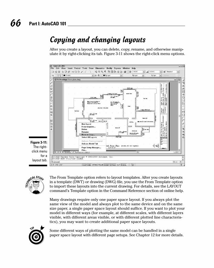
Copying and changing layoutsAfter you create a layout, you can delete, copy, rename, and otherwise manip-ulate it by right-clicking its tab. Figure 3-11 shows the right-click menu options.
The From Template option refers to layout templates. After you create layoutsin a template (DWT) or drawing (DWG) file, you use the From Template optionto import these layouts into the current drawing. For details, see the LAYOUTcommand’s Template option in the Command Reference section of online help.
Many drawings require only one paper space layout. If you always plot thesame view of the model and always plot to the same device and on the samesize paper, a single paper space layout should suffice. If you want to plot yourmodel in different ways (for example, at different scales, with different layersvisible, with different areas visible, or with different plotted line characteris-tics), you may want to create additional paper space layouts.
Some different ways of plotting the same model can be handled in a singlepaper space layout with different page setups. See Chapter 12 for more details.
Figure 3-11:The right-
click menufor a
layout tab.
66 Part I: AutoCAD 101
d571389 Ch03.qxd 4/12/04 9:43 AM Page 66

If you want to add another viewport to an existing layout, you need to becomefamiliar with the MVIEW command and the ZOOM command’s mysterious XPoption. See the MVIEW and ZOOM commands in the Command Reference section of AutoCAD online help. After you have the concepts down, using the Viewports dialog box (choose View➪Viewports➪New Viewports) andViewports toolbar can help you create and manage viewports more efficiently.
Lost in paper spaceAfter you create a paper space layout, you suddenly have two views of thesame drawing geometry: the view on your original Model tab and the newlayout tab view (perhaps decorated with a handsome title block and otheraccoutrements of plotting nobility). It’s important to realize that both viewsare of the same geometry. If you change the model geometry on one tab,you’re changing it on all tabs, because all tabs display the same model spaceobjects. It’s like seeing double after downing a few too many drinks — theduplication is in your head, not in the real world (or in this case, in the CADworld).
When you make a paper space layout current by clicking its tab, you canmove the cursor between paper space (that is, drawing and zooming on thesheet of paper) and model space (drawing and zooming on the model, insidethe viewport) in several ways, including:
� Clicking the PAPER/MODEL button on the status bar
� In the drawing area, double-clicking over a viewport to move the cursorinto model space in that viewport, or double-clicking outside all view-ports (for example, in the gray area outside the sheet) to move thecursor into paper space
� Entering MSpace or PSpace at the command prompt
When the cursor is in model space, anything you draw or edit changes themodel (and thus appears on the Model tab and on all paper space layout tabs,assuming that the given paper space layout displays that part of the underlyingmodel). When the cursor is in paper space, anything you draw appears only onthat one paper space layout tab. It’s as though you were drawing on an acetatesheet over the top of that sheet of plotter paper — the model beneath remainsunaffected.
This distinction can be disorienting at first — even if you haven’t had a fewtoo many drinks. To avoid confusion, stick with the following approach (atleast until you’re more familiar with paper space):
� If you want to edit the model, switch to the Model tab first. (Don’t try toedit the model in a paper space viewport.)
67Chapter 3: Setup for Success
d571389 Ch03.qxd 4/12/04 9:43 AM Page 67

� If you want to edit a particular plot layout without affecting the model,switch to that layout’s tab and make sure that the cursor is in paperspace.
Cooking Up Terrific TemplatesYou can create a template from any DWG file by using the Save As dialog box.Follow these steps to save your drawing as a template:
1. Choose File➪Save As from the menu bar.
The Save Drawing As dialog box appears, as shown in Figure 3-12.
2. From the Save As Type pull-down menu, choose AutoCAD DrawingTemplate (*.dwt).
3. Navigate to the folder where you want to store the drawing.
AutoCAD 2005’s default folder for template drawings is called Templateand is buried deep in the bowels of your Windows user profile. Saveyour templates there if you want them to appear in the AutoCAD’s SelectTemplate list. You can save your templates in another folder, but if youwant to use them later, you’ll have to navigate to that folder each time touse them. See the Technical Stuff paragraph after this procedure foradditional suggestions.
4. Enter a name for the drawing template in the File Name text box.
5. Click the Save button to save your drawing template.
Figure 3-12:Saving a
drawing asa template.
68 Part I: AutoCAD 101
d571389 Ch03.qxd 4/12/04 9:43 AM Page 68

The drawing is saved as a template. A dialog box for the templatedescription and units appears.
6. Enter the template’s measurement units (English or Metric).
Enter the key info now; you can’t do it later unless you save the templateto a different name. Don’t bother filling in the Description field. AutoCADdoesn’t display it later in the Select Template dialog box.
7. Click OK to save the file.
8. To save your drawing as a regular drawing, choose File➪Save As fromthe menu bar.
The Save Drawing As dialog box appears again.
9. From the Save As Type pull-down menu, choose AutoCAD 2004Drawing (*.dwg).
AutoCAD 2005 uses the same DWG file format as AutoCAD 2004, so thefile type is listed that way.
10. Navigate to the folder where you want to store the drawing.
Use a different folder from the one with your template drawings.
11. Enter the name of the drawing in the File Name text box.
12. Click the Save button to save your drawing.
The file is saved. Now, when you save it in the future, the regular file, notthe template file, gets updated.
AutoCAD 2005 includes a new command called QNEW (“Quick NEW”), which,when properly configured, can bypass the Select Template dialog box andcreate a new drawing from your favorite template. The first button on theStandard toolbar — the one with the plain white sheet of paper — runs thenew QNEW command instead of the old NEW command.
To put the Quick into QNEW, though, you have to tell AutoCAD which defaulttemplate to use: Choose Tools➪Options➪Files➪Drawing Template Settings➪Default Template File for QNEW. AutoCAD 2005’s default setting for DefaultTemplate File for QNEW is None, which causes QNEW to act just like NEW(that is, QNEW opens the Select Template dialog box).
AutoCAD 2005, unlike AutoCAD 2002 and earlier versions, stores templatedrawings and many other support files under your Windows user folder. If youwant to discover where your Template folder is, choose Tools➪Options➪Files➪Drawing Template Settings➪Drawing Template File Location. In all likeli-hood, your Template folder lives under a hidden folder, so you won’t at first be able to see it in Windows Explorer. If you want to find the template folder,choose Tools➪Folder Options➪View in Windows Explorer. Set the Hidden Filesand Folders setting to Show Hidden Files and Folders, click the OK button, andthen choose View➪Refresh. (After you snoop around, you’ll probably want toswitch back to Do Not Show Hidden Files and Folders.)
69Chapter 3: Setup for Success
d571389 Ch03.qxd 4/12/04 9:43 AM Page 69

If you want to avoid this nonsense, create a folder where you can find it easily(for example, C:\Acad-templates or F:\Acad-custom\templates on a net-work drive). Put the templates that you actually use there and change theDrawing Template File Location so that it points to your new template folder.
As this chapter demonstrates, there’s quite a bit to drawing setup inAutoCAD. As with any other initially forbidding task, take it step by step andsoon the sequence will seem natural. The Drawing Setup Roadmap on theCheat Sheet will help you stay on track and avoid missing a step.
70 Part I: AutoCAD 101
d571389 Ch03.qxd 4/12/04 9:43 AM Page 70

Part IILet There Be Lines
e571389 PP02.qxd 4/12/04 9:43 AM Page 71

In this part . . .
Lines, circles, and other elements of geometry makeup the heart of your drawing. AutoCAD offers many
different drawing commands, many ways to use them todraw objects precisely, and many properties for control-ling the objects’ display and plot appearance. After youdraw your geometry, you’ll probably spend at least asmuch time editing it as your design and drawings evolve.And in the process, you need to zoom in and out and panall around to see how the entire drawing is comingtogether. Drawing geometry, editing it, and changing thedisplayed view are the foundation of the drawing process;this part shows you how to make that foundation solid.And for those who want to build a little higher, this sec-tion ends with an introduction to 3D modeling andpresentation.
e571389 PP02.qxd 4/12/04 9:43 AM Page 72

Chapter 4
Get Ready to DrawIn This Chapter� Managing layers
� Managing other object properties: color, linetype, and lineweight
� Copying layers and other named objects with DesignCenter
� Typing coordinates at the keyboard
� Snapping to object features
� Using other precision drawing and editing techniques
CAD programs are different from other drawing programs. You need topay attention to little details like object properties and the precision of
the points that you specify when you draw and edit objects. If you just startdrawing objects without taking heed of these details, you’ll end up with anunruly mess of imprecise geometry that’s hard to edit, view, and plot.
This chapter introduces you to the AutoCAD tools and techniques that helpyou prevent making CAD messes. This information is essential before youstart drawing objects and editing them, which I describe in Chapters 5 and 6.
Drawing and Editing with AutoCADWhen you first start using AutoCAD, its most daunting requirement is thenumber of property settings and precision controls that you need to payattention to — even when you draw a simple line. Unlike in many other pro-grams, it’s not enough to draw a line in a more-or-less adequate location andthen slap some color on it. All those settings and controls can inspire thefeeling that you have to find out how to pilot an airliner to make a trip downthe street. (The advantage is that, after you are comfortable in the cockpit,AutoCAD will take you on the long-haul trips and get you there faster.)
f571389 Ch04.qxd 4/12/04 9:44 AM Page 73

These are the three keys to good CAD drawing practice:
� Pay attention to and manage the properties of every object that youdraw — especially the layer that each object is on.
� Pay attention to and manage the named objects in every drawing — thelayers, text styles, block definitions, and other nongraphical objects thatserve to define the look of all the graphical objects in the drawing.
� Pay attention to and control the precision of every point and distancethat you use to draw and edit each object.
These can seem like daunting tasks at first, but the following three sectionshelp you cut them down to size.
Managing Your PropertiesAll the objects that you draw in AutoCAD are like good Monopoly players: Theyown properties. In AutoCAD, these properties aren’t physical things; they’re anobject’s characteristics such as layer, color, linetype, and lineweight. You useproperties to communicate information about the characteristics of the objectsyou draw, such as the kinds of real-world objects they represent, their materials,their relative location in space, or their relative importance. In CAD, you alsouse the properties to organize objects for editing and plotting purposes.
You can view — and change — all of an object’s properties in the Propertiespalette. In Figure 4-1, the Properties palette shows properties for a line object.
Figure 4-1:A line rich in
properties.
74 Part II: Let There Be Lines
f571389 Ch04.qxd 4/12/04 9:44 AM Page 74
To toggle the Properties palette on and off, click the Properties button on theStandard toolbar. Before you select an object, the Properties palette displaysthe current properties — properties that AutoCAD applies to new objectswhen you draw them. After you select an object, AutoCAD displays the prop-erties for that object. If you select more than one object, AutoCAD displaysthe properties that they have in common.
Putting it on a layerEvery object has a layer as one of its properties. You may be familiar withlayers — independent drawing spaces that stack on top of each other tocreate an overall image — from using drawing programs. AutoCAD, like mostCAD programs, uses layers as the primary organizing principle for all theobjects that you draw. Layers organize objects into logical groups of thingsthat belong together; for example, walls, furniture, and text notes usuallybelong on three separate layers, for a couple of reasons:
� They give you a way to turn groups of objects on and off — both on thescreen and on the plot.
� They provide the best way of controlling object color, linetype, andlineweight.
75Chapter 4: Get Ready to Draw
Looking at layersIf you spent any time “on the boards,” as griz-zled old-timers like to call paper-and-pencildrafting, you may be familiar with the manualdrafting equivalent of layers. In pin-bar drafting,you stack a series of transparent Mylar sheets,each of which contains a part of the overalldrawing — walls on one sheet, the plumbingsystem on another, the electrical system onanother, and so on. You can get different viewsof the drawing set by including or excluding var-ious sheets.
If you’re too young to remember pin-bar drafting — or old enough to prefer not to — you may remember something similar from atextbook about human anatomy. There’s the
skeleton on one sheet, the muscles on the nextsheet that you laid over the skeleton, and so onuntil you built up a complete picture of thehuman body — that is, if your parents didn’tremove some of the more grown-up sections.
CAD layers serve a similar purpose; they enableyou to turn on or off groups of related objects.But layers do a lot more. You use them inAutoCAD to control other object display and plotproperties, such as color, linetype, andlineweight. You also can use them to makesome editing tasks more efficient and reducethe time that it takes AutoCAD to load somedrawings. Take the time to give each of yourdrawings a suitably layered look.
f571389 Ch04.qxd 4/12/04 9:44 AM Page 75

You create layers, assign them names, assign them properties such as colorand linetype, and then put objects on them. When you draw an object,AutoCAD automatically puts it on the current layer, which appears in thedrop-down list on the Layers toolbar.
Before you draw any object in AutoCAD, you should set an appropriate layercurrent — creating it first, if necessary, using the procedure described laterin this section. If the layer already exists in your drawing, you can make it thecurrent layer by choosing it in the Layers toolbar, as shown in Figure 4-2.
Make sure that no objects are selected before you use the Layer drop-downlist to change the current layer. (Press the Esc key twice to be sure.) If objectsare selected, the Layer drop-down list displays — and lets you change —those objects’ layer. When no objects are selected, the Layer drop-down listdisplays — and lets you change — the current layer.
If you forget to set an appropriate layer before you draw an object, you canselect the object and then change its layer by using either the Propertiespalette or the Layer drop-down list.
Figure 4-2:Set a
currentlayer before
you draw.
76 Part II: Let There Be Lines
f571389 Ch04.qxd 4/12/04 9:44 AM Page 76

Accumulating propertiesBesides layers, the remaining object properties that you’re likely to want touse often are color, linetype, lineweight, and possibly plot style. Table 4-1summarizes these four properties.
Table 4-1 Useful Object PropertiesProperty Controls
Color Displayed color and plotted color or lineweight
Linetype Displayed and plotted dash-dot line pattern
Lineweight Displayed and plotted line width
Plot style Plotted characteristics (see Chapter 12)
In Release 14 and older versions of AutoCAD, color also controlled the plot-ted lineweight of each object — strange, but now very common in theAutoCAD world. You may find yourself working this way even in AutoCAD2005, for compatibility with drawings (and co-workers) that use the old way,as described in the “About colors and lineweights” sidebar.
AutoCAD gives you two different ways of controlling object properties:
� By layer: Each layer has a default color, linetype, lineweight, and plotstyle property. Unless you tell AutoCAD otherwise, objects inherit theproperties of the layers on which they’re created. AutoCAD calls thisapproach controlling properties by layer.
77Chapter 4: Get Ready to Draw
Stacking up your layersHow do you decide what to call your layers andwhich objects to put on them? Some industrieshave developed layer guidelines, and manyoffices have created documented layer stan-dards. Some projects even impose specificlayer requirements. (But be careful; if someonesays, “You need a brick layer for this project,”that can mean a couple of different things.) Ask
experienced CAD drafters in your office orindustry how they use layers in AutoCAD. If youcan’t find any definitive answer, create a chartof layers for yourself. Each row in the chartshould list the layer name, default color, defaultlinetype, default lineweight, and what kinds of objects belong on that layer. Chapter 15includes an example.
f571389 Ch04.qxd 4/12/04 9:44 AM Page 77

� By object: AutoCAD also enables you to override an object’s layer’sproperty setting and give the object a specific color, linetype, lineweight,or plot style that differs from the layer’s. AutoCAD calls this approachcontrolling properties by object.
If you’ve worked with other graphics programs, you may be used to assigningproperties such as color to specific objects. If so, you’ll be tempted to use theby object approach to assigning properties in AutoCAD. Resist the tempta-tion. In almost all cases, it’s better to create layers, assign properties to eachlayer, and let the objects on each layer inherit that layer’s properties. Hereare some benefits of using the by layer approach:
� You can easily change the properties of a group of related objects thatyou put on one layer. You simply change the property for the layer, notfor a bunch of separate objects.
� Experienced drafters use the by layer approach, so if you work withdrawings from other people, you’ll be much more compatible with themif you do it the same way. You’ll also avoid getting yelled at by irate CADmanagers, whose jobs include haranguing any hapless newbies whoassign properties by object.
78 Part II: Let There Be Lines
About colors and lineweightsAutoCAD drafters traditionally have achieved dif-ferent printed lineweights by mapping variouson-screen display colors of drawing objects todifferent plotted lineweights. An AutoCAD-usingcompany may decide that red lines are to beplotted thin, green lines are to be plotted thicker,and so on. This indirect approach soundsstrange, but until AutoCAD 2000, it was the onlypractical way to plot from AutoCAD with a vari-ety of lineweights. Also, not many people plottedin color until recently, so few folks minded thefact that color was used to serve a differentmaster.
AutoCAD 2000 added lineweight as an inherentproperty of objects and the layers that they liveon. Thus, object display color can revert tobeing used for — surprise! — color. You canuse display colors to control plot colors, ofcourse. But even if you make monochromeplots, you can use color to help you distinguish
different kinds of objects when you view themon-screen or to make jazzy on-screen presen-tations of drawings for others.
Lineweights are handy, but they have quirks.Watch for these problems as you work withthem:
� Although lineweights may have beenassigned to objects in a drawing that youopen, you won’t necessarily see them onthe screen. You must turn on the Show/HideLineweight button on the AutoCAD statusbar (the button labeled LWT).
� On a slow computer or a complex drawing,showing lineweights may cause AutoCADto redraw the screen more slowly when youzoom and pan.
� You may need to zoom in on a portion of thedrawing before the differing lineweightsbecome apparent.
f571389 Ch04.qxd 4/12/04 9:44 AM Page 78

If you take my advice and assign properties by layer, all you have to do is setlayer properties in the Layer Properties Manager dialog box, as shown inFigure 4-3. Before you draw any objects, make sure the Color Control, LinetypeControl, Lineweight Control, and Plotstyle Control drop-down lists on theProperties toolbar are set to ByLayer, as shown in Figure 4-4.
If the drawing is set to use color-based plot styles instead of named plotstyles (see Chapter 12), the Plotstyle Control drop-down list will be inactiveand will display ByColor.
If you don’t like doing things the wrong way and getting yelled at by CADmanagers, don’t assign properties to objects in either of these ways:
� Don’t choose a specific color, linetype, lineweight, or plot style from theappropriate drop-down list on the Object Properties toolbar, and thendraw the objects.
� Don’t draw the objects, select them, and then choose a property fromthe same drop-down lists.
If you prefer to do things the right way, assign these properties by layer, as Idescribe in this section.
Layer control
Color control
Linetype control
Lineweight control
Plotstyle control
Figure 4-4:ByLayer all
the way.
Figure 4-3:Use layer
propertiesto control
objectproperties.
79Chapter 4: Get Ready to Draw
f571389 Ch04.qxd 4/12/04 9:44 AM Page 79
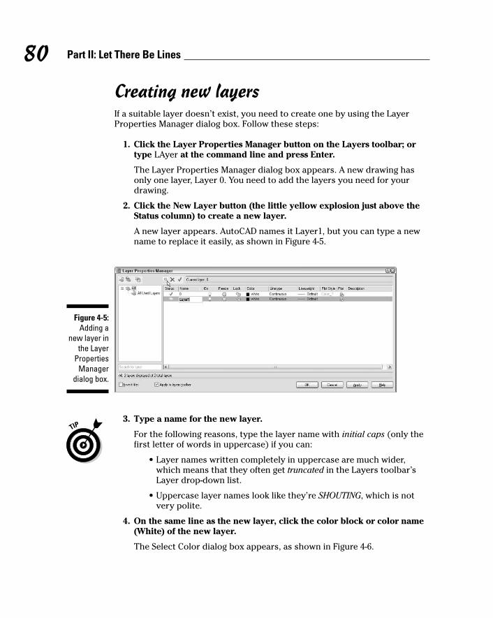
Creating new layersIf a suitable layer doesn’t exist, you need to create one by using the LayerProperties Manager dialog box. Follow these steps:
1. Click the Layer Properties Manager button on the Layers toolbar; ortype LAyer at the command line and press Enter.
The Layer Properties Manager dialog box appears. A new drawing hasonly one layer, Layer 0. You need to add the layers you need for yourdrawing.
2. Click the New Layer button (the little yellow explosion just above theStatus column) to create a new layer.
A new layer appears. AutoCAD names it Layer1, but you can type a newname to replace it easily, as shown in Figure 4-5.
3. Type a name for the new layer.
For the following reasons, type the layer name with initial caps (only thefirst letter of words in uppercase) if you can:
• Layer names written completely in uppercase are much wider,which means that they often get truncated in the Layers toolbar’sLayer drop-down list.
• Uppercase layer names look like they’re SHOUTING, which is notvery polite.
4. On the same line as the new layer, click the color block or color name(White) of the new layer.
The Select Color dialog box appears, as shown in Figure 4-6.
Figure 4-5:Adding a
new layer inthe Layer
PropertiesManager
dialog box.
80 Part II: Let There Be Lines
f571389 Ch04.qxd 4/12/04 9:44 AM Page 80
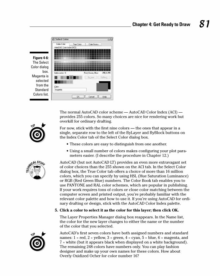
The normal AutoCAD color scheme — AutoCAD Color Index (ACI) —provides 255 colors. So many choices are nice for rendering work butoverkill for ordinary drafting.
For now, stick with the first nine colors — the ones that appear in asingle, separate row to the left of the ByLayer and ByBlock buttons onthe Index Color tab of the Select Color dialog box.
• These colors are easy to distinguish from one another.
• Using a small number of colors makes configuring your plot para-meters easier. (I describe the procedure in Chapter 12.)
AutoCAD (but not AutoCAD LT) provides an even more extravagant setof color choices than the 255 shown on the ACI tab. In the Select Colordialog box, the True Color tab offers a choice of more than 16 millioncolors, which you can specify by using HSL (Hue Saturation Luminance)or RGB (Red Green Blue) numbers. The Color Book tab enables you touse PANTONE and RAL color schemes, which are popular in publishing.If your work requires tons of colors or close color matching between thecomputer screen and printed output, you’re probably familiar with therelevant color palette and how to use it. If you’re using AutoCAD for ordi-nary drafting or design, stick with the AutoCAD Color Index palette.
5. Click a color to select it as the color for this layer; then click OK.
The Layer Properties Manager dialog box reappears. In the Name list,the color for the new layer changes to either the name or the number of the color that you selected.
AutoCAD’s first seven colors have both assigned numbers and standardnames: 1 = red, 2 = yellow, 3 = green, 4 = cyan, 5 = blue, 6 = magenta, and7 = white (but it appears black when displayed on a white background).The remaining 248 colors have numbers only. You can play fashiondesigner and make up your own names for these colors. How aboutOverly Oxidized Ocher for color number 16?
Figure 4-6:The Select
Color dialogbox.
Magenta isselectedfrom the
StandardColors list.
81Chapter 4: Get Ready to Draw
f571389 Ch04.qxd 4/12/04 9:44 AM Page 81

6. On the same line as the new layer, click the Linetype name of the new layer.
The default AutoCAD linetype is Continuous, which means no gaps inthe line.
The Select Linetype dialog box appears, as shown in Figure 4-7.
If you already loaded the linetypes you need for your drawing, the SelectLinetype dialog box displays them in the Loaded Linetypes list. If not,click the Load button to open the Load or Reload Linetypes dialog box.By default, AutoCAD displays linetypes from the standard AutoCAD 2004linetype definition file — Acad.lin for imperial units drawings orAcadiso.lin for metric units drawings. Load the desired linetype byselecting its name and clicking the OK button.
The linetypes whose names begin with ACAD_ISO are for people whouse ISO (International Organization for Standardization) linetype pat-terns. If you don’t follow ISO standards, you’ll probably find it easier touse the linetypes with the more descriptive names: CENTER, DASHED,and so on.
7. Click the desired linetype in the Loaded Linetypes list to select it asthe linetype for the layer; then click OK.
The Select Linetype dialog box disappears, returning you to the LayerProperties Manager dialog box. In the Name list, the linetype for theselected layer changes to the linetype you just chose.
8. On the same line as the new layer, click the new layer’s lineweight.
The Lineweight dialog box appears, as shown in Figure 4-8.
9. Select the lineweight you want from the scrolling list, then click OK.
The lineweight 0.00 mm tells AutoCAD to use the thinnest possiblelineweight on the screen and on the plot. I recommend that, for now, youleave lineweight set to Default and instead map screen color to plottedlineweight, as described briefly in the “About colors and lineweights”sidebar earlier in this chapter and in greater detail in Chapter 12.
Figure 4-7:The Select
Linetypedialog box.
82 Part II: Let There Be Lines
f571389 Ch04.qxd 4/12/04 9:44 AM Page 82

The default lineweight for the current drawing is defined in the LineweightSettings dialog box. After you close the Layer Properties Manager dialogbox, choose Format➪Lineweight or enter LWeight at the command line tochange the default lineweight.
You use the plot style property to assign a named plot style to the layer,but only if you’re using named plot styles in the drawing (Chapter 12explains why you probably don’t want to). The final property, Plot, con-trols whether the layer’s objects appear on plots. Toggle this setting offfor any layer whose objects you want to see on the screen but hide onplots.
10. If you want to add a description to the layer, scroll the layer list to theright to see the Description column, click twice in the Description boxcorresponding to your new layer, and type a description.
Layer descriptions are a new feature of AutoCAD 2005. If you choose touse them, stretch the Layer Properties Manager dialog box to the right sothat you can see the descriptions without having to scroll the layer list.
11. Repeat Steps 2 through 10 to create any other layers that you want.
12. Select the new layer that you want to make current and click the SetCurrent button (the green check mark).
The current layer is the one on which AutoCAD places new objects thatyou draw.
13. Click OK to accept the new layer settings.
The Layer drop-down list on the Layers toolbar now displays your newlayer as the current layer.
After you create layers, you can set any one of them to be the current layer.Make sure that no objects are selected; then choose the layer name from theLayer drop-down list on the Layers toolbar.
Figure 4-8:The
Lineweightdialog box.
83Chapter 4: Get Ready to Draw
f571389 Ch04.qxd 4/12/04 9:44 AM Page 83

After you create layers and drawn objects on them, you use the LayerProperties Manager dialog box to change layer properties. For example, youcan turn a layer off or on to hide or show the objects on that layer.
If you find yourself using lots of layers, you can create layer filters to makeviewing and managing the layer list easier. AutoCAD 2005 provides two kindsof layer filters: group and property. A group filter is simply a subset of layersthat you choose (by dragging layer names into the group filter name or byselecting objects in the drawing). A property filter is a subset of layers thatAutoCAD creates and updates automatically based on layer property criteriathat you define (for example, all layer names whose names contain the textWall or whose color is green). To find out more, click the Help button on theLayer Properties Manager dialog box and read about the New Property Filterand New Group Filter buttons.
84 Part II: Let There Be Lines
A load of linetypesMy layer creation procedure demonstrates howto load a single linetype, but AutoCAD comeswith a whole lot of linetypes, and there are otherways of working with them. You don’t have to gothrough the Layer Properties Manager dialogbox to load linetypes. You can perform the fullrange of linetype management tasks by choos-ing Format➪Linetype, which displays theLinetype Manager dialog box. This dialog box issimilar to the Select Linetype dialog boxdescribed in the layer creation procedure, but itincludes some additional options.
After you click the Load button to display theLoad or Reload Linetypes dialog box, you canload multiple linetypes in one fell swoop byholding down the Shift or Ctrl key while you clicklinetype names. As in most Windows dialogboxes, Shift+click selects all objects betweenthe first and second clicks, and Ctrl+clickenables you to select multiple objects, even ifthey aren’t next to each other.
When you load a linetype, AutoCAD copies itslinetype definition — a recipe for how to createthe dashes, dots, and gaps in that particularlinetype — from the Acad.lin (imperial units)or Acadiso.lin (metric units) file into thedrawing. The recipe doesn’t automatically
appear in other drawings; you have to load eachlinetype that you want to use into each drawingin which you want to use it. If you find yourselfloading the same linetypes repeatedly into dif-ferent drawings, consider adding them to yourtemplate drawings instead. (See Chapter 3 forinformation about templates and how to createthem.) After you add linetypes to a templatedrawing, all new drawings that you create fromthat template will start with those linetypesloaded automatically.
Don’t go overboard on loading linetypes. Forexample, you don’t need to load all the linetypesin the Acad.lin file on the off chance that youmight use them all someday. The resulting line-type list would be long and unwieldy. Mostdrawings require only a few linetypes, and mostindustries and companies settle on a half dozenor so linetypes for common use. Your industry,office, or project may have guidelines aboutwhich linetypes to use for which purposes.
If you’re the creative type and don’t mind edit-ing a text file that contains linetype definitions,you can define your own linetypes. ChooseContents➪Customization Guide➪Custom Line-types in the AutoCAD 2005 online help system.
f571389 Ch04.qxd 4/12/04 9:44 AM Page 84

Using AutoCAD DesignCenterDesignCenter is a dumb name for a useful, if somewhat busy, palette. (Chapter2 describes how to turn on and work with palettes.) The DesignCenter paletteis handy for mining data from all kinds of drawings. Whereas the Propertiespalette, described earlier in this chapter, is concerned with object properties,the DesignCenter palette deals primarily with named objects: layers, linetypes,block (that is, symbol) definitions, text styles, and other organizational objectsin your drawings.
Named objectsEvery drawing includes a set of symbol tables, which contain named objects.For example, the layer table contains a list of the layers in the current drawing,along with the settings for each layer (color, linetype, on/off setting, and soon). Each of these table objects, be it a layer or some other type, has a name,so Autodesk decided to call them named objects (duh!).
Neither the symbol tables nor the named objects appear as graphical objectsin your drawing. They’re like hardworking stagehands who keep the showrunning smoothly behind the scenes. The named objects include
� Layers (this chapter)
� Linetypes (this chapter)
� Text styles (Chapter 9)
� Dimension styles (Chapter 10)
� Block definitions and xrefs (Chapter 13)
� Layouts (Chapter 3)
When you use commands such as LAyer, LineType, and Dimstyle, you are cre-ating and editing named objects. After you’ve created named objects in adrawing, DesignCenter gives you the tools to copy them to other drawings.
Getting (Design)CenteredThe DesignCenter palette (shown in Figure 4-9) consists of a toolbar at thetop, a set of tabs below that, a navigation pane on the left, and a content paneon the right. The navigation pane displays a tree view with drawing files andthe symbol tables contained in each drawing. The content pane usually dis-plays the contents of the drawing or symbol table.
85Chapter 4: Get Ready to Draw
f571389 Ch04.qxd 4/12/04 9:44 AM Page 85
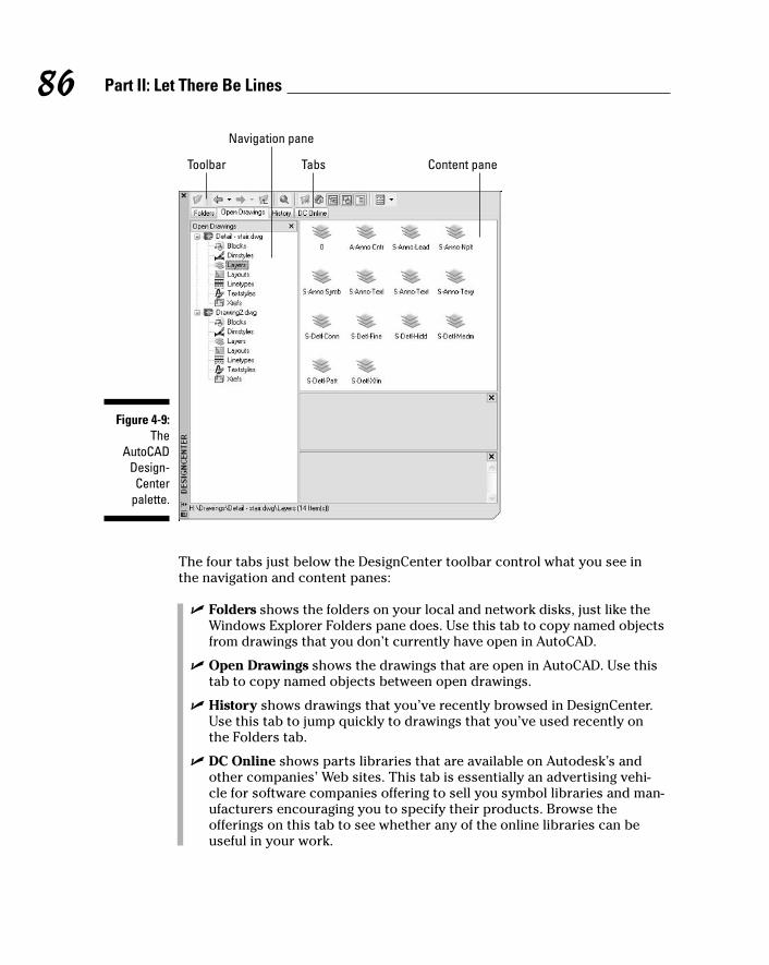
The four tabs just below the DesignCenter toolbar control what you see inthe navigation and content panes:
� Folders shows the folders on your local and network disks, just like theWindows Explorer Folders pane does. Use this tab to copy named objectsfrom drawings that you don’t currently have open in AutoCAD.
� Open Drawings shows the drawings that are open in AutoCAD. Use thistab to copy named objects between open drawings.
� History shows drawings that you’ve recently browsed in DesignCenter.Use this tab to jump quickly to drawings that you’ve used recently onthe Folders tab.
� DC Online shows parts libraries that are available on Autodesk’s andother companies’ Web sites. This tab is essentially an advertising vehi-cle for software companies offering to sell you symbol libraries and man-ufacturers encouraging you to specify their products. Browse theofferings on this tab to see whether any of the online libraries can beuseful in your work.
Toolbar
Navigation pane
Tabs Content pane
Figure 4-9:The
AutoCADDesign-Center
palette.
86 Part II: Let There Be Lines
f571389 Ch04.qxd 4/12/04 9:44 AM Page 86
The toolbar buttons further refine what you see in the navigation and contentpanes. A few of these buttons toggle off and on different parts of the panes. Ifyour DesignCenter palette is missing an area that appears in Figure 4-9, clickeach of the buttons until the missing part reappears.
Follow these steps to use DesignCenter:
1. Load the drawing(s) whose content you want to view or use into thenavigation pane on the left.
If a drawing doesn’t appear on the Open Drawings tab, click the Loadbutton — the first one on the DesignCenter toolbar — to load it into thenavigation pane.
2. Navigate the symbol tables (such as blocks and layers), viewing theirindividual named objects in the content pane on the right.
3. If you need them, drag or copy and paste individual named objectsfrom the content pane into other open AutoCAD drawings.
Copying layers between drawingsThe following steps copy layers from one drawing to another using Design-Center. You can use the same technique to copy dimension styles, layouts,linetypes, and text styles.
1. Toggle the DesignCenter palette on by choosing the DesignCenterbutton on the Standard toolbar or pressing Ctrl+2.
2. Open or create a drawing containing named objects you want to copy.
You can also use the Folders tab, the Open button, or the Search buttonto load a drawing into DesignCenter without opening it in AutoCAD.
3. Open or create a second drawing to which you want to copy thenamed objects.
4. Click the Open Drawings tab to display your two currently openeddrawings in DesignCenter’s navigation pane on the left.
If you used the Folders tab, the Open button, or the Search button inStep 2, skip this step; DesignCenter already displays the drawing youselected on the Folders tab.
5. If DesignCenter doesn’t display the symbol tables indented under-neath the source drawing (the one you opened in Step 2), as shown inFigure 4-9, click the plus sign next to the drawing’s name to displaythem.
87Chapter 4: Get Ready to Draw
f571389 Ch04.qxd 4/12/04 9:44 AM Page 87
6. Click the Layers table to display the source drawing’s layers in thecontent pane.
7. Choose one or more layers in the content pane.
8. Right-click in the content pane and choose Copy from the cursor menuto copy the layer(s) to the Windows Clipboard.
9. Click in the AutoCAD destination drawing’s window (the drawing thatyou opened in Step 3).
10. Right-click and choose Paste from the cursor menu.
AutoCAD copies the layers into the current drawing, using the colors,linetypes, and other settings from the source drawing.
Two other ways exist to copy layers from DesignCenter. You can drag layersfrom the content pane to a drawing window. You also can right-click in thecontent pane and choose Add Layer(s) from the cursor menu, which addslayers to the current drawing. The copy-and-paste method in my examplerequires the least amount of manual dexterity and less guesswork aboutwhich drawing the layers get added to.
If the current drawing contains a layer whose name matches the name of oneof the layers you’re copying, AutoCAD doesn’t change that layer’s definition.For example, if you drag a layer named Doors whose color is red into a draw-ing that already includes a layer called Doors whose color is green, the targetdrawing’s Doors layer remains green. Named objects from DesignCenternever overwrite objects with the same name in the destination drawing.AutoCAD always displays the message “Duplicate definitions will be ignored”even if there aren’t any duplicates.
If you’re repeatedly copying named objects from the same drawings or fold-ers, add them to your DesignCenter favorites list. On the Folders tab, right-click the drawing or folder and choose Add to Favorites from the cursormenu. This procedure adds another shortcut to your list of favorites.
� To see your favorites, click the DesignCenter toolbar’s Favorites button.
� To return to a favorite, double-click its shortcut in the content pane.
Precise-liness Is Next to CAD-linessDrawing precision is vital to good CAD drafting practice, even more than formanual drafting. If you think CAD managers get testy when you assign proper-ties by object instead of by layer, wait until they berate someone who doesn’tuse precision techniques when creating drawings in AutoCAD.
88 Part II: Let There Be Lines
f571389 Ch04.qxd 4/12/04 9:44 AM Page 88
In CAD, lack of precision makes later editing, hatching, and dimensioningtasks much more difficult and time consuming:
� Small errors in precision in the early stages of creating or editing a draw-ing often have a big effect on productivity and precision later.
� Drawings may guide manufacturing and construction projects; drawingdata may drive automatic manufacturing machinery. Huge amounts ofmoney, even lives, can ride on a drawing’s precision.
In recognition of this, a passion for precision permeates the profession.Permanently. Precision is one of the characteristics that separates CAD fromordinary illustration-type drawing work. The sooner you get fussy about pre-cision in AutoCAD, the happier everyone is.
In the context of drawing objects, precision means specifying points and dis-tances precisely, and AutoCAD provides a range of tools for doing so. Table4-2 lists the more important AutoCAD precision techniques, plus the statusbar buttons that you click to toggle some of the features off and on.
Precision is especially important when you’re drawing or editing geometry —the lines, arcs, and so on that make up whatever you’re representing in theCAD drawing. Precision placement usually is less important with notes, lead-ers, and other annotations that describe, not show.
89Chapter 4: Get Ready to Draw
CAD precision versus accuracyWe often use the words precision and accuracyinterchangeably, but I think it’s useful to maintaina distinction. When I use the word precision, Imean controlling the placement of objects sothey lie exactly where you want them to lie in thedrawing. For example, lines whose endpointsmeet must meet exactly, and a circle that’s sup-posed to be centered on the coordinates 0,0must be drawn with its center exactly at 0,0. I use accuracy to refer to the degree to whichyour drawing matches its real-world counter-part. An accurate floor plan is one in which thedimensions of the CAD objects equal the dimen-sions of the as-built house.
CAD precision usually helps produce accuratedrawings, but that’s not always the case. Youcan produce a precise CAD drawing that’s inac-curate because you started from inaccurateinformation (for example, the contractor gaveyou a wrong field measurement). Or you mightdeliberately exaggerate certain distances toconvey the relationship between objects moreclearly on the plotted drawing. Even where youmust sacrifice accuracy, aim for precision.
f571389 Ch04.qxd 4/12/04 9:44 AM Page 89

Table 4-2 Precision TechniquesTechnique Status Bar Button Description
Coordinate entry — Type exact X,Y coordinates.
Single-point object snaps — Pick points on existingobjects (lasts for one pointpick).
Running object snaps OSNAP Pick points on existingobjects (lasts for multiplepoint picks).
Snap SNAP Pick points on an imaginarygrid of equally spaced “hotspots.”
Ortho ORTHO Constrain the cursor tomove at an angle of 0, 90,180, or 270 degrees from theprevious point.
Direct distance entry — Point the cursor in a direc-tion and type a distance.
Object snap tracking OTRACK Helps the cursor locatepoints based on multipleobject snap points.
Polar tracking POLAR Makes the cursor prefercertain angles.
Polar snap — Causes the cursor to prefercertain distances alongpolar tracking angles.
Before you draw objects, always check the status bar’s SNAP, ORTHO,POLAR, OSNAP, and OTRACK buttons and set the buttons according to yourprecision needs.
� A button that looks pushed in indicates that the feature is on.
� A button that looks popped up indicates that the feature is off.
Keyboard capers: Coordinate entryThe most direct way to enter points precisely is to type numbers at the com-mand line. AutoCAD uses these keyboard coordinate entry formats:
90 Part II: Let There Be Lines
f571389 Ch04.qxd 4/12/04 9:44 AM Page 90
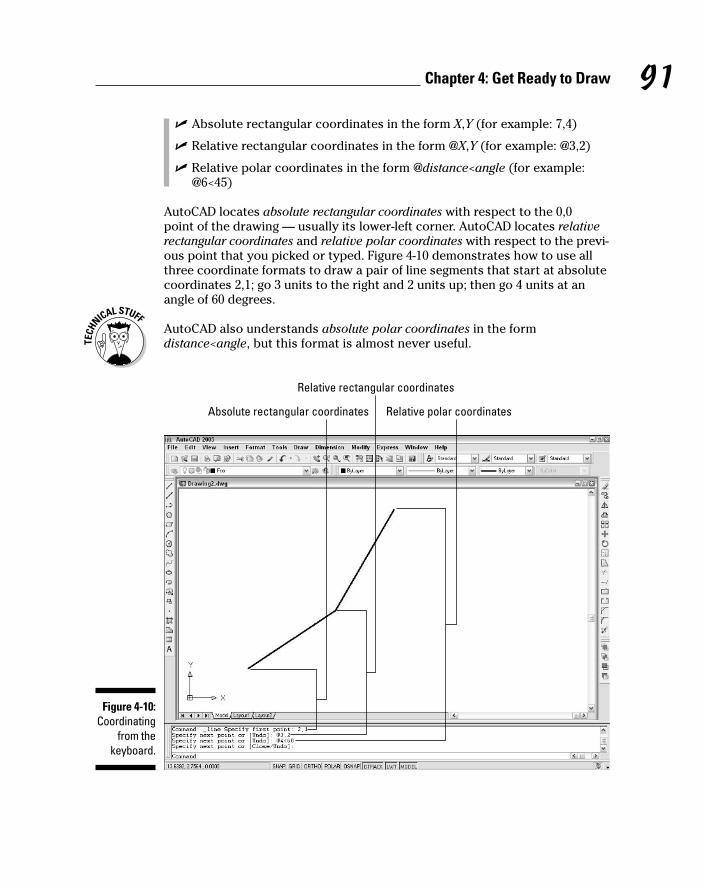
� Absolute rectangular coordinates in the form X,Y (for example: 7,4)
� Relative rectangular coordinates in the form @X,Y (for example: @3,2)
� Relative polar coordinates in the form @distance<angle (for example:@6<45)
AutoCAD locates absolute rectangular coordinates with respect to the 0,0 point of the drawing — usually its lower-left corner. AutoCAD locates relativerectangular coordinates and relative polar coordinates with respect to the previ-ous point that you picked or typed. Figure 4-10 demonstrates how to use allthree coordinate formats to draw a pair of line segments that start at absolutecoordinates 2,1; go 3 units to the right and 2 units up; then go 4 units at anangle of 60 degrees.
AutoCAD also understands absolute polar coordinates in the formdistance<angle, but this format is almost never useful.
Absolute rectangular coordinates
Relative rectangular coordinates
Relative polar coordinates
Figure 4-10:Coordinating
from thekeyboard.
91Chapter 4: Get Ready to Draw
f571389 Ch04.qxd 4/12/04 9:44 AM Page 91
You can view coordinate locations by moving the cursor around in the draw-ing area and reading the Coordinates area at the left of the status bar. The X,Ycoordinates should change as you move the cursor. If the coordinates don’tchange, click the Coordinates area until the command line says <Coords on>.Although it’s not apparent at first, there are in fact two <Coords on> displaymodes: absolute coordinates and polar coordinates. If you start a commandsuch as LINE, pick a point, and then click the Coordinates area a few times,the display changes from coordinates off to live absolute coordinates (X,Yposition) to live polar coordinates (distance and angle from the previous point).The live polar coordinates display mode is the most informative most of thetime.
When you type coordinates at the command line, do not add any spaces,because AutoCAD interprets them as though you’ve pressed Enter. This“Spacebar = Enter” weirdness is a productivity feature that’s been in AutoCADforever. It’s easier to find the spacebar than the Enter key when you’re enteringlots of commands and coordinates in a hurry.
If you’re working in architectural or engineering units, the default unit ofentry is inches, not feet.
� To specify feet, you must enter the symbol for feet after the number, forexample:
6’ for 6 feet
� You can enter a dash to separate feet from inches, as architects often do:
6’–6” is 6 feet, 6 inches.
� Both the dash and the inch mark are optional when you’re entering coor-dinates and distances:
AutoCAD understands 6’6” and 6’6 as the same as 6’–6”.
� If you’re typing a coordinate or distance that contains fractional inches,you must enter a dash — not a space — between the whole number ofinches and the fraction:
6’6–1/2 (or 6’–6–1/2) represents 6 feet, 61⁄2 inches.
� If all this dashing about confuses you, enter partial inches by using deci-mals instead:
6’6.5 is the same as 6’6–1/2 to AutoCAD, whether you’re workingin architectural or engineering units.
Grab an object and make it snappyAfter you’ve drawn a few objects precisely in a new drawing, the most effi-cient way to draw more objects with equal precision is to grab points, such as
92 Part II: Let There Be Lines
f571389 Ch04.qxd 4/12/04 9:44 AM Page 92

endpoints, midpoints, or quadrants, on the existing objects. AutoCAD callsthis object snapping, because the program pulls, or snaps, the cursor to apoint on an existing object. The object snapping feature in general and objectsnap points in particular often are called osnaps.
I’d like to make just one pointAutoCAD provides two kinds of object snapping modes:
� Single point (or override) object snaps
A single point object snap lasts just while you pick one point.
� Running object snaps
A running object snap stays in effect until you turn it off.
Here’s how you draw precise lines by using single point object snaps:
1. Open a drawing containing some geometry.
2. Turn off running osnap mode by clicking the OSNAP button on thestatus bar until the button appears to be pushed out and the words<Osnap off> appear on the command line.
Although you can use single point object snaps while running objectsnap mode is turned on, you should turn off running osnap mode whileyou’re getting familiar with single point object snaps. After you’ve gottenthe hang of each feature separately, you can use them together.
3. Start the LINE command by clicking the Line button on the Draw toolbar.
The command line prompts you to select the first endpoint of the line:
Specify first point:
4. Hold down the Shift key, right-click anywhere in the drawing area,and release the Shift key.
If you find the Shift+right-click sequence awkward, you can avoid it byusing the Object Snap toolbar instead. To turn the toolbar on, point toany toolbar button, right-click, and choose Object Snap. Now you canactivate a single point object snap by clicking its toolbar button.
The object snap cursor menu appears, as shown in Figure 4-11.
5. Choose an object snap mode, such as Endpoint, from the object snapcursor menu.
The object snap cursor menu disappears, and the command line dis-plays an additional prompt indicating that you’ve directed AutoCAD toseek out, for example, endpoints of existing objects:
_endp of:
93Chapter 4: Get Ready to Draw
f571389 Ch04.qxd 4/12/04 9:44 AM Page 93

6. Move the cursor slowly around the drawing, pausing over variouslines and other objects without clicking yet.
When you move the cursor near an object with an endpoint, a coloredsquare icon appears at the endpoint, indicating that AutoCAD can snapto that point. If you stop moving the cursor for a moment, a yellowToolTip displaying the object snap mode (for example, Endpoint)appears to reinforce the idea.
7. When the endpoint object snap square appears on the point you wantto snap to, click.
AutoCAD snaps to the endpoint, which becomes the first point of thenew line segment that you’re about to draw. The command line promptsyou to select the other endpoint of the new line segment:
Specify next point or [Undo]:
When you move the cursor around the drawing, AutoCAD no longerseeks out endpoints because single point object snaps last only for asingle pick. Use the object snap cursor menu again to snap the other endof your new line segment to another point on an existing object.
8. Use the “press Shift, right-click, release Shift” sequence described inStep 4 to display the object snap cursor menu, and then chooseanother object snap mode, such as Midpoint, from the object snapcursor menu.
The command line displays an additional prompt indicating that you’vedirected AutoCAD to seek, for example, midpoints of existing objects:
_mid of:
Figure 4-11:The object
snap cursormenu.
94 Part II: Let There Be Lines
f571389 Ch04.qxd 4/12/04 9:44 AM Page 94
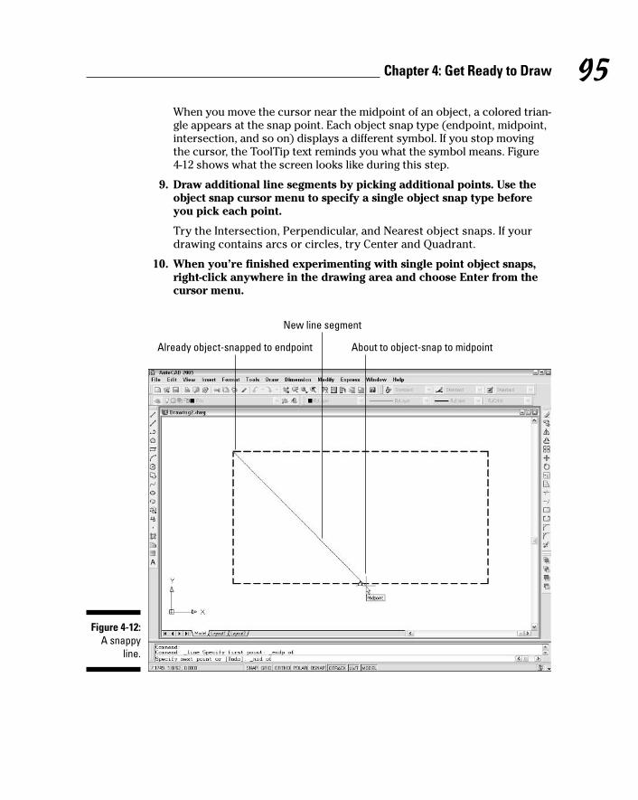
When you move the cursor near the midpoint of an object, a colored trian-gle appears at the snap point. Each object snap type (endpoint, midpoint,intersection, and so on) displays a different symbol. If you stop movingthe cursor, the ToolTip text reminds you what the symbol means. Figure4-12 shows what the screen looks like during this step.
9. Draw additional line segments by picking additional points. Use theobject snap cursor menu to specify a single object snap type beforeyou pick each point.
Try the Intersection, Perpendicular, and Nearest object snaps. If yourdrawing contains arcs or circles, try Center and Quadrant.
10. When you’re finished experimenting with single point object snaps,right-click anywhere in the drawing area and choose Enter from thecursor menu.
Already object-snapped to endpoint
New line segment
About to object-snap to midpoint
Figure 4-12:A snappy
line.
95Chapter 4: Get Ready to Draw
f571389 Ch04.qxd 4/12/04 9:44 AM Page 95
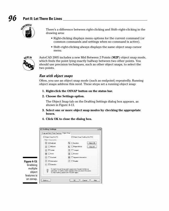
There’s a difference between right-clicking and Shift+right-clicking in thedrawing area:
• Right-clicking displays menu options for the current command (orcommon commands and settings when no command is active).
• Shift+right-clicking always displays the same object snap cursormenu.
AutoCAD 2005 includes a new Mid Between 2 Points (M2P) object snap mode,which finds the point lying exactly halfway between two other points. Youshould use precision techniques, such as other object snaps, to select thetwo points.
Run with object snapsOften, you use an object snap mode (such as endpoint) repeatedly. Runningobject snaps address this need. These steps set a running object snap:
1. Right-click the OSNAP button on the status bar.
2. Choose the Settings option.
The Object Snap tab on the Drafting Settings dialog box appears, asshown in Figure 4-13.
3. Select one or more object snap modes by checking the appropriateboxes.
4. Click OK to close the dialog box.
Figure 4-13:Grabbing
multipleobject
features isan osnap.
96 Part II: Let There Be Lines
f571389 Ch04.qxd 4/12/04 9:44 AM Page 96

You click the OSNAP button on the status bar to toggle running object snapmode off and on. After you turn on running object snap, AutoCAD hunts forpoints that correspond to the object snap modes you checked in the DraftingSettings dialog box. As with single-point object snaps, AutoCAD displays aspecial symbol — such as a square for an endpoint object snap — to indicatethat it has found an object snap point. If you keep the cursor still, AutoCADalso displays a ToolTip that lists the kind of object snap point.
Use single point or running object snaps to enforce precision by making surethat new points you pick coincide exactly with points on existing objects. InCAD, it’s not good enough for points to almost coincide or to look like theycoincide. AutoCAD knows the difference between “looks the same” and “isthe same,” and will cause you untold amounts of grief if you try to make dowith “looks the same.” You lose points, both figuratively and literally, if youdon’t use object snaps or one of the other precision techniques covered inthis chapter to enforce precision.
Other precision practicesThe following are some other AutoCAD precision techniques (refer to Table 4-2,earlier in this chapter):
� Snap: If you turn on snap mode, AutoCAD constrains the cursor to animaginary rectangular grid of points at the spacing that you’ve specified.Follow these steps to turn on snap mode:
1. Right-click the SNAP button on the status bar.
2. Choose the Settings option.
The Snap and Grid tab on the Drafting Settings dialog box appears.
3. Enter a snap spacing in the Snap X Spacing field and then click OK.
Click the SNAP button on the status bar or Press F9 to toggle snap modeoff and on. To use snap effectively, change the snap spacing frequently —changing to a smaller spacing as you zoom in and work on smaller areas.You often need to toggle snap off and on, because selecting objects andsome editing tasks are easier with snap off.
� Ortho: Ortho mode constrains the cursor to move at right angles (orthog-onally) to the previous point. Click the ORTHO button on the status bar orPress F8 to toggle ortho mode off and on. Because technical drawingsoften include lots of orthogonal lines, you’ll use ortho mode a lot.
97Chapter 4: Get Ready to Draw
f571389 Ch04.qxd 4/12/04 9:44 AM Page 97

� Direct distance entry: This “point and type” technique is an easy andefficient way to draw with precision. You simply point the cursor in a par-ticular direction, type a distance at the command line, and press Enter.AutoCAD calls it “direct distance entry” because it avoids the indirectcommand line method of specifying a distance by typing relative or polarcoordinates. (I describe this older method earlier in this chapter.) Youcan use direct distance entry any time the crosshair cursor is anchoredto a point and the command line prompts you for another point or a dis-tance. You’ll usually use direct distance entry with ortho mode turnedon, to specify a distance in an orthogonal direction (0, 90, 180, or 270degrees). You also can combine direct distance entry with polar trackingto specify distances in non-orthogonal directions (for example, in angleincrements of 45 degrees).
� Object snap tracking: This feature extends running object snaps so thatyou can locate points based on more than one object snap point. Forexample, you can pick a point at the center of a square by tracking tothe midpoints of two perpendicular sides. (AutoCAD LT lacks the objectsnap tracking feature.)
� Polar tracking: When you turn on polar tracking, the cursor jumps toincrements of the angle you selected. When the cursor jumps, a ToolTiplabel starting with Polar: appears. Right-click the POLAR button on thestatus bar and choose the Settings option to display the Polar Trackingtab on the Drafting Settings dialog box. Select an angle from the IncrementAngle drop-down list and then click OK. Click the POLAR button on thestatus bar or press F10 to toggle polar tracking mode off and on.
� Polar snap: You can force polar tracking to jump to specific incrementaldistances along the tracking angles by changing the snap type from Gridsnap to Polar snap. For example, if you turn on polar tracking and set itto 45 degrees and turn on polar snap and set it to 2 units, polar trackingjumps to points that are at angle increments of 45 degrees and distanceincrements of 2 units from the previous point. Polar snap has a similareffect on object snap tracking.
To activate polar snap, follow these steps:
1. Right-click the SNAP button on the status bar.
2. Choose the Settings option.
The Snap and Grid tab on the Drafting Settings dialog box appears.
3. Click the Polar Snap radio button, type a distance in the PolarDistance edit box, and then click OK.
When you want to return to ordinary rectangular snap, as described atthe beginning of this list, select the Grid Snap radio button in theDrafting Settings dialog box.
98 Part II: Let There Be Lines
f571389 Ch04.qxd 4/12/04 9:44 AM Page 98

If you’re new to AutoCAD, its wide range of precision tools probably seemsoverwhelming at this point. Rest assured that there’s more than one way toskin a cat precisely, and not everyone needs to understand all the ways. Youcan make perfectly precise drawings with a subset of AutoCAD’s precisiontools. I recommend these steps:
1. Get comfortable with typing coordinates, ortho mode, direct distanceentry, and single point object snaps.
2. Become familiar with running object snaps and try snap.
3. After you have all these precision features under your belt, feel free toexperiment with polar tracking, polar snap, and object snap tracking.
It’s easy to confuse the names of the snap and object snap (osnap) features.Remember that snap limits the cursor to locations whose coordinates aremultiples of the current snap spacing. Object snap (osnap) enables you tograb points on existing objects, whether those points happen to correspondwith the snap spacing or not.
99Chapter 4: Get Ready to Draw
f571389 Ch04.qxd 4/12/04 9:44 AM Page 99

100 Part II: Let There Be Lines
f571389 Ch04.qxd 4/12/04 9:44 AM Page 100

Chapter 5
Where to Draw the LineIn This Chapter� Drawing with the AutoCAD drawing commands
� Lining up for lines and polylines
� Closing up with rectangles and polygons
� Rounding the curves with circles, arcs, splines, and clouds
� Dabbling in ellipses and donuts
� Making your points
As you probably remember from your crayon and coloring book days,drawing stuff is fun. CAD imposes a little more discipline, but drawing
AutoCAD objects is still fun. In computer-aided drafting, you usually start bydrawing geometry — shapes such as lines, circles, rectangles, and so on thatrepresent the real-world object that you’re documenting. This chapter showsyou how to draw geometry.
After you’ve created some geometry, you’ll probably need to add somedimensions, text, and hatching, but those elements come later (in Part III ofthis book). Your first task is to get the geometry right; then you can worryabout labeling things.
Drawing geometry properly in AutoCAD depends on paying attention to objectproperties and the precision of the points that you specify to create theobjects. I cover these matters in Chapter 4, so if you eagerly jumped to thischapter to get right to the fun stuff, take a moment to review that chapter first.
f571389 Ch05.qxd 4/12/04 9:44 AM Page 101

Introducing the AutoCAD Drawing Commands
For descriptive purposes, this chapter divides the drawing commands intothree groups:
� Straight lines and objects composed of straight lines
� Curves
� Points
AutoCAD-based application-specific programs such as Architectural Desktopadd extra drawing tools to the mix — for example, commands for drawingwalls and doors. See the documentation that comes with the application-specific program for information on such tools.
Table 5-1 offers an overview of most of the drawing commands in AutoCAD,without the 3D-related commands. It describes the commands’ major optionsand shows you how to access them from the command line, the Draw menu,and the Draw toolbar. (Don’t worry if not all the terms in the table are famil-iar to you; they become clear as you read through the chapter and use thecommands.)
Table 5-1 AutoCAD Drawing CommandsButton Command Major Options Toolbar Button Draw Menu
Line Start, end points Line Line
RAY Start point, point None Raythrough which ray passes
XLine Two points on line Construction line Construction line
PLine Vertices Polyline Polyline
POLygon Number of sides, Polygon Polygoninscribed/circumscribed
102 Part II: Let There Be Lines
f571389 Ch05.qxd 4/12/04 9:44 AM Page 102
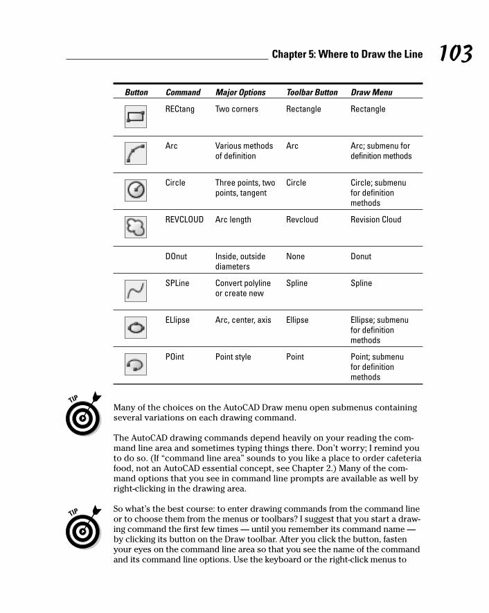
Button Command Major Options Toolbar Button Draw Menu
RECtang Two corners Rectangle Rectangle
Arc Various methods Arc Arc; submenu forof definition definition methods
Circle Three points, two Circle Circle; submenupoints, tangent for definition
methods
REVCLOUD Arc length Revcloud Revision Cloud
DOnut Inside, outside None Donutdiameters
SPLine Convert polyline Spline Splineor create new
ELlipse Arc, center, axis Ellipse Ellipse; submenufor definitionmethods
POint Point style Point Point; submenufor definitionmethods
Many of the choices on the AutoCAD Draw menu open submenus containingseveral variations on each drawing command.
The AutoCAD drawing commands depend heavily on your reading the com-mand line area and sometimes typing things there. Don’t worry; I remind youto do so. (If “command line area” sounds to you like a place to order cafeteriafood, not an AutoCAD essential concept, see Chapter 2.) Many of the com-mand options that you see in command line prompts are available as well byright-clicking in the drawing area.
So what’s the best course: to enter drawing commands from the command lineor to choose them from the menus or toolbars? I suggest that you start a draw-ing command the first few times — until you remember its command name —by clicking its button on the Draw toolbar. After you click the button, fastenyour eyes on the command line area so that you see the name of the commandand its command line options. Use the keyboard or the right-click menus to
103Chapter 5: Where to Draw the Line
f571389 Ch05.qxd 4/12/04 9:44 AM Page 103

select options, depending on whether your hand is on the keyboard or themouse at that moment. After you’re acquainted with a drawing command anddecide that you like it enough to use it often, find out how to type its keyboardshortcut (the uppercase letters in the command names in Table 5-1).
A few drawing commands, such as DOnut, aren’t on the Draw toolbar; youhave to type those or choose them on the Draw menu.
The Straight and Narrow: Lines,Polylines, and Polygons
As I harp on a bunch of times elsewhere in this book, CAD programs are forprecision drawing, so you’ll spend a lot of your AutoCAD time drawing objectscomposed of straight-line segments. This section covers these commands:
� Line: Draws a series of straight line segments; each segment is a sepa-rate object
� PLine: Draws a polyline — a series of straight and/or curved line seg-ments; all the segments remain connected to each other as a single object
� RECtang: Draws a polyline in the shape of a rectangle
� POLygon: Draws a polyline in the shape of a regular polygon (that is, aclosed shape with all sides equal and all angles equal)
The following additional straight-line drawing commands also are available inAutoCAD:
� RAY: Draws a semi-infinite line (a line that extends infinitely in one direction)
� XLine: Draws an infinite line (a line that extends infinitely in both directions)
The RAY and XLine commands are used to draw construction lines that guidethe construction of additional geometry. Drawing construction lines is lesscommon in AutoCAD than in some other CAD programs. AutoCAD’s manyprecision techniques often provide more efficient methods than constructionlines of creating new geometry.
Toe the lineThe Line command in AutoCAD draws a series of one or more connected linesegments. Well, it appears to draw a series of connected segments. In fact,
104 Part II: Let There Be Lines
f571389 Ch05.qxd 4/12/04 9:44 AM Page 104

105Chapter 5: Where to Draw the Line
each segment, or piece of a line with endpoints, is a separate object. This con-struction doesn’t seem like a big deal until you try to move or otherwise edita series of segments that you drew with the Line command; you must selectevery piece separately. To avoid such a hassle, use polylines, described laterin this chapter, not lines and arcs when you want the connected segments tobe a single object.
If you’re used to drawing lines in other programs, you may find it confusingat first that AutoCAD’s Line command doesn’t stop after you draw a singlesegment. AutoCAD keeps prompting you to specify additional points so thatyou can draw a series of (apparently) connected segments. When you’re fin-ished drawing segments, just press the Enter key to finish the Line commandand return to the Command prompt.
Unlike a lot of AutoCAD drawing commands, Line doesn’t offer a bunch ofpotentially confusing options. There’s a Close option to create a closedpolygon and an Undo option to remove the most recent segment that youdrew.
Like all drawing commands, Line puts the line segment objects that it drawson the current layer, and uses the current color, linetype, lineweight, and plotstyle properties.
� Make sure that you’ve set these properties correctly before you startdrawing. (I recommend that you set color, linetype. lineweight, and plotstyle to ByLayer.) See Chapter 4 for information on setting the currentproperties with the Object Properties toolbar.
� When you’re doing real drafting as opposed to just experimenting, makesure that you use one of AutoCAD’s precision tools, such as objectsnaps, typed coordinates, or tracking to ensure that you specify eachobject point precisely. Chapter 4 describes these tools.
Follow these steps to draw a series of line segments by using the Line command:
1. Set object properties to the layer and other properties that you wantapplied to the line segments that you’ll draw.
2. Click the Line button on the Draw toolbar.
AutoCAD starts the Line command and prompts you at the commandline:
Specify first point:
3. Specify the starting point by clicking a point or typing coordinates.
Remember to use one of the precision techniques described in Chapter 4if you’re doing real drafting. For the first point, object snap, snap, track-ing, and typing coordinates all work well.
f571389 Ch05.qxd 4/12/04 9:44 AM Page 105

AutoCAD prompts you at the command line to specify the other end-point of the first line segment:
Specify next point or [Undo]:
4. Specify additional points by clicking or typing.
Again, use one of the AutoCAD precision techniques if you’re doing realdrafting. For the second and subsequent points, all the techniques men-tioned in the previous step work well, plus ortho and direct distance entry.
After you specify the third point, AutoCAD adds the Close option to thecommand line prompt:
Specify next point or [Close/Undo]:
5. When you’re finished drawing segments, end with one of these steps:
• Press Enter, or right-click anywhere in the drawing area andchoose Enter (as shown in Figure 5-1), to leave the figure open.
• Type C and press Enter, or right-click anywhere in the drawing areaand choose Close from the cursor menu, to close the figure.
AutoCAD draws the final segment and returns to the Command prompt,indicating that the Line command is finished:
Command:
Figure 5-1:Line it up:Drawing line seg-
ments with the Line
command.
106 Part II: Let There Be Lines
f571389 Ch05.qxd 4/12/04 9:44 AM Page 106
107Chapter 5: Where to Draw the Line
Connect the lines with polylineThe Line command is fine for some drawing tasks, but the PLine command isa better, more flexible choice in many situations. The PLine command drawsa special kind of object called a polyline. You may hear CAD drafters refer to apolyline as a pline because of the command name. (By the way, PLine is pro-nounced to rhyme with “beeline” — in other words, it sounds like the placeyou stand when you’ve drunk a lot of beer at the ball game.)
The most important differences between the Line and PLine commands arethese:
� The Line command draws a series of single line segment objects. Eventhough they appear on the screen to be linked, each segment is a sepa-rate object. If you move one line segment, the other segments that youdrew at the same time don’t move with it. The PLine command, on theother hand, draws a single, connected, multisegment object. If youselect any segment for editing, your changes affect the entire polyline.Figure 5-2 shows how the same sketch drawn with the Line and thePLine commands responds when you select one of the objects.
Use the PLine command instead of Line in most cases where you need todraw a series of connected line segments. If you’re drawing a series of end-to-end segments, there’s a good chance that those segments are logicallyconnected — for example, they might represent the outline of a singleobject or a continuous pathway. If the segments are connected logically, itmakes sense to keep them connected in AutoCAD. The most obvious prac-tical benefit of grouping segments together into a polyline is that manyediting operations are more efficient when you use polylines. If you move asingle, disconnected line segment, the other segments that you drew atthe same time don’t move with it — likewise for other common editingoperations, such as copying, erasing, rotating, and mirroring. When youselect any segment in a polyline for editing, the entire polyline is affected.
� The PLine command can draw curved segments as well as straight ones.
� You can add width to each segment of a polyline. Polyline segment widthis similar to lineweight, except that it can be uniform or tapered. Theability to create polyline segments with line widths was more importantin the old days before AutoCAD had lineweight as an object property.People used to draw polylines with a small amount of width to show thesegments as somewhat heavier than normal on plots. Nowadays, it’seasier and more efficient to achieve this effect with object lineweights(as described in Chapter 4) or plot styles (as described in Chapter 12).
After you create a polyline, you can adjust its segments by grip editing any ofthe vertex points. (The little squares on the vertices in Figure 5-2 are calledgrips; see Chapter 6 for details on grip editing.) For more complicated poly-line editing tasks, you can use the PEdit command to edit the polyline, or youcan convert the polyline to a collection of line and arc segments by using the
f571389 Ch05.qxd 4/12/04 9:44 AM Page 107

eXplode command — although you lose any width defined for each segmentwhen you explode a polyline.
Drawing polylines composed of straight segments is pretty much like drawingwith the Line command, as demonstrated in the following procedure. Watchthe command prompts carefully because the PLine command has a lot ofoptions! Remember that you can right-click in the drawing area to select oneof the options, but reading the command prompts is your ticket to knowingwhat the options are at any moment.
To draw a polyline composed of straight segments, follow these steps:
1. Set object properties to the layer and other properties that you wantapplied to the polyline object that you’ll draw.
2. Click the Polyline button — the one that looks like a fishhook — onthe Draw toolbar.
AutoCAD starts the PLine command and prompts you at the commandline:
Specify start point:
3. Specify the starting point by clicking a point or typing coordinates.
AutoCAD displays the current polyline segment line-width and promptsyou to specify the other endpoint of the first polyline segment:
Current line-width is 0.0000Specify next point or [Arc/Halfwidth/Length/Undo/Width]:
Polyline (all segments form one object)
Line (each segment is a separate object)
Figure 5-2:Results of
drawingwith theLine and
PLinecommands.
108 Part II: Let There Be Lines
f571389 Ch05.qxd 4/12/04 9:44 AM Page 108
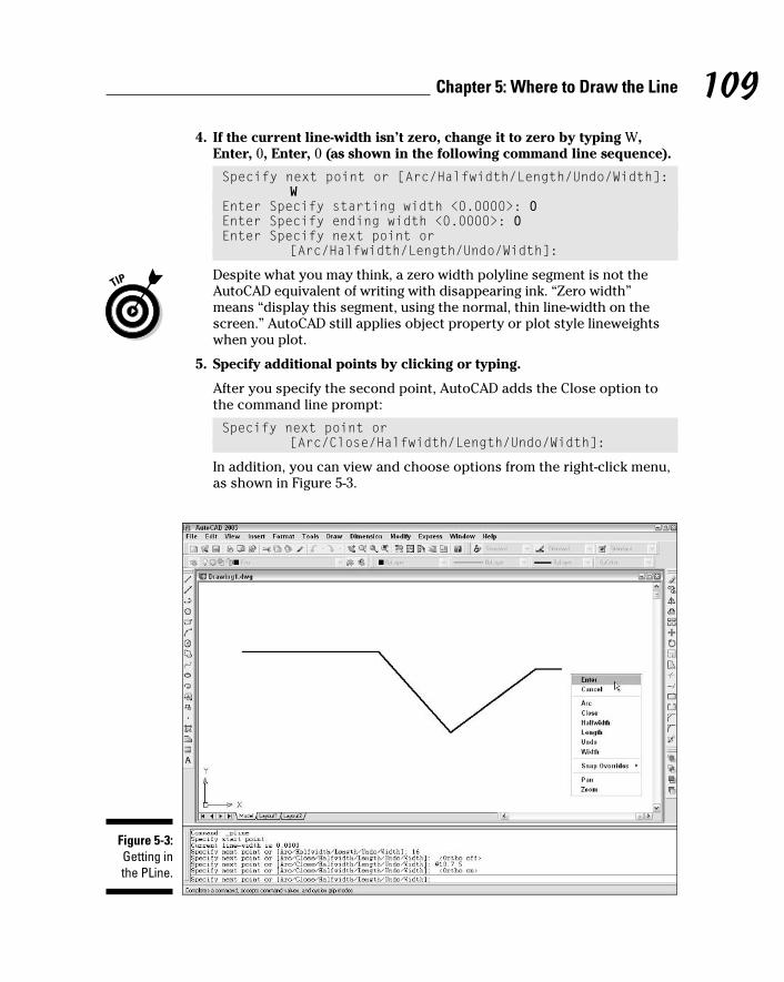
109Chapter 5: Where to Draw the Line
4. If the current line-width isn’t zero, change it to zero by typing W,Enter, 0, Enter, 0 (as shown in the following command line sequence).
Specify next point or [Arc/Halfwidth/Length/Undo/Width]:W
Enter Specify starting width <0.0000>: 0Enter Specify ending width <0.0000>: 0Enter Specify next point or
[Arc/Halfwidth/Length/Undo/Width]:
Despite what you may think, a zero width polyline segment is not theAutoCAD equivalent of writing with disappearing ink. “Zero width”means “display this segment, using the normal, thin line-width on thescreen.” AutoCAD still applies object property or plot style lineweightswhen you plot.
5. Specify additional points by clicking or typing.
After you specify the second point, AutoCAD adds the Close option tothe command line prompt:
Specify next point or[Arc/Close/Halfwidth/Length/Undo/Width]:
In addition, you can view and choose options from the right-click menu,as shown in Figure 5-3.
Figure 5-3:Getting inthe PLine.
f571389 Ch05.qxd 4/12/04 9:44 AM Page 109

6. After you finish drawing segments, either press Enter (to leave thefigure open) or type C and press Enter (to close it).
AutoCAD draws the final segment and returns to the Command prompt,indicating that the PLine command is finished:
Command:
In the following procedure, I spice things up a bit and give you a preview ofcoming (curvy) attractions by adding an arc segment to a polyline.
Just so you know, curved segments in polylines are circular arcs — pieces ofcircles that you can draw with the AutoCAD Arc command. AutoCAD candraw other kinds of curves, including ellipses and splines, but not within thePLine command.
To draw a polyline that includes curved segments, follow these steps:
1. Repeat Steps 1 through 5 of the previous procedure.
2. When you’re ready to add one or more arc segments, type A andpress Enter to select the Arc option.
The command line prompt changes to show arc segment options. Mostof these options correspond to the many ways of drawing circular arcsin AutoCAD; see “Arc-y-ology,” later in this chapter.
Specify endpoint of arc or[Angle/CEnter/CLose/Direction/Halfwidth/Line/Radius/Second pt/Undo/Width]:
3. Specify the endpoint of the arc by clicking a point or typing coordinates.
AutoCAD draws the curved segment of the polyline. The command lineprompt continues to show arc segment options.
Specify endpoint of arc or[Angle/CEnter/CLose/Direction/Halfwidth/Line/Radius/Second pt/Undo/Width]:
Your options at this point include
• Specifying additional points to draw more arc segments
• Choosing another arc-drawing method (such as CEnter or Second pt)
• Returning to drawing straight-line segments with the Line option
In this example, I return to drawing straight-line segments.
110 Part II: Let There Be Lines
f571389 Ch05.qxd 4/12/04 9:44 AM Page 110
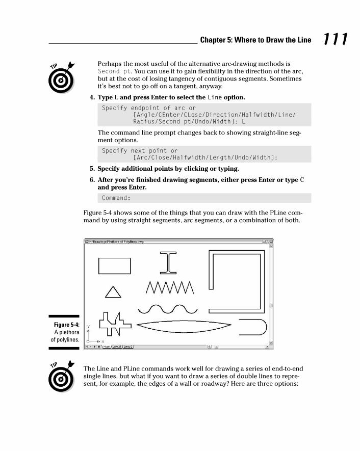
Perhaps the most useful of the alternative arc-drawing methods isSecond pt. You can use it to gain flexibility in the direction of the arc,but at the cost of losing tangency of contiguous segments. Sometimesit’s best not to go off on a tangent, anyway.
4. Type L and press Enter to select the Line option.
Specify endpoint of arc or[Angle/CEnter/CLose/Direction/Halfwidth/Line/Radius/Second pt/Undo/Width]: L
The command line prompt changes back to showing straight-line seg-ment options.
Specify next point or[Arc/Close/Halfwidth/Length/Undo/Width]:
5. Specify additional points by clicking or typing.
6. After you’re finished drawing segments, either press Enter or type Cand press Enter.
Command:
Figure 5-4 shows some of the things that you can draw with the PLine com-mand by using straight segments, arc segments, or a combination of both.
The Line and PLine commands work well for drawing a series of end-to-endsingle lines, but what if you want to draw a series of double lines to repre-sent, for example, the edges of a wall or roadway? Here are three options:
Figure 5-4:A plethora
of polylines.
111Chapter 5: Where to Draw the Line
f571389 Ch05.qxd 4/12/04 9:44 AM Page 111
� Use the AutoCAD MLine command to draw multilines — series of two ormore parallel, straight lines. The AutoCAD multiline feature was full oflimitations and bugs when it debuted ten years ago. It hasn’t improvedsignificantly since then. Look up the MLine and MLSTYLE commands inAutoCAD’s online help system if you’d like to tangle with this feature,but be prepared to spend time experimenting and struggling.
� In AutoCAD LT only, use the DLine (Double Line) command to draw pairsof parallel line and/or arc segments. AutoCAD LT doesn’t include theMLine command, which, given MLine’s problems, probably is more of ablessing than a limitation. AutoCAD, on the other hand, doesn’t includethe DLine command. (Score one for the little brother!)
� Use the PLine command to draw a single set of connected line and/orarc segments, and then use the Offset command to create one or moresets of parallel segments. Chapter 6 covers the Offset command.
Square off with rectangleYou can use the PLine or Line command to draw a rectangle segment by seg-ment. In most cases, though, you’ll find it easier to use the special-purposeRECtang command. The following procedure demonstrates how:
1. Set object properties to the layer and other properties that you wantapplied to the rectangle that you’ll draw.
2. Click the Rectangle button on the Draw toolbar.
AutoCAD starts the RECtang command and prompts you at the com-mand line to specify a point for one corner of the rectangle:
Specify first corner point or[Chamfer/Elevation/Fillet/Thickness/Width]:
You can add fancy effects with the additional command options. Thedefault options work best for most purposes. Look up “RECTANG com-mand” in the AutoCAD help system if you want to know more about theoptions.
3. Specify the first corner by clicking a point or typing coordinates.
The command line prompts you to specify the other corner of therectangle — the one that’s diagonally opposite from the first corner:
Specify other corner point or [Dimensions]:
4. Specify the other corner by clicking a point or typing coordinates.
112 Part II: Let There Be Lines
f571389 Ch05.qxd 4/12/04 9:44 AM Page 112
If you know the size of the rectangle that you want to draw (for example,100 units long by 75 units high), type relative coordinates to specify thedimensions (for example, @100,75). (Chapter 4 describes how to typecoordinates.)
AutoCAD draws the rectangle.
Choose your sides with polygonRectangles and other closed polylines are types of polygons, or closed figureswith three or more sides. The AutoCAD POLygon command provides a quickway of drawing regular polygons — polygons in which all sides and angles areequal. (If regular polygons seem a little square, maybe that’s because asquare is a special case of a regular polygon!)
The following procedure demonstrates the POLygon command:
1. Set object properties to the layer and other properties that you wantapplied to the polygon that you’ll draw.
2. Click the Polygon button on the Draw toolbar.
AutoCAD starts the POLygon command and prompts you at the com-mand line to enter the number of sides for the polygon:
Enter number of sides <4>:
3. Type the number of sides in the polygon that you want to draw andpress Enter.
The command line prompts you to specify the center point of thepolygon:
Specify center of polygon or [Edge]:
You can use the Edge option to draw a polygon by specifying one side,instead of the center and radius of an imaginary inscribed or circum-scribed circle. The imaginary circle method is much more common.
4. Specify the center point by clicking a point or typing coordinates.
The command line prompts you to specify whether the polygon will beinscribed in or circumscribed about an imaginary circle whose radiusyou will specify in the following step:
Enter an option [Inscribed in circle/Circumscribed aboutcircle] <I>:
113Chapter 5: Where to Draw the Line
f571389 Ch05.qxd 4/12/04 9:44 AM Page 113

5. Type I or C and press Enter.
The command line prompts you to specify the radius of imaginary circle:
Specify radius of circle:
6. Specify the radius by typing a distance or clicking a point.
AutoCAD draws the polygon.
If you type a distance or you click a point with Ortho turned on, thepolygon will be aligned orthogonally, as shown in Figure 5-5. If you clicka point with Ortho turned off, the polygon most likely won’t be alignedorthogonally.
Figure 5-5 shows the results of drawing plenty of polygons — a practice knownas “polygony,” and which, as far as I know, remains legal in most states.
Rectangles and polygons in AutoCAD are really just polylines that you specifyin a way that’s appropriate to the shape you’re creating. You’ll notice thiswhen you grip edit a rectangle or polygon and move one of the vertexes: Onlythe selected vertex moves. AutoCAD doesn’t make the entire rectangle orpolygon larger or smaller. (See Chapter 6 for information about grip editing.)
Figure 5-5:A polygonal
party.
114 Part II: Let There Be Lines
f571389 Ch05.qxd 4/12/04 9:44 AM Page 114

(Throwing) CurvesAlthough straight line segments predominate in many CAD drawings, eventhe most humdrum, rectilinear design is likely to have a few curves. And ifyou’re drawing car bodies or Gaudí buildings, your drawings will be almostnothing but curves! This section shows you how to use the followingAutoCAD curve-drawing commands:
� Circle: Draws circles (you were expecting rectangles, maybe?)
� Arc: Draws circular arcs — arcs cut from circles, not from ellipses,parabolas, or some other complicated curve
� ELlipse: Draws ellipses and elliptical arcs
� SPLine: Draws smoothly flowing curves of a variety of shapes
� DOnut: Draws filled-in annular rings and circles
� REVCLOUD: Draws free-form “clouds,” the most common application ofwhich is to indicate revised areas in the drawing
The following sections describe each command.
Going full circleAutoCAD offers an easy way to draw circles, and it also offers . . . other ways.The easy way is to define the center point of the circle and then to define theradius or diameter. You can also define a circle by entering one of the follow-ing options of the command (for those “other” ways):
� 3P (3-Point): Specify any three points on the circumference.
� 2P (2-Point): Specify the endpoints of a diameter of the circle.
� Ttr (Tangent-Tangent-Radius): Specify two lines or other objects thatare tangent to the circle, and then specify its radius.
Whether these additional circle-drawing methods are useful or superfluousdepends on the kinds of drawings that you make and how geometry isdefined in your industry. Get familiar with the default center point/radiusmethod and then try the other methods to see whether they may be helpfulto you. If you find yourself going around in circles, you can always draw themthe default way and move them into position with other geometry.
115Chapter 5: Where to Draw the Line
f571389 Ch05.qxd 4/12/04 9:44 AM Page 115

1. Set object properties to the layer and other properties that you wantapplied to the circle that you’ll draw.
2. Click the Circle button on the Draw toolbar.
AutoCAD starts the Circle command and prompts you at the commandline to specify the center point of the circle:
Specify center point for circle or [3P/2P/Ttr (tan tanradius)]:
The prompt shows the methods other than “center point plus radius”that you can use to draw circles in AutoCAD. (No, “tan tan radius” is nota mathematician’s dance.) Look up “CIRCLE command” in the onlinehelp if you think you may have a use for these less common circle-drawing methods.
3. Specify the center point by clicking a point or typing coordinates.
Use one of the precision techniques described in Chapter 4 if you’redoing real drafting. Object snap, snap, and typing coordinates all workwell for specifying the center point.
The command line then prompts you to specify the circle’s radius:
Specify radius of circle or [Diameter]:
Type D and press Enter if you prefer to enter the diameter rather thanthe radius and you’ve forgotten your twos tables — or, more seriously,if the diameter is easier to specify with the cursor or type exactlythan the radius is.
4. Specify the radius by typing a distance or clicking a point.
AutoCAD draws the circle, as shown in Figure 5-6.
Arc-y-ologyArcs in AutoCAD are, quite simply, pieces of circles. As with circles, AutoCADoffers you an easy way to define arcs. Just specify three points on-screen todefine the arc, easy as one-two-three. These points tell AutoCAD where tostart the arc, how much to curve it, and where to end it.
Sounds pretty easy, right? So where’s the problem? The trouble is that youoften must specify arcs more exactly than is possible by using this method.AutoCAD helps you specify such arcs, too, but the procedure ain’t easy.
116 Part II: Let There Be Lines
f571389 Ch05.qxd 4/12/04 9:44 AM Page 116
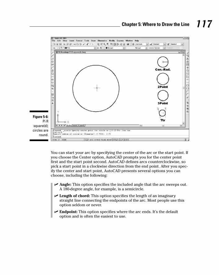
You can start your arc by specifying the center of the arc or the start point. Ifyou choose the Center option, AutoCAD prompts you for the center pointfirst and the start point second. AutoCAD defines arcs counterclockwise, sopick a start point in a clockwise direction from the end point. After you spec-ify the center and start point, AutoCAD presents several options you canchoose, including the following:
� Angle: This option specifies the included angle that the arc sweeps out.A 180-degree angle, for example, is a semicircle.
� Length of chord: This option specifies the length of an imaginarystraight line connecting the endpoints of the arc. Most people use thisoption seldom or never.
� Endpoint: This option specifies where the arc ends. It’s the defaultoption and is often the easiest to use.
Figure 5-6:Pi R
square(d);circles are
round.
117Chapter 5: Where to Draw the Line
f571389 Ch05.qxd 4/12/04 9:44 AM Page 117
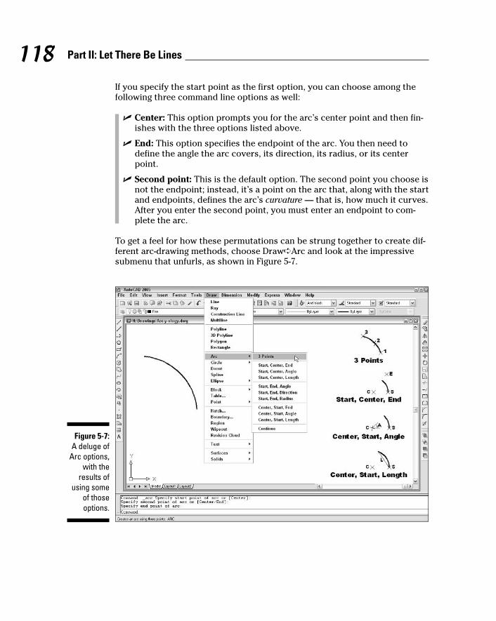
If you specify the start point as the first option, you can choose among thefollowing three command line options as well:
� Center: This option prompts you for the arc’s center point and then fin-ishes with the three options listed above.
� End: This option specifies the endpoint of the arc. You then need todefine the angle the arc covers, its direction, its radius, or its centerpoint.
� Second point: This is the default option. The second point you choose isnot the endpoint; instead, it’s a point on the arc that, along with the startand endpoints, defines the arc’s curvature — that is, how much it curves.After you enter the second point, you must enter an endpoint to com-plete the arc.
To get a feel for how these permutations can be strung together to create dif-ferent arc-drawing methods, choose Draw➪Arc and look at the impressivesubmenu that unfurls, as shown in Figure 5-7.
Figure 5-7:A deluge of
Arc options,with the
results ofusing some
of thoseoptions.
118 Part II: Let There Be Lines
f571389 Ch05.qxd 4/12/04 9:44 AM Page 118
The following example shows how you draw an arc with the default startpoint/second point/endpoint method:
1. Set object properties to the layer and other properties that you wantapplied to the arc that you’ll draw.
2. Click the Arc button on the Draw toolbar.
AutoCAD starts the Arc command and prompts you at the command lineto specify the first endpoint of the arc:
Specify start point of arc or [Center]:
3. Specify the start point by clicking a point or typing coordinates.
The command line prompts you to specify a second point on the arc:
Specify second point of arc or [Center/ENd]:
4. Specify a second point on the arc by clicking a point or typingcoordinates.
The second point lies somewhere along the curve of the arc. AutoCADdetermines the exact curvature of the arc after you choose the final end-point in the following step. To align the second point with an existingobject, use an object snap mode.
The command line prompts you to specify the other endpoint of the arc;as you move the cursor around, AutoCAD shows how the arc will look:
Specify end point of arc:
5. Specify the other endpoint of the arc by clicking a point or typingcoordinates.
AutoCAD draws the arc, as shown in Figure 5-7.
Ellipses (S. Grant?)An ellipse is like a warped circle with a major (long) axis and a minor (short)axis. These axes determine the ellipse’s length, width, and degree of curva-ture. An elliptical arc is an arc cut from an ellipse. Some kinds of drawinggeometry require ellipses or elliptical arcs, but many people use AutoCADhappily for years without ever drawing an ellipse. If you think you’re one ofthose people, skip this section.
The AutoCAD ELlipse command provides a straightforward way of drawingan ellipse: You specify the two endpoints of one of its axes and then specifyan endpoint on the other axis. But like the Arc command, the ELlipse com-mand offers a bunch of other options on the command line:
119Chapter 5: Where to Draw the Line
f571389 Ch05.qxd 4/12/04 9:44 AM Page 119

� Arc: This option generates an elliptical arc, not a full ellipse. You definean elliptical arc just as you do a full ellipse. The following methods forcreating an ellipse apply to either.
� Center: This option requires that you define the center of the ellipse andthen the endpoint of an axis. You can then either enter the distance ofthe other axis or specify that a rotation around the major axis define theellipse. If you choose the latter, you can enter (or drag the ellipse to) aspecific rotation for the second axis that, in turn, completely defines theellipse.
� Rotation: With this option, you specify an angle, which defines the cur-vature of the ellipse — small angles make fat ellipses (0 degrees createsa circle, in fact), and large angles make skinny ellipses. The name of theoption, Rotation, has something to do with rotating an imaginary circlearound the first axis. If you can figure out the imaginary circle business,then you have a better imagination than I do.
The following example creates an ellipse by using the default endpoints ofthe axes method. Figure 5-8 shows an ellipse and an elliptical arc.
Figure 5-8:An ellipse
andelliptical
arc.
120 Part II: Let There Be Lines
f571389 Ch05.qxd 4/12/04 9:44 AM Page 120
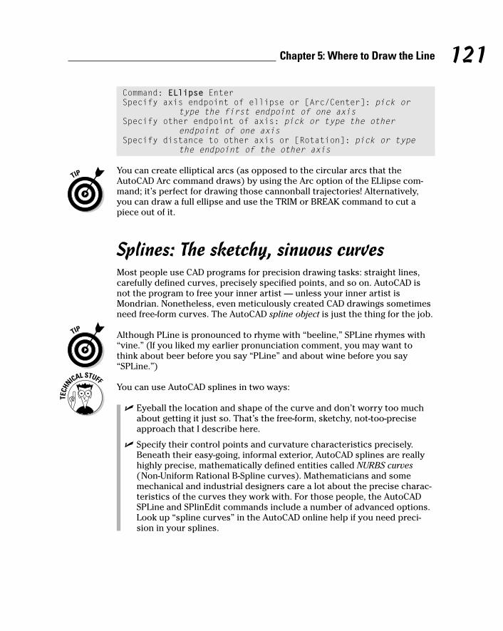
Command: ELlipse EnterSpecify axis endpoint of ellipse or [Arc/Center]: pick or
type the first endpoint of one axisSpecify other endpoint of axis: pick or type the other
endpoint of one axisSpecify distance to other axis or [Rotation]: pick or type
the endpoint of the other axis
You can create elliptical arcs (as opposed to the circular arcs that theAutoCAD Arc command draws) by using the Arc option of the ELlipse com-mand; it’s perfect for drawing those cannonball trajectories! Alternatively,you can draw a full ellipse and use the TRIM or BREAK command to cut apiece out of it.
Splines: The sketchy, sinuous curvesMost people use CAD programs for precision drawing tasks: straight lines,carefully defined curves, precisely specified points, and so on. AutoCAD isnot the program to free your inner artist — unless your inner artist isMondrian. Nonetheless, even meticulously created CAD drawings sometimesneed free-form curves. The AutoCAD spline object is just the thing for the job.
Although PLine is pronounced to rhyme with “beeline,” SPLine rhymes with“vine.” (If you liked my earlier pronunciation comment, you may want tothink about beer before you say “PLine” and about wine before you say“SPLine.”)
You can use AutoCAD splines in two ways:
� Eyeball the location and shape of the curve and don’t worry too muchabout getting it just so. That’s the free-form, sketchy, not-too-preciseapproach that I describe here.
� Specify their control points and curvature characteristics precisely.Beneath their easy-going, informal exterior, AutoCAD splines are reallyhighly precise, mathematically defined entities called NURBS curves(Non-Uniform Rational B-Spline curves). Mathematicians and somemechanical and industrial designers care a lot about the precise charac-teristics of the curves they work with. For those people, the AutoCADSPLine and SPlinEdit commands include a number of advanced options.Look up “spline curves” in the AutoCAD online help if you need preci-sion in your splines.
121Chapter 5: Where to Draw the Line
f571389 Ch05.qxd 4/12/04 9:44 AM Page 121

Drawing splines is straightforward, if you ignore the advanced options. Thefollowing procedure draws a free-form curve with the SPLine command:
1. Set object properties to the layer and other properties that you wantapplied to the spline that you’ll draw.
2. Click the Spline button on the Draw toolbar.
AutoCAD starts the SPLine command and prompts you at the commandline to specify the first endpoint of the spline:
Specify first point or [Object]:
3. Specify the start point by clicking a point or typing coordinates.
The command line prompts you to specify additional points:
Specify next point:
4. Specify additional points by clicking or typing coordinates.
After you pick the second point, the command line prompt changes toshow additional options:
Specify next point or [Close/Fit tolerance] <start tangent>:
Because you’re drawing a free-form curve, you usually don’t need to useobject snaps or other precision techniques when picking spline points.
5. Press Enter after you’ve chosen the final endpoint of your spline.
AutoCAD prompts you to specify tangent lines for each end of the spline:
Specify start tangent:Specify end tangent:
The Specify start tangent and Specify end tangent prompts cancontrol the curvature of the start and end points of the spline. In mostcases, just pressing Enter at both prompts to accept the default tangentsworks fine.
6. Press Enter twice to accept the default tangent directions.
AutoCAD draws the spline.
Figure 5-9 shows some examples of splines.
After you’ve drawn a spline, you can grip edit it to adjust its shape. SeeChapter 6 for information about grip editing. If you need finer control overspline editing, look up the SPlinEdit command in the AutoCAD online help.
122 Part II: Let There Be Lines
f571389 Ch05.qxd 4/12/04 9:44 AM Page 122

Donuts: The circles with a differenceCreating a donut is a simple way to define a single object that consists of twoconcentric circles with the space between them filled.
When you start the DOnut command, AutoCAD prompts you for the insidediameter and the outside diameter — the size of the hole and the size of thedonut, as measured across their widest points. After you’ve entered thesevalues, AutoCAD prompts you for the center point of the donut. But onedonut is rarely enough, so AutoCAD keeps prompting you for additionalcenter points until you press Enter (the AutoCAD equivalent of saying, “no,really, I’m full now!”).
The following example draws a regulation-size donut, with a 1.5-inch hole and3.5-inch outside diameter. Figure 5-10 shows several kinds of donuts.
Command: DOnut EnterSpecify inside diameter of donut <0.5000>: 1.5 EnterSpecify outside diameter of donut <1.0000>: 3.5 EnterSpecify center of donut or <exit>: pick or type the center
point of one or more donutsSpecify center of donut or <exit>: Enter
Figure 5-9:A slew of
splines.
123Chapter 5: Where to Draw the Line
f571389 Ch05.qxd 4/12/04 9:44 AM Page 123
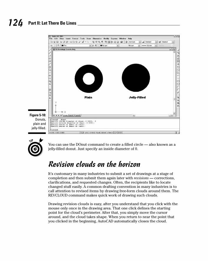
You can use the DOnut command to create a filled circle — also known as ajelly-filled donut. Just specify an inside diameter of 0.
Revision clouds on the horizonIt’s customary in many industries to submit a set of drawings at a stage ofcompletion and then submit them again later with revisions — corrections,clarifications, and requested changes. Often, the recipients like to locatechanged stuff easily. A common drafting convention in many industries is tocall attention to revised items by drawing free-form clouds around them. TheREVCLOUD command makes quick work of drawing such clouds.
Drawing revision clouds is easy, after you understand that you click with themouse only once in the drawing area. That one click defines the startingpoint for the cloud’s perimeter. After that, you simply move the cursoraround, and the cloud takes shape. When you return to near the point thatyou clicked in the beginning, AutoCAD automatically closes the cloud.
Figure 5-10:Donuts,
plain andjelly-filled.
124 Part II: Let There Be Lines
f571389 Ch05.qxd 4/12/04 9:44 AM Page 124

The following example shows you how to draw a revision cloud. Figure 5-11shows what revision clouds look like.
Command: REVCLOUDMinimum arc length: 0.5000 Maximum arc length: 0.5000
Style: NormalSpecify start point or [Arc length/Object/Style] <Object>:
pick a point along the perimeter of your futurecloud
Guide crosshairs along cloud path... sweep the cursor aroundto define the cloud’s perimeter
You don’t need to click again. Simply move the cursor around without click-ing. AutoCAD draws the next lobe of the cloud when your cursor reaches theMinimum arc length distance from the end of the previous lobe.
Continue moving the cursor around until you return to the point that youclicked at first.
Revision cloud finished.
Figure 5-11:Cloud cover.
125Chapter 5: Where to Draw the Line
f571389 Ch05.qxd 4/12/04 9:44 AM Page 125

Here are a few tips for using revision clouds:
� It’s a good idea to put revision clouds on their own layer so that you canchoose to plot with or without the clouds visible.
� You’ll probably find it easier to control the shape of revision clouds ifyou turn off ortho mode before you start the command.
� You may need to add a triangle and number, as shown in Figure 5-11, toindicate the revision number. A block with an attribute is a good way tohandle this requirement: Chapter 13 covers blocks and attributes.
If the revision cloud’s lobes are too small or too large, erase the cloud, restartthe REVCLOUD command, and use the command’s Arc length option tochange the minimum and maximum arc lengths. The default minimum andmaximum lengths are 0.5 (or 15 in metric drawings) multiplied by the DIM-SCALE (DIMension SCALE) system variable setting. If you make the minimumand maximum lengths equal (which is the default), the lobes will be approxi-mately equal in size. If you make them unequal, there will be more variationin lobe size — you’ll get “fluffier” clouds. Fortunately, of these options aremore than most nonmeteorologists will need. If you’ve set DIMSCALE prop-erly during your drawing setup procedure (see Chapter 3), REVCLOUDshould do a pretty good job of guessing reasonable default arc lengths.
Scoring PointsI thought about not covering points in this book, but I didn’t want you com-plaining that AutoCAD 2005 For Dummies is pointless.
The word point describes two different things in AutoCAD:
� A location in the drawing that you specify (by typing coordinates orclicking with the mouse)
� An object that you draw with the POint command
Throughout this chapter and most of the book, I tell you to specify points —that’s the location meaning. This section tells you how to draw point objects.
A point object in AutoCAD can serve two purposes.
� Points often identify specific locations in your drawing to otherpeople who look at the drawing. A point can be something that dis-plays on the screen, either as a tiny dot or as another symbol, such as across with a circle around it.
126 Part II: Let There Be Lines
f571389 Ch05.qxd 4/12/04 9:44 AM Page 126

� You can use points as precise object snap locations. Think of them asconstruction points. For example, when you’re laying out a new building,you might draw point objects at some of the engineering survey pointsand then snap to those points as you sketch the building’s shape withthe polyline command. You use the NODe object snap mode to snap toAutoCAD point objects. In this guise, points usually are for your use indrawing and editing precisely. Other people who view the drawing prob-ably won’t even be aware that the point objects are there.
What makes AutoCAD point objects complicated is their almost limitlessrange of display options, provided to accommodate the two different kinds ofpurposes just described (and possibly some others that I haven’t figured outyet). You use the Point Style dialog box, shown in Figure 5-12, to specify howpoints should look in the current drawing.
DDPTYPE is the command that opens the Point Style dialog box. You canaccess it from the menus by choosing Format➪Point Style. The top portion ofthe dialog box shows the available point display styles. Most of the choicesdo pretty much the same thing. Just click one of the squares that says “hey,that’s a point!” to you.
Figure 5-12:The Point
Style dialogbox controls
the waypoint
objectsappear
on-screen.
127Chapter 5: Where to Draw the Line
f571389 Ch05.qxd 4/12/04 9:44 AM Page 127

The first choice, a single-pixel dot, is hard to see on the screen, and thesecond choice, invisible (a stealth point?), is impossible to see. Avoid thesechoices if you want your point objects to show up on the screen and on plots.The single-pixel dot, which is the default display style, works well if you usepoint objects as object snap locations and don’t want the points obtrusiveon plots.
The remaining settings in the Point Style dialog box control the size at whichpoints appear on the screen at different zoom resolutions. The default set-tings often work fine, but if you’re not satisfied with them, click the Helpbutton to find out how to change them.
After you specify the point style, placing points on-screen is easy; the follow-ing example shows you how.
This is an example of the command-line commands to create a point:
Command: POint EnterCurrent point modes: PDMODE=0 PDSIZE=0.0000Specify a point: pick or type the coordinates of a location
in the drawing
PDMODE and PDSIZE in the command prompt are system variables that corre-spond to the point display mode and display size options in the Point Styledialog box. If you want to know exactly how the system variables correspondto the dialog box choices, you have all the makings of a successful CAD nerd.Click the Help button in the Point Style dialog box to find out more (about thesystem variables — not about yourself).
If you start the POint command from the Draw toolbar or the Draw➪Point➪Multiple Point menu, it will repeat automatically — that is, it will prompt yourepeatedly to Specify a point. When you’re finished drawing points, pressEsc to finish the command for good. If the command doesn’t repeat automati-cally and you want to draw more points, press the Enter key to repeat thePOint command and pick another location on the screen. Repeat as required:Enter, pick, Enter, pick, Enter pick . . . by now you should’ve gotten the point.
128 Part II: Let There Be Lines
f571389 Ch05.qxd 4/12/04 9:44 AM Page 128

Chapter 6
Edit for CreditIn This Chapter� Using command-first editing
� Selecting objects with maximum flexibility
� Moving, copying, and stretching objects
� Manipulating whole objects
� Changing pieces of objects
� Editing with grips
� Editing object properties
Editing objects is the flip side of creating them, and in AutoCAD, you spenda lot of time editing — far more than drawing objects from scratch. That’s
partly because the design and drafting process is by its nature iterative, andalso because CAD programs make it easy to edit objects cleanly.
When you edit objects in AutoCAD, you need to be just as concerned aboutspecifying precise locations and distances as you are when you originallycreate the objects. Make sure that you’re familiar with the precision tech-niques described in Chapter 4 before you apply the editing techniques fromthis chapter to real drawings.
Commanding and SelectingAutoCAD offers two main styles of editing:
� Command-first editing
� Selection-first editing
Within the selection-first editing style, you have an additional choice of edit-ing that uses actual, named commands and direct manipulation of objectswithout named commands. The following sections cover these editing styles.
f571389 Ch06.qxd 4/12/04 9:44 AM Page 129
Command-first editingWith command-first editing, you enter a command and then click the objectson which the command works. This style of editing may seem backwards toyou at first unless you’re a longtime user of AutoCAD or a veteran of command-line operating systems (where you typically type the name of command andthen the names of the files or other objects to which you want to apply thecommand). Command-first editing works well for power users who are in ahurry and who are willing to memorize most of the commands they need todo their work. It’s no surprise that command-first editing is the default styleof editing in AutoCAD.
Selection-first editingIn selection-first editing, you perform the same steps — in the same order —as in most Windows applications: Select the object first, then choose thecommand.
Selection-first editing tends to be easier to master, which is why Windows andthe Macintosh are easier for most people to use for a variety of tasks than DOSever was. Selection-first editing makes AutoCAD more approachable for newand occasional users.
Direct manipulation is a refinement of selection-first editing in which you per-form common editing operations by using the mouse to grab the selectedobject and perform an action on it, such as moving all or part of it to a differ-ent place in the drawing. No named command is involved; the act of movingthe mouse and clicking the mouse buttons in certain ways causes the editingchanges to happen. AutoCAD supports direct manipulation through a power-ful but somewhat complicated technique called grip editing. Grips are the littlesquare handles that appear on an object when you select it. You can use thegrips to stretch, move, copy, rotate, or otherwise edit the object. These grip-editing techniques can make selection-first editing almost as powerful as command-first editing. The complications arise from the fact that you can do so many things with an object after you select it.
Choosing an editing styleThis chapter emphasizes command-first editing. (I also discuss grip editing atthe end of the chapter.) AutoCAD is fundamentally a command-first program.AutoCAD started out offering only command-first editing and later added selection-first methods; AutoCAD 2005 inherits this ancestral trait. I emphasize command-first editing for the following reasons:
130 Part II: Let There Be Lines
f571389 Ch06.qxd 4/12/04 9:44 AM Page 130

� It’s the default AutoCAD editing style.
� It works consistently with all editing commands — some editing com-mands remain command-first only.
� It provides added object selection flexibility, which is useful when youwork on complicated, busy drawings.
After you know how to do command-first editing, you can simply reverse theorder of many editing operations to do them selection-first style instead. Butif you don’t get familiar with command-first editing in the beginning, you’ll becompletely bewildered by some very useful AutoCAD commands that workonly in the command-first style, such as TRim and EXtend. (Commands such asthese ignore any already selected objects and prompt you to select objects.)
Much of the information in this chapter assumes that you’re using the defaultAutoCAD selection settings. If object selection or grip editing works differentlythan I describe in this chapter, check the settings on the Option dialog box’sSelection tab. Five check box settings should be turned on (all other check boxsettings should be turned off):
� Noun/Verb Selection
� Implied Windowing
� Object Grouping
� Enable Grips
� Enable Grip Tips
Grab ItPart of AutoCAD’s editing flexibility comes from its object selection flexibility.For example, command-first editing offers 16 selection modes! (I describe themost useful ones in this chapter.) Don’t worry though; you can get by most ofthe time with three selection modes:
� Selecting a single object
� Enclosing objects in a window (pick left corner; then right corner)
� Including part or all objects in a crossing window (pick right corner;then left corner)
131Chapter 6: Edit for Credit
f571389 Ch06.qxd 4/12/04 9:44 AM Page 131
One-by-one selectionThe most obvious way to select objects is to pick (by clicking) them one at atime. You can build up a selection set cumulatively with this “pick one objectat a time” selection mode. This cumulative convention may be different fromwhat you’re used to. In most Windows programs, if you select one object andthen another, the first object is deselected, and the second one selected. Onlythe object you select last remains selected. In AutoCAD, all the objects youselect, one at a time, remain selected and are added to the set, no matter howmany objects you pick. (You can change this behavior to make AutoCAD worklike Windows does by turning on ‘Use Shift to add to selection’ on the Optiondialog box’s Selection tab, but I suggest you not change it.) Most editing com-mands affect the entire group of selected objects.
Selection boxes left and rightSelecting objects one at a time works great when you want to edit a smallnumber of objects, but many CAD editing tasks involve editing lots of objects.Do you really want to pick 132 lines, arcs, and circles, one at a time?
Like most Windows graphics programs, AutoCAD provides a selection windowfeature for grabbing a bunch of objects in a rectangular area. As you may guessby now, the AutoCAD version of this feature is a bit more powerful than theanalogous feature in other Windows graphics programs and, therefore, slightlyconfusing at first. AutoCAD calls its version implied windowing.
If you click a blank area of the drawing —, that is, not on an object — you’reimplying to AutoCAD that you want to specify a selection window, or box. Ifyou move the cursor to the right before picking the other corner of the selec-tion box, you’re further implying that you want to select all objects that residecompletely within the selection box. If you instead move the cursor to the leftbefore picking the other corner of the selection box, you’re implying that youwant to select all objects that reside completely or partially within the selec-tion box.
The AutoCAD terminology for these two kinds of selection boxes gets a littleconfusing:
� The move-to-the-right, only-select-objects-completely-within-the-boxmode is called Window object selection.
� The move-to-the-left, select-objects-completely-or-partially-within-the-box mode is called Crossing object selection.
132 Part II: Let There Be Lines
f571389 Ch06.qxd 4/12/04 9:44 AM Page 132

You might think of these modes as bounding box (to the right) and crossingbox (to the left). Fortunately, AutoCAD gives you a visual cue that there’s adifference. As you move to the right, the bounding box appears as a solid rec-tangle. As you move to the left, the crossing box appears as a ghosted, ordashed, rectangle.
Figures 6-1 and 6-2 show a bounding box and a crossing box, respectively, inaction.
You can mix and match selecting individual objects, specifying a bounding box,and specifying a crossing box. Each selection adds to the current selection set,allowing you to build up an enormously complicated selection of objects andthen operate on them with one or more editing commands.
Selection box
Pick point 1
Pick point 2
Figure 6-1:A bounding
selec-tion box
(Window),drawn left
to right,selects
only objectscompletely
within the box.
133Chapter 6: Edit for Credit
f571389 Ch06.qxd 4/12/04 9:44 AM Page 133

You can press the Shift key in combination with any of the three standardselection modes — single object, bounding box (Window), and crossing box(Crossing) — to remove already selected objects from the selection set. Thisfeature is especially useful when you’re building a selection set in a crowdeddrawing; you can select a big batch of objects by using Window or Crossing,and then hold down the Shift key while selecting to remove the objects thatyou want to exclude from the editing operation.
Perfecting SelectingWhen you edit in command-first mode, you have all the selection optionsdescribed in the previous section — single object, bounding box (Window),and crossing box (Crossing) — plus a slew of others. If you type ? and pressEnter at any Select objects prompt, AutoCAD lists all the selection options:
Pick point 2
Pick point 1
Selection box
Figure 6-2:A crossing
selec-tion box
(Crossing),drawn right
to left,selectsobjects that are
completelyor partially
within the box.
134 Part II: Let There Be Lines
f571389 Ch06.qxd 4/12/04 9:44 AM Page 134

Window/Last/Crossing/BOX/ALL/Fence/WPolygon/CPolygon/Group/Add/Remove/Multiple/Previous/Undo/AUto/SIngle
Table 6-1 summarizes the most useful command-first selection options.
Table 6-1 Some Useful Command-First Selection OptionsOption Description
Window All objects within a rectangle that you specify by picking twopoints
Last The last object you drew that’s still visible in the drawing area
Crossing All objects within or crossing a rectangle that you specify by pick-ing two points
ALL All objects on layers that aren’t frozen and that are in the currentspace (model space or paper space)
Fence All objects touching an imaginary polyline whose vertices youspecify by picking points
WPolygon All objects within a polygonal area whose corners you specify bypicking points
CPolygon All objects within or crossing a polygonal area whose corners youspecify by picking points
Previous The previous selection set that you specified
To use any of the command-first selection options at the Select objectsprompt, type the uppercase letters corresponding to the option and pressEnter. After you’re finished selecting objects, you must press Enter again totell AutoCAD that you’ve finished selecting objects and want to start the edit-ing operation.
The following example demonstrates how to use the Erase command in command-first mode with several different selection options. The selectiontechniques used in this example apply to most AutoCAD editing commands:
1. Press Esc to make sure that no command is active and no objects areselected.
If any objects are selected when you start an editing command, thecommand in most cases will operate on those objects (selection-firstediting) instead of prompting you to select objects (command-first edit-ing). For the reasons that I describe earlier in this chapter, you shoulduse the command-first editing style until you’re thoroughly familiar with
135Chapter 6: Edit for Credit
f571389 Ch06.qxd 4/12/04 9:44 AM Page 135

it. Later, you can experiment with selection-first editing if you like. (Justreverse the sequence of commanding and selecting that I describe in thischapter.)
2. Click the Erase button on the Modify toolbar.
The command line displays the Select objects prompt.
3. Select two or three individual objects by clicking each one.
AutoCAD adds each object to the selection set. All the objects you selectremain ghosted. The command line displays the Select objects prompt.
4. Specify a bounding selection box (Window) that completely enclosesseveral objects.
Move the cursor to a point below and to the left of the objects, click,release the mouse button, move the cursor above and to the right of theobjects, and click again.
All objects that are completely within the box are selected.
5. Specify a crossing selection box (Crossing) that encloses a few objectsand cuts through several others.
Move the cursor to a point below and to the right of some of the objects,click, release the mouse button, move the cursor above and to the left ofsome of the objects, and click and release again.
All objects that are completely within or cross through the box areselected.
6. Type WP and press Enter to activate the WPolygon selection option.
The command line prompts you to pick points that define the selectionpolygon.
7. Pick a series of points and press Enter.
Figure 6-3 shows an example. After you press Enter, AutoCAD selects allobjects that are completely within the polygon.
8. Press Enter to end object selection.
AutoCAD erases all the selected objects.
Notice how you were able to use a combination of object selection methods tobuild up a selection set and then press Enter to execute the command on them.Most AutoCAD editing commands work this way in command-first mode.
If, after erasing a selection set, you immediately realize that you didn’t reallymean to do away with so many objects, you can use the Undo button on theStandard toolbar to restore all of them. But AutoCAD has one additional un-erase trick up its sleeve — the aptly named OOPS command. When youtype OOPS and press Enter, AutoCAD restores the last selection set that youerased — even if you’ve run other commands after Erase.
136 Part II: Let There Be Lines
f571389 Ch06.qxd 4/12/04 9:44 AM Page 136
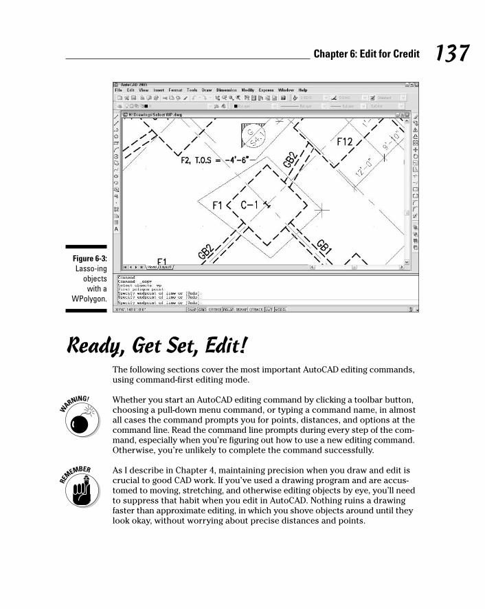
Ready, Get Set, Edit!The following sections cover the most important AutoCAD editing commands,using command-first editing mode.
Whether you start an AutoCAD editing command by clicking a toolbar button,choosing a pull-down menu command, or typing a command name, in almostall cases the command prompts you for points, distances, and options at thecommand line. Read the command line prompts during every step of the com-mand, especially when you’re figuring out how to use a new editing command.Otherwise, you’re unlikely to complete the command successfully.
As I describe in Chapter 4, maintaining precision when you draw and edit iscrucial to good CAD work. If you’ve used a drawing program and are accus-tomed to moving, stretching, and otherwise editing objects by eye, you’ll needto suppress that habit when you edit in AutoCAD. Nothing ruins a drawingfaster than approximate editing, in which you shove objects around until theylook okay, without worrying about precise distances and points.
Figure 6-3:Lasso-ing
objects with a
WPolygon.
137Chapter 6: Edit for Credit
f571389 Ch06.qxd 4/12/04 9:44 AM Page 137

The Big Three: Move, CoPy, and StretchMoving, copying, and stretching are, for many drafters, the three most commonediting operations. AutoCAD obliges this need with the Move, CoPy, and Stretchcommands.
Base points and displacementsThe Move, CoPy, and Stretch commands all require that you specify how farand in what direction you want the objects moved, copied, or stretched. Afteryou’ve selected the objects to be edited and started the command, AutoCADprompts you for two pieces of information:
Specify base point or displacement:Specify second point of displacement or <use first point as
displacement>:
In a not-so-clear way, these prompts say that two possible methods exist foryou to specify how far and in what direction you want the objects copied,moved, or stretched:
� The most common way is to pick or type the coordinates of two pointsthat define a displacement vector. AutoCAD calls these points the basepoint and the second point (hence, it’s called the “base point method”).Imagine an arrow pointing from the base point to the second point —that arrow defines how far and in what direction the objects get copied,moved, or stretched.
� The other way is to type an X,Y pair of numbers that represents a dis-tance rather than a point. This distance is the absolute displacementthat you want to copy, move, or stretch the objects (thus it’s called the“displacement method”).
How does AutoCAD know whether your response to the first prompt is a basepoint or a displacement? It depends on how you respond to the second prompt.(Is that confusing, or what?) First, you pick a point on-screen or enter coordi-nates at the Base point prompt. Next, there are a couple of possibilities:
� If you then pick or type the coordinates of a point at the second pointprompt, AutoCAD says to itself, “Aha — displacement vector!” and movesthe objects according to the imaginary arrow pointing from the base pointto the second point.
� If you press Enter at the second prompt (without having typed anything),AutoCAD says, “Aha — displacement distance,” and uses the X,Y pair ofnumbers that you typed at the first prompt as an absolute displacementdistance.
138 Part II: Let There Be Lines
f571389 Ch06.qxd 4/12/04 9:44 AM Page 138
What makes this displacement business even more confusing is that AutoCADlets you pick a point at the first prompt and press Enter at the second prompt.AutoCAD still says, “Aha — displacement distance,” but now it treats the coor-dinates of the point you picked as an absolute distance. If the point you pickedhas relatively large coordinates, the objects can get moved way outside thenormal drawing area as defined by the limits. The objects fly off into space,which you probably won’t notice at first because you’re zoomed into part ofyour normal drawing area; it just looks to you like the objects have vanished!In short, be careful when you press Enter during the Move, CoPy, and Stretchcommands. Press Enter in response to the second prompt only if you wantAutoCAD to use your response to the first prompt as an absolute displace-ment. If you make a mistake, click the Undo button to back up and try again.You can use Zoom Extents (described in Chapter 7) to look for objects thathave flown off into space.
MoveThe following steps demonstrate command-first editing with the Move com-mand, using the base point method of indicating how far and in what directionto move the selected objects. This procedure also gives detailed recommenda-tions on how to use precision techniques when you edit:
1. Press Esc to make sure that no command is active and no objects areselected.
2. Click the Move button on the Modify toolbar.
The command line displays the Select objects prompt.
3. Select one or more objects.
You can use any of the object selection techniques described in the “Per-fecting Selecting” section, earlier in this chapter.
4. Press Enter when you’re finished selecting objects.
AutoCAD displays the following prompt:
Specify base point or displacement:
5. Specify a base point by clicking a point or typing coordinates.
This point serves as the tail end of your imaginary arrow indicating howfar and in what direction you want the objects moved. After you pick abase point, it’s fairly easy to see what’s going on because AutoCAD dis-plays a temporary image of the object that moves around as you movethe cursor. Figure 6-4 shows what the screen looks like.
139Chapter 6: Edit for Credit
f571389 Ch06.qxd 4/12/04 9:44 AM Page 139

Specify a base point somewhere on or near the object(s) that you’removing. You can use an object snap mode to choose a point exactly onone of the objects.
AutoCAD displays the following prompt:
Specify second point of displacement or <use first pointas displacement>:
6. Specify the second point by clicking a point or typing coordinates.
The second point serves as the arrow end of your imaginary displace-ment arrow. After you specify the second point, AutoCAD moves theobjects.
Don’t press Enter alone at this prompt! If you do, AutoCAD treats the X,Ycoordinates of the first point you picked as an absolute displacement,and the objects fly off in an unpredictable fashion.
Original location Drag image to new location
Displacement vector
Figure 6-4:Draggingobjects in
the middleof the MOVE
command.
140 Part II: Let There Be Lines
f571389 Ch06.qxd 4/12/04 9:44 AM Page 140

These are common precision techniques for specifying the second point:
� Use an object snap mode to pick a second point exactly on another objectin the drawing.
� Type a relative or polar coordinate, as described in Chapter 4. For exam-ple, if you type @6,2, AutoCAD moves the objects 6 units to the right and2 units up. If you type @3<45, AutoCAD moves the objects 3 units at anangle of 45 degrees.
� Use direct distance entry to move objects in an orthogonal or polar track-ing direction. See Chapter 4 for instructions.
CopyThe CoPy command works almost identically to the Move command, exceptthat AutoCAD leaves the selected objects in place and moves new copies ofthem to the new location. The CoPy command also includes a Multiple optionfor making multiple copies of the same set of objects. You activate the Multi-ple option by typing M and pressing Enter after you finish object selection. Asalways, you must watch the command line prompts to find out what you cando and when to do it!
Copy between drawingsYou can’t copy objects from one drawing to another with the CoPy command.Instead, you use the COPYCLIP command, together with its companion com-mand, PASTECLIP. Follow these steps:
1. Open two drawings that contain geometry you want to copy from oneto the other. Arrange the two drawings so that you can see both ofthem, as shown in Figure 6-5.
If you don’t have enough screen real estate to arrange the two drawingsside by side, you can leave them overlapped and change between the twodrawing windows by using the Window menu or by pressing Ctrl+Tab.
2. In the first drawing, right-click in the drawing area and choose Copyfrom the cursor menu.
Choose Cut if you want to move rather than copy the objects to the otherdrawing. Choose Copy with Base Point if you want to choose a specificbase point rather than let AutoCAD choose a base point.
The base point that AutoCAD chooses is the lower-left corner of an imag-inary rectangle that just barely encloses all the objects you’ve selected.
3. If you chose Copy with Base Point in Step 2, pick a base point to usefor the copy operation.
The base point is like a base point for a block definition, as described inChapter 13. Choose a useful point such as the endpoint of a line, thelower-left corner of a rectangle, or the center of a circle.
141Chapter 6: Edit for Credit
f571389 Ch06.qxd 4/12/04 9:44 AM Page 141

4. Select the objects that you want to copy and then press Enter to endobject selection.
5. Click in the second drawing’s window to make it current.
6. Right-click in the second drawing’s window and choose Paste from thecursor menu.
Choose Paste to Original Coordinates if you want to copy the objects sothat they land at the same point (with respect to 0,0) in the seconddrawing as they were located in the first drawing.
7. Specify an insertion point for the copied objects by object snapping toa point on an existing object or typing absolute X,Y coordinates.
AutoCAD copies the objects.
It’s easy to confuse the CoPy and COPYCLIP commands:
� CoPy is AutoCAD’s primary command for copying objects within a drawing.
� COPYCLIP — along with related commands like CUTCLIP and PASTECLIP — is AutoCAD’s version of copy and paste via the WindowsClipboard.
Figure 6-5:Copyingobjects
betweendrawings.
142 Part II: Let There Be Lines
f571389 Ch06.qxd 4/12/04 9:44 AM Page 142
(You can use the Windows Clipboard cut-and-paste method to copy or moveobjects within a single drawing, but using the AutoCAD CoPy and Move com-mands usually gives you better control and precision.)
Table 6-2 summarizes AutoCAD’s Clipboard-related commands, along with theequivalent choices on the right-click menu and the Standard toolbar.
Table 6-2 AutoCAD Clipboard CommandsCursor Menu Choice Command Name Toolbar Button Name
Cut CUTCLIP Cut to Clipboard (Ctrl+X)
Copy COPYCLIP Copy to Clipboard (Ctrl+C)
Copy with Base Point COPYBASE none
Paste PASTECLIP Paste from Clipboard (Ctrl+V)
Paste as Block PASTEBLOCK none
Paste to Original Coordinates PASTEORIG none
StretchThe Stretch command is superficially similar to CoPy and Move; it has thesame inscrutable base point and displacement prompts, and it shifts objects —or parts of objects — to other locations in the drawing. But it also has impor-tant differences that often confound new AutoCAD users to the point wherethey give up trying to find out how to use Stretch. That’s a mistake, becauseStretch is a valuable command. With it, you can perform editing operations inseconds that would take many minutes with other commands. Here are thethings you need to know to make Stretch your friend:
� To use Stretch, you must select objects by using a crossing selection box(or crossing polygon), as described in the section “Perfecting Selecting,”earlier in this chapter. See Figure 6-6.
� Stretch operates on the defining points of objects — endpoints of a line,vertices of a polyline, the center of a circle, and so on — according tothe following rule: If a defining point is within the crossing selection boxthat you specify, AutoCAD moves the defining point and updates theobject accordingly.
For example, if your crossing selection box surrounds one endpoint of aline but not the other endpoint, Stretch moves the first endpoint andredraws the line in the new position dictated by the first endpoint’s newlocation. It’s as though you have a rubber band tacked to the wall withtwo pins, and you move one of the pins. See Figure 6-7.
143Chapter 6: Edit for Credit
f571389 Ch06.qxd 4/12/04 9:44 AM Page 143
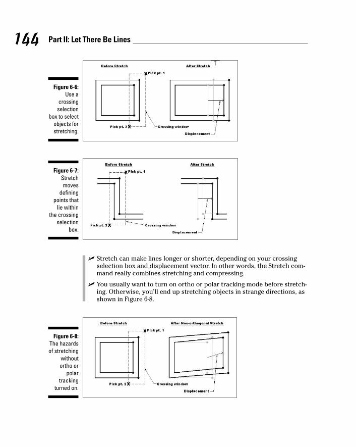
� Stretch can make lines longer or shorter, depending on your crossingselection box and displacement vector. In other words, the Stretch com-mand really combines stretching and compressing.
� You usually want to turn on ortho or polar tracking mode before stretch-ing. Otherwise, you’ll end up stretching objects in strange directions, asshown in Figure 6-8.
Figure 6-8:The hazardsof stretching
withoutortho or
polartracking
turned on.
Figure 6-7:Stretchmoves
definingpoints that
lie withinthe crossing
selectionbox.
Figure 6-6:Use a
crossingselection
box to selectobjects forstretching.
144 Part II: Let There Be Lines
f571389 Ch06.qxd 4/12/04 9:44 AM Page 144

The following steps describe how to Stretch lines:
1. Draw some lines in an arrangement similar to the dark lines shown inFigure 6-9.
Start your stretching with simple objects. You can work up to more com-plicated objects — polylines, circles, arcs, and so on — after you’ve lim-bered up with lines.
2. Press Esc to make sure that no command is active and no objects areselected.
3. Click the Stretch button on the Modify toolbar.
The command line displays the Select objects prompt, with a warn-ing to use the Crossing or CPolygon object selection mode:
Select objects to stretch by crossing-window or crossing-polygon...
Select objects:
4. Specify a crossing selection box that encloses some, but not all, end-points of the lines.
Figure 6-9 shows a sample crossing selection box that completely enclosesthe two vertical lines on the right side of the figure. This crossing selec-tion box cuts through the four horizontal lines, enclosing only one end-point of each.
You specify a crossing selection box by picking a point, moving yourmouse to the left, and picking a second point.
5. Press Enter to end object selection.
AutoCAD displays the following prompt.
Specify base point or displacement:
6. Specify a base point by object snapping to a point on an existing objector by typing absolute X,Y coordinates.
This step is just like Step 5 in the Move procedure earlier in this chapter.
AutoCAD displays the following prompt.
Specify second point of displacement or <use first pointas displacement>:
7. Toggle ortho mode on and then off by clicking the ORTHO button onthe status bar; try moving the cursor around first with ortho mode onand then with it off to see the difference.
Figure 6-9 shows what the screen looks like as you move the cursoraround with ortho off.
145Chapter 6: Edit for Credit
f571389 Ch06.qxd 4/12/04 9:44 AM Page 145

8. Toggle ortho mode on and then specify the second point — usually byusing direct distance entry, object snapping to a point on an existingobject, or typing relative X,Y coordinates.
This step is just like Step 6 in the Move procedure earlier in this chapter.After you pick the second point, AutoCAD stretches the objects. Noticethat the Stretch command moved the two vertical lines because thecrossing selection box contained both endpoints of both lines. Stretchlengthened or shortened the four horizontal lines because the crossingselection box enclosed only one endpoint of each.
The Stretch command takes some practice, but it’s worth the effort. Draw someadditional kinds of objects and practice stretching with different crossing selec-tion box locations as well as different base points and second points.
Original location
Drag image to new location
Crossing window pick point 1
Displacement vector
Crossing window pick point 2
Figure 6-9:Draggingobjects in
the middleof the
Stretchcommand.
146 Part II: Let There Be Lines
f571389 Ch06.qxd 4/12/04 9:44 AM Page 146

More manipulationsThe commands in this section — ROtate, SCale, ARray, and OFfset — provideother ways (in addition to Move, CoPy, and Stretch) of manipulating objectsor creating new versions of them. The procedures for each command assumethat you’re familiar with the object selection and editing precision techniquespresented in the Move, CoPy, and Stretch procedures (see the previous sec-tions in this chapter).
RotateThe ROtate command “swings” one or more objects around a point that youspecify. Follow these steps to use the ROtate command:
1. Press Esc to make sure that no command is active and no objects areselected.
2. Click the Rotate button on the Modify toolbar.
3. Select one or more objects and then press Enter to end object selection.
AutoCAD prompts you for the base point for rotating the selected objects:
Specify base point:
4. Specify a base point by clicking a point or typing coordinates.
The base point becomes the point about which AutoCAD rotates theobjects. You also have to specify a rotation angle:
Specify rotation angle or [Reference]:
5. Specify a rotation angle by typing an angle measurement and pressingEnter.
Alternatively, you can indicate an angle on the screen by moving thecursor until the Coordinates section of the status bar indicates thedesired angle and then clicking. If you choose this alternative, you willneed to use ortho mode or polar tracking to indicate a precise angle (forexample, 90 or 45 degrees) or an object snap to rotate an object so thatit aligns precisely with other objects.
After you specify the rotation angle by typing or picking, AutoCAD rotatesthe objects into their new position.
147Chapter 6: Edit for Credit
f571389 Ch06.qxd 4/12/04 9:44 AM Page 147

ScaleIf you read all my harping on drawing scales and drawing scale factors in Chap-ter 3, you may think that the SCale command performs some magical scaletransformation on your entire drawing. No such luck. It merely scales one ormore objects up or down by a factor that you specify. Here’s how it works:
1. Press Esc to make sure that no command is active and no objects areselected.
2. Click the Scale button on the Modify toolbar.
3. Select one or more objects and then press Enter to end object selection.
AutoCAD prompts you for the base point about which it will scale all theselected objects:
Specify base point:
AutoCAD does not scale each object individually around its own basepoint (because most AutoCAD drawing objects don’t have individualbase points). Instead, AutoCAD uses the base point that you specify todetermine how to scale all objects in the selection set. For example, ifyou select a circle to scale, pick a point outside the circle as the basepoint, and then specify a scale factor of 2, AutoCAD not only makes thecircle twice as big, but also moves the circle twice as far away from thebase point that you specified.
4. Specify a base point by picking a point or typing coordinates.
The base point becomes the point about which the objects are scaled.AutoCAD prompts you for the scale factor:
Specify scale factor or [Reference]:
5. Type a scale factor and press Enter.
AutoCAD then scales the objects by the factor that you type, using thebase point that you specified. Numbers greater than one increase theobjects’ size. Numbers smaller than one decrease the objects’ size.
Changing the drawing scale factor of a drawing after you’ve drawn it is atedious and complicated process in AutoCAD. In brief, you need to change thescale-dependent system variables described in Chapter 3, and then scalesome, but not all, drawing objects. You don’t scale the real-world geometrythat you’ve drawn, because its measurements in the real world remain thesame. You do scale objects such as text and hatching that have a fixed heightor spacing regardless of drawing scale factor. (The SCALETEXT command canhelp with this operation. See Chapter 9 for more information.) Because of thesecomplications, try to make sure that you choose a proper scale and set upthe drawing properly for that scale before you begin drawing. See Chapter 3for details.
148 Part II: Let There Be Lines
f571389 Ch06.qxd 4/12/04 9:44 AM Page 148
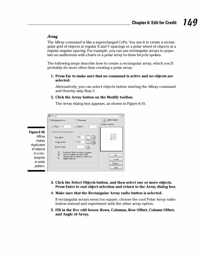
ArrayThe ARray command is like a supercharged CoPy: You use it to create a rectan-gular grid of objects at regular X and Y spacings or a polar wheel of objects at aregular angular spacing. For example, you can use rectangular arrays to popu-late an auditorium with chairs or a polar array to draw bicycle spokes.
The following steps describe how to create a rectangular array, which you’llprobably do more often than creating a polar array:
1. Press Esc to make sure that no command is active and no objects areselected.
Alternatively, you can select objects before starting the ARray commandand thereby skip Step 3.
2. Click the Array button on the Modify toolbar.
The Array dialog box appears, as shown in Figure 6-10.
3. Click the Select Objects button, and then select one or more objects.Press Enter to end object selection and return to the Array dialog box.
4. Make sure that the Rectangular Array radio button is selected.
If rectangular arrays seem too square, choose the cool Polar Array radiobutton instead and experiment with the other array option.
5. Fill in the five edit boxes: Rows, Columns, Row Offset, Column Offset,and Angle of Array.
Figure 6-10:ARraymakes
duplicatesof objects
in a rec-tangular or polarpattern.
149Chapter 6: Edit for Credit
f571389 Ch06.qxd 4/12/04 9:44 AM Page 149

The Rows and Columns numbers include the row and column of the origi-nal objects themselves. In other words, entries of 1 don’t create any newobjects in that direction. The Row Offset and Column Offset measure-ments are the distances between adjacent rows and columns.
6. Click Preview.
AutoCAD shows what the array will look like by using your current set-tings and displays a dialog box with Accept, Modify, and Cancel buttons.
7. Click the Accept button if you’re satisfied with the array, or the Modifybutton if you want to change the array parameters.
OffsetYou use Offset to create parallel copies of lines, polylines, circles, arcs, orsplines. Follow these steps to use OFfset:
1. Click the Offset button on the Modify toolbar.
AutoCAD prompts you for the offset distance — the distance from the orig-inal object to the copy you’re creating:
Specify offset distance or [Through] <Through>:
2. Type an offset distance and press Enter.
Alternatively, you can indicate an offset distance by picking two points onthe screen. If you choose this method, you normally should use objectsnaps to specify a precise distance from one existing object to another.
AutoCAD prompts you to select the object from which you want tocreate an offset copy:
Select object to offset or <exit>:
3. Select a single object, such as a line, polyline, or arc.
Note that you can select only one object at a time with the OFfset com-mand. AutoCAD asks where you want the offset object:
Specify point on side to offset:
4. Point to one side or the other of the object and then click.
It doesn’t matter how far away from the object the cursor is when youclick. You’re simply indicating a direction.
AutoCAD repeats the Select object prompt, in case you want to offsetother objects by the same distance:
Select object to offset or <exit>:
5. Go back to Step 3 if you want to offset another object, or press Enter ifyou’re finished offsetting objects for now.
Figure 6-11 shows the OFfset command in progress.
150 Part II: Let There Be Lines
f571389 Ch06.qxd 4/12/04 9:44 AM Page 150
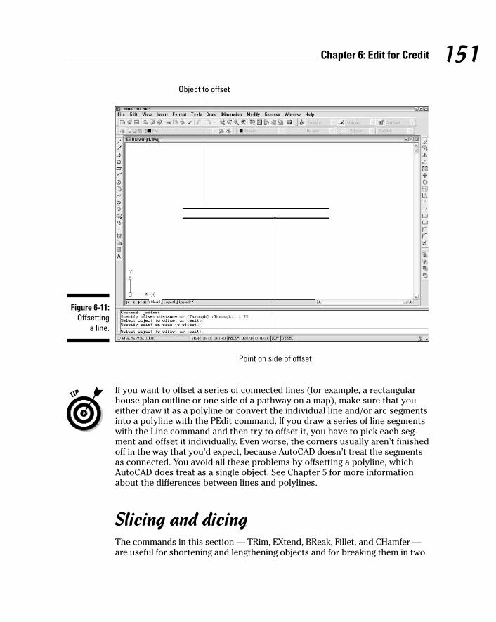
If you want to offset a series of connected lines (for example, a rectangularhouse plan outline or one side of a pathway on a map), make sure that youeither draw it as a polyline or convert the individual line and/or arc segmentsinto a polyline with the PEdit command. If you draw a series of line segmentswith the Line command and then try to offset it, you have to pick each seg-ment and offset it individually. Even worse, the corners usually aren’t finishedoff in the way that you’d expect, because AutoCAD doesn’t treat the segmentsas connected. You avoid all these problems by offsetting a polyline, whichAutoCAD does treat as a single object. See Chapter 5 for more informationabout the differences between lines and polylines.
Slicing and dicingThe commands in this section — TRim, EXtend, BReak, Fillet, and CHamfer —are useful for shortening and lengthening objects and for breaking them in two.
Object to offset
Point on side of offset
Figure 6-11:Offsetting
a line.
151Chapter 6: Edit for Credit
f571389 Ch06.qxd 4/12/04 9:44 AM Page 151

Trim and ExtendTRim and EXtend are the twin commands for making lines, polylines, and arcsshorter and longer. They’re the yin and yang, the Laurel and Hardy, the JackSprat and his wife of the AutoCAD editing world. The two commands and theirprompts are almost identical, so the following steps cover both. I show theprompts for the TRim command; the EXtend prompts are similar:
1. Click the Trim or Extend button on the Modify toolbar.
AutoCAD prompts you to select cutting edges that will do the trimming(or, if you chose the EXtend command, boundary edges for extending to):
Current settings: Projection=UCS, Edge=NoneSelect cutting edges ...Select objects:
2. Select one or more objects that will act as the knife for trimming objectsor the wall to which objects will be extended. Press Enter to end objectselection.
Figure 6-12 shows a cutting edge (for TRim) and a boundary edge (forEXtend).
AutoCAD prompts you to select objects that you want to trim or extend:
Select object to trim or shift-select to extend or[Project/Edge/Undo]:
3. Select a single object to trim or extend. Choose the portion of theobject that you want AutoCAD to trim away or the end of the objectthat’s closer to the extend-to boundary.
AutoCAD trims or extends the object to one of the objects that youselected in Step 2. If AutoCAD can’t trim or extend the object — for exam-ple, if the trimming object and the object to be trimmed are parallel —the command line displays an error message such as Object does notintersect an edge.
TRim and EXtend normally allow you to select only one object at a timefor trimming or extending. The one exception is that you can type F andpress Enter to use the Fence object selection mode (refer to Table 6-1).Fence is useful for trimming or extending a large group of objects in onefell swoop.
The command line continues to prompt you to select other objects totrim or extend:
Select object to trim or shift-select to extend or[Project/Edge/Undo]:
152 Part II: Let There Be Lines
f571389 Ch06.qxd 4/12/04 9:44 AM Page 152

4. Choose additional objects, or press Enter when you’re finished trim-ming or extending.
If you accidentally trim or extend the wrong object and you’re still in theTRim or EXtend command, type U and press Enter to undo the mostrecent trim or extend.
The example in Figure 6-12 shows trimming to a single cutting edge, in whichthe end of the trimmed lines gets lopped off. Another common use of the TRimcommand is for trimming out a piece of a line between two cutting edges. Inthe two-cutting-edges scenario, TRim cuts a piece out of the middle of thetrimmed line.
The LENgthen command provides other useful ways to make lines, arcs, andpolylines longer (or shorter). You can specify an absolute distance (or “delta”)to lengthen or shorten by, a percentage to lengthen or shorten by, or a newtotal length. Look up “LENGTHEN command” in AutoCAD’s help system formore information.
Cutting edge (for trim)
Objects to trim Objects to extend
Boundary edge (for extend)
Figure 6-12:Anatomy of
the TRimand EXtendoperations.
153Chapter 6: Edit for Credit
f571389 Ch06.qxd 4/12/04 9:44 AM Page 153

BreakThe BReak command isn’t what you use before heading out for coffee. It’s forbreaking pieces out of — that is, creating gaps in — lines, polylines, circles,arcs, or splines. BReak also comes in handy if you need to split one objectinto two without actually removing any visible material.
If you want to create regularly spaced gaps in an object — so that it displaysdashed, for instance — don’t use BReak. Use an AutoCAD dash-dot linetypeinstead. See Chapter 4 for more linetype information.
The following example shows how you BReak an object:
1. Click the Break button on the Modify toolbar.
AutoCAD prompts you to select a single object that you want to break:
Select object:
2. Select a single object, such as a line, polyline, or arc.
The point you pick when selecting the object serves double duty: Itselects the object, of course, but it also becomes the default first breakpoint (that is, it defines one side of the gap that you’ll create). Thus, youshould either use one of the AutoCAD precision techniques, such as anobject snap, to pick the object at a precise point, or use the First pointoption (described in the next step) to repick the first break point.
AutoCAD prompts you to specify the second break point, or to type F andpress Enter if you want to respecify the first break point:
Specify second break point or [First point]:
3. If the point that you picked in the preceding step doesn’t also corre-spond to a break point (see the previous tip), type F and press Enter torespecify the first break point, and then pick the point with an objectsnap or other precision technique.
If you do type F and press Enter and then respecify the first break point,AutoCAD prompts you now to select the second break point:
Specify second break point:
4. Specify the second break point by picking a point or typing coordinates.
AutoCAD cuts a section out of the object, using the first and secondbreak points to define the length of the gap.
If you want to cut an object into two pieces without removing anything, clickthe Break at Point button on the Modify toolbar. You first select the object andthen choose a second point that defines where AutoCAD breaks the object intwo. You can then move, copy, or otherwise manipulate each section of theoriginal object as a separate object.
154 Part II: Let There Be Lines
f571389 Ch06.qxd 4/12/04 9:44 AM Page 154

Fillet and ChamferWhereas TRim, EXtend, and BReak alter one object at a time, the Fillet andCHamfer commands require a pair of objects. As Figure 6-13 shows, Fillet cre-ates a curved corner between two lines, whereas CHamfer creates an angled,straight corner. In case you wondered, it’s pronounced “fill-et,” not “fill-eh.”Saying that you know how to “fill-eh” may get you a job in a butcher shop, butit will get you strange looks in a design office.
The following steps describe how to use the Fillet command:
1. Click the Fillet button on the Modify toolbar.
AutoCAD displays the current Fillet settings and prompts you to selectthe first object for filleting or specify one of three options:
Current settings: Mode = TRIM, Radius = 0.0000Select first object or [Polyline/Radius/Trim/mUltiple]:
2. Type R and press Enter to set the fillet radius.
AutoCAD prompts you to specify the fillet radius that it uses for futurefillet operations:
Specify fillet radius <0.0000>:
Figure 6-13:Cleaning up those
corners withFillet andCHamfer.
155Chapter 6: Edit for Credit
f571389 Ch06.qxd 4/12/04 9:44 AM Page 155
3. Type a fillet radius and press Enter.
The number you type will be the radius of the arc that joins the two lines.
Select first object or [Polyline/Radius/Trim/mUltiple]:
4. Select the first line of the pair that you want to fillet.
AutoCAD prompts you to select the second object for filleting:
Select second object:
5. Select the second line of the pair that you want to fillet.
AutoCAD fillets the two objects, drawing an arc of the radius that youspecified in Step 3.
You can fillet two lines and specify a radius of zero to make them meet at apoint. If you have lots of lines to fillet, whether with a zero or nonzero radius,use the Fillet command’s mUtliple option to speed the process.
The CHamfer command works similarly except that, instead of specifying afillet distance, you specify either two chamfer distances or a chamfer lengthand angle.
Get a GripAlthough command-first editing is the most flexible and widespread editingstyle in AutoCAD, it’s not the only way. Grip editing is a useful adjunct to command-first editing, especially when you want to modify just one or twoobjects. You may have encountered grip editing when using other kinds ofgraphics programs. Even if you’re an experienced user of other graphics pro-grams, you’ve never seen grips used in quite the way that AutoCAD uses them.
Anything that you can do with grip editing can be done with command-firstediting as well. In some situations, grip editing is a little more efficient or con-venient than command-first editing, but command-first editing always getsthe job done. If you master only one style of editing, make it command-firststyle. In other words, feel free to skip this section — at least until you’re com-fortable with command-first editing.
About gripsGrips are little square handles that appear on an object after you select it.
156 Part II: Let There Be Lines
f571389 Ch06.qxd 4/12/04 9:44 AM Page 156
In their simplest guise, AutoCAD grips work similar to the little squares ongraphical objects in other Windows programs. But in AutoCAD, instead ofclicking and dragging a grip, you must click, release the mouse button, movethe cursor, and click again at the new location. (By separating the selection ofbeginning and ending points into two different operations, AutoCAD allowsyou to use different techniques — such as different object snap modes — toselect each point.)
AutoCAD grips are, for sophisticated users, better than the grips found in mostother programs, because you can do so much more with them. You can, forexample, use AutoCAD grips to move, stretch, or copy an object. You also canuse them to rotate an object, scale it to a different size, or mirror an object —that is, create one or more backwards copies. Grips also act as visible objectsnaps, or little magnets that draw the cursor to themselves.
A gripping exampleThe following sections cover in detail the five grip-editing modes — Stretch,Move, Rotate, Scale, and Mirror. Follow these steps to explore the grip-editingmodes:
1. Press Esc to make sure that no command is active and no objects areselected.
AutoCAD displays the naked command prompt — that is, no commandis currently active:
Command:
2. Click an object on-screen to select it and display its grips.
Grips — solid blue squares on the selected object — appear at variouspoints on the object. Note that the AutoCAD command prompt remainsnaked; you haven’t started a command or grip-editing operation yet.
3. Click another object.
Both the newly selected object and the object that you selected previ-ously display grips.
4. Click one of the grips on either object.
The blue square turns to a red square. This grip is now hot, or ready fora grip-editing operation.
Grip-editing options now appear on the command line. The first optionto appear is STRETCH.
157Chapter 6: Edit for Credit
f571389 Ch06.qxd 4/12/04 9:44 AM Page 157
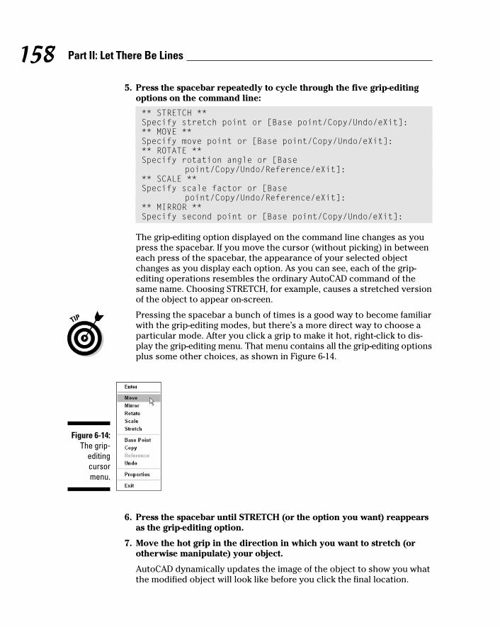
5. Press the spacebar repeatedly to cycle through the five grip-editingoptions on the command line:
** STRETCH **Specify stretch point or [Base point/Copy/Undo/eXit]:** MOVE **Specify move point or [Base point/Copy/Undo/eXit]:** ROTATE **Specify rotation angle or [Base
point/Copy/Undo/Reference/eXit]:** SCALE **Specify scale factor or [Base
point/Copy/Undo/Reference/eXit]:** MIRROR **Specify second point or [Base point/Copy/Undo/eXit]:
The grip-editing option displayed on the command line changes as youpress the spacebar. If you move the cursor (without picking) in betweeneach press of the spacebar, the appearance of your selected objectchanges as you display each option. As you can see, each of the grip-editing operations resembles the ordinary AutoCAD command of thesame name. Choosing STRETCH, for example, causes a stretched versionof the object to appear on-screen.
Pressing the spacebar a bunch of times is a good way to become familiarwith the grip-editing modes, but there’s a more direct way to choose aparticular mode. After you click a grip to make it hot, right-click to dis-play the grip-editing menu. That menu contains all the grip-editing optionsplus some other choices, as shown in Figure 6-14.
6. Press the spacebar until STRETCH (or the option you want) reappearsas the grip-editing option.
7. Move the hot grip in the direction in which you want to stretch (orotherwise manipulate) your object.
AutoCAD dynamically updates the image of the object to show you whatthe modified object will look like before you click the final location.
Figure 6-14:The grip-
editingcursormenu.
158 Part II: Let There Be Lines
f571389 Ch06.qxd 4/12/04 9:44 AM Page 158

8. Click again to finish the grip-editing operation.
The selected object with the hot grip updates. The object with the coldgrips doesn’t change.
9. Click the same grip that you chose in Step 4 (now in a different loca-tion) to make it hot.
10. This time, move the cursor near one of the grips on the other object.When you feel the magnetic pull of the grip on the other object, clickagain to connect the hot grip with the other grip.
The object point represented by the hot grip now coincides exactly withthe grip on the other object.
11. Press Esc to deselect all objects and remove all grips.
Figure 6-15 shows a hot (red) endpoint grip of a line being connected to thecold (blue) endpoint grip of another line. The ghosted line shows the originalposition of the line being edited, and the continuous line shows the new posi-tion. Using a grip in this way as a visible object snap offers the same advan-tage as using single point object snaps, as described in Chapter 4: It ensuresprecision by making sure that objects meet exactly.
Red (hot) grip Blue (cold) grip
Figure 6-15:Using gripsto connect
two objects.
159Chapter 6: Edit for Credit
f571389 Ch06.qxd 4/12/04 9:44 AM Page 159
You can experiment with all the grip-editing options to find out how they affecta selected object.
Because MOVE and STRETCH are the most useful grip-editing modes, I coverthem more specifically.
Move it!Back in the days of manual drafting, moving objects was a big pain in theeraser. You had to erase the stuff you wanted to move and redraw the objectsin their new location. In the process, you usually ended up erasing parts ofother stuff that you didn’t want to move and left smudged lines and piles oferaser dust everywhere. CAD does away with all the fuss and muss of movingobjects, and AutoCAD grip editing is a great way to make it happen. The fol-lowing steps describe how to move objects:
1. Select one or more objects.
Use any combination of the three editing modes — single object, bound-ing box, or crossing box — described in the section, “Grab It,” earlier inthis chapter.
2. Click one of the grips to make it hot.
At this point in your editing career, it doesn’t matter which grip you click.As you become more familiar with grip editing, you’ll discover that cer-tain grips serve as better reference points than others for particular edit-ing operations.
3. Right-click anywhere in the drawing area and choose Move from thecursor menu.
4. Move the cursor to a different location and click.
As you move the cursor around, AutoCAD displays the tentative newpositions for all the objects, as shown in Figure 6-16. After you click, theobjects assume their new positions.
5. Press Esc to deselect all objects and remove all grips.
Copy, or a kinder, gentler MoveIf you were paying attention during “A gripping example,” earlier in the chapter,you may have noticed while pressing the spacebar that COPY was not amongthe five grip-editing modes. Why not? Because every grip mode includes a copyoption (as the command line prompts shown in “A gripping example,” earlier inthis chapter indicate). In other words, you can STRETCH with copy, MOVE withcopy, ROTATE with copy, SCALE with copy, and MIRROR with copy.
160 Part II: Let There Be Lines
f571389 Ch06.qxd 4/12/04 9:44 AM Page 160

The copy option leaves the selected objects in place and does the editingoperation on a new copy of the objects.
By far the most common use for the copy option is with the MOVE grip-editingmode. If you think about “MOVE with copy” for about two seconds, you’ll real-ize that it’s just a complicated way of saying “copy.” The following steps showhow to copy objects quickly by using grip editing:
1. Select one or more objects.
2. Click any one of the grips to make it hot.
3. Right-click anywhere in the drawing area and choose Move from thecursor menu.
If you want to copy objects in the normal sense of the word “copy,” youmust choose the MOVE grip-editing mode first. Otherwise, you’ll be copy-ing with the STRETCH grip-editing mode.
4. Right-click again and choose Copy from the cursor menu.
Original location Drag image to new location
Displacement vector
Figure 6-16:Draggingobjects in
the middleof the MOVEgrip-editing
operation.
161Chapter 6: Edit for Credit
f571389 Ch06.qxd 4/12/04 9:44 AM Page 161

5. Move the cursor to a different location and click.
After you click, new objects appear in the new location.
6. Move the cursor to additional locations and click there if you want tomake additional copies.
7. Press Esc twice — once to end the copying operation and once to des-elect all objects and remove all grips.
A warm-up StretchIn AutoCAD, stretching is the process of making objects longer or shorter. TheSTRETCH grip-editing operation is really a combination of stretching and com-pressing, but the programmers probably realized that STRETCHANDCOMPRESSdidn’t exactly roll off the tongue.
The STRETCH grip-editing mode works differently than the other modes. Bydefault, it affects only the object with the hot grip on it, not all objects withgrips on them. You can override this default behavior by using the Shift keyto pick multiple hot grips. Follow these steps to get acquainted with using theSTRETCH grip-editing mode to stretch one or more objects:
1. Turn off ortho mode by clicking the ORTHO button on the status baruntil the button appears to be pushed out and the words <Ortho off>appear on the command line.
Ortho mode forces stretch displacements to be orthogonal — that is,parallel to lines running at 0 and 90 degrees. During real editing tasks,you’ll often want to turn on ortho mode, but while you get acquaintedwith stretching, leaving ortho mode off makes things clearer.
2. Select several objects, including at least one line.
3. On one of the lines, click one of the endpoint grips to make it hot.
All the objects remain selected, but as you move the cursor, only the linewith the hot grip changes. Figure 6-17 shows an example.
4. Click a new point for the hot endpoint grip.
The line stretches to accommodate the new endpoint location.
5. On the same line, click the midpoint grip to make it hot.
As you move the cursor, the entire line moves. Using the STRETCH grip-editing mode with a line’s midpoint “stretches” the entire line to a newlocation.
162 Part II: Let There Be Lines
f571389 Ch06.qxd 4/12/04 9:44 AM Page 162

6. Click a new point for the hot midpoint grip.
The line moves to the new midpoint location.
7. On one of the lines, click one of the endpoint grips to make it hot.
8. Hold down the Shift key, and then click one of the endpoint grips on adifferent line to make it hot.
Two grips on two different lines are now hot because you held down theShift key and clicked the second grip.
You can create more hot grips by holding down the Shift key and clickingmore grips.
9. Release the Shift key and re-pick any one of the hot grips.
Original location
Drag image to new location
Displacement vector
Figure 6-17:Dragging
a line’sendpoint inthe middle
of theSTRETCH
grip-editingoperation.
163Chapter 6: Edit for Credit
f571389 Ch06.qxd 4/12/04 9:44 AM Page 163

Releasing the Shift key signals that you’re finished making grips hot. Re-picking one of the hot grips establishes it as the base point for the stretchoperation (see Figure 6-18).
10. Click a new point for the grip.
All the objects with hot grips stretch based on the displacement of thegrip that you clicked in Step 9.
11. Turn on ortho mode by clicking the ORTHO button on the status baruntil the button appears to be pushed in and the words <Ortho on>appear on the command line. Repeat Steps 2 through 10 to see theeffect of ortho mode on stretching.
For most real-world editing situations, you’ll want to turn on ortho or polartracking mode before stretching. Ortho mode is good for all kinds of drawingand editing tasks because it enforces a nice, rectilinear orderliness on yourdrawing. Chapter 4 describes how to use ortho mode to draw orthogonal lines.
The hot grip used as a base point
Multiple hot grips
Figure 6-18:Stretching
multipleobjects with
multiple hot grips.
164 Part II: Let There Be Lines
f571389 Ch06.qxd 4/12/04 9:44 AM Page 164

165Chapter 6: Edit for Credit
Polishing those propertiesWhen you think of editing objects, you probablythink first about editing their geometry: moving,stretching, making new copies, and so on. That’sthe kind of editing I cover in this chapter.
Another kind of editing is changing objects’properties. As I describe in Chapter 4, everyobject in an AutoCAD drawing has a set of non-geometrical properties, including layer, color,linetype, and lineweight. Sometimes, you needto edit those properties — when you acciden-tally draw something on the wrong layer, forexample. Three common ways of editingobjects properties in AutoCAD are
� The Properties palette: This is the most flex-ible way to edit properties. Select any object(or objects), right-click in the drawing area,and choose Properties from the cursormenu. The Properties palette displays a
tabular grid that lists the names and valuesof all properties. Click in the value cell tochange a particular property.
� Layers and Properties toolbars: Another wayto change properties is to select objects andthen choose from the drop-down lists (Layer,Color, and so on) on the Layers and theProperties toolbars. See Chapter 4 for moreinformation.
� Match Properties: You can use the MatchProperties button on the Standard toolbar— the button with the paintbrush on it — topaint properties from one object to another.Match Properties works similarly to theFormat Painter button in Microsoft applica-tions. Match Properties works even whenthe objects reside in different drawings.
f571389 Ch06.qxd 4/12/04 9:44 AM Page 165

166 Part II: Let There Be Lines
f571389 Ch06.qxd 4/12/04 9:44 AM Page 166
Chapter 7
A Zoom with a ViewIn This Chapter� Zooming and panning
� Naming and restoring views
� Zooming and panning in paper space layouts
� Regenerating the display
One of the advantages of CAD over manual drawing is its capability ofgiving you different ways to view your drawing. You can zoom in close,
zoom out to a great distance, and pan around. In fact, not only can you zoomand pan in your drawing, but in most kinds of drawings, you must do it fre-quently to be able to draw, edit, and view effectively.
Technical drawings are jampacked with lines, text, and dimensions. Zoomingand panning frequently enables you to see the details better, draw more con-fidently (because you can see what you’re doing), and edit more quickly(because object selection is easier when there aren’t a zillion objects on thescreen). This chapter covers AutoCAD’s most useful display control features.
Zoom and Pan with Glass and HandMoving your viewpoint in to get a closer view of your drawing data is calledzooming in; moving your viewpoint back to get a more expansive view iscalled zooming out.
Zooming in and out of your drawing is one of the big advantages thatAutoCAD offers over manual drawing. You can do detailed work on tinyobjects and then zoom out and move around rooms, houses, or neighbor-hoods from an Olympian perspective.
Panning is closely related to zooming. If you zoom in enough that some of yourdrawing no longer shows up on-screen, you’re going to want to pan around —move left, right, up, and down in your drawing — without zooming in and out.AutoCAD makes panning easy with scroll bars and real-time panning.
f571389 Ch07.qxd 4/12/04 9:44 AM Page 167

Both panning and zooming change what is known as the view. The view is thecurrent location and magnification of the AutoCAD depiction of your drawing.Each time you zoom or pan, you establish a new view. You can give a name toa specific view to make returning to that view easy, as I demonstrate later inthis chapter.
Fortunately, zooming and panning in AutoCAD is as simple as it is necessary.The following steps describe how to use AutoCAD’s Zoom and Pan Realtimefeature, which is easy to operate and provides a lot of flexibility:
1. Click the Zoom Realtime button (the one that looks a magnifying glasswith a plus/minus sign next to it) on the Standard toolbar.
The Realtime option of the Zoom command starts. The cursor changesto a magnifying glass, and AutoCAD prompts you at the command line:
Press ESC or ENTER to exit, or right-click to displayshortcut menu.
2. Move the cursor near the middle of the screen, press and hold downthe left mouse button, and drag the cursor up and down until thetable almost fills the screen.
Dragging up increases the zoom magnification and dragging downdecreases it.
3. Right-click in the drawing area to display the Zoom/Pan Realtimecursor menu, shown in Figure 7-1, and choose Pan from the menu thatappears.
The cursor changes to a hand.
4. Click and drag to pan the drawing in any direction.
You can use the right-click menu to toggle back and forth between Zoomand Pan as many times as you like. If you get lost, choose Zoom Originalor Zoom Extents to return to a recognizable view.
5. Right-click in the drawing area and choose Exit.
The cursor returns to the normal AutoCAD crosshairs.
Figure 7-1:The
Zoom/PanRealtime
cursormenu.
168 Part II: Let There Be Lines
f571389 Ch07.qxd 4/12/04 9:44 AM Page 168

In the preceding example, you started with zooming and ended with panning.You also have the option of doing the reverse: Click the Pan Realtime button(the one showing a hand), and after you’ve panned, use the right-click menuto switch to zooming. However you start it, the important thing to realize isthat Zoom and Pan Realtime is a single AutoCAD function. At any time, youcan switch between panning and zooming (or switch to a related function,such as Zoom Window) by using the right-click menu.
You also can pan and zoom by using your mouse’s scroll wheel (if it has one)or the middle button of a three-button mouse:
� To zoom in and out, roll the scroll wheel forward (in) or backward (out).
� To zoom to the extents of your drawing, double-click the scroll wheel orthe middle button.
� To pan, hold down the scroll wheel or the middle button as you movethe mouse.
The scroll wheel or middle mouse button zoom and pan operations describedin the preceding paragraph depend on an obscure AutoCAD system variablenamed MBUTTONPAN. (See Chapter 2 for a description of what system vari-ables are and how to change them.) When MBUTTONPAN is set to 1 — thedefault value — you can use the middle button to pan and zoom, as I describein the preceding tip. If you change MBUTTONPAN to 0, clicking the middlemouse button displays a cursor object snap menu, as it did in older AutoCADversions. If you’re not able to zoom or pan with your middle mouse button, setMBUTTONPAN back to 1. (With MBUTTONPAN set to 1, you use Shift+right-click to display the cursor object snap menu.)
Realtime zooming and panning is the easiest, most interactive way to getaround in your drawings. In some situations, though, this method is less effi-cient or precise than the old-fashioned methods, the most important ofwhich are described in the next section.
Out of the frying pan . . .Another way to pan in AutoCAD should be familiar from other Windows programs — the scroll bars in the drawing area. Scrolling is the same inAutoCAD as in any other Windows program; click the arrows in the right andbottom borders of the drawing window to scroll, or pan, a step at a time; orclick and drag the little square “thumbs” in those borders to pan as little oras much as you want to.
Believe it or not, the realtime and scrollbar panning methods are relativelyrecent enhancements in AutoCAD’s long history. These methods have prettymuch replaced the less-intuitive two-point method of panning in older ver-sions of AutoCAD. If you want to see how Grandpa used to pan, enter –Pan
169Chapter 7: A Zoom with a View
f571389 Ch07.qxd 4/12/04 9:44 AM Page 169

(with the leading dash) at the command line and then follow the prompts.This older method remains useful in special situations where you need to panorthogonally by a specific distance — that is, move the display precisely hori-zontally without wavering up and down or precisely vertically without waver-ing side to side. This situation sometimes occurs in advanced paper spaceviewport setup, which I don’t cover in this book.
Time to zoomBecause zooming is such a frequent necessity in AutoCAD, it’s worth knowingsome alternative ways of doing it.
The Zoom command has different options, the most important of which arethe following:
� All and Extents: Zoom Extents zooms out just far enough to show all theobjects in the current drawing. Zoom All does the same thing, unless thedrawings limits are larger than the extents, in which case Zoom All zoomsto show the entire rectangular area defined by the limits. If you’ve definedyour limits properly (see Chapter 3), Zoom All is a good way to see yourwhole drawing area. These two options are especially useful when youzoom in too small or pan off into empty space and want to see your entiredrawing again.
It’s a good idea to Zoom All or Zoom Extents and then save before youclose a drawing. By performing these steps, you ensure the following:
• The next person who opens the drawing — whether it’s you orsomeone else — can see the full drawing from the very beginning.
• The drawing preview that displays in the Select File dialog box displays the full drawing, instead of just a tiny, unidentifiablecorner of it.
� Window: This option is great for zooming in quickly and precisely. Itzooms to a section of your drawing that you specify by clicking twopoints. The two points define the diagonal of a window around the areayou want to look at. (Note that the Zoom command’s Window option isnot a click-and-drag operation — unlike in some other Windows pro-grams and, confusingly, unlike in the Zoom/Pan realtime Zoom Windowoption. With the Zoom command’s Window option, you click one corner,release the mouse button, and then click the other corner.)
� Scale (X/XP): The X option zooms by a percentage of the current display;values less than 1 cause you to zoom in, values greater than 1 cause you tozoom out. You can also think of the value as a scaling factor: 0.5X causesthe screen image to shrink to half its apparent size, and 2X causes thescreen image to double its apparent size. (The XP option after a number isfor zooming model space objects in a viewport relative to paper space; seeChapter 3 for information about paper space.)
170 Part II: Let There Be Lines
f571389 Ch07.qxd 4/12/04 9:44 AM Page 170

� Realtime: Realtime zooming, the technique described previously,enables you to zoom in and out by starting a realtime zoom and thenmoving the cursor up to zoom in or down to zoom out.
� Previous: This option undoes the last zoom and/or pan sequence. It’slike going back in time but without the funny costumes!
Some of the zoom options take some getting used to. I recommend that you use realtime zoom and pan for most of your zooming and panning. Supplementit with Zoom Window to move quickly into a precise area, Zoom Previous toback up in zoom/pan time, and Zoom All or Zoom Extents to view your wholedrawing.
A View by Any Other Name . . .If you find yourself repeatedly zooming and panning to the same area, youprobably can get there faster with a named view. A named view is a name thatyou assign to a particular region of your drawing. After you create a namedview, you can return to that region quickly by restoring the view. You use theView command, which displays the View dialog box, to create and restorenamed views. Follow these steps to create a named view:
1. Zoom and pan until you find the view that you want to assign a name to.
2. Choose View➪Named Views.
The View dialog box appears.
3. Click the New button.
The New View dialog box appears, as shown in Figure 7-2.
4. Type a name in the View Name text box.
5. (Optional) Type a new category in the View Category box, or select anexisting one from the drop-down list.
View Category is a new view property in AutoCAD 2005. You use it toorganize views and certain display characteristics of views in sheet sets,as described in Chapter 14. Until you use the sheet sets feature, you canleave this box blank.
6. Select the Current Display radio button, if it’s not selected already.
If you want to name a region other than the currently displayed view,select the Define Window radio button instead, click the Define ViewWindow button to the right of it, and pick two corners of the region’srectangle (as though you were zooming windows).
171Chapter 7: A Zoom with a View
f571389 Ch07.qxd 4/12/04 9:44 AM Page 171

7. Confirm or change the choices in the Settings area.
The Store Current Layer Settings with View option is new in AutoCAD2005. If you leave this setting turned on, then when you later restore theview, AutoCAD also will restore the layer visibility settings (on/off andfreeze/thaw) that were in effect when you created the view. (Chapter 4describes the layer visibility settings.) The two UCS-related settings areprimarily for 3D drawings (see Chapter 8). If you’re creating 2D draw-ings, you can ignore the UCS settings.
8. Click OK.
The New View dialog box disappears, and you see your new named viewin the list in the View dialog box.
9. Click OK.
The View dialog box disappears.
To restore a named view, choose View➪Named Views or enter View at thecommand line to display the View dialog box. Click the name of the view thatyou want to restore, click the Set Current button, and then click OK to closethe dialog box.
With the new Update Layers and Edit Boundaries buttons in the main Viewdialog box, you can change the layer visibility settings that AutoCAD associ-ates with an existing view and revise the view’s boundary.
You also can plot the area defined by a named view. See Chapter 12 forinstructions on plotting views.
Figure 7-2:Create a
new viewfor you.
172 Part II: Let There Be Lines
f571389 Ch07.qxd 4/12/04 9:44 AM Page 172

Looking Around in Layout LandAll the zoom, pan, and view operations I describe in this chapter apply to paperspace layouts as well as to model space. (Chapter 3 describes the differencebetween model space and paper space and how to navigate between the two.)One little complication exists, though: In a paper space layout — that is, anydrawing area tab except for the Model tab — it’s possible for the cursor to beeither in paper space or in model space inside a viewport. Zooming and panninghave a different effect depending on which space your cursor is in at themoment. Experiment with the different effects by following these steps:
1. Open a drawing that contains at least one paper space layout with atitle block and one or more viewports.
If you don’t have any such drawings handy, try using the AutoCAD sampledrawing \Program Files\AutoCAD 2005\Sample\Wilhome.dwg.
2. Click one of the layout tabs — that is, any tab other than the Model tab.
AutoCAD displays the paper space layout for that tab, including any titleblock and viewports.
3. Click the PAPER/MODEL button on the status bar until it says PAPER.
Alternatively, you can double-click in the gray part of the drawing areaoutside of the layout.
The cursor is now in paper space, so zooming and panning changes thedisplay of all the objects in the layout, including the title block.
4. Choose View➪Zoom➪All.
AutoCAD displays the entire layout, as shown in Figure 7-3.
5. Zoom and pan by using any of the techniques described in this chapter.
Zooming and panning change the appearance of the title block, asshown in Figure 7-4. The effect is similar to moving a plotted sheet inand out and all around in front of your face.
6. Choose View➪Zoom➪All.
AutoCAD displays the entire layout again.
7. Click the PAPER/MODEL button on the status bar until it says MODEL.
Alternatively, you can double-click with the cursor over a viewport.
The cursor is now in model space, inside the viewport, so zooming andpanning change only the display of the objects that are visible in theviewport. The display of the title block doesn’t change.
173Chapter 7: A Zoom with a View
f571389 Ch07.qxd 4/12/04 9:44 AM Page 173

Paper space icon Paper/Model button set to Paper
Figure 7-4:Zooming in
paperspace.
Figure 7-3:The fulllayout.
174 Part II: Let There Be Lines
f571389 Ch07.qxd 4/12/04 9:44 AM Page 174
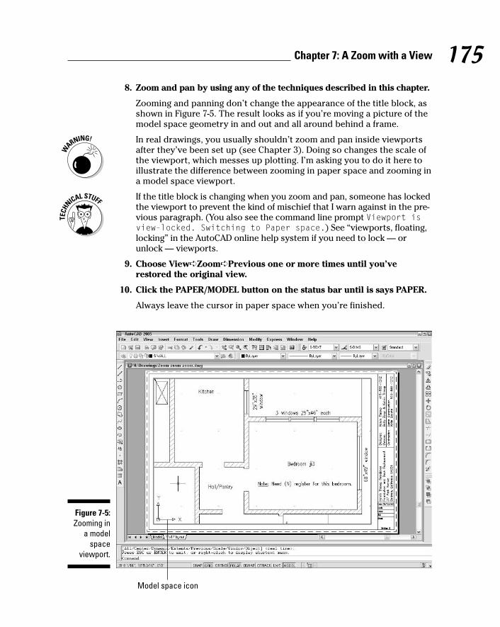
8. Zoom and pan by using any of the techniques described in this chapter.
Zooming and panning don’t change the appearance of the title block, asshown in Figure 7-5. The result looks as if you’re moving a picture of themodel space geometry in and out and all around behind a frame.
In real drawings, you usually shouldn’t zoom and pan inside viewportsafter they’ve been set up (see Chapter 3). Doing so changes the scale ofthe viewport, which messes up plotting. I’m asking you to do it here toillustrate the difference between zooming in paper space and zooming ina model space viewport.
If the title block is changing when you zoom and pan, someone has lockedthe viewport to prevent the kind of mischief that I warn against in the pre-vious paragraph. (You also see the command line prompt Viewport isview-locked. Switching to Paper space.) See “viewports, floating,locking” in the AutoCAD online help system if you need to lock — orunlock — viewports.
9. Choose View➪Zoom➪Previous one or more times until you’verestored the original view.
10. Click the PAPER/MODEL button on the status bar until is says PAPER.
Always leave the cursor in paper space when you’re finished.
Model space icon
Figure 7-5:Zooming in
a modelspace
viewport.
175Chapter 7: A Zoom with a View
f571389 Ch07.qxd 4/12/04 9:44 AM Page 175
11. Choose File➪Close and click the No button to close the drawing with-out saving changes.
In this example, I have you close the drawing without saving changes,just in case you did mess up the viewport zoom scale.
In most cases, you set up a paper space layout once, as described in Chapter 3,and then just return to it to plot. You shouldn’t be spending a lot of time zoom-ing and panning in paper space layouts. You zoom and pan to get a better viewof what you’re drawing and editing, and that’s what the Model tab is for. But ifyou do want to zoom in paper space — to get a better look at part of your titleblock, for example — make sure that you’re doing it with the PAPER/MODELbutton set to PAPER.
AutoCAD 2005 includes new VPMAX and VPMIN commands for maximizing andminimizing a viewport in the current layout. These commands provide an alter-native to switching between the Model and Layout tabs without the potentialproblems of zooming inside of paper space viewports. The easiest way to runVPMAX or VPMIN is to click the new Maximize Viewport/Minimize Viewportbutton located on the status bar, just to the right of the PAPER button.
Degenerating and RegeneratingAs you zoom and pan around your drawing, you may wonder how the imagethat you see on the screen is related to the DWG file that AutoCAD saves onthe hard disk. Well, maybe you don’t wonder about that, but I’m going to tellyou anyway!
When you draw and edit objects, AutoCAD stores all their geometrical prop-erties (that is, location and size) in a highly precise form — technically,double floating-point precision. The program always maintains that precisionwhen you save the DWG file. For computer performance reasons, however,AutoCAD does not use that high-precision form of the data to display yourdrawing on the screen. Instead, AutoCAD converts the highly precise num-bers in the DWG file into slightly less precise integers in order to create theview that you see on the screen.
The happy consequence of this conversion is that zooming, panning, andother display changes are a lot faster than they would be otherwise. Theunhappy consequence is that the conversion, which is called a regeneration(or regen for short), occasionally leaves you with some artifacts to deal with.
In most cases, AutoCAD performs regenerations automatically when it needsto. You sometimes will see command line messages like Regenerating modelor Regenerating layout, which indicate that AutoCAD is taking care ofregens for you.
176 Part II: Let There Be Lines
f571389 Ch07.qxd 4/12/04 9:44 AM Page 176

If, on the other hand, you see the command line message Regen queued,then AutoCAD is warning you that it’s not performing a regeneration, eventhough one might be advisable now. In addition, you might see a warningdialog box with the message “About to regen — proceed?” These messagesare AutoCAD’s way of saying, “What your drawing looks like on the screen atthe moment may not exactly match the real version of the drawing databasethat gets stored when you save the drawing. I’ll update the display version atthe next regeneration.”
The REGENAUTO system variable controls whether or not AutoCAD performsmost regenerations automatically (see Chapter 1 if you’re unfamiliar withsystem variables or how to change them):
� The default REGENAUTO setting in new drawings, 1, tells AutoCAD toregenerate your drawing automatically if it’s required to synchronize thescreen display with the drawing database.
� The other REGENAUTO setting, 0 (Off), tells AutoCAD not to regenerateautomatically, but instead to display Regen queued on the commandline and let you force a regeneration with the REgen command if youwant to.
The REGENAUTO off option is for the most part a holdover from much slowercomputers and older versions of AutoCAD. You probably don’t need to sub-ject yourself to the mental contortion of trying to avoid REgens unless youwork on huge drawings and/or use a painfully slow computer.
Don’t confuse the REgen command with the Redraw command. REgen(View➪Regen) forces the synchronization process described in this section.Redraw (View➪Redraw) simply repaints the screen, without attempting tosynchronize the screen with the drawing database. The Redraw commandwas useful in the days of very slow computers and older versions ofAutoCAD, which didn’t handle the display as effectively, but it’s essentially auseless command now.
The REgenAll command (View➪Regen All) regenerates all viewports in apaper space layout. If you run the REgenAll command in model space, it hasthe same effect as the ordinary REgen command.
177Chapter 7: A Zoom with a View
f571389 Ch07.qxd 4/12/04 9:44 AM Page 177

178 Part II: Let There Be Lines
f571389 Ch07.qxd 4/12/04 9:44 AM Page 178

Chapter 8
On a 3D SpreeIn This Chapter� Understanding 3D pros and cons
� Looking at 3D models in multiple viewports from different viewpoints
� Orbiting around 3D models
� Using user coordinate systems and specifying coordinates in 3D
� Drawing 3D wireframes, surfaces, and solids
� Getting the rendered look
For millennia, people have documented the design and construction ofthree-dimensional objects by drawing two-dimensional views of them.
Most people have continued to use these “classical” methods with CADbecause the methods are well understood and work reasonably well. After all,if 2D drawing was good enough for guys like Leonardo da Vinci and AndreaPalladio, it should be good enough for us, right?
Nonetheless, there’s a growing trend of using CAD programs to create 3Dmodels and letting the CAD program generate the 2D views more-or-less auto-matically. This approach seems more logical, especially if the documentationrequires numerous, complex views of the same object. 3D modeling also is avirtual necessity (pun intended) when you want to create rendered (shaded)views for presentation purposes.
The 3D construction and visualization tools in AutoCAD have improved dra-matically over the years to support this 3D modeling approach to CAD, butit’s still a complex process that requires sophistication on the part of theCAD user. Although 3D modeling requires only one more dimension than 2Ddrafting, developing 3D CAD models is considerably more complicated. Usersmust master new techniques and contend with the 2D limitations of most dis-play screens and input devices.
This chapter introduces you to the concepts, tools, and techniques forAutoCAD 3D modeling and visualization. Be prepared to spend some additionaltime wading around in the AutoCAD online help system and experimenting ifyou want to become proficient at 3D modeling. And if 3D CAD makes you feela little wobbly at first, Figure 8-1 shows that you’re not alone.
f571389 Ch08.qxd 4/12/04 9:44 AM Page 179
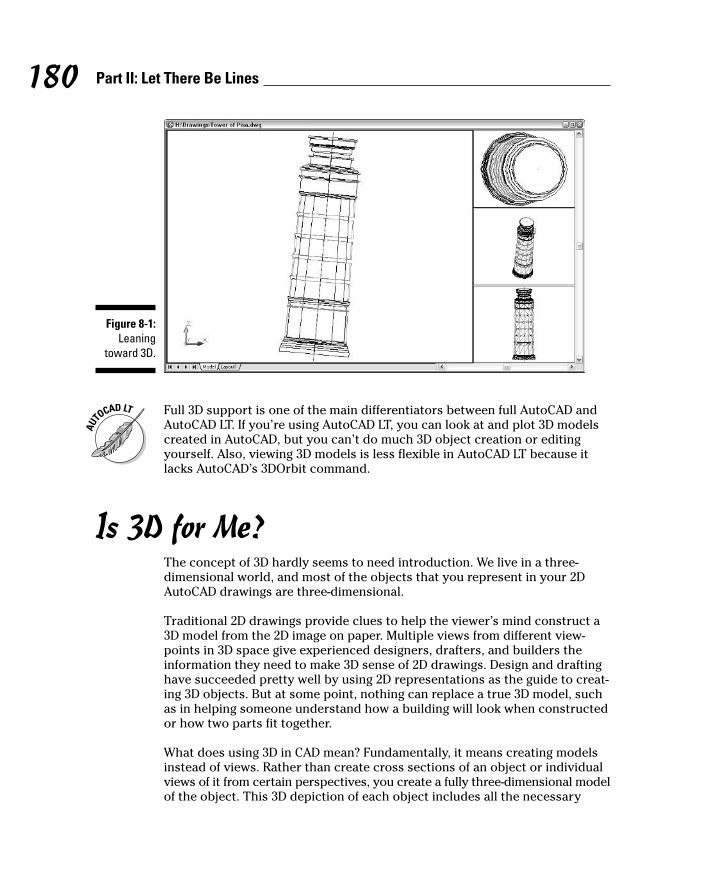
Full 3D support is one of the main differentiators between full AutoCAD andAutoCAD LT. If you’re using AutoCAD LT, you can look at and plot 3D modelscreated in AutoCAD, but you can’t do much 3D object creation or editingyourself. Also, viewing 3D models is less flexible in AutoCAD LT because itlacks AutoCAD’s 3DOrbit command.
Is 3D for Me?The concept of 3D hardly seems to need introduction. We live in a three-dimensional world, and most of the objects that you represent in your 2DAutoCAD drawings are three-dimensional.
Traditional 2D drawings provide clues to help the viewer’s mind construct a3D model from the 2D image on paper. Multiple views from different view-points in 3D space give experienced designers, drafters, and builders theinformation they need to make 3D sense of 2D drawings. Design and draftinghave succeeded pretty well by using 2D representations as the guide to creat-ing 3D objects. But at some point, nothing can replace a true 3D model, suchas in helping someone understand how a building will look when constructedor how two parts fit together.
What does using 3D in CAD mean? Fundamentally, it means creating modelsinstead of views. Rather than create cross sections of an object or individualviews of it from certain perspectives, you create a fully three-dimensional modelof the object. This 3D depiction of each object includes all the necessary
Figure 8-1:Leaning
toward 3D.
180 Part II: Let There Be Lines
f571389 Ch08.qxd 4/12/04 9:44 AM Page 180

information for AutoCAD to create a view from any point of view. With a prop-erly constructed 3D model, AutoCAD can output commands to machines tocreate actual 3D objects, whether plastic prototypes carved from a tank ofjelly by lasers or an actual bolt, valve, or piston created by computer-controlled machine tools.
AutoCAD, like most 3D CAD programs, enables you to create three differentkinds of 3D models of objects:
� Wireframes: A wireframe model is like a skeleton of a 3D object; itshows the edges of the object, not any of its surfaces. You create a set of2D objects that represent an outline of each part of the object and thenconnect them three-dimensionally to make the wireframe. It’s like build-ing a model from wire coat hangers. One of the biggest limitations ofwireframe models is that you can’t shade them; there aren’t any surfaces“inside” the wire edges to catch the light — imagine shining a flashlighton a coat hanger.
� Surfaces: A surface model represents the “skin” of an object but not thesolid mass inside. AutoCAD uses objects called meshes to create sur-faces. A mesh is a faceted surface that represents the edges and surfacesof a 3D object. You also can create a surface mesh by sweeping a 2Dobject such as a polyline around an axis. Creating a surface model is likebuilding a physical model out of thin sheets of balsa wood. A surfacemodel is one step up from a wireframe model because you can applymaterial properties and shading to its surfaces.
Surface meshes are just the thing for some 3D modeling tasks, but theyhave limitations:
• Some 3D objects are awkward to build by pasting surfaces together.
• You can’t check mass properties or interferences of a surfacemodel. (AutoCAD doesn’t recognize that there’s any solid massinside the surfaces.)
� Solids: A solid model is as close to true 3D as you can get without whip-ping out some Play-Doh and building a real-world model yourself. Youbuild solid models by constructing basic 3D shapes and then combiningthem — adding, subtracting, or finding their intersections — and modi-fying them. It’s like using lots of fancy saws, drills, and glue to build amodel made out of wooden blocks. You can render a solid model, as wellas check mass properties and interferences.
In most practical applications of 3D, you select one type of representation —wireframe, surface, or solid — for all or most of the objects in the drawing,based on ease of construction and intended use of the model. However,AutoCAD doesn’t prevent you from mixing all three types of 3D objects in thesame drawing.
181Chapter 8: On a 3D Spree
f571389 Ch08.qxd 4/12/04 9:44 AM Page 181
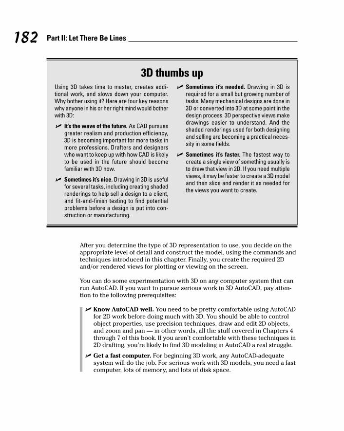
After you determine the type of 3D representation to use, you decide on theappropriate level of detail and construct the model, using the commands andtechniques introduced in this chapter. Finally, you create the required 2Dand/or rendered views for plotting or viewing on the screen.
You can do some experimentation with 3D on any computer system that canrun AutoCAD. If you want to pursue serious work in 3D AutoCAD, pay atten-tion to the following prerequisites:
� Know AutoCAD well. You need to be pretty comfortable using AutoCADfor 2D work before doing much with 3D. You should be able to controlobject properties, use precision techniques, draw and edit 2D objects,and zoom and pan — in other words, all the stuff covered in Chapters 4through 7 of this book. If you aren’t comfortable with these techniques in2D drafting, you’re likely to find 3D modeling in AutoCAD a real struggle.
� Get a fast computer. For beginning 3D work, any AutoCAD-adequatesystem will do the job. For serious work with 3D models, you need a fastcomputer, lots of memory, and lots of disk space.
182 Part II: Let There Be Lines
3D thumbs upUsing 3D takes time to master, creates addi-tional work, and slows down your computer.Why bother using it? Here are four key reasonswhy anyone in his or her right mind would botherwith 3D:
� It’s the wave of the future. As CAD pursuesgreater realism and production efficiency,3D is becoming important for more tasks inmore professions. Drafters and designerswho want to keep up with how CAD is likelyto be used in the future should becomefamiliar with 3D now.
� Sometimes it’s nice. Drawing in 3D is usefulfor several tasks, including creating shadedrenderings to help sell a design to a client,and fit-and-finish testing to find potentialproblems before a design is put into con-struction or manufacturing.
� Sometimes it’s needed. Drawing in 3D isrequired for a small but growing number oftasks. Many mechanical designs are done in3D or converted into 3D at some point in thedesign process. 3D perspective views makedrawings easier to understand. And theshaded renderings used for both designingand selling are becoming a practical neces-sity in some fields.
� Sometimes it’s faster. The fastest way tocreate a single view of something usually isto draw that view in 2D. If you need multipleviews, it may be faster to create a 3D modeland then slice and render it as needed forthe views you want to create.
f571389 Ch08.qxd 4/12/04 9:44 AM Page 182
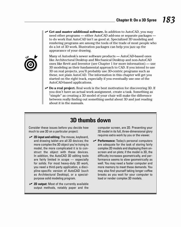
� Get and master additional software. In addition to AutoCAD, you mayneed other programs — either AutoCAD add-ons or separate packages —to do work that AutoCAD isn’t as good at. Specialized 3D modeling andrendering programs are among the tools of the trade of most people whodo a lot of 3D work. Illustration packages can help you jazz up theappearance of your drawing.
Many of Autodesk’s newer software products — AutoCAD-based oneslike Architectural Desktop and Mechanical Desktop and non-AutoCADones like Revit and Inventor (see Chapter 1 for more information) — use3D modeling as their fundamental approach to CAD. If you intend to use3D on real projects, you’ll probably use 3D-centric programs such asthese, not plain AutoCAD. The information in this chapter will get youstarted on the right track, especially if you eventually use one of theAutoCAD-based applications.
� Do a real project. Real work is the best motivation for discovering 3D. Ifyou don’t have an actual work assignment, create a task. Something as“simple” as creating a 3D model of your chair will make the differencebetween really finding out something useful about 3D and just readingabout it in the manuals.
183Chapter 8: On a 3D Spree
3D thumbs downConsider these issues before you decide howmuch to use 3D on a particular project:
� 2D input and editing: The mouse, keyboard,and drawing tablet are all 2D devices; themore complex the 3D object you’re trying tomodel, the more complicated it is to con-struct the object with these devices. In addition, the AutoCAD 3D editing toolsare fairly limited in scope — especially for solids. For most heavy-duty 3D work, you need a third-party application, a disci-pline-specific version of AutoCAD (such as Architectural Desktop), or a special-purpose solid modeling program.
� 2D output: Most of the currently availableoutput methods, notably paper and the
computer screen, are 2D. Presenting your3D model in its full, three-dimensional gloryrequires extra work by you or the viewer.
� Performance: Today’s personal computersare adequate for the task of storing fairlycomplex 2D models and displaying them on-screen and on plots; if the model is 3D, thedifficulty increases geometrically, and per-formance seems to slow geometrically aswell. You may need a faster computer andmore memory to meet these demands. Youmay also find yourself taking longer coffeebreaks as you wait for your computer toload or render complex 3D models.
f571389 Ch08.qxd 4/12/04 9:44 AM Page 183

Getting Your 3D BearingsThe first challenge in 3D modeling is being able to see your three-dimensionalmodel on a two-dimensional computer screen. The normal model space viewon the Model tab in the drawing area shows a single, projected 2D view ofyour model — the top-down, “plan” view by default.
AutoCAD provides two model space capabilities that enable you to escapethis visual flatland:
� With viewports, you can carve the model space drawing area into smallerrectangular areas, each of which shows a different view of the model.
� With viewpoints, you can change the point in 3D space from which youlook at the model. By setting a different viewpoint in each viewport, youcan look at several sides of your model at the same time. It’s like lookingat one of Picasso’s cubist paintings, only more orderly.
If you want to experiment with viewports and viewpoints in an existing 3Ddrawing, try one of the AutoCAD2005 samples, such as \Program Files\AutoCAD 2005\Sample\Welding Fixture Model.dwg. To remove shadingand make the model faster to work with, choose View➪Shade➪2D Wireframe.
Model space viewports left and rightChapter 3 discusses viewports in paper space, which are useful for creatinglayouts for use in plots and presentations in both 2D and 3D. Model spaceviewports, cousins of paper viewports, are less powerful but simpler and areintended to help you construct 3D models.
Model space viewports divide the screen into separate rectangles with nogaps between them. Unlike with paper space viewports, you can’t move,stretch, or overlap them. You can’t plot multiple model space viewports;that’s what paper space is for. And, unlike in layouts, a layer that’s visible inone model space viewport always is visible in all of them.
You may hear or read references to tiled viewports, which is just another namefor model space viewports. Tiled refers to the way in which model space view-ports always fill the drawing area, with no gaps and no overlapping allowed.Conversely, paper space viewports are sometimes called floating viewportsbecause you can move them around, leave gaps between them, and overlapthem.
Model space viewports enable you to see several views of your model at onetime, each from a different viewpoint. For this reason, model space viewportsare especially useful when you’re creating and editing objects in 3D. As youdraw and edit, the different views help ensure that you’re picking points thatare located correctly in 3D space.
184 Part II: Let There Be Lines
f571389 Ch08.qxd 4/12/04 9:44 AM Page 184
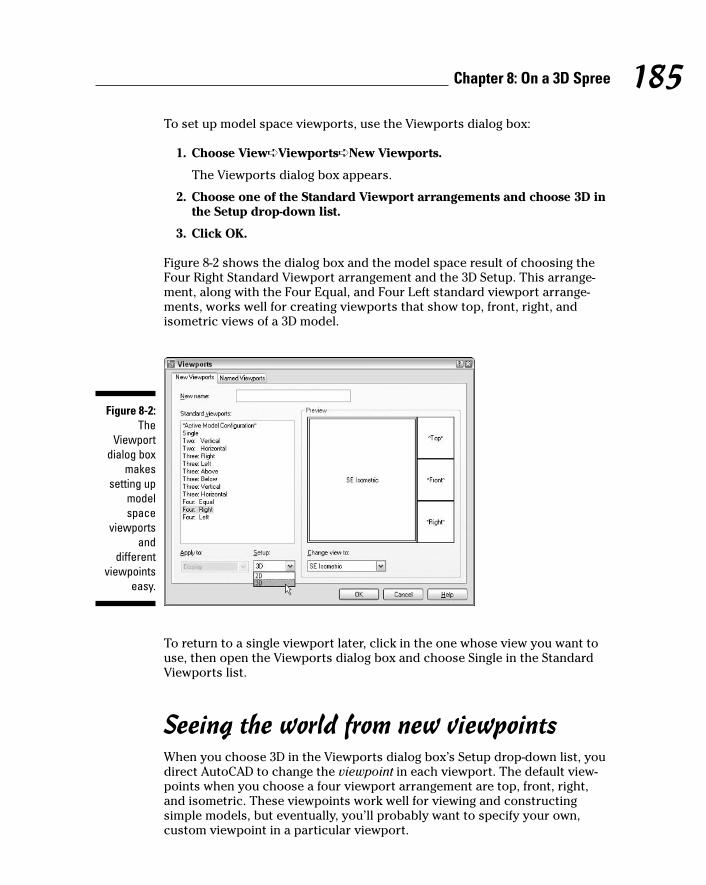
To set up model space viewports, use the Viewports dialog box:
1. Choose View➪Viewports➪New Viewports.
The Viewports dialog box appears.
2. Choose one of the Standard Viewport arrangements and choose 3D inthe Setup drop-down list.
3. Click OK.
Figure 8-2 shows the dialog box and the model space result of choosing theFour Right Standard Viewport arrangement and the 3D Setup. This arrange-ment, along with the Four Equal, and Four Left standard viewport arrange-ments, works well for creating viewports that show top, front, right, andisometric views of a 3D model.
To return to a single viewport later, click in the one whose view you want touse, then open the Viewports dialog box and choose Single in the StandardViewports list.
Seeing the world from new viewpointsWhen you choose 3D in the Viewports dialog box’s Setup drop-down list, youdirect AutoCAD to change the viewpoint in each viewport. The default view-points when you choose a four viewport arrangement are top, front, right,and isometric. These viewpoints work well for viewing and constructingsimple models, but eventually, you’ll probably want to specify your own,custom viewpoint in a particular viewport.
Figure 8-2:The
Viewportdialog box
makessetting up
modelspace
viewportsand
differentviewpoints
easy.
185Chapter 8: On a 3D Spree
f571389 Ch08.qxd 4/12/04 9:44 AM Page 185

The easiest way to change viewpoints is to use the View➪3D Views submenu(shown in Figure 8-3) to switch to one of the standard orthographic 3D viewsor an isometric view:
� The six standard orthographic (straight-on) views are Top, Bottom, Left,Right, Front, Back.
� The four standard isometric views are SW (left-front), SE (right-front), NE(right-back), and NW (left-back). An isometric view is one in which yousee the object from above, but not too high above — as though you werehovering in a low-flying helicopter.
These ten views are called standard because they’re often used in manualdrafting and rendering work. They work well for showing 3D models ofcommon objects such as mechanical components and buildings. (You canalso change to plan view, which is a top-down view of either the world coordi-nate system or a user coordinate system. I describe coordinate systems in “ACartesian Orientation,” later in this chapter.)
You can specify nonstandard viewpoints by choosing View➪3D Views➪Viewpoint Presets. In the Viewpoint Presets dialog box that appears, specifythe following settings:
� A viewing angle in the XY plane (imagine moving a camera on a dollyaround an object, while keeping the camera at the same elevation)
� An angle from the XY plane (imagine using a boom to swoop the cameraup to a different height so that you’re looking at the object from increas-ingly steep angles)
Figure 8-3:The 3DViews
submenu.
186 Part II: Let There Be Lines
f571389 Ch08.qxd 4/12/04 9:44 AM Page 186

By default, AutoCAD shows 3D models in 2D wireframe mode, even if you’vecreated surface or solid objects. If you want to better visualize which objectsare in front of which other objects, especially in an isometric or other non-orthogonal view, you have a couple of options:
� Choose View➪Shade and then choose Hidden or any of the Shadedoptions.
� Render the model, as described later in this chapter.
Dynamic viewpoints with 3DOrbitStandard views and the Viewpoint Presets dialog box are fine for many 3Dconstruction tasks, but if you really want to have fun with a model, 3DOrbit isyour ticket to it.
AutoCAD LT doesn’t include the 3DOrbit command. In LT, you can use theDDVPOINT and DView commands to look at a model from different points ofview.
The 3DOrbit command displays an arcball on the screen — a circle represent-ing a sphere around your object. You click various places inside, outside, andon the arcball and then drag to change the 3D view. The idea is that you’respinning the imaginary sphere containing your model. As you drag thecursor, AutoCAD updates the screen dynamically.
3DOrbit provides many other options through its right-click shortcut menu.You can change the shading mode and projection type, and you can turn onseveral visual aids that help you understand where you are in 3D space.Additional shortcut menu options enable you to pan, zoom, and restore stan-dard or named views.
The following steps show some of the things that you can do with 3DOrbit:
1. If you’ve divided model space into two or more viewports, click in theviewport in which you want to change the viewpoint.
2. Choose View➪3D Orbit.
The 3DOrbit arcball appears, as shown in Figure 8-4.
3. Move the cursor inside the arcball.
The 3DOrbit full orbit cursor appears: two oval arrows circling a sphere.
4. Click and drag, keeping the cursor inside the arcball.
You can rotate the model in all directions. Imagine that the cursor isyour finger pushing on a globe that rotates freely in all directions.
187Chapter 8: On a 3D Spree
f571389 Ch08.qxd 4/12/04 9:44 AM Page 187
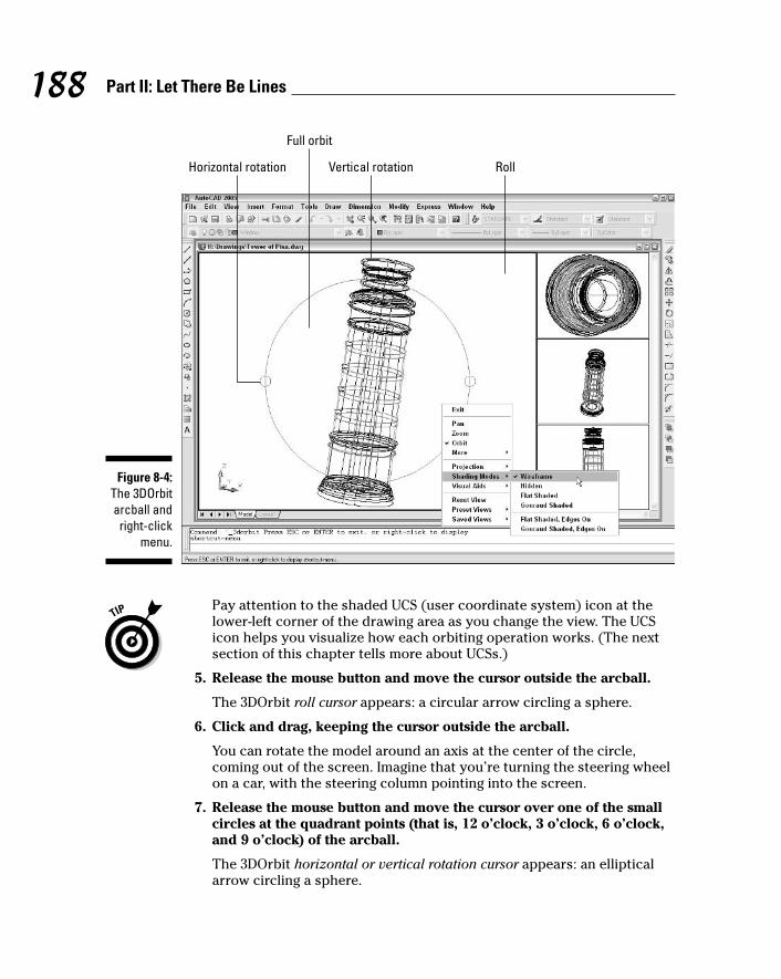
Pay attention to the shaded UCS (user coordinate system) icon at thelower-left corner of the drawing area as you change the view. The UCSicon helps you visualize how each orbiting operation works. (The nextsection of this chapter tells more about UCSs.)
5. Release the mouse button and move the cursor outside the arcball.
The 3DOrbit roll cursor appears: a circular arrow circling a sphere.
6. Click and drag, keeping the cursor outside the arcball.
You can rotate the model around an axis at the center of the circle,coming out of the screen. Imagine that you’re turning the steering wheelon a car, with the steering column pointing into the screen.
7. Release the mouse button and move the cursor over one of the smallcircles at the quadrant points (that is, 12 o’clock, 3 o’clock, 6 o’clock,and 9 o’clock) of the arcball.
The 3DOrbit horizontal or vertical rotation cursor appears: an ellipticalarrow circling a sphere.
Horizontal rotation
Full orbit
Vertical rotation Roll
Figure 8-4:The 3DOrbitarcball and
right-clickmenu.
188 Part II: Let There Be Lines
f571389 Ch08.qxd 4/12/04 9:44 AM Page 188

8. Click and drag away from the small circle.
You can rotate the model around a horizontal axis (if you clicked thecircle at 3 o’clock or 9 o’clock) or a vertical axis (if you clicked the circleat 12 o’clock or 6 o’clock) passing through the little circle. Imagine thatyou’re turning a piece of meat on a spit, with the spit located horizon-tally or vertically in the plane of the screen.
9. Release the mouse button and right-click in the drawing area.
The 3DOrbit shortcut menu, shown in Figure 8-4, appears.
10. Experiment with the additional options, such as Shading Modes andProjection.
Here’s the lowdown on some of these options:
• Gouraud Shaded usually looks more realistic than Flat Shaded.
• Hidden removes hidden lines but doesn’t shade.
• Wireframe is the default wireframe view, without hidden linesremoved.
• Parallel projection is the default AutoCAD projection — lines thatare parallel in the 3D object remain parallel in the projected viewon the screen.
• Perspective projection makes objects look more realistic (forexample, train tracks appear to converge in the distance), but linesthat are parallel in the model don’t remain parallel in perspectiveprojection.
If you manage to 3DOrbit out of control so that you no longer see yourmodel, right-click to display the 3DOrbit shortcut menu and chooseMore➪Zoom Extents. The Zoom, Pan, and Preset Views options offerother ways of getting your model back in your sights.
11. When you’re finished orbiting, right-click in the drawing area andchoose Exit.
Choose More➪Adjust Clipping Planes on the 3DOrbit right-click menu (or the3DCLIP command outside of 3DOrbit) to slice away part of your model tem-porarily to view what’s inside the surfaces or solid boundaries. See “clipping,3D objects” in the AutoCAD online help for more information.
You can control the camera point and target point that 3DOrbit uses (the pointthat you’re looking from and the point that you’re looking towards). Beforeyou start the 3DOrbit command, type CAMERA at the command prompt andpress Enter. Click or type the coordinates of the desired camera point targetpoints.
189Chapter 8: On a 3D Spree
f571389 Ch08.qxd 4/12/04 9:44 AM Page 189

A Cartesian OrientationViewing your model from different viewpoints in multiple viewports is all welland good, but unless your 3D spree is limited to looking at other people’smodels, you need to know how to specify points and distances in 3D. To dothat, you need to understand AutoCAD’s coordinate systems and conventionsfor entering 3D points and distances.
Coordinate systems: The WCS and UCSAutoCAD stores the locations of all the objects that you draw as 3D Cartesiancoordinates (X, Y, and Z) in the world coordinate system (or WCS). The WCSdefines the origin (0,0,0) point for the drawing and the orientation of the X, Y,and Z axes. A particular point in the Cartesian coordinate system is definedby its X, Y, and Z coordinates, where the coordinate indicates the distancefrom the origin (0,0,0) point along the X, Y, or Z axis.
The WCS is the default XYZ coordinate system when you start a new drawing.X is horizontal on the screen, Y is vertical on the screen, and Z extends out ofthe screen, towards your face.
The X-Y plane (the set of points where Z = 0) is the construction plane inwhich you create 2D objects. It’s also important for creating 3D objects,because many commands operate with respect to the X-Y plane.
When you’re drawing and editing 3D objects, it’s often useful to be able tomove or rotate the construction plane. You do so in AutoCAD by defining auser coordinate system (UCS). A UCS can have a different origin (0,0,0) pointand can have its X, Y, and Z axes point in different directions than they do inthe WCS.
Choose Tools➪Orthographic UCS➪Preset to run the UCSMAN command,which opens the UCS dialog box, shown in Figure 8-5. This dialog box simpli-fies the job of changing to common UCSs, such as Top, Front, and Right. TheTools➪New UCS submenu runs the UCS command, which provides additionaloptions. Look up “UCS command” in AutoCAD’s online help to find out moreabout UCSs and how to work with them.
To keep you informed about which coordinate system is current in each view-port, AutoCAD displays a UCS (user coordinate system) icon in each view-port by default. The icon looks like two or three little arrows (depending onthe viewpoint), each of which represents the direction of the positive X, Y, orZ axis. This icon shows the working construction plane — the plane in whichAutoCAD places 2D objects when you draw them. Use the View➪Display➪UCSIcon submenu to turn the icon off or on or to change its properties.
190 Part II: Let There Be Lines
f571389 Ch08.qxd 4/12/04 9:44 AM Page 190

Don’t confuse viewpoints and coordinate systems:
� The viewpoint controls what you see in a particular viewport, but doesn’tcontrol what you do to objects — that is, the viewpoint doesn’t dictatethe results of drawing and editing commands.
� The current coordinate system defines the construction plane in a par-ticular viewport — that is, the UCS (or WCS) dictates how the pointsthat you specify during drawing and editing commands influence thespecific locations and orientations of objects. The UCS icon shows thecurrent coordinate system, not the current viewpoint.
Specifying coordinates in 3DAs I indicate in Chapter 4, you specify points in 2D drafting by typing a pair ofnumbers in the format X,Y for absolute coordinates (with respect to the point0,0) or @X,Y for relative coordinates (with respect to the previous point thatyou specified). In both cases, you ignore the Z coordinate, but AutoCAD stillstores it — as zero.
When you create 3D models, you no longer can ignore the Z axis. You need toworry about three coordinates for each point that you pick or type. AutoCADprovides several ways of specifying 3D points. These are the most common:
� Typed coordinates: When you type coordinates, you simply add a Zcoordinate: X,Y,Z for absolute coordinates (with respect to the point 0,0,0)or @X,Y,Z for relative coordinates.
There are 3D analogues to 2D polar coordinates (@distance<angle), too.See “polar coordinates, entering, cylindrical” and “polar coordinates,entering, spherical” in the AutoCAD online help.
Figure 8-5:Get with the
UCSMAN.
191Chapter 8: On a 3D Spree
f571389 Ch08.qxd 4/12/04 9:44 AM Page 191
� Object snaps: Happily, the object snap techniques described in Chapter4 for picking precise locations on existing objects work equally well in3D. You can object snap to endpoints, intersections, midpoints, and soon, without having to worry about the current construction plane asdefined by the WCS or UCS.
In practice, you’ll have to be more careful when using object snaps in 3Dwork. Remember that there are now three coordinates instead of two tobe precise about. If you’re viewing a 3D model from just one viewpoint,it’s easy to osnap to a point that looks right in that view but in fact lies“deeper” or “shallower” in 3D space that you realize. Thus it’s a goodidea to display your model from several different points of view, asdescribed in the “Getting Your 3D Bearings” section, earlier in this chap-ter. The different points of view help you predict which location in 3Dspace a given object snap mode will grab and make any object snap mis-takes more obvious.
An additional object snap mode, Apparent Intersection, is useful whenyou want to snap to the imaginary intersection of two objects thatappear on the screen to intersect, but don’t in fact intersect becausethey lie in different planes.
� Coordinate filters: You’ll sometimes need to pick a point some of whosecoordinates (for example, the X and Y coordinates) match one object snappoint and some of whose coordinates (for example, the Z coordinate)match another object snap point. Coordinate filters — also called pointfilters — solve this problem handily. With coordinate filters, you use thecoordinates of points on existing objects to help specify new points. Youuse coordinate filters together with object snaps to “build up” a point oneor two coordinates at a time. When AutoCAD prompts you to pick a point,you activate a coordinate filter before you pick the point. The coordinatefilter tells AutoCAD which coordinates of the subsequent point to use.
You activate a coordinate filter by clicking one of the six choices on theobject snap cursor menu’s Point Filters submenu (shown in Figure 8-6):.X, .Y, .Z, .XY, .YZ, or .XZ. (You display the object snap cursor menu bypressing Shift+right-click; see Chapter 4 for more information.) For exam-ple, if you select .XY and then pick a point, AutoCAD remembers onlythe X and Y coordinates of that point. AutoCAD then prompts you topick another point and combines the Z coordinate of that second pointwith the X and Y coordinates of the first point to determine the 3D loca-tion of the new point. Look up “coordinate filters” in AutoCAD’s onlinehelp for more information and an example.
At this point, you may be feeling less then completely 3D-coordinated,despite the WCS, UCSs, and XYZs. All this stuff will become clearer after youcreate some viewports and draw some objects. The next section gives yousome specific instructions, but don’t be afraid to experiment with typingCartesian coordinates, object snapping in 3D, and working with different pre-defined UCSs. Or, you can console yourself with the following paragraph’sgeometrical trivia and vile pun.
192 Part II: Let There Be Lines
f571389 Ch08.qxd 4/12/04 9:44 AM Page 192

In case you’re wondering, the Cartesian coordinate system is named after itsinventor, the French mathematician René Descartes. (Yes, he of “I think there-fore I am” and the Monty Python Philosophers’ Drinking Song fame.) He did not,however, invent the cart. The cart came earlier, and the horse came earlierstill. It’s for that reason that we know not to put Descartes before de horse.
Drawing in 3DThis section introduces four techniques for creating 3D objects: drawing 3Dlines and polylines, extruding 2D objects, creating surface meshes, and creat-ing solids.
When you draw 3D objects, just like when you draw 2D objects, put them onappropriate layers and use precision techniques to specify each point anddistance. See Chapter 4 for more information.
Drawing 3D lines and polylinesThe most straightforward way to draw objects for a 3D wireframe model is touse the Line or 3DPOLY (3D Polyline) command and specify 3D coordinates.The 3DPOLY command is similar to the PLine (Polyline) command, which isdescribed in Chapter 5. Both commands draw a series of connected line seg-ments, but they have different capabilities:
Figure 8-6:The object
snap cursormenu’s
Point Filterssubmenu.
193Chapter 8: On a 3D Spree
f571389 Ch08.qxd 4/12/04 9:44 AM Page 193

� The 3DPOLY command accepts 3D points for the line segments’ vertices.The PLine command requires that all vertices be in the same plane.
� 3DPOLY is limited to straight line segments. PLine can draw arc segmentsand create segments with uniform or tapered width.
� Segments created with 3DPOLY can’t display dash-dot linetypes; 3Dpolyline segments always display as continuous lines.
The command sequence for drawing 3D segments with the Line or 3DPOLYcommand is the same as for drawing 2D segments with the Line command;see Chapter 5 for details. The only difference is that you specify 3D coordi-nates instead of 2D ones. Figure 8-7 shows an example.
Creating 2D representations in this way is straightforward, though tedious forall but the simplest objects. More important, a wireframe model becomesincreasingly difficult to decipher as the complexity of the model increases.You see a mass of lines representing the edges, and you have difficulty tellingwhich parts of which edges are in front of others. To reduce this visual confu-sion, you need to graduate to a surface or solid modeling commands, asdescribed earlier and in the subsequent sections of this chapter.
Extruding from 2D to 3DOne way to create a surface model is to extrude, or thicken, 2D objects. Forexample, if you give thickness to a circle, it becomes a cylinder. If you givethickness to a 2D polyline or a series of lines segments, it looks like a fence.
AutoCAD calls this depth thickness, which is not to be confused with othercharacteristics that you may be tempted to call “thickness” — linewidths thatyou add for plotting and uniform or tapered widths that you can add to poly-line segments. Linewidths and polyline segment widths make objects fatterbut leave them in the 2D plane. Thickness pushes objects out of the plane,giving them a new dimension.
Folks who do heavy-duty 3D modeling somewhat derisively refer to the resultof adding thickness to 2D objects as 21⁄2D — a bit more than 2D, but not quite3D. That’s because extrusion is a limited 3D technique compared to creatingreal surface meshes and solids, as described in the following two sections.You can’t model most objects in a detailed way with extrusion alone. Imaginea set of wooden blocks in which every block has a uniform thickness, with notapering allowed — kind of dull, huh? Even AutoCAD LT, despite its adver-tised 3D limitations, can do extrusion (although only the simple kind of extru-sion described in the following steps). Nonetheless, extrusion is a fun andfairly low-stress way to get started with 3D, and it’s adequate for some simplemodeling tasks. It’s also a good warm-up exercise for full 3D solid extrusion,which I describe later in this chapter.
194 Part II: Let There Be Lines
f571389 Ch08.qxd 4/12/04 9:44 AM Page 194

The following steps show the general procedure for creating “21⁄2D” extrudedobjects.
1. Define a suitable UCS (user coordinate system), as described earlier in“Coordinate systems: The WCS and UCSs.”
The extrusion direction will be perpendicular to the UCS, so think aboutthe orientation of the 2D object and which way you want it to “pop out”into 3D space.
2. Draw a 2D object.
See Chapter 5 for more information.
3. Open the Properties palette.
See Chapter 6 for more information.
4. Press Esc to make sure that no objects are selected.
5. Click the object to select it.
6. In the Thickness field, type an extrusion thickness and press Enter.
AutoCAD extrudes the object perpendicular to the UCS in which you cre-ated it, as shown in Figure 8-8.
Figure 8-7:Drawing
3D linesegments.
195Chapter 8: On a 3D Spree
f571389 Ch08.qxd 4/12/04 9:44 AM Page 195

If you extrude closed polylines and then shade or render them, the extrudedshapes appear hollow — that is, without any tops or bottoms on them. Youcan work around this limitation by using the 3DFACE command to add three-sided or four-sided surfaces as “lids.” You can build up irregular shapes byusing a combination of three-sided and four-sided faces. A better approach inmost cases is to use the EXTrude command, which creates a true solid out ofclosed polylines and other closed shapes. (EXTrude requires AutoCAD — it’snot included in AutoCAD LT.)
Meshing around with surface meshesFor surface models that are more complex than simple extrusions of 2Dobjects, you can use a variety of AutoCAD commands that draw 3D meshes.One set of commands draws surface model representations of 3D primitives:box, pyramid, wedge, dome, sphere, cone, torus, dish, and mesh. (In this case,the word primitive isn’t a pejorative. A 3D primitive is a relatively simple shapethat can be used alone or as a subcomponent of a more complex 3D object.)
To create these objects, choose Draw➪Surfaces➪3D Surfaces, select a primi-tive shape from the image tile menu (shown in Figure 8-9), and follow thecommand line prompts. It’s like constructing your own set of wooden blocks,except that they don’t take up any space in your closet after you’re finishedplaying with them!
Figure 8-8:Just add
thicknessand voilà —
instant 3D!(Or 21⁄2D,anyway.)
196 Part II: Let There Be Lines
f571389 Ch08.qxd 4/12/04 9:44 AM Page 196
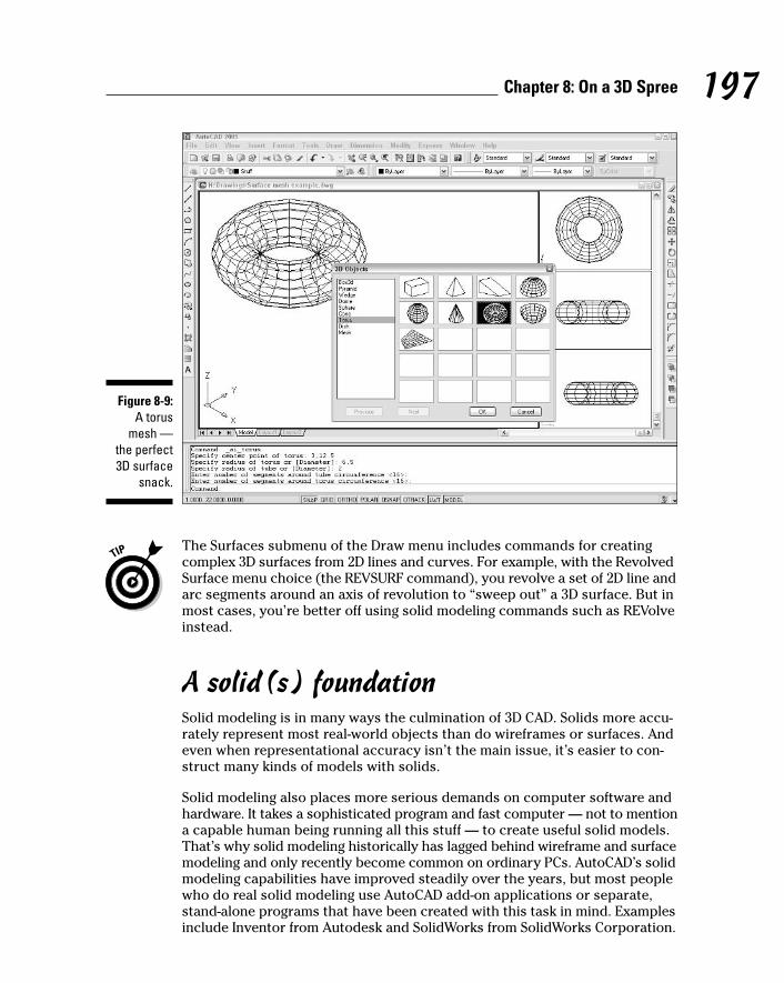
The Surfaces submenu of the Draw menu includes commands for creatingcomplex 3D surfaces from 2D lines and curves. For example, with the RevolvedSurface menu choice (the REVSURF command), you revolve a set of 2D line andarc segments around an axis of revolution to “sweep out” a 3D surface. But inmost cases, you’re better off using solid modeling commands such as REVolveinstead.
A solid(s) foundationSolid modeling is in many ways the culmination of 3D CAD. Solids more accu-rately represent most real-world objects than do wireframes or surfaces. Andeven when representational accuracy isn’t the main issue, it’s easier to con-struct many kinds of models with solids.
Solid modeling also places more serious demands on computer software andhardware. It takes a sophisticated program and fast computer — not to mentiona capable human being running all this stuff — to create useful solid models.That’s why solid modeling historically has lagged behind wireframe and surfacemodeling and only recently become common on ordinary PCs. AutoCAD’s solidmodeling capabilities have improved steadily over the years, but most peoplewho do real solid modeling use AutoCAD add-on applications or separate,stand-alone programs that have been created with this task in mind. Examplesinclude Inventor from Autodesk and SolidWorks from SolidWorks Corporation.
Figure 8-9:A torus
mesh —the perfect3D surface
snack.
197Chapter 8: On a 3D Spree
f571389 Ch08.qxd 4/12/04 9:44 AM Page 197
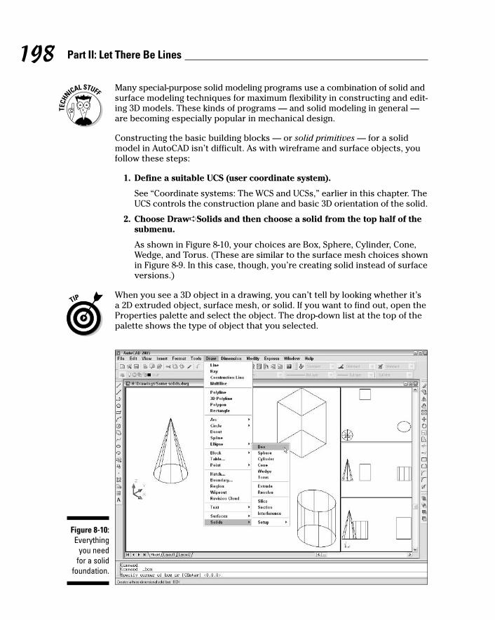
Many special-purpose solid modeling programs use a combination of solid andsurface modeling techniques for maximum flexibility in constructing and edit-ing 3D models. These kinds of programs — and solid modeling in general —are becoming especially popular in mechanical design.
Constructing the basic building blocks — or solid primitives — for a solidmodel in AutoCAD isn’t difficult. As with wireframe and surface objects, youfollow these steps:
1. Define a suitable UCS (user coordinate system).
See “Coordinate systems: The WCS and UCSs,” earlier in this chapter. TheUCS controls the construction plane and basic 3D orientation of the solid.
2. Choose Draw➪Solids and then choose a solid from the top half of thesubmenu.
As shown in Figure 8-10, your choices are Box, Sphere, Cylinder, Cone,Wedge, and Torus. (These are similar to the surface mesh choices shownin Figure 8-9. In this case, though, you’re creating solid instead of surfaceversions.)
When you see a 3D object in a drawing, you can’t tell by looking whether it’sa 2D extruded object, surface mesh, or solid. If you want to find out, open theProperties palette and select the object. The drop-down list at the top of thepalette shows the type of object that you selected.
Figure 8-10:Everything
you needfor a solid
foundation.
198 Part II: Let There Be Lines
f571389 Ch08.qxd 4/12/04 9:44 AM Page 198
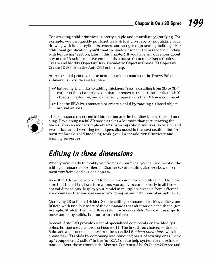
Constructing solid primitives is pretty simple and immediately gratifying. Forexample, you can quickly put together a virtual cityscape by populating yourdrawing with boxes, cylinders, cones, and wedges representing buildings. Foradditional gratification, you’ll want to shade or render them (see the “Endingwith Rendering” section, later in this chapter). If you have any questions aboutany of the 3D solid primitive commands, choose Contents➪User’s Guide➪Create and Modify Objects➪Draw Geometric Objects➪Create 3D Objects➪Create 3D Solids in the AutoCAD online help.
After the solid primitives, the next pair of commands on the Draw➪Solidssubmenu is Extrude and Revolve:
� Extruding is similar to adding thickness (see “Extruding from 2D to 3D,”earlier in this chapter) except that it creates true solids rather than “21⁄2D”objects. In addition, you can specify tapers with the EXTrude command.
� Use the REVolve command to create a solid by rotating a closed objectaround an axis.
The commands described in this section are the building blocks of solid mod-eling. Developing useful 3D models takes a lot more than just knowing thebasics. You can model simple objects by using solid primitives, extrusion andrevolution, and the editing techniques discussed in the next section. But formost real-world solid modeling work, you’ll want additional software andlearning resources.
Editing in three dimensionsWhen you’re ready to modify wireframes or surfaces, you can use most of theediting commands described in Chapter 6. Grip editing also works well onmost wireframe and surface objects.
As with 3D drawing, you need to be a more careful when editing in 3D to makesure that the editing transformations you apply occur correctly in all threespatial dimensions. Display your model in multiple viewports from differentviewpoints so that you can see what’s going on and catch mistakes right away.
Modifying 3D solids is trickier. Simple editing commands like Move, CoPy, andROtate work fine, but most of the commands that alter an object’s shape (forexample, Stretch, Trim, and Break) don’t work on solids. You can use grips tomove and copy solids, but not to stretch them.
Instead, AutoCAD provides a set of specialized commands on the Modify➪Solids Editing menu, shown in Figure 8-11. The first three choices — Union,Subtract, and Intersect — perform the so-called Boolean operations, whichcreate new 3D solids by combining and removing parts of existing ones. Lookup “composite 3D solids” in the AutoCAD online help system for more infor-mation about these commands. Also see Contents➪User’s Guide➪Create and
199Chapter 8: On a 3D Spree
f571389 Ch08.qxd 4/12/04 9:44 AM Page 199

Modify Objects➪Change Existing Objects➪Modify 3D Solids for a descriptionof the other options on the Modify➪Solids Editing menu.
Ending with RenderingTo my mother, who grew up on a farm in Iowa, rendering was what you did tofat to make it into lard. But in CAD, rendering is the process of illuminating aset of 3D objects with one or more imaginary lights and then creating a more-or-less realistic picture of the results. (No, computer programmers didn’thave lard on their minds when they borrowed the word rendering. Hand-drawn pictures of building facades were called renderings long before com-puters got into the act.)
A single example of this technique is called a still rendering. Multiple framesstrung together produce computer animation. The objects that you see inmovies such as Toy Story or A Bug’s Life are first created as 3D models andthen rendered frame by frame — a process that can take immense amounts oftime even on ultrafast graphics workstations — to produce the beautifully,well-rendered images you see.
AutoCAD creates still renderings only. If you want to create animations, youneed to use other software programs such as Discreet’s 3DS Max. Even if youuse animation programs, AutoCAD can be useful for developing the initial 3Dmodels.
Figure 8-11:Specialized
solidsediting
commands.
200 Part II: Let There Be Lines
f571389 Ch08.qxd 4/12/04 9:44 AM Page 200
Rendering has steadily improved in speed and usability as PCs have becomefaster, and programmers have improved their rendering algorithms.Rendering of simple scenes is now practical on a mainstream PC, and a fastpersonal computer can create some impressive images in a reasonableamount of time. Rendered images are useful for previewing how your modelswill work in real life and also can be powerful tools for sales and marketingcommunications for your company. A (rendered) picture can be worth quitea bit more than a thousand words.
To see how rendering works with the default options in AutoCAD, use thesteps that follow. When you’re ready to get fancy, choose User’s Guide➪Create Realistic Images and Graphics➪Render 3D Objects for Realism in theAutoCAD online help system.
1. Create one or more 3D objects.
Use the steps in the previous section or use one of the sample 3D drawingsin \Program Files\AutoCAD 2005\Sample.
Unless you want a monochromatic rendering, create the objects onseveral different layers that you’ve assigned different colors.
2. Choose View➪Render➪Render.
The Render dialog box appears, as shown in Figure 8-12.
Figure 8-12:The Render
dialog boxand a
renderedobject.
201Chapter 8: On a 3D Spree
f571389 Ch08.qxd 4/12/04 9:44 AM Page 201

3. Ignore all the options and click the Render button.
You can get okay results without changing the options. When you clickRender, AutoCAD renders the 3D objects. See Figure 8-12 for an example.
To make rendered images look less cartoonish, you need to apply materialsto 3D objects and define different light sources. For more information, navi-gate to the Render 3D Objects for Realism help page mentioned just beforethe preceding steps and then look at Create Rendered Images➪Use Materialsin Rendering and Create Rendered Images➪Use Lights in Rendering.
The SHADE command offers a simpler alternative to the RENDER command,without all the lighting, surface materials, and other options. To experimentwith shading, choose any of the options on the View➪Shade menu. (To returnto an unshaded view, choose View➪Shade➪2D Wireframe.) As I mention ear-lier in this chapter, the 3DOrbit command’s right-click menu includes shadedmodes that you can see even while navigating around your model in real time.
In addition to viewing rendered and shaded views on the screen, you can plotthem, whether they’re in a paper space layout or in model space. Use theShaded Viewport Options area of the expanded Plot dialog box to control thisfeature. Chapter 12 contains more information about plotting.
If you want to plot multiple rendered views (or a rendered view plus othernonrendered views), create a paper space layout with multiple viewports, asdescribed in Chapter 3. As I mention earlier in this chapter, tiled model spaceviewports are great for creating and viewing 3D models, but you can plot onlyone model space viewport at a time. Use paper space layouts to composemultiple viewports for plotting purposes.
People who do a lot of rendering and want higher quality, photorealisticresults usually use programs other than AutoCAD to render their models.Discreet 3DS Max, Autodesk VIZ, and McNeel’s are three popular photorealis-tic rendering programs. Most rendering programs can import 3D models fromAutoCAD DWG files, but some people use specialized 3D modeling programsto do their modeling as well.
202 Part II: Let There Be Lines
f571389 Ch08.qxd 4/12/04 9:44 AM Page 202
Part IIIIf DrawingsCould Talk
g571389 PP03.qxd 4/12/04 9:44 AM Page 203

In this part . . .
Text, dimensions, and hatching have long been impor-tant clarifying elements in drafting. In AutoCAD, these
elements are flexible almost to a fault, and you can editand update them quickly as you change the geometrybeneath them. The text, dimension, and hatching annota-tions that you add “speak” about the geometry so thatothers can understand exactly what, how big, and how far.
After you’ve made some drawings that talk, you’ll proba-bly send the message around by printing — or as CADusers call it, plotting — them. AutoCAD 2005 introduces aredesigned, streamlined Plot dialog box, which makes theoften-complex task of plotting a little less daunting.Chapter 12 in this section is your passport to navigatingthe revised plot process, understanding how the legacyof AutoCAD plotting influences current practice, and mostof all getting a good-looking, properly scaled plot ontopaper.
g571389 PP03.qxd 4/12/04 9:44 AM Page 204
Chapter 9
Text with CharacterIn This Chapter� Using text styles to control text appearance
� Creating single-line and multiline text
� Using fields and background masks with text
� Making hanging indents
� Editing text contents and properties
� Creating tables
� Checking spelling
Although it’s often true that “A picture is worth a thousand words,” it’salso true that adding a few words to your drawing can save you from
having to draw a thousand lines and arcs. It’s a lot easier to write “SimpsonA35 framing clip” next to a simple, schematic representation of a clip than todraw one in photorealistic detail and hope that the contractor can figure outwhat it is!
Most CAD drawings include some text in the form of explanatory notes, objectslabels, and titles. This chapter demonstrates how to add text to drawings andshows you how to take advantage of AutoCAD text styles and the spellingchecker. Chapter 10 covers text that’s connected with dimensions and leaders.
In most cases, adding text, dimensions, and other descriptive symbols issomething that you should do later in the drafting process, after you’vedrawn at least some of the geometry. In CAD drawings, text and other annota-tions usually are intended to complement the geometry, not to stand alone.Thus, you generally need to have the geometry in place before you annotateit. Many drafters find that it’s most efficient to draw as much geometry aspossible first, and then add text labels and dimensions to all the geometry atthe same time. In this way, you develop a rhythm with the text and dimen-sioning commands, instead of bouncing back and forth between drawinggeometry and adding annotations. (It helps if you hum “I’ve got rhythm . . .”while sliding the mouse back and forth in time.)
h571389 Ch09.qxd 4/12/04 9:44 AM Page 205
Getting Ready to WriteIn AutoCAD, adding text to a drawing is only slightly more complicated thanadding it to a word processing document. Here are the steps:
1. Create a new AutoCAD text style, or select an existing style, thatincludes the font and other text characteristics you want to use.
2. Make an appropriate text layer current.
3. Run one of these commands to draw text:
• mText draws paragraph (also called multiline) text.
• TEXT draws single-line text.
4. Specify the text alignment points, justification, and height.
5. Type the text.
You’re probably familiar with most of these steps already — especially ifyou’ve ever used a word processor. In the next few sections of this chapter, Ireview the particularities of AutoCAD text styles, the two kinds of AutoCADtext, and ways of controlling height and justification.
Simply stylish textAutoCAD assigns text properties to individual lines or paragraphs of textbased on text styles. These text styles are similar to the paragraph styles inMicrosoft Word: They contain font and other settings that determine the lookand feel of text. An AutoCAD text style includes
� The font
� A font height, which you can set or leave at 0 for later flexibility
� Special effects such as italic
� Really special effects such as vertical and upside down, which almostnobody uses
Before you add text to a drawing, use the Text Style dialog box to select anexisting style or create a new one with settings that are appropriate to yourpurpose. Your AutoCAD notes may generate strange responses (or no responseat all) if they appear in Old Persian Cuneiform or the Cyrillic alphabet.
Most drawings require very few text styles. You can create one style for allnotes, object labels, and annotations, and another one for special titles. Atitle block may require one or two additional fonts, especially if you want tomimic the font used in a company logo or project logo.
206 Part III: If Drawings Could Talk
h571389 Ch09.qxd 4/12/04 9:44 AM Page 206

As with layers, your office may have its own text style standards. If so, you’llmake everyone happy by following those standards. One of the best waysto make your use of text styles efficient and consistent is to create them ina template drawing that you use to start new drawings. (If your office iswell organized, it may already have a template drawing with the company-approved styles defined in it.) See Chapter 3 for information about creatingand using templates. Another handy technique is to copy existing text stylesfrom one drawing to another by using the DesignCenter palette. See Chapter 4for instructions.
Font folliesWhen you create a text style in AutoCAD, you have a choice of a huge numberof fonts. AutoCAD can use two different kinds of fonts: native AutoCAD SHX(compiled SHape) fonts and Windows TTF (TrueType) fonts:
� SHX: In the Text Style dialog box, SHX font names appear with a draftingcompass to the left of the name. SHX fonts usually provide better perfor-mance because they’re optimized for AutoCAD’s use.
� TTF: In the Text Style dialog box, TrueType font names appear with a TTsymbol to the left of name. TTF fonts give you more and fancier fontoptions, but they slow down AutoCAD when you zoom, pan, and selectand snap to objects. TrueType fonts also can cause greater complica-tions when you exchange drawings with other AutoCAD users. Chapter16 describes the special procedure that you need to use in order toinstall custom TrueType fonts.
It’s okay to use a TrueType font sparingly for something like a title block logo,but in general, you should stick with standard AutoCAD SHX fonts wheneverpossible.
The most popular AutoCAD font is ROMANS.SHX (Roman Simplex). (You mayalso run into SIMPLEX.SHX, an older version of Roman Simplex.) ROMANS.SHXis a good, general-purpose font for drafting in AutoCAD. Avoid complicated,thick fonts. They can slow down AutoCAD, and they’re usually more difficultto read than the simpler fonts. Remember, you’re doing CAD here — not fancygraphic design or reproduction of medieval manuscripts!
Whenever possible, avoid custom fonts, which are font files that don’t comewith AutoCAD or AutoCAD LT (both programs come with the same fonts).AutoCAD installs its standard SHX fonts into the C:\Program Files\AutoCAD2005\Fonts folder — as long as you haven’t added any custom fonts to thatfolder, you can refer to it for a list of standard fonts. If you use a custom font,exchanging your drawings with other people will be more complicated. Ifyou’re compelled to use a custom font, make a note of it and remember eitherto send it whenever you send the DWG file (assuming that the font isn’t copy-righted, which many custom fonts are) or to warn the recipients that the text
207Chapter 9: Text with Character
h571389 Ch09.qxd 4/12/04 9:44 AM Page 207

will appear different on their systems. It’s far less hassle to eschew customfonts altogether. See Chapter 16 for additional information about how to dealwith fonts when you send and receive drawings.
Get in styleThe following steps describe how to select an existing text style or create a newone before you enter text into a drawing. (If you want to experiment with anexisting drawing that contains a variety of text styles, you can use \ProgramFiles\AutoCAD 2005\Sample\Hummer Elevation.dwg.)
1. Choose Format➪Text Style.
The Text Style dialog box appears, as shown in Figure 9-1.
2. In the Style Name drop-down list, select each style in turn to see whattext styles have been created in this drawing.
Note the font name and look at the Preview panel to get a feel for whatthe different fonts look like.
3. If you find a suitable text style, select it in the Style Name drop-downlist and then skip to Step 9.
What constitutes a suitable text style depends on industry practices,office standards, and personal preferences about how the text shouldlook. The information in preceding sections may help you decide. If not,ask an experienced drafter in your office or look at some printed draw-ings and try to match the text on those.
The selected text style name becomes the current style.
4. If you don’t find a suitable text style, or if you prefer to create yourown text style, click New.
The New Text Style dialog box appears, with an edit box for you to typea name.
Figure 9-1:Text with
style.
208 Part III: If Drawings Could Talk
h571389 Ch09.qxd 4/12/04 9:44 AM Page 208

5. Type a name for your new text style and then click OK.
Your new text style is added to the Style Name list and becomes thecurrent style.
6. Choose a font from the Font Name list.
ROMANS.SHX is the best all-purpose font for most drafting work. If you’dlike to use a different font, review the font suggestions and warnings inthe previous section.
The font that you choose becomes the font that’s assigned to your newtext style.
7. Set the remaining text style settings as shown in Figure 9-1: Height =0.0, Width Factor = 1.0, Oblique Angle = 0.0, and all four check boxesunchecked.
A text style height of 0.0 makes the style variable height, which meansthat you can specify the height separately for each single-line text object.Assigning a fixed (that is, nonzero) height to a text style forces all single-line text using the style to be the same height. Variable height styles aremore flexible, but fixed height styles usually make it easier to draw textof consistent height. The decision to use variable height versus fixedheight styles is another aspect of text that depends on office practice,so if you work with other AutoCAD users, ask around.
8. Click Apply.
9. Click Close.
The Text Style dialog box closes, and the text style that you selected orcreated is now the current style for new text objects.
Taking your text to new heightsIn Chapter 3, I describe the importance of choosing an appropriate drawingscale when you set up a drawing. I warn you that you need to know the draw-ing scale factor for tasks described in other chapters of this book. This is oneof those chapters, and I’m about to explain one of those tasks!
Drawing scale is the traditional way of describing a scale with an equal signor colon — for example 1⁄4” = 1’–0”, 1:20, or 2:1. The drawing scale factor repre-sents the same relationship with a single number such as 48, 20, or 0.5. Thedrawing scale factor is the multiplier that converts the first number in thedrawing scale into the second number.
One of the things that distinguishes knowledgeable CAD users is that theyalways know the drawing scale factor of any drawing they’re working on.Make it a point to determine the drawing scale factor of a drawing before youadd text to it.
209Chapter 9: Text with Character
h571389 Ch09.qxd 4/12/04 9:44 AM Page 209

Plotted text heightMost industries have plotted text height standards. A plotted text height of 1⁄8inch or 3 mm is common for notes. Some companies use slightly smallerheights (for example, 3⁄32 inch or 2.5 mm) to squeeze more text into smallspaces.
Calculating AutoCAD text heightTo calculate AutoCAD text height, you need to know the drawing scale factor,the desired plotted text height, and the location of the multiplication buttonon your calculator. Use the following steps to figure out text height:
1. Determine the drawing’s drawing scale factor.
If you set up the drawing, you should know its drawing scale, asdescribed in Chapter 3. If someone else set up the drawing, try the sug-gestions in the sidebar, “Figuring out a drawing’s scale factor.”
210 Part III: If Drawings Could Talk
Attack of the giant text strings“Why do I need to know the drawing scalefactor in order to draw text?,” you may ask —especially if you’ve spent time “on the boards,”as we grizzled old-timers like to call manualdrafting. You need to know the drawing scalefactor because you handle scaling of objectsand text in CAD opposite from the way you do inmanual drafting.
In manual drafting, you squeeze real-worldobjects (the building, widget, or whatever) downby a specific scale factor, like 10 or 48, so thatthey fit nicely on a sheet of paper. Naturally,you always draw text the size that you want itto appear on the paper (for example, 1⁄8 inch or 3 mm high), regardless of the scale of thedrawing.
In CAD drafting, you draw objects as if they wereat their actual size. Then, when you plot, youshrink — or, if you make drawings of tiny thingssuch as microprocessor circuitry, expand —the entire drawing by that same scale factor (forexample, 10 or 48) to fit on the paper. When youshrink the whole drawing to fit on the paper, textshrinks, too. To avoid indecipherably small text,
or incredibly large text, you must create text ata size that’s scaled appropriately by the draw-ing scale factor. (If you’re an architect, imaginethat your text is neon lettering on the side of thebuilding. If you’re a mechanical designer, thinkof a brand name stamped on the side of a screw.)
For example, assume that someone has drawna widget at a scale of 1:20 (corresponding to adrawing scale factor of 20), and you want yournotes to appear 3 mm high when the drawing isplotted to scale. You need to create text that’s20 times 3 mm, or 60 mm, high. In a building plandrawn at a scale of 1⁄4” = 1’–0” (drawing scalefactor equals 48), text that will appear 1⁄8 inchwhen plotted needs to be 1⁄8 inch times 48, or 6inches, high.
This “tiny text”/”enormous text” approachseems peculiar at first, especially if you wereschooled in manual drafting. But it’s a conse-quence of CAD’s ability to let you draw andmeasure the geometry in real-world units. Afterall, the geometry of what you’re representing,not the ancillary notes, usually is the main pointof the drawing.
h571389 Ch09.qxd 4/12/04 9:44 AM Page 210

2. Determine the height that your notes should appear when you plotthe drawing to scale.
See the “Plotted text height” section for suggestions.
3. Multiply the numbers that you figured out in Steps 1 and 2.
Table 9-1 lists some common drawing scales and text heights for drawings inimperial and metric units. You should know how to calculate the drawingscale factors and text heights, but you’re allowed to use the table to checkyour work. (Hint: Multiply the number in the second column by the numberin the third column to get the number in the fourth column!) The Cheat Sheettables include some additional drawing scales and text heights.
Table 9-1 Common Drawing Scales and Text HeightsDrawing Scale Drawing Scale Plotted Text AutoCAD Text
Factor Height Height
1⁄8” = 1’–0” 96 1⁄8” 12”
1⁄4” = 1’–0” 48 1⁄8” 6”
3⁄4” = 1’–0” 16 1⁄8” 2”
1” = 1’–0” 12 1⁄8” 11⁄2”
1 = 100 mm 100 3 mm 300 mm
1 = 50 mm 50 3 mm 150 mm
1 = 20 mm 20 3 mm 60 mm
1 = 10 mm 10 3 mm 30 mm
211Chapter 9: Text with Character
Figuring out a drawing’s scale factorIf you’re adding text to a drawing that someoneelse created, you may not immediately know itsdrawing scale factor. In some cases, making thedetermination is trivial, whereas in other casesit’s tricky indeed. Here are some methods youcan use:
� Ask the creator of the drawing.
� Look for text or a scale bar on the drawingthat indicates the scale.
� Use an architectural or engineering scale tomeasure distances on the plotted drawing,if you have one.
� Check the value of the DIMSCALE (DIMensionSCALE) system variable, as described inChapter 10.
None of these methods is infallible by itself, butby comparing the evidence, you usually canfigure out the drawing scale factor with rea-sonable certainty.
h571389 Ch09.qxd 4/12/04 9:44 AM Page 211

After you know the AutoCAD text height, you can use it to define the height ofa text style or of an individual text object. If you assign a nonzero height to atext style (Step 7 in the “Get in style” section, earlier in this chapter), allsingle-line text strings that you create with that style will use the fixed height.If you leave the text style’s height set to zero, AutoCAD asks you for the textheight when you draw each single-line text object.
This discussion of text height assumes that you’re adding text in modelspace, which is the most common practice. You may want to add text to apaper space layout — for example, when you draw text in a title block or adda set of sheet notes that doesn’t directly relate to the model space geometry.When you create text in paper space, you specify the actual, plotted height,instead of the scaled-up height.
One line or two?For historical reasons (namely, because the AutoCAD text capabilities usedto be much more primitive than they are now), AutoCAD offers two differentkinds of text objects and two corresponding text-drawing commands. Table 9-2explains the two options.
Table 9-2 The Two Kinds of AutoCAD TextText Object Command Comments
Paragraph text mText Designed for multiple lines, with word-wrapping.AutoCAD keeps the multiple lines together as asingle object. Other special formatting, such ashanging indents, is possible.
Single-line text TEXT Designed for creating single lines. Although youcan press Enter to create more than one line oftext, each line becomes a separate text object.
Although you may be inclined to ignore the older single-line text option, it’sworth knowing how to use both kinds of text. The TEXT command is a bitsimpler than the mText command, so it’s still useful for entering short, single-line pieces of text such as object labels and one-line notes. And it’s the com-mand of choice for CAD comedians who want to document their one-liners!
Your text will be justifiedBoth the TEXT and mText commands offer a bewildering array of text justifica-tion options — in other words, which way the text flows from the justificationpoint or points that you pick in the drawing. For most purposes, the default
212 Part III: If Drawings Could Talk
h571389 Ch09.qxd 4/12/04 9:44 AM Page 212
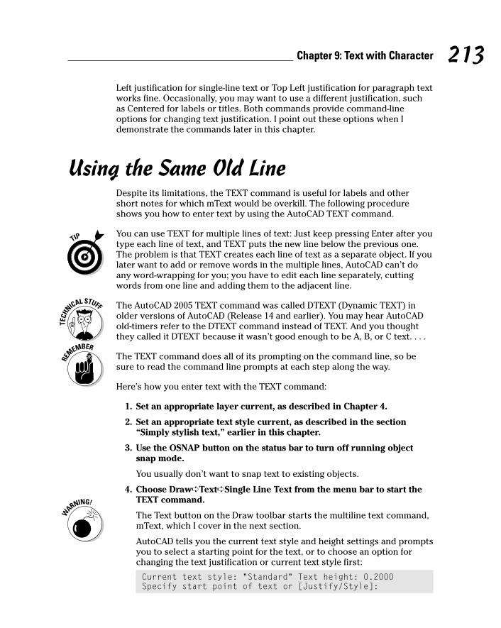
Left justification for single-line text or Top Left justification for paragraph textworks fine. Occasionally, you may want to use a different justification, suchas Centered for labels or titles. Both commands provide command-lineoptions for changing text justification. I point out these options when Idemonstrate the commands later in this chapter.
Using the Same Old LineDespite its limitations, the TEXT command is useful for labels and othershort notes for which mText would be overkill. The following procedureshows you how to enter text by using the AutoCAD TEXT command.
You can use TEXT for multiple lines of text: Just keep pressing Enter after youtype each line of text, and TEXT puts the new line below the previous one.The problem is that TEXT creates each line of text as a separate object. If youlater want to add or remove words in the multiple lines, AutoCAD can’t doany word-wrapping for you; you have to edit each line separately, cuttingwords from one line and adding them to the adjacent line.
The AutoCAD 2005 TEXT command was called DTEXT (Dynamic TEXT) inolder versions of AutoCAD (Release 14 and earlier). You may hear AutoCADold-timers refer to the DTEXT command instead of TEXT. And you thoughtthey called it DTEXT because it wasn’t good enough to be A, B, or C text. . . .
The TEXT command does all of its prompting on the command line, so besure to read the command line prompts at each step along the way.
Here’s how you enter text with the TEXT command:
1. Set an appropriate layer current, as described in Chapter 4.
2. Set an appropriate text style current, as described in the section“Simply stylish text,” earlier in this chapter.
3. Use the OSNAP button on the status bar to turn off running objectsnap mode.
You usually don’t want to snap text to existing objects.
4. Choose Draw➪Text➪Single Line Text from the menu bar to start theTEXT command.
The Text button on the Draw toolbar starts the multiline text command,mText, which I cover in the next section.
AutoCAD tells you the current text style and height settings and promptsyou to select a starting point for the text, or to choose an option forchanging the text justification or current text style first:
Current text style: “Standard” Text height: 0.2000Specify start point of text or [Justify/Style]:
213Chapter 9: Text with Character
h571389 Ch09.qxd 4/12/04 9:44 AM Page 213
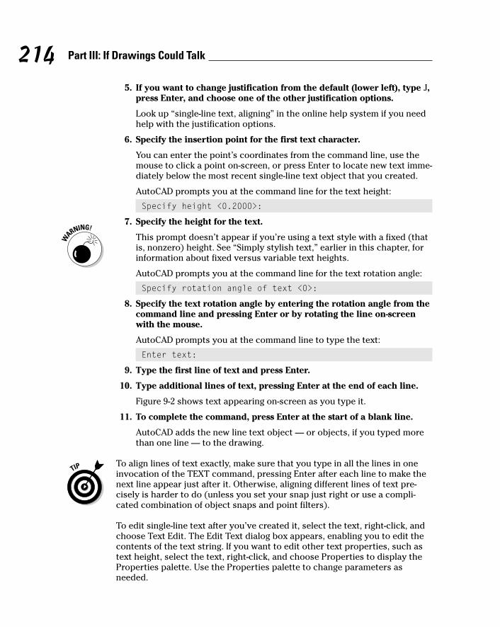
5. If you want to change justification from the default (lower left), type J,press Enter, and choose one of the other justification options.
Look up “single-line text, aligning” in the online help system if you needhelp with the justification options.
6. Specify the insertion point for the first text character.
You can enter the point’s coordinates from the command line, use themouse to click a point on-screen, or press Enter to locate new text imme-diately below the most recent single-line text object that you created.
AutoCAD prompts you at the command line for the text height:
Specify height <0.2000>:
7. Specify the height for the text.
This prompt doesn’t appear if you’re using a text style with a fixed (thatis, nonzero) height. See “Simply stylish text,” earlier in this chapter, forinformation about fixed versus variable text heights.
AutoCAD prompts you at the command line for the text rotation angle:
Specify rotation angle of text <0>:
8. Specify the text rotation angle by entering the rotation angle from thecommand line and pressing Enter or by rotating the line on-screenwith the mouse.
AutoCAD prompts you at the command line to type the text:
Enter text:
9. Type the first line of text and press Enter.
10. Type additional lines of text, pressing Enter at the end of each line.
Figure 9-2 shows text appearing on-screen as you type it.
11. To complete the command, press Enter at the start of a blank line.
AutoCAD adds the new line text object — or objects, if you typed morethan one line — to the drawing.
To align lines of text exactly, make sure that you type in all the lines in oneinvocation of the TEXT command, pressing Enter after each line to make thenext line appear just after it. Otherwise, aligning different lines of text pre-cisely is harder to do (unless you set your snap just right or use a compli-cated combination of object snaps and point filters).
To edit single-line text after you’ve created it, select the text, right-click, andchoose Text Edit. The Edit Text dialog box appears, enabling you to edit thecontents of the text string. If you want to edit other text properties, such astext height, select the text, right-click, and choose Properties to display theProperties palette. Use the Properties palette to change parameters asneeded.
214 Part III: If Drawings Could Talk
h571389 Ch09.qxd 4/12/04 9:44 AM Page 214

Saying More in Multiline TextWhen you just can’t shoehorn your creative genius into one or more one-linepieces of text, the AutoCAD multiline text object gives you room to go on andon and on. The following procedure shows you how to create text paragraphswith the mText (multiline Text) command.
Making it with mTextThe first part of the mText command prompts you for various points andoptions on the command line. The order is a bit confusing, so read thesesteps and the command line prompts carefully.
Here’s how you use the mText command:
1. Set an appropriate layer and text style current and turn off runningobject snaps, as in Steps 1 through 3 in the previous section.
Figure 9-2:Single-line
text.
215Chapter 9: Text with Character
h571389 Ch09.qxd 4/12/04 9:44 AM Page 215

2. Click the Multiline Text button on the Draw toolbar.
The command line displays the current text style and height settingsand prompts you to select the first corner of an imaginary rectangle thatwill determine the word-wrapping width for the text object:
Current text style: “S-NOTES” Text height: 0.125Specify first corner:
3. Pick a point in the drawing.
The command line prompts you for the opposite corner of the text rec-tangle that will determine the word-wrapping width and gives you theoption of changing settings first:
Specify opposite corner or [Height/Justify/Linespacing/Rotation/Style/Width]:
4. Type H and press Enter to change the default text height.
The command line prompts you for a new default text height:
Specify height <0.2000>:
5. Type an appropriate text height.
See the “Taking your text to new heights” section, earlier in this chapter,for information. If you’re adding text in model space, remember to usethe scaled AutoCAD text height, not the plotted text height.
The command line prompt for the opposite corner of the mText rectan-gle reappears:
Specify opposite corner or [Height/Justify/Linespacing/Rotation/Style/Width]:
6. If you want to change justification from the default (top left), type J,press Enter, and choose one of the other justification options.
Look up “multiline text, aligning, Justify Multline Text” in the index of theonline help system if you want an explanation of the other justificationoptions.
7. Pick another point in the drawing.
Don’t worry about the height of the rectangle that you create by choos-ing the second point; the width of the rectangle is all that matters.AutoCAD adjusts the height of the text rectangle to accommodate thenumber of lines of word-wrapped text. Don’t worry too much about thewidth, either; you can adjust it later.
The Multiline Text Editor frameless window appears with the tab andindent ruler above it and the Text Formatting toolbar above that, asshown in Figure 9-3.
216 Part III: If Drawings Could Talk
h571389 Ch09.qxd 4/12/04 9:44 AM Page 216

If you want to see multiline text at its final height as you type it, zoom toa reasonable resolution before you start the mText command. If the textwould be very small (because you’re zoomed way out) or very large(because you’re zoomed way in), AutoCAD temporarily adjusts the sizeof the text in the frameless editor to show what you’re typing. When youfinish entering the text (as in Step 11), AutoCAD places it in the drawingat the height that you specified.
8. Verify the text font and height.
The text font and height should be right if you correctly performedSteps 1, 4, and 5. If not, you can change these settings in the Font drop-down list and the Font Height edit box in the Text Formatting toolbar.
9. Type text into the text area of the dialog box.
AutoCAD word wraps multiline text automatically. If you want to force aline break at a particular location, press Enter.
10. If you want other formatting, select text, right-click, and select theappropriate option from the right-click menu (as in Figure 9-4).
Text formatting toolbar
Multiline text editor frameless window
Tab and indent ruler
Figure 9-3:Adding
multilinetext.
217Chapter 9: Text with Character
h571389 Ch09.qxd 4/12/04 9:45 AM Page 217

11. Click OK in the Text Formatting toolbar (or press Ctrl+Enter).
The Multiline Text Editor window closes, and AutoCAD adds your text tothe drawing.
As you can tell by looking at the Text Formatting toolbar and multiline textright-click menu, the mText command gives you plenty of other options. TheText Formatting toolbar includes a Stack/Unstack button for fractions. Theright-click menu includes access to the Indents and Tabs feature, a Find andReplace utility, tools for changing between lower- and uppercase, a specialSymbol submenu (including some new symbols in AutoCAD 2005), and anImport Text option for importing text from a TXT (ASCII text) file or RTF (RichText Format) file. If you think you may have a use for these additional features,choose Contents➪Command Reference➪Commands➪M Commands➪MTEXTin AutoCAD’s online help.
New mText might in AutoCAD 2005AutoCAD 2005 adds two more options to the multiline text right-click menu:Insert Field and Background Mask.
mText dons a maskWhen you turn on background masking, AutoCAD hides the portions of anyobjects that lie underneath the text. Use these steps to turn on and controlthis feature:
Figure 9-4:More
multilinetext
formattingoptions inthe right-
click menu.
218 Part III: If Drawings Could Talk
h571389 Ch09.qxd 4/12/04 9:45 AM Page 218

1. Right-click in the Multiline Text Editor window and chooseBackground Mask from the context menu.
2. Click the Use Background Mask check box so that this option isturned on.
3. Either click Use Background (to make the mask the same color as thedrawing area’s background color) or choose a color from the drop-downlist (to make the text appear in a solid rectangle of the specified color).
4. Click OK to return to the Multiline Text Editor window.
If you’ve turned on background masking but it isn’t having the desired effect,use the DRaworder or TEXTTOFRONT command to move text “on top of”other objects.
mText plays the fieldInsert Field creates a text field that updates automatically every time youopen, save, plot, or regenerate the drawing. These fields can contain datasuch as the date, filename, or author. Fields draw information from the oper-ating system settings, Drawing Properties dialog box, sheet sets feature, andAutoCAD system variables (see Chapter 2). Use the following procedure toadd a field while you’re creating mtext:
1. Right-click in the Multiline Text Editor window and choose InsertField from the context menu.
2. Choose a Field Name in the left column.
3. Choose a Format in the right column, or, for date fields, type a formatin the Date Format box.
4. Click OK.
AutoCAD adds the field to the mText object that you’re creating or editing.
If you see four dashes instead of a valid field value, you probably need to doone of the following things:
� Regenerate the drawing (see Chapter 7).
� Save the drawing.
� Fill in Drawing Properties dialog box values (see Chapter 3) and thenregenerate the drawing.
� Configure sheet sets (see Chapter 14).
Figure 9-5 shows fields and background masking in action.
219Chapter 9: Text with Character
h571389 Ch09.qxd 4/12/04 9:45 AM Page 219

Keeping tabs (and indents) on your mTextAnother advantage of mText is that it supports tabs and indents. This featureis especially useful for creating hanging indents — the kind of indents thatpush an entire paragraph to the right of a number or bullet, as shown inFigure 9-5. (Before AutoCAD 2004, there was no straightforward way to per-form this feat.) The procedure isn’t as straightforward as in most word pro-cessing programs, but at least you can create numbered and bulleted listswith hanging indents. Here’s how:
1. Follow Steps 1 through 8 in the preceding section, “Making it withmText.”
2. In the tab and indent ruler, drag the lower slider (the triangle point-ing up) to the right a small distance.
The lower slider controls the indentation of the second and subsequentlines in each paragraph. (The upper slider controls the indentation ofthe first line in each paragraph.) An indent of two to four of the short,vertical tick marks usually works well.
3. Click in the ruler just above the lower slider.
A small L appears above the lower slider. The L shows the tab stop.
Figure 9-5:mText plays
the fieldand dons
a mask.
220 Part III: If Drawings Could Talk
h571389 Ch09.qxd 4/12/04 9:45 AM Page 220

Make sure that the corner of the L aligns horizontally with the point ofthe lower slider triangle. If not, click and drag the L until it aligns.
4. Type a number followed by a period or parenthesis (for example, 1.)or a character that represents a bullet (for example, *).
5. Press the Tab key.
The cursor jumps to the tab stop that you added in Step 3.
6. Type the text corresponding to the current number or bullet.
As AutoCAD wraps the text, the second and subsequent lines align withthe beginning of the text in the first line, as in Figure 9-6.
7. Press Enter to finish the current numbered or bulleted item.
8. Press Enter again if you want to leave a blank line between numberedor bulleted items.
Indentation of first line
Tab
Indentation of second and subsequent lines
Figure 9-6:Tabs and
indents setto createhangingindents.
221Chapter 9: Text with Character
h571389 Ch09.qxd 4/12/04 9:45 AM Page 221
9. Repeat Steps 4 through 8 for each subsequent numbered or bulleteditem.
If you find that your indents aren’t quite the right size, select all the textand adjust the lower slider and tab stop.
10. Resume with Step 9 in the section, “Making it with mText.”
If you prefer to type tab and indent distances, not adjust them with thecursor, use the Indents and Tabs choice on the mText right-click menu.Whichever way you do it, if you select text first, the tab and indent changesapply to the selected text. If you don’t select text first, the changes apply tonew text from that point in the multiline text object forward.
The AutoCAD text commands are designed for the kinds of text that mostpeople add to drawings: short, single-line notes or longer blocks of a para-graph or two. If you want sophisticated formatting or long stretches of text,you’re likely to bump up against the fact that AutoCAD lacks the capabilitiesof even the most basic word processing programs. If you’re contemplatingadding pages of text or fancy text formatting to a drawing, consider puttingthe text in a separate word processing document instead. If you absolutelymust place the text from a long document on a drawing (on a general notessheet, for example), you’ll have to break it up into several columns, each ofwhich is a separate mText object. Get the text right in a word processor firstand then copy and paste it into AutoCAD.
If you’re tempted to circumvent my warning by pasting a word processingdocument directly into an AutoCAD drawing, please read Chapter 17 first.
Modifying mTextAfter you create a multiline text object, you edit it like a single-line textobject: Select the object, right-click, and choose Mtext Edit or Properties.
� The Mtext Edit option opens the Multiline Text Editor window so thatyou can change the text contents and formatting.
� The Properties option opens the Properties palette, where you canchange overall properties for the text object.
The easiest way to change the word-wrapping width of a paragraph text objectis to grip edit it. Select the text object, click one of the corner grips, release themouse button, move the cursor, and click again. Chapter 6 describes gripediting in detail.
AutoCAD includes two text modification commands that may be useful toyou when you become an AutoCAD textpert. SCALETEXT scales a group oftext objects, similar to the SCale command. The difference is that SCALETEXTscales each text object around its own base point, whereas SCale uses a single
222 Part III: If Drawings Could Talk
h571389 Ch09.qxd 4/12/04 9:45 AM Page 222

base point for scaling all objects. SCALETEXT is especially useful when youhave to change the scale of a drawing. JUSTIFYTEXT changes the justificationof one or more text strings without causing the text to move. Both of thesecommands are available on the Modify➪Object➪Text submenu.
Setting the Text TableMy vote for the best new feature in AutoCAD 2005 without a doubt goes totables. You don’t know the meaning of the word “tedious” unless you’ve triedto create a column-and-row data table in previous versions of AutoCAD withthe Line and TEXT commands. AutoCAD 2005’s new table object and theTableStyle and TaBle commands for creating it make the job almost fun.
Tables have style, tooYou control the appearance of tables — both the text and the gridlines —with table styles (just as you control the appearance of stand-alone text withtext styles). Use the TableStyle command to create and modify table styles.Follow these steps to create a table:
1. Choose Format➪Table Style.
The Table Style dialog box appears.
2. In the Styles list, select the existing table style whose settings youwant to use as the starting point for the settings of your new style.
For example, select the default table style named Standard.
3. Click the New button to create a new table style that’s a copy of theexisting style.
The Create New Table Style dialog box appears.
4. Enter a New Style Name and click Continue.
The New Table Style dialog box appears as shown in Figure 9-7.
5. On the Data tab, specify settings for the data text and gridlines (thatis, for all cells except the column heads and the table title).
The settings you are likely to want to change are Text Style, Text Height,and perhaps either Text Color or Grid Color. (If you leave colors set toByBlock, then the text and grid lines will inherit the color that’s currentwhen you create the table. That color will be the current layer’s color, ifyou follow my advice in the “Accumulating properties” section ofChapter 4.)
223Chapter 9: Text with Character
h571389 Ch09.qxd 4/12/04 9:45 AM Page 223
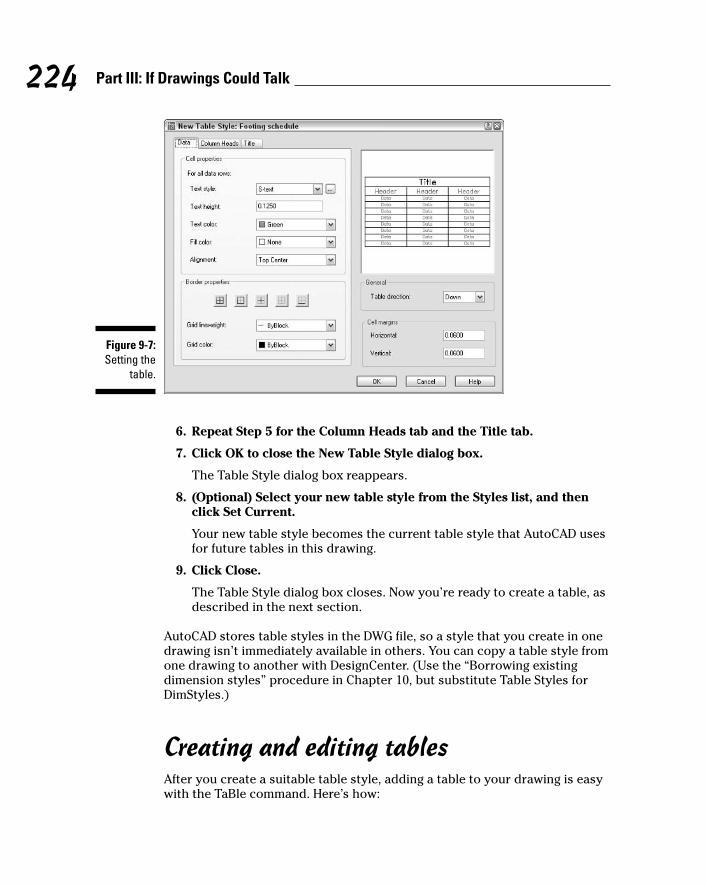
6. Repeat Step 5 for the Column Heads tab and the Title tab.
7. Click OK to close the New Table Style dialog box.
The Table Style dialog box reappears.
8. (Optional) Select your new table style from the Styles list, and thenclick Set Current.
Your new table style becomes the current table style that AutoCAD usesfor future tables in this drawing.
9. Click Close.
The Table Style dialog box closes. Now you’re ready to create a table, asdescribed in the next section.
AutoCAD stores table styles in the DWG file, so a style that you create in onedrawing isn’t immediately available in others. You can copy a table style fromone drawing to another with DesignCenter. (Use the “Borrowing existingdimension styles” procedure in Chapter 10, but substitute Table Styles forDimStyles.)
Creating and editing tablesAfter you create a suitable table style, adding a table to your drawing is easywith the TaBle command. Here’s how:
Figure 9-7:Setting the
table.
224 Part III: If Drawings Could Talk
h571389 Ch09.qxd 4/12/04 9:45 AM Page 224

1. Set an appropriate layer current.
Assuming that you leave the current color, linetype, and lineweight setto ByLayer, as I recommend in Chapter 4, the current layer’s propertieswill control the properties of any parts of the table that you left set toByBlock when you defined the table style. (See Step 5 in the “Tableshave style, too” section.)
2. Choose Draw➪Table.
The Insert Table dialog box appears.
3. Choose a table style from the Table Style Name drop-down list.
4. Choose an Insertion Behavior.
Specify Insertion Point is the easiest method and means that you’ll pickthe location of the table’s upper-left corner (or lower-left corner if youset Table Direction to Up in the table style). With this method, you spec-ify the default column width and number of rows in the Insert Tabledialog box.
Specify Window means that you’ll pick the upper-left corner and thenthe lower-right corner. With this method, AutoCAD automatically scalesthe column widths and determines how many rows to include.
5. Specify Column & Row Settings.
If you chose Specify Window in Step 4, AutoCAD sets the Column Widthand number of Data Rows to Auto, which means that AutoCAD will figurethem out based on the overall size of the table that you specify in Steps7 and 8.
6. Click OK.
AutoCAD prompts you to specify the insertion point of the table.
7. Click a point or type cooordinates.
If you chose Specify Insertion Point in Step 4, AutoCAD draws the tablegrid lines, places the cursor in the title cell, and displays the TextFormatting toolbar.
8. If you chose Specify Window in Step 4, specify the diagonally oppositecorner of the table.
AutoCAD draws the table. Based on the table size that you indicated,AutoCAD chooses the column width and number of rows.
9. Type a title for the table.
10. Press the arrow keys or tab key to move among cells, and type valuesin each cell.
The cell right-click menu offers many other options, including copyingcontents from one cell to another, merging cells, inserting rows andcolumns, changing formatting, and inserting a block (that is, a graphicalsymbol — see Chapter 13 for information about blocks).
225Chapter 9: Text with Character
h571389 Ch09.qxd 4/12/04 9:45 AM Page 225
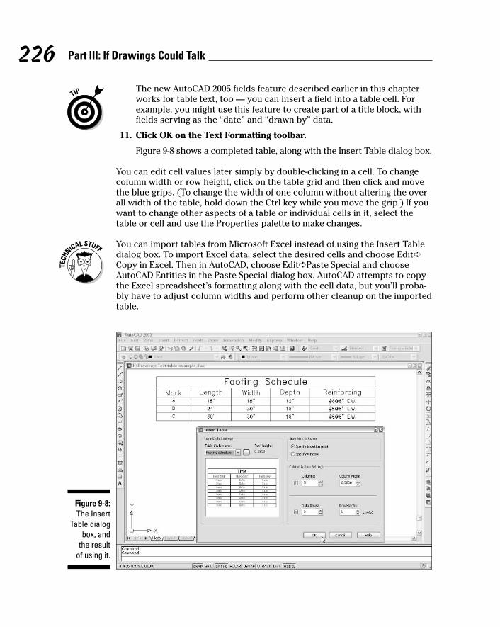
The new AutoCAD 2005 fields feature described earlier in this chapterworks for table text, too — you can insert a field into a table cell. Forexample, you might use this feature to create part of a title block, withfields serving as the “date” and “drawn by” data.
11. Click OK on the Text Formatting toolbar.
Figure 9-8 shows a completed table, along with the Insert Table dialog box.
You can edit cell values later simply by double-clicking in a cell. To changecolumn width or row height, click on the table grid and then click and movethe blue grips. (To change the width of one column without altering the over-all width of the table, hold down the Ctrl key while you move the grip.) If youwant to change other aspects of a table or individual cells in it, select thetable or cell and use the Properties palette to make changes.
You can import tables from Microsoft Excel instead of using the Insert Tabledialog box. To import Excel data, select the desired cells and choose Edit➪Copy in Excel. Then in AutoCAD, choose Edit➪Paste Special and chooseAutoCAD Entities in the Paste Special dialog box. AutoCAD attempts to copythe Excel spreadsheet’s formatting along with the cell data, but you’ll proba-bly have to adjust column widths and perform other cleanup on the importedtable.
Figure 9-8:The Insert
Table dialogbox, and
the resultof using it.
226 Part III: If Drawings Could Talk
h571389 Ch09.qxd 4/12/04 9:45 AM Page 226
You can go the other direction — from AutoCAD to Excel or another program —via a CSV (Comma Separated Value) file. Look up “TABLEEXPORT command”in AutoCAD’s online help.
Checking Out Your SpellingAutoCAD, like almost every other computer program on this planet — andpossibly on other planets and moons in our solar system — has a spellingchecker.
Unlike Microsoft Word, AutoCAD’s spelling checker doesn’t make those littlered squiggles under your errors, but it does let you search for spelling errorsin most of the text objects in your drawing. This feature checks single-linetext, paragraph text, and attribute text (described in Chapter 13), but notdimension text (described in Chapter 10). The following procedure demon-strates how to use the spell checker:
1. Press the Esc key to unselect any selected objects.
2. Choose Tools➪Spelling to start the SPell command.
This is text spell-checking, not casting a spell. (That’s the EYEOFNEWTcommand.) The command line prompts you to select objects.
3. Select the objects you want to check.
You can use any of the standard AutoCAD object selection methods toselect text to check. (See Chapter 6 if you’re unfamiliar with object selec-tion.) Type ALL and press Enter if you want to check the spelling of alltext in the drawing. Don’t worry if you select objects other than text; thespelling checker ignores any objects that aren’t text. When you’re fin-ished selecting objects, press Enter to start the spelling check.
If a misspelling is found, the Check Spelling dialog box appears with thefirst misspelled or unrecognized word. Figure 9-9 shows an example.
4. Click the dialog box buttons to tell AutoCAD how to handle a misspelling.
You probably know which buttons to click from having used otherspelling checkers. If not, use the dialog box help to find out: Click thequestion mark on the Check Spelling dialog box’s title bar, and then clickthe button that you want to know more about.
AutoCAD continues with spell-checking until it has checked all theselected text objects. When it finds no further misspellings, the dialogbox disappears, and the Spelling check complete alert appears.
227Chapter 9: Text with Character
h571389 Ch09.qxd 4/12/04 9:45 AM Page 227

Every industry has its own abbreviations and specialized vocabulary. At first,AutoCAD complains about perfectly good words (from a drafter’s point ofview) such as thru and S.A.D. (which stands for See Architectural Drawing).Be prepared to click the Add button frequently during the first few weeks totell AutoCAD which words and abbreviations are acceptable in your industryand office. If you’re patient with it, AutoCAD, like an errant puppy, will gradu-ally become more obedient. Then you’ll be thru feeling S.A.D.
Figure 9-9:It’s good to
sue yourspelling
checker.
228 Part III: If Drawings Could Talk
h571389 Ch09.qxd 4/12/04 9:45 AM Page 228

Chapter 10
Entering New DimensionsIn This Chapter� Understanding dimension parts and types
� Using dimension styles from other drawings
� Creating and modifying your own dimension styles
� Drawing dimensions
� Editing dimensions
� Drawing leaders
In drafting — either CAD or manual drafting — dimensions are special textlabels with attached lines that together indicate unambiguously the size of
something. Although it’s theoretically possible to draw all the pieces of eachdimension by using AutoCAD commands such as Line and mText, dimension-ing is so common a drafting task that AutoCAD provides special commandsfor doing the job more efficiently. These dimensioning commands group theparts of each dimension into a convenient, easy-to-edit package. Even better,as you edit an object — by stretching it for example — AutoCAD automati-cally updates the measurement displayed in the dimension text label to indi-cate the object’s new size, as shown in Figure 10-1.
AutoCAD controls the look of dimensions by means of dimension styles, just asit controls the look of text with text styles. (AutoCAD also uses text styles tocontrol the appearance of the text in dimensions.) But dimension styles aremuch more complicated than text styles, because dimensions have so manymore pieces that you need to control. After you find or create an appropriatedimension style, you use one of several dimensioning commands to drawdimensions that point to the important points on an object (the two endpointsof a line, for example).
AutoCAD dimensioning is a big, complicated subject. (It’s so complicated, infact, that Autodesk has an especially wise person in charge of dimensioning inAutoCAD — this person is called the “DimWit.”) Every industry has its owndimensioning conventions, habits, and quirks. As usual, AutoCAD tries to sup-port them all and, in so doing, makes things a bit convoluted for everyone. Thischapter covers the essential concepts and commands that you need to knowto start drawing dimensions. Be prepared to spend some additional time study-ing how to create any specialized types of dimensions that your industry uses.
h571389 Ch10.qxd 4/12/04 9:45 AM Page 229

You may be able to avoid getting too deeply into the details of dimensioningjust by copying dimension styles from existing drawings in your office. (I showyou how later in this chapter.) This may also be a good time to get some adviceand coaching from the AutoCAD geek in the cubicle across from yours.
You add dimensions to a drawing after you’ve drawn at least some of thegeometry; otherwise, you won’t have much to dimension! Your dimensioningand overall drafting efficiency improve if you add dimensions in batches,rather than draw a line, draw a dimension, draw another line, draw anotherdimension. . . .
Dimension updates when you change the object
Original dimension
Figure 10-1:Changing
objectsautomati-
callyupdates
dimensions.
230 Part III: If Drawings Could Talk
Why dimensions in CAD?You may think that CAD would have renderedtext dimensions obsolete. After all, you complywith all my suggestions about using AutoCADprecision techniques when you draw and edit,and you’re careful to draw each object at itstrue size, right? The contractor or machinist canjust use AutoCAD to query distances and anglesin the CAD DWG file, right? Sorry, but no (to the
last question, anyway). Here are a few reasonswhy the traditional dimensioning that CAD draft-ing has inherited from manual drafting is likelyto be around for a while:
� Some people need to or want to use paperdrawings when they build something. We’restill some time away from the day when
h571389 Ch10.qxd 4/12/04 9:45 AM Page 230

Discovering New DimensionsBefore digging into the techniques that you use to create dimension stylesand dimensions, I review some AutoCAD dimensioning terminology. If you’realready familiar with CAD dimensioning lingo, just skim this section and lookat the figures in it. Otherwise, read on.
Anatomy of a dimensionAutoCAD uses the names shown in Figure 10-2 and described in the followinglist to refer to the parts of each dimension:
� Dimension text: Dimension text usually is the number that indicates theactual distance or angle. Dimension text can also include other textinformation in addition to or instead of the number. For example, youcan add a suffix such as TYP. to indicate that a dimension is typical ofseveral similar configurations, or you can insert a description such asSee Detail 3/A2.
� Dimension lines: The dimension lines go from the dimension text out-ward (parallel to the direction of the object being measured), to indicatethe extent of the dimensioned length. AutoCAD’s default dimension stylesettings center the dimension text vertically and horizontally on thedimension lines (see Figure 10-2), but you can change those settings to
231Chapter 10: Entering New Dimensions
contractors haul computers around in theirtool belts (never mind mousing around adrawing while hanging from scaffolding).
� In many industries, paper drawings still rulelegally. Your company may supply both plot-ted drawings and DWG files to clients, butyour contracts probably specify that the plot-ted drawings govern in the case of any dis-crepancy. The contracts probably also warnagainst relying on any distances that therecipient of the drawings measures — usingmeasuring commands in the CAD DWG fileor a scale on the plotted drawing. The textdimensions are supposed to supply all thedimensional information that’s needed toconstruct the object.
� Dimensions sometimes carry additionalinformation besides the basic length or
angle. For example, dimension text can indi-cate the allowable construction tolerances orshow that a particular distance is typical ofsimilar situations elsewhere on the drawing.
� Even conscientious CAD drafters rarelydraw every object its true size. Drafterssometimes exaggerate distances for graph-ical clarity. For example, they might draw asmall object larger than its true size so thatit shows up clearly on a scaled plot. In addi-tion, drafters sometimes settle for approxi-mate distances because time pressures(especially late in a project) make it difficultto be completely accurate.
So remember the old rule of drafting prowess:“It’s not the size of the drawn object that mat-ters, but the dimensions that are on it.”
h571389 Ch10.qxd 4/12/04 9:45 AM Page 231
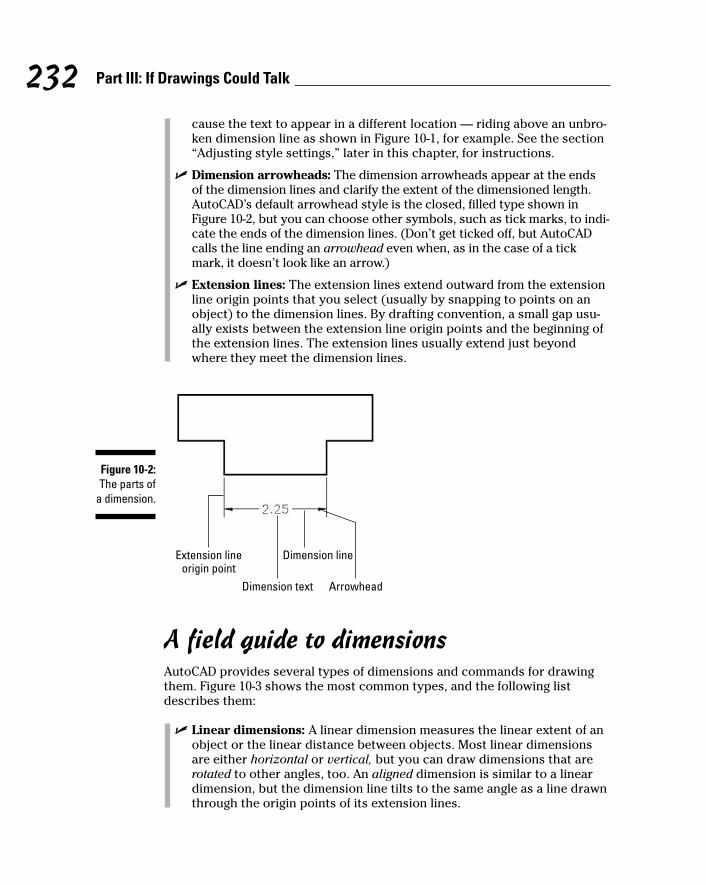
cause the text to appear in a different location — riding above an unbro-ken dimension line as shown in Figure 10-1, for example. See the section“Adjusting style settings,” later in this chapter, for instructions.
� Dimension arrowheads: The dimension arrowheads appear at the ends of the dimension lines and clarify the extent of the dimensioned length.AutoCAD’s default arrowhead style is the closed, filled type shown inFigure 10-2, but you can choose other symbols, such as tick marks, to indi-cate the ends of the dimension lines. (Don’t get ticked off, but AutoCADcalls the line ending an arrowhead even when, as in the case of a tickmark, it doesn’t look like an arrow.)
� Extension lines: The extension lines extend outward from the extensionline origin points that you select (usually by snapping to points on anobject) to the dimension lines. By drafting convention, a small gap usu-ally exists between the extension line origin points and the beginning ofthe extension lines. The extension lines usually extend just beyondwhere they meet the dimension lines.
A field guide to dimensionsAutoCAD provides several types of dimensions and commands for drawingthem. Figure 10-3 shows the most common types, and the following listdescribes them:
� Linear dimensions: A linear dimension measures the linear extent of anobject or the linear distance between objects. Most linear dimensionsare either horizontal or vertical, but you can draw dimensions that arerotated to other angles, too. An aligned dimension is similar to a lineardimension, but the dimension line tilts to the same angle as a line drawnthrough the origin points of its extension lines.
Extension lineorigin point
Dimension text
Dimension line
Arrowhead
Figure 10-2:The parts of
a dimension.
232 Part III: If Drawings Could Talk
h571389 Ch10.qxd 4/12/04 9:45 AM Page 232
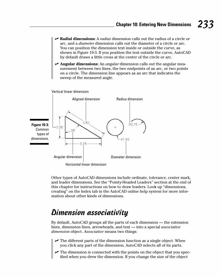
� Radial dimensions: A radius dimension calls out the radius of a circle orarc, and a diameter dimension calls out the diameter of a circle or arc.You can position the dimension text inside or outside the curve, asshown in Figure 10-3. If you position the text outside the curve, AutoCADby default draws a little cross at the center of the circle or arc.
� Angular dimensions: An angular dimension calls out the angular mea-surement between two lines, the two endpoints of an arc, or two pointson a circle. The dimension line appears as an arc that indicates thesweep of the measured angle.
Other types of AutoCAD dimensions include ordinate, tolerance, center mark,and leader dimensions. See the “Pointy-Headed Leaders” section at the end ofthis chapter for instructions on how to draw leaders. Look up “dimensions,creating” on the Index tab in the AutoCAD online help system for more infor-mation about other kinds of dimensions.
Dimension associativityBy default, AutoCAD groups all the parts of each dimension — the extensionlines, dimension lines, arrowheads, and text — into a special associativedimension object. Associative means two things:
� The different parts of the dimension function as a single object. Whenyou click any part of the dimension, AutoCAD selects all of its parts.
� The dimension is connected with the points on the object that you spec-ified when you drew the dimension. If you change the size of the object
Radius dimension
Diameter dimension
Aligned dimension
Vertical linear dimension
Horizontal linear dimension
Angular dimension
Figure 10-3:Commontypes of
dimensions.
233Chapter 10: Entering New Dimensions
h571389 Ch10.qxd 4/12/04 9:45 AM Page 233

(for example, stretch a line), the dimension updates appropriately — thelines and arrows move, and the text changes to reflect the line’s newsize.
I call dimensions with both of these characteristics geometry-driven associative dimensions, because the geometry “drives” the location of theparts of the dimension and what the text says.
For historical reasons, AutoCAD also is capable of creating dimensions thatpossess just the first type of associativity — that is, the dimension functions asa single, grouped object but isn’t directly connected with the object whose sizeit shows. Autodesk now calls these kinds of dimensions nonassociative, whichis pretty confusing to AutoCAD veterans, because AutoCAD used to call themassociative! AutoCAD also is capable of creating dimensions that possess notype of associativity at all — no grouping of the bits and pieces and no connec-tion to the dimensioned object. Autodesk now calls these exploded dimensions,but before AutoCAD 2002, they were called nonassociative!
I mention the conflicting use of associative and nonassociative in case youfind yourself discussing dimensions with AutoCAD veterans, most of whomwill use the terms in their older sense. To avoid confusion, I always use theterm geometry-driven associative dimensions (or simply geometry-drivendimensions) in this book to refer to dimensions that possess both types ofassociativity. For more information about how to determine which kind ofdimension AutoCAD draws, see “Controlling and editing dimension associa-tivity,” later in this chapter.
Pulling out your dimension toolsThe AutoCAD Dimension menu provides access to dimensioning commands. Ifyou find yourself adding dimensions in batches, the Dimension toolbar is moreefficient because it makes the dimensioning commands more accessible. Youtoggle the Dimension toolbar off and on by right-clicking any AutoCAD toolbaricon and choosing Dimension from the cursor menu. As with other toolbars,you can move the Dimension toolbar to a different location on the screen ordock it on any margin of the drawing area.
All dimensioning commands have long command names (such as DIMLINEARand DIMRADIUS) and corresponding shortened abbreviations (DLI and DRA)that you can type at the command prompt. If you do lots of dimensioning anddon’t want to toggle the Dimension toolbar on and off repeatedly, memorizethe abbreviated forms of the dimension commands that you use frequently.You’ll find a list of the long command names on the Contents tab in theAutoCAD online help system. Choose Command Reference➪Commands➪D Commands. The short names are the first, fourth, and fifth letters of thelong names. (In other words, take the first five letters of the long name andremove IM.)
234 Part III: If Drawings Could Talk
h571389 Ch10.qxd 4/12/04 9:45 AM Page 234
Doing Dimensions with Style(s)Creating a usable dimension style that gives you the dimension look you wantis the biggest challenge in using AutoCAD’s dimensioning features. Each draw-ing contains its own dimension styles, so changes you make to a dimensionstyle in one drawing affect only that drawing. However, after you get the dimen-sion styles right in a drawing, you can use it as a template or starting point forlater drawings.
A dimension style is a collection of drawing settings called dimension variables,which are a special class of the system variables that I introduce in Chapter 2.
If you want to see a list of the dimension variable names and look up what eachvariable controls, see Contents➪Command Reference➪System Variables➪D System Variables in the AutoCAD online help system. All the system variablesthat begin with DIM are dimension variables.
AutoCAD users, like all computer nerds, like to shorten names. You may hearthem refer to dimstyles and dimvars instead of dimension styles and dimen-sion variables. You can tell them that doing so makes you think of them asdimwits — which is actually an honorable title at Autodesk, as I mention earlierin this chapter.
Borrowing existing dimension stylesIf you’re lucky enough to work in an office where someone has set up dimensionstyles that are appropriate for your industry and project, you can skip the painand strain of creating your own dimension styles. If the ready-made dimensionstyle that you need lives in another drawing, you can use the DesignCenterpalette to copy it into your drawing, as described in the following steps:
1. Open the drawing that contains the dimension style you want to copy(the source drawing).
2. Open the drawing to which you want to copy the dimension style (thedestination drawing).
If you already had both drawings open, make sure that you can see thedestination drawing. If you can’t, choose the Window menu and thenchoose the destination drawing in order to bring it to the foreground.
3. Click the AutoCAD DesignCenter button on the Standard toolbar.
The DesignCenter palette appears. (Chapter 4 describes this palette indetail.)
4. In the DesignCenter palette, click the Open Drawings tab.
DesignCenter’s navigation pane displays a list of drawings that you cur-rently have open in AutoCAD.
235Chapter 10: Entering New Dimensions
h571389 Ch10.qxd 4/12/04 9:45 AM Page 235
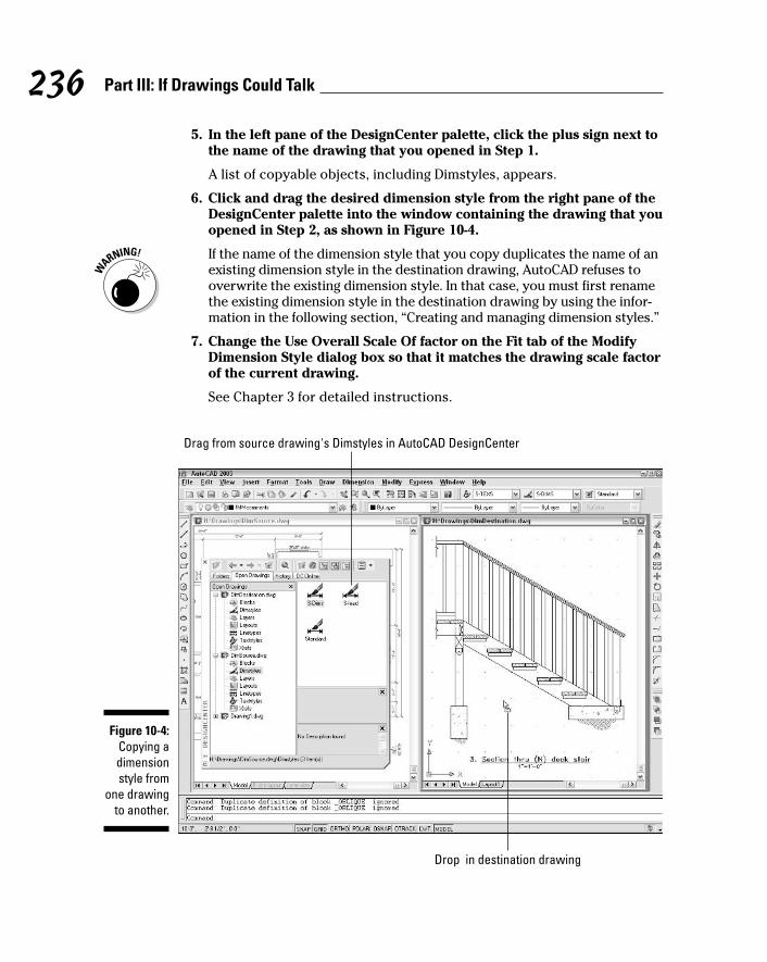
5. In the left pane of the DesignCenter palette, click the plus sign next tothe name of the drawing that you opened in Step 1.
A list of copyable objects, including Dimstyles, appears.
6. Click and drag the desired dimension style from the right pane of theDesignCenter palette into the window containing the drawing that youopened in Step 2, as shown in Figure 10-4.
If the name of the dimension style that you copy duplicates the name of anexisting dimension style in the destination drawing, AutoCAD refuses tooverwrite the existing dimension style. In that case, you must first renamethe existing dimension style in the destination drawing by using the infor-mation in the following section, “Creating and managing dimension styles.”
7. Change the Use Overall Scale Of factor on the Fit tab of the ModifyDimension Style dialog box so that it matches the drawing scale factorof the current drawing.
See Chapter 3 for detailed instructions.
Drag from source drawing's Dimstyles in AutoCAD DesignCenter
Drop in destination drawing
Figure 10-4:Copying adimensionstyle from
one drawingto another.
236 Part III: If Drawings Could Talk
h571389 Ch10.qxd 4/12/04 9:45 AM Page 236
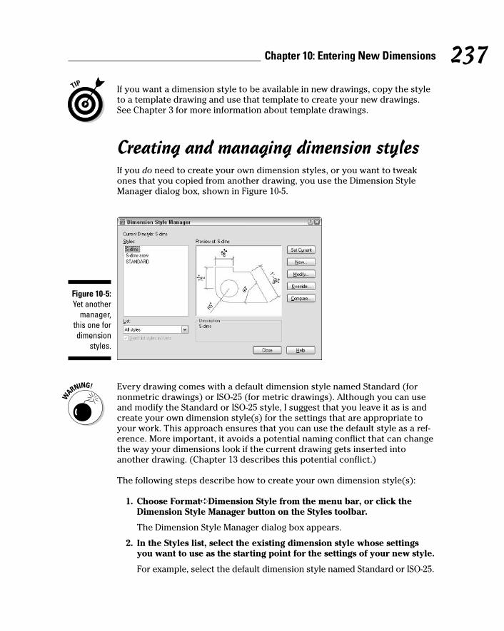
If you want a dimension style to be available in new drawings, copy the styleto a template drawing and use that template to create your new drawings.See Chapter 3 for more information about template drawings.
Creating and managing dimension stylesIf you do need to create your own dimension styles, or you want to tweakones that you copied from another drawing, you use the Dimension StyleManager dialog box, shown in Figure 10-5.
Every drawing comes with a default dimension style named Standard (fornonmetric drawings) or ISO-25 (for metric drawings). Although you can useand modify the Standard or ISO-25 style, I suggest that you leave it as is andcreate your own dimension style(s) for the settings that are appropriate toyour work. This approach ensures that you can use the default style as a ref-erence. More important, it avoids a potential naming conflict that can changethe way your dimensions look if the current drawing gets inserted intoanother drawing. (Chapter 13 describes this potential conflict.)
The following steps describe how to create your own dimension style(s):
1. Choose Format➪Dimension Style from the menu bar, or click theDimension Style Manager button on the Styles toolbar.
The Dimension Style Manager dialog box appears.
2. In the Styles list, select the existing dimension style whose settingsyou want to use as the starting point for the settings of your new style.
For example, select the default dimension style named Standard or ISO-25.
Figure 10-5:Yet another
manager,this one fordimension
styles.
237Chapter 10: Entering New Dimensions
h571389 Ch10.qxd 4/12/04 9:45 AM Page 237

3. Click the New button to create a new dimension style that’s a copy ofthe existing style.
The Create New Dimension Style dialog box appears.
4. Enter a New Style Name and click Continue.
The New Dimension Style dialog box appears, which is the same as theModify Dimension Style dialog box shown in Figure 10-6.
5. Modify dimension settings on any of the six tabs in the New DimensionStyle dialog box.
See the descriptions of these settings in the next section of this chapter.In particular, be sure to set the Use Overall Scale Of factor on the Fit tabto set the drawing scale factor.
6. Click OK to close the New Dimension Style dialog box.
The Dimension Style Manager dialog box reappears.
7. Select your new dimension style from the Styles list, and then click SetCurrent.
Your new dimension style becomes the current dimension style thatAutoCAD uses for future dimensions in this drawing.
8. Click Close.
The Dimension Style Manager dialog box closes.
9. Draw some dimensions to test your new dimension style.
Avoid changing existing dimension styles that you didn’t create, unless youknow for sure what they’re used for. When you change a dimension style set-ting, all dimensions that use that style change to reflect the revised setting.Thus, one small dimension variable setting change can affect a large numberof existing dimensions! When in doubt, ask the dimension style’s creatorwhat the dimension style is for and what the consequences of changing it are.If that’s not possible, instead of modifying an existing dimension style, createa new style by copying the existing one, and then modify the new one.
A further variation on the already baroque dimension style picture is that youcan create dimension secondary styles (also called substyles or style families) —variations of a main style that affect only a particular type of dimension, such asradial or angular. You probably want to avoid this additional complication if youcan, but if you open the Dimension Style Manager dialog box and see names ofdimension types indented beneath the main dimension style names, be awarethat you’re dealing with secondary styles. Look up “dimension styles, sec-ondary styles” on the Index tab in the AutoCAD online help system for moreinformation.
238 Part III: If Drawings Could Talk
h571389 Ch10.qxd 4/12/04 9:45 AM Page 238

Adjusting style settingsAfter you click New or Modify in the Dimension Style Manager dialog box,AutoCAD displays a tabbed New/Modify Dimension Style subdialog box with amind-boggling — and potentially drawing-boggling, if you’re not careful — arrayof settings. Figure 10-6 shows the settings on the first tab, which I’ve modifiedfrom the AutoCAD defaults to conform to one office’s drafting standards.
Fortunately, the dimension preview that appears on all tabs — as well as on themain Dimension Style Manager dialog box — immediately shows the results ofmost setting changes. With the dimension preview and some trial-and-errorchanging of settings, you usually can home in on an acceptable group of set-tings. For more information, use the dialog box help: Click the question markbutton on the title bar and then click the setting that you want to know moreabout.
Before you start messing with dimension style settings, it’s important toknow what you want your dimensions to look like when they’re plotted. Ifyou’re not sure how it’s done in your industry, ask others in your office orprofession or look at a plotted drawing that someone in the know representsas being a good example.
The following sections introduce you to the more important New/ModifyDimension Style tabs and highlight useful settings. Note that whenever youspecify a distance or length setting, you should enter the desired plotted size.AutoCAD scales all these numbers by the overall scale factor that you enteron the Fit tab.
Figure 10-6:Modifyingdimension
settings.
239Chapter 10: Entering New Dimensions
h571389 Ch10.qxd 4/12/04 9:45 AM Page 239
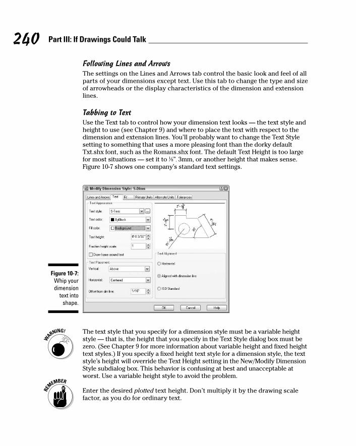
Following Lines and ArrowsThe settings on the Lines and Arrows tab control the basic look and feel of allparts of your dimensions except text. Use this tab to change the type and sizeof arrowheads or the display characteristics of the dimension and extensionlines.
Tabbing to TextUse the Text tab to control how your dimension text looks — the text style andheight to use (see Chapter 9) and where to place the text with respect to thedimension and extension lines. You’ll probably want to change the Text Stylesetting to something that uses a more pleasing font than the dorky defaultTxt.shx font, such as the Romans.shx font. The default Text Height is too largefor most situations — set it to 1⁄8”, 3mm, or another height that makes sense.Figure 10-7 shows one company’s standard text settings.
The text style that you specify for a dimension style must be a variable heightstyle — that is, the height that you specify in the Text Style dialog box must bezero. (See Chapter 9 for more information about variable height and fixed heighttext styles.) If you specify a fixed height text style for a dimension style, the textstyle’s height will override the Text Height setting in the New/Modify DimensionStyle subdialog box. This behavior is confusing at best and unacceptable atworst. Use a variable height style to avoid the problem.
Enter the desired plotted text height. Don’t multiply it by the drawing scalefactor, as you do for ordinary text.
Figure 10-7:Whip yourdimension
text intoshape.
240 Part III: If Drawings Could Talk
h571389 Ch10.qxd 4/12/04 9:45 AM Page 240
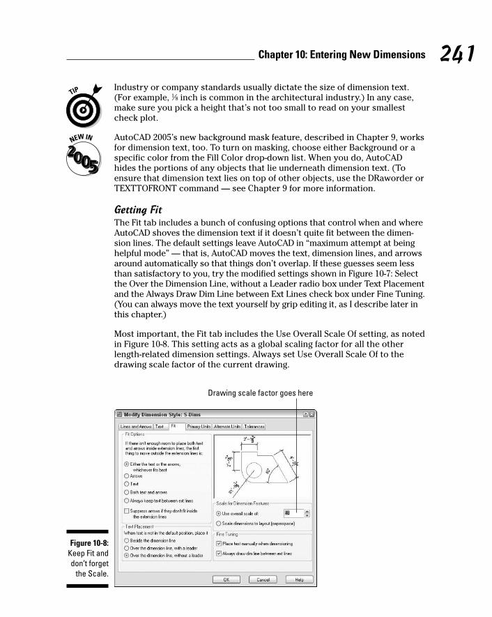
Industry or company standards usually dictate the size of dimension text.(For example, 1⁄8 inch is common in the architectural industry.) In any case,make sure you pick a height that’s not too small to read on your smallestcheck plot.
AutoCAD 2005’s new background mask feature, described in Chapter 9, worksfor dimension text, too. To turn on masking, choose either Background or aspecific color from the Fill Color drop-down list. When you do, AutoCADhides the portions of any objects that lie underneath dimension text. (Toensure that dimension text lies on top of other objects, use the DRaworder orTEXTTOFRONT command — see Chapter 9 for more information.
Getting FitThe Fit tab includes a bunch of confusing options that control when and whereAutoCAD shoves the dimension text if it doesn’t quite fit between the dimen-sion lines. The default settings leave AutoCAD in “maximum attempt at beinghelpful mode” — that is, AutoCAD moves the text, dimension lines, and arrowsaround automatically so that things don’t overlap. If these guesses seem lessthan satisfactory to you, try the modified settings shown in Figure 10-7: Selectthe Over the Dimension Line, without a Leader radio box under Text Placementand the Always Draw Dim Line between Ext Lines check box under Fine Tuning.(You can always move the text yourself by grip editing it, as I describe later inthis chapter.)
Most important, the Fit tab includes the Use Overall Scale Of setting, as notedin Figure 10-8. This setting acts as a global scaling factor for all the otherlength-related dimension settings. Always set Use Overall Scale Of to thedrawing scale factor of the current drawing.
Drawing scale factor goes here
Figure 10-8:Keep Fit anddon’t forget
the Scale.
241Chapter 10: Entering New Dimensions
h571389 Ch10.qxd 4/12/04 9:45 AM Page 241
If your drawing includes areas of different scales, you can create multipledimension styles, one for each scale. Alternatively, you can set the UseOverall Scale Of setting to 1.0 and draw dimensions in a paper space layout,rather than in model space. See the “Trans-spatial dimensioning” section,later in this chapter, for more information.
The Use Overall Scale Of setting corresponds to the DIMSCALE system vari-able, and you’ll hear AutoCAD drafters refer to it as such. AutoCAD acceptszero as a special DIMSCALE setting for dimensioning in paper space layouts.Look up the DIMSCALE system variable in the AutoCAD online help systemfor more information about additional dimension scale options.
Using Primary UnitsThe Primary Units tab gives you incredibly — or maybe overly — detailed con-trol over how AutoCAD formats the characters in the dimension text string. Youusually want to set the Unit format and Precision and maybe specify a suffix forunit-less numbers, such as mm for millimeters. You may also change the ZeroSuppression settings, depending on whether you want dimension text to read0.5000, .5000, or 0.5. (“Zero Suppression!” also makes a great rallying cry fororganizing your fellow AutoCAD drafters.)
Other style settingsIf your work requires that you show dimensions in two different units (suchas inches and millimeters), use the Alternate Units tab to turn on and controlalternate units. If your work requires listing construction tolerances (forexample, 3.5 mm +/–0.01), use the Tolerances tab to configure the toleranceformat that you want.
The New/Modify Dimension Style dialog box Tolerance tab settings are foradding manufacturing tolerances (for example, +0.2 or -0.1) to the text of ordi-nary dimensions — the kind of dimensions I cover in this chapter. AutoCAD alsoincludes a separate TOLERANCES command that draws special symbols calledgeometric tolerances. If you need these symbols, you probably know it; if you’venever heard of them, just ignore them. Look up “Geometric Tolerance dialog box”on the Index tab in the AutoCAD online help system for more information.
Drawing DimensionsAfter you’ve copied or created a suitable dimension style, you’re ready todimension. Fortunately, adding dimensions to a drawing with existing dimen-sion styles is usually pretty straightforward.
When you want to dimension something in AutoCAD, you can either selectthe object, such as a line or polyline segment, or select points on that object,such as the endpoints of the line or polyline segment. If you select an object,
242 Part III: If Drawings Could Talk
h571389 Ch10.qxd 4/12/04 9:45 AM Page 242
AutoCAD finds the most obvious points on it to dimension, such as the end-points of a line. If you choose to select individual points instead, use objectsnaps (see Chapter 4). The points that you pick — or that AutoCAD finds foryou — are called the origins of the dimension’s extension lines. When youchange the size of the object (for example, by stretching it), AutoCAD auto-matically moves the dimension’s origin points and updates the dimensiontext to show the new length.
If you don’t use object snaps or another AutoCAD precision technique tochoose dimension points, the dimension text probably won’t reflect the pre-cise measurement of the object. This lack of precision can cause seriousproblems. When in doubt, osnap to it!
When you set up a new drawing, make sure that you change the Use OverallScale Of setting on the Fit tab in the New/Modify Dimension Style dialog boxso that it matches the drawing scale factor. Before you draw any dimensionsin a drawing that you didn’t set up, check this setting to make sure it’s correct.
The AutoCAD dimension drawing commands prompt you with useful informa-tion at the command line. Read the command line prompts during every stepof the command, especially when you’re trying a dimensioning command forthe first time.
Lining up some linear dimensionsLinear dimensions are the most common type of dimensions, and horizontaland vertical are the most common of those. The following example demon-strates all the important techniques for creating horizontal and verticallinear dimensions, as well as aligned dimensions (which are similar to lineardimensions):
1. Use the LINE command to draw a nonorthogonal line — that is, a linesegment that’s not horizontal or vertical.
An angle of about 30 degrees works well for this example.
If you want to apply dimensioning to an object other than a line, usethese steps as a general guideline, filling in the appropriate commandsand data as applicable to your drawing.
2. Set a layer that’s appropriate for dimensions current.
See Chapter 4 for details.
3. Set a dimension style that’s appropriate for your needs current.
Choose an existing dimension style from the Dim Style Control drop-downlist on the Styles toolbar, or create a new style by using the procedure inthe section, “Creating and managing dimension styles,” earlier in thischapter.
243Chapter 10: Entering New Dimensions
h571389 Ch10.qxd 4/12/04 9:45 AM Page 243

4. Choose Dimension➪Linear or click the Linear Dimension button onthe Dimension toolbar.
AutoCAD prompts you:
Specify first extension line origin or <select object>:
5. To specify the origin of the first extension line, snap to the lower-leftendpoint of the line by using endpoint object snap.
If you don’t have endpoint as one of your current running object snaps,specify a single endpoint object snap by holding down the Shift key, right-clicking, and choosing Endpoint from the cursor menu. (See Chapter 4 formore about object snaps.)
AutoCAD prompts you:
Specify second extension line origin:
6. To specify the origin of the second extension line, snap to the otherendpoint of the line by using endpoint object snap again.
AutoCAD draws a horizontal dimension — the length of the displacementin the left-to-right direction — if you move the cursor above or below theline. It draws a vertical dimension — the length of the displacement in the up-and-down direction — if you move the cursor to the left or right of the line.
AutoCAD prompts you:
Specify dimension line location or[Mtext/Text/Angle/Horizontal/Vertical/Rotated]:
7. Move the mouse to generate the type of dimension you want, horizon-tal or vertical, and then click wherever you want to place the dimen-sion line.
When you’re specifying the dimension line location, you usually don’twant to object snap to existing objects — you want the dimension lineand text to sit in a relatively empty part of the drawing rather than bumpinto existing objects. If necessary, temporarily turn off running objectsnap (for example, click the OSNAP button on the status bar) in order toavoid snapping the dimension line to an existing object.
AutoCAD draws the dimension.
If you want to be able to align subsequent dimension lines easily, turn onSnap and set a suitable snap spacing — more easily done than said! —before you pick the point that determines the location of the dimensionline. See Chapter 4 for more information about snap.
8. Repeat Steps 4 through 7 to create another linear dimension of theopposite orientation (vertical or horizontal).
244 Part III: If Drawings Could Talk
h571389 Ch10.qxd 4/12/04 9:45 AM Page 244
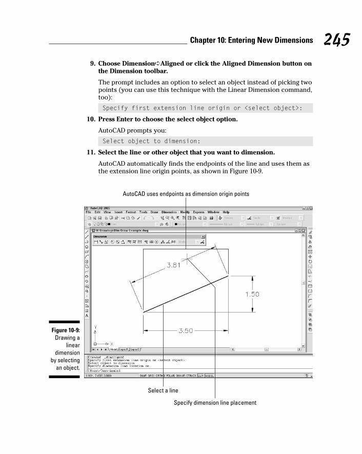
9. Choose Dimension➪Aligned or click the Aligned Dimension button onthe Dimension toolbar.
The prompt includes an option to select an object instead of picking twopoints (you can use this technique with the Linear Dimension command,too):
Specify first extension line origin or <select object>:
10. Press Enter to choose the select object option.
AutoCAD prompts you:
Select object to dimension:
11. Select the line or other object that you want to dimension.
AutoCAD automatically finds the endpoints of the line and uses them asthe extension line origin points, as shown in Figure 10-9.
AutoCAD uses endpoints as dimension origin points
Select a line
Specify dimension line placement
Figure 10-9:Drawing a
lineardimension
by selectingan object.
245Chapter 10: Entering New Dimensions
h571389 Ch10.qxd 4/12/04 9:45 AM Page 245

AutoCAD prompts you:
Specify dimension line location or[Mtext/Text/Angle]:
12. Click wherever you want to place the dimension line.
AutoCAD draws the dimension.
Drawing other kinds of dimensionsAfter you have the hang of ordinary linear dimensions, you should be able tomaster other common dimension types quickly. Draw some lines, arcs, andcircles, and try the other dimension commands on the Dimension toolbar ormenu.
Although AutoCAD includes special commands for dimensioning the diame-ter or radius of a circle or arc, you can use the linear dimension techniquesdescribed in the previous section to dimension these objects.
To draw a series of side-by-side dimensions whose dimension lines are per-fectly aligned, use the DimCOntinue command. To draw an overall dimensionabove one or more smaller dimensions, use DimBAseline. If you use thesecommands often in your work, you may find that the QDIM (Quick DIMension)command provides a quick way to draw lots of dimensions in one fell swoop.
Figure 10-10 shows some results of using the more common additional dimen-sioning commands.
Trans-spatial dimensioningTrans-spatial dimensioning may sound like the latest New Age fad — after all,most of Autodesk’s programmers do work in California — but actually it’s justa relatively new (circa AutoCAD 2002) dimensioning feature. There’s an age-old argument about whether to draw dimensions in model space, where thegeometry that you’re dimensioning usually resides, or paper space. (SeeChapter 3 for information about model space and paper space.) Most peoplehave settled on dimensioning in model space, but sometimes dimensioning inpaper space offers advantages — for example, when you want to dimensiondifferent parts of the same geometry in different paper space viewports.
Since AutoCAD 2002, the program works much better for dimensioning inpaper space layouts — when you set the DIMSCALE system variable to 1.0and then draw dimensions in paper space, AutoCAD can associate them withobjects in model space.
246 Part III: If Drawings Could Talk
h571389 Ch10.qxd 4/12/04 9:45 AM Page 246
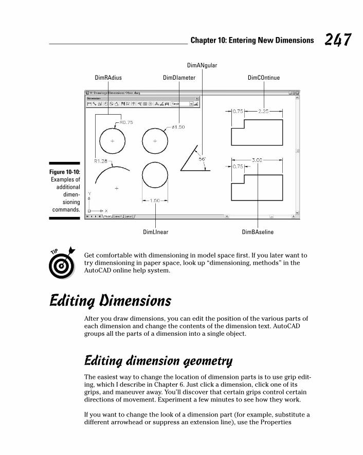
Get comfortable with dimensioning in model space first. If you later want totry dimensioning in paper space, look up “dimensioning, methods” in theAutoCAD online help system.
Editing DimensionsAfter you draw dimensions, you can edit the position of the various parts ofeach dimension and change the contents of the dimension text. AutoCADgroups all the parts of a dimension into a single object.
Editing dimension geometryThe easiest way to change the location of dimension parts is to use grip edit-ing, which I describe in Chapter 6. Just click a dimension, click one of itsgrips, and maneuver away. You’ll discover that certain grips control certaindirections of movement. Experiment a few minutes to see how they work.
If you want to change the look of a dimension part (for example, substitute adifferent arrowhead or suppress an extension line), use the Properties
DimRAdius
DimLInear
DimDIameter
DimANgular
DimCOntinue
DimBAseline
Figure 10-10:Examples of
additionaldimen-sioning
commands.
247Chapter 10: Entering New Dimensions
h571389 Ch10.qxd 4/12/04 9:45 AM Page 247

palette. (See Chapter 6 for more on the Properties palette.) All the dimensionsettings in the New/Modify Dimension Style dialog box (see “Adjusting stylesettings,” earlier in this chapter) are available in the Properties palette whenyou select one or more dimensions.
If you select one or more dimensions and right-click, the cursor menu dis-plays a number of useful options for overriding dimension settings or assign-ing a different style.
When you change a setting in the Properties palette, you’re overriding thedefault style setting for that dimension. If you need to make the same change toa bunch of dimensions, it’s better to create a new dimension style and assignthat style to them. You can use the Properties palette or the right-click menu tochange the dimension style that’s assigned to one or more dimensions.
You can use the Properties palette to turn on AutoCAD 2005’s new back-ground mask feature, described in Chapter 9, for the text of individual dimen-sions: Select the dimensions, display the Text area in the Properties palette,and choose either Background or a specific color from the Fill Color drop-down list. Note that turning on background mask in the Multiline Text Editorwindow, as Chapter 9 tells you to do for regular (nondimension) text, doesnot work for dimension text. You must use the Fill Color setting on either theText tab of the New/Modify Dimension Style dialog box (as described earlierin this chapter) or the Properties palette.
The AutoCAD eXplode command on the Modify toolbar will blow a dimensionapart, into a bunch of line and multiline text objects. Don’t do it! Exploding adimension makes it much harder to edit cleanly and eliminates AutoCAD’scapability of updating the dimension text measurement automatically.
Editing dimension textIn most cases, you shouldn’t have to edit dimension text. Assuming that you drew your geometry accurately and picked the dimension points pre-cisely, AutoCAD displays the right measurement. If you change the size of theassociated object, AutoCAD updates the dimension and its measurement.However, you occasionally may need to override the dimension text (that is,replace it with a different measurement) or add a prefix or a suffix to the truemeasurement.
AutoCAD creates dimension text as a multiline text (mText) object, so dimen-sion text has the same editing options as ordinary text. Unfortunately, theright-click menu for dimension objects doesn’t include a Text Edit option. Youcan use the Text Override field in the Properties palette, or type ED (the key-board shortcut for the ddEDit command) to edit dimension text in theMultiline Text Editor window.
248 Part III: If Drawings Could Talk
h571389 Ch10.qxd 4/12/04 9:45 AM Page 248

The default text is <> (that is, the left and right angled bracket characters),which acts as a placeholder for the true length. In other words, AutoCAD dis-plays the true dimension length as text in the actual dimension (and keepsthe text up-to-date if you change the distance between the dimension’s originpoints). You can override the true length by typing a specific length or othertext string. You can preserve the true length but add a prefix or suffix bytyping it before or after the left- and right-angled bracket characters. In otherwords, if you enter <> Max., and the actual distance is 12.00, AutoCAD dis-plays 12.00 Max. for the dimension text. If you later stretch the object sothat the actual distance changes to 14.50, AutoCAD automatically changesthe dimension text to read 14.50 Max. Now you can appreciate the impor-tance of drawing and editing geometry precisely!
Avoid the temptation to override the default dimension text by replacing theangled brackets with a numeric value. Doing so eliminates AutoCAD’s capabil-ity of keeping dimension measurements current, but even worse, you get novisual cue that the default distance has been overridden (unless you edit thedimension text). If you’re overriding dimension text a lot, it’s probably a signthat the creator of the drawing didn’t pay enough attention to using precisiontechniques when drawing and editing. I’m not going to point any fingers, butyou probably know whom to talk to.
Controlling and editing dimension associativityWhen you add dimensions by selecting objects or picking points on theobjects by using object snap modes, AutoCAD normally creates geometry-driven associative dimensions, which are connected to the objects and movewith them. This is the case in new drawings that were originally created inany version of AutoCAD starting with 2002. (Autodesk introduced geometry-driven dimensions in AutoCAD 2002. Before that, AutoCAD normally createddimensions whose parts functioned as a single grouped object but thatweren’t connected with the dimensioned object.)
In drawings that were created originally in versions older than AutoCAD 2002,you must set the new DIMASSOC system variable to 2 before AutoCAD 2005will create geometry-driven associative dimensions. An easy way to make thischange for the current drawing is to open the Options dialog box (chooseTools➪Options), click the User Preferences tab, and turn on the Make NewDimensions Associative setting. Be aware that this setting affects only newdimensions that you draw from now on. Thus, you’ll end up with geometry-driven associative new dimensions and less than fully associative existingdimensions in your old drawing. Look up “DIMASSOC system variable” in theAutoCAD online help system for more information.
249Chapter 10: Entering New Dimensions
h571389 Ch10.qxd 4/12/04 9:45 AM Page 249
You aren’t likely to need any of these three commands very often, but if youdo, look up the command name in the online help system.
� DIMREASSOCIATE: If you have dimensions that aren’t currently geometry-driven (probably because they were created in older versions of AutoCAD)or are associated with the wrong objects, you can use the DIMREASSOCI-ATE command (Dimensions➪Reassociate Dimensions) to associate themwith points on the objects of your choice.
� DIMDISASSOCIATE: You can use the DIMDISASSOCIATE command tosever the connection between a dimension and its associated object.
� DIMREGEN: In a few special circumstances, AutoCAD doesn’t automati-cally update geometry-driven associative dimensions (maybe Autodeskshould call them “usually geometry-driven but occasionally asleep at thewheel associative dimensions”). In those cases, the DIMREGEN commandwill fix things.
Pointy-Headed LeadersNo, I’m not talking about your boss (or about you, if you happen to be theboss). I’m talking about arrows that point from your comment to the objector area about which you’re commenting. AutoCAD treats leaders as a specialkind of dimension object (no jokes about dimwitted leaders, now). You candraw leaders and text at the same time easily by using the qLEader (QuickLeader) command, as described in the following steps.
qLEader is an improved version of the old LEADER command, which remains inAutoCAD 2005 for compatibility reasons. I recommend that you use qLEaderinstead of LEADER. Fortunately, the AutoCAD 2005 Dimension menu and tool-bar choices run the qLEader command.
qLEader is another one of those annoying AutoCAD commands that promptsyou for some information on the command line and some in a dialog box. Payclose attention to the command line prompts throughout this example:
1. Set a layer that’s appropriate for dimensions current.
See Chapter 4 for details.
2. Set a dimension style that’s appropriate for your needs current.
Choose an existing dimension style from the drop-down list on the Stylestoolbar, or create a new style by using the procedure in the section,“Creating and managing dimension styles,” earlier in this chapter.
250 Part III: If Drawings Could Talk
h571389 Ch10.qxd 4/12/04 9:45 AM Page 250

3. Choose Dimension➪Leader or click the Quick Leader button on theDimension toolbar.
The command line prompts you to select the first leader point — that is,the arrowhead point — and gives you the option of changing leader set-tings first:
Specify first leader point, or [Settings] <Settings>:
If you want to draw curved rather than straight leader lines or choose adifferent leader arrowhead style, press Enter now to open the LeaderSettings dialog box.
4. Pick a point that you want to point to.
If you use an object snap mode, such as Nearest or Midpoint, to pick apoint on an object, AutoCAD associates the leader with the object. If youlater move the object, AutoCAD updates the leader so that it points tothe new location.
The command line prompts you for the next point — AutoCAD draws ashaft from the arrowhead to this point:
Specify next point:
5. Pick a second point.
If you pick a second point that’s too close to the arrowhead point,AutoCAD doesn’t have enough room to draw the arrowhead, and thusomits it.
AutoCAD repeats the next point prompt so that you can draw a multiseg-ment shaft if you want to:
Specify next point:
6. Pick one more point if you want to, or press Enter if you want a leaderwith a single shaft.
Pressing Enter tells the qLEader command that you’re finished selectingthe points that define the leader shaft. By default, the qLEader commandlets you pick up to three points (the arrowhead point and two morepoints). You can change this behavior in the Leader Settings dialog box(refer to Step 3).
The command line prompts you to specify the width for word-wrappingthe text that you’ll attach to the leader:
Specify text width <0.0>:
The default text width, 0.0, turns off word-wrapping and displays yourtext on a single line. You can type a width or point and click with themouse.
251Chapter 10: Entering New Dimensions
h571389 Ch10.qxd 4/12/04 9:45 AM Page 251
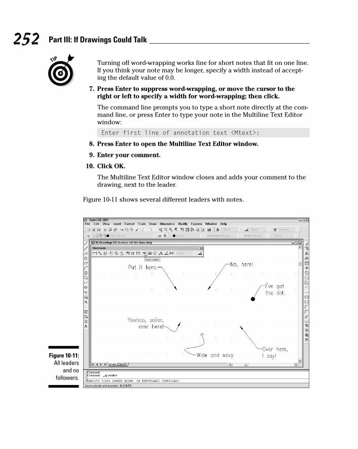
Turning off word-wrapping works fine for short notes that fit on one line.If you think your note may be longer, specify a width instead of accept-ing the default value of 0.0.
7. Press Enter to suppress word-wrapping, or move the cursor to theright or left to specify a width for word-wrapping; then click.
The command line prompts you to type a short note directly at the com-mand line, or press Enter to type your note in the Multiline Text Editorwindow:
Enter first line of annotation text <Mtext>:
8. Press Enter to open the Multiline Text Editor window.
9. Enter your comment.
10. Click OK.
The Multiline Text Editor window closes and adds your comment to thedrawing, next to the leader.
Figure 10-11 shows several different leaders with notes.
Figure 10-11:All leaders
and nofollowers.
252 Part III: If Drawings Could Talk
h571389 Ch10.qxd 4/12/04 9:45 AM Page 252

If both the leader arrowhead and the text are the wrong size or appear to bemissing entirely, the dimension scale isn’t set correctly in the drawing. (As Iwarn you earlier, AutoCAD treats leaders as a special kind of dimensionobject.) See Chapter 3 for detailed instructions on how to set the dimensionscale. After you set the dimension scale properly, erase and re-create theleader and text.
If you add a comment to a drawing and later decide that the comment meritsa leader, you can use the qLEader command to draw the leader so that theend of the shaft ends up in the vicinity of the existing text object. Then, whenthe Multiline Text Editor window appears (Step 8 in the previous steps), clickOK without entering any new text.
A leader and the text that you draw with it are partially associated with eachother. When you move the text, the leader’s shaft follows. Unfortunately, theconverse isn’t true — moving the leader or one of its vertices doesn’t causethe text to follow.
253Chapter 10: Entering New Dimensions
h571389 Ch10.qxd 4/12/04 9:45 AM Page 253

254 Part III: If Drawings Could Talk
h571389 Ch10.qxd 4/12/04 9:45 AM Page 254

Chapter 11
Down the HatchIn This Chapter� Adding hatching to your drawings
� Copying existing hatches
� Using predefined and user-defined hatch patterns
� Making solid and gradient fills
� Scaling hatches properly
� Choosing hatching boundaries
� Editing hatches
If you were hoping to hatch a plot (or plot a hatch), see Chapter 12 instead.If you want to hatch an egg, buy my companion book, Raising Chickens For
Dummies. If you need to fill in closed areas of your drawings with special pat-terns of lines, this is your chapter.
Drafters often use hatching to represent the type of material that makes up anobject, such as insulation, metal, concrete, and so on. In other cases, hatchinghelps emphasize or clarify the extent of a particular element in the drawing —for example, showing the location of walls in a building plan, or highlighting aswampy area on a map so you know where to avoid building a road. Figure 11-1shows an example of hatching in a structural detail.
An AutoCAD hatch is a separate object that fills a space, that has an appear-ance dictated by the hatch pattern assigned to it, and that is associated withthe objects that bound the space, such as lines, polylines, or arcs. If you moveor stretch the boundaries, AutoCAD normally updates the hatching to fill theresized area.
Don’t go overboard with hatching. The purpose of hatching is to clarify, notoverwhelm, the other geometry in the drawing. If your plots look like a patch-work quilt of hatch patterns, it’s time to simplify.
h571389 Ch11.qxd 4/12/04 9:45 AM Page 255
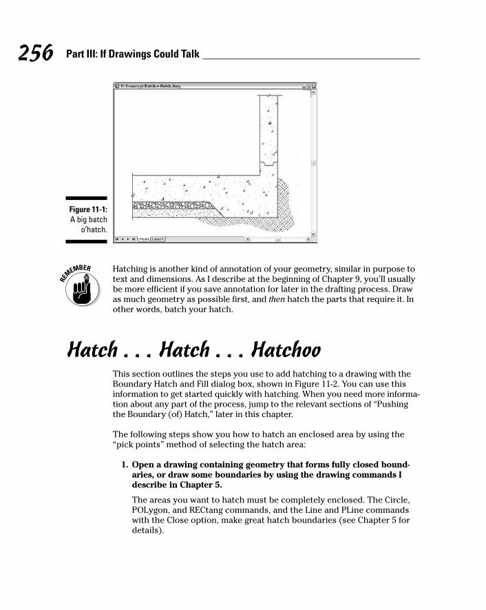
Hatching is another kind of annotation of your geometry, similar in purpose totext and dimensions. As I describe at the beginning of Chapter 9, you’ll usuallybe more efficient if you save annotation for later in the drafting process. Drawas much geometry as possible first, and then hatch the parts that require it. Inother words, batch your hatch.
Hatch . . . Hatch . . . HatchooThis section outlines the steps you use to add hatching to a drawing with theBoundary Hatch and Fill dialog box, shown in Figure 11-2. You can use thisinformation to get started quickly with hatching. When you need more informa-tion about any part of the process, jump to the relevant sections of “Pushingthe Boundary (of) Hatch,” later in this chapter.
The following steps show you how to hatch an enclosed area by using the“pick points” method of selecting the hatch area:
1. Open a drawing containing geometry that forms fully closed bound-aries, or draw some boundaries by using the drawing commands Idescribe in Chapter 5.
The areas you want to hatch must be completely enclosed. The Circle,POLygon, and RECtang commands, and the Line and PLine commandswith the Close option, make great hatch boundaries (see Chapter 5 fordetails).
Figure 11-1:A big batch
o’hatch.
256 Part III: If Drawings Could Talk
h571389 Ch11.qxd 4/12/04 9:45 AM Page 256

2. Set an appropriate layer current, as described in Chapter 4.
It’s usually best to put hatching on its own layer.
3. Start the bHatch command by clicking the Hatch button on the Drawtoolbar.
The Boundary Hatch and Fill dialog box appears.
For historical reasons, AutoCAD 2005 also has a HATCH command, whichprompts you at the command line instead of opening a dialog box. Trustme — you want the bHatch command’s dialog box.
4. Choose Predefined, User Defined, or Custom from the Type drop-downlist.
Predefined or User Defined works best for most purposes. See the nextsection for details.
5. If you chose Predefined or Custom in the previous step, select anypredefined or custom hatch pattern from the Pattern drop-down listor the Pattern button just to the right of it. If you chose User Defined,you don’t need to choose a pattern.
6. Specify an Angle and Scale for the hatch pattern (or, if you chose UserDefined in Step 4, specify Angle and Spacing).
See “Getting it right: Hatch angle and scale,” later in this chapter, for moreinformation.
Figure 11-2:The Hatchtab of theBoundary
Hatch and Fill
dialog box.
257Chapter 11: Down the Hatch
h571389 Ch11.qxd 4/12/04 9:45 AM Page 257
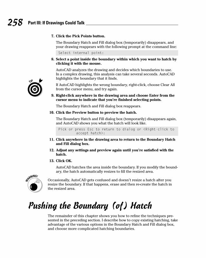
7. Click the Pick Points button.
The Boundary Hatch and Fill dialog box (temporarily) disappears, andyour drawing reappears with the following prompt at the command line:
Select internal point:
8. Select a point inside the boundary within which you want to hatch byclicking it with the mouse.
AutoCAD analyzes the drawing and decides which boundaries to use. In a complex drawing, this analysis can take several seconds. AutoCADhighlights the boundary that it finds.
If AutoCAD highlights the wrong boundary, right-click, choose Clear Allfrom the cursor menu, and try again.
9. Right-click anywhere in the drawing area and choose Enter from thecursor menu to indicate that you’re finished selecting points.
The Boundary Hatch and Fill dialog box reappears.
10. Click the Preview button to preview the hatch.
The Boundary Hatch and Fill dialog box (temporarily) disappears again,and AutoCAD shows you what the hatch will look like.
Pick or press Esc to return to dialog or <Right-click toaccept hatch>:
11. Click anywhere in the drawing area to return to the Boundary Hatchand Fill dialog box.
12. Adjust any settings and preview again until you’re satisfied with thehatch.
13. Click OK.
AutoCAD hatches the area inside the boundary. If you modify the bound-ary, the hatch automatically resizes to fill the resized area.
Occasionally, AutoCAD gets confused and doesn’t resize a hatch after youresize the boundary. If that happens, erase and then re-create the hatch inthe resized area.
Pushing the Boundary (of) HatchThe remainder of this chapter shows you how to refine the techniques pre-sented in the preceding section. I describe how to copy existing hatching, takeadvantage of the various options in the Boundary Hatch and Fill dialog box,and choose more complicated hatching boundaries.
258 Part III: If Drawings Could Talk
h571389 Ch11.qxd 4/12/04 9:45 AM Page 258
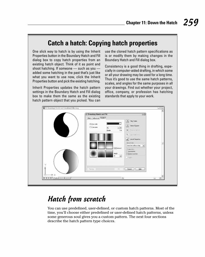
Hatch from scratchYou can use predefined, user-defined, or custom hatch patterns. Most of thetime, you’ll choose either predefined or user-defined hatch patterns, unlesssome generous soul gives you a custom pattern. The next four sectionsdescribe the hatch pattern type choices.
259Chapter 11: Down the Hatch
Catch a hatch: Copying hatch propertiesOne slick way to hatch is by using the InheritProperties button in the Boundary Hatch and Filldialog box to copy hatch properties from anexisting hatch object. Think of it as point andshoot hatching. If someone — such as you —added some hatching in the past that’s just likewhat you want to use now, click the InheritProperties button and pick the existing hatching.
Inherit Properties updates the hatch patternsettings in the Boundary Hatch and Fill dialogbox to make them the same as the existinghatch pattern object that you picked. You can
use the cloned hatch pattern specifications asis or modify them by making changes in theBoundary Hatch and Fill dialog box.
Consistency is a good thing in drafting, espe-cially in computer-aided drafting, in which someor all your drawing may be used for a long time.Thus it’s good to use the same hatch patterns,scales, and angles for the same purposes in allyour drawings. Find out whether your project,office, company, or profession has hatchingstandards that apply to your work.
h571389 Ch11.qxd 4/12/04 9:45 AM Page 259

Pick a pattern, any pattern: Predefined hatch patternsTo use AutoCAD’s predefined hatch patterns, select Predefined from the drop-down list box at the top of the Hatch tab in the Boundary Hatch and Fill dialogbox. This selection sets the stage for choosing the hatch pattern.
You specify a predefined hatch pattern in one of two ways:
� If you know the name of the hatch pattern, select it from the Pattern drop-down list. The list is alphabetical, except that SOLID (that is, a solid fill)is at the very beginning.
� If you don’t know the pattern’s name, or you prefer the visual approach,click the Pattern button (the tiny button with the ellipsis [three dots] tothe right of the Pattern prompt and pattern name) to display the HatchPattern Palette with pattern previews and names.
AutoCAD has about 80 predefined hatch patterns from which to choose. Thelist includes ANSI (American National Standards Institute) and ISO (Interna-tional Standards Organization) standard hatch patterns. Figure 11-3 showsthe Other Predefined hatch patterns, which cover everything from Earth toEscher to Stars. Hatch patterns whose names begins with AR- are intendedfor architectural and related industries.
After you’ve selected a pattern, specify angle and scale, as I describe in thesection “Getting it right: Hatch angle and scale,” in this chapter.
Figure 11-3:Plenty of
hatchpatterns.
260 Part III: If Drawings Could Talk
h571389 Ch11.qxd 4/12/04 9:45 AM Page 260

It’s up to you: User-defined hatchesA user-defined hatch pattern makes a hatch pattern out of parallel lines. Usethis option to create a simple pattern and specify the space between the linesin drawing units. For example, you can hatch a wall in a building plan with auser-defined pattern and specify that the hatch lines be three inches apart.
After you choose User Defined from the Type drop-down list in the BoundaryHatch and Fill dialog box, you specify the angle and spacing of the lines. Youcan select the Double check box to achieve a crosshatching effect (two per-pendicular sets of hatching lines).
Getting it right: Hatch angle and scalePredefined and custom hatch patterns require that you enter the angle andscale for AutoCAD to generate the hatching. You usually won’t have any trou-ble deciding on an appropriate angle, but a suitable scale can be tricky.
261Chapter 11: Down the Hatch
Make it solid, manAlthough you may not guess it, AutoCAD treatsfilling an area with a solid color as a type ofhatching. Simply choose Solid from the top ofthe Pattern drop-down list.
Like any other object, a solid hatch takes onthe current object color — or the currentlayer’s color if you leave color set to ByLayer.Therefore, check whether the current objectlayer and color are set appropriately beforeyou use the Solid hatching option (see Chapter4 for details).
You can create the effect of a solid fill inAutoCAD in several other ways:
� If you want a filled-in circle or donut, usethe DOnut command and specify an insidediameter of 0.
� If you want one or more line segments witheither uniform or tapered widths, use thePLine command’s Width option. (Chapter 5discusses the DOnut and PLine commands.)
� If you want a pattern that starts out solid butthen fades away (or transitions to a differ-ent color) in one or more directions, use theGradient tab on the Boundary Hatch and Filldialog box. This option creates a gradientfill. You can control the color(s), direction(s),and angle of the gradient.
Solid and gradient fills are a good way to mimicpoché — an old hand-drafting technique inwhich you shade areas with a lighter coloredpencil (usually red) to make those areas appearlightly shaded on blueline prints. The figureshows some examples of solid and gradient fills.
h571389 Ch11.qxd 4/12/04 9:45 AM Page 261

The hatch scale usually should be a pattern-specific multiplier times the draw-ing scale factor, as described in Chapter 3. For example, the EARTH pattern(in the Other Predefined tab of the Hatch Pattern Palette; refer to Figure 11-3)looks pretty good in a full scale (1 = 1) drawing with a hatch scale of 0.75. Ifyou’re adding EARTH pattern hatching to a 1” = 1’–0” detail (drawing scalefactor equals 12), try using a hatch scale of 0.75 × 12, or 9.0. This pattern-specific multiplier and drawing-scale-factor approach ensures that hatchinglooks consistent (that the spaces between the lines are the same) at all scaleswhen you plot.
Assuming that you know your drawing’s scale factor, the only complication isfiguring out what the pattern-specific multiplier should be for a particularhatch pattern. In a more rational world, the pattern-specific multiplier wouldalways be something sensible, like 1.0. Unfortunately, that’s not the case forall hatch pattern definitions. Even worse, there’s no way to predict beforeyou use a hatch pattern for the first time what an appropriate pattern-specificmultiplier might be. (Autodesk created the hatch patterns whose names beginswith AR- — that is, the ones intended for architectural drawings — with a finalhatch scale of 1.0 in mind, but in some cases you’ll have to adjust up or downin order to achieve a suitable scale.) You have to use trial and error the firsttime, and then make a note of the hatch pattern and multiplier for future use.
The first time you use a hatch pattern definition, try 1.0 as the multiplier. Don’tforget to multiply by the drawing scale factor. Preview the hatch and thenadjust the hatch scale iteratively; preview after each change. After you settleupon a scale for the current drawing, calculate the corresponding multiplier(for future use); divide the hatch scale by the current drawing’s scale factor.
User-defined patterns require that you enter an angle and spacing, not angleand scale. Spacing is expressed in the current drawing units.
Do fence me in: Defining hatch boundariesAfter you specify the hatch pattern, angle, and scale you want to use, youdefine the boundary (or boundaries) into which you want to pour that hatchpattern in one of two ways:
� Picking points within the area(s) you want hatched
� Selecting objects that surround those areas
The actual operation involved in using either of these options is confusing tomost people. You’ll probably need a little practice before you get used to it.
262 Part III: If Drawings Could Talk
h571389 Ch11.qxd 4/12/04 9:45 AM Page 262
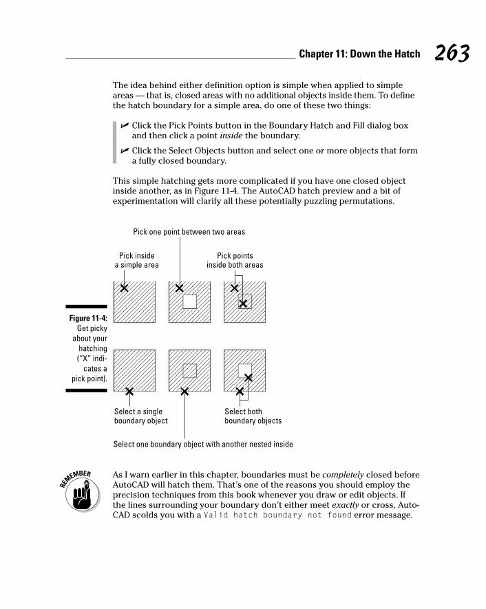
The idea behind either definition option is simple when applied to simpleareas — that is, closed areas with no additional objects inside them. To definethe hatch boundary for a simple area, do one of these two things:
� Click the Pick Points button in the Boundary Hatch and Fill dialog boxand then click a point inside the boundary.
� Click the Select Objects button and select one or more objects that forma fully closed boundary.
This simple hatching gets more complicated if you have one closed objectinside another, as in Figure 11-4. The AutoCAD hatch preview and a bit ofexperimentation will clarify all these potentially puzzling permutations.
As I warn earlier in this chapter, boundaries must be completely closed beforeAutoCAD will hatch them. That’s one of the reasons you should employ theprecision techniques from this book whenever you draw or edit objects. Ifthe lines surrounding your boundary don’t either meet exactly or cross, Auto-CAD scolds you with a Valid hatch boundary not found error message.
Pick insidea simple area
Pick one point between two areas
Pick pointsinside both areas
Select a singleboundary object
Select one boundary object with another nested inside
Select bothboundary objects
Figure 11-4:Get picky
about yourhatching(“X” indi-
cates a pick point).
263Chapter 11: Down the Hatch
h571389 Ch11.qxd 4/12/04 9:45 AM Page 263

The Valid hatch boundary not found error message means you need to“repair” lines or other objects so they are a fully closed boundary. Sometimesyou can use the Fillet command with a zero fillet radius to force two lines tomeet exactly. Another possibility is to use grip editing to align one endpointprecisely with another. Chapter 6 discusses these two editing techniques.
If you don’t want to go to the trouble of repairing your drawing in this way, youcan use AutoCAD 2005’s new Gap Tolerance setting, located on the Advancedtab of the Boundary Hatch and Fill dialog box, to tell AutoCAD to overlooksmall gaps when dealing with hatch boundaries.
Hatching that knows its placeIn AutoCAD 2005, the Boundary Hatch and Fill dialog box includes a new DrawOrder setting that controls where AutoCAD places the hatching with respect tothe boundary in terms of object selection. (Refer to Figure 11-2.) The defaultsetting, Send behind boundary, puts the hatching “underneath” its boundaryfor object selection purposes, and that’s usually exactly what you want.
Have palette, will hatchWith Tool Palettes, described in Chapter 2, you can create click-and-draghatch palettes. With a hatch palette, you click a tool (a swatch) and draginto an enclosed boundary to hatch the area. If your hatching needs aresimple, you can create a Tool Palette for the patterns and scales you oftenuse. See “hatches, adding to tool palettes” in AutoCAD’s online help for moreinformation.
Editing Hatch ObjectsEditing an existing hatch pattern is simple after you’re familiar with the Bound-ary Hatch and Fill dialog box. Follow these steps:
1. Select the hatch object.
2. Right-click anywhere in the drawing area and choose Hatch Edit fromthe cursor menu.
AutoCAD opens the Hatch Edit dialog box and displays the hatch object’scurrent settings.
3. Make any desired changes, use the Preview button to look them over,and click OK to keep the changes.
264 Part III: If Drawings Could Talk
h571389 Ch11.qxd 4/12/04 9:45 AM Page 264

Alternatively, you can use the Properties palette (described in Chapter 6) tomake most existing hatch pattern changes. The Properties palette is especiallygood for changing several hatches at once.
To make one hatch look like another, use the Match Properties button on theStandard toolbar.
The TRim command (described in Chapter 6) is now capable of trimming hatchpatterns in most cases — although it removes associativity of the hatch pat-tern with the boundary.
265Chapter 11: Down the Hatch
h571389 Ch11.qxd 4/12/04 9:45 AM Page 265

266 Part III: If Drawings Could Talk
h571389 Ch11.qxd 4/12/04 9:45 AM Page 266
Chapter 12
The Plot ThickensIn This Chapter� Configuring printers and plotters
� Plotting model space
� Plotting to scale
� Plotting paper space layouts
� Plotting lineweights and colors
� Controlling plotting with plot styles
� Using page setups
� Troubleshooting plotting
Despite the increasing number of offices with a computer (or two) onevery desk, many people still need to or want to work with printed
drawings. Perhaps you thought that using AutoCAD means you don’t have torely on hard-copy versions of drawings, but can view them on-screen instead.Even if that’s true, you may need to give hard-copy prints to your less savvycolleagues who don’t have AutoCAD. You may want to make some quickprints to pore over during your bus ride home. You may find that checkingdrawings the old-fashioned way — with a hard-copy print and a red pencil —turns up errors that managed to remain hidden on the computer screen.
Whatever the reason, you’ll want to print drawings at some point — probablysooner rather than later. Depending on where you are in a project, plotting isthe pop quiz, midterm, or final exam of your drawing-making semester. Thischapter helps you ace the test.
You Say Printing, I Say PlottingPlotting originally meant creating hard-copy output on a device that was capa-ble of printing on larger sheets, such as D size or E size, that measure severalfeet on a side. (See Chapter 3 for information about drafting paper sizes.)These plotters often used pens to draw, robot-fashion, on large sheets of
h571389 Ch12.qxd 4/12/04 9:45 AM Page 267
vellum or Mylar. The sheets could then be run through diazo bluelinemachines — copying machines that create blueline prints — in order tocreate less-expensive copies. Printing meant creating hard-copy output onordinary printers that used ordinary sized paper, such as A size (letter size,81⁄2 x 11 inches) or B size (tabloid or ledger size, 11 x 17 inches).
Nowadays, AutoCAD and most CAD users make no distinction between plot-ting and printing. AutoCAD veterans usually say “plotting,” so if you want tobe hip, you can do so, too.
Whatever you call it, plotting an AutoCAD drawing is considerably more com-plicated than printing a word processing document or a spreadsheet. CAD hasa larger range of different plotters and printers, drawing types, and outputprocedures than other computer applications. AutoCAD tries to help you tamethe vast jungle of plotting permutations, but you’ll probably find that you haveto take some time to get the lay of the land and clear a path to your desiredhard-copy output.
The plotting system in AutoCAD 2005 is essentially the same as the one thatAutodesk introduced in AutoCAD 2000, but with a reorganized, somewhatless imposing Plot dialog box. In addition, Autodesk has improved the pagesetups feature and added background plotting. I describe all these changes inthis chapter.
Get with the systemOne of the complications you face in your attempts to create hard copy is thatAutoCAD has two distinct ways of communicating with your plotters and print-ers. Operating systems, and the programs that run in them, use a special pieceof software called a printer driver to format data for printing and then send it tothe printer or plotter. When you configure Windows to recognize a new printerconnected to your computer or your network, you’re actually installing theprinter’s driver. (“Bring the Rolls around front, James. And bring me a gin andtonic and a D-size plot while you’re at it.”) AutoCAD, like other Windows pro-grams, works with the printers you’ve configured in Windows. AutoCAD callsthese system printers because they’re part of the Windows system.
But AutoCAD, unlike other Windows programs, can’t leave well enough alone.Some output devices, especially some larger plotters, aren’t controlled veryefficiently by Windows system printer drivers. For that reason, AutoCAD comeswith specialized nonsystem drivers (that is, drivers that are not installed as partof the Windows system) for plotters from companies such as Hewlett Packard,Xerox, and Océ. These drivers are kind of like nonunion workers. They ignorethe tidy rules for communicating with Windows printers in order to get thingsdone a bit more quickly and flexibly.
268 Part III: If Drawings Could Talk
h571389 Ch12.qxd 4/12/04 9:45 AM Page 268

Using already-configured Windows system printer drivers usually is easiest,and they work well with many devices — especially devices that print onsmaller paper, such as laser and inkjet printers. However, if you have a largeplotter, you may be able to get faster plotting, better plot quality, or moreplot features by installing a nonsystem driver. To find out more, chooseContents➪Driver and Peripheral Guide➪Use Plotters and Printers in theAutoCAD online help system.
The AutoCAD 2005 CD includes a Windows system printer driver for Hewlett-Packard DesignJet large format printers. This driver is optimized for CADplotting. To install the driver, load your AutoCAD 2005 CD, click Install, andthen click Hewlett Packard DesignJet Printer Drivers.
Configure it outFor now, you simply should make sure that AutoCAD recognizes the devicesthat you want to use for plotting. The following steps show you how:
1. Launch AutoCAD and open an existing drawing or start a new, blankdrawing.
2. Choose Tools➪Options to open the Options dialog box, and click thePlot and Publish tab.
3. Click the drop-down arrow to view the list just below the Use AsDefault Output Device option, as shown in Figure 12-1.
The list includes two kinds of device configurations, designated by twotiny, difficult-to-distinguish icons to the left of the device names:
• A little laser printer icon, with a sheet of white paper coming outthe top, indicates a Windows system printer configuration.
• A little plotter icon, with a piece of paper coming out the front,indicates a nonsystem (that is, AutoCAD-specific) configuration.
The nonsystem configuration names always end in pc3, because they’restored in special AutoCAD Printer Configuration version 3 files. So, if youcan’t tell the difference between the icons, look for the pc3 at the end ofthe name.
4. Verify that the list includes the printers and plotters that you want tohave available in AutoCAD.
If not, choose Start➪Printers and Faxes (in Windows XP) or Start➪Settings➪Printers (in Windows 2000), launch the Add Printer Wizard,and follow the instructions. If your printer isn’t in the default Windowslist, cancel the wizard and hunt down a driver disk that came with yourprinter, or, better yet, download the current driver from the printer manufacturer’s Web site.
269Chapter 12: The Plot Thickens
h571389 Ch12.qxd 4/12/04 9:45 AM Page 269

5. Choose the output device that you want to make the default for newdrawings.
6. Click OK to close the dialog box and retain any change that you madein the previous step.
You use the AutoCAD Plotter Manager Add-A-Plotter Wizard to create nonsys-tem driver configurations. (Choose File➪Plotter Manager to display a windowcontaining a shortcut to the wizard.) This wizard is similar to the WindowsAdd Printer Wizard; if you can handle adding an ordinary printer in Windows,you probably can handle adding a nonsystem plotter configuration toAutoCAD. When you complete the wizard steps, AutoCAD saves the informa-tion in a PC3 (Plot Configuration version 3) file.
A Simple PlotOkay, so you believe me. You know that you’re not going to master AutoCADplotting in five minutes. That doesn’t change the fact that your boss, employee,wife, husband, construction foreman, or 11-year-old son wants a quick checkplot of your drawing.
Nonsystem printers
System printers List of devices
Figure 12-1:System andnonsystem
printerconfigur-
ations.
270 Part III: If Drawings Could Talk
h571389 Ch12.qxd 4/12/04 9:45 AM Page 270

Plotting success in 16 stepsHere’s the quick, cut-to-the-chase procedure for plotting a simple drawing —a mere 16 steps! This procedure assumes that you plot in model space — thatis, that the Model tab at the bottom of the drawing area shows the drawing ina way that you want to plot. (I cover plotting paper space layout tabs in thesection “Plotting the Layout of the Land,” later in this chapter.) This proce-dure doesn’t deal with controlling plotted lineweights (see the “PlottingLineweights and Colors” section later in this chapter for those details). Itshould, however, result in a piece of paper that bears some resemblance towhat AutoCAD displays on your computer monitor.
Follow these steps to make a simple, not-to-scale, monochrome plot of a drawing:
1. Open the drawing in AutoCAD.
2. Click the Model tab at the bottom of the drawing area to ensure thatyou’re plotting the model space contents.
I explain model space and paper space in Chapter 3, and I explain how toplot paper space layouts later in this chapter.
3. Zoom to the drawing’s current extents (choose View➪Zoom➪Extents)so you can verify the area you’re going to plot.
The extents of a drawing consist of a rectangular area just large enoughto include all the objects in the drawing.
4. To display the Plot dialog box, click the Plot button on the Standardtoolbar.
The Plot dialog box appears, as shown in Figure 12-2.
5. In the Printer/Plotter area, select a device from the Name list.
6. In the Paper Size area, select a paper size that’s loaded in your printeror plotter.
Of course, you must make sure that the paper size is large enough to fitthe drawing at the scale you want to plot it at. For example, if you wantto plot a D-size drawing, but you have only a B-size printer, you’re out ofluck — unless you resort to multiple pieces of paper and lots of tape.
7. In the Plot Area area (sponsored by the Department of RedundancyDepartment), choose Extents.
If you set limits properly, as I suggest in Chapter 3, then choose Limitsinstead in order to plot the drawing area that you defined. The Windowoption — that is, plot a window whose corners you pick — is usefulwhen you want to plot just a portion of your drawing.
8. In the Plot Offset area, choose Center the Plot.
Alternatively, you can specify offsets of zero or other amounts in orderto position the plot at a specific location on the paper.
271Chapter 12: The Plot Thickens
h571389 Ch12.qxd 4/12/04 9:45 AM Page 271

9. In the Plot Scale area, either choose Fit to Paper or uncheck Fit toPaper and specify a scale (by choosing from the drop-down list ortyping into the two text boxes).
For most real plotting, you’ll plot to a specific scale, but feel free tochoose Fit to Paper for now. If you do want to plot to a specific scale, seethe “Instead of fit, scale it” section later in this chapter for guidance.
10. Click the More Options button (at the bottom-right corner of thedialog box, next to the Help button.
The Plot dialog box reveals additional settings, as shown in Figure 12-3.
11. In the Plot Style Table (Pen Assignments) area, chooseMonochrome.ctb or Monochrome.stb.
AutoCAD may ask you whether to “Assign this plot style table to all lay-outs?” Answer Yes to make Monochrome.ctb (or Monochrome.stb) thedefault plot style table for the paper space layout tabs as well as the Modeltab, or answer No to make the change apply only to the current tab.
The “Plotting with style” section later in this chapter describes plot styletables.
12. In the Plot Options area, make sure that Plot With Plot Styles is onand Save Changes to Layout is off, as shown in Figure 12-3.
Leaving Save Changes to Layout turned off tells AutoCAD to use any plotsettings changes that you make only for this plot — AutoCAD will revertto the original plot settings the next time you plot the drawing.
More Options button
Figure 12-2:The Plot
dialog box.
272 Part III: If Drawings Could Talk
h571389 Ch12.qxd 4/12/04 9:45 AM Page 272

After you become confident with plotting, you may want to turn on thissetting so that AutoCAD does save your plotting settings changes as thedefault. Alternatively, click the Apply to Layout button to make the cur-rent plot settings the default for future plotting of this tab (that is, theModel tab) in this drawing.
13. In the Drawing Orientation area, choose Portrait or Landscape.
The postage stamp-sized preview in the middle of the Plot dialog boxshould help you decide on the right orientation. If not, the full preview inthe next step will tell you for sure.
14. Click the Preview button and check that the drawing displays on thepaper at the correct orientation and size, as shown in Figure 12-4;then, right-click and choose Exit to return to the Plot dialog box.
15. If you found any problems in the preview, adjust the plot settings (forexample, Plot Area, Plot Scale, or Drawing Orientation) and repeatthe preview until the plot looks right.
16. Click OK to create the plot.
When AutoCAD finishes generating and sending the plot, it displays a“Plot and Publish Job Complete” balloon notification from the status bar.If you decide that you don’t want to see these notifications, right -lickthe Plot/Publish Details Report Available icon near the right end of thestatus bar and deselect Enable Balloon Notification.
There — 16 steps, as promised. If for some reason your plot didn’t work, well,I warned you that AutoCAD plotting was complicated and temperamental!Read the rest of this chapter for all the details about the numerous otherplotting options that can cause plotting to go awry. If you’re in a big hurry,turn directly to the troubleshooting section, “Troubles with Plotting,” at theend of the chapter.
Figure 12-3:The
expandedPlot dialog
box.
273Chapter 12: The Plot Thickens
h571389 Ch12.qxd 4/12/04 9:45 AM Page 273

Preview one, twoOne of the keys to efficient plotting is liberal use of AutoCAD’s partial and fullpreview features. (To maintain political fairness, I recommend conservativeuse of some other AutoCAD options elsewhere in the book.)
The postage stamp-sized partial preview in the middle of the Plot dialog boxis a quick reality check to make sure your plot fits on the paper and is turnedin the right direction. If the plot area at the current scale is too large for thepaper, AutoCAD displays thick red warning lines along the side(s) of thesheet where the drawing will be truncated.
Press the Preview button to see a full preview in a separate window. You seeexactly how your drawing lays out on the paper and how the various line-weights, colors, and other object plot properties will appear. You can zoom and pan around the preview by using the right-click menu. (Any zooming orpanning that you do does not affect what area of the drawing gets plotted —zooming and panning is just a way to get a better look at different areas of theplot preview.)
Figure 12-4:Preview of
coming plot-tractions.
274 Part III: If Drawings Could Talk
h571389 Ch12.qxd 4/12/04 9:45 AM Page 274

Instead of fit, scale itIn most real plotting situations, you want to plot to a specific scale ratherthan let AutoCAD choose an oddball scale that just happens to maximize thedrawing on the paper. And if you’re going to plot the Model tab of a drawingto scale, you need to know its drawing scale factor. Chapter 3 describes setupconcepts and Chapter 9 provides some tips for determining the scale factorof a drawing that someone else created.
If your drawing was created at a standard scale, such as 1:50 or 1⁄4 ”=1’–0”,then you simply choose the scale from the handy drop-down Scale list in thePlot dialog box. If your scale is not in the list, then type the ratio betweenplotted distance and AutoCAD drawing distance into the two text boxesbelow the Scale list, as shown in Figure 12-5. The easiest way to express theratio usually is to type 1 (one) in the upper box and the drawing scale factorin the lower box. (See Chapter 3 for more information.)
Creating half-size plots for some purposes is common in some industries. Toplot model space half-size, double the drawing scale factor. For example, a 1⁄8 ”=1’–0” drawing has a drawing scale factor of 96, which is equivalent to aplot scale of 1=96. To make a half-size model space plot of it, specify a plotscale of 1=192 (or choose 1⁄16 ”=1’–0” from the Scale drop-down list).
Choose apredefinedscale
Fit
Type a ratio
Figure 12-5:Lots of
weighs toscale.
275Chapter 12: The Plot Thickens
h571389 Ch12.qxd 4/12/04 9:45 AM Page 275

Even if you work with drawings that are created to be plotted at a specificscale, plotting with a Fit to Paper scale may be the most efficient way to makea reduced-size check plot. For example, drafters in your office might createdrawings that get plotted on D size sheets (24 x 36 inch), whereas you haveaccess to a laser printer with a B size (11 x 17 inch) paper tray. By plottingthe D size drawings Scaled to Fit on B size paper, you end up with check plotsthat are slightly smaller than half size (11⁄24 size, to be exact). You won’t beable to measure distances on the check plots with a scale, but you probablywill be able to check them visually for overall correctness.
Plotting the Layout of the LandIn the previous section I show you how to plot the model space representa-tion of your drawing by making sure that the Model tab is active when youopen the Plot dialog box. However, paper space gives you many additionaloptions for controlling the look of your output, without having to modify theunderlying geometry or the way it looks to someone working on the DWG file.So in some drawings, you want to plot a paper space layout instead.
About paper space layouts and plottingAs Chapter 3 describes, you can use AutoCAD’s paper space feature to com-pose one or more layouts for plotting your drawing in particular ways. Eachlayout lives on a separate tab, which you click at the bottom of the drawingarea. In addition, AutoCAD saves plot settings (plot device, paper size, plotscale, and so on) separately for each of the tabs — that is, for each of layouttabs as well as the Model tab.
Whether to plot model space or a paper space layout in a drawing dependsentirely on how the drawing was set up. If you or someone else went througha layout setup procedure similar to the one in Chapter 3, then you probablyshould plot the paper space layout. If not, then plot the Model tab.
Don’t confuse the Model tab at the bottom of the drawing area with theMODEL/PAPER button on the status bar. The tabs control which view of thedrawing (model space or a paper space layout) fills the drawing area. When a paper space layout fills the drawing area, the status bar button controlswhether drawing and editing take place in paper space or in model spaceinside a viewport. When you plot a layout, it doesn’t matter whether theMODEL/PAPER button says MODEL or PAPER — AutoCAD always plots thepaper space layout (not just the contents of model space in the viewport).
276 Part III: If Drawings Could Talk
h571389 Ch12.qxd 4/12/04 9:45 AM Page 276
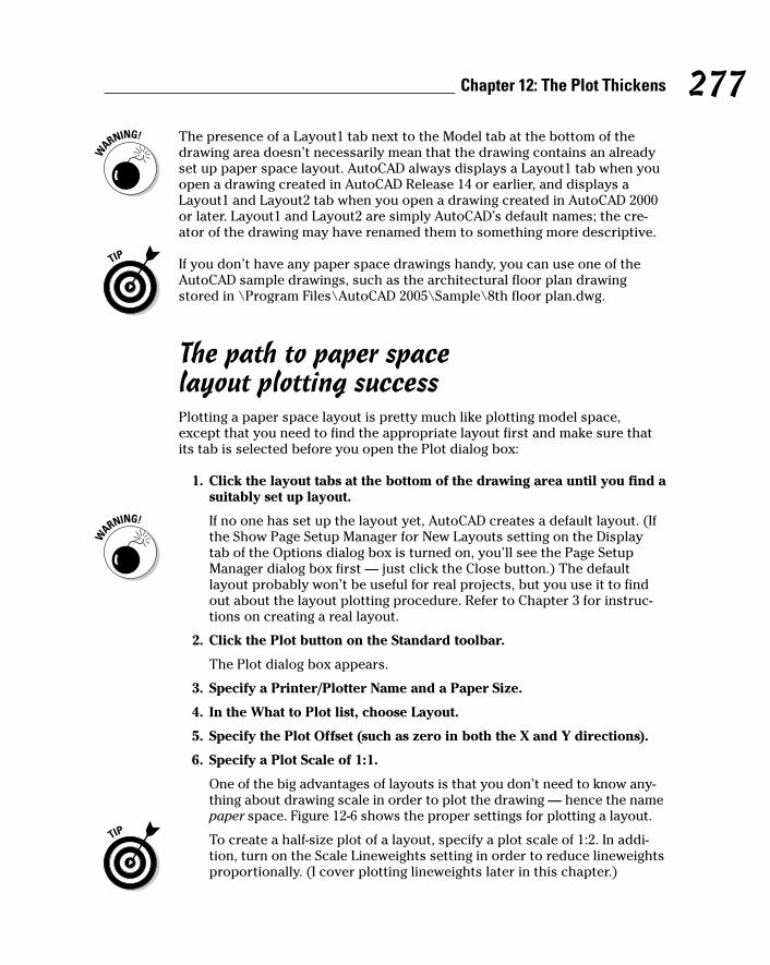
The presence of a Layout1 tab next to the Model tab at the bottom of thedrawing area doesn’t necessarily mean that the drawing contains an alreadyset up paper space layout. AutoCAD always displays a Layout1 tab when youopen a drawing created in AutoCAD Release 14 or earlier, and displays aLayout1 and Layout2 tab when you open a drawing created in AutoCAD 2000or later. Layout1 and Layout2 are simply AutoCAD’s default names; the cre-ator of the drawing may have renamed them to something more descriptive.
If you don’t have any paper space drawings handy, you can use one of theAutoCAD sample drawings, such as the architectural floor plan drawingstored in \Program Files\AutoCAD 2005\Sample\8th floor plan.dwg.
The path to paper space layout plotting successPlotting a paper space layout is pretty much like plotting model space,except that you need to find the appropriate layout first and make sure thatits tab is selected before you open the Plot dialog box:
1. Click the layout tabs at the bottom of the drawing area until you find asuitably set up layout.
If no one has set up the layout yet, AutoCAD creates a default layout. (Ifthe Show Page Setup Manager for New Layouts setting on the Displaytab of the Options dialog box is turned on, you’ll see the Page SetupManager dialog box first — just click the Close button.) The defaultlayout probably won’t be useful for real projects, but you use it to findout about the layout plotting procedure. Refer to Chapter 3 for instruc-tions on creating a real layout.
2. Click the Plot button on the Standard toolbar.
The Plot dialog box appears.
3. Specify a Printer/Plotter Name and a Paper Size.
4. In the What to Plot list, choose Layout.
5. Specify the Plot Offset (such as zero in both the X and Y directions).
6. Specify a Plot Scale of 1:1.
One of the big advantages of layouts is that you don’t need to know any-thing about drawing scale in order to plot the drawing — hence the namepaper space. Figure 12-6 shows the proper settings for plotting a layout.
To create a half-size plot of a layout, specify a plot scale of 1:2. In addi-tion, turn on the Scale Lineweights setting in order to reduce lineweightsproportionally. (I cover plotting lineweights later in this chapter.)
277Chapter 12: The Plot Thickens
h571389 Ch12.qxd 4/12/04 9:45 AM Page 277

If you find that the layout is too big for your plotter’s largest paper sizeat a plot scale of 1:1, you can change the What to Plot setting to Extentsand then specify Fit to Paper for the Plot Scale. Alternatively, you canexit the Plot dialog box and fix the problem if you want to have a paperspace layout that permanently reflects a new paper size. Use the PageSetup dialog box to modify the layout settings, or copy the layout andmodify the new layout.
7. Click the More Options button and change any additional plot optionsthat you want to.
Refer to Steps 11 through 13 in the section, “Plotting success in 16 steps.”
8. Click the Preview button, check that the drawing displays on thepaper at the correct orientation and size, right-click and choose Exitto return to the Plot dialog box.
If you found any problems in the preview, change your plot settings andPreview again until it looks right.
9. Click OK to create the plot.
Scale = 1:1
Plot area = Layout
Figure 12-6:Settings for
plotting apaper space
layout.
278 Part III: If Drawings Could Talk
h571389 Ch12.qxd 4/12/04 9:45 AM Page 278
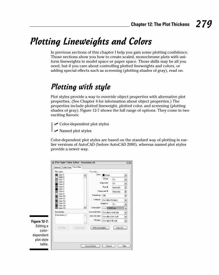
Plotting Lineweights and ColorsIn previous sections of this chapter I help you gain some plotting confidence.Those sections show you how to create scaled, monochrome plots with uni-form lineweights in model space or paper space. Those skills may be all youneed, but if you care about controlling plotted lineweights and colors, oradding special effects such as screening (plotting shades of gray), read on.
Plotting with stylePlot styles provide a way to override object properties with alternative plotproperties. (See Chapter 4 for information about object properties.) Theproperties include plotted lineweight, plotted color, and screening (plottingshades of gray). Figure 12-7 shows the full range of options. They come in twoexciting flavors:
� Color-dependent plot styles
� Named plot styles
Color-dependent plot styles are based on the standard way of plotting in ear-lier versions of AutoCAD (before AutoCAD 2000), whereas named plot stylesprovide a newer way.
Figure 12-7:Editing a
color-dependent
plot styletable.
279Chapter 12: The Plot Thickens
h571389 Ch12.qxd 4/12/04 9:45 AM Page 279
It’s remotely possible that you won’t need to bother with plot styles. If thedrawings you want to plot have layer and object properties (especiallylineweight) that reflect how you want objects to plot, you can dispense withplot styles. But most people and most drawings use plot styles, so youshould at least be familiar with them.
A couple of common reasons for using plot styles are to:
� Map screen colors to plotted lineweights. If this idea seems completelyloony to you, try to suspend judgment until you’ve read the “Plottingthrough thick and thin” section, a bit later in this chapter.
� Create screened lines on monochrome plots. Lines that are screeneddisplay in various shades of gray, not black. Drafters sometimes usescreened lines to de-emphasize secondary objects that otherwise wouldoverwhelm the main objects in the drawing. Screening is expressed as apercentage, with 100% being completely black and 0% being invisible.
Using plot stylesIf you want objects in your drawing to plot with properties that differ fromtheir display properties, you need plot styles. For example, you can plot withdifferent lineweights or colors from the ones you’re using for display purposes.Or, as I mention in the preceding section, you may need to map display colorsto plotted lineweights. AutoCAD groups plot styles into plot style tables, eachof which is stored in a separate file.
Color-dependent plot style tables live in Color TaBle (CTB) files and they mapthe 255 AutoCAD display colors to 255 plot styles. AutoCAD automaticallyattaches the color-dependent plot styles to every object, based on — youguessed it — the object’s color. (Are those AutoCAD programmers brilliant, orwhat?) Color-dependent plot style tables are especially handy for mimickingthe old color-mapped-to-lineweight plotting approach of AutoCAD R14 and ear-lier releases; this remains the most common method in most companies.
Named plot style tables live in Style TaBle (STB) files. After you’ve created a named plot style table, you create one or more plot styles and give themany names you like. Then you can assign the named plot styles to layers or to individual objects. (See Chapter 4 for more information about object andlayer properties.)
“Named” refers to the plot styles, not to the tables. Both color-dependentplot style tables and named plot style tables have names because both arestored in files and files have to have names. But color-dependent plot stylesdon’t have names and named plot styles do have names.
To use a plot style table, and its included plot styles (whether they’re color-dependent or named), you must attach it to model space or a paper space
280 Part III: If Drawings Could Talk
h571389 Ch12.qxd 4/12/04 9:45 AM Page 280

layout. The plot style table then affects plotting only for that tab. This approachlets you plot the same drawing in different ways by attaching different plotstyles to different tabs.
You can attach a plot style to model space or a paper space layout by select-ing its tab at the bottom of the drawing area, opening the Plot dialog box orPage Setup dialog box, and choosing the plot style table name in the PlotStyle Table (Pen Assignments) area of the expanded Plot dialog box. See“Controlling plotted lineweights with screen colors,” later in this chapter, foran example.
When you start a new drawing in the usual way — that is, by using a templatedrawing (see Chapter 3), the template drawing’s plot style behavior determineswhether you can choose CTB or STB files. (That’s why most of AutoCAD’sstock template drawings come in Color Dependent Plot Styles and Named PlotStyles versions.) If you want to change from color-dependent plot styles tonamed plot styles (or vice versa) in a particular drawing, use the CONVERTPSTYLES command.
The Plotting tab on the Options dialog box contains a setting called DefaultPlot Style Behavior For New Drawings, but it’s practically useless. It doesn’tchange the current drawing and, despite its name, doesn’t even affect newdrawings that you start from a template drawing.
Creating plot stylesIf you’re really lucky, you won’t need to use plot styles. If you’re somewhatlucky, you’ll need to use plot styles, but someone will provide the plot styletable files for you. If that’s the case, you must put the CTB or STB files in yourPlot Styles folder in order for AutoCAD to recognize them. (To find the loca-tion of your Plot Styles folder, open the Options dialog box, choose the Filestab, and look for the Printer Support File Path➪Plot Style Table Search Pathsetting.)
If you’re not lucky at all, then you’ll need to be smart — that is, you’ll want toknow how to create your own plot style table files. Here’s how:
1. Choose File➪Plot Style Manager.
The Plot Styles folder opens in a separate window.
2. Double-click the Add-A-Plot Style Table Wizard program shortcut.
3. Read the opening screen and then click Next.
4. Choose the Start From Scratch option, or one of the other three optionsif you want to start with settings from another file. Then click Next.
The remaining steps in this procedure assume that you chose Start FromScratch. If you chose another option, simply follow the wizard’s prompts.
281Chapter 12: The Plot Thickens
h571389 Ch12.qxd 4/12/04 9:45 AM Page 281

If the creator of a drawing provides you with an AutoCAD R14/AutoCADLT 98 PC2 (version 2) or AutoCAD R12/AutoCAD LT 95 PCP (version 1)file, choose the Use A PCP Or PC2 File option. With this option, thewizard imports color-to-plotted-lineweight settings automatically.
5. Choose whether you want to create a color-dependent plot style table(CTB file) or a named plot style table (STB file). Then click Next.
Choose Color-Dependent Plot Style Table in order to map screen colorsto plotted lineweights. Choose Named Plot Style Table in order to leavescreen colors alone (so that the colors plot as you see them on-screen)and to create named plot styles that you can apply to layers or objects.
6. Type a name for the new CTB or STB file and then click Next.
7. Click the Plot Style Table Editor button.
The Plot Style Table Editor dialog box opens (refer to Figure 12-7).
8. If you created a color-dependent plot style table, assign Lineweight,Screening, or other plot properties to each color that’s used in thedrawing. If you created a named plot style table, click the Add Stylebutton and then assign plot properties to each of the named stylesthat you create.
To determine which colors are used in a drawing, switch to the AutoCADwindow and open the Layer Properties Manager dialog box by clickingthe Layers button located on the Object Properties toolbar.
To change a setting for all colors or named styles, select all of them firstby clicking the first color or named style, holding down the Shift key,scrolling to the end of the list, and then clicking the last color or namedstyle. Any subsequent changes you make get applied to all the selectedcolors or named styles.
9. Click the Save & Close button to close the Plot Style Table Editordialog box. Then click Finish to complete the steps for the wizard.
The Plot Styles folder now displays your new CTB or STB file.
10. Close the Plot Styles folder by clicking on the X in its title bar.
Creating your first plot style table can be a harrowing experience, becauseyou have so many options. Just remember that your most likely reason forcreating one is to map screen colors to plotted lineweights (as I describe ingreater detail in the next section). Also remember that you may be able tominimize your effort by getting a CTB file from the person who created thedrawing that you want to plot.
In Chapter 4, I recommend that you limit yourself to the first 9 Standard Auto-CAD Colors when defining layers, and not a patchwork of the 255 colors thatAutoCAD makes available. If you follow my advice, your work to create a color-dependent plot style table will be much reduced, because you’ll have to assignplot properties for only 9 colors, rather than worrying about 255 of them.
282 Part III: If Drawings Could Talk
h571389 Ch12.qxd 4/12/04 9:45 AM Page 282

You can use \Program Files\AutoCAD 2005\Sample\Plot Screening and FillPatterns.dwg for systematic testing of your CTB files. This drawing shows anarray of color swatches for all 255 AutoCAD colors. Some of the other tabs(such as Grayscale and Screening 25%) also demonstrate how different CTBfiles attached to the same layout produce radically different results.
If you really get carried away and decide to take advantage of the 16 million-odd colors in AutoCAD’s True Color capability, then you’re not going to becontrolling lineweights with color-dependent plot styles. CTB plot stylesaffect the lineweights only of objects that use the traditional 255 colors of theAutoCAD Color Index palette. If you want True Color, use object lineweightsor named plot styles to control plotted lineweight.
Plotting through thick and thinLong ago, manual drafters developed the practice of drawing lines of differentthicknesses, or lineweights, in order to distinguish different kinds of objects.Manual drafters did it with different technical ink pen nib diameters or withdifferent hardnesses of pencil lead and varying degrees of pressure on thepencil. Because a computer mouse usually doesn’t come with different diam-eters of mouse balls or a pressure-sensitive button, AutoCAD and its develop-ers had to figure out how to let users indicate lineweights on-screen and on aplot. They came up with two different ways to indicate lineweight:
� Mapping on-screen colors to plotted lineweights. I describe thiscommon approach in Chapter 4.
� Displaying lineweights on-screen to match what the user can expect tosee on the plot. This approach was introduced in AutoCAD 2000.
Controlling plotted lineweights with object lineweightsPlotting object lineweights is trivial, assuming that the person who createdthe drawing took the trouble to assign lineweights to layers or objects (seeChapter 4 for details). Just make sure that the Plot Object Lineweights settingin the expanded Plot dialog box is turned on. You may also want to turn offthe Plot With Plot Styles setting, because plot styles can override the objectlineweights with different plotted lineweights.
As long as you turn on the Plot Object Lineweights setting, you’ll find that(those who hate cheap puns, read no further!) the plot thickens! It also thins,but that’s not as funny.
If you don’t want to plot the lineweights assigned to objects, you must turnoff both the Plot Object Lineweights and Plot With Plot Styles settings in thePlot Options area of the Plot dialog box. Turning on Plot With Plot Stylesturns on Plot Object Lineweights as well.
283Chapter 12: The Plot Thickens
h571389 Ch12.qxd 4/12/04 9:45 AM Page 283

Controlling plotted lineweights with screen colorsTo map screen colors to plotted lineweights, you need a color-dependent plotstyle table (CTB file), as I describe in the section “Plotting with style,” earlierin this chapter. If you’re plotting a drawing created by someone else, thatsomeone else may be able to supply you with the appropriate CTB file, or atleast with a PCP or PC2 file from which you can create the CTB file quickly. Atthe very least, the creator of the drawing should be able to give you a printedchart showing which plotted lineweight to assign to each AutoCAD screencolor. Use the instructions in the “Plotting with style” section to copy orcreate the required CTB file.
Unfortunately, no industry-wide standards exist for mapping screen colors toplotted lineweights. Different offices do it differently. That’s why it’s so usefulto receive a CTB, PCP, or PC2 file with drawings that someone sends you.
After you have the appropriate CTB file stored in your Plot Styles folder,follow these steps to use it:
1. Click the tab that you want to plot — the Model tab or the desiredpaper space layout tab.
2. Click the Plot button on the Standard toolbar.
3. In the Plot Style Table (Pen Assignments) area on the expanded Plot dialog box, select the CTB file from the Name list, as shown inFigure 12-8.
This action attaches the plot style table (CTB file) to the tab that youclicked in Step 1.
284 Part III: If Drawings Could Talk
Plotting with ploddersColor-as-color and lineweight-as-lineweightseem like great ideas, but Autodesk knew whenit added object lineweights back in 1999 thatlongtime users of AutoCAD weren’t going toabandon the old colors-mapped-to-lineweightsapproach overnight. Thus, you can still controlplotted lineweight by display color in AutoCAD.
AutoCAD veterans by and large have chosen tostick with their Old Way for now. They’ve doneso for a variety of reasons, including inertia,plotting procedures and drawings built aroundthe Old Way, third-party applications that don’tfully support the newer methods, and the need to exchange drawings with clients and
subcontractors who haven’t upgraded. In sum-mary, the ripple effect of those who need to orwant to continue using colors-mapped-to-lineweights is lasting a long time. Don’t be sur-prised if you find yourself going with the flowfor awhile.
The default setting in AutoCAD 2005 is to plotobject lineweights, so that’s the easiest methodif you don’t have to consider the historical prac-tices or predilections of other people with whomyou exchange drawings. Mapping screen colorsto lineweights requires some initial work on yourpart, but after you’ve set up the mapping scheme,the additional effort is minimal.
h571389 Ch12.qxd 4/12/04 9:45 AM Page 284

4. Click the Apply to Layout button.
AutoCAD records the plot setting change with the current tab’s configu-ration information. Assuming that you save the drawing, AutoCAD usesthe CTB that you selected as the default plot style when you (or otherpeople) plot that tab in the future.
5. Continue with the plotting procedures described earlier in this chapter.
If your drawing uses a named plot style table instead of a color-dependentplot style table, you follow the same procedure, except that you select anSTB file instead of a CTB file in Step 3.
You can tell whether the current drawing was set up to use color-dependentplot styles or named plot styles by looking at the Properties toolbar. If thelast drop-down list (Plot Style Control) is grayed out, the drawing can usecolor-dependent plot styles. If this list is not grayed out, the drawing can usenamed plot styles.
Plotting in colorPlotting the colors that you see on-screen requires no special tricks. In theabsence of a plot style table (that is, if you set Plot Style Table (Pen Assign-ments) to None in the Plot dialog box), AutoCAD sends color information as it appears on-screen to the plotter. As long as your output device can plot incolor, what you see should be what you get.
Figure 12-8:Selecting a
plot styletable that
mapsscreen
colors toplotted
lineweights.
285Chapter 12: The Plot Thickens
h571389 Ch12.qxd 4/12/04 9:45 AM Page 285

If you attach a plot style table to the tab that you’re plotting (as described inthe previous section), you can — if you really want to — map screen colorsto different plotted colors. In most cases you don’t want that kind of confu-sion. Instead, leave the Color property in the plot style table set to UseObject Color.
If your goal is not to plot color, make sure that you set the Color property forall plot styles to Black. If you try to plot colors on a monochrome device, youmay find that objects appear in various shades of gray, like in a black andwhite newspaper photograph, with lighter colors mapped to lighter shades ofgray and darker colors to darker shades of gray. This process of mappingcolors to shades of gray is called monochrome dithering, and it usually is notwhat you want in a CAD drawing. To override it, use the Plot Style TableEditor, as described in the section “Creating plot styles,” earlier in this chap-ter, to set the Color option for all colors to Black (the default setting is UseObject Color). If you don’t already have a plot style table that you want to use,choose Monochrome.ctb (for color-based plot styles) or Monochrome.stb (fornamed plot styles), both of which come with AutoCAD.
286 Part III: If Drawings Could Talk
When in doubt, send it outWhether you plot to scale or not, with differentlineweights or not, in color or not, consider usinga service bureau for some of your plotting. In-house plotting on your office’s output devices isgreat for small check plots on faster laser or inkjetprinters. Large format plotting, on the other hand,can be slow and time consuming. If you need toplot lots of drawings, you may find yourselfspending an afternoon loading paper, replenish-ing ink cartridges, and trimming sheets.
Good plotting service bureaus have big, fast,expensive plotters that you can only dream aboutowning. Also, they’re responsible for babysittingthose fancy devices, feeding them, and fixingthem. As a bonus, service bureaus can makeblueline prints from your plots, if you need to dis-tribute hard-copy sets to other people.
The only downside is that you need to coordinatewith a service bureau to make sure it gets what itneeds from you and can deliver the kinds of plotsyou need. Some service bureaus plot directlyfrom your DWG files, while others ask you to
make PLT (plot) files. Some service bureaus specialize in color plotting, while others are morecomfortable with monochrome plotting andmaking blueline copies.
When you’re choosing a service bureau, look forone that traditionally has served drafters, archi-tects, and engineers. These service bureaustend to be more knowledgeable about AutoCAD,and they should have more plotting expertisethan the desktop publishing, printing, and copy-ing shops.
Whomever you choose, do some test plots wellbefore the day when that important set of draw-ings is due. Talk to the plotting people and get acopy of their plotting instructions. Have the ser-vice bureau create some plots of a couple ofyour typical drawings and make sure they lookthe way you want them to.
If you do lots of plotting with a service bureau,look into whether you can charge it to your clientsas an expense (just like bluelines or copying).
h571389 Ch12.qxd 4/12/04 9:45 AM Page 286

To see the full range of AutoCAD colors available on your plotter, or to seehow a particular plot style table affects plotting, plot \Program Files\AutoCAD2005\Sample\Plot Screening and Fill Patterns.dwg. The Screening 100% layoutin this drawing contains color swatches for all 255 AutoCAD colors.
It’s a (Page) Setup!Page setups specify the plotter, paper size, and other plot settings that youuse to plot a particular tab of a particular drawing. AutoCAD maintains sepa-rate page setups for model space and for each paper space model layout(that is, for each tab you see in the drawing area). When you click the Applyto Layout button in the Plot dialog box (or turn on the Save Changes toLayout setting and then click OK to plot), AutoCAD stores the current plotsettings as the page setup for the current tab.
You also can give page setups names and save them. The advantage of doingso is that you can switch quickly between different plot settings and copy plotsettings from one drawing tab to another. Named page setups are stored witheach drawing, but you can copy them from another drawing into the currentone with the Page Setup Manager dialog box (described later in this section).
If your plotting needs are simple, you don’t need to do anything special withpage setups. In the Plot dialog box, just click the Apply to Layout button orturn on the Save Changes to Layout setting to save any plotting changes withthe tab you’re plotting.
If you want to get fancier, you can create named page setups in order to plotthe same layout (or the model tab) in different ways, or to copy plot settingsfrom one tab to another or one drawing to another. Click the Add button inthe Plot dialog box to create a named page setup from the current plot set-tings. After you create a named page setup, you can restore its plot settingsby choosing it from the Page Setup Name list.
For even greater control, choose File➪Page Setup Manager to create, change,and copy page setups. In the Page Setup Manager dialog box, shown in Figure12-9, you can create new page setups and modify existing ones. Click the Modifybutton to open the Page Setup dialog box, which is almost identical to the Plotdialog box. The primary difference is that you’re changing plot settings ratherthan actually plotting. The Set Current button copies the page setup that you’veselected n the Page Setups list to the current layout tab. With the Import button,you can copy a layout from another drawing or drawing template (DWT) file.
287Chapter 12: The Plot Thickens
h571389 Ch12.qxd 4/12/04 9:45 AM Page 287

Continuing the Plot DialogIn previous sections of this chapter, I cover most of the important options inthe Plot dialog box. This section reveals a few more fine points that will makeyour plotting life easier. I don’t cover every minute, obscure, useful-only-at-cocktail party-discussions detail. I do point out some occasionally usefuloptions that will increase your vocabulary when you’re communicating withthe Plot dialog box.
Use the Plot dialog box’s quick help to find out more about any part of thedialog box:
1. Click the question mark next to the close button in the dialog box’stitle bar.
2. Point the cursor at the part of the dialog box that confuses you and click.
3. Click the Help button at the bottom of the dialog box if the pop-up helpisn’t enough.
� Printer/Plotter: As I describe in the section “Configure it out,” earlier inthis chapter, you use the Name list to select the Windows system printeror nonsystem driver configuration that you want to use for plotting.
The Properties button opens the Plotter Configuration Editor dialog box,with which you can change media (type of paper) and other propertiesthat are unique to the currently selected plotter or printer. In particular,you can define custom paper sizes.
Figure 12-9:The Page
SetupManager
dialog box.
288 Part III: If Drawings Could Talk
h571389 Ch12.qxd 4/12/04 9:45 AM Page 288
As if AutoCAD’s Plot dialog box settings weren’t overwhelming enough,some plotter drivers hide important settings in the Plotter ConfigurationEditor dialog box, typically behind the Custom Properties button near thebottom of the dialog box. (For example, if you’re using the HP enhancedWindows system driver mentioned earlier in this chapter, you can clickthe Custom Properties button and then the More Sizes button to specifywhich paper sizes are available to you on the Plot Settings tab of the mainPlot dialog box.)
To make matters even more confusing, if you make any changes in the Plotter Configuration Editor dialog box, AutoCAD prompts you to savethe changes to a separate PC3 file. You should choose Save Changesto the Following File (that is, create a new AutoCAD-specific con-figuration that includes the revised settings) and type a configurationname that you’ll recognize later. When you want to plot with custom set-tings, remember to choose the AutoCAD-specific PC3 configuration nearthe end of the Plotter Configuration Name list, and not the Windowssystem printer configuration near the beginning of the list.
� Plot to File: If you need to plot to a file rather than directly to your plot-ter or network printer queue, turn on this option. When you click OK toplot, AutoCAD asks you for a plot file name and location.
This option is especially useful when you want to use the ePlot featureto publish a DWF file on a Web site. You also may need to create files tosend to a plotting service bureau.
� Plot Stamp On: Use this option to turn on and off and configure the con-tents of a text string that AutoCAD adds automatically to the corner ofeach plot. The plot stamp can include useful information such as thedrawing filename and plot date and time.
� Plot Area: Specify the area of the drawing to plot. Your choices includeDisplay, Extents, and Window, regardless of whether you’re plotting apaper space layout or the model space tab. If you defined named viewsin the drawing, AutoCAD adds a View option. The additional choice isLayout for a paper space layout tab or Limits for the model space tab.
• Display means the drawing as it’s currently displayed in the drawingwindow (including any white space — or black space — around thedrawing objects).
• Extents means the rectangular area containing all the objects in thedrawing.
• Limits means the model space area that you specified (or shouldhave specified) when you set up the drawing, See Chapter 3 fordetails.
• Window means a rectangular area that you specify.
• View means a named view, which you select from the drop-downlist (Chapter 7 describes named views and how to create them).
289Chapter 12: The Plot Thickens
h571389 Ch12.qxd 4/12/04 9:45 AM Page 289

Usually, you’ll choose to plot Layout in paper space. For model space,the choice depends on whether the drawing was set up properly andwhat you want to plot. If you set limits properly, as I suggest in Chapter 3,then plot Limits in order to get the whole drawing area. If you’re tryingto plot a drawing in which the limits weren’t set properly, try Extentsinstead. Use Window or View if you want to plot just a portion of modelspace.
� Plot Offset: A plot offset of X=0 and Y=0 positions the plot at the lower-left corner of the plottable area. If you want to move the plot from thisdefault position on the paper, enter nonzero numbers or turn on theCenter the Plot option. (The Center the Plot option is available onlywhen you haven’t selected Layout from the What to Plot list.)
� Shaded Viewport Options: If your drawing includes viewports showingshaded or rendered 3D models (see Chapter 8), use this area to controlthe plotted appearance.
� Plot Options: The Plot Object Lineweights option and the Plot with PlotStyles option control whether AutoCAD uses the features described inthe “Plotting with style” and “Plotting through thick and thin” sectionsearlier in this chapter.
The Hide Paperspace Objects option controls whether AutoCAD hidesobjects that are behind other objects when a 3D model is displayed in aviewport. If your drawing is entirely 2D, then this option doesn’t matter. Ifyour drawing includes 3D objects, them turning on this setting is likeapplying the 3DOrbit command’s Hidden option, described in Chapter 8,to the plot.
� Plot Upside-Down: Turn on this setting if you want to rotate the plot 180degrees on the paper (a handy option for plotting in the southern hemi-sphere, or for avoiding having to cock your head at an uncomfortableangle as you watch plots come out of the plotter).
AutoCAD normally generates plots in the foreground — that is, the plottingprocess takes over the program for the entire time that the program is creat-ing the plot. AutoCAD 2005 includes a new background plotting feature thatreturns control of the program to you more quickly. If you have a reasonablyfast computer with adequate memory, turn on this feature in the Optionsdialog box: Choose Tools➪Options, click the Plot and Publish tab, and turnon Plotting in the Background Processing Options area.
If you want to automate plotting for a batch of drawings, check out Chapter 15.
290 Part III: If Drawings Could Talk
h571389 Ch12.qxd 4/12/04 9:45 AM Page 290

Troubles with PlottingNo matter how many times you read this chapter or how carefully you studythe AutoCAD documentation, you’ll occasionally run into plotting problems.You’re especially likely to encounter problems when trying to plot otherpeople’s drawings, because you don’t always know what plotting conventionsthey had in mind. (Plotting conventions aren’t where spies meet; they’re astandardized approach to plotting issues.) Table 12-1 describes some of themore common plotting problems and solutions.
Table 12-1 Plotting Problems and SolutionsProblem Possible Solution
Nothing comes out of the plotter Check whether you can print to the device(system printer driver). from other Windows applications. If not, it’s
not an AutoCAD problem. Try the WindowsPrint Troubleshooter (Start➪Help➪Contents➪Troubleshooting andMaintenance).
Nothing comes out of the plotter Choose File➪Plotter Manager, double-click(nonsystem printer driver). the plotter configuration, and check the
settings.
Objects don’t plot the way they Check for a plot style table with weird appear on-screen. settings, or try plotting without a plot style
table.
Objects appear “ghosted” or with In the plot style table, set Color to Black forwashed-out colors. all colors.
Scaled to Fit doesn’t work right in Change the plot area from Layout to Extents.paper space.
The HP enhanced Windows system On the Plot dialog box’s Plot Device tab, clickdriver that came on the AutoCAD the Properties button, and then the Custom2005 CD, and the available paper Properties button (near the bottom), andsizes aren’t right (for example, no then the More Sizes button to specify thearchitectural paper sizes). standard and custom paper sizes.
Something else is wrong. Check the plot log: Click the Plot/PublishDetails Report Available icon near the rightend of the status bar and look for error messages.
291Chapter 12: The Plot Thickens
h571389 Ch12.qxd 4/12/04 9:45 AM Page 291

292 Part III: If Drawings Could Talk
h571389 Ch12.qxd 4/12/04 9:45 AM Page 292

Part IVShare and
Share Alike
i571389 PP04.qxd 4/12/04 9:45 AM Page 293

In this part . . .
After you get the lines and text right, you may be justi-fied in thinking that your work in AutoCAD is done.
But AutoCAD enables you to do so much more! Blocks andexternal references help you manage data within draw-ings, between drawings, and across a network. AutoCAD2005’s new sheet sets feature bids fair to redefine howpeople organize drawings on larger, multisheet projects,so this section devotes a new chapter to it. If you plan toshare drawings — whether among your own projects, withpeople in your office, or with folks in other companies,you need to think about consistency in presentation anddrawing organization — in other words, CAD standards.The Internet is the biggest ongoing swap meet in humanhistory, and AutoCAD offers some unique trading possibil-ities — and potential pitfalls — via e-mail and the Web.With the information in this part, you’ll be teachingAutoCAD how to give and receive in no time.
i571389 PP04.qxd 4/12/04 9:45 AM Page 294
Chapter 13
Playing Blocks and RasteroidsIn This Chapter� Introducing blocks, external references (xrefs), and raster images
� Creating block definitions
� Inserting blocks
� Using attributes in blocks
� Attaching and managing xrefs
� Controlling xref paths
� Attaching and managing raster image files
Chapter 6 shows you how to copy objects within a drawing or even toanother drawing. That’s one way to use CAD to improve drafting efficiency.
You can copy a DWG file and then modify it to create a similar drawing — aneven better productivity-booster, as long as you’re in the habit of making simi-lar drawings. But all those are baby steps compared to the techniques that Icover in this chapter: treating drawings, parts of drawings, and raster images asreusable and updateable modules. If you want to make drafting productionmore efficient with CAD, then you want to know how to use blocks, xrefs, andraster files.
A block is a collection of objects grouped together to form a single object. Youcan insert this collection more than once in the same drawing, and when youdo, all instances of the block remain identical, even after you change the blockdefinition. Although a block lives within a specific drawing, you can transfercopies of it into other drawings. You can add fill-in-the-blank text fields calledattributes to blocks.
An external reference, or xref, is like an industrial-strength block. An externalreference is a pointer to a separate drawing outside the drawing you’re work-ing on. The referenced drawing appears on-screen and on plots as part ofyour drawing, but it continues to live as a separate document on your harddisk. If you edit the externally referenced drawing, the appearance of thedrawing changes in all drawings that reference it.
j571389 Ch13.qxd 4/12/04 9:45 AM Page 295
A raster file (also called a bitmap file) stores a graphical image as a series ofdots. Raster files are good for storing photographs, logos, and other images,whereas CAD vector files are good for storing geometrical objects such as linesand arcs, along with text and other annotations for describing the geometry.Sometimes it’s handy to combine raster images with CAD vector files, andAutoCAD’s IMage command makes the process straightforward.
Blocks, external references, and raster images enable you to reuse your workand the work of others, giving you the potential to save tremendous amountsof time — or to cause tremendous problems if you change a file on which otherpeoples’ drawings depend. Use these features when you can to save time, butdo so in an organized and careful way so as to avoid problems.
The way you use blocks and especially xrefs will depend a lot on the professionand office in which you work. Some disciplines and companies use these draw-ing organization features heavily and in a highly organized way, while othersdon’t. Ask your colleagues what the local customs are and follow them.
Rocking with BlocksFirst, a little more block theory and then you can rock right into those blocks.
To use a block in a drawing, you need two things: a block definition and oneor more block inserts. AutoCAD doesn’t always make the distinction betweenthese two things very clear, but you need to understand the difference to avoidterminal confusion about blocks. (Maybe this syndrome should be calledblockheadedness?)
A block definition lives in an invisible area of your drawing file called the blocktable. (It’s one of those symbol tables that I describe in Chapter 4.) The blocktable is like a book of graphical recipes for making different kinds of blocks.Each block definition is like a recipe for making one kind of block. When youinsert a block, as described later in this chapter, AutoCAD creates a specialobject called a block insert. The insert points to the recipe and tells AutoCAD,“Hey, draw me according to the instructions in this recipe!”
Although a block may look like a collection of objects stored together andgiven a name, it’s really a graphical recipe (the block definition) plus one ormore pointers to that recipe (one or more block inserts). Each time you inserta particular block, you create another pointer to the same recipe.
296 Part IV: Share and Share Alike
j571389 Ch13.qxd 4/12/04 9:45 AM Page 296

The advantages of blocks include:
� Grouping objects together when they belong together logically. You candraw a screw using lines and arcs, and then make a block definition out ofall these objects. When you insert the screw block, AutoCAD treats it as asingle object for purposes of copying, moving, and so on.
� Saving time and reducing errors. Inserting a block is, of course, muchquicker than redrawing the same geometry again. And the less geometryyou draw from scratch, the less opportunity there is to make a mistake.
� Efficiency of storage when you reuse the same block repeatedly. If youinsert the same screw block 15 times in a drawing, AutoCAD stores thedetailed block definition only once. The 15 block inserts that point tothe block definition take up much less disk space than 15 copies of allthe lines, polylines, and arcs.
� The ability to edit all instances of a symbol in a drawing simply by mod-ifying a single block definition. This one is the biggie. If you decide thatyour design requires a different kind of screw, you simply redefine thescrew’s block definition. With this new recipe, AutoCAD then replaces all15 screws automatically. That’s a heck of a lot faster than erasing andrecopying 15 screws!
Blocks aren’t as great for drawing elements used in multiple drawings, however,especially in a situation where several people are working on and sharing partsof drawings with one another. That’s because blocks, after they get into multi-ple drawings, stay in each drawing; a later modification to a block definition inone drawing does not automatically modify all the other drawings that use thatblock. If you use a block with your company’s logo in a number of drawingsand then you decide to change the logo, you must make the change withineach drawing that uses the block.
External references enable you to modify multiple drawings from the originalreferenced drawing. You can find out more about external references in thesection “Going External,” later in this chapter.
If all you need to do is make some objects into a group so that you can moreeasily select them for copying, moving, and so on, use the AutoCAD group fea-ture. Type Group and press Enter to open the Group Manager dialog box. Thenselect some objects, click the Create Group button, and type a name for thegroup. When you’re editing drawings containing groups, press Ctrl+H to toggle“group-ness” on or off. If you’ve toggled “group-ness” on, picking any objectin a group selects all objects in the group. If you’ve toggled it off, picking anobject selects only that object, even if it happens to be a member of a group.
297Chapter 13: Playing Blocks and Rasteroids
j571389 Ch13.qxd 4/12/04 9:45 AM Page 297

Creating block definitionsTo create a block definition from objects in the current drawing, use the BlockDefinition dialog box. (The other way to create a block definition is by insertinganother drawing file into your current drawing as a block, which I explain in thenext section.) The following steps show you how to create a block definitionusing the Block Definition dialog box:
1. Click the Make Block button on the Draw toolbar.
The Block Definition dialog box appears (see Figure 13-1).
Layers matter when you create the objects that makes up a block. Blockgeometry created on most layers retains the characteristics, such as colorand linetype, of those layers. But if you create a block using geometry onLayer 0, that geometry has no characteristics, such as color and linetypeof its own; chameleonlike, it takes on the features of the layer into whichit’s inserted.
2. Type the block definition’s name in the Name text entry box.
If you type the name of an existing block definition, AutoCAD replaces thatblock definition with the new group of objects you select. This process iscalled block redefinition.
To see a list of the names of all the current blocks in your drawing, pulldown the Name list.
Figure 13-1:The BlockDefinition
dialog box.
298 Part IV: Share and Share Alike
j571389 Ch13.qxd 4/12/04 9:45 AM Page 298

3. Specify the base point, also known as the insertion point, of the block,using either of the following methods:
• Enter the coordinates of the insertion point in the X, Y, and Z textboxes.
• Click the Pick Point button and then select a point on the screen.(In this case, use an object snap or other precision technique, asdescribed in Chapter 4, to grab a specific point on one of the block’sobjects.)
The base point is the point on the block by which you insert it later, as Idescribe in the next section.
Use an obvious and consistent point on the group of objects for the basepoint, such as the lower-left corner, so that you know what to expect whenyou insert the block.
4. Click the Select Objects button and then select the objects that you wantas part of the block.
AutoCAD uses the selected objects to create a block definition. Figure 13-2shows the base point and group of selected objects during the process ofcreating a new block definition.
Base point
Figure 13-2:Building a
block.
299Chapter 13: Playing Blocks and Rasteroids
j571389 Ch13.qxd 4/12/04 9:45 AM Page 299

5. Click a radio button to tell AutoCAD what to do with the objects usedto define the block: Retain them in place, Convert them into a blockinstance, or Delete them.
The default choice, Convert To Block, is usually the best. See Step 9 for adescription of what happens with each choice.
6. Choose Create Icon From Block Geometry in the Preview Icon area.
Go ahead and create the icon; it will help you and others find the rightblock to use later.
7. Specify the Insert units to which the block will be scaled in the Drag-and-Drop Units drop-down menu.
When you or someone else drags the block from one drawing into anothervia the DesignCenter palette (see Chapter 4) or Tool Palette (describedlater in this chapter), the units you specify here and the units of the draw-ing you’re dragging into will control the default insertion scale factor.
8. Enter the block Description.
Now is the time to think like a database manager and enter a usefuldescription that will identify the block to yourself and others.
9. Click OK to complete the block definition process.
If you typed the name of an existing block definition in Step 2, AutoCADwarns you that you’ll redefine that block definition. Click Yes to redefine,which will update all instances of the block in the current drawing tomatch the changed block definition.
AutoCAD stores the block definition in the current drawing’s block table. Ifyou chose the Convert To Block radio button (the default) in Step 5, Auto-CAD also creates a block insert pointing to the new block definition — theobjects look the same on-screen, but now they’re an instance of the blockrather than existing as separate objects. If you chose the Retain radiobutton, the objects remain in place but aren’t converted into a blockinsert — they stay individual objects with no connection to the new blockdefinition. If you chose the Delete radio button, the objects disappear(but the block definition still gets created).
You can include in a block definition a special kind of variable text object calledan attribute definition. When you insert a block that contains one or moreattribute definitions, AutoCAD prompts you to fill in values for the text fields.Attributes are useful for variable title block information (sheet number, sheettitle, and so on) and symbols that contain different codes or call-outs. Idescribe how to create and use attribute definitions later in this chapter.
300 Part IV: Share and Share Alike
j571389 Ch13.qxd 4/12/04 9:45 AM Page 300
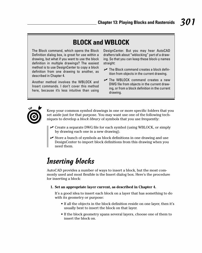
Keep your common symbol drawings in one or more specific folders that youset aside just for that purpose. You may want use one of the following tech-niques to develop a block library of symbols that you use frequently:
� Create a separate DWG file for each symbol (using WBLOCK, or simplyby drawing each one in a new drawing).
� Store a bunch of symbols as block definitions in one drawing and useDesignCenter to import block definitions from this drawing when youneed them.
Inserting blocksAutoCAD provides a number of ways to insert a block, but the most com-monly used and most flexible is the Insert dialog box. Here’s the procedurefor inserting a block:
1. Set an appropriate layer current, as described in Chapter 4.
It’s a good idea to insert each block on a layer that has something to dowith its geometry or purpose:
• If all the objects in the block definition reside on one layer, then it’susually best to insert the block on that layer.
• If the block geometry spans several layers, choose one of them toinsert the block on.
301Chapter 13: Playing Blocks and Rasteroids
BLOCK and WBLOCKThe Block command, which opens the BlockDefinition dialog box, is great for use within adrawing, but what if you want to use the blockdefinition in multiple drawings? The easiestmethod is to use DesignCenter to copy a blockdefinition from one drawing to another, asdescribed in Chapter 4.
Another method involves the WBLOCK andInsert commands. I don’t cover this methodhere, because it’s less intuitive than using
DesignCenter. But you may hear AutoCADdrafters talk about “wblocking” part of a draw-ing. So that you can keep these block-y namesstraight:
� The Block command creates a block defin-ition from objects in the current drawing.
� The WBLOCK command creates a newDWG file from objects in the current draw-ing, or from a block definition in the currentdrawing.
j571389 Ch13.qxd 4/12/04 9:45 AM Page 301

If any of the block definition’s geometry was created on layer 0, then thatgeometry will inherit the color, linetype, and other object properties ofthe layer that you insert the block on. It’s like the chameleon changingcolor to match its surroundings or a politician changing his position tomatch the day’s opinion polls.
2. Click the Insert Block button on the Draw toolbar.
The Insert dialog box appears, as shown in Figure 13-3.
3. Enter the block definition name or external filename by using one ofthe following methods:
• Use the Name drop-down list to select from a list of block definitionsin the current drawing.
• Click the Browse button to select an external DWG file and haveAutoCAD create a block definition from it.
You can use an external drawing to replace a block definition in your cur-rent drawing. If you click Browse and choose a file whose name matchesthe name of a block definition that’s already in your drawing, AutoCADwarns you and then updates the block definition in your drawing withthe current contents of the external file. This process is called blockredefinition, and as described in Steps 2 and 9 in the preceding section,AutoCAD automatically updates all the block inserts that point to theblock definition.
4. Enter the insertion point, scale, and rotation angle of the block.
You can either click the Specify On-Screen check box in each area, to spec-ify the parameters on-screen at the command prompt, or type the valuesyou want in the Insertion Point, Scale, and Rotation text boxes.
Check the Uniform Scale check box to constrain the X, Y, and Z scalingparameters to the same value (which in almost all cases you want).
Figure 13-3:The Insert
dialog box.
302 Part IV: Share and Share Alike
j571389 Ch13.qxd 4/12/04 9:45 AM Page 302
5. If you want AutoCAD to create a copy of the individual objects in theblock instead of a block insert that points to the block definition, clickthe Explode check box.
6. Click OK.
7. If you checked Specify On-Screen for the insertion point, scale, orrotation angle, answer the prompts on the command line to specifythese parameters.
After you insert a block, all the objects displayed in the block insert behaveas a single object. When you select any object in the block insert, AutoCADhighlights all the objects in it.
Another way to insert a block is to drag a DWG file’s name from WindowsExplorer and drop it anywhere in the current drawing window. AutoCAD thenprompts you to choose an insertion point and optionally change the defaultscale factor and rotation angle. Similarly, you can drag a block definition’sname from the Blocks section of the DesignCenter palette and drop it into thecurrent drawing window. (Chapter 4 describes DesignCenter.)
AutoCAD provides one additional way of inserting blocks: the Tool Palette,which is described in Chapter 2. As is true of using Tool Palette for hatching(Chapter 11), you first must create and configure appropriate tools — that is,swatches. The easiest method is right-clicking a drawing in DesignCenter andchoosing Create Tool Palette. A new page is added to the Tool Palette area con-taining all the block definitions from the drawing that you right-clicked. Simplyclick and drag a tool to insert its corresponding block into a drawing. As withhatching, you don’t get the chance to specify a different insertion scale. Youalso can’t use all of AutoCAD’s precision tools to specify the insertion pointprecisely, so you may need to move the block into place after inserting it. Irecommend that you first master the other block insertion methods describedin this chapter — especially the Insert dialog box and DesignCenter palette.Then if you find yourself inserting the same blocks frequently, consider creat-ing a Tool Palette containing them. See “tool palettes, adding drawings from” inthe AutoCAD online help system for more information.
Be careful when inserting one drawing into another. If the host (or parent)drawing and the inserted (or child) drawing have different definitions forlayers that share the same name, the objects in the child drawing takes onthe layer characteristics of the parent drawing. For example, if you insert adrawing with lines on a layer called Walls that’s blue and dashed into a draw-ing with a layer called Walls that’s red and continuous, the inserted lines onthe wall layer will turn red and continuous after they’re inserted. The samerules apply to linetypes, text styles, dimension styles, and block definitionsthat are nested inside the drawing you’re inserting.
303Chapter 13: Playing Blocks and Rasteroids
j571389 Ch13.qxd 4/12/04 9:45 AM Page 303
If you need to modify a block definition after you’ve inserted one or moreinstances of it, use the REFEDIT command (Modify➪Xref and Block Editing➪Edit Reference In-Place). Look up “REFEDIT” in the AutoCAD online helpsystem.
Attributes: Fill-in-the-blank blocksYou may think of attributes as the good (or bad) qualities of your significantother, but in AutoCAD, attributes are fill-in-the-blank text fields that you canadd to your blocks. When you create a block definition and then insert it sev-eral times in a drawing, all the ordinary geometry (lines, circles, regular textstrings, and so on) in all the instances are exactly identical. Attributes pro-vide a little more flexibility in the form of text strings that can be different ineach block insert.
For example, suppose that you frequently designate parts in your drawingsby labeling them with a distinct number or letter in a circle for each part. Ifyou want to create a block for this symbol, you can’t simply draw the numberor letter as regular text using the mText or TEXT command. If you create ablock definition with a regular text object (for example, the letter A), the textstring will be the same in every instance of the block (always the letter A).That’s not much help in distinguishing the parts!
Instead, you create an attribute definition, which acts as a placeholder for a textstring that can vary each time you insert the block. You include the attributedefinition when you create the block definition (as I demonstrate in the “Creat-ing block definitions” section earlier in this chapter). Then each time you insertthe block, AutoCAD prompts you to fill in an attribute value for each attributedefinition.
The AutoCAD documentation and dialog boxes often use the term attribute torefer indiscriminately to an attribute definition or an attribute value. I attributea lot of the confusion about attributes to this sloppiness. Just remember thatan attribute definition is the text field or placeholder in the block definition,while an attribute value is the specific text string that you type when you insertthe block.
If you’ve worked with databases, the correspondences in Table 13-1 betweenAutoCAD objects (blocks and attributes) and database terminology may helpyou understand the concept.
304 Part IV: Share and Share Alike
j571389 Ch13.qxd 4/12/04 9:45 AM Page 304
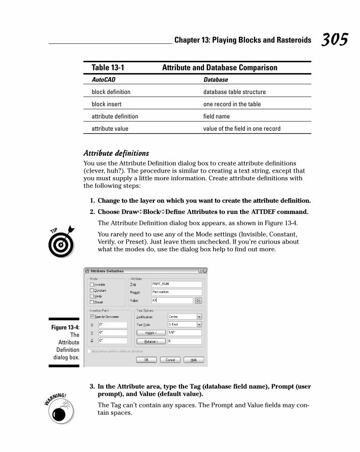
Table 13-1 Attribute and Database ComparisonAutoCAD Database
block definition database table structure
block insert one record in the table
attribute definition field name
attribute value value of the field in one record
Attribute definitionsYou use the Attribute Definition dialog box to create attribute definitions(clever, huh?). The procedure is similar to creating a text string, except thatyou must supply a little more information. Create attribute definitions withthe following steps:
1. Change to the layer on which you want to create the attribute definition.
2. Choose Draw➪Block➪Define Attributes to run the ATTDEF command.
The Attribute Definition dialog box appears, as shown in Figure 13-4.
You rarely need to use any of the Mode settings (Invisible, Constant,Verify, or Preset). Just leave them unchecked. If you’re curious aboutwhat the modes do, use the dialog box help to find out more.
3. In the Attribute area, type the Tag (database field name), Prompt (userprompt), and Value (default value).
The Tag can’t contain any spaces. The Prompt and Value fields may con-tain spaces.
Figure 13-4:The
AttributeDefinition
dialog box.
305Chapter 13: Playing Blocks and Rasteroids
j571389 Ch13.qxd 4/12/04 9:45 AM Page 305
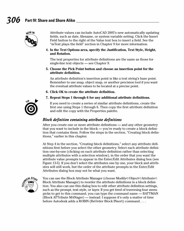
Attribute values can include AutoCAD 2005’s new automatically updatingfields, such as date, filename, or system variable setting. Click the InsertField button to the right of the Value text box to insert a field. See the“mText plays the field” section in Chapter 9 for more information.
4. In the Text Options area, specify the Justification, Text Style, Height,and Rotation.
The text properties for attribute definitions are the same as those forsingle-line text objects — see Chapter 9.
5. Choose the Pick Point button and choose an insertion point for theattribute definition.
An attribute definition’s insertion point is like a text string’s base point.Remember to use snap, object snap, or another precision tool if you wantthe eventual attribute values to be located at a precise point.
6. Click OK to create the attribute definition.
7. Repeat Steps 1 through 6 for any additional attribute definitions.
If you need to create a series of similar attribute definitions, create thefirst one using Steps 1 through 6. Then copy the first attribute definitionand edit the copy with the Properties palette.
Block definition containing attribute definitionsAfter you create one or more attribute definitions — and any other geometrythat you want to include in the block — you’re ready to create a block defini-tion that contains them. Follow the steps in the section, “Creating block defin-itions,” earlier in this chapter.
At Step 4 in the section, “Creating block definitions,” select any attribute defi-nitions first before you select the other geometry. Select each attribute defini-tion one-by-one (clicking on each attribute definition rather than selectingmultiple attributes with a selection window), in the order that you want theattribute value prompts to appear in the Enter/Edit Attributes dialog box (seeFigure 13-5). If you don’t select the attributes one by one, your block and attrib-utes will still work, but the order of the attribute prompts in the Enter/EditAttributes dialog box may not be what you want.
You can use the Block Attribute Manager (choose Modify➪Object➪Attribute➪Block Attribute Manager) to reorder the attribute definitions in a block defini-tion. You also can use this dialog box to edit other attribute definition settings,such as the prompt, text style, or layer. If you get tired of traversing four menupicks to get to this command, you can type the command name — BATTMAN(Block ATTribute MANager) — instead. I suppose it’s only a matter of timebefore Autodesk adds a ROBIN (ReOrder Block INsert) command. . . .
306 Part IV: Share and Share Alike
j571389 Ch13.qxd 4/12/04 9:45 AM Page 306
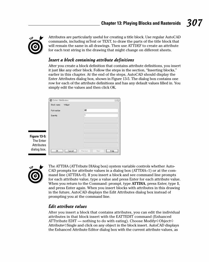
Attributes are particularly useful for creating a title block. Use regular AutoCADcommands, including mText or TEXT, to draw the parts of the title block thatwill remain the same in all drawings. Then use ATTDEF to create an attributefor each text string in the drawing that might change on different sheets.
Insert a block containing attribute definitionsAfter you create a block definition that contains attribute definitions, you insertit just like any other block. Follow the steps in the section, “Inserting blocks,”earlier in this chapter. At the end of the steps, AutoCAD should display theEnter Attributes dialog box, shown in Figure 13-5. The dialog box contains onerow for each of the attribute definitions and has any default values filled in. Yousimply edit the values and then click OK.
The ATTDIA (ATTribute DIAlog box) system variable controls whether Auto-CAD prompts for attribute values in a dialog box (ATTDIA=1) or at the com-mand line (ATTDIA=0). If you insert a block and see command line promptsfor each attribute value, type a value and press Enter for each attribute value.When you return to the Command: prompt, type ATTDIA, press Enter, type 1,and press Enter again. When you insert blocks with attributes in this drawingin the future, AutoCAD displays the Edit Attributes dialog box instead ofprompting you at the command line.
Edit attribute valuesAfter you insert a block that contains attributes, you can edit the individualattributes in that block insert with the EATTEDIT command (EnhancedATTtribute EDIT — nothing to do with eating). Choose Modify➪Object➪Attribute➪Single and click on any object in the block insert. AutoCAD displaysthe Enhanced Attribute Editor dialog box with the current attribute values, as
Figure 13-5:The EnterAttributes
dialog box.
307Chapter 13: Playing Blocks and Rasteroids
j571389 Ch13.qxd 4/12/04 9:45 AM Page 307
shown in Figure 13-6. The most common attribute editing operation is to editthe text value — that is, the text string that appears in the block insert. Youalso can change properties of the attributes, such as layer and text style.
Many people use attributes in the way I’ve described so far — as fill-in-the-blank text fields in blocks. But attributes also can serve as data extractiontools. For example, you can export attribute values, such as part numbers andquantities, to a text, spreadsheet, or database file for analysis or reporting. TheAttribute Extraction wizard (Tools➪Attribute Extraction) makes the processfairly straightforward. If you’re hungry to find out more, look up “EATTEXT(Enhanced ATTribute EXTtract) command” in the AutoCAD online help system.
Exploding blocksThe objects in each block insert act like a well-honed marching squadron: Ifyou move or otherwise edit one object in the block insert, all objects move orchange in the same way. Usually this cohesion is an advantage, but occasion-ally you need to break up the squadron in order to modify one object withoutaffecting the others.
To explode a block insert into individual objects, click Explode (the firecrackerbutton) on the Edit toolbar and then select the block insert. When you explodea block insert, AutoCAD replaces it with all the objects — lines, polylines, arcs,and so on — specified in the block definition. You then can edit the objects orperhaps use them to make more block definitions.
Don’t make a habit of exploding blocks cavalierly, especially if you’re workingin someone else’s drawing and aren’t sure why the objects are organized asblocks. Most people use blocks for a reason, and if you go around explodingthem left and right, you’re likely to be treated the same way that anyone whoblows up a lot of things gets treated.
Figure 13-6:The
EnhancedAttribute
Editor dialogbox.
308 Part IV: Share and Share Alike
j571389 Ch13.qxd 4/12/04 9:45 AM Page 308

If you explode a block that contains attributes, the attribute values changeback to attribute definitions. This usually isn’t the sort of change that you want.If you really need to explode the block insert, you’ll probably want to erasethe attribute definitions and draw regular text strings in their place. If you’veinstalled the AutoCAD Express Tools, you can perform this task automaticallywith the BURST command (Express➪Blocks➪Explode Attributes to Text).
Going ExternalIn AutoCAD, an xref, or external reference, is a reference to another, externalfile — one outside the current drawing — that you can make act as thoughit’s part of your drawing. Technically, a reference is simply a pointer from onefile to another. The xref is the actual pointer, but many people call the combi-nation of the pointer and the external file the xref.
Drawings that you include as xrefs in other drawings often are called child draw-ings. Drawings that contain pointers to the child drawings are called parentdrawings. This family terminology gets a little weird when you realize that a
309Chapter 13: Playing Blocks and Rasteroids
Purging unused block definitionsEach block definition slightly increases the sizeof your DWG file, as do other named objectssuch as layers, text styles, and dimension styles.If you delete (or explode) all the block inserts thatpoint to a particular block definition, then thatblock definition no longer serves any purpose.
You should run the PUrge command periodicallyin each drawing and purge unused block defin-itions and other named objects. Choose File➪Drawing Utilities➪Purge to display the Purgedialog box, as shown in the figure. Click thePurge All button in order to purge all unusednamed objects in the current drawing.
j571389 Ch13.qxd 4/12/04 9:45 AM Page 309

child drawing can have lots of parent drawings that refer to it — apparently it’sthe commune version of family relations. If you find such relationships odd, youcan, like the AutoCAD online help system, refer to the parent drawing as thehost drawing. I prefer the terms parent and child, in part because they’re easilyextendable to describing more complex hierarchies, such as a parent draw-ing, which xrefs a child drawing, which in turn xrefs a grandchild drawing.
Xrefs have a big advantage over blocks: If you change a child drawing, AutoCADautomatically loads the change into all the parent drawings that reference thechild drawing.
AutoCAD loads all xrefs into the parent drawing each time the parent drawingis opened. If the child drawing has been changed, AutoCAD automaticallyincorporates those changes into the parent drawing.
When you open a drawing containing xrefs, AutoCAD 2004 displays a littlesymbol (which looks like papers with a binder clip) on the right end of thestatus bar. This symbol alerts you to the fact that some of the things you seein the drawing are actually parts of other, xrefed drawings. If an xref changeswhile you have the parent drawing open (because you or someone else opensand saves the child drawing), the status bar xref symbol displays an ExternalReference Files Have Changed balloon notification. (If you want to changewhether the notifications appear and how often AutoCAD checks for changes,look up XREFNOTIFY and XNOTIFYTIME in the online help.) You can use theReload option in the Xref Manager dialog box to show the updated xrefs. Seethe “Managing xrefs” section later in this chapter for details.
Another advantage of xrefs over blocks is that their contents aren’t stored inyour drawing even once. The disk storage space taken up by the original draw-ing (that is, the xref) isn’t duplicated, no matter how many parent drawings ref-erence it. This characteristic makes xrefs much more efficient than blocks forlarger drawings that are reused several times.
But you can always buy more hard disk space, so the storage issue isn’t cru-cial. The key benefit of xrefs is that they enable you to organize your drawingsin a modular way so that changes you make to a single drawing file automati-cally “ripple through” all the parent drawings to which it’s xrefed. This benefitis even greater on larger projects involving multiple drafters, each of whosework may be incorporated in part or in whole in the work of others.
The automatic update feature of xrefs is a big advantage only if you’re orga-nized about how you use xrefs. Suppose that an architect creates a plan draw-ing showing a building’s walls and other major features that are common tothe architectural, structural, plumbing, and electrical plan drawings. The archi-tect then tells the structural, plumbing, and electrical drafters to xref this back-ground plan into their drawings, so that everyone is working from a consistentand reusable set of common plan elements. If the architect decides to revise
310 Part IV: Share and Share Alike
j571389 Ch13.qxd 4/12/04 9:45 AM Page 310

the wall locations and updates the xrefed drawing, everyone will see the cur-rent wall configuration and be able to change their drawings. But if the archi-tect absent-mindedly adds architecture-specific objects, such as toilets andfurniture, to the xrefed drawing, or shifts all the objects with respect to 0,0,everyone else will have problems. If different people in your office share xrefs,create a protocol for who is allowed to modify which file when, and what com-munication needs to take place after a shared xref is modified.
Becoming attached to your xrefsAttaching an external reference is similar to inserting a block, and almost aseasy. Just use the following steps:
1. Set an appropriate layer current, as described in Chapter 4.
I recommend that you insert xrefs on a separate layer from all otherobjects. Note that if you freeze the layer an xref is inserted on, the entirexref disappears. (This behavior can be either a handy trick or a nastysurprise.)
2. Choose Insert➪Xref Manager from the menu bar to start the XRefcommand.
The Xref Manager dialog box appears (see Figure 13-7).
Don’t choose Insert➪External Reference. This menu choice jumps aheadto Step 4, which will be confusing at this point.
3. Click Attach.
The Select Reference File dialog box appears.
Figure 13-7:The Xref
Managerdialog box.
311Chapter 13: Playing Blocks and Rasteroids
j571389 Ch13.qxd 4/12/04 9:45 AM Page 311

4. Browse to find the file you want to attach, select it, and then click Open.
The External Reference dialog box appears.
5. Specify the parameters for the xref in the dialog box.
Parameters include the insertion point, scaling factors, and rotation angle.You can set these parameters in the dialog box or specify them on-screen,just as you can do when inserting a block, as described earlier in thischapter.
You can choose the Attachment or Overlay radio button to tell AutoCADhow to handle the xref. The choice matters only if you create a drawingthat uses xrefs, and then your drawing is in turn used as an xref. Attach-ment is the default choice, and it means that the xrefed file will alwaysbe included with your drawing when someone else uses your drawing asan xref. Overlay, the other choice, means that you see the xrefed draw-ing, but someone who xrefs your drawing won’t see the overlaid file. Bychoosing Overlay, you can xref in a map, for example, to your drawing ofa house, but not have the map show up when someone else xrefs yourhouse drawing. (That person can xref the map, if need be.) I recommendthat you use the default Attachment reference type unless you have aspecific reason to do otherwise.
The Path Type drop-down list provides more flexibility in how the xref’spath gets stored. See the “Forging an xref path” section later in thischapter for more information. For now, I recommend that you chooseRelative path instead of the default Full path.
6. Click OK.
The externally referenced file appears in your drawing.
Layer-paloozaWhen you attach or overlay an xref, AutoCAD adds new layers to your currentdrawing that correspond to the layers in the xrefed DWG file. The new layersare assigned names that combine the drawing name and layer name; forexample, if you xref the drawing MYSCREW.DWG, which has the layer namesGEOMETRY, TEXT, and so on, the xrefed layers will be named MYSCREW|GEOMETRY, MYSCREW|TEXT, and so on. By creating separate layers corre-sponding to each layer in the xrefed file, AutoCAD eliminates the potentialproblem I warned you about with blocks when layers have the same namebut different color or linetype in the two drawings.
AutoCAD also creates new linetypes, text styles, dimension styles, and block definitions for each of these items in the xrefed file — for example,MYSCREW|DASHED, MYSCREW|NOTES, MYSCREW|A-DIMS, andMYSCREW|LOGO.
312 Part IV: Share and Share Alike
j571389 Ch13.qxd 4/12/04 9:45 AM Page 312

Creating and editing an external reference fileTo create a file that you can use as an external reference, just create a drawingand save it (or use the WBLOCK command to create a new DWG from geometryin the current drawing). That’s it. You then can create or open another drawingand create an external reference to the previous one. The xrefed drawingappears in your parent drawing as a single object, like a block insert. In otherwords, if you click any object in the xref, AutoCAD selects the entire xref. Youcan measure or object snap to the xrefed geometry, but you can’t modify ordelete individual objects in the xref — you open the xref drawing in order toedit its geometry.
AutoCAD 2004’s XOPEN command (Modify➪Xref and Block Editing➪OpenReference) provides a quick way to open an xrefed drawing for editing. Youjust start the command and pick on any object in the xref. Alternatively, youcan use the Open button in the Xref Manager dialog box to open one or morexrefs for editing. See the “Managing xrefs” section later in this chapter formore information.
An alternative to opening the xrefed file when you need to edit it is to use theREFEDIT command (Modify➪Xref and Block Editing➪Edit Reference In-Place).Look up “REFEDIT” in the AutoCAD online help system.
Forging an xref pathWhen you attach an xref, AutoCAD by default stores the xref’s full path — thatis, the drive letter and sequence of folders and subfolders in which the DWGfile resides, along with the filename. This default behavior corresponds to theFull path setting in the Path Type drop-down list. (Figure 13-8 shows thethree xref path options.) Full path works fine as long as you never move fileson your hard disk or network and never send your DWG files to anyone else —which is to say, it almost never works fine!
At the other end of the path spectrum, the No path option causes AutoCADnot to store any path with the xref attachment — only the filename is stored.This is the easiest and best option if the parent and child drawings reside inthe same folder.
If you prefer to organize the DWG files for a particular project in more then onefolder, then you’ll appreciate AutoCAD’s Relative path option, shown inFigure 13-8. This option permits xrefing across more complex, hierarchicalfolder structures, but avoids many of the problems that Full path can cause.
313Chapter 13: Playing Blocks and Rasteroids
j571389 Ch13.qxd 4/12/04 9:45 AM Page 313

For example, you may have a parent drawing H:\Project-X\Plans\First floor.dwgthat xrefs H:\Project-X\Common\Column grid.dwg. If you choose Relativepath, AutoCAD will store the xref path as ..\ Common\Column grid.dwginstead of H:\Project-X\Common\Column grid.dwg. Now if you decide tomove the \Project-X folder and its subfolders to a different drive (or sendthem to someone else who doesn’t have an H: drive), AutoCAD will still beable to find the xrefs.
When you use Relative path, you’ll see xref paths that include the specialcodes . and .. (single and double period). The single period means “thisparent drawing’s folder” and the double period means “the folder above this parent drawing’s folder” (in other words, the folder of which the parentdrawing’s folder is a subfolder).
You can report on and change xref paths for a set of drawings with theAutoCAD Reference Manager. See Chapter 16 for more information.
If all these path options and periods have got you feeling punchy, you cankeep your life simple by always keeping parent and child drawings in the samefolder and using the No path option when you attach xrefs.
Managing xrefsThe Xref Manager dialog box includes many more options for managing xrefsafter you attach them. Important dialog box options include:
Figure 13-8:Chart yourpath whenyou attach
an xref.
314 Part IV: Share and Share Alike
j571389 Ch13.qxd 4/12/04 9:45 AM Page 314
� List of external references: You can change between a List and a Treeview of your drawing’s external references just by clicking the appropri-ate button at the top of the dialog box. You also can resize the columnsby dragging the column dividers or re-sort the list by clicking the columnheader names, just as in other Windows dialog boxes.
� Detach: Completely removes the selected reference to the external filefrom your drawing.
� Reload: Causes AutoCAD to reread the selected xrefed DWG file from thedisk and update your drawing with its latest contents. This feature ishandy when you share xrefs on a network and someone has just madechanges to a drawing that you’ve xrefed.
� Unload: Makes the selected xref disappear from the on-screen displayof your drawing and from any plots you do of it, but retains the pointerand attachment information. Use the Reload button to redisplay anunloaded xref.
� Bind: Brings the selected xref into your drawing and makes it a block.You might use this function, for example, to “roll up” a complex set ofxrefs into a single archive drawing.
In many offices, binding xrefs without an acceptable reason for doing sois a crime as heinous as exploding blocks indiscriminately. In both cases,you’re eliminating an important data management link. Find out whatthe policies are in your company. When in doubt, keep yourself out of abind. And even when you do have a good reason to bind, you generallyshould do it on a copy of the parent drawing.
� Open: Opens one or more xref drawings in separate drawing windowsafter you close the Xref Manager dialog box. After you edit and save anxref drawing, return to the parent drawing and use the Reload option inthe Xref Manager dialog box to show the changes.
None of these options (other than opening and editing the xref) affects thexrefed drawing itself; it continues to exist as a separate DWG file. If you need todelete or move the DWG file that the xref refers to, do it in Windows Explorer.
The fact that the xrefed drawing is a separate file is a potential source of prob-lems when you send your drawing to someone else; that someone else needsall the files that your drawing depends on, or it will be useless to the receivingparty. Make sure to include xrefed files in the package with your drawing. SeeChapter 16 for a procedure.
AutoCAD (but not AutoCAD LT) includes an additional xref feature called xrefclipping. You can use the XCLIP command to clip an externally referenced fileso only part of it appears in the parent drawing. AutoCAD LT doesn’t includethe XCLIP command, but if you open a drawing containing an xref that wasclipped in AutoCAD, the clipped view will be preserved.
315Chapter 13: Playing Blocks and Rasteroids
j571389 Ch13.qxd 4/12/04 9:45 AM Page 315

Blocks, Xrefs, and Drawing OrganizationBlocks and xrefs are useful for organizing sets of drawings to use and updaterepeated elements . It’s not always clear, though, when to use blocks andwhen to use xrefs. Applications for xrefs include
� The parts of a title block that are the same on all sheets in a project.
� Reference elements that need to appear in multiple drawings (for exam-ple, wall outlines, site topography, column grids).
� Assemblies that are repeated in one or more drawings, especially if the assemblies are likely to change together (for example, repeatedframing assemblies, bathroom layouts, modular furniture layouts).
� Pasting up several drawings (for example, details or a couple of plans)onto one plot sheet.
� Temporarily attaching a background drawing for reference or tracing.
On the other hand, blocks remain useful in simpler circumstances. Situationsin which you might stick with a block are:
� Components that aren’t likely to change.
� Small components.
� A simple assembly that’s used repeatedly, but in only one drawing. (Youcan easily update a block in one drawing with the REDEFIT command.)
� When you want to include attributes (variable text fields) that you can fillin each time you insert a block. Blocks let you include attribute defini-tions; xrefs don’t.
Everyone in a company or workgroup should aim for consistency in whenand how they use blocks and xrefs. Check whether guidelines exist for usingblocks and xrefs in your office. If so, follow them; if not, it would be a goodidea to develop some guidelines. Chapter 15 discusses how to start suchguidelines.
Mastering the RasterAutoCAD includes another xreflike feature: the ability to attach raster imagesto drawings. This feature is useful for adding a raster logo to a drawing titleblock or placing a photographed map or scene behind a drawing. A raster, orbitmapped, image is one that’s stored as a field of tiny points.
316 Part IV: Share and Share Alike
j571389 Ch13.qxd 4/12/04 9:45 AM Page 316

Most AutoCAD drawings are vector images. A vector image is an image definedby storing geometrical definitions of a bunch of objects. Typical objects includea line, defined by its two endpoints, and a circle, defined by its center point andradius. Vector-based images are typically smaller (in terms of the disk spacethey occupy) and more flexible than raster images, but also are less capable ofdisplaying visually rich images such as photographs.
Raster images often come from digital cameras or other programs, such asPhotoshop. Raster images also can come into the computer from some kindof scanner that imports a blueline print, photograph, or other image.
Whether you’re doing your scanning yourself or having a service bureau do itfor you, you need to know that AutoCAD handles most of the popular image fileformats including the Windows BMP format, the popular Web graphics formatsGIF and JPEG, the popular PCX and TIFF formats, as well as DIB, FLC, FLI, GP4,MIL, PNG, RLE, RST, and TGA.
Here are three scenarios to incorporate raster images in your drawing:
� Small stuff: You can add logos, special symbols, and other small imagesthat you have in raster files.
� Photographs and maps: You can add photographs (such as a future build-ing site) and maps (for example, showing the project location).
� Vectorization: To convert a raster image into a vector drawing by tracinglines in the raster image, you can attach the raster image in your draw-ing, trace the needed lines by using AutoCAD commands, then detach theraster image. (This procedure is okay for a simple raster image; add-onsoftware is available, from Autodesk and others, to support automatic orsemiautomatic vectorization of more complex images.)
Using raster images is much like using external references. The raster imageisn’t stored with your drawing file; a reference to the raster image file isestablished from within your drawing, like an xref. You can clip the image andcontrol its size, brightness, contrast, fade, and transparency. These controlsfine-tune the appearance of the raster image on-screen and on a plot.
When you attach raster images, you have to make sure that you send theraster files along when you send your drawing to someone else.
AutoCAD LT can open, view, and plot drawings containing attached rasterimages, but LT can’t do the attaching. Raster masters require full AutoCAD.
317Chapter 13: Playing Blocks and Rasteroids
j571389 Ch13.qxd 4/12/04 9:45 AM Page 317

Attaching an imageFollow these steps to bring a raster image into AutoCAD:
1. Choose Insert➪Image Manager from the menu bar or type IMage at thecommand line to start the IMage command.
The Image Manager dialog box appears (see Figure 13-9).
2. Click the Attach button.
The Select Image File dialog box appears.
3. Browse to find the file you want to attach, select it, then click Open.
The Image dialog box appears.
Click the Details button in the Image dialog box to see more informationabout the resolution and image size of the image you’re attaching.
4. Specify the parameters for the attached image in the dialog box.
Parameters include the insertion point, scale factor, and rotation angle.You can set these parameters in the dialog box or specify them on-screen,similar to what you can do with blocks and external references, asdescribed earlier in this chapter. Use the quick dialog box help (click thequestion mark in the dialog box’s title bar and then click the area in thedialog box for which you want help) or click the dialog box’s Help buttonto find out more about specific options.
The AutoCAD 2005 IMage command includes the same Full path,Relative path, and No path options that debuted for xrefs inAutoCAD 2004. (See “Forging an xref path” earlier in this chapter.)
Figure 13-9:The Image
Managerdialog box.
318 Part IV: Share and Share Alike
j571389 Ch13.qxd 4/12/04 9:45 AM Page 318
5. Click OK.
The image appears in your drawing.
6. If you need to ensure that the raster image floats behind other objectsin the drawing, select the raster image, right-click, choose Draw Order,and then choose Send to Back.
The DRaworder command provides additional options for which objectsappear on top of which other objects. If you need this kind of flexibility,look up “DRAWORDER command” in the AutoCAD online help system.
Managing imagesYou manage the images in your drawing with the Image Manager dialog box.It includes virtually the same options as the External References dialog box.You can view a list of image files that appear in the current drawing, detach(remove) image references, and unload and reload images when needed. Youcan’t bind an image to your drawing; it always remains an external file.
You can clip images so that only part of the image is displayed in your draw-ing. Choose Modify➪Clip➪Image and follow the prompts to clip the image. Youcan have multiple overlapping or distinct pieces of any number of images inyour drawing, and only the parts you need are loaded into memory when youhave your drawing open.
Raster image files often are larger than DWG files of corresponding complex-ity; raster file size can affect performance within AutoCAD, because the rasterfile loads into memory when you are working on your drawing. Some work-arounds speed up operations:
� Attach raster images late in the production process.
� Create a lower-resolution version of the raster file, just large enough tocreate the desired effect in your drawing.
� Use the Unload button in the Image Manager dialog box to temporarilydisable an image without losing the attachment information.
In addition, raster files can increase the time that AutoCAD takes to generateplots (and the plot file sizes) dramatically. Before you settle on using largeraster files in your AutoCAD drawing, do some testing on zooming, editing,and plotting.
319Chapter 13: Playing Blocks and Rasteroids
j571389 Ch13.qxd 4/12/04 9:45 AM Page 319

320 Part IV: Share and Share Alike
j571389 Ch13.qxd 4/12/04 9:45 AM Page 320

Chapter 14
Sheet Sets without RegretsIn This Chapter� Understanding resource drawings, views, and sheets
� Creating and using sheet sets
� Adding drawings and assembling views
� Adding a sheet list table
A typical AutoCAD project can include dozens of drawings, scores ofsheets, lots of layouts, copious cross-drawing references, and more than
a few people working on those components at once. How do you create,manage, update, plot, and generally keep a handle on all that stuff withoutgoing crazy? The new sheets sets feature in AutoCAD 2005 is Autodesk’sresponse to this challenge.
Without sheet sets, you must manage project drawings “manually” — that is,you have to make sure that all the project’s drawings get created, get num-bered and named correctly, and have up-to-date title block information. Youalso have to ensure that cross-sheet references are accurate (for example,when a plan includes references to details on other sheets). When the timecomes to send drawings to clients or consultants, you must ensure that youinclude all the sheets and that all of them are up-to- date. For a large projectwith many drawings, these can be daunting tasks. It’s easy to end up withmissing sheets or sheets that contain obsolete title block or cross-referenceinformation, especially when you add or renumber sheets later in a project.
Sheet sets comprise a new palette, a group of completely new commands, anda few updated existing features. Together these things make possible a newapproach to managing all the drawings for a project. Sheet sets provide a singleinterface that lists all your sheets, their numbers, and their names. (AutoCADstores this information, along with the relationships among the sheets, in a DSTfile.) You can add and renumber sheets easily. You can create cross-sheet refer-ences that update automatically after you renumber sheets, and you can createa sheet list on your title sheet that updates automatically after you changesheet numbers or titles. When you’re ready to send or plot drawings, a sheetset enables AutoCAD to locate and gather all the required files.
j571389 Ch14.qxd 4/12/04 9:45 AM Page 321

Because the sheet sets approach is brand new, it remains to be seen howquickly (or whether) AutoCAD users adopt it. My prediction is that companieswith well-managed CAD production staffs that work on larger projects requir-ing lots of sheets will find sheet sets compelling and move to adopt themquickly. Companies whose projects require only a few drawing sheets or whoseAutoCAD users tend to do their own thing with little central organization prob-ably will continue to deal with sheets as discreet, unconnected DWG files.
Sheet sets rely on other relatively sophisticated AutoCAD features, so makesure that you’re familiar with the following before you delve into this chapter:
� Paper space layouts (Chapter 3)
� Named views (Chapter 7)
� Tables and text fields (Chapter 9)
� Blocks and attributes (Chapter 13)
� External references (Chapter 13)
Understanding external references and layouts is especially important becausethese features are central to the way that the Sheet Set Manager creates andorganizes sheets.
Taming Sheet SetsYour passport to the brave new world of sheet sets comes in the form of theSheet Set Manager palette, shown in Figure 14-1. You use this palette for mostsheet set operations. To toggle the palette on or off, click the Sheet SetManager button (which looks like a roll of drawings) on the Standard toolbaror press Ctrl+4. If you choose to leave the palette on most of the time, youmay want to turn on its auto-hide setting so that it gets out of the way auto-matically when you’re not using it — refer to Chapter 2 for instructions.
The Sheet Set Manager palette’s three tabs indicate the three major types ofobjects you use to create and manage sheet sets:
� Resource Drawings contain subcomponents such as individual plans,details, and elevations that you use to build your sheets. Resource draw-ings usually contain geometry and annotations in model space only.Resource drawings usually don’t include title blocks or paper space lay-outs. You must add DWG files to the Resource Drawings tab before youcan create Views and add them to Sheets.
� Views are areas of resource drawings that you place on a sheet. A sheetset view can be the entire resource drawing or just a portion of it thatyou’ve defined, using the AutoCAD named views feature. (Chapter 7explains named views and shows how to create them.)
322 Part IV: Share and Share Alike
j571389 Ch14.qxd 4/12/04 9:45 AM Page 322

You don’t have to use named views in order to take advantage of sheetsets, but you may use them to assemble different areas of a resourcedrawing onto one or more sheets. For example, if you draw a large planthat needs to be broken up onto several sheets in order to plot at a legi-ble scale, you define a named view for each area of the plan and placeeach view on a separate sheet.
� Sheets are paper space layouts within drawing files. (Chapter 3 describeslayouts and shows how to create them.) Each sheet corresponds to onesheet in the sheet set. With the sheet set methodology, AutoCAD attachesresource drawings as xrefs into sheet drawings and creates paper spaceviewports on a layout in order to show the desired area of the resourcedrawing — either a named view or the entire drawing. You use the SheetSet Manager to tell AutoCAD which resource drawings and views to puton which sheets. AutoCAD then does the attach-xref-and-make-viewportprocedure automatically.
AutoCAD stores the settings for all this stuff — the names of files and configu-ration data that control how the sheet set features work with those files — ina DST file. Each project has its own DST file, and multiple AutoCAD users canuse one project’s DST file at the same time.
Using an Existing Sheet SetThe quickest way to get started with sheet sets is to use one that someoneelse — such as a CAD manager in your office — has set up. You also can
Figure 14-1:The Sheet
SetManager
palette.
323Chapter 14: Sheet Sets without Regrets
j571389 Ch14.qxd 4/12/04 9:45 AM Page 323

experiment with Autodesk’s sheet set samples, located under C:\ProgramFiles\AutoCAD Neo\Sample\Sheet Sets.
To open an existing sheet set configuration, do one of the following:
� Click the menu at the top of the Sheet Set Manager palette and chooseOpen. AutoCAD displays a file dialog box, in which you can navigate tothe appropriate folder, select the sheet set data file, and click the Openbutton.
� In Windows Explorer, double-click on a DST file.
In either case, AutoCAD displays the sheet set information in the Sheet SetManager palette, as shown in Figure 14-1. Click each of the three tabs to getan idea of how the particular sheet set that you opened is configured.
With a sheet set open, you’re ready to perform tasks such as these:
� Double-click a name on any of the tabs to open the corresponding DWGfile in AutoCAD. Double-clicking a sheet name on the Sheet List tab or adrawing name on the Resource Drawings tab opens that DWG file, whiledouble-clicking a view name on the View List tab opens the DWG file andzooms to the view. Thus, you can use the Sheet Set Manager to navigatequickly among all the drawings for a project.
� Right-click the sheet set name or a sheet subset name on the Sheet Listtab to create a new sheet, using the template drawing (DWT file) config-ured for the project or sheet subset. (The “Getting Your Sheets Together”section, later in this chapter, describes how to specify the DWT file for asheet set or subset.)
� Right-click a resource drawing to place it — either the entire drawing ora named view within it — on a sheet drawing.
� Right-click a sheet or view to rename and renumber it. Names and num-bers can be linked to labels on the sheets, so that when you change thenames or numbers in the Sheet Set Manager, AutoCAD automaticallyupdates them in all drawings where they appear. (See the next two para-graphs for more information.)
� Right-click the sheet set name to add a sheet list table (that is, an indexof the drawings for the project) to the current drawing. AutoCAD usesthe name and number data described in the preceding paragraph tocreate the sheet table list and keep it current.
� On the View List tab, right-click the sheet set name and choose Propertiesto specify label blocks and callout blocks. Then you can right-click viewnames to place these automatically updating blocks in drawings. Labelblocks show the number and name of a part of a drawing (for example, asingle detail or a plan). Callout blocks reference another part of the draw-ing set — usually on another sheet (for example, a pointer on a plan to anelevation or detail on a different sheet).
324 Part IV: Share and Share Alike
j571389 Ch14.qxd 4/12/04 9:45 AM Page 324

� Right-click sheets or subsets to publish (that is, plot) them, packagethem for electronic transmittal, or archive them for yourself. (Chapter 16includes instructions for these tasks.)
The rest of this chapter provides details and procedures for many of theseoperations.
You don’t have to use all the features described earlier in order to benefitfrom sheet sets. For example, you might use the Sheet Set Manager just tocreate a navigational list of your drawings, add a sheet index to the coversheet of the drawing set, and batch plot all the sheets.
The Sheet Set SetupIf you don’t have an obliging CAD manager to configure sheets sets for you,then you’ll have to do it yourself. You use the Create Sheet Set wizard for thistask. Follow these steps to create a new sheet set:
1. Open the menu at the top of the Sheet Set Manager palette and chooseNew Sheet Set.
The Create Sheet Set wizard appears.
2. Choose Create a Sheet Set Using Existing Drawings, and then clickNext.
The Sheet Set Details page appears, as shown in Figure 14-2.
Figure 14-2:Sheet Set
Details.
325Chapter 14: Sheet Sets without Regrets
j571389 Ch14.qxd 4/12/04 9:45 AM Page 325

3. Type a name and description for the sheet set, and choose a directoryfor the DST (sheet set configuration data) file.
By default, AutoCAD stores DST files that you create in your local MyDocuments\AutoCAD Sheet Sets folder. Unless you’re the only personworking on a project, you should instead put DST files in a commonlyaccessible place on your local network. You can store the DST files forall projects in a single network folder or simply keep each project’s DSTfile in the same folder that holds the project’s DWG files.
4. Click the Sheet Set Properties button, review the other settings, andclick OK.
You can change all this stuff later in the Sheet Set Manager palette, sodon’t worry too much about it now. Use the dialog box help (click thequestion mark and then click on a setting) to find out more about any ofthe settings.
5. Click Next.
The Choose Layouts page appears. You can click the Browse button toadd any drawing(s) that you’ve already created for the project to thesheet set, but it’s just as easy to add them later in the Sheet Set Managerpalette. (I show you how in the next section.)
6. Click Next.
The wizard displays a summary of the settings that it saved to the newDST file.
7. Click Finish.
AutoCAD closes the Create Sheet Set wizard and opens your new sheetset in the Sheet Set Manager palette.
The other way to create a new sheet set is to copy one from an existing DSTfile. If you choose Create a Sheet Set Using An Example Sheet Set in Step 2,then you can choose from half a dozen Autodesk samples or open a filedialog box and browse to other DST files. The Autodesk examples are fine forexperimenting, but you will need to modify them in order to make themusable on real projects.
To change any of the sheet set properties (which you reviewed in Step 5above), right-click the sheet set name on the Sheet List tab of the Sheet SetManager palette and choose Properties.
Getting Your Sheets TogetherA new sheet set without any sheets is a lonely thing indeed, so after you createa new sheet set, you’ll need to populate the set with drawings. A common wayto get started is to create a drawing with a suitable layout and title block in
326 Part IV: Share and Share Alike
j571389 Ch14.qxd 4/12/04 9:45 AM Page 326

paper space and then add it to the set. The other method is to direct the SheetSet Manager to create a new drawing, using the template and folder that’s con-figured in the sheet set properties. I cover both methods here.
Adding existing sheets to a setUse these steps to add an existing drawing to the sheet set for a project:
1. Create and save at least one properly set up drawing, including apaper space layout. (See Chapter 3 for details.)
If you delete any unused layout tabs (right-click the tab and chooseDelete), the sheet list will turn out cleaner and less confusing. Whenyou’re using sheet sets, it’s usually best to set up and use just one layoutper drawing file.
2. Open the Sheet Set Manager palette.
3. (Optional) On the Sheet List tab of the Sheet Set Manager palette,right-click the sheet set name and choose New Subset. Type a subsetname and click OK.
You can use sheets subsets to group your sheets into categories. See the“Sheet subsets” section after these steps for an explanation and examples.
This isn’t your only chance to assign a sheet to a subset. You can createthe subset later and then drag the sheet into it.
4. Right-click the sheet set name (or the subset name that you created inthe previous step) and choose Import Layout as Sheet.
The Import Layouts as Sheets dialog box appears.
5. Click the browse button (the one with an ellipsis on it).
6. Navigate to and select the drawing that you created in Step 1, andthen click Open.
AutoCAD will report an error if you try to import a drawing that doesn’tcontain any configured layouts.
7. Select one or more layouts to import into the Sheet List and click OK.
AutoCAD adds the layout(s) to the Sheet List, as shown in Figure 14-3.The sheet name is a combination of the DWG file name (S-sheet-plans-01in this figure) and layout name (30x42).
8. Right-click the newly imported sheet and choose Rename andRenumber.
The Rename and Renumber Sheet dialog box appears.
327Chapter 14: Sheet Sets without Regrets
j571389 Ch14.qxd 4/12/04 9:45 AM Page 327
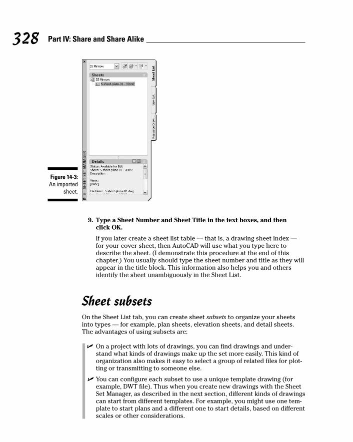
9. Type a Sheet Number and Sheet Title in the text boxes, and then click OK.
If you later create a sheet list table — that is, a drawing sheet index —for your cover sheet, then AutoCAD will use what you type here todescribe the sheet. (I demonstrate this procedure at the end of thischapter.) You usually should type the sheet number and title as they willappear in the title block. This information also helps you and othersidentify the sheet unambiguously in the Sheet List.
Sheet subsetsOn the Sheet List tab, you can create sheet subsets to organize your sheetsinto types — for example, plan sheets, elevation sheets, and detail sheets.The advantages of using subsets are:
� On a project with lots of drawings, you can find drawings and under-stand what kinds of drawings make up the set more easily. This kind oforganization also makes it easy to select a group of related files for plot-ting or transmitting to someone else.
� You can configure each subset to use a unique template drawing (forexample, DWT file). Thus when you create new drawings with the SheetSet Manager, as described in the next section, different kinds of drawingscan start from different templates. For example, you might use one tem-plate to start plans and a different one to start details, based on differentscales or other considerations.
Figure 14-3:An imported
sheet.
328 Part IV: Share and Share Alike
j571389 Ch14.qxd 4/12/04 9:45 AM Page 328

� You can configure each subset to create new sheet drawings in differentfolders. For example, you might keep your plan sheets and detail sheetsin two different folders.
To configure both of the second two options, right-click the subset name andchoose Properties.
Don’t confuse sheet subsets with sheet selections. You create the latter withthe Sheet Selections button at the top of the Sheet List tab. A sheet selectionis simply a grouping of sheets with a name attached to it. You can use sheetselections to grab a group of sheets quickly for transmitting, archiving, orpublishing. (Chapter 16 describes these activities.) Sheet selections don’tstore any configuration information and don’t affect the organization of theSheet List. Sheet subsets do both of those things.
Creating new sheets for a setUse the following steps to create a new sheet drawing, using the configura-tion settings for the sheet set:
1. (Optional) On the Sheet List tab of the Sheet Set Manager palette,right-click the sheet set name and choose New Subset. Type a subsetname and click OK.
2. Right-click the sheet set name or subset name and choose Properties.
The Sheet Set Properties dialog box appears.
3. Verify or change the Sheet Creation properties, and then click OK.
Sheet Storage Location determines where the new sheet DWG file willget created, and Sheet Creation Template specifies the DWT file that itgets created from.
4. Right-click the sheet set name or subset name and choose New Sheet.
The New Sheet dialog box appears, as shown in Figure 14-4.
Figure 14-4:Creating a
new sheet.
329Chapter 14: Sheet Sets without Regrets
j571389 Ch14.qxd 4/12/04 9:45 AM Page 329

5. Type a Sheet Number, Sheet Title, and File Name in the text boxes,and then click OK.
The previous procedure describes what the Sheet Number and Sheet Titleare for. File Name determines the name of the DWG file that AutoCAD cre-ates. AutoCAD generates the default file name by combining the sheetnumber and sheet title. You probably want to remove the sheet numberfrom this automatically generated name, for the reasons described in thefollowing Tip.
Don’t type .DWG in the File Name box. AutoCAD always adds the file extension,so if you type .DWG, AutoCAD will create a file named Whatever.Dwg.Dwg.
If you anticipate ever having to renumber sheets on your project — and evenif you don’t anticipate it, it may happen! — you should name your sheet filesbased on their general contents rather than their (current) sheet numbers.For example, when you create an architectural floor plan that you anticipatewill be sheet A-201, name the sheet file A-FP01.dwg (first floor plan in theseries) instead of A-201.dwg. By giving sheet files names that are independentof their sheet numbers, you retain the flexibility to renumber sheets automat-ically later with just a few changes in the Sheet Set Manager.
Assembling sheet views from resource drawingsAfter you create a new sheet (or add an existing one that doesn’t yet containall the necessary drawing components), you use the Resource Drawing tab tocompose views on the sheet. A view can be simply the entire drawing, or itcan be a named view that you’ve created in the resource drawing. In all cases,the Sheet Set Manager attaches the resource drawing as an xref to the sheetdrawing and creates a properly scaled viewport on the sheet drawing’s layout.Each sheet can contain one view (for example, a large plan) or more than one(for example, several elevations or a dozen details).
To place an entire resource drawing on a sheet, follow these steps:
1. On the Sheet List tab of the Sheet Set Manager palette, double-clickthe sheet to which you want to add the resource drawing.
AutoCAD opens the drawing for editing.
2. Click the Resource Drawings tab.
3. If you haven’t yet specified the folder that contains the resource draw-ing that you want to use, double-click Add New Location, browse tothe directory, and click the Open button.
330 Part IV: Share and Share Alike
j571389 Ch14.qxd 4/12/04 9:45 AM Page 330
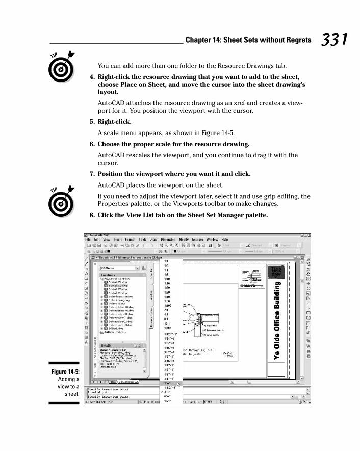
You can add more than one folder to the Resource Drawings tab.
4. Right-click the resource drawing that you want to add to the sheet,choose Place on Sheet, and move the cursor into the sheet drawing’slayout.
AutoCAD attaches the resource drawing as an xref and creates a view-port for it. You position the viewport with the cursor.
5. Right-click.
A scale menu appears, as shown in Figure 14-5.
6. Choose the proper scale for the resource drawing.
AutoCAD rescales the viewport, and you continue to drag it with thecursor.
7. Position the viewport where you want it and click.
AutoCAD places the viewport on the sheet.
If you need to adjust the viewport later, select it and use grip editing, theProperties palette, or the Viewports toolbar to make changes.
8. Click the View List tab on the Sheet Set Manager palette.
Figure 14-5:Adding aview to a
sheet.
331Chapter 14: Sheet Sets without Regrets
j571389 Ch14.qxd 4/12/04 9:45 AM Page 331

AutoCAD has added the resource drawing that you just used to the listof views for this sheet set.
9. Right-click the new view name and choose Rename and Renumber.
The Rename and Renumber Sheet dialog box appears, as shown inFigure 14-6.
10. Type a View Number and View Title in the text boxes, and then click OK.
As I describe earlier in this chapter, you can direct the Sheet Set Managerto use this information to create automatically updating labels. For exam-ple, if you place a detail on a sheet, AutoCAD feeds the information in thisdialog box to a label block in the sheet drawing that shows the detailnumber and title. In addition, you can create callouts on other sheets thatrefer to this detail. If you later change the information in this dialog box,the Sheet Set Manager changes it in the detail label as well as in the call-outs that reference the detail. (You create label and callout blocks in sepa-rate drawings, as described in Chapter 13. You then right-click the sheetset name or a view name and choose Properties to configure the sheet setor view to use these blocks.) Look up “callout blocks (for sheet views)”and “label blocks (for sheet views)” in the AutoCAD online help systemfor detailed instructions.
Figure 14-6:Specifying
a view’snumber
and title.
332 Part IV: Share and Share Alike
j571389 Ch14.qxd 4/12/04 9:45 AM Page 332
After you specify callout and label blocks on the View List tab, use the view’sright-click menu to place either kind of block.
On the View List tab, you can create view categories by right-clicking the sheetset name and choosing New View Category. Each view category can use differ-ent callout blocks — right-click the view category and choose Properties toconfigure callout blocks.
Placing a named view on a layout is just like placing an entire resource draw-ing, except that on the Resource Drawing tab you click the plus sign next tothe drawing name to reveal its named views, right-click the desired view, andchoose Place on Sheet. (If you haven’t yet created the named view that youneed, open the drawing by double-clicking it on the Resource Drawing tab,and choose View➪Named Views to open the View dialog box. See the sectiontitled “A View by Any Other Name. . .” in Chapter 7 for instructions on how tocreate named views.)
Making an Automatic Sheet ListAfter you create sheets and assemble views on them from resource drawings,you can take advantage of the additional sheet set features described in the“Using an Existing Sheet Set” section earlier in this chapter. For example, youcan batch plot all the sheets for a project by right-clicking the sheet set nameand choosing Publish➪Publish to Plotter. (Chapter 16 describes the PUBLISHcommand.)
Before you publish your CAD magnum opus, however, you probably want tocreate an index. As long as you’re diligent about filling in the sheet numberand title properties, as I advise in the “Adding existing sheets to a set” and“Creating new sheets for a set” sections earlier in this chapter, the Sheet SetManager will build a drawing index for you automatically. Even better, whenyou add, remove, renumber, or rename sheets, AutoCAD updates the indexautomatically. The Sheet Set Manager creates the drawing index, usingAutoCAD 2005’s new table object, for which reason it’s called a sheet list table.(See Chapter 9 for information about tables.)
Use the following steps to create an automatic and automatically updateablesheet list table:
1. On the Sheet List tab of the Sheet Set Manager palette, double-clickthe sheet to which you want to add the drawing index.
AutoCAD opens the drawing for editing.
2. Right-click the sheet set name and choose Insert Sheet List Table.
The Insert Sheet List Table dialog box appears.
333Chapter 14: Sheet Sets without Regrets
j571389 Ch14.qxd 4/12/04 9:45 AM Page 333
3. If you’re not happy with the fonts, text heights, colors, or text align-ment of the table in the Table Style Settings area, click the ellipsisbutton to open the Table Style dialog box, create and configure a newstyle, and then click Close to return to the Insert Sheet List Tabledialog box.
Chapter 9 shows how to create table styles.
The default alignment for the data cells is Top Center. You may want tochange it to Top Left (that is, align sheet numbers and titles left flushrather than centered).
4. If you want to change the number of columns, which data appear ineach column, and what the column headings and table title say, usethe Table Data Settings area to do so.
Click the Add button to create an additional column. Drop-down lists inthe Column Settings area show the types of data that you can include inthe table. (Double-click the entry in the Data Type column to display thedrop-down list.) Much of the additional, optional data come from theDrawing Properties dialog box, which I describe in Chapter 3. (The SheetNumber, Title, Description, and Plot data all come from the sheet setproperties.)
5. Click OK.
By default, AutoCAD displays a dialog box reminding you not to edit the sheet list table manually, because the Sheet Set Manager handles itautomatically.
6. Click OK.
AutoCAD creates the table, and you drag it with the cursor.
7. Position the table where you want it and click.
AutoCAD places the table on the sheet. Each of the data cells is a fieldthat gets its value from the sheet set properties (see Figure 14-7) ordrawing properties.
After you make changes to the Sheet List, such as adding a sheet or editing asheet title, select the table, right-click, and choose Update Sheet List Table.Now are computers great, or what?!
If you didn’t quite get the sheet list table properties right on the first try,select the table, right-click, and choose Edit Sheet List Table Settings.
334 Part IV: Share and Share Alike
j571389 Ch14.qxd 4/12/04 9:45 AM Page 334
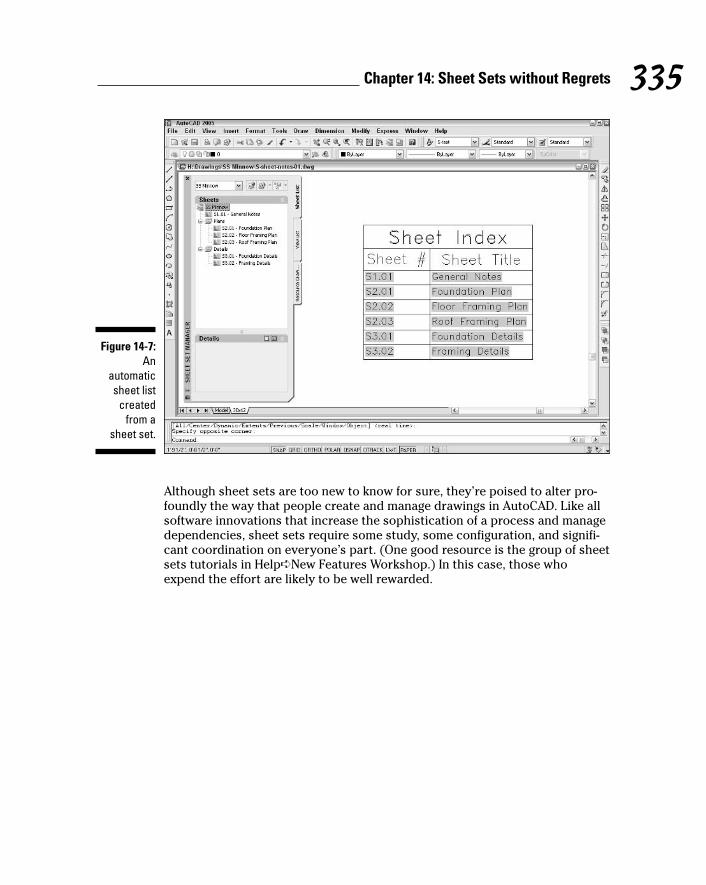
Although sheet sets are too new to know for sure, they’re poised to alter pro-foundly the way that people create and manage drawings in AutoCAD. Like allsoftware innovations that increase the sophistication of a process and managedependencies, sheet sets require some study, some configuration, and signifi-cant coordination on everyone’s part. (One good resource is the group of sheetsets tutorials in Help➪New Features Workshop.) In this case, those whoexpend the effort are likely to be well rewarded.
Figure 14-7:An
automaticsheet list
createdfrom a
sheet set.
335Chapter 14: Sheet Sets without Regrets
j571389 Ch14.qxd 4/12/04 9:45 AM Page 335

336 Part IV: Share and Share Alike
j571389 Ch14.qxd 4/12/04 9:45 AM Page 336
Chapter 15
CAD Standards RuleIn This Chapter� Making the case for CAD standards
� Choosing from existing standards
� Rolling your own standards
� Taking advantage of cool standards tools
If you’ve ever worked with other people to create a multichapter, visuallycomplex, frequently updated text document, then you probably under-
stand the importance of coordinating how everyone works on the parts ofthe document. Even if you’re someone who churns out documents from yourone-person office or lonely cubicle, you probably try to ensure a reasonablyconsistent look and feel in similar documents. You employ consistent fonts,the same company logo, and the same paper size in most documents — or ifyou don’t, you probably at least think that you should!
CAD exacts similar demands for reasonable consistency, only more so:
� Most companies would like to take pride in the clarity and consistencyof their drawings. Sloppy drawings with randomly varying text heightsand lineweights don’t reflect well on you and make your drawings harderto read.
� CAD drawings that don’t conform with some logically consistent schemeusually are harder to edit and to reuse by others who work on the pro-ject and by you when you work on other projects.
This stuff is important enough in CAD that it has a special name: CAD standards.Those people compulsive enough to fret about it all the time and sadisticenough to impose their fretting on others also have a special name: CAD man-agers. This chapter won’t turn you into a CAD manager — a reassurance you’reprobably grateful for — but it does introduce the most important CAD stan-dards issues. This chapter also suggests some ways to come up with yourown simple CAD standards, in case you’re going it alone and don’t have the
j571389 Ch15.qxd 4/12/04 9:45 AM Page 337
benefit of a ready-made company or project CAD standards document to guideyou. The chapter ends with an overview of AutoCAD tools that can help youcomply with and check conformity to CAD standards.
Why CAD Standards?Throughout this book, I emphasize things like setting up your drawings prop-erly, drawing objects on appropriate and consistent layers, and specifying suit-able text fonts and heights. These practices amount to conforming to a CADstandard.
You need to do these things if you work with or exchange drawings with others.If you don’t, several bad things will happen. You’ll be pegged as a clueless new-bie by experienced drafters, who understand the importance of CAD consis-tency. Even if your ego can handle the contempt, you’ll make everyone’swork slower and more difficult. And if the project has electronic drawing sub-mittal requirements, you may find that your client rejects your DWG files anddemands that you make them conform to the CAD standards in the contract.
Even if you work solo and don’t have any particular requirements imposedfrom outside, your own work will go more smoothly and look better if youadhere to a reasonably consistent way of doing things in AutoCAD. You’ll cer-tainly find plotting easier and more predictable.
CAD standards originally grew out of a desire to achieve a graphical consis-tency on the plotted drawings that mirrored the graphical consistency onhand-drafted drawings. Before the days of CAD, most companies had manualdrafting standards that specified standard lettering (text) sizes, dimensionappearance, symbol shapes, and so on. Sometimes these standards werebased on standard industry reference books, such as the Architectural GraphicStandards.
As CAD users became more sophisticated, they realized that CAD standardsneeded to incorporate more than just the look of the resulting plot. CAD draw-ings contain a lot more organizational depth than printed drawings — layers,screen colors, blocks, xrefs, text and dimension styles, and the like. If thesethings aren’t subject to a modicum of standardization; then different peoplewho work on the same drawings or projects are likely to end up stumblingover — or throwing things at — one another.
In short, the first job of CAD standards is to impose some graphical consis-tency on plotted output. CAD standards also encourage consistency in theway that people create, assign properties to, organize, and display objects inthe CAD file.
338 Part IV: Share and Share Alike
j571389 Ch15.qxd 4/12/04 9:45 AM Page 338

Which CAD Standards?If CAD standards are as important as I claim, you might expect that industrieswould’ve settled on a standardized way of doing things. No such luck. Althoughthe manual drafting conventions in many professions have carried over tosome degree into CAD, a lot of the things that need standardization have beenleft to the imagination of individual companies, departments, or people. Forexample, you’ll find that different companies usually name layers differentlyand employ different schemes for mapping object screen color to plottedlineweight (see Chapter 12). In particularly disorganized companies, you’llfind that different drafters use different layers and color-to-lineweight. And inthe worst cases, the same drafter will do these things differently in differentdrawings!
As you can imagine, this proliferation of nonstandard standards makes shar-ing and reusing parts of CAD drawings a lot more difficult. You can at leastminimize the pain within your own office by conforming to any existing CADstandards or, if there aren’t any, by encouraging the development of some.(Later in this chapter, I give some suggestions for how to get started.)
339Chapter 15: CAD Standards Rule
The aesthetics of CADManual drafting veterans frequently complainthat CAD drawings don’t look as good as thedrawings that they used to create by hand. “Too‘flat,’ too cartoonish, and inconsistent” aresome of the refrains that you hear. These com-plaints are not just the whining of old-timers.Good manual drafters were justifiably proud ofthe appearance of their drawings. They focusedon making the finished bluelines look sharp andread well.
When computers and CAD software got into theact, it became easy for CAD drafters to focus onthe screen image and pay less attention to theplotted output. In the early days, CAD usersstruggled with a new way of making drawingsand didn’t have as much time to make them look
good. By the time that CAD became common-place, a new crop of CAD users had grown upwithout the benefit of discovering how to makegood-looking drawings on paper.
There’s no reason that CAD drawings can’t lookas good as manual drawings. It’s a matter ofunderstanding the look that you’re after andcaring enough to want to achieve it. If you seesome especially clear and elegant printeddrawings, find out who drew them and take thatperson out to lunch. You’ll probably uncoversome techniques that you can translate intomaking better CAD drawings. You may also gainnew respect for the skills of those who madehandsome and functional drawings with thesimplest of tools.
j571389 Ch15.qxd 4/12/04 9:45 AM Page 339

Even if you’re lucky or perseverant enough to get a well-rounded set of CADstandards in your office, that may not be the end of it. CAD-savvy people fromdifferent companies who collaborate on projects often want to minimize thepain of inconsistency during drawing exchange. Although each company mayhave its own CAD standards house in order, there’s no way that all those stan-dards will be the same. Thus, one or more companies (often the lead consul-tant) may impose a set of project-specific CAD standards. Project-specificstandards don’t necessarily need to be as detailed as a full-blown companyCAD standards document, but depending on the project and the person whocreated the project-specific CAD standards, they might be.
The result of this confusing muddle of industry practices, company CAD stan-dards, and project-specific CAD standards is that you find yourself switchingamong different standards as you work on different projects. Before you startmaking drawings, find out whether any particular CAD standards apply. It’s alot easier to start off conforming with those standards than to fix nonconform-ing drawings later.
340 Part IV: Share and Share Alike
Industry standardsProfessional, trade, and governmental groups insome industries have made an attempt to pro-mulgate CAD standards for the benefit of every-one in the industry. For example, the AmericanInstitute of Architects (AIA), together with sev-eral professional engineering associations,published a CAD Layer Guidelines document,which has become part of a so-called NationalCAD Standard that’s now promulgated by theU.S. government’s National Institute of BuildingSciences, or NIBS (see www.nationalcad-standard.org). The International Organiza-tion for Standardization, or ISO (the acronymreflects the French ordering of the words), pub-lishes ISO standards document 13567 (see www.iso.ch). This document, which comes in nofewer than three parts, attempts to provide aframework for CAD layer standards in the build-ing design industries throughout the world.
These documents may be useful to you in yoursearch for standards, but they aren’t a panacea.
The majority of CAD-using companies hasignored officially promulgated CAD standards,because these companies developed their ownstandards and practices years ago and areloath to change. That doesn’t mean that youcan’t use the officially promulgated standards,but they won’t suddenly make you a part ofsome mythical CAD standards mainstream.Also, practical implementation of most officialCAD standards in a specific company requires agenerous amount of clarification, modification,and additional documentation. In other words,you don’t just buy the document and then get towork; someone needs to tailor it to your com-pany and projects. And finally, some of theseofficially promulgated CAD standards docu-ments are shockingly expensive. Apparentlythese organizations haven’t found out that theway to make something popular is to post it onthe Web for free!
j571389 Ch15.qxd 4/12/04 9:45 AM Page 340

What Needs to Be Standardized?If you are in a company or on a project without any CAD standards, puttogether at least a minimal set of guidelines. First, impose some consistencyon plotted appearance and use of layers. If you make a few rules for yourselfbefore you start, you’ll end up with drawings that are more professional look-ing and easier to edit — and more likely to be useful on future projects.
A spreadsheet or word processing program is great for documenting your CADstandards decisions as they firm up. Many CAD standards components workbest as tabular lists of layers, colors, and so on. (See Tables 15-1 and 15-2 inthis chapter for examples.) Use the cells in a spreadsheet or the tables featurein a word processor to organize your CAD standards documentation.
Before you start, make sure that you’re familiar with managing properties(Chapter 4) and plot styles (Chapter 12). You need a good understanding tomake intelligent decisions about your plotting and layer standards. (If youwant to make unintelligent decisions, don’t worry about those chapters!)
PlottingIf you plan to use color-dependent plot styles (most people do), develop acolor-to-lineweight plotting chart like Table 15-1. If you choose the more logi-cal but lonelier named plot styles approach, make a similar chart, with plotstyle names instead of color in the first column. (See Chapter 12 for informa-tion about color-dependent and named plot styles.) After you complete aplotting chart, create a plot style table (CBT file for color-dependent plotstyles or STB file for named plot styles), as in Chapter 12.
Table 15-1 Sample Color-to-Lineweight Plotting ChartAutoCAD Color Plotted Lineweight
1 (red) 0.15 mm
2 (yellow) 0.20 mm
3 (green) 0.25 mm
4 (cyan) 0.30 mm
5 (blue) 0.35 mm
6 (magenta) 0.40 mm
(continued)
341Chapter 15: CAD Standards Rule
j571389 Ch15.qxd 4/12/04 9:45 AM Page 341
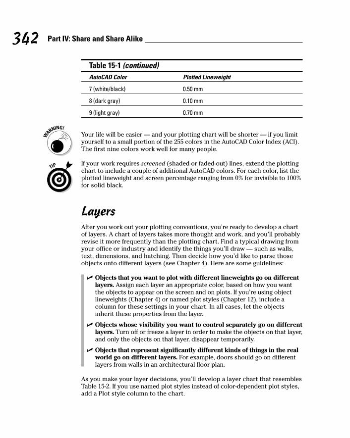
Table 15-1 (continued)AutoCAD Color Plotted Lineweight
7 (white/black) 0.50 mm
8 (dark gray) 0.10 mm
9 (light gray) 0.70 mm
Your life will be easier — and your plotting chart will be shorter — if you limityourself to a small portion of the 255 colors in the AutoCAD Color Index (ACI).The first nine colors work well for many people.
If your work requires screened (shaded or faded-out) lines, extend the plottingchart to include a couple of additional AutoCAD colors. For each color, list theplotted lineweight and screen percentage ranging from 0% for invisible to 100%for solid black.
LayersAfter you work out your plotting conventions, you’re ready to develop a chartof layers. A chart of layers takes more thought and work, and you’ll probablyrevise it more frequently than the plotting chart. Find a typical drawing fromyour office or industry and identify the things you’ll draw — such as walls,text, dimensions, and hatching. Then decide how you’d like to parse thoseobjects onto different layers (see Chapter 4). Here are some guidelines:
� Objects that you want to plot with different lineweights go on differentlayers. Assign each layer an appropriate color, based on how you wantthe objects to appear on the screen and on plots. If you’re using objectlineweights (Chapter 4) or named plot styles (Chapter 12), include acolumn for these settings in your chart. In all cases, let the objectsinherit these properties from the layer.
� Objects whose visibility you want to control separately go on differentlayers. Turn off or freeze a layer in order to make the objects on that layer,and only the objects on that layer, disappear temporarily.
� Objects that represent significantly different kinds of things in the realworld go on different layers. For example, doors should go on differentlayers from walls in an architectural floor plan.
As you make your layer decisions, you’ll develop a layer chart that resemblesTable 15-2. If you use named plot styles instead of color-dependent plot styles,add a Plot style column to the chart.
342 Part IV: Share and Share Alike
j571389 Ch15.qxd 4/12/04 9:45 AM Page 342

Table 15-2 Sample Layer ChartLayer Name Color Linetype Use
Wall 5 Continuous Walls
Wall-Belo 3 Dashed Walls below (shown dashed)
Cols 6 Continuous Columns
Door 4 Continuous Doors
Text 3 Continuous Regular note text
Text-Bold 7 Continuous Large/bold text
Dims 2 Continuous Dimensions
Patt 1 Continuous Hatch patterns
Cntr 1 Center Centerlines
Symb 2 Continuous Annotational symbols
Nplt 8 Continuous Non-plotting information
The layer chart in Table 15-2 is simpler than the layer systems used by experi-enced drafters in most companies. The layer names in the table are based onnames in the AIA CAD Layer Guidelines document mentioned in the “Industrystandards” sidebar. That document recommends adding a discipline-specificprefix to each layer name: A-Walls for walls drawn by the architectural team,S-Walls for walls drawn by the structural team, and so on.
Other stuffThe following settings and procedures deserve some consistency, too:
� Text styles: Decide on text fonts and heights and use them consistently.(See Chapter 9 for more information.)
Manual CAD drafting standards often specify a minimum text height of 1⁄8 inch or 3 mm, because hand-lettered text smaller than that becomesdifficult to read, especially on half-size prints. Plotted 3⁄32 inch or 2.5 mmCAD text is quite legible, but half-size plots with these smaller textheights can result in text that’s on the margin of legibility. Text legibilityon half-size — or smaller — plots depends on the plotter resolution, thelineweight assigned to the text, and the condition of your eyes. Testbefore you commit to using smaller text heights, or use 1⁄8 inch or 3 mmas a minimum.
343Chapter 15: CAD Standards Rule
j571389 Ch15.qxd 4/12/04 9:45 AM Page 343

� Dimension styles: Create a dimension style that reflects your preferredlook and feel. (See Chapter 10.)
� Hatch patterns: Choose the hatch patterns that you need and decide onan appropriate scale and angle for each. (See Chapter 11.)
� Drawing setup and organization: Set up all the drawings on a project inthe same way, and use sheet sets, blocks, and xrefs in a consistent fashion.
After you make standards, create a simple test drawing and make sure thatthe plotted results are what you want. You’ll undoubtedly revise and extendyour standards as you go, especially on your first few projects. In time, you’llfind a set of standards that works for you.
Cool Standards ToolsMost of the hard CAD standards work happens outside of AutoCAD — think-ing, deciding, documenting, revising, and so on. But ultimately you need totranslate that work into your CAD practice, and AutoCAD includes some toolsto make the job easier. Table 15-3 lists standards-related AutoCAD utilities.
Table 15-3 AutoCAD’s CAD Standards ToolsUtility Name Command Menu Use Cross-
Name Choice Reference
DesignCenter ADCenter Tools➪ Copy layers, Chapter 4Design- dimension Center styles, and
other named objects from other drawings
Tool Palettes ToolPalettes Tools➪Tool Create symbol Chapter 2 and Palettes and hatch “Tool Palettes” Window pattern in the online
libraries help system
Layer LAYTRANS Tools➪CAD Translate from “LAYTRANS Translator Standards➪ one set of command, Layer
Layer layer names Translator” in Translator and properties the online help
to another system
344 Part IV: Share and Share Alike
j571389 Ch15.qxd 4/12/04 9:45 AM Page 344
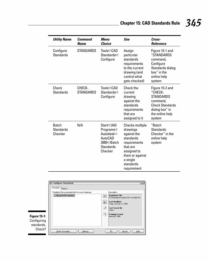
Utility Name Command Menu Use Cross-Name Choice Reference
Configure STANDARDS Tools➪CAD Assign Figure 15-1 and Standards Standards➪ particular “STANDARDS
Configure standards command, requirements Configure to the current Standards dialog drawing (and box” in the control what online help gets checked) system
Check CHECK- Tools➪CAD Check the Figure 15-2 and Standards STANDARDS Standards➪ current “CHECK-
Configure drawing STANDARDS against the command, standards Check Standards requirements dialog box” in that are the online help assigned to it system
Batch N/A Start➪(All) Checks multiple “Batch Standards Programs➪ drawings Standards Checker Autodesk➪ against the Checker” in the
AutoCAD standards online help 2005➪Batch requirements systemStandards that are Checker assigned to
them or against a single standards requirement
Figure 15-1:Configuringstandards.
Check?
345Chapter 15: CAD Standards Rule
j571389 Ch15.qxd 4/12/04 9:45 AM Page 345

AutoCAD standards checking tools require an AutoCAD Drawing Standards(DWS) file. You create a DWS file from a drawing with all the allowed layers,dimension styles, text styles, and linetypes; use File➪Save As to save it as aDWS (not DWG) file. The DWS file defines acceptable named objects for theCheck Standards and Batch Standards Checker utilities. See “standards files,creating” in AutoCAD’s online help system for information.
AutoCAD 2005 monitors CAD standards compliance when you’ve specifiedstandards for the current drawing. By default, a balloon notification appearsfrom the right end of the status bar. CAD managers can trade the balloon fora message that offers to fix the mistake. To configure the notification level,click the Settings button in the Configure Standards dialog box.
If your company does have CAD standards in place, someone may have createdcustom tools to help you comply with those standards. For example, the CADmanager may have put together template drawings with customized settings orblock libraries of standard symbols. CAD managers sometimes create custommenu choices, scripts, or utility programs for the company’s CAD standards.
Figure 15-2:Checking
standards.Check!
346 Part IV: Share and Share Alike
j571389 Ch15.qxd 4/12/04 9:45 AM Page 346

Chapter 16
Drawing on the InternetIn This Chapter� Understanding AutoCAD Internet features
� Exchanging drawing files via e-mail and FTP
� Using the Reference Manager to view and fix file dependencies
� Using the Drawing Web Format and ePlot
� Making multiple Web and paper plots with PUBLISH
� Viewing and plotting drawings without AutoCAD
� Protecting drawings with passwords and digital signatures
Unless you’ve been living under a rock for the past five years, you knowthat the Internet is causing major changes in the way that people work.
(And even if you have been living under a rock, someone probably is offeringbroadband service to it by now!) Because of the Net, most of us communicatedifferently, exchange files more rapidly, and fill out express delivery forms lessfrequently.
AutoCAD users were among the online pioneers, well before the Internet burstonto the public scene. Despite this early adoption, the CAD world has beenrelatively slow to take the full-immersion Internet plunge. Exchanging draw-ings via e-mail and using the World Wide Web for CAD software research andsupport are pretty common nowadays. But it’s still uncommon to find draw-ings incorporated into Web pages or Web-centric CAD applications. That’spartly because CAD drafters have traditionally been somewhat insulated fromthe general computing community — they spend most of their time crankingout drawings and leave all that new-fangled Web design stuff to people who don’t have real work to get done, thank you very much! Even the moreforward-thinking CAD users tend to display a healthy, and often reasonable,skepticism about whether any particular innovation will help with the press-ing job of getting drawings finished on deadline.
j571389 Ch16.qxd 4/12/04 9:45 AM Page 347

Many of the features described in this chapter have undergone frequent tinker-ing, revision, and refocusing in recent AutoCAD versions. AutoCAD 2005 addsnew ETRANSMIT and PUBLISH capabilities to keep up with the new sheet setsfeature, which is described in Chapter 14. The Standard toolbar includes anew Markup Set Manager for those who receive drawing markups from usersof Autodesk DWF Composer. (DWF Composer is Autodesk’s newest effort todraw more people into using the DWF format. The idea is that architects, engi-neers, and others who don’t themselves use AutoCAD can mark up drawingsby using DWF Composer and then transmit those markups to an AutoCADdrafter, who incorporates the changes into the DWG files.)
This chapter shows you how — and when — to use AutoCAD’s Internet fea-tures. I also cover how the Internet features can connect with traditional CADtasks, such as plotting. The emphasis of this chapter is on useful, no-nonsenseways of taking advantage of the Internet in your CAD work.
Your ticket to most of the features described in this chapter is an account withan Internet service provider (ISP). You probably already have Internet accessthrough work or a private ISP account — or both; but if not, now is the time toget connected. Other CAD users will expect to be able to send drawings to youand receive them from you via e-mail. Software companies, including Autodesk,expect you to have Web access in order to download software updates andsupport information. Dial-up modem access to the Internet is acceptable, but ifyou’re doing much drawing exchange or want to be able to download softwareupdates without waiting all day, consider springing for broadband access, suchas DSL (Digital Subscriber Line) or cable modem.
The Internet and AutoCAD: An OverviewAs with all things Internet-y, AutoCAD 2005’s Internet features are a hodge-podge of the genuinely useful, the interesting but still somewhat immature ordifficult to use, and the downright foolish. I steer you toward features andtechniques that are reliable and widely used today. I warn you about “stupidpet trick” features that may impress a 12-year-old computer geek but leaveyour project leader wondering what planet you come from. On the otherhand, a few of today’s questionable features are likely to become the reliable,commonplace ones of tomorrow. I give you enough context to see how every-thing works and where it may lead. Table 16-1 summarizes the AutoCAD 2005Internet features and tells you where in this book to find more information.
348 Part IV: Share and Share Alike
j571389 Ch16.qxd 4/12/04 9:45 AM Page 348

Table 16-1 AutoCAD 2005 Internet FeaturesFeature Description Comments Where You Can
Find More Info
ETRANSMIT Package DWG files Useful to most “Send it with command for sending via e-mail people eTransmit” in this
or FTP or posting on chapterthe Web
Reference Report on and modify Useful for people “Help from the Manager paths of referenced who send drawings Reference
files and use complex, Manager” in multi-folder xref this chapterschemes
File navigation Can save to and open Potentially useful Chapter 2dialog box from Web and FTP for people who
sites routinely work with files on Web or FTP sites
DWF files A lightweight drawing The recipient must “Drawing Web file format for posting have Autodesk Format — Not drawings on the Web Express Viewer Just for the Web” or sharing them with installed; potentially in this chapterpeople who don’t useful for sharing have AutoCAD drawings with
people who don’t have AutoCAD
PUBLISH Create DWF files, plot Can help automate “Making DWFs command (PLT) files, or paper the traditional (or Plots) with
plots in batches plotting procedure; PUBLISH” in if DWF files ever this chaptercatch on, will streamline their creation
Publish to A wizard that builds Like most wizards, “PUBLISHTOWEBWeb and publishes a Web fairly easy to use, command” in the
page containing but limited; possibly AutoCAD online drawings useful as a quick- help system
and-dirty Web publishing approach
(continued)
349Chapter 16: Drawing on the Internet
j571389 Ch16.qxd 4/12/04 9:45 AM Page 349

Table 16-1 (continued)Feature Description Comments Where You Can
Find More Info
Insert Add hyperlinks to Of questionable “Hand-y objects” hyperlink objects in drawings use, except in in this chapter
specialized applications
Password Requires a password Useful for limiting “The Drawing protection in order to open a access to sensitive Protection
drawing DWG or DWF files Racket” in thischapter
Digital Provide electronic Requires an “The Drawing signatures confirmation that account with a Protection
someone has digital certificate Racket” in this approved a particular provider; new chapterversion of a technology, so look particular drawing before you leap —
and talk to your attorney first
Sending StrategiesE-mail and FTP (File Transfer Protocol) have largely replaced blueline prints,overnight delivery, floppies, and higher capacity disks as the standard meansof exchanging drawings. Some companies even use specially designed Web-based services, such as Autodesk’s Buzzsaw, as a repository for project draw-ings from all the companies working on a particular project. Whether you’reexchanging drawings in order to reuse CAD objects or simply to make hard-copy plots of someone else’s drawings, you need to be comfortable sendingand receiving drawings electronically.
Sending and receiving DWG files doesn’t differ much from sending and receiv-ing other kinds of files, except for the following:
� DWG files tend to be bigger than word processing documents andspreadsheets. Consequently, you may need to invest in a faster Internetconnection, as described earlier in this chapter.
� You can easily forget to include all the dependent files. I tell you in thenext section how to make sure that you send all the necessary files — andhow to pester the people who don’t send you all their necessary files.
350 Part IV: Share and Share Alike
j571389 Ch16.qxd 4/12/04 9:45 AM Page 350
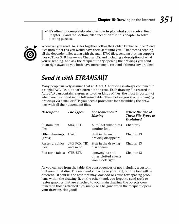
� It’s often not completely obvious how to plot what you receive. ReadChapter 12 and the section, “Bad reception?” in this chapter to solveplotting puzzles.
Whenever you send DWG files together, follow the Golden Exchange Rule: “Sendfiles unto others as you would have them sent unto you.” That means sendingall the dependent files along with the main DWG files, sending plotting supportfiles (CTB or STB files — see Chapter 12), and including a description of whatyou’re sending. And ask the recipient to try opening the drawings you sendthem right away, so you both have more time to respond if there’s any problem.
Send it with ETRANSMITMany people naively assume that an AutoCAD drawing is always contained ina single DWG file, but that’s often not the case. Each drawing file created inAutoCAD can contain references to other kinds of files, the most important ofwhich are described in the following table. Thus, before you start exchangingdrawings via e-mail or FTP, you need a procedure for assembling the draw-ings with all their dependent files.
Description File Types Consequences if Where the Use of Missing These File Types is
Explained
Custom font SHX, TTF AutoCAD substitutes Chapter 9files another font
Other drawings DWG Stuff in the main Chapter 13(xrefs) drawing disappears
Raster graphics JPG, PCX, TIF, Stuff in the drawing Chapter 13files and so on disappears
Plot style tables CTB, STB Lineweights and Chapter 12other plotted effects won’t look right
As you can see from the table, the consequences of not including a customfont aren’t that dire: The recipient still will see your text, but the font will bedifferent. Of course, the new font may look odd or cause text spacing prob-lems within the drawing. If, on the other hand, you forget to send xrefs orraster graphics that are attached to your main drawing, the objects con-tained on those attached files simply will be gone when the recipient opensyour drawing. Not good!
351Chapter 16: Drawing on the Internet
j571389 Ch16.qxd 4/12/04 9:45 AM Page 351

Table 16-2 doesn’t exhaust the types of files that your DWG files might referto. Custom plotter settings (such as custom paper sizes) may reside in PC3 or PMP files. If you use the new sheet sets feature, a DST file contains infor-mation about the sheet structure. An FMP file controls some aspects of fontmapping. (Like so much else in AutoCAD, the tools and rules for mappingmissing fonts are flexible but somewhat complicated. Look up the “FONTALT”and “FONTMAP” system variables in the AutoCAD online help system fordetailed information.)
Rapid eTransmitFortunately, the AutoCAD ETRANSMIT command pulls together all the filesthat your main DWG file depends on. Follow these steps to assemble a draw-ing with all its dependent files with ETRANSMIT.
1. Open the drawing that you want to run ETRANSMIT on.
If the drawing is already open, save it. ETRANSMIT requires that anychanges to the drawing be saved before you proceed.
2. Choose File➪eTransmit.
The Create Transmittal dialog box appears, as shown in Figure 16-1.
3. On the Files Tree or Files Table tab, remove the check mark next toany file that you want ETRANMSIT not to copy with the main drawing.
Figure 16-1:Rapid
eTransmit.
352 Part IV: Share and Share Alike
j571389 Ch16.qxd 4/12/04 9:45 AM Page 352
Unless you have assigned custom font mapping, you can omit theAcad.fmp file.
4. Select a transmittal setup from the list.
Transmittal setups are new in AutoCAD 2005. They contain settings thatcontrol how ETRANSMIT processes the drawings and creates the trans-mittal package. Click the Transmittal Setups button to create new ormodify existing setups. The default Standard transmittal setup worksfine for many purposes, except that you probably want to turn on theInclude Fonts setting, as described in the next paragraph. In any case,you should view the settings (click the Modify button) just to see whatoptions you can change if you need to later.
If you want AutoCAD to include SHX and TTF font files, including anycustom fonts that you’re using, you must turn on the Include Fonts settingin the transmittal setup. (Click Transmittal Setups, click Modify, and checkthe Include Fonts box.) Note, however, that many SHX and TTF files arecustom fonts, which work like licensed software. Sending them to othersis just like sharing your AutoCAD program CD with others. No, I don’tmean that it’s easy and fun; I mean that it’s illegal and unethical. Beforeyou send a custom font file to someone else, find out what the licensingrestrictions are on the font and be prepared to work within them.
5. Click the View Report button.
You see a report listing the files that ETRANSMIT will copy, along withwarnings about any files that it can’t locate.
6. Review the report and make sure that ETRANSMIT was able to find allthe files.
7. Click OK.
ETRANMSIT displays a file dialog box so that you can specify the nameand location of the transmittal package (which is a ZIP file by default).
8. Click Save.
ETRANSMIT creates the transmittal package (which is a ZIP file bydefault).
Although AutoCAD 2005 automatically compresses its DWG files, zipping filesmanages to compress them even further (about 20 percent more, in my expe-rience). More importantly, zipping creates a single, tidy package of all yourDWG, raster image, plot style table, and font files. No one likes to receive ane-mail message carrying an endless cargo of attached files. Do everyone afavor: be hip and zip.
The only downside to zipping is that creating a zipped file and extracting filesfrom it require a separate zip/unzip program. Several good shareware utilitiesare available, including WinZip (www.winzip.com).
353Chapter 16: Drawing on the Internet
j571389 Ch16.qxd 4/12/04 9:45 AM Page 353

Transmitting multiple drawingsIn many cases, you’ll want to send more than one drawing to a recipient. Inthis situation, you can open each drawing and run ETRANSMIT on each inturn. (In the transmittal setup, set Transmittal Package Type to Folder (setof files), specify the Transmittal File Folder to copy the files to, and useTransmittal Options to control whether the files are copied to one or morethan one folder.) When you’ve processed all the drawings, use a program likeWinZip to package the files into a single zipped file before sending it.
AutoCAD 2005 provides a slicker way of transmitting multiple drawings, aslong as you’re using the new sheet sets feature (described in Chapter 14). Inthe Sheet Set Manager palette, just right-click the sheet set name and chooseeTransmit. The Create Transmittal dialog box then will include an additionalSheets tab, as shown in Figure 16-2. This tab lists all drawings in the sheet setand includes them in the transmittal by default.
AutoCAD 2005 includes a new ARCHIVE command, which functions identicallyto ETRANSMIT, but without the transmittal document and without savedsetups. ARCHIVE works only with sheet sets. In the Sheet Set Manager palette,right-click the sheet set name and choose Archive. You use this command tosave copies of a set of drawings at some milestone during a project — forexample, at a design review or bid set submittal.
Figure 16-2:eTransmit
faster withsheet sets.
354 Part IV: Share and Share Alike
j571389 Ch16.qxd 4/12/04 9:45 AM Page 354
FTP for you and meFTP, or File Transfer Protocol, is a simple but robust protocol for copying filesover the Internet. A computer that’s connected to the Internet can act as an FTPserver, which means that part of its hard disk is accessible over the Internet.The person who configures the FTP server can place restrictions so that onlypeople who enter a particular logon name and password can see and downloadfiles. FTP overcomes the file size limitations that often occur with e-mail.
Because of all these FTP benefits, it’s increasingly common for people atlarger companies to place drawing files on their company’s FTP site and tellyou to go get them. This approach relieves them of having to e-mail you thefiles, and relieves you of waiting for that 10MB e-mail download when youleast expected it.
In most cases, the person making the files available to you via FTP will sendyou a Uniform Resource Locator (URL) that looks like a Web page address,except that it starts with FTP:// instead of HTTP://. If you open your Webbrowser and enter the FTP URL into the address field, the browser should con-nect to the FTP site, ask you for a location and name to use for the file when itgets copied to your system, and begin downloading the file. If the FTP site usespassword protection, you’ll have to enter a logon name and password first.
If you want fancier FTP download options, you can use an FTP utility programsuch as WS_FTP (www.ipswitch.com).
Even if you work for a small company, you may be able to post files on yourISP’s FTP server in order to make them available to others. Check with yourISP to find out whether you can do it and, if so, what the procedures are.
FTP transfers are more prone to user confusion problems than are e-mail files,especially if the recipient hasn’t used FTP before. For example, it’s common forthe person posting the files to forget to tell the recipient the logon name andpassword, or for the recipient not to have an FTP program — or to not knowhow to use it. Check with your recipient the first couple of times you use FTPto transfer files to make sure they got the files successfully — and don’t be sur-prised if they ask you to use e-mail or overnight delivery instead.
Bad reception?Other sections in this chapter focus on sending files to others. What happenswhen you’re on the receiving end? Not everyone will be as conscientious asyou are about following the Golden Exchange Rule. You’ll receive drawings withmissing dependent files and no information or support files for plotting.
355Chapter 16: Drawing on the Internet
j571389 Ch16.qxd 4/12/04 9:45 AM Page 355

When you receive an e-mail message or FTP download containing drawings(zipped, I hope!), copy the file to a new folder on your hard disk or a networkdisk and unzip the files.
Check at least a few of the drawings in the package to make sure that all thexrefs, fonts, and raster image files were included. You can perform this checkby opening each main drawing in that folder. After you open each file, pressthe F2 key to view the command line window, and look for missing font andxref error messages of the following sort:
Substituting [simplex.shx] for [helv.shx].Resolve Xref “GRID”: C:\Here\There\Nowhere\grid.dwgCan’t find C:\Here\There\Nowhere\grid.dwg
A Substituting. . . message indicates AutoCAD couldn’t find a font and issubstituting a different font for it. A Can’t find. . . message indicates thatAutoCAD couldn’t locate an xref. Any missing raster files appear as rectangu-lar boxes with the names of the image files inside the rectangles. Alterna-tively, you can open the Xref Manager or Image Manager dialog box, whichreveals any missing xref or raster image files. (See Chapter 13 for details.)
Write down each missing file and then tell the sender to get on the ball andsend you the missing pieces. While you’re at it, tell that person to buy thisbook and read this chapter!
Press the F2 key after opening any drawing that you didn’t create so that youknow right away if any fonts and xrefs are missing.
If you receive drawings with custom TrueType font files (files whose extensionsare TTF), you must install those files before Windows and AutoCAD will recog-nize them. Choose Start➪Settings➪Control Panel. (In Windows XP, chooseStart➪Control Panel and then click the Switch to Classic View link in order tosee the Fonts applet.) Double-click the Fonts icon to open the Fonts window,and then choose File➪Install New Font.
Help from the Reference ManagerIn Chapter 13, I warn you about the complications of xref paths and the poten-tial perils of AutoCAD not being able to locate xrefs if you move project foldersaround or transfer drawings to or from someone else. A similar danger existsfor raster image files (Chapter 13) and font files (Chapter 9). The ETRANSMIT
356 Part IV: Share and Share Alike
j571389 Ch16.qxd 4/12/04 9:45 AM Page 356

command, described earlier in this chapter, does a good job of gatheringtogether dependent xrefs, raster files, and font files, but it can’t gather whatAutoCAD can’t locate.
AutoCAD’s Reference Manager utility is a real lifesaver if you find yourself suf-fering from xref, raster image, or font path perils — whether they occur inyour own company or when sending files to or receiving them from others.
Reference Manager is a separate utility program, not a command insideAutoCAD. Follow these steps to launch the utility:
1. Choose Start➪Programs➪Autodesk➪AutoCAD 2005➪ReferenceManager.
The Reference Manager program opens, as shown in Figure 16-3.
2. Choose the Add Drawings button to add one or more DWG files to thedrawings pane on the left.
3. Click the Export Report button to create a text report listing all thedependent files and their paths, or click the Edit Selected Pathsbutton to modify paths.
Click the Help button in Reference Manager to find out more about theutility’s capabilities.
If you always keep parent and child DWG files in the same folder — the sim-plest approach to dealing with xref paths — then you probably won’t need touse the Reference Manager.
Figure 16-3:The
ReferenceManager.
357Chapter 16: Drawing on the Internet
j571389 Ch16.qxd 4/12/04 9:45 AM Page 357
Drawing Web Format — Not Just for the Web
In a previous section of this chapter, I explain how you can exchange drawingsvia e-mail and FTP. That’s all the Internet connectivity that many AutoCADusers need, but if you’re curious about connecting drawings to the Web orsharing drawings with people who don’t have AutoCAD, this section is for you.
The AutoCAD Web features are built on two pieces of technology:
� A special lightweight drawing format called DWF that Autodesk originallydeveloped especially for putting drawings on the Web.
� A free program from Autodesk called Autodesk Express Viewer thatenables anyone to view and print DWF files without having AutoCAD.
All about DWFThe AutoCAD DWG format works well for storing drawing information on localand network disks, but the high precision and large number of object proper-ties that AutoCAD uses make for comparatively large files.
To overcome this size problem and encourage people to publish drawings onthe Web, Autodesk developed an alternative lightweight vector format for rep-resenting AutoCAD drawings: DWF (Design Web Format). A DWF file is a morecompact representation of a DWG file. DWF uses less space — and less transfertime over the Web and e-mail — because it’s less precise and doesn’t have allthe information that’s in the DWG file.
DWF hasn’t exactly taken the Web by storm; Autodesk has gradually recast itas a format for electronic plotting, or ePlotting, including for sharing drawingswith people who don’t have AutoCAD. In other words, Autodesk is pushingDWF as a CAD analogue to Adobe’s PDF (Portable Document Format). Thusyou can create DWF files from your drawings and send the DWFs to peoplewho don’t have AutoCAD. Your recipients can view and plot the DWF filesafter they download the free Autodesk Express Viewer program, which isavailable on Autodesk’s Web site, www.autodesk.com.
358 Part IV: Share and Share Alike
j571389 Ch16.qxd 4/12/04 9:45 AM Page 358

ePlot, not replotA DWF file captures a single, plotted view of your drawing, so, unlike a DWGfile, it can provide a relatively unambiguous snapshot of what you want tosee on paper. With a DWG file, on the other hand, you have to provide lots ofinformation to other people — drawing view, scale, plot style settings, and soon — in order for them to get the same plotting results that you did.
Potential ePlotting scenarios include:
� Architects and other consultants on a building project periodically uploadDWF files to the project Web site. Architects and engineers with some min-imal CAD knowledge can review the drawings on-screen and create theirown hard-copy plots, if necessary. Principals and clients who don’t wantanything to do with CAD, or even with computers, can have their secre-taries or other employees create hard-copy plots for them to examine.
� When Internet-savvy people need hard-copy prints of your drawings, youe-mail a zipped file containing DWF files, along with the URL for AutodeskExpress Viewer and simple instructions for creating plots from the DWFfiles. (Be ready to walk them through the process by phone the first timeor two to reduce anxiety on everyone’s part.)
� A CAD plotting service bureau encourages its customers to send DWF filesinstead of DWG files for plotting. The DWF files are much smaller andrequire less intervention on the part of the service bureau’s employees.
The ePlot concept debuted in AutoCAD 2000 and hasn’t yet caught on in a bigway. Autodesk hopes to establish ePlot and the DWF format as a standard forCAD documents similar to what Adobe’s PDF has become for word process-ing documents. It remains to be seen whether ePlotting will become a popu-lar way to generate hard-copy output. In particular, many people outside ofCAD-using companies don’t have access to large-format plotters. They’re lim-ited to 81⁄2-x-11-inch — or, at best, 11-x-17-inch — reduced-size check plots.Consequently, many people won’t be able to plot your DWF files to scale, andmay not even be able to plot them large enough to read everything.
Don’t be afraid to try ePlotting with colleagues inside or outside your com-pany, but don’t become too dependent on it until you see whether the rest ofthe CAD world shares your enthusiasm. Otherwise, you risk becoming theonly one who’s willing to use your DWF files for plotting — in which case thenext version of the feature will be called mePlot.
359Chapter 16: Drawing on the Internet
j571389 Ch16.qxd 4/12/04 9:45 AM Page 359

AutoCAD 2005 uses version 6 of the DWF format, which Autodesk introducedwith AutoCAD 2004. (The DWF format changes at least as often as the DWGformat, as Autodesk adds new features to AutoCAD and new Design WebFormat capabilities.) The most important new feature in DWF 6 is multiplesheets in a single DWF file, as shown in Figure 16-4. It’s like stapling together a set of drawings, except that you never have to worry about your staplerbeing empty.
Making DWFs with ePlotAs I describe in the previous section, AutoCAD treats DWF files like electronicplots, or ePlots. You create a DWF file from the current drawing just as if youwere plotting it to a piece of paper, as I describe in Chapter 12. The only differ-ence is that, in the Plot dialog box’s Printer/Plotter area, you choose the plotterconfiguration named DWF6 ePlot.pc3, as shown in Figure 16-5. When you doso, AutoCAD automatically turns on the Plot To File setting. Then when youclick OK to generate the ePlot, AutoCAD displays a file dialog box in which youspecify a filename and location for the DWF file that gets created. The locationcan be a folder on a hard disk or a Web server.
Figure 16-4:One DWF
file canincludemultiplesheets.
360 Part IV: Share and Share Alike
j571389 Ch16.qxd 4/12/04 9:45 AM Page 360
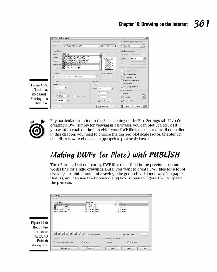
Pay particular attention to the Scale setting on the Plot Settings tab. If you’recreating a DWF simply for viewing in a browser, you can plot Scaled To Fit. Ifyou want to enable others to ePlot your DWF file to scale, as described earlierin this chapter, you need to choose the desired plot scale factor. Chapter 12describes how to choose an appropriate plot scale factor.
Making DWFs (or Plots) with PUBLISHThe ePlot method of creating DWF files described in the previous sectionworks fine for single drawings. But if you want to create DWF files for a lot ofdrawings or plot a bunch of drawings the good ol’ fashioned way (on paper,that is), you can use the Publish dialog box, shown in Figure 16-6, to speedthe process.
Figure 16-6:Hot off the
presses:AutoCAD
Publishdialog box.
Figure 16-5:“Look ma,
no paper!”Plotting to a
DWF file.
361Chapter 16: Drawing on the Internet
j571389 Ch16.qxd 4/12/04 9:45 AM Page 361

Although the Publish dialog box is wired to support DWF as well as regular(paper) plotting, for now, more people are likely to use it for paper plotting. (Analternative use is creating plot files to send to a plotting service bureau.) But ifyou do decide to go into large-scale DWF publishing, including multisheet DWFfiles, use the Publish Drawing Sheets dialog box, as in the following steps.
1. Choose File➪Publish.
The Publish dialog box appears (refer to Figure 16-6). The dialog boxlists all tabs (Model and paper space layouts) of the current drawing forplotting. The Publish dialog box refers to each tab as a sheet.
2. Use the buttons below the sheet list to preview any sheet, add sheetsfrom other drawings, remove sheets from the to-be-plotted list, orrearrange the plotting order.
With the additional buttons, you can save and recall lists of sheets. SeeStep 4 for more information.
3. After you specify the sheets that you want to plot, specify whether youwant to plot them to an actual plotter or plot (PLT) file or to a DWF file.
You can select a specific plotter configuration for each sheet by choos-ing a Page Setup in the sheet list. See Chapter 12 for more informationabout page setups.
4. Click the Publish Options button to display a dialog box containingadditional settings.
Most of these options are of concern only if you’re creating DWF files. Theone exception is Default Output Directory, which also applies to creatingplot (PLT) files.
5. Click the Save Sheet List button to save the current drawings and set-tings list, if you anticipate having to publish the same group of draw-ings again.
6. Click the Publish button to start the process.
AutoCAD 2005’s new sheet sets feature (described in Chapter 14) includes adirect link to multisheet publishing. In the Sheet Set Manager palette, right-click the sheet set name and choose Publish. The submenu includes choicesfor publishing directly to a plotter or DWF file and for opening the Publishdialog box preloaded with all the sheet sets.
Don’t confuse the PUBLISH command (File➪Publish) with the PUBLISHTOWEBcommand (File➪Publish to Web). The PUBLISH command creates sets of DWFfiles, plot files, or actual plots. The PUBLISHTOWEB Wizard creates a Web pagecontaining images of your drawings. The results of this Wizard won’t put any
362 Part IV: Share and Share Alike
j571389 Ch16.qxd 4/12/04 9:45 AM Page 362
Web designers or programmers out of work, but you can use it to create primi-tive Web page paste-ups of your drawings. See “PUBLISHTOWEB command” inthe AutoCAD online help system if you’d like to give it a whirl.
Hand-y objectsNo Web file format would be complete without hyperlinks, and DWF has those,too. You can attach a hyperlink to any drawing object in AutoCAD, not just to atext string. As you pass the cursor over an object with a hyperlink, the cursorchanges from the ordinary pointer to a globe and two links of a chain (as in“World Wide Web” and “link,” not “world-wide chain gang”). Right-click theobject and select the Hyperlink option from the menu, which opens yourbrowser and navigates to the URL that’s attached to the object. If you create aDWF file that includes objects with hyperlinks, Autodesk Express Viewerembeds the links in the DWF file so that you can Ctrl+click to navigate to them.
Hyperlinks on objects are a clever trick, but they’re of limited practical valuein most DWG and DWF files:
� The drawing images are so small that it’s difficult to distinguish the hyper-link on one object from the hyperlink on another object.
� Most people aren’t used to associating hyperlinks with individual linesand other objects. The interface is likely to leave them perplexed.
If you’d like to experiment with hyperlinks in objects, look up “HYPERLINKcommand, about” in the online help system.
Autodesk Express ViewerAfter you create DWF files, whether with ePlot or PUBLISH, you or the recipi-ent of your DWF files can use Autodesk Express Viewer to view and printthem. Autodesk Express Viewer, shown in Figure 16-4 earlier in this chapter,is a free viewer from Autodesk. You can download the current version fromAutodesk’s Web page, www.autodesk.com (click on Product and Solutionsand then Autodesk Express Viewer).
When you install AutoCAD 2005, the setup program by default installs Auto-desk Express Viewer as well. Choose Start➪Programs➪Autodesk➪AutodeskExpress Viewer, or simply double-click on a DWF file in Windows Explorer, tolaunch it.
363Chapter 16: Drawing on the Internet
j571389 Ch16.qxd 4/12/04 9:45 AM Page 363
The Drawing Protection RacketWhether you’re sending DWG or DWF files, you may be concerned about theirmisuse (that is, by the wrong people or for the wrong purposes), abuse (forexample, modification without your consent), or reuse (on other projects or byother people without due compensation to you).
The previous version, AutoCAD 2004, added two new features for securingyour drawings when you send them to others:
� Password protection enables you to lock a DWG or DWF file so that onlythose who type the password that you’ve specified can open, insert, orxref it.
Add password protection to drawings only when you really need it:
• If you forget the password, then you no longer will be able to openthe drawing. Neither AutoCAD nor Autodesk has any magical wayto extract the password or unlock the drawing.
• After you password protect a drawing, others can’t insert the draw-ing as a block or attach it as an xref.
If you’re using a password, you probably should do it on a copy of thedrawing that you send, and keep an unprotected version for yourself.
� Digital signature is a high-tech way to add an electronic marker to aDWG file that verifies that someone approved the drawing. AutoCAD’sdigital signature feature relies on fairly new technology by Microsoft.You must first get an account with a digital certificate provider, whoserves to authenticate you and your computer. Of course, for this fea-ture to be useful, you need to send drawings to someone who wants toreceive digitally authenticated drawings from you (or vice versa) andwho has the technological savvy to deal with digital certificates. Formore information, see “digital signatures, learning more about” in theAutoCAD online help system.
To activate either of these options for the current drawing, choose File➪SaveAs to display the Save Drawing As dialog box, and then choose Tools➪SecurityOptions to display the Security Options dialog box before you save the file. Ifyou want to add a password to the current drawing, just type it in the text fieldon the password tab of the Security Options dialog box.
After you password protect and save a DWG file, anyone who tries to open,insert, or xref it will see a dialog box similar to the one shown in Figure 16-7.
364 Part IV: Share and Share Alike
j571389 Ch16.qxd 4/12/04 9:45 AM Page 364

To password protect a DWF file, use the PUBLISH command and click thePublish Options button in the Publish dialog box.
Although electronic security features such as the ones described in this section can be useful as part of a strategy to protect your work from misuse,they’re not a substitute for communicating clearly, preferably in the form ofwritten contracts, what constitutes appropriate use of drawings that yousend to or receive from others. http://markcad.com/autocad/elecdwgexchange.htm outlines the issues and suggests how to play well with yourdrawing exchange buddies.
Figure 16-7:Password,
please.
365Chapter 16: Drawing on the Internet
j571389 Ch16.qxd 4/12/04 9:45 AM Page 365

366 Part IV: Share and Share Alike
j571389 Ch16.qxd 4/12/04 9:45 AM Page 366

Part VThe Part of Tens
k571389 PP05.qxd 4/12/04 9:46 AM Page 367
In this part . . .
Tens sounds a lot like tense, and tense is how AutoCADmay make you feel sometimes. But never fear — help
is on the way! Checklists are always a big help in gettingthings right and fixing things that are wrong. And a TopTen list is a good way to quickly spot the best — or theworst — of almost anything, AutoCAD included. ThisPart of Tens features lists that help you keep your draw-ings healthy and trade drawings with other people andprograms.
k571389 PP05.qxd 4/12/04 9:46 AM Page 368

Chapter 17
Ten Ways to Do No Harm
Hippocrates of Greece is famous for many things, not least of which isthe Hippocratic oath sworn by doctors. It begins “First, do no harm.”
This is not a bad approach to take when editing existing drawings withAutoCAD whether the drawings were created originally by you or by some-one else. You can accidentally undo days or weeks of work by yourself andothers in minutes. (Of course, you also can purposefully undo days or weeksof work by yourself and others in minutes, but I can’t give much advice tostop you if you want to do that!)
Follow these guidelines to avoid doing harm to the hard work of others andthe productive potential of yourself.
Be PreciseThroughout this book, I remind you that using precision techniques such assnap, object snaps, and typed coordinates is a fundamental part of good CADpractice. Don’t try to use AutoCAD like an illustration program, in which youeyeball locations and distances. Use one of the many AutoCAD precisiontechniques every time you specify a point or distance.
Control Properties by LayerAs I describe in Chapter 4, AutoCAD gives you two different ways of control-ling object properties such as color, linetype, and lineweight: by layer and byobject. Unless you have a really good reason to assign properties by object —such as instructions from your company’s CAD manager or the client forwhom you’re creating the drawing — use the by-layer method: Assign colors,linetypes, and lineweights to layers, and let objects inherit their propertiesfrom the layer on which they reside. Don’t assign explicit color, linetype, orlineweight to objects.
l571389 Ch17.qxd 4/12/04 9:46 AM Page 369

Know Your Drawing Scale FactorChapter 3 describes the importance of choosing an appropriate drawingscale factor when you set up a drawing. Knowing the drawing scale factor ofany drawing you’re working on is equally important whether you set it up ornot. You need this number in order to calculate lots of scale-dependentobjects, such as text, dimensions, and hatching. Chapter 9 includes tips forfiguring out the drawing scale factor of an existing drawing.
Know Your SpaceUnderstand the difference between model space and paper space (describedin Chapter 2) and know which space the different parts of the drawing you’relooking at on-screen reside in. Above all, make sure that you draw objects inthe appropriate space. When you’re viewing a paper space layout, keep aneye on the status bar’s MODEL/PAPER button so that you know which spacethe cursor currently is in. (Chapter 3 describes how to keep your model andpaper space bearings.) When you plot, ensure that you’ve selected the righttab — either Model or one of the paper space layout tabs.
If Someone (Sheet) Set It,Don’t Forget It
Sheet sets are brand new in AutoCAD 2005, and it remains to be seen howreadily AutoCAD-using companies will take to them as a way of organizingdrawing sets. If you create new drawings on a project that’s organized withsheet sets, use the Sheet Set Manager palette to ensure that your drawingstarts out as a full-fledged citizen of the set. If you find yourself working on adrawing that’s part of a set, be sure that you understand how the sheet set asa whole is organized and how your drawing fits into it. Be aware that someinformation, such as title sheet data, sheet list, and pointer blocks, may begenerated automatically for the sheet set, and avoid thwarting these auto-matic annotations by drawing separate text or symbols for the same purpose.
Explode with CareThe eXplode command makes it easy to explode polylines (Chapter 5),dimensions (Chapter 10), hatches (Chapter 11), and block inserts (Chapter 13)into their constituent objects. The only problem is that someone probably
370 Part V: The Part of Tens
l571389 Ch17.qxd 4/12/04 9:46 AM Page 370
grouped those objects together for a reason. So until you understand thatreason and know why it no longer applies, leave the dynamite alone.
Don’t Cram Your GeometryIt’s okay to cram for a geometry test, but don’t cram geometry, dimensions,text, or anything (and everything) else into your drawings. A real temptationexists to put a lot of stuff into every square inch of your drawing, usingAutoCAD’s flexible panning and zooming capabilities to really work over allthe available space. If you succumb to this temptation, you’ll discover thatediting is more difficult and adding more information may be impossible! Inaddition, the result probably will be harder to read. Instead of cramming stuffonto the sheet, use white (empty) space to surround areas of dense geome-try. Put details on separate sheets. Attach a page of notes instead of putting aton of text onto your drawing. Managing a reasonable number of drawingswith less on each one is easier than having two or three densely packedsheets crammed with every bit of geometry and annotation needed for theproject.
Freeze Instead of EraseIt’s common to start with an existing drawing from another discipline whenyou want to add, say, an electrical system to a floor plan. But if you removethe landscaping around a building because you don’t need it for the wiring,you may cause a great deal of rework when the landscaping information isneeded again. And what if the person who did the landscaping work has, inthe meantime, decided to leaf? (Sorry . . . ) Unless you know that objects areno longer needed, use the AutoCAD Freeze or Off layer setting to makeobjects on those layers invisible without obliterating them. These settingsare in the Layer Properties Manager dialog box, as described in Chapter 4.
Use CAD StandardsBecome knowledgeable about CAD standards in your industry and company,and take advantage of any standardized resources and approaches that areavailable to you. (See Chapter 15 for suggestions.) By following standardsconsistently, you can apply your creativity, expertise, and energy to the inter-esting parts of the job at hand, not to arguing about which hatching patternsto use. And if you find that things are a mess in your company because noone else pays much attention to industry standards, well, knowing thosestandards makes you very employable as well.
371Chapter 17: Ten Ways to Do No Harm
l571389 Ch17.qxd 4/12/04 9:46 AM Page 371

Save and Back Up Drawings RegularlyAs with all computer documents that you work on, get in the habit of savingyour current AutoCAD drawing regularly. I recommend every 10 minutes orso. Each time you save, AutoCAD writes the current state of the drawing tothe drawingname.DWG file, after renaming the previously saved version drawingname.BAK. Thus, you can always recover the next-to-last saved ver-sion of your drawing by renaming drawingname.BAK to somethingelse.DWGand opening it in AutoCAD.
AutoCAD also includes an automatic drawing save feature. It’s useful as a sec-ondary backup save, but you shouldn’t rely on it exclusively. AutoCAD createsautomatic save files with inscrutable names like Drawing1_1_1_1478.SV$and puts them in the folder specified by the Automatic Save File Location set-ting on the File tab of the Options dialog box. Save your drawing and saveyourself the pain of lost work and the hassle of trying to locate the right auto-matic save file. If you find yourself in the unfortunate position of needing anautomatic save file, move the SV$ files file from the automatic save folder toanother folder. Rename the files from SV$ to DWG, open them in AutoCAD,and look for the one that corresponds to the drawing you’re trying torecover. Note that AutoCAD deletes the SV$ file after you close the drawing,so it’s usually useful only after a software or computer crash.
Backing up your data is prudent advice for any important work that you doon a computer, but it’s doubly prudent for CAD drawings. A set of CAD draw-ings is a lot harder and more time consuming to re-create than most othercomputer documents. Unless you’re willing to lose more than a day’s worthof work, develop a plan of daily backups onto tape, CD-RW (CD ReWritable)discs, or another high-capacity medium.
Don’t be lulled into complacency by the increasing reliability of hard disks.Although hard disk failure is increasingly rare, it still happens, and if it hap-pens to you sans backup, you’ll quickly understand the full force of thephrase “catastrophic failure.” Also, backups aren’t just protection againstdisk failure. Most of the time, backups help you recover from “pilot error” —accidentally erasing a file, messing up a drawing with ill-advised editing, andso on. Even if you’re conscientious and never make mistakes, there’s a goodchance that someone else in your office who has access to your DWG fileshasn’t quite achieved your exalted level of perfection. Protect your work andminimize recriminations with regular backups.
372 Part V: The Part of Tens
l571389 Ch17.qxd 4/12/04 9:46 AM Page 372

Chapter 18
Ten Ways to Swap DrawingData with Other People
and ProgramsAt various times, you probably need to transfer information from one
kind of document to another. You even may have taken the CAD plungebecause you want to import AutoCAD drawing data into your word process-ing or other documents. If so, this chapter is for you. It covers exchangingAutoCAD drawing data with other programs — what works, what doesn’t,and how to do it. I also tell you when to give up and reach for the scissorsand glue.
This chapter frequently mentions vector and raster graphics file formats:
� A vector format stores graphics as collections of geometrical objects(such as lines, polygons, and text). Vector graphics are good for highgeometrical precision and for stretching or squeezing images to differentsizes. These two characteristics make vector formats good for CAD.
� A raster format stores graphics as a series of dots, or pixels. Rastergraphics are good for depicting photographic detail and lots of colors.
Exchanging AutoCAD drawing data with other programs sometimes worksgreat the first time you try it. Sometimes, you have to try a bunch of tech-niques or exchange formats to get all the data to transfer in an acceptableway. Occasionally, no practical exchange method exists for preserving for-matting or other properties that are important to you. Where your exchangeefforts fall in this spectrum depends on the kind of drawings you make,the other programs you work with, and the output devices or formats thatyou use. I provide recommendations in this chapter, but be prepared toexperiment.
Table 18-1 lists exchange formats between common programs and AutoCAD.
l571389 Ch18.qxd 4/12/04 9:46 AM Page 373
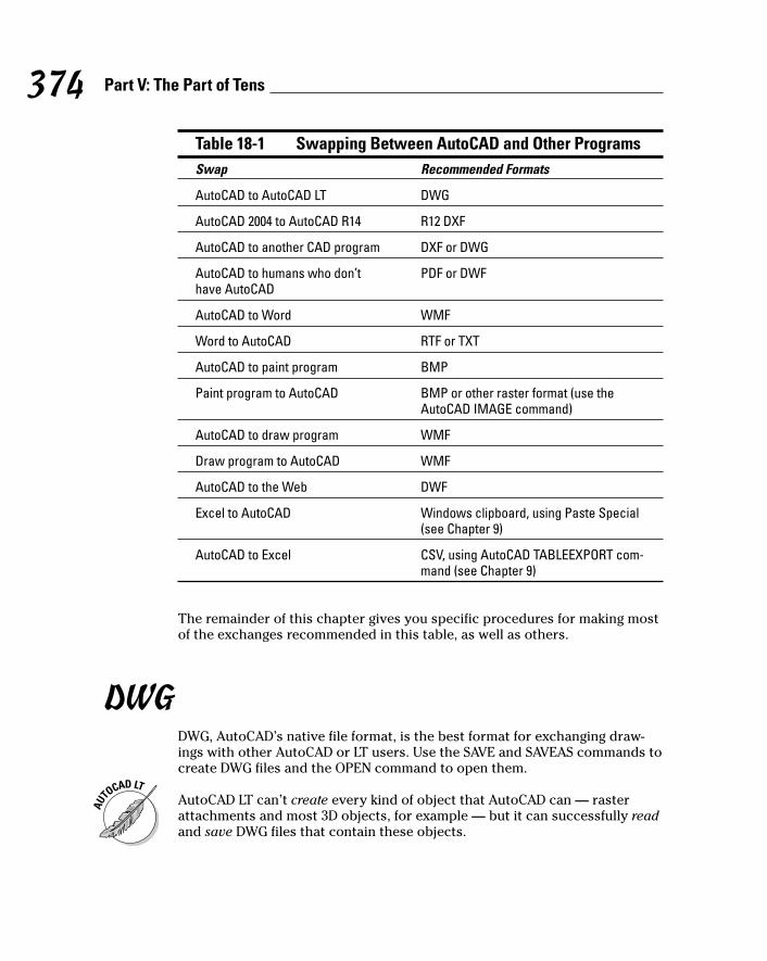
Table 18-1 Swapping Between AutoCAD and Other ProgramsSwap Recommended Formats
AutoCAD to AutoCAD LT DWG
AutoCAD 2004 to AutoCAD R14 R12 DXF
AutoCAD to another CAD program DXF or DWG
AutoCAD to humans who don’t PDF or DWFhave AutoCAD
AutoCAD to Word WMF
Word to AutoCAD RTF or TXT
AutoCAD to paint program BMP
Paint program to AutoCAD BMP or other raster format (use theAutoCAD IMAGE command)
AutoCAD to draw program WMF
Draw program to AutoCAD WMF
AutoCAD to the Web DWF
Excel to AutoCAD Windows clipboard, using Paste Special(see Chapter 9)
AutoCAD to Excel CSV, using AutoCAD TABLEEXPORT com-mand (see Chapter 9)
The remainder of this chapter gives you specific procedures for making mostof the exchanges recommended in this table, as well as others.
DWGDWG, AutoCAD’s native file format, is the best format for exchanging draw-ings with other AutoCAD or LT users. Use the SAVE and SAVEAS commands tocreate DWG files and the OPEN command to open them.
AutoCAD LT can’t create every kind of object that AutoCAD can — rasterattachments and most 3D objects, for example — but it can successfully readand save DWG files that contain these objects.
374 Part V: The Part of Tens
l571389 Ch18.qxd 4/12/04 9:46 AM Page 374

AutoCAD 2005 can’t save to the AutoCAD Release 14 DWG format. Apparently,the Autodesk bigwigs figure that the best way to persuade R14 users toupgrade is to make their lives as inconvenient and isolated as possible! Ifyou need to send AutoCAD 2005 drawings to AutoCAD R14 users, save themin R12 DXF format instead of a DWG format. (See the “DXF” section forinstructions.)
Autodesk does not document the native AutoCAD DWG file format, and rec-ommends that all file exchanges between AutoCAD and other CAD programstake place via DXF files (see the next section). But several companies havereverse-engineered the DWG format, and it’s now common for other CAD pro-grams to read and sometimes write DWG files directly, with greater or lesseraccuracy. Because the DWG format is complicated, isn’t documented, andgets changed every couple of years, no one ever figures it out perfectly. Thus,exchanging DWG files with non-Autodesk programs always involves somecompatibility risks.
When you send DWG files to other people — whether they use AutoCAD or adifferent CAD program — you need to make sure that their software can readthe DWG file version that you’re sending. See Chapter 1 for information aboutAutoCAD DWG file versions.
When you send DWG files to other people, remember to use the ETRANSMITcommand to ensure that you send all the dependent files (fonts, xrefs, andraster images). See Chapter 16 for details.
375Chapter 18: Ten Ways to Swap Drawing Data with Other People and Programs
Round-trip DWG fareThe most demanding — and elusive — kind ofdata exchange is called round-trip transfer.Round-trip means that you create and save afile in one program, edit and save it in anotherprogram, and then edit and save it in the firstprogram again. A perfect round trip is one inwhich all the data survives and the users of bothprograms can happily edit whatever they wantto. Unfortunately, the perfect round trip, like theperfect visit to your cousins, rarely happens.
In CAD, round-trip transfer becomes an issuewhen two people want to work on the samedrawings with different CAD programs. AutoCADand AutoCAD LT have excellent round-tripcompatibility, as Chapter 1 explains. Expect abumpier road if you’re exchanging drawingswith users of other CAD programs. Performsome test transfers before you assume thatyour drawings can get from here to there andback again unscathed.
l571389 Ch18.qxd 4/12/04 9:46 AM Page 375

DXFDXF (Drawing eXchange Format) is the Autodesk-approved format forexchanging between different CAD programs. (Some other vector graphicsapplications, such as drawing and illustration programs, read and write DXFfiles, too.) DXF is a documented version of the DWG format. Because DXFmore-or-less exactly mimics the DWG file’s contents, it’s (usually) a faithfulrepresentation of AutoCAD drawings.
How well DXF works for exchanging data depends largely on the other pro-gram that you’re exchanging with. Some CAD and vector graphics programsdo a good job of reading and writing DXF files, while others don’t. In practice,geometry usually comes through well, but properties, formatting, and othernongeometrical information can be tricky. Test before you commit to a large-scale exchange, and always check the results.
To create DXF files, use the SAVEAS command (File➪Save As) and choose oneof the three DXF versions in the Files of Type drop-down list. To open a DXFfile, do the same with the OPEN command (File➪Open).
DWFAs Chapter 16 describes, DWF is Autodesk’s special “lightweight” drawingformat for posting drawings on the Web or sharing them with people whodon’t have AutoCAD. Those people can use Autodesk’s free Express Viewerprogram to view and print DWF files (as well as DWG files). Chapter 16describes how to create and use DWF files.
PDFAdobe’s PDF (Portable Document Format) is the most popular format forexchanging formatted text documents among users of different computersand operating systems. PDF also does graphics, as you probably know fromhaving viewed PDF brochures on Web sites.
Autodesk has worked hard to make DWF the PDF for CAD drawing exchange,but DWF hasn’t yet caught on in a big way. When AutoCAD users need tosend drawings to people who don’t have AutoCAD, many prefer to convertthe drawings to PDF files. Most potential recipients are familiar with PDF andalready have the free Adobe Reader installed on their computers, neither ofwhich can be said of DWF.
376 Part V: The Part of Tens
l571389 Ch18.qxd 4/12/04 9:46 AM Page 376

The free Adobe Reader views and prints PDF files, but won’t create them. Inorder to convert an AutoCAD drawing (or any other Windows document) intoa PDF file, you’ll need additional software. Adobe sells Acrobat Standard andProfessional for this purpose — see www.adobe.com/acrobat/ for detailsand a trial version. Many other companies offer commercial and sharewarePDF-creation programs. One such utility is Pdf995 (www.pdf995.com), which,despite its under-$10 price, does a good job of creating PDF files fromAutoCAD drawings.
WMFThere are lots of different vector and raster graphics file formats, butMicrosoft has been pretty successful at making its WMF and BMP formats thelingua franca — or should that be lingua bill-a? — for exchanging graphicalinformation in Windows.
WMF (Windows MetaFile) is a vector format, so it does a decent job of repre-senting AutoCAD objects such as lines, arcs, and text.
To create a WMF file showing some or all the objects in a drawing, use theEXPORT command (File➪Export) and choose Metafile (*.wmf) in the Filesof Type drop-down list. After you create a WMF file in AutoCAD, use the otherprogram’s file insertion command to place the image in a document.
AutoCAD puts objects in the WMF file with the colors and display lineweightsthat you see on the AutoCAD screen. To create a WMF file that looks like amonochrome plot — that is, with varying lineweights and all objects black —you need to set layer and object properties in AutoCAD so the objects lookthat way on-screen before you create the WMF file.
You can go the other direction, from a WMF file into AutoCAD, by using theWMFIN command (Insert➪Windows Metafile).
BMP, JPEG, TIFF, and Other Raster Formats
BMP (BitMaP) is the standard Windows raster format. AutoCAD can createBMP files from drawing objects (via the EXPORT command) and place BMPfiles in drawings (via the IMage command). When you export AutoCAD draw-ing objects to a BMP file, all the objects get converted to dots. Turning a lineinto a bunch of dots isn’t a swell idea if you want to change the line again. Butit is useful if you need to copy a drawing into a company brochure.
377Chapter 18: Ten Ways to Swap Drawing Data with Other People and Programs
l571389 Ch18.qxd 4/12/04 9:46 AM Page 377
One problem with BMP files is their big file size. Unlike some other raster for-mats, BMP doesn’t offer compression. Because CAD drawings usually arefairly large in area, they can turn into monstrously large BMP files.
Creating a BMP file showing some or all the objects in a drawing is just likecreating a WMF file: Use the EXPORT command (File➪Export) but chooseBitmap (*.bmp) in the Files of Type drop-down list. After you create a BMPfile in AutoCAD, you use the other program’s File➪Open to open it or thegraphics file insertion command to place it in an existing document.
If you want to go the other direction, a BMP file into an AutoCAD drawing, usethe IMage command, as described in Chapter 13.
Although BMP is a standard Windows format for exchanging raster data, it’scertainly not the preferred format of many programs. Other common rasterformats include PCX, JPEG, and TIFF (the latter two appears as JPG and TIF inWindows). Among their other advantages, these formats offer image com-pression, which can reduce the size of raster files dramatically.
If the program that you’re trying to work with works best with other formats,or you want to avoid huge BMP files, you have a couple of options:
� Create an AutoCAD-friendly format (such as WMF or BMP) and translateit to another graphics format with a translation program such as HiJaak(www.imsisoft.com) or VuePrint (www.hamrick.com).
AutoCAD includes new JPGOUT, PNGOUT, and TIFOUT commands forcreating JPG, PNG, and TIF files in the same way that you export WMFand BMP files. Type the command name, press Enter, specify a raster filename, and select the objects to be included in the image file. These com-mands use the current drawing area background color as the back-ground color for the image. If you want your image background to bewhite, make sure that the AutoCAD drawing area color is white whenyou run the command. (Choose Tools➪Options➪Display➪Colors tochange display colors.)
� If you need to convert drawings to a raster format other than BMP orTIF, the second option is to use the AutoCAD Raster File Format driver.This driver enables you to “plot” to a file with one of nine raster formats,including PCX, JPEG, and TIFF. Before you can use the Raster File Formatdriver, you must create a new plotter configuration: Choose File➪PlotterManager and then run the Add-A-Plotter wizard. After you create theRaster File Format driver configuration, you use the Plot dialog box asdescribed in Chapter 12 to generate “plots” to raster files.
To go the other direction, raster image file into an AutoCAD drawing, use theIMage command, as described in Chapter 13.
378 Part V: The Part of Tens
l571389 Ch18.qxd 4/12/04 9:46 AM Page 378
Windows ClipboardIf you need to transfer lots of WMF or BMP figures, you can do it a bit morequickly with the Windows Clipboard, which bypasses the creation of WMFand BMP files on disk. Instead, Windows uses your computer’s memory totransfer the data. Choose Edit➪Copy in the program from which you want tocopy the data and Edit➪Paste Special in the program to which you want tocopy it. In the Paste Special dialog box, choose Picture to paste the image inWMF format or Bitmap to paste it in BMP format.
OLEMicrosoft Windows includes a data transfer feature, Object Linking andEmbedding, or OLE. (In case you’re wondering, that’s “OLE” pronounced likethe Spanish cheer, not like the Cockney way of saying hole.) Microsoft toutsOLE as an all-purpose solution to the challenge of exchanging formatted databetween any two Windows programs.
If you want to share data between two OLE-aware programs (and mostWindows applications are OLE-aware), creating an embedded or linked docu-ment shouldn’t be much more complicated than cut and paste. That’s thetheory.
Here’s how it works. In OLE lingo, the program that you’re taking the datafrom is the source. The program that receives the data is called the container.For example, if you want to place some word processing text from MicrosoftWord into an AutoCAD drawing, Word is the source, and AutoCAD is thecontainer.
In Word, you select the text that you want to put in the AutoCAD drawing andchoose Edit➪Copy to copy them to the Windows Clipboard. Then, you switchto AutoCAD and choose Edit➪Paste Special. The Paste Special choice dis-plays a dialog box containing the choices Paste and Paste Link. The Pasteoption creates a copy of the object from the source document and embedsthe copied object into the container document. The Paste Link option linksthe new object in the container document to its source document so anychanges to the source document are automatically reflected in the containerdocument. In other words, if you link word processing text to an AutoCADdrawing, changes that you make later in the Word document get propagatedto the AutoCAD drawing automatically. If you embed the same spreadsheetobject in an AutoCAD drawing, changes that you later make to the text inWord aren’t reflected in the AutoCAD drawing.
379Chapter 18: Ten Ways to Swap Drawing Data with Other People and Programs
l571389 Ch18.qxd 4/12/04 9:46 AM Page 379
That’s how it’s supposed to work. In practice, the container application some-times doesn’t display or print all the linked or embedded data correctly. Seethe “Should you shout, ‘OLE!’?” sidebar for details.
Screen CaptureIf your goal is to show the entire AutoCAD program window, not just thedrawing contained in it, create a screen capture. Most of the figures in thisbook are screen captures. You might use similar figures to put together atraining manual or to show your mom all the cool software you use.
380 Part V: The Part of Tens
Should you shout, “OLE!”?Unfortunately, OLE is afflicted with several prac-tical problems.
� Compound OLE documents can slow per-formance — a lot. If you plan to use OLE,you should have a fast computer with lotsof memory — or lots of time on your hands.
� Supporting OLE well is a difficult program-ming job, and many applications, includingAutoCAD, suffer from OLE design limitationsand bugs. (For example, when you link orembed a word processing document, onlythe first page appears in AutoCAD.)
� Previous versions of AutoCAD exhibitedmore OLE problems than AutoCAD 2005. Inparticular, plotted OLE output often under-went creative but undesirable transforma-tions. If you exchange drawings with usersof earlier versions, what they see on thescreen and plot may not match what youcreated.
AutoCAD 2005 includes a bevy of OLE improve-ments, which address some of the limitations:
� You can control text size more easily,via the MOLESCALE system variable andOLESCALE command.
� Editing of OLE objects with commands suchas Move and CoPy is more consistent withediting of native AutoCAD objects.
� You can control the quality of plotted OLEobjects with a setting on the Plot andPublish tab of the Options dialog box.
Even with the OLE improvements in AutoCAD2005, you should consider carefully and testextensively before embedding or linking docu-ments into drawings. If you want to play it safe,use the alternative methods described in thischapter, and save OLÉ for your next trip toSpain.
l571389 Ch18.qxd 4/12/04 9:46 AM Page 380

Windows includes a no-frills screen capture capability that is okay for anoccasional screen capture. It works like this:
1. Capture the whole screen or active window with one of these steps:
• Press the Print Screen key to capture the entire Windows screen,including the desktop and taskbar.
• Hold down the Alt key and press the Print Screen key to capturejust the active program window (for example, AutoCAD).
Windows copies a bitmap image to the Windows Clipboard.
2. Paste the bitmap image into another program. You have two options:
• Paste into a paint program (such as the Paint program inWindows). Use that program to save a raster image as a BMP fileformat.
• Paste the bitmap image directly into a document (such as a Worddocument or an AutoCAD drawing) without creating another file.
If you do lots of captures, a screen capture utility program makes the jobfaster and gives you more options. You can control the area of the screen thatgets captured, save to different raster file formats with different mono-chrome, grayscale, and color options, and print screen captures. One goodscreen capture utility program is FullShot by Inbit, Inc. (www.inbit.com).
When you create screen captures, pay attention to resolution and colors:
� High screen resolutions (for example, above 1280 x 1024) can make yourcaptures unreadable when they get compressed onto an 81⁄2-x-11-inchsheet of paper and printed on a low-resolution printer.
� Some colors don’t print in monochrome, and a black AutoCAD drawingarea is overwhelmingly dark. For most of the screen captures in thisbook I used 1024 x 768 resolution, a white AutoCAD drawing area, anddark colors — mostly black — for all the objects in the drawing.
TXT and RTFTXT (Text, also called ASCII for American Standard Code for InformationInterchange) is the simplest format for storing letters and numbers. TXT filesstore only basic text, without such formatting as boldface or special para-graph characteristics. RTF (Rich Text Format) is a format developed byMicrosoft for exchanging word processing documents (text plus formatting).
381Chapter 18: Ten Ways to Swap Drawing Data with Other People and Programs
l571389 Ch18.qxd 4/12/04 9:46 AM Page 381

Select Import Text from the Multiline Text Editor window’s right-click menuto import an TXT or RTF file. AutoCAD imports plain text from TXT and RTFfiles. When you import an RTF file, AutoCAD even brings along most of thetext formatting and alignment. Chapter 9 covers the Multiline Text Editorwindow.
Because no sane person would use AutoCAD as a word processor, AutoCADdoesn’t provide any special tools for exporting text. You can select AutoCADtext, copy it to the Windows Clipboard, then paste it into another program.
382 Part V: The Part of Tens
l571389 Ch18.qxd 4/12/04 9:46 AM Page 382
• Symbols andNumerics •<> (angle brackets), 30, 249‘ (apostrophe) character, 31* (asterisk) character, 37| (pipe) character, 312? (question mark) character, 37, 38 [] (square brackets) character, 30_ (underscore) character, 31@X,Y coordinates, 91_LINE command, 312D drawings
coordinate entry, 191creating 3D objects from, 194–196input and output devices for, 183and system performance, 183versus 3D, 180wireframe mode, 184, 187
2P (2-Point) option (Circle command), 1153D meshes, 1963D modeling
AutoCAD LT limitations, 14AutoCAD 2005 support for, 179–182 Cartesian coordinate systems, 190–191cautions, 183coordinate filters, 192creating 3D objects, 194–197 editing commands, 199–200lines and polylines, 193–194object snaps, 192prerequisites for, 182–183primitives, 196, 198–199rendering, 200solids modeling, 197–199and system performance, 183typed coordinates, 191uses for, 179–181using 3DOrbit command, 187–189wireframes, 181
3D Surfaces option (Draw menu), 1963D Views option (View menu), 186–1873DClip command, 1893DFACE command, 1963DOrbit command, 187–1893DPOLY command, 193–1953DS Max (Discreet) animation
program, 2003P (3-Point) option (Circle
command), 115
• A •absolute coordinates
entering in command area, 191polar and rectangular, 91
Acad DWG formats. See DWG filesAcad.dwt template, 51–53ACAD-ISO linetypes, 82Acadiso.dwt template, 53Acad.lin file, 82, 84Acadiso.lin file, 82, 84accuracy versus precision, 89ACI (AutoCAD Color Index), 81ADCenter command, 344Add Printer Wizard, 269Add-A-Plotter Wizard, 270add-on products, 183, 197Adjust Clipping Planes (3DOrbit), 189Adobe PDF files, 376–377aesthetics, 339aligned dimensions, 232, 244–245ALL object selection option, 135All option (Zoom command), 170Alternate Units tab settings (New/Modify
Dimensions dialog box), 242Alt-key shortcuts, 21Always Draw Dim Line settings
(dimensions)American Institute of Architects (AIA),
CAD Layer Guidelines, 340, 343
Index
m571389 index.qxd 4/12/04 9:46 AM Page 383

American National Standards Institute(ANSI) plot sheet sizes, 47
angle brackets (<>), 30, 249Angle option (Arc command), 117–118Angle Precision list (Drawing Units dialog
box), 55angle settings (hatch patterns), 261–262Angle Type list (Drawing Units dialog
box), 55angular dimensions, 233animations, 200annotations, 49, 88–89, 256ANSI (American National Standards
Institute) plot sheet sizes, 47apostrophe (‘) character, 31Apparent Intersection snap mode, 192Arc command, 103, 115, 117–119Arc length option (REVCLOUD
command), 126Arc option (ELlipse command), 120, 121arcball (3DOrbit), 187Architectural Desktop, 102, 183Architectural drawing units
default, 92drawing limit settings, 57scale options, 44–46
Architectural sheet sizes, 47–48ARCHIVE command, 354arcs, circular and elliptical, 110, 116–119ARray command, 149–150arrow keys, 31arrowheads, 250–253associative dimension objects, 233–234,
249–250asterisk (*) character, 37attachment options (xrefs), 312ATTDEF command, 305ATTDIA system variable, 307Attribute Extraction wizard, 308attributes
attribute values, 304, 307–308versus database fields, 305defining, 300, 304–306in exploded blocks, 309using, 304, 307
AUNITS system variable, 51
AUPREC system variable, 51AutoCAD 2004, upgrading from, 14–16AutoCAD 2005
add-ons for, 13versus AutoCAD LT, 13–14compatibility with earlier versions, 11–12,
14–16new features, 15–16, 40versus other Windows programs, 18
AutoCAD Color Index (ACI), 81AutoCAD LT 2005 feature overview, 13–14AutoCAD LT 2005 For Dummies, 1–2, 14AutoCAD Releases 12-14 compatibility
issues, 12Autodesk
add-on products, 10, 13Buzzsaw, 350DWF Composer, 350Express Viewer, 358, 363Knowledge Base, 40solids modeling utilities, 1973D modeling utilities, 183VIZ rendering program, 202Web site for, 40
auto-hide feature (palettes), 36AutoLISP (LSP) programs, 15automated plotting, 289–290
• B •back up (BAK) files, 371background masking, 218–219, 241 background plotting, 15base points
for blocks, 299for drawing manipulations, 145–148selecting and using, 138–143
Batch Standards Checker utility, 345BATTMAN command, 306bHatch command, 257Bind button (Xref Manager dialog box), 315bitmap (BMP) files
exchanging, sharing, 377–378uses for, 296versus vector files, 371
bitmapped (raster) images, 216–219
384 AutoCAD 2005 For Dummies
m571389 index.qxd 4/12/04 9:46 AM Page 384
Block Attribute Manager, 306Block command, 301block libraries, 301blocks
defining, 295–300, 304, 306–307exploding, 308–309functions, 295, 297, 316icons for, 300inserting in drawings, 296, 301–304limitations, 297redefining, 298, 302versus xrefs, 310
blueline machines (blueprints), 268BMP (BitMaP) files, 296, 377–378 Boolean operations, 199borders, 43, 50, 256boundary edges, 152–153. See also
hatching (hatch objects)Boundary Hatch and Fill dialog box,
256–264bounding boxes, 132–133brackets in command line prompts, 30BReak command, 121, 154broadband access, 348bulleted lists, 221–222BURST command, 309buttons
active versus inactive, 26, 90issuing commands using, 18
Buzzsaw (Autodesk) drawing repository, 350
by-layer property controls, 77–79, 224–227by-object property controls, 77–78
• C •CAD (computer-aided drafting, drawing)
drawing programsgood practices, 74versus manual drawing, 167versus non-CAD drawing programs,
73, 101requirements for, 42text in, 2053D modeling capability, 179–180
CAD Layer Guidelines (American Instituteof Architects), 340, 343
CAD standardsaesthetics, 339color-to-lineweight plotting charts,
341–342compliance-enhancing utilities, 344–346implementation challenges, 340importance of, 337–338, 371internal or project-specific, 340layer charts, 342–343nonstandard, 339for styles and drawing set up, 343–344text size, 241
camera point controls (3DOrbit), 189Cartesian coordinate systems, 190cartoons, 49CD-browser screen, 15center points, identifying
for arcs, 110, 117for ellipses, 120
CHamfer command, 155–156channels (Communication Center), 25–26Check Standards utility, 345–346CHECKSTANDARDS command, 345child drawings. See dependent files (child
drawings)circles, circular arcs, drawing, 103,
110–111, 115–116clipping 3D objects, 189Close command, 20, 28Close option
Line command, 106PLine command, 109
closing drawing areas, 256closing toolbars, 22clouds, revision, 124–126Color Book tab (Select Color dialog
box), 81Color TaBle (CTB) files, 280, 283–285color-dependent plot styles
attaching to drawing, 285plot property settings, 282storage location, 280tables for, 279
385Index
m571389 index.qxd 4/12/04 9:46 AM Page 385
colors, color propertyapplying, 80–81, 248for hatch patterns, 261for lineweights, 78, 283, 341–342in raster format files, 378uses for, 77viewing and changing settings for, 282
color-to-lineweight plotting charts, 283,341–342
columns (tables), widening, 226command line area
command options, 103–104coordinate entry, 28–29, 90–92Esc key with, 30features, 26right-click action, 31for system variables, 36using, 17–18, 27–28 watching, 30–31, 34
command prompt, 29Command Reference (online help), 38,
217–218, 234–235command-first editing
as default, 130–131Erase command, 135–137object selection, 131–135
commands. See also command line areaissuing, 18options, viewing, 27recent, viewing and rerunning, 31transparent, 31
Communication Center, 25–26configuration settings, 31, 20Configure Standards utility, 345construction lines, 104container programs (OLE), 379content pane, 88Control-key shortcuts, overview, 21coordinate filters, 192Coordinates area, 92coordinates, coordinate systems
for camera point target points, 189for cursors, 24, 27icons for, 190precision techniques, 90–92for 2D and 3D drawings, 191–193
versus viewpoints, 191WCS and UCS systems, 190–191
CoPy commandversus COPYCLIP command, 142keyboard shortcut, 27with 3D solids, 199using, 138, 141
copy option (grip modes), 160–161COPYBASE command, 143COPYCLIP command, 141–143copying
dimension styles, 235–237layers, 87–88layouts, 66–67methods for, 142sheet sets, 326
CPolygon object selection, 135Create Layout Wizard, 63–65Create New Dimension Style dialog
box, 238Create New Table Style dialog box,
223–224Create Realistic Images and Graphics
(User’s Guide), 201–202Create Sheet Set wizard, 325–326Create Transmittal dialog box,
352–353crossing object selection, 132–133,
135–136, 144CSV (Comma Separated Value) files, 227CTB (Color TaBle) files, 280, 283–285Ctrl+1, +2, +3, +4 keyboard shortcuts, 34Ctrl+H keyboard shortcut, 297Ctrl+N keyboard shortcut, 52Ctrl+O keyboard shortcut, 21Ctrl+S keyboard shortcut, 21current layer, 76current properties, 75cursors
cursor coordinates, 24full-orbit cursor, 187
curved segments, 107. See also arcscurve-drawing commands, 115–126custom fonts, 207–208, 356 Customization Guide, 22, 84Customize dialog box (toolbars), 23
386 AutoCAD 2005 For Dummies
m571389 index.qxd 4/12/04 9:46 AM Page 386
customizinghatching areas, 256–258system variables, 36–37templates, 68–70toolbars, 22
CUTCLIP command, 143cutting edges, trimming, 152–153
• D •dash-dot linetypes, 45, 60data extraction, 307–308database fields, versus attributes, 305DC Online tab (DesignCenter palette), 86ddEDIT command, 248DDPTYPE command, 127–128DDVPOINT command, 187decimal units, 44Default Template File, 69defaults
command line area action, 30configuring and restoring, 18coordinate entry units, 92dimension style, 237dimension text, 249editing style, 130hatch placement, 264template drawing, 51, 53, 693D coordinate system, 1903D model display, 187toolbar arrangement, 22transmittal package format, 353
Define Attributes (Draw menu), 305Define View Window button (New View
dialog box), 171degenerating images, 176–177dependent files (child drawings)
blocks with, 303in Web-based transmissions, 350xrefs with, 309–310
depth thickness, 194–196Description box (Layer Properties Manager
dialog box), 83DesignCenter palette
components, 85–87copying dimension styles, 236
favorites list, 88keyboard shortcuts, 34maintaining CAD standards using, 344screen display, 35
DesignJet printers (Hewlett-Packard), 269Detach button (Xref Manager dialog
box), 315dialog boxes
features and uses, 38–39modal versus modeless, 35
diameters, 233diazo blueline machines (blueprints), 268digital signatures, 364Dim Style Control list, 243DimANgular command, 247DIMASSOC system variable, 249DimBAseline command, 246–247 DimCOntinue command, 246–247DIMDISASSOCIATE command, 250Dimension menu, 234, 244–245Dimension Style Manager dialog box, 51,
61, 237–238dimension styles. See also dimensions,
dimensioningcharacter formatting, 242creating, 237–238defined, 229–230, 235line and arrows settings, 240ready-made, copying, 235–237scaling options, 241–242secondary styles, 238standardizing, 343text settings, 240tolerance settings, 242
Dimension toolbaraccess and uses, 234Aligned Dimension button, 245Linear Dimension button, 244Quick Leader button, 251
dimensions, dimensioning. See alsodimension styles
angular, 233associative dimension objects, 233–234commands for, 234, 246defined, 36, 60–61dimension arrowheads, 232
387Index
m571389 index.qxd 4/12/04 9:46 AM Page 387

dimensions, dimensioning (continued)dimension lines, 231–232dimension text, 230–231, 249editing, 247–250importance of, 229, 230–231linear, 232–233, 243–246object selection options, 242–243radial, 233scale settings, 51, 61side-by-side, 246trans-spatial, 246–247variables for, 36, 235
DimLinear command, 247DimRAdius command, 247DIMREASSOC command, 250DIMREGEN command, 250DIMSCALE system variable
with revision clouds, 126settings for, 242with trans-spatial dimensioning, 246–247using, 51, 211
Dimstyle command, 61, 85direct distance entry, 90, 98direct manipulation editing, 130displacement distances, 138–139 display settings, 18, 92dithering, monochrome, 286DLine command, 112DOnut command, 103–104, 115, 123–124donuts, 123–125double lines, 111–112double-floating-point precision, 176Drafting Settings dialog box
Object Snap tab, 96–97Polar Tracking tab, 98Snap and Grid tab, 57system variable settings, 51
drag-and-drop actioncopying dimension styles, 236–237copying layers, 88inserting blocks, 303with Stretch command, 146
Drag-and-Drop Scale area (Drawing Unitsdialog box), 55
Draw menuBlock, Define Attributes option, 305
commands on, 102–103Single Line Text option, 213Solids submenu, 198Surfaces, 3D Surfaces option, 196
Draw Order setting (Boundary Hatch andFill dialog box), 264
Draw Order toolbar, 22Draw toolbar
Insert Block button, 302Make Block button, 298Multiline Text button, 216using, 22, 103
drawing areaannotation space, 49calculating, 48–49drawing on, 31, 34model space, 25, 32and printer/plotter limitations, 49reading coordinates in, 92scroll bar panning, 169–170Shift+right-clicking in, 95–96title bar and sizing buttons, 20
drawing commands, 28, 102–106Drawing eXchange Format (DXF) files, 376Drawing Orientation area (Plot dialog
box), 273Drawing Properties dialog box, 60–61drawing scale factor
applying to linetypes, 61for architectural drawing scales, 46choosing correctly, 370determining from drawings, 211versus drawing scales, 45text heights, 211text styles, 209–210
drawing scales, 45–47drawing units, 43–44, 54–55Drawing Units dialog box
choosing type and precision of units, 44linear and angular unit settings, 54–55system variable settings, 51
drawing windows, 20drawings
aesthetics, 339arcs, 117–119blocks in, 296, 301–304, 307
388 AutoCAD 2005 For Dummies
m571389 index.qxd 4/12/04 9:46 AM Page 388
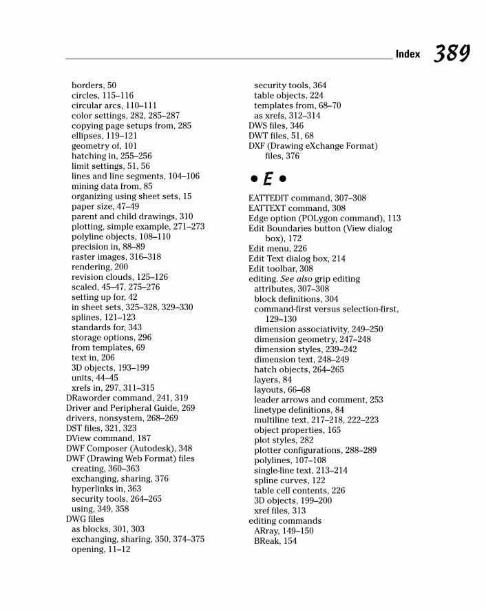
borders, 50circles, 115–116circular arcs, 110–111color settings, 282, 285–287copying page setups from, 285ellipses, 119–121geometry of, 101hatching in, 255–256limit settings, 51, 56lines and line segments, 104–106mining data from, 85organizing using sheet sets, 15paper size, 47–49parent and child drawings, 310plotting, simple example, 271–273polyline objects, 108–110precision in, 88–89raster images, 316–318rendering, 200revision clouds, 125–126scaled, 45–47, 275–276setting up for, 42in sheet sets, 325–328, 329–330splines, 121–123standards for, 343storage options, 296from templates, 69text in, 2063D objects, 193–199units, 44–45xrefs in, 297, 311–315
DRaworder command, 241, 319Driver and Peripheral Guide, 269drivers, nonsystem, 268–269DST files, 321, 323DView command, 187DWF Composer (Autodesk), 348DWF (Drawing Web Format) files
creating, 360–363exchanging, sharing, 376hyperlinks in, 363security tools, 264–265using, 349, 358
DWG filesas blocks, 301, 303exchanging, sharing, 350, 374–375opening, 11–12
security tools, 364table objects, 224templates from, 68–70as xrefs, 312–314
DWS files, 346DWT files, 51, 68DXF (Drawing eXchange Format)
files, 376
• E •EATTEDIT command, 307–308EATTEXT command, 308Edge option (POLygon command), 113Edit Boundaries button (View dialog
box), 172Edit menu, 226Edit Text dialog box, 214Edit toolbar, 308editing. See also grip editing
attributes, 307–308block definitions, 304command-first versus selection-first,
129–130dimension associativity, 249–250dimension geometry, 247–248dimension styles, 239–242dimension text, 248–249hatch objects, 264–265layers, 84layouts, 66–68leader arrows and comment, 253linetype definitions, 84multiline text, 217–218, 222–223object properties, 165plot styles, 282plotter configurations, 288–289polylines, 107–108single-line text, 213–214spline curves, 122table cell contents, 2263D objects, 199–200xref files, 313
editing commandsARray, 149–150BReak, 154
389Index
m571389 index.qxd 4/12/04 9:46 AM Page 389
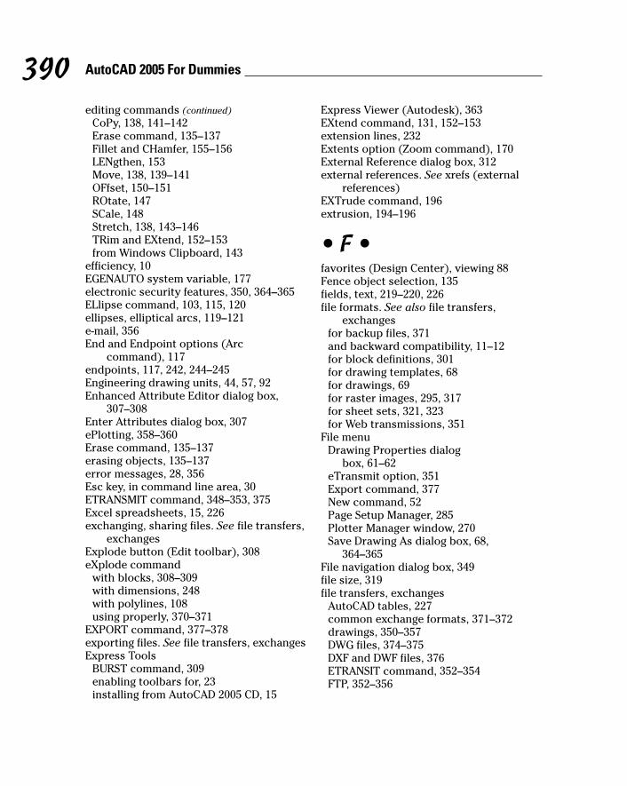
editing commands (continued)CoPy, 138, 141–142Erase command, 135–137Fillet and CHamfer, 155–156LENgthen, 153Move, 138, 139–141OFfset, 150–151ROtate, 147SCale, 148Stretch, 138, 143–146TRim and EXtend, 152–153from Windows Clipboard, 143
efficiency, 10EGENAUTO system variable, 177electronic security features, 350, 364–365ELlipse command, 103, 115, 120ellipses, elliptical arcs, 119–121e-mail, 356End and Endpoint options (Arc
command), 117endpoints, 117, 242, 244–245 Engineering drawing units, 44, 57, 92Enhanced Attribute Editor dialog box,
307–308Enter Attributes dialog box, 307ePlotting, 358–360Erase command, 135–137erasing objects, 135–137error messages, 28, 356Esc key, in command line area, 30ETRANSMIT command, 348–353, 375 Excel spreadsheets, 15, 226exchanging, sharing files. See file transfers,
exchangesExplode button (Edit toolbar), 308eXplode command
with blocks, 308–309with dimensions, 248with polylines, 108using properly, 370–371
EXPORT command, 377–378exporting files. See file transfers, exchangesExpress Tools
BURST command, 309enabling toolbars for, 23installing from AutoCAD 2005 CD, 15
Express Viewer (Autodesk), 363EXtend command, 131, 152–153extension lines, 232Extents option (Zoom command), 170External Reference dialog box, 312external references. See xrefs (external
references)EXTrude command, 196extrusion, 194–196
• F •favorites (Design Center), viewing 88Fence object selection, 135fields, text, 219–220, 226file formats. See also file transfers,
exchangesfor backup files, 371and backward compatibility, 11–12for block definitions, 301for drawing templates, 68for drawings, 69for raster images, 295, 317for sheet sets, 321, 323for Web transmissions, 351
File menuDrawing Properties dialog
box, 61–62eTransmit option, 351Export command, 377New command, 52Page Setup Manager, 285Plotter Manager window, 270Save Drawing As dialog box, 68,
364–365File navigation dialog box, 349file size, 319file transfers, exchanges
AutoCAD tables, 227common exchange formats, 371–372drawings, 350–357DWG files, 374–375DXF and DWF files, 376ETRANSIT command, 352–354FTP, 352–356
390 AutoCAD 2005 For Dummies
m571389 index.qxd 4/12/04 9:46 AM Page 390

Object Linking and Embedding, 379–380PDF files, 376–377raster format files, 377–378screen captures, 380–381TXT and RTF files, 381–382Web-based, 350–357Windows Clipboard, 379WMF files, 377
Files tab (Options dialog box), 281Fillet command, 155–156filter options, 192First point option (BReak command), 154Fit tab settings (New/Modify Dimensions
dialog box), 241–242Fit to Paper settings (Plot dialog box),
46–47, 275–276fixed height text styles, 209Flat Shaded mode, 189floating viewports, 184folders
for plot styles, 281for templates, 70
Folders tab (DesignCenter palette), 86fonts, 206–208, 356Format menu
Dimension Style Manager dialog box, 61Drawing Limits option, 56Linetype command, 61, 84Point Style dialog box, 127Table Style option, 223Text Style dialog box, 208–209Units option, 54
formatting multiline text, 217–218Fractional drawing units, 44fractional inches, 92Freeze layer setting, 371FTP (File Transfer Protocol), 355–356F2 key, 29full orbit cursor (3DOrbit), 187–188
• G •geometric tolerances, 242geometry
in CAD drawing, 101crammed, avoiding, 371
editing, 247–248precision in, 88–89
geometry-driven associative dimensions, 234
Global Scale factor edit box (LinetypeManager dialog box), 61
Gouraud Shaded mode, 189gradient fill hatch patterns, 261gray scale in drawings, 286grid mode, 24, 57, 58grid spacing, 51, 57–59GRIDMODE system variable, 51GRIDUNIT system variable, 51grip editing
defined, 130MOVE mode, 161–162for multiline text, 222–223spline curves, 122STRETCH mode, 157–158, 162–164using, 156–157with wireframe and surface objects, 199
grips (hot grips)defined, 107, 130, 156displaying, 157using, 160, 164
Group command, 297group filters (layers), 84Group Manager dialog box, 297grouping objects, 297
• H •half-size plots, 275hard copy, options, 267–268. See also
plottinghardware requirements, 15Hatch Edit dialog box, 264–265hatch palettes, 264hatch patterns
angle and scale settings, 261–262copying settings for, 259predefined, 260–261standardizing, 343trimming, 265updating, 259user-defined, 261
391Index
m571389 index.qxd 4/12/04 9:46 AM Page 391
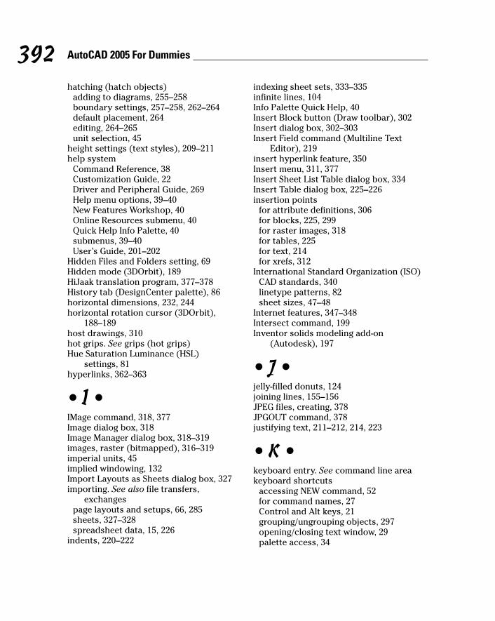
hatching (hatch objects)adding to diagrams, 255–258boundary settings, 257–258, 262–264default placement, 264editing, 264–265unit selection, 45
height settings (text styles), 209–211help system
Command Reference, 38Customization Guide, 22Driver and Peripheral Guide, 269Help menu options, 39–40New Features Workshop, 40Online Resources submenu, 40Quick Help Info Palette, 40submenus, 39–40User’s Guide, 201–202
Hidden Files and Folders setting, 69Hidden mode (3DOrbit), 189HiJaak translation program, 377–378History tab (DesignCenter palette), 86horizontal dimensions, 232, 244horizontal rotation cursor (3DOrbit),
188–189host drawings, 310hot grips. See grips (hot grips)Hue Saturation Luminance (HSL)
settings, 81hyperlinks, 362–363
• I •IMage command, 318, 377Image dialog box, 318Image Manager dialog box, 318–319images, raster (bitmapped), 316–319imperial units, 45implied windowing, 132Import Layouts as Sheets dialog box, 327importing. See also file transfers,
exchangespage layouts and setups, 66, 285sheets, 327–328spreadsheet data, 15, 226
indents, 220–222
indexing sheet sets, 333–335infinite lines, 104Info Palette Quick Help, 40Insert Block button (Draw toolbar), 302Insert dialog box, 302–303Insert Field command (Multiline Text
Editor), 219insert hyperlink feature, 350Insert menu, 311, 377Insert Sheet List Table dialog box, 334Insert Table dialog box, 225–226insertion points
for attribute definitions, 306for blocks, 225, 299for raster images, 318for tables, 225for text, 214for xrefs, 312
International Standard Organization (ISO)CAD standards, 340linetype patterns, 82sheet sizes, 47–48
Internet features, 347–348Intersect command, 199Inventor solids modeling add-on
(Autodesk), 197
• J •jelly-filled donuts, 124joining lines, 155–156JPEG files, creating, 378JPGOUT command, 378justifying text, 211–212, 214, 223
• K •keyboard entry. See command line areakeyboard shortcuts
accessing NEW command, 52for command names, 27Control and Alt keys, 21grouping/ungrouping objects, 297opening/closing text window, 29palette access, 34
392 AutoCAD 2005 For Dummies
m571389 index.qxd 4/12/04 9:46 AM Page 392

• L •Last object selection option, 135layer charts, 342–343LAyer command, 85layer filters and table, 84–85Layer Translator utility, 344layers
for block insertions, 301controlling properties using, 77–79copying, 87–88creating, 76for hatch objects, 257importance of, 75, 369with Line command, 105property settings, 79–84, 282similarity to pin-bar drafting, 75stacking, 77standardizing, chart for, 342–343for xrefs, 312
Layers and Properties toolbar, 165Layers table (DesignCenter palette), 88Layers toolbar, 21layouts
copying, modifying, 66–68creating, 63–65defined, 32, 62–63importing, 66in paper versus model space, 25, 67–68plotting using, 276–278in sheet sets, 327
LAYOUTWIZARD command, 63LAYTRANS command, 344LEADER command, 250leaders, 250–253Length of chord option (Arc
command), 117Length Precision list (Drawing Units dialog
box), 55Length Type list (Drawing Units dialog
box), 54–55LENgthen command, 153lengthening objects, 151–157libraries, block, 301LIMITS command, 56limits, drawing, 55–57
LIMMAX/LIMMIN system variables, 51LINE command
advantages of using, 30, 102drawing 3D objects using, 193drawing line segments, 104–106keyboard shortcut, 27_LINE command, 31object snap techniques, 93–95options for, 28versus PLine command, 107
Line option (PLine command), 110line segments
connected, offsetting, 151drawing, 28polyline segments, 107in 3D drawings, 193–195
Linear command, 244Linear Dimension button (Dimension
toolbar), 244linear dimensions
creating, 243–246defined, 232–233
linear units, settings for, 51, 54lines
double, 111–112drawing, 104–114joining, 155–156stretching, 143–146
Lines and Arrows tab settings (New/ModifyDimensions dialog box), 240
LineType command, 61, 84–85Linetype Manager dialog box, 51, 61, 84linetype property, 77, 82linetype scale settings, 51, 60–61lineweight (LWT) display mode button
(status bar), 25Lineweight dialog box (Layer Properties
Manager dialog box), 82lineweights
applying to new layers, 82–83and color, 78mapping screen colors to, 280plotted, 283–285with polylines, 107uses for, 77
List view (xrefs), 315
393Index
m571389 index.qxd 4/12/04 9:46 AM Page 393
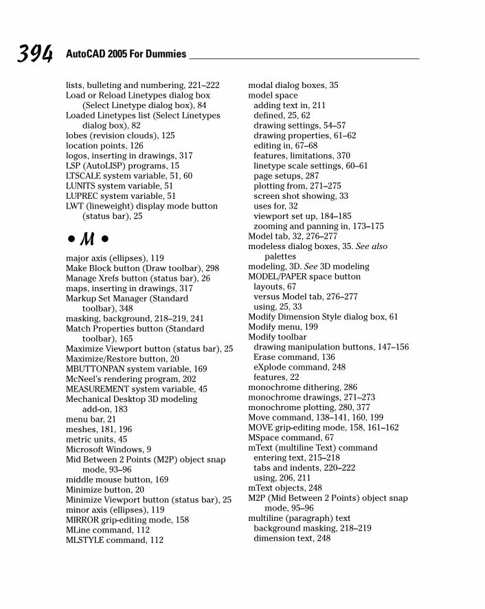
lists, bulleting and numbering, 221–222Load or Reload Linetypes dialog box
(Select Linetype dialog box), 84Loaded Linetypes list (Select Linetypes
dialog box), 82lobes (revision clouds), 125location points, 126logos, inserting in drawings, 317LSP (AutoLISP) programs, 15LTSCALE system variable, 51, 60LUNITS system variable, 51LUPREC system variable, 51LWT (lineweight) display mode button
(status bar), 25
• M •major axis (ellipses), 119Make Block button (Draw toolbar), 298Manage Xrefs button (status bar), 26maps, inserting in drawings, 317Markup Set Manager (Standard
toolbar), 348masking, background, 218–219, 241 Match Properties button (Standard
toolbar), 165Maximize Viewport button (status bar), 25Maximize/Restore button, 20MBUTTONPAN system variable, 169McNeel’s rendering program, 202MEASUREMENT system variable, 45Mechanical Desktop 3D modeling
add-on, 183menu bar, 21meshes, 181, 196metric units, 45Microsoft Windows, 9Mid Between 2 Points (M2P) object snap
mode, 93–96middle mouse button, 169Minimize button, 20Minimize Viewport button (status bar), 25minor axis (ellipses), 119MIRROR grip-editing mode, 158MLine command, 112MLSTYLE command, 112
modal dialog boxes, 35model space
adding text in, 211defined, 25, 62drawing settings, 54–57drawing properties, 61–62editing in, 67–68features, limitations, 370linetype scale settings, 60–61page setups, 287plotting from, 271–275screen shot showing, 33uses for, 32viewport set up, 184–185zooming and panning in, 173–175
Model tab, 32, 276–277modeless dialog boxes, 35. See also
palettesmodeling, 3D. See 3D modelingMODEL/PAPER space button
layouts, 67versus Model tab, 276–277using, 25, 33
Modify Dimension Style dialog box, 61Modify menu, 199Modify toolbar
drawing manipulation buttons, 147–156Erase command, 136eXplode command, 248features, 22
monochrome dithering, 286monochrome drawings, 271–273monochrome plotting, 280, 377Move command, 138–141, 160, 199MOVE grip-editing mode, 158, 161–162MSpace command, 67mText (multiline Text) command
entering text, 215–218tabs and indents, 220–222using, 206, 211
mText objects, 248M2P (Mid Between 2 Points) object snap
mode, 95–96multiline (paragraph) text
background masking, 218–219dimension text, 248
394 AutoCAD 2005 For Dummies
m571389 index.qxd 4/12/04 9:46 AM Page 394

editing, 222–223, 248entering and formatting, 215–219justifying, 223leaders, 252tabs and indents, 220–222using, 211
Multiline Text Editor, 219multiple drawings
DWF files from, 362in sheet sets, 354xrefs with, 297
multiple lines, drawing, 111–112multiple objects, selecting, 155–156Multiple option (CoPy command), 141multisegmented objects, 107MVIEW command, 67
• N •named objects
examples of, 85managing, 74overwriting, 88
named plot styles, 279–280, 285named views, 171–172, 322–323National Institute of Building Sciences
(NIBS) standards, 340NEW command, 52New Features Workshop, 40New Layer button (Layer Properties
Manager dialog box), 80New Text Style dialog box, 208–209New View dialog box, 171–172New/Modify Dimension Style dialog box,
239–242NIBS (National Institute of Building
Sciences) standards, 340NODe object snap mode, 127nonassociative dimensions, 234nonAutodesk program file exchanges,
374–375nonsystem drivers, 268–270Non-Uniform Rational B-Spline (NURBS)
curves, 121notes, precision in, 88–89numbered lists, 221–222
• O •object lineweights, 283–284Object Linking and Embedding (OLE),
379–380object properties. See properties (objects)Object Properties toolbar, 79Object Snap and Dimension toolbar, 22,
24–25, 93 object snap tracking, 25, 90, 98Object Snap Tracking (OTRACK) button,
24–25object snapping
for dimensioning, 243–244precision techniques, 90, 92–97for 3D modeling, 192
objectsconnecting, 158–159dimensions, 242–243grouping, 295, 297hatching, 263–264line segments, 105–106moving, 160multisegmented, 107named, 74, 85removing, 134selecting, 131–134
Off layer setting, 371OFfset command, 112, 150–151offset distance, 150OLE (Object Linking and Embedding),
379–380online help. See help systemOOPS command, 136Open button (Xref Manager dialog
box), 315Open Drawings tab (DesignCenter palette),
86, 87opening screen features, 20–31option keyword, 28options for commands, viewing, 27–30Options dialog box
command-first editing settings, 131Display tab, 18Files tab, 281Profiles tab, 18
395Index
m571389 index.qxd 4/12/04 9:46 AM Page 395
Options dialog box (continued)screen shot, 39Setup Wizards, 53system variable settings, 38–39
orbiting (3DOrbit), 187–189orientation, paper, 64origins, for dimensions, 243–244ortho mode
enabling/disabling, 164precision techniques, 90, 97
ORTHO mode button, 24, 164ortho tracking, 144Orthographic UCS option (Tools menu), 190OSNAP (Running Object Snap) button,
24–25, 90, 96–97OTRACK (Object Snap Tracking) button,
24–25, 90output. See plottingoutput devices, viewing and selecting,
269–270Over the Dimension Line setting
(dimensions)overlaying xrefs, 312override (single-point) object snaps, 92overwriting named objects, 88
• P •Page Setup Manager (File menu), 285palettes, 34–35. See also specific palettesPan Realtime button (Standard
toolbar), 169panning
defined, 167degenerating and regenerating images,
176–177in model space, 173–175in paper space, 175–176process for, 168–169scroll bars for, 169–1703D objects, 189
PANTONE color scheme, 81paper orientation settings, 64paper size
drawing area and scale calculations,42–43, 53, 56–57, 64
options and standards, 47–49 and plotting, 275–276
paper spaceadding text in, 211defined, 25, 62features, limitations, 32, 370layouts, 32, 63–68versus model space, 67–68page setups, 287plotting drawings from, 276–278screen display, 33and sheet sets, 323zooming and panning in, 174–176
paragraph text object. See multiline(paragraph) text
parallel lines, drawing, 112Parallel projection (3DOrbit), 189parent and child drawings, 303,
309–310password protection feature, 350, 364Paste Special option (Edit menu), 226PASTEBLOCK command, 143PASTECLIP command, 141–143PASTEORIG command, 143paths
to Plot Styles folder, 281for raster images, 318for xrefs, 313–314
patterns, hatch. See hatch patternsPC3 files, 269, 289PCX files, 378PDF (Portable Document Format) files,
376–377PDMODE system variable, 128PDSIZE system variable, 128PEdit command, 107, 151performance, and 3D modeling, 183Perspective projection (3DOrbit), 189photographs, inserting in drawings, 317Pick Points button (Boundary Hatch and
Fill dialog box), 263pin-bar drafting, 75pipe (|) character, 312PLine command
drawing curved lines, 110–112drawing straight lines, 108–110
396 AutoCAD 2005 For Dummies
m571389 index.qxd 4/12/04 9:46 AM Page 396

function, 102versus Line command, 107
Plot and Publish tab (Tools, Optionsmenu), 269
Plot Area area (Plot dialog box), 271Plot Area option (Plotter Configuration
Editor dialog box), 289–290Plot button (Standard toolbar), 271Plot dialog box
accessing, 271creating DWF files, 360–361Fit to Paper option, 46with paper space layouts, 277–278Plot Object Lineweights settings, 283Plot Style Table settings, 285Plotter Configuration Editor, 288–289settings and options, 271–272Shaded Viewport Options area, 202
plot layouts, defined, 62–63Plot Object Lineweights setting (Plot dialog
box), 283Plot Objects options (Plotter Configuration
Editor dialog box), 290Plot Offset settings (Plot dialog box),
271–272, 290Plot Options setting (Plot dialog box), 272plot (PLT) files, 286plot scale, 45, 272Plot Scale area (Plot dialog box), 272plot sheet sizes, 47–49plot style property, 77Plot Style Table area (Plot dialog
box), 272Plot Style Table Editor dialog box,
281–283, 286Plot Style Table (Pen Assignments) settings
(Plot dialog box), 285plot style tables, 280–285plot styles
creating, 281–283versus plot style tables, 280types and uses for, 279–280
Plot Styles folder, 281Plot to File option (Plotter dialog box), 289Plot Upside-Down option (Plotter dialog
box), 290
Plot with Plot Styles setting (Plot dialogbox), 272–273
Plot/Publish Details Reports, 273Plotstyle Control list (Properties
toolbar), 79plotted text height, 210, 240–241Plotter Configuration Editor dialog box,
288–289Plotter Manager dialog box, 270plotters, printers
configuring, 269, 362drivers, 268–269Hewlett-Packard DesignJet, 269print area limitations, 49troubleshooting problems with, 291viewing and selecting, 64, 269–270
plottingbatch plotting, 333changing definitions, 267–268color versus monochrome, 285–287color-dependent, 279–280interface improvements, 15monochrome not-to-scale drawing,
271–273overview, 267–268page setups, 287–288paper space layouts, 276–278scaled drawings, 275–276service bureaus for, 286standardizing, chart for, 341–342
PLT (plot) files, 286, 362PNGOUT command, 378POint command, 103, 128point filters, 192–193Point Style dialog box, 127–128points
adding dimensions using, 242–243grabbing, 92–97hatch area boundary settings, 258,
263–264for leaders, 251point objects, 126–128
polar arrays, 149POLAR button, 98polar coordinates, 91, 191polar snap, 90, 98
397Index
m571389 index.qxd 4/12/04 9:46 AM Page 397

polar trackingdefined, 24precision entry using, 90, 98with Stretch command, 144
POLygon command, 30, 102, 113–114polygons, defined, 113polylines
drawing polyline objects, 108–110editing, 107–108offsetting, 151segment widths, 107in 3D drawings, 193–195
Portable Document Format (PDF) files,376–377
precisionversus accuracy, 89AutoCAD features, 10choosing level of, 243and coordinate entry, 90–92and direct distance entry, 98double-floating-point precision, 176and editing, 137importance of, 74, 88–89, 369object snapping, 92–98and ortho mode, 97polar snapping, 98selecting level of, 44, 51, 55
predefined hatching, 257preexisting drawings, as templates, 43previewing plotter output, 274, 278Previous object selection, 135Previous option (Zoom command), 171Primary Units tab settings (New/Modify
Dimensions dialog box), 242primitives (3D objects), 196, 198–199Printer/Plotter area (Plot dialog
box), 360–361printers. See plotters, printersprinting versus plotting, 268Product Support, 40Profiles tab (Options dialog box), 18program window
command line area, 17, 26–31menu bar, 21opening screen features, 19status bar, 22–26title bar, 20
projections (3D Orbit), 189Properties and DesignCenter palette, 34Properties button (Standard toolbar), 75properties (objects)
color, 77controlling, 77–79current, 75editing, 165hatch pattern settings, 259–261layers, 75–77, 80–84linetype settings, 77lineweight settings, 77managing, 74plot style, 77viewing, 74
Properties palettedisplay for, 35editing dimensions, 248editing hatch objects, 265editing object properties, 165enabling/disabling, 74–75extrusion process, 195–196keyboard shortcuts, 34Text Override field, 248
Properties toolbar, 21, 79property filters, for layers, 84PSLTSCALE system variable, 51PSpace command, 67PUBLISH command
batch plotting, 33creating DWF files, 362function, 348–349versus PUBLISHTOWEB command,
362–363Publish dialog box (File menu), 361–363Publish to Plotter option (Publish
menu), 333PUBLISHTOWEB command
function, 349versus PUBLISH command, 362–363
PUrge command, 309
• Q •QDIM (Quick DIMension) command, 246question mark (?) character, 37, 38 qLEader (Quick Leader) command, 250
398 AutoCAD 2005 For Dummies
m571389 index.qxd 4/12/04 9:46 AM Page 398

QNEW command, 52, 69Quick Help Info Palette, 40Quick Leader button (Dimension
toolbar), 251
• R •radial dimensions, 233, 246RAL color scheme, 81raster (bitmap) files
exchanging, sharing, 377–378uses for, 295versus vector files, 371
raster (bitmapped) images, 296, 316–319
Raster File Format driver, 378ratios and drawing scales, 45–46RAY command, 102realtime zooming and panning,
167–169, 171RECtang command, 103, 112–113rectangles
absolute versus relative coordinates, 91
options for drawing, 112–113rectangular arrays, 149
Red Green Blue (RGB) number settings, 81
redefining blocks, 302Redraw command, 177REFEDIT command, 304, 313Reference Manager utility, 349, 357REgen command, 177Regen queued message, 177REgenAll command, 177regenerating images, 176–177Regenerating layout message, 176Regenerating model message, 176regular polygons, 113–114Relative path xref storage
option, 314relative polar and rectangular
coordinates, 91Reload option (Xref Manager dialog
box), 315removing objects, 134
Rename and Renumber Sheet dialog box,327–328, 332
renaming layouts, 66–67RENDER command, 201–202rendering drawings, 200–202renumbering sheets, 330resizing objects, 148, 257–258resource drawings (sheet sets),
330–331Resource Drawings tab (Sheet Set Manager
palette), 322, 330–331restoring default configurations, 18REVCLOUD command, 103, 115, 124revision clouds, 124–126REVolve command, 197REVSURF command, 197RGB (Red Green Blue) number
settings, 81Rich Text Format (RTF) files, 381–382right-click action
in command line area, 31for copying layers, 88in drawing area, 34for editing dimension geometry, 248issuing commands using, 18, 103–104modifying layouts using, 66opening sheet sets, 324–325versus Shift+right-click action, 95–96with 3DOrbit command, 189
roll cursor (3DOrbit), 188ROMAN.SHX font, 208–209ROtate command, 147, 199ROTATE grip-editing mode, 158rotated dimensions, 232rotation angle
for raster images, 318for xrefs, specifying, 312
Rotation option (ELlipse command), 120rotation options (3DOrbit), 187–189round-trip file transfer, 375RTF (Rich Text Format) files, 381–382Running Object Snap (OSNAP) button,
24–25running object snaps
defined, 92precision techniques, 90, 96–97
399Index
m571389 index.qxd 4/12/04 9:46 AM Page 399

• S •Save As command (File menu), 68Save Drawing As dialog box (File menu)
activating passwords, digital signatures,364–365
creating custom templates, 68–69SAVEAS command, 21SAVETIME system variable, 36saving
backup files, importance of, 371plot settings, 272–273profiles, 18
SCale command, 148, 222–223Scale for Dimension Features area (Modify
Dimension Style dialog box), 61SCALE grip-editing mode, 158Scale (X/XP) option (Zoom command), 170scales, scaling
determining before setup, 43dimension text, 241–242and drawing area calculations, 48–49and drawing limits, 57drawings, 45DWF files, 361hatch patterns, 261–262multiline text objects, 222–223and plotting, 275–276raster images, 318resource drawings, 330–333for smart paper drawings, 42text, 210for xrefs, 312
SCALETEXT command, 148, 222–223schematic sketches, 49Scientific drawing units, 44screen captures, 380–381screen colors, mapping, 284–285screen displays
command line area, 26–31customizing, 18maximizing when using palettes, 36menu bar, 21opening screen features, 19status bar, 22–26title bar, 20
scroll bars (drawing area), 169–170
scroll wheel (mouse), 169second point coordinates
for arcs, 110–111, 117and base point method, 138precision techniques, 141
secondary styles (dimensions), 238segments, line. See line segmentsSelect Color dialog box (Layer Properties
Manager dialog box), 80–81Select Image File dialog box (Image
Manager dialog box), 318–319Select Linetype dialog box (Layer
Properties Manager dialog box), 82Select Objects button (Block Definition
dialog box), 134–135, 299–300Select Reference File dialog box (Xref
Manager dialog box), 311Select Template dialog box, 52selecting objects
base point and displacement methods,138–139
for dimensioning, 242–243with Erase command, 136removing selected objects, 134for spell-checking, 227standard selection modes, 131–134for Stretch command, 143, 145for TRim and EXtend commands, 152
selection sets, erasing, 136selection-first editing, 130semi-infinite lines, 104service bureaus, 286setting layers, 76setup for drawings
borders, 50drawing units, 44–45importance of, 42linetype scale settings, 60–61model space, 54–62paper size, 47–49planning for, 43scale selection, 45–47system variables, 50–51template drawings, 51–53unit selection, 44–45using preexisting drawings for, 43
Setup Wizards, 53
400 AutoCAD 2005 For Dummies
m571389 index.qxd 4/12/04 9:46 AM Page 400

SETvar command, 37SHADE command, 202Shade submenu (View menu)
rendering using, 2022D Wireframe option, 184
Shaded Viewport Options area (Plot dialogbox), 202, 290
shading in drawings, 184, 187Shading Modes and Projection options
(3DOrbit), 189Sheet List tab (Sheet Set Manager palette),
323, 324, 328–333sheet list tables, 333–335Sheet Set Manager palette
creating sheet sets, 323–326keyboard shortcuts, 34managing sheet sets, 326–328Publish dialog box, 362Resource Drawings tab, 322screen display, 35sheet list table, 333–334Sheets tab, 323using, 34viewports, 330–333Views tab, 322–323
Sheet Set Properties button (Create SheetSet wizard), 325–326
sheet setsadding to, 327–328copying, 326creating, 323–326, 329–330and file exchanges, 354indexing, 333–335organizing, 328–329prerequisites for, 322storage location, 321using, 15, 321–322, 370
sheet sizes. See paper sizeShift key, deselecting objects
using, 134Shift+right-click or left-click keyboard
shortcuts, 93, 95–96shortening objects, 151–157SHX (compiled SHape) fonts, 207–208single point (override) object snaps, 92single-line text objects, 211, 213–214
single-point object snaps, 90size, paper, 43sketches, value of, 49smart paper, 42Snap and Grid tab (Drafting Settings dialog
box), 58SNAP button
activating polar snap, 98–99enabling/disabling snap feature, 24, 58precision entry using, 90, 97
snap feature. 24, 57–58snap locations, 127snap spacing settings, 51, 57–59SNAPMODE system variable, 51SNAPUNIT system variable, 51software requirements, 14solid fill hatch patterns, 261solids, 3D. See also 3D modeling
editing, 199–200modeling, 181, 197–198primitives for, 198–199
SolidWorks add-on, 197source drawing, 87–88source programs (OLE), 379spaces, when typing coordinates, 92Specify Insertion Point option (Insert Table
dialog box), 225Specify Window option (Insert Table dialog
box), 225SPell command (spell-checking tool),
227–228SPLine command
options, 121using, 103, 115, 122
spline curves, 121–123spreadsheets, exchanging data with,
15, 226square brackets ([]) characters, 30stacking layers, 77Standard toolbar
accessing palettes from, 34DesignCenter button, 87features overview, 21Markup Set Manager, 348Match Properties button, 165Pan Realtime button, 169
401Index
m571389 index.qxd 4/12/04 9:46 AM Page 401

Standard toolbar (continued)Plot button, 271Properties button, 75QNEW command, 52, 69Zoom Realtime button, 168
standards. See CAD standardsSTANDARDS command, 345starting points. See base pointsstatus bar
features overview, 24–26MODEL/PAPER space button, 25, 33Snap and Grid buttons, 57
STB (Style TaBle) files, 280still rendering, 200Store Current Layer Settings with View
option, 172straight lines, drawing, 104–106Stretch command, 138, 143–146STRETCH grip-editing mode, 157–158, 162stretching 3D solids, 199style families, 238Style TaBle (STB) files, 280styles, standardizing, 343. See also
dimension styles; plot styles; text styles
Styles toolbar, 21subsets (sheets), 328–329substyles, 238Subtract command, 199Summary tab (Drawing Properties dialog
box), 61–62surface meshes, 196surface models (3D), 181Surfaces option (Draw menu), 196symbol tables, 85system requirements, 15system variables. See also specific variables
changing, 36–37common settings for, 50–51types of, 36, 38, 235viewing, 37
• T •TaBle command, 224–227table object
editing cells, 226
plot style tables, 280–285right-click menu options, 225sheet list tables, 333–334storage format, 224table styles, 223–227uses for, 223
Table Style dialog box, 334Table Style option (Format
menu), 223TABLEEXPORT command, 227tables, plot style. See plot style tablestabs, with multiline text, 220–222Tangent-Tangent-Radius (Ttr) option
(Circle command), 115–116target point controls, 189technical drawings, 10template drawings
copying dimension styles to, 237customizing, 68–70for layouts, 66prepackaged, 51–53storage location, 69–70
textadding in model space, 211adding to drawings, 206editing, 248–249entering, 213–218fonts, 206–207height, 210–211justifying, 211–212, 214spell-checking, 227–228text styles, 206–207types of, 211uses for, 205
TEXT commandfunctions, 206, 211using, 213–215
text fields, 219–220Text Formatting toolbar, 218text height
calculating, 210–211for dimensions, 240plotted text, 240–241style settings, 209
Text Style dialog box, 207–209Text Style setting (New/Modify Dimensions
dialog box), 240
402 AutoCAD 2005 For Dummies
m571389 index.qxd 4/12/04 9:46 AM Page 402
text stylescontents, 206and drawing scale factor, 209–210height settings, 209selecting or creating, 208–209standardizing, 343
Text tab (New/Modify Dimensions dialogbox), 240
text tables, 15text (TXT) files, 381–382Text Window, 29TEXTTOFRONT command, 241thickness of extrusion, 194–196third-party add-on products, 13, 153D meshes, 1963D modeling
AutoCAD LT limitations, 14AutoCAD 2005 support for, 179–182 Cartesian coordinate systems, 190–191cautions, 183coordinate filters, 192creating 3D objects, 194–197 editing commands, 199–200lines and polylines, 193–194object snaps, 192prerequisites for, 182–183primitives, 196, 198–199rendering, 200solids modeling, 197–199and system performance, 183typed coordinates, 191uses for, 179–181using 3DOrbit command, 187–189wireframes, 181
3D Surfaces option (Draw menu), 1963D Views option (View menu), 186–1873DClip command, 1893DFACE command, 1963DOrbit command, 187–1893DPOLY command, 193–1953DS Max (Discreet) animation
program, 2003P (3-Point) option (Circle command), 115TIFF files, 378TIFOUT command, 378tiled viewports, 184
title bars, 20title blocks
attribute definitions, 300creating, 64–65effects of zooming on, 173with layouts, 32planning before setup, 43
Tolerance tab settings (New/ModifyDimensions dialog box), 242
TOLERANCES command, 242Tool Palettes
creating hatch patterns, 264features, 34–36, 344inserting blocks, 303
toolbarscustomizing, 22issuing commands using, 18overview, 21–22screen shot showing, 23
Toolbars tab (Customize dialog box), 23Tools menu
Create Layout Wizard, 63Display and Profiles tabs, 18Orthographic UCS option, 190Plot and Publish tab, 269
ToolTips, 22tracking options, 25transmittal packages, 352–354Transmittal Setups button (Create
Transmittal dialog box), 353transparent commands, 31trans-spatial dimensioning, 246–247Tree view (xrefs), 315TRim command
with ellipses, 121with hatch patterns, 265using, 131, 152–153
troubleshooting plotter problems, 291True Color tab (Select Color dialog box), 81TrueType (TTF) fonts, 207, 356Ttr (Tangent-Tangent-Radius) option
(Circle command), 115–1162D drawings
coordinate entry, 191creating 3D objects from, 194–196input and output devices for, 183
403Index
m571389 index.qxd 4/12/04 9:46 AM Page 403
2D drawings (continued)and system performance, 183versus 3D, 180wireframe mode, 184, 187
2P (2-Point) option (Circle command), 115TXT (Text) files, 381–382
• U •UCS (user coordinate system), 188, 190UCSMAN command, 190–191underscore (_) character, 31Undo command, 28, 139un-erasing, 136Union command, 199unitless units, 44units, drawing, settings for, 43, 51, 54Units option (Format menu), 54Unload option (Xref Manager dialog
box), 315un-maximizing windows, 20Update Layers button (View dialog
box), 172upgrading, importance of, 15–16Use Overall Scale Of setting (dimensions),
241–242, 243user coordinate system (UCS), 188, 190user-defined hatch patterns,
256–258, 261User’s Guide, 201–202. See also help system
• V •values, default, 30variable height settings (text styles), 209variables, system. See system variablesvector files, 371vectorization, 317vectors, displacement, 138versions (AutoCAD), and backward
compatibility, 11–12vertex points (vertices), 107vertical dimensions, 24, 232vertical rotation cursor (3DOrbit), 188–189View Category property, 171
View dialog box, 171–172View List tab (Sheet Set Manager
palette), 333View menu
Named Views option, 171–172Render dialog box, 201–202Shade submenu, 2023D Views option, 1852D Wireframe option, 184
Viewpoint Presets (View menu, 3D Views), 186
viewpointsversus coordinate systems, 191dynamic, 187–189standard versus nonstandard, 186–187and 3D modeling, 184–186
viewportsarranging, 65defined, 25, 32locking, unlocking, 175maximizing, minimizing, 176model space, 184–185for resource drawing, 331for sheet sets, 330–3333D setup options, 185viewing layouts using, 67
viewsassembling from resource
drawings, 333defined, 168named views, 171–172for xrefs, 315
Views (View List) tab (Sheet Set Managerpalette), 322–324
VPMAX command, 176VPMIN command, 176
• W •WBLOCK command, 301, 313WCS (world coordinate system), 190Web sites
Adobe Acrobat, 377Autodesk Express Viewer program,
358, 363
404 AutoCAD 2005 For Dummies
m571389 index.qxd 4/12/04 9:46 AM Page 404
electronic security information, 350HiJaak translation program, 378International Standard Organization
(ISO), 340National Institute of Building Sciences
(NIBS), 340third party add-on products, 13WinZip utility, 353WS_FTP utility, 355
Web-based file transmittal, 351–356width settings (text styles), 209window object selection, 132,
135–136Window option (Zoom command), 170window, program. See program windowwindowing, implied, 132Windows Clipboard
commands from, 142–143file exchange using, 379
Windows MetaFile (WMF) files, 377Windows program interface versus
AutoCAD 2005, 18Windows True Type fonts (TTF). See
TrueType (TTF) fontsWinZip utility, 353wireframe models (3D), drawing, 181,
193–194Wireframe option, 189WMF (Windows MetaFile) files, 377WMFIN command, 377word wrapping
with leader arrows, 252with multiline text, 217
world coordinate system (WCS), 190WPolygon object selection, 135, 137WS_FTP utility program, 355
• X •X,Y and @X,Y coordinates, 91XLine command, 102XOPEN command, 313XP option (ZOOM command), 67xref clipping, 315Xref Manager dialog box, 311, 313, 315xrefs (external references)
attaching to drawings, 311–312versus blocks, 309–310creating and editing, 311–313defined, 295function, 297, 309–310, 316limitations, 310–311managing, 26, 314–335storage location, 313
• Z •Zero Suppression settings, 242zipping files, 353Zoom and Pan Realtime feature, 168Zoom command options, 56, 67, 168,
170–171Zoom Extents, 139, 189Zoom Realtime button (Standard
toolbar), 168zooming
defined, 167degenerating, regenerating images,
176–177in model space, 173–175with panning, 168–169in paper space, 174–176with 3D objects, 189
405Index
m571389 index.qxd 4/12/04 9:46 AM Page 405

Notes____________________________________________________________________________________________________________________________________________________________________________________________________________________________________________________________________________________________________________________________________________________________________________________________________________________________________________________________________________________________________________________________________________________________________________________________________________________________________________________________________________________________________________________________________________________________________________________________________________________________________________________________________________________________________________________________________________________________________________________________________________________________
m571389 index.qxd 4/12/04 9:46 AM Page 406

Notes____________________________________________________________________________________________________________________________________________________________________________________________________________________________________________________________________________________________________________________________________________________________________________________________________________________________________________________________________________________________________________________________________________________________________________________________________________________________________________________________________________________________________________________________________________________________________________________________________________________________________________________________________________________________________________________________________________________________________________________________________________________________
m571389 index.qxd 4/12/04 9:46 AM Page 407

Notes____________________________________________________________________________________________________________________________________________________________________________________________________________________________________________________________________________________________________________________________________________________________________________________________________________________________________________________________________________________________________________________________________________________________________________________________________________________________________________________________________________________________________________________________________________________________________________________________________________________________________________________________________________________________________________________________________________________________________________________________________________________________
m571389 index.qxd 4/12/04 9:46 AM Page 408

PERSONAL FINANCE
Also available:
Estate Planning For Dummies(0-7645-5501-4)401(k)s For Dummies (0-7645-5468-9)Frugal Living For Dummies(0-7645-5403-4)Microsoft Money “X” ForDummies (0-7645-1689-2)Mutual Funds For Dummies(0-7645-5329-1)
Personal Bankruptcy ForDummies (0-7645-5498-0)Quicken “X” For Dummies (0-7645-1666-3)Stock Investing For Dummies(0-7645-5411-5)Taxes For Dummies 2003 (0-7645-5475-1)
Also available:
Business Plans Kit ForDummies (0-7645-5365-8)Consulting For Dummies (0-7645-5034-9)Cool Careers For Dummies (0-7645-5345-3)Human Resources Kit ForDummies (0-7645-5131-0)Managing For Dummies (1-5688-4858-7)
QuickBooks All-in-One DeskReference For Dummies (0-7645-1963-8)Selling For Dummies (0-7645-5363-1)Small Business Kit ForDummies (0-7645-5093-4)Starting an eBay Business ForDummies (0-7645-1547-0)
The easy way to get more done and have more fun
Available wherever books are sold.Go to www.dummies.com or call 1-877-762-2974 to order direct.
BUSINESS & CAREERS
Also available:
Controlling Cholesterol ForDummies (0-7645-5440-9)Dieting For Dummies (0-7645-5126-4)High Blood Pressure ForDummies (0-7645-5424-7)Martial Arts For Dummies (0-7645-5358-5)Menopause For Dummies(0-7645-5458-1)
Nutrition For Dummies (0-7645-5180-9)Power Yoga For Dummies (0-7645-5342-9)Thyroid For Dummies (0-7645-5385-2)Weight Training For Dummies(0-7645-5168-X)Yoga For Dummies (0-7645-5117-5)
HEALTH, SPORTS & FITNESS
0-7645-5231-7 0-7645-2431-3 0-7645-5331-3
0-7645-5314-3 0-7645-5307-0 0-7645-5471-9
0-7645-5167-1 0-7645-5146-9 0-7645-5154-X
n571389 BOB.qxd 4/12/04 9:46 AM Page 409

Also available:
America’s National Parks ForDummies (0-7645-6204-5)Caribbean For Dummies (0-7645-5445-X)Cruise Vacations ForDummies 2003(0-7645-5459-X)Europe For Dummies (0-7645-5456-5)Ireland For Dummies (0-7645-6199-5)France For Dummies(0-7645-6292-4)
London For Dummies (0-7645-5416-6)Mexico’s Beach Resorts ForDummies (0-7645-6262-2)Paris For Dummies(0-7645-5494-8)RV Vacations For Dummies(0-7645-5443-3)Walt Disney World & OrlandoFor Dummies (0-7645-5444-1)
Available wherever books are sold. Go to www.dummies.com or call 1-877-762-2974 to order direct.
A world of resources to help you grow
HOME, GARDEN & HOBBIES
Also available:
Auto Repair For Dummies (0-7645-5089-6)Chess For Dummies (0-7645-5003-9)Home Maintenance ForDummies (0-7645-5215-5)Organizing For Dummies (0-7645-5300-3)Piano For Dummies (0-7645-5105-1)
Poker For Dummies (0-7645-5232-5)Quilting For Dummies (0-7645-5118-3)Rock Guitar For Dummies (0-7645-5356-9)Roses For Dummies (0-7645-5202-3)Sewing For Dummies (0-7645-5137-X)
Also available:
Bartending For Dummies (0-7645-5051-9)Chinese Cooking ForDummies (0-7645-5247-3)Christmas Cooking ForDummies (0-7645-5407-7)Diabetes Cookbook ForDummies (0-7645-5230-9)
Grilling For Dummies (0-7645-5076-4)Low-Fat Cooking ForDummies (0-7645-5035-7)Slow Cookers For Dummies(0-7645-5240-6)
FOOD & WINE
TRAVEL
0-7645-5295-3 0-7645-5130-2 0-7645-5106-X
0-7645-5250-3 0-7645-5390-9 0-7645-5114-0
0-7645-5453-0 0-7645-5438-7 0-7645-5448-4
n571389 BOB.qxd 4/12/04 9:46 AM Page 410

Available wherever books are sold. Go to www.dummies.com or call 1-877-762-2974 to order direct.
Plain-English solutions for everyday challenges
COMPUTER BASICS
Also available:
PCs All-in-One DeskReference For Dummies (0-7645-0791-5)Pocket PC For Dummies (0-7645-1640-X)Treo and Visor For Dummies(0-7645-1673-6)Troubleshooting Your PC ForDummies (0-7645-1669-8)
Upgrading & Fixing PCs ForDummies (0-7645-1665-5)Windows XP For Dummies (0-7645-0893-8)Windows XP For DummiesQuick Reference (0-7645-0897-0)
Also available:
Excel Data Analysis ForDummies (0-7645-1661-2)Excel 2002 All-in-One DeskReference For Dummies (0-7645-1794-5)Excel 2002 For DummiesQuick Reference (0-7645-0829-6)GoldMine “X” For Dummies (0-7645-0845-8)
Microsoft CRM For Dummies(0-7645-1698-1)Microsoft Project 2002 ForDummies (0-7645-1628-0)Office XP For Dummies (0-7645-0830-X)Outlook 2002 For Dummies(0-7645-0828-8)
BUSINESS SOFTWARE
0-7645-0838-5 0-7645-1663-9 0-7645-1548-9
0-7645-0822-9 0-7645-0839-3 0-7645-0819-9
• Find listings of even more For Dummies titles
• Browse online articles
• Sign up for Dummies eTips™
• Check out For Dummies fitness videos and other products
• Order from our online bookstore
Get smart! Visit www.dummies.com
™
n571389 BOB.qxd 4/12/04 9:46 AM Page 411

Also available:
Adobe Acrobat 5 PDF ForDummies (0-7645-1652-3)Fireworks 4 For Dummies (0-7645-0804-0)Illustrator 10 For Dummies (0-7645-3636-2)
QuarkXPress 5 For Dummies(0-7645-0643-9)Visio 2000 For Dummies (0-7645-0635-8)
Available wherever books are sold. Go to www.dummies.com or call 1-877-762-2974 to order direct.
Helping you expand your horizons and realize your potential
INTERNET
Also available:
America Online 7.0 ForDummies (0-7645-1624-8)Genealogy Online ForDummies (0-7645-0807-5)The Internet All-in-One DeskReference For Dummies (0-7645-1659-0)Internet Explorer 6 ForDummies (0-7645-1344-3)
The Internet For DummiesQuick Reference (0-7645-1645-0)Internet Privacy For Dummies(0-7645-0846-6)Researching Online ForDummies (0-7645-0546-7)Starting an Online BusinessFor Dummies (0-7645-1655-8)
Also available:
CD and DVD Recording ForDummies (0-7645-1627-2)Digital Photography All-in-One Desk ReferenceFor Dummies (0-7645-1800-3)Digital Photography ForDummies Quick Reference (0-7645-0750-8)Home Recording forMusicians For Dummies (0-7645-1634-5)
MP3 For Dummies (0-7645-0858-X)Paint Shop Pro “X” ForDummies (0-7645-2440-2)Photo Retouching &Restoration For Dummies (0-7645-1662-0)Scanners For Dummies (0-7645-0783-4)
DIGITAL MEDIA
GRAPHICS
0-7645-0894-6 0-7645-1659-0 0-7645-1642-6
0-7645-1664-7 0-7645-1675-2 0-7645-0806-7
0-7645-0817-2 0-7645-1651-5 0-7645-0895-4
n571389 BOB.qxd 4/12/04 9:46 AM Page 412

Available wherever books are sold. Go to www.dummies.com or call 1-877-762-2974 to order direct.
The advice and explanations you need to succeed
Also available:
Chemistry For Dummies (0-7645-5430-1)English Grammar ForDummies (0-7645-5322-4)French For Dummies (0-7645-5193-0)The GMAT For Dummies (0-7645-5251-1) Inglés Para Dummies (0-7645-5427-1)
Italian For Dummies (0-7645-5196-5)Research Papers ForDummies (0-7645-5426-3)The SAT I For Dummies (0-7645-5472-7)U.S. History For Dummies (0-7645-5249-X)World History For Dummies(0-7645-5242-2)
SELF-HELP, SPIRITUALITY & RELIGION
Also available:
The Bible For Dummies (0-7645-5296-1)Buddhism For Dummies (0-7645-5359-3)Christian Prayer For Dummies(0-7645-5500-6)Dating For Dummies (0-7645-5072-1)Judaism For Dummies (0-7645-5299-6)
Potty Training For Dummies(0-7645-5417-4)Pregnancy For Dummies (0-7645-5074-8)Rekindling Romance ForDummies (0-7645-5303-8)Spirituality For Dummies (0-7645-5298-8)Weddings For Dummies (0-7645-5055-1)
Also available:
Labrador Retrievers ForDummies (0-7645-5281-3)Aquariums For Dummies (0-7645-5156-6)Birds For Dummies (0-7645-5139-6)Dogs For Dummies (0-7645-5274-0)Ferrets For Dummies (0-7645-5259-7)
German Shepherds ForDummies (0-7645-5280-5)Golden Retrievers ForDummies (0-7645-5267-8)Horses For Dummies (0-7645-5138-8)Jack Russell Terriers ForDummies (0-7645-5268-6)Puppies Raising & TrainingDiary For Dummies (0-7645-0876-8)
PETS
EDUCATION & TEST PREPARATION
0-7645-5302-X 0-7645-5418-2 0-7645-5264-3
0-7645-5255-4 0-7645-5286-4 0-7645-5275-9
0-7645-5194-9 0-7645-5325-9 0-7645-5210-4
n571389 BOB.qxd 4/12/04 9:46 AM Page 413

WEB DEVELOPMENT
Also available:
ASP.NET For Dummies (0-7645-0866-0)Building a Web Site ForDummies (0-7645-0720-6)ColdFusion “MX” ForDummies (0-7645-1672-8)Creating Web Pages All-in-One Desk ReferenceFor Dummies (0-7645-1542-X)
FrontPage 2002 For Dummies(0-7645-0821-0)HTML 4 For Dummies QuickReference (0-7645-0721-4)Macromedia Studio “MX”All-in-One Desk ReferenceFor Dummies (0-7645-1799-6)Web Design For Dummies (0-7645-0823-7)
Also available:
Beginning Programming ForDummies(0-7645-0835-0)Crystal Reports “X”For Dummies (0-7645-1641-8)Java & XML For Dummies (0-7645-1658-2)Java 2 For Dummies (0-7645-0765-6)JavaScript For Dummies(0-7645-0633-1)Oracle9i For Dummies (0-7645-0880-6)
Perl For Dummies (0-7645-0776-1)PHP and MySQL ForDummies (0-7645-1650-7)SQL For Dummies(0-7645-0737-0)VisualBasic .NET ForDummies (0-7645-0867-9)Visual Studio .NET All-in-OneDesk Reference For Dummies(0-7645-1626-4)
We take the mystery out of complicated subjects
Available wherever books are sold.Go to www.dummies.com or call 1-877-762-2974 to order direct.
PROGRAMMING & DATABASES
Also available:
CCNP All-in-One CertificationFor Dummies (0-7645-1648-5)Cisco Networking ForDummies (0-7645-1668-X)CISSP For Dummies (0-7645-1670-1)CIW Foundations ForDummies with CD-ROM(0-7645-1635-3)
Firewalls For Dummies (0-7645-0884-9)Home Networking ForDummies (0-7645-0857-1)Red Hat Linux All-in-OneDesk Reference For Dummies(0-7645-2442-9)TCP/IP For Dummies(0-7645-1760-0)UNIX For Dummies(0-7645-0419-3)
LINUX, NETWORKING & CERTIFICATION
0-7645-1643-4 0-7645-0723-0 0-7645-1630-2
0-7645-0746-X 0-7645-1657-4 0-7645-0818-0
0-7645-1545-4 0-7645-0772-9 0-7645-0812-1
n571389 BOB.qxd 4/12/04 9:46 AM Page 414