Autocad 2012 pentru prosti - engleza
660
-
Upload
independent -
Category
Documents
-
view
0 -
download
0
Transcript of Autocad 2012 pentru prosti - engleza


AutoCAD®2012ForDummies®
Visitwww.dummies.com/cheatsheet/autocad2012toviewthisbook'scheatsheet.
TableofContents
ForewordIntroduction
What’sNot(AndWhatIs)inThisBook
Macattack!
WhoDoIThinkYouAre?HowThisBookIsOrganized
PartI:AutoCAD101PartII:LetThereBeLinesPartIII:IfDrawingsCouldTalkPartIV:AdvancingwithAutoCADPartV:Ona3DSpreePartVI:ThePartofTensButwait...there’smore!
IconsUsedinThisBookAFewConventions—JustinCase
CommandingfromthekeyboardTyingthingsupwiththeRibbon
WheretoGofromHere
PartI:AutoCAD101
Chapter1:IntroducingAutoCADandAutoCADLT
WhyAutoCAD?

TheImportanceofBeingDWGSeeingtheLTCheckingSystemRequirementsSuddenly,It’s2012!
Chapter2:LeTourdeAutoCAD2012
AutoCADDoesWindows(AndOffice)AndThey’reOff:AutoCAD’sOpeningScreens
RunningwithRibbons
GettingwiththeProgram
LookingforMr.StatusBarLetyourfingersdothetalking:ThecommandwindowThekey(board)toAutoCADsuccessKeepingtabsonpalettesDownthemainstretch:Thedrawingarea
FunwithF1
Chapter3:ALaparoundtheCADTrack
ASimpleSetupDrawinga(Base)Plate
DrawingrectanglesontherightlayersCirclingyourplatePlacingyourpolygon
GettingaCloserLookwithZoomandPanModifyingtoMakeItMerrier
Hip-hip-array!StretchingoutCrossingyourhatches
FollowingthePlot

Chapter4:SetupforSuccess
ASetupRoadmap
ChoosingyourunitsWeighingupyourscalesThinkingannotativelyThinkingaboutpaperDefendingyourborder
ATemplateforSuccessMakingtheMostofModelSpace
SettingyourunitsMakingthedrawingareasnap-py(andgrid-dy)SettinglinetypeanddimensionscalesEnteringdrawingproperties
MakingTemplatesYourOwn
Chapter5:PlanningforPaper
SettingUpaLayoutinPaperSpace
Willthatbetabsorbuttons?CreatingalayoutCopyingandchanginglayoutsLostinpaperspaceAview(port)fordrawingin
AboutPaperSpaceLayoutsandPlotting
PartII:LetThereBeLines
Chapter6:ManageYourProperties
ManagingYourProperties
PuttingitonalayerAccumulatingproperties

CreatingnewlayersManipulatinglayers
UsingNamedObjects
UsingAutoCADDesignCenterCopyinglayersbetweendrawings
Chapter7:PreciselinessIsNexttoCADliness
ControllingYourPrecision
Keyboardcapers:CoordinateinputUnderstandingAutoCAD’scoordinatesystemsGrabanobjectandmakeitsnappy
OtherPracticalPrecisionProcedures
Chapter8:DowntheStraightaway
IntroducingtheAutoCADDrawingCommandsTheStraightandNarrow:Lines,Polylines,andPolygons
ToeingthelineConnectingthelineswithpolylineSquaringoffwithrectanglesChoosingyoursideswithpolygon
Chapter9:DangerousCurvesAhead
(Throwing)Curves
GoingfullcircleArc-y-ologySolarellipsesSplines:Thesketchy,sinuouscurvesDonuts:ThecircleswithadifferenceRevisioncloudsonthehorizon
ScoringPoints

Chapter10:GetaGriponObjectSelection
CommandingandSelecting
Command-firsteditingSelection-firsteditingDirectobjectmanipulationChoosinganeditingstyle
GrabIt
One-by-oneselectionSelectionboxesleftandright
PerfectingSelectingObjectSelection:NowYouSeeIt...GetaGrip
AboutgripsAgrippingexampleMoveit!Copy,orakinder,gentlerMoveAwarm-upStretch
Chapter11:EditforCredit
YourAutoCADToolKitTheBigThree:Move,Copy,andStretch
BasepointsanddisplacementsMoveCopyCopybetweendrawingsStretch
MoreManipulations
MirrorRotate

ScaleArrayOffset
Slicing,Dicing,andSplicing
TrimandExtendBreakFilletandChamferandBlendJoin
Chapter12:AZoomwithaView
ZoomandPanwithGlassandHand
NavigatingyourdrawingTimetozoom
AViewbyAnyOtherName...LookingAroundinLayoutLandDegeneratingandRegenerating
PartIII:IfDrawingsCouldTalk
Chapter13:TextwithCharacter
GettingReadytoWrite
SimplystylishtextTakingyourtexttonewheightsOnelineortwo?Yourtextwillbejustified
UsingtheSameOldLineTurningOnYourAnnotativeObjectsSayingMoreinMultilineText
MakingitwithMtextItslices,itdices...

DoinganumberonyourMtextlistsLineupincolumns—Now!ModifyingMtext
GatherRoundtheTables
Tableshavestyle,tooCreatingandeditingtables
BringOutYourInnerLeader
ElectingaleaderMultioptionsformultileaders
Chapter14:EnteringNewDimensions
DiscoveringNewDimensions
AnatomyofadimensionAfieldguidetodimensionsDimensionassociativityFindingyourdimensiontools
DoingDimensionswithStyle(s)
BorrowingexistingdimensionstylesCreatingandmanagingdimensionstylesAdjustingstylesettings
DrawingDimensions
LiningupsomelineardimensionsMakingdimensionsannotativeDrawingotherkindsofdimensions
EditingDimensions
EditingdimensiongeometryEditingdimensiontextControllingandeditingdimensionassociativity

Chapter15:DowntheHatch
BattenDowntheHatches!PushingtheBoundary(of)Hatch
HatchfromscratchGettingitright:HatchangleandscaleHatchingforthe21stcenturyDofencemein:DefininghatchboundariesHavepalette,willhatch
EditingHatchObjects
Chapter16:ThePlotThickens
YouSayPrinting,ISayPlotting
GetwiththesystemConfigureitout
ASimplePlot
Plottingsuccessin16stepsPreviewone,twoInsteadoffit,scaleit
PlottingtheLayoutoftheLand
Thepathtopaperspacelayoutplottingsuccess
PlottingLineweightsandColors
PlottingwithstylePlottingthroughthickandthinPlottingincolor
It’sa(Page)Setup!ContinuingthePlotDialogTroubleswithPlotting

PartIV:AdvancingwithAutoCAD
Chapter17:TheABCsofBlocks
RockingwithBlocks
CreatingblockdefinitionsInsertingblocksAttributes:Fill-in-the-blankblocksExplodingblocksPurgingunusedblockdefinitions
Chapter18:GoingDynamicandExternal
ArrayingAssociatively
ComparingtheoldandnewARRAYcommandsArrayingalongapathAssociativelyediting
ThemeandVariations:DynamicBlocks
Nowyouseeit...Lights!Parameters!!Actions!!!Manipulatingdynamicblocks
GoingExternal
BecomingattachedtoyourxrefsLayer-paloozaCreatingandeditinganexternalreferencefileForginganxrefpathManagingxrefs
Blocks,Xrefs,andDrawingOrganizationMasteringtheRaster
AttachinganimageMaintainingyourimage

YousayPDF,IsayDWF
Chapter19:CalltheParametrics!
MaintainingDesignIntent
DefiningtermsConstrainyourself
UnderstandingDimensionalConstraints
PracticealittleconstraintMakingyourdrawingevensmarterUsingtheParametersManagerDimensionsorconstraints—haveitbothways!
UnderstandingGeometricConstraints
ApplyingalittlemoreconstraintAutoconstrainyourself!
Chapter20:DrawingontheInternet
TheInternetandAutoCAD:AnOverviewSendingStrategies
SenditwithETRANSMITRapideTransmitFTPforyouandmeBadreception?HelpfromtheReferenceManager
DesignWebFormat—NotJustfortheWeb
AllaboutDWFandDWFxePlot,notreplotMakingDWFswithePlotMakingDWFs(orplots)withPUBLISHHyperobjects

AutodeskDesignReview2012
TheDrawingProtectionRacket
PartV:Ona3DSpree
Chapter21:It’sa3DWorldAfterAll
Understanding3DDigitalModelsToolsoftheTrade
WarpspeedaheadEnteringthethirddimensionUntyingtheRibbonandopeningsomepalettes
ModelingfromAbove
Using3DcoordinateinputUsingpointfiltersObjectsnapsandobjectsnaptracking
ChangingPlanes
DisplayingtheUCSiconAdjustingtheUCS
Navigatingthe3DWaters
Orbitàgo-goTakingaspinaroundthecubeGrabbingtheSteeringWheels
Visualizing3Dobjects
Gettingsome(visual)style
Chapter22:FromDrawings...toModels
Is3DforMe?GettingYour3DBearings

Creatingabetter3DtemplateSeeingtheworldfromnewviewpoints
FromDrawingtoModelingin3D
Drawingbasic3DobjectsGainingasolidfoundationDrawingsolidprimitives
AddingtheThirdDimensionto2DObjects
Creating3Dobjectsfrom2Ddrawings
Modifying3DObjects
SelectingsubobjectsWorkingwithgizmosMore3Dvariantsof2DcommandsEditingsolids
Chapter23:OnaRenderBender
VisualizingtheDigitalWorldAddingLighting
DefaultlightingUser-definedlightsSunlight
CreatingandApplyingMaterialsDefiningaBackgroundRenderinga3DModel
PartVI:ThePartofTens
Chapter24:TenGreatAutoCADResources
Autodesk’sFeedbackCommunityAutodesk’sDiscussionGroupsAutodesk’sOwnBloggers

AutodeskUniversityTheAutodeskChannelonYouTubeTheWorldWide(CAD)WebYourLocalATCYourLocalUserGroupAUGIBooks
Chapter25:TenDifferencesbetweenAutoCADandAutoCADLT
Price3DAbilitiesCustomizationOptionsNetworkLicensingExpressToolsParametricsStandardsCheckingDataExtractionMLINEversusDLINEProfilesReferenceManager
Chapter26:TenSystemVariablestoMakeYourLifeEasier
APERTUREDIMASSOCMENUBARMIRRTEXTOSNAPZPICKBOXREMEMBERFOLDERSROLLOVERTIPSTOOLTIPSVISRETAIN
CheatSheet

AutoCAD®2012ForDummies®
byDavidByrnes
ForewordbyHeidiHewett
AutoCADTechnicalMarketingManager
AutoCAD®2012ForDummies®
PublishedbyWileyPublishing,Inc.111RiverSt.Hoboken,NJ07030-5774www.wiley.com
Copyright©2011byWileyPublishing,Inc.,Indianapolis,Indiana
PublishedsimultaneouslyinCanada
Nopartofthispublicationmaybereproduced,storedinaretrievalsystemortransmittedinanyformorbyanymeans,electronic,mechanical,photocopying,recording,scanningorotherwise,exceptaspermittedunderSections107or108ofthe1976UnitedStatesCopyrightAct,withouteitherthepriorwrittenpermissionofthePublisher,orauthorizationthroughpaymentoftheappropriateper-copyfeetotheCopyrightClearanceCenter,222RosewoodDrive,Danvers,MA01923,(978)750-8400,fax(978)646-8600.RequeststothePublisherforpermissionshouldbeaddressedtothePermissionsDepartment,JohnWiley&Sons,Inc.,111RiverStreet,Hoboken,NJ07030,(201)748-6011,fax(201)748-6008,oronlineathttp://www.wiley.com/go/permissions.
Trademarks:Wiley,theWileyPublishinglogo,ForDummies,theDummiesManlogo,AReferencefortheRestofUs!,TheDummiesWay,DummiesDaily,TheFunandEasyWay,Dummies.com,MakingEverythingEasier,andrelatedtradedressaretrademarksorregisteredtrademarksofJohnWiley&Sons,Inc.and/oritsaffiliatesintheUnitedStatesandothercountries,andmaynotbeusedwithoutwrittenpermission.AutoCADisaregisteredtrademarkofAutodesk,Inc.Allother

trademarksarethepropertyoftheirrespectiveowners.WileyPublishing,Inc.,isnotassociatedwithanyproductorvendormentionedinthisbook.
LimitofLiability/DisclaimerofWarranty:Thepublisherandtheauthormakenorepresentationsorwarrantieswithrespecttotheaccuracyorcompletenessofthecontentsofthisworkandspecificallydisclaimallwarranties,includingwithoutlimitationwarrantiesoffitnessforaparticularpurpose.Nowarrantymaybecreatedorextendedbysalesorpromotionalmaterials.Theadviceandstrategiescontainedhereinmaynotbesuitableforeverysituation.Thisworkissoldwiththeunderstandingthatthepublisherisnotengagedinrenderinglegal,accounting,orotherprofessionalservices.Ifprofessionalassistanceisrequired,theservicesofacompetentprofessionalpersonshouldbesought.Neitherthepublishernortheauthorshallbeliablefordamagesarisingherefrom.ThefactthatanorganizationorWebsiteisreferredtointhisworkasacitationand/orapotentialsourceoffurtherinformationdoesnotmeanthattheauthororthepublisherendorsestheinformationtheorganizationorWebsitemayprovideorrecommendationsitmaymake.Further,readersshouldbeawarethatInternetWebsiteslistedinthisworkmayhavechangedordisappearedbetweenwhenthisworkwaswrittenandwhenitisread.
Forgeneralinformationonourotherproductsandservices,pleasecontactourCustomerCareDepartmentwithintheU.S.at877-762-2974,outsidetheU.S.at317-572-3993,orfax317-572-4002.
Fortechnicalsupport,pleasevisitwww.wiley.com/techsupport.
Wileyalsopublishesitsbooksinavarietyofelectronicformats.Somecontentthatappearsinprintmaynotbeavailableinelectronicbooks.
LibraryofCongressControlNumber:2011926309
ISBN:978-1-118-02440-9
ManufacturedintheUnitedStatesofAmerica
10987654321
AbouttheAuthorDavidByrnesisoneofthosegrizzledold-timersyou’llfindmentionedeveryso

ofteninAutoCAD2011ForDummies.Hebeganhisdraftingcareerontheboardsin1979,andfirstlearnedAutoCADwithversion1.4.DaveisbasedinVancouver,BritishColumbia,whereheworksasacivil/structuraldrafter.HetaughtAutoCADforfifteenyearsatEmilyCarrUniversityofArt+DesignandBritishColumbiaInstituteofTechnologyinVancouver.Davehasauthoredorco-authoredoveradozenAutoCADbooksandhasbeenthesoleauthorofthistitlesinceAutoCAD2008ForDummies.
DedicationIleftthebohemianlifestyleoftheAutoCADconsultantatthebeginningof2008andrejoinedtheengineeringcompanyIlastworkedforin1988(luckilythey’dforgottenallaboutthatchandelier).Workingfull-time(oh!thehorror!)andkeepingupwithAutoCADsoIcanrevisethisbookhasmademesomewhatinaccessiblefor3monthsayear,andI’mforevergratefultoAnnieandDelia,stillandalwaysthetwowomeninmylife,whoremindmethereareotherthingsbesideskeyboardsandmice(andsometimestheyhavetotryreallyhard).
Author’sAcknowledgmentsThanks,firstofall,toformerauthorMarkMiddlebrookforbringingmeintotheAutoCADForDummiesworld.MarkaskedmetotecheditAutoCAD2000ForDummies,thentojoinhimasco-authorofAutoCAD2006ForDummies,andfinallytotakeoverthetitlealtogether.IhopemytorchbearingcomesclosetothehighstandardsthatMarkset,andIwishhimwellinhisnewcareerintheworldoffinewine(what,mejealous?).
Thanks,too,tocolleaguesandfriendsatAutodesk:aboveallGuillermoMelantoni,HeidiHewett,andBudSchroeder,whoneverseemtomindbeingaskedeventhedumbestquestions.Andspeakingofcolleagues,thankstomycubicle-matesatSandwellforshowingmehowthingsaredoneintherealworldofengineering.
AtWiley,AcquisitionsEditorKyleLooperwasareliablesourceofcalmbutfirmdirection.ItwasapleasuretoworkwithprojecteditorPatO’Brienagain,andcopyeditorBarryChild-HeltonpointedoutwhereImixedupmyPsandmyQs.Andthanks,finally,toLeeAmbrosiuswhodidhisusualsterlingjoboftechediting.

Publisher’sAcknowledgmentsWe’reproudofthisbook;pleasesendusyourcommentsthroughouronlineregistrationformlocatedatwww.dummies.com/register/.
Someofthepeoplewhohelpedbringthisbooktomarketincludethefollowing:
Acquisitions,Editorial,andMediaDevelopment
ProjectEditor:PatO’Brien(PreviousEdition:BlairPottenger)
AcquisitionsEditor:KyleLooper
CopyEditor:BarryChilds-Helton
TechnicalEditor:LeeAmbrosius
EditorialManager:KevinKirschner
MediaDevelopmentProjectManager:LauraMoss-Hollister
MediaDevelopmentAssistantProjectManager:JennySwisher
MediaDevelopmentAssociateProducers:JoshFrank,MarilynHummel,DouglasKuhn,andShawnPatrick
EditorialAssistant:AmandaGraham
Sr.EditorialAssistant:CherieCase
Cartoons:RichTennant(www.the5thwave.com)
CompositionServices
ProjectCoordinator:KatherineCrocker
LayoutandGraphics:SamanthaK.Cherolis,JoyceHaughey,LavonneRoberts,CorrieSocolovitch
Proofreader:ConTextEditorialServices,Inc.
Indexer:BIMIndexing&ProofreadingServices
PublishingandEditorialforTechnologyDummies

RichardSwadley,VicePresidentandExecutiveGroupPublisher
AndyCummings,VicePresidentandPublisher
MaryBednarek,ExecutiveAcquisitionsDirector
MaryC.Corder,EditorialDirector
PublishingforConsumerDummies
DianeGravesSteele,VicePresidentandPublisher
CompositionServices
DebbieStailey,DirectorofCompositionServices

ForewordIfyouarecompletelynewtoAutoCADorjustfeelingalittlerusty,thisbookwillhelpstartthewheelsturningandkeepyourollingintherightdirection.Tidbitsofhistoricalinsightandexplanationshelpyouunderstandnotonly“how”toperformatask,but“why.”David’sfriendlyandhumorouswritingstylemakesthebookeasy(andevenentertaining)toread.Thetopicsarewellorganized,enablingyoutoreaditcovertocoveroruseitasahandyreferencetool.ItincludesacomprehensiveTableofContentsandIndextohelpyouquicklylocatekeytopics.Iconsscatteredthroughoutthebookfurtheraidinyourquestforknowledgebyidentifyingimportantorusefulinformationsuchaswarningsornewfunctionality.And,theAutoCAD2012editionisprintedincolormakingiteveneasiertovisualizeandunderstandkeyconcepts.
HeidiHewett
AutoCADTechnicalMarketingManager

IntroductionIt’samazingtothinkthatAutoCADcameintobeingmorethanaquarterofacenturyago,atatimewhenmostpeoplethoughtthatpersonalcomputersweren’tcapableofindustrial-strengthtaskslikeCAD.(TheacronymstandsforComputer-AidedDrafting,Computer-AidedDesign,orboth,dependingonwhomyoutalkto.)What’sequallyamazingtothegrizzledold-timerwritingthesewordsisthefactthatmanyoftoday’shotshotAutoCADusersweren’tevenbornwhentheprogramfirsthitthestreet!It’salmostasamazingthat,25yearsandcountingafteritsbirth,AutoCADremainsthekingofthemicrocomputerCADhillbyatallmargin,makingitoneofthelongest-livedPCprogramsever.It’sconceivablethatthelong-termfutureofCADmaybelongtospecial-purpose,3D-basedsoftwaresuchastheAutodeskInventorandRevitprograms,butforthepresentandthenearfutureanyway,AutoCADiswheretheCADactionis.
AutoCADhasgrownmorecomplexovertheyears,inparttokeepupwiththeincreasingcomplexityofthedesignanddraftingprocessesthatAutoCADisintendedtoserve.It’snotenoughjusttodrawnice-lookinglinesanymore.IfyouwanttoplayCADwiththebigboysandgirls,youneedtocarefullyorganizetheobjectsyoudraw,theirproperties,andthefilesinwhichtheyreside.YouneedtocoordinateyourCADworkwithotherpeopleinyourofficewhowillbeworkingonormakinguseofthesamedrawings.YouneedtobesavvyaboutshippingdrawingsaroundviatheInternet.YoumayevenneedtobealittlecognizantofworkingwithAutoCADinthreedimensions.
AutoCAD2012providesthetoolsfordoingallthesethings,butit’snotalwayseasytofigureoutwhichhammertopickuporwhichnailtobangonfirst.Withthisbook,youhaveanexcellentchanceofcreatingapresentable,usable,printable,andsharabledrawingonyourfirstorsecondtrywithoutputtingaT-squarethroughyourcomputerscreeninfrustration.
What’sNot(AndWhatIs)inThisBookUnlikemanyotherForDummiesbooks,thisonedoessometimestellyoutoconsulttheofficialsoftwaredocumentation—suchasitis.AutoCADisjusttoobigandcomplicatedforasinglebooktoattempttodescribeitcompletely.
AutoCADisalsotoobigandcomplicatedforabooklikethistocovereveryfeature.Idon’taddressadvancedtopicslikedatabaseconnectivity,customization,orprogramming,intheinterestofbringingyouabookofa

reasonablesize—onethatyou’llreadratherthanstickonyourshelfwiththoseother1,000pagetomes!
Autodesklikestokeepitsusers(andusauthors!)guessingaboutnewfeaturesinfuturereleasesofthesoftware.AutoCAD2009surprisedusersandauthorsalikewithatotallyrevampeduserinterface,replacingthedrop-downmenusandtoolbarsofpreviousversionswithaMicrosoftOffice2007–styleRibbon(happily,Autodeskdoesn’tforceitsuserstoadoptthenewlookthewayMicrosoftdoes—there’sstillan“AutoCADClassic”interfaceavailable).ThenewinterfacegotsometweakinginAutoCAD2010—2009’sMenuBrowser,whichessentiallyduplicatedthepull-downmenustructure,wasreplacedwithabetter-thought-outApplicationMenu.
AutoCAD2010alsodeliveredtwosignificantnewfeatures—parametricdrawingandorganic(orfree-form)3Dmodeling.ThechangesinAutoCAD2012arerelativelyminorcomparedwiththose:AutoCADaddedinferredconstraintstoitsparametrictoolbox,and3Dbenefittedfromtheadditionofamajorsuiteofsurface-modelingtools.Butwhiletheprogrammaynothavechangedthatmuchfromthelastrelease,thebookyouholdinyourhandshaschanged.Foryearsnow,I’vebeenbemoaningthefactthatlackofspacepreventedvirtuallyanycoverageof3Dmodeling.IguesstheeditorsatWileygottiredofmywhining,soAutoCAD2012ForDummiesproudlypresentsthreenewchapterson3Dmodelingandvisualization,writtenby3Dexpert(andAutoCAD2012ForDummiestechnicaleditor!)LeeAmbrosius.
ThisbookfocusesonAutoCAD2012andaddressesitsslightly-less-capablebutmuch-lower-pricedsibling,AutoCADLT2012.Idooccasionallymentiondifferenceswithpreviousreleasessothateveryonehassomecontextandupgraderscanmorereadilyunderstandthedifferences.IalsomentiontheimportantdifferencesbetweenAutoCADandAutoCADLTsoyou’llknowwhatyou—oryourLT-usingcolleagues—aremissingsofarasthisbookisconcerned;themajordifferenceisthealmost-totalabsenceof3DcapabilitiesinAutoCADLT.Thisbookdoesnotcoverthediscipline-specificfeaturesinAutoCAD-basedproductssuchasAutoCADArchitecture2012orAutoCADMechanical2012(exceptforsomegeneraldiscussioninChapter1),butmostoftheinformationinthisbookappliestothegeneral-purposeAutoCADfeaturesintheAutoCAD2012–basedversionsofthoseprogramsaswell.
Macattack!Latein2010,Autodeskreleasedthefirstnon-MicrosoftWindowsversionofAutoCADin20years.AutoCADForMacisouttheretoday,butthisbookcovers

theWindowsversionsonly.Althoughthetwoversionsarefile-compatible,therearemanydifferencesinhowtheylookandwhattheycando.IfyouhaveAutoCADForMac,youshouldbeabletogainsomeunderstandingofconcepts,butyoumightbebetteroffwithaMac-specificbooksuchasMasteringAutoCADForMacbyGeorgeOmuraandRickGraham(SybexPublishing).
WhoDoIThinkYouAre?AutoCADhasalarge,loyal,dedicatedgroupoflong-timeusers.ThisbookisnotforthesortofpeoplewhohavebeenusingAutoCADforadecadeormore,whoplantheirvacationtimearoundAutodeskUniversity,orwhoconsider1,000-page-plustechnicaltomesaboutAutoCADtobepleasurereading.ThisbookisforpeoplewhowanttogetgoingquicklywithAutoCADbutwhoalsoknowtheimportanceofdevelopingproperCADtechniquesfromthebeginning.
However,youdoneedtohavesomeideaofhowtouseyourcomputersystembeforetacklingAutoCAD—andthisbook.YouneedtohaveacomputersystemwithAutoCADorAutoCADLT(preferablythe2012version).AprinterorplotterandaconnectiontotheInternetwillbebighelps,too.
YoualsoneedtoknowhowtouseyourversionofWindowstocopyanddeletefiles,createafolder,andfindafile.Youneedtoknowhowtouseamousetoselect(highlight)ortochoose(activate)commands,howtocloseawindow,andhowtominimizeandmaximizewindows.Makesurethatyou’refamiliarwiththebasicsofyouroperatingsystembeforeyoustartwithAutoCAD.
HowThisBookIsOrganizedAppearancescanbedeceptive.Forexample,hadyouwanderedintomyofficeandseentheapparentlyrandompilesofstuffthatcoveredmydeskwhileIwaswritingthisbook,youmightwonderhowIcouldpossiblyorganizeasentence,letaloneanentirebook.But—givenasuitabledegreeofconcertedthought—Iknowexactlywheretoputmyhandsonthatlistofnewdimensionvariables,mybagof1/2"binderclips,ortherestofthatbagelandcreamcheeseIstartedatcoffeebreak.
Ihopeyou’llfindthatthebookalsoreflectssomeconcertedthoughtabouthowtopresentAutoCADinawaythat’sbotheasy-to-dip-intoandsmoothly-flowing-from-beginning-to-end.

Theorganizationofthisbookintoparts—collectionsofrelatedchapters—isoneofthemostimportant,uh,partsofthisbook.YoureallycangettoknowAutoCADonepieceatatime,andeachpartrepresentsagroupofcloselyrelatedtopics.Theorderofpartsalsosayssomethingaboutpriority;yes,youhavemypermissiontoignorethestuffinlaterpartsuntilyou’vemasteredmostofthestuffintheearlyones.Thiskindofbuilding-blockapproachcanbeespeciallyvaluableinaprogramascomplexasAutoCAD.
Thefollowingsectionsdescribethepartsthatthebookbreaksdowninto.
PartI:AutoCAD101NeedtoknowyourwayaroundtheAutoCADscreen?WhydoesAutoCADevenexist,anyway?WhatareallthedifferentAutoCAD-basedproductsthatAutodesksells,andshouldyoubeusingoneofthem—forexample,AutoCADLT—insteadofAutoCAD?Iseverythingsoslooowbecauseit’ssupposedtobeslow,ordoyouhavetoowimpyamachinetousethiswonderofmodern-daycomputing?Andwhydoyouhavetodothisstuffinthefirstplace?
PartIanswersallthesequestionsandmore.ThispartalsoincludeswhatmayseemlikeagreatdealofexcruciatingdetailaboutsettingupanewdrawinginAutoCAD.Butwhat’sevenmoreexcruciatingisdoingyoursetupworkincorrectlyandthenfeelingasifAutoCADisfightingyoueverystepoftheway.Withalittledrawingsetupworkdoneinadvance,itwon’t.
PartII:LetThereBeLinesInthispart,youdiscoversomeessentialconcepts,includingobjectpropertiesandCADprecisiontechniques.Iknowyou’rerarin’tomakesomedrawings,butifyoudon’tgetahandleonthisstuffearlyon,you’llbeterminallyconfusedwhenyoutrytodrawandeditobjects.Ifyouwanttomakedrawingsthatlookgood,plotgood,andaregood,readthisstuff!
Aftertheconceptspreamble,thebulkofthispartcoversthetrioofactivitiesthatyou’llprobablyspendmostofyourtimeinAutoCADdoing:drawingobjects,editingthem,andzoomingandpanningtoseethembetteronthescreen.Thesearethethingsthatyoudoinordertocreatethegeometry—thatis,theCADrepresentationsoftheobjectsintherealworldthatyou’redesigning.BytheendofPartII,youshouldbeprettygoodatgeometry,evenifyourninth-grademathteachertoldyouotherwise.

PartIII:IfDrawingsCouldTalkCADdrawingsdon’tliveonlinesalone—mostofthemrequirequiteabitoftext,dimensioning,andhatchinginordertomakethedesignintentcleartothepoorchumpwhohastobuildyouramazingcreation.(Whoeversaid“apictureisworthathousandwords”mustnothavecountedupthenumberofwordsontheaveragearchitecturaldrawing!)Thispartshowsyouhowtoaddtheseessentialfeaturestoyourdrawings.
Afteryou’vegussiedupyourdrawingwithtext,dimensions,andhatching,you’llprobablywanttocreateasnapshotofittoshowofftoyourclient,contractor,orgrandma.Normalpeoplecallthisprocessprinting,butCADpeoplecallitplotting.Whateveryoudecidetocallit,Ishowyouhowtodoit.
PartIV:AdvancingwithAutoCADAgoodCADuser,likeagoodkindergartner,playswellwithothers.AutoCADencouragesthisbehaviorwithahostofdrawing-anddata-sharingfeatures.Blocks,externalreferencefiles,andrasterimagesencouragereuseofpartsofdrawings,entiredrawings,andbitmapimagefiles.Youcancreatesymbolswithchangeabletextorappearance,andyoucanapplyparametric“rules”todrawingobjectssotheyhelpmaintaindesignintent.ThispartofthebookendsbyexplaininghowtouseAutoCAD’sInternetfeaturestoenablesharingofdrawingswellbeyondyourharddiskandlocalnetwork.
Thedrawing-anddata-sharingfeaturesinAutoCADtakeyouwaybeyondold-style,pencil-and-paperdesignanddrafting.Afteryou’vediscoveredhowtoapplythetechniquesinthispart,you’llbewellonyourwaytofullCADnerdhood.(Youmaywanttowarnyourfamilybeforehand.)
PartV:Ona3DSpreeInthispart,youlearnthebasicsof3DmodelinginAutoCAD2012.Beginningwiththe3Denvironment—howtochangeitsappearance,howtomovearoundinit,howtoexaminethemodelitselfindifferentways—thechaptersintroducedifferentmodelingtechniques,fromsolidmodels,throughtothelatestsurfacemodelingcommandsincludedwithAutoCAD2012.
PartVI:ThePartofTens

ThispartcontainsaconcisecatalogofdifferencesbetweenAutoCADandAutoCADLT,andlistsofresourcesandsettingsthatcanmakethetimeyouspendinAutoCADlandmoreenjoyable.There’salotofmeatpackedintothesethreechapters—juicytidbitsfromyearsofdrafting,experimentation,andfist-shakingatthingsthatdon’tworkright—nottomentionyearsofcompulsivelist-making.Ihopethattheselistshelpyougetontherighttrackquicklyandstaythere.
Butwait...there’smore!AutoCAD2012ForDummieshasacompanionWebsite.Pointyourbrowseratwww.dummies.com/go/autocad2012fdtofindmanyofthedrawingfilesIusetodemonstratecommandsandproceduresinthisbook.ThedrawingsarepostedtotheWebsiteinZIPformat;justdownloadandunzipthemandthey’rereadytoopeninAutoCAD.TheZIPfilesarenamedforthechaptersandcontainoneormoredrawingfiles.Forexample,afd03.zipcontainstheversionsofthedrawingforthebaseplateexerciseinChapter3ofthebook(refertothedownloadableReadMefileforanexplanationofthenamingconventionsusedforthedrawingfiles).Notethatnotallchaptershaveassociateddrawingfiles.
ThedrawingfilesaresavedinAutoCAD2010formatandcanbeopenedinAutoCAD2010,AutoCAD2011,orAutoCAD2012(and,ofcourse,AutoCADLT2010,2011,or2012).Ifyou’reusingthisbookwithanearlierrelease,youcandownloadAutodesk’sDWGTrueView,afreeviewing-and-conversionutilityfromwww.autodesk.com/trueview.
Ifyoudon’thaveanyAutoCADreleaseandjustwanttogetatasteoftheprogrambeforeyoubuy,youcanalsodownloadafree30-daytrialversionofeitherAutoCAD2012orAutoCADLT2012.Justbrowseto
www.autodesk.com/autocadorwww.autodesk.com/autocadlt
Youcanalsofindthecheatsheetthat’smentionedhereandthereinthebookat
www.dummies.com/cheatsheet/autocad2012
IconsUsedinThisBookThroughoutthisbook,Ipointoutcertainmorselsofparticularlyimportantorusefulinformationbyplacinghandylittleiconsinthemargin.Naturally,differenticonsindicatedifferenttypesofinformation:

ThisicontellsyouthathereinliesapointedinsightthatcansaveyoutimeandtroubleasyouuseAutoCAD.Inmanycases,TipparagraphsactasafunnelonAutoCAD’simpressivebutsometimesoverwhelmingflexibility:Aftertellingyouallthewaysthatyoucandosomething,Itellyouthewaythatyoushoulddoitinmostcases.
TheTechnicalStufficonpointsoutplaceswhereIdelvealittlemoredeeplyintoAutoCAD’sinnerworkingsorpointoutsomethingthatmostpeopledon’tneedtoknowmostofthetime.Theseparagraphsdefinitelyarenotrequiredreadingthefirsttimethrough,soifyoucometooneofthematatimewhenyou’vereachedyourtechie-detailthreshold,feelfreetoskipoverit.
Thisiconpointsouttextthattellsyouhowtostayoutoftroublewhenlivingclosetotheedge.Failuretoheeditsmessagemayhaveunpleasantconsequencesforyouoryourdrawing—orboth.
There’salottorememberwhenyou’reusingAutoCAD,soI’verememberedtoremindyounottoforgetaboutsomeofthosethingsthatyoushouldremember.Theseparagraphsusuallyrefertoacrucialpointearlierinthechapterorinapreviouschapter.Soifyou’rereadingsequentially,aRememberparagraphservesasafriendlyreminder.Ifyou’renotreadingsequentially,thiskindofparagraphmayhelpyourealizethatyouneedtoreviewacentralconceptortechniquebeforeproceeding.
ThisiconpointstonewstuffinAutoCAD2012(andsometimesAutoCADLT2012).It’smostlydesignedforpeoplewhoaresomewhatfamiliarwithapreviousversionofAutoCADandwanttobealertedtowhat’snewinthisrelease.NewAutoCADusersstartingouttheirCADworkingliveswithAutoCAD2012willfindthisstuffinteresting,too—especiallywhentheycanshowofftheirnewbook-learnin’tothegrizzledAutoCADveteransintheofficewhodon’tyetknowaboutallthecoolnewfeatures.
ThisiconhighlightstextthatshowsthedifferencesbetweenAutoCADLTandAutoCAD.Ifyou’reusingAutoCADLT,you’llfindoutwhatyou’re

missingcomparedto“full”AutoCAD.IfyourfriendisusingLT,you’llknowwheretolooktofindstuffinAutoCADtobragabout.
Thisiconpointsoutplaceswhereyoudon’thavetodrawstufffromscratch.Justvisitthebook’scompanionWebsiteat
www.dummies.com/go/autocad2012
anddownloadthespecifiedfileorfiles.
AFewConventions—JustinCaseYoucanprobablyfigureoutforyourselfalltheinformationinthissection,butherearethedetailsjustincase.
CommandingfromthekeyboardTextyoutypeintotheprogramatthecommandline,inadialogbox,inatextbox,andsoonappearsinboldfacetype.ExamplesofAutoCADpromptsappearinaspecialtypeface,asdoesanyothertextinthebookthatechoesamessage,aword,oroneormorelinesoftextthatactuallyappearon-screen.SequencesofpromptsthatappearintheAutoCADcommandlineareahaveashadedbackground,likeso:
Specifylowerleftcorneror[ON/OFF]<0.0000,0.0000>:
Manyofthefigures—especiallyinChapters8through11—alsoshowAutoCADcommandlinesequencesthatdemonstrateAutoCAD’spromptsandexampleresponses.
ManyAutoCADcommandshavealiases—shortcut(fewer-letter)versionsforthebenefitofthosewholiketotypecommandsattheAutoCADcommandline.Inthisbook,Ishowcommandnamesinuppercaseletters.Chaptersthroughoutthebookincludetableslisting,respectively,themostcommonlyuseddrawingandeditingcommands,andforeachtableIlistboththefullcommandnameanditsaliasinparentheses;forexample,LINE(L),ARRAY(AR),andsoforth.Ifyou’reusingthekeyboardtoentercommands,thismeansyoucantypeeitherLINEorsimplyLandthenpresstheEnterkeytoexecutethecommand.YoucanviewalistofallthecommandaliasesinbothAutoCADandAutoCADLTbyclickingEditAliasesontheManagetab’sCustomizationpanel—butjustlook,andbecarefulnotto

changeanything!
TyingthingsupwiththeRibbonAsyou’venoticedifyou’veskimmedthroughthebookandlookedatafewofthefigures,AutoCAD2012doesn’tlooklikeearlierreleasesyoumaybefamiliarwith.Throughoutthebook,ItellyouwheretofindcommandsonthenewOffice2007–styleApplicationMenuandRibboninterface.(TheRibbonisorganizedintoaseriesoftask-basedtabs,andeachtabhasanumberofpanelscontainingspecifictoolbuttons.)
WheretoGofromHereIfyoureadthisIntroduction,you’relikeme—youliketoread.(Thecut-to-the-chasepeopletendtofliptotheindexrightawayandlookupwhattheyneedtoknowatthatinstant.)Ifyou’reatotalAutoCADnewbie,youcanreadthisbookinorder,fromfronttoback;itfollowsastraightforwardroutefromsettingupyourdrawingenvironment,tooutputtingyourmasterworkstohardcopy,tosharingyourworkwithothers.Ifyou’reanexperienceduser,you’llprobablybeoneofthoseindex-flipperslookingforthemissinginformationyouneedtocompleteaspecifictask.Youcanprobablyfindtheindexonyourown,butIencourageyoutobrowsethroughthebookanyway,withhighlighterorstickynotesinhand,soyoucanfindthoseparticularlyimportantplaceswhenyouneedthemagain.Ifyou’recompetentinmostareasofAutoCADandprettyfamiliarwiththepreviousversion,lookfortheNewIn2012iconsinthemarginstofindoutthelatestfeaturesyouneverknewyoucouldn’tlivewithout.Whicheverrouteyouchoose,IhopeyouenjoyyourtimewithAutoCAD2012ForDummies.And...you’reoff!
PleasenotethatsomespecialsymbolsusedinthiseBookmaynotdisplayproperlyonalleReaderdevices.Ifyouhavetroubledetermininganysymbol,pleasecallWileyProductTechnicalSupportat800-762-2974.OutsideoftheUnitedStates,pleasecall317-572-3993.YoucanalsocontactWileyProductTechnicalSupportatwww.wiley.com/techsupport.

PartI
AutoCAD101

Inthispart...AutoCAD2012ismorethanjustanotherdrawingprogram;it’sacompleteenvironmentfordraftinganddesign.Soifyou’renewtoAutoCAD,youneedtoknowseveralthingstogetofftoagoodstart—especiallyhowtousethecommand-lineareaandhowtosetupyourdrawingproperly.Thesekeytechniquesaredescribedinthispartofthebook.
Ifyou’veusedearlierversionsofAutoCAD,you’llbemostinterestedinthehighpointsofthenewrelease,includingsomenewerinterfacecomponents.Thelowdownonwhat’snewishere,too.


Chapter1
IntroducingAutoCADandAutoCADLT
InThisChapterGettingtheAutoCADadvantage
UsingAutoCADandDWGfiles
MeetingtheAutoCADproductfamily
UsingAutoCADLTinsteadofAutoCAD
Findingoutwhat’snewin2012

Maybeyou’reoneofthefewremainingholdoutswhocontinuetopracticetheancientartofmanualdraftingwithpencilandvellum.Ifso,Imusttellyouthatyoubelongtoadwindlingbreed.Ormaybeyou’recompletelynewtodraftingandyearnforthewealthandfame(wouldIleadyouon?)ofthedrafter’slife.Maybeyou’reanengineerorarchitectwhoneedstocatchupwiththeyoungCADhotshotsinyouroffice.MaybeyoutriedtouseAutoCADalongtimeago,butgaveupinfrustrationorjustgotrusty.Ormaybeyoucurrentlyuseanolderrelease,suchasAutoCAD2006oreven(ifyou’reintoantiques)AutoCAD2000.
Whateveryourcurrentsituationormotivation,IhopethatyouenjoytheprocessofbecomingproficientwithAutoCAD.DrawingwithAutoCADischallengingatfirst,butit’sachallengeworthmeeting.AutoCADrewardsthosewhothinkcreativelyabouttheirworkandlookforwaystodoitbetter.Youcanalwaysfindoutmore,discoveranewtrick,orimprovetheefficiencyandqualityofyourdrawingproduction.
AutoCADfirsthitthebricksintheearly1980s,aroundthesametimeasthefirstIBMPCs.Itwasofferedforabewilderingvarietyofoperatingsystems,includingCP/M(askyourgranddadaboutthatone!),variousflavorsofUnix,andevenApple’sMacintosh.ByfarthemostpopularofthoseearlyversionswasforMS-DOS(yourdadcantellyouaboutthatone).In1997,AutodesksettledonMicrosoftWindowsasthesoleoperatingsystemforAutoCAD,andthatwasthecaseforthenext13years.Then,in2010,Autodeskreleaseditsfirstnon-Windowsversionformanyyears:AutoCADforMac.ThelastversionofAutoCADtorunontheMacwasRelease12,whichappearedaslongagoas1992.It’stakenawhile,butitlooksliketheMacisback!
Inthisbook,IcoveronlytheWindowsversionsofAutoCAD2012andAutoCADLT2012.AutoCADForMacisdifferentenough—inbothcapabilitiesandinterface—fromtheWindowsversionsthatIsimplycan’tcoveritallhere.Ifyou’reaMacuserwithaninterestinrunningAutoCAD,checkoutMasteringAutoCADForMacbyGeorgeOmuraandRickGraham(SybexPublishing).
AutoCAD2012andAutoCADLT2012aresupportedinthefollowingWindowsflavors,includingboth32-and64-bitversions:
Windows7andWindowsVistaHomePremium
Windows7Professional
Windows7andWindowsVistaEnterprise
Windows7andWindowsVistaUltimate

WindowsVistaBusiness
WindowsXPProfessional
WindowsXPHome(32-bitonly)
Althoughnotofficiallysupported,AutoCAD2012(andAutoCADLT2012)canalsoruninWindowsXPTablet2005Edition,andmakeuseofthetabletfunctionalityincludedinWindowsVistaandWindows7.Tryingtodoproductiondraftingonatabletisn’tagreatideabecauseoflimitationsinthegraphicssystem,butIknowitworks,becauseI’mrunningitthatwaymyself!
BecauseofAutoCAD’sMS-DOSheritageanditsemphasisonefficiencyforproductiondrafters,it’snottheeasiestprogramtomaster,butithasgotteneasierandmoreconsistentoverthepastdecadeorso.AutoCADisprettywellintegratedintotheWindowsenvironmentnow,butyoustillbumpintosomevestigesofitsMS-DOSlegacy—especiallythecommandline(thattextarealurkingatthebottomoftheAutoCADscreen—seeChapter2fordetails).Buteventhecommandline—oops!commandwindow—iskinderandgentlerinAutoCAD2012.Thisbookguidesyouaroundthebumpsandminimizesthebruises.
WhyAutoCAD?AutoCADhasbeenaroundalongtime—since1982,whichIsuspect,dearreaders,islongerthansomeofyou!AutoCADusheredinthetransitionfromreallyexpensivemainframeandminicomputerCADsystemscostingtensofthousandsofdollarstomerelysomewhatexpensivemicrocomputerCADprogramscostingafewthousanddollars.
AutoCAD’s3Dcapabilitieshavegrownbyleapsandboundsoverthelastseveralreleases,and3Dmodelingisbecomingacommonwayofcheckingdesignsbeforethey’redrafted.Nevertheless,AutoCADis,firstandforemost,aprogramforcreatingtwo-dimensionaltechnicaldrawings:drawingsinwhichmeasurementsandprecisionareimportantbecausethesekindsofdrawingsoftengetusedtobuildsomething.ThedrawingsthatyoucreatewithAutoCADmustadheretostandardsestablishedlongagoforhand-drafteddrawings.TheupfrontinvestmenttouseAutoCADiscertainlymoreexpensivethantheinvestmentneededtousepencilandpaper,andthelearningcurveismuchsteeper,too.Sowhybother?ThekeyreasonsforusingAutoCADratherthanpencilandpaperare
Precision:Creatinglines,circles,andothershapesoftheexactdimensions

iseasierwithAutoCADthanwithpencils.
Modifiability:Drawingsaremucheasiertomodifyonthecomputerscreenthanonpaper.CADmodificationsarealotcleaner,too.
Efficiency:CreatingmanykindsofdrawingsisfasterwithaCADprogram—especiallydrawingsthatinvolverepetition,suchasfloorplansinamultistorybuilding.Butthatefficiencytakesskillandpractice.Ifyou’reanaccomplishedpencil-and-paperdrafter,don’texpectCADtobefasteratfirst!
Figure1-1showsseveralkindsofdrawingsinAutoCAD2012.
WhychooseAutoCAD?AutoCADisjustthestartingpointofawholeindustryofsoftwareproductsdesignedtoworkwithAutoCAD.Autodesk(thesoftwarecorporationthatdevelopsandsellsAutoCADalongwithahostofotherdesignsoftware)hashelpedthisprocessalongimmenselybyprovidingaseriesofprogramminginterfacestoAutoCAD(although,alas,nottoAutoCADLT—seethe“SeeingtheLT”sectionlaterinthechapter)thatothercompanies—andAutodeskitself—haveusedtoextendtheapplication.Someoftheadd-onproductsbecamesuchwinnersthatAutodeskacquiredthemandincorporatedthemintoitsownproducts.Whenyoucomparealltheresources—includingtheadd-ons,extensions,trainingcourses,books,andsoon—AutoCADdoesn’thavemuchPCCADcompetition.

Figure1-1:Cities,houses,littletoytrains—whatdoyouwanttodrawtoday?
TheImportanceofBeingDWGTotakefulladvantageofAutoCADinyourworkenvironment,youneedtobeawareoftheDWGfileformat,theformatinwhichAutoCADsavesdrawings.HerearesomeDWGfactstokeepinmind:
Insomecases,anolderreleaseofAutoCADcan’topenaDWGfilethat’sbeensavedbyanewerAutoCADrelease.
AnewerreleaseofAutoCADcanalwaysopenfilessavedbyolderversions.
SomepreviousAutoCADreleasescanopenfilessavedbythesubsequentoneortwoversions.Forexample,AutoCAD2007andAutoCAD2008canopenDWGfilessavedbyAutoCAD2009.That’sbecauseAutodeskdidn’tchangetheDWGfileformatbetweenthosereleases.However,thedrawingfileformatdidchangewithAutoCAD2010,sodrawingscreatedinthecurrentreleasemustbesavedinanolderformattobeopenablein

AutoCAD2009andearlier.
YoucanusetheSaveAsoptioninnewerreleasestosavethefiletosomeolderDWGformats.Infact,AutoCAD2012cansaveasfarbackasAutoCADRelease14,whichdatesallthewaybackto1997!
Table1-1showswhichversions(describedlaterinthischapter)usewhichDWGfileformats.
ThenewfileformatintroducedinAutoCAD2010wasnecessarytohandlenewfeatures—especiallyparametricdrafting,andthatformatprovedmoreefficientatsavingfilesandhandlingmuchlargerobjects.Bestofall,fromtheuser’sperspective,itwasnoticeablyfastertoworkwiththanAutoCAD2009.
WorkingwithAutoCADiseasierwhenyourco-workersandcolleaguesinothercompaniesallusethesamereleaseofAutoCADandAutoCAD-relatedtools.Thatway,yourDWGfiles,add-ontools,andeventhedetailsofyourCADknowledgecanbemixedandmatchedamongyourworkgroupandpartners.Intherealworld,youmayworkwithpeople,probablyfromothercompanies,whouseAutoCAD

releasesasoldasAutoCAD2006—orevenolder.
ManyprogramsclaimtobeDWG-compatible—thatis,capableofconvertingdatatoandfromtheAutoCADDWGformat.Achievingthiscompatibilityis,however,adifficultthingtodowell.Evenasmallerrorinfileconversioncanhaveresultsranginginseverityfromannoyingtoappalling.Everytimeyouopenadrawingfile,AutoCADchecksitsparentageandwarnsyouifthedrawingwascreatedbyanon-Autodeskprogram.IfyouexchangeDWGfileswithpeoplewhouseotherCADprograms,youmayhavetospendtimefindingandfixingtranslationproblems.
SeeingtheLTAutoCADLTisoneofthebestdealsaround,ashiningexampleoftheold80/20rule:roughly80percentofthecapabilitiesofAutoCADforroughly20percentofthemoney.(Actually,withrecentpricecreep,it’snowmorelikea70/30rule.)LikeAutoCAD,AutoCADLTrunsonmainstreamWindowscomputersanddoesn’trequireanyadditionalhardwaredevices.WithAutoCADLT,youcanbeaplayerintheworldofAutoCAD,theworld’sleadingCADprogram,foracomparativelylowstartingcost.
AutoCADLTisaveryclosecousintoAutoCAD.AutodeskcreatesAutoCADLTbystartingwiththeAutoCADprogram,takingoutafewfeaturestojustifychargingalowerprice,andaddingacoupleoffeaturestoenhanceeaseofuseversusfullAutoCAD.Asaresult,AutoCADLTlooksandworksmuchlikeAutoCAD.Thedrawingareas,Ribbons,andApplicationMenuofthetwoprogramsarenearlyidentical.(LTismissingafewRibbontabs,panels,andcommands.)
Infact,themajordifferencebetweentheprogramshasnothingtodowiththeprogramsthemselves.ThemajordifferenceisthatAutoCADLTlackssupportforseveralcustomizationandprogramminglanguagesthatareusedtodevelopAutoCADadd-ons.Thatmeansthatalmostnoneoftheadd-onprogramsorutilitiesofferedbyAutodeskandothersareavailabletoLTusers.
AutoCADLTalsohaslimited3Dsupport.Youcanviewandedit3DobjectsinAutoCADLT,soyoucanworkwithdrawingscreatedinAutoCADthatcontain3Dobjects.However,youcan’tcreatetrue3DobjectsinLT.
AlthoughyoumayhearclaimsthatAutoCADLTiseasiertomasterandusethanAutoCAD,thetruthisthatthey’reaboutequallydifficult(oreasy,dependingon

yourNQ[nerdquotient]).TheLTlearningcurvedoesn’tdiffersignificantlyfromthatofAutoCAD.AutoCADwasoriginallydesignedformaximumpowerandthenmodifiedsomewhattoimproveeaseofuse.AutoCADLTsharesthissameheritage.
Fortunately,theminimaldifferencesbetweenLTandAutoCADmeanthatafteryouclimbthatlearningcurve,youhavethesamegreatview.YouhavealmostthefullrangeoftheAutoCAD2Ddraftingtools,andyoucanexchangeDWGfileswithAutoCADuserswithoutdataloss.
ThisbookcoversAutoCAD2012,butmostoftheinformationinit(exceptforthe3DchaptersinPartV)appliestoAutoCADLT2012aswell.Theiconthatyouseetotheleftofthisparagraphhighlightssignificantdifferences.
CheckingSystemRequirementsIfyou’reupgradingfromAutoCAD2011oranotherrecentrelease,andyouworkmostlyorentirelyin2D,you’reprobablyalreadycurrentwithsystemrequirements.Infact,ifyourworkismostlyorentirely2D—andtherefore,thisappliesespeciallyforLTusers—AutoCAD2012willrunfineonprettywellanycomputerthatwillrunWindows7,Vista,orXP.
AutoCAD’srequirementsforrunninginWindows7orVistaaresubstantiallyhigherthanforrunninginXP.Thissectioncoversthedetails.
YoushouldknowthefollowingbeforeyouupgradefromanyolderAutoCADrelease:
WashthoseoldWindows:AutoCAD2012doesnotsupportolderversionsofWindows,suchasWindows2000,NT,98,orMe.ForAutoCAD2012,youhavethreechoicesofoperatingsystem:
•WindowsXP(HomeorProfessional,SP3orlater)
•WindowsVista(Enterprise,Business,Ultimate,orHomePremium,SP2orlater)
•Windows7(Enterprise,Ultimate,Professional,orHomePremium)
Ifyouliketobecuttingedge,thereare64-bitversionsofAutoCAD

2012andAutoCADLT2012thatruninthe64-bitversionsofXP,Vista,andWindows7.
DWGfilecompatibility:TheAutoCADDWGfileformatchangedwithAutoCAD2010.UsersofthatversioncanopendrawingscreatedinAutoCAD2012,butyouhavetousetheSaveAsoptionontheApplicationMenu,ortheSAVEAScommand,tocreateDWGfilesforusersofAutoCAD2009andearlierversions.YoucansaveasfarbackasRelease14,andifyouneedtogoevenfurtherback,youcansavetotheRelease12DXFformat.Visittheonlinehelpsystemforinstructions.
Applicationcompatibility:Ifyouusethird-partyapplicationswithapreviousAutoCADrelease,theymaynotworkwithAutoCAD2012.AutoCADapplicationsdevelopedwiththe.NETortheObjectARX(AutoCADRuntimeeXtension)interfacesmayormaynotneedtoberecompiled.ManyLSP(AutoLISP)programswrittenforthelastseveralversionsofAutoCADshouldworkwithoutchange.
Built-insupportforVBAapplicationsisnotincludedinAutoCAD2012.YoucancontinuetorunVBAapplications,butyoufirsthavetodownloadandinstalltheVBAinstallerfromtheAutodeskWebsite.Atthetimethisbookwenttopress,theURLhasnotbeenfinalized;justgotowww.autodesk.comandenterVBAinstallerintheSearchbox.Thereare32-and64-bitversions,somakesureyoudownloadtherightoneforyoursystem.
Computersystemrequirements:ForAutoCAD2012,Autodeskrecommendsa1.6GHzorbetterIntelorAMDprocessorwithatleast2GBofRAMifrunninginWindowsXP,anda3.0GHzorbetterchipand2GBofRAMifrunninginWindowsVistaorWindows7.TherecommendedoperatingsystemisWindows7(64-bit).Multipleprocessorsanddualcorearesupported.Youalsoneeda1024x768orhigherdisplayresolutionwithTrueColorgraphics,1GBto2GBofavailableharddiskspace,anInternetconnection,andMicrosoftInternetExplorer7.0orlater.
Additionalrequirementsforworkingin3D:AutoCADrecommendsa3GHzorbetterprocessor;4GBormoreofRAM;aworkstation-class,Direct3D-capablegraphicscardwithatleast128MBofmemory;andanadditional2GBofharddiskspacebeyondthe1GBrequiredforinstallation.

Ifindeventherecommendedsystemrequirementsontheminimalside.Forexample,mydesktopcomputerrunsatascreenresolutionsof1600x1200and1280x1024(yes,Irundualmonitors),andmytabletcomputerrunsat1400x1050.Thefiguresinthisbookwereshotataresolutionof1024x768,andasyoucansee,thingscangetprettycrowdedatthatresolution.
Suddenly,It’s2012!There’sbeenanewreleaseofAutoCADeveryspringsinceAutoCAD2004waslaunchedin2003.That’snotmuchtimeforevenanarmyofprogrammerstodeliveracompellingnewfeaturesetthat’sgoingtoconvinceallusersthattheyjusthavetoupgrade.Whatseemstohavebeenhappeningisaconcentrationonparticularareasinrecentreleases.Forexample,AutoCAD2007wasa3Drelease;the3Dmodelingenginewasmademucheasiertouse,buttherewasrelativelylittletopleasethe2Dcrowd.Bycontrast,AutoCAD2008wasdeemedtobe“thedrafter’srelease”becauseofthenumberofenhancementsto2Ddrawingcapabilities—aboveall,theintroductionofannotativedocumentationobjects.InAutoCAD2009,thenewinterfacegotthelion’sshareofdevelopment(suddenly,it’sOffice2007!);majornewfeatureswerelimitedtosome3Dnavigationtools,theveryusefulQuickPropertiestool,andapalettizedLayerPropertiesManager.AutoCAD2010offeredsignificantenhancementstoboth2Dand3Dusers,inparametricdraftingtools,andfree-formmeshmodeling,andAutoCAD2011introducedsomeworkflowchangesandawelcomenewobjectproperty,transparency.
AutoCAD2012onceagainhaspresentsforboththe2Dandthe3Dcrowds,inthenew“in-canvas”viewportcontrols(notinAutoCADLT),aselectableusercoordinatesystemicon,apowerfulContentExplorerfeature,andtheInventorFusionplug-inthathelpsyougenerate2Ddrawingviewsfromexisting3Dmodels.(Note:InventorFusionisnotincludedinAutoCADLT,andIdon’thaveroomtocoveritinthisbook).Here’sashortlistofsomeofAutoCAD2012’snewfeatures,alongwithwhereyoucangotofindoutmore:
ContentExplorer:Ifyou’rerunninginWindowsVistaorWindows7,you’refamiliarwiththenewandfastSearchfeature.ContentExplorerislikeWindowsSearchfordrawings.YoutagfolderstobewatchedintheContentExplorerpalette.Then,afterthey’vebeenindexed(abackgroundoperationthatcantakesometimetocomplete),youcanfindnamed

blocks,layouts,textstrings,styles,andsoforthprettywellinstantly.Idon’tcoverContentExplorerindetailinthisbook,socheckouttheonlinehelpforspecificinformation.
Autocomplete:Startingtotypeacommandisnowjustlikestartingtotypesomeone’saddressinyoure-mailprogram.AutoCAD2012’sAutocompletefeaturestartssuggestingcommandsasyoutype.Iwasn’tconvincedthatthiswassuchagreatadditionuntilInoticedthatInolongerhadtotype(ormistype!)commandandvariablenameslikeDRAWORDERorREMEMBERFOLDERS.IintroduceyoutoAutocompleteinChapter2.
AutodeskExchange:AutodeskExchangeforAutoCADisanewfrontendfortheprogramthatstarts(bydefault)automaticallywhenyoustartAutoCAD2012.TheHomescreenincludes“what’snew”videosandlinkstovariousAutodeskWebpages.ItalsocontainstheAutoCADversionoftheiTunesstore,whereyoucanpurchaseapps—freeorlow-costadd-instomakeyourworkgomoresmoothly.TheonlinehelpsystemnowrunsintheAutodeskExchangewindow.
Groups:AutoCADandAutoCADLThavehadagroupfunctionformanyyears,butit’sneverbeenthateasytouse.NowasimpleGrouppanelontheHometabmakescreating,viewing,andungroupingobjectsabreeze.IcovergroupsinChapter10.
Copyenhancements:TheCOPYcommandgetsanArrayoptionformakingduplicatesinalinearpattern.AndtheNCOPYcommand,forcopyingobjectsnestedinsideblocks,formerlyanExpressTool,movestothecoreprogram—whichmeansthatAutoCADLTusershaveitforthefirsttime.SeeChapter11formoreinformation.
Deleteduplicates:TheOVERKILLcommandisanotherExpressToolthat’sbeenmovedtothecore(andsoisavailabletoLTusers).Thiscommandsearchesyourdrawingforobjectsdrawnontopofotherobjectsand(asitsnamesuggests)deletesthem.IcoverthisfeatureinChapter11.
Fillets,chamfers,blends,andjoins:FILLETandCHAMFERnowincludeapreviewthatshowsyoutheeffectofchangingafilletradiusorchamferdistancebeforeyoufinishthecommand.ThenewBLENDcommandcreatescurvedtransitionswithtangent-orcurve-continuitybetweenlines,arcs,splines,andpolylines.AndJOINnowincorporatestheJoinoptionofthePEDITcommand:Selectabunchofindividualobjectswithcommonendpoints,andthenruntheJOINcommandtocreateanewpolylineobject.IcoverthesechangedcommandsinChapter11.

Associativearrays:PriortoAutoCAD2012,theARRAYcommandcreatedsimplerectangularorcircularpatternsofselectedobjects.AutoCAD2012replacestheoldARRAYwithanew,complexcommandthatcreatesanewassociativearrayobject.I’moftwomindsonthisone.Ithasitsuses,I’msure,buttheoldARRAYwasprobablymoreusefulineverydaydrafting,andthatcommandisnowhardertousethanitwasinAutoCAD2011.IcoverassociativearraysinChapters11and18.
Onlinetab:BothAutoCAD2012andAutoCADLT2012getanewOnlinetab.MostofthetoolsonthistabstarttheAutoCADWSservice.Withanaccountatwww.autocadws.com,youcanuploaddrawingstoandfrommobiledevicesrunningApple’siOS4operatingsystem—thatis,iPhones,iPads,andtheiPodtouch.Formoreinformation,havealookatChapter20.
UCSenhancements:TheUCS(UserCoordinateSystem)iconisnowselectable.Youcangrabitbyselectingthegripandtheoriginandmoveittoanewbasepoint,andyoucanorientyournewUCSbydraggingthegripsontheX-,Y-,andZ-axesoftheicon.IintroduceyoutothisnewwayofsettingupcoordinatesystemsinChapter21.
In-canvasviewportcontrols:ThisisprobablymyfavoritenewfeatureinAutoCAD2012.I’vebarelystartedusingitinthisrelease,andalreadyI’mlookingforitintheAutoCAD2010versionIuseattheofficeeveryday—and,ofcourse,it’snotthere!Youcansimplyclickoneofthelabelsatthetop-leftcornerofaviewporttoswitchviewsorvisualstyles,ortogglebetweenamultipleviewportconfigurationorasingleviewport.IcoverthisnewinterfacefeatureinChapter22.

Chapter2
LeTourdeAutoCAD2012


InThisChapterTouringtheAutoCAD2012screens
BrowsingAutoCAD’smenus
Goingbarhopping:titlebars,themenubar,toolbars,andthestatusbar
UnravelingtheRibbon
NavigatingwithBarandCube
Practicingwithpalettes
Discoveringthedrawingarea
Usingonlinehelp
AutoCAD2012isafull-fledgedandthoroughlyup-to-datememberoftheWindowsworld,butifyourlastkickatthesoftwarewasAutoCAD2008,oryou’reusingWindowsXP,oryou’veyettokickthetiresoftheMicrosoftOffice2007suite,youmaynotrecognizemuchinAutoCAD’snewestrelease.Butthetitlebarsays“AutoCAD2012,”soyoumustbeintherightplace!
Liketherestofthebook,thischapteriswrittenforsomeonewhohasusedotherWindowsprogramsbuthaslittleornoexperiencewithAutoCAD.IfyouareexperiencedwithrecentreleasesofAutoCAD,someofthischaptermaybeoldhat(evenifitdoeslookdifferent).Hereandthroughouttherestofthebook,IshowyouhowtodothingsusingAutoCAD’simplementationofMicrosoft’sFluentUserInterface(orFUIforshort).Inthe“Goingforthatclassiclook”sidebarlaterinthischapter,Ishowyouhowtomakethenewversionlookalotlikeanoldone.
Bydefault,AutoCAD2012opensintheDrafting&Annotationworkspace,andwillcontinuetodosountilyoumakeanotherworkspacecurrent.(Iexplainworkspacesinthesection“AndThey’reOff:AutoCAD’sOpeningScreens,”laterinthischapter.)Ifyou’vebeenawayfromAutoCADforawhile,rightnowyoumaybeaskingyourself,“Wherearemytoolbars?Whereismymenu?”UnlikeolderWindowsprograms,AutoCAD2012sportsjustonetoolbar—theQuickAccessToolbar,ontheapplicationtitlebar,rightnexttotheApplicationbutton(knowninformallyasthe“BigRedA”)—anddoesn’tshowamenubarinthisenvironment.Instead,theDrafting&Annotationworkspacedisplaystwomajorinterfaceitems:
TheApplicationMenu:ClickingtheApplicationbuttonatthetop-leftcorneroftheAutoCADwindowopenstheAutoCAD2012ApplicationMenu.TheApplicationMenupresentsfile-relatedcommandsonly;here

youcancreatenewdrawings,openexistingdrawings,savefiles,orprintyourmasterpieces.
TheRibbon:TheRibbonreplacesthemenus,toolbars,manyofthepalettes,andthedashboardofearlierreleases.WhereastheApplicationMenufocusesonfilemanagement,theRibboniswhereyoufindcommandstocreateandmodifydrawingobjects.TheAutodeskprogrammersmadeabestguessatatask-basedapproachtodraftingandorganizedtheoldinterfaceitemsintopanelsofrelatedtools.
Idiscussbothoftheseitemsinmoredetailinthefollowingsections.Forthedyed-in-the-wooltraditionalists,youcanresettheAutoCAD2012environmentsoitlooksprettymuchlikeitdidinAutoCAD2008.Ishowyouhowinthe“Goingforthatclassiclook”sidebar,inthischapter.
AutoCADDoesWindows(AndOffice)Whetheryou’reatotalnewcomeroranexperienceduserfromafewreleasesback,IcanguaranteethatfindingyourwayaroundAutoCAD2012isgoingtobeachallengingexperience.
Ifyou’realreadyfamiliarwiththeMicrosoftOffice2007suite,youmayrecognizesomeprogramfeatures,suchastheRibbonandtheApplicationMenu,whichyouuseforchoosingcommandsorchangingsystemsettings.ButevenifAutoCAD’snewlookdoesseemalittlefamiliarinplaces,manyaspectsoftheprogram’sappearance—andsomeofthewaysinwhichyouworkwithit—arequitedifferentfromotherWindowsprograms.Dependingontheworkspaceyou’vechosentouse,youcan,inmanycases,telltheprogramwhattodoinatleastfiveways—pickatoolbarbutton,pickfromapull-downmenu,pickatoolbuttonfromaRibbonpanel,typeatthekeyboard,orchoosefromaright-clickmenu—noneofwhichisnecessarilythebestmethodtouseforeverytask.
ProfilingyourdisplayThe illustrationsanddescriptions in thischapterand throughout thebookshow thedefaultconfigurationof theAutoCAD2012Drafting&Annotationworkspace—that is, thewaythescreenlooksifyouusethestandardversionofAutoCAD2012(notaflavoredversion,suchasAutoCAD Architecture 2012 or AutoCAD Mechanical 2012) and don’t change any display

settings.YoucanchangeworkspacesbyclickingeithertheWorkspaceSwitchingbuttononthestatusbarortheWorkspacedrop-downmenuontheQuickAccessToolbar,andchoosingadifferentworkspacefromthemenu.YoucanchangetheappearanceoftheworkspaceitselfwithsettingsontheDisplaytaboftheOptionsdialogbox(clicktheApplicationbutton,andthenclick Options at the bottom of the Application Menu) and by dragging toolbars and otherscreencomponents.
ThemainchangefromAutoCAD’sdefaultsettingsthatI’vemadeforthisbookistoconfigurethedrawingareabackgroundtobewhitebecausethefiguresshowupbetterthatway.ThedefaultbackgroundcolorinbothAutoCAD2012andAutoCADLT2012isdarkgray,butmanylongtimeuserspreferapureblackbackgroundbecausetheybelieve there’s lessglare thatway.(ThisismuchlessofanissuewithLCDflat-paneldisplays.)Youmaywanttosetablackorawhitebackgroundonyourownsystemorstaywiththedefaultgraybackground—it’syourchoice,andthere’snorightorwrongway.SomeAutoCADobjectcolorsshowupbetteronalightbackground,andsomearebetteronablackone.
YoucanresetthedefaultAutoCAD2012colorschemefromtheOptionsdialogboxDisplaytab.ClickColorstoopentheDrawingWindowColorsdialogbox,andthenclicktheRestoreClassicColors button. AutoCAD 2012 includes a couple of skin-like color schemes, also accessiblefromtheDisplaytaboftheOptionsdialogbox.Designedtoenhancethe lookoftheRibbon-based interface and ingeniously named Light and Dark, the differences between them areprettysubtleandapplytoWindowselements(suchasthetitleandtaskbar),nottoAutoCADelementslikecrosshairsorbackgroundcolors.
Slickastheyare,navigatingRibbonpanelsandbrowsingthroughtheApplicationMenuaren’talwaysthemostefficientwayofdoingthings.Whenyouwanttogetrealworkdone,youneedtocombinetheRibbonpanelswithothermethods—especiallyenteringoptionsatthekeyboardorchoosingthemfromtheright-clickmenus.Ishowyouhowthroughoutthisbook.
AndThey’reOff:AutoCAD’sOpeningScreens
InadditiontotheDrafting&Annotationworkspace,afewadditionalpreconfiguredworkspacesareavailablefromtheWorkspaceSwitchingbutton.However,formostofthisbook,Istickwiththeout-of-the-boxDrafting&Annotationworkspace(theexceptionisPartV,whichdealswith3Dmodeling),

andIrecommendyoudothesameasyoureadalong.
Aworkspaceisacollectionofmenus,palettes,toolbars,and/orRibbonpanelstailoredforspecifictasks,suchas3Dmodelingor2Ddrafting.
Afteryouswitch,AutoCADrememberswhichworkspaceyoulastusedandopensinthatone.FourstandardworkspacesarecreatedwhenyouinstallAutoCAD2012(onlytwocomewithAutoCADLT2012):
Drafting&Annotation:Thisworkspace(asshowninFigure2-1)isconfiguredfora2Ddraftingenvironment,withRibbontabsandpanelsoptimizedfortechnicaldrawingintwodimensions.
3DBasics:Thisworkspaceisdesignedtohelpyougetyourfeetwetwith3DmodelinginAutoCAD2012.ItleavesouttheSolid,Surface,andMeshobjectcreationtabs,andprovidessimplifiedpanelsintheothertabs.Icovermodelingin3DinPartVofthisbook,andthereIuse(andrecommendthatyoudothesame)thefull3DModelingworkspaceRibbon.Thisworkspaceisn’tincludedinAutoCADLTbecauseLTdoesn’tdo3D.

Figure2-1:Where’smyAutoCAD?:TheAutoCAD2012Drafting&Annotationworkspace.
3DModeling:ThisRibbon-basedworkspaceisconfiguredfora3Dmodelingenvironment,withnavigation,visualization,andmodelingtoolssuitableforworkingin3D.Thisworkspaceisn’tincludedinAutoCADLT,either.
AutoCADClassic:Thisworkspaceisconfiguredfora2Ddraftingenvironment,withtoolbarsandtoolpalettearrangementssimilartothoseinAutoCAD2008andearlier.InAutoCADLT,thisworkspaceiscalledAutoCADLTClassic.

RunningwithRibbonsWhetheryou’rerunningAutoCAD2012inWindows7,Vista,orXP,mostoftheAutoCADdefaultscreen(refertoFigure2-1)isprettydifferentfromtraditionalWindowsfare.Yes,youhavetitlebarsandastatusbar,buttherestoftheinterfacemightlookforeign.Icoverthefamiliarstufffirst.
Ahierarchyoftitlebars
LikemostWindowsprograms,AutoCADhasatitlebaratthetopofitsapplicationwindowthatremindsyouwhichprogramyou’rein(notthatyou’devermistaketheAutoCAD2012windowfor,say,FreeCell—orevenAutoCAD2008!).
AttherightsideoftheprogramtitlebaristhestandardsetofthreeWindowscontrolbuttons:Minimize,Maximize/Restore,andClose.
Eachnon-maximizeddrawingwindowwithintheAutoCADprogramwindowhasitsowntitlebar,asshowninFigure2-2.Youcanusethecontrolbuttonsonadrawingwindow’stitlebartominimize,maximize/restore,orclosethatdrawinginsteadoftheentireAutoCADprogram.
AsinotherWindowsprograms,ifyoumaximizeadrawing’swindow,itexpandstofilltheentiredrawingarea.IntheAutoCAD2012Drafting&Annotationworkspace,amaximizeddrawingwindow’scontrolbuttonshavemigratedsouth,fromthemenubar(whichisn’tthereanymore)totheupper-rightcornerofthedrawingareaitself.Toun-maximize(restore)thedrawingsothatyoucanseeanyotherdrawingsthatyouhaveopen,clickthelowerRestorebutton.
Theprogramtitleanddrawingnamearecenteredinthetitlebarinsteadofbeingofftotheleft,besideaprogramicon.TheAutoCADtitlebaralsohasacoupleofdevicesaddedtoit:
InfoCenter:Locatedattherightsideoftheprogramtitlebar,thisisInformationCentralforAutoCAD.Typeakeywordandthenclickthebinocularsformoreinformation,orsignintoyourAutodeskaccount(ifyouhaveone).TheremainingtwobuttonsbothopentheAutodeskExchangeforAutoCADwindow.Thebuttonthatlookslikeahalf-positive,half-negativeXopenstheExchangewindowHomepagewithlinksto“what’snew”videosandtheAutodeskSubscriptionCenter(alas,notincludedinthepriceofadmission).Youcandownloadfreeorinexpensiveadd-onprogramsfromtheAppspage.Clickingthequestionmarkbuttonin

theInfoCenterarea,asyoucanprobablyfigureoutforyourself,openstheExchangewindowHelppage.
Figure2-2:TheAutoCADscreenwiththedrawingwindowrestored.
QuickAccessToolbar:Thispermanenttoolbar(theonlyonecommontoallworkspaces)containsfrequentlyusedcommandsinaneasilyaccessiblelocation.YoucanaddandremovetoolbuttonsbyclickingthedownarrowattherightendoftheQuickAccessToolbarandselectingordeselectingtheonesyouwanttoaddorremove,respectively.
Ifyou’reflounderingaroundlookingforthecommandsyouusedtobeabletofind,alifepreserverishidinginthedrop-downmenuattherightendoftheQuickAccessToolbar.ClickShowMenuBar,andtheoldfamiliarclassicmenuappearsabovetheRibbon.
GoingforthatclassiclookLikeitornot,theRibbon-baseduserinterfaceisn’tgoingawayanytimesoon.Ididn’tcarefor

the2DDrafting&AnnotationworkspacewhenitfirstshowedupinAutoCAD2008,butthankstotheRibbon,I’mnowsoldonit.AutoCAD2012’sDrafting&AnnotationworkspaceiswhereIspendmostofmytime,andthat’swhatnearlyallthefiguresinthisbook(includingthefigurehere)show.
UnliketheMicrosoftOffice2007suite,whichdraggedlongtimeuserskickingandscreaminginto the new FluentUser Interface,AutoCADusers have the option of stayingwith the oldinterface.Theeasiestwaytogobacktothefutureistoswitchworkspacesusing(whatelse?)theWorkspaceSwitchingbuttononthestatusbar,ortheWorkspacedrop-downmenuontheQuickAccessToolbar.SelectAutoCADClassic,andpresto!—this is (almost)your father’sAutoCAD!Youendupwithamenubar;somefamiliar-lookingtoolbarsdockedtothetop,left,andrightsidesofthedrawingarea;andafloatingtoolpalettenearthemiddleofthedisplay.
TheRibbon-basedinterfaceletsyouaddbitsoftheoldone,too.Youcandisplaytheclassicdrop-downmenu system by clicking the down arrow at the right end of the Quick AccessToolbarandchoosingShowMenuBar.YoucanalsostaymostlyintheRibbonbutdisplayyourfavoriteclassic toolbarsat thesame time.JustclickToolbarson theWindowspanelof theViewtab,clickAutoCADtodisplaytheentirelistoftoolbars,andthenselecttheoneyouwant.
MakingchoicesfromtheApplicationMenu

TheApplicationMenuisaccessiblefromallworkspaces.TheAutoCAD2012ApplicationMenufollowstheMicrosoftFUIguidelinesinplacingfilemanagementcommandshere,andalldrawingandeditingcommandsontheRibbon.TheApplicationMenuisdividedintoninecategories,asfollows:
New:Createanewdrawingfromalistoftemplatesorcreateanewsheetset(anamedcollectionofdrawinglayoutsderivedfromoneormoredrawingfilesthatcanbeprintedorarchivedatonego).SheetsetsareincludedinAutoCADLT2012,butIdon’tcovertheminthisbook.
Open:Openanexistingdrawingorsheetsetforediting,orimportdatafromaMicroStationDGNfileintoanewAutoCADdrawing.
Save:Savethecurrentdrawinginthecurrentlocation;ifthecurrentdrawinghasn’tbeensaved,you’repromptedforafilenameandalocation.
SaveAs:Savethecurrentdrawingtoanewfilenameand/orlocationandmakethenewlynamedorlocatedfilethecurrentdrawing.Alsosavethedrawingasatemplate(DWT)orstandards(DWS)file,orexportapaperspacelayouttoanewdrawing.
UsethenewDWGConverttooltosavedrawingfilestodifferentDWGformatsfromAutoCAD2007backtoRelease14.Yes,youcanalreadydothatwiththeregularSAVEAScommand,butDWGConvertcandobatchconversionsofgroupsoffilesandentirefilefolders.
Export:SavethecurrentdrawingtoavarietyofDesignWebFormat(DWF)files,aPDF,aDGN,orotherfileformat.IdiscussmostoftheseformatsinChapters18and20.
AutoCAD2012exportstoFBXformat(that’soneIdon’tdiscussinthisbook).FBXisspecificallydesignedtoexportlightsandmaterials—evenanimationdata(andhaven’twecomealongwayfromlinesandcircles?)fromAutoCADdrawingstomorespecialized3DprogramslikeAutodeskMayaorMax.Inshort:Ifyouneedthisformat,youalreadyknowaboutit.
Publish:Senda3Dmodeltoanoutside3Dprintingserviceorcreateanarchivedsheetset.(AutoCADLTdoesn’tsupport3D.)UseeTransmittocreateapackagethatincludesallfilesreferencedbytheselecteddrawings,ore-mailthecurrentdrawingusingyourconfigurede-mailclient.
Print:Printasingledrawingorbatchplotmultipledrawings,createormodifynamedpagesetups,andmanageplottersandplotstyles.IcovermostoftheseoperationsinChapter16.

DrawingUtilities:Setfilepropertiesordrawingunits;purgeunusedblocks,layers,andstylesfromthecurrentdrawing;andauditorrecoverdamageddrawings.
Close:Closethecurrentdrawingorclosealldrawings.Ifanydrawingshavebeenchanged,you’repromptedtosavebeforeAutoCADclosesthefile.
Butwait!There’smoreundertheBigRedA
InadditiontotheApplicationMenu’sactualfilemenuitems,afewotherfeaturesareworthamention:
RecentDocuments:Ifyouchoosethisoption,therightpanedisplaysalistofdrawingsthatyourecentlyeditedbutthataren’tcurrentlyopen.Youcanshowtheminasimplelistorasthumbnailimages,asshowninFigure2-3.Youcanalsopinthemtostopthemfromscrollingoffthelist.Naturallyenough,clickingoneoftheiconsopensthedrawing.
OpenDocuments:Choosethisoptiontoseewhat’salreadyopen,andclickanitemtoswitchtoit.ThisisequivalenttopressingCtrl+TabtoswitchbetweenopendocumentsinanyWindowsprogramandworksthesamebasicwayastheQuickViewDrawingsfeature,describedinthe“LookingforMr.StatusBar”section,laterinthechapter.
Options:ClickthisbuttontoopentheOptionsdialogbox,whereyoucanmakehundredsofsystemsettings.YoucanalsoopenOptionsbytypingOP(thealiasfortheOPTIONScommand).
Search:Ifyou’renotsureofacommandnameoryouwanthelponatopic,juststarttypingintheApplicationMenu’ssearchbar.AutoCAD2012veryquicklydisplaysacategorizedlist,completewithlinkstostartcommandsortoaccesstheonlinehelp(seeFigure2-4).

Figure2-3:Findthatdrawingyouknowyouworkedonyesterday.

Figure2-4:Ifyoucan’tfinditintheRibbonortoolbuttons,juststarttyping!
UnravelingtheRibbon
It’sawholenewracetrackinAutoCAD2012.InAutoCAD2008andpriorreleases,

youbouncedaroundabunchofpalettes,toolbars,anddashboardpanelstofindthecommandsyouwanted.Noweverything(well,almosteverything)livesinoneplace:theRibbon.
TheprimaryinterfaceelementintheDrafting&Annotation,3DBasics,and3DModelingworkspacesistheRibbon,anadjustableareathatcontainsdifferentcollectionsoftabbed,task-orientedcollectionsofpanels.Somepanels—thosemarkedwithalittleblacktriangleonthepanellabel—havemoretoolsconcealedonaslideout(seeFigure2-5).Clickthepanellabeltoopentheslideout.Youcanclickthepushpinicontopintheslideoutopen—otherwise,itwillslideawayhomeafteryouclickabutton.
InAutoCAD2012,youcanclickanddragaRibbonpanelandpullitintothedrawingarea.Soif,forexample,youfindyourselfdoingawhackofdimensioning,butyoualsowanttomoveawayfromtheAnnotatetabtootherRibbontabs,youcandragtheDimensionspanelintothedrawing,anditwillstayput,evenasyouswitchtootherpanelsortabs.Justbesuretoputitbackwhereitcamefromwhenyou’refinishedwithit(asyourmomusedtosay).

Figure2-5:MoretoolsthanyoucanwaveaRibbonat.
Autodesk’sprogrammersseetheRibbonasanalternativewayofinteractingwiththeprogram.Theoretically,theRibboneliminatestheneedformenusandseparatetoolbars,althoughthechange-aversemaythinkotherwise.TheRibbonisfullycustomizable,butIdon’tgetintocustomizingAutoCADinthisbook.Ifyouwanttofindoutmore,clickCustomizationGuideintheAutoCAD2012onlinehelpHomepage.
NoExpressservice?IfyourRibbondoesn’tincludetheExpressToolstab(atthefarrightinFigure2-1),youshouldconsiderinstallingtheExpressToolsfromyourAutoCADDVD.(AutoCADLTdoesnotincludeorsupporttheExpressTools.)
WhenyoufirstinstallAutoCAD2012,youchoosebetweenaTypicalandaCustominstallation.IfyouchooseTypical,thenextscreenaskswhetheryouwanttoinstalltheExpressTools.IfyouchooseaCustominstallation, inthenextscreen,makesuretochecktheExpressToolsiteminthelistofcomponents.Ifyoudon’tinstalltheExpressToolsduringinitialsetup,you’llhavetorerunthesetuproutinefromyourAutoCAD2012DVD.Ifyouhaven’tinstalledAutoCADyet,IstronglyrecommendthatyouchoosetheTypicalinstallationoption—oratleastmakesuretheExpressToolscheckboxisselectedcheckedduringaCustominstallation.
Bydefault,theRibbonisdockedatthetopofthescreen,butitcanbedockedagainstanyedge,anchoredtotheleftorrightsideoftheAutoCADwindow,orfloated.Togainsomescreenspace,youcanclickthelittlewhitebuttontotherightofthelasttabontheRibbon’stabbartoreducetheamountofspacetheRibbontakes,orusethedrop-downmenunexttothelittlewhitebuttontotailortheRibbon’sdisplaytojustthewayyouwantit.
InsteadofmenusofgroupedcommandslikeDraw,Modify,Insert,andsoforth,thetabsareorganizedbytaskasfollows:
Home:TheHometabcontainsDraw,Modify,Layers,Annotation,Block,Properties,Groups,Utilities,andClipboardpanels.Somepanelsmaybedisplayedascollapsed,dependingonyourscreenresolution.Asanexample,thefivepanelsattherightendoftheAnnotatetabinFigure2-5areinacollapsedstate.Icovermostofthecommandsinthesepanelsinotherpartsofthebook.
Insert:ThistabgroupsBlockandReferencepanels,aswellaspointcloudtools,Importcommands,andaseriesofcommandsforworkingwithnongraphicalinformation,includingattributes,fields,anddatalinks.Ido

coverblocks(Chapter17)andexternalreferences(Chapter18),butpointclouds,importing,anddatatoolsarebeyondthescopeofthisbookandaren’tcovered.
Annotate:TheAnnotatetabexpandsontheminimalistAnnotationpanelontheHometab,withmanymoreoptionsforcreatingtext,dimensions,leaders,andtables,aswellasmarkupfunctionsandafewannotationscalingtools.
ThenewDrawingViewspanelontheAutoCAD2012Annotatetabcontainsagroupofcommandsthathelpyougenerate2Dviewsofimported3Dmodels.ThispanelisnotincludedinAutoCADLT,andIdon’tcoverthefeatureinthisbook.
Parametric:ThistabishomeforoneofAutoCAD2012’smostpowerfulfeatures—parametricdrawing.Youcanapplygeometricordimensionalparametersorconstraintstodrawingobjectssothat,say,twocirclesarealwaysconcentricorthelengthofarectangleisalwaystwiceitswidth.(AutoCADLTislimitedinthisdepartment:Youcanmodifyordeleteexistingconstraints,butyouneedthefullversiontocreatethem.)IintroduceparametricdrawinginChapter19.
View:TheViewtabcontainstoolsandpanelsforcontrollingdrawingdisplay,workingwithusercoordinatesystemsandviewports,loadingvariouspalettes,andorganizingWindowsfunctionssuchascascadingopenfilesordisplayingdifferentpartsoftheapplicationwindow.Iexplainmostofthefeaturesonthistablaterinthebook.
Manage:ThistabcontainspanelsthataccesstheActionRecorder,CADStandards(neitherofwhichisinAutoCADLT),andasetofdrawingmanagementandcustomizationtools.Idon’tcoveranythingontheManagetabinthisbook.
Output:Panelsonthistaballowyoutogetthosedrawingsoffyourhandsbyprinting,publishing,exportingtoPDForDWF,orsimplysendingthemelectronicallytoothers.IcoversomeofthesefunctionsinChapter16.
Plug-Ins:ThisnewtabispresentinbothAutoCADandAutoCADLT,althoughinLT,thereisonlyonepanelinsteadoftwo.BothversionshaveaContentpanelwithasingleExplorebuttonthatrunsthenewContentExplorertool.Afteryouletitindexyourfilefolders,ContentExplorercanwinnowthroughallyourdrawingslookingforspecificblocks,layers,
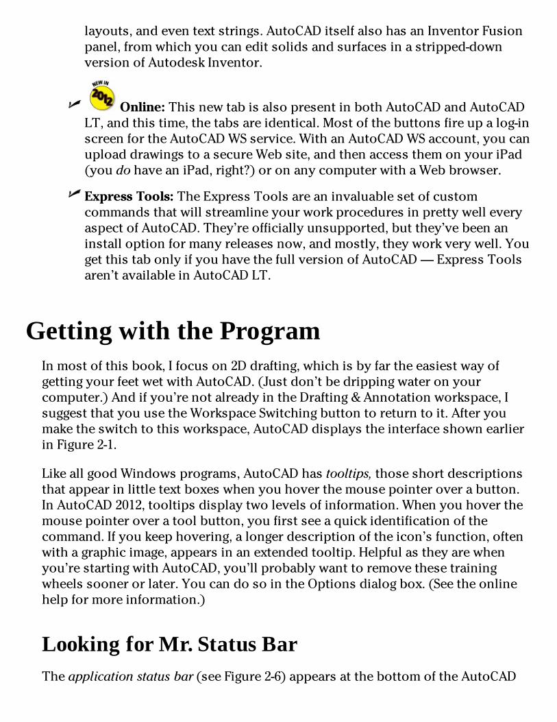
layouts,andeventextstrings.AutoCADitselfalsohasanInventorFusionpanel,fromwhichyoucaneditsolidsandsurfacesinastripped-downversionofAutodeskInventor.
Online:ThisnewtabisalsopresentinbothAutoCADandAutoCADLT,andthistime,thetabsareidentical.Mostofthebuttonsfireupalog-inscreenfortheAutoCADWSservice.WithanAutoCADWSaccount,youcanuploaddrawingstoasecureWebsite,andthenaccessthemonyouriPad(youdohaveaniPad,right?)oronanycomputerwithaWebbrowser.
ExpressTools:TheExpressToolsareaninvaluablesetofcustomcommandsthatwillstreamlineyourworkproceduresinprettywelleveryaspectofAutoCAD.They’reofficiallyunsupported,butthey’vebeenaninstalloptionformanyreleasesnow,andmostly,theyworkverywell.YougetthistabonlyifyouhavethefullversionofAutoCAD—ExpressToolsaren’tavailableinAutoCADLT.
GettingwiththeProgramInmostofthisbook,Ifocuson2Ddrafting,whichisbyfartheeasiestwayofgettingyourfeetwetwithAutoCAD.(Justdon’tbedrippingwateronyourcomputer.)Andifyou’renotalreadyintheDrafting&Annotationworkspace,IsuggestthatyouusetheWorkspaceSwitchingbuttontoreturntoit.Afteryoumaketheswitchtothisworkspace,AutoCADdisplaystheinterfaceshownearlierinFigure2-1.
LikeallgoodWindowsprograms,AutoCADhastooltips,thoseshortdescriptionsthatappearinlittletextboxeswhenyouhoverthemousepointeroverabutton.InAutoCAD2012,tooltipsdisplaytwolevelsofinformation.Whenyouhoverthemousepointeroveratoolbutton,youfirstseeaquickidentificationofthecommand.Ifyoukeephovering,alongerdescriptionoftheicon’sfunction,oftenwithagraphicimage,appearsinanextendedtooltip.Helpfulastheyarewhenyou’restartingwithAutoCAD,you’llprobablywanttoremovethesetrainingwheelssoonerorlater.YoucandosointheOptionsdialogbox.(Seetheonlinehelpformoreinformation.)
LookingforMr.StatusBarTheapplicationstatusbar(seeFigure2-6)appearsatthebottomoftheAutoCAD

screen.Thestatusbardisplaysandallowsyoutochangeseveralimportantdrawingmodes,aids,andsettingsthataffecthowyoudrawandeditinthecurrentdrawing.Iintroducetheminthissection.
Youcansetstatusbarbuttonstodisplayiconsorthetraditionaltextlabelsthatwillbefamiliartousersofearlierreleases.Toswitchfromonestyletotheother,right-clickanyofthedrawingmodebuttonsattheleftsideofthestatusbarandselectordeselectUseIcons.
Figure2-6:Status(bars)check.
Someofthesestatusbarsettingswon’tmakecompletesenseuntilyou’veusedtheAutoCADcommandsthattheyinfluence,buthere’sabriefdescription,withreferencestodetaileddescriptionsofhowtouseeachsetting,startingattheleftendofthestatusbar(andnotethatnotallbuttonsaredisplayedatalltimes,soFigure2-6doesn’tshowallthebuttonslisted):
Coordinatesofthecrosshairs:ThecoordinatesreadoutdisplaysthecurrentX,Y,Zlocationofthecrosshairsinthedrawingarea,withrespecttotheoriginpoint(whosecoordinatesare0,0,0).(AutoCADLTdisplaysonlytheX,Ycrosshairslocation.)Chapter7describesAutoCAD’scoordinateconventionsandhowtousethisareaofthestatusbar.
Ifthecoordinatesinthelower-leftcornerofthescreenaregrayedout,coordinatetrackingisturnedoff.Clickthecoordinatessothattheyappearindarknumbersthatchangewhenyoumovethecrosshairsinthedrawingarea.
InferConstraints(INFER):ParametricconstraintswerenewinAutoCAD2010,andinferredconstraintsarethefirstmajorenhancementtothisrelativelynewfeature.(TheinferredconstraintsfeatureisnotavailableinAutoCADLT.)WhenInferConstraintsisenabled,youautomaticallysetgeometry-basedconstraintsasyoudraw.IcovergeometricanddimensionalconstraintsinChapter19.

SnapMode(SNAP):Constrainsthecrosshairstoregularlyspacedintervals,enablingyoutodrawobjectsafixeddistanceapartmoreeasily
GridDisplay(GRID):Displaysaseriesofgraphpaper–stylelinesorregularlyspaceddots,whichserveasadistancereference
OrthoMode(ORTHO):Constrainsthecrosshairstohorizontalandverticalmovement,whichmakesdrawingorthogonal(straighthorizontalandvertical)lineseasy
SeeChapter4forinstructionsonhowtoconfigurethesemodesandChapter7forinformationaboutwhy,when,andhowtousetheminactualdrawingoperations.
PolarTracking(POLAR):Polartrackingcausesthecrosshairstojumptocertainangleswhenyoudrawandeditobjects.Thedefaultanglesettingsaremultiplesof90degrees,butyoucanspecifyotherangleincrements,suchas45or30degrees.SeeChapter7forinstructionsonspecifyingthepolartrackinganglesthatyouprefer.ClickingthePolarbuttontogglespolartrackingonandoff.Orthoandpolartrackingaremutuallyexclusive—turningononemodedisablestheother.
ObjectSnap(OSNAP):ObjectsnapisanotherAutoCADtoolforensuringprecisiondrawingandediting.Youuseobjectsnapstograbpointsonexistingobjects—forexample,theendpointofalineorthecenterofacircle.Chapter7containsdetailedinstructionsonhowtousethisfeature.
3DObjectSnap(3DOSNAP):WithAutoCAD’senhanced3Dcapabilities,anextensionofobjectsnapsintothethirddimensionwasagiven(notinAutoCADLT,ofcourse).Enablingthismodeletsyousnaptotheprecisecenterofaface,avertex,themidpointofanedge,oranumberofsimilar3Dpointsyoucan’tgettowithregularobjectsnaps.
ObjectSnapTracking(OTRACK):Whenyouturnonobjectsnaptracking,AutoCADhuntsinamoresophisticatedwayforpointsthatarederivedfromobjectsnappoints.Chapter7brieflydescribesthisadvancedfeature.
Allow/DisallowDynamicUCS(DUCS):Thisone’sfor3Dobjectcreation(andsoisn’tincludedinAutoCADLT).MostAutoCADprimitiveobjects,suchaslines,arcs,andcircles,areplanar,andyouhavetosetanappropriateplaneinthreedimensionsifyouwanttoworkin3D.YoucansetplaneswiththeUCScommand—IexplainhowinChapter22—butenablingDynamicUCSautomaticallysetstheworkplanebysimply

hoveringthemouseoverthefaceofanobject.
DynamicInput(DYN):DynamicInputdisplayscommands,options,prompts,anduserinputinatooltipadjacenttothecrosshairsandenablesyoutokeepfocusedonwhatyou’redrawing.Inaddition,theDynamicInputtooltipdisplayswhatyoutypeinresponsetoprompts.IdescribeDynamicInputlaterinthischapter.
Show/HideLineweight(LWT):OneofthepropertiesthatyoucanassigntoobjectsinAutoCADislineweight—thethicknessthatlinesappearwhenyouplotthedrawing.Thisbuttoncontrolswhetheryouseethelineweightsonthescreen.(Thisbuttondoesn’tcontrolwhetherlineweightsappearonplots;that’saseparatesettinginthePlotdialogbox.)Chapter6givesyoutheskinny(andthewide)onlineweights.
Show/HideTransparency(TPY):Youcanassigntransparencytoindividualobjectsortoallobjectsonagivenlayer.SimilartotheLineweightbutton,thisbuttoncontrolswhetherobjectsassignedthetransparencypropertyappeartransparentoropaque.IintroduceyoutoobjecttransparencyinChapter6.
QuickProperties(QP):WhenQuickPropertiesisenabled,selectinganobjectinthedrawingdisplaysapop-upwindowthatliststhemainpropertiesofthatobject.Youcanchoosewhichpropertiesyouwantdisplayedbyright-clickingtheQPbuttonandchoosingSettings.IfillyouinonobjectpropertiesinChapter6.
InAutoCAD2012,QUICKPROPERTIESisalsoanexplicitcommand.TypeQP(thealiasforQUICKPROPERTIES)andselectanobjecttoopentheQuickPropertiespalette.
SelectionCycling(SC):It’sremarkablyeasyinAutoCADtodrawobjectsontopofotherobjectsandnotbeabletotellyou’vedoneso.WhenSelectionCyclingisenabled,aniconshowingtwooverlappingrectanglesappearsbesidethecrosshairsifAutoCADfindsmorethanoneobjectunderthem.Ifyouthenclicktoselect,aSelectionwindowpopsupshowingyouhowmanyobjects,andofwhattype,areunderthepointthatyoupicked(seeFigure2-7).
ModelorPaperspace(MODEL/PAPER):Clickingthisbuttontogglesbetweenmodelspaceandpaperspace.
AsIdescribeintheupcomingsection“Downthemainstretch:The

drawingarea,”AutoCAD’sdrawingareaiscomposedoftwooverlappingenvironments:Modelspaceiswhereyoucreateyourmodelgeometry,andpaperspaceiswhereyoucomposeyourdrawingsheettodocumentthatgeometry.ClickingthisbuttonwhentheModeltabisactive(thatis,you’reinfull-screenmodelspace)switchesyoutoapaperspacelayout.Acompletedlayoutincludesviewports,whichrevealtheobjectsinmodelspaceataparticularscale.(ItellyoumoreaboutviewportsandlayoutsinChapter5.)Afteryouswitchtoapaperspacelayout,clickingthisbuttontogglesbetweenpaperspaceandmodelspacewithinthelayout.ThebuttonlabelswitchesfromMODELtoPAPERtoshowyouwhichspaceyou’rein.
Figure2-7:OverlappingobjectslistedintheSelectionwindow.
Modeland<Layout>:Note:ThesetwobuttonsdisappearifModelandLayouttabsaredisplayed.ClickingtheModelbuttonswitchesyououtofthelayoutandbacktofull-screenmodelspace.(IfModelandLayouttabsaredisplayed,youclicktheModeltabtoswitchtofull-screenmodelspace.)ClickingLayoutswitchesyoutowhicheverpaperspacelayoutwasactivewhenyouswitchedtomodelspace.AlsonotethatthetooltipfortheLayoutbuttondisplaysthenameofthelayout,whichmightbechangedfromthedefaultLayout1orLayout2.
QuickViewLayouts:Clickingthisbuttondisplaysahorizontalrowofgraphicimagesofalllayoutsinthecurrentdrawing.Clickalayoutimagetomakethatlayoutcurrent.TheQuickViewtoolbarbelowthelayoutimagescontainsbuttonsforpinningtheQuickViewLayoutsbarsoitstaysopen,creatinganewlayout,publishingtheselectedlayout,andclosingQuick

ViewLayouts.IcoverlayoutcreationinChapter5andpublishinginChapter16.
QuickViewDrawings:Clickingthisbuttondisplaysarowofgraphicimagesofallopendrawings.Clickadrawingimagetomakeitactive.(Why,yes,itisthesameasCtrl+Tabbing!)QuickViewDrawingsincludesthesameQuickViewtoolbarasQuickViewLayouts.
Maximize/MinimizeViewport(appearsonpaperspacelayoutsonly):Whenyou’relookingatoneoftheLayouttabsinsteadoftheModeltab,thestatusbardisplaysanadditionalMaximizeViewportbutton.Clickthisbuttontoexpandthecurrentpaperspaceviewportsothatitfillstheentiredrawingarea.Clickthebutton—nowcalledMinimizeViewport—againtorestoretheviewporttoitsnormalsize.(Chapter5describesviewports.)
ThenextsixbuttonscontrolthesizeandappearanceofAutoCAD’sannotativeobjects—thingsliketext,dimensions,hatching,andsoforth.Annotativeobjectsarecomplex,sodon’tworryifyoudon’tunderstandatthispoint.Fornow,justrememberthatinthischapter,I’mjustshowingyouwhatthebuttonsdo.Becauseannotativeobjectsmeanstextmorethananythingelse,IexplainthisfeatureinChapter13.
Lock/UnlockViewport:Whenyou’resatisfiedwiththedisplayinsideyourviewport,andyou’veassignedaviewportscale,usethisbuttontolocktheviewportdisplaysoyoudon’taccidentallypanorzoominsideit.(SeeChapter5formoreonviewports.)
AnnotationScale(appearsinfull-screenmodelspaceonly):ClickingAnnotationScaledisplaysalistofpresetannotationscales;iftheAuto-maticallyAddScalesbuttonistoggledon,changingascaleherecausesallannotativeobjectstoupdatetothenewscale.
ViewportScale:Thisbuttonappearsonlyinalayout,whenamodelspaceviewportisactivated.Iftheviewportislocked,thisbuttonisinactive.Iftheviewportisunlocked,clickingthebuttondisplaysalistofscales;choosethedesiredscalefromthelist.
AnnotationScaleIsNotEqualToViewportScale:Ifthescaleassignedtoannotativeobjectswithintheviewportdiffersfromthescaleassignedtotheviewportitself,clickingthisbuttonwillsynchronizetheannotationscaletotheviewportscale.
AnnotationVisibility:Thisbuttontogglesthevisibilityofannotativeobjects.Whenthelightbulbisoff(gray),onlyannotativeobjectsofthe

currentannotativescalearevisible;whenthelightbulbison(yellow),allannotativeobjectsinthedrawing,regardlessofscale,arevisible.
AutomaticallyAddScales:Whenthisbuttonistoggledon,additionalannotativescalesareautomaticallyaddedtoobjectsinsidetheviewportwhenyouchangetheviewportscale.
WorkspaceSwitching:Clickingthisbuttondisplaysalistofsavedworkspaces,includingthefourdefaultworkspaces(twoinAutoCADLT):AutoCADClassic,Drafting&Annotation,3DBasics,and3DModeling(thelattertwoarenotincludedinAutoCADLT),plusanyuser-definedandsavedworkspaces.
Lock/UnlockToolbar/WindowPositions:“Now,wheredidIleavethatPropertiespalette?”You’llneverhavetoaskyourselfthatquestionagainbecauseyoucanclickthisbuttontolocktheRibbon,toolbars,orpalettesinposition,soyou’llalwaysknowwheretheyare.
HardwareAcceleration:Youcanquicklytogglehardwareaccelerationonandofffromthestatusbar.PriortoAutoCAD2011,youhadtorunthe3DCONFIGcommandandproceedthroughacoupleofdialogboxes.Visittheonlinehelptofindoutmoreaboutimprovedgraphicsperformanceandbetterrenderingoptionsusinghardwareacceleration;hardwareaccelerationisavailableinbothAutoCADandAutoCADLT.
Theremainingstatusbaricons,withtheexceptionofCleanScreenattheveryend,liveinaspecialareaofthestatusbarcalledthetray.Thetraydisplaysiconsthatrepresentdrawingservices,andmostdonotappearatalltimes.Thesetrayiconsinclude
TrustedAutodeskDWG:AtrusteddrawingisonecreatedbyAutoCAD,AutoCADLT,oranyprogramdevelopedbyAutodesk.Inrecentyears,moreandmoreprogramshavebeenabletosaveinDWGformat,butinAutodesk’seyes,thesefilesarenottobetrusted.Ifyouopensuchadrawingfile,you’llgetawarningdialogboxandalittleyellowdangersignoverthetrustedDWGicon(makesureyouknowwhereyourwalletiswhenyouworkononeofthesefiles).
ObjectIsolation:Youdon’tneedtoturnalayer—andeverythingonit—offifyouwantaclearerviewofsomethinginacrowdeddrawing.Nowyoucanselectanobjectandeitherhideit(soitdisappears)orisolateit(soeverythingelsedisappears).Ifthelightbulbonthisbuttonisdim,oneormoreobjectsareeitherhiddenorisolated;clickthebuttonandchooseUnisolateObjectstoturneverythingelse—includingthelightbulbicon

—backon.
AssociatedStandardsFile:Youseethisbuttonifyou’veenabledCADstandards-checkingandconfiguredadrawingstandards(DWS)file.ClickingthisbuttondisplaystheCheckStandardsdialogbox.AutoCAD’sCADStandardsfunctionsarenotincludedinAutoCADLT.Idon’tcoverstandardscheckinginthisbook.
ManageXrefs:Youwon’tseethiscombinationbuttonandnotificationsymboluntilyouopenadrawingthatcontainsxrefs(externalDWGfilesthatareincorporatedintothecurrentdrawing).Chapter18tellsyouhowtousexrefsandwhattheManageXrefsbuttondoes.
StatusBarMenu:Whenyouclicktheeasy-to-miss,downward-pointingarrowneartherightendofthestatusbar,youopenamenuwithoptionsfortogglingofforoneachstatusbarbutton.Nowyoucandecorateyourstatusbartoyourtaste.Youcanalsoturnonthedrawingstatusbar.Doingsomovesanyofthesetrayiconsandthethreeannotationscalingbuttonsdescribedabovetoaseparatedrawing-specificstatusbar.(Mypersonalpreferenceistoleaveitturnedoff.)
CleanScreen:No,thisbuttondoesn’tsqueegeeyourmonitor.ClickingthisbuttonfreesupabitmorescreenspacebyfirstmaximizingtheAutoCADwindowandthenturningoffthetitlebar,toolbars,palettes,andtheWindowstaskbar.Clickthebuttonagaintorestorethoseelements.
Severalstatusbarbuttons,includingSnapMode,PolarTracking,ObjectSnap,andObjectSnapTracking,sportright-clickmenusthatofferaspeedierwayofsettingoptions.Withsomeoftheotherbuttons,suchasGridDisplayandDynamicInput,youright-clickthebuttonandchooseSettingstoopentheDraftingSettingsdialogboxtospecifyoptions.Chapters4and6giveyouspecificguidanceaboutwhenandhowtochangethesesettings.
InAutoCAD2012,primaryaccesstothedisplaycommandsisviatheNavigationbarthatappears,bydefault,attherightedgeoftheprogramwindow.AutoCADalsohasaViewCubethatprovidesanalternativetotheOrbittool.(NeithertheViewCubenortheOrbittoolareincludedinAutoCADLT.)Figure2-8showsthedifferencesbetweenthenavigationdevicesinAutoCAD(ontheleft)andAutoCADLT.IintroduceyoutotheNavigationbarbuttonsinthefollowinglist,andexplaintheiroperationmorefullyinChapter12.IgiveyouthedrillontheViewCubeandtheOrbittoolinChapter21.
SteeringWheels:Youwereprobablywonderingwhenthismotoring

metaphorwasgoingtopayoff,right?Well,believeitornot,therereallyisanAutoCADfunctioncalledtheSteeringWheel!(I’mstilllookingfortheGasPedal...oops,ImeanGasPedal.)ASteeringWheelisdescribedintheonlinehelpasatrackingmenu—theideahereisthatyoucombineanumberofdisplayoperationsintoasingleinput“device.”ImentionSteeringWheelsinChapter12butpointoutherethatit’soflittleusein2Ddrafting—which,unfortunately,isallthatAutoCADLTuserscandowithit.
PanandZoom:Thesebuttonsprovideaccesstotwocommonlyuseddisplaycommands,PANandZOOM.PANmovesyouaroundyourdrawingwithoutchangingyourviewingdistance;ZOOMbringsthedrawingobjectsclosersoyoucanseemoredetail,orfartheraway,soyoucanseemoreofthedrawingarea.TheseandotherdisplaycommandsaredescribedinChapter12.
Orbit:TheOrbittool(notavailableinAutoCADLT)isaninteractivedeviceforviewingyour3Dmodelsfromanyangle.Idescribethistoolwiththeother3DviewingoptionsinChapter21.
ShowMotion:TheShowMotiontoolstartsarudimentaryanimationprogram.Astheonlinehelpdescribesit,youcangenerateeffectssimilartothoseinTVcommercialstodressupmotionstudiesofyourdesigns.ShowMotionisn’tincludedinAutoCADLTandisbeyond—wellbeyond—thescopeofthisbook.


Figure2-8:NavigationtoolsinAutoCAD(left)andAutoCADLT(right).
Letyourfingersdothetalking:ThecommandwindowTheinfamouscommandwindow(orcommandline,orcommandprompt,orcommandarea,whateveryouwanttocallit),showninFigure2-9,isathrowbacktothedarkagesofAutoCAD.ItpuzzlesnewcomersanddelightsAutoCADaficionados.DespitethepromiseofAutoCAD’sheads-upDynamicInput,fornowatleast,thehardtruthisthatyouhavetocometolike—oratleasttolerate—thecommandwindowifyouwanttobecomeatallcomfortableusingAutoCAD.
Figure2-9:Obeythecommandwindow.
Youshouldcottononandcozyuptothecommandwindowbecauseit’sstillAutoCAD’sprimarycommunicationsconduitwithyou.AutoCADsometimesdisplaysprompts,warnings,anderrormessagesinthecommandwindowthatDynamicInputdoesn’tshow—theresimplyisn’troomintheDynamicInputtooltiptoshowasmuchinformationasyougetatthecommandwindow.True,whenusingDynamicInput,youcanpressthedown-arrowkeytoseemoreoptions.Butwhichislessefficient:movingyoureyesdownthescreentoglanceatthecommandwindow,ortakingyoureyesrightoffthescreentofindthedown-arrowkeyonyourkeyboard?
Thekey(board)toAutoCADsuccessDespite(orisitbecauseof?)AutoCAD’slongheritageasthemostsuccessfulCADsoftwareforpersonalcomputers,newcomersarestillastonishedattheamountoftypingtheyhavetodo.Somemore-modernprogramshavemuchlessdependencyonthekeyboardthanAutoCAD,butasyougetusedtoit,you’llfindthatnootherinputmethodgivesyouasmuchflexibilityaspoundingtheivories...oops,wrongkeyboard!
Typingatyourcomputer’skeyboardisanefficientwaytorunsomecommandsandtheonlywaytorunafewothers.Insteadofclickingabuttonorchoosingfromamenu,youcanstartacommandbytypingthecommandnameandthenpressingEnter.Evenbetter,formostcommoncommands,youcantypetheshortformfor

acommandnameandpressEnter.Mostoftheshortforms(calledaliases)ofcommandnamesarejustoneortwoletters—forexample,LfortheLINEcommand,andCPfortheCOPYcommand.MostpeoplewhodiscoverhowtousethealiasesforthecommandsthattheyrunmostfrequentlyfindthattheirAutoCADproductivityimprovesnoticeably.Evenifyou’renotworriedaboutincreasingyourproductivitywiththistechnique,severaleverydaycommandsarenowheretobefoundontheRibbon.Ifyouwanttorunthosecommands,youhavetotypethem!
AutoCAD2012’snewAutocompletefeaturepromptsoneresponse:Whydidittakesolong?MostefficientAutoCADjockeysusethekeyboard.ManyhavecustomizedtheirPGPfilessothecommandstheyusethemostareonekeytapaway,butthentherearethoseoccasionallyusedcommands,andthoseevenmoreoccasionallyaccessedsystemvariablesthatdon’tgetquiteenoughusagetojustifyaspecialshortcut.Nowyoucanjuststarttypingletters,andassoonasyourcommandorvariableappears,youcanjustclickit.Handsup,everyonewho’drathertypeAPPLYthanAPPLYGLOBALCAPACITIES!
NotallcommandaliasesareasobviousasLforLINE:Forexample,CPforCOPYor—believeitornot—TforMTEXT.Toseeacompletelistofcommandaliases,lookintheAutoCAD(ortheAutoCADLT)ProgramParameters(PGP)filebygoingtotheManagetabandclickingEditAliasesontheCustomizationpanel.WhenWindowsNotepadopenswiththeacad.pgp(oracadlt.pgp)fileloaded,scrolldowntotheSampleAliasesforAutoCADCommandssection.Idon’trecommendchanginganythinghere,butit’sagoodideatoprintthisfileandpinupthealiasessectionoveryourdesk.
Afteryoustartacommand—whetherfromaRibbonpaneltoolbutton,orbytyping—theDynamicInputtooltipandthecommandwindowarewhereAutoCADpromptsyouwithoptionsforthatcommand.Youactivateoneoftheseoptionsbytypingtheuppercaseletter(s)intheoptionandthenpressingEnter.
Inmanycases,youcanactivateacommand’soptionsbyright-clickinginthedrawingareaandchoosingthedesiredoptionfromthemenuthatappears,insteadofbytypingtheletter(s)fortheoptionandpressingEnter.
IlikeDynamicInput.Really,Ido.Butsometimesitfightswithnormal

commandinput,andthatcanmakethingsreallyconfusing.Inthefollowingchapters,Itellyouwhentobewary.
Thefollowingsequencedemonstrateshowyouusethekeyboardtoruncommandsandtoviewandselectoptions.IfyouhaveDynamicInputtoggledon,yourresultsaregoingtobedifferentfromwhatIsay,soIsuggestyouclickDynamicInputonthestatusbartoturnitoff,temporarilyatleast.Inthefollowingsteps,watchthecommandwindow,andpayattentiontomessagesfromAutoCAD:
1.TypeLandthenpressEnter.AutoCADstartstheLINEcommandanddisplaysthefollowingpromptinthecommandwindow:
LINESpecifyfirstpoint:2.Clickapointanywhereinthedrawingarea.Thecommandwindowpromptchangesto
Specifynextpointor[Undo]:3.Clickanotherpointanywhereinthedrawingarea.AutoCADdrawsthefirstlinesegment.
4.Clickathirdpointanywhereinthedrawingarea.AutoCADdrawsthesecondlinesegmentandprompts
Specifynextpointor[Close/Undo]:Thecommandlinenowdisplaystwooptions:CloseandUndo,separatedbyaslash.
Inthiscase,theCloseandUndooptionsappearinbrackets.TheAutoCADcommandlinealwaysdisplayscommandoptionsinsquarebrackets.Toactivateanoption,typetheletter(s)showninuppercaseandthenpressEnter.Youcantypetheoptionletter(s)inlowercaseoruppercase.
5.TypeUandthenpressEnter.AutoCADundoesthesecondlinesegment.
6.Type3,2(withoutanyspaces)andthenpressEnter.AutoCADdrawsanewlinesegmenttothepointwhoseXcoordinateis3andYcoordinateis2.
7.Clickseveralmorepointsanywhereinthedrawingarea.AutoCADdrawsadditionallinesegments.
8.TypeXandthenpressEnter.Xisn’tavalidoptionoftheLINEcommand,soAutoCADdisplaysanerrormessageandpromptsyouagainforanotherpoint:
Pointoroptionkeywordrequired.

Specifynextpointor[Close/Undo]:
Optionkeywordisprogrammerjargonfortheletter(s)showninuppercasethatyoutypetoactivateacommandoption.ThiserrormessageisAutoCAD’swayofsaying,“Idon’tunderstandwhatyoumeanbytypingX.Eitherspecifyapoint,ortypealetterthatIdounderstand.”
9.TypeCandthenpressEnter.AutoCADdrawsafinallinesegment,whichcreatesaclosedfigureandendstheLINEcommand.Ablankcommandlinereturns,indicatingthatAutoCADisreadyforthenextcommand:
Command:10.PressF2.AutoCADdisplaystheAutoCADTextWindow,whichissimplyanenlarged,scrollableversionofthecommandwindow,asshowninFigure2-10.
Thenormalthree-linecommandwindowusuallyshowsyouwhatyouneedtosee,butoccasionallyyouwanttoreviewalargerchunkofcommand-linehistory.(“WhatwasAutoCADtryingtotellmeaminuteago?!”)
11.PressF2again.AutoCADclosestheAutoCADTextWindow.
Figure2-10:My,howyou’vegrown:F2expandsthecommandlinetoacommandtextwindow.
Hereareafewothertipsandtricksforeffectivekeyboarding:

UsetheEsckeytobailoutofthecurrentoperation.Sometimesyoumightgetconfusedaboutwhatyou’redoinginAutoCADand/orwhatyou’reseeinginthecommandwindowortheDynamicInputtooltip.Ifyouneedtobailoutofthecurrentoperation,justpressEsconeormoretimesuntilyouseeablankcommandline—Command:atthebottomofthecommandwindow,withnothingafterit.AsinmostotherWindowsprograms,Escisthecancelkey.UnlikemanyotherWindowsprograms,AutoCADkeepsyouwellinformedofwhetheranoperationisinprogress.TheblankcommandlineindicatesthatAutoCADisresting,waitingforyournextcommand.
PressEntertoacceptthedefaultaction.Somecommandpromptsincludeadefaultactioninangledbrackets.Forexample,thefirstpromptofthePOLYGONcommandis
Enternumberofsides<4>:Thedefaulthereisfoursides,andyoucanacceptitsimplybypressingEnter.(Thatis,youdon’thavetotype4first.)
AutoCADusestwokindsofbracketswhenitprompts.
•Commandoptionsappearinregularsquarebrackets:[Close/Undo].
Toactivateacommandoption,typetheletter(s)thatappearinuppercaseandthenpressEnter.TheDynamicInputtooltipdoesn’tdisplayoptionsinbrackets;instead,youpressthedown-arrowkeytodisplayadditionalcommandoptionsinrowsnexttothecrosshairs.
•Adefaultvalueoroptionappearsinangledbrackets:<4>.
Tochoosethedefaultvalueoroption,simplypressEnter.DefaultvaluesinangledbracketsappearinboththeDynamicInputtooltipandthecommand-lineprompts.
Youdon’talwayshavetopressEntertoforwardyourinputtoAutoCAD.Dependingonwhatyou’redoing,youcanoftenright-clickandchooseEnterfromthetopoftheright-clickmenu.Andmostefficientofall,evenforthemostinepttypists,youcanusethespacebarasanEnterkey—aslongasyou’renotenteringtext.
Watchthecommandline.Youcandiscoveralotabouthowtousethecommandlinesimplybywatchingitaftereachactionthatyoutake.When

youclickatoolbarbuttonormenuchoice,AutoCADdisplaysthenameofthecommandintheDynamicInputtooltipandatthecommandline.Ifyou’rewatchingthecommandline,you’llabsorbthecommandnamesmoreorlessnaturally.
WhenAutoCADechoescommandsautomaticallyinresponsetoyourtoolbarandmenuclicks,itusuallyaddsoneortwoextracharacterstothefrontofthecommandname:
•AutoCADusuallyputsanunderscoreinfrontofthecommandname:forexample,_LINEinsteadofLINE.TheunderscoreisanAutodeskprogrammers’trickthatenablesnon-EnglishlanguageversionsofAutoCADtounderstandtheEnglishcommandnamesthatareembeddedinthemenus.
•AutoCADsometimesputsanapostropheinfrontofthecommandnameandanyunderscore(forexample,‘_ZOOMinsteadofZOOM).Theapostropheindicatesatransparentcommand;youcanrunatransparentcommandinthemiddleofanothercommandwithoutcancelingthefirstcommand.Forexample,youcanstarttheLINEcommand,runtheZOOMcommandtransparently,andthenpickupwhereyouleftoffwiththeLINEcommand.
Leavethecommandlineinthedefaultconfiguration.Thecommandwindow,likemostotherpartsoftheAutoCADscreen,isresizableandmovable.Thedefaultlocation(dockedatthebottomoftheAutoCADscreen)andsize(threelinesdeep)workwellformostpeople.Resistthetemptationtomesswiththecommandwindow’sappearance—atleastuntilyou’recomfortablewithusingthecommandline.
Right-clickinthecommandwindowforoptions.Ifyouright-clickinthecommandwindow,youseeamenuwithsomeusefulchoices,includingRecentCommands—thelastsixcommandsthatyouran.
Presstheup-anddown-arrowkeystocyclethroughthestackofcommandsthatyou’veusedrecently.Thisisanotherhandywaytorecallandrerunacommand.Presstheleft-andright-arrowkeystoeditthecommandlinetextthatyou’vetypedorrecalled.
MostWindowsusersarefamiliarwithAlt-keyshortcuts.PresstheAltkeyintraditionalWindowsprograms,andyourmenubarlightsupwithonecharacterofeachmenuitemunderlined.Youtypetheunderlinedlettertoopenthemenuorexecutethecommand.AutoCAD’simplementationofMicrosoft’sFluentUser

Interfacehasanequivalent—KeyTips—whichworkinmuchthesameway.InFigure2-11,I’vejustpressedtheAltkey.IfInowtaptheAkey,theAnnotatetabwillopenwithanewsetofKeyTips,andIcankeeptappingthekeystoexecuteaspecificcommand.
Figure2-11:HolddowntheAltkeytodisplayakazillionKeyTips.
KeepingtabsonpalettesPalettesarerefined(well-mannered)versionsofdialogboxes.Unlikeregulardialogboxes,whichinsistonyourundividedattentionaslongasthey’reopen,palettesstaydiscreetlyinthebackgroundasyoucarryonwithothertasks.AutoCADstillhasmanydialogboxes,butoverthepastseveralreleases,quiteafewformerdialogboxeshavebeenreplacedbypalettes.
AutoCAD2012containsmorethanadozenpalettes(morethanahalf-dozeninAutoCADLT).Unlessnotedotherwise,youcanopenanyofthesepalettesfromthePalettespaneloftheViewtab.Themorecommonlyusedpalettesare
Properties,DesignCenter,andContentExplorer:Thesepalettesareusedtocontrolobjectpropertiesandfindanddisplaynamedobjects(layers,blocks,andsoon),andcopythembetweendrawings.IcoverthefirsttwoinChapter6.
ToolPalettes:Eachtoolpaletteholdscontent(drawingsymbolsandhatchpatterns)and/orcommands(notregularAutoCADcommands—whatwouldbethepoint?—butmacrosthatmakecommandsdospecificthings)insteadofpaints.Youcancreateyourowntoolpalettes,buttheonesthatcomewithAutoCADcontaindozensofsymbolsyoucandrag

intoyourdrawing—check’emout!
SheetSetManager:Providestoolsformanagingallofaproject’sdrawingsasasheetset.Idon’tcoversheetsetsinAutoCAD2012ForDummies.
ExternalReferences:Usedtoattachexternalfilestothecurrentdrawing;filetypesincluderasterimages,DrawingWebFormat(DWF,orDWFx)files,PDFfiles,MicroStationDGNfiles,andotherdrawingfiles.IdiscussattachingexternalreferencefilesinChapter18.
MarkupSetManager:DisplaysdesignanddraftingreviewcommentsfromusersofAutodeskDesignReview.Formoreinformationonmarkupsets,seetheonlinehelp.
QuickCalc:AhandypushbuttonscientificcalculatorthathidesoutontheHometab’sUtilitiespanel.You’llknowifyouneedthis.
LayerPropertiesManager:Themaincontrolcenterformanagingthelayersonyourdrawing.ThepalettizedLayerPropertiesManagernotonlystaysopenwhileyou’redoingotherthings,butalsoappliesanychangesyoumakeinstantlyinthedrawing.TheLayerPropertiesManagercanbefoundontheLayerspaneloftheHometab.
UsingtheViewandHometabsisonewayofopeningpalettes.Alternatively,severalpaletteshavekeyboardshortcuts.YoucantogglethesebypressingCtrl+1(Properties),Ctrl+2(DesignCenter),Ctrl+3(ToolPalettes),Ctrl+4(SheetSetManager),Ctrl+7(MarkupSetManager),orCtrl+8(QuickCalc).
Downthemainstretch:ThedrawingareaAfterallthesewarm-uplaps,you’reprobablyitchingforthemainevent—theAutoCADdrawingarea.Thisiswhereyoudoyourdrawing,ofcourse.Inthecourseofcreatingdrawings,youclickpointstospecifylocationsanddistances,clickobjectstoselectthemforediting,andzoomandpantogetabetterviewofwhatyou’reworkingon.
Mostofthisbookshowsyouhowtointeractwiththedrawingarea,butyoushouldknowafewthingsupfront.
Modelspaceandpaperspacelayouts
OneoftheinitiallydisorientingthingsaboutAutoCADisthatfinisheddrawings

canbecomposedofobjectsdrawnindifferentspaces,whichAutoCADindicateswitheithertwostatusbarbuttons,ortwoormoretabsatthebottomleftofthedrawingarea:
Modelspace:Whereyoucreateandmodifytheobjectsthatrepresentthingsintherealworld—walls,widgets,waterways,orwhatever.
Paperspace:Whereyoucreateparticularviewsoftheseobjectsforplotting,usuallywithatitleblockaroundthem.Paperspacecomprisesoneormorelayouts,eachofwhichcancontainadifferentarrangementofmodelspaceviewsanddifferenttitleblockinformation.
WhenyouclicktheModelbuttononthestatusbarortheModeltab,youseepure,unadulteratedmodelspace,asshowninFigure2-12.WhenyouclicktheLayoutbutton,youseeapaperspacelayout,asshowninFigure2-13.Acompletedlayoutusuallyincludesoneormoreviewports,whicharewindowsthatdisplayallorpartofmodelspaceataparticularscale.Alayoutalsousuallyincludesatitleblockorotherobjectsthatexistonlyinthelayoutanddon’tappearwhenyouclicktheModeltab.(Thinkoftheviewportasawindowlookingintomodelspaceandthetitleblockasaframearoundthewindow.)Thus,alayoutdisplaysmodelspaceandpaperspaceobjectstogether,andAutoCADletsyoudrawandeditobjectsineitherspace.SeeChapter5forinformationaboutcreatingpaperspacelayoutsandChapter16forthelowdownonplottingthem.

Figure2-12:Abuildingmodelreadyforeditinginmodelspace.
Whenalayoutiscurrent,youcanmovethecrosshairsbackandforthbetweenmodelspaceandpaperspacewhileremaininginthelayout.Youcan’tbeinbothspacesatthesametime,however;ifpaperspaceiscurrent,youcanclickdirectlyontopofamodelspaceobject,butitwon’tbeselected.Similarly,ifmodelspaceiscurrent,youcan’tselectanythinginpaperspace.Tomovebetweenthetwospaces,double-clickinsideaviewporttoswitchtomodelspaceoroutsideaviewporttoswitchtopaperspace.
Thisback-and-forthdouble-clickingisnecessaryonlywhenyou’redrawingthingswhileviewingoneofthepaperspacelayoutsoradjustingtheviewofthedrawingobjectswithintheviewport.Inpractice,youprobablywon’tdrawverymuchusingthismethod.Instead,you’lldomostofyourdrawingontheModeltab,andafteryou’vesetupapaperspacelayout,clickitslayouttabonlywhenyouwanttoplot.

Figure2-13:Freshlylaidoutinpaperspace.
Drawingonthedrawingarea
HereareafewotherthingstoknowabouttheAutoCADdrawingarea:
Efficient,confidentuseofAutoCADrequiresthatyoucontinuallyglancefromthedrawingareatothecommandwindow(toseethoseall-importantprompts!)andthenbackuptothedrawingarea.Thissequenceisnotanaturalreflexformostpeople,andthat’swhytheDynamicInputtooltipatthecrosshairswasintroduced.Butyoustillgetinformationfromthecommandlinethatyoudon’tgetanywhereelse.Getinthehabitoflookingatthecommandlineaftereachactionthatyoutake.
ClickingatrandominthedrawingareaisnotquiteasharmlessinAutoCADasitisinmanyotherWindowsprograms.WhenyouclickintheAutoCADdrawingarea,you’realmostalwaysperformingsomeaction—usuallyspecifyingapointorselectingobjectsforediting.Feelfreetoexperiment,butlookatthecommandlineaftereachclick.Ifyougetconfused,pressEscacoupleoftimestoclearthecurrentoperationandreturntothenakedcommandprompt.

Inmostcases,youcanright-clickinthedrawingareatodisplayamenuwithsomeoptionsforthecurrentsituation.
FunwithF1AutoCAD2012’sratherlimitedHelpmenuisaccessibleonlyasadrop-downlistontheprogramtitlebar.(Asalways,pressingF1atanytimeopenstheonlinehelpwindow.)Clickthedownarrowbesidethequestionmarktoopenthemenu.
ThemainAutoCAD2012Helpsystem,asshowninFigure2-14,isoneofthemajorcomponentsoftheAutodeskExchangeforAutoCADapplication.AutoCADLT’ssetupissimilarexceptthatthereisnoAppspage—justtheHomepageandtheHelpsystem.
AsisthecasewithmostWindowsprograms,AutoCADhelpiscontext-sensitive;forexample,ifyoustarttheLINEcommandandjustdon’tknowwhattodonext,Helpwill,er,help.YoucanbrowsethroughtheonlineProductDocumentationfromtheAutoCAD2012Helppage,ortypeintheSearchboxtolookforspecificwords.Inthisbook,IsometimesdirectyoutotheAutoCADonlinehelpsystemforinformationaboutadvancedtopics.
AutoCADisoneprogramwhereyoureallyneedtotakeadvantageoftheonlinehelpresources.AutoCADcontainsmanycommands,options,andquirks.(Alas,thequirksaren’tlistedintheonlinehelp.)EveryonefromthegreenestbeginnertothemostseasonedexpertcanfindoutsomethingbyusingtheAutoCADonlinehelp.TakeamomenttoperusetheHomepageofthemainhelpsystemsothatyouknowwhat’savailable.Throughoutthisbook,IdirectyoutopagesinthehelpsystemthatIthinkareparticularlyuseful,butdon’tbeafraidtoexploreonyourownwhenyougetstuckorfeelcurious.

Figure2-14:HelpisatyourF1fingertip.

Chapter3
ALaparoundtheCADTrack
InThisChapterSettingupasimpledrawing
Drawingsomeobjects
Zoomingandpanninginyourdrawing
Editingsomeobjects
Plottingyourdrawing

TheprevioustwochaptersintroduceyoutotheAutoCADworldandtheAutoCAD2012interface.Thechaptersthatfollowpresentthetechniquesthatunderliegooddraftingpractice.Bynow,you’reprobablyeagertostartmovingthecrosshairsaroundanddrawsomething!ThischaptertakesyouonagentletourofthemostcommonCADdraftingfunctions:
Settingupanewdrawing
Drawingsomeobjects
Editingthoseobjects
Zoomingandpanningsoyoucanviewthoseobjectsbetter
Plotting(printing)thedrawing
Muchofthestuffinthischaptermaybemysterioustoyou.Don’tworry—Itellyouwheretolookformoreinformationonspecifictopics.Inthischapter,you’resimplytakingAutoCADoutforatestdrivetogetafeelforwhatitcando.Goaheadandkickthetires—anddon’tworryaboutputtingadentinthefender!
Inthischapter,youcreateadrawingofanarchitecturaldetail—abaseplateandcolumn,asshowninFigure3-1.Evenifyoudon’tworkinarchitectureorbuildingconstruction,thisexercisegivesyousomesimpleshapestoworkwithanddemonstratescommandsyoucanuseinmostdraftingdisciplines.
Throughoutthisbook,IshowAutoCADrunningintheRibbon-basedDrafting&AnnotationworkspacethatwasintroducedinAutoCAD2009andpresentinbothAutoCAD2012andAutoCADLT2012.Likewise,ItellyouwheretofindcommandsandwhattoselectusingtheRibbon.
Ifyou’refamiliarwithearlierversionsofAutoCADandthepost-AutoCAD2008userinterfacelooksjusttooweird,youcanstraponsometrainingwheelswhileyou’regettingusedtoit.JustclickthedownarrowattherightendoftheQuickAccessToolbar(bydefault,itappearstotherightoftheWorkspacedrop-downlist)andchooseShowMenuBar.Ifyou’rereallyandtrulyaLudditewheretheRibbonisconcerned,youcanreverttothe“classic”wayofdoingthingsbyeitheropeningtheWorkspacedrop-downontheQuickAccessToolbar,orbyclickingtheWorkspaceSwitchingbuttononthestatusbarandchoosingAutoCADClassic(AutoCADLTClassicinthatversion).Prestochange-o—suddenly,it’s2008!

Figure3-1:Howbaseismyplate.
Althoughthedraftingexampleinthischapterissimple,theproceduresthatitdemonstratesarereal,honest-to-CAD-ness,properdraftingpractice.Iemphasizefromthebeginningtheimportanceofproperdrawingsetup,puttingobjectsonappropriatelayers,anddrawingandeditingwithdueconcernforprecision.Someofthestepsinthischaptermayseemabitcomplicatedatfirst,buttheyreflectthewaythatexperiencedAutoCADuserswork.MygoalistohelpyoudevelopgoodCADhabitsanddothingstherightwayfromtheverystart.
Thestep-by-stepproceduresinthischapter,unlikethoseinmostchaptersofthisbook,formasequence.Youmustdothestepsinorder.FiguringouthowtouseAutoCADisalittlelikefiguringouthowtodrive,exceptthatwithAutoCAD,you’refreetostopinthemiddleofthestreetandtakeabreak.
IfyoufindthatobjectselectionoreditingfunctionsworkdifferentlyfromhowIdescribetheminthischapter,you(orsomeoneelse)probablychangedtheconfigurationsettingsontheOptiondialogbox’sSelectiontab.Chapter

10describesthesesettingsandhowtorestoretheAutoCADdefaults.
ASimpleSetupInthischapter,Iwalkyouthroughcreating,editing,viewing,andplottinganewdrawing—refertoFigure3-1ifyouwanttogetanideaofwhatthefinishedproductlookslike.Youcanfollowthesestepsusingeitherimperialormetricunits;Ishowmetricvaluesinbracketsaftertheimperialones,likethis:Type1.5[38]andpressEnter.
YoucanfindthefilesIuseinthissequenceofstepsatthisbook’scompanionwebsite.Gotowww.dummies.com/go/autocad2012fdanddownloadafd03.zip.Thezipfilecontainsimperialandmetricversionsofthebaseplateexerciseatvariousstages—theReadMefileonthedownloadstabhasadetaileddescriptionofthefiles.
PayattentiontoAutoCAD’sfeedback.GlanceatthemessagesAutoCADsendsaftereachstepviathecommandwindowatthebottomofthescreenortheDynamicInputtooltipnearthecrosshairssothatyoubegintogetfamiliarwiththenamesofcommandsandtheiroptions.(Ifyoudon’tseeanymessagesnexttothecrosshairsasyouusetheprogram,clicktheDynamicInputbuttononthestatusbar—ifyourstatusbardisplaysbuttoniconsratherthantextlabels,clickthebuttonwiththetooltipthatreads“DynamicInput.”)AsIdescribeinChapter4,drawingsetupisn’tasimpletaskinAutoCAD.Nonetheless,drawingsetupisanimportantpartofthejob,andifyoudon’tgetinthehabitofdoingitright,yourunintoendlessproblemslateron—especiallywhenyoutrytoplot.(SeeChapter16forthelowdownonplottingyourdrawings.)Inthisfirstsetofsteps,youcreateanewdrawingfromatemplate,changesomesettingstoestablisha1:10scale(thatis,1inchor1millimeteronthedrawingisequivalentto10inchesor10millimetersontherealobject),andsavethedrawing:
1.StartAutoCADbydouble-clickingitsshortcutontheWindowsdesktop.Ifyoudon’thaveanAutoCADshortcutonyourdesktop,chooseStart⇒[All]Programs⇒Autodesk⇒AutoCAD2012⇒AutoCAD2012.(ThelasttwowillbeAutoCADLT2012,ifthat’syourversion.)TheworkspacesinAutoCAD2012lookverysimilartooneanother.Tomakesureyou’reinthesameworkspacethatIam,lookattheWorkspacelabelatthe

leftsideoftheAutoCADwindow’stitlebar(ifyou’rerunningataverylowscreenresolution,youmayhavetoclickthelittlearrowattherightoftheQuickAccessToolbar).Ifitdoesn’tsayDrafting&Annotation,clickthelittleblackarrowonthebuttonandthenselectDrafting&Annotationfromthemenu.
2.ClicktheApplicationbutton—that’sthebigredAatthetopleftofthescreen—todisplaytheApplicationMenu.Then,clickNew,orhoverthemousepointeroverNewandselectDrawing.Don’tclicktheNewbuttonontheQuickAccessToolbar—usethemenu.IexplainwhyinChapter4,butjusthumormefornow.TheSelectTemplatedialogboxappearswithalistofdrawingtemplates(DWTfiles),whichyoucanuseasthestartingpointfornewdrawings.Chapter4describeshowtocreateandusedrawingtemplates.
3.Selectacad.dwt[acadiso.dwt],asshowninFigure3-2,andclickOpen.(ForAutoCADLT,selectacadlt.dwt[acadltiso.dwt].)AutoCADcreatesanew,blankdrawingthatusesthesettingsinacad.dwtoracadiso.dwt.Theacad.dwttemplate(acadlt.dwtinAutoCADLT)isAutoCAD’sdefault,plain-Janetemplatefordrawingsinimperialunits(unitsexpressedininchesand/orfeet).Theacadiso.dwt(acadltiso.dwtinAutoCADLT)templateisthecorrespondingversionfordrawingscreatedinmetricunits.Chapter4containsadditionalinformationabouttheseandothertemplates.

Figure3-2:Startinganewdrawingfromatemplate.
4.ClickallthebuttonsonthelefthalfofthestatusbarexceptDynamicInputuntiltheylookdimmed(they’llbegrayinsteadoflightblue).Ifyourstatusbardisplaysbuttoniconsratherthantextlabels,clickthebuttonwiththeDynamicInputtooltip.Someofthesesettingscanmakeselectingpointsdifficult.It’sbesttostartwiththemallturnedoffandthentogglethemonandoffasneeded.Itellyouwhichonestouseinthestepsthatfollow.
Ifyourstatus-barbuttonsshowiconsinsteadoftext,right-clickanybutton,clickUseIconstodeselecttheoptionanddisplaytextlabels.Youcanleavethemthatwayorright-clickandselectUseIconsagaintotoggletheicondisplaybackon.
5.TypeLIMITSandpressEnter.Drawinglimitsdefineyourworkingarea.AutoCADpromptsyoutoresetthemodelspacelimits.Fornow,ignoretheDynamicInputtooltipnexttothecrosshairsandlookatthecommandwindow.Thecommandlinereads
Specifylowerleftcorneror[ON/OFF]<0.0000,0.0000>:
6.PressEntertokeep0,0asthelower-left-cornervalue.AutoCADpromptsfortheupper-rightcorner.Thecommandlinereads
Specifyupperrightcorner<12.0000,9.0000>[<420.0000,297.0000>]:
7.Type100,50[2750,1250](nospaces)andpressEnter.AutoCADechoesthevaluesyouenteratthecommandline.100x50correspondsto10inchesby5inches(alittlesmallerthanan8.5-x-11-inchpieceofpaperturnedonitslongside)timesadrawingscalefactorof10(becauseyou’reeventuallygoingtoplotat1:10scale).Ifyou’reametricmaven,2750x1250correspondsto275mmby125mm(slightlysmallerthananISOA4sheetturnedlengthways)timesadrawingscalefactorof10(becauseyou,too,willeventuallyplotat1:10scale).SeeChapter4formoreinformationaboutdrawingscales.Tobehonest,settinglimitsisn’tveryimportantinAutoCADanymore—moderncomputerscanprocessmuchmoredatathantheycouldinthe1980swhenAutoCADfirstappeared—butitdoesmakeiteasiertoplotadrawingfrommodelspaceasyoudointhischapter.
8.Right-clicktheSnapModebuttononthestatusbarandchooseSettings.Ifyourstatusbardisplaysbuttoniconsratherthantextlabels,right-clickthebuttonwiththeSnapModetooltip.

TheSnapandGridtaboftheDraftingSettingsdialogboxappears,asshowninFigure3-3.(NotethatAutoCADLTlackssomeoptionsthatarepresentinthefullversionofAutoCAD.)
Figure3-3:SnapandGridsettings.
9.ChangethevaluesinthedialogboxsoitlookslikeFigure3-3:•SnapOn:Selected
Snapconstrainsyourcrosshairstomovinginaninvisiblegridofequallyspacedpoints(0.5[10]unitsapartinthiscase).
•GridOn:Selected
Griddisplaysavisiblegridoflittledotsorgridlinesonthescreen(5[100]unitsapartinthiscase),whichyoucanuseasreferencepoints.Thegriddoesn’tappearonprinteddrawings.

•SnapXSpacing:0.5[10]
•SnapYSpacing:0.5[10]
•GridXSpacing:5[100]
•GridYSpacing:5[100]
10.ClickOK.Youseeanetworkofgridlines,5[100]unitsapart,inthedrawingarea.Ifyoumoveyourmousepointeraroundandwatchthecoordinatedisplayareaattheleftsideofthestatusbar,younoticethatthevalueschangein0.5-unit[10-unit]increments.
11.ClickthetinydownarrowbelowtheZoombutton(theonewiththemagnifyingglass)ontheNavigationbar(attherightedgeofthedrawingareainFigure3-1),thenchooseZoomAllfromthemenu.AutoCADzoomsoutsothattheentireareadefinedbythelimitsisvisible.
12.ClicktheSavebuttonontheQuickAccessToolbarorpressCtrl+S.Becauseyouhaven’tsavedthedrawingyet,AutoCADopenstheSaveDrawingAsdialogbox.
13.NavigatetoasuitablefolderbychoosingfromtheSaveIndrop-downlistand/ordouble-clickingfoldersinthelistoffoldersbelowit.Rememberwhereyousavethefilesoyoucangobacktoitlater.
14.TypeanameintheFileNametextboxandclickSave.Forexample,typeDetailorMyPlateisBase.DependingonyourWindowsExplorersettings,youmayormaynotseethe.dwgextensionintheFileNametextbox.Inanycase,youdon’tneedtotypeit.AutoCADaddsitforyou.AutoCADsavesthenewDWGfiletothefolderyouspecifiedinStep13.
Whew—thatwasmoreworkthandiggingaposthole—andalljusttosetupasimpledrawing!Chapter4goesintomoredetailaboutdrawingsetupanddescribeswhyallthesegyrationsarenecessary.
Drawinga(Base)PlateWithaproperlyset-updrawing,you’rereadytodrawsomeobjects.Inthisexample,youusetheRECTANGcommandtodrawasteelbaseplateandcolumn,theCIRCLEcommandtodrawananchorbolt,andthePOLYGONcommandtodrawahexagonalnut.(BoththeRECTANGandPOLYGONcommandscreate

polylines—objectsthatcontainaseriesofstraight-linesegmentsand/orarcsegments.)IdescribethesedrawingcommandsinmoredetailinChapters8and9.
AutoCAD,likemostCADprograms,useslayersasanorganizingprincipleforalltheobjectsthatyoudraw.Chapter6describeslayersandotherobjectpropertiesindetail.Inthisexample,youcreateseparatelayersforthebaseplate,column,anchorbolts,andnuts.Thismightseemlikelayermadness,butwhenyou’redoingcomplexdrawings,youneedtousealotoflayersjusttokeepthingsorganized.
DrawingrectanglesontherightlayersThefollowingstepsdemonstratehowtocreateanduselayers,aswellashowtodrawrectangles.Youalsoseehowtoapplyfilletstoobjectsandoffsetthem.(Chapter6describeslayersindetail,andChapter8coverstheRECTANGcommand.Chapter11explainstheFILLETandOFFSETcommands.)StartbycreatingaColumnlayerandaPlatelayerandthendrawingarectangularcolumnontheColumnlayerandasquarebaseplateonthePlatelayer:
1.MakesurethatyoucompletethedrawingsetupintheprevioussectionofthischapterandhavethedrawingopeninAutoCAD.2.ClicktheHometabontheRibbon.You’llfindthemostfrequentlyusedcommandsfor2DdraftingtasksontheRibbon’sHometab.(Forarefresheronthecontentsoftheothertabs,refertothe“UnravelingtheRibbon”sectioninChapter2.)UnlessIdirectyouotherwise,lookontheHometabforthepanelsandbuttonsIspecifyinthefollowingsteps.
3.OntheLayerspanel,clicktheLayerPropertiesbutton.TheLayerPropertiesbuttonisattheupper-leftcorneroftheLayerspanel.TheLAYERcommandstarts,andAutoCADdisplaystheLayerPropertiesManagerpalette.
4.ClicktheNewLayerbutton.AutoCADaddsanewlayertothelistandgivesitthedefaultnameLayer1(seeFigure3-4).

Figure3-4:Creatinganewlayer.
5.Typeamoresuitablenameforthelayeronwhichyou’lldrawthecolumnandpressEnter.Forthisexample,typeColumn.
6.Clickthecolorswatchorname(white)intheColumnlayerrow.TheSelectColordialogboxappears(seeFigure3-5).

Figure3-5:Blueisthecolor—selectitfromthestandardcolortiles.
7.Clickcolor5(blue)inthesingle,separaterowtotheleftoftheByLayerandByBlockbuttons,thenclickOK.TheSelectColordialogboxcloses,andAutoCADchangesthecoloroftheColumnlayertoblue.
8.WiththeLayerPropertiesManagerstillopen,repeatSteps4through7tocreateanewlayernamedPlateandsetitscolorto4(cyan).9.WithlayerPlatestillhighlighted,clicktheSetCurrentbutton(thegreencheckmark).Platebecomesthecurrentlayer,andeverythingyoudrawisplacedonthatlayeruntilyousetadifferentlayercurrent.
10.ClickClose(the“X”atthetop-leftcornerofthepaletteinFigure3-4)to

closetheLayerPropertiesManagerpalette.TheLayerdrop-downlistontheHometab’sLayerspaneldisplaysPlateasthecurrentlayer.NowyoucandrawarectangularplateonthePlatelayer.YouprobablyalreadyknowthattheRECTANGcommandwilldrawarectangularplateforyou,butforthenextstep,pretendyoudon’t.
Youcanstartfromthispointwithdrawingafd03a-i.dwg[afd03a-m.dwg]availableintheafd03.zipdownloadatwww.dummies.com/go/autocad2012fd.
11.ClicktheApplicationbutton,clickinsidetheSearcheditboxatthetopoftheApplicationMenu,andstarttypingRECT...AsyoutypeintotheSearchbox,AutoCADguesseswhatyoumightbelookingfor.Whenyou’vetypedenoughletters,thecommandyou’reprobablylookingforappearsatornearthetopoftheApplicationMenu.
12.When“Rectangle”appearsintheSearchresults,simplyclickthecommanditem.TheRECTANGcommandstarts,andAutoCADpromptsyoutospecifythefirstcornerpoint.Thecommandlineshows
Specifyfirstcornerpointor[Chamfer/Elevation/Fillet/Thickness/Width]:
13.Clickinthedrawingareaatthepoint32,7[800,175].BywatchingthecoordinatedisplayontheDynamicInputtooltip,youcanseethecoordinatesofthecurrentcrosshairslocation.BecauseSnapModeissetto0.5[10]units,youcanlandrightonthepoint32,7[800,175].Pickingthefirstcornerinthislocationgivesyouenoughroomtowork.AutoCADpromptsatthecommandline
Specifyothercornerpointor[Area/Dimensions/Rotation]:
14.Type36,36[900,900](withoutanyspaces)andpressEnter.MakesurethattheDynamicInputbuttonisonforthisstep.Ifit’snot,AutoCADtreatsaninputof36,36asabsolutecoordinates—thatis,36unitsaboveand36unitstotherightoftheorigin.WhenDynamicInputison,aninputof36,36istreatedas36unitsaboveand36unitstotherightofthelastpoint—inotherwords,asrelativetothelastpoint.SeeChapter7formoreinformationabouttypingabsoluteandrelativecoordinates.AutoCADdrawsthe36x36[900x900]rectangle,asshowninFigure3-6.It’sonthePlatelayerandinheritsthatlayer’scyancolor.Youdrawthecolumnnext,butfirstyouhavetochangelayers.

Figure3-6:Your(base)plateisempty.
15.OntheLayerspaneloftheHometab,clicktheLayerdrop-downlisttodisplaythelistoflayers.ClickColumntosetitasthecurrentlayer.UsingtheLayerdrop-downlistsavesyoufromhavingtoopentheLayerPropertiesManager,selectthelayer,andclicktheSetCurrentbutton.BecominganAutoCADmasterisallaboutefficiency!
16.Right-clickinanemptyareaofthescreentodisplaytheshortcutmenu.ChooseRepeatRECTANGtodrawanotherrectangle.Inthenextsteps,youcreateahollowsteelcolumn.
17.AttheSpecifyFirstCornerPointprompt,type44,16[1100,400]andpressEnter.18.AttheSpecifyOtherCornerPointprompt,type12,18[300,450]andpressEnter.Asecondrectangleisdrawninthemiddleofthebaseplate.Next,youroundthecornersofthecolumnwiththeFILLETcommandandthenuseOFFSETtogiveitsomethickness.
19.OntheHometab’sModifypanel,clicktheFilletbutton.TheFILLETcommandstarts,andAutoCADpromptsyoutoselectthefirst

object.Lookatthecommandlinetoseetheoptionsforthiscommand.Inthenextstep,youspecifya2-inch[50mm]radiusfillettoallfourcorners.
20.TypeRandpressEntertosetanewfilletradius.Type2[50]andpressEnter.AutoCADagainpromptsyoutoselectthefirstobject.Youcouldpickeachofthelinesateachcornerthatneedtobefilleted(that’seightpicks),butbecausethecolumnisacontinuouspolyline,inthiscaseamoreefficientmethodistousetheFILLETcommand’sPolylineoptiontofilletallfourcornersinonefellswoop.
21.TypePtochoosethePolylineoption,andthenpressEnter.AutoCADpromptsyoutoselecta2Dpolyline.Asyoumoveyourmousepointerovertherectangle,AutoCADshowsyouapreviewofwhatthefilletwilllooklike.
22.SelecttherectangleyoudrewinSteps16to18.Allfourcornersofthecolumnareroundedwitha2-inch[50-mm]radiusfillet.Next,offsetthepolylinetocreatea3/4-inch[19mm]thicksteelcolumn.
23.OntheModifypanel,clicktheOffsetbutton.24.AttheSpecifyOffsetDistanceprompt,type.75[19]andpressEnter.25.AttheSelectObjecttoOffsetprompt,clicktheroundedrectangle.AttheSpecifyPointonSidetoOffsetprompt,clickanywhereinsidetheroundedrectangle.PressEntertocompletethecommand.AutoCADoffsetstheselectedobjecttowardtheinsideoftheroundedrectangle(seeFigure3-7).
MakesureyourObjectSnapstatusbarbuttonistoggledoffforthisstep,orAutoCADmayoffsetyourobjectbackontopofitself.
26.ClicktheDynamicInputbuttononthestatusbarsothebuttonlooksdimmed.
Nowthatyou’vegivenDynamicInputatestdrive,turnitofffortherestofthischapter.Youknowhowtoturnitoffandon,andifyoulikeit,byallmeans,turnitonagainfortheremainderofthebook.Personally,Ithinkthatitgetsinthewaytoomuchtobetrulyuseful,soIrarelyuseit.
27.PressCtrl+Stosavethedrawing.AutoCADsavesthedrawingandrenamesthepreviouslysavedversiondrawingname.bak—forexample,MyPlateisBase.bak..bakisAutoCAD’sextensionforabackupfile.

Figure3-7:GiveitsomethicknesswithOFFSET.
CirclingyourplateYoucanusetheCIRCLEcommandtodrawa11/2-inchdiameteranchorboltonanAnchorBoltslayerbyfollowingthesesteps:

1.RepeatSteps2through7intheprevioussectiontocreateanewlayerfortheanchorbolts.GivethelayerthenameAnchorBolts,assignitthecolor3(green),setitasthecurrentlayer,andthenclosetheLayerPropertiesManager.TheLayerdrop-downontheLayerspaneldisplaysAnchorBoltsasthecurrentlayer.
2.OntheHometab’sDrawpanel,clicktheCirclebutton.TheCIRCLEcommandstarts,andAutoCADpromptsyoutospecifythecenterpoint.Thecommandlineshows
Specifycenterpointforcircleor[3P/2P/Ttr(tantanradius)]:
3.Clickinthedrawingareaatpoint38,13[950,325].AutoCADasksyoutospecifythesizeofthecircle.Thecommandlineshows
Specifyradiusofcircleor[Diameter]:Youdecidethatyouwant11/2-inch[38mm]diameteranchorbolts.AutoCADisaskingforaradius.Althoughyoucanprobablyfigureouttheradiusofa11/2-inch[38mm]diametercircle,specifytheDiameteroptionandletAutoCADdothehardwork.
4.TypeDandpressEntertoselecttheDiameteroption.AutoCADpromptsyou:
Specifydiameterofcircle:5.Type1.5[38]andpressEnter.AutoCADdrawsthe11/2-inch[38mm]diametercircle.It’sontheAnchorBoltslayerandinheritsthatlayer’sgreencolor(seeFigure3-8).
6.PressCtrl+Stosavethedrawing.

Figure3-8:AnchoritwithCIRCLE.
PlacingyourpolygonEverygoodboltdeservesanut.UsethePOLYGONcommandtodrawahexagonalshapeonaNutslayer(well,whatelsewouldyoucallit?).Besidesshowingyouhowtodrawpolygons,thesestepsintroduceyoutoacoupleofAutoCAD’smoreusefulprecisiontechniques:objectsnapsandOrthoMode.
1.RepeatSteps2through7inthe“Drawingrectanglesontherightlayers”section,earlierinthischapter,tocreateanewlayerforthenutsandsetthenewlayercurrent.GivethelayerthenameNutsandassignitthecolor1(red).TheLayerdrop-downlistdisplaysNutsasthecurrentlayer.
Youdon’thavetocreateaseparatelayerforeverytypeofobjectthat

youdraw.Forexample,youcoulddrawboththeanchorboltsandnutsonalayercalledHardware.Layernamesandusagedependonindustryandofficepractices,inadditiontoacertainamountofindividualjudgment.Havingtoomanylayersisbetterthanhavingtoofewbecauselumpingtwoormorelayerstogetherismucheasierthandividingtheobjectsononelayerintotwoormorelayers.TheRibbon’sstandardpanelsaren’tbigenoughtocontainabuttonforeverycommand,soAutoCADhidestheonesthatdon’tfitindrop-downbuttonsorslideoutpanelsthatyouopenbyclickingthepanellabel.Asmalldown-pointingtrianglebesidethepanelnamemeansthere’saslideoutwithmorecommandsavailable.
2.OntheHometab’sDrawpanel,clickthePolygonbutton—theonethatlookslikeaplanofthePentagon.Ifthisisthefirsttimeyou’vedrawnapolygon,itsbuttonishidingundertheRectangletoolbutton.Lookforthebuttonshowingarectanglewithlittlecirclesattwocorners.Clickthedownarrowbesidethatbutton,andthenclickPolygon.ThePOLYGONcommandstarts,andAutoCADpromptsyouasfollows:
Enternumberofsides<4>:PeekaheadtoFigure3-9togetanideaofhowthenutwilllookafteryoudrawit.Four-sidednutscanbealittledifficulttoadjustintherealworld,soIstickwiththeconventionalhexagonalsort.
3.Type6andpressEnter.AutoCADnextpromptsyouforthecenterofthepolygon:
Specifycenterofpolygonor[Edge]:Inthenextsteps,youuseoneofAutoCAD’sprecisiondraftingmodes:ObjectSnap.IexplainobjectsnapsindetailinChapter7,butfornow,justfollowalonghere.
4.ClicktheObjectSnapbuttononthestatusbartoturnonObjectSnapmode.WhenObjectSnapisenabled,thebuttonappearslightblueandthecommandpromptshows<Osnapon>.Asyoumovethecrosshairsaroundneartheanchorbolt,noticethatAutoCADtendstopullthecrosshairstocertainpointsonexistingobjects.
5.Movethecrosshairsovertheanchorboltyoujustdrew.AtooltipshouldshowCenterandpullthecrosshairstothecenteroftheanchor-boltcircle.Ifyoudon’tseeaCenterobjectsnapmarkerortooltip,thenright-clicktheObjectSnapbuttonandclickCenter.Youmayalsoseetrackingvectorsacrossthescreenfromthispoint—youcanignorethose.
6.ClickwhenthetooltipreadsCenter—notCenter-Intersectionor

somethingsimilar—justCenter.ThePOLYGONcommanddrawsregularclosedpolygonsbasedonanimaginarycircle;thecenterofthisimaginarycircleisthepointyoujustpicked.AutoCADpromptsyou:
Enteranoption[Inscribedincircle/Circumscribedaboutcircle]<I>:
7.PressEntertoacceptthedefaultInscribedinCircleoption.
TheInscribedoptiondrawsapolygonwhosecornerstouchthecircumferenceoftheimaginarycircle.TheCircumscribedoptiondrawsapolygonwhosesidesaretangenttothecircumferenceofthecircle.AutoCADthenasksyouto
Specifyradiusofcircle:8.TurnonOrthoModebyclickingtheOrthoModebuttononthestatusbaruntilyousee<Orthoon>onthecommandline.Orthomodeforcesthecrosshairstomoveorthogonally—thatis,inaprecisehorizontalorverticaldirection.(IdescribeOrthomodemorefullyinChapter7.)
9.Movethemousepointertotherightsothetopandbottomsidesofthepolygonarehorizontal,butdon’tclickyet!10.Type1.5[38]andpressEnter.AutoCADdrawsthenut,asshowninFigure3-9.It’sontheNutslayerandinheritsthatlayer’sredcolor.
Thedrawingafd03b-i.dwg[afd03b-m.dwg]containedintheafd03.zipdownloadincludesthebaseplate,column,andoneanchorbolt.Ifyournut-and-boltlooksjustlikeFigure3-9,waytogo—youdiditright!If,bychance,yourboltiscompletelyinsidethecircle,youprobablymissedStep4ofthe“Circlingyourplate”section,earlierinthischapter,whereItellyoutousetheCIRCLEcommand’sDiameteroption.

Figure3-9:Boltsandnuts...readytoanchor.
11.TurnoffOrthomodeandobjectsnapbyclickingtheOrthoModeandObjectSnapbuttonsonthestatusbaruntiltheylookdimmedandyousee<Orthooff>and<Osnapoff>onthecommandline.Occasionally,OrthoModeandobjectsnapsinterferewithdraftinginAutoCAD.Disablingthem(asyoudointhisstep)keepsthemfrombeingaproblem.
12.PressCtrl+Stosavethedrawing.
Notmuchofabaseplateyet,isit?Butdon’tworry—Icovercreatingmorenutsandboltswitheditingcommandsinthesection“ModifyingtoMakeItMerrier,”laterinthischapter.Ifyourbrainisfeelingfull,nowisagoodtimetotakeabreakandgolookoutthewindow.IfyouexitAutoCAD,justrestarttheprogramandreopenyourdrawingwhenyou’rereadytocontinue.
GettingaCloserLookwithZoomandPanTheexampledrawinginthischapterisprettyunclutteredandsmall,butmostrealCADdrawingsareneitherofthose.Technicaldrawingsareusuallyjam-packed

withlines,text,anddimensions.CADdrawingsoftengetplottedonsheetsofpaperthatmeasuretwotothreefeetonaside—that’sinthehundredsofmillimeters,ifyou’reametricmaven.Anyonewhoownsamonitorthatlargeprobablycanaffordtohireawholeroomofdrafters(andthereforeisn’treadingthisbook).Youneedtozoomandpaninyourdrawings—alot.IcoverzoomingandpanningindetailinChapter12.Quickdefinitionsshouldsufficefornow:
Zoommeanschangingthemagnificationofthedisplay.Whenyouzoomin,youmoveclosertothedrawingobjectssoyoucanseedetail,andwhenyouzoomout,youmovefartherawaysoyoucanseemoreofthedrawingarea.
Panmeansmovingfromoneareatoanotherwithoutchangingthemagnification.Ifyou’veusedthescrollbarsinanyapplication,you’vepannedthedisplay.
Zoomingandpanningfrequentlyletsyouseethedetailsbetter,drawmoreconfidently(becauseyoucanseewhatyou’redoing),andeditmorequickly(becauseobjectselectioniseasierwhenazillionobjectsaren’tonthescreen).
Fortunately,zoomingandpanninginAutoCADisassimpleasitisnecessary.ThefollowingstepsdescribehowtouseAutoCAD’sZoomandPanRealtimefeature,whichisprettyeasytooperateandprovidesalotofflexibility.Chapter12coversadditionalzoomandpanoptions.
Tozoomandpaninyourdrawing,followthesesteps:
1.Right-clickinablankareaofthedrawingandchooseZoomfromtheshortcut(right-click)menu.TheRealtimeoptionoftheZOOMcommandstarts.Thecrosshairschangetoamagnifyingglass,andAutoCADpromptsyouatthecommandlineasfollows:
PressESCorENTERtoexit,orright-clicktodisplayshortcutmenu.
2.Movethecrosshairsnearthemiddleofthescreen,pressandholdtheleftmousebutton,anddragthemousepointerupanddownuntilthebaseplatealmostfillsthescreen.Asyoucansee,draggingupincreasesthezoommagnification,anddraggingdowndecreasesit.
3.Right-clickinthedrawingareatodisplaytheZoom/PanRealtimemenu(asshowninFigure3-10),andchoosePanfromthemenu.Themagnifying-glasspointerchangestoahand.
4.Clickanddragtopanthedrawinguntiltheplateismoreorlesscentered

inthedrawingarea.
You’renotmovingtheplate,althoughitmaylooklikeit.You’removingyourviewingpositionwhiletheplatestaysput.Nevermovedrawingobjectsifyoujustwanttoviewthemfromadifferentposition.Youcanusetheright-clickmenutotogglebackandforthbetweenZoomandPanasmanytimesasyoulike.Ifyougetlost,chooseZoomOriginalorZoomExtentstoreturntoarecognizableview.
Figure3-10:TheZoom/PanRealtimeright-clickmenu.
5.Right-clickinthedrawingareaandchooseExitfromtheZoom/PanRealtimemenu.

ThehandpointerreturnstothenormalAutoCADcrosshairs.
ModifyingtoMakeItMerrierWhenyouhaveabetterviewofyourbaseplate(whichItalkaboutintheprecedingsection),youcanedittheobjectsonitmoreeasily.Inthefollowingsections,youusetheARRAYcommandtoaddmoreanchorbolts,theSTRETCHcommandtochangetheshapeoftheplate,andtheHATCHcommandtoaddcrosshatchingtothecolumn.(Asalways,Icoverthesecommandsindetaillaterinthebook.)
Hip-hip-array!UsingtheARRAYcommandisagreatwaytogenerateabunchofnewobjectsfromexistingobjectsatregularanglesorspacing.Thearraypatterncanberectangular(thatis,columnsandrowsofobjects),polar(inacirclearoundacenterpoint,likethespokesofawheelarounditshub),oritcanfollowapath.
AutoCAD2012introducesasophisticatednewmethodofarrayingobjects—IexplainitindetailinChapter18.Inthischapter,Iintroducethesimpler,old-stylearrayfeature.
Inthisexample,youusearectangulararraytocreatethreeadditionalanchorbolts:
1.Type–ARRAYandpressEnter(don’tomitthehyphen!).TypingahypheninfrontofacommandnametellsAutoCADyouwanttousethecommandlineratherthanadialogboxtospecifyvaluesforthearray.Theold-styleARRAYcommandstartsatthecommandline,andAutoCADpromptsyoutoselecttheobjectsyouwanttoarray.
2.Clicktheanchorboltandthenclickthenut.
Ifyouencounteranyproblemswhiletryingtoselectobjects,presstheEsckeyacoupleoftimestocancelthecommand;thenrestartthe–ARRAYcommandandtryagain.AutoCADcontinuestopromptyouatthecommandline:
Selectobjects:1found,2total3.PressEnterorright-clicktoendobjectselection.

YouspecifytheparametersofanarraybyfirsttellingAutoCADwhetheryouwantarectangularorpolar(circular)array.Arectangulararraycreatesregularlyspacedrowsandcolumns.Nextyouspecifythenumberofrowsandthenumberofcolumns,andthenthespacingbetweenrowsandthespacingbetweencolumns.AutoCADprompts:
Enterthetypeofarray[Rectangular/Polar]<R>:4.TypeRandpressEntertoacceptarectangulararray.AutoCADprompts:
Enterthenumberofrows(---)<1>:AutoCADwantstoknowhowmanyrowsandcolumnsyouwant.BecausethesourceobjectisincludedinAutoCADarrays,youmustspecifytworowsandtwocolumnsofbolts.
5.Type2andpressEnter.Atthenextpromptforthenumberofcolumns,type2andpressEnteragain.AutoCADprompts:
Enterthedistancebetweenrowsorspecifyunitcell(---):
Almostdone!TocompletethearrayyoutellAutoCADthespacingbetweenrowsandcolumns.
6.Type24[600]andpressEnter.AttheEnterdistancebetweencolumnsprompt,type24[600]andpressEnteragain.AutoCADaddstheadditionalobjectstothedrawing,asshowninFigure3-11.
7.Ifanythinglookswrong,typeUorclickUndotodeletethearrayandstartagain.Unfortunately,thecommandlineisnotasforgivingasadialogbox!
8.PressCtrl+Stosavethedrawing.

Figure3-11:Buttoned-downbaseplate.
Perfect!Exceptthatnutbarengineerhasdecidedthecolumnneedstobe18x18inches[450x450mm]insteadof12x18inches[300x450mm—unfortunately,therearejustasmanymetricnutbarsasimperialones].Andthatmeansthebaseplateistoosmall,andtheanchorboltsareinthewrongplace,too.Ifyouwereworkingonthedrawingboard,you’dbegettingoutaneraserrightaboutnowandrubbingoutallyourefforts.AutoCADtotherescue!
Thedrawingafd03c-i.dwg[afd03c-m.dwg]containedintheafd03.zipdownloadaddstheremaininganchorbolts.
StretchingoutTheSTRETCHcommandispowerfulbutalittlecomplicated—itcanstretchormoveobjects,dependingonhowyouselectthem.ThekeytousingSTRETCHisspecifyingacrossingselectionboxproperly.(Chapter10givesyoumoredetailsaboutcrossingboxesandhowtousethemwiththeSTRETCHcommand.)

Followthesestepstostretchthecolumnandbaseplate:
1.OntheModifypanel,clicktheStretchbutton—theonewiththecornerofarectanglebeingstretched.TheSTRETCHcommandstarts,andAutoCADpromptsyoutoselectobjects.Thisisoneofthosetimes(andoneofthosecommands)thatreallydoesrequireyoutolookatthecommandline:
Selectobjectstostretchbycrossing-windoworcrossing-
polygon...
Selectobjects:
2.Clickapointaboveandtotherightoftheupper-rightcorneroftheplate(Point1inFigure3-12).
Figure3-12:SpecifyingacrossingboxfortheSTRETCHcommand.

3.Movethecrosshairsdownandtotheleft.Thepointerchangestoadashedrectangleenclosingarectangulargreenarea,whichindicatesthatyou’respecifyingacrossingbox.AutoCADpromptsyouatthecommandlineasfollows:
Selectobjects:Specifyoppositecorner:
4.Clickapointbelowtheplate,roughlyunderthecenterofthecolumn(Point2inFigure3-12).ThecrossingboxmustcutthroughtheplateandcolumninorderfortheSTRETCHcommandtowork(refertoFigure3-12).AutoCADpromptsyouatthecommandline:
Selectobjects:Specifyoppositecorner:7found
Selectobjects:
5.PressEntertoendobjectselection.AutoCADpromptsyoutospecifythebasepoint.
6.Ifthey’renotalreadyon,turnonSnapMode,OrthoMode,andObjectSnapbyclickingtheirrespectivebuttonsonthestatusbaruntiltheyappearhighlighted.7.Moveyourmousepointeroverthelower-rightcorneroftheplate,andclickwhenyouseeasquareboxwithan“Endpoint”tooltip.Thispointservesasthebasepointforthestretchoperation.Chapter11describesbasepointsanddisplacementsingreaterdetail.AutoCADpromptsyouatthecommandline:
Specifysecondpointor<usefirstpointasdisplacement>:
8.Movethecrosshairstotherightuntilthetooltipshowsadisplacementof6[150]unitstotheright,andthenclickinthedrawingspace(seeFigure3-13).AutoCADstretchesthecolumnandplatebythedistancethatyouindicateandmovestheanchorboltsthatwerecompletelyinsidethecrossingwindowrectangle,asshowninFigure3-13.
Ifyourfirststretchdidn’tworkright,pressCtrl+Zandtryagain.STRETCHisanimmenselyusefulcommand—onethatmakesyouwonderhowdraftersusedtodoitallwitherasersandpencils—butitdoestakesomepracticetogetthehangofthosecrossingboxes.
9.PressCtrl+Stosavethedrawing.

Figure3-13:Stretchingthebaseplate.
Thedrawingafd03d-i.dwg[afd03d-m.dwg]containedintheafd03.zipdownloadisthestretchedversionofthebaseplate.
CrossingyourhatchesYourfinaleditingtaskistoaddsomecrosshatchingtothespacebetweentheinsideandoutsideedgesofthecolumntoindicatethatthedrawingshowsasectionofthecolumn.Todoso,followthesesteps:
1.TurnoffSnap,Ortho,andObjectSnapModesbyclickingtheirrespectivebuttonsonthestatusbaruntiltheylookdimmed.2.RepeatSteps2through7fromthe“Drawingrectanglesontherightlayers”section(earlierinthischapter)tocreateanewlayernamedHatch.Setitscolorto6(magenta)andmakeitthecurrentlayer.3.OntheHometab’sDrawpanel,clicktheHatchbutton—theonethatshowsthefinecrosshatchinginsideasquare.

TheHatchCreationtabappearsontheRibbon.Formoreinformationonthistab,andhatchingingeneral,seeChapter15.
4.IntheHatchCreationtab’sPatternpanel,clicktheHatchPatternbuttonandselectANSI31.Dependingonyourscreenresolutionthepanelsmayshowmoreorlessinformation.YoumayseeanANSI31swatchwithouthavingtoclicktheHatchPatternbutton.Asyoumoveyourcrosshairsoverthedrawingobjects,alivepreviewshowsyoutheresultifyouclickatthecurrentcrosshairposition.AutoCADprompts
Pickinternalpointor[Selectobjects/seTtings]:
5.Movethecrosshairssothey’rebetweentheinsideandoutsideedgesofthecolumn.Zoominifyouneedtogetcloser.ThelivepreviewshowstheANSI31hatchpatternfillingthespacebetweenthetwofilletedrectangles.Livepreviewnotonlyshowsyouthepattern,italsoletsyouadjusthatchangleandscale.Inthiscase,itlookslikethehatchpatternmaybetoofine.
6.IntheScaleboxoftheHatchCreationtab’sPropertiespanel,changethevalueto5andpresstheTabkeytoconfirmit.7.Moveyourcrosshairsbacktothespacebetweenthetwofilletedrectanglestopreviewthehatchagain.Ifitlooksokay,clickwithinthehatchedareatoconfirmthehatchobject,thenpressEntertofinishthecommand.YourfinishedcolumnandbaseplatelookslikeFigure3-14.

Figure3-14:Yourcolumnishatched.
8.ClickthetinyarrowbelowtheZoombuttonontheNavigationbarandchooseZoomAllfromthemenu.AutoCADzoomsoutsothattheentireareadefinedbythelimitsisvisible.
9.PressCtrl+Stosavethedrawing.
Aftersomedrawingandediting,youmaywonderhowyou’resupposedtoknowwhentoturnofforonthevariousstatusbarmodes(Snap,Grid,Ortho,ObjectSnap,andsoon).You’llstarttogetaninstinctivesenseofwheneachmodeisusefulandwhenitgetsintheway.Insubsequentchaptersofthisbook,Igiveyousomemorespecificguidelines.
Drawingafd03e-i.dwg[afd03e-m.dwg]availableintheafd03.zipdownloadisthecompletedbaseplate.Howdoesitcomparewithyourversion?

FollowingthePlotLookingatdrawingsonacomputerscreenandexchangingthemwithothersviae-mailorWebsitesisallwellandgood.Butsoonerorlater,someone—maybeyou!—willwanttoseeaprintedversion.Printingdrawings—orplotting,asCADgeeksliketocallit—ismuchmorecomplicatedthanprintingaword-processingdocumentoraspreadsheet.That’sbecauseyouhavetoworryaboutthingssuchasdrawingscale,lineweights,titleblocks,andweirdpapersizes.IgodeeperintoplottinginChapter16,butthissectiongivesyouanabbreviatedprocedurethatcanhelpyougeneratearecognizableprinteddrawing.
Thefollowingstepsshowyouhowtoplotthemodelspaceportionofthedrawing.AsChapter5describes,AutoCADincludesasophisticatedfeature—paperspacelayouts—forcreatingarrangementsofyourdrawingthatyouplot.Thesearrangementsusuallyincludeatitleblock.BecauseIpromisedyouagentletourofAutoCADdraftingfunctions,I’vesavedthediscussionofpaperspacelayoutandtitleblocksforabitlater.Whenyou’rereadyforthewholeplottingenchilada,turntoChapter5forinformationabouthowtosetuppaperspacelayouts;seeChapter16forfullplottinginstructions.
Followthesestepstoplotadrawing:
1.ClickthePlotbuttonontheQuickAccessToolbar.TheQuickAccessToolbarisattheleftendoftheprogram’stitlebar,justtotherightoftheApplicationbutton.ThePloticonlookslikeanordinarydesktopprinter.AutoCADopensthePlot-Modeldialogbox,withthetitlebarshowingwhatyou’replotting(modelspace,inthiscase).
2.ClicktheMoreOptionsbutton(inthebottom-rightcornerofthedialogbox,nexttotheHelpbutton).ThePlotdialogboxrevealsadditionalsettings,asshowninFigure3-15.

Figure3-15:ThePlotdialogboxwiththeMoreOptionsareavisible.
3.InthePrinter/Plotterarea,selectaprinterfromtheNamedrop-downlist.4.InthePaperSizearea,usethedrop-downlisttoselectapapersizethat’sloadedinyourprinterorplotter.AnythingLettersize(81/2x11inches)[A4(210x297mm)]orlargerworksforthisexample.
5.InthePlotArea,selectLimitsfromthedrop-downlist.Thisistheentiredrawingarea,whichyouspecifiedwhenyousetupthedrawinginthesection“ASimpleSetup,”earlierinthischapter.
6.InthePlotOffsetarea,selecttheCenterthePlotcheckbox.Alternatively,youcanspecifyoffsetsof0orotheramountsinordertopositiontheplotataspecificlocationonthepaper.
7.InthePlotScalearea,deselecttheFittoPapercheckboxandchoose1:10fromtheScaledrop-downlist.1:10isthescaleusedtosetupthedrawing(whichIexplaininthesection“ASimpleSetup,”earlierinthischapter).Noprizesforguessingthemetricequivalentof1:10!
8.InthePlotStyleTable(PenAssignments)area,clickthedrop-downlist

andchoosemonochrome.ctb.Themonochrome.ctbplotstyletableensuresthatallyourlinesappearsolidblack,ratherthanasdifferentcolorsorweirdshadesofgray.SeeChapter16forinformationaboutplotstyletables,andmonochromeandcolorplotting.
9.ClickYeswhenaquestiondialogboxappears,askingAssignThisPlotStyleTabletoAllLayouts?Youcanleavetheremainingsettingsattheirdefaultvalues(refertoFigure3-15).
Someprintersletyouprintclosertotheedgesofthesheetthandoothers.Tofindouttheactualprintableareaofyourownprinter,movethemousepointertothepostage-stamp-sizepartialpreviewinthemiddleofthePlotdialogboxandpause.Atooltipappears,listingthePaperSizeandPrintableAreafortheprinterandthepapersizethatyouselected.
10.ClickthePreviewbutton.IftheplotscaleyouenteredinthePlotdialogboxisoutofsyncwiththedrawing’sannotationscale,aPlotScaleConfirmdialogboxappears,advisingyouthattheannotationscaleisn’tequaltotheplotscale.Thisdrawingdoesn’tcontainanytextordimensions,andIdidn’tbothermakingthehatchannotative,soit’sfinetoclickContinueandgeneratetheplot.
Annotativescalingcontrolstheprintedsizeoftext,dimensions,hatching,andothertypesofannotationobjectsatplottime—aslongasthedrawing’sannotationscalematchestheplotscale.IexplainannotativeobjectsinChapter13.ThePlotdialogboxdisappearstemporarily,andAutoCADshowshowtheplotwilllookonpaper.Inaddition,AutoCADpromptsyouonthestatusbarasfollows:
Presspickbuttonanddragverticallytozoom,ESCorENTERtoexit,orright-clicktodisplayshortcutmenu.
11.Right-clickinthepreviewareaandchooseExit.12.Ifthepreviewdoesn’tlookright,adjustthesettingsinthePlotdialogboxandlookatthepreviewagainuntilitlooksright.13.ClickOK.ThePlotScaleConfirmdialogboxpopsupagain.YoumaybetemptedtoclickAlwaysContinueUnderTheseConditions,butIrecommendagainstthatuntilyou’vegainedalittlefamiliaritywithannotativeobjects.ThePlotdialogboxcloses.AutoCADgeneratestheplotandsendsittothe

printer.Aftergeneratingtheplot,AutoCADdisplaysaPlotandPublishJobCompleteballoonnotificationfromtherightendofthestatusbar.(AClicktoViewPlotandPublishDetailslinkdisplaysmoreinformationabouttheplotjob.)
14.ClicktheX(Close)buttoninthePlotandPublishJobCompleteballoonnotification.Theballoonnotificationdisappears.
Ifyou’renothappywiththelineweightsofthelinesonyourplotatthispoint,fearnot.Youcanusethelineweightsfeature(Chapter6)orplotstyles(Chapter16)tocontrolplottedlineweights.
15.PressCtrl+Stosavethedrawing.
Congratulations!YousuccessfullyexecutedyourfirstplotinAutoCAD.Chapter16tellsyoumore—muchmore—aboutAutoCAD’shighlyflexible(butoccasionallyperplexing)plottingsystem.

Chapter4
SetupforSuccess
InThisChapter
Developingasetupstrategy
Startinganewdrawing
Settingupmodelspace
Creatingandusingdrawingtemplates
Surprisingly,drawingsetupisoneofthetrickieraspectsofusingAutoCAD.It’saneasythingtodoincompletelyorincorrectly,andAutoCAD2012doesn’tprovidea

simple,one-clicktooltohelpyoudoallofitright.Andyet,drawingsetupisacrucialthingtogetright.Setupstepsthatyouomitordon’tdorightmaycomebacktobiteyoulater.
Sloppysetupreallybecomesapparentwhenyoutrytoplot(print)yourdrawing.Thingsthatseemedmoreorlessokayasyouzoomedaroundonthescreenaresuddenlythewrongsizeorscaleonpaper.AndnothingbrandssomeoneasanaïveAutoCADwannabeasquicklyastheinabilitytoplotadrawingattherightsizeandscale.Chapter5coversplottingsetupprocedures,buttheinformationinthischapterisanecessaryprerequisitetosuccessfulplottingandsheetsetup.Ifyoudon’tgetthisstuffright,there’sagoodchanceyou’llfindthat...theplotsickens.
Thischapterdescribesthedecisionsyouneedtomakebeforeyousetupanewdrawing,showsthestepsfordoingacompleteandcorrectsetup,anddemonstrateshowtosavesetupsettingsforreuse.
Don’tassumethatyoucanjustcreateanewblankDWGfileandstartdrawingthings.Doreadthischapterbeforeyougettoodeepintothelaterchaptersinthisbook.ManyAutoCADdrawingcommandsandconceptsdependonproperdrawingsetup,soyou’llhaveamucheasiertimedrawingandeditingthingsifyou’vedoneyoursetuphomework.Afewminutesinvestedinsettingupadrawingwellcansavehoursofthrashingaroundlateron.
Afteryou’vedigestedthedetaileddrawingsetupproceduresdescribedinthisandthefollowingchapter,usetheAutoCADDrawingSetupRoadmapontheCheatSheet(whichyoucanfindatthisbook’scompanionWebsiteatwww.dummies.com/cheatsheet/autocad2012)asaquickreferencetoguideyouthroughtheprocess.
ASetupRoadmapYouhavetosetupAutoCADcorrectly,partlybecauseAutoCADissoflexibleandpartlybecause,well,you’redoingCAD—computer-aideddrafting(ordesign).Thecomputercan’taidyourdrafting(ordesign)ifyoudon’tclueitinonthingslikesystemofmeasure,drawingscale,papersize,andunits.Inthiscontext,thefollowingfactshelpexplainwhyAutoCADdrawingsetupisimportant:
Electronicpaper:Themostimportantthingyoucandotomakeusing

AutoCADfunistoworkonacorrectly-set-updrawingsothatyourscreenactslikepaper,onlysmarter.Whendrawingonrealpaper,youconstantlyhavetotranslatebetweenunitsonthepaperandthereal-lifeunitsoftheobjectyou’redrawing.ButwhendrawinginAutoCAD’ssmarterpaper,youdrawdirectlyinreal-lifeunits—feetandinches,millimeters,orwhateveryoutypicallyuseonyourprojects.AutoCADcanthencalculatedistancesanddimensionsforyouandaddthemtothedrawing.Youcanmakethemousepointerjumpdirectlytopresetintervalson-screen,andavisible,resizablegridgivesyouabettersenseofthescaleofyourdrawing.However,thissmart-paperfunctionworkswellonlyifyoutellAutoCADsomecrucialparametersforyourspecificdrawing.AutoCADcan’treallydoitsjobuntilyoutellithowtowork.
Dead-treespaper:Creatingagreatdrawingon-screenthatdoesn’tfitwellonpaperisalltooeasy.AfteryoufinishcreatingyourdrawingonthesmartpaperthatAutoCADprovideson-screen,youusuallyhavetoplotitonthegoodold-fashionedreal-worldpaperthatpeoplehaveusedforthousandsofyears.Atthatpoint,youmustdealwiththefactthatpeopleliketousecertainstandardpapersizesanddrawingscales.(Mostpeoplealsolikeeverythingtofitneatlyononesheetofpaper.)IfyousetupAutoCADcorrectly,goodplottingistheautomaticresult;ifnot,plottingtimecanbecomeonecolossalhassle.
Itain’teasy:AutoCADprovidestemplatesandSetupWizardsforyou,butthetemplatesdon’tworkwellunlessyouunderstandthem,andsomeofthewizardsdon’tworkwellevenifyoudounderstandthem.ThisdeficiencyisoneofthemajorweaknessesinAutoCAD.Youmustfigureoutonyourown(withthehelpofthisbook,ofcourse)howtomaketheprogramworkright.Ifyoujustplungeinwithoutcarefullysettingup,yourdrawingandprintingeffortsarelikelytowinduparealmess.
Fortunately,settingupAutoCADcorrectlyisabitlikefollowingaroadmaptoanewdestination.Althoughthedirectionsforperformingyoursetuparecomplex,youcanmasterthemwithattentionandpractice.Evenmorefortunately,thischapterprovidesadetailedandfield-testedroute.Andsoon,you’llknowtheroutelikethebackofyourhand.
Whileyou’reworkinginAutoCAD,alwayskeepinmindwhatyourfinaloutputshouldlooklikeonrealpaper.Evenyourfirstprinteddrawingsshouldlookjustlikehand-drawnones—onlywithoutallthoseerasersmudges.

Beforeyoustartthedrawing-setupprocess,youneedtomakedecisionsaboutyournewdrawing.Thefollowingfourquestionsareabsolutelycritical;ifyoudon’tanswerthemoryouranswersarewrong,you’llprobablyneedtoreworkthedrawinglater:
Whatsystemofmeasure—metricorimperial—willyouuse?
Whatdrawingunitswillyouuse?
Atwhatscale—orscales—willyouplotit?
Onwhatsizepaperdoesitneedtofit?
Insomecases,youcandeferansweringoneadditionalquestion,butit’susuallybettertodealwithitupfront:Whatkindofborderortitleblockdoesyourdrawingrequire?
Ifyou’reinahurry,it’stemptingtofindanexistingdrawingthatwassetupforthedrawingscaleandpapersizethatyouwanttouse,makeacopyofthatDWGfile,erasetheobjects,andstartdrawing.Usethisapproachwithcare,though.Whenyoustartfromanotherdrawing,youinheritanysetupmistakesthatmaylurkinthatdrawing.Also,drawingsthatwerecreatedinmucholderversionsofAutoCADmaynottakeadvantageofcurrentprogramfeaturesandCADpractices.IfyoucanfindasuitabledrawingthatwassetupinarecentversionofAutoCADbyanexperiencedpersonwhowasconscientiousaboutdoingsetupright,thenconsiderusingit.Otherwiseyou’rebetteroffsettingupanewdrawingfromscratch.
ChoosingyourunitsAutoCADisextremelyflexibleaboutdrawingunits;itletsyouhavethemyourway.Usually,youchoosethetypeofunitsthatyounormallyusetotalkaboutwhateveryou’redrawing:feetandinchesforabuildingintheUnitedStates,millimetersforametricscrew,andsoon.
Speakingofmillimeters,there’sanotherchoiceyouhavetomakeevenbeforeyouchooseyourunitsofmeasure,andthat’syoursystemofmeasure.
Enterthemetricsystem. . .or,“Let’s forgeteverythingwe learnedaboutmeasuringstuffandstartoveragain!”All(well,nearlyall)theworldismetric.Insteadofasystemoflinearmeasurebasedontwelves,of

volumemeasurebasedonsixteens,andoftemperaturemeasurebasedonwhoknowswhat,metricbasesall typesofmeasureontens.(Ofcourse,ForDummiesbooksare in themetricvanguardbecauseeverysingleForDummiestitleincludesaPartofTens.)
Themetricsystemfirstgainedatoehold(tentoes,ofcourse)inFranceduringtheRevolution.Overtime,itbecameapparentthatsomestandardizationwascalledfor,andamerecenturyandahalflater,SIMetricbecamethatstandard.SIisshortforSystemeInternationald’Unites.(That’s International System of Units in English. Isn’t it great to speak more than onelanguage?)
TheUnitedStatesmaybelatecomingtotheparty,buttheU.S.federalgovernmenthasmadeacommitment to adopt SI Metric. For more information, point your browser to the NationalInstitute of Standards and Technology’s Special Publication 814(http://ts.nist.gov/WeightsAndMeasures/Metric/pub814.cfm).
Mostoftheworldabandonedlocalsystemsofmeasuregenerationsago.Evenwidelyadoptedonesliketheimperialsystemhavemostlyfallenbythewayside,justliketheirdrivingforce,theBritishEmpire.Except,ofcourse,intheUnitedStates,wherefeet,inches,pounds,gallons,anddegreesFahrenheitstillrule.
Duringdrawingsetup,youchoosesettingsforLengthunits(formeasuringlinearobjectsanddistances)andAngleunits(formeasuringanglesbetweennonparallelobjectsorpointsonarcsorcircles)intheDrawingUnitsdialogbox,asshowninFigure4-1.(Ishowyouhowtospecifythesesettingsinthesection“Settingyourunits,”laterinthischapter.)AutoCAD’sLengthunittypesareasfollows:
Architecturalunitsarebasedinfeetandinchesandusefractionstorepresentpartialinches.
Decimalunitsareunitless—thatis,they’renotbasedonanyparticularreal-worldunit.Withdecimalunits,eachunitinthedrawingcouldrepresentaninch,amillimeter,acubit(ifyou’reintobuildingarksincasethatrainydayshouldcome),oranyotherunitofmeasureyoudeemsuitable.
Engineeringunitsarebasedinfeetandinchesandusedecimalstorepresentpartialinches.
Fractionalunits,likedecimalunits,areunitlessandshowvaluesasfractionsratherthandecimalnumbers.
Scientificunitsarealsounitlessandshowvaluesasexponents,usedfordrawingreallytinyorreallylargethings.Ifyoudesignmoleculesor

galaxies,thisistheunittypeforyou.
AutoCAD’sAngleunittypesareasfollows:
DecimalDegreesshowanglesasdecimalnumbersandarebyfartheeasiesttoworkwith—ifyourtypeofworkallowsit!
Deg/Min/Secisbasedontheoldstyleofdividingadegreeintominutesandminutesintoseconds.Butsecondsaren’tfineenoughtodisplayAutoCAD’sprecisioncapabilities,sosecondscanbefurtherdividedintodecimals.
GradsandRadiansaremathematicallybeautiful(soI’mtold)butarenotwidelyusedindrafting.ApparentlytheFrenchartilleryusesgrads,butaslongaswe’refriendswiththem,weshouldn’thavetoworry.
Surveyor’sUnitstypeissimilartoDeg/Min/Sec,butusesquadrants(quartercircles),ratherthanawholecircle,whereanangleinDeg/Min/Secmightmeasure300°0'0.00",thesameangleinSurveyor’sUnitswouldberepresentedasS30°0'0.00"E.
ForthegreatmajorityofAutoCADusers,theunittypestoknowanduseareDecimal,Architectural,andDecimalDegree.You’llknoworbetoldifyouneedtouseoneoftheothertypes!

Figure4-1:TheDrawingUnitsdialogbox.
Afteryouspecifyatypeofunit,youdrawthingson-screenatfullsizeinthoseunitsjustasthoughyouwerelayingthemoutontheconstructionsiteorinthemachineshop.Youdrawan8-foot-highline,forexample,toindicatetheheightofawallandan8-inch-highlinetoindicatethecutoutforadoggiedoor(foradachshund,naturally).Theon-screenlinemayactuallybeonly2incheslongataparticularzoommagnification,butAutoCADstoresthelengthas8feet.ThiswayofworkingiseasyandnaturalformostpeopleforwhomCADistheirfirstdrafting

experience,butitseemsweirdtopeoplewho’vedonealotofmanualdrafting.Ifyou’reinthelattercategory,don’tworry;you’llsoongetthehangofit.
Whenyouusedash-dotlinetypes(Chapter6)andhatching(Chapter15)inadrawing,itmatterstoAutoCADwhetherthedrawingusesanimperial(inches,feet,miles,andsoon)ormetric(millimeters,meters,kilometers,andsoon)systemofmeasure.TheMEASUREMENTsystemvariablecontrolswhetherthelinetypeandhatchpatternsthatAutoCADlistsforyoutochoosefromarescaledwithinchesormillimetersinmindastheplottingunits.MEASUREMENT=0meansinches(thatis,animperial-unitsdrawing),whereasMEASUREMENT=1meansmillimeters(thatis,ametric-unitsdrawing).Ifyoustartfromanappropriatetemplatedrawing(asdescribedinthesection“ATemplateforSuccess,”laterinthischapter),theMEASUREMENTsystemvariablewillbesetcorrectly,andyouwon’teverhavetothinkaboutit.(Foranexplanationofsystemvariablesandhowtosetthem,seeChapter26.)
WeighingupyourscalesThenextdecisionyoushouldmakebeforesettingupanewdrawingischoosingthescaleatwhichyou’lleventuallyplotthedrawing.Thisdecisiongivesyouthedrawingscaleanddrawingscalefactor—twowaysofexpressingthesamerelationshipbetweentheobjectsintherealworldandtheobjectsplottedonpaper.
Thescalefactorfactor
“Okay,”you’resaying,“IunderstandIneedtoprintmydrawingsatascaleacceptabletothedisciplineIworkin.ButifI’mdrawingstufffullsize,whydoIneedtoworryaboutthescalefactor?”Grabyourselfanicemugofcocoaandsettledown’roundthefire,becauseI’mgoingtotellyou.Bynowyouknow(becauseI’vetoldyouso)thatyoudrawrealthingsfullsize,butdrawingscontainotherthingsthatarenotreal,suchastext,dimensions,hatchpatterns,titleblocks,dash-dotlinetypes,andsoforth.Andthosenonrealthingsneedtobelegibleonyourplotteddrawing.
Say,forexample,youwanttodrawaplanofyourgarage.Youneedittofitonan11-x-17-inchsheetofpaper,andyouwanttoaddatitlelike(ifyou’rereallyoriginallikeme)“MyGarage.”Typically,textannotationsare3/32"or1/8"high.Now,ifyoudrawyour6"-widewallfullsize,puta1/8"-hightitlebesideit,andthenprintthedrawingatascaleof,say,1:24(that’s1drawinginchequals24realinches,

usuallyexpressedas1/2"=1'-0"),the6"wallitselfwillmeasure1/4"onthesheet,andthenotewillbeanillegiblelittlespeckbesideit.Youfixitwiththehelpofthedrawingscalefactor;the“Drawingscaleversusdrawingscalefactor”sidebarexplainshowyouarriveatthescalefactor,andTable4-1,inthefollowingsection,presentsalistofacceptablestandardscaleswiththeircorrespondingscalefactorsforbothimperialandmetricsystemsofmeasure.
ThinkingannotativelyAfewyearsback,AutoCADintroducedanewwayofsettingsometypesofannotationobjectstotheappropriateplottedsize.Annotativeobjectspossessaspecialpropertysothatwhenyouchangetheannotationscaleofalayout’sviewportorofthemodeltab,alltheannotativeobjects—includingtext,dimensions,dash-dotlinetypes,hatchpatterns,andsymbolblocks—changeautomaticallytotheircorrectsizeforthechosenscale.ItakeacloserlookatannotativeobjectsinChapter13,butinthemeantime,it’sstillworthwhilegettingfamiliarwithusingdrawingscalefactorsbecausethey’reusefulinafewotherways.
Youshouldn’tjustinventsomearbitraryscalebasedonwhatlooksokayonwhateversizepaperyouhappentohavehandy.Mostindustriesworkwithasmallsetofapproveddrawingscalesthatarerelatedtooneanotherbyfactorsof2or10.Ifyouuseotherscales,atbestyou’llbebrandedacluelessnewbie—andatworstyou’llhavetoredoallyourdrawingsatanacceptedscale.
DrawingscaleversusdrawingscalefactorCADusersemploytwodifferentwaysoftalkingaboutadrawing’sintendedplotscale:drawingscaleanddrawingscalefactor.
Drawingscaleisthetraditionalwayofdescribingascale—traditionalbecauseitexistedlongbefore CAD came to be. Drawing scales are expressedwith an equal sign or colon— forexample,1/8”=1’–0”,1:20,or2:1.Youcantranslatetheequalsignorcolonas“correspondsto.” In all cases, themeasurement to the left of the equal sign or colon indicates a papermeasurement, and the number to the right indicates a real-world measurement. In otherwords, the imperial drawing scale 1/8” = 1’–0” means that 1/8” on the plotted drawingcorresponds to1’–0” in theCADdrawingand in the realworld,assuming that theplotwasmade at the proper scale. Ametric drawing scale is usually expressedwithout units, as asimpleratio.Thus,ascaleof1:20means1unitontheplotteddrawingcorrespondsto20unitsin the real world. In architectural and engineering drawings, the numbers usually refer to

millimeters.
Drawingscalefactorisasinglenumberthatrepresentsamultiplier,suchas96,20,or0.5.Thedrawingscalefactorforadrawingistheconversionfactorbetweenameasurementontheplotandameasurementintherealworld.
Table4-1listssomecommonarchitecturaldrawingscales,usingbothimperialandmetricsystemsofmeasure.Thetablealsoliststhedrawingscalefactorcorrespondingtoeachdrawingscaleandthecommonusesforeachscale.Ifyouworkinindustriesotherthanthoselistedhere,askdraftersorcoworkerswhatthecommondrawingscalesareandforwhatkindsofdrawingsthey’reused.
Table4-1CommonArchitecturalDrawingScales
DrawingScale DrawingScaleFactor CommonUses
1/16"=1'–0" 192 Largebuildingplans
1/8"=1'–0" 96 Medium-sizebuildingplans
1/4"=1'–0" 48 Houseplans
1/2"=1'–0" 24 Smallbuildingplans
1"=1'–0" 12 Details
1:200 200 Largebuildingplans
1:100 100 Medium-sizebuildingplans
1:50 50 Houseplans
1:20 20 Smallbuildingplans
1:10 10 Details
Afteryouchooseadrawingscale,engravethecorrespondingdrawingscalefactoronyourdesk,writeitonyourhand(don’tmixthosetwoup,okay?),andputitonastickynoteonyourmonitor.Youneedtoknowthedrawingscalefactorformanydrawingtasks,aswellasforsomeplotting.Youshouldbeabletorecitethedrawingscalefactorofanydrawingyou’reworkingoninAutoCADwithouteventhinkingaboutit.
Evenifyou’regoingtousethePlotdialogbox’sFittoPaperoption(ratherthanaspecificscalefactor)toplotthedrawing,youstillneedtochooseascaletomakethenon-realthings(suchastext,dash-dotlinetypes,hatchpatterns,andsoon)appearatausefulsize.Chooseascalethat’sinthe

neighborhoodoftheFittoPaperplottingfactor,whichAutoCADdisplaysinthePlotScaleareaofthePlotdialogbox.Forexample,ifyoudeterminethatyouneedtosqueezeyourdrawingdownabout90timestofitonthedesiredsheetsize,chooseadrawingscaleof1/8inch=1'–0"(drawingscalefactor=96)ifyou’reusingarchitecturalunitsor1:100(drawingscalefactor=100)forotherkindsofunits.
ThinkingaboutpaperWithknowledgeofyourindustry’scommondrawingscales,youcanchooseaprovisionalscalebasedonwhatyou’redepicting.Butyouwon’tknowforsurewhetherthatscaleworksuntilyoucompareitwiththesizeofthepaperthatyouwanttouseforplottingyourdrawing.Hereagain,mostindustriesuseasmallrangeofstandardsheetsizes.Threecommonsetsofsizesexist,asshowninFigure4-2andTable4-2:
ANSI(AmericanNationalStandardsInstitute)
Architectural
ISO(InternationalOrganizationforStandardization)
Figure4-2:Relationshipsamongstandardpapersizes.
Table4-2CommonPlotSheetSizes
SheetSize Dimensions Comment
ANSIE 34x44"
ANSID 22x34" Esheetfoldedinhalf
ANSIC 17x22" Dsheetfoldedinhalf
ANSIB 11x17" Csheetfoldedinhalf
ANSIA 81/2x11" Bsheetfoldedinhalf
ArchitecturalLargeE 36x48"

ArchitecturalE 30x42"
ArchitecturalD 24x36" LargeEsheetfoldedinhalf
ArchitecturalC 18x24" Dsheetfoldedinhalf
ArchitecturalB 12x18" Csheetfoldedinhalf
ArchitecturalA 9x12" Bsheetfoldedinhalf
ISOA0 841x1189mm
ISOA1 594x841mm A0sheetfoldedinhalf
ISOA2 420x594mm A1sheetfoldedinhalf
ISOA3 297x420mm A2sheetfoldedinhalf
ISOA4 210x297mm A3sheetfoldedinhalf
Youselectaparticularsetofsheetsizesbasedonthecommonpracticesinyourindustry.Youthennarrowdownyourchoicebasedonthearearequiredbywhatyou’regoingtodraw.Forexample,mostimperial-unitsarchitecturalplansareplottedonArchitecturalorANSID-orE-sizesheets,andmostmetricarchitecturalplansgoonISOA1orA0sheets.
Ifyouknowthedesiredsheetsizeanddrawingscalefactor,youcancalculatetheavailabledrawingareaeasily.Simplymultiplyeachofthesheet’sdimensionsbythedrawingscalefactor.Forexample,ifyouchoosean11-x-17-inchsheetandadrawingscalefactorof96(correspondingtoaplotscaleof1/8"=1'–0"),youmultiply17times96and11times96togetanavailabledrawingareaof1,632inchesx1,056inches(or136feetx88feet).Ifyoursheetsizeisininchesbutyourdrawingscaleisinmillimeters,youneedtomultiplybyanadditional25.4toconvertfrominchestomillimeters.Forexample,withan11-x-17-inchsheetandascaleof1:200(drawingscalefactor=200),youmultiply17times200times25.4and11times200times25.4toget86,360x55,880mmor86.36x55.88m—notquitebigenoughforafootballfield(AmericanorEuropeanfootball).
Conversely,ifyouknowthesheetsizethatyou’regoingtouseandthereal-worldsizeofwhatyou’regoingtodraw,andyouwanttofindoutthelargestplotscaleyoucanuse,youhavetodivide,notmultiply.Dividetheneededreal-worlddrawingarea’slengthandwidthbythesheet’sdimensions.Takethelargernumber—eitherthelengthresultorthewidthresult—androunduptothenearestrealdrawingscalefactor(thatis,onethat’scommonlyusedinyourindustry).Forexample,supposeyouwanttodrawa60-x-40-foot(or720-x-480-inch)floorplanandprintiton11-x-17-inchpaper.Youdivide720by17and480by11toget42.35and43.64,respectively.Thelargernumber,43.64,correspondsinthisexampletotheshortdimensionofthehouseandthepaper.Thenearestlargercommonarchitecturaldrawingscalefactoris48(correspondingto1/4"=1'–0"),whichleavesalittleroomfortheplottingmarginandtitleblock.

TheCheatSheetatthisbook’scompanionWebsite(www.dummies.com/cheatsheet/autocad2012)includestwotablesthatlisttheavailabledrawingareasforarangeofsheetsizesanddrawingscales.Thosetablescanhelpyoudecideonanappropriatepapersizeanddrawingscale;reverttothecalculationmethodforsituationsthatthetablesdon’tcover.Ifyoudon’tkeepafavoriteoldcalculatoronyourphysicaldesktop,don’tdespair:AutoCAD2012hasonelurkingontheRibbon.You’llfinditontheHometab’sUtilitiespanel(hint:Itlookslikeacalculator).YouspeeddemonscantoggleQuickCalcoffandonwiththeCtrl+8keycombo!
Whenyouselectasheetsizeanddrawingscale,alwaysleavesomeextraroomforthefollowingtworeasons:
Marginallowance:Mostplottersandprinterscan’tprintallthewaytotheedgeofthesheet—theyrequireasmallmargin.Forexample,mytrustyoldHewlett-PackardLaserJet4050hasaprintableareaofabout8.0x10.7inchesonan8.5x11-inchANSIA-size(letter-size)sheet.(YoucanfindthisinformationinthePlotdialogbox,asdescribedinChapter16.)Ifyou’reasticklerforprecision,youcanusetheprintableareainsteadofthephysicalsheetareainthecalculationsdescribedearlierinthissection.
Annotations:Mostdrawingsrequiresomeannotations—text,dimensions,gridbubbles,andsoon—outsidetheobjectsyou’redrawing,plusatitleblocksurroundingtheobjectsandannotations.Ifyoudon’tleavesomeroomfortheannotationsandtitleblock,you’llenduphavingtocramthingstogethertoomuchorchangetoadifferentsheetsize.Eitherway,you’llbesloweddownlaterintheproject,whenyoucanleastaffordit.
Someindustriesdealwiththesheet-is-too-small/drawing-scale-is-too-largeproblembybreakingupdrawingsontomultipleplottedsheets.Youmightconsiderdoingthesame.
Don’tbeafraidtostartwithrealpaper.Experienceddraftersoftenmakeaquick,throwawaypencil-and-papersketchindicatingthedimensionsofthesheetofpapertheyintendtoploton,asketchofthetitleblock,andaveryrough,schematicsketchofthethingthey’regoingtodraw.Bysketchingonpaperfirst,you’lloftencatchscaleorsheet-sizeproblemsbeforeyousetupadrawing,whenrepairstakeonlyafewminutes—notafteryou’vecreatedthe

drawing,whenfixingtheproblemcantakehours.
DefendingyourborderThenextdecisiontomakeiswhatkindofborderyourdrawingneeds.Theoptionsincludeafull-blowntitleblock,asimplerectangle,ornothingatallaroundyourdrawing.Ifyouneedatitleblock,doyouhaveone,canyouborrowanexistingone,orwillyouneedtodrawonefromscratch?Althoughyoucandrawtitleblockgeometryinanindividualdrawing,you’llsavetimebyreusingthesametitleblockformultipledrawings.Yourcompanymayalreadyhaveastandardtitle-blockdrawingreadytouse,orsomeoneelsewho’sworkingonyourprojectmayhavecreatedonefortheproject.
ThemostefficientwayofcreatingatitleblockisasaseparateDWGfile,drawnatitsnormalplottedsize(forexample,36incheslongby24incheshighforanarchitecturalD-sizetitleblock,or841mmlongby594mmhighforanISOA1-sizeversion).Youtheninsertorxrefthetitleblockdrawingintoeachsheetdrawing.Iexplaininsertingdrawingsintootherdrawings,orattachingdrawingsasexternalreferencefilesinChapters17and18.
ATemplateforSuccessWhenyoustartineithertheDrafting&Annotationworkspace(asIdothroughoutthisbook)ortheoldAutoCADClassicworkspace,AutoCADcreatesanew,blankdrawingconfiguredfor2Ddrafting.Dependingonwhereyoulive(yourcountry,notyourstreetaddress!)andthedominantsystemofmeasureusedthere,AutoCADwillbasethisnewdrawingononeoftwodefaultdrawingtemplates:acad.dwtfortheimperialsystemofmeasure,asusedintheUnitedStates,oracadiso.dwtforthemetricsystem,usedthroughouttherestofthegalaxy.(InAutoCADLT,thetwodefaulttemplatesareacadlt.dwtandacadltiso.dwt.)WhenyouexplicitlycreateanewdrawingfromwithinAutoCAD,theSelectTemplatedialogbox,asshowninFigure4-3,appearsbydefaultsoyoucanchooseatemplateonwhichtobaseyournewdrawing.

Figure4-3:Atoolboxoftemplates.
YoumaybefamiliarwithMicrosoftWordorExceltemplatefiles,andAutoCADdrawingtemplatesworkprettymuchthesameway—becauseAutodeskstoletheideafromthem(encouraged,ofcourse,byMicrosoft).
AtemplateissimplyadrawingwhosenameendsinthelettersDWT,whichyouuseasthestartingpointforanotherdrawing.Whenyoucreateanewdrawingfromatemplate,AutoCADmakesacopyofthetemplatefileandopensthecopyinanewdrawingeditorwindow.Thefirsttimeyousavethefile,you’repromptedforanewfilenametosaveto;theoriginaltemplatefilestaysunchanged.
Usingasuitabletemplatecansaveyoutimeandworrybecausemanyofthesetupoptionsarealreadysetcorrectlyforyou.Youknowthedrawingwillprintcorrectly;youjusthavetoworryaboutgettingthegeometryandtextright.Ofcourse,allthisoptimismassumesthatthepersonwhosetupthetemplateknewwhatshewasdoing.
ThestocktemplatesthatcomewithAutoCADareokayasastartingpoint,butyou’llneedtomodifythemtosuityourpurposesorcreateyourownfromscratch.Inparticular,thestockAutoCADtemplatesareprobablynotsetupforthescalesyou’llwanttouse.Theinstructionsintherestofthischaptertellyou
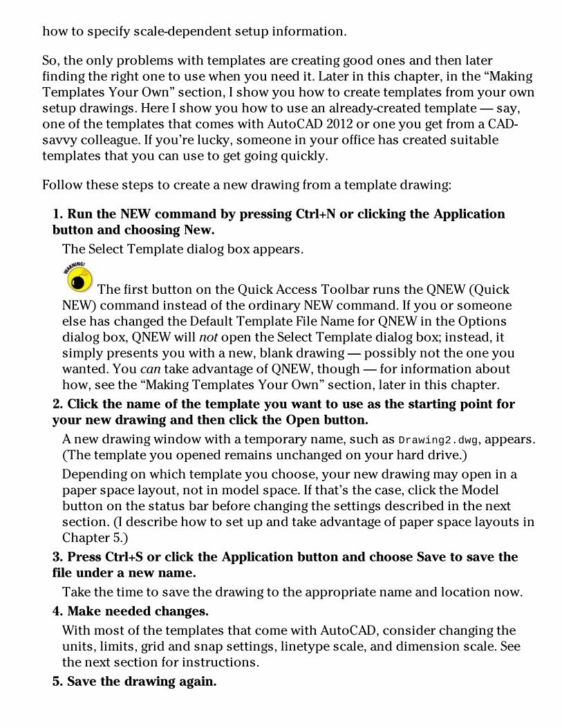
howtospecifyscale-dependentsetupinformation.
So,theonlyproblemswithtemplatesarecreatinggoodonesandthenlaterfindingtherightonetousewhenyouneedit.Laterinthischapter,inthe“MakingTemplatesYourOwn”section,Ishowyouhowtocreatetemplatesfromyourownsetupdrawings.HereIshowyouhowtouseanalready-createdtemplate—say,oneofthetemplatesthatcomeswithAutoCAD2012oroneyougetfromaCAD-savvycolleague.Ifyou’relucky,someoneinyourofficehascreatedsuitabletemplatesthatyoucanusetogetgoingquickly.
Followthesestepstocreateanewdrawingfromatemplatedrawing:
1.RuntheNEWcommandbypressingCtrl+NorclickingtheApplicationbuttonandchoosingNew.TheSelectTemplatedialogboxappears.
ThefirstbuttonontheQuickAccessToolbarrunstheQNEW(QuickNEW)commandinsteadoftheordinaryNEWcommand.IfyouorsomeoneelsehaschangedtheDefaultTemplateFileNameforQNEWintheOptionsdialogbox,QNEWwillnotopentheSelectTemplatedialogbox;instead,itsimplypresentsyouwithanew,blankdrawing—possiblynottheoneyouwanted.YoucantakeadvantageofQNEW,though—forinformationabouthow,seethe“MakingTemplatesYourOwn”section,laterinthischapter.
2.ClickthenameofthetemplateyouwanttouseasthestartingpointforyournewdrawingandthenclicktheOpenbutton.Anewdrawingwindowwithatemporaryname,suchasDrawing2.dwg,appears.(Thetemplateyouopenedremainsunchangedonyourharddrive.)Dependingonwhichtemplateyouchoose,yournewdrawingmayopeninapaperspacelayout,notinmodelspace.Ifthat’sthecase,clicktheModelbuttononthestatusbarbeforechangingthesettingsdescribedinthenextsection.(IdescribehowtosetupandtakeadvantageofpaperspacelayoutsinChapter5.)
3.PressCtrl+SorclicktheApplicationbuttonandchooseSavetosavethefileunderanewname.Takethetimetosavethedrawingtotheappropriatenameandlocationnow.
4.Makeneededchanges.WithmostofthetemplatesthatcomewithAutoCAD,considerchangingtheunits,limits,gridandsnapsettings,linetypescale,anddimensionscale.Seethenextsectionforinstructions.
5.Savethedrawingagain.

Ifyou’llneedotherdrawingsinthefuturesimilartothecurrentone,considersavingyourmodifiedtemplateasatemplateinitsownright.Seethesection“MakingTemplatesYourOwn,”laterinthischapter,forthelowdownonsavingtemplates.
AfewoftheremainingtemplatesthatcomewithAutoCADincludetitleblocksforvarioussizesofsheets.Inaddition,mosttemplatescomeintwoversions—oneforpeoplewhousecolor-dependentplotstylesandoneforpeoplewhousenamedplotstyles.Youprobablywantthecolor-dependentversions.(Chapter16describesthetwokindsofplotstylesandwhyyouprobablywantthecolor-dependentvariety.)Iwarnedyouthatthisdrawingsetupstuffwouldbecomplicated!
MakingtheMostofModelSpaceAfteryou’vedecidedondrawingscaleandsheetsize,you’rereadytosetupyourdrawing.Mostdrawingsrequireatwo-partsetup:
1.Setupmodelspace,whereyou’llcreatemostofyourdrawing.2.Createoneormorepaperspacelayoutsforplotting.
AsIexplaininChapter2,modelspaceistheinfinitelylarge,three-dimensionalenvironmentinwhichyoucreatethe“real”objectsyou’redrawing.Youcansetupyourmodelspaceasdescribedinthissection;Chapter5introducesyoutosettingupyourpaperspacelayouts.
SettingyourunitsFirst,setthelinearandangularunitsthatyouwanttouseinyournewdrawing.Thefollowingproceduredescribeshow:
1.ClicktheApplicationbuttonandthenchooseUnitsfromtheDrawingUtilitiesgroup.TheDrawingUnitsdialogboxappears,asshowninFigure4-4.

Figure4-4:Setyourunitshere.
2.ChoosealinearunittypefromtheLengthTypedrop-downlist.Choosethetypeofunitrepresentationthat’sappropriateforyourwork.EngineeringandArchitecturalunitsaredisplayedinfeetandinches;theothertypesofunitsaren’ttiedtoanyparticularunitofmeasurement.Youdecidewhethereachunitrepresentsamillimeter,centimeter,meter,inch,foot,orsomethingelse.Yourchoiceismuchsimplerifyou’reworkinginmetric:ChooseDecimalunits.

AutoCADcanthinkininches!Ifyou’reusingEngineeringorArchitecturalunits(feetandinches),AutoCADinterpretsanydistanceorcoordinateyouenterasthatmanyinches.Youmustusethe’(apostrophe)characteronyourkeyboardtoindicateanumberinfeetinsteadofinches.
3.FromtheLengthPrecisiondrop-downlist,choosethelevelofprecisionyouwantwhenAutoCADdisplayscoordinatesandlinearmeasurements.TheLengthPrecisionsettingcontrolshowpreciselyAutoCADdisplayscoordinates,distances,andpromptsinsomedialogboxes.Forexample,theCoordinatessectionofthestatusbardisplaysthecurrentcoordinatesofthecrosshairsusingthecurrentprecision.
ThelinearandangularprecisionsettingsaffectonlyAutoCAD’sdisplayofcoordinates,distances,andanglesonthestatusbar,indialogboxes,andinthecommandwindowandDynamicInputtooltipareas.FordrawingsstoredasDWGfiles,AutoCADalwaysusesmaximumprecisiontostorethelocationsandsizesofallobjectsthatyoudraw,regardlessofhowmanydecimalplacesyouchoosetodisplayintheDrawingUnitsdialogbox.Inaddition,AutoCADprovidesseparatesettingsforcontrollingtheprecisionofdimensiontext—seeChapter14fordetails.
4.ChooseanangularunittypefromtheAngleTypedrop-downlist.DecimalDegreesandDeg/Min/Secarethemostcommonchoices.TheClockwisecheckboxandtheDirectionbuttonprovideadditionalanglemeasurementoptions,butyou’llrarelyneedtochangethedefaultsettings:Unlessyou’realandsurveyor,measureanglescounterclockwiseanduseeastasthe0-degreedirection.
5.FromtheAnglePrecisiondrop-downlist,choosethedegreeofprecisionyouwantwhenAutoCADdisplaysangularmeasurements.6.IntheInsertionScalearea,choosetheunitsofmeasurementforthisdrawing.Chooseyourbaseunitforthisdrawing—thatis,thereal-worlddistancerepresentedbyoneAutoCADunit.
TheAutoCAD(butnottheAutoCADLT)DrawingUnitsdialogboxincludesaLightingareawhereyouspecifytheunittypetobeusedtomeasuretheintensityofphotometriclights.Iintroducelightingaspartofrendering3DmodelsinChapter23.
7.ClickOKtoexitthedialogboxandsaveyoursettings.

Makingthedrawingareasnap-py(andgrid-dy)Forthelastthreedecades,AutoCAD’sgridconsistedofasetofevenly-spaceddotsthatservedasavisualdistancereference.YoucanstillconfigureadotgridinAutoCAD2012,butstartingwithAutoCAD2011,thedefaultisasnazzygraph-paper-likegridmadeupofanetworkoflines.
AutoCAD’ssnapfeaturecreatesasetofevenlyspaced,invisiblehotspots,whichmakethecrosshairsmoveinnice,evenincrementsasyouspecifypointsinthedrawing.BothGridModeandSnapModeareliketheintersectionpointsofthelinesonapieceofgridpaper,butthegridissimplyavisualreference—itneverprints—whereasSnapconstrainsthepointsthatyoucanpickwiththemouse.Youcan—andusuallywill—setgridandsnapspacingtodifferentvalues.
PriortoAutoCAD2012,whenSnapModewasenabled,itwasonfull-time.Thiscouldbedistractingasyoumovedyourcrosshairsaroundthescreen—anddownrightannoyingwhenyouweretryingtoselectanobjectthatdidn’thappentofallonasnappoint.YounolongerhavetokeeptogglingSnapModeonandoff.It’snowengagedonlywhenyou’reusingacommandthatasksyoutospecifyapoint.Forexample,whenSnapison,youcanmoveyourcrosshairsfreelyaroundthescreen,butwhenyoustarttheLINEcommand,SnapModekicksinandyourcrosshairsjumptotheclosestsnappoint.
SetthegridandthesnapintervalsintheDraftingSettingsdialogboxbyfollowingthesesteps:
1.Right-clicktheSnapModeorGridDisplaybuttononthestatusbarandchooseSettings.TheDraftingSettingsdialogboxappearswiththeSnapandGridtabselected,asshowninFigure4-5.TheSnapandGridtabhassixsections,buttheSnapSpacingandGridSpacingareaswithinthattabareallyouneedtoworryaboutformost2Ddraftingwork.

Figure4-5:Getyourdraftingsettingshere!
2.SelecttheSnapOncheckboxtoturnonSnapMode.Thisactionenablesdefaultsnapshalfaunitapart(tenunitsapartifyou’reworkingwiththedefaultmetrictemplate).
AutoCADusuallyhasseveralwaysofdoingthings.YoucanalsoclicktheSnapModebuttononthestatusbartotogglesnaponandoff;thesamegoesfortheGridDisplaybuttonandthegridsetting.Oryoucouldusethefunctionkeys:F7togglesthegridoffandon,andF9doesthesameforSnapMode.
3.EnterthesnapintervalyouwantintheSnapXSpacingbox.Usetheinformationinthesectionsprecedingthisproceduretodecideonareasonablesnapspacing.

IftheEqualXandYSpacingcheckboxisselected,theYspacingchangesautomaticallytoequaltheXspacing,whichisalmostalwayswhatyouwant.Unchecktheboxifyouwanttospecifyunequalsnapspacing.
4.SelecttheGridOncheckboxtoturnonthegrid.5.EnterthedesiredgridspacingintheGridXSpacingbox.Usetheinformationinthesectionsprecedingthisproceduretodecideonareasonablegridspacing.Aswithsnapspacing,iftheEqualXandYSpacingcheckboxisselected,theYspacingautomaticallychangestoequaltheXspacing.Again,youusuallywanttoleaveitthatway.Xmeasureshorizontaldistance;Ymeasuresverticaldistance.TheAutoCADdrawingareanormallyshowsanXandYiconincaseyouforget.
Ifyou’reanoldAutoCADhandandfindthegraph-papergridtooobtrusive,checktheDisplayDottedGridIn2DModelSpaceboxintheGridStyleareatoswitchtotheold-stylerowsandcolumnsofdots.
6.SpecifyadditionalgriddisplayoptionsintheGridBehaviorarea.IfyouselecttheAdaptiveGridcheckbox,AutoCADchangesthedensityorspacingofthegridlinesordotsasyouzoominandout.IfyoualsoselectAllowSubdivisionBelowGridSpacing,thespacingcangolowerthanwhatyou’veset,anditmaygohigherifyou’rezoomedalongwayoutofyourdrawing.(Ifitdidn’t,youcouldn’tseeyourdrawingforthegrid!)SelectingtheDisplayGridBeyondLimitscheckboxallowsthegridtodisplayovertheentiredrawingarea,nomatterhowfaryou’rezoomedout.ClearingthischeckboxmakesAutoCADbehavethewayit’salwaysbehaved—thatis,thegridisdisplayedonlyintheareadefinedbythedrawinglimits.
TheFollowDynamicUCSoption(notavailableinAutoCADLT)isa3D-specificfeaturethatchangesyourdrawingplaneasyoumouseover3Dobjects.IcoverthisfeatureinChapter22.
7.ClickOKtoclosetheDraftingSettingsdialogbox.
SettinglinetypeanddimensionscalesEventhoughyou’veengravedthedrawingscalefactoronyourdeskandwrittenitonyourhand—notviceversa—AutoCADdoesn’tknowthedrawingscaleuntilyouenterit.KeepingAutoCADinthedarkisfineaslongasyou’rejustdrawing

continuouslinesandcurvesrepresentingreal-worldgeometrybecauseyoudrawtheseobjectsattheirreal-worldsize,withoutworryingaboutplotscale.
However...assoonasyoustartusingnon-continuousdash-dotlinetypes(linepatternsthatcontaingapsinthem),youneedtotellAutoCADhowtoscalethegapsinthelinetypesbasedontheplotscale.Ifyouforgetthis,thedash-dotlinetypepatternscanlookwaaaaytoobigortoosmall.Figure4-6showswhatImean.
Figure4-6:...andthislittlecenterlinelooksjuuuustright!
Thescalefactorthatcontrolsdash-dotlinetypesisfoundinasystemvariablecalledLTSCALE(asinLineTypeSCALE).Youcanchangethissettingatanytime,butit’sbesttosetitcorrectlywhenyou’resettingupthedrawing.
Thefollowingsequenceincludesdirectionsfortypingsystemvariableandcommandnames.Tosetthelinetypescaleatthekeyboard,followthesesteps:
1.TypeLTSCALE(orLTS)andpressEnter.AutoCADrespondswithaprompt,askingyouforthescalefactor.Thevalueattheendofthepromptisthecurrentlinetypescalesetting,asshowninthefollowingcommandlineexample:
Enternewlinetypescalefactor<1.0000>:2.TypethevalueyouwantforthelinetypescaleandpressEnter.Theeasiestchoiceistosetthelinetypescaletothedrawingscalefactor.Somepeople,however,findthatthedashesandgapsindash-dotlinetypesgetabittoolongwhentheyusethedrawingscalefactor.Ifyou’reoneofthosepeople,setLTSCALEtoone-halfofthedrawingscalefactor.(Feelfreetoexperimentwiththisvalue;somepeoplepreferalinetypescaleofthree-quartersthescalefactor.Ifyou’reworkinginmetric,try0.75timesthescalefactorinstead—justaskyourcalculatorifyoudon’tbelieveme.)

Alternatively,youcanspecifylinetypescaleintheLinetypeManagerdialogbox:ClicktheLinetypedrop-downonthePropertiespaneloftheRibbon’sHometabandselectOther.Then,intheLinetypeManagerdialogbox,clicktheShowDetailsbutton,andtypeyourdesiredlinetypescaleintheGlobalScaleFactortextbox.
BesidesLTSCALE,therearethreeothersimilarlynamedsystemvariablesyoucanusetocontrolthedisplayofdash-dotlinetypes:
PSLTSCALE:Makeslinetypespacinglookthesameinpaperspaceviewports,regardlessoftheviewportscale.
CELTSCALE:Changestheeffectivelinetypescalefactorfornewobjects.
MSLTSCALE:Visuallydisplaysdash-dotlinetypesinthemodeltabbasedontheannotativescalesetting.
Ifanyofthesesounduseful—andIhighlyrecommendyouenablePSLTSCALE—checkthemoutintheonlinehelpindex.
Theproceduredescribedhereforsettinglinetypescaleassumesthatyou’restartinganewdrawingfromoneoftheplain-janetemplates(acad.dwtoracadiso.dwtinthefullversion,acadlt.dwtoracadltiso.dwtinAutoCADLT)andusingthedefaultlinetypescale.Don’tchangeLTSCALEinexistingdrawingswithoutknowingexactlywhyyou’redoingitandwhatvaluestosetthemto,incasesomeonebeforeyousettheirvaluesforgoodreasons.
EnteringdrawingpropertiesIrecommendonelastbitofhousekeepingbeforeyou’refinishedwithmodel-spacedrawingsetup:EntersummaryinformationintheDrawingPropertiesdialogbox,asshowninFigure4-7.ClicktheApplicationbutton;intheDrawingUtilitiessection,chooseDrawingPropertiestoopentheDrawingPropertiesdialogbox;thenclicktheSummarytab.Enterthedrawingscaleandthedrawingscalefactoryou’reusingintheCommentsarea,plusanyotherinformationyouthinkuseful.
Don’tconfusedrawingproperties(whicharereallyfileproperties)withyour

drawing’sobjectproperties—they’redifferentthings.Thepropertiesyouenterherecanhelpyouorsomeoneyoulovewhensheopensyourdrawingandwondershowyousetitup.Objectpropertiesareabigenoughtopictomerittheirownchapter—seeChapter6.
Figure4-7:Surveyingyourdrawing’sproperties.

MakingTemplatesYourOwnYoucancreateatemplatefromanyDWGfilebyusingtheSaveDrawingAsdialogbox.Followthesestepstosaveyourdrawingasatemplate:
1.ClickSaveAsontheQuickAccessToolbar.TheSaveDrawingAsdialogboxappears,asshowninFigure4-8.
2.FromtheFilesofTypedrop-downlist,chooseAutoCADDrawingTemplate(*.dwt)orAutoCADLTDrawingTemplate(*.dwt).
Figure4-8:Savingadrawingasatemplateandapplyingoptions.
3.Navigatetothefolderwhereyouwanttostorethedrawingtemplate.TheAutoCAD2012defaultfolderfordrawingtemplatesisburieddeepinthebowelsofyourWindowsuserprofile.SaveyourtemplatesthereifyouwantthemtoappearinAutoCAD’sSelectTemplatelist.Youcansaveyourtemplatesinanotherfolder,butifyouwanttousethemlater,youhavetonavigatetothatfoldereverytimeyouwanttousethem.SeetheTechnicalStuffparagraphthatfollowsthisprocedureforadditionalsuggestions.
4.EnteranameforthedrawingtemplateintheFileNametextboxandclickSave.Adialogboxforthetemplatedescriptionandunitsappears.
5.Specifythetemplate’smeasurementunits(EnglishorMetric)inthedrop-downlist.

Enterthekeyinfonow—youcan’tdoitlaterunlessyousavethetemplatetoadifferentname.Don’tbotherfillingintheDescriptionfield;AutoCADdoesn’tdisplayitintheSelectTemplatedialogbox.Don’tworryabouttheNewLayerNotificationareashowninFigure4-8fornow;ItellyouallaboutdrawinglayersinChapter6.
6.ClickOKtosavethefile.TheTemplateOptionsdialogboxclosesandthetemplateissavedtoyourharddrive.
7.Tosaveyourdrawingasaregulardrawing,clickSaveAsontheQuickAccessToolbar.TheSaveDrawingAsdialogboxappearsagain.
8.FromtheFilesofTypedrop-downlist,chooseAutoCAD2010Drawing(*.dwg).ChoosetheAutoCADLTequivalent,ifthat’syourversion.AutoCAD2012usestheAutoCAD2010DWGfileformat.ChooseapreviousDWGfileformatifyouwanttobeabletoopenyourdrawinginAutoCAD2009orearlier.
9.Navigatetothefolderwhereyouwanttostorethedrawing.Useadifferentfolderfromtheonewithyourtemplatedrawings.
10.EnterthenameofthedrawingintheFileNametextboxandclickSave.Thefileissaved.Now,whenyousaveitinthefuture,theregularfile—notthetemplatefile—getsupdated.
TheQNEW(QuickNEW)command,whenproperlyconfigured,canbypasstheSelectTemplatedialogboxandcreateanewdrawingfromyourfavoritetemplate.ThefirstbuttonontheQuickAccessToolbar—thebuttonwiththeplainwhitesheetofpaper—runsthenewerQNEWcommandinsteadoftheolderNEWcommand.
ToputtheQuickintoQNEW,though,youhavetotellAutoCADwhichdefaulttemplatetouse:
1.ClicktheApplicationbutton,thenclicktheOptionsbuttonatthelower-rightcorneroftheApplicationMenu.2.OntheFilestab,chooseTemplateSettings⇒DefaultTemplateFileNameforQNEW.TheQNEWdefaultfilenamesettingisNone,whichcausesQNEWtoactjustlikeNEW(thatis,QNEWopenstheSelectTemplatedialogbox).Specifythenameofyourfavoritetemplatehere,andyougetanewdrawingfilebasedoniteverytimeyouclickQNEW.

AutoCAD2012storesdrawingtemplatesandmanyothersupportfilesunderyourWindowsuserfolder.Todiscoverwhereyourtemplatefolderishiding,opentheOptionsdialogbox.OntheFilestab,chooseTemplateSettings⇒DrawingTemplateFileLocation,asshowninFigure4-9.
Figure4-9:Seekandyoushallfindyourtemplatefolder.
Youdon’thavetokeepyourtemplatefileswherethatbossyMisterGatestellsyou.Createafolderthatyoucanfindeasily(forexample,C:\Acad-templatesorF:\Acad-custom\templatesonanetworkdrive),putthetemplatesthatyouactuallyusethere,andchangetheDrawingTemplateFileLocationsettingsothatitpointstoyournewtemplatefolder.

Chapter5
PlanningforPaper
InThisChapterSettinguppaperspacelayouts
Buttonsortabsforlayoutfashionistas
Lookingintoviewports
Workinginpaperspace
Mostofwhattheearlierchapterslookatrevolvesaroundsettingupthemodel

spaceenvironment—thatinfinitelylarge,three-dimensionalrealmwhereinyoucreateyourgleamingtowers,yourwondrouselectronicgadgetry...oryourgardenshedoryouranglebracket.However,youmayhavepickedupahinthereortherethatAutoCADhasawholedifferentenvironmentknownaspaperspace.
Thefinalproductofallthissetup,remember,isaprinteddrawingonapieceofpaper.Inmostindustries,paperdrawingsarelegalcontractdocuments,soit’sprettyimportantthattheyareunderstandableandeasilyread.Thefirstpartofthatprocessisconfiguringthesheetlayoutinpaperspace,whichIexplaininthischapter.Fortheactualprocessofoutputtingeithermodelspaceorlayoutstoprinterorplotter,seeChapter16.
Chapter2introducesyoutothetwospaces—modelandpaper—andChapter4explainshowtoconfiguremodelspaceforefficientdrawing.Beforeyouplungeintopaperspace,aquickrecapofmodelspaceisinorder.
Modelspaceisthedrawingenvironmentthat’scurrentwhentheModeltab(nottheModelbutton)onthestatusbarisactive.Modelspaceiswhereyoucreatethe“real”objectsthatyou’redrawing,sotheseobjectsarereferredtoasmodelgeometrywhetherthey’re2Dor3Dentities.WhentheModeltabisactive,youseeobjectsinmodelspaceonly—anythinginpaperspaceisinvisible.
InAutoCAD2012,it’sstillpossibletoignorepaperspacelayoutsentirelyanddoallyourdrawingandplottinginmodelspace.Butyouoweittoyourselftogivelayoutsatry.You’llprobablyfindthattheymakeplottingmoreconsistentandpredictable.They’llgiveyoumoreplottingflexibilitywhenyouneedit.Andyou’llcertainlyencounterdrawingsfromotherpeoplethatmakeextensiveuseofpaperspace,soyouneedtounderstanditifyouplantoexchangedrawingswithanyoneelse.
SettingUpaLayoutinPaperSpaceApaperspacelayoutisarepresentationofadrawingsheet.Althoughthemodelgeometry—therealstuff—goesinmodelspace,the“not-real”drawingobjects(forexample,adrawingborder,titleblock,generalnotes,perhapsviewlabels,andsymbolslikeNortharrows)allgoinpaperspaceonthelayout.Inessence,modelspaceisliketheworld,infinitelylargeandthree-dimensional;paperspaceisfinite

—thesizeofadrawingsheet,infact—andtwo-dimensional,justlikeadrawingsheet.
Asidefromjustanarrangementofyourdrawingsheet,layoutsalsostoreplotinformation.AutoCADsavesseparateplotsettingswitheachlayoutaswellasmodelspacesothatyoucanploteachonedifferently.Inpractice,you’llprobablyneedtouseonlyoneofthepaperspacelayouttabs,especiallywhenyou’regettingstartedwithAutoCAD.
Ratherthanjustreadingaboutit,youmayalsowanttoopenafewoftheAutoCAD2012sampledrawingsandclicktheModelandLayoutbuttonsortabstowitnessthevarietyofwaysinwhichpaperspaceisused.
TheAutoCADandAutoCADLTsampledrawingsarenolongerinstalledwiththeprogram,butthey’restillavailable—online.Downloadthemfromwww.autodesk.com/autocad-samplesorwww.autodesk.com/autocadlt-samples.Theupsideofthechangeisthatusersofeitherprogramnowhaveaccesstotheother’ssamplefiles.
Willthatbetabsorbuttons?TheAutodeskdocumentationsometimesreferstotheModeltabortolayouttabs,andsometimes(likejustasecondago)Idohereaswell.Initsout-of-the-boxcondition,AutoCADdoesdisplayactual,selectabletabsatthelower-leftedgeofthedrawingwindow,clearlylabeledModel,Layout1,andLayout2(refertoFigure5-4).Youcangainafractionmorescreenspaceifyouhidethetabs,butevenwhenthey’rehidden,they’restillreferredtoastabs.Here’showtotogglethewaythattabsaredisplayed:
Tohidelayouttabs:Right-clickthevisibleModeltaboranylayouttab,andchooseHideLayoutandModelTabsfromthepop-upmenu.
Toshowlayouttabs:Right-clicktheModelbutton(theonewiththeiconandtheModeltooltip,nottheModelorPaperSpacebutton,whichissometimesconfusinglylabeledMODEL)—ortheLayoutbuttonrightnextdoor—andchooseDisplayLayoutandModelTabs.
Hidingthetabsdoesgiveyouabitmoredrawingarea,butthere’sadrawback—theLayoutbuttoncanonlycontrolasinglelayout(whicheverlayouthappenstobecurrent).YouhavetousetheQuickViewLayoutsfeature(describedinthenextsection)toswitchbetweenlayouts,butifyourdrawingonlyhasonelayout,

hidingthetabsiswellworthwhile.
Youcanrenamelayouttabs—butnottheModeltab—bydouble-clickingthelayoutnameandtypinganewone.
Thestateofyourtabsisstored—butnotautomaticallysaved—inyourcurrentworkspace.Forexample,ifyou’reworkingintheDrafting&Annotationworkspace,thenswitchtotheAutoCADClassicworkspace,andthenswitchbacktoDrafting&Annotation,thechangeyoumadefromtabstobuttons(orviceversa)willnotberetained.Forinformationonsavingyourowncustomworkspace,lookupworkspaceintheonlinehelpsystem.
ViewlayoutsQuick(View)ly
QuickViewLayoutsisthesecondoftwoAutoCAD2012featuresthatusetheQuickViewimagestriptodisplaypreviewimagesofdrawingsorlayouts.IintroduceQuickViewDrawings—whichpreviewsallyouropendrawingsintheQuickViewstrip—inChapter2.
InearlierversionsofAutoCAD,withbuttonsenabledratherthantabs,youwouldright-clicktheLayoutbuttontoopenashortcutmenulistingthedrawing’slayouts.Butmerewordsinamenuaresoprevious-release!Thefollowingstepsexplainhowtochangebetweenmodelspaceandalayoutorswitchbetweenlayouts:
1.ClicktheQuickViewLayoutsbuttononthestatusbar.TheQuickViewimagestripappearsabovethestatusbaranddisplaysresizableimagepanelsformodelspaceandalllayouts.RightbelowtherowofimagesistheQuickViewtoolbar.Figure5-1showsatypicalarrangementinamulti-layoutdrawing.

Figure5-1:Viewthoselayouts,andmakeitQuick!
Don’tconfusetheQuickViewtoolbarwiththeQuickAccessToolbarthatlivesuptop,nexttotheApplicationbutton.(AutoCADisgettingsoquick,it’shardtokeepupwithit!)TheQuickViewtoolbarcontainsfourbuttonsthatperformthefollowingtasks(buttonslistedfromlefttoright):
•PinQuickViewLayouts:Normallytheimagesdisappearassoonasyouselectalayoutorclickoutsideit.Clickingthisbuttonreorientsthesideviewofthepushpinsoitlookslikeit’spokingaholeinyourscreen(youshouldbeawarethatneitherAutodesknorIamresponsibleforpuncturesinyourmonitor)andforcestheimagepanelstoremainopen.
•NewLayout:Clickthisbuttontocreateanewlayoutwithasingleviewport.Thenewlayoutappearsasanewimageattheendofthestrip.
•Publish:ClickthisbuttontoopenthePublishdialogbox.YouusethePUBLISHcommandifyouhaveawholesetofdrawingsyouwanttooutputandpackageatonetime.IexplaintheAutoCADversionofpublishinginChapter20.
•CloseQuickViewLayouts:UsethisbuttontoclosetheQuickView

Layoutsimagestripifyoupinneditopen.Simplyclickingoutsidetheimagestripclosestheimagestripifit’sunpinned.
2.MoveyourmousepointerovereachimageintheQuickViewpanel.Theimagebackgroundhighlightstoindicatewhichlayoutthepointer’sfocusison.Whenapanelishighlighted,twoiconsappearatthetopcornersofthepanel.ThePublishbuttonattop-rightdoesthesamethingasBatchPlotontheApplicationMenu.IfyouwanttoprinttheindividuallayoutwithoutgoingthroughallthePublishrigmarole,clickthePloticonatthetop-left.
3.Clickthepreviewimageofmodelspaceorthelayoutyouwanttomakecurrent.Theselectedlayoutisactivatedandfillsthedrawingwindow;thepreviewimagestripcloses.
Ifyouhaveawheelmouse,youcanmovebetweenpreviewsbyscrollingthewheelineitherdirection.YoucanalsoresizethepreviewsbymousingoveranimageandthenpressingtheCtrlkeywhilescrollingthewheelbackandforth.
CreatingalayoutCreatingasimplepaperspacelayoutisstraightforward,thankstotheCreateLayoutWizard,asshowninFigure5-2.(Yes!Finally,ausefulAutoCADwizard.)ThecommandnameisLAYOUTWIZARD,andit’smissinginactionfromAutoCAD2012’sdefaultuserinterface.Togettoit,typeLAYOUTWIZARDatthekeyboard(or,ifyou’reusingtheAutoCADClassicworkspace,opentheInsertmenu,chooseLayout,thenCreateLayoutWizard).

Figure5-2:TheCreateLayoutWizard.
AlthoughtheCreateLayoutWizardguidesyou,stepbystep,throughtheprocessofcreatingapaperspacelayoutfromscratch,itdoesn’teliminatethenecessityofcomingupwithasensiblesetoflayoutparameters.Thesheetsizeandplotscalethatyouchooseprovideacertainamountofspaceforshowingyourmodel(seethe“Thinkingaboutpaper”sectioninChapter4),andwizardsaren’tallowedtobendthelawsofarithmetictoescapethatfact.Forexample,amapofAustraliaatascaleof1inch=1footwon’tfitonan81/2-x11-inchsheet,noway,nohow.Inotherwords,garbagein,garbage(lay)out.Fortunately,theCreateLayoutWizardlendsitselftoexperimentation,andyoucaneasilydeletelayoutsthatdon’twork.
Followthesestepstocreatealayout:
1.TypeLAYOUTWIZARDandpressEnter.TheCreateLayoutWizarddisplaysitsfirstpageandpromptsyoutoenteranameforthenewlayout.
2.GivethenewlayoutanameandclickNext.Inplaceofthedefaultname,Layout3,Irecommendsomethingmoredescriptive—forexample,D-SizeSheet.OryoucancallitA1-SizeSheetifyou’reofthemetricpersuasion.

3.ChooseaprinterorplottertousewhenplottingthislayoutandthenclickNext.Thinkofyourchoiceasthedefaultplotterforthislayout.Youcanchangetoadifferentplotterlater—orcreatepagesetupsthatplotthesamelayoutondifferentplotters.(IexplainpagesetupsinChapter16.)
Manyofthenamesintheconfiguredplotterlistshouldlookfamiliarbecausethey’reyourWindowsprinters(systemprinters,inAutoCADlingo).Nameswitha.pc3extensionrepresentnon-systemprinterdrivers.SeeChapter16fordetails.
4.Chooseapapersize,specifywhethertouseinchesormillimeterstorepresentpaperunits,andclickNext.TheavailablepapersizesdependontheprinterorplotterthatyouselectedinStep3.
5.SpecifytheorientationofthedrawingonthepaperandclickNext.TheicondisplayingtheletterAonthepieceofpapershowsyouwhichorientationiswhich.
6.OntheCreateLayout–TitleBlockpage,selectNoneandclickNext.Idon’trecommendselectingoneofthetwoavailabletitleblocks,asoddsareslimthateitherofthosewillfitonthepapersizeyouselectedinStep4.Here’swhy....
EarlierAutoCADreleasesincludedahandysetofpre-drawntitleblocksforarangeofbothimperialandmetricpapersizes.Allbuttwoofthemhavedisappeared,andthosetwoarestilltheonlyonesavailableinAutoCAD2012’sLayoutWizard.Unfortunately,neitherofthemislikelytoworkoutforyou.If,inStep4,youchoseinchesasyourunitsandanypapersizeotherthanARCHD(36.00x24.00inches)—orchosemillimetersasyourunitsandanypapersizeatall—thetitleblockwillnotfitthesheet.
Whenyouknowyourwayaroundtheprogramabit,youcanalwaysdraw,insert,orxrefatitleblocklater.(SeeChapters17and18forinformationaboutinsertingorxrefingatitleblock.)YoucanalsoaddcustomtitleblockdrawingstoyourAutoCADTemplatefolder.Ifyouwanttoknowwheretoputthem,seethesectiononmakingtemplatesinChapter4.
7.DefinethearrangementofviewportsthatAutoCADshouldcreateandselecttheviewportscaleforthemallfromthedrop-downlist.ThenclickNext.Aviewportisawindowfrompaperspaceintomodelspace.Youmustcreateat

leastoneviewporttodisplaythemodelinyournewlayout.Itellyoumoreaboutviewportsinthesection“Aview(port)fordrawingin,”laterinthischapter.
ThedefaultViewportscale,ScaledtoFit,ensuresthatallofyourmodeldrawingobjectsappearintheviewport,butitresultsinanarbitraryscalefactor.Mosttechnicaldrawingsrequireaspecificscale,suchas1:100or1/8"=1'–0".
8.ClickSelectLocationtospecifythelocationoftheviewport(s)onthelayout;thenpicktheviewport’scorners.AfteryouclicktheSelectLocationbutton,theCreateLayoutWizarddisplaysthepreliminarylayoutwithanytitleblockthatyou’vechosen.Picktwopointstodefinearectanglethatfallswithinthedrawingareaofyourtitleblock(orwithintheplottableareaofthesheet,ifyouchosenotitleblockinStep6).AutoCADthenredisplaystheFinishpageoftheCreateLayoutwizard.AutoCADrepresentstheplottableareaofthesheetwithadashedrectangleneartheedgeofthesheet.Ifyoudon’tselectalocationfortheviewport(s),theCreateLayoutWizardcreatesaviewportthatfillstheplottableareaofthesheet.
9.ClickFinish.AutoCADcreatesthenewlayout.Liketheotherwizards,theCreateLayoutWizardisaimedatnewusersorold-timerswhohavesomehowoverlookedtheintroductionofpaperspacelayouts.Youwon’tneedtorunthiswizardeverytimeyoustartanewdrawing,butyoumaywellrunitonceandthensavetheresultingfileasatemplateforfuturedrawings(seeChapter4formoreabouttemplates).
CopyingandchanginglayoutsAfteryoucreatealayout,youcandelete,copy,rename,andotherwisemanipulateitbyclickingQuickViewLayoutsonthestatusbarandright-clickingapreviewimage.Ifyou’reusinglayouttabsratherthanbuttons,right-clickatabtodisplaythemenuorsimplydragthetabtoanewposition.Figure5-3showsthemenuoptionswhenyouright-clickalayouttab.

Figure5-3:TheQuickViewLayoutsright-clickmenu.

TheFromTemplateoptionreferstolayouttemplates.Afteryoucreatelayoutsinatemplate(DWT)oradrawing(DWG)file,youcanusetheFromTemplateoptiontoimporttheselayoutsintothecurrentdrawing.Fordetails,seetheLAYOUTcommand’sTemplateoptionintheCommandReferencesectionofonlinehelp.
Manydrawingsrequireonlyonepaperspacelayout.Ifyoualwaysplotthesameviewofthemodelandalwaysplottothesamedeviceandonthesamesizepaper,asinglepaperspacelayoutshouldsuffice.Ifyouwanttoplotyourmodelindifferentways(forexample,atdifferentscales,withdifferentlayersvisible,withdifferentareasvisible,orwithdifferentplottedlinecharacteristics),youmaywanttocreateadditionalpaperspacelayouts.
LostinpaperspaceAfteryoucreateapaperspacelayout,yousuddenlyhavetwoviewsofthesamedrawinggeometry:theviewinyouroriginalmodelspaceandthenewlayout’sview(perhapsdecoratedwithahandsometitleblockandotheraccoutrementsofplottingnobility).It’simportanttorealizethatbothviewsareofthesamegeometry.Ifyouchangethemodelgeometryononeview,you’rechangingiteverywherebecausealllayoutsdisplaythesamemodelspaceobjects.
Whenyoumakealayoutcurrent,youcanswitchtheactivespacebetweenpaperspace(thatis,drawingandzoomingonthesheetofpaper)andmodelspace(drawingandzoomingonthemodel,insidetheviewport)inseveralways,includingthefollowing:
Inthedrawingarea,double-clickinsideaviewportboundarytomovethecrosshairsintomodelspaceinthatviewport.Alternatively,youcandouble-clickoutsideallviewports(forexample,inthegrayareaoutsidethesheet)tomovethecrosshairsintopaperspace.
ClicktheMaximize/MinimizeViewportbuttononthestatusbar.(Formoreinformation,seeChapter2.)
TypeMSPACE(thecommandaliasisMS)orPSPACE(PS)atthekeyboard.
ClicktheMODEL/PAPERbuttononthestatusbar.
Whenthecrosshairsareinmodelspace,anythingyoudraworeditchangesthemodelinmodelspaceandtherefore,throughtheviewports,onallpaperspace

layouts.Whenthecrosshairsareinpaperspace,anythingyoudrawappearsonlyonthatonelayout.It’sasthoughyouweredrawingonanacetatesheetoverthetopofthatsheetofplotterpaper—themodelbeneathremainsunaffected.
Thisbehaviorcanmakeyourbrainhurtuntilyougetusedtoit.Toavoidconfusion,stickwiththefollowingapproach(atleastuntilyou’remorefamiliarwithpaperspace):
Ifyouwanttoeditthemodel:Dosoinfull-screenmodelspace.ClicktheModeltabiftabsaredisplayed,orclicktheModelbuttoniftabsarehidden.(TheModelbuttonistheonewiththelittleblackicon;don’tconfuseitwiththeMODEL/PAPERbutton,whichswitchesbetweenmodelandpaperspacewithinthesamelayout.)Don’ttrytoeditthemodelinapaperspaceviewport—it’saveryinefficientuseofyourscreenspace.
Ifyouwanttoeditaparticularlayoutwithoutaffectingthemodel:UseoneofthemethodsI’vedescribedtomakethatlayoutcurrent,andmakesurethatthecrosshairsareinpaperspace.
WhatspaceamIin?
Whenyoustartworkinginlayouts,itmaynotalwaysbecrystal-clearwhetheryou’reinmodelspaceorpaperspace.Thestatus-barbuttonwillhelp—itwillsayPAPERifyou’reinpaperspaceorMODELifyou’reintheotherplace.Hereareafewotherwaystotellyourlayoutspacesapart:
Checkthecrosshairs.Ifyou’reinpaperspace,youcanmovethecrosshairsovertheentiredrawingarea.Ifyou’reinmodelspace,youcanmovethecrosshairsonlywithinthecurrentlyactiveviewport;ifyoutrytomovethecrosshairsoutsidetheviewport,theyturnintoaWindowsselectionarrow.
Selectsomemodelgeometry.Tryclickingsomeobjectsyouknowareinmodelspace.Ifyoucanselectthemandtheyhighlight,thenyou’reinmodelspace.Ifnothinghappenswhenyouclickthem,they’reinaccessiblebecauseyou’reinpaperspace.
ChecktheUCSicon.TheUCS(forUserCoordinateSystem)iconisthesymbolatthelower-leftcornerofthedrawingarea.Themodelspaceicontakestheshapeoftwolinesatrightanglestoeachother,withthelettersindicatingthedirectionoftheX-axisandtheY-axis(ifyou’veconfiguredAutoCADtousethe2DUCSicon,theWstandsfortheWorldCoordinateSystem).Thepaperspaceiconistriangular,andtheclosed,three-sided
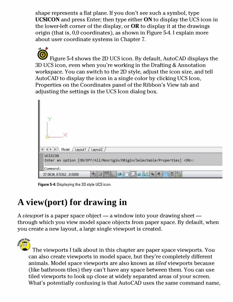
shaperepresentsaflatplane.Ifyoudon’tseesuchasymbol,typeUCSICONandpressEnter;thentypeeitherONtodisplaytheUCSiconinthelower-leftcornerofthedisplay,orORtodisplayitatthedrawingsorigin(thatis,0,0coordinates),asshowninFigure5-4.IexplainmoreaboutusercoordinatesystemsinChapter7.
Figure5-4showsthe2DUCSicon.Bydefault,AutoCADdisplaysthe3DUCSicon,evenwhenyou’reworkingintheDrafting&Annotationworkspace.Youcanswitchtothe2Dstyle,adjusttheiconsize,andtellAutoCADtodisplaytheiconinasinglecolorbyclickingUCSIcon,PropertiesontheCoordinatespaneloftheRibbon’sViewtabandadjustingthesettingsintheUCSIcondialogbox.
Figure5-4:Displayingthe2DstyleUCSicon.
Aview(port)fordrawinginAviewportisapaperspaceobject—awindowintoyourdrawingsheet—throughwhichyouviewmodelspaceobjectsfrompaperspace.Bydefault,whenyoucreateanewlayout,alargesingleviewportiscreated.
TheviewportsItalkaboutinthischapterarepaperspaceviewports.Youcanalsocreateviewportsinmodelspace,butthey’recompletelydifferentanimals.Modelspaceviewportsarealsoknownastiledviewportsbecause(likebathroomtiles)theycan’thaveanyspacebetweenthem.Youcanusetiledviewportstolookupcloseatwidelyseparatedareasofyourscreen.What’spotentiallyconfusingisthatAutoCADusesthesamecommandname,

andeventhesamedialogbox,forcreatingthetwodifferenttypesofviewports.Forthischapter,makesurethatyou’reinpaperspacewhenyoucreateviewports.
Paperspaceviewportsareassigneddrawingscales,andyoucanhavemultipleviewportswithdifferentscalesonthesamelayout.Forexample,oneviewportcanshowthefloorplanofanexhibitspaceat1/4"toonefoot,andanotherviewportcanshowanenlargedviewofadisplaycabinetat1"=1'.Becausetheindividualviewportsarescaled,theentirelayoutcanbeplottedat1:1.
TheCreateLayoutWizardisfinewhenyou’restartingout,butmostrealdrawingshaveunique,non-standardizedarrangementsofviewports.Whencreatinglayouts,it’softeneasiesttocreateviewportsfromscratch.Thefollowingprocedureexplainshow:
1.Usingoneofthetechniquesdescribedinthe“Creatingalayout”section,earlierinthischapter,createanewlayoutinyourdrawing.Forexample,clickQuickViewLayoutstodisplaythepreviewimages,andthenright-clickanyoftheimagesandchooseNewLayout.Anewlayoutisaddedtotheendoftheimagestrip.
2.Clicktheimageforthenewlayouttoopenit.Anewlayoutappearsinthedrawingwindow,showingthedefaultsheetareaandasinglerectangularviewportcenteredonthesheet.Youaren’tgoingtousethisviewport.
3.Movethecrosshairsovertheviewportboundaryandclicktoselectit.PresstheDeletekey.Althoughtheydon’tbehavelikeotherdrawingobjects,viewportsareobjects,justlikelinesorcircles.Andlikeanyotherdrawingobjects,theycanbeselectedandmoved,copied,arrayed—ordeleted.
4.OntheRibbon,clicktheViewtab;then,intheViewportspanel,chooseRectangular.AutoCADpromptsyoutopickthefirstcornerforthenewviewport.
Youmustbeinpaperspaceforthesestepstoworkasdescribed.IftheRectangularbutton(Iknow,they’reallrectangular—Imeantheonethatsays“Rectangular”)isgrayedout,you’restillinmodelspace.
5.Pickapointsomewhereontheblankpagetolocatethefirstcornerofthenewviewport.AutoCADpromptsyoutopickthesecondcorner.
6.Pickanotherpointtoplacethesecondcornerofthenewviewport.

AutoCADdrawstheviewport,andthemodelspacegeometryappearsinsideit.Next,specifyadrawingscaleforyourviewport(s).Specifyingthecorrectviewportscalesoonerratherthanlaterbestowsacoupleofimportantbenefits:
•Correctlyscalingviewportsallowsyoutouseannotativedocumentationobjectssuchastext,dimensions,hatchpatterns,blocks,andnon-continuous(dash-dot)linetypes.IintroduceyoutoannotativeobjectsinChapter13.
•Correctlyscalingallyourviewportsallowsyoutoeasilyplotthecompletedlayoutatascaleof1:1whileretainingindividual,true-to-scaleviewports.
7.Double-clickinsidetheviewportyouwanttoapplyascaleto.Modelspacebecomesactive,asitmust,becausethat’sthespaceyouhavetoscale.TheViewportScalebuttonappearstowardtherightsideofthestatusbarwhenmodelspaceisactivatedinalayout.
8.ClicktheViewportScalebuttononthestatusbar.ClickingtheViewportScalebuttonopensapop-uplistofeverydrawingscaleregisteredinthescaleslist—includingmetricscalesevenifyou’reworkinginanEnglish-unitsdrawing,andviceversa.
Mostofthetime,formostpeople,therearewaytoomanyscalesinthelistsyouseeintheViewportScalebuttonandthePlotdialogbox.AutoCADhasahandy-dandyEditDrawingScalesdialogboxthatletsyouremovethoseimperialscalesifyouneverworkinfeetandinchesandviceversa,ifyouworkonlyinmetric.Torunthroughyourscales,chooseScaleListfromtheAnnotationScalingpanelontheAnnotatetab,ortypeSCALELISTEDITandpressEntertoopentheEditDrawingScalesdialogbox.Ifyoumakeamistake,theResetbuttonintheEditDrawingScalesdialogboxwillrestoreallthedefaultscales.
9.Findthescaleyouwanttoapplytotheactiveviewportandselectitfromthelist.Thedisplayzoomsinorouttoadjusttothechosenviewportscale.
Rereadthatlastsentenceandthenthinkabouthowoftenyouhavetopanandzoominyourdrawing.Ifyouzoominsideaviewportwhosescaleyou’veset—kaboom!—youjustblewthescaleoffthemap.Luckily,youcanpreventyourselforanyoneelsefrominadvertentlydestroyingyourbeautifullyarrangedandscaledviewportbycompletingthefinalstepsofviewportsetup:

10.Makesureyou’reinpaperspace(checktheUCSiconormovethecrosshairs).11.Selecttheboundaryoftheviewportwhosearrangementyouwanttoprotect.Withtheviewportselected,theViewportScalebuttonreappearswithitsselectablelistofscales,andrightbesideitisanotherbuttonwithayellowunlockedpadlockicon.Asitstooltipindicates,itsfunctionistolockandunlockviewports.
12.ClicktheLock/UnlockViewportbuttontolocktheviewportscale.Theyellowunlockedpadlockchangestoabluelockedpadlock,andtheViewportScalebuttonnowbecomesunselectable.LockingthedisplaysetsAutoCADupforsomeniftyzooming...ifyou’reinpaperspace,anormalzoomisexecuted.Ifyou’reinmodelspaceinsideaviewport,anormalzoomwouldwreckthescale,sowhenyoutrytozoom,AutoCADnear-instantaneouslyswitchestopaperspace,zoomsyouin,andthenswitchesbacktomodelspace.Sheerprestidigitation!
Sometimestheperfectviewportarrangementrequiresthatasmallerviewportbecompletelysurroundedbyalargerone.Easyenoughtocreate,yes,andeasytoselect—aslongasyou’reinpaperspace.However,ifyou’reinmodelspaceandyouwanttoclickfromoneviewporttothenexttomakeitcurrent,it’simpossibletomakemodelspacecurrentinacompletelysurroundedviewportbyclickinginsideit.Letyourfingerscometotherescue:TheCtrl+Rkeycombinationcyclesthroughmodelspaceinalldrawingviewports,evenifthey’recompletelysurroundedbyotherviewports.
Andthereyouhaveyour12-stepprogramtolayoutbliss!Allthatsetuphadapurpose,ofcourse:toenableyoutoprintperfectpaperplots(orplotperfectpaperprints,ifyouprefertoseeitthatway).IcoverplottingindepthinChapter16,butashortintroductorywordheremightbeuseful.
AboutPaperSpaceLayoutsandPlottingAsthischapterdescribes,youcanuseAutoCAD’spaperspacefeaturetocomposeoneormorelayoutsforplottingyourdrawinginparticularways.Eachlayoutlivesonaseparatetab,whichyouclickatthebottomofthedrawingarea—orinasecrethidingplaceifyou’vehiddentheModelandLayouttabs.AutoCADsavesplotsettings(plotdevice,papersize,plotscale,andsoon)separatelyforeachofthelayouts,aswellasmodelspace.

Whethertoplotmodelspaceoralayoutinadrawingdependsentirelyonhowthedrawingwassetup.Ifyouorsomeoneelsewentthroughalayout-setupproceduresimilartotheoneinthischapter,youprobablyshouldplotthelayout.Ifnot,plotmodelspace.
Viewportboundarieswillprintifyoudon’tpayattentiontowhereyoucreatethem.Whatthatmeansisthateachdrawingviewhasanicerectangularborderaroundit.Nice,butadefiniteno-noineverydraftingoffice.InChapter6,Iintroduceyoutoobjectproperties,includingprobablythemostimportantone,layers.Youcandefinealayersothatobjectsonitdonotplot,andthat’swhereyoushouldcreateyourviewports.
Ifyoudon’thaveanypaperspacedrawingshandy,youcanuseoneoftheAutoCADsampledrawings.Refertothetipnearthebeginningofthe“SettingUpaLayoutinPaperSpace”section,earlierinthechapterforwheretofindthesampledrawings.
Somedifferentwaysofplottingthesamemodelcanbehandledinasinglepaperspacelayoutwithdifferentpagesetups.SeeChapter16formoredetails.Ifyourprojectsrequirelotsofdrawings,youcanparlaylayoutsintosheetsets—afeaturethatmakesformoresophisticatedcreation,management,plotting,andelectronictransferofmulti-sheetdrawingsets.

PartII
LetThereBeLines


Inthispart...Lines,circles,andotherelementsofgeometrymakeuptheheartofyourdrawing.AutoCADoffersmanydifferentdrawingcommands,manywaystousethemtodrawobjectsprecisely,andmanypropertiesforcontrollingtheon-screenandplottedappearanceofobjects.Afteryoudrawyourgeometry,you’llprobablyspendatleastasmuchtimeeditingitasyourdesignanddrawingsevolve.Andintheprocess,you’llneedtozoominandoutandpanallaroundtoseehowtheentiredrawingiscomingtogether.
Drawinggeometry,editingit,andchangingthedisplayedviewarethefoundationofthedrawingprocess;thispartshowsyouhowtomakethatfoundationsolid.


Chapter6
ManageYourProperties
InThisChapterManaginglayers
Managingotherobjectproperties:color,linetype,andlineweight
CopyinglayersandothernamedobjectswithDesignCenter
CADprogramsaredifferentfromotherdrawingprograms.Youhavetopayattentiontolittledetailslikeobjectpropertiesandtheprecisionofthepointsthatyouspecifywhenyoudrawandeditobjects.Ifyouignorethesedetailsandjust

startdrawing,you’llendupwithamessofsloppygeometrythat’shardtoedit,view,andplot.
Thischapterintroducesyoutoobjectproperties,onesetofAutoCADtoolsandtechniquesthathelpyoupreventCADmesses.Chapter7explainsthemostimportantprecisiondrawingtechniquesthatyouneedtoobserveinordertocreateusableAutoCADdrawings.Theinformationinthesetwochaptersisessentialtounderstandbeforeyoustartdrawingandeditingobjects,proceduresthatIdescribeinChapters8,9,10,and11.
WhenyoufirststartusingAutoCAD,oneofitsmostoverwhelmingfeaturesisthenumberofpropertysettingsandprecisioncontrolsthatyouneedtopayattentionto—evenwhenyoudrawasimpleline.Unlikemanyotherprograms,it’snotenoughtodrawalineinamore-or-less-adequatelocationandthenslapsomecoloronit.ButallthosesettingsandcontrolscaninspirethefeelingthatyouhavetofindouthowtodriveaFormula1cartomakeatripdownthestreet.(Theadvantageisthatafteryouarecomfortableinthedriver’sseat,AutoCADwilltakeyouonthelong-haultripsandgetyoutherefaster.)
FollowingarethethreekeystogoodCADdrawingpractice:
Properties:Payattentiontoandmanagethepropertiesofeverydrawingobjectthatyoucreate—especiallythelayerthateachdrawingobjectison.Iexplainlayersandotherobjectpropertiesinthenextsection.
Namedobjects:Payattentiontoandusethenamedobjectsineverydrawing—thelayers,textstyles,blockdefinitions,andothernon-graphicalobjectsthatservetodefinethelookofallthegraphicalobjectsinthedrawing.Ienlightenyouinthe“UsingNamedObjects”section,laterinthischapter.
Precision:Payattentiontoandcontroltheprecisionofeverypointanddistancethatyouusetodrawandediteachobject.IfillyouinonAutoCAD’sprecisiondrawingtechniquesinChapter7.
Thesecanseemlikedauntingtasksatfirst,butthefollowingsectionshelpyoucutthemdowntosize.
ManagingYourPropertiesAlltheobjectsthatyoudrawinAutoCADarelikegoodMonopolyplayers:Theyownproperties.InAutoCAD,thesepropertiesaren’tphysicalthings;they’rean

object’scharacteristics,suchaslayer,color,linetype,lineweight,transparency,andplotstyle.Youusepropertiestocommunicateinformationaboutthecharacteristicsoftheobjectsyoudraw,suchasthekindsofreal-worldobjectstheyrepresent,theirmaterials,theirrelativelocationinspace,ortheirrelativeimportance.InAutoCAD,youalsousepropertiestoorganizeobjectsforeditingandplottingpurposes.
Youcanview—andchange—allpropertiesofanobjectinthePropertiespalette,andmanyoftheminQuickPropertiespalette.InFigure6-1,thePropertiespaletteattheleftandtheQuickPropertiespaletteattherightshowpropertiesfortheselectedlineobject.
ThePropertiespalettewasjoinedinAutoCAD2009byitsmorestreamlinedlittlesibling,QuickProperties.WhenQuickPropertiesistoggledoninthestatusbar,selectinganobjectopensafloatingpalettethatdisplaysacustomizableselectionofthatobject’sproperties.(Ifyourstatusbarbuttonsshowtextratherthanicons,lookfortheQPbutton.)
Figure6-1:Comprehensiveorquick?Sometimesyouneedlotsofinformation,andsometimesyoudon’t.
Handyasitis,theQuickPropertiespalettehasaknackofpoppingupontopofdrawingobjectsthatyouneedtosee.InAutoCAD2012,youcankeep

QuickPropertiesmodetoggledoffatthestatusbar,andinsteadusethenewQUICKPROPERTIEScommand.TypeQPandselectanobjecttodisplaytheQuickPropertiespanel.Youcanalsodouble-clickmostobjectstodisplaytheirquickproperties.
TotogglethefullPropertiespaletteonandoff,clickthePropertiesbuttonontheViewtaboftheRibbonorusetheCtrl+1keycombination.Beforeyouselectanobject,thePropertiespalettedisplaysthecurrentproperties—propertiesthatAutoCADappliestonewobjectswhenyoudrawthem.Afteryouselectanobject,thePropertiespalettedisplaysthepropertiesforthatobject.Ifyouselectmorethanoneobject,thePropertiespalettedisplaysthepropertiesthattheyhaveincommon.
PuttingitonalayerEveryobjecthasalayerasoneofitsproperties.Youmaybefamiliarwithlayers—independentdrawingspacesthatstackontopofeachothertocreateanoverallimage—fromusingdrawingprograms.AutoCAD,likemostCADprograms,useslayersastheprimaryorganizingprincipleforalltheobjectsthatyoudraw.Youuselayerstoorganizeobjectsintologicalgroupsofthingsthatbelongtogether;forexample,walls,furniture,andtextnotesusuallybelongonthreeseparatelayers,foracoupleofreasons:
Layersgiveyouawaytoturngroupsofobjectsonandoff—bothonthescreenandontheplot.
Layersprovidethemostefficientwayofcontrollingobjectcolor,linetype,lineweight,transparency,andplotstyle.
So,toworkefficientlyinAutoCAD,youcreatesomelayers,assigningthemnamesandproperties,suchascolorandlinetype.Thenyoudrawobjectsonthoselayers.Whenyoudrawanobject,AutoCADautomaticallyputsitonthecurrentlayer—thelayerthatyouseeintheLayerdrop-downlistontheHometab’sLayerspanelwhennoobjectsareselected.Ifalayeralreadyexistsinyourdrawing,youcanmakeitthecurrentlayerbychoosingitintheLayerdrop-downlist,asshowninFigure6-2.
It’snotabsolutelynecessarytocreateallyourlayersbeforeyoudrawanything,butitwillsaveyousometimeifyoustartwithafewbasiclayersandthenaddnewlayersasneeded.ManyexperiencedAutoCADusersdrawthingsfirstandthencreateappropriatelayersandchangetheobjectstothe

newlayers.Youcaneasilychangeanobject’slayerbyselectingitandthenchoosingthedesirednewlayernamefromtheLayerdrop-downlist.
Figure6-2:Settinganexistinglayerasthecurrentlayer.
MakesurethatnoobjectsareselectedbeforeyouusetheLayerdrop-downlisttochangethecurrentlayer.(PresstheEsckeytwicetobesure.)Ifobjectsareselected,theLayerdrop-downlistdisplays(andletsyouchange)thoseobjects’layers.Whennoobjectsareselected,theLayerdrop-downlistdisplays(andletsyouchange)thecurrentlayer.
StackingupyourlayersHowdoyoudecidewhattocallyourlayersandwhichobjectstoputonthem?Someindustrieshavedevelopedlayerguidelines,andmanyofficeshavecreateddocumentedlayerstandards.Someprojectsevenimposespecificlayerrequirements.(Butbecareful;ifsomeonesays,“Youneed a brick layer for this project,” that can mean a couple of different things.) AskexperiencedCADdrafters inyourofficeor industryhowtheyuse layers inAutoCAD. Ifyoucan’t findanydefinitiveanswer,createachartof layers foryourself.Eachrowin thechartshould list the layer name, default color, default linetype, default lineweight, default

transparency,andwhatkindsofobjectsbelongonthatlayer.Ifyouusenamedplotstylestocontrol your plotted output, add a default plot style to the list— that’s not necessary fortraditionalcolor-basedplotting.
AccumulatingpropertiesBesideslayers,theremainingobjectpropertiesthatyou’relikelytowanttouseoftenarecolor,linetype,lineweight,transparency,andpossiblyplotstyle.Table6-1summarizesthesefiveproperties.
Table6-1UsefulObjectProperties
Property WhatItControls
Color Displayedcolorandplottedcolororlinewidth
Linetype Displayedandplotteddash-dotlinepattern
Lineweight Displayedandplottedlinewidth
Transparency Displayedandplottedopacityofobjects
Plotstyle Plottedcharacteristics(seeChapter16)
LongbeforeAutoCADcoulddisplaylineweightsonthescreenandprintthosesamelineweightsonpaper,objectcolorscontrolledtheprintedlineweightofobjects.AutoCAD2000introducedamorelogicalsystem,whereyoucouldassignanactualplottedthicknesstoobjects.Aslogicalasthatmethodseems,theoldermethod,inwhichthecolorofobjectsdeterminestheirplottedlineweight,continuestodominate.YoumayfindyourselfworkingthiswayeveninAutoCAD2012,forcompatibilitywithdrawings(andcoworkers)thatusetheoldway.Figure6-3showsyoutheidea.Themodelspaceviewattheleftshowsobjectsindifferentcolors,butwiththesamedefaultlineweight.Thepaperspaceviewattheright(whatyourplotteddrawingwillactuallylooklike)showsthat,althoughthelinesareallblack,theirthicknessesvary,determinedbythemodelspacecolors.Forexample,BlueisverythickandBlackisverythin.

Figure6-3:Changemylinethicknessbutcolormeblack.
AutoCADgivesyoutwodifferentwaysofcontrollingobjectproperties:
ByLayer:Eachlayerhasadefaultcolor,linetype,lineweight,transparency,andplotstyleproperty.UnlessyoutellAutoCADotherwise,objectsinheritthepropertiesofthelayersonwhichthey’recreated.Whenobjectsareselectedinadrawingcreatedusingthissystem,theobjectpropertiesarelistedasByLayer.
ByObject:AutoCADalsoenablesyoutooverrideanobject’slayer’spropertysettingandgivetheobjectaspecificcolor,linetype,lineweight,transparency,orplotstylethatdiffersfromthelayer’s.
Ifyou’veworkedwithothergraphicsprograms,youmaybeusedtoassigningproperties,suchascolor,tospecificobjects.Ifso,youmaybetemptedtodothesameinAutoCAD.Resistthetemptation.Didyoucatchthat?Onemoretime:Resistthetemptation.
Inalmostallcases,it’sbettertocreatelayers,assignpropertiestoeachlayer,andlettheobjectsoneachlayerinheritthatlayer’sproperties.HerearesomebenefitsofusingtheByLayerapproach:
Youcaneasilychangethepropertiesofagroupofrelatedobjectsthatyouputononelayer.Yousimplychangethepropertyforthelayer,notforabunchofseparateobjects.

ExperienceddraftersusetheByLayerapproach,soifyouworkwithdrawingsfromotherpeople,you’llbemuchmorecompatiblewiththemifyoudoitthesameway.You’llalsoavoidgettingyelledatbyirateCADmanagers,whosejobdutiesincludeharanguinganyhaplessnewbiewhoassignspropertiestoindividualobjects.
IfyoutakemyadviceandassignpropertiesByLayer,allyouhavetodoissetlayerpropertiesintheLayerPropertiesManagerpalette(Itellyouhowinthissection),asshowninFigure6-4.Beforeyoudrawanyobjects,makesuretheColorControl,LinetypeControl,andLineweightControldrop-downlists,andtheTransparencybuttonontheRibbonHometab’sPropertiespanelareallsettoByLayer,asshowninFigure6-5.(Rememberthattheconfigurationofpanelsanddrop-downlistsmayvaryaccordingtotheresolutionofyourdisplay.)Ifthedrawingissettousecolor-basedplotstylesinsteadofnamedplotstyles(seeChapter16),thePlotStyleControldrop-downlistwillbeinactiveandwilldisplayByColor.
Figure6-4:Uselayerpropertiestocontrolobjectproperties.

Figure6-5:ByLayer(nearly)alltheway.
AswithallpalettesinAutoCAD,youcanleavetheLayerPropertiesManageropenwhileyoudootherthingsinthedrawing—unlikethedialogboxmethodofstoppingwhatyou’redoing,openingthedialogbox,makingadjustments,closing

thedialogbox,andthenresumingwhatyouweredoing.Alsolikeotherpalettes,theLayerPropertiesManagercanbesettoauto-hideitselftoitstitlebar,tobeeitherfloatingordocked,ortobeanchored(doyougetthesensethattherearesomeAutoCADprogrammerswho’dratherbesailing?)toeithersideofthescreen.
Ifthedrawingissettousenamedplotstylesinsteadofcolor-basedplotstyles(seeChapter16),thePlotStylecontroldrop-downlistshouldalsodisplayByLayer.
IfyouwanttoavoiddoingthingsthewrongwayandgettingyelledatbyCADmanagers,don’tassignpropertiestoobjectsineitheroftheseways:
Don’tmaketheverycommonbeginner’smistakeofchoosingaspecificcolor,linetype,lineweight,transparency,orplotstylefromtheappropriatedrop-downlistonthePropertiespaneloftheRibbon’sHometab,orfromthePropertiespalette,andthendrawingtheobjects.
Don’tmakethealso-very-commonbeginner’smistakeofdrawingtheobjects,selectingthem,andthenchoosingapropertyfromthesamedrop-downlists.
Ifyouprefertodothingstherightway(thatis,myway!),assignthesepropertiesByLayer,asIdescribeinthefollowingsection.
AutoCAD’sSETBYLAYERcommandletsyoucorrectthosenon-ByLayerproperties—ontheRibbon’sHometab,clicktheModifypanellabeltoopenthepanelslideout,andthenclickSettoByLayer.Answerthepromptsatthecommandlinetofinishmodifyingobjects.Formoreinformation,refertoSETBYLAYERintheonlinehelp.
CreatingnewlayersIfasuitablelayerdoesn’texist,youneedtocreateoneintheLayerPropertiesManagerpalette.Followthesesteps:
1.ClicktheLayerPropertiesbuttonontheLayerspaneloftheRibbon’sHometab,ortypeLAYER(orLA)atthecommandlineandpressEnter.TheLayerPropertiesManagerpaletteappears.Anewdrawinghasonlyone

layer:Layer0.Youneedtoaddthelayersnecessaryforyourdrawing.2.ClicktheNewLayerbutton(itlookslikeasheetofpaperwithalittlesunburstononecorner)tocreateanewlayer.Anewlayerappears.AutoCADnamesitLayer1buthighlightsthenameinaneditboxsoyoucantypeanewnametoreplaceiteasily,asshowninFigure6-6.
Figure6-6:AddinganewlayerintheLayerPropertiesManagerpalette.
3.Typeanameforthenewlayer.
Typethelayernamewithinitialcaps(onlythefirstlettersofwordsinuppercase).Layernameswrittencompletelyinuppercasearemuchwider,whichmeansthattheyoftengettruncatedintheLayerControldrop-downlist.
4.Onthesamelineasthenewlayer,clickthecolorblockorcolorname(Whitebydefault)ofthenewlayer.TheSelectColordialogboxappears,asshowninFigure6-7.

Figure6-7:TheSelectColordialogbox.MagentaisselectedfromtheStandardColorslist.
ThenormalAutoCADcolorscheme—AutoCADColorIndex(ACI)—provides255colors.Somanychoicesareoverkillforordinarydrafting.
Fornow,stickwiththefirstninecolors—theonesthatappearinasingle,separaterowtotheleftoftheByLayerandByBlockbuttonsontheIndexColortaboftheSelectColordialogbox—forthefollowingreasons:
•Thesecolorsareeasytodistinguishfromoneanother.
•Usingasmallnumberofcolorsmakesconfiguringyourplotparameterseasier.(IdescribethatprocedureinChapter16.)

IntheSelectColordialogbox,theTrueColortaboffersachoiceofmorethan16millioncolors,whichyoucanspecifybyusingHSL(HueSaturationLuminance)orRGB(RedGreenBlue)numbers.TheColorBookstabenablesyoutousePANTONEandRALcolorschemes,whicharepopularinpublishing.Ifyourworkrequirestonsofcolorsorclosecolormatchingbetweenthecomputerscreenandprintedoutput,you’reprobablyfamiliarwiththerelevantcolorpaletteandhowtouseit.Ifyou’reusingAutoCADforordinarydraftingordesign,stickwiththeAutoCADColorIndexpalette.
5.ClickacolortoselectitasthecolorforthislayerandclickOK.TheSelectColordialogboxcloses,andfocusreturnstotheLayerPropertiesManagerpalette.IntheColorcolumn,thenewlayercolorchangestoeitherthenameorthenumberofthecolorthatyouselected.
AutoCAD’sfirstsevencolorshavebothnumbersandstandardnames:1=red,2=yellow,3=green,4=cyan,5=blue,6=magenta,and7=white(whichappearsblackwhendisplayedonawhitebackground).Theremaining248colorshavenumbersonly.
6.Onthesamelineasthenewlayer,clicktheLinetypenameofthenewlayer.TheSelectLinetypedialogboxappears,asshowninFigure6-8.ThedefaultAutoCADlinetypeisContinuous,whichmeansnogapsintheline.

Figure6-8:TheSelectLinetypedialogbox.
Ifyoualreadyloadedthelinetypesyouneedforyourdrawing,orifthetemplatefileyoustartedfromhassomelinetypesloaded,theSelectLinetypedialogboxdisplaysthemintheLoadedLinetypeslist.Ifnot,clicktheLoadbuttontoopentheLoadorReloadLinetypesdialogbox.Bydefault,AutoCADdisplayslinetypesfromthestandardAutoCADorAutoCADLTlinetypedefinitionfile—acad.linforimperial-unitsdrawingsoracadiso.linformetric-unitsdrawings(acadlt.linandacadltiso.lininAutoCADLT).LoadthedesiredlinetypebyselectingitsnameandclickingOK.
Unlessyouhaveareallygoodreason(forexample,yourbosstellsyouso),avoidloadingorusinganylinetypeslabeledACAD_ISO.Theselinetypesarenormallyusedonlyinmetricdrawings—andrarelyeventhen.TheyoverruleeverythingI’mtryingtoshowyouaboutprintedlineweightinwhatfollowsso,ifatallpossible,justsayNOtoACAD_ISO.Ipromiseyou’llfinditeasiertousethelinetypeswiththemoredescriptivenames:CENTER,DASHED,andsoon.
7.ClickthedesiredlinetypeintheLoadedLinetypeslisttoselectitasthelinetypeforthelayer;saythatreallyfastfivetimesandthenclickOK.TheSelectLinetypedialogboxdisappears,returningyoutotheLayerPropertiesManagerpalette.IntheNamelist,thelinetypefortheselectedlayerchangestothelinetypeyoujustchose.
8.Onthesamelineasthenewlayer,clickthenewlayer’slineweight.TheLineweightdialogboxappears,asshowninFigure6-9.

Figure6-9:TheLineweightdialogbox.
9.SelectthelineweightyouwantfromthelistandclickOK.Usingthelineweightpropertyisatwo-stepprocess.Afteryou’veassignedalineweighttoalayer,youmustclicktheShow/HideLineweightbuttononthestatusbartoseetheeffect.Youcantogglethefeatureoffandonwiththisbutton.

Thelineweight0.00mmtellsAutoCADtousethethinnestpossiblelineweightonthescreenandontheplot.Irecommendthatfornow,youleavelineweightsettoDefaultandinsteadmapscreencolortoplottedlineweight,asdescribedingreaterdetailinChapter16.AutoCAD2012’stransparencypropertywillprobablybemostappreciatedbypeoplepreparingdrawingsforpresentation.ClickingintheTransparencycolumnopenstheLayerTransparencydialogbox;typeanumericvaluebetween0and90orusethedrop-downlisttosetavalue.Transparency=0isthedefault,andmeansnotransparencyatall—objectsdrawnonalayersettoTransparency=0arecompletelyopaque.Setthevaluetogreaterthan0andyoustartseeingthingsthroughtheobjectsyoudraw.
10.Inthesamelineasthenewlayer,clickthevalueintheTransparencycolumn.Bydefault,layertransparencyissetto0,fornotransparency.Asyouincreasethenumericvalue,thedegreeoftransparencyincreases(themaximumvalueis90).SimilartotheLineweightproperty,youhavetoturnontheTransparencybuttononthestatusbartoseethroughyourobjects.ThePlotStylecolumn’scontentsdependonwhetherthedrawingusesnamedplotstylesorthetraditionalcolor-basedplotting.Drawingssetuptousecolor-basedplottingdisplayanunchangeableplotstylenamebasedonthelayer’scolorproperty.Thegrayed-outstylenamechangesonlywhenthelayercolorchanges.If,ontheotherhand,yourdrawingusesnamedplotstyles,youcanassignanamedplotstyletothelayerinthiscolumn.(Chapter16explainswhyyoumightnotwantto.)ThesettinginthePlotcolumncontrolswhetherthelayer’sobjectsappearonplots.Clickthelittleprintericontotogglethissettingoff(thelittleprintergetsaredbarthroughit)foranylayerwhoseobjectsyouwanttoseeonthescreenbuthideonplots.
11.(Optional)Ifyouwanttoaddadescriptiontothelayer,scrollthelayerlisttotherighttoseetheDescriptioncolumn,clickintheDescriptionboxcorrespondingtoyournewlayer,andtypeadescription.
Myadviceistonameyourlayerssoyoucantellwhat’sonthem.Ifyoudochoosetouselayerdescriptions,stretchtheLayerPropertiesManagerpalettetotherightsothatyoucanseethedescriptionswithouthavingtoscrollthelayerlist.
12.RepeatSteps1through11tocreateanyotherlayersthatyouwant.13.SelectthenewlayerthatyouwanttomakecurrentandclicktheSet

Currentbutton(thegreencheckmark).ChangesyoumakeintheLayerPropertiesManagerpaletteareinstantaneous,unlikeadialogboxinwhichyouhavetoclickOKtoclosethedialogboxandapplythechange.
Don’tforgettotoggleontheLineweightandTransparencybuttonsonthestatusbartoseetheeffectofassigningtheseproperties.Unlikecolorandlinetype,lineweightandtransparencycanbeswitchedoffandon.TheLayerControldrop-downlistnowdisplaysyournewlayerasthecurrentlayer—theoneonwhichAutoCADplacesnewobjectsthatyoudraw.
Afteryoucreatelayers,youcansetanyoneofthemtobethecurrentlayer:Makesurethatnoobjectsareselected,andthenchoosethelayernamefromtheLayerControldrop-downlistontheLayerspanelintheRibbonortheLayerstoolbar.
AloadoflinetypesWhenyouloadalinetype,AutoCADcopiesitslinetypedefinition—aformulaforhowtocreatethedashes,dots,andgapsinthatparticularlinetype—fromtheacad.lin(imperialunits)oracadiso.lin (metric units) file into the drawing. (The files are acadlt.lin andacadltiso.lin,respectively, inAutoCADLT.)Thedefinitiondoesn’tautomaticallyappearinotherdrawings;youhavetoloadeachlinetypethatyouwanttouseintoeachdrawinginwhichyouwant to use it. If you find yourself loading the same linetypes repeatedly into differentdrawings, consider adding them to your template drawings instead. (See Chapter 4 forinformationabouttemplatesandhowtocreatethem.)Afteryouaddlinetypestoatemplatedrawing,allnewdrawings thatyoucreate fromthat templatewillstartwith those linetypesloadedautomatically.
Don’tgooverboardonloadinglinetypes.Forexample,youdon’tneedtoloadallthelinetypesintheacad.linfileontheoffchancethatyoumightusethemallsomeday.Theresultinglinetypelist would be long and unwieldy. Most drawings require only a few linetypes, and mostindustriesandcompaniessettleonahalfdozenorsolinetypesforcommonuse.Yourindustry,office,orprojectmayhaveguidelinesaboutwhichlinetypestouseforwhichpurposes.
If you’re the techno-dweeb type and don’t mind editing a text file that contains linetypedefinitions,youcandefineyourownlinetypesorweedouttheonesyou’llneveruse.PressF1toopenthemainonlinehelpwindow.ThenchooseCustomizationGuide⇒CustomLinetypes.
Manipulatinglayers

Afteryoucreatelayersanddrawobjectsonthem,youcanturnalayerofforontohideorshowtheobjectsonthatlayer.IntheLayerPropertiesManagerpalette,thefirstthreeiconstotherightofthelayernamecontrolAutoCAD’slayervisibilitymodes:
Off/On:Clickthelight-bulbicontotogglevisibilityofallobjectsontheselectedlayer.AutoCADdoesnotregeneratethedrawingwhenyouturnlayersbackon.(IgiveyouthelowdownonregenerationsinChapter12.)
Freeze/Thaw:Clickthesunicontotoggleoffvisibilityofallobjectsontheselectedlayer.Clickthesnowflakeicontotogglevisibilityon.AutoCADregeneratesthedrawingwhenyouthawlayers.
Lock/Unlock:Clickthepadlockicontolockandunlocklayers.Whenalayerislocked,youcanseebutnoteditobjectsonthatlayer.
Youcanrearrangecolumnorderbysimplydragginganddroppingthecolumnlabeltoanewplace.Andyoucanright-clickanycolumnlabeltodisplayamenufromwhichyoucanturncolumnsoffandon.
Off/OnandFreeze/Thawdoalmostthesamething—bothsettingsletyoumakeobjectsvisibleorinvisiblebylayer.Intheolddays,turninglayersoffandonwasoftenafasterprocessthanthawingfrozenlayersbecausethawinglayersalwaysrequiredregeneratingthedrawing.Butmoderncomputers,modernoperatingsystems,andrecentAutoCADreleasesmakeregenerationsmuchlessofanissueonallbutthelargestdrawings.You’llprobablyfinditmakesnoappreciabledifferencewhetheryoufreezeandthawlayersorturnthemoffandon.
Youcanturnlayersoffandon,freezeandthawthem,andlockandunlockthembyclickingtheappropriateiconsintheLayerControldrop-downlistontheRibbon.
Thestateofyourlayers
Sayyouhaveafloorplanofahousethatincludesalayershowingtheframingandanotherlayershowingthewiring.You’dprobablynevershowbothofthoseelementsonthesamedrawing,soyou’dneedtodosomelayermanagementwhenyoushowedyourdrawingtotheframersortheelectricians.Ratherthanturningadozenlayersoffandadifferentdozenlayersonwhenyouwantadifferentviewintoyourdrawing,youcansavegroupsoflayersettingsasanamedlayerstate.YoucanmanageyourlayerstatesintheappropriatelynamedLayerStatesManagerdialogboxbyclickingtheLayerStatesManagerbuttonintheLayer

PropertiesManager.YoucanalsoaccesstheLayerStatesManagerdirectlybyenteringLAYERSTATESatthecommandlineorchoosingManageLayerStatesfromtheLayerStatedrop-downlistintheLayerspanel.
AutoCADfadeslockedlayers,givingyouareallyeffectivevisualreferencewithoutconfusingyouaboutwhichlayersmightbelockedornot.YoucancontroltheamountoffadingbysettinganonzerovalueforthesystemvariableLAYLOCKFADECTL.(SeeChapter26foranexplanationofsystemvariablesandcheckouttheonlinehelpforspecificinfoonthisone.)Youcanturnofffadingbutretainthecurrentsettingforfutureusebyaddingaminussign(–)infrontofthefadevalue,oryoucanturnoffthefadingaltogetherbysettingthisvalueto0.
Ifyoufindyourselfusinglotsoflayers,youcancreatelayerfilterstomakeviewingandmanagingthelayerlisteasier.Agroupfilterissimplyasubsetoflayersthatyouchoose(bydragginglayernamesintothegroupfilternameorbyselectingobjectsinthedrawing).ApropertyfilterisasubsetoflayersthatAutoCADcreatesandupdatesautomaticallyaccordingtolayerpropertycriteriathatyoudefine(forexample,alllayerswhosenamescontainWallorwhosecolorisgreen).Tofindoutmore,moveyourmousepointerintotheLayerPropertiesManagerpalette,pressF1,andclicktheNewPropertyFilterhyperlink.
InbothAutoCADandAutoCADLT,youcanaccessasetoflayertoolsthroughtheLayerspaneloftheRibbon’sHometab—seeFigure6-10(youmayhavetoopenthepanelslideouttoseethemall).LayerIsolateandLayerOffareespeciallyuseful—yousimplyclickanobjecttospecifythelayertoisolate(thatis,fadealllayersexceptthechosenone)orturnoffaltogether.Formoreinformationonlayers,opentheonlinehelpsystemandchooseUser’sGuide⇒CreateandModifyObjects⇒ControlthePropertiesofObjects⇒WorkwithLayers⇒UseLayerstoManageComplexity.

Figure6-10:Toolingthroughthelayertools.
TheLAYISOcommandincorporatesthesamelayer-fadingfeaturedescribedintheprecedingtipforlockedlayers—anditlocksthelayersaswell.SetitupthewayyouwantbytypingS(forSettings)andpressingEnter;thentypetheoptionletterforthespecificsettingsyouwant.LookupLAYISOintheonlinehelpIndexformoreinformation.
Insteadofturningoffalayerwhenthereareonlyafewthingsintheway,youcanhideorisolateindividualobjectswithAutoCAD2012’sISOLATEOBJECTSandHIDEOBJECTScommandswhilekeepingnormalvisibilityforotherobjectsonthelayer.IdiscussthesecommandsinChapter10.
UsingNamedObjectsOneofthethingsthatcanmakeAutoCADatoughnuttocrackisthesomewhatcavaliernamingconventionsusedintheprogram’sdocumentation.Foryears,thingslikelines,arcs,andothergraphicalitemswerecalledentities,butmorerecently,theystartedbeingcalledobjects.Fairenough,butobjecthasalsolongbeenusedtodefinecertainnon-graphicalcomponentsofadrawing—thingsthatyou’dhardlyconsidertobeobjectsatall—andthosearethekindof“namedobjects”Idescribeinwhatfollows.

HiddenintheinnardsofeveryAutoCADdrawingfileisasetofnamedobjects.Namedobjectsareorganizedintosymboltables,andthepropertiesthatarecommontoallAutoCADobjectsaredefinedinthesetables.Forexample,allthelineobjectsinadrawingarestoredononeormorelayers,soalayerpropertyiscommontoalllinesandisdefinedinthelayertable.Butthecoordinatesthatdefinethestartandendpointsofagivenlineareuniquetothatline(ortheyshouldbe!)—sothecoordinatepropertiesarenotcommontoalllines.
Layersareoneexampleofanamedobject.Thelayertableinagivendrawingcontainsalistofthelayersinthecurrentdrawing,alongwiththesettingsforeachlayer(color,linetype,on/offsetting,andsoon).
Namedobjectsdon’tappearasgraphicalobjectsinyourdrawing.They’relikethehard-workingpitcrewthatkeepstheracecarsrunningsmoothlybehindthescenes.Thenamedobjectsyou’relikelytousethemostinclude
Layers(coveredinthesection“Puttingitonalayer,”earlierinthischapter)
Linetypes(coveredinthesection“Accumulatingproperties,”earlierinthischapter)
Textstyles(seeChapter13)
Tablestyles(seeChapter13)
Multileaderstyles(seeChapter13)
Multilinestyles(notcoveredinthisbook;seetheonlinehelp)
Dimensionstyles(seeChapter14)
Blockdefinitionsandxrefs(seeChapters17and18)
Layouts(seeChapter5)
Whenyouusecommands,suchasLAYER,LINETYPE,andDIMSTYLE,you’recreatingandeditingnamedobjects.Afteryou’vecreatednamedobjectsinadrawing,AutoCADDesignCenterorthenew-in-2012ContentExplorergiveyouthetoolstocopythemtootherdrawings.
DonaldTrumpmightthinkotherwise,butyoucanhavetoomanyproperties

(atleastinAutoCAD).Youmayhavecreatedlayersorloadedlinetypes,text,ordimensionstylesthatyouendupnotusing.Ifyouthinkyoumayhavesomeofthesesuperfluousnamedobjectsinyourdrawing,thePURGEcommandcanhelpyougetridofthem.ClicktheApplicationbuttontodisplaytheApplicationMenu.ChooseDrawingUtilities,andthenPurgetoopenthePurgedialogbox.Youcanclicktheplussign(+)besideeachcategoryandpurgeindividualitems,oryoucanclickPurgeAllandgetridoftonsofstuffatonce.Visittheonlinehelpformoreaboutpurging.
UsingAutoCADDesignCenterDesignCenterisadumbnameforauseful,ifsomewhatbusy,palette.(Atleasttheydidn’tcallitDesignCenterManager!)TheDesignCenterpaletteishandyforborrowingdatafromallkindsofdrawings.WhereasthePropertiespalette(describedinthesection“ManagingYourProperties,”earlierinthischapter)isconcernedwithpropertiesofgraphicalobjects,theDesignCenterpalettedealsprimarilywithnamedobjects:layers,linetypes,blockdefinitions,textstyles,andotherorganizationalobjectsinyourdrawings.
TheDesignCenterpalette(showninFigure6-11)consistsofatoolbaratthetop,asetofthreetabsbelowthat,atreeviewpaneontheleft,andacontentpaneontheright.ThetreeviewpanedisplaysaWindowsExplorer–likenavigationpanel,showingdrawingfilesandthesymboltablescontainedineachdrawing.Thecontentpaneusuallydisplaysthecontentsoftheselecteddrawingorsymboltable.

Figure6-11:TheAutoCADDesignCenterpalette.
ThethreetabsjustbelowtheDesignCentertoolbarcontrolwhatyouseeinthetreeviewandcontentpanes:
Folders:Thistabshowsthefoldersonyourlocalandnetworkdrives,justliketheWindowsExplorerFolderspanedoes.Usethistabifthedrawingyouwanttocopyfromisn’tcurrentlyopeninAutoCAD.
OpenDrawings:Thistab(currentinFigure6-11)showsthedrawingsthatarecurrentlyopeninAutoCAD.Usethistabtocopynamedobjectsbetweenopendrawings.

History:Thistabshowsdrawingsthatyou’verecentlybrowsedinDesignCenter.Usethistabtojumpquicklytodrawingsthatyou’veusedrecentlyontheFolderstab.
TheAutodeskSeekDesignContentbuttononDesignCenter’stoolbarlinkstopartslibrariesthatareavailableonAutodesk’sWebsites.(AutodeskSeekisalsoaccessiblethroughthenewContentExplorer,whichIintroduceyoutoinChapters1and2.)AutodeskSeekisessentiallyanonlinecatalogofbuildingproducts.Browsetheofferingstoseewhetheranyoftheonlinelibrariescanbeusefulinyourwork.
Thetoolbarbuttonsfurtherrefinewhatyouseeinthetreeviewandcontentpanes.Afewofthesebuttonstoggledifferentpartsofthepanes.
ThefollowingstepsoutlinetheprocedureforusingDesignCentertocopynamedobjectsfromonedrawingtoanother.Seethenextsection,“Copyinglayersbetweendrawings,”foraspecificexample.
1.Ifitisn’talreadyopen,switchtotheRibbon’sViewtab,findthePalettespanel,andclickDesignCentertoopentheDesignCenterpalette.YoucanalsopressCtrl+2toopenthispalette.
2.Selectorloadthedrawing(s)whosecontentyouwanttovieworuseintothenavigationpaneontheleft.Ifthesourcedrawingisalreadyopen,youcanaccessitscontentfromtheOpenDrawingstab.Ifthesourcedrawingisn’topenbutisstoredonyourharddriveornetwork,clickLoadontheDesignCentertoolbarandnavigatetothefile’slocationintheFolderstab.
3.IntheOpenDrawingstab(ifthesourcedrawingiscurrentlyopen)ortheFolderstab(ifthesourcedrawingisnotopen)ofthetreeviewpane,clicktheplussign(+)besidethesourcefiletoexpandthelistofnamedobjectcategories.Thelistofnamedobjectcategoriesappearsinalistinthetreeviewpaneontheleftandasiconsinthecontentpaneontheright.
4.Inthetreeviewpane,selectthecategoryofnamedobjectyouwanttocopy.Thecontentpanenowdisplaystheindividualnamedobjectswithinthenamedobjectcategory.Forexample,inFigure6-11(shownpreviously),theLayerscategoryisselectedinthetreeviewpane,andiconsforeachnamedlayerareshowninthecontentpane.
5.Inthecontentpane,selecttheitemsyouwanttocopy.Right-clickand

chooseAdd[Symbol](orInsertBlockifyou’recopyingblockdefinitions)orsimplydraganddropthemintothedrawingarea.UseShiftorCtrltoselectmultiplenamedobjects.
CopyinglayersbetweendrawingsTheprevioussetofstepsoutlinesthegeneralprocedureforcopyingnamedobjectsfromonedrawingtoanotherbyusingDesignCenter.Thefollowingstepsshowaspecificexample:copyinglayersfromonedrawingtoanother.Youcanusethesametechniquetocopydimensionstyles,layouts,linetypes,tablestyles,textstyles,oranyofthenamedobjectsshowninthetreeviewpaneinFigure6-11.
1.Openthedrawingthatcontainsthelayersyouwanttocopy(thesourcedrawing).2.Openthedrawingtowhichyouwanttocopythelayers(thedestinationdrawing).Ifyoualreadyhadbothdrawingsopen,makesurethatyoucanseethedestinationdrawing.Ifyoucan’t,clickSwitchWindowsintheViewtab’sWindowspanelandchoosethedestinationdrawinginordertobringittotheforeground,ortilethewindows,asshowninFigure6-12,byclickingTileVerticallyinthesameWindowspanel.

Figure6-12:Copyingalayerfromonedrawingtoanother.
3.ClicktheDesignCenterbuttononthePalettespaneloftheRibbon’sViewtaborpressCtrl+2.4.IntheDesignCenterpalette,clicktheOpenDrawingstab.TheDesignCentertreeviewpaneontheleftsideofthepalettedisplaysalistofdrawingsthatyoucurrentlyhaveopeninAutoCAD.
YoucanalsousetheFolderstab,theLoadbutton,ortheSearchbuttontoloadadrawingintoDesignCenterwithoutopeningitinAutoCAD.
5.InthetreeviewpaneoftheDesignCenterpalette,clicktheplussign(+)nexttothenameofthesourcedrawingthatyouopenedinStep1.Alistofsymbolcategoriesthatyoucancopy,includinglayers,appearsinthetreeviewpane.
6.ClickLayersinthelistinthetreeviewpane.Thedisplayinthecontentpaneattherightchangestoshowtheindividuallayersthatarestoredinthesourcedrawing.
7.ClickanddragthedesiredlayerorlayersfromthecontentpaneoftheDesignCenterpaletteintothewindowcontainingthedestinationdrawing

thatyouopenedinStep2,asshowninFigure6-12.
Ifthecurrentdrawingcontainsalayerwhosenamematchesthenameofoneofthelayersyou’recopying,AutoCADdoesn’tchangethecurrentdrawing’slayerdefinition.Forexample,ifyouaddalayernamedDoorswhosecolorisredintoadrawingthatalreadyincludesaDoorslayerwhosecolorisgreen,thedestinationdrawing’sDoorslayerremainsgreen.NamedobjectsfromDesignCenterneveroverwriteobjectswiththesamenameinthedestinationdrawing.AutoCADalwaysdisplaysthemessageDuplicatedefinitionswillbeignoredeveniftherearen’tanyduplicates.
Ifyou’rerepeatedlycopyingnamedobjectsfromthesamedrawingsorfolders,addthemtoyourDesignCenterfavoriteslist.OntheFolderstab,right-clickthedrawingorfolder,andchooseAddtoFavoritesfromthemenu.Thisprocedureaddsanothershortcuttoyourlistoffavorites.
Toseeyourfavorites:ClicktheDesignCentertoolbar’sFavoritesbutton.
Toreturntoafavorite:Double-clickitsshortcutinthecontentpane.

Chapter7
PreciselinessIsNexttoCADliness
InThisChapterTypingcoordinatesatthekeyboard
GettingtoknowAutoCAD’sCoordinateSystems
Snappingtoobjectfeatures
Usingotherprecisiondrawingandeditingtechniques
DrawingprecisionisvitaltogoodCADdraftingpractice,evenmorethanfor

manualdrafting.(Accuracy,ofcourse,isvitaltobothtypesofdrafting—ifyou’resketchyonthedifferencebetweenaccuracyandprecision,lookaheadtothe“CADprecisionversusaccuracy”sidebarinthischapter.)IfyouthinkCADmanagersgetalittletensewhenyouassignpropertiesdirectlytoobjectsinsteadofByLayer,waituntilyouseethemlayintosomeone(Isincerelyhopeit’snotyou!)whodoesn’tuseprecisiontechniqueswhencreatingdrawingsinAutoCAD.
ControllingYourPrecisionInAutoCAD,lackofprecisionmakeslaterediting,hatching,anddimensioningtasksmuchmoredifficultandtimeconsuming.Keepthesefactsinmind:
Smallerrorsinprecisionintheearlystagesofcreatingoreditingadrawingoftenhaveabigeffectonproductivityandprecisionlater.
Drawingsmayguidemanufacturingandconstructionprojects;drawingdatamaydriveautomaticmanufacturingmachinery.Hugeamountsofmoneyandevenlivescanrideonadrawing’sprecision.
Inrecognitionofthesefacts,apassionforprecisionpermeatestheprofession.PrecisionisoneofthecharacteristicsthatseparatesCADfromordinaryillustration-typedrawingwork.ThesooneryougetfussyaboutprecisioninAutoCAD,thehappiereveryoneis.
CADprecisionversusaccuracyYou often hear thewords precision and accuracy used interchangeably, but it’s useful tounderstandthedifference.Inthisbook,Iuseprecisiontomeancontrollingtheplacementofobjectssotheylieexactlywhereyouwantthemtolieinthedrawing.Forexample,lineswhoseendpoints meet must meet exactly, and a circle that’s supposed to be centered on thecoordinates0,0mustbedrawnwith itscenterexactlyat0,0. Iuseaccuracy to refer to thedegreetowhichyourdrawingmatches itsreal-worldcounterpart.Anaccuratefloorplan isoneinwhichthedimensionsoftheCADobjectsequalthedimensionsoftheas-builthouse.Inasense,then,it’snotthedrawingthatshouldbeaccurate—it’sthehouse!
CADprecisionusuallyhelpsproduceaccuratedrawings,butthat’snotalwaysthecase.YoucanproduceapreciseCADdrawingthat’s inaccuratebecauseyoustartedfrominaccurateinformation(forexample,thecontractorgaveyouawrongfieldmeasurement).Oryoumightdeliberatelyexaggeratecertaindistances toconvey the relationshipbetweenobjectsmoreclearlyontheplotteddrawing.Evenwhereyoumustsacrificeaccuracy,aimforprecision.

WhenItalkaboutdrawingthingsprecisely,Imeanusingprecisiontechniquesandtoolstospecifypointsanddistanceswithasmuchexactnessastheprogramallows.Luckily,AutoCADprovidesacomprehensivepackageoftoolsfordoingjustthat.Table7-1liststhemoreimportantAutoCADprecisiontechniques,alongwithvisualcuestothestatusbarbuttonsthatyouclicktotogglesomeofthefeatures.
AsIdescribeinChapter2,youcanswitchthedisplayonstatusbarbuttonsbetweentextandiconsbyright-clickinganyofthosebuttonsandselectingorunselectingUseIcons.Table7-1showstheiconsandliststhetextforbothalternatives.
Precisionisespeciallyimportantwhenyou’redrawingoreditinggeometry—thelines,arcs,andsoonthatmakeupwhateveryou’rerepresentingintheCADdrawing.Precisionplacementusuallyislessimportantwithnotes,leaders,andotherannotationsthatdescribe,notshow.

Beforeyoudrawobjects,alwayscheckthestatusbarbuttonsandsetthem

accordingtoyourprecisionneeds.
Abuttonthatlookslit(thatis,justalittlebrighterthanitsneighbors—typically,alightblue)indicatesthatthefeatureison.
Abuttonthatlooksdimmed(typically,darkgray)indicatesthatthefeatureisoff.
Keyboardcapers:CoordinateinputThemostdirectwaytoenterpointspreciselyistotypenumbersatthekeyboard.AutoCADusesthesekeyboardcoordinateentryformats:
AbsoluteCartesian(X,Y)coordinatesintheformX,Y(forexample,7,4)
RelativeX,Ycoordinatesintheform@X,Y(forexample,@3,2)
Relativepolarcoordinatesintheform@distance<angle(forexample,@6<45)
UnderstandingAutoCAD’scoordinatesystemsAutoCADstoreslocationaldataforeveryobjectinadrawingbasedonacenturies-oldsystemofCartesian,orX,Ycoordinates.
CartesiancoordinatesarenamedforFrenchphilosopherRené“Ithink,thereforeIam”Descartes.InhisDiscourseonMethod,Descartescameupwiththeideaoflocatinganypointonaplanarsurfacebymeasuringitsdistancefromtheintersectionofapairofaxes(that’saxesasinmorethanoneaxis,notthetoolforchoppingwood).Byconvention,theintersectionofthoseaxes(called,alsobyconvention,theX-axisandtheY-axis)areperpendiculartooneanother,andtheirintersectionpointisidentifiedas0,0.ThelogicalnextstepinthissystemofX,Ycoordinatesistointroduceathirdaxis(called,whatelse,theZ-axis),perpendiculartotheplanedefinedbytheX-andY-axes.ThisonesharestheX,Yintersectionpointof0,0andsoitscoordinatesareidentifiedas0,0,0.
Theoretically,anypointinthree-dimensionalspacecanbelocatedbyasetofX,Y,Zcoordinates.And,byextension,everypointinanAutoCADdrawingfilecanbeidentifiedbyitsX,Y,Zcoordinates(inmost2Ddrawings,theZ-coordinateis0).ThissystemofcoordinatesisreferredtoinAutoCADastheWorldCoordinateSystem,orWCS.

IntroducingUserCoordinateSystems
Manytimes,it’sconvenienttodefineadditionalcoordinatesystemstomakedrawingthingsalittleeasier,soAutoCADletsyourollyourown.Thesenon–WorldCoordinateSystemsarecalledUserCoordinateSystems(UCSforshort),andthey’resowidelyusedthatUCSnowreferstoeverycoordinatesysteminAutoCAD.
WhywouldyouwanttodivergefromthestandardWCS?Well,themostcommonreasonisthatyoumightbeworkingin3D,andit’swayeasiertocalculateandentercoordinatesifthey’rebasedontheplaneyouwanttoworkon.Forexample,sayyou’remodelingoneofthoseold-fashionedwedge-shapedrubberdoorstops,andyouwanttoaddthemanufacturer’slogototheslopingsurfaceofthewedge.That’snoteasyifyoustayintheWCS,butAutoCADletsyousetanewUCSbasedonthatslopingsurface.OncethatUCSismadecurrent,youdrawinitjustasyoudrawintheWCS.(IhavemoretosayaboutUCSsin3DinChapter21.)
UCSscanbeusefulontwodimensionsaswellasthree.TheWCSassumesthenorthdirectionisstraightup—90degrees,accordingtoAutoCAD’sdefaults—butyourdrawingmightworkbetteronasheetwherenorthpointedtotheleft.Easyenough—createaUCSwithnorthpointingleft(I’llleaveyoutolookupthisprocessintheonlinehelp—Ionlyhavesomanypages!)
It’sgenerallyeasiertocreateaUCSbytypingoptionsatthecommandline,butoncethey’recreated,they’reeasiertomanagethroughtheUCSdialogbox.ClicktheUCS,NamedUCSbuttonontheViewtab’sCoordinatespanel,ortypeUCSMANandpressEnter.
InAutoCAD2012,it’seveneasiertodragthenewselectableUCSiconintothedrawingandmanipulateitdirectly.IcoverthisnewpropertyoftheUCSiconinChapter21,sinceit’sparticularlyapplicableto3Dwork.
AutoCAD’sUCSiconshowsyouclearlywhetheryou’reinpaperspaceormodelspace,andalmostasclearlywhetheryou’reintheWCSoraUCSifyou’reinmodelspace.Forsomereason,theAutoCADprogrammershavemadethemodelspaceUCSiconhardertoseeinthelastfewreleases.Figure7-1showsAutoCAD2012’svariationsonthetheme.
YoucanusetheUCScommandinpaperspaceaswellasmodelspace,but

it’salmostalwaysabadidea.LeavepaperspaceintheWCStomakeyourplottingawholeloteasier.
TheUCSiconinbothAutoCAD2012andAutoCADLT2012isselectable;clickitandgripsappearattheoriginandtheendsoftheaxisindicators.YoucandragtheiconbyitsgripstosetanewUCS.IcoverthisnewfeaturemorefullyinChapter21.
Figure7-1:TheUCSiconshowsyouyourcurrentcoordinatesystem.
Drawingbynumbers
AutoCADlocatesabsoluteX,Ycoordinateswithrespecttothe0,0point(otherwiseknownastheorigin)ofthedrawing—usuallyitslower-leftcorner.AutoCADlocatesrelativeX,Ycoordinatesandrelativepolarcoordinateswithrespecttothepreviouspointthatyoupickedortyped.Figure7-2demonstrateshowtouseallthreecoordinateformatstodrawapairoflinesegmentsthatstartatabsolutecoordinates2,1;thengo3unitstotherightand2unitsuprelativetothefirstpoint;then,relativetothatpoint,go4unitsatanangleof60degrees.

Incaseyou’rewondering,AutoCADalsounderstandsabsolutepolarcoordinatesintheformdistance<angle,butthisformatisalmostneveruseful.
YoucanfindouttheX,Ylocationofyourcrosshairsbymovingthemaroundinthedrawingareaandreadingthecoordinatevaluesattheleftendofthestatusbar.TheX,Ycoordinatesshouldchangeasyoumovethecrosshairs.Ifthecoordinatesdon’tchange,clickthedrawingcoordinatesareauntilyousee<Coordson>inthecommandwindow.
AstuteobserversofthefullversionofAutoCADwillhavenoticedthattherearethreenumbersattheleftendofthestatusbar(AutoCADLTisnumericallydeprived).AutoCADisactuallyshowingyoutheX,Y,Zcoordinatesofthecrosshairs.However,in2Ddrafting,theZvalueis(orshouldbe)0,soyoucancontinuecallingthemX,Ycoordinates.

Figure7-2:Coordinatingfromthekeyboard.
Althoughit’snotapparentatfirst,thereare,infact,threecoordinatedisplaymodes.Clickingthecoordinatesreadoutcyclesthrough
Off(<Coordsoff>):Thestatusbarcoordinatesreadoutisdimmed,andthecoordinatevaluesdon’tupdateuntilyoupickapoint.
On,showingX,Ycoordinates(<Coordson>):Thecoordinatesreadoutappearsblack,andtheabsoluteX,Ycoordinatesupdatecontinuouslyasyoumovethecrosshairs.Ifnocommandisactive,clickingthecoordinatesreadoutalternatesbetweenthismodeand<coordsoff>.
On,showingpolarcoordinates(<Coordson>):Thismode,whichdisplaysdistanceandanglerelativetothelastpointpickedratherthanabsoluteX,Yvalues,appearsifacommandisactiveandAutoCADiswaitingforyoutopickapoint.

IfyoustartacommandsuchasLINE,pickapoint,andthenclicktheCoordinatesareaafewtimes,thedisplaychangesfromcoordinatesofftoliveabsolutecoordinates(X,Yposition)tolivepolarcoordinates(distanceandanglefromthepreviouspoint).Displayinglivepolarcoordinatesisthemostinformativemodemostofthetime.
Whenyoutypecoordinatesatthecommandline,donotaddanyspacesbecauseAutoCADinterpretsaspaceasthoughyou’vepressedEnter.This“Spacebar=Enter”weirdnessisaproductivityfeaturethat’sbeeninAutoCADforever.It’seasiertofindthespacebarthantheEnterkeywhenyou’reenteringlotsofcommandsandcoordinatesinahurry—andit’sespeciallyhandyfortouchtypistswhoareallthumbs.
Ifyou’reworkinginAutoCAD’sArchitecturalorEngineeringunits,thedefaultunitofentryisinches,notfeet.Herearesomethingstoconsideraboutenteringnumericvalueswhenyouworkinfeetandinches:
Tospecifyfeet,youmustenterthesymbolforfeetafterthenumber.Forexample:
6'for6feet.
Youcanenteradashtoseparatefeetfrominches,asarchitectsoftendo:
6'–6"is6feet,6inches.
Boththedashandtheinchmarkareoptionalwhenyou’reenteringcoordinatesanddistances:
6'6"and6'6isthesameas6'–6".
Ifyou’retypingacoordinateordistancethatcontainsfractionalinches,youmustenteradash—notaspace—betweenthewholenumberofinchesandthefraction:
6'6–1/2(or6'–6–1/2)represents6feet,61/2inches.
Ifallthisdashingaboutconfusesyou,enterpartialinchesbyusingdecimalsinstead:
6'6.5isthesameas6'6–1/2"toAutoCAD,whetheryou’reworkinginArchitecturalorEngineeringunits.

Haveyoueverwantedtochecktheaccuracy(orprecision!)ofsomethingthat’salreadydrawn?TheMEASUREGEOMcommandisaone-stopshopwhereyoucanquerydrawingobjectsfordistances,angles,areas,andothergeometricorlocationalinformationaboutdrawingobjects.YoucanfinditontheUtilitiespaneloftheHometab—lookforaniconwithayellowruler.
GrabanobjectandmakeitsnappyAfteryou’vedrawnafewobjectspreciselyinanewdrawing,themostefficientwaytodrawmoreobjectswithequalprecisionistograbspecific,geometricallyprecisepoints,suchasendpoints,midpoints,orquadrants,ontheexistingobjects.EveryobjecttypeinAutoCADhasatleastoneofthesepoints,andyoucan“snap”tothempreciselyasyoudrawbyusingobjectsnaps(osnapsforshortbythoseintheknow).
AutoCADprovidestwowaysofusingobjectsnaps:
Objectsnapoverrides:Anobjectsnapoverrideisactiveforasinglepick.
Runningobjectsnaps:Arunningobjectsnapstaysineffectuntilyouturnitoff.
AutoCAD2011introducedanewsuiteofobjectsnapsspecificallyforworkingin3D(asusual,3DfeaturesarenotincludedinAutoCADLT).IcoverthemfullyinChapter21,butpointthemoutherebecausethenew3DOSNAPstatusbarbuttonisrightnexttotheregularoldOSNAPbutton,andnotsoeasytodistinguishfromit.InAutoCAD2012,thebuttonsarestillthesame,butthemarkersthemselvesarecoloreddifferently,sothey’reatleastalittleeasiertodistinguishinthedrawingitself.
Inthissection,youusetheregularObjectSnapbuttonthatshowsthesquarewiththesunburstatthetop-leftcorner,notthe3D-lookingboxwiththesunburstatthebottom-leftcorner.
Grabbingpointswithobjectsnapoverrides
Here’showyoudrawpreciselinesbyusingobjectsnapoverrides:
1.Openadrawingcontainingsomegeometry.

2.TurnoffrunningobjectsnapmodebyclickingtheObjectSnapbuttononthestatusbaruntilthebuttonappearstobedimmedand<Osnapoff>appearsinthecommandwindow.
Althoughyoucanuseobject-snapoverrideswhilerunningobjectsnapsareenabled,Irecommendthatyouturnoffanyrunningobjectsnapswhileyou’regettingfamiliarwithobjectsnapoverrides.Afteryou’vegotthehangofeachfeatureseparately,youcanusethemtogether.
3.StarttheLINEcommandbyclickingtheLinebuttonontheRibbon’sDrawpanelortypingLINE(orL)andpressingEnter.AutoCADpromptsyoutoselectthestartingpointoftheline:Specifyfirstpoint:
4.HolddowntheShiftkey,right-clickanywhereinthedrawingarea,andreleasetheShiftkey.TheObjectSnapmenuappears,asshowninFigure7-3.


Figure7-3:TheObjectSnapright-clickmenu.
5.ChooseanObjectSnapmode,suchasEndpoint,fromtheobjectsnapmenu.TheObjectSnapmenudisappears,andthecommandwindowdisplaysanadditionalprompttoindicatethatyou’vedirectedAutoCADtoseekout,forexample,theendpointsofexistingobjects:_endpof:
6.Movethecrosshairsslowlyaroundthedrawing,pausingovervariouslinesandotherobjectswithoutclickingyet.Whenyoumovethecrosshairsnearanobjectwithanendpoint,acoloredsquareiconappearsattheendpoint,indicatingthatAutoCADcansnaptothatpoint.Ifyoustopmovingthecrosshairsforamoment,atooltipdisplayingtheObjectSnapmode(forexample,Endpoint)appears,toreinforcetheidea.
7.ClickwhentheEndpointobjectsnapsquareappearsonthepointyouwanttosnapto.AutoCADsnapstotheendpoint,whichbecomesthefirstpointofthenewlinesegmentthatyou’reabouttodraw.Thecommandlinepromptsyoutoselecttheotherendpointofthenewlinesegment:Specifynextpointor[Undo]:
Whenyoumovethecrosshairsaroundthedrawing,AutoCADnolongerseeksoutendpointsbecauseObjectSnapoverrideslastforonlyasinglepick.YoucanusetheObjectSnapright-clickmenuagaintosnaptheotherendofyournewlinesegmenttoanotherpointonanexistingobject.
8.UsetheShift+right-clicksequencedescribedinStep4todisplaytheObjectSnapmenuagain.ThenchooseanotherObjectSnapmode,suchasMidpoint,fromtheObjectSnapmenu.Thecommandlinedisplaysanadditionalpromptindicatingthatyou’vedirectedAutoCADtoseek,forexample,midpointsofexistingobjects:_midof:
Whenyoumovethecrosshairsnearthemidpointofanobject,acoloredtriangleappearsatthesnappoint.EachObjectSnaptype(Endpoint,Midpoint,Intersection,andsoon)displaysadifferentsymbol.Ifyoustopmovingthecrosshairs,thetooltiptextremindsyouwhatthesymbolmeans.Figure7-4showswhatthescreenlookslikeduringthisstep.
9.Drawadditionallinesegmentsbypickingadditionalpoints.UsetheObjectSnapright-clickmenutospecifyasingleobjectsnaptypebeforeyoupickeachpoint.TrytheIntersection,Perpendicular,andNearestobjectsnaps.Ifyourdrawingcontainsarcsorcircles,tryCenterandQuadrant.

Figure7-4:Asnappyline.
10.Whenyou’refinishedexperimentingwithobjectsnapoverrides,right-clickanywhereinthedrawingareaandchooseEnterfromthemenutoendtheLINEcommand.
There’sadifferencebetweenright-clickingandShift+right-clickinginthedrawingarea:•Right-clicking:Displaysmenuoptionsforthecurrentcommand(orcommoncommandsandsettingswhennocommandisactive).•Shift+right-clicking:AlwaysdisplaysthesameObjectSnapmenu.
Runningwithobjectsnaps

Often,youuseanobjectsnapsetting(suchasEndpoint)repeatedly.Userunningobjectsnapstoaddressthisneed.
Thefollowingstepssetarunningobjectsnap:
1.Right-clicktheOSNAPbuttononthestatusbar.TheObjectSnapmenuappears,asshowninFigure7-5.
Manystatusbarbuttonsdisplayshortcutmenuswhenyouright-click,asshowninFigure7-5.(ObjectSnapandObjectSnapTrackingbothdisplaythemenuofrunningobjectsnaps.)Manysettings,includingallrunningObjectSnaptypes,canbesetbyclickingamenuitem—younolongerneedtoopentheDraftingSettingsdialogbox,makeyoursettings,andthenclickOKtoclosethedialogbox.
Figure7-5:Grabbingmultipleobjectfeaturesisanosnap.
2.ClickinthemenutoselectoneormoreObjectSnapsettings.ActiverunningObjectSnapsettingsshowahighlightedsquarearoundtheicon(seeFigure7-5).

YouclicktheObjectSnapbuttononthestatusbartotoggleRunningObjectSnapmode.AfteryouturnonRunningObjectSnap,AutoCADhuntsforpointsthatcorrespondtotheobjectsnapsyoucheckedontheObjectSnapbutton’sright-clickmenu.AswithObjectSnapoverrides,AutoCADdisplaysaspecialsymbol—suchasasquareforanEndpointobjectsnap—toindicatethatithasfoundanobjectsnappoint.Ifyoukeepthecrosshairsstill,AutoCADalsodisplaysatooltipthatliststhekindofobjectsnappoint.
UseObjectSnapoverridesorrunningobjectsnapstoenforceprecisionbymakingsurethatnewpointsyoupickcoincideexactlywithpointsonexistingobjects.InAutoCAD,it’snotgoodenoughforpointstoalmostcoincideortolookliketheycoincide.Youlosepoints,bothfigurativelyandliterally,ifyoudon’tuseobjectsnapsoroneoftheotherprecisiontechniquescoveredinthischaptertoenforceprecision.
Most,butnotall,ObjectSnapoverrideshaveRunningObjectSnapequivalents.Forexample,Endpoint,Midpoint,andCenterworkaseitheroverridesorrunningobjectsnaps,butMidBetween2PointsworksonlyinOverridemode.
OtherPracticalPrecisionProceduresThefollowingaresomeotherAutoCADprecisiontechniques(refertoTable7-1):
Snap:IfyouturnonSnapmode,AutoCADconstrainsthecrosshairstoanimaginaryrectangulargridofpointsatthespacingthatyou’vespecifiedwhenAutoCADpromptsyoutospecifyapoint.
IneveryAutoCADreleaseuntilthisone,Snapmodewasasmuchnuisanceasdraftingaid.EnablingSnapmodecausedthecursortomoveinsnapincrementsallthetime,andthatcouldpreventyoufromselectingobjectsorpickingthepointyouwanted.WhenyouenableSnapmodeinAutoCAD2012,yourcrosshairsjumptosnappointsonlywhentheprogramasksyoutopickapoint.
FollowthesestepstoturnonSnapmode:
1.Right-clicktheSnapModebuttononthestatusbar.
2.ChooseSettings.

TheSnapandGridtabontheDraftingSettingsdialogboxappears.
3.EnterasnapspacingintheSnapXSpacingfieldandclickOK.
ClicktheSnapModebuttononthestatusbar(labeledSNAPifyourstatus-barbuttonsshowtext)orpressF9totoggleSnapmodeoffandon.TouseSnapeffectively,changethesnapspacingfrequently—changingtoasmallerspacingasyouzoominandworkonsmallerareas.
YoucanswitchbetweenGridSnap(thatis,snappointsinrowsandcolumns)andPolarSnap(snappointsbasedondistancesandangles)byusingtheSnapModebutton’sshortcutmenu.SeethePolarSnapitemlaterinthislistformoreinfo.
Ortho:Orthomodeforcesthecrosshairstomovehorizontallyorverticallyrelativetothecurrentcoordinatesystem’sX-andY-axes.ClicktheOrthoModebutton(ORTHOfortextbuttons)onthestatusbarorpressF8totoggleOrthomode.Becausetechnicaldrawingsoftenincludelotsoforthogonallines,youmayuseOrthomodealot—buttakeacloselookatpolartrackingaswell.
Directdistanceentry(DDE):Thispoint-and-typetechniqueisaneasyandefficientwaytodrawwithprecision.Yousimplypointthecrosshairsinaparticulardirection,typeadistancevalueatthecommandline,andpressEnter.YoucanuseDDEanytimethecrosshairsareanchoredtoapoint,andthecommandlineorDynamicInputtooltippromptsyouforanotherpointoradistance.
You’llusuallyuseDDEwithPolarTrackingturnedontospecifydistancesinparticulardirections(forexample,inangleincrementsof45degrees).YoucanalsocombineDDEwithOrthomodetospecifyadistanceinanorthogonaldirection(0,90,180,or270degrees).
ObjectSnapTracking:Thisfeatureextendsrunningobjectsnapssothatyoucanlocatepointsbasedonmorethanoneobjectsnappoint.Forexample,youcandefineapointatthecenterofasquarebytrackingtothemidpointsoftwoperpendicularsides.ClickObjectSnapTrackingonthestatusbar(ifyou’reshowingtextinsteadoficons,thisbuttonislabeledOTRACK—whichhasnothingatalltodowiththeIrishrailwaysystem)orpressF11totoggleObjectSnapTracking.
PolarTracking:WhenyouturnonPolarTracking,thecrosshairsjumptoincrementsoftheangleyouspecifiedintheDraftingSettingsdialogboxorchoseontheright-clickmenu.Whenthecrosshairsjump,atooltiplabelstartingwithPolar:appears.Right-clickthePolarTrackingbuttononthe

statusbar(POLARonbuttonsthatshowtextlabels)andchoosetheSettingsoptiontodisplaythePolarTrackingtabontheDraftingSettingsdialogbox.SelectananglefromtheIncrementAngledrop-downlistandthenclickOK.ClickthePolarTrackingbuttononthestatusbarorpressF10totogglePolarTrackingmode.
Remember,youcansetapredefinedPolarTrackinganglebyright-clickingthePolarTrackingbuttonandchoosingitfromthemenu.Ifyouwanttoaddananglethat’snotonthelist,youhavetoclickSettingstoopentheDraftingSettingsdialogbox.
PolarSnap:YoucanforcepolartrackingtojumptospecificincrementaldistancesalongthetrackinganglesbychangingthesnaptypefromGridsnaptoPolarSnap.Forexample,ifyouturnonpolartrackingandsetitto45degrees,andthenturnonPolarSnapandsetitto2units,polartrackingjumpstopointsthatareatangleincrementsof45degreesanddistanceincrementsof2unitsfromthepreviouspoint.PolarSnaphasasimilareffectonObjectSnaptracking.
ToactivatePolarSnap,right-clicktheSnapModebuttonandchoosePolarSnapfromthemenu.TospecifyaPolarSnapdistance,followthesesteps:
1.Right-clicktheSNAPbuttononthestatusbar.2.ChooseSettings.TheSnapandGridtabontheDraftingSettingsdialogboxappears.3.ClickthePolarSnapradiobutton,typeadistanceinthePolarDistancetextbox,andthenclickOK.
Whenyouwanttoreturntoordinaryrectangularsnap,asdescribedatthebeginningofthislist,right-clicktheSnapModebuttonandchooseGridSnapfromthemenu.
Temporaryoverrides:Settings,suchasSNAP,ORTHO,andPOLARremainonuntilyouturnthemoff.Youcanalsousetemporaryoverrides,whichlastonlyaslongasyouholddowntheirkeyorkeycombination.Forexample,withorthoturnedoff,holdingdowntheShiftkeyputsAutoCADintoatemporaryOrthomodeforaslongasyoupressShift.Foradditionalinformation,visittheonlinehelpsystem.
Ifyou’renewtoAutoCAD,itswiderangeofprecisiontoolsprobablyseemsoverwhelmingatthispoint.Restassuredthatthere’smorethanonewaytoskinacatprecisely(withcats,accuracyisunimportant),andnoteveryone

needstounderstandalltheways.YoucanmakeperfectlyprecisedrawingswithoutusingeverysingleimplementinAutoCAD’sprecisiontoolkit.Irecommendthesesteps:
1.Getcomfortablewithtypingcoordinates,Orthomode,directdistanceentry,andObjectSnapoverrides.2.BecomefamiliarwithrunningobjectsnapsandtrySnapmode.3.Afteryouhavealltheseprecisionfeaturesunderyourbelt,feelfreetoexperimentwithPolarTracking,PolarSnap,andObjectSnapTracking.
It’seasytoconfusethenamesofthesnapandobjectsnap(osnap)features.Rememberthatsnapconstrainsthecrosshairstolocationswhosecoordinatesaremultiplesofthecurrentsnapspacing.Snapworkswhetherornotthereareobjectsinthedrawing.Objectsnap(osnap)enablesyoutograbpointsonexistingobjects,whetherornotthosepointshappentocorrespondwiththesnapspacing.

Chapter8
DowntheStraightaway
InThisChapterDrawinglinearthingswiththeAutoCADdrawingcommands
Liningupforlinesandpolylines
Closingupwithrectanglesandpolygons
Asyouprobablyrememberfromyourcrayon-and-coloring-bookdays,drawingstuffisfun.CADimposesalittlemorediscipline,butdrawingstuffwithAutoCADisstillfun(trustmeonthisone).Incomputer-aideddrafting,youusuallystartby

drawinggeometry—shapessuchaslines,circles,rectangles,andsoon—thatrepresentsthereal-worldobjectthatyou’redocumenting.Thischaptershowsyouhowtodrawlineargeometry—objectsthatproceedinastraightforwardmannerfromonepointtothenext.InChapter9,Ithrowsomecurvesatyou.
Afteryou’vecreatedsomestraightorcurvygeometry,you’llprobablyneedtoaddsomedimensions,text,andhatching,butthoseelementscomelater(inPartIIIofthisbook).Oryoumaywanttousethatgeometryasthebasisforsomecool3Dmodeling(IintroduceyoutothattopicinPartV).Yourfirsttaskistogetthegeometryright;thenyoucanworryaboutlabelingthings.
DrawinggeometryproperlyinAutoCADdependsonpayingattentiontoobjectpropertiesandtheprecisionofthepointsthatyouspecifytocreatetheobjects.IcoverthesemattersinChapters6and7,soifyoueagerlyjumpedtothischaptertogetrighttothefunstuff,takeamomenttoreviewthosechaptersfirst.
IntroducingtheAutoCADDrawingCommands
Fordescriptivepurposes,I’mdividingthedrawingcommandsintothreegroups:
Straightlinesandobjectscomposedofstraightlines(coveredinthischapter)
Curves(whichIexplaininChapter9)
Points(seeChapter9ifyou’rewonderingwhatthepointis)
Table8-1presentsthemostimportantcommandsfordrawing2DlinearobjectsinAutoCAD.Itlistseachcommandbyname,withtheitsshortform,oralias(whenoneexists),inparentheses.Thetablealsodisplayseachcommand’sgraphicalicon,asfoundontheDrawpaneloftheRibbon’sHometab,andinidenticalformontoolbarbuttonsandpull-downmenusintheAutoCADClassicworkspace.

Ifyou’recomingfromAutoCAD2008orearlier,orevenifyou’vebeenresistingtheRibboninmorerecentreleases,AutoCAD2012’sRibbonisobviouslyverydifferentfromwhatyou’reusedto;it’sevenalittledifferentfromtheRibboninAutoCAD2009.LikemanyRibbonpanels,theDrawpanelhasadditionaltoolbuttonsonaslideoutyoucanuseonceorpinsoitstaysopen—refertoChapter2forarefresheronRibbonpanelsandslideouts.Similarly,manyofthechoicesontheAutoCADDrawmenuopensubmenuscontainingseveralvariationsoneachdrawingcommand.
AutoCAD’sdrawingcommandsarehighlyinteractive.Youneedtoreadandrespondtothepromptsinthecommandwindow(orattheDynamicInputtooltipnexttothecrosshairsifDynamicInputmodeisturnedon).Youcanalsoaccessmanyofthecommandoptionsthatyouseeincommandwindowpromptsbypressingtheup-anddown-arrowkeystodisplaytheoptionsattheDynamicInputtooltip.Youcanevenright-clickandselectcommandoptionsfromthecontext-specificshortcutmenu.

AutoCAD’sDynamicInputsystemdisplaysalotoftheinformationthatyouusedtohavetolookdowntothecommandwindowtosee.TouseDynamicInput,makesuretheDynamicInputbuttononthestatusbaristurnedon(thatis,itlookshighlighted).YoucanalsopresstheF12functionkeytotoggleDynamicInputonandoff.Don’tturnthecommandwindowoffjustyet,though—especiallyifyou’renewtoAutoCAD.Irecommendthatyoukeepthecommandwindowopenanddockedatalltimes.
Sowhat’sthebestcourse:toenterdrawingcommandsfromthecommandline,whichyoucandoinanyworkspace?OrtochoosecommandsfromtheRibbonintheDrafting&Annotationworkspace,ortheAutoCADClassicworkspace’smenusortoolbars?Well...italldepends:
Ifyou’veneverusedAutoCADinyourlife:UsetheRibbon(thatis,thedefaultDrafting&Annotationworkspace)ratherthanthetoolbarsandmenusofthetraditionalAutoCADClassicworkspace.ThankstoMicrosoft’scloutintheuser-interfaceworld,Idon’tthinktheRibbonisgoingaway.Isuspectmoreandmoreprogramsaregoingtoadoptitslook,iffornootherreasonthantoavoidlookingold-fashioned.
Ifyou’reanexperiencedAutoCADuserwho’sbeenawayforareleaseortwo:GivetheRibbonadecenttestdrivebeforeyouswitchtotheAutoCADClassicworkspace.Toeaseyourtransition,youcandisplaytheclassicmenubarabovetheRibbon.SimplyclickthedownarrowattherightendoftheQuickAccessToolbarandchooseShowMenuBar(seeFigure8-1).

Figure8-1:StraponyourAutoCADtrainingwheelswiththeclassicmenubar.
Whicheverkindofuseryouareandregardlessoftheworkspaceyouchoose,it’satruthuniversallyacknowledgedthatthemostefficientwayofworkingwithAutoCADistousethekeyboardtoentercommandaliasesoropenandclosepalettes.Nomatterhowmanytimesthegraphicaluserinterfacechanges,justrememberthatyoucanalwaysusethesystemthat’sbeenpartofAutoCADsinceversion1.0in1982:Usethekeyboardandletyourfingersdothetalking.
TheStraightandNarrow:Lines,Polylines,andPolygons
AsIharponabunchoftimeselsewhereinthisbook,CADprogramsareforprecisiondrawing,soyou’llspendalotofyourAutoCADtimedrawingobjectscomposedofstraight-linesegments.Thisrestofthechaptercoversthesecommands:

LINE(L):Drawsaseriesofstraightlinesegments;eachsegmentisaseparateobject.
PLINE(PL):Drawsapolyline—aseriesofstraightand/orcurvedlinesegments.(Yes,I’mcheatingabithere—curvythingsarecoveredinChapter9—butIdidn’twantyoutohavetoreadaboutonecommandintwodifferentplaces!)Allthesegmentsremainconnectedtoeachotherasasingleobject.
RECTANG(REC):Drawsapolylineintheshapeofarectangle.
POLYGON(POL):Drawsapolylineintheshapeofaregularpolygon(thatis,aclosedshapewithallsidesequalandallanglesequal).
Thefollowingadditionalstraight-linedrawingcommandsarealsoavailableinAutoCAD:
RAY:Drawsalinethatstartsatapointandjustkeepsongoing;araythereforeisalinethatextendsinfinitelyinonedirection.
XLINE(XL):Drawsalinethatpassesthroughapointandextendsinfinitelyinbothdirections.
TheRAYandXLINEcommandsareusedtodrawconstructionlinesthatguidetheconstructionofadditionalgeometry.DrawingconstructionlinesislesscommoninAutoCADthaninsomeotherCADprograms.AutoCAD’smanyprecisiontechniquesoftenprovidemoreefficientmethodsforcreatingnewgeometrythanaddingconstructionlinestoyourdrawingdoes.
ToeingthelineTheLINEcommandinAutoCADdrawsaseriesofoneormorevisuallyconnectedlinesegments.Althoughthelinesappeartobephysicallyconnected,infact,eachsegment,orpieceofalinewithendpoints,isaseparateobject.Thisconstructiondoesn’tseemlikeabigdealuntilyoutrytomove(orotherwiseedit)aseriesofsegmentsthatyoudrewwiththeLINEcommand;youmustselecteverypieceseparately.Toavoidsuchahassle,usepolylines(describedinthefollowingsection),notlines(orlinesandarcs),whenyouwanttheconnectedsegmentstoactasasingleobject.
Ifyou’reusedtodrawinglinesinotherprograms,youmayfinditconfusingat

firstthatAutoCAD’sLINEcommanddoesn’tstopafteryoudrawasinglesegment.AutoCADkeepspromptingyoutospecifyadditionalpointssothatyoucandrawaseriesof(apparently)connectedsegments.Whenyou’refinisheddrawingsegments,justpressEntertofinishtheLINEcommand.
UnlikealotoftheAutoCADdrawingcommands,LINEdoesn’tofferabunchofpotentiallyconfusingoptions.IthasaCloseoptiontocreateaclosedpolygonalshapeandanUndooptiontoremovethemostrecentsegmentthatyoudrew.
Likealldrawingcommands,LINEputsthelinesegmentsthatitdrawsonthecurrentlayerandusesthecurrentcolor,linetype,lineweight,transparency,andplot-styleproperties.Whenyou’redoingrealdrafting,asopposedtojustexperimenting,makesureofthefollowing:
Thinkaboutsettingthesepropertiesbeforeyoustartdrawing.Althoughyoucaneasilychangeanobject’slayerorotherobjectproperties,it’softenmoreefficienttosetpropertiesfirst.(Irecommendthatyousetcolor,linetype,lineweight,transparency,and,ifyou’reusingnamedplotstyles,plotstyletoByLayer.)SeeChapter6forinformationonsettingthecurrentpropertieswiththetoolsontheHometab’sPropertiespanel.
MakesurethatyouuseoneofAutoCAD’sprecisiontools,suchasobjectsnaps,typedcoordinates,ortracking,toensurethatyouspecifyeachobjectpointprecisely.Chapter7describesthesetools.
FollowthesestepstodrawaseriesoflinesegmentsbyusingtheLINEcommand:
1.Setanappropriatelayercurrentandsetotherobjectpropertiesthatyouwantappliedtothelinesegmentsthatyou’lldraw.2.ClicktheHometabontheRibbon.ThepanelsontheHometabcontainthemostcommonlyusedcommandsinAutoCAD.
3.ClicktheLinebuttonontheDrawpaneloftheRibbon’sHometab,ortypeLandpressEnter.AutoCADstartstheLINEcommandandpromptsyoutoselectthefirstpoint.
4.Specifythestartingpointbyclickingapointortypingcoordinates.RemembertouseoneoftheprecisiontechniquesIdescribeinChapter7ifyou’redoingrealdrafting.Forthefirstpoint,objectsnap,snap,andtypingcoordinatesallworkwell.AutoCADpromptsyoutospecifytheotherendpointofthefirstlinesegment.

ThecommandwindowpromptshowsSpecifynextpointor[Undo]:
YoucanalsoseecommandpromptsattheDynamicInputtooltipbesidethecrosshairsbypressingthedown-arrowkey(pressF12orclicktheDynamicInputstatusbarbuttontoenableDynamicInputmode).Thearrowicononthedynamic-inputtooltipisyourindicatorthatthereareoptionsavailable.
5.Specifyadditionalpointsbyclickingortyping.Again,useoneoftheAutoCADprecisiontechniquesifyou’redoingrealdrafting.Forthesecondandsubsequentpoints,allthetechniquesmentionedinStep4workwell,asdoortho,polar,objectsnaptracking,anddirectdistanceentry.Afteryouspecifythethirdpoint,AutoCADaddstheCloseoption.Thecommandpromptshows
Specifynextpointor[Close/Undo]:6.Whenyou’refinisheddrawingsegments,endwithoneofthesesteps:
•EitherpressEnterorright-clickanywhereinthedrawingareaandchooseEnterfromtheright-clickmenutoleavethefigureopen.
•TypeCandpressEnterorpressthedownarrowonyourkeyboardandchooseClosefromthemenu(asshowninFigure8-2)toclosethefigure.
Ineithercase,theblankcommandpromptindicatesthattheLINEcommandisfinished:
Command:

Figure8-2:Lineitup—drawinglinesegmentswiththeLINEcommand.
ConnectingthelineswithpolylineTheLINEcommandisfineforsomedrawingtasks,butthePLINEcommandisabetter,moreflexiblechoiceinmanysituations.ThePLINEcommanddrawsaspecialkindofobjectcalledapolyline.YoumayhearCADdraftersrefertoapolylineasapline(rhymeswithbeeline)becauseofthecommandname.
ThemostimportantdifferencesbetweentheLINEandPLINEcommandsarethese:
TheLINEcommanddrawsaseriesofseparatelinesegments.Eventhoughtheyappeartobeconnectedonthescreen,eachsegmentisaseparateobject.Ifyoumoveonelinesegment,theothersegmentsthatyoudrewatthesametimedon’tmovewithit.
ThePLINEcommanddrawsasingle,connected,multisegmentobject.Ifyouselectanysegmentforediting,yourchangesaffecttheentirepolyline.Figure8-3showshowthesamesketchdrawnwiththeLINEandthePLINEcommandsrespondswhenyouselectoneoftheobjects.

Figure8-3:ResultsofdrawingwiththeLINEandPLINEcommands.
UsePLINEinsteadofLINEinmostcaseswhereyouneedtodrawaseriesofconnectedlinesegments.Ifyou’redrawingaseriesofend-to-endsegments,there’sagoodchancethatthosesegmentsarelogicallyconnected—forexample,theymightrepresenttheoutlineofasingleobjectoracontinuouspathway.Ifthesegmentsareconnectedlogically,itmakessensetokeepthemconnectedinAutoCAD.Themostobviouspracticalbenefitofgroupingsegmentstogetherintoapolylineisthatmanyeditingoperationsaremoreefficientwhenyouusepolylines.Whenyouselectanysegmentinapolylineforediting,theentirepolylineisaffected.
ThePLINEcommandcandrawcurvedsegmentsaswellasstraightones.IfyouwantacombinationofseparatelinearandcurvedsegmentsyoumustswitchbackandforthbetweentheLINEandARCcommands(IcoverarcsinChapter9).WithPLINEyoucanswitchbetweenlinearorcircular-curvesectionsbychoosingthecommandoptionsdescribedinthestepsthatcomeafterthislist.
Polylinescanhavewidth.PolylinesegmentwidthisvisuallysimilartoAutoCAD’slineweightobjectproperty,exceptthatpolylinesegmentwidth

canbeuniformortapered.Theabilitytocreatepolylinesegmentswithlinewidthswasmoreimportantintheolddays,beforeAutoCADhadlineweightasanobjectproperty.Peopleusedtodrawpolylineswithasmallamountofwidthtoshowthesegmentsasjustslightlybolderthanregularlines,whicharealwaysdisplayedasasinglepixelwide.Nowadays,it’seasierandmoreefficienttoachievethiseffectwithobjectlineweights(asdescribedinChapter6)orplotstyles(asdescribedinChapter16).
Afteryoucreateapolyline,youcanadjustitssegmentsbygrip-editinganyofthevertexpoints.(ThelittlesquaresontheverticesinFigure8-3arecalledgrips;seeChapter10fordetailsongripediting.)Formorecomplicatedpolyline-editingtasks,youcanusethePEDITcommandtoeditthepolyline,oryoucanconvertthepolylinetoacollectionoflineandarcsegmentsbyusingtheEXPLODEcommand—althoughyouloseanywidthdefinedforeachsegmentwhenyouexplodeapolyline.Formoreinformationonthesetwocommands,lookthemupintheindexoftheonlinehelp.
DrawingpolylinescomposedofstraightsegmentsisprettymuchlikedrawingwiththeLINEcommand,asdemonstratedinthefollowingprocedure.ThePLINEcommandhaslotsofoptions,sowatchtheprompts!IfDynamicInputison,usethedown-arrowkeytoseetheoptionslistedatthecrosshairs,orright-clicktodisplaythePLINEright-clickmenu,orsimplyreadthecommandline.
Todrawapolylinecomposedofstraightsegments,followthesesteps:
1.Setanappropriatelayercurrentandsetotherobjectpropertiesthatyouwantappliedtothelinesegmentsthatyou’lldraw.
2.ClickthePolylinebuttonontheRibbon’sDrawpanelortypePLandpressEnter.AutoCADstartsthePLINEcommandandpromptsyoutospecifyastartpoint.
3.Specifythestartingpointbyclickingapointortypingcoordinates.AutoCADdisplaysthecurrentpolylinesegmentlinewidthatthecommandlineandpromptsyoutospecifytheotherendpointofthefirstpolylinesegment:
Currentline-widthis0.0000Specifynextpointor[Arc/Halfwidth/Length/Undo/Width]:
4.Ifthecurrentlinewidthisn’tzero,changeittozerobytypingWtoselecttheWidthoption,andthenentering0asthestartingandendingwidths,asshowninthefollowingcommand-linesequence:
Specifynextpointor[Arc/Halfwidth/Length/Undo/Width]:WSpecifystartingwidth<0.0000>:0Specifyendingwidth<0.0000>:0

Specifynextpointor[Arc/Halfwidth/Length/Undo/Width]:
Despitewhatyoumaythink,azero-widthpolylinesegmentisn’ttheAutoCADequivalentofdrawingwithinvisibleink.Zerowidthmeans“displaythissegmentusingthenormal,single-pixelwidthonthescreen.”
5.Specifyadditionalpointsbyclickingortyping.Afteryouspecifythesecondpoint,AutoCADaddstheCloseoptiontotheprompt.Thecommandlineshows
Specifynextpointor[Arc/Close/Halfwidth/Length/Undo/Width]:Inaddition,youcanviewandchooseoptionsfromtheDynamicInputoptionslist,asshowninFigure8-4,bypressingthedownarrowonyourkeyboard.

Figure8-4:MakingaPLINE.
6.Afteryoufinishdrawingsegments,eitherpressEnter(toleavethefigureopen)ortypeCandpressEnter(tocloseit).AutoCADdrawsthefinalsegment.TheblankcommandlineindicatesthatthePLINEcommandisfinished.
Inthefollowingprocedure,Ispicethingsupabitandgiveyouapreviewofcoming(curvy)attractions(inChapter9)byaddinganarcsegmenttoapolyline.
Justsoyouknow,curvedsegmentsinpolylinesarecirculararcs—piecesofcircleswithcenterpointsthatyoucandrawwithAutoCAD’sARCcommand.AutoCADcandrawotherkindsofcurves,includingellipsesandsplines,butnotwithinthePLINEcommand.
Todrawapolylinethatincludescurvedsegments,followthesesteps:
1.RepeatSteps1through5ofthepreviousprocedure.2.Whenyou’rereadytoaddoneormorearcsegments,typeAandpressEntertoselecttheArcoption.Thepromptchangestoshowarcsegmentoptions.MostoftheseoptionscorrespondtothemanywaysofdrawingcirculararcsinAutoCAD;seethesectiononarcsinChapter9.Thecommandlineshows
Specifyendpointofarcor[Angle/CEnter/CLose/Direction/Halfwidth/Line/Radius/Secondpt/Undo/Width]:
3.Specifytheendpointofthearcbyclickingapointortypingcoordinates.AutoCADdrawsthecurvedsegmentofthepolyline.Thepromptscontinuetoshowarcsegmentoptions.Youroptionsatthispointinclude
•Specifyingadditionalpointstodrawmorearcsegments.
•Choosinganotherarc-drawingmethod(suchasCenterorSecondpt).
•Returningtodrawingstraight-linesegmentswiththeLineoption.
Inthisexample,youreturntodrawingstraight-linesegments.
Perhapsthemostusefulofthealternativearc-drawingmethodsisSecondpt.Thatgivesyoumorecontroloverthedirectionofthearc,butatthecostoflosingtangencyofadjacentsegments.Sometimesit’sbestnottogooffonatangent,anyway.

4.TypeLandpressEntertoselecttheLineoption.Specifyendpointofarcor[Angle/CEnter/CLose/Direction/Halfwidth/Line/Radius/Secondpt/Undo/Width]:L
Thepromptchangesbacktoshowingstraight-linesegmentoptions.Specifynextpointor[Arc/Close/Halfwidth/Length/Undo/Width]:
5.Specifyadditionalpointsbyclickingortyping.6.Afteryou’refinisheddrawingsegments,eitherpressEnterortypeCandpressEnter.
Figure8-5showssomeofthethingsthatyoucandrawwiththePLINEcommandbyusingstraightsegments,arcsegments,oracombinationofboth.
TheLINEandPLINEcommandsworkwellfordrawingaseriesofend-to-endsinglelines,butwhatifyouwanttodrawaseriesofdoublelinestorepresent,forexample,theedgesofawallorroadway?Herearesomeoptions:
Figure8-5:Aplethoraofpolylines.
UsetheAutoCADMLINEcommandtodrawmultilines—seriesoftwoormoreparallelstraightlines.TheAutoCADmultilinefeaturewasfulloflimitationswhenitdebutedwaybackin1994(inthenotoriousRelease13),anddespitesomeminortweaksinAutoCAD2006,ithasn’timprovedsignificantlysincethen.LookuptheMLINEandMLSTYLEcommandsinAutoCAD’sonlinehelpsystemifyou’dliketotanglewiththisfeature,butbepreparedtospendtimeexperimentingandstruggling.

InAutoCADLTonly,usetheDLINE(DL),orDoubleLine,commandtodrawpairsofparallellineand/orarcsegments.AutoCADLTdoesn’tincludetheMLINEcommand,which,givenMLINE’sproblems,ismoreofablessingthanalimitation.AutoCAD,ontheotherhand,doesn’tincludetheDLINEcommand.(Scoreoneforthelittlebrother!)
UsethePLINEcommandtodrawasinglesetofconnectedlineand/orarcsegments,andthenusetheOFFSETcommandtocreateoneormoresetsofparallelsegments.Chapter11coverstheOFFSETcommand.
SquaringoffwithrectanglesYoucanusethePLINEorLINEcommandtodrawarectanglesegmentbysegment.Inmostcases,though,you’llfinditeasiertousethespecial-purposeRECTANGcommand.Thefollowingproceduredemonstrateshow:
1.Setanappropriatelayercurrentandsetotherobjectpropertiesthatyouwantappliedtothelinesegmentsthatyou’lldraw.
2.ClicktheRectanglebuttonontheHometab’sDrawpanelortypeRECandpressEnter.AutoCADstartstheRECTANGcommandandpromptsyoutospecifyapointforonecorneroftherectangle.Thecommandlineshows
Specifyfirstcornerpointor[Chamfer/Elevation/Fillet/Thickness/Width]:
Youcanaddfancyeffectswiththeadditionalcommandoptions.Thedefaultoptionsworkbestformostpurposes.LookupRECTANGintheAutoCADhelpsystemifyouwanttoknowmoreabouttheoptions.
3.Specifythefirstcornerbyclickingapointortypingcoordinates.AutoCADpromptsyoutospecifytheothercorneroftherectangle—theonethat’sdiagonallyoppositefromthefirstcorner.
Specifyothercornerpointor[Area/Dimensions/Rotation]:4.Specifytheothercornerbyclickingapointortypingcoordinates.
Ifyouknowthesizeoftherectanglethatyouwanttodraw(forexample,100unitslongby75unitshigh),typerelativecoordinatestospecifythedimensions—forexample,@100,75,orjust100,75ifDynamicInputisenabled.(Chapter7describeshowtotypecoordinates.)AutoCADdrawstherectangle.

UnliketheneglectedMLINEcommand,theRECTANGcommandhasimprovedconsiderablysinceitsdebut.Youcanspecifyarotationangleand—veryhandyforspaceplanners—youcanprovideonedimensionandanarea.RECTANGwillcalculatethelengthoftheothersideanddrawtherectangle.
ChoosingyoursideswithpolygonRectanglesandotherclosedpolylinesaretypesofpolygons,orclosedfigureswiththreeormoresides.TheAutoCADPOLYGONcommandprovidesaquickwayofdrawingregularpolygons—polygonsinwhichallsidesandanglesareequal.
ThefollowingproceduredemonstratesthePOLYGONcommand:
1.Setanappropriatelayercurrentandsetotherobjectpropertiesthatyouwantappliedtothelinesegmentsthatyou’lldraw.
2.ClickPolygonontheHometab’sDrawpanel’sRectangledrop-downbuttonortypePOLandpressEnter.AutoCADstartsthePOLYGONcommandandpromptsyoutoenterthenumberofsidesforthepolygon.
Enternumberofsides<4>:3.TypethenumberofsidesforthepolygonthatyouwanttodrawandpressEnter.Yourpolygoncanhavebetween3and1,024sides.AutoCADpromptsyoutospecifythecenterpointofthepolygon.
Specifycenterofpolygonor[Edge]:
YoucanusetheEdgeoptiontodrawapolygonbyspecifyingthelengthofonesideinsteadofthecenterandradiusofanimaginaryinscribedorcircumscribedcircle.Theimaginarycirclemethodismuchmorecommon.
4.Specifythecenterpointbyclickingapointortypingcoordinates.AutoCADpromptsyoutospecifywhetherthepolygonwillbeinscribedin(thatis,thecornerstouchthecircumferenceofthecircle)orcircumscribedabout(thatis,thesidesaretangenttothecircle)animaginarycirclewhoseradiusyouwillspecifyinStep6:
Enteranoption[Inscribedincircle/Circumscribedaboutcircle]<I>:5.TypeI(forinscribed)orC(forcircumscribed),andpressEnter.Thecommandlinepromptsyoutospecifytheradiusofanimaginarycircle.
Specifyradiusofcircle:6.Specifytheradiusbytypingadistanceorclickingapoint.

AutoCADdrawsthepolygon.
Ifyoutypeadistanceoryouclickapointwithorthoturnedon,thepolygonwillbealignedorthogonally,asshowninFigure8-6.
Figure8-6showstheresultsofdrawingplentyofpolygons—apracticeknownaspolygony,which,asfarasIknow,islegalnearlyeverywhere.
Figure8-6:Apolygonalparty.

Chapter9
DangerousCurvesAhead
InThisChapterRoundingthecurveswithcircles,arcs,splines,andclouds
Dabblinginellipses
Dunkingfordonuts
Makingyourpoints
Althoughstraight-linesegmentspredominateinmanyCADdrawings,eventhe

mosthumdrum,rectilineardesignislikelytohaveafewcurves.Andifyou’redrawingAudicarbodiesorGaudíbuildings,yourdrawingsaregoingtocontainalotofcurves!Yourdrawingsshouldalsohaveapoint;infact,theymayhaveseveralpoints,soattheendofthischapter,IfillyouinoncreatingpointobjectsinAutoCAD.Buttobegin,IshowyouhowtousethefollowingAutoCADcurve-drawingcommands:
CIRCLE:Drawscircles.(Youwereexpectinghyperbolicparaboloids,maybe?)
ARC:Drawscirculararcs—arcswithcenterpointsandfixedradii,notarcscutfromellipses,parabolas,orsomeothercomplexcurve.
ELLIPSE:Drawsellipsesandellipticalarcs.
SPLINE:Drawssmoothlyflowingcurvesofavarietyofshapes.
DONUT:Drawsfilled-inringsandcircles.
REVCLOUD:Drawsfreeform“clouds,”themostcommonapplicationofwhichistoindicaterevisedareasinthedrawing.
(Throwing)CurvesTable9-1liststheAutoCADcommandsfordrawingcurvythings.ItshowsyouthetooliconsfoundontheRibbon,toolbars,andmenus,andgivesthecommandnamewithalias(whereoneexists)ifyouliketotype.ItalsotellsyouwheretofindorhowtoenterthecommandsusingboththeRibbonintheDrafting&AnnotationworkspaceandtheDrawtoolbarandDrawmenuintheAutoCADClassicenvironment.

SlideoutpanelsarepartoftheRibboninterfaceinAutoCAD2012’sDrafting&Annotation,3DBasics,and3DModelingworkspaces.Slideoutsarepresentinpanelsthatshowasmalldown-pointingtrianglenexttothepaneltitle.Toopenaslideout,clickthepaneltitlebar(forexample,DrawontheHometab).Thepanelexpandsdownward,andapushpiniconappearsattheleftendofthepaneltitlebar.Afteryouclickatoolbutton,theslideoutpanelcloses.Clickthepushpininthetitlebartopinthepanel—thatis,forceittostayopen.
Ifyou’refamiliarwithearlierAutoCADreleases,youmaysuspectthattheDrawpanelinAutoCAD2012’sRibboninterfaceisalsomissingsomecommands.Well,astheyusedtosayinthe’90s,theparadigmhasshifted!Thosecommandsarestillthere,they’vejustshiftedaroundtoreflectthetask-basedRibbonlayout.For

example,blockcreationandinsertionusedtoliveontheclassicDrawmenuandDrawtoolbar,butintheneweruserinterface,thosetoolshavemovedtotheBlockpanel,whichcanbefoundonboththeInsertandHometabs.Similarly,thetextcommands(whoseclassicinterfacehomewasalsoontheDrawmenuandDrawtoolbar)areontheRibbon’sAnnotateandHometabs.
GoingfullcircleAutoCADoffersaneasyandintuitivewaytodrawcircles,anditalsooffers...otherways.Theeasywayistodefinethecenterpointofthecircleandthentospecifytheradius(thedefaultoption)orthediameter.Youcanalsodefineacirclebychoosingoneofthefollowingoptionsofthecommand(forthoseotherways):
2-Point(2P):Drawsacirclewherethedistancebetweentwospecifiedpointsisequaltothediameterofthecircle.Ifyou’rekeyboarding,enter2Patthecommandprompttochoosethisoption;it’sspelledoutas2-Pointontooltips.
3-Point(3P):Drawsacirclethroughanythreespecifiedpoints.
Tangent-Tangent-Radius(Ttr):Drawsacircletangenttotwoexistingdrawingobjectsandaspecifiedradius.
Tangent-Tangent-Tangent:Drawsacircletangenttothreevalidexistingdrawingobjects.(Byvalid,Imeanit’smathematicallypossibletoconstructacircletangenttothethreeselectedobjects.)Notethatyoucan’tcreatethiskindofcirclebytypingacommandoptionatthecommandlinebecausethereisnosuchcommandoption.ThismethodisactuallyamacroandyourunitbychoosingTan,Tan,TanfromtheCirclebuttonmenuontheHometab’sDrawpanel.
Figure9-1illustratesthesesixdifferentwaysofdrawingcircles.Whethertheseadditionalmethodsareusefulornotdependsonthekindsofdrawingsthatyoumakeandhowgeometryisdefinedinyourindustry.Getfamiliarwiththedefaultcenterpoint/radiusmethodandthentrytheothermethodstoseewhethertheymaybehelpfultoyou.Ifyoufindyourselfgoingaroundincircles,youcanalwaysdrawthemthedefaultwayandmovethemintopositionwithothergeometry.

Figure9-1:PiRsquared;circlesRround.
FollowthesestepstousetheCIRCLEcommand:
1.ClicktheHometabontheRibbon.ThemostfrequentlyusedcommandsinAutoCADarefoundontheRibbon’sHometab.
2.Setanappropriatelayercurrentandsetotherobjectpropertiesthatyouwantappliedtothecirclesthatyou’lldraw.
3.ClicktheCirclebuttonontheRibbon’sDrawpanelortypeCandpressEnter.AutoCADstartstheCIRCLEcommandandpromptsyoutospecifythecenterpointofthecircle.IfDynamicInputistoggledon,pressthedown-arrowonyourkeyboardtoseetheoptionsatthecrosshairs.Thecommandlineshows
Specifycenterpointforcircleor[3P/2P/Ttr(tantanradius)]:
Thepromptsshowthemethodsotherthan“centerpointplusradius”thatyoucanusetodrawcirclesinAutoCAD.(No,tantanradiusisnotamathematician’sdance.)LookupCIRCLEcommandintheonlinehelpifyouthinkyoumayhaveausefortheseless-commoncircle-drawingtechniques.
4.Specifythecenterpointbyclickingapointortypingcoordinates.

UseoneoftheprecisiontechniquesdescribedinChapter7ifyou’redoingrealdrafting.Objectsnap,snap,andtypingcoordinatesallworkwellforspecifyingthecenterpoint.AutoCADthenpromptsyoutospecifythecircle’sradius.
Specifyradiusofcircleor[Diameter]:
TypeDandpressEnterifyouprefertoenterthediameterratherthantheradiusandyou’veforgottenyourtwo-timestables—or,moreseriously,ifthediameteriseasiertotypeexactlythantheradiusis.
5.Specifytheradiusbytypingadistanceorclickingapoint.AutoCADdrawsyourcircleandreturnstoablankcommandprompt.Thefirstpointyoupickedisthecenter.Thecommandpromptdoesn’ttellyouso,butifyoupickasecondpointinsteadofenteringanumber(ortypingDtoinvoketheDiameteroption),AutoCADinterpretsthedistancebetweenthefirstandsecondpointsastheradiusvalue.
Arc-y-ologyArcsinAutoCADare,quitesimply,piecesofcircles.Aswithcircles,AutoCADoffersyouaneasywaytodefinearcs.Justspecifythreepointson-screentodefinethearc,easyasone-two-three.ThesepointstellAutoCADwheretostartthearc,howmuchtocurveit,andwheretoendit.
Soundsprettyeasy,right?So,where’stheproblem?Thetroubleisthatyounearlyalwayshavetospecifyarcsmoreexactlythanispossiblebyusingthismethod.AutoCADhelpsyouspecifysucharcs,too—buttheprocedureain’teasy.
Youcanstartyourarcbyspecifyingthecenterofthearcorthestartpoint.IfyouchoosetheCenteroption,AutoCADpromptsyouforthecenterpointfirstandthestartpointsecond.AutoCADdefinesarcscounterclockwise,sopickastartpointinaclockwisedirectionfromtheendpoint.Afteryouspecifythecenterandstartpoint,AutoCADpresentsseveraloptionsyoucanchoose,includingthefollowing:
Angle:Specifiestheincludedanglethatthearcsweepsout.A180-degreeangle,forexample,isasemicircle.
Lengthofchord:Specifiesthelengthofanimaginarystraightlineconnectingtheendpointsofthearc.Mostpeopleseldomorneverusethisoption.

Endpoint:Specifieswherethearcends.It’sthedefaultoptionandoftentheeasiesttouse.
Ifyouspecifythestartpointasthefirstoption,youcanchooseamongthefollowingthreecommandoptionsaswell:
Center:Promptsyouforthearc’scenterpointandthenfinisheswiththethreeoptionslistedpreviously.
End:Specifiestheendpointofthearc.Youthenneedtodefinetheanglethatthearccovers,itsdirection,itsradius,oritscenterpoint.
Secondpoint:Thedefaultoption.Thesecondpointyouchooseisn’ttheendpoint;instead,it’sapointonthearcthat,alongwiththestartpointandendpoint,defineshowmuchthearccurves.Afteryouenterthesecondpoint,youmustenteranendpointtocompletethearc.
Togetafeelforhowthesepermutationscanbestrungtogethertocreatedifferentarc-drawingmethods,clickthedownarrowbesidetheArctoolbuttonontheRibbon’sDrawpanelandlookatthedrop-downmenuthatunfurls,asshowninFigure9-2.UsingtheRibbonisalsothemostdirectwayofactuallyusinganyoftheseoptions—atleastuntilyou’rereallyfamiliarwiththeprogramandareadeptatenteringkeyboardshortcuts.
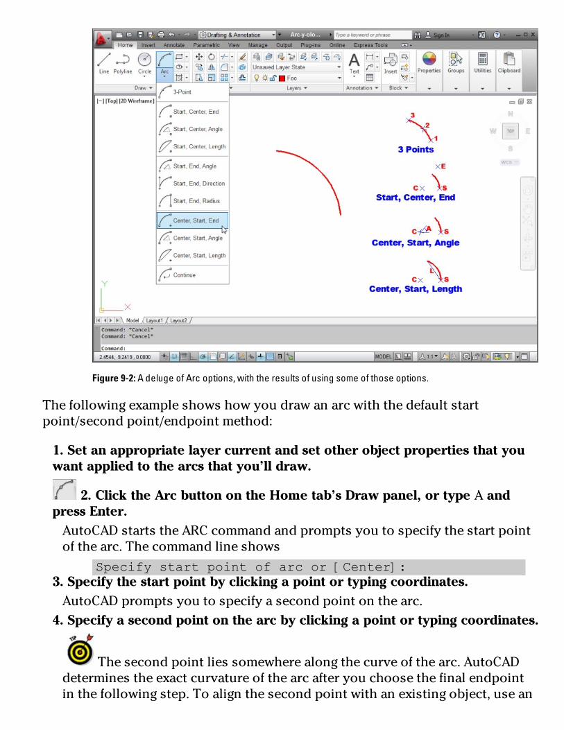
Figure9-2:AdelugeofArcoptions,withtheresultsofusingsomeofthoseoptions.
Thefollowingexampleshowshowyoudrawanarcwiththedefaultstartpoint/secondpoint/endpointmethod:
1.Setanappropriatelayercurrentandsetotherobjectpropertiesthatyouwantappliedtothearcsthatyou’lldraw.
2.ClicktheArcbuttonontheHometab’sDrawpanel,ortypeAandpressEnter.AutoCADstartstheARCcommandandpromptsyoutospecifythestartpointofthearc.Thecommandlineshows
Specifystartpointofarcor[Center]:3.Specifythestartpointbyclickingapointortypingcoordinates.AutoCADpromptsyoutospecifyasecondpointonthearc.
4.Specifyasecondpointonthearcbyclickingapointortypingcoordinates.
Thesecondpointliessomewherealongthecurveofthearc.AutoCADdeterminestheexactcurvatureofthearcafteryouchoosethefinalendpointinthefollowingstep.Toalignthesecondpointwithanexistingobject,usean

ObjectSnapmode.AutoCADpromptsyoutospecifytheendpointofthearc;asyoumovethecrosshairsaround,AutoCADshowshowthearcwilllook.
5.Specifytheendpointofthearcbyclickingapointortypingcoordinates.AutoCADdrawsthearc,asshownpreviouslyinFigure9-2.
Asyoumayrecall,pressingEnterrepeatsthelastcommand.WhatoftenthrowsnewAutoCADusersisthatEnterdoesn’trepeattheoptionsofthelastcommand.IfyoudrawanarcusingtheCenter,Start,Endoption,forexample,pressingEnterisn’tgoingtorepeatthatmethod—it’sgoingtorepeattheARCcommandinitsdefaultform,andthethreepointsyoupickprobablywon’tgiveyouthearcyoumeanttodraw.Bottomline:Watchthecommandline!
SolarellipsesIncaseyou’veforgottenyourninth-grademath,anellipseislikeasquishedcircle(pleaseexcusethetechnicaljargon).Mathematically,anellipseisdefinedbyamajor(long)axisandaminor(short)axis.Theseaxesdeterminetheellipse’slength,width,anddegreeofcurvature.Anellipticalarcisanarccutfromanellipse.
TheAutoCADELLIPSEcommandprovidesastraightforwardwayofdrawinganellipse:Youspecifythetwoendpointsofoneofitsaxesandthenspecifyanendpointontheotheraxis.ButliketheARCcommand,theELLIPSEcommandoffersabunchofotheroptions:
Arc:Generatesanellipticalarc,notafullellipse.Youdefineanellipticalarcjustasyoudoafullellipse.ThemethodsthatIdiscussinthissectionforcreatinganellipseapplytoeither.
Center:Thisoptionrequiresthatyoudefinethecenteroftheellipseandthentheendpointofanaxis.Youcantheneitherenterthedistanceoftheotheraxisorspecifythatarotationaroundthemajoraxisdefinestheellipse.Ifyouchoosethelatter,youcanenter(ordragtheellipseto)aspecificrotationforthesecondaxisthat,inturn,completelydefinestheellipse.
Rotation:Withthisoption,youspecifyananglewhichdefinesthecurvatureoftheellipse—smallanglesmakefatellipses(0degreescreates

acircle,infact),andlargeanglesmakeskinnyellipses.Thenameoftheoption,Rotation,hassomethingtodowithrotatinganimaginarycirclearoundthefirstaxis.Ifyoucanfigureouttheimaginarycirclebusiness,youhaveabetterimaginationthanIdo.
Thefollowingcommandlineexamplecreatesanellipsebyusingthedefaultendpointsoftheaxesmethod.Figure9-3showsanellipseandanellipticalarc.
Command:ELLIPSE
Specifyaxisendpointofellipseor[Arc/Center]:pickortypethe
firstendpointofoneaxis
Specifyotherendpointofaxis:pickortypetheotherendpointofone
axis
Specifydistancetootheraxisor[Rotation]:pickortypethe
endpointoftheotheraxis
Youcancreateellipticalarcs(asopposedtothecirculararcsthattheAutoCADARCcommanddraws)byusingtheArcoptionoftheELLIPSEcommand;it’sperfectfordrawingthosecannonballtrajectories!Alternatively,youcandrawafullellipseandusetheTRIMorBREAKcommandtocutapieceoutofit.
Figure9-3:Tomakeanomelet,sometimesyouhavetobreakafewellipses.
Splines:Thesketchy,sinuouscurves

MostpeopleuseCADprogramsforprecisiondrawingtasks:straightlines,carefullydefinedcurves,preciselyspecifiedpoints,andsoon.AutoCADisnottheprogramtofreeyourinnerartist—unlessyourinnerartistisMondrian.Nonetheless,evenmeticulouslycreatedCADdrawingssometimesneedfreeformcurves.TheAutoCADsplineobjectisjustthethingforthejob.
YoucanuseAutoCADsplinesintwoways:
Eyeballthelocationandshapeofthecurveanddon’tworrytoomuchaboutgettingitjustso.That’sthefreeform,sketchy,not-too-preciseapproachthatIdescribeinthissection.
Specifytheircontrolpointsandcurvaturecharacteristicsprecisely.
Beneaththeireasygoing,informalexterior,AutoCADsplinesarereallyhighlyprecise,mathematically-definedentitiescalledNURBScurves(NonUniformRationalB-Splinecurves).Mathematiciansandsomemechanicalandindustrialdesignerscarealotabouttheprecisecharacteristicsofthecurvestheyworkwith.Forthosepeople,theAutoCADSPLINEandSPLINEDITcommandsincludeanumberofadvancedoptions.LookupsplinecurvesintheAutoCADonlinehelpifyouneedprecisioninyoursplines.
Drawingsplinesisstraightforward,ifyouignoretheadvancedoptions.ThefollowingproceduredrawsafreeformcurvewiththeSPLINEcommand:
1.Setanappropriatelayercurrentandsetotherobjectpropertiesthatyouwantappliedtothesplinesegmentsthatyou’lldraw.
2.ClicktheSplineFitbuttonontheHometab’sDrawpanelslideoutortypeSPLandpressEnter.AutoCADstartstheSPLINEcommandandpromptsyoutospecifythestartpointofthespline.Thecommandlineshows
Currentsettings:Method=FitKnots=ChordSpecifyfirstpointor[Method/Knots/Object]:
3.Specifythestartpointbyclickingapointortypingcoordinates.AutoCADpromptsyoutospecifyadditionalpoints:
Enternextpointor[startTangency/toLerance]:4.Specifyadditionalpointsbyclickingortypingcoordinates.Afteryoupickthesecondpoint,pressthedown-arrowkeytodisplayadditionaloptionsattheDynamicInputtooltip.(EnableDynamicInputatthe

statusbarifyouneedto.)Thecommandlineshows
Enternextpointor[endTangency/toLerance/Undo/Close]:
Becauseyou’redrawingafreeformcurve,youusuallydon’tneedtouseobjectsnapsorotherprecisiontechniqueswhenpickingsplinepoints.
5.PressEnterafteryou’vechosentheendpointofyourspline.AutoCADdrawsthespline.
Youcanspecifythestartandendtangencyofthesplinetocontrolthecurvatureofthestartpointsandendpointsofthespline.Ifallyou’reafterisaswoopyfreeformcurve,justpickingpointsasinthisexampleworksfine.
Figure9-4showssomeexamplesofsplines.
Figure9-4:Aslewofsplines.
Afteryou’vedrawnaspline,youcangripeditittoadjustitsshape.SeeChapter10forinformationaboutgripediting.Ifyouneedfinercontroloversplineediting,lookuptheSPLINEDITcommandintheAutoCADonlinehelp.
Donuts:ThecircleswithadifferenceAdonutinAutoCADisanotherspecialtypeofpolylineobjectthatyoucreatewith

(whatelse?)theDONUTcommand.(TherectanglesandregularpolygonsIshowyouinChapter8arealsopolylineobjects.)Creatingadonutisasimplewaytodefineasingleobjectthatconsistsoftwoconcentriccircleswiththespacebetweenthemfilled.
WhenyoustarttheDONUTcommand,AutoCADpromptsyoufortheinsidediameterandtheoutsidediameter—thesizeoftheholeandthesizeofthedonut—asmeasuredacrosstheirwidestpoints.Afteryou’veenteredthesevalues,AutoCADpromptsyouforthecenterpointofthedonut.Butonedonutisrarelyenough,soAutoCADkeepspromptingyouforadditionalcenterpointsuntilyoupressEnter(theAutoCADequivalentofsaying,“no,really,I’mfullnow!”).
Thefollowingexampledrawsaregulation-sizedonut,witha1.5-inchholeand3.5-inchoutsidediameter.
Command:DONUT
Specifyinsidediameterofdonut<0.5000>:1.5
Specifyoutsidediameterofdonut<1.0000>:3.5
Specifycenterofdonutor<exit>:pickortypethecenterpointof
oneormoredonuts
YoucanusetheDONUTcommandtocreateafilledcircle—alsoknownasajelly-filleddonut.Justspecifyaninsidediameterof0.Figure9-5showsbothkindsofdonuts.
Figure9-5:Donuts,plainandjelly-filled.

RevisioncloudsonthehorizonIt’scustomaryinmanyindustriestosubmitasetofdrawingsatdifferentprojectmilestonesorstagesofcompletionandthensubmitthemagainlaterwithrevisions—corrections,clarifications,andrequestedchanges.Usually,therecipientsliketolocatechangedstuffeasily,andacommondraftingconventionistocallattentiontoreviseditemsbydrawingfreeformcloudsaroundthem.TheREVCLOUDcommandmakesquickworkofdrawingsuchclouds.
Drawingrevisioncloudsiseasy,afteryouunderstandthatyouclickonlyonceinthedrawingarea.Thatoneclickdefinesthestartingpointforthecloud’sperimeter.Afterthat,yousimplymovethecrosshairsaround,andthecloudtakesshape.Whenyoureturntonearthepointthatyouclickedinthebeginning,AutoCADautomaticallyclosesthecloud.
Thefollowingcommandlineexampleshowsyouhowtodrawarevisioncloud.Figure9-6showswhatrevisioncloudslooklike.
Command:REVCLOUD
Minimumarclength:0.5000Maximumarclength:0.5000Style:Normal
Specifystartpointor[Arclength/Object/Style]<Object>:picka
pointalongtheperimeterofyourfuturecloud
Guidecrosshairsalongcloudpath...sweepthecrosshairsaroundto
definethecloud’sperimeter
Youdon’tneedtoclickagain.Simplymovethecrosshairsaroundwithoutclicking.AutoCADdrawsthenextarcsegmentofthecloudwhenyourcrosshairsreachtheminimumarclengthdistancefromtheendofthepreviousarcsegment.
Continuemovingthecrosshairsarounduntilyoureturntothepointwhereyouclickedfirst.

Figure9-6:Meanwhile,revisioncloudsweregatheringoverEurope.
Hereareafewtipsforusingrevisionclouds:
It’sagoodideatoputrevisioncloudsontheirownlayersoyoucanchoosetoplotwithorwithoutthecloudsvisible.
You’llprobablyfinditeasiertocontroltheshapeofrevisioncloudsifyouturnoffOrthomodebeforeyoustartthecommand.
Youmayneedtoaddatriangleandnumber,asshowninFigure9-6,toindicatetherevisionnumber.Ablockwithanattributeisagoodwaytohandlethisrequirement:Chapter17coversblocksandattributes.
Iftherevisioncloud’sarcsaretoosmallortoolarge,erasethecloud,restarttheREVCLOUDcommand,andusethecommand’sArcLengthoptiontochangetheminimumandmaximumarclengths.Thedefaultminimumandmaximumlengthsare0.5(or15inmetricdrawings).Ifyoumaketheminimumandmaximumlengthsequal(whichisthedefault),thelobeswillbeapproximatelyequalinsize.Ifyoumakethemunequal,therewillbemorevariationinlobesize—you’llgetfluffierclouds.Fortunately,alltheseoptionsaremorethanmostnon-meteorologistswillneed.

ScoringPointsIthoughtaboutnotcoveringpointsinthisbook,butIdidn’twantyoucomplainingthatAutoCAD2012ForDummiesispointless.
ThewordpointdescribestwodifferentthingsinAutoCAD:
Alocationinthedrawingthatyouspecify(bytypingcoordinatesorclickingwiththemouse)
AnobjectthatyoudrawwiththePOINTcommand
Throughoutthischapterandmostofthebook,Itellyoutospecifypoints—that’sthelocationmeaning.Thissectiontellsyouhowtodrawpointobjects.
ApointobjectinAutoCADcanservetwopurposes:
Pointsoftenidentifyspecificlocationsinyourdrawingtootherpeoplewholookatthedrawing.Apointcanbesomethingthatdisplaysonthescreen,eitherasatinydotorasanothersymbol,suchasacrosswithacirclearoundit.
Youcanusepointsaspreciseobjectsnaplocations.Thinkofthemasconstructionpoints.Forexample,whenyou’relayingoutanewbuilding,youmightdrawpointobjectsatsomeoftheengineeringsurveypointsandthensnaptothosepointsasyousketchthebuilding’sshapewiththePLINEcommand.YouusetheNodeObjectSnapmodetosnaptoAutoCADpointobjects.
WhatmakesAutoCADpointobjectscomplicatedistheiralmostlimitlessrangeofdisplayoptions,providedtoaccommodatethetwodifferentkindsofpurposesjustdescribed(andpossiblysomeothersthatIhaven’tfiguredoutyet).YouusethePointStyledialogbox,asshowninFigure9-7,tospecifyhowpointsshouldlookinthecurrentdrawing.

Figure9-7:ThePointStyledialogboxcontrolsthewaypointobjectsappearon-screen.
ThePointStyledialogboxcanbefoundontheHometab’sUtilitiespanelslideout,orbytypingitscommandname—whichhappenstobeabouttheleastintuitivecommandnameinallofAutoCAD:DDPTYPE(pronouncedddptype).Thetopportionofthedialogboxshowstheavailablepointdisplaystyles.Mostofthe

choicesdoprettymuchthesamething.Justclickoneofthesquaresthatsays,“Hey,that’sagoodpoint!”toyou.
Thefirstchoice,asingle-pixeldot,ishardtoseeonthescreen,andthesecondchoice,invisible(astealthpoint?),isimpossibletosee.Avoidthesechoicesifyouwantyourpointobjectstoshowuponthescreenandonplots.Thesingle-pixeldot,whichisthedefaultdisplaystyle,workswellifyouusepointobjectsasobjectsnaplocationsanddon’twantobtrusivepointsonyourplots.
TheremainingsettingsinthePointStyledialogboxcontrolthesizeatwhichpointsappearonthescreenatdifferentzoommagnifications.Thedefaultsettingsoftenworkfine,butifyou’renotsatisfiedwiththem,clicktheHelpbuttoninthedialogboxtofindouthowtochangethem.
Afteryouspecifythepointstyle,placingpointson-screeniseasy.Thefollowingexampleshowsyouhow;justtypePOINTandpressEnter.
Command:POINT
Currentpointmodes:PDMODE=0PDSIZE=0.0000
Specifyapoint:pickortypethecoordinatesofalocationinthe
drawing
ThePDMODEandPDSIZEitemslistedinthecommandwindowaresystemvariablesthatcorrespondtothepointdisplaymodeanddisplaysizeoptionsinthePointStyledialogbox.Ifyouwanttoknowexactlyhowthesystemvariablescorrespondtothedialogboxchoices,youhaveallthemakingsofasuccessfulCADnerd.ClicktheHelpbuttoninthePointStyledialogboxtofindoutmore(aboutthesystemvariables—notaboutyourself).

Chapter10
GetaGriponObjectSelection
InThisChapterUsingcommand-firstediting
Selectingobjectswithmaximumflexibility
Editingwithgrips
Editingobjectsistheflipsideofcreatingthem,andinAutoCAD,youspendalotoftimeediting—farmorethandrawingobjectsfromscratch.That’spartlybecausethedesignanddraftingprocessis,byitsnature,repetitive,andalso

becauseAutoCADmakesiteasytoeditobjectscleanly.
WhenyoueditobjectsinAutoCAD,youneedtobejustasconcernedaboutspecifyingpreciselocationsanddistancesasyouarewhenyouoriginallycreatetheobjects.Makesurethatyou’refamiliarwiththeprecisiontechniquesdescribedinChapter7beforeyouapplytheeditingtechniquesfromthischaptertorealdrawings.
CommandingandSelectingAutoCADoffersthreestylesofediting:
Command-firstediting
Selection-firstediting
Directobjectmanipulation(gripediting)
AutoCADreferstocommand-firsteditingasverb-nouneditingandtoselection-firsteditingasnoun-verbediting.Whenyouseethisterminology—forexample,intheOptionsdialogboxortheonlinehelpsystem—don’tworry,youhaven’tdroppedbackintoyourfifth-gradeEnglishclass!
Command-firsteditingWithcommand-firstediting,youstartacommandandthenselecttheobjectsonwhichthecommandworks.Thisstyleofeditingmayseembackwardtoyouatfirstunlessyou’realongtimeAutoCADuser.Command-firsteditingworkswellforpoweruserswhoareinahurryandwhoarewillingtomemorizemostofthecommandstheyneedtodotheirwork.It’salsotheonlywaytousesomeoftheeditingcommands(suchasFILLETandBREAK).It’snosurprisethatcommand-firsteditingisthetraditionaleditingstyleinAutoCAD,andtheonemethodwithwhichyouneedtobemostcomfortable.
Selection-firsteditingInselection-firstediting,youperformthesamesteps—inthesameorder—asin

mostWindowsapplications:Selecttheobjectfirst,andthenchoosethecommand.Selection-firsteditingtendstobeeasiertomasterandmakesAutoCADmoreapproachablefornewandoccasionalusers.
DirectobjectmanipulationWithdirectobjectmanipulation,youperformcommoneditingoperationsbyusingthemousetograbtheselectedobjectandperformanactiononit,suchasmovingallorpartofittoadifferentplaceinthedrawing.Nonamedcommandisinvolved;theactofmovingthemouseandclickingthemousebuttonsincertainwayscausestheeditingchangestohappen.AutoCADsupportsdirectobjectmanipulationthroughapowerfulbutsomewhatcomplicatedtechniquecalledgripediting.Gripsarethelittlesquare,rectangular,ortriangularhandlesthatappearonanobjectwhenyouselectit.Youcanusethegripstostretch,move,copy,rotate,scale,orotherwiseedittheobject.
ChoosinganeditingstyleThisbookemphasizescommand-firstediting,butIalsodiscussgripeditinginthesection“GetaGrip,”laterinthischapter.AutoCAD,initsheartofhearts,isacommand-firstprogram.Infact,itstartedoutofferingonlycommand-firsteditingandlateraddedselection-firstmethods;AutoCAD2012inheritsthisancestraltrait.Istresscommand-firsteditingforthefollowingreasons:
It’stheeditingstylethat’sbeeninAutoCADthelongest,andtheonewithwhichexperiencedAutoCADusersaremostfamiliar.
Itworksconsistentlywithalleditingcommands—someeditingcommandsremaincommand-firstonly.
Itprovidesaddedobjectselectionflexibility,whichisusefulwhenyouworkoncomplicated,busydrawings.
Afteryouknowhowtodocommand-firstediting,youcansimplyreversetheorderofmanyeditingoperationstodothemselection-firststyle,instead.Butifyoudon’tgetfamiliarwithcommand-firsteditinginthebeginning,you’llbebewilderedbyafewusefulAutoCADcommandsthatworkonlyinthecommand-firststyle;commandssuchastheseignoreanyalready-selectedobjectsandpromptyoutoselectobjectsbeforeyoucancontinue.
Muchoftheinformationintherestofthisbookassumesthatyou’reusingthe

defaultAutoCADselectionsettings.IfyoufindthatobjectselectionorgripeditingareworkingdifferentlyfromthewayIdescribetheminthischapter,clicktheApplicationbutton,chooseOptionsfromthebottomoftheApplicationMenutoopentheOptionsdialogbox,andthencheckthesettingsontheSelectiontab.Theelevencheckboxsettingslistednextshouldbeselected,asshowninFigure10-1.(Allothercheckboxsettingsshouldbedeselected.)
Figure10-1:SettingselectionoptionsintheOptionsdialogbox.
Noun/VerbSelection
ObjectGrouping
ImpliedWindowing
SelectionPreviewWhenaCommandisActive
SelectionPreviewWhenNoCommandisActive
ShowGrips

ShowGripTips
ShowDynamicGripMenu
AllowCtrl+CyclingBehavior
ShowSingleGriponGroups
ShowBoundingBoxonGroups
Forinformationonwhattheseoptionsdo,hoverthemousepointeroveranoptiontodisplayatooltipwithinformationfromtheonlinehelp.
GrabItPartofAutoCAD’seditingflexibilitycomesfromitsobject-selectionflexibility.Forexample,command-firsteditingoffers16selectionmodes!(Idescribethemostusefulonesinthischapter.)Don’tworry,though;youcangetbymostofthetimewiththreeselectionmodes,eachofwhichIdescribeinthissection:
Selectingasingleobjectbypickingit
Selectingmultipleobjectsbyenclosingtheminawindowselectionboxorpolygon
Selectingmultipleobjectsbyenclosingtheminacrossingselectionboxorpolygon
One-by-oneselectionThemostobviouswaytoselectobjectsistopick(byclicking)themoneatatime.Oneormoreobjectsthatareselectedandreadyforeditingarecalledaselectionset.Youcanbuildaselectionsetcumulativelywiththispick-one-object-at-a-timeselectionmode,butthiscumulativeconventionmaybedifferentfromwhatyou’reusedto.InmostWindowsprograms,ifyouselectoneobjectandthenanother,thefirstobjectisdeselected,andthesecondoneselected;onlytheobjectyouselectlastremainsselected.InAutoCAD,alltheobjectsyouselect,oneatatime,remainselectedandareaddedtotheselectionset,nomatterhowmanyobjectsyoupick.(YoucanchangethisbehaviortomakeAutoCADworklikeotherWindowsprogramsbyturningontheUseShifttoAddtoSelectionoptiononthe

Optiondialogbox’sSelectiontab,butIsuggestthatyoudon’tchangeit.)Mosteditingcommandsaffecttheentiregroupofselectedobjects.
UsetheSELECTSIMILARcommandtoautomaticallyselectsimilarobjectsbasedontheirproperties.Selectanobject,right-click,andchooseSelectSimilarfromtheshortcutmenu,andAutoCADselectsallsimilarobjects.YoucanfilterthepropertiesusedforselectionbytypingSELECTSIMILARatthecommandprompt,thenenteringSEtodisplaytheSelectSimilarSettingsdialogbox(seeFigure10-2).
Figure10-2:Chooseyoursimilarity-selectionsettingshere.
SelectionboxesleftandrightSelectingobjectsoneatatimeworksgreatwhenyouwanttoeditasmallnumber

ofobjects,butmanyCADeditingtasksinvolveeditinglotsofobjects.Doyoureallywanttopick132lines,arcs,andcircles,oneatatime?
LikemostWindowsgraphicsprograms,AutoCADprovidesaselectionwindowfeatureforgrabbingabunchofobjectsinarectangulararea.Asyoumayguessbynow,theAutoCADversionofthisfeatureisabitmorepowerfulthanthesimilarfeatureinotherWindowsgraphicsprogramsandis,therefore,slightlyconfusingatfirst.AutoCADcallsitsversionimpliedwindowing.Here’showyouuseit.
Ifyouclickablankareaofthedrawing—thatis,notonanobject—you’reimplyingtoAutoCADthatyouwanttospecifyaselectionbydraggingawindowaroundtheobjects.Ifyoumovethecrosshairstotherightbeforepickingthenextcorneroftheselectionarea,you’refurtherimplyingthatyouwanttoselectallobjectsthatresidecompletelywithintheselectionarea.Ifyoumovethecrosshairstotheleftbeforepickingthenextcorneroftheselectionarea,you’reimplyingthatyouwanttoselectallobjectsthatresidecompletelyorpartiallywithintheselectionarea.
TheAutoCADterminologyforthesetwokindsofselectionareasgetsalittleconfusing:
Windowobjectselection:Themove-to-the-right,only-select-objects-completely-within-the-areamode
Crossingobjectselection:Themove-to-the-left,select-objects-completely-or-partially-within-the-areamode
Fortunately,AutoCADgivesyouvisualcuesthatthere’sadifference.Asyoumovetotheright,thewindowareaappearsasarectangularorpolygonalareawithabluefillandasolidborder.Asyoumovetotheleft,thecrossingareaappearsasarectangleorpolygonwithgreenfillandadashedborder.
Ifyoureditingmethodofpreferenceisselection-first,AutoCAD2012nowgivesyoutheoptionofdraggingapolygonalwindoworcrossingarea,orsimplydraggingaseriesoflinesthroughtheobjectsyouwanttoselect.Yousimplyclickapointanddragtotheleftorrighttogetrectangularselectionboxesasdescribedabove,oryoucanchoosetheWPolygon,CPolygon,orFenceoptionsbytypingtheappropriateletteratthecommandline.
Figures10-3and10-4showawindowboxandacrossingbox,respectively,inaction.

Figure10-3:Awindowselectionbox,drawnlefttoright,selectsonlyobjectscompletelywithinthebox.

Figure10-4:Acrossingselectionbox,drawnrighttoleft,selectsobjectsthatarecompletelyorpartiallywithinthebox.
Youcanmixandmatchselectingindividualobjects,specifyingawindowbox,andspecifyingacrossingbox.Eachselectionaddstothecurrentselectionset,allowingyoutobuildanenormouslycomplicatedselectionofobjectsandthenoperateonthemwithoneormoreeditingcommands.
YoucanpresstheShiftkeyincombinationwithanyofthethreestandardselectionmodes—singleobject,windowarea,andcrossingarea—toremovealready-selectedobjectsfromtheselectionset.Thisfeatureisespeciallyusefulwhenyou’rebuildingaselectionsetinacrowdeddrawing;youcanselectabigbatchofobjectsbyusingWindoworCrossing,andthenholddowntheShiftkeywhileselectingtoremovetheobjectsthatyouwanttoexcludefromtheeditingoperation.

PerfectingSelectingWhenyoueditincommand-firstmode,youhavealltheselectionoptionsdescribedintheprevioussection—singleobject,windowbox,windowpolygon,crossingpolygon,andcrossingbox—plusaslewofothers.Ifyoutype?andpressEnteratanySelectobjectsprompt,AutoCADlistsalltheselectionoptionsatthecommandline:
Window/Last/Crossing/BOX/ALL/Fence/WPolygon/CPolygon/
Group/Add/Remove/Multiple/Previous/Undo/AUto/
SIngle/SUbobject/Object
Table10-1summarizesthemostusefulcommand-firstselectionoptions.
Table10-1SomeUsefulCommand-FirstSelectionOptions
Option Description
Window Allobjectscompletelywithinarectangularareathatyouspecifybypickingtwopoints
Crossing Allobjectswithinorcrossingarectangularareathatyouspecifybypickingtwopoints
WPolygon Allobjectscompletelywithinapolygonalareawhosecornersyouspecifybypickingpoints
CPolygon Allobjectswithinorcrossingapolygonalareawhosecornersyouspecifybypickingpoints
Fence Allobjectstouchinganimaginarypolylinewhoseverticesyouspecifybypickingpoints
Last Thelastobjectyoudrew(whetherornotit’svisibleinthedisplay)
Previous Thepreviousselectionsetthatyouspecified
ALL Allobjectsonlayersthataren’tfrozenorlockedandthatareinthecurrentspace(modelspaceorpaperspace)
Touseanyofthecommand-firstselectionoptionsattheSelectobjectsprompt,typetheuppercaselettersindicatedinTable10-1thatcorrespondtothedesiredoptionandpressEnter.Afteryou’refinishedselectingobjects,youmustpressEnteragaintotellAutoCADthatyou’vefinishedselectingobjectsandwanttostarttheeditingoperation.
Afteryou’refinishedselectingobjects,youmustpressEnteragaintotellAutoCADthatyou’vefinishedselectingobjectsandwanttostarttheeditingoperation.Say...isthereanechoinhere?Asamatteroffact,Iamrepeatingmyself.OneofthethingsthatmostnewAutoCADusersfindhardesttorememberisthenecessityofpressingEnterafteryoufinishselectingobjects.

AutoCAD’sSelectionpreviewfeaturesremovealotofdoubtaboutwhichobjectsyou’reselecting.Rolloverhighlightingdisplaysindividualobjectswithathick,dashedlineweightasyoumovethecrosshairsoverthem.Areaselectiondisplaysatransparent,coloredhighlightovermultipleselectionswhenyouuseWindowandCrossingoptions.YoucanenableanddisablebothfeaturesontheSelectiontaboftheOptionsdialogbox(refertoFigure10-1).
ThefollowingexampledemonstrateshowtousetheERASEcommandincommand-firstmodewithseveraldifferentselectionoptions.TheselectiontechniquesusedinthisexampleapplytomostAutoCADeditingcommands.
1.Openadrawingthatcontainssomeobjects,orstartanewdrawingandcreatesomelines,arcs,orcircles.Youneedn’tbetooparticulardrawingthesebecauseyou’regoingtoblowthemawayinthefollowingsteps.
2.PressEsctomakesurethatnocommandisactiveandnoobjectsareselected.
Ifanyobjectsareselectedwhenyoustartaneditingcommand,thecommand,inmostcases,willoperateonthoseobjects(selection-firstediting)insteadofpromptingyoutoselectobjects(command-firstediting).ForthereasonsthatIdescribeinthesection“CommandingandSelecting,”earlierinthischapter,Irecommendthatyouusecommand-firsteditingstyleuntilyou’rethoroughlyfamiliarwithit.Later,youcanexperimentwithselection-firsteditingifyoulike.(JustreversethesequenceofcommandingandselectingthatIdescribeinthischapter.)
3.ClicktheErasebuttonontheHometab’sModifypanel.AutoCADdisplaystheSelectobjectspromptatthecommandlineand,ifDynamicInputisenabledonthestatusbar,theDynamicInputtooltip.
4.Selecttwoorthreeindividualobjectsbyclickingeachone.AutoCADaddseachobjecttotheselectionset.Alltheobjectsyouselectremainhighlighted,andAutoCADcontinuestodisplaytheSelectobjectsprompt.
5.Specifyawindowselectionboxthatcompletelyenclosesseveralobjects.Movethecrosshairstoapointbelowandtotheleftoftheobjects,click,releasethemousebutton,movethecrosshairsaboveandtotherightoftheobjects,andclickagain.

Allobjectsthatarecompletelywithintheboxareselected.6.Specifyacrossingselectionboxthatcompletelyenclosesafewobjectsandcutsthroughseveralothers.Movethecrosshairstoapointbelowandtotherightofsomeoftheobjects,click,releasethemousebutton,movethecrosshairsaboveandtotheleftofsomeoftheobjects,andclickandreleaseagain.Allobjectsthatarecompletelywithinorcrossthroughtheboxareselected.AutoCADcontinuestodisplaytheSelectobjectsprompt.
7.TypeWPandpressEntertoactivatetheWPolygonselectionoption.AutoCADpromptsyoutopickpointsthatdefinetheselectionpolygon.
8.PickaseriesofpointsandpressEnter.Figure10-5showsanexample.AfteryoupressEnter,AutoCADselectsallobjectsthatarecompletelywithinthepolygon.AutoCADcontinuestodisplaytheSelectobjectspromptuntilyoupressEnter.
9.PressEntertoendobjectselection.AutoCADerasesalltheselectedobjectsandreturnstoanemptycommandprompt.
NoticehowyoucoulduseacombinationofobjectselectionmethodstobuildaselectionsetandthenpressEntertoexecutethecommandontheselectedobjects.MostAutoCADeditingcommandsworkthiswayincommand-firstmode.

Figure10-5:LassoingobjectswithaWPolygon.
If,aftererasingaselectionset,youimmediatelyrealizethatyoudidn’treallymeantodoawaywithsomanyobjects,youcanusetheUndobuttonontheQuickAccessToolbartorestorethemall.ButAutoCADhasoneadditionalunerasetrickupitssleeve—theaptlynamedOOPScommand.WhenyoutypeOOPSandpressEnter,AutoCADrestoresthelastselectionsetthatyouerased—evenifyou’verunothercommandsafterERASE.
TheERASEcommandisn’ttheonlywaytoremoveunwantedobjectsfromyourdrawing.EasiestofallinanyworkspaceistosimplyselectanitemandpresstheDeletekey.
It’salltooeasytodrawobjectsontopofotherobjects,andoncethey’rethere,prettywellimpossibletorecognizethattherearemultiplessoyoucanweedouttheonesyoudon’twant.Forthelastcoupleofreleases,holdingdowntheShiftkeyandthespacebartogetherwhileclickingonsuspectedmultipleobjectswillhighlightthem,oneaftertheother;whentheoneyou’reafterlightsup,youpress

Entertoselectit.AutoCAD2011introducedamorepowerfulselectioncyclingmethod.WithSelectionCyclingenabledonthestatusbar,AutoCADdisplaysablueiconshowingoverlappingrectanglesifitdetectsmultipleobjectsunderyourcrosshairs.Andwhenyoupickanobjectwiththisicondisplayed,AutoCADopensaSelectiondialogboxwhereyoucanchoosetheobjectyouactuallywantto.
AutoCAD2011couldfindthoseduplicates,andnowAutoCAD2012willblowthemawayforyou!ClickthenewDeleteDuplicateObjectstool(lookforthebroomontheModifypanelslideoutontheHometab)toruntheaptlynamedOVERKILLcommand.YoucanprocessanentiredrawingatonefellswoopbyenteringALLattheSelectObjectsprompt.TheDeleteDuplicateObjectsdialogboxappears;thereyoucansetanumberofpropertiesandoptions(seeFigure10-6).Checktheonlinehelpformoreaboutthiscommand.
AutoCADLTusers,forsomestrangereason,thetoolbuttonIdescribeintheprecedingparagraphmaynothavemadeitontoLT’sModifypanel.However,youdohaveaccesstothecommand—youjustneedtotypeOVERKILLatthecommandprompttocalluptheDeleteDuplicateObjectsdialogbox.
Likemostgraphicsprograms,AutoCADletsyouselectabunchofobjectsandgatherthemintoagroup,sothatwhenyouclickononeobject,everythinginthegroupisselected.ThenewGroupspanelontheHometabofAutoCAD2012’sRibbonoffersawelcomeupdatefortheoldandcomplicatedObjectGrouping(AutoCAD)andGroupManager(AutoCADLT)dialogboxes.YousimplyselectyourobjectsandclickGroup.Ifyouwant,youcannameyourgroupasyoucreateit.ThebuttonsonthemainGroupspanelletyoucreatenewgroups,togglegroupselectionoffandon,editgroupsbyaddingorremovingindividualobjects,orpermanentlyungroupaselectedgroup.ClickingGroupManagerintheGroupspanelslideoutdisplaystheoldObjectGrouping(inAutoCAD)orGroupManager(inAutoCADLT)dialogboxforevenmoregroupfunctions.

Figure10-6:Weedoutthoseduplicateobjects.
ObjectSelection:NowYouSeeIt...Themanyobject-selectionmodesIdescribeinprevioussections—andsomeIdon’tdescribeatall,suchastheFILTERcommand(checkouttheonlinehelpsystemformoreonthat)—areusefulasfarastheygo.
AutoCAD2012letsyoucontrolthevisibilityofindividualobjects.Thismayormaynotsoundlikeabigdeal,butbelieveme,itis.BeforeAutoCAD2011,theonly

waytocontrolthedisplayofobjectswastoturnofforfreezethelayeronwhichtheyresided.Iftherewereotherobjectsonthatlayerthatyoudidwanttosee...toobad!Threecommandsturnthatlimitationintoancienthistory:
HIDEOBJECTS:Promptsyoutoselectthoseobjectsyouwanttomaketemporarilydisappear
ISOLATEOBJECTS:Promptsyoutoselectthoseobjectsyouwanttoseewhiletemporarilymakingeverythingelsedisappear
UNISOLATEOBJECTS:Endsthehidingandisolatingofobjects
Theprimarymethodofinvokingthesecommandsisviatheright-clickmenu.Usingeithercommand-firstorselection-firstediting(asdescribedinthesection“CommandingandSelecting,”earlierinthischapter),simplyright-clickandyouseetheIsolateitemshowninFigure10-7.Astatusbaricon—alightbulbatthelower-rightcornerofthedisplay—isdimmedwhenobjectsareeitherhiddenorisolated.Clickthisicontoopenamenuthatletsyouturnoffthehidingorisolating.
Ifyou’reworriedaboutthepossibleimplicationsofthis(“Hmm...IwassureIaddedthosecenterlines...doIneedtoaddthemagain?”),relax.Hidingandisolatingobjectsistemporary—itonlylastsaslongasyourcurrentdrawingsession.Ifyouendadrawingwithobjectsisolatedorhidden,theyreappearwhenyoureopenthefile.

Figure10-7:Makethoseobjectsgoaway(butonlytemporarily!).
GetaGripAlthoughcommand-firsteditingisthemostflexibleandwidespreadeditingstyleinAutoCAD,it’snottheonlyway.Gripeditingisausefuladjuncttocommand-firstediting,especiallywhenyouwanttomodifyjustoneortwoobjects.Youmayhaveencounteredgripeditingwhenusingotherkindsofgraphicsprograms.Butevenifyou’reanexperienceduserofothergraphicsprograms,you’veneverseengripsusedinquitethewaythatAutoCADusesthem.
Anythingthatyoucandowithgripeditingcanbedonewithcommand-first

editingaswell.Insomesituations,gripeditingisalittlemoreefficientorconvenientthancommand-firstediting,butcommand-firsteditingalwaysgetsthejobdone.Ifyoumasteronlyonestyleofediting,makeitcommand-firststyle.Inotherwords,feelfreetoskipthissection—atleastuntilyou’recomfortablewithcommand-firstediting.
AboutgripsGripsarethoselittlesquare,rectangular,ortriangularhandlesthatappearonanobjectafteryouselectit.
Intheirsimplestguise,AutoCADgripsworksimilarlytothelittlesquaresongraphicalobjectsinotherWindowsprograms.ButinAutoCAD,insteadofclickinganddraggingagrip,youmustclick,releasethemousebutton,movethecrosshairs,andclickagainatthenewlocation.(Byseparatingtheselectionofbeginningandendingpointsintotwodifferentoperations,AutoCADallowsyoutousedifferenttechniques—suchasdifferentobjectsnaps—toselecteachpoint.)
AutoCADgripsare,forsophisticatedusers,betterthanthegripsfoundinmostotherprogramsbecauseyoucandosomuchmorewiththem.Youcan,forexample,useAutoCADgripstomove,stretch,orcopyanobject.Youalsocanusethemtorotateanobject,scaleittoadifferentsize,ormirroranobject—thatis,createoneormorereversedcopies.Gripsalsoactasvisibleobjectsnaps,orlittlemagnetsthatattractthecrosshairs.
InAutoCAD2012,gripsonlines,arcs,andellipticalarcshavebecomemultifunctional.Hoveringoveranendpointgripdisplaysapop-upmenuthatoffersyouachoiceoflengtheningorstretchingtheobject.Hoveringoverthemidpointgriponanarcoffersthechoiceofstretchingthearcbyitsmidpoint(thatis,keepingthesameendpoints)orchangingitsradius.Ellipticalarcsgainnewtriangulargripsthatletyouincreasethelengthofthearcwithoutchangingitsotherparameters.
AgrippingexampleThefollowingsectionscoverindetailthefivegrip-editingmodes:STRETCH,MOVE,ROTATE,SCALE,andMIRROR.Followthesestepstoexplorethegrip-editingmodes:

1.Drawsomesimplegeometry,suchastheobjectshowninFigure10-8.Here’sagreatplacetopracticesomeofthestraight-lineobjectcreationtoolsIdescribeinChapter8!
2.PressEsctomakesurethatnocommandisactiveandnoobjectsareselected,andthenclickQuickPropertiesonthestatusbartoturnofftheQuickPropertiespalette.TheQuickPropertiespaletteisprettyusefulforeditingthepropertiesofobjects,butmoreoftenthannot,itgetsinthewaywhenyouwanttoedittheobjectsthemselves.AutoCADdisplaysablankcommandprompt—thatis,nocommandiscurrentlyactive.
3.Clickanobjecton-screentoselectitanddisplayitsgrips.Grips—solidbluesquaresontheselectedobject—appearatvariouspointsontheobject.NotethattheAutoCADcommandpromptremainsblank;youhaven’tstartedacommandorgrip-editingoperationyet.
4.Clickanotherobject.Boththenewlyselectedobjectandthepreviouslyselectedobjectdisplaygrips.
5.Clickoneofthegripsoneitherobject.Ifapop-upmenuappearswhenyougetclosetoagrip,ignoreitfornowandgoaheadandclickthegrip.Thebluesquareturnstoadarkredsquare.Thisgripisnowhot,orselectedandreadyforagrip-editingoperation.Grip-editingoptionsnowappearonthecommandline.ThefirstoptiontoappearisSTRETCH.
6.Pressthespacebarrepeatedlytocyclethroughthefivegrip-editingoptionsonthecommandline.
**STRETCH**Specifystretchpointor[Basepoint/Copy/Undo/eXit]:**MOVE**Specifymovepointor[Basepoint/Copy/Undo/eXit]:**ROTATE**Specifyrotationangleor[Basepoint/Copy/Undo/Reference/eXit]:**SCALE**Specifyscalefactoror[Basepoint/Copy/Undo/Reference/eXit]:**MIRROR**Specifysecondpointor[Basepoint/Copy/Undo/eXit]:
Thegrip-editingoptiondisplayedonthecommandlineandthedynamic-inputtooltip(ifDynamicInputisenabled)changesasyoupressthespacebar.Ifyoumovethecrosshairs(withoutpicking)inbetweeneachpressofthespacebar,theappearanceofyourselectedobjectchangesasyoudisplayeachoption.ChoosingSTRETCH,forexample,causesastretchedversionoftheobjecttoappearon-screen.

Pressingthespacebarabunchoftimesisagoodwaytobecomefamiliarwiththegrip-editingmodes,butthere’samoredirectwaytochooseaparticularmode.Afteryouclickagriptomakeithot,right-clicktodisplaythegrip-editingmenu.Thatmenucontainsallthegrip-editingoptionsplussomeotherchoices,asshowninFigure10-8.
Figure10-8:Thegrip-editingright-clickmenu.
IfDynamicInputisenabled,pressingthedown-arrowkeywhilecyclingthroughthegrip-editingoptionsdisplaysadynamicmenuatthecrosshairsfromwhichyoucanchooseoptionsspecifictothecurrentgrip-editingfunction.
7.PressthespacebaruntilSTRETCH(ortheoptionyouwant)reappearsasthegrip-editingoption.8.Movethehotgripinthedirectioninwhichyouwanttostretch(orotherwisemanipulate)yourobject.AutoCADdynamicallyupdatestheimageoftheobjecttoshowyouwhatthemodifiedobjectwilllooklikebeforeyouclickthefinallocation.

9.Clickagaintofinishthegrip-editingoperation.Theselectedobjectwiththehotgripupdates.
10.ClickthesamegripthatyouchoseinStep5(nowinadifferentlocation)tomakeithot.11.Thistime,movethecrosshairsnearoneofthegripsontheotherobject.Whenyouseethemagneticpullofthegripontheotherobject,clickagaintoconnectthehotgripwiththeothergrip.Theobjectpointrepresentedbythehotgripnowcoincidesexactlywiththegripontheotherobject.
12.PressEsctodeselectallobjectsandremoveallgrips.
Figure10-9showsahot(red)endpointgripofalinebeingconnectedtotheendpointgripofanotherline.Theangledlineshowstheoriginalpositionofthelinebeingedited,andthethinverticallineshowsthenewposition.UsingagripinthiswayasavisibleobjectsnapoffersthesameadvantageasusingObjectSnapoverrides,asdescribedinChapter7:Itensuresprecisionbymakingsurethatobjectsmeetexactly.

Figure10-9:Usinggripstoconnecttwoobjects.
Youcanexperimentwithallthegrip-editingoptionstofindouthowtheyaffectaselectedobject.BecauseMOVEandSTRETCHarethemostusefulgrip-editingmodes,Icovertheminmoredetail.

Moveit!Backinthedaysofmanualdrafting,movingobjectswasabigpainintheeraser.Youhadtoerasethestuffyouwantedtomoveandredrawtheobjectsintheirnewlocation.Intheprocess,youusuallyendeduperasingpartsofotherstuffthatyoudidn’twanttomoveandleftsmudgedlinesandpilesoferaserdusteverywhere.CADdoesawaywithallthefussandmussofmovingobjects,andAutoCADgripeditingisagreatwaytomakeithappen.Thefollowingstepsdescribehowtomoveobjects:
1.Selectoneormoreobjects.Useanycombinationofthethreeobjectselectionmodes—singleobject,windowselection,andcrossingselection—describedinthe“GrabIt”section,earlierinthischapter.
2.Clickoneofthegripstomakeithot.Atthispointinyoureditingcareer,itdoesn’tmatterwhichgripyouclick.Asyoubecomemorefamiliarwithgripediting,you’lldiscoverthatcertaingripsserveasbetterreferencepointsthanothersforparticulareditingoperations.
3.Right-clickanywhereinthedrawingareaandchooseMovefromthecrosshairsmenu.4.Movethecrosshairstoadifferentlocationandclick.Asyoumovethecrosshairsaround,AutoCADdisplaysthetentativenewpositionsforalltheobjects,justasitdoesfortheregularMOVEcommand,asshownpreviouslyinFigure10-9.Afteryouclick,theobjectsassumetheirnewpositions.
5.PressEsctodeselectallobjectsandremoveallgrips.
Copy,orakinder,gentlerMoveIfyouwerepayingattentionduringthesection“Agrippingexample,”earlierinthechapter,youmayhavenoticedwhilepressingthespacebarthatcopywasnotamongthefivegrip-editingmodes.Whynot?Becauseeverygripmodeincludesacopyoption(asthecommand-linepromptsshowinthe“Agrippingexample”section).Inotherwords,youcanSTRETCHwithcopy,MOVEwithcopy,ROTATEwithcopy,SCALEwithcopy,andMIRRORwithcopy.
Thecopyoptionleavestheselectedobjectsinplaceanddoestheeditingoperationonanewcopyoftheobjects.
ByfarthemostcommonuseforthecopyoptioniswiththeMOVEgrip-editing

mode.Ifyouthinkabout“MOVEwithcopy”forabouttwoseconds,you’llrealizethatit’sjustacomplicatedwayofsaying“copy.”Thefollowingstepsshowhowtocopyobjectsquicklybyusinggripediting:
1.Selectoneormoreobjects.2.Clickanyoneofthegripstomakeithot.3.Right-clickanywhereinthedrawingareaandchooseMovefromthemenu.4.Right-clickagainandchooseCopyfromthemenu.5.Movethecrosshairstoadifferentlocationandclick.Afteryouclick,newobjectsappearinthenewlocation.
6.Movethecrosshairstoadditionallocationsandclickthereifyouwanttomakeadditionalcopies.7.PressEsctwice—oncetoendthecopyingoperationandoncetodeselectallobjectsandremoveallgrips.
Awarm-upStretchTheSTRETCHgrip-editingmodeworksdifferentlyfromtheothermodes.Bydefault,itaffectsonlytheobjectwiththehotgriponit,notallobjectswithgripsonthem.YoucanoverridethisdefaultbehaviorbyusingtheShiftkeytopickmultiplegripsandmakethemhot.FollowthesestepstogetacquaintedwithusingtheSTRETCHgrip-editingmodetostretchoneormoreobjects:
1.MakesurethatOrthoModeistoggledoffonthestatusbarbyclickingtheOrthoModebuttonuntil<Orthooff>appearsonthecommandline.Orthomodeforcesstretchdisplacementstobeorthogonal—thatis,paralleltolinesrunningat0and90degrees.Duringrealeditingtasks,you’lloftenwanttoturnonOrthomodebutwhileyougetacquaintedwithstretching,leavingOrthomodeoffmakesthingsclearer.
2.Selectseveralobjects,includingatleastoneline.3.Ononeofthelines,clickoneoftheendpointgripstomakeithot.Alltheobjectsremainselected,butasyoumovethecrosshairs,onlythelinewiththehotgripchanges.Figure10-10showsanexample.

Figure10-10:Draggingaline’sendpointinthemiddleoftheSTRETCHgrip-editingoperation.
4.Clickanewpointforthehotendpointgrip.Thelinestretchestoaccommodatethenewendpointlocation.
5.Onthesameline,clickthemidpointgriptomakeithot.Asyoumovethecrosshairs,theentirelinemoves.UsingtheSTRETCHgrip-editingmodewithaline’smidpoint“stretches”theentirelinetoanewlocation.
6.Clickanewpointforthehotmidpointgrip.Thelinemovestothenewmidpointlocation.
7.HolddowntheShiftkey.Ononeofthelines,clickoneoftheendpointgripstomakeithot.8.StillholdingdowntheShiftkey,clickoneoftheendpointgripsonadifferentlinetomakeithot.TwogripsontwodifferentlinesarenowhotbecauseyouhelddowntheShiftkeyandthenclickedbothgrips.

YoucancreatemorehotgripsbyholdingdowntheShiftkeyandclickingmoregrips.
9.ReleasetheShiftkeyandre-pickanyoneofthehotgrips.ReleasingtheShiftkeysignalsthatyou’refinishedmakinggripshot.Re-pickingoneofthehotgripsestablishesitasthebasepointforthestretchoperation.
10.Clickanewpointforthegrip.AlltheobjectswithhotgripsstretchbasedonthedisplacementofthegripthatyouclickedinStep9(seeFigure10-11).
Figure10-11:Stretchingmultipleobjectswithmultiplehotgrips.
11.TurnonOrthomodebyclickingitsstatusbarbuttonuntil<Orthoon>appearsonthecommandline.RepeatSteps2through10toseetheeffectofOrthomodeonstretching.

Chapter11
EditforCredit
InThisChapterMoving,copying,andstretchingobjects
Manipulatingwholeobjects
Changingpiecesofobjects
Editingobjectproperties
InChapter10,youdiscoverthatAutoCADhasseveraldifferentmethodsof

modifyingdrawingobjects.Youalsoreadhowtoselectthoseobjectsinthefirstplacesoyoucaneditthem.Nowit’stimetorollupyoursleevesandgetdirty—inthischapter,IintroducetheprimaryeditcommandsinAutoCAD.
ThefollowingsectionscoverthemostimportantAutoCADeditingcommands,usingcommand-firsteditingmode.
AsIexplaininChapter10,command-firstediting—orverb-nouneditinginAutoCAD-ese—isoneofthreedifferentapproachestomodifyingobjectsinAutoCAD.Iconcentrateonthismethod,whereyoustartacommandandthenyoupicktheobjectsonwhichthecommandwillact,becauseit’stheonlymethodthatworksforalleditingcommandsinAutoCAD.
YourAutoCADToolKitTable11-1listsAutoCAD’smost-frequently-usededitingcommands.ItshowsthetooliconsfoundontheRibbon,theclassictoolbar,andtheclassicmenu,anditgivestheofficialcommandnamewithcorrespondingalias(whereoneexists)forthetypistsintheroom.RibbonbuttonsareontheHometab’sModifypanelintheDrafting&Annotationworkspace.IntheAutoCADClassicworkspace,lookforthesecommandsontheModifyorModifyIItoolbarandModifymenu.
TheARRAYcommandhasundergoneamassiverevisioninAutoCAD2012—somuchsothatithardlyqualifiesasaModifycommandanymore.IcoverthenewassociativearrayfeatureinChapter18.However,Ithinkthere’sstillaneedforsimplearrays—thatis,copiesofobjectsinregularpatterns—soIexplainhowtodothose(andit’sjustalittlemoredifficultthanitusedtobe)inthischapter.TheiconsandinputlocationsforthefourArraycommandsshownTable11-1runthenewassociativearraycommandswhichIcoverinChapter18;Iincludethemherebecausethey’restillgroupedwiththeotherModifycommands.


WhetheryoustartanAutoCADeditingcommandbyclickingaRibbonbuttonortypingacommandnameoralias,inalmostallcasesAutoCADpromptsyouforpoints,distances,andoptionsinthecommandwindow.Readthepromptsduringeverystepofthecommand,especiallywhenyou’refiguringouthowtouseaneweditingcommand.Otherwiseyou’reunlikelytocompletethecommandsuccessfully.
AutoCAD’sDynamicInputsystemdisplayscommandoptionsatthecrosshairs.WhenyouseeaDynamicInputtooltipwithadown-arrowicon,pressthedown-arrowkeyonthekeyboardtodisplaythecommandoptions.Youthencanusethemousetoselectanoption(seeFigure11-1).Pressingtheup-arrowkeydisplayspreviousinput.
AsIdescribeinChapter7,maintainingprecisionwhenyoudrawandeditiscrucialtogoodCADwork.Ifyou’veusedadrawingprogramandareaccustomedtomoving,stretching,andotherwiseeditingobjectsbyeye,you’llneedtosuppressthathabitwhenyoueditinAutoCAD.Nothingruinsadrawingfasterthaneyeball-editing,inwhichyoushoveobjectsarounduntiltheylookokay,withoutworryingaboutprecisedistancesandpoints.

Figure11-1:ChoosingcommandoptionsfromtheDynamicInputmenu.
UsersofWindowsPaintandotherbitmapdrawingprogramswillbefamiliarwiththeconceptof“nudging”—selectingsomeobjectsandusingthearrowkeysonyourkeyboardtomovethemacertainnumberofpixelshorizontallyorvertically.Forbetterorworse,AutoCADhasjoinedthenudgingparty.Nowyoucanmoveobjectsapixel’s-worththiswayorthatbyholdingdownCtrlandpressinganarrowkey.Whetherthat’sagoodthingornotisdebatable.InthisbookItrytoteachyoutried-and-trueprecisiondraftingtechniques,andmovingobjectsbythepixelinsteadofbyreal-worldunitsistheoppositeofprecise.Itmightbeokaytomoveapieceoftextbynudgingit,butyoushouldnevermoveactualdrawinggeometrythatway.
TheBigThree:Move,Copy,andStretchMoving,copying,andstretchingare,formanydrafters,thethreemostcommoneditingoperations.AutoCADobligesthisneedwiththeMOVE,COPY,andSTRETCHcommands.

BasepointsanddisplacementsTheMOVE,COPY,andSTRETCHcommandsallrequirethatyouspecifyhowfarandinwhatdirectionyouwanttheobjectsmoved,copied,orstretched.Afteryou’vestartedthecommandandselectedtheobjectstobeedited,AutoCADpromptsyoufortwopiecesofinformation:
Specifybasepointor[Displacement]<Displacement>:
Specifysecondpointor<usefirstpointasdisplacement>:
Inanot-so-clearway,thesepromptssaythattwopossiblemethodsexistforyoutospecifyhowfarandinwhatdirectionyouwanttheobjectscopied,moved,orstretched:
Themostcommonwayistopickortypethecoordinatesoftwopointsthatdefineadisplacementvector.AutoCADcallsthesepointsthebasepointandthesecondpoint.Imagineanarrowpointingfromthebasepointtothesecondpoint—thatarrowdefineshowfar,andinwhatdirection,theobjectsgetcopied,moved,orstretched.
TheotherwayistotypeanX,Ypairofnumbersthatrepresentsadistanceratherthanapoint.Thisdistanceistheabsolutedisplacementthatyouwanttocopy,move,orstretchtheobjects.
HowdoesAutoCADknowwhetheryourresponsetothefirstpromptisabasepointoradisplacement?Itdependsonhowyourespondtothesecondprompt.(Isthatconfusing,orwhat?)First,youpickapointon-screenorentercoordinatesattheBasepointprompt.Next,thereareacoupleofpossibilities:
Ifyouthenpickortypethecoordinatesofapointatthesecondpointprompt,AutoCADsaystoitself,“Aha—displacementvector!”andmovestheobjectsaccordingtotheimaginaryarrowpointingfromthebasepointtothesecondpoint.
IfyoupressEnteratthesecondprompt(withouthavingtypedanything),AutoCADsays,“Aha—displacementdistance,”andusestheX,Ypairofnumbersthatyoutypedatthefirstpromptasanabsolutedisplacementdistance.
WhatmakesthisdisplacementbusinessevenmoreconfusingisthatAutoCADletsyoupickapointatthefirstpromptandpressEnteratthesecondprompt.AutoCADstillsays,“Aha—displacementdistance,”butnow

ittreatsthecoordinatesofthepointyoupickedasanabsolutedistance.Ifthepointyoupickedhasrelativelylargecoordinates,theobjectscangetmovedwayoutsidethenormaldrawingareaasdefinedbythelimits.Theobjectsflyoffintospace,andyouprobablywon’tseewherethey’vegonebecauseyou’rezoomedintopartofyournormaldrawingarea;itjustlookstoyouliketheobjectshavevanished!Inshort,becarefulwhenyoupressEnterduringtheMOVE,COPY,andSTRETCHcommands.PressEnterinresponsetothesecondpromptonlyifyouwantAutoCADtouseyourresponsetothefirstpromptasanabsolutedisplacement.Ifyoumakeamistake,clickUndoorpressCtrl+Ztobackupandtryagain.YoucanuseZoomExtents(describedinChapter12)tolookforobjectsthathaveflownoffintospace.
MoveThefollowingstepsdemonstratecommand-firsteditingwiththeMOVEcommand,usingthebasepointmethodofindicatinghowfarandinwhatdirectiontomovetheselectedobjects.Thisprocedurealsogivesdetailedrecommendationsonhowtouseprecisiontechniqueswhenyouedit.
1.PressEsctomakesurethatnocommandisactiveandnoobjectsareselected.
2.ClicktheMovebuttonontheModifypaneloftheHometab.ThecommandlinedisplaystheSelectobjectsprompt.
3.Selectoneormoreobjects.Youcanuseanyoftheobjectselectiontechniquesdescribedinthe“PerfectingSelecting”sectioninChapter10.
4.PressEnterwhenyou’refinishedselectingobjects.AutoCADdisplaysthefollowingprompt:
Specifybasepointor[Displacement]<Displacement>:5.Specifyabasepointbyclickingapointortypingcoordinates.Thispointservesasthetailendofyourimaginaryarrowthatindicateshowfarandinwhatdirectionyouwanttheobjectsmoved.Afteryoupickabasepoint,it’sfairlyeasytoseewhat’sgoingonbecauseAutoCADdisplaysatemporaryimageoftheobjectthatmovesaroundasyoumovethecrosshairs.Figure11-2showswhatthescreenlookslike.
Specifyabasepointsomewhereonorneartheobject(s)thatyou’removing.YoucanuseanObjectSnapmodetochooseapointexactlyononeoftheobjects.

AutoCADdisplaysthefollowingprompt:
Specifysecondpointor<usefirstpointasdisplacement>:
Figure11-2:DraggingobjectsinthemiddleoftheMOVEcommand.
6.Specifythesecondpointbyclickingapointortypingcoordinates.Thesecondpointservesasthearrowendofyourimaginarydisplacementarrow.Afteryouspecifythesecondpoint,AutoCADmovestheobjects.
Don’tpressEnteraloneatthisprompt!Ifyoudo,AutoCADtreatstheX,Ycoordinatesofthefirstpointyoupickedasanabsolutedisplacement,andtheobjectsflyoffunpredictably.Irepeat:Don’tpressEnteraloneatthisprompt!PressingEnterwithoutpickingapointortypingcoordinatesatthispromptisoneofthemostcommonerrorsnewAutoCADusersmake,anditcanreallypolluteyourdrawingwithunwantedobjects.
Thesearecommonprecisiontechniquesforspecifyingthesecondpoint:
UseanObjectSnapmodetopickasecondpointexactlyonanotherobject

inthedrawing.
Typearelativeorpolarcoordinate,asdescribedinChapter7.Forexample,ifyoutype–6,2,AutoCADmovestheobjects6unitstotherightand2unitsup.Ifyoutype–3<45,AutoCADmovestheobjects3unitsatanangleof45degrees.
Usedirectdistanceentrytomoveobjectsinanorthogonalorpolar-trackingdirection.SeeChapter7forinstructions.
Copy
TheCOPYcommandworksalmostidenticallytotheMOVEcommand,exceptthatAutoCADleavestheselectedobjectsinplaceandmakesnewcopiesoftheminthenewlocation.
TheCOPYcommandcreatesmultiplecopiesbydefault.Ifyouwantonlyonecopy,pressEnterafterplacingitinthedrawing.ChoosingmOdeatthecommandpromptortheDynamicInputoptionslistletsyouswitchbetweenmakingasinglecopyandmultiplecopies.Ifyoumostlymakemultiplecopiesormostlymakesinglecopies,you’llappreciatebeingabletochangethedefaultsetting.
TheCOPYcommandnowincludesanArrayoption.Inadditiontoplunkingcopiedobjectsdownjustanywhere,typingAtochoosetheArrayoptionletsyouspecifyspacingforanevenly-laid-outlineararray.That’sgoodasfarasitgoes,butyou’llstillneedtheARRAYcommand(whichIdescribelaterinthechapter)tocreaterowsandcolumnsorcircularpatternsofcopiedobjects.
TheCOPYcommandincludesanUndooptionwithwhichyoucanrollbackmultiplecopieswithinasingleCOPYoperation.
CopybetweendrawingsYoucan’tcopyobjectsfromonedrawingtoanotherwiththeCOPYcommand.Instead,youusetheCOPYCLIPcommandtogetherwithitscompanioncommand,PASTECLIP.
COPYCLIPandPASTECLIPusetheWindowsClipboardtotemporarilystore

drawingobjectsfromonefilesotheycanbepastedintoanotherfile.TheClipboardpanelontheRibboncontainsCut,Copy,andPastetools,thethreestandardClipboardbuttonsyoufindineveryWindowsprogram.
Asyou’refiguringoutwherethingsarehidingintheAutoCAD2012Ribbon,rememberthatthestandardWindowskeyboardshortcuts—Ctrl+X(cut),Ctrl+C(copy),andCtrl+V(paste)—arestillavailableandareoftenthemostefficientwayofusingtheWindowsClipboard—evenafteryou’vefoundtheClipboardpanel!
Table11-2summarizesAutoCAD’smostimportantClipboard-relatedcommands,alongwiththeequivalentchoicesontheright-clickmenuandRibbon’sClipboardpanel.(TheclassicStandardtoolbarbuttons’tooltipsdisplaythesamenames.)
Stretch

TheSTRETCHcommandissuperficiallysimilartoCOPYandMOVE;ithasthesameinscrutablebasepointanddisplacementprompts,anditshiftsobjects—orpartsofobjects—tootherlocationsinthedrawing.ButitalsohasimportantdifferencesthatoftenconfoundnewAutoCADuserstothepointthattheygiveuptryingtofigureouthowtouseSTRETCH.That’samistakebecauseSTRETCHisavaluablecommand.Withit,youcanperformeditingoperationsinseconds,whereasothercommandswouldtakemanyminutestouse.HerearethethingsyouneedtoknowtomakeSTRETCHyourfriend:
Selectingobjectstostretch:TouseSTRETCH,youmustselectobjectsbyusingacrossingselectionbox(orcrossingpolygon),asdescribedinChapter10.SeeFigure11-3foravisualexplanation.
Definingpoints:STRETCHoperatesonthedefiningpointsofobjects—endpointsofaline,verticesofapolyline,thecenterofacircle,andsoon—accordingtothefollowingrule:Ifadefiningpointiswithinthecrossingselectionboxthatyouspecify,AutoCADmovesthedefiningpointandupdatestheobjectaccordingly.
Figure11-3:Useacrossingselectionboxtoselectobjectsforstretching.
Forexample,ifyourcrossingselectionboxsurroundsoneendpointofalinebutnottheotherendpoint,STRETCHmovesthefirstendpointandredrawsthelineinthenewpositiondictatedbythefirstendpoint’snewlocation.It’sasthoughyouhavearubberbandtackedtothewallwithtwopins,andyoumoveoneofthepins.

Compressingandstretching:STRETCHcanmakelineslongerorshorter,dependingonyourcrossingselectionboxanddisplacementvector.Inotherwords,theSTRETCHcommandreallycombinesstretchingandcompressing.
Gettinginthemode:It’sagoodideatoturnonOrthoorPolarTrackingmodebeforestretching.Otherwiseyou’llendupstretchingobjectsinstrangedirections,asshowninFigure11-4.
Figure11-4:Thehazardsofstretchingwithoutorthoorpolartrackingturnedon.
Thefollowingstepsdescribehowtostretchlines:
1.DrawsomelinesinanarrangementsimilartothedarklinesshowninFigure11-5.

Figure11-5:DraggingobjectsinthemiddleoftheSTRETCHcommand.
Startyourstretchingwithsimpleobjects.Youcanworkuptomorecomplicatedobjects—polylines,arcs,andsoon—afteryou’velimberedupwithlines.
2.PressEsctomakesurethatnocommandisactiveandnoobjectsareselected.
3.ClicktheStretchbuttonontheModifypaneloftheRibbon’sHometab.ThecommandlinedisplaystheSelectobjectspromptwithawarningtousetheCrossingorCPolygonobject-selectionmode:
Selectobjectstostretchbycrossing-windoworcrossing-
polygon...
Selectobjects:

4.Pickpointstospecifyacrossingselectionboxthatenclosessome,butnotall,endpointsofthelines.Figure11-5showsasamplecrossingselectionboxthatcompletelyenclosesthetwoverticallinesontherightsideofthefigure.Thiscrossingselectionboxcutsthroughthefourhorizontallines,enclosingonlyoneendpointofeach.
Youspecifyacrossingselectionboxbypickingapoint,movingyourmousetotheleft,andpickingasecondpoint.
5.PressEntertoendobjectselection.AutoCADdisplaysthefollowingprompt:
Specifybasepointor[Displacement]<Displacement>:6.SpecifyabasepointbyobjectsnappingtoapointonanexistingobjectorbytypingabsoluteX,Ycoordinates.AutoCADdisplaysthefollowingprompt:
Specifysecondpointor<usefirstpointasdisplacement>:
ToggleOrthomodeonandthenoffbyclickingtheOrthoModebuttononthestatusbar;trymovingthecrosshairsaroundfirstwithorthoonandthenwithitofftoseethedifference.Figure11-5showswhatthescreenlookslikeasyoumovethecrosshairsaroundwithoutbenefitoforthoorpolartracking.
7.ToggleOrthomodeon(ifitisn’talready),andthenspecifythesecondpoint—usuallybyusingdirectdistanceentry.YoucanalsospecifythesecondpointbyobjectsnappingtoapointonanexistingobjectorbytypingrelativeX,Ycoordinates.Afteryoupickthesecondpoint,AutoCADstretchestheobjects.NoticethattheSTRETCHcommandmovedthetwoverticallinesbecausethecrossingselectionboxcontainedbothendpointsofbothlines.STRETCHlengthenedorshortenedthefourhorizontallinesbecausethecrossingselectionboxenclosedonlyoneendpointofeach.
TheSTRETCHcommandtakessomepractice,butit’sworththeeffort.Drawsomeadditionalkindsofobjectsandpracticestretchingwithdifferentcrossingselectionboxlocationsaswellasdifferentbasepointsandsecondpoints.
TheSTRETCHcommandpromptsaysSelectobjectstostretchby

crossing-windoworcrossing-polygonbutpickingpointsasinStep4doesn’tgiveyouthecrossing-polygonoption.(SeeChapter10ifyouneedarefresheroncrossing-polygonselection.)Touseapolygonalcrossingselection,typeCPattheSelectobjectspromptandpressEnter.
MoreManipulationsThecommandsinthissection—MIRROR,ROTATE,SCALE,ARRAY,andOFFSET—provideotherways(inadditiontoMOVE,COPY,andSTRETCH)ofmanipulatingobjectsorcreatingnewversionsofthem.Theproceduresforeachcommandassumethatyou’refamiliarwiththeobjectselectionandeditingprecisiontechniquespresentedintheMOVE,COPY,andSTRETCHprocedures(seeChapter10andtheprevioussectionsinthischapter).
MirrorTheMIRRORcommandcreatesareversecopyofoneormoreobjects.Afteryouselectyourobjects,AutoCADpromptsyoutoselecttwopointsthatdefinealineaboutwhichtheobjectswillbemirrored.Youthenhavetheoptiontoretainordeletethesourceobjects.FollowthesestepstousetheMIRRORcommand:
1.PressEsctomakesurethatnocommandisactiveandnoobjectsareselected.
2.ClicktheMirrorbuttonontheHometab’sModifypanel.3.Selectoneormoreobjects,andthenpressEntertoendobjectselection.AutoCADpromptsyoutodefinethemirrorlinebypickingpoints:
Specifyfirstpointofmirrorline:4.Specifythestartofthemirrorlinebyclickingapointortypingcoordinates.AutoCADprompts
Specifysecondpointofmirrorline:5.Pickasecondpoint.Mostofthetimeyou’llwanttohavePolarTrackingorOrthoModeenabledsoyoucanmirroryourobjectsprecisely.ThemirroredcopiestemporarilydisappearandAutoCADprompts
Erasesourceobjects?[Yes/No]<N>:IfyoutypeYatthefinalprompt,thesourceobjectsdisappearandyou’releft

withthenewmirroredcopy.AcceptthedefaultNooptionifyouwanttoretainthesourceobjectsalongwiththemirroredcopies.
Normallywhenyoumirrortextordimensions,thewordscomeoutbackwards.ThesystemvariableMIRRTEXTcanhandlethatlittleproblem.Bydefault,MIRRTEXTisturnedoff(thatis,itsvalueis0)sothetextitselfstillreadstherightwayaroundaftertheobjectsaremirrored.Ifyoureallywantyourdrawingtexttobebackwards,changethevalueofMIRRTEXTto1.(IcoversystemvariablesinalittlemoredetailinChapter26.)
RotateTheROTATEcommandpivotsoneormoreobjectsaroundapointthatyouspecify.FollowthesestepstousetheROTATEcommand:
1.PressEsctomakesurethatnocommandisactiveandnoobjectsareselected.
2.ClicktheRotatebuttonontheHometab’sModifypanel.3.SelectoneormoreobjectsandthenpressEntertoendobjectselection.AutoCADpromptsyouforthebasepointforrotatingtheselectedobjects:
Specifybasepoint:4.Specifyabasepointbyclickingapointortypingcoordinates.ThebasepointbecomesthepointaroundwhichAutoCADrotatestheobjects.Youalsohavetospecifyarotationangle:
Specifyrotationangleor[Copy/Reference]<0>:5.SpecifyarotationanglebytypingananglemeasurementandpressingEnter,orjustpressEntertoacceptthedefaultvalueshowninanglebrackets.Alternatively,youcanindicateanangleonthescreenbymovingthecrosshairsuntiltheCoordinatessectionofthestatusbarindicatesthedesiredangleandthenclicking.Ifyouchoosethisalternative,youwillneedtouseOrthomodeorPolarTrackingtoindicateapreciseangle(forexample,90or45degrees)oranobjectsnaptorotateanobjectsoitalignspreciselywithotherobjects.Afteryouspecifytherotationanglebytypingorpicking,AutoCADrotatestheobjectsintotheirnewposition.TheROTATEcommand’sCopyoptionmakesarotatedcopywhileleavingthesourceobjectinplace.

ScaleIfyoureadallmyharpingaboutdrawingscalesandscalefactorsinChapter4,youmaythinkthattheSCALEcommandperformssomemagicalscaletransformationonyourentiredrawing.Nosuchluck.Itmerelyuniformlyscalesoneormoreobjectsupordownbyafactorthatyouspecify.Here’showitworks:
1.PressEsctomakesurethatnocommandisactiveandnoobjectsareselected.
2.ClicktheScalebuttonontheHometab’sModifypanel.3.SelectoneormoreobjectsandthenpressEntertoendobjectselection.AutoCADpromptsyouforthebasepointaroundwhichitwillscalealltheselectedobjects:
Specifybasepoint:4.Specifyabasepointbypickingapointortypingcoordinates.Thebasepointbecomesthepointaroundwhichtheobjectsarescaled.AutoCADpromptsyouforthescalefactor:
Specifyscalefactoror[Copy/Reference]<1.0000>:
Don’tassumethatAutoCADwillscaletheobjectsbutleavethemmoreorlesswheretheyareinthedrawing.AutoCADscalesthedistancebetweenobjectsaswellastheobjectsthemselves.Forexample,ifyouselectacircletoscale,pickapointoutsidethecircleasthebasepointandthenspecifyascalefactorof2.AutoCADnotonlymakesthecircletwiceasbig,butalsomovesthecircletwiceasfarawayfromthebasepointthatyouspecified.Ifyouwanttomakeacirclebiggerbutleaveitwhereit’scurrentlylocated,makesureyouselectitscenterpointasthebasepointforthescaleoperation.
5.TypeascalefactorandpressEnter.AutoCADscalestheobjectsbythefactorthatyoutype,usingthebasepointthatyouspecified.Numbersgreaterthan1increasetheobjects’sizes.Numberssmallerthan1decreasetheobjects’sizes.
JustliketheROTATEcommand,SCALEalsohasacopyoptionwithwhichyoucanmakeenlargedorreducedduplicatesofselectedobjects—withoutalteringthesourceobjects.AndbothSCALEandROTATErememberthelastscalefactororrotationangleenteredthroughoutthedrawingsession.

ArrayTheARRAYcommandislikeasuperchargedCOPY:YouuseittocreatearectangulargridofobjectsatregularXandYspacingsoraradialarrangementofobjectsaroundacenterpointataregularangularspacing.Forexample,youcanuserectangulararraystopopulateanauditoriumwithchairsorapolararraytopopulateabicyclewheelwithspokes.
ThekindofarrayIdescribeinthischapteristheold-style—butstillveryuseful—non-associativearray.(Icoverthenew-stylearrayinChapter18).Non-associativearraysaresimplycopiesofthesourceobject;theydwellonthesamelayersastheirsource,andtheycanbeeditedindividually,eveninolderreleasesofAutoCAD.
Thefollowingstepsdescribehowtocreatearectangulararray,whichyou’llprobablydomoreoftenthancreatingapolararray:
1.PressEsctomakesurethatnocommandisactiveandnoobjectsareselected.2.Type-ARRAY(don’tforgetthehyphen)andpressEnter.TypingahypheninfrontofanAutoCADcommandnormallytellstheprogramtorunatthecommandlineratherthaninadialogbox.InAutoCAD2012,typingARRAYrunsthenewassociativearraytool,whereastyping-ARRAYrunstheold,non-associativeversion.First,AutoCADpromptsyoutoselecttheobjectsyouwanttoarray.
3.Selectoneormoreobjects;thenpressEnter.Next,AutoCADpromptsyoutochoosethetypeofarrayyouwant:
Enterthetypeofarray[Rectangular/Polar]<R>:4.TypeRandpressEntertocreatearectangulararray.Next,youspecifythenumberofrowsandcolumnsyouwant,andthedistancebetweeneachofthem.AutoCADprompts:
Enterthenumberofrows(---)<1>:5.EnteravalueandpressEnter.AutoCADnextasksthenumberofcolumns,thedistancebetweenrows,andfinallythedistancebetweencolumns.TheRowsandColumnsnumbersincludetherowandcolumnoftheoriginalobjectsthemselves.Inotherwords,entriesof1don’tcreateanynewobjectsinthatdirection.
6.Entervaluesforthenumberofcolumns,andthedistancesbetweenadjacentrowsandcolumns,thenpressEnter.

AutoCADcreatesregularlyspacedcopiesoftheselectedobjectsinneatrowsandcolumns.
Tocreateregularlyarrayedobjectsinrowsandcolumnsorarrangedaroundacenterpoint,youmustusethecommand-lineversionofARRAYbytypingahypheninfrontofthecommandname.TypingARRAYwithoutthehyphencreatesnew-styleassociativearrayobjects.
OffsetYouuseOFFSETtocreateparallelorconcentriccopiesoflines,polylines,circles,arcs,orsplines.FollowthesestepstouseOFFSET:
1.ClicktheOffsetbuttonontheHometab’sModifypanel.AutoCADdisplaysthecurrentcommandsettingsandpromptsyoufortheoffsetdistance—thedistancefromtheoriginalobjecttothecopyyou’recreating:
Currentsettings:Erasesource=NoLayer=SourceOFFSETGAPTYPE=0
Specifyoffsetdistanceor[Through/Erase/Layer]<Through>:
2.TypeanoffsetdistanceandpressEnter.Alternatively,youcanindicateanoffsetdistancebypickingtwopointsonthescreen.Ifyouchoosethismethod,youshouldnormallyuseobjectsnapstospecifyaprecisedistancefromoneexistingobjecttoanother.AutoCADpromptsyoutoselecttheobjectfromwhichyouwanttocreateanoffsetcopy:
Selectobjecttooffsetor[Exit/Undo]<Exit>:3.Selectasingleobject,suchasaline,apolyline,oranarc.NotethatyoucanselectonlyoneobjectatatimewiththeOFFSETcommand.AutoCADaskswhereyouwanttheoffsetobject:
Specifypointonsidetooffsetor[Exit/Multiple/Undo]<Exit>:
4.Pointtoonesideortheotheroftheobjectandthenclick.Itdoesn’tmatterhowfarawayfromtheobjectthecrosshairsarewhenyouclick.You’resimplyindicatingadirection.AutoCADrepeatstheSelectobjectprompt,incaseyouwanttooffsetotherobjectsbythesamedistance:
Selectobjecttooffsetor[Exit/Undo]<Exit>:

5.GobacktoStep3ifyouwanttooffsetanotherobjectorpressEnterifyou’refinishedoffsettingobjectsfornow.
Figure11-6showstheOFFSETcommandinprogress.Forinformationonthecommandoptions—andMultiple,Erase,andLayerareallusefuloptions—lookupOFFSETintheonlinehelp’sCommandReferencesection.
Figure11-6:Offsettingapolyline.
Ifyouwanttooffsetaseriesofconnectedlines(forexample,arectangularhouseplanoutlineoronesideofapathwayonamap),makesurethatyoueitherdrawitasapolylineorconverttheindividuallineand/orarcsegmentsintoapolylinewiththeJOINcommand.(IcoverJOINlaterinthischapter.)IfyoudrawaseriesoflinesegmentswiththeLINEcommandandthentrytooffsetit,youhavetopickeachsegmentandoffsetitindividually.Evenworse,thecornersusuallyaren’tfinishedoffinthewaythatyou’dexpectbecauseAutoCADdoesn’ttreatthesegmentsasconnected.Youavoidallthese

problemsbyoffsettingapolyline,whichAutoCADdoestreatasasingleobject.Figure11-6showsanoffsetpolyline.SeeChapter8formoreinformationaboutthedifferencesbetweenlinesandpolylines.
Slicing,Dicing,andSplicingThecommandsinthissection—TRIM,EXTEND,BREAK,FILLET,CHAMFER,andJOIN—areusefulforshorteningandlengtheningobjects,forbreakingthemintwo,andforputtingthembacktogetheragain.
TrimandExtendTRIMandEXTENDarethetwincommandsformakinglines,polylines,andarcsshorterandlonger.They’retheyinandyang,theLaurelandHardy,theJackSpratandhiswifeoftheAutoCADeditingworld.Thetwocommandsandtheirpromptsarealmostidentical,sothefollowingstepscoverboth.IshowthepromptsfortheTRIMcommand;theEXTENDpromptsaresimilar:
1.ClicktheTrimorExtendbuttonontheHometab’sModifypanel.AutoCADpromptsyoutoselectcuttingedgesthatwilldothetrimming(or,ifyouchoosetheEXTENDcommand,boundaryedgesforextendingto):
Currentsettings:Projection=UCS,Edge=None
Selectcuttingedges...
Selectobjectsor<selectall>:2.PressEntertoacceptthedefaultoptiontoselectalldrawingobjects,orselectindividualobjectsbypickingthem.PressEntertoendobjectselection.TheobjectsyouselectinthisstepbecomethecuttingedgeoftheTRIMcommandortheboundarytowhichobjectswillbeextendedbytheEXTENDcommand.Figure11-7showsacuttingedge(forTRIM)andaboundaryedge(forEXTEND).AutoCADpromptsyoutoselectobjectsthatyouwanttotrimorextend(EXTENDdoesn’thavetheeRaseoption):
Selectobjecttotrimorshift-selecttoextendor[Fence/Crossing/Project/Edge/eRase/Undo]:
3.Selectasingleobjecttotrimorextend.ChoosetheportionoftheobjectthatyouwantAutoCADtotrimawayortheendoftheobjectthat’sclosertotheextend-toboundary.

AutoCADtrimsorextendstheobjecttooneoftheobjectsthatyouselectedinStep2.IfAutoCADcan’ttrimorextendtheobject—forexample,ifthetrimmingobjectandtheobjecttobetrimmedareparallel—thecommandlinedisplaysanerrormessagesuchasObjectdoesnotintersectanedge.
YoucanselectmultipleobjectstotrimandextendbytypingFandpressingEntertousetheFenceobjectselectionmodeorbyenteringCtouseCrossingselection.Evenbetter,youcanuseimpliedwindowinganddragaselectionboxtoselectmultipleobjects.RefertoChapter10formoreonmultipleobjectselection.
Figure11-7:AnatomyoftheTRIMandEXTENDoperations.
Thecommandlinecontinuestopromptyoutoselectotherobjectstotrimorextend:
Selectobjecttotrimorshift-selecttoextendor[Fence/Crossing/Project/Edge/eRase/Undo]:
4.ChooseadditionalobjectsorpressEnterwhenyou’refinishedtrimmingor

extending.
Here’satriple-threattip:Ifyouaccidentallytrimorextendthewrongobjectandyou’restillintheTRIMorEXTENDcommand,typeUandpressEntertoundothemostrecenttrimorextend.YoucanswitchbetweenTRIMandEXTENDwithoutexitingthecommandbyholdingdowntheShiftkeyfortheothertool.Andfinally,ifyoufindyourselfwitharemnantthatwon’ttrimbecauseitdoesn’tcrossthecuttingedge,typeR(foreRase)andpressEntertoeraseitwithoutleavingtheTRIMcommand.
TheexampleinFigure11-7showstrimmingtoasinglecuttingedge,inwhichtheendofeachtrimmedlinegetsloppedoff.AnothercommonuseoftheTRIMcommandisfortrimmingoutapieceofalinebetweentwocuttingedges.Inthetwo-cutting-edgesscenario,TRIMcutsapieceoutofthemiddleofthetrimmedline.ThedefaultoptionforselectingcuttingedgesorboundariesisALL,whichworkswellinthisscenario.PressingEntertoacceptthedefaultoptionselectsallobjectsinthedrawingasacuttingedgeifyou’reintheTRIMcommand,oraboundaryifyou’reintheEXTENDcommand.
TheLENGTHEN(LEN)commandprovidesotherusefulwaystomakelines,arcs,andpolylineslonger(orshorter).Youcanspecifyanabsolutedistance(ordelta)tolengthenorshortenby,apercentagetolengthenorshortenby,oranewtotallength.LookuptheLENGTHENcommandinAutoCAD’shelpsystemformoreinformation.
AsIdescribeinChapter10,LENGTHENisnowanoptiononthenewGrippop-upmenusonlinesandarcs.Todisplaythemenu,justhoveryourmousepointeroveranendpointgriponeitherofthoseobjecttypesoroveroneofthenewtriangulargripsonanellipticalarcandclickLengthen.
BreakTheBREAKcommandisn’twhatyouusebeforeheadingoutforcoffee.(AutoCADdoesn’thaveacommandforthatyet,butIkeephoping.)It’sforcreatinggapsinlines,polylines,circles,arcs,orsplines.BREAKalsocomesinhandyifyouneedtosplitoneobjectintotwowithoutactuallyremovinganyvisiblematerial.
ThefollowingexampleshowshowyouBREAKanobject(don’tworry—inAutoCAD,youwon’thavetopayforit):

1.OntheRibbon’sHometab,clickthelabeloftheModifypaneltoopenitsslideoutandthenclicktheBreakbutton.AutoCADpromptsyoutoselectasingleobjectthatyouwanttobreak.
2.Selectasingleobject,suchasaline,apolyline,oranarc.
Thepointyoupickwhenselectingtheobjectservesdoubleduty:Itselectstheobject,ofcourse,butitalsobecomesthedefaultfirstbreakpoint(thatis,itdefinesonesideofthegapthatyou’llcreate).Thus,youshouldeitheruseoneoftheAutoCADprecisiontechniques,suchasanobjectsnap,topicktheobjectataprecisepointorusetheFirstpointoption(describedinthenextstep)torepickthefirstbreakpoint.AutoCADpromptsyoutospecifythesecondbreakpointortotypeFandpressEnterifyouwanttorespecifythefirstbreakpoint:
Specifysecondbreakpointor[Firstpoint]:3.Ifthepointthatyoupickedintheprecedingstepdoesn’talsocorrespondtoabreakpoint(seethepreviousTip),typeFandpressEntertorespecifythefirstbreakpoint.Thenpickthepointwithanobjectsnaporotherprecisiontechnique.IfyoudotypeFandpressEnterandthenrespecifythefirstbreakpoint,AutoCADpromptsyoutoselectthesecondbreakpoint:
Specifysecondbreakpoint:4.Specifythesecondbreakpointbypickingapointortypingcoordinates.AutoCADcutsasectionoutoftheobject,usingthefirstandsecondbreakpointstodefinethelengthofthegap.
Ifyouwanttocutanobjectintotwopieceswithoutremovinganything,clicktheBreakatPointbuttonontheModifypanel’sslideout.YoufirstselecttheobjectandthenchooseapointthatdefineswhereAutoCADbreakstheobjectintwo.Youcanthenmove,copy,orotherwisemanipulateeachsectionoftheoriginalobjectasaseparateobject.
AsindicatednearthebottomofTable11-1,AutoCADhasanEXPLODEcommand.Aswithallthingsexplosive,approachthiscommandwithcaution.EXPLODEbreaksupcomplexobjectsintoAutoCADprimitives.Mostofthetime,thosecomplexobjectsarecreatedthatwayforareason.Thethingsyoucanexplode(butshouldn’tunlessyouhaveareally,reallygoodreason)includepolylines,blocks,3Dsolids,associativearrays,tables,andmultilinetext.AndeventhoughAutoCADwillletyou,youshouldnever,everexplode

dimensionsorleaders.
FilletandChamferandBlendWhereasTRIM,EXTEND,andBREAKalteroneobjectatatime,theFILLETandCHAMFERcommandsmodifyapairofobjects.AsFigure11-8shows,FILLETcreatesacurvedcornerbetweentwolines,whereasCHAMFERcreatesabeveledcorner.(Incaseyouwondered,it’spronouncedFILL-et,notfill-AY.Sayingthatyouknowhowtofill-AYmaygetyouajobinabutchershop,butitwillgetyoustrangelooksinadesignoffice.)
Figure11-8:CleaningupthosecornerswithFILLETandCHAMFER.
FILLETandCHAMFERnowshowapreviewoftheresultsoftheoperationassoonasyouselecttheobjectstomodify.Inearlierreleases,youhadtoactuallyfinishthefilletorchamfer,andifitdidn’tlookright,youhadtoundoandstartagain.InAutoCAD2012,ifthefilletradiusorthechamferdistancesdon’tlookrightinthepreview,youcanchangetheirvaluesbeforecompletingthecommand.
ThefollowingstepsdescribehowtousetheFILLETcommand.TheCHAMFERcommandworkssimilarlyexceptthat,insteadofspecifyingafilletradius,youspecifyeithertwochamferdistancesorachamferlengthandangle.
1.ClicktheFilletbuttonontheHometab’sModifypanel.FILLETandCHAMFERshareaflyoutbutton;ifyouseeastraight-linecornerinsteadofaroundedone,clicktheflyoutarrowtoselectFILLET.AutoCADdisplaysthecurrentfilletsettingsandpromptsyoutoselectthefirstobjectforfilletingorspecifyoneofthreeoptions:
Currentsettings:Mode=TRIM,Radius=0.0000
Selectfirstobjector[Undo/Polyline/Radius/Trim/

Multiple]:2.TypeRandpressEntertosetthefilletradius.AutoCADpromptsyoutospecifythefilletradiusthatitusesforfuturefilletoperations:
Specifyfilletradius<0.0000>:3.TypeafilletradiusandpressEnter.Thenumberyoutypewillbetheradiusofthearcthatjoinsthetwolines.AutoCADthenasksyoutoselectthefirstobject:
Selectfirstobjector[Undo/Polyline/Radius/Trim/Multiple]:
4.Selectthefirstlineofthepairthatyouwanttofillet.AutoCADpromptsyoutoselectthesecondobjectforfilleting:
Selectsecondobjectorshift-selecttoapplycorneror[Radius]:
5.Selectthesecondlineofthepairthatyouwanttofillet.AutoCADfilletsthetwoobjects,drawinganarcoftheradiusthatyouspecifiedinStep3.
FILLEThasmoretricksupitssleeve.Youcanfillettwolinesandspecifyaradiusofzerotomakethemmeetatapoint.Ifyouhavelotsoflinestofillet,whetherwithazeroorthesamenonzeroradius,usetheFILLETcommand’sMultipleoptiontospeedtheprocess.IfyoustartFILLETandselecttwoparallellines,yougetanice180degreearcjoiningthem.Youcanaddfilletstoarcsand(newinAutoCAD2012)splines.AndyoucanfilletalltheverticesonapolylineatonetimebychoosingthePolylineoptionbeforeyouselecttheobject.
HoldingdowntheShiftkeybeforepickingthesecondlineautomaticallygivesyouacleanintersection,thesameasifyou’dsetthefilletradiusto0.TheCHAMFERcommandhasthesameShift-selectoption.
ThenewBLENDcommandjoinsCHAMFERandFILLET,offeringyetanothermethodforcreatingtransitionsbetween2Ddrawingobjects.WhereCHAMFERcreatesbeveledcorners(thatis,straightlines),andFILLETcreatesroundcorners(circulararcs),BLEND’scornersaresplineobjects.Figure11-9showsthetwotypesofavailableblend;thefeatureisconnectingthegreenlines.ChoosingtheTangentoptionproducedtheredspline,andchoosingtheSmoothoptionproducedthebluespline.UnlikeCHAMFERandFILLET—

bothofwhichwouldmodifythesourceobjectsinordertomakearadiusedorbeveledtransition,BLENDleavesthesourceobjectsintact.Blendsaregoingtoappealtoindustrialdesignersandotherpurveyorsofswoopyshapes.Ifyou’reamechanicaldrafter,it’susuallybesttostickwithfilletsandchamfers.
Figure11-9:Blendingsmoothly(ortangentially).
JoinUsetheJOINcommandtofillgapsinlines,arcs,ellipticalarcs,splines,andpolylines.Ifthelinesarecollinear(thatis,theylieinthesamestraightline),orthearcs,splines,polylines,orellipticalarcsareonasimilarlycurvedpath,JOINwillcreateasinglenewentitytoreplacetheexistingseparatepieces,asshowninFigure11-10.
Inearlierreleases,JOINwasmorelimited;forexample,youwerelimitedtojoiningcollinearlinesintoanewlineobject,orarcsthatwerepartofthesameimaginarycircleintoanewarc.InAutoCAD2012youcanuseJOINto

createpolylinesfromarcsornon-collinearlines.
Figure11-10:Joiningsunderedpieces.
ThefollowingstepsdescribehowtousetheJOINcommand:
1.ClicktheModifypaneltitleatthebottomedgeoftheRibbon’sHometabtoopentheModifypanel’sslideout,thenclicktheJoinbutton.Ifyouforeseedoingalotofjoinery,youcanpintheslideoutopen,asshowninFigure11-10.AutoCADpromptsyoutoselectthesourceobject.
2.Selectthesourceobject—thatis,theobjectyouwanttojoinotherobjectsto.AutoCADpromptsaccordingtotheobjecttypeselected.Ifyouselectaline,thecommandpromptorDynamicInputtooltipshows
Selectsourceobjectormultipleobjectstojoinatonce:
3.Selectvalidobjectstojointotheoriginalsourceobject.Forexample,ifyouselectedalineasyoursourceobject,AutoCADcontinuespromptingforadditionaladjoininglinesuntilyoupressEntertoendobject

selection.4.PressEntertoendthecommand.AutoCADjoinstheselectedobjectsintoasingleobject.Thenewobjectwillinheritrelevantpropertiessuchasthelayerorlinetypeofthesourceobject.
YoucanturnanarcintoacircleoranellipticalarcintoafullellipsewithJOIN’scLoseoption.
PolishingthosepropertiesWhenyouthinkofeditingobjects,youprobablythinkfirstabouteditingtheirgeometry:moving,stretching,makingnewcopies,andsoon.That’sthekindofeditingIcoverinthischapter.
Anotherkindofeditingischangingobjects’properties.AsIdescribeinChapter6,everyobjectinanAutoCADdrawinghasasetofnon-geometricalproperties,includinglayer,color,linetype,lineweight,transparency,andmaybeplotstyle.Sometimesyouneedtoeditthoseproperties—whenyouaccidentallydrawsomethingonthewronglayer,forexample.Here’sahandfulofwaysofeditinganobject’spropertiesinAutoCAD:
ThePropertiespalette:Thisisthemostflexiblewaytoeditproperties.Selectanyobject(or objects), right-click in the drawing area, and choose Properties from the menu. TheProperties palette displays the names and values of all properties. Click in the appropriatevaluecelltochangeaparticularproperty.
TheQuickPropertiespalette: IfQuickProperties isenabledbyclicking its statusbarbutton,apalettepopsupnearthecrosshairswhenyouselectanobject.LikethePropertiespalette, the Quick Properties palette contains value cells that you can click to change thespecificproperty.YoucanchoosehowmanylinesofinformationyouwantQuickPropertiestodisplaybyright-clickingtheQuickPropertiesstatusbarbuttonandchoosingSettings.
Layers and Properties control lists: Another way to change properties is to selectobjectsandthenchoosefromthedrop-downlists(Layer,Color,andsoon)onthePropertiespalette. It’s fine tochange layers thisway,butdon’tbeslapdashaboutchanging theotherproperties—seeChapter6formoreinformation.
MatchProperties:YoucanuseMatchPropertiestocopythepropertiesfromasourceobjecttooneormoreotherobjects.YoucanfindtheMatchPropertiesbuttonontheClipboardpaneloftheAutoCAD2012Ribbon’sHometab.MatchPropertiesworkssimilarlytotheFormatPainter button in Microsoft applications. Match Properties works even when the objectsresideindifferentdrawings.

ChangeSpace:IintroducetheconceptsofmodelspaceandpaperspaceinChapters4and5.Sometimesyouaddsomegeometrytopaperspaceandthenrealizeitshouldhavebeeninmodelspace,orviceversa.TheCHSPACEcommandcancometotherescue—you’llfinditontheModifypanelslideoutontheRibbon’sHometab.Formoreinformation,lookupCHSPACEintheCommandReferenceoftheonlinehelp.
TheREVERSEcommandprovidesaneasywayofreversingthedirectionoflinesandpolylines.Whydoesthatmatter?Well,mostofthetimeitdoesn’t,butifyouhappentobeusingacomplexlinetypethatusestextoradirectionalarrowblock,youprobablywantthetexttoreadright-way-upandthearrowtopointintherightdirection.Lines,polylines,andotherentitytypeshavestartpointsandendpoints,andtherefore,adirectionthatrunsfromtheformertothelatter.Insteadofredrawingyourlineworksoyourtextorsymbolsappeartherightwayup,usetheREVERSEcommandtoflipthestartandendpoints.
TheDeleteDuplicateObjectstool(akatheOVERKILLcommand)hasbeenpresentinthefullversionofAutoCADforyearsasanExpressTool.InAutoCAD2012,OVERKILLhasbeenrolledintothecoreprogram,whichmeansit’savailabletoAutoCADLTusersforthefirsttime.DeleteDuplicateObjectsiscertainlymoredescriptiveofwhatthiscommanddoes:Itlooksforfullyorpartiallyoverlappingobjects,andeithercombinesthemordeletesthem—it’sagreatwaytocleanupyourdrawings.AutoCADLTusersmayneedtotypethecommandname;attimeofwriting,thetoolbuttonwasmissingfromLT’sModifypanel.

Chapter12
AZoomwithaView
InThisChapterZoomingandpanning
Namingandrestoringviews
Zoomingandpanninginpaperspacelayouts
Regeneratingthedisplay
OneofAutoCAD’sadvantagesovermanualdrawingisitsabilitytoshowyou

differentviewsofyourdrawing.Youcanzoominclose,zoomouttoagreatdistance,andpanaround.Infact,notonlycanyouzoomandpaninyourdrawing,butinmostkindsofdrawings,youmustdoitfrequentlytobeabletodrawandediteffectively.
Technicaldrawingsarejam-packedwithlines,text,anddimensions.Zoomingandpanningfrequentlyenablesyoutoseethedetailsbetter,drawmoreconfidently(becauseyoucanseewhatyou’redoing),andeditmorequickly(becauseobjectselectioniseasierwhentherearen’tazillionobjectsonthescreen).ThischaptercoversAutoCAD’smostusefuldisplaycontrolfeatures.
ZoomandPanwithGlassandHandMovingyourviewpointintogetacloserviewofyourdrawingdataiscalledzoomingin;movingyourviewpointbacktogetamoreexpansiveviewiscalledzoomingout.Movingyourviewpointtoanotherpartofyourdrawingwithoutzoominginoroutiscalledpanning.
Changingyourviewingpositionletsyoudodetailedworkontinyobjectsandthenzoomoutandmovearoundrooms,houses,orneighborhoodsfromanOlympianperspective.EarlyversionsofAutoCADincludedasampledrawingofoursolarsystem,drawntoscalewithkilometersasunits,whichprovedthis.Ifyouzoomedallthewayout,youcouldseePluto’sorbit(yes,kids,Plutowasaplanetbackthen),andyoucouldzoomincloseenoughtoEarth’smoontoreadtheinscriptionontheplaqueleftbytheApollo11astronauts!
Panningmeanschangingyourviewingpositionwithoutchangingthemagnificationoftheview.Ifyouzoominenoughthatsomeofyourdrawingnolongershowsupon-screen,you’regoingtowanttopanaround—moveleft,right,up,anddowninyourdrawing—withoutzoominginandout.AutoCADmakespanningeasywithscrollbarsandrealtimepanning.Andincaseyou’rewonderingwhatrealtimepanningmightbe(asopposedtopretendtimepanning,maybe?),itsimplymeansyoucanseetheobjectsmovingaroundthescreenasyoudragthemouseupanddownorbackandforth.(Ofcourse,it’syourviewpointthat’smoving,nottheobjects!)
Bothpanningandzoomingchangetheview—thecurrentlocationandmagnificationoftheAutoCADdepictionofyourdrawing.Eachtimeyouzoomorpan,youestablishanewview.Youcangiveanametoaspecificviewtomakereturningtothatvieweasy,asIdemonstrateinthesection“AViewbyAnyOtherName...,”laterinthischapter.

You’llgetabettersenseofpanningandzoomingaroundadrawingifyouactuallyhaveadrawingtolookat.Drawsomeobjectsonthescreen,openoneofyourownexistingdrawings,orlaunchoneofAutoCAD’ssampledrawings.(Ifyouhaven’tdonesoalready,youcandownloadthesamplefilesfromwww.autodesk.com/autocad-samples;theAutoCADLTsamplefilesarealsoonlinenow,atwww.autodesk.com/autocadlt-samples.)
NavigatingyourdrawingYoumaythinkthatAutoCADisallaboutdrawing,andmaybe,occasionally,evenabouterasing.Inthatcase,itmaysurpriseyoutolearnthattwoofthemostfrequentlyusedcommandsinallofAutoCADarePANandZOOM.ThesecommandsandafewotherscanbefoundonaninterfacecomponentcalledtheNavigationbar.
TheNavigationbarislinkedbydefaulttoanotherinterfacecomponentnamedtheViewCube.(AutoCADLTusersgettheNavigationbar,butnottheViewCube.)Figure12-1showstheupper-rightcorneroftheAutoCADwindowwiththeViewCubeandNavigationbarintheirdefaultlocations.


Figure12-1:BellyuptotheNavigationbar.
IfillyouinontheViewCubeinChapter21,sinceit’samoreusefultoolinthreedimensionsthanintwo.IalsocovertheSteeringWheelsandShowMotioncommands(thelatterisnotpresentinAutoCADLT)inPartVofthisbook.
Controllingyourcube
ApartfromthebigchunkofscreenspacetheViewCubeandNavigationbaroccupy,thecubeitselfhassomedisconcertingbehaviors.IfyouclicktheHomebutton,forexample,youautomaticallyswitchtoapreset3Disometricview—notthathelpfulifyou’redoinga2Ddrawing.
Ithinkthecube-barcomboisworthwhilewhenyou’redoing3Dmodeling,butmoreintrusivethanusefulfor2Ddrafting.Luckily,AutoCADoffersquiteabitofcontroloverboththeViewCubeandtheNavigationbar.Youcanturnoffthenavigationbuttonsyoudon’tuse,andyoucanturnofftheViewCubeitself,eitherforthedrawingsessionorpermanently.
Toturnoffnavigationbuttons:OpentheNavigationbar’smenubyclickingthedownarrowatitsbottom-rightcorner(refertoFigure12-1)anduncheckingSteeringWheels,Orbit,andShowMotion.
ToturnofftheViewCubeinthecurrentviewport:GototheViewtab’sWindowspanel,clickUserInterface,anduncheckViewCube.Reversetheproceduretoturnitonagain.
ToturnofftheViewCubepermanently:OpentheOptionsdialogbox,andselectthe3DModelingtab.IntheDisplayToolsInViewportarea,uncheck2DWireframeVisualStyleandAllOtherVisualStylesunderDisplayTheViewCube.
InadditiontotheNavigationbar,theNavigateandNavigate2DpanelsoftheRibbon’sViewtabcontainsaPanbuttonandadrop-downsetofZoomtoolbuttons(inmyopinion,notaveryconvenientlocationforsuchfrequentlyusedcommands!).
AutoCADoffers11differentwaysofzoomingaroundinyourdrawing;Iexplainthemostimportantonesinthenextsection.ThefollowingstepsdescribehowtouseAutoCAD’sZoomandPanRealtimefeature,whichiseasytooperateandprovidesalotofflexibility:

1.ClickthelowerpartoftheZoomsplitbuttonontheNavigationbarandchooseZoomRealtimefromthemenu.TheRealtimeoptionoftheZOOMcommandstarts.Thecrosshairschangetoamagnifyingglass,andAutoCADpromptsyouatthecommandline:
Specifycornerofwindow,enterascalefactor(nXornXP),or[All/Center/Dynamic/Extents/Previous/Scale/Window/Object]<realtime>:
PressESCorENTERtoexit,orright-clicktodisplayshortcutmenu.2.Movethemagnifyingglasscursornearthemiddleofthescreen,pressandholddowntheleftmousebutton,anddragthecursorupanddownuntiltheobjectsyouwanttoseealmostfillthescreen.Draggingupincreasesthezoommagnification,anddraggingdowndecreasesit.
3.Right-clickinthedrawingareaandchoosePanfromthemenuthatappears(asshowninFigure12-2).

Figure12-2:TheZoom/PanRealtimeright-clickmenu.
BecauseAutoCADLTdoesn’tdo3D,there’sno3DOrbitchoiceonLT’sright-clickmenu.Themagnifyingglasscursorchangestoahand.
4.Clickanddragtopanthedrawinginanydirection.
Youcanusetheright-clickmenutotogglebetweenZoomandPanasmanytimesasyoulike.Ifyougetlostinyourdrawing,chooseZoomOriginalorZoomExtentstoreturntoamorefamiliarview.
5.Right-clickinthedrawingareaandchooseExit.TheZoomorPanRealtimecursorreturnstothenormalAutoCADcrosshairs.

Intheprecedingexample,youstartedwithzoomingandendedwithpanning.Youalsohavetheoptionofdoingthereverse:ClickthePanbuttonontheNavigationbar,andafteryou’vepanned,usetheright-clickmenutoswitchtozooming.Howeveryoustartit,theimportantthingtorealizeisthatZoomandPanRealtimeisasingleAutoCADfunction.Atanytime,youcanswitchbetweenpanningandzooming(orswitchtoarelatedfunction,suchasZoomWindow)byusingtheright-clickmenu.
Youalsocanpanandzoombyusingyourmouse’sscrollwheel(ifithasone)orthemiddlebuttonofathree-buttonmouse:
Topan:Holddownthescrollwheelorthemiddlebuttonasyoumovethemouse.
Tozoominandout:Rollthescrollwheelforwardandbackward.
Tozoomtotheextentsofyourdrawing:Double-clickthescrollwheelorthemiddlebutton.
ThescrollwheelormiddlemousebuttonzoomandpanoperationsdescribedintheprecedinglistdependonanobscureAutoCADsystemvariablenamedMBUTTONPAN.WhenMBUTTONPANissetto1—thedefaultvalue—youcanusethemiddlebuttontopanandzoomasIdescribeintheprecedinglist.Unlessyoursystemhasbeencustomizedbysomeone,ifyouchangeMBUTTONPANto0,clickingthemiddlemousebuttondisplaysanObjectSnapmenuatthecrosshairs,asitdidinolderAutoCADreleases.Ifyoucan’tzoomorpanwithyourmiddlemousebutton,setMBUTTONPANbackto1.(WithMBUTTONPANsetto1,youuseShift+right-clicktodisplaytheObjectSnapmenuatthecrosshairs.)
Realtimezoomingandpanningistheeasiest,mostinteractivewaytogetaroundinyourdrawings.Insomesituations,though,thismethodislessefficientorprecisethantheold-fashionedmethods,themostimportantofwhichIdescribeinthenextsection.
AnotherwaytopaninAutoCADshouldbefamiliarfromotherWindowsprograms—thescrollbarsinthedrawingarea.ScrollingisthesameinAutoCADasinanyotherWindowsprogram;clickthearrowsintherightandbottomscrollbarsonthebordersofthedrawingwindowtoscroll,orpan,a

stepatatime;orclickanddragthelittlescrollboxestopanaslittleorasmuchasyouwantto.Toturnscrollbarsofforon,chooseOptionsintheApplicationMenu(ortypeOPTIONSorOP)todisplaytheOptionsdialogbox.OntheDisplaytab,selectordeselecttheDisplayScrollBarsinDrawingWindowcheckbox.Myownpreferenceisnottousescrollbarsandregainthescreenspacetheyoccupy,sothat’swhyyoudon’tseetheminmostfiguresinthisbook.
TimetozoomRealtimezoomingisgoodasfarasitgoes,butyougetmuchmorecontroloverthedisplayifyouusesomeofZOOM’salternativemethods.BecausezoomingissuchafrequentactivityinAutoCAD,it’sworthknowingsomeofthosealternativewaysofdoingit.
InadditiontotheNavigationbarbuttonIdescribeabove,you’llfindtoolbuttonsforalltheZOOMoptionsontheViewtab’sNavigate2Dpanel(thispaneliscalled,simply,NavigateinAutoCAD’s3DModelingworkspace).Themagnifying-glassbuttonhasamenu—clickthedownarrowbesidethemagnifyingglass,andamenuwiththeotheroptionsopens(seeFigure12-3).


Figure12-3:Amenuformagnifying.
TheZOOMcommandhas11differentoptions,themostimportantofwhicharethefollowing:
ExtentsandAll:ZoomExtents(thebuttonwiththefour-headedarrowandthemagnifyingglass)zoomsoutjustfarenoughtoshowalltheobjectsinthecurrentdrawing.ZoomAll(thebuttonshowingthesheetwiththefolded-overcorner)doesthesamething,unlessthedrawing’slimitsarelargerthantheextents,inwhichcase,ZoomAllzoomstoshowtheentirerectangularareadefinedbythelimits.Thesetwooptionsareespeciallyusefulwhenyouzoomintoosmallorpanoffintoemptyspaceandwanttoseeyourentiredrawingagain.
It’sagoodideatoZoomAllorZoomExtentsandthensavethedrawingbeforeyoucloseit.Byperformingthesesteps,youensurethefollowing:
•Thenextpersonwhoopensthedrawing—whetherit’syouorsomeoneelse—canseethefulldrawingassoonastheystartworking.
•Ifyou’veaccidentallycopiedsomeobjectswaybeyondwheretheyshouldbe,ZoomAllorExtentswillmakethemshowupsoyoucandeletethem.
•ThedrawingpreviewthatappearsintheSelectFiledialogboxdisplaysthefulldrawing,insteadofjustatiny,unidentifiablecornerofit.
Window:Thisoptionisgreatforzoominginquicklyandprecisely.Itzoomstoasectionofyourdrawingthatyouspecifybyclickingtwopoints.Thetwopointsdefinethediagonalofawindowaroundtheareayouwanttolookat.
NotethattheZOOMcommand’sWindowoptionisnotaclick-and-dragoperation—unlikeinsomeotherWindowsprogramsand,confusingly,unlikeintheZoom/PanRealtimeZoomWindowoption.WiththeZOOMcommand’sWindowoption,youclickonecorner,releasethemousebutton,andthenclicktheothercorner.
Realtime:Realtimezooming,thetechniquedescribedpreviously,

enablesyoutozoominandoutbystartingarealtimezoomandthendraggingthemagnifyingglasscursorup(tozoomin)ordown(tozoomout).
Previous:Thisoptionundoesthelastzoomand/orpansequence,takingyoubacktowhereyoustarted.
Object:Thisoptionzoomsincloseenoughtoshowselectedobjectsaslargeastheycanbedisplayedon-screen.UsingZOOMObjectislikeputtingtheselectedobjectsunderAutoCAD’smicroscope.
AutoCADprovidessmoothviewtransitionswheneveryouusethenon-realtimepanandzoomcommands.SometimesyoucangetlostifyoudoaZOOMAllfromasmall,highlymagnifiedarea.It’sabadideatoleaveatrailofbreadcrumbsacrossyourscreen,sotheseslow-motionpansandzoomsmaybefine,atleastuntilyoudoknowyourwayoutoftheforest...oryourdrawing.If,likeme,youfindthatthisfeaturegetsoldfast,there’saViewTransitionsdialogbox(typeVTOPTIONStoopenit)inwhichyoucanturnitoff.JustunchecktheEnableAnimationforPan&Zoomoption.
Someofthezoomoptionstakesomegettingusedto.Irecommendthatyouuserealtimezoomandpanformostofyourzoomingandpanning.SupplementitwithZoomWindowtomovequicklyintoaprecisearea,ZoomPrevioustogobackinzoom/pantime,andZoomAllorZoomExtentstoviewyourwholedrawing.
Ifyou’rewonderingaboutthoseotherZOOMcommandoptions—theonesIsuggestarelessimportant(Dynamic,Center,Scale,InandOut),lookupZOOMintheonlinehelp’scommandreferencesection.ZoomDynamicisanold,oldcommandoptionthat’sbeenmaderedundantbytheRealTimeoption.Asfortheremainingoptions,andyoucanprobablygettotheviewyouwantbydeftmovementswithyourwheelmouse(youareusingawheelmouse,aren’tyou?)
AViewbyAnyOtherName...Ifyoufindyourselfrepeatedlyzoomingandpanningtothesamearea,youcanprobablygettherefasterwithanamedview.Afteryounameandsaveaviewofaparticularareaofyourdrawing,youcanreturntothatareaquicklybyrestoring

theview.YouusetheVIEWcommand,whichdisplaystheViewManagerdialogbox,tocreateandrestorenamedviews.
TheViewManagermanagesshotsaswellasviews.ViewshavebeenapartofAutoCADfromveryearlydays,butshotsarearecentaddition.Whileviewsarestatic,shotsaremotion-based.(InregularAutoCAD,butnotAutoCADLT,youmayhavenoticedtheShowMotionbuttonontheNavigationbar.)Andnotonlycanyoucreateanimatedscenes,youcanevenaddfancytransitionslikejumpcutsandfades.Iintroduceyoutoshots(thenon-potablekind!)andtheShowMotioncommandinPartVofthisbook.
Followthesestepstocreateanamedview:
1.Zoomandpanuntilyoufindtheareaofthedrawingthatyouwanttoassignanameto.2.OntheRibbon’sViewtab,chooseViewManagerfromtheViewspanel.TheViewManagerdialogboxappears.
3.ClickNew.TheNewView/ShotPropertiesdialogboxappears,asshowninFigure12-4.
Figure12-4:Saveaviewintoyourdrawing.
4.TypeanameintheViewNametextbox.

5.(Optional)TypeanewcategoryintheViewCategoryboxorselectanexistingonefromthedrop-downlist.YoucreateyourownViewCategoriestoorganizeviewsandcertaindisplaycharacteristicsofviews.Thisfeatureisusedmainlyinsheetsets.Ifyouaren’tusingsheetsets,youcanleavethisboxblank.
6.MakesuretheViewTypedrop-downissettoStill.VisittheonlinehelpifyouwanttoknowmoreabouttheCinematicandRecordedWalkoptions.
AutoCADLTdoesn’tsupportviewtypes.TheNewViewdialogboxinLTismissingtheViewTypelistbox,mostoftheSettingsdrop-downs,andtheBackgroundareashowninFigure12-4.
7.IntheBoundaryarea,selecttheCurrentDisplayradiobutton,ifit’snotselectedalready.
Ifyouwanttosaveadifferentviewboundary,selecttheDefineWindowradiobuttoninstead,clicktheDefineViewWindowbuttontotherightofit,andpicktwocornersoftheregion’sboundary(asifyouwerezoomingwindows).
8.ConfirmorchangethechoicesintheSettingsarea.IfyouselecttheSaveLayerSnapshotwithViewcheckbox,whenyoulaterrestoretheview,AutoCADalsowillrestorethelayervisibilitysettings(on/offandfreeze/thaw)thatwereineffectwhenyoucreatedtheview.(Chapter6describesthelayervisibilitysettings.)TheLiveSectionandVisualStylesettingsareprimarilyfor3Ddrawings;thesetwosettingsarenotincludedinAutoCADLT.
9.ClickOK.TheNewView/ShotProperties(NewViewinAutoCADLT)dialogboxdisappears,andyouseeyournewnamedviewinthelistintheViewManagerdialogbox.
10.ClickOK.TheViewManagerdialogboxdisappears.
Torestoreanamedview,proceedasfollows:
1.GobacktotheRibbon’sViewtabandchooseViewManagerfromtheViewpanel.Alternatively,typeVIEW(orV)andpressEnter.TheViewManagerdialogboxappears.

2.IntheViewslist,expandeitherModelViewsorLayoutViews(dependingonwhereyousavedyourview).3.Clickthenameoftheviewthatyouwanttorestore,clicktheSetCurrentbutton,andthenclickOKtoclosethedialogbox.
Youalsocanplottheareadefinedbyanamedview.SeeChapter16forinstructionsonplottingviews.
NewinAutoCAD(butnotAutoCADLT)thistimearoundisanextremelyhandysetofmodelspaceviewportcontrols.Therearethreeofthesein-canvascontrolsatthetopleftcornerofthedrawingarea:
[-][+]:Double-click[-]totogglebetweenasinglemodelspaceviewportthatfillsthedrawingareaand(bydefault)fourequally-sizedviewportsconfiguredfor3Dviewing.Clickoncetodisplayamenuwithoptionstoreconfiguretheviewportlayout,andtotogglethedisplayoftheViewCube,SteeringWheels,andNavigationBar.
[Viewname]:Clickthecurrentviewname([Top],forexample)toopenamenulistingalldefaultandcustomviewsinthedrawing.Clickamenuitemtoswitchtoadifferentview.YoucanalsoopentheViewManager,andswitchtheviewprojectionbetweenparallelandperspective.
[VisualStyle]:Clickthecurrentvisualstylename([2DWireframe],forexample)toopenamenulistingallthevisualstylesdefinedinthedrawing(visualstylesaremostusefulin3Dmodeling,andIdiscusstheminChapter21).Clickamenuitemtoswitchtoadifferentvisualstyle,ortoopentheVisualStylesManagerpalette.
InbothAutoCADandAutoCADLT,youcansetnamedviewscurrentwithouthavingtoopentheViewManagerdialogbox.JustgototheViewspanelontheViewtabandchooseanamedviewtorestorefromthelist.
LookingAroundinLayoutLandAllthezoom,pan,andviewoperationsIdescribeinthischapterworkinpaperspacelayoutsaswellasinmodelspace.(Chapters4and5describethe

differencesbetweenmodelspaceandpaperspaceandhowtonavigatebetweenthetwo.)Onelittlecomplicationexists,though:Inapaperspacelayout—thatis,anydrawingareatabexceptfortheModeltab—it’spossibleforthecrosshairstobeineitherpaperspaceorinmodelspaceinsideaviewport.Zoomingandpanningproducedifferenteffectsdependingonwhichspaceyourcrosshairsareinatthemoment.YouswitchbetweenthetwospacesusingtheMSPACE(MS)andPSPACE(PS)commands.
Experimentwiththedifferenteffectsbyfollowingthesesteps:
1.Openadrawingthatcontainsatleastonepaperspacelayoutwithatitleblockandoneormoreviewports.Ifyoudon’thaveanysuchdrawingshandy,tryusingoneoftheAutoCADsampledrawingsthatyoucandownloadfromwww.autodesk.com/autocad-samples.Forexample,havealookatarchitectural_-_annotation_scaling_and_multileaders.dwg.
2.ClickQuickViewLayoutsonthestatusbarandthenclickoneofthelayoutpreviewimages—thatis,anyimageotherthantheModelpreviewimage.AutoCADdisplaysthepaperspacelayout,includinganytitleblockandviewports.ClicksomewhereawayfromanimagetodismisstheQuickViewimagebar.
3.TypePSPACE(orPS)andpressEnter.AutoCADwilleitherswitchtopaperspaceortellyouthatyou’realreadythere.
Alternatively,youcandouble-clickinthegraypartofthedrawingareaoranywhereoutsidetheviewport.YoushouldseethetriangularpaperspaceUCSiconatthelower-leftcornerofthedisplay.Ifyoudon’tseeanicon,clicktheViewtabontheRibbonandthenclickShowUCSIconorShowUCSIconatOriginontheCoordinatespanel’sShowUCSIcondrop-downmenu.
AutoCAD’sprogrammersdecidedtoremovetheCoordinatespanelfromtheViewtabintheDrafting&Annotationworkspace.Thegoodnewsis,youcanputitback!Todoso,withtheViewtabcurrent,right-clickinthegrayareaattherightendoftheribbonandchooseShowPanelsfromtheshortcutmenu.SelectCoordinatestopermanentlyaddthispaneltotheViewtab.Thecrosshairsarenowinpaperspace,sozoomingandpanningchangestheappearanceofalltheobjectsinthelayout,includingthetitleblock.
4.TypeZ,pressEnter,thentypeA,thenpressEnter.

AutoCADdisplaystheentirelayout,asshowninFigure12-5.
Figure12-5:Thefulllayout.
Asanalternativetotyping—ortonavigatingthroughRibbonpanels—here’saneasierwaytochoosefromalistofallavailableZOOMoptions:TypeZandpressEnter,thenright-clickinthedrawingareatoseetheright-clickmenu,asshowninFigure12-6.


Figure12-6:All(andExtents,andWindow)isrevealedwhenyouright-click.
5.Zoomandpanbyusinganyofthetechniquesdescribedinthischapter.Whileyou’reinpaperspace,zoomingandpanningchangethemagnificationofthewholedrawinglayout,asshowninFigure12-7.Theeffectissimilartomovingaplottedsheetinandoutandallaroundinfrontofyourface.
Figure12-7:Zoominginpaperspace.
6.Returntoazoomed-allviewusinganyofthesetechniques;ortypeZandpressEnter,thentypeAandpressEnter.AutoCADdisplaystheentirelayoutagain.
7.TypeMSPACE(orMS)andpressEnter.Alternatively,youcandouble-clickwiththecrosshairsoveraviewport.YoushouldseethemodelspaceUCSiconatthelower-leftcornerofthedisplay(refertoStep3ifyoudon’tseeanicon).Thecrosshairsarenowinmodelspace,insidetheviewport,sozoomingandpanningchangeonlythedisplayoftheobjectsthatarevisibleintheviewport.Thedisplayofthetitleblockdoesn’tchange.
8.Zoomandpanusinganyofthetechniquesdescribedinthischapter.

Zoomingandpanningdon’tchangetheappearanceofthetitleblock,asshowninFigure12-8.Theresultlooksasifyou’removingapictureofthemodelspacegeometryinandoutandallaroundbehindaframe.
Inrealdrawings,youusuallyshouldn’tzoomandpaninsideviewportsafterthey’vebeensetup(seeChapter5).Doingsochangesthescaleoftheviewport,whichmessesupplotting.I’maskingyoutodoithereonlytoillustratethedifferencebetweenzoominginpaperspaceandzoominginamodelspaceviewport.
Figure12-8:Showingnothingbutthekitchensinkinamodelspaceviewport.
Ifthetitleblockchangeswhenyouzoomandpan,itmeanssomeonehaslockedtheviewporttopreventthekindofmischiefthatIwarnagainstinthepreviousparagraph.(YoualsoseethecommandpromptViewportisview-locked.SwitchingtoPaperspace.)RefertoChapter5forinformationonlockingandunlockingviewports.
9.ChooseZoomPrevioususingyourfavoriteZOOMtechniqueoneormoretimesuntilyou’verestoredtheoriginalview.10.TypePSandpressEnter.Alwaysleavethecrosshairsinpaperspacewhenyou’rereadytocalladrawing

finished.11.ClicktheClosewindowcontrolintheupper-rightcornerofthedrawingarea.ClickNotoclosethedrawingwithoutsavingchanges.Inthisexample,Ihaveyouclosethedrawingwithoutsavingchangesjustincaseyoudidmessuptheviewportzoomscale.
Inmostcases,yousetupapaperspacelayoutonce(asdescribedinChapter5)andthenjustreturntoittoplot.Youshouldn’tbespendingalotoftimezoomingandpanninginpaperspacelayouts.Youzoomandpantogetabetterviewofwhatyou’redrawingandediting,andthat’swhatfull-screenmodelspaceisfor.Butifyoudowanttozoominpaperspace—togetabetterlookatpartofyourtitleblock,forexample—makesurethatyou’redoingitwiththetriangularpaperspaceUCSiconondisplayatthelower-leftcornerofthedrawingarea.
Thein-canvasviewportcontrolsIdescribeearlierinthechapterareformanipulatingmodelspace,ortiled,viewports.TheVPMAXandVPMINcommandsallowyoutomaximizeandminimizeaviewportinthecurrentlayout.ThesecommandsprovideanalternativetoswitchingbetweentheModelandLayoutbuttonswithoutthepotentialproblemsofzoominginsideofpaperspaceviewports.TheeasiestwaytorunVPMAXorVPMINistoclicktheMaximizeViewport/MinimizeViewportbuttonlocatedonthestatusbar,totherightoftheModelandLayoutbuttons.
DegeneratingandRegenerating
Asyouzoomandpanaroundyourdrawing,youmaywonderhowtheimagethatyouseeon-screenisrelatedtotheDWGfilethatAutoCADsavesontheharddisk.Well,maybeyoudon’twonderaboutthat,butI’mgoingtotellyouanyway!
Whenyoudrawandeditobjects,AutoCADstoresalltheirgeometricalproperties(thatis,locationandsize)inahighlypreciseform—technically,doublefloating-pointprecision.TheprogramalwaysmaintainsthatprecisionwhenyousavetheDWGfile.Forcomputerperformancereasons,however,AutoCADdoesnotusethathigh-precisionformofthedatatodisplayyourdrawingon-screen.Instead,AutoCADconvertsthehighlyprecisenumbersintheDWGfileintoslightlylesspreciseintegersinordertocreatetheviewthatyouseeon-screen.

Thehappyconsequenceofthisconversionisthatzooming,panning,andotherdisplaychangesarealotfasterthantheywouldbeotherwise.Theunhappyconsequenceisthattheconversion,whichisaregeneration(orregenforshort),occasionallyleavesyouwithsomeon-screendebristodealwith.
Inmostcases,AutoCADperformsregenerationsautomaticallywhenitneedsto.Youwillsometimesseecommand-linemessageslikeRegeneratingmodelorRegeneratinglayout,whichindicatethatAutoCADistakingcareofregensforyou.
If,ontheotherhand,youseethecommand-linemessageRegenqueued,AutoCADiswarningyouthatit’snotperformingaregeneration,eventhoughonemightbeadvisablenow.Inaddition,youmightseeawarningdialogboxwiththemessageAbouttoregen--proceed?ThesemessagesareAutoCAD’swayofsaying,“Whatyourdrawinglookslikeonthescreenatthemomentmaynotexactlymatchtherealversionofthedrawingdatabasethatgetsstoredwhenyousavethedrawing.I’llupdatethedisplayversionatthenextregeneration.”YoucancontrolwhetherregenerationshappenautomaticallywiththeREGENMODEsystemvariable—seetheonlinehelpformoreinformationonthisvariableandrefertoChapter26formoreinformationonsystemvariablesingeneral.
TheREGENALL(REA)command(onceagain,onlyavailablefromthecommandline)regeneratesallviewportsinapaperspacelayout.IfyouruntheREGENALLcommandinmodelspace,ithasthesameeffectastheordinaryREGENcommand.

PartIII
IfDrawingsCouldTalk


Inthispart...Text,dimensions,andhatchinghavelongbeenimportantclarifyingelementsindrafting.InAutoCAD,theseelementsareflexiblealmosttoafault—andyoucaneditandupdatethemquicklyasyouchangethegeometrybeneaththem.Thetext,dimension,andhatchingannotationsthatyouadd“speak”aboutthegeometrysootherscanunderstandexactlywhat,howbig,andhowfar.
Afteryou’vemadesomedrawingsthattalk,you’llprobablysendthemessagearoundbyprinting—or,asCADuserscallit,plotting—them.Chapter16isyourguidebooktonavigatingtheplotprocess,understandinghowthelegacyofAutoCADplottingstillinfluencescurrentpractice,andmostofall,gettingagood-looking,properlyscaledplotontopaper.


Chapter13
TextwithCharacter
InThisChapterCreatingannotativetext
Usingtextstylestocontroltextappearance
Creatingsingle-lineandmultilinetext
Usingfieldsandbackgroundmaskswithtext
Makingnumberedandbulletedlists
Workingwithcolumnsandparagraphs

Editingtextcontentsandproperties
Creatingtables
Drawingmultileaders
Itusedtobesaidthat“apictureisworthathousandwords.”(Whatwithinflationandcostoflivingincreases,apictureisnowactuallyworth4,061words!)Theoppositeisoftentrueaswell:Addingafewwordstoyourdrawingcansaveyoufromhavingtodrawthousandsoflinesandarcs.It’saloteasiertowriteSimpsonA35framingclipnexttoasimple,schematicrepresentationofaclipthantodrawoneinmicroscopicdetailandhopethatthecontractorcanfigureoutwhatitis!
MostCADdrawingsincludesometextintheformofexplanatorynotes,objectlabels,andtitles.Thischaptershowsyouhowtoaddgeneraldrawingtextandleaders(descriptivenoteswitharrowsthatpointtospecificdrawingobjects)toyourdrawings.IshowyouhowtotakeadvantageofAutoCAD’sannotativetextobjectsandtextstyles,aswellashowtofindspecifictextandcheckyourdrawingforspellingerrors.Chapter14coverstextthat’sconnectedwithdimensions.
Inmostcases,addingtext,dimensions,andotherdescriptivesymbolsissomethingthatyoushoulddolaterinthedraftingprocess,afteryou’vedrawnatleastsomeofthegeometry.InCADdrawings,textandotherannotationsareusuallyintendedtocomplementthegeometry,nottostandalone.Thus,yougenerallyneedtohavethegeometryinplacebeforeyouannotateit.Manydraftersfindthatit’smostefficienttodrawasmuchgeometryaspossiblefirst,andthentoaddtextannotationsanddimensionstoallthegeometryatthesametime.Inthisway,youdeveloparhythmwiththetextanddimensioningcommandsinsteadofbouncingbackandforthbetweendrawinggeometryandaddingannotations.
AsImentioninChapter4,AutoCAD’sannotativeobjectspresentastreamlinedwayofaddingnotes,dimensions,andotherannotationstoyourdrawings.Thischapterintroducesannotativetext,andsubsequentchapterscoverannotativedimensionsandhatches.Seethe“Annotativelyyours”sidebar,laterinthischapter,forsomebackground.
GettingReadytoWriteInAutoCAD,addingtexttoadrawingisonlyslightlymorecomplicatedthan

addingittoaword-processingdocument.Herearethebasicsteps,whichIexplaininmoredetailinthesectionsthatfollow:
1.SelectanexistingAutoCADtextstyle,orcreateanewstyle,thatincludesthefontandothertextcharacteristicsyouwanttouse.Justlikeawordprocessor,AutoCADusesstyles—collectionsofformattingproperties—tocontroltheappearanceofdrawingtext.Iexplaintextstylesinthenextsection.
2.Makeanappropriatelayercurrent.
TomakeyourAutoCADdrawingefficientandeasytoeditforbothyouandothers,createtextonitsownlayer.MostdraftingofficesalreadyhaveasetofCADstandardsthatestablishspecificlayersfortextandotherobjecttypes.
3.Runoneofthesecommandstodrawtext:•TEXT:Drawssingle-linetext
•MTEXT:Drawsparagraph(alsocalledmultiline)text
4.Specifythetextalignmentpoints,justification,and(ifnecessary)height.5.Typethetext.6.(Optional)Forannotativetext,assignannotationscalestothetextyoujusttyped.
AnnotativelyyoursOneof thegreat thingsaboutAutoCADis that itoffersmultiplewaysofaccomplishingyourdraftingtasks.Thedrawback,ofcourse,isthatit’smuchmorecomplicatedtolearn.Youcouldmasteroneofthewaysandthenfindyourselfworkinginanofficewhereyou’reexpectedtouseadifferentway,one thatyou’venever tried.Thesolution—one that thisbook tries toprovide—istogiveyouatleastatasteofthemostcommonmethods.
AutoCADsupportsthreedifferentmethodsforaddingannotationstoyourdrawings:
Add text anddimensions inmodel space,multiplying thedrawing scale factor (seeChapter 4 for details) times the desired plotted text height. For example, assume thatsomeonehasdrawnafloorplanatascaleof1/4”=1’–0”(correspondingtoadrawingscalefactorof48),andyouwantyournotestoappear1/8”highwhenthedrawingisplottedtoscale.Youneedtocreatetextthat’s48times1/8”,or6”,high.Andthatworksfine—untilyouneedtoplotyourdrawingatadifferentscale.
Addtextanddimensionsinlayoutsinpaperspace.Becausepaperspaceisplottedat1:1, you create annotations at their actual plotted size. The scale calculations are simple(“What’s1/8”times1,boss?”),butsometimesit’sbeneficialtohavedrawingannotationsinthe

samespaceasthedrawinggeometry,andyoumayhavetoduplicatenotesineachlayout.
Addtextanddimensionsinmodelspaceusingannotativetextanddimensionstyles.Create your annotations at their actual plotted size— referred to aspaper text height byAutoCAD—andthenassignannotationscalesforallyourdesiredplotscales.Changingtheannotationscaleonthestatusbarautomaticallychangesthevisibleannotationscale inthedrawing.
Usingannotativeobjectsmakesthemostsensetome,astheycancoverallplotscales.Also,becausethey’reinmodelspace,theydon’thavetobeduplicatedonmultiplelayouts.Asyou’relearningAutoCAD,oneofthemoredifficultconceptstograspisthenecessityofscalingtextanddimensionstoapparentlyludicroussizes(6”-highdrawingtext,forexample)sothattheyplot correctly. Annotative objects allow you to keep your annotations in model space andspecifythepapersize;AutoCADdoesthescalecalculationsforyou.
Annotative object types include both single-line andmultiline text (covered in the sections“UsingtheSameOldLine”and“SayingMoreinMultilineText,”respectively,inthischapter),leaders (covered in thesection“BringOutYour InnerLeader,” in thischapter), dimensions(coveredinChapter14),hatches(seeChapter15),andblocksandattributes(refertoChapter17). By default, only annotative objects at the current annotation scale as set on theapplication or drawing status bar are displayed, but a handy toggle beside the AnnotationScalelistletsyouviewannotativeobjectsatallscalesifyouneedto.
The annotative workflow does require an additional step compared with the other twomethodslistedpreviously.Insteadof justcreatingyourtext(orotherannotativeobject)andstoppingthere,youcreateitasusualandthenaddannotationscalestotheobjects.Idescribetheprocessindetailinthestepsinthischapterandinthefollowingchapters.
You’reprobablyfamiliarwithmostofthesestepsalready—especiallyifyou’veeverusedawordprocessor.Inthenextfewsectionsofthischapter,IreviewtheparticularitiesofAutoCADtextstyles,thetwokindsofAutoCADtext,andwaysofcontrollingheightandjustification.
SimplystylishtextAutoCADassignstextpropertiestoindividuallinesorparagraphsoftextbasedontextstyles.Thesetextstylesaresimilartotheparagraphstylesinawordprocessor;theycontainfontandothersettingsthatdeterminethelookandfeeloftext.AnAutoCADtextstyleincludes
Thefont

Atextheight,whichyoucansettoaspecificvalueorleaveat0forlaterflexibility
Specialeffects(whereavailable),suchasitalics
Reallyspecialeffects,suchasverticalandupsidedown,whichalmostnobodyuses
Beforeyouaddtexttoadrawing,usetheTextStyledialogboxtoselectanexistingstyleorcreateanewonewithsettingsthatareappropriatetoyourpurpose.
YoucanassigntheannotativepropertytotextstylesinolddrawingsbyopeningtheTextStyledialogboxinthedrawing,selectingtheindividualtextstyleyouwanttoupdate,selectingtheAnnotativecheckbox,andthensavingthedrawinginAutoCAD2012.
Mostdrawingsrequireveryfewtextstyles.Youcancreateonestyleforallnotes,objectlabels,andannotationsandanothertextstyleforspecialtitles.Youmayalsowanttocreateauniquetextstyleforyourdimensions(refertoChapter14formoreondimensiontext).Atitleblockmayrequireoneortwoadditionalfonts,especiallyifyouwanttomimicthefontusedinacompanylogoorprojectlogo.
Aswithlayers,yourofficemayhaveitsownstandardsfortextstyles.Ifso,you’llmakeeveryonehappybyfollowingthosestandards.Oneofthebestwaystomakeyouruseoftextstylesefficientandconsistentistocreatetheminatemplatedrawingthatyouusetostartnewdrawings.(Ifyourofficeiswellorganized,itmayalreadyhaveatemplatedrawingwiththecompany-approvedstylesdefinedinit.)SeeChapter4forinformationaboutcreatingandusingtemplates.AnotherhandytechniqueistocopyexistingtextstylesfromonedrawingtoanotherbyusingtheDesignCenterpalette.SeeChapter6forinstructions.
Fontfollies
WhenyoucreateatextstyleinAutoCAD,youhaveachoiceofahugenumberoffonts.AutoCADcanusetwodifferentkindsoffonts:nativeAutoCADSHX(compiledshape)fontsandWindowsTrueTypefonts:
SHX:IntheTextStyledialogbox,SHXfontnamesappearwithadrafting

compasstotheleftofthenameanddisplaythe.shxfileextension.SHXfontsusuallyprovidebetterperformancebecausethey’reoptimizedforAutoCAD’suse.
TrueType:IntheTextStyledialogbox,TrueTypefontnamesappearwithaTTsymboltotheleftofthenameandnofileextension.TrueTypefontsgiveyoumoreandfancierfontoptions,buttheycanslowdownAutoCADwhenyouzoom,pan,orselectandsnaptoobjects.TrueTypefontsalsocancausegreatercomplicationswhenyouexchangedrawingswithotherAutoCADusers.
It’sokaytouseaTrueTypefontsparinglyforsomethinglikeatitle-blocklogo,butingeneral,youshouldstickwithstandardAutoCADSHXfontswheneverpossible.
ThemostpopularAutoCADfontisRomans.shx(RomanSimplex).(YoumayalsorunintoSimplex.shx,anolderversionofRomanSimplex.)Romans.shxisagood,general-purposefontfordraftinginAutoCAD.Avoidcomplicated,thickfonts.TheycanslowdownAutoCAD,andthey’reusuallymoredifficulttoreadthanthesimplerfonts.Remember,you’redoingCADhere,notfancygraphicdesignorreproductionsofmedievalmanuscripts!
Wheneverpossible,avoidcustomfonts,whicharefontfilesthatdon’tcomewithAutoCADorAutoCADLT(bothprogramscomewiththesamefonts).AutoCADinstallsitsstandardSHXfontsintheC:\ProgramFiles\Autodesk\AutoCAD2012-English\Fontsfolder(C:\ProgramFiles\Autodesk\AutoCADLT2012-English\FontsinAutoCADLT);aslongasyouhaven’taddedanycustomfontstothatfolder,youcanrefertoitforalistofstandardfonts.AutoCADdoesn’tembedfontfilesindrawings;instead,itmustrefertothefontfilesinstalledlocallyundereitherAutoCAD(forSHXfonts)orWindows(forTrueTypefonts).Ifyouuseacustomfontofeithertype,exchangingyourdrawingswithotherpeoplewillbemorecomplicated.Ifyoumustuseacustomfont,makeanoteofitandremembereithertosenditwheneveryousendtheDWGfile(assumingthatthefontisn’tcopyrighted,whichmanycustomfontsare)ortowarntherecipientsthatthetextwillappeardifferentontheirsystems.It’sfarlesshassletoavoidcustomfontsaltogether.SeeChapter20foradditionalinformationabouthowtodealwithfontswhenyousendandreceivedrawings.
Getinstyle

Thefollowingstepsdescribehowtoselectanexistingtextstyleorcreateanewonebeforeyouentertextintoadrawing.Ifyouwanttoexperimentwithanexistingdrawingthatcontainsavarietyoftextstyles,youcandownloadtheAutoCAD2012sampledrawingsfromwww.autodesk.com/autocad-samples.Lookforarchitectural_-_annotation_scaling_and_multileaders.dwg.
1.OntheRibbon’sHometab,clicktheAnnotationpanel’slabeltoopentheslideoutandthenclickTextStyle.TheTextStyledialogboxappears,asshowninFigure13-1.
Figure13-1:Text—withstyle.
2.IntheStyleslist,selecteachstyleinturntoexaminethepropertiesofthetextstylesthathavebeencreatedinthisdrawing.NotethefontnameandlookatthePreviewpanelinthelower-leftcornerofthedialogboxtogetafeelforwhatthedifferentfontslooklike.
3.Ifyoufindasuitabletextstyle,selectitintheStyleslist,clickSetCurrent,andthenskiptoStep9.Whatmakesatextstylesuitabledependsonindustrypractices,officestandards,andpersonalpreferencesabouthowthetextshouldlook.Theinformationinprecedingsectionsmayhelpyoudecide.Ifnot,askanexperienceddrafterinyourofficeorlookatsomeprinteddrawingsandtrytomatchthetextonthose.Ifyou’restartingfromscratch,Ihighlyrecommend

thatyouuseannotativestyles—lookforthetriangularsymbolbesidethestylename.
4.Ifyoudon’tfindasuitabletextstyleorifyouprefertocreateyourowntextstyle,clickNew.
Payattentiontothestylethat’scurrentwhenyouclickNew.Ifit’sanannotativestyle,thenyournewstylewillbeannotative;ifthecurrentstyleisn’tannotative,thenewstylewon’tbe,either.It’seasyenoughtoselectordeselecttheAnnotativecheckbox,butyoumayoverlookthisactionatfirst.TheNewTextStyledialogboxappears,withatextboxforyoutotypeaname.
5.TypeanameforyournewtextstyleandthenclickOK.YournewtextstyleisaddedtotheStyleslistandbecomesthecurrentstyle.
6.ChooseafontfromtheFontNamelist.Romans.shxisthebestall-purposefontformostdraftingwork.Ifyouwanttouseadifferentfont,reviewthefontsuggestionsandwarningsintheprevioussection.Thefontthatyouchoosebecomesthefontthat’sassignedtoyournewtextstyle.
7.Tocreateanannotativetextstyle,selecttheAnnotativecheckbox.Clearthecheckboxfornon-annotativetext.ClicktheiiconnexttotheAnnotativelabeltoopenAutoCAD’sonlinehelpandfindoutmore.
8.Adjusttheremainingtextstylesettings.ThetextstyleshowninFigure13-1hasthefollowingsetup:
•PaperTextHeight(justHeightfornon-annotativestyles)=0.0
•WidthFactor=1.0
•ObliqueAngle=0
•AllcheckboxesotherthanAnnotativearedeselected.
Atextstyleheightof0.0makesthestylevariableheight,whichmeansthatyoucanspecifytheheightseparatelyforeachtextobject.Assigningafixed(thatis,nonzero)heighttoatextstyleforcesalltextthatusesthestyletobethesameheight.Variableheightstylesaremoreflexible,butfixedheightstylesusuallymakeiteasiertodrawtextofconsistentheight.Thedecisiontousestylesofvariableheightversusfixedheightisanotheraspectoftextthatdependsonofficepractice;ifyouworkwithotherAutoCADusers,askaround.
Dimensionsusetextstylestoformattheappearanceofthedimension

text.Whenyoucreateatextstylethatyouthinkyoumightuseforyourdimensions,youmustsetaheightof0.Otherwisethesettingthatcontrolsthedimensiontextwon’twork,andyourdimensiontextislikelytobeeitherenormousormicroscopic.Thisoneshouldbeadoublewarningbecauseit’soneofthemostcommonmistakesmadebynewAutoCADdrafters!
9.ClickApplyandthenclickClose.TheTextStyledialogboxcloses,andthetextstylethatyouselectedorcreatedisnowthecurrentstylefornewtextobjects.
TakingyourtexttonewheightsOntheoffchancethatyou’rechoosingnottouseannotativetextstyles,thissectionshowsyouwhyyoumightwanttochangeyourmind.
InChapter4,Idescribetheimportanceofchoosinganappropriatedrawingscalewhenyousetupadrawing.Iwarnyouthatyouneedtoknowthedrawingscalefactorfortasksdescribedinotherchaptersofthisbook.Thisisoneofthosechapters,andI’mabouttoexplainoneofthosetasks!AndwhenI’mdone,remember—youcanavoidallthearithmeticbyusingannotativetext—it’sjustacheckboxaway!
Drawingscaleisthetraditionalwayofdescribingascalewithanequalsignorcolon—forexample1/4"=1'–0",1:20,or2:1.Thedrawingscalefactorrepresentsthesamerelationshipwithasinglenumber,suchas48,20,or0.5.Thedrawingscalefactoristhemultiplierthatconvertsthefirstnumberinthedrawingscaleintothesecondnumber.
Makeitapointtodeterminethedrawingscalefactorofadrawingbeforeyouaddnon-annotativetexttoit.
Plottedtextheight
Mostindustrieshaveplottedtextheightstandards(AutoCADreferstopapertextheight,whichmeansthesamething).Aplottedtextheightof1/8"or3mmiscommonfornotes.Somecompaniesuseslightlysmallerheights(forexample,3/32"or2.5mm)tosqueezemoretextintosmallspaces.
Calculatingnon-annotativeAutoCADtextheight

Tocalculatenon-annotativetextheight,youneedtoknowthedrawingscalefactor,thedesiredplottedtextheight,andthelocationofthemultiplicationbuttononyourcalculator.Usethefollowingstepstofigureouttextheight:
1.Determinethedrawingscalefactor.Ifyousetupthedrawing,youshouldknowitsdrawingscale,asdescribedinChapter4.Ifsomeoneelsesetupthedrawing,andisstillaround,askthatperson!
Othermethodsoffiguringoutadrawing’sscalefactorincludesearchingthedrawingforabarscaleoratextnotethatindicatesthedrawingscale,orifaprintoutisavailable,measuringdimensioneddistancesonthehardcopywithanarchitecturalorengineeringscale.Finally,ifthedrawingdimensionsareinmodelspace,youcancheckthevalueoftheDIMSCALEvariable(thesystemvariablethatcontrolsdimensionscale),asdescribedinChapter14.
2.Determinetheheightthatyournotesshouldappearwhenyouplotthedrawingtoscale.Seethepreceding“Plottedtextheight”sectionforsuggestions.
3.MultiplythenumbersthatyoufiguredoutinSteps1and2.AfteryouknowtheAutoCADtextheight,youcanuseittodefinetheheightofatextstyleorofanindividualtextobject.
Ifyouassignanonzeroheighttoatextstyle(Step8inthe“Getinstyle”section,earlierinthischapter),alltextthatyoucreatewiththatstylewillusethefixedheight.Ifyouleavethetextstyle’sheightsetto0,AutoCADasksyouforthetextheightwhenyoudrawsingle-linetextobjects.
Thisdiscussionoftextheightassumesthatyou’readdingnon-annotativetextinmodelspace.Inadditiontoannotativetextinmodelspace,there’sathirdalternative.Youcanaddannotativeornon-annotativetexttoapaperspacelayout—forexample,whenyoudrawtextinatitleblockoraddasetofsheetnotesthatdoesn’tdirectlyrelatetothemodelspacegeometry.Whenyoucreatetextinpaperspace,youspecifytheactual,plottedpaperheightinsteadofthescaled-upheight.
Onelineortwo?Forhistoricalreasons(namely,becausetheAutoCADtextcapabilitiesusedtobemuchmoreprimitivethantheyarenow),AutoCADofferstwodifferentkindsof

textobjectsandtwocorrespondingtext-drawingcommands.Table13-1explainsthetwocommands,withtheiraliasesshowninparentheses.
Althoughyoumaybeinclinedtoignoretheoldersingle-linetextoption,it’sworthknowinghowtousebothkindsoftext.TheTEXTcommandisquiteabitsimplerthantheMTEXTcommand,andit’sstillusefulforenteringshort,single-linepiecesoftextsuchasobjectlabelsandone-linenotes.Andit’sthecommandofchoiceforCADcomedianswhowanttodocumenttheirone-liners!
Ifyouworkinanofficewithpeoplewho’vebeenAutoCADusersformorethanafewyears,youwillprobablyhearthemreferringtoDTEXT.Forthelastfewreleases,TEXThasbeenanaliasfortheDTEXT(DforDynamic)command.However,lurkingupinAutoCAD’satticisathirdtextcreationcommand,alsonamedTEXT(confusedyet?);ifyouwanttoexperiencethiscreakyoldcommand,type–TEXT.UnlikethecurrentTEXT(formerlyknownasDTEXT)command,with–TEXTyougetnoon-screenfeedbackatall.
YourtextwillbejustifiedBoththeTEXTandMTEXTcommandsofferabewilderingarrayoftextjustificationoptions—inotherwords,whichwaythetextflowsfromthepointorpointsthatyoupickinthedrawingtolocateit.Formostpurposes,thedefaultLeftjustificationforsingle-linetextorTopLeftjustificationforparagraphtextworksfine.Occasionally,youmaywanttouseadifferentjustification,suchasCenterfor

labelsortitles.Bothcommandsprovideoptionsforchangingtextjustification.IpointouttheseoptionswhenIdemonstratethecommandslaterinthischapter.
UsingtheSameOldLineDespiteitslimitations,theTEXTcommandisusefulforlabelsandothershortnotesforwhichMTEXTwouldbeoverkill.ThefollowingprocedureshowsyouhowtoaddtexttoyourdrawingbyusingAutoCAD’sTEXTcommand.
YoucanuseTEXTformultiplelinesoftext:JustkeeppressingEnterafteryoutypeeachlineoftext,andTEXTputsthenewlinebelowthepreviousone.TheproblemwiththisapproachisthatTEXTcreateseachlineoftextasaseparateobject.Ifyouwanttoaddorremovewordsinthosemultiplelineslateron,AutoCADcan’tdoanyword-wrappingforyou;youhavetoediteachlineseparately,cuttingwordsfromonelineandaddingthemtotheadjacentline.
TheTEXTcommanddoesn’tuseadialogbox,afancyformattingtoolbar,oracontextualRibbontabliketheMTEXTcommand’sIn-PlaceTextEditor.YousetoptionsbytypingthemintothecommandlineortheDynamicInputtooltip.
Here’showyouaddtextwiththeTEXTcommand:
1.Setanappropriatetextstylecurrent,asdescribedinthesection“Simplystylishtext,”earlierinthischapter.It’spossibletosetanalready-createdtextstylecurrentattheTEXTcommandprompt,butit’susuallymorestraightforwardtosetthestylebeforestartingthecommand.
AnalternativetoopeningtheTextStyledialogboxtomakeanexistingstylecurrentistoclicktheTextStyledrop-downlistandchoosethestylethere.LookfortheTextStyledrop-downlistontheAnnotationpanel’sslideout(Hometab)ortheTextpaneloftheAnnotatetab.
2.(Optional)UsetheObjectSnapbuttononthestatusbartoenableordisablerunningobjectsnaps.Youmayormaynotwanttosnaptexttoexistingobjects.Forexample,you’d

wanttouseaCenterobjectsnaptolocatealetterornumberpreciselyatthecenterofacircle.
3.OntheHometab’sAnnotationpanel,clickthelowerpartofthebigbuttonlabeledText,thenchooseSingleLinefromthedrop-downmenutostarttheTEXTcommand.Don’tclicktheupperpartoftheTextbutton—thatstartsthemultilinetextcommand,MTEXT,whichIcoverinthenextsection.Ifyourtextstyleisannotativeandthisisthefirstannotativeobjectyou’recreatinginthisdrawingsession,AutoCADdisplaysaSelectAnnotationScaledialogbox,whichadvisesyouthatyouareindeedcreatinganannotativeobjectandasksyoutosetthescaleatwhichyouwanttheannotationtoappear;clickOKtocontinue.AutoCADtellsyouthecurrenttextstyleandheightsettingsandpromptsyoutoselectastartingpointforthetextortochooseanoptionforchangingthetextjustificationorcurrenttextstylefirst:
Currenttextstyle:“Standard”Textheight:0.2000Annotative:
No
Specifystartpointoftextor[Justify/Style]:Ifthetextstyleisannotative,thetextheightdisplayedinthepromptisthemodelspaceheight,nottheultimateplottedtextheight.Forexample,ifthetextstyleiscreatedwithafixedpapertextheightof0.2000,andtheannotationscaleissetto1:2,theAutoCADpromptwillreadTextheight:0.4000.
4.Ifyouwantadifferentjustificationfromthedefault(Left),typeJ,pressEnter,andchooseoneoftheotherjustificationoptions.Lookupcreatesingle-linetextintheonlinehelpsystemifyouneedhelpwiththejustificationoptions.
5.Specifytheinsertionpointforthefirsttextcharacter.Youcanenterthepoint’scoordinatesfromthekeyboard,usethemousetoclickapointon-screen,orpressEntertolocatenewtextimmediatelybelowthemostrecentsingle-linetextobjectthatyoucreated.AutoCADpromptsyouforthetextheight(orthepaperheightifthetextstyleisannotative):
Specifyheight<0.2000>:6.Specifytheheightforthetext.
Thispromptdoesn’tappearifyou’reusingatextstylewithafixed(thatis,nonzero)height.Seethe“Simplystylishtext”section,earlierinthischapter,forinformationaboutfixedversusvariabletextheights.AutoCADpromptsyouforthetextrotationangle:

Specifyrotationangleoftext<0>:7.SpecifythetextrotationanglebytypingtherotationangleandpressingEnterorbyrotatingthelineon-screenwiththemouse.AutoCADpromptsyoutotypethetext.
8.TypethefirstlineoftextandpressEnter.9.Typeadditionallinesoftext,pressingEnterattheendofeachline.Figure13-2showstextappearingon-screenasyoutypeit(oritwouldifthisbookhadanimatedpages).
10.Tostopenteringtextandreturntothecommandprompt,pressEnteratthestartofablankline.AutoCADaddsthenewsingle-linetextobject—orobjects,ifyoutypedmorethanoneline—tothedrawing.
Figure13-2:Single-linetextappearsletterbyletter.
Toalignlinesoftextexactly,makesurethatyoutypeallthelinesinoneinstanceoftheTEXTcommand,pressingEnteraftereachlinetomakethenextlineappearjustafterit.Otherwise,aligningdifferentlinesoftextpreciselyishardertodo(unlessyousetyoursnapjustrightorusea

complicatedcombinationofobjectsnapsandpointfilters).Toeditsingle-linetextafteryou’vecreatedit,selectthetext,right-click,andchooseEdit(ordouble-clickthetext)toopentheIn-PlaceTextEditor.(In-placesimplymeansthatyouedittextatitsexactsizeandlocationinthedrawing.)Itellyoumoreaboutin-placetexteditinginthesection“MakingitwithMtext,”laterinthischapter.
Anin-placeeditingboxhighlightstheselectedtextobject,enablingyoutoeditthecontentsofthetextstring.Ifyouwanttoeditothertextpropertiessuchastextheight,selectthetext,right-click,andchoosePropertiestodisplaythePropertiespalette.UsethePropertiespalettetochangeparametersasneeded.
IftheQuickPropertiesbuttononyourapplicationstatusbarisenabled,clickingasingle-linetextobjectopenstheQuickPropertiespanel,allowingyoutochangesome(butnotall)ofthesamepropertiesasthePropertiespalette.
TurningOnYourAnnotativeObjectsAsIdescribeinthe“Annotativelyyours”sidebar,earlierinthechapter,youhaveacoupleofextrastepsintheworkflowinordertotakeadvantageofsingle-lineormultilinetextyoucreateusingannotativestyles.Youhavetoassignthescalesyou’relikelytouseinyourdrawingtothetextobjectsandthensettheannotationscaleaccordingly.Thefollowingstepsexplainhowtoassignannotationscalestotextthathasbeencreatedusinganannotativetextstyle:
1.Makesurethetextisannotativebyhoveringthecrosshairsoverit.Ifthetextwascreatedwithanannotativestylethathasn’thadanyannotationscalesappliedtoit,youseeasingletriangularsymbolbesidethecrosshairs.(Thesymbolrepresentstheendviewofatriangularengineeringscale.)Ifthere’snosymbol,thetextisn’tannotative.
IfQuickPropertiesisenabledatthestatusbar,youcanmakeindividualtextobjectsannotativeevenifthey’vebeencreatedusinganon-annotativestylebyselectingthetextandchangingtheAnnotativepropertyfromNotoYesintheQuickPropertiespalette;youcandothesameinthePropertiespalettebyselectingthetextandpressingCtrl+1.Theremaybetimeswhenyouwouldwanttodothis,butthey’reprobablyfewandfarbetween.Untilyoubecomeveryfamiliarwithannotativeobjectsanddecidehowyouwanttouse

theminbothnewandolddrawings,Irecommendthatyousticktocreatingyourannotativetextbyusingannotativetextstylesratherthanassigningtheannotativepropertytoindividualtextobjectscreatedwithnon-annotativestyles.
2.Clickatextobjecttoselectit,thenright-clickandchooseAnnotativeObjectScale⇒Add/DeleteScales.TheAnnotationObjectScaledialogboxappearsandshowsalistofallannotativescalesassignedtotheselectedobject.Inthecaseofanewtextorotherannotativeobject,theonlyscalelistedonthestatusbarwillbewhateverannotationscaleissetcurrently.
3.IntheAnnotationObjectScaledialogbox,clickAdd.TheAddScalestoObjectdialogboxappears,displayingalistofalldrawingscalevaluesstoredinthedrawing.
4.Selectthedesiredscalesfromthelist,holdingdowntheCtrlkeytoselectmorethanone,andthenclickOK.TheAnnotationObjectScaledialogboxreappears,withthescalesyouaddeddisplayedinthelistbox.
AutoCADwillhappilyletyouselectallthescalesinthebox,butyourdrawingswillbeeasiertomanageifyouselectonlythescalesyou’relikelytouse—youcanalwaysgobackandaddanotherscalelater.
Mostofthetime,formostpeople,therearewaytoomanyscaleslistedintheAddScalestoObjectdialogbox.AutoCADhasahandydandyEditDrawingScalesdialogboxthatletsyouremovethoseimperialscalesfromyourcurrentdrawingifyouneverworkinfeetandinches.(Andviceversa,forthemetricallychallenged.)Torunthroughyourscales,chooseScaleListontheAnnotationScalingpaneloftheRibbon’sAnnotatetab.Ifyoumakeamistake,theResetbuttonwillrestoreallthedefaultscales.YoucanremovethoseextrascalesforallyourdrawingintheDefaultScaleListdialogbox,accessibleontheUserPreferencestaboftheOptionsdialogbox.
5.ClickOK.Afteryouassignannotativescalestotext(oranyannotativeobject),you’llseeapairoftriangularannotativeobjectsymbols.Don’tworry—althoughyouareseeingdouble,you’vedoneitright!
6.OpentheAnnotationScalelistontheapplicationordrawingstatusbarandselectoneofthescalesyouaddedtotheobject.Theannotativeobjects(textinthiscase)willchangetheirsizeasyouchangetheannotationscale.Ifyouselectascalefromthelistthatyoudidnotassign

totheobjectinStep3,theannotativeobjectsdisappearunlessyouturnontheAnnotationVisibilitytoggleonthestatusbar.Thisisacomplexfeaturewithalotofoptions,amessofsettings,andaslewofsystemvariables.Tofindoutmoreaboutannotativeobjects,clickHelpontheapplicationtitlebarandtypescale,annotationsintheSearchHelpResourcestextbox.
Youcandisplaythedrawingstatusbar(showninFigures13-2and13-3)byclickingthedownarrowneartherightendoftheapplicationstatusbartoopentheapplicationstatusbarmenu,andthenchoosingDrawingStatusBar.
Figure13-3:Annotativeobjectsresizeautomaticallyastheannotationscalechanges.
Figure13-3showstwoversionsofthesamedrawing,withthesametextobjects(thebulletednotesandwindowssizes)andwallhatchingdisplayingatthedifferentannotationscalesspecifiedinthetwostatusbars.Thenon-annotativetext(theroomlabel)remainsunchanged.(IcoverhatchingyourdrawingsinChapter15.)

SayingMoreinMultilineTextWhenyoujustcan’tshoehornyourcreativegeniusintooneormoreone-linepiecesoftext,AutoCAD’smultilinetextobjectgivesyouroomtogoonandonandon.ThefollowingprocedureshowsyouhowtocreatemultilinetextwiththeMTEXTcommand.
MakingitwithMtext
ThefirstpartoftheMTEXTcommandpromptsyouforvariouspointsandoptions.Theorderisabitconfusing,soreadthesestepsandthepromptscarefully.
Here’showyouusetheMTEXTcommand:
1.Setanappropriatetextstylecurrentand(optionally)turnoffrunningobjectsnaps,asdescribedinSteps1and2inthe“UsingtheSameOldLine”section,earlierinthischapter.Ifyou’redoingrealdrafting,youshouldalsosetanappropriatelayercurrent.
2.OntheHometab’sAnnotationpanel,clicktheupperpartofthesplitbuttonlabeledTexttostarttheMTEXTcommand.Thecommandlinedisplaysthecurrenttextstyleandheightsettings,andpromptsyoutoselectthefirstcornerofanimaginaryrectanglethatwilldeterminetheword-wrappingwidthforthetextobject:
Currenttextstyle:“Standard”Textheight:0.2000Annotative:
No
Specifyfirstcorner:3.Pickapointinthedrawing.Thecommandlinepromptsyoufortheoppositecornerofarectanglethatwilldeterminetheword-wrappingwidth;italsogivesyoutheoptionofchangingsettingsfirst:
Specifyoppositecorneror[Height/Justify/Linespacing/Rotation/Style/Width/Columns]:
4.TypeHandpressEntertochangethedefaulttextheight.Thecommandlinepromptsyouforanewdefaulttextheight:
Specifyheight<0.2000>:5.Typeanappropriatetextheight.

Seethe“Takingyourtexttonewheights”section,earlierinthischapter,forinformation.Ifyou’readdingtextinmodelspace,Ihighlyrecommendthatyouuseannotativetext.ThepromptfortheoppositecorneroftheMtextrectanglereappears.Thecommandlineshows
Specifyoppositecorneror[Height/Justify/Linespacing/Rotation/Style/Width/Columns]:
6.Ifyouwantadifferentjustificationfromthedefault(topleft),typeJ,pressEnter,andchooseoneoftheotherjustificationoptions.Enterjustifymultilinetextinthesearchboxoftheonlinehelpsystemifyouwantanexplanationoftheotherjustificationoptions.
7.Pickanotherpointinthedrawing.
Don’tworryabouttheheightoftherectanglethatyoucreatebychoosingthesecondpoint;thewidthoftherectangleisallthatmatters.AutoCADadjuststheheightofthetextrectangletoaccommodatethenumberoflinesofword-wrappedtext.Don’tworrytoomuchaboutthewidth,either;youcanadjustitlater.TheIn-PlaceTextEditorframelesswindowappearswiththetabandindentruleraboveit,andapreviouslyhiddenTextEditorcontextualtabappearsontheRibbon,asshowninFigure13-4.(Ifyoudon’tseethetabandindentruleratthetopofyourTextEditorwindow,right-clickinsidethewindowandchooseEditorSettings,thenShowRulerfromtheright-clickmenu.)
Newisn’talwaysbetter;youmayprefertheclassicTextFormattingtoolbarovertheRibbon’sTextEditorcontextualtab.Ifyouwanttogivetheclassicversionatestdrive,changethevalueofthesystemvariableMTEXTTOOLBAR.Thedefaultvalue(2)displaystheTextEditortabonly;settingitto1displaysboththetabandthetoolbar.Idon’trecommendsettingthisvariableto0—thatturnsofftheTextFormattingtoolbarinallworkspaces.Formoreaboutsystemvariables,seeChapter26.
WhenyoucreatemultilinetextineitherAutoCADorAutoCADLT,yourtextobjectsdefaulttoDynamicColumnmode.Youcantellthat’swhatyou’regoingtogetiftheIn-PlaceTextEditordisplaysadouble-headed-arrowsymbolinthecenterofthebottomborderoftherectangleyoudefine(refertoFigure13-4).Thisisausefuldefaultifyoureallyarewritinganovel,butformostdrawingnotations,Irecommendyouturnoffcolumns.Todoso,clickColumnsontheTextEditorpanel(ortheText

Editingtoolbarifthat’syourpreference)andchooseNoColumns.SettingthesystemvariableMTEXTCOLUMNto0willforcetheMTEXTcommandtocreatenon-columnizedtext.
8.Verifythetextfontandheight.ThetextfontandheightshouldberightifyoucorrectlyperformedSteps1,4,and5.Ifnot,youcanchangethesesettingsintheFontdrop-downlistandtheTextHeighttextboxontheTextEditortab(ortheclassicTextFormattingtoolbar).
Figure13-4:Addingimmortalmultilinetext.
9.TypetextintothetextareaoftheIn-PlaceTextEditor.AutoCADword-wrapsmultilinetextautomatically.Ifyouwanttoforcealinebreakataparticularlocation,pressEnter.
10.Ifyouwantotherformattingoptions,selecttext,right-click,andmakeanappropriatechoicefromthemenu(asshowninFigure13-5).

Byconventioninmostindustries,textindrawingsisalwaysuppercase.HowmanytimeshaveyouforgottentopresstheCapsLockkeybeforeenteringdrawingtext?HowmanytimeshaveyouforgottentoturnCapsLockoffagainwhenit’stimetotypeyoure-mail?Tosaveyourselfsomeagony,right-clickintheIn-PlaceTextEditorandchooseAutoCAPSfromthemenu.
11.ClickCloseTextEditor(orOKintheclassicTextFormattingtoolbar).TheIn-PlaceTextEditorwindowcloses,andAutoCADaddsyourtexttothedrawing.
Youcanclosethetexteditormuchmoreeasilybysimplyclickingoutsideitswindow.Butifyoulikeclickingbuttonsinstead,AutoCADhasamplyprovidedforyou.
12.Addannotationscalestothenewmultilinetextobject.Thestepsarethesameformultilinetextasforsingle-linetext.Refertothe“TurningOnYourAnnotativeObjects”section,earlierinthischapter,ifyouneedarefresher.

Figure13-5:Right-clickyourwaytotextualexcellence.
AsyoucantellbylookingattheTextEditortab(ortheTextFormattingtoolbar)andmultilinetextright-clickmenu,theMTEXTcommandgivesyouplentyofotheroptions.Youcanshoworhidethetoolbar,theruler,ortheOptionsbuttons,andyoucangivetheIn-PlaceTextEditoranopaquebackground.Othertoolbuttonsgiveyouaccesstocolumnsandnumberedorbulletedlists(botharecoveredinthesection“DoinganumberonyourMtextlists,”laterinthischapter).
Betweenthem,theTextEditortab(ortheTextFormattingtoolbar)andtheright-clickmenualsoincludeaStack/Unstackfeatureforfractions,aFindandReplaceutility,toolsforchangingbetweenlowercaseanduppercase,optionsforapplyingbackgroundmasksandinsertingfields,aspecialSymbolsubmenu,andanImportTextoptionforimportingtextfromaTXT(ASCIItext)fileorRTF(RichTextFormat)file.Idiscussbackgroundmasksandfieldsinthenextsection.Ifyouthinkyoumayhaveauseforanyoftheseotherfeatures,chooseCommandReference⇒Commands⇒MCommands⇒MTEXTinAutoCAD’sonlinehelpbrowsertofindoutmoreaboutthem.

Itslices,itdices...Twomoreusefuloptionsonthemultilinetextright-clickmenuareBackgroundMaskandInsertField.
Mtextdonsamask
Whenyouturnonbackgroundmasking,AutoCADhidestheportionsofanyobjectsthatlieunderneaththemultilinetext.Usethesestepstoturnonandcontrolthisfeature:
1.Right-clickintheIn-PlaceTextEditorandchooseBackgroundMaskfromthemenu.TheBackgroundMaskdialogboxappears.
2.ClicktheUseBackgroundMaskcheckboxsothatthisoptionisturnedon.3.EitherclickUseDrawingBackgroundColor(tomakethemaskthesamecolorasthedrawingarea’sbackgroundcolor)orchooseacolorfromthedrop-downlist(tomakethetextappearinasolidrectangleofthespecifiedcolor).4.ClickOKtoreturntotheIn-PlaceTextEditor.
OneofthemostirritatingfeaturesoftheUseBackgroundMaskdialogboxwasitsconstantbeliefthatyoualwayswantedafixed-sizeboundaryaroundthemask,and—evenworse—thatitshouldbered(99%ofthetime,peoplewantthebackgroundmasktobethesamecoloras...er,thebackground.)UseBackgroundMaskisnowsmartenoughtorememberthelastboundarydistance,and—evenbetter—thatyoureallydowantthebackgroundcolorforthemasktobeBackground.
Ifyou’veturnedonbackgroundmaskingbutitisn’thavingthedesiredeffect,usetheTEXTTOFRONTcommandtomovethetextontopofotherobjects.ClicktheBringtoFrontdrop-downbuttonontheHometab’sModifypanelslideoutandchooseBringTexttoFront.
Mtextplaysthefield
TheInsertFieldoptionontheIn-LineTextEditor’sright-clickmenucreatesatextfieldthatupdatesautomaticallyeverytimeyouopen,save,plot,orregeneratethe

drawing.Fieldscancontaindatasuchasthedate,filename,orauthor.Fieldsdrawinformationfromtheoperating-systemsettings,DrawingPropertiesdialogbox,sheetsetsfeature(notcoveredinthisbook),andAutoCADsystemvariables.(Formoreinformationaboutsystemvariables,seeChapter26.)Usethefollowingproceduretoaddafieldwhileyou’recreatingmultilinetext:
1.Right-clickintheIn-PlaceTextEditorandchooseInsertFieldfromthemenu.TheFielddialogboxappears.
2.ChooseaFieldNameintheleftcolumn.3.ChooseaFormatintherightcolumn,orfordatefields,typeaformatintheDateFormatbox.4.ClickOK.AutoCADaddsthefieldtotheMtextobjectthatyou’recreatingorediting.
DoinganumberonyourMtextlistsMtextsupportsbulletedandnumberedlists.Thisfeatureisespeciallyusefulforcreatinggeneraldrawingnotes,asshowninFigure13-6.AutoCADautomatestheprocessofcreatingnumberedlistsalmostcompletely.Here’show:
1.FollowSteps1through8intheearliersection,“MakingitwithMtext,”toopentheIn-PlaceTextEditor.2.Typeatitle—forexample,DESIGNCRITERIA.Ifyouwantyourtitleunderlined,clickUnderlineontheFormattingpanel(ortheTextFormattingtoolbar)beforeyoutypethetitle;clickUnderlineagaintoturnitoff.PressEntertogotothenextlineandpressEnteragaintoleavealittlemorespace.
3.OntheParagraphpaneloftheTextEditortab,clicktheBulletsandNumberingdrop-downbutton;verifythatAllowAuto-List,UseTabDelimiterOnly,andAllowBulletsandListsareselected;andthenclickNumbered,asshowninFigure13-6.Thenumber1followedbyaperiodappearsonthecurrentline,andthecursorjumpstothetabstopvisibleintheruleratthetopoftheIn-PlaceTextEditorwindow.
EnablingNumberedplacesnumeralsfollowedbyperiodsinfrontofitemsinalist.(Bulletedplacesbulletcharactersinfrontofitemsinalist.)Auto-Listenablesautomaticnumbering—eachtimeyoupressEntertomove

toanewline,AutoCADincrementsthenumber.
Figure13-6:Tabs,indents,andautomaticnumberingsettocreatenumberedlists.
4.Typethetextcorrespondingtothecurrentnumberorbullet.AsAutoCADwrapsthetext,thesecondandsubsequentlinesalignwiththetabstop,andthetextisindentedautomatically.
5.PressEnterattheendoftheparagraphtomovetothenextline.Justlikecreatingnumberedlistsinyourfavoritewordprocessor,AutoCADautomaticallyinsertsthenextnumberatthebeginningofthenewparagraph,witheverythingperfectlyaligned.
TocreatenestednumberedorbulleteditemsasshowninFigure13-6,simplypressTabatthestartoftheline.Ifyouchangeyourmind,youcanbumpanestedtextitemupalevelbyselectingtheitemintheIn-PlaceTextEditorandpressingShift+Tab.
6.RepeatSteps4and5foreachsubsequentnumberedorbulleteditem.
Forlegibility,yousometimeswanttoaddspacesbetweenthenotes.IfyoupressEntertwicetogiveyourselfablankline,AutoCAD—likeeverygoodwordprocessor—thinksyou’refinishedwithyourlistandturnsnumbering

off.AutoCADissmart,soyouneedtobesmarter.IfyouputthecursorattheendofthefirstnoteandpressEnter,yougetablankline.Theproblemis,theblanklineisnownumbered,andyourintendedNote2isnowNote3.JustpresstheBackspacekey.Thenumberontheblanklinedisappears,andNote2isbacktobeingNote2again.Whenyoudeleteanumbereditem,theremainingnumbersadjustautomatically.Ifyoudon’tlikethehorizontalspacingofthenumbersorthealignmentofsubsequentlines,youcanadjustthemeasilybymanipulatingthetabandindentmarkersintheIn-PlaceTextEditor’sruler.
7.Intheruler,dragtheupperslider(thetrianglepointingdown)totherightashortdistance.Dragthelowerslider(thetrianglepointingup)aslightlygreaterdistancetotheright.Theupperslidercontrolstheindentationofthefirstlineineachparagraph.Thelowerslidercontrolstheindentationofthesecondandsubsequentlines.Anindentofonetotwooftheshort,verticaltickmarksusuallyworkswellforthefirstline.Anindentoftwotofourtickmarksworkswellforthesecondandsubsequentlines.
8.Clickintherulerjustabovethelowerslider.AsmallLappearsabovethelowerslider.TheLshowsthetabstop.MakesurethatthecorneroftheLalignshorizontallywiththepointofthelowerslidertriangle.Ifnot,clickanddragtheLuntilitaligns.
Ifyouprefertotypetabandindentdistances,notadjustthemwiththecursor,opentheParagraphdialogboxbyeither
ClickingthelittlearrowattherightendoftheParagraphpanellabel(inAutoCADese,it’scalledaPanelDialogBoxLauncher).
Right-clickinginsidetheIn-PlaceTextEditorandchoosingParagraph.
Whicheverwayyoudoit,ifyouselecttextfirst,thetabandindentchangesapplytotheselectedtext.Ifyoudon’tselecttextfirst,thechangesapplytonewtextfromthatpointinthemultilinetextobjectforward.
Lineupincolumns—Now!AutoCADisgettingmoreandmorewordprocessor–like.Afewreleasesback,itwassimpleindents,thencamenumberedandbulletedlists.Themostrecentadditioniscolumnsinmultilinetext.

Columnscomeintwoflavors:staticanddynamic.
Static:Youspecifythenumberofcolumnsintowhichyouwanttoflowyourtext.Columnsarealwaysthesameheight,andtextisallowedtooverflowthefinalcolumnifthere’stoomuchofit.
Dynamic:Asyoumightexpect,thesecolumnsarefriendlier,moreflexible,andthelifeofanyparty.Youcanindividuallyadjustcolumnheights,andnewcolumnsareaddedautomaticallytoaccommodatethetext.
SelectingeithercolumntypealsooffersyouaColumnSettingsdialogboxwhereyoucanspecifyvaluesnumericallyinsteadofbydragginggrips.
Figure13-7showsablockofmultilinetextimportedasanRTFfilefromawordprocessorandthenformattedindynamiccolumnswiththeManualHeightoption.
Settingupcolumnsisprettystraightforward—thefollowingstepsexplainhow:
1.Openadrawingthatcontainsalargemultilinetextobjectorcreatealargemultilinetextobjectinanewdrawing.
Ifyoualreadyhavedrawingspecificationsorgeneralnotesinawordprocessordocument,orevenatextfile,youcanright-clickinsidetheMTEXTcommand’sIn-PlaceTextEditorandchooseImportText.TheSelectFiledialogboxopens,givingyouthechoiceofRichTextFormat(RTF)orASCIItext(TXT)files.
2.IftheIn-PlaceTextEditorisnotalreadyopen,double-clickthetext,orselectit,thenright-clickandchooseMtextEdit.

Figure13-7:Dynamicallycolumnizingyourtext.
3.ClickColumnsintheInsertpanelandchooseeitherDynamicColumnsorStaticColumns.IfyouchooseDynamicColumns,selecteitherAutoHeightorManualHeight.SelectingManualHeightputsgripsoneachcolumnsoyoucanadjusttheirheightindividually(refertoFigure13-7).AutoHeightdisplaysasinglegrip,sotheheightsofallcolumnsremainthesame,butnewcolumnsarestilladdedasrequiredbytheamountoftext.IfyouchooseStaticColumns,selectthenumberofcolumnsyouwantfromthemenu.Clicking2,forexample,createstwocolumnsregardlessofthelengthofyourtext—youmayendupwithoverflowingtextoremptycolumns.
4.ClickCloseTextEditor(orOKintheTextFormattingtoolbar)whenyou’resatisfiedwiththecolumnarrangement.Youcanreverttoanon-columnararrangementbyclickingtheColumnsbuttonintheInsertpanelandchoosingNoColumns.
ModifyingMtext

Afteryoucreateamultilinetextobject,youcanedititinthesamewaysasasingle-linetextobject:Selecttheobject,right-click,andchooseMtextEditorProperties.
MtextEdit:SelectingthisoptionopenstheIn-PlaceTextEditorwindowsothatyoucanchangethetextcontentsandformatting.
Properties:SelectingthisoptionopensthePropertiespalette,whereyoucanchangeoverallpropertiesforthetextobject.
QuickProperties:EnablethissettingonthestatusbartomakesimplyselectingamultilinetextobjectopentheQuickPropertiespalette,inwhichyoucanmodifyasubsetoftheMtextobject’sproperties.
Theeasiestwaytochangetheword-wrappingwidthofaparagraphtextobjectistogrip-editit.Selectthetextobject,clickoneofthecornergrips,releasethemousebutton,movethecrosshairs,andclickagain.Chapter10describesgripeditingindetail.
Justlikeanygoodwordprocessorortexteditor,AutoCADincludesbothaspellcheckerandafind-and-replacetoolfortextordimensions.Tocheckthespellingofselectedobjectsortheentiredrawing,clicktheAnnotatetabontheRibbonandchooseCheckSpellingfromtheTextpaneltodisplaytheCheckSpellingdialogbox.Onthesamepanel,clickingFindText,ortypingFINDandpressingEnterdisplaystheFindandReplacedialogbox.Handily,FindandReplaceandSpellCheckarebothalsoaccessiblefromtheTextEditortab’sSpellCheckandToolspanels—incaseyoujustwanttoreplacetextorcheckspellingwithinasinglemultilinetextobject.LookupSPELLorFINDintheonlinehelpifyouneedmoreinformationoneithercommand.
GatherRoundtheTablesYoudon’tknowthemeaningofthewordtediousunlessyou’vetriedtocreateacolumn-and-rowdatatableinolderversionsofAutoCADusingtheLINEandTEXTcommands.AutoCAD’stableobjectandtheTABLESTYLEandTABLEcommandsforcreatingitmakethejobalmostfun.
TableobjectsinAutoCAD2012arenotannotative,soyouhavejusttwomethodsofaddingthemtodrawings:Youcancreatetheminmodelspace,scalingthemupbythedrawingscalefactor(seeChapter4forarefresher),or

—andthisseemsmoresensibletome—youcancreatetheminalayout,inpaperspace,definingthembytheiractualplotted(paper)dimensions.
Tableshavestyle,tooYoucontroltheappearanceoftables—boththetextandthegridlines—withtablestyles(justasyoucontroltheappearanceofstandalonetextwithtextstyles).UsetheTABLESTYLEcommandtocreateandmodifytablestyles.Followthesestepstocreateatable:
1.OntheHometab,clicktheAnnotationpanel’slabeltoopenitsslideoutandthenchooseTableStyle.TheTableStyledialogboxappears.
2.IntheStyleslist,selecttheexistingtablestylewhosesettingsyouwanttouseasthestartingpointforthesettingsofyournewstyle.Forexample,selectthedefaulttablestylenamedStandard.
3.ClicktheNewbuttontocreateanewtablestylethat’sacopyoftheexistingstyle.TheCreateNewTableStyledialogboxappears.
4.EnteraNewStyleNameandclickContinue.TheNewTableStyledialogboxappears,asshowninFigure13-8.

Figure13-8:Settingthetable.
5.IntheCellStylesarea,withDatashowinginthelistbox,specifysettingsforthedataalignment,margins,text,andborders.Thesettingsyou’relikelytowanttochangeareTextStyle,TextHeight,andperhapseitherTextColor(allthreeareontheTexttab)orGridColor(ontheBorderstab).IfyouleavecolorssettoByBlock,thetextandgridlineswillinheritthecolorthat’scurrentwhenyoucreatethetable.Thatcolorwillbethecurrentlayer’scolor,ifyoufollowmyadviceinChapter6.
6.IntheCellStylesarea,openthedrop-downlistandrepeatStep5fortheHeaders(thatis,thecolumnheadings)andtheTitle.7.ClickOKtoclosetheNewTableStyledialogbox.TheTableStyledialogboxreappears.
8.ClickClose.YournewtablestylebecomesthecurrenttablestylethatAutoCADusesforfuturetablesinthisdrawing,andtheTableStyledialogboxcloses.Nowyou’rereadytocreateatable,asdescribedinthenextsection.
YoucanaccesstheManageCellStylesdialogboxdirectlyfromtheCell

Stylesdrop-downlistoftheNewTableStyledialogbox.TheTableCellFormat(ontheGeneraltab,Formatrow,clicktheellipsisbutton)dialogboxprovidesanumberofadditionaloptionsforformattingcellsbydatatype.
AutoCADstorestablestylesintheDWGfile,soastylethatyoucreateinonedrawingisn’timmediatelyavailableinothers.YoucancopyatablestylefromonedrawingtoanotherwithDesignCenter.(UsetheprocedureforcopyinglayersbetweendrawingsoutlinedinChapter6,butsubstituteTablestylesforLayers.)
CreatingandeditingtablesAfteryoucreateasuitabletablestyle,addingatabletoyourdrawingiseasywiththeTABLEcommand.Here’show:
1.Setanappropriatelayercurrent.Assumingthatyouleavethecurrentcolor,linetype,andlineweightsettoByLayer,asIrecommendinChapter6,thecurrentlayer’spropertieswillcontrolthepropertiesofanypartsofthetablethatyouleftsettoByBlockwhenyoudefinedthetablestyle.(SeeStep5intheprecedingsection,“Tableshavestyle,too.”)
2.OntheHometab’sAnnotationpanel,chooseTable.TheInsertTabledialogboxappears.
3.ChooseatablestylefromtheTableStyledrop-downlist.4.ChooseanInsertionBehavior:
•SpecifyInsertionPoint:Theeasiestmethod.Youpickthelocationofthetable’supper-leftcorner(orlower-leftcornerifyousetTableDirectiontoUpinthetablestyle).Whenyouusethismethod,youspecifythedefaultcolumnwidthandnumberofrowsintheInsertTabledialogbox.
•SpecifyWindow:Youpicktheupper-leftcornerandthenthelower-rightcorner.Whenyouusethismethod,AutoCADautomaticallyscalesthecolumnwidthsanddetermineshowmanyrowstoinclude.
5.SpecifyColumn&RowSettings.IfyouchoseSpecifyWindowinStep4,AutoCADsetstheColumnWidthandnumberofDataRowstoAuto,whichmeansthatAutoCADwillfigurethemout,basingthosevaluesontheoverallsizeofthetablethatyouspecifyinSteps7and8.
6.ClickOK.

AutoCADpromptsyoutospecifytheinsertionpointofthetable.7.Clickapointortypecoordinates.IfyouchoseSpecifyInsertionPointinStep4,AutoCADdrawsthetablegridlines,placesthecursorinthetitlecell,anddisplaystheTextEditortabontheRibbon.
8.IfyouchoseSpecifyWindowinStep4,specifythediagonallyoppositecornerofthetable.AutoCADdrawsthetablebasedonthetablesizeyouindicatedandchoosesthecolumnwidthandnumberofrows.
9.Typeatitleforthetable.10.Typevaluesineachcell,usingthearrowkeysorTabkeytomoveamongcells.Thecellright-clickmenuoffersmanyotheroptions,includingcopyingcontentsfromonecelltoanother,mergingcells,insertingrowsandcolumns,changingformatting,andinsertingablock(thatis,agraphicalsymbol—seeChapter17forinformationaboutblocks).
Thefieldsfeaturedescribedearlierinthischapterworksfortabletext,too—youcaninsertafieldintoatablecell.Forexample,youmightusethisfeaturetocreatepartofatitleblock,withfieldsservingasthe“date”and“drawnby”data.
11.ClickCloseTextEditorontheRibbon(orclickOKontheTextFormattingtoolbar).Figure13-9showsacompletedtable,alongwiththeInsertTabledialogbox.
Youcaneditcellvalueslater,simplybydouble-clickinginacell.Tochangecolumnwidthorrowheight,clickthetablegridandthenclickandmovethebluegrips.(Tochangethewidthofonecolumnwithoutalteringtheoverallwidthofthetable,holddowntheCtrlkeywhileyoumovethegrip.)Ifyouwanttochangeotheraspectsofatableorindividualcellsinit,selectthetableorcellandusetheQuickPropertiespaletteorthePropertiespalettetomakechanges.

Figure13-9:TheInsertTabledialogboxandoneresultofusingit.
YoucanimporttablesfromMicrosoftExcelinsteadofusingtheInsertTabledialogbox.ToimportExceldata,inExcel,selectthedesiredcellsandchooseEdit⇒Copy.TheninAutoCAD,choosePasteSpecialfromtheHometab’sClipboardpanel(it’sonthePastedrop-downbutton)andthenchooseAutoCADEntitiesinthePasteSpecialdialogbox.AutoCADattemptstocopytheExcelspreadsheet’sformattingalongwiththecelldata,butyou’llprobablyhavetoadjustcolumnwidthsandperformothercleanupchoresontheimportedtable.
Youcangotheotherdirection—fromAutoCADtoExceloranotherprogram—viaaCSV(CommaSeparatedValue)file.LookupTABLEEXPORTcommandinAutoCAD’sonlinehelp.
Youcanextractattributedatatotables.SeeChapter17forinformationaboutblocksandattributes.Youcanalsoperformsimplecalculationsintablesbyusingpredefinedfunctionsoryourownarithmeticalexpressions.

LookupUseFormulasinTableCellsinAutoCAD’sonlinehelp.
BringOutYourInnerLeaderDon’tworry;I’mnotgoingtomakeyouwalkacrossabedofred-hotcoalsorgiveyouasalespitchaboutofficepoliticsorpersonalgrowthopportunities!No,I’mtalkingaboutthosenoteswitharrowsthatpointtodrawingobjectsthatyouneedtoembellishwithsomeverbiage.
Multileaders—mleadersforshort—areavastimprovementoverold-styleleadersavailablepriortoAutoCAD2008.Infact,they’resogood,theyshouldberunningtheUnitedNations!Mleaders,unliketheold-styleleaders,aresingleobjects.Theyarealsoabletopointinmultipledirectionsatonce(justdon’taskthemwhichwayisthebusstation).Finally,multileaders—justliketext,dimensions,hatching,andotherobjectsyouusetodocumentyourdrawing—canbeannotative.
Therearetwoolder-styleleadersstoredinAutoCAD’sattic(Autodeskhatestothrowanythingaway).Thesesemi-retiredleadersarenolongeraccessibleonmenusortoolbars,butthey’restilllurkinguptherewaitingto...er,leadyouastray.Ifyou’vebecomeattachedtotypingcommands,youmaybeinclinedtotypeeitherLEADERorLEtocreatethosepointy-headedthingies.Ifyoudo,beawarethatLEADERrunsthepositivelyancientcommandforcreatingnotes-with-arrows.Therearenooptions,soonlystraightleaderlinesandinfinitelylongtextstringsarewhatyouget.LE(thealiasfortheQLEADERcommand)runsthemerelyelderlycommandforcreatingnotes-with-arrows;thisonehasaSettingsdialogboxwhereyoucansetsomeoptions,anditdoesaskyoutospecifyawidthforyourMtextnote.However,unlikemultileaders,bothLEADERandLEcreatetheleaderlinesandthetextastwoseparateobjects.
ElectingaleaderYoucandrawmultileaderobjectsthatconsistofleaderlinesandmultilinetextatthesametimebyusingtheMLEADERcommand,asdescribedinthefollowingsteps:
1.Setamultileaderstyle—onethat’sappropriateforyourneeds—current.
ChooseanexistingstylefromtheMultileaderStyledrop-downlistontheHometab’sAnnotationpanelslideout,orcreateanewstylebyclickingtheMultileaderStylebuttonontheAnnotationslideout.Visittheonlinehelpfortipsoncreatingnewmultileaderstyles.
2.ChooseMultileaderfromtheAnnotationpanel.Thecommandlinepromptsyoutoselectthelocationforthepointyendoftheleaderarrowhead:
Specifyleaderarrowheadlocationor[leaderLanding
first/Contentfirst/Options]<Options>:Theinitialdefaultmethodistolocatethearrowheadfollowedbytheleaderlanding(thatis,theshorthorizontallinebetweentheleaderlineandthetext),atwhichpointAutoCADdisplaystheIn-PlaceTextEditor,andyouenterthetextofyournote.Ifyou’dratherplacetheleaderlandingfirst,typeLandpressEnter.Ifyou’drathertypethecontentfirst,typeCandpressEnter.Ifyouwanttodrawspline-curvedratherthanstraightleaderlines,specifythenumberofpickpointsfortheleaderlinesandpressEntertodisplaymultileaderoptionsatthecommandlineorthedynamic-inputtooltip.Refertotheonlinehelpformoreinformationonthecommandoptions.
3.Pickalocationinthedrawingthatyouwanttheleadertopointto.IfyouuseanObjectSnapmode,suchasNearestorMidpoint,topickapointonanobject,AutoCADassociatestheleaderwiththeobject.Ifyoulatermovetheobject,AutoCADupdatestheleadersothatitpointstothenewlocation.Thecommandlinepromptsyouforthenextpoint.
4.Pickasecondpoint.AutoCADdrawsashaftfromthearrowheadtothispoint.
Ifyoupickasecondpointthat’stooclosetothearrowheadpointandAutoCADdoesn’thaveenoughroomtodrawthearrowhead,itomitsthearrowhead.Bydefault,AutoCADletsyoupicktwopointsfortheleaderline:Thefirstpointlocatesthearrowhead,andthesecondpointlocatesthestartoftheshorthorizontalleaderlanding.Ifyouneedmorepointsthanthat,restartthecommandandchooseOptions,Maxpointsandsetanewvalue.Afteryoupickthepointfortheleaderlanding,AutoCADopenstheIn-PlaceTextEditor.
5.Typeyourtext.You’renowinthesameIn-PlaceTextEditorIdescribeearlierinthischapter,withthesameTextEditortabandoptions.

6.ClickClose.TheIn-PlaceTextEditorwindowclosesandaddsyourtexttothedrawing,nexttotheleader.
Figure13-10showsseveraldifferentleaderswithnotes.
Youcanusegripstomanipulateamultileader’sindividualcomponents,justasifitwereseveralobjectsinsteadofasingleobject.HolddowntheCtrlkeyandclickamultileadertoselectdifferentpieces.YoucanevenusegripstoadjustthewidthofmultileadertextasifitwereaplaineverydayMtextobject.
MultioptionsformultileadersInadditiontotheMLEADERcommanditself,whichIwalkyouthroughintheprecedingsteps,multileaderscomewithaslewofformatting,drawing,andeditingcommands:
Figure13-10:Nolossfor(multi)leaders.

MLEADEREDIT:Usethiscommandtoaddorremoveleaderlinesfrommultileaderobjects.You’llfindeachofthosefunctionsontheMultileaderdrop-downlist(refertoFigure13-10).
MLEADERSTYLE:Multileaders,liketext,tables,anddimensions,areformattedaccordingtonamedstyles.TodisplaytheMultileaderStyleManagerdialogbox(whichlooksalotlikeasimplifiedversionoftheDimensionStyleManager)clickMultileaderStyleontheHometab’sAnnotationslideout.
MLEADERALIGN:AtediouschoreinearlierAutoCADversionswasgettingalltheleaderstolineup;itusuallyinvolveddrawingaconstructionlineandthenusingobjectsnapstomovecommonpointsontheleaderstotheconstructionline.Tolineupmultileaders,chooseAlignfromtheMultileaderdrop-downlist.
MLEADERCOLLECT:Multileaderscancontainblocksaswellastext(IcoverblocksinChapter17).ChooseCollectfromtheMultileaderdrop-downlisttogatheragroupofleaderscontainingblocks;they’llrearrangethemselvesasasinglemultileadercontainingthemultipleblocks.
Formoreinformationonanyofthesecommands,lookthemupbynameintheCommandReferencesectionoftheonlinehelp.
Multileadersandmultileaderstylescanbeannotativeornon-annotative.Makingthemannotativeandassigningappropriateannotationscalesisahugetimesaverforcreatingdetailviewsthatyoumightwanttoplotatdifferentscales.

Chapter14
EnteringNewDimensions
InThisChapterUnderstandingdimensionpartsandtypes
Usingdimensionstylesfromotherdrawings

Creatingandmodifyingyourowndimensionstyles
Choosingadimensioningmethod
Drawingandmodifyingannotativedimensions
Editingdimensions
Indrafting—eitherCADormanualdrafting—dimensionsarespecialtextlabelswithattachedlinesthattogetherclearlyindicatethesizeofsomething.Althoughit’stheoreticallypossibletodrawallthepiecesofeachdimensionbyusingAutoCADcommands,suchasLINEandMTEXT,dimensioningissocommonadraftingtaskthatAutoCADprovidesspecialcommandsfordoingthejobmoreefficiently.Thesedimensioningcommandsgroupthepartsofeachdimensionintoaconvenient,easy-to-editpackage.Evenbetter,asyoueditanobject—bystretchingit,forexample—AutoCADautomaticallyupdatesthemeasurementdisplayedinthedimensiontextlabeltoindicatetheobject’snewsize,asshowninFigure14-1.Andperhapsbestofall,AutoCAD’sannotativedimensionschangetheirsizeautomaticallyasyouchangetheannotationscaleonthemodeltabortheviewportscaleinalayout.IexplainthegeneralprinciplesofannotativeobjectsinChapter13;inthischapter,Itakeacloserlookatannotativedimensions.
AutoCADcontrolsthelookofdimensionsbymeansofdimensionstyles,justasitcontrolsthelookoftextwithtextstyles,andtableswithtablestyles.(AutoCADalsousestextstylestocontroltheappearanceofthetextindimensions.)Butdimensionstylesaremuchmorecomplicatedthantextstylesbecausedimensionshavesomanymorepiecesthatyouneedtocontrol.Afteryoufindorcreateanappropriatedimensionstyle,youuseoneofseveraldimensioningcommandstodrawdimensionsthatpointtotheimportantpointsonanobject(thetwoendpointsofaline,forexample).

Figure14-1:Changingobjectsautomaticallyupdatesdimensions.
AutoCADdimensioningisabig,complicatedsubject.(It’ssocomplicated,infact,thatAutodeskhasanespeciallywisepersoninchargeofdimensioninginAutoCAD—thispersoniscalledthedimwit.)Everyindustryhasitsowndimensioningconventions,habits,andquirks.Asusual,AutoCADtriestosupportthemalland,insodoing,makesthingsabitconvolutedforeveryone.Thischaptercoverstheessentialconceptsandcommandsthatyouneedtoknowtostartdrawingdimensions.Bepreparedtospendsomeadditionaltimestudyinghowtocreateanyspecializedtypesofdimensionsthatyourindustryuses.Whoknows—ifyouworkveryhardandpracticeeveryday,youtoocouldbecomeanAutoCADdimwit!

Youadddimensionstoadrawingafteryou’vedrawnatleastsomeofthegeometry;otherwiseyouwon’thavemuchtodimension!Yourdimensioningandoveralldraftingefficiencyimproveifyouadddimensionsinbatchesratherthandrawaline,drawadimension,drawanotherline,drawanotherdimension....
WhydimensionsinCAD?YoumaythinkthatCADwouldhaverenderedtextdimensionsobsolete.Afterall,youcomplywithallmysuggestionsaboutusingAutoCADprecisiontechniqueswhenyoudrawandedit,andyou’recarefultodraweachobjectatitstruesize,right?ThecontractorormachinistcanjustuseAutoCADtoquerydistancesandanglesintheDWGfile,right?Sorry,butno(tothelastquestion,anyway).HereareafewreasonswhythetraditionaldimensioningthatCADdraftinghasinheritedfrommanualdraftingislikelytobearoundforawhile:
Somepeopleneedtoorwanttousepaperdrawingswhentheybuildsomething.EvenwithiPadsandAutoCADWS,we’restillsometimeawayfromthedaywhencontractorshaulcomputersaroundon their tool belts (nevermindmousingaroundadrawingwhilehangingfromscaffolding).
Inmany industries,paperdrawingsstill rule legally.YourcompanymaysupplybothplotteddrawingsandDWGfilestoclients,butyourcontractsprobablyspecifythattheplotteddrawingsgovern in thecaseofanydiscrepancy.Thecontractsprobablyalsowarnagainstrelying on any distances that the recipient of the drawings measures— using measuringcommandsintheelectronicdrawingfileorascaleontheplotteddrawing.Thetextdimensionsaresupposedtosupplyallthedimensionalinformationthat’sneededtoconstructtheobject.
Dimensionssometimescarryadditionalinformationbesidesthebasiclengthorangle.Forexample,dimensiontextcanindicatetheallowablemanufacturingtolerancesorshowthataparticulardistanceistypicalofsimilarsituationselsewhereonthedrawing.
DiscoveringNewDimensionsBeforediggingintothetechniquesthatyouusetocreatedimensionstylesandthedimensionsthemselves,here’ssomeAutoCADdimensioningterminologythatyouneedtounderstand.Ifyou’realreadyfamiliarwithCADdimensioninglingo,justskimthissectionandlookatthefiguresinit.Otherwise,readon.

AnatomyofadimensionAutoCADusesthenamesshowninFigure14-2anddescribedinthefollowinglisttorefertothepartsofeachdimension:
Dimensiontext:Thenumericvaluethatindicatesthetruedistanceoranglebetweenpointsorlines.Dimensiontextcanalsoincludeotherinformationinadditiontoorinsteadofthenumber.Forexample,youcanaddasuffix,suchasTYP.,toindicatethatadimensionistypicalofseveralsimilarconfigurations.AutoCAD’sdefaultsettingsfordimensionstylescenterthedimensiontextverticallyandhorizontallyonthedimensionlines,asshowninFigure14-2,butyoucanchangethosesettingstomakethetextappearinadifferentlocation—sittingoveranunbrokendimensionline,asshownpreviouslyinFigure14-1,forexample.Seethesection“Adjustingstylesettings,”laterinthischapter,forinstructions.

Figure14-2:Thepartsofadimension.
Dimensionlines:Inlineardimensions,thedimensionlinesindicatethetruedistancebetweenpoints.Lineardimensionlinescanbehorizontal,vertical,rotatedataspecificangle,oralignedwiththeobjectbeingdimensioned.Angulardimensionshavecurveddimensionlineswiththecenterofthecurveatthevertexpointoftheobjectsbeingdimensioned.Forradiusanddiameterdimensions,thedimensionlinesimplypointsattheobjectbeingdimensioned(seeFigure14-3forexamplesofthesedimensiontypes).
Arrowheads:Thedimension’sarrowheadsappearattheendorendsofthedimensionlinesandemphasizetheextentofthedimensionedlength.

AutoCAD’sdefaultarrowheadstyleistheclosed,filledtypeshowninFigure14-2,butyoucanchooseothersymbols,suchasdotsortickmarks,toindicatetheendsofthedimensionlines.(Don’tgettickedoff,butAutoCADcallsthelineendinganarrowheadevenwhen,asinthecaseofatickmark,itdoesn’tlooklikeanarrow.)
Figure14-3:Commontypesofdimensions.
Extensionlines:Theseextendoutwardfromthedefinitionpoints(alsoknownasdefpoints)thatyouselect(usuallybysnappingtopointsonanobject)tothedimensionlines.Bydraftingconvention,asmallgapusuallyexistsbetweenthedefpointsandthebeginningoftheextensionlines.Alsobyconvention,theextensionlinesusuallyextendjustpastthedimensionlines—seeFigures14-2and14-3forexamples.Youcanmakeasetofdimensionslooktidierbyassigningfixedlengthsfortheextensionlines.Andifyouneedtodimensiontocirclesorcenterlines,youcanassigndash-dotlinetypestoeitherorbothextensionlines.
Defpoints:Whenyoucreateanykindofdimension,AutoCADplacesoneormoredefinitionpoints(universallyknownasdefpoints)onaspeciallayernamed(whatelse?)Defpoints,whichtheprogramcreateswhenadimensioncommandisissuedforthefirsttime.Thesepointsareusuallyinvisiblebecausetheobjectsbeingdimensionedareontopofthem,butyoucanseewheretheysitbyselectingadimensiontoturnonitsgrips.

Thegripsontheobjectsbeingdimensionedareonthedimension’sdefinitionpoints.Becauseyouwouldn’twantthesepointstoappearwhenyouplotyourdrawings,theDefpointslayerhasaspecialproperty:NothingcreatedontheDefpointslayerwillprint.
BecauseoftheDefpointslayer’snon-printingproperty,experiencedusershavebeenusingitforyearsasaplacetoputsketches,guidelines,andimportantnotes(forexample,“Don’tforgettobuybreadonthewayhome!”).Idon’tendorsethispracticebecauseaconvolutedrelationshipexistsbetweentheDefpointslayerandLayer0—itcanbeveryhardtotellwhat’sonwhichlayer,andthatcanmakethedrawinghardertoedit.Ifyouwanta“scratch”layerforthoseimportantnotes,createonenamedScratchandsetittoNoPlotintheLayerPropertiesManagerpalette.(FormoreaboutlayersandtheLayerPropertiesManager,seeChapter6.)
AfieldguidetodimensionsAutoCADprovidesseveraltypesofdimensionsandcommandsfordrawingthem.Figure14-3,earlierinthischapter,showsthemostcommontypes,andthefollowinglistdescribesthem:
Lineardimensions:Indicatethelinearextentofanobjectorthelineardistancebetweenobjects.Mostlineardimensionsareeitherhorizontalorvertical,butyoucandrawdimensionsthatarerotatedtootherangles,too.
Aligneddimensions:Similartolineardimensions,butthedimensionlinetiltstothesameangleasalinedrawnthroughtheoriginpointsofitsextensionlines.
Radialdimensions:Aradiusdimensionshowstheradiusofacircleoranarc,andadiameterdimensioncallsoutthediameterofacircleoranarc.Youcanpositionthedimensiontextinsideoroutsidethecurve,asshowninFigure14-3.Ifyoupositionthetextoutsidethecurve,AutoCAD(bydefault)drawsalittlecrossatthecenterofthecircleorarc.AsshowninFigures14-2and14-3,AutoCADautomaticallyaddsthediameterandradiussymbolstotheappropriatedimensiontype.
Ifyou’rewonderingwhenyoushouldusewhich,becauseradiusanddiameterdimensionsseemtodothesamething,theconventioninmostdraftingdisciplinesistousediameterdimensionsforwholecircles(for

example,ahole)andradiusdimensionsforpartcirclesorarcs(forexample,afillet).
Angulardimensions:Indicatetheangularmeasurementbetweentwolines,thetwoendpointsofanarc,ortwopointsonacircle.Thedimensionlineappearsasanarcthatindicatesthesweepofthemeasuredangle.
Othertypesofdimensionsanddimension-likeannotationsyoucanaddtoAutoCADobjectsincludearclengthandordinatedimensions,tolerances,inspectiondimensions,andcentermarks.Formoreinformationaboutother,lessfrequentlyusedkindsofdimensions,clickHelptoopentheExchangewindow’sHelptab,thenchooseUser’sGuide⇒AnnotateDrawings⇒DimensionsandTolerances.
DimensionassociativityBydefault,AutoCADgroupsallthepartsofeachdimension—theextensionlines,dimensionlines,arrowheads,andtext—intoaspecialassociativedimensionobject.Associativemeanstwothings:
Thedifferentpartsofthedimensionfunctionasasingleobject.Whenyouclickanypartofthedimension,AutoCADselectsallitsparts.
Thedimensionisconnectedtothepointsontheobjectthatyouspecifiedwhenyoudrewthedimension.Ifyouchangethesizeoftheobject(forexample,stretchaline),thedimensionupdatesappropriately—thelinesandarrowsmove,andthetextchangestoreflecttheline’snewsize.
TheassociativedimensionsI’mtalkingaboutherefirstappearedinAutoCAD2002.Beforethat,AutoCADhadamoreprimitivekindofdimensioning.Dimensionsweresingleobjects,andtheydidupdateifyoustretchedanobjectaslongasyouwereverycarefultoincludethedimensionitselfinthecrossingselectionfortheSTRETCHcommand.Here’swherethingscangetabitconfusing:AutoCADusedtocalltheseold-style,single-objectdimensionsassociativebutnowcallsthemnon-associative,andwhatusedtobecallednon-associativedimensionsbeforeAutoCAD2002arenowcalledexplodeddimensions.FormoreinformationabouthowtodeterminewhichkindofdimensionAutoCADdraws,seethe“Controllingandeditingdimensionassociativity”section,laterinthischapter.

FindingyourdimensiontoolsBoththeAnnotationpanelontheRibbon’sHometabandtheDimensionspanelontheAnnotatetabprovideaccesstoAutoCAD’smostfrequentlyusedbasicdimensioningcommands.(Ifyou’reanAutoCADClassicworkspaceuser,you’llfindthemontheclassicDimensionmenuandDimensiontoolbar.)
AsmuchasIliketheDrafting&AnnotationworkspaceandtheRibbon,onetaskwheretheclassicinterfacejustmightbemoreefficientisindimensioning.TheclassicDimensiontoolbarprovidesaccesstomoredimensiontoolsthantheRibbon,anditdoessowhilemaintainingconsistentone-clickaccesstoeachcommand.WiththeRibbon,youmayfindittakesacoupleofclickstogettothecommandyouwant,andsomedimensioncommandsaren’teventhere.
Here’showtoturnontheDimensiontoolbarinaRibbon-basedworkspace:
1.ClicktheViewtabontheRibbon.2.OntheWindowspanel,clickToolbars.AutoCADdisplaysamenuofloadedcustomizationfiles.IfyoursystemdoesnothavetheExpressToolsinstalled,orifyou’reusingAutoCADLT,youmayseeonly“AutoCAD”(or“AutoCADLT”)onthismenu.Ifyou’reworkingforalargecompany,youmaywellseeadditionalcustommenusonthislist.
3.ClickAutoCADorAutoCADLTtodisplayalistofclassictoolbars.4.ChooseDimensionfromthemenu.AutoCADclosestheToolbarsmenuandtheclassicDimensiontoolbarappearseitherfloatingordockedonanedgeofthedrawingarea.
Alldimensioningcommandshavelongcommandnames(suchasDIMARC,DIMLINEAR,andDIMRADIUS)andcorrespondingcommandaliases(suchasDAR,DLI,andDRA,respectively—doyouseeapattern?)thatyoucantypeatthecommandprompt.Ifyoudolotsofdimensioninganddon’twanttotoggletheDimensiontoolbaronandoffrepeatedly,memorizetheabbreviatedformsofthedimensioncommandsthatyouusefrequently.YoucanfindalistofthelongcommandnamesintheCommandReferencesectionoftheAutoCADhelpsystem.OntheHelphomepage,chooseCommandReference⇒Commands⇒DCommands.

DoingDimensionswithStyle(s)CreatingausabledimensionstylethatgivesyouthedimensionlookyouwantisthebiggestchallengeinusingAutoCAD’sdimensioningfeatures.Eachdrawingcontainsitsowndimensionstyles,sochangesyoumaketoadimensionstyleinonedrawingaffectonlythatdrawing.However,afteryougetthedimensionstylesrightinadrawing,youcanuseitasatemplateorstartingpointforlaterdrawings.
Adimensionstyle(ordimstyleforshort)isacollectionofdrawingsettingscalleddimensionvariables,whichareaspecialclassofthesystemvariablesthatIdescribeinChapter26.
Youcancreatedimensionstyleswiththeannotativeproperty—thestepstocreatingbothannotativeandnon-annotativedimensionstylesarespelledoutinthefollowingsections.Althoughit’spossibletochangeindividualnon-annotativedimensionstoannotativeintheQuickPropertiesorthePropertiespalettes,it’sfarmoreefficienttoassigntheannotativepropertytoadimensionstylesothatalldimensionscreatedinthatstylewillbeannotative.
BorrowingexistingdimensionstylesIfyou’reluckyenoughtoworkinanofficewheresomeonehassetupdimensionstylesthatareappropriateforyourindustryandproject,youcanskipthepainandstrainofcreatingyourowndimensionstyles.Bearinmind,however,thatsinceannotativeobjectswereintroducedinAutoCAD2008,dimensionstylescopiedfrompre-AutoCAD2008drawingsarenotgoingtobeannotative.Iftheready-madedimensionstylethatyouneedhappenstoliveinanotherdrawing,youcanusetheDesignCenterpalettetocopyitintoyourdrawing.ForarefresheronusingDesignCenter,seethesections“UsingAutoCADDesignCenter”and“Copyinglayersbetweendrawings”inChapter6—justsubstituteDimstyles.
CreatingandmanagingdimensionstylesIfyoudoneedtocreateyourowndimensionstylesoryouwanttotweakonesthatyoucopiedfromanotherdrawing,usetheDimensionStyleManagerdialogbox,asshowninFigure14-4.

Figure14-4:Yetanothermanager,thisonefordimensionstyles.
EverydrawingcomeswithadefaultdimensionstylenamedStandard(forimperial[feet-and-inches]drawings)orISO-25(formetricdrawings).AlthoughyoucanuseandmodifytheStandardorISO-25style,Isuggestthatyouleavethemas-isandcreateyourowndimensionstyle(s)forthesettingsthatareappropriatetoyourwork.Thisapproachensuresthatyoucanusethedefaultstyleasareference.Moreimportant,itavoidsapotentialnamingconflictthatcanchangethewayyourdimensionslookifthecurrentdrawinggetsinsertedintoanotherdrawing.(Chapter17describesthispotentialconflict.)
NewdrawingscreatedinAutoCAD2012orAutoCADLT2012usingeithertheimperialtemplate(acad.dwtoracadlt.dwtinAutoCADLT)orthemetrictemplate(acadiso.dwtoracadltiso.dwtinLT)containtwodimensionstyles.Asnotedpreviously,imperialdrawingshaveastylenamedStandard,andmetricdrawingssportastylenamedISO-25;inaddition,bothhaveastylecalledAnnotative.TheAnnotativestyleisacloneofStandardorISO-25withthesingledifferencebeingthevaluesoftheoverallscalefactor(alsoknownastheDIMSCALEsystemvariable).
Thefollowingstepsdescribehowtocreateyourowndimensionstyle(s):

1.OntheRibbon’sHometab,clickthelabeloftheAnnotationpaneltoopenthepanelslideout,thenclicktheDimensionStylebutton.Alternatively,ifthatjustsoundsliketoomuchwork,youcouldtypeDandpressEnter.TheDimensionStyleManagerdialogboxappears.
2.IntheStyleslist,selecttheexistingdimensionstylewhosesettingsyouwanttouseasthestartingpointforthesettingsofyournewstyle.Forexample,selectthedefaultdimensionstylenamedStandardorISO-25.
3.ClicktheNewbuttontocreateanewdimensionstylethat’sacopyoftheexistingstyle.TheCreateNewDimensionStyledialogboxappears.
4.EnteraNewStyleNameandselectordeselecttheAnnotativecheckbox.ClickContinue.SelecttheAnnotativecheckboxtocreateanannotativedimensionstyle,ordeselectitforanon-annotativestyle.RefertoChapter13formoreaboutannotativeobjects.TheNewDimensionStyledialogboxappears.(ThisdialogboxisvirtuallyidenticaltotheModifyDimensionStyledialogboxshowninFigure14-5inthefollowingsection.)
5.ModifydimensionsettingsonanyoftheseventabsintheNewDimensionStyledialogbox.Seethedescriptionsofthesesettingsinthenextsectionofthischapter.
6.ClickOKtoclosetheNewDimensionStyledialogbox.TheDimensionStyleManagerdialogboxreappears.
7.ClickClose.TheDimensionStyleManagerdialogboxcloses,andyournewdimensionstylebecomesthecurrentdimensionstylethatAutoCADusesforfuturedimensionsinthisdrawing.
8.Drawsomedimensionstotestyournewdimensionstyle.
Avoidchangingexistingdimensionstylesthatyoudidn’tcreateunlessyouknowforsurewhatthey’reusedfor.Whenyouchangeadimensionstylesetting,alldimensionsthatusethatstylechangetoreflecttherevisedsetting.Thus,onesmalldimensionvariablesettingchangecanaffectalargenumberofexistingdimensions!Toplayitsafe,insteadofmodifyinganexistingdimensionstyle,createanewstylebycopyingtheexistingoneandmodifyingthenewone.

Afurthervariationonthealreadyconvoluteddimensionstylespictureisthatyoucancreatedimensionsubstyles(alsocalledstylefamilies)—variationsofamainstylethataffectonlyaparticulartypeofdimension,suchasradialorangular.IfyouopentheDimensionStyleManagerdialogboxandseenamesofdimensiontypesindentedbeneaththemaindimensionstylenames,beawarethatyou’redealingwithsubstyles.
AdjustingstylesettingsAfteryouclickNeworModifyintheDimensionStyleManagerdialogbox,AutoCADdisplaysatabbedNewDimensionStyleorModifyDimensionStyledialogbox(thetwodialogboxesareidenticalexceptforthetitlebar)withamind-boggling—andpotentiallydrawing-bogglingifyou’renotcareful—arrayofsettings.Figure14-5showsthesettingsontheLinestab,whichI’vemodifiedfromtheAutoCADdefaultstoconformtooneoffice’sdraftingstandards.

Figure14-5:ModifyingextensionlinesettingsontheLinestab.
Fortunately,thedimensionpreviewthatappearsonalltabs—aswellasonthemainDimensionStyleManagerdialogbox—immediatelyshowstheresultsofmostsettingchanges.Withthedimensionpreviewandsometrial-and-errorchangingofsettings,youcanusuallyhomeinonanacceptablegroupofsettings.Formoreinformation,usethedialogboxhelpfeature:Justhoveryourmousepointeroverthesettingthatyouwanttoknowmoreabout.
Beforeyoustartmessingwithdimensionstylesettings,it’simportanttoknowwhatyouwantyourdimensionstolooklikewhenthey’replotted.Ifyou’renotsurehowit’sdoneinyourindustry,askothersinyourofficeorprofession,orlookataplotteddrawingthatsomeoneintheknowrepresentsasbeingagoodexample.

ThefollowingsectionsintroduceyoutothemoreimportanttabsintheNew/ModifyDimensionStyledialogboxesandhighlightusefulsettings.Notethatwheneveryouspecifyadistanceorlengthsetting,youshouldenterthedesiredplottedsize.Fordimensionscreatedwithannotativestyles,thesearetheactualpaper(plotted)sizes.Fordimensionswithnon-annotativestyles,AutoCADscalesallthesenumbersbytheoverallscalefactorthatyouenterontheFittab.
Followinglinesandarrows
ThesettingsontheLinestabandtheSymbolsandArrowstabcontrolthebasiclookandfeelofallpartsofyourdimensionsexcepttext.Usethesetabstochangethetypeandsizeofarrowheadsorthedisplaycharacteristicsofthedimensionandextensionlines.
Tabbingtotext
UsetheTexttabtocontrolhowyourdimensiontextlooks—thetextstyleandheighttouse(seeChapter13)andwheretoplacethetextwithrespecttothedimensionandextensionlines.YoumaywanttochangetheTextStylesettingfromthedefaultArialTrueTypefonttothemoretraditionalRomans.shxfont.ThedefaultTextHeightistoolargeformostsituations—setitto1/8",3mm,oranotherheightthatmakessense.Figure14-6showsonecompany’sstandardtextsettings.

Figure14-6:Whipyourdimensiontextintoshape.
Ifyou’renotopposedtodefacingbooks,getoutabrightredmarkerandputacirclearoundthiswarning(unlessyouborrowedthebookfromthelibrary,ofcourse).Heregoes:Youmustdefinethetextstylethatyouspecifyforadimensionstylewithaheightof0intheTextStyledialogbox.(SeeChapter13formoreinformationaboutvariable-heightandfixed-heighttextstyles.)Ifyouspecifyafixed-heighttextstyleforadimensionstyle,thetextstyle’sheightwilloverridetheTextHeightsettingintheNew/ModifyDimensionStyledialogboxes.Useazero-heightstyletoavoidtheproblem—andbearinmindthatusingnonzero-heighttextstylesindimensionsisoneofthemostcommonmistakesmadebynewAutoCADusers.
Industryorcompanystandardsusuallydictatethesizeofdimensiontext.

(Forexample,1/8"or3mmiscommoninthearchitecturalindustry.)Inanycase,makesureyoupickaheightthat’snottoosmalltoreadonyoursmallestcheckplot.
TheTexttabintheNew/ModifyDimensionStyledialogboxsportsaViewDirectionoption.WhensettoLeft-to-Right,horizontaldimensiontextreadsright-way-up,andverticaltextreadsfromtherightsideofthedrawing.Thisisnearlyalwayswhatyouwant,butoccasionallyyoumightneedtorotateanentiredrawingviewby90degreessoitfitsyourdrawingsheet(maybeyoudrawelevatorshafts?),andatsuchtimes,someofyourdimensiontextmayreadthewrongwayaround.YoucancreateawholeAutoCADdimensionstyleforthis,andyoucanalsomodifytheviewdirectionofindividualdimensionsinthePropertiespalette(seeChapter6formoreonobjectproperties).
Gettingfit
TheFittabincludesabunchofconfusingoptionsthatcontrolwhenandwhereAutoCADshovesthedimensiontextifitdoesn’tquitefitbetweenthedimensionlines.ThedefaultsettingsleaveAutoCADin“maximumattemptatbeinghelpful”mode—thatis,AutoCADmovesthetext,dimensionlines,andarrowsaroundautomaticallysothatthingsdon’toverlap.Iftheseguessesseemlessthansatisfactorytoyou,trythemodifiedsettingsshowninFigure14-7:SelecttheOverDimensionLine,WithoutLeaderradiobuttonunderTextPlacementandtheDrawDimLinebetweenExtLinescheckboxunderFineTuning.(Youcanalwaysmovethetextyourselfbygrip-editingit,asIdescribeinthesection“Editingdimensiongeometry,”laterinthischapter.)
Evenatitsmosthelpful,AutoCADsometimesmakesabadfirstguessabouthowyouwantyourdimensiontextandarrowsarranged.Ifyou’rehavingproblemsgettingthelookyouwant,don’tflipyourwig—flipyourarrowstotheothersideofthedimensionlinesbyselectingthedimension,andchoosingFlipArrowfromthemultifunctiongriponthearrow.
Mostimportant,theFittabincludestheAnnotativecheckbox,asshowninFigure14-7.Usingannotativedimensions,asIrecommendinthischapter,willmakeyourdimensioninggoalotmoresmoothly!
Justaswithtext,asIexplaininChapter13,youcanchooseoneofthreedifferentmethodsfordimensioningyourdrawings:

Youcandimensioninmodelspaceusingannotativedimensions.Assignannotationscalestothedimensions,andtheychangesizeasyouchangeAnnotationscalesonthestatusbar.Ithinkthissystemhasthemosttoofferbothnewandexperiencedusers.
Figure14-7:KeepFitanddon’tforgettheAnnotativesetting.
Youcandimensioninmodelspaceusingnon-annotativedimensions.Ifyourdrawingincludesareasofdifferentscales,youcancreatemultipledimensionstyles,oneforeachscale.Thisisprobablytheleastconvenient—althoughthelongestestablished—method,especiallyinadrawingwithmultiplescaleviews.

Youcandimensioninpaperspaceusingeitherannotativeornon-annotativedimensions.SelecttheScaleDimensionstoLayoutradiobuttonontheDimensionStyleManager’sFittabanddrawdimensionsinapaperspacelayout.
Irecommendthatyougetcomfortablewithannotativedimensioninginmodelspacefirst.Lateron,ifyouwanttotrydimensioninginpaperspace,lookintheAutoCADhelpsystem:FromtheExchangewindow’sHelppage,chooseUser’sGuide⇒AnnotateDrawings⇒DimensionsandTolerances⇒UseDimensionStyles⇒SettheScaleforDimensions.Asforold-style(thatis,non-annotative)dimensioning,it’sstillpartoftheprogram,andmanyofficeswillprobablykeepdoingitthatwayforawhiletocome.
TheUseOverallScaleOfsettingcorrespondstotheDIMSCALEsystemvariable,andyou’llhearAutoCADdraftersrefertoitassuch.WheneitherScaleDimensionstoLayout(forpaperspacelayoutdimensioning)orAnnotative(forrescalablemodelspacedimensioning)isselected,DIMSCALEisautomaticallysetto0.Formoreinformationaboutadditionaldimension-scaleoptions,lookuptheDIMSCALEsystemvariableintheAutoCADhelpsystem.
Usingprimaryunits
ThePrimaryUnitstabgivesyouhighlydetailedcontroloverhowAutoCADformatsthecharactersinthedimensiontextstring.YouusuallywanttosettheUnitformatandPrecisionandmaybespecifyasuffixforunitlessnumbersifit’snotclearfromyourdrawingwhatunitsyou’reusing.YoumayalsochangetheZeroSuppressionsettings,dependingonwhetheryouwantdimensiontexttoread0.5000,.5000,or0.5.(“ZeroSuppression!”alsomakesagreatrallyingcryfororganizingyourfellowAutoCADdrafters.)
AutoCAD2010introducedaninterestingtweaktodimensiontext:Dimensionsubunits.Ifthemainunitofmeasureonyourdrawingismeters,ratherthanhaveabunchofsmallerdistancesdimensionedas,say,0.450,youcouldcreateacentimetersubunitsothatanydimensionoflessthan1meterwouldbeshownincentimeters.Now,ineveryofficeI’veeverworkedin,there’saverystrictdraftingstandardthatsaysthatalldimensionsonadrawingmustbeinthesameunits—inotherwords,inadrawingwith

metersasthedimensionunit,0.45wouldbecorrect,and45cmwouldbeincorrect.Checkyourownofficestandardsbeforeyouincorporatethisfeature,whichyoucanfindonthePrimaryUnitstaboftheNew/ModifyDimensionStyledialogbox.
Otherstylesettings
Ifyourworkrequiresthatyoushowdimensionsintwodifferentsystemsofmeasure(suchasinchesandmillimeters),usetheAlternateUnitstabtoturnonandcontrolalternateunits.Ifyourworkrequireslistingconstructiontolerances(forexample,3.5+/–0.01),usetheTolerancestabtoconfigurethetoleranceformatthatyouwant.Unlikesubunits(describedintheprecedingparagraph),alternateunitsdisplaybothdimensionsatonce;subunitsreplacesoneunit(say,meters),withanotherunit(say,centimeters).
TheNew/ModifyDimensionStyledialogboxTolerancestabsettingsareforaddingmanufacturingtolerances(forexample,+0.2or-0.1)tothetextofordinarydimensions—thekindofdimensionsIcoverinthischapter.AutoCADalsoincludesaseparateTOLERANCEcommandthatdrawsspecialsymbolscalledgeometrictolerances.Ifyouneedthesesymbols,youprobablyknowit;ifyou’veneverheardofthem,justignorethem.LookupGeometricTolerancedialogboxintheAutoCADhelpsystemformoreinformation.
DrawingDimensionsWhew!Thehardpartisgettingittolookright.Afteryou’vecopiedorcreatedasuitabledimensionstyle,you’rereadytodimension.Fortunately,addingdimensionstoadrawingwithexistingdimensionstylesisusuallyprettystraightforward.
WhenyouwanttodimensionsomethinginAutoCAD,youcaneitherselecttheobject,suchasalineorpolylinesegment,orselectpointsonthatobject,suchastheendpointsofthelineorpolylinesegment.Ifyouselectanobject,AutoCADfindsthemostobviouspointsonittodimension,suchastheendpointsofaline.Ifyouchoosetoselectindividualpointsinstead,useobjectsnaps(seeChapter7).Whenyouchangethesizeoftheobject(forexample,bystretchingit),AutoCADautomaticallymovesthedimension’soriginpointsandupdatesthedimensiontexttoshowthenewlength.

Ifyoudon’tuseobjectsnapsoranotherAutoCADprecisiontechniquetochoosedimensionpoints,thedimensiontextprobablywon’treflecttheprecisemeasurementoftheobject.Thislackofprecisioncancauseseriousproblems.Whenindoubt,OSNAPtoit!
Whenyousetupanewdrawingandyouwanttouseannotativedimensions,makesuretheAnnotativeboxisselectedontheFittabintheNew/ModifyDimensionStyledialogbox(refertoFigure14-7).Foranewdrawingwithnon-annotativedimensions,changetheUseOverallScaleOfsettingontheFittabsothatitmatchesthedrawingscalefactor.Beforeyoudrawanydimensionsinadrawingthatyoudidn’tsetup,checkthissettingtomakesureit’scorrect.
TheAutoCADdimensioningcommandspromptyouwithusefulinformationatthecommandlineordynamic-inputprompts.Readthepromptsduringeverystepofthecommand,especiallywhenyou’retryingadimensioningcommandforthefirsttime.
Liningupsomelineardimensions
YoucanfindthefilesIuseinthissequenceofstepsatthisbook’scompanionwebsite.Gotowww.dummies.com/go/autocad2012fdanddownloadafd14.zip.Thedrawingnamedafd14a.dwgcontainsthemechanicalpartshowninFigure14-1.
Lineardimensionsarethemostcommontypeofdimensions,andhorizontalandverticalarethemostcommonofthose.Thefollowingexampledemonstratesalltheimportanttechniquesforcreatinghorizontalandverticallineardimensions,aswellasaligneddimensions(whicharesimilartolineardimensions):
1.UsetheLINEcommandtodrawanon-orthogonalline—thatis,alinesegmentthat’snothorizontalorvertical.Anangleofabout30degreesworkswellforthisexample.Ifyouwanttoapplydimensioningtoanobjectotherthanaline,usethesestepsasageneralguideline,fillingintheappropriatecommandsanddataasapplicabletoyourdrawing.
2.Setalayerthat’sappropriatefordimensionsascurrent.Justaswithtext,it’sagoodideatohaveadedicatedlayerfordimensionsin

everydrawing.SeeChapter6fordetailsonsettingalayerascurrent.3.Setadimensionstylethat’sappropriateforyourneedsascurrent.ChooseanexistingdimensionstylefromtheDimensionStyledrop-downlistontheAnnotationpanelslideoutontheRibbon’sHometab,orcreateanewstylebyusingtheprocedureinthesection“Creatingandmanagingdimensionstyles,”earlierinthischapter.
4.OntheAnnotatetab’sDimensionspanel,clickthelowerhalfoftheDimensionsplitbuttonandchooseLinear,ortypeDLIandpressEnter.AutoCADpromptsyou:
Specifyfirstextensionlineoriginor<selectobject>:
5.Tospecifytheoriginofthefirstextensionline,snaptothelower-leftendpointofthelinebyusingendpointobjectsnap.Ifyoudon’thaveendpointasoneofyourcurrentrunningobjectsnaps,specifyasingleendpointobjectsnapbyholdingdowntheShiftkey,right-clicking,andchoosingEndpointfromthemenu.(SeeChapter7formoreaboutobjectsnaps.)AutoCADpromptsyou:
Specifysecondextensionlineorigin:6.Tospecifytheoriginofthesecondextensionline,snaptotheotherendpointofthelinebyusingendpointobjectsnapagain.AutoCADdrawsahorizontaldimension—thelengthofthedisplacementintheleft-to-rightdirection—ifyoumovethecrosshairsaboveorbelowtheline.Itdrawsaverticaldimension—thelengthofthedisplacementintheup-and-downdirection—ifyoumovethecrosshairstotheleftorrightoftheline.AutoCADpromptsyou:
Specifydimensionlinelocationor[Mtext/Text/Angle/Horizontal/Vertical/Rotated]:
7.Movethemousetogeneratethetypeofdimensionyouwant,horizontalorvertical,andthenclickwhereveryouwanttoplacethedimensionline.AutoCADdrawsthedimension.
Whenyou’respecifyingthedimensionlinelocation,youusuallydon’twanttoobjectsnaptoexistingobjects—youwantthedimensionlineandtexttositinarelativelyemptypartofthedrawingratherthanhaveitbumpintoexistingobjects.Ifnecessary,temporarilyturnoffrunningobjectsnap(forexample,clicktheOSNAPbuttononthestatusbar)inordertoavoidsnappingthedimensionlinetoanexistingobject.

Ifyouwanttobeabletoalignsubsequentdimensionlineseasily,turnonSnapModeandsetasuitablesnapspacing—moreeasilydonethansaid!—beforeyoupickthepointthatdeterminesthelocationofthedimensionline.SeeChapter4formoreinformationaboutSnapMode.
8.RepeatSteps4through7tocreateanotherlineardimensionoftheoppositeorientation(verticalorhorizontal).
9.OntheAnnotatetab’sDimensionspanel,clickthelowerhalfoftheDimensionsplitbuttonandchooseAlignedfromthedrop-downmenu,ortypeDALandpressEnter.Thepromptincludesanoptiontoselectanobjectinsteadofpickingtwopoints(youcanusethistechniquewiththeLinearDimensioncommand,too):
Specifyfirstextensionlineoriginor<selectobject>:
10.PressEntertochoosetheSelectObjectoption.AutoCADpromptsyou:
Selectobjecttodimension:11.Selectthelineorotherobjectthatyouwanttodimension.AutoCADautomaticallyfindstheendpointsofthelineandusesthemastheextensionline’soriginpoints(thatis,thedefpoints),asshowninFigure14-8.(ThebrokenextensionlineiscreatedwiththeDIMBREAKcommand,whichIdescribeinthesection“Morefinetweaking,”laterinthischapter.)

Figure14-8:Drawinganaligneddimensionbyselectinganobject.
AutoCADpromptsyou:
Specifydimensionlinelocationor[Mtext/Text/Angle]:
12.Clickwhereveryouwanttoplacethedimensionline.AutoCADdrawsthedimension.
MakingdimensionsannotativeIfyou’vecreatedyourdimensionsusinganannotativestyle,youcansetthemupsothattheychangetotheappropriateplotted(paper)sizewhenyouchangethedrawing’sannotationscale.Theprocessisthesamefordimensionsasitisfortext(coveredinChapter13)orforhatching(coveredinChapter15).RefertoChapter13fordetails.

DrawingotherkindsofdimensionsAfteryouhavethehangofordinarylineardimensions,youshouldbeabletomasterothercommondimensiontypesquickly.Drawsomelines,arcs,andcirclesandtrytheotherdimensioncommandsontheHometab’sAnnotationpanelorthefullersetontheAnnotatetab’sDimensionspanel.You’llfindmoredimensioncommandsontheDimensiontoolbar(see“Findingyourdimensiontools,”earlierinthischapter,forinstructionsonloadingit).
Ifyouwanttobesuper-efficient,learnthethree-letteraliasesforthedimensioncommandsyouusethemost.
Todrawaseriesofside-by-sidedimensionswhosedimensionlinesareperfectlyaligned,usetheDIMCONTINUEcommand.Todrawanoveralldimensionaboveoneormoresmallerdimensions,useDIMBASELINE.Todrawadimensionthatdoesnotshowtheactualmeasureddistancethat’sindicatedbythedimensionvalue,useDIMJOGLINE.SeeFigure14-9forexamplesoftheseandotherdimensiontypes.
TheQDIM(QuickDIMension)commandprovidesaquickwaytodrawlotsofdimensionsthat,whennecessary,canformatthemselvesautomaticallyintocontinuedandbaselinedimensionsinonefellswoop.YoucanfindQDIMontheAnnotatetab’sDimensionspanelinbothAutoCADandAutoCADLT.
EditingDimensionsAfteryoudrawdimensions,youcaneditthepositionofthevariouspartsofeachdimensionandchangethecontentsofthedimensiontext.AutoCADgroupsallthepartsofadimensionintoasingleobject.

Figure14-9:Examplesofadditionaldimensioningcommands.
EditingdimensiongeometryTheeasiestwaytochangethelocationofdimensionpartsistousegripediting,whichIdescribeinChapter10.Justclickadimension,clickoneofitsgrips,andmaneuveraway.You’lldiscoverthatcertaingripscontrolcertaindirectionsofmovement.Ingeneral,selectingadimensiondisplaysgripsatthetext,theendsofthedimensionlines,andthedefpoints.Experimentforafewminutestoseehowtheywork.
InAutoCAD2012,dimensionsjointhegroupofobjectsthatfeaturemulti-functiongrips.Clickthetextgriponalineardimensionandusethegripmenutoadjustthetextlocation.Clickanarrowgripandyoucancreateacontinuousorbaselinedimensionfromthatendofthedimension,oryoucanflipthearrow.YoucandothesethingsbyselectingadimensionandchangingitemsinthePropertiespalette,butthemulti-functiongripsmakeita

lotmoreefficient.
Ifyouwanttochangethelookofacomponentofaspecific,individualdimension(forexample,substituteadifferentarrowheadorsuppressanextensionline),usethePropertiespalette.(SeeChapter11formoreonthePropertiespalette.)AllthedimensionsettingsintheNew/ModifyDimensionStyledialogboxes(see“Adjustingstylesettings,”earlierinthischapter)areavailableinthePropertiespalettewhenyouselectoneormoredimensions.
Morefinetweaking
Inmanualdrafting,it’sconsideredbadformtocrossobjectlines(thatis,realgeometry)withdimensionlinesorextensionlines.DimensionBreak(DIMBREAK)promptsyoutoselectadimensionandthenanobjecttobreakit.InFigure14-8,earlierinthischapter,therightextensionlineofthe3.50horizontaldimensionisbrokenbythelowerextensionlineofthe1.50verticaldimension.
TheDimensionSpace(DIMSPACE)commandappliesaspecifiedseparationbetweenexistinglinearorangulardimensions.Spacingdimensionsequally—ifyoudon’tusetheDIMBASELINEcommandasthey’recreated—requirestediousmanipulationwithSnapandMOVE.
Ifyouselectoneormoredimensionsandright-click,themenudisplaysanumberofusefuloptionsforoverridingdimensionsettingsorassigningadifferentstyle.
WhenyouchangeasettinginthePropertiespalette,you’reoverridingthedefaultstylesettingforthatdimension.Ifyouneedtomakethesamechangetoabunchofdimensions,it’susuallybettertocreateanewdimensionstyleandassignthatstyletothem.YoucanusethePropertiespaletteortheright-clickmenutochangethedimensionstylethat’sassignedtooneormoredimensions.
YoucanusethePropertiespalettetoturnonAutoCAD’sbackgroundmaskfeature(describedinChapter13)forthetextofindividualdimensions:Selectthedimensions,displaytheTextareainthePropertiespalette,andfindtheFillColoritem.Clickinthelistbox,scrolldown,andselectBackgroundtousethedrawingbackgroundcolor(whichusuallygivesthebestresults).Toensurethatdimensiontextliesontopofotherobjects,usetheDRAWORDERorTEXTTOFRONTcommand—seeChapter13formoreinformation.

TheAutoCADEXPLODEcommandontheHometab’sModifypanelwillblowadimensiontosmithereens—oratleastintoabunchoflineandmultilinetextobjects.Don’tdoit!ExplodingadimensionmakesitmuchhardertoeditcleanlyandeliminatesAutoCAD’sabilitytoupdatethedimensiontextmeasurementautomatically.
EditingdimensiontextInmostcases,youshouldn’thavetoeditdimensiontext.Assumingthatyoudrawyourgeometryaccuratelyandpickthedimensionpointsprecisely,AutoCADdisplaystherightmeasurement.Ifyouchangethesizeoftheassociatedobject,AutoCADupdatesthedimensionanditsmeasurement.However,youmayoccasionallywanttooverridethedimensiontext(thatis,replaceitwithadifferentmeasurement)oraddaprefixorasuffixtothetruemeasurement.
AutoCADcreatesdimensiontextasmultilinetext,sodimensiontexthasthesameeditingoptionsasordinarytext.Unfortunately,theright-clickmenufordimensionobjectsdoesn’tincludeaTextEditoption.YoucanusetheTextOverridefieldinthePropertiespaletteortypeED(thekeyboardshortcutfortheDDEDITcommand)toeditdimensiontextintheIn-PlaceTextEditor.
AutoCADdisplaysthetruedimensionlengthastextintheactualdimension(andkeepsthetextuptodateifyouchangethesizeorlocationoftheobject).Youcanoverridethetruelengthbytypingaspecificlengthorothertextstring.Youcanpreservethetruelengthbutaddaprefixorsuffixbyinserting<>(thatis,theleftandrightangle-bracketcharacters)asplaceholdersforthedimensionvalue.Forexample,ifyouenter<>Max.,andtheactualdistanceis12.00,AutoCADdisplays12.00Max.forthedimensiontext.Ifyoustretchtheobjectlateronsotheactualdistancechangesto14.50,AutoCADchangesthedimensiontextautomaticallytoread14.50Max.Nowyoucanappreciatetheimportanceofdrawingandeditinggeometryprecisely!
Avoidthetemptationtooverridethedefaultdimensiontextbyreplacingtheangledbracketswithanumericvalue.DoingsoeliminatesAutoCAD’sabilitytokeepdimensionmeasurementscurrent,butevenworse,yougetnovisualcuethatthedefaultdistancehasbeenoverridden(unlessyoueditthedimensiontext).Ifyou’reoverridingdimensiontextalot,it’sprobablyasignthatthecreatorofthedrawingdidn’tpayenoughattentiontousingprecisiontechniqueswhendrawingandediting.I’mnotgoingtopointanyfingers,but

youprobablyknowwhomtotalkto.
ControllingandeditingdimensionassociativityWhenyouadddimensionsbyselectingobjectsorbyusingObjectSnapmodestopickpointsontheobjects,AutoCADnormallycreatesassociativedimensions,whichareconnectedtotheobjectsandmovewiththem.ThisisthecaseinnewdrawingsthatwereoriginallycreatedinanyreleaseofAutoCADstartingwith2002.
IfyouhavetoworkondrawingscreatedorlasteditedinversionsolderthanAutoCAD2002,youmustsettheDIMASSOCsystemvariableto2beforeAutoCAD2012willcreateassociativedimensions.AneasywaytomakethischangeforthecurrentdrawingistoopentheOptionsdialogbox(clicktheApplicationbuttonandchooseOptionsfromthebottomoftheApplicationMenu),clicktheUserPreferencestab,andturnontheMakeNewDimensionsAssociativesetting.Beawarethatthissettingaffectsonlynewdimensionsthatyoudrawfromnowon—tomakeexistingnon-associativedimensionsassociative,usetheDIMREASSOCIATEcommanddescribedinthefollowinglist.LookupDIMASSOCsystemvariableintheAutoCADhelpsystemformoreinformation.
Youaren’tlikelytoneedanyofthesethreecommandsveryoften,butifyoudo,lookupthecommandnameintheonlinehelpsystem:
DIMREASSOCIATE:Ifyouhavedimensionsthataren’tcurrentlyassociative(probablybecausetheywerecreatedinolderversionsofAutoCAD)orareassociatedwiththewrongobjects,youcanusetheDIMREASSOCIATEcommandtoassociatethemwithpointsontheobjectsofyourchoice.DIMREASSOCIATEcanbefoundontheAnnotatetab’sDimensionspanelslideout,oryoucanjusttypeDREandpressEnter.
DIMDISASSOCIATE:YoucanusetheDIMDISASSOCIATE(DDA)commandtosevertheconnectionbetweenadimensionanditsassociatedobject.
DIMREGEN:Inafewspecialcircumstances,AutoCADdoesn’tautomaticallyupdategeometry-drivenassociativedimensions.(MaybeAutodeskshouldcallthem“usually-fully-awake-but-occasionally-asleep-at-the-wheelassociativedimensions.”)Inthosecases,theDIMREGEN(nocommandalias)commandwillfixthings.


Chapter15
DowntheHatch
InThisChapterAddinghatchingtoyourdrawings
Copyingexistinghatches
Usingpredefinedanduser-definedhatchpatterns
Makingsolidandgradientfills
Usingannotativehatching
Choosinghatchingboundaries

Editinghatches
Ifyouwerehopingtohatchaplot(orplotahatch),seeChapter16instead.Ifyouwanttohatchanegg,lookforRaisingChickensForDummies,byKimberlyWillisandRobertT.Ludlow(WileyPublishing,Inc.).Ifyouneedtofillinclosedareasofyourdrawingswithspecialpatternsoflinesorsolidfills(knownashatching),thisisyourchapter.
Draftersoftenusehatchingtorepresentthetypeofmaterialthatmakesupanobject,suchasinsulation,metal,concrete,andsoon.Inothercases,hatchinghelpsemphasizeorclarifytheextentofaparticularelementinthedrawing—forexample,showingthelocationofwallsinabuildingplanorhighlightingaswampyareaonamapsoyouknowwheretoavoidbuildingaroad.Figure15-1showsanexampleofhatchinginastructuraldetail.
AsImentioninChapter13,hatchingisanothercomponentofAutoCAD’sannotativeobjects.Hatchpatternshaveascalefactor(asIexplaininthe“Gettingitright:Hatchangleandscale”section,laterinthischapter)andcanbecreatedsothatthehatchscaleupdatesastheannotationscalechanges.

Figure15-1:Abigbatcho’hatch.
AnAutoCADhatchisaseparateobjectthatfillsaspace,hasanappearancedictatedbythehatchpatternassignedtoit,andbydefaultisassociatedwiththeobjectsthatboundthespace,suchaslines,polylines,orarcs.Ifyoumoveorstretchtheboundaries,AutoCADnormallyupdatesthehatchingtofilltheresizedarea.
Hatchpatternsaredefinedbyexternalfilesnamedacad.patoracadlt.pat(imperialunits),oracadiso.patoracadltiso.pat(metricunits).EachfileincludesdefinitionsforeightANSIhatchpatterns(mostlyvariationsondiagonallines),14ISOpatterns,and50otherpredefinedpatterns.(IrecommendyouavoidtheISOpatternsforthesamereasonasIsuggestedyoustayclearofISOlinetypesinChapter6.)Youcancreateyourownhatchpatterns—theonlinehelpsystem’sCustomizationGuideexplainshow—oryoucanbuylibrariesofcustomhatchpatterns.Anypatternsnotdefinedin

acad.patoracadiso.patarereferredtoascustompatterns.
HatchinginAutoCADhasprogresseddramaticallyoverthelasthalf-dozenreleases.We’vegonefromakeyboard-onlycommand,throughseveraldifferentiterationsoftheHatchdialogbox,to(whatelse?)acontextualRibbontabforhatching.AmongtheothermorerecentHatchimprovementsIdescribeinthischapterare
Hatchpreview:StarttheHATCHcommandandmoveyourmousepointeroverthedrawing.AutoCADpresentsapreviewofthecurrenthatchpatternasyoumoveovereachclosedarea.
Hatchproperties:Hatches—evensolidhatches—canbetransparent,andallhatchobjectscanhaveaseparatebackgroundcolor.
SendHatchestoBack:ThisvariantoftheDRAWORDERcommandletsyougathereveryhatchobjectinyourdrawingandsendthemallbehindotherdrawingobjects.
Mirroredhatches:Anewsystemvariable(MIRRHATCH)letsyoumirrordrawinggeometrythatincludeshatcheswithoutmirroringthehatchangle.
Don’tgooverboardwithhatching.Thepurposeofhatchingistoclarify,notoverwhelm,theothergeometryinthedrawing.Ifyourplotslooklikeapatchworkquiltofhatchpatterns,it’stimetosimplify.
Hatchingisanotherkindofannotationofyourgeometry,similarinpurposetotextanddimensions.AsIdescribeatthebeginningofChapter13,you’llusuallybemoreefficientifyousaveannotationforlaterinthedraftingprocess.Drawasmuchgeometryaspossiblefirst,andthenhatchthepartsthatrequireit.Inotherwords,batchyourhatch.
BattenDowntheHatches!ThissectionoutlinesthestepsyouusetoaddhatchingtoadrawingwiththeHatchCreationcontextualRibbontab,asshowninFigure15-2.Youcanusethisinformationtogetstartedquicklywithhatching.Whenyouneedmoreinformationaboutanypartoftheprocess,jumptotherelevantsectionsof“PushingtheBoundary(of)Hatch,”laterinthischapter.

Figure15-2:TheHatchCreationcontextualRibbontab.
Thefollowingstepsshowyouhowtohatchanenclosedareabyusingthe“pickpoints”methodofselectingthehatcharea:
1.Openadrawingcontaininggeometrythatformsfullyclosedboundaries,ordrawsomeboundariesbyusingthedrawingcommandsdescribedinChapters8and9.Theareasyouwanttohatchshouldbecompletelyenclosed.TheCIRCLE,POLYGON,andRECTANGcommands,andtheLINEandPLINEcommandswiththeCloseoption,makegreathatchboundaries(seeChapters8and9fordetails).
2.StarttheHATCHcommandbytypingHandpressingEnter.Alternatively,clicktheHatchbuttonontheDrawpaneloftheRibbon’sHometab.TheHatchCreationcontextualRibbontab(asseeninFigure15-2)appears.
3.SelectanypredefinedhatchpatternonthePatternpanel.Alternatively,youcanclicktheHatchTypebuttonatthetopleftofthePropertiespanelandchooseCustomorUserDefined.IfyouchooseUserDefined,youdon’tneedtochooseapattern.(YoucanalsochooseUserfromtheendofthePatternpaneldrop-downmenu.)Custompatternsappearafterthepredefinedpatterns;ifyoudon’thaveanycustompatternsonyoursystem,ZIGZAGwillbethelastpredefinedonelisted,justbeforeUser.
4.SpecifyanAngleandScaleforthehatchpattern.(Or,ifyouchoseUserDefinedinStep3,specifyAngleandSpacing.)Seethesection,“Gettingitright:Hatchangleandscale,”laterinthischapter,formoreinformation.
5.Selecthatchoptionsasrequired.Forthisexample,leavetheAnnotativebuttonunselected.Tryittheold-fashionedwayfirstandthenhavealookatthe“Hatchingforthe21stcentury”sectionlaterinthechapter.
Don’tconfuseAnnotativewithAssociative,eventhoughbotharepolysyllabicwordsthatstartwithAandarerightnexttooneanotherintheHatchCreationtab’sOptionspanel.Annotativehatchobjectsrescale

themselveswhenyouchangetheannotationscaleinmodelspaceorinaviewport.Associativehatchobjects(enabledbydefault)updatetothenewareawhenyouchangethehatchboundary.Bydefault,whenyouselectanumberofclosedareasandthenpressEnter,thehatchedareaswillbecreatedasasingleobject;chooseCreateSeparateHatchesontheOptionsslideoutpanelifyouwanttobeabletomodifyeachhatchedareaindividually.SettheDrawOrderdrop-downlisttospecifywhetherthehatchobjectsareinfrontoforbehindthehatchboundaryorotherdrawingobjects(seeFigure15-3).
6.Movethecrosshairsovertheareayouwanthatched.Asyoumovethecrosshairsoverthedrawing,thehatchpatternandotheroptionsyouchoseintheprecedingstepsaredisplayedovereveryclosedareawherethecrosshairspause.Thefollowingpromptappearsatthecommandline:
Pickinternalpointor[Selectobjects/seTtings]:7.Pickapointinsidetheboundaryoftheareayouwanttohatch.AutoCADanalyzesthedrawingandhighlightstheboundarythatitfinds.
8.Right-clickanywhereinthedrawingareaandchooseEnterfromthemenutoindicatethatyou’refinishedselectingpoints.AutoCADhatchestheareainsidetheboundary.

Figure15-3:Hatchoptionsforeveryoccasion.
AutoCADisstillreluctanttohatchsupposedlyclosedareaswhereevenaspeckofdaylightgetsthrough,butAutoCAD2012atleastshowsyouwhereyouneedtofixaleakyboundary.TheHatchroutinedisplaysoneormoreredcirclesatgapsinthenot-quite-enclosedareayouwanttohatch.Evenifitwon’tfixthegaps,itdoesshowyouwhereyoushouldfixthem.

PushingtheBoundary(of)HatchTheremainderofthischaptershowsyouhowtorefinethetechniquespresentedintheprecedingsection.Idescribehowtocopyexistinghatching,takeadvantageofthevariousoptionsintheHatchandGradientdialogbox(whichoffersabitmorecontrolthantheHatchCreationcontextualtab),andchoosemorecomplicatedhatchingboundaries.
Catchahatch:CopyinghatchpropertiesOneslickwaytohatch isbyusing theMatchPropertiesbuttonon theOptionspanelof theHatchCreationtab,ortheInheritPropertiesbuttonintheHatchandGradientdialogbox,tocopyhatchpropertiesfromanexistinghatchobject.Thinkofitaspoint-and-shoothatching.Ifsomeone—suchasyou—addedsomehatchinginthepastthat’sjustlikewhatyouwanttouse now, click the Inherit Properties or Match Properties button and pick the existinghatching.
Inherit Properties (Match Properties) updates the hatch pattern settings in the Hatch andGradient dialog box to make them the same as the existing hatch pattern object that youpicked.Youcanuse theclonedhatchpatternspecificationsas theyareormodify thembymakingchangesintheHatchandGradientdialogbox.
Consistencyisagoodthingindrafting,especiallyincomputer-aideddrafting,inwhichsomeorallyourdrawingmaybeusedforalongtime.Thus,it’sgoodtousethesamehatchpatterns,scales,andanglesforthesamepurposesinallyourdrawings.Findoutwhetheryourproject,office,company,orprofessionhashatchingstandardsthatapplytoyourwork.
HatchfromscratchAnalternativetotheRibbonistheHatchandGradientdialogboxasshowninFigure15-4.Youdon’tseeyourhatchobjectupdatingasyouchangesettingsthewayyoudowiththeRibbon,butyoudohaveabitmorecontroloverwhatyou’regoingtoendupwith.TodisplaytheHatchandGradientdialogbox,clickthedialogboxlauncher(theteenyarrowattherightendoftheOptionspaneloftheRibbon’sHatchCreationtab).

Figure15-4:TheHatchtaboftheexpandedHatchandGradientdialogbox.
Youcanusepredefined,user-defined,orcustomhatchpatterns.Mostofthetime,you’llchooseeitherpredefinedoruser-definedhatchpatterns,unlesssomegeneroussoulgivesyouacustompattern.
Bydefault,therightthirdoftheHatchandGradientdialogboxishidden;toseetheadditionalhatchoptionsattherightsideofthedialogbox,asshowninFigure15-4,clicktheMoreOptionsarrowbesidetheHelpbutton.
Pickapattern,anypattern:Predefinedhatchpatterns
TouseAutoCAD’spredefinedhatchpatterns,selectPredefinedfromtheTypedrop-downlistatthetopoftheHatchtabintheHatchandGradientdialogbox.Thisselectionsetsthestageforchoosingthehatchpattern.
Youspecifyapredefinedhatchpatterninoneoftwoways:

Patterndrop-downlist:Ifyouknowthenameofthehatchpattern,selectitfromthePatterndrop-downlist.Thelistisalphabetical,exceptthatSOLID(thatis,asolidfill)isattheverybeginning.
Patternbutton:Ifyoudon’tknowthepattern’snameorifyoupreferthevisualapproach,clickthePatternbutton(thetinybuttonwiththeellipsis[threedots]totherightofthePatterndrop-downlistandpatternname)todisplaytheHatchPatternPalettewithpatternpreviewsandnames.
Figure15-5showsthesomeoftheOtherPredefinedhatchpatterns,whichcovereverythingfromEarthtoEschertoStars.
Figure15-5:Plentyofhatchpatterns.
Afteryou’veselectedapattern,specifyangleandscale,asIdescribeinthe

section,“Gettingitright:Hatchangleandscale,”laterinthischapter.
Althoughyoumaynotguessit,AutoCADtreatsfillinganareawithasolidcolorasatypeofhatching.SimplychooseSOLIDfromthetopofthePatterndrop-downlist.
Likeanyotherobject,asolidhatchtakesonthecurrentobjectcolor—orthecurrentlayer’scolorifyouleavecolorsettoByLayer.Therefore,checkwhetherthecurrentobjectlayerandcoloraresetappropriatelybeforeyouusetheSolidhatchingoption(seeChapter6fordetails).
AutoCAD’stransparencyobjectpropertyisprobablymostuseful(in2Danyway)whenappliedtosolidhatches.Youcanusetransparentsolidhatchestodemarcateareasonarchitecturalfloorplansoraerialphotographsofprojectsites.InadditiontothesettingsIlistintheprecedingparagraph,makesurethecurrentobjectorlayertransparencyissetcorrectlytoo.
It’suptoyou:User-definedhatches
Auser-definedhatchpatternmakesahatchpatternoutofparallellines.Usethisoptiontocreateasimplepatternandspecifythespacebetweenthelinesinpaperunitsforannotativehatchesordrawingunitsfornon-annotativehatches.Forexample,youcanhatchawallinabuildingplanwithanannotativeuser-definedpatternandspecifythatthehatchlinesbe1/8"apart.
AfteryouchooseUserDefinedfromtheTypedrop-downlistintheHatchandGradientdialogbox,youspecifytheangleandspacingofthelines.YoucanselecttheDoublecheckboxtoachieveacrosshatchingeffect(twoperpendicularsetsofhatchinglines).
User-definedpatternsrequirethatyouenteranangleandspacing,notangleandscale.
Gettingitright:HatchangleandscalePredefinedandcustomhatchpatternsrequirethatyouentertheangleandscaleforAutoCADtogeneratethehatching.Usually,youwon’thaveanytroubledecidingonanappropriateangle,butasuitablescalecanbetricky.Because(withafewexceptions)AutoCAD’shatchpatternsdon’trepresentrealobjects,you

don’thavetobethatpreciseaboutscalingthem—youcanjustmakethemlookgood.Butwheredoyoustart?
Theanswertothatquestiondependsonwhetheryou’reusingAutoCAD’sannotativehatchingortheold-style,non-annotativehatching.Ifyou’reanup-to-the-minuteCADgalorguy,checkoutthenextsection,“Hatchingforthe21stcentury.”Fornon-annotativehatching,youneedtocalculatethehatchscalebasedonthedrawingscalefactor,asdescribedinChapter4.Asageneralrule,hatchpatternslookbestatsomewherebetweenone-halfandthree-quartersofthedrawingscalefactor.Forexample,theEARTHpattern(intheOtherPredefinedtaboftheHatchPatternPalette,asshowninFigure15-5andasusedinanactualdrawingbackinFigure15-1)looksprettygoodinafull-scale(1=1)drawingwithahatchscaleof0.75.Ifyou’readdingEARTHpatternhatchingtoa1"=1'–0"detail(drawingscalefactorequals12),tryusingahatchscaleof0.75´12,or9.0.Usingaconsistentmultiplierlike0.5or0.75appliedtothedrawingscalefactorensuresthathatchinglooksconsistent(thatthespacesbetweenthelinesarethesame)atallscaleswhenyouplot.
AutodeskcreatedthehatchpatternswhosenamesbeginwithAR-particularlyforuseinarchitecturaldrawings,andunlikethenon-ARpatterns,theydorepresentrealobjectssuchasbrickandroofshakes.TheAR-patternsweredesignedwithafinalhatchscaleof1.0inmind,butinsomecases,you’llhavetoadjustupordowninordertoachieveasuitablescale.
Hatchingforthe21stcenturyWithannotativehatching,youstartwiththepaperscale(becausethat’swhereallyourfancyCADgeometryisgoingtoendup)of1:1.Onceagain,mostpatternslookbetteratbetweenhalfandthree-quartersofthepaperscale,sotrysettingthehatchscaleto,say,0.75.Thefollowingstepsexplainhowtocreateannotativehatching:
YoucanfindthefilesIuseinthissequenceofstepsatthisbook’scompanionwebsite.Gotowww.dummies.com/go/autocad2012fdanddownloadafd15.zip.Thedrawingnamedafd15a.dwgcontainsthearchitecturaldetailshowninFigure15-6.
1.Openadrawingcontaininggeometrythatformsfullyclosedboundaries,ordrawsomeboundariesbyusingthedrawingcommandsdescribedin

Chapters8and9.Theareasyouwanttohatchshouldbecompletelyenclosed.TheCIRCLE,POLYGON,andRECTANGcommands,andtheLINEandPLINEcommandswiththeCloseoption,makegreathatchboundaries(seeChapters8and9fordetails).
2.Setanappropriatelayercurrent,asdescribedinChapter6.3.StarttheHATCHcommandbytypingHandpressingEnter.Alternatively,clicktheHatchbuttonontheDrawpaneloftheRibbon’sHometab.AutoCADprompts:
Pickinternalpointof[Selectobjects/seTtings]:4.TypeTtoselecttheseTtingsoptionandpressEnter.TheHatchandGradientdialogboxasseeninFigure15-4appears.
5.ChoosePredefined,UserDefined,orCustomfromtheTypedrop-downlist.Predefinedworksbestformostpurposes.Seethe“Hatchfromscratch”section,earlierinthischapter,fordetails.
6.IfyouchosePredefinedorCustominthepreviousstep,selectanypredefinedorcustomhatchpatternfromthePatterndrop-downlist.IfyouchoseUserDefined,youdon’tneedtochooseapattern.
7.SpecifyanAngleandScaleforthehatchpattern.(Or,ifyouchoseUserDefinedinStep5,specifyAngleandSpacing.)Seetheprevioussection,“Gettingitright:Hatchangleandscale,”formoreinformation.
8.IntheOptionsareaofthedialogbox,selecttheAnnotativecheckbox.Thistimeyou’regoingtocreateannotativehatchobjects.
9.ClicktheAdd:PickPointsbutton.TheHatchandGradientdialogbox(temporarily)disappears,andyourdrawingreappearswiththefollowingpromptatthecommandline:
Pickinternalpointor[Selectobjects/seTtings]:10.Pickapointinsidetheboundaryoftheareayouwanttohatch.AutoCADanalyzesthedrawinganddecideswhichboundariestouse.Inacomplexdrawing,thisanalysiscantakeseveralseconds.AutoCADhighlightstheboundarythatitfindsandpreviewsthehatchedarea.
11.Right-clickanywhereinthedrawingareaandchooseEnterfromthemenutoindicatethatyou’refinishedselectingpoints.AutoCADhatchestheareainsidetheboundary.Ifyou’vecorrectlycreatedanannotativehatchobject,youseetheannotativeobjectsymbol(theendofatriangulardrawingscale)besidethecrosshairsifyoumoveyourcrosshairs

overthehatch.12.Selectthehatchobject;thenright-clickandchooseAnnotativeObjectScale,thenAdd/DeleteScalestoassignannotativescalestothehatchobject.TheAnnotationObjectScaledialogboxappears,showingalistofallannotativescalesassignedtotheselectedobject.Inthecaseofanewhatchobject,theonlyscalelistedwillbethecurrentannotationscale;ifyou’redoingthisinanewdrawing,thescalewillprobablybe1:1,thedefaultvalue.
13.IntheAnnotationObjectScaledialogbox,clickAdd.TheAddScalestoObjectdialogboxappears,displayingalistofalldrawingscalevaluesstoredinthedrawing.
14.Selectthedesiredscalesfromthelist,holdingdowntheCtrlkeytoselectmorethanone,andthenclickOK.TheAnnotationObjectScaledialogboxreappears,withthescalesyouaddeddisplayedinthelistbox.
Don’tgooverboardandselecteveryscaleinthelist—selectonlythescalesyou’relikelytouse.
15.ClickOK.Afteryou’veassignedannotativescalestoahatch(oranyannotative)object,youseeapairoftriangularannotativeobjectsymbols.Don’tworry—althoughyouareseeingdouble,you’vedoneitright!
16.OpentheAnnotationScaledrop-downlistontheapplicationordrawingstatusbarandselectoneofthescalesyouaddedtotheobject.Theannotativehatchobjectswillchangetheirspacingasyouchangetheannotationscale.Ifyouselectascalefromthelistthatyoudidn’tassigntotheobjectinStep14,thehatchrevertstothedefault1:1scale.
Figure15-6showstwoversionsofthesamedrawing,dressedupwithannotativeandnon-annotativehatchpatterns.Astheannotationscalesdisplayedonthedrawingstatusbarsshow,theannotativehatcheschangetheirscalewhilethenon-annotativehatchesremainunchanged.BeforeannotativehatchingfirstappearedinAutoCAD2008,theonlywaytogettheeffectinthesetwoviewswastocreatetwoseparatelayers,oneforeachhatchscale,andhatchtheobjecttwice.

Figure15-6:Hatchesannotative(andnot).
Dofencemein:DefininghatchboundariesAfteryouspecifythehatchpattern,angle,andscaleyouwanttouse,youdefinetheboundary(orboundaries)intowhichyouwanttopourthathatchpatterninoneoftwoways:
Pickingpointswithinthearea(s)youwanthatched
Selectingobjectsthatsurroundthoseareas
Theactualoperationinvolvedinusingeitheroftheseoptionsisconfusingtomostpeople.You’llprobablyneedalittlepracticebeforeyougetusedtoit.
Theideabehindeitherdefinitionoptionissimplewhenappliedtosimpleareas—thatis,closedareaswithnoadditionalobjectsinsidethem.Todefinethehatchboundaryforasimplearea,dooneofthesetwothings:
ClicktheAdd:PickPointsbuttonintheHatchandGradientdialogboxand

thenclickapointinsidetheboundary.
ClicktheAdd:SelectObjectsbuttonandselectoneormoreobjectsthatformafullyclosedboundary.
Thissimplehatchinggetsmorecomplicatedifyouhaveoneclosedobjectinsideanother,asshowninFigure15-7.TheAutoCADhatchpreviewandabitofexperimentationwillclarifyallthesepotentiallypuzzlingpermutations.
AsIwarnearlierinthischapter,boundariesmustbecompletelyclosedbeforeAutoCADwillhatchthem.That’soneofthereasonsyoushouldemploytheprecisiontechniquesfromthisbookwheneveryoudraworeditobjects.Ifthelinessurroundingyourboundarydon’teithermeetexactlyorcross,AutoCADscoldsyouwithanAClosedBoundaryCouldNotBeDeterminederrormessage.
TheAClosedBoundaryCouldNotBeDeterminederrormessagemeansthatyouneedtorepairlinesorotherobjectssothey’reafullyclosedboundary.SometimesyoucanusetheFILLETcommandwithazerofilletradiustoforcetwolinestomeetexactly.Anotherpossibilityistousegripeditingtoalignoneendpointpreciselywithanother.Chapter10discussesthesetwoeditingtechniques.
AutoCAD2010madegrip-editingnon-associativehatchesabreeze—infact,theybecameeasiertomanagethanassociativehatches.AutoCAD2011addedgripfunctionsthatmakeassociativeandnon-associativehatcheseasytoedit.Hoveringyourmousepointerovertheroundcentergrip(inAutoCAD2011andAutoCADLT2011andlater)givesyouquickaccesstochangingthehatchorigin,angle,andscale,allwithoutrunningtheHATCHEDITcommand.Don’tbemisledbytheStretchoptionontheright-clickmenu,though—youcanonlymoveahatchwiththisoption.

Figure15-7:Getpickyaboutyourhatching.(Xindicatesapickpoint.)
Havepalette,willhatchWithtoolpalettes(describedinChapter2),youcancreateclick-and-draghatchpalettes.Withahatchpalette,youclickatool(aswatch)anddragintoanenclosedboundarytohatchthearea.Ifyourhatchingneedsaresimple,youcancreateatoolpaletteforthepatternsandscalesyouoftenuse.Seehatches,addingtotoolpalettesinAutoCAD’sonlinehelpformoreinformation.

EditingHatchObjectsEditinganexistinghatchpatternissimpleonceyou’refamiliarwiththeRibbon’sHatchCreationtab.Followthesesteps:
1.Selectthehatchobject.AutoCADopenstheHatchEditorcontextualRibbontabanddisplaysthehatchobject’scurrentsettings.
2.Makeanydesiredchangesandwatchthereal-timepreviewasyoudo.Whenyou’rehappy,clickCloseHatchEditortokeepthechanges.
Alternatively,youcanusethePropertiespaletteortheQuickPropertiespalette(describedinChapter6)tomakemostexistinghatchpatternchanges.Bydefault,AutoCADopenstheQuickPropertiespaletteanddisplaystheHatchEditortabwhenyoudouble-clickahatchobject.TheQuickPropertiespaletteisespeciallygoodforchangingseveralhatchesatonce.
WithoutevenopeningtheHatchEditortab,youcanmakeonehatchlooklikeanotherbyusingtheMatchPropertiesbuttononClipboardpaneloftheRibbon’sHometab.
ThemultitudeofoptionsintheHatchCreationandHatchEditorRibbontabsletyoutweakyourhatchpatternsinallsortsofusefulandsemi-usefulways.Youcaneasilysetaneworiginpointforhatchobjects,youcanhatchareasthatarenotfullyvisibleon-screen,andyoucanoptionallyhatchmultipleboundariesatonegoandhavethosehatchestreatedasindividualobjects.
YoucanfindtheareaofanyhatchobjectbysimplyselectingthehatchobjectandthenopeningthePropertiespalette.TheareaislistedintheGeometrysection,nearthebottomofthepalette.

Chapter16
ThePlotThickens
InThisChapterConfiguringprintersandplotters
Plottingmodelspace
Plottingtoscale
Plottingpaperspacelayouts
Plottinglineweightsandcolors
Controllingplottingwithplotstyles

Troubleshootingplotting
Despitetheinfinitesimallysmallnumberofofficeswithoutacomputer(ortwo)oneverydesk,manypeoplestillwantorneedtoworkwitheasily-readableelectronicdrawings(canyouspellPDF?)oractual,dead-treepaperdrawings.Youmayneedtogivehard-copyprintsorPDFstoyourless-savvycolleagueswhodon’thaveAutoCAD.Youmaywanttomakesomequickpaperprintstoporeoverduringyourbusridehome.Youmayevenfindthatcheckingdrawingstheold-fashionedway—withahard-copyprintandaredpencil—turnsuperrorsthatmanagedtoremainhiddenonthecomputerscreen.
Whateverthereason,you’llwanttoprintdrawingsatsomepoint—probablysoonerratherthanlater.Dependingonwhereyouareinaproject,plottingisthepopquiz,midterm,orfinalexamofyourdrawing-makingsemester.Thischapterhelpsyouacethetest.
YouSayPrinting,ISayPlottingPlottingoriginallymeantcreatinghard-copyoutputonadevicethatwascapableofprintingonlargersheets,suchasDsizeorEsize(orA1orA0forthemetricallyinclined),thatmeasureseveralfeet(orameterormore)onaside.(SeeChapter4forinformationaboutdrafting-papersizes.)Theseplottersoftenusedpenstodraw,robot-fashion,onlargesheetsofvellumordraftingfilm.Thesheetscouldthenberunthroughdiazobluelinemachines—copyingmachinesthatcreatebluelineprints—inordertocreateless-expensivecopies.Printingmeantcreatinghard-copyoutputonordinaryprintersthatusedordinary-sizedpaper,suchasAsize(lettersize,81⁄2x11inches)orBsize(tabloidorledgersize,11x17inches)—that’sA4orA3foryoumetricfolk.
Nowadays,AutoCADandmostCADusersmakenodistinctionbetweenplottingandprinting.AutoCADveteransusuallysay“plotting,”soifyouwanttobecool,youcandoso,too.
Whateveryoucallit,plottinganAutoCADdrawingisconsiderablymorecomplicatedthanprintingaword-processingdocumentoraspreadsheet.CADhasalargerrangeofdifferentplottersandprinters,drawingtypes,andoutputproceduresthanothercomputerapplications.AutoCADtriestohelpyoutamethevastjungleofplottingpermutations,butyou’llprobablyfindthatyouhavetotakesometimetogetthelayofthelandandclearapathtoyourdesiredhard-copyoutput.

GetwiththesystemOneofthecomplicationsyoufaceinyourattemptstocreateahardcopyisthatAutoCADhastwodistinctwaysofcommunicatingwithyourplottersandprinters.Operatingsystems,andtheprogramsthatrunonthem,useaspecialpieceofsoftwarecalledaprinterdrivertoformatdataforprintingandthensendittotheprinterorplotter.WhenyouconfigureWindowstorecognizeanewprinterconnectedtoyourcomputeroryournetwork,you’reactuallyinstallingtheprinter’sdriver.AutoCAD,likeotherWindowsprograms,workswiththeprintersyou’veconfiguredinWindows.AutoCADcallsthesesystemprintersbecausethey’repartoftheWindowsoperatingsystem.
ButAutoCAD,unlikeotherWindowsprograms,can’tleavewellenoughalone.Someoutputdevices,especiallysomelargerplotters,aren’tcontrolledveryefficientlybytheWindowssystemprinterdrivers.Forthatreason,AutoCADcomeswithspecializednon-systemdrivers(thatis,driversthatarenotinstalledaspartoftheWindowssystem)forplottersfromcompaniessuchasHewlett-Packard,Xerox,KIP,andOcé.ThesedriversignorethetidyrulesforcommunicatingwithWindowsprintersinordertogetthingsdoneabitmorequicklyandflexibly.
Mostofthetime,usingalready-configuredWindowssystemprintersiseasiest,andtheyworkwellwithmanydevices—especiallydevicessuchaslaserandinkjetprintersthatprintonsmallerpaper.However,ifyouhavealarge-formatplotter,youmaybeabletogetfasterplotting,betterplotquality,ormoreplotfeaturesbyinstallinganon-systemdriver.Tofindoutmore,chooseInstallation&Deployment⇒DriverandPeripheralGuide⇒UsePlottersandPrintersontheAutoCADonlinehelpsystem’shomepage.
ConfigureitoutFornow,youshouldsimplymakesurethatAutoCADrecognizesthedevicesthatyouwanttouseforplotting.Thefollowingstepsshowyouhow:
1.LaunchAutoCADandopenanexistingdrawingorstartanew,blankdrawing.2.ChooseOptionsontheApplicationMenu,ortypeOPandpressEnter,toopentheOptionsdialogbox;thenclickthePlotandPublishtab.3.Clickthedrop-downarrowtoviewthelistjustbelowtheUseasDefaultOutputDeviceoption,asshowninFigure16-1.Thelistincludestwokindsofdeviceconfigurations,designatedbytwotiny,

difficult-to-distinguishiconstotheleftofthedevicenames:•AlittleprintericonwithasheetofwhitepapercomingoutthetopindicatesaWindowssystemprinterconfiguration.
•Alittleplotter-with-legsiconwithapieceofpapercomingoutthefrontindicatesanon-system(thatis,AutoCAD-specific)configuration.
Thenon-systemconfigurationnamesalwaysendin.pc3becausethey’restoredinspecialAutoCADPlotterConfigurationversion3files.So,ifyoucan’tdistinguishthedifferencebetweentheicons,lookforthe.pc3attheendofthename.

Figure16-1:Systemandnon-systemprinterconfigurations.
4.VerifythatthelistincludestheprintersandplottersthatyouwanttohaveavailableinAutoCAD.Ifthey’renotinthelist,howyouaddonedependsonyouroperatingsystem:
•InWindowsXP,chooseStart⇒PrintersandFaxesandclicktheAddaPrinterlinkunderPrinterTasksontheleftsideofthewindow.
•InWindowsVista,chooseStart⇒ControlPanel⇒HardwareandSound⇒Printers⇒AddaPrinter,andthenclickAddaLocalPrinter.
•InWindows7,chooseStart⇒DevicesandPrinters⇒AddaPrinter,andthenclickAddaLocalPrinter.

Ifyourprinterisn’tinthedefaultWindowslist,cancelthewizardandhuntdownadriverdiskthatcamewithyourprinter,orbetteryet,downloadthecurrentdriverfromtheprintermanufacturer’sWebsite.
5.Choosetheoutputdevicethatyouwanttomakethedefaultfornewdrawings.6.ClickOKtoclosethedialogboxandretainanychangesthatyoumadeinthepreviousstep.
YouusetheAutoCADPlotterManager’sAdd-a-PlotterWizardtocreatenon-systemdriverconfigurations.(ChoosePlotterManageronthePlotpaneloftheRibbon’sOutputtabtodisplayanExplorerwindowcontainingashortcuttothewizard.)ThiswizardissimilartotheWindowsAddPrinterWizard;ifyoucanhandleaddinganordinaryprinterinWindows,youcanprobablyhandleaddinganon-systemplotterconfigurationtoAutoCAD.Whenyoucompletethewizardsteps,AutoCADsavestheinformationinaPC3(PlotterConfigurationversion3)file.IfyouaddanHPDesignjetprinterorcertainOcéwide-formatprinters,youwillbeadvisedbytheAdd-a-PlotterWizardtoexitandinsteadinstallthedeviceasaWindowssystemprinter(formoreinformation,chooseInstallation&Deployment⇒DriverandPeripheralGuide⇒UsePlottersandPrinters⇒SetUpPlottersandPrintersfromtheonlinehelpsystem’shomepage).Manypeoplefindthatthestandarddriversworkfine,butasImentionlaterinthischapter,customdriversmayincludeadditionalpapersizesaswellasotherhandysettings.
ASimplePlotOkay,soyoubelieveme.Youknowthatyou’renotgoingtomasterAutoCADplottinginfiveminutes.Thatdoesn’tchangethefactthatyourboss,employee,wife,husband,constructionforeman,or11-year-olddaughterwantsaquickcheckplotofyourdrawing.
Plottingsuccessin16stepsHere’sthequick,cut-to-the-chaseprocedureforplottingasimpledrawing—amere16steps!Thisprocedureassumesthatyouplotinmodelspace—thatis,thatclickingtheModelbuttononthestatusbarshowsyouthedrawinginawaythatyouwanttoplot.(Icoverplottingpaperspacelayouttabsinthesection“PlottingtheLayoutoftheLand,”laterinthischapter.)Thisproceduredoesn’t

dealwithcontrollingplottedlineweights—seethe“PlottingLineweightsandColors”section,laterinthischapter,forthosedetails.Itshould,however,resultinapieceofpaperthatbearssomeresemblancetowhatAutoCADdisplaysonyourcomputermonitor.
Followthesestepstomakeasimple,not-to-scale,monochrome(black-and-white)plotofadrawing:
1.OpenthedrawinginAutoCAD.
2.ClickModel(nottheMODEL/PAPERbutton)onthestatusbartoensurethatyou’replottingthemodelspacecontents.IfyouhavetheModelandLayouttabsdisplayed,ratherthanthestatus-barbuttons,clicktheModeltab.IexplainmodelspaceandpaperspaceinChapters4and5,andhowtoplotpaperspacelayoutsinthesection“PlottingtheLayoutoftheLand,”laterinthischapter.
3.Zoomtothedrawing’scurrentextents;clicktheZoomExtentsbuttonontheNavigationbar(ifnecessary,clickthetinydown-arrowbelowtheZoombuttonandchooseZoomExtentsfromthemenu).OrtypeZ,pressEnter,thentypeEandpressEnteragain.Theextentsofadrawingconsistofarectangularareajustlargeenoughtoincludealltheobjectsinthedrawing.
4.TodisplaythePlotdialogbox,clickthePlotbuttonontheQuickAccessToolbar.ThePlotdialogboxappears,asshowninFigure16-2.
AutoCADautomaticallyappendswhateveryou’reabouttoplotinthedialogbox’stitlebar.Forexample,inFigure16-2thedialogboxtitleisPlot–Model.Ifyou’replottingalayoutandhaven’tchangedthelayoutname,thetitlemightbePlot–Layout1.Ifyouhavechangedthelayoutname,thedialogboxtitlewillbePlot–FirstFloorPlanorwhateveryou’verenameditto.InthisbookIcallit,simply,thePlotdialogbox.
5.InthePrinter/Plotterarea,selectadevicefromtheNamedrop-downlist.6.InthePaperSizearea,selectapapersizethat’sloadedinyourprinterorplotter.Makesurethatthepapersizeislargeenoughtofitthedrawingatthescaleatwhichyouwanttoplotit.Forexample,ifyouwanttoplotaD-sizedrawing,butyouhaveonlyaB-sizeprinter,you’reoutofluck—unlessyouresorttomultiplepiecesofpaperandlotsoftape.

Figure16-2:ThePlotdialogbox.
7.InthePlotAreaarea(sponsoredbytheDepartmentofRedundancyDepartment),selectExtentsfromtheWhattoPlotdrop-downlist.IfyousetyourdrawinglimitsasIdemonstrateinChapter3,youcanselectLimitsinsteadtoplotthedrawingareathatyoudefined.TheWindowoption—thatis,plotawindowwhosecornersyoupick—isusefulwhenyouwanttoplotjustaportionofyourdrawing.

8.InthePlotOffset(OriginSettoPrintableArea)area,selecttheCenterthePlotcheckbox.Alternatively,youcanspecifyoffsetsofzeroorotheramountsinordertopositiontheplotataspecificlocationonthepaper.
9.InthePlotScalearea,eitherselecttheFittoPapercheckboxordeselectFittoPaperandspecifyascale(bychoosingfromthedrop-downlistortypingintothetwotextboxes).Formostrealplotting,you’llplottoaspecificscale,butfeelfreetoselecttheFittoPapercheckboxfornow.Ifyoudowanttoplottoaspecificscale,seethe“Insteadoffit,scaleit”sectionlaterinthischapterforguidance.
10.ClicktheMoreOptionsbutton(atthebottom-rightcornerofthedialogbox,nexttotheHelpbutton).ThePlotdialogboxrevealsadditionalsettings,asshowninFigure16-3.
Figure16-3:TheexpandedPlotdialogbox.
11.InthePlotStyleTable(PenAssignments)area,choosemonochrome.ctbormonochrome.stbfromthedrop-downlist.
AutoCADmayaskwhetheryouwantto“Assignthisplotstyletabletoall

layouts?”AnswerYestomakemonochrome.ctb(ormonochrome.stb)thedefaultplotstyletableforthepaperspacelayouttabsaswellastheModeltab,oranswerNotomakethechangeapplyonlytothecurrenttab.The“Plottingwithstyle”section,laterinthischapter,describesplotstyletables.
12.InthePlotOptionsarea,makesurethatthePlotwithPlotStylescheckboxisselectedandthattheSaveChangestoLayoutcheckboxisdeselected,asshowninFigure16-3.LeavingtheSaveChangestoLayoutcheckboxdeselectedtellsAutoCADtouseanyplotsettingschangesthatyoumakeonlyforthisplot—AutoCADwillreverttotheoriginalplotsettingsthenexttimeyouplotthedrawing.
13.IntheDrawingOrientationarea,choosePortraitorLandscape.
Afteryoubecomeconfidentwithplotting,youmaywanttoselectthischeckboxsothatAutoCADdoessaveyourplottingsettingschangesasthedefault.Alternatively,clicktheApplytoLayoutbuttontomakethecurrentplotsettingsthedefaultforfutureplottingofthistab(thatis,theModeltab)inthisdrawing.Theicon(theletterAonasheet)inthelower-rightcornermayhelpyoudecideontherightorientation.Ifnot,thefullpreviewinthenextstepwilltellyouforsure.
14.ClickthePreviewbuttonandchecktomakesurethedrawingappearsonthepaperatthecorrectorientationandsize,asshowninFigure16-4;thenright-clickandchooseClosePreviewWindowtoreturntothePlotdialogbox.

Figure16-4:Apreviewofcomingplot-tractions.
15.Ifyoufoundanyproblemsinthepreview,adjusttheplotsettings(forexample,PlotArea,PlotScale,orDrawingOrientation)andrepeatthepreviewuntiltheplotlooksright.16.ClickOKtocreatetheplot.WhenAutoCADfinishesgeneratingandsendingtheplot,itdisplaysaPlotandPublishJobCompleteballoonnotificationfromthestatusbar.Ifyoudecidethatyoudon’twanttoseethesenotifications,right-clickthePlot/PublishDetailsReportAvailableiconneartherightendofthestatusbaranddeselectEnableBalloonNotification.
There—16steps,aspromised.If(forsomereason)yourplotdidn’twork,well,IwarnedyouthatAutoCADplottingwascomplicatedandtemperamental!Readtherestofthischapterforallthedetailsaboutthenumerousotherplottingoptionsthatcancauseplottingtogoawry.Ifyou’reinabighurry,turndirectlytothetroubleshootingsection,“TroubleswithPlotting,”laterinthischapter.
Previewone,two

OneofthekeystoefficientplottingisliberaluseofAutoCAD’spreviewfeature.(Tomaintainpoliticalbalance,IrecommendconservativeuseofsomeotherAutoCADoptionselsewhereinthebook.)
Thepostagestamp–sizedpartialpreviewinthemiddleofthePlotdialogboxisaquickrealitychecktomakesureyourplotfitsonthepaperandisturnedintherightdirection.Iftheplotareaatthecurrentscaleistoolargeforthepaper,AutoCADdisplaysthickredwarninglinesalongtheside(s)ofthesheetwherethedrawingwillbetruncated.
ClickthePreviewbuttontoseeafullpreviewinaseparatewindow.Youseeexactlyhowyourdrawinglaysoutonthepaperandhowthevariouslineweights,colors,andotherobjectplotpropertieswillappear.Youcanzoomandpanaroundthepreviewbyusingtheright-clickmenu.
Anyzoomingorpanningthatyoudowon’taffectwhatareaofthedrawinggetsplotted—zoomingandpanningisjustawaytogetabetterlookatdifferentareasoftheplotpreview.
Insteadoffit,scaleitInmostrealplottingsituations,youwanttoplottoaspecificscaleratherthanletAutoCADchoosesomeoddballscalethatjusthappenstomaximizethedrawingonthepaper.Andifyou’regoingtoplottheModeltabofadrawingtoscale,youneedtoknowitsdrawingscalefactor.Chapter4describessetupconcepts,andChapter13providessometipsfordeterminingthescalefactorofadrawingthatsomeoneelsecreated.
Ifyourdrawingwascreatedatastandardscale,suchas1:50or1/4"=1'–0",thenyousimplychoosethescalefromthehandyScaledrop-downlistinthePlotdialogbox.Ifyourscaleisn’tinthelist,typetheratiobetweenplotteddistanceandAutoCADdrawingdistanceintothetwotextboxesbelowtheScaledrop-downlist,asshowninFigure16-5.Usuallytheeasiestwaytoexpresstheratioistotype1intheupperboxandthedrawingscalefactorinthelowerbox.(SeeChapter4formoreinformation.)
YourCADmanagermayhaveeditedtheScaledrop-downlisttoadduncommonscalesorremovescalesthatyourcompanyneveruses.Ifyou’redesigningespressomachinesinMilano,forexample,you’llprobablynever

needtoplotyourdrawingsat1/128"=1'–0".
Figure16-5:Lotsofwaystoscale.
Creatinghalf-sizeplotsforsomepurposesiscommoninsomeindustries.Toplotmodelspacehalf-size,doublethedrawingscalefactor.Forexample,a1/8"=1'–0"drawinghasadrawingscalefactorof96,whichisequivalenttoaplotscaleof1=96.Tomakeahalf-sizemodel-spaceplotofit,specifyaplotscaleof1=192(orchoose1/16"=1'–0"fromtheScaledrop-downlist).

Evenifyouworkwithdrawingsthatarecreatedtobeplottedataspecificscale,plottingwithaFittoPaperscalemaybethemostefficientwaytomakeareduced-sizecheckplot.Forexample,draftersinyourofficemightcreatedrawingsthatgetplottedonD-sizesheets(24x36inches),whereasyouhaveaccesstoalaserprinterwithaB-size(11x17inches)papertray.ByplottingtheD-sizedrawingsscaledtofitonB-sizepaper,youendupwithcheckplotsthatareslightlysmallerthanhalfsize.Youwon’tbeabletomeasuredistancesonthecheckplotswithascale,butyoucangivethemavisualcheckforoverallcorrectness.
PlottingtheLayoutoftheLandInthesection“Plottingsuccessin16steps,”earlierinthischapter,IshowyouhowtoplotthemodelspacerepresentationofyourdrawingbymakingsurethattheModeltabisactivewhenyouopenthePlotdialogbox.Inmostindustries,however,modelspaceplottingwentthewayofthedodo20yearsago.Paperspacegivesyoumanyadditionaloptionsforcontrollingthelookofyouroutputwithouthavingtomodifytheunderlyinggeometry.Somostofthetime,youwillwanttoplotapaperspacelayoutinstead.
Paperspaceistheenvironmentthat’sspecificallydesignedforoutputtinghardcopyofyourdrawings.Ifyouneedarefresheronpaperspaceorlayouts,haveanotherlook(orafirstlook!)atChapter5.
ThepathtopaperspacelayoutplottingsuccessAsIexplaininChapter5,AutoCADgivesyoutwoalternativewaysofswitchingbetweenfull-screenmodelspaceandthepaperspacelayoutsstoredinthedrawing.IfyouchoosetodisplaytheModelandLayouttabs,yousimplyclicktheappropriatetabtoselecttheoneyouwant.IfinsteadyouhidetheModelandLayouttabs,usetheModelandLayoutbuttons,plusQuickViewLayouts,onthestatusbar.ForthecompletelowdownonusingQuickViewLayouts,refertoChapter5.Inthissection,Iexplainusingthisfeaturetoprintyourpaperspacelayouts.
Plottingapaperspacelayoutisprettymuchlikeplottingmodelspaceexceptthat

youneedtofindtheappropriatelayoutfirstandmakesurethatitstabisselectedbeforeyouopenthePlotdialogbox,asfollows:
1.ClickQuickViewLayoutsonthestatusbarandscrollthroughtheimagepanel.TheQuickViewimagepanelopensinthelowerpartofthedrawingareaanddisplaysapreviewpanelofmodelspaceandeachlayoutstoredinthedrawing.
2.MoveyourmousepointeracrosstheimagesintheQuickViewpanelandpauseovertheimageofthelayoutyouwanttoplot.Asyoumoveyourmouseovereachimage,iconsappear:Publishattheupper-rightcornerandPlotattheupperleft.IdescribethePUBLISHcommandbrieflyinChapter20.Inthischapter,I’mstickingwithPLOT.
3.ClickthePlotbuttonintheupper-leftcorneroftheimagepanelofthelayoutyouwanttoplot.ThePlotdialogboxappearswiththenameofthelayouttobeplotteddisplayedinthetitlebar.(InFigure16-6,I’mplottingalayoutnamedD-SizeLayout.)
Ifnoonehassetupalayoutyet,AutoCADcreatesadefaultlayout.(IftheShowPageSetupManagerforNewLayoutssettingontheDisplaytaboftheOptionsdialogboxisturnedon,you’llseethePageSetupManagerdialogboxfirst—justclicktheClosebutton.)Thedefaultlayoutprobablywon’tbeusefulforrealprojects,butyoucanuseittofindoutaboutthelayoutplottingprocedure.RefertoChapter5forinstructionsoncreatingareallayout.
4.SpecifyaPrinter/PlotterNameandaPaperSize.
Ifyoudon’thaveaprintercapableofoutputtinglargerthanletter-ortabloid-sizesheets,youcanstillexperimentbyselectingadevicethatoutputstofile,suchasDWGToPDF.pc3.
5.IntheWhattoPlotdrop-downlist,chooseLayout,asshowninFigure16-6.TheLayoutoptionisavailableonlywhenplottingalayouttab;LimitsisavailableonlywhenplottingtheModeltab.
6.SpecifythePlotOffset(suchas0inboththeXandYdirections).SpecifyingthePlotOffsetas0inbothXandYdirectionsplacesthelower-leftcorneroftheplotteddrawingatthelower-leftcorneroftheprintablearea.
7.InthePlotScalearea,select1:1fromtheScaledrop-downlist,asshowninFigure16-6.

Oneofthebigadvantagesoflayoutsisthatyoudon’tneedtoknowanythingaboutdrawingscaleinordertoplotthedrawing—hencethenamepaperspace.Figure16-6showsthepropersettingsforplottingalayout.
Figure16-6:Settingsforplottingapaperspacelayout.
Tocreateahalf-sizeplotofalayout,select1:2fromtheScaledrop-downlist.Inaddition,selecttheScaleLineweightscheckboxinordertoreducelineweightsproportionally.(Icoverplottinglineweightsinthenextsection.)Ifyoufindthatthelayoutistoobigforyourplotter’slargestpapersizeataplotscaleof1:1,youcanselectExtentsfromtheWhattoPlotdrop-downlist

andthenselecttheFittoPapercheckboxinthePlotScalearea.Alternatively,youcanclosethePlotdialogboxandfixtheproblemifyouwanttohaveapaperspacelayoutthatpermanentlyreflectsanewpapersize.UsethePageSetupdialogboxtomodifythelayoutsettings,orcopythelayoutandmodifythenewcopy.
8.ClicktheMoreOptionsbuttonandchangeanyadditionalplotoptionsthatyouwantto.RefertoSteps11through13intheearliersection,“Plottingsuccessin16steps.”
9.ClickthePreviewbutton,ensurethatthedrawingdisplaysonthepaperatthecorrectorientationandsize,andthenright-clickandchooseExittoreturntothePlotdialogbox.Ifyoufoundanyproblemsinthepreview,changeyourplotsettingsandpreviewagainuntilitlooksright.
10.ClickOKtocreatetheplot.
PlottingLineweightsandColorsInprevioussectionsofthischapter,Ihelpyougainsomeplottingconfidence.Thosesectionsshowyouhowtocreatescaled,monochromeplotswithuniformlineweightsinmodelspaceorpaperspace.Thoseskillsmaybeallyouneed,butifyoucareaboutcontrollingplottedlineweightsandcolorsoraddingspecialeffectssuchasscreening(plottingshadesofgray),readon.
PlottingwithstylePlotstylesprovideawaytooverrideobjectpropertieswithalternativeplotproperties.(SeeChapter6forinformationaboutobjectproperties.)Thepropertiesincludeplottedlineweight,plottedcolor,andscreening(plottingshadesofgray).Figure16-7showsthefullrangeofoptions.Plotstylescomeintwoexcitingflavors:
Color-dependentplotstyles
Namedplotstyles
Color-dependentplotstylesarebasedonthestandardwayofplottinginearlierversionsofAutoCAD(beforeAutoCAD2000),whereasnamedplotstylesprovideanewerway.

Figure16-7:Editingacolor-dependentplotstyletable.
It’sremotelypossiblethatyouwon’tneedtobotherwithplotstyles.Ifthedrawingsyouwanttoplothavelayerandobjectproperties(especiallylineweight)thatreflecthowyouwantobjectstoplot,youcandispensewithplotstyles.Butmostpeopleandmostdrawingsuseplotstyles,soyoushouldatleastbefamiliarwiththem.
Acoupleofcommonreasonsforusingplotstylesareto
Mapscreencolorstoplottedlineweights.Ifthisideaseemscompletely

loonytoyou,trytosuspendjudgmentuntilyou’vereadthe“Plottingthroughthickandthin”section,abitlaterinthischapter.
Createscreenedlinesonmonochromeplots.Linesthatarescreeneddisplayinvariousshadesofgray,notblack.Drafterssometimesusescreenedlinestode-emphasizesecondaryobjectsthatotherwisewouldoverwhelmthemainobjectsinthedrawing.Screeningisexpressedasapercentage,with100percentbeingcompletelyblackand0percentbeinginvisible.
Usingplotstyles
Ifyouwantobjectsinyourdrawingtoplotwithpropertiesthatdifferfromtheirdisplayproperties,youneedplotstyles.Forexample,youcanplotwithdifferentlineweightsorcolorsfromtheonesyou’reusingfordisplaypurposes.Or,asImentionintheprecedingsection,youmayneedtomapdisplaycolorstoplottedlineweights.AutoCADgroupsplotstylesintoplotstyletables,eachofwhichisstoredinaseparatefile.
Color-basedplotstylesliveincolor-dependentplotstyletable(CTB)files,andtheymapthe255AutoCADdisplaycolorsto255plotstyles.AutoCADautomaticallyattachesthecolor-dependentplotstylestoeveryobject,basedon—youguessedit—theobject’scolor.(ArethoseAutoCADprogrammersbrilliant,orwhat?)Color-dependentplotstyletablesmimictheoldcolor-mapped-to-lineweightplottingapproachofAutoCADR14andearlierreleases;thisremainsthemostcommonmethodinmostcompanies.
NamedplotstyleswereintroducedinAutoCAD2000,andareobjectproperties,justlikecolor,linetype,andlineweight.Namedplotstyleslivein(wouldn’tyouknowit?)namedplotstyletable(STB)files.Afteryou’vecreatedanamedplotstyletable,youcreateoneormoreplotstylesandgivethemanynamesyoulike.Thenyoucanassignthenamedplotstylestolayersortoindividualobjects.(SeeChapter6formoreinformationaboutobjectandlayerproperties.)
Tousetheplotstylesinaplotstyletable(whetherthey’recolor-dependentornamed),youmustattachtheplotstyletabletomodelspaceorapaperspacelayout.Theattachedplotstyletableaffectsplottingonlyforthatlayoutorformodelspace.Thisapproachletsyouplotthesamedrawingindifferentwaysbyattachingdifferentplotstylestodifferenttabs.
YoucanattachaplotstyletomodelspaceorapaperspacelayoutbyselectingitsimageintheQuickViewLayoutspanelandopeningthePlotdialogbox,orbyright-clickingoveranimageandchoosingPageSetupManager,thenclickingthe

Modifybutton.ChoosetheplotstyletablenameinthePlotStyleTable(PenAssignments)areaoftheexpandedPageSetuporPlotdialogbox.Seethesection“Controllingplottedlineweightswithscreencolors,”laterinthischapter,foranexample.
Whenyoustartanewdrawingintheusualway—thatis,byusingatemplatedrawing(seeChapter4)—thetemplatedrawing’splotstylebehaviordetermineswhetheryoucanchooseCTBorSTBfiles.Ifyouwanttochangefromcolor-dependentplotstylestonamedplotstyles(orviceversa)inaparticulardrawing,usetheCONVERTPSTYLEScommand.
Creatingplotstyles
Ifyou’relucky,someonewillprovideyouwiththeplotfilesyouneed.Ifthat’sthecase,youmustputtheCTBorSTBfilesinyourPlotStylesfolderinorderforAutoCADtorecognizethem.(TofindthelocationofyourPlotStylesfolder,opentheOptionsdialogbox,choosetheFilestab,andlookforthePrinterSupportFilePath⇒PlotStyleTableSearchPathsetting.)
Ifyou’renotlucky,you’llneedtobesmart—thatis,you’llwanttoknowhowtocreateyourownplotstyletablefiles.Here’show:
1.ClicktheApplicationbuttontoopentheApplicationMenu,choosePrint,andthenchooseManagePlotStyles.Usethetinydownarrowatthebottomofthelisttoscrollfurtherdownifnecessary.ThePlotStylesfolderopensinaseparateWindowsExplorerwindow.
2.Double-clicktheAdd-a-PlotStyleTableWizardprogramshortcut.3.ReadtheopeningscreenandthenclickNext.4.OntheAddPlotStyleTable–Beginpage,choosetheStartfromScratchoptionoroneoftheotherthreeoptionsifyouwanttostartwithsettingsfromanotherfile.ThenclickNext.TheremainingstepsinthisprocedureassumethatyouchoseStartfromScratch.Ifyouchoseanotheroption,simplyfollowthewizard’sprompts.
IfthecreatorofadrawingprovidesyouwithanAutoCADR14/AutoCADLT98PC2(version2)orAutoCADR12/AutoCADLT95PCP(version1)file,choosetheUseaPCPorPC2Fileoption.Withthisoption,thewizardimportscolor-to-plotted-lineweightsettingsautomatically.

5.OntheAddPlotStyleTable–PickPlotStyleTablepage,choosewhetheryouwanttocreateacolor-dependentplotstyletable(CTBfile)oranamedplotstyletable(STBfile).ThenclickNext.ChooseColor-DependentPlotStyleTableinordertomapscreencolorstoplottedlineweights.ChooseNamedPlotStyleTableinordertocreatenamedplotstylesthatyoucanapplytolayersorobjects.
6.OntheAddPlotStyleTable–FileNamepage,typeanameforthenewCTBorSTBfileandthenclickNext.7.ClickthePlotStyleTableEditorbuttonontheAddPlotStyleTable–Finishpage.ThePlotStyleTableEditordialogboxopenstotheFormViewtabifyou’recreatingacolor-dependentplotstyletable(refertoFigure16-7),ortotheTableViewtabifyoucreateanamedplotstyletable.
IfyouchooseanamedplotstyleinStep5,thePlotStyleTableEditordialogboxopensinTableView,withoneplotstylenamedNormalinthefirstdatacolumn,ablankcolumntoitsright,andAddStyleandDeleteStylebuttonsatthebottom.Newnamedplotstylesthatyoucreatecontinuetobeaddedincolumnstotherightofthepreviouscolumn.Formoreinformation,clicktheHelpbuttoninthePlotStyleTableEditor.
8.Ifyoucreatedacolor-dependentplotstyletable,assignLineweight,Screening,orotherplotpropertiestoeachcolorthat’susedinthedrawing.Ifyoucreatedanamedplotstyletable,clicktheAddStylebuttonandthenassignplotpropertiestoeachofthenamedstylesthatyoucreate.Todeterminewhichcolorsareusedinadrawing,switchtotheAutoCADwindowandopentheLayerPropertiesManagerpalettebyclickingtheLayerPropertiesbuttonlocatedontheLayerspaneloftheRibbon’sHometab.
Tochangeasettingforallcolorsornamedstyles,selectthemallfirstbyclickingthefirstcolorornamedstyle,holdingdowntheShiftkey,scrollingtotheendofthelist,andthenclickingthelastcolorornamedstyle.Anysubsequentchangesyoumakegetappliedtoalltheselectedcolorsornamedstyles.
9.ClicktheSave&ClosebuttontoclosethePlotStyleTableEditordialogbox.ThenclickFinishtocompletethestepsforthewizard.ThePlotStylesfoldernowdisplaysyournewCTBorSTBfile.
10.ClosethePlotStylesfolderbyclickingtheXinitstitlebar.
Creatingyourfirstplotstyletablecanbeaharrowingexperiencebecauseyou

havesomanyoptions.Justrememberthatyourmostlikelyreasonforcreatingoneistomapscreencolorstoplottedlineweights(asIdescribeingreaterdetailinthenextsection).AlsorememberthatyoumaybeabletominimizeyoureffortbygettingaCTBorSTBfilefromthepersonwhocreatedthedrawingthatyouwanttoplot.
InChapter6,IrecommendthatyoulimityourselftothefirstnineStandardAutoCADColorswhendefininglayers,andnotapatchworkofthe255colorsthatAutoCADmakesavailable.Ifyoufollowmyadvice,yourworktocreateacolor-dependentplotstyletablewillbemuchreducedbecauseyou’llhavetoassignplotpropertiesforonly9colors,ratherthanworryingabout255ofthem.
ForsystematictestingofyourCTBfiles,youcandownloadthefilenamedplot_screening_and_fill_patterns.dwgfromtheAutoCAD2010SampleFilesgroupatwww.autodesk.com/autocad-samples(LTusers,feelfreetohelpyourselvestothisfiletoo—it’snotincludedwiththedownloadsatwww.autodesk.com/autocadlt-samples).Thisdrawingshowsanarrayofcolorswatchesforall255AutoCADcolors.Thelayouts(suchasGrayscaleandScreening25%)demonstratehowdifferentCTBfilesattachedtothesamelayoutproduceradicallydifferentresults.
Namedplotstylesholdalotofpromise,butthereareatleastacoupleofplaces—dimensionsandtables—wheretheydon’tworkaswellastraditionalcolor-basedplotting.Dimensionpropertiesallowyoutoassigndifferentcolorstodimensionlines,extensionlines,andtext.Thepurposeforthisistoallowdifferentpartsofadimensionobjecttoprintwithdifferentlineweights;forexample,youcanhaveyourdimensiontextprintwithamediumlineweight,thesameasyourannotationtext,whilekeepingextensionanddimensionlinestoafinelineweight.Butbecausenamedplotstylesarebasedonobjectsorlayers,youdon’thavethatlineweightcontroloverindividualdimensioncomponents.Thesamelimitationappliestotables,whereyoucansetyourtexttobeonecolorandyourgridlinestobeanother.
Ifyoureallygetcarriedawayanddecidetotakeadvantageofthe16million-oddcolorsinAutoCAD’sTrueColororColorBookmodes,you’renotgoingtobecontrollinglineweightswithcolor-dependentplotstyles.CTBplotstylesaffectthelineweightsonlyofobjectsthatusethetraditional255colorsoftheAutoCAD

ColorIndexset.IfyouwantTrueColororColorBookcolors,useobjectlineweightsornamedplotstylestocontrolplottedlineweight.
PlottingthroughthickandthinLongago,manualdraftersdevelopedthepracticeofdrawinglinesofdifferentthicknesses,orlineweights,inordertodistinguishdifferentkindsofobjects.Manualdraftersdiditwithdifferenttechnicalinkpennibdiametersorwithdifferenthardnessesofpencilleadandvaryingdegreesofpressureonthepencil.Becauseacomputermouseusuallydoesn’tcomewithmouseballsofdifferentdiameters,theAutoCADdevelopershadtofigureouthowtoletusersindicatelineweightson-screenandonaplot.Theycameupwithtwodifferentwaystoindicatelineweight:
Mappingon-screencolorstoplottedlineweights.IdescribethiscommonapproachinChapter6.
Displayinglineweightson-screentomatchwhattheusercanexpecttoseeontheplot.ThisapproachfirstappearedinAutoCAD2000.
PlottingwithploddersColor-as-colorandlineweight-as-lineweightseemlikegreatideas,butAutodeskknewwhenitadded object lineweights back in 1999 that longtime users of AutoCAD weren’t going toabandontheoldcolors-mapped-to-lineweightsapproachovernight.ThusyoucanstillcontrolplottedlineweightbydisplaycolorinAutoCAD.
AutoCADveterans,byandlarge,havechosentostickwiththeoldwayfornow.They’vedonesoforavarietyofreasons,includinginertia,plottingproceduresanddrawingsbuiltaroundtheoldway,third-partyapplicationsthatdon’tfullysupportthenewermethods,andtheneedtoexchangedrawingswithclientsandsubcontractorswhohaven’tupgraded.Insummary,therippleeffectofthosewhoneedtoorwanttocontinueusingcolors-mapped-to-lineweightsislastingalongtime.Don’tbesurprisedifyoufindyourselfgoingwiththeflowforawhile.
ThedefaultsettinginAutoCAD2012istoplotobjectlineweights,sothat’stheeasiestmethodifyoudon’thavetoconsiderthehistoricalpracticesorpredilectionsofotherpeoplewithwhomyouexchangedrawings.Mappingscreencolorstolineweightsrequiressomeinitialworkonyourpart,butafteryou’vesetupthemappingscheme,theadditionaleffortisminimal.
Controllingplottedlineweightswithobjectlineweights

Plottingobjectlineweightsistrivial,assumingthatthepersonwhocreatedthedrawingfirsttookthetroubletoassignalineweightpropertytolayersorobjects(seeChapter6fordetails).JustmakesurethatthePlotObjectLineweightscheckboxintheexpandedPlotdialogboxisselected.YoumayalsowanttodeselectthePlotwithPlotStylescheckboxbecauseplotstylescanoverridetheobjectlineweightswithdifferentplottedlineweights.YoucanalsomakethesesettingsinthePageSetupdialogboxfortheappropriateLayoutorModeltab.ToaccessthePageSetupManager,right-clicktheQuickViewLayoutsbuttononthestatusbarandchoosePageSetupManager.
Ifyouwantobjectlineweightstocontrolplottedlineweights,makesurethatthePlotObjectLineweightscheckboxisselectedinthePlotOptionsareaofthePlotorPageSetupdialogbox.Ifyoudon’twanttoplotthelineweightsassignedtoobjects,youmustdeselectboththePlotObjectLineweightsandPlotwithPlotStylescheckboxesinthePlotorPageSetupdialogbox.SelectingPlotwithPlotStylesselectsPlotObjectLineweightsaswell.
Controllingplottedlineweightswithscreencolors
Tomapscreencolorstoplottedlineweights,youneedacolor-dependentplotstyletable(CTBfile),asIdescribeinthesection“Plottingwithstyle,”earlierinthischapter.Ifyou’replottingadrawingcreatedbysomeoneelse,thatsomeoneelsemaybeabletosupplyyouwiththeappropriateCTBfileor,atleast,withaPCPorPC2filefromwhichyoucancreatetheCTBfilequickly.Attheveryleast,thecreatorofthedrawingshouldbeabletogiveyouaprintedchartshowingwhichplottedlineweighttoassigntoeachAutoCADscreencolor.Usetheinstructionsinthe“Plottingwithstyle”sectiontocopyorcreatetherequiredCTBfile.
Unfortunately,noindustry-widestandardsexistformappingscreencolorstoplottedlineweights.Differentofficesdoitdifferently.That’swhyit’ssousefultoreceiveaCTB,PCP,orPC2filewithdrawingsthatsomeonesendsyou.
AfteryouhavetheappropriateCTBfilestoredinyourPlotStylesfolder,followthesestepstouseit:
1.ClicktheQuickViewLayoutsbuttononthestatusbartoopentheQuickViewLayoutspanel.Movethemousepointertotheimageofmodelspaceorthelayoutthatyouwanttoplot.

Asyoumovethepointerovereachimagepanel,iconsforthePLOTandPUBLISHcommandsappearattheuppercorners.
2.ClickthePlotbuttonintheupper-leftcorneroftheselectedimage.ThePlotdialogboxopens.ClicktheMoreOptionsbuttonifthedialogboxdoesn’topeninexpandedmode,asshowninFigure16-8.
3.InthePlotStyleTable(PenAssignments)areaonthePlotdialogbox,selecttheCTBfilefromthedrop-downlist,asshowninFigure16-8.Thisactionattachestheplotstyletable(CTBfile)tothelayoutormodelspacetabthatyouclickedinStep1.
Figure16-8:Selectingaplotstyletablethatmapsscreencolorstoplottedlineweights.
4.ClicktheApplytoLayoutbutton.AutoCADrecordstheplotsettingchangewiththecurrentlayout’sconfigurationinformation.Assumingthatyousavethedrawing,AutoCADusestheCTBthatyouselectedasthedefaultplotstylewhenyou(orotherpeople)plotthatlayoutinthefuture.
5.Continuewiththeplottingproceduresdescribedearlierinthischapter.
Ifyourdrawingusesanamedplotstyletableinsteadofacolor-dependentplot

styletable,youfollowthesameprocedure,exceptthatyouselectanSTBfileinsteadofaCTBfileinStep3.
Youcantellwhetherthecurrentdrawingwassetuptousecolor-dependentplotstylesornamedplotstylesbylookingatthePropertiespanelontheRibbon’sHometab.Iftheupper-rightdrop-downlistisgrayedout,showsByColor,anddoesn’tdisplayatooltip,thedrawingusescolor-dependentplotstyles.Ifthislistisn’tgrayedoutanddisplaysthePlotStyletooltip,thedrawingusesnamedplotstyles.
PlottingincolorPlottingthecolorsthatyouseeon-screenrequiresnospecialtricks.Intheabsenceofaplotstyletable(thatis,ifyouselectedNonefromthedrop-downlistinthePlotStyleTable[PenAssignments]areainthePlotorPageSetupdialogbox),AutoCADsendscolorinformationasitappearson-screentotheplotter.Aslongasyouroutputdevicecanplotincolor,whatyouseeshouldbewhatyouget.
Ifyouattachaplotstyletabletothelayoutthatyou’replotting(asdescribedintheprevioussection),youcan—ifyoureallywantto—mapscreencolorstodifferentplottedcolors.Inmostcases,youdon’twantthatkindofconfusion.Instead,leavetheColorpropertyintheplotstyletablesettoUseObjectColor.
Ifyourgoalisnottoplotcolor,makesurethatyousettheColorpropertyforallplotstylestoBlack.Ifyoutrytoplotcolorsonamonochromedevice,youmayfindthatobjectsappearinvariousshadesofgray,withlightercolorsmappedtolightershadesofgrayanddarkercolorstodarkershadesofgray.Thisprocessofmappingcolorstoshadesofgrayiscalleddithering,anditusuallyisnotwhatyouwantinaCADdrawing.Tooverrideit,usethePlotStyleTableEditor,asdescribedinthesection“Creatingplotstyles,”earlierinthischapter,tosettheColoroptionforallcolorstoBlack.(ThedefaultsettingisUseObjectColor.)Ifyoudon’talreadyhaveaplotstyletablethatyouwanttouse,selectmonochrome.ctbforcolor-basedplotstylesorselectmonochrome.stbfornamedplotstyles—bothofwhichcomewithAutoCAD—fromthedrop-downlistinthePlotStyleTable(PenAssignments)areaofthePlotdialogbox.

ToseethefullrangeofAutoCADcolorsavailableonyourplotter,ortoseehowaparticularplotstyletableaffectsplotting,openandthenplotthesamplefileplot_screening_and_fill_patterns.dwgwhichyoucandownloadfromwww.autodesk.com/autocad-samples.TheScreening100%layoutinthisdrawingcontainscolorswatchesforall255AutoCADcolors(andthisfileisavailabletoAutoCADLTusersaswell).
It’sa(Page)Setup!Pagesetupsspecifytheplotter,papersize,andotherplotsettingsthatyouusetoplotaparticularlayoutorthemodelspaceofadrawing.AutoCADmaintainsseparatepagesetupsformodelspaceandforeachpaperspacelayout.WhenyouclicktheApplytoLayoutbuttoninthePlotdialogbox(orselecttheSaveChangestoLayoutcheckboxandthenclickOKtoplot),AutoCADstoresthecurrentplotsettingsasthepagesetupforthecurrentlayout.
Whenindoubt,senditoutWhetheryouplot toscaleornot,withdifferent lineweightsornot, incolorornot,considerusing a service bureau for some of your plotting. In-house plotting on your office’s outputdevicesisgreatforsmallcheckplotsonfasterlaserorinkjetprinters.Large-formatplotting,ontheotherhand,canbeslowandtime-consuming.Ifyouneedtoplotlotsofdrawings,youmay find yourself spending an afternoon loading paper, replenishing ink cartridges, andtrimmingsheets.
Goodplottingservicebureaushavebig,fast,expensiveplottersthatyoucanonlydreamaboutowning.Also,they’reresponsibleforbabysittingthosefancydevices,feedingthem,andfixingthem.As a bonus, service bureaus canmakeblueline prints from your plots if you need todistributehard-copysetstootherpeople.
Theonlydownsideisthatyouneedtocoordinatewithaservicebureautomakesureitgetswhatitneedsfromyouandcandeliverthekindsofplotsyouneed.Someservicebureausplotdirectly from your DWG files while others ask you to make PLT (plot) files. Some servicebureaus specialize in color plotting while others are more comfortable with monochromeplottingandmakingbluelinecopies.
Whenyou’rechoosingaservicebureau, look forone that traditionallyhasserveddrafters,architects, and engineers. These service bureaus tend to be more knowledgeable aboutAutoCAD,andtheyshouldhavemoreplottingexpertisethanthedesktop-publishing,printing,andcopyingshops.

Whomeveryouchoose,dosometestplotswellbeforethedaythatimportantsetofdrawingsisdue.Talktotheplottingpeopleandgetacopyoftheirplottinginstructions.Havetheservicebureaucreatesomeplotsofacoupleofyourtypicaldrawingsandmakesurethey lookthewayyouwantthemto.
Ifyoudo lotsofplottingwithaservicebureau, look intowhetheryoucancharge it toyourclientsasanexpense(justlikebluelinesorcopying).
Youcanalsogivepagesetupsnamesandsavethem.Theadvantageofdoingsoisthatyoucanswitchquicklybetweendifferentplotsettingsandcopyplotsettingsfromonedrawinglayouttoanother.Namedpagesetupsarestoredwitheachdrawing,butyoucancopythemfromanotherdrawingintothecurrentonewiththePageSetupManagerdialogbox(describedlaterinthissection).
Ifyouwanttogetfancier,youcancreatenamedpagesetupsinordertoplotthesamelayout(ormodelspace)indifferentways,ortocopyplotsettingsfromonelayouttoanotheroronedrawingtoanother.ClicktheAddbuttoninthePageSetupareaofthePlotdialogboxtocreateanamedpagesetupfromthecurrentplotsettings.Afteryoucreateanamedpagesetup,youcanrestoreitsplotsettingsbychoosingitfromthePageSetupNamedrop-downlist.
Forevengreatercontrol,right-clickQuickViewLayoutsonthestatusbarandchoosePageSetupManagertocreate,change,andcopypagesetups.InthePageSetupManagerdialogbox,asshowninFigure16-9,youcancreatenewpagesetupsandmodifyexistingones.ClicktheModifybuttontoopenthePageSetupdialogbox,whichisalmostidenticaltothePlotdialogbox.Theprimarydifferenceisthatyou’rechangingplotsettingsratherthanactuallyplotting.TheSetCurrentbuttoncopiesthepagesetupthatyou’veselectedonthePageSetupslisttothecurrentlayouttab.WiththeImportbutton,youcancopyapagesetupfromanotherdrawingordrawingtemplate(DWT)file.

Figure16-9:ThePageSetupManagerdialogbox.
ContinuingthePlotDialogInprevioussectionsofthischapter,IcovermostoftheimportantoptionsinthePlotdialogbox.Thissectionrevealsafewmorefinepointsthatwillmakeyourplottinglifeeasier.Idon’tcovereveryminute,obscure,useful-only-at-cocktail-party-discussionsdetail.(Andifthissoundslikeyourkindofcocktailparty,remindmethatI’mbusythatnight!)Idopointoutsomeoccasionallyusefuloptionsthatwillincreaseyourvocabularywhenyou’recommunicatingwiththePlotdialogbox.

UsethePlotdialogbox’stooltipstofindoutmoreaboutanypartofthedialogbox:
1.Hoveryourmousepointeroverthepartofthedialogboxthatyouwanttoknowmoreabout.2.PressF1orclicktheHelpbuttonatthebottomofthedialogboxifthepop-uphelpisn’tenough.
3.Foramoreconceptualtakeonplotting,clicktheLearnaboutPlottinglinktoviewtheQuickStarttoPlottingsectionoftheonlinehelp.
Thefollowinglistexplainsmostoftheremainingcontrols,checkboxes,andlistsinthePlotdialogbox:
Printer/Plotter:AsIdescribeinthesection“Configureitout,”earlierinthischapter,youusetheNamedrop-downlisttoselecttheWindowssystemprinterornon-systemdriverconfigurationthatyouwanttouseforplotting.
ClickingthePropertiesbuttonopensthePlotterConfigurationEditordialogbox,withwhichyoucanchangemedia(typeofpaper)andotherpropertiesthatareuniquetothecurrentlyselectedplotterorprinter.Inparticular,youcandefinecustompapersizes.
AsifAutoCAD’sPlotdialogboxsettingsweren’toverwhelmingenough,dependingonyourplotdevice,youmayalsohavetodealwiththePlotterConfigurationEditordialogbox.Someplotterdrivershideimportantsettingsinthisdialogbox.Toaccessthem,youtypicallyclicktheCustomPropertiesbuttonnearthebottomofthePlotterConfigurationEditordialogbox.Forexample,ifyou’reusingtheenhancedWindowssystemdriverforHPplotters,availableatwww.designjet.hp.com,youcanclicktheCustomPropertiesbuttonandthentheMoreSizesbuttontospecifywhichpapersizesareavailabletoyouonthePaperSizedrop-downlistofthemainPlotdialogbox.
Tomakemattersevenmoreconfusing,ifyoumakeanychangesinthePlotterConfigurationEditordialogbox,AutoCADpromptsyoutosavethechangestoaseparatePC3file.YoushouldchooseSaveChangestotheFollowingFile(thatis,createanewAutoCAD-specificconfigurationthatincludestherevisedsettings)andtypeaconfigurationnamethatyou’ll

recognizelater.Whenyouwanttoplotwithcustomsettings,remembertochoosetheAutoCAD-specificPC3configurationneartheendofthePrinter/PlotterNamedrop-downlist,andnottheoriginalWindowssystemprinterconfigurationnearthebeginningofthelist.
PlottoFile:Ifyouneedtoplottoafile,ratherthandirectlytoyourplotterornetworkprinterqueue,selectthePlottoFileoption.WhenyouclickOKtoplot,AutoCADasksyouforaplotfilenameandlocation.Youmayneedtousethisoptiontocreatefilestosendtoaplottingservicebureau.
AutoCAD2009addedDWFxtoitsePlotoptions.DWFxisaflavoredversionofDWFthatconformstoMicrosoft’sXPSpagedescriptionlanguage.Formostpeople,thehandiestthingaboutthisformatisthatifyouplottoDWFx,theresultingfilecanbedisplayedinWindowsExplorer(aslongasyou’rerunninginWindowsVistaorlater).
PlottingtotheDWGtoPDF.pc3filecreatesversionsofyourdrawingfilesthatcanbeopenedandviewedinthefreeandwidelyavailableAdobeReadersoftware.
PlotStampOn:UsethisoptiontoturnonandoffandconfigurethecontentsofatextstringthatAutoCADaddsautomaticallytothecornerofeachplot.Theplotstampcanincludeusefulinformation,suchasthedrawing’sfilenameandplotdateandtime.
PlotArea:Specifytheareaofthedrawingtoplot.YourchoicesincludeDisplay,Extents,andWindow,regardlessofwhetheryou’replottingapaperspacelayoutormodelspace.Ifyoudefinednamedviewsinthedrawing,AutoCADaddsaViewoption.TheadditionalchoiceisLayoutforapaperspacelayoutorLimitsformodelspace.
•Display:Thedrawingasit’scurrentlydisplayedinthedrawingwindow(includinganyemptyspacearoundthedrawingobjects).
•Extents:Therectangularareacontainingalltheobjectsinthedrawing.
•Limits(full-screenmodelspaceonly):Themodelspaceareathatyoumayormaynothavespecifiedwhenyousetupthedrawing.Ifyoudidnotspecificallysetyourdrawing’slimits(asIdemonstrateinChapter3),thenplottinglimitswillgiveunpredictableresults.Useoneoftheotheroptionsinstead.
•Layout(Layoutsonly):Thepaperspaceareayoudefinedwhenyousetupthelayout.
•Window:Arectangularareathatyouspecify.

•View:Anamedviewwhichyouselectfromadrop-downlist.(Chapter12describesnamedviewsandhowtocreatethem.)
Usually,you’llchoosetoplotLayoutinpaperspace.Formodelspace,thechoicedependsonhowthedrawingwassetupandwhatyouwanttoplot.Ifyou’retryingtoplotadrawinginwhichthelimitsweren’tset,tryExtentsinstead.UseWindoworViewifyouwanttoplotjustaportionofmodelspace.
PlotOffset:AplotoffsetofX=0andY=0positionstheplotatthelower-leftcorneroftheplottablearea.Ifyouwanttomovetheplotfromthisdefaultpositiononthepaper,enternon-zeronumbersorselecttheCenterthePlotcheckbox.(TheCenterthePlotcheckboxisnotavailableifyouselectLayoutfromtheWhattoPlotdrop-downlist.)
ShadedViewportOptions:Ifyourdrawingincludesviewportsshowingshadedorrendered3Dmodels,usethisareatocontroltheplottedappearance.
PlotOptions:ThePlotObjectLineweightsandthePlotwithPlotStylescheckboxescontrolwhetherAutoCADusesthefeaturesdescribedinthe“Plottingwithstyle”and“Plottingthroughthickandthin”sections,earlierinthischapter.
TheHidePaperspaceObjectscheckboxcontrolswhetherAutoCADhidesobjectsthatarebehindotherobjectswhena3Dmodelisdisplayedinaviewport.
PlotUpside-Down:Selectthischeckboxifyouwanttorotatetheplot180degreesonthepaper.(It’sahandyoptionforplottinginthesouthernhemisphereorforavoidinghavingtocockyourheadatanuncomfortableangleasyouwatchplotscomeoutoftheplotter.)
AutoCADnormallygeneratesplotsintheforeground—thatis,theplottingprocesstakesovertheprogramfortheentiretimethattheprogramiscreatingtheplot.AutoCAD2012includesabackgroundplottingfeaturethatreturnscontroloftheprogramtoyoumorequickly.Ifyouhaveareasonablyfastcomputerwithadequatememory,turnonthisfeatureintheOptionsdialogbox:TypeOPTIONS(orOP)andpressEnter,clickthePlotandPublishtab,andintheBackgroundProcessingOptionsarea,selectPlotting.

Ifyouwanttoautomateplottingforabatchofdrawings,checkoutthesheetsetsfeatureinAutoCADandAutoCADLT.Oneofthetasksthatsheetsetsaredesignedtoaccomplishisthepublishingofasetofdrawingsheetsatonefellswoop.Ifthissoundslikeyourtickettoplottingbliss,gototheonlinehelpsystemandtypeWorkwithSheetsinaSheetSetintheSearchHelpResourcesbox.
TroubleswithPlottingNomatterhowmanytimesyoureadthischapterorhowcarefullyyoustudytheAutoCADdocumentation,you’lloccasionallyrunintoplottingproblems.You’reespeciallylikelytoencounterproblemswhentryingtoplototherpeople’sdrawingsbecauseyoudon’talwaysknowwhatplottingconventionstheyhadinmind.(Plottingconventionsaren’twherespiesmeet;they’reastandardizedapproachtoplottingissues.)Table16-1describessomeofthemorecommonplottingproblemsandsolutions.
Table16-1PlottingProblemsandSolutions
Problem PossibleSolution
Nothingcomesoutoftheplotter(systemprinterdriver).
CheckwhetheryoucanprinttothedevicefromotherWindowsapplications.Ifnot,it’snotanAutoCADproblem.TrytheWindowsPrintTroubleshooter(WindowsXP:Start⇒HelpandSupport⇒PrintingandFaxing⇒FixingaPrintingProblem⇒PrintingTroubleshooter;WindowsVistaandWindows7:Start⇒HelpandSupport,typeprintingtroubleshootingintheSearchboxandpressEnter,thenclickTroubleshootPrinterProblemsorOpenthePrintertroubleshooter).
Nothingcomesoutoftheplotter(non-systemprinterdriver).
ChoosePlotterManageronthePlotpaneloftheRibbon’sOutputtab,double-clicktheplotterconfiguration,andcheckthesettings.
Objectsdon’tplotthewaytheyappearon-screen. Checkforaplotstyletablewithweirdsettingsortryplottingwithoutaplotstyletable.
Objectsappearghostedorwithwashed-outcolors. Intheplotstyletable,setColortoBlackforallcolors.
ScaledtoFitdoesn’tworkrightinpaperspace. ChangetheWhattoPlotdrop-downlistfromLayouttoExtents.
TheHP-enhancedWindowssystemdriverthatyoudownloadedfromHP’sWebsitedoesn’thavetherightpapersizes(forexample,noarchitecturalpapersizes).
InthePlotdialogbox’sPrinter/Plotterarea,clickthePropertiesbuttontodisplaythePlotterConfigurationEditordialogbox,clicktheCustomPropertiesbutton(nearthebottom),andthenclicktheMoreSizesbuttontospecifythestandardandcustompapersizes.
Somethingelseiswrong. Checktheplotlog:ClickthePlot/PublishDetailsReportAvailableiconneartherightendofthestatusbarandlookforerrormessages.

PartIV
AdvancingwithAutoCAD

Inthispart...Afteryougetthelinesandtextright,youmaybejustifiedinthinkingthatyourworkinAutoCADisdone.ButAutoCADenablesyoutodosomuchmore!Blocksandexternalreferenceshelpyoumanagedatawithindrawings,betweendrawings,andacrossanetwork.Parametricdrawingletsyoumaintaintheintentofyourdesigns.Ifyouplantosharedrawings(whetheramongyourownprojects,withpeopleinyouroffice,orwithfolksinothercompanies),youneedtothinkaboutconsistencyinpresentationanddrawingorganization.
TheInternetisthebiggestongoingswapmeetinhumanhistory,andAutoCADofferssomeuniquetradingpossibilities—andpotentialpitfalls—viae-mailandtheWeb.Withtheinformationinthispart,you’llbeteachingAutoCADhowtogiveandreceiveinnotime.


Chapter17
TheABCsofBlocks
InThisChapterIntroducingblocks
Creatingblockdefinitions
Insertingblocks

Usingattributesinblocks
UsingPURGEtoremoveunwantedblockdefinitions
Chapter11showsyouhowtocopyobjectswithinadrawing,oreventoanotherdrawing.That’sonewaytouseAutoCADtoimprovedraftingefficiency.YoucancopyaDWGfileandthenmodifyittocreateasimilardrawing—anevenbetterproductivitybooster,aslongasyou’reinthehabitofmakingsimilardrawings.ButallthosearebabystepscomparedtothetechniquesthatIcoverinthischapterandChapter18:treatingdrawings,partsofdrawings,drawingssavedinWebformat(DWF,orDesignWebFormat),PDFs,MicroStationDGNfiles,andrasterimagesasreusableandupdateablemodules.IfyouwanttomakedraftingproductionmoreefficientwithAutoCAD,youwanttoknowhowtouseblocks,xrefs,PDFs,DWFs,DGNs,andrasterfiles.
Ablockisacollectionofobjectsgroupedtogethertoformasingleobject.Youcaninsertthiscollectionmorethanonceinthesamedrawing,andwhenyoudo,allinstancesoftheblockremainidentical.Byredefiningtheblockdefinition,youcanautomaticallychangeallinstancesoftheblockinsertion(officiallycalledablockreference)atonce.Althoughablockliveswithinaspecificdrawing,youcantransfercopiesofitintootherdrawings.Andyoucanaddfill-in-the-blanktextfields,calledattributes,toblocks.
Youcancreatesinglelineormultilineattributes;inadditiontohavingmorethanoneline,multilineattributeshavemanyoftheformattingoptionsofmultilinetext.Andblocksbothwithandwithoutattributescanbedefinedasannotativeobjectstoboot.(SeeChapter13forarundownonannotativeobjects.)
Inthischapter,IpresenttheABCsofblocks—basiccreationandinsertion,addingattributes,andgettingridofblockdefinitionsyounolongerneedorwant.InChapter18,Ishowyouhowtomakeevenmoreofalready-createddrawingdata,includingdynamicblocks,associativearrayobjects,andseveralflavorsofexternalreferencefiles(includingPDFsandMicroStationDGNfiles)andrasterimages.
Blocks,alongwithexternalreferences,DWFandPDFunderlays,rasterimages,andDGNfiles,enableyoutoreuseyourworkandtheworkofothers,givingyouthepotentialtosavetremendousamountsoftime—ortocausetremendousproblemsifyouchangeafileonwhichotherpeople’sdrawingsdepend.Usethesefeatureswhenyoucantosavetime,butdosoinanorganizedandcarefulwaysoastoavoidproblems.

Howyouuseblocksandxrefsdependsalotontheprofessionandofficeinwhichyouwork.Somedisciplinesandcompaniesusethesedrawingorganizationfeaturesheavilyandinahighlyorganizedway,butothersdon’t.Askyourcolleagueswhatthelocalcustomsareandfollowthem.
RockingwithBlocksFirst,alittlemoreblocktheory,andthenyoucanrockrightintothoseblocks.Touseablockinadrawing,youneedtwothings:ablockdefinitionandoneormoreblockinsertions.AutoCADdoesn’talwaysmakethedistinctionbetweenthesetwothingsveryclear,butyouneedtounderstandthedifferencetoavoidterminalconfusionaboutblocks.(Maybethissyndromeshouldbecalledblockheadedness?)
Ablockdefinitionlivesinaninvisibleareaofyourdrawingfilecalledtheblocktable.(It’soneofthosesetsofnamedsymbolsthatIdescribeinChapter6.)Theblocktableislikeabookofgraphicalrecipesformakingdifferentkindsofblocks.Eachblockdefinitionislikearecipeformakingonekindofblock.Whenyouinsertablock,asdescribedinthesection“Insertingblocks,”laterinthischapter,AutoCADcreatesaspecialobjectcalledablockreference.TheblockreferencepointstotherecipeandtellsAutoCAD,“Hey,drawmeaccordingtotheinstructionsinthisrecipe!”
Althoughablockmaylooklikeacollectionofobjectsstoredtogetherandgivenaname,it’sreallyagraphicalrecipe(theblockdefinition)plusoneormorepointerstothatrecipe(oneormoreblockreferences).Eachtimeyouinsertaparticularblock,youcreateanotherpointertothesamerecipe.
Theadvantagesofblocksinclude
Groupingobjectstogetherwhentheybelongtogetherlogically:Youcandrawascrewusinglinesandarcsandthenmakeablockdefinitionoutofalltheseobjects.Whenyouinsertthescrewblock,AutoCADtreatsitasasingleobjectforpurposesofcopying,moving,andsoon.
Savingtimeandreducingerrors:Insertingablockis,ofcourse,muchquickerthanredrawingthesamegeometryagain.Andthelessgeometryyoudrawfromscratch,thelessopportunitythereistomakeamistake.
Efficiencyofstoragewhenyoureusethesameblockrepeatedly:Ifyou

insertthesamescrewblock15timesinadrawing,AutoCADstoresthedetailedblockdefinitiononlyonce.The15blockreferencesthatpointtotheblockdefinitiontakeupmuchlessdiskspacethan15copiesofallthelines,polylines,andarcs.
Theabilitytoeditallinstancesofasymbolinadrawingsimplybymodifyingasingleblockdefinition:Ifyoudecidethatyourdesignrequiresadifferentkindofscrew,yousimplyredefinethescrew’sblockdefinition.Withthisnewrecipe,AutoCADthenreplacesall15screwsautomatically.That’saheckofalotfasterthanerasingandrecopying15screws!
Varyingtheappearanceofblockreferencesbyusingdynamicblocks:Ifyourdesignrequiresadifferentkindofscrew,yousimplychangetheviewofthescrewtotheotherkind(assuming,ofcourse,you’vedefinedyourscrewasadynamicblock).Everyinstanceofthescrewinthedrawingcouldshowadifferentkindofscrew.Andthat’saheckofalotmoreefficientthancreating15differentblockdefinitions!Forthelowdownoncreating,inserting,andmanipulatingdynamicblocks,seeChapter18.
Blocksaren’tallthatgreatfordrawingelementsthatmightbeusedinmultipledrawingshowever,especiallyifseveralpeopleareworkingonandsharingpartsofdrawingswithoneanother.That’sbecauseblocks,aftertheygetintomultipledrawings,stayineachdrawing;alatermodificationtoablockdefinitioninonedrawingdoesnotautomaticallymodifyalltheotherdrawingsthatusethatblock.Ifyouuseablockwithyourcompany’slogoina
numberofdrawingsandthenyoudecidetochangethelogo,youmustmakethechangewithineachdrawingthatusestheblock.
Ifallyouneedtodoisgroupsomeobjectssothatyoucanmoreeasilyselectthemforcopying,moving,andsoon,useAutoCAD’sGroupfeature,whichIdescribealittlemorefullyinChapter10.TypeGROUP(orthecommandaliasG)andpressEnter,orsimplyclicktheGroupbuttonontheHometab’sGroupspanel(newinAutoCAD2012).Thenjustselectsomeobjectsandyou’redone.Whenyou’reeditingdrawingsthatcontaingroups,pressCtrl+Shift+Atotoggle“group-ness”onoroff.Ifyou’vetoggledgroup-nesson,pickinganyobjectinagroupselectsallobjectsinthegroup.Ifyou’vetoggleditoff,pickinganobjectselectsonlythatobject,evenifithappenstobeamemberofagroup.Formoreinformation,refertoChapter10

orvisittheonlinehelpindex.
CreatingblockdefinitionsTocreateablockdefinitionfromobjectsinthecurrentdrawing,usetheBlockDefinitiondialogbox.(Theotherwaytocreateablockdefinitionisbyinsertinganotherdrawingfileintoyourcurrentdrawingasablock,whichIexplaininthenextsection.)ThefollowingstepsshowyouhowtocreateablockdefinitionbyusingtheBlockDefinitiondialogbox:
1.OntheRibbon’sHometab,clicktheCreatebuttonontheBlockpanel.TheBlockDefinitiondialogboxappears(seeFigure17-1).
Figure17-1:TheBlockDefinitiondialogbox.
Payattentiontolayerswhenyoucreatetheobjectsthatmakeupablock.Asarule,blockgeometrycreatedonmostlayersretainsthecolor,linetype,lineweight,transparency,andplotstylepropertiesofthoselayers.TheexceptiontotheruleisobjectgeometrycreatedonLayer0.Ifyoucreatea

blockusinggeometrydrawnonLayer0,thentheblocktakesonthefeaturesofanylayerintowhichyouinsertit.
2.Typetheblockdefinition’snameintheNametextbox.Ifyoutypethenameofanexistingblockdefinition,AutoCADwillwarnyouwhenyouclickOKattheendoftheprocessandaskifyouwanttoreplacethatblockdefinitionwiththenewobjectsyouselect.Thisprocessiscalledblockredefinition.
Toseealistofthenamesofallthecurrentblocksinyourdrawing,opentheNamedrop-downlist.
3.Specifythebasepoint(alsoknownastheinsertionpoint)oftheblock,usinganyofthefollowingmethods:
•EnterthecoordinatesoftheinsertionpointintheX,Y,andZtextboxes.
•ClickthePickPointbuttonandthenspecifyapointonthescreen.(Inthiscase,useanobjectsnaporotherprecisiontechnique,asdescribedinChapter7,tograbaspecificpointononeoftheblock’sobjects.)
Thebasepointisthepointontheblockbywhichyouinsertitlater,asIdescribeinthenextsection.
Useanobviousandconsistentpointonthegroupofobjectsforthebasepoint,suchasthelower-leftcorner,sothatyouknowwhattoexpectwhenyouinserttheblock.
4.ClicktheSelectObjectsbuttonandthenselecttheobjectsthatyouwantaspartoftheblock.AutoCADusestheselectedobjectstocreateablockdefinitionanddisplaysaniconshowingthoseobjectsnexttotheblockname.Figure17-2showsthebasepointandgroupofselectedobjectsduringtheprocessofcreatinganewblockdefinition.

Figure17-2:Buildingablock.
5.IntheObjectsarea,selectoneoftheradiobuttonstotellAutoCADwhattodowiththeobjectsusedtodefinetheblock:retaintheminplace,convertthemintoablockinstance,ordeletethem.Thedefaultchoice,ConverttoBlock,isusuallythebest.SeeStep9foradescriptionofwhathappenswitheachchoice.
6.SpecifytheinsertunitstowhichtheblockwillbescaledintheBlockUnitdrop-downlist.WhenyouorsomeoneelsedragstheblockfromonedrawingintoanotherviatheDesignCenterpalette(seeChapter6)orToolPalettes(describedlaterinthischapter),theunitsyouspecifyhereandtheunitsofthedrawingyou’redraggingintowillcontrolthedefaultinsertionscalefactor.
ThreeadditionalfeaturesinAutoCAD’sBlockDefinitiondialogboxgiveyouevenmorecontroloverwhathappenstoyourblocksasthey’reinserted:
•IftheAnnotativecheckboxisselected:YoucanassignmultipleplotteddrawingscalestotheblockandthendisplaytheinsertedblockatthedifferentscalerepresentationsbychoosingonefromtheAnnotationscalelistonthestatusbar.(IexplainthenutsandboltsofannotativeobjectsinChapter13.)
•IftheScaleUniformlycheckboxisselected:BlockswillbeinsertedwiththesameX,Y,orZscalefactors.(ScaleUniformlyisselectedautomaticallyifAnnotativeisselected.)
•IftheAllowExplodingcheckboxisselected:Blockscanbeexplodedduringoraftertheirinsertioninadrawing.
7.EnteradescriptionfortheblockintheDescriptiontextarea.Youdon’thavetoenteradescriptiontocreateablock,butit’snotabadidea.

Thinklikeadatabasemanagerandenterausefuldescriptionthatwillidentifytheblocktoyourselfandothers.
8.MakesurethattheOpeninBlockEditorcheckboxisdeselected.Youdon’tneedtousetheEditBlockDefinitiondialogboxunlessyou’regoingtoadddynamicfeaturestotheblock(seeChapter18tofindoutmoreaboutdynamicblocks).
9.ClickOKtocompletetheblockdefinitionprocess.AutoCADstorestheblockdefinitioninthecurrentdrawing’sblocktable.TheradiobuttonsyouchoosefrominStep5dothefollowing:
•IfyouselecttheConverttoBlockradiobutton(thedefault)inStep5,AutoCADcreatesablockreferencepointingtothenewblockdefinition—theobjectslookthesameon-screen,buttheyarenowaninstanceoftheblockratherthantheoriginalseparateobjects.Mostofthetime,thisisyourbestchoice.
•IfyouselecttheRetainradiobutton,theobjectsremaininplacebutaren’tconvertedintoablockreference—theyremainindividualobjectswithnoconnectiontothenewblockdefinition.
•IfyouselecttheDeleteradiobutton,theobjectsdisappear(buttheblockdefinitionstillgetscreated).
Whenyoudefineablock,youcanincludeaspecialkindofvariabletextobjectcalledanattributedefinition.Whenyouinsertablockthatcontainsoneormoreattributedefinitions,AutoCADpromptsyoutofillinvaluesforthetextfields.Attributesareusefulforvariabletitleblockinformation(sheetnumber,sheettitle,andsoon)andsymbolsthatcontaindifferentcodesorcallouts.Idescribehowtocreateanduseattributedefinitionslaterinthischapter.
Keepyourcommonsymboldrawingsinoneormorespecificfoldersthatyousetasidejustforthatpurpose.Youmaywanttouseoneofthefollowingtechniquestodevelopalibraryofsymbolsthatyouusefrequently:
CreateaseparateDWGfileforeachblock.
StoreabunchofsymbolsasblockdefinitionsinonedrawinganduseDesignCentertoimportblockdefinitionsfromthisdrawingwhenyouneedthem.

InsertingblocksAutoCADprovidesanumberofwaystoinsertablockorawholedrawingfile,butthemostcommonlyusedandmostflexibleistheInsertdialogbox.Here’stheprocedureforinsertingablock:
1.Setanappropriatelayercurrent,asdescribedinChapter6.It’sagoodideatoinserteachblockonalayerthathassomethingtodowiththeblock’sgeometryorpurpose:•Ifalltheobjectsintheblockdefinitionresideononelayer,it’susuallybesttoinserttheblockonthatlayer.•Iftheblockgeometryspansseverallayers,chooseoneofthemtoinserttheblockon.
Ifanyoftheblockdefinition’sgeometrywascreatedonLayer0,thatgeometrywillinheritthecolor,linetype,andotherobjectpropertiesofthelayeronwhichyouinserttheblock.It’slikethechameleonchangingcolortomatchitssurroundingsorapoliticianchanginghispositiontomatchtheday’sopinionpolls.
2.OntheRibbon’sHometabclicktheInsertbuttonontheBlockpanel.TheInsertdialogboxappears,asshowninFigure17-3.

Figure17-3:TheInsertdialogbox.
3.Entertheblockdefinitionname(orexternalfilename)byusingoneofthefollowingmethods:
•UsetheNamedrop-downlisttoselectfromalistofblockdefinitionsinthecurrentdrawing.
•ClicktheBrowsebuttontoselectanexternalDWGfileandhaveAutoCADcreateablockdefinitionfromit.
Youcanuseanexternaldrawingtoreplaceablockdefinitioninyourcurrentdrawing.IfyouclickBrowseandchooseafilewhosenamematchesthenameofablockdefinitionthat’salreadyinyourdrawing,AutoCADasksyoutoconfirmtheupdateand,ifyouagree,updatestheblockdefinitioninyourdrawingwiththecurrentcontentsoftheexternalfile.Thisprocessiscalledblockredefinition,andAutoCADautomaticallyupdatesallblockreferencesthatpointtotheblockdefinition.
4.Entertheinsertionpoint,scale,androtationangleoftheblock.YoucaneitherselecttheSpecifyOn-Screencheckboxineachareatospecifytheparameterson-screenatthecommandprompt,ortypethevaluesyouwantinthetextboxesintheInsertionPoint,Scale,andRotationareas.
SelecttheUniformScalecheckboxtoconstraintheX,Y,andZscalingparameterstothesamevalue(whichiswhatyouwantinalmostallcases).
5.IfyouwantAutoCADtocreateacopyoftheindividualobjectsintheblockinsteadofablockreferencethatpointstotheblockdefinition,selecttheExplodecheckboxandclickOK.6.IfyouselectedtheSpecifyOn-Screencheckboxfortheinsertionpoint,scale,orrotationangle,answerthepromptsonthecommandlinetospecifytheseparameters.
Afteryouinsertablock,alltheobjectsdisplayedintheblockreferencebehaveasasingleobject.Whenyouselectanyobjectintheblockreference,AutoCADhighlightsalltheobjectsinit.
AnotherwaytoinsertablockistodragaDWGfilefromWindowsExploreranddropitanywhereinthecurrentdrawingwindow.AutoCADthenpromptsyoutochooseaninsertionpointandoptionallychangethedefaultscalefactorandrotationangle.Similarly,youcandragablockdefinitionfromtheBlockssectionoftheDesignCenterpaletteanddropitintothecurrentdrawingwindow.(Chapter6describesDesignCenter.)

AutoCADprovidesoneadditionalwayofinsertingblocks:theToolPaletteswindow,whichIdescribeinChapter2.Asistrueofusingatoolpaletteforhatching(Chapter15),youfirstmustcreateandconfigureappropriatetools.Theeasiestmethodisright-clickingadrawinginDesignCenterandchoosingCreateToolPalette.AnewtabbedpageisaddedtotheToolPaletteswindow,containingalltheblockdefinitionsfromthedrawingthatyouright-clicked.Simplyclickanddragatooltoinsertitscorrespondingblockintoadrawing.Draggingblocksfromatoolpalettedoesn’tgiveyouthechancetospecifyadifferentinsertionscale,norcanyouuseallAutoCAD’sprecisiontoolstospecifytheinsertionpointprecisely—youmayneedtomovetheblockintoplaceafterinsertingit.Irecommendthatyoufirstmastertheotherblockinsertionmethodsdescribedinthischapter—especiallytheInsertdialogboxandDesignCenterpalette.Then,ifyoufindyourselfinsertingthesameblocksfrequently,considercreatingatoolpalettecontainingthem.Checkout“AddContentwithDesignCenter”intheAutoCADonlinehelpsystemformoreinformation.
AlthoughtheprecedingparagraphreferstotheToolPaletteswindow,palettesinAutoCADarenotlikeregularwindowsordialogboxes.Theyaremodeless,whichmeanstheycanstayopenwhileyoucarryonwithothertasksoutsidethem.Theofficialprogrammer-esetermforpalettesisenhancedsecondarywindow,orESWforshort.(IthinkI’mstickingwithpalettes.)
Becarefulwhenyouinsertonedrawingintoanother.Ifthehost(orparent)drawingandtheinserted(orchild)drawinghavedifferentdefinitionsforlayersthatsharethesamename,theobjectsintheinserteddrawingtakeonthelayercharacteristicsofthehostdrawing.Forexample,ifyouinsertadrawingwithlinesonalayercalledWallsthat’sblueanddashedintoadrawingwithalayercalledWallsthat’sredandcontinuous,theinsertedlinesontheWalllayerwillturnredandcontinuousafterthey’reinserted.Thesamerulesapplytolinetypes,textstyles,dimensionstyles,tablestyles,multileaderstyles,andblockdefinitionsthatarenestedinsidethedrawingyou’reinserting.Asyouprobablyrememberfromwhenyouwerelittle...parentsrule!
Ifyouneedtomodifyablockdefinitionafteryou’veinsertedoneormoreinstancesofit,usetheBlockEditor(BEDITcommand);chooseBlockEditorontheHometab’sBlockpanel.LookupBEDITintheAutoCADonlinehelpsystem.

LocateUsingGeographicDataisanoptioninAutoCAD’sInsertdialogbox.GeographicdatareferstolocatingdrawinggeometrywithreferencetospecificlocationsonplanetEarth(sofar)definedinoneofanumberofrecognizedglobalcoordinatesystems.Thisfeaturepromisestobeverybiginthecivilengineeringcommunity,orpossiblyforverylargearchitecturalprojects,whereaground-basedcoordinatesystemisinplace.Ifitsoundslikesomethingyouneed,lookintheonlinehelp(andvisityourlocaldealerortrainingcenterforfurtherdirection).
Attributes:Fill-in-the-blankblocksYoumaythinkofattributesasthegood(orbad)qualitiesofyoursignificantother,butinAutoCAD,attributesarefill-in-the-blanktextfieldsthatyoucanaddtoyourblocks.Whenyoucreateablockdefinitionandtheninsertitseveraltimesinadrawing,alltheordinarygeometry(lines,circles,regulartextstrings,andsoon)inalltheinstancesareexactlyidentical.Attributesprovidealittlemoreflexibilityintheformoftextstringsthatcanbedifferentineachblockreference.
Forexample,supposethatyoufrequentlydesignatepartsinyourdrawingsbylabelingthemwithadistinctnumberorletterinacircleforeachpart.Ifyouwanttocreateablockforthissymbol,youcan’tsimplydrawthenumberorletterasregulartextusingtheMTEXTorTEXTcommand.Ifyoucreateablockdefinitionwitharegulartextobject(forexample,theletterA),thetextstringwillbethesameineveryinstanceoftheblock(alwaystheletterA).That’snotmuchhelpindistinguishingtheparts!
Instead,youcreateanattributedefinition,whichactsasaplaceholderforatextstringthatcanvaryeachtimeyouinserttheblock.Youincludetheattributedefinitionwhenyoucreatetheblockdefinition(refertothe“Creatingblockdefinitions”section,earlierinthischapter).Theneachtimeyouinserttheblock,AutoCADpromptsyoutofillinanattributevalueforeachattributedefinition.
Whentheywerefirstintroduced,andforalongtimeafterward,blockattributevalueswerelimitedtoasinglelineofvariabletextwithamaximumof255characters.AutoCAD2008andlatersupportmultilineattributes;aswellasofferingmorethanoneline,multilineattributeshavemanyoftheformattingoptionsofmultilinetext.Formoreinformationoncreatingandinsertingblockswithmultilineattributes,lookupDefineBlockAttributesintheonlinehelpsystem.
TheAutoCADdocumentationanddialogboxesoftenusethetermattribute

toreferindiscriminatelytoanattributedefinitionoranattributevalue.Iattributealotoftheconfusionaboutattributestothissloppiness.Justrememberthatanattributedefinitionisthetextfieldorplaceholderintheblockdefinition,andanattributevalueisthespecifictextstringthatyoutypewhenyouinserttheblock.
Creatingattributedefinitions
YouusetheAttributeDefinitiondialogboxtocreateattributedefinitions(clever,eh?).Theprocedureissimilartocreatingatextstringexceptthatyoumustsupplyalittlemoreinformation.Createattributedefinitionswiththefollowingsteps:
1.Changetothelayeronwhichyouwanttocreatetheattributedefinition.2.ChooseDefineAttributesontheHometab’sBlockpanelslideouttoruntheATTDEFcommand.TheAttributeDefinitiondialogboxappears,asshowninFigure17-4.
YourarelyneedtouseanyofthefirstfourModesettings(Invisible,Constant,Verify,orPreset).Justleavethemdeselected.Ifyou’recuriousaboutwhatthemodesdo,hoveryourmousepointeroveranitem;ifthatdoesn’tgiveyouenoughinformation,usethedialogboxHelpbuttontofindoutmore.
3.SelectordeselecttheLockPositioncheckbox.IfLockPositionisselected,theattributescan’tberelocatedwithintheblockreference—thewholethingistreatedasasingleobject.DeselectingLockPositionallowsattributestobemovedbydraggingtheirgrips,withoutmovingtheblockreferenceasawhole.

Figure17-4:TheAttributeDefinitiondialogbox.
4.SelectordeselecttheMultipleLinescheckbox.SelectingMultipleLinesintheModeareadisablesthe“Default”textboxanddisplaysabuttontoopentheMultilineEditor.Bydefault,youdon’tgetthewholepanoplyofformattingoptionsthatyougetintheMTEXTcommand’sIn-PlaceTextEditor,butyoucanoverscoreorunderscoretext,andaright-clickmenuletsyouimporttext,assignabackgroundmask,orchoosefromanumberofotheroptions.SettingthevalueofthesystemvariableATTIPEto1enablesallformattingoptionsintheIn-PlaceTextEditor—refertotheonlinehelpsystemformoreinformation.
5.IntheAttributearea,typevaluesforthetag(theuniqueidentifierfortheattribute),theuserprompt,andthedefaultvalue.
ThenameyoutypeintotheTagtextboxcan’tcontainanyspaces.ThePromptandDefaulttextboxesmaycontainspaces.

Attributevaluescanincludefieldsthatautomaticallyupdate,suchasdate,filename,orsystemvariablesettings.ClicktheInsertFieldbuttontotherightoftheDefaulttextboxtoinsertafield.SeeChapter13formoreinformationonfields.
6.(Optional)IfyouselectedtheMultipleLinescheckboxinStep4,clicktheMultilineEditorbutton(itshowsthreeperiods)toenterthemultilinedefaultattributevalueandaddanyformatting;thenclickOK.Thevalueyouenterhereisthedefaulttextstoredintheattributedefinition,andyoucanchangeitwhenyouinserttheblock.
7.IntheTextSettingsarea,specifytheJustification,TextStyle,Annotativeproperty,TextHeight,Rotation,andBoundaryWidth(thelastformultilineattributesonly).Thetextpropertiesforattributedefinitionsarethesameasthosefortextobjects—seeChapter13.
8.SelectSpecifyOn-Screentochooseaninsertionpointfortheattributedefinition.Anattributedefinition’sinsertionpointislikeatextstring’sbasepoint.Remembertousesnap,objectsnap,oranotherprecisiontoolifyouwanttheeventualattributevaluestobelocatedataprecisepoint.
9.ClickOKtocreatetheattributedefinition.10.RepeatSteps1through9foranyadditionalattributedefinitions.
Ifyouneedtocreateaseriesofattributedefinitionsinneatrows,createthefirstoneusingSteps1through9andthenselecttheAlignBelowPreviousAttributeDefinitioncheckboxforthesubsequentdefinitions.Tomakeaseriesofnon-adjacentattributes,createthefirstoneusingSteps1through9andthencopythefirstattributedefinitionandeditthecopywiththePropertiespalette.YoucanpreventyourattributesfrombeingdraggedaroundtheblockbyselectingtheLockPositioncheckboxintheAttributeDefinitiondialogbox.
Definingblocksthatcontainattributedefinitions
Afteryoucreateoneormoreattributedefinitions—andanyothergeometrythatyouwanttoincludeintheblock—you’rereadytocreateablockdefinitionthatcontainsthem.Followthestepsinthesection“Creatingblockdefinitions,”earlierinthischapter.
AtStep4inthesection“Creatingblockdefinitions,”youcanselectanyattributedefinitionsbeforeorafteryouselecttheothergeometry.However,youshouldselecteachattributedefinitiononebyone(clickingeachattributedefinition

ratherthanselectingmultipleattributeswithaselectionwindow)intheorderthatyouwanttheattributevaluepromptstoappearintheEditAttributesdialogbox(seeFigure17-5inthenextsection).Ifyoudon’tselecttheattributesonebyone,yourblockandattributeswillstillwork,buttheorderoftheattributepromptsintheEditAttributesdialogboxmaynotbewhatyouwant.
YoucanusetheBlockAttributeManagertoreordertheattributedefinitionsinablockdefinition.ChooseAttribute,BlockAttributeManagerontheHometab’sBlockpanelslideout.Youalsocanusethisdialogboxtoeditotherattributedefinitionsettings,suchastheprompt,textstyle,orlayer.
Insertingblocksthatcontainattributedefinitions
Afteryoucreateablockdefinitionthatcontainsattributedefinitions,youinsertitjustlikeanyotherblock.Followthestepsinthesection“Insertingblocks”earlierinthischapter.Attheendofthesteps,AutoCADdisplaystheEditAttributesdialogbox,asshowninFigure17-5.Thedialogboxcontainsonerowforeachoftheattributedefinitionsandhasanydefaultvaluesfilledin.YousimplyeditthevaluesandthenclickOK.

Figure17-5:TheEditAttributesdialogbox.
TheATTDIA(ATTributeDIAlogbox)systemvariablecontrolswhetherAutoCADpromptsforattributevaluesinadialogbox(ATTDIA=1)oratthecommandline(ATTDIA=0).Ifyouinsertablockandseecommand-linepromptsforeachattributevalue,typeavalueandpressEnterforeachattributevalueyouwanttoset.Whenyoureturntothecommandprompt,typeATTDIA,pressEnter,type1,andpressEnteragain.Whenyouinsertblockswithattributesintothisdrawinginthefuture,AutoCADdisplaystheEditAttributesdialogboxinsteadofpromptingyouatthecommandline.
Editattributevalues
Afteryouinsertablockthatcontainsattributes,youcanedittheindividualattributevaluesinthatblockreferencewiththeEATTEDITcommand.ClicktheSingledrop-downbuttonontheHometab’sBlockpanelandclickanyobjectintheblockreference.AutoCADdisplaystheEnhancedAttributeEditordialogboxwiththecurrentattributevalues,asshowninFigure17-6.Themostcommon

attributeeditingoperationistoeditthetextvalue—thatis,thetextstringthatappearsintheblockreference.Youalsocanchangepropertiesoftheattributes,suchaslayerandtextstyle.
Figure17-6:TheEnhancedAttributeEditordialogbox.
ManypeopleuseattributesinthewayI’vedescribedsofar—asfill-in-the-blanktextfieldsinblocks.Butattributesalsocanserveasdataextractiontools.Forexample,youcanexportattributevalues,suchaspartnumbersandquantities,toatableobjectinAutoCADortoatext,spreadsheet,ordatabasefileforanalysisorreporting.
Extractingdata
SelectingExtractDatafromtheLinking&ExtractionpanelontheRibbon’sInserttabstartstheDataExtractionWizard.Youcanfindoutmuchmoreaboutthisspecializedfunctionintheonlinehelp.CheckoutUser’sGuide⇒ShareDatabetweenFiles⇒ExtractDatafromDrawingsandSpreadsheets.And,AutoCADLTusers,althoughyoudon’thavethiswizard,youcanstillextractattributeinformationtospace-orcomma-delimitedtextfilesbyusingtheAttributeExtractiondialogbox.Formoreinformation,visittheonlinehelp.

ExplodingblocksInregularblockdefinitions(notdynamicblocks),theobjectsineachblockreferenceactlikeawell-honedmarchingsquadron:Ifyoumoveorotherwiseeditoneobjectintheblockreference,allobjectsmoveorchangeinthesameway.Usuallythiscohesionisanadvantage,butoccasionallyyouneedtobreakupthesquadroninordertomodifyoneobjectwithoutaffectingtheothers.
Toexplodeablockreferenceintoindividualobjects,clickExplodeontheHometab’sModifypanelortypeXandpressEnter,andthenselecttheblockreference.Whenyouexplodeablockreference,AutoCADreplacesitwithalltheobjects—lines,polylines,arcs,andsoon—specifiedintheblockdefinition.Youthencanedittheobjectsindividuallyorperhapsusethemtomakemoreblockdefinitions.
Ifyouexplodeablockthatcontainsattributes,theattributevalueschangebacktoattributedefinitions.Thisusuallyisn’tthesortofchangethatyouwant.Ifyoureallyneedtoexplodetheblockreference,you’llprobablywanttoerasetheattributedefinitionsanddrawregulartextstringsintheirplace.Ifyou’veinstalledtheAutoCADExpressTools(notavailableinAutoCADLT),youcanperformthistaskautomaticallywiththeBURSTcommand.JusttypeBURSTandpressEnter.
BothAutoCAD2012andAutoCADLT2012haveanewNCOPYcommandthatletsyoucopyobjectscontainedwithinblockswithouthavingtoexplodetheblock.(AutoCADusersfamiliarwiththeExpressToolsmayalreadybefamiliarwithNCOPY;thecommandisnowinthecoreoftheprogramandthereforeavailabletoLTusersforthefirsttime.Inbothversions,youcanfindtheCopyNestedObjectstoolontheHometab’sModifypanelslideout(oryoucansimplytypeNCOPY).
PurgingunusedblockdefinitionsEachblockdefinitionslightlyincreasesthesizeofyourDWGfile,asdoothernamedobjectssuchaslayers,textstyles,anddimensionstyles.Ifyoudelete(orexplode)alltheblockreferencesthatpointtoaparticularblockdefinition,thatblockdefinitionnolongerservesanypurpose.
YoushouldrunthePURGEcommandperiodicallyineachdrawingandpurge

unusedblockdefinitions.ClicktheApplicationbuttontoopentheApplicationMenu,chooseDrawingUtilitiesontheleftside,thenchoosePurgetodisplaythePurgedialogbox.ClickthePurgeAllbuttontopurgeallunusednamedobjectsinthecurrentdrawing.
PURGEisn’tonlyforblocks—youcanalsoremoveemptylayers,blanktextstrings,zero-lengthlines,emptygroups(newinAutoCAD2012),andunusedstyledefinitions.InFigure17-7,thePurgedialogboxshowstheunuseddimension,multileader,andtextstylesthatcanberemovedfromthisdrawingwithaclickofthePurgeAllbutton.

Figure17-7:Purgingyourdrawingofunneedednamedobjects.

Chapter18
GoingDynamicandExternal
InThisChapterIntroducingassociativearrays,dynamicblocks,externalreferences(xrefs),
andrasterimages
Creatingassociativearrays
Authoringdynamicblocks
Attachingandmanagingxrefs,DWFs,andPDFs
Controllingxrefpaths

Attachingandmanagingrasterimagefiles
InChapter17,IintroduceblocksascollectionsofobjectgeometrythataretreatedassingleentitiesinAutoCAD.Inthatchapter,Ialsodescribegivingblocksalittlemoreoomphbyaddingattributes—changeabletexttagsthatcandifferwitheachinsertion.Otherthanthatkindofslightvariation,though,theblocksIdescribeinChapter17tendtobeprettystatic.
Butblocksdon’thavetobestaticcreations.Insteadofhavingahalf-dozenregularblocksforahalf-dozendifferentdoorsizes,youcancreateasingledynamicblockthatincludesallthosesizes.Unlikearegularblock,inwhicheveryinstanceofaparticularblockisgeometricallyidentical,eachinstanceofadynamicblockcandisplaygeometricvariations.Forexample,youcaninsertonefurnitureblockthreetimesandhaveoneinstancedisplayasasofa,oneasaloveseat,andoneasanarmchair.Iintroduceblockauthoring—theprocessforcreatingandeditingdynamicblocks—inthischapter.
There’snoquestionthatcreatingpractical,efficient,easilyuseabledynamicblocksisacomplexprocess.Asimplerwayofachievingsimilarresults(andwithoutthehassleofcreatingdynamicblocks)isAutoCAD2012’snewassociativearrayfeature.Associativearraysarealsodynamic—youcaneditthembychangingthenumberofitemsorbyadjustingvariousotherparameters.Associativearraysareinnowayasubstitutefordynamicblocks,buttheybridgethegapbetweenthesimplearraysIexplaininChapter11,andfull-blowndynamicblocksasdescribedinthischapter.
Anexternalreferencedrawing,orxref,islikeanindustrial-strengthblock.Anxrefisapointertoaseparatedrawingoutsidethedrawingyou’reworkingon.Whenyouattachareferencedrawing,itappearson-screenandonplotsaspartofyourdrawing,butitcontinuestoliveasaseparatedocumentonyourharddriveornetwork.Ifyouedittheexternallyreferenceddrawing,theappearanceofthedrawingchangesinalldrawingsthatreferenceit.
Arasterimagefilestoresagraphicalimageasaseriesofdots.Rasterfilesaregoodforstoringphotographs,logos,andotherimages,whereasAutoCADvectorfilesaregoodforstoringgeometricalobjectssuchaslinesandarcs,alongwithtextandotherannotationsfordescribingthegeometry.Sometimesit’shandytocombinerasterimageswithAutoCADvectorfilesbyattachingthemtoyourdrawingfiles,andtheExternalReferencespalettemakestheprocessstraightforward.

BeforeAutoCAD2007,externalreferencesmeantAutoCADdrawingfiles(andonlyAutoCADdrawingfiles)thatyouattachedtoyourcurrentdrawing.Imageswere(andstillare)rastergraphicsfilesthatyouattachedinasimilarwaybutwithadifferentcommand.InAutoCAD2007andlater,ExternalReferencesisthenameofthepalettewithwhichyouattachandmanagenotonlyexternallyreferencedAutoCADdrawings(xrefs)and2DMicroStationDGNdrawingfiles,butalsoimagefilesandDWForPDFunderlays.(DWFstandsforDesignWebFormat;aDWFisa“lightweight”versionofaDWGfileintendedfordesignrevieworpostingonaWebsite.)IdiscussattachingDWFsorPDFsasexternalreferencesattheendofthischapter,anddescribetheWebfunctionsofDWFsinChapter20.
BothAutoCAD2012andAutoCADLT2012enableyoutoattachDGNfilestocurrentdrawingsviatheExternalReferencespalette.DGNfilesaredrawingfilescreatedbyoneofAutoCAD’smajorcompetitors:MicroStationfromBentleySystems.(YoucanalsoimportandexportDGNdrawingdatainbothAutoCADandAutoCADLT.)Ifyou’renewtoAutoCAD,you’renotsolikelytoencounterDGNfilesunlessyou’reworkingforalargecompanythatexchangesalotofdrawingswithpartnersandconsultants.FormoreinformationonDGNfilesinAutoCAD2012,enterDGNFilesintheSearchboxatthetopoftheonlinehelpHomepage.
AsImentioninChapter17,blocks,externalreferences,DWFunderlays,PDFunderlays,rasterimages,andDGNfilesenableyoutoreuseyourworkandtheworkofothers,givingyouthepotentialtosavetremendousamountsoftime—ortocausetremendousproblemsifyouchangeafileonwhichotherpeople’sdrawingsdepend.Usethesefeatureswhenyoucantosavetime,butdosoinanorganizedandcarefulwaysoastoavoidproblems.
ArrayingAssociativelyThingsusedtobesosimple,backaround...oh,AutoCAD2011.ARRAYwasunequivocallyamodifyingcommand,justlikeCOPYorROTATE.Youfilledinvaluesinadialogbox,andafterabitoftweaking,youendedupwithmultiplecopiesofthesourceobjects,neatlyarrangedingeometricpatterns:eitherinevenlyspacedrowsandcolumns,orevenlydistributedradiallyaboutacenterpoint.ThenAutodesk’sprogrammersdecidedold-fashionedarraysweren’tenough.TheytooktheoldARRAYcommandintothelab,wiredelectrodestoitsbrainandthrewtheswitch—anduprosethenewsuperARRAY!

ComparingtheoldandnewARRAYcommandsTheresultsofusingthenewARRAYcommandaresodifferentfromthoseyougotinpreviousreleasesthatIreallywishthey’dgivenitanewname.I’mgoingtodomybesttoclarifythemuddywaters,sohere’stheterminologyI’musinginthisbook:
ARRAY:ThenewAutoCAD2012commandforcreatingassociativeandnon-associativerectangular,polar,pathand3Darraysofexistingobjects.TheARRAYRECT,ARRAYPATHandARRAYPOLARaresubsetsoftheARRAYcommand.
–ARRAY:Thecommand-promptversionoftheoriginalARRAYcommandpresentinAutoCADforthelasttwentyyears.ThisversiononlycreateswhatIrefertoas“simple”arrays.
Associativearray:New-in-2012objecttypecreatedasasingleobjectfromseparatesourceobjects.Associativearrays(thinkofthemasdynamicarrays)ignorethesourceobjectlayersandarecreatedonthecurrentlayer.TheycanbeeditedonlyinAutoCAD2012usingthenewARRAYEDITcommandandappearasanonymousblocksinearlierreleases.
Non-associativearray:Individualcopiesofsourceobjectscreatedinregularrectangularorpolarpatternsoralongapathusingthenon-associativeoptionofthenewARRAYcommand.
Simplearray:Individualcopiesofsourceobjectscreatedinregularrectangularorpolarpatternsusingthe–ARRAYcommand.
Theresultsofsimplearraysandnon-associativearraysareidentical;onlythemethodofcreatingthemisdifferent.
Herearesomeofthedifferencesbetweensimplearraysandnew,AutoCAD2012-styleassociativearrays:
Simplearraysmustbecreatedatthecommandlinebytyping–ARRAY;tocreateanassociativeornon-associativearray,youcantypeARRAY(withoutthehyphen)orclickoneofthethreeArraybuttonsontheHometab’sModifypanelandchoosetheassociativityoptionatthecommandprompt.
SimplearrayscanbeeitherRectangular(thatis,inevenly-spacedrowsandcolumns)orPolar(evenlyarrangedaroundacenterpoint).Associativeandnon-associativearrayshaveanewPathoptionaswellasRectangular

andPolarpatterns.
Whenyouarrayobjectswith–ARRAY,thesourceobjectsaresimplycopiedinrectangularorradialpatterns—theyremainasseparatelinesorcirclesorwhatevertheoriginalentitytype.Whenyoucreateanassociativearray,thesourceobjectsaredeletedfromthedrawingandreplacedbyanewassociativearrayobject.Non-associativearraysbehavethesameassimplearrays.
Whenyouuse–ARRAYondrawingobjects,thecopiesareplacedonthesamelayersasthesource.Withthenewassociativearray,thesourceobjectlayersareignored,andthenewobjectisplacedonwhateverlayerhappenstobecurrent.Again,non-associativearraysbehavethesameassimplearrays.
AssociativearrayobjectsarerecognizedassuchinAutoCAD2012only.AvoidusingthemifyouhavetosharedrawingswithusersofAutoCAD2011orearlier.Inearlierreleases,associativearraysaretreatedasanonymousblocks,andthecontentcanonlybeeditedbyexplodingthem.
ArrayingalongapathInChapter3Ishowyouhowtocreateasimplerectangulararray,andinChapter11Iexplainhowtocreateanequallysimplepolararray.Theconceptsandthepatterntypesarethesameforassociativeandnon-associativearraysastheyareforsimplearrays,sointhissectionIdemonstratethebrand-newPatharray.
Unlikerectangularandpolararrays,whichrequireonlysourceobjectsandsomeinputparameters,patharraysrequireanadditionalpieceofdrawinggeometry—apath.Apathcanbeassimpleasalineoracircle,oritcanbeasplineora2Dor3Dpolyline.Inthefollowingsteps,Ibringsomechairstotheellipticaldiningroomtableandusethetableitselfasthepath.Youcanusethissequencetocreateanassociativepatharrayofanyobjects.
ARRAYPATHisacomplicatedcommand,withseverallevelsofcommandprompt.Andit’snotmadeanyeasierbyAutodesk’sdecisionstoremovethedialogboxfromearlierreleases,andtoprovidenohelpfulcontextualRibbonpanel.It’salldoneatthecommandprompt,andifyougetoneentrywrong,youhavetocancelandstartalloveragain(thisshouldgivethenewbiesa

tasteofwhatAutoCADwaslikeacoupleofdecadesago!).Thisexampleshowsoneparticularroutethroughthecommandprompts;feelfreetotryalternativemethods—andremember:Theonlinehelpisyourfriend!
1.Openadrawingcontainingsomeobjectsyouwanttoarrayalongapath,ordrawsomesimplegeometryforyoursourceobject,andanopenorclosedsplineorpolylineforyourpath.
Youcanalsoopendrawingafd18a.dwgwhichyoucanfindonthisbook’scompanionwebsite(seeFigure18-1).Pointyourbrowseratwww.dummies.com/go/autocad2012fdanddownloadafd18.zip,thenunzipthecontentstoafolderonyourlocalcomputer.(Thedrawingnamedafd18b.dwgcontainsthecompletedarray.)
Figure18-1:Dinnerforone—gettingreadytoarray.
2.OntheHometab’sModifypanel,choosePathArrayontheArraydrop-downbutton.Choosingthespecificarraytypefromthedrop-downsavesyoufromansweringonepromptyou’dgetifyoutypedARRAY.Andthat’sworthsomething,becausefromhereon,theprocedureiscommandline(orDynamicInput)only.
3.AttheSelectobjectsprompt,selectoneormoreobjectsthatyouwantto

arrayalongapath.AutoCADprompts:
Type=PathAssociative=YesSelectpathcurve:
Thefirstlineisinformationonly.Ifyoureallydon’twantapatharrayyouronlyoptionistocancel.Ifyouwantanon-associativeratherthananassociativearray,youhavetowaituntiltheverylastprompttoswitch.
4.Selecttheobjectyouwanttoserveasthepath.Validobjecttypesincludelines,polylines,splines,arcs,circles,andellipsesaswellashelixesand3Dpolylines.Youdon’thavetopressEntertoselectthepath—AutoCADimmediatelyprompts:
Enternumberofitemsalongpathor[Orientation/Expression]<Orientation>:
Ifyounowdragyourcrosshairsalongthepathcurve,AutoCADdynamicallypreviewsthearrayasdefinedbythecurrentsettings.
5.Enterthenumberofinstancesofyoursourceobjectsyouwanttobearrayed.Asyoudragyourcrosshairsalongthepath,AutoCADupdatesthedynamicpreviewuptothespecifiednumberofinstances.AutoCADnextwantstoknowhowyouwanttheobjectsspacedalongthepath:
Specifythedistancebetweenitemsalongpathor[Divide/Total/Expression]<Divideevenlyalongpath>:
Ifyouknowyouwantyourgueststositprecisely36inchesapart,youcanenterthatvalue,oryoucanpressEntertodistributethearrayedsourceobjectswithequalspacingbetweenthem.Younowgetyourlastchancetotweakyourarraybeforeexitingthecommand.AutoCADprompts:
PressEntertoacceptor[ASsociative/Basepoint/Items/Rows/Levels/Alignitems/Zdirection/eXit]<eXit>:
6.PressEntertoconfirmthepatharrayisexactlythewayyouwantit,ortypeanoptionlettertotweakit.AtthispointyoucantypeAStochangethearrayfromassociativetonon-associative.Doingsomeanstheduplicatedsourceobjectsareindependentofeachotherandhavenorelationshipwiththepathcurve.YoucanalsochangetheItemsoptiontoaddorremovecopiesofthesourceobjects,orchangetheAlignmentsoallcopiesarealignedthesamewayasthesourceobjects.
Figure18-2showsthediningtablewithadozenseatsplaceddynamicallyusinganassociativepatharray.

Figure18-2:Dinnerfortwelve—bringontheturkey!
IfyouworkwithusersofAutoCAD2011andearlier,youshouldchoosetomakeyourarraysnon-associative.Otherwise,usersofthoseearlierreleaseswillhavetoexplodeyourarraysbeforetheycanedityourobjects.
Associativelyediting
Youneedaspecialtoolfortinkeringwithassociativearrays,andAutoCADprovidesitwiththeARRAYEDITcommand.SelectinganymemberofanassociativearraydisplaystheArraycontextualtabontheRibbon(andhowhelpfulwouldthathavebeenwhileyou’reactuallycreatingassociativearrays?).Figure18-3showsthetabwithitssixpanelsthroughwhichyoucanmodifyjustabouteveryaspectofthearray.Andnomatterhowmuchtinkeringyoudo,youcanalwaysreverttotheoriginalstatebyclickingResetArrayontheOptionspaneloftheArraytab.
ThemeandVariations:DynamicBlocks

Youcanaddvarietytoyourblocksbymakingthemdynamic.Thetwomostusefulapplicationsfordynamicblocksaremultiplepresentationsofsimilarobjectsandmanipulationofcomponentswithinindividualblockinserts.
AutoCAD’sdynamicblocksfeaturegivesagreatdealofflexibilitytoblockcreationandinsertion.Butit’salsoaverycomplicatedsystem,withitsownsetofcommandsandsystemvariables.Irecommendthatyoubecomeveryfamiliarwithregularblockcreationandinsertiontechniquesforcreatingandinsertingblocks(whichIdescribeinChapter17)beforeyoutackledynamicblocks.
Figure18-3:EditingafterthefactwiththeArraycontextualRibbontab.
Spendsometimeplanningyourdynamicblocks.Sketchoutthegeometryforeachvariationinappearance(orvisibilitystate)anddecidewherethecommonbasepointshouldbe.Unlessyou’realotsmarterthanIam,you’llprobablyfindthatcreatingdynamicblocksiscomplexenoughwithouttryingtodesignyourblocksasyougo.
Nowyouseeit...

Ifyourdrawingshowssixdifferentkindsofwindows,oneapproachistocreatesixdifferentstandardblockstorepresentthemall.Alternatively,youcancreateasingledynamicblockanddefinevisibilitystatestocoverallsixdifferenttypes.Thefollowingstepsshowyouhowtomakeyourblocksdodouble(orsextuple?)dutybyusingtheEditBlockDefinitiondialogbox:
1.Openadrawingthatcontainssomeblockdefinitionsyou’dliketocombine,ordrawsomesimplegeometrytomakesomesimilartypesofobjects.
YoucanfindthefilesIuseinthissequenceofstepsatthisbook’scompanionwebsite.Gotowww.dummies.com/go/autocad2012fdanddownloadafd18.zip.Thedrawingnamedafd18b.dwgcontainsthethree-piecefurnituresuite(seeFigure18-4)Iusetocreateadynamicblock.Youcancreatedynamicblocksfromscratch,oryoucanworkwithexistingstandard(thatis,non-dynamic)blockdefinitions.Figure18-4showsadrawingwiththreenon-dynamicblocks.
Figure18-4:Threeblockstomakethreeseats.

2.OntheBlockpaneloftheHometab,chooseBlockEditortoopentheEditBlockDefinitiondialogbox.3.IntheBlockToCreateOrEditbox,specifyanewblocknameorselect<CurrentDrawing>andthenclickOKtodisplaytheBlockEditorwindow.TheBlockEditorisaspecialauthoringenvironmentwithitsownRibbontabplusapasselofcommand-linecommands.YoualsohaveaccesstotherestoftheRibbontabs,soyoucandrawandeditjustlikeyouwouldintheregulardrawingwindow.Thebackgroundcolorisdifferentfromthedrawingeditor’sbackgroundcolortohelpyourememberwhereyouare.TheBlockEditortab’sGeometric,Dimensional,andManagepanels(seeFigure18-5)areelementsofAutoCAD’sparametricdrawingfeature.(AutoCADLTdoesn’tfullysupportparametricdrawing,soLT’sBlockEditorlackstheGeometricandDimensionalpanelsandgetsamini-versionoftheManagepanel.)Inthisbook,Idon’thaveroomtocoverparametricconstraintsindynamicblocks,butIdocoverparametricdraftinginChapter19.Theconceptsareprettysimilartoaddingparametricfeaturestodynamicblocks.Ifyouenteranewblockname,AutoCADdisplaysanemptyblock-authoringenvironmentwhereyoudrawgeometryorinsertexistingblocks.IfyouinsteadselectCurrentDrawing,AutoCADplacesalldrawingobjectsinsidetheblockauthoringenvironment.
4.Createsomegeometryforthefirstvisibilitystate.Alternatively,clicktheHometab,chooseInsertontheBlockpanel,andselectanexistingblockdefinitiontoserveasthefirstvisibilitystate.Whencreatinggeometryfromscratch,payattentiontowherethecommonbasepointshouldbe.Althoughyouusedifferentblockstoassembleamultiple-viewblock,theyshouldallhavethesamebasepoint(0,0isagoodoneforblocks).Youdon’twantyourchairsjumpingaroundbetweendifferentinsertionpoints!
5.IfyouinsertedanexistingblockinStep4,deselectallthreeSpecifyOn-Screencheckboxes,makesurethattheExplodecheckboxisnotselected,andthenclickOK.6.RepeatSteps4and5,drawingorinsertingallthenecessarygeometry.Atthispoint,yourdrawingscreenmaylookprettystrange(seeFigure18-5).Don’tworry;you’regoingtofixitupinthenextsteps.

Figure18-5:ThreeseatsintheBlockEditor.
7.ClicktheParameterstaboftheBlockAuthoringPalettesandthenclickVisibility(refertoFigure18-5).Ifthepalettesaren’topen,clickAuthoringPalettesontheManagepanelonthehighlightedBlockEditorcontextualtaboftheRibbon.AutoCADpromptsyoutospecifytheparameterlocation.
8.ClicktoplacetheparametermarkersomewhereotherthanthebasepointlocationyouchoseinStep4.AutoCADplacesaparametermarkerattheselectedpointandreturnstothecommandline.AsshowninFigure18-5,thelabelVisibility1appearsnexttotheVisibilityParametermarker,andayellowAlertsymbolindicatesthatnoactionhasbeenassignedtotheparameteryet.ThecontrolsontheRibbon’s

Visibilitypanelbecomeactive.
Theparameterlocationyouspecifywillbethespotontheblockwherethedynamicblockoptiongripwillbedisplayed.It’snotcrucialwhereyoulocatethispoint,buttrytopickasensiblelocationontheobject.Ifyouspecifythesamepointfortheparameterlocationasthebasepointfortheblock,youmayhaveahardtimeselectingthedynamicoptiongrip.
9.ClickVisibilityStatesontheVisibilitypanel.ClickRenameandchangeVisibilityState0tosomethingmoredescriptive.ClickOK.AsisthecasewithothernamedobjectsinAutoCAD,it’sgoodproceduretoassignuseful,descriptivenamesratherthanacceptthedefaultgenericlabels.
10.OntheVisibilitypanel,clicktheMakeInvisiblebutton.AttheSelectObjectsprompt,selectthegeometryorblockinsertsthatshouldbeinvisibleinthecurrentvisibilitystate—thatis,thosethatarenotassociatedwiththecurrentvisibilitystate—andthenpressEnter.AutoCADprompts:
Hideforcurrentstateorallvisibilitystates[Current/All]<Current>:C
11.ClickVisibilityStatesagainandthenclickNewtocreateanewvisibilitystate.IntheNewVisibilityStatedialogbox,enteradescriptivename.SelecttheShowAllExistingObjectsinNewStateradiobuttonandthenclickOK.Allyourgeometryshouldreappear.
12.RepeatSteps9and10tocreateadditionalvisibilitystatesassociatedwiththeremaininggeometryorblocks.Thegeometryorblockinsertassociatedwiththelast-createdvisibilitystateshouldbevisibleon-screen.
13.ClickOKtoclosetheVisibilityStatesdialogbox,thenclickCloseBlockEditorontheRibbon.Savethechangestoyournewblockorto<CurrentDrawing>.AutoCADdisplaysanalertboxaskingifyouwanttosavechangestoyourblock.ClickCanceltoreturntotheblockeditororDiscardtheChangestoclosetheBlockEditorwithoutsavingyourchanges.ClickSavetheChangestoupdatetheblockandexit.AutoCADclosestheblockauthoringenvironmentandreturnstothestandarddrawingeditorwindow.
AutoCAD2012’sBlockEditortabincludesaTestBlocktoolthatletsyouseewhatyourfinishedproductwilllooklikewithoutthehassleofclosingtheeditorandinsertingormanipulatingtheblockinsidethedrawingeditor.Test

Blockdisplaysthegeometryandletsyoutrydifferentparameters;theneasilyreturntotheBlockEditortotweakyourmasterpiece.You’llfindtheTestBlockbuttonontheOpen/SavepaneloftheBlockEditorcontextualtab.
Lights!Parameters!!Actions!!!Youcanmodifytheappearanceofindividualinstancesofthesameblockbydefiningparametersandactionstomove,rotate,flip,oralignpartsofthem.Youcanadjusttheblock’sappearanceasyouinsertitoratanytimeafterward.ThefollowingstepsshowyouhowtousetheBlockEditortoaddsomeactiontoablockdefinition:
1.Openadrawingthatcontainssomeblockdefinitionswhoseappearanceyou’dliketospiceupalittle,ordrawsomesimplegeometrythatmightmakeasuitablydynamicblock.Actionparametersaremosteffectiveinblockdefinitionsthatcontaingroupsofrelatedobjects—forexample,anofficedeskandchairorafurniturearrangement.
2.OntheBlockpaneloftheRibbon’sHometab,chooseBlockEditortoopentheEditBlockDefinitiondialogbox.3.IntheBlockToCreateOrEditbox,typeanewblocknameorselect<CurrentDrawing>,andthenclickOK.4.Createsomegeometryorinsertsomeblocks.Whenyouinsertblocks,remembertomakesurethattheExplodecheckboxatthelower-leftcorneroftheInsertdialogboxisnotselected,andthenclickOK.Drawthegeometryorinserttheblocksinagroupsuchthatyoucaninsertthefinishedarrangementintoyourdrawings—forexample,Figure18-6showsthecreationofadynamicblockforacoffeeshoporcafeteria.
5.RepeatStep4untilyou’vedrawnalltheneededgeometryorinsertedallthenecessaryblocks.6.ClicktheParameterstaboftheBlockAuthoringPalettesandthenclickRotationParameter.AutoCADpromptsyoutospecifytheparameterlocation.
7.Clicktoplacetheparametermarkersomewhereontheobjectgeometryotherthanthebase-pointlocation.Ifyouspecifythesamepointfortheparameterlocationasthebasepointfortheblock,youmayhaveahardtimeselectingthedynamicoptiongrip.
8.AutoCADplacesaparametermarkerattheselectedpointandreturnstothecommandline,promptingyoutospecifytheradiusoftherotation

parameterandthedefaultrotationangle.Theparametermarker’slabelappearsnexttotherotationparametermarker.
9.ClicktheActionstaboftheBlockAuthoringPalettesandthenclickRotateAction.SelecttheRotateParameter,selecttheobjectsthatshouldbemodifiedwhenthegripisused,andspecifyapointfortheaction’slabel.AutoCADreturnstothecommandprompt.Atthispoint,it’sfinetogowithdefaultvaluesandon-screenpickpoints.
10.RepeatSteps6through9,tryingdifferentparametersandactions.Forexample,chooseaPointParameterandaMoveAction.Figure18-6showsasetofblockcomponents,severalofwhichhaveactionparametersassignedtothem.Aftertheblockisinserted,youcanmanipulatethecomponentstowhichyou’veaddedparameterstovarytheappearanceoftheblocks.Iexplainhowalittlelaterinthischapter.
Figure18-6:Apasselofparametersreadyforaction.

11.ClickCloseBlockEditorontheRibbonandsaveordiscardyourchanges.AutoCADclosestheblock-authoringenvironmentandreturnstothestandarddrawingeditorwindow.
ManipulatingdynamicblocksAfteradynamicblockhasbeeninsertedinadrawing,youcanselectitandmodifyitsdisplaythroughaspecialsetofcustomgrips.(That’swhatAutoCADcallsthem,soI’mfollowingsuit.)
Whenyouselectanon-dynamicblock,youseeasinglegripattheinsertionpoint.Whenyouselectadynamicblock,youseeatleasttwo—andmaybemore—customgrips,aswellastheinsertionpointgrip.Thecustomgripsusuallylookdifferentfromtheregularobjectgrips,butnotalways,sotakecarewhileclickinggrips.
Thefollowingstepsshowyouhowtomakeyourdynamicblocksdothethingsyoujustspentallthistimeteachingthemtodo:
1.Insertafewblocksthatcontainsomedynamicparameters,suchasvisibilityoractionparameters.Ifyourblockinsertsdon’thaveanyactionparameters,gotoStep4.
2.Selectablockthatincludessomeactionparameters.Theblockinsertdisplaysanumberofgrips(seeFigure18-7).Iftheinsertdisplaysonlyasinglesquaregrip,itisn’tadynamicblock.

Figure18-7:Variationsondynamicblocks(originalontheright,andahandygriptiponachairatleftcenter).
3.Clickoneofthecustomgrips—forexample,clickingaroundgripopenstherotationparameteroftheobject.Rotatethecomponentasrequired.4.Selectablockthatincludesavisibilityparameterandthenclickthevisibilitygrip.Choosethedesiredvisibilitystatefromtheright-clickmenu.Foradditionalinformationonmanipulatingactionsandvisibilitystates,lookupDynamicBlocksintheonlinehelpsystem.
Dynamicblocks,asI’vesuggestedmorethanonce,areapowerful—andcomplicated—feature.PriortoAutoCAD2010,theBlockAuthoringPalettescontained10selectableparameters,8actions,and20parametersets.AutoCAD2010added12geometricconstraintsand6dimensionalconstraints.I’mthinkingofwritinganewbookcalledAutoCADBlockAuthoringForDummies(although,truthbetold,itmayneverhappen).UntilIdo,AutoCAD’sonlinehelpsystemisyourbestresourceformoreinformationonallthepossibilitiesofdynamicblocks.ThequickestandmostdirectwaytoAutoCAD’sownhelponthesubjectistotypeDynamicBlocksintotheSearchboxontheprogramtitlebar.
GoingExternalInAutoCAD,anxref,orexternalreference,isareferencetoanother,externaldrawingfile—oneoutsidethecurrentdrawing—thatyoucanmakeactas

thoughit’spartofyourdrawing.Technically,areferenceissimplyapointerfromonefiletoanother.Thexrefistheactualpointer,butmanypeoplecallthecombinationofthepointerandtheexternalfilethexref.
InbothAutoCADandAutoCADLT,externaldrawingfilesarejustoneoffivedifferentfiletypesyoucanattachtoyourcurrentdrawingbyusingtheSelectReferenceFiledialogbox.YouusethisdialogboxtoattachexternallyreferencedAutoCADdrawings(xrefs),rasterimagefiles,DWFandDWFXfiles,PDFfiles,andMicroStationDGNdrawingfiles.
UsetheAttachbuttonontheInserttab’sReferencepaneltoopentheSelectReferenceFiledialogbox.Whenyouattachanexternaldrawingtoyourcurrentdrawing,youbecomethehostoftheexternalfile.Noneedtobreakoutthecocktailsandcanapés,though...it’sactuallyyourcurrentdrawingthat’sdoingthehosting,andinAutoCAD,it’scalled(whatelse?)thehostdrawing.Youcanthinkoftheattachedxrefsasguests,butmostofthetimethey’reprettywell-behavedones,andlikethebestofguests,theygoawayassoonasyouwantthemto.
Xrefshaveabigadvantageoverblocks:Ifadrawingisinsertedasablockintoanotherdrawing,itsgeometrydoesn’tchangeiftheoriginaldrawingischangedinanyway—italwayslooksthewayitlookswhenit’sinserted.Ifthatdrawingisattachedasanxref,however,AutoCADwillautomaticallyupdateeveryhostdrawingtowhichit’sattachedwhenthehostdrawingisreopened.Youcanalsomanuallyreloadthechangedxrefifyoudon’twanttocloseandreopenthehostdrawing.
Whenyouopenadrawingthatcontainsxrefs,AutoCADdisplaysalittlesymbol(whichlookslikepaperswithabinderclip)ontherightendofthestatusbar.Thissymbolalertsyoutothefactthatsomeofthethingsyouseeinthedrawingareactuallypartsofother,xrefeddrawings.Ifanxrefchangeswhileyouhavethehostdrawingopen(becauseyouorsomeoneelseopensandsavesthereferenceddrawing),thestatusbarxrefsymboldisplaysanExternalReferenceFilesHaveChangedballoonnotification.SimplyclicktheReloadlinkintheballoonnotificationtoshowtheupdatedxrefs.(IfyouwanttochangehowAutoCADchecksforchanges,lookupXREFNOTIFYintheonlinehelp.)
Anotheradvantagethatxrefshaveoverblocksisthattheircontentsaren’tstoredinyourdrawingevenonce.Thediskstoragespacetakenupbytheoriginaldrawing(thatis,thexref)isn’tduplicated,nomatterhowmanyhostdrawingsreferenceit.Thischaracteristicmakesxrefsmuchmoreefficientthanblocksforlargerdrawingsthatarereusedseveraltimes.

Youcanalwaysbuyalargerharddrive,however,sothestorageissueisn’tcrucial.Thekeybenefitofxrefsisthattheyenableyoutoorganizeyourdrawingssothechangesyoumaketoasingledrawingfileautomatically“ripplethrough”allthehostdrawingsintowhichit’sxrefed.Thisbenefitisevengreateronlargerprojectsinvolvingmultipledrafters,eachofwhoseworkmaybeincorporatedinpartorinwholeintheworkofothers.
Theautomaticupdatefeatureofxrefsisabigadvantageonlyifyou’reorganizedabouthowyouusexrefs.Supposethatanarchitectcreatesaplandrawingshowingabuilding’swallsandothermajorfeaturesthatarecommontothearchitectural,structural,plumbing,andelectricalplandrawings.Thearchitectthentellsthestructural,plumbing,andelectricaldrafterstoxrefthisbackgroundplanintotheirdrawingssothateveryoneisworkingfromaconsistentandreusablesetofcommonplanelements.Ifthearchitectdecidestorevisethewalllocationsandupdatesthexrefeddrawing,everyonewillseethecurrentwallconfigurationandbeabletochangetheirdrawings.Butifthearchitectabsentmindedlyaddsarchitecture-specificobjects(toiletsandfurniture,forexample)tothexrefeddrawing,orshiftsalltheobjectswithrespectto0,0,everyoneelsewillhaveproblems.Ifdifferentpeopleinyourofficesharexrefs,createaprotocolforwhoisallowedtomodifywhichfilewhen,andwhatcommunicationneedstotakeplaceafterasharedxrefismodified.
BecomingattachedtoyourxrefsAttachinganexternalreferencedrawingissimilartoinsertingablock,andalmostaseasy.Justusethefollowingsteps:
1.Setanappropriatelayercurrent,asdescribedinChapter6.It’sagoodideatoinsertxrefsonaseparatelayerfromallotherobjects.Notethatifyoufreezethelayeranxrefisinsertedon,theentirexrefdisappears.(Thisbehaviorcanbeeitherahandytrickoranastysurprise.)
2.IftheExternalReferencespaletteisn’talreadyopen,clickitsicon(itlookslikeasheafofpaperswithabulldogclipandasilhouetteduser)onthePalettespaneloftheViewtabtoopenit.ThetoolbaratthetopofthepaletteletsyouattachanexternalDWGfile,aDWFunderlay,aPDFunderlay,aMicroStationDGNdrawingfile,orarasterimagefile.IcoverattachingimagesandDWFsorPDFslaterinthischapter.IfyouneedtoattachDGNfiles,visittheonlinehelp.

3.ClickAttachDWG.(Clickthedownarrowifthetooltipofferstoattachsomethingelse—seeFigure18-8.)TheSelectReferenceFiledialogboxappears.
4.Browsetofindthefileyouwanttoattach,selectit,andthenclickOpen.TheAttachExternalReferencedialogboxappears.
5.Specifytheparametersforthexrefinthedialogbox.Parametersincludetheinsertionpoint,scalingfactors,locationbasedongeographicdata,androtationangle(IdescribegeographiclocationbrieflyinChapter17).Youcansettheseparametersinthedialogboxorspecifythemon-screen,justasyoucandowheninsertingablock,asdescribedinChapter17.
YoucanselecttheAttachmentorOverlayradiobuttontotellAutoCADhowtohandlethexref.Thechoicemattersonlyifyoucreateadrawingthatusesxrefs,andthenyourdrawingis,inturn,usedasanxref.Attachmentisthedefaultchoice,anditmeansthatthexrefedfilewillalwaysbeincludedwithyourdrawingwhensomeoneelseusesyourdrawingasanxref.Overlay,theotherchoice,meansthatyouseethexrefeddrawing,butsomeonewhoxrefsyourdrawingwon’tseetheoverlaidfile.BychoosingOverlay,youcanxrefamap,forexample,toyourdrawingofahousebutnothavethemapshowupwhensomeoneelsexrefsyourhousedrawing.(Thatpersoncanxrefthemap,ifneedbe.)IrecommendthatyouusethedefaultAttachmentreferencetypeunlessyouhaveaspecificreasontodootherwise.


Figure18-8:UsingtheExternalReferencespalettetoattachanxref.
ThePathTypedrop-downlistprovidesmoreflexibilityinhowthexrefpathgetsstored.Seethe“Forginganxrefpath”section,laterinthischapter,formoreinformation.Fornow,IrecommendthatyouchooseRelativePathinsteadofthedefaultFullPath.
6.ClickOK.Theexternallyreferencedfileappearsinyourdrawing.
Indrawingsthatcontainalotofxrefs,itcanbedifficulttolocatetheoneyouwant.AutoCAD2011addedanenhancementtotheExternalReferencespalette:Whenyouselectanobjectthat’spartofanxrefinthedrawingarea,thexref’snamehighlightsintheExternalReferencespalette.Likewise,selectinganxrefintheExternalReferencespalettehighlightstheattachedfilegeometryinthedrawingeditor.
Layer-paloozaWhenyouattachoroverlayanxref,AutoCADaddsnewlayerstoyourcurrentdrawingthatcorrespondtothelayersinthexrefedDWGfile.Thenewlayersareassignednamesthatcombinethedrawingnameandlayername;forexample,ifyouxrefthedrawingMYSCREW.DWG,whichhasthelayernamesGEOMETRY,TEXT,andsoon,thexrefedlayerswillbenamedMYSCREW|GEOMETRY,MYSCREW|TEXT,andsoon.Bycreatingseparatelayerscorrespondingtoeachlayerinthexrefedfile,AutoCADeliminatesthepotentialproblemwithblocksIwarnyouaboutinChapter17,whenlayershavethesamenamebutdifferentcolororlinetypeinthetwodrawings.
CreatingandeditinganexternalreferencefileTocreateafilethatyoucanuseasanexternalreference,justcreateadrawingandsaveit.That’sit.Youcanthencreateoropenanotherdrawingandcreateanexternalreferencetothepreviousone.Thexrefeddrawingappearsinthehostdrawingasasingleobject,suchasablockinsert.Inotherwords,ifyouclickanyobjectinthexref,AutoCADselectstheentirexref.Youcanmeasureorobjectsnaptothexrefedgeometry,butyoucan’tmodifyordeleteindividualobjectsinthexref—youopenthexrefdrawinginordertoedititsgeometry.
TheXOPENcommandprovidesaquickwaytoopenanxrefeddrawingforediting.Youjuststartthecommandandpickanyobjectinthexref.Alternatively,

youcanselectthexrefintheExternalReferencespaletteandthenright-clickandchooseOpentoopenoneormorexrefsforediting.Seethe“Managingxrefs”section,laterinthischapter,formoreinformation.
AnalternativetoopeningthexrefedfilewhenyouneedtoedititistousetheREFEDITcommand.REFEDIT(shortforReferenceEdit)letsyouedittheexternalfilefromwithinthehostdrawing,ratherthanhavingtoopenthereferenceinitsownwindow.LookupREFEDITintheAutoCADonlinehelpsystem’sCommandReference.
Withseveralxrefsattachedtoyourdrawing,itcanbedifficulttotellwhichobjectsbelongtothedrawingyou’recurrentlyediting,andwhicharepartofthexref.Forseveralreleasesit’sbeenpossibletofadeareferencefilewhileusingREFEDIT.InAutoCAD2012,youcanfadeyourxrefsatalltimes,notjustwhenyou’reeditingthem,asfollows:
1.Openadrawingcontaininganexternalreferencedrawing.Alternatively,youcanattachadrawingtoyourcurrentdrawingbyfollowingthestepsinthe“Becomingattachedtoyourxrefs”section,earlierinthischapter.
2.OntheInserttab,clicktheReferencepanellabeltoopentheReferenceslideout.TheReferenceslideoutalsocontainstheEditReferencebuttonwhichrunstheREFEDITcommanddescribedintheprevioussection.
3.ClicktheXrefFadingbuttontotogglereferencefadingoffandon.4.DragtheXrefFadingslidertoincreaseordecreasetheleveloffadinginthereferencefile.Thedefaultvalueis70;increasingthevaluetoward90(themaximum)increasesthedegreeoffading,whileloweringitreducesthefadelevel.
ForginganxrefpathWhenyouattachanxref,AutoCAD,bydefault,storesthexref’sfullpath—thatis,thedriveletterandsequenceoffoldersandsubfoldersinwhichtheDWGfileresides—alongwiththefilename.ThisdefaultbehaviorcorrespondstotheFullPathsettinginthePathTypedrop-downlist.(Figure18-9showsthethreexrefpathoptions.)FullPathworksfineaslongasyounevermovefilesonyourharddriveornetworkandneversendyourDWGfilestoanyoneelse—whichistosay,italmostneverworksfine!

Figure18-9:Followthepathlesstraveledwhenyouattachanxref.
Attheotherendofthepathspectrum,theNoPathoptioncausesAutoCADnottostoreanypathwiththexrefattachment—onlythefilenameisstored.Thisistheeasiestandbestoptionifthehostdrawingsandthexrefsresideinthesamefolder.However,ifthehostandthexrefareindifferentfolders,youhavetobrowsetofindthereferencefileeverytimeyouopenthehostdrawing.
IfyouprefertoorganizetheDWGfilesforaparticularprojectinmorethanonefolder,you’llappreciateAutoCAD’sRelativePathoption,asshowninFigure18-9.ThisoptionpermitsxrefingacrossmorecomplexfolderstructuresbutavoidsmanyoftheproblemsthattheFullPathoptioncancause.Forexample,youmayhaveahostdrawing,H:\Project-X\Plans\Firstfloor.dwg,thatxrefsH:\Project-X\Common\Columngrid.dwg.IfyouchooseRelativePath,AutoCADwillstorethexrefpathas..\Common\Columngrid.dwginsteadofH:\Project-X\Common\Columngrid.dwg.Thisway,ifyoudecidetomovethe\Project-Xfolderanditssubfolderstoadifferentdrive(orsendthemtosomeoneelsewhodoesn’thaveanH:drive),AutoCADcanstillfindthexrefs.

WhenyouuseRelativePath,you’llseexrefpathsthatincludethespecialcodes.and..(singleanddoubleperiod).Thesingleperiodmeansthishostdrawing’sfolder,andthedoubleperiodmeansthefolderabovethishostdrawing’sfolder.
YoucanreportonandchangexrefpathsforasetofdrawingswiththeReferenceManager(notinAutoCADLT).SeeChapter20formoreinformation.
Ifallthesepathoptionsandperiodsleaveyoufeelingpunchy,youcankeepyourlifesimplebyalwayskeepinghostandxrefdrawingsinthesamefolderandusingtheNoPathoptionwhenyouattachxrefs.
ManagingxrefsTheExternalReferencespaletteincludesmanymoreoptionsformanagingxrefsafteryouattachthem.Manyoftheseoptionsarehidinginright-clickmenus.Importantoptionsinclude
Listofexternalreferences:YoucanchangebetweentheListviewandTreeviewofyourdrawing’sexternalreferencesjustbyclickingtheappropriatebuttonatthetopofthepalette(refertoFigure18-8).Youcanresizethecolumnsbydraggingthecolumndividersorre-sortthelistbyclickingthecolumnheadernames,justasinWindowsExplorer.
Unload:Right-clickanxrefandchooseUnloadtomaketheselectedxrefdisappearfromtheon-screendisplayofyourdrawingandfromanyplotsyoudoofit,butretainthepointerandattachmentinformation.Right-clickagainandchooseReloadtoredisplayanunloadedxref.
Reload:Right-clickanxrefandchooseReloadtoforceAutoCADtorereadtheselectedxrefedDWGfilefromthediskandupdateyourdrawingwithitslatestcontents.Thisfeatureishandywhenyousharexrefsonanetworkandsomeonehasjustmadechangestoadrawingthatyou’vexrefed.
Detach:Right-clickanxrefintheExternalReferencespaletteandchooseDetachtocompletelyremovetheselectedreferencetotheexternalfilefromyourdrawing.
Bind:Right-clickanxrefandchooseBindtobringtheselectedxrefinto

yourdrawingandturnitintoablock.Youmight,forexample,usethisfunctiontorollupacomplexsetofxrefsintoasinglearchivedrawing.
Inmanyoffices,bindingxrefswithoutanacceptablereasonfordoingsoisacrimeasheinousasexplodingblocksindiscriminately.Inbothcases,you’reeliminatinganimportantdata-managementlink.Findoutwhatthepoliciesareinyourcompany.Whenindoubt,keepyourselfoutofabind.Andevenwhenyoudohaveagoodreasontobind,yougenerallyshoulddoitonacopyofthehostdrawing.
Open:Right-clickanxrefandchooseOpentoopenoneormorexrefdrawingsinseparatedrawingwindows.Afteryoueditandsaveanxrefdrawing,returntothehostdrawingandusetheReloadoptionintheExternalReferencespalettetoshowthechanges.
Noneoftheseoptions(otherthanopeningandeditingthexref)affectsthexrefeddrawingitself;itcontinuestoexistasaseparateDWGfile.IfyouneedtodeleteormovetheDWGfilethatthexrefrefersto,doitinWindowsExplorer.
Thefactthatthexrefeddrawingisaseparatefileisapotentialsourceofproblemswhenyousendyourdrawingtosomeoneelse;thatsomeoneelseneedsallthefilesthatyourdrawingdependson,oritwillbeuseless.Makesuretoincludexrefedfilesinthepackagewithyourdrawing.SeeChapter20foraprocedure.
BothAutoCAD2012andAutoCADLT2012includeanadditionalxreffeaturecalledxrefclipping:Youcanclipanykindofexternallyreferencedfileorblockinsertionsoonlypartofitappearsinthehostdrawing.UsetheCLIPcommandtotrimawayunwantedpartsofxrefdrawings,DWFandDWFxfiles,rasterimages,MicroStationDGNfilesorPDFs.Youcanevenclipblockinsertions.Formoreinformation,lookupCLIPintheonlinehelp’sCommandReferencesection.
Blocks,Xrefs,andDrawingOrganizationBlocksandxrefsareusefulfororganizingsetsofdrawingstouseandupdaterepeatedelements.It’snotalwaysclear,though,whentouseblocksandwhentousexrefs.Applicationsforxrefsinclude
Thepartsofatitleblockthatarethesameonallsheetsinaproject.

Referenceelementsthatmustappearinmultipledrawings(forexample,walloutlines,sitetopography,columngrids).
Assembliesthatarerepeatedinoneormoredrawings,especiallyiftheassembliesarelikelytochangetogether(forexample,repeatedframingassemblies,bathroomlayouts,andmodularfurniturelayouts).
Pastingupseveraldrawings(forexample,detailsoracoupleofplans)ontooneplotsheet.
Temporarilyattachingabackgrounddrawingforreferenceortracing.
Ontheotherhand,blocksremainusefulinsimplercircumstances.Situationsinwhichyoumightstickwithablockare
Componentsthataren’tlikelytochange.
Smallcomponents.
Asimpleassemblythat’susedrepeatedlybutinonlyonedrawing.
Whenyouwanttoincludeattributes(variabletextfields)thatyoucanfillineachtimeyouinsertablock.Blocksletyouincludeattributedefinitions;xrefsdon’t.RefertoChapter17forthelowdownonattributes.
Everyoneinacompanyorworkgroupshouldaimforconsistencyastowhenandhowtheyuseblocksandxrefs.Checkwhetherguidelinesexistforusingblocksandxrefsinyouroffice.Ifso,followthem;ifnot,itwouldbeagoodideatodevelopsomeguidelines.
MasteringtheRasterAutoCADincludesfourmorexref-likefeatures:theabilitytoattachrasterimages,DWFfiles,PDFfiles,andDGNfilestodrawings.IcoverDWFandPDFfilesinthenextsectionandreferyoutotheonlinehelpifyoushouldfindsomeDGNfilesonyourhands.Theimagefeatureisusefulforaddingarasterlogotoadrawingtitleblockorplacingaphotographedmaporscenebehindadrawing.Araster,orbitmapped,imageisonethat’sstoredasafieldoftinypoints.
MostAutoCADdrawingsarevectorfiles.Avectordrawingisagraphicfiledefinedbystoringgeometricaldefinitionsofabunchofobjects.Typicalobjectsincludealine(definedbyitstwoendpoints)andacircle(definedbyitscenterpointandradius).Vector-basedimagesaretypicallysmaller(intermsofthediskspacethey

occupy)andmoreflexiblethanrasterimages,butalsoarelesscapableofdisplayingvisuallyrichimages,suchasphotographs.
Rasterimagesoftencomefromdigitalcamerasorfromotherprograms,suchasPhotoshop.Rasterimagesalsocancomeintothecomputerfromsomekindofscannerthatimportsabluelineprint,photograph,orotherimage.
Whetheryou’redoingyourownscanningorhavingaservicebureaudoitforyou,youneedtoknowthatAutoCADhandlesmostofthepopularimagefileformats,including:theWindowsBMPformat;thepopularWebgraphicsformatsGIFandJPEG;commonprintformatssuchasPCX,PNG,andTIFF;thelesspopularDIB,FLC,FLI,GP4,MIL,RLE,RST,TGAformats,andseveralevenmoreobscureones.
Herearethreescenariosinwhichyoucouldincorporaterasterimagesinyourdrawing:
Smallstuff:Youcanaddlogos,specialsymbols,andothersmallimagesthatyouhaveinrasterfiles.
Photographsandmaps:Youcanaddphotographs(suchasafuturebuildingsite)andmaps(forexample,showingtheprojectlocation).
Vectorization:Toconvertarasterimageintoavectordrawingbytracinglinesintherasterimage,youcanattachtherasterimageinyourdrawing,tracetheneededlinesbyusingAutoCADcommands,andthendetachtherasterimage.(Thisprocedureisokayforasimplerasterimage;add-onsoftwareisavailable,fromAutodeskandothers,tosupportautomaticorsemiautomaticvectorizationofmorecompleximages.)
Usingrasterimagesismuchlikeusingexternalreferences.Therasterimageisn’tstoredwithyourdrawingfile;areferencetotherasterimagefileisestablishedfromwithinyourdrawing,likeanxref.Youcancliptheimageandcontrolitssize,brightness,contrast,fade,andtransparency.Thesecontrolsfine-tunetheappearanceoftherasterimageon-screenandonaplot.
Whenyouattachrasterimages,youhavetomakesurethatyousendtherasterfilesalongwhenyousendyourdrawingtosomeoneelse.
AttachinganimageFollowthesestepstobringarasterimageintoAutoCAD:

1.IftheExternalReferencespaletteisn’talreadyopen,clickitsicononthePalettespaneloftheViewtabtoopenit.Usethedrop-downlistonthefirsttoolbarbuttontoattachadrawing,animage,aDWFfile,aPDFfile,oraDGNfile.
2.ClickAttachImageandlocatetheimagefileyouwanttoattach.TheSelectReferenceFiledialogboxappears,asshowninFigure18-10.
Figure18-10:TheSelectReferenceFiledialogbox.
3.Browsetofindthefileyouwanttoattach,selectit,andthenclickOpen.TheAttachImagedialogboxappears.
ClicktheShowDetailsbuttonintheAttachImagedialogboxtoseemoreinformationabouttheresolutionandimagesizeoftheimageyou’reattaching.
4.Specifytheparametersfortheattachedimageinthedialogbox.Parametersincludetheinsertionpoint,scalefactor,androtationangle.Youcansettheseparametersinthedialogboxorspecifythemon-screen,similartowhatyoucandowithblocksandexternalreferences,asdescribedearlierinthischapter.TheAttachImagedialogboxincludesthesameFullPath,RelativePath,andNoPathoptionsasthoseforattachingxrefs.(Seethe“Forginganxrefpath”section,earlierinthischapter.)
5.ClickOK.Theimageappearsinyourdrawing.

6.Ifyouneedtoensurethattherasterimagefloatsbehindotherobjectsinthedrawing,selecttherasterimage,right-click,chooseDrawOrder,andthenchooseSendtoBack.
TheDRAWORDERcommandprovidesadditionaloptionsforwhichobjectsappearontopofwhichotherobjects.Ifyouneedthiskindofflexibility,lookupDRAWORDERcommandintheAutoCADonlinehelpsystem.
MaintainingyourimageYoumanagetheimagesinyourdrawingwiththeExternalReferencespalette.Youcanviewalistofimagefilesthatappearinthecurrentdrawing,detach(remove)imagereferences,andunloadandreloadimageswhenneeded.Youcan’tbindanimagetoyourdrawing;italwaysremainsanexternalfile.
Youcanclipimagessothatonlypartoftheimageisdisplayedinyourdrawing.ChooseClipontheInserttab’sReferencepanelandfollowthepromptstocliptheimage.Youcanhavemultipleoverlappingordistinctpiecesofanynumberofimagesinyourdrawing,andonlythepartsyouneedareloadedintomemorywhenyouhaveyourdrawingopen.
RasterimagefilesoftenarelargerthanDWGfilesofcorrespondingcomplexity;rasterfilesizecanaffectperformancewithinAutoCADbecausetherasterfileloadsintomemorywhenyou’reworkingonyourdrawing.Someworkaroundsspeedupoperations:
Attachrasterimageslateintheproductionprocess.
Createalower-resolutionversionoftherasterfile,justlargeenoughtocreatethedesiredeffectinyourdrawing.
Right-clickoveranimageintheExternalReferencespaletteandchooseUnloadtotemporarilyhideanimagewithoutlosingtheattachmentinformation.
Inaddition,rasterfilescanincreasethetimethatAutoCADtakestogenerateplots(andtheplotfilesizes)dramatically.BeforeyousettleonusinglargerasterfilesinyourAutoCADdrawing,dosometestingonzooming,editing,andplotting.

YousayPDF,IsayDWFAdobe’sPDFformathasbeenaroundforaverylongtime,andforawhile,itseemedlikeAutodeskwastryingtosupplantitwithitsown“universal”fileformat—DWF.Thatdidn’thappen,butifyoucan’tbeatthem...AutoCADnowincludesaveryacceptablePDFprinterdriver,andbothPDFandDWFaresuitablecandidatesforexternalreferencefiles.
DWFstandsforDesignWebFormat.YoucouldthinkofaDWFas“DWGLite”becauseitlooksjustlikeadrawingfileandcontainssomeoftheactualdrawingfiledata.ItalkmoreabouttheWebsideofDWFsinChapter20;inthissection,IexplainhowyoucanuseDWFsaswellasPDFsasreferencefilesinyourowndrawings.(SomepeoplecallDWFfilesdwiffs,butI’mgoingtoholdoffonthatoneuntilIstarthearingDWGfilescalleddwiggs.)
YoucreatebothDWFsandPDFsfromwithinAutoCADinoneoftwoways.EitherchoosePlotandselectaDWForPDFoptioninthePrinter/Plotternamelist,orchoosePrint⇒BatchPlotfromtheApplicationMenuandselectDWF,DWFx,orPDFinthePublishToareaofthePublishdialogbox.Bothfiletypesarecompactandsecure:Youcan’tediteitherPDFsorDWFsinAutoCAD.Bothformatsareidealfortwopurposes:YoucanpostDWFsorPDFsontheWeb,andyoucansendyourdrawingstoconsultantsandclientsinaformthattheycan’tmessup.YoucanattachPDFsorDWFstoyourdrawingfilesinprettymuchthesamewayyouattachdrawingsasexternalreferences.DWFsandPDFsattachedtodrawingfilesarereferredtoasDWFunderlaysorPDFunderlays.
AswithDWFandDGNattachments,youcanobject-snaptoentitiesinthePDFunderlaybyenablingtheSnaptoUnderlaysfunctionintheReferencepanelslideoutontheInserttab.SettingPDFparametersisvirtuallyidenticaltosettingDWFparameters,andyoucanattachaPDFtoyourdrawingusingexactlythesamestepsastheonesthatfollow.
TheprevioussectionsshowhowtoattachaDWGandarasterimage.FollowthesestepstoattachaDWF(oraPDF!)fileasanunderlay:
1.IftheExternalReferencespaletteisn’talreadyopen,clickitsicononthePalettespaneloftheViewtabtoopenit.Thetoolbaratthetopofthepaletteletsyouattachanexternalfileasanxref,arasterimagefile,oraDGNorDWFunderlay.Icoverattachingxrefsandimagesearlierinthischapter.SeetheonlinehelpforinformationonattachingDGNfiles.
2.ClickAttachDWForAttachPDFandlocatethefileyouwanttoattach.

TheSelectReferenceFiledialogboxappears.3.Browsetofindthefileyouwanttoattach,selectit,andthenclickOpen.TheAttachDWFUnderlayorAttachPDFUnderlaydialogboxappears.
4.SpecifytheparametersfortheDWForthePDFinthedialogbox.Parametersincludespecifyingasheet,theinsertionpoint,scalingfactors,rotationangle,andpathtype(seeFigure18-11).Youcansettheseparametersinthedialogboxorspecifythemon-screen,justasyoucandowheninsertingablock,attachinganxref,orattachinganimage,asdescribedearlierinthischapter.
Figure18-11:TheAttachPDFUnderlaydialogbox.
5.ClickOK.TheexternallyreferencedDWForPDFfileappearsinyourdrawing.
NeitherPDFnorDWFfilesareaspreciseasDWGs—that’swhythey’realotsmaller.WhenusingobjectsnapstolocatepointsinDWFs,youmayseethewordapproximateontheObjectSnaptooltip.Ifthisisaproblem,youcanincreasetheprecisionofyourDWFfilewhenyoucreateit.

Chapter19
CalltheParametrics!
InThisChapter

Introducingparametricdrawing
Understandingconstraints
Applyinggeometricanddimensionalconstraints
Usinginferredconstraints
Editingparametricdrawings
Acoupleofreleasesback,AutoCAD2010includedasetofparametricdrawingtoolsand,offhand,Ican’tthinkofamoresignificantnewfeatureinrecentyears.(Don’tworry,I’mgoingtoofferadefinitionofparametricinjustafewmoreparagraphs.)Infact,ifyouworkprimarilyin2D,andespeciallyifyou’reinthemanufacturingbusiness,parametricsinAutoCAD(and,toaverylimiteddegree,inAutoCADLT)mightjustbethemostsignificantnewfeatureever.
IfyouknowwhatI’mtalkingabout,you’reprobablyprettyinterestedinfindingoutmoreaboutwhatyoucandowithparametricsinAutoCAD.If,ontheotherhand,youthinkparametricsarethefolkswhoshowupwhenyoudial911,thefollowingparagraphsshouldstraightenyouout.
MaintainingDesignIntentParametric(rule-based)drawingisbyfarthebestwayofenforcingdesignintentin2Ddrafting.DesignintentinAutoCAD(oranyotherengineeringsoftware)meansthatwhendrawingsareedited—thispartmadewider,thatholemadelarger—alltheattachedorrelatedobjectsbehaveinapredictablewaythathonorsthedesigner’sintentionswhenshecreatedthedrawinginthefirstplace.
BeforeAutoCAD2010,therewassimplynowayofmaintainingthedesignconceptsthatwentintoadrawing.YoucoulduseAutoCAD’sdrawingandeditingcommandstodrawaccurate,preciseplans,sections,anddetails,butasfarasAutoCADwasconcerned,theywerejustabunchoflinesandcircles.
Take,forexample,thatbase-platedrawingexampleinChapter3.Maybetheengineerhashadasecondlookanddeterminedthatthose11⁄2-inch(38mmforthemetriccrowd)boltsaren’tquiteuptothejob—theyneedtobechangedto13⁄4inch(44mm).TorevisethedrawingusingAutoCADinthetraditionalway,youdrawanew,largercirclefortheboltanderasetheoldone.Nowthenutistoosmall,andsoistheholeintheplate(maybeyoucan’tseeit,butyouknowandIknowit’sthere).There’sawholelotofeditingrequiredtofixthisdrawing.

InAutoCAD2012,youcanaddsomeintelligencetothoselinesandcirclesbyapplyingconstraintstothem.Forexample,youcouldapplyadimensionalconstrainttotheboltcircleandtheholecirclesuchthattheholecircleisalways1⁄16"(2mm)biggerthantheboltcircle.Andwhileyou’reatit,you’dprobablywanttoapplyaconcentricgeometricconstraintbetweenthecirclessothatwhenevertheboltcirclemoved,theholecirclemovedwithit.
Nowthatisintelligentdesign!
DefiningtermsAsyoumighthaveguessed,theadjectiveparametricisderivedfromthenounparameter(andsoendethtoday’sEnglishlesson).Ifyoulookupparameterinmostdictionaries,you’llgetanexplanationintermsofpuremath—andthat’swaaaaydeeperthanyouneedtogo.ForthepurposesofmakingdrawingsinAutoCAD,thinkofaparameterasarule—andthereforethinkofparametricdrawingasrule-baseddrawing.
AutoCAD’sparametricrules—officiallythey’recalledconstraints—fallintotwocategories:
Dimensionalconstraints:Basedondimensioneddistancesonorbetweenobjectsorpointsonobjects.Forexample,youcouldapplyadimensionalconstrainttotwolinesthatrepresentawallthicknesssothatregardlessofwhereyoumovedthemorhowyourotatedthem,theywouldalwaysbe6"or150millimetersapart.
Geometricconstraints:Basedonobjecttypesandrelationshipsbetweenobjects;differentobjecttypeshavedifferentpotentialconstraints.Forexample,youcanapplyaconcentricconstrainttoanarcandacirclesothatwhenyoumoveone,itmaintainsitspositioninrelationtotheother.
BothAutoCADandAutoCADLTsupportconstraints,butasisusuallythecase,thefeatureislimitedinLT.Ifyouusethefullversion,youcancreateandmodifygeometricanddimensionalconstraints,asIdescribeinthestepsinthischapter.Ifyou’reusingLT,youcan’tcreateeithertypeofrestraint,butyoucanworkwithexistingconstraintsindrawingsthatwerecreatedinAutoCADitself.Figure19-1showsthedifferencebetweentheAutoCADandAutoCADLTParametrictabs.

Ifyou’reusingAutoCADLT,orifyoujustwanttocheckoutsomeready-madeparametricpossibilities,youcandownloadthesampledrawingdatasetsfromeitherwww.autodesk.com/autocad-samplesorwww.autodesk.com/autocadlt-samples.Theparametricsamplesarearchitectural_example-imperial.dwg,civil_example-imperial.dwg,andmechanical_example-imperial.dwg.
Figure19-1:ParametrictabsinAutoCAD(above)andAutoCADLT(below).
ConstrainyourselfYoucanapplydimensionalorgeometricconstraintstonewgeometryasyoucreateit,oryoucanassignconstraintstoexistinggeometryinolddrawings.Youcanevenconvertexistingassociativedimensionstodynamicdimensionalconstraints.Thefollowingsectionsdescribetheavailableconstraintsineachofthetwocategories.Istartwithdimensionalconstraints,asthey’reconceptuallyalittleeasiertounderstand,andnearlyallofthemhaveanalogstoregulardimensioncommands(whichIcoverinChapter14).
UnderstandingDimensionalConstraintsThenormalpracticeinAutoCADistocreatesomegeometry—ofcourse,usingalltheprecisiontechniquesIdiscussinChapter7—andthenapplydimensionsasIdescribeinChapter14.Assumingthatyou’reusingfullyassociativedimensions,youcantheneditthegeometryandwatchthedimensionsupdateautomatically.Thelengthofthelineortheradiusofthecircleareincontrol,andthose

dimensionsarecalleddrivendimensionsbecausetheychangewhentheobjectgeometrychanges.
Dimensionalconstraints,unlikeregularAutoCADdimensions,aredrivingdimensions,whichmeansthatwhenyouchangethevalueofadynamicdimensiononaline,thelinechangestomatch—inotherwords,thelengthofthelineisbeingdrivenbythedimension,nottheotherwayaround.
Thereareonlyeightdimensional-constraintoptions,buttheycoverallthebases.Table19-1liststhemanddescribestheirpurposes.
Table19-1DimensionalConstraints
ButtonIcon
ConstraintName
Description
Linear Appliesahorizontalorverticaldimensionalconstraint(similartoDIMLINEAR)
Horizontal AppliesadimensionalconstraintalignedwiththeX-axisofthecoordinatesystem(similartoDIMLINEAR’sHorizontaloption)
Vertical AppliesadimensionalconstraintalignedwiththeY-axisofthecoordinatesystem(similartoDIMLINEAR’sVerticaloption)
Aligned Appliesadimensionalconstraintalignedwiththeobjectorwiththepointsbeingdimensioned(similartoDIMALIGNED)
Radial Appliesasetvalueorformulatotheradiusofanarcorcircle(similartoDIMRADIUS)
Diameter Appliesasetvalueorformulatothediameterofanarcorcircle(similartoDIMDIAMETER)
Angular Appliesasetvalueorformulatotheanglebetweentwolinesorthreepoints(similartoDIMANGULAR)
Convert Convertsanexistingassociativedimensionobjecttoadimensionalconstraint
Practicealittleconstraint
TheobjectsyouaddtoyourdrawingfromtheDimensionalpanelarenotthesameasthedimensionobjectsyouaddfromtheAnnotatetab.Dimensionalconstraintsaredrivingdimensions—thatmeanswhenyouchangethevalueofoneofthesedimensions,thegeometrychanges.
Alotishappeningbehindthescenesasyouapplyparametricconstraints.

YoucangetagreatsenseofhowtheseconstraintsworkatkeepingyourdrawingobjectsinorderbytryingtheSTRETCHcommandonobjectsafteryouapplyaconstrainttothem.
YoucanfindthefilesIuseinthissequenceofstepsatthisbook’scompanionwebsite.Gotowww.dummies.com/go/autocad2012fdanddownloadafd19.zip.Thedrawingnamedafd19a.dwgcontainstheunconstrainedgeometry,anddrawingafd19b.dwgcontainstheendproduct.
Thefollowingstepspresentaverysimpleexampleofdimensionalconstraints:
1.StartanewdrawingandmaketheRibbon’sParametrictabcurrent.Turnonsomeappropriateprecisiondrawingaidsonthestatusbar,suchasSnap,Ortho,andOsnap.
2.DrawsomereasonablyprecisegeometryusingsomeofthoseprecisiontechniquesIdescribeinearlierchapters.Inthefollowingexample,I’veusedtheRECTANGandCIRCLEcommandstodrawthegeometryyouseeinFigure19-2.Therectangleis10unitssquare,andthe2.5-unit-radiuscircleisdeliberatelydrawnawayfromthemiddleofthesquare.
3.OntheDimensionalpaneloftheParametrictab,clickthetoppartoftheLinearsplitbutton.AlineardimensioniconappearsbesidethepickboxandAutoCADpromptsyoutospecifythefirstconstraintpointorpickanobject.JustliketheDIMLINEARcommand,theLineardimensionalconstrainttoolisinferential—whichwayyoudragthecrosshairscontrolswhetheryougetahorizontalorverticaldimension.Also,justlikeDIMLINEAR,youcanpressEnteratthecommandpromptandselectanobjecttodimension.
4.PressEnteratthecommandprompttoconfirmyouwanttoselectanobjectandthenselectthebottomhorizontallinesegment.
Ifyouseeredmarkersatthemidpointandendsofthebottomline,youdidn’tpressEnter,andyou’reinpoint-selectionratherthanobject-selectionmode.AutoCADgeneratesapreviewofadimensionalconstraintandpromptsyouforalocation.

Figure19-2:Simplegeometrybadlyinneedofconstraining.
5.Clicktolocatethedimensionposition.AutoCADdrawsadimensionalconstraintwithahighlightedtextfielddisplayingthedimensionname(d1inthisexample)andthevaluereturnedbyAutoCAD.Youcouldtypeanewvalueintheeditbox,butfornow,justpressEntertoconfirmthevalueandthedimensionlocation(seeFigure19-3).
Ifyourdimensionalconstraintsdisappearassoonasyouplacethem,clicktheShowAllbuttonontheParametrictab’sDimensionalpanel(asshowninFigure19-3).
Dimensionalconstraintsarenotregulardimensionobjects—they’renotgoingtoplot,soitdoesn’treallymatterwhereyouputthemorwhattheylooklike.(Ishowyouhowtoturndimensionalconstraintsintoproperlystyled,plottabledimensionsinthenextsection.)
6.RepeatSteps3–5andaddadimensionalconstrainttotherightverticaledgeoftherectangle.AutoCADdrawsaseconddimensionalconstraint,thisonenamedd2.

AsyoumouseovertheLinearbutton,youcanseethatunlikeitsAlignedneighbor,it’ssplitintotwoparts.Youcanforcealineardimensionalconstrainttobeeitherhorizontalorvertical(ratherthandependentonthedirectioninwhichyoudragyourcrosshairs)byclickingthebottompartoftheLinearbuttonandmakingyourchoicefromthedrop-downmenu.
Figure19-3:Placingadimensionalconstraint.
MakingyourdrawingevensmarterIfthiswereatraditionalmechanicaldrawingthatfollowedtherulesofdrafting,thosetwodimensionswouldbeenough—whoeverisreadingyourdrawingunderstandsthatifsidesareparallelandperpendicular,adimensionononesideappliestotheoppositesideaswell.Butinthischapter,I’mtalkingaboutintelligentdrawingsthatrespectdesignintent,notdumbcollectionsoflinesandcircles,eveniftheydofollowtherulesofdrafting!
Ifyoutrystretchingtherectangleinvariousways(fromtheupper-leftcorner,forexample),youcanseethatonlythebottomandrightsidesareconstrainedto10

unitsinlength.Youcouldaddtwomorelineardimensionalconstraintstotheunconstrainedsides,butthenyou’dhavetoremembertoeditbothdimensions.Ratherthanconstrainingbothsidestobe10unitslong,thewaytomaintaindesignintentistomakebothsidesequalinlength.
Youcanmakethetwosidesequalusingeitherdimensionalorgeometricconstraints.It’ssometimesagoodideatoapplysomegeometricconstraintstoyourdrawingsoobjectsareatleastalittlelockeddown.Infact,inareal-worldworkflow,you’dbeusingbothgeometricanddimensionalconstraintsasyouproduceyourdesign.
Icovergeometricconstraintsinalittlemoredetailinthe“UnderstandingGeometricConstraints”sectionlaterinthechapter,butfornow,I’mgoingtoapplythreegeometricconstraintssothedrawingbehavesmorepredictably.
1.OntheGeometricpaneloftheParametrictab,clickFix(thepadlockicon)andclickthelower-leftcorneroftherectangle.
2.OntheGeometricpanel,clickHorizontalandclickthebottomsideoftherectangle.ThenclickVerticalandclicktheleftside.Iconsappearnearthedrawinggeometry,showingthatthosethreegeometricconstraintsareactive(seeFigure19-6afewpagesahead).Iexplainthoseicons—andgeometricconstraints,ingeneral—inthenextsection,butI’mgoingbacktodimensionalconstraintstofinishthisdrawing.
3.OntheDimensionalpaneloftheParametrictab,clickLinearandaddadimensionalconstrainttothetophorizontalline.4.Clicktolocatethedimension,typed1,andpressEnterwhenAutoCADpromptsforthedimensiontext.Insteadofhavingnumericvalueslikethefirsttwolinearconstraints,thisnewdimensionalconstraintdisplaysfx:d3=d1.
Themainpartofthisexpressionsetsthed3dimensiontoequalthevalueofthed1dimension.Thefx:istherejusttoremindyouthatothervariablesinotherdimensionsarebeingreferenced.
5.RepeatSteps3and4,thistimeaddingaconstrainttotheverticallineattheleftandenteringd2asthedimensiontext.Allfourdynamicdimensionalconstraintsdisplaytheirnames,plusavalueorexpressionforeach.

Dimensionalconstraintshavenamesaswellasvalues.Theycanalsoincludeexpressionsorformulas.Youcansetthedefaultappearanceofdynamicdimensionalconstraintsbyclickingthedialog-boxlauncher(thelittlearrowattherightendoftheDimensionalpanellabel)toopentheConstraintSettingsdialogboxwiththeDimensionaltabactive(seeFigure19-4).Theoptionsare
Name:Thefirstlineardimensionisnamedd1,thesecondd2,andsoforth.Youusethedimensionnamesinexpressions.
Value:ThenumericvaluethatyouenterintothedimensionalconstraintorthatAutoCADentersifyoudon’toverrideit.
NameandExpression:Thedimensionnameshownasequaltoanexpression.Theexpressioncanbeavalue,asinthisexample,oritcanbeaformula.

Figure19-4:FormattheappearanceofdimensionalconstraintsintheConstraintSettingsdialogbox.
UsingtheParametersManagerBothAutoCADandAutoCADLTincludetheParametersManagerpalette,accessibleontheManagepanelsoftheirRibbon’sParametrictab.YoucanusetheParametersManagertogiveallthosedimensionalconstraintsmoresensiblenamesthand1andd2,butevenmoreusefully,youcanenterexpressionsinsteadofplainnumericvalues,asIexplaininthefollowingsteps.
1.ClickParametersManagerintheManagepanel.TheParametersManagerpaletteappears,showingalistofdimensional

constraintscurrentlyappliedinthedrawing(seeFigure19-5).InFigure19-5,theExpressioncolumnshowsthenumericvaluesIspecifiedford1andd2andtheexpressionsIenteredford3andd4.Theread-onlyValuecolumnshowsthecalculatedvalue.Youcan’tchangeavalueintheValuecolumn(it’sgrayedouttoremindyou);youcanonlyeditthecellsintheExpressioncolumn.
2.Inthed1row,clickintheExpressionfieldtohighlightthecurrentvalue(10inthisexample),thenclickagainandtypeanewvalue.Forexample,type13andpressEnter.Therectangleresizesitselfinthedrawingeditor,andbecausethed3constraintonthetopsidewasmadeequaltothed1constraintonthebottomside,bothsideschangeequally.

Figure19-5:TheParametersManagerpalette.
Next,useanequationasanexpression.3.Inthed2row,clickintheExpressionfieldtohighlightthecurrentvalueandthentypeanexpression.Forexample,typed1*0.75andpressEnter.Theread-onlyValuecolumnandthedrawinggeometryshowthatthenewd1distanceof13hasbeenmultipliedby0.75andisnow9.75(seeFigure19-6).
Figure19-6:EditingconstraintsintheParametersManager.
4.ClosetheParametersManager.Finally,constrainthecirclesoitscenterisalwaysatdeadcenteroftherectangle,nomatterhowtherectangle’ssizechanges.
5.Applyahorizontaldimensionalconstraintfromtheupper-leftcorneroftherectangletothecenterofthecircle.Locatethedimensionandthentyped3/2andpressEnter.Becausetherectangleisnowdimensionallyconstrainedonallfoursides,itdoesn’treallymatterwhichcorneryoustartfrom.Andnotethatyoudon’thavetotypethewholeexpressiond5=d3/2.AutoCADknowswhatyoumean!
6.RepeatStep5,thistimeaddingaverticalconstraintfromoneofthecornerstothecenterofthecircle.Locatethedimensionandthentyped4/2.Figure19-7showstheobjectgeometrywithallconstraintsaddedinthissection.Whoknewthatdraftingcouldbesuchfun?

Figure19-7:Alllockeddown—dimensionally,atleast.
Ifyourdrawingstartsgettingoverwhelmedwithparameters,youcanaddparameterfiltersintheParametersManagerpalette.Right-clickanyparameterandchooseShowFilterTree,orclickthedoublerightarrowatthetopleftofthepalettetoopentheFilterspane.Clickthefunneliconinthetoolbartocreateanewfiltergroup,thensimplydraganddropparametersintothegroup.Figure19-8showsthetwoconstraintsaddedinSteps5and6draggedintoanewgroupfilter.

Figure19-8:Filteryourparameterstokeepthemorganized.
Dimensionsorconstraints—haveitbothways!Afterallthathardworkaddingdimensionalconstraintstoyourdrawings,itwouldbeadownrightshametohavetogobackandapplyregulardimensions,wouldn’tit?Well—youdon’thaveto—youcanmakedimensionalconstraintslookandbehavelikeregulardimensions.Youcangotheotherwaytoo,andmakeyourregulardimensionsactlikedimensionalconstraints.
Dimensionalconstraintsareavailableintwoflavors:
Dynamicconstraints:Thedefaultform.Dynamicconstraintsappeargray

withapadlockiconnexttotheminthedrawingarea.YoucanmakethemappearanddisappearbyclickingShowAllintheDimensionalpanel.Theydon’tplot,andtheyresizeasyouzoominandoutofthedrawingsothey’realwayslegible.
Annotationalconstraints:Thisformiscontrolledasanobjectproperty,soyouhavetosetitinthePropertiespalette.Annotationalconstraintsdoplot,don’tresizeasyouzoominandout,anddon’tdisappearasyoutoggletheShowAllbuttononandoff.Annotationalconstraintsconformtodimensionstylesettings.
ThedimensionnameformatofannotationalconstraintscanbesettoName,Value,orNameandExpression,justlikedynamicconstraints(refertoFigure19-4foranotherlookattheConstraintSettingsdialogbox).Ifyou’regoingtoplotyourdrawingwithannotationalconstraints,remembertoresettheformatsoitdoesn’tshowthedimensionnameortheexpression.
Here’showtoturndynamicdimensionalconstraintsintoannotationalconstraints.
1.Openadrawingthatcontainssomegeometrywithdimensionalconstraints.Youcanalsostartanewdrawing,drawsomesimplegeometry,andaddadimensionalconstrainttotwo.
2.Selectadynamicconstraint,right-click,andchooseProperties.ThePropertiespaletteopenswiththeobjectpropertiesoftheselecteddimensionalconstraintlistedintableform.
3.ClickintheConstraintFormfieldandinthedrop-downlist,changeDynamictoAnnotational(seeFigure19-9).Thedynamicconstraintbecomesannotational,andtakesontheappearanceofthecurrentdimensionstyle.IfyouchangethedimensionstyleinthePropertiespalette,theannotationalconstraintupdatestothenewdimensionstyleformat.Youcangotheotherwaytoo,fromregulardimensionobjectstodimensionalconstraints.
4.Addalinear,radius,diameter,aligned,orangulardimension(thatis,aregulardimension,notadimensionalparameter)toyourdrawinggeometry.Nearlyeverytypeofdimensionobjecthasaparametricanalog;theexceptionsarearclength,joggedradius,joggedlinear,andordinatedimensions.

5.ClickConvertintheDimensionalpanel,selectoneofthedimensiontypesinStep4,andpressEnter.TheDimensionalConstrainttextboxdisplaysassoonasyouclickanassociativedimension,andthedimensionbecomesadynamicconstraintassoonasyoupressEnter.
Theonlycluethatadimensionisanannotationalconstraintratherthanaregularoldassociativedimensionisthepadlockiconthatappearsnexttothedimensionvalue.YoucanturnoffthedisplayofthepadlockintheConstraintSettingsdialogbox,butIrecommendyouleaveiton.Itdoesn’tplotanyway,andyoumightdecidetodeletethedimensionwithoutrealizingit’scontrollingyourobjectgeometry.


Figure19-9:Turningdynamicconstraintsintoannotationalones.
UnderstandingGeometricConstraintsAddinggeometricconstraintstoobjectgeometrymaytakealittlegettingusedtobecauseit’sunlikeanythingAutoCADhasofferedbefore.
Inafewcases,AutoCAD’sgeometricconstraintshaveequivalentobjectsnaps.Therearetangent,parallel,andperpendicularobjectsnapsandtangent,parallel,andperpendiculargeometricconstraints.Thedifferencebetweentheserelationsasobjectsnapsandgeometricconstraintsisthatconstraintsarepersistent.
Forexample,youcandrawalineatanyangle,startanotherline,turnonparallelobjectsnap,andcreateasecondlinethat’sparalleltothefirst.Butthenyoucaneasilyrotateeitherlinesothey’renolongerparallel.If,however,youapplyaparallelconstrainttothesecondline,itwillrotatewiththefirstline,alwaysmaintainingthatparallelrelationuntilyoudeletetheconstraint.
Thereare12geometricconstraintsyoucanapplytoyourdrawingobjects,andtheeasiestwaytoapplythemisbyclickingbuttonsontheGeometricpaneloftheRibbon’sParametrictab.Table19-2presentsalistofthegeometricconstraintsandexplainswhattheydo.
Table19-2GeometricConstraints
ButtonIcon
ConstraintName
Description
Coincident Forcestwoormorepoints,suchasendpointsormidpoints,tocoincide;canalsoconstrainapointtolieanywhereonanobject
Collinear Forcestwoormorelinestoliealonganinfinitelylongprojectionofthefirstlineselected
Concentric Forcesthecentersoftwoormorearcs,circles,ellipses,orarcsegmentsofpolylinestocoincide
Fix Locksthelocationofanobjectorapointonanobjecttoaspecificlocationinthedrawing
Parallel Forcestwolinestobeparallel;thesecondlineselectedbecomesparalleltothefirstline
Perpendicular Forcestwolinestobeperpendiculartooneanother
Horizontal Forcesalineortwopointstobehorizontalrelativetothecurrentcoordinatesystem

Vertical Forcesalineortwopointstobeverticalrelativetothecurrentcoordinatesystem
Tangent Forcesanobjecttobetangenttoaselectedarcorcircle
Smooth Joinsaselectedsplineobjectwithanotherspline,line,arc,orpolylinewhilemaintainingcurvature(alsoknownasG2)continuity
Symmetric Forcestwoobjects,ortwopointsonobjectstobesymmetricalaboutanimaginaryline
Equal Forcestwolinesorlinearpolylinesegmentstobethesamelength;forcestwoarcsorcirclestohavethesameradius
Textobjectscanalsobegeometricallyconstrained.Youcanapplyhorizontalorverticalconstraintstotext,andyoucanmaketextparallel,perpendicular,orcollinearwithlines.Anyonewho’shadtolabelutilitylinesoncivilengineeringdrawingsinearlierreleasessothetextalignswiththelinework(who...moi??)willbeveryhappywiththisfeature!
ApplyingalittlemoreconstraintIfyou’reusingthefullversionofAutoCAD(notAutoCADLT),youcanconstraindrawingobjectsgeometricallybyclickingbuttonsontheGeometricpaneloftheParametrictab.Inthefollowingsteps,Ishowyouhowtogetstartedwithgeometricconstraints.
YoucanfindthefilesIuseinthissequenceofstepsatthisbook’scompanionwebsite.Gotowww.dummies.com/go/autocad2012fdanddownloadafd19.zip.Thedrawingnamedafd19c.dwgcontainstheunconstrainedgeometry,anddrawingafd19d.dwgcontainstheendproduct.
1.Startanewdrawing.MaketheRibbon’sParametrictabcurrentandturnoffSnap,Ortho,Polar,Osnap,andOtrackatthestatusbar.Forrealdrafting,youprobablywanttousetheseprecisionaids,butforthisexample,yougetabettersenseofparametricswithareallyimprecisedrawing.
2.DrawsomelineworkusingthePLINEcommandandaddacoupleofcircles.DrawsomethingsimilartoFigure19-10ifyouwanttofollowclosely.

Figure19-10:Randomshapesthatbadlyneedconstraining.
Everydrawingisgoingtobetackleddifferently,andit’sagoodideatothinkaheadandfigureoutthemostefficientwaytoapplytheconstraintsyouneedsothatyourdesignintentismaintained.Inthisexample,Iwanttoendupwithtwoconcentriccirclesinthemiddleofasquare.
AsImentionearlier,you’llfinditaloteasiertoapplyconstraintsifatleastonepointonthegeometryisfixedinspace.Inmanycases,oneofthefirstconstraintsyoushouldthinkaboutapplyingisFix,theonethatconstrainsapointtoonelocationinthedrawingarea.Inthisexample,I’mgoingtolockoneoftheendpointsofthepolylineintoposition.
3.ClickFixintheGeometricpanelandthenclickapointyouwanttofixinspace.Abluepadlockiconisdisplayedbesidethepickbox,andtheredpickpointmarkerappearswhenyou’reoverapointyoucanconstrain(seeFigure19-11).Inthisexample,Iclickoneoftheendpointsonthepolyline.Apadlockiconappearsintheconstraintbarindicatingtheendpointofthepolylinesegment

isfixedinplace.Withatleastonepointonthegeometryfixedinplace,Istartconstrainingthegeometrybyclosingthegapinthelinework.
Figure19-11:Lockingdownanobjectindrawingspace.
4.ClickCoincidentintheParametrictab’sGeometricpanel.Youuseacoincidentconstrainttomaketwopointscoincide.Ablue

coincidenticonappearsnearthepickboxand,asyoumoveyourcrosshairsoveranobject,amarkerappearsoverrelevantpoints—inthecaseoflinesorpolylinesegments,attheendpointsandmidpoint.
Useappropriatedrawingcommandsbasedonyourdesignintent.Iuseapolylineinthisexamplebecausetheendsofthesegmentsarealreadycoincident-constrainedbybeingpartofasinglepolylineobject.IfIdrawthisshapewithlines,Ihavetoapplyindividualcoincidentconstraintstoeachcorner.
5.Clickanendpointonthefirstpolylinesegmentyouwanttoconnectandthenclickanendpointonthesecondsegment.Theendpointofthesecondpolylinesegmentjumpstotheendpointofthefirstline,andasmallbluesquare—themarkerforcoincidentconstraints—appearsattheintersection.(Ifyoudon’tseethelittlebluesquare,clickShowAllintheGeometricpanel.)Next,Iapplysomeorthographicparameterssomylineworkstartstolookalittlemorelikearectangle.
6.ClickHorizontalintheParametrictab’sGeometricpanelandthenclickalineorpolylinesegmentyouwanttobealignedwiththedrawing’sX-axis.Inthisexample,Ipickedthebottomsegmentofthepolyline.Thesegmentrealignsitselfhorizontallyfromtheendpointnearesttowhereyoupickedtheline(unlessaFixconstraintisaddedfirst),andahorizontalconstraintmarker—officiallycalledaconstraintbar—appearsneartheobject.
7.ClickVerticaltoalignalineorpolylinesegmentwiththedrawing’sY-axis.Inthisexample,Ipickedtheleftverticalishpolylinesegment.Thesegmentrealignsitselfat90degreestothehorizontalsegment,andaconstraintbarshowingaverticalconstraintappears.Withonehorizontallyandoneverticallyconstrainedlinesegment,you’rehalfwaytoageometricallypreciserectangle!Becauserectangleshaveparallelandperpendicularsides,nextIapplythoseconstraintstomylinework.
8.ClickParallelintheParametrictab’sGeometricpanel,clicktheverticallyconstrainedlinesegment,andthenclickthelinesegmentopposite.Becausethere’salreadyaverticalconstraintappliedtoonesegment,itdoesn’tmatterwhichlineyoupickfirst.Ifneitherlinehadanexistingconstraint,the

secondlineyoupickedwouldbecomeparalleltothefirstline.
Alwayskeepyourdesignintentinmindasyouthinkaboutwhichconstraintstoapplyandwhentoapplythem.Asageneralrule,it’sgoodtostartwiththemostimportantanddrilldowntotheleastimportant.And,asIremindyouearlierinthechapter,applyingafixconstraintearlyinthegamecanpreventyourgeometryrearrangingitselfinwaysyoudon’texpect.Tomakethefinalsideofthealmost-rectangleorthogonalwiththeotherthree,Icoulduseanotherparallelconstraintandclickthebottomline.However,Idon’twanttowearoutmyParallelbutton,soI’llusePerpendicularonthefinalsegment.
9.ClickPerpendicularontheGeometricpanel,clickeitheroftheverticalsides,andthenclickthenon-orthogonalside.Again,becausethreeofthefoursidesarealreadyconstrainedtohorizontalandvertical,itdoesn’tmatterwhichsegmentyoupickfirst.
Todeleteaconstraint,movethemousepointerovertheconstraintmarkertodisplaytheconstraintsbar(seeFigure19-12),right-clickandchooseDelete.Fromfournonorthogonal,not-even-closedlinesegments,applyingahandfulofconstraintsyieldsaperfectrectangle—butIreallywantasquare!Here’swheretheEqualconstraintcomesin.
10.ClickEqualontheGeometricpanel,clickthebottomside,andthenclickeitheroftheverticalsides.Aperfectsquare!NowIwanttoconstrainthosecircles.Mydesignintentinthisexampleistohavethecirclesbeconcentricandtolocatetheircentersintheexactcenteroftherectangle.Firsttheeasypart:Makingthecirclesconcentric.
11.ClickConcentricintheGeometricpanel,clickonecircle,andthenclicktheother.Thetwocirclesareconcentricallyconstrained(trysayingthattentimesinahurry!),andanewconstraintbarappearsintheirvicinity.Trymovingonecirclebyclickingitandwatchtheothertagalong.

Figure19-12:Constrainingtoorthogonal.
AsIsuggested,concentricwastheeasyconstraint.I’dlovetobeabletousetheMidBetween2Pointsobjectsnapandjustclicktwodiagonallyoppositecornerstolocatethecirclesdeadcenterintherectangle.However,sinceyoucanconstrainonlyobjectsorpointsonobjects,I’mgoingtohavetoaddsomeconstructiongeometryinordertomaintainmydesignintent.
12.DrawalinebetweendiagonallyoppositecornersusingEndpointobjectsnapsandthenapplycoincidentconstraintsbetweentheendpointsofthislineandthecornersoftherectangle(seeFigure9-13).

DrawconstructiongeometryonaseparatelayerandsetthatlayertoNoPlotintheLayerPropertiesManager.Ifyoudon’twanttoevenseeit,letalonenotplotit,youcanturnoffyourconstructiongeometrylayerorevenfreezeit—thegeometricconstraintswillstillwork.
13.ClickCoincidentintheGeometricpanel.Clickeithercirclesotheparametricmarkerappearsinthecenter,movethepickboxovertheconstructionline,andclickwhentheparametricmarkerisoverthemidpointoftheline.You’redone(whew!).YoucantestyourdesignintentbyusingtheSTRETCHcommandonthecorneroftherectanglethatdoesn’tdisplayalittlesquare,bluecoincidenticon.Asyoudragthecorner,youshouldseethetwocirclesmovingtoo,alwaysmaintainingtheirpositioninthemiddleoftherectangle(seeFigure19-14).

Figure19-13:Addingsomeconstructiongeometry.
Figure19-14:Full-ongeometricconstraints.
ParametricswasanewfeatureinAutoCAD2010,anditgotaconsiderableenhancementinAutoCAD2011withtheadditionofinferredconstraints.Astatusbarbutton(totheleftoftheSnapbutton)togglesInferConstraintsmodeoffandon.WhenInferConstraintsmodeisenabled,youdon’tevenhavetospecificallyapplygeometricconstraints.Forexample,inAutoCAD2010,ifyouwantedtomakesuretheendpointofalinewasalwayscoincidentwiththecenterofacircle,youhadtoselecttheCoincidenttoolandclickthetwopoints.Withinferredconstraints,AutoCADautomaticallyappliesa

coincidentconstrainttothesetwopoints.InferredConstraintsmodeisapowerfulcomponentofparametricdraftinginAutoCAD,butIrecommendthatfirstyoumakeyourselffamiliarwithmanuallyapplyingconstraintsinthewaysIshowinthischapter.
Autoconstrainyourself!
ThegeometricconstraintslistedinTable19-2aremeanttobeappliedoneatatime.It’sgreattohavethatflexibility,butitcanbeprettydarnedtime-consumingtogoaroundacomplexobject,tryingtofigureoutwhatthebestconstraintoptionwouldbeandthenapplyingit.
TheAutoConstrainbuttonontheParametrictab’sGeometricpanelcanapplyawhackofconstraintstoaselectionofobjectswithasingleclick—butbeforeyouexecutethatsingleclick,it’sworthtakingalookattheAutoConstrainsettings.Clickthedialogboxlauncher(thelittlearrowattherightendoftheGeometricpanellabel)toopentheConstraintSettingsdialogboxandmaketheAutoConstraintabactive(seeFigure19-15).Choosewhichconstraintsyouwanttoapplyautomatically,andwhatorderyouwanttheminthelistsotheonesthatshouldtakeprecedencehaveahigherpriority.

Figure19-15:Auto-constrainablegeometricrelationsintheConstraintSettingsdialogbox.
AutoConstrainworksonlywithgeometricconstraints,notwithdimensionalconstraints.
ThethreebuttonsattherightsideofAutoCAD’sGeometricpanel—andtheonlybuttonsonAutoCADLT’sGeometricpanel—areforcontrollingthevisibilityofgeometricconstraintmarkers.ShowAllshowsthemall,andHideAll(surprise!)hidesthemall.UsetheShow/Hidebuttontodisplaytheconstraintsonselectedobjects.Thislastbuttonisalittleclunky.Itwouldbenicetobeabletohoverthemousepointeroveranobjectandhavetheconstraintsshow,butyouactuallyhavetoclickanobjectandthenpressEntertoseeanyresults.

InthischapterIpresentthetwovarietiesofparametricconstraintsseparately,butyou’llgetthemostmileagefromthisfeaturewhenyouincorporatebothgeometricanddimensionalconstraintswithallthoseotherprecisiontechniquesItellyouaboutinChapter7.Infact,ifyoustartadrawingusingSnap,Ortho,Osnap,andotherprecisiontechniquesbeforeyoustartaddingdimensionalandparametricconstraints,you’llbewellonthewaytocreatingalibraryofintelligentdrawingsthatmaintainyourdesignintent.

Chapter20
DrawingontheInternet
InThisChapterUnderstandingAutoCADInternetfeatures
Exchangingdrawingfilesviae-mailandFTP
UsingtheReferenceManagertoviewandfixfiledependencies
UsingDesignWebFormatandePlot
MakingmultipleWebandpaperplotswithBatchPlot
Protectingdrawingswithpasswordsanddigitalsignatures

Unlessyou’vebeenlivingunderarockforthepast20years,youknowthattheInternetiscausingmajorchangesinthewaypeoplework.BecauseoftheNet,mostofuscommunicatedifferently,exchangefilesmorerapidly,andphoneoutforpizzalessfrequently.
Inthischapter,IshowyouhowandwhentouseAutoCAD’sInternetfeatures.IalsocoverhowtheInternetfeaturescanconnectwithtraditionalCADtasks,suchasplotting.Theemphasisofthischapterisonuseful,no-nonsensewaystotakeadvantageoftheInternetinyourCADwork.
TheInternetandAutoCAD:AnOverviewAswithallthingsWebby,theInternetfeaturesinAutoCADareahodgepodgeofthegenuinelyuseful,theinterestingbutstillsomewhatimmatureordifficulttouse,andthedownrightfoolish.Inthischapter,Isteeryoutowardfeaturesandtechniquesthatarereliableandwidelyusedtoday,andawayfromfeaturesthat(toputitkindly)mightnotbereadyforprimetime.Ontheotherhand,afewoftoday’squestionablefeaturesmaybecomethereliable,commonplaceonesoftomorrow.Igiveyouenoughcontexttoseehoweverythingworksandwhereitmaylead.Table20-1summarizesAutoCAD’sInternetfeaturesandtellsyouwhereinthisbook(ortheonlinehelp)tofindmoreinformation.


ThenewSHAREcommand(inbothAutoCADandAutoCADLT)offersaccesstoanewonlineservicecalledAutoCADWSviatheRibbon’snewOnlinetab.AutoCADWSletsyousharedrawingsviaasecureWebsite.YouuploaddrawingsfromyourlocalcomputerornetworktotheAutoCADWSsite,andcanthenreviewthemonanyInternet-connectedcomputerorApplemobiledevice(atpresent,onlyiPads,iPhones,andtheiPodToucharesupported).
YouneedtwothingstosharedrawingswithAutoCADWS:Anaccountatwww.autocadws.com,andtheAutoCADWSappthatyoucandownloadfromtheiTunesstoreandsynctoyourmobiledevice.Idon’thaveenoughpagesinthis

booktocoveralltheoptionsandcapabilitiesofthisnewservice,butforathoroughoverview,checkoutthosefrequentlyaskedquestionsatwww.autocadws.com/faq—andsignupforyourfreeaccount!
SendingStrategiesE-mailandFTP(FileTransferProtocol)havelargelyreplacedbluelineprintsandovernightdeliveryasthestandardmeansofexchangingdrawings.SomecompaniesevenusespeciallydesignedWeb-basedservices,suchasAutodesk’sBuzzsaw,asarepositoryforprojectdrawingsfromallthecompaniesworkingonaparticularproject.Whetheryou’reexchangingdrawingsinordertoreuseCADobjectsorsimplytomakehard-copyplotsofsomeoneelse’sdrawings,youneedtobecomfortablesendingandreceivingdrawingselectronically.
SendingandreceivingDWGfilesdoesn’tdiffermuchfromsendingandreceivingotherkindsoffiles,exceptforthefollowing:
DWGfilestendtobebiggerthanwordprocessingdocumentsandspreadsheets.Consequently,youmayneedtoinvestinafasterInternetconnection.Forinstance,ifyou’restillrelyingondialupmodemaccesstotheInternet,it’sprobablytimetoupgradetobroadband.
Youcaneasilyforgettoincludeallthedependentfiles.Itellyouinthenextsectionhowtomakesurethatyousendallthenecessaryfiles—andhowtopesterthepeoplewhodon’tsendyoualltheirnecessaryfiles.
It’softennotcompletelyobvioushowtoplotwhatyoureceive.ReadChapter16andthe“Badreception?”section,laterinthischapter,tosolveplottingpuzzles.
WheneveryousendDWGfilestogether,followtheGoldenRuleofDrawingExchange:“Sendfilesuntoothersasyouwouldhavethemsentuntoyou.”ThatmeanssendingallthedependentfilesalongwiththemainDWGfiles,sendingplottingsupportfiles(CTBorSTBfiles—seeChapter16),andincludingadescriptionofwhatyou’resending.Andasktherecipienttotryopeningthedrawingsyousentrightawaysoyoubothhavemoretimetorespondifthere’sanyproblem.
SenditwithETRANSMIT
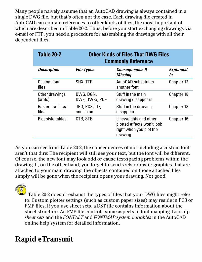
ManypeoplenaivelyassumethatanAutoCADdrawingisalwayscontainedinasingleDWGfile,butthat’softennotthecase.EachdrawingfilecreatedinAutoCADcancontainreferencestootherkindsoffiles,themostimportantofwhicharedescribedinTable20-2.Thus,beforeyoustartexchangingdrawingsviae-mailorFTP,youneedaprocedureforassemblingthedrawingswithalltheirdependentfiles.
AsyoucanseefromTable20-2,theconsequencesofnotincludingacustomfontaren’tthatdire:Therecipientwillstillseeyourtext,butthefontwillbedifferent.Ofcourse,thenewfontmaylookoddorcausetext-spacingproblemswithinthedrawing.If,ontheotherhand,youforgettosendxrefsorrastergraphicsthatareattachedtoyourmaindrawing,theobjectscontainedonthoseattachedfilessimplywillbegonewhentherecipientopensyourdrawing.Notgood!
Table20-2doesn’texhaustthetypesoffilesthatyourDWGfilesmightreferto.Customplottersettings(suchascustompapersizes)mayresideinPC3orPMPfiles.Ifyouusesheetsets,aDSTfilecontainsinformationaboutthesheetstructure.AnFMPfilecontrolssomeaspectsoffontmapping.LookupsheetsetsandtheFONTALTandFONTMAPsystemvariablesintheAutoCADonlinehelpsystemfordetailedinformation.
RapideTransmit

Fortunately,AutoCAD’sETRANSMITcommandpullstogetherallthefilesthatyourmainDWGfiledependson.FollowthesestepstoassembleadrawingwithallitsdependentfilesbyusingETRANSMIT:
1.OpenthedrawingthatyouwanttorunETRANSMITon.Ifthedrawingisalreadyopen,saveit.ETRANSMITpromptsyoutosavebeforeyouproceed;it’snotessentialtodothis,butit’susuallyagoodidea.
2.ClicktheApplicationbuttonandchoosePublish,theneTransmitfromtheApplicationMenu.TheCreateTransmittaldialogboxappears,asshowninFigure20-1.
Figure20-1:RapideTransmit.
3.OntheFilesTreeorFilesTabletab,removethecheckmarknexttoanyfilethatyouwantETRANSMITnottocopywiththemaindrawing.

Unlessyouhaveassignedcustomfontmapping,youcanomittheAcad.fmpfile.(Ifyou’reanAutoCADLTuser,theequivalentfileisnamedAcadlt.fmp.)
4.Selectatransmittalsetupfromthelist.
TransmittalsetupscontainsettingsthatcontrolhowETRANSMITprocessesthedrawingsandcreatesthetransmittalpackage.ClicktheTransmittalSetupsbuttontocreatenewormodifyexistingsetups.ThedefaultStandardtransmittalsetupworksfineformanypurposes,exceptthatyouprobablywanttoturnontheIncludeFontssetting,asdescribedinthenextparagraph.Inanycase,youshouldviewthesettings(clicktheModifybutton)justtoseewhatoptionsyoucanchangeifyouneedtolater.
IfyouwantAutoCADtoincludeSHXandTTFfontfiles,includinganycustomfontsthatyou’reusing,youmustturnontheIncludeFontssettinginthetransmittalsetup.(ClickTransmittalSetups,clickModify,andchecktheIncludeFontscheckbox.)Note,however,thatmanySHXandTTFfilesarecustomfonts,whichworklikelicensedsoftware:SendingthemtoothersisjustlikesharingyourAutoCADprogramDVDwithothers.No,Idon’tmeanthatit’seasyandfun;Imeanthatit’sillegalandunethical.Beforeyousendacustomfontfiletosomeoneelse,findoutthelicensingrestrictionsonthefontandworkwithinthem.
5.ClicktheViewReportbutton.YouseeareportlistingthefilesthatETRANSMITwillcopy,alongwithwarningsaboutanyfilesthatitcan’tlocate.
6.ReviewthereportandmakesurethatETRANSMITwasabletofindallthefiles.7.ClickOK.ETRANSMITdisplaysafiledialogboxsothatyoucanspecifythenameandlocationofthetransmittalpackage.
8.ClickSave.ETRANSMITcreatesthetransmittalpackage(whichisaZipfilebydefault).Zippingcreatesasingle,tidypackageofallyourDWG,DGN,DWF,PDF,rasterimage,plotstyletable,andfontfiles.
FTPforyouandme

FTP,orFileTransferProtocol,isasimple-but-robustprotocolforcopyingfilesovertheInternet.Acomputerthat’sconnectedtotheInternetcanactasanFTPserver,whichmeansthatpartofitsharddiskisaccessibleovertheInternet.ThepersonwhoconfigurestheFTPservercanplacerestrictionssothatonlypeoplewhoenteraparticularlogonnameandpasswordcanseeanddownloadfiles.FTPovercomesthefilesizelimitationsthatoftenoccurwithe-mail.
BecauseofalltheseFTPbenefits,it’sincreasinglycommonforpeopleatlargercompaniestoplacedrawingfilesontheircompany’sFTPsiteandtellyoutogogetthem.Thisapproachrelievesthemofhavingtoe-mailyouthefiles,andrelievesyouofwaitingforthat10MBe-maildownloadwhenyouleastexpectedit.
Inmostcases,thepersonmakingthefilesavailabletoyouviaFTPwillsendyouaUniformResourceLocator(URL)thatlookslikeaWeb-pageaddress,exceptthatitstartswithftp://insteadofhttp://.IfyouopenyourWebbrowserandentertheFTPURLintotheaddressfield,thebrowserconnectstotheFTPsite,asksyouforalocationandnametouseforthefilewhenitgetscopiedtoyoursystem,andbeginsdownloadingthefile.IftheFTPsiteusespasswordprotection,you’llhavetoenteralogonnameandpasswordfirst.
IfyouwantfancierFTPdownloadoptions,youcanuseanFTPutilitysuchasFileZilla(http://filezilla-project.org).
Badreception?Othersectionsinthischapterfocusonsendingfilestoothers.Whathappenswhenyou’reonthereceivingend?NoteveryonewillbeasconscientiousasyouareaboutfollowingtheGoldenRuleofDrawingExchange.You’llreceivedrawingswithmissingdependentfilesandnoinformationorsupportfilesforplotting.
Whenyoureceiveane-mailmessageorFTPdownloadthatcontainsdrawings(zipped,Ihope!),copythefiletoanewfolderonyourharddiskoranetworkdiskandunzipthefiles.
Checkatleastafewofthedrawingsinthepackagetomakesurethatallthexrefsandotherreferencefiles,fonts,andrasterimagefileswereincluded.Youcanperformthischeckbyopeningeachmaindrawinginthatfolder.Afteryouopeneachfile,presstheF2keytoviewtheAutoCADtextwindowandlookformissingfontandxreferrormessagesofthefollowingsort:
Substituting[simplex.shx]for[helv.shx].

ResolveXref“GRID”:C:\Here\There\Nowhere\grid.dwg
Can’tfindC:\Here\There\Nowhere\grid.dwg
ASubstituting...messageindicatesthatAutoCADcouldn’tfindafontandissubstitutingadifferentfontforit.ACan’tfind...messageindicatesthatAutoCADcouldn’tlocateanxref.Anymissingrasterfilesappearasrectangularboxeswiththenamesoftheimagefilesinsidetherectangles.MissingDWFsappearasanerrormessageattheinsertionpoint.Alternatively,youcanopentheExternalReferencespalette,whichrevealsanymissingreferencedfiles.(SeeChapter18fordetails.)
Writedowneachmissingfileandthentellthesendertogetontheball(inaniceway,ofcourse)andsendyouthemissingpieces.Whileyou’reatit,tellthatpersontobuythisbookandreadthischapter!Orbuyitforthemyourself!
IfyoureceivedrawingswithcustomTrueTypefontfiles(fileswhoseextensionsareTTF),youmustinstallthosefilesinWindows(notAutoCAD)beforeWindowsandAutoCADwillrecognizethem.RefertoyourWindowsversion’sonlinehelpforinstructionsoninstallingfonts.
HelpfromtheReferenceManagerInChapter18,IwarnyouaboutthecomplicationsofxrefpathsandthepotentialperilsofAutoCADnotbeingabletolocatexrefsifyoumoveprojectfoldersaroundortransferdrawingstoorfromsomeoneelse.AsimilardangerexistsforrasterimagefilesandDWF/DWFx,DGN,andPDFunderlays(Chapter18)andforfontfiles(Chapter13).TheETRANSMITcommand,describedinthesection“RapideTransmit,”earlierinthischapter,doesagoodjobofgatheringdependentreferencefiles,rasterfiles,andfontfiles,butitcan’tgatherwhatAutoCADcan’tlocate.
AutoCAD’sReferenceManagerutility(notincludedwithAutoCADLT)isareallifesaverifyoufindyourselfsufferingfromfile-pathperils—whethertheyoccurinyourowncompanyorwhensendingfilestoorreceivingthemfromothers.
ReferenceManagerisaseparateprogram,notacommandinsideAutoCAD.FollowthesestepstolaunchtheutilityfromyourWindowsdesktop:
1.ChooseStart⇒AllPrograms⇒Autodesk⇒AutoCAD2012⇒ReferenceManager.TheReferenceManagerprogramopens,asshowninFigure20-2.

Figure20-2:TheReferenceManager.
2.ClicktheAddDrawingsbuttontoaddoneormoreDWGfilestotheDrawingspaneontheleft.Navigatetothefolderthatcontainsthedrawingsyouwanttosend,selectthem,andclickOpen.
3.IntheReferenceManager–AddXrefsdialogbox,chooseAddAllXrefsAutomaticallyRegardlessofNestingLevel.TheReferenceManagerprocessesthedrawingsanddisplaysallreferencedobjectsinitsrightpane.
4.ClickExportReporttocreateatextreportlistingallthedependentfilesandtheirpaths,orclickEditSelectedPathstomodifypathsofselectedreferencefiles.5.Ifyoudochoosetomodifyanyselectedpaths,clickApplyChanges.Whenyou’refinishedexportingreportsandrepathingreferencefiles(orjustcheckingoutthisprogramyoumayneversuspectedyouhad),closetheReferenceManagerwindow.ClicktheHelpbuttoninReferenceManagertofindoutmoreabouttheutility’scapabilities.
IfyoualwayskeepparentandchildDWGfilesinthesamefolder—thesimplestapproachtodealingwithxrefpaths—youprobablywon’tneedtousetheReferenceManager.
DesignWebFormat—NotJustfortheWeb

Earlierinthischapter,Iexplainhowyoucanexchangedrawingsviae-mailandFTP.That’salltheInternetconnectivitythatmanyAutoCADusersneed,butifyou’recuriousaboutconnectingdrawingstotheWeborsharingdrawingswithpeoplewhodon’thaveAutoCAD,thissectionisforyou.
TheAutoCADWebfeaturesarebuiltonthreepiecesoftechnology:
Aspecial“lightweight”drawingformatcalledDWFthatAutodeskoriginallydevelopedespeciallyforputtingdrawingsontheWeb.
Anupdated,XML-compliantversionoftheDWFformatcalledDWFxthatcanbeviewedusingtheMicrosoftXPSViewerthat’sbuiltintoWindowsVistaandWindows7oravailableasaplug-inforWindowsXP.
AfreeprogramfromAutodeskcalledAutodeskDesignReview2012thatenablesanyonetoview,markup,andprintDWFfileswithouthavingAutoCAD.
AllaboutDWFandDWFxTheAutoCADDWGformatworkswellforstoringdrawinginformationonlocalandnetworkdisks,butthehighprecisionandlargenumberofobjectpropertiesthatAutoCADusesmakeforcomparativelylargefiles.
ToovercomethissizeproblemandencouragepeopletopublishdrawingsontheWeb,AutodeskdevelopedanalternativelightweightvectorformatforrepresentingAutoCADdrawings:DWF(DesignWebFormat).ADWFfileisamorecompactrepresentationofaDWGfile.DWFuseslessspace—andlesstransfertimeovertheWebande-mail—becauseit’slesspreciseanddoesn’thavealltheinformationthat’sintheDWGfile.
DWFxisaversionofregularDWFthat’scompliantwithMicrosoft’sXMLPaperSpecification(orXPSforshort—hadyourfillofalphabetsoupyet?).EverythingaboutDWFinthischapteralsoappliestoDWFx.TheDWFFORMATcommanddetermineswhetherthePUBLISH,3DDWF,andEXPORTcommandsoutputtoDWForDWFx.Ifthissoundslikesomethingthatmightbeimportantinyourwork,lookupDWFFORMATintheonlinehelpsystem.WindowsVistaandWindows7includeanXPSViewer,andthelongandtheshortofthisfeatureisthatdrawingsplottedtoDWFxcanbeviewedautomaticallyintheseWindowsversionswithoutAutoCADoranyspecialviewingsoftware.

YoucancreateDWForDWFxfilesfromyourdrawingsandsendthosefilestopeoplewhodon’thaveAutoCAD.YourrecipientscanviewandplottheDWFfilesaftertheydownloadthefreeAutodeskDesignReview2012program,whichisavailableonAutodesk’sWebsite,www.autodesk.com.
DWFsandDWFxscanbeusedjustlikeexternalreferences.Here’sonemorefiletype—andonemorereason—touseReferenceManagerorETRANSMITtopackageupyourdrawingsbeforeyousendthemout.FormoreonDWF/DWFxunderlays,seeChapter18.
ePlot,notreplotADWFfilecapturesasingle,plottedviewofyourdrawing,so,unlikeaDWGfile,itcanprovideaclear-cutsnapshotofwhatyouwanttoseeonpaper.WithaDWGfile,ontheotherhand,youhavetoprovidelotsofinformationtootherpeople—drawingview,scale,plotstylesettings,andsoon—inorderforthemtogetthesameplottingresultsthatyoudid.
PotentialePlottingscenariosincludethefollowing:
ArchitectsandotherconsultantsonabuildingprojectperiodicallyuploadDWFfilestotheprojectWebsite.ArchitectsandengineerswithsomeminimalCADknowledgecanreviewthedrawingson-screenandcreatetheirownhard-copyplots,ifnecessary.Principalsandclientswhodon’twantanythingtodowithCAD,orevenwithcomputers,canhavetheiremployeescreatehard-copyplotsforthemtoexamine.
WhenInternet-savvypeopleneedhard-copyprintsofyourdrawings,youe-mailazippedfilecontainingDWFfiles,alongwiththeURLforAutodeskDesignReviewandsimpleinstructionsforcreatingplotsfromtheDWFfiles.(Bereadytowalkthemthroughtheprocessbyphonethefirsttimeortwotoreduceanxietyoneveryone’spart.)
ACADplottingservicebureauencouragesitscustomerstosendDWFfilesinsteadofDWGfilesforplotting.TheDWFfilesaremuchsmallerandrequirelessinterventiononthepartoftheservicebureau’semployees.
AutodeskhopestoestablishePlotandtheDWF/DWFxformatasastandardforCADdocumentssimilartowhatAdobe’sPDFhasbecomeforwordprocessingdocuments.ItremainstobeseenwhetherePlottingwillbecomea

popularwaytogeneratehard-copyoutput(althoughDWFxwillcertainlypushitthatway).Inparticular,manypeopleoutsideCAD-usingcompaniesdon’thaveaccesstolarge-formatplotters.They’relimitedto8-1/2x11-inch—or,atbest,11x17-inch—reduced-sizecheckplots.Consequently,manypeoplewon’tbeabletoplotyourDWFfilestoscaleandmaynotevenbeabletoplotthemlargeenoughtoreadeverything.
Don’tbeafraidtotryePlottingwithcolleaguesinsideoroutsideyourcompany,butdon’tbecometoodependentonituntilyouseewhethertherestoftheCADworldsharesyourenthusiasm.Otherwiseyouriskbecomingtheonlyonewho’swillingtouseyourDWFfilesforplotting—inwhichcase,thenextversionofthefeaturewillbecalledmePlot.
MakingDWFswithePlotAsIdescribeintheprecedingsection,AutoCADtreatsDWFfileslikeelectronicplots,orePlots.YoucreateaDWFfilefromthecurrentdrawingjustasifyouwereplottingittoapieceofpaper,asIdescribeinChapter16.Theonlydifferenceisthat,inthePlotdialogbox’sPrinter/Plotterarea,youchooseoneoftwoplotterconfigurations:DWF6ePlot.pc3orDWFxePlot(XPSCompatible).pc3,asshowninFigure20-3.Whenyoudoso,AutoCADautomaticallyturnsonthePlottoFilesetting.Then,whenyouclickOKtogeneratetheePlot,AutoCADdisplaysadialogboxinwhichyouspecifyafilenameandlocationfortheDWFfilethatgetscreated.ThelocationcanbeafolderonaharddriveoraWebserver.

Figure20-3:“Lookma,nopaper!”PlottingtoaDWFfile.
WhenyoumakeDWFswithePlot,payparticularattentiontotheScalesettinginthePlotScalearea.Ifyou’recreatingaDWFsimplyforviewinginabrowser,youcanselecttheFittoPapercheckboxratherthanworryaboutaspecificplotscale.IfyouwanttoenableotherstoplotyourDWFfiletoscale(asdescribedearlierinthischapter),chooseanappropriateplotscalefactor(Chapter16describeshow).
MakingDWFs(orplots)withPUBLISHTheePlotmethodofcreatingDWFfilesdescribedintheprevioussectionworksfineforsingledrawings.ButifyouwanttocreateDWFfilesforalotofdrawingsorplotabunchofdrawingsthegoodold-fashionedway(onpaper,thatis),youcanusethePublishdialogbox,asshowninFigure20-4,tospeedtheprocess.
YouaccessPUBLISHfromtheAutoCAD2012ApplicationMenu—clickthe

Applicationbutton,choosePrint(notPublish!),andthenchooseBatchPlot.PDFisalsoaPUBLISHoutputoption,andpracticallyeverythingIdescribehereappliestobothDWFandPDF.
Figure20-4:Hotoffthepresses:AutoCAD’sPublishdialogbox.
AlthoughthePublishdialogboxiswiredtosupportDWF,DWFx,andPDFaswellasregular(paper)plotting,fornow,morepeoplearelikelytouseitforpaperplotting.(Analternativeuseiscreatingplotfilestosendtoaplottingservicebureau.)Butifyoudodecidetogointolarge-scaleDWFpublishing,includingmultisheetDWForPDFfiles,usethePublishdialogbox,asshowninthefollowingsteps:
1.ClicktheApplicationbutton,choosePrint,andthenBatchPlot.ThePublishdialogboxappears(refertoFigure20-4).Thedialogboxlistsalltabs(modelandpaperspacelayouts)ofallcurrentlyopendrawingsforplotting.ThePublishdialogboxreferstoeachtabasasheet.
2.Clickthebuttonsabovethesheetlisttopreviewanysheet,addsheets

fromotherdrawings,removesheetsfromtheto-be-plottedlist,orrearrangetheplottingorder.Withtheadditionalbuttons,youcansaveandrecalllistsofsheets.SeeStep4formoreinformation.
3.Afteryouselectthesheetsthatyouwanttoplot,specifywhetheryouwanttoplotthemtoanactualplotterorplot(PLT)fileortoaDWF/DWFxorPDFfile.YoucanselectaspecificplotterconfigurationforeachsheetbychoosingaPageSetupintheSheetList.SeeChapter16formoreinformationaboutpagesetups.
4.ClickthePublishOptionsbuttontodisplayadialogboxcontainingadditionalsettings.Mostoftheseoptionsareofconcernonlyifyou’recreatingDWF/DWFxorPDFfiles.TheoneexceptionisDefaultOutputDirectory,whichalsoappliestocreatingplot(PLT)files.
5.Ifyouanticipatehavingtopublishthesamegroupofdrawingsagain,clicktheSaveSheetListbuttontosavethecurrentdrawingsandsettingslist.6.ClickthePublishbuttontostarttheprocess.
Don’tconfusethePUBLISHcommandwiththelittle-usedPUBLISHTOWEBcommand.(Don’tworryaboutstartingitaccidentally;unlessyou’reworkingintheAutoCADClassicworkspace,youhavetotypethewholecommandnametostartthiscommand.)ThePUBLISHcommandcreatessetsofDWF,DWFx,orPDFfiles,plotfiles,oractualplots.ThePUBLISHTOWEBWizardcreatesaWebpagecontainingimagesofyourdrawings.Theresultsofthiswizardwon’tputanyWebdesignersorprogrammersoutofwork,butyoucanuseittocreateprimitiveWebpagepaste-upsofyourdrawings.(SeePUBLISHTOWEBcommandintheAutoCADonlinehelpsystemifyou’dliketogiveitawhirl.)
HyperobjectsNoWebfileformatwouldbecompletewithouthyperlinks,andDWFhasthose,too.YoucanattachahyperlinktoanydrawingobjectinAutoCAD,notjusttoatextstring.Asyoupassthecrosshairsoveranobjectwithahyperlink,thecursorchangesfromtheordinarypointertoaglobeandtwolinksofachain(asin“WorldWideWeb”and“link,”not“world-widechaingang”).Right-clicktheobjectandselecttheHyperlinkoptionfromthemenu,whichopensyourbrowserandnavigatestotheURLthat’sattachedtotheobject.IfyoucreateaDWFfilethat

includesobjectswithhyperlinks,AutodeskDesignReview2012displaysthemintheDWFfilesothatyoucanclicktonavigatetothem.
Hyperlinksonobjectsareaclevertrick,butthey’reoflimitedpracticalvalueinmostDWGandDWFfiles:
Thedrawingimagesaresosmallthatit’sdifficulttodistinguishthehyperlinkononeobjectfromthehyperlinkonanotherobject.
Mostpeoplearen’tusedtoassociatinghyperlinkswithindividuallinesandotherobjects.Theinterfaceislikelytoleavethemperplexed.
Ifyou’dliketoexperimentwithhyperlinksonobjects,lookupHYPERLINKcommand,aboutintheonlinehelpsystem.
AutodeskDesignReview2012AfteryoucreateDWFfiles,whetherwithePlotorPUBLISH,youortherecipientofyourDWFfilescanuseAutodeskDesignReviewtoviewandprintthem.(AutodeskDesignReview2012,thecurrentrelease,isafreeviewerfromAutodesk.)IfyousendDWFstopeoplewithoutAutoCAD,theycandownloadDesignReview2012fromAutodesk’sWebpage,www.autodesk.com.
WhenyouinstallAutoCAD2012,thesetupprogram,bydefault,installsAutodeskDesignReview2012,aswell.FromyourWindowsdesktop,chooseStart⇒AllPrograms⇒Autodesk⇒AutodeskDesignReview2012—orsimplydouble-clickaDWFfileinWindowsExplorertolaunchtheviewer.
TheDrawingProtectionRacketWhetheryou’resendingDWGorDWFfiles,youmaybeconcernedabouttheirmisuse(thatis,bythewrongpeopleorforthewrongpurposes);abuse(forexample,modificationwithoutyourconsent);orreuse(onotherprojectsorbyotherpeoplewithoutduecompensationtoyou).AutoCADhastwofeaturesforsecuringyourdrawingswhenyousendthemtoothers:
Passwordprotection:EnablesyoutolockaDWGorDWFfilesothatonlythosewhotypethepasswordthatyou’vespecifiedcanopen,insert,orxrefit(AutoCADLTuserscan’tapplyapassword,buttheycanopenpassword-protectedfiles.Iftheyknowthepassword,ofcourse!).

Addpasswordprotectiontodrawingsonlywhenyoureallyneedit:
•Ifyouforgetthepassword,you’llnolongerbeabletoopenthedrawing.NeitherAutoCADnorAutodeskhasanymagicalwaytoextractthepasswordorunlockthedrawing.
•Afteryoupassword-protectadrawing,otherscan’tinsertthedrawingasablockorattachitasanxref.
Ifyou’reusingapassword,youprobablyshoulddoitonacopyofthedrawingthatyousend;keepanunprotectedversionforyourself.
Digitalsignature:Ahigh-techwaytoaddanelectronicmarkertoaDWGfilethatverifiesthatsomeoneapprovedthedrawing.Youmustfirstgetanaccountwithadigital-certificateprovider,whoservestoauthenticateyouandyourcomputer.Ofcourse,forthisfeaturetobeuseful,youneedtosenddrawingstosomeonewhowantstoreceivedigitallyauthenticateddrawingsfromyou(orviceversa)andwhohasthetechnologicalsavvytodealwithdigitalcertificates.Formoreinformation,seedigitalsignatures,aboutintheAutoCADonlinehelpsystem.
Toactivateeitheroftheseoptionsforthecurrentdrawing,opentheApplicationMenuandchooseSaveAs,andthenchooseAutoCADDrawingtodisplaytheSaveDrawingAsdialogbox;thenchooseTools⇒SecurityOptionstodisplaytheSecurityOptionsdialogboxbeforeyousavethefile.IfyouwanttoaddadigitalsignatureandyouhaveadigitalIDfromacertificateprovider,enteryourinformationontheDigitalSignaturetaboftheSecurityOptionsdialogbox.Ifyouwanttoaddapasswordtothecurrentdrawing,justtypeitinthetextfieldonthePasswordtaboftheSecurityOptionsdialogbox.
Afteryoupassword-protectandsaveaDWGfile,anyonewhotriestoopen,insert,orxrefitwillseeadialogboxsimilartotheoneshowninFigure20-5.
Topassword-protectaDWFfile,usethePUBLISHcommandandclickthePublishOptionsbuttoninthePublishdialogbox.IntheDWFDataOptionssection,clickDisabledandchooseSpecifyPassword,thentypeyoursecretwordintothePasswordfield.
Althoughelectronicsecurityfeaturessuchastheonesdescribedinthissectioncanbeusefulaspartofastrategytoprotectyourworkfrommisuse,they’renotasubstituteforcommunicatingclearly—preferablyintheformof

writtencontracts—whatconstitutesappropriateuseofdrawingsthatyousendtoorreceivefromothers.
Figure20-5:Password,please.

PartV
Ona3DSpree
Inthispart...Yourworldisn’tflat,andyourdrawingsdon’tneedtobeeither!It’sbeennothingbutXsandYsupuntilnow,butthere’sawholenewaxisoutthere,andyou’reabouttoshinnyup(ordown)itinthischapter.Inthechaptersinthispartofthebook,youdiscoverhowyourAutoCADdesignscanescapetheboundsoftheX,Y

planeandgainsomeheightaswellaslengthandbreadth.YougiveyourdesignssomevolumebyspecifyingZ-coordinatesalongwithX-andY-values.YoucandosomerapidvisualizationbychangingtooneofAutoCAD2012’spredefinedvisualstyles.
Youcanplantyourdesignsinreallocations,too,andrendertheminawaybasedonthatlocationaswellasontimeofyearandhourofday.Allinall,AutoCADhastakendraftingalongwayfromthedrawingboard!


Chapter21
It’sa3DWorldAfterAll
InThisChapterUnderstandingthebasicsof3Dmodeling
Accessingthemodelingtools
Specifyingcoordinatesin3D
Managingusercoordinatesystems
Changingthecurrentworkingplane
Navigatinginthreedimensions

Applyingvisualstyles
Theadditionofathirdcoordinate—theZ-coordinate—releasesyourdesignworkinAutoCADfromtheplanarworldoftwodimensionsintoamuchmorelifelikethree-dimensionalspace.AutoCAD’s3DcapabilitieshavegrownbyleapsandboundssinceAutoCAD2007appearedwithasouped-up3Dengine.Notonlyhaveitsmodelcreationandeditingtoolsadvanced;AutoCADisnowadabhandatvisualizationandrendering.Youcanviewyour3Dmodelsfromanyangle,orslicethroughthemtoseewhattheylooklikeinside.Andfinally,sincetheworldoftechnicaldrawingisstillatwo-dimensionalone,youcanuseAutoCAD’sviewingoptionstocreate2Dviewsfrom3Dmodels.
Ifyou’reanAutoCADLTuser,you’regoingtohavetositoutmostofthisandthenexttwochapters.OneofthemajorareaswhereAutoCADLTdiffersfromregularAutoCADisinitsextremelylimited3Dfunctionality.Evenviewing3DmodelsismuchmoredifficultinAutoCADLTthanitneedbe.LTuserscanacquirenearlyallthe3DviewingcapabilitiesofthefullversionofAutoCAD,butyouneedaseparate—andfree—programtodoso.Justgotowww.autodesk.com/trueviewanddownloadDWGTrueview.
ThischaptertakesalookatsomeofthetoolsavailableinAutoCAD2012’s3DModelingworkspaceandintroducesyoutomanyofthegeneralconceptsofcreating3Dobjects.Youalsodiscoverhowtolookatyourmodelfromdifferentviewpoints,andhowtochangethewayitappearson-screen.
3Dmodelingandvisualizationisalotmoredemandingoncomputerhardwarethan2Ddraftingis.3Dmodelstendtobebiggerthan2Ddrawings,soyoumayneedmorediskspace.Andyou’llcertainlybehappierwithmorethanthebareminimumofRAMrequiredfor2DinAutoCAD.InChapter2,IlistAutoCAD2012’ssystemrequirementsandpointouttheincreasedresourcesneededfor3Dwork.
Understanding3DDigitalModelsTherearethreebasictypesof3Dcomputermodel:
Wireframemodels:Consistofedgesandverticesonly.Althoughtheydo

occupy3Dspace,they’retotallyunrealisticanddifficulttoreadcorrectly.AutoCADdoesn’tcreatewireframemodels,althoughyoucanviewthemassuch.
Surfacemodels:Consistofinfinitelythinskinsthatstretchfromedgetoedgeofamodel.AutoCADcancreatetwodifferenttypesofsurfaces:Meshsurfaces,composedofthousandsandthousandsof3-or4-sidedfaces,andNURBSsurfaces(Non-UniformRationalB-Splines,ifyoumustknow).Meshsurfacestendtobealittleimprecise;they’remostoftenusedfor3Danimationorterrainmodeling.NURBSsurfacesarefarmoreprecise(asyou’dexpectwithanamelikethat!)andarefrequentlyusedinproductdesign.Duetospacelimitations,Idon’tcovereithertypeofsurfacemodelinginAutoCAD2012ForDummies.
Solidmodels:Haveedges,surfacesandmass.Solidmodelsarethemostcomplextype(althoughprecisesurfacemodelscanbemoredifficulttoconstruct).Solidmodelscanbeassignedphysicalmaterialpropertiessuchassteeloraluminum,andsomass,centersofrotation,etccanbecalculatedbythecomputeranddisplayedvisually.
Whilesurfaceandsolidmodelsarecreatedandmodifieddifferently,the3Dobjectsthatmakeupthemodelsaremadeupofthesamesubobjects.Thesubobjectsthata3Dobjectismadeupofare
Vertex:The3DequivalentofanAutoCADpointobject.VerticesaredefinedbyasingleX,Y,Zcoordinate,canexistanywherein3Dspaceandarelocatedwheretheedgesofa3Dobjectmeet.
Edge:Theboundaryofaface,asdefinedbytwoX,Y,Zcoordinates,oneateachvertex.
Face:Thesurfaceareaboundedbythreeormoreedges.
Figure21-1showsasimple3Dobject—asix-sidedcubicshapecreatedwithAutoCAD’sBOXcommand—anditssubobjects.

Figure21-1:Subobjectsofa3Dobject.
ToolsoftheTradeAutoCADincludesaplethoraoftoolsforcreating,editing,viewing,andvisualizing3Dmodels.Youcanfindthemostcommonlyusedtoolsfor3Dmodelingonthe3DModelingworkspace’sRibbon.
AutoCAD2012comeswithtwo3Dworkspaces:3DModelingand3DBasics.Isupposetheideaisthatifyou’renewto3D,yougetyourfeetwetwiththe3DBasicsworkspaceandthengraduatetothe3DModelingworkspaceafteryou’vegainedsomeexperience.Personally,Ithinkthe3DBasicsworkspaceisawasteoftime;mypreferenceistohavethewholeenchiladaavailablefromtheget-go.Forthisbook,Iwillbeworkingexclusivelywiththe3DModelingworkspace.
AutoCAD’s3Denvironmentisalotlikeits2Dversion,buttherearesomeimportantdifferences.Youshouldbeawareofthefollowingprogramsettingsandelements:
HardwareAcceleration:Graphicsfunctionssuchaschangingvisualstylesandrunning3DOrbitcanbeprocessedonthemainCPU,or,ifhardwareaccelerationisenabled,onthegraphicscarditself.Turningonhardwareacceleration(whichIcoverinthenextsection)nearlyalways

improves3Dperformance.
Workspaces:AutoCAD2012comeswithtwo3Dworkspaces;Ihighlyrecommendyouusethe3DModelingworkspace(IintroduceworkspacesinChapter2).Formoreaboutthetoolsinthe3DModelingworkspace,see“EnteringtheThirdDimension”laterinthischapter.
DrawingWindow:Thedrawingwindow’sbackground,crosshairs,anddynamictooltipcolorschangewhenyouswitchbetween2Dand3Dviews,andin3Dviews,whenyouswitchbetweenparallelandperspectiveprojection.ClickOptionsontheApplicationMenu,selecttheDisplaytab,andthenclicktheColorsbuttontoaccesscolorsettingsforthedifferentinterfaceelements.NotethatI’vetweakedthebackgroundcolorsonmysystemsothey’reclearerontheprintedpage.Unlessyou’vemadechangesalready,you’llbelookingataverydarkgraybackground,ratherthanthelightgrayoneinthischapter’sfigures.
UCSIcon:Whenworkingin3D,theUCSiconshowstheorientationofthecurrentXYplaneandthedirectionoftheZ-axis.ForinformationonusingtheUCSicon,see“ChangingPlanes”laterinthischapter.
PriortoAutoCAD2012,theUCSiconmerelyshowedyoutheorientationoftheX-,Y-,andZ-axes.IfyouusedtheUCScommandtosetanewUCS,theiconreorienteditselfaccordingly.InAutoCAD2012,thenew,selectableUCSiconisinthedriver’sseat—youcandirectlymanipulatetheicontochangetheUCS.IintroduceyoutothenewUCSiconinthe“ChangingPlanes”sectionlaterinthechapter.
WarpspeedaheadWhenyoustartAutoCADforthefirsttimeafterinstallingit,theprogramassessesyourcomputer’sgraphicscard,and—ifit’suptothetask—enableshardwareacceleration.Withhardwareacceleration,youcanchangetheviewofyourmodel—evenmodelswithlightingandappliedmaterials—inrealtime,withoutanydeteriorationinquality.Hardwareaccelerationalsobooststheoverallvisualqualityofdrawingobjects,aswellasregenerationperformance.
Autodesktestsawiderangeofcardsanddriverswitheachnewrelease.TofindoutwhetheryourgraphicscardissupportedforAutoCAD,checkoutthegraphicshardwarelistonlineat(www.autodesk.com/autocad-graphicscard).

EnteringthethirddimensionIfyou’renewtothe3Dgame,andyou’vebeenworkingin2Dupuntilnow,thereareacoupleofthingsyouneedtodobeforeyoucanstartanew3DmodelinAutoCAD.Youhavetochangetheworkspace,andthenyouhavetoopenanewfileusinga3Dtemplate.Thefollowingstepsexplainhow:
1.OpentheWorkspacesdrop-downlistontheQuickAccessToolbar,orclicktheWorkspaceSwitchingbuttononthestatusbar,andchoose3DModeling.Toolbars,palettes,andRibbonpanelsflashonandoff,andsoonAutoCADsettlesdowntodisplaytheRibbon,asconfiguredforthe3DModelingworkspacewithafewadditionalpanels.
2.ClicktheApplicationbuttonandchooseNew,thenclickDrawing.TheSelectTemplatedialogboxappears.
3.Chooseacad3d.dwtifyou’reworkinginimperialunitsoracadiso3d.dwtifyou’reworkinginmetric.ClickOpen.A3Dmodelingspaceappears(seeFigure21-2)where,insteadoflookingstraightdownatthedrawingarea,youlookatitatananglefromabove.
4.Toswitchfrom3Dtothe2Dworld,simplyreversethestepsjustgiven.

Figure21-2:AscendingtheZ-axis.
UntyingtheRibbonandopeningsomepalettesMostofAutoCAD’s3DmodelingtoolscanbeaccessedfromtheRibbonand3D-relatedpalettes.ThefollowinglistintroducesyoutotheRibbontabsandpalettesavailableinthe3DModelingworkspace(notethatnotallitemsinthislistarevisibleinFigure21-2):
Hometab:Containsasubsetofthemostfrequentlyused3Dtoolsforcreatingandeditingsolids,surfaces,andmeshesaswellasusercoordinatesystemcommandoptions,viewtools,2Ddrawingandeditingcommands,andlayerandgrouptools.
Solidtab:Containstoolsforcreatingandmodifying3Dsolids.IshowyousomeofthefinerpointsofsolidmodelinginChapter22.
Surfacetab:Containstoolsusedtocreate,edit,andanalyzeNURBSsurfaces.
Meshtab:Containstoolsusedtocreateandmodifymeshes,convertthem

tosolids,andgeneratelivesections.
Rendertab:Containstoolstoaddlightingandmaterialstoa3Dmodel,andgeneraterenderedoutput.Chapter23presentsthebasicsofrenderinginAutoCAD2012.
Viewtab:Containstoolstonavigate,visualizeandchangethecurrentviewandUCSofa3Dmodel.Icovernavigationtools,coordinatesystems,andvisualstylesinthischapter.
Outputtab:Containstoolstooutputa3DmodeltoaDWForPDFfileorevengeneratea3Dprint.Icoverplotting2DdrawingsinChapter16,andoutputting3Ddesignstopaperisnotsignificantlydifferent—Ireferyoutotheonlinehelpforspecifics.(Idon’tcoverexportingto3DDWFor3Dprintinginthisbook.)
Plug-instab:ContainstheInventorFusionpanelwiththesingleEditinFusionbutton.InventorFusionisafreestanding3Dmodelingapplicationinstalled(optionally)withAutoCAD2012.TheInventorFusionplug-inletsyouselect3DobjectsfromyourAutoCADdrawing,edittheminFusion,andthenreturntoAutoCADwhenyou’redone.
MaterialsBrowserpalette:Usedtoapplymaterialstotheobjectsinthecurrentmodel,andtomanagematerialsinsavedmateriallibraries.
MaterialsEditorpalette:Usedtoapply,create,andmodifymaterialsinthecurrentmodel.Chapter23introducesyoutomaterials.
AdvancedRenderSettingspalette:Usedtomanagerenderingpresets.
VisualStylesManagerpalette:Usedtocreate,modify,andmanagevisualstylesinthecurrentmodel.
LightsinModelpalette:Usedtomanagelightsinthecurrentmodel.
SunPropertiespalette:UsedtospecifythelightingsettingsfortheSunlightsysteminthecurrentmodel.
ModelingfromAboveSofarinthisbook,you’vebeenworkingwithX-andY-coordinatesonly.X-andY-coordinatesbythemselvesdefineatwo-dimensionalplaneknown(logicallyenough)astheX,Yplane.

Inthisandthefollowingtwochapters,yousupplyathirdvalue,aZ-coordinate,inordertolocategeometryaboveorbelowtheX,Yplane.YouusethesamemethodstospecifyCartesian(X,Y,Z)coordinatesastheonesIsetoutinChapter7—youjustaddacommaandanothernumber.Thefollowingtechniquescanbeusedtospecifypointsin3D:
Coordinateanddirectdistanceentry
Pointfilters
Objectsnaps
3Dobjectsnaps
Object-snaptracking
Using3DcoordinateinputIintroduceyouto2DcoordinateentryinChapter7.Torecap,theinputformatsare:
AbsoluteCartesiancoordinates:ExpressedasX,Y—thedistancesalongtheX-andY-axesfromtheorigin(0,0).
RelativeCartesiancoordinates:Expressedas@X,Y—thedistancesparalleltotheX-andY-axesfromlastpoint.
Relativepolarcoordinates:Expressedas@d<a—thedistanceandangleintheX,Yplanefromthelastpoint.
Whileyoucanusethese2Dcoordinateinputmethodsin3D,youusuallyhavetogiveAutoCADjustalittlemoreinformationwhenyouwanttoworkinthreedimensions.YoucanuseabsoluteorrelativeCartesiancoordinatesbysimplyaddingaZ-coordinatetotheend.Inaddition,therearetwo3D-onlycoordinateformats,bothbasedon2Dpolarcoordinates.Youcanenter3Dcoordinatesusingthefollowingmethods:
AbsoluteCartesiancoordinates:ExpressedasX,Y,Z.Workingwithabsolutecoordinatesin3Dshouldlookfamiliarbecausetheinputislikeworkingin2D,exceptyouaddaZ-coordinateattheend.
RelativeCartesiancoordinates:Expressedas@X,Y,Z.Relativecoordinatesin3Dworkjustliketheydoin2D,exceptyouaddtheZ-coordinate.

Cylindricalcoordinates:Expressedas@d<a,z.Cylindricalcoordinatesaresimilartorelativepolarcoordinates(disthedistanceandatheanglefromthelastpointintheX,Yplane)withtheadditionofaCartesianZ-coordinatetolocatethepointaboveorbelowtheX,Yplane.
Sphericalcoordinates:Expressedas@d<a1<a2.Sphericalcoordinatesarealsobasedonrelativepolarcoordinates,butinsteadofaZ-coordinatetospecifyalocationaboveorbelowtheX,Yplane,youspecifyananglefromtheX,Yplane.
UsingpointfiltersCoordinateentryasdescribedintheprevioussectionisfineifyoualreadyknowthecoordinatevaluesordistancesin3Dspacewhereyouwanttolocateyourpoints.Often,however,youmayneedtoderive3Dpointsfromexistinggeometrywithoutknowingthoseexactvalues.Usingpointfilters,youcanlocatenewpointsbasedonexistingpoints.Youcanusepointfilterstoconstruct2Dand3Dcoordinates.
WhenAutoCADpromptsyoutospecifyapoint,youcaneitherenterpointfiltervaluesatthecommandline,orbringuptheright-clickmenuandchooseafilteroptionfromthePointFilterssubmenu.Afterselectingapointfilteroption,specifyapointtofilteroutpartofthecoordinatevalueandthenentertherequestedvalue.Forexample,usethe.XYfiltertoenteryourownZ-coordinatevalueafterspecifyingapointonthecurrentworkingplane.
ObjectsnapsandobjectsnaptrackingObjectsnapsallowyoutoaccuratelyspecifypointsonexistingobjectsina
3Dmodel.Youcanuseobjectsnapssuchasendpoints,midpoints,andcenteron3Dobjects,butAutoCADalsoprovidesasetofobjectsnapsspecificto3Dmodeling.
3Dobjectsnapsallowyoutospecifypointson3Dobjectsthatregularobjectsnapswon’trecognize—forexample,thecenterofaface,oravertex.Youenable3Dobjectsnapsbyclickingthe3DObjectSnapbuttononthestatusbar.Right-clickthe3DObjectSnapbuttonandchoosetherunning3Dobject-snapmodesyouwanttouse.
Objectsnaptrackingallowsyoutocalculatepointsthatarenotonanobjectbyusingobjectsnappointsonexistingobjects.Whenworkingin3D,youcannot

onlytrackpointsonthecurrentX,YplanebutalsoalongtheZ-axis.WhiletrackingpointsalongtheZ-axis,AutoCADprovidesfeedbackintheformofatooltipthatletsyouknowyouaremovingalongtheZ-axisinthepositiveornegativedirection.
TheELEVATIONsystemvariableallowsyoutospecifyaheightaboveorbelowthecurrentworkingplane.Whenyouentera2Dcoordinate,AutoCADusesthevalueassignedtoELEVATIONsystemvariable(bydefault,it’s0)tocreatea3Dcoordinate.YoucansettheOSNAPZsystemvariableto1,tosubstitutetheZ-coordinatevalueofapointspecifiedusinganobjectsnapwiththevalueofELEVATION.
ChangingPlanesComeflywithmewhileIexplainchangingplanesinAutoCAD.(JuststepthroughthismetaldetectoroverherewhileIx-rayyourbags.)
Okay,it’snotthatkindofplane.Thissectioncoversusingtheusercoordinatesystem(UCS)tocontrolthecurrentworking(orX,Y)plane.TheUCSicondisplayedeitheratthelower-leftcornerofthedrawingwindoworattheorigin(0,0,0)showsyoutheorientationofthecurrentworkplaneandthepositivedirectionoftheZ-axis.
DisplayingtheUCSiconBydefault,theUCSiconisdisplayedinboth2Dand3Dviews.Youcanloseyourbearingsprettyeasilywhenworkingin3D,andIstronglyrecommendyoukeeptheUCSiconinyoursightsatalltimes.Ifyoudon’tseeaUCSicon,youcanturnitonfromtheCoordinatespaneloftheViewtab.Clickthebuttonwiththeburned-outlightbulbandchooseeitherShowUCSIconorShowUCSIconatOrigin.
InadditiontocontrollingthedisplayoftheUCSicon,youcanalsotweakitssize,color,andlocationusingtheUCSIcondialogbox.TodisplaytheUCSIcondialogbox,chooseUCSIcon,PropertiesontheCoordinatespaneloftheHometab.
InpreviousreleasestheUCSiconwasmerelyagraphicindicatorofthe

currentcoordinatesystem.Ifyousetanewusercoordinatesysteminmodelspace,theUCSiconadjusteditselftoshowyoutheorientationofthenewX,YplaneandZ-axis.Inotherwords,theUCSiconwasdrivenbythecurrentcoordinatesystem.InAutoCAD2012,theUCSiconmovesacrosstothedriver’sseat!YoucannowselecttheUCSiconandseenewmulti-functiongripsthatallowyoutosetanewUCSbydraggingthegripsontheoriginandthelegsoftheicon.There’salsoanewright-clickmenu.YoucanenableordisableUCSiconselectabilityontheSettingstaboftheUCSdialogbox—typeUCSMANtoopenit.Inthenextsection,IshowyouhowtocreateanewusercoordinatesystembyselectingandmanipulatingtheUCSicon.
AdjustingtheUCSEverydrawingyoucreateutilizestheworldcoordinatesystem(WCS),butwhenworkingin3Dyouneedtocreateadditionalworkplanes.Usercoordinatesystems(UCSs)arehelpfulwhenyouneedtodrawobjectsonworkplanesotherthantheWCS.TraditionalUCSsarestatic;createoneanditstayscurrentuntilyouchangeittoadifferentone.Bydefault,suchcoordinatesystemsareunnamed,butyoucanassignanameandsaveitforfutureuse.Acoupleofreleasesback,AutoCADintroduceddynamicUCSs.Sincedynamicistheoppositeofstatic,whatyougetisatemporarycoordinatesystemthatchangesasyoumoveyourmousepointeroverdifferentplanarfacesofa3Dobject.UsethestatusbarAllow/DisallowDynamicUCSbuttononthestatusbar,orpresstheF6functionkeytotoggledynamicUCSonandoff.
NamethatUCS
TheUCScommandofferstenoptionstohelpyoudefineanewUCS.AccesstheUCScommandoptionsfromtheCoordinatespanelsoneithertheVieworHometaboftheRibbon.
ThemostcommonlyusedoptionsoftheUCScommandarelistedbelow.AfteryouselectoneoftheseoptionsfromtheRibbon,followthecommandpromptsatthecommandlineortheDynamicInputprompt.
World:AligntheUCStomatchtheworldcoordinatesystem(WCS).
Face:AligntheUCStothefaceofa3Dsolid.
View:AligntheUCSsotheX,Yplaneisperpendiculartoyourcurrentviewingdirection.

3Point:SpecifyaneworiginfortheUCS,andthenthepositivedirectionoftheX-andY-axes.Alternatively,usethemulti-functiongripsonAutoCAD2012’sUCSicontocreateanewUCSbymovingandrealigningtheicon.
FormoreinformationonalltheUCScommand’soptions,refertoAutoCAD’sonlinehelpsystem.
ThemoreUCSsinyourdrawing,themoreyouneedhelpmanagingthem.AutoCADoffersahandydandyUCSdialogboxfordoingjustthat.Openitbyclickingthedialogboxlauncher(thelittlearrowattherightendofthepanellabel)ontheCoordinatespaneloftheVieworHometab,orsimplytypeUCSMANandpressEnter.TherearethreetabsintheUCSdialogbox:
NamedUCSs:ListsWorldandotherusercoordinatesystems.SetaUCScurrentwiththeSetCurrentbutton,orright-clickaUCStorenameordeleteanamedUCS.(Youcan’trenameordeletetheWorldUCS.)
OrthographicUCSs:Liststhesixdefaultorthographiccoordinatesystems(frontandback,leftandright,topandbottom)relativetotheWCS.TheseUCSsareautomaticallycreatedbyAutoCADandcan’tbedeletedorrenamed.
Settings:ControlspropertiesofboththeUCSiconandtheUCSitself.
AfteryoudefineaUCSyouthinkyoumightwanttouseagain,youcansaveitintheUCSdialogbox.Iexplainhowinthefollowingsteps,whichyoubeginbycreatingasolidbox.
1.Startanew3Ddrawingselectingacad3d.dwt(oracadiso3d.dwtforthemetriccrowd)foryourtemplate,andensurethe3DModelingworkspaceiscurrent.Refertothestepsinthe“Enteringthethirddimension”sectionearlierinthechapterifyouneedarefresher.
2.OntheModelingpaneloftheHometab,clickBox.AutoCADprompts:
Specifyfirstcorneror[Center]:3.Type0,0,0andpressEnter.AutoCADanchorsthefirstcorneroftheboxattheoriginoftheWCSandprompts:
Specifyothercorneror[Cube/Length]:4.Dragyourcrosshairsawayfromthefirstcornerandclickapointtoset

thelengthandwidthofthebox.Exactdistancesdon’tmatterinthisexample.And,hey!Ifyou’reworkinginmetric,youcandragandclicktosetanewcornertoo!AutoCADprompts:
Specifyheightor[2Point]:5.Dragthecrosshairsupwardfromthesecondcornerandclicktosettheheightofthebox.AutoCADcreatesthe3Dboxandexitsthecommand.Preliminariesareover—nowit’stimetostartmakingsomeUCSs!
6.MovethecrosshairsovertheUCSicon.TheUCSiconcurrentlyshowstheorientationoftheWorldCoordinateSystem.Asyoumovethecrosshairsovertheicon,itturnsagreenish-goldcolor,indicatingthatitcanbeselected.
7.ClicktoselecttheUCSicon.Asquaremulti-functiongripappearsattheorigin,androundmulti-functiongripsappearattheendsoftheicon’slegs.
8.Movethecrosshairsovereachmulti-functiongripandlookatthegripmenus.Hoveringoveroneoftheroundgripsattheendofalegletsyouchoosebetweenrealigningtheselectedaxis,orrotatingtheUCSaroundoneoftheunselectedaxes.HoveringthemousepointerovertheorigingripletsyoumovetheUCSorigintoanewlocationandeitherwhilekeepthecurrentalignmentoftheX-andY-axesorrealignthem.Thethirdgripoption,World,restorestheWCS.NowyouusetheUCSicon’smulti-functiongripstosetanewUCS.
9.ClicktheUCSicontoselectit,thenmovethecrosshairsoverthesquaremulti-functiongripattheorigin.Thecrosshairsjumptotheoriginandthegripmenuappears.
10.Fromthegripmenu,chooseMoveandAlign.AutoCADprompts:
**MOVEANDALIGN**Specifyoriginpointoraligntoface,surface,ormesh:
Movethecrosshairstoadifferentcornerofthebox,andwhentheUCSiconoriginisoverthecorner,clicktosettheneworigin.Ifyouwish,youcandragtheroundgripsontheaxestorealignthenewUCS.Onceyou’vegotitthewayyouwant,it’sworthsavingit.Thenextstepsshowhow.
11.OntheCoordinatespaneloftheHometab,chooseUCS,NamedUCS.AutoCADdisplaystheUCSdialogbox.

12.WiththeNamedUCSstabcurrent,selectUnnamedintheUCSslist.Thenew,unnamedUCSisthecurrentUCSinthedrawingandislistedatthetopofthelist.
13.Right-clickUnnamedandselectRenamefromtheshortcutmenu.Anin-placeeditorisdisplayedthatallowsyoutorenametheUCS.
14.TypeanameforthenewUCSpressEnter.TheUnnamedUCSisrenamed(seeFigure21-3).
15.ClickOK.TheUCSdialogboxclosesandthenewUCSissavedinthedrawing.
Figure21-3:NamingacustomUCS.
16.OntheCoordinatespaneloftheHometab,chooseUCS,World.ThecurrentUCSisnowalignedwiththeWCS.
17.OntheCoordinatespaneloftheHometab,clickintheNamedUCSdrop-downlistandchoosethenameoftheUCSyoujustsaved.ThenewUCSisrestored.

AutoCADlikesgivingyoulotsofchoices.YoucanalsorestoreanamedUCSarefromtheUCSdrop-downlistatthebottomoftheViewCube.(IfillyouinontheViewCubeinthe“Takingaspinaroundthecube”sectionlaterinthischapter.)Oryoucanright-clicktheUCSicon,chooseNamedUCS,andthenselecttheUCSfromthemenu.
UsingDynamicUCS
AnamedUCSallowsyoutoworkondifferentworkplanes,butitcantakeabitofefforttosetupandthatcandistractyouwhenyou’refocusedon3Dmodeling.WithDynamicUCS,youcanfocusonmodeling,notoncreatingaUCS.ToenableordisablethedynamicUCSfeature,clicktheDynamicUCSbuttononthestatusbar.
Figure21-4showsanexampleofdrawingacircleonthesideofa3Dsolid.WithDynamicUCSenabled,AutoCADhighlightsthefaceofthe3DsolidthattheUCSwillbealignedwith.ClickoverthefacetoaligntheUCSwiththeface,andthenfinishthecommand.Thecircleisalignedwiththefaceofthe3DsolidandthepreviousUCSisthenrestored.

Figure21-4:DynamicallycreateaUCSon3Dsolids.
Navigatingthe3DWatersIfyou’rebrandnewto3DinAutoCAD,youmaybewonderinghowtolookatwhateveritisyou’remodelingfromwhateverangleyoudesire.
OnewaytochangeviewpointsthatworksinbothAutoCADandAutoCADLTistousethepresetviewsfromtheRibbonbyselectingtheViewtab,thenclickingthedownarrowonthe3DPresetViewsdrop-downmenuontheViewspanel(showninFigure21-5)toswitchtooneofthestandardorthographic3Dviewsoranisometricview.
Thesixstandardorthographic(straight-on)viewsareTop,Bottom,Left,

Right,Front,Back.
ThefourstandardisometricviewsareSW(left-front),SE(right-front),NE(right-back),andNW(left-back).(Anisometricviewisoneinwhichyouseetheobjectfromabove—orbelow,butAutoCAD’sstandardviewsdon’tdobelow.)
Anisometricviewisanunrealistic3Dviewsincealllinesthatareparallelinrealityarealsoparallelintheview.Inaperspectiveview,linesthatareparallelinrealityappeartomeetatavanishingpoint,asparallellinesappeartodoinreality(thinkofrailroadtracksheadingacrosstheprairie).TheisometricviewsImentionedpreviouslyareparallelprojectionviews,andyoucanview3DmodelsusingthoseviewsineitherthefullversionofAutoCADorAutoCADLT.

Figure21-5:3DPresetViewsdrop-downmenu.
ThiswarningisforAutoCADLTusers(usersofthefullversionofAutoCADdon’tneedtoworry).AsI’vealreadypointedout,AutoCADLTcanopendrawingscreatedinthefullversion.ThoseAutoCADdrawingscanbesavedwithperspectiveprojectioncurrent,andifyouopensuchadrawinginAutoCADLT,youcanseeitinperspective.YoucanswitchfromperspectivetoparallelprojectionbychangingthePERSPECTIVEsystemvariable’svaluefrom1to0.Beverycarefulifyoudothis,becauseyoucan’tchangeitbackagain!YoucoulduseUNDOtoreversethechange,butifyousaveandclose

thedrawing,you’resunk.
Thesixorthographicandfourisometricviewsworkwellforshowing3Dmodelsofcommonobjectssuchasmechanicalcomponentsandbuildings.(Youcanalsochangetoplanview,whichisatop-downviewofeithertheworldcoordinatesystemorausercoordinatesystem.)
AutoCADLThaslimited3Dviewingcapabilities.ThesamepresetviewsareinbothAutoCADandAutoCADLT,andthere’salsoaViewpointPresetsdialogbox(DDVPOINTcommand)inwhichyousetaviewingpositionbyspecifyinganglesinandfromtheXYplane.Finally,there’sthereallyuglycommand-lineonlyVPOINTcommand(Man,thatone’ssoooouglyit’snotevenontheRibbon!).
Orbitàgo-go
Presetviewsarefineformany3Dmodelingtasks,butifyoureallywanttohavefun,3DOrbit(notinAutoCADLT)isyourtickettoit.(Orbitinga3DmodelinAutoCADissimilarinconcepttoorbitingaroundtheEarthinasatellite—onlyalotcheaper.)Therearetwoorbitermodes:ConstrainedandFree.ConstrainedmodeisprettymuchliketheFreemodewithtrainingwheels.
FreeOrbitdisplaysanarcballonthescreen—acirclerepresentingaspherearoundyourobject.Youclickvariousplacesinside,outside,andonthearcballandthendragtochangethe3Dview.Theideaisthatyou’respinninganimaginaryspherecontainingyourmodel.Asyoudragthecursor,AutoCADupdatesthescreendynamically.
YoucanstartConstrainedorbiting,the3DOrbitcommand,byholdingtheSHIFTkeydownandthenholdingthemiddlemousebuttonwhiledraggingthemouse.
Youmightalsowanttoexperimentwithdifferentprojectionmodes:
ParallelprojectionisthedefaultAutoCADprojection—linesthatareparallelinthe3Dobjectremainparallelintheprojectedviewonthescreen.

Perspectiveprojectionmakesobjectslookmorerealistic(forexample,traintracksappeartoconvergeinthedistance),butlinesthatareparallelinthemodeldon’tappearparallelinperspectiveprojection.
Ifyoumanageto3DOrbitoutofcontrolandcannolongerseeyourmodel,right-clicktodisplaythe3DOrbitshortcutmenuandchooseZoomExtents.TheZoom,Pan,andPresetViewsoptionsofferotherwaysofgettingyourmodelbackinyoursights.
Whenyoustartorbitingwithnoobjectsselected,AutoCADtriestoupdatethedisplayofeverythinginyourmodel,andthiscantakesometime.Tospeedthingsuportosimplyregainyourbearings,tryselectingsomeobjectsbeforeyoustartorbiting.ThenAutoCADupdatesthedisplayoftheselectedobjectsonly.Whenyouexitorbitmode,theentiremodelredisplaysbasedonthenewviewpoint.
TakingaspinaroundthecubeWithsomuchtalkabouthybriddevicesthesedays,AutodeskdecidedtocreateitsownintheformoftheViewCube(notinAutoCADLT).TheViewCube(seeFigure21-6)isaninteractivetoolthatprovidesvisualfeedbackaboutthecurrentviewpoint,allowsyoutosetapresetviewcurrentororbitthemodel,restoreanamedUCS,anddefineandrestoretheHomeviewofamodel.

Figure21-6:ViewCube,themultifunctionalviewingdevice.
TochangetheviewofthemodelusingtheViewCubeyoucandooneofthefollowing:
Clickacorner,edge,orfacetoalignthecurrentviewwiththesameviewpointrepresentedontheViewCube.
ClickanddragthemainareaoftheViewCubetoorbittheviewofthemodel.
Clickoneoftherollarrowstorotatethecurrentview90degrees.
Clickoneoftheadjacentfacetrianglestoswitchtotheadjacentorthographicviewthatisindicatedbythetriangle.
Clickoneoftheletters(N,E,S,W),orclickanddragthecompasstorotatetheviewaroundthecenterofthedrawing.
TheHomeviewisaspecialviewthatyoucandefinesoyouhaveaknownreferenceviewinthemodel.Soifyouloseyourbearings,youalwayshaveawaytogetbackhome.YoucanrestoretheHomefromtheViewCubeortheSteeringWheels(seethenextsection)right-clickmenus.

GrabbingtheSteeringWheels
SteeringWheelsactasakindofnavigationhubthatallowsyoutoaccessseveraldifferent2Dand3Dnavigationtoolsfromasingleuserinterface.(AutoCADLTincludesonlythe2DNavigationwheel.)AutoCAD(thefullversion)comeswiththe2DNavigationwheelandthreeotherwheelsthataredesignedtobeusedwith3Dmodeling.Thethreeadditionalwheelsare
ViewObject:Containstoolstocenteramodelinthecurrentview,zoominandout,ororbitaroundamodel.
TourBuilding:Containstoolstomovetheviewpointforwardandbackward,lookaroundthemodelfromafixedlocation,andchangetheelevationofthecurrentviewpoint.
FullNavigation:Containsacombinationofthetoolsfoundonthe2DNavigation,ViewObject,andTourBuildingwheelswiththeadditionoftoolstowalkaroundorflythroughamodel.
AllwheelsincludeaRewindtoolwhichallowsyoutorestoreapreviousview.TheRewindtoolissimilartothePreviousoptionoftheZOOMcommand.
Whenawheelisactive,movethecursoroverthewedgethatcontainsthetoolyouwanttouse.Formanyofthetoolsyoueitherclickoverthetool,orclickanddragtousethetool.SometoolssupportalternateversionsofthemselveswhenyoupressandholdtheShiftkey.Togetanideaofwhateachtooldoes,hoverthecursoroverthetooltodisplayatooltipmessage.Tolearnmoreabouteachofthewheelsandthetoolsonthem,seeAutoCAD’sonlinehelp.Todisplaythehelpspecifictothewheels,right-clickwhenawheelisdisplayedandchooseHelpfromtheshortcutmenu.
Visualizing3DobjectsItreallydoesn’tseemlikethatlongagowhentheonlywayofviewing3Dmodelswaswireframemode.ButthelastseveralreleaseshavedramaticallyimprovedAutoCAD’svisualizationcapabilities.Therearealmostadozendifferentdisplaymodes—calledvisualstyles—thatyoucansetwiththeclickofadrop-downmenu.Figure21-7showsthedefaultvisualstyles—andyoucanaddyourownif

youwant—intheVisualStylesManagerpalette.
Gettingsome(visual)styleVisualstylesarecollectionsofsettingsthatbuildontheSHADEMODEsettingsfoundinearlierincarnationsofAutoCAD.AutoCAD2008introducedfivedefaultvisualstyles,andthatnumberdoubledwithAutoCAD2011toatotaloften:
Figure21-7:Somenewstylestotryon.
2DWireframe:AutoCAD’sclassic2Dviewingmode:fullwireframe,dot-basedgrid,the2DUCSicon,andnoperspective.
Conceptual:Anillustrativekindofshadedview.Colorsareunrealisticandedgesareheavy,butyougetagoodsenseofthemodel’sform.Figure21-3

showsanexampleoftheConceptualvisualstyle.
Hidden:Looksslightlylikeawireframeview(nosurfacesarevisible)butedgesbehindfacesarehidden.
Realistic:Fullyshaded,butnotrenderedvisualstyle;edgesarenotdisplayed,andadefaultambientlightinghighlightsthefaceswithdifferentintensitiesoftheobjectcolor.Materialsandtexturesarevisibleifthey’vebeenapplied.HavealookatFigure21-8foranexample.
Shaded:SimilartoRealistic,butwithmoresubduedlighting.Texturesdonotappearinthisvisualstyle.
ShadedwithEdges:SameastheShadedvisualstyle,exceptIsolinesaresettobedisplayed.
ShadesofGray:LikeShaded,onlyallobjectcolorsarechangedtodifferentintensitiesofgray.
Sketchy:Visualstylethatdoesnotapplyanyshadingtothefacesof3Dobjectsbutgivetheedgesof3Dobjectshandsketchlook.
Wireframe:Prettymuchthesameas2Dwireframe,exceptforbackgroundcolor,optionalperspective,andthe3Dratherthanthe2DUCSicon.Figure21-4showsasimplemodelinWireframevisualstyle.
X-ray:SimilartoShadedwithEdges,exceptMaterialsandTexturesareappliedliketheRealisticvisualstyleandfacesaresetto50%opacity.
AutoCAD2012’stenpreconfiguredvisualstylesareonlythebeginning.YoucanmodifyanyofthestylesorcreatenewonesintheVisualStylesManagerpalette(seeFigure21-8).

Figure21-8:Amanagerforyourvisualstyles.
TodisplaytheVisualStylesManager,clickthedialogboxlauncher(thelittlearrowattherightendofthepanellabel)ontheVisualStylespaneloftheViewtab,orsimplytypeVSMandpressEnter.

Chapter22
FromDrawings...toModels
InThisChapterEscapingfromtheXYplane
Understanding3Dprosandcons
Settingupa3Dworkingenvironment
Creating3Dsolidgeometry
Editing3Dmodels
Formillennia,peoplehavedocumentedthedesignandconstructionofthree-

dimensionalobjectsbydrawingtwo-dimensionalviewsofthem.Mostpeoplehavecontinuedtousethese“classical”methodswithCADdraftingbecausethemethodsarewellunderstoodandworkreasonablywell.Afterall,if2DdrawingwasgoodenoughforguyslikeLeonardodaVinciandAndreaPalladio,itshouldbegoodenoughforus,right?
Nonetheless,forthelastdecadeorso,there’sbeenatrendtowardcreating3DCADmodelsandlettingthesoftwaregeneratethe2Dviewsmore-or-lessautomatically.Thisapproachseemsmorelogical,especiallyiftheprojectdocumentationrequiresnumerous,complexviewsofthesameobject.3Dmodelingalsoisanabsolutenecessitywhenyouwanttocreaterenderedviewsforpresentationpurposes.
WhiletheAutoCAD’s3Dconstructionandvisualizationtoolshaveimproveddramaticallyovertheyears(trustme—youshouldhaveseenwhattheywerelikeasrecentlyasAutoCAD2006!),it’sstillacomplexprocessthatrequiressophisticationonthepartoftheAutoCADuser.Although3Dmodelingrequiresonlyonemoredimensionthan2Ddrafting,developing3DCADmodelsisconsiderablymorecomplicated.Usersmustmasternewtechniquesandcontendwiththe2Dlimitationsofmostdisplayscreensandinputdevices.
Inthepreviouschapter,Ishowedyouhowtomovearoundmodelsthatothershavemade,andexplainedtheprinciplesof3DcoordinatesystemsthatyouneedtounderstandtoworkinAutoCAD’s3Denvironment.Thischapterintroducesyoutotheconcepts,tools,andtechniquesofAutoCAD3Dmodelingitself;hereyoucangetyourfeetwetcreatingyourown3Dobjects.
Full3DsupportisoneofthemaindifferencesbetweenfullAutoCADandAutoCADLT.Ifyou’reusingAutoCADLT,youcanlookatandplot3DmodelscreatedinAutoCAD,butyoucan’tdomuch3Dobjectcreationoreditingyourself.Also,viewing3DmodelsislessflexibleinAutoCADLTbecauseitlacksnearlyallthe3DnavigationtoolsinthefullversionofAutoCAD.
Is3DforMe?Traditional2Ddrawingsprovidecluestohelptheviewer’smindconstructa3Dmodelfromthe2Dimageonpaper.Multipleviewsfromdifferentviewpointsin3Dspacegiveexperienceddesigners,drafters,andbuilderstheinformationtheyneedtomake3Dsenseof2Ddrawings.Designanddraftinghavesucceededprettywellbyusing2Drepresentationsastheguidetocreating3Dobjects.Butatsome

point,nothingcanreplaceatrue3Dmodel,suchasinhelpingsomeoneunderstandhowabuildingwilllookwhenconstructedorhowtwopartsfittogether.
Whatdoesusing3DinAutoCADmean?Fundamentally,itmeanscreatingmodelsinsteadofdrawings.Ratherthangeneratecrosssectionsofanobjectorindividualviewsofitfromcertainperspectives,youcreateathree-dimensionalmodeloftheobject.This3DdepictionofeachobjectincludesallthenecessaryinformationforAutoCADtocreateadrawingviewfromanypointofview.Withaproperlyconstructed3Dmodel,AutoCADcanoutputcommandstomachinestocreateactual3Dobjects,whetherplasticprototypescarvedfromatankofjellyby3Dprinters,oranactualbolt,valve,orpistoncreatedbycomputer-controlledmachinetools.
AsIexplaininChapter21,AutoCADcancreatethreetypesof3Dmodels:Wireframe,Surface,andSolid.Inmostpracticalapplicationsof3D,youselectoneofthesetypesforallormostoftheobjectsinthedrawing,basedoneaseofconstructionandintendeduseofthemodel.However,AutoCADdoesn’tpreventyoufrommixingallthreetypesof3Dobjectsinthesamedrawing.
Afteryoudeterminethetypeof3Drepresentationtouse,youdecideontheappropriatelevelofdetailandconstructthemodel,usingthecommandsandtechniquesintroducedinthischapter.Ifyouneedto,youcangoonfromtheretocreateanyrequired2Dand/orrenderedviewsforplottingorviewingon-screen.
GettingYour3DBearingsThefirstchallengein3Dmodelingisbeingabletoseeyourthree-dimensionalmodelonatwo-dimensionalcomputerscreen.ThenormalmodelspaceviewontheModeltabinthedrawingareashowsasingle,projected2Dviewofyourmodel—thetop-down,“plan”viewbydefault.
AutoCADprovidestwomodelspacecapabilitiesthatenableyoutoescapethisvisualflatland:
Withviewports,youcancarvethemodelspacedrawingareaintosmallerrectangularareas,eachofwhichshowsadifferentviewofthemodel.
Withviewpoints,youcanchangethepointin3Dspacefromwhichyoulookatthemodel.Bysettingadifferentviewpointineachviewport,youcanlookatseveralsidesofyourmodelatthesametime.It’slikelookingat

oneofPicasso’scubistpaintings,onlywhatyouseeismoreorderly.
Nomatterhowmuchorhowlittle3Dmodelingyou’rethinkingaboutdoing,it’swellworthyourwhiletosetupatemplate.(IfillyouinondrawingtemplatesinChapter4.)Ifyou’veeverstartedanewdrawing,you’reprobablyawarethatAutoCADalreadycomeswithatemplatefor3Dmodelingnamedacad3d.dwt(oracadiso3D.dwtforthemetricallyinclined).Thisisfineasfarasitgoes,butitonlyshowsyouasingleviewofyourmodel.Thenextsectionexplainshowtoimproveonthistemplate.
Creatingabetter3DtemplateModelspaceviewportsenableyoutoseeseveralviewsofyourmodelatonetime,eachfromadifferentviewpoint.Forthisreason,modelspaceviewportsareespeciallyusefulwhenyou’recreatingandeditingobjectsin3D.Asyoudrawandedit,thedifferentviewshelpensurethatyou’repickingpointsthatarelocatedcorrectlyin3Dspace.
Chapter5discussesviewportsinpaperspace,whichareusefulforcreatinglayoutsforuseinplotsandpresentationsinboth2Dand3D.Modelspaceviewports,cousinsofpaperviewports,arelessflexiblebutsimpler,andareagreathelpinconstructing3Dmodels.
Modelspaceviewportsdividethescreenintoseparaterectangleswithnogapsbetweenthem.Unlikewithpaperspaceviewports,youcan’tmove,stretch,oroverlapthem.Youcan’tplotmultiplemodelspaceviewports(that’swhatpaperspaceisfor).And,unlikethesituationinlayouts,alayerthat’svisibleinonemodelspaceviewportalwaysisvisibleinallofthem.
Youmayhearorreadreferencestotiledviewports,whichisjustanothernameformodelspaceviewports.Tiledreferstothewayinwhichmodelspaceviewportsalwaysfillthedrawingarea,withnogapsandnooverlappingallowed.Conversely,paperspaceviewportsaresometimescalledfloatingviewportsbecauseyoucanmovethemaround,leavegapsbetweenthem,andoverlapthem.
OneofthebestnewfeaturesinAutoCAD2012gobythesomewhatobscuretitleofin-canvasviewportcontrols.Thoselittletextlabelsthatyoumayhavenoticedatthetop-leftcornerofthegraphicsarea(refertoFigure22-1for

example)areclickablecontrolsthatletyousetthevisualstyleandtheview.What’sespeciallyniftyisthatdouble-clickingtheplusorminussigntogglesthedrawingareabetweenmultipletiledviewportsalreadyconfiguredfor3Dviewing,andasingle,maximizedviewport.Outofthebox,double-clickingtheminus(–)signswitchestofourequalsizedviewportsshowingdifferentviewsofthegeometry.Figure22-1illustrateswhatI’mtalkingabout:Inthisexample,youseefourviewports,fourdifferentviewpoints,andfourdifferentvisualstyles.That’sabitextremeforeverydaywork,butitgivesyouanideaofthepossibilities.
Figure22-1:3Dviewingfromeverywhichway.
Ihighlyrecommendworkingwithmultipleviewportswhenyou’remodelingin3D—thatwayyougettoseeexactlywhatyou’redoinginallthreedimensions,inrealtime.Myownpreferenceistoworkmostlyintheisometricviewport,soImakethatonelargerthantheotherthree.Thein-canvasviewporttogglewillswitchbackandforthbetweenthelastmultipleviewportyousetup,andamaximizedviewport.Inthefollowingsteps,Iexplainhowtosetupthetiled-viewportconfigurationyouseeinFigure22-3.
1.Ifyou’renotalreadyinthe3DModelingworkspace,clicktheWorkspace

drop-downlistintheQuickAccessToolbarandselect3DModeling.YoucanalsoclicktheWorkspaceSwitchingbuttononthestatusbarandagain,select3DModeling.IftheMaterialsBrowserpaletteopens,closeit.
2.ClickNewontheQuickAccessToolbartoopentheSelectTemplatedialogbox.Ifanewblankdrawingappearsandyoudon’tseetheSelectTemplatedialogbox,someonehasassignedadefaulttemplatetothisbuttonintheOptionsdialogbox.Inthatcase,clicktheApplicationbutton(theBigRedA)andchooseNew,thenchooseDrawingfromthesubmenu.
3.Chooseacad.dwt(chooseacadiso.dwtifmetricisyourpreference),andclickOpen.Yes,Iknowthereareready-made3Dtemplates(acad3d.dwtandacadiso3d.dwt),buttrustme—it’seasiertostartthissetupfroma2Dtemplate.
4.FromtheViewportspanelontheRibbon’sViewtab,chooseNamed.TheViewportsdialogboxappears.
5.ClicktheNewViewportstabtomakeitcurrent,thenchooseFour:Left(mypreference)orFour:RightfromtheStandardViewportslistbox.ThePreviewpanelshowsalarge,squarishviewportoccupyingmostoftheworkarea,withthreesmallsquarishviewportsstackedontheleft(orright).Thedefault2Dsetupshowsthevisualstyleofallfourviewportsas“2DWireframe.”(IexplainvisualstylesinChapter21.)
6.FromtheSetupdrop-downlist,choose3D.Thevisualstylesremainas2DWireframe,buttheviewdirection(listedas“Current”in2DSetup)isnowSEIsometricinthelargeviewport,whilethethreesmallviewportsshowTop,Front,andRightorthographicviews.
Whenmodelingin3D,it’snearlyalwayshelpfultolookatyourobjectsindifferentwaysatthesametime.Whenlookingatorthographicviews,sameaswithadrafteddrawing,youprobablywanttoseeallyourlinework.Butyoucangetabettersenseofthethree-dimensionalityofyourmodelbylookingatitinashadedview.Withmultipleviewports,youcandobothatthesametime.
7.InthePreviewarea,clickinsidethelargeSEIsometricviewport,thenchooseConceptualfromtheVisualStyledrop-down.You’realmostfinishedinhere.Ratherthangothroughthissetupeverytimeyouwanttodosomemodeling,giveyournewviewportconfigurationaname.
8.IntheNewNameboxatthetopoftheViewportsdialogbox,enteraname—V3D,forexample—fortheconfiguration.

Figure22-2showsthenew,namedviewportconfiguration.AfteryouclosetheViewportsdialogbox,youcanrestorethisconfigurationatanytimebyclickingtheNamedViewportstab,choosingV3D,andclickingOK.
Figure22-2:Settingupa3DworkenvironmentintheViewportsdialogbox.
9.ClickOKtosavetheviewportconfigurationandclosetheViewportsdialogbox.InFigure22-3,I’veturnedoffthegridinthethreesmallorthoviewports,butwhetheryouleaveitonorturnitoffisamatterofpersonalpreference.

Figure22-3:2Dand3Dallatthesametime.
TheViewCube’sHomebuttoncantripyouupbychangingtoaviewyoudon’texpect.(IintroducetheViewCubeinChapter21.)IfyouwanttokeepthecurrentSEIsometricviewpoint,besuretoresettheHomeview.Andbecauseyou’vegonetothetroubleofsettingupashaded3Dviewport,whynotmakeitalittlemorerealisticandturnonperspectivemodeatthesametime?
10.Inthelarge3Dviewport,right-clicktheViewCubetodisplayitsshortcutmenu,thenclickPerspectiveWithOrthoFaces(seeFigure22-4).SelectingPerspectiveshowsyourorthographicviewsinperspectivemode,andusuallyyoudon’twantthat.SelectingPerspectiveWithOrthoFacesresetstheprojectionmodefromperspectivetoparallelwhenyouswitchtoanorthographicview.

Figure22-4:ChangingsettingsintheViewCube’sright-clickmenu.
11.RepeatStep10,thistimeselectingSetCurrentViewAsHome.Nowyoucanreadilyreturntothisviewportconfiguration,keepingthesameviewpointinallviewports,perspectiveprojectioninthe3Dviewport,andparallelprojectionintheorthographicviewports.Toreturntoasingleviewportlater,simplyclicktheplus(+)signonthein-canvasviewportcontrol.Thelastthingtodoissavetheconfigurationyou’vejustsetupasatemplate(.dwt)file.
12.ClickSaveontheQuickAccessToolbar.OntheFilesOfTypedrop-downmenu,chooseAutoCADDrawingTemplate(*.dwt)andenterafilename.ClickSave.AutoCADsavesyournew3Dtemplatefileinthesameplaceasyourothertemplatessoit’salwaysthereforyoutoselectwhenyouwanttodosomeserious3Dmodeling.
SeeingtheworldfromnewviewpointsWhenyouchoose3DintheViewportsdialogbox’sSetupdrop-downlist,youdirectAutoCADtochangetheviewpointineachviewport.Thedefaultviewpointswhenyouchooseafourviewportarrangementaretop,front,right,andSE

(“southeast”)isometric.Theseviewpointsworkwellforviewingandconstructingsimplemodels,buteventually,you’llprobablywanttospecifyyourowncustomviewpointinaparticularviewport.
InbothAutoCADandAutoCADLT,thebest—butnottheeasiest—waytochangeviewpointsistousethedrop-downlistontheViewspaneloftheViewtab(asshowninFigure22-5)toswitchtooneofthestandardorthographic3Dviewsoranisometricview:
Thesixstandardorthographic(straight-on)viewsareTop,Bottom,Left,Right,Front,Back.
ThefourstandardisometricviewsareSW(left-front),SE(right-front),NE(right-back),andNW(left-back).Anisometricviewisoneinwhichyouseetheobjectfromabove,butnottoohighabove—asthoughyouwerehoveringinalow-flyinghelicopter.
Figure22-5:Thepresetviewsdrop-downmenu.
Theeasiest—butnotthebest—waytochangeviewpointsistoclickoneofthenamedfacesontheViewCube(notavailableinAutoCADLT).Idon’trecommendthisbecausetheViewCubeisaviewingaid,andnothingbut.You

usuallychangetoanorthographicviewbecauseyouwanttodosomedrawingormodelingthere,andforthat,yourUCS(usercoordinatesystem)oughttoorientitselfwiththeview(seeChapter21fortheskinnyonUCSs).ClickingFrontontheViewCubeshowsyouanicefrontviewofyourmodel,butitleavestheUCSunchanged,andthatcanmakedrawinganythingdifficult.ClickingFrontontheViewtab’sViewspaneldoeschangetheUCStoFrontsoitmatchestheviewandletsyoudrawwithoutdifficulty.
Thesetenviewsarecalled“standard”becausethey’reoftenusedinmanualdraftingandrenderingwork.Theyworkwellforshowing3Dmodelsofcommonobjectssuchasmechanicalcomponentsandbuildings.Youcanalsochangetoplanview,whichisatop-downviewofeithertheworldcoordinatesystemorausercoordinatesystem.(IdescribecoordinatesystemsinChapter21.)
ThefullversionofAutoCADhastheViewCube,the3DORBITcommand,andtheShift+Middlebuttonmethodofchanging3Dviewpoints(allaredescribedinChapter21).AutoCADLT’soptionsaremuchmorelimited.LTuserscansetnonstandardviewpointsbytypingDDVPOINTandpressingEnter.IntheViewpointPresetsdialogboxthatappears,specifythefollowingsettings:
AviewingangleintheXYplane(imaginemovingacameraonadollyaroundanobject,whilekeepingthecameraatthesameelevation)
AnanglefromtheXYplane(imagineusingaboomtoswoopthecamerauptoadifferentheightsothatyou’relookingattheobjectfromincreasinglysteepangles)
AutoCADuserscansetviewpointsthesameway,butit’sgrosslyinefficientcomparedtotheotherviewingoptions.
Bydefault,AutoCADshows3Dmodelsin2Dwireframemode,evenifyou’vecreatedsurfaceorsolidobjects.Ifyouwanttobettervisualizewhichobjectsareinfrontofwhichotherobjects,especiallyinanisometricorothernon-orthogonalview,youhaveacoupleofoptions:
SelectashadedvisualstylesuchasRealistic,Conceptual,X-Ray,orShadesofGray,fromtheVisualStylesdrop-downontheVisualStylespaneloftheViewtab.(SeeChapter21forthelow-downonvisualstyles.)
Renderthemodel,asdescribedinChapter23.

AutoCADLTdoesn’tincludevisualstyles,becausethey’renotmuchusein2Ddrafting.AdrawingsavedinavisualstyleinthefullversionofAutoCADdoesdisplaythatstylewhenit’sopenedinAutoCADLT—however,there’snowayofchangingitto2Dwireframe(oranythingelse)soyoucanactuallyworkonit.
FromDrawingtoModelingin3DThissectionintroducesthreetechniquesforcreating3Dobjects:drawing3Dlinesandpolylines,creating3Dobjectsfrom2Dgeometry,andcreatingsolids.(InAutoCADLTyoucanusethefirsttwotechniquesonly.)AutoCADisalsoverycapableatsurfacemodeling,offeringbothfreeformmeshandNURBSsurfaces.Ifyou’reinterestedineitherofthese,checkouttheonlinehelpsystem—navigatetoUser’sGuide,thenchooseWorkwith3DModels,andthenCreate3Dmodels.Topicsincludecreatingsurfacesandmeshesfromscratch,andcreatingsolidsandsurfacesfrom2Dobjects.
Whenyoudraw3Dobjects,justlikewhenyoudraw2Dobjects,putthemonappropriatelayersanduseprecisiontechniquestospecifyeachpointanddistance.(SeeChapter5formoreinformation.)
Drawingbasic3DobjectsThemostbasicformsof3Dgeometryarewireframe-likeobjectscreatedbypickingpointsorenteringX,Y,Zcoordinates.Suchobjectshavenosurfaces,solookthesamein2DWireframemodeoraphotorealisticrendering.Theyaremostusefulaspathsforsweepsandlofts,orasedgesforsurfacecreation.Suchobjectsinclude
Lines.Linesarereally2Dobjects;althoughyoucanspecifydifferentz-coordinatesforstart-andendpointssotheyarenotcoplanarwiththeworldcoordinatesystem,eachindividualsegmentisbasedonitsown2Dplane.Youcan,however,uselinesforconstructingobjectsin3Dspace.
3DPolylines.Createdwiththe3DPOLYcommand.Similartothe2DpolylinesIdescribeinChapter8,excepttheverticesof3Dpolylinescanhavedifferentz-coordinates(2Dpolylinesmustbeplanar).3Dpolylinesareusefulaspathsforsweepsorforfly-throughs(Idon’tcoverwalk-

throughsorfly-throughsinthisbook).
Splines.Splinesarefreeformcurves,createdwiththeSPLINEcommandandIdescribethemina2DcontextinChapter9.Splinesare3Dobjectsandverticescanhavedifferentz-values.Splinesareabetteroptionthan3Dpolylinesforsweepsbecausetheycanhavesmoothercurves.
Helixes.Helixescanbeeither2D(thinkofamosquitocoil,ortheelementonanelectricrange)or3D(thinkofMr.Slinky).Helixesareespeciallyusefulaspathsforthreadedobjects.
YoucanfindtheLINE,3DPOLY,andSPLINEcommandsontheDrawpaneloftheRibbon’sHometab;theHELIXcommandisonthatpanel’sslideout.
The3DPOLYcommandissimilartothePLINE(plainold2Dpolylines)command.Bothcommandsdrawaseriesofconnectedlinesegments,buttheyhavedifferentcapabilities:
The3DPOLYcommandaccepts3Dpointsforthelinesegments’vertices.ThePLINEcommandrequiresthatallverticesbeonthesameplane.
3DPOLYislimitedtostraightlinesegments.PLINEcandrawarcsegmentsandcreatesegmentswithuniformortaperedwidth.
Segmentscreatedwith3DPOLYcan’tdisplaydash-dotlinetypes;3Dpolylinesegmentsalwaysdisplayascontinuouslines.
Thecommandsequencefordrawing3DsegmentswiththeLINEor3DPOLYcommandisthesameasfordrawing2DsegmentswiththeLINEorPLINEcommand;seeChapter8ifyouneedarefresherondrawinglines.Theonlydifferenceisthatyouspecify3Dcoordinatesinsteadof2Dones.Figure22-6showsanexample.

Figure22-6:Entering3Dcoordinatestodrawa3Dpolyline.
Creating2Drepresentationsinthiswayisstraightforward,thoughtediousforallbutthesimplestobjects.Moreimportant,awireframemodelbecomesincreasinglydifficulttodecipherasthecomplexityofthemodelincreases.Youseeamassoflinesrepresentingtheedges,andyouhavedifficultytellingwhichpartsofwhichedgesareinfrontofothers.Toreducethisvisualconfusion,youneedtograduatetosurfaceorsolidmodelingcommands.Iintroduceyoutosolidmodelinginsubsequentsectionsofthischapter.
GainingasolidfoundationSolidmodelingisinmanywaystheculminationof3DCAD.Solidsmoreaccuratelyrepresentmostreal-worldobjectsthandowireframesorsurfaces.Andevenwhenrepresentationalaccuracyisn’tthemainissue,it’seasiertoconstructmanykindsofmodelswithsolids.
Manyspecial-purposesolidmodelingprogramsuseacombinationofsolidandsurfacemodelingtechniquesformaximumflexibilityinconstructingand

editing3Dmodels.Thesekindsofprograms—andsolidmodelingingeneral—arebecomingespeciallypopularinmechanicaldesign.
Constructingthebasicbuildingblocks—orsolidprimitives—forasolidmodelinAutoCADisn’tdifficult.Justfollowthesesteps:
1.DefineasuitableUCS(usercoordinatesystem).Seethe“ChangingPlanes”sectioninChapter21.TheUCScontrolstheconstructionplaneandbasic3Dorientationofthesolid.
2.ClicktheleftmostbuttonontheModelingpaneloftheHometab,andthenchooseasolidprimitivefromthelowerhalfofthesplitbutton.AsshowninFigure22-7,yourchoicesareBox,Cylinder,Cone,Sphere,Pyramid,Wedge,andTorus.
Whenyouseea3Dobjectinadrawing,youcan’ttellbylookingwhetherit’sa2Dextrudedobject,surfacemesh,orsolid.Ifyouwanttofindout,openthePropertiespaletteandselecttheobject.Thedrop-downlistatthetopofthepaletteshowsthetypeofobjectthatyouselected.


Figure22-7:Everythingyouneedforasolidfoundation.
DrawingsolidprimitivesSolidsaretheeasiestkindofobjecttoworkwithifyou’renewto3D.Therearetwotypesof3Dsolidobject:
Primitivesolids:Themostbasicof3Dbuildingblocks,suchasboxes,cones,andspheres.Primitivesolidsarebasedonsimplegeometricshapeslikelinesandcircles.
Complex(orcompound)solids:MadebycombiningprimitivesolidsandoptionallyeditingthemwithBooleanoperations.Thefollowingsectionsfocusoncreatingandmodifying3Dsolids.
Booleaneditingoperations(namedfortheVictorianEnglishmathematicianGeorgeBoole)usearithmetic-likefunctionstocombinesolidobjectsorremovepartsofthem.ThethreeprimaryBooleancommandsinAutoCADareUNION,SUBTRACT,andINTERSECT.See“Booleanoperations”laterinthischapterformoreinformation.
AddingtheThirdDimensionto2DObjectsAutoCAD’s2Drootsrundeep.Draftingcontinuestobetheprimaryfocusoftheprogram,butrecentAutoCADreleaseshaveshiftedfocus,andtheprogramhasbecomemoreandmoreadeptat3Dmodeling.Thissectioninvitesyoutotakewhatyouprobablyhaveanabundanceofrightnow(2Dobjects)andcreatenew3Dobjectsfromthem.
Creating3Dobjectsfrom2DdrawingsYoucancreate3Dobjectsfrom2Dobjectsbyusinganumberofdifferenttechniques.Youcanaddthicknessorextrudeanopen2Dobjecttocreateasurface,ortakemultiple2Dcrosssectionsandcreatealoftedobjectthatadaptstotheshapeandsizeofeachcrosssectionselected.EverythingmentionedhereappliestoAutoCADonly(notAutoCADLT),withtheexceptionofthethicknessproperty.

Addthicknesstoa2Dobject
Most2Dobjects,suchaslinesandcircles,haveathicknessproperty.Changinga2Dobject’sthicknesspropertydoesnotcreateatrue3Dobject,butitdoescreateapseudo-surfacethatlookslikea3Dsurface.Thesepseudo-surfacescanhideobjectsbeyondthem,buttheydohavelimitations.Ifyouaddthicknesstoacircle,anopencylinderiscreatedwithoutcapsonthetopandbottom.Youcanalsochangethethicknessofapolylinetocreateanopenboxthathasnotoporbottom.
Extrudeopenandclosedobjects
Thicknessisonewayofaddingheighttoanobject,butextrudinganobjectisusuallyabetterapproach.Youcanextrudeopenorclosed2Dobjectstocreatea3Dobject.Extrudingaclosed2Dobject,suchasapolyline,spline,ellipse,circle,orregion,createsa3Dsolid;extrudinganopen2Dobject,suchasapolyline,spline,line,orarc,createsasurface.Figure22-8showsresultsofextrudingopenandclosedobjects.
Toextrudeanopenorclosed2Dobject,clickExtrudeontheSolidpaneloftheSolidtab,orclicktheExtrudesplitbuttonontheHometab’sModelingpanel(ifyouseeabuttonlabeledLoft,Revolve,orSweep,clickthelowerpartofthesplitbuttonandchooseExtrudefromthedrop-downmenu).UsetheMOdeoptiontocontrolwhetheryoucreateasurfaceor3Dsolidfromaclosedobject,selecttheobjectsyouwanttoextrude,andspecifyanextrusionheightordistancetocreatethe3Dsolid.
TheDELOBJsystemvariablecontrolswhetherthe2Dobjectsyouusetocreate3Dsolidsisretainedorerased.Mostofthetime,youprobablywanttokeepthesourcegeometry,butthedefaultDELOBJsettingerasesit.Ifyouwanttokeeptheoriginal2Dgeometry,typeDELOBJandsetitsvalueto0.(SeeChapter26formoreaboutsystemvariables.)DELOBJalsocontrolswhetherornotthesourceobjectsforassociativearrays(introducedinChapter18)areretainedordeleted.

Figure22-8:2Dto3Dbyextrusioniseasyas1,2,3.
Pressandpullclosedboundaries
ThePRESSPULLcommandallowsyoutocreate3Dgeometrybyextrudingaclosedboundary.PRESSPULLdiffersfromEXTRUDEinthattheEXTRUDEcommandrequires2DgeometrywhilePRESSPULLcanuseclosedboundariesformedbyother3Dsolids.
Topressorpullwithinaclosedboundarytocreatea3Dobject,clickPresspullontheSolidtab’sSolidpanel,andthenclickasrequiredtospecifyaclosedboundary.Afteryou’veclickedinaclosedboundary,dragorspecifythedistanceontheextrusionyouwanttocreate.
Loftopenandclosedobjects
Loftingallowsyoutoselectaseriesof2Dcross-sectionstocreateasurfaceor3Dsolid.Theselectedcross-sectionsareusedtodefinetheoutersurfacethat’sgenerated.Youmustselectaminimumoftwocross-sections.Ifyouselectopen

objects,theresultingloftisasurface;ifyouselectclosedobjects,theresultingloftcanbeeitherasurfaceor3Dsolid,dependingonthecurrentvalueoftheMOdeoptionfortheLOFTcommand.
Youcanloftobjectsalongapathusingguidecurves,orjustbetweentheselectedcross-sections(seeFigure22-9).Toloftopenorclosed2Dobjects,opentheSweep/Loftdrop-downontheSolidtab’sSolidpanel.UsetheMOdeoptiontocontrolwhetheryoucreateasurfaceor3Dsolidfromaclosedobjectcross-sections,andspecifyhowtheloftobjectshouldbecalculated.
Figure22-9:Usingcross-sectionstocreatedaloftedobject
Sweepopenandclosedobjectsalongapath
Sweepingissimilartoextrudinga2Dobject,exceptyouspecifyapath,ratherthanaheightordistance.Theobjectusedasthepathcanbeeitheranopenorclosed2Dobject,andcanbeonlyasingleobject(seeFigure22-10).Ifyousweepanopenobject,theresultingsweptobjectisasurface;ifyousweepaclosedobject,theresultingsweptobjectisasurfaceor3DsolidbasedonthecurrentvalueoftheMOdeoptionoftheSWEEPcommand.
Tosweepanopenorclosed2Dobject,opentheSweep/Loftdrop-downontheSolidpaneloftheSolidtab.UsetheMOdeoptiontocontrolwhetheryoucreateasurfaceor3Dsolidfromaclosedobject,selecttheobjectstosweep,andspecifyapathforthesweep.

Figure22-10:Sweepingaclosedobjectalongapath.
Revolveopenorclosedobjectsaroundanaxis
Revolvingallowsyoutocreateasurfaceor3Dsolidbyturningselectedobjectsaroundanaxis(seeFigure22-11).Ifopenobjectsareselected,theresultingrevolvedobjectisasurface;ifyouselectclosedobjects,theresultingrevolvedobjectisa3Dsolid.
Torevolveanopenorclosed2Dobject,clickRevolveontheSolidpaneloftheSolidtab,orclicktheRevolvesplitbuttonontheHometab’sModelingpanel(ifyouseeabuttonlabeledLoft,Extrude,orSweep,clickthelowerpartofthesplitbuttonandchooseRevolvefromthedrop-down).UsetheMOdeoptiontocontrolwhetheryoucreateasurfaceor3Dsolidfromaclosedobject,selecttheobjectstorevolve,andspecifytheaxistouse.

Figure22-11:Revolvingaclosedobjectaroundanaxis.
Modifying3DObjectsManyofthemodificationtechniquesandcommandsthatyouusein2Ddraftingcanbeappliedto3Dmodeling.Inaddition,aspecializedsetof3Deditingcommandsisavailable.AllthesecommandsarelocatedontheModifypaneloftheHometabwhenthe3DModelingworkspaceiscurrent.
Selectingsubobjects3Dobjectsthemselvesarecomplexobjectsthatcanbemadeupofseveralhundred—eventhousandsof—objects.Althoughtheseobjectsneverstrayfromtheirparent,youcanaccessthemindividuallyoringroupsthroughsubobjectselection.Subobjectselectionmeansselectingavertex,edge,orfaceofa3Dobject.Afteryouselectasubobject,youcanusegripeditingandthe3Dgizmostomanipulateit.Idiscussthe3Dgizmosinthefollowingsection.
Tomakeiteasiertoselectsubobjects,youcanenablesubobjectfilteringfromtheRibbon.Vertex,edge,andfacefiltersarelocatedontheSubobjectSelectionFiltersplitbuttonontheSelectionpaneloftheHomeandSolidtabs.

TheCULLINGOBJandCULLINGOBJSELECTIONsystemvariableshelplimitobjectselectiontothefacesthatarevisibleinthecurrentviewbyignoringfacesaroundthebackoftheobjectsbeingviewed.Bydefault,bothofthesevariablesareturnedoff,soyoucanselectobjectsinfrontandbehind.Ifyouhaveacomplexmodel,turncullingon.Toturncullingon,clickCullingontheSelectionpaneloftheHometab.Toturnitoff,clicktheCullingbuttonagain.Thebuttonisshadedbluewhenthefeatureisenabled.
Ifyoujustneedtoselectafaceona3Dobject,pressandholdtheCtrlkeyandselectthefaceyouwanttoselect.Thiscanbefasterthanturningsubobjectfiltersonandoff.
WorkingwithgizmosAlthoughyoucanusetheMOVE,ROTATE,andSCALEcommandstomodify3Dobjects,theycansometimesgiveunexpectedresultsin3D.Enterthe3DMOVE,3DROTATE,and3DSCALEcommands,whichallutilizeagizmoorgriptoolwhenanon-orthographicviewiscurrent(seeFigure22-12).
Figure22-12:Usinggizmostomodifyobjectsin3D.
ThegizmosrestrictorconstrainmovementalongtheX,YplaneandtheZ-axis.Touseagizmo,clickoneoftheaxesonthetooltorestrictmovementtothataxis.Youcanaccessthethreegizmosbyusingthefollowingmethods:
3DMOVE:Click3DMoveontheHometab’sModifypanel,ortype3DMOVEatthecommandline.
3DROTATE:Click3DRotateontheModifypanel(Hometab),ortype3DROTATEatthecommandline.

3DSCALE:Click3DScaleontheModifypanel,ortype3DSCALEatthecommandline.
YoucanalsoaccesstheMove,Rotate,andScalegizmosin3Dbyselectingobjectswhennocommandisactive.Youcansetthedefaultgizmothatisdisplayedwhenyouusegripsin3DbyopeningtheGizmodrop-downintheHometab’sSelectionpanelandselectingthegizmoyouwanttobeactive.Right-clickingoveragizmoallowsyoutoswitchbetweendifferentgizmosandconstraints.
More3Dvariantsof2DcommandsMoving,rotating,andscalingobjectsarecertainlythebigthreeoperationsof3Dediting,butanumberofother3Dvariationson2Deditingcommandsarehidinginthewings,awaitingtheirturninthespotlight(formoreaboutspotlights,seeChapter23!).
Gettingyour3Dducksinarow
Gettingobjectstoalignwitheachotherin3Dcanbeachallengeattimes,especiallyifyouneedtonotonlymoveanobjectin3D,butalsorotateandscaleitbasedonthespecifiedalignment.AutoCADhastwocommandsthatcanbeusedtoalignobjects:
ALIGN:Usedtoalign2Dand3Dobjectsbasedonone,two,orthreepairsofpoints.Basedonthenumberofpairsofpointsspecifiedandhowthey’reselected,theALIGNcommandmightmoveandrotatetheselectedobjectsintoplace.Itcanalsobeusedtoscaleobjectsaswell.OntheHometab,chooseAlignfromtheModifypanelslideout.
3DALIGN:AnimprovedversionoftheALIGNcommandthatincludesadditionaloptions,aswellastheabilitytomoveandrotateacopyoftheselectedobjectsanduseDynamicUCSwiththecommand.Click3DAlignontheModifypaneloftheHometab.
Holdingupamirror
TheMIRRORcommandislimitedtoworkingontheX,Yplane.Ifyouwanttomirrorobjectsin3D,youneedtousetheMIRROR3Dcommand.Click3DMirrorontheModifypaneloftheHometab.TheMIRROR3Dcommandissimilartothe

MIRRORcommand,butyoucancontroltheplaneonwhichthemirroringisperformed.
Associativearrays,whichIdiscussinChapter18,workin3Daswellas2D.AutoCADhaslonghada3DARRAYcommand;it’sstillthere,andissimilartotheoldstyleARRAYcommand(refertoChapter10forthatone)inthatitdoesn’tcreateanassociativearrayobject.Forinformationoncreatingrectangular,polar,andpatharrayobjects,refertotheonlinehelp.
Editingsolids3Dsolidscanbeeditedinavarietyofdifferentwaysthatotherobjectscan’tbe.Youcanusegrip-editingtochangetheshapeof3Dsolids,orBooleanoperationsona3Dsolidtocreatecomplexmodels.Youcanfilletandchamfertheedgesofa3DsolidusingtheFILLETEDGEandCHAMFEREDGEcommands.
Usinggripstoeditsolids
Grip-editingisoneofthemostdirectwaystomodifyanobject.Toedita3Dsolidbyusinggrips,selectthe3Dsolidwhennocommandisrunning,andthenselectthegripyouwanttousetoeditthesolid.Paycloseattentiontothegripyouselect;somegripsgiveyoucontroloverchangingtheoverallsizeofasolid;othersmightchangeonlypartofasolid,suchasthefaceortopradiusofacone.Figure22-13showsapyramidwithitstopradius(I’llbetyoudidn’tknowthatpyramidshadradiuses!)beingeditedwithgrips.

Figure22-13:Grip-editingapyramid.
Booleanoperations
AsImentioninthe“Drawingsolidprimitives”sectionearlierinthischapter,youcanjoin3DsolidsbyusingtheUNIONcommandtocreateanew3Dsolid.Youcanalsosubtractvolumefroma3Dsolidbyusinganotherintersecting3DsolidtodeterminewhatshouldberemovedwiththeSUBTRACTcommand.TheINTERSECTcommandcanbeusedtocalculateanew3Dsolidbasedontheintersectingoftwoormore3Dsolids.SeeFigure22-14forexamples.YoucanfindthesethreecommandsontheBooleanpaneloftheSolidtab.

Figure22-14:Solidprimitivesontheleft,andtheresultfromUNION,SUBTRACT,andINTERSECTcommands.
Filletingandchamfering
Sincefilletsandchamfersarecommonreal-worldfeatures,it’slogicalthattoolsforcreatingthemareavailable.Youcanfilletorbeveltheedgesofa3DsolidbyclickingtheFilletEdge(orChamferEdge)splitbuttonontheSolidtab’sSolidEditingpanel.
Bothcommandsallowyoutoselectmultipleedgestofilletorbevel.Whenyouselectanedge,AutoCADgivesyoufeedbackonhowtheselectededgewillbeaffected.Figure22-15showsanL-shaped3Dsolidthat’sbeenfilletedandchamfered.
Figure22-15:Beforeandafterfilletingandchamferinga3Dsolid.
YoucanremoveafilletorchamferbystartingtheERASEcommandand,attheSelectObjectsprompt,holdingdowntheCtrlkeyandselectingthefilletorchamfertoberemoved.Forfillets,youmayneedtoalsoremovenearbyfilletedcornersthatmighthavebeencreatedduringtheapplicationofthe

fillet.
TheFILLETEDGEandCHAMFEREDGEcommandswerenewinAutoCAD2011.YoucanstillusetheFILLETandCHAMFERcommandson3Dsolids,butthenewcommandsaremuchmoreefficient.
Slice
TheSLICEcommandallowsyoutocuta3Dsolidalongaplane.Youcanslicea3Dsolidbyusingaplanarcurvesuchasacircle,2Dpolyline,orasurface,amongmanyothers.Whenyouslicea3Dsolid,youcanchoosewhichpartofthe3Dsolidiskept—oryoucankeepboth.Figure22-16showsasolidmodelthat’sbeenslicedinhalf.TostarttheSLICEcommand,chooseSlicefromtheSolidEditingpaneloftheSolidtab.Afterthecommandisstarted,specifya3Dsolidtoslice,anaxisorobjecttodefinethecuttingplane,andthenfinallywhichnew3Dsolidstokeep.
Figure22-16:CarvingupasolidmodelwiththeSLICEcommand.

Chapter23
OnaRenderBender
InThisChapterVisualizinga3Dmodel
Lightingyourmodels
Applyingmaterials
Assigningabackground
Renderinga3Dmodel

Inthecomputergraphicsworld,renderingistheprocessofilluminatingasetof3Dobjectswithoneormoreimaginarylightsandthencreatingamore-or-lessrealisticpictureoftheresults.(No,computerprogrammersdidn’thavelardontheirmindswhentheyborrowedthewordrendering.Hand-drawnpicturesofbuildingfacadeswerecalledrenderingslongbeforecomputersgotintotheact.)
Asingleexampleofthistechniqueiscalledastillrendering.Multipleframesstrungtogetherproducecomputeranimation.TheobjectsthatyouseeinmoviessuchasWALL-EorToyStory3arefirstcreatedas3Dmodelsandthenrenderedframebyframe—aprocessthatcantakeimmenseamountsoftimeevenonultrafastgraphicsworkstations—toproducethebeautifully,well-renderedimagesyousee.
AutoCADisbestatcreatingstillrenderings.Ifyouwanttocreatephotorealisticrenderedanimations,youneedtouseothersoftwareprogramssuchasAutodesk3dsMax.Evenifyouuseotheranimationprograms,AutoCADcanstillbeusefulfordevelopingtheinitial3Dmodels.
RenderinghassteadilyimprovedinspeedandusabilityasPCshavebecomefasterandprogrammersimprovedtheirrenderingalgorithms.RenderingofsimplescenesisnowpracticalonamainstreamPC,andafastpersonalcomputercancreatesomeimpressiveimagesinareasonableamountoftime.Renderedimagesareusefulforpreviewinghowyourmodelswillworkinreallifeandalsocanbepowerfultoolsforsalesandmarketingcommunicationsforyourcompany.A(rendered)picturecanbeworthquiteabitmorethanathousandwords.
Peoplewhodoalotofrenderingandwanthigherquality,photorealisticresultsusuallyuseprogramsotherthanAutoCADtorendertheirmodels.Autodesk3dsMax,Cinema4D(Maxon),andAccuRender(RobertMcNeel&Associates)arethreepopularphotorealisticrenderingprograms.Mostrenderingprogramscanimport3DmodelsfromAutoCADDWGfiles,butsomepeopleusespecialized3Dmodelingprogramstodotheirmodelingaswell.
VisualizingtheDigitalWorldRenderingallowsyoutoseehowafinalproductmightlookbeforeitismanufacturedorbuiltintherealworld(seeFigure23-1);itdefinitelyhelpstosellaconcepttoaclient.Whileyoucanshowaclientahiddenlineorshadedviewofa3Dmodel,aphotorealisticrenderjusthelpsmakeitfeelthatmuchmorerealwhenlookingatit.

Figure23-1:RenderingcomparedtoConceptualvisualstyle.
Beforerenderinga3Dmodel,youneedtodothefollowing:
Addlightingtohighlightfeaturesanddefineshadows
Applymaterialsto3Dobjectsbyface,object,orlayer
Setupabackgroundforyour3Dmodeltoberenderedagainst
Alltheabove-mentioneditemshelptobringrealismtoa3Dmodel.Thischapterfocusesoneachofthesetasksbeforecoveringthestepstocreatearendering.
AddingLightingOneofthekeyingredientsinthesoupthatmakesarenderinglookgoodislighting.Lightinghelpsgiveamodeldepththroughtheuseofhighlightsandshadows.Justasintherealworld,objectsthatareclosesttothelightsourceappearthebrightestandthosethefarthestawayappearthedarkest.
ThetwotypesoflightinginAutoCADaredefaultanduser-defined.Defaultlighting,asitsnamesuggests,isonandavailableineverydrawing,andit’swhatgivessomebasicformtoyour3DmodelwhenyouclicktheRenderbuttonbeforeyouaddlightingofyourown.Alltypesofuser-definedlightscancastshadows.MostofthetoolsthatyouusetocreateandeditlightsarelocatedontheLightsandSun&LocationpanelsontheRendertab.
DefaultlightingOverthepastfewyears,AutoCAD’sdefaultlightinghasimprovedinquality.Prior
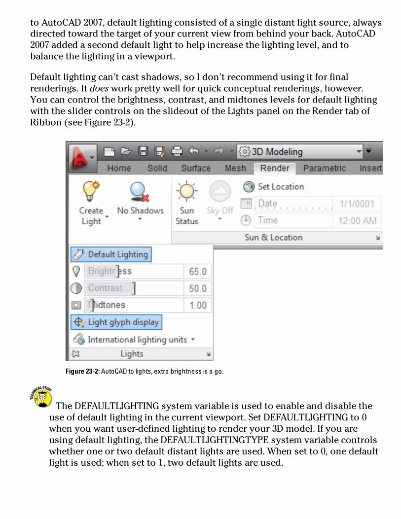
toAutoCAD2007,defaultlightingconsistedofasingledistantlightsource,alwaysdirectedtowardthetargetofyourcurrentviewfrombehindyourback.AutoCAD2007addedaseconddefaultlighttohelpincreasethelightinglevel,andtobalancethelightinginaviewport.
Defaultlightingcan’tcastshadows,soIdon’trecommendusingitforfinalrenderings.Itdoesworkprettywellforquickconceptualrenderings,however.Youcancontrolthebrightness,contrast,andmidtoneslevelsfordefaultlightingwiththeslidercontrolsontheslideoutoftheLightspanelontheRendertabofRibbon(seeFigure23-2).
Figure23-2:AutoCADtolights,extrabrightnessisago.
TheDEFAULTLIGHTINGsystemvariableisusedtoenableanddisabletheuseofdefaultlightinginthecurrentviewport.SetDEFAULTLIGHTINGto0whenyouwantuser-definedlightingtorenderyour3Dmodel.Ifyouareusingdefaultlighting,theDEFAULTLIGHTINGTYPEsystemvariablecontrolswhetheroneortwodefaultdistantlightsareused.Whensetto0,onedefaultlightisused;whensetto1,twodefaultlightsareused.

User-definedlightsDefaultlightsarefineforquickrenderings,buttheydon’tbringyourrenderingstolifeinthewaythatuser-definedlightscan.User-definedlightsarelightsthatyoucreate—withoneexception—andmodifyinyour3Dmodel.Theonlyuser-definablelighttypethatyoucanenableandmodify,butcan’tcreate,isthesunlightsystem.
Thefirsttimethatauser-definedlightisplacedinadrawing,theLighting–ViewportLightingModealertboxisdisplayed,advisingyouthatyouneedtoturnoffdefaultlightinginordertoseelightfromuser-definedsources.ClickTurnOfftheDefaultLightingtodisabledefaultlighting.(Toturndefaultlightingbackon,opentheLightspanelslideoutontheRendertabandclickDefaultLighting.)Youshouldalwaysdisabledefaultlightingwhenusinguser-definedlights;otherwiseyoucanendupover-lightingyourmodel,makingitlookunnatural.
Thetwotypesofuser-definedlightsthatyoucancreatearegenericandphotometric:
Genericlights:Provideadvancedcontroloverhowtheyemitlightandaremuchmorecomplexthanphotometriclights
Photometriclights:Moreconvenienttouseastheyaredefinedtorepresenthowlightsworkinthephysicalworld
TheLIGHTINGUNITSsystemvariablecontrolswhetheruser-definedlightsinyourdrawingarerepresentedasgenericorphotometriclights.WhenLIGHTINGUNITSissetto0,genericlightsareused.WhenLIGHTINGUNITSissetto1or2,photometriclightsareused;1indicatesAmericanlightingunits,and2indicatesInternationallightingunits.Lightsdon’thavetoberemovedandaddedtoswitchbetweengenericandphotometriclights;youjustneedtoswitchthesystemvariable.
Toaddauser-definedlighttoyourdrawing,clickthelowerhalfoftheCreateLightsplitbuttonontheLightspaneloftheRendertab.Youcanchoosefromfourdistincttypesoflightsontheflyout(forthedifferencesbetweenthelighttypes,seeFigure23-3):
Pointlight:Emitslightuniformlyinalldirections,buttheemittedlightfallsoffthefartheritgetsfromthesource.Apointlightissimilartoacandleoralantern.

Spotlight:Emitslightinaspecificdirection.Aslighttravelsfartherfromthesource,itspreadsoutintheshapeofacone.Youcandefinethehotspot—thebrightestpartoftheemittedlight—andthefall-offofthelight.
Distantlight:Emitslightalongaspecifiedvectoranddoesn’tdecayorfallofflikeotheruser-definedlightsdo.Adistantlightissimilartothesun.
Weblight:Acrossbetweenapointlightandaspotlight.Weblightsareavailableonlywhenusingphotometriclights,andthewaytheyemitlightisdeterminedbyanIESfile.IESfilesareprovidedbylightingcompaniesforuseinproductslikeAutoCADtomimicthelightsthattheymanufacture.
AutoCADandIbothstronglyadviseagainstusingdistantlightswhenusingphotometriclighting.Ifyoudecidetoignorethiswarning,makesuretoturndowntheintensityfactorofthedistantlighttoavoidwashingoutyourrendering.
Pointlights,spotlights,andweblightscanbeselectedandediteddirectlyinadrawingbecauseaglyphisdisplayedtoshowwherethelightislocated.Distantlightsdonothaveanassociatedglyph.(Aglyphisanonprintingobjectdisplayedinadrawingthatenablesyoutoselectanobjectthatisnotpartoftheactualmodel.)

Figure23-3:Lightingprimitiveswiththefourtypesofuser-definedlights.
Shadows...ornoshadows?
AutoCADallowsyoutodefinelightsthatcan’tgenerateshadows.Thismightseemillogicalbecauseshadowsarecastwhenlightisobscuredbyanobject.Thisisimportantbecauseyoumaywanttofillanareawithlightbutnothaveitaffectthewayshadowsarecast.
Tocontroltheshadowsalightcangenerate,selectalight,right-click,andthenchoosePropertiestoopenthePropertiespalette.TheShadowsoptionintheGeneralcategoryenablesordisablesshadowcreationfromtheselectedlight.TheRenderedShadowDetailscategorygivesyoualargedegreeofcreativecontrolovershadowappearance.Formoreinformationonputtingyourobjectsintheshade,opentheonlinehelpandsearchon“Render3DObjectsforRealism”.
Youcanalsocontrolhowobjectsthemselvesaffectshadows.Selecta3Dobject,right-click,andchooseProperties.Inthe3DVisualizationcategoryofthePropertiespalette,clicktheShadowDisplaydrop-down;youcanconfigureyourobjectstocastshadows,receiveshadows,castandreceiveshadows,orignoreshadowsaltogether.

TheLightsinModelpalette
Inacomplexdrawingoroneinwhichyoumighthaveaddedadistantlight,you’llwanttousetheLightsinModelpalette(seeFigure23-4).TheLightsinModelpaletteallowsyoutoselect,delete,andaccessthePropertiespaletteforselectedlights.TodisplaytheLightsinModelpalette,clicktheLightspanellauncher(thelittlearrowattherightendoftheLightspanellabel).
Figure23-4:Ah...yes,you’reonthelightslist.
Sunlight

YoucansimulatesunlightviatheSunPropertiespalette(seeFigure23-5).Addingsunlighttoadrawingallowsyoutoperformsunlightstudiesaswellasaddsomerealismtobothindoorandoutdoorrenderings.
TheSunPropertiespaletteallowsyoutolocatethesun’spositionbasedonthenearestlargecity,orbyenteringlatitudeandlongitudevalues.YoucanalsouseGoogleEarthKMLorKMZfilestospecifyyourlocation.Inadditiontolocation,youcandesignatethenortherndirectioninyourdrawingtogetthecorrectdailymovementofthesunlightinyourdrawing.Toadjustthesunlightinadrawing,opentheSunPropertiespalettebyclickingtheSun&Locationpanellauncher(thelittlearrowonthepanellabel).


Figure23-5:TheSunPropertiespalettegivesyoutopowertocontroldayandnight.
CreatingandApplyingMaterialsMaterialscanbringyourmodeltolife.Materialscanbeassimpleaspaint—matteorglossyoranywherebetween.Theycanbeopaque,transparent,reflective,ornonreflective.Youcanapplyrepresentationsofrealistic,real-worldmaterialslikestone,marble,glass,polishedmetal,fabric...thelistisalmostendless.AutoCAD2012comeswithamateriallibraryofliterallythousandsofdifferentmaterialtypes,andassigningthemtoobjectscanbeassimpleasdraggingfromapaletteanddroppingonanobject.Oritcanbeascomplexasyoucaretomakeit.
PriortoAutoCAD2011,youcreatedandstoredmaterialsinindividualdrawings,whichmadethemdifficulttomanage.AutoCAD2011introducedtheMaterialsBrowser,whichmakesmanagingmaterialsmucheasier.PartneredwiththeMaterialsBrowseristhenewMaterialsEditor,accessiblefromatoolbuttonintheMaterialsBrowser.
ThenewmaterialslibrariesintroducedinAutoCAD2011tookupvastamountsofharddiskspace.Thatwasseenaswastefulforpeoplewhoneverdidrenderings,soinAutoCAD2012,mostofthemateriallibrariesareonline.ThefirsttimeyouclicktheRenderbuttoninAutoCAD2012,AutoCADaskswhetheryouwanttogoonlinetoinstalltheMediumMaterialLibrary.Ifrenderinglooksinterestingtoyou,goaheadandinstallthelibrary.
UsetheMATBROWSERcommandtodisplaytheMaterialsBrowserpalette(seeFigure23-6),fromwhichyoucancreate,edit,andmanageinthecurrentdrawingormateriallibraries.Youaddmaterialstoyourdrawingbyusingapreconfiguredmaterialorcreatingacustommaterial.
Followthesestepstocreateandmanageanewmaterial:
1.OntheRendertab,chooseMaterialsBrowserfromtheMaterialspanel.2.OntheMaterialsBrowserpalettethatopens,clickCreateaMaterial(intheupper-left)andthenchoosethematerialtemplateyouwanttostartwith.Forexample,chooseMetallicPaint.TheMaterialsEditorpaletteisdisplayed(seeFigure23-6).

3.OntheMaterialsEditorpalette,clickintheNamefieldlocatedbelowthepreviewofthematerialandenteraname.4.Enternewvaluesintheappropriateattributesforthematerial.Theattributesthatyoucaneditvary,baseduponthetypeofmaterialtemplatethatyouchoosetostartwith.Whenyoufinisheditingthematerial,youcancloseorhidetheMaterialsEditorpalette.Thematerialisautomaticallyaddedtothecurrentdrawing.
Figure23-6:Addingcolorandtexturetoa3DmodelwiththeMaterialsBrowserpaletteandtheMaterialsEditorpalette.
5.(Optional)Savethematerialinalibrarytouseitinmorethanonedrawing.OntheMaterialsBrowserpalette,atthebottom,clickManage,thenselectCreateNewLibrary.TheCreateLibrarydialogboxisdisplayed.
6.Enteranameandlocationforthenewlibrary.ClickSave.7.OntheMaterialsBrowserpalette,dragthecustommaterialyoucreated

ontothenameofthenewlibrary.Nowyoucanaccessthematerialfromanydrawing.Youcancreatecategoriesifyouwanttomanagemultiplematerialswithinalibrary.IntheMaterialsBrowser,right-clickthelibraryname,chooseCreateCategory,andthenenteranameforthenewcategory.Afterthecategoryiscreated,simplyselectthematerialfromtherightsideoftheMaterialsBrowseranddragittothenewcategory.
YoucanopentheMaterialsEditordirectlyfromtheRibbonbyclickingtheMaterialspanellauncher(thelittlearrowattherightendoftheMaterialspanellabel).
Whichmaterialsyouuseinamodeldependsonwhatyou’retryingtorepresent.Forexample,youmightchoosetomakeamaterialsemitransparenttocommunicateanidearatherthanatruematerialselection.Afteryoucreateamaterial,youcanapplyittotheobjectsinyour3Dmodel.Youcanapplymaterialstoobjectsinthefollowingways:
ByLayer:Globallyassignmaterialstoallobjectsonaparticulardrawinglayerbyassigningamaterialtothelayer.Toassignmaterialsbylayer,opentheMaterialsslideoutontheRendertabandchooseAttachByLayer.
ByObject:Assignmaterialstoanobjectbyselectingtheobject,thenright-clickingthematerialyouwanttoassignintheMaterialsBrowserpalette.Fromtheright-clickmenu,chooseAssigntoSelection.YoucanalsodraganddropamaterialfromtheMaterialsBrowserpaletteontoanobjectinadrawingorchangeanobject’sMaterialpropertyusingthePropertiespalette.
ByFace:Assignmaterialstoindividualfacesofa3Dsolid.SelectafaceusingSubobjectfilteringbyholdingdowntheCtrlkeyandselectingthefaceyouwanttoapplyamaterialto.Right-clickthematerialyouwanttoassignintheMaterialsBrowserpaletteandthenchooseAssigntoSelection.
DefiningaBackgroundWhileyourmodelmightnowbelookingalittlemorerealisticwithsomeuser-definedlightingandcustommaterialsassignedtoit,itssettingmightlookalittle...empty.Youcanassignbackgroundstofillthatemptyspacebeyondthe3D
modelinyourscene.Abackgroundisapropertyofnamedviews,andyoucansetthemupintheViewManagerdialogbox(IcovertheVIEWcommandandViewManagerdialogboxinChapter12).Youcandefineabackgroundasasolidcolor,agradient(twoorthreecolors),arasterimage,oraskywithasun(availableonlywhenusingphotometriclighting).
Followthesestepstocreateanewnamedviewandassignabackgroundtoit:
1.OntheViewspaneloftheViewtab,clickNamedViews.TheViewManagerdialogboxappears.
2.ClickNewtodisplaytheNewView/ShotPropertiesdialogbox.Forarefresheroncreatingnamedviews,refertoChapter12.
3.IntheBackgroundarea,clicktheDefaultdrop-down,chooseanoptiontooverridethedefaultbackground,andthenclickOK.ChooseSolidorGradientifyouwantastudio-typescene,orchooseImageifyouhaveasuitablerasterimagetohighlightyourmodel.AnyoftheseoptionsdisplaystheBackgrounddialogboxwhereyoumakeyoursettings(seeFigure23-7).ChooseSun&Skyifyouwanttoplaceyourmodelinthegreatoutdoors(andit’salwaysfairweatherinAutoCAD!).ChoosingthelastoptiondisplaystheAdjustSun&SkyBackgrounddialogbox,asshowninFigure23-8.

Figure23-7:Paintingthecanvasofthedrawingwindow.
4.Afterthebackgroundisdefined,selecttheviewfromtheViewstreeandclickSetCurrent.5.WhentheViewManagercloses,thenewbackgroundshouldbedisplayed.FormoreinformationontheViewManager,seeChapter12.
Ifyoudon’twanttocreateanamedviewfirst,entertheBACKGROUNDcommandatthecommandlinetodisplaytheBackgrounddialogbox.

Figure23-8:Herecomesthesun.
Renderinga3DModelAfteryouaddlights,applymaterials,anddefineabackgroundforyour3Dmodel,you’rereadytopressthemagicbutton!ClickingRendertellsAutoCADtoroundupallthematerialsandapplythemtotheobjectsandfacestowhichthey’reassigned.Aftermaterialsareassigned,thebackgroundisappliedtothecurrentviewport,andthenfinallyAutoCADcalculateslightandshadowsbasedonall

thosepropertysettingsyoumadeearlierinthechapter.
Bydefault,renderingisperformedintheRenderWindow(seeFigure23-9).Tostartrenderingyourvirtualfatintodigitallard(andhow’sthatforagrislyimage?),clickRenderontheRendertab’sRenderpanel(anotherofferingfromtheDepartmentofRedundancyDepartment).
Tohelpmakerenderingaseasyaspossible,AutoCADcomeswithfiverenderpresets.Arenderpresetisaconfigurationofrenderingsettingsthatyoucanusetogetpredictableresultswhenrenderingamodel.Thepresetsrangeinqualityofoutput,fromDraft,throughLow,Medium,andHigh,toPresentationquality.
Figure23-9:RenderingarenderingintheRenderWindow.
Tosetarenderpresetcurrent,choosetheRenderPresetsdrop-downontheRendertab’sRenderpanel.ChooseManageRenderPresetsatthebottomoftheRenderPresetsdrop-downtoopentheRenderPresetsManagerdialogbox.TheRenderPresetsManagerallowsyoutocreateandeditcustomrenderpresets.Youcanstartwithanexistingrenderpresetwhenyoucreateanewone.

Iftherenderpresetsdon’tseemtoofferthelookyou’restrivingfor,youcanexperimentwiththeAdvancedRenderSettingspalette(seeFigure23-10).Whenyougetthesettingsyoulike,youcansavethemtoarenderpreset.
InadditiontorenderingastillimagewiththeRENDERorRENDERCROPcommands,youcancreateananimatedwalkthroughofyourmodelusingtheANIPATH.Tofindoutmoreaboutcreatinganimations,seetheAutoCADonlinehelpsystem.


Figure23-10:TheAdvancedRenderSettingspalettegivesyoucontroloverallthesettingsoftherenderingprocess.

PartVI
ThePartofTens
Inthispart...Tenssoundsalotliketense,andtenseishowAutoCADmaymakeyoufeelsometimes.Tensalsomayremindyouofthemetricsystem,andifyou’renotusedtoit,thatmayalsomakeyoufeeltense.Butneverfear—helpisontheway!ATopTenListisagoodwaytoquicklyspotthebest—ortheworst—ofalmostanything,AutoCADincluded.ThisPartofTensfeaturesliststhathelpyouunderstandsomeofthenutsandboltsthatmakeAutoCADwork,figureoutwhetheryoushouldbeusingAutoCADorAutoCADLT,andhuntforthemostvaluableAutoCADresources.


Chapter24
TenGreatAutoCADResources
MuchasI’dliketomakeaclaimtothecontrary,youprobablydoneedjustateensybitmorethanthisbookandacopyofthesoftwaretoreachtheveryhighestpeaksofAutoCADmastery!Thischapterliststenlikelysuspectsifyouwanttofindoutmoreaboutyourfavoritesoftwareprogram.
Autodesk’sFeedbackCommunityInterestedinhelpingshapefuturereleasesofAutoCAD?Ifso,visitAutodesk’sFeedbackCommunityPortal(https://beta.autodesk.com)andsignup.Inreturnfor

small—orsometimesconsiderable—timecommitments,youcancontributeyourideastotheAutoCADFuturesgrouporapplytobeta-testthenextreleaseofAutoCAD.
Autodesk’sDiscussionGroupsAlthoughtherearestillsomeindependent,newsreader-baseddiscussiongroupsoutthere,themajorityoftheAutoCADactionnowadayshappensonAutodesk’sownmoderateddiscussiongroups.Theseareuser-to-usergroups,butevenso,youfrequentlyseeAutodeskemployeesjumpingintoanswerquestionsintheirareasofexpertise—sometimesontheirowntime!
Toseewhat’sthere,pointyourbrowsertowww.autodesk.com/discussion.Thereareproduct-baseddiscussiongroupsforAutoCADandAutoCADLT.
Autodesk’sOwnBloggersSeveralofAutodesk’semployeesruntheirownblogsthroughthecompany’sservers,andthey’rechockablockwithtips,techniques,andsomeoccasionallyhighlyentertainingdigressions.ForalistofallAutodesk’sblogs,gotowww.autodesk.com/blogs.TheAutoCAD-basedblogsIhighlyrecommendareShaanHurley’sBetweentheLines,HeidiHewitt’sAutoCADInsider,KateMorrical’sLTUnlimited,andLynnAllen’sBlog(that’swhatit’scalled,honest!).
AutodeskUniversityAutodeskUniversityisanannualevent,sponsoredbyAutodesk,thatusuallyrunsforthreeorfourdaysaroundtheendofNovember.Forthelastfewyears,theeventhassettledinLasVegas,Nevada.Thedaysarefilledwitheducationalsessionsinadozenormoredifferentdisciplines,andthenightsarefilledwithsocializingandtakinginthelocalattractions.Checkouthttp://au.autodesk.comtofindouthowtoschmoozelikeaproandcomehomeaguru!
TheAutodeskChannelonYouTube

IfyouuseGoogletosearchtheWebforsolutionstoparticularAutoCADissues,it’sprettylikelyyou’vealreadydiscoveredYouTube’sAutodeskChannel.TherearedozensanddozensofvideoclipsherethatcovernotonlyAutoCADandAutoCADLT,butotherAutodeskproductslikeInventorandRevit.Youcansubscribeandreceivee-mailnotificationsofnewvideoseverycoupleofweeks.Checkitoutatwww.youtube.com/autodesk.
TheWorldWide(CAD)WebI’mreluctanttolistanyspecificsites;Ijustwentlookingforanoldfavorite,andit’snotthereanymore.Yoursearchenginewillbeyourbestfriendhere.ApartfromAutodesk’sownWebpresence,therearethousandsuponthousandsofothersitesscatteredaroundtheworld.SearchonAutoCADtutorialsforonlineexercises,ortryAutoCADblogsforsomeindependentviewsandopinionsaswellastipsandtricksforusingAutoCAD.
YourLocalATCAutodesk’sAuthorizedTrainingCenters,orATCs,arelocatedaroundtheworldinbothprivateinstitutionsandpubliccollegesandinstitutes.AtanATC,youattendscheduled,instructor-ledclasseswhereyoulearnAutoCADfromthegroundup.Coursesaredesignedforrankbeginnersorexperienceduserswhowanttolearnthelatestcustomizationtechniques.TofindthelocationofyournearestATC,browsetowww.autodesk.com/atc.
YourLocalUserGroupAutoCADhashadanincrediblyloyalfollowinginthequarter-centurysinceitsinitialrelease.Therearemanyreasonsforthis,butoneofthemainoneswastheespeciallyenthusiasticindividualswhowouldarrangetomeetuponeeveningamonthandtalkaboutwhatthey’ddiscoveredtheycoulddowithAutoCAD.Thosefolksarestilloutthere—althoughsomeareabitgrayerandmorewrinkledthantheyusedtobe—andtheystilllovetogettogetherandtalkaboutAutoCAD.Andmostareespeciallywelcomingtonewcomers!Myownlocalgroup,theVancouverAutoCADUsersSociety(www.vaus.org),happenstobetheoldestusergroupinexistence,anditsnewslettergrewandgrewuntilitbecameCadalystmagazine!Tofindanearbygroup,enter“AutoCADusergroup”andyourcityinyourbrowser’s

searchbox.
AUGIAUGI(theacronymforAutodeskUserGroupsInternational)istheumbrellaorganizationfortheglobalusergroupcommunity.Youdon’tevenhavetobelongtoagrouptoparticipate—individualscanjointoo,andmembershipisfree.AUGIisprobablybestknownfortheannualwishlistitpresentstoAutodesk;thelistiscompiledfromrequestsfrommembersforchangesornewfeaturesinAutoCAD.It’softenthecasethattopwish-listitemsfindtheirwayintonewreleasesofAutoCAD,sohere’sanotherplacewhereyoucanhelptoshapefuturereleases.Browsetowww.augi.comtofindoutmore.
BooksAlthoughI’dliketofillyouinonallthewondersofAutoCAD,there’sonlysomuchIcandoina500-pagebook.AsIexplainintheintroduction,Isimplydon’thavethespacetocoverthingslikedatalinkingandcustomization(notthateitherofthoseareofmuchusetoAutoCADLTusersanyway).TherearedozensofbooksonAutoCAD—justgotowww.amazon.comandsearchonAutoCADifyoudon’tbelieveme!ForamorecomprehensivelookatAutoCAD(whichathousandpagesallows!),haveaganderatEllenFinkelstein’sAutoCAD2012andAutoCADLT2012Bible(WileyPublishing,Inc.).

Chapter25
TenDifferencesbetweenAutoCADandAutoCADLT
ThisbookisaimedatusersofboththefullversionofAutoCADandAutoCADLT.Throughoutthetext,youcanfindiconsinthemarginthathighlightplacesinmydescriptionsorstepsthataresignificantlydifferentbetweenthetwoversions.
Ratherthanmakeyougothroughtheentiretext(notthatitwouldn’tbeahighlyrewardingtask!)lookingfortidbitsofinformation,inthischapter,Igatherthetenmostsignificantdifferencesbetweenthetwoversions.
PriceMostimportanttomanypeople—especiallyifyouworkin2Ddrafting

exclusivelyanddon’tseeaneedtospendalotoftimelearningAutoCAD’scustomizationlanguages—isthemuchlowercostofAutoCADLT.Youcanbuyeitherversiononline(visitwww.autodesk.comandclickPurchase,thenShopOnline)andinthefirstmonthof2011,AutoCADlistedat$3,995andAutoCADLTat$1,200(bothpricesareforboxedpackagesanddon’tincludeasubscription).
3DAbilitiesThismaybethemostsignificantdifferenceforsomeusers.Ifyouwanttomodelin3D,youhavenochoicebuttousethefullversion.InAutoCADLT,youcanopenandview3DmodelscreatedinthefullversionofAutoCAD,butyoucan’teditthemorcreatenewones.Theonly3DconstructionyoucandoinAutoCADLTistoapplyathicknesspropertytolinework.(InAutoCAD,thicknessmeansperpendiculartothedrawingplane;don’tconfuseitwithwidth,whichappliestoobjectsonthedrawingplane.)
Andevenifyoucanopen3DmodelsfromthefullversioninAutoCADLT,it’snoteasytoviewthem.Thereareonlyalimitednumberofpresetviewingpositions,unlikethefullversionwhereyoucanrotateororbitaroundyourmodeltoyourheart’scontent.
Finally,becauseAutoCADLTisreallya2Ddraftingprogram,therearenovisualizationorpresentationcapabilities,unlikethefullprogram,whichhasseveralbuilt-invisualstyles,suchasConceptualandRealistic,aswellasahumongousmaterialslibraryforrenderingmodels.
CustomizationOptionsThisoneisalsoabiggieformanypeople.TalktoseasonedAutoCADusersatworkoryourlocalusergroup,andyou’llfindthattheirkeytohappinessisbeingabletocustomizeAutoCADsoitdoeswhattheywantwiththeminimumamountoftimeoreffort.ThefullversionofAutoCADsupportsanumberofApplicationProgrammingInterfaces,orAPIs.TheseincludeAutoCAD’sveryownprogramminglanguage—AutoLISP—anditsmarginallyfriendliersiblingVisualLISP,ActiveXAutomation,andcompiledlanguageprogrammingusingObjectARXorMicrosoft’s.NETframework.
AlthoughyoucandofairlysimplecustomizationinAutoCADLT—forexample,creatingormodifyingtoolbars,writingscripts,orusingcustomhatchpatternsor

linetypes—noneofthehigher-levelprogrammingdescribedintheprecedingparagraphispossibleinLT.
NetworkLicensingOnceagain,theparadigmis“bigengineeringcompany”versus“home-officedoodler”,andtheassumptionisthatAutoCADLTusershavenoneedforanetworklicense.WithtenseatsofregularAutoCAD,youcangetanetworklicensethatmakesthingsprettyeasytoadminister.Ifyou’reanLTuserandfindthatyouneedtenseats,thenyouneedtenindividualcopies.
ExpressToolsTheExpressToolsareasetofofficiallyunsupportedbutneverthelessprettyreliable“bonus”commands.TheExpressToolsareanoptionalitemwhenyouinstallAutoCAD,andIhighlyrecommendyouchoosetoincludethem.Thereareadditionaldrawingandeditingcommands,afarmoreelaboratehatchroutinethantheregularHATCHcommand,andcommandsforworkingwithblocksandxrefs,text,dimensions,andlayouts.
BecausemostoftheExpressToolsarewrittenusingtheAPIsmentionedintheearlier“CustomizationOptions”section,theywon’tworkinAutoCADLT.Onthepositiveside,sometimesafewoftheExpressToolsaremovedintothecoreoftheAutoCADexecutable;becausethey’renotusingoneofthoseAPIsImentionearlier,theycanbemadeavailabletoAutoCADLT.Forexample,AutoCADLT2012nowincludestheOVERKILLcommandforweedingoutduplicateobjectsthathadpreviouslybeenanExpressTool.
ParametricsIcoverparametricsinChapter19ofthisbook,andIpointoutthatAutoCADLTisextremelylimitedinthisarea.Yes,there’saParameterstab,andaParametersManager,butinLT,theManagerdoesn’thavealotofclout.Youcan’tcreateparameterswithLT,butyoucandeletethem,andthereforedoalotofdamagetoahelplessDWGfile.Ifyouliketheideaofyourdrawinggeometrychangingwhenyouchangethevalueofadimension,thenyoureallyoughttothinkaboutthefullversionofAutoCADratherthanLT.

StandardsCheckingStandards—asindraftingstandards—areimportantthingstomaintainindesignoffices.Withstandardschecking,youconfigureaDWSfile(thatis,aDWGfilesetupwithyourstandardlayers,textanddimensionstyles,layouts,andsoforth),andthencompareyourcurrentdrawing,ordrawingsdonebyoutsideconsultants,withthatDWSfiletoensuretheyconformtoyourofficestandards.
DataExtractionAsIexplaininChapter17,attributesarevariabletextstringsthatyoucreateaspartofablockdefinition.ThedataintheattributescanbeeditedorextractedeasilyinregularAutoCAD,andnearlyaseasilyinAutoCADLT(AutoCADLTlacksthefullversion’sDataExtractionWizard,whichextractsinformationfromobjectsandfromattributedornon-attributedblocks.)IfbeingabletouseallthedatainyourAutoCADdrawings,choosingthefullversionwouldbeabetterbet.
MLINEversusDLINEHere’sacasewhereAutoCADLTbeatsitsbigsibling!AutoCAD(fullversion)includesanextremelyunwieldycommandcalledMLINEfordrawingmultipleparallellines.YoucandrawsuchlinesinthesamewayyoupickpointsfortheLINEcommand,butmultilinesareunintuitivetoconfigureandprettydarneddifficulttoedit.
AutoCADLTdoesn’thaveMLINE,butitdoeshaveadifferentcommandcalledDLINE.DLINE(asinDoubleLINE)maynotdrawmorethantwoparallellines,anditcan’taddcoloredfills,butit’slogicaltouseandmucheasiertoedit.Andsorry,AutoCADusers(I’vebeenwaitingtowritethatforthewholebook!),butyoudon’thaveDLINE.
ProfilesThroughoutthebookImakereferencetotheOptionsdialogbox.Thisistheplacewhereyoumakebothdrawing-specificandsystem-widesettingssoyoucanconfiguretheprogramtoworkthewaythatyouwant.Inthefullversionof

AutoCAD,youcansavethesesettingsasnamedprofiles,andswitchbetweenthemontheProfilestaboftheOptionsdialogbox.Forexample,youcanhaveoneprofilewithawhitedrawingbackground,andanotherwithadarkbackground.Oryoucanhavedifferentprofilesthatpointtodifferentclientsupportfiles.Ifmorethanonepersonsharesacomputer,eachpersoncanhavehisorherownprofile.
Onlyinthefullversion,though—thereisnoProfilestabinAutoCADLT’sOptionsdialogbox,becauseAutoCADLTdoesnotsupportprofiles.AnychangesyoumaketoLT’soptionsbecomethecurrentdefaults,buttheycan’tbesavedandrestoredlater.
ReferenceManagerReferenceManagerisafree-standingprogram,notpartofAutoCADorAutoCADLT.Ifyouhavethefullversioninstalled,you’llfindReferenceManagerontheWindowsStartmenu.ReferenceManagerhelpsyoumakesurethatanydependentfiles(forexample,fontfiles,images,orxrefs)areincludedwhenyoushipasetoffilesanywhere.There’snotechnicalreasonwhyAutoCADLTshouldn’tincludetheReferenceManager.Butitdoesn’t.

Chapter26
TenSystemVariablestoMakeYourLifeEasier
SystemvariablesaresettingsthatAutoCADchecksbeforeitdecideshowtodosomething.Forexample,ifyousetthesystemvariableSAVETIMEto10,AutoCADsavesyourdrawingfileautomaticallyeverytenminutes;ifyousetSAVETIMEto60,thetimebetweenautomaticsavesisonehour.HundredsofsystemvariablescontrolAutoCAD’soperations.
Tochangethevalueofasystemvariable,justtypeitsnameattheAutoCADcommandpromptandpressEnter.AutoCADdisplaysthecurrentvalueofthesystemvariablesettingandpromptsforanewvalue.PressEntertoconfirmtheexistingsetting,ortypeavalueandpressEntertochangethesetting.

Beingabletochangesystemvariablesbytypingtheirnamesisaboontopowerusers,andoccasionallyanecessityforeverybodyelse.Theonlyproblemisfindingorrememberingwhatthenamesare.Inmostcases,you’llbetoldwhatsystemvariable’snameyouneedtotype—bymeinthisbookorbythelocalAutoCADguruinyouroffice.
Herearethethreekindsofsystemvariables:
ThosesavedintheWindowsRegistry:Ifyouchangethiskindofsystemvariable,itaffectsalldrawingswhenyouopenthemonyoursystem,butnotnecessarilyonothercomputers.
Thosesavedinthedrawing:Ifyouchangethiskindofsystemvariable,thechangeaffectsonlythecurrentdrawing,butonanycomputer.
Thosethataren’tsavedanywhere:Ifyouchangethiskindofsystemvariable,thechangelastsonlyforthecurrentdrawingsession.
TheSystemVariablessectionoftheonlinehelp’sCommandReferencetellsyouwhichkindofsystemvariableeachoneis.Thereareseveralhundredsystemvariables,butunderstandingthetenlistedinthischapterwillgoalongwaytomakingyouahappyCADster.
APERTUREAPERTUREcontrolshowclosethecrosshairsmustgettoanobjectbeforeanobject-snapmarkerappears(IdiscussobjectsnapsinChapter7).YoucansetAPERTUREatthecommandlineanywherefrom0to50pixels,oryoucansetitintheOptionsdialogboxbyadjustingaslidertoamaximumof20pixels.Theinitialvalueis10,butIfind20pixelsisjustaboutrightforme.APERTUREisstoredintheWindowsRegistry.
DIMASSOCDIMASSOCcontrolshowAutoCAD’sdimensionobjectsarecreated(seeChapter14forthelowdownondimensioning).WhenDIMASSOCis0,AutoCADcreatesexplodeddimensionsofseparatelines,2Dsolids,andtext.Youreallydon’twanttoworkonDIMASSOC=0drawings.WhenDIMASSOC=1,dimensionsarereferredto

asnon-associative—thatmeansthatthey’resingleobjects,buttheyusuallydon’tupdateifyouchangeanobject’ssize.WhenDIMASSOC=2(thedefault),AutoCADcreatesfullyassociativedimensions.YoucansetthisvalueatthecommandlineorselecttheMakeNewDimensionsAssociativecheckboxinOptions⇒UserPreferences.Ifyouworkwitholderdrawings,you’lllikelyfindthattheDIMASSOCvalueis1,whichisthebestthatreleasespriortoAutoCAD2002couldmanage.TheDIMASSOCsettingisstoredinthedrawing.
MENUBARWhenMENUBARis1,AutoCADdisplaysitstraditionalclassicmenubarbelowtheapplicationtitlebar.IfMENUBARissetto0(thedefault),themenubardoesn’tappear.MENUBARissetautomaticallywhenyouswitchbetweentheAutoCADClassicandDrafting&Annotationworkspaces.
Ifyou’vebeenawayfromAutoCADforafewyearsandfeelinneedoftrainingwheelswhileyougetusedtotheRibbon,displayingtheclassicmenubarisagoodapproach.(IdescribethedifferencesbetweenthetraditionalAutoCADClassicandthenewerRibbon-basedworkspacesinChapter2.)
MIRRTEXTYou’vegottoloveitwhenasystemvariable’snamegivesyouaclearindicationofwhatitdoes(ROLLOVERTIPS,anyone?).You’llfrequentlywanttobuildupadrawingbymirroringalready-drawncomponentsofit.That’swhattheMIRRORcommanddoes,butunfortunately,iftextordimensionsareincludedinwhatyou’remirroring,thoseendupbeingreversedaswell.Havingtouseamirrortoreadthetextonyourdrawingiscounterproductive,soyoucaninvokeMIRRTEXTtofixthings.WhenMIRRTEXTis0(thedefault),textismirroredalongwitheverythingelse;settingitto1meanseverythinggetsmirroredbutthetextstillreadstherightwayaround.MIRRTEXTisstoredinthedrawing.
OSNAPZSometimesdrawingin3Dcanbealittlepuzzling,especiallyifyou’relookingat3Dobjectsinorthographicviews.Sayyouhaveawireframecubethatyou’relooking

atinPlanview,andyouwanttodrawalinebetweentwodiagonalcornersonthetopofthecube.Usingobjectsnapstopickthecorners,asoftenasnotyou’llfindthatyouhavealinethat’snotontheplaneofthetopofthebox,butstartsatatopcornerandendsatabottomcorner.OnewayaroundthisproblemissettheOSNAPZvariableappropriately.Bydefault,OSNAPZissetto0,whichmeansAutoCADwillfindtheX-,Y-,andZ-coordinateofthesnapped-topoint.Butoftenyoudon’twantthattohappen.SetOSNAPZto1,andAutoCADreplacestheZ-valueofthepickedpointwiththecurrentelevation—ortheZ-valueofthefirstpointpicked.
SinceOSNAPZonlyaffectsdrawinginthreedimensions,it’snotavailableinAutoCADLT.
PICKBOXThepickboxisthelittlesquareboxthatthecrosshairsturnintowhenAutoCADpromptsyoutoselectsomething.YoucontrolpickboxsizebysettingavalueinpixelsforthePICKBOXvariable.TheinitialsettingofPICKBOXis3,whichisfineforalowerscreenresolutionlike1024x768.Butwhenyoustartrunningathigherresolutions—orwhenyourhairisgrayer,yourfacemorewrinkled,andyourvisionnotquiteasacuteasitoncewas,ahighersettingmightbemoreuseful.Myofficecomputerrunsat1600x1200resolution,andIhavetosetPICKBOXto5tobeabletouseiteffectively.Mylaptoprunsat1400x1050,andPICKBOX=4isfineforthat.Astheysay,yourmileagemayvary.
REMEMBERFOLDERSSometimesyoudon’twantAutoCADtostartinthesameDocumentsfolderwhereeveryotherprogramstoresitsfiles.Maybeyouworkonanumberofprojectsandwouldlikeaseparatedesktopiconforeachtostartinaparticularfolder.REMEMBERFOLDERSisyourtickettonirvana.Bydefault,it’ssetto1,whichmeansitdefaultstostoringfilesinMyDocuments(justplainDocumentsinWindowsVistaandWindows7).Setitto0,anditwillopenfromandsavetothefolderyouspecifyinyourdesktopiconwhenyoustart,andthelastfolderyouvisitasyouwork.REMEMBERFOLDERSisapermanentsettingthat’sstoredintheWindowsregistry(permanent,thatis,untilyouchangeittosomethingelse).

ROLLOVERTIPSYouwerewaitingforthisone,weren’tyou?ROLLOVERTIPScontrolsthetooltip-likemessageboxesyouseewhenyouhoverthemousepointeroverobjectsinthedrawingeditor.IfROLLOVERTIPSis1,mousingoveryourdrawingdisplaysatemporarypanelshowingtheobjecttypewithitslayer,color,andlinetype.If,likeme,youfindthisalittleintrusive,setitsvalueto0.
Youcangetdouble-dutyfromthiscommand.NotonlycanyoukeyitintoAutoCAD,butifyouhaveadognamedTips,youcanuseittoteachhimaneatpettrick!ROLLOVERTIPSisstoredintheWindowsregistry.(Andbelieveitornot—andI’llbetyouwon’t—there’sanothersystemvariablecalledNOMUTT!CouldthatbeAutoCAD-eseforBADDOGTIPS!?)
TOOLTIPSTooltipsthemselvesarethelittletextboxesthatappear(bydefault,anyway)whenyouhoveryourmousepointeroveratoolbarorRibbonbutton,orjustaboutanywhereinadialogbox.Tooltipsarereallyusefulwhenyou’regettingtoknowyourwayaroundaprogram,butwhenyouhaveasenseofwherethingsare,theycangetintheway.Bydefault,TOOLTIPSissetto1,whichmeanstheyappearwhenyouhoverthemousepointeroversomething.SetTOOLTIPSto0ifyoudon’twanttoseethemagain.TheTOOLTIPSsettingisstoredintheWindowsregistry.
VISRETAINIfyouworkwithxrefs(refertoChapter18),youknowthepotentialforcompetinglayerproperties.Sometimesyouwantyourxreftolookdifferentfromyourcurrentdrawingsoyoucantellwhichiswhich.YoucanchangelayercolorsofxrefsintheLayerPropertyManager,butwhetheryouhavetodothateverytimeyouopenadrawingwithanattachedxrefdependsonthesettingoftheVISRETAINsystemvariable.WhenVISRETAINissetto0,thelayerpropertiesinthexreftakeprecedence,whichmeansyouwouldhavetomakethosechangeseverytimeyouopenedthehostdrawing.WhenVISRETAINissetto1(thedefaultvalue),changesyoumaketolayerpropertiesinthehostdrawingremainintacteverytimeyouopenthathostdrawing;however,thosechangeshavenoeffectontheexternalfileitself.TheVISRETAINvalueisstoredinthecurrentdrawing.


Toaccessthecheatsheetspecificallyforthisbook,gotowww.dummies.com/cheatsheet/autocad2012.