Introduction to AutoCAD - CDEEP-IIT Bombay
30
1 Introduction to AutoCAD Video Lecture for ME119 Instructor: Amitabh Bhattacharya Department of Mechanical Engineering, I.I.T. Bombay http://www.autodesk.com/education/free-software/autocad Acknowledgement: Prof. Tanmay Bhandakkar, Prof. Salil Kulkarni
-
Upload
khangminh22 -
Category
Documents
-
view
5 -
download
0
Transcript of Introduction to AutoCAD - CDEEP-IIT Bombay

1
Introduction to AutoCAD
Video Lecture for ME119
Instructor: Amitabh BhattacharyaDepartment of Mechanical Engineering,
I.I.T. Bombay
http://www.autodesk.com/education/free-software/autocad
Acknowledgement: Prof. Tanmay Bhandakkar, Prof. Salil Kulkarni

ComputerAided Drawing (CAD)❑ Computer aided drafting (CAD) is a process of constructing drawing
computer screen with the help of specially developed software❑ Advantages: Accurate, time saving, standardization, easily
shared, easy to edit❑ Widely used commercial softwares:
• AutoCAD• Pro/Engineer• Catia• SolidWorks• NX Unigraphics
2

3
Snapshot of the AutoCAD screenRibbon panel
Command lineStatus bar
Graphic cursor
Drawing space
Co-ordinate system (UCS)
Ribbon tab

Setting Units• In this course, the units for drawing objects will
usually be in mm– If nothing is mentioned then units are in mm
• AutoCAD does not use mm by default– This may cause issues while printing/saving as pdf– Becomes difficult to define other properties like line
thickness, etc• We will first ensure that the units are in mm
– Also a good idea to set the precision to single decimalplace
4

Setting Units
A B

Page Setup : Model
Printer name: DWG to PDFPaper size: ISO full bleed A3 (420x297 mm)Scale: 1:1
• Choose “dwg to pdf” for printer name• Choose “ISO Full Bleed A3 (420x297 mm)”
under paper size• We won’t really worry about the page setup
for “Layout” tabs

Object Snap (OSNAP Command)• While hovering cursor, AutoCAD will
automatically select intersections, midpoints etc.
• OSNAP command can be used to set whichpoints should be chosen

v
Utilities ‐> Point Style
Make Nodes/Points Visible
• Sometimes we mark intersections/divisions using nodes/points
• We have to make these intersections visible using markers

Annotation –> Text Style ‐> Manage text styles
Annotation – Select Annotativefor text, dimensions and multi‐leader style
Select annotative
Setting Up Text Style
• Text size should not be too large/small compared to figures– Always test your settings

Annotation –>Dimension Style ‐>Manage text styles
OR
Command: DIMSTY
Dimensioning Style
Make sure that size of text and arrows are not too large/smallAgain – test your settings

Layer manager
Add new layer
To activate a layer in thedrawing
To change the line type of a layer, click on the current linetype, then load, then select appropriate line type to load.
Now select the loaded line type.
New layers created using the layer manager
Using the layer manager you can add/delete layers, changelinetypes, colour and freeze and thaw layers
LAYER Command
You may use different colors for layers. Set all layers to white colorbefore exporting to pdf.
NEVER use the ͞defpoints͟ layer
12
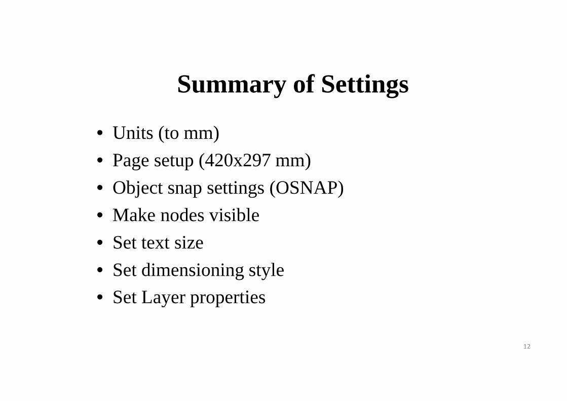
Summary of Settings
• Units (to mm)• Page setup (420x297 mm)• Object snap settings (OSNAP)• Make nodes visible• Set text size• Set dimensioning style• Set Layer properties

COPY/MOVE
• Make a circle (CIRCLE command)
• Enter COPY command->select object (left-click)->right click (select base point)->drag object->right click (repeat if needed)
• Press Esc once you are finished copying• MOVE command is very similar
13

(1,1) (3,1)
(4,2)
(4,3)(1,3) 5
PLINE: Different ways of creating polygons
Relative Cartesian coordinatesCommand: PLINE1st point: 1,12nd point: 2,03rd point: 1,14th point: 0,15th point: ‐2,06th point: c
1 2
3
4
Relative Polar coordinatesCommand: PLINE1st point: 1,12nd point: 2<03rd point: 1.414<454th point: 1<905th point: 3<1806th point: c
Other important shapes: CIRCLE, SPLINE

ORTHO Mode
• ORTHO mode ON helps us draw lines that are exactly parallel to axes
• Turn ORTHO OFF if line needs to be drawn at an angle
15

❑ Paper, margins and name plate:• Size of sheet is A3 (Width = 420 mm, Height = 297 mm)• 10 mm margin on all sides• Name plate (Size: 150 mm x 45 mm) should appear in the right bottom
corner as follows
Template to be used for all the AutoCAD sheets

17
Steps to generate the template
(1) Use "rectangle" command with corner co-ordinates (0,0) and (420,297) to generate"A3" size drawing area.
(2) Use "rectangle" command with corner co-ordinates (10,10) and (410,287) togenerate border with a gap of 10 mm. Other option is "offset" command or relativeco-ordinates @.
(3) For name-plate, again "rectangle" command can be used with appropriate co-ordinates.
(4) Other option is move the "ucs" to the right bottom corner of the inner rectangle.Use "rectangle" command with corner co-ordinates (0,0) and (-150,45). Move the"ucs" back to the left corner of the outer rectangle.
(5) For Name plate, the innermost smaller rectangle in the right corner is to be dividedinto three equal parts. Switch on the ORTHO mode (F8). See the right corner of thecomputer screen.
(6) Draw line to coincide with the horizontal edge of the smallest rectangle.(7) "Move" the line along –y direction by 15 units w.r.t original location.(8) "Copy" this line and move the new line relative to the 2nd line further by 15 units in
the –y direction.(9) In the bottommost rectangle of the name plate, use “Move" and "Copy" to further
divide the rectangle into three move parts. Keep both the ORTHOMODE andSNAPON mode active.

18
Steps to generate the template10) Add text using "text" command. The text should appear at the centre of the
rectangular boxes of the rectangles of the name plate. It’s a good idea to turn off“Object Snap” (OSNAP), since the text placement can get constrained.
11) With TEXT command, you can always enter multiple text lines. Press CTRL-ENTER to stop entering the text.

Snapshot of the template to be used for all the AutoCAD sheets
(0,0)
(420,297)(410,287)
(10,10)
150
45
19

Example: Drawing a Hexagon
• Draw a hexagon with side 50 mm
Commands used: CIRCLE, LAYER, TRIM, TEXT, DIMALI
20

Example: Drawing a Spline
• Draw a polyline, connect the vertices with a curve
21
Commands used: PLINE, POINT, LAYER, DIMALI, DIMANG

Example: Divide a Line
• Divide a line into 5 equal parts
Commands used: PLINE, DIVIDE, POINT, DIMALI,
• Use MEASURE command to verify distance between divisions
22

Example: Final Sheet
• Use export‐>pdf toprint
• Always check print‐>plot preview
23

Dimensioning for Scaled Objects
• Say actual square has dimensions 500mm, but I want to show it with a square of 100 mm– Scale is 1:5
• Use DIMLFAC statement– Set DIMLFAC=5
24

25
LTSCALE: Adjusting Dashed/Dash-Dot Lines
• Dashed/Dash-dot lines will have default spacing between the dashes and dots
• LTSCALE can be used to set this spacing• Usually LTSCALE value of between 0.1 and 1
is used

26
EXTEND: Extending Lines
• Construction lines may sometimes need to be extended
• A reference line needs to be chosen, which intersects the trace of the original line
• The original line is then extended by theEXTEND statement– Reference line can then be deleted

27
TRIM: Trimming ConstructionLines and Arcs
• Circles and long lines are sometimes used for construction, and need trimming
• A reference curve (e.g. circle, line..) needs to be chosen which intersects the construction line/circle
• TRIM statement can then be used to trim theconstruction line

Sectioning In AutoCAD
AutoCAD does not have a section line. We will have to make our own section lines
Use QLEAD command for arrowSet arrow size in properties
a,1
c,3Two different layers are required for the dash-dot lines
Use HATCH command to hatch the sectionANSI 31 can be used, along with appropriate scaling
x y
b,2
d,4
a' c'
1' 4' 3'
28

29
Isometric Drawing• 1. To draw isometric views, use the ISODRAFT command
– https://knowledge.autodesk.com/support/autocad/learn-explore/caas/CloudHelp/cloudhelp/2018/ENU/AutoCAD- Core/files/GUID-37463F74-0B06-46E2-8791-6C5B852A069D-htm.html
• 2. To draw isometric view of circle, use ELLIPSE command after using ISODRAFTcommand– https://knowledge.autodesk.com/support/autocad/learn-
explore/caas/CloudHelp/cloudhelp/2018/ENU/AutoCAD- Core/files/GUID-B46904E8-F4E43D8-AA74-E06B0D9E83FB-htm.html
• 3. To dimension isometric drawings in AutoCAD, use the aligned dimensions, along withe DIMEDIT and DIMTEDIT commands– https://www.thesourcecad.com/how-to-make-isometric-dimension-and-
text-in-autocad/

30
ARC AREA ARRAY BLOCK CIRCLE COPYCYLINDER DIM DIMALINGNED DIMANGULAR DIMCENTER DIMDIAMETER DIMLFAC DIMSTYLE DIVIDE ELLIPSE ERASE
List of importantAutoCAD commands
(Details at knowledge.autodesk.com)
EXTEND LAYER LINE MOVE OFFSET PLINE POLYGON QLEAD RECTANG REDRAW ROTATE SAVE SCALE TRIMU UCSZOOM