Fundamentals of Paint Application - CDEEP-IIT Bombay
49
1 Fundamentals of Paint Application A.S.Khanna IIT Bombay
-
Upload
khangminh22 -
Category
Documents
-
view
2 -
download
0
Transcript of Fundamentals of Paint Application - CDEEP-IIT Bombay

1
Fundamentals of Paint
Application
A.S.Khanna
IIT Bombay

2
Main Coating Components
Four components of
paint:
– Additives (0 - 5%)
– Solvent (30 - 80%)
– Binder, resin, or polymer
(20 - 60 %)
– Pigment (2 - 40%)

3
Curing/ Drying Mechanisms
Solvent Loss
Air Reaction
Emulsion Drying
Radiation Curing
Chemical Reaction
– Epoxy , Polyurethane
4
Types of Coatings
Conventional Solvent-borne
High-solids Solvent-borne
Water-borne
Plural Component
Powder

5
Classification of Paint Application
Techniques
Manual Methods
- Brush
- Roller
Spray Techniques
- Air Spray
– HVLP
– Airless
– Air Assisted
– Electrostatic
– Airspray
– Air Assisted
Alternative Coating Methods
- Electroplating
- Galvanizing
- Powder Coating

6
Paint Application –
By Brush
Advantages
1. Applicable of Low
viscosities paints and low
volumes.
2. Can reach any profile
3. Least Expensive
Disadvantages
1. Very Slow Application
2. No Consistancy with film thickness ( Non Uniform coating thickness )
3. High Fatigue to the applicator
4. Speeds of painting is generally defined by the applicator
5. Applicator is in contact with harmful solvents for longer periods of time.
6. Not suitable for High solids and low pot life paints.

7
Paint Application –
By Roller
Advantages
1. 3-4 times faster than
Brush
2. Suitable for Low
viscosities
3. Best suited for low /
medium volumes
4. Superior over Brush
finish
5. Least Expensive
Disadvantages
1. Slow Application
2. High Fatigue to the applicator
3. Speeds of painting is generally defined by the applicators skill.
4. Applicator is in contact with harmful solvents for longer periods of time.
5. Not suitable for High solids and low pot life paints.
6. Cannot be used on all profiles

8
Spray Application
Atomization is:
Breaking up fluid into
small particles
Collection of moving
particles on surface is
known as spray
Spray pattern can be
created by variety of
means

9
Fluid Properties & Particle Size
Fluid viscosity
Density
Surface Tension of the
paint.

10
Adjusting Atomization
Viscosity
Quantity - fluid flow rate
Energy - air and/or fluid pressure required to atomize the
paint.

11
Liquid Spray Application
Air Spray/ HVLP
Airless
Air Assisted
Electrostatic
Types of Atomization

12
Low Pressure Application
Generally use Airspray Conventional or HVLP
Common applications:
– Decorative coating
– Primers
– Top Coats
– Clear Coats
– Stains

13
Air Spray Atomization
AAddvvaannttaaggeess LLiimmiittaattiioonnss
FFiinnee ffiinniisshh qquuaalliittyy.. EEaassyy ttoo oovveerr--aattoommiizzee aanndd ccaauussee
eexxcceessssiivvee oovveerrsspprraayy..
FFlleexxiibbllee ---- ooppeerraattoorr ccoonnttrrooll ooff
aallll aassppeeccttss ooff aattoommiizzaattiioonn
iinncclluuddiinngg pprreessssuurree,, ffaann wwiiddtthh,,
aanndd fflluuiidd ddeelliivveerryy..
TTyyppiiccaallllyy,, ttoooo mmuucchh ccoonnttrrooll ffoorr
iinneexxppeerriieenncceedd ooppeerraattoorr.. TTaakkeess aann
eexxppeerriieenncceedd ooppeerraattoorr ttoo sseett--uupp tthhee
gguunn ffoorr ooppttiimmuumm ppeerrffoorrmmaannccee
IInneexxppeennssiivvee eeqquuiippmmeenntt
rreeqquuiirreedd PPuurrcchhaasseedd dduuee ttoo pprriiccee ttoooo mmaannyy
ttiimmeess..
EEaassyy ttoo uussee.. SSiimmppllee ooppeerraattiioonn eeaassyy ttoo ooppeerraattee oouuttssiiddee ooff tthhee gguunnss
ddeessiiggnn lliimmiittss..
LLooww pprreessssuurree ssaaffeettyy.. NNoott rreeccoommmmeennddeedd ffoorr pprrootteeccttiivvee
ccooaattiinngg aapppplliiccaattiioonn,,
TTyyppiiccaallllyy tthhoouugghhtt ooff aass tthhee
oonnllyy wwaayy ttoo ggeett aa ggoooodd ffiinniisshh.. TTrraannssffeerr eeffffiicciieennccyy iiss ppoooorr,, ccaannnnoott
hhaannddllee hhiigghh ssoolliiddss ppaaiinnttss..

14

15
Different Air Spray
Applications Equipment
Gravity Feed system
Siphon Feed System
Pressure Pot Feed system
Low Pressure Pump feed system

16
Airspray, Theory of Operation
Airspray atomization is
created by air flow
disrupting a fluid stream.
Airspray gives the finest
finish quality referred to as
an Automotive finish or
Class A Finish.
Air Pressure
20-60 psi
1.5-3.5 bar
Transfer efficiency = 20 - 30%
17
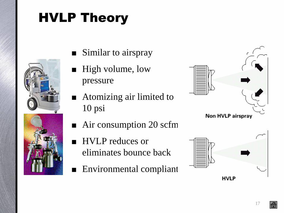
HVLP Theory
Similar to airspray
High volume, low
pressure
Atomizing air limited to
10 psi
Air consumption 20 scfm
HVLP reduces or
eliminates bounce back
Environmental compliant

18
Fluid Pressure
5-10 psi
.33-.66 bar
1-6 in
25-150 mm
HVLP Setting Fluid Stream
Apply fluid pressure to
create an 1-6 inch fluid
stream
Different materials -
different fluid pressures
Measured in ounces per
minute (cc/minute)

19
2000+ psi fluid pressure
Transfer efficiency = 50 - 60%
Airless, Theory of Operation
Airless spray atomization
- hydraulic force through
a cats eye shaped orifice
2000+ psi fluid pressure
Fastest and heaviest spray
finish and is measured in
liters per minutes
Transfer efficiency =
50-60%
Protective coatingsClick to see spray

20
Airless, Theory of Operation
Airless spray atomization is created by hydraulic force pushing material through an orifice.
As the fluid exits the orifice, friction between the fluid stream and atmosphere disrupts the stream into small particles.
Airless spray gives the fastest and heaviest spray finish and is measured in gallons per minutes.
Used when a protective coating is the priority.
Higher pressure is needed for a complete pattern .
2000 psi
133 Bar 13.3 MPa
Fluid pressure
Transfer efficiency = 40-50%

21
Airless Application
Advantages
High Productivity
Bonding between the
Coating and surface to be
coated
Penetration of coating into
the blasted profile.
Very Low chances for
coating failure
High Transfer Efficiency
Disadvantages
Applicable where surface finish quality is not the criteria.
Not suitable for small job works where less than 5ltr of paint is consumed in one batch
Expensive Equipment
Required skilled operator technique

22
Typical Airless Applications

23
Application Equipment &Applications

24
Airless Sprayer Product Family
80:1 33:1 Zinc 24:1
80:1 AA 41:1

25
Choosing the Right TIP.
Choosing the right tip is important for maximum productivity – Tip determines the fluid flow and size of the spray pattern
Right tip results in maximum control and minimum over spray
It is easy to determine which tip size to use when you know the material you will be spraying.
Need to know the maximum flow rate of the Pump- * ( Flow rate of the pump should always be higher than the flow of the tip)
Recommended Best Fan size for the Job
Recommended Tip Recommended Tip Sizes for Common Coating
Material Tip Size ( in.)
Stain or Lacquer .011 to .013
Oil Base Paint .013 to .015
Latex Paints .015 to .019
Heavy Latex & Smooth Electrometric .021 to .025
Electrometric and Block Fillers .025 to .035+
Eg : Tip xxx415 and xxx 515 have a 1 ltr flow rate with different fax sizes. Tip 415 sprays a 8in fax with a thicker coat (More mil build ) , and tip 515 sprays a 10” fan with a less mil build.
DO not try to increase the area covered with each pass by backing the gun away from the surface , Further away from the surface , less paint will reach the surface and go to waste as over spray .
Spray at the lowest possible pressure greatly extends the life of major pump components – and the spray tips too.
Watch for runs or sags in the pattern as a sign of a worn tip. DO not increase pressure of the pump to combat this problem
You will only waste paint and increase the wear on the pump. – Simply replace the tip.

26
“tails”
“tails”
Air-Assist, Theory
Air-Assist spray
atomization similar to
airless, but less pressure
Better finish than airless
High flow rate
800+ psi fluid pressure
~20 psi air pressure
Transfer efficiency =
60-65%

27
Air Assisted Airless Spray
•Advantages
• Reduced flow rates compared to
airless
• Increase operator control due to
lower fluid flow rates and pressure
• Increase finish quality due to
reduced particle velocity
- the softer the particles,
the better the finish quality.
• Higher transfer efficiency.
• Reduced parts wear.
•Disadvantage
• Takes two hoses,
air and fluid
• Higher Cost.

28
Air Assisted Airless Electrostatic
Applications
Structural Steel
Tubing
Ornamental Iron, metal tubing, trim work
Engineering Equip.Manufacturing
Handrails
Aircraft and Ground Support Equipment
Farm Equipment

29
Transfer Efficiency
Transfer efficiency (TE) = (paint deposited on a part)/(total paint sprayed)
TE = (Wp/Ws) x 100%
Wp = Weight of wet coating on the part
Ws = Weight of liquid coating sprayed

30
Electrostatic Technology

31
1500 liters of wet paint is required yearly to coat the parts.
Using a 3 lbs/gal VOC material that is 10 lbs/gal overall.
Transfer Efficiency
Comparison
Application Method
(Transfer Efficiency)
Liters of
Paint/Yr
Tons of
VOC's/Yr
Liters of
Paint
Wasted/Yr
Tons of
Paint
Sludge/Yr
Air Spray
(30% Efficiency)
5000
7.5
3500
12.25
HVLP
(45% Efficiency)
3333
5
1833.3
6.4
Airless ( 50-55%) 2800 3.25 1500 4.5
Air Assisted Airless (60%
Efficiency)
2500
3.75
1000
3.5
Electrostatic Air Spray
(75% Efficiency)
2000
3
500
1.75
Electrostatic Air Assisted
Airless
(85% Efficiency)
1765
2.65
265
0.93

32
Higher Transfer Efficiency
Less solvent emissions and cost
Less exposure of personnel to harmful solvents
Less paint sludge to dispose
Lower booth maintenance costs
Less production downtime for cleanup
Less paint handling and cost
33
Electrostatics & Transfer
Efficiency
Factors that effect electrostatic transfer efficiency
– Distance from gun to grounded part
– Gun distance should be 10 to 12 inches (250 - 300 mm) from
the target
– Material conductivity
– Highly conductive (low resistivity) materials
– Shape of the target
– Corners or enclosed area cause a Faraday Cage Effect

34
Typical Installation Equipment for Electrostatic Application

35
Air Assisted Airless Electrostatic
Applications
Structural Steel
Tubing
Ornamental Iron, metal tubing, trim work
Engg Equip. Manufacturing
Handrails
Aircraft and Ground Support Equipment
Farm Equipment

36
Definition of Plural Component
Materials
Two materials,
blended in specific proportions
to produce a new usable product.

37
Plural Component Materials
Names
“A”
Component
Resin
Base
Prepolymer
Polyol
Lacquer
“B”
Component
Isocyanate
Catalyst
Accelerator
Promoter
Activator
Hardener
MIX• Atomization
( Spray )
• Dispensing
• Extrusion• Hand
• Mechanical
• Electronic

38
Working Pot Life / Pot Life
Working Pot Life
– The period of time after mixing that the material provides Good Application Characteristics.
– a.k.a.; Spray Life for coatings,
Pot Life
– the period of time prior to the material hardening
Time
SolidLiquid
Working Pot Life Pot
Life
Vis
cosi
ty

39
Maintaining proper ratio
Application prior to curing
(spray life/work time)
Off-ratio blending results in
costly failures for manufacturers:
– Lost Production
– Rework
– Scrap
– Warranty
Maintaining finish quality
Plural Component Materials
Challenges

40
Manual or Hand Mixing Issues
Why Manual or Hand Mixing?
– Not capital $ intensive
– Some materials ratios are not that critical
– Low production volumes/rates
What are the issues with Hand Mixing?
– Operator related measuring and mixing quality issues
– Disposal of cans
– Large quantities of clean-up solvent
– Labor intensive
– “Quality of life” for employees

41
Hand Mixing.
Hand measured and mixed often referred to as Hot Potting.
– least accurate
– generates the most waste
– labor intensive
– inaccurate mixing of material
– more exposure to chemicals
– no expensive equipment needed

42
Benefits of 2 K application
Equipment
Data collection and reports
Batch Reports
– ISO conformance
Material / recipe usage reports
– Environmental reports
Inventory reports
· Sample Batch Report
Batch Report
Date 11/04/96 Started at 22:36
Recipe ID: 39684285 Job: A 0357
Name: Star Blue Batch: 000865
Unit Measure: Gallons Operator: A0357
COMPONENT TARGET ACTUAL ERROR TOLERANCE
03 Resin 1.000 0.992 gal. -0.80% +/- 1.50%
05 Catalyst 1.000 0.995 gal. -0.50% +/- 2.00%
Solvent 0.250 0.248 gal. -0.80% +/- 2.00%
Total Batch 2.250 2.235 gal. -0.70%
Completed at 22:41
• Reduced operator exposure
to hazardous materials
• Accurate Mixing

43
Application Equipment Solutions
Batch Mixing
– Pressure Pots
– Airless Spray Package
Mechanical Proportioners
– Fixed & Variable Ratio HydraCat
Electronic Proportioners
– Xtreme Mix

44
•Mechanical
Proportioning
•Manual or Hand Mixing
(Batch Mixing)
•Electronic Proportioning
Systems
Price•Mechanical with on-line
Ratio Assurance DevicesPerformance
Handling Plural Component
Materials
45
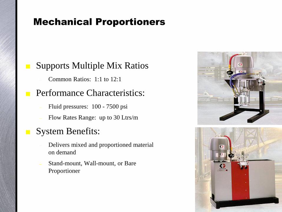
Mechanical Proportioners
Supports Multiple Mix Ratios
– Common Ratios: 1:1 to 12:1
Performance Characteristics:
– Fluid pressures: 100 - 7500 psi
– Flow Rates Range: up to 30 Ltrs/m
System Benefits:
– Delivers mixed and proportioned material
on demand
– Stand-mount, Wall-mount, or Bare
Proportioner

46
Operation
Proximity
Sensor
Fluid
Manifold
Integrator

47
Contractor’s Equipments
required at job site

48
Portable toilet at job site
Hand wash unit

49
Soluble salt Test Key