AT Commands - Sumelco
65
AT Commands INSYS GSM AT Command Reference Jun-10
-
Upload
khangminh22 -
Category
Documents
-
view
0 -
download
0
Transcript of AT Commands - Sumelco

AT
Com
man
ds
INSYS GSM
AT Command Reference
Jun-10


Copyright © June 10 INSYS MICROELECTRONICS GmbH Any duplication of this manual is prohibited. All rights on this documentation and the devices are with INSYS MICROELECTRONICS GmbH Regensburg. Trademarks The use of a trademark not shown below is not an indication that it is freely available for use. MNP is a registered trademark of Microcom Inc. IBM PC, AT, XT are registered trademarks of International Business Machine Corporation. INSYS ® is a registered trademark of INSYS MICROELECTRONICS GmbH. Windows™ is a registered trademark of Microsoft Corporation. Linux is a registered trademark of Linus Torvalds. Publisher: INSYS MICROELECTRONICS GmbH Waffnergasse 8 D-93047 Regensburg, Germany Phone: +49 (0)941/56 00 61 Fax: +49 (0)941/56 34 71 E-mail: [email protected] Internet: http://www.insys-tec.de Date: Jun-10
Item: 31-22-03.036
Version: 3.1
Language: EN

Contents
1 General Notes to the AT Command Sets ............................................................ 5
2 Short Description Standard AT Commands........................................................ 7
2.1 AT Commands According to V.25ter ..................................................................................8
2.2 AT Commands for GSM Connections ...............................................................................12
2.3 AT Commands for SMS .....................................................................................................14
3 Short Description INSYS AT Commands ........................................................... 16
4 Description of INSYS AT Commands................................................................. 18
5 GSM Character Set for SMS............................................................................... 57
6 Network Provider Identification Numbers....................................................... 58
4 Jun-10

INSYS GSM General Notes to the AT Command Sets
1 General Notes to the AT Command Sets
The INSYS GSM is configured and controlled using two AT command sets: The standard AT commands control the GSM engine for establishing data connections via the GSM network. The extended INSYS AT commands control the extensions implemented by IN-SYS for the digital IOs, alarm functions, safety functions and time-controlled functions.
The standard AT commands can only be entered locally via the serial interface, if the IN-SYS GSM is in offline state (no active data connection) or in online command mode (in-terrupted data connection).
The extended INSYS AT commands (section 1) can be entered locally and remote (remote configuration) and, in most of the cases, also via SMS. The configuration via SMS is lim-ited to commands with responses of up to 140 characters.
The modem guideline V.25ter must be used in view of the chronological sequence of the interface commands. The AT standard is a line-oriented command language. The entry is not case-sensitive. All commands are completed with the line end character, configured with the ATS3 command (Default = <CR> = 0Dh). The line edit character, configured with the ATS5 command, can be used to delete incorrectly entered characters (Default = <BS> - 08h -).
Each command is acknowledged with a response according to V.25ter (configuration with ATV):
Response Code Type Meaning
OK 0 final Command executed, no error
CONNECT 1 final Connection established, if parameter setting X=0
CONNECT[<text>] final Connection established, if parameter setting X>0 <text>: e.g. ‘connect 9600’. The data transmission rate is then 9600 Bit/s.
RING 2 unsolicited Ring tome detected
NO CARRIER 3 final Connection not established or terminated
ERROR 4 final Invalid command or command line too long
NO DIALTONE 5 final No dial tone, connection establishment not successful, wrong operating mode
BUSY 6 final Remote terminal busy
NO ANSWER 7 final Timeout during connection establishment
5

General Notes to the AT Command Sets INSYS GSM
A <CR> (Carriage Return) is indicated as line end character in the further course to ease readability. The standard responses OK or ERROR are always used as responses, regard-less of the actually selected responses according to V.25.
A collating sequence of several commands is not possible for the extended INSYS AT commands. Further commands can only be sent if the processing of a previous command has been finished, i.e. the response has been is-sued.
We refer to the detailed command set of the GSM engine for a sequence of standard AT commands.
The IT commands implemented in the INSYS GSM 2.0 are replaced by the extended INSYS AT commands of the format AT**name. A change to configuration mode is not required any more.
6

INSYS GSM Short Description Standard AT Commands
2 Short Description Standard AT Commands
The standard AT commands comprise the specifications according to V.25ter, GSM 07.07 and GSM 07.05. Only the most important standard AT commands are described with syntax and parameters in the following.
The applicability of individual features may depend on the selected GSM network.
Syntax:
<expression> Parameter input
<pause> Means a waiting period of 1 second
[expression] Optional parameter input
Factory default settings are indicated with "(default)".
7

Short Description Standard AT Commands INSYS GSM
2.1 AT Commands According to V.25ter Command Description
ATA Answer mode
The INSYS GSM changes to answer mode. Only effective if a call is coming in.
AT&C<n> Configuring the function of the DCD control line
AT&C0 DCD is always ON
AT&C1 DCD indicates presence of carrier signal (default)
ATD<n> Establishing a connection
Dialling the phone number <n>
AT&D<n> Function type of the DTR control line
Configuring (change ONOFF)
AT&D0 Ignored
AT&D1 Change into command mode, connection held
AT&D2 Change into command mode, connection terminated, no auto-matic connection acceptance with DTR OF. (default)
ATDL Redialling the last dialled number
ATE<n> Command input echo
The INSYS GSM sends back all entries on the serial interface.
ATE0 Disabling echo
ATE1 Enabling echo (default)
AT&F Loading factory default settings
The factory default settings are loaded. All factory default settings in this AT
command list are indicated with "(default)".
Note: The settings of the INSYS AT** commands are reset with AT**DEFAULT.
ATH Terminating a connection
The INSYS GSM hangs up. Immediately after the disconnect, the controller will
not respond to external AT commands for a certain period. This period is made
up of the query duration of the field strength (AT**GSMREQ; 5 s at 19200 baud)
and the duration of SMS polling (AT**SMSBUF) together.
ATI Displaying the product information of the GSM engine
8

INSYS GSM Short Description Standard AT Commands
Command Description
AT+ICF Configuring the data format
This command configures the data format of the serial interface.
AT+ICF=? Displaying the possible settings
AT+ICF=<x,y> Setting the data format x and the parity y
<x>=1 8N2
<x>=2 8E/O2
<x>=3 8N1 (default)
<x>=5 7E/O1
<y>=0 Odd parity (O)
<y>=1 Even parity (E)
AT+ICF? Querying the configured data format
AT+IPR Configuring the baud rate
This command configures the baud rate of the serial interface.
AT+IPR=? Displaying the possible settings
AT+IPR=<x> Setting the baud rate to x baud
AT+IPR? Querying the configured baud rate
ATO<n> Returning to online data mode
ATQ<n> Quiet control
This command enables or disables sending messages from the INSYS GSM to
the PC
ATQ0 Sending messages to PC (default)
ATQ0 Sending no messages to PC
AT\Q<n> Data flow control of the serial interface
AT\Q0 OFF (default)
AT\Q1 Software handshake (XON/XOFF)
AT\Q2 Only CTS
AT\Q3 Hardware handshake (RTS/CTS)
ATS<n> Reading/writing the S registers
Some S registers can only be modified in certain limits. The modem still reports
OK, although the value has not changed as specified. Some registers can only be
read. We recommend therefore to check the results after each write attempt,
using the ATS<n>? command.
ATS<n>=x Sets the S register n to the value x
ATS<n>? Shows the value of the S registry n.
9

Short Description Standard AT Commands INSYS GSM
Command Description
ATS<n> Configuring automatic call acceptance
The automatic call acceptance is configured using the S register S0. S0 can be
configured between 0 and 255.
ATS0=<x> Automatic call acceptance after x ring tones (<x> = 2..255)
ATS0=0 Disabling automatic call acceptance
ATS0? Querying automatic call acceptance
AT&S<n> Configuring the function of the DSR control line
AT&S0 DSR always ON (default)
AT&S1 DSR follows DCD
ATX<n> CONNECT response format and connection monitoring
<n> 0 Numerical response for CONNECT, no dial tone detection, no
busy signal detection
1 Text response for CONNECT, no dial tone detection, no busy
signal detection
2 Text response for CONNECT, dial tone detection, no busy
signal detection
3 Text response for CONNECT, no dial tone detection, busy
signal detection
4 Text response for CONNECT, dial tone detection, busy signal
detection
ATV<n> Format of modem messages
This command determines, whether the INSYS GSM transfers messages to the
PC in short or long form.
ATV0 Messages in short format, i.e. only the error number
ATV1 Messages in long format, i.e. the error text (default)
Note: The settings of the INSYS AT** commands are displayed with AT**PROFILE.
AT&V Showing the configurations
This command causes the display of the active configuration of the INSYS GSM,
the stored user settings.
Note: The settings for AT+IFC, ATE, ATQ, ATV, AT\Q, AT&C, AT&D, AT&S, ATS0 do not correspond with the actual values for AT&V.
The settings of the INSYS AT** commands are displayed with AT**PROFILE.
10
INSYS GSM Short Description Standard AT Commands
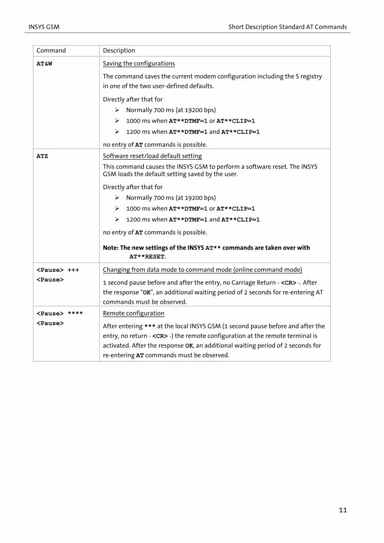
Command Description
AT&W Saving the configurations
The command saves the current modem configuration including the S registry
in one of the two user-defined defaults.
Directly after that for
Normally 700 ms (at 19200 bps)
1000 ms when AT**DTMF=1 or AT**CLIP=1
1200 ms when AT**DTMF=1 and AT**CLIP=1
no entry of AT commands is possible.
ATZ Software reset/load default setting
This command causes the INSYS GSM to perform a software reset. The INSYS GSM loads the default setting saved by the user.
Directly after that for
Normally 700 ms (at 19200 bps)
1000 ms when AT**DTMF=1 or AT**CLIP=1
1200 ms when AT**DTMF=1 and AT**CLIP=1
no entry of AT commands is possible.
Note: The new settings of the INSYS AT** commands are taken over with AT**RESET.
<Pause> +++
<Pause>
Changing from data mode to command mode (online command mode)
1 second pause before and after the entry, no Carriage Return - <CR> -. After
the response "OK", an additional waiting period of 2 seconds for re-entering AT
commands must be observed.
<Pause> ****
<Pause>
Remote configuration
After entering *** at the local INSYS GSM (1 second pause before and after the
entry, no return - <CR> -) the remote configuration at the remote terminal is
activated. After the response OK, an additional waiting period of 2 seconds for
re-entering AT commands must be observed.
11

Short Description Standard AT Commands INSYS GSM
2.2 AT Commands for GSM Connections Command Description
AT+CBST? Querying the type of bearer service
AT+CBST=<n> Configuring the bearer service to modem and ISDN TA
AT+CBST=0 Autobauding
AT+CBST=4 2.400 bps (V.22bis)
AT+CBST=6 4.800 bps (V.32)
AT+CBST=7 9.600 bps (V.32) (default)
AT+CBST=68 2.400 bps (V.110)
AT+CBST=70 4.800 bps (V.110)
AT+CBST=71 9.600 bps (V.110)
AT+COPS? Displaying the selected network provider
AT+COPS=<n>
[,<format>,
<oper>]
Selecting network provider and registering
AT+COPS=? Displaying the network providers available at the
location
AT+COPS=0 Automatic (default)
AT+COPS=1 Manual selection <oper>
AT+COPS=2 Logout from GSM network
AT+COPS=4 Manual selection <oper> - if not available, automatic selection
<format> 2 Numerical information for <oper>
<oper> Specification of the network provider (refer to the
Network Provider Identification Numbers section)
AT+CPIN? Querying the required password
Response (selection):
READY No entry required or PIN transfer successful
SIM PIN Enter SIM card PIN
SIM PUK Enter SIM card PUK (after repeated incorrect entry of
the PIN)
ERROR SIM card not inserted or not recognized
AT+CPIN=<n> Entering the PIN of the SIM Card
<n> 4-digit number
The PUK must be entered after repeated wrong entry. The following command must be used to enter the PUK AT+CPIN=<PUK>,<new PIN>
The PIN can be stored permanently in the controller using the extended command AT**PIN.
12

INSYS GSM Short Description Standard AT Commands
Command Description
AT+CRC Configuring extended RING messages
If the extended RING message is enabled, an incoming call will be displayed
with an unsolicited result code.
AT+CRC=0 Disable extended RING message (default)
AT+CRC=1 Enable extended RING message
AT+CREG? Displaying the registration state (network state)
Response: <n>,<stat>
<stat> 0 Not registered, no GSM network search
1 Registered with the standard provider
2 Not registered, GSM network search
3 Refused
5 Registered, roaming
AT+CSQ Displaying the signal quality (GSM signal intensity)
Response: <rssi>,<ber>
<rssi> Value of the received GSM field strength
0..10 Poor reception, change location
11..31 Good reception
99 Not detectable
Note: Antenna positions with values below 12 should be avoided.
<ber> Bit Error Rate
The bit error rate is only measured for an established
connection. Otherwise, the value 0 or 99 is returned.
13

Short Description Standard AT Commands INSYS GSM
2.3 AT Commands for SMS Command Description
AT+CMGD=<n> Deleting SMS message <n>
AT+CMGF? Querying the SMS message format
AT+CMGF=<n> Configuring the SMS message format
AT+CMGF=0 PDU mode (default)
AT+CMGF=1 Text mode
AT+CMGL=<stat> Listing the SMS message in the selected memory
PDU mode
AT+CMGL=0 Unread messages
AT+CMGL=1 Read messages
AT+CMGL=2 Stored, sent messages
AT+CMGL=3 Stored, unread messages
AT+CMGL=ALL All messages
Text mode
AT+CMGL=REC READ Read messages
AT+CMGL=REC UNREAD Unread messages
AT+CMGL=STO SENT Stored, sent messages
AT+CMGL=STO UNSENT Stored, unread messages
AT+CMGL=ALL All messages
Note: The statuts of unread messages will be set to read.
AT+CMGR=<n> Reading SMS message <n>
Note: The statuts of unread messages will be set to read.
AT+CMGS=<no>
<CR><text>
<Strg-Z>
Sending an SMS message (text mode)
<no> Phone number
<CR> Enter/carriage return key
<text> Text of the SMS message
<Ctrl-Z> Press CTRL and Z (0x1A)
The phone number entry is completed with <CR>, the actual text with <Ctrl-Z>.
Note: The SMS message format is to be changed to AT+CMGF=1.
AT+CNMI Immediately outputting and deleting an SMS message
This command can be used to output incoming messages immediately and
delete them afterwards.
AT+CNMI=2,2 Output SMS message immediately and delete it afterwards
AT+CNMI=0,0 Don't output SMS message immediately (default)
14

INSYS GSM Short Description Standard AT Commands
Command Description
AT+CSCA? Querying the number of the SMS Service Center
AT+CSCA=<no> Configuring the number of the SMS Service Center
<no> Number in international format +49…
AT^SMGL Listing SMS messages from preferred memory
(without changing the state)
AT^SMGO? Querying the SMS overflow presentation mode
Response: ^SMGO: <n>,<mode>
AT^SMGO=<n> Configuring the SMS overflow presentation mode
AT^SMGO=0 Disabled (default)
AT^SMGO=1 Enabled – change of <mode> is displayed
<mode> 0 Memory location available
1 Memory full
2 Memory full, message waits
AT^SMGR=<n> Reading SMS message <n> (without changing the state)
15

Short Description INSYS AT Commands INSYS GSM
3 Short Description INSYS AT Commands
Configuration Command Short description local remote SMS
AT**ALIVE Alive SMS X X S AT**BAUD Baud rate of the serial interface X X X AT**CALLBACK Target pohne number of security callback X X X AT**CLIP Selective call acceptance X X S AT**COMBINE Connection of the alarm text with a target number of
the number pool (AT**POOL) X X S
AT**DATE Date X X X AT**DAY Weekday X X X AT**DEFAULT Default settings of the INSYS AT commands X X X AT**DIAL Dial-up attempts for alive or alarm messages X X X AT**DIR I/O configuration X X X AT**DST Main target phone number for alarm messages X X S AT**DTC Idle connection control (data transmit control) X X X AT**DTMF Enable DTMF evaluation X X X AT**ESC Escape character for remote command mode X X X AT**EXIT Exiting the remote command mode X AT**FLASH Firmware update of the controller X X AT**FORMAT Data format of the serial interface X X X AT**GSMREQ Periodic request of the field strength and login state of
the GSM network X X X
AT**HISTORY History function (event log) X X S AT**IN Querying the alarm inputs X X X AT**INPUT Configuration of the alarm inputs X X X AT**LOGOUT Timer-controlled logout/login or reset X X X AT**MSG Alarm message texts X X S AT**OH Configuration of the OH_GSM control line X X X AT**OUT Setting/resetting the control outputs X X X AT**OUTPUT Configuration of the switch outputs X X X AT**PASS Password protection X X X AT**PIN PIN of the SIM card X X X AT**POOL Phone number pool for alarm messages X X S AT**POWER Power-up SMS X X S AT**PROFILE Querying the settings of the INSYS AT commands X X AT**PROVIDER Manual GSM network provider selection X X X AT**RESET Resetting the Device X X X AT**SCN SMS Service Center Nummer X X X AT**SIGNAL GSM signal field strength X X X AT**SMS Manual SMS dispatch of the configured alarm messages X X AT**SMSRX Automatic SMS reception evaluation X X X
AT**SMSBUF Specification of the existing SMS storage locations on
the SIM card
X X X
AT**SWITCH Execution of a switch process (starting with FW version
2.40)
X X X
16

INSYS GSM Short Description INSYS AT Commands
17
Configuration Command Short description local remote SMS
AT**SWITCHENTRY Assignment of a clear text name to a switch process
(starting with FW version 2.40)
X X S
AT**TIME Time X X X AT**VERSION Querying the software version X X X X = completely implemented S = only setting implemented

Description of INSYS AT Commands INSYS GSM
4 Description of INSYS AT Commands
The prefix always consists of the characters "AT**".
Syntax:
<expression> Parameter input
<pause> Means a waiting period of 1 second
[expression] Optional parameter input
Factory default settings are indicated with "default".
The standard end character is "Return" (0Dh) or also known as "<CR>".
The commands are acknowledged with OK or ERROR. It must be waited for the acknowl-edgement of a command being processed before entering the next command to ensure a proper processing.
All settings made with AT** commands are immediately stored to the EEPROM. How-ever, some of them become only effective after a restart.
The explanation of the parameters for the responses following queries can be found at the write commands. Most AT** commands can also be executed via SMS – exceptions are explicitly indicated.
The commands AT**COMBINE, AT**DIR, AT**DST, AT**INPUT, AT**MSG, AT**IN, AT**OUTPUT, AT**OUT and AT**SWITCHENTRY described in the following differ de-pending on the device (i-modul or DIN rail device or DIN rail device with 4 inputs, or are not available for some devices at all. Therefore, each of these command is described indi-vidually for the respective device. Please take care to read the right description.
18

INSYS GSM Description of INSYS AT Commands
AT**ALIVE Alive SMS
Read: AT**ALIVE?
Response:
ALIVE: <mode>[,<day>][,<time>] ALIVE: DST = <number> ALIVE: MSG = <text>
OK
Parameters:
<mode> inactive Function disabled
Note: This query cannot be performed via SMS
Write: AT**ALIVE=<mode> AT**ALIVEDST=<number> Target phone number AT**ALIVEMSG=<text> Message text
Parameters:
<mode> D,<time> Daily dispatch of the periodic alive SMS at the time <time>; <day> regardless
W,<day>,<time> Weekly dispatch of the periodic alive SMS at the weekday <day> and the time <time>
M,<day>,<time> Montly dispatch of the periodic alive SMS at the day <day> and time <time>
<time> Time in format hh:mm, e.g. 09:35
<day> <mode> = D: regardless <mode> = W: Weekday in format: MO, TU, WE, TH, FR, SA, SU <mode> = M: Day from 1 ... 31 If a month has less days than specified in <day>, the function
will be executed at the last day of the month.
<number> Target phone number of the periodic alive SMS, max. 20 digits
<text> Message text of the periodic alive SMS, max. 140 digits
If no data connection is active and no alarm is processes, the time for the peri-odic alive SMS is checked in intervals of 30 seconds.
Delete: AT**ALIVE= Disableing the peridic alive SMS dispatch AT**ALIVEDST= Deleting the target phone number AT**ALIVEMSG= Deleting the message
The entry line is completed after "=" with <CR>.
Default: AT**ALIVE=inactive
AT**BAUD Configuring the baud rate of the serial interface
Read:
AT**BAUD?
Response: BAUD: <baud>
OK
19

Description of INSYS AT Commands INSYS GSM
Write: AT**BAUD=<baud>
Parameters: <baud> AT**baud=300 300 bps AT**baud=600 600 bps AT**baud=1200 1200 bps AT**baud=2400 2400 bps AT**baud=4800 4800 bps AT**baud=9600 9600 bps AT**baud=14400 14400 bps AT**baud=19200 19200 bps AT**baud=38400 38400 bps AT**baud=57600 57600 bps AT**baud=115200 115200 bps
In case of a local or SMS configuration, the reply will still be issued with the pre-vious baud rate before the baud rate is changed. In case of a remote configuration, the baud rate will be changed after the next reset of the device.
Default: AT**BAUD=19200
AT**CALLBACK Target phone number of security callback
Read: AT**CALLBACK?
Response: CALLBACK: <number>
OK
Write: AT**CALLBACK=<number>
Parameters:
<number> Phone number that is called back with enabled security callback function. The maximum length is 20 digits.
Prerequisite for the security callback function is the activation of the data pass-words (AT**PASSC).
Delete: AT**CALLBACK=
The entry line is completed after "=" with <CR>.
Default: AT**CALLBACK=0,0,0
AT**CLIP? Selective call acceptance
Read: AT**CLIP=? Read out status
Response: CLIP: <status>
OK
AT**CLIP? Read out phone numbers. This query cannot be performed via SMS!
Response: CLIP: 01=<number> ... CLIP: 15/30=<number>
OK
20

INSYS GSM Description of INSYS AT Commands
Write:
AT**CLIP=<status> Enable/disable call acceptance
Parameters: <status> 0 Selective call acceptance disabled 1 Selective call acceptance enabled
AT**CLIP<index>=<number> Enter permitted phone numbers
Parameters:
<index> 1 ... 15/30 15/30 Entries for phone numbers
99 Delete complete list
<number> Phone number that is permitted for a call or SMS to the device. The maximum length is 20 digits.
It is possible to release complete number blocks. The wildcard character "*" stands for any one digit.
Note: Starting with firmware version 2.40, it is possible to enter 30 instead of 15 phone number as before.
In order to use these security functions, the caller must have the calling line identification presentation (CLIP) enabled. The selective call acceptance becomes only active following a reset of the device. Then, the GSM engine operates with the setting (AT+CLIP=1). The phone number will be output with each incoming call in addition to the "RING" message here.
Example:
RING
+CLIP: "+49941560061",145,,,,0
The allowed number has to be entered in exactly the same format, as it is output for a call with “+CLIP:..." (without ””).
Note: The transmitted number format may depend on the provider – it may be possible that the leading "+49" is replaced by "0049" for example. It is urgently recommended to verify the entry with a test call from the number.
Incoming calls from non-permitted numbers will be rejected immediately in order to keep the lines clear. It is also not possible to accept them manu-ally (ATA). The caller gets the BUSY signal.
Delete: AT**CLIP<index>=
AT**CLIP99=<CR> Deletes the complete list
The entry line is completed after "=" with <CR>.
Default: Disabled, no numbers entered
21

Description of INSYS AT Commands INSYS GSM
AT**COMBINE Connection of the alarm text with a target number of the number pool (only valid for i-modul GSM PRO)
Read: AT**COMBINE?
Response: COMBINE: IO1=[<co1>[,<co2>...[,<co10>]]]]]]]]]] COMBINE: IO2=[<co1>[,<co2>...[,<co10>]]]]]]]]]] COMBINE: IO3=[<co1>[,<co2>...[,<co10>]]]]]]]]]] COMBINE: IO4=[<co1>[,<co2>...[,<co10>]]]]]]]]]] OK This query cannot be performed via SMS.
Write: AT**COMBINE[<input>]=[<co1>…[,<co10>]…]
Parameters: <input> Alarm input for which the connection is intended. 1 Alarm input I/O1 2 Alarm input I/O2 3 Alarm input I/O3 4 Alarm input I/O4 If <input> is not specified, alarm input 1 will be used. The respective I/O must be defined as input, of course (AT**DIR). <co1> 1..20 1. Reference to a number from the number pool
defined with AT**POOL. The index of the number in the pool is specified.
... <co10> 1..20 10. Reference to a number of the pool defined
with AT**POOL. Each alarm message can be sent to 10 further targets defined via the number pool in addition to the main target number (AT**DST), i.e. up to 11 times .
These connections are also evaluated if no main target number is configured.
Delete: AT**COMBINE[<input>]=
The entry line is completed after "=" with <CR>.
Default: Empty
22
INSYS GSM Description of INSYS AT Commands
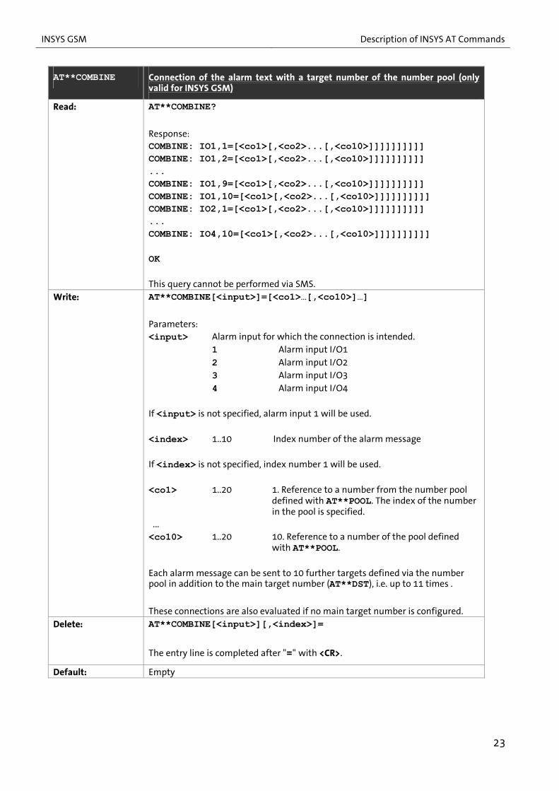
AT**COMBINE Connection of the alarm text with a target number of the number pool (only valid for INSYS GSM)
Read: AT**COMBINE?
Response: COMBINE: IO1,1=[<co1>[,<co2>...[,<co10>]]]]]]]]]] COMBINE: IO1,2=[<co1>[,<co2>...[,<co10>]]]]]]]]]] ... COMBINE: IO1,9=[<co1>[,<co2>...[,<co10>]]]]]]]]]] COMBINE: IO1,10=[<co1>[,<co2>...[,<co10>]]]]]]]]]] COMBINE: IO2,1=[<co1>[,<co2>...[,<co10>]]]]]]]]]] ... COMBINE: IO4,10=[<co1>[,<co2>...[,<co10>]]]]]]]]]] OK This query cannot be performed via SMS.
Write: AT**COMBINE[<input>]=[<co1>…[,<co10>]…]
Parameters: <input> Alarm input for which the connection is intended. 1 Alarm input I/O1 2 Alarm input I/O2 3 Alarm input I/O3 4 Alarm input I/O4 If <input> is not specified, alarm input 1 will be used. <index> 1..10 Index number of the alarm message If <index> is not specified, index number 1 will be used. <co1> 1..20 1. Reference to a number from the number pool
defined with AT**POOL. The index of the number in the pool is specified.
... <co10> 1..20 10. Reference to a number of the pool defined
with AT**POOL. Each alarm message can be sent to 10 further targets defined via the number pool in addition to the main target number (AT**DST), i.e. up to 11 times .
These connections are also evaluated if no main target number is configured.
Delete: AT**COMBINE[<input>][,<index>]=
The entry line is completed after "=" with <CR>.
Default: Empty
23

Description of INSYS AT Commands INSYS GSM
AT**DATE Date
Read: AT**DATE?
Response: DATE: <dd>.<mm>.<yy> OK
Write: AT**DATE=<dd>.<mm>.<yy>
Parameters: <dd> Day (two-digit) <mm> Month (two-digit) <yy> Year (two-digit)
The setting is immediately written to the RTC.
Default: AT**DATE=01/01/2003
AT**DAY Weekday
Read: AT**DAY?
Response: DAY: <day> OK
Write:
AT**DAY=<day>
Parameters: <day> Current weekday MO Monday TU Tuesday WE Wednesday TH Thursday FR Friday SA Saturday SU Sunday
The setting is immediately written to the RTC.
Default: AT**DAY=SU
24

INSYS GSM Description of INSYS AT Commands
AT**DEFAULT Loading factory default settings
Write: AT**DEFAULT
The following factory default settings of the AT** commands will be set.
TIME: 00:00:00 DAY: SU DATE: 01.01.03
BAUD: 19200 FORMAT: 8N1 ESC: * OH: 1
PROVIDER: LOGOUT: 00:00,inactive SCN: DTC: 000 SMSRX: 0 SMSBUF: 10 GSMREQ: 1 DIAL: 03
POWER: inactive POWER: DST = POWER: MSG =
ALIVE: inactive ALIVE: DST = ALIVE: MSG =
PASSC: inactive PASSD: inactive PASST: inactive
CALLBACK:
CLIP: 0 CLIP: 01= … CLIP: 15=
DIR: IO1 = OUT DIR: IO2 = IN DIR: IO3 = OUT DIR: IO4 = IN
OUTPUT: IO1 = 1,0,0 OUTPUT: IO2 = IN OUTPUT: IO3 = 1,0,0 OUTPUT: IO2 = IN
25

Description of INSYS AT Commands INSYS GSM
AT**DEFAULT
Write:
(CONTINUATION)
OUT: IO1 = 0 OUT: IO2 = IN OUT: IO3 = 0 OUT: IO4 = IN
DST: IO1= DST: IO2= DST: IO3= DST: IO4=
MSG: IO1= MSG: IO2= MSG: IO3= MSG: IO4=
POOL: 01= … POOL: 20=
COMBINE: IO1= COMBINE: IO2= COMBINE: IO3= COMBINE: IO4=
OK Note: A set PIN will not be deleted (refer to AT**PIN) The event log of the history function will be deleted.
The device performs an automatic reset not later than 25 seconds after entering
the command in order to take over the modified settings and re-initialise the
GSM engine!
The reset takes another 25 seconds.
AT**DIAL Dial-up attempts for periodic alive or alarm messages
Read: AT**DIAL?
Response: DIAL: <count> OK
Write: AT**DIAL=<count>
Parameters: <count> 1 .. 12 Number of attempts for the message dispatch or
connection establishment for alarm and periodic alive messages
The dispatch of a confirmation SMS will only be tried once after a configuration via SMS.
Default: AT**DIAL=3
26

INSYS GSM Description of INSYS AT Commands
AT**DIR Configuring the I/Os as inputs or outputs (only valid for i-modul GSM PRO)
Note: This description is only valid for the i-modul GSM PRO! Read: AT**DIR?
Response: DIR: IO1 = <status> DIR: IO2 = <status> DIR: IO3 = <status> DIR: IO4 = <status> OK
Write: AT**DIR<io>=<status> Parameters: <io> 1 IO1 2 IO2 3 IO3 4 IO4 <status> IN IO defined as input OUT IO defined as output
The dispatch of a confirmation SMS will only be tried once after a configuration via SMS.
Default: DIR: IO1 = OUT DIR: IO2 = IN DIR: IO3 = OUT DIR: IO4 = IN
27
Description of INSYS AT Commands INSYS GSM
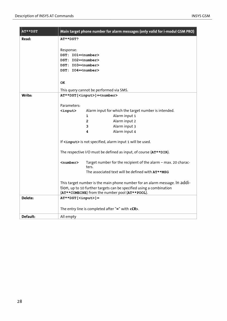
AT**DST Main target phone number for alarm messages (only valid for i-modul GSM PRO)
Read: AT**DST?
Response: DST: IO1=<number> DST: IO2=<number> DST: IO3=<number> DST: IO4=<number>
OK
This query cannot be performed via SMS. Write: AT**DST[<input>]=<number>
Parameters: <input> Alarm input for which the target number is intended. 1 Alarm input 1 2 Alarm input 2 3 Alarm input 3 4 Alarm input 4 If <input> is not specified, alarm input 1 will be used. The respective I/O must be defined as input, of course (AT**DIR). <number> Target number for the recipient of the alarm – max. 20 charac-
ters. The associated text will be defined with AT**MSG
This target number is the main phone number for an alarm message. In addi-tion, up to 10 further targets can be specified using a combination (AT**COMBINE) from the number pool (AT**POOL).
Delete: AT**DST[<input>]=
The entry line is completed after "=" with <CR>.
Default: All empty
28

INSYS GSM Description of INSYS AT Commands
AT**DST Main target phone number for alarm messages (only valid forINSYS GSM)
Read: AT**DST?
Response: DST: IO1,1=<number> DST: IO1,2=<number> ... DST: IO1,9=<number> DST: IO1,10=<number> DST: IO2,1=<number> ... DST: IO4,10=<number>
OK
This query cannot be performed via SMS.
Write: AT**DST[<input>][,<index]=<number> Parameters: <input> Alarm input for which the target number is intended. 1 Alarm input 1 2 Alarm input 2 3 Alarm input 3 4 Alarm input 4 If <input> is not specified, alarm input 1 will be used. <index> 1..10 Index number of the alarm message If <index> is not specified, index number 1 will be used. <number> Target number for the recipient of the alarm – max. 20 charac-
ters. The associated text will be defined with AT**MSG
This target number is the main phone number for an alarm message. In addi-tion, up to 10 further targets can be specified using a combination (AT**COMBINE) from the number pool (AT**POOL).
Delete: AT**DST[<input>][,<index>]=
The entry line is completed after "=" with <CR>.
Default: All empty
29

Description of INSYS AT Commands INSYS GSM
AT**DTC Idle connection control (data transmit control)
Read: AT**DTC?
Response: DTC: <timeout> OK
Write: AT**DTC=<timeout>
Parameters: <timeout> 0 Disabled 1 .. 255 Waiting time in seconds. If no data is transferred
during this time, the data connection will be re-leased.
Each character, which is transferred via the serial interface, resets this timer.
Default: AT**DTC=0
AT**DTMF Enable DTMF evaluation
Read: AT**DTMF?
Response: DTMF: <status> OK
Write: AT**DTMF=<status>
Parameters: <status> 0 Disabled 1 Enabled: DTMF tones are evaluated. (Password
protection with AT**PASST)
The following extended responses are displayed for enabled DTMF evaluation instead of RING:
+CRING: VOICE For voice/DTMF connections +CRING: REL ASYNC For data connections Incoming voice connections are accepted automatically with enabled DTMF evaluation. (Selective call acceptance remains valid)
Note: The setting becomes only effective after a reset.
Default: AT**DTMF=0
30

INSYS GSM Description of INSYS AT Commands
AT**ESC Escape character for remote configuration mode
Read: AT**ESC?
Response: ESC: <esc> OK
Write: AT**ESC=<esc> Parameters: <esc> 1 ASCII character
The Escape sequence is used to change into remote configuration mode during a data connection. The input of the following sequence (without <CR>) is required for this: 1 second pause <esc> <esc> <esc> 1 second pause
The data connection is continued with the AT**EXIT command again.
Default: AT**ESC=*
AT**EXIT Exiting the remote configuration mode
Write: AT**EXIT
Response: REMOTE CONFIGURATION MODE EXIT OK Response in case of input failure / not in remote configuration mode: ERROR After this command has been executed correctly, the INSYS GSM is in data transmission mode again.
Note: This query cannot be performed via SMS.
31

Description of INSYS AT Commands INSYS GSM
AT**FLASH Firmware update of the controller
Write: AT**FLASH
The terminal baud rate must be set to 19,200 bps for a local flash process. The following responses are returned with this fix baud rate:
Start Update with Esc, Reset with @
The flash process must be started by entering <ESC> (= 0x1Bh) then.
The following prompt appears: Expecting download with 8N1
The firmware is to be sent as *.mhx file. Settings of the terminal program: Protocol: ASCII Data format: 8N1 Handshake: Hardware
The process can be started locally as well as in remote command mode.
Attention: The use of hardware handshake is absolutely necessary; make sure, that the modem of the remote terminal is set to hardware handshake as well as the ter-minal program.
To avoid a remote flash crash, the baud rate of the device must be set to 19,200 bps (for remote configuration this new baud rate will only be active after the device is reset).
In addition, the terminal program that initiates the flash process must be set to a line delay of at least 100 ms (line end character TX=CR). The duration of the re-mote flash is approx. 5 minutes.
After the end of a remote flash, “@” must be entered to initiate a reset.
After the flash process is completed, all parameters are reset to default settings like with AT**DEFAULT. The PIN is kept.
Note: This command cannot be executed via SMS.
AT**FORMAT Data format of the serial interface
Read: AT**FORMAT?
Response:
FORMAT: <format>
OK
32

INSYS GSM Description of INSYS AT Commands
Write: AT**FORMAT=<format>
Parameters:
<format> 8N1 8 data bits, 1 stop bit, no parity 8E1 8 data bits, 1 stop bit, even parity 8O1 8 data bits, 1 stop bit, odd parity 8N2 8 data bits, 2 stop bit, no parity 7N1 7 data bits, 1 stop bit, no parity 7E1 7 data bits, 1 stop bit, even parity 7O1 7 data bits, 1 stop bit, odd parity 7N2 7 data bits, 2 stop bit, no parity
During local configuration the response at the serial interface is output with the old data format. The data format will be changed afterwards. For remote configuration, the changes will be active after a reset of the device only.
Default: AT**FORMAT=8N1
AT**GSMREQ Periodic request of the field strength and login state of the GSM network
Read: AT**GSMREQ?
Response: GSMREQ: <status> OK
Write: AT**GSMREQ=<status>
Parameters:
<status> 0 Periodic GSM network query disabled 1 Periodic GSM network query enabled If the setting is activated, the controller queries the GSM signal strength and the login state of the GSM engine in the network cyclically every minute to control the LEDs STATUS and SIGNAL. The query duration is approx. 5 seconds at 19200 baud.
Any activity at the serial interface (AT commands) restarts the query interval. Also, no query is made during an active data connection.
If the query is already started, commands, which are entered at the serial inter-face during the query are not processed. If the periodical query is deactivated, the LED SIGNAL is off during operation and the LED STATUS does not display the network state anymore, but only a data connection (blinking) or an alarm processing (flashing). Note: If the periodical network query is deactivated, the output cannot be
automatically activated during network failure (refer to AT**OUTPUT).
Default: AT**GSMREQ=1
33

Description of INSYS AT Commands INSYS GSM
AT**HISTORY Event log
Read: AT**HISTORY?
Response: HISTORY: <Cause> <Detail> <Dir> <Number> <Time> <Date> … (up to 200 entries) … <Cause> <Detail> <Dir> <Number> <Time> <Date>
OK
Refer to the manual for a description of the parameter.
Note: This command cannot be executed via SMS.
Delete: AT**HISTORY=<CR>
The event memory in the EEPROM will be deleted.
AT**INPUT Configuration of the alarm inputs (only valid for i-modul GSM PRO)
Note: This description is only valid for the i-modul GSM PRO! Read: AT**INPUT?
Response: INPUT: IO1 = <mode> INPUT: IO2 = <mode> INPUT: IO3 = <mode> INPUT: IO4 = <mode> OK
Parameters:
<mode> OUT I/O is defined as output; otherwise refer to write command
Write:
AT**INPUT[<input>]=<mode>
Parameters:
<input> Alarm input for which the setting is intended. 1 Alarm input I/O1 2 Alarm input I/O2 3 Alarm input I/O3 4 Alarm input I/O4
If <input> is not specified, alarm input 1 will be used.
The respective I/O must be defined as input, of course. <mode> Action for operated alarm input
0 No action 1 SMS dispatch 2 Data connection (no combination with number
pool) 3 Data connection, automatic hang-up after dis-
patching the message 5 Voice connection (no combination with number
pool)
34

INSYS GSM Description of INSYS AT Commands
Default: INPUT: IO1 = OUT INPUT: IO2 = 0 INPUT: IO3 = OUT INPUT: IO4 = 0
AT**INPUT Configuration of the alarm inputs (only valid for INSYS GSM)
Note: This description is only valid for the INSYS GSM! Read: AT**INPUT?
Response: INPUT: IN1 = <mode> INPUT: IN1 = <mode> OK
Parameters: Refer to write command Write:
AT**INPUT[<input>]=<mode>
Parameters:
<input> Alarm input for which the setting is intended. 1 Alarm input IN1 2 Alarm input IN2
If <input> is not specified, alarm input 1 will be used.
<mode> Action for operated alarm input
0 No action 1 SMS dispatch 2 Data connection (no combination with number
pool) 3 Data connection, automatic hang-up after dis-
patching the message 4 SMS dispatch according to the number of alarm
pulses 5 Voice connection (no combination with number
pool) Default: INPUT: IN1 = 0
INPUT: IN2 = 0
AT**INPUT Configuration of the alarm inputs (only valid for INSYS GSM I4)
Note: This description is only valid for the INSYS GSM I4! Read: AT**INPUT?
Response: INPUT: IN1 = <mode> INPUT: IN1 = <mode> INPUT: IN3 = <mode> INPUT: IN4 = <mode> OK
Parameters: Refer to write command
35

Description of INSYS AT Commands INSYS GSM
Write:
AT**INPUT[<input>]=<mode>
Parameters:
<input> Alarm input for which the setting is intended. 1 Alarm input IN1 2 Alarm input IN2 3 Alarm input IN3 4 Alarm input IN4
If <input> is not specified, alarm input 1 will be used.
<mode> Action for operated alarm input
0 No action 1 SMS dispatch 2 Data connection (no combination with number
pool) 3 Data connection, automatic hang-up after dis-
patching the message 4 SMS dispatch according to the number of alarm
pulses 5 Voice connection (no combination with number
pool) Default: INPUT: IN1 = 0
INPUT: IN2 = 0 INPUT: IN3 = 0 INPUT: IN4 = 0
AT**IN Querying the alarm inputs (only valid for i-modul GSM PRO)
Note: This description is only valid for the i-modul GSM PRO! Read: AT**IN?
Response: IN: IO1 = <status> IN: IO2 = <status> IN: IO3 = <status> IN: IO4 = <status> OK Parameters: <status> 1 Idle state: alarm input open (not connected with
GND) 0 Alarm operated: alarm input connected with
GND OUT I/O not defined as input
36

INSYS GSM Description of INSYS AT Commands
AT**IN Querying the alarm inputs (only valid for INSYS GSM)
Note: This description is only valid for the INSYS GSM! Read: AT**IN?
Response: IN: IN1 = <status> IN: IN2 = <status> OK Parameters: <status> OPEN Idle state: alarm input open (not connected with
GND) CLOSE Alarm operated: alarm input connected with
GND
AT**IN Querying the alarm inputs (only valid for INSYS GSM I4)
Note: This description is only valid for the INSYS GSM I4! Read: AT**IN?
Response: IN: IN1 = <status> IN: IN2 = <status> IN: IN3 = <status> IN: IN4 = <status> OK Parameters: <status> OPEN Idle state: alarm input open (not connected with
GND) CLOSE Alarm operated: alarm input connected with
GND
AT**LOGOUT Timer-controlled logout/login
Read: AT**LOGOUT?
Response: LOGOUT: <starttime>,<duration> OK if the function is deactivated, “inactive” appears
37

Description of INSYS AT Commands INSYS GSM
Write: AT**LOGOUT=<starttime>,<duration>
Parameters: <starttime> Input in format hh:mm
<duration> 0 Function disabled 1 .. 98 Logout time in minutes after reached start time;
tolerance +/-1 minute 99 Logout with subsequent device reset
Note: The setting is immediately written to the RTC.
Default: AT**LOGOUT=00:00,0
AT**MSG Alarm message texts (only valid for i-modul GSM PRO)
Read: AT**MSG?
Response: MSG: IO1=<text> MSG: IO2=<text> MSG: IO3=<text> MSG: IO4=<text> OK Note: This command cannot be executed via SMS.
Write: AT**MSG[<input>]=<text> Parameters:
<input> Alarm input for which the target number is intended.
1 Alarm input I/O1 2 Alarm input I/O2 3 Alarm input I/O3 4 Alarm input I/O4
If <input> is not specified, alarm input I/O1 will be used.
The respective I/O must be defined as input, of course (AT**DIR). <text> Message text, max. 140 digits
Delete: AT**MSG[<input>]=
The entry line is completed after "=" with <CR>.
Default: All empty
38

INSYS GSM Description of INSYS AT Commands
AT**MSG Alarm message texts (only valid for INSYS GSM)
Read: AT**MSG?
Response: MSG: IO1,0=<text> MSG: IO1,1=<text> ... MSG: IO1,9=<text> MSG: IO1,10=<text> MSG: IO2,0=<text> ... MSG: IO4,10=<text> OK Note: This command cannot be executed via SMS.
Write: AT**MSG[<input>][,<index>]=<text> Parameters:
<input> Alarm input for which the target number is intended.
1 Alarm input I/O1 2 Alarm input I/O2 3 Alarm input I/O3 4 Alarm input I/O4
If <input> is not specified, alarm input I/O1 will be used.
<index> 0..10 Index number of the alarm message If <index> is not specified, index number 0 will be used. <text> Message text, max. 140 digits
Delete: AT**MSG[<input>][,<index>]=
The entry line is completed after "=" with <CR>.
Default: All empty
AT**OH Configuration of the control line OH_GSM~
Read: AT**OH?
Response: OH: <mode> OK
39

Description of INSYS AT Commands INSYS GSM
Write: AT**OH=<mode> Parameters:
<mode> Behaviour of the control line OH_GSM~ (pin 13)
0 Always disabled (high level CMOS) 1 Always enabled (low level CMOS) 2 enabled (low level CMOS) for an alarm voice connection
Default: 1
AT**OUTPUT Configuration of the switch outputs (only valid for i-modul GSM PRO)
Note: This description is only valid for the i-modul GSM PRO! Read: AT**OUTPUT?
Response: OUTPUT: IO1 = [IN][<man>,<ri>,<net>] OUTPUT: IO2 = [IN][<man>,<ri>,<net>] OUTPUT: IO3 = [IN][<man>,<ri>,<net>] OUTPUT: IO4 = [IN][<man>,<ri>,<net>] OK
Parameters:
If the respective I/O is defined as input, „IN“ appears, otherwise refer to write command
Write: AT**OUTPUT[<output>]=<man>[,<ri>[,<net>]]
Parameters: <output> Switch output for which the setting is intended.
1 Switch output I/O1 2 Switch output I/O2 3 Switch output I/O3 4 Switch output I/O4 The respective I/O must be defined as output, of course (AT**DIR).
<man> Manual switching with command AT**OUT, via SMS or DTMF 0 Not released 1 Released; the settings <ri> and <net> are dis-
abled (no entry required)
<ri> Switching for incoming connection request (RING signal of the GSM engine) 0 Not enabled 1 Enabled
2 Modem connection (DCD) enabled (from FW 2.40)
<net> Switching for GSM network failure 0 Not enabled 1 Enabled (update interval approx. 1 min-
ute, synchronous with periodical log-in state query); is only performed when the periodical field strength and log-in state query is enabled (AT**GSMREQ=1).
40

INSYS GSM Description of INSYS AT Commands
Default: OUTPUT: IO1 = 1,0,0 OUTPUT: IO2 = IN OUTPUT: IO3 = 1,0,0 OUTPUT: IO4 = IN
AT**OUTPUT Configuration of the switch outputs (only valid for INSYS GSM)
Note: This description is only valid for the INSYS GSM (not in the I4 version)! Read: AT**OUTPUT?
Response: OUTPUT: OUT1 = <man>,<ri>,<net>,<alarm> OUTPUT: OUT2 = <man>,<ri>,<net>,<alarm> OK
Parameters: Refer to write command
Write: AT**OUTPUT[<output>]=<man>[,<ri>[,<net>[,<alarm>]]]
Parameters: <output> Switch output for which the setting is intended.
1 Switch output OUT1 2 Switch output OUT2
<man> Manual switching with command AT**OUT, via SMS or DTMF 0 Not released 1 Released; the settings <ri>, <net> and
<alarm> are disabled (no entry required)
<ri> Switching for incoming connection request (RING signal of the GSM engine) 0 Not enabled 1 Enabled
2 Modem connection (DCD) enabled (from FW 2.40)
<net> Switching for GSM network failure 0 Not enabled
1 Enabled (update interval approx. 1 minute, synchronous with periodical log-in state query); is only performed when the periodical field strength and log-in state query is enabled (AT**GSMREQ=1).
<alarm> Switching in case of alarm at the respective alarm input 0 Not enabled 1 Enabled
Default: OUTPUT: OUT1 = 1,0,0,0 OUTPUT: OUT2 = 1,0,0,0
41

Description of INSYS AT Commands INSYS GSM
AT**OUT Setting the switch outputs (only valid for i-modul GSM PRO)
Note: This description is only valid for the i-modul GSM PRO! Read: AT**OUT?
Response:
OUT: IO1 = <status> OUT: IO2 = <status> OUT: IO3 = <status> OUT: IO4 = <status> OK
Parameters:
<status> IN I/O is defined as input; otherwise refer to write command
Write: AT**OUT[<output>]=<status> Parameters:
<output> Switch output for which the setting is intended.
1 Switch output I/O1 2 Switch output I/O2
3 Switch output I/O3
4 Switch output I/O4 The respective I/O must be defined as output, of course (AT**DIR). <status> 0 Switch output on low level (CMOS) 1 Switch output on high level (CMOS) The state of the output is permanently stored in the EEprom and restored after a reset.
In order to switch the outputs via DTMF, these must be defined as output!.
Default: OUT: IO1 = 0 OUT: IO2 = IN OUT: IO3 = 0 OUT: IO4 = IN
42

INSYS GSM Description of INSYS AT Commands
AT**OUT Setting the switch outputs (only valid for INSYS GSM)
Note: This description is only valid for the INSYS GSM (not in the I4 version)! Read: AT**OUT?
Response:
OUT: OUT1 = <status> OUT: OUT2 = <status> OK
Parameters: Refer to write command Write: AT**OUT[<output>]=<status>
Parameters:
<output> Switch output for which the setting is intended.
1 Switch output OUT1 2 Switch output OUT2 <status> CLOSE Switch output closed OPEN Switch output open The state of the output is permanently stored in the EEprom and restored after a reset.
In order to switch the outputs via DTMF, these must be defined as output!.
Default: OUT: OUT1 = CLOSE OUT: OUT2 = CLOSE
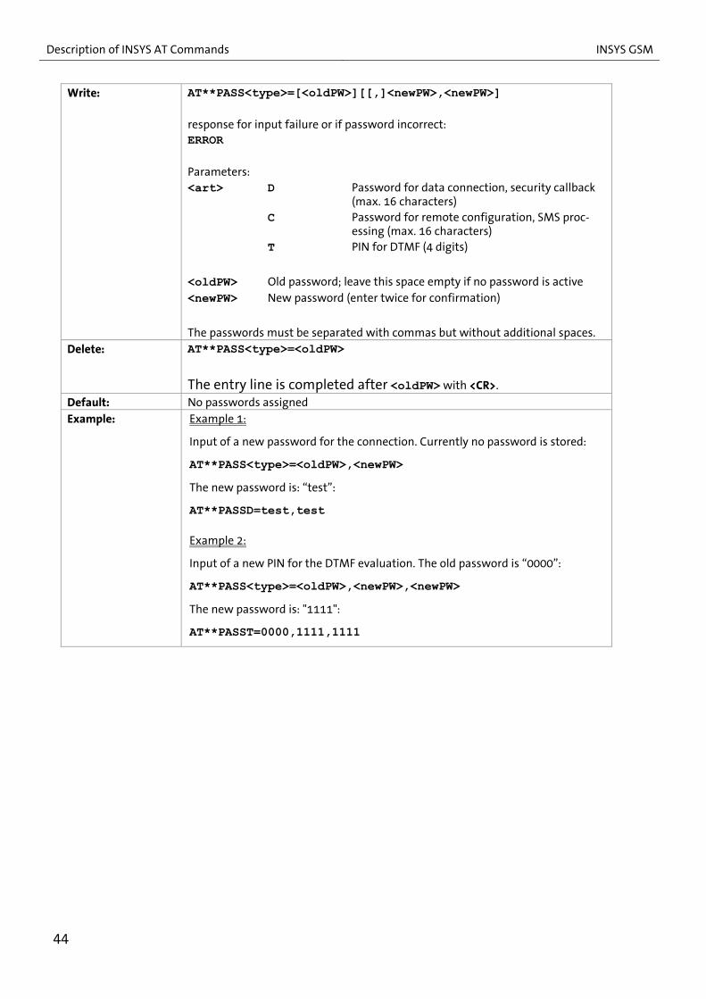
AT**PASS Password protection
Read: AT**PASS?
Response: PASSC: <status> PASSD: <status> PASST: <status> OK
Parameters: <status> active Password stored inactive No password stored
43
Description of INSYS AT Commands INSYS GSM
Write: AT**PASS<type>=[<oldPW>][[,]<newPW>,<newPW>] response for input failure or if password incorrect: ERROR Parameters: <art> D Password for data connection, security callback
(max. 16 characters) C Password for remote configuration, SMS proc-
essing (max. 16 characters) T PIN for DTMF (4 digits)
<oldPW> Old password; leave this space empty if no password is active <newPW> New password (enter twice for confirmation)
The passwords must be separated with commas but without additional spaces.
Delete: AT**PASS<type>=<oldPW>
The entry line is completed after <oldPW> with <CR>.
Default: No passwords assigned
Example: Example 1:
Input of a new password for the connection. Currently no password is stored:
AT**PASS<type>=<oldPW>,<newPW>
The new password is: “test”:
AT**PASSD=test,test
Example 2:
Input of a new PIN for the DTMF evaluation. The old password is “0000”:
AT**PASS<type>=<oldPW>,<newPW>,<newPW>
The new password is: "1111":
AT**PASST=0000,1111,1111
44

INSYS GSM Description of INSYS AT Commands
AT**PIN PIN of the SIM card
Read: AT**PIN?
Response: PIN: <status> OK
Parameters:
<status> active PIN stored inactive No PIN stored
Write: AT**PIN=<pin>
Parameters:
<pin> Four to eight digit number with the PIN of the inserted SIM card.
The setting will only be accepted after the device has been reset.
Attention: Before inserting a new SIM card you have to ensure that the cor-rect PIN is stored or if the PIN must be deleted. Otherwise the de-vice tries to login with a wrong PIN, which results in a locking of the PIN if the attempt is repeated.
Delete: AT**PIN=
The entry line is completed after "=" with <CR>. This enables the operation of SIM cards with deactivated PIN query.
Default: No PIN stored
45

Description of INSYS AT Commands INSYS GSM
AT**POOL Phone number pool for alarm messages
Read: AT**POOL?
Response:
POOL: 01=<number> ... POOL: 20=<number> OK Parameters: see write command This query cannot be performed via SMS.
Write: AT**POOL<index>=<number> Parameters:
<index> 01 ... 20 Up to 20 entries are possible
<number> Phone number, the maximum length is 20 characters
Up to 10 numbers from this pool can be defined as additional re-cipients for each alarm message (AT**COMBINE).
Delete: AT**POOL<index>=
The entry line is completed after "=" with <CR>.
Default: Empty
AT**POWER Power-up SMS
Read: AT**POWER?
Response:
POWER: <status>
POWER: DST= <target number>
POWER: MSG= <text>
46

INSYS GSM Description of INSYS AT Commands
Write: AT**POWER=<status>
AT**POWERDST=<target number>
AT**POWERMSG=<text>
Parameters:
<status> active Power-up SMS enabled
inactive Power-up SMS disabled*
<target number> Phone number, the maximum length is
20 characters
<text> Message text, max. 30 digits
The power up function will only be activated after a power outage of at least 15
seconds. An SMS is sent after each power-up (not reset).
The text of the power up SMS consists of a part which has been assigned by the
µ controller
“INSYS GSM 4.x: POWER UP AT hh:mm dd.mm.yy LAST TIMESTAMP
WAS hh:mm dd.mm.yy (INTERVAL EVERY 5 MINUTES)”
and the text defined by the user (max. 30 characters).
Last “TIMESTAMP“ describes the last valid entry in the “Time stamp buffer”, in
which time and date are entered every 5 minutes. Thus, when a power failure
occurs, the time of the power failure can be determined with a 5-minute accu-
racy.
Default AT**POWER=inactive
47

Description of INSYS AT Commands INSYS GSM
AT**PROFILE Querying the settings of the INSYS AT commands
Read: AT**PROFILE?
Response:
INSYS MICROELECTRONICS INSYS GSM 4.x SW-Version 1.23, 10.01.2005
BL: ACFA FW: 78FE-01D0
TIME: 10:30:37 DAY: MO DATE: 04/03/2003
BAUD: 19200 FORMAT: 8N1 ESC: * OH: 1
PIN: active PROVIDER: SIGNAL: 22 LOGOUT: 00:00,inactive SCN: +491710760000 DTC: 000 SMSRX: 0 GSMREQ: 1 DTMF: 0 DIAL: 03
POWER: inactive POWER: DST = POWER: MSG =
ALIVE: inactive ALIVE: DST = ALIVE: MSG =
PASSC: inactive PASSD: active PASST: inactive
CALLBACK:
CLIP: 0 CLIP: 01= (…) CLIP: 15=
48
INSYS GSM Description of INSYS AT Commands
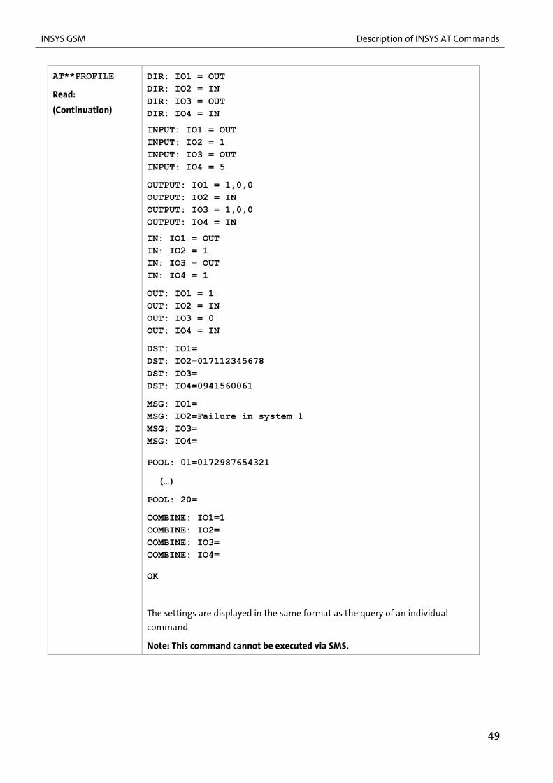
AT**PROFILE
Read:
(Continuation)
DIR: IO1 = OUT DIR: IO2 = IN DIR: IO3 = OUT DIR: IO4 = IN
INPUT: IO1 = OUT INPUT: IO2 = 1 INPUT: IO3 = OUT INPUT: IO4 = 5
OUTPUT: IO1 = 1,0,0 OUTPUT: IO2 = IN OUTPUT: IO3 = 1,0,0 OUTPUT: IO4 = IN
IN: IO1 = OUT IN: IO2 = 1 IN: IO3 = OUT IN: IO4 = 1
OUT: IO1 = 1 OUT: IO2 = IN OUT: IO3 = 0 OUT: IO4 = IN
DST: IO1= DST: IO2=017112345678 DST: IO3= DST: IO4=0941560061
MSG: IO1= MSG: IO2=Failure in system 1 MSG: IO3= MSG: IO4=
POOL: 01=0172987654321
(…)
POOL: 20=
COMBINE: IO1=1 COMBINE: IO2= COMBINE: IO3= COMBINE: IO4=
OK
The settings are displayed in the same format as the query of an individual
command.
Note: This command cannot be executed via SMS.
49

Description of INSYS AT Commands INSYS GSM
AT**PROVIDER Manual GSM network provider selection
Read: AT**PROVIDER?
Response: PROVIDER: <mode>[,<format>[,<oper>]]
OK
Write: AT**PROVIDER=<mode>[,<format>[,<oper>]]
Parameters: <mode> empty Automatic operation; <oper> is ignored
0 Automatic operation; <oper> is ignored
1 Manal network provider selection; <oper> and <format> must be present;
2 Manual logout of the network
4 Automatic, manually pre-selected; if the manual login to network provider <oper> fails, auto-matic operation will be used
<format> 2 Numerical format for <oper>: GSM Location Area Identification Number 5-digit, unique identi-fier of a network provider
<oper> Designation of the network provider
Note: This command corresponds with the AT+COPS= command of the GSM engine. It is managed as a string by the controller and handed over to the GSM engine for login when initializing the device.
Delete: AT**PROVIDER=
The entry line is completed after "=" with <CR>.
Default: AT**PROVIDER=
AT**RESET Device reset
Write: AT**RESET
When the input is correct the INSYS GSM will execute a full reset. After a reset, the previously entered values are re-loaded. The command is similar to pressing the key on the device.
50

INSYS GSM Description of INSYS AT Commands
AT**SCN SMS Service Center Nummer
Read: AT**SCN?
Response: SCN: <number> OK
Write:
AT**SCN=<number>
Parameters: <number> SMS service center number of the GSM provider. Has to be set to
be able to dispatch an SMS (alarm SMS, periodic alive SMS, ac-knowledgement SMS). The number should be stored in interna-tional format to ensure the SMS dispatch when roaming (exam-ple Germany: +49…) (max. 20 digits).
S Specifying this parameter causes to read out and store the SMS service center number of the GSM provider from the SIM card (from firmware version 2.40).
Delete: AT**SCN=
The entry line is completed after "=" with <CR>.
Default: Empty
AT**SIGNAL GSM signal field strength
Read: AT**SIGNAL?
Response:
SIGNAL: <signal>
OK Parameters:
<signal> Value of the received GSM field strength
0 -113 dBm or less
1 -111 dBm
1..30 -111 dBm … -53 dBm (2 dB – steps)
31 -31 dBm or better
99 Field strength not detectable
Note: Antenna locations with values below 10 should be avoided. (Refer also to AT**GSMREQ)
51

Description of INSYS AT Commands INSYS GSM
AT**SMS= <output>
Manual SMS dispatch of the stored alarm messages
Write: AT**SMS=<io>
Response if SMS was successfully dispatched: OK
Immediate response for input or send failure: ERROR
Parameters: SMS dispatch:
<io> 1 Text and target number for I/O1
2 Text and target number for I/O2
3 Text and target number for I/O3
4 Text and target number for I/O4
It is not imperative that the I/O is defined as input.
The combinations with AT**POOL/AT**COMBINE are not executed!
52

INSYS GSM Description of INSYS AT Commands
AT**SMSBUF Specification of existing SMS storage locations of the SIM card
Read: AT**SMSBUF
Response:
SMSBUF: <number>
OK
Write: AT**SMSBUF=<number>
Parameters:
<number> The number of SMS SIM storage locations
The SIM cards of the various mobile phone providers have different numbers of SMS storage locations. The command AT**SMSRX will report to the Controller how many storage locations must be queried for incoming SMS.
The duration of the polling increases with the number of storage locations and takes place every 60 seconds after the last query. No AT commands are proc-essed during the polling procedure.
The baud rate and the number of configured SMS storage locations determine the duration of the query.
Example: Baud rate 19200 bps Configured SMS storage locations 15 Duration of the query 5 seconds
If this query period will result in a critical condition for the application, the num-ber of storage locations to be queried can be set individually.
The SMS messages incoming during an existing data connection are stored in the storage locations and will only be processed after the disconnection. If more storage locations are used than queried by the polling, the SMS messages in these storage locations will not be processed. Note: The setting becomes effective after a reset (AT**RESET) only.
Default: AT**SMSBUF=10
AT**SMSRX Automatic SMS reception evaluation
Read: AT**SMSRX?
Response: SMSRX: <status> OK
53

Description of INSYS AT Commands INSYS GSM
Write: AT**SMSRX=<status>
Parameters: <status> 0 Disabled
1 Enabled - each incoming SMS will be deleted af-ter evaluation
2 Enabled - SMS that are not intended for the IN-SYS GSM will remain in the buffer
General:
When this function is activated, the GSM engine is operated in the operation mode AT+CMGF=1 (SMS text mode).
Every 60 seconds the controller will query the input buffer of the GSM engine (number of storage locations for incoming SMS mes-sages may be set with AT**SMSBUF).
However, any activity at the serial interface (AT commands) will restart the query interval without executing the query. No query is made during an active data connection.
The Status LED is flashing during the query of the SMS messages. Commands entered at the serial interface during this period are ignored. The query duration depends on the baud rate and the number of the SMS storage locations to be queried.
Incoming SMS messages are optionally protected with the remote configuration password.
To <status> 1:
Each SMS is checked for validity (format, password, selective call acceptance). After processing, a response SMS is possibly sent, and the SMS is deleted from the storage location.
If the SMS is not usable, it will be deleted from the SMS buffer immediately. The usage of the SMS reception by the user application is only possible in a restricted way.
To <status> 2:
The SMS which are not processed by INSYS GSM stay in the buffer of the SIM card, until they are retrieved and deleted by the application via the serial inter-face. When the buffer of the SIM card is full, no further SMS messages will be accepted:
The INSYS GSM processes and deletes the following SMS messages: a) all SMS messages with correct configuration password (when set), irre-
spective if the password is followed by a valid command or not. b) All SMS messages with correct syntax, if no password is set. Those are:
- SMS messages starting with AT**
- SMS messages with the text “QUITT” as content
- SMS messages, where the content is an alarm mes-sage saved in the device (acknowledgement of alarms)
54

INSYS GSM Description of INSYS AT Commands
Write: (CONTINUATION)
Possible solution:
A configuration password should be allocated and introduced to the application. The application can then leave SMS messages with this password to the INSYS GSM and process and delete the rest of the SMS messages.
In addition should the query cycle of the application be larger than the one for the controller (e.g. factor 2 to 3), as otherwise the controller will re-trigger its query cycle for each query of the application (= activity at the RS232 interface). If this is not considered, the controller can no longer start queries of the SMS input buffer.
Default: AT**SMSRX=0
AT**SWITCH Executing a switch command
Execute: AT**SWITCH <text>
Executes the switch command, to which the clear text name <text> has been assigned with the command AT**SWITCHENTRY. Response: OK Switch command has been executed ERROR No switch command has been assigned to the specified clear text
name
Note: This command is only available from firmware version 2.40.
AT**SWITCHENTRY Assigning a clear text name to a switch command
Note: This description is not valid for the INSYS GSM I4! This command is only avail-able from firmware version 2.40!
Read: AT**SWITCHENTRY?
Response: Switch: OUT1,00=<text> Switch: OUT1,01=<text> Switch: OUT1,03=<text> ... OK
Write: AT**SWITCHENTRY<output>,<action>=<text>
Parameters:
<output> Output, to which the clear text is to be assigned <action> Number of pulses, which are to be output at the output <text> Clear text name of the switch command
Example:
AT**SWITCHENTRY1,3=Pump The clear text name "Pump" is assigned to the switch command "Output 1 3x pulsing“.
Default: AT**SWITCHENTRY<output>,<action>=
55

Description of INSYS AT Commands INSYS GSM
AT**TIME Time settings
Read: AT**TIME
Response: TIME: <hh>:<mm>:<ss> OK
Write: AT**TIME=<hh>:<mm>:<ss>
Parameters:
<hh> Hour two-digit <mm> Minute two-digit <ss> Second two-digit
Note: The setting is immediately written to the RTC. Default: AT**TIME=00:00:00
AT**VERSION Querying the software version
Read: AT**VERSION?
Response:
INSYS MICROELECTRONICS INSYS i-modul 3.x SW-Version 1.23, 10.01.2005
BL: ACFA FW: 78FE-01D0
OK
Command: Meaning:
BL: ACFA Boot loader checksum FW: 78FE-01D0 Firmware version 01D0: Firmware checksum
56

INSYS GSM GSM Character Set for SMS
5 GSM Character Set for SMS
The internal GSM character set GSM 03.38 does not match the usual ASCII character set of PCs in all positions. Therefore, the following restrictions must be observed for SMS texts.
When entering data via the masks of the configuration software HSComm:
Permitted text characters in SMS messages are only letters (without umlauts), digits, punctuation marks, brackets, underscore, % & *.
8-bit characters (e.g. umlauts) and the characters $ @ { } [ ] ^ ° ` ´are not sup-ported.
The character @ of an e-mail address must be replaced by an asterisk *.
For direct entry into a terminal program the following applies:
The underscore must be replaced by the character number 11h (hexadecimal).
The character 00h (hexadecimal) may not be used in any case.
57

Network Provider Identification Numbers INSYS GSM
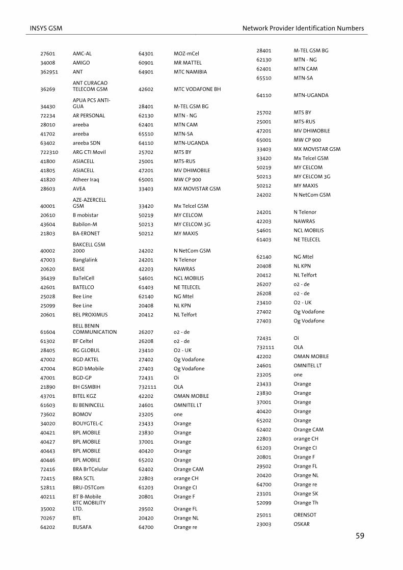
6 Network Provider Identification Numbers
Identifiers and names of the network providers (GSM Location Area Identification Number) for the GSM module, in alphabetic order:
58
41802 2 41902 KT MTCNet 64501 ZM CELTEL 23430 30 41903 KT WATANIYA 64804 ZW ECONET 23431 31 40102 KZ KCELL 64801 ZW NET*ONE 23432 32 40101 KZ K-MOBILE 61801 LBR Lonestar Cell
310150 150 27001 L LUXGSM 29577 LI TANGO
310170 170 27077 L TANGO 61802 LIBERCELL
310410 410 27099 L VOX.LU 60600 LIBYANA
45703 45703 61801 LBR Lonestar Cell 51008 LIPPO TEL
27202 02 - IRL 29577 LI TANGO 65102 LS-ECONET-EZI-CEL
23210 3 AT 61802 LIBERCELL 24602 LT BITE GSM
23806 3 DK 60600 LIBYANA 24701 LV LMT GSM, LV LMT
45403 3 HK 51008 LIPPO TEL 24702 LV TELE2
22299 3 ITA 65102 LS-ECONET-EZI-CEL 45501 MAC-CTMGSM
24002 3 SE 24602 LT BITE GSM 28202 MAGTI-GSM-GEO
23420 3 UK 24701 LV LMT GSM, LV LMT 61001 MALITEL ML
45404 3(2G) 24702 LV TELE2 23458 Manx Pronto
50506 3TELSTRA 45501 MAC-CTMGSM 90112 MCP Maritime Com
62801 628 01/LIBERTIS 28202 MAGTI-GSM-GEO 25902 MD MOLDCELL
23207 A tele.ring 61001 MALITEL ML 25901 MD VOXTEL
23201 A1 23458 Manx Pronto 25002 MegaFon RUS
46668 ACeS 90112 MCP Maritime Com 70801 Megatel GSM
51000 ACeS 25902 MD MOLDCELL 64602 MG ANTARIS
51511 ACeS 25901 MD VOXTEL 64601 MG Madacom
52020 ACeS 25002 MegaFon RUS 61902 MILLICOM SL
41201 AF AWCC 70801 Megatel GSM 29402 MKD COSMOFON
40402 AirTel 64602 MG ANTARIS 29401 MKD-MOBIMAK
40403 AirTel 64601 MG Madacom 41401 MM 900
40410 AirTel 61902 MILLICOM SL 42899 MN MobiCom
40431 AirTel 29402 MKD COSMOFON 21805 MOBI'S
40445 AirTel 29401 MKD-MOBIMAK 29341 MOBITEL
40449 AirTel 41401 MM 900 41301 Mobitel
40490 AirTel 42899 MN MobiCom 45601 MOBITEL-KHM
40492 AirTel 21805 MOBI'S 64002 MOBITEL - TZ
40493 AirTel 29341 MOBITEL 63401 MobiTel SDN
40494 AirTel 41301 Mobitel 22004 MONET
40495 AirTel 45601 MOBITEL-KHM 60401 MOR IAM
40496 AirTel 64002 MOBITEL - TZ 60400 MOR MEDITEL
40497 AirTel 63401 MobiTel SDN 21407 movistar
40498 AirTel 22004 MONET 70403 MoviStar
41501 alfa 60401 MOR IAM 70604 MoviStar
60301 ALG Mobilis 60400 MOR MEDITEL 64301 MOZ-mCel
42001 ALJAWAL 21407 movistar 60901 MR MATTEL
79502 Altyn Asyr 70403 MoviStar 64901 MTC NAMIBIA
72424 AMAZONIA 70604 MoviStar 42602 MTC VODAFONE BH
INSYS GSM Network Provider Identification Numbers
27601 AMC-AL 64301 MOZ-mCel 28401 M-TEL GSM BG
34008 AMIGO 60901 MR MATTEL 62130 MTN - NG
362951 ANT 64901 MTC NAMIBIA 62401 MTN CAM
36269 ANT CURACAO TELECOM GSM 42602 MTC VODAFONE BH
65510 MTN-SA
34430 APUA PCS ANTI-GUA 28401 M-TEL GSM BG
64110 MTN-UGANDA
72234 AR PERSONAL 62130 MTN - NG 25702 MTS BY
28010 areeba 62401 MTN CAM 25001 MTS-RUS
41702 areeba 65510 MTN-SA 47201 MV DHIMOBILE
63402 areeba SDN 64110 MTN-UGANDA 65001 MW CP 900
722310 ARG CTI Movil 25702 MTS BY 33403 MX MOVISTAR GSM
41800 ASIACELL 25001 MTS-RUS 33420 Mx Telcel GSM
41805 ASIACELL 47201 MV DHIMOBILE 50219 MY CELCOM
41820 Atheer Iraq 65001 MW CP 900 50213 MY CELCOM 3G
28603 AVEA 33403 MX MOVISTAR GSM 50212 MY MAXIS
40001 AZE-AZERCELL GSM 33420 Mx Telcel GSM
24202 N NetCom GSM
20610 B mobistar 50219 MY CELCOM 24201 N Telenor
43604 Babilon-M 50213 MY CELCOM 3G 42203 NAWRAS
21803 BA-ERONET 50212 MY MAXIS 54601 NCL MOBILIS
40002 BAKCELL GSM 2000 24202 N NetCom GSM
61403 NE TELECEL
47003 Banglalink 24201 N Telenor 62140 NG Mtel
20620 BASE 42203 NAWRAS 20408 NL KPN
36439 BaTelCell 54601 NCL MOBILIS 20412 NL Telfort
42601 BATELCO 61403 NE TELECEL 26207 o2 - de
25028 Bee Line 62140 NG Mtel 26208 o2 - de
25099 Bee Line 20408 NL KPN 23410 O2 - UK
20601 BEL PROXIMUS 20412 NL Telfort 27402 Og Vodafone
61604 BELL BENIN COMMUNICATION 26207 o2 - de
27403 Og Vodafone
61302 BF Celtel 26208 o2 - de 72431 Oi
28405 BG GLOBUL 23410 O2 - UK 732111 OLA
47002 BGD AKTEL 27402 Og Vodafone 42202 OMAN MOBILE
47004 BGD bMobile 27403 Og Vodafone 24601 OMNITEL LT
47001 BGD-GP 72431 Oi 23205 one
21890 BH GSMBIH 732111 OLA 23433 Orange
43701 BITEL KGZ 42202 OMAN MOBILE 23830 Orange
61603 BJ BENINCELL 24601 OMNITEL LT 37001 Orange
73602 BOMOV 23205 one 40420 Orange
34020 BOUYGTEL-C 23433 Orange 65202 Orange
40421 BPL MOBILE 23830 Orange 62402 Orange CAM
40427 BPL MOBILE 37001 Orange 22803 orange CH
40443 BPL MOBILE 40420 Orange 61203 Orange CI
40446 BPL MOBILE 65202 Orange 20801 Orange F
72416 BRA BrTCelular 62402 Orange CAM 29502 Orange FL
72415 BRA SCTL 22803 orange CH 20420 Orange NL
52811 BRU-DSTCom 61203 Orange CI 64700 Orange re
40211 BT B-Mobile 20801 Orange F 23101 Orange SK
35002 BTC MOBILITY LTD. 29502 Orange FL
52099 Orange Th
70267 BTL 20420 Orange NL 25011 ORENSOT
64202 BUSAFA 64700 Orange re 23003 OSKAR
59

Network Provider Identification Numbers INSYS GSM
60
65201 BW MASCOM 23101 Orange SK 26803 P OPTIMUS
25701 BY VELCOM 52099 Orange Th 26806 P TMN
338180 C&W 25011 ORENSOT 41004 PAK - PL
342600 C&W 23003 OSKAR 71401 PANCW
344920 C&W 26803 P OPTIMUS 70401 PCS
346140 C&W 26806 P TMN 311170 PetroCom
352110 C&W 41004 PAK - PL 51505 PH Sun Cellular
354860 C&W 71401 PANCW 31180 Pine Cellular
356110 C&W 70401 PCS 41001 PK MK
358110 C&W 311170 PetroCom 41003 PK-UFONE
360110 C&W 51505 PH Sun Cellular 26001 Plus GSM
365840 C&W 31180 Pine Cellular 53701 PNGBMobile
366110 C&W 41001 PK MK 74001 PORTA GSM
376350 C&W 41003 PK-UFONE 25092 Primetelefone RUS
23455 Cable & Wireless Guernsey 26001 Plus GSM
22002 ProMonte
45618 CAMBODIA SHI-NAWATRA 53701 PNGBMobile
74402 PRY Porthable
302720 CAN Rogers Wire-less Inc. 74001 PORTA GSM
310500 PSC Wireless
348570 CCT Boatphone 25092 Primetelefone RUS 74405 PY Personal
63089 CD OASIS 22002 ProMonte 42701 QAT QATARNET
61803 Celcom GSM 74402 PRY Porthable 28301 RA-ARMGSM
65507 Cell C 310500 PSC Wireless 63510 R-CELL
311130 Cell One Amarillo 74405 PY Personal 25012 RF FAR EAST
310450 Cell One of NE Colorado 42701 QAT QATARNET
41503 RL MTC Lebanon
40434 CellOne 28301 RA-ARMGSM 22601 RO CONNEX
40438 CellOne 63510 R-CELL 22603 RO Cosmorom
40451 CellOne 25012 RF FAR EAST 22610 RO ORANGE
40453 CellOne 41503 RL MTC Lebanon 41220 ROSHAN
40454 CellOne 22601 RO CONNEX 25007 RUS 07, RUS SMARTS
40455 CellOne 22603 RO Cosmorom 25017 RUS 17
40457 CellOne 22610 RO ORANGE 25010 RUS DTC
40458 CellOne 41220 ROSHAN 25013 RUS Kuban-GSM
40459 CellOne 25007 RUS 07, RUS SMARTS 25044 RUS North Caucasian
GSM 40462 CellOne 25017 RUS 17 25019 RUS_BASHCELL
40464 CellOne 25010 RUS DTC 25015 RUS15, RUS SMARTS
40466 CellOne 25013 RUS Kuban-GSM 25016 RUS16,250 16
40471 CellOne 25044 RUS North Caucasian GSM 24007 S COMVIQ
40472 CellOne 25019 RUS_BASHCELL 42101 SabaFon
40473 CellOne 25015 RUS15, RUS SMARTS 63902 Safaricom
40474 CellOne 25016 RUS16,250 16 61401 SAHELCOM
40475 CellOne 24007 S COMVIQ 41808 SanaTel
40476 CellOne 42101 SabaFon 25005 SCS RUS
40477 CellOne 63902 Safaricom 71073 SERCOM
40479 CellOne 61401 SAHELCOM 36301 SETAR GSM
40480 CellOne 41808 SanaTel 63301 SEYCEL
40481 CellOne 25005 SCS RUS 63310 SEZ AIRTEL
61701 CELLPLUS-MRU 71073 SERCOM 64710 SFR REUNION
310560 Cellular One DCS 36301 SETAR GSM 52503 SGP-M1-3GSM
61402 CELTEL 63301 SEYCEL 29370 SI VEGA 070
62901 CELTEL 63310 SEZ AIRTEL 29340 SI vodafone

INSYS GSM Network Provider Identification Numbers
63903 CELTEL 64710 SFR REUNION 25004 SIBCHALLENGE RUS
64005 celtel 52503 SGP-M1-3GSM 52501 SingTel
63002 CELTEL DRC 29370 SI VEGA 070 52502 SingTel-G18
62803 CELTEL GA 29340 SI vodafone 51503 SMART
65010 CELTEL MW 25004 SIBCHALLENGE RUS 45406 SmarTone
61901 CELTEL SL 52501 SingTel 45500 SmarTone
62201 CELTEL TCD 52502 SingTel-G18 45415 SmarTone 3G
70802 CELTELHND 51503 SMART 60801 SN ALIZE
31030 Centennial Com-munications 45406 SmarTone
60802 SN-SENTEL SG
46000 CHINA MOBILE 45500 SmarTone 63704 SOMAFONE
46001 CHN-CUGSM 45415 SmarTone 3G 43601 Somoncom
46692 Chunghwa 60801 SN ALIZE 63701 SOMTELESOM
310380 Cingular 60802 SN-SENTEL SG 42102 SPACETEL
342810 Cingular 63704 SOMAFONE 64201 Spacetel Bl
344930 Cingular 43601 Somoncom 30801 SPM AMERIS
35010 Cingular 63701 SOMTELESOM 24010 SpringMobil SE
35230 Cingular 42102 SPACETEL 74602 SR.TELESUR.GSM
35830 Cingular 64201 Spacetel Bl 41303 SRI-CELLTEL
36010 Cingular 30801 SPM AMERIS 41302 SRI DIALOG
36620 Cingular 24010 SpringMobil SE 21303 STA-MOBILAND
54801 CK KOKANET 74602 SR.TELESUR.GSM 52505 STARHUB
73001 CL ENTEL PCS 41303 SRI-CELLTEL 62601 STP CSTmovel
73010 CL ENTEL PCS 41302 SRI DIALOG 45419 SUNDAY
72405 Claro 21303 STA-MOBILAND 22802 Sunrise
62910 COG LIBERTIS 52505 STARHUB 65310 Swazi-MTN
732101 COLOMBIA - COMCEL S.A 62601 STP CSTmovel
24004 SWEDEN
70402 Comcel_GSM 45419 SUNDAY 24005 Sweden 3G
62501 CPV MOVEL 22802 Sunrise 22801 Swisscom
72432 CTBC CEL 65310 Swazi-MTN 29501 SwisscomFL
72433 CTBC CEL 24004 SWEDEN 41709 SYR MOBILE SYR
72434 CTBC CEL 24005 Sweden 3G 41701 SYRIATEL
36801 CU/C_COM 22801 Swisscom 46689 T3G
28001 CY CYTAGSM 29501 SwisscomFL 45708 TANGO LAO
25014 Di-ex 41709 SYR MOBILE SYR 23801 TDC MOBIL
50216 DiGi 41701 SYRIATEL 36251 Telcell GSM
33805 DIGICEL 46689 T3G 29001 TELE Greenland
342750 DIGICEL 45708 TANGO LAO 24603 TELE2
35250 Digicel 23801 TDC MOBIL 24803 TELE2
35850 DIGICEL 36251 Telcell GSM 25020 TELE2
36070 DIGICEL 29001 TELE Greenland 61602 TELECEL BENIN
70602 Digicel 24603 TELE2 74404 Telecel GSM
310940 Digital Cellular 24803 TELE2 64502 TELECEL ZM
73402 DIGITEL TIM 25020 TELE2 64803 TELECEL ZW
63801 DJ EVATIS 61602 TELECEL BENIN 64282 TELECEL-BDI
60302 Djezzy 74404 Telecel GSM 61205 TELECEL-CI
23802 DK SONOFON 64502 TELECEL ZM 73002 TELEFONICA
60303 DZA-NEDJMA 64803 TELECEL ZW 310740 TELEMETRIX
21403 E AMENA 64282 TELECEL-BDI 72423 TELEMIG CEL
31090 Edge Wireless 61205 TELECEL-CI 70603 TELEMOVIL
24802 EE elisa 73002 TELEFONICA 41006 Telenor PK
24801 EE EMT GSM 310740 TELEMETRIX 23820 TELIA DK
61

Network Provider Identification Numbers INSYS GSM
62
60201 EGY MobiNiL 72423 TELEMIG CEL 24001 TELIA S
61710 EMTEL-MRU 70603 TELEMOVIL 50501 Telstra Mobile
311160 EMW 41006 Telenor PK 310900 Texas Cellular
26203 E-Plus 23820 TELIA DK 61501 TG-TOGO CELL
26002 Era 24001 TELIA S 52015 TH ACT 1900
70601 ESV PERSONAL 50501 Telstra Mobile 52001 TH GSM
63601 ETH-MTN 310900 Texas Cellular 52023 TH GSM 1800
42003 Etihad Etisalat 61501 TG-TOGO CELL 52018 TH-DTAC
45702 ETL MOBILE NET-WORK 52015 TH ACT 1900
71610 TIM
23002 EUROTEL - CZ 52001 TH GSM 72402 TIM BRASIL
20820 F - BOUYGUES TELECOM 52023 TH GSM 1800
72403 TIM BRASIL
20810 F SFR 52018 TH-DTAC 72404 TIM BRASIL
46601 Far EasTone 71610 TIM 20210 TIM GR
311210 FARMERS 72402 TIM BRASIL 43603 TJK MLT
41601 Fastlink 72403 TIM BRASIL 51402 TLS-TT
24414 FI AMT 72404 TIM BRASIL 31026 T-Mobile
24491 FI SONERA 20210 TIM GR 31031 T-Mobile
302370 Fido 43603 TJK MLT 310160 T-Mobile
24403 FINNET 51402 TLS-TT 310200 T-Mobile
24412 FINNET 31026 T-Mobile 310210 T-Mobile
54201 FJ VODAFONE 31031 T-Mobile 310220 T-Mobile
24405 FL elisa 310160 T-Mobile 310230 T-Mobile
29505 FL1 310200 T-Mobile 310240 T-Mobile
34001 F-Orange 310210 T-Mobile 310250 T-Mobile
34002 FR 310220 T-Mobile 310260 T-Mobile
55001 FSM Telecom 310230 T-Mobile 310270 T-Mobile
54720 F-VINI 310240 T-Mobile 310660 T-Mobile
28801 F�oya Tele 310250 T-Mobile 23203 T-Mobile A
62802 GAB TELECEL 310260 T-Mobile 23001 T-Mobile CZ
60701 GAMCEL 310270 T-Mobile 26201 T-Mobile D
28201 GEO-GEOCELL 310660 T-Mobile 21630 T-Mobile H
62002 GH ONEtouch 23203 T-Mobile A 21901 T-Mobile HR
62001 GH SPACEFON 23001 T-Mobile CZ 20416 T-Mobile NL
62003 GH-MOBITEL 26201 T-Mobile D 23102 T-Mobile SK
26601 GIBTEL GSM 21630 T-Mobile H 28602 TR TELSIM
62150 Glo NG 21901 T-Mobile HR 28601 TR TURKCELL
51502 Globe Telecom-PH 20416 T-Mobile NL 37412 TSTT
61102 GN LAGUI 23102 T-Mobile SK 60503 TUNISIANA
62701 GNQ01 28602 TR TELSIM 60502 TUNISIE TELECOM
27821 go mobile 28601 TR TURKCELL 46697 TWN GSM 1800
20201 GR COSMOTE 37412 TSTT 46693 TWN MOBITAI
20209 GR Q-TELECOM 60503 TUNISIANA 25506 UA life:)
73802 GUY CLNK PLS 60502 TUNISIE TELECOM 25501 UA UMC
73801 GUY TW 46697 TWN GSM 1800 42402 UAE ETISALAT
21601 H PANNON GSM 46693 TWN MOBITAI 25505 UA-GT
311110 High Plains 25506 UA life:) 25503 UA-KYIVSTAR
31070 Highland 25501 UA UMC 53901 U-CALL
45400 HK CSL 42402 UAE ETISALAT 64101 UG CelTel
45402 HK CSL 25505 UA-GT 25502 UKR-WellCOM
45418 HK CSL 25503 UA-KYIVSTAR 41603 UMNIAH
45410 HK NEW WORLD 53901 U-CALL 72207 UNIFON

INSYS GSM Network Provider Identification Numbers
45412 HK PEOPLES 64101 UG CelTel 63102 UNITEL
45416 HK SUNDAY 25502 UKR-WellCOM 25039 Uraltel
70830 HND 41603 UMNIAH 74810 URYAMWU
74401 HOLA PARAGUAY S.A. 72207 UNIFON
310870 US
21910 HR VIP 63102 UNITEL 31020 US - Union Telephone
65401 HURI 25039 Uraltel 310100 US PLATEAU
40401 Hutch 74810 URYAMWU 310320 USA-CellularOne
40405 Hutch 310870 US 310590 USA - Extended Area
40411 Hutch 31020 US - Union Telephone 310690 USA - Immix Wireless
40413 Hutch 310100 US PLATEAU 31080 USA 080
40415 Hutch 310320 USA-CellularOne 310340 USA 340
40430 Hutch 310590 USA - Extended Area 310640 USA AE Airadigm
40484 Hutch 310690 USA - Immix Wireless 310630 USA AmeriLink
40486 Hutch 31080 USA 080 310190 USA Dutch Harbor
40488 Hutch 310340 USA 340 310400 USA i CAN
40566 Hutch 310640 USA AE Airadigm 311250 USA i CAN
41308 Hutch 310630 USA AmeriLink 31100 USA Mid-Tex Cellular,
Ltd 45503 Hutchison MAC 310190 USA Dutch Harbor 310790 USA Pinpoint
22201 I TIM 310400 USA i CAN 31046 USA SIMMETRY
22288 I WIND 311250 USA i CAN 310950 USA XIT
71201 I.C.E. 31100 USA Mid-Tex Cellular, Ltd 310950 Cellular
40404 IDEA 310790 USA Pinpoint 310880 USAACSI
40407 IDEA 31046 USA SIMMETRY 311190 USAC1ECI
40412 IDEA 310950 USA XIT 31170 USAEC
40419 IDEA 310950 Cellular 310910 USAFC
40422 IDEA 310880 USAACSI 31190 USASXLP
40424 IDEA 311190 USAC1ECI 31040 USATX
40456 IDEA 31170 USAEC 310530 USA-WVA WIRELESS
40478 IDEA 310910 USAFC 64111 UTL-Mango
26003 IDEA, PL IDEA, PL 03 31190 USASXLP
43405 UZB CSOCOM GSM
61002 IKATEL ML 31040 USATX 43404 UZB DAEWOO-GSM
42502 IL Cellcom 310530 USA-WVA WIRELESS 43407 UZB-UZD
42501 IL ORANGE 64111 UTL-Mango 27404 Viking
42503 IL Pelephone 43405 UZB CSOCOM GSM 73601 VIVA
22807 In&Phone 43404 UZB DAEWOO-GSM 45201 VN MOBIFONE
40442 INA AIRCEL 43407 UZB-UZD 45202 VN VINAPHONE
40441 INA RPG 27404 Viking 45204 VNM and VIETTEL
40414 INA SPICE 73601 VIVA 64004 VodaCom
40444 INA SPICE 45201 VN MOBIFONE 63001 VODACOM CD
51011 IND - Excelcom 45202 VN VINAPHONE 65101 Vodacom Lesotho
40440 IND AIRTEL 45204 VNM and VIETTEL 64304 VodaCom-MZ
40551 IND AirTel 64004 VodaCom 65501 VodaCom-SA
40552 IND AirTel 63001 VODACOM CD 27602 vodafone AL
40553 IND AirTel 65101 Vodacom Lesotho 50503 vodafone AU
40554 IND AirTel 64304 VodaCom-MZ 60202 vodafone EG
40555 IND AirTel 65501 VodaCom-SA 21401 vodafone ES
51001 IND INDOSAT 27602 vodafone AL 20205 vodafone GR
51021 IND INDOSAT 50503 vodafone AU 21670 vodafone HU
51010 IND TELKOMSEL 60202 vodafone EG 27201 vodafone IE
40470 INDH1 21401 vodafone ES 22210 vodafone IT
31130 Indigo 20205 vodafone GR 44020 Vodafone JP
63

Network Provider Identification Numbers INSYS GSM
64
43602 Indigo-T 21670 vodafone HU 27801 vodafone MT
310770 Iowa Wireless USA 27201 vodafone IE 20404 vodafone NL
43214 IR KISH 22210 vodafone IT 53001 vodafone NZ
43219 IR MTCE 44020 Vodafone JP 26801 vodafone P
43232 IR, VALIACOM 27801 vodafone MT 24008 vodafone SE
41830 IRAQNA 20404 vodafone NL 23415 vodafone UK
27203 IRL-METEOR 53001 vodafone NZ 26202 Vodafone.de
43211 IR-TCI 26801 vodafone P 54101 VUT SMILE
27401 IS SIMINN 24008 vodafone SE 73401 VZ INFO
51501 ISLACOM 23415 vodafone UK 41007 WaridTel
42505 JAWWAL-PALESTINE 26202 Vodafone.de
23450 wave
41677 JO MobCom 54101 VUT SMILE 31101 Wilkes USA
44010 JP DoCoMo 73401 VZ INFO 31105 Wilkes USA
28802 KALL 41007 WaridTel 50502 YES OPTUS
46688 KGT-Online 23450 wave 22001 YU MOBTEL
45602 KHM-Hello GSM 31101 Wilkes USA 22003 YUG 03
54509 KL-Frigate 31105 Wilkes USA 64003 ZANTEL-TZ
45005 KOR SK Telecom 50502 YES OPTUS 64501 ZM CELTEL
46703 KP SUN 22001 YU MOBTEL 64804 ZW ECONET
45002 KR KTF 22003 YUG 03 64801 ZW NET*ONE
45008 KR KTF 64003 ZANTEL-TZ