Unicore Reference Commands Manual for High Precision ...
71
Unicore Reference Commands Manual for High Precision GNSS Board and Module Command Reference Manual
-
Upload
khangminh22 -
Category
Documents
-
view
0 -
download
0
Transcript of Unicore Reference Commands Manual for High Precision ...

Unicore
Reference Commands Manual for High Precision GNSS Board and
Module
Command Reference Manual

Command and Log Reference
2
Revision History Version Revision History Date
V1.0 First Release Mar. 2017
Disclaimer
Information in this document is subject to change without notice and does not
represent a commitment on the part of Unicore Communications, Inc. No part of this
manual may be reproduced or transmitted in any form or by any means, electronic or
mechanical, including photocopying and recording, for any purpose without the
express written permission of a duly authorized representative of Unicore
Communications, Inc. The information contained within this manual is believed to be
true and correct at the time of publication.
*Unicorecomm, Nebulas II are registered trademarks of Unicore
Communications, Inc. All other brands/product names are trademarks or registered
trademarks of their respective companies.
© Copyright 2009-2017 Unicore Communications, Inc. All rights Reserved.
Foreword This < Commands and Logs Reference Book > offers you information on commands,
logs, default settings, and examples of Unicore high precision receivers.
For the generic version of this manual, please refer to different part of the manual
according to your purchased product configuration, concerning CORS, RTK and
Heading.
Readers it applies to
This <User Manual> is applied to the technicists who know GNSS Receiver to some
extent but not to the general readers.
Command and Log Reference
3
Content: 1. Frequently Used Commands ............................................................................ 5
1.1. Base Station Configuration ....................................................................... 6
1.2. Rover Station Configuration ..................................................................... 7
1.3. Moving Base Configuration ....................................................................... 7
1.4. Heading Configuration .............................................................................. 8
1.5. Inertial Navigation..................................................................................... 8
2. Command Types Introduction ......................................................................... 9
3. MODE Command ............................................................................................. 9
3.1 Base Station Mode Configuration ........................................................... 10
3.1.1 Fixed Base Station with BLH Coordinate................................................. 10
3.1.2 Fixed Base Station with ECEF Coordinate ............................................... 11
3.1.3 Base Station Mode without parameters ................................................ 11
3.1.4 Self-Optimizing Base Station Mode ........................................................ 12
3.1.5 Set base station ID .................................................................................. 13
3.2 Moving Base Mode Configuration .......................................................... 13
3.3 Rover Station Mode Configuration ......................................................... 14
3.4 Heading Configuration Command .......................................................... 14
4. CONFIG Command ......................................................................................... 15
4.1 Configure Antenna .................................................................................. 16
4.2 Configure Undulation .............................................................................. 16
4.3 Configure Serial Port ............................................................................... 17
4.4 Configure PPS .......................................................................................... 18
4.5 Configure DGPS Command ..................................................................... 17
4.6 Configure RTK Command ........................................................................ 17
4.7 Configure INS Device ............................................................................... 17
4.7.1 Configure INS devices to be enabled ...................................................... 20
4.7.2 Configure INS device installation angel .................................................. 21
4.7.3 Configure INS Timeout ............................................................................ 21
4.7.4 Configure INS Alignment Velocity threshold .......................................... 22
5. MASK Command ............................................................................................ 22
5.1 MASK Set Satellite System ...................................................................... 22
5.2 UNMASK Set Satellite System ................................................................. 23
6. LOG COMMAND ............................................................................................. 23
6.1 NMEA 0183 ASCII log output .................................................................. 23
6.1.1 GNGGA GNSS Multi-System Positioning Output .................................... 28
6.1.2 GPGGA GNSS Fix Data output by GPGGA ............................................... 29
6.1.3 GPSGGA GPS Fix Data Output ................................................................. 30
6.1.4 BDSGGA BDS Fix Data Output ................................................................. 32
6.1.5 GLOGGA GLONASS Fix Data Output ....................................................... 33
6.1.6 GALGGA Galileo Fix Data Output ............................................................ 35
6.1.7 GPGSA GPS DOP and Active Satellites .................................................... 36
6.1.8 GPGST Pseudorange measurement noise statistics ............................... 37

Command and Log Reference
4
6.1.9 GPGSV GNSS Satellites in View ............................................................... 38
6.1.10 GPHDT Heading Log ......................................................................... 39
6.1.11 GPRMC GNSS Recommended Information ...................................... 40
6.1.12 GNRMC GNSS Recommended Information ..................................... 41
6.2 Binary Information .................................................................................. 42
6.2.1 OBSVM Oberservation ............................................................................ 44
6.2.2 OBSVH Oberservation ............................................................................. 50
6.2.3 ION Ionosphere Parameters ................................................................... 54
6.2.4 UTC Coordinated Universal Time ............................................................ 55
6.2.5 GLOEPHEM GLONASS Ephemeris ........................................................... 56
6.2.6 GPSEPHEM GPS Ephemeris .................................................................. 60
6.2.7 BDSEPHEM BDS Ephemeris ..................................................................... 62
6.2.8 GALEPHEM GALILEO Ephemeris .......................................................... 63
7. TIMING Command ......................................................................................... 66
7.1 Real-time Positioning Timing .................................................................. 66
7.2 Timing with fixed coordinate .................................................................. 66
7.3 Self-optimized Timing ............................................................................. 67
8. MISC COMMAND ........................................................................................... 67
8.1 Unlog Stop outputting specific log .......................................................... 67
8.2 Freset Clear selected data from NVM and Reset receiver ..................... 68
8.3 Reset Reset configuration ....................................................................... 68
8.4 ANTENNA Detect..................................................................................... 69
8.5 Saveconfig Save current configuration into NVM .................................. 70
9. RTCM V2 Standard Logs ................................................................................. 70
9.1 RTCM V3 Standard Logs .......................................................................... 70

Command and Log Reference
5
1. Frequently Used Commands
Unicore high precision receivers support abbreviated ASCII format. Without CRC
bits, abbreviated ASCII is easy to use for users’ input.
All commands compose with command header and configuration parameters.
Header field contains the command name or the message header.
Frequently used commands are listed in Table 1-1:
Table 1-1: Unicore Commands Sorted by Function
Command Name Description
freset Restore the factory default settings
version Query version information for all components
config Query status of the serial port
mask GPS Disable GPS system satellites, BDS/GPS/GLO/GAL system
are all supported to disable
Mask – GPS (or unmask BDS) Enable GPS system satellites, BDS/GPS/GLO/GAL system
are all supported to enable
config com1 115200 Configure com1 port operating at 115200 baud rate.
The usable COM port are COM1、COM2、COM3.
The baud rate could be 9600, 19200, 38400, 57600,
115200, 230400,460800bps.
unlog Disable all outputs of the port in use.
saveconfig Save the settings
Base/Rover Station Settings
mode base time 60 1.5 2.5 Base station receiver positioning results within 60 seconds,
or accuracy satisfies horizontal less than 1.5m and
elevation less than 2.5m, average the results and fix them
as the base station coordinate.
Base coordinates are automatically set in this mode.
Power off and restart the receiver triggers a new
calculation and reposition
bestpos Get the best positon computed by the receiver: latitude,
longitude, height
mode base lat lon height Set the known base station coordinate:
latitude、longitude、 ellipsoid height.
Base coordinates are fixed, even if power off and restart
the receiver.
Note:
the Southern Hemisphere is corresponding a negative
latitude value;
the Western Hemisphere is corresponding a negative
longitude value.
mode base Set the default base station mode

Command and Log Reference
6
mode movingbase Set the moving base station mode
mode rover Set the default rover station mode (disable base station
mode)
rtcm1033 comx 10
rtcm1006 comx 10
rtcm1074 comx 1
rtcm1124 comx 1
rtcm1084 comx 1
rtcm1094 comx 1
Set base station to transfer RTCM messages to rover
receivers via the serial port comx.
The serial port can be assigned as com1、com2、com3.
NMEA0183 Messages Associated
gpgga comx 1
Set the GGA message output at rates 1Hz.
Message type and logging period support user selection.
The valid logging period are:1, 0.5, 0.2, 0.1, corresponding
to 1Hz、2Hz、5Hz、10Hz.
The optional message types are: GGA、GSV、GSA、
RMC、GST、VTG、ZDA、NTR.
gphdt comx 1 Set the HDT message output at rates 1Hz.
Vessel heading message types include HDT and TRA.
1.1. Base Station Configuration
For RTK reference station (fixed base station), the antenna is placed at a fixed
place, and won’t move.
The precise coordinates of the known point and the satellite information received
are sent to the rover station receiver (the undetermined point), the rover station
receiver also receives the base station information and the satellite observations, then,
performs RTK solution to achieve the centimeter level or millimeter level accuracy
positioning. Frequently commands used to configure the RTK base station are as
follows.
When the precise coordinate is known, input the following commands to the
receiver:
Table 1-2: Fixed Base Station Configuration
Number Command Description
1 mode base lat lon hgt Set the known base station coordinate:
latitude、longitude、 ellipsoid height
2 rtcm1006 com2 10 Base station antenna coordinate (antenna height
included)
3 rtcm1033 com2 10 Receiver and antenna description
4 rtcm1074 com2 1 GPS system correction data
5 rtcm1124 com2 1 BDS system correction data
6 rtcm1084 com2 1 Glonass system correction data
7 rtcm1094 com2 1 Galileo system correction data

Command and Log Reference
7
8 saveconfig Save configuration
If base station coordinate is unknown, we provide you obtain the average values
from a period time of positioning results in specific conditions. The following
instructions required to enter and save at the base station:
Table 1-3: Self-Optimizing Base Station Configuration
Number Command Description
1 mode base time 60 1.5 2.5
Base station receiver positioning results within 60
seconds, or accuracy satisfies horizontal less than
1.5m and elevation less than 2.5m, average the
results and fix them as the base station coordinate
2 rtcm1006 com2 10 Base station antenna coordinate (antenna height
included)
3 rtcm1033 com2 10 Receiver and antenna description
4 rtcm1074 com2 1 GPS system correction data
5 rtcm1124 com2 1 BDS system correction data
6 rtcm1084 com2 1 Glonass system correction data
7 rtcm1094 com2 1 Galileo system correction data
8 saveconfig Save configuration
1.2. Rover Station Configuration
The RTK Rover Station receives the real-time differential correction data sent by
the base station. Rover receiver can adaptively recognize the RTCM data format;
simultaneously receive the satellite signal to perform RTK solution, to realize the RTK
high precision positioning. Frequently used commands for RTK rover station is: MODE ROVER
GPGGA 1
SAVECONFIG
1.3. Moving Base Configuration
Moving base station is different from fixed base station. Fixed base station is a
fixed point with known precise cooridinates, while the moving base station is at
moving status, the received satellite information is sent to the rover station receiver
(the undetermined point) in RTCM protocol. While receiving the satellite observations,
the rover station receiver also receives the moving base station information,
calculates the relative position of the rover station. Frequently commands used to
configure the moving base station are as follows:
Table 1-4: Moving Base Station Configuration
Number Command Description
1 mode movingbase Set base station in movingbase mode
Command and Log Reference
8
2 rtcm1006 com2 1 Base station antenna coordinate
(antenna height included)
3 rtcm1033 com2 1 Receiver and antenna description
4 rtcm1074 com2 1 GPS system correction data
5 rtcm1124 com2 1 BDS system correction data
6 rtcm1084 com2 1 Glonass system correction data
7 rtcm1094 com2 1 Galileo system correction data
8 saveconfig Save configuration
1.4. Heading Configuration
The heading result is the angle from True North to the baseline of the base to
rover in a clockwise direction. Receivers(UB482&UM482) supports heading output by
default. Frequently used commands are as follows: MODE HEADING
GPHDT COM1 1
SAVECONFIG
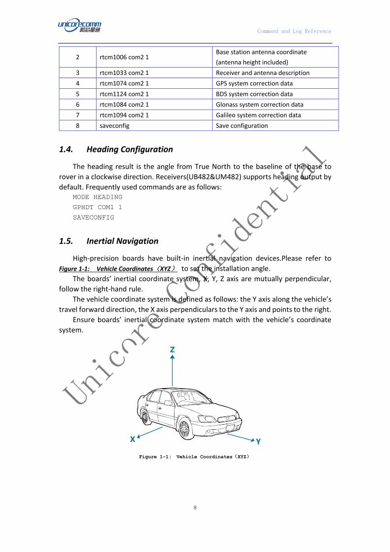
1.5. Inertial Navigation
High-precision boards have built-in inertial navigation devices.Please refer to
Figure 1-1: Vehicle Coordinates(XYZ) to set the installation angle.
The boards’ inertial coordinate system, X, Y, Z axis are mutually perpendicular,
follow the right-hand rule.
The vehicle coordinate system is defined as follows: the Y axis along the vehicle’s
travel forward direction, the X axis perpendiculars to the Y axis and points to the right.
Ensure boards’ inertial coordinate system match with the vehicle’s coordinate
system.
Figure 1-1: Vehicle Coordinates(XYZ)
Command and Log Reference
9
2. Unicore Command Types Introduction
The Unicore commands for High precision GNSS board and modules can be
catageoriezed into the following types. Unicore UB4B0,UB482 boards and UM4B0,
UM482, UM440 modules comply with the command reference.
Table 2-1: Command Types
NO. Type Description
1 Mode Set working mode like base/rover
2 Configure Configure recevier’s function/interfaces
3 Mask Mask/unmask constellation or eleviation
4 Log Output the position/heading/velocity etc.
5 Timing Dedicated for the timing application
6 Misc Reset/Freset/Saveconfig
3. MODE Command
MODE command is used to set the working mode of the receiver. The receiver’s
working modes include base station mode, rover station mode, moving base mode,
heading mode, TDIF mode, ARTK mode, high precision timing mode, and precision
point position (PPP) working mode.
The above working modes are mutually exclusive. That is, the receiver can only
work under one mode of the above working modes. Re-enter a new command to the
receiver, the receiver will be reset according to the latest input mode (mode).
Rover station working mode receivers can automatically identify the RTCM data
format protocol, and users need not specify the RTCM difference input data type.
Command Format: MODE [mode][parameters]
Abbreviated ASCII Syntax: MODE BASE 40.45628476579 116.2859754968 58.0984
MODE ROVER
MODE MOVINGBASE
MODE HEADING
MODE HEADING
Table 3-1: Receiver Work Modes List
Number Mode Mode Description
1 BASE Set the fixed base station mode
2 ROVER Set the rover station mode
3 MOVINGBASE Set the moving base station mode

Command and Log Reference
10
4 HEADING Set the Heading mode
5 TIMING Set the Timing mode
6 TDIF Set the TDIF mode
7 ARTK Set the ARTK mode
8 PPP Set the PPP mode
3.1 Base Station Mode Configuration
The fixed base station antenna will be installed in a fixed position, without moving
during use. The precise coordinates of the known station and the satellite
observations will be sent to the rover station receiver (undetermined point),
supporting the rover station receiver to perform the RTK solution and to achieve
centimeter or millimeter level positioning accuracy. The base station configuration
involves the input of its coordinates and RTCM data. Details of base station
configuration are described below.
Command Format: MODE BASE {auto(default pos time parameter)|B,L,H,und,[id]}
Input Example: MODE BASE
MODE BASE [ID]
Set fixed coordinate Base Station: MODE BASE 40.45628476579 116.2859754968 58.0984
MODE BASE 2 40.45628476579 116.2859754968 58.0984
Optimized base station: MODE BASE TIME 60 1 1
Set base station, and automatically optimize the base station configuration: MODE BASE 2 TIME 60 2.5 3.5
3.1.1 Fixed Base Station with BLH Coordinate
Set fixed BLH coordinate of the base station antenna to make the receiver work
in the base station mode. After setting the fixed coordinates, the position information
(GPGGA) output by the receiver will always display the fixed coordinate, including the
base station position information in the RTCM correction data.
“[ID]” in the command is the base station ID. The value for ID is a positive integer
between 0 and 1023.
Command Format: MODE BASE [ID] [B L H]
Input Example: MODE BASE 40.45628476579 116.2859754968 58.0984

Command and Log Reference
11
MODE BASE 1 40.45628476579 116.2859754968 58.0984
Table 3-2: Base Station Mode with Fixed Coordinates
3.1.2 Fixed Base Station with ECEF Coordinate
Set fixed ECEF coordinate of the base station antenna to make the receiver work
in the base station mode. After setting the fixed coordinates, the position information
(GPGGA) output by the receiver will always display the fixed coordinate, including the
base station position information in the RTCM correction data.
“[ID]” in the command is the base station ID. The value for ID is a positive integer
between 0 and 1023.
Command Format: MODE BASE [ID] [X Y Z]
Input Example: MODE BASE -2160489.0276 4383620.1006 4084738.1110
MODE BASE 1 -2160489.0276 4383620.1006 4084738.1110
Table 3-3: Base Station Mode with Fixed Coordinates
3.1.3 Base Station Mode without parameters
The base station mode without parameters: MODE BASE, when the BASE
command is not followed by any parameters, the receiver will start the default base
station configuration. The default configuration of the base station is: output MSM4
messages in RTCM3.2 from the receiver’s COM2 port, and average coordinates of the
Comma
nd
Mode Field Paramet
er
Parameters Description
MODE BASE
1 Latitude Latitude coordinate in degree
(±90)
2 Longitude Longitude coordinate in degree
(±180)
3 Height Height in meter(±30000)
Comma
nd
Mode Field Paramet
er
Parameters Description
MODE BASE
1 X The X-axis coordinate in the ECEF
coordinate system, in meters
2 Y The Y-axis coordinate in the ECEF
coordinate system, in meters
3 Z The Z-axis coordinate in the ECEF
coordinate system, in meters

Command and Log Reference
12
60 seconds positioning results are set as the base station coordinates. When time is
up to 60 seconds, or the optimized coordinates accuracy of the horizontal and vertical
reach 0.5m, the receiver will stop the self-optimizing calculation and the final
optimized coordinates are set as the base station coordinates.
Command Format: MODE BASE [ID]
Input Example: MODE BASE
Table 3-4: Base Station Mode with Default Parameters
Command Mode Field Parameter Parameters Description
MODE BASE 1 - Option for default base station
mode
MODE BASE 1 ID
Optional field for base station ID.
Positive integer between 0 and
1023.
3.1.4 Self-Optimizing Base Station Mode
Set the receiver to optimize the positioning results, when optimize to the
specified time or precision, the receiver will automatically fix the final coordinates as
the base station coordinates. The position optimization will last a set length of time,
or until the optimized position errors are less than the thresholds. That is, when the
optimization time is up, or the optimized coordinates accuracy of the horizontal and
vertical reach the set values, the receiver will stop the self-optimizing calculation and
the final optimized coordinates are set as the base station coordinates.
When the base station receiver has first been started in the self-optimaizing mode,
then user re-enters the fixed coordinates, the receiver will reset to the fixed base
station mode, that is, the receiver switch to the working mode of user input coordinate
mode:
Command Format: MODE BASE [ID] TIME [T STD1 STD2]
Input Example: MODE BASE TIME 60 1 1
MODE BASE 1 TIME 60 2.5 3.5
Table 3-5: Base Station Mode with Self-Optimizing Coordinates
Command Mode Field Parameter Parameters Description
MODE BASE
TIME 1 time
Maximum time for average
position, in units of seconds

Command and Log Reference
13
3.1.5 Set base station ID
Set base station ID, 0≤ID<1024 positive integers.
Command Format: MODE BASE [ID]
Input Example: MODE BASE 1
Table 3-6: Base Station ID Parameter
Command Mode Field Parameter Parameters Description
MODE BASE 1 ID
Optional field for base station ID.
Positive integer between 0 and
1024.
3.2 Moving Base Mode Configuration
The command is used to set on/off moving base working mode for receivers.
Moving base station is different from fixed base station. Fixed base station is a
fixed point with known precise cooridinates, while the moving base station is at
moving status, the received satellite information is sent to the rover station receiver
(the undetermined point) in RTCM protocol. While receiving the satellite observations,
the rover station receiver also receives the moving base station information,
calculates the relative position of the rover station. At this point the coordinates of
the rover station are relative to the position of the moving base. Under the moving
base mode, moving base receiver will send RTCM data and its position to Heading
receiver.
Command Format: MODE MOVINGBASE [parameter]
2 param1
Horizontal error tolerance of
average position
(default = 0.5m)
3 param2
Vertical error tolerance of average
position
(default = 0.5m)

Command and Log Reference
14
Abbreviated ASCII Syntax: MODE MOVINGBASE
MODE MOVINGBASE DISABLE
Table 3-7: Moving Base Station Work Mode Parameters
Command Mode Parameter Parameters Description
MODE MOVINGBASE —— Enable moving base station mode
DISABLE Disable moving base station mode
3.3 Rover Station Mode Configuration
Rover Station receives the real-time differential correction data sent by the base
station. Rover receiver can adaptively recognize the RTCM data format;
simultaneously receive the satellite signal to perform RTK solution, to realize the RTK
high precision positioning. There are three kinds of RTK mode: static mode, dynamic
mode and automatic mode.
By default, the receiver's RTK solution is under dynamic mode. The receiver will
automatically start RTK positioning when RTCM differential correction data are
received by any serial port.
Command Format: MODE ROVER [parameter]
Input Example: MODE ROVER
MODE ROVER STATIC
Table 3-8: Rover Station Work Mode Parameters
Command Mode Parameter Parameters Description
MODE ROVER — RTK dynamic mode(default)
STATIC RTK static mode
3.4 Heading Configuration Command
This command is used to set the heading mode for the receiver. The heading
result is the angle from True North to the baseline of the base to rover in a clockwise
direction. For dual-antenna receivers, it is not necessary to send this command. In
heading mode configure the antennas motion status of the moving base and the
heading can improve the heading precision. The command of “MODE HEADING” will
enable the receiver in fixed baseline heading.
Command Format: MODE HEADING [parameters]

Command and Log Reference
15
Abbreviated ASCII Syntax: MODE HEADING //Enable fixed baseline heading
MODE HEADING FIXLENGTH //Enable fixed baseline heading
MODE HEADING STATIC //Enalbe static baseline heading
Table 3-9: Heading Mode Parameters
Command Mode Parameter Parameters Description
MODE HEADING
-
Between two antennas (static or
dynamic) of moving base station and
heading receiver, the relative positions
or distance keeps relative stationary
FIXLENGTH
Between two antennas (static or
dynamic) of moving base station and
heading receiver, the relative positions
or distance keeps relative stationary
STATIC
Both two antennas of moving base
station and heading receiver are in
static status
VARIABLENGTH
Between two antennas of moving base
station and heading receiver, the
relative positions or distance dynamic
changes
4. CONFIG Command
CONFIG command is the command protocol header using in configuring receiver’s
serial ports, antenna power, Inertial devices, PPS, geoid undulation, DGPS engine, and
RTK engine.
Command Format: CONFIG [device name][dev device parameter]
The [device name] mainly includes serial port, inertial navigation, receiver
antenna, PPS, elevation abnormality table, DGPs engine, RTK engine. As shown in the
following Table 4-1: Device Name List:
Abbreviated ASCII Syntax: CONFIG COM1 115200 8 n 1
CONFIG ANTENNA POWERON
CONFIG PPS ENABLE BDS POSITIVE 100000 1000 0 0
CONFIG UNDULATION 9.7
CONFIG RTK TIMEOUT 60
CONFIG DGPS TIMEOUT 100
Table 4-1: Device Name List

Command and Log Reference
16
Num
ber
Device
Name Device Description
1 COM1 COM1 serial port: port settings related to COM1, such as baud
rate, parity bit.
2 COM2 COM2 serial port: port settings related to COM2, such as baud
rate, parity bit.
3 COM3 COM3 serial port: port settings related to COM3, such as baud
rate, parity bit.
4 INS INS configuration: enable/disable INS, INS installing angle
5 ANTENNA Antenna feed switch configuration
6 PPS PPS configuration: enable/disable PPS output, polarity, period
and pulse width.
7 EVENT Event configuration: reserved.
8 UNDULATION Geoid undulation configuration: input a specific undulation
value or use built-in geoid grid.
9 RTK RTK configuration: RTK solution、maximum age of RTK data.
10 DGPS DGPS configuration: maximum age of DGPS data.
4.1 Configure Antenna
This command is used to configure the power switch of antenna. The receiver is
connected to an active antenna, that is, the receiver will feed the antenna through the
RF cable. The receiver will feed the antenna through the RF cable by default.
Command Format: CONFIG ANTENNA [parameter]
Abbreviated ASCII Syntax: CONFIG ANTENNA POWERON
CONFIG ANTENNA POWEROFF
Table 4-2:Antenna Configuration
Command Device Field ASCII Value Parameters Description
CONFIG ANTEN
NA SWITCH
POWERON Switch on the antenna feed
POWEROFF Switch off the antenna feed
4.2 Configure Undulation
This command permits you to either enter a specific geoid undulation or use the
built-in grid value of geoid undulations.
Command Format: CONFIG UNDULATION [Parameter]
Command and Log Reference
17
Abbreviated ASCII Syntax: CONFIG UNDULATION 9.7
Table 4-3: Undulation Configuration
Command Device Parameter ASCII
Value
Parameters Description
CONFIG UNDULATIO
N OPTION
auto Use built-in geoid undulation
grid table
separation
Use user-specified undulation
value, ranged from -1000m to
+1000m
4.3 Configure RTK Command
This command is used to resets the RTK engine and to clear the RTK parameters.
Command Format: CONFIG RTK [parameter]
Abbreviated ASCII Syntax: CONFIG RTK 60
Table 4-4: RTK Solution Configuration
Comma
nd Device Field Parameter
Parameters Description
CONFIG RTK
1 TIMEOUT
0 Disable RTK solution
1-1000 Option for maximum age of RTK
data (default = 300), seconds
1 RESET Reset the RTK solution
1 USER_DEFA
ULTS Set the RTK to default settings
1 DISABLE Do not perform RTK solution
1 FLOAT Only perform RTK float solution
4.4 Configure DGPS Command
This command is used to set the receiver’s maximum age of DGPS differential data
accepted from the base station. DGPS differential data received later than specified
age is ignored, which can also be used to prohibit DGPS positioning calculations.
Command Format: CONFIG DGPS [Parameter]

Command and Log Reference
18
Abbreviated ASCII Syntax: CONFIG DGPS 100
Table 4-5: DGPS Maximum Age Configuration
Command Device Parameter ASCII
Value
Parameters Description
CONFIG DGPS DELAY
0 Disable the DGPS positioning
1-1000
Option for maximum age of
differential corrections data
(default = 300), in units of seconds
4.5 Configure PPS
This command sets the PPS pulse signal with a specific period and pulse width,
and can compensate for the delay of the PPS.
Abbreviated ASCII Syntax: CONFIG PPS ENABLE GPS POSITIVE 500000 1000 0 0
Table 4-6: PPS Configuration
ID Field ASCII Value Parameters Description
1 PPS -
2 Switch DISABLE(default)
Disable PPS output (once disable
is set, all other parameters are ignored)
ENABLE Enable PPS output
3 Timeref GPST or BDST Option for reference time system, now
support the GPS and BDS only
4 Polarity
POSITIVE
Option to generates a normally low,
active high PPS pulse with the rising
edge as the reference
NEGATIVE
Option to generates a normally high,
active low pulse with the falling edge as
the reference
5 Pulse Width Any value between 0 and
the period
Option to specify the pulse width of the
PPS signal, microseconds
6 Period
valid values:
50,100,200,250,50,1000,2
000,3000…,20000
The period of the pulse, milliseconds
7 Rf Delay Inter between -32768 and
32767 Set RF delay, nanoseconds
8 User Delay Inter between -32768
and 32767 Set user delay, nanoseconds

Command and Log Reference
19
4.6 Configure Serial Port
This command is to configure the data communication parameters for the
physical serial port: setting the baud rate, data bits, parity, stop bit properties of the
serial port.
High-precision GNSS receivers maximumly support 3 serial ports, COM1, COM2,
COM3 respectively. The three serial ports have the same functions, but work
independently according to their respective configurations. The three ports can be
configured mutually, e.g. COM2/COM3 serial port properties can be configured
through COM1, and COM1 can also be configured through COM2/COM3.
The command format for configuring the serial port is: CONFIG [serial number] [serial port property parameter]
Command Format: CONFIG COMX [parameter]
Abbreviated ASCII Syntax: CONFIG COM1 115200
CONFIG COM1 115200 8 n 1
Table 4-7: Serial Port Parameters List
Command Device Fiel
d
parameters
Supported Parameters Description
CONIFG
COM1
COM2
COM3
1 baud
rate/bps
Option for COM port communication
baud rate.
The supported baud rate see Table
4-8:Baud Rate Supported
2 data bits
Option for COM port data bits. To set
this field, notice that the preceding
baud rate field should existing.
3 parity
Option for COM port parity.
To set this field, notice that the
preceding fields should existing.
4 stop bits
Option for COM port stop bits.
To set this field, notice that the
preceding fields should existing.
Table 4-8:Baud Rate Supported
Serial port Description
COM1 9600, 19200, 38400, 57600, 115200, 230400, 460800
COM2 9600, 19200, 38400, 57600, 115200, 230400, 460800
COM3 9600, 19200, 38400, 57600, 115200, 230400, 460800

Command and Log Reference
20
4.7 Configure INS Device
The receiver integrates onboard MEMS chips (except UB380 and UB280/UB282),
which greatly optimized continuity and reliability•of•heading/positioning
output•in•such complex environments•as•buildings, tunnels•and overpasses.
With onboard MEMS devices, Unicore High-precision receivers support GNSS and
INS combined navigation to provide continuous, high quality and high output
positioning results under complicated environment. This command is used to
enable/disable the inertial navigation devices, to configure the inertial divece’s
installation angle. The inertial navigation devices are disabled by default. To use the
INS function, please send INS enable command to the device. After started, the INS
devices can not be successfully initialized unless the vehicle speed meets the minimum
speed (5m/s by default) required. When the inertial navigation device is initialized
successfully, the receiver will enter the GNSS and INS integrated navigation
positioning mode.
Command Format: CONFIG INS [parameter]
Abbreviated ASCII Syntax: CONFIG INS ENABLE
CONFIG INS ANGLE 0, 9000, 18000
CONFIG INS TIMEOUT 60
CONFIG INS ALIGNMENTVEL 5.0
4.7.1 Configure INS devices to be enabled
The receiver integrates onboard MEMS chips (except UB380 and UB280/UB282).
However, the INS device is disabled by default, the receiver is working under GNSS
only mode. When the receiver is sent an INS enable command, and at the same time
the receiver response correctly, the INS device of the receiver begins to work. During
this period of time, the velocity of the vehicle should reach the initialization speed
threshold, and the receiver works under the GNSS+INS mode. After enabling the
inertial navigation device, the receiver is required to be stablely fixed on the vehicle.
Command Format: CONFIG INS [enable/disable]
Abbreviated ASCII Syntax: CONFIG INS ENABLE
Table 4-9: INS Configuration
Command Device Parameter Parameters Description
CONFIG INS Enable Enable INS

Command and Log Reference
21
Disable Disable INS
4.7.2 Configure INS device installation angel
This command is used to set the installation angle of the board relative to the
vehicle’s XYZ direction. The receiver is labeled with the XYZ axis direction of the inertial
navigation device. It is required that the XYZ axis of the receiver is consistent with that
of the vehicle. If the XYZ axis of the inertial device of the receiver is not consistent with
that of the vehicle because of the installation reason, a rotation angle of two
coordinate systems is required to be input.
Command Format: CONFIG INS ANGLE [angle]
Abbreviated ASCII Syntax: CONFIG INS ANGLE 0 9000 18000
Table 4-10: INS Installing Angle Configuration
Command Device Angle Number Parameter Parameters Description
CONFIG INS ANGLE
1 ANGLEX Rotation angle from vehicle
X-axis to INS module X-axis
2 ANGLEY Rotation angle from vehicle Y-
axis to INS module Y-axis
3 ANGELZ Rotation angle from vehicle Z-
axis to INS module Z-axis
Table 4-11: INS Installing Angle Descriptions
Number Parameter ASCII Value Description
1 AngleX 0-36000
Rotation angle from vehicle X-axis to INS module X-
axis (right-handed coordinate system), in units 0.01
degree
2 AngleY 0-36000
Rotation angle from vehicle Y-axis to INS module Y-
axis (right-handed coordinate system), in units 0.01
degree
3 AngleZ 0-36000
Rotation angle from vehicle Z-axis to INS module Z-
axis (right-handed coordinate system), in units of
0.01 degree
4.7.3 Configure INS Timeout
This command is used to set the time, which the INS device will continue
positioning without GNSS signal, in seconds.
Command Format:
Command and Log Reference
22
CONFIG INS TIMEOUT [time]
Abbreviated ASCII Syntax: CONFIG INS TIMEOUT 60
Table 4-12:INS Maximum Prediction Time Configuration
Command Device Field ASCII Value Parameters Description
CONFIG INS timeout
0 Disable INS positioning
1-1000
The maximum time allow INS to
positioning after no GNSS
satellite signal (default = 200),
seconds
4.7.4 Configure INS Alignment Velocity threshold
This command sets the initialization calibration of the INS device when the vehicle
reaches the specified velocity.
Command Format: CONFIG INS ALIGNMENTVEL [velocity]
Abbreviated ASCII Syntax: CONFIG INS ALIGNMENTVEL 5.0
Table 4-13:INS Velocity Threshold Configuration
Command Device Field ASCII Value Parameters Description
CONFIG INS alignm
entvel velocity
Option for the velocity threshold of INS
calibration speed, meters/second
5. MASK Command
5.1 MASK Set Satellite System
This command is used to set the satellite systems, satellite frequencies, satellite
cut-off angle.
Command Format: MASK {+-}/{90}/system/
Abbreviated ASCII Syntax: MASK [+/- satellite system or cut-off angle] [satellite system frequency]
Command and Log Reference
23
Input Example:
Disable receiver tracking GPS/BDS/GLO/GAL satellite system: MASK GPS/BDS/GLO/GAL
Enable receiver tracking GPS/BDS/GLO/GAL satellite system: MASK -GPS/BDS/GLO/GAL
Set cut-off angle of the receiver tracking satellite: MASK 10
Set cut-off angle of GPS/BDS/GLO/GAL satellite: MASK 10 GPS/BDS/GLO/GAL
Disable the receiver to track BDS B1 signal: MASK BDSB1
Enable the receiver to track BDS B1 signal: MASK -BDSB1
Table 5-1: GNSS System and Frequency Band
Number System Satellite Frequency Description
1 GPS L1、L2、L5 Three frequencies of GPS satellites: L1、L2、L5
2 BDS B1、B2、B3 Three frequencies of BDS satellites:B1、B2、B3
3 GLO L1、L2 Two frequencies of Glonass satellites:L1、L2
4 GAL E1、E5a、E5b Three frequencies of Galileo satellites:E1、E5a、
E5b
5.2 UNMASK Set Satellite System
This command is used to set the satellite systems, satellite frequencies, satellite
cut-off angle.
Command Format: UNMASK /system frequency/
Abbreviated ASCII Syntax: UNMASK [satellite system frequency]
Input Example:
Enable receiver tracking GPS/BDS/GLO/GAL satellite system: UNMASK GPS/BDS/GLO/GAL
6. LOG COMMAND
6.1 NMEA 0183 ASCII log output
This command is used to log current position, velocity, heading of the receiver.
Command Format:

Command and Log Reference
24
LOG [device] [output rate {0-9*.{0-9}| onchanged]|
Rules:
If the message begins with “GN” and without special instructions, the output is
multi-system calucating results by default.
If the message begins with 3-letter(BDS/GPS/GLO/GAL) and without special
instructions, the output is single system calucating results. BDS indicates BDS system,
GPS indicates GPS system, GLO indicates GLONASS system, GAL indicates Galileo
system.
Abbreviated ASCII Syntax: LOG [device] [output rate]
Input Example: GNGGA 0.1
GNGGA COM2 1
BDSGGA COM1 0.5
Table 6-1: Output Message of Positioning and Heading
Number Command Port Parameter Description
1 GNGGA
COM1
COM2
COM3
0.05、0.1、
0.2、0.5、
1、
5、10……
Set the port output the multiple-system
joint positioning results, begins with
“GNGGA”
2 GPSGGA
COM1
COM2
COM3
0.05、0.1、
0.2、0.5、
1、
5、10……
Set the port output the single GPS system
positioning results, begins with “GPSGGA”
3 BDSGGA
COM1
COM2
COM3
0.05、0.1、
0.2、0.5、
1、
5、10……
Set the port output the single BDS system
positioning results, begins with “BDSGGA”
4 GLOGGA
COM1
COM2
COM3
0.05、0.1、
0.2、0.5、
1、
5、10……
Set the port output the single Glonass
system positioning results, begins with
“GLOGGA”
5 GALGGA
COM1
COM2
COM3
0.05、0.1、
0.2、0.5、
1、
5、10……
Set the port output the single Galileo
system positioning results, begins with
“GALGGA”
6 GNGSV
COM1
COM2
COM3
0.05、0.1、
0.2、0.5、
1、
5、10……
Information of all supported systems
satellites in view: PRN number, elevation,
azimuth and SNR value

Command and Log Reference
25
7 GPGSV
COM1
COM2
COM3
0.05、0.1、
0.2、0.5、
1、
5、10……
Information of GPS satellites in view: PRN
number, elevation, azimuth and SNR value
8 GNGSA
COM1
COM2
COM3
0.05、0.1、
0.2、0.5、
1、
5、10……
Information of receiver operating mode,
all satellites involved positioning and DOP
values
9 GPGSA
COM1
COM2
COM3
0.05、0.1、
0.2、0.5、
1、
5、10……
Information of receiver operating mode,
GPS satellites involved positioning and
DOP values
10 GNRMC
COM1
COM2
COM3
0.05、0.1、
0.2、0.5、
1、
5、10……
Information of receiver time, data,
position, track mode and speed data
11 GPRMC
COM1
COM2
COM3
0.05、0.1、
0.2、0.5、
1、
5、10……
Information of receiver time, data,
position, track mode and speed data
12 GPSRMC
COM1
COM2
COM3
0.05、0.1、
0.2、0.5、
1、
5、10……
GPS specific information
13 BDSRMC
COM1
COM2
COM3
0.05、0.1、
0.2、0.5、
1、
5、10……
BDS specific information
14 GLORMC
COM1
COM2
COM3
0.05、0.1、
0.2、0.5、
1、
5、10……
Glonass specific information
15 GALRMC
COM1
COM2
COM3
0.05、0.1、
0.2、0.5、
1、
5、10……
Galileo specific information
16 GPGST
COM1
COM2
COM3
0.05、0.1、
0.2、0.5、
1、
5、10……
Information of pseudorange measurement
noise statistics in the position domain
17 GPHDT
COM1
COM2
COM3
0.05、0.1、
0.2、0.5、
1、
5、10……
Information of actual vessel heading in
degrees True from True North

Command and Log Reference
26
18 GPVTG
COM1
COM2
COM3
0.05、0.1、
0.2、0.5、
1、
5、10……
Information of track made good and
speed relative to the ground
19 GPZDA
COM1
COM2
COM3
0.05、0.1、
0.2、0.5、
1、
5、10……
Information of UTC time and date
20 GPNTR
COM1
COM2
COM3
0.05、0.1、
0.2、0.5、
1、
5、10……
NMEA0183
21 GPTRA
COM1
COM2
COM3
0.05、0.1、
0.2、0.5、
1、
5、10……
NMEA0183
22 RTCM1
COM1
COM2
COM3
0.05、0.1、
0.2、0.5、
1、
5、10……
RTCM
23 RTCM1004
COM1
COM2
COM3
0.05、0.1、
0.2、0.5、
1、
5、10……
RTCM
24 RTCM1005
COM1
COM2
COM3
0.05、0.1、
0.2、0.5、
1、
5、10……
RTCM
25 RTCM1006
COM1
COM2
COM3
0.05、0.1、
0.2、0.5、
1、
5、10……
RTCM
26 RTCM1007
COM1
COM2
COM3
0.05、0.1、
0.2、0.5、
1、
5、10……
RTCM
27 RTCM1012
COM1
COM2
COM3
0.05、0.1、
0.2、0.5、
1、
5、10……
RTCM
28 RTCM1013
COM1
COM2
COM3
0.05、0.1、
0.2、0.5、
1、
5、10……
RTCM

Command and Log Reference
27
29 RTCM1019
COM1
COM2
COM3
0.05、0.1、
0.2、0.5、
1、
5、10……
RTCM
30 RTCM1020
COM1
COM2
COM3
0.05、0.1、
0.2、0.5、
1、
5、10……
RTCM
31 RTCM1033
COM1
COM2
COM3
0.05、0.1、
0.2、0.5、
1、
5、10……
RTCM
32 RTCM1104
COM1
COM2
COM3
0.05、0.1、
0.2、0.5、
1、
5、10……
RTCM
33 RTCM1124
COM1
COM2
COM3
0.05、0.1、
0.2、0.5、
1、
5、10……
RTCM
34 RTCM1125
COM1
COM2
COM3
0.05、0.1、
0.2、0.5、
1、
5、10……
RTCM
35
RTCM1819
COM1
COM2
COM3
0.05、0.1、
0.2、0.5、
1、
5、10……
RTCM
36
RTCM3
COM1
COM2
COM3
0.05、0.1、
0.2、0.5、
1、
5、10……
RTCM
37
RTCM31
COM1
COM2
COM3
0.05、0.1、
0.2、0.5、
1、
5、10……
RTCM
38
RTCM32
COM1
COM2
COM3
0.05、0.1、
0.2、0.5、
1、
5、10……
RTCM
39
CMROBS
COM1
COM2
COM3
0.05、0.1、
0.2、0.5、
1、
5、10……
Observations of all supported systems

Command and Log Reference
28
40
CMRDESC
COM1
COM2
COM3
0.05、0.1、
0.2、0.5、
1、
5、10……
Base station description
6.1.1 GNGGA GNSS Multi-System Positioning Output
This command is used to log time, multi-system positioning fix data of the receiver.
The message begins with GNGGA.
Recommend Input:
Output 1Hz GNGGA message from current serial port: GNGGA 1
Output 1Hz GNGGA message from COM2: GNGGA COM2 1
LOG output: $GNGGA,025754.00,4004.74102107,N,11614.19532779,E,1,18,0.7,63.
3224,M,-9.7848,M,00,0000*58
Table 6-2: GNGGA Message Description
ID Field Description Symbol Example
1 $GNGGA Log header $GNGGA
2 utc
UTC time of the current position
(hours/minutes/seconds/
decimal seconds)
hhmmss.ss 170659.00
3 lat Latitude (DDmm.mm) IIII.II 4001.1220
4 lat dir Latitude direction (N = North, S = South) a N
5 lon Longitude (DDDmm.mm) yyyyy.yy 11600.3622
6 lon dir Longitude direction (E = East, W = West) a E
7 GPS quality
Quality indicators of positioning results:
0 = Positioning not available or invalid
1 = Single point
2 = Pseudorange differential or SBAS
4 = RTK fixed solution
5 = RTK floating solution
6 = INS
7 = User fixed position
x 1
8 # sats Number of satellites in use, may not the
same as the number in view. xx 10
9 hdop Horizontal dilution of precision x.x 1.0
10 alt Antenna height, above/below the mean x.x 1098.44

Command and Log Reference
29
ID Field Description Symbol Example
sea level
11 a-units Units of antenna height (M = meter) M M
12 undulation
Undulation: the vertical separation
between the geoid and the WGS84
ellipsoid
x.x -15.174
13 u-units Units of undulation (M = meter) M M
14 age Age of differential correction data,
seconds xx
This value is set to
00 when no
correction data
available
15 stn ID Differential base station ID, between 0000
and 1023 xxxx
This value is set to
00 when no
correction data
available
16 *xx Checksum *hh *3F
17 [CR][LF] Sentence terminator [CR][LF]
6.1.2 GPGGA GNSS Fix Data output by GPGGA
This command is used to log time, multi-system positioning fix data of the receiver.
Output GNSS fix data using “$GPGGA” as the message header by force. The message
begins with GPGGA.
Recommend Input:
Output 1Hz GPGGA message from current serial port: GPGGA 1
Output 1Hz GPGGA message from com2: GPGGA COM2 1
LOG output: $GPGGA,025754.00,4004.74102107,N,11614.19532779,E,1,18,0.7,63.
3224,M,-9.7848,M,00,0000*58
Table 6-3: GPGGA Message Description
ID Field Description Symbol Example
1 $GPGGA Log headera $GPGGA
2 utc
UTC time of the current position
(hours/minutes/seconds/
decimal seconds)
hhmmss.ss 170659.00
3 lat Latitude (DDmm.mm) IIII.II 4001.1220

Command and Log Reference
30
ID Field Description Symbol Example
4 lat dir Latitude direction (N = North, S =
South) a N
5 lon Longitude (DDDmm.mm) yyyyy.yy 11600.3622
6 lon dir Longitude direction (E = East, W =
West) a E
7 GPS quality
Quality indicators of positioning
results:
0 = Positioning not available or invalid
1 = Single point
2 = Pseudorange differential or SBAS
4 = RTK fixed solution
5 = RTK floating solution
6 = INS
7 = User fixed position
x 1
8 # sats Number of satellites in use, may not
the same as the number in view. xx 10
9 hdop Horizontal dilution of precision x.x 1.0
10 alt Antenna height, above/below the
mean sea level x.x 1098.44
11 a-units Units of antenna height (M = meter) M M
12 undulation
Undulation: the vertical separation
between the geoid and the WGS84
ellipsoid
x.x -15.174
13 u-units Units of undulation (M = meter) M M
14 age Age of differential correction data,
seconds xx
This value is set
to 00 when no
correction data
available
15 stn ID Differential base station ID, between
0000 and 1023 xxxx
This value is set
to 00 when no
correction data
available
16 *xx Checksum *hh *3F
17 [CR][LF] Sentence terminator [CR][LF]
a. The two characters in NMEATALKER followed “$”is fixed as “GP”, both in multiple-system joint
positioning and single system positioning.
6.1.3 GPSGGA GPS Fix Data Output
This command is used to log time, GPS system positioning fix data of the receiver.
The message begins with “$GPSGGA”.

Command and Log Reference
31
Recommend Input:
Output 1Hz GPSGGA message from current serial port: GPSGGA 1
Output 1Hz GPSGGA message from com2: GPSGGA COM2 1
LOG output: $GPSGGA,025754.00,4004.74102107,N,11614.19532779,E,1,18,0.7,63
.3224,M,-9.7848,M,00,0000*58
Table 6-4: GPSGGA Message Description
ID Field Description Symbol Example
1 $GPSGGA Log header $GPSGGA
2 utc
UTC time of the current position
(hours/minutes/seconds/
decimal seconds)
hhmmss.ss 170659.00
3 lat Latitude (DDmm.mm) IIII.II 4001.1220
4 lat dir Latitude direction (N = North, S = South) a N
5 lon Longitude (DDDmm.mm) yyyyy.yy 11600.3622
6 lon dir Longitude direction (E = East, W = West) a E
7 GPS quality
Quality indicators of positioning results:
0 = Positioning not available or invalid
1 = Single point
2 = Pseudorange differential or SBAS
4 = RTK fixed solution
5 = RTK floating solution
6 = INS
7 = User fixed position
x 1
8 # sats Number of satellites in use, may not the
same as the number in view. xx 10
9 hdop Horizontal dilution of precision x.x 1.0
10 alt Antenna height, above/below the mean
sea level x.x 1098.44
11 a-units Units of antenna height (M = meter) M M
12 undulation
Undulation: the vertical separation
between the geoid and the WGS84
ellipsoid
x.x -15.174
13 u-units Units of undulation (M = meter) M M
14 age Age of differential correction data,
seconds xx
This value is set to
00 when no

Command and Log Reference
32
ID Field Description Symbol Example
correction data
available
15 stn ID Differential base station ID, between
0000 and 1023 xxxx
This value is set to
00 when no
correction data
available
16 *xx Checksum *hh *3F
17 [CR][LF] Sentence terminator [CR][LF]
6.1.4 BDSGGA BDS Fix Data Output
This command is used to log time, BDS system positioning fix data of the receiver.
The message begins with “$BDSGGA”.
Recommend Input:
Output 1Hz BDSGGA message from current serial port: BDSGGA 1
Output 1Hz BDSGGA message from com2: BDSGGA COM2 1
LOG output: $BDSGGA,025754.00,4004.74102107,N,11614.19532779,E,1,18,0.7,63
.3224,M,-9.7848,M,00,0000*58
Table 6-5: BDSGGA Message Description
ID Field Description Symbol Example
1 $BDSGGA Log header $BDSGGA
2 utc
UTC time of the current position
(hours/minutes/seconds/
decimal seconds)
hhmmss.ss 170659.00
3 lat Latitude (DDmm.mm) IIII.II 4001.1220
4 lat dir Latitude direction (N = North, S =
South) a N
5 lon Longitude (DDDmm.mm) yyyyy.yy 11600.3622
6 lon dir Longitude direction (E = East, W =
West) a E
7 GPS quality
Quality indicators of positioning
results:
0 = Positioning not available or invalid
1 = Single point
2 = Pseudorange differential or SBAS
x 1

Command and Log Reference
33
ID Field Description Symbol Example
4 = RTK fixed solution
5 = RTK floating solution
6 = INS
7 = User fixed position
8 # sats Number of satellites in use, may not
the same as the number in view. xx 10
9 hdop Horizontal dilution of precision x.x 1.0
10 alt Antenna height, above/below the
mean sea level x.x 1098.44
11 a-units Units of antenna height(M = meter) M M
12 undulation
Undulation: the vertical separation
between the geoid and the WGS84
ellipsoid
x.x -15.174
13 u-units Units of undulation(M = meter) M M
14 age Age of differential correction data,
seconds xx
This value is set
to 00 when no
correction data
available
15 stn ID Differential base station ID, between
0000 and 1023 xxxx
This value is set
to 00 when no
correction data
available
16 *xx Checksum *hh *3F
17 [CR][LF] Sentence terminator [CR][LF]
6.1.5 GLOGGA GLONASS Fix Data Output
This command is used to log time, GLONASS system positioning fix data of the
receiver. The message begins with “$GLOGGA”.
Recommend Input:
Output 1Hz GLOGGA message from current serial port: GLOGGA 1
Output 1Hz GLOGGA message from com2: GLOGGA COM2 1
LOG Output $GLOGGA,025754.00,4004.74102107,N,11614.19532779,E,1,18,0.7,63
.3224,M,-9.7848,M,00,0000*58
Table 6-6: GLOGGA Message Description

Command and Log Reference
34
ID Field Description Symbol Example
1 $GLOGGA Log header $GLOGGA
2 utc
UTC time of the current position
(hours/minutes/seconds/
decimal seconds)
hhmmss.ss 170659.00
3 lat Latitude (DDmm.mm) IIII.II 4001.1220
4 lat dir Latitude direction (N = North, S =
South) a N
5 lon Longitude (DDDmm.mm) yyyyy.yy 11600.3622
6 lon dir Longitude direction (E = East, W =
West) a E
7 GPS quality
Quality indicators of positioning
results:
0 = Positioning not available or invalid
1 = Single point
2 = Pseudorange differential or SBAS
4 = RTK fixed solution
5 = RTK floating solution
6 = INS
7 = User fixed position
x 1
8 # sats Number of satellites in use, may not
the same as the number in view. xx 10
9 hdop Horizontal dilution of precision x.x 1.0
10 alt Antenna height, above/below the
mean sea level x.x 1098.44
11 a-units Units of antenna height (M = meter) M M
12 undulation
Undulation: the vertical separation
between the geoid and the WGS84
ellipsoid
x.x -15.174
13 u-units Units of undulation (M = meter) M M
14 age Age of differential correction data,
seconds xx
This value is set to
00 when no
correction data
available
15 stn ID Differential base station ID, between
0000 and 1023 xxxx
This value is set to
00 when no
correction data
available
16 *xx Checksum *hh *3F
17 [CR][LF] Sentence terminator [CR][LF]

Command and Log Reference
35
6.1.6 GALGGA Galileo Fix Data Output
This command is used to log time, Galileo system positioning fix data of the
receiver. The message begins with “$GALGGA”.
Recommend Input:
Output 1Hz GALGGA message from current serial port: GALGGA 1
Output 1Hz GALGGA message from com2: GALGGA COM2 1
LOG output: $GALGGA,025754.00,4004.74102107,N,11614.19532779,E,1,18,0.7,63
.3224,M,-9.7848,M,00,0000*58
Table 6-7: GALGGA Message Description
ID Field Description Symbol Example
1 $ GALGGA Log header $ GALGGA
2 utc Log header hhmmss.ss 170659.00
3 lat
UTC time of the current position
(hours/minutes/seconds/
decimal seconds)
IIII.II 4001.1220
4 lat dir Latitude (DDmm.mm) a N
5 lon Latitude direction (N = North, S =
South) yyyyy.yy 11600.3622
6 lon dir Longitude (DDDmm.mm) a E
7 GPS quality Longitude direction (E = East, W =
West) x 1
8 # sats
Quality indicators of positioning
results:
0 = Positioning not available or invalid
1 = Single point
2 = Pseudorange differential or SBAS
4 = RTK fixed solution
5 = RTK floating solution
6 = INS
7 = User fixed position
xx 10
9 hdop Horizontal dilution of precision x.x 1.0
10 alt Antenna height, above/below the
mean sea level x.x 1098.44
11 a-units Units of antenna height(M = meter) M M
12 undulation Undulation: the vertical separation x.x -15.174

Command and Log Reference
36
ID Field Description Symbol Example
between the geoid and the WGS84
ellipsoid
13 u-units Units of undulation(M = meter) M M
14 age Age of differential correction data,
seconds xx
This value is set to
00 when no
correction data
available
15 stn ID Differential base station ID, between
0000 and 1023 xxxx
This value is set to
00 when no
correction data
available
16 *xx Checksum *hh *3F
17 [CR][LF] Sentence terminator [CR][LF]
6.1.7 GPGSA GPS DOP and Active Satellites
This command is used to log receiver operating mode, satellites in use and DOP
values.
Recommend Input:
Output 1Hz GPGSA message from current serial port: GPGSA 1
Output 1Hz GPGSA message from com2: GPGSA COM2 1
LOG output: $GPGSA,M,3,22,25,12,14,18,09,31,,,,,,1.7,0.9,1.4*37
Table 6-8: GPGSA Message Description
ID Field Description Symbol Example
1 $GPGSA Log header $GPGSA
2 mode MA
A = Automatic mode, 2D/3D
M = Manual input mode, fixed in 2D
or 3D
M M
3 mode 123
Mode:
1 = Fix not available;
2 = 2D;
3 = 3D
x 3
4 - 15 prn
PRN numbers of satellites in use
(unused fields is null), contains 12
fields;
GPS = 1 to 32
xx,xx,..... 18,03,13, 25,16,
24,12, 20,,,,

Command and Log Reference
37
ID Field Description Symbol Example
GLONASS=38 to 74
GALILEO = 75 to 119
BD2 = 161 to 197
16 pdop Position dilution of precision x.x 1.5
17 hdop Horizontal dilution of precision x.x 0.9
18 vdop Vertical dilution of precision x.x 1.2
19 *xx Checksum *hh *3F
20 [CR][LF] Sentence terminator [CR][LF]
6.1.8 GPGST Pseudorange measurement noise statistics
This command is used to log pseudorange measurement noise statistics, these
values will be sent to the positioning results to present statistical qualities of the
positioning solution.
This log reflects the positioning accuracy of the “GPGGA”, except for the RMS field.
The RMS field, since it specifically relates to pseudorange inputs, does not represent
carrier-phase based positions.
Recommend Input:
Output 1Hz GPGST message from current serial port: GPGST 1
Output 1Hz GPGST message from com2: GPGST COM2 1
LOG output: $GPGST,141451.00,1.18,0.00,0.00,0.0000,0.00,0.00,0.00*6B
Table 6-9: GPGST Message Description

Command and Log Reference
38
ID Field Description Symbol Example
1 $GPGST Log header $GPGST
2 utc
UTC time of the current position
(hours/minutes/seconds/
decimal seconds)
hhmmss.ss
173653.00
3 rms
RMS value of the standard deviation of
the range involved in positioning. The
range include pseudoranges and DGPS
corrections
x.x
2.73
4 smjr std Standard deviation of semi-major axis
of error ellipse (m)
x.x
2.55
5 smnr std Standard deviation of semi-minor axis
of error ellipse (m)
x.x
1.88
6 orient
Orientation of semi-major axis of error
ellipse (degrees from true
north)
x.x
15.2525
7 lat std Standard deviation of latitude error (m) x.x 2.51
8 lon std Standard deviation of longitude error
(m) x.x 1.94
9 alt std Standard deviation of altitude error (m) x.x 4.30
10 *xx Checksum *hh *6E
11 [CR][LF] Sentence terminator [CR][LF]
6.1.9 GPGSV GNSS Satellites in View
This command is used to log number of SVs in view, PRN numbers, elevation,
azimuth and SNR value. Four satellites maximum per message. When required,
additional satellite data sent in 2 or more messages (a maximum of 9). The total
number of messages being transmitted and the current message being transmitted
are indicated in the first two fields.
Recommend Input:
Output 1Hz GPGSV message from current serial port: GPGSV 1
Output 1Hz GPGSV message from com2: GPGSV COM2 1
LOG output: $GPGSV,3,1,11,18,87,050,48,22,56,250,49,21,55,122,49,03,40,284,47*78
Table 6-10: GPGSV Message Description
ID Field Description Symbol Example
1 $GPGSV Log header $GPGSV

Command and Log Reference
39
ID Field Description Symbol Example
2 # msgs Total number of message, 1 to 9 x 3
3 msg # Message number, 1 to 9 x 1
4 # sats Total number of satellites in view, may not
the same as the number in use. xx 09
5 prn
Satellite PRN number:
GPS=1~32
GLONASS=38~74
Galileo=75~119
SBAS= 120~ 138
BDS=161~197
xxx 03
6 elev Elevation, degrees, 90°maximum xx 51
7 azimuth Azimuth, degrees True, 000 to 359 xxx 140
8 SNR SNR(C/No), 00-99 dB-Hz, 0 when not
tracking xx 42
…
…
…
…
…
…
Next satellite PRN number, elev, azimuth,
SNR,
……
Last satellite PRN number, elev, azimuth,
SNR,
Variable *xx Checksum *hh *72
variable [CR][LF] Sentence terminator [CR][LF]
6.1.10 GPHDT Heading Log
This command is used to log actual heading information in degrees from True
North.
To log the information requires receiver working in heading mode.
Recommend Input:
Output 1Hz GPHDT message from current serial port: GPHDT 1
Output 1Hz GPHDT message from com2: GPHDT COM2 1
LOG output: $GPHDT,178.7236,T*15
Table 6-11: GPHDT Message Description
ID Field Description Symbol Example
1 $GPHDT Log header $GPHDT
2 heading Heading, degree X.X 178.7236
3 TRUE Degrees True T T
Command and Log Reference
40
4 *XX Checksum *hh *15
5 [CR][LF] Sentence terminator [CR][LF]
6.1.11 GPRMC GNSS Recommended Information
This command is used to log time, date, position, heading and velocity data
calculated by receivers. RMC is the recommended minimum navigation data for
receivers.
The GPRMC log outputs these messages without waiting for a valid almanac.
Instead, it uses a UTC time, calculating with default parameters. In this case, the UTC
time status is set to WARNING since it may not be one hundred percent accurate.
When a valid almanac is available, the receiver uses the real parameters to calculate.
Then the UTC time status is set to VALID.
Recommend Input:
Output 1Hz GPRMC message from current serial port: GPRMC 1
Output 1Hz GPRMC message from com2: GPRMC COM2 1
LOG output $GPRMC,094403.00,A,4004.73794422,N,11614.18999462,E,0.037,5.5,
260815,6.5,W,A*35
Table 6-12: GPRMC Message Description
ID Field Description Symbol Example
1 $GPRMC Log header $GPRMC
2 utc UTC time of the current position hhmmss.ss 144326.00
3 pos status Position status:
A = Data valid, V = Positioning invalid A A
4 lat Latitude (DDmm.mm) llll.ll 5107.0017737
5 lat dir Latitude direction (N = North, S = South) a N
6 lon Longitude (DDDmm.mm) yyyyy.yy 11402.3291611
7 lon dir Longitude direction (E = East, W = West) a W
8 speed Kn Speed over ground, knots x.x 0.080
9 track true Course Over Ground, degrees True x.x 323.3
10 date Date: dd/mm/yy xxxxxx 210307
11 mag var Magnetic variation, degrees x.x 0.0
12 var dir Direction of magnetic variation
(E = East, W = West) a E
13 mode ind
Positioning mode indicator:
A = Autonomous mode
D = Differential mode
a A

Command and Log Reference
41
ID Field Description Symbol Example
E = Estimated (dead reckoning) mode
M = Manual input mode
S = Simulator mode
N = Data not valid
14 *xx Checksum *hh *72
15 [CR][LF] Sentence terminator [CR][LF]
6.1.12 GNRMC GNSS Recommended Information
This log contains time, date, position, heading and velocity data calculated by
receivers. RMC is the recommended minimum navigation data for receivers.
The GNRMC log outputs these messages without waiting for a valid almanac.
Instead, it uses a UTC time, calculating with default parameters. In this case, the UTC
time status is set to WARNING since it may not be one hundred percent accurate.
When a valid almanac is available, the receiver uses the real parameters to calculate.
Then the UTC time status is set to VALID.
Recommend Input:
Output 1Hz GNRMC message from current serial port: GNRMC 1
Output 1Hz GNRMC message from com2: GNRMC COM2 1
LOG output $GNRMC,094403.00,A,4004.73794422,N,11614.18999462,E,0.037,5.5,
260815,6.5,W,A*35
Table 6-13: GNRMC Message Description
ID Field Description Symbol Example
1 $GNRMC Log header $GNRMC
2 utc UTC time of the current position hhmmss.ss 144326.00
3 pos status Position status:
A = Data valid, V = Positioning invalid A A
4 lat Latitude (DDmm.mm) llll.ll 5107.0017737
5 lat dir Latitude direction (N = North, S = South) a N
6 lon Longitude (DDDmm.mm) yyyyy.yy 11402.3291611
7 lon dir Longitude direction (E = East, W = West) a W
8 speed Kn Speed over ground, knots x.x 0.080
9 track true Course Over Ground, degrees True x.x 323.3
10 date Date: dd/mm/yy xxxxxx 210307
11 mag var Magnetic variation, degrees x.x 0.0
12 var dir Direction of magnetic variation a E
Command and Log Reference
42
ID Field Description Symbol Example
(E = East, W = West)
13 mode ind
Positioning mode indicator:
A = Autonomous mode
D = Differential mode
E = Estimated (dead reckoning) mode
M = Manual input mode
S = Simulator mode
N = Data not valid
a A
14 *xx Checksum *hh *72
15 [CR][LF] Sentence terminator [CR][LF]
6.2 Binary Information
Binary messages are strictly machine readable format and are ideal choice for
application of large amount data transmission. Since the inherent compression format,
binary message has much smaller data amount compared to ASCII, so the
communication ports of the receiver are able to transmit or receive more data. Binary
format is difined as below.
Basic Format:
Header 3 Sync bytes plus 24 bytes of header information. The header length is
variable as fields may be appended in the future. Always check the header length.
Data variable
CRC 4 bytes
The 3 Sync bytes fixed as Table 6-14:
Table 6-14: The 3 Sync Bytes Values
Byte Hex Decimal
First 0xAA 170
Second 0x44 68
Third 0xB5 181
This CRC applies to all data, including 32-bit CRC of the header.
Binary and ASCII header format for reference as follows:
Table 6-15: Binary Message Header Structure
ID Field Type Description Binary
Bytes
Binary
Offset
1 Sync Char Hexadecimal 0xAA 1 0
2 Sync Char Hexadecimal 0x44 1 1
3 Sync Char Hexadecimal 0xB5 1 2
4 CPU Idle Uchar Time the processor is idle,
between 0 and 100 1 3

Command and Log Reference
43
ID Field Type Description Binary
Bytes
Binary
Offset
5 Message ID Ushort Message ID number of the log 2 4
6 Message
Length Ushort
The length in bytes of the
message body, excluding the
header and the CRC
2 6
7 Time Ref UChar Reference time of GPS or BDS 1 8
8 Time Status Uchar GPS or BDS time quality indicator 1 9
9 Wn Ushort Reference week number 2 10
10 Ms ULONG
GPS seconds from the beginning
of the reference
week, accurate to the
millisecond
4 12
11 res ULONG Reserved 4 16
12 version uchar Release version 1 20
13 Leap sec char Leap seconds of GPST relative to
UTC 1 21
14 Output Delay Ushort Output delay time, ms 2 22
Table 6-16: ASCII Message Header Structure
ID Field Type Description
1 Sync Char Sync character. The ASCII message always starts with
the “$” character
2 Message Char The ASCII name of the log or command of this manual
3 CPUIDle Uchar The minimum percentage of time that the processor
is idle, calculated once per second
4 Time Ref UChar Reference time of GPS or BDS
5 Time Status Uchar
GPS time quality indicator:
UNKNOWN = Time validity
FINE = Time has fine precision
6 Wn Ushort GPS reference week number
7 Ms ULONG GPS seconds from the beginning of the reference
week, accurate to the millisecond
8 res ULONG Reserved
9 version uchar 8-bit hexadecimal number indicating the status of the
hardware and software of the receiver
10 Leap sec uchar Leap seconds of GPST relative to UTC
11 Output Delay Ushort Output delay time, ms
Command and Log Reference
44
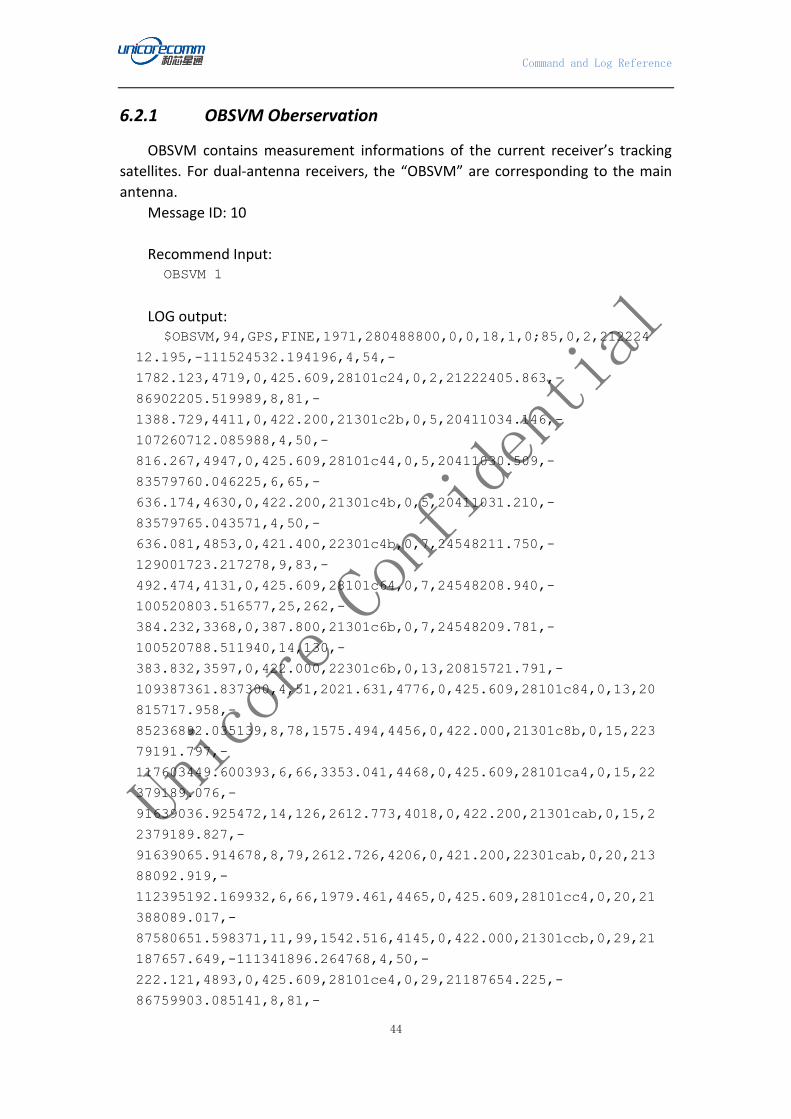
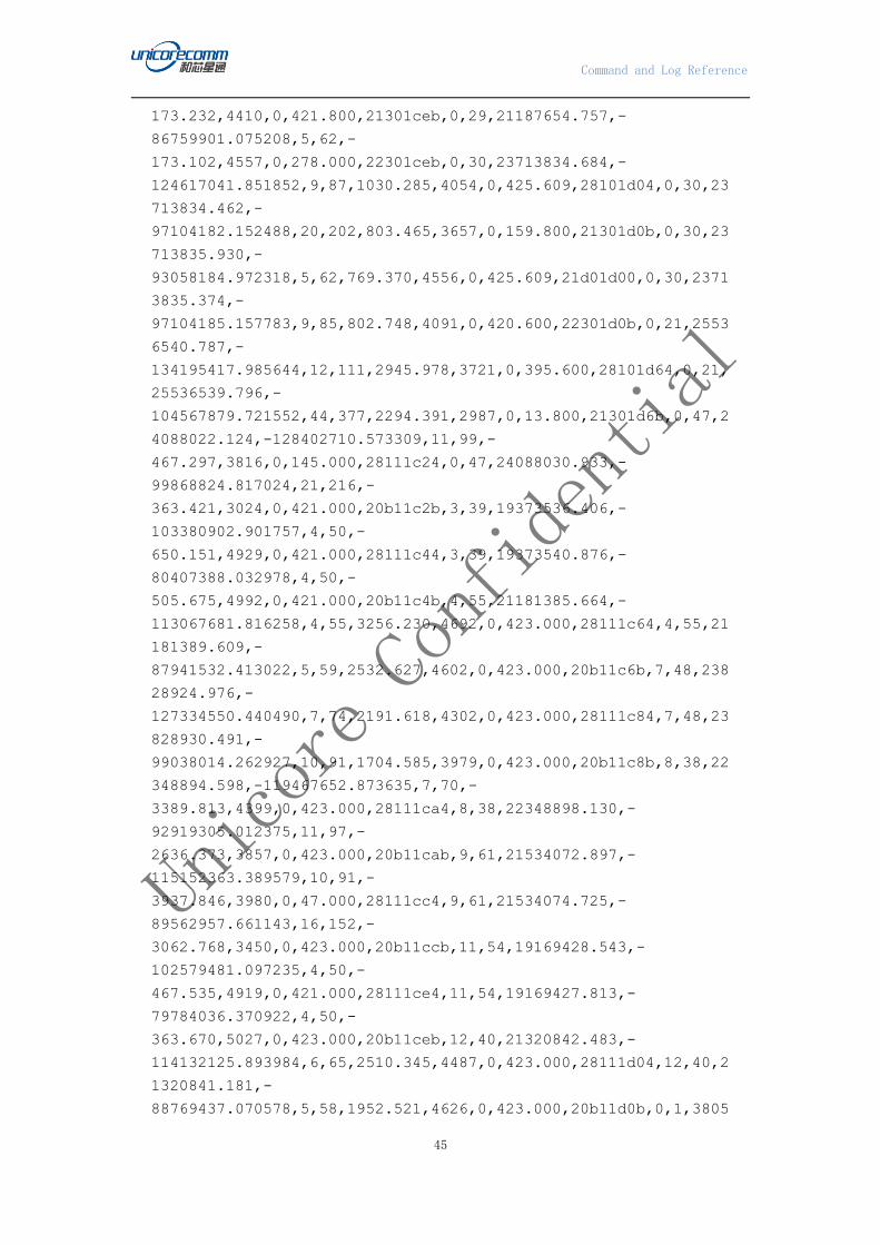
6.2.1 OBSVM Oberservation
OBSVM contains measurement informations of the current receiver’s tracking
satellites. For dual-antenna receivers, the “OBSVM” are corresponding to the main
antenna.
Message ID: 10
Recommend Input: OBSVM 1
LOG output: $OBSVM,94,GPS,FINE,1971,280488800,0,0,18,1,0;85,0,2,212224
12.195,-111524532.194196,4,54,-
1782.123,4719,0,425.609,28101c24,0,2,21222405.863,-
86902205.519989,8,81,-
1388.729,4411,0,422.200,21301c2b,0,5,20411034.146,-
107260712.085988,4,50,-
816.267,4947,0,425.609,28101c44,0,5,20411030.509,-
83579760.046225,6,65,-
636.174,4630,0,422.200,21301c4b,0,5,20411031.210,-
83579765.043571,4,50,-
636.081,4853,0,421.400,22301c4b,0,7,24548211.750,-
129001723.217278,9,83,-
492.474,4131,0,425.609,28101c64,0,7,24548208.940,-
100520803.516577,25,262,-
384.232,3368,0,387.800,21301c6b,0,7,24548209.781,-
100520788.511940,14,130,-
383.832,3597,0,422.000,22301c6b,0,13,20815721.791,-
109387361.837300,4,51,2021.631,4776,0,425.609,28101c84,0,13,20
815717.958,-
85236892.035139,8,78,1575.494,4456,0,422.000,21301c8b,0,15,223
79191.797,-
117603449.600393,6,66,3353.041,4468,0,425.609,28101ca4,0,15,22
379189.076,-
91639036.925472,14,126,2612.773,4018,0,422.200,21301cab,0,15,2
2379189.827,-
91639065.914678,8,79,2612.726,4206,0,421.200,22301cab,0,20,213
88092.919,-
112395192.169932,6,66,1979.461,4465,0,425.609,28101cc4,0,20,21
388089.017,-
87580651.598371,11,99,1542.516,4145,0,422.000,21301ccb,0,29,21
187657.649,-111341896.264768,4,50,-
222.121,4893,0,425.609,28101ce4,0,29,21187654.225,-
86759903.085141,8,81,-
Command and Log Reference
45
173.232,4410,0,421.800,21301ceb,0,29,21187654.757,-
86759901.075208,5,62,-
173.102,4557,0,278.000,22301ceb,0,30,23713834.684,-
124617041.851852,9,87,1030.285,4054,0,425.609,28101d04,0,30,23
713834.462,-
97104182.152488,20,202,803.465,3657,0,159.800,21301d0b,0,30,23
713835.930,-
93058184.972318,5,62,769.370,4556,0,425.609,21d01d00,0,30,2371
3835.374,-
97104185.157783,9,85,802.748,4091,0,420.600,22301d0b,0,21,2553
6540.787,-
134195417.985644,12,111,2945.978,3721,0,395.600,28101d64,0,21,
25536539.796,-
104567879.721552,44,377,2294.391,2987,0,13.800,21301d6b,0,47,2
4088022.124,-128402710.573309,11,99,-
467.297,3816,0,145.000,28111c24,0,47,24088030.933,-
99868824.817024,21,216,-
363.421,3024,0,421.000,20b11c2b,3,39,19373536.406,-
103380902.901757,4,50,-
650.151,4929,0,421.000,28111c44,3,39,19373540.876,-
80407388.032978,4,50,-
505.675,4992,0,421.000,20b11c4b,4,55,21181385.664,-
113067681.816258,4,55,3256.230,4692,0,423.000,28111c64,4,55,21
181389.609,-
87941532.413022,5,59,2532.627,4602,0,423.000,20b11c6b,7,48,238
28924.976,-
127334550.440490,7,74,2191.618,4302,0,423.000,28111c84,7,48,23
828930.491,-
99038014.262927,10,91,1704.585,3979,0,423.000,20b11c8b,8,38,22
348894.598,-119467652.873635,7,70,-
3389.813,4399,0,423.000,28111ca4,8,38,22348898.130,-
92919305.012375,11,97,-
2636.373,3857,0,423.000,20b11cab,9,61,21534072.897,-
115152363.389579,10,91,-
3937.846,3980,0,47.000,28111cc4,9,61,21534074.725,-
89562957.661143,16,152,-
3062.768,3450,0,423.000,20b11ccb,11,54,19169428.543,-
102579481.097235,4,50,-
467.535,4919,0,421.000,28111ce4,11,54,19169427.813,-
79784036.370922,4,50,-
363.670,5027,0,423.000,20b11ceb,12,40,21320842.483,-
114132125.893984,6,65,2510.345,4487,0,423.000,28111d04,12,40,2
1320841.181,-
88769437.070578,5,58,1952.521,4626,0,423.000,20b11d0b,0,1,3805

Command and Log Reference
46
8203.146,-198179055.329748,8,80,-
17.748,4195,0,429.209,2c141c24,0,1,38058191.636,-
153244568.938695,4,55,-
13.751,4683,0,427.209,26341c2b,0,1,38058194.464,-
161036675.262810,6,62,-
14.456,4550,0,427.609,26a41c20,0,2,37980441.830,-
197774134.361522,11,99,-
11.797,3814,0,425.809,2c141c44,0,2,37980434.014,-
152931471.984884,5,61,-
9.076,4575,0,427.409,26341c4b,0,2,37980437.293,-
160707659.255514,6,67,-
9.558,4453,0,427.809,26a41c40,0,3,37520296.484,-
195378031.357099,9,86,-
26.363,4068,0,429.209,2c141c64,0,3,37520289.036,-
151078660.605401,4,51,-
20.336,4772,0,427.609,26341c6b,0,3,37520290.972,-
158760630.041439,5,61,-
21.367,4570,0,427.609,26a41c60,0,4,38936240.668,-
202751230.928856,11,100,-
23.196,3800,0,429.209,2c141c84,0,4,38936234.049,-
156780081.759398,6,67,-
17.886,4441,0,427.409,26341c8b,0,4,38936235.116,-
164751955.098402,9,82,-
18.862,4152,0,427.609,26a41c80,0,5,39849559.838,-
207507123.809685,13,120,-
9.338,3662,0,429.209,2c141ca4,0,5,39849553.652,-
160457641.631816,7,74,-
7.064,4319,0,426.009,26341cab,0,5,39849554.576,-
168616505.129904,10,89,-
7.527,4020,0,426.009,26a41ca0,0,6,36206998.273,-
188539348.434993,6,62,211.339,4548,0,428.609,28141cc4,0,6,3620
6991.026,-
145790550.817916,4,50,163.479,5156,0,423.600,22341ccb,0,6,3620
6991.028,-
153203626.957558,4,50,171.762,5047,0,423.600,22a41cc0,0,8,3672
5569.798,-191239681.033605,7,71,-
864.311,4379,0,428.609,28141ce4,0,8,36725561.871,-
147878620.056780,4,50,-
668.303,4938,0,423.600,22341ceb,0,8,36725561.526,-
155397868.878389,4,50,-
702.257,4859,0,423.600,22a41ce0,0,13,35554344.045,-
185140805.845714,4,51,-
314.216,4772,0,428.209,28141d04,0,13,35554343.509,-
143162608.914397,4,50,-
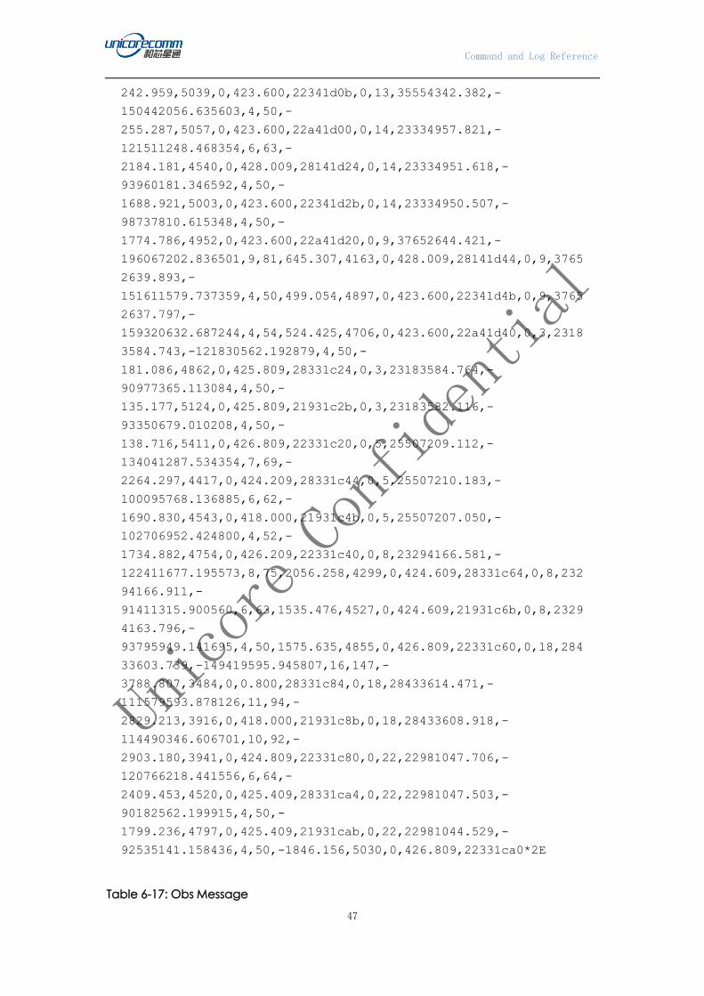
Command and Log Reference
47
242.959,5039,0,423.600,22341d0b,0,13,35554342.382,-
150442056.635603,4,50,-
255.287,5057,0,423.600,22a41d00,0,14,23334957.821,-
121511248.468354,6,63,-
2184.181,4540,0,428.009,28141d24,0,14,23334951.618,-
93960181.346592,4,50,-
1688.921,5003,0,423.600,22341d2b,0,14,23334950.507,-
98737810.615348,4,50,-
1774.786,4952,0,423.600,22a41d20,0,9,37652644.421,-
196067202.836501,9,81,645.307,4163,0,428.009,28141d44,0,9,3765
2639.893,-
151611579.737359,4,50,499.054,4897,0,423.600,22341d4b,0,9,3765
2637.797,-
159320632.687244,4,54,524.425,4706,0,423.600,22a41d40,0,3,2318
3584.743,-121830562.192879,4,50,-
181.086,4862,0,425.809,28331c24,0,3,23183584.764,-
90977365.113084,4,50,-
135.177,5124,0,425.809,21931c2b,0,3,23183582.116,-
93350679.010208,4,50,-
138.716,5411,0,426.809,22331c20,0,5,25507209.112,-
134041287.534354,7,69,-
2264.297,4417,0,424.209,28331c44,0,5,25507210.183,-
100095768.136885,6,62,-
1690.830,4543,0,418.000,21931c4b,0,5,25507207.050,-
102706952.424800,4,52,-
1734.882,4754,0,426.209,22331c40,0,8,23294166.581,-
122411677.195573,8,75,2056.258,4299,0,424.609,28331c64,0,8,232
94166.911,-
91411315.900560,6,63,1535.476,4527,0,424.609,21931c6b,0,8,2329
4163.796,-
93795949.141695,4,50,1575.635,4855,0,426.809,22331c60,0,18,284
33603.739,-149419595.945807,16,147,-
3788.807,3484,0,0.800,28331c84,0,18,28433614.471,-
111579593.878126,11,94,-
2829.213,3916,0,418.000,21931c8b,0,18,28433608.918,-
114490346.606701,10,92,-
2903.180,3941,0,424.809,22331c80,0,22,22981047.706,-
120766218.441556,6,64,-
2409.453,4520,0,425.409,28331ca4,0,22,22981047.503,-
90182562.199915,4,50,-
1799.236,4797,0,425.409,21931cab,0,22,22981044.529,-
92535141.158436,4,50,-1846.156,5030,0,426.809,22331ca0*2E
Table 6-17: Obs Message

Command and Log Reference
48
ID Field Type Descri
ption
Binary
Bytes
Binary
Offset
1 Obsvm
header
Log header H 0
2 obs
Number
Number of corresponding observation
information
Ulong 4 H
3 System
Freqency
Satellite system UShort 2 H+4
4 PRN/ slot Satellite PRN number(starting from 1) UShort 2 H+6
5 psr pseudorange measurement, meter Double 8 H+8
6 adr Carrier phase(accumulated Doppler
range), cycle
Double 8 H+16
7 psr std Pseudorange measurement standard
deviation, meter
UShort 2 H+24
8 adr std Estimated carrier phase standard
deviation, cycle
UShort 2 H+26
9 dopp Instantaneous carrier Doppler
frequency, Hz
Float 4 H+28
10 C/No Carrier to noise density ratio
C/No = 10[log10(S/N0)](dB-Hz)
UShort 2 H+32
11 Reserved Reserved UShort 2 H+36
12 locktime Continuous tracking Time of satellite
signal, second
Float 4 H+38
13
ch-tr-
status
Tracking status of satellite signal, see
Table 6-19: Channel Tracking
Status
4 H+42
14…
variable
xxxx 32-bit CRC(for ASCII and Binary only)
Hex
Hex 4 H+4+(#o
bs*42)
variable [CR][LF] Sentence terminator(for ASCII only)
Table 6-18: Tracking State
State Description State Description
0 Reserved 7 Reserved
1 Reserved 8 Reserved
2 Reserved 9 Reserved
3 Reserved 10 Reserved
4 L1 phase lock loop 11 L2 phase lock loop
5 Reserved 19 Reserved
6 Reserved
Table 6-19: Channel Tracking Status

Command and Log Reference
49
Nibble # Bit # Mask Description Range Value
N0 0 0x00000001
Tracking state
See Table 6-18: Tracking State
1 0x00000002
2 0x00000004
3 0x00000008
N1 4 0x00000010
5 0x00000020
SV channel
number
0-n (0 = first, n = last)
n depends on the receiver used 6 0x00000040
7 0x00000080
N2 8 0x00000100
9 0x00000200
10 0x00000400 Phase lock flag 0 = Not locked, 1= Locked
11 0x00000800 Parity valid flag 0 = Valid, 1= Invalid
N3 12 0x00001000 Code locked flag 0 = Not locked, 1= Locked
13 0x00002000 Reserved
14 0x00004000
15 0x00008000
N4 16 0x00010000 Satellite system 0 = GPS
1 = GLONASS
2 = SBAS
3 = Galileo
4 = BD2
5 = QZSS
6-7 = Reserved
17 0x00020000
18 0x00040000
19 0x00080000 Reserved
N5 20 0x00100000 Reserved
21 0x00200000 Signal type Depends on satellite system supported:
GPS
0 = L1C/A
9 = L2P
6 = L5I
14 = L5 Q
17 = L2C
GLONASS
0 = L1 C/A
5 = L2 C/A
BD2:
0 = B1I
4 = B1Q
5 = B2Q
17 = B2I
6 = B3Q
21 = B3I
GALILEO:
1 = E1B
2 = E1C
12 = E5A
17 = E5B
22 0x00400000
23 0x00800000
N6 24 0x01000000
25 0x02000000
26 0x04000000 Reserved
27 0x08000000 Reserved
N7 28 0x10000000 Reserved
29 Reserved Reserved

Command and Log Reference
50
Nibble # Bit # Mask Description Range Value
30 0x40000000 Reserved
31 0x80000000 Reserved
Grouping: each channel has other channels associated with it(L1/L2 or B1/B2/B3 are grouped)
6.2.2 OBSVH Oberservation
OBSVM contains measurement informations of the current receiver’s tracking
satellites. For dual-antenna receivers, the “OBSVH” are corresponding to the Heading
antenna.
Message ID: 11
Recommend Input: OBSVH COM1 1
LOG output: $OBSVH,93,GPS,FINE,1971,280559400,0,0,18,2,0;85,0,2,212465
63.814,-111651450.311282,4,52,-
1813.155,4757,0,496.209,28101c24,0,2,21246557.603,-
87001102.717152,8,78,-
1412.040,4457,0,492.800,21301c2b,0,5,20422151.825,-
107319135.401189,4,50,-
838.619,5010,0,496.209,28101c44,0,5,20422148.083,-
83625284.703105,6,66,-
653.217,4624,0,492.800,21301c4b,0,5,20422148.735,-
83625289.696302,4,50,-
653.478,4848,0,492.000,22301c4b,0,7,24555097.903,-
129037910.067692,8,78,-
532.447,4227,0,496.209,28101c64,0,7,24555095.330,-
100549001.011807,24,253,-
415.050,3409,0,458.400,21301c6b,0,7,24555095.526,-
100548986.047458,14,130,-
415.134,3595,0,492.600,22301c6b,0,13,20788837.832,-
109246085.757039,4,50,1980.700,4848,0,496.209,28101c84,0,13,20
788833.931,-
85126806.818378,8,75,1543.838,4489,0,492.600,21301c8b,0,15,223
34307.904,-
117367584.521957,6,64,3328.780,4501,0,496.209,28101ca4,0,15,22
334305.349,-
91455246.122632,13,116,2594.435,4066,0,492.800,21301cab,0,15,2
2334306.039,-
91455275.123345,8,75,2593.830,4281,0,491.800,22301cab,0,20,213
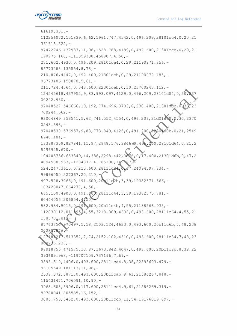
Command and Log Reference
51
61619.331,-
112256072.151839,6,62,1961.747,4542,0,496.209,28101cc4,0,20,21
361615.322,-
87472246.432987,11,96,1528.788,4189,0,492.600,21301ccb,0,29,21
190975.160,-111359330.458807,4,50,-
271.602,4930,0,496.209,28101ce4,0,29,21190971.856,-
86773488.135554,8,78,-
210.876,4447,0,492.400,21301ceb,0,29,21190972.483,-
86773486.150078,5,61,-
211.724,4564,0,348.600,22301ceb,0,30,23700243.112,-
124545618.437952,9,83,993.097,4129,0,496.209,28101d04,0,30,237
00242.980,-
97048527.546666,19,192,774.696,3703,0,230.400,21301d0b,0,30,23
700244.562,-
93004849.353541,5,62,741.552,4554,0,496.209,21d01d00,0,30,2370
0243.893,-
97048530.576957,9,83,773.849,4123,0,491.200,22301d0b,0,21,2549
6948.404,-
133987359.827841,11,97,2948.176,3846,0,466.200,28101d64,0,21,2
5496945.670,-
104405756.653349,44,388,2298.442,3076,0,17.400,21301d6b,0,47,2
4094588.963,-128437714.785108,14,127,-
524.247,3615,0,215.600,28111c24,0,47,24094597.834,-
99896050.327367,20,210,-
407.528,3063,0,491.600,20b11c2b,3,39,19382371.366,-
103428047.664277,4,50,-
685.150,4903,0,491.600,28111c44,3,39,19382375.781,-
80444056.206854,4,50,-
532.934,5015,0,491.600,20b11c4b,4,55,21138566.935,-
112839112.011195,4,55,3218.809,4692,0,493.600,28111c64,4,55,21
138570.781,-
87763755.970497,5,58,2503.524,4633,0,493.600,20b11c6b,7,48,238
00230.876,-
127181217.513352,7,74,2152.102,4310,0,493.600,28111c84,7,48,23
800236.238,-
98918755.471575,10,87,1673.842,4047,0,493.600,20b11c8b,8,38,22
393689.968,-119707109.737196,7,69,-
3393.510,4406,0,493.600,28111ca4,8,38,22393693.479,-
93105549.181113,11,96,-
2639.372,3871,0,493.600,20b11cab,9,61,21586267.848,-
115431471.706091,10,90,-
3968.608,3996,0,117.600,28111cc4,9,61,21586269.319,-
89780041.805585,16,152,-
3086.750,3452,0,493.600,20b11ccb,11,54,19176019.897,-

Command and Log Reference
52
102614752.527436,4,50,-
531.554,4898,0,491.600,28111ce4,11,54,19176019.165,-
79811469.703518,4,50,-
413.449,5052,0,493.600,20b11ceb,12,40,21287928.841,-
113955937.368650,6,66,2480.915,4477,0,493.600,28111d04,12,40,2
1287927.629,-
88632401.666176,4,55,1929.630,4692,0,493.600,20b11d0b,0,1,3805
8449.391,-198180337.735370,8,80,-
18.549,4182,0,499.809,2c141c24,0,1,38058437.844,-
153245560.550125,4,54,-
14.347,4708,0,497.809,26341c2b,0,1,38058440.711,-
161037717.307865,6,63,-
15.071,4529,0,498.209,26a41c20,0,2,37980610.307,-
197775012.106405,12,100,-
13.054,3793,0,496.409,2c141c44,0,2,37980602.521,-
152932150.749658,5,60,-
10.147,4599,0,498.009,26341c4b,0,2,37980605.798,-
160708372.535672,6,68,-
10.666,4435,0,498.409,26a41c40,0,3,37520658.963,-
195379919.180620,9,87,-
27.164,4056,0,499.809,2c141c64,0,3,37520651.428,-
151080120.448378,4,50,-
21.044,4797,0,498.209,26341c6b,0,3,37520653.418,-
158762164.117300,5,62,-
22.121,4554,0,498.209,26a41c60,0,4,38936560.986,-
202752899.790897,12,102,-
24.053,3784,0,499.809,2c141c84,0,4,38936554.390,-
156781372.255777,6,66,-
18.622,4468,0,498.009,26341c8b,0,4,38936555.554,-
164753311.205573,9,83,-
19.607,4129,0,498.209,26a41c80,0,5,39849693.104,-
207507817.825727,13,124,-
10.409,3638,0,499.809,2c141ca4,0,5,39849686.908,-
160458178.348569,7,73,-
8.098,4339,0,496.609,26341cab,0,5,39849687.772,-
168617069.112898,10,89,-
8.487,4000,0,496.609,26a41ca0,0,6,36204179.624,-
188524671.355730,6,62,204.503,4543,0,499.209,28141cc4,0,6,3620
4172.334,-
145779201.603625,4,50,158.106,5175,0,494.200,22341ccb,0,6,3620
4172.436,-
153191700.647308,4,50,166.136,5034,0,494.200,22a41cc0,0,8,3673
7365.859,-191301107.254962,7,72,-
875.775,4342,0,499.209,28141ce4,0,8,36737358.039,-
Command and Log Reference
53
147926118.697148,4,50,-
677.188,4950,0,494.200,22341ceb,0,8,36737357.765,-
155447782.710365,4,50,-
711.617,4836,0,494.200,22a41ce0,0,13,35558681.030,-
185163389.740799,4,51,-
325.438,4761,0,498.809,28141d04,0,13,35558680.456,-
143180072.212451,4,50,-
251.630,5061,0,494.200,22341d0b,0,13,35558679.398,-
150460407.906754,4,50,-
264.479,5044,0,494.200,22a41d00,0,14,23364625.316,-
121665734.377409,6,67,-
2192.042,4457,0,498.609,28141d24,0,14,23364618.930,-
94079639.637225,4,50,-
1695.031,5000,0,494.200,22341d2b,0,14,23364617.795,-
98863343.053086,4,50,-
1781.213,4939,0,494.200,22a41d20,0,9,37643948.924,-
196021923.587074,9,83,637.549,4135,0,498.609,28141d44,0,9,3764
3944.361,-
151576566.991013,4,50,492.925,4915,0,494.200,22341d4b,0,9,3764
3942.290,-
159283839.623689,4,55,517.999,4691,0,494.200,22a41d40,0,3,2318
6169.438,-121844145.804248,4,50,-
203.606,4833,0,496.409,28331c24,0,3,23186169.669,-
90987508.756380,4,50,-
152.034,5100,0,496.409,21931c2b,0,3,23186166.942,-
93361087.256507,4,50,-
155.992,5404,0,497.409,22331c20,0,5,25537681.241,-
134201421.471488,7,71,-
2271.943,4373,0,494.809,28331c44,0,5,25537682.609,-
100215348.656667,6,65,-
1696.623,4486,0,488.600,21931c4b,0,5,25537679.489,-
102829652.441565,4,52,-
1740.861,4742,0,496.809,22331c40,0,8,23266657.315,-
122267114.589514,8,76,2039.056,4276,0,495.209,28331c64,0,8,232
66657.382,-
91303363.371759,6,65,1522.727,4498,0,495.209,21931c6b,0,8,2326
6654.529,-
93685180.464955,4,50,1562.410,4925,0,497.409,22331c60,0,18,284
84323.274,-149686128.604221,34,289,-
3762.348,3181,0,0.000,08331084,0,18,28484338.970,-
111778646.467969,12,104,-
2809.395,3766,0,488.600,21931c8b,0,18,28484335.109,-
114694591.972402,10,90,-
2882.746,3983,0,495.409,22331c80,0,22,23013557.538,-

Command and Log Reference
54
120937058.902399,6,65,-
2430.128,4496,0,496.009,28331ca4,0,22,23013557.352,-
90310137.827397,4,51,-
1814.649,4769,0,496.009,21931cab,0,22,23013554.227,-
92666044.851554,4,50,-1862.045,5008,0,497.409,22331ca0*41
Table 6-20: Obsvh Message
ID Field Type Descri
ption
Binary
Bytes
Binary
Offset
1 Obsvh
header
Log header H 0
2 obs
Number
Number of corresponding observation
information
Ulong 4 H
3 System
Freqency
Satellite system UShort 2 H+4
4 PRN/ slot Satellite PRN number(starting from 1) UShort 2 H+6
5 psr pseudorange measurement, meter Double 8 H+8
6 adr Carrier phase(accumulated Doppler
range), cycle
Double 8 H+16
7 psr std Pseudorange measurement standard
deviation, meter
UShort 2 H+24
8 adr std Estimated carrier phase standard
deviation, cycle
UShort 2 H+26
9 dopp Instantaneous carrier Doppler
frequency, Hz
Float 4 H+28
10 C/No Carrier to noise density ratio
C/No = 10[log10(S/N0)](dB-Hz)
UShort 2 H+32
11 Reserved Reserved UShort 2 H+36
12 locktime Continuous tracking Time of satellite
signal, second
Float 4 H+38
13 ch-tr-
status
Tracking status of satellite signal, see
Table 6-19: Channel Tracking Status
4 H+42
14…
variable
xxxx 32-bit CRC(for ASCII and Binary only)
Hex
Hex 4 H+4+(#o
bs*42)
variable [CR][LF] Sentence terminator(for ASCII only) - - -
6.2.3 ION Ionosphere Parameters
This log provides ionosphere model parameters.
Message ID: 8
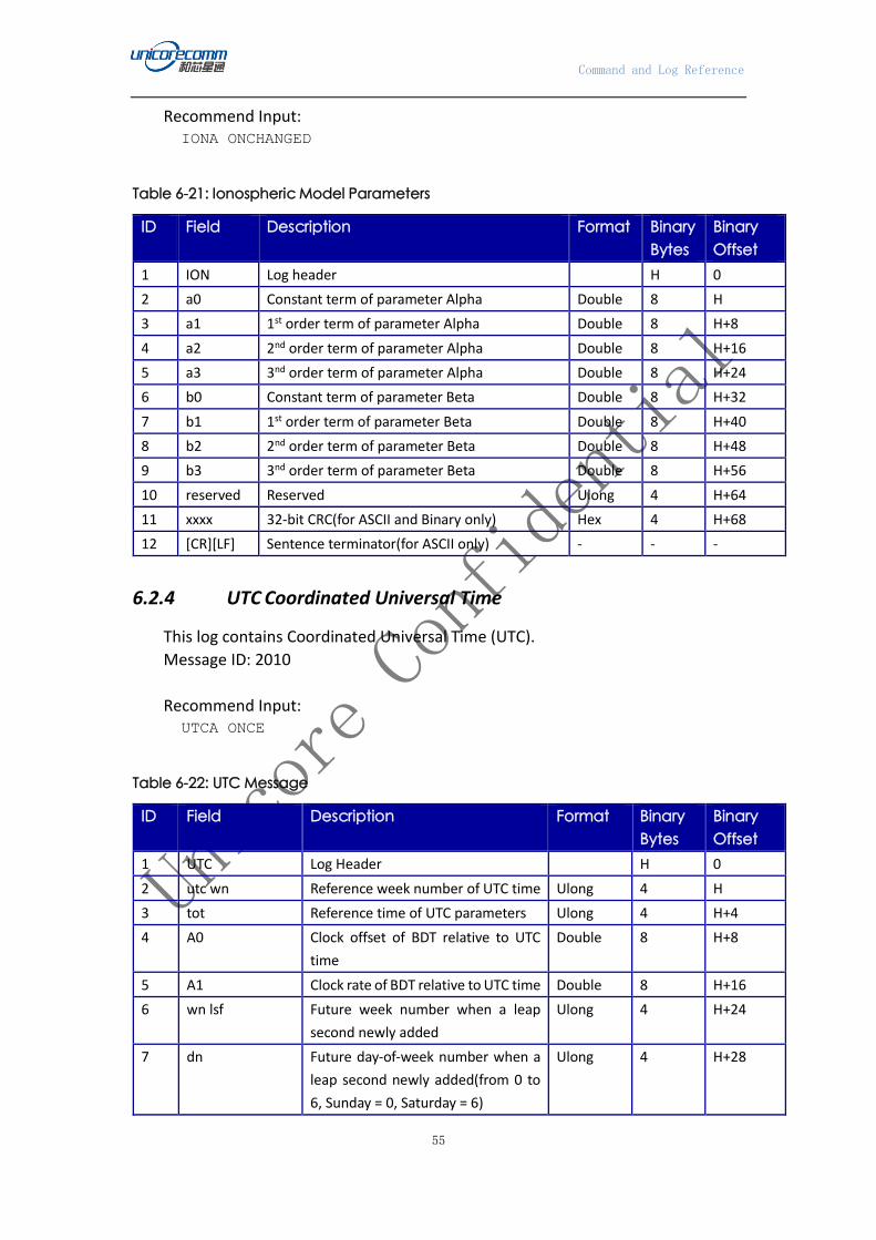
Command and Log Reference
55
Recommend Input: IONA ONCHANGED
Table 6-21: Ionospheric Model Parameters
ID Field Description Format Binary
Bytes
Binary
Offset
1 ION Log header H 0
2 a0 Constant term of parameter Alpha Double 8 H
3 a1 1st order term of parameter Alpha Double 8 H+8
4 a2 2nd order term of parameter Alpha Double 8 H+16
5 a3 3nd order term of parameter Alpha Double 8 H+24
6 b0 Constant term of parameter Beta Double 8 H+32
7 b1 1st order term of parameter Beta Double 8 H+40
8 b2 2nd order term of parameter Beta Double 8 H+48
9 b3 3nd order term of parameter Beta Double 8 H+56
10 reserved Reserved Ulong 4 H+64
11 xxxx 32-bit CRC(for ASCII and Binary only) Hex 4 H+68
12 [CR][LF] Sentence terminator(for ASCII only) - - -
6.2.4 UTC Coordinated Universal Time
This log contains Coordinated Universal Time (UTC).
Message ID: 2010
Recommend Input: UTCA ONCE
Table 6-22: UTC Message
ID Field Description Format Binary
Bytes
Binary
Offset
1 UTC Log Header H 0
2 utc wn Reference week number of UTC time Ulong 4 H
3 tot Reference time of UTC parameters Ulong 4 H+4
4 A0 Clock offset of BDT relative to UTC
time
Double 8 H+8
5 A1 Clock rate of BDT relative to UTC time Double 8 H+16
6 wn lsf Future week number when a leap
second newly added
Ulong 4 H+24
7 dn Future day-of-week number when a
leap second newly added(from 0 to
6, Sunday = 0, Saturday = 6)
Ulong 4 H+28

Command and Log Reference
56
ID Field Description Format Binary
Bytes
Binary
Offset
8 deltat ls Existing leap seconds of BDT relative
to UTC before the next leap second
arriving
Long 4 H+32
9 deltat lsf Future total leap seconds of BDT
relative to UTC when a leap second
newly added
Long 4 H+36
10 deltat utc Time offset of BDT relative to UTC Ulong 4 H+40
11 reserved Reserved Ulong 4 H+44
12 xxxx 32-bit CRC(for ASCII and Binary only) Hex 4 H+48
13 [CR][LF] Sentence terminator(for ASCII only) - - -
6.2.5 GLOEPHEM GLONASS Ephemeris
This Log contains GLONASS ephemeris. GLONASS ephemeris table takes PZ90.02
Geodetic Datum as reference, without adjusting GPS and GLONASS reference frames
during positioning.
Message ID: 723
Recommend Input: GLOEPHEMA ONCHANGED
LOG output: #GLOEPHEMERISA,COM1,0,83.0,FINE,1971,121080.000,577928,577
938,18;38,8,1,0,1971,121518000,10782,655,0,0,51,0,-
2.089683984375000e+07,3.919853515625000e+06,1.410376757812500e
+07,-1.926688194274902e+03,-1.610822677612305e+02,-
2.808049201965332e+03,-0.000003725290298,-9.313225746154785e-
07,-1.862645149230957e-06,-1.669488847255707e-05,8.381903172e-
09,0.000000000000000e+00,45000,2,1,0,13*d4fbe56e
#GLOEPHEMERISA,COM1,0,83.0,FINE,1971,121080.000,577928,577
938,18;39,3,1,0,1971,121518000,10782,655,0,0,51,0,-
2.632718750000000e+06,1.063776074218750e+07,2.306636669921875e
+07,-3.112833976745605e+03,-4.779558181762695e+02,-
1.392812728881836e+02,-0.000000000000000,-9.313225746154785e-
07,-2.793967723846436e-06,-2.754162997007370e-04,5.587935448e-
09,1.818989403545856e-12,45000,2,1,0,13*074457de
#GLOEPHEMERISA,COM1,0,83.0,FINE,1971,121080.000,577928,577
938,18;40,12,1,0,1971,121518000,10782,655,0,0,51,0,1.587903955
078125e+07,1.062770898437500e+07,1.695457617187500e+07,-
2.268429756164551e+03,-
4.617605209350586e+02,2.415321350097656e+03,0.000003725290298,

Command and Log Reference
57
-9.313225746154785e-07,-1.862645149230957e-06,-
1.133931800723076e-04,-2.793967724e-09,9.094947017729282e-
13,45150,2,2,0,12*b7cd873d
#GLOEPHEMERISA,COM1,0,83.0,FINE,1971,121080.000,577928,577
938,18;47,0,1,0,1971,117918000,10782,655,0,0,47,0,-
1.134552539062500e+07,-
4.513038085937500e+06,2.239658691406250e+07,2.536255836486816e
+03,-1.732788085937500e+03,9.272031784057617e+02,-
0.000001862645149,-9.313225746154785e-07,-2.793967723846436e-
06,-9.001232683658600e-06,8.381903172e-
09,0.000000000000000e+00,42270,2,3,0,4*45223ac0
#GLOEPHEMERISA,COM1,0,83.0,FINE,1971,121080.000,577928,577
938,18;48,7,1,0,1971,121518000,10782,655,0,0,51,0,-
1.515490087890625e+07,3.172944335937500e+06,2.030857031250000e
+07,1.826836585998535e+03,-
2.088369369506836e+03,1.686817169189453e+03,-
0.000002793967724,-0.000000000000000e+00,-1.862645149230957e-
06,1.241173595190048e-05,2.793967724e-09,-
0.000000000000000e+00,45000,2,2,0,13*b453771f
#GLOEPHEMERISA,COM1,0,83.0,FINE,1971,121080.000,577928,577
939,18;49,6,1,0,1971,121518000,10782,655,0,0,51,0,-
1.780039746093750e+07,1.643404443359375e+07,7.877607910156250e
+06,8.098993301391602e+02,-
7.367382049560547e+02,3.372859001159668e+03,-
0.000002793967724,-1.862645149230957e-06,-9.313225746154785e-
07,2.159643918275833e-05,7.450580597e-09,-9.094947017729282e-
13,45000,2,3,0,13*aa06e715
#GLOEPHEMERISA,COM1,0,83.0,FINE,1971,121080.000,577928,577
939,18;54,11,1,0,1971,121518000,10782,655,0,0,51,0,1.066629492
187500e+07,2.278390820312500e+07,4.087210937500000e+06,3.75474
9298095703e+02,4.565658569335938e+02,-
3.532135009765625e+03,0.000001862645149,-1.862645149230957e-
06,-0.000000000000000e+00,-7.885787636041641e-
05,0.000000000e+00,1.818989403545856e-
12,45000,2,1,0,13*454a5260
#GLOEPHEMERISA,COM1,0,83.0,FINE,1971,121080.000,577928,577
939,18;55,4,1,0,1971,121518000,10782,655,0,0,51,0,1.3415126953
12500e+07,1.126978271484375e+07,1.857166259765625e+07,1.026165
008544922e+03,2.328159332275391e+03,-
2.149991989135742e+03,0.000002793967724,-9.313225746154785e-
07,-1.862645149230957e-06,-1.700306311249733e-04,5.587935448e-
09,9.094947017729282e-13,45000,2,0,0,13*750f711f
#GLOEPHEMERISA,COM1,0,83.0,FINE,1971,121080.000,577928,577
939,18;61,9,1,0,1971,117918000,10782,655,0,0,47,0,2.2695893554

Command and Log Reference
58
68750e+06,2.540404296875000e+07,-
5.895527343750000e+05,2.107028961181641e+02,-
9.823799133300781e+01,-
3.594802856445313e+03,0.000001862645149,-9.313225746154785e-
07,0.000000000000000e+00,1.571131870150566e-04,2.793967724e-
09,-0.000000000000000e+00,42240,2,4,0,12*68db014f
Table 6-23: Glonass Ephemeris Message
ID Field Description Format Binary
Bytes
Binary
Offset
1 GLOEPHEM
header
Log header H 0
2 sloto Glonass satellite PRN number Ushort 2 H
3 freqo Satellite frequency channel offset,
between 0 and 20
Ushort 2 H+2
4 sat type Satellite type:
0 = GLO_SAT
1 = GLO_SAT_M (M type)
Uchar 1 H+4
5 Reserved 1 H+5
6 e week Reference time of ephemeris, week
number(refer to GPST)
Ushort 2 H+6
7 e time Reference time of ephemeris, in
ms(refer to GPST)
Ulong 4 H+8
8 t offset Integer seconds between GPST and
Glonass time. A positive value indicates
Glonass time ahead of GPST
Ulong 4 H+12
9 Nt Calendar number of day, the starts
over at January 1st of each leap year
Ushort 2 H+16
10 Reserved Reserved 1 H+18
11 Reserved Reserved 1 H+19
12 issue Interval numbers corresponding to
ephemeris reference time , based 15
minutes as a unit
Ulong 4 H+20
13 healtha Health status of ephemeris:
0 = GOOD
1 = BAD
Ulong 4 H+24
14 pos x Satellite X-axis coordinate at reference
time(PZ-90.02), meters
Double 8 H+28
15 pos y Satellite Y-axis coordinate at reference
time(PZ-90.02), meters
Double 8 H+36
16 pos z Satellite Z-axis coordinate at reference
time(PZ-90.02), meters
Double 8 H+44
17 vel x Satellite X-axis velocity at reference Double 8 H+52

Command and Log Reference
59
ID Field Description Format Binary
Bytes
Binary
Offset
time(PZ-90.02), meters/second
18 vel y Satellite Y-axis velocity at reference
time(PZ-90.02), meters/second
Double 8 H+60
19 vel z Satellite Z-axis velocity at reference
time(PZ-90.02), meters/second
Double 8 H+68
20 LS acc x Lunisolar X-axis acceleration at
reference time(PZ-90.02),
meters/second²
Double 8 H+76
21 LS acc y Lunisolar Y-axis acceleration at
reference time(PZ-90.02),
meters/second²
Double 8 H+84
22 LS acc z Lunisolar Z-axis acceleration at
reference time(PZ-90.02),
meters/second²
Double 8 H+92
23 tau_n Correction to the nth satellite time t_n
relative to GLONASS time t_c, seconds
Double 8 H+100
24 delta_tau_n Time transmission delay of nth satellite
navigation RF signal between L2 band
and L1 band, second
Double 8 H+108
25 gamma Frequency correction, second/second Double 8 H+116
26 Tk Time of frame start(start from Glonass
day), second
Ulong 4 H+124
27 P Technical parameter Ulong 4 H+128
28 Ft User range accuracy Ulong 4 H+132
29 age Age of data, day Ulong 4 H+136
30 Flags Information flags, see Table 6-24:
GLONASS Ephemeris Flags Coding
Ulong 4 H+140
31 xxxx 32-bit CRC(for ASCII and Binary only) Hex 4 H+144
32 [CR][LF] Sentence terminator(for ASCII only) - - -
a. The last four bits of field ”Health”are used to indicate the ephemeris health:
Bit 0-2: Bn
Bit 3: In
All other bits are reserved and set to 0.
Table 6-24: GLONASS Ephemeris Flags Coding
Bit Description ASCII Value Hex Value
0 P1 flag: time interval between two
adjacent parameters fb values
See Table 6-25: P1
Flags Range
Values
00000001
1 00000002
2 P2 flag: Odd or Even flag of parameter fb 0=even,1=odd 00000004
3 P3 flag: satellite numbers of almanac 0=5,1=4 00000008
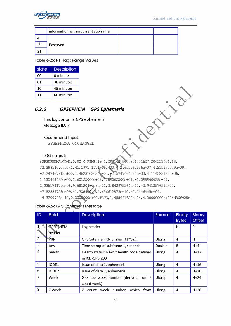
Command and Log Reference
60
information within current subframe
4
Reserved
…
31
Table 6-25: P1 Flags Range Values
state Description
00 0 minute
01 30 minutes
10 45 minutes
11 60 minutes
6.2.6 GPSEPHEM GPS Ephemeris
This log contains GPS ephemeris.
Message ID: 7
Recommend Input: GPSEPHEMA ONCHANGED
LOG output: #GPSEPHEMA,COM1,0,90.0,FINE,1971,298163.800,206351627,206351636,18;
32,298140.0,0,41,41,1971,1971,302400.0,2.655962336e+07,4.215175579e-09,
-2.247467812e+00,1.4623102034e-03,-2.5747464564e+00,4.114583135e-06,
1.135468483e-05,1.60125000e+02,7.69062500e+01,-1.098960638e-07,
2.235174179e-08,9.5812048008e-01,2.842975564e-10,-2.941357651e+00,
-7.82889753e-09,41,302400.0,4.656612873e-10,-5.1446445e-04,
-4.3200998e-12,0.0000000e+00,TRUE,1.458641622e-04,4.00000000e+00*d86f925e
Table 6-26: GPS Ephemeris Message
ID Field Description Format Binary
Bytes
Binary
Offset
1 GPSEPHEM
header
Log header H 0
2 PRN GPS Satellite PRN umber(1~32) Ulong 4 H
3 tow Time stamp of subframe 1, seconds Double 8 H+4
4 health Health status: a 6-bit health code defined
in ICD-GPS-200
Ulong 4 H+12
5 IODE1 Issue of data 1, ephemeris Ulong 4 H+16
6 IODE2 Issue of data 2, ephemeris Ulong 4 H+20
7 Week GPS toe week number (derived from Z
count week)
Ulong 4 H+24
8 Z Week Z count week number, which from Ulong 4 H+28

Command and Log Reference
61
subframe 1(tow week)
9 Toe Reference time of GPS ephemeris,
seconds
Double 8 H+32
10 A Semi-major axis of satellite orbit, meters Double 8 H+40
11 ΔN Correction of satellite Mean angular
velocity, radians/second
Double 8 H+48
12 M0 Mean anomaly of TOE time, radians Double 8 H+56
13 Ecc Eccentricity of satellite orbit Double 8 H+64
14 ω Argument of perigee, radians Double 8 H+72
15 cuc Argument of Latitude (amplitude of
cosine, radians)
Double 8 H+80
16 cus Argument of Latitude (amplitude of sine,
radians)
Double 8 H+88
17 crc Orbit radius (amplitude of cosine, meters) Double 8 H+96
18 crs Orbit radius (amplitude of sine, meters) Double 8 H+104
19 cic Inclination (amplitude of cosine, radians) Double 8 H+112
20 cis Inclination (amplitude of sine, radians) Double 8 H+120
21 I0 Inclination angle at TOE time, radians Double 8 H+128
22 IDOT Rate of inclination angle at TOE time,
radians/second
Double 8 H+136
23 Ω0 Right ascension of satellite ascending
node, radians
Double 8 H+144
24 Ω dot Rate of right ascension, radians/second Double 8 H+152
25 iodc Issue of data, clock Ulong 4 H+160
26 toc Reference time of Satellite clock, seconds Double 8 H+164
27 tgd Satellite group delay, seconds Double 8 H+172
28 af0 Satellite clock offset parameter, seconds Double 8 H+180
29 af1 Satellite clock rate parameter,
seconds/second
Double 8 H+188
30 af2 Satellite clock drift parameter,
seconds/second/second
8 H+196
31 AS Anti-spoofing: 0 = FALSE, 1=TRUE Enum 4 H+204
32 N Corrected satellite Mean angular velocity,
radians/second
Double 8 H+208
33 URA User Range Accuracy variance, ㎡。 This
value computes from the ephemeris’s URA
index and the converter algorithm listed in
the ICD-GPS-200. Notice here is the square
of the nominal standard deviation
value(variance)
Double 8 H+216
34 xxxx 32-bit CRC(for ASCII and Binary only) Hex 4 H+224
35 [CR][LF] Sentence terminator(for ASCII only) - - -
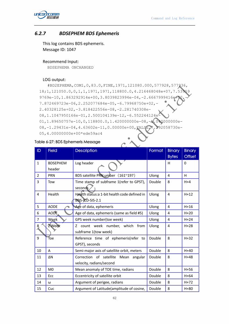
Command and Log Reference
62
6.2.7 BDSEPHEM BDS Ephemeris
This log contains BDS ephemeris.
Message ID: 1047
Recommend Input: BDSEPHEMA ONCHANGED
LOG output: #BD2EPHEMA,COM1,0,83.0,FINE,1971,121080.000,577928,577936,
18;1,121050.0,0,1,1,1971,1971,118800.0,4.216468048e+07,7.53959
9769e-10,1.863292914e+00,3.8039823994e-04,-2.6667999416e+00,-
7.872469723e-06,2.252077684e-05,-6.79968750e+02,-
2.40328125e+02,-3.818422556e-08,-2.281740308e-
08,1.1047950166e-01,2.500104139e-12,-6.552244124e-
01,1.89650757e-10,0,118800.0,1.420000000e-08,-1.040000000e-
08,-1.29431e-04,4.63602e-11,0.00000e+00,FALSE,7.292058730e-
05,4.00000000e+00*ede59ac4
Table 6-27: BDS Ephemeris Message
ID Field Description Format Binary
Bytes
Binary
Offset
1 BDSEPHEM
header
Log header H 0
2 PRN BDS satellite PRN umber(161~197) Ulong 4 H
3 Tow Time stamp of subframe 1(refer to GPST),
seconds
Double 8 H+4
4 Health Health status:a 1-bit health code defined in
BDS-ICD-SIS-2.1
Ulong 4 H+12
5 AODE Age of data, ephemeris Ulong 4 H+16
6 AODE Age of data, ephemeris (same as field #5) Ulong 4 H+20
7 Week GPS week number(toe week) Ulong 4 H+24
8 Z Week Z count week number, which from
subframe 1(tow week)
Ulong 4 H+28
9 Toe Reference time of ephemeris(refer to
GPST), seconds
Double 8 H+32
10 A Semi-major axis of satellite orbit, meters Double 8 H+40
11 ΔN Correction of satellite Mean angular
velocity, radians/second
Double 8 H+48
12 M0 Mean anomaly of TOE time, radians Double 8 H+56
13 Ecc Eccentricity of satellite orbit Double 8 H+64
14 ω Argument of perigee, radians Double 8 H+72
15 Cuc Argument of Latitude(amplitude of cosine, Double 8 H+80

Command and Log Reference
63
ID Field Description Format Binary
Bytes
Binary
Offset
radians)
16 Cus Argument of Latitude(amplitude of sine,
radians)
Double 8 H+88
17 crc Orbit radius(amplitude of cosine , meters) Double 8 H+96
18 crs Orbit radius(amplitude of sine, meters) Double 8 H+104
19 cic Inclination(amplitude of cosine, radians) Double 8 H+112
20 cis Inclination(amplitude of sine, radians) Double 8 H+120
21 I0 Inclination angle at TOE time, radians Double 8 H+128
22 IDOT Rate of inclination angle at TOE time,
radians/second
Double 8 H+136
23 Ω0 Right ascension of satellite ascending
node, radians
Double 8 H+144
24 Ω dot Rate of right ascension, radians/second Double 8 H+152
25 AODC Age of data, clock Ulong 4 H+160
26 toc Reference time of Satellite clock(refer to
GPST), seconds
Double 8 H+164
27 tgd1 Equipment group delay of B1signal,
seconds
Double 8 H+172
28 tgd2 Equipment group delay of B2 signal,
seconds
Double 8 H+180
29 af0 Satellite clock offset parameter, seconds Double 8 H+188
30 af1 Satellite clock rate parameter,
seconds/second
Double 8 H+196
31 af2 Satellite clock drift parameter,
seconds/second/second
Double 8 H+204
32 AS Anti-spoofing: 0 = FALSE, 1=TRUE Enum 4 H+212
33 N Corrected satellite Mean angular velocity,
radians/second
Double 8 H+216
34 URA User Range Accuracy variance, ㎡。 This
value computes from the ephemeris’s URA
index and the converter algorithm listed in
the ICD-GPS-200. Notice here is
the square of the nominal standard
deviation value(variance)
Double 8 H+224
35 xxxx 32-bit CRC(for ASCII and Binary only) Hex 4 H+232
36 [CR][LF] Sentence terminator(for ASCII only) - - -
6.2.8 GALEPHEM GALILEO Ephemeris
This log contains Galileo ephemeris data.
Message ID: 1048

Command and Log Reference
64
Recommend Input: GALEPHEMA ONCHANGED
LOG output: #GALEPHEMERISA,COM1,0,97.0,FINE,1916,285525.800,00000000,3
935238,0;72,TRUE,TRUE,0,0,0,0,0,0,107,0,309,285000,5.44062828e
+03,3.0373e-09,2.05419566e+00,3.211809089e-04,-
1.066763838e+00,4.2263e-06,1.0300e-05,1.192e+02,9.212e+01,-
5.9605e-08,5.7742e-08,9.593394346e-01,5.6574e-10,-
2.883462182e+00,-5.53880214e-09,285000,1.215380675e-
03,3.917222e-10,0.0e+00,285000,1.215380442e-03,3.917222e-
10,0.0e+00,-5.355e-09,-6.752e-09*5194ad77
Table 6-28: Galileo Ephemeris Message
ID Field Description Format Binary
Bytes
Binary
Offset
1 GALEPHEM
header
Log header H 0
2 PRN Galileo satellite PRN umber(75 to 119) Ulong 4 H
3 FNAVReceived Indicator of FNAV ephemeris data received Bool 4 H+4
4 INAVReceived Indicator of INAV ephemeris data received Bool 4 H+8
5 E1BHealth Health status bits for E1B (only valid if
INAVReceived is TRUE)
Uchar 1 H+12
6 E5aHealth Health status bits for E5a(only valid if
FNAVReceived is TRUE)
Uchar 1 H+13
7 E5BHealth Health status bits for E5b (only valid if
INAVReceived is TRUE)
Uchar 1 H+14
8 E1BDVS E1B data validity status (only valid if
INAVReceived is TRUE)
Uchar 1 H+15
9 E5aDVS E5a data validity status (only valid if
FNAVReceived is TRUE)
Uchar 1 H+16
10 E5bDVS E5b data validity status (only valid if
INAVReceived is TRUE)
Uchar 1 H+17
11 SISA Index Signal in space accuracy, unitless Uchar 1 H+18
12 Reserved Uchar 1 H+19
13 IODNav Issue of data, ephemeris Ulong 4 H+20
14 Toe Reference time of ephemeris(refer to
GPST), seconds
Ulong 4 H+24
15 A Semi-major axis of satellite orbit, meters Double 8 H+28
16 ΔN Correction of satellite Mean angular
velocity, radians/second
Double 8 H+36
17 M0 Mean anomaly of TOE time, radians Double 8 H+44
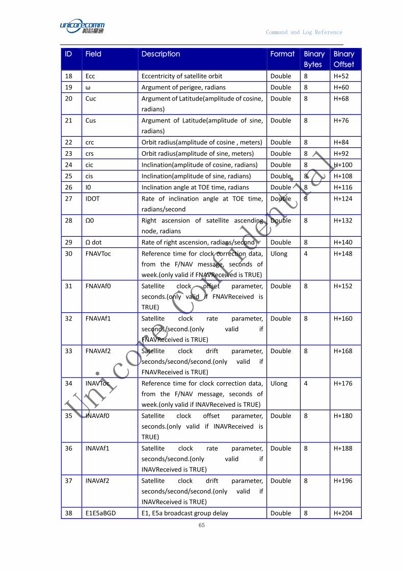
Command and Log Reference
65
ID Field Description Format Binary
Bytes
Binary
Offset
18 Ecc Eccentricity of satellite orbit Double 8 H+52
19 ω Argument of perigee, radians Double 8 H+60
20 Cuc Argument of Latitude(amplitude of cosine,
radians)
Double 8 H+68
21 Cus Argument of Latitude(amplitude of sine,
radians)
Double 8 H+76
22 crc Orbit radius(amplitude of cosine , meters) Double 8 H+84
23 crs Orbit radius(amplitude of sine, meters) Double 8 H+92
24 cic Inclination(amplitude of cosine, radians) Double 8 H+100
25 cis Inclination(amplitude of sine, radians) Double 8 H+108
26 I0 Inclination angle at TOE time, radians Double 8 H+116
27 IDOT Rate of inclination angle at TOE time,
radians/second
Double 8 H+124
28 Ω0 Right ascension of satellite ascending
node, radians
Double 8 H+132
29 Ω dot Rate of right ascension, radians/second Double 8 H+140
30 FNAVToc Reference time for clock correction data,
from the F/NAV message, seconds of
week.(only valid if FNAVReceived is TRUE)
Ulong 4 H+148
31 FNAVAf0 Satellite clock offset parameter,
seconds.(only valid if FNAVReceived is
TRUE)
Double 8 H+152
32 FNAVAf1 Satellite clock rate parameter,
seconds/second.(only valid if
FNAVReceived is TRUE)
Double 8 H+160
33 FNAVAf2 Satellite clock drift parameter,
seconds/second/second.(only valid if
FNAVReceived is TRUE)
Double 8 H+168
34 INAVToc Reference time for clock correction data,
from the F/NAV message, seconds of
week.(only valid if INAVReceived is TRUE)
Ulong 4 H+176
35 INAVAf0 Satellite clock offset parameter,
seconds.(only valid if INAVReceived is
TRUE)
Double 8 H+180
36 INAVAf1 Satellite clock rate parameter,
seconds/second.(only valid if
INAVReceived is TRUE)
Double 8 H+188
37 INAVAf2 Satellite clock drift parameter,
seconds/second/second.(only valid if
INAVReceived is TRUE)
Double 8 H+196
38 E1E5aBGD E1, E5a broadcast group delay Double 8 H+204

Command and Log Reference
66
ID Field Description Format Binary
Bytes
Binary
Offset
39 E1E5bBGD E1, E5b broadcast group delay Double 8 H+212
40 xxxx 32-bit CRC(for ASCII and Binary only) Hex 4 H+220
41 [CR][LF] Sentence terminator(for ASCII only) - - -
7. TIMING Command
This command is used to set high precision timing mode for the receiver. There
are three kinds of GNSS receiver timing modes according to different application
requirements: self-optimizing timing, timing with fixed coordinate, and default high-
precision timing mode. The command parameters and methods for the three timing
modes are shown in the following:
Table 7-1: Timing Mode Parameters
7.1 Real-time Positioning Timing
Real-time positioning timing, refers that the receiver receives satellite signals and
makes positioning/timing solution, at the same time outputs the correct PPS second
pulse signal.
Abbreviated ASCII Syntax: MODE TIMING
7.2 Timing with fixed coordinate
Timing with fixed coordinate means that the receiver antenna is correctly and
stablely installed in the known proper position. With the exact known coordinates, the
receiver carries on high-precision solution of the time information, and outputs the
correct PPS second pulse signal.
Abbreviated ASCII Syntax: MODE TIMING fix lat lon Hgt
Command Mode Parameter Parameters Description
MODE TIMING
- - Generates PPS with real time
positioning
FIX Lat Lon Hgt Generate PPS with fixed
receiver coordinates
Surveyin Time param1 param2 Generate PPS with self-
optimizing coordinates

Command and Log Reference
67
Input Example: MODE TIMING fix 40.245757 116.24323987 56.862
7.3 Self-optimized Timing
Self-optimized timing, refers that the receiver makes an autonomous positioning
optimization according to user’s input of time, horizontal accuracy, elevation accuracy.
Only when the time length, horizontal accuracy, elevation accuracy satisfies the
optimization requirements simultaneously, the coordinate becomes a normal
optimized coordinate. If one of these three factors are not satisfied, the optimization
fails. The final coordinates of the optimization are set to fixed coordinates. The high
precision time information is calculated based on the coordinate, and the correct PPS
second pulse signal is output.
Abbreviated ASCII Syntax: MODE TIMING Surveyin Time param1 param2
Input Example: MODE TIMING Surveyin 60 1.5 2.5
8. MISC COMMAND
8.1 Unlog Stop outputting specific log
This command stops outputting specific log from serial port. Parameter [port] can
be configured to stop output of the port; parameter [message] can be configured to
stop outputting corresponding message. If [port] is not assigned, it is recognized as
the current port received this command by default; if [message]
is not specifically stated, the output of all data are stopped.
Abbreviated ASCII Syntax: UNLOG [port][message]
Recommend Input:
Stop outputting all messages from the current serial port: UNLOG
Stop outputting GPGGA message from current serial port: UNLOG GPGGA
Stop outputting GPGGA message from com2: UNLOG COM2 GPGGA
Table 8-1: Unlog Command

Command and Log Reference
68
ID Field ASCII Value Description
1 UNLOG
Header
-
2 port Serial port Serial port to be stopped
3 message Any valid message ID Name of the message to be
stopped
8.2 Freset Clear selected data from NVM and Reset receiver
This command clears all user specified configurations, satellite ephemeris,
position information, factory settings stored in non-volatile memory and force to reset
receiver.
This command will not clear parameters set by NETCONFIG.
Abbreviated ASCII Syntax: FRESET
Table 8-2: Freset Command
ID Field ASCII Value Description
1 FRESET
header
- Erase all stored data, including the
ephemeris 、 almanac and any other
configurations, and leads to restore the
factory default settings.
8.3 Reset Reset configuration
This command used to reset the receiver, or configure the hot start, cold start,
and warm start of the receiver.
Abbreviated ASCII Syntax: RESET
Table 8-3: Reset Command
ID Field Description
1 FRESET header
2 ephem Reset the stored GPS ephemeris
3 Position Reset the stored position
4 almanac Reset the stored almanac
5 IONUTC Reset the ionospheric and UTC information

Command and Log Reference
69
8.4 ANTENNA Detect
UM4B0 and UM482 support antenna working status query, the antenna state
includes normal, open circuit, and short circuit. Hardware detection and software
query output indicates hardware functions, software output data protocol, and
command format.
1. For active antenna of working normally, the board feeds the antenna, normal
operating current forms a loop, the receiver querys its real-time status;
2. Antenna open circuit: when the receiver is not connected to the antenna, or
the RF cable is damaged, disconnected or for other reasons, the receiver failed to
receive satellite signals;
3. Antenna short circuit: due to antenna failure, short circuit of the receiver's RF
cable connections, or other reasons, the receiver is short-circuit connected with the
antenna, resulting in the receiver can not work properly.
Command format :
antenna 1 Abbreviated ASCII
antennaa 1 ASCII
antennaab 1 Binary
LOG output: #ANTENNAA,COM1,0,90.0,FINE,1971,298166.000,206353827,206353835
,18;ON,OFF,OFF,0*5dc686b4
Table 8-4: Antenna Message
ID Field Description Format Binary
Bytes
Binary
Offset
1 antenna header Log header H 0
2 status1 Status of antenna 1 ENUM 4 H
3 status2 Status of antenna 2 ENUM 4 H+4
4 Status3 Status of antenna 3 ENUM 4 H+8
5 Reversed Reserved ENUM 4 H+12
6 xxxx 32-bit CRC(for ASCII and Binary only) Hex 4 H+16
7 [CR][LF] Sentence terminator(for ASCII only) - - -
Table 8-5: Antenna Status
Status Description ANT*_NLOD,ANT*_FFLG
3 ON OK 1,1
1 OFF open-circuit 0,1
2 SHORT short-circuit 1,0
0 RSV other cases 0,0

Command and Log Reference
70
The antenna status output ASCII and abbreviated ASCII in the Unicore ASCII
format, in the sequence of the above binary number, output in packages splited by “,”.
8.5 Saveconfig Save current configuration into NVM
This command used to save current user configuration into non-volatile memory
(NVM), including LOG (except logs with ONCE trigger), port configuration, etc.
Abbreviated ASCII Syntax: SAVECONFIG
Table 8-6: Saveconfig Command
ID Field Description
1 SAVECONFIG
header
Save all the present configurations in receiver’s non-
volatile memory
9. RTCM V2 Standard Logs
RTCM1 Differential GPS Corrections
RTCM3 Base Station parameters
RTCM9 Partial Difference GPS Corrections
RTCM1819 Raw Measurements Without Corrected
RTCM24 Antenna ReferencePoint
RTCM31 Differential GLONASS Corrections
RTCM32 GLONAS Base Station parameters
RTCM41 Multi-System Differential Corrections(RTCM v2.4)
RTCM42 Partial Multi-System Differential Corrections(RTCM v2.4)
Recommend Input:
RTCM1819 COM2 1
9.1 RTCM V3 Standard Logs
The RTCM SC-104 Type 3 standards recommended by the RTCM Special
Committee, consists primarily of Version 3.0 and Version 3.2. Refer to the
http://www.rtcm.org/overview.php.
RTCM V3:
Group 1 -Observations:
RTCM1001 L1-Only GPS RTK Observables
RTCM1002 Extended L1-Only GPS RTK Observables
RTCM1004 Extended L1 and L2 GPS RTK Observables
RTCM1009 GLONASS L1-Only RTK

Command and Log Reference
71
RTCM1010 Extended GLONASS L1-Only RTK
RTCM1011 GLONASS L1/L2 RTK
RTCM1012 Extended GLONASS L1/L2 RTK
RTCM1071 MSM1 GPS Code Measurements
RTCM1074 MSM4 GPS Code, Phase and CNR Measurements
RTCM1075 MSM5 GPS Code, Phase, CNR and Doppler Measurements
RTCM1081 MSM1 GLONASS Code Measurements
RTCM1084 MSM4 GLONASS Code, Phase and CNR Measurements
RTCM1085 MSM5 GLONASS Code, Phase, CNR and Doppler Measurements
RTCM1121 MSM1 BeiDou Code Measurements
RTCM1124 MSM4 BeiDou Code, Phase and CNR Measurements
RTCM1125 MSM5 BeiDou Code, Phase, CNR and Doppler Measurements
Group 2 –Base Station Coordinates:
RTCM1005 RTK Stationary RTK Base Station Antenna Reference Point (ARP)
RTCM1006 RTK Stationary RTK Base Station ARP with Antenna Height
Group 3 –Antenna Description:
RTCM1007 Extended Antenna Descriptor and Setup Information
Group 4 –Auxiliary Operation Information:
RTCM63 BDS Ephemeris
RTCM1019 GPS Ephemeris
RTCM1020 GLONASS Ephemeris
RTCM1033 Receiver and Antenna Description