FN980 family AT Commands Reference Guide
625
FN980 family AT Commands Reference Guide 80624ST10996A Rev. 5 – 2021-06-24
-
Upload
khangminh22 -
Category
Documents
-
view
0 -
download
0
Transcript of FN980 family AT Commands Reference Guide

FN980 family AT Commands Reference Guide
80624ST10996A Rev. 5 – 2021-06-24

80624ST10996A Rev. 5 Page 2 of 625 2021-06-2424
SPECIFICATIONS ARE SUBJECT TO CHANGE WITHOUT NOTICE
NOTICE
While reasonable efforts have been made to assure the accuracy of this document, Telit assumes no liability resulting from any inaccuracies or omissions in this document, or from use of the information obtained herein. The information in this document has been carefully checked and is believed to be reliable. However, no responsibility is assumed for inaccuracies or omissions. Telit reserves the right to make changes to any products described herein and reserves the right to revise this document and to make changes from time to time in content hereof with no obligation to notify any person of revisions or changes. Telit does not assume any liability arising out of the application or use of any product, software, or circuit described herein; neither does it convey license under its patent rights or the rights of others.
It is possible that this publication may contain references to, or information about Telit products (machines and programs), programming, or services that are not announced in your country. Such references or information must not be construed to mean that Telit intends to announce such Telit products, programming, or services in your country.
COPYRIGHTS
This instruction manual and the Telit products described in this instruction manual may be, include or describe copyrighted Telit material, such as computer programs stored in semiconductor memories or other media. Laws in the Italy and other countries preserve for Telit and its licensors certain exclusive rights for copyrighted material, including the exclusive right to copy, reproduce in any form, distribute and make derivative works of the copyrighted material. Accordingly, any copyrighted material of Telit and its licensors contained herein or in the Telit products described in this instruction manual may not be copied, reproduced, distributed, merged or modified in any manner without the express written permission of Telit. Furthermore, the purchase of Telit products shall not be deemed to grant either directly or by implication, estoppel, or otherwise, any license under the copyrights, patents or patent applications of Telit, as arises by operation of law in the sale of a product.
COMPUTER SOFTWARE COPYRIGHTS
The Telit and 3rd Party supplied Software (SW) products described in this instruction manual may include copyrighted Telit and other 3rd Party supplied computer programs stored in semiconductor memories or other media. Laws in the Italy and other countries preserve for Telit and other 3rd Party supplied SW certain exclusive rights for copyrighted computer programs, including the exclusive right to copy or reproduce in any form the copyrighted computer program. Accordingly, any copyrighted Telit or other 3rd Party supplied SW computer programs contained in the Telit products described in this instruction manual may not be copied (reverse engineered) or reproduced in any manner without the express written permission of Telit or the 3rd Party SW supplier. Furthermore, the purchase of Telit products shall not be deemed to grant either directly or by implication, estoppel, or otherwise, any license under the copyrights, patents or patent applications of Telit or other 3rd Party supplied SW, except for the normal non-exclusive, royalty free license to use that arises by operation of law in the sale of a product.

80624ST10996A Rev. 5 Page 3 of 625 2021-06-2424
USAGE AND DISCLOSURE RESTRICTIONS
I. License Agreements
The software described in this document is the property of Telit and its licensors. It is furnished by express license agreement only and may be used only in accordance with the terms of such an agreement.
II. Copyrighted Materials
Software and documentation are copyrighted materials. Making unauthorized copies is prohibited by law. No part of the software or documentation may be reproduced, transmitted, transcribed, stored in a retrieval system, or translated into any language or computer language, in any form or by any means, without prior written permission of Telit
III. High Risk Materials
Components, units, or third-party products used in the product described herein are NOT fault-tolerant and are NOT designed, manufactured, or intended for use as on-line control equipment in the following hazardous environments requiring fail-safe controls: the operation of Nuclear Facilities, Aircraft Navigation or Aircraft Communication Systems, Air Traffic Control, Life Support, or Weapons Systems (High Risk Activities"). Telit and its supplier(s) specifically disclaim any expressed or implied warranty of fitness for such High Risk Activities.
IV. Trademarks
TELIT and the Stylized T Logo are registered in Trademark Office. All other product or service names are the property of their respective owners.
V. Third Party Rights
The software may include Third Party Right software. In this case you agree to comply with all terms and conditions imposed on you in respect of such separate software. In addition to Third Party Terms, the disclaimer of warranty and limitation of liability provisions in this License shall apply to the Third Party Right software.
TELIT HEREBY DISCLAIMS ANY AND ALL WARRANTIES EXPRESS OR IMPLIED FROM ANY THIRD PARTIES REGARDING ANY SEPARATE FILES, ANY THIRD PARTY MATERIALS INCLUDED IN THE SOFTWARE, ANY THIRD PARTY MATERIALS FROM WHICH THE SOFTWARE IS DERIVED (COLLECTIVELY “OTHER CODE”), AND THE USE OF ANY OR ALL THE OTHER CODE IN CONNECTION WITH THE SOFTWARE, INCLUDING (WITHOUT LIMITATION) ANY WARRANTIES OF SATISFACTORY QUALITY OR FITNESS FOR A PARTICULAR PURPOSE.
NO THIRD PARTY LICENSORS OF OTHER CODE SHALL HAVE ANY LIABILITY FOR ANY DIRECT, INDIRECT, INCIDENTAL, SPECIAL, EXEMPLARY, OR CONSEQUENTIAL DAMAGES (INCLUDING WITHOUT LIMITATION LOST PROFITS), HOWEVER CAUSED AND WHETHER MADE UNDER CONTRACT, TORT OR OTHER LEGAL THEORY, ARISING IN ANY WAY OUT OF THE USE OR DISTRIBUTION OF THE OTHER CODE OR THE EXERCISE OF ANY RIGHTS GRANTED UNDER EITHER OR BOTH THIS LICENSE AND THE LEGAL TERMS APPLICABLE TO ANY SEPARATE FILES, EVEN IF ADVISED OF THE POSSIBILITY OF SUCH DAMAGES.

80624ST10996A Rev. 5 Page 4 of 625 2021-06-2424
APPLICABILITY TABLE
FN980
FN980m
FT980
FT980m
FT980-KS
38.X2.002 / M0H.020002
38.X2.202 / M0H.020202

80624ST10996A Rev. 5 Page 5 of 625 2021-06-2424
CONTENTS
NOTICE .............................................................................................................................................................. 2
COPYRIGHTS .................................................................................................................................................... 2
COMPUTER SOFTWARE COPYRIGHTS ......................................................................................................... 2
USAGE AND DISCLOSURE RESTRICTIONS .................................................................................................. 3
APPLICABILITY TABLE .................................................................................................................................... 4
CONTENTS ........................................................................................................................................................ 5
1. INTRODUCTION ................................................................................................................................... 15
Scope ......................................................................................................................................... 15
Audience .................................................................................................................................... 15
Contact Information, Support ..................................................................................................... 15
Icons and Text Conventions ....................................................................................................... 16
2. AT COMMANDS ................................................................................................................................... 17
Definitions .................................................................................................................................. 17
AT Command Syntax ................................................................................................................. 17
2.2.1. String Type Parameters ............................................................................................................. 18
2.2.2. Command Lines ......................................................................................................................... 18
2.2.2.1. ME Error Result Code - +CME ERROR: <err> .......................................................................... 19
2.2.2.2. Message Service Failure Result Code - +CMS ERROR: <err> ................................................. 22
2.2.3. Information Responses and Result Codes ................................................................................. 23
2.2.4. Command Response Time-Out .................................................................................................. 23
2.2.5. Command Issuing Timing ........................................................................................................... 23
Storage....................................................................................................................................... 24
2.3.1. Factory Profile and User Profiles ................................................................................................ 24
AT Command Short Overview Table .......................................................................................... 25
3. AT COMMANDS REFERENCES .......................................................................................................... 26
Call & DTMF ............................................................................................................................... 26
3.1.1. AT+CHUP - Hang Up Call .......................................................................................................... 26
3.1.2. AT+CSTA - Select Type of Address ........................................................................................... 27
3.1.3. AT+FCLASS - Select Active Service Class ................................................................................ 28
3.1.4. AT#ACALEXT - Extended Automatic Call .................................................................................. 29
3.1.5. AT#ECAM - Extended Call Monitoring ....................................................................................... 30
3.1.6. AT+VTS - DTMF Tones Transmission ....................................................................................... 32
3.1.7. AT+VTD - Tone Duration ........................................................................................................... 33
3.1.8. AT+CRC - Cellular Result Codes ............................................................................................... 34
3.1.9. AT#ACAL - Automatic Call ......................................................................................................... 35
3.1.10. AT+CVHU - Voice Hung Up Control ........................................................................................... 37
3.1.11. AT#UDUB - User Determined User Busy ................................................................................... 38
General Control and Config ........................................................................................................ 39
3.2.1. AT#DIALMODE - Set Dialing Mode ........................................................................................... 39
3.2.2. AT#GETFW - Get firmware status ............................................................................................. 41
80624ST10996A Rev. 5 Page 6 of 625 2021-06-2424
3.2.3. AT#ACTIVEFW - Active firmware .............................................................................................. 42
3.2.4. AT#CLEARFW - Clear firmware ................................................................................................. 43
3.2.5. AT#FIRMWARE - Firmware ....................................................................................................... 44
3.2.6. AT#HWREV - Hardware Identification ....................................................................................... 45
3.2.7. AT#ICMP - Ping Support ............................................................................................................ 46
3.2.8. AT#B30TXDIS - Set B30 TX disable .......................................................................................... 47
3.2.9. AT#SELQTMANT - Select QTM Antenna .................................................................................. 48
3.2.10. Command Line Prefixes ............................................................................................................. 49
3.2.10.1. AT - Starting a Command Line ................................................................................................... 49
3.2.10.2. A/ - Last Command Automatic Repetition .................................................................................. 50
3.2.10.3. AT#/ - Repeat Last Command .................................................................................................... 51
3.2.11. Generic Modem Control ............................................................................................................. 52
3.2.11.1. AT#SELINT - Select Interface Style ........................................................................................... 52
3.2.11.2. AT&F - Set to Factory-Defined Configuration ............................................................................. 53
3.2.11.3. ATZ - Soft Reset ........................................................................................................................ 54
3.2.11.4. AT&Y - Default Reset Basic Profile Designation ........................................................................ 55
3.2.11.5. AT&P - Default Reset Full Profile Designation ........................................................................... 56
3.2.11.6. AT&W - Store Current Configuration .......................................................................................... 57
3.2.11.7. AT&V - Display some Configuration and Profile ......................................................................... 58
3.2.11.8. AT\V - Single Line Connect Message ........................................................................................ 59
3.2.11.9. AT+GCI - Country of Installation ................................................................................................ 60
3.2.11.10. AT%L - Line Signal Level ........................................................................................................... 61
3.2.11.11. AT%Q - Line Quality .................................................................................................................. 62
3.2.11.12. ATL - Speaker Loudness............................................................................................................ 63
3.2.11.13. ATM - Speaker Mode ................................................................................................................. 64
3.2.11.14. AT+GCAP - Capabilities List ...................................................................................................... 65
3.2.11.15. AT+GMI - Manufacturer Identification ........................................................................................ 66
3.2.11.16. AT+GMM - Model Identification .................................................................................................. 67
3.2.11.17. AT+GMR - Revision Identification .............................................................................................. 68
3.2.11.18. AT+CEER - Extended Error Report ............................................................................................ 69
3.2.11.19. AT+GSN - Serial Number ........................................................................................................... 70
3.2.11.20. AT+CGMI - Request Manufacturer Identification........................................................................ 71
3.2.11.21. AT+CGMM - Request Model Identification ................................................................................. 72
3.2.11.22. AT+CGMR - Request Revision Identification ............................................................................. 73
3.2.11.23. AT+CGSN - Request Product Serial Number Identification ....................................................... 74
3.2.11.24. AT#CGMI - Request Manufacturer Identification ........................................................................ 75
3.2.11.25. AT#CGMR - Request Revision Identification ............................................................................. 76
3.2.11.26. AT#CGSN - Product Serial Number Identification ...................................................................... 77
3.2.11.27. AT#CGMF - Request Product Code ........................................................................................... 78
3.2.11.28. AT#SWPKGV - Request Software Package Version ................................................................. 79
3.2.11.29. AT+CPAS - Phone Activity Status .............................................................................................. 80
3.2.11.30. AT+CFUN - Set Phone Functionality .......................................................................................... 81
3.2.11.31. AT+CIND - Indicator Control ...................................................................................................... 82
3.2.11.32. AT+CMER - Mobile Equipment Event Reporting ....................................................................... 85
3.2.11.33. AT+CACM - Accumulated Call Meter ......................................................................................... 87

80624ST10996A Rev. 5 Page 7 of 625 2021-06-2424
3.2.11.34. AT+CAMM - Accumulated Call Meter Maximum ........................................................................ 88
3.2.11.35. AT+CPUC - Price per Unit and Currency Table ......................................................................... 89
3.2.11.36. AT+CCWE - Call Meter Maximum Event ................................................................................... 90
3.2.11.37. AT+CSVM - Set Voice Mail Number .......................................................................................... 91
3.2.11.38. AT+CLAC - Available AT Commands ........................................................................................ 92
3.2.11.39. AT#LANG - Select Language ..................................................................................................... 93
3.2.11.40. AT+CMEE - Report Mobile Equipment Error .............................................................................. 94
3.2.11.41. AT#VCDISABLE - Disable Voice Call ........................................................................................ 95
3.2.11.42. AT#PERSISTAPN - Preserve APN Profile during firmware upgrade ......................................... 96
3.2.11.43. AT+CSCS - Select TE Character Set ......................................................................................... 97
3.2.11.44. AT+PACSP - Network Selection Menu Availability ..................................................................... 98
3.2.11.45. AT#USBCFG - USB Configuration ............................................................................................. 99
3.2.11.46. AT#USB3TUNE - Tune USB 3.0 PHY ..................................................................................... 100
3.2.11.47. AT#USBSWITCH - Switch USB Speed .................................................................................... 103
3.2.11.48. AT#USBDMOFF - Disable of DIAG channel on USB ............................................................... 104
3.2.11.49. AT#RESETINFO - Read reason for most recent devices reset or power-down ....................... 105
3.2.11.50. AT&V2 - Display Last Connection Statistics ............................................................................. 106
3.2.11.51. AT#CGMM - Request Model Identification ............................................................................... 107
3.2.11.52. AT&V0 - Display Current Configuration and Profile .................................................................. 108
3.2.11.53. AT#FWSWITCH - Set Active Firmware Image ......................................................................... 109
3.2.11.54. AT#FWAUTOSIM - Automatic Carrier Switch By SIM .............................................................. 111
3.2.11.55. AT#FWPLS - Firmware PLMN ID List ...................................................................................... 113
3.2.11.56. AT#CQI - HSDPA Channel Quality Indication .......................................................................... 115
3.2.11.57. AT#PDPAUTH - PDP Authentication Parameters .................................................................... 116
3.2.11.58. AT#LOOPBACKMODECFG - Set the loopback mode configuration ....................................... 117
3.2.11.59. AT+IMEISV - Request IMEI and Software Version Number ..................................................... 118
3.2.11.60. AT#USBPCISWITCH - Switching between USB and PCIe for Network Interface .................... 119
3.2.12. S Parameters ........................................................................................................................... 121
3.2.12.1. ATS0 - Number of Rings to Auto Answer ................................................................................. 121
3.2.12.2. ATS1 - Ring Counter ................................................................................................................ 122
3.2.12.3. ATS2 - Escape Character ........................................................................................................ 123
3.2.12.4. ATS3 - Command Line Termination Character ........................................................................ 124
3.2.12.5. ATS4 - Response Formatting Character .................................................................................. 125
3.2.12.6. ATS5 - Command Line Editing Character ................................................................................ 126
3.2.12.7. ATS7 - Connection Completion Time-Out ................................................................................ 127
3.2.12.8. ATS25 - Delay to DTR Off ........................................................................................................ 128
3.2.12.9. AT&V1 - S Registers Display ................................................................................................... 129
3.2.12.10. ATS12 - Escape Prompt Delay ................................................................................................ 130
3.2.12.11. ATS10 - Carrier Off with Firm Time .......................................................................................... 131
3.2.12.12. AT&V3 - Extended S Registers Display ................................................................................... 132
3.2.13. DTE - Modem Interface Control ............................................................................................... 133
3.2.13.1. ATE - Command Echo ............................................................................................................. 133
3.2.13.2. ATQ - Quiet Result Codes ........................................................................................................ 134
3.2.13.3. ATV - Response Format........................................................................................................... 135
3.2.13.4. ATI - Identification Information ................................................................................................. 136

80624ST10996A Rev. 5 Page 8 of 625 2021-06-2424
3.2.13.5. AT&C - Data Carrier Detect (DCD) Control .............................................................................. 137
3.2.13.6. AT&D - Data Terminal Ready (DTR) Control ........................................................................... 138
3.2.13.7. AT\Q - Standard Flow Control .................................................................................................. 139
3.2.13.8. AT&K - Flow Control ................................................................................................................ 140
3.2.13.9. AT&S - Data Set Ready (DSR) Control .................................................................................... 141
3.2.13.10. AT+IPR - UART DCE Interface Data Rate Speed .................................................................... 142
3.2.13.11. AT+IFC - DTE-Modem Local Flow Control ............................................................................... 144
3.2.13.12. AT+ICF - DTE-Modem Character Framing .............................................................................. 146
3.2.13.13. ATX - Extended Result Codes ................................................................................................. 147
3.2.13.14. AT#NOPT - Notification Port .................................................................................................... 148
3.2.13.15. AT#NOPTEXT - Notification Port Extension ............................................................................. 149
3.2.13.16. AT\R - Ring (RI) Control ........................................................................................................... 151
3.2.14. Call (Voice and Data) Control ................................................................................................... 152
3.2.14.1. ATH - Hang Up/Disconnect the Current Call ............................................................................ 152
3.2.14.2. ATA - Answer Incoming call ..................................................................................................... 153
3.2.14.3. ATD - Dialup Connection.......................................................................................................... 154
Network .................................................................................................................................... 157
3.3.1. AT#LTEDS - Current Network status in E-UTRAN ................................................................... 157
3.3.2. AT+CNUM - Subscriber Number .............................................................................................. 160
3.3.3. AT+COPN - Read Operator Names ......................................................................................... 161
3.3.4. AT+CREG - Network Registration Status ................................................................................. 162
3.3.5. AT+CLCK - Facility Lock/Unlock .............................................................................................. 165
3.3.6. AT+CPWD - Change Facility Password ................................................................................... 167
3.3.7. AT+CLIR - Calling Line Identification Restriction...................................................................... 169
3.3.8. AT+COLP - Connected Line Identification Presentation .......................................................... 171
3.3.9. AT+CCFC - Call Forwarding Number And Condition ............................................................... 173
3.3.10. AT+CCWA - Call Waiting ......................................................................................................... 175
3.3.11. AT+CHLD - Call Holding Services............................................................................................ 178
3.3.12. AT+CTFR - Call Deflection ....................................................................................................... 180
3.3.13. AT+CUSD - Unstructured Supplementary Service Data .......................................................... 181
3.3.14. AT+CAOC - Advice of Charge.................................................................................................. 183
3.3.15. AT+CLCC - List Current Calls .................................................................................................. 185
3.3.16. AT+CSSN - SS Notification ...................................................................................................... 187
3.3.17. AT+CCUG - Closed User Group .............................................................................................. 189
3.3.18. AT+CPOL - Preferred Operator List ......................................................................................... 190
3.3.19. AT#CODECINFO - Codec Information ..................................................................................... 192
3.3.20. AT+CPLS - Selection of Preferred PLMN List .......................................................................... 196
3.3.21. AT+CSQ - Signal Quality ......................................................................................................... 197
3.3.22. AT#SERVINFO - Serving Cell Information ............................................................................... 199
3.3.23. AT#BCCHLOCK - Lock to Single BCCH ARFCN ..................................................................... 201
3.3.24. AT#CODEC - GSM and UMTS Audio Codec ........................................................................... 204
3.3.25. AT#BND - Select Band............................................................................................................. 206
3.3.26. AT+CEMODE - Set Mode of Operation for EPS ...................................................................... 213
3.3.27. AT+CEUS - UE's usage setting for EPS and 5GS ................................................................... 215
3.3.28. AT+CPNER - Primary Notification Event Reporting ................................................................. 216

80624ST10996A Rev. 5 Page 9 of 625 2021-06-2424
3.3.29. AT+CESQ - Extended Signal Quality ....................................................................................... 217
3.3.30. AT#ENS - Enhanced Network Selection .................................................................................. 221
3.3.31. AT#EONS - Enable URC of Enhanced Operator Name String ................................................ 222
3.3.32. AT+WS46 - PCCA STD-101 Select Wireless Network ............................................................. 223
3.3.33. AT+CEREG - EPS Network Registration Status ...................................................................... 224
3.3.34. AT+C5GREG - 5GS Network Registration Status .................................................................... 226
3.3.35. AT+CEN - Reading and reporting of emergency numbers ....................................................... 229
3.3.36. AT#RFSTS - Read Current Network Status ............................................................................. 230
3.3.37. AT+C5GNSSAI - 5GS NSSAI setting ....................................................................................... 235
3.3.38. AT+C5GNSSAIRDP - 5GS NSSAI read dynamic parameters ................................................. 236
3.3.39. AT#5GCTL - Control the 5G bands .......................................................................................... 239
3.3.40. AT#USRMMWS - User MMWAVE Selection ........................................................................... 241
3.3.41. AT#USRMMWW - User MMWAVE Write ................................................................................. 243
3.3.42. AT#USRMMWR - User MMWAVE Read ................................................................................. 245
3.3.43. AT#USRMMWD - User MMWAVE Delete ................................................................................ 247
3.3.44. AT#USRMMWL - User MMWAVE List ..................................................................................... 249
3.3.45. AT#USRMMWC - User MMWAVE Control .............................................................................. 251
3.3.46. AT#MONI - Cell Monitor ........................................................................................................... 252
3.3.47. AT#ICMCONNECT - Control Data call DISCONNECT/CONNECTADD/DELETE ................... 257
3.3.48. AT#LTECAT - LTE Category Setting ....................................................................................... 261
3.3.49. AT#FDOR - Fast Dormancy ..................................................................................................... 262
3.3.50. AT+RSRP - Read RSRP measurement value ......................................................................... 264
3.3.51. AT+RSRQ - Read RSRQ measurement value ......................................................................... 265
3.3.52. AT+RSCP - Read RSCP measurement value ......................................................................... 266
3.3.53. AT+ECNO - Read ECNO measurement value ......................................................................... 267
3.3.54. AT+COLR - Connected Line Identification Restriction status ................................................... 268
3.3.55. AT+CDIP - Called line identification presentation..................................................................... 269
3.3.56. AT+CLIP - Calling Line Identification Presentation................................................................... 271
3.3.57. AT+VZWRSRP - Read RSRP Values ...................................................................................... 273
3.3.58. AT+VZWRSRQ - Read RSRQ Values ..................................................................................... 274
3.3.59. AT#5GLINKSTAT - 5G Link state ............................................................................................ 275
3.3.60. AT#BNDPRI - Set the band priority list for LTE ........................................................................ 276
3.3.61. AT+COPS - Operator Selection ............................................................................................... 277
3.3.62. AT#ICMAUTOCONN - Set Datacall Auto connection mode ..................................................... 280
SMS & CB ................................................................................................................................ 282
3.4.1. AT+CSMS - Select Message Service ....................................................................................... 282
3.4.2. AT+CPMS - Preferred Message Storage ................................................................................. 284
3.4.3. AT+CMGF - Message Format .................................................................................................. 287
3.4.4. AT+CSCA - Service Center Address ........................................................................................ 288
3.4.5. AT+CSMP - Set Text Mode Parameters .................................................................................. 290
3.4.6. AT+CSDH - Show Text Mode Parameters ............................................................................... 293
3.4.7. AT+CSCB - Select Cell Broadcast ........................................................................................... 294
3.4.8. AT+CSAS - Save Settings ....................................................................................................... 295
3.4.9. AT+CRES - Restore Settings ................................................................................................... 296
3.4.10. AT+CMMS - More Message to Send ....................................................................................... 297

80624ST10996A Rev. 5 Page 10 of 625 2021-06-2424
3.4.11. AT+CGSMS - Select Service for MO SMS Messages ............................................................. 298
3.4.12. AT+CNMI - New Message Indications to Terminal Equipment ................................................ 299
3.4.13. AT+CMGL - List Messages ...................................................................................................... 307
3.4.14. AT+CMGR - Read Message .................................................................................................... 316
3.4.15. AT+CNMA - New Message Acknowledgement ........................................................................ 323
3.4.16. AT+CMGS - Send Short Message ........................................................................................... 326
3.4.17. AT+CMSS - Send Message from Storage ............................................................................... 331
3.4.18. AT+CMGW - Write Short Message to Memory ........................................................................ 333
3.4.19. AT+CMGD - Delete Message................................................................................................... 339
3.4.20. AT#SMSFORMAT - Select 3GPP or 3GPP2 Format for MO SMS .......................................... 340
3.4.21. AT#ISMSCFG - SMS Transport Configuration ......................................................................... 341
3.4.22. AT+C5GSMS - 5GS access selection preference for MO SMS ............................................... 342
3.4.23. AT+C5GUSMS - 5GS use of SMS over NAS ........................................................................... 343
Time & Alarm ........................................................................................................................... 345
3.5.1. AT+CCLK - Clock Management ............................................................................................... 345
3.5.2. AT#UPTIME - System Up Time ............................................................................................... 347
3.5.3. AT+CSDF - Setting Date Format.............................................................................................. 348
3.5.4. AT+CTZR - Time Zone Reporting ............................................................................................ 350
3.5.5. AT+CTZU - Automatic Time Zone Update ............................................................................... 352
3.5.6. AT+CSTF - Setting Time Format.............................................................................................. 353
3.5.7. AT#NITZ - Network Identity and Time Zone ............................................................................. 354
Phonebook ............................................................................................................................... 356
3.6.1. AT+CPBS - Select Phonebook Memory Storage ..................................................................... 356
3.6.2. AT+CPBR - Read Phonebook Entries ...................................................................................... 358
3.6.3. AT+CPBF - Find Phonebook Entries ........................................................................................ 361
3.6.4. AT+CPBW - Write Phonebook Entry ........................................................................................ 364
3.6.5. AT#CPBGR - Read Group Entries ........................................................................................... 366
3.6.6. AT#CPBGW - Write Group Entry ............................................................................................. 368
Packet Domain ......................................................................................................................... 369
3.7.1. AT+CGCLASS - GPRS Mobile Station Class .......................................................................... 369
3.7.2. AT+CGQREQ - Quality of Service Profile (Requested) ............................................................ 370
3.7.3. AT+CGDCONT - Define PDP Context ..................................................................................... 372
3.7.4. AT+CGCONTRDP - PDP Context Read Dynamic Parameters ................................................ 377
3.7.5. AT+CGQMIN - Quality of Service Profile (Minimum Acceptable) ............................................. 379
3.7.6. AT+CGEQREQ - 3G Quality of Service Profile (Requested) ................................................... 381
3.7.7. AT+CGEQNEG - 3G Quality of Service Profile (Negotiated) ................................................... 385
3.7.8. AT+CGPADDR - Show PDP Address ...................................................................................... 387
3.7.9. AT+CGCMOD - Modify PDP Context ....................................................................................... 389
3.7.10. AT+CGEQMIN - 3G Quality of Service Profile (Minimum Acceptable) ..................................... 390
3.7.11. AT+CGEQOS - Define EPS Quality of Service ........................................................................ 394
3.7.12. AT+CGPIAF - Printing IP Address Format ............................................................................... 396
3.7.13. AT+CGEREP - Packet Domain Event Reporting ..................................................................... 398
3.7.14. AT+CGATT - PS Attach or Detach ........................................................................................... 400
3.7.15. AT+CGTFT - Traffic Flow Template ......................................................................................... 401
3.7.16. AT+CGEQOSRDP - EPS Quality of Service Read Dynamic Parameters ................................ 404

80624ST10996A Rev. 5 Page 11 of 625 2021-06-2424
3.7.17. AT+CGTFTRDP - Traffic Flow Template Read Dynamic Parameters ...................................... 406
3.7.18. AT+CGACT - PDP Context Activate or Deactivate .................................................................. 409
3.7.19. AT+CGDSCONT - Define Secondary PDP Context ................................................................. 410
3.7.20. AT+CGSCONTRDP - Secondary PDP Context Read Dynamic Parameters ........................... 412
3.7.21. AT+CGREG - GPRS Network Registration Status ................................................................... 413
3.7.22. AT#SINGLEAPNSWITCH - set APN param change ................................................................ 415
SIM ........................................................................................................................................... 416
3.8.1. AT+CPIN - Enter the PIN ......................................................................................................... 416
3.8.2. AT+CPINR - Remaining PIN Retries ........................................................................................ 418
3.8.3. AT+ICCID - Read ICCID .......................................................................................................... 420
3.8.4. AT+CIMI - International Mobile Subscriber Identity (IMSI) ....................................................... 421
3.8.5. AT+CRSM - Restricted SIM access ......................................................................................... 422
3.8.6. AT+CSIM - Generic SIM Access .............................................................................................. 425
3.8.7. AT+CCHO - Open Logical Channel ......................................................................................... 427
3.8.8. AT+CCHC - Close Logical Channel ......................................................................................... 429
3.8.9. AT+CGLA - Generic UICC Logical Channel Access ................................................................ 430
3.8.10. AT+CUAD - UICC Application Discovery ................................................................................. 432
3.8.11. AT#QSS - Query SIM Status .................................................................................................... 433
3.8.12. AT#SIMDET - SIM Detection Mode ......................................................................................... 435
3.8.13. AT+CSUS - Set card slot ......................................................................................................... 436
3.8.14. AT#SIMSELECT - SIM Slot Switch .......................................................................................... 437
3.8.15. AT#SIMPR - SIM Presence Status .......................................................................................... 438
3.8.16. AT#HSEN - Hot-Swap Enable .................................................................................................. 440
3.8.17. AT#SIMINCFG - SIMIN Pin Configuration ................................................................................ 442
3.8.18. AT+CSUPI - Request 5G subscription permanent identifier ..................................................... 444
3.8.19. AT#ESIMUPN - Updates the nickname.................................................................................... 445
3.8.20. AT#ESIMPFINFO - Provides the profile data ........................................................................... 446
3.8.21. AT#ESIMPF - Manage the profiles ........................................................................................... 448
3.8.22. AT#ESIMADDPF - Allows download a new profile ................................................................... 450
3.8.23. AT#ESIMID - Provides the EUICC ID ...................................................................................... 452
3.8.24. AT#ESIMGETADDR - Configures the default SM-DP+ address .............................................. 453
3.8.25. AT#ESIMPFUC - Provides the user consent ............................................................................ 454
3.8.26. AT#ESIMCAP - Sets or gets the terminal capability ................................................................. 455
3.8.27. AT#ESIMMEMRST - Resets the eUICC card .......................................................................... 458
SIM Toolkit ............................................................................................................................... 459
3.9.1. AT#STIA - SIM/USIM Toolkit Interface Action .......................................................................... 459
3.9.2. AT#STGI - SIM Toolkit Get Information.................................................................................... 464
3.9.3. AT#STSR - SIM Toolkit Send Response.................................................................................. 472
3.9.4. AT#SDM - Set SIM Toolkit Display Mode................................................................................. 474
3.9.5. AT#STIME - Set SIM Toolkit timeout value .............................................................................. 475
3.9.6. AT#STKENV - Send SIM Toolkit Envelop Command .............................................................. 476
Audio ........................................................................................................................................ 477
3.10.1. Digital Voice Interface .............................................................................................................. 477
3.10.1.1. AT#DVI - Digital Voiceband Interface ....................................................................................... 477
3.10.1.2. AT#DVICLK - Digital Voiceband Interface Clock ...................................................................... 479

80624ST10996A Rev. 5 Page 12 of 625 2021-06-2424
Power Down ............................................................................................................................. 480
3.11.1. AT#REBOOT - Module Reboot ................................................................................................ 480
3.11.2. AT#ENHRST - Periodic Reset ................................................................................................. 481
3.11.3. AT#SHDN - Software Shutdown .............................................................................................. 483
3.11.4. AT#FASTSHDN - Fast Shutdown Configuration ...................................................................... 484
HW and Radio Control ............................................................................................................. 486
3.12.1. AT#DPRLIST - TX Dynamic Power Reduction List .................................................................. 486
3.12.2. AT#DPRCTL - TX Dynamic Power Reduction Control ............................................................. 489
3.12.3. AT#MACADDR - Configure MAC Address ............................................................................... 490
3.12.4. AT#I2CDIS - I2C disable .......................................................................................................... 491
3.12.5. AT+CBC - Battery Charge ........................................................................................................ 492
3.12.6. AT#GPIO - General Purpose Input/Output Pin Control ............................................................ 494
3.12.7. AT#WWANLED - WWLAN_LED GPIO Setting ........................................................................ 497
3.12.8. AT#I2CWR - Write to I2C ......................................................................................................... 499
3.12.9. AT#I2CRD - Read from I2C ..................................................................................................... 501
3.12.10. AT#RXDIV - Enable RX Diversity and Set DARP .................................................................... 503
3.12.11. AT#LRXDIV - Enable LTE RX Diversity ................................................................................... 504
3.12.12. AT#TEMPSENS - Temperature Monitor .................................................................................. 506
3.12.13. AT#TMLVL - Thermal Mitigation Level ..................................................................................... 508
3.12.14. AT#CAINFO - Show LTE CA Information ................................................................................. 510
3.12.15. AT#TESTMODE - Test Mode Configuration ............................................................................ 517
3.12.16. AT#LAPS - LTE Antenna Ports Signals ................................................................................... 529
3.12.17. AT#LCFC - LTE Carrier Aggregation Frequencies and Combinations ..................................... 531
3.12.18. AT#CACTL - LTE Carrier Aggregation enable and disable ...................................................... 533
3.12.19. AT#SHDNIND - Shutdown Indication ....................................................................................... 534
3.12.20. AT#RXTOGGLE - Swap RX from Main to Diversity ................................................................. 536
3.12.21. AT#CBC - Battery and Charger Status..................................................................................... 538
3.12.22. AT#4RXDIS - Enable or Disable for 4RX ................................................................................. 539
Easy Scan ................................................................................................................................ 540
3.13.1. AT#CSURV - Network Survey .................................................................................................. 540
3.13.2. AT#CSURVC - Network Survey (Numeric Format) .................................................................. 544
IoT Portal .................................................................................................................................. 548
3.14.1. AT#LWM2MSKIP - No Starting any LwM2M Client .................................................................. 548
3.14.2. AT+ODIS - Commands for Saving and Retrieving the Odis Parameters ................................. 550
FOTA & OMA ........................................................................................................................... 552
3.15.1. FOTA Legacy ........................................................................................................................... 552
3.15.1.1. AT#OTAUPW - OTA Delta Write .............................................................................................. 552
3.15.2. OMA-DM .................................................................................................................................. 553
3.15.2.1. AT#HOSTODIS - Host ODIS Parameters Management .......................................................... 553
GNSS ....................................................................................................................................... 555
3.16.1. GNSS Configuration ................................................................................................................. 555
3.16.1.1. AT$GPSNVRAM - Delete GNSS NVRAM Parameters ............................................................ 555
3.16.1.2. AT$LCSSLP - Update SLP Address ........................................................................................ 556
3.16.1.3. AT$LCSTER - Update Terminal Information ............................................................................ 557
3.16.1.4. AT$LCSLRMT - Mobile Terminated Location Request (MT-LR) .............................................. 558

80624ST10996A Rev. 5 Page 13 of 625 2021-06-2424
3.16.1.5. AT$LTC - LCS Certificate ......................................................................................................... 561
3.16.1.6. AT$GPSQOS - GPS Quality of Service ................................................................................... 563
3.16.1.7. AT$GPSSTOP - Stop Location Service Request ..................................................................... 566
3.16.1.8. AT$GPSSLSR - Start Location Service Request ..................................................................... 567
3.16.1.9. AT$LCSLRV - Location Request Verification ........................................................................... 570
3.16.1.10. AT$GPSAPN - Set GPS APN Profile ....................................................................................... 571
3.16.1.11. AT$AGPSEN - Set GNSS capability supporting to module ...................................................... 573
3.16.1.12. AT$LCSLPP - Set Configuration Information for LPP Protocol ................................................ 574
3.16.1.13. AT$LCSAGLO - Selection of Positioning protocols for A-GLONASS ....................................... 575
3.16.1.14. AT#LOCAUTOSTART - GNSS Auto Start Configuration ......................................................... 577
3.16.1.15. AT#LOCNMEATYPE - NMEA Type Configuration ................................................................... 579
3.16.1.16. AT$XTRAEN - GpsOneXTRA feature control .......................................................................... 581
3.16.2. GNSS Receiver ........................................................................................................................ 584
3.16.2.1. AT$GPSRST - Restore Default GNSS Parameters ................................................................. 584
3.16.2.2. AT$GPSSAV - Save GNSS Parameters Configuration ............................................................ 585
3.16.2.3. AT$GPSP - GNSS Positioning Session Control ....................................................................... 586
3.16.3. GNSS General Management ................................................................................................... 588
3.16.3.1. AT$GNSSCONF - Configuration of the GNSS receiver ........................................................... 588
3.16.3.2. AT$GPSR - Reset the GNSS Controller .................................................................................. 590
3.16.3.3. AT$GPSLOCK - GNSS Lock Mode ......................................................................................... 592
3.16.3.4. AT$GPSANTPORT - Configuration of GNSS Antenna Port Type ............................................ 593
3.16.3.5. AT$GNSSMBCFG - GNSS Multi-band Configuration .............................................................. 594
3.16.4. GNSS Positioning Information .................................................................................................. 595
3.16.4.1. AT$GPSNMUN - Unsolicited NMEA Data Configuration.......................................................... 595
3.16.4.2. AT$GPSACP - Get Acquired GNSS Position ........................................................................... 598
3.16.4.3. AT$GPSNMUNEX - Unsolicited NMEA Extended Data Configuration ..................................... 600
PSM (Power Saving Mode) ...................................................................................................... 602
3.17.1. AT#PSMWDISACFG - Power Saving mode configuration ....................................................... 602
3.17.2. AT#PSMEVTCFG - Wake Up Event configuration ................................................................... 604
3.17.3. AT#PSMWAKENCFG - WAKE_N pin configuration command ................................................ 606
3.17.4. AT#PSMEVT - Get Wake up events ........................................................................................ 607
IMS ........................................................................................................................................... 608
3.18.1. AT+CIREG - IMS registration state .......................................................................................... 608
Customization Feature AT Commands .................................................................................... 610
3.19.1. AT#MIMOSTS - Display MIMO status of LTE and NR5G ........................................................ 610
3.19.2. AT#GETCUSTFEAT - Get the Setting of Customization Feature ............................................ 611
3.19.3. AT#SETCUSTFEAT - Set the Customization Feature ............................................................. 613
3.19.4. AT#HPSSICFG - HPS SI service configuration ........................................................................ 615
3.19.5. AT#MMWANT - mmWAVE Antenna selection ......................................................................... 616
Dying GASP AT Commands .................................................................................................... 618
3.20.1. AT#DGCFG - Dying GASP Configuration ................................................................................ 618
3.20.2. AT#DGSTAT - Dying GASP Statistics Management ................................................................ 619
3.20.3. AT#DGENABLE - Dying GASP Enable/Disable SMS/Detach Request ................................... 620
4. LIST OF ACRONYMS ......................................................................................................................... 622
5. DOCUMENT HISTORY ....................................................................................................................... 623

80624ST10996A Rev. 5 Page 14 of 625 2021-06-2424

80624ST10996A Rev. 5 Page 15 of 625 2021-06-2424
1. INTRODUCTION
Scope This document is aimed in providing a detailed specification and a comprehensive listing as a reference for the whole set of AT command.
Audience Readers of this document should be familiar with Telit modules and their ease of controlling by means of AT Commands.
Contact Information, Support For general contact, technical support services, technical questions and report documentation errors contact Telit Technical Support at:
Alternatively, use:
http://www.telit.com/support
For detailed information about where you can buy the Telit modules or for recommendations on accessories and components visit:
http://www.telit.com
Our aim is to make this guide as helpful as possible. Keep us informed of your comments and suggestions for improvements.
Telit appreciates feedback from the users of our information.

80624ST10996A Rev. 5 Page 16 of 625 2021-06-2424
Icons and Text Conventions
SET section – This section provides all information related to SET functionality of involved AT command. If it has got strictly and relevant SET information, these are located at section end.
READ section – This section provides all information related to READ functionality of involved AT command. If it has got strictly and relevant READ information, these are located at section end.
TEST section – This section provides all information related to TEST functionality of involved AT command. If it has got strictly and relevant TEST information, these are located at section end.
Additional info – This section provides any kind of additional and useful information related to the AT command section as well as command exceptions or special behavior cases.
REFERENCE section – This section provides useful references (standards or normative) related to involved AT command.
EXAMPLE section – This section provides useful examples related to involved AT command.
NOTE section – This section provides all information related to involved AT commands. Each note can provide a different level of information: danger, caution/warning and tip/information.
Danger – This information MUST be followed or catastrophic equipment failure or bodily injury may occur.
Caution or Warning – Alerts the user to important points about integrating the module, if these points are not followed, the module and end user equipment may fail or malfunction.
Tip or Information – Provides advice and suggestions that may be useful when integrating the module.
All dates are in ISO 8601 format, i.e. YYYY-MM-DD.

80624ST10996A Rev. 5 Page 17 of 625 2021-06-2424
2. AT COMMANDS
The Telit wireless module family can be controlled via the serial interface using the standard AT commands 1F1F
1. The Telit wireless module family is compliant with:
1. Hayes standard AT command set, to maintain the compatibility with existing SW programs.
2. 3GPP TS 27.007 specific AT command and GPRS specific commands.
3. 3GPP TS 27.005 specific AT commands for SMS (Short Message Service) and CBS (Cell Broadcast Service)
Moreover, Telit wireless module family supports also Telit proprietary AT commands for special purposes.
The following is a description of how to use the AT commands with the Telit wireless module family.
Definitions
The following syntactical definitions apply:
<CR> Carriage return character, is the command line and result code terminator character, which value, in decimal ASCII between 0 and 255, is specified within parameter S3. The default value is 13.
<LF> Linefeed character, is the character recognized as line feed character. Its value, in decimal ASCII between 0 and 255, is specified within parameter S4. The default value is 10. The line feed character is output after carriage return character if verbose result codes are used (V1 option used) otherwise, if numeric format result codes are used (V0 option used) it will not appear in the result codes.
<...> Name enclosed in angle brackets is a syntactical element. They do not appear in the command line.
[...] Optional sub parameter of a command or an optional part of TA information response is enclosed in square brackets. Brackets themselves do not appear in the command line. When sub parameter is not given in AT commands which have a Read command, new value equals to its previous value. In AT commands which do not store the values of any of their sub parameters, and so have not a Read command, which are called action type commands, action should be done based on the recommended default setting of the sub parameter.
AT Command Syntax
The syntax rules followed by Telit implementation of either Hayes AT commands, GSM commands are very similar to those of standard basic and extended AT commands.
There are two types of extended command:
- Parameter type commands. This type of commands may be "set" (to store a value or values for later use), "read" (to determine the current value or values stored), or "tested" (to determine ranges of values supported). Each of them has a test command (trailing =?) to give information about the type of its sub parameters; they also have a Read command (trailing?) to check the current values of sub parameters.
- Action type commands. This type of command may be "executed" or "tested".
• "executed" to invoke a function of the equipment, which generally involves more than the simple storage of a value for later use
• "tested" to determine: o if sub parameters are associated with the action, the ranges of sub parameters values that
are supported; if the command has no sub parameters, issuing the correspondent Test command (trailing =?) raises the result code "ERROR". Note: issuing the Read command (trailing?) causes the command to be executed.
1 The AT is an ATTENTION command and is used as a prefix to other parameters in a string. The AT command combined with other parameters can be set up in the communications package or typed in manually as a command line instruction combined with other parameters can be set up in the communications package or typed in manually as a command line instruction.

80624ST10996A Rev. 5 Page 18 of 625 2021-06-2424
o whether or not the equipment implements the Action Command (in this case issuing the correspondent Test command - trailing =? - returns the OK result code), and, if sub parameters are associated with the action, the ranges of sub parameters values that are supported.
Action commands don’t store the values of any of their possible sub parameters.
Moreover:
The response to the Test Command (trailing =?) may be changed in the future by Telit to allow the description of new values/functionalities.
If all the sub parameters of a parameter type command +CMD are optional, issuing AT+CMD=<CR> causes the OK result code to be returned and the previous values of the omitted sub parameters to be retained.
2.2.1. String Type Parameters A string, either enclosed between quotes or not, is a valid string type parameter input. According to V25.ter space characters are ignored on the command line and may be used freely for formatting purposes, unless they are embedded in numeric or quoted string constants; therefore a string containing a space character has to be enclosed between quotes to be considered a valid string type parameter (e.g. typing AT+COPS=1,0,"A1" is the same as typing AT+COPS=1,0,A1; typing AT+COPS=1,0,"A BB" is different from typing AT+COPS=1,0,A BB).
A string is always case sensitive.
A small set of commands requires always to write the input string parameters within quotes: this is explicitly reported in the specific descriptions.
2.2.2. Command Lines A command line is made up of three elements: the prefix, the body and the termination character.
The command line prefix consists of the characters "AT" or "at", or, to repeat the execution of the previous command line, the characters "A/" or "a/" or AT#/ or at#/.
The termination character may be selected by a user option (parameter S3), the default being <CR>.
The basic structures of the command line are:
• ATCMD1<CR> where AT is the command line prefix, CMD1 is the body of a basic command (nb: the name of the command never begins with the character "+") and <CR> is the command line terminator character
• ATCMD2=10<CR> where 10 is a sub parameter
• AT+CMD1;+CMD2=, ,10<CR> These are two examples of extended commands (nb: the name of the command always begins with the character "+"2F2F
2). They are delimited with semicolon. In the second command the sub parameter is omitted.
• +CMD1?<CR> This is a Read command for checking current sub parameter values
• +CMD1=?<CR> This is a test command for checking possible sub parameter values
These commands might be performed in a single command line as shown below:
ATCMD1 CMD2=10+CMD1;+CMD2=, ,10;+CMD1?;+CMD1=?<CR>
anyway, it is always preferable to separate into different command lines the basic commands and the extended commands; furthermore, it is suggested to avoid placing several action commands in the same command line,
2 The set of proprietary AT commands differentiates from the standard one because the name of each of them begins with either "@", "#", "$" or "*". Proprietary AT commands follow the same syntax rules as extended commands

80624ST10996A Rev. 5 Page 19 of 625 2021-06-2424
because if one of them fails, then an error message is received but it is not possible to argue which one of them has failed the execution.
If command V1 is enabled (verbose responses codes) and all commands in a command line has been performed successfully, result code <CR><LF>OK<CR><LF> is sent from the TA to the TE, if sub parameter values of a command are not accepted by the TA or command itself is invalid, or command cannot be performed for some reason, result code <CR><LF>ERROR<CR><LF> is sent and no subsequent commands in the command line are processed.
If command V0 is enabled (numeric responses codes), and all commands in a command line has been performed successfully, result code 0<CR> is sent from the TA to the TE, if sub-parameter values of a command are not accepted by the TA or command itself is invalid, or command cannot be performed for some reason, result code 4<CR> and no subsequent commands in the command line are processed.
In case of errors depending on ME operation, ERROR (or 4) response may be replaced by +CME ERROR: <err> or +CMS ERROR: <err>.
The command line buffer accepts a maximum of 560 characters. If this number is exceeded none of the commands will be executed and TA returns ERROR.
2.2.2.1. ME Error Result Code - +CME ERROR: <err>
This is NOT a command, it is the error response to +Cxxx 3GPP TS 27.007 commands.
Syntax: +CME ERROR: <err>
Parameter: <err> - error code can be either numeric or verbose (see +CMEE). The possible values of <err> are reported in the table:
Numeric Format 3 Verbose Format 4 0 phone failure
1 no connection to phone
2 phone adaptor link reserved
3 operation not allowed
4 operation not supported
5 PH-SIM PIN required
6 PH-FSIM PIN required
7 PH-FSIM PUK required
10 SIM not inserted
11 SIM PIN required
12 SIM PUK required
13 SIM failure
14 SIM busy
15 SIM wrong
16 incorrect password
17 SIM PIN2 required
18 SIM PUK2 required
20 memory full
21 invalid index
22 not found
23 memory failure
24 text string too long
25 invalid characters in text string
26 dial string too long
27 invalid characters in dial string
30 no network service
31 network timeout
32 network not allowed - emergency calls only
3 Not all modules support the error codes shown in the table. 4 There could be small variations in the message depending on the module in use.

80624ST10996A Rev. 5 Page 20 of 625 2021-06-2424
Numeric Format 3 Verbose Format 4 34 numeric parameter instead of text parameter
35 text parameter instead of numeric parameter
36 numeric parameter out of bounds
37 text string too short
38 The GPIO Pin is already used
40 network personalization PIN required
41 network personalization PUK required
42 network subset personalization PIN required
43 network subset personalization PUK required
44 service provider personalization PIN required
45 service provider personalization PUK required
46 corporate personalization PIN required
47 corporate personalization PUK required
49 EAP method not supported
50 Invalid EAP parameter
51 Parameter length error for all Auth commands
52 Temporary error for all Auth command
53 not verified hidden key
100 unknown
103 Illegal MESSAGE
106 Illegal ME
107 GPRS services not allowed
111 PLMN not allowed
112 Location area not allowed
113 Roaming not allowed in this location area
132 service option not supported
133 requested service option not subscribed
134 service option temporarily out of order
148 unspecified GPRS error
149 PDP authentication failure
150 invalid mobile class
257 network rejected request
258 retry operation
259 invalid deflected to number
260 deflected to own number
261 unknown subscriber
262 service not available
263 unknown class
264 unknown network message
273 Minimum TFT per PDP address error
274 Duplicate TFT eval prec index
275 Invalid TFT param combination
277 Invalid number of parameters
278 Invalid Parameter
320 Call index error
321 Call state error
322 Sys state error
323 Parameters error
550 generic undocumented error
551 wrong state
552 wrong mode
553 context already activated
554 stack already active
555 activation failed
556 context not opened
557 can not setup socket
558 can not resolve DN
559 time-out in opening socket
560 can not open socket
561 remote disconnected or time-out
562 connection failed
563 tx error
564 already listening

80624ST10996A Rev. 5 Page 21 of 625 2021-06-2424
Numeric Format 3 Verbose Format 4 565 socket disconnection
566 can not resume socket
567 ip version type incompatible
568 ipv6 not enabled
569
600 Generic undocumented error
601 wrong state
602 Can not activate
603 Can not resolve name
604 Can not allocate control socket
605 Can not connect control socket
606 Bad or no response from server
607 Not connected
608 Already connected
609 Context down
612 Resource used by other instance
613 Data socket yet opened in cmdmode
614 FTP CmdMode data socket closed
615 FTP not connected
616 FTP disconnected
617 FTP read command closed
618 FTP read command error
619 FTP write command closed 620 FTP write command error
621 FTP read data closed
622 FTP read data error
623 FTP write data closed
624 FTP write data error
625 FTP host not found
626 FTP accept failure
627 FTP listen failure
628 FTP bind failure
629 FTP file create failure
630 FTP file get failure
631 FTP file put failure
632 FTP file not found
633 FTP timed out
634 FTP login incorrect
635 FTP close error
636 FTP server not ready
637 FTP server shutdown
638 FTP unexpected reply
639 FTP user ID and password don't match
640 FTP user ID and password don't match
641 FTP user already logged in
642 FTP open channel timeout
643 FTP communication timeout
644 FTP unknown error
657 Network survey error (No Carrier)
658 Network survey error (Busy)
659 Network survey error (Wrong request)
660 Network survey error (Aborted)
680 LU processing
681 Network search aborted
682 PTM mode
683 Network search terminated
684 CSG Search processing
690 Active call state
691 RR connection established
770 SIM invalid
900 No Response for AT Command
1000 SSL not activated
1001 SSL certs and keys wrong or not stored
1002 SSL generic error

80624ST10996A Rev. 5 Page 22 of 625 2021-06-2424
Numeric Format 3 Verbose Format 4 1003 SSL already activated
1004 SSL error during handshake
1005 SSL socket error
1006 SSL invalid state
1007 SSL cannot activate
1008 SSL not connected
1009 SSL already connected
1010 SSL error enc/dec data
1011 SSL disconnected
1100 Model not recognized
1101 Model information missing
1102 Unable to open the file
1103 Unable to close the file
1104 Unable to read the nv file
1105 Unable to write the nv file
1106 Input pattern is wrong
1113 Call establishment failed
1114 File name already exist
1251 This APN is not allowed on this device. Please try another one.
2.2.2.2. Message Service Failure Result Code - +CMS ERROR: <err>
This is NOT a command, it is the error response to +Cxxx 3GPP TS 27.005 commands.
Syntax: +CMS ERROR: <err>
Parameter: <err> - numeric error code.
The <err> values are reported in the table:
Numeric Format Meaning
According to 3GPP TS 24.011 section 8.2.5.4
0...127
According to 3GPP TS 23.040 sub clause 9.2.3.22 values
128...255
According to 3GPP TS 27.005 section 3.2.5 - Message Service Failure Result Code +CMS ERROR
300 ME failure
301 SMS service of ME reserved
302 operation not allowed
303 operation not supported
304 invalid PDU mode parameter
305 invalid text mode parameter
310 SIM not inserted
311 SIM PIN required
312 PH-SIM PIN required
313 SIM failure
314 SIM busy
315 SIM wrong
316 SIM PUK required
317 SIM PIN2 required
318 SIM PUK2 required
320 memory failure
321 invalid memory index
322 memory full
330 SMSC address unknown
331 no network service
332 network time-out
340 no +CNMA acknowledgement expected

80624ST10996A Rev. 5 Page 23 of 625 2021-06-2424
Numeric Format Meaning
500 unknown error
510 msg blocked
<err> 512 and on are manufacturer specific
512 No SM resources
513 TR1M timeout
514 LL error
515 No response from network
2.2.3. Information Responses and Result Codes The TA response, in case of verbose response format enabled, for the previous examples command line could be as shown below:
• information response to +CMD1? <CR><LF>+CMD1:2,1,10<CR><LF>
• information response to +CMD1=? <CR><LF>+CMD1(0-2),(0,1),(0-15)<CR><LF>
• result code <CR><LF>OK<CR><LF>
Moreover, there are other two types of result codes:
• result codes that inform about progress of TA operation (e.g. connection establishment CONNECT)
• result codes that indicate occurrence of an event not directly associated with issuance of a command from TE (e.g. ring indication RING).
Here the basic result codes according to ITU-T V25Ter recommendation
Numeric form Verbose form
0 OK
1 CONNECT or CONNECT <text>3F3F5
2 RING
3 NO CARRIER
4 ERROR
6 NO DIALTONE
7 BUSY
8 NO ANSWER
10 CONNECT 24004
11 CONNECT 48004
12 CONNECT 96004
15 CONNECT 144004
23 CONNECT 1200/754
2.2.4. Command Response Time-Out Every command issued to the Telit modules returns a result response, if response codes are enabled (default). The time needed to process the given command and return the response varies, depending on the command type. Commands that do not interact with the SIM or the network, and only involve internal setups or readings, have an immediate response. Commands that interact with the SIM or the network could take many seconds to send a response, depending on SIM configuration (e.g., number of contacts stored in the phonebook, number of stored SMS), or on the network the command may interact with.
2.2.5. Command Issuing Timing The chain Command -> Response shall always be respected, and a new command must not be issued before the module has terminated all the sending of its response result code (whatever it may be).
5 <text> can be"300", "1200", "2400", "4800", "9600", "14400" or "1200/75"

80624ST10996A Rev. 5 Page 24 of 625 2021-06-2424
This applies especially to applications that "sense" the OK text and therefore may send the next command before the complete code <CR><LF>OK<CR><LF> is sent by the module.
It is advisable anyway to wait for at least 20ms between the end of the reception of the response and the issue of the next AT command.
If the response codes are disabled and therefore the module does not report any response to the command, then at least the 20ms pause time shall be respected.
Storage
2.3.1. Factory Profile and User Profiles The Telit wireless modules store the values, set by several commands, in the internal nonvolatile memory (NVM), allowing to remember this setting even after power off. In the NVM, these values are set either as factory profile or as user profiles. There are two customizable user profiles and one factory profile in the NVM of the device: by default, the device will start with user profile 0 equal to factory profile.
For backward compatibility, each profile is divided into two sections, one base section which was historically the one that was saved and restored in early releases of code, and the extended section which includes all the remaining values.
The &W command is used to save the current values of both sections of profiles into the NVM user profile.
Commands &Y and &P are both used to set the profile to be loaded at startup. &Y instructs the device to load at startup only the base section. &P instructs the device to load at startup the full profile: base + extended sections.
The &F command resets to factory profile values only the command of the base section of profile, while the &F1 resets to factory profile values the full set of base + extended section commands.
The values set by other commands are stored in NVM outside the profile: some of them are stored always, without issuing any &W, some other are stored issuing specific commands (+CSAS); all these values are read at power-up.
In this document, each AT command description begins with a "AT Command short overview table" having the following format:
SIM Presence Setting saved Can be aborted
MAX timeout SELINT
/ see below / / /
This chapter focus on the values that Setting saved field can assume and their meaning. The meaning of the other fields will be described in the next chapter. Setting saved field can have one of the values listed below:
Specific profile /
Common profile
The parameters values set by the command are stored in the profile base section. Examples of the AT commands: +IPR, E, Q, V, X, &C, etc.
The parameters values set by the command are stored in the profile extended section. Examples of the AT commands: +CREG, +CMEE, etc.
There is no difference between “Specific profile” and “Common profile” in FN980m.
Auto The parameters values set by the command are automatically stored in NVM, without issuing any storing AT command, and independently from the profile (unique values). The values are automatically restored at startup. Examples of the AT commands: +COPS, +CGQREQ, etc.
In some cases, the parameters values are store in the file system.
Other The parameters values set by the command are stored in NVM issuing a specific command and independently from the profile. Examples of the AT commands: +CSCA, +CSMP setting is saved by +CSAS and restored by +CRES command.

80624ST10996A Rev. 5 Page 25 of 625 2021-06-2424
AT Command Short Overview Table
As stated before, each AT command description begins with a "AT Command short overview table" having the following format:
SIM Presence Setting saved Can be aborted MAX timeout SELINT
Not required / No - 2
Here are the table fields meanings:
SIM Presence indicates if the AT command to be executed needs the SIM presence.
Can be aborted indicates if the AT command can be aborted during its execution.
MAX timeout indicates the time within which the command must be executed.
SELINT indicates on which AT interface type the AT command is available.

80624ST10996A Rev. 5 Page 26 of 625 2021-06-2424
3. AT COMMANDS REFERENCES
Call & DTMF
3.1.1. AT+CHUP - Hang Up Call
This command cancels all active and held calls
3GPP TS 27.007
SIM Presence Setting saved Can be aborted MAX timeout SELINT
Not required No No - 2
AT+CHUP
Execution command cancels all active and held calls, also if a multi-party session is running
AT+CHUP=?
Test command returns the OK result code
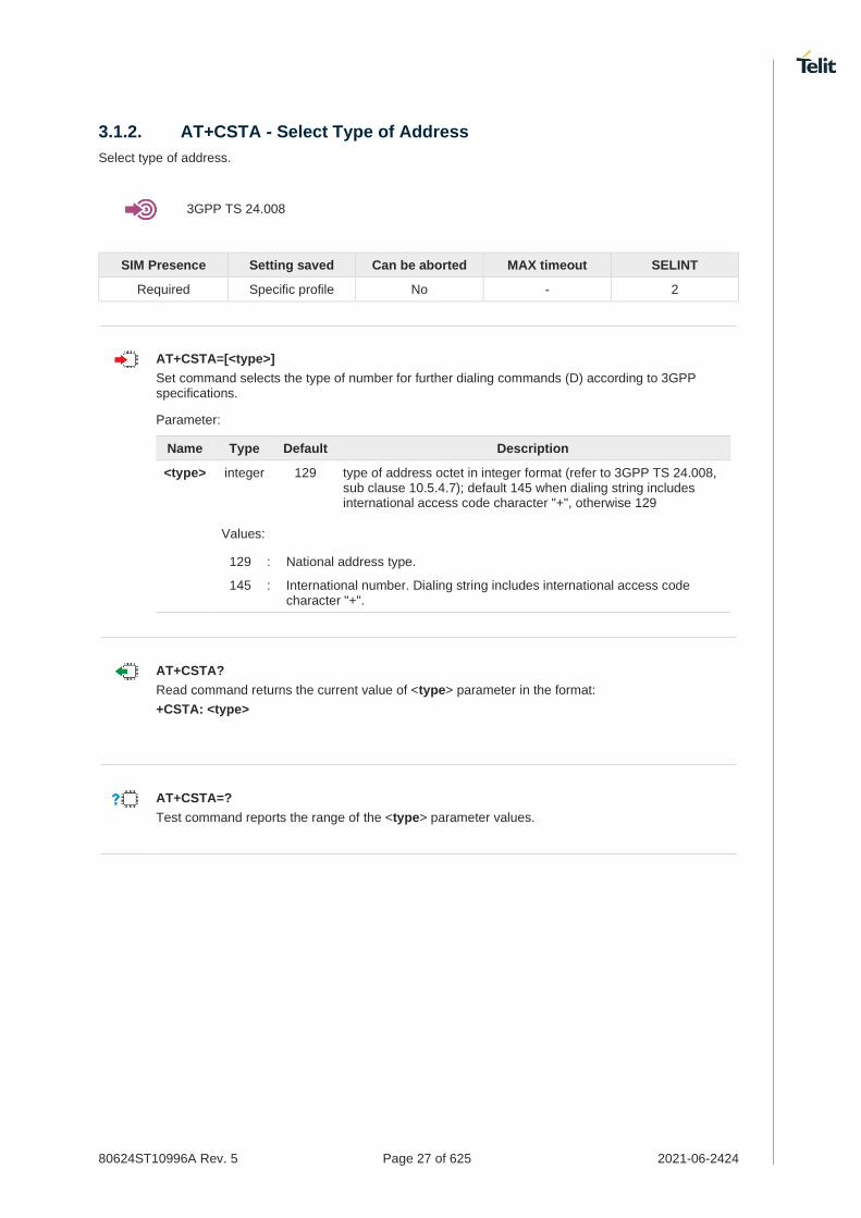
80624ST10996A Rev. 5 Page 27 of 625 2021-06-2424
3.1.2. AT+CSTA - Select Type of Address
Select type of address.
3GPP TS 24.008
SIM Presence Setting saved Can be aborted MAX timeout SELINT
Required Specific profile No - 2
AT+CSTA=[<type>]
Set command selects the type of number for further dialing commands (D) according to 3GPP specifications.
Parameter:
Name Type Default Description
<type> integer 129 type of address octet in integer format (refer to 3GPP TS 24.008, sub clause 10.5.4.7); default 145 when dialing string includes international access code character "+", otherwise 129
Values:
129 : National address type.
145 : International number. Dialing string includes international access code character "+".
AT+CSTA?
Read command returns the current value of <type> parameter in the format:
+CSTA: <type>
AT+CSTA=?
Test command reports the range of the <type> parameter values.

80624ST10996A Rev. 5 Page 28 of 625 2021-06-2424
3.1.3. AT+FCLASS - Select Active Service Class
This command sets the wireless module in specified connection mode (data, voice), hence all the calls done afterwards will be data or voice.
3GPP TS 27.007
SIM Presence Setting saved Can be aborted MAX timeout SELINT
Not required Specific profile No - 2
AT+FCLASS=<n>
Parameter:
Name Type Default Description
<n> integer 0 type of call
Values:
0 : data type
8 : voice type
AT+FCLASS?
Read command returns the current configuration value of the parameter <n>.
AT+FCLASS=?
Test command returns all supported values of the parameters <n>.

80624ST10996A Rev. 5 Page 29 of 625 2021-06-2424
3.1.4. AT#ACALEXT - Extended Automatic Call
This command enables the extended automatic call function.
SIM Presence Setting saved Can be aborted MAX timeout SELINT
Not required Specific profile No - 2
AT#ACALEXT=[<mode>,<index>]
Set command enables/disables the extended automatic call function.
Parameters:
Name Type Default Description
<mode> integer 0 enables/disables the automatic call function to a contact in the selected phonebook
Values:
0 : disable
1 : enable, internal phonebook
2 : enable, "SM" phonebook
3 : enable, "ME" phonebook
<index> integer 0 position in the currently selected phonebook
Value:
0÷max : index
The max value of <index> is given by the test command.
If the extended automatic call function is enabled and &D2 has been issued, the transition OFF/ON of DTR causes an automatic call to the number stored in position <index> in the selected phonebook.
The type of call depends on the last setting of the command +FCLASS.
AT#ACALEXT?
Read command returns the current value of <mode> and <index> in the format: #ACALEXT: <mode>,<index>
AT#ACALEXT=?
Test command returns three ranges of values: the first for parameter <mode>, the second for parameter <index>, when the internal phonebook is chosen, and the third for parameter <index>, when the "SM" phonebook is chosen, the fourth for parameter <index> when "ME" phonebook is chosen.
The range of available positions in a phonebook depends on the selected phonebook.

80624ST10996A Rev. 5 Page 30 of 625 2021-06-2424
3.1.5. AT#ECAM - Extended Call Monitoring
This command enables/disables the call monitoring function in the ME.
SIM Presence Setting saved Can be aborted MAX timeout SELINT
Required Specific profile No - 2
AT#ECAM=[<onoff>]
Set command enables/disables the call monitoring function in the ME.
Parameter:
Name Type Default Description
<onoff> integer 0 Enables/disables the call monitoring function in the ME, that informs the user about call events such as incoming call, connected, hang up etc. using the following unsolicited indication:
#ECAM: <ccid>,<ccstatus>,<calltype>,,,[<number>,<type>]
Values:
0 : disables call monitoring function
1 : enables call monitoring function
Unsolicited fields:
Name Type Description
<ccid> integer call ID number
<ccstatus> integer call status
Values:
0 : idle
1 : calling (MO)
2 : connecting (MO)
3 : active
4 : hold
5 : waiting (MT)
6 : alerting (MT)
7 : busy
8 : retrieved
9 : CNAP (Calling Name Presentation) information (MT)
<calltype> integer call type indicator
Values:
1 : voice
2 : data
<number> string called number (valid only if <ccstatus> is 1)
<type> string type of <number>

80624ST10996A Rev. 5 Page 31 of 625 2021-06-2424
Values:
129 : national number
145 : international number
the unsolicited indication is sent along with usual codes (OK, NO CARRIER, BUSY...)
AT#ECAM?
Read command reports whether the extended call monitoring function is currently enabled or not, in the format:
#ECAM: <onoff>
AT#ECAM=?
Test command returns the list of supported values for <onoff>

80624ST10996A Rev. 5 Page 32 of 625 2021-06-2424
3.1.6. AT+VTS - DTMF Tones Transmission
The command handles the transmission of DTMF tones.
3GPP TS 27.007 TIA IS-101
SIM Presence Setting saved Can be aborted MAX timeout SELINT
Required No No - 2
AT+VTS=<dtmfString>[,<duration>]
Execution command allows the transmission of DTMF tones.
Parameters:
Name Type Default Description
<dtmfString> string - string of <dtmf>s, i.e. ASCII characters in the set (0 9), #,*,(A-D),P;
it allows the user to send a sequence of DTMF tones, each of them with a duration that was defined through +VTD command
<duration> integer 0 duration of a tone in 1/100 sec;
this parameter can be specified only if the length of first parameter is just one ASCII character
Values:
0 : a single DTMF tone will be transmitted for a duration depending on the network, no matter what the current AT+VTD setting is
1÷255 : a single DTMF tone will be transmitted for a time <duration> (in 10 ms multiples), no matter what the current AT+VTD setting is
The character P does not correspond to any DTMF tone, but it is interpreted as a pause of 3 seconds between the preceding and succeeding DTMF string elements.
AT+VTS=?
Test command provides the list of supported <dtmf>s and the list of supported <duration>s in the format:
(list of supported <dtmf>s)[,(list of supported <duration>s)]

80624ST10996A Rev. 5 Page 33 of 625 2021-06-2424
3.1.7. AT+VTD - Tone Duration
This command sets the length of tones transmitted with +VTS command.
3GPP TS 27.007 TIA IS-101
SIM Presence Setting saved Can be aborted MAX timeout SELINT
Required Common profile No - 2
AT+VTD=<n>
Set command refers to an integer <n> that defines the length of tones emitted with +VTS command.
Parameter:
Name Type Default Description
<n> integer 0 duration of a tone
Values:
0 : the duration of every single tone is dependent on the network
1÷255 : duration of every single tone in 1/10 sec
AT+VTD?
Read command reports the current Tone Duration, in the format: <duration>
AT+VTD=?
Test command provides the list of supported <duration>

80624ST10996A Rev. 5 Page 34 of 625 2021-06-2424
3.1.8. AT+CRC - Cellular Result Codes
Set command controls whether the extended format of incoming call indication is used.
3GPP TS 27.007
SIM Presence Setting saved Can be aborted MAX timeout SELINT
Required Specific profile No - 2
AT+CRC=[<mode>]
Parameter:
Name Type Default Description
<mode> integer 0 disables/enables extended format reporting. When enabled, an incoming call is indicated to the TE with unsolicited result code
+CRING: <type>
instead of the normal RING
Values:
0 : disables extended format reporting (factory default)
1 : enables extended format reporting
Unsolicited field:
Name Type Description
<type> string call type
Values:
ASYNC : asynchronous transparent data
SYNC : synchronous transparent data
REL ASYNC : asynchronous non-transparent data
REL SYNC : synchronous non-transparent data
VOICE : normal voice (TS 11)
Entering AT+CRC= returns OK but has no effect.
AT+CRC?
Read command returns current value of the parameter <mode>
AT+CRC=?
Test command returns supported values of the parameter <mode>

80624ST10996A Rev. 5 Page 35 of 625 2021-06-2424
3.1.9. AT#ACAL - Automatic Call
Automatic Call.
SIM Presence Setting saved Can be aborted MAX timeout SELINT
Not required Specific profile No - 2
AT#ACAL=[<mode>]
Set command enables/disables the automatic call function.
Parameter:
Name Type Default Description
<mode> integer 0 disables or enables the automatic call function
Values:
0 : disable the automatic call function
1 : enable the automatic call function
Additional info:
<mode>=1
If the automatic call function is enabled, and &D2 command has been issued, the transition OFF/ON of DTR causes an automatic call to the first number (position 0) stored in the internal phonebook.
Type of call depends on the last issue of command +FCLASS.
See &Z and &N commands respectively to write or read the phone number on/from the internal phonebook of the module.
AT#ACAL?
Read command reports the current automatic call function mode in the format:
#ACAL: <mode>
As a consequence of the introduction of the command #ACALEXT (Extended Automatic Call), it is possible that the read command returns a value supported by #ACALEXT but not supported by #ACAL. Due to this possible situation it is strongly recommended not to use contemporaneously both commands.
Because of the typing in of the #ACALEXT (Extended Automatic Call) command, the #ACAL? read command could return a value supported by #ACALEXT and not by #ACAL set command. Therefore, it is strongly recommended to avoid the use of these two commands at the same time.
AT#ACAL=?
Test command returns the supported range of <mode> parameter values.

80624ST10996A Rev. 5 Page 36 of 625 2021-06-2424
• Assume that #ACALEXT command has been entered. The #ACAL? read command could return the following parameter value.
AT#ACAL? #ACAL: 2 OK

80624ST10996A Rev. 5 Page 37 of 625 2021-06-2424
3.1.10. AT+CVHU - Voice Hung Up Control
This command is used in order to set how to disconnect a voice connection.
SIM Presence Setting saved Can be aborted MAX timeout SELINT
Required Specific profile No - 2
AT+CVHU=[<mode>]
Set command selects whether ATH or "drop DTR" shall cause a voice connection to be disconnected or not.
Parameter:
Name Type Default Description
<mode> integer 2 Selects how to disconnect a voice connection.
Values:
0 : "Drop DTR" ignored but OK result code given. ATH disconnects.
1 : "Drop DTR" and ATH ignored but OK result code given.
2 : "Drop DTR" behavior according to &D setting. ATH disconnects.
OK result code is displayed only when using UART.
AT+CVHU?
Read command reports the current value of the <mode> parameter, in the format:
+CVHU: <mode>
AT+CVHU=?
Test command reports the range of supported values for parameter <mode>.

80624ST10996A Rev. 5 Page 38 of 625 2021-06-2424
3.1.11. AT#UDUB - User Determined User Busy
This command disconnects all active calls setting the "user busy" cause for disconnection.
SIM Presence Setting saved Can be aborted MAX timeout SELINT
Required No No - 2
AT#UDUB
Execution command disconnects all active calls (like H or +CHUP), but setting the "user busy" cause for disconnection (only if we have an incoming call that has not been answered yet, and that we want to reject).
AT#UDUB=?
Test command returns the OK result code

80624ST10996A Rev. 5 Page 39 of 625 2021-06-2424
General Control and Config
3.2.1. AT#DIALMODE - Set Dialing Mode
This command sets dialing modality.
SIM Presence Setting saved Can be aborted MAX timeout SELINT
Not required Auto No - 2
AT#DIALMODE=[<mode>]
Set command sets dialing modality.
Parameter:
Name Type Default Description
<mode> integer 0 sets dialing modality
Values:
0 : voice call only, see Additional info
1 : voice call only, see Additional info
2 : voice call and data call, see Additional info
Additional info:
<mode>=0
Voice call only, OK result code is received as soon as it starts remotely ringing.
<mode>=1
Voice call only, OK result code is received only after the called party answers. Any character typed aborts the call and OK result code is received.
<mode>=2
Voice call and data call, the following custom result codes are received, monitoring step by step the call status:
DIALING (MO in progress) RINGING (remote ring) CONNECTED (remote call accepted) RELEASED (after ATH) DISCONNECTED (remote hang-up).
Any character typed before the CONNECTED message aborts the call.
In case a BUSY tone is received and at the same time ATX0 is enabled ATD will return NO CARRIER instead of DISCONNECTED.
The setting is saved in NVM and available on following reboot.

80624ST10996A Rev. 5 Page 40 of 625 2021-06-2424
AT#DIALMODE?
Read command returns current ATD dialling mode in the format:
#DIALMODE: <mode>
AT#DIALMODE=?
Test command returns the supported range of values for parameter <mode>.

80624ST10996A Rev. 5 Page 41 of 625 2021-06-2424
3.2.2. AT#GETFW - Get firmware status
This command used to read all modem carrier firmware information.
SIM Presence Setting saved Can be aborted MAX timeout SELINT
Not required No No - 2
AT#GETFW
Execution command return all modem firmware information in the following format:
HOST FIRMWARE : <Host Version> SLOT STATUS CARRIER VERSION TMCFG <modem firmware 1 > <modem firmware 2 >
Carrier name has been deprecated(only for backward compatibility)
AT#GETFW=?
Test command returns OK.

80624ST10996A Rev. 5 Page 42 of 625 2021-06-2424
3.2.3. AT#ACTIVEFW - Active firmware
This command used to select active modem firmware.
SIM Presence Setting saved Can be aborted MAX timeout SELINT
Not required Auto No - 2
AT#ACTIVEFW=<op_mode>,<option>
Set command active the selected modem firmware at <slot_idx>.
If the specified modem firmware selected, it return OK result. Power-cycle (reboot) action will be performed, automatically. And a new selected modem firmware loaded at boot time.
Parameters:
Name Type Default Description
<op_mode> integer N/A option mode
Values:
1 : Active specific modem firmware by slot index
2 : Active specific modem firmware by carrier name
3 : Active specific modem firmware by version name
<option> mixed - If <op_mode> is 1:
<option> is decimal number of slot index to active 1 : Active modem firmware at slot 1 2 : Active modem firmware at slot 2
If <op_mode> is 2:
<option> is string value of firmware name to active (ex) "GCF"
If <op_mode> is 3:
<option> is string value of version name to active (ex) "M0H.000000-A002"
If <op_mode> is 2:
Carrier name has been deprecated(only for backward compatibility)
AT#ACTIVEFW?
Read command returns information of the activated modem carrier firmware
AT#ACTIVEFW=?
Test command returns OK

80624ST10996A Rev. 5 Page 43 of 625 2021-06-2424
3.2.4. AT#CLEARFW - Clear firmware
This command used to clear modem firmware from module.
SIM Presence Setting saved Can be aborted MAX timeout SELINT
Not required Auto No - 2
AT#CLEARFW=<op_mode>[,<option>]
Execution command clear modem firmware from module
Parameters:
Name Type Default Description
<op_mode> integer N/A option mode
Values:
0 : clear all modem firmware
1 : clear specific modem firmware by slot index
2 : clear specific modem firmware by firmware name
3 : clear specific modem firmware by version name
<option> mixed - If <op_mode> is 0:
There are no option field for <op_mode> 0
If <op_mode> is 1:
<option> is decimal number of slot index to clear (ex) 2
If <op_mode> is 2:
<option> is string value of firmware name to clear (ex) "firmware name"
If <op_mode> is 3:
<option> is string value of version name to clear (ex) "version name"
Slot 1 is fixed for specific firmware image and cannot be erased by this command
Double Quotation (" ") should be added for "firmware name" and "version name".
If <op_mode> is 2:
Carrier name has been deprecated(only for backward compatibility)
AT#CLEARFW=?
Test command returns OK.

80624ST10996A Rev. 5 Page 44 of 625 2021-06-2424
3.2.5. AT#FIRMWARE - Firmware
This command used to get modem firmware information.
SIM Presence Setting saved Can be aborted MAX timeout SELINT
Not required Auto No - 2
AT#FIRMWARE[=<mfw_idx>]
Set command load the selected modem carrier firmware.
If the specified modem carrier firmware selected, it return OK result. Power-cycle (reboot) action will be performed, automatically. And a new selected modem carrier firmware loaded at boot time.
Parameter:
Name Type Default Description
<mfw_idx> integer - 1 : modem carrier firmware 1 ...
N : modem carrier firmware N
Where N is the maximum index for the modem firmware
Additional info:
Execution command return all firmware information in the following format
HOST FIRMWARE : <Host Version> MODEM FIRMWARE : <The maximum value of N> INDEX STATUS CARRIER VERSION TMCFG LOC <modem carrier firmware 1 > ... <modem carrier firmware N >
#FIRMWARE has been replaced by AT#ACTIVEFW.
Carrier name has been deprecated(only for backward compatibility)
AT#FIRMWARE?
Read command returns the activated modem firmware index
#FIRMWARE: <mfw_idx>
AT#FIRMWARE=?
Test command returns the list of supported carrier firmware index.
#FIRMWARE: (1-N)

80624ST10996A Rev. 5 Page 45 of 625 2021-06-2424
3.2.6. AT#HWREV - Hardware Identification
This command returns the device Hardware revision identification code.
SIM Presence Setting saved Can be aborted MAX timeout SELINT
Not required No No - 2
AT#HWREV
Execution command returns the device Hardware revision identification code without command echo.
AT#HWREV=?
Test command returns the OK result code.

80624ST10996A Rev. 5 Page 46 of 625 2021-06-2424
3.2.7. AT#ICMP - Ping Support
This command enables/disables the ICMP Ping support.
SIM Presence Setting saved Can be aborted MAX timeout SELINT
Required Auto No - 2
AT#ICMP=<mode>
Set command enables/disables the ICMP Ping support.
Parameter:
Name Type Default Description
<mode> integer 0 ICMP mode selection.
Values:
0 : disable ICMP Ping support
1 : enable firewalled ICMP Ping support (Not available)
2 : enable free ICMP Ping support; the module is sending a proper ECHO_REPLY to every IP Address pinging it.
AT#ICMP?
Read command returns whether the ICMP Ping support is currently enabled or not, in the format:
#ICMP: <mode>
AT#ICMP=?
Test command reports the supported range of values for the <mode> parameter.

80624ST10996A Rev. 5 Page 47 of 625 2021-06-2424
3.2.8. AT#B30TXDIS - Set B30 TX disable
This command enable or disable the LTE B30 TX.
SIM Presence Setting saved Can be aborted MAX timeout SELINT
Not required Auto No - 2
AT#B30TXDIS=<mode>
Set command allows the LTE B30 TX enable/disable.
Parameter:
Name Type Default Description
<mode> integer 0 LTE B30 TX enable/disable value.
Values:
0 : B30 TX enable
1 : B30 TX disable
The value set by command operate after power cycle.
AT#B30TXDIS?
Read command reports the currently selected <mode> in the format:
#B30TXDIS: <mode>
AT#B30TXDIS=?
Test command reports the supported range of values.
AT#B30TXDIS?
#B30TXDIS: 0 : Modem support LTE B30 TX.
#B30TXDIS: 1 : Modem don't support LTE B30 TX.

80624ST10996A Rev. 5 Page 48 of 625 2021-06-2424
3.2.9. AT#SELQTMANT - Select QTM Antenna
This command is used to select MMWAVE QTM Antenna configuration.
SIM Presence Setting saved Can be aborted MAX timeout SELINT
Not required Auto No - 2
AT#SELQTMANT=<mode>
Set command is used to select MMWAVE QTM Antenna configuration.
Parameter:
Name Type Default Description
<mode> integer 0 select the QTM configuration. (default : 0)
Values:
0 : Use QTM Antenna #0, #1, #2, #3
1 : Use QTM Antenna #0, #1, #2
2 : Use QTM Antenna #0, #1, #3
3 : Use QTM Antenna #0, #2, #3
4 : Use QTM Antenna #1, #2, #3
5 : Use QTM Antenna #0, #1
6 : Use QTM Antenna #0, #2
7 : Use QTM Antenna #0, #3
8 : Use QTM Antenna #1, #2
9 : Use QTM Antenna #1, #3
10 : Use QTM Antenna #2, #3
Additional info:
Mode\QTM #0 #1 #2 #3
0 O O O O
1 O O O X
2 O O X O
3 O X O O
4 X O O O
5 O O X X
6 O X O X
7 O X X O
8 X O O X
9 X O X O
10 X X O O
If AT#SELQTMANT=1 has been issued, the QTM Antenna #0,#1 and #2 will be automatically set. This means that customer want to use only QTM Antenna #0,#1 and #2 except #3.
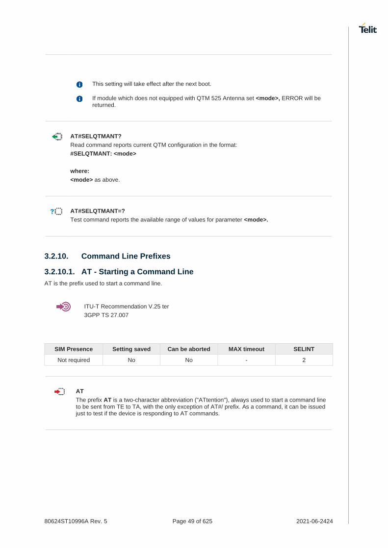
80624ST10996A Rev. 5 Page 49 of 625 2021-06-2424
This setting will take effect after the next boot.
If module which does not equipped with QTM 525 Antenna set <mode>, ERROR will be returned.
AT#SELQTMANT?
Read command reports current QTM configuration in the format:
#SELQTMANT: <mode>
where:
<mode> as above.
AT#SELQTMANT=?
Test command reports the available range of values for parameter <mode>.
3.2.10. Command Line Prefixes
3.2.10.1. AT - Starting a Command Line
AT is the prefix used to start a command line.
ITU-T Recommendation V.25 ter
3GPP TS 27.007
SIM Presence Setting saved Can be aborted MAX timeout SELINT
Not required No No - 2
AT
The prefix AT is a two-character abbreviation ("ATtention"), always used to start a command line to be sent from TE to TA, with the only exception of AT#/ prefix. As a command, it can be issued just to test if the device is responding to AT commands.

80624ST10996A Rev. 5 Page 50 of 625 2021-06-2424
3.2.10.2. A/ - Last Command Automatic Repetition
The command immediately executes the previously issued command or commands.
ITU-T Recommendation V.25 ter
SIM Presence Setting saved Can be aborted MAX timeout SELINT
Not required No No - 2
A/
If the prefix A/ is issued, the device immediately executes once again the body of the preceding command line. No editing is possible, and no termination character is necessary. A command line may be repeated multiple times through this mechanism, if desired.
If A/ is issued before any command line has been executed, the preceding command line is assumed to have been empty (that results in an OK result code).
This command works only at fixed IPR.
The custom prefix AT#/ has been defined: it causes the last command to be executed again too; but it doesn’t need a fixed +IPR.

80624ST10996A Rev. 5 Page 51 of 625 2021-06-2424
3.2.10.3. AT#/ - Repeat Last Command
The command immediately executes the previously issued command or commands.
SIM Presence Setting saved Can be aborted MAX timeout SELINT
Not required No No - 2
AT#/
If AT#/ is issued, the device immediately executes once again the body of the preceding command line. No editing is possible, and no termination character is necessary. A command line may be repeated multiple times through this mechanism, if desired.
If AT#/ is issued before any command line has been executed, the preceding command line is assumed to have been empty (that results in an OK result code).
This command is the same as A/ but does not need a fixed +IPR.

80624ST10996A Rev. 5 Page 52 of 625 2021-06-2424
3.2.11. Generic Modem Control
3.2.11.1. AT#SELINT - Select Interface Style
This command sets the AT command interface style.
SIM Presence Setting saved Can be aborted MAX timeout SELINT
Not required Auto No - 2
AT#SELINT=[<v>]
Set command sets the AT command interface style depending on parameter.
Parameter:
Name Type Default Description
<v> integer 2 AT command interface style
Value:
2 : standard AT parser
AT#SELINT?
Read command reports the current interface style in the format:
#SELINT: <v>
AT#SELINT=?
Test command reports the available range of values for parameter <v>.

80624ST10996A Rev. 5 Page 53 of 625 2021-06-2424
3.2.11.2. AT&F - Set to Factory-Defined Configuration
Set configuration parameters to default values.
ITU-T Recommendation V.25 ter
SIM Presence Setting saved Can be aborted MAX timeout SELINT
Not required No No - 2
AT&F[<value>]
Execution command sets the configuration parameters to default values specified by manufacturer; it takes in consideration hardware configuration switches and other manufacturer-defined criteria.
Parameter:
Name Type Default Description
<value> integer 0 parameters to reset
Values:
0 : only the factory profile base section parameters are considered
1 : either the factory profile base section and the extended section are considered (full factory profile)
If parameter <value> is omitted, the command has the same behavior as AT&F0.

80624ST10996A Rev. 5 Page 54 of 625 2021-06-2424
3.2.11.3. ATZ - Soft Reset
Soft Reset
ITU-T Recommendation V.25 ter
SIM Presence Setting saved Can be aborted MAX timeout SELINT
Not required No No - 2
ATZ[<n>]
Execution command loads the base section of the specified user profile and the extended section of the default factory profile
Parameter:
Name Type Default Description
<n> integer N/A user profile number
Value:
0,1 : user profile number
If parameter <n> is omitted, the command has the same behavior as ATZ0
Any active call is terminated.

80624ST10996A Rev. 5 Page 55 of 625 2021-06-2424
3.2.11.4. AT&Y - Default Reset Basic Profile Designation
Define the basic profile is loaded on startup.
SIM Presence Setting saved Can be aborted MAX timeout SELINT
Not required Specific profile No - 2
AT&Y[<n>]
Execution command defines the basic profile that will be loaded on startup.
Parameter:
Name Type Default Description
<n> integer 0 basic profile that will be loaded on startup.
Value:
0,1 : profile number: the wireless module can store 2 complete configurations (see command &W).
Differently from command Z<n>, which loads just once the desired profile, the one chosen through command &Y will be loaded on every startup.
If parameter is omitted the command has the same behavior as AT&Y0.

80624ST10996A Rev. 5 Page 56 of 625 2021-06-2424
3.2.11.5. AT&P - Default Reset Full Profile Designation
Define which full profile is loaded at startup.
SIM Presence Setting saved Can be aborted MAX timeout SELINT
Not required Auto No - 2
AT&P[<n>]
Execution command defines which full profile will be loaded at startup.
Parameter:
Name Type Default Description
<n> integer 0 full profile will be loaded on startup.
Value:
0,1 : profile number: the wireless module can store 2 full configurations (see command &W).
Differently from command Z<n>, which loads just once the desired profile, the one chosen through command &P will be loaded at every startup.
If parameter is omitted, the command has the same behavior as AT&P0

80624ST10996A Rev. 5 Page 57 of 625 2021-06-2424
3.2.11.6. AT&W - Store Current Configuration
Stores the complete configuration of the device.
SIM Presence Setting saved Can be aborted MAX timeout SELINT
Not required No No - 2
AT&W[<n>]
Execution command stores on profile <n> the complete configuration of the device.
Parameter:
Name Type Default Description
<n> integer 0 profile identifier
Value:
0,1 : profile identifiers
If parameter is omitted, the command has the same behavior of AT&W0.

80624ST10996A Rev. 5 Page 58 of 625 2021-06-2424
3.2.11.7. AT&V - Display some Configuration and Profile
The command displays some of the basic modem configuration settings and parameters
SIM Presence Setting saved Can be aborted MAX timeout SELINT
Not required No No - 2
AT&V
Execution command returns some of the basic modem configuration settings and parameters, one for each row, in the format: setting/parameter : value
The row of information about CTS (C106) OPTIONS is in the output of &V for compatibility reasons and represents only a dummy value.
Example of returned values.
• AT&V
COMMAND ECHO : E1=YES
RESULT MESSAGES : Q0=YES
VERBOSE MESSAGES : V1=YES
EXTENDED MESSAGES : X1=YES
LINE SPEED : F0=autodetect
CONSTANT DTE SPEED : YES
FLOW CONTROL OPTIONS : &K3=HW bidirect.
ERROR CORRECTION MODE : RLP
CTS (C106) OPTIONS : &B2=OFF while disc.
DSR (C107) OPTIONS : &S3=PHONE ready->ON
DTR (C108) OPTIONS : &D0=ignored
DCD (C109) OPTIONS : &C1=follows carrier
RI (C125) OPTIONS : \R1=OFF dur. off-hk
C108/1 OPERATION : &D0=NO
POWER SAVING ON DTR : +CFUN:1=NO
DEFAULT PROFILE : &Y0=user profile 1
OK

80624ST10996A Rev. 5 Page 59 of 625 2021-06-2424
3.2.11.8. AT\V - Single Line Connect Message
This command sets single line connect message.
SIM Presence Setting saved Can be aborted MAX timeout SELINT
Not required No No - 2
AT\V[<n>]
Execution command sets single line connect message.
Parameter:
Name Type Default Description
<n> integer 0 set single line connect message
Values:
0 : set OFF
1 : set ON
if parameter is omitted, the command has the same behaviour of AT\V0.

80624ST10996A Rev. 5 Page 60 of 625 2021-06-2424
3.2.11.9. AT+GCI - Country of Installation
Set command allows to select the installation country code according to ITU-T35 Annex A.
ITU-T Recommendation V.25 ter
SIM Presence Setting saved Can be aborted MAX timeout SELINT
Not required No No - 2
AT+GCI=<code>
Parameter:
Name Type Default Description
<code> integer 59 installation country code
Value:
59 : it currently supports only the Italy country code
AT+GCI?
Read command reports the currently selected country code.
AT+GCI=?
Test command reports the supported values of parameter <code>.

80624ST10996A Rev. 5 Page 61 of 625 2021-06-2424
3.2.11.10. AT%L - Line Signal Level
It has no effect and is included only for backward compatibility with landline modems.
SIM Presence Setting saved Can be aborted MAX timeout SELINT
Not required No No - 2

80624ST10996A Rev. 5 Page 62 of 625 2021-06-2424
3.2.11.11. AT%Q - Line Quality
It has no effect and is included only for backward compatibility with landline modems
SIM Presence Setting saved Can be aborted MAX timeout SELINT
Not required No No - 2

80624ST10996A Rev. 5 Page 63 of 625 2021-06-2424
3.2.11.12. ATL - Speaker Loudness
It has no effect and is included only for backward compatibility with landline modems.
SIM Presence Setting saved Can be aborted MAX timeout SELINT
Not required No No - 2
ATL<n>
Set command has no effect and is included only for backward compatibility with landline modems.
Parameter:
Name Type Default Description
<n> integer - This parameter has no effect
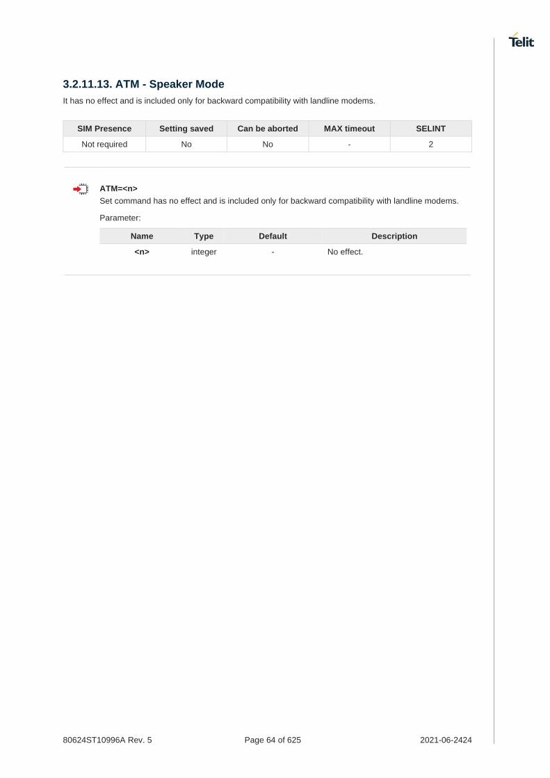
80624ST10996A Rev. 5 Page 64 of 625 2021-06-2424
3.2.11.13. ATM - Speaker Mode
It has no effect and is included only for backward compatibility with landline modems.
SIM Presence Setting saved Can be aborted MAX timeout SELINT
Not required No No - 2
ATM=<n>
Set command has no effect and is included only for backward compatibility with landline modems.
Parameter:
Name Type Default Description
<n> integer - No effect.

80624ST10996A Rev. 5 Page 65 of 625 2021-06-2424
3.2.11.14. AT+GCAP - Capabilities List
This command returns the equipment supported command set list.
ITU-T Recommendation V.25 ter
SIM Presence Setting saved Can be aborted MAX timeout SELINT
Not required No No - 2
AT+GCAP
Execution command returns the equipment supported command set list: +GCAP: +CGSM
Additional info:
Supported Command Set:
+CGSM: GSM ETSI command set
AT+GCAP=?
Test command returns OK result code.

80624ST10996A Rev. 5 Page 66 of 625 2021-06-2424
3.2.11.15. AT+GMI - Manufacturer Identification
This command returns the manufacturer identification.
ITU-T Recommendation V.25 ter
SIM Presence Setting saved Can be aborted MAX timeout SELINT
Not required No No - 2
AT+GMI
Execution command returns the manufacturer identification followed by an <OK> at newline.
AT+GMI=?
Test command returns OK result code.

80624ST10996A Rev. 5 Page 67 of 625 2021-06-2424
3.2.11.16. AT+GMM - Model Identification
The command returns the model identification.
ITU-T Recommendation V.25 ter
SIM Presence Setting saved Can be aborted MAX timeout SELINT
Not required No No - 2
AT+GMM
The execution command returns the model identification followed by an <OK> at newline.
AT+GMM=?
Test command returns OK result code.

80624ST10996A Rev. 5 Page 68 of 625 2021-06-2424
3.2.11.17. AT+GMR - Revision Identification
The command returns the software revision identification.
ITU-T Recommendation V.25 ter
SIM Presence Setting saved Can be aborted MAX timeout SELINT
Not required No No - 2
AT+GMR
Execution command returns the software revision identification followed by an <OK> at newline.
AT+GMR=?
Test command returns OK result code.

80624ST10996A Rev. 5 Page 69 of 625 2021-06-2424
3.2.11.18. AT+CEER - Extended Error Report
Reports extended error related to the last unsuccessful call.
3GPP TS 27.007
SIM Presence Setting saved Can be aborted MAX timeout SELINT
Not required No No - 2
AT+CEER
Execution command returns one or more lines of information text <report> offering the TA user an extended error report, in the format:
+CEER: <report>
This report regards some error condition that may occur:
1. the failure in the last unsuccessful call setup (originating or answering) 2. the last call release
If no error condition has occurred since power up, then "Normal, unspecified" condition is reported
AT+CEER=?
Test command returns OK result code.

80624ST10996A Rev. 5 Page 70 of 625 2021-06-2424
3.2.11.19. AT+GSN - Serial Number
The command reports the device board serial number.
ITU-T Recommendation V.25 ter
SIM Presence Setting saved Can be aborted MAX timeout SELINT
Not required No No - 2
AT+GSN
Execution command returns the device board serial number.
The number returned is not the IMSI, but it is the board number.
AT+GSN=?
Test command returns OK result code.

80624ST10996A Rev. 5 Page 71 of 625 2021-06-2424
3.2.11.20. AT+CGMI - Request Manufacturer Identification
The command returns device manufacturer identification code.
3GPP TS 27.007
SIM Presence Setting saved Can be aborted MAX timeout SELINT
Not required No No - 2
AT+CGMI
Execution command returns the device manufacturer identification code followed by an OK at newline.
AT+CGMI=?
Test command returns OK result code.

80624ST10996A Rev. 5 Page 72 of 625 2021-06-2424
3.2.11.21. AT+CGMM - Request Model Identification
This command returns the device model identification.
3GPP TS 27.007
SIM Presence Setting saved Can be aborted MAX timeout SELINT
Not required Auto No - 2
AT+CGMM
Execution command returns the device model identification code followed by an OK at newline.
AT+CGMM=?
Test command returns OK result code.

80624ST10996A Rev. 5 Page 73 of 625 2021-06-2424
3.2.11.22. AT+CGMR - Request Revision Identification
The command returns device software revision number.
3GPP TS 27.007
SIM Presence Setting saved Can be aborted MAX timeout SELINT
Not required No No - 2
AT+CGMR
Execution command returns device software revision number followed by an OK at newline.
AT+CGMR=?
Test command returns OK result code.

80624ST10996A Rev. 5 Page 74 of 625 2021-06-2424
3.2.11.23. AT+CGSN - Request Product Serial Number Identification
This command allows to retrieve the product serial number in form of IMEI of the mobile.
3GPP TS 27.007
SIM Presence Setting saved Can be aborted MAX timeout SELINT
Not required No No - 2
AT+CGSN
Execution command returns the product serial number, identified as the IMEI of the mobile.
AT+CGSN=?
Test command returns OK result code.

80624ST10996A Rev. 5 Page 75 of 625 2021-06-2424
3.2.11.24. AT#CGMI - Request Manufacturer Identification
The command returns device manufacturer identification code.
SIM Presence Setting saved Can be aborted MAX timeout SELINT
Not required No No - 2
AT#CGMI
Execution command returns the device manufacturer identification code, with command echo.
The response is as follows
#CGMI: <code>
OK
AT#CGMI=?
Test command returns OK result code.

80624ST10996A Rev. 5 Page 76 of 625 2021-06-2424
3.2.11.25. AT#CGMR - Request Revision Identification
The command returns device software revision number.
SIM Presence Setting saved Can be aborted MAX timeout SELINT
Not required No No - 2
AT#CGMR
Execution command returns device software revision number, with command echo.
The response is as follows
#CGMR: <num>
OK
AT#CGMR=?
Test command returns OK result code.

80624ST10996A Rev. 5 Page 77 of 625 2021-06-2424
3.2.11.26. AT#CGSN - Product Serial Number Identification
This command returns the product serial number in form of IMEI of the mobile.
SIM Presence Setting saved Can be aborted MAX timeout SELINT
Not required No No - 2
AT#CGSN
Execution command returns the product serial number in form of IMEI of the mobile, with command echo.
The response is as follows
#CGSN: <sn>
OK
AT#CGSN=?
The test command returns the OK result code.

80624ST10996A Rev. 5 Page 78 of 625 2021-06-2424
3.2.11.27. AT#CGMF - Request Product Code
Execution command returns the device product parameter code
SIM Presence Setting saved Can be aborted MAX timeout SELINT
Not required No No - 2
AT#CGMF
The command returns the following message:
AT#CGMF <product parameter version> OK
AT#CGMF=?
Test command returns OK result code.

80624ST10996A Rev. 5 Page 79 of 625 2021-06-2424
3.2.11.28. AT#SWPKGV - Request Software Package Version
This command allows to retrieve the software package version.
SIM Presence Setting saved Can be aborted MAX timeout SELINT
Not required No No - 2
AT#SWPKGV
Execution command returns the software package version without #SWPKGV: command echo. The response is as follows:
AT#SWPKGV <Telit Software Package Version>-<Production Parameters Version> <Modem FW Version> <Production Parameters Version> <Application FW Version> OK
AT#SWPKGV=?
Test command returns OK result code.
AT#SWPKGV
38.02.000-B006-P0H.000400 M0H.020000-B014 P0H.000400 A0H.000200-B006
OK

80624ST10996A Rev. 5 Page 80 of 625 2021-06-2424
3.2.11.29. AT+CPAS - Phone Activity Status
Execution command reports the device status in the form shown in Additional info section.
3GPP TS 27.007
SIM Presence Setting saved Can be aborted MAX timeout SELINT
Not required No No - 2
AT+CPAS
Additional info:
Message format returned by the execution command:
+CPAS: <pas>
Name Type Default Description
<pas> integer 0 phone activity status.
Values:
0 : ready (device allows commands from TA/TE)
1 : unavailable (device does not allow commands from TA/TE)
2 : unknown (device is not guaranteed to respond to instructions)
3 : ringing (device is ready for commands from TA/TE, but the ringer is active)
4 : call in progress (device is ready for commands from TA/TE, but a call is in progress)
'1' and '2' at <pas> is not supported.
In the LTE registration state, CPAS: 4 (call in progress) is displayed.
AT+CPAS=?
Test command reports the supported range of values for <pas>.
Although +CPAS is an execution command, 3GPP TS 27.007 requires the Test command to be defined.

80624ST10996A Rev. 5 Page 81 of 625 2021-06-2424
3.2.11.30. AT+CFUN - Set Phone Functionality
This command selects the level of functionality in the ME.
3GPP TS 27.007
SIM Presence Setting saved Can be aborted MAX timeout SELINT
Not required Specific profile No - 2
AT+CFUN=[<fun>[,<rst>]]
Set command selects the level of functionality in the ME.
Parameters:
Name Type Default Description
<fun> integer 1 Power saving function mode.
Values:
0 : minimum functionality (low power mode)
1 : mobile full functionality
4 : disable both TX and RX
6 : reset
7 : offline mode
<rst> integer 0 reset flag
Values:
0 : do not reset the ME before setting it to <fun> functionality level
1 : reset the ME before setting it to <fun> full functionality
Issuing AT+CFUN=0[,0] causes the module to perform either a network deregistration and a SIM deactivation.
In the <fun>=7(offline), modem can only be changed to <fun>=6(reset)
AT+CFUN?
Read command reports the current setting of <fun>.
AT+CFUN=?
Test command returns the list of supported values for <fun> and <rst>.

80624ST10996A Rev. 5 Page 82 of 625 2021-06-2424
3.2.11.31. AT+CIND - Indicator Control
This command is used to control the registration state of modem indicators.
3GPP TS 27.007
SIM Presence Setting saved Can be aborted MAX timeout SELINT
Not required Specific profile No - 2
AT+CIND=[<state>[,<state[,...]]]
Set command is used to control the registration state of ME indicators, in order to automatically send the +CIEV URC, whenever the value of the associated indicator changes. The supported indicators (<descr>) and their order appear from test command AT+CIND=?
Parameter:
Name Type Default Description
<state> integer 1 registration state
Values:
0 : the indicator is deregistered; there's no unsolicited result code (+CIEV URC) automatically sent by the modem to the application, whenever the value of the associated indicator changes; the value can be directly queried with +CIND?
1 : the indicator is registered: an unsolicited result code (+CIEV URC) is automatically sent by the modem to the application, whenever the value of the associated indicator changes; it is still possible to query the value through AT+CIND?
When the modem is switched on all of the indicators are in registered mode.
See also command +CMER
AT+CIND?
Read command returns the current value of ME indicators, in the format:
+CIND: <ind>[,<ind>[,...]]
Additional info:
Read command response parameter
Name Type Default Description
<ind> integer - indicator value, which shall be in range of corresponding <descr>. See test command AT+CIND=?

80624ST10996A Rev. 5 Page 83 of 625 2021-06-2424
The order of the values <ind>s is the one returned by test command AT+CIND=?
AT+CIND=?
Test command returns pairs, where string value <descr> is a description of the indicator and compound value is the supported values for the indicator, in the format:
+CIND: ((<descr>, (list of supported <ind>s))[,(<descr>, (list of supported <ind>s))[,...]])
Additional info:
Test command response parameters
Name Type Default Description
<descr> string N/A indicators names, maximum 16 chars long
Values:
"battchg" : battery charge level; indicator <ind> in the range 0...5, or 99 (not measurable)
"signal" : signal quality; indicator <ind> in the range 0...7, or 99 (not measurable); same as bit error rate (<ber>) in +CSQ command
"sounder" : sounder activity; indicator <ind> is 0 (no sound activity) or 1 (sound activity)
"service" : service availability; indicator <ind> is 0 (not registered to any network) or 1 (registered)
"message" : message received; indicator <ind> is 0 (no unread SMS in memory "SM") or 1 (unread SMS in memory "SM")
"call" : call in progress; indicator <ind> is 0 (no calls in progress) or 1 (at least a call has been established)
"roam" : roaming; indicator <ind> is 0 (registered to home network, or not registered) or 1 (registered to other network))
"smsfull" : SMS memory status; indicator <ind> is 0 (memory locations available) or 1 (an SMS storage in the modem is full)
"rssi" : received signal strength level; indicator <ind> values are 0 (signal strength under -112dBm), from 1 to 4 (signal strength from -97 to -66 dBm, in 15 dBm steps), 5 (signal strength greater than -51 dBm), or 99 (not measurable)

80624ST10996A Rev. 5 Page 84 of 625 2021-06-2424
Next command causes all the indicators to be registered
AT+CIND=1,1,1,1,1,1,1,1,1
Next command causes all the indicators to be de-registered
AT+CIND=0,0,0,0,0,0,0,0,0
Next command to query the current value of all indicators
AT+CIND?
CIND: 4,0,1,0,0,0,0,0,2
OK

80624ST10996A Rev. 5 Page 85 of 625 2021-06-2424
3.2.11.32. AT+CMER - Mobile Equipment Event Reporting
This command configures sending of unsolicited result codes from TA to TE.
3GPP TS 27.007
SIM Presence Setting saved Can be aborted MAX timeout SELINT
Not required Specific profile No - 2
AT+CMER=[<mode>[,<keyp>[,<disp>[,<ind>[,<bfr>]]]]]
Set command enables/disables sending of unsolicited result codes from TA to TE in the case of indicator state changes.
Parameters:
Name Type Default Description
<mode> integer 0 controls the processing of unsolicited result codes
Values:
0 : buffer +CIEV Unsolicited Result Codes
1 : discard +CIEV Unsolicited Result Codes when TA-TE link is reserved (e.g. on-line data mode); otherwise forward them directly to the TE
2 : buffer +CIEV Unsolicited Result Codes in the TA when TA-TE link is reserved (e.g. on-line data mode) and flush them to the TE after reservation; otherwise forward them directly to the TE
3 : forward +CIEV Unsolicited Result Codes directly to the TE; when TA is in on-line data mode each +CIEV URC is stored in a buffer; once the ME goes into command mode (after +++ was entered), all URCs stored in the buffer will be output
<keyp> integer 0 keypad event reporting
Value:
0 : No keypad event reporting
<disp> integer 0 display event reporting
Value:
0 : no display event reporting
<ind> integer 0 indicator event reporting
Values:
0 : no indicator event reporting
2 : indicator event reporting
<bfr> integer 0 TA buffer clearing
Values:
0 : TA buffer of unsolicited result codes is cleared when <mode> 1..3 is entered

80624ST10996A Rev. 5 Page 86 of 625 2021-06-2424
1 : TA buffer of unsolicited result codes is flushed to the TE when <mode> 1...3 is entered (OK response shall be given before flushing the codes)
Sending of URCs in the case of key pressings or display changes are currently not implemented.
After +CMER has been switched on with e.g. AT+CMER=2,0,0,2 command (i.e. <bfr> is 0), URCs for all registered indicators will be issued only first time, if previous <mode> was 0, for backward compatibility. Values shown by the indicators will be current indicators values, not buffered ones. Subsequent +CMER commands with <mode> different from 0 and <bfr> equal to 0 will not flush the codes, even if <mode> was set again to 0 before. To flush the codes, <bfr> must be set to 1.
Although it is possible to issue the command when SIM PIN is pending, it will answer ERROR if "message" or "smsfull" indicators are enabled in +CIND, because with pending PIN it is not possible to give a correct indication about SMS status. To issue the command when SIM PIN is pending you have to disable "message" and "smsfull" indicators in +CIND first.
AT+CMER?
Read command returns the current setting of parameters, in the format: +CMER: <mode>,<keyp>,<disp>,<ind>,<bfr>
AT+CMER=?
Test command returns the range of supported values for parameters <mode>, <keyp>, <disp>, <ind>, <bfr>, in the format: +CMER: (list of supported <mode>s),(list of supported <keyp>s), (list of supported <disp>s),(list of supported <ind>s),(list of supported <bfr>s)

80624ST10996A Rev. 5 Page 87 of 625 2021-06-2424
3.2.11.33. AT+CACM - Accumulated Call Meter
This command resets the Advice of Charge related Accumulated Call Meter (ACM) value in SIM card or in the active application in the UICC.
3GPP TS 27.007
SIM Presence Setting saved Can be aborted MAX timeout SELINT
Required Auto No - 2
AT+CACM=[<pwd>]
Set command resets the Advice of Charge related accumulated call meter (ACM) value in SIM card or in the active application in the UICC. ACM contains the total number of home units for both the current and preceding calls. SIM PIN2 is usually required to reset the value.
Parameter:
Name Type Default Description
<pwd> string - SIM PIN2
AT+CACM?
Read command returns the current value of ACM in the format:
+CACM: <acm>
Additional info:
Response parameter
Name Type Default Description
<acm> string - accumulated call meter value; three bytes of the ACM value in hexadecimal format (e.g. "00001E" indicates decimal value 30)
The value <acm> is in home units; price per unit and currency are defined with command +CPUC.
AT+CACM=?
Test command returns the OK result code.

80624ST10996A Rev. 5 Page 88 of 625 2021-06-2424
3.2.11.34. AT+CAMM - Accumulated Call Meter Maximum
This command sets the Advice of Charge related to accumulated call meter maximum (ACMmax) value stored in SIM.
3GPP TS 27.007
SIM Presence Setting saved Can be aborted MAX timeout SELINT
Required Other No - 2
AT+CAMM=<acmmax>[,<pwd>]
Set command sets the Advice of Charge related accumulated call meter maximum value (ACMmax) stored in SIM. ACMmax contains the maximum number of home units allowed to be consumed by the subscriber. When ACM (refer +CACM) reaches ACMmax calls are prohibited. SIM PIN2 is usually required to set the value.
Parameters:
Name Type Default Description
<acmmax> string - accumulated call meter maximum value
<pwd> string - SIM PIN2
Setting <acmmax> to 0 disables the feature.
AT+CAMM?
Read command returns the current value of ACMmax in the format:
+CAMM: <acmmax>
AT+CAMM=?
Test command returns the OK result code.
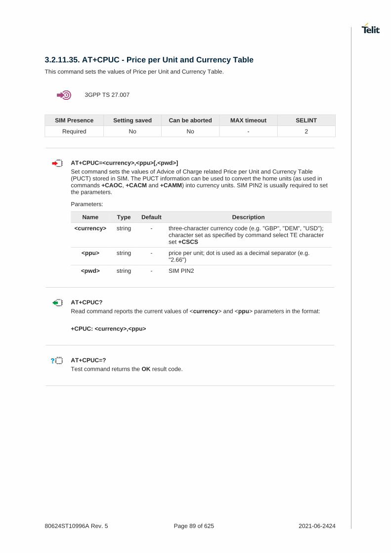
80624ST10996A Rev. 5 Page 89 of 625 2021-06-2424
3.2.11.35. AT+CPUC - Price per Unit and Currency Table
This command sets the values of Price per Unit and Currency Table.
3GPP TS 27.007
SIM Presence Setting saved Can be aborted MAX timeout SELINT
Required No No - 2
AT+CPUC=<currency>,<ppu>[,<pwd>]
Set command sets the values of Advice of Charge related Price per Unit and Currency Table (PUCT) stored in SIM. The PUCT information can be used to convert the home units (as used in commands +CAOC, +CACM and +CAMM) into currency units. SIM PIN2 is usually required to set the parameters.
Parameters:
Name Type Default Description
<currency> string - three-character currency code (e.g. "GBP", "DEM", "USD"); character set as specified by command select TE character set +CSCS
<ppu> string - price per unit; dot is used as a decimal separator (e.g. "2.66")
<pwd> string - SIM PIN2
AT+CPUC?
Read command reports the current values of <currency> and <ppu> parameters in the format:
+CPUC: <currency>,<ppu>
AT+CPUC=?
Test command returns the OK result code.
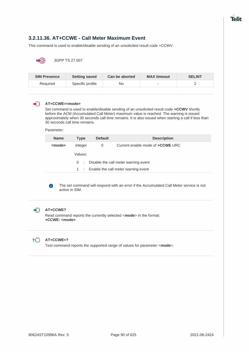
80624ST10996A Rev. 5 Page 90 of 625 2021-06-2424
3.2.11.36. AT+CCWE - Call Meter Maximum Event
This command is used to enable/disable sending of an unsolicited result code +CCWV.
3GPP TS 27.007
SIM Presence Setting saved Can be aborted MAX timeout SELINT
Required Specific profile No - 2
AT+CCWE=<mode>
Set command is used to enable/disable sending of an unsolicited result code +CCWV shortly before the ACM (Accumulated Call Meter) maximum value is reached. The warning is issued approximately when 30 seconds call time remains. It is also issued when starting a call if less than 30 seconds call time remains.
Parameter:
Name Type Default Description
<mode> integer 0 Current enable mode of +CCWE URC
Values:
0 : Disable the call meter warning event
1 : Enable the call meter warning event
The set command will respond with an error if the Accumulated Call Meter service is not active in SIM.
AT+CCWE?
Read command reports the currently selected <mode> in the format: +CCWE: <mode>
AT+CCWE=?
Test command reports the supported range of values for parameter <mode>.

80624ST10996A Rev. 5 Page 91 of 625 2021-06-2424
3.2.11.37. AT+CSVM - Set Voice Mail Number
Command to set voice mail server number.
SIM Presence Setting saved Can be aborted MAX timeout SELINT
Required Specific profile No - 2
AT+CSVM=<mode>[,<number>[,<type>]]
Set command is dummy. It only checks for parameters values validity; it does not send any actual write request to SIM to update voice mail number, nor sends any request to network to enable/disable voice mail.
Parameters:
Name Type Default Description
<mode> integer 1 enable/disable voice mail number
Values:
0 : disable the voice mail number
1 : enable the voice mail number
<number> string - string type phone number of format specified by <type>
<type> integer 129 type of address octet in integer format
Values:
129 : unknown type of number and ISDN/Telephony numbering plan
145 : international type of number and ISDN/Telephony numbering plan (contains the character "+")
AT+CSVM?
Read command returns the currently selected voice mail number and the status (i.e. enabled/disabled) in the format
+CSVM:<mode>,<number>,<type>
AT+CSVM=?
Test command reports the range for the parameters <mode> and <type>.

80624ST10996A Rev. 5 Page 92 of 625 2021-06-2424
3.2.11.38. AT+CLAC - Available AT Commands
This command shows the available AT commands list.
3GPP TS 27.007
SIM Presence Setting saved Can be aborted MAX timeout SELINT
Required No No - 2
AT+CLAC
The execution command causes the ME to return one or more lines reporting the AT commands that are available to the user. The format is:
<ATcmd1>[<CR><LF><ATcmd2>[...]]
<ATcmdn> is the AT command.
AT+CLAC=?
Test command returns the OK result code.

80624ST10996A Rev. 5 Page 93 of 625 2021-06-2424
3.2.11.39. AT#LANG - Select Language
Set command selects the currently used language for displaying different messages.
SIM Presence Setting saved Can be aborted MAX timeout SELINT
Not required No No - 2
AT#LANG=<lan>
Parameter:
Name Type Default Description
<lan> string en selected language
Values:
en : English
it : Italian
de : German
AT#LANG?
Read command reports the currently selected <lan> in the format:
#LANG: <lan>
AT#LANG=?
Test command reports the supported range of values for parameter <lan>.

80624ST10996A Rev. 5 Page 94 of 625 2021-06-2424
3.2.11.40. AT+CMEE - Report Mobile Equipment Error
The command enables the use of result code.
3GPP TS 27.007
SIM Presence Setting saved Can be aborted MAX timeout SELINT
Not required Specific profile No - 2
AT+CMEE=[<n>]
Set command disables/enables the use of result code:
+CME ERROR: <err>
as an indication of an error relating to the +Cxxx command issued.
When enabled, device related errors cause the +CME ERROR: <err> final result code instead of the default ERROR final result code. ERROR is returned normally when the error message is related to syntax, invalid parameters or DTE functionality.
Parameter:
Name Type Default Description
<n> integer 0 enable flag
Values:
0 : disable
1 : enable and use numeric<err> values
2 : enable and use verbose <err> values
The detailed description of <err> is available in section "ME Error Result Code - +CME ERROR: <err>".
+CMEE has no effect on the final result code +CMS.
AT+CMEE?
Read command returns the current value of parameter <n> in the format: +CMEE: <n>
AT+CMEE=?
Test command returns the supported values of parameter <n>.

80624ST10996A Rev. 5 Page 95 of 625 2021-06-2424
3.2.11.41. AT#VCDISABLE - Disable Voice Call
The command used to disable the Voice Call.
SIM Presence Setting saved Can be aborted MAX timeout SELINT
Not required Auto No - 2
AT#VCDISABLE=<type>
Set command set the incoming voice call function disable.
Parameter:
Name Type Default Description
<type> integer N/A Disable type
Values:
0 : Incoming call allowed.
1 : Ignore paging.
2 : Reject the voice call with cause code 88.
The setting is saved in NVM, will affect after rebooting.
When set <type> by 1, modem may not be able to distinguish clearly whether paging is for Voice Call at the time of receiving the Paging Message.
Usually, default value is 0 in models support the voice function.
AT#VCDISABLE?
Read command read a current value.
#VCDISABLE: <type>
AT#VCDISABLE=?
Test command reports the supported range.

80624ST10996A Rev. 5 Page 96 of 625 2021-06-2424
3.2.11.42. AT#PERSISTAPN - Preserve APN Profile during firmware upgrade
APN Persistence
SIM Presence Setting saved Can be aborted MAX timeout SELINT
Required Auto No - 2
AT#PERSISTAPN=<mode>
Set command determines whether to retain the APN profile. When a firmware download event occurs, the APN profile is backed up. If the backup APN profile exists when you download the firmware, restore the APN profile.
Parameter:
Name Type Default Description
<mode> integer 0 mode for operation
Values:
0 : initialized with the APN profile specified by the network operator
1 : backup and restore the current APN profile
When this feature is set to enable, the set value is retained even if the changed firmware is changed.
It applies not only to downloading the firmware but also when changing the active carrier with the AT#FIRMWARE command.
AT#PERSISTAPN?
Read command returns "OK" string along with last accepted mode in the format:
#PERSISTAPN: <mode>
AT#PERSISTAPN=?
Test command reports the supported range of values.

80624ST10996A Rev. 5 Page 97 of 625 2021-06-2424
3.2.11.43. AT+CSCS - Select TE Character Set
The command purpose is to set different character sets that are used by the device.
3GPP TS 27.007
SIM Presence Setting saved Can be aborted MAX timeout SELINT
Required Specific profile No - 2
AT+CSCS=[<chset>]
Set command sets the current character set used by the device.
Parameter:
Name Type Default Description
<chset> string IRA character set to be used by the device.
Values:
GSM : GSM default alphabet (3GPP TS 23.038).
IRA : international reference alphabet (ITU-T T.50).
8859-1 : ISO 8859 Latin 1 character set.
PCCP437 : PC character set Code Page 437.
UCS2 : 16-bit universal multiple-octet coded character set (ISO/IEC10646).
AT+CSCS?
Read command returns the current value of the active character set.
AT+CSCS=?
Test command returns the supported values for parameter <chset>.

80624ST10996A Rev. 5 Page 98 of 625 2021-06-2424
3.2.11.44. AT+PACSP - Network Selection Menu Availability
This command returns the current value of the <mode> parameter which is PLMN mode bit in the CSP file with SIM.
SIM Presence Setting saved Can be aborted MAX timeout SELINT
Not required No No - 2
AT+PACSP?
Read command returns the current value of the <mode> parameter in the format:
+PACSP<mode>
Additional info:
Read command response parameter
Name Type Default Description
<mode> integer N/A returns the PLMN mode bit (in CSP file on the SIM)
Values:
0 : restriction of menu option for manual PLMN selection
1 : no restriction of menu option for Manual PLMN selection
It can support only AT&T specific module.
AT+PACSP=?
Test command returns the OK result code.

80624ST10996A Rev. 5 Page 99 of 625 2021-06-2424
3.2.11.45. AT#USBCFG - USB Configuration
This command sets USB configuration on the modem device.
SIM Presence Setting saved Can be aborted MAX timeout SELINT
Not required Auto No - 2
AT#USBCFG=<mode>
Set command sets the USB composition according to <mode> number given, where:
Parameter:
Name Type Default Description
<mode> integer 1 USB configuration mode.
Values:
0 : use 0x1052 composition file
1 : use 0x1050 composition file
2 : use 0x1051 composition file
3 : use 0x1053 composition file
Additional info:
0x1052: RNDIS + DIAG + ADB + NMEA + MODEM + MODEM + AUX
0x1050: DIAG + ADB + RmNet + NMEA + MODEM + MODEM + AUX
0x1051: DIAG + ADB + MBIM +| NMEA + MODEM + MODEM + AUX
0x1053: DIAG + ADB + ECM + NMEA + MODEM + MODEM + AUX
The modem device is reset automatically, and new USB composition applied from the next boot up time.
The value is stored in file system region when Set command executed and it is kept even on download case.
AT#USBCFG?
Read command returns the current composition set by number as detailed in the section above:
0x1052 composition file return 0
0x1050 composition file return 1
0x1051 composition file return 2
0x1053 composition file return 3
AT#USBCFG=?
Test command returns the list of supported values.

80624ST10996A Rev. 5 Page 100 of 625 2021-06-2424
This command is not supported by FT980-KS using dedicated 0x1054 PID and FD980m-KS using dedicated 0x1056 PID.
3.2.11.46. AT#USB3TUNE - Tune USB 3.0 PHY
This command is for tuning USB 3.0 PHY.
SIM Presence Setting saved Can be aborted MAX timeout SELINT
Not required Auto No - 2
AT#USB3TUNE=<emp>,<drv>
This command is for tuning USB 3.0 PHY.
Parameters:
Name Type Default Description
<emp> integer - Adjusts the Tx output post cursor level.
The value of this parameter should be one of below table.
Dec De-emphasis(dB) Vde/Vpre
0 0.0 100%
1 -0.2 98%
2 -0.4 95%
3 -0.6 93%
4 -0.9 91%
5 -1.1 88%
6 -1.3 86%
7 -1.6 84%
8 -1.8 81%
9 -2.1 79%
10 -2.3 77%
11 -2.6 74%
12 (default) -2.9 72%
13 -3.2 70%
14 -3.5 67%
15 -3.8 65%
16 -4.1 63%
17 -4.4 60%
18 -4.8 58%
19 -5.1 55%
20 -5.5 53%
21 -5.9 51%
22 -6.3 48%
23 -6.7 46%
24 -7.2 44%
25 -7.7 41%
26 -8.2 39%
27 -8.7 37%
28 -9.3 34%
29 -9.9 32%
30 -10.5 30%
31 -11.3 27%

80624ST10996A Rev. 5 Page 101 of 625 2021-06-2424
<drv> integer - Select Tx drive level.
The value of this parameter should be one of below table.
Dec Vp-p1 (mV) % of Vcca
0 218.8 25%
1 239.9 27%
2 261.1 30%
3 282.3 32%
4 303.4 35%
5 324.6 37%
6 345.8 40%
7 366.9 42%
8 388.1 44%
9 409.3 47%
10 430.4 49%
11 451.6 52%
12 472.8 54%
13 494.0 56%
14 515.1 59%
15 536.3 61%
16 557.5 64%
17 578.6 66%
18 599.8 69%
19 621.0 71%
20 642.1 73%
21 663.3 76%
22 684.5 78%
23 705.6 81%
24 726.8 83%
25 748.0 85%
26 769.2 88%
27 790.3 90%
28 811.5 93%
29 832.7 95%
30 853.8 98%
31(default) 875.0 100%
Additional info:
This tune data is going to be applied after target reboot.
3. The setting is maintained for both firmware updates and firmware switches. 4. Be careful to configure these values because configuring can make USB
connection failed.
AT#USB3TUNE?
Read command reports the currently selected parameters in the format:
#USB3TUNE : <emp>,<drv>

80624ST10996A Rev. 5 Page 102 of 625 2021-06-2424
AT#USB3TUNE=?
Reports the supported range of values for parameter(s) <emp> and <drv>.
#USB3TUNE: (0-31),(0-31)

80624ST10996A Rev. 5 Page 103 of 625 2021-06-2424
3.2.11.47. AT#USBSWITCH - Switch USB Speed
This command is for switching USB speed between Super-speed and High-speed.
SIM Presence Setting saved Can be aborted MAX timeout SELINT
Not required Auto No - 2
AT#USBSWITCH=<mode>
Switch USB configuration between Super-speed and High-speed mode.
Parameter:
Name Type Default Description
<mode> integer 0 USB mode
Values:
0 : Auto (Support all speeds)
1 : Support only High-speed
Manually reboot is required after changing USB configuration.
The setting be kept for both firmware update and firmware switch.
After AT#REBOOT or AT#SHDN command is issued, a serial port opened in host should be closed because a Yellow Bang error appears once on Windows OS.
AT#USBSWITCH?
Read command reports the currently selected <mode> in the format:
#USBSWITCH: <mode>
AT#USBSWITCH=?
Test command reports the supported range of values for parameters <mode>.

80624ST10996A Rev. 5 Page 104 of 625 2021-06-2424
3.2.11.48. AT#USBDMOFF - Disable of DIAG channel on USB
This command enable/disable DIAG channel of USB composition.
SIM Presence Setting saved Can be aborted MAX timeout SELINT
Not required No No - 2
AT#USBDMOFF=<disable>,<seccode>
Configure DIAG channel of USB composition.
Parameters:
Name Type Default Description
<disable> integer 0 disable / enable DIAG channel
Values:
0 : Enable DIAG channel
1 : Disable DIAG channel
<seccode> string - Security Code, must be "Tws!l1"
QPST can’t detect DIAG channel in disabling case.
AT#USBDMOFF?
Reports the current configured values.
AT#USBDMOFF=?
Returns the list of supported values.
Examples for this command
• Disable DIAG
AT#USBDMOFF=1,"Tws!l1"
OK
• Enable DIAG
AT#USBDMOFF=0,"Tws!l1"
OK

80624ST10996A Rev. 5 Page 105 of 625 2021-06-2424
3.2.11.49. AT#RESETINFO - Read reason for most recent devices reset or power-down
This command used to get RESET INFO that has reason for most recent devices reset or power-down.
SIM Presence Setting saved Can be aborted MAX timeout SELINT
Not required No No - 2
AT#RESETINFO?
Read command reports most recent reset reason in the following format
#RESETINFO: <type>,<source>
Parameter:
<type> - type of reset or power down
0 – unknown
1 – warm
2 – hard
3 – crash
4 – power
<source> - entity which initiated the reset or power down
0 -- unknown
1 -- user requested (AT#REBOOT, Firmware download - including host-initiated image switching)
2 -- Not supported - hardware switch (W_DISABLE)
3 -- temperature critical
4 -- voltage critical
5 -- Not supported - configuration update (SIM-based image switching)
6 -- Not supported - LWM2M (Light Weight M2M client (internal process for LWM2M))
7 -- Not supported - OMA-DM
8 -- Not supported - FOTA
AT#RESETINFO=?
Test command returns OK result code.
AT#RESETINFO
#RESETINFO: 2,1
OK

80624ST10996A Rev. 5 Page 106 of 625 2021-06-2424
3.2.11.50. AT&V2 - Display Last Connection Statistics
The command displays last connection statistics.
SIM Presence Setting saved Can be aborted MAX timeout SELINT
Not required No No - 2
AT&V2
Execution command returns the last connection statistics and connection failure reason.
Example of connection statistics get with no connection and no error.
• AT&V2 TOTAL CONNECTION TIME : 0:00:00 CONNECTION FAILURE REASON : powered off OK

80624ST10996A Rev. 5 Page 107 of 625 2021-06-2424
3.2.11.51. AT#CGMM - Request Model Identification
This command returns the device model identification.
SIM Presence Setting saved Can be aborted MAX timeout SELINT
Not required No No - 2
AT#CGMM
Execution command returns the device model identification code, with command echo.
AT#CGMM #CGMM: <code>
OK
AT#CGMM=?
Test command returns OK result code.

80624ST10996A Rev. 5 Page 108 of 625 2021-06-2424
3.2.11.52. AT&V0 - Display Current Configuration and Profile
The command displays current modem configuration and profile.
SIM Presence Setting saved Can be aborted MAX timeout SELINT
Not required No No - 2
AT&V0
Execution command returns all the modem configuration parameters settings.
This command is the same as &V, it is included only for backwards compatibility.
The row of information about CTS (C106) OPTIONS is in the output of &V0 only for compatibility reasons and represents only a dummy value.

80624ST10996A Rev. 5 Page 109 of 625 2021-06-2424
3.2.11.53. AT#FWSWITCH - Set Active Firmware Image
Set active modem firmware image and network configuration
SIM Presence Setting saved Can be aborted MAX timeout SELINT
Not required Auto No - 2
AT#FWSWITCH=<config_num>[,<modem_fw>]
Set command allows to active the specified modem FW image and network configuration.
Parameters:
Name Type Default Description
<config_num> integer N/A network configuration to be activated
Values:
0 : Rest of World. Generic GCF Config; Default Config
1 : North America. Generic PTCRB Config
10 : North America. AT&T Network Conifg
11 : North America. T-Mobie Netowrk Config
12 : North America. Verizon Wireless Network Config
20 : Korea. SK Telecom Network Config
21 : Korea. SK Telecom Dongle Network Config
30 : Japan. NTT Docomo Network Config
31 : Japan. KDDI Network Config
40 : Australia. Telstra Network Config
50 : Latin America. Anatel Network Config
<modem_fw> integer N/A modem FW image to be activated. If <modem_fw> is not specified, a current <modem_fw> will be configured.
Values:
0 : M0 modem FW
1 : M1 modem FW
Additional info:
Execution command lists the supported network configuration in string format as below
AT#FWSWITCH
#FWSWITCH: <config_num>,<config name string>,<config version string>
...
#FWSWITCH: <config_num>,<config name string>,<config version string>
OK

80624ST10996A Rev. 5 Page 110 of 625 2021-06-2424
This AT command performs a system reboot.
A current activated <config_num> and <modem_fw> maintained, even if new firmware updated.
AT#FWSWITCH?
Read command reports the current activated configuration in the following format
#FWSWITCH: <config_num>,<modem_fw>
AT#FWSWITCH=?
Test command reports the range of supported values for parameters <config_num>,<modem_fw>
Example 1. switch to AT&T config in the M1 modem FW from GCF Generic config in the M0 modem FW
• Example 1
// Query current FW switch config
AT#FWSWITCH?
#FWSWITCH: 0,0
OK
// Switch to AT&T network config on M1 modem FW
AT#FWSWITCH=10,1
OK
// Show the supported network config list
AT#FWSWITCH
#FWSWITCH: 0,"Generic GCF",P0H.000520
#FWSWITCH: 1,"Generic PTCRB",P0H.010530
#FWSWITCH: 10,"AT&T",P0H.100570
...
#FWSWITCH: 40,"Telstra",P0H.400160
OK

80624ST10996A Rev. 5 Page 111 of 625 2021-06-2424
3.2.11.54. AT#FWAUTOSIM - Automatic Carrier Switch By SIM
This command is the functionality for automatic carrier switch by SIM.
SIM Presence Setting saved Can be aborted MAX timeout SELINT
Not required Auto No - 2
AT#FWAUTOSIM=<mode>
Set command sets automatic carrier switch enable mode by SIM.
Parameter:
Name Type Default Description
<mode> integer 0 automatic carrier switch mode by SIM
Values:
0 : Disable automatic carrier switch by SIM
1 : Enable automatic carrier switch by SIM
2 : Enable one-shot automatic carrier switch by SIM
If automatic carrier switch mode is enabled, the #FWSWITCH command will return ERROR.
AT#FWAUTOSIM?
Read command reports the current stored <mode>.
#FWAUTOSIM: <mode>
Additional info:
automatic carrier switch mode by SIM
Name Type Default Description
<mode> integer N/A automatic carrier switch mode by SIM
Values:
0 : Disable automatic carrier switch by SIM
1 : Enable automatic carrier switch by SIM
2 : Enable one-shot automatic carrier switch by SIM
3 : Waiting enable one-shot automatic carrier switch by SIM
AT#FWAUTOSIM=?
Test command reports the supported range of values for parameter <mode>.

80624ST10996A Rev. 5 Page 112 of 625 2021-06-2424
#FWAUTOSIM: (0-2)

80624ST10996A Rev. 5 Page 113 of 625 2021-06-2424
3.2.11.55. AT#FWPLS - Firmware PLMN ID List
This command allows the customer to read/add/remove the list of PLMN IDs for automatic carrier switch by SIM.
SIM Presence Setting saved Can be aborted MAX timeout SELINT
Not required Auto No - 2
AT#FWPLS=<mode>[,<carrier_index>[,<sub_carrier_index>[,<mcc_mnc>]]]
Execution command reads/adds/removes the list of PLMN IDs for automatic carrier switch by SIM.
Parameters:
Name Type Default Description
<mode> integer N/A access mode
Values:
0 : read
1 : add
2 : remove
<carrier_index> integer - carrier index; refer the <config_num> parameter of #FWSWITCH.
<sub_carrier_index> integer 0 sub carrier index
Values:
0 : main carrier of <carrier_index>
else : sub carrier of <carrier_index>
<mcc_mnc> integer - MCC/MNC; 5 or 6 digits
Additional info:
If <mode> is 0, the response format is:
#FWPLS: <carrier_index>,<carrier_name> #FWPLS: <mcc_mnc1>, <access_type> ... #FWPLS: <mcc_mncn>, <access_type>
Name Type Default Description
<carrier_name> string - carrier name
<access_type> integer N/A access type
Values:
0 : read only (pre-defined MCC/MNC)
1 : read/write (user-defined MCC/MNC)

80624ST10996A Rev. 5 Page 114 of 625 2021-06-2424
If <mode> is 0 and <carrier_index> is omitted, the PLMN of all carriers is shown.
If <mode> is 2 and <mcc_mnc> is set, the MCC/MNC is removed in selected carrier list.
If <mode> is 2 and <mcc_mnc> is unset, the selected carrier list is deleted.
AT#FWPLS?
Read command returns the loaded carrier information in the format:
<carrier_index1>:<carrier_name> ... <carrier_indexn>:<carrier_name>
AT#FWPLS=?
Test command reports the supported range of values for parameters <mode>, <carrier_index>, <sub_carrier_index>, and the maximum length of <mcc_mnc>.
AT#FWPLS=0,12 #FWPLS: 12, VERIZON #FWPLS: 310590, 0 #FWPLS: 310890, 0 #FWPLS: 311480, 0 #FWPLS: 311270, 0 #FWPLS: 312770, 0 OK
AT#FWPLS=1,12,0,123123 OK
AT#FWPLS=0,12 #FWPLS: 12, VERIZON #FWPLS: 310590, 0 #FWPLS: 310890, 0 #FWPLS: 311480, 0 #FWPLS: 311270, 0 #FWPLS: 312770, 0 #FWPLS: 123123, 1 OK
AT#FWPLS=2,12,0,123123 OK
AT#FWPLS=0,12 #FWPLS: 12, VERIZON #FWPLS: 310590, 0 #FWPLS: 310890, 0 #FWPLS: 311480, 0 #FWPLS: 311270, 0 #FWPLS: 312770, 0 OK

80624ST10996A Rev. 5 Page 115 of 625 2021-06-2424
3.2.11.56. AT#CQI - HSDPA Channel Quality Indication
This command returns the channel quality indication of the <mode> parameter which is PLMN mode bit in the CSP file with SIM.
SIM Presence Setting saved Can be aborted MAX timeout SELINT
Not required No No - 2
AT#CQI
Execution command indicates channel quality indication in the form:
#CQI: <cqi>,<nr5g_cqi>
Additional info:
CQI values:
Name Type Default Description
<cqi> integer N/A Channel Quality indication
Values:
0÷30 : The value range for WCDMA
0÷15 : The value range for LTE
31 : Unknown or not detectable
<nr5g_cqi> integer N/A Channel Quality indication for NR5G
Values:
0÷15 : The value range for NR5G
31 : Unknown or not detectable
The <cqi> value is able to show 0-31 when UE get the WCDMA system. The <cqi> value is able to show 0-15,31 when UE get the LTE system.
AT#CQI=?
Test command returns the supported range of values of the parameter <cqi> and <nr5g_cqi>.
The UE supports the WCDMA on the "RW modem FW" and "NTT Docomo Config" only. Otherwise the UE doesn't support the WCDMA.

80624ST10996A Rev. 5 Page 116 of 625 2021-06-2424
3.2.11.57. AT#PDPAUTH - PDP Authentication Parameters
This set command specifies PDP authentication parameters values for a PDP context identified by the (local) context identification parameter <cid>.
SIM Presence Setting saved Can be aborted MAX timeout SELINT
Required Auto No - 2
AT#PDPAUTH=<cid>,<auth_type>,[<username>,[<password>]]
Set command specifies PDP authentication parameters values for a PDP context identified by the (local) context identification parameter <cid>.
Parameters:
Name Type Default Description
<cid> integer N/A context identifier
Value:
1÷max : specifies a particular PDP context definition. The value of max is returned by the Test command.
<auth_type> integer 0 authentication type
Values:
0 : no authentication
1 : PAP authentication
2 : CHAP authentication
<username> string - supplied by network provider. Required for <auth_type> = 1 and 2
<password> string - supplied by network provider. Required for <auth_type> = 1 and 2.
AT#PDPAUTH?
Read command returns the PDP authentication parameters, excluding <password>, set for every PDP, in the format:
#PDPAUTH: <cid1>,<auth_type1>,<username1><CR><LF>
...
#PDPAUTH:<cidmax>,<auth_typemax>,<usernamemax><CR><LF>]]
AT#PDPAUTH=?
Test command reports the supported range of values for parameters <cid> and <auth_type> and the maximum allowed length of the string parameters <password> and <username>.

80624ST10996A Rev. 5 Page 117 of 625 2021-06-2424
3.2.11.58. AT#LOOPBACKMODECFG - Set the loopback mode configuration
Loopback mode test
SIM Presence Setting saved Can be aborted MAX timeout SELINT
Not required Auto No - 2
AT#LOOPBACKMODECFG=<mode>[,<dl_replicate_cnt>]
Set command configures the internal loopback mode.
Parameters:
Name Type Default Description
<mode> integer 0 mode for operation
Values:
0 : loopback mode disabled; it does not require <dl_replicate_cnt>
1 : loopback mode enabled
<dl_replicate_cnt> integer N/A number of times in which each packet needs to be replicated in the direction of DL
Value:
1÷25 : It is used to amplify DL data rate by max 25 times of UL data speed.
Need to power cycle the unit for the setting to take effect.
If the device needs a firmware change, change the <mode> of parameter to 0 and download it.
AT#LOOPBACKMODECFG?
Read command reports current configuration.
AT#LOOPBACKMODECFG=?
Test command reports the range of supported values for parameters.
Amplify 7x DL data rate of UL data speed in loopback mode:
AT#LOOPBACKMODECFG=1,25
OK
AT#REBOOT
OK

80624ST10996A Rev. 5 Page 118 of 625 2021-06-2424
3.2.11.59. AT+IMEISV - Request IMEI and Software Version Number
This command returns the International Mobile Station Equipment Identity and Software Version Number.
3GPP TS 23.003
SIM Presence Setting saved Can be aborted MAX timeout SELINT
Not required No No - 2
AT+IMEISV
Execution command returns the International Mobile Station Equipment Identity and Software Version Number, identified as the IMEISV of the module.
Additional info:
The IMEISV is composed of the following elements (each element shall consist of decimal digits only):
- Type Allocation Code (TAC). Its length is 8 digits.
- Serial Number (SNR) is an individual serial number uniquely identifying each equipment within each TAC. Its length is 6 digits.
- Software Version Number (SVN) identifies the software version number of the mobile equipment. Its length is 2 digits.
AT+IMEISV=?
Test command returns OK result code.

80624ST10996A Rev. 5 Page 119 of 625 2021-06-2424
3.2.11.60. AT#USBPCISWITCH - Switching between USB and PCIe for Network Interface
Switch physical interface between USB and PCIe-EP.
SIM Presence Setting saved Can be aborted MAX timeout SELINT
Not required Auto No - 2
AT#USBPCISWITCH=<mode>,<tgpio>[,<rcmode>]
Set this feature with enable/disable, TGPIO number and PCIe-RC mode.
Parameters:
Name Type Default Description
<mode> integer 0 Enable or disable this feature
Values:
0 : Disable switching feature
1 : Enable switching feature
<tgpio> integer N/A TGPIO number in enable case.
This parameter could be skipped in disable case.
Only TGPIO_05 is allowed.
Value:
5 : TGPIO_05
<rcmode> integer N/A PCIe-RC mode when the network interface path is selected to USB.
If this parameter is skipped with enabling, this field is set to 2.
Values:
0 : PCIe-RC is enabled
2 : PCIe isn't used
Additional info:
This feature requires a power cycle for an activation.
AT#USBPCISWITCH?
Get the current configurations.
AT#USBPCISWITCH=?
Return the range of each parameter.

80624ST10996A Rev. 5 Page 120 of 625 2021-06-2424
Even If the PCIe is selected for the network interface, other functions for DUN and debugging are provided over USB.
This command is only supported for FN980.
When a TGPIO is selected for this function, the TGPIO is configured as an ALT9 function in #GPIO command.
Examples for this command
• Disable this feature
AT#USBPCISWITCH=0
OK
• Enable this feature with 05 TGPIO
AT#USBPCISWITCH=1,5
OK
AT#REBOOT
OK
• Enable this feature with 05 TGPIO and enabling PCIe-RC
AT#USBPCISWITCH=1,5,0
OK
AT#REBOOT
OK
• Enable this feature with 05 TGPIO and disabling PCIe
AT#USBPCISWITCH=1,5,2
OK
AT#REBOOT
OK
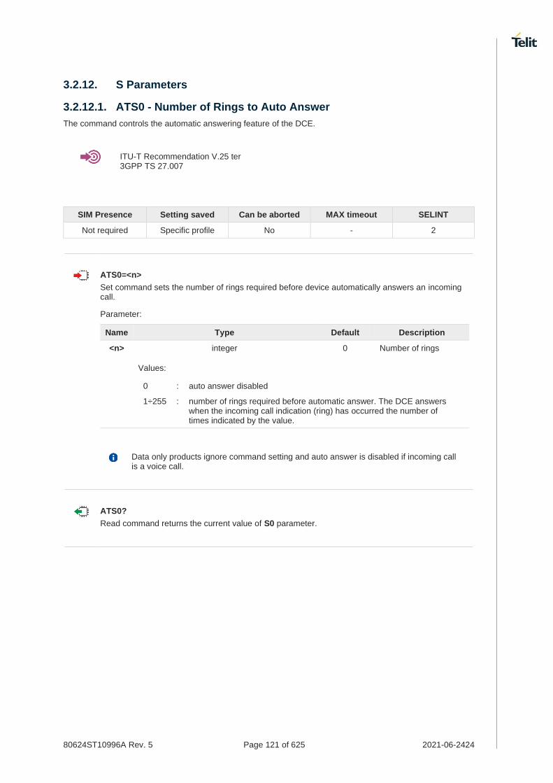
80624ST10996A Rev. 5 Page 121 of 625 2021-06-2424
3.2.12. S Parameters
3.2.12.1. ATS0 - Number of Rings to Auto Answer
The command controls the automatic answering feature of the DCE.
ITU-T Recommendation V.25 ter 3GPP TS 27.007
SIM Presence Setting saved Can be aborted MAX timeout SELINT
Not required Specific profile No - 2
ATS0=<n>
Set command sets the number of rings required before device automatically answers an incoming call.
Parameter:
Name Type Default Description
<n> integer 0 Number of rings
Values:
0 : auto answer disabled
1÷255 : number of rings required before automatic answer. The DCE answers when the incoming call indication (ring) has occurred the number of times indicated by the value.
Data only products ignore command setting and auto answer is disabled if incoming call is a voice call.
ATS0?
Read command returns the current value of S0 parameter.

80624ST10996A Rev. 5 Page 122 of 625 2021-06-2424
3.2.12.2. ATS1 - Ring Counter
S1 is incremented each time the device detects the ring signal of an incoming call. S1 is cleared as soon as no ring occur.
SIM Presence Setting saved Can be aborted MAX timeout SELINT
Not required Specific profile No - 2
ATS1
The form ATS1 has no effect, returns OK result code.
ATS1?
Read command returns S1 value.

80624ST10996A Rev. 5 Page 123 of 625 2021-06-2424
3.2.12.3. ATS2 - Escape Character
The command manages the ASCII character used as escape character.
SIM Presence Setting saved Can be aborted MAX timeout SELINT
Not required Specific profile No - 2
ATS2=<char>
Set command sets the ASCII character to be used as escape character.
Parameter:
Name Type Default Description
<char> integer 43 escape character decimal ASCII
Value:
43 : factory default value is '+'
The escape sequence consists of three escape characters preceded and followed by n ms of idle (see S12 to set n).
This command only supports 43 for <char> parameter.
ATS2?
Read command returns the current value of S2 parameter.
The format of the numbers in output is always 3 digits, left-filled with 0s.

80624ST10996A Rev. 5 Page 124 of 625 2021-06-2424
3.2.12.4. ATS3 - Command Line Termination Character
The command manages the character configured as command line terminator.
ITU-T Recommendation V.25 ter
3GPP TS 27.007
SIM Presence Setting saved Can be aborted MAX timeout SELINT
Not required Specific profile No - 2
ATS3=<char>
Set command sets the value of the character either recognized by the device as command line terminator and generated by the device as part of the header, trailer, and terminator for result codes and information text, along with S4 parameter.
Parameter:
Name Type Default Description
<char> integer 13 command line termination character (decimal ASCII)
Value:
0÷127 : command line termination character
The "previous" value of S3 is used to determine the command line termination character for entering the command line containing the S3 setting command. However, the result code issued shall use the "new" value of S3 (as set during the processing of the command line)
ATS3?
Read command returns the current value of S3 parameter.
The format of the numbers in output is always 3 digits, left-filled with 0s

80624ST10996A Rev. 5 Page 125 of 625 2021-06-2424
3.2.12.5. ATS4 - Response Formatting Character
The command manages the character generated by the device as part of the header, trailer, and terminator for result codes and information text.
ITU-T Recommendation V.25 ter
3GPP TS 27.007
SIM Presence Setting saved Can be aborted MAX timeout SELINT
Not required Specific profile No - 2
ATS4=<char>
Set command sets the value of the character generated by the device as part of the header, trailer, and terminator for result codes and information text, along with the S3 parameter.
Parameter:
Name Type Default Description
<char> integer 10 response formatting character (decimal ASCII)
Value:
0÷127 : response formatting character
If the value of S4 is changed in a command line the result code issued in response of that command line will use the new value of S4.
ATS4?
Read command returns the current value of S4 parameter.
The format of the numbers in output is always 3 digits, left-filled with 0s.

80624ST10996A Rev. 5 Page 126 of 625 2021-06-2424
3.2.12.6. ATS5 - Command Line Editing Character
The command manages the value of the character recognized by the DCE as a request to delete from the command line the immediately preceding character.
ITU-T Recommendation V.25 ter
3GPP TS 27.007
SIM Presence Setting saved Can be aborted MAX timeout SELINT
Not required Specific profile No - 2
ATS5=<char>
Set command sets the value of the character recognized by the device as a request to delete from the command line the immediately preceding character.
Parameter:
Name Type Default Description
<char> integer 8 command line editing character (decimal ASCII)
Value:
0÷127 : command line editing character
ATS5?
Read command returns the current value of S5 parameter.
The format of the numbers in output is always 3 digits, left-filled with 0s.
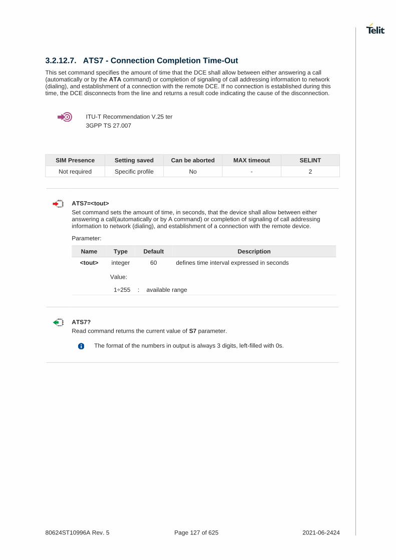
80624ST10996A Rev. 5 Page 127 of 625 2021-06-2424
3.2.12.7. ATS7 - Connection Completion Time-Out
This set command specifies the amount of time that the DCE shall allow between either answering a call (automatically or by the ATA command) or completion of signaling of call addressing information to network (dialing), and establishment of a connection with the remote DCE. If no connection is established during this time, the DCE disconnects from the line and returns a result code indicating the cause of the disconnection.
ITU-T Recommendation V.25 ter
3GPP TS 27.007
SIM Presence Setting saved Can be aborted MAX timeout SELINT
Not required Specific profile No - 2
ATS7=<tout>
Set command sets the amount of time, in seconds, that the device shall allow between either answering a call(automatically or by A command) or completion of signaling of call addressing information to network (dialing), and establishment of a connection with the remote device.
Parameter:
Name Type Default Description
<tout> integer 60 defines time interval expressed in seconds
Value:
1÷255 : available range
ATS7?
Read command returns the current value of S7 parameter.
The format of the numbers in output is always 3 digits, left-filled with 0s.

80624ST10996A Rev. 5 Page 128 of 625 2021-06-2424
3.2.12.8. ATS25 - Delay to DTR Off
The command manages the amount of time that the device will ignore the DTR.
SIM Presence Setting saved Can be aborted MAX timeout SELINT
Not required Specific profile No - 2
ATS25=<time>
Set command defines the amount of time, in hundredths of second, that the device will ignore the DTR for taking the action specified by command &D.
Parameter:
Name Type Default Description
<time> integer 5 expressed in hundredths of a second
Value:
0÷255 : expressed in hundredths of a second
The delay is effective only if its value is greater than 5. To be recognized as valid, the DTR transition must be greater than S25. Low values could require a transition increased of a factor 1.5 to be correctly handled (e.g., to be sure that S25=5 works, use a DTR toggle of 75ms to be detected).
In power saving (e.g. +CFUN=5 with DTR low) DTR must be off at least 3 seconds for taking the action specified by command &D, independently of S25 parameter.
ATS25?
Read command returns the current value of S25 parameter.
The format of the numbers in output is always 3 digits, left-filled with 0s.

80624ST10996A Rev. 5 Page 129 of 625 2021-06-2424
3.2.12.9. AT&V1 - S Registers Display
The command displays the S registers values.
SIM Presence Setting saved Can be aborted MAX timeout SELINT
Not required No No - 2
AT&V1
Execution command returns the S registers values in both decimal and hexadecimal format. The response is in the form:
REG (S register) DEC (value in dec. notation) HEX (value in hex notation)
<reg0> <dec> <hex>
<reg1> <dec> <hex>
... ... ...
<regN> <dec> <hex>
Here is a generic example showing the format.
AT&V1 REG DEC HEX 000 000 000 001 000 000 002 043 02B 003 013 00D 004 010 00A 005 008 008 007 060 03C 012 050 032 ... ... ... ... ... ... OK

80624ST10996A Rev. 5 Page 130 of 625 2021-06-2424
3.2.12.10. ATS12 - Escape Prompt Delay
The command manages the prompt delay between two different escape characters.
SIM Presence Setting saved Can be aborted MAX timeout SELINT
Not required Specific profile No - 2
ATS12=<time>
Set command sets:
5. the minimum period, before receipt of the first character of the three escape character sequence, during which no other character has to be detected in order to accept it as valid first character;
6. the maximum period allowed between receipt of first or second character of the three escape character sequence and receipt of the next;
7. the minimum period, after receipt of the last character of the three escape character sequence, during which no other character has to be detected in order to accept the escape sequence as a valid one.
Parameter:
Name Type Default Description
<time> integer 50 delay expressed in fiftieth of a second
Value:
20÷255 : expressed in fiftieth of a second
The minimum period S12 has to pass after CONNECT result code too, before a received character is accepted as valid first character of the three escape character sequence.
ATS12?
Read command returns the current value of S12 parameter.
The format of the numbers in output is always 3 digits, left-filled with 0s

80624ST10996A Rev. 5 Page 131 of 625 2021-06-2424
3.2.12.11. ATS10 - Carrier Off with Firm Time
The command is available only for backward compatibility
SIM Presence Setting saved Can be aborted MAX timeout SELINT
Not required Specific profile No - 2
ATS10=<n>
Set command has no effect and is available only for backward compatibility with landline modems.
Parameter:
Name Type Default Description
<n> integer N/A dummy
Value:
1÷255 : dummy parameter

80624ST10996A Rev. 5 Page 132 of 625 2021-06-2424
3.2.12.12. AT&V3 - Extended S Registers Display
The command displays the extended S registers values.
SIM Presence Setting saved Can be aborted MAX timeout SELINT
Not required No No - 2
AT&V3
Execution command returns the extended S registers values in both decimal and hexadecimal format. The response is in the form as shown in AT&V1 command.
Here is a generic example showing the format.
AT&V3 REG DEC HEX 000 000 000 001 000 000 002 043 02B 003 013 00D 004 010 00A 005 008 008 007 060 03C 012 050 032 025 005 005 ... ... ... ... ... ... OK

80624ST10996A Rev. 5 Page 133 of 625 2021-06-2424
3.2.13. DTE - Modem Interface Control
3.2.13.1. ATE - Command Echo
This command allows to enable or disable the command echo.
ITU-T Recommendation V.25 ter
SIM Presence Setting saved Can be aborted MAX timeout SELINT
Not required Specific profile No - 2
ATE[<n>]
The execution command allows to enable/disable the command echo.
Parameter:
Name Type Default Description
<n> integer 1 Configuration value
Values:
0 : disables command echo
1 : enables command echo, hence command sent to the device are echoed back to the DTE before the response is given.
If parameter is omitted, the command has the same behavior of ATE0

80624ST10996A Rev. 5 Page 134 of 625 2021-06-2424
3.2.13.2. ATQ - Quiet Result Codes
This command allows to enable or disable the result code.
ITU-T Recommendation V.25 ter
SIM Presence Setting saved Can be aborted MAX timeout SELINT
Not required Specific profile No - 2
ATQ[<n>]
Set command enables or disables the result codes.
Parameter:
Name Type Default Description
<n> integer 0 enables/disables result codes
Values:
0 : enables result codes
1 : disables result codes. The commands entered after ATQ1 do not return the result code.
2 : disables result codes (only for backward compatibility). The commands entered after ATQ2 do not return the result code.
If parameter is omitted, the command has the same behavior of ATQ0.
After issuing ATQ0 the OK result code is returned AT+CGACT=? +CGACT: (0-1) OK
After issuing ATQ1 or ATQ2 the OK result code is not returned. AT+CGACT=? +CGACT: (0-1)

80624ST10996A Rev. 5 Page 135 of 625 2021-06-2424
3.2.13.3. ATV - Response Format
This command allows to set format of information responses and result codes.
[1] ITU-T Recommendation V.25 ter
SIM Presence Setting saved Can be aborted MAX timeout SELINT
Not required Specific profile No - 2
ATV[<n>]
Set command determines the contents of the header and trailer transmitted with result codes and information responses. It also determines if result codes are transmitted in a numeric form or an alphanumeric form (according to [1]).
Parameter:
Name Type Default Description
<n> integer 1 format of information responses and result codes. See Additional info section.
Values:
0 : limited headers and trailers and numeric format of result codes
1 : full headers and trailers and verbose format of result codes
Additional info:
<n>=0
information responses <text><CR><LF>
result codes <numericCode><CR>
<n>=1
information responses <CR><LF> <text><CR><LF>
result codes <CR><LF> <verboseCode><CR><LF>
the <text> portion of information responses is not affected by this setting.
if parameter is omitted, the command has the same behavior of ATV0

80624ST10996A Rev. 5 Page 136 of 625 2021-06-2424
3.2.13.4. ATI - Identification Information
This command returns identification information.
ITU-T Recommendation V.25 ter
SIM Presence Setting saved Can be aborted MAX timeout SELINT
Not required No No - 2
ATI[<n>]
Execution command returns product information.
Parameter:
Name Type Default Description
<n> integer 0 information request
Values:
0 : numerical identifier
1 : module checksum
2 : checksum check result
3 : manufacturer
4 : product name
5 : DOB version
If parameter is omitted, the command has the same behavior of ATI0

80624ST10996A Rev. 5 Page 137 of 625 2021-06-2424
3.2.13.5. AT&C - Data Carrier Detect (DCD) Control
This command controls the DCD output behavior.
ITU-T Recommendation V25 ter
SIM Presence Setting saved Can be aborted MAX timeout SELINT
Not required No No - 2
AT&C[<n>]
Set command controls the DCD output behavior of the serial port.
Parameter:
Name Type Default Description
<n> integer 1 DCD output behavior
Values:
0 : DCD remains always High
1 : DCD follows the Carrier detect status: if carrier is detected DCD goes High, otherwise DCD is Low
2 : DCD is always High except for 1 sec "wink" when a data call is disconnected
If parameter is omitted, the command has the same behavior of AT&C0.

80624ST10996A Rev. 5 Page 138 of 625 2021-06-2424
3.2.13.6. AT&D - Data Terminal Ready (DTR) Control
This set command configures the behavior of the module according to the DTR control line transitions.
ITU-T Recommendation V25 ter
SIM Presence Setting saved Can be aborted MAX timeout SELINT
Not required Specific profile No - 2
AT&D[<n>]
Set command configures the module behavior relative to the DTR signal transitions.
Parameter:
Name Type Default Description
<n> integer 0 defines the module behavior according to the DTR control line transitions
Values:
0 : DTR transitions are ignored by the module
1 : DTR drop from active to inactive: Change to command mode while retaining the connected data call
2 : DTR drop from active to inactive: Disconnect data call, change to command mode. During the inactive state of DTR auto answer is off
If parameter is omitted, the command has the same behavior of AT&D0.
URC message is sent only if DTR is ON, otherwise, URC message discarded.

80624ST10996A Rev. 5 Page 139 of 625 2021-06-2424
3.2.13.7. AT\Q - Standard Flow Control
This command controls the RS232 flow control behavior.
ITU-T Recommendation V25 ter
SIM Presence Setting saved Can be aborted MAX timeout SELINT
Not required No No - 2
AT\Q[<n>]
Set command controls the RS232 flow control behavior.
Parameter:
Name Type Default Description
<n> integer 0 RS232 flow control behavior
Values:
0 : no flow control
3 : hardware bi-directional flow control (both RTS/CTS active) (factory default)
This command has no effect on USB interface. It's only used for UART interface.

80624ST10996A Rev. 5 Page 140 of 625 2021-06-2424
3.2.13.8. AT&K - Flow Control
Flow Control settings.
SIM Presence Setting saved Can be aborted MAX timeout SELINT
Not required Specific profile No - 2
AT&K[<n>]
Set command controls the serial port flow control behavior.
Parameter:
Name Type Default Description
<n> integer 3 flow control behavior
Values:
0 : no flow control
3 : hardware bi-directional flow control (both RTS/CTS active)
If parameter is omitted, the command has the same behavior as AT&K0
&K has no Read Command. To verify the current setting of &K, simply check the settings of the active profile issuing AT&V.
It has no effect and is included only for backward compatibility with legacy modems.

80624ST10996A Rev. 5 Page 141 of 625 2021-06-2424
3.2.13.9. AT&S - Data Set Ready (DSR) Control
Set DSR behavior on serial port
SIM Presence Setting saved Can be aborted MAX timeout SELINT
Not required Specific profile No - 2
AT&S[<n>]
Set command controls DSR behavior on serial port
Parameter:
Name Type Default Description
<n> integer 3 Configuration parameter
Values:
0 : Always High
1 : Follows carrier status
2 : High on DATA mode, Low on AT command mode
3 : Follows DTR status
If parameter is omitted, the command has the same behavior of AT&S0.
DSR behavior with AT&S1 work as DCD behavior with AT&C1.

80624ST10996A Rev. 5 Page 142 of 625 2021-06-2424
3.2.13.10. AT+IPR - UART DCE Interface Data Rate Speed
The command sets the speed of the DTE serial port.
[1] Hardware User's Guide of the used module
[2] ITU-T Recommendation V25 ter
SIM Presence Setting saved Can be aborted MAX timeout SELINT
Not required Specific profile No - 2
AT+IPR=<rate>
Set command specifies the DTE speed on UART interface;
Parameter:
Name Type Default Description
<rate> integer 115200 speed of the serial port expressed in bit per second
Values:
300 : bps
600 : bps
1200 : bps
2400 : bps
4800 : bps
9600 : bps
19200 : bps
38400 : bps
57600 : bps
115200 : bps
230400 : bps
921600 : bps
2900000 : bps
3000000 : bps
3200000 : bps
4000000 : bps
AT+IPR?
Read command returns the current value of <rate> parameter.
AT+IPR=?
Test command returns the list of supported auto detectable <rate> values and the list of fixed-only <rate> values in the format:

80624ST10996A Rev. 5 Page 143 of 625 2021-06-2424
+IPR:(list of supported auto detectable <rate> values), (list of fixed-only <rate> values)
This command has no effect on USB interface; the DCE sends the OK result but the settings has no effect on serial interface
Test command example
AT+IPR=?
+IPR: (),(300,600,1200,2400,4800,9600,19200,38400,57600,115200,230400,921600,2000000,2900000,3200000,3200000,3686400,4000000)
OK

80624ST10996A Rev. 5 Page 144 of 625 2021-06-2424
3.2.13.11. AT+IFC - DTE-Modem Local Flow Control
This set command selects the flow control of the serial port in both directions.
ITU-T Recommendation V25 ter
SIM Presence Setting saved Can be aborted MAX timeout SELINT
Not required Specific profile No - 2
AT+IFC=<byDTE>,<byDCE>
Set command selects the flow control behavior of the serial port in both directions: from DTE to modem (<byDTE> option)and from modem to DTE (<byDCE>)
Parameters:
Name Type Default Description
<byDTE> integer 2 specifies the method used by the DTE to control the flow of data received from the device (DCE)
Values:
0 : no flow control
2 : flow control by RTS control line (C105, Request to Send)
<byDCE> integer 2 specifies the method used by the device (DCE) to control the flow of data received from the DTE
Values:
0 : no flow control
2 : flow control by CTS control line (C105, Clear to Send)
The only possible commands are AT+IFC=0,0 and AT+IFC=2,2.
AT+IFC?
Read command returns active flow control settings.
AT&K is also used to set the flow control and it has the same effect with this command
if flow control behavior had been set with AT&K command, The changed setting value by AT&K will return
AT+IFC=?
Test command returns all supported values of the parameters <byDTE> and <byDCE>.
This command has no effect on USB interface. It's only for UART interface

80624ST10996A Rev. 5 Page 145 of 625 2021-06-2424

80624ST10996A Rev. 5 Page 146 of 625 2021-06-2424
3.2.13.12. AT+ICF - DTE-Modem Character Framing
This set command defines the asynchronous character framing.
ITU-T Recommendation V.25 ter
SIM Presence Setting saved Can be aborted MAX timeout SELINT
Not required Specific profile No - 2
AT+ICF=<format>[,<parity>]
Set command defines the asynchronous character framing to be used when autobauding is disabled.
Parameters:
Name Type Default Description
<format> string 3 sets the number of Data bits and Stop bits. Only the <format>=3 is supported.
Value:
3 : 8 Data, 1 Stop
<parity> string 0 This parameter is used for the backward compatibility. It's no meaningful.
Values:
0 : odd
1 : even
AT+ICF?
Read command returns current settings for parameters <format> and <parity>.
AT+ICF=?
Test command returns the ranges of values for the parameters <format> and <parity>.
This command has no effect on USB interface. It's used only for UART interface.
AT+ICF=3 OK
AT+ICF=? +ICF: (3),(0,1)
OK

80624ST10996A Rev. 5 Page 147 of 625 2021-06-2424
3.2.13.13. ATX - Extended Result Codes
This command allows to select the subset of result code messages.
ITU-T Recommendation V.25 ter
SIM Presence Setting saved Can be aborted MAX timeout SELINT
Required Specific profile No - 2
ATX[<n>]
Set command selects the subset of result code messages the modem uses to reply to the DTE upon AT commands execution.
Parameter:
Name Type Default Description
<n> integer 1 configuration value
Values:
0 : when entering in dial mode a CONNECT result code is relayed; see Additional info.
1÷4 : when entering in dial mode a CONNECT <text> result code is relayed, see Additional info.
Additional info:
<n>=0 OK, CONNECT, RING, NO CARRIER, ERROR, NO ANSWER result codes are enabled. Dial tone and busy detection (NO DIALTONE and BUSY result codes) are disabled.
<n>=1÷4 all the remaining result codes are enabled.
When the <n> parameter is omitted, the command acts like ATX0.

80624ST10996A Rev. 5 Page 148 of 625 2021-06-2424
3.2.13.14. AT#NOPT - Notification Port
Set notification(URC) message port
SIM Presence Setting saved Can be aborted MAX timeout SELINT
Not required Specific profile No - 2
AT#NOPT=<num>
Set command specifies the port output notification (URC) messages
Parameter:
Name Type Default Description
<num> integer 0 Notification(URC) port
Values:
0 : All Ports; URC messages are sent to all ports
1 : Telit USB Modem 1 Port
2 : Telit USB Modem 2 Port
3 : Telit USB Aux port
URC messages sent out only on the configured ports by this command
DTE must enable DTR line to get URC messages on Telit USB ports, otherwise URC message will be discarded.
AT#NOPT?
Read command reports the current notification port.
AT#NOPT=?
Test command reports the available range of values for parameter <num>.

80624ST10996A Rev. 5 Page 149 of 625 2021-06-2424
3.2.13.15. AT#NOPTEXT - Notification Port Extension
Set notification extension port
SIM Presence Setting saved Can be aborted MAX timeout SELINT
Not required Specific profile No - 2
AT#NOPTEXT=<noptext_enable>[,<port1_enable>[,<port2_enable>[,<port3_enable>]]]
Set command specified the port output notification (URC) messages
This command is extended from AT#NOPT command.
Unlike AT#NOPT, this command allow to enable URC message on multiple ports
Parameters:
Name Type Default Description
<noptext_enable> integer 0 enable #NOPTEXT
Values:
0 : Disable #NOPTEXT command set
1 : Enable #NOPTEXT command set
<port1_enable> integer N/A enable port1 - Telit USB Modem 1 port
Values:
0 : disable URC message on port1
1 : enable URC message on port1
<port2_enable> integer N/A enable port2 - Telit USB Modem 2 port
Values:
0 : disable URC message on port2
1 : enable URC message on port2
<port3_enable> string N/A enable port3 - Telit USB AUX port
Values:
0 : disable URC message on port3
1 : enable URC message on port3
if <noptext_enable> is enable, #NOPT's setting value ignored and URC message port specified by #NOPTEXT setting value.
AT#NOPTEXT?
Read command show current <mode> on all notification(URC) port in the following format
#NOPTEXT: <noptext_enable>,<port1_enable>,<port2_enable>,<port3_enable>

80624ST10996A Rev. 5 Page 150 of 625 2021-06-2424
AT#NOPTEXT=?
Test command returns the list of supported values in the following format
#NOPTEXT: (0,1),(<port1_descr>,(0,1)),(<port2_descr>,(0,1)),...
<port_descr>:
1. "USB_MDM1" - Telit USB Modem 1 Port
2. "USB_MDM2" - Telit USB Modem 2 Port
3. "USB_AUX" - Telit USB Aux Port
DTE must enable DTR line to get URC messages on Telit USB ports, otherwise URC message will be discarded
This command enable URC message on "Telit USB Modem1 Port" and "Telit USB Modem2 Port"
• AT#NOPTEXT=1,1,1,0
OK

80624ST10996A Rev. 5 Page 151 of 625 2021-06-2424
3.2.13.16. AT\R - Ring (RI) Control
This command allows the user to control the RING output pin behaviour.
SIM Presence Setting saved Can be aborted MAX timeout SELINT
Not required Specific profile No - 2
AT\R[<n>]
Set command controls the RING output pin behaviour.
Parameter:
Name Type Default Description
<n> integer 1 RING pin behaviour
Values:
0 : RING on during ringing and further connection
1 : RING on during ringing
2 : RING follows the ring signal
If the parameter is omitted, the command has the same behaviour of AT\R0.
To check the ring option status use the &V command.

80624ST10996A Rev. 5 Page 152 of 625 2021-06-2424
3.2.14. Call (Voice and Data) Control
3.2.14.1. ATH - Hang Up/Disconnect the Current Call
This execution command hangs up/disconnects the current voice/data call or dial-up.
ITU-T Recommendation V.25 ter
SIM Presence Setting saved Can be aborted MAX timeout SELINT
Not required No No - 2
ATH
When a data call or a dial-up is active the device is in on-line mode hence, to execute ATH command the device must be previously turned in command mode using the escape sequence or, if &D1 option is active, tying Low the DTR pin.

80624ST10996A Rev. 5 Page 153 of 625 2021-06-2424
3.2.14.2. ATA - Answer Incoming call
The command is used to answer to an incoming call if automatic answer is disabled.
ITU-T Recommendation V.25 ter 3GPP TS 27.007
SIM Presence Setting saved Can be aborted MAX timeout SELINT
Required No No - 2
ATA
Execution command informs the DCE that answer sequence must be started if automatic answer is disabled.
This command must be the last in the command line and must be followed immediately by a <CR> character.
Data only products do not start the call and command answer is ERROR if a voice call is requested.

80624ST10996A Rev. 5 Page 154 of 625 2021-06-2424
3.2.14.3. ATD - Dialup Connection
This command establishes a Mobile Originated call to the destination phone number.
ITU-T Recommendation V.25 ter
3GPP TS 27.007
SIM Presence Setting saved Can be aborted MAX timeout SELINT
Not required No Yes - 2
ATD
The ATD execution command can assume different formats, which are described in the following Additional info section.
Additional info:
ATD<number>[;]
If ";" character is present, a voice call is performed using the phone number given as parameter.
Name Type Default Description
<number> string - phone number to be dialed
Accepted characters are 0-9 and *,#,"A", "B", "C", "D","+". For backwards compatibility with landline modems, modifiers "T", "P", "R", ",", "W", "!", "@" are accepted, but have no effect.
ATD><str>[;]
If ";" character is present, a voice call is performed using the phone number identified by an alphanumeric field. All available memories are scanned to find out the field.
Name Type Default Description
<str> string - is an alphanumeric field identifying the phone number. The characters must be enclosed in quotation marks. The parameter is case sensitive. Use +CSCS command to select the character set.
ATD><mem><n>[;]
If ";" character is present, a voice call is performed using the phone number stored in the selected phonebook memory storage and in the selected entry location. Use +CPBS=? command to get all the available memories.
Name Type Default Description
<mem> string N/A identifies the phonebook memory storage
Value:

80624ST10996A Rev. 5 Page 155 of 625 2021-06-2424
SM : SIM/UICC phonebook
<n> integer - entry location. It must be in the range of the available locations in the used memory.
ATD><n>[;]
If ";" character is present, a voice call is performed using a phone number on entry location <n> of the active phonebook memory storage (see +CPBS).
Name Type Default Description
<n> integer - entry location of the active phonebook
ATD<number><modifier>[;]
If ";" character is present, a voice call is performed overriding the CLIR supplementary service subscription default value, or checking the CUG supplementary service information for the current call according to the modifier.
Name Type Default Description
<number> integer - phone number to be dialed
<modifier> string N/A causes the call overrides the CLIR supplementary service subscription default value, or checks the CUG supplementary service information
Values:
I : invocation, restrict CLI presentation
i : suppression, allow CLI presentation
G : refer to +CCUG command
g : refer to +CCUG command
ATD*<gprs_sc>[*<addr>][*[<L2P>][*[<cid>]]]]#
This command is specific for GPRS functionality, and causes the MT to perform whatever actions are necessary to establish communication between the TE and the external PDN.
Name Type Default Description
<gprs_sc> integer N/A is the GPRS Service Code, which identifies a request to use the GPRS communication
Value:
99 : GPRS Service Code
<addr> string - identifies the called party in the address space applicable to the PDP.
<L2P> string - for communications software that does not support arbitrary characters in the dial string, the following numeric equivalents shall be used: 1 is equivalent to PPP.
<cid> integer - PDP context definition, see +CGDCONT command

80624ST10996A Rev. 5 Page 156 of 625 2021-06-2424
• Dial the phone number stored in the SIM phonebook at entry 6. The call is a data or voice call according to the mode set by +FCLASS command.
ATD>SM6 OK
• Dial the phone number stored in the active phonebook at entry 6. The ";" character is used, therefore the call is a voice call.
ATD>6; OK
• Dial the phone number corresponding to the alphanumeric field "Name". The alphanumeric field is searched in all available memories. The ";" character is used, therefore the call is a voice call.
ATD>"Name"; OK

80624ST10996A Rev. 5 Page 157 of 625 2021-06-2424
Network
3.3.1. AT#LTEDS - Current Network status in E-UTRAN
This command is used to read the current network status in E-UTRAN
SIM Presence Setting saved Can be aborted MAX timeout SELINT
Not required No No - 2
AT#LTEDS
Execution command reports the information about E-UTRAN network status.
#LTEDS: <EARFCN(DL/UL)>,<BAND>,<BW>,<PLMN>,<TAC>,<CELL(Physical Cell ID)>,
<ESMCAUSE>,<DRX>,<RSRP>,<RSRQ>,<RSSI>,<L2W>,<RI>,<CQI>,<STATUS>,<SUBSTATUS>,
<RRC>,<SVC>,<SINR>,<TXPWR>,<TMSI>,<IP>,<AVGRSRP>,<ANTBAR>,<MCS>,<MOD(DL/UL)>,
<BLER(DL/UL)>
Additional info:
Parameters Description
EARFCN(DL/UL) E-UTRAN Absolute Radio Frequency Channel Number
BAND Band Class BW Band Width PLMN Public Land Mobile Network TAC Tracking Area Code CELL(Physical Cell ID)
CELL ID (Physical Cell ID)
ESMCAUSE ESM Cause DRX Discontinuous Reception RSRP Reference Signal Received Power RSRQ Received Signal Received Quality RSSI Received Signal Strength Indicator L2W Cell reselection from E-UTRAN to WCDMA RI Rank Indicator CQI Channel Quality Indicator STATUS Service Status/EMM Status SUBSTATUS Sub State of EMM-DEREGISTERED, EMM-REGISTERED and
EMM-REGISTERED-INITIATED RRC Radio Resource Control SVC Service Domain SINR Signal to noise ratio TXPWR Tx Power TMSI Temporary Mobile Subscriber Identity IP Public IP Address AVGRSRP Average of RSRP ANTBAR Antenna Bar Number MCS Modulation and coding scheme MOD(DL/UL) Modulation BLER(DL/UL) Block error rate
Cell ID(Physical Cell ID) : eNB ID-Cell ID(Physical Cell ID)
Service Status
0 : "No_SRV"
1 : "LIMITED"
2 : "SRV"

80624ST10996A Rev. 5 Page 158 of 625 2021-06-2424
3 : "LIMITED_REGION"
4 : "PWR_SAVE"
EMM Status
0 : "NULL"
1 : "DEREGISTERD"
2 : "REG_INIT"
3 : "REGISTRED"
4 : "TAU_INIT"
5 : "SVC_REQ_INIT"
6 : "DEREGINIT"
7 : "INVALID"
Sub Status
-This parameter depend on the EMM Status is "DEREGISTERD".
0 : "NO_IMSI"
//EMM_DEREGISTERED_NO_IMSI,
1 : "PLMN_SRCH"
//EMM_DEREGISTERED_PLMN_SEARCH,
2 : "ATT_NEED"
//EMM_DEREGISTERED_ATTACH_NEEDED,
3 : "NO_CELL"
//EMM_DEREGISTERED_NO_CELL_AVAILABLE,
4 : "ACC2ATT"
//EMM_DEREGISTERED_ATTEMPTING_TO_ATTACH,
5 : "NORMAL"
//EMM_DEREGISTERED_NORMAL_SERVICE,
6 : "LTD_SVC"
//EMM_DEREGISTERED_LIMITED_SERVICE
7 : "PDN_CONN_REQ"
//EMM_DEGEGISTERED_WAITING_PDN_CONN_REQ
-This parameter depend on the EMM Status is "REGISTERED".
0 : "NORMAL"
//EMM_REGISTERED_NORMAL_SERVICE
1 : "UDT_NEED"
//EMM_REGISTERED_UPDATE_NEEDED
2 : "ACC2UPD"
//EMM_REGISTERED_ATTEMPTING_TO_UPDATE
3 : "NO_CELL"
//EMM_REGISTERED_NO_CELL_AVAILABLE
4 : "PLMN_SRCH"
//EMM_REGISTERED_PLMN_SEARCH
5 : "LTD_SVC"
//EMM_REGISTERED_LIMITED_SERVICE
6 : "ACC2UPDMM"
//EMM_REGISTERED_ATTEMPTING_TO_UPDATE_MM
7 : "IMSI_DET"
//EMM_REGISTERED_IMSI_DETACH_INITIATED

80624ST10996A Rev. 5 Page 159 of 625 2021-06-2424
8 : "WAIT4ESM_ISR"
//EMM_REGISTERED_WAITING_FOR_ESM_ISR_STATUS
-This parameter depend on the EMM Status is "REG_INIT".
0 : "WAIT4NW_REP"
//EMM_WATING_FOR_NW_RESPONSE
1 : "WAIT4ESM_REP"
//EMM_WAITING_FOR_ESM_RESPONSE
RRC
0 : IDLE_STATE
1 : WAITING_FOR_RRC_CONFIRMATION_STATE
2 : CONNECTED_STATE
3 : RELEASING_RRC_CONNECTION_STATE
SVC
0 : NO_SVC
1 : CS_ONLY
2 : PS_ONLY
3 : CS_PS
BLER(DL/UL) doesn't support
IP is only displayed for profile 1
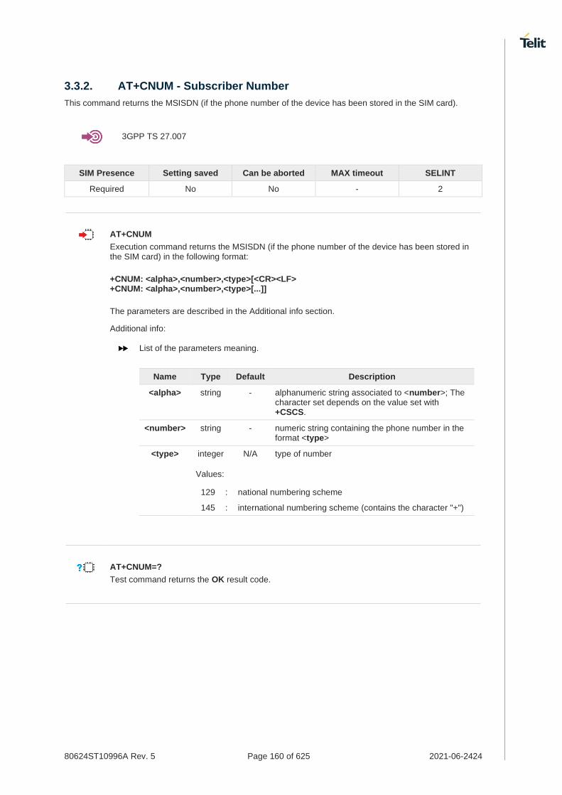
80624ST10996A Rev. 5 Page 160 of 625 2021-06-2424
3.3.2. AT+CNUM - Subscriber Number
This command returns the MSISDN (if the phone number of the device has been stored in the SIM card).
3GPP TS 27.007
SIM Presence Setting saved Can be aborted MAX timeout SELINT
Required No No - 2
AT+CNUM
Execution command returns the MSISDN (if the phone number of the device has been stored in the SIM card) in the following format:
+CNUM: <alpha>,<number>,<type>[<CR><LF> +CNUM: <alpha>,<number>,<type>[...]]
The parameters are described in the Additional info section.
Additional info:
List of the parameters meaning.
Name Type Default Description
<alpha> string - alphanumeric string associated to <number>; The character set depends on the value set with +CSCS.
<number> string - numeric string containing the phone number in the format <type>
<type> integer N/A type of number
Values:
129 : national numbering scheme
145 : international numbering scheme (contains the character "+")
AT+CNUM=?
Test command returns the OK result code.

80624ST10996A Rev. 5 Page 161 of 625 2021-06-2424
3.3.3. AT+COPN - Read Operator Names
This command read operator names.
3GPP TS 27.007
SIM Presence Setting saved Can be aborted MAX timeout SELINT
Required Auto No - 2
AT+COPN
Execution command returns the list of operator names from the ME in the format:
+COPN: <numeric1>,<alpha1>[<CR><LF>
+COPN: <numeric2>,<alpha2>[...]]
The parameters are described in the Additional info section.
Additional info:
List of the parameters meaning.
Name Type Default Description
<numericn> string - operator in numeric format, see +COPS.
<alphan> string - operator in long alphanumeric format, see +COPS.
Each operator code <numericn> that has an alphanumeric equivalent <alphan> in the ME memory is returned.
Because <alphan> display to depend on character set (+CSCS), <alphan> may not be displayed properly.
AT+COPN=?
Test command returns the OK result code.

80624ST10996A Rev. 5 Page 162 of 625 2021-06-2424
3.3.4. AT+CREG - Network Registration Status
The command enables/disables the network registration unsolicited result code (URC) and selects its presentation format.
3GPP TS 27.007
SIM Presence Setting saved Can be aborted MAX timeout SELINT
Not required Specific profile No - 2
AT+CREG=[<mode>]
Set command enables/disables the network registration unsolicited result code and selects one of the two available formats:
short format: +CREG: <stat> long format: +CREG: <stat>[,<lac>,<ci>[,<AcT>]]
The parameter meanings are shown in Unsolicited code value section.
Parameter:
Name Type Default Description
<mode> integer 0 enables/disables the network registration unsolicited result code and selects one of the two formats: shot or long format.
8. URC short format is displayed every time there is a change in the network registration status
9. URC long format is displayed every time there is a change of the network cell
Values:
0 : disable the network registration unsolicited result code
1 : enable the network registration unsolicited result code, and selects the short format
2 : enable the network registration unsolicited result code, and selects the long format (includes the network cell identification data)
Unsolicited fields:
Name Type Description
<stat> integer network registration status of the module
Values:
0 : not registered, terminal is not currently searching a new operator to register to
1 : registered, home network
2 : not registered, but terminal is currently searching a new operator to register to
3 : registration denied
4 : unknown
5 : registered, roaming

80624ST10996A Rev. 5 Page 163 of 625 2021-06-2424
<lac> string the parameter reports:
10. Local Area Code when <AcT>=0 11. Tracking Area Code when <AcT>=7
<ci> string Cell Id for the currently registered on cell
<AcT> integer access technology of the registered network
Values:
0 : GSM
2 : UTRAN
3 : GSM w/EGPRS (see NOTE 3)
4 : UTRAN w/HSDPA (see NOTE 4)
5 : UTRAN w/HSUPA (see NOTE 4)
6 : UTRAN w/HSDPA and HSUPA (see NOTE 4)
7 : E-UTRAN
13 : E-UTRA-NR dual connectivity(see NOTE 8)
<lac>, <ci> and <AcT> network information is reported by URC only if <mode>=2, and the module is registered on some network cell.
NOTE 3: 3GPP TS 44.018 [156] specifies the System Information messages which give the information about whether the serving cell supports EGPRS.
NOTE 4: 3GPP TS 25.331 [74] specifies the System Information blocks which give the information about whether the serving cell supports HSDPA or HSUPA.
NOTE 8: 3GPP TS 38.331 [160] specifies the information which, if present, indicates that the serving cell is supporting dual connectivity of E-UTRA with NR and is connected to an EPS core.
AT+CREG?
Read command returns the current value of <mode>, the registration status <stat>, and the network information (<lac>, <ci> and <AcT>) according to the used <mode> parameter value.
+CREG: <mode>,<stat>[,<lac>,<ci>[,<AcT>]]
<lac>, <ci>, and <AcT> network information is reported only if <mode>=2 and the module is registered on some network cell.
AT+CREG=?
Test command returns supported values for parameter <mode>.

80624ST10996A Rev. 5 Page 164 of 625 2021-06-2424
Check the registration status of the module. AT+CREG?
+CREG: 0,2
OK
The module is in network searching state
...
...
Check again module status AT+CREG?
+CREG: 0,1
OK
The module is registered

80624ST10996A Rev. 5 Page 165 of 625 2021-06-2424
3.3.5. AT+CLCK - Facility Lock/Unlock
This command is used to lock, unlock, or interrogate a MT or a network facility.
3GPP TS 27.007
SIM Presence Setting saved Can be aborted MAX timeout SELINT
Not required No No - 2
AT+CLCK=<fac>,<mode>[,<passwd>[,<class>]]
Set command is used to lock, unlock, or interrogate a MT or a network facility.
Parameters:
Name Type Default Description
<fac> string N/A facility
Values:
"AB" : All Barring services (applicable only for <mode>=0)
"AC" : All inComing barring services (applicable only for <mode>=0)
"AG" : All outGoing barring services (applicable only for <mode>=0)
"AI" : BAIC (Barr All Incoming Calls)
"AO" : BAOC (Barr All Outgoing Calls)
"IR" : BIC-Roam (Barr Incoming Calls when Roaming outside the home country)
"OI" : BOIC (Barr Outgoing International Calls)
"OX" : BOIC-exHC (Barr Outgoing International Calls except to Home Country)
"SC" : SIM (lock SIM/UICC card installed in the currently selected card slot) (SIM/UICC asks password in MT power-up and when this lock command issued)
"FD" : SIM card or active application in the UICC (GSM or USIM) fixed dialling memory feature (if PIN2 authentication has not been done during the current session, PIN2 is required as <passwd>)
"PN" : Network Personalization
"PU" : network sUbset Personalization
"PP" : service Provider Personalization
"PC" : Corporate Personalization
"PF" : lock Phone to the very First inserted SIM/UICC card (also referred in the present document as PHFSIM) (MT asks password when other than the first SIM/UICC card is inserted)
<mode> integer N/A defines the operation to be done on the facility
Values:
0 : unlock
1 : lock

80624ST10996A Rev. 5 Page 166 of 625 2021-06-2424
2 : query status
<passwd> string - shall be the same as password specified for the facility from the MT user interface or with command Change Password +CPWD
<class> integer 7 a sum of integers each representing a class of information
1: voice(telephony)
2: data
4: fax (facsimile services)
8: short message service
16: data circuit sync
32: data circuit async
64: dedicated packet access
128: dedicated PAD access
Value:
1÷255 : 1..255
Additional info:
When <mode>=2 and command is successful:
+CLCK: <status>[,<class1>[<CR><LF> +CLCK: <status>,<class2>[...]]
Name Type Default Description
<status> integer N/A the current status of the facility
Values:
0 : not active
1 : active
AT+CLCK=?
Test command reports all the facilities supported by the device.
Querying such a facility returns an output on three rows, the first for voice, the second for data, the third for fax:
AT+CLCK ="AO",2
+CLCK: <status>,1
+CLCK: <status>,2
+CLCK: <status>,4
OK

80624ST10996A Rev. 5 Page 167 of 625 2021-06-2424
3.3.6. AT+CPWD - Change Facility Password
This command is used to change the password for the facility lock function defined by command Facility Lock +CLCK.
3GPP TS 27.007
SIM Presence Setting saved Can be aborted MAX timeout SELINT
Required Other Yes - 2
AT+CPWD=<fac>,<oldpwd>,<newpwd>
Action command sets a new password for the facility lock function defined by command Facility Lock +CLCK.
Parameters:
Name Type Default Description
<fac> string N/A facility
Values:
"AB" : All Barring services
"AC" : All inComing barring services
"AG" : All outGoing barring services
"AI" : BAIC (Barr All Incoming Calls)
"AO" : BAOC (Barr All Outgoing Calls)
"IR" : BIC-Roam (Barr Incoming Calls when Roaming outside the home country)
"OI" : BOIC (Barr Outgoing International Calls)
"OX" : BOIC-exHC (Barr Outgoing International Calls except to Home Country)
"SC" : SIM (PIN request)
"P2" : SIM PIN2
"PN" : Network Personalization
"PU" : network sUbset Personalization
"PP" : service Provider Personalization
"PC" : Corporate Personalization
"PF" : lock Phone to the very First inserted SIM/UICC card (also referred in the present document as PHFSIM) (MT asks password when other than the first SIM/UICC card is inserted)
<oldpwd> string - It shall be the same as password specified for the facility from the MT user interface or with command Change Password +CPWD.
<newpwd> string - new password; maximum length of password can be determined with <pwdlength>

80624ST10996A Rev. 5 Page 168 of 625 2021-06-2424
AT+CPWD=?
Test command returns a list of pairs (<fac>,<pwdlength>) which present the available facilities and the maximum length of their password.
Additional info:
the available facilities and the maximum length of their password
Name Type Default Description
<fac> string - facility
<pwdlength> integer - maximum length of the password for the facility

80624ST10996A Rev. 5 Page 169 of 625 2021-06-2424
3.3.7. AT+CLIR - Calling Line Identification Restriction
The command manages the CLIR service.
3GPP TS 27.007 3GPP TS 22.081
SIM Presence Setting saved Can be aborted MAX timeout SELINT
Required Specific profile No - 2
AT+CLIR=[<n>]
Set command overrides the CLIR subscription when temporary mode is provisioned as a default adjustment for all following outgoing calls. This adjustment can be revoked by using the opposite command. This command refers to CLIR service (see 3GPP TS 22.081), that allows a calling subscriber to enable or disable the presentation of the Calling Line Identification (CLI, i.e., the phone number of the caller) to the called party when originating a call.
This command sets the default behavior of the device in all outgoing calls.
Parameter:
Name Type Default Description
<n> integer 0 setting of CLIR service
Values:
0 : CLIR facility according to CLIR service network status
1 : CLIR facility active (CLI not sent)
2 : CLIR facility not active (CLI sent)
AT+CLIR?
Read command gives the default adjustment for all outgoing calls (<n>) and also triggers an interrogation of the provision status of the CLIR service (<m>), in the form
+CLIR: <n>,<m>
Additional info:
Name Type Default Description
<n> integer 0 facility status in the Mobile
Values:
0 : CLIR facility according to CLIR service network status
1 : CLIR facility active (CLI not sent)
2 : CLIR facility not active (CLI sent)
<m> integer 0 facility status in the Network

80624ST10996A Rev. 5 Page 170 of 625 2021-06-2424
Values:
0 : CLIR service not provisioned
1 : CLIR service provisioned permanently
2 : unknown (e.g. no network present)
3 : CLI temporary mode presentation restricted
4 : CLI temporary mode presentation allowed
AT+CLIR=?
Test command reports the supported values of parameter <n>

80624ST10996A Rev. 5 Page 171 of 625 2021-06-2424
3.3.8. AT+COLP - Connected Line Identification Presentation
This command enables/disables the presentation of the COL at the TE.
SIM Presence Setting saved Can be aborted MAX timeout SELINT
Required Specific profile No - 2
AT+COLP=[<n>]
Set command enables/disables the presentation of the COL at the TE. When enabled (and called subscriber allows), the following intermediate result code is returned from TA to TE before any +CR or ITU T Recommendation V.250 responses: +COLP: <number>,<type>
Parameter:
Name Type Default Description
<n> integer 0 enable/disable COL indication
Values:
0 : disable COL indication
1 : enable COL indication
Additional info:
This command refers to the GSM/UMTS supplementary service COLP (Connected Line Identification Presentation) that enables a calling subscriber to get the connected line identity (COL) of the called party after setting up a mobile originated call. It has no effect on the execution of the supplementary service COLR in the network.
Unsolicited fields:
Name Type Description
<number> string string type phone number of format specified by <type>
<type> integer type of address octet in integer format
Values:
129 : unknown type of number and ISDN/Telephony numbering plan
145 : international type of number and ISDN/Telephony numbering plan (contains the character "+")
If COL information is needed, it is recommended to set <mode> to 1 in #DIALMODE command, in order to have network information available for display before returning to command mode.
AT+COLP?

80624ST10996A Rev. 5 Page 172 of 625 2021-06-2424
Read command gives the status of <n>, and also triggers an interrogation of the provision status of the COLP service according 3GPP TS 22.081 (given in <m>) in the format: +COLP: <n>,<m>
Additional info:
where
Name Type Default Description
<n> integer N/A COL presentation enabled/disabled
Values:
0 : COL presentation disabled
1 : COL presentation enabled
<m> integer N/A status of the COLP service on the GSM network
Values:
0 : COLP not provisioned
1 : COLP provisioned
2 : unknown (e.g. no network is present)
This command issues a status request to the network, hence it may take a few seconds to give the answer due to the time needed to exchange data with it.
AT+COLP=?
Test command returns the range for the parameter <n>.

80624ST10996A Rev. 5 Page 173 of 625 2021-06-2424
3.3.9. AT+CCFC - Call Forwarding Number And Condition
This command controls the call forwarding supplementary service.
3GPP TS 27.007
SIM Presence Setting saved Can be aborted MAX timeout SELINT
Required Auto No - 2
AT+CCFC=<reason>,<cmd>[,<number>[,<type>[,<class>[,<time>]]]]
The execution command controls the call forwarding supplementary service. Registration, erasure, activation, deactivation, and status query are supported.
Parameters:
Name Type Default Description
<reason> integer 0 reason of call forwarding
Values:
0 : unconditional
1 : mobile busy
2 : no reply
3 : not reachable
4 : all calls (not with query command)
5 : all conditional calls (not with query command)
<cmd> integer 0 command parameter
Values:
0 : disable
1 : enable
2 : query status
3 : registration
4 : erasure
<number> string - string type phone number of forwarding address in format specified by <type> parameter
<type> integer 129 type of address octet in integer format
Values:
129 : National numbering scheme
145 : International numbering scheme (contains the character "+")
<class> integer 7 sum of integers each representing a class of information which the command refers to; default 7 (voice + data + fax)
12. 1 voice(telephony) 13. 2 data 14. 4 fax (facsimile services) 15. 8 short message service 16. 16 data circuit sync

80624ST10996A Rev. 5 Page 174 of 625 2021-06-2424
17. 32 data circuit async 18. 64 dedicated packet access 19. 128 dedicated PAD access
Value:
0÷255 : class of information
<time> integer 20 time in seconds to wait before call is forwarded; it is valid only when <reason> "no reply" is enabled (<cmd>=1) or queried (<cmd>=2)
Value:
1÷30 : automatically rounded to a multiple of 5 seconds
Additional info:
when <cmd>=2 and command successful, it returns: +CCFC: <status>,<class
1>[,<number>,<type>[,,,<time>]][<CR><LF>
+CCFC: <status>,<class2>[,<number>,<type>[,,,<time>]][ ... ]]
Name Type Default Description
<status> integer 0 status of the network service
Values:
0 : not active
1 : active
<time> string - it is returned only when <reason>=2 ("no reply") and <cmd>=2.
When querying the status of a network service (<cmd>=2) the response line for 'not active' case (<status>=0) should be returned only if service is not active for any <class>.
AT+CCFC=?
Test command reports supported values for the parameter <reason>.

80624ST10996A Rev. 5 Page 175 of 625 2021-06-2424
3.3.10. AT+CCWA - Call Waiting
This command allows control of the supplementary service Call Waiting. Activation, deactivation and status query are supported.
3GPP TS 27.007
SIM Presence Setting saved Can be aborted MAX timeout SELINT
Required Specific profile No - 2
AT+CCWA=[<n>[,<cmd>[,<class>]]]
Set command allows to enable/disable of the presentation of the URC to the TE when call waiting service is enabled; it also permits to activate, deactivate and query the status of the call waiting service.
The URC has the following format:
+CCWA: <number>,<type>,<class>[,<alpha>][,<cli_validity>]
Parameters:
Name Type Default Description
<n> integer 0 Enables/disables the presentation of an unsolicited result code
Values:
0 : disable
1 : enable
<cmd> integer 0 Enables/disables or queries the service at network level
Values:
0 : disable
1 : enable
2 : query status
<class> integer 7 sum of integers each representing a class of information which the command refers to; default is 7 (voice + data + fax)
20. 1 voice(telephony) 21. 2 data 22. 4 fax (facsimile services) 23. 8 short message service 24. 16 data circuit sync 25. 32 data circuit async 26. 64 dedicated packet access 27. 128 dedicated PAD access
Value:
1÷255 : class of information
Unsolicited fields:
Name Type Description
<number> string Phone number of calling address in format specified by <type>

80624ST10996A Rev. 5 Page 176 of 625 2021-06-2424
<type> integer Type of address in integer format
<class> integer See before
<alpha> string Alphanumeric representation of <number> corresponding to the entry found in phonebook; used character set should be the one selected with +CSCS.
<cli_validity> integer This parameter can provide details why <number> does not contain a calling party BCD number.
Values:
0 : CLI valid
1 : CLI has been withheld by the originator
2 : CLI is not available due to interworking problems or limitations of originating network
The response to the query command is in the format:
+CCWA: <status>,<class1>[<CR><LF>
+CCWA: <status>,<class2>[ ... ]]
where
<status> represents the status of the service: 0 - inactive 1 - active
<class
n> - same as <class>
If parameter <cmd> is omitted then network is not interrogated.
In the query command the class parameter must not be issued.
The difference between call waiting report disabling (AT+CCWA = 0,1,7) and call waiting service disabling (AT+CCWA = 0,0,7) is that in the first case the call waiting indication is sent to the device by network but this last one does not report it to the modem; instead in the second case the call waiting indication is not generated by the network. Hence the device results busy to the third party in the second case, while in the first case a ringing indication is sent to the third party.
The command AT+CCWA=1,0 has no effect and is a non sense, then must not be issued.
AT+CCWA?
Read command reports the current value of the parameter <n> in the format +CCWA: <n>

80624ST10996A Rev. 5 Page 177 of 625 2021-06-2424
AT+CCWA=?
Test command reports the supported values for the parameter <n>.

80624ST10996A Rev. 5 Page 178 of 625 2021-06-2424
3.3.11. AT+CHLD - Call Holding Services
The command controls the network call hold service.
3GPP TS 27.007
SIM Presence Setting saved Can be aborted MAX timeout SELINT
Required No No - 2
AT+CHLD=[<n>]
Set command controls the network call hold service. With this service it is e.g. possible to disconnect temporarily a call and keep it suspended while it is retained by the network, or make a multiparty connection.
Parameter:
Name Type Default Description
<n> integer N/A the parameter is used to release, activate or add an held call
Values:
0 : releases all held calls, or sets the UDUB (User Determined User Busy) indication for a waiting call.
1 : releases all active calls (if any exist), and accepts the other (held or waiting) call
1X : releases a specific active call X
2 : places all active calls (if any exist) on hold and accepts the other (held or waiting) call.
2X : places all active calls on hold except call X with which communication shall be supported
3 : adds an held call to the conversation
4 : connects the two calls and disconnects the subscriber from both calls (Explicit Call Transfer (ECT))
"X" is the numbering (starting with 1) of the call given by the sequence of setting up or receiving the calls (active, held or waiting) as seen by the served subscriber. Calls hold their number until they are released. New calls take the lowest available number.
Where both a held and a waiting call exist, the above procedures apply to the waiting call (i.e. not to the held call) in conflicting situation.
The command is only applicable to voice calls.
For VoLTE,
28. conference call <n>=2X and <n>=4 parameter not supported. 29. while no active or held calls option <n>=3 starts conference call to conference
server without participants.

80624ST10996A Rev. 5 Page 179 of 625 2021-06-2424
AT+CHLD=?
Test command returns the list of supported values of parameter <n>.

80624ST10996A Rev. 5 Page 180 of 625 2021-06-2424
3.3.12. AT+CTFR - Call Deflection
This command is used to request a service that causes an incoming alerting call to be forwarded to a specified number.
3GPP TS 22.072
SIM Presence Setting saved Can be aborted MAX timeout SELINT
Required No No - 2
AT+CTFR=<number>[,<type>]
Set command is used to request a service that causes an incoming alerting call to be forwarded to a specified number. This is based on the GSM/UMTS supplementary service CD (Call Deflection, refer 3GPP TS 22.072).
Parameters:
Name Type Default Description
<number> string - string type phone number of format specified by <type>
<type> integer 145 type of address octet in integer format
Values:
145 : default value when dialing string includes international access code character "+"
129 : default value when dialing string doesn't include international access code character "+"
The interaction of this command with other commands based on other GSM/UMTS supplementary services is described on GSM/UMTS standard.
Call Deflection is only applicable to an incoming voice call
AT+CTFR=?
Test command tests for command existence

80624ST10996A Rev. 5 Page 181 of 625 2021-06-2424
3.3.13. AT+CUSD - Unstructured Supplementary Service Data
Set command allows control of the Unstructured Supplementary Service Data (USSD 3GPP TS 22.090).
3GPP TS 27.007 3GPP TS 22.090 3GPP TS 23.038
SIM Presence Setting saved Can be aborted MAX timeout SELINT
Required Specific profile No - 2
AT+CUSD=[<n>[,<str>[,<dcs>]]]
The unsolicited result code enabled by parameter <n> is in the format:
+CUSD: <m>[,<str>,<dcs>]
Parameters:
Name Type Default Description
<n> integer 0 disable/enable the presentation of an unsolicited result code
Values:
0 : disable the result code presentation
1 : enable the result code presentation
2 : cancel an ongoing USSD session (not applicable to read command response)
<str> string - USSD-string (when <str> parameter is not given, network is not interrogated)
30. If <dcs> indicates that GSM338 default alphabet is used ME/TA converts GSM alphabet into current TE character set (see +CSCS).
31. If <dcs> indicates that 8-bit data coding scheme is used: ME/TA converts each 8-bit octet into two IRA character long hexadecimal number; e.g. octet with integer value 42 is presented to TE as two characters 2A (IRA 50 and 65).
<dcs> integer - 3GPP TS 23.038 Cell Broadcast Data Coding Scheme in integer format (default is 0).
Unsolicited field:
Name Type Description
<m> integer Status service value
Values:
0 : no further user action required (network initiated USSD-Notify, or no further information needed after mobile initiated operation)

80624ST10996A Rev. 5 Page 182 of 625 2021-06-2424
1 : further user action required (network initiated USSD-Request, or further information needed after mobile initiated operation)
2 : USSD terminated by the network
3 : other local client has responded
4 : operation not supported
5 : network time out
AT+CUSD?
Read command reports the current value of the parameter <n>
AT+CUSD=?
Test command reports the supported values for the parameter <n>

80624ST10996A Rev. 5 Page 183 of 625 2021-06-2424
3.3.14. AT+CAOC - Advice of Charge
This command allows the user to get information about the cost of calls and to enable an unsolicited event reporting of the Current Call Meter (CCM) information.
3GPP TS 27.007
SIM Presence Setting saved Can be aborted MAX timeout SELINT
Required Specific profile No - 2
AT+CAOC=<mode>
Set command refers to the Advice of Charge supplementary services that enable subscriber to get information about the cost of calls; the command also includes the possibility to enable an unsolicited event reporting of the Current Call Meter (CCM) information.
Parameter:
Name Type Default Description
<mode> integer N/A mode of presentation of CCM information
Values:
0 : query CCM value
1 : disables unsolicited CCM reporting
2 : enables unsolicited CCM reporting
Additional info:
If AT+CAOC=0 is issued, the current CCM value is shown in the format:
+CAOC: <ccm>
where: <ccm> - current call meter in home units, string type: three bytes of the CCM value in hexadecimal format (e.g. "00001E" indicates decimal value 30)
Unsolicited field:
Name Type Description
<ccm> hex The unsolicited result code enabled by parameter <mode> is in the format: +CCCM: <ccm>
where: <ccm> - current call meter in home units, string type: three bytes of the CCM value in hexadecimal format (e.g. "00001E" indicates decimal value 30)
The unsolicited result code +CCCM is sent when the CCM value changes, but not more than every 10 seconds.

80624ST10996A Rev. 5 Page 184 of 625 2021-06-2424
AT+CAOC?
Read command reports the value of parameter <mode> in the format: +CAOC: <mode>
AT+CAOC=?
Test command reports the supported values for <mode> parameter.
+CAOC command returns an estimate of the cost of the current call only, produced by the MS and based on the information provided by either AoCI or AOCC supplementary services; it is not stored in the SIM.

80624ST10996A Rev. 5 Page 185 of 625 2021-06-2424
3.3.15. AT+CLCC - List Current Calls
This command returns the list of current calls and their characteristics
3GPP TS 27.007
SIM Presence Setting saved Can be aborted MAX timeout SELINT
Required No No - 2
AT+CLCC
Execution command returns the list of current calls and their characteristics in the format:
[+CLCC:<id1>,<dir>,<stat>,<mode>,<mpty>,<number>,<type>,<alpha>[<CR><LF>
+CLCC:<id2>,<dir>,<stat>,<mode>,<mpty>,<number>,<type>,<alpha>[...]]]
The parameters are described in the Additional info section.
Additional info:
List of the parameters meaning.
Name Type Default Description
<idn> integer - call identification number
<dir> integer N/A call direction
Values:
0 : mobile originated call
1 : mobile terminated call
<stat> integer N/A state of the call
Values:
0 : active
1 : held
2 : dialing (MO call)
3 : alerting (MO call)
4 : incoming (MT call)
5 : waiting (MT call)
<mode> integer N/A call type
Values:
0 : voice
1 : data
2 : fax (not supported by LTE)
9 : unknown
<mpty> integer N/A multiparty call flag
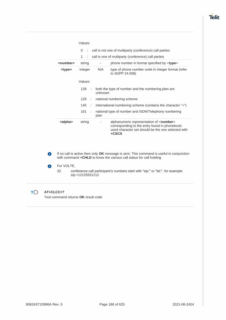
80624ST10996A Rev. 5 Page 186 of 625 2021-06-2424
Values:
0 : call is not one of multiparty (conference) call parties
1 : call is one of multiparty (conference) call parties
<number> string - phone number in format specified by <type>
<type> integer N/A type of phone number octet in integer format (refer to 3GPP 24.008)
Values:
128 : both the type of number and the numbering plan are unknown
129 : national numbering scheme
145 : international numbering scheme (contains the character "+")
161 : national type of number and ISDN/Telephony numbering plan
<alpha> string - alphanumeric representation of <number> corresponding to the entry found in phonebook; used character set should be the one selected with +CSCS
If no call is active then only OK message is sent. This command is useful in conjunction with command +CHLD to know the various call status for call holding
For VOLTE,
32. conference call participant’s numbers start with "sip:" or "tel:", for example: sip:+12125551212
AT+CLCC=?
Test command returns OK result code
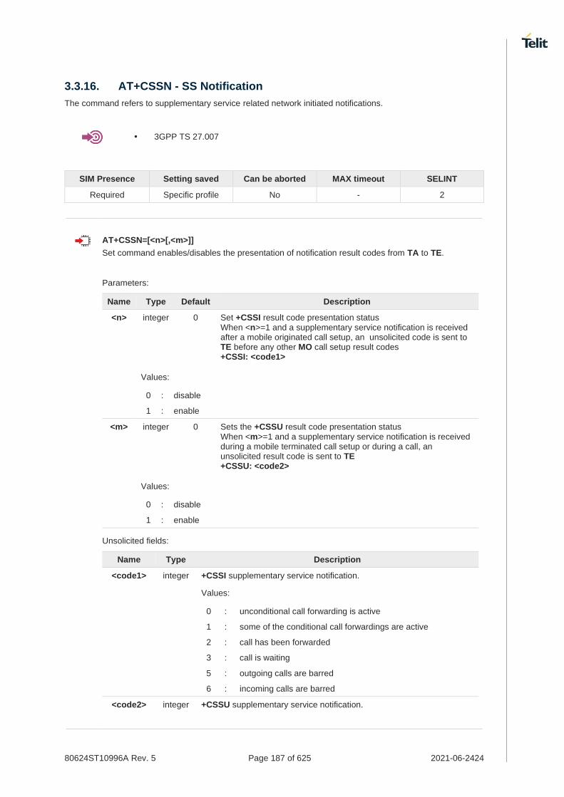
80624ST10996A Rev. 5 Page 187 of 625 2021-06-2424
3.3.16. AT+CSSN - SS Notification
The command refers to supplementary service related network initiated notifications.
• 3GPP TS 27.007
SIM Presence Setting saved Can be aborted MAX timeout SELINT
Required Specific profile No - 2
AT+CSSN=[<n>[,<m>]]
Set command enables/disables the presentation of notification result codes from TA to TE.
Parameters:
Name Type Default Description
<n> integer 0 Set +CSSI result code presentation status When <n>=1 and a supplementary service notification is received after a mobile originated call setup, an unsolicited code is sent to TE before any other MO call setup result codes +CSSI: <code1>
Values:
0 : disable
1 : enable
<m> integer 0 Sets the +CSSU result code presentation status When <m>=1 and a supplementary service notification is received during a mobile terminated call setup or during a call, an unsolicited result code is sent to TE +CSSU: <code2>
Values:
0 : disable
1 : enable
Unsolicited fields:
Name Type Description
<code1> integer +CSSI supplementary service notification.
Values:
0 : unconditional call forwarding is active
1 : some of the conditional call forwardings are active
2 : call has been forwarded
3 : call is waiting
5 : outgoing calls are barred
6 : incoming calls are barred
<code2> integer +CSSU supplementary service notification.

80624ST10996A Rev. 5 Page 188 of 625 2021-06-2424
Values:
0 : this is a forwarded call (MT call setup)
2 : call has been put on hold (during a voice call)
3 : call has been retrieved (during a voice call)
10 : additional incoming call forwarded
AT+CSSN?
Read command reports the current value of the parameters.
AT+CSSN=?
Test command reports the supported range of values for parameters <n>, <m>.

80624ST10996A Rev. 5 Page 189 of 625 2021-06-2424
3.3.17. AT+CCUG - Closed User Group
This command allows control of the Closed User Group supplementary service.
3GPP TS 27.007 3GPP TS 22.085
SIM Presence Setting saved Can be aborted MAX timeout SELINT
Required No No - 2
AT+CCUG=[<n>[,<index>[,<info>]]]
Set command enables the served subscriber to select a CUG index, to suppress the Outgoing Access (OA), and to suppress the preferential CUG.
Parameters:
Name Type Default Description
<n> integer 0 enables/disables the CUG temporary mode
Values:
0 : disable CUG temporary mode
1 : enable CUG temporary mode
<index> integer 10 Closed Used Group index
Values:
0÷9 : CUG index
10 : no index (preferred CUG taken from subscriber data)
<info> integer 0 information added to the CUG
Values:
0 : no information
1 : suppress Outgoing Access (OA)
2 : suppress preferential CUG
3 : suppress OA and preferential CUG
AT+CCUG?
Read command reports the current value of the parameters in the format +CCUG: <n>,<index>,<info>
AT+CCUG=?
Test command returns the OK result code

80624ST10996A Rev. 5 Page 190 of 625 2021-06-2424
3.3.18. AT+CPOL - Preferred Operator List
This command is used to edit the PLMN selector with Access Technology lists in the SIM card or active application the UICC (GSM or USIM).
3GPP TS 27.007
SIM Presence Setting saved Can be aborted MAX timeout SELINT
Required No No - 2
AT+CPOL=[<index>] [,<format>[,<oper>[,<GSM_AcT>,<GSM_Compact_AcT>, <UTRAN_AcT>,<E_UTRAN_AcTn>]]]
Execution command writes an entry in the SIM list of preferred operators.
Parameters:
Name Type Default Description
<index> integer N/A The order number of operator in the SIM preferred operators.
Value:
1÷n : order number in the list
<format> integer N/A
Values:
0 : Long format alphanumeric <oper>
1 : Short format alphanumeric <oper>
2 : Numeric <oper>
<oper> string - <format> indicates if the format is alphanumeric or numeric
<GSM_AcT> integer N/A GSM access technology.
Values:
0 : access technology not selected
1 : access technology selected
<GSM_Compact_AcT> integer N/A GSM compact access technology
Values:
0 : access technology not selected
1 : access technology selected
<UTRAN_AcT> integer N/A UTRA access technology
Values:
0 : access technology not selected
1 : access technology selected
<E_UTRAN_AcTn> integer N/A E-UTRAN access technology

80624ST10996A Rev. 5 Page 191 of 625 2021-06-2424
Values:
0 : access technology not selected
1 : access technology selected
If <index> given but <oper> left out, the entry deleted.
If <oper> given but <index> left out, <oper> put in the next free location.
If only <format> given, the format of the <oper> in the read command changes.
The user controlled PLMN could not be read/wrote/returned values and range on some SIM like AT&T when it set to CPLS 0 because the EF_PLMNwACT field does not exit.
The module which does not have the GSM access technology cannot support <GSM_AcT> and <GSM_Compact_AcT>.
AT+CPOL?
Read command returns all used entries from the SIM list of preferred operators.
AT+CPOL=?
Test command returns the whole <index> range supported by the SIM and the range for the parameter <format>

80624ST10996A Rev. 5 Page 192 of 625 2021-06-2424
3.3.19. AT#CODECINFO - Codec Information
This command returns information about the channels codecs.
SIM Presence Setting saved Can be aborted MAX timeout SELINT
Not required Specific profile No - 2
AT#CODECINFO[=<format>[,<mode>]]
This command is a set or an execution command. It enables/disables unsolicited channel codec information reports, or returns the channel codec info, in both case according to the specified format.
Set command format:
AT#CODECINFO=<format>,<mode>
Execution command format:
AT#CODECINFO
Parameters:
Name Type Default Description
<format> integer 0 select the return information format: numeric or textual
Values:
0 : numeric format, see info section
1 : textual format, see info section
<mode> integer 0 enable/disable unsolicited channels codecs information
Values:
0 : disable the URC of the channels codecs information, see info section
1 : enable the URC of the channels codecs information only if the codec changes, see info section
2 : enable the short URC of the channels codecs information only if the codec changes, see info section
Additional info:
<mode>=1, the URC of the channels codecs information is displayed according to the <format> parameter value:
if <format>=0, the URC is: #CODECINFO: <codec_used>,<codec_set>
if <format>=1, the URC is:
#CODECINFO: <codec_used>,<codec_set1>[,<codec_set2>[..[,codec_setn]]]
<mode>=2 the short URC of the channels codecs information is displayed as shown below:
#CODECINFO: <codec_used>
The <codec_used> format dependes on the <format> parameter value.

80624ST10996A Rev. 5 Page 193 of 625 2021-06-2424
Execution command (AT#CODECINFO<CR>) returns immediately channels codecs information according to the previous setting of <format> parameter.
if <format>=0, the return message is:
#CODECINFO: <codec_used>,<codec_set>
if <format>=1, the return message is:
#CODECINFO: <codec_used>,<codec_set1>[,<codec_set2>[..[,codec_setn]]]
The parameters and their format is described in the Unsolicited code values section.
Unsolicited fields:
Name Type Description
<codec_used> string <format>=0, <codec_used> is displayed in numeric format
Values:
0 : no TCH
1 : full rate speech 1 on TCH
2 : full rate speech 2 on TCH
4 : half rate speech 1 on TCH
8 : full rate speech 3 – AMR on TCH
16 : half rate speech 3 – AMR on TCH
128 : full data 9.6
129 : full data 4.8
130 : full data 2.4
131 : half data 4.8
132 : half data 2.4
133 : full data 14.4
134 : full rate AMR wide band
135 : UMTS AMR version 2
136 : UMTS AMR wide band
<codec_set> string <format>=0, <codec_set> is displayed in numeric format. It is the sum of integers each representing a specific channel codec.
channel codec: 1 - FR, full rate mode enabled 2 - EFR, enhanced full rate mode enabled 4 - HR, half rate mode enabled 8 - FAMR, AMR full rate mode enabled 16 - HAMR, AMR half rate mode enabled 32 - FR-AMR-WB, full rate AMR wide band 64 - UMTS-AMR-V2, UMTS AMR version 2 128 - UMTS-AMR-WB, UMTS AMR wide band
Value:
1..255 : sum of integers each representing a specific channel codec

80624ST10996A Rev. 5 Page 194 of 625 2021-06-2424
<codec_used> string <format>=1, <codec_used> is displayed in textual format
Values:
None : no TCH
FR : full rate speech 1 on TCH
EFR : full rate speech 2 on TCH
HR : half rate speech 1 on TCH
FAMR : full rate speech 3 – AMR on TCH
HAMR : half rate speech 3 – AMR on TCH
FD96 : full data 9.6
FD48 : full data 4.8
FD24 : full data 2.4
HD48 : half data 4.8
HD24 : half data 2.4
FD144 : full data 14.4
FAWB : full rate AMR wide band
UAMR2 : UMTS AMR version 2
UAWB : UMTS AMR wide band
<codec_setn> string <format>=1, <codec_setn> are displayed in textual format
Values:
FR : full rate mode enabled
EFR : enhanced full rate mode enabled
HR : half rate mode enabled
FAMR : AMR full rate mode enabled
HAMR : AMR half rate mode enabled
FAWB : full rate AMR wide band
UAMR2 : UMTS AMR version 2
UAWB : UMTS AMR wide band
The command refers to codec information in speech call, and to channel mode in data call.
If AT#CODEC=0, the reported channels codecs set, for <format>=0, is 255 (all codecs).
AT#CODECINFO?
Read command reports <format> and <mode> parameter values in the format:
#CODECINFO: <format>,<mode>

80624ST10996A Rev. 5 Page 195 of 625 2021-06-2424
AT#CODECINFO=?
Test command returns the range of supported <format> and <mode> parameters values.

80624ST10996A Rev. 5 Page 196 of 625 2021-06-2424
3.3.20. AT+CPLS - Selection of Preferred PLMN List
The command is used to select a list of preferred PLMNs in the SIM/USIM card.
3GPP TS 27.007
SIM Presence Setting saved Can be aborted MAX timeout SELINT
Required Auto No - 2
AT+CPLS=<list>
Set command select one PLMN selector with Access Technology list in the SIM card or active application in the UICC (GSM or USIM), that is used by +CPOL command.
Parameter:
Name Type Default Description
<list> integer 0 PLMNs list selector
Values:
0 : User controlled PLMN selector with Access Technology EFPLMNwAcT, if not found in the SIM/UICC then PLMN preferred list EFPLMNsel (this file is only available in SIM card or GSM application selected in UICC)
1 : Operator controlled PLMN selector with Access Technology EFOPLMNwAcT
2 : HPLMN selector with Access Technology EFHPLMNwAcT
The value set by command is directly stored in NVM and doesn't depend on the specific CMUX instance.
AT+CPLS?
Read command returns the selected PLMN selector <list> from the SIM/USIM.
AT+CPLS=?
Test command returns the whole index range supported <list>s by the SIM/USIM.

80624ST10996A Rev. 5 Page 197 of 625 2021-06-2424
3.3.21. AT+CSQ - Signal Quality
Execution command returns received signal strength indication <rssi> and channel bit error rate <ber> from the MT.
3GPP TS 27.007 3GPP TS 25.133
SIM Presence Setting saved Can be aborted MAX timeout SELINT
Required No No - 2
AT+CSQ
See Additional info sections.
Additional info:
3G Networks
The execution command returns the following message:
+CSQ: <rssi>,<ecio>
Name Type Default Description
<rssi> integer N/A measurements of the radio signal power, expressed in dBm, are mapped to <rssi> as shown below
Values:
0 : -113 dBm or less
1 : -111 dBm
2÷30 : -109 dBm ... -53 dBm; 2 dBm per step
31 : -51 dBm or greater
99 : not known or not detectable
<ecio> integer N/A Chip energy per total wideband power in dBm.
For <ecio> levels are mapped to range 0...7.
Values:
0 : -1…0
1 : -5…-2
2 : -8…-6
3 : -11…-9
4 : -15…-12
5 : -18…-16
6 : -22…-19
7 : -24...-23
99 : not known or not detectable

80624ST10996A Rev. 5 Page 198 of 625 2021-06-2424
4G Networks
The execution command returns the following message:
+CSQ: <rssi>,<rsrq>
Name Type Default Description
<rssi> integer N/A Received Signal Strength Indication. For <rssi> to be compliant with 3GPP TS27.007 specification, levels are mapped to range 0...31.
Values:
0 : -113 dBm or less
1 : -111 dBm
2÷30 : -109...-53 dBm
31 : - 51 dBm or greater
99 : not known or not detectable
<rsrq> integer N/A Reference Signal Received Quality. For <rsrq> levels are mapped to range 0...7.
Values:
0 : -4...-3 dBm
1 : -6...-5 dBm
2 : -8...-7 dBm
3 : -10...-9 dBm
4 : -13...-11 dBm
5 : -15...-14 dBm
6 : -17...-16 dBm
7 : -19...-18 dBm
99 : not known or not detectable
For UMTS, the current radio signal strength indicates CPICH RSCP in levels.
For UMTS, radio signal quality CPIC Ec/Io range -24dB to 0dB is scaled to 0 to 7.
AT+CSQ=?
Test command returns values supported as compound values.
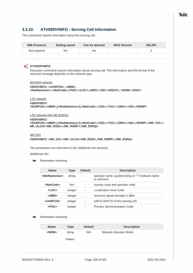
80624ST10996A Rev. 5 Page 199 of 625 2021-06-2424
3.3.22. AT#SERVINFO - Serving Cell Information
This command reports information about the serving cell.
SIM Presence Setting saved Can be aborted MAX timeout SELINT
Not required No No - 2
AT#SERVINFO
Execution command reports information about serving cell. The information and the format of the returned message depends on the network type.
WCDMA network
#SERVINFO: <UARFCN>, <dBM>, <NetNameAsc>,<NetCode>,<PSC>,<LAC>,<DRX>,<SD>,<RSCP>, <NOM>,<RAC>
LTE network
#SERVINFO: <EARFCN>,<dBM>,[<NetNameAsc>],<NetCode>,<CID>,<TAC>,<DRX>,<SD>,<RSRP>
LTE network with NR (ENDC)
#SERVINFO: <EARFCN>,<dBM>,[<NetNameAsc>],<NetCode>,<CID>,<TAC>,<DRX>,<SD>,<RSRP>,<NR_CH>,<NR_ULCH><NR_RSSI>,<NR_RSRP>,<NR_RSRQ>
NR (SA)
#SERVINFO: <NR_CH>,<NR_ULCH><NR_RSSI>,<NR_RSRP>,<NR_RSRQ>
The parameters are described in the Additional info sections.
Additional info:
Parameters meaning.
Name Type Default Description
<NetNameAsc> string - operator name, quoted string or "" if network name is unknown.
<NetCode> hex - country code and operator code.
<LAC> integer - Localization Area Code
<dBM> integer - received signal strength in dBm
<UARFCN> integer - UMTS ARFCN of the serving cell
<PSC> integer - Primary Synchronization Code
Parameters meaning.
Name Type Default Description
<NOM> string N/A Network Operator Mode.
Values:

80624ST10996A Rev. 5 Page 200 of 625 2021-06-2424
I : Network Mode I
II : Network Mode II
III : Network Mode III
<RAC> integer - Routing Area Color Code.
Parameters meaning.
Name Type Default Description
<DRX> integer - Discontinuous reception cycle length.
<SD> integer N/A Service Domain
Values:
0 : No Service
1 : CS only
2 : PS only
3 : CS & PS
<RSCP> integer - Received Signal Code Power in dBm.
<EARFCN> integer - LTE Assigned Radio Channel
<CID> integer - Cell Identifier
<TAC> integer - Tracking Area Code
<RSRP> integer - Reference Signal Received Power
<NR_CH> integer - NR DL active channel
<NR_ULCH> integer - NR UL active channel
<NR_RSSI> integer - NR received signal strength in dBm
<NR_RSRP> integer - NR Reference Signal Received Power
<NR_RSRQ> string - NR Reference Signal Received Quality
AT#SERVINFO=?
Test command returns OK result code.

80624ST10996A Rev. 5 Page 201 of 625 2021-06-2424
3.3.23. AT#BCCHLOCK - Lock to Single BCCH ARFCN
This command enables/disable the single BCCH ARFCN locking.
SIM Presence Setting saved Can be aborted MAX timeout SELINT
Not required Auto No - 2
AT#BCCHLOCK=<LockedBcch>[,<LockedUarfcn>[,<LockedPsc>[,<LockedEarfcn>[,<LockedPci>]]]]
This command allows to set the single BCCH ARFCN(also UARFCN and EARFCN) the device must be locked to, selectable within those allowed for the specific product.
Parameters:
Name Type Default Description
<LockedBcch> integer 1024 enable/disable 2G BCCH locking
Values:
1024 : disable
0÷124 : enable on GSM 900MHz
975÷1023 : enable on GSM 900MHz
512÷885 : enable on DCS 1800MHz
128÷251 : enable on GSM 850MHz
512÷810 : enable on PCS 1900MHz
<LockedUarfcn> integer 0 enable/disable 3G BCCH locking
Values:
0 : disable
712÷10838 : enable on downlink UARFCN in UMTS supported bands (some values in range 712-10838 are not supported according to product band configuration).
<LockedPsc> integer 65535 enable/disable 3G BCCH locking Primary Scrambling Code selection
Values:
65535 : disable
0÷511 : Primary Scrambling Code
<LockedEarfcn> integer 0 A number in the range 0-68935 representing the earfcn to search. An value of 0 will remove the earfcn restriction and any associated Physical Cell ID lock.
Values:
0 : disable
0÷68935 : enable on downlink EARFCN in LTE supported bands (some values in range 0-68935 are not supported according to product band configuration).
<LockedPci> hex 0 E-UTRAN physical cell ID in hexadecimal format. Valid range 0 - 1F7. If the value 0 of <LockedEarfcn> is input, this value would be 0.
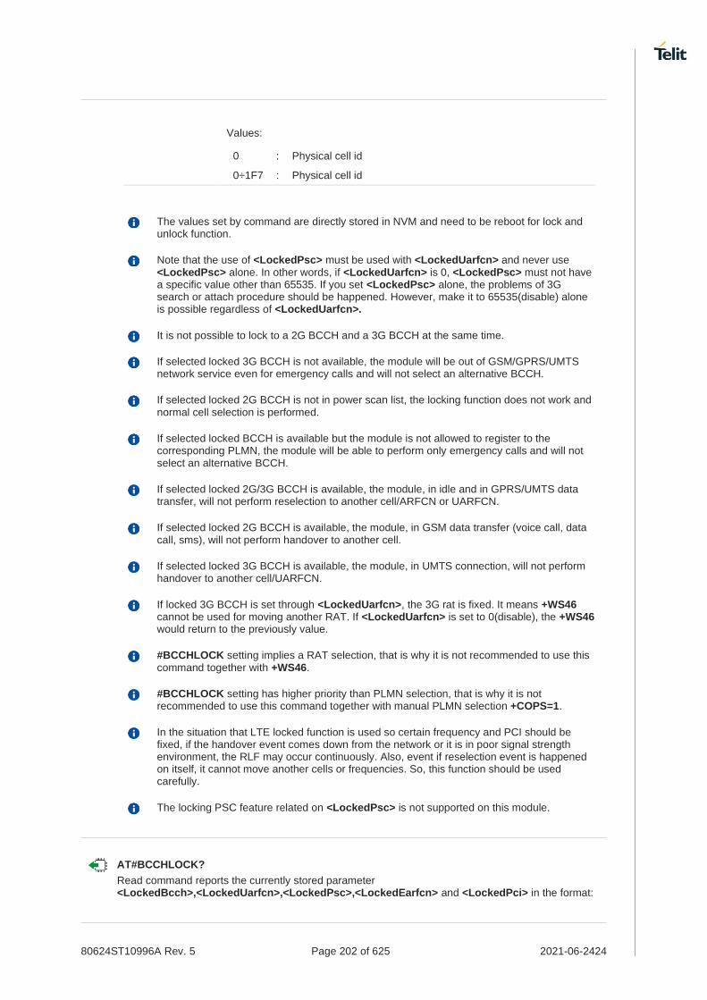
80624ST10996A Rev. 5 Page 202 of 625 2021-06-2424
Values:
0 : Physical cell id
0÷1F7 : Physical cell id
The values set by command are directly stored in NVM and need to be reboot for lock and unlock function.
Note that the use of <LockedPsc> must be used with <LockedUarfcn> and never use <LockedPsc> alone. In other words, if <LockedUarfcn> is 0, <LockedPsc> must not have a specific value other than 65535. If you set <LockedPsc> alone, the problems of 3G search or attach procedure should be happened. However, make it to 65535(disable) alone is possible regardless of <LockedUarfcn>.
It is not possible to lock to a 2G BCCH and a 3G BCCH at the same time.
If selected locked 3G BCCH is not available, the module will be out of GSM/GPRS/UMTS network service even for emergency calls and will not select an alternative BCCH.
If selected locked 2G BCCH is not in power scan list, the locking function does not work and normal cell selection is performed.
If selected locked BCCH is available but the module is not allowed to register to the corresponding PLMN, the module will be able to perform only emergency calls and will not select an alternative BCCH.
If selected locked 2G/3G BCCH is available, the module, in idle and in GPRS/UMTS data transfer, will not perform reselection to another cell/ARFCN or UARFCN.
If selected locked 2G BCCH is available, the module, in GSM data transfer (voice call, data call, sms), will not perform handover to another cell.
If selected locked 3G BCCH is available, the module, in UMTS connection, will not perform handover to another cell/UARFCN.
If locked 3G BCCH is set through <LockedUarfcn>, the 3G rat is fixed. It means +WS46 cannot be used for moving another RAT. If <LockedUarfcn> is set to 0(disable), the +WS46 would return to the previously value.
#BCCHLOCK setting implies a RAT selection, that is why it is not recommended to use this command together with +WS46.
#BCCHLOCK setting has higher priority than PLMN selection, that is why it is not recommended to use this command together with manual PLMN selection +COPS=1.
In the situation that LTE locked function is used so certain frequency and PCI should be fixed, if the handover event comes down from the network or it is in poor signal strength environment, the RLF may occur continuously. Also, event if reselection event is happened on itself, it cannot move another cells or frequencies. So, this function should be used carefully.
The locking PSC feature related on <LockedPsc> is not supported on this module.
AT#BCCHLOCK?
Read command reports the currently stored parameter <LockedBcch>,<LockedUarfcn>,<LockedPsc>,<LockedEarfcn> and <LockedPci> in the format:

80624ST10996A Rev. 5 Page 203 of 625 2021-06-2424
#BCCHLOCK: <LockedBcch>,<LockedUarfcn>,<LockedPsc>,<LockedEarfcn>,<LockedPci>
If <LockedEarfcn> is set to 0, the related EFS would be removed so <LockedPci> always returned 0 even if its value was input.
AT#BCCHLOCK=?
Test command reports the supported range of values for parameter <LockedBcch>,<LockedUarfcn>,<LockedPsc>,<LockedEarfcn> and <LockedPci>.

80624ST10996A Rev. 5 Page 204 of 625 2021-06-2424
3.3.24. AT#CODEC - GSM and UMTS Audio Codec
GSM and UMTS audio codec mode settings
3GPP TS 24.008
SIM Presence Setting saved Can be aborted MAX timeout SELINT
Not required Common profile No - 2
AT#CODEC=[<codec>]
Set command sets the GSM and UMTS audio codec mode.
Parameter:
Name Type Default Description
<codec> integer 0 0 = all the codec modes are enabled
1-255: sum of integers each representing a specific codec mode as follows
33. 1 = FR, full rate mode enabled 34. 2 = EFR, enhanced full rate mode enabled 35. 4 = HR, half rate mode enabled 36. 8 = AMR-FR, AMR full rate mode enabled 37. 16 = AMR-HR, AMR half rate mode enabled 38. 32 = FAWB, full rate AMR wide band 39. 64 = UAMR2, UMTS AMR version 2 40. 128 = UAWB, UMTS AMR wide band
Value:
0÷255 : codec modes setting
Full rate mode is added by default to any setting in the SETUP message (as specified in 3GPP TS 24.008), but the call drops if the network assigned codec mode has not been selected by the user.
AT#CODEC=4 and AT#CODEC=16 are not recommended; better using AT#CODEC=5 and AT#CODEC=24 respectively
The setting 0 is equivalent to the setting 255.
AT#CODEC?
Read command returns current audio codec mode in the format:
#CODEC: <codec>
AT#CODEC=?
Test command returns the range of available values for parameter <codec>

80624ST10996A Rev. 5 Page 205 of 625 2021-06-2424
• AT#CODEC=14
OK
sets the codec modes HR (4), EFR (2) and AMR-FR (8)

80624ST10996A Rev. 5 Page 206 of 625 2021-06-2424
3.3.25. AT#BND - Select Band
This command selects RF bands
SIM Presence Setting saved Can be aborted MAX timeout SELINT
Not required Auto No - 2
AT#BND=<GSM_band>[,<UMTS_band>[,<LTE_band>[,<LTE_band_ext>[,<NSA_NR5G_band_1_64>[,<NSA_NR5G_band_65_128>[,<NSA_NR5G_band_257_320>[,<SA_NR5G_band_1_64>[,<SA_NR5G_band_65_128>[,<SA_NR5G_band_257_320>]]]]]]]]]
Set command selects the current WCDMA, LTE and NR5G bands.
Parameters:
Name Type Default Description
<GSM_band> integer 0 GSM band selection.
Values:
0 : GSM 900MHz + DCS 1800MHz
1 : GSM 900MHz + PCS 1900MHz
2 : GSM 850MHz + DCS 1800MHz
3 : GSM 850MHz + PCS 1900MHz
4 : GSM 900MHz + DCS 1800MHz + PCS 1900MHz
5 : GSM 850MHz + GSM 900MHz + DCS 1800MHz + PCS 1900MHz
<UMTS_band> integer N/A WCDMA band selection.
Values:
0 : 2100MHz (FDD I)
1 : 1900MHz (FDD II)
2 : 850MHz (FDD V)
3 : 2100MHz (FDD I) + 1900MHz (FDD II) + 850MHz (FDD V)
4 : 1900MHz (FDD II) + 850MHz (FDD V)
5 : 900MHz (FDD VIII)
6 : 2100MHz (FDD I) + 900MHz (FDD VIII)
7 : 1700MHz (FDD IV)
8 : 2100MHz (FDD I) + 850MHz (FDD V)
9 : 2100MHz (FDD I) + 900MHz (FDD VIII) + 850MHz (FDD V)
10 : 1900MHz (FDD II) + 1700MHz (FDD IV) + 850MHz (FDD V)
11 : 2100MHz (FDD I) + 1900MHz (FDD II) + 1700MHz (FDD IV) + 850MHz (FDD V) + 900MHz (FDD VIII)
12 : 2100MHz (FDD I) + 1800MHz (FDD III) + 850MHz (FDD V) + 900MHz (FDD VIII)
13 : 1800MHz (FDD III)

80624ST10996A Rev. 5 Page 207 of 625 2021-06-2424
14 : 2100MHz (FDD I) + 1800MHz (FDD III) + 850MHz (FDD V)
15 : 1800MHz (FDD III) + 850MHz (FDD V)
16 : 2100MHz (FDD I) + 1900MHz (FDD II) + 1800MHz (FDD III) + 1700MHz (FDD IV) + 850MHz (FDD V) + 900MHz (FDD VIII)
17 : 2100MHz (FDD I) + 1900MHz (FDD II) + 900MHz (FDD VIII)
18 : 2100MHz (FDD I) + 1900MHz (FDD II) + 1700MHz (FDD IV) + 850MHz (FDD V) + 900MHz (FDD VIII) + JAPAN1800(FDD IX) + JAPAN800(FDD XIX)
19 : 2100MHz (FDD I) + 1900MHz (FDD II) + 1700MHz (FDD IV) + 850MHz (FDD V) + JAPAN850MHz (FDD VI) + 900MHz (FDD VIII) + JAPAN1800(FDD IX) + JAPAN800(FDD XIX)
20 : 2100MHz (FDD I) + 1900MHz (FDD II) + 1800MHz (FDD III) + 1700MHz (FDD IV)
21 : 2100MHz (FDD I) + 1900MHz (FDD II) + 1800MHz (FDD III) + 1700MHz (FDD IV) + 850MHz (FDD V) + JAPAN850MHz (FDD VI) + 900MHz (FDD VIII) + JAPAN1800(FDD IX) + JAPAN800(FDD XIX)
<LTE_band> hex N/A Indicates the LTE supported bands expressed as the sum of Band number (1+2+8 ...) calculated as shown in the table (mask of 64 bits):
Band number(Hex) Band i
0 disable
1 B1
2 B2
4 B3
8 B4
... ...
80000000 B32
... ...
800000000000 B48
Value:
0÷A7E2BB0F38DF : range of the sum of Band number (1+2+4 ...)
<LTE_band_ext> hex N/A Indicates the LTE supported bands from B65 expressed as the sum of Band number (1+2+8 ...) calculated as shown in the table (mask of 64 bits):
Band number(Hex) Band i
0 disable
2 B66
40 B71
Value:
0÷42 : range of the sum of Band number (2+40)
<NSA_NR5G_band_1_64> hex N/A Indicates the NSA NR5G supported bands expressed as the sum of Band

80624ST10996A Rev. 5 Page 208 of 625 2021-06-2424
number (1+2+8 ...) calculated as shown in the table (mask of 64 bits):
Band number(Hex) Band i
0 disable
1 n1
2 n2
4 n3
8 n4
... ...
80000000 n32
... ...
800000000000 n48
Value:
0÷81A0090808D7 : range of the sum of Band number (1+2+4 ...)
<NSA_NR5G_band_65_128> hex N/A Indicates the NSA NR5G supported bands from B65expressed as the sum of Band number (1+2+8 ...) calculated as shown in the table (mask of 64 bits):
Band number(Hex) Band i
0 disable
2 n66
40 n71
1000 n77
2000 n78
4000 n79
Value:
0÷7042 : range of the sum of Band number (2+40+1000 ...)
<NSA_NR5G_band_257_320> hex N/A Indicates the NSA NR5G supported bands from B257 expressed as the sum of Band number (1+2+8 ...) calculated as shown in the table (mask of 64 bits):
Band number(Hex) Band i
0 disable
1 n257
2 n258
8 n260
10 n261
Value:
0÷1B : range of the sum of Band number (1+2...)
<SA_NR5G_band_1_64> hex 0 Indicates the SA NR5G supported bands expressed as the sum of Band number (1+2+8 ...) calculated as shown in the table (mask of 64 bits):
Band number(Hex) Band i

80624ST10996A Rev. 5 Page 209 of 625 2021-06-2424
0 disable
1 n1
2 n2
4 n3
8 n4
... ...
80000000 n32
... ...
800000000000 n48
Values:
0÷10009000047 : range of the sum of Band number (1+2+4 ...)
0 : Not support
<SA_NR5G_band_65_128> hex N/A Indicates the SA NR5G supported bands from B65expressed as the sum of Band number (1+2+8 ...) calculated as shown in the table (mask of 64 bits):
Band number(Hex) Band i
0 disable
2 n66
40 n71
1000 n77
2000 n78
4000 n79
Value:
0÷6042 : range of the sum of Band number (2+40+1000 ...)
<SA_NR5G_band_257_320> hex 0 It cannot be used by default because solution provider did not support yet.
Indicates the SA NR5G supported bands from B257 expressed as the sum of Band number (1+2+8 ...) calculated as shown in the table (mask of 64 bits):
Band number(Hex) Band i
0 disable
1 n257
2 n258
8 n260
10 n261
Value:
0 : Not support
Additional info:
The NR5G FR2 bands, <NSA_NR5G_band_257_320>, follows the QTM antenna identity.
QTM antenna Supported mmwave band
QTM 525-2 n257, n258
QTM 525-5 n258, n260, n261

80624ST10996A Rev. 5 Page 210 of 625 2021-06-2424
QTM 527-1 n260, n261
QTM 527-2 n257, n258, n261
None Not supported
This setting is maintained even after power off. <GSM_band>, <UMTS_band> parameters are decimal value. <LTE_band>,<LTE_band_ext>,<NSA_NR5G_band_1_64>,<NSA_NR5G_band_65_128>,<NSA_NR5G_band_257_320>,<SA_NR5G_band_1_64>,<SA_NR5G_band_65_128> and <SA_NR5G_band_257_320> parameters are hex format value and band set should be entered in HEX format without "0x".
The <LTE_band> and <LTE_band_ext> cannot be set to 0 at the same time.
If the one of NR5G bands is changed, the reboot process have to be needed for proper band search behavior.
The NR5G bands cannot be set to 0 at the same time.
This module use fixed unused value 0 for <GSM_band> parameter. For any variants which cannot support WCDMA, the <UMTS_band> is fixed unused value 0.
Supported band for each network provider.
<GCF>
5G FR1 NSA : 1,2,3,5,7,8,12,20,25,28,38,40,41,48,66,71,77,78,79
5G FR2 NSA : Depends on the MMW antenna.
5G FR1 SA : Not supported by default, but N1,2,3,7,25,28,41,66,71,78 and 79 can be enabled through #BND command.
5G FR2 SA : Not supported by default because it cannot be supported by solution provider.
LTE : 1,2,3,4,5,7,8,12,13,14,17,18,19,20,25,26,28,29,30,32,34,38,39,40,41,42,43,46,48,66,71
WCDMA : 1,2,3,4,5,6,8,9,19
GSM : Not Supported
<NTT>
5G FR1 NSA : 2,5,7,12,20,25,38,40,48,66,71,77,78,79 (N1,3,8,28 and 41 are not supported by default, but it can be enabled through #BND command)
5G FR2 NSA : Depends on the MMW antenna.
5G FR1 SA : Not supported by default, but N1,2,3,7,25,28,41,66,71,78 and 79 can be enabled through #BND command.
5G FR2 SA : Not supported by default because it cannot be supported by solution provider.
LTE : 1,2,3,4,5,7,8,12,13,14,17,18,19,20,25,26,28,29,30,32,34,38,39,40,41,42,43,46,48,66,71
WCDMA : 1,2,3,4,5,6,8,9,19
GSM : Not Supported
<TELSTRA>
5G FR1 NSA : 2,5,8,12,20,25,38,40,41,48,66,71,77,78,79 (N1,3,7 and 28 are not supported by default, but it can be enabled through #BND command)
5G FR2 NSA : Depends on the MMW antenna.
5G FR1 SA : Not supported by default, but N1,2,3,7,25,28,41,66,71,78 and 79 can be enabled through #BND command.
5G FR2 SA : Not supported by default because it cannot be supported by solution provider.
LTE : 1,2,3,4,5,7,8,12,13,14,17,18,19,20,25,26,28,29,30,32,34,38,39,40,41,42,43,46,48,66,71

80624ST10996A Rev. 5 Page 211 of 625 2021-06-2424
WCDMA : 1,2,3,4,5,6,8,9,19
GSM : Not Supported
<KDDI>
5G FR1 NSA : 78 (N1,2,3,5,7,8,12,20,25,28,38,40,41,48,66,71,77,79 are not supported by default, but it can be enabled through #BND command)
5G FR2 NSA : Depends on the MMW antenna.
5G FR1 SA : Not supported by default, but N1,2,3,7,25,28,41,66,71,78 and 79 can be enabled through #BND command.
5G FR2 SA : Not supported by default because it cannot be supported by solution provider.
LTE : 1,3,18,26,28,41,42 (B2,4,5,7,8,12,13,14,17,19,20,25,29,30,32,34,38,39,40,43,46,48,66,71 are not supported by default, but it can be enabled through #BND command)
WCDMA : 1,2,3,4,5,6,8,9,19
GSM : Not Supported
<VZW, SPRINT>
5G FR1 NSA : 1,2,3,5,7,8,12,20,25,28,38,40,41,48,66,71,77,78,79
5G FR2 NSA : Depends on the MMW antenna.
5G FR1 SA : Not supported by default, but N1,2,3,7,25,28,41,66,71,78 and 79 can be enabled through #BND command.
5G FR2 SA : Not supported by default because it cannot be supported by solution provider.
LTE : 1,2,3,4,5,7,8,12,13,14,18,19,20,25,26,28,29,30,32,34,38,39,40,41,42,43,46,48,66,71
WCDMA : Not Supported
GSM : Not Supported
<PTCRB/TMO>
5G FR1 NSA : 1,2,3,5,7,8,12,20,25,28,38,40,41,48,66,71,77,78,79
5G FR2 NSA : Depends on the MMW antenna.
5G FR1 SA : Not supported by default, but N1,2,3,7,25,28,41,66,71,78 and 79 can be enabled through #BND command.
5G FR2 SA : Not supported by default because it cannot be supported by solution provider.
LTE : 1,2,3,4,5,7,8,12,13,14,18,19,20,25,26,28,29,30,32,34,38,39,40,41,42,43,46,48,66,71
WCDMA : Not Supported
GSM : Not Supported
<ATT>
5G FR1 NSA : 2,5,12,66,77
5G FR2 NSA : Depends on the MMW antenna.
5G FR1 SA : Not supported by default, but N1,2,3,7,25,28,41,66,71,78 and 79 can be enabled through #BND command.
5G FR2 SA : Not supported by default because it cannot be supported by solution provider.
LTE : 2,4,5,12,14,26,29,30,46,48,66 (B1,3,7,8,13,18,19,20,25,28,32,34,38,39,40,41,42,43,71 are not supported by default, but they can be enabled through #BND command)
WCDMA : Not Supported
GSM : Not Supported
<ANATEL>
5G FR1 NSA : 1,2,3,5,7,8,12,20,25,28,38,40,41,48,66,71,77,78,79
5G FR2 NSA : Depends on the MMW antenna.
5G FR1 SA : Not supported by default, but N1,2,3,7,25,28,41,66,71,78 and 79 can be enabled through #BND command.

80624ST10996A Rev. 5 Page 212 of 625 2021-06-2424
5G FR2 SA : Not supported by default because it cannot be supported by solution provider.
LTE : 1,2,3,4,5,7,8,12,13,14,18,19,20,25,26,28,29,30,32,34,38,40,41,42,43,46,48,66,71
WCDMA : Not Supported
GSM : Not Supported
<SKT/SKTD>
5G FR1 NSA : 78
5G FR2 NSA : Depends on the MMW antenna and only 257 band can be supported.
5G FR1 SA : 78
5G FR2 SA : Not supported by default because it cannot be supported by solution provider.
LTE : 1,3,5,7,8
WCDMA : Not Supported
GSM : Not Supported
Although the FT980-KS module is a SKT variant, it supports only LTE bands 1, 3, 5 and 7.
AT#BND?
Read command returns the current selected band in the format:
#BND: <band>,<UMTS_band>,<LTE_band>,<LTE_band_ext>,<NSA_NR5G_band_1_64>,<NSA_NR5G_band_65_128>,<NSA_NR5G_band_257_320>,<SA_NR5G_band_1_64>,<SA_NR5G_band_65_128>,<SA_NR5G_band_257_320>
AT#BND=?
Test command returns the supported range of values of parameters <band>, <UMTS_band><LTE_band>,<LTE_band_ext>,<NSA_NR5G_band_1_64>,<NSA_NR5G_band_65_128>,<NSA_NR5G_band_257_320>,<SA_NR5G_band_1_64>,<SA_NR5G_band_65_128> and <SA_NR5G_band_257_320>.
Test command
AT#BND=? #BND: (0),(0-21),(A7E2BB0F38DF),(42),(81A0090808D7),(7042),(3),(10009000047),(6042),(0) OK
Read command
AT#BND? #BND: 0,21,A7E2BB0F38DF,42,81A0090808D7,7042,3,0,0,0 OK
Read command indicates the supported bands.

80624ST10996A Rev. 5 Page 213 of 625 2021-06-2424
3.3.26. AT+CEMODE - Set Mode of Operation for EPS
This command used to configure the mode of operation for EPS.
3GPP TS 24.301
SIM Presence Setting saved Can be aborted MAX timeout SELINT
Not required Auto No - 2
AT+CEMODE=[<mode>]
This set command configures the mode of operation for EPS.
Parameter:
Name Type Default Description
<mode> integer 1 mode of operation. The default value depends on product.
UE modes of operation can be found in 3GPP TS 24.301. Other values are reserved and will result in an ERROR response to the set command.
Values:
0 : PS mode 2 of operation
1 : CS/PS mode 1 of operation
2 : CS/PS mode 2 of operation
3 : PS mode 1 of operation
The default value of parameter <mode> is 2 in FT980-KS.
AT+CEMODE?
Read command returns the current value of parameter <mode> in the format:
+CEMODE: < mode >
The read command will return right values after set command, but effectively the mode of operation changes after power cycle.
AT+CEMODE=?
Test command returns the supported range of values of parameters <mode>.

80624ST10996A Rev. 5 Page 214 of 625 2021-06-2424
Set EPS mode AT+CEMODE=1 OK
Check EPS mode AT+CEMODE? +CEMODE: 1 OK

80624ST10996A Rev. 5 Page 215 of 625 2021-06-2424
3.3.27. AT+CEUS - UE's usage setting for EPS and 5GS
This command sets the UE's usage setting for EPS and 5GS.
SIM Presence Setting saved Can be aborted MAX timeout SELINT
Not required Auto No - 2
AT+CEUS=[<setting>]
Set command is used to set the UE to operate according to the specified UE's usage setting for EPS (see 3GPP TS 24.301) and 5GS (see 3GPP TS 24.501).
Parameter:
Name Type Default Description
<setting> integer N/A indicates the usage setting of the UE
Values:
0 : voice centric
1 : data centric
AT+CEUS?
Read command returns the usage setting value
+CEUS: <setting>
AT+CEUS=?
Test command returns supported values for parameter <setting>.

80624ST10996A Rev. 5 Page 216 of 625 2021-06-2424
3.3.28. AT+CPNER - Primary Notification Event Reporting
This command enables/disables reporting of primary notification events received from the network.
SIM Presence Setting saved Can be aborted MAX timeout SELINT
Required Auto No - 2
AT+CPNER=[<reporting>]
This command enables/disables reporting of primary notification events with the following unsolicited result code.
+CPNERU: <message_identifier>,<serial_number>,<warning_type>
Primary notification events used for public warning systems like ETWS (Earthquake and Tsunami Warning Systems).
Parameter:
Name Type Default Description
<reporting> integer 1 Controlling reporting of primary notification events.
Values:
0 : Disable primary notification events.
1 : Enable reporting of primary notification events without security information, unsolicited result code(default)
Unsolicited fields:
Name Type Description
<message_identifier> string string type in hexadecimal character format. The parameter contains the message identifier (2 bytes) of the primary notification.
<serial_number> string string type in hexadecimal character format. The parameter contains the serial number (2 bytes) of the primary notification.
<warning_type> string string type in hexadecimal character format. The parameter contains the warning type (2 bytes) of the primary notification.
AT+CPNER?
Read command reports the current value of the parameter.
AT+CPNER=?
Test command returns supported of parameter.
AT+CPNER?
+CPNER: 1
OK

80624ST10996A Rev. 5 Page 217 of 625 2021-06-2424
3.3.29. AT+CESQ - Extended Signal Quality
Execution command returns received signal quality parameters.
[1] 3GPP TS 27.007 [2] 3GPP TS 45.008 [3] 3GPP TS 25.133 [4] 3GPP TS 26.133 [5] 3GPP TS 38.133
SIM Presence Setting saved Can be aborted MAX timeout SELINT
Required No No - 2
AT+CESQ
Execution command reports received signal quality parameters in the form:
+CESQ: <rxlev>,<ber>,<rscp>,<ecno>,<rsrq>,<rsrp>,<ss_rsrq>,<ss_rsrp>,<ss_sinr>
Additional info:
Name Type Default Description
<rxlev> integer N/A Received signal strength level (see 3GPP TS 45.008 subclause 8.1.4)
Values:
0 : rssi < -110 dBm
1 : -110 dBm ≤ rssi < -109 dBm
2 : -109 dBm ≤ rssi < -108 dBm
... : ...
61 : - 50 dBm ≤ rssi < - 49 dBm
62 : - 49 dBm ≤ rssi < -48 dBm
63 : - 48 dBm ≤ rssi
99 : not known or not detectable or if the current serving cell is not a GERAN cell
<ber> integer N/A Channel bit error rate (in percent)
Values:
0÷7 : as RXQUAL values, see 3GPP TS 45.008 subclause 8.2.4
99 : not known or not detectable or if the current serving cell is not a GERAN cell
<rscp> integer N/A Received signal code power (see 3GPP TS 25.133 subclause 9.1.1.3 and 3GPP TS 25.123 subclause 9.1.1.1.3)

80624ST10996A Rev. 5 Page 218 of 625 2021-06-2424
Values:
0 : rscp < -120 dB
1 : -120 dBm ≤ rscp < -119 dBm
2 : -119 dBm ≤ rscp < -118 dBm
... : ...
94 : -27 dBm ≤ rscp < -26 dBm
95 : -26 dBm ≤ rscp < -25 dBm
96 : -25 dBm ≤ rscp
255 : not known, not detectable or if the current serving cell is not a UTRA cell
<ecno> integer N/A Ratio of the received energy per PN chip to the total received power spectral density (see 3GPP TS 25.133 subclause).
Values:
0 : Ec/Io < -24 dBm
1 : -24 dBm ≤ Ec/Io < -23.5 dBm
2 : -23.5 dBm dBm ≤ Ec/Io < -23 dBm
... : ...
47 : -1 dBm ≤ Ec/Io < -0.5 dBm
48 : -0.5 dBm ≤ Ec/Io < 0 dBm
49 : 0 dBm ≤ Ec/Io
255 : not known, not detectable or if the current serving cell is not a UTRA cell
<rsrq> integer 0 reference signal received quality (see 3Gpp TS 36.133 subclause 9.1.7)
Values:
0 : rsrq < -19.5 dBm
1 : -19.5 dBm ≤ rsrq < -19 dBm
2 : -19 dBm ≤ rsrq < -18.5 dBm
... : ...
32 : -4 dBm ≤ rsrq < -3.5 dBm
33 : -3.5 dBm ≤ rsrq < -3 dBm
34 : -3 dBm ≤ rsrq
255 : not known, not detectable or if the current serving cell is not a EUTRA cell
<rsrp> integer 0 reference signal received power (see 3Gpp TS 36.133 subclause 9.1.4)
Values:
0 : rsrp < -140 dBm
1 : -140 dBm ≤ rsrp < -139 dBm

80624ST10996A Rev. 5 Page 219 of 625 2021-06-2424
2 : -139 dBm ≤ rsrp < -138 dBm
... : ...
95 : -46 dBm ≤ rsrp < -45 dBm
96 : -45 dBm ≤ rsrp < -44 dBm
97 : -44 dBm ≤ rsrp
255 : not known, not detectable or if the current serving cell is not a EUTRA cell
<ss_rsrq> integer 0 synchronization signal based reference signal received quality (see 3GPP TS 38.133 [169] subclause 10.1.11)
Values:
0 : ss_rsrq < -43 dB
1 : -43 dB ≤ ss_rsrq < -42.5 dB
2 : -42.5 dB ≤ ss_rsrq < -42 dB
... : ...
124 : 18.5 dB ≤ ss_rsrq < 19 dB
125 : 19 dB ≤ ss_rsrq < 19.5 dB
126 : 19.5 dB ≤ ss_rsrq < 20 dB
255 : not known or not detectable
<ss_rsrp> integer 0 synchronization signal based reference signal received power (see 3GPP TS 38.133 [169] subclause 10.1.6)
Values:
0 : ss_rsrp < -156 dBm
1 : -156 dBm ≤ ss_rsrp < -155 dBm
2 : -155 dBm ≤ ss_rsrp < -154 dBm
... : ...
125 : -32 dBm ≤ ss_rsrp < -31 dBm
126 : -31 dBm ≤ ss_rsrp
255 : not known or not detectable
<ss_sinr> integer 0 synchronization signal based signal to noise and interference ratio (see 3GPP TS 38.133 [169] subclause 10.1.16)
Values:
0 : ss_sinr < -23 dB
1 : -23 dB ≤ ss_sinr < -22.5 dB
2 : -22.5 dB ≤ ss_sinr < -22 dB
... : ...
125 : 39 dB ≤ ss_sinr < 39.5 dBm
126 : 39.5 dB ≤ ss_sinr < 40 dB

80624ST10996A Rev. 5 Page 220 of 625 2021-06-2424
127 : 40 dB ≤ ss_sinr
255 : not known or not detectable
This project does not support the GSM access technology.
AT+CESQ=?
Test command returns values supported as compound values.

80624ST10996A Rev. 5 Page 221 of 625 2021-06-2424
3.3.30. AT#ENS - Enhanced Network Selection
Set command is used to activate the Enhanced Network Selection (ENS) functionality.
SIM Presence Setting saved Can be aborted MAX timeout SELINT
Not required Auto No - 2
AT#ENS=[<mode>]
Set command is used to activate the ENS functionality
Parameter:
Name Type Default Description
<mode> integer 0 ENS functionality
Values:
0 : Disable ENS functionality
1 : Enable ENS functionality
If AT#ENS=1 has been issued, the following values will be automatically set and also at every next power-up:
41. All bands are enabled 42. SIM Application Toolkit enabled on user interface 0 if not previously enabled on
a different user interface (AT#STIA-2)
The default value is 1 on the ATT mode(variant) only.
AT#ENS?
Read command reports whether the ENS functionality is currently enabled or not, in the format:
#ENS: <mode>
AT#ENS=?
Test command reports the available range of values for parameter <mode>

80624ST10996A Rev. 5 Page 222 of 625 2021-06-2424
3.3.31. AT#EONS - Enable URC of Enhanced Operator Name String
This command is used to set URC and activation feature of EONS.
SIM Presence Setting saved Can be aborted MAX timeout SELINT
Not required No No - 2
AT#EONS=<ena>
Set command enables URC & feature of EONS. Unsolicited result code (URC) available format:
#EONS: <net>
Parameter:
Name Type Default Description
<ena> integer 0 -
Values:
0 : Disable URC & feature of EONS
1 : Enable URC & feature of EONS
Unsolicited field:
Name Type Description
<net> string Alpha tag of network name.
Name string can be any network name as well as EONS and sent by its priority. The following order of priority for which "name source" is to use used:
Values: 1:EF-SPN 2:EF-OPL and EF-PNN 3:CPHS Operator Name String 4:Name Information received by the NITZ service 5:Any name stored internal to the ME 6:Displaying the broadcast MCC-MNC
AT#EONS?
Read command returns the current selected parameter in the format:
#EONS: <ena>[,<net>]
Name string is shown only when network service is available.
AT#EONS=?
Test command returns the supported range of values of parameters <ena>.

80624ST10996A Rev. 5 Page 223 of 625 2021-06-2424
3.3.32. AT+WS46 - PCCA STD-101 Select Wireless Network
This command selects the cellular network (Wireless Data Service, WDS).
3GPP TS 27.007
SIM Presence Setting saved Can be aborted MAX timeout SELINT
Not required Auto No - 2
AT+WS46=[<n>]
Set command selects the cellular network (Wireless Data Service, WDS) to operate with the TA (WDS-Side Stack Selection).
Parameter:
Name Type Default Description
<n> integer 38 WDS-Side Stack to be used by the TA.
Values:
22 : UTRAN only
28 : E-UTRAN only
31 : UTRAN and E-UTRAN
36 : NG-RAN only
37 : NG-RAN and E-UTRAN
38 : NG-RAN, E-UTRAN and UTRAN
40 : NG-RAN and UTRAN
<n> parameter setting is stored in NVM.
Available <n> parameters in PTCRB/ATT/TMO/VZW/ANATEL : 28,37(default:37)
Available <n> parameters in SKT/SKT_DG : 22,28,31,36-38,40(default:38)
Available <n> parameters in others : 22,28,31,37,38(default:38)
AT+WS46?
Read command reports the currently selected cellular network, in the format:
+ WS46: <n>
AT+WS46=?
Test command reports the range for the parameter <n>.

80624ST10996A Rev. 5 Page 224 of 625 2021-06-2424
3.3.33. AT+CEREG - EPS Network Registration Status
This command monitors the Evolved Packet System (EPS) network registration status in LTE.
[1] 3GPP TS 24.008 [2] 3GPP TS 24.301 [3] 3GPP TS 25.331
SIM Presence Setting saved Can be aborted MAX timeout SELINT
Not required Specific profile No - 2
AT+CEREG=[<mode>]
Set command enables/disables the EPS network registration unsolicited result code (URC) in LTE, and selects one of the available formats:
short format: +CEREG: <stat> long format: +CEREG: <stat>[,[<tac>],[<ci>],[<AcT>]]
<tac>, <ci>, and <AcT> are reported by the command only if available.
In case of error, possible response(s): +CME ERROR: <err>
Parameter:
Name Type Default Description
<mode> integer 0 enables/disables the network registration unsolicited result code (URC), and selects one of the available formats.
The following events triggers the URC:
43. URC short format is displayed every time there is a change in the EPS network registration status
44. URC long format is displayed every time there is a change of network cell in LTE
Values:
0 : disable the network registration unsolicited result code
1 : enable the network registration unsolicited result code, and select the short format
2 : enable the network registration unsolicited result code, and selects the long format (includes the network cell identification data)
Unsolicited fields:
Name Type Description
<stat> integer EPS registration status
Values:
0 : not registered, terminal is not currently searching a new operator to register to
1 : registered, home network
2 : not registered, but terminal is currently searching a new operator to register to

80624ST10996A Rev. 5 Page 225 of 625 2021-06-2424
3 : registration denied
4 : unknown. Example, out of LTE coverage
5 : registered, roaming
6 : registered for "SMS only", home network (not applicable)
7 : registered for "SMS only", roaming (not applicable).
8 : attached for emergency bearer services only. 3GPP TS 24.008 [8] and 3GPP TS 24.301 [83] specify the condition when the MS is considered as attached for emergency bearer services. (not applicable).
9 : registered for "CSFB not preferred", home network (not applicable).
10 : registered for "CSFB not preferred", roaming (not applicable).
<tac> string tracking area code (two bytes) in hexadecimal format (e.g. "00C3" equals 195 in decimal)
<ci> string LTE cell ID (four bytes) in hexadecimal format
<AcT> integer indicates the access technology of the serving cell.
Values:
0 : GSM (not applicable)
1 : GSM Compact (not applicable)
2 : UTRAN (not applicable)
3 : GSM w/EGPRS (not applicable)
4 : UTRAN w/HSDPA (not applicable)
5 : UTRAN w/HSUPA (not applicable)
6 : UTRAN w/HSDPA and HSUPA (not applicable)
7 : E-UTRAN
13 : E-UTRA-NR dual connectivity (see NOTE 8)
NOTE 8: 3GPP TS 38.331 [160] specifies the information which, if present, indicates that the serving cell is supporting dual connectivity of E-UTRA with NR and is connected to an EPS core.
AT+CEREG?
Read command returns the current value of <mode>, the registration status <stat>, and the information <tac>, <ci>, <AcT> according to the current <mode> parameter value.
+CEREG: <mode>,<stat>[,[<tac>],[<ci>],[<AcT>]]
<tac>, <ci> and <AcT> are reported only if <mode>=2 and the mobile is registered on some network cell.
AT+CEREG=?
Test command returns supported values for parameter <mode>.
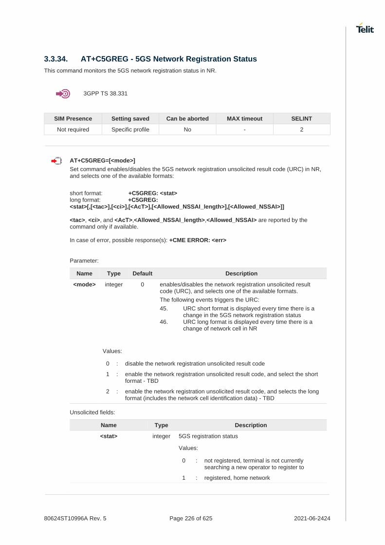
80624ST10996A Rev. 5 Page 226 of 625 2021-06-2424
3.3.34. AT+C5GREG - 5GS Network Registration Status
This command monitors the 5GS network registration status in NR.
3GPP TS 38.331
SIM Presence Setting saved Can be aborted MAX timeout SELINT
Not required Specific profile No - 2
AT+C5GREG=[<mode>]
Set command enables/disables the 5GS network registration unsolicited result code (URC) in NR, and selects one of the available formats:
short format: +C5GREG: <stat> long format: +C5GREG: <stat>[,[<tac>],[<ci>],[<AcT>],[<Allowed_NSSAI_length>],[<Allowed_NSSAI>]] <tac>, <ci>, and <AcT>,<Allowed_NSSAI_length>,<Allowed_NSSAI> are reported by the command only if available. In case of error, possible response(s): +CME ERROR: <err>
Parameter:
Name Type Default Description
<mode> integer 0 enables/disables the network registration unsolicited result code (URC), and selects one of the available formats.
The following events triggers the URC:
45. URC short format is displayed every time there is a change in the 5GS network registration status
46. URC long format is displayed every time there is a change of network cell in NR
Values:
0 : disable the network registration unsolicited result code
1 : enable the network registration unsolicited result code, and select the short format - TBD
2 : enable the network registration unsolicited result code, and selects the long format (includes the network cell identification data) - TBD
Unsolicited fields:
Name Type Description
<stat> integer 5GS registration status
Values:
0 : not registered, terminal is not currently searching a new operator to register to
1 : registered, home network

80624ST10996A Rev. 5 Page 227 of 625 2021-06-2424
2 : not registered, but terminal is currently searching a new operator to register to
3 : registration denied
4 : unknown. (e.g. out of NR coverage)
5 : registered, roaming
6 : registered for "SMS only", home network (not applicable)
7 : registered for "SMS only", roaming (not applicable)
8 : attached for emergency bearer services only. 3GPP TS 24.008 and 3GPP TS 24.301 specify the condition when the MS is considered as attached for emergency bearer services (not applicable)
9 : registered for "CSFB not preferred", home network (not applicable)
10 : registered for "CSFB not preferred", roaming (not applicable)
<tac> string tracking area code (two bytes) in hexadecimal format (e.g. "00C3" equals 195 in decimal)
<ci> string NR cell ID (four bytes) in hexadecimal format
<AcT> integer indicates the access technology of the serving cell
Values:
0 : GSM(not applicable)
1 : GSM Compact (not applicable)
2 : UTRAN (not applicable)
3 : GSM w/EGPRS (not applicable)
4 : UTRAN w/HSDPA (not applicable)
5 : UTRAN w/HSUPA (not applicable)
6 : UTRAN w/HSDPA and HSUPA (not applicable)
7 : E-UTRAN(not applicable)
11 : NR connected to a 5GCN
12 : NG-RAN (not applicable)
13 : E-UTRA-NR dual connectivity (see NOTE 8) (not applicable)
<Allowed_NSSAI_length> integer Indicates the number of octets of the <Allowed_NSSAI> information element
<Allowed_NSSAI> string Dependent of the form, the string can be separated by dot(s), semicolon(s). This parameter indicates the list of allowed S-NSSAIs received from the network. The <Allowed_NSSAI> is coded as a list of <S-NSSAI>s separated by colons. Refer parameter <S-NSSAI> in subclause 10.1.1. This parameter shall not be subject to conventional character conversion as per +CSCS.

80624ST10996A Rev. 5 Page 228 of 625 2021-06-2424
Supported kind of <AcT>s are not determined yet and it will be determined by Solution provider later.
NOTE 8: 3GPP TS 38.331 [160] specifies the information which, if present, indicates that the serving cell is supporting dual connectivity of E-UTRA with NR and is connected to an EPS core.
AT+C5GREG?
Read command returns the current value of <mode>, the registration status <stat>, and the information <tac>, <ci>, <AcT>, <Allowed_NSSAI_length>, <Allowed_NSSAI> according to the current <mode> parameter value.
+C5GREG: <mode>,<stat>[,[<tac>],[<ci>],[<AcT>][,<Allowed_NSSAI_length>],[Allowed_NSSAI>]]
<tac>, <ci> and <AcT>,<Allowed_NSSAI_length>,<Allowed_NSSAI> are reported only if <mode>=2 and the mobile is registered on some network cell.
AT+C5GREG=?
Test command returns supported values for parameter <mode>.

80624ST10996A Rev. 5 Page 229 of 625 2021-06-2424
3.3.35. AT+CEN - Reading and reporting of emergency numbers
This command allows for reading and dynamical reporting of emergency numbers as received from the network.
SIM Presence Setting saved Can be aborted MAX timeout SELINT
Required No No - 2
AT+CEN=[<reporting>]
Set command enables reporting of new emergency numbers received from the network
Parameter:
Name Type Default Description
<reporting> integer 0 Enable/disable reporting
Values:
0 : Disable reporting
1 : Enable reporting
AT+CEN?
Read command returns one line of intermediate result code +CEN1: <reporting>,<mcc> with the current <reporting> setting and the Mobile Country Code <mcc>. Then follows zero or more occurrences of the emergency numbers with intermediate result code +CEN2: <cat>,<number>:
+CEN1: <reporting>[,<mcc>,<mnc>] <CR><LF>[+CEN2: <cat>,<number> [<CR><LF>+CEN2: <cat>,<number> [...]]]
Additional info:
where:
Name Type Default Description
<reporting> integer - as above
<mcc> string - A three-digit value indicating mobile country code
<mnc> string - A three-digit value indicating mobile network code
<cat> string - Emergency Service Category Value
<number> string - Representing an emergency number from the list
AT+CEN=?
Test command reports the supported range of values for parameter <reporting>.

80624ST10996A Rev. 5 Page 230 of 625 2021-06-2424
3.3.36. AT#RFSTS - Read Current Network Status
Command reads current network status.
SIM Presence Setting saved Can be aborted MAX timeout SELINT
Required No No - 2
AT#RFSTS
Execution command returns the current network status. The format of the returned message is according to the network on which the module is registered.
WCDMA network #RFSTS: <PLMN>,<UARFCN>,<PSC>,<Ec/Io>,<RSCP>,<RSSI>,<LAC>,<RAC>,[<TXPWR>],<DRX>,<MM>,<RRC>,<NOM>,<BLER>,<CID>,<IMSI>,<NetNameAsc>,<SD>,<nAST>[,<nUARFCN>,<nPSC>,<nEc/Io>]
Parameters Description
<PLMN> Country code and operator code (MCC, MNC)
<UARFCN> UMTS Assigned Radio Channel
<PSC> Active PSC(Primary Synchronization Code)
<Ec/Io> Active Ec/Io(chip energy per total wideband power in dBm)
<RSCP> Active RSCP (Received Signal Code Power in dBm)
<RSSI> Received Signal Strength Indication
<LAC> Localization Area Code
<RAC> Routing Area Code
<TXPWR> Tx Power
<DRX> Discontinuous reception cycle Length(cycle length : display using ms)
<MM> Mobility Management
<RRC> Radio Resource Control
<NOM> Network Operator Mode
<BLER> Block Error Rate(005 means 0.5 %)
<CID> Cell ID(Hexadecimal character format).
<IMSI> International Mobile Station ID
<NetNameAsc> Operation Name, Quoted string type
<SD> Service Domain (0 : No Service, 1 : CS only, 2 : PS only, 3 : CS+PS)
<nAST> Number of Active Set(Maximum 6)
<nUARFCN> UARFCN of n th active set
<nPSC> PSC of n th active set
<nEc/Io> Ec/Io of n th active Set
Parameter/values Description
<MM> Mobility Management state (for debug purpose only)
0 NULL
3 LOCATION UPDATING INITIATED
5 WAIT FOR OUTGOING MM CONNECTION
6 CONNECTION ACTIVE
7 IMSI DETACH INITIATED
8 PROCESS CM SERVICE PROMPT
9 WAIT FOR NETWORK COMMAND
10 LOCATION UPDATE REJECTED
13 WAIT FOR RR CONNECTION LOCATION UPDATE
14 WAIT FOR RR CONNECTION MM
15 WAIT FOR RR CONNECTION IMSI DETACH
17 WAIT FOR REESTABLISHMENT

80624ST10996A Rev. 5 Page 231 of 625 2021-06-2424
18 WAIT FOR RR ACTIVE
19 IDLE
20 WAIT FOR ADDITIONAL OUTGOING MM CONNECTION
21 CONNECTION ACTIVE GROUP TRANSMIT
22 WAIT RR CONNECTION GROUP TRANSMIT
23 LOCATION UPDATING PENDING
24 IMSI DETACH PENDING
25 RR CONNECTION RELEASE NOT ALLOWED
255 UNKNOWN
Parameter/values Description
<RR> Radio Resource state (for debug purpose only)
0 INACTIVE
1 GOING_ACTIVE
2 GOING_INACTIVE
3 CELL_SELECTION
4 PLMN_LIST_SEARCH
5 IDLE
6 CELL_RESELECTION
7 CONNECTION_PENDING
8 CELL_REESTABLISH
9 DATA_TRANSFER
10 NO_CHANNELS
11 CONNECTION_RELEASE
12 EARLY_CAMPED_WAIT_FOR_SI
13 W2G_INTERRAT_HANDOVER_PROGRESS
14 W2G_INTERRAT_RESELECTION_PROGRESS
15 W2G_INTERRAT_CC_ORDER_PROGRESS
16 G2W_INTERRAT_RESELECTION_PROGRESS
17 WAIT_FOR_EARLY_PSCAN
18 GRR
19 G2W_INTERRAT_HANDOVER_PROGRESS
21 W2G_SERVICE_REDIRECTION_IN_PROGRESS
22 RESET
29 FEMTO
30 X2G_RESEL
31 X2G_RESEL_ABORTED
32 X2G_REDIR
33 G2X_REDIR
34 X2G_CGI
35 X2G_CCO_FAILED
36 X2G_CCO_ABORTED
37 X2G_CCO_FAILED_ABORTED
40 RR_CELL_SELECTED_ACQUIRE_SI
41 RR_STATE_MAX
Parameters Descriptions
<RRC> Radio Resource Control state for 3G (for debug purpose only)
0 IDLE
2 CELL FACH
3 CELL DCH
4 CELL PCH
5 URA PCH
Parameters Descriptions
<RRC> Radio Resource Control state for 4G (for debug purpose only)
0 IDLE
2 CELL DCH

80624ST10996A Rev. 5 Page 232 of 625 2021-06-2424
LTE network
#RFSTS:<PLMN>,<EARFCN>,<RSRP>,<RSSI>,<RSRQ>,<TAC>,<RAC>,[<TXPWR>],<DRX>,<MM>,<RRC>,<CID>,<IMSI>,[<NetNameAsc>],<SD>,<ABND>
Parameters Description
<PLMN> Country code and operator code(MCC, MNC)
<EARFCN> E-UTRA Assigned Radio Channel
<RSRP> Reference Signal Received Power
<RSSI> Received Signal Strength Indication
<RSRQ> Reference Signal Received Quality
<TAC> Tracking Area Code
<RAC> Routing Area Code
<TXPWR> Tx Power (In traffic only)
<DRX> Discontinuous reception cycle Length (cycle length in ms)
Parameter/values Description
<MM> Mobility Management state (for debug purpose only)
0 NULL
1 DEREGISTERED
2 REGISTRATION INITIATED
3 REGISTERED
4 TRACKING AREA UPDATE INITIATED
5 SERVICE REQUEST INITIATED
6 DEREGISTRATION INITIATED
Parameters Description
<RRC> Radio Resource state (for debug purpose only; see above)
<CID> Cell ID
Parameter/values Description
<IMSI> International Mobile Station ID<SD> - Service Domain
0 No Service
1 CS only
2 PS only
3 CS+PS
Parameter/values Description
<NetNameAsc> Operation Name, Quoted string type or “” if network name is unknown
<SD> Service Domain (0: No Service, 1: CS only, 2: PS only, 3: CS+PS)
Parameters/values Description
<ABND> Active Band
1..63 According to 3GPP TS 36.101
LTE network with NR (ENDC)
#RFSTS:<PLMN>,<EARFCN>,<RSRP>,<RSSI>,<RSRQ>,<TAC>,<RAC>,[<TXPWR>],<DRX>,<MM>,<RRC>,<CID>,<IMSI>,[<NetNameAsc>],<SD>,<ABND>,<NR_CH>,<NR_ULCH>,<NR_RSRP>,<NR_RSSI>,<NR_RSRQ>,<NR_BAND>,<NR_BW>,<NR_ULBW>,<NR_TXPWR>

80624ST10996A Rev. 5 Page 233 of 625 2021-06-2424
NR (SA)
#RFSTS:<PLMN>,<NR_CH>,<NR_ULCH>,<NR_RSRP>,<NR_RSSI>,<NR_RSRQ>,<NR_BAND>,<NR_BW>,<NR_ULBW>,<NR_TXPWR>
Parameters Description
<PLMN> Country code and operator code(MCC, MNC)
<EARFCN> E-UTRA Assigned Radio Channel
<RSRP> Reference Signal Received Power
<RSSI> Received Signal Strength Indication
<RSRQ> Reference Signal Received Quality
<TAC> Tracking Area Code
<RAC> Routing Area Code
<TXPWR> Tx Power (In traffic only)
<DRX> Discontinuous reception cycle Length (cycle length in ms)
Parameter/values Description
<MM> Mobility Management state (for debug purpose only)
0 NULL
1 DEREGISTERED
2 REGISTRATION INITIATED
3 REGISTERED
4 TRACKING AREA UPDATE INITIATED
5 SERVICE REQUEST INITIATED
6 DEREGISTRATION INITIATED
Parameters Description
<RRC> Radio Resource state (for debug purpose only; see above)
<CID> Cell ID
Parameter/values Description
<IMSI> International Mobile Station ID<SD> - Service Domain
0 No Service
1 CS only
2 PS only
3 CS+PS
Parameter/values Description
<NetNameAsc> Operation Name, Quoted string type or “” if network name is unknown
<SD> Service Domain (0: No Service, 1: CS only, 2: PS only, 3: CS+PS)
Parameters/values Description
<ABND> Active Band
1..63 According to 3GPP TS 36.101
Parameters/values Description
<NR_CH> NR DL active channel
<NR_ULCH> NR UL active channel
<NR_RSRP> NR Reference Signal Received Power
<NR_RSSI> NR received signal strength in dBm
<NR_RSRQ> NR Reference Signal Received Quality
<NR_BAND> NR active band
<NR_BW> NR DL bandwidth
<NR_ULBW> NR UL bandwidth
<NR_TXPWR> NR Tx Power (In traffic only)

80624ST10996A Rev. 5 Page 234 of 625 2021-06-2424
The <NR_TXPWR> of NR information is still unimplemented so it is always reported 0.
AT#RFSTS=?
Test command tests for command existence.

80624ST10996A Rev. 5 Page 235 of 625 2021-06-2424
3.3.37. AT+C5GNSSAI - 5GS NSSAI setting
This command enables the update of the default configured NSSAI stored at the MT.
SIM Presence Setting saved Can be aborted MAX timeout SELINT
Required Auto No - 2
AT+C5GNSSAI=<defult_configured_nssai_lngth>,<default_configured_nssai>
The set command enables updating the default configured NSSAI stored at the MT.
If <default_configured_nssai_length> has a value of zero and <default_configured_nssai> consists of an empty string, the default configured NSSAI stored at the MT, if any, shall be deleted by the MT.
Parameters:
Name Type Default Description
<defult_configured_nssai_lngth> integer - indicates the length in octets of the default configured NSSAI to be stored at the MT
<default_configured_nssai> string - string type in hexadecimal format. Dependent of the form, the string can be separated by dot(s), semicolon(s) and colon(s). This parameter indicates the list of S-NSSAIs included in the default configured NSSAI to be stored by the MT. The <default_configured_nssai> is coded as a list of <S-NSSAI>s separated by colons.
If the value is an empty string (""), no default configured NSSAI is stored at the MT.
AT+C5GNSSAI?
The read command returns the current parameter values.
+C5GNSSAI: [<default_configured_nssai_length>,<default_configured_nssai>]
AT+C5GNSSAI=?
The test command returns the values supported as compound values.
Command is supported only in 5G NR mode

80624ST10996A Rev. 5 Page 236 of 625 2021-06-2424
3.3.38. AT+C5GNSSAIRDP - 5GS NSSAI read dynamic parameters
The execution command returns the default configured NSSAI, rejected NSSAI for 3GPP access and rejected NSSAI for non-3GPP access stored at the MT, if any, as well as the configured NSSAI, allowed NSSAI for 3GPP access and allowed NSSAI for non-3GPP access stored at the MT, if any for the PLMN identified by <plmn_id>.
SIM Presence Setting saved Can be aborted MAX timeout SELINT
Required No No - 2
AT+C5GNSSAIRDP[=<nssai_type>[,<plmn_id>]]
The set or execution command returns the default configured NSSAI, rejected NSSAI for 3GPP access and rejected NSSAI
for non-3GPP access stored at the MT, if any, as well as the configured NSSAI, allowed NSSAI for 3GPP access and
allowed NSSAI for non-3GPP access stored at the MT, if any for the PLMN identified by <plmn_id>.
[+C5GNSSAIRDP: [<default_configured_nssai_length>,<default_configured_nssai>[,<rejected_nssai_3gpp_length>,<rejected_nssai_3gpp>[,<rejected_nssai_non3gpp_length>,<rejected_nssai_non3gpp>]]] [<CR><LF>+C5GNSSAIRDP: <plmn_id>[,<configured_nssai_length>,<configured_nssai>[,<allowed_nssai_3gpp_length>,<allowed_nssai_3gpp>,<allowed_nssai_non3gpp_length>,<allowed_nssai_non3gpp>]] [<CR><LF>+C5GNSSAIRDP: <plmn_id>[,<configured_nssai_length>,<configured_nssai>[,<allowed_nssai_3gpp_length>,<allowed_nssai_3gpp>,<allowed_nssai_non3gpp_length>,<allowed_nssai_non3gpp>]] [...]]]]
Parameters:
Name Type Default Description
<nssai_type> integer 0 specifies the type of NSSAI to be returned
Values:
0 : return stored default configured NSSAI only
1 : return stored default configured NSSAI and rejected NSSAI(s)
2 : return stored default configured NSSAI, rejected NSSAI(s) and configured NSSAI(s)
3 : return stored default configured NSSAI, rejected NSSAI(s), configured NSSAI(s) and allowed NSSAI(s)
<plmn_id> string - indicates the MCC and MNC of the PLMN to which the NSSAI information applies.
Additional info:
Other defined values that were displayed by set or execution command
Name Type Default Description
<default_configured_nssai_lngth> integer - indicates the length in octets of the default configured NSSAI stored at the MT.
<default_configured_nssai> string - Dependent of the form, the string can be separated by

80624ST10996A Rev. 5 Page 237 of 625 2021-06-2424
dot(s), semicolon(s) and colon(s). This parameter indicates the list of S-NSSAIs included in the default configured NSSAI stored at the MT for the PLMN. The <default_configured_nssai> is coded as a list of <S-NSSAI>s separated by colons.
<rejected_nssai_3gpp_length> integer - indicates the length in octets of the rejected NSSAI associated with 3GPP access stored at the MT for the serving PLMN.
<rejected_nssai_3gpp> string - Dependent of the form, the string can be separated by dot(s), colon(s) and hash(es). This parameter indicates the list of rejected S-NSSAIs associated with 3GPP access stored at the MT for the serving PLMN. The <rejected_NSSAI_3gpp> is coded as a list of rejected S-NSSAIs separated by colon.
The rejected S-NSSAI has one of the forms: sst#cause only slice/service type (SST) and reject cause are present sst.sd#cause SST and slice differentiator (SD) and reject cause are present
<rejected_nssai_non3gpp_length> integer - indicates the length in octets of the rejected NSSAI associated with non-3GPP access stored at the MT for the serving PLMN.
<rejected_nssai_non3gpp> string - Dependent of the form, the string can be separated by dot(s), colon(s) and hash(es). This parameter indicates the list of rejected S-NSSAIs associated with non-3GPP access stored at the MT for the serving PLMN. The <rejected_NSSAI_non3gpp> is coded as a list of rejected S-NSSAIs separated by colon.
The rejected S-NSSAI has one of the forms:
sst#cause only slice/service type (SST) and reject cause are present
sst.sd#cause SST and slice differentiator (SD) and reject cause are present
<configured_nssai_length> integer - indicates the length in octets of the configured NSSAI stored at the MT for the PLMN identified by <plmn_id>

80624ST10996A Rev. 5 Page 238 of 625 2021-06-2424
<configured_nssai> string - Dependent of the form, the string can be separated by dot(s), semicolon(s) and colon(s). This parameter indicates the list of configured S-NSSAIs stored at the MT for the PLMN identified by <plmn_id>. The <configured_nssai> is coded as a list of <S-NSSAI>s separated by colons.
<allowed_nssai_3gpp_length> integer - indicates the length in octets of the allowed NSSAI associated with 3GPP access stored at the MT for the PLMN identified by <plmn_id>.
<allowed_nssai_3gpp> string - Dependent of the form, the string can be separated by dot(s), semicolon(s) and colon(s). This parameter indicates the list of allowed S-NSSAIs associated with 3GPP access stored at the MT for the PLMN identified by <plmn_id>. The <allowed_nssai_3gpp> is coded as a list of <S-NSSAI>s separated by colons.
<allowed_nssai_non3gpp_length> integer - indicates the length in octets of the allowed NSSAI associated with non-3GPP access stored at the MT for the PLMN identified by <plmn_id>.
<allowed_nssai_non3gpp> string - Dependent of the form, the string can be separated by dot(s), semicolon(s) and colon(s). This parameter indicates the list of allowed S-NSSAIs associated with non-3GPP access stored at the MT for the PLMN identified by <plmn_id>. The <allowed_nssai_non3gpp> is coded as a list of <S-NSSAI>s separated by colons.
If the parameter <plmn_id> is omitted, the NSSAIs for all PLMNs for which the MT has stored NSSAI information are returned.
AT+C5GNSSAIRDP=?
The test command returns the values supported as compound values.
Command is supported only in 5G NR mode

80624ST10996A Rev. 5 Page 239 of 625 2021-06-2424
3.3.39. AT#5GCTL - Control the 5G bands
This command used to control the enable/disable the 5G bands like NSA FR1/FR2 and SA FR1/FR2.
SIM Presence Setting saved Can be aborted MAX timeout SELINT
Not required No No - 2
AT#5GCTL=<5g_mode>
Set command enable/disable the 5G bands with <5g_mode>.
Parameter:
Name Type Default Description
<5g_mode> integer - If the 5G bands like NSA FR1/FR2 and SA FR1/FR2 is selected, it returns OK result. Power-cycle (reboot) action will be performed, automatically.
Parameter:
<5g_mode>
NSA FR1 NSA FR2 SA FR1 SA FR2
1 O
2 O
3 O O
4 O
5 O O
6 O O
7 O O O
8 O
9 O O
10 O O
11 O O O
12 O O
13 O O O
14 O O O
15 O O O O
(O: Enable, Blank: Disable)
The ERROR will be returned when module which cannot support FR2 try to input <5g_mode> includes FR2 enabled value.
Currently, the FN980m module does not support SA FR2, so when it input <5g_mode> containing SA FR2, an ERROR occurs.
If the value of the band to be enabled is 0, default value would be written. On the other hand, if there is a specific value in the band to be enabled, the default value is not written and skipped.
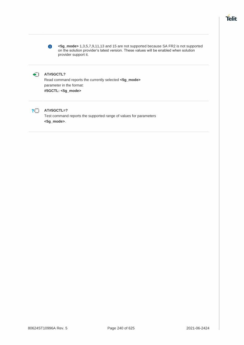
80624ST10996A Rev. 5 Page 240 of 625 2021-06-2424
<5g_mode> 1,3,5,7,9,11,13 and 15 are not supported because SA FR2 is not supported on the solution provider’s latest version. These values will be enabled when solution provider support it.
AT#5GCTL?
Read command reports the currently selected <5g_mode>
parameter in the format:
#5GCTL: <5g_mode>
AT#5GCTL=?
Test command reports the supported range of values for parameters
<5g_mode>.

80624ST10996A Rev. 5 Page 241 of 625 2021-06-2424
3.3.40. AT#USRMMWS - User MMWAVE Selection
This command select a QTM id for user calibration data.
SIM Presence Setting saved Can be aborted MAX timeout SELINT
Not required Auto No - 2
AT#USRMMWS=[<qtm_id>]
This command set the QTM id to apply user calibration data.
Parameter:
Name Type Default Description
<qtm_id> integer N/A MMWAVE QTM Identity
Values:
525 : QTM 525-2 and 525-5
527 : QTM 527-1 and 527-2
<qtm_id> parameter setting is stored in NVM.
Before writing the user's calibration data, the <qtm_id> value have to be set.
AT#USRMMWS?
Read command reports the currently <qtm_id> in the format:
#USRMMWS: <qtm_id>
If <qtm_id> is not set, <qtm_id> has a value of 0.
AT#USRMMWS=?
Test command reports supported range of values for parameters <qtm_id>.
This command can be executed only in modules that support a mmwave.

80624ST10996A Rev. 5 Page 242 of 625 2021-06-2424
AT#USRMMWS=?
#USRMMWS: (525,527)
OK
AT#USRMMWS=527
OK
AT#USRMMWS?
#USRMMWS: 527
OK

80624ST10996A Rev. 5 Page 243 of 625 2021-06-2424
3.3.41. AT#USRMMWW - User MMWAVE Write
This command write user calibration data to user folder.
SIM Presence Setting saved Can be aborted MAX timeout SELINT
Not required No No - 2
AT#USRMMWW=<cal_file_name>,<size>
Set command write a user calibration file, <cal_file_name>, in the user folder. The file should be sent using RAW ASCII file transfer after command line is terminated with <CR>, the module prompts the following five-character sequence:
<CR>,<LF>,<greater_than><greater_than><greater_than> (see IRA 13, 10, 62, 62, 62)
then a file sized <size> bytes should be entered from user.
The operations complete when all bytes are received. If writing ends successfully the response is OK, otherwise, an error code is reported.
Parameters:
Name Type Default Description
<cal_file_name> integer N/A MMWAVE calibration file name
Value:
29640÷30030 : MMWAVE calibration file number
<size> integer - file size in bytes
The range that can be written depends on the QTM ID which selected by #USRMMWS.
<None>
Nothing
<QTM 525>
cal_file_name: 29640,29652,29770,30000,30001,30002,30003,30013,30014,30015,30030
size: 1-16548
<QTM 527>
cal_file_name: 29640,29652,30000,30002,30003,30013,30014,30015,30030
size: 1-77316
The user must know the <size> of the MMWAVE calibration file to be written.
A tool such as Tera Term should be used, and "binary option" must be checked when sending file.
AT#USRMMWW=?
Test command reports supported range of values for parameters <cal_file_name> and <size>.
This command can be executed only in modules that support a mmwave.

80624ST10996A Rev. 5 Page 244 of 625 2021-06-2424
AT#USRMMWW=?
#USRMMWW: (29640,29652,30000,30002,30003,30013,30014,30015,30030)
OK
AT#USRMMWW=29640,5
>>>
OK
AT#USRMMWL
#USRMMWL: <.>
#USRMMWL: <..>
#USRMMWL: "00029640",5
#USRMMWL: free bytes: 1908736
OK

80624ST10996A Rev. 5 Page 245 of 625 2021-06-2424
3.3.42. AT#USRMMWR - User MMWAVE Read
This command reports the content of a user calibration file stored in user folder.
SIM Presence Setting saved Can be aborted MAX timeout SELINT
Not required No No - 2
AT#USRMMWR=[<cal_file_name>]
Set command reads the content of a user mmwave calibration file, <cal_file_name>, stored in the user folder written by #USRMMWW. After command line is terminated with <CR>, the module prompts the following five-character sequence:
<CR><LF><less_than><less_than><less_than> (see IRA 13, 10, 60, 60, 60)
followed by the file content.
Parameter:
Name Type Default Description
<cal_file_name> integer N/A MMWAVE calibration file name
Value:
29640÷30030 : MMWAVE calibration file number
The range that can be read depends on the QTM ID which selected by #USRMMWS.
<None>
Nothing
<QTM 525>
29640,29652,29770,30000,30001,30002,30003,30013,30014,30015,30030
<QTM 527>
29640,29652,30000,30002,30003,30013,30014,30015,30030
AT#USRMMWR=?
Test command reports supported range of values for parameters <cal_file_name>.
This command can be executed only in modules that support a mmwave.

80624ST10996A Rev. 5 Page 246 of 625 2021-06-2424
AT#USRMMWL
#USRMMWL: <.>
#USRMMWL: <..>
#USRMMWL: "00029640",5
#USRMMWL: "00030030",1251
#USRMMWL: free bytes: 1904640
OK
AT#USRMMWR=30030
<<<VTNV
x쩤klSuu�鉦X/?춈?
ThLt
x럿];;?????톈M0AE풕Q7??bJ??Q&
㈊|駿?:퓋~?oI켒?Ss??咆팾?쯩?킽D[6쩤┗P>uR啨!'?r*nu?4
_�{X?J쩪]?oz5쟵寥e
â™5^c*
-┸&씌HK??[[쟃L?O?ç± ã�»ãƒ–jM? W?U쯗
쪶쯛iå�·ï¼ŠSuks?쪲Xn??툅급.1\?ai_H癤?^\ã�‚嫦f2K]ì º?밴臺?I? ?Xv;ì´£J??墮"[?ì½·d툵\d땜둑\???2?G2牟?
e??????
?
?羊??b�?冊2爬^~?`kⓥTO
?.ëµ�혻nj'?ZC???r7ì˜ì�¤ë¸Ÿf-???敬毕??t
ä¹–az^â…¢p츫Eh%-'??⑹\y熟`???;x>åº N?Jí‘¥Kã…—?NGi핹?B'$ヴ=}Mt쳂? 욉舜??如????딘cí�§?.'ä½�I??í‘®8"?졬|v?s?퓼??å ¡íŽŽ
?秩u?C先?햂S좲?
?Zm???&2W33
?&?é©¢?
?yT????3nfY.ΔR?J?쵴??@ 튕?
rn�???땋jl.阪6??/?#z??
?
ì“¿6?|e:δMæ®Ší• "
#?B%괴켿(-E?z?o�Ig??)瑩?邕FO>
J샨蕕#bFjT湟3E蒻 ?}껫�톱?H
旺=?普弊?\?쬼帖??8!????g쨚쩾?f??
é–Gy??v{ì »
??儺%5wH??料$yXr�??Jj?`b샅줦?e??Y\촣Q�텳?v?其I?쩺V?Iㆌ
.[??4"-~m? ?Ω1*궉B?칀 ??h
U?4`??-\쯈??隣?쬗N6?尕? g?
OK

80624ST10996A Rev. 5 Page 247 of 625 2021-06-2424
3.3.43. AT#USRMMWD - User MMWAVE Delete
This command allows to delete a file in user folder.
SIM Presence Setting saved Can be aborted MAX timeout SELINT
Not required No No - 2
AT#USRMMWD=[<cal_file_name>]
Set command allows to delete the <cal_file_name> file for a user folder.
Parameter:
Name Type Default Description
<cal_file_name> string N/A MMWAVE user calibration file name
Values:
0 : Delete all the user calibration file
29640÷30030 : Calibration file number
The range that can be deleted depends on the QTM ID which selected by #USRMMWS.
<None>
0
<QTM 525>
0,29640,29652,29770,30000,30001,30002,30003,30013,30014,30015,30030
<QTM 527>
0,29640,29652,30000,30002,30003,30013,30014,30015,30030
AT#USRMMWD=?
Test command reports supported range of values for parameters <cal_file_name>.
This command can be executed only in modules that support a mmwave.

80624ST10996A Rev. 5 Page 248 of 625 2021-06-2424
AT#USRMMWL
#USRMMWL: <.>
#USRMMWL: <..>
#USRMMWL: "00029640",5
#USRMMWL: "00029652",17
#USRMMWL: "00030000",14729
#USRMMWL: "00030002",10271
#USRMMWL: "00030003",96
#USRMMWL: "00030013",76952
#USRMMWL: "00030014",12724
#USRMMWL: "00030015",12724
#USRMMWL: "00030030",1251
#USRMMWL: free bytes: 1761280
OK
AT#USRMMWD=29640
OK
AT#USRMMWL
#USRMMWL: <.>
#USRMMWL: <..>
#USRMMWL: "00029652",17
#USRMMWL: "00030000",14729
#USRMMWL: "00030002",10271
#USRMMWL: "00030003",96
#USRMMWL: "00030013",76952
#USRMMWL: "00030014",12724
#USRMMWL: "00030015",12724
#USRMMWL: "00030030",1251
#USRMMWL: free bytes: 1761280
OK
AT#USRMMWD=0
OK
AT#USRMMWL
#USRMMWL: <.>
#USRMMWL: <..>
#USRMMWL: free bytes: 1908736
OK

80624ST10996A Rev. 5 Page 249 of 625 2021-06-2424
3.3.44. AT#USRMMWL - User MMWAVE List
This command list files and directories inside the user folder.
SIM Presence Setting saved Can be aborted MAX timeout SELINT
Not required No No - 2
AT#USRMMWL
Execution command reports the list of directories and files stored in user folder. At the end of the reports, the available free memory is shown in the current drive. The report is in the format:
[<CR><LF>#USRMMWL: <.> <CR><LF>#USRMMWL: <..>] [<CR><LF>#USRMMWL: <dir_name
1>...
[<CR><LF>#USRMMWL: <dir_namen>]]
[<CR><LF>#USRMMWL: <file_name1>,<size
1>...
[<CR><LF>#USRMMWL: <file_namen>,<size
n>]]
<CR><LF>#USRMMWL: free bytes: <free_mem>
Additional info:
Response parameters:
Name Type Default Description
<dir_name> string - directory name, string type delimited by < and > (max 255 characters, case sensitive)
<file_name> string - file name, quoted sting type (max 255 characters, case sensitive)
<size> integer - size of file in bytes
<free_mem> integer - size of available free memory in the current drive in bytes
<.> string - current directory
<..> string - upper directory
AT#USRMMWL=?
Test command returns OK result code.
This command can be executed only in modules that support a mmwave.

80624ST10996A Rev. 5 Page 250 of 625 2021-06-2424
AT#USRMMWL
#USRMMWL: <.>
#USRMMWL: <..>
#USRMMWL: "00029640",5
#USRMMWL: "00029652",17
#USRMMWL: "00030000",14729
#USRMMWL: "00030002",10271
#USRMMWL: "00030003",96
#USRMMWL: "00030013",76952
#USRMMWL: "00030014",12724
#USRMMWL: "00030015",12724
#USRMMWL: "00030030",1251
#USRMMWL: free bytes: 1761280
OK
AT#USRMMWL=?
OK

80624ST10996A Rev. 5 Page 251 of 625 2021-06-2424
3.3.45. AT#USRMMWC - User MMWAVE Control
This command control user calibration data.
SIM Presence Setting saved Can be aborted MAX timeout SELINT
Not required No No - 2
AT#USRMMWC=[<usr_data_control>]
Set command control the user calibration data with <usr_data_control>.
Parameter:
Name Type Default Description
<usr_data_control> integer N/A Control the mmwave user calibration data.
Values:
0 : Move/Overwrite user calibration data to RFNV folder
1 : Backup user RFNV files which were moved from user folder to ICO
2 : Restore user backup files from ICO
3 : Delete user backup files from ICO
AT#USRMMWC=?
Test command reports supported range of values for parameters <usr_data_control>.
This command can be executed only in modules that support a mmwave.
AT#USRMMWC=?
#USRMMWC: (0-3)
OK
AT#USRMMWC=0
OK
AT#USRMMWC=1
OK
AT#USRMMWC=2
OK
AT#USRMMWC=3
OK

80624ST10996A Rev. 5 Page 252 of 625 2021-06-2424
3.3.46. AT#MONI - Cell Monitor
This command is both a set and an execution command.
SIM Presence Setting saved Can be aborted MAX timeout SELINT
Required No No - 2
AT#MONI[=[<number>]]
Set command sets one cell out of seven, in a neighbor list of the serving cell including it, from which extract WCDMA/LTE/NR related information.
After entering the set command, enter the execution command AT#MONI<CR> to get the WCDMA/LTE/NR related information for the selected cell and dedicated channel (if exists) in the format shown, for each network, in the Additional info section.
Parameter:
Name Type Default Description
<number> integer - the parameter meaning depends on the network, see Additional info section.
Additional info:
WCDMA network
Name Type Default Description
<number> integer 0 WCDMA network
Values:
0 : it is the active set
1 : it is the candidate set
2 : it is the synchronized neighbor set
3 : it is the asynchronized neighbor set
4 : it is the ranked neighbor set(cells which are not suitable cells to camp on)
5,6 : it is not available
7 : it is a special request to obtain information from the whole set of detected cells in the neighbor list of the serving cell
LTE network
Name Type Default Description
<number> integer 0 LTE network
Values:
0 : it is the serving cell
1 : it is the intra-frequency cells

80624ST10996A Rev. 5 Page 253 of 625 2021-06-2424
2 : it is the inter-frequency cells
3 : it is the WCDMA neighbor cells
4 : it is the GSM neighbor cells
5÷7 : it is not available
issuing AT#MONI<CR> indicates the following WCDMA/LTE-related information for selected cell and dedicated channel(if exists).
If the last setting done by #MONI is in the range [0..6], the output format is as follows:
a) When extracting data for the serving cell and the network name is known the format is:
WCDMA network
#MONI: <netname> PSC:<psc> RSCP:<rscp> LAC:<lac> Id:<id> EcIo:<ecio> UARFCN:<uarfcn> PWR:<dBm>dbm DRX:<drx> SCR:<scr>
LTE network
#MONI: <netmame> RSRP:<rsrp> RSRQ:<rsrq> TAC:<tac> Id:<id> EARFCN:<earfcn> PWR:<dBm>dbm DRX:<drx>
LTE network with NR (ENDC)
#MONI: <netmame> RSRP:<rsrp> RSRQ:<rsrq> TAC:<tac> Id:<id> EARFCN:<earfcn> PWR:<dBm>dbm DRX:<drx> NR_BAND:<nr_band> NR_BW:<nr_bandwidth> NR_ULBW:<nr_ul_bandwidth> NR_CH:<nr_channel> NR_ULCH:<nr_ul_channel> NR_PWR:<nr_rssi>dbm NR_RSRP:<nr_rsrp> NR_RSRQ:<nr_rsrq> NR_PCI:<nr_pci> NR_SINR:<nr_sinr> NR_STATE:<nr_state> NR_TXPWR:<nr_txpwr> NR_DLMOD:<nr_dl_mod> NR_ULMOD:<nr_ul_mod>
NR (SA)
#MONI: <netmame> NR_BAND:<nr_band> NR_BW:<nr_bandwidth> NR_ULBW:<nr_ul_bandwidth> NR_CH:<nr_channel> NR_ULCH:<nr_ul_channel> NR_PWR:<nr_rssi>dbm NR_RSRP:<nr_rsrp> NR_RSRQ:<nr_rsrq> NR_PCI:<nr_pci> NR_SINR:<nr_sinr> NR_STATE:<nr_state> NR_TXPWR:<nr_txpwr> NR_DLMOD:<nr_dl_mod> NR_ULMOD:<nr_ul_mod>
b) When the network name is unknown, the format is:
WCDMA network
#MONI: Cc:<cc> Nc:<nc> PSC:<psc> RSCP:<rscp> LAC:<lac> Id:<id> EcIo:<ecio> UARFCN:<uarfcn> PWR:<dBm>dbm DRX:<drx> SCR:<scr>
LTE network
#MONI: Cc:<cc> Nc:<nc> RSRP:<rsrp> RSRQ:<rsrq> TAC:<tac> Id:<id> EARFCN:<earfcn> PWR:<dBm>dbm DRX:<drx>
LTE network with NR (ENDC)
#MONI: Cc:<cc> Nc:<nc> RSRP:<rsrp> RSRQ:<rsrq> TAC:<tac> Id:<id> EARFCN:<earfcn> PWR:<dBm>dbm DRX:<drx> NR_BAND:<nr_band> NR_BW:<nr_bandwidth> NR_ULBW:<nr_ul_bandwidth> NR_CH:<nr_channel> NR_ULCH:<nr_ul_channel> NR_PWR:<nr_rssi>dbm NR_RSRP:<nr_rsrp> NR_RSRQ:<nr_rsrq> NR_PCI:<nr_pci> NR_SINR:<nr_sinr> NR_STATE:<nr_state> NR_TXPWR:<nr_txpwr> NR_DLMOD:<nr_dl_mod> NR_ULMOD:<nr_ul_mod>

80624ST10996A Rev. 5 Page 254 of 625 2021-06-2424
LTE network with NR (SA)
#MONI: Cc:<cc> Nc:<nc> NR_BAND:<nr_band> NR_BW:<nr_bandwidth> NR_ULBW:<nr_ul_bandwidth> NR_CH:<nr_channel> NR_ULCH:<nr_ul_channel> NR_PWR:<nr_rssi>dbm NR_RSRP:<nr_rsrp> NR_RSRQ:<nr_rsrq> NR_PCI:<nr_pci> NR_SINR:<nr_sinr> NR_STATE:<nr_state> NR_TXPWR:<nr_txpwr> NR_DLMOD:<nr_dl_mod> NR_ULMOD:<nr_ul_mod>
c) When extracting data for an adjacent cell, the format is:
WCDMA network
#MONI: PSC:<psc> RSCP:<rscp> EcIo:<ecio> UARFCN:<uarfcn> SCR:<scr>
LTE network
(E-UTRAN intra-frequency and inter-frequency cells)
#MONI: RSRP:<rsrp> RSRQ:<rsrq> Id:<id> EARFCN:<earfcn> PWR:<dBm>dbm
LTE network with NR (ENDC)
#MONI: RSRP:<rsrp> RSRQ:<rsrq> Id:<id> EARFCN:<earfcn> PWR:<dBm>dbm NR_BAND:<nr_band> NR_BW:<nr_bandwidth> NR_ULBW:<nr_ul_bandwidth> NR_CH:<nr_channel> NR_ULCH:<nr_ul_channel> NR_PWR:<nr_rssi>dbm NR_RSRP:<nr_rsrp> NR_RSRQ:<nr_rsrq> NR_PCI:<nr_pci> NR_SINR:<nr_sinr> NR_STATE:<nr_state> NR_TXPWR:<nr_txpwr> NR_DLMOD:<nr_dl_mod> NR_ULMOD:<nr_ul_mod>
LTE network with NR (SA)
#MONI: RSRP:<rsrp> RSRQ:<rsrq> Id:<id> EARFCN:<earfcn> PWR:<dBm>dbm NR_BAND:<nr_band> NR_BW:<nr_bandwidth> NR_ULBW:<nr_ul_bandwidth> NR_CH:<nr_channel> NR_ULCH:<nr_ul_channel> NR_PWR:<nr_rssi>dbm NR_RSRP:<nr_rsrp> NR_RSRQ:<nr_rsrq> NR_PCI:<nr_pci> NR_SINR:<nr_sinr> NR_STATE:<nr_state> NR_TXPWR:<nr_txpwr> NR_DLMOD:<nr_dl_mod> NR_ULMOD:<nr_ul_mod>
Name Type Default Description
<netname> string - name of network operator
<cc> string - country code
<nc> string - network operator code
<lac> string - localization area code
<id> integer - cell identifier
<uarfcn> integer - UMTS assigned radio channel
<dBm> integer - received signal strength in dBm.
<rscp> integer - Received Signal Code Power in dBm.
<ecio> integer - chip energy per total wideband power in dBm
<drx> integer - Discontinuous reception cycle length
<psc> integer - primary synchronisation code
<rsrp> integer - Reference Signal Received Power
<rsrq> integer - Reference Signal Received Quality

80624ST10996A Rev. 5 Page 255 of 625 2021-06-2424
<tac> integer - Tracking Area Code
<rsrp> integer - Reference Signal Received Power
<earfcn> integer - E-UTRA Assigned Radio Channel
<scr> integer - Scrambling code
<nr_band> integer - NR active band
<nr_bandwidth> integer - NR DL bandwidth
<nr_ul_bandwidth> integer - NR UL bandwidth
<nr_channel> integer - NR DL active channel
<nr_ul_channel> integer - NR UL active channel
<nr_rssi> integer - NR received signal strength in dBm
<nr_rsrp> integer - NR Reference Signal Received Power
<nr_rsrq> integer - NR Reference Signal Received Quality
<nr_pci> integer - NR physical cell id
<nr_sinr> integer - NR measured SINR
<nr_state> integer N/A NR state
Values:
0 : init
1 : idle
2 : connected
<nr_txpwr> integer - NR Tx Power (In traffic only)
<nr_dlmod> integer N/A Downlink modulation
Values:
0 : BPSK
1 : QPSK
2 : 16QAM
3 : 64QAM
4 : 256QAM
5 : Unknown
<nr_ulmod> integer N/A Uplink modulation
Values:
0 : BPSK
1 : QPSK
2 : 16QAM
3 : 64QAM
4 : 256QAM
5 : Unknown

80624ST10996A Rev. 5 Page 256 of 625 2021-06-2424
If the last setting done by #MONI is 7, the execution command produces a table-like formatted output, as follows:
WCDMA network
a) First row reports a set of information for the serving cell:
#MONI: <netname> PSC:<psc> RSCP:<rscp> LAC:<lac> Id:<id>EcIo:<ecio> UARFCN:<uarfcn> PWR:<dBm> DRX:<drx> SCR:<scr>
b) the other rows report a set of information for all detected neighbour cells:
#MONI: PSC:<psc> RSCP:<rscp> EcIo:<ecio> UARFCN:<uarfcn> SCR:<scr>
See above for parameters description.
When AT#MONI=7 is the last setting entered, the execution command AT#MONI<CR> reports the information previously listed for each of the cells in the neighbor of the serving cell. The information is formatting in a sequence of <CR><LF>-terminated strings.
The <nr_txpwr>,<nr_dlmod> and <nr_ulmod> of NR information is still unimplemented they always report 0.
The NR information is not affected by <number>.
AT#MONI=?
Test command reports the maximum number of cells, in a neighbor of the serving cell excluding it, from which we can extract WCDMA/LTE related information, along with the ordinal number of the current selected cell, in the format:
#MONI: (<MaxCellNo>,<CellSet>)
where:
<MaxCellNo> - maximum number of cells, in a neighbour of the serving cell and excluding it, from which we can extract GSM-related information. This value is always 6.
<CellSet> - the last setting done with command #MONI.
Additional info:
Parameters meaning.
Name Type Default Description
<MaxCellNo> integer - maximum number of cells in a neighbor of the serving cell and excluding it from which we can extract WCDMA/LTE related information. This value is always 6.
<CellSet> integer - last setting done with command #MONI.

80624ST10996A Rev. 5 Page 257 of 625 2021-06-2424
3.3.47. AT#ICMCONNECT - Control Data call DISCONNECT/CONNECTADD/DELETE
This command establishes data call for Multiple PDN
SIM Presence Setting saved Can be aborted MAX timeout SELINT
Required Auto No - 2
AT#ICMCONNECT=<cmd>,<pdn>,<userIpType>[,<cid0>[,<cid1>]]
This command establishes data call, referring to the PDP profile specified by the Cid and makes it possible that ECM/RNDIS could bind the activated data service and have access to external internet.
Parameters:
Name Type Default Description
<cmd> string N/A Command
Values:
DIS : disconnect
CON : connect
DEL : delete PDN
ADD : add PDN
SET : set PDN
<pdn> integer N/A PDN profile index. In the case of add PDN (i.e. <cmd> is "ADD"), the set value of <pdn> will be ignored, which means no matter what the input value is, the PDN will be added in numerical order if the command executed successfully.
Value:
1÷4 : PDN index
<userIpType> integer 4 user IP type
Values:
4 : IPv4
6 : IPv6
10 : ipv4v6 (option used only if the <cmd> is “ADD” or “SET”)
<cid0> integer N/A PDP context identification (see +CGDCONT command). <cid0> represent the cid with IPV4 type when <cmd> is "ADD" or "SET" with 5 arguments. If <cmd> is "CON" or "SET" with 4 arguments, <cid0> represent the cid with the input <userIpType> IP type.
Value:
1÷max : max is where the value of max is returned by the Test command
<cid1> integer N/A PDP context identification with IPV6 type (see +CGDCONT command), valid only if <cmd> is "ADD" or "SET" with 5 arguments.

80624ST10996A Rev. 5 Page 258 of 625 2021-06-2424
Value:
1÷max : max is where the value of max is returned by the Test command
This command activates a specified PDP context, so all necessary operations have to be done before issuing the command like registering to network and configuring PDP profiles.
The "OK" result code does not guarantee that data is connected successfully. It is recommended that User should verify the status of connection by issuing read command.
Error is returned if cid profile is not valid or already used by other PDN index while adding PDN profile. Refer to +CDGCONT to set cid profile.
When the IPV4 or IPV6 data call already established for the specific PDN, if user want to change the cid profile which mapping to this PDN, we recommend to disconnect the data call first and then change the PDN by "SET" command option.
If VLAN interface is defined in the VLAN list and has been mapped to the corresponding PDN, VLAN interface could be brought up by using this AT command. It is possible to bring up multiple network interfaces simultaneously which consist of both ECM/RNDIS primary interface and VLAN interfaces over the ECM/RNDIS. The multiple interfaces come to have dedicated data paths to each APN defined by the corresponding cid.
AT#ICMCONNECT?
Read command returns the session state in the following format:
Additional info:
#ICMCONNECT: <pdn>,<cid0>,<ipv4State>,<cid1>,<ipv6State>
#ICMCONNECT: <pdn>,<cid0>,<ipv4State>,<cid1>,<ipv6State>
OK
Name Type Default Description
<cid0> integer N/A IPV4 cid
Value:
1÷max : max is where the value of max is returned by the Test command
<ipv4State> integer N/A IPv4 connection state
Values:
0 : disconnected
1 : connected
-1 : Invalid CID
<cid1> integer N/A IPV6 CID
Value:

80624ST10996A Rev. 5 Page 259 of 625 2021-06-2424
1÷max : max is where the value of max is returned by the Test command
<ipv6State> integer N/A IPV6 state
Values:
0 : disconnected
1 : connected
-1 : Invalid CID
AT#ICMCONNECT=?
Test command returns the range of supported values for all the parameters. Note that the range of <cid0> and <cid1> will following the setting of +CGDCONT command.
AT#ICMCONNECT=?
#ICMCONNECT: ("DIS","CON","DEL","ADD","SET"),(1-1),(4,6,10),(1-1),(1-1)
OK
Note that the valid <pdn> range will be returned by test command.

80624ST10996A Rev. 5 Page 260 of 625 2021-06-2424
//Check the default value
AT# ICMCONNECT?
#ICMCONNECT: 1,1,0,1,0
OK
//Check the range of supported values
AT#ICMCONNECT=?
#ICMCONNECT: ("DIS","CON","DEL","ADD","SET"),(1-1),(4,6,10),(1-1),(1-1)
OK
//Add a cid
AT+CGDCONT=1,"IPV4V6","APN1"
OK
//Add the second cid
AT+CGDCONT=2,"IPV4V6","APN2"
OK
//Cid is added successfully by checking with Test command
AT#ICMCONNECT=?
#ICMCONNECT: ("DIS","CON","DEL","ADD","SET"),(1-1),(4,6,10),(1-2),(1-2)
OK
//Add the second PDN profile with cid 2
AT#ICMCONNECT=add,1,10,2,2
OK
//PDN is added successfully
AT#ICMCONNECT?
#ICMCONNECT: 1,1,0,1,0
#ICMCONNECT: 2,2,0,2,0
OK
//Establish data call for IPV4
AT#ICMCONNECT=con,1,4
OK
//Check the status
AT#ICMCONNECT?
#ICMCONNECT: 1,1,1,1,0
#ICMCONNECT: 2,2,0,2,0
OK
//Disconnect IPV4 data call
AT#ICMCONNECT=dis,1,4
OK
//Establish data call for IPV6
AT#ICMCONNECT=con,1,6
OK
//Disconnect IPV6 data call
AT#ICMCONNECT=dis,1,6
OK
//Delete the added PDN:
AT#ICMCONNECT=del,2
OK
//PDN is deleted successfully
AT#ICMCONNECT?
#ICMCONNECT: 1,1,0,1,0
OK

80624ST10996A Rev. 5 Page 261 of 625 2021-06-2424
3.3.48. AT#LTECAT - LTE Category Setting
This command selects the LTE category.
SIM Presence Setting saved Can be aborted MAX timeout SELINT
Not required Auto No - 2
AT#LTECAT=<category>
Set command sets the specific LTE category.
Parameter:
Name Type Default Description
<category> integer N/A LTE category
Values:
4 : LTE Caterory 4
6 : LTE Caterory 6
12 : LTE Caterory 12
<category> is saved in NVM.
FN980/FN980m/FT980-KS supports UE CAT12 which is MAX CAT20 DL+ MAX CAT18 UL.
AT#LTECAT?
Read command returns the LTECAT current setting, in the format:
#LTECAT: <category>
AT#LTECAT=?
Test command reports the supported range of values for parameters <category>.

80624ST10996A Rev. 5 Page 262 of 625 2021-06-2424
3.3.49. AT#FDOR - Fast Dormancy
This command triggers fast dormancy; if all conditions are passed successful SCRI will be send towards the network.
SIM Presence Setting saved Can be aborted MAX timeout SELINT
Required Auto No - 2
AT#FDOR=<mode>[,<FDDelayTimer>[,<SCRITimer>]]
Set command triggers fast dormancy; if all conditions are passed successfully, SCRI will be sent towards the network. SCRI will be sent as a one shot or according to the specified delay timer expiry, depending on the mode selected.
The Fast Dormancy feature is WCDMA only feature and not present in LTE. Therefore, it can be set in WCMDA online mode.
Parameters:
Name Type Default Description
<mode> integer 2 Selection for the supported configurations for Fast Dormancy.
Values:
1 : indicate application driven (1 shot) Fast Dormancy to modem.
2 : switch ON autonomous Fast Dormancy (AFD).
3 : switch OFF autonomous Fast Dormancy (AFD).
<FDDelayTimer> integer 6 (maximum timer) will be started when the network re-establishes the radio bearer due to some incoming data. After this timer expiry, Data activity will be checked. If there is data activity within this time period, no action will be taken. If there is no data activity, the signalling connection release request will be sent to network.
Value:
1÷60 : integer value in seconds.
<SCRITimer> integer 0 The timer is used for fast dormancy inhibit timer in NAS/UAS to adapt to network operator requirements. The timer value is stored persistently. A timer value of 0 means that the timer is not used.
Values:
0 : used a T323 Timer value in SIB1
1÷120 : integer value in seconds
Additional info:
the reject cause from lower layers is reported by the unsolicited indication
#FDOR: <cause>
Name Type Default Description
<cause> integer N/A reject cause

80624ST10996A Rev. 5 Page 263 of 625 2021-06-2424
Value:
6 : Reject when Network deactivated FD, by not sending timer T323 in SIB1.
When <mode> is 2, <FDDelayTimer> timer value becomes effective and monitor user plane data at the moment of expiry. Default timer value is 6 sec.
AT#FDOR?
Read command returns OK string along with last accepted mode and timer values, in the format:
#FDOR: <mode>,< FDDelayTimer >,< SCRITimer>
AT#FDOR=?
Test command returns OK string along with supported modes and timer values.

80624ST10996A Rev. 5 Page 264 of 625 2021-06-2424
3.3.50. AT+RSRP - Read RSRP measurement value
Additional AT&T specific AT command used for certification tests.
SIM Presence Setting saved Can be aborted MAX timeout SELINT
Not required No No - 2
AT+RSRP?
Read command reports the RSRP measurement info in the format:
+RSRP: <cellID1>,<EARFCN1>,<RSRP1>[,<cellID2>,<EARFCN2>,<RSRP2>[,... [,<cellIDn>,<EARFCNn>,<RSRPn>]]]
Additional info:
Here are the parameters meaning:
Name Type Default Description
<cellIDx> integer - physical cell id (3 digits)
<EARFCNx> integer - EARFCN for the given cell
<RSRPx> integer - RSRP value in dBm
AT+RSRP=?
Test command returns the OK result code.

80624ST10996A Rev. 5 Page 265 of 625 2021-06-2424
3.3.51. AT+RSRQ - Read RSRQ measurement value
Additional AT&T specific AT command used for certification tests.
SIM Presence Setting saved Can be aborted MAX timeout SELINT
Not required No No - 2
AT+RSRQ?
Read command reports the RSRQ measurement info in the format:
+RSRQ: <cellID1>,<EARFCN1>,<RSRQ1>[,<cellID2>,<EARFCN2>,<RSRQ2>[,... [,<cellIDn>,<EARFCNn>,<RSRQn>]]]
Additional info:
Here are the parameters meaning:
Name Type Default Description
<cellIDx> integer - physical cell id (3 digits)
<EARFCNx> integer - EARFCN for the given cell
<RSRQx> integer - RSRQ measured value
AT+RSRQ=?
Test command returns the OK result code.

80624ST10996A Rev. 5 Page 266 of 625 2021-06-2424
3.3.52. AT+RSCP - Read RSCP measurement value
Additional AT&T specific AT command used for certification tests.
SIM Presence Setting saved Can be aborted MAX timeout SELINT
Not required No No - 2
AT+RSCP?
Read command reports the RSCP measurement info in the format:
+RSCP: <psc1>,<UARFCN1>,<RSCP1>[,<psc2>,<UARFCN2>,<RSCP2>[,... [,<pscn>,<UARFCNn>,<RSCPn>]]]
Additional info:
Here are the parameters meaning:
Name Type Default Description
<pscx> integer - Primary scrambling code (3 digits)
<UARFCNx> integer - UARFCN for the given cell
<RSCPx> integer - RSCP value in dBm
AT+RSCP=?
Test command returns the OK result code.

80624ST10996A Rev. 5 Page 267 of 625 2021-06-2424
3.3.53. AT+ECNO - Read ECNO measurement value
Additional AT&T specific AT command used for certification tests.
SIM Presence Setting saved Can be aborted MAX timeout SELINT
Not required No No - 2
AT+ECNO?
Read command reports the ECNO measurement info in the format:
+ECNO: <psc1>,<UARFCN1>,<ECNO1>[,<psc2>,<UARFCN2>,<ECNO2>[,... [,<pscn>,<UARFCNn>,<ECNOn>]]]
Additional info:
Here are the parameters meaning:
Name Type Default Description
<pscx> integer - Primary scrambling code (3 digits)
<UARFCNx> integer - UARFCN for the given cell
<ECNOx> integer - ECNO value in dBm
AT+ECNO=?
Test command returns the OK result code.

80624ST10996A Rev. 5 Page 268 of 625 2021-06-2424
3.3.54. AT+COLR - Connected Line Identification Restriction status
This command refers to the GSM/UMTS supplementary service COLR (Connected Line Identification Restriction) that enables a called subscriber to restrict the possibility of presentation of connected line identity (COL) to the calling party after receiving a mobile terminated call
[1] 3GPP TS 22.081
SIM Presence Setting saved Can be aborted MAX timeout SELINT
Required No No - 2
AT+COLR
The command displays the status of the COL presentation in the network. It has no effect on the execution of the supplementary service COLR in the network.
Execution command triggers an interrogation of the activation status of the COLR service according to standard [1]. The command returns the COLR service status in the format:
+COLR: <m>
The <m> parameter is described in Additional info section.
Additional info:
Here is the meaning of the <m> parameter returned by the command.
Name Type Default Description
<m> integer 0 subscriber COLR service status.
Values:
0 : COLR not provisioned
1 : COLR provisioned
2 : unknown (example: no network, etc.)
Activation, deactivation, registration and erasure of the supplementary service COLR are not applicable.
AT+COLR=?
Test command tests for command existence

80624ST10996A Rev. 5 Page 269 of 625 2021-06-2424
3.3.55. AT+CDIP - Called line identification presentation
This command enables/disables the presentation of the CLI at the TE.
SIM Presence Setting saved Can be aborted MAX timeout SELINT
Required No No - 2
AT+CDIP
Set command enables/disables the presentation of the CLI (called line identifications) at the TE.
This command related to a network service that provides "multiple called numbers (called line identifications) service" to an MT. This command enables a called subscriber to get the called line identification of the called party when receiving a mobile terminated call.
When the presentation of the called line identification at the TE is enabled, the below URC is returned after every RING (or +CRING: <type>; refer subclause "Cellular result codes +CRC") result code sent from TA to TE. It is manufacturer specific if this response used when normal voice call answered.
+CDIP:<number>,<type>[,<subaddr>,<satype>]
Unsolicited fields:
Name Type Description
<n> integer parameter sets/shows the result code presentation status to the TE
Values:
0 : disable
1 : enable
<number> string phone number of format specified by <type>
<type> string type of address octet in integer format (refer 3GPP TS 24.008 subclause 10.5.4.7)
<subaddr> string string type subaddress of format specified by <satype>
<satype> string type of subaddress octet in integer format (refer 3GPP TS 24.008 subclause 10.5.4.8)
AT+CDIP?
Read command gives the status of <n> and also triggers an interrogation of the provision status of the "multiple called numbers" service.
+CDIP: <n>,<m>
Additional info:
where
Name Type Default Description
<n> integer N/A parameter sets/shows the result code presentation status to the TE

80624ST10996A Rev. 5 Page 270 of 625 2021-06-2424
Values:
0 : disable
1 : enable
<m> integer 0 parameter shows the subscriber "multiple called numbers" service status in the network
Values:
0 : "multiple called numbers service" is not provisioned
1 : "multiple called numbers service" is provisioned
2 : unknown (e.g. no network, etc.)
AT+CDIP=?
Test command returns the range for the parameter <n>.

80624ST10996A Rev. 5 Page 271 of 625 2021-06-2424
3.3.56. AT+CLIP - Calling Line Identification Presentation
This command enables/disables the presentation of the CLI (Calling Line Identity).
3GPP TS 27.007 3GPP TS 22.081
SIM Presence Setting saved Can be aborted MAX timeout SELINT
Required Specific profile No - 2
AT+CLIP=[<enable>]
Set command refers to the supplementary service CLIP (Calling Line Identification Presentation) that enables a called subscriber to get the calling line identity (CLI) of the calling party when receiving a mobile terminated call. If enabled the device reports after each RING the response: +CLIP: <number>,<type>,"",128,<alpha>,<CLI_validity>
Parameter:
Name Type Default Description
<enable> integer 0 enables/disables CLI indication. The command changes only the report behavior of the device, it does not change CLI supplementary service setting on the network.
Values:
0 : disable
1 : enable
Unsolicited fields:
Name Type Description
<number> string phone number of format specified by <type>
<type> integer type of address octet
Values:
128 : both the type of number and the numbering plan are unknown
129 : unknown type of number and ISDN/Telephony numbering plan
145 : international type of number and ISDN/Telephony numbering plan (contains the character "+")
161 : national type of number and ISDN/Telephony numbering plan
<alpha> string alphanumeric representation of <number> corresponding to the entry found in phonebook; used character set should be the one selected with command +CSCS
<CLI_validity> integer validity of CLIP
Values:
0 : CLI valid

80624ST10996A Rev. 5 Page 272 of 625 2021-06-2424
1 : CLI has been withheld by the originator
2 : CLI is not available due to interworking problems or limitation or originating network
in the +CLIP: response they are currently not reported either the subaddress information (it's always "" after the 2nd comma) and the subaddress type information (it's always 128 after the 3rd comma).
AT+CLIP?
Read command returns the presentation status of the CLI in the format: +CLIP: <enable>,<status>
Additional info:
Parameters:
Name Type Default Description
<enable> integer N/A status of the local setting
Values:
0 : CLI presentation disabled
1 : CLI presentation enabled
<status> integer N/A status of the CLIP service on the network
Values:
0 : CLIP not provisioned
1 : CLIP provisioned
2 : unknown (e.g. no network is present)
Read command issues a status request to the network, hence it may take a few seconds to give the answer due to the time needed to exchange data with it.
AT+CLIP=?
Test command returns the supported values of parameter <enable>.

80624ST10996A Rev. 5 Page 273 of 625 2021-06-2424
3.3.57. AT+VZWRSRP - Read RSRP Values
Additional Verizon Wireless specific AT command used for certification tests.
LTE AT commands for Test automation REQ_FEB2014
SIM Presence Setting saved Can be aborted MAX timeout SELINT
Not required No No - 2
AT+VZWRSRP?
Read command reports the RSRP info in the format:
+VZWRSRP:<cellID1>,<EARFCN1>,<RSRP1>[,<cellID2>,<EARFCN2>,<RSRP2>[,... [,<cellIDn>,<EARFCNn>,<RSRPn>]]]
Additional info:
Here are the parameters meaning:
Name Type Default Description
<cellIDx> integer - physical cell id (3 digits)
<EARFCNx> integer - EARFCN for the given cell
<RSRPx> integer - RSRP value in dBm/15kHz
AT+VZWRSRP=?
Test command returns the OK result code.

80624ST10996A Rev. 5 Page 274 of 625 2021-06-2424
3.3.58. AT+VZWRSRQ - Read RSRQ Values
Additional Verizon Wireless specific AT command used for certification tests.
LTE AT commands for Test automation REQ_FEB2014
SIM Presence Setting saved Can be aborted MAX timeout SELINT
Not required No No - 2
AT+VZWRSRQ?
Read command reports the RSRQ info in the format:
+VZWRSRQ:<cellID1>,<EARFCN1>,<RSRQ1>[,<cellID2>,<EARFCN2>,<RSRQ2>[,... [,<cellIDn>,<EARFCNn>,<RSRQn>]]]
Additional info:
Here are the parameters meaning:
Name Type Default Description
<cellIDx> string - physical cell id (3 digits)
<EARFCNx> integer - EARFCN for the given cell
<RSRQx> string - RSRQ value
AT+VZWRSRQ=?
Test command returns the OK result code.

80624ST10996A Rev. 5 Page 275 of 625 2021-06-2424
3.3.59. AT#5GLINKSTAT - 5G Link state
This command is used to read 5G RRC link state and related parameters which are RestrictDCNR and upperlayerindication.
SIM Presence Setting saved Can be aborted MAX timeout SELINT
Not required No No - 2
AT#5GLINKSTAT?
Read command reports the parameters which are description as below.
Additional info:
AT#5GLINKSTAT: <restrict_dcnr>, <sib2_upr_ind>, <rrc_link_state>
Name Type Default Description
<restrict_dcnr> integer N/A The value of parameter for RestrictDCNR
Values:
0 : FALSE
1 : TRUE
<sib2_upr_ind> integer N/A The value of parameter for Upperlayerindication
Values:
0 : FALSE
1 : TRUE
<rrc_link_state> integer N/A 5G RRC link state
Values:
0 : IDLE
1 : LTE Only Connected
2 : 5G Connected
AT#5GLINKSTAT=?
Test command reports the supported range of values
Additional info:
#5GLINKSTAT: (0,1), (0,1), (0-2)

80624ST10996A Rev. 5 Page 276 of 625 2021-06-2424
3.3.60. AT#BNDPRI - Set the band priority list for LTE
This command sets the desired band priority list
SIM Presence Setting saved Can be aborted MAX timeout SELINT
Not required Auto No - 2
AT#BNDPRI=<bnd1>,<bnd2>
This command allows to set for band priority list according to each network provider.
Parameters:
Name Type Default Description
<bnd1> integer - 1st band on the desired band priority list
<bnd2> integer - 2nd
band on the desired band priority list
The <bnd1> and <bnd2> supports band3 and band5 only.
AT#BNDPRI?
Read command reports the current stored parameter:
#BNDPRI: <bnd1>,<bnd2>
AT#BNDPRI=?
Test command returns reports the supported range of value for parameter:
EFS file location is /nv/item_files/modem/lte/rrc/efs/band_priority_list_v2
at#bndpri=3,5
band searching is 3 -> 5.
at#bndpri=5,3
band searching is 5 -> 3.

80624ST10996A Rev. 5 Page 277 of 625 2021-06-2424
3.3.61. AT+COPS - Operator Selection
The command selects a network operator and registers the module.
3GPP TS 27.007
SIM Presence Setting saved Can be aborted MAX timeout SELINT
Required Auto Yes - 2
AT+COPS=[<mode>[,<format>[,<oper>[,<AcT>]]]]
The set command attempts to select a network operator and registers the module on the just chosen operator; the selection can be automatic or manual.
Parameters:
Name Type Default Description
<mode> integer 0 defines the operator selection: automatic or manual.
Values:
0 : automatic selection, the parameter <oper> is ignored
1 : manual selection, the parameter <oper> must be present
2 : deregister from network. The module is unregistered until a +COPS with <mode>=0, 1 or 4 is issued
3 : set only <format> parameter, the parameter <oper> is ignored
4 : manual/automatic, <oper> parameter must be present. If manual selection fails, the module will tray automatic mode (<mode>=0)
<format> integer 0 specifies the operator name format, see <oper> parameter
Values:
0 : alphanumeric long form (max length 16 digits)
1 : alphanumeric short form
2 : numeric 5 or 6 digits [country code (3) + network code (2 or 3)]
<oper> mixed - network operator in format defined by <format> parameter
<AcT> integer N/A access technology selected
Values:
0 : GSM
2 : UTRAN
7 : E-UTRAN
12 : NG-RAN
13 : E-UTRA-NR dual connectivity (see NOTE 6)

80624ST10996A Rev. 5 Page 278 of 625 2021-06-2424
<mode> parameter setting is stored in NVM and available at next reboot. <mode>=3 is not saved.
If <mode>=1 or 4, the selected network is stored in NVM too and is available at next reboot (this will happen also after inserting another SIM).
<format> parameter setting is never stored in NVM.
If AT+COPS=0 is issued after the switch-on, it causes a new attempt to select a network operator and registers the module on the selected operator.
NOTE 6: 3GPP TS 38.331 [160] specifies the information which, if present, indicates that the serving cell is supporting dual connectivity of E-UTRA with NR and is connected to an EPS core.
AT+COPS?
Read command returns current value of <mode>, <format>, <oper> and <AcT> in format <format>. If no operator is selected, <format>, <oper> and <AcT> are omitted.
+COPS: <mode>[, <format>, <oper>,< AcT>]
Additional info:
If the module is deregistered, <format>, <oper>, and <AcT> parameters are omitted and all of these parameters have the same type as set command except <AcT>.
Name Type Default Description
<AcT> integer N/A access technology selected
Values:
0 : GSM
2 : UTRAN
3 : GSM w/EGPRS (see NOTE 1)
4 : UTRAN w/HSDPA (see NOTE 2)
5 : UTRAN w/HSUPA (see NOTE 2)
6 : UTRAN w/HSDPA and HSUPA (see NOTE 2)
7 : E-UTRAN
11 : NR connected to a 5GCN (see NOTE 5)
12 : NG-RAN
13 : E-UTRA-NR dual connectivity (see NOTE 6)
NOTE 1: 3GPP TS 44.018 [156] specifies the System Information messages which give the information about whether the serving cell supports EGPRS.
NOTE 2: 3GPP TS 25.331 [74] specifies the System Information blocks which give the information about whether the serving cell supports HSDPA or HSUPA.

80624ST10996A Rev. 5 Page 279 of 625 2021-06-2424
NOTE 5: 3GPP TS 38.331 [160] specifies the information which, if present, indicates that the serving cell is connected to a 5G CN. This value is not applicable in set command.
NOTE 6: 3GPP TS 38.331 [160] specifies the information which, if present, indicates that the serving cell is supporting dual connectivity of E-UTRA with NR and is connected to an EPS core.
AT+COPS=?
Test command returns a list of quadruplets, each representing an operator present in the network. The quadruplets list is ended with the range values of the <mode> and <formats> parameters.
The quadruplets in the list are closed between round brackets, separated by commas, the <oper> parameter is returned in both formats.
+COPS: [quadruplets list (<stat>,<oper (in <format>=0)>,,<oper (in <format>=2)>,< act>), (<stat>,<oper (in <format>=0)>,,<oper (in <format>=2)>,< act>), ...] [,,(range of <mode>),(range of <format>)]
<stat> parameter is described in the Additional info section.
Additional info:
Meaning of the <stat> parameter.
Name Type Default Description
<stat> integer N/A operator availability
Values:
0 : unknown
1 : available
2 : current
3 : forbidden
Since with this command a network scan is done, this command may require some seconds before the output is given.
<AcT> can be displayed 7(E-UTRAN) although module registered at E-UTRA-NR dual connectivity(13) because the master node is eNB and core is EPC for ENDC and it is Solution provider implementation.

80624ST10996A Rev. 5 Page 280 of 625 2021-06-2424
3.3.62. AT#ICMAUTOCONN - Set Datacall Auto connection mode
This command is intended to setup data call automatically to external internet through RNDIS or ECM when device boots up and get available system.
But user or network vender wants to use then will open it.
SIM Presence Setting saved Can be aborted MAX timeout SELINT
Required Auto No - 2
AT#ICMAUTOCONN=<pdn>,<auto_connect>
This command is intended to setup data call automatically to external internet through RNDIS or ECM when device boots up and get available system.
Parameters:
Name Type Default Description
<pdn> integer N/A PDN index
Value:
1÷4 : disable auto connection
<auto_connect> integer N/A Enable/Disable Auto connection
Values:
0 : Disable Auto connection
1 : Enable Auto connection
Device does not try to connect when set to enable auto connection. It is applied after connect manually or next booting time.
Note: this command activates a context, so all necessary setup has to be done before it (registration, APN).
AT#ICMAUTOCONN?
Read command returns the session state in the following format:
Additional info:
# ICMAUTOCONN: <state>
...
OK
Name Type Default Description
<pdn> integer N/A PDN index
Value:
1÷4 : PDN index
<auto_connection> integer N/A auto connection status

80624ST10996A Rev. 5 Page 281 of 625 2021-06-2424
Values:
0 : Disabled
1 : Enabled
AT#ICMAUTOCONN=?
Test command returns the range of supported values for all the parameters.

80624ST10996A Rev. 5 Page 282 of 625 2021-06-2424
SMS & CB
3.4.1. AT+CSMS - Select Message Service
This command selects messaging service type.
3GPP TS 27.005
3GPP TS 23.040
3GPP TS 23.041
SIM Presence Setting saved Can be aborted MAX timeout SELINT
Required Auto No - 2
AT+CSMS=<service>
Set command selects messaging service <service>. It returns the types of messages supported by the ME:
+CSMS: <mt>,<mo>,<bm>
For parameters meaning see Additional info section.
Parameter:
Name Type Default Description
<service> integer 0 Select Message Service
Values:
0 : 3GPP TS 23.040 and 3GPP TS 23.041. The syntax of SMS AT commands is compatible with 3GPP TS 27.005
1 : 3GPP TS 23.040 and 3GPP TS 23.041. The syntax of SMS AT commands is compatible with 3GPP TS 27.005. The requirement of <service> setting 1 is mentioned under corresponding command descriptions
Additional info:
Parameters meaning of the returned message.
Name Type Default Description
<mt> integer 0 mobile terminated messages support
Values:
0 : type not supported
1 : type supported
<mo> integer 0 mobile originated messages support
Values:
0 : type not supported

80624ST10996A Rev. 5 Page 283 of 625 2021-06-2424
1 : type supported
<bm> integer 0 broadcast type messages support
Values:
0 : type not supported
1 : type supported
Setting of <service> will not be stored automatically.
AT+CSMS?
Read command reports current service setting along with supported message types in the format:
+CSMS: <service>, <mt>, <mo>, <bm>
AT+CSMS=?
Test command reports the supported value of the parameter <service>.

80624ST10996A Rev. 5 Page 284 of 625 2021-06-2424
3.4.2. AT+CPMS - Preferred Message Storage
The command selects the memory storage used by SMs (Short Messages).
3GPP TS 27.005
SIM Presence Setting saved Can be aborted MAX timeout SELINT
Required Auto No - 2
AT+CPMS=<memr>[,<memw>[,<mems>]]
For 3GPP format SMS (see #SMSFORMAT), set command selects memory storage <memr>, <memw> and <mems> to be used for reading, writing, sending and storing SMs. Set command is as below:
AT+CPMS=<memr>[,<memw>[,<mems>]]
The command returns the memory storage status in the format:
+CPMS: <usedr>,<totalr>,<usedw>,<totalw>,<useds>,<totals>
For 3GPP2 format SMS (see #SMSFORMAT), set command selects memory storage <memr>, <memw> to be used for reading, writing, sending and storing SMS. Set command is as below:
AT+CPMS=<memr>[,<memw>]
The command returns the memory storage status in the format:
+CPMS: <usedr>,<totalr>,<usedw>,<totalw>
The returned parameters are described in the Additional info section.
Parameters:
Name Type Default Description
<memr> string SM memory from which messages are read and deleted
Note: "ME" will be set as default if SIM storage is not supported
Values:
SM : SIM SMS memory storage
ME : SMS memory storage in Flash
SR : Status report storage (in SIM EF-SMSR file exists, otherwise in the RAM non-volatile memory)
<memw> string SM memory to which writing and sending operations are made
Note: "ME" will be set as default if SIM storage is not supported
Values:
SM : SIM SMS memory storage
ME : SMS memory storage in Flash
<mems> string SM memory to which received SMs are preferred to be stored
Note: "ME" will be set as default if SIM storage is not supported

80624ST10996A Rev. 5 Page 285 of 625 2021-06-2424
Values:
SM : SIM SMS memory storage
ME : SMS memory storage in Flash
Additional info:
Here is the meaning of the parameters returned by the command.
Name Type Default Description
<usedr> integer - number of SMs stored in <memr>
<totalr> integer - max number of SMs that <memr> can contain
<usedw> integer - number of SMs stored in <memw>
<totalw> integer - max number of SMs that <memw> can contain
<useds> integer - number of SMs stored in <mems>
<totals> integer - max number of SMs that <memw> can contain
For 3GPP format SMS, "SR" non-volatile memory is cleared when another SIM card is inserted. It is kept, even after a reset, while the same SIM card is inserted.
AT+CPMS?
Read command reports the message storage status.
3GPP format SMS:
+CPMS:<memr>,<usedr>,<totalr>,<memw>,<usedw>,<totalw>,<mems>, <useds>,<totals>
3GPP2 format SMS:
+CPMS: <memr>,<usedr>,<totalr>,<memw>,<usedw>,<totalw>
The parameters are described in previous sections.
AT+CPMS=?
For 3GPP format SMS, test command reports the supported values for parameters <memr>, <memw> and <mems>.
For 3GPP2 format SMS, test command reports the supported values for parameters <memr>, <memw>

80624ST10996A Rev. 5 Page 286 of 625 2021-06-2424
Example for 3GPP format SMS:
AT+CPMS="SM","ME","SM" +CPMS: 1,20,27, 50,1,20 OK
AT+CPMS? +CPMS: "SM",1,20,"ME",27, 50,"SM",1,20 OK
You have 1 out of 20 SMS SIM positions occupied
Example for 3GPP2 format SMS:
AT+CPMS=?
+CPMS: ("ME","SM"),("ME","SM")
OK
AT+CPMS?
+CPMS: "ME",5,99, "ME",5,99
OK
AT+CPMS="ME", "ME"
+CPMS: 5,99,5,99
OK
AT+CPMS?
+CPMS: "ME",5,99, "ME",5,99
OK
AT+CPMS="SM", "SM"
+CPMS: 2,20,2,20
OK
AT+CPMS?
+CPMS: "SM",2,20,"SM",2,20
OK

80624ST10996A Rev. 5 Page 287 of 625 2021-06-2424
3.4.3. AT+CMGF - Message Format
Selects the format of SMS messages to be used in following SMS commands.
3GPP TS 27.005
SIM Presence Setting saved Can be aborted MAX timeout SELINT
Required Specific profile No - 2
AT+CMGF=[<mode>]
Set command selects the format of SMS messages used with send, list, read and write commands.
Parameter:
Name Type Default Description
<mode> integer 0 format to use for SMS operations
Values:
0 : PDU mode
1 : text mode
AT+CMGF?
Read command reports the current value of the parameter <mode> in the format: +CMGF: <mode>
AT+CMGF=?
Test command returns the supported values of parameter <mode>.

80624ST10996A Rev. 5 Page 288 of 625 2021-06-2424
3.4.4. AT+CSCA - Service Center Address
This command allows to set the Service Center Address for SMS transmissions.
3GPP TS 27.005
SIM Presence Setting saved Can be aborted MAX timeout SELINT
Required Other No - 2
AT+CSCA=<number>[,<type>]
Set command sets the Service Center Address to be used for mobile originated SMS transmissions
Parameters:
Name Type Default Description
<number> string - String type phone number of forwarding address in format specified by <type> parameter
<type> integer N/A The type of number;
For Verizon FW, the range of <type> is 0 - 255.
Values:
129 : National numbering scheme
145 : International numbering scheme (contains the character "+")
AT+CSCA?
Read command reports the current value of the SCA in the format:
+CSCA: <number>,<type>
If SCA is not present the device reports an error message.
AT+CSCA=?
Test command returns the OK result code.
To use the SM service, is mandatory to set a Service Center Address at which service requests will be directed.
In Text mode, this setting is used by send and write commands; in PDU mode, setting is used by the same commands, but only when the length of the SMSC address coded into the <pdu> parameter equals zero.
The current settings are stored through +CSAS.
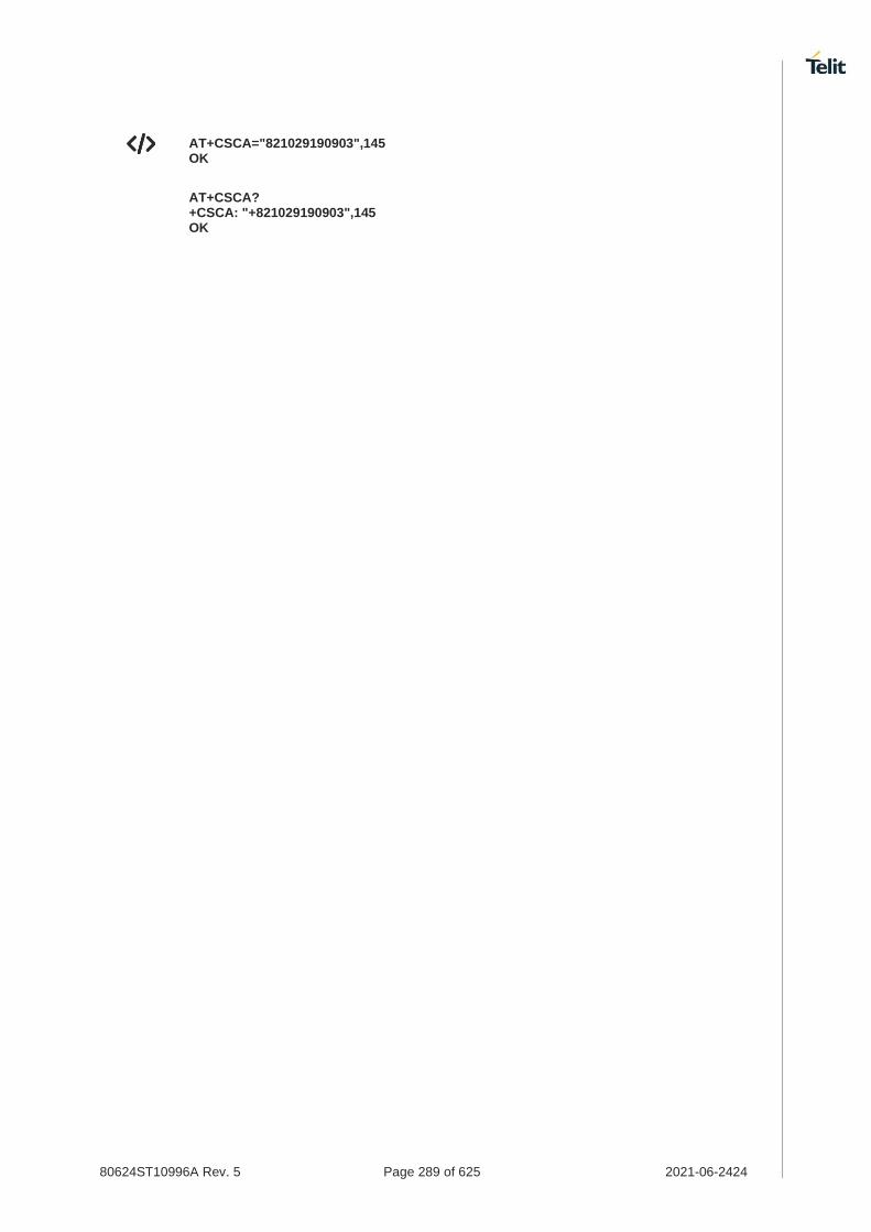
80624ST10996A Rev. 5 Page 289 of 625 2021-06-2424
AT+CSCA="821029190903",145 OK
AT+CSCA? +CSCA: "+821029190903",145 OK

80624ST10996A Rev. 5 Page 290 of 625 2021-06-2424
3.4.5. AT+CSMP - Set Text Mode Parameters
This command is used to select values for additional parameters for storing and sending SMS when the text mode is used (AT+CMGF=1).
3GPP TS 27.005
3GPP TS 03.40/23.040
3GPP TS 03.38/23.038
SIM Presence Setting saved Can be aborted MAX timeout SELINT
Required Other No - 2
AT+CSMP=[<fo>[,<vp>[,<pid>[,<dcs>]]]]
Set command is used to select values for additional parameters for storing and sending 3GPP format SMS when the text mode is used (AT+CMGF=1).
For 3GPP2 format SMS, please refer to the additional information.
Parameters:
Name Type Default Description
<fo> integer 17 first octet of SMS-SUBMIT or SMS-DELIVER PDU, as described in 3GPP TS 23.040
bit 0/1 = Message Type Indicator bit 2 = Reject Duplicates bit 3/4 = Validity Period Format bit 5 = Status Report Request bit 6 = User Data Header Indicator bit 7 = Reply Path
Value:
0÷255 : mask
<vp> mixed 167 Validity Period, the format depends on Validity Period Format in <fo>, as described in 3GPP TS 23.040:
bit 0/1 = Message Type Indicator bit 2 = Reject Duplicates bit 3/4 = Validity Period Format bit 5 = Status Report Request bit 6 = User Data Header Indicator bit 7 = Reply Path
Value:
0÷255 : range for Validity Period in relative format
<pid> integer 0 TP-Protocol-Identifier, as described in 3GPP TS 23.40
Value:
0÷255 : described in 3GPP TS 23.40
<dcs> integer 0 SMS Data Coding Scheme, as described in 3GPP TS 23.038
Value:
0÷255 : described in 3GPP TS 23.038

80624ST10996A Rev. 5 Page 291 of 625 2021-06-2424
Additional info:
Set command is used to select values for additional parameters for storing and sending 3GPP2 format SMS when the text mode is used (AT+CMGF=1, AT#SMSFORMAT=1).
AT+CSMP=[<callback_addr>[,<tele_id >[,<priority>[,<enc_type >]]]]
Name Type Default Description
<callback_addr> string - Callback address;
Maximum length is 20 characters.
Note: Initially, this parameter is null. Some carrier networks discard SMS's without a callback number. Therefore, we recommend that customer setup callback number using AT+CSMP command.
<tele_id> integer 4098 Teleservice ID
Values:
4097 : page
4098 : SMS message
4101 : EMS message(concatenated)
<priority> integer 0 Priority
Values:
0 : Normal
1 : High
<enc_type> integer 2 data coding scheme
Values:
0 : 8-bit Octet
2 : 7-bit ASCII
4 : 16-bit Unicode
9 : GSM 7bit
In the parameter <fo>: only the following values are supported for Message Type Indicator:
[00] - SMS-DELIVER
[01] - SMS-SUBMIT
In the parameter <fo>: user is not responsible for setting bit 2 and bit 6, if set, they will have no meaning.
In the parameter <vp>: the absolute format is a quoted time-string type (see +CCLK).
The current settings are stored through +CSAS.
<vp>, <pid> and <dcs> default values are loaded from first SIM SMS Parameters profile, if present. If it is not present, then the default values are those above indicated.

80624ST10996A Rev. 5 Page 292 of 625 2021-06-2424
AT+CSMP?
Read command for 3GPP format SMS (see #SMSFORMAT) returns the current setting in the format:
+CSMP: <fo>,<vp>,<pid>,<dcs>
Read command for 3GPP2 format SMS (see #SMSFORMAT) returns the current setting in the format:
+CSMP: < callback_addr >,<tele_id >,< priority >,< enc_type >
AT+CSMP=?
Test command returns the OK result code.
Set the parameters for an outgoing 3GPP format message with 24 hours of validity period and default properties:
AT+CSMP=17,167,0,0 OK
Set the parameters for an outgoing 3GPP2 format message:
AT+CSMP=? OK AT+CSMP? +CSMP: "",4098,0,2 OK AT+CSMP="1234567890",4097,1,2 OK AT+CSMP? +CSMP: "1234567890",4097,1,2 OK

80624ST10996A Rev. 5 Page 293 of 625 2021-06-2424
3.4.6. AT+CSDH - Show Text Mode Parameters
This command controls whether detailed header information is shown in text mode.
3GPP TS 27.005
SIM Presence Setting saved Can be aborted MAX timeout SELINT
Required Specific profile No - 2
AT+CSDH=[<show>]
Set command controls whether detailed header information is shown in text mode (AT+CMGF=1) result codes.
Parameter:
Name Type Default Description
<show> integer 0 control the display of the result codes.
Values:
0 : see Additional info section
1 : show the values in result codes
Additional info:
If <show>=0
do not show header values defined in commands +CSCA and +CSMP (<sca>,<tosca>, <fo>, <vp>, <pid> and <dcs>) nor <length>, <toda> or <tooa> in +CMT, +CMGL, +CMGR result codes for SMS-DELIVERs and SMS-SUBMITs in text mode.
For SMS-COMMANDs in +CMGR result code do not show <pid>, <mn>, <da>, <toda>, <length> or <cdata>
AT+CSDH?
Read command reports the current setting in the format:
+CSDH: <show>
AT+CSDH=?
Test command reports the supported range of values for parameter <show>.
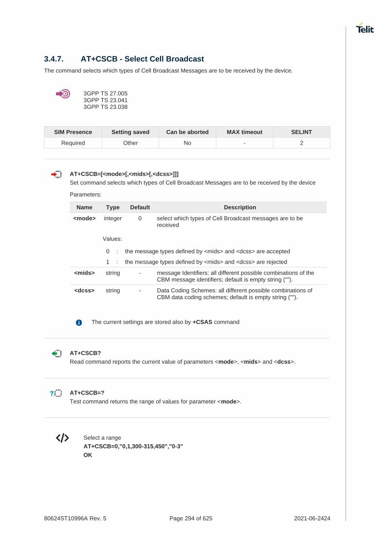
80624ST10996A Rev. 5 Page 294 of 625 2021-06-2424
3.4.7. AT+CSCB - Select Cell Broadcast
The command selects which types of Cell Broadcast Messages are to be received by the device.
3GPP TS 27.005 3GPP TS 23.041 3GPP TS 23.038
SIM Presence Setting saved Can be aborted MAX timeout SELINT
Required Other No - 2
AT+CSCB=[<mode>[,<mids>[,<dcss>]]]
Set command selects which types of Cell Broadcast Messages are to be received by the device
Parameters:
Name Type Default Description
<mode> integer 0 select which types of Cell Broadcast messages are to be received
Values:
0 : the message types defined by <mids> and <dcss> are accepted
1 : the message types defined by <mids> and <dcss> are rejected
<mids> string - message Identifiers: all different possible combinations of the CBM message identifiers; default is empty string ("").
<dcss> string - Data Coding Schemes: all different possible combinations of CBM data coding schemes; default is empty string ("").
The current settings are stored also by +CSAS command
AT+CSCB?
Read command reports the current value of parameters <mode>, <mids> and <dcss>.
AT+CSCB=?
Test command returns the range of values for parameter <mode>.
Select a range
AT+CSCB=0,"0,1,300-315,450","0-3"
OK

80624ST10996A Rev. 5 Page 295 of 625 2021-06-2424
3.4.8. AT+CSAS - Save Settings
Execution command saves settings which have been made by the +CSCA, +CSMP and +CSCB commands in local non-volatile memory.
For 3GPP2 format SMS (see #SMSFORMAT), only +CSMP settings will be saved.
3GPP TS 27.005
SIM Presence Setting saved Can be aborted MAX timeout SELINT
Required No No - 2
AT+CSAS=<profile>
Parameter:
Name Type Default Description
<profile> integer 0 Index of the profile where the settings are saved
Values:
0 : it saves the settings to NVM
1÷n : SIM profile number; the value of n depends on the SIM and its max is 3.
If parameter is omitted the settings are saved in the non-volatile memory (profile 0).
Certain settings may not be supported by the SIM and therefore they are always saved to NVM, regardless the value of <profile>.
For 3GPP2 format SMS (see #SMSFORMAT), store the settings to SIM is not supported, only NVM profile 0-1 are supported.
AT+CSAS=?
Test command returns the possible range of values for the parameter <profile>.

80624ST10996A Rev. 5 Page 296 of 625 2021-06-2424
3.4.9. AT+CRES - Restore Settings
Execution command restores message service settings saved by +CSAS command from either NVM or SIM.
3GPP TS 27.005
SIM Presence Setting saved Can be aborted MAX timeout SELINT
Not required No No - 2
AT+CRES[=[<profile>]]
Parameter:
Name Type Default Description
<profile> integer N/A Defines which message service profiles to restore.
Values:
0 : restores message service settings from NVM
1÷n : restores message service settings from SIM. The value of n depends on the SIM and its max is 3.
If parameter is omitted the command restores message service settings from NVM (profile 0).
Certain settings may not be supported by the SIM and therefore they are always restored from NVM, regardless the value of <profile>.
For 3GPP2 format SMS (see #SMSFORMAT), restore the settings from SIM is not supported, only NVM profile 0-1 are supported.
AT+CRES=?
Test command returns the possible range of values for the parameter <profile>.

80624ST10996A Rev. 5 Page 297 of 625 2021-06-2424
3.4.10. AT+CMMS - More Message to Send
Set command controls the continuity of SMS relay protocol link. When feature is enabled (and supported by network) multiple messages can be sent much faster as link is kept open.
3GPP TS 27.005
SIM Presence Setting saved Can be aborted MAX timeout SELINT
Required No No - 2
AT+CMMS=[<n>]
Parameter:
Name Type Default Description
<n> integer 0 enables/disables the relay protocol link continuity.
Values:
0 : disable
1 : keep enabled until the time between the response of the latest message send command (+CMGS, +CMSS, etc.) and the next send command exceeds 5 seconds, then the link is closed and the parameter <n> is automatically reset to 0
2 : enable (if the time between the response of the latest message send command and the next send command exceeds 5 seconds, the link is closed but the parameter <n> remains set to 2)
Entering AT+CMMS= returns OK but has no effect.
AT+CMMS?
Read command reports the current value of the parameter <n> in the format:
+CMMS: <n>
AT+CMMS=?
Test command returns the range of supported <n>.

80624ST10996A Rev. 5 Page 298 of 625 2021-06-2424
3.4.11. AT+CGSMS - Select Service for MO SMS Messages
Set command is used to specify the service or service preference that the MT will use to send MO SMS messages.
3GPP TS 27.005
SIM Presence Setting saved Can be aborted MAX timeout SELINT
Required Auto No - 2
AT+CGSMS=[<service>]
Parameter:
Name Type Default Description
<service> integer 1 indicates the service or service preference to be used
Values:
0 : GPRS
1 : circuit switched
2 : GPRS preferred. Use circuit switched if SMS via GPRS service not available or GPRS not registered.
3 : circuit switched preferred. Use GPRS if SMS via circuit switched not available.
Entering AT+CGSMS= returns OK but has no effect.
AT+CGSMS?
The read command returns the currently selected service or service preference in the format:
+CGSMS: <service>
AT+CGSMS=?
Test command reports the supported list of currently available <service>.
The <service> value is saved on NVM as global parameter.

80624ST10996A Rev. 5 Page 299 of 625 2021-06-2424
3.4.12. AT+CNMI - New Message Indications to Terminal Equipment
This command sets the parameters for receiving SMS messages.
3GPP TS 27.005
SIM Presence Setting saved Can be aborted MAX timeout SELINT
Not required Specific profile No - 2
AT+CNMI=[<mode>[,<mt>[,<bm>[,<ds>[,<bfr>]]]]]
Set command selects the behavior of the device on how the receiving of new messages from the network is indicated to the DTE.
Set command for 3GPP format SMS (see #SMSFORMAT):
AT+CNMI=[<mode>[,<mt>[,<bm>[,<ds>[,<bfr>]]]]]
Set command for 3GPP2 format SMS (see #SMSFORMAT):
AT+CNMI=[<mt>]
Parameters:
Name Type Default Description
<mode> integer 0 unsolicited result codes buffering option.
Values:
0 : Buffer unsolicited result codes in the TA. If TA result code buffer is full, indications can be buffered in some other place or the oldest indications may be discarded and replaced with the new received indications.
1 : Discard indication and reject new received message unsolicited result codes when TA-TE link is reserved, otherwise forward them directly to the TE.
2 : Buffer unsolicited result codes in the TA in case the DTE is busy and flush them to the TE after reservation. Otherwise forward them directly to the TE.
3 : If <mt> is set to 1, the hardware ring line enabled for 1 second when a SMS is received while the module is in online data mode. (If ring supported)
<mt> integer 0 result code indication reporting for SMS-DELIVER.
Values:
0 : No SMS-DELIVER indications are routed to the TE and message is stored.
1 : If SMS-DELIVER is stored into ME/TA, indication of the memory location is routed to the TE using the URC described in Additional info section (3GPP format SMS). 3GPP2 format SMS will be indicated with +CMTI format.
2 : SMS-DELIVERs (except class 2 messages and messages in the message waiting indication group) are routed directly to the TE using the URC described in the Additional info section (3GPP format SMS). 3GPP2 format SMS will be indicated with +CMT format.

80624ST10996A Rev. 5 Page 300 of 625 2021-06-2424
3 : Class 3 SMS-DELIVERs are routed directly to TE using unsolicited result codes defined in <mt>=2. Messages of other data coding schemes result in indication as defined in <mt>=1 (3GPP format SMS)).
<bm> integer 0 broadcast reporting option
Values:
0 : Cell Broadcast Messages are not sent to the DTE
2 : New Cell Broadcast Messages are sent to the DTE with the URC described in Additional info section.
<ds> integer 0 SMS-STATUS-REPORTs reporting option
Values:
0 : status report receiving is not reported to the DTE and is not stored
1 : the status report is sent to the DTE with the URC described in the Additional info section.
2 : if a status report is stored, then the unsolicited result code, described in Additional info section, is sent.
<bfr> integer 0 buffered result codes handling method
Values:
0 : TA buffer of unsolicited result codes defined within this command is flushed to the TE when <mode>=1..3 is entered (OK response shall be given before flushing the codes)
1 : TA buffer of unsolicited result codes defined within this command is cleared when <mode>=1..3 is entered.
Additional info:
For both 3GPP and 3GPP2 format SMS, when <mt>=1:
+CMTI: <mems>,<index>
For 3GPP format SMS, when <mt>=2:
PDU mode
+CMT: <alpha>,<length><CR><LF><PDU>
TEXT mode
+CMT:<oa>,<alpha>,<scts>[,<tooa>,<fo>,<pid>,<dcs>,<sca>,<tosca>,<length>]<CR><LF> <data>
The parameters written in italics will be present depending on +CSDH last setting.
Class 2 messages and messages in the message waiting indication group (stored message) result in indication as defined in <mt>=1.

80624ST10996A Rev. 5 Page 301 of 625 2021-06-2424
Acknowledge for the received SMS-DELIVER SM is sent to network immediately when +CSMS <service> is set to '0' or when +CSMS <service> is set to '1', acknowledge is sent via +CNMA command during predefine time-out, an error is sent to network in case timeout expire, next +CMT response is depend on acknowledge of current received +CMT response in case +CSMS <service> parameter set to '1'.
For 3GPP2 format SMS, when <mt>=2:
PDU mode
+CMT: ,<length><CR><LF><PDU>
TEXT mode
+CMT: <orig_num>,<callback>,<date>[,<tooa>,<tele_id>,<priority>,<enc_type>,<udh>,<length>]<CR><LF><data>
<bm>=2:
PDU mode
+CBM: <length><CR><LF><PDU>
Text mode
+CBM:<sn>,<mid>,<dcs>,<pag>,<pags><CR><LF><data>
<ds>=1:
PDU mode
+CDS: <length><CR><LF><PDU>
TEXT mode
+CDS: <fo>,<mr>,<ra>,<tora>,<scts>,<dt>,<st>
Acknowledge for the received SMS-STATUS-REPORT SM is sent to network immediately when +CSMS <service> is set to '0' or when +CSMS <service> is set to '1', acknowledge is sent via +CNMA command during pre-defined timeout, an error is sent to network in case timeout expire, next +CDS response is depend on acknowledge of current received +CDS response in case +CSMS <service> parameter set to '1'.
<ds>=2:
+CDSI: <mems>,<index>
Unsolicited fields:
Name Type Description

80624ST10996A Rev. 5 Page 302 of 625 2021-06-2424
<mems> string memory storage where the new message is stored: "SM", "ME".
<index> integer
location on the memory where SMS is stored.
<alpha> string alphanumeric representation of originator/destination number corresponding to the entry found in MT phonebook; used character set should be the one selected with command +CSCS.
<length> integer
PDU length
<PDU> string PDU message
For 3GPP2 format SMS in PDU mode, please refer to below information for the detail.
<pdu>: <orig_num><date><tele_id><priority><enc_type><udh><length><data>
where:
<orig_num> : <addr_len><tooa><address>
<addr_len> : Octets length of address field(1 Octet : <tooa> and <address>).
<tooa> : Type of address(1 Octet).
<addres> : Address digits with representation of semi-octets.
<date> : Serivce center time stamp (6 Octets : YYMMDDHHMMSS).
<tele_id> : Teleservice ID (2 Octets).
<priority> : Priority(1 Octet).
<enc_type> : Encoding type(1 Octet).
<udh> : User data header (1 Octet).
<length> : Refer to below Note (1 Octet).
<data> : User data of message.
Note:
If user data header<udh> is present,
If encoding type is 7bit ASCII,
<length> value is the sum of the number of septets in user data and the number of septets in user data header (including any padding).
Otherwise,
<length> value is the sum of the number of octets in user data and the number of octets in user data header.
If user data header<udh> is not present,
If encoding type is 7bit ASCII,
<length> value is the number of septets in user data.
Otherwise,
<length> value is the number of octets in user data.
<oa> string originating address, string type converted in the currently selected character set (see +CSCS)
<alpha> string alphanumeric representation of <oa>; used character set should be the one selected with command +CSCS.
<scts> string arrival time of the message to the SC
<tooa> integer
type of number <oa>
Values:

80624ST10996A Rev. 5 Page 303 of 625 2021-06-2424
129 : number in national format
145 : number in international format (contains the "+")
<fo> string first octet of message PDU, see 3GPP TS 03.40/23.040
<pid> string Protocol Identifier
<dcs> string Data Coding Scheme
<sca> string Service Centre address, string type, converted in the currently selected character set (see +CSCS)
<tosca> integer
type of number <sca>
Values:
129 : number in national format
145 : number in international format (contains the "+")
<length> integer
text length
<data> string TP-User-Data
* If <dcs> indicates that GSM 03.38 default alphabet is used and <fo> indicates that GSM 03.40 TP-User-Data-Header-Indication is not set (bit 6 of <fo> is 0), each character of GSM alphabet will be converted into current TE character set (see +CSCS).
* If <dcs> indicates that 8-bit or UCS2 data coding scheme is used or <fo> indicates that GSM 03.40 TP-User-Data-Header-Indication is set (bit 6 of <fo> is 1), each 8-bit octet will be converted into two IRA character long hexadecimal number (e.g. octet 0x2A will be converted as two characters 0x32 0x41).
Class 2 messages and messages in the "store" message waiting indication group result in indication as defined in <mt>=1.
<sn> integer
message serial number
<mid> integer
message ID
<dcs> string Data Coding Scheme
<pag> integer
page number
<pags> integer
total number of pages of the message
<data> string CBM Content of Message
* If <dcs> indicates that GSM 03.38 default alphabet is used, each character of GSM alphabet will be converted into current TE character set (see +CSCS)
* If <dcs> indicates that 8-bit or UCS2 data coding scheme is used, each 8-bit octet will be converted into two IRA character long hexadecimal number (e.g. octet 0x2A will be converted as two characters 0x32 0x41)
<mr> integer
message reference number; 3GPP TS 23.040 TP-Message-Reference in integer format
<ra> string recipient address, string type, represented in the currently selected character set (see +CSCS)

80624ST10996A Rev. 5 Page 304 of 625 2021-06-2424
<tora> integer
type of number <ra>
Values:
129 : number in national format
145 : number in international format (contains the "+")
<scts> string arrival time of the message to the SC
<dt> string sending time of the message
<st> string message status as coded in the PDU
<orig_num>
string Origination number (only for 3GPP2 format SMS)
<callback> string Callback number (only for 3GPP2 format SMS)
<date> string Received date in form as "YYYYMMDDHHMMSS" (only for 3GPP2 format SMS)
<tooa> integer
Type of <orig_num> (only for 3GPP2 format SMS)
<tele_id> integer
Teleservice ID (only for 3GPP2 format SMS)
Values:
4097 : page
4098 : SMS message
4099 : voice mail notification
4101 : EMS message(concatenated)
262144 : voice mail notification
<priority> integer
Priority (only for 3GPP2 format SMS)
Values:
0 : Normal
1 : High
<enc_type>
integer
Encoding type of message (only for 3GPP2 format SMS)
Values:
0 : 8-bit Octet
2 : 7-bit ASCII
4 : 16-bit Unicode
9 : GSM 7bit
<udh> integer
User data header (only for 3GPP2 format SMS)
Values:
0 : Not present the user data header
1 : Present the user data header
<length> integer
Length of message (only for 3GPP2 format SMS)
<data> string Message data (Indicates the new voice mail count, if <tele_id> is voice mail notification) (only for 3GPP2 format SMS)

80624ST10996A Rev. 5 Page 305 of 625 2021-06-2424
DTR signal is ignored, hence the indication is sent even if the DTE is inactive (DTR signal is Low). In this case the unsolicited result code may be lost so if MODULE remains active while DTE is not, at DTE startup is suggested to check whether new messages have reached the device meanwhile with command AT+CMGL=0 that lists the new messages received.
For 3GPP2 format SMS, regardless of <mt>, a message is saved in SMS memory storage.
AT+CNMI?
Read command returns the current parameter settings for +CNMI command in the form:
+CNMI: <mode>,<mt>,<bm>,<ds>,<bfr>
AT+CNMI=?
Test command reports the supported range of values for the +CNMI command parameters

80624ST10996A Rev. 5 Page 306 of 625 2021-06-2424
• Example for 3GPP format SMS
AT+CMGF=1 OK
AT+CNMI=1,2,0,1,0 OK
Received message from network
+CMT: "+821020955219",,"07/07/26,20:09:07+36"
TEST MESSAGE
• Example for 3GPP2 format SMS
AT+CNMI=?
+CNMI: (0-2)
OK
AT+CNMI=1
OK
AT+CNMI?
+CNMI: 1
OK
Received message from network
+CMTI:"ME",98
AT+CNMI=2
OK
AT+CNMI?
+CNMI: 2
OK
Received message from network
+CMT: "My Number","My Number",20141023165007,129,4098,0,2,0,8
TEST SMS

80624ST10996A Rev. 5 Page 307 of 625 2021-06-2424
3.4.13. AT+CMGL - List Messages
This command is used to list the messages.
3GPP TS 27.005 3GPP TS 23.040 3GPP TS 23.038
SIM Presence Setting saved Can be aborted MAX timeout SELINT
Required No No - 2
AT+CMGL[=<stat>]
Execution command reports the list of all the messages with status value <stat> stored into <memr> message storage (<memr> is the message storage for read and delete SMs as last settings of command +CPMS).
Parameter:
Name Type Default Description
<stat> mixed - <stat> parameter type and the command output depend on the last settings of the +CMGF command (message format to be used).
There are two modes:
- PDU mode
- Text mode
See the following Additional info sections.
Additional info:
When message format is PDU mode, the <stat> parameter is:
Name Type Default Description
<stat> integer N/A status value
Values:
0 : new message
1 : read message
2 : stored message not sent yet
3 : stored message already sent
4 : all messages
In case of 3GPP PDU mode the representation format (see +CMGF, #SMSFORMAT) is: +CMGL: <index>,<stat>,<alpha>,<length><CR><LF><pdu>[<CR><LF> +CMGL: <index>,<stat>,<alpha>,<length><CR><LF><pdu>[...]]
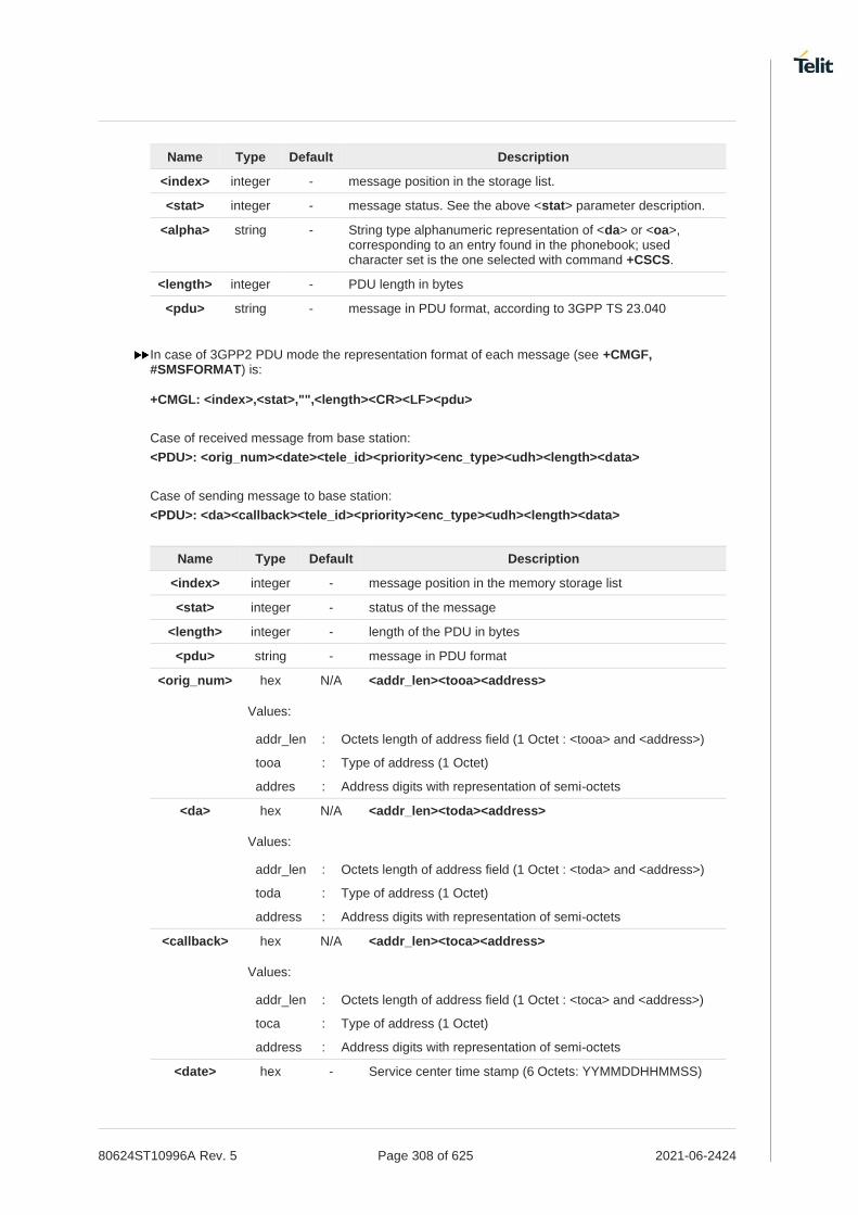
80624ST10996A Rev. 5 Page 308 of 625 2021-06-2424
Name Type Default Description
<index> integer - message position in the storage list.
<stat> integer - message status. See the above <stat> parameter description.
<alpha> string - String type alphanumeric representation of <da> or <oa>, corresponding to an entry found in the phonebook; used character set is the one selected with command +CSCS.
<length> integer - PDU length in bytes
<pdu> string - message in PDU format, according to 3GPP TS 23.040
In case of 3GPP2 PDU mode the representation format of each message (see +CMGF, #SMSFORMAT) is: +CMGL: <index>,<stat>,"",<length><CR><LF><pdu>
Case of received message from base station:
<PDU>: <orig_num><date><tele_id><priority><enc_type><udh><length><data>
Case of sending message to base station:
<PDU>: <da><callback><tele_id><priority><enc_type><udh><length><data>
Name Type Default Description
<index> integer - message position in the memory storage list
<stat> integer - status of the message
<length> integer - length of the PDU in bytes
<pdu> string - message in PDU format
<orig_num> hex N/A <addr_len><tooa><address>
Values:
addr_len : Octets length of address field (1 Octet : <tooa> and <address>)
tooa : Type of address (1 Octet)
addres : Address digits with representation of semi-octets
<da> hex N/A <addr_len><toda><address>
Values:
addr_len : Octets length of address field (1 Octet : <toda> and <address>)
toda : Type of address (1 Octet)
address : Address digits with representation of semi-octets
<callback> hex N/A <addr_len><toca><address>
Values:
addr_len : Octets length of address field (1 Octet : <toca> and <address>)
toca : Type of address (1 Octet)
address : Address digits with representation of semi-octets
<date> hex - Service center time stamp (6 Octets: YYMMDDHHMMSS)

80624ST10996A Rev. 5 Page 309 of 625 2021-06-2424
<tele_id> hex - Teleservice ID (2 Octets)
<priority> hex - Priority (1 Octet)
<enc_type> hex - Encoding type (1 Octet)
<udh> string - User data header (1 Octet)
<length> hex - 1 Octet in the PDU data
If user data header<udh> is present,
If encoding type is 7bit ASCII,
<length> value is the sum of the number of septets in user data and the number of septets in user data header (including any padding).
Otherwise,
<length> value is the sum of the number of octets in user data and the number of octets in user data header.
If user data header<udh> is not present,
If encoding type is 7bit ASCII,
<length> value is the number of septets in user data.
Otherwise,
<length> value is the number of octets in user data.
<data> hex - User data of message
When message format is TEXT mode, the <stat> parameter is:
Name Type Default Description
<stat> string N/A status value
Values:
"REC UNREAD"
: new message
"REC READ" : read message
"STO UNSENT" : stored message not sent yet
"STO SENT" : stored message already sent
"ALL" : all messages
In case of 3GPP TEXT mode (see #SMSFORMAT), the representation format for stored messages (either sent or unsent) or received messages (either read or unread, not message delivery confirm) is: +CMGL: <index>,<stat>,<oa/da>,<alpha>,<scts>[,<tooa/toda>,<length>]<CR><LF> <data>[<CR><LF> +CMGL: <index>,<stat>,<oa/da>,<alpha>,<scts>[,<tooa/toda>,<length>]<CR><LF> <data>[...]]
The information written in italics will be present depending on +CSDH last setting.
Name Type Default Description
<index> integer - message position in the storage list.
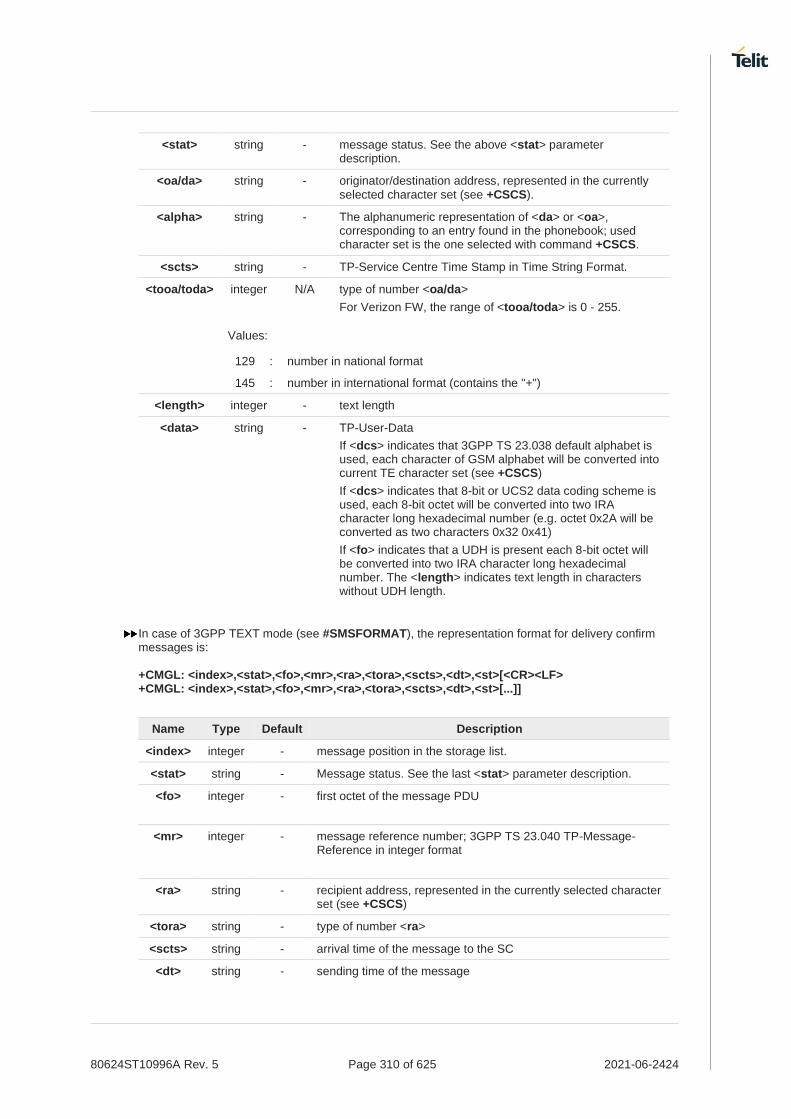
80624ST10996A Rev. 5 Page 310 of 625 2021-06-2424
<stat> string - message status. See the above <stat> parameter description.
<oa/da> string - originator/destination address, represented in the currently selected character set (see +CSCS).
<alpha> string - The alphanumeric representation of <da> or <oa>, corresponding to an entry found in the phonebook; used character set is the one selected with command +CSCS.
<scts> string - TP-Service Centre Time Stamp in Time String Format.
<tooa/toda> integer N/A type of number <oa/da>
For Verizon FW, the range of <tooa/toda> is 0 - 255.
Values:
129 : number in national format
145 : number in international format (contains the "+")
<length> integer - text length
<data> string - TP-User-Data
If <dcs> indicates that 3GPP TS 23.038 default alphabet is used, each character of GSM alphabet will be converted into current TE character set (see +CSCS)
If <dcs> indicates that 8-bit or UCS2 data coding scheme is used, each 8-bit octet will be converted into two IRA character long hexadecimal number (e.g. octet 0x2A will be converted as two characters 0x32 0x41)
If <fo> indicates that a UDH is present each 8-bit octet will be converted into two IRA character long hexadecimal number. The <length> indicates text length in characters without UDH length.
In case of 3GPP TEXT mode (see #SMSFORMAT), the representation format for delivery confirm messages is: +CMGL: <index>,<stat>,<fo>,<mr>,<ra>,<tora>,<scts>,<dt>,<st>[<CR><LF> +CMGL: <index>,<stat>,<fo>,<mr>,<ra>,<tora>,<scts>,<dt>,<st>[...]]
Name Type Default Description
<index> integer - message position in the storage list.
<stat> string - Message status. See the last <stat> parameter description.
<fo> integer - first octet of the message PDU
<mr> integer - message reference number; 3GPP TS 23.040 TP-Message-Reference in integer format
<ra> string - recipient address, represented in the currently selected character set (see +CSCS)
<tora> string - type of number <ra>
<scts> string - arrival time of the message to the SC
<dt> string - sending time of the message

80624ST10996A Rev. 5 Page 311 of 625 2021-06-2424
<st> integer - message status as coded in the PDU
In case of 3GPP2 TEXT mode (see #SMSFORMAT), each message to be listed is represented in the format (the information written in italics will be present depending on +CSDH last setting):
If there is at least a Received message to be listed the representation format is:
+CMGL: <index>,<stat>,<orig_num>,<callback>,<date>[,<tooa>,<tele_id>,<priority>,<enc_type>,<udh>,<length>]<CR><LF> <data>
If there is at least a Sent or an Unsent message to be listed the representation format is:
+CMGL: <index>,<stat>,<da>,<callback>,[,<toda>,<tele_id>,<priority>,<enc_type>,<udh>,<length>]<CR><LF><data>
Name Type Default Description
<orig_num> string - origination number
<callback> string - callback number
<date> string - received date in form as "YYYYMMDDHHMMSS"
<tooa> string - type of <orig_num>
<toda> string - type of <da>
<tele_id> string N/A teleservice ID
Values:
4097 : page
4098 : SMS message
4099 : voice mail notification
4101 : EMS message(concatenated)
262144 : voice mail notification
<priority> integer N/A priority
Values:
0 : Normal
1 : Interactive
2 : Urgent
3 : Emergency
<enc_type> integer N/A encoding type of message
Values:
0 : 8-bit Octet
2 : 7-bit ASCII
4 : 16-bit Unicode
9 : GSM 7bit
<udh> integer N/A user data header

80624ST10996A Rev. 5 Page 312 of 625 2021-06-2424
Values:
0 : Not present the user data header
1 : Present the user data header
<length> integer - length of message
<data> string - message data. (Indicates the new voice mail count, if <tele_id> is voice mail notification)
If parameter is omitted the command returns the list of SMS with "REC UNREAD" status.
The order in which the messages are reported by +CMGL corresponds to their position in the memory storage.
If a message is present when +CMGL="ALL" is used it will be changed status from REC UNREAD to REC READ.
AT+CMGL=?
Test command returns a list of supported <stat>s.

80624ST10996A Rev. 5 Page 313 of 625 2021-06-2424
Examples for 3GPP2 format SMS.
• PDU mode:
Case of received message from base station:
AT+CMGL=1
+CMGL: 13,1,"",51
06811041394306141023155820100202020024C3870E1C3870E1C3870E1C3870E1C3870E1C3870E1C3870E1C3870E1C3870E10
OK
06 <addr_len: 6byte>
81 <type_addr: 129>
1041394306 <Origination number: 0114933460>
141023155820 <Date: 14/10/23,15:58:20>
1002 <Teleservice_id: 4098(decimal)>
02 <priority: urgent >
02 <encoding_type: 7-bit ASCII >
00 <udh: Not present user data header >
24 <data_len: 36> C3870E1C3870E1C3870E1C3870E1C3870E1C3870E1C3870E1C3870E1C3870E10
<user_data: aaaaaaaaaaaaaaaaaaaaaaaaaaaaaaaaaaaa>
Else:
AT+CMGL=2
+CMGL: 31,2,"",23
07801091346554F307801091346554F310020000000A61616161616161616161
OK
07 <addr_len: 7byte>
81 <type_addr:129>
1091346554F3 <Destination_addr: 01194356453>
07 <addr_len: 7byte>
81 <type_addr:129>
1096224658F1 <Callback_Number: 01692264851>
1002 <Teleservice_id: 4098(decimal)>
00 <priority: normal >
00 <encoding_type: 8-bit Octet >
00 <udh: Not present user data header >
0A <data_len: 10>
61616161616161616161 <data: aaaaaaaaaa>
AT+CMGF=0
OK
AT+CMGF?
+CMGF: 0
OK
AT+CMGL=?
+CMGL: (0-4)
OK
AT+CMGL=4

80624ST10996A Rev. 5 Page 314 of 625 2021-06-2424
+CMGL: 0,2,"",19
0681104139430606811041394306100200000006313233343536
+CMGL: 1,2,"",22
0681104139430606811041394306100200000009313233343536363737
+CMGL: 2,2,"",25
068110413943060681104139430610020000000C313132323334343434343434
+CMGL: 3,2,"",28
068110413943060681104139430610020000000F616666617364656565656565656565
OK
• Text Mode:
AT+CMGF=1
OK
AT+CMGF?
+CMGF: 1
OK
AT+CMGL=?
+CMGL: ("REC UNREAD","REC READ","STO UNSENT","STO SENT","ALL")
OK
AT+CMGL="ALL"
+CMGL: 0,"STO UNSENT","My Number","My Number",
123456
+CMGL: 1, "STO UNSENT","My Number","My Number",
123456677
+CMGL: 2, "STO UNSENT","My Number","My Number",
112234444444
+CMGL: 3, "STO UNSENT","My Number","My Number",
affasdeeeeeeeee
OK

80624ST10996A Rev. 5 Page 315 of 625 2021-06-2424

80624ST10996A Rev. 5 Page 316 of 625 2021-06-2424
3.4.14. AT+CMGR - Read Message
This command is used to read a message.
3GPP TS 27.005
3GPP TS 23.040
3GPP TS 23.038
SIM Presence Setting saved Can be aborted MAX timeout SELINT
Required No No - 2
AT+CMGR=<index>
Execution command reports the message with location value <index> from <memr> message storage (<memr> is the message storage for read and delete SMs as last settings of command +CPMS).
Parameter:
Name Type Default Description
<index> integer - message index. The command output depends on the last settings of command +CMGF (message format to be used). There are two modes:
- PDU mode
- Text mode
See the following Additional info sections.
Additional info:
In case of 3GPP PDU mode (see #SMSFORMAT), if there is a message in location <index>, the output has the following format: +CMGR: <stat>,<alpha>,<length><CR><LF><pdu>
Name Type Default Description
<stat> integer N/A status of the message
Values:
0 : new message
1 : read message
2 : stored message not yet sent
3 : stored message already sent
<alpha> string - string type alphanumeric representation of <da> or <oa>, corresponding to an entry found in the phonebook; used character set is the one selected with command +CSCS
<length> integer - PDU length in bytes
<PDU> string - message in PDU format, according to 3GPP TS 23.040
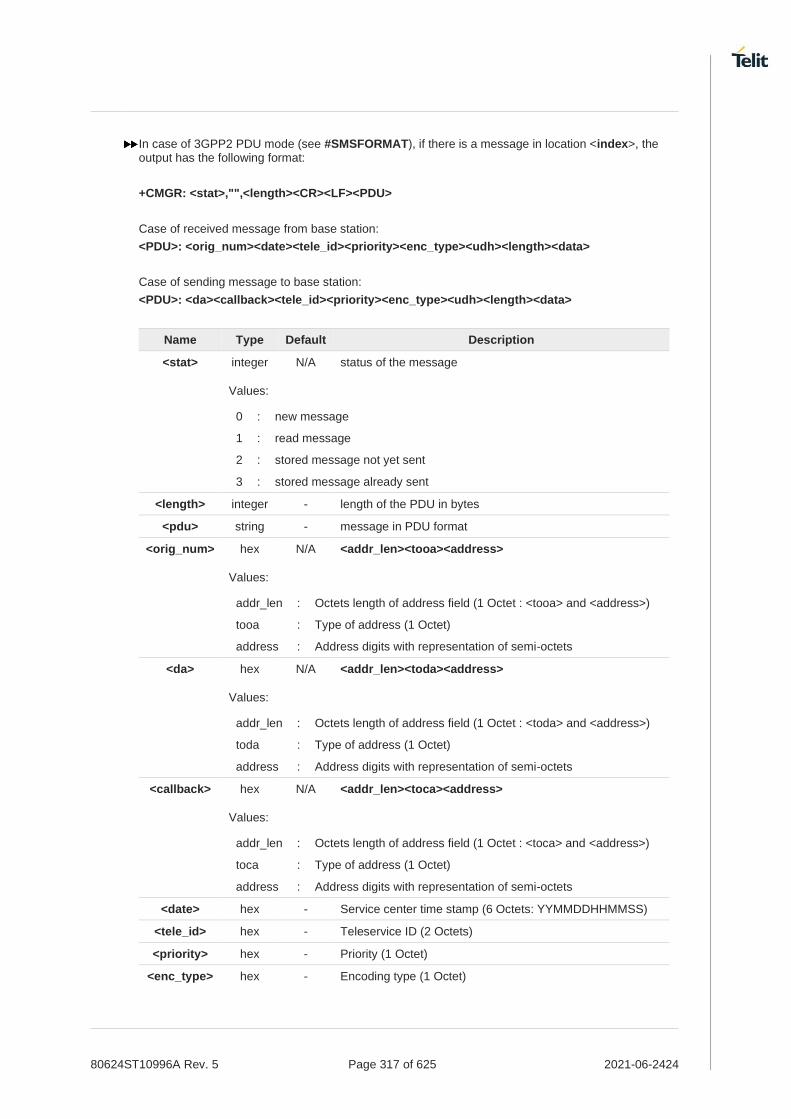
80624ST10996A Rev. 5 Page 317 of 625 2021-06-2424
In case of 3GPP2 PDU mode (see #SMSFORMAT), if there is a message in location <index>, the output has the following format:
+CMGR: <stat>,"",<length><CR><LF><PDU>
Case of received message from base station:
<PDU>: <orig_num><date><tele_id><priority><enc_type><udh><length><data>
Case of sending message to base station:
<PDU>: <da><callback><tele_id><priority><enc_type><udh><length><data>
Name Type Default Description
<stat> integer N/A status of the message
Values:
0 : new message
1 : read message
2 : stored message not yet sent
3 : stored message already sent
<length> integer - length of the PDU in bytes
<pdu> string - message in PDU format
<orig_num> hex N/A <addr_len><tooa><address>
Values:
addr_len : Octets length of address field (1 Octet : <tooa> and <address>)
tooa : Type of address (1 Octet)
address : Address digits with representation of semi-octets
<da> hex N/A <addr_len><toda><address>
Values:
addr_len : Octets length of address field (1 Octet : <toda> and <address>)
toda : Type of address (1 Octet)
address : Address digits with representation of semi-octets
<callback> hex N/A <addr_len><toca><address>
Values:
addr_len : Octets length of address field (1 Octet : <toca> and <address>)
toca : Type of address (1 Octet)
address : Address digits with representation of semi-octets
<date> hex - Service center time stamp (6 Octets: YYMMDDHHMMSS)
<tele_id> hex - Teleservice ID (2 Octets)
<priority> hex - Priority (1 Octet)
<enc_type> hex - Encoding type (1 Octet)

80624ST10996A Rev. 5 Page 318 of 625 2021-06-2424
<udh> hex - User data header (1 Octet)
<length> hex - 1 octet in the PDU data
If user data header<udh> is present,
If encoding type is 7bit ASCII,
<length> value is the sum of the number of septets in user data and the number of septets in user data header (including any padding).
Otherwise,
<length> value is the sum of the number of octets in user data and the number of octets in user data header.
If user data header<udh> is not present,
If encoding type is 7bit ASCII,
<length> value is the number of septets in user data.
Otherwise,
<length> value is the number of octets in user data.
<data> hex - User data of message
In case of 3GPP Text mode (see #SMSFORMAT), if there is a received message in location <index>, the output has the following format (the information written in italics will be present depending on +CSDH last setting): +CMGR:<stat>,<oa>,<alpha>,<scts> [,<tooa>,<fo>,<pid>,<dcs>,<sca>,<tosca>,<length>]<CR><LF><data> In case of Text mode, if there is either a sent or an unsent message in location <index> the output format is: +CMGR:<stat>,<da>,<alpha> [,<toda>,<fo>,<pid>,<dcs>,[<vp>],<sca>,<tosca>,<length>]<CR><LF><data> In case of Text mode, if there is a Message Delivery Confirm message in location <index> the output format is: +CMGR: <stat>,<fo>,<mr>,<ra>,<tora>,<scts>,<dt>,<st>
Name Type Default Description
<stat> string N/A status of the message
Values:
"REC UNREAD"
: new received message
"REC READ" : received message read
"STO UNSENT" : message stored not yet sent
"STO SENT" : message stored already sent
<fo> integer - first octet of the message PDU
<mr> integer - message reference number; 3GPP TS 23.040 TP-Message-Reference in integer format
<ra> string - recipient address, represented in the currently selected character set (see +CSCS)

80624ST10996A Rev. 5 Page 319 of 625 2021-06-2424
<tora> string N/A type of number <ra>
For Verizon FW, the range of <tooa> is 0 - 255.
Values:
129 : number in national format
145 : number in international format (contains the "+")
<scts> string - arrival time of the message to the SC
<dt> string - sending time of the message
<st> integer - message status as coded in the PDU
<pid> integer - Protocol Identifier
<dcs> integer - Data Coding Scheme
<vp> mixed - Validity Period; its format depends on SMS-SUBMIT <fo> setting (see +CPMS):
1. Not present: if <fo> tells that Validity Period Format is not present
2. Integer: if <fo> tells that Validity Period Format is relative
3. Quoted time-string type: if <fo> tells that Validity Period Format is absolute
4. Quoted hexadecimal representation of 7 octets: if <fo> tells that Validity Period Format is enhanced
<oa> string - Originator address, represented in the currently selected character set (see +CSCS).
<da> string - Destination address, represented in the currently selected character set (see +CSCS).
<alpha> string - The alphanumeric representation of <da> or <oa>, corresponding to an entry found in the phonebook; used character set is the one selected with command +CSCS.
<sca> string - Service Centre Address
<tooa> integer N/A type of number of <oa>
For Verizon FW, the range of <tooa> is 0 - 255.
Values:
129 : number in national format
145 : number in international format (contains the "+")
<toda> integer N/A type of number of <da>
For Verizon FW, the range of <tooa> is 0 - 255.
Values:
129 : number in national format
145 : number in international format (contains the "+")
<tosca> integer - type of number of <sca>
For Verizon FW, the range of <tooa> is 0 - 255.
<length> integer N/A text length

80624ST10996A Rev. 5 Page 320 of 625 2021-06-2424
Values:
129 : number in national format
145 : number in international format (contains the "+")
<data> string - TP-User-Data
If <dcs> indicates that 3GPP TS 23.038 default alphabet is used, each character of GSM alphabet will be converted into current TE character set (see +CSCS)
If <dcs> indicates that 8-bit or UCS2 data coding scheme is used, each 8-bit octet will be converted into two IRA character long hexadecimal number (e.g. octet 0x2A will be converted as two characters 0x32 0x41)
If <fo> indicates that a UDH is present each 8-bit octet will be converted into two IRA character long hexadecimal number. The <length> indicates text length in characters without UDH length.
In case of 3GPP2 Text mode (see #SMSFORMAT), output format for messages (the information written in italics will be present depending on +CSDH last setting):
Output format for message Delivery message is:
+CMGR: <stat>,<orig_num>,<callback>,<date>[,<tooa>,<tele_id>,<priority>,<enc_type>,<udh>,<length>]<CR><LF><data>
If there is either a Sent or an Unsent message in location <index> the output format is:
+CMGR: <stat>,<da>,<callback>,[,<toda>,<tele_id>,<priority>,<enc_type>,<udh>,<length>]<CR><LF><data>
Name Type Default Description
<stat> string N/A status of the message
Values:
“REC UNREAD”
: new received message unread
“REC READ” : received message read
“STO UNSENT” : message stored not yet sent
“STO SENT” : message stored already sent
<orig_num> string - Origination number
<callback> string - Callback number
<date> string - Received date in form as "YYYYMMDDHHMMSS"
<tooa/toda> integer - Type of <orig_num>/<da>.
<tele_id> integer N/A Teleservice ID
Values:
4097 : page
4098 : SMS message

80624ST10996A Rev. 5 Page 321 of 625 2021-06-2424
4099 : voice mail notification
4101 : EMS message(concatenated)
262144 : voice mail notification
<priority> integer N/A Priority
Values:
0 : Normal
1 : High
<enc_type> integer N/A Encoding type of message
Values:
0 : 8-bit Octet
2 : 7-bit ASCII
4 : 16-bit Unicode
9 : GSM 7bit
<udh> integer N/A User data header
Values:
0 : Not present the user data header
1 : Present the user data header
<length> integer - Length of message
<data> string - Message data. (Indicates the new voice mail count, if <tele_id> is voice mail notification)
Both in PDU and Text Mode, if status of the message was 'received unread' before reading, then status in the storage changes to 'received read'.
AT+CMGR=?
Test command returns the OK result code

80624ST10996A Rev. 5 Page 322 of 625 2021-06-2424
Examples for 3GPP2 format SMS.
• PDU Mode:
Case of received message from base station:
AT+CMGR=29
+CMGR: 1,"",51
06811041394306141023155820100202020024C3870E1C3870E1C3870E1C3870E1C3870E1C3870E1C3870E1C3870E1C3870E10
OK
06 <addr_len: 6byte>
81 <type_addr: 129>
1041394306 <Origination number: 0114933460>
141023155820 <Date: 14/10/23,15:58:20>
1002 <Teleservice_id: 4098(decimal)>
02 <priority: urgent >
02 <encoding_type: 7-bit ASCII >
00 <udh: Not present user data header >
24 <data_len: 36 >
C3870E1C3870E1C3870E1C3870E1C3870E1C3870E1C3870E1C3870E1C3870E10
<user_data: aaaaaaaaaaaaaaaaaaaaaaaaaaaaaaaaaaaa>
Else:
AT+CMGR=31
+CMGR: 2,"",23
07801091346554F307801091346554F310020000000A61616161616161616161
OK
07 <addr_len: 7byte>
81 <type_addr:129>
1091346554F3 <Destination_addr: 01194356453>
07 <addr_len: 7byte>
81 <type_addr:129>
1096224658F1 <Callback_Number: 01692264851>
1002 <Teleservice_id: 4098(decimal)>
00 <priority: normal >
00 <encoding_type: 8-bit Octet >
00 <udh: Not present user data header >
0A <data_len: 10>
61616161616161616161 <data: aaaaaaaaaa>
• Text Mode:
AT+CSDH=1
OK
AT+CMGR=1
+CMGR: "REC READ", "0114933460", "01149334690", 20140109180259, 129, 4098,0,2,0,12
TEST MESSAGE
OK
AT+CMGR=4
+CMGR: "STO UNSENT","0114933460","0114933460",,129,4098,0,0,0,12
TEST MESSAGE
OK

80624ST10996A Rev. 5 Page 323 of 625 2021-06-2424
3.4.15. AT+CNMA - New Message Acknowledgement
This command is used to confirm the correct reception of a new message.
3GPP TS 27.005
SIM Presence Setting saved Can be aborted MAX timeout SELINT
Not required No No - 2
AT+CNMA
Execution command confirms correct reception of a new message (SMS-DELIVER or SMS-STATUS-REPORT) which is routed directly to the TE.
Acknowledge with +CNMA is possible only if the +CSMS parameter is set to 1 (+CSMS=1) when a +CMT or +CDS indication is shown.
If no acknowledgement is given within the network timeout (17 seconds), an RP-ERROR is sent to the network, the <mt> and <ds> parameters of the +CNMI command are then reset to zero (do not show new message indication).
If command is executed, but no acknowledgement is expected, or some other ME related error occurs, result code +CMS ERROR: <err> is returned.
The AT command syntax and functionalities are different between SMS PDU Mode and SMS Text Mode, as explained in Additional info sections.
Additional info:
PDU Mode
AT+CNMA[=<n>[,<length>[<CR>PDU is given<ctrl-Z/ESC>]]]
Either positive (RP-ACK) or negative (RP-ERROR) acknowledgement to the network is possible. Parameter <n> defines which one will be sent. Optionally (when <length> is greater than zero) an acknowledgement TPDU (SMS-DELIVER-REPORT for RP-ACK or RP-ERROR) may be sent to the network. The entering of PDU is done similarly as specified in command Send Message +CMGS, except that the SMSC address field is not present.
Name Type Default Description
<n> integer N/A type of acknowledgement in PDU mode
Values:
0 : send RP-ACK without PDU (same as TEXT mode)
1 : send RP-ACK with optional PDU message
2 : send RP-ERROR with optional PDU message
<length> integer - length of the PDU message
Text Mode

80624ST10996A Rev. 5 Page 324 of 625 2021-06-2424
AT+CNMA
Only positive acknowledgement to network (RP-ACK) is possible.
AT+CNMA=?
Test command returned information are different between SMS PDU Mode and SMS Text Mode, as explained below.
Additional info:
PDU Mode
Test command returns the possible range of values for the parameter <n>.
Text Mode
Test command returns the OK result code.
In case that a directly routed message must be buffered in ME/TA (possible when +CNMI parameter <mode> equals 0 or 2) or AT interpreter remains too long in a state where result codes cannot be sent to TE (e.g. user is entering a message using +CMGS), acknowledgement (RP-ACK) is sent to the network without waiting +CNMA command from TE.
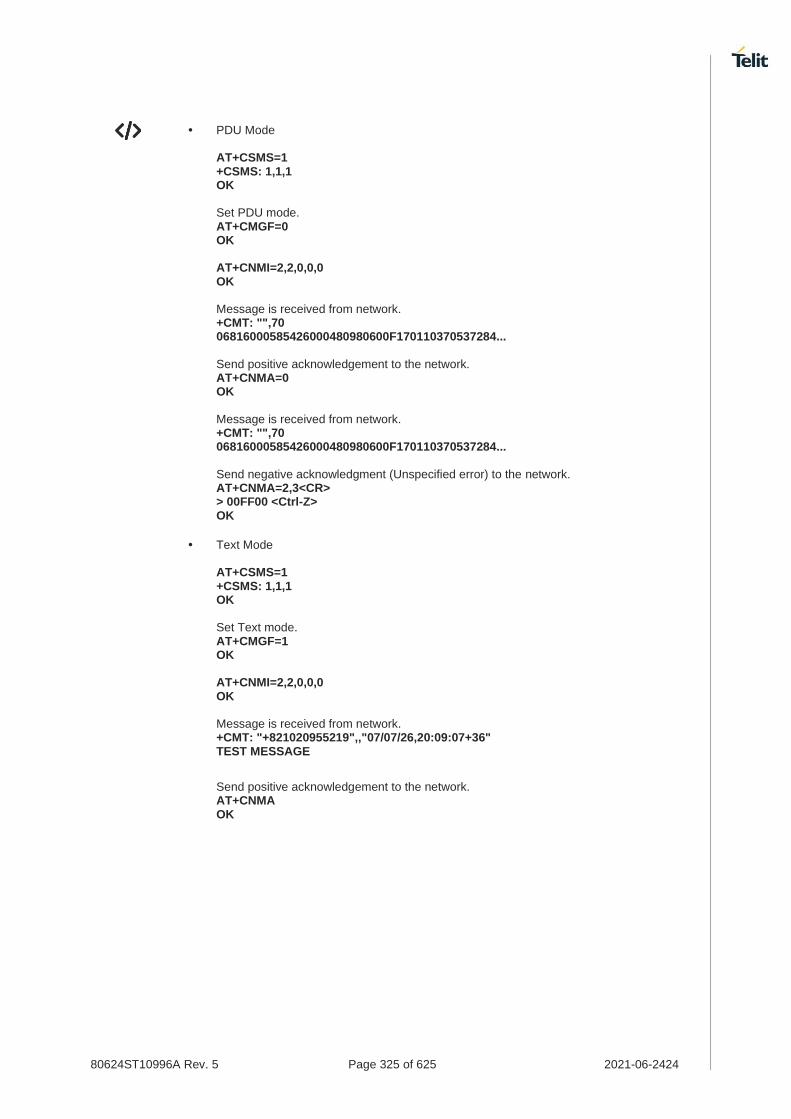
80624ST10996A Rev. 5 Page 325 of 625 2021-06-2424
• PDU Mode AT+CSMS=1 +CSMS: 1,1,1 OK Set PDU mode. AT+CMGF=0 OK AT+CNMI=2,2,0,0,0 OK Message is received from network. +CMT: "",70 06816000585426000480980600F170110370537284... Send positive acknowledgement to the network. AT+CNMA=0 OK Message is received from network. +CMT: "",70 06816000585426000480980600F170110370537284... Send negative acknowledgment (Unspecified error) to the network. AT+CNMA=2,3<CR> > 00FF00 <Ctrl-Z> OK
• Text Mode AT+CSMS=1 +CSMS: 1,1,1 OK Set Text mode. AT+CMGF=1 OK AT+CNMI=2,2,0,0,0 OK Message is received from network. +CMT: "+821020955219",,"07/07/26,20:09:07+36" TEST MESSAGE
Send positive acknowledgement to the network. AT+CNMA OK

80624ST10996A Rev. 5 Page 326 of 625 2021-06-2424
3.4.16. AT+CMGS - Send Short Message
The command is related to sending short messages.
3GPP TS 27.005
3GPP TS 23.040
3GPP TS 23.038
SIM Presence Setting saved Can be aborted MAX timeout SELINT
Required Auto No - 2
AT+CMGS
Execution command sends a short message to the network. It can have two syntax formats according to the SMS format: PDU or Text mode (see +CMGF command). If short message is successfully sent to the network, the result is shown with the following URC: +CMGS: <mr>[,<scts>]
Additional info:
In PDU mode the +CMGS command has the following syntax:
AT+CMGS=<length>
After command line is terminated with <CR>, the module responds sending a four-character sequence prompt:
<CR><LF><greater_than><space> (IRA 13, 10, 62, 32)
and waits for the specified number of bytes. the PDU shall be hexadecimal format (each octet of the PDU is given as two IRA character long hexadecimal number) and given in one line.
To send the message issue Ctrl-Z char (0x1A hex). To exit without sending the message issue ESC char (0x1B hex).
Name Type Default Description
<length> integer N/A 3GPP format SMS (see #SMSFORMAT):
length in bytes of the PDU to be sent (excluding the SMSC address octets)
or 3GPP2 format SMS (see #SMSFORMAT):
length of the PDU to be sent in bytes (excluding the Destination Address octets)
Values:
7÷164 : number of bytes for 3GPP format SMS
5÷183 : or number of bytes for 3GPP2 format SMS

80624ST10996A Rev. 5 Page 327 of 625 2021-06-2424
In 3GPP Text mode (see #SMSFORMAT) the +CMGS command has the following syntax:
AT+CMGS=<da>[,<toda>]
After command line is terminated with <CR>, the module responds sending a four-character sequence prompt:
<CR><LF><greater_than><space> (IRA 13, 10, 62, 32)
After this prompt, you can enter text that should be formatted as follows:
a) If current <dcs> (see +CSMP) indicates that GSM03.38 default alphabet is used and current <fo> (see +CSMP) indicates that 3GPP TS 23.040 TP-User-Data-Header-Indication is not set, then ME/TA converts the entered text into GSM alphabet, according to 3GPP TS 27.005, Annex A; backspace can be used to delete last character and carriage returns can be used; after every <CR> entered by the user the sequence <CR><LF><greater_than><space> is sent to the TE.
b) If current <dcs> (see +CSMP) indicates that 8-bit or UCS2 data coding scheme is used or current <fo> (see +CSMP) indicates that 3GPP TS 23.040 TP-User-Data-Header-Indication is set, the entered text should consist of two IRA character long hexadecimal numbers which ME/TA converts into 8-bit octet (e.g. the 'asterisk' will be entered as 2A (IRA50 and IRA65) and this will be converted to an octet with integer value 0x2A).
To send the message issue Ctrl-Z char (0x1A hex). To exit without sending the message issue ESC char (0x1B hex).
Name Type Default Description
<da> string - destination address, string type represented in the currently selected character set (see +CSCS).
<toda> string 129 type of destination address
For Verizon FW, the range of <toda> is 0 - 255.
Values:
129 : number in national format
145 : number in international format (contains the "+")
In 3GPP2 Text mode (see #SMSFORMAT) the +CMGS command has the following syntax:
AT+CMGS=<da>[,<toda>]
To send the message issue Ctrl-Z char (0x1A hex).
To exit without sending the message issue ESC char (0x1B hex).
Name Type Default Description
<da> string - destination address, string type represented in the currently selected character set (see +CSCS);

80624ST10996A Rev. 5 Page 328 of 625 2021-06-2424
ASCII characters in the set (0 9), #,*;
Maximum length is 20 characters.
<toda> integer 129 type of destination address
Values:
129 : number in national format
145 : number in international format (contains the “+”)
Unsolicited fields:
Name Type Description
<mr> integer TP-Message-Reference number as per 3GPP TS 23.040
<scts> string TP-Service Centre Time Stamp in Time String Format.
<scts> is returned when +CSMS <service> value is 1 and network supports.
Note: this field only for 3GPP format SMS
The DCD signal shall be in ON state while data is entered. The echoing of data is controlled by echo command E.
in 3GPP PDU mode (see #SMSFORMAT): when the length of the SMSC address equals 0, then the SMSC address set with command +CSCA is used; in this case the SMSC Type of Address octet shall not be present in the data.
To ensure that during the command execution, which may take several seconds, no other SIM interacting commands issued, care must take.
If message sending fails for some reason, then an error code is reported.
For 3GPP format SMS, it is possible to send a concatenation of at most 10 SMs; the maximum number of chars depends on the <dcs>: 1520 chars if 3GPP TS 23.038 default alphabet is used, 1330 chars if 8-bit is used, 660 chars if UCS2 is used.
For 3GPP2 format SMS, it is possible to send a concatenation of at most 10 SMs in Verizon Network. For sending a concatenation message, the teleservice ID should be set to 4101 and the data coding scheme should be set to 9.
Send a 3GPP format SMS can be aborted.
AT+CMGS=?
Test command returns the OK result code.
To avoid malfunctions it is suggested to wait for the +CMGS: <mr> or +CMS ERROR: <err> response before issuing further commands.

80624ST10996A Rev. 5 Page 329 of 625 2021-06-2424
• Examples for 3GPP FORMAT SMS
PDU mode AT+CMGF=0
AT+CMGS=18 > 088128010099010259115507811020905512F90000A704F4F29C0E
+CMGS: 124
OK
Text mode AT+CMGF=1
OK
AT+CSMP=17,167,0,0
OK
AT+CMGS="01090255219",129
>TEST MESSAGE
+CMGS:125
OK
• Examples for 3GPP2 FORMAT SMS
PDU mode
AT+CMGF=0
OK
AT+CMGS=36
>07811091346554F307811096224658F110020000001662626262626262626262626262626262626262626262
+CMGS: 4
OK
07 <addr_len: 7byte>
81 <type_addr: 129>
1091346554F3 <Destination_address:01194356453>
07 <addr_len: 7byte>
81 <type_addr: 129>
1096224658F1 <callback_address:01692264851>
1002 <Teleservice_id: 4098(decimal)>
00 <priority: normal >
00 <encoding_type: octet >
00 <udh: Not present user data header >
16 <data_len: 22>
62626262626262626262626262626262626262626262 <user_data: bbbbbbbbbbbbbbbbbbbbbb>
AT+CMGS=32
>07811091346554F307811091346554F3100202020014C3870E1C3870E1C387162C58B162C58B1620
+CMGS: 3
OK

80624ST10996A Rev. 5 Page 330 of 625 2021-06-2424
07 <addr_len: 7byte>
81 <type_addr: 129>
1091346554F3 <destination_address:01194356453>
07 <addr_len: 7byte>
81 <type_addr: 129>
1091346554F3 <callback_address: 01194356453>
1002 <Teleservice_id: 4098(decimal)>
02 <priority: ungent >
02 <encoding_type: 7-bit ASCII >
00 <udh: Not present user data header >
14 <data_len: 20>
C3870E1C3870E1C387162C58B162C58B1620 <user_data: aaaaaaaaaabbbbbbbbbb>
If user data header<udh> is present,
If encoding type is 7bit ASCII,
<data_len> value is the sum of the number of septets in user data and the number of septets in user data header (including any padding).
Otherwise,
<data_len> value is the sum of the number of octets in user data and the number of octets in user data header.
If user data header<udh> is not present,
If encoding type is 7bit ASCII,
<data_len> value is the number of septets in user data.
Otherwise,
<data_len> value is the number of octets in user data.
Text mode
AT+CMGF=1
OK
AT+CMGS="9194547830"
> Test SMS
+CMGS: 1
OK

80624ST10996A Rev. 5 Page 331 of 625 2021-06-2424
3.4.17. AT+CMSS - Send Message from Storage
This command sends to the network a message which is already stored in the <memw> storage.
3GPP TS 27.005
SIM Presence Setting saved Can be aborted MAX timeout SELINT
Required No No - 2
AT+CMSS=<index>[,<da>[,<toda>]]
Execution command sends to the network a message which is already stored in the <memw> storage (see +CPMS) at the location <index>.
Parameters:
Name Type Default Description
<index> string - location value in the message storage <memw> of the message to send
<da> string - destination address, string type represented in the currently selected character set (see +CSCS); if it is given it shall be used instead of the one stored with the message.
<toda> integer N/A type of destination address
For Verizon FW, the range of <toda> is 0 - 255 (3GPP format).
Values:
129 : number in national format
145 : number in international format (contains the "+")
Additional info:
If message is successfully sent to the network, then the result is sent in the format:
+CMSS: <mr>
Name Type Default Description
<mr> integer - message reference number
If message sending fails for some reason, an error code is reported:
+CMS ERROR:<err>
To store a message in the <memw> storage see command +CMGW.
Care must be taken to ensure that during the command execution, which may take several seconds, no other SIM interacting commands are issued.
Send a 3GPP format SMS can be aborted.

80624ST10996A Rev. 5 Page 332 of 625 2021-06-2424
AT+CMSS=?
Test command returns the OK result code.
To avoid malfunctions is suggested to wait for the +CMSS: <mr> or +CMS ERROR: <err> response before issuing further commands.

80624ST10996A Rev. 5 Page 333 of 625 2021-06-2424
3.4.18. AT+CMGW - Write Short Message to Memory
The command is related to writing short messages.
3GPP TS 27.005 3GPP TS 23.040 3GPP TS 23.038
SIM Presence Setting saved Can be aborted MAX timeout SELINT
Required Auto No - 2
AT+CMGW
Execution command writes a new short message in the <memw> memory storage (see +CPMS). It can have two syntax formats according to the SMS format: PDU or Text mode (see +CMGF command). If short message is successfully written the following URC is displayed:
+CMGW: <index>
Additional info:
In 3GPP/3GPP2 PDU mode (see #SMSFORMAT) the +CMGW command has the following syntax:
AT+CMGW=<length>[,<stat>]
After command line is terminated with <CR>, the module responds sending a four-character sequence prompt:
<CR><LF><greater_than><space> (IRA 13, 10, 62, 32)
and waits for the specified number of bytes.
To write the message issue Ctrl-Z char (0x1A hex). To exit without sending the message issue ESC char (0x1B hex).
Name Type Default Description
<length> integer N/A 3GPP format SMS (see #SMSFORMAT):
length in bytes of the PDU to be written
or 3GPP2 format SMS (see #SMSFORMAT):
length of the PDU to be sent in bytes (excluding the Destination Address octets)
Values:
7÷164 : number of bytes for 3GPP format SMS
5÷183 : or number of bytes for 3GPP2 format SMS
<stat> integer N/A message status
Values:

80624ST10996A Rev. 5 Page 334 of 625 2021-06-2424
0 : new message (received unread message; default for DELIVER messages (3GPP TS 23.040 SMS-DELIVER messages))
1 : read message
2 : stored message not sent yet (default for SUBMIT messages (3GPP TS 23.040 SMS-SUBMIT messages))
3 : stored message already sent
<data> hex - PDU bytes, given in online mode
In 3GPP Text mode (see #SMSFORMAT) the +CMGW command has the following syntax:
AT+CMGW[=<da>[,<toda>[,<stat>]]]
After command line is terminated with <CR>, the module responds sending a four-character sequence prompt:
<CR><LF><greater_than><space> (IRA 13, 10, 62, 32)
After this prompt, you can enter text that should be formatted as follows:
a) If current <dcs> (see +CSMP) indicates that GSM03.38/23.038 default alphabet is used and current <fo> (see +CSMP) indicates that 3GPP TS 03.40/23.040 TP-User-Data-Header-Indication is not set, then ME/TA converts the entered text into GSM alphabet, according to 3GPP TS 27.005, Annex A; backspace can be used to delete last character and carriage returns can be used.
b) If current <dcs> (see +CSMP) indicates that 8-bit or UCS2 data coding scheme is used or current <fo> (see +CSMP) indicates that 3GPP TS 23.040 TP-User-Data-Header-Indication is set, the entered text should consist of two IRA character long hexadecimal numbers which ME/TA converts into 8-bit octet (e.g. the 'asterisk' will be entered as 2A (IRA50 and IRA65) and this will be converted to an octet with integer value 0x2A).
The command waits for the specified number of bytes.
To write the message issue Ctrl-Z char (0x1A hex). To exit without writing the message issue ESC char (0x1B hex).
Name Type Default Description
<da> string - destination address, string type represented in the currently selected character set (see +CSCS).
<toda> integer N/A type of destination address
For Verizon FW, the range of <toda> is 0 - 255.
Values:
129 : number in national format
145 : number in international format (contains the "+")
<stat> string "STO UNSENT"
message status
Values:

80624ST10996A Rev. 5 Page 335 of 625 2021-06-2424
"REC UNREAD"
: new received message unread
"REC READ" : received message read
"STO UNSENT" : message stored not yet sent
"STO SENT" : message stored already sent
In 3GPP2 Text mode (see #SMSFORMAT) the +CMGW command has the following syntax:
AT+CMGW[=<da>[,<toda>[,<stat>]]]
After command line is terminated with <CR>, the device responds sending a four character sequence prompt:
<CR><LF><greater_than><space> (IRA 13, 10, 62, 32)
To write the message issue Ctrl-Z char (0x1A hex).
To exit without writing the message issue ESC char (0x1B hex).
Name Type Default Description
<da> string - destination address, string type represented in the currently selected character set (see +CSCS);
ASCII characters in the set (0 9), #,*;
Maximum length is 20 characters.
<toda> integer N/A type of destination address
Values:
129 : number in national format
145 : number in international format (contains the “+”)
<stat> string “STO UNSENT”
message status
Values:
“REC UNREAD”
: new received message unread
“REC READ” : received message read
“STO UNSENT” : message stored not yet sent
“STO SENT” : message stored already sent
Unsolicited field:
Name Type Description
<index> integer message location index in the memory <memw> (see +CPMS). If message storing fails for some reason, an error code is reported.
The DCD signal shall be in ON state while <data> is entered. The echoing of <data> is controlled by echo command E.

80624ST10996A Rev. 5 Page 336 of 625 2021-06-2424
In 3GPP PDU mode, not only SUBMIT messages can be stored in SIM, but also DELIVER and STATUS REPORT messages (3GPP TS 23.040 SMS-STATUS-REPORT messages). SUBMIT messages can only be stored with status 2 or 3; DELIVER and STATUS REPORT messages can only be stored with status 0 or 1.
Care must be taken to ensure that during the command execution, which may take several seconds, no other SIM interacting commands are issued.
In text mode, not only SUBMIT messages can be stored in SIM, but also DELIVER messages.
For 3GPP format SMS, the type of saved message depends upon the current <fo> parameter (see +CSMP). For a DELIVER message, current <vp> parameter (see +CSMP) is used to set the message Service Centre Time Stamp <scts>, so it must be an absolute time string, e.g. "09/01/12,11:15:00+04".
SUBMIT messages can only be stored with status "STO UNSENT" or "STO SENT"; DELIVER messages can only be stored with status "REC UNREAD" or "REC READ".
If message writing fails for some reason, then an error code is reported.
For 3GPP format SMS, it is possible to save a concatenation of at most 10 SMS; the maximum number of chars depends on the <dcs>: 1520 chars if 3GPP TS 23.038 default alphabet is used, 1330 chars if 8-bit is used, 660 chars if UCS2 is used.
For 3GPP2 format SMS, it is possible to save a concatenation of at most 10 SMS if the operator is Verizon. For saving a concatenation message, the teleservice ID should be set to 4101 and the data coding scheme should be set to 9.
AT+CMGW=?
Test command returns the OK result code.
To avoid malfunctions it is suggested to wait for the +CMGW: <index> or +CMS ERROR: <err> response before issuing further commands.

80624ST10996A Rev. 5 Page 337 of 625 2021-06-2424
• Examples for 3GPP Format SMS
PDU mode
AT+CMGF=0 OK
AT+CMGW=18
> 088128010099010259115507811020905512F90000A704F4F29C0E
+CMGW: 29
OK
Text mode
AT+CMGF=1 OK
AT+CSMP=17,167,0,0 OK
AT+CSCA="821029190903",145 OK
AT+CMGW="0165872928"
> test message...
+CMGW: 28
OK
• Examples for 3GPP2 Format SMS
PDU mode
AT+CMGF=0
OK
AT+CMGW=36
>07811091346554F307811096224658F110020000001662626262626262626262626262626262626262626262
+CMGW: 4
OK
07 <addr_len: 7byte>
81 <type_addr: 129>
1091346554F3 <Destination_address: 01194356453>
07 <addr_len: 7byte>
81 <type_addr: 129>
1096224658F1 <callback_address: 01692264851>
1002 <Teleservice_id: 4098(decimal)>
00 <priority: normal >
00 <encoding_type: octet >
00 <udh: Not present user data header >
16 <data_len: 22>
62626262626262626262626262626262626262626262 <user_data: bbbbbbbbbbbbbbbbbbbbbb>
Note:
If user data header<udh> is present,

80624ST10996A Rev. 5 Page 338 of 625 2021-06-2424
If encoding type is 7bit ASCII,
<data_len> value is the sum of the number of septets in user data and the number of septets in user data header (including any padding).
Otherwise,
<data_len> value is the sum of the number of octets in user data and the number of octets in user data header.
If user data header<udh> is not present,
If encoding type is 7bit ASCII,
<data_len> value is the number of septets in user data.
Otherwise,
<data_len> value is the number of octets in user data.
Text mode
AT+CMGW=?
OK
AT+CMGF=1
OK
AT+CMGW
> Test message
> Ctrl+Z must be used to write message
+CMGW: 1
OK
AT+CMGW="9194397977"
> Test SMS
+CMGW: 2
OK
AT+CMGW="9194397977",129
> Test SMS
+CMGW: 3
OK

80624ST10996A Rev. 5 Page 339 of 625 2021-06-2424
3.4.19. AT+CMGD - Delete Message
This command allows to delete from memory messages.
3GPP TS 27.005
SIM Presence Setting saved Can be aborted MAX timeout SELINT
Required No No - 2
AT+CMGD=<index>[,<delflag>]
Execution command deletes SMS message(s) from a selected memory storage. Storage is selected by command +CPMS.
Parameters:
Name Type Default Description
<index> integer - Message index in the selected storage; it can have values form 1 to N, where N depends on the available space in the selected storage (see +CPMS)
<delflag> integer 0 Type of multiple message deletion
Values:
0 : delete message specified in <index>
1 : delete all read messages from selected storage, leaving unread messages and stored mobile originated messages (whether sent or not) untouched
2 : delete all read messages from selected storage and sent mobile originated messages, leaving unread messages and unsent mobile originated messages untouched
3 : delete all read messages from selected storage, sent and unsent mobile originated messages, leaving unread messages untouched
4 : delete all messages from selected storage.
If <delflag> is present and not set to 0 then, if <index> is greater than 0, <index> is ignored and the command follows the rules for <delflag> shown above.
In case of Verizon FW, delete an empty slot with specified <index> will return +CMS ERROR: 321 or ERROR.
AT+CMGD=?
Test command shows the valid memory locations <index> and the supported values of <delflag>.
AT+CMGD=? +CMGD: (1,2,3,6,7,17,18,19,20,37,38,39,47),(0-4) OK

80624ST10996A Rev. 5 Page 340 of 625 2021-06-2424
3.4.20. AT#SMSFORMAT - Select 3GPP or 3GPP2 Format for MO SMS
This command selects the 3GPP or 3GPP2 format for MO SMS.
SIM Presence Setting saved Can be aborted MAX timeout SELINT
Required Auto No - 2
AT#SMSFORMAT=[<mode>]
Set command selects the 3GPP or 3GPP2 format for MO SMS.
Parameter:
Name Type Default Description
<mode> integer N/A MO SMS format
Values:
0 : 3GPP format (factory default)
1 : 3GPP2 format
AT#SMSFORMAT?
Read command reports the current setting of parameter <mode>, in the format:
#SMSFORMAT: <mode>
AT#SMSFORMAT=?
Test command returns the supported range of values for parameter <mode>.

80624ST10996A Rev. 5 Page 341 of 625 2021-06-2424
3.4.21. AT#ISMSCFG - SMS Transport Configuration
This command changes the configuration parameter for outgoing SMS.
SIM Presence Setting saved Can be aborted MAX timeout SELINT
Not required Auto No - 2
AT#ISMSCFG=[<mode>]
Set command changes the configuration parameter for outgoing SMS, which will be used to route the outgoing SMS either over CPS or over IMS (IP Multimedia Core Network Subsystem).
Parameter:
Name Type Default Description
<mode> integer 1 mode to invoke SMS service
Values:
0 : SMS service is not to be invoked over the IP networks
1 : SMS service is preferred to be invoked over the IP networks
AT#ISMSCFG?
Read command returns the current domain selected to route the outgoing SMS in the format:
#ISMSCFG: <mode>
AT#ISMSCFG=?
Test command returns the supported range of values for parameter <mode>, in the format:
#ISMSCFG: (list of supported <mode>s)

80624ST10996A Rev. 5 Page 342 of 625 2021-06-2424
3.4.22. AT+C5GSMS - 5GS access selection preference for MO SMS
5GS access selection preference for MO SMS
SIM Presence Setting saved Can be aborted MAX timeout SELINT
Not required No No - 2
AT+C5GSMS=[<access_pref>]
The set command is used to specify the access preference that the MT will use to send MO SMS over NAS messages in 5GS.
Parameter:
Name Type Default Description
<access_pref> integer 0 indicates the access preference to use to send MO SMS over NAS messages.
Values:
0 : 3GPP access preferred, non-3GPP access is used if 3GPP access is not available
1 : non-3GPP access preferred, 3GPP access is used if non-3GPP access is not available
AT+C5GSMS?
The read command returns the currently selected access preference.
+C5GSMS: <access_pref>
AT+C5GSMS=?
The test command returns the supported access preferences as a compound value.

80624ST10996A Rev. 5 Page 343 of 625 2021-06-2424
3.4.23. AT+C5GUSMS - 5GS use of SMS over NAS
5GS use of SMS over NAS
SIM Presence Setting saved Can be aborted MAX timeout SELINT
Not required No No - 2
AT+C5GUSMS=[<n>[,<sms_requested>]]
The set command enables the UE to request the use of SMS over NAS in 5GS or to request stopping the use of SMS over NAS in 5GS
Parameters:
Name Type Default Description
<n> integer 0 enable/disable unsolicited result code.
Values:
0 : no change in current setting of <n>
1 : disable unsolicited result code +C5GUSMS: <sms_available>,<sms_allowed>
2 : enable unsolicited result code +C5GUSMS: <sms_available>,<sms_allowed>
<sms_requested> integer 0 indicates the UE's request for SMS over NAS in 5GS.
Values:
0 : triggers the UE to request the use of SMS over NAS in 5GS
1 : triggers the UE to request stopping the use of SMS over NAS in 5GS
Additional info:
The set command controls the presentation of the unsolicited result code +C5GUSMS: <sms_available>,<sms_allowed> when <n>=2 and SMS over NAS in 5GS allowed status information or SMS over NAS in 5GS availability status information is received from the network, for the UE (see 3GPP TS 24.501 [161] subclauses 5.4.4.3, 5.5.1.2.4 and 5.5.1.3.4).
AT+C5GUSMS?
The read command returns the current SMS over NAS in 5GS availability status for the UE and the current SMS over NAS in 5GS allowed status for the UE.
Additional info:
+C5GUSMS: <sms_available>,<sms_allowed>
Name Type Default Description

80624ST10996A Rev. 5 Page 344 of 625 2021-06-2424
<sms_available> integer N/A indicates the current SMS over NAS in 5GS availability status for the UE in the network
Values:
0 : indicates that the SMS over NAS in 5GS availability status for the UE is unknown
1 : indicates that SMS over NAS in 5GS is not available in the network for the UE (see 3GPP TS 24.501 [161] subclause 5.4.4.3)
2 : indicates that SMS over NAS in 5GS is available in the network for the UE (see 3GPP TS 24.501 [161] subclause 5.4.4.3)
<sms_allowed> integer N/A indicates the current SMS over NAS in 5GS allowed status for UE in the network.
Values:
0 : indicates that SMS over NAS in 5GS allowed status for the UE is unknown
1 : indicates that the UE is not allowed by the network to use SMS over NAS in 5GS (see 3GPP TS 24.501 [161] subclauses 5.4.4.3, 5.5.1.2.4 and 5.5.1.3.4)
2 : indicates that the UE is allowed by the network to use SMS over NAS in 5GS (see 3GPP TS 24.501 [161] subclauses 5.5.1.2.4 and 5.5.1.3.4)
AT+C5GUSMS=?
The test command returns the values supported as compound values.

80624ST10996A Rev. 5 Page 345 of 625 2021-06-2424
Time & Alarm
3.5.1. AT+CCLK - Clock Management
The command is related to real time clock management.
3GPP TS 27.007
SIM Presence Setting saved Can be aborted MAX timeout SELINT
Not required Auto No - 2
AT+CCLK=<time>
Set command sets the real-time clock of the module.
Parameter:
Name Type Default Description
<time> string N/A Current time as quoted string in the format:
"yy/MM/dd,hh:mm:ss±zz"
Values:
yy : year (two last digits are mandatory), range is 00..99
MM : month (two digits are mandatory), range is 01..12
dd : day (two digits are mandatory) The range for dd(day) depends either on the month and on the year it refers to. Available ranges are: (01..28) (01..29) (01..30) (01..31). Trying to enter an out of range value will raise an ERROR message.
hh : hour (two digits are mandatory), range is 00..23
mm : minute (two digits are mandatory), range is 00..59
ss : seconds (two digits are mandatory), range is 00..59
±zz : time zone (indicates the difference, expressed in quarter of an hour, between the local time and GMT; two digits are mandatory), range is -96...+96
AT+CCLK?
Read command returns the current setting <time> of the real-time clock, in the format: +CCLK: <time>
The three last characters of <time>, i.e. the time zone information, are returned by AT+CCLK? only if the #NITZ URC 'extended' format has been enabled (see #NITZ).
AT+CCLK=?
Test command returns the OK result code.

80624ST10996A Rev. 5 Page 346 of 625 2021-06-2424
Set date and time: AT+CCLK="02/09/07,22:30:00+00" OK
Read date and time: AT+CCLK? +CCLK: "02/09/07,22:30:25" OK

80624ST10996A Rev. 5 Page 347 of 625 2021-06-2424
3.5.2. AT#UPTIME - System Up Time
This command returns elapsed time from system up.
SIM Presence Setting saved Can be aborted MAX timeout SELINT
Not required No No - 2
AT#UPTIME=<format>
This command returns elapsed time from system up according to format setting.
Parameter:
Name Type Default Description
<format> integer N/A time format
Values:
0 : sec unit
1 : time unit
AT#UPTIME=?
Test command return all support value of the parameters <format>.

80624ST10996A Rev. 5 Page 348 of 625 2021-06-2424
3.5.3. AT+CSDF - Setting Date Format
This command sets the date format of the date information presented to the user.
SIM Presence Setting saved Can be aborted MAX timeout SELINT
Not required Specific profile No - 2
AT+CSDF=[<mode>[,<auxmode>]]
This command sets the date format of the date information presented to the user, which is specified by use of the <mode> parameter. The <mode> affects the date format on the phone display and doesn't affect the date format of the AT command serial interface, so it has no effect on our device.
The command also sets the date format of the TE-TA interface, which is specified by use of the <auxmode> parameter (i.e., the <auxmode> affects the <time> of +CCLK).
Parameters:
Name Type Default Description
<mode> integer 1 phone display data format.
Values:
1 : DD-MMM-YYYY
2 : DD-MM-YY
3 : MM/DD/YY
4 : DD/MM/YY
5 : DD.MM.YY
6 : YYMMDD
7 : YY-MM-DD
<auxmode> integer 1 TE-TA interface data format.
Values:
1 : yy/MM/dd
2 : yyyy/MM/dd
The <time> format of +CCLK and +CALA is:
47. "yy/MM/dd,hh:mm:ss+zz" when <auxmode>=1 48. "yyyy/MM/dd,hh:mm:ss+zz" when <auxmode>=2
If the parameters are omitted (AT+CSDF=), then this command sets the default value of <mode>.
AT+CSDF?
Read command reports the currently selected <mode> and <auxmode> in the format:
+CSDF: <mode>,<auxmode>

80624ST10996A Rev. 5 Page 349 of 625 2021-06-2424
AT+CSDF=?
Test command reports the supported range of values for parameters <mode> and <auxmode>.
• AT+CSDF?
+CSDF: 1,1
OK
AT+CCLK?
+CCLK: "00/01/02,03:42:08+00"
OK
• AT+CSDF=1,2
OK
AT+CCLK?
+CCLK: "2000/01/02,03:42:23+00"
OK

80624ST10996A Rev. 5 Page 350 of 625 2021-06-2424
3.5.4. AT+CTZR - Time Zone Reporting
This command enables and disables the time zone change event reporting.
SIM Presence Setting saved Can be aborted MAX timeout SELINT
Not required Specific profile No - 2
AT+CTZR=<reporting>
Set command permits to enable/disable the time zone change event reporting.
If the reporting is enabled and whenever the time zone is changed, the MT returns the unsolicited result code:
<reporting> : 1 +CTZV: <tz> <reporting> : 2 +CTZV: <tz>,<dst>,[<time>]
Parameter:
Name Type Default Description
<reporting> integer 0 enable/disable the time zone change event reporting.
Values:
0 : Disable time zone change event reporting
1 : Enable time zone change event reporting
2 : Enable extended time zone change event reporting
Unsolicited fields:
Name Type Description
<tz> string New time zone.
<dst> integer Daylight Saving Time
Values:
0 : <tz> includes no adjustment for Daylight Saving Time
1 : <tz> includes +1 hour (equals 4 quarters in <tz>) adjustment for daylight saving time
2 : <tz> includes +2 hours (equals 8 quarters in <tz>) adjustment for daylight saving time
<time> string string type value representing the local time. The format is "YYYY/MM/DD,hh:mm:ss". This parameter can be provided by the network.
AT+CTZR?
Read command reports the currently selected <reporting> in the format:
+CTZR: <reporting>

80624ST10996A Rev. 5 Page 351 of 625 2021-06-2424
AT+CTZR=?
Test command reports the supported range of values for parameter <reporting>

80624ST10996A Rev. 5 Page 352 of 625 2021-06-2424
3.5.5. AT+CTZU - Automatic Time Zone Update
Set command enables/disables the automatic time zone update via NITZ.
3GPP TS 27.007
SIM Presence Setting saved Can be aborted MAX timeout SELINT
Required Specific profile No - 2
AT+CTZU=<onoff>
Parameter:
Name Type Default Description
<onoff> integer 0 enables/disables the automatic time zone update via NITZ
Values:
0 : disable
1 : enable
The command +CTZU is the ETSI standard equivalent of Telit custom command #NITZ (for the date and time update functionality).
Despite of the name, the command +CTZU enables automatic update of the date and time set by +CCLK command (not only time zone). This happens when a Network Identity and Time Zone (NITZ) message is sent by the network.
If the automatic date and time update functionality has been enabled by +CTZU or #NITZ (or both), NITZ message will cause a date and time update.
AT+CTZU?
Read command reports the current setting of <onoff> in the format: +CTZU: <onoff>
AT+CTZU=?
Test command returns the supported values of parameter <onoff>.

80624ST10996A Rev. 5 Page 353 of 625 2021-06-2424
3.5.6. AT+CSTF - Setting Time Format
Set command sets the time format of the time information presented to the user.
3GPP TS 27.007
SIM Presence Setting saved Can be aborted MAX timeout SELINT
Not required Specific profile No - 2
AT+CSTF=[<mode>]
This command sets the time format of the time information presented to the user, which is specified by use of the <mode> parameter. The <mode> affects the time format on the phone display and doesn't affect the time format of the AT command serial interface, so it not actually not used.
Parameter:
Name Type Default Description
<mode> integer 1 phone display time format
Values:
1 : [hh]:[mm] (24 hour clock)
2 : [hh]:[mm] (a.m./p.m.)
Entering AT+CSTF= returns OK but has no effect.
AT+CSTF?
Read command reports the currently selected <mode> in the format: +CSTF: <mode>.
AT+CSTF=?
Test command reports the supported range of values for parameter <mode>.

80624ST10996A Rev. 5 Page 354 of 625 2021-06-2424
3.5.7. AT#NITZ - Network Identity and Time Zone
This command handles Network Identity and Time Zone.
SIM Presence Setting saved Can be aborted MAX timeout SELINT
Not required Specific profile No - 2
AT#NITZ=[<val>[,<mode>]]
Set command enables/disables the automatic date/time updating and the Full Network Name applying. It enables also the #NITZ URC in the format: #NITZ: <datetime> and permits to change its format.
Parameters:
Name Type Default Description
<val> integer 7 identifies the functionalities to enable. The <val> parameter is a sum of integer values, where every value corresponds to a functionality:
49. 1 - enables automatic date/time updating 50. 2 - enables Full Network Name applying 51. 4 - sets the #NITZ URC 'extended' format (see
<datetime> below) 52. 8 - sets the #NITZ URC 'extended' format with Daylight
Saving Time (DST) support (see <datetime> below)
Values:
0 : disables every functionality
1÷15 : sum of integer values
<mode> integer 0 enables/disables the #NITZ URC
Values:
0 : disables the URC
1 : enables the URC
Unsolicited field:
Name Type Description
<datetime> string string format depends on parameter <val>
53. "yy/MM/dd,hh:mm:ss" - 'basic' format, if <val> is in (0..3) 54. "yy/MM/dd,hh:mm:ss±zz" - 'extended' format, if <val> is in
(4..7) 55. "yy/MM/dd,hh:mm:ss±zz,d" - 'extended' format with DST
support, if <val> is in (8..15)
For the meaning of the <datetime> subfields, please check +CCLK and #CCLK commands

80624ST10996A Rev. 5 Page 355 of 625 2021-06-2424
If the DST information isn't sent by the network, then the <datetime> parameter will have the format "yy/MM/dd,hh:mm:ss±zz".
Date and time information can be sent by the network after GSM registration or after PS attach.
AT#NITZ?
Read command reports whether
56. automatic date/time updating 57. Full Network Name applying 58. #NITZ URC (as well as its format)
are currently enabled or not in the format:
#NITZ: <val>,<mode>
AT#NITZ=?
Test command returns supported values of parameters <val> and <mode>.

80624ST10996A Rev. 5 Page 356 of 625 2021-06-2424
Phonebook
3.6.1. AT+CPBS - Select Phonebook Memory Storage
This command selects phonebook memory storage, which is used by other phonebook commands.
3GPP TS 27.007
SIM Presence Setting saved Can be aborted MAX timeout SELINT
Required Specific profile No - 2
AT+CPBS=<storage>[,<password>]
Set command selects phonebook memory storage, which is used by other phonebook commands.
Parameters:
Name Type Default Description
<storage> string "SM" the phonebook memory storage
Values:
"SM" : SIM phonebook
"FD" : SIM fixed dialing-phonebook (FDN) (only phase 2/2+ SIM)
"LD" : SIM last-dialing-phonebook (+CPBF is not applicable for this storage)
"MC" : device missed (unanswered received) calls list (+CPBF is not applicable for this storage)
"RC" : ME received calls list (+CPBF is not applicable for this storage)
"MB" : mailbox numbers stored on SIM; it is possible to select this storage only if the mailbox service is provided by the SIM (see #MBN)
"DC" : ME last-dialing-phonebook (+CPBF is not applicable for this storage)
"ME" : ME phonebook
"EN" : SIM emergency numbers phonebook (+CPBW and +CPBF not applicable for this storage)
"ON" : SIM own numbers (MSISDNs) phonebook (+CPBF is not applicable for this storage)
"SD" : SIM Service Dialing Numbers (SDN) phonebook (+CPBW is not applicable for this storage)
<password> string - the PIN2-code required when selecting PIN2-code locked <storage>s above "FD"; If <password> parameter is given, PIN2 will be verified, even if it is not required, i.e. PIN2 is verified even if it has already been inserted and verified during current session.
If "SM" is the currently selected phonebook, selecting "FD" phonebook with AT+CPBS="FD" command simply selects the FDN as the phonebook upon which all subsequent +CPBW, +CPBF and +CPBR commands act. The command does not deactivate "SM" phonebook and does not activate FDN.

80624ST10996A Rev. 5 Page 357 of 625 2021-06-2424
AT+CPBS?
Read command returns currently selected memory <storage>, number of used locations <used> and total number of locations <total> in the memory, in the format:
+CPBS: <storage>,<used>,<total>
For <storage>="MC": if there are more than one missed call from the same number the read command will return only the last call.
AT+CPBS=?
Test command returns the supported range of values for the parameter <storage>.
Current phonebook storage is SIM.
AT+CPBS="SM"
OK
AT+CPBR=1
+CPBR: 1,"0105872928",129,"James"
OK
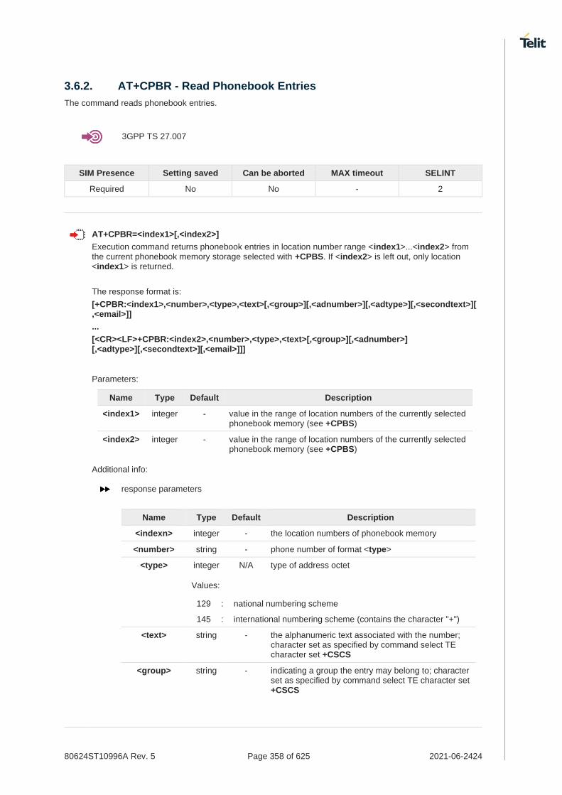
80624ST10996A Rev. 5 Page 358 of 625 2021-06-2424
3.6.2. AT+CPBR - Read Phonebook Entries
The command reads phonebook entries.
3GPP TS 27.007
SIM Presence Setting saved Can be aborted MAX timeout SELINT
Required No No - 2
AT+CPBR=<index1>[,<index2>]
Execution command returns phonebook entries in location number range <index1>...<index2> from the current phonebook memory storage selected with +CPBS. If <index2> is left out, only location <index1> is returned.
The response format is:
[+CPBR:<index1>,<number>,<type>,<text>[,<group>][,<adnumber>][,<adtype>][,<secondtext>][,<email>]]
...
[<CR><LF>+CPBR:<index2>,<number>,<type>,<text>[,<group>][,<adnumber>] [,<adtype>][,<secondtext>][,<email>]]]
Parameters:
Name Type Default Description
<index1> integer - value in the range of location numbers of the currently selected phonebook memory (see +CPBS)
<index2> integer - value in the range of location numbers of the currently selected phonebook memory (see +CPBS)
Additional info:
response parameters
Name Type Default Description
<indexn> integer - the location numbers of phonebook memory
<number> string - phone number of format <type>
<type> integer N/A type of address octet
Values:
129 : national numbering scheme
145 : international numbering scheme (contains the character "+")
<text> string - the alphanumeric text associated with the number; character set as specified by command select TE character set +CSCS
<group> string - indicating a group the entry may belong to; character set as specified by command select TE character set +CSCS

80624ST10996A Rev. 5 Page 359 of 625 2021-06-2424
<adnumber> string - an additional phone number of format <adtype>
<adtype> integer - type of address octet
<secondtext> string - second text field associated with the number; character set as specified by command select TE character set +CSCS
<email> string - email field; character set as specified by command select TE character set +CSCS
If "MC" is the currently selected phonebook memory storage, a sequence of missed calls coming from the same number will be saved as one missed call and +CPBR will show just one line of information.
If all queried locations are empty (but available), no information text lines may be returned. If listing fails in an MT error, +CME ERROR: <err> is returned.
AT+CPBR=?
Test command returns location range supported by the current storage as a compound value and the maximum lengths of <number>, <text>, <group>, <secondtext> and <email>, in the format:
+CPBR: (<minIndex> - <maxIndex>),<nlength>,<tlength>,<glength>,<slength>,<elength>
Additional info:
response parameters
Name Type Default Description
<minIndex> integer - the minimum <index> number
<maxIndex> integer - the maximum <index> number
<nlength> integer - the maximum length of field <number>
<tlength> integer - the maximum length of field <text>
<glength> integer - the maximum length of field <group>
<slength> integer - the maximum length of field <secondtext>
<elength> integer - the maximum length of field <email>
The value of <nlength> could vary, depending on the availability of Extension service, in the following situations:
1. if "SM" memory storage has been selected (see +CPBS) and the SIM supports the Extension1 service
2. if "FD" memory storage has been selected (see +CPBS) and the SIM supports the Extension2 service
3. if "MB" memory storage has been selected (see +CPBS) and the SIM supports the Extension6 service

80624ST10996A Rev. 5 Page 360 of 625 2021-06-2424
Remember to select the PB storage with +CPBS command before issuing PB commands.
AT+CPBS="ME"
OK
AT+CPBS?
+CPBS: "ME",1,100
OK
AT+CPBR=?
+CPBR: (1-100),40,255
OK
AT+CPBR=1
+CPBR: 1,"01048771234",129,"James"
OK

80624ST10996A Rev. 5 Page 361 of 625 2021-06-2424
3.6.3. AT+CPBF - Find Phonebook Entries
This command search phonebook record from the current phonebook memory storage selected with +CPBS.
3GPP TS 27.007
SIM Presence Setting saved Can be aborted MAX timeout SELINT
Required Other No - 2
AT+CPBF=<findtext>
Execution command returns phonebook entries (from the current phonebook memory storage selected with +CPBS) which alphanumeric field start with string <findtext>.
Parameter:
Name Type Default Description
<findtext> string - string to be searched among the phonebook entries; character set as specified by command select TE character set +CSCS
Additional info:
This command returns the response in the following format:
[+CPBF:<index1>,<number>,<type>,<text>[,<group>][,<adnumber>] [,<adtype>][,<secondtext>][,<email>]<CR><LF>
+CPBF:<index2>,<number>,<type>,<text>[,<group>][,<adnumber>] [,<adtype>][,<secondtext>][,<email>][...]]]
Name Type Default Description
<indexn> integer - the location number of the phonebook entry
<number> string - phone number of format <type>
<type> integer N/A type of address octet
Values:
129 : national numbering scheme
145 : international numbering scheme (contains the character "+")
<text> string - the alphanumeric text associated with the number; character set as specified by command select TE character set +CSCS
<group> string - a group the entry may belong to; character set as specified by command select TE character set +CSCS
<adnumber> string - an additional number of format <adtype>
<adtype> integer - type of address octet
<secondtext> string - a second text field associated with the number; character set as specified by command select TE character set +CSCS
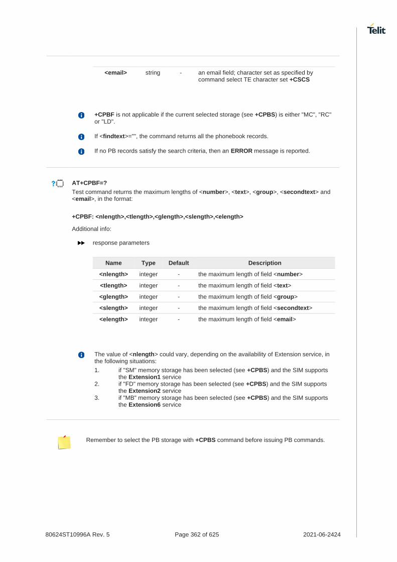
80624ST10996A Rev. 5 Page 362 of 625 2021-06-2424
<email> string - an email field; character set as specified by command select TE character set +CSCS
+CPBF is not applicable if the current selected storage (see +CPBS) is either "MC", "RC" or "LD".
If <findtext>="", the command returns all the phonebook records.
If no PB records satisfy the search criteria, then an ERROR message is reported.
AT+CPBF=?
Test command returns the maximum lengths of <number>, <text>, <group>, <secondtext> and <email>, in the format:
+CPBF: <nlength>,<tlength>,<glength>,<slength>,<elength>
Additional info:
response parameters
Name Type Default Description
<nlength> integer - the maximum length of field <number>
<tlength> integer - the maximum length of field <text>
<glength> integer - the maximum length of field <group>
<slength> integer - the maximum length of field <secondtext>
<elength> integer - the maximum length of field <email>
The value of <nlength> could vary, depending on the availability of Extension service, in the following situations:
1. if "SM" memory storage has been selected (see +CPBS) and the SIM supports the Extension1 service
2. if "FD" memory storage has been selected (see +CPBS) and the SIM supports the Extension2 service
3. if "MB" memory storage has been selected (see +CPBS) and the SIM supports the Extension6 service
Remember to select the PB storage with +CPBS command before issuing PB commands.
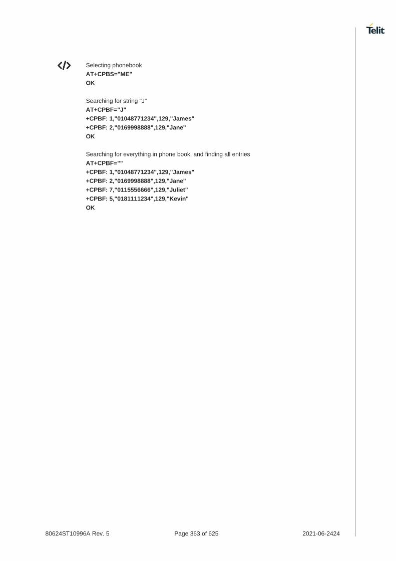
80624ST10996A Rev. 5 Page 363 of 625 2021-06-2424
Selecting phonebook
AT+CPBS="ME"
OK
Searching for string "J"
AT+CPBF="J"
+CPBF: 1,"01048771234",129,"James"
+CPBF: 2,"0169998888",129,"Jane"
OK
Searching for everything in phone book, and finding all entries
AT+CPBF=""
+CPBF: 1,"01048771234",129,"James"
+CPBF: 2,"0169998888",129,"Jane"
+CPBF: 7,"0115556666",129,"Juliet"
+CPBF: 5,"0181111234",129,"Kevin"
OK

80624ST10996A Rev. 5 Page 364 of 625 2021-06-2424
3.6.4. AT+CPBW - Write Phonebook Entry
This command writes phonebook entry in the current phonebook memory.
3GPP TS 27.007
SIM Presence Setting saved Can be aborted MAX timeout SELINT
Required Other No - 2
AT+CPBW=[<index>][,<number>[,<type>[,<text>[,<group>[,<adnumber>[,<adtype> [,<secondtext>[,<email>]]]]]]]]
Execution command writes phonebook entry in location number <index> in the current phonebook memory storage selected with +CPBS.
Parameters:
Name Type Default Description
<index> integer - the location numbers of phonebook memory
<number> string - phone number in the format <type>
<type> integer 129 type of address octet
Values:
129 : national numbering scheme
145 : international numbering scheme (contains the character "+")
<text> string - the alphanumeric text associated with the number; character set as specified by command select TE character set +CSCS
<group> string - a group the entry may belong to; character set as specified by command select TE character set +CSCS
<adnumber> string - an additional number of format <adtype>
<adtype> integer - type of address octet
<secondtext> string - a second text field associated with the number; character set as specified by command select TE character set +CSCS
<email> string - email field; character set as specified by command select TE character set +CSCS
If record number <index> already exists, it will be overwritten.
If either <number>, <type> and <text> are omitted, the phonebook entry in location <index> is deleted.
If either "LD", "MC" or "RC" memory storage has been selected (see +CPBS) it is possible just to delete the phonebook entry in location <index>, therefore parameters <number>, <type> and <text> must be omitted.
If <index> is omitted or <index>=0, the number <number> is stored in the first free phonebook location.
AT+CPBW=0,"+39040X192YZ1",129,"Text"

80624ST10996A Rev. 5 Page 365 of 625 2021-06-2424
AT+CPBW=,"+39040X192YZ1",129,"Text"
AT+CPBW=?
Test command returns location range supported by the current storage and types of address as compound values, the maximum length of <number> field, supported number formats of the storage, the maximum length of <text> field, the maximum length of <group>, the maximum length of <secondtext> and the maximum length of <email>. The format is:
+CPBW: (list of supported <index>s),<nlength>,(list of supported <type>s),<tlength>, <glength>,<slength>,<elength>
Additional info:
response fields
Name Type Default Description
<nlength> integer - the maximum length of field <number>
<tlength> integer - the maximum length of field <text>
<glength> integer - the maximum length of field <group>
<slength> integer - the maximum length of field <secondtext>
<elength> integer - the maximum length of field <email>
The value of <nlength> could vary, depending on the availability of Extension service, in the following situations:
1. if "SM" memory storage has been selected (see +CPBS) and the SIM supports the Extension1 service
2. if "FD" memory storage has been selected (see +CPBS) and the SIM supports the Extension2 service
3. if "MB" memory storage has been selected (see +CPBS) and the SIM supports the Extension6 service
Remember to select the PB storage with +CPBS command before issuing PB commands.
AT+CPBW=?
+CPBW: (1-100),40,(129, 145),255
OK
AT+CPBW=6,"18651896699",129,"John"
OK

80624ST10996A Rev. 5 Page 366 of 625 2021-06-2424
3.6.5. AT#CPBGR - Read Group Entries
This command returns Grouping information Alpha String (GAS) USIM file entries.
SIM Presence Setting saved Can be aborted MAX timeout SELINT
Required No No - 2
AT#CPBGR=<indexFirst>[,<indexLast>]
Set command returns Grouping information Alpha String (GAS) USIM file entries in location number range <indexFirst>...<indexLast>. If <indexLast> is omitted, only location <indexFirst> is returned. The response, for each location, is a string. This string is a name used for a group the ADN entries can belong to. The response format is: [#CPBGR: <index1>,<text1>[<CR><LF> #CPBGR: <index2>,<text2>[…]]]
Parameters:
Name Type Default Description
<indexFirst> integer NA first location to be read
Value:
minIndex÷maxIndex : range of location numbers of GAS, where "minIndex" and "maxIndex" can be obtained by issuing the test command
<indexLast> integer NA last location to be read
Value:
minIndex÷maxIndex : range of location numbers of GAS, where "minIndex" and "maxIndex" can be obtained by issuing the test command
Additional info:
Response parameters:
Name Type Default Description
<index> integer N/A location number of the GAS entry
Value:
indexFirst÷indexLast : range of location numbers of GAS returned in the response
<text> string - alphanumeric text associated to the entry
AT#CPBGR=?
Test command returns the supported values of the parameters <indexn> and the maximum length
of <textn> field, in the format:

80624ST10996A Rev. 5 Page 367 of 625 2021-06-2424
#CPBGR: (<minIndex> - <maxIndex>),<tlength>
Additional info:
Parameters:
Name Type Default Description
<minIndex> integer - minimum <index> number
<maxIndex> integer - maximum <index> number
<tlength> integer - maximum <text> field length

80624ST10996A Rev. 5 Page 368 of 625 2021-06-2424
3.6.6. AT#CPBGW - Write Group Entry
Set command writes the name of a phonebook group <text> in the Grouping information Alpha String (GAS) USIM file in a specified location number <index>.
SIM Presence Setting saved Can be aborted MAX timeout SELINT
Required No No - 2
AT#CPBGW=<index>,<text>
Parameters:
Name Type Default Description
<index> integer - number of the record in the GAS file to be written; value ranges from 1 to the number of records of the GAS file, that varies from USIM to USIM
<text> string - text to be stored in the record
If record number <index> already exists, it will be overwritten
AT#CPBGW=?
Test command returns location range supported by the current storage as a compound value, and maximum length of <text> field. The format is:
+CPBGW: (list of supported <index>s),<tlength>
Additional info:
Parameter:
Name Type Default Description
<tlength> integer - maximum length of field <text> in bytes; actual maximum number of characters that can be stored depends upon <text> coding (see +CSCS)

80624ST10996A Rev. 5 Page 369 of 625 2021-06-2424
Packet Domain
3.7.1. AT+CGCLASS - GPRS Mobile Station Class
This command sets the GPRS class.
SIM Presence Setting saved Can be aborted MAX timeout SELINT
Required Auto No - 2
AT+CGCLASS=[<class>]
Set command sets the GPRS class according to <class> parameter.
Parameter:
Name Type Default Description
<class> string "A" GPRS class
Values:
"A" : Class-A mode of operation (A/Gb mode), or CS/PS mode of operation (Iu mode) (factory default)
"B" : Class-B mode of operation (A/Gb mode), or CS/PS mode of operation (Iu mode)
"CG" : Class-C mode of operation in PS only mode (A/Gb mode), or PS mode of operation (Iu mode)
"CC" : Class-C mode of operation in CS only mode (A/Gb mode), or CS (Iu mode)
AT+CGCLASS?
Read command returns the mode of operation set by the TE, in the format:
+CGLASS: <class>
AT+CGCLASS=?
Test command reports the range for the parameter <class>.
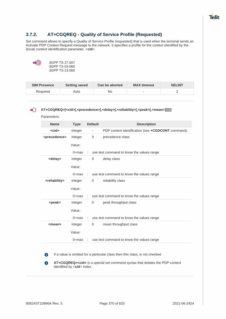
80624ST10996A Rev. 5 Page 370 of 625 2021-06-2424
3.7.2. AT+CGQREQ - Quality of Service Profile (Requested)
Set command allows to specify a Quality of Service Profile (requested) that is used when the terminal sends an Activate PDP Context Request message to the network. It specifies a profile for the context identified by the (local) context identification parameter, <cid>.
3GPP TS 27.007 3GPP TS 03.060 3GPP TS 23.060
SIM Presence Setting saved Can be aborted MAX timeout SELINT
Required Auto No - 2
AT+CGQREQ=[<cid>[,<precedence>[,<delay>[,<reliability>[,<peak>[,<mean>]]]]]]
Parameters:
Name Type Default Description
<cid> integer - PDP context identification (see +CGDCONT command).
<precedence> integer 0 precedence class
Value:
0÷max : use test command to know the values range
<delay> integer 0 delay class
Value:
0÷max : use test command to know the values range
<reliability> integer 0 reliability class
Value:
0÷max : use test command to know the values range
<peak> integer 0 peak throughput class
Value:
0÷max : use test command to know the values range
<mean> integer 0 mean throughput class
Value:
0÷max : use test command to know the values range
If a value is omitted for a particular class then this class, is not checked
AT+CGQREQ=<cid> is a special set command syntax that delates the PDP context identified by <cid> index.

80624ST10996A Rev. 5 Page 371 of 625 2021-06-2424
AT+CGQREQ?
Read command returns the current settings for each defined context in the format:
+CGQREQ:<cid>,<precedence>,<delay>,<reliability>,<peak>,<mean>[<CR><LF> +CGQREQ:<cid>,<precedence>,<delay>,<reliability>,<peak>,<mean>[...]]
If no PDP context has been defined, it has no effect and OK result code is returned.
AT+CGQREQ=?
Test command returns as a compound value the type of the current PDP context and the supported values for the sub parameters in the format:
+CGQREQ: <PDP_Type>, (list of supported <precedence>s),(list of supported <delay>s), (list of supported <reliability>s),(list of supported <peak>s), (list of supported <mean>s)
Additional info:
PDP type meaning.
Name Type Default Description
<PDP_Type> string - specifies the type of packet data protocol (see +CGDCONT command)
AT+CGQREQ? +CGQREQ: 1,0,0,3,0,0 OK
AT+CGQREQ=1,0,0,3,0,0 OK
AT+CGQREQ=? +CGQREQ: "IP",(0-3),(0-4),(0-5),(0-9),(0-18,31) +CGQREQ: "PPP",(0-3),(0-4),(0-5),(0-9),(0-18,31) +CGQREQ: "IPV6",(0-3),(0-4),(0-5),(0-9),(0-18,31) OK
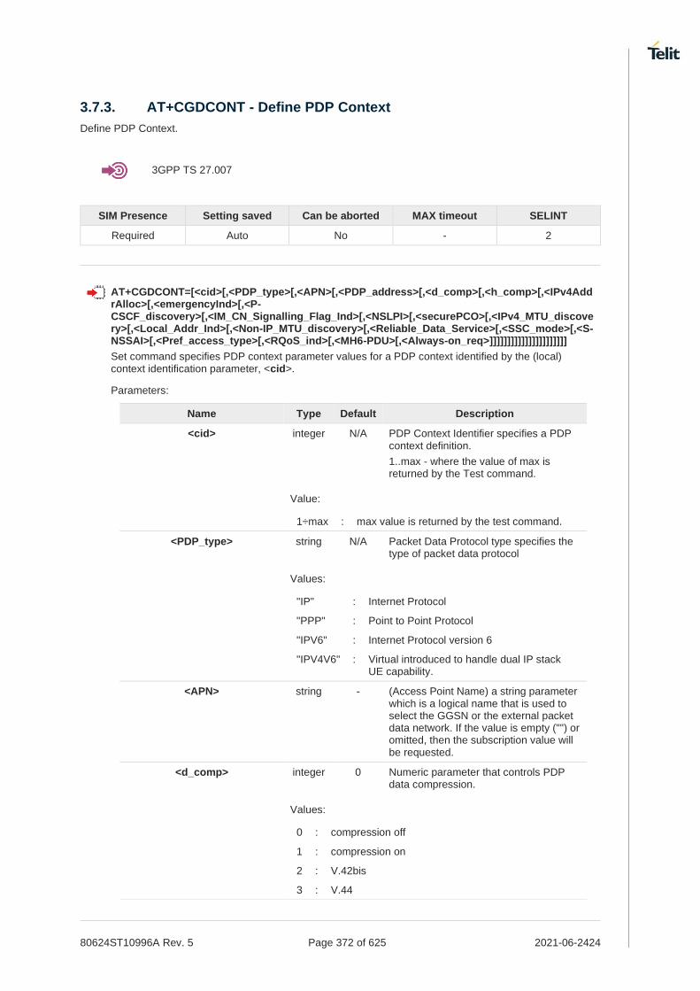
80624ST10996A Rev. 5 Page 372 of 625 2021-06-2424
3.7.3. AT+CGDCONT - Define PDP Context
Define PDP Context.
3GPP TS 27.007
SIM Presence Setting saved Can be aborted MAX timeout SELINT
Required Auto No - 2
AT+CGDCONT=[<cid>[,<PDP_type>[,<APN>[,<PDP_address>[,<d_comp>[,<h_comp>[,<IPv4AddrAlloc>[,<emergencyInd>[,<P-CSCF_discovery>[,<IM_CN_Signalling_Flag_Ind>[,<NSLPI>[,<securePCO>[,<IPv4_MTU_discovery>[,<Local_Addr_Ind>[,<Non-IP_MTU_discovery>[,<Reliable_Data_Service>[,<SSC_mode>[,<S-NSSAI>[,<Pref_access_type>[,<RQoS_ind>[,<MH6-PDU>[,<Always-on_req>]]]]]]]]]]]]]]]]]]]]]]
Set command specifies PDP context parameter values for a PDP context identified by the (local) context identification parameter, <cid>.
Parameters:
Name Type Default Description
<cid> integer N/A PDP Context Identifier specifies a PDP context definition.
1..max - where the value of max is returned by the Test command.
Value:
1÷max : max value is returned by the test command.
<PDP_type> string N/A Packet Data Protocol type specifies the type of packet data protocol
Values:
"IP" : Internet Protocol
"PPP" : Point to Point Protocol
"IPV6" : Internet Protocol version 6
"IPV4V6" : Virtual introduced to handle dual IP stack UE capability.
<APN> string - (Access Point Name) a string parameter which is a logical name that is used to select the GGSN or the external packet data network. If the value is empty ("") or omitted, then the subscription value will be requested.
<d_comp> integer 0 Numeric parameter that controls PDP data compression.
Values:
0 : compression off
1 : compression on
2 : V.42bis
3 : V.44

80624ST10996A Rev. 5 Page 373 of 625 2021-06-2424
<h_comp> integer 0 controls PDP header compression.
Values:
0 : compression off
1 : compression on
2 : RFC1144 (applicable for SNDCP only)
3 : RFC2507
4 : RFC3095 (applicable for PDCP only)
<IPv4AddrAlloc> integer 0 a numeric parameter that controls how the MT/TA requests to get the IPv4 address information.
Values:
0 : IPv4 Address Allocation through NAS Signaling
1 : IPv4 Address Allocated through DHCP
<emergencyInd> integer 0 a numeric parameter used to indicate whether the PDP context is for emergency bearer services or not.
Values:
0 : PDP context is not for emergency bearer services (default)
1 : PDP context is for emergency bearer services
<P-CSCF_discovery> integer 0 a numeric parameter influences how the MT/TA requests to get the P-CSCF address, see 3GPP TS 24.229 [89] annex B and annex L.
Values:
0 : Preference of P-CSCF address discovery not influenced by +CGDCONT
1 : Preference of P-CSCF address discovery through NAS Signalling
<IM_CN_Signalling_Flag_Ind> integer 0 a numeric parameter used to indicate to the network whether the PDP context is for IM CN subsystem-related signalling only or not.
Values:
0 : UE indicates that the PDP context is not for IM CN subsystem-related signalling only
1 : UE indicates that the PDP context is for IM CN subsystem-related signalling only
<NSLPI> integer 0 indicates the NAS signalling priority requested for this PDP context
Values:
0 : indicates that this PDP context is to be activated with the value for the low priority indicator configured in the MT.

80624ST10996A Rev. 5 Page 374 of 625 2021-06-2424
1 : indicates that this PDP context is to be activated with the value for the low priority indicator set to "MS is not configured for NAS signalling low priority".
<securePCO> integer 0 Specifies if security protected transmission of PCO is requested or not (applicable for EPS only)
Values:
0 : Security protected transmission of PCO is not requested
1 : Security protected transmission of PCO is requested
<IPv4_MTU_discovery> integer 0 influences how the MT/TA requests to get the IPv4 MTU size
Values:
0 : Preference of IPv4 MTU size discovery not influenced by +CGDCONT
1 : Preference of IPv4 MTU size discovery through NAS signalling
<Local_Addr_Ind> integer 0 indicates to the network whether or not the MS supports local IP address in TFTs
Values:
0 : indicates that the MS does not support local IP address in TFTs
1 : indicates that the MS supports local IP address in TFTs
<Non-IP_MTU_discovery> integer 0 influences how the MT/TA requests to get the Non-IP MTU size
Values:
0 : Preference of Non-IP MTU size discovery not influenced by +CGDCONT
1 : Preference of Non-IP MTU size discovery through NAS signalling
<Reliable_Data_Service> integer 0 indicates whether the UE is using Reliable Data Service for a PDN connection or not
Values:
0 : Reliable Data Service is not being used for the PDN connection
1 : Reliable Data Service is being used for the PDN connection
<SSC_mode> integer 0 indicates the session and service continuity (SSC) mode for the PDU session in 5GS
Values:
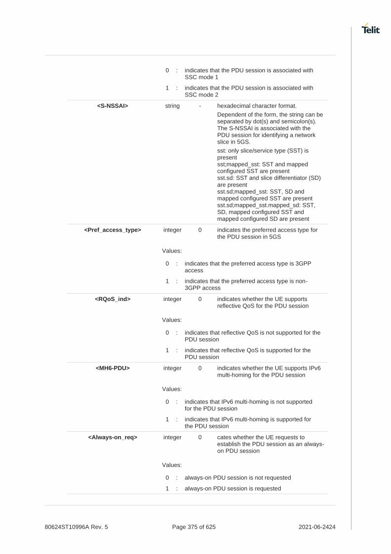
80624ST10996A Rev. 5 Page 375 of 625 2021-06-2424
0 : indicates that the PDU session is associated with SSC mode 1
1 : indicates that the PDU session is associated with SSC mode 2
<S-NSSAI> string - hexadecimal character format.
Dependent of the form, the string can be separated by dot(s) and semicolon(s). The S-NSSAI is associated with the PDU session for identifying a network slice in 5GS.
sst: only slice/service type (SST) is present sst;mapped_sst: SST and mapped configured SST are present sst.sd: SST and slice differentiator (SD) are present sst.sd;mapped_sst: SST, SD and mapped configured SST are present sst.sd;mapped_sst.mapped_sd: SST, SD, mapped configured SST and mapped configured SD are present
<Pref_access_type> integer 0 indicates the preferred access type for the PDU session in 5GS
Values:
0 : indicates that the preferred access type is 3GPP access
1 : indicates that the preferred access type is non-3GPP access
<RQoS_ind> integer 0 indicates whether the UE supports reflective QoS for the PDU session
Values:
0 : indicates that reflective QoS is not supported for the PDU session
1 : indicates that reflective QoS is supported for the PDU session
<MH6-PDU> integer 0 indicates whether the UE supports IPv6 multi-homing for the PDU session
Values:
0 : indicates that IPv6 multi-homing is not supported for the PDU session
1 : indicates that IPv6 multi-homing is supported for the PDU session
<Always-on_req> integer 0 cates whether the UE requests to establish the PDU session as an always-on PDU session
Values:
0 : always-on PDU session is not requested
1 : always-on PDU session is requested

80624ST10996A Rev. 5 Page 376 of 625 2021-06-2424
a special form of the Set command, +CGDCONT=<cid>, causes the values for context number <cid> to become undefined.
but if <cid> is already configured as default attach profile or embedded profile or tethered profile, it will be re-defined automatically with default values.
Only IP, IPV6 and IPV4V6 values are supported for EPS(LTE) services.
For EPS(LTE) <PDP_addr> is omitted.
if <emergencyInd> is enabled, this profile can not be used attached profile.
The following parameters are supported to input some value. Other parameters that not supported should be NULL value.
<cid>, <PDP_type>, <APN>, <PDP_address>, <d_comp>, <h_comp>, <IPv4AddrAlloc>, <emergencyInd>, <SSC_mode>, <S-NSSAI>, <Always-on_req>
Ex) <SSC_mode>
AT+CGDCONT=42,"IP","test","",0,0,0,1,,,,,,,,,0
AT+CGDCONT?
Read command returns the current settings for each defined context in the format:
+CGDCONT: <cid>,<PDP_type>,<APN>,<PDP_addr>,<d_comp>,<h_comp>[,<IPv4AddrAlloc>[,<emergencyInd>[,<P-CSCF_discovery>[,<IM_CN_Signalling_Flag_Ind>[,<NSLPI>[,<securePCO>[,<IPv4_MTU_discovery>[,<Local_Addr_Ind>[,<Non-IP_MTU_discovery>[,<Reliable_Data_Service>[,<SSC_mode>[,<S-NSSAI>[,<Pref_access_type>[,<RQoS_ind>[,<MH6-PDU>[,<Always-on_req>]]]]]]]]]]]]]]]][<CR><LF>
+CGDCONT: <cid>,<PDP_type>,<APN>,<PDP_addr>,<d_comp>,<h_comp>[,<IPv4AddrAlloc>[,<emergencyInd>[,<P-CSCF_discovery>[,<IM_CN_Signalling_Flag_Ind>[,<NSLPI>[,<securePCO>[,<IPv4_MTU_discovery>[,<Local_Addr_Ind>[,<Non-IP_MTU_discovery>[,<Reliable_Data_Service>[,<SSC_mode>[,<S-NSSAI>[,<Pref_access_type>[,<RQoS_ind>[,<MH6-PDU>[,<Always-on_req>]]]]]]]]]]]]]]]][<CR><LF>
AT+CGDCONT=?
Test command returns values supported as a compound value.
AT+CGDCONT=1,"IP","APN","10.10.10.10",0,0,0,0,0.0 OK
AT+CGDCONT? +CGDCONT: 1,"IP","APN","10.10.10.10",0,0,0,0,,,,,,,,,"",,,,0 OK

80624ST10996A Rev. 5 Page 377 of 625 2021-06-2424
3.7.4. AT+CGCONTRDP - PDP Context Read Dynamic Parameters
The execution command returns the relevant information for a PDP Context established by the network.
3GPP TS 27.007
SIM Presence Setting saved Can be aborted MAX timeout SELINT
Required Auto No - 2
AT+CGCONTRDP[=<cid>]
The execution command returns the relevant information on a PDP Context established by the network with the context identifier <cid>. If the parameter <cid> is omitted, the information for all established PDP contexts is returned. The response message has the following format:
+CGCONTRDP:<cid>,<bearerId>,<apn>[,<ip&subnet>[,<gw_addr>[,<DNS_prim> [,<DNS_sec>[, <P_CSCF_prim>[,<P_CSCF_sec>]]]]]][<CR><LF> +CGCONTRDP:<cid>,<bearerId>,<apn>[, <ip&subnet_mask>[,<gw_addr>[,<DNS_prim> [,<DNS_sec>[, <P_CSCF_prim>[,<P_CSCF_sec>]]]]]] [...]]
If the context cannot be found an ERROR response is returned.
The response message parameters are described in the Additional info section.
Parameter:
Name Type Default Description
<cid> integer - identifies a non secondary PDP context definition. The parameter is local to the TE-MT interface and is used in other PDP context-related commands.
Additional info:
List of the meaning of the response message parameters.
Name Type Default Description
<berrerId> integer - identifies the bearer, EPS Bearer in EPS and NSAPI in UMTS/GPRS.
<apn> string - logical name used to select the GGSN or the external packet data network.
<ip&subnet> string - IP address and subnet mask of the MT. The string is given as dot-separated numeric (0-255) parameters on the form. For more information, see next Additional info section.
<gw_addr> string - Gateway address of the MT. The string is given as dot-separated numeric (0-255) parameters.
<DNS_prim> string - IP address of the primary DNS Server.
<DNS_sec> string - IP address of the secondary DNS Server.
<P_CSCF_prim> string - IP address of the primary P-CSCF Server.
<P_CSCF_sec> string - IP address of the secondary P-CSCF Server.

80624ST10996A Rev. 5 Page 378 of 625 2021-06-2424
Referring to <ip&subnet> parameter:
the string is given as dot-separated numeric (0-255) parameters. The format is:
for IPv4:
"a1.a2.a3.a4.m1.m2.m3.m4"
for IPv6:
"a1.a2.a3.a4.a5.a6.a7.a8.a9.a10.a11.a12.a13.a14.a15.a16. m1.m2.m3.m4.m5.m6.m7.m8.m9.m10.m11.m12. m13.m14.m15.m16"
When +CGPIAF is supported, its settings can influence the format of this parameter returned with the execute form of +CGCONTRDP.
The dynamic part of the PDP context will only exist if established by the network. The test command returns a list of <cid>s associated with active contexts.
If the MT has dual stack capabilities, two lines of information are returned per <cid>. First one line with the IPv4 parameters followed by one line with the IPv6 parameters.
AT+CGCONTRDP=?
Return the list of <cid>s associated with active contexts.
AT+CGACT=1,1
OK
AT+CGCONTRDP=?
+CGCONTRDP: (1)
OK
AT+CGCONTRDP =1
+CGCONTRDP: 1,5,lte.ktfwing.com,"10.52.202.76",,"211.219.86.1","168.126.63.1"
OK

80624ST10996A Rev. 5 Page 379 of 625 2021-06-2424
3.7.5. AT+CGQMIN - Quality of Service Profile (Minimum Acceptable)
Set command allows to specify a minimum acceptable profile which is checked by the terminal against the negotiated profile returned in the Activate PDP Context Accept message.
3GPP TS 27.007 3GPP TS 03.060 3GPP TS 23.060
SIM Presence Setting saved Can be aborted MAX timeout SELINT
Required Auto No - 2
AT+CGQMIN=[<cid>[,<precedence>[,<delay>[,<reliability>[,<peak>[,<mean>]]]]]]
Parameters:
Name Type Default Description
<cid> integer - PDP context identification (see +CGDCONT command)
<precedence> integer 0 precedence class
Value:
0÷max : use test command to know the values range
<delay> integer 0 delay class
Value:
0÷max : use test command to know the values range
<reliability> integer 0 reliability class
Value:
0÷max : use test command to know the values range
<peak> integer 0 peak throughput class
Value:
0÷max : use test command to know the values range
<mean> integer 0 mean throughput class
Value:
0÷max : use test command to know the values range
If a value is omitted for a class, then this class is not checked.
A special form of the set command, AT+CGQMIN=<cid> causes the requested profile for context number <cid> to become undefined.

80624ST10996A Rev. 5 Page 380 of 625 2021-06-2424
AT+CGQMIN?
Read command returns the current settings for each defined context in the format:
+CGQMIN: <cid>,<precedence>,<delay>,<reliability>,<peak>,<mean>[<CR><LF>
+CGQMIN: <cid>,<precedence>,<delay>,<reliability>,<peak>,<mean>[...]]
If no PDP context has been defined, it has no effect and OK result code is returned
AT+CGQMIN=?
Test command returns as a compound value the type of the current PDP context and the supported values for the sub parameters in the format:
+CGQMIN: <PDP_Type>, (list of supported <precedence>s),(list of supported <delay>s), (list of supported <reliability>s),(list of supported <peak>s), (list of supported <mean>s)
Additional info:
PDP type meaning.
Name Type Default Description
<PDP_Type> string - specifies the type of packet data protocol, see +CGDCONT command
Only the "IP" <PDP_Type> is currently supported.

80624ST10996A Rev. 5 Page 381 of 625 2021-06-2424
3.7.6. AT+CGEQREQ - 3G Quality of Service Profile (Requested)
The command allows to specify a 3G quality of service profile for the context identified by the context identification parameter.
• 3GPP TS 27.007
SIM Presence Setting saved Can be aborted MAX timeout SELINT
Required Auto No - 2
AT+CGEQREQ[<cid>[,<trafficClass>[,<maxBitRateUL>[,<maxBitRateDL>[,<guarBitRateUL> [,<guarBitRateDL>[,<deliverOrder>[,<maxSDUsize>[,<SDUerrRatio> [,<resBitErrRatio>[,<delErrSDUs>[,<tranDelay>[,<traffHandPrio> [,<sourStatiDesc>[,<signInd>]]]]]]]]]]]]]]]
The set command allows to specify a 3G quality of service profile for the context identified by the(local) context identification parameter <cid> which is used when the MT sends an Activate PDP Context Request message to the network.
Parameters:
Name Type Default Description
<cid> integer - PDP context identification (see +CGDCONT command).
<trafficClass> integer 4 traffic class
Values:
0 : conversational
1 : streaming
2 : interactive
3 : background
4 : subscribed value
<maxBitRateUL> integer 0 maximum bitrate up link (kbits/s). This parameter should be provided if the <trafficClass> is specified as conversational or streaming.
Values:
0 : subscribed value
1÷568 : kbits/s
576÷11520 : kbits/s
<maxBitRateDL> integer 0 maximum bitrate down link (kbits/s). This parameter should be provided if the <trafficClass> is specified as conversational or streaming.
Values:
0 : subscribed value
1÷568 : kbits/s
576÷8640 : kbits/s
8700÷42200 : kbits/s

80624ST10996A Rev. 5 Page 382 of 625 2021-06-2424
<guarBitRateUL> integer 0 guaranteed bitrate up link(kbits/s). This parameter should be provided if the <trafficClass> is specified as conversational or streaming.
Values:
0 : subscribed value
1÷568 : kbits/s
576÷8640 : kbits/s
8700÷42200 : kbits/s
<guarBitRateDL> integer 0 guaranteed bitrate down link(kbits/s). This parameter should be provided if the <trafficClass> is specified as conversational or streaming.
Values:
0 : subscribed value
1÷568 : kbits/s
576÷8640 : kbits/s
8700÷42200 : kbits/s
<deliverOrder> integer 2 SDU delivery order
Values:
0 : disable
1 : enable
2 : subscribed value
<maxSDUsize> integer 0 maximum SDU size in octets
Values:
0 : subscribed value
10÷1500 : size in octets
1502 : size in octets
1510 : size in octets
1520 : size in octets
<SDUerrRatio> string 0E0 SDU error ratio
mEe means m*10-e, e.g 1E2 means 1*10-2
Values:
0E0 : 0*10-0
1E1 : 1*10-1
1E2 : 1*10-2
7E3 : 7*10-3
1E3 : 1*10-3
1E4 : 1*10-4
1E5 : 1*10-5
1E6 : 1*10-6

80624ST10996A Rev. 5 Page 383 of 625 2021-06-2424
<resBitErrRatio> string 0E0 residual bitt error ratio
mEe means m*10-e, e.g. 1E2 mean 1*10-2
Values:
0E0 : 0*10-0
5E2 : 5*10-2
1E2 : 1*10-2
5E3 : 5*10-3
4E3 : 4*10-3
1E3 : 1*10-3
1E4 : 1*10-4
1E5 : 1*10-5
1E6 : 1*10-6
6E8 : 6*10-8
<delErrSDUs> integer 3 delivery of erroneous SDUs
Values:
0 : disable
1 : enable
2 : no detect
3 : subscribed value
<tranDelay> integer 0 transfer delay (milliseconds)
Values:
0 : subscribed value
10÷150 : delay (milliseconds)
200÷950 : delay (milliseconds)
1000÷4000 : delay (milliseconds)
<traffHandPrio> integer 0 traffic handling priority
Values:
0 : subscribed value
1÷3 : priority level
<sourStatiDesc> integer 0 characteristics of the source of the submitted SDUs for a PDP context. This parameter should be provided if the <trafficClass> is specified as conversational or streaming
Values:
0 : characteristics of SDUs is unknown
1 : characteristics of SDUs corresponds to a speech source
<signInd> integer 0 signalling content of submitted SDUs for a PDP context. This parameter should be provided if the <trafficClass> is specified as interactive.

80624ST10996A Rev. 5 Page 384 of 625 2021-06-2424
Values:
0 : PDP context is not optimized for signalling
1 : PDP context is optimized for signalling <PDP_type> (see +CGDCONT command)
A special form of the Set command, +CGEQREQ=<cid> causes the requested profile for context number <cid> to become undefined.
The set command can modify the 2G QoS according to standard [2], see +CGQREQ command.
AT+CGEQREQ?
Read command returns the current settings for each defined context in the format:
[+CGEQREQ: <cid>,<trafficClass>,<maximumBitrateUl>, <maximumBitrateDl>,<guaranteedBitrateUl>,<guaranteedBitrateDl>, <deliveryOrder>,<maximumSduSize>,<sduErrorRatio>, <residualBitErrorRatio>,<deliveryErroneousSdus>,<transferDelay>, <trafficHandlingPriority>,<sourceStatisticsDescriptor>, <signallingIndication><CR><LF>]
If no PDP context has been defined it has no effect, and OK result code is returned.
AT+CGEQREQ=?
Test command returns as a compound value the type of the current PDP context and the supported values for the sub-parameters in the format:
+CGQEQREQ: <pdpType>, (list of supported <trafficClass>s), (list of supported <maximumBitrateUl>s), (list of supported <maximumBitrateDl>s), (list of supported <guaranteedBitrateUl>s), (list of supported <guaranteedBitrateDl>s), (list of supported <deliveryOrder>s), (list of supported <maximumSduSize>s), (list of supported <sduErrorRatio>s), (list of supported <residualBitErrorRatio>s), (list of supported <deliveryErroneousSdus>s), (list of supported <transferDelay>s), (list of supported <trafficHandlingPriority>s), (list of supported <sourceStatisticsDescriptor>s), (list of supported <signallingIndication>s)
Additional info:
PDP type
Name Type Default Description
<pdpType> string - specifies the type of packet data protocol (see +CGDCONT command)

80624ST10996A Rev. 5 Page 385 of 625 2021-06-2424
3.7.7. AT+CGEQNEG - 3G Quality of Service Profile (Negotiated)
This command allows the TE to retrieve the negotiated 3G quality of service returned in the Activate PDP Context Accept/Modify message.
3GPP TS 27.007
SIM Presence Setting saved Can be aborted MAX timeout SELINT
Required Auto No - 2
AT+CGEQNEG=[<cid>[,<cid>[,…]]]
Set command returns the negotiated 3G QoS profile for the specified context identifiers, <cid>s. The QoS profile consists of a number of parameters, each of which may have a separate value.
+CGEQNEG: <cid>, <Traffic class>, <Maximum bitrate UL> ,<Maximum bitrate DL>, <Guaranteed bitrate UL>, <Guaranteed bitrate DL>, <Delivery order>, <Maximum SDU size>, <SDU error ratio>, <Residual bit error ratio>, <Delivery of erroneous SDUs>, <Transfer delay>, <Traffic handling priority>[<CR><LF>
+CGEQNEG: <cid>, <Traffic class>, <Maximum bitrate UL>, <Maximum bitrate DL>, <Guaranteed bitrate UL>, <Guaranteed bitrate DL>, <Delivery order>, <Maximum SDU size>, <SDU error ratio>, <Residual bit error ratio>, <Delivery of erroneous SDUs>, <Transfer delay>, <Traffic handling priority>[...]]
Parameters:
Name Type Default Description
<cid> integer - PDP context identification (see +CGDCONT command)
AT+CGEQNEG=?
Test command returns a list of <cid>s associated with active contexts.

80624ST10996A Rev. 5 Page 386 of 625 2021-06-2424
AT+CGEQREQ?
+CGEQREQ: 1,4,0,0,0,0,2,0,"0E0","0E0",3,0,0,0,0
OK
AT+CGACT=1,1
OK
AT+CGEQNEG=?
+CGEQNEG: (1)
OK
AT+CGEQNEG=1
+CGEQNEG: 1,3,128,384,0,0,2,1500,"1E4","1E5",3,0,1,0,0
OK

80624ST10996A Rev. 5 Page 387 of 625 2021-06-2424
3.7.8. AT+CGPADDR - Show PDP Address
This command returns a list of PDP addresses for the specified context identifiers.
3GPP TS 27.007
SIM Presence Setting saved Can be aborted MAX timeout SELINT
Required No No - 2
AT+CGPADDR=[<cid>[,...]]
Execution command returns a list of PDP addresses for the specified context identifiers.
Parameter:
Name Type Default Description
<cid> integer - specifies a PDP context definition, see +CGDCONT command. If no <cid> specified, the addresses for all defined contexts are returned.
Additional info:
The command returns a row of information for every <cid> whose context has been defined. No row is returned for a <cid> whose context has not been defined. Here is the response format:
+CGPADDR: <cid>,<PDP_addr><CR><LF> +CGPADDR: <cid>,<PDP_addr><CR><LF> ...
Name Type Default Description
<PDP_addr> string - identifies the terminal in an address space applicable to the PDP. The address may be static or dynamic:
4. for a static address, it will be the one set by the +CGDCONT command when the context was defined
5. for a dynamic address it will be the one assigned during the last PDP context activation that used the context definition referred to by <cid>; <PDP_addr> is omitted if none is available
AT+CGPADDR=?
Test command returns a list of defined <cid>s.

80624ST10996A Rev. 5 Page 388 of 625 2021-06-2424
AT+CGACT=1,3 OK
AT+CGACT?
+CGACT: 1,0
+CGACT: 2,0
+CGACT: 3,1
OK
AT+CGPADDR=3 +CGPADDR: 3,”xxx.yyy.zzz.www”
OK
AT+CGPADDR=? +CGPADDR: (3)
OK

80624ST10996A Rev. 5 Page 389 of 625 2021-06-2424
3.7.9. AT+CGCMOD - Modify PDP Context
The execution command is used to modify the specified PDP context(s) with respect to QoS profiles and TFTs.
SIM Presence Setting saved Can be aborted MAX timeout SELINT
Required No No - 2
AT+CGCMOD=[<cid_n>[,...]]
After command has completed, the MT returns to V.250 online data state. If the requested modification for any specified context cannot be achieved, an ERROR or +CME: ERROR response is returned. Extended error responses are enabled by the +CMEE command.
For EPS, the modification request for an EPS bearer resource will be answered by the network by an EPS bearer Modification request. The request must be accepted by the MT before the PDP context effectively changed.
Parameter:
Name Type Default Description
<cid_n> integer - generic PDP context identifier.
If no parameters are specified (no <cid_n> specified), the command modifies all active contexts.
AT+CGCMOD=?
Test command returns a list of <cid_n>s associated with active contexts.
+CGCMOD: (list of <cid_n>s associated with active contexts)

80624ST10996A Rev. 5 Page 390 of 625 2021-06-2424
3.7.10. AT+CGEQMIN - 3G Quality of Service Profile (Minimum Acceptable)
This command sets the 3G Quality of Service parameters for the context identified by the context identification parameter.
SIM Presence Setting saved Can be aborted MAX timeout SELINT
Required Auto No - 2
AT+CGEQMIN[<cid>[,<trafficClass>[,<maxBitRateUL>[,<maxBitRateDL>[,<guarBitRateUL> [,<guarBitRateDL>[,<deliverOrder>[,<maxSDUsize>[,<SDUerrRatio> [,<resBitErrRatio>[,<delErrSDUs>[,<tranDelay>[,<traffHandPrio> [,<sourStatiDesc>[,<signInd>]]]]]]]]]]]]]]]
Set command allows specifying a 3G quality of service profile for the context identified by the (local) context identification parameter <cid> which is checked by the MT against the negotiated profile returned in the Activate/Modify PDP Context Accept Message.
Parameters:
Name Type Default Description
<cid> integer - PDP context identification (see +CGDCONT command).
<trafficClass> integer 4 Select traffic class.
Values:
0 : Conversational
1 : Streaming
2 : Interactive
3 : Background
4 : subscribed value
<maxBitRateUL> integer 0 Configure Maximum bitrate Up Link (kbits/s).
Values:
0 : subscribed value
1÷568 : kbits/s
576÷11520 : kbits/s
<maxBitRateDL> integer 0 Configure Maximum bitrate down Link (kbits/s).
Values:
0 : subscribed value
1÷568 : kbits/s
576÷8640 : kbits/s
8700÷42200 : kbits/s
<guarBitRateUL> integer 0 Configure the guaranteed bitrate up link(kbits/s).
Values:
0 : subscribed value
1÷568 : kbits/s
576÷8640 : kbits/s

80624ST10996A Rev. 5 Page 391 of 625 2021-06-2424
8700÷42200 : kbits/s
<guarBitRateDL> integer 0 Configure the guaranteed bitrate down link(kbits/s).
Values:
0 : subscribed value
1÷568 : kbits/s
576÷8640 : kbits/s
8700÷42200 : kbits/s
<deliverOrder> integer 2 SDU Delivery order.
Values:
0 : No (for default value)
1 : Yes - SDU
2 : subscribed value
<maxSDUsize> integer 0 Maximum SDU size in octets.
Values:
0 : subscribed value
10÷1500 : Size in octets
1502 : Size in octets
1510 : Size in octets
1520 : Size in octets
<SDUerrRatio> string 0E0 SDU error ratio.
mEe mean m*10-e, for example 1E2 mean 1*10-2
Values:
0E0 : means 0*10-0
1E1 : means 1*10-1
1E2 : means 1*10-2
7E3 : means 7*10-3
1E3 : means 1*10-3
1E4 : means 1*10-4
1E5 : means 1*10-5
1E6 : means 1*10-6
<resBitErrRatio> string 0E0 Residual bit error ratio
mEe mean m*10-e , for example 1E2 mean 1*10-2
Values:
0E0 : means 0*10-0
5E2 : means 5*10-2
1E2 : means 1*10-2
5E3 : means 5*10-3
4E3 : means 4*10-3

80624ST10996A Rev. 5 Page 392 of 625 2021-06-2424
1E3 : means 1*10-3
1E4 : means 1*10-4
1E5 : means 1*10-5
1E6 : means 1*10-6
6E8 : means 6*10-8
<delErrSDUs> integer 0 Delivery of erroneous SDUs.
Values:
0 : no (default value)
1 : yes
2 : no detect
3 : subscribed value
<tranDelay> integer 0 Transfer delay (milliseconds)
Values:
0 : subscribed value
10÷150 : Delay (milliseconds)
200÷950 : Delay (milliseconds)
1000÷4000 : Delay (milliseconds)
<traffHandPrio> integer 0 Traffic handling priority
Values:
0 : subscribed value
1÷3 : priority level
<sourStatiDesc> integer 0 Characteristics of the source of the submitted SDUs for a PDP context. This parameter should be provided if the <Traffic Class> is specified as conversational or streaming
Values:
0 : Characteristics of SDUs is unknown
1 : Characteristics of SDUs corresponds to a speech source
<signInd> integer 0 Signalling content of submitted SDUs for a PDP context. This parameter should be provided if the <TrafficClass> is specified as interactive
Values:
0 : PDP context is not optimized for signalling
1 : PDP context is optimized for signalling
A special form of the Set command, +CGEQMIN=<cid> causes the requested profile for context number <cid> to become undefined.
The current settings are stored in NVM.
Set command can modify the 2G QoS according to 3GPP 23.107 (see +CGQMIN).

80624ST10996A Rev. 5 Page 393 of 625 2021-06-2424
AT+CGEQMIN?
Read command returns the current settings for each defined context in the format:
[+CGEQMIN: <cid>,<trafficClass>,<maxBitRateUL>,<maxBitRateDL>,<guarBitRateUL>,<guarBitRateDL>,<deliverOrder>,<maxSDUsize>,<SDUerrRatio>,<resBitErrRatio>,<delErrSDUs>,<tranDelay>,<traffHandPrio>,<sourStatiDesc>,<signInd><CR><LF>] [+CGEQMIN:...]
If no PDP context has been defined, it has no effect and OK result code is returned.
Parameters are described as for the set command except the parameters described in Additional info section.
AT+CGEQMIN=?
Test command returns as a compound value the type of the current PDP context and the supported values for the sub-parameters in the format:
+CGQMIN:<PDP_Type>, (list of supported <traffClass>s),(list of supported <maxBitRateUL>s), (list of supported <maxBitRateDL>s),(list of supported <guarBitRateUL>s), (list of supported <guarBitRateDL>s),(list of supported <deliverOrder>s), (list of supported<maxSDUsize>s),(list of supported<SDUerrRatio>s), (list of supported<resBitErrRatio>s),(list of supported <delErrSDUs>s), (list of supported <tranDelay>s),(list of supported <traffHandPrio>s), (list of supported<sourStatiDesc>s), (list of supported <signInd>s)
<PDP_Type> parameter specifies the Packet Data Protocol type, see +CGDCONT command.
Only the "IP" Packet Data Protocol type is supported.
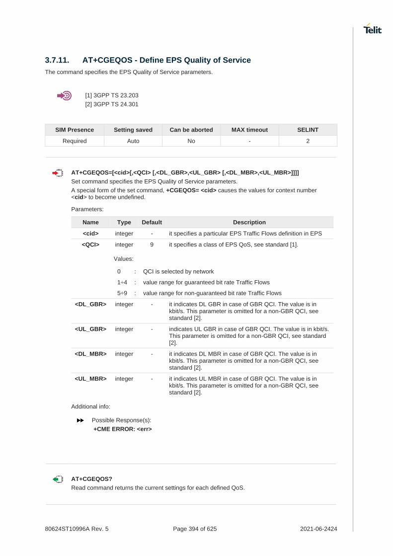
80624ST10996A Rev. 5 Page 394 of 625 2021-06-2424
3.7.11. AT+CGEQOS - Define EPS Quality of Service
The command specifies the EPS Quality of Service parameters.
[1] 3GPP TS 23.203
[2] 3GPP TS 24.301
SIM Presence Setting saved Can be aborted MAX timeout SELINT
Required Auto No - 2
AT+CGEQOS=[<cid>[,<QCI> [,<DL_GBR>,<UL_GBR> [,<DL_MBR>,<UL_MBR>]]]]
Set command specifies the EPS Quality of Service parameters.
A special form of the set command, +CGEQOS= <cid> causes the values for context number <cid> to become undefined.
Parameters:
Name Type Default Description
<cid> integer - it specifies a particular EPS Traffic Flows definition in EPS
<QCI> integer 9 it specifies a class of EPS QoS, see standard [1].
Values:
0 : QCI is selected by network
1÷4 : value range for guaranteed bit rate Traffic Flows
5÷9 : value range for non-guaranteed bit rate Traffic Flows
<DL_GBR> integer - it indicates DL GBR in case of GBR QCI. The value is in kbit/s. This parameter is omitted for a non-GBR QCI, see standard [2].
<UL_GBR> integer - indicates UL GBR in case of GBR QCI. The value is in kbit/s. This parameter is omitted for a non-GBR QCI, see standard [2].
<DL_MBR> integer - it indicates DL MBR in case of GBR QCI. The value is in kbit/s. This parameter is omitted for a non-GBR QCI, see standard [2].
<UL_MBR> integer - it indicates UL MBR in case of GBR QCI. The value is in kbit/s. This parameter is omitted for a non-GBR QCI, see standard [2].
Additional info:
Possible Response(s):
+CME ERROR: <err>
AT+CGEQOS?
Read command returns the current settings for each defined QoS.

80624ST10996A Rev. 5 Page 395 of 625 2021-06-2424
+CGEQOS: <cid>, <QCI>,[<DL_GBR>,<UL_GBR>],[<DL_MBR>,<UL_MBR>][<CR>>LF>+CGEQOS: <cid>, <QCI>,[<DL_GBR>,<UL_GBR>],[<DL_MBR>,<UL_MBR>][...]]
AT+CGEQOS=?
Test command returns the ranges of the supported parameters:
+CGEQOS: (list of supported <cid>s),(list of supported <QCI>s), (list of supported <DL_GBR>s), (list of supported <UL_GBR>s), (list of supported <DL_MBR>s),(list of supported <UL_MBR>s)

80624ST10996A Rev. 5 Page 396 of 625 2021-06-2424
3.7.12. AT+CGPIAF - Printing IP Address Format
This command selects the printout format of the IPv6 address.
3GPP TS 27.007
SIM Presence Setting saved Can be aborted MAX timeout SELINT
Not required No No - 2
AT+CGPIAF=[<IPv6_AddressFormat>[,<IPv6_SubnetNotation>[,<IPv6_LeadingZeros> [,<Pv6_CompressZeros>]]]]
Parameters:
Name Type Default Description
<IPv6_AddressFormat> integer 0 selects the IPv6 address format. Relevant for all AT command parameters that can hold an IPv6 address.
Values:
0 : use IPv4-like dot-notation. IP addresses, and subnetwork mask if applicable, are dot-separated.
1 : use IPv6-like colon-notation. IP address, and subnetwork mask if applicable and when given explicitly, are separated by a space.
<IPv6_SubnetNotation> integer 0 selects the subnet-notation for remote address and subnet mask. Setting does not apply if IPv6 address format <IPv6_AddressFormat>=0.
Values:
0 : both IP address, and subnet mask are started explicitly, separated by a space.
1 : the printout format is applying /(forward slash) subnet-prefix Classless Inter-Domain Routing (CIDR) notation.
<IPv6_LeadingZeros> integer 0 selects whether leading zeros are omitted or not. Setting does not apply if IPv6 address format <IPv6_AddressFormat>=0.
Values:
0 : leading zeros are omitted.
1 : leading zeros are included.
<Pv6_CompressZeros> integer 0 selects whether 1-n instances of 16-bit- zero values are replaced by only "::". This applies only once. Setting does not apply if IPv6 address format <IPv6_AddressFormat>=0.
Values:
0 : no zero compression.
1 : use zero compression.

80624ST10996A Rev. 5 Page 397 of 625 2021-06-2424
AT+CGPIAF?
Read command returns the current parameter setting.
AT+CGPIAF=?
Test command returns values supported as compound values.
AT+CGPIAF=0,0,0,0
OK
AT+CGACT=1,1
OK
AT+CGPADDR =
+CGPADDR: 1,"252.1.171.171.205.205.239.224.0.0.0.0.0.0.0.1"
OK
AT+CGPIAF=1,0,0,0
OK
AT+CGACT=1,1
OK
AT+CGPADDR =
+CGPADDR: 1,"FC01:ABAB:CDCD:EFE0:0:0:0:1"
OK

80624ST10996A Rev. 5 Page 398 of 625 2021-06-2424
3.7.13. AT+CGEREP - Packet Domain Event Reporting
This command enables or disables the presentation of unsolicited result codes.
3GPP TS 27.007
SIM Presence Setting saved Can be aborted MAX timeout SELINT
Required Specific profile No - 2
AT+CGEREP=[<mode>[,<bfr>]]
Set command enables/disables sending of unsolicited result codes in case of certain events occurring in the module or in the network. The URC formats and related events are shown in the Additional info sections.
Parameters:
Name Type Default Description
<mode> integer 0 controls the processing of URCs specified with this command.
Values:
0 : buffer unsolicited result codes in the TA. If TA result code buffer is full, the oldest one can be discarded. No codes are forwarded to the TE.
1 : discard unsolicited result codes when TA-TE link is reserved (e.g. in on-line data mode); otherwise forward them directly to the TE.
2 : buffer unsolicited result codes in the TA when TA-TE link is reserved (e.g. in on-line data mode) and flush them to the TE when TA-TE link becomes available; otherwise forward them directly to the TE.
<bfr> integer 0 controls the effect on buffered codes when <mode> 1 or 2 is entered.
Values:
0 : TA buffer of unsolicited result codes defined within this command is cleared when <mode> 1 or 2 is entered.
1 : TA buffer of unsolicited result codes defined within this command is flushed to the TE when <mode> 1 or 2 is entered (OK response shall be given before flushing the codes)
Additional info:
A network request for PDP context activation occurred when the TA was unable to report it to the TE with a +CRING unsolicited result code and was automatically rejected.
+CGEV: REJECT <PDP_type>, <PDP_addr>
The network has requested a context reactivation. The <cid> that was used to reactivate the context is provided if known to TA.
+CGEV: NW REACT <PDP_type>, <PDP_addr>, [<cid>]

80624ST10996A Rev. 5 Page 399 of 625 2021-06-2424
The network has forced a context deactivation. The <cid> that was used to activate the context is provided if known to TA.
+CGEV: NW_DEACT <PDP_type>, <PDP_addr>, [<cid>]
The mobile equipment has forced a PS detach. This implies that all active contexts have been deactivated. These are not reported separately.
+CGEV: ME_DETACH
The network has forced a PS detach. This implies that all active contexts have been deactivated. These are not reported separately.
+CGEV: NW_DETACH
The mobile equipment has forced a change of MS class. The highest available class is reported (see +CGCLASS).
+CGEV: ME CLASS <class>
Unsolicited fields:
Name Type Description
<PDP_type> string Packet Data Protocol type, which specifies the type of packet data protocol
<PDP_addr> string identifies the terminal in the address space applicable to the PDP
<cid> integer PDP Context Identifier
AT+CGEREP?
Read command returns the current <mode> and <bfr> settings, in the format:
+CGEREP: <mode>,<bfr>
AT+CGEREP=?
Test command reports the supported range of values for the +CGEREP command parameters.

80624ST10996A Rev. 5 Page 400 of 625 2021-06-2424
3.7.14. AT+CGATT - PS Attach or Detach
This execution command is used to register (attach) the terminal to or deregister (detach) the terminal from the Packet Domain service.
3GPP TS 27.007
SIM Presence Setting saved Can be aborted MAX timeout SELINT
Required No No - 2
AT+CGATT=<state>
Parameter:
Name Type Default Description
<state> integer N/A state of PS attachment
Values:
0 : detached
1 : attached
AT+CGATT?
Read command returns the current PS state in the format:
+CGATT: <state>
AT+CGATT=?
Test command returns the values range of the <state> parameter.
AT+CGATT? +CGATT: 0 OK
AT+CGATT=? +CGATT: (0,1) OK
AT+CGATT=1 OK

80624ST10996A Rev. 5 Page 401 of 625 2021-06-2424
3.7.15. AT+CGTFT - Traffic Flow Template
This command allows the TE to specify a Packet Filter - PF for a Traffic Flow Template - TFT that is used in the GGSN in UMTS/GPRS and Packet GW in EPS for routing of packets onto different QoS flows towards the TE.
3GPP TS 27.007
3GPP TS 03.60/23.060
SIM Presence Setting saved Can be aborted MAX timeout SELINT
Required Auto No - 2
AT+CGTFT=[<cid>[,<packet filter identifier>[,<evaluation precedence index>[,<source address and subnet mask>[,<prot num(ipv4)/next hdr(ipv6)>[,<destination port range>[,<source port range>[,<ipsec sec param index (spi)>[,<tos(ipv4) TP class(ipv6)&mask>[,<flow label (ipv6)>]]]]]]]]]
The concept further described in the 3GPP TS 23.060 [47]. A TFT consists of from one and up to 16 Packet Filters, each identified by a unique <packet filter identifier>. A Packet Filter also has an <evaluation precedence index> that is unique within all TFTs associated with all PDP contexts that are associated with the same PDP address.
The set command specifies a Packet Filter that whom added to the TFT stored in the MT and used for the context identified by the (local) context identification parameter, <cid>. The specified TFT will be stored in the GGSN in UMTS/GPRS and Packet GW in EPS only at activation or MS-initiated modification of the related context. Since this is the same parameter that is used in the +CGDCONT and +CGDSCONT commands, the +CGTFT command is effectively an extension to these commands. The Packet Filters consist of a number of parameters, each of which may be set to a separate value.
A special form of the set command, +CGTFT= <cid> causes all of the Packet Filters in the TFT for context number
<cid> to become undefined. At any time there may exist only one PDP context with no associated TFT amongst all
PDP contexts associated to one PDP address. At an attempt to delete a TFT, which would violate this rule, an ERROR or +CME ERROR response is returned. Extended error responses are enabled by the +CMEE command.
Possible Response(s):
OK
ERROR
Parameters:
Name Typ
e Default
Description
<cid> integer
- a numeric parameter which specifies a particular PDP context definition (see the +CGDCONT and +CGDSCONT commands). The following parameters are defined in 3GPP TS 23.060 [47]:
<packet filter
identifier>
integer
- The value range is from 1 to 16.
<evaluation precedence
index>
integer
- The value range is from 0 to 255.

80624ST10996A Rev. 5 Page 402 of 625 2021-06-2424
<source address
and subnet mask>
string
- The string is given as dot-separated numeric (0-255)
parameters on the form:
"a1.a2.a3.a4.m1.m2.m3.m4" for IPv4 or
"a1.a2.a3.a4.a5.a6.a7.a8.a9.a10.a11.a12.a13.a14.a15.a16.m1.m2.m3.m4.m5.m6.m7.m8.m9.m10.m11.m12.m13.
m14.m15.m16", for IPv6.
<prot num(ipv4)/
next hdr(ipv6)>
integer
- The value range is from 0 to 255.
<destination port range>
string
- The string is given as dot-separated numeric (0-65535) parameters on the form "f.t".
<source port range>
string
- The string is given as dot-separated numeric (0-65535) parameters on the form "f.t".
<ipsec sec param
index (spi)>
integer
- The value is in hexadecimal format. The value range is from 0 to FFFFFFFF.
<tos(ipv4) TP
class(ipv6)&mask>
string
- The string is given as dot-separated numeric (0-255) parameters on the form "t.m".
<flow label (ipv6)>
integer
- The numeric value is in hexadecimal format. The value range is from 0 to FFFFF. Valid for IPv6 only.
Additional info:
Some of the above listed attributes may coexist in a Packet Filter while others mutually exclude each other, the possible combinations are shown in 3GPP TS 23.060 [47].
AT+CGTFT?
The read command returns the current settings for all Packet Filters for each defined context.
AT+CGTFT: <cid>, <packet filter identifier>, <evaluation precedence index>, <source address and subnet mask>, <protocol number (ipv4) / next header (ipv6)>, <destination port range>, <source port range>, <ipsec security parameter index (spi)>, <type of service (tos) (ipv4) and mask /traffic class (ipv6) and mask>, <flow label (ipv6)> [<CR><LF>+CGTFT: <cid>, <packet filter identifier>, <evaluation precedence index>, <source address and subnet mask>, <protocol number (ipv4) / next header (ipv6)>, <destination port range>, <source port range>, <ipsec security parameter index (spi)>, <type of service (tos) (ipv4) and mask / traffic class (ipv6) and mask>, <flow label (ipv6)> [...]]
AT+CGTFT=?
The test command returns values supported as a compound value. If the MT supports several PDP types, the parameter value ranges for each PDP type returned on a separate line. TFTs shall be used for PDP-type IP and PPP only. For PDP-type PPP a TFT is applicable only when IP traffic is carried over PPP. If PPP carries header-compressed IP packets, then a TFT cannot be use.
AT+CGTFT: <PDP_type>, (list of supported <packet filter identifier>s), (list of supported <evaluation precedence index>s), (list of supported <source address and subnet mask>s), (list of supported <protocol number (ipv4) / next header (ipv6)>s), (list of supported <destination port range>s), (list of supported <source port range>s), (list of supported <ipsec security parameter index (spi)>s), (list of supported <type of service (tos) (ipv4) and mask / traffic class(ipv6) and mask>s), (list of supported

80624ST10996A Rev. 5 Page 403 of 625 2021-06-2424
<flow label (ipv6)>s) [<CR><LF>+CGTFT: <PDP_type>, (list of supported <packet filter identifier>s), (list of supported <evaluation precedence index>s), (list of supported <source address and subnet mask>s),(list of supported <protocol number (ipv4) / next header (ipv6)>s), (list of supported <destination port range>s), (list of supported <source port range>s), (list of supported <ipsec security parameter index (spi)>s),(list of supported <type of service (tos) (ipv4) and mask / traffic class (ipv6) and mask>s), (list of supported <flow label (ipv6)>s) [...]]
The possible combinations listed on 3GPP TS 23.060 [47].

80624ST10996A Rev. 5 Page 404 of 625 2021-06-2424
3.7.16. AT+CGEQOSRDP - EPS Quality of Service Read Dynamic Parameters
The command returns the parameters related to the Quality of Service.
SIM Presence Setting saved Can be aborted MAX timeout SELINT
Required No No - 2
AT+CGEQOSRDP=[<cid>]
The execution command returns the Quality of Service parameters <QCI>, [<DL_GBR> and <UL_GBR>] and
[<DL_MBR> and <UL_MBR>] of the active secondary or non secondary PDP context associated to the provided context identifier <cid>.
If the parameter <cid> is omitted, the Quality of Service parameters for all secondary or non secondary active PDP contexts are returned.
Parameter:
Name Type Default Description
<cid> integer - it specifies a particular Traffic Flows definition in EPS and a PDN connection definition in UMTS/GPRS.
Additional info:
Possible Response(s):
+CGEQOSRDP:<cid>,<QCI>,[<DL_GBR>,<UL_GBR>],[<DL_MBR>,<UL_MBR>][<CR>>LF>
+CGEQOSRDP:<cid>,<QCI>,[<DL_GBR>,<UL_GBR>],[<DL_MBR>,<UL_MBR>][...]]
Defined values:
Name Type Default Description
<QCI> integer - specifies a class of EPS QoS. (see 3GPP TS 23.203 [85])0 QCI is selected by network [1..4] value range for guaranteed bit rate Traffic Flows [5..9] value range for non-guaranteed bit rate Traffic Flows.
<DL_GBR> integer - indicates DL GBR in case of GBR QCI. The value is in kbit/s. This parameter is omitted for a non-GBR QCI. (see 3GPP TS 24.301 [83])
<UL_GBR> integer - indicates UL GBR in case of GBR QCI. The value is in kbit/s. This parameter omitted for a non-GBR QCI. (see 3GPP TS 24.301 [83])
<DL_MBR> integer - indicates DL MBR in case of GBR QCI. The value is in kbit/s. This parameter omitted for a non-GBR QCI. (see 3GPP TS 24.301 [83])
<UL_MBR> integer - indicates UL MBR in case of GBR QCI. The value is in kbit/s. This parameter omitted for a non-GBR QCI. (see 3GPP TS 24.301 [83])

80624ST10996A Rev. 5 Page 405 of 625 2021-06-2424
AT+CGEQOSRDP=?
+CGEQOSRDP: (list of <cid>s associated with secondary or non secondary active contexts)
Parameters of both network and MT/TA initiated PDP contexts returned.

80624ST10996A Rev. 5 Page 406 of 625 2021-06-2424
3.7.17. AT+CGTFTRDP - Traffic Flow Template Read Dynamic Parameters
This command returns the relevant information about Traffic Flow Template of <cid> together with the additional network assigned values when established by the network.
3GPP TS 27.007; 3GPP TS 03.60/23.060
SIM Presence Setting saved Can be aborted MAX timeout SELINT
Required No No - 2
AT+CGTFTRDP=[<cid>]
The execution command returns the relevant information about Traffic Flow Template for an active secondary or non secondary PDP context specified by <cid> together with the additional network assigned values when established by the network.
If the parameter <cid> is omitted, the Traffic Flow Templates for all active secondary and non secondary PDP contexts are returned.
Parameters of both network and MT/TA initiated PDP contexts returned.
Possible Response(s):
+CGTFTRDP: <cid>, <packet filter identifier>, <evaluation precedence index>, <source address and subnet mask>, <protocol number (ipv4) / next header(ipv6)>,<destination port range>, <source port range>, <ipsec security parameter index (spi)>, <type of service (tos) (ipv4) and mask / traffic class (ipv6) and mask>, <flow label ipv6)>, <direction>, <NW packet filter Identifier>[<CR><LF>
+CGTFTRDP: <cid>, <packet filter identifier>, <evaluation precedence index>, <source address and subnet mask>, <protocol number (ipv4) / next header (ipv6)>, <destination port range>, <source port range>, <ipsec security parameter index (spi)>, <type of service (tos) (ipv4) and mask / traffic class (ipv6) and mask>, <flow label (ipv6)>, <direction>,<NW packet filter Identifier> [...]]
Parameter:
Name Type Default Description
<cid> integer - a numeric parameter which specifies a particular PDP context definition or Traffic Flows definition.
Additional info:
List of the meaning of the response message parameters.
Name Type Default
Description
<packet
filter identifi
er>
integer N/A packet filter identifier
Value:
1÷16 : supported range
<evaluation
preced
integer N/A evaluation precedence index

80624ST10996A Rev. 5 Page 407 of 625 2021-06-2424
ence index>
Value:
0÷255 : supported range
<source
address and
subnet mask>
string - source address and subnet mask
The string is given as dot-separated numeric (0-255) parameters on the form:
"a1.a2.a3.a4.m1.m2.m3.m4" for IPv4 or
"a1.a2.a3.a4.a5.a6.a7.a8.a9.a10.a11.a12.a13.a14.a15.a16.m1.m2.m3.m4.m5.m6.m7.m8.m9.m10.m11.m12.m13.m14.m15.m16" for IPv6.
<protocol
number/next
header>
string N/A protocol number for ipv4 or next header for ipv6
Value:
0÷255 : supported range
<destination port
range>
string - The string is given as dot-separated numeric (0-65535) parameters on the form "f.t"
<source port range>
string - The string is given as dot-separated numeric (0-65535) parameters on the form "f.t"
<ipsec spi>
hex N/A ipsec security parameter index (spi) in hexadecimal format
Value:
00000000÷FFFFFFFF : supported range
<tos/traffic class and
mask>
string - type of service (tos) (ipv4) and mask / traffic class (ipv6) and mask
The string given as dot-separated numeric (0-255) parameters on the form "t.m"
<flow label
(ipv6)>
hex N/A valid for IPv6 only
Value:
00000÷FFFFF : supported range
<direction>
string N/A specifies the transmission direction in which the Packet Filter shall be applied
Values:
0 : Pre Release 7 TFT Filter (see 3GPP TS 24.008, table 10.5.162)
1 : Uplink

80624ST10996A Rev. 5 Page 408 of 625 2021-06-2424
2 : Downlink
3 : Bidirectional (Used for Uplink and Downlink)
<NW packet filter
Identifier>
integer N/A in EPS the value is assigned by the network when established
Value:
1÷16 : supported range
Some of the above listed attributes can coexist in a Packet Filter while others mutually exclude each other. The possible combinations listed on 3GPP TS 23.060 [47].
AT+CGTFTRDP=?
+CGTFTRDP: (list of <cid>s associated with active secondary or non secondary contexts)
Some of the above listed attributes can coexist in a Packet Filter while others mutually exclude each
other. The possible combinations listed on 3GPP TS 23.060 [47].

80624ST10996A Rev. 5 Page 409 of 625 2021-06-2424
3.7.18. AT+CGACT - PDP Context Activate or Deactivate
This command activates or deactivates the specified PDP context(s).
3GPP TS 27.007
SIM Presence Setting saved Can be aborted MAX timeout SELINT
Required No No - 2
AT+CGACT=[<state>[,<cid>[,<cid>][,...]]]]
Parameters:
Name Type Default Description
<state> integer N/A activate/deactivate the PDP context
Values:
0 : deactivate
1 : activate
<cid> integer - specifies a PDP context definition (see +CGDCONT command)
if no <cid>s are specified, the activation form of the command activates the first three defined contexts. The deactivation form deactivates all the active contexts.
AT+CGACT?
Read command returns the current activation state for all the defined PDP contexts in the format:
+CGACT: <cid>,<state>[<CR><LF> +CGACT: <cid>,<state>[...]]
AT+CGACT=?
Test command reports information on the supported PDP context activation states <state>.
AT+CGACT=1,1 OK
AT+CGACT? +CGACT: 1,1
OK

80624ST10996A Rev. 5 Page 410 of 625 2021-06-2424
3.7.19. AT+CGDSCONT - Define Secondary PDP Context
Define secondary PDP Context.
[1] 3GPP TS 44.065 [2] 3GPP TS 25.323 [3] RFC1144 [4] RFC2507 [5] RFC3095
SIM Presence Setting saved Can be aborted MAX timeout SELINT
Required Auto No - 2
AT+CGDSCONT=[<cid>,<p_cid>[,<d_comp>[,<h_comp>[,<IM_CN_Signalling_Flag_Ind>]]]]
Set command specifies PDP context parameter values for a Secondary PDP context identified by the (local) context Identification parameter, <cid>.
Parameters:
Name Type Default Description
<cid> integer - specifies a particular PDP Context Identifier, see +CGDCONT command.
<p_cid> integer - specifies a particular PDP context definition which has been specified by use of the +CGDCONT command. The parameter is local to the TE-MT interface.
<d_comp> integer 0 controls PDP data compression (applicable for SNDCPonly) (refer 3GPP TS 44.065 [61])
Values:
0 : off (default if value is omitted)
1 : on (manufacturer preferred compression)
2 : V.42 bis
3 : V.44
<h_comp> integer 0 controls PDP header compression (refer 3GPP TS 44.065 [61] and 3GPP TS 25.323 [62]).
Values:
0 : off (default if value is omitted)
1 : on (manufacturer preferred compression)
2 : RFC1144 (applicable for SNDCP only)
3 : RFC2507
4 : RFC3095 (applicable for PDCP only)
<IM_CN_Signalling_Flag_Ind> integer N/A indicates to the network whether the PDP context is for IM CN subsystem-related signalling only or not.

80624ST10996A Rev. 5 Page 411 of 625 2021-06-2424
Values:
0 : UE indicates that the PDP context is not for IM CN subsystem-related signalling only
1 : UE indicates that the PDP context is for IM CN subsystem-related signalling only
AT+CGDSCONT?
The read command returns the current settings for each defined context in the format:
+CGDSCONT: <cid>,<p_cid>,<d_comp>,<h_comp>,<IM_CN_Signalling_Flag_Ind>[<CR><LF> +CGDSCONT: <cid>,<p_cid>,<d_comp>,<h_comp>,<IM_CN_Signalling_Flag_Ind> [...]]
AT+CGDSCONT=?
Test command returns the supported range of values of parameters.

80624ST10996A Rev. 5 Page 412 of 625 2021-06-2424
3.7.20. AT+CGSCONTRDP - Secondary PDP Context Read Dynamic Parameters
This command returns parameters for a given <cid>.
SIM Presence Setting saved Can be aborted MAX timeout SELINT
Required No No - 2
AT+CGSCONTRDP[=<cid>]
The execution command returns <p_cid> and <bearer_id> parameters for a given <cid>. If the context cannot be found an ERROR response is returned. If the parameter <cid> is omitted, the <cid>, <p_cid> and <bearer_id> are returned for all established PDP contexts. Format of the returned message:
+CGSCONTRDP:<cid>,<p_cid>,<bearer_id>[<CR><LF> +CGSCONTRDP: <cid>, <p_cid>,<bearer_id> [...]]
Parameter:
Name Type Default Description
<cid> integer - specifies a particular PDP context or Traffic Flows definition. The parameter is local to the TE-MT interface and is used in other PDP context-related commands.
Additional info:
Here is the list of the parameters meanings returned by the +CGSCONTRDP command.
Name Type Default Description
<p_cid> integer - specifies a particular PDP context definition or default EPS context Identifier which has been specified by use of the +CGDCONT command. The parameter is local to the TE-MT interface.
<bearer_id> integer - identifies the bearer, EPS Bearer in EPS and NSAPI in GPRS.
AT+CGSCONTRDP=?
The test command returns a list of <cid>s associated with active contexts:
+CGSCONTRDP: (list of <cid>s associated with active contexts)
Parameters for network-initiated PDP contexts returned as well. The dynamic part of the PDP context will only exist if established by the network.

80624ST10996A Rev. 5 Page 413 of 625 2021-06-2424
3.7.21. AT+CGREG - GPRS Network Registration Status
Set command controls the presentation of the +CGREG: unsolicited result code
3GPP TS 27.007 3GPP TS 24.008
SIM Presence Setting saved Can be aborted MAX timeout SELINT
Not required Specific profile No - 2
AT+CGREG=[<mode>]
Set command enables/disables the +CGREG: unsolicited result code, and selects one of the available formats:
short format: +CGREG:<stat>
long format: +CGREG:<stat>[,<lac>,<ci>[,<AcT>,<rac>]]
Parameter:
Name Type Default Description
<mode> integer 0 enables/disables the network registration unsolicited result code (URC), and selects one of the available formats.
The following events triggers the URC:
6. URC short format is displayed every time there is a change in the network registration status
7. URC long format is displayed, according to <mode> value, every time there is a change of the network cell.
Values:
0 : disable the network registration unsolicited result code
1 : enable the network registration unsolicited result code, and selects the short format
2 : enable the network registration unsolicited result code, and selects the long format (includes the network cell identification data)
Unsolicited fields:
Name Type Description
<stat> integer registration status of the module
Values:
0 : not registered, terminal is not currently searching a new operator to register to
1 : registered, home network
2 : not registered, but terminal is currently searching a new operator to register to
3 : registration denied

80624ST10996A Rev. 5 Page 414 of 625 2021-06-2424
4 : unknown
5 : registered, roaming
<lac> string the parameter reports:
8. Local Area Code when <AcT>=0 or 2 9. Tracking Area Code when <AcT>=7
<ci> string cell ID in hexadecimal format
<AcT> integer access technology of the registered network.
Values:
0 : GSM
2 : UTRAN
3 : GSM w/EGPRS (see NOTE 3)
4 : UTRAN w/HSDPA (see NOTE 4)
5 : UTRAN w/HSUPA (see NOTE 4)
6 : UTRAN w/HSDPA and HSUPA (see NOTE 4)
7 : E-UTRAN
<rac> string routing area code (one byte) in hexadecimal format
<lac>, <ci>, <AcT>, and <rac> network information is reported by URC only if <mode>=2, and the module is registered on some network cell.
<lac> and <rac> values will change <tac> and <mme_code> values in LTE.
NOTE 3: 3GPP TS 44.018 [156] specifies the System Information messages which give the information about whether the serving cell supports EGPRS.
NOTE 4: 3GPP TS 25.331 [74] specifies the System Information blocks which give the information about whether the serving cell supports HSDPA or HSUPA.
AT+CGREG?
Read command returns the current value of <mode>, the registration status <stat>, and the network information (<lac>, <ci>, <AcT>, and <rac> ) according to the used <mode> parameter value. +CGREG: <mode>,<stat>[,<lac>,<ci>[,<AcT>,<rac>]]
<lac>, <ci>, <AcT>, and <rac> network information is reported only if <mode>=2 or 4 and the module is registered on some network cell.
<lac> and<rac> values will change <tac> and <mme_code> values in LTE.
AT+CGREG=?
Test command returns supported values for parameter <mode>.

80624ST10996A Rev. 5 Page 415 of 625 2021-06-2424
3.7.22. AT#SINGLEAPNSWITCH - set APN param change
This command sets APN param change.
SIM Presence Setting saved Can be aborted MAX timeout SELINT
Not required Auto No - 2
AT#SINGLEAPNSWITCH=<mode>
If it is enabled and an APN network identifier or APN-related parameter is updated, Modem can re-activate PDN context with changed APN if there are no application working on the activated PDN context and APN name is changed. If the PDN context is for LTE attach, UE will attempt to reattach with changed APN. In other systems, this command works as if it is disabled.
If it is disabled, the changed APN will go into effect at the moment when the PDN context is deactivated and then re-activated. Power recycling is one of operations that will have new APN activated.
Parameter:
Name Type Default Description
<mode> integer 1 Set enable or disable
Values:
0 : Disable
1 : Enable
AT#SINGLEAPNSWITCH?
Read command reports current configuration.
AT#SINGLEAPNSWITCH=?
Test command reports the supported range of values.

80624ST10996A Rev. 5 Page 416 of 625 2021-06-2424
SIM
3.8.1. AT+CPIN - Enter the PIN
The command sends to the device a password which is necessary before it can be operated.
3GPP TS 27.007
SIM Presence Setting saved Can be aborted MAX timeout SELINT
Not required Other No - 2
AT+CPIN=<pin>[,<newpin>]
Set command sends to the device a password which is necessary before it can be operated (SIM PIN, SIM PUK, PH-SIM PIN, etc.). If the PIN required is SIM PUK or SIM PUK2, the <newpin> is required. The <newpin> will replace the old pin in the SIM.
Parameters:
Name Type Default Description
<pin> string - PIN required or old PIN if the command is used to change the SIM PIN
<newpin> string - new PIN that will replace old pin
AT+CPIN?
Read command reports the PIN/PUK/PUK2 request status of the device in the form: +CPIN: <code>
Additional info:
Parameters:
Name Type Default Description
<code> string N/A PIN/PUK/PUK2 request status code
Values:
READY : ME is not pending for any password
SIM PIN : ME is waiting SIM PIN to be given
SIM PUK : ME is waiting SIM PUK to be given
PH-SIM PIN : ME is waiting phone-to-SIM card password to be given
PH-FSIM PIN : ME is waiting phone-to-very first SIM card password to be given
PH-FSIM PUK : ME is waiting phone-to-very first SIM card unblocking password to be given
SIM PIN2 : ME is waiting SIM PIN2 to be given; this <code> is returned only when the last executed command

80624ST10996A Rev. 5 Page 417 of 625 2021-06-2424
resulted in PIN2 authentication failure (i.e. +CME ERROR: 17)
SIM PUK2 : ME is waiting SIM PUK2 to be given; this <code> is returned only when the last executed command resulted in PUK2 authentication failure (i.e. +CME ERROR: 18)
PH-NET PIN : ME is waiting network personalization password to be given
PH-NET PUK : ME is waiting network personalization unblocking password to be given
PH-NETSUB PIN : ME is waiting network subset personalization password to be given
PH-NETSUB PUK : ME is waiting network subset personalization unblocking password to be given
PH-SP PIN : ME is waiting service provider personalization password to be given
PH-SP PUK : ME is waiting service provider personalization unblocking password to be given
PH-CORP PIN : ME is waiting corporate personalization password to be given
PH-CORP PUK : ME is waiting corporate personalization unblocking password to be given
Pin pending status at startup depends on PIN facility setting; to change or query the default power up setting use the command AT+CLCK.
AT+CPIN=?
Test command returns OK result code.
AT+CMEE=1 OK
AT+CPIN? +CME ERROR: 10 //error: you have to insert the SIM
AT+CPIN? +CPIN: READY //you inserted the SIM and module is not waiting for PIN OK

80624ST10996A Rev. 5 Page 418 of 625 2021-06-2424
3.8.2. AT+CPINR - Remaining PIN Retries
This command returns the number of remaining PIN retries for the MT passwords.
3GPP TS 27.007
SIM Presence Setting saved Can be aborted MAX timeout SELINT
Required No No - 2
AT+CPINR[=[<sel_code>]]
Execution command cause the MT to return the number of remaining PIN retries for the MT passwords.
The intermediate response format is:
+CPINR: <code>,<retries>,<default_retries>
Parameter:
Name Type Default Description
<sel_code> string - These values are strings and shall be indicated within double quotes. It is optional to support wildcard match by '*', meaning match any (sub-)string.
Additional info:
One line with one intermediate result code is returned for every <code> selected by <sel_code>.
Name Type Default Description
<code> string - type of PIN
<retries> integer - number of remaining retries per PIN
<default_retries> integer - number of default/initial retries per PIN
AT+CPINR=?
Test command returns the OK result code.

80624ST10996A Rev. 5 Page 419 of 625 2021-06-2424
AT+CPINR="SIM*" +CPINR: SIM PIN,3,3 +CPINR: SIM PUK,10,10 +CPINR: SIM PIN2,0,3 +CPINR: SIM PUK2,2,10 OK
AT+CPINR="*SIM*" +CPINR: SIM PIN,3,3 +CPINR: SIM PUK,10,10 +CPINR: SIM PIN2,0,3 +CPINR: SIM PUK2,2,10 +CPINR: PH-FSIM PIN,10,10 +CPINR: PH-FSIM PUK,0,0 OK

80624ST10996A Rev. 5 Page 420 of 625 2021-06-2424
3.8.3. AT+ICCID - Read ICCID
Execution command reads on SIM the Integrated Circuit Card Identification (ICCID). It is the card identification number that provides a unique identification number for the SIM.
SIM Presence Setting saved Can be aborted MAX timeout SELINT
Required No No - 2
AT+ICCID
The command returns the following message:
+ICCID: <ICCID>
AT+ICCID=?
Test command returns the OK result code.
AT+ICCID
+ICCID: 89861109091740011006
OK
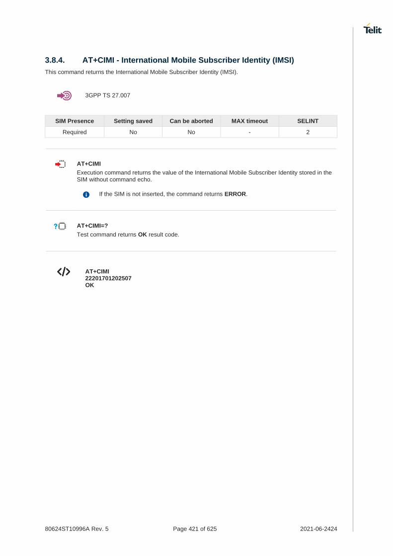
80624ST10996A Rev. 5 Page 421 of 625 2021-06-2424
3.8.4. AT+CIMI - International Mobile Subscriber Identity (IMSI)
This command returns the International Mobile Subscriber Identity (IMSI).
3GPP TS 27.007
SIM Presence Setting saved Can be aborted MAX timeout SELINT
Required No No - 2
AT+CIMI
Execution command returns the value of the International Mobile Subscriber Identity stored in the SIM without command echo.
If the SIM is not inserted, the command returns ERROR.
AT+CIMI=?
Test command returns OK result code.
AT+CIMI 22201701202507 OK

80624ST10996A Rev. 5 Page 422 of 625 2021-06-2424
3.8.5. AT+CRSM - Restricted SIM access
The command transmits to the UICC some specific commands and their required parameters.
3GPP TS 11.11/51.011
3GPP TS 27.007
ETSI TS 102 221
SIM Presence Setting saved Can be aborted MAX timeout SELINT
Required No No - 2
AT+CRSM=<command>[,<fileId>[,<P1>,<P2>,<P3>[,<data>[,<pathid>]]]]
Set command transmits to the MT the SIM <command> and its required parameters. The MT handles internally all SIM-MT interface locking and file selection routines. As response to the command, MT sends the actual SIM information parameters and response data. The response of the command is in the format:
+CRSM: <sw1>,<sw2>[,<response>]
For parameters meanings see Additional info section.
Parameters:
Name Type Default Description
<command> integer N/A command passed on by the MT to the SIM
Values:
176 : READ BINARY
178 : READ RECORD
192 : GET RESPONSE
214 : UPDATE BINARY
220 : UPDATE RECORD
242 : STATUS
<fileId> integer - identifier of an elementary data file on SIM. Mandatory for every command except STATUS.
<P1> integer N/A parameter passed on by the MT to the SIM. It is mandatory for every command except GET RESPONSE and STATUS.
Value:
0÷255 : parameter passed on by the MT to the SIM
<P2> integer N/A parameter passed on by the MT to the SIM. It is mandatory for every command except GET RESPONSE and STATUS.
Value:
0÷255 : parameter passed on by the MT to the SIM
<P3> integer N/A parameter passed on by the MT to the SIM. It is mandatory for every command except GET RESPONSE and STATUS.

80624ST10996A Rev. 5 Page 423 of 625 2021-06-2424
Value:
0÷255 : parameter passed on by the MT to the SIM
<data> string - information which shall be written to the SIM (hexadecimal character format).
<pathid> string - contains the path of an elementary file on the SIM/UICC in hexadecimal format. This shall only be used in the mode "select by path from MF" (e.g. "7F205F70").
Additional info:
Response data fields:
Name Type Default Description
<sw1> integer - information from the SIM about the execution of the actual command (successful or failed)
<sw2> integer - information from the SIM about the execution of the actual command (successful or failed)
<response> hex - response of a successful completion of the command previously issued (hexadecimal character format). STATUS and GET RESPONSE return data, which gives information about the current elementary data field. This information includes the type of file and its size. After READ BINARY, READ RECORD or RETRIEVE DATA command the requested data will be returned. <response> is not returned after a successful UPDATE BINARY, UPDATE RECORD or SET DATA command.
Use only decimal numbers for parameters <command>, <fileid>, <P1>, <P2> and <P3>.
AT+CRSM=?
Test command returns the OK result code.

80624ST10996A Rev. 5 Page 424 of 625 2021-06-2424
Read binary, ICCID(2FE2)
AT+CRSM=176,12258,0,0,10 +CRSM: 144,0,982850702001107686F4 OK
Read record, ADN(6F3A)
AT+CRSM=178,28474,1,4,40 +CRSM: 144,0,42434A554EFFFFFFFFFFFFFFFFFFFFFF06811056789282FFFFFFFFFFFFFF OK
Update Binary, KcGPRS(6F52)
AT+CRSM=214,28539,0,0,8,C69018C7958C87 +CRSM: 144,0 OK
Update Record, ADN(6F3A)
AT+CRSM=220,28474,9,4,30,657469FFFFFFFFFFFFFFFFFFFFFFFFFFFFFFFFFFFFFFFFFFF FFFFFFFFFFF +CRSM: 144,0 OK
Status, FPLMN(6F7B)
AT+CRSM=242,28539 +CRSM:144,0,623C820238218410A0000000871002FFFFFFFF89040300FFA51180013181030 10A3282011E8304000030E08A01058B032F0609C6099001C0830101830181 OK
Get Response, MSISDN(6F40) AT+CRSM=192,28480 +CRSM: 144,0,621E8205422100260283026F40A5039201008A01058B036F06058002004C8800 OK

80624ST10996A Rev. 5 Page 425 of 625 2021-06-2424
3.8.6. AT+CSIM - Generic SIM Access
This command sends a generic command to the UICC.
[1] 3GPP TS 11.11 [2] 3GPP TS 31.101 [3] 3GPP TS 31.102
SIM Presence Setting saved Can be aborted MAX timeout SELINT
Required No No - 2
AT+CSIM=<length>,<command>
Set command transmits to the MT the <command>, it then shall send as it is to the UICC. As response to the command, MT sends back the actual UICC <response> to the TA as it is. The response message of the command is in the format:
+CSIM: <length>,<response>
Error case: +CME ERROR: <err>
The response messages parameters are described in the Additional info section.
Parameters:
Name Type Default Description
<length> integer - characters number of the <command> sent to UICC (two times the actual length of the command)
<command> string - command passed on by the MT to the UICC in the format as described in standard [1] or [2] (hexadecimal character format, refer to +CSCS)
Additional info:
List of the meaning of the response messages parameters.
Name Type Default Description
<length> integer - characters number of the <response> sent to TE (two times the actual length of the response)
<response> string - response to the command passed on by the UICC to the TE in the format as described in standard [1] or [2] (hexadecimal character format)
<err> string - error values (numeric format followed by verbose format)
AT+CSIM=?
Test command returns the OK result code.

80624ST10996A Rev. 5 Page 426 of 625 2021-06-2424
AT+CSIM=<lock>
This special form of the command has no effect and is kept only for backward compatibility.
Parameters:
<lock>=1 locking of the interface <lock>=0 unlocking of the interface
• 2G SIM, see standard [1]:
STATUS AT+CSIM=10,A0F2000016 +CSIM:48,"000002A87F20020000000000099300220800838A838A9000" OK
SELECT EF 6F07 AT+CSIM=14,A0A40000026F07 +CSIM: 4,"9F0F" OK
GET RESPONSE AT+CSIM=10,A0C000000F +CSIM: 34,"000000096F0704001A001A010200009000" OK
SELECT EF 6F30 AT+CSIM=14,A0A40000026F30 +CSIM: 4,"9F0F" OK
READ BINARY AT+CSIM=10,A0B00000FC +CSIM:508,"FFFFFF1300831300901300541300301300651300381300801301801 3000113110913013013009813007713005913004313008113009513014013002313 0016330420130041FFFFFFFFFFFF21436542F41922F28822F201FFFFFFFFFFFF FFFFFFFFFFFFFFFFFFFFFFFFFFFFFFFFFFFFFFFFFFFFFFFFFFFFFFFFFFFF FFFFFFFFFFFFFFFFFFFFFFFFFFFFFFFFFFFFFFFFFFFFFFFFFFFFFFFFFFFF FFFFFFFFFFFFFFFFFFFFFFFFFFFFFFFFFFFFFFFFFFFFFFFFFFFFFFFFFFFF FFFFFFFFFFFFFFFFFFFFFFFFFFFFFFFFFFFFFFFFFFFFFFFFFFFFFFFFFFFF FFFFFFFFFFFFFFFFFFFFFFFFFFFFFFFFFFFFFFFFFFFFFFFFFFFFFFFFFFFF FFFFFFFFFFFFFFFFFF9000" OK

80624ST10996A Rev. 5 Page 427 of 625 2021-06-2424
3.8.7. AT+CCHO - Open Logical Channel
Open Logical Channel
3GPP TS 27.007
SIM Presence Setting saved Can be aborted MAX timeout SELINT
Required No No - 2
AT+CCHO=<dfname>
Execution command causes the MT to return <sessionId> to allow the TE to identify a channel that is being allocated by the currently selected UICC, which is attached to ME. The currently selected UICC will open a new logical channel, select the application identified by the <dfname> received with this command and return a <sessionId> as the response. The ME shall restrict the communication between the TE and the UICC to this logical channel.
The response message of the command is in the format: +CCHO: <sessionId>
The <sessionId> is described in the Additional info section.
Error case: +CME ERROR: <err>
Parameter:
Name Type Default Description
<dfname> string - all selectable applications in the UICC are referenced by a DF name coded on 1 to 16 bytes
Additional info:
Response parameter
Name Type Default Description
<sessionId> integer - a session Id to be used in order to target a specific application on the smart card (e.g. (U)SIM, WIM, ISIM) using logical channels mechanism
The logical channel number is contained in the CLASS byte of an APDU command, thus implicitly contained in all APDU commands sent to a UICC. In this case it will be up to the MT to manage the logical channel part of the APDU CLASS byte and to ensure that the chosen logical channel is relevant to the <sessionId> indicated in the AT command.
This <sessionId> is to be used when sending commands with Generic UICC Logical Channel access +CGLA commands.

80624ST10996A Rev. 5 Page 428 of 625 2021-06-2424
AT+CCHO=?
Test command returns the OK result code.

80624ST10996A Rev. 5 Page 429 of 625 2021-06-2424
3.8.8. AT+CCHC - Close Logical Channel
Close Logical Channel
3GPP TS 27.007
SIM Presence Setting saved Can be aborted MAX timeout SELINT
Required No No - 2
AT+CCHC=<sessionId>
Execution command asks the ME to close a communication session with the active UICC. The ME shall close the previously opened logical channel. The TE will no longer be able to send commands on this logical channel. The UICC will close the logical channel when receiving this command.
Error case:
+CME ERROR: <err>
Parameter:
Name Type Default Description
<sessionId> integer - a session Id to be used in order to target a specific application on the smart card (e.g. (U)SIM, WIM, ISIM) using logical channels mechanism
AT+CCHC=?
Test command returns the OK result code.

80624ST10996A Rev. 5 Page 430 of 625 2021-06-2424
3.8.9. AT+CGLA - Generic UICC Logical Channel Access
This command is used to control the currently selected UICC on the TE.
3GPP TS 27.007
SIM Presence Setting saved Can be aborted MAX timeout SELINT
Required No No - 2
AT+CGLA=<sessionId>,<length>,<command>
Set command transmits to the MT the <command> it then shall send as it is to the selected UICC. In the same manner the UICC <response> shall be sent back by the MT to the TA as it is. This command allows a direct control of the currently selected UICC by a distant application on the TE. The TE shall then take care of processing the received UICC information.
The response of the command is in the format:
+CGLA: <length>,<response>
Error case:
+CME ERROR: <err>
The response messages parameters are described in the Additional info section.
Parameters:
Name Type Default Description
<sessionId> integer - the identifier of the session to be used in order to send the APDU commands to the UICC. It is mandatory to send commands to the UICC when targeting applications on the smart card using a logical channel other than the default channel (channel "0").
<length> integer - length of the characters that are sent to TE in <command> (two times the actual length of the command)
<command> string - command passed on by the MT to the UICC in the format as described in 3GPP TS 31.101 (hexadecimal character format; refer +CSCS).
Additional info:
List of the meaning of the response messages parameters.
Name Type Default Description
<length> integer - length of the characters that are sent to TE in the <response> (two times the actual length of the response)
<response> string - response to the command passed on by the UICC to the MT in the format as described in 3GPP TS 31.101 (hexadecimal character format; refer +CSCS).

80624ST10996A Rev. 5 Page 431 of 625 2021-06-2424
<err> string - error values (numeric format followed by verbose format)
AT+CGLA=?
Test command returns the OK result code.

80624ST10996A Rev. 5 Page 432 of 625 2021-06-2424
3.8.10. AT+CUAD - UICC Application Discovery
This command asks the MT to discover what applications are available for selection on the UICC.
3GPP TS 27.007
ETSI TS 102.221
SIM Presence Setting saved Can be aborted MAX timeout SELINT
Required No No - 2
AT+CUAD
This command asks the MT to discover what applications are available for selection on the UICC. The ME shall access and read the EF
DIR file in the UICC and return the values that are stored in
the records.
Response syntax:
+CUAD: <response>
The parameter is described in the Additional info section.
Additional info:
the parameter meaning
Name Type Default Description
<response> string - the content of the EFDIR
; hexadecimal character
format
AT+CUAD=?
Test command returns the OK result code.

80624ST10996A Rev. 5 Page 433 of 625 2021-06-2424
3.8.11. AT#QSS - Query SIM Status
Query SIM Status.
SIM Presence Setting saved Can be aborted MAX timeout SELINT
Not required Specific profile No - 2
AT#QSS=<mode>
Set command enables/disables the query SIM status unsolicited indication in the ME. The format of the unsolicited indication is the following:
#QSS: <status>,<active_slot>
Parameter:
Name Type Default Description
<mode> integer 0 type of the notification
Values:
0 : disabled; It is only possible to query the current SIM status through read command.
1 : enabled; The ME informs SIM status change through the basic unsolicited indication where <status> range is 0...1.
2 : enabled; The ME informs SIM status change through the basic unsolicited indication where <status> range is 0...3.
Unsolicited fields:
Name Type Description
<status> integer current SIM status
Values:
0 : SIM not inserted
1 : SIM inserted
2 : SIM inserted and PIN unlocked
3 : SIM inserted and READY (SMS and Phonebook access are possible)
<active_slot> integer current active SIM slot
Values:
0 : SIM slot1
1 : SIM slot2
It is strongly suggested to set <mode>=2 and save the value in the user profile, then power off the module. The proper SIM status will be available at the next power on.

80624ST10996A Rev. 5 Page 434 of 625 2021-06-2424
AT#QSS?
Read command reports whether the unsolicited indication #QSS is currently enabled or not, along with the SIM status, in the format:
#QSS: <mode>,<status>,<active_slot>
AT#QSS=?
Test command returns the supported range of values for parameter <mode>.
If AT#SIMDET=0,
AT#QSS?
#QSS:0,1,0
OK
If AT#SIMDET=1,
AT#QSS?
#QSS: 0,1,1
OK

80624ST10996A Rev. 5 Page 435 of 625 2021-06-2424
3.8.12. AT#SIMDET - SIM Detection Mode
This command specifies the SIM detection mode.
SIM Presence Setting saved Can be aborted MAX timeout SELINT
Not required Common profile No - 2
AT#SIMDET=<mode>
Set command specifies the SIM detection mode.
Parameter:
Name Type Default Description
<mode> integer 0 SIM detection mode
Values:
0 : switch to SIM slot1
1 : switch to SIM slot2
AT#SIMDET?
Read command returns the currently selected SIM detection mode in the format:
#SIMDET: <mode>,<simin>
Additional info:
Response parameters
Name Type Default Description
<mode> integer - SIM detection mode
<simin> integer N/A SIMIN pin real status
Values:
0 : SIM is not inserted
1 : SIM is inserted
If no SIMIN pin supported in product, <simin> will always be '0'.
AT#SIMDET=?
Test command reports the supported range of values for parameter <mode>.

80624ST10996A Rev. 5 Page 436 of 625 2021-06-2424
3.8.13. AT+CSUS - Set card slot
This command selects the SIM card installed in the indicated card slot.
SIM Presence Setting saved Can be aborted MAX timeout SELINT
Not required Auto No - 2
AT+CSUS=<slot>
Set command directs the MT to select the SIM card installed in the indicated card slot.
Parameter:
Name Type Default Description
<slot> integer 0 Slot information
Values:
0 : Slot 0
1 : Slot 1
AT+CSUS?
Read command returns the currently selected card slot.
AT+CSUS?
+CSUS: <slot>
OK
AT+CSUS=?
Test command reports the supported range of values for parameters <slot>.

80624ST10996A Rev. 5 Page 437 of 625 2021-06-2424
3.8.14. AT#SIMSELECT - SIM Slot Switch
SIM Slot Switch
SIM Presence Setting saved Can be aborted MAX timeout SELINT
Not required Auto No - 2
AT#SIMSELECT=<slot>
Set command selects to activate one of the two SIM slots to support Dual SIM Single Standby (DSSS).
Parameter:
Name Type Default Description
<slot> integer 1 SIM slot
Values:
1 : SIM slot 1
2 : SIM slot 2
To select SIM slot 2 on LE910Cx series, SIM slot 2 must be activated by AT#ENSIM2 command (AT#ENSIM2=1).
AT#SIMSELECT?
Read command reports the activate SIM slot, in the format:
#SIMSELECT: <slot>
AT#SIMSELECT=?
Test command reports the supported range of values for parameter <slot>.

80624ST10996A Rev. 5 Page 438 of 625 2021-06-2424
3.8.15. AT#SIMPR - SIM Presence Status
This command enables/disables the SIM presence status unsolicited indication.
SIM Presence Setting saved Can be aborted MAX timeout SELINT
Not required Specific profile No - 2
AT#SIMPR=<mode>
Set command enables/disables the SIM presence status unsolicited indication in the ME. If notification is enabled, the ME informs the SIM status change through the following URC:
#SIMPR: <active_SIM>,<status>
Parameter:
Name Type Default Description
<mode> integer 0 type of the notification
Values:
0 : disabled; It’s possible only to query the current SIM status through read command.
1 : enabled; The ME informs the active SIM status change through the unsolicited indication.
Unsolicited fields:
Name Type Description
<active_SIM> integer current active SIM slot
Values:
0 : SIM slot1
1 : SIM slot2
<status> integer current SIM status
Values:
0 : SIM not inserted
1 : SIM inserted
AT#SIMPR?
Read command reports the SIM presence status, both SIM slot1 and slot2, in the following format:
#SIMPR: <mode>,0,<status><CR><LF> #SIMPR: <mode>,1,<status>
AT#SIMPR=?
Test command reports the range for the parameter <mode>.

80624ST10996A Rev. 5 Page 439 of 625 2021-06-2424
If no SIMIN pin supported in product, <status> will always be '0'.
If SIMIN pin are supported and SIM are inserted in both SIM slot1 and slot2,
AT#SIMPR?
#SIMPR: 0,0,1
#SIMPR: 0,1,1
OK
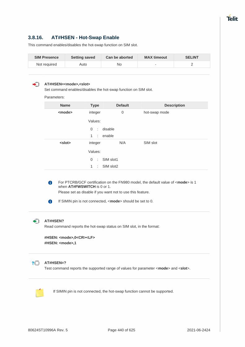
80624ST10996A Rev. 5 Page 440 of 625 2021-06-2424
3.8.16. AT#HSEN - Hot-Swap Enable
This command enables/disables the hot-swap function on SIM slot.
SIM Presence Setting saved Can be aborted MAX timeout SELINT
Not required Auto No - 2
AT#HSEN=<mode>,<slot>
Set command enables/disables the hot-swap function on SIM slot.
Parameters:
Name Type Default Description
<mode> integer 0 hot-swap mode
Values:
0 : disable
1 : enable
<slot> integer N/A SIM slot
Values:
0 : SIM slot1
1 : SIM slot2
For PTCRB/GCF certification on the FN980 model, the default value of <mode> is 1 when AT#FWSWITCH is 0 or 1.
Please set as disable if you want not to use this feature.
If SIMIN pin is not connected, <mode> should be set to 0.
AT#HSEN?
Read command reports the hot-swap status on SIM slot, in the format:
#HSEN: <mode>,0<CR><LF>
#HSEN: <mode>,1
AT#HSEN=?
Test command reports the supported range of values for parameter <mode> and <slot>.
If SIMIN pin is not connected, the hot-swap function cannot be supported.

80624ST10996A Rev. 5 Page 441 of 625 2021-06-2424
SIMIN pin is connected and SIM is inserted in SIM slot1.
AT#HSEN?
#HSEN: 0,0
#HSEN: 0,1
OK
AT#SIMPR?
#SIMPR: 1,0,1
#SIMPR: 1,1,0
OK
Enable the hot-swap function of SIM slot1.
AT#HSEN=1,0
OK
AT#REBOOT
OK
AT#HSEN?
#HSEN: 1,0
#HSEN: 0,1
OK
Remove SIM card on SIM slot 1.
#SIMPR: 0,0
Insert SIM card on SIM slot 1.
#SIMPR: 0,1

80624ST10996A Rev. 5 Page 442 of 625 2021-06-2424
3.8.17. AT#SIMINCFG - SIMIN Pin Configuration
This command configures the SIM detection mode on the SIMIN pin.
SIM Presence Setting saved Can be aborted MAX timeout SELINT
Not required Auto No - 2
AT#SIMINCFG=<SIM_id>,<SIMIN_det_mode>
Set command sets the SIM detection mode on the SIMIN pin to detect the presence of a SIM.
Parameters:
Name Type Default Description
<SIM_id> integer N/A SIM slot index
Values:
1 : SIM slot1
2 : SIM slot2
<SIMIN_det_mode> integer 1 status of SIMIN pin for SIM detection
Values:
0 : SIMIN pin LOW means SIM inserted, HIGH means SIM removed (for normal SIM holder).
1 : SIMIN pin LOW means SIM removed, HIGH means SIM inserted (for micro SIM holder)
AT#SIMINCFG?
Read command reports the detection mode of the configured SIMIN pin in the format:
#SIMINCFG: 1,<SIMIN_det_mode><CR><LF> #SIMINCFG: 2,<SIMIN_det_mode>
AT#SIMINCFG=?
Test command reports supported values of parameters <SIM_id> and <SIMIN_det_mode>.
If SIMIN pin is not connected, the hot-swap function cannot be supported.

80624ST10996A Rev. 5 Page 443 of 625 2021-06-2424
SIM is inserted in card slot1. The SIMIN is GND when SIM is inserted.
AT#SIMINCFG=1,0
OK
AT#SIMINCFG=2,0
OK
AT#REBOOT
OK
AT#SIMPR?
#SIMPR: 0,0,1
#SIMPR: 0,1,0
OK
Remove SIM in card slot1.
AT#SIMPR?
#SIMPR: 0,0,0
#SIMPR: 0,1,0
OK
SIM is inserted in card slot1. The SIMIN is GND when SIM is not inserted.
AT#SIMINCFG=1,1
OK
AT#SIMINCFG=2,1
OK
AT#REBOOT
OK
AT#SIMPR?
#SIMPR: 0,0,1
#SIMPR: 0,1,0
OK
Remove SIM in card slot1.
AT#SIMPR?
#SIMPR: 0,0,0
#SIMPR: 0,1,0
OK

80624ST10996A Rev. 5 Page 444 of 625 2021-06-2424
3.8.18. AT+CSUPI - Request 5G subscription permanent identifier
Request 5G subscription permanent identifier.
SIM Presence Setting saved Can be aborted MAX timeout SELINT
Not required No No - 2
AT+CSUPI
Execution command causes the TA to return <SUPI>, which is intended to permit the TE to identify the individual USIM card or active application in the UICC which is attached to 5G MT.
Additional info:
The command returns the following message:
<SUPI>
Name Type Default Description
<SUPI> string - 5G subscription permanent identifier (string without double quotes).
AT+CSUPI=?
Test command returns the OK result code.

80624ST10996A Rev. 5 Page 445 of 625 2021-06-2424
3.8.19. AT#ESIMUPN - Updates the nickname
This command updates the nickname of the requested profile.
SIM Presence Setting saved Can be aborted MAX timeout SELINT
Not required Other No - 2
AT#ESIMUPN=<slot>,<profile_id>,<nickname>
Set command updates the nickname of the requested profile. If the nickname is missing or has zero length, the nickname is removed from profile.
Parameters:
Name Type Default Description
<slot> integer N/A Slot information
Values:
1 : Slot 1
2 : Slot 2
<profile_id> integer N/A Profile ID information
Values:
1 : profile 1
2 : profile 2
3 : profile 3
4 : profile 4
5 : profile 5
6 : profile 6
7 : profile 7
8 : profile 8
<nickname> string - Nickname information, supported 0 ~ 64 character string.
AT#ESIMUPN=?
Test command reports the supported range of values for parameters <slot>,<profile_id>.

80624ST10996A Rev. 5 Page 446 of 625 2021-06-2424
3.8.20. AT#ESIMPFINFO - Provides the profile data
This command provides the profile data for the profile ID.
SIM Presence Setting saved Can be aborted MAX timeout SELINT
Not required Other No - 2
AT#ESIMPFINFO=<slot>,<profile_id>
Set command provides the profile data for the profile ID in request.
Parameters:
Name Type Default Description
<slot> integer N/A Slot information
Values:
1 : Slot 1
2 : Slot 2
<profile_id> integer N/A Profile ID information
Values:
1 : profile 1
2 : profile 2
3 : profile 3
4 : profile 4
5 : profile 5
6 : profile 6
7 : profile 7
8 : profile 8
Additional info:
Response:
#ESIMPFINFO: <iccid>,<profile_state>,<profile_nickname>,<profile_spn>,<profile_name>,<profile_class>,<profile_rules>
Name Type Default Description
<iccid> integer - Card identification number
<profile_state> integer N/A Profile state information
Values:
0 : inactive profile
1 : active profile
<profile_nickname> string - Nickname of profile
<profile_spn> string - The profile service provider

80624ST10996A Rev. 5 Page 447 of 625 2021-06-2424
<profile_name> string - Name of profile
<profile_class> integer N/A Profile class information
Values:
0 : Test profile
1 : Provisioning profile
2 : Operational profile
<profile_rules> integer - Indicates the profile policy rules applicable for this profile. If this parameter is missing, it indicates there is no profile policy rule associated with this profile.
AT#ESIMPFINFO=?
Test command reports the supported range of values for parameters <slot>,<profile_id>

80624ST10996A Rev. 5 Page 448 of 625 2021-06-2424
3.8.21. AT#ESIMPF - Manage the profiles
This command queries, switches or deletes the profiles supported by the card.
SIM Presence Setting saved Can be aborted MAX timeout SELINT
Not required Other No - 2
AT#ESIMPF=<mode>,<slot>[,<profile_id>[,<enable_profile>]]
Set command queries, switches or deletes the profiles supported by the card. The response contains a list of profiles supported by the card and profile information of the currently active profile.
Parameters:
Name Type Default Description
<mode> integer N/A mode information
Values:
0 : queries the profiles
1 : switches the profiles
2 : deletes the profiles
<slot> string N/A Slot information
Values:
1 : Slot 1
2 : Slot 2
<profile_id> integer N/A profile ID information
Values:
1 : profile 1
2 : profile 2
3 : profile 3
4 : profile 4
5 : profile 5
6 : profile 6
7 : profile 7
8 : profile 8
<enable_profile> integer N/A Profile enable or not
Values:
0 : disable the profile
1 : enable the profile
Additional info:
If you want queries the profile, only two parameters <mode> and <slot> are needed. The return value is as follow.
Response about queries the profile:
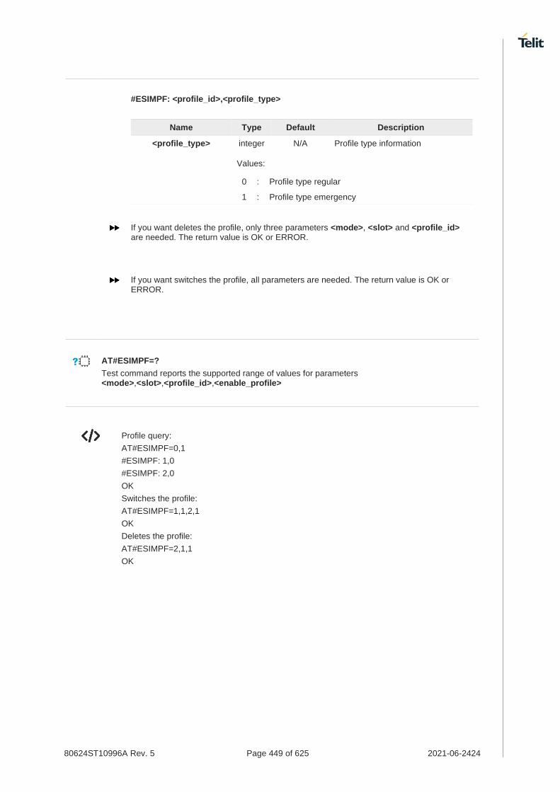
80624ST10996A Rev. 5 Page 449 of 625 2021-06-2424
#ESIMPF: <profile_id>,<profile_type>
Name Type Default Description
<profile_type> integer N/A Profile type information
Values:
0 : Profile type regular
1 : Profile type emergency
If you want deletes the profile, only three parameters <mode>, <slot> and <profile_id> are needed. The return value is OK or ERROR.
If you want switches the profile, all parameters are needed. The return value is OK or ERROR.
AT#ESIMPF=?
Test command reports the supported range of values for parameters <mode>,<slot>,<profile_id>,<enable_profile>
Profile query:
AT#ESIMPF=0,1
#ESIMPF: 1,0
#ESIMPF: 2,0
OK
Switches the profile:
AT#ESIMPF=1,1,2,1
OK
Deletes the profile:
AT#ESIMPF=2,1,1
OK

80624ST10996A Rev. 5 Page 450 of 625 2021-06-2424
3.8.22. AT#ESIMADDPF - Allows download a new profile
This command allows the eUICC card to download a new profile based on the activation code and confirmation code provided.
SIM Presence Setting saved Can be aborted MAX timeout SELINT
Not required No No - 2
AT#ESIMADDPF=<slot>,<act_code>[,<conf_code>[,<user_consent>]]
Set command allows the eUICC card to download a new profile based on the activation code and confirmation code provided.
Indication during profile download:
#ESIMADDPF: <slot>,<status>[,<error_cause>,<percentage>,<pp_rule>,<user_consent_needed>]
Parameters:
Name Type Default Description
<slot> integer 1 Slot information
Values:
1 : Slot 1
2 : Slot 2
<act_code> string - Indicated the activation code required for downloading a profile.
<conf_code> string - Indicated the confirmation code required for downloading a profile.
<user_consent> integer 0 Indicates whether the control point is able to support a request for consent from the user.
Values:
0 : User consent not supported
1 : User consent supported
Unsolicited fields:
Name Type Description
<slot> integer Slot information
<status> integer Indicates the status of profile download and install.
Values:
1 : Profile download error
2 : Profile download in progress with download percentage.
3 : Profile download is complete, and installation is in progress.
4 : Profile installation is complete.
5 : User consent is required for proceeding with download/installation of profile.
<error_cause> integer Indicates the cause of the download error.

80624ST10996A Rev. 5 Page 451 of 625 2021-06-2424
Values:
1 : Profile download generic error.
2 : Profile download error from the SIM card.
3 : Profile download error from the network.
4 : Profile download error no memory on terminal.
5 : Profile download error unsupported profile class.
6 : Profile download error profile policy rules not allowed.
<percentage> integer Percentage of download/installation done.
<pp_rule> integer Indicates the profile policy rules for this profile.
<user_consent_needed> integer Indicates whether user consent is required or not.
AT#ESIMADDPF=?
Test command reports the supported range of values for parameters <slot>,<user_consent>

80624ST10996A Rev. 5 Page 452 of 625 2021-06-2424
3.8.23. AT#ESIMID - Provides the EUICC ID
This command provides the unique ID number for the eUICC card present in the slot.
SIM Presence Setting saved Can be aborted MAX timeout SELINT
Not required No No - 2
AT#ESIMID=<slot>
Set command provides the unique ID number for the eUICC card present in the slot.
Parameter:
Name Type Default Description
<slot> integer N/A Slot for which the EID is requested
Values:
1 : Slot 1
2 : Slot 2
Additional info:
Response:
#ESIMID: <eid_value>
Name Type Default Description
<eid_value> hex - The EID value
AT#ESIMID=?
Test command reports the supported range of values for parameters <slot>

80624ST10996A Rev. 5 Page 453 of 625 2021-06-2424
3.8.24. AT#ESIMGETADDR - Configures the default SM-DP+ address
This command configures the default SM-DP+ address on the eUICC.
SIM Presence Setting saved Can be aborted MAX timeout SELINT
Not required Other No - 2
AT#ESIMGETADDR=<slot>[,<default_smdp_addr>]
Set command configures the default SM-DP+ address on the eUICC.
Parameters:
Name Type Default Description
<slot> integer - Slot information
<default_smdp_addr> string - Support 0 ~ 255 character string. Indicates the address that must be configured on the eUICC as the default SM-DP+ address.
Additional info:
If <default_smdp_addr> is set to 0, the command removes the default SM-DP+ address from the eUICC
If the Default SM-DP+ Address is missing, the command retrieves the default SM-DS address configured on the eUICC. It can also return the default SM-DP+ address if it is configured on the eUICC.
Response:
#ESIMGETADDR: <default_smds_address>,<default_smdp_addr>
Name Type Default Description
<default_smds_address> string - default SM-DS address
AT#ESIMGETADDR=?
Test command reports the supported range of values for parameters <slot>

80624ST10996A Rev. 5 Page 454 of 625 2021-06-2424
3.8.25. AT#ESIMPFUC - Provides the user consent
This command provides the user consent to the service which is required for proceeding with the profile download/installation operation after receiving a UIM_ADD_PROFILE_IND indication with status set to UIM_PROFILE_USER_CONSENT_REQUIRED.
SIM Presence Setting saved Can be aborted MAX timeout SELINT
Not required No No - 2
AT#ESIMPFUC=<slot>,<user_consent>
Set command provides the user consent to the service which is required for proceeding with the profile download/installation operation after receiving a UIM_ADD_PROFILE_IND indication with status set to UIM_PROFILE_USER_CONSENT_REQUIRED.
Parameters:
Name Type Default Description
<slot> integer N/A Slot information
Values:
1 : Slot 1
2 : Slot 2
<user_consent> integer N/A User consent information
Values:
0 : Not OK for profile operation
1 : OK for profile operation
AT#ESIMPFUC=?
Test command reports the supported range of values for parameters <slot>,<user_consent>

80624ST10996A Rev. 5 Page 455 of 625 2021-06-2424
3.8.26. AT#ESIMCAP - Sets or gets the terminal capability
This command allows the client to set the contents of the TERMINAL CAPABILITY command that is sent to the card as part of card initialization procedure.
SIM Presence Setting saved Can be aborted MAX timeout SELINT
Not required Other No - 2
AT#ESIMCAP=<slot>[,<tag>,<value>,<remove_tlv>]
Set command allows the client to set the contents of the TERMINAL CAPABILITY command that is sent to the card as part of card initialization procedure. The configuration set by this command is applicable only from the next card initialization.
Parameters:
Name Type Default Description
<slot> integer N/A Slot information
Values:
1 : Slot 1
2 : Slot 2
<tag> integer N/A Terminal capability tag, according to ETSI TS 102.221. The service allows the client to update only certain tags including
Values:
82 : additional interface support
83 : eUICC-related capabilities
<value> integer - Value of the terminal capability.
<remove_tlv> integer N/A Indicates whether this TLV should be removed from the terminal capability that is sent to the card. When this is set to TRUE, the value field is ignored.
Values:
0 : not remove the terminal capability
1 : remove the terminal capability, the value field is ignored
Additional info:
In case <tag> is '82':
Name Type Default Description
<value> integer N/A Value of the terminal capability.
Values:
0 : UICC-CLF interface according to ETSI TS 102.613 not supported
1 : UICC-CLF interface according to ETSI TS 102.613 supported

80624ST10996A Rev. 5 Page 456 of 625 2021-06-2424
In case <tag> is '83':
Name Type Default Description
<value> integer N/A unsigned Integer used as a bit field, according to GSMA SGP.22
0 … 255 - used as a bit field:
bit1:
0 - Local User Interface in the Device (LUId) not supported
1 - Local User Interface in the Device (LUId) supported
bit2:
0 - Local Profile Download in the Device (LPDd) not supported
1 - Local Profile Download in the Device (LPDd) supported
bit3:
0 - Local Discovery Service in the Device (LDSd) not supported
1 - Local Discovery Service in the Device (LDSd) supported
bit4:
0 - LUIe based on SCWS not supported
1 - LUIe based on SCWS supported
bit5 to 8: reserved for future.
Value:
0÷255 : eUICC-related capabilities
If there is only <slot> parameter in set command, this command returns Terminal Capability set in card as follows:
Response:
#ESIMCAP: <terminal_cap_len>,< tag >,<value>,<tag>,<value> ……
Name Type Default Description
<terminal_cap_len> integer - number of sets of <tag> and <value>
<tag> integer N/A Terminal capability tag, according to ETSI TS 102.221. The service allows the client to update only certain tags including.
Values:
80 : Terminal power supply
81 : Extended logical channels terminal support
82 : additional interface support
83 : eUICC-related capabilities
<value> mixed - In case <tag> is '80':
<value> - Hex value, within the constructed TLV object.

80624ST10996A Rev. 5 Page 457 of 625 2021-06-2424
First byte - Actual used supply voltage class
Second byte - Maximum available power supply of the terminal ('0A' to '3C')
Third byte - Actual used clock frequency ('0A' to 'FF')
In case <tag> is '81':
<value> - The extended logical channels terminal support TLV with zero length. In order to allow future extension of this TLV.
AT#ESIMCAP=?
Test command reports the supported range of values for parameters <slot>,<tag>,<remove_tlv>.

80624ST10996A Rev. 5 Page 458 of 625 2021-06-2424
3.8.27. AT#ESIMMEMRST - Resets the eUICC card
This command resets the eUICC card present on given slot based on the provided option.
SIM Presence Setting saved Can be aborted MAX timeout SELINT
Not required No No - 2
AT#ESIMMEMRST=<slot>,<option_1>,<option_2>,<option_3>
Set command resets the eUICC card present on given slot based on the provided option. If two or more options are set, the action is taken for all those set options.
Parameters:
Name Type Default Description
<slot> integer N/A Slot information
Values:
1 : Slot 1
2 : Slot 2
<option_1> integer N/A Option 1
Values:
0 : do not action
1 : delete all the test profiles
<option_2> integer N/A Option 2
Values:
0 : do not action
1 : delete all operational profiles
<option_3> integer N/A Option 3
Values:
0 : do not action
1 : reset the default SM-DP+ address
AT#ESIMMEMRST=?
Test command reports the supported range of values for parameters <slot>,<option_1>,<option_2> and <option_3>

80624ST10996A Rev. 5 Page 459 of 625 2021-06-2424
SIM Toolkit
3.9.1. AT#STIA - SIM/USIM Toolkit Interface Action
The SIM/USIM Application Toolkit (SAT/USAT) provides an interface to the applications existing in the SIM/USIM device. The module must support the mechanisms required by the SIM/USIM applications.
[1] 3GPP TS 23.038 [2] 3GPP TS 31.111 [3] Telit SIM/USIM Application Toolkit Application Note
SIM Presence Setting saved Can be aborted MAX timeout SELINT
Required Specific profile No - 2
AT#STIA=[<mode>[,<timeout>]]
Set command is used to enable/disable the SIM/USIM Application Toolkit (SAT/USAT). In addition, the command can enable the URCs sending.
Parameters:
Name Type Default Description
<mode> integer 1 enables/disables SAT/USAT.
In addition, <mode> parameter enables the:
- #STN URCs notifying the user that the SIM/USIM application has issued a proactive command. Some proactive commands require a user response.
- #STN URCs that are the SIM/USIM device responses concerning actions initiated by the user, refer to Additional info section.
If <mode>=2, the URC format depends on the <cmdType> as described in the Additional info sections. For <cmdType>, and all other URC parameters refer to #STGI command. The <mode> parameter values are listed below.
Values:
0 : disable SAT/USAT
1 : enable SAT/USAT without #STN URC
2 : enable SAT/USAT and extended #STN URC
3 : enable SAT/USAT and reduced #STN URC
17 : enable SAT/USAT without #STN URC and the alphabet used
18 : enable SAT/USAT, extended #STN URC, and the alphabet used
19 : enable SAT/USAT, reduced #STN URC, and the alphabet used
33 : enable SAT/USAT without #STN URC and the UCS2 alphabet used
34 : enable SAT/USAT, extended #STN URC, and the UCS2 alphabet used
35 : enable SAT/USAT, reduced #STN URC, and the UCS2 alphabet used
<timeout> integer 2 When an ongoing proactive command, requiring a user response, is not answered before <timeout> minutes, it is automatically aborted. In this case, the terminal response from the module is either "ME currently unable to process

80624ST10996A Rev. 5 Page 460 of 625 2021-06-2424
command" or, if applicable, "No response from user". In addition, the following URC is sent on the AT interface. For parameter meaning of the URC refer to Unsolicited fields section.
#STN:<cmdTerminateValue>
Value:
1,2 : timeout expressed in minutes
Additional info:
<mode>=3, the URC has the following reduced format:
#STN: <cmdType>
<mode>=2, and <cmdType>=1 (REFRESH), the URC has the following extended format:
#STN: 1,<refreshType>
<mode>=2, and <cmdType>=5 (SET UP EVENT LIST), the URC has the following extended format:
#STN: 5[,<eventListMask>]
<mode>=2, and <cmdType>=16 (SET UP CALL), the URC has the following extended format:
#STN: 16,<cmdDetails>,[<confirmationText>],<calledNumber>
<mode>=2, and one of the following proactive command:
<cmdType>=17 (SEND SS) <cmdType>=18 (SEND USSD) <cmdType>=19 (SEND SHORT MESSAGE) <cmdType>=20 (SEND DTMF) <cmdType>=32 (PLAY TONE) <cmdType>=64 (OPEN CHANNEL) <cmdType>=65 (CLOSE CHANNEL) <cmdType>=66 (RECEIVE DATA) <cmdType>=67 (SEND DATA) the URC has the following extended format:
#STN: <cmdType>[,<alphaIdentifier>]
If <cmdType>=19 (SEND SHORT MESSAGE) fails, the #STN: 119 URC is sent to the module.
<mode>=2, and <cmdType>=33 (DISPLAY TEXT), the URC is sent if allowed by SIM/USIM, the extended format is:
#STN: 33[,<cmdDetails>[,<alphaIdentifier>]]
If bit 7 of <cmdDetails>=1, the response with the #STSR command is required.

80624ST10996A Rev. 5 Page 461 of 625 2021-06-2424
<mode>=2, and <cmdType>=34 (GET INKEY), the URC has the following extended format:
#STN: 34,<cmdDetails>,<text>
<mode>=2, and <cmdType>=35 (GET INPUT), the URC has the following extended format:
#STN: 35,<cmdDetails>,<text>,<responseMin>,<responseMax>[,<defaultText>]
<mode>=2, and <cmdType>=36 (SELECT ITEM), the URC has the following extended format:
the first line of output is:
#STN: 36,<cmdDetails>,<numOfItem>[,<titleText>]<CR><LF>
one line follows for every item, repeated <numOfItems> times:
#STN: 36,<itemId>,<itemText>[,<nextActionId>]
<mode>=2, and <cmdType>=37 (SET UP MENU), the URC has the following extended format:
the first line of output is:
#STN: 37,<cmdDetails>,<numOfItem>,<titleText><CR><LF>
one line follows for every item, repeated for <numOfItems>:
#STN: 37,<itemId>,<itemText>[,<nextActionId>]
<mode>=2, and <cmdType>=40 (SET UP IDLE MODE TEXT), the URC has the following extended format:
#STN: 40[,<idleModeTextString>]
This Additional info section deals with the action initiated by the user (no proactive commands activated by the SIM/USIM device).
If the call control or SMS control facility present in the SIM/USIM device is activated, when the user application makes an outgoing call, or sends a SS or USSD, or a SMS, the following #STN URC could be sent to indicate whether the outgoing call has been accepted, rejected or modified by the SIM, or if the SMS service center address or destination has been changed. For parameters meaning refer to Unsolicited fields section.
#STN: <cmdControlResponse>,<Result>[,<alphaIdentifier>[,<Number>[,<MODestAddr>]]]
Unsolicited fields:
Name Type Description
<cmdTerminateValue> integer is defined as <cmdType> + terminate offset. Terminate offset = 100

80624ST10996A Rev. 5 Page 462 of 625 2021-06-2424
<cmdControlResponse> integer response of the SIM/USIM device
Values:
150 : SMS control response
160 : call/SS/USSD response
<Result> integer identify the result of the Call or SMS control performed by SIM/USIM device
Values:
0 : Call/SMS not allowed
1 : Call/SMS allowed
2 : Call/SMS allowed with modification
<alphaIdentifier> string optional text provided by the SIM/USIM device in ASCII format
<Number> string Called number, Service Center Address or SS String in ASCII format
<MODestAddr> string MO destination address in ASCII format
The settings are saved on user profile and available on following reboot. SIM/USIM Toolkit activation/deactivation is only performed at power on according to the saved setting.
If AT#ENS=1, the <mode> parameter is set to 2.
Just one instance at a time, the one which first issued AT#STIA=<mode> (with <mode> not equal to 0), is allowed to issue SAT/USAT commands, and this is valid till the same instance issues AT#STIA=0. After reboot, SAT/USAT can be used on another instance.
A typical SAT/USAT session on AT interface starts after an #STN: 37 unsolicited code is received, if enabled (see above). At that point usually an AT#STGI=37 command is issued (see #STGI), and after the SAT main menu has been displayed on TE an AT#STSR=37,0,x command is issued to select an item in the menu (see #STSR).
AT#STIA?
Read command can be used to get information about the SAT/USAT interface. The message format is:
#STIA: <state>,<mode>,<timeout>,<SatProfile>
Additional info:
Returned parameters.
Name Type Default Description
<state> integer 0 state of the sending of the SET UP MENU proactive command (37)
Values:
0 : SIM/USIM has not sent the SET UP MENU proactive command (37)

80624ST10996A Rev. 5 Page 463 of 625 2021-06-2424
1 : SIM/USIM has sent the SET UP MENU proactive command (37)
<mode> integer - refer to Set section
<timeout> integer - refer to Set section
<SatProfile> string - SAT/USAT Terminal Profile. Is the list of SIM/USIM Application Toolkit facilities supported by the ME. The profile cannot be changed by the TA.
In SAT/USAT applications an SMS message is usually sent to the network provider containing service requests, e.g. to send the latest news. The provider returns a message with the requested information. Before activating SAT/USAT, it is recommended to set the SMS text mode with the AT+CMGF=1 command and enable URC for incoming SMS messages with +CNMI command.
AT#STIA=?
Test command returns the range of available values for the parameters <mode> and <timeout>.

80624ST10996A Rev. 5 Page 464 of 625 2021-06-2424
3.9.2. AT#STGI - SIM Toolkit Get Information
This command interfaces to the SIM/USIM Application Toolkit to get information on the ongoing proactive command.
3GPP TS 31.111 Telit SIM/USIM Application Toolkit Application Note
SIM Presence Setting saved Can be aborted MAX timeout SELINT
Not required No No - 2
AT#STGI=[<cmdType>]
Set command gets parameters of the ongoing proactive command. The command can be used after the reception of the #STN: <cmdType> URC. If no proactive command is ongoing, it returns an ERROR message.
Parameter:
Name Type Default Description
<cmdType> integer N/A proactive command code. For each proactive command listed below, the response format is described in the Additional info sections.
Values:
1 : REFRESH
5 : SET UP EVENT LIST
16 : SET UP CALL
17 : SEND SS
18 : SEND USSD
19 : SEND SHORT MESSAGE
20 : SEND DTMF
32 : PLAY TONE
33 : DISPLAY TEXT
34 : GET INKEY
35 : GET INPUT
36 : SELECT ITEM
37 : SET UP MENU
40 : SET UP IDLE MODE TEXT
Additional info:
<cmdType>=1 (REFRESH)
the response format:
#STGI: 1,<refreshType>
Name Type Default Description

80624ST10996A Rev. 5 Page 465 of 625 2021-06-2424
<refreshType> integer N/A identifies the refresh type
Values:
0 : SIM Initialization and Full File Change Notification
1 : File Change Notification
2 : SIM Initialization and File Change Notification
3 : SIM Initialization
4 : SIM Reset
5 : NAA Application Reset
6 : NAA Session Reset
7 : Steering of Roaming
8 : Steering of Roaming WLAN
<cmdType>=5 (SET UP EVENT LIST)
the response format:
#STGI: 5,<eventListMask>
Name Type Default Description
<eventListMask> hex N/A identifies the list of events to monitor.
The <eventListMask> (two bytes long) is a bit mask where each bit, when set, indicates that the corresponding event must be monitored (e.g. if <eventListMask> is 0x0001, it means that MT call must be monitored).
bit 0 = MT call
bit 1 = Call connected
bit 2 = Call disconnected
bit 3 = Location status
bit 4 = User activity
bit 5 = Idle screen available
bit 6 = Card reader status (if class "a" is supported)
bit 7 = Language selection
bit 8 = Browser Termination (if class "c" is supported)
bit 9 = Data available (if class "e" is supported)
bit 10 = Channel status (if class "e" is supported)
bits 11 - 15 = reserved for future use
Value:
0x0001÷0x01FF : mask
<cmdType>=16 (SET UP CALL)
the response format:

80624ST10996A Rev. 5 Page 466 of 625 2021-06-2424
#STGI: 16,<cmdDetails>,[<confirmationText>],<calledNumber>
Name Type Default Description
<cmdDetails> integer N/A identifies the command details
Values:
0 : set up call, but only if not currently busy on another call
1 : set up call, but only if not currently busy on another call, with redial
2 : set up call, putting all other calls (if any) on hold
3 : set up call, putting all other calls (if any) on hold, with redial
4 : set up call, disconnecting all other calls (if any)
5 : set up call, disconnecting all other calls (if any), with redial
<confirmationText> string - string for user confirmation stage
<calledNumber> string - string containing called numbers
This section is dedicated to the following proactive commands:
<cmdType>=17 (SEND SS) <cmdType>=18 (SEND USSD) <cmdType>=19 (SEND SHORT MESSAGE) <cmdType>=20 (SEND DTMF) <cmdType>=32 (PLAY TONE)
the response format:
#STGI: <cmdType>[,<alphaIdentifier>]
Name Type Default Description
<alphaIdentifier> string - optional text provided by the SIM/USIM device in ASCII format
<cmdType>=33 (DISPLAY TEXT)
the response format:
#STGI: 33,<cmdDetails>[,<text>]
Name Type Default Description
<cmdDetails> hex N/A a bit mask where each bit position, according to its value, has a specific meaning:
bit 0: 0 - normal priority 1 - high priority
bits 1-6: reserved for future use
bit 7: 0 - clear message after a delay 1 - wait for user to clear message

80624ST10996A Rev. 5 Page 467 of 625 2021-06-2424
Value:
0x00÷0xFF : mask
<text> string - text provided by the SIM/USIM device in ASCII format
<cmdType>=34 (GET INKEY)
the response format:
#STGI: 34,<cmdDetails>,<text>
Name Type Default Description
<cmdDetails> hex N/A a bit mask where each bit position, according to its value, has a specific meaning:
bit 0: 0 - digits only (0-9, *, # and +) 1 - alphabet set
bit 1: 0 - SMS default alphabet (GSM character set) 1 - UCS2 alphabet
bit 2: 0 - character sets defined by bit 0 and bit 1 are enabled 1 - character sets defined by bit 0 and bit 1 are disabled and the "Yes/No" response is requested
bits 3-6: 0
bit 7: 0 - no help information available 1 - help information available
Value:
0x00÷0x87 : mask
<text> string - string as prompt for test
<cmdType>=35 (GET INPUT)
the response format:
#STGI: 35,<cmdDetails>,<text>,<responseMin>,<responseMax>[,<defaultText>]
Name Type Default Description
<cmdDetails> hex N/A a bit mask where each bit position, according to its value, has a specific meaning:
bit 0: 0 - digits only (0-9, *, #, and +) 1 - alphabet set
bit 1: 0 - SMS default alphabet (GSM character set) 1 - UCS2 alphabet
bit 2: 0 - ME may echo user input on the display 1 - user input shall not be revealed in any way. Hidden entry mode is only available when

80624ST10996A Rev. 5 Page 468 of 625 2021-06-2424
using digit input. In hidden entry mode only characters ('0'-'9', '*' and '#') are allowed.
bit 3: 0 - user input to be in unpacked format 1 - user input to be in SMS packed format
bits 4-6: 0
bit 7: 0 - no help information available 1 - help information available
Value:
0x00÷0x8F : mask
<text> string - string as prompt for text
<responseMin> integer N/A minimum number of characters of the user input
Value:
0÷255 : minimum length of user input.
<responseMax> integer N/A maximum number of characters of the user input.
Value:
0÷255 : maximum length of user input
<defaultText> string - string supplied as default response text
<cmdType>=36 (SELECT ITEM)
the response format:
the first line of output is:
#STGI: 36,<cmdDetails>,<numOfItem>[,<titleText>]<CR><LF>
one line follows for every item, repeated <numOfItems> times:
#STGI: 36,<itemId>,<itemText>[,<nextActionId>]
Name Type Default Description
<cmdDetails> hex N/A a bit mask where each bit position, according to its value, has a specific meaning:
bit 0: 0 - presentation type is not specified 1 - presentation type is specified in bit 1
bit 1: 0 - presentation as a choice of data values if bit 0 = 1 1 - presentation as a choice of navigation options if bit 0 is 1
bit 2: 0 - no selection preference 1 - selection using soft key preferred
bits 3-6: 0

80624ST10996A Rev. 5 Page 469 of 625 2021-06-2424
bit 7: 0 - no help information available 1 - help information available
Value:
0x00÷0x87 : mask
<numOfItems> integer - number of items in the list
<titleText> string - menu title string
<itemId> integer N/A item identifier
Value:
1÷numOfItems : item identifier range
<itemText> string - item title string
<nextActionId> integer - is the code of next proactive command to be issued upon execution of the menu item.
If <nextActionId>=0, no next action information available.
<cmdType>=37 (SET UP MENU)
the response format:
the first line of output is:
#STGI: 37,<cmdDetails>,<numOfItem>,<titleText><CR><LF>
one line follows for every item, repeated for <numOfItems>:
#STGI: 37,<itemId>,<itemText>[,<nextActionId>]
Name Type Default Description
<cmdDetails> hex N/A a bit mask where each bit position, according to its value, has a specific meaning:
bit 0: 0 - no selection preference 1 - selection using soft key preferred
bit 1-6: 0
bit 7: 0 - no help information available 1 - help information available
Value:
0x00÷0x81 : mask
<numOfItems> integer - number of items in the list
<titleText> string - menu title string
<itemId> integer N/A item identifier
Value:
1÷numOfItems : item identifier range
<itemText> string - item title

80624ST10996A Rev. 5 Page 470 of 625 2021-06-2424
<nextActionId> integer - numerical code of next proactive command type to be issued upon execution of the menu item.
If <nextActionId>=0, no next action information available.
<cmdType>=40 (SET UP IDLE MODE TEXT)
the response format:
#STGI: 40,<idleModeTextString>
Name Type Default Description
<idleModeTextString> string - text provided by the SIM/USIM device in ASCII format
The proactive commands are only those command types that use the AT interface. SAT/USAT commands which are not using the AT interface (not MMI related SAT commands, e.g. PROVIDE LOCAL INFORMATION) are executed without sending any indication to the user.
AT#STGI?
Read command returns the ongoing proactive command and the SAT/USAT state. The message format is:
#STGI: <state>,<cmdType>
Additional info:
Returned parameters:
Name Type Default Description
<state> integer - state of the sending of the SET UP MENU proactive command (37), refer to AT#STIA? command
<cmdType> integer - ongoing proactive command code
AT#STGI=?
Test command returns the supported values of parameters <state> and <cmdType>.

80624ST10996A Rev. 5 Page 471 of 625 2021-06-2424
A typical SAT/USAT session, running on AT interface, starts when the user receives the #STN: 37 URC. The unsolicited result code must be previously enabled by the #STIA command. The #STN: 37 notifies the user that the main menu of the SIM/USIM Application has been sent to TA, and TA has stored the just received menu. Later, at any time, you can type in the AT#STGI=37 command to display the main menu of the SIM/USIM Application on TE.
Upon receiving the #STGI response, you must enter the #STSR command to confirm the execution of the proactive command and provide any required user response. In this case, you must enter the AT#STSR=37,0,x command to select the x item of the SIM/USIM Application menu.
The #STN: 237 URC indicates that the main menu of the SIM/USIM Application has been removed from TA, and it is no longer available. In this case, AT#STGI=37 command returns ERROR message.

80624ST10996A Rev. 5 Page 472 of 625 2021-06-2424
3.9.3. AT#STSR - SIM Toolkit Send Response
This command allows the user to provide a response to confirm the execution of the ongoing proactive command.
3GPP TS 31.111 Telit SIM/USIM Toolkit Application Note
SIM Presence Setting saved Can be aborted MAX timeout SELINT
Required No No - 2
AT#STSR=[<cmdType>[,<userAction>[,<data>]]]
Set command allows the user to provide a response action to the ongoing proactive command when the action is required by the command itself.
Parameters:
Name Type Default Description
<cmdType> integer - proactive command code, refer to #STGI command to have information on the <cmdType>
<userAction> integer 0 identify the user action
Values:
0 : the user accepts the ongoing proactive command
16 : proactive SIM/USIM session terminated by user
17 : backward move in the proactive SIM/USIM session requested by the user
18 : no response from user
19 : help information required by the user
20 : USSD/SS Transaction terminated by user
32 : TA currently unable to process command
34 : user has denied SIM/USIM call setup request
35 : user cleared down SIM/USIM call before connection or network release
<data> string - data entered by user, see Additional info section
Additional info:
<data> parameter is used according to <cmdType>, and when <userAction>=0:
<cmdType>=34 (GET INKEY)
<data> contains the key pressed by the user. The character set is selected by +CSCS command.
If the ongoing proactive command requires to the user a binary choice (yes/no), the valid content of <data> is:
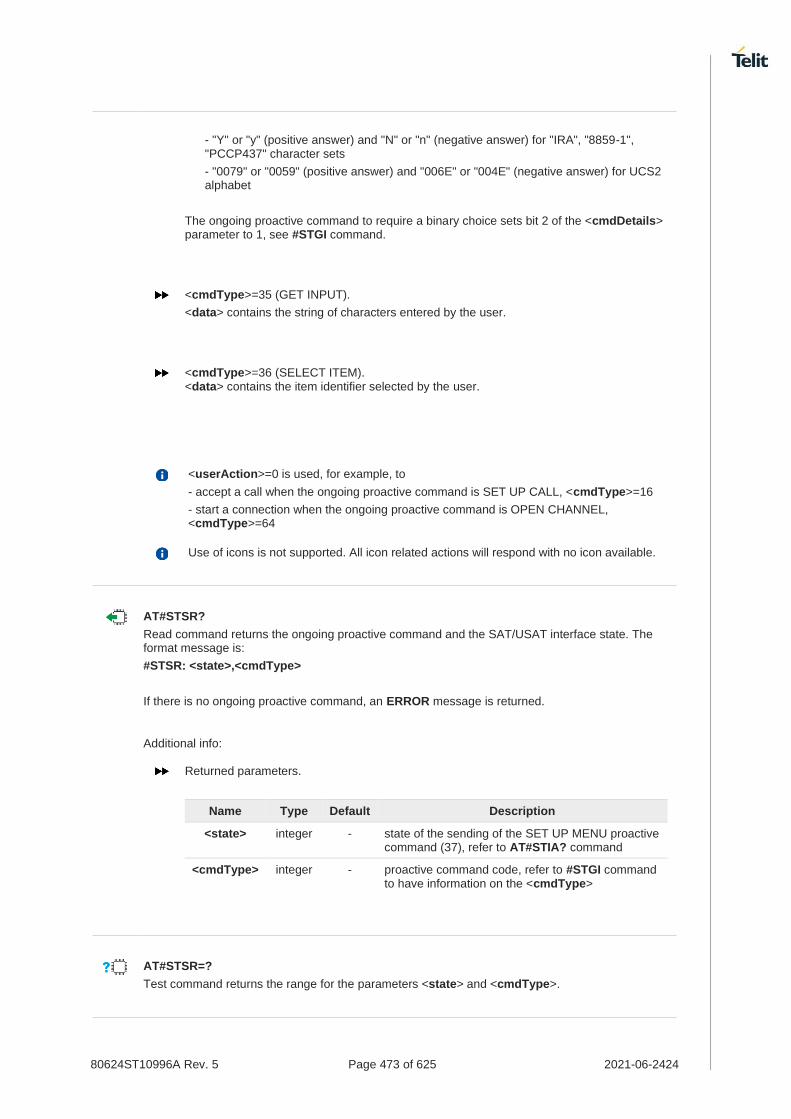
80624ST10996A Rev. 5 Page 473 of 625 2021-06-2424
- "Y" or "y" (positive answer) and "N" or "n" (negative answer) for "IRA", "8859-1", "PCCP437" character sets
- "0079" or "0059" (positive answer) and "006E" or "004E" (negative answer) for UCS2 alphabet
The ongoing proactive command to require a binary choice sets bit 2 of the <cmdDetails> parameter to 1, see #STGI command.
<cmdType>=35 (GET INPUT).
<data> contains the string of characters entered by the user.
<cmdType>=36 (SELECT ITEM). <data> contains the item identifier selected by the user.
<userAction>=0 is used, for example, to
- accept a call when the ongoing proactive command is SET UP CALL, <cmdType>=16
- start a connection when the ongoing proactive command is OPEN CHANNEL, <cmdType>=64
Use of icons is not supported. All icon related actions will respond with no icon available.
AT#STSR?
Read command returns the ongoing proactive command and the SAT/USAT interface state. The format message is:
#STSR: <state>,<cmdType>
If there is no ongoing proactive command, an ERROR message is returned.
Additional info:
Returned parameters.
Name Type Default Description
<state> integer - state of the sending of the SET UP MENU proactive command (37), refer to AT#STIA? command
<cmdType> integer - proactive command code, refer to #STGI command to have information on the <cmdType>
AT#STSR=?
Test command returns the range for the parameters <state> and <cmdType>.

80624ST10996A Rev. 5 Page 474 of 625 2021-06-2424
3.9.4. AT#SDM - Set SIM Toolkit Display Mode
This command is used to set normal/high priority standby display mode.
SIM Presence Setting saved Can be aborted MAX timeout SELINT
Not required No No - 2
AT#SDM=<priority>
Set command sets to normal/high priority standby display mode.
Parameter:
Name Type Default Description
<priority> integer 0 priority
Values:
0 : normal
1 : high
AT#SDM?
Read command returns the current value of the <priority> parameter.
AT#SDM=?
Test command returns the range of values for parameter <priority>.

80624ST10996A Rev. 5 Page 475 of 625 2021-06-2424
3.9.5. AT#STIME - Set SIM Toolkit timeout value
This command sets the timeout value for STK timeout test of GCF/PTCRB.
SIM Presence Setting saved Can be aborted MAX timeout SELINT
Not required Common profile No - 2
AT#STIME=[<mode>]
Set command sets a unit of STK timeout value.
Parameter:
Name Type Default Description
<mode> integer 0 a unit of STK timeout value
Values:
0 : in minute
1 : in second
AT#STIME?
Read command returns the current <mode>.
AT#STIME=?
Test command returns the supported range of values for parameter <mode>.
AT#STIA command is not set to a second unit. When you test "No response from user" and "timeout" of STK test, you must change to a second unit to timeout value of STK.
Set STK timeout value to a second unit.
AT#STIME=1 OK
Timeout value is 30 second
AT#STIA=2,30 OK
Set STK timeout value to a minute unit.
AT#STIME=0 OK
Timeout value is 1 minute
AT#STIA=2,1 OK

80624ST10996A Rev. 5 Page 476 of 625 2021-06-2424
3.9.6. AT#STKENV - Send SIM Toolkit Envelop Command
This command set envelope command send to the UICC when the UE has successfully accepted the list of events of SIM application toolkit.
SIM Presence Setting saved Can be aborted MAX timeout SELINT
Required No No - 2
AT#STKENV=<cmd_id>
Execution command sends Envelop command to UICC.
Parameter:
Name Type Default Description
<cmd_id> integer N/A command type
Values:
1 : menu selection
2 : language selection
3 : user activity
4 : Idle screen available
AT#STKENV=?
Test command returns the OK result code.
#STN: 05,03
AT#STKENV=3
OK

80624ST10996A Rev. 5 Page 477 of 625 2021-06-2424
Audio
3.10.1. Digital Voice Interface
3.10.1.1. AT#DVI - Digital Voiceband Interface
Digital Voiceband Interface handling.
[1] Hardware User's Guide of the used module
SIM Presence Setting saved Can be aborted MAX timeout SELINT
Not required Common profile No - 2
AT#DVI=<mode>[,<dviport>,<clockmode>]
Set command enables/disables the Digital Voiceband Interface, see documents [1].
Parameters:
Name Type Default Description
<mode> integer 1 Enables/disables the DVI
Values:
0 : disable DVI; audio is forwarded to the analog line; DVI pins should be Not Connected/or Tri-State
1 : Enable DVI: audio is forwarded to the DVI block
<dviport> integer 2 Select DVI port
Value:
2 : DVI port 2 will be used
<clockmode> integer 1 Select DVI clock mode
Values:
0 : DVI slave
1 : DVI master
- #DVI parameters are saved in the extended profile. - On <mode> 0 supported by "DVI master" only. - The <dviport> parameter have no effect and is included only for backward
compatibility. - On Active/MT/MO Voice Call return Error. - If Voice/VoLTE call are not supported in module the command will return error.
AT#DVI?
Read command reports last setting, in the format:
#DVI: <mode>,<dviport>,<clockmode>.

80624ST10996A Rev. 5 Page 478 of 625 2021-06-2424
AT#DVI=?
Test command reports the range of supported values for parameters <mode>,<dviport> and <clockmode>.
Configure DVI as master on DVI Port #2.
AT#DVI=1,2,1 OK

80624ST10996A Rev. 5 Page 479 of 625 2021-06-2424
3.10.1.2. AT#DVICLK - Digital Voiceband Interface Clock
The command configures the DVI clock signal.
SIM Presence Setting saved Can be aborted MAX timeout SELINT
Required Auto No - 2
AT#DVICLK=<clock>[,<samplerate>]
Set command configures and activates the DVICLK clock signal and the Digital Voiceband Interface.
Parameters:
Name Type Default Description
<clock> integer 0 DVI Clock
Values:
0 : Disable (factory default)
128 : DVI Clock activated at 128 KHz
256 : DVI Clock activated at 256 KHz
512 : DVI Clock activated at 512 KHz
1024 : DVI Clock activated at 1024 KHz
2048 : DVI Clock activated at 2048 KHz
4096 : DVI Clock activated at 4096 KHz
<samplerate> integer 0 sample rate
Values:
0 : audio scheduler sample rate 8KHz
1 : audio scheduler sample rate 16KHz
- On Active/MT/MO Voice Call return Error. - Clock 4096KHz don't supported with Sample Rate 8KHz - If Voice/VoLTE call are not supported in module the command will return error.
AT#DVICLK?
Read command reports last setting, in the format:
#DVICLK: <clock>,<samplerate>
AT#DVICLK=?
Test command reports the range of parameter <clk> and <samplerate>.

80624ST10996A Rev. 5 Page 480 of 625 2021-06-2424
Power Down
3.11.1. AT#REBOOT - Module Reboot
Immediate module reboot.
SIM Presence Setting saved Can be aborted MAX timeout SELINT
Not required No No - 2
AT#REBOOT
Execution command reboots immediately the unit. It can be used to reboot the system after a remote update of the script in order to have the new one running.
If #REBOOT follows an AT command that stores some parameters in NVM, it is recommended to insert a delay of at least 5 seconds before to issue #REBOOT, to permit the complete NVM storing.
#REBOOT is an obsolete AT command; please refer to #ENHRST to perform a module reboot.
AT#REBOOT=?
Test command returns OK result code.
• Reboot the module AT#REBOOT OK (the module reboots)

80624ST10996A Rev. 5 Page 481 of 625 2021-06-2424
3.11.2. AT#ENHRST - Periodic Reset
Enable or Disable the one shot or periodic unit reset
SIM Presence Setting saved Can be aborted MAX timeout SELINT
Not required Auto No - 2
AT#ENHRST=<mode>[,<delay>]
Set commands enables/disables the unit reset after the specified <delay> in minutes
Parameters:
Name Type Default Description
<mode> integer 0 Enable\Disable mode
Values:
0 : disables the unit reset
1 : enables the unit reset only one time (one shot reset)
2 : enables periodically unit reset
<delay> integer - time interval in minutes after that the unit reboots; numeric value in minutes
Not available setting <delay> to 0 with <mode>=2. When the command is set with <mode>=2, it could take more time than the <delay> value due to booting time.
The settings are saved automatically only if old or new <mode> value is 2, i.e. unit set in periodic reset mode. Therefore, any change from 0 to 1 or conversely is not stored.
The command AT#ENHRST=1,0 causes the immediate module reboot. If it follows an AT command that stores some parameters in NVM, it is strongly recommended to insert a delay of at least 5 sec before issuing it, to permit the complete NVM storing process.
AT#ENHRST?
Read command reports the current parameter settings in the following format:
#EHNRST: <mode>[,<delay>,<remainTime>]
Additional info:
Read command parameter for <mode> is 1 or 2.
Name Type Default Description
<remainTime> integer - time remaining before next reset
AT#ENHRST=?
Test command reports supported range of values for parameters <mode> and <delay>.

80624ST10996A Rev. 5 Page 482 of 625 2021-06-2424
Example of #ENHRST usage and expected unit behavior.
• AT#ENHRST=1,60 ...
Module reboots after 60 minutes
• AT#ENHRST=1,0
Module reboots immediately
• AT#ENHRST=2,60
...
Module reboots after 60 minutes and indefinitely after every following power on

80624ST10996A Rev. 5 Page 483 of 625 2021-06-2424
3.11.3. AT#SHDN - Software Shutdown
Software Shutdown
SIM Presence Setting saved Can be aborted MAX timeout SELINT
Not required No No - 2
AT#SHDN
Execution command causes device detachment from the network and shut down.
Before definitive shut down an OK response is returned.
After the issuing of this command any previous activity is terminated and the device will not respond to any further command.
AT#SHDN=?
Test command returns the OK result code.
If hardware pin FULL_CARD_POWER_OFF_N is maintained to High, module will turn on automatically after shutdown.

80624ST10996A Rev. 5 Page 484 of 625 2021-06-2424
3.11.4. AT#FASTSHDN - Fast Shutdown Configuration
This command can be used as a set command to configure a GPIO pin performing a fast shutdown when on it is forced a High to Low or Low to High level transition. Or can be used as an execute command to force immediately a fast shutdown.
SIM Presence Setting saved Can be aborted MAX timeout SELINT
Not required Auto No - 2
AT#FASTSHDN[=<enable>[,<GPIO>[,<trigger>]]]
Set command to configure fast power down. Module enters power off autonomously if fast power down is enabled and GPIO event is triggered after modem boot done.
Parameters:
Name Type Default Description
<enable> integer 0 enable/disable the fast shutdown execution via a GPIO pin.
Values:
0 : disabled
1 : enabled
<GPIO> integer - GPIO number used to execute the fast shutdown. Can check the available GPIO range from #FASTSHDN=? command.
This parameter is no meaning when <mode> is 0.
<trigger> integer 0 GPIO trigger level used for fast shutdown execution.
This parameter is no meaning when <mode> is 0.
Values:
0 : execute fast shutdown when the selected GPIO pin goes from High to Low level
1 : execute fast shutdown when the selected GPIO pin goes from Low to High level
Additional info:
The execution command AT#FASTSHDN forces the module to execute immediately the fast shutdown regardless of the fast shutdown configuration.
Depending on <trigger>, the selected <GPIO> pin is automatically configured as below.
<trigger> = 0, <GPIO> pin set as Pull-up
1, <GPIO> pin set as Pull-down
Configuration values are stored on module and will keep on next power cycle.
AT#FASTSHDN?
Read command reports the currently selected configuration in the format:
#FASTSHDN: <enable>,<GPIO>[,<trigger>]

80624ST10996A Rev. 5 Page 485 of 625 2021-06-2424
AT#FASTSHDN=?
Test command returns the supported range of values for all the parameters.
Enable fast shutdown on GPIO_05 AT#FASTSHDN=1,5 OK
AT#FASTSHDN? #FASTSHDN: 1,5
OK
Force immediate fast shutdown AT#FASTSHDN OK

80624ST10996A Rev. 5 Page 486 of 625 2021-06-2424
HW and Radio Control
3.12.1. AT#DPRLIST - TX Dynamic Power Reduction List
This command is the functionality for TX Dynamic Power Reduction LIST.
SIM Presence Setting saved Can be aborted MAX timeout SELINT
Not required Auto No - 2
AT#DPRLIST=<rat>,<bnd>,<pwr_level>
This command support TX DPR(Dynamic Power Reduction) list.
Parameters:
Name Type Default Description
<rat> string N/A supported RAT
Values:
UMTS : UMTS Radio Access Technology
LTE : LTE Radio Access Technology
NR5G : NR Radio Access Technology
<bnd> integer N/A supported band
Values:
1÷19 : Band for UMTS
1÷71 : Band for LTE
1÷79 : Band for NR5G
257 : NR5G MMWAVE band 257
258 : NR5G MMWAVE band 258
260 : NR5G MMWAVE band 260
261 : NR5G MMWAVE band 261
<pwr_level> string 0 power backoff level
Values:
0÷19 : power backoff level
0 : TX default power (default: 21 dbm)
1 : TX power 20.5 dbm
2 : TX power 20 dbm
3 : TX power 19.5 dbm
4 : TX power 19 dbm
5 : TX power 18.5 dbm
6 : TX power 18 dbm
7 : TX power 17.5 dbm
8 : TX power 17 dbm

80624ST10996A Rev. 5 Page 487 of 625 2021-06-2424
9 : TX power 16.5 dbm
10 : TX power 16 dbm
11 : TX power 15.5 dbm
12 : TX power 15 dbm
13 : TX power 14.5 dbm
14 : TX power 14 dbm
15 : TX power 13.5 dbm
16 : TX power 13 dbm
17 : TX power 12.5 dbm
18 : TX power 12 dbm
19 : TX power 11.5 dbm
<rat>,<bnd>,<pwr_level> parameter setting is stored in NVM.
Tx power value base on the Fx980 product, so OEM need to set and check the proper value base on the OEM product.
If try to input an unsupported band, an ERROR will be returned.
The DPR function of MMWAVE band are not supported now even if they can set.
In the table below, MCC operates according to the power reduction behavior.
If the MCC that is not in the table operates as peak exposure.
MCC Country Power Reduction Behavior
310-316 USA Time Averaged Exposure
302 Canada Time Averaged Exposure
334 Mexico Peak Exposure
404-405 India Peak Exposure
440 Japan Time Averaged Exposure
450 South Korea Peak Exposure
460 China Peak Exposure
505 Australia/NZ Peak Exposure
525 Singapore Peak Exposure
724 Brazil Peak Exposure
901 EU Time Averaged Exposure

80624ST10996A Rev. 5 Page 488 of 625 2021-06-2424
Only FN980 module currently can operate DPR function.
AT#DPRLIST?
Read command reports the currently written <rat>,<bnd> and <pwr_level> in the format:
#DPRLIST: <rat>,<bnd>,<pwr_level>
This command reads only values whose <pwr_level> is not 0.
AT#DPRLIST=?
Test command reports the supported range of values for parameter <rat>,<bnd> and <pwr_level>.

80624ST10996A Rev. 5 Page 489 of 625 2021-06-2424
3.12.2. AT#DPRCTL - TX Dynamic Power Reduction Control
This command is the functionality for TX Dynamic Power Reduction control.
SIM Presence Setting saved Can be aborted MAX timeout SELINT
Not required Auto No - 2
AT#DPRCTL=<mode>
This command control the TX DPR(Dynamic Power Reduction).
Parameter:
Name Type Default Description
<mode> integer 0 Control the DPR
Values:
0 : DPR disabled
1 : DPR enabled regardless of DPR PIN
2 : DPR enabled depends on DPR PIN
0÷2 : mode of control DPR
The <mode> parameter setting is stored in NVM.
The control of TDD DPR depends on TDD pattern(uplink-downlink configurations, 3GPP TS 36.211). The TDD pattern 1 is used for SDX55.
If <mode> is set to a value different from the previous value, a reboot process is required.
<mode> availablity like below. Another SDX 55 module can not set <mode> 2 because HW is different from FN980m so DPR PIN cannot be used.
FN980 : 0,1,2
FN980m + mmwave configuration(X) : 0,1,2
FN980m + mmwave configuration(O): 0
Another SDX55 module + mmwave configuration(X): 0,1
Another SDX55 module + mmwave configuration(O): 0
The DPR function for MMWAVE is not supported.
AT#DPRCTL?
Read command reports the currently written <mode> in the format:
#DPRCTL: <mode>
AT#DPRCTL=?
Test command reports the supported range of values for parameter <mode>.

80624ST10996A Rev. 5 Page 490 of 625 2021-06-2424
3.12.3. AT#MACADDR - Configure MAC Address
Configure hardware MAC address for each network interface.
SIM Presence Setting saved Can be aborted MAX timeout SELINT
Not required Auto No - 2
AT#MACADDR=<type>,<macaddr>
Configure MAC address for each network interface.
Parameters:
Name Type Default Description
<type> integer N/A Network Interface Type.
Value:
0 : Ethernet Interface
<macaddr> string - MAC Address, this parameter should include double quotes("").
e.g. "xx:xx:xx:xx:xx:xx"
This SET command require manual power cycle (e.g. AT#REBOOT).
Network interfaces supporting this command for each product.
FN980m: None
FT980-KS/FT980: Ethernet
AT#MACADDR?
Read MAC Addresses configured currently for all network interfaces.
AT#MACADDR=?
Returns the list of the supported values.
Example of this command.
• AT#MACADDR=0,"00:21:7E:00:00:00"
OK

80624ST10996A Rev. 5 Page 491 of 625 2021-06-2424
3.12.4. AT#I2CDIS - I2C disable
This command is used to disable I2C.
SIM Presence Setting saved Can be aborted MAX timeout SELINT
Not required Auto No - 2
AT#I2CDIS=<mode>
Set command enable/disable the I2C.
Parameter:
Name Type Default Description
<mode> integer 0 mode
Values:
0 : enable I2C
1 : disable I2C
The setting is saved in system and available on following reboot
AT#I2CDIS?
Read command reports the currently selected <mode> in the format:
#I2CDIS: <mode>
AT#I2CDIS=?
Test command returns the supported range of values of parameter <mode>.

80624ST10996A Rev. 5 Page 492 of 625 2021-06-2424
3.12.5. AT+CBC - Battery Charge
This command allows to read the current Battery Charge status.
• 3GPP TS 27.007
SIM Presence Setting saved Can be aborted MAX timeout SELINT
Not required Other No - 2
AT+CBC
Execution command returns the current Battery Charge status.
Additional info:
Battery Charge status is shown in the format: +CBC: <bcs>,<bcl>
Name Type Default Description
<bcs> integer N/A battery status
Values:
0 : ME is powered by the battery
1 : ME has a battery connected, and charger pin is being powered
2 : ME does not have a battery connected
3 : Recognized power fault, calls inhibited
<bcl> integer N/A battery charge level, only if <bcs>=0
Values:
0 : battery is exhausted, or ME does not have a battery connected
25 : battery charge remained is estimated to be 25%
50 : battery charge remained is estimated to be 50%
75 : battery charge remained is estimated to be 75%
100 : battery is fully charged
<bcs>=1 indicates that the battery charger supply is inserted and the battery is being recharged if necessary with it. Supply for ME operations is taken anyway from VBATT pins.
Without battery/power connected on VBATT pins or during a power fault the unit is not working, therefore values <bcs>=2 and <bcs>=3 will never appear.
<bcl> indicates battery charge level only if battery is connected and charger is not connected.

80624ST10996A Rev. 5 Page 493 of 625 2021-06-2424
AT+CBC=?
Test command returns parameter values supported as a compound value.
The ME does not make differences between being powered by a battery or by a power supply on the VBATT pins, so it is not possible to distinguish between these two cases.
AT+CBC +CBC: 0,75 OK

80624ST10996A Rev. 5 Page 494 of 625 2021-06-2424
3.12.6. AT#GPIO - General Purpose Input/Output Pin Control
Set the value of the GPIO(general purpose input/output) pins.
SIM Presence Setting saved Can be aborted MAX timeout SELINT
Not required Other No - 2
AT#GPIO=<pin>,<mode>[,<dir>[,<save>]]
Execution command sets the value or reads current state of the GPIO(general purpose input/output) pin.
Parameters:
Name Type Default Description
<pin> integer - GPIO pin number. The supported range is hardware dependent. Use AT#GPIO=? test command to know available range.
<mode> integer 4 sets GPIO pin configuration, its action depends on <dir> value. Refer to Additional info sections.
Values:
0 : set GPIO pin to 0(Low) if <dir>=1(Output), otherwise has no meaning
1 : set GPIO pin to 1(High) if <dir>=1(Output), otherwise has no meaning
2 : reports current direction and value of GPIO pin
3 : set internal pull-up if <dir>=0(Input), otherwise has no meaning
4 : set internal pull-down if <dir>=0(Input), otherwise has no meaning
5 : set internal no-pull if <dir>=0(Input), otherwise has no meaning
<dir> integer 0 sets the GPIO pin in input or output. Refer to Additional info sections.
Values:
0 : pin set as input
1 : pin set as output
<save> integer 0 GPIO pin save configuration.
Values:
0 : GPIO pin configuration is not saved
1 : GPIO pin configuration is saved
Additional info:
When <mode>=2, reports current direction and value of <pin> in the below format and in this mode, <dir> and <save> can be omitted.
#GPIO: <dir>,<stat>[,<mode>]
Name Type Description
<dir> integer current direction of the selected GPIO<pin>.
0 : GPIO is input
1 : GPIO is output
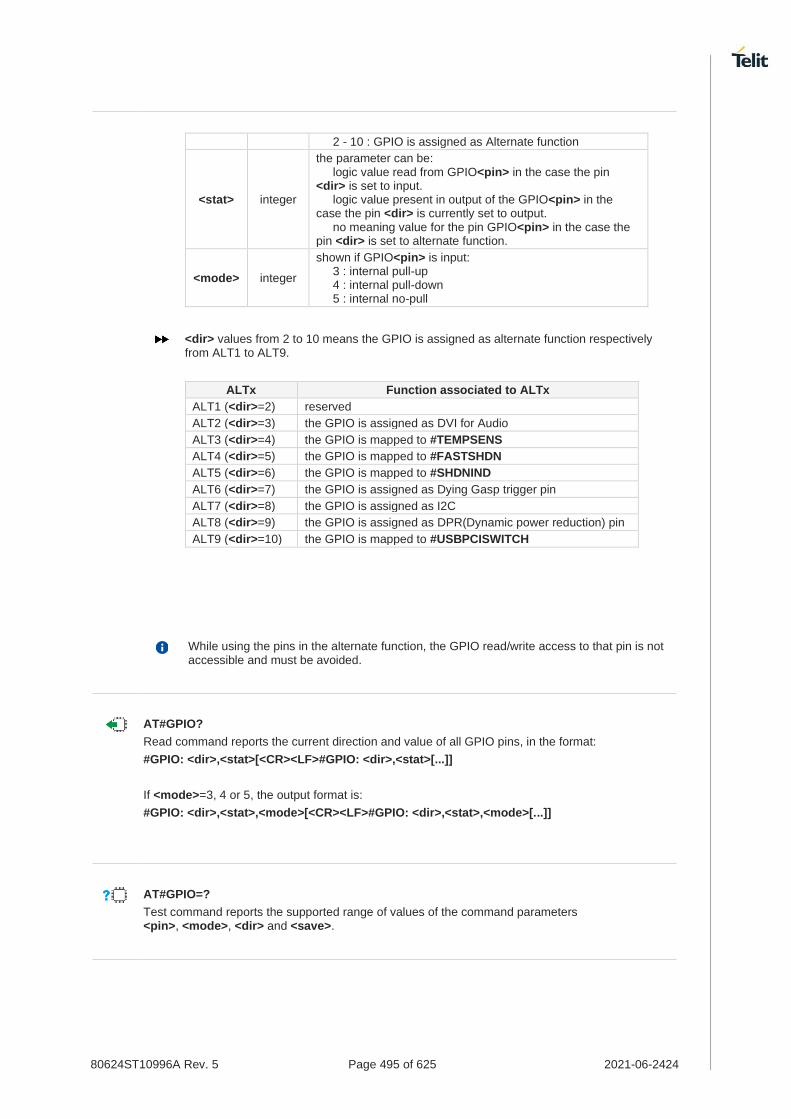
80624ST10996A Rev. 5 Page 495 of 625 2021-06-2424
2 - 10 : GPIO is assigned as Alternate function
<stat> integer
the parameter can be:
logic value read from GPIO<pin> in the case the pin <dir> is set to input. logic value present in output of the GPIO<pin> in the case the pin <dir> is currently set to output.
no meaning value for the pin GPIO<pin> in the case the pin <dir> is set to alternate function.
<mode> integer
shown if GPIO<pin> is input:
3 : internal pull-up 4 : internal pull-down 5 : internal no-pull
<dir> values from 2 to 10 means the GPIO is assigned as alternate function respectively from ALT1 to ALT9.
ALTx Function associated to ALTx
ALT1 (<dir>=2) reserved
ALT2 (<dir>=3) the GPIO is assigned as DVI for Audio
ALT3 (<dir>=4) the GPIO is mapped to #TEMPSENS
ALT4 (<dir>=5) the GPIO is mapped to #FASTSHDN
ALT5 (<dir>=6) the GPIO is mapped to #SHDNIND
ALT6 (<dir>=7) the GPIO is assigned as Dying Gasp trigger pin
ALT7 (<dir>=8) the GPIO is assigned as I2C
ALT8 (<dir>=9) the GPIO is assigned as DPR(Dynamic power reduction) pin
ALT9 (<dir>=10) the GPIO is mapped to #USBPCISWITCH
While using the pins in the alternate function, the GPIO read/write access to that pin is not accessible and must be avoided.
AT#GPIO?
Read command reports the current direction and value of all GPIO pins, in the format:
#GPIO: <dir>,<stat>[<CR><LF>#GPIO: <dir>,<stat>[...]]
If <mode>=3, 4 or 5, the output format is:
#GPIO: <dir>,<stat>,<mode>[<CR><LF>#GPIO: <dir>,<stat>,<mode>[...]]
AT#GPIO=?
Test command reports the supported range of values of the command parameters <pin>, <mode>, <dir> and <save>.

80624ST10996A Rev. 5 Page 496 of 625 2021-06-2424
Check the available values ranges AT#GPIO=? #GPIO: (1-6),(0-5),(0-1),(0,1)
OK
Set GPIO_03 as output, and set logical value HIGH AT#GPIO=3,1,1 OK
Set GPIO_04 as output, value HIGH a save setting AT#GPIO=4,1,1,1 OK
Report GPIO_03 state AT#GPIO=3,2 #GPIO: 1,1
OK
Read command AT#GPIO? #GPIO: 1,1 // GPIO_01 is output, value is HIGH #GPIO: 0,0,4 // GPIO_02 is input with internal pull down #GPIO: 1,1 #GPIO: 0,0,4 #GPIO: 0,1,3 // GPIO_05 is input with internal pull up, value is HIGH #GPIO: 1,0 // GPIO_06 is output, value is LOW
OK

80624ST10996A Rev. 5 Page 497 of 625 2021-06-2424
3.12.7. AT#WWANLED - WWLAN_LED GPIO Setting
This command is used to set GPIO for WWLAN LED.
SIM Presence Setting saved Can be aborted MAX timeout SELINT
Not required Auto No - 2
AT#WWANLED=<mode>,<status>[,<on_duration>[,<off_duration>]]
Set command sets the behavior of the WWLAN_LED GPIO.
Parameters:
Name Type Default Description
<mode> integer N/A Modem status desired WWLAN_LED blink.
Values:
0 : Low power mode
1 : Offline
2 : No service
3 : In Service, Roaming
4 : Data Active
<status> integer 0 On/Off WWLAN_LED blink pattern for selected <mode>.
Values:
0 : Off mode
1 : On mode
<on_duration> integer 0 The duration of period in which WWLAN_LED signal is tied to Low for selected <mode>
Value:
0÷100 : In tenth of seconds
<off_duration> integer 0 The duration of period in which WWLAN_LED signal is tied to High for selected <mode>.
Value:
0÷100 : In tenth of seconds
The value of 0 means "deactivate" in the <on_duration> and <off_duration>. Therefore, the value 0 can be used for this LED always on/off.
The following table shows factory default setting
Low Power Mode OFF - Dark
Offline OFF - Dark
No Service OFF - Dark
In Service OFF - Dark
Data Active OFF - Dark
Roaming : Blinking ON 5s, OFF 200ms.

80624ST10996A Rev. 5 Page 498 of 625 2021-06-2424
The blink pattern of roaming is fixed and it cannot be modified. However, the roaming status also set to disabled as a factory default setting and it will be activated when "In Service" mode's status is on.
Current consumption could increase depends on LED scenario.
AT#WWANLED?
Read command returns the WWLAN_LED GPIO current setting, in the format:
#WWANLED:<mode0>,<status0>,<on_duration0>,<off_duration0><CR><LF> ... #WWANLED:<mode4>,<status4>,<on_duration4>,<off_duration4>
AT#WWANLED=?
Test command reports the supported range of values for parameters <mode>,<status>,<on_duration> and <off_duration>.
AT#WWANLED=0,0,0,0
OK
: Set always off the LED when low power mode
AT#WWANLED=2,1,1,0
OK
: Set always on the LED when no service mode
AT#WWANLED=3,1,10,10
OK
: Set Blinking the LED when in service mode

80624ST10996A Rev. 5 Page 499 of 625 2021-06-2424
3.12.8. AT#I2CWR - Write to I2C
This command is used to send data to an I2C peripheral connected to module.
[1] Hardware User's Guide of the used module
SIM Presence Setting saved Can be aborted MAX timeout SELINT
Not required No No - 2
AT#I2CWR=<sdaPin>,<sclPin>,<deviceId>,<registerId>,<len>
Execution command sends data to an I2C peripheral connected to module GPIOs. After the writing activity has been accomplished, the GPIOs will not be restored to the original setting. Use #GPIO command to see the status of the used GPIOs. To have information on GPIO pins refer to document [1].
Parameters:
Name Type Default Description
<sdaPin> integer - GPIO number for SDA. To know the range use #I2CWR test command.
<sclPin> integer - GPIO number for SCL. To know the range use #I2CWR test command.
<deviceId> hex N/A address of the I2C device (7 bits). The Least Significant Bit is used for read/write command, it doesn't matter if the LSB is set to 0 or 1.
Address must be written in hexadecimal form without 0x.
Value:
0÷3FF : addressing range extended to 10 bit
<registerId> hex N/A register to write data to
Value:
0÷FF : value must be written in hexadecimal form without 0x
<len> integer N/A number of data to send
Value:
1÷254 : number of data to send
Additional info:
After entering the command, the module returns the prompt ">" and waits for the data to send. To complete the operation, send Ctrl-Z char (0x1A hex); to exit without writing the message send ESC char (0x1B hex). Data must be written in hexadecimal form.
If data are successfully sent, the response is OK, otherwise an error code is reported.

80624ST10996A Rev. 5 Page 500 of 625 2021-06-2424
AT#I2CWR=?
Test command returns the range of available values for parameters <sdaPin>, <sclPin>, <deviceId>, <registerId>, <len>.
Set GPIO_9 as SDA, and GPIO_10 as SCL. Device I2C address is 0x20; 0x10 is the address of the first register where to write I2C data; 14 data bytes will be written starting from register 0x10.
AT#I2CWR=9,10,20,10,14 > 00112233445566778899AABBCCDD<ctrl-z> OK

80624ST10996A Rev. 5 Page 501 of 625 2021-06-2424
3.12.9. AT#I2CRD - Read from I2C
This command is used to read data from an I2C peripheral connected to module.
[1] Hardware User's Guide of the used module
SIM Presence Setting saved Can be aborted MAX timeout SELINT
Not required No No - 2
AT#I2CRD=<sdaPin>,<sclPin>,<deviceId>,<registerId>,<len>
Execution command reads data from an I2C peripheral connected to module GPIOs. After the reading activity has been accomplished, the GPIOs will not be restored to the original setting. Use #GPIO command to see the status of the used GPIOs. To have information on GPIO pins refer to document [1].
Parameters:
Name Type Default Description
<sdaPin> integer - GPIO number for SDA. To know the range use #I2CRD test command.
<sclPin> integer - GPIO number for SCL. To know the range use #I2CRD test command.
<deviceId> hex N/A address of the I2C device (7 bits). The Least Significant Bit is used for read/write command, it doesn't matter if the LSB is set to 0 or 1.
Address must be written in hexadecimal form without 0x.
Value:
0÷3FF : addressing range extended to 10 bit
<registerId> hex N/A Register to read data from
Value:
0÷FE : value must be written in hexadecimal form without 0x
<len> integer N/A Number of data to receive
- Data Read from I2C will be dumped in hexadecimal format
- If data requested are more than data available in the device, dummy data (normally 0x00 or 0xff) will be dumped
Value:
1÷254 : number of data to receive
AT#I2CRD=?
Test command returns the range of available values for parameters <sdaPin>, <sclPin>, <deviceId>, <registerId>, <len>.

80624ST10996A Rev. 5 Page 502 of 625 2021-06-2424
Read 12 bytes from I2C device with address 0x20, starting from register address 0x10. SDA is mapped on GPIO_9, SCL is mapped on GPIO_10.
AT#I2CRD=9,10,20,10,12 #I2CRD: 00112233445566778899AABBCC OK

80624ST10996A Rev. 5 Page 503 of 625 2021-06-2424
3.12.10. AT#RXDIV - Enable RX Diversity and Set DARP
This command enables the RX Diversity and sets DARP.
SIM Presence Setting saved Can be aborted MAX timeout SELINT
Not required Auto No - 2
AT#RXDIV=<DIV_enable>[,<DARP_mode>]
Set command enables/disables the RX Diversity and sets DARP.
Parameters:
Name Type Default Description
<DIV_enable> integer 1 enable/disable the RX Diversity
Values:
0 : disable
1 : enable
<DARP_mode> integer 0 select DARP mode
Values:
0 : DARP not supported
1 : DARP phase 1
The values set by command are available at next power-on.
The values set by command are directly stored in NVM.
The FN980m module does NOT support GSM tech, so DARP mode is not support.
Case of #RXTOGGLE already set "1", #RXDIV don't set "1" (Error return).
AT#RXDIV?
Read command reports the currently selected <DIV_enable> and <DARP_mode> parameters in the format: #RXDIV: <DIV_enable>,<DARP_mode>
AT#RXDIV=?
Test command reports the supported values of parameters <DIV_enable> and <DARP_mode>.

80624ST10996A Rev. 5 Page 504 of 625 2021-06-2424
3.12.11. AT#LRXDIV - Enable LTE RX Diversity
This command enables LTE RX Diversity and moves the LTE-RX receiver.
SIM Presence Setting saved Can be aborted MAX timeout SELINT
Not required Auto No - 2
AT#LRXDIV=<Ldiv_enable>
Set command enables/disables the LTE RX Diversity and sets moves the LTE-RX receiver from the main antenna to the diversity antenna.
Parameter:
Name Type Default Description
<Ldiv_enable> integer 1 enable/disable the specific antenna for LTE Rx diversity
Values:
0 : enables the only Rx0 antenna. (Only use Rx0)
1 : enables the ALL LTE Rx. (Factory default)
2 : enables the only Rx1 antenna. (only use Rx1)
3 : enables the only Rx2 antenna. (only use Rx2)
4 : enables the only Rx3 antenna. (only use Rx3)
Additional info:
10. RX0 (Main Antenna is PRI0 or PRI1), 11. RX1 (Diversity Antenna is DIV0 or DIV1) 12. RX2, RX3 (LTE band 2,4,25,41,66 support)
13. Antenna of PRI1 and DIV1 using the LTE B7, 30, 32, 38, 40, 41, 42, 43, 46, 48 14. 4 RX support band: LTE B2, 4, 25, 41, 66
#LRXDIV=0 #LRXDIV=1 #LRXDIV=2 #LRXDIV=3 #LRXDIV=4
RX0 Enable Enable Disable Disable Disable
RX1 Disable Enable Enable Disable Disable
RX2 Disable Enable Disable Enable Disable
RX3 Disable Enable Disable Disable Enable
TX Enable Enable Enable Enable Enable
15. #LRXDIV = 0: Use RX0 for TX and only RX0 enables for RX 16. #LRXDIV = 1: Use RX0 for TX and all RX paths enable for RX 17. #LRXDIV = 2: Use RX0 for only TX and only RX1 enables for RX 18. #LRXDIV = 3: Use RX0 for only TX and only RX2 enables for RX 19. #LRXDIV = 4: Use RX0 for only TX and only RX3 enables for RX

80624ST10996A Rev. 5 Page 505 of 625 2021-06-2424
The value set by command operate both real time and power cycle.
For switch back all enable rx path, modem should reboot.
This command only have to use for the purpose of test.
Ensure that the call is connected and that all chains are running before triggering any of commands.
AT#LRXDIV?
Read command reports the currently selected <Ldiv_enable> parameters in the format:
#LRXDIV: <Ldiv_enable>
AT#LRXDIV=?
Test command reports the supported range of values for parameter <Ldiv_enable>.
For real time operation:
AT#LRXDIV?
#LRXDIV: 1 (RX0, RX1, RX2 and RX3 enable)
AT#LRXDIV=0 (RX0 enable only)
AT#LRXDIV=2 (RX1 enable only)
AT#LRXDIV=3 (RX2 enable only)
AT#LRXDIV=4 (RX3 enable only)
AT#LRXDIV=1 (Set to RX0, RX1, RX2 and RX3 enable)
AT#REBOOT (for RX0, RX1, RX2 and RX3 enable)
After rebooting, operation
AT#LRXDIV?
#LRXDIV: 1 (RX0, RX1, RX2 and RX3 enable)

80624ST10996A Rev. 5 Page 506 of 625 2021-06-2424
3.12.12. AT#TEMPSENS - Temperature Monitor
This command used to set an operation of the module temperature monitor.
SIM Presence Setting saved Can be aborted MAX timeout SELINT
Not required No No - 2
AT#TEMPSENS=<mod>[,<interval>[,<action>,<low_temp>,<high_temp>[,<gpio>]]]
Set command sets the operation of the module temperature monitor.
Parameters:
Name Type Default Description
<mod> integer 0 temperature monitor mode
Values:
0 : disables the periodic reporting
1 : enables the periodic reporting
2 : instantaneous reporting of the module temperature
<interval> integer 0 duration in seconds of the interval between next measurement. It has meaning only if <mod> is 1.
Value:
1÷60 : measurement interval in seconds
<action> integer N/A bit 0 - it enables the presentation of the temperature monitor URC periodically. Default value if <action> is not specified.
bit 1 - it enables the presentation of the temperature notification URC, whenever the module internal temperature reaches either <low_temp> or <high_temp> levels.
bit 2 - Output pin <gpio> is tied HIGH when set temperature bounds are reached; when the temperature is back to normal the output pin <gpio> is tied LOW. It is mandatory to set the <gpio> parameter too to set this <action>.
Value:
1÷7 : bit calculation of actions
<low_temp> integer N/A temperature lower bound in Celsius Degrees.
Value:
40÷0 : temperature lower bound in Celsius Degrees
<high_temp> integer N/A temperature upper bound in Celsius Degrees
Value:
0÷100 : temperature upper bound in Celsius Degrees
<gpio> integer - GPIO number. Use test command to know available range. This parameter is required only if <action>=4, 5, 6 or 7.
Additional info:

80624ST10996A Rev. 5 Page 507 of 625 2021-06-2424
when <mode>=2, the unsolicited message is in the format:
#TEMPSENS: <sensor>,<value>
where:
<sensor> - temperature sensor name
<value> - actual temperature expressed in Celsius degrees
the notification message is in the format:
#TEMPNOTI: <level>,<value>
where:
<level> - threshold level
-1 - module temperature is under <low_temp>
0 - normal temperature
1 - module temperature is upper <high_temp>
<low_temp> and <high_temp> values are TSENS criteria.
The module cannot enter sleep while <mod>=1.
AT#TEMPSENS?
Read command reports the current parameter settings in the format:
#TEMPSENS: <mod>,<interval>[,<action>,<low_temp>,<high_temp>,[<gpio>]]
AT#TEMPSENS=?
Test command reports supported range of values for parameters <mod>,<interval>,<action>,<low_temp>,<high_temp> and <gpio>.
• AT#TEMPSENS=2 #TEMPSENS: TSENS3,37 #TEMPSENS: PA_THERM1,33
OK

80624ST10996A Rev. 5 Page 508 of 625 2021-06-2424
3.12.13. AT#TMLVL - Thermal Mitigation Level
Report Thermal Mitigation Level
SIM Presence Setting saved Can be aborted MAX timeout SELINT
Not required No No - 2
AT#TMLVL=<device_id>
Reports a current thermal mitigation level of specific <device_id>.
Parameter:
Name Type Default Description
<device_id> integer N/A Device to get level of mitigation.
The report message is in the format:
#TMLVL: <level>
Where:
<level> - thermal mitigation level
0 - normal
1 - level1
2 - level2
3 - level3
Values:
1 : Thermal mitigation device MODEM
2 : Thermal mitigation device PA
3 : Thermal mitigation device PA_FR1
4 : Thermal mitigation device MMW0
AT#TMLVL?
Reports a current thermal mitigation level of all devices in the format:
#TMLVL: MODEM,<level> #TMLVL: PA,<level> #TMLVL: PA_FR1,<level> #TMLVL: MMW0,<level>
OK
AT#TMLVL=?
Returns the supported range of values for parameter <device_id>.

80624ST10996A Rev. 5 Page 509 of 625 2021-06-2424
Examples for set and read sections.
• AT#TMLVL=2 #TMLVL: 1
OK
• AT#TMLVL? #TMLVL: MODEM,1 #TMLVL: PA,1
OK

80624ST10996A Rev. 5 Page 510 of 625 2021-06-2424
3.12.14. AT#CAINFO - Show LTE CA Information
This command indicates the LTE and NR carrier aggregation information of PCC and SCC
SIM Presence Setting saved Can be aborted MAX timeout SELINT
Not required No No - 2
AT#CAINFO?
Read command extract carrier aggregation information for PCC and SCC which includes LTE/NR related information.
Additional info:
<On 2CA: PCC + SCC>
#CAINFO: <band_class>,<rx_channel>,<dl_bw>,<pci>,<rsrp>,<rssi>,<rsrq>,<sinr>,<tac>,<tx_power>,<uplink_modulation>,<downlink_modulation>,<band_class>,<rx_channel>,<dl_bw>,<pci>,<rsrp>,<rssi>,<rsrq>,<sinr>,<state>,<uplink_modulation>,<downlink_modulation>
<On 2CA: PCC + ENDC>
#CAINFO: <band_class>,<rx_channel>,<dl_bw>,<pci>,<rsrp>,<rssi>,<rsrq>,<sinr>,<tac>,<tx_power>,<uplink_modulation>,<downlink_modulation>
ENDC: <nr_band>,<nr_bandwidth>,<nr_ul_bandwidth>,<nr_channel>,<nr_ul_channel>,<nr_rssi>,<nr_rsrp>,<nr_rsrq>,<nr_pci>,<nr_sinr>,<nr_state>,<nr_txpwr>,<nr_dl_mod>,<nr_ul_mod>
<On 3CA: PCC + SCC + SCC>
#CAINFO: <band_class>,<rx_channel>,<dl_bw>,<pci>,<rsrp>,<rssi>,<rsrq>,<sinr>,<tac>,<tx_power>,<uplink_modulation>,<downlink_modulation>,<band_class>,<rx_channel>,<dl_bw>,<pci>,<rsrp>,<rssi>,<rsrq>,<sinr>,<state>,<uplink_modulation>,<downlink_modulation>,<band_class>,<rx_channel>,<dl_bw>,<pci>,<rsrp>,<rssi>,<rsrq>,<sinr>,<state>,<uplink_modulation>,<downlink_modulation>
<On 3CA: PCC + SCC + ENDC>
#CAINFO: <band_class>,<rx_channel>,<dl_bw>,<pci>,<rsrp>,<rssi>,<rsrq>,<sinr>,<tac>,<tx_power>,<uplink_modulation>,<downlink_modulation>,<band_class>,<rx_channel>,<dl_bw>,<pci>,<rsrp>,<rssi>,<rsrq>,<sinr>,<state>,<uplink_modulation>,<downlink_modulation>
ENDC: <nr_band>,<nr_bandwidth>,<nr_ul_bandwidth>,<nr_channel>,<nr_ul_channel>,<nr_rssi>,<nr_rsrp>,<nr_rsrq>,<nr_pci>,<nr_sinr>,<nr_state>,<nr_txpwr>,<nr_dl_mod>,<nr_ul_mod>
<On 4CA: PCC + SCC + SCC + SCC>
#CAINFO: <band_class>,<rx_channel>,<dl_bw>,<pci>,<rsrp>,<rssi>,<rsrq>,<sinr>,<tac>,<tx_power>,<uplink_modulation>,<downlink_modulation>,<band_class>,<rx_channel>,<dl_bw>,<pci>,<rsrp>,<rssi>,<rsrq>,<sinr>,<state>,<uplink_modulation>,<downlink_modulation>,<band_class>,<rx_channel>,<dl_bw>,<pci>,<rsrp>,<rssi>,<rsrq>,<sinr>,<state>,<uplink_modulation>,<downlink_modulation>,<band_class>,<rx_channel>,<dl_bw>,<pci>,<rsrp>,<rssi>,<rsrq>,<sinr>,<state>,<uplink_modulation>,<downlink_modulation>

80624ST10996A Rev. 5 Page 511 of 625 2021-06-2424
<On 4CA: PCC + SCC + SCC + ENDC>
#CAINFO: <band_class>,<rx_channel>,<dl_bw>,<pci>,<rsrp>,<rssi>,<rsrq>,<sinr>,<tac>,<tx_power>,<uplink_modulation>,<downlink_modulation>,<band_class>,<rx_channel>,<dl_bw>,<pci>,<rsrp>,<rssi>,<rsrq>,<sinr>,<state>,<uplink_modulation>,<downlink_modulation>,<band_class>,<rx_channel>,<dl_bw>,<pci>,<rsrp>,<rssi>,<rsrq>,<sinr>,<state>,<uplink_modulation>,<downlink_modulation>
ENDC: <nr_band>,<nr_bandwidth>,<nr_ul_bandwidth>,<nr_channel>,<nr_ul_channel>,<nr_rssi>,<nr_rsrp>,<nr_rsrq>,<nr_pci>,<nr_sinr>,<nr_state>,<nr_txpwr>,<nr_dl_mod>,<nr_ul_mod>
<On 5CA: PCC + SCC + SCC + SCC + SCC>
#CAINFO: <band_class>,<rx_channel>,<dl_bw>,<pci>,<rsrp>,<rssi>,<rsrq>,<sinr>,<tac>,<tx_power>,<uplink_modulation>,<downlink_modulation>,<band_class>,<rx_channel>,<dl_bw>,<pci>,<rsrp>,<rssi>,<rsrq>,<sinr>,<state>,<uplink_modulation>,<downlink_modulation>,<band_class>,<rx_channel>,<dl_bw>,<pci>,<rsrp>,<rssi>,<rsrq>,<sinr>,<state>,<uplink_modulation>,<downlink_modulation>,<band_class>,<rx_channel>,<dl_bw>,<pci>,<rsrp>,<rssi>,<rsrq>,<sinr>,<state>,<uplink_modulation>,<downlink_modulation>,<band_class>,<rx_channel>,<dl_bw>,<pci>,<rsrp>,<rssi>,<rsrq>,<sinr>,<state>,<uplink_modulation>,<downlink_modulation>
<On 5CA: PCC + SCC + SCC + SCC + ENDC>
#CAINFO: <band_class>,<rx_channel>,<dl_bw>,<pci>,<rsrp>,<rssi>,<rsrq>,<sinr>,<tac>,<tx_power>,<uplink_modulation>,<downlink_modulation>,<band_class>,<rx_channel>,<dl_bw>,<pci>,<rsrp>,<rssi>,<rsrq>,<sinr>,<state>,<uplink_modulation>,<downlink_modulation>,<band_class>,<rx_channel>,<dl_bw>,<pci>,<rsrp>,<rssi>,<rsrq>,<sinr>,<state>,<uplink_modulation>,<downlink_modulation>,<band_class>,<rx_channel>,<dl_bw>,<pci>,<rsrp>,<rssi>,<rsrq>,<sinr>,<state>,<uplink_modulation>,<downlink_modulation>
ENDC: <nr_band>,<nr_bandwidth>,<nr_ul_bandwidth>,<nr_channel>,<nr_ul_channel>,<nr_rssi>,<nr_rsrp>,<nr_rsrq>,<nr_pci>,<nr_sinr>,<nr_state>,<nr_txpwr>,<nr_dl_mod>,<nr_ul_mod>
<On 6CA: PCC + SCC + SCC + SCC + SCC + SCC>
#CAINFO: <band_class>,<rx_channel>,<dl_bw>,<pci>,<rsrp>,<rssi>,<rsrq>,<sinr>,<tac>,<tx_power>,<uplink_modulation>,<downlink_modulation>,<band_class>,<rx_channel>,<dl_bw>,<pci>,<rsrp>,<rssi>,<rsrq>,<sinr>,<state>,<uplink_modulation>,<downlink_modulation>,<band_class>,<rx_channel>,<dl_bw>,<pci>,<rsrp>,<rssi>,<rsrq>,<sinr>,<state>,<uplink_modulation>,<downlink_modulation>,<band_class>,<rx_channel>,<dl_bw>,<pci>,<rsrp>,<rssi>,<rsrq>,<sinr>,<state>,<uplink_modulation>,<downlink_modulation>,<band_class>,<rx_channel>,<dl_bw>,<pci>,<rsrp>,<rssi>,<rsrq>,<sinr>,<state>,<uplink_modulation>,<downlink_modulation>,<band_class>,<rx_channel>,<dl_bw>,<pci>,<rsrp>,<rssi>,<rsrq>,<sinr>,<state>,<uplink_modulation>,<downlink_modulation>
<On 6CA: PCC + SCC + SCC + SCC + SCC + ENDC>
#CAINFO: <band_class>,<rx_channel>,<dl_bw>,<pci>,<rsrp>,<rssi>,<rsrq>,<sinr>,<tac>,<tx_power>,<uplink_modulation>,<downlink_modulation>,<band_class>,<rx_channel>,<dl_bw>,<pci>,<rsrp>,<rssi>,<rsrq>,<sinr>,<state>,<uplink_modulation>,<downlink_modulation>,<band_class>,<rx_channel>,<dl_bw>,<pci>,<rsrp>,<rssi>,<rsrq>,<sinr>,<state>,<uplink_modulation>,<downlink_modulation>,<band_class>,<rx_channel>,<dl_bw>,<pci>,<rsrp>,<rssi>,<rsrq>,<sinr>,<state>,<uplink_modulation>,<downlink_modulation>,<band_class>,<rx_channel>,<dl_bw>,<pci>,<rsrp>,<rssi>,<rsrq>,<sinr>,<state>,<uplink_modulation>,<downlink_modulation>
ENDC: <nr_band>,<nr_bandwidth>,<nr_ul_bandwidth>,<nr_channel>,<nr_ul_channel>,<nr_rssi>,<nr_rsrp>,<nr_rsrq>,<nr_pci>,<nr_sinr>,<nr_state>,<nr_txpwr>,<nr_dl_mod>,<nr_ul_mod>

80624ST10996A Rev. 5 Page 512 of 625 2021-06-2424
<On 7CA: PCC + SCC + SCC + SCC + SCC + SCC + SCC>
#CAINFO: <band_class>,<rx_channel>,<dl_bw>,<pci>,<rsrp>,<rssi>,<rsrq>,<sinr>,<tac>,<tx_power>,<uplink_modulation>,<downlink_modulation>,<band_class>,<rx_channel>,<dl_bw>,<pci>,<rsrp>,<rssi>,<rsrq>,<sinr>,<state>,<uplink_modulation>,<downlink_modulation>,<band_class>,<rx_channel>,<dl_bw>,<pci>,<rsrp>,<rssi>,<rsrq>,<sinr>,<state>,<uplink_modulation>,<downlink_modulation>,<band_class>,<rx_channel>,<dl_bw>,<pci>,<rsrp>,<rssi>,<rsrq>,<sinr>,<state>,<uplink_modulation>,<downlink_modulation>,<band_class>,<rx_channel>,<dl_bw>,<pci>,<rsrp>,<rssi>,<rsrq>,<sinr>,<state>,<uplink_modulation>,<downlink_modulation>,<band_class>,<rx_channel>,<dl_bw>,<pci>,<rsrp>,<rssi>,<rsrq>,<sinr>,<state>,<uplink_modulation>,<downlink_modulation>,<band_class>,<rx_channel>,<dl_bw>,<pci>,<rsrp>,<rssi>,<rsrq>,<sinr>,<state>,<uplink_modulation>,<downlink_modulation>
Name Type Default Description
<band_class> integer N/A LTE band class
Values:
120 : BAND 1
121 : BAND 2
122 : BAND 3
123 : BAND 4
124 : BAND 5
125 : BAND 6
126 : BAND 7
127 : BAND 8
128 : BAND 9
129 : BAND 10
130 : BAND 11
131 : BAND 12
132 : BAND 13
133 : BAND 14
134 : BAND 17
135 : BAND 33
136 : BAND 34
137 : BAND 35
138 : BAND 36
139 : BAND 37
140 : BAND 38
141 : BAND 39
142 : BAND 40
143 : BAND 18
144 : BAND 19
145 : BAND 20

80624ST10996A Rev. 5 Page 513 of 625 2021-06-2424
146 : BAND 21
147 : BAND 24
148 : BAND 25
149 : BAND 41
150 : BAND 42
151 : BAND 43
152 : BAND 23
153 : BAND 26
154 : BAND 32
155 : BAND 125
156 : BAND 126
157 : BAND 127
158 : BAND 28
159 : BAND 29
160 : BAND 30
161 : BAND 66
162 : BAND 250
163 : BAND 46
166 : BAND 71
167 : BAND 47
168 : BAND 48
<rx_channel> integer N/A E-UTRA absolute radio frequency channel number of the serving cell
Value:
0÷68935 : Channel
<dl_bw> integer N/A Bandwidth
Values:
0 : 1.4 MHz bandwidth
1 : 3 MHz bandwidth
2 : 5 MHz bandwidth
3 : 10 MHz bandwidth
4 : 15 MHz bandwidth
5 : 20 MHz bandwidth
<pci> integer N/A Physical Cell Id
Value:
0÷503 : Cell ID
<rsrp> string N/A Current RSRP
Value:

80624ST10996A Rev. 5 Page 514 of 625 2021-06-2424
44÷140 : dbm
<rssi> string N/A Current RSSI
Value:
0÷120 : dbm
<rsrq> string N/A Current RSRQ
Value:
3÷20 : dbm
<sinr> string N/A Measured SINR. This value is mapped to dB.
0 = -20dB
1 = -19.8dB
...
249 = 29.8dB
250 = 30dB
Value:
0÷250 : SINR
<tac> string - Tracking area code information for LTE
<tx_power> string N/A Current uplink TX power. The tx_power value is only meaningful when the device is in traffic. When there is no traffic, tx_power is "0".
Value:
50÷33 : When there is no traffic, tx_power is "0"
<state> integer N/A Current SCC state
Values:
0 : INIT
1 : CONFIGURED
2 : ACTIVE
<uplink_modulation> integer N/A Uplink Modulation
Values:
0 : BPSK
1 : QPSK
2 : 16QAM
3 : 64QAM
4 : 256QAM
5 : UNKOWN
<downlink_modulation> integer N/A Downlink Modulation
Values:
0 : BPSK

80624ST10996A Rev. 5 Page 515 of 625 2021-06-2424
1 : QPSK
2 : 16QAM
3 : 64QAM
4 : 256QAM
5 : UNKOWN
<nr_band> integer - NR active band.
<nr_bandwidth> integer - NR DL bandwidth.
<nr_ul_bandwidth> integer - NR UL bandwidth.
<nr_channel> integer - NR DL active channel.
<nr_ul_channel> integer - NR UL active channel.
<nr_rssi> integer - NR received signal strength in dBm.
<nr_rsrp> integer - NR Reference Signal Received Power.
<nr_rsrq> integer - NR Reference Signal Received Quality.
<nr_pci> integer - NR physical cell id.
<nr_sinr> integer - NR measured SINR.
<nr_state> integer N/A NR state.
Values:
0 : Init
1 : Configured
2 : Active
<nr_txpwr> integer - NR Tx Power (In traffic only).
<nr_dlmod> integer N/A NR Downlink modulation.
Values:
0 : BPSK
1 : QPSK
2 : 16QAM
3 : 64QAM
4 : 256QAM
5 : Unknown
<nr_ulmod> integer N/A NR Uplink modulation.
Values:
0 : BPSK
1 : QPSK
2 : 16QAM
3 : 64QAM
4 : 256QAM
5 : Unknown

80624ST10996A Rev. 5 Page 516 of 625 2021-06-2424
The first block from <band_class> to <downlink_modulation> is PCC information. The next information block which are from <band_class> to <downlink_modulation> is information of SCC. Additional SCC information could add in the rear of first SCC. If the LTE information of SCC is not valid, it always returns 0. If it acquires the UMTS or GSM technology, this command will display "ERROR".
The first block from <nr_band> to <nr_ul_mod> is ENDC information. The next information block which are from <nr_band> to <nr_ul_mod> is information of second ENDC information. Additional ENDC information could add in the rear of first ENDC. If the ENDC information is not valid, it always returns 0. If it acquires the UMTS or GSM technology, this command will display "ERROR".
The FN980m module can support 7CA with only LTE cells. If there are NR cells in carrier aggregation (ENDC), it supports maximum 6CA with one NR cell.
The <nr_txpwr>,<nr_dl_mod> and <nr_ul_mod> of NR information is still unimplemented they always report 0.
AT#CAINFO=?
Test command returns OK

80624ST10996A Rev. 5 Page 517 of 625 2021-06-2424
3.12.15. AT#TESTMODE - Test Mode Configuration
Set module in test mode for configuring and testing the POWER level.
SIM Presence Setting saved Can be aborted MAX timeout SELINT
Not required Auto No - 2
AT#TESTMODE=<cmd>
The command allows setting module in not signaling mode. The functionality has to be first activated by sending AT#TESTMODE="TM" and AT#TESTMODE="INIT4G" , which set the module in Test Mode. Only after this set, AT#TESTMODE can be used with the other allowed commands. To exit from Test Mode and go back to Operative Mode, the command AT#TESTMODE="OM" must be sent.
Parameters:
Name Type Default Description
<cmd> string N/A Current command as quoted string in the format: "<cmd>"
Values:
"TM" : Forces the module in Test Mode.
"OM" : Forces the module in Operative Mode.
"TCH" : Starts the non-stop module transmission.
"ESC" : Exits the current non-stop sequence (stop TX transmission) and disable RX chain.
<cmd> string N/A Current command as quoted string in the format: "<cmd>"
4G commands
Values:
"SETLTEBAND" : Sets the LTE band
"LTXBW" : Sets TX bandwidth (Default: 10MHz)
"LRXBW" : Sets RX bandwidth (Default: 10MHz)
"CH" : Sets the EUARFCN
"LTXWAVEFORM" : Sets the WAVEFORM transmission
"LPASTATE" : Sets the PA STATE to high gain state
"LPABIASSET" : Sets the PA BIAS
"LTXGAIN" : Refer to Note 14
"LNA4G" : Sets 4G LNA GAIN STATE
"PRXRL4G" : Reads the 4G RX power level of primary path for selected channel. Refer to Note 16.
"DRXRL4G" : Reads the 4G RX power level of diversity path for selected channel. Refer to Note 16.
"MIMO1RL4G" : Reads the 4G RX power level of MIMO primary path for selected channel. Refer to Note 16.
"MIMO2RL4G" : Reads the 4G RX power level of MIMO diversity path for selected channel. Refer to Note 16.

80624ST10996A Rev. 5 Page 518 of 625 2021-06-2424
"MIMOSET" : Sets for MIMO RX path. Refer to Note 18.
"MIMOTDD" : Sets for MIMO TDD bands. Refer to Note 18.
<cmd> string N/A Current command as quoted string in the format: "<cmd>"
3G commands
Values:
"SETWCDMABAND" : Sets the WCDMA band
"CH" : Sets the UARFCN
"WTXWAVEFORM" : Sets the WAVEFORM transmission
"WPASET" : Sets the PA high gain
"WPABIASSET" : Sets the PA BIAS
"TXPDM " : Sets the value for desired TX power strength. Refer to Note 15
"LNA 3G" : Sets 3G LNA Gain state. <LNA GAIN STATE> value must set 0.
"RL3G" : Provide the 3G Rx power level for selected channel. Refer to the Note 16.
<cmd> string N/A Current command as quoted string in the format: "<cmd>"
GNSS command
Values:
"GNSS" : Start GNSS RF receive path test for L1 Band.
"GNSSL5" : Start GNSS RF receive path test for L5 Band.
<cmd> string N/A Current command as quoted string in the format: "<cmd>"
NR sub 6 commands
Values:
"SETSUB6BAND" : Sets the 5G sub6 band
"FREQ" : Sets the Frequency
"PRXRLSUB6" : Reads the NR sub6 RX power level of primary path for selected frequency. Refer to Note 21.
"DRXRLSUB6" : Reads the NR sub6 RX power level of diversity path for selected frequency. Refer to Note 21.
"MIMO1RLSUB6" : Reads the NR sub6 RX power level of MIMO primary path for selected channel. Refer to Note 21.
"MIMO2RLSUB6" : Reads the NR sub6 RX power level of MIMO diversity path for selected channel. Refer to Note 21.
"MIMOSETSUB6" : Sets for MIMO RX path of NR sub6. Refer to Note 19.
"STXGAIN" : Refer to Note 20.
"SUB6TX1SET" : Refer to Note 20.
"STX1GAIN" : Refer to Note 20.
<cmd> string N/A Current command as quoted string in the format: "<cmd>"
NR mmWave commands

80624ST10996A Rev. 5 Page 519 of 625 2021-06-2424
Values:
"SETMMWBAND" : Sets the 5G mmWave band
"SETMMWBID" : Sets the 5G mmWave beam ID
"SETMMWMBID" : Sets the 5G mmWave beam ID of MIMO
"MMWCH" : Sets the point channel
"MMWTXGAIN" : Refer to Note 22.
"MMWRXCHK" : Reads the NR mmWave RX power level for selected point channel.
"MMWTXOFF" : Release the settings of TX.
"MMWDROP" : Release the whole settings of mmWave for test.
Additional info:
Recommend "CH<EARFCN UL>"
LTE Band EARFCN UL Recommend
1 18000 ~ 18599 18300
2 18600 ~ 19199 18900
3 19200 ~ 19949 19575
4 19950 ~ 20399 20175
5 20400 ~ 20649 20525
7 20750 ~ 21449 21100
8 21450 ~ 21799 21625
12 23010 ~ 23179 23095
13 23180 ~ 23279 23230
14 23280 ~ 23379 23330
17 23730 ~ 23849 23790
18 23850 ~ 23999 23925
19 24000 ~ 24149 24075
20 24150 ~ 24449 24300
25 26040 ~ 26689 26365
26 26690 ~ 27039 26865
28 27210 ~ 27659 27435
29(Rx only) 9660 ~ 9769 9715
30 27660 ~ 27759 27710
32(Rx only) 9920 ~ 10359 10140
34 36200 ~ 36349 36275
38 37750 ~ 38249 38000
39 38250 ~ 38649 38450
40 38650 ~ 39649 39150
41 39650 ~ 41589 40620
42 41590 ~ 43589 42590
43 43590 ~ 45589 46090
46(Rx only) 46790 ~ 54539 50665
48 55240 ~ 59089 55990
66 131972~132671 132322
71 133122~133471 133297
Recommend "TXGAIN_IDX" value
MODEL BAND TXGAIN _IDX TX Power
FN980m
1 57 23dBm
2 61
3 59

80624ST10996A Rev. 5 Page 520 of 625 2021-06-2424
4 59
5 53
7 61
8 53
12 53
13 53
14 53
17 53
18 53
19 53
20 55
25 63
26 53
28 57
29 NA (Rx only)
30 63
32 NA (Rx only)
34 55
38 46
39 61
40 51
41 44
42 59
43 59
46 NA (Rx only)
48 57
66 59
71 56
Recommend "CH <CARFCN>"
Band(3G) UARFCN UL recommend
1 9612 ~ 9888 9750
2 9262 ~ 9538 9400
4 1312 ~ 1513 1413
5 4132 ~ 4233 4183
8 2712 ~ 2863 2788
9 8762 ~ 8912 8837
19 312 ~ 363 338
Recommend "TXPDM" value.
MODEL BAND TXPDM TX POWER
FN980m
1 53 23dBm
2 59
4 61
5 49
8 49
9 63
19 49
Recommend "FREQ <FREQ_DL>"
NR SUB6 Band FREQ DL(kHz) Recommend
1 2110000 ~ 2170000 2140000
2 1930000 ~ 1990000 1960000
3 1805000 ~ 1880000 1842500
5 869000 ~ 894000 881500

80624ST10996A Rev. 5 Page 521 of 625 2021-06-2424
7 2620000 ~ 2690000 2655000
8 925000 ~ 960000 942500
12 729000 ~ 746000 737500
20 791000 ~ 821000 806000
25 1930000 ~ 1995000 1962500
28 758000 ~ 803000 780500
38 2570000 ~ 2620000 2595000
40 2300000 ~ 2400000 2350000
41 2496000 ~ 2690000 2593000
48 3550000 ~ 3700000 3625000
66 2110000 ~ 2200000 2155000
71 617000 ~ 652000 634500
77 3300000 ~ 4200000 3750000
78 3300000 ~ 3800000 3550000
79 4400000 ~ 5000000 4700000
Recommend "STXGAIN <TXGAIN>" and "STX1GAIN <TXGAIN>"
MODEL NR SUB6 Band TXGAIN TX1GAIN
TX POWER
FN980m 1 58 75 23dBm
2 60 72
3 58 68
5 54 54
7 50 60
12 54 NA
20 57 NA
25 67 NA
28 57 NA
38 48 NA
40 53 NA
41 50 NA
48 61 NA
66 62 69
71 56 NA
77 60 60
78 60 60
79 60 70
Recommend "MMWCH <NR-ARFCN>"
NR mmWave Band
NR-ARFCN Recommend
N257 2054167 - 2104165 2086707
N258 2016667 - 2070831 2044541
N260 2229167 - 2279165 2254959
N261 2070833 - 2084999 2078709
Recommend "BID_IDX" and "MBID_IDX" value for QTM525
BAND BID_IDX MBID_IDX Recommend
N257 0 - 63 128 - 191 TBD
N258 0 - 63 128 - 191
N260 0 - 63 128 - 191
N261 0 - 63 128 - 191
Recommend "MMWTXGAIN_IDX" value for QTM525
BAND MMWTXGAIN _IDX TX Power

80624ST10996A Rev. 5 Page 522 of 625 2021-06-2424
N257 210 - 240 21 - 24 dBm
N258 210 - 240
N260 210 - 240
N261 210 - 240
Recommend GNSS test sequence is below :
Check the GNSS Antenna Port type (See AT$GPSANTPORT) in L1 Band case
AT$GPSANTPORT? $GPSANTPORT: 3 OK
For dedicated GNSS connector
- AT$GPSANTPORT=2
For shared Diversity/GNSS connector
- AT$GPSANTPORT=1
Note: After testing, the default value should be restored.
Use either the dedicated GNSS connector or the shared Diversity/GNSS connector.
To test the GNSS receive path:
CW Signal generator setup:
For L1 Band,
Frequency=1575.52 MHz (1575.42 MHz + 100KHz offset)
For L5 Band,
Frequency=1176.55 MHz (1176.45 MHz + 100KHz offset)
CW Level= -110dBm
Test the signal C/No level at the GNSS receiver:
- AT#TESTMODE="TM"
For L1 Band case,
- AT#TESTMODE="GNSS"
- Repeat AT#TESTMODE="GNSS" five to ten times to ensure the measurements are repeatable and stable.
For L5 Band case,
- AT#TESTMODE="GNSSL5"
- Repeat AT#TESTMODE="GNSSL5" five to ten times to ensure the measurements are repeatable and stable.
- AT#TESTMODE="OM"
The response to AT#TESTMODE="GNSS" and AT#TESTMODE="GNSSL5" for a good connection should show C/No within 60dB +/- 5dB and Freq (frequency offset) within 100000 Hz +/- 3150 Hz.
Bands support varies depending on the product
Note 1: This command should be checked individually.
Note 2: FN980m 3G Supported bands - WCDMA 1,2,4,5,8,9,19.
Note 3: FN980m 4G Supported bands - LTE: FDD 1,2,3,4,5,7,8,12,13,14,17,18,19,20,25,26,28,29,30,32,66,71. / TDD 34,38,39,40,41,42,46,48.
Note 4: In Test Mode, the other AT commands don't use.

80624ST10996A Rev. 5 Page 523 of 625 2021-06-2424
Note 5: The Test Mode Status is stored in NVM
Note 6: "TM" command only can set on the Online mode.
Note 7: Must issuing #TESTMODE according to recommended test sequence.
Note 8: In case of "RL3G" command, we only guarantee readable RX -60dBm , because chipset has limitation.
Note 9: In case of "PRXRL4G" and "DRXRL4G" command, we only guarantee readable RX -60dBm , because chipset has limitation.
Note 10: In case of 4G, Signal generator CW(unmodulated) signal must be set Frequency to "Fc + 500kHz"
500kHz offset from center frequency should be set to avoid DC(0 Hz).
Note 11: In case of 3G, Signal generator CW(unmodulated)signal must be set Frequency to "Fc + 200kHz"
200kHz offset from center frequency should be set to avoid DC(0 Hz)
Note 12: After One band check is finished, must set the "ESC" and "OM"
Note 13: After #TESTMODE command process finish, modem must reboot.
Note 14 : TXGAIN_IDX and TX1GAIN_IDX range is around 53~75(FDD) or 44~70(TDD) for 23dBm and some deviation for each module.
Note 15 : TXPDM range is around 38~65 for 23dBm and some deviation for each module.
Note 16 : PRXRL4G, DRXRL4G, MIMO1RL4G, MIMO2RL4G, and RL3G have a difference +/- 5dBm based on input RX power.
Note 17: Customer should consider the UL EARFCN settings base on the BW 10MHz.(Refer to the 3GPP TS 36.508)
Note 18: FN980m 4G MIMO Supported bands - LTE: FDD 1,2,3,4,7,25,30,32,66,71. / TDD 34,38,39,40,41,46.
Note 19: NR Sub6 MIMO Supported bands - N1, N2, N3, N7, N38, N40, N41, N48, N66, N77, N78, N79.
Note 20 : STXGAIN_IDX range is around 45~65 for 23 dBm and some deviation for each module.
Note 21 : PRXRLSUB6, DRXRLSUB6, MIMO1RLSUB6, and MIMO2RLSUB6 have a difference +/- 7dBm based on input RX power.
Note 22 : MTXGAIN_IDX range is around 210~240 for 23dBm and some deviation for each module.
Note 23 : Bandwidth of LTE and NR5G(Sub6, mmWave) is fixed.
LTE bandwidth: 10MHz.
NR5G sub6 bandwidth: 20MHz.
NR5G mmWave bandwidth: 100MHz.
Note 24: In NR5G SUB6 TX case, SETSUB6TXWF range is 0(CW) to 1(PUSCH: Default). In case of CW, signal must be set Frequency to "Fc + 2500kHz"

80624ST10996A Rev. 5 Page 524 of 625 2021-06-2424
Note 25: In NR5G SUB6 RX case, Signal generator CW(unmodulated)signal must be set Frequency to "Fc + 2500kHz"
2500kHz offset from center frequency should be set to avoid DC(0 Hz)
AT#TESTMODE?
Read command reports the currently selected <command> in the format:
#TESTMODE: <testModeStatus>
Additional info:
Parameter meaning:
Name Type Default Description
<testModeStatus> integer 0 status
Values:
0 : module is in Operative Mode
1 : module is in Test Mode
AT#TESTMODE=?
Test command returns the OK result code

80624ST10996A Rev. 5 Page 525 of 625 2021-06-2424
1. Recommend 4G TX test sequence is below :
Spectrum analyzer setup:
Frequency=1747.6MHz
RBW=1MHz
Span=100MHz
Manual Attenuation = 30dB
Ref level Offset = depends on a cable loss
Use the trigger video to fix the measurement
Use the peak search marker
LTE band 3 and set EARFCN = 19575,
LTXGAIN = 39 and TX max power level about +23dBm.
- AT#TESTMODE="TM"
- AT#TESTMODE="SETLTEBAND 3"
- AT#TESTMODE="LTXBW"
- AT#TESTMODE="LRXBW"
- AT#TESTMODE="CH 19575"
- AT#TESTMODE="TCH"
- AT#TESTMODE="LTXWAVEFORM"
- AT#TESTMODE="LPASET"
- AT#TESTMODE="LPABIASSET"
- AT#TESTMODE="LTXGAIN 39"
- AT#TESTMODE="ESC"
- AT#TESTMODE="OM"
- AT#REBOOT
2. Recommend 4G RX test sequence is below :
[FDD LTE Band]
Signal generator setup:
Frequency = 1842.5MHz + 500KHz offset
Level = -60dBm
CW is sent (RF on, MOD off)
Offset = depends on a cable loss
LTE band3 and set EARFCN = 19575,
- AT#TESTMODE="TM"
- AT#TESTMODE="SETLTEBAND 3"
- AT#TESTMODE="LTXBW"
- AT#TESTMODE="LRXBW"
- AT#TESTMODE="CH 19575"
- AT#TESTMODE="LNA4G"
- AT#TESTMODE="PRXRL4G" -> for check primary antenna path.
PRXRL4G: -60 -> Return the 4G RX Level of primary antenna path
- AT#TESTMODE="DRXRL4G" -> for check secondary antenna path.
DRXRL4G: -60 -> Return the 4G RX Level of secondary antenna path
- AT#TESTMODE="MIMOSET"
- AT#TESTMODE="MIMO1RL4G"
MPRXRL4G: -60 -> Return the 4G RX Level of MIMO primary antenna path
- AT#TESTMODE="MIMO2RL4G"
MDRXRL4G: -60 -> Return the 4G RX Level of MIMO secondary antenna path
- AT#TESTMODE="ESC"

80624ST10996A Rev. 5 Page 526 of 625 2021-06-2424
- AT#TESTMODE="OM"
- AT#REBOOT
[TDD LTE BAND]
Signal generator setup:
Frequency = 2595MHz + 500KHz offset
Level = -60dBm
CW is sent (RF on, MOD off)
Offset = depends on a cable loss
LTE band38 and set EARFCN = 38000,
- AT#TESTMODE="TM"
- AT#TESTMODE="SETLTEBAND 38"
- AT#TESTMODE="LTXBW"
- AT#TESTMODE="LRXBW"
- AT#TESTMODE="CH 38000"
- AT#TESTMODE="LNA4G"
- AT#TESTMODE="PRXRL4G" -> for check primary antenna path.
PRXRL4G: -60 -> Return the 4G RX Level of primary antenna path
- AT#TESTMODE="DRXRL4G" -> for check secondary antenna path.
DRXRL4G: -60 -> Return the 4G RX Level of secondary antenna path
- AT#TESTMODE="ESC"
- AT#TESTMODE="MIMOTDD"
- AT#TESTMODE="MIMOSET"
- AT#TESTMODE="MIMO1RL4G"
MPRXRL4G: -60 -> Return the 4G RX Level of MIMO primary antenna path
- AT#TESTMODE="MIMO2RL4G"
MDRXRL4G: -60 -> Return the 4G RX Level of MIMO secondary antenna path
- AT#TESTMODE="ESC"
- AT#TESTMODE="OM"
- AT#REBOOT
3. Recommend 3G TX test sequence is below :
Spectrum analyser setup:
Frequency=1950MHz
RBW=1MHz
Span=100MHz
Manual Attenuation = 30dB
Ref level Offset = depends on a cable loss
Use the trigger video to fix the measurement
Use the peak search marker
3G band 1 and set UARFCN = 9750,
3G TXPDM = 49 and TX max power level about +23dBm.
- AT#TESTMODE="TM"
- AT#TESTMODE="SETWCDMABAND 1"
- AT#TESTMODE="CH 9750"
- AT#TESTMODE="TCH"
- AT#TESTMODE="WTXWAVEFORM"
- AT#TESTMODE="WPASET"
- AT#TESTMODE="WPABIASSET"

80624ST10996A Rev. 5 Page 527 of 625 2021-06-2424
- AT#TESTMODE="TXPDM 49"
- AT#TESTMODE="ESC"
- AT#TESTMODE="OM"
- AT#REBOOT
4. Recommend 3G RX test sequence is below :
Signal generator setup:
Frequency = 2140MHz+200kHz offset
Level = -60dBm
CW is sent (RF on, MOD off)
Offset = depends on a cable loss
3G band 1 and set EARFCN = 9750,
- AT#TESTMODE="TM"
- AT#TESTMODE="SETWCDMABAND 1"
- AT#TESTMODE="CH 9750"
- AT#TESTMODE="LNA3G 0"
- AT#TESTMODE="RL3G" -> for check primary antenna path.
RL3G: -60
- AT#TESTMODE="ESC"
- AT#TESTMODE="OM"
- AT#REBOOT
5. Recommend NR SUB6 TX test sequence is below :
Spectrum analyzer setup:
Frequency=1950MHz
RBW=1MHz
Span=100MHz
Manual Attenuation = 30dB
Ref level Offset = depends on a cable loss
Use the trigger video to fix the measurement
Use the peak search marker
NR SUB6 band 1 and set FREQ = 2140000(kHz),
STXGAIN = 58 and TX max power level about +23dBm.
- AT#TESTMODE="TM"
- AT#TESTMODE="SETSUB6BAND 1"
- AT#TESTMODE="FREQ 2140000"
- AT#TESTMODE="TCH"
- AT#TESTMODE="STXGAIN 58"
- AT#TESTMODE="ESC"
- AT#TESTMODE="SUB6TX1SET" -> If the bands available use TX1.
- AT#TESTMODE="TCH" -> If the bands available use TX1.
- AT#TESTMODE="STX1GAIN 58" -> If the bands available use TX1.
- AT#TESTMODE="ESC"
- AT#TESTMODE="OM"
- AT#REBOOT
6. Recommend NR SUB 6 RX test sequence is below :
Signal generator setup:
Frequency = 2140 MHz offset

80624ST10996A Rev. 5 Page 528 of 625 2021-06-2424
Level = -60dBm
CW is sent (RF on, MOD off)
Offset = depends on a cable loss
NR SUB 6 band1 and set FREQ = 2140,
- AT#TESTMODE="TM"
- AT#TESTMODE="SETSUB6BAND 1"
- AT#TESTMODE="FREQ 2140000"
- AT#TESTMODE="PRXRLSUB6" -> for check primary antenna path.
PRXRLSUB6: -60 -> Return the NR SUB 6 RX Level of primary antenna path.
- AT#TESTMODE="DRXRLSUB6" -> for check secondary antenna path..
DRXRLSUB6: -60 -> Return the NR SUB 6 RX Level of secondary antenna path.
- AT#TESTMODE="MIMOSETSUB6"
- AT#TESTMODE="MIMO1RLSUB6"
MPRXRLSUB6: -60 -> Return the NR SUB 6 RX Level of MIMO primary antenna path.
- AT#TESTMODE="MIMO2RL4G"
MDRXRLSUB6: -60 -> Return the NR SUB 6 RX Level of MIMO secondary antenna path.
- AT#TESTMODE="ESC"
- AT#TESTMODE="OM"
- AT#REBOOT
7. Recommend NR mmWave test sequence is below :
- AT#TESTMODE="TM"
- AT#TESTMODE="SETMMWBAND 257"
- AT#TESTMODE="SETMMWBID 54
- AT#TESTMODE="SETMMWMBID 180"
- AT#TESTMODE="MMWCH 2086707" <- Input Point A Channel
- AT#TESTMODE="MMWTXGAIN 230" -> 230 means 23 dBm
- AT#TESTMODE="MMWTXOFF" <- Release the settings of TX
- AT#TESTMODE="MMWRXCHK"
RXRLMMW: -84 -> Return the NR mmWave RX Level
- AT#TESTMODE="MMWDROP" -> Release whole settings of mmWave for test
- AT#TESTMODE="ESC"
- AT#TESTMODE="OM"
- AT#REBOOT

80624ST10996A Rev. 5 Page 529 of 625 2021-06-2424
3.12.16. AT#LAPS - LTE Antenna Ports Signals
This command returns LTE antenna ports signal for RSRP and RSRQ.
SIM Presence Setting saved Can be aborted MAX timeout SELINT
Not required No No - 2
AT#LAPS
Execution command indicates RSRP and RSRQ signals in LTE separated antenna ports.
#LAPS: <rsrp_0>,<rsrq_0>,<rsrp_1>,<rsrq_1>[,<rsrp_2>,<rsrq_2>,<rsrp_3>,<rsrq_3>]
Additional info:
Name Type Default Description
<rsrp_0> integer - Reference Signal Received Power of RX path 0
Primary Antenna 0 or 1
: It depends on specific band
<rsrq_0> integer - Reference Signal Received Quality of RX path 0
Primary Antenna 0 or 1
: It depends on specific band
<rsrp_1> integer - Reference Signal Received Power of RX path 1
Secondary Antenna 0 or 1
: It depends on specific band
<rsrq_1> integer - Reference Signal Received Quality of RX path 1
Secondary Antenna 0 or 1
: It depends on specific band
<rsrp_2> integer - Reference Signal Received Power of RX path 2
Primary Antenna 0 or 1
: It depends on specific band
<rsrq_2> integer - Reference Signal Received Quality of RX path 2
Primary Antenna 0 or 1
: It depends on specific band
<rsrp_3> integer - Reference Signal Received Power of RX path 3
Secondary Antenna 0 or 1
: It depends on specific band
<rsrq_3> integer - Reference Signal Received Quality of RX path 3
Secondary Antenna 0 or 1
: It depends on specific band
Current reference signal receive power in dBm. (-44 - -140)
The value set by command operate after mode reboot. (-3 - -20)

80624ST10996A Rev. 5 Page 530 of 625 2021-06-2424
Please refer to HW USER GUIDE for detailed information of antenna ports.
AT#LAPS?
Read command operates as execution command.
This command type needs for backward compatibility.
AT#LAPS=?
Test command returns OK.
Please refer to H/W user guide to get the LTE antenna ports information.
For case of 4x4 using B41:
RF path 0: Primary Antenna 1
RF path 1: Secondary Antenna 1
RF path 2: Primary Antenna 0
RF path 3: Secondary Antenna 0
For the other 4x4 capable bands:
RF path 0: Primary Antenna 0
RF path 1: Secondary Antenna 0
RF path 2: Primary Antenna 1
RF path 3: Secondary Antenna 1

80624ST10996A Rev. 5 Page 531 of 625 2021-06-2424
3.12.17. AT#LCFC - LTE Carrier Aggregation Frequencies and Combinations
Command reads LTE Carrier Aggregation Frequencies and Combinations.
SIM Presence Setting saved Can be aborted MAX timeout SELINT
Not required No No - 2
AT#LCFC
Execution command indicates supported CA frequencies and Combinations of current mode(variant).
#LCFC: <mode>,<freq>,<combo>
Additional info:
Name Type Default Description
<mode> integer N/A Current mode(variant)
Values:
0 : mode is GENERIC
1 : mode is ATT
2 : mode is VZW
3 : mode is EU
4 : mode is SPRINT
5 : mode is TMUS
6 : mode is SKT
7 : mode is NTT
8 : mode is KDDI
9 : mode is TELSTRA
10 : mode is ANATEL
<freq> string N/A Supported frequencies
Values:
1 (2100) : LTE Band 1
2 (1900) : LTE Band 2
3 (1800) : LTE Band 3
4 (1700) : LTE Band 4
5 (850) : LTE Band 5
7 (2600) : LTE Band 7
8 (900) : LTE Band 8
12 (700a) : LTE Band 12

80624ST10996A Rev. 5 Page 532 of 625 2021-06-2424
13 (700c) : LTE Band 13
14 (700ps) : LTE Band 14
17 (700b) : LTE Band 17
18 (800) : LTE Band 18
19 (800) : LTE Band 19
20 (800) : LTE Band 20
25 (1900) : LTE Band 25
26 (850) : LTE Band 26
28 (700) : LTE Band 28
29 (700d) : LTE Band 29
30 (2300) : LTE Band 30
32 (1500) : LTE Band 32
34 (TD2000) : LTE Band 34
38 (TD2600) : LTE Band 38
39 (TD1900) : LTE Band 39
40 (TD2300) : LTE Band 40
41 (TD2500) : LTE Band 41
42 (TD3500) : LTE Band 42
43 (TD3700) : LTE Band 43
46 (TD Unlicensed) : LTE Band 46
48 (TD3600) : LTE Band 48
66 (1700) : LTE Band 66
71 (600) : LTE Band 71
<combo> string - Supported combinations
AT#LCFC=?
Test command returns the OK result code.

80624ST10996A Rev. 5 Page 533 of 625 2021-06-2424
3.12.18. AT#CACTL - LTE Carrier Aggregation enable and disable
This command is able to set enable/disable the LTE carrier aggregation.
SIM Presence Setting saved Can be aborted MAX timeout SELINT
Not required Auto No - 2
AT#CACTL=<mode>
Set command enable/disable the LTE Carrier Aggregation.
Parameter:
Name Type Default Description
<mode> integer 1
Values:
0 : CA disable
1 : CA enable
The value set by command operate after mode reboot.
AT#CACTL?
Read command reports the current selected <mode> in the format:
#CACTL: <mode>
AT#CACTL=?
Test command reports the supported range of values.
For carrier aggregation disable
AT#CACTL=0
AT#REBOOT
For carrier aggregation enable
AT#CACTL=1
AT#REBOOT

80624ST10996A Rev. 5 Page 534 of 625 2021-06-2424
3.12.19. AT#SHDNIND - Shutdown Indication
This command used to enable/disable shutdown GPIO indicator.
SIM Presence Setting saved Can be aborted MAX timeout SELINT
Not required Auto No - 2
AT#SHDNIND=<enable>[,<gpio>]
Set command enable/disables shutdown GPIO indicator. Shutdown GPIO indicator acts as a notification to host with translation to low when the modem is finished a shutdown process and power removal is possible.
Parameters:
Name Type Default Description
<enable> integer 0 enable/disable shutdown GPIO indicator
Values:
0 : disable
1 : enable indicator when shut down
2 : enable indicator when fast shutdown
3 : enable indicator when shut down and fast shutdown
<gpio> integer - GPIO number will be used for indicator. Use AT#SHDNIND=? test command to know available range.
This parameter is no meaning when <enable> is 0.
Additional info:
shutdown indication GPIO also acts as BOOT_OK pin. this pin translates to high when module enters idle state after booting.
don't need to set <gpio> when disable indicator using <enable> is 0.
the stored configuration is maintained even when firmware update or switching.
AT#SHDNIND?
Read command reports a current configuration in the format:
#SHDNIND: <enable>,<gpio>
<gpio> shown as '0' when shutdown indicator is disabled.
AT#SHDNIND=?
Test command returns the supported range of values for parameter <enable> and <gpio>.

80624ST10996A Rev. 5 Page 535 of 625 2021-06-2424
• AT#SHDNIND=3,3
OK
• AT#SHDNIND? #SHDNIND: 3,3
OK

80624ST10996A Rev. 5 Page 536 of 625 2021-06-2424
3.12.20. AT#RXTOGGLE - Swap RX from Main to Diversity
This command swaps the receiver from the main antenna to the diversity antenna.
SIM Presence Setting saved Can be aborted MAX timeout SELINT
Not required Auto No - 2
AT#RXTOGGLE=<TOGGLE_enable>
Parameter:
Name Type Default Description
<TOGGLE_enable> integer 0 toggle between normal to diversity antenna
Values:
0 : set the RX to the main antenna
1 : set the RX to the diversity antenna
Please disable usage of two antennas (AT#RXDIV=0) before swap antennas.
Case of Diversity receiver path(RD) already set(#RXDIV=1), #RXTOGGLE command don't set "1"(Error return).
The values set by command are directly stored in NVM.
They are available at next power on.(Solution provider’s Limitation.)
AT#RXTOGGLE?
Read command reports the currently selected <TOGGLE_enable> in the format:
#RXTOGGLE: <TOGGLE_enable>
AT#RXTOGGLE=?
Test command reports the supported range of values.

80624ST10996A Rev. 5 Page 537 of 625 2021-06-2424
AT#RXDIV? #RXDIV: 1,1 AT#RXTOGGLE=1 (When RXDIV=1, RXTOGGLE command return ERROR.) ERROR AT#RXDIV=0 disable the RX Diversity OK AT#RXTOGGLE=1 set the RX to the diversity antenna OK AT#REBOOT reboot the module OK AT+COPS=0 register to the 3G network OK AT+CREG=1 enable network registration unsolicited result code OK AT+CREG? read <mode> and <stat> parameters +CREG: 1,1 OK

80624ST10996A Rev. 5 Page 538 of 625 2021-06-2424
3.12.21. AT#CBC - Battery and Charger Status
This command returns the current Battery and Charger state.
SIM Presence Setting saved Can be aborted MAX timeout SELINT
Not required No No - 2
AT#CBC
Execution command returns the current Battery and Charger state. The response is in the format: #CBC: <ChargerState>,<BatteryVoltage>
Additional info:
The response has its fields described below.
Name Type Default Description
<ChargerState> integer 0 Battery charger state
Values:
0 : charger not connected
1 : charger connected and charging
2 : charger connected and charge completed
<BatteryVoltage> integer - battery voltage in units of 10 mV: it is the real battery voltage only if charger is not connected; if the charger is connected this value depends on the charger voltage
AT#CBC=?
Test command returns the OK result code.

80624ST10996A Rev. 5 Page 539 of 625 2021-06-2424
3.12.22. AT#4RXDIS - Enable or Disable for 4RX
This command is the functionality for 4RX disable.
SIM Presence Setting saved Can be aborted MAX timeout SELINT
Not required Auto No - 2
AT#4RXDIS=<mode>
This command enable or disable the 4RX.
Parameter:
Name Type Default Description
<mode> integer 0
Values:
0 : 4RX enable
1 : 4RX disable
The value set by command operate after mode reboot.
This Command add or remove below efs file.
/nv/item_files/modem/lte/rrc/cap/lte_feature_disable
4RX supported bands are TBD.
AT#4RXDIS?
Read command reports the currently <mode> in the format:
#4RXDIS: <mode>
AT#4RXDIS=?
Test command reports the supported range of values.
AT#4RXDIS?
#4RXDIS: 0
//Modem supports 4RX.
#4RXDIS: 1
//Modem doesn't support 4RX, only support 2RX.

80624ST10996A Rev. 5 Page 540 of 625 2021-06-2424
Easy Scan
3.13.1. AT#CSURV - Network Survey
The command allows to perform a network survey through band channels.
SIM Presence Setting saved Can be aborted MAX timeout SELINT
Not required No No - 2
AT#CSURV[=[<s>,<e>]]
Execution command allows to perform a quick survey through channels belonging to the band selected by last #BND command issue, starting from channel <s> to channel <e>. Issuing AT#CSURV<CR>, a full band scan is performed.
After issuing the command the device responds with the string: Network survey started... After a while, a list of network survey information text lines, one for each received BCCH-carrier, is reported.
Parameters:
Name Type Default Description
<s> integer - starting channel
<e> integer - ending channel
Additional info:
2G Network survey information text lines:
(For BCCH-Carrier) arfcn: <arfcn> bsic: <bsic> rxLev: <rxLev> ber: <ber> mcc: <mcc> mnc: <mnc> lac: <lac> cellId: <cellId> cellStatus: <cellStatus> numArfcn: <numArfcn> arfcn: [<arfcn1> ..[ <arfcn64>]] [numChannels: <numChannels> array: [<ba1> ..[<ba32>]] [pbcch: <pbcch> [nom: <nom> rac: <rac> spgc: <spgc> pat: <pat> nco: <nco> t3168: <t3168> t3192: <t3192> drxmax: <drxmax> ctrlAck: <ctrlAck> bsCVmax: <bsCVmax> alpha: <alpha> pcMeasCh: <pcMeasCh>]]] <CR><LF><CR><LF><CR><LF>
(For non BCCH-Carrier) arfcn: <arfcn> rxLev: <rxLev>
Name Type Default Description
<arfcn> integer - C0 carrier assigned radio channel (BCCH - Broadcast Control Channel).
<bsic> integer - base station identification code
<rxLev> integer - decimal number; it is the reception level (in dBm).
<ber> integer - decimal number; it is the bit error rate (in %).
<mcc> hex - hexadecimal 3-digits number; it is the mobile country code.

80624ST10996A Rev. 5 Page 541 of 625 2021-06-2424
<mnc> hex - hexadecimal 2/3 digits number; it is the mobile network code.
<lac> mixed - location area code
<cellId> mixed - cell identifier
<cellStatus> string N/A string type; it is the cell status
Values:
CELL_SUITABLE : the cell is a suitable cell.
CELL_LOW_PRIORITY : the cell is low priority based on the received system information.
CELL_FORBIDDEN : the cell is forbidden.
CELL_BARRED : the cell is barred based on the received system information.
CELL_LOW_LEVEL : the cell <rxLev> is low.
CELL_OTHER : none of the above (e.g. exclusion timer running, no BCCH available, etc.).
<numArfcn> integer - number of valid channels in the Cell Channel Description.
<arfcnn> integer - arfcn of a valid channel in the Cell Channel Description (n is in the range 1..<numArfcn>)
<numChannels> integer - decimal number; it is the number of valid channels in the BCCH Allocation list;
<ban> integer - decimal number; it is the arfcn of a valid channel in the BA list (n is in the range 1..<numChannels>)
<pbcch> integer N/A packet broadcast control channel.
Values:
0 : pbcch not activated on the cell
1 : pbcch activated on the cell
<nom> integer - network operation mode
<rac> integer - routing area code
<spgc> integer N/A SPLIT_PG_CYCLE support.
Values:
0 : SPLIT_PG_CYCLE is not supported on CCCH on this cell
1 : SPLIT_PG_CYCLE is supported on CCCH on this cell
<pat> integer - priority access threshold
<nco> integer - network control order
<t3168> integer - timer 3168
<t3192> integer - timer 3192
<drxmax> integer - discontinuous reception max time (in seconds)
<ctrlAck> integer - packed control ack

80624ST10996A Rev. 5 Page 542 of 625 2021-06-2424
<bsCVmax> integer - blocked sequence countdown max value
<alpha> integer - alpha parameter for power control
<pcMeasCh> integer N/A type of channel which shall be used for downlink measurements for power control.
Values:
0 : BCCH
1 : PDCH
3G Network survey information text lines:
uarfcn: <uarfcn> rxLev: <rxLev> mcc: <mcc> mnc: <mnc> scr code: <scrcode> cellId: <cellId> lac: <lac> cellStatus: <cellStatus> rscp: <rscp> ecio: <ecio>
<CR><LF><CR><LF><CR><LF>
Name Type Default Description
<uarfcn> integer - The carrier frequency is designated by the UTRA Absolute Radio Frequency Channel Number.
<rxLev> integer - decimal number; it is the reception level (in dBm).
<mcc> hex - hexadecimal 3-digits number; it is the mobile country code.
<mnc> hex - hexadecimal 2/3 digits number; it is the mobile network code.
<scrcode> integer - decimal number; it is the scrambling code.
<cellId> mixed - cell identifier
<lac> mixed - location area code
<cellStatus> string N/A string type; it is the cell status
Values:
CELL_SUITABLE : the cell is a suitable cell.
CELL_LOW_PRIORITY : the cell is low priority based on the received system information.
CELL_FORBIDDEN : the cell is forbidden.
CELL_BARRED : the cell is barred based on the received system information.
CELL_LOW_LEVEL : the cell <rxLev> is low.
CELL_OTHER : none of the above (e.g. exclusion timer running, no BCCH available, etc.).
<rscp> integer - decimal number; it is the received signal code power (in dBm)
<ecio> integer - decimal number; it is the chip energy per total wideband power (in dBm)
4G Network survey information text lines:
Currently work only if module camped on LTE cell.

80624ST10996A Rev. 5 Page 543 of 625 2021-06-2424
For serving cell: earfcn: <earfcn> rxLev: <rxLev> mcc: <mcc> mnc: <mnc> cellId: <cellId> tac: <tac>
For neighbor cell: earfcn: <earfcn> rxLev: <rxLev> cellId: <cellId>
Name Type Default Description
<earfcn> integer - E-UTRA Assigned Radio Channel
<rxLev> integer - decimal number; it is the reception level (in dBm)
<mcc> hex - hexadecimal 3-digits number; it is the mobile country code
<mnc> hex - hexadecimal 2/3 digits number; it is the mobile network code
<cellId> mixed - cell identifier
<tac> mixed - Tracking Area Code
The command is executed within max. 2 minute.
AT#CSURV
Network survey started ...
earfcn: 2500 rxLev: -45 mcc: 450 mnc: 05 cellId: 273 tac: 12556
earfcn: 2500 rxLev: -55 cellId: 64
earfcn: 1350 rxLev: -71 cellId: 64
earfcn: 1350 rxLev: -71 cellId: 99
earfcn: 1350 rxLev: -71 cellId: 256
uarfcn: 10737 rxLev: -57 mcc: 450 mnc: 05 scr code: 224 cellId: 63808804 lac: 8673 cellStatus: CELL_SUITABLE rscp: -60 ecio: -3.5
uarfcn: 10836 rxLev: -66 mcc: 450 mnc: 08 scr code: 1488 cellId: 14909569 lac: 7170 cellStatus: CELL_FORBIDDEN rscp: -69 ecio: -3.5
Network survey ended
OK

80624ST10996A Rev. 5 Page 544 of 625 2021-06-2424
3.13.2. AT#CSURVC - Network Survey (Numeric Format)
This command allows to perform a network survey through band channels with output in numeric format.
SIM Presence Setting saved Can be aborted MAX timeout SELINT
Not required No No - 2
AT#CSURVC[=[<s>,<e>]]
Execution command allows to perform a quick survey through channels belonging to the band selected by last #BND command issue, starting from channel <s> to channel <e>. Issuing AT#CSURVC<CR>, a full band scan is performed.
After issuing the command the device responds with the string: Network survey started... After a while, a list of network survey information text lines, one for each received BCCH-carrier, is reported.
Parameters:
Name Type Default Description
<s> integer - starting channel
<e> integer - ending channel
Additional info:
2G Network survey information text lines:
(For BCCH-Carrier)
arfcn: <arfcn> bsic: <bsic> rxLev: <rxLev> ber: <ber> mcc: <mcc> mnc: <mnc> lac: <lac> cellId: <cellId> cellStatus: <cellStatus> numArfcn: <numArfcn> arfcn: [<arfcn1> ..[ <arfcn64>]] [numChannels: <numChannels> array: [<ba1> ..[<ba32>]] [pbcch: <pbcch> [nom: <nom> rac: <rac> spgc: <spgc> pat: <pat> nco: <nco> t3168: <t3168> t3192: <t3192> drxmax: <drxmax> ctrlAck: <ctrlAck> bsCVmax: <bsCVmax> alpha: <alpha> pcMeasCh: <pcMeasCh>]]] <CR><LF><CR><LF><CR><LF>
(For non BCCH-Carrier) arfcn: <arfcn> rxLev: <rxLev>
Name Type Default Description
<arfcn> integer - C0 carrier assigned radio channel (BCCH - Broadcast Control Channel).
<bsic> integer - base station identification code
<rxLev> integer - decimal number; it is the receiption level (in dBm).
<ber> integer - decimal number; it is the bit error rate (in %).
<mcc> hex - hexadecimal 3-digits number; it is the mobile country code.

80624ST10996A Rev. 5 Page 545 of 625 2021-06-2424
<mnc> hex - hexadecimal 2-digits/3-digits number; it is the mobile network code.
<lac> mixed - location area code
<cellId> mixed - cell identifier
<cellStat> string N/A string type; it is the cell status
Values:
0 : the cell is a suitable cell (CELL_SUITABLE).
1 : the cell is low priority based on the received system information (CELL_LOW_PRIORITY).
2 : the cell is forbidden (CELL_FORBIDDEN).
3 : the cell is barred based on the received system information (CELL_BARRED).
4 : the cell <rxLev> is low (CELL_LOW_LEVEL).
5 : none of the above (e.g. exclusion timer running, no BCCH available, etc.) (CELL_OTHER).
<numArfcn> integer - number of valid channels in the Cell Channel Description.
<arfcnn> integer - arfcn of a valid channel in the Cell Channel Description (n is in the range 1..<numArfcn>)
<numChannels> integer - decimal number; it is the number of valid channels in the BCCH Allocation list
<ban> integer - decimal number; it is the arfcn of a valid channel in the BA list (n is in the range 1..<numChannels>)
<pbcch> integer N/A packet broadcast control channel.
Values:
0 : pbcch not activated on the cell
1 : pbcch activated on the cell
<nom> integer - network operation mode
<rac> integer - routing area code
<spgc> integer N/A SPLIT_PG_CYCLE support
Values:
0 : SPLIT_PG_CYCLE is not supported on CCCH on this cell
1 : SPLIT_PG_CYCLE is supported on CCCH on this cell
<pat> integer - priority access threshold
<nco> integer - network control order.
<t3168> integer - timer 3168
<t3192> integer - timer 3192
<drxmax> integer - discontinuous reception max time (in seconds)
<ctrlAck> integer - packed control ack.
<bsCVmax> integer - blocked sequence countdown max value.

80624ST10996A Rev. 5 Page 546 of 625 2021-06-2424
<alpha> integer - alpha parameter for power control.
<pcMeasCh> integer N/A type of channel which shall be used for downlink measurements for power control.
Values:
0 : BCCH
1 : PDCH
3G Network survey information text lines:
<uarfcn>,<rxLev>,<mcc>,<mnc>,<scrcode>,<cellId>,<lac>,<cellStatus>,<rscp>,<ecio> <CR><LF><CR><LF><CR><LF>
Name Type Default Description
<uarfcn> integer - the cell carrier frequency designated by UTRA Absolute Radio Frequency Channel Number
<rxLev> integer - decimal number; it is the receiption level (in dBm)
<mcc> hex - hexadecimal 3-digits number; it is the mobile country code
<mnc> hex - hexadecimal 2-digits/3-digits number; it is the mobile network code
<scrcode> integer - decimal number; it is the scrambling code
<cellId> integer - cell identifier
<lac> integer - location area code
<cellStatus> string N/A string type; it is the cell status
Values:
0 : the cell is a suitable cell (CELL_SUITABLE).
1 : the cell is low priority based on the received system information (CELL_LOW_PRIORITY).
2 : the cell is forbidden (CELL_FORBIDDEN).
3 : the cell is barred based on the received system information (CELL_BARRED).
4 : the cell <rxLev> is low (CELL_LOW_LEVEL).
5 : none of the above (e.g. exclusion timer running, no BCCH available,etc.) (CELL_OTHER).
<rscp> integer - decimal number; it is the RSCP level (in dBm)
<ecio> integer - decimal number; it is the EC/IO ratio level (in dB)
4G Network survey information text lines:
Currently work only if module camped on LTE cell.
For serving cell: <earfcn>,<rxLev>,<mcc>,<mnc>,<cellId>,<tac>

80624ST10996A Rev. 5 Page 547 of 625 2021-06-2424
For neighbor cell: <earfcn>,<rxLev>,<cellId>
Name Type Default Description
<earfcn> integer - E-UTRA Assigned Radio Channel.
<rxLev> integer - decimal number; it is the reception level (in dBm)
<mcc> hex - hexadecimal 3-digits number; it is the mobile country code
<mnc> hex - hexadecimal 2/3 digits number; it is the mobile network code
<cellId> mixed - cell identifier
<tac> mixed - Tracking Area Code
The command is executed within max. 2 minute.
The information provided by #CSURVC is the same as that provided by #CSURV. The difference is that the output of #CSURVC is in numeric format only.
AT#CSURVC
Network survey started ...
2500,-45,450,05,273,12556
2500,-54,64
2500,-54,99
1350,-71,64
1350,-71,99
1350,-71,256
10836,-66,450,08,1488,14909569,7170,2,-69,-3.5
10737,-60,450,05,224,63808804,8673,0,-64,-4.0
Network survey ended
OK

80624ST10996A Rev. 5 Page 548 of 625 2021-06-2424
IoT Portal
3.14.1. AT#LWM2MSKIP - No Starting any LwM2M Client
The set command enables/disables the LwM2M Client startup in the module.
SIM Presence Setting saved Can be aborted MAX timeout SELINT
Not required Other No - 2
AT#LWM2MSKIP=<enable>
Parameter:
Name Type Default Description
<enable> integer 0 enables or disables the "skipping client startup" modality
Values:
0 : skip is disable, thus all the LwM2M clients shall start
1 : skip is enabled, thus all the LwM2M clients shall not start
Please notice that this command is not intended to give the user the possibility to control the LwM2M client starting. It has been introduced mainly to allow a fast way to enable/disable it in case of demo, module certifications and similar.
The set command reboots the module to make the change immediately effective.
The reboot is requested even if the skip is being applied on a module already set to skip the LwM2M client starting, or, in opposite way, if the skip is disabled on a module already set to this value.
AT#LWM2MSKIP?
Read command reports the current values of parameters in the format:
#LWM2MSKIP: <enable>
AT#LWM2MSKIP=?
Test command reports the supported range of values for all the parameters.

80624ST10996A Rev. 5 Page 549 of 625 2021-06-2424
// verify the supported range of values
AT#LWM2MSKIP=?
#LWM2MSKIP: (0,1)
OK
// verify the currently set value
AT#LWM2MSKIP?
#LWM2MSKIP: 0
OK
// set to disable lwm2m client, will reboot automatically
AT#LWM2MSKIP=1
OK

80624ST10996A Rev. 5 Page 550 of 625 2021-06-2424
3.14.2. AT+ODIS - Commands for Saving and Retrieving the Odis Parameters
This command allows the end-user to handle the Host ODIS parameters. In case of AT&T LwM2M agent up and running, the command is executed internally to the LwM2M client, updating this client about the values change (i.e.: the server will be notified about this change if the observation on these items is active).
SIM Presence Setting saved Can be aborted MAX timeout SELINT
Required Auto No - 2
AT+ODIS=<instance>,<hostUniqueDevId>,<hostManufacturer>,<hostModel>,<hostSwVersion>
Parameters:
Name Type Default Description
<instance> integer N/A Instance number
Values:
0 : Instance #0
1 : Instance #1
<hostUniqueDevId> string - contains a string, between double quotes, with the host unique device identifier
HUID0, default value
<hostManufacturer> string - contains a string, between double quotes, with the host manufacturer identifier.
HMAN0, default value
<hostModel> string - contains a string, between double quotes, with the host model identifier.
HMOD0, default value
<hostSwVersion> string - contains a string, between double quotes, with the host software version identifier.
HSW0, default value
The odis setting requires all the odis values to be set each time the command is issued, therefore, to change only one odis parameters it is recommended to read all the values first, and then compose the command input string accordingly.
Since the odis items are 4, it is quite unlikely but possible that some the storing of some of them fails. In this case, the new values, where succeeded, are kept. An advice is that, in case of storing failure, the +ODIS? command is used to verify what are the odis items changed, if any.
AT+ODIS?
Read command reports the current odis values in the format:
+ODIS: <instance#0>,<hostManufacturer#0>,<hostModel#0>,<hostSwVersion#0>
+ODIS: <instance#1>,<hostManufacturer#1>,<hostModel#1>,<hostSwVersion#1>
As per AT&T specification, the <hostUniqueDevId> odis parameter could be set but it cannot be read by AT commands.

80624ST10996A Rev. 5 Page 551 of 625 2021-06-2424
AT+ODIS=?
Test command reports the supported range of values for all parameters
AT+ODIS?
+ODIS: 0,"HMAN0","HMOD0","HSW0"
+ODIS: 1,"HMAN1","HMOD1","HSW1"
OK
AT+ODIS=0,"HUID12","HMAN34","HMOD56","HSW78"
OK
AT+ODIS?
+ODIS: 0,"HMAN34","HMOD56","HSW78"
+ODIS: 1,"HMAN1","HMOD1","HSW1"
OK

80624ST10996A Rev. 5 Page 552 of 625 2021-06-2424
FOTA & OMA
3.15.1. FOTA Legacy
3.15.1.1. AT#OTAUPW - OTA Delta Write
Execution command starts injection of a delta file into the device.
SIM Presence Setting saved Can be aborted MAX timeout SELINT
Not required No No - 2
AT#OTAUPW[=<size>]
This command will only write the file to the device to be ready for installation.
In order to install the delta file, you have to send the command #OTAUP.
You can send #OTAUPW with or without <size> parameter.
Once received the command #OTAUPW, the device prints the "CONNECT" reply wait for data to received.
Send escape sequence +++ to end data transmission (which will result in OK response)
If <size> parameter value was specified, the command will report OK once all size is received.
Parameter:
Name Type Default Description
<size> integer - size in bytes of data to be injected
AT#OTAUPW=?
Test command returns OK result code.
// Send the command #OTAUPW to start the
// injection of the Delta FW into module's
// flash memory
AT#OTAUPW
CONNECT
// Send the Delta FW to the module via
// user's USB/SERIAL interface
// remind to use hardware flow control while
// sending the file
// Once the sending of the file has been
// terminated, close the connection through
// the escape sequence (+++).
+++
OK

80624ST10996A Rev. 5 Page 553 of 625 2021-06-2424
3.15.2. OMA-DM
3.15.2.1. AT#HOSTODIS - Host ODIS Parameters Management
The command manages the Host Odis parameters related to AT&T OMA LwM2M Client.
[1] <CDR-DVM-4543> of AT&T, revision 19.2
SIM Presence Setting saved Can be aborted MAX timeout SELINT
Not required Auto No - 2
AT#HOSTODIS=<Param>,<Action>[,<Value>[,<Instance>]]
The set command allows the end-user to handle the Host Odis parameters for AT&T OMA LwM2M client
Parameters:
Name Type Default Description
<Param> integer N/A selects the specific item on which work.
Values:
0 : Host Manufacturer name
1 : Host model Name
2 : Host Software application version
3 : Host Device Unique ID
<Action> integer N/A selects the action to be performed on the item selected by <Param>
Values:
0 : "SET" action
1 : "GET" action
2 : "RESET" action
<Value> string - contains a string, between double quotes, with data to be set. Maximum string length is 64 characters. It is valid only if <Action> = 0 ("SET" action)
<Instance> integer 0 instance number
Value:
0,1 : allowed values
Host Manufacturer, Host Model and Host Software application version do not change after an OTA firmware upgrade
"GET" action is not allowed on Host Device Unique ID.
Default values, according to specification [1], are:
Instance 0:

80624ST10996A Rev. 5 Page 554 of 625 2021-06-2424
20. HUID0 (for Host Device Unique ID) 21. HMAN0 (for Host Manufacturer) 22. HMOD0 (for Host Model) 23. HSW0 (for Host Software version)
Instance 1:
24. HUID1 (for Host Device Unique ID) 25. HMAN1 (for Host Manufacturer) 26. HMOD1 (for Host Model) 27. HSW1 (for Host Software version)
AT#HOSTODIS=?
Test command returns the supported values ranges of the parameters.
Get the currently set values (i.e.: Host Model) AT#HOSTODIS=1,1 #HOSTODIS:"HMOD1" OK Set a new Host Model value AT#HOSTODIS=1,0,"Model #4 - 2nd version" OK Get the currently set value AT#HOSTODIS=1,1 #HOSTODIS: 0,"Model #4 - 2nd version" OK Reset the Model value AT#HOSTODIS=1,2 OK Get again the currently set value AT#HOSTODIS=1,1 #HOSTODIS:"HMOD1" OK

80624ST10996A Rev. 5 Page 555 of 625 2021-06-2424
GNSS
3.16.1. GNSS Configuration
3.16.1.1. AT$GPSNVRAM - Delete GNSS NVRAM Parameters
Delete GPS NVRAM parameters
SIM Presence Setting saved Can be aborted MAX timeout SELINT
Not required Other No - 2
AT$GPSNVRAM=<bitField>,<action>
Execution command is used to delete the GPS information stored in NVRAM.
Parameters:
Name Type Default Description
<bitField> integer 15 The assistance data mask for the type(s) of GPS data to read/delete with the following meaning:
1: Ephemeris
2: Location
4: Time
8: Almanac
Value:
1÷15 : data mask value
<action> integer 0 command action
Value:
0 : delete data described in bitfield
AT$GPSNVRAM?
Read command reports the current value of the <bitField> parameter, in the format:
$GPSNVRAM: <bitField>
AT$GPSNVRAM=?
Test command returns the supported range of values for parameters <bitField> and <action>.
The current setting is stored through $GPSSAV command.
AT$GPSNVRAM=15,0 OK

80624ST10996A Rev. 5 Page 556 of 625 2021-06-2424
3.16.1.2. AT$LCSSLP - Update SLP Address
Update the SLP address.
SIM Presence Setting saved Can be aborted MAX timeout SELINT
Not required Auto No - 2
AT$LCSSLP=<slp_address_type>[,<slp_address>[,<slp_port_number>]]
Set command allows to update the SLP address and SLP port number.
Parameters:
Name Type Default Description
<slp_address_type> integer 2 SLP address type
Values:
0 : IPv4
1 : FQDN
2 : IMSI
3 : IPv6 (if the IPv6 is supported)
<slp_address> string - SLP address in FQDN format or IPv4/IPv6 format
<slp_port_number> integer - SLP port number. Default value is 7275.
If <slp_address_type> is 0, 1 or 3, then <slp_address> is a mandatory.
If <slp_address_type> is 2, then <slp_address> and <slp_port_number> are not required.
AT$LCSSLP?
Read command returns the current SLP address.
AT$LCSSLP=?
Test command returns the supported values of parameter <slp_address_type>.

80624ST10996A Rev. 5 Page 557 of 625 2021-06-2424
3.16.1.3. AT$LCSTER - Update Terminal Information
This command updates the terminal information like IMSI, MSISDN or IPv4/IPv6 address.
SIM Presence Setting saved Can be aborted MAX timeout SELINT
Not required No No - 2
AT$LCSTER=<id_type>[,<id_value>[,<pref_pos_mode>[,<tls_mode>]]]
Set command updates the terminal information like IMSI, MSISDN or IPv4/IPv6 address.
Parameters:
Name Type Default Description
<id_type> integer 1 a number which can have any of the following values
Values:
0 : MSIDSN
1 : IMSI
2 : IPv4 address
3 : IPv6 address (if IPv6 is supported)
4 : Invalid
<id_value> string - as defined in <id_type>
<pref_pos_mode> integer 0 preferred position mode
Values:
0 : default position mode
1 : none preferred position mode
<tls_mode> integer 1 indicates if TLS mode should/should not be used by the SET
Values:
0 : non-TLS mode
1 : TLS mode
The following parameters are included only for backward compatibility and have no effect.
<id_type>, <id_value> and <pref_pos_mode>
If <id_type> is MSISDN ,IPv4 address or IPv6 address, then <id_value> shall be entered.

80624ST10996A Rev. 5 Page 558 of 625 2021-06-2424
3.16.1.4. AT$LCSLRMT - Mobile Terminated Location Request (MT-LR)
The network can request the current location of a target MS. This command allows to enable the unsolicited response that inform that an MT incoming call is arrived.
SIM Presence Setting saved Can be aborted MAX timeout SELINT
Not required Auto No - 2
AT$LCSLRMT=<mode>
Set command is used to enable/disable unsolicited response. The URC format is:
$LCSLRMT: <TransportProtocol>,<NotifType>,<LocEstimateType>,<ClientId>, <ClientNameEncodingType>,<ClientNameType>,<ClientName>,<RequestorIdEncodingType>, <RequestorIdType>,<RequestorId>,<Codeword>,<ServiceTypeId>,<ReqId>
Parameter:
Name Type Default Description
<mode> integer 1 enable\disable unsolicited
Values:
0 : disable unsolicited
1 : enable unsolicited
Unsolicited fields:
Name Type Description
<TransportProtocol> integer Transport protocol used
Values:
0 : C-Plane Protocol
1 : SUPL Protocol
2 : Invalid
<NotifType> integer Notify type
Values:
0 : Notify
1 : Verify request (no response will be treated as permission granted, see $LCSLRV)
2 : Verify request (no response will be treated as permission denied, see $LCSLRV)
<LocEstimateType> integer Location estimate type
Values:
0 : Current location
1 : Current or Last Location Known
2 : Initial location
<RequestorIdEncodingtype> integer Client Identification
Values:

80624ST10996A Rev. 5 Page 559 of 625 2021-06-2424
0 : UCS2
1 : GSM default format
2 : UTF-8 format
3 : invalid format
<ClientNameEncodingType> integer Encoding type of the Client Name
Values:
0 : UCS2
1 : GSM default format
2 : UTF-8 format
3 : invalid format
<ClientNameType> integer Type of Client Name
Values:
0 : logical name
1 : email-address
2 : MSISDN
3 : URL of client
4 : SIP URL
5 : MIN
6 : MDN
7 : IMS Public Identity
8 : invalid type
<RequestorIdType> integer Type of the Requestor Id
Values:
0 : logical name
1 : email-address
2 : MSISDN
3 : URL of client
4 : SIP URL
5 : MIN
6 : MDN
7 : IMS Public Identity
8 : invalid type
<ClientName> string Name of Client displayed as per data coding scheme
<RequestorId> string Requestor Id displayed as per data coding scheme
<CodeWord> string Codeword displayed as per data coding scheme
<ServiceTypeId> integer Id of service Type (0-127)
<ReqId> integer Identification of the request

80624ST10996A Rev. 5 Page 560 of 625 2021-06-2424
<ReqId> uniquely identifies the MT-LR sent by the network and the same <reqid> shall be used in $LCSLRV command in case the <Notif_type> is of type "Verify request".
AT$LCSLRMT?
Read command returns the current value of parameter <mode>.
AT$LCSLRMT=?
Test command returns the range of values for parameter <mode>.

80624ST10996A Rev. 5 Page 561 of 625 2021-06-2424
3.16.1.5. AT$LTC - LCS Certificate
This command is used to pass the security objects (e.g. certificate, key) to the Transport Layer Security Protocol, via binary string.
SIM Presence Setting saved Can be aborted MAX timeout SELINT
Not required Auto No - 2
AT$LTC=<string>,<total_message_length>,<seq_no>,<security_object_type>
Set command is used to pass the security objects (e.g. certificate, key) to the Transport Layer Security Protocol (binary string). The certificate shall be in hexadecimal format (each octet of the certificate is given as two IRA character long hexadecimal number).
Parameters:
Name Type Default Description
<string> string - string certificate segment. The maximum value of accepted characters is 300 characters per segment.
<total_message_length> integer N/A total certificate size to be received
Value:
1÷4096 : overall number of Certificate characters
<seq_no> integer N/A sequence number of the segment
Value:
1÷13 : sequence number
<security_object_type> integer 0 security object typology.
Value:
0 : Root Certificate
Execution command deletes the certificates stored in NVM.
AT$LTC?
Read command provides the first 300 characters of each valid certificate stored in NVM in the format:
$LTC: <string>,<total_message_length>,1,<security_object_type>
If no certificate is stored, the read command provides:
$LTC: "",0,1,<security_object_type>
AT$LTC=?
Test command returns the range of values for parameters <total_message_length>, <seq_no> and <security_object_type>.

80624ST10996A Rev. 5 Page 562 of 625 2021-06-2424
The last two certificates are stored in NVM.

80624ST10996A Rev. 5 Page 563 of 625 2021-06-2424
3.16.1.6. AT$GPSQOS - GPS Quality of Service
This command configures the GPS Quality of Service.
SIM Presence Setting saved Can be aborted MAX timeout SELINT
Not required Other No - 2
AT$GPSQOS=[<horiz_accuracy>[,<vertic_accuracy>[,<rsp_time>[,<age_of_location_info>[,<location_type>[,<nav_profile>[,<velocity_request>]]]]]]]
Set command used to set the GPS Quality of Service (QoS).
Parameters:
Name Type Default Description
<horiz_accuracy> integer 1800000 horizontal accuracy (in meter)
Values:
0÷50 : 50m; 0 is highest accuracy.
51÷500 : 500m
501÷1800000 : 1km; 1800000 is lowest accuracy
<vertic_accuracy> integer 990 vertical accuracy
Value:
0÷990 : 0 is highest accuracy, 990 is lowest accuracy (in meters)
<rsp_time> integer 14400 response time
Value:
0÷14400 : 0 is the low delay and 14400 is the highest delay in seconds
<age_of_location_info> integer 0 maximum age of location
Value:
0÷1966020 : Value 0 means that stored location information should not be used. Value 1966020 indicates the maximum tolerable age of the stored location information. The valid range of interval for SUPL (Transport protocol) is [0 - 65535] seconds & [0 - 1966020] seconds for C-plane (Transport protocol).
<location_type> integer 0 type of location required. Used only in case of C-Plane
Values:

80624ST10996A Rev. 5 Page 564 of 625 2021-06-2424
0 : Current Location
1 : Current or Last known location
2 : Invalid Location, indicates that this parameter shall not be used
<nav_profile> integer 0 navigation profile
Values:
0 : Car navigation profile
1 : Personal profile
2 : Low speed profile
3 : Invalid profile, indicates that this parameter shall not be used
<velocity_request> integer 1 velocity information is needed.
Values:
0 : FALSE
1 : TRUE; It is always supported with TRUE.
The following parameters are included only for backward compatibility and have no effect.
<vertic_accuracy>, <age_of_location_info>, <location_type>, <nav_profile>, and <velocity_request>
The <rsp_time> is supported as 0-255. If <rsp_time> is bigger than 255 seconds, the value is supported as the highest 255 seconds.
AT$GPSQOS?
Read command returns the current QoS values, in the format:
AT$GPSQOS: <horiz_accuracy>,<vertic_accuracy>,<rsp_time>,<age_of_location_info>,<location_type>,<nav_profile>,<velocity_request>
AT$GPSQOS=?
Test command returns the list of supported QoS values for each field.
$GPSQOS: (0-1800000),(0-990),(0-14400),(0-1966020),(0-2),(0-3),(0,1)
The current setting is stored through $GPSSAV.

80624ST10996A Rev. 5 Page 565 of 625 2021-06-2424
AT$GPSQOS=1800000,990,150,0,0,0 OK

80624ST10996A Rev. 5 Page 566 of 625 2021-06-2424
3.16.1.7. AT$GPSSTOP - Stop Location Service Request
This command is used to stop location service request.
SIM Presence Setting saved Can be aborted MAX timeout SELINT
Not required Other No - 2
AT$GPSSTOP=<abort_cause>
Set command stops the Receiver in Autonomous or A-GPS mode initiated through $GPSSLSR set command.
Parameter:
Name Type Default Description
<abort_cause> integer 1 set abort cause
Values:
0 : user denies the request
1 : unspecified cause for abort
2 : cause Invalid
The <abort_cause> can be recovered by $GPSRST.
The current setting is stored through $GPSSAV.
The <abort_cause> option isn't supported. It has no effect and is included only for backward compatibility.
AT$GPSSTOP?
Read command returns the current value of parameter <abort_cause>.
AT$GPSSTOP=?
Test command returns OK result code.

80624ST10996A Rev. 5 Page 567 of 625 2021-06-2424
3.16.1.8. AT$GPSSLSR - Start Location Service Request
This command configures the GPS Start Location Service Request.
SIM Presence Setting saved Can be aborted MAX timeout SELINT
Not required Other No - 2
AT$GPSSLSR=<transport_protocol>[,<pos_mode>[,<client_id>,<clientid_type>[,<mlc_number>,<mlcnumber_type>[,<interval>[,<service_type_id>[,<pseudonym_indicator>]]]]]]
Execution command used to start the Receiver in Autonomous or A-GPS mode.
Parameters:
Name Type Default Description
<transport_protocol> integer 2 Configure transport protocol.
Values:
0 : CPlane
1 : SUPL
2 : Invalid
<pos_mode> integer 3 Configure MS Based mode.
Values:
0 : Pure MS Assisted - Location estimate from the network (MS Assisted mode)
1 : MS Based - Assistance Data from the network (MS Based mode)
2 : Not supported
3 : Autonomous – Autonomous GPS mode of operation
<client_id> string - String parameter containing the ID of the LCS-Client to which the location estimate is to be transferred. Max length is 64 bytes.
<clientid_type> integer N/A Configure client ID type.
Values:
0 : MSISDN
1 : Invalid
<mlc_number> string - String parameter containing the address of the GMLC through which the location estimate is to be sent to the LCS-Client.
<mlcnumber_type> integer N/A Configure mlc type.
Values:
0 : MSISDN
1 : Invalid
<interval> integer 1 Configure interval period.
Value:

80624ST10996A Rev. 5 Page 568 of 625 2021-06-2424
0÷7200 : GPS reporting period in seconds (will be sent unsolicited). if the value is 0 then a single shot NMEA Message will be provided Any value different from 0 sets the period (in seconds) between each NMEA Sentence.
<service_type_id> integer 255 Configure service type id.
Value:
0÷255 : where 255 indicates that this parameter shall not be used
<pseudonym_indicator> integer N/A Enable/disable display user name.
Values:
0 : display user name at the external client
1 : display user name as anonymous at the external client
Additional info:
If C-PLANE or SUPL session is not successfully completed, it will be stopped, and unsolicited indication reports the error cause in the following formats:
$GPSSLSR: C-PLANE ERROR,<error_code>
or
$GPSSLSR: SUPL ERROR,<error_code>
<error_code>
1 Session failed.
2 Fix request failed because the session timed out.
3 Fix request failed due to bad parameters in the request.
4 Fix request failed because the phone is offline.
5 Fix request failed because the engine is locked.
If <pos_mode> is Autonomous, the <transport_protocol> should be invalid.
If <transport_protocol> is C-plane and <pos_mode> is Pure MS Assisted, then <interval> should be 0 (or omitted).
If <interval> is not set, it is assumed to be 0.
The Unsolicited NMEA sentences have to be enabled with the commands $GPSNMUN.
The following parameters are included only for backward compatibility and have no effect.
<client_id>, <clientid_type>, <mlc_number>, <mlcnumber_type>, <service_type_id> and <pseudonym_indicator>
AT$GPSSLSR?
Read command returns the current settings, in the format:
$GPSSLSR: <transport_protocol>[,<pos_mode >[,<client_id>,<clientid_type>[,<mlc_number>,<mlcnumber_type>[,< interval>[,<service_type_id>[,<pseudonym_indicator>]]]]]]
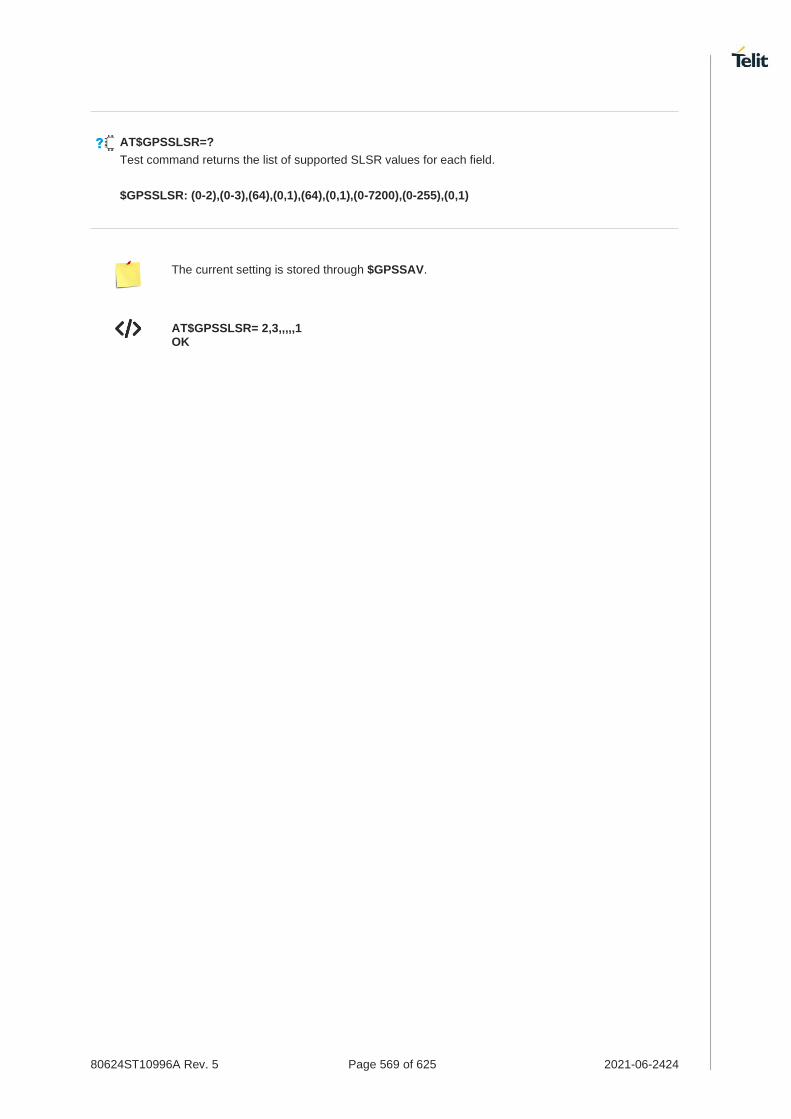
80624ST10996A Rev. 5 Page 569 of 625 2021-06-2424
AT$GPSSLSR=?
Test command returns the list of supported SLSR values for each field.
$GPSSLSR: (0-2),(0-3),(64),(0,1),(64),(0,1),(0-7200),(0-255),(0,1)
The current setting is stored through $GPSSAV.
AT$GPSSLSR= 2,3,,,,,1 OK

80624ST10996A Rev. 5 Page 570 of 625 2021-06-2424
3.16.1.9. AT$LCSLRV - Location Request Verification
Location request verification
SIM Presence Setting saved Can be aborted MAX timeout SELINT
Not required Auto No - 2
AT$LCSLRV=<permission>,<reqid>
Set command is used to verify a location request coming from the network. The verification is sent back to the network with request id.
Parameters:
Name Type Default Description
<permission> integer 0 set the permission
Values:
0 : permission denied
1 : permission granted
<reqid> string - uniquely identifies the MT-LR sent by the network
AT$LCSLRV=?
Test command returns the range of values for parameter <permission>.
The <reqid> must use the identical value as <reqid> of following $LCSLRMT (see $LCSLRMT).

80624ST10996A Rev. 5 Page 571 of 625 2021-06-2424
3.16.1.10. AT$GPSAPN - Set GPS APN Profile
This command sets the GPS APN profile.
SIM Presence Setting saved Can be aborted MAX timeout SELINT
Not required Auto No - 2
AT$GPSAPN=<profile>[,<pdptype>,<apnname>]
Set command sets the GPS APN profile.
Parameters:
Name Type Default Description
<profile> integer 0 GPS APN profile type
Value:
0 : SUPL APN profile
<pdptype> integer N/A GPS APN PDP type
Values:
0 : IPV4
1 : IPV6
2 : IPV4V6
<apnname> string - GPS APN name; The maximum length is 100.
AT$GPSAPN?
Read command returns the current GPS APN profile in the format:
$GPSAPN: <profile>,<pdptype>,<apnname>
AT$GPSAPN=?
Test command returns the supported range of parameters <profile> and <pdptype> and the maximum length of <apnname> in the format:
$GPSAPN: (the supported range of <profile>),(the supported range of <pdptype>),<apnname_length>
Additional info:
response fields
Name Type Default Description
<apnname_length> integer - the maximum length of field <apnname>

80624ST10996A Rev. 5 Page 572 of 625 2021-06-2424
If the parameter <profile> only exists, the profile is deleted.
The GPS APN profile for SUPL session should be defined with same APN of +CGDCONT command. (See +CGDCONT)

80624ST10996A Rev. 5 Page 573 of 625 2021-06-2424
3.16.1.11. AT$AGPSEN - Set GNSS capability supporting to module
This command set GNSS capability supporting to module.
SIM Presence Setting saved Can be aborted MAX timeout SELINT
Not required Auto No - 2
AT$AGPSEN=<mode>
Set command sets GPS/A-GPS/A-GLOASS capability supporting on the module.
Parameter:
Name Type Default Description
<mode> integer 1 GNSS capability
Values:
0 : Standalone GPS only
1 : Full GPS capability (Standalone GPS, A-GPS)
2 : Full GPS (Standalone GPS, A-GPS) and A-GLONASS capability
3 : Not support GPS
The default value depends on operator.
For Fx980 series,
28. Generic : 2 29. Others : 1
AT$AGPSEN?
Read command returns the currently selected GNSS capability in the format:
$AGPSEN: <mode>
AT$AGPSEN=?
Test command reports the supported range of values for parameter(s) <mode>.
$AGPSEN: (the supported range of <mode>)

80624ST10996A Rev. 5 Page 574 of 625 2021-06-2424
3.16.1.12. AT$LCSLPP - Set Configuration Information for LPP Protocol
This command sets the configuration information for LPP Protocol.
SIM Presence Setting saved Can be aborted MAX timeout SELINT
Not required Auto No - 2
AT$LCSLPP=<mode>
Set command sets the configuration information for LPP (LTE Poisoning Protocol).
Parameter:
Name Type Default Description
<mode> integer N/A configuration for LPP
Values:
0 : RRLP in LTE
1 : LPP user plane in LTE
2 : LPP control plane in LTE
3 : LPP UP/CP in LTE
The default value depends on operator.
For LM9x0 series,
30. VZW / T-Mobile: 3 31. Others: 2
For Fx980 series,
32. Generic / VZW / T-Mobile / NTT / TELSTRA: 3 33. KDDI : 1 34. Others: 2
AT$LCSLPP?
Read command returns the currently selected configuration for LPP protocol in the format:
$LCSLPP: <mode>
AT$LCSLPP=?
Test command reports the supported range of values for parameter(s) <mode>.
$LCSLPP: (the supported range of <mode>)

80624ST10996A Rev. 5 Page 575 of 625 2021-06-2424
3.16.1.13. AT$LCSAGLO - Selection of Positioning protocols for A-GLONASS
This command set selection of positioning protocols (RRLP, RRC, LPP) for A-GLONASS.
SIM Presence Setting saved Can be aborted MAX timeout SELINT
Not required Auto No - 2
AT$LCSAGLO=<mask>
Set command sets the selection of positioning protocols for A-GLONASS.
Parameter:
Name Type Default Description
<mask> integer 0 protocol mask of A-GLONASS
0: Not selected
1: RRC control plane (In case AT&T, Default)
2: RRLP user plane
4: LPP user plane
8: LPP control plane
Value:
0÷15 : protocol mask of A-GLONASS
The default value depends on operator.
For LM9x0 / LE910Cx series,
35. AT&T : 1 36. Others : 0
For Fx980 series,
37. AT&T : 1 38. Generic : 15 39. Others: 0
AT$LCSAGLO?
Read command returns the currently selected protocol mask of A-GLONASS in the format:
$LCSAGLO: <mask>
AT$LCSAGLO=?
Test command reports the supported range of values for parameter(s) <mask>.
$LCSAGLO: (the supported range of <mask>)

80624ST10996A Rev. 5 Page 576 of 625 2021-06-2424
This command is only applicable for A-GLONASS capable setting. (see $AGPSEN)
The <mask> 4 and 8 must be set in the LPP configuration for this to take effect. (see $LCSLPP)

80624ST10996A Rev. 5 Page 577 of 625 2021-06-2424
3.16.1.14. AT#LOCAUTOSTART - GNSS Auto Start Configuration
This command is related to GNSS auto start configuration.
80624ST11005A_FN980m_QMI_Command_Reference_Guide_Preliminary_Draft.docx
40. QMI_GMS_LOC_GET_AUTO_START 41. QMI_GMS_LOC_SET_AUTO_START
SIM Presence Setting saved Can be aborted MAX timeout SELINT
Not required Auto No - 2
AT#LOCAUTOSTART=<function>,<fix_type>,<max_time>,<max_dist>,<fix_rate>
Set command sets the GNSS auto start configuration.
Parameters:
Name Type Default Description
<function> integer 2 setting to indicate when modem should start an automatic
Values:
0 : disable
1 : AT bootup
2 : when NMEA port is opened (Default with OEM PRI setting)
<fix_type> string 4 type of GNSS fix
Values:
1 : default engine mode
2 : MS-based
3 : MS-assisted
4 : Standalone (Default with OEM PRI setting)
<max_time> integer 255 maximum time allowed for the receiver to get a fix in seconds
Value:
1÷255 : Default with OEM PRI setting: 255
<max_dist> string 1000 maximum uncertainty of a fix measured by distance in meters
Value:
1÷4294967280 : Default with OEM PRI setting: 1000
<fix_rate> string 1 time between fixes in seconds
Value:
1÷65535 : Default with OEM PRI setting: 1
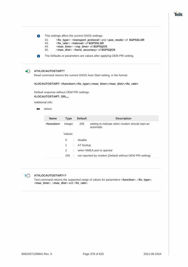
80624ST10996A Rev. 5 Page 578 of 625 2021-06-2424
This settings affect the current GNSS settings.
42. <fix_type>: <transport_protocol> and <pos_mode> of $GPSSLSR 43. <fix_rate>: <interval> of $GPSSLSR 44. <max_time>: <rsp_time> of $GPSQOS 45. <max_dist>: <horiz_accuracy> of $GPSQOS
The Defaults or parameters are values after applying OEM PRI setting.
AT#LOCAUTOSTART?
Read command returns the current GNSS Auto Start setting, in the format:
#LOCAUTOSTART: <function>,<fix_type>,<max_time>,<max_dist>,<fix_rate>
Default response without OEM PRI settings:
#LOCAUTOSTART: 255,,,,
Additional info:
where
Name Type Default Description
<function> integer 255 setting to indicate when modem should start an automatic
Values:
0 : disable
1 : AT bootup
2 : when NMEA port is opened
255 : not reported by modem (Default without OEM PRI setting)
AT#LOCAUTOSTART=?
Test command returns the supported range of values for parameters <function>, <fix_type>, <max_time>, <max_dist> and <fix_rate>.
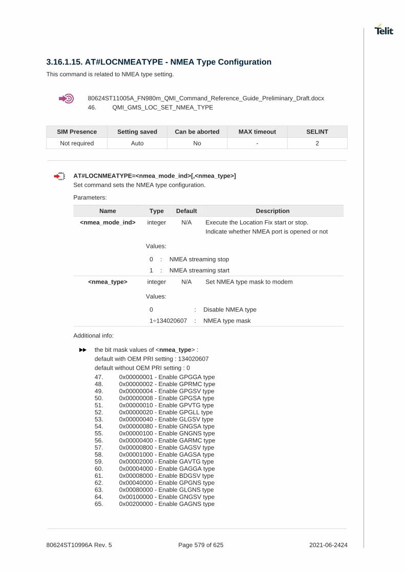
80624ST10996A Rev. 5 Page 579 of 625 2021-06-2424
3.16.1.15. AT#LOCNMEATYPE - NMEA Type Configuration
This command is related to NMEA type setting.
80624ST11005A_FN980m_QMI_Command_Reference_Guide_Preliminary_Draft.docx
46. QMI_GMS_LOC_SET_NMEA_TYPE
SIM Presence Setting saved Can be aborted MAX timeout SELINT
Not required Auto No - 2
AT#LOCNMEATYPE=<nmea_mode_ind>[,<nmea_type>]
Set command sets the NMEA type configuration.
Parameters:
Name Type Default Description
<nmea_mode_ind> integer N/A Execute the Location Fix start or stop.
Indicate whether NMEA port is opened or not
Values:
0 : NMEA streaming stop
1 : NMEA streaming start
<nmea_type> integer N/A Set NMEA type mask to modem
Values:
0 : Disable NMEA type
1÷134020607 : NMEA type mask
Additional info:
the bit mask values of <nmea_type> :
default with OEM PRI setting : 134020607
default without OEM PRI setting : 0
47. 0x00000001 - Enable GPGGA type 48. 0x00000002 - Enable GPRMC type 49. 0x00000004 - Enable GPGSV type 50. 0x00000008 - Enable GPGSA type 51. 0x00000010 - Enable GPVTG type 52. 0x00000020 - Enable GPGLL type 53. 0x00000040 - Enable GLGSV type 54. 0x00000080 - Enable GNGSA type 55. 0x00000100 - Enable GNGNS type 56. 0x00000400 - Enable GARMC type 57. 0x00000800 - Enable GAGSV type 58. 0x00001000 - Enable GAGSA type 59. 0x00002000 - Enable GAVTG type 60. 0x00004000 - Enable GAGGA type 61. 0x00008000 - Enable BDGSV type 62. 0x00040000 - Enable GPGNS type 63. 0x00080000 - Enable GLGNS type 64. 0x00100000 - Enable GNGSV type 65. 0x00200000 - Enable GAGNS type

80624ST10996A Rev. 5 Page 580 of 625 2021-06-2424
66. 0x00400000 - Enable BDGSA type 67. 0x00800000 - Enable BDRMC type 68. 0x01000000 - Enable BDVTG type 69. 0x02000000 - Enable BDGGA type 70. 0x04000000 - Enable BDGNS type
For <nmea_mode_ind> value, each value means the following description,
71. NMEA streaming start: GPS engine start location fix and start to stream out NMEA sentences.
72. NMEA streaming stop: GPS engine stop location fix and stop NMEA streaming.
The current setting <nmea_type> is stored in NVM.
The Default of <nmea_type> is value after applying OEM PRI setting.
If $GPSNMUN or $GPSNMUNEX command is already used, the user should avoid using this command because this setting have an effect on $GPSNMUN and $GPSNMUNEX operation.
AT#LOCNMEATYPE?
Read command returns the current NMEA type configuration, in the format:
#LOCNMEATYPE: <nmea_type>
AT#LOCNMEATYPE=?
Test command reports the supported range of values for parameters <nmea_mode_ind> and <nmea_type>.

80624ST10996A Rev. 5 Page 581 of 625 2021-06-2424
3.16.1.16. AT$XTRAEN - GpsOneXTRA feature control
This command enables/disables the GpsOneXTRA Feature.
SIM Presence Setting saved Can be aborted MAX timeout SELINT
Not required Auto No - 2
AT$XTRAEN=<mode>
Execution command set to control the GpsOneXTRA feature.
Parameter:
Name Type Default Description
<mode> integer 0 Control GpsOneXTRA feature.
Values:
0 : Disable GpsOneXTRA feature
1 : Enable GpsOneXTRA feature
AT$XTRAEN?
Read command returns the values of saved GpsOneXTRA feature <mode>.
$XTRAEN: <mode>
AT$XTRAEN=?
Test command returns the supported range of values of parameters <mode>
$XTRAEN: (0,1)

80624ST10996A Rev. 5 Page 582 of 625 2021-06-2424
New setting is applicable across device power cycles.
The current setting is stored in NVM.
If gpsOneXTRA feature is enabled, the unintentional data usage can be occurred. Please set as disable if you want not to use this feature.
In case Fx980 series,
If gpsOneXTRA feature is enabled, the following describes only the general behaviors of XTRA client.
An XTRA file contains orbit predictions for constellations, which are valid up to 7 days. With valid XTRA data present, a GNSS engine on modem can eliminate the need for GNSS navigation data demodulation over the air and reduce the time required for generating a position fix.
1) XTRA data download
- XTRA data downloading always requires data service. The pending XTRA data download is resumed after data connection is available.
2) XTRA data download Initiation
- After power-up: XTRA client initiates XTRA data download after power-up and data service is connected.
- On-demand: When the modem requests for XTRA data download, XTRA client initiates XTRA data download.
3) Download throttle mechanism
- The maximum number of downloads per UTC day are three. After this download limit is reached, no download request is accepted on that day

80624ST10996A Rev. 5 Page 583 of 625 2021-06-2424
• The following describes only the gpsOneXTRA behaviors for Fx980 series.
- Enable gpsOneXTRA Feature.
AT$XTRAEN? $XTRAEN: 0 OK
AT$XTRAEN=1 OK AT#REBOOT OK
AT$XTRAEN? $XTRAEN: 1 OK
- Enable Data connection (See #ICMCONNECT)
AT+CGDCONT? +CGDCONT: 1,"IPV4V6","lte.sktelecom.com","0.0.0.0.0.0.0.0.0.0.0.0.0.0.0.0",0,0,0,0,,,,,,,,,"",,,,0 OK
AT#ICMCONNECT="CON",1,4 OK AT#ICMCONNECT="CON",1,6 OK
AT#ICMCONNECT? #ICMCONNECT: 1,1,1,1,1 OK
- Check the standalone GNSS mode.
AT$GPSSLSR? $GPSSLSR: 2,3,,,,,1,255 OK
- On-demand Trigger with cold start for example.
AT$GPSR=1 OK AT$GPSP=1 OK
- After few seconds, the GNSS SVs information from XTRA Data download is displayed on NMEA stream and can get a fix soon.
AT$GPSNMUN? $GPSNMUN: 2,1,1,1,1,1,1 OK
$GPGSA,A,1,,,,,,,,,,,,,,,,*32 $GPVTG,,T,,M,,N,,K,N*2C $GPRMC,,V,,,,,,,,,,N,V*29 $GPGGA,,,,,,0,,,,,,,,*66 $GPGLL,,,,,,V,N*64 $GPGSA,A,1,,,,,,,,,,,,,,,,*32 $GPVTG,,T,,M,,N,,K,N*2C $GPRMC,,V,,,,,,,,,,N,V*29 $GPGGA,,,,,,0,,,,,,,,*66 $GPGLL,,,,,,V,N*64 $GPGSV,3,1,12,16,58,274,34,31,56,085,38,03,08,261,,04,36,306,,1*64 $GPGSV,3,2,12,08,00,000,,09,07,322,,18,11,099,,22,02,237,,1*6E $GPGSV,3,3,12,26,71,345,,27,27,194,,29,22,042,,32,08,160,,1*68 $GPGSA,A,1,,,,,,,,,,,,,,,,*32 $GPVTG,,T,,M,,N,,K,N*2C $GPRMC,,V,,,,,,,,,,N,V*29 $GPGGA,,,,,,0,,,,,,,,*66

80624ST10996A Rev. 5 Page 584 of 625 2021-06-2424
$GPGLL,,,,,,V,N*64 $GPGSV,3,1,12,04,36,306,31,16,58,274,34,26,71,345,37,31,56,085,39,1*6D $GPGSV,3,2,12,03,08,261,,08,00,000,,09,07,322,,18,11,099,,1*64 $GPGSV,3,3,12,22,02,237,,27,27,194,,29,22,042,,32,08,160,,1*6C $GPGSA,A,1,,,,,,,,,,,,,,,,*32 $GPVTG,,T,,M,,N,,K,N*2C $GPRMC,,V,,,,,,,,,,N,V*29 $GPGGA,,,,,,0,,,,,,,,*66 $GPGLL,,,,,,V,N*64 $GPGSV,3,1,12,04,36,306,34,16,58,274,34,26,71,345,38,31,56,085,40,1*69 $GPGSV,3,2,12,03,08,261,,08,00,000,,09,07,322,,18,11,099,,1*64 $GPGSV,3,3,12,22,02,237,,27,27,194,,29,22,042,,32,08,160,,1*6C $GPGSA,A,3,04,16,26,31,,,,,,,,,4.1,2.1,3.5,1*2A $GPVTG,203.1,T,203.1,M,23.1,N,42.7,K,A*22 $GPRMC,013356.18,A,3731.301587,N,12655.781339,E,23.1,203.1,080421,6.0,W,A,V*63 $GPGGA,013356.18,3731.301587,N,12655.781339,E,1,04,2.1,92.1,M,18.0,M,,*5F $GPGLL,3731.301587,N,12655.781339,E,013356.18,A,A*6E
3.16.2. GNSS Receiver
3.16.2.1. AT$GPSRST - Restore Default GNSS Parameters
This command resets the GNSS parameters to "Factory Default" configuration.
SIM Presence Setting saved Can be aborted MAX timeout SELINT
Not required Auto No - 2
AT$GPSRST
Execution command resets the GNSS parameters to "Factory Default" configuration and stores them in the NVM of the device.
AT$GPSRST=?
Test command returns the OK result code.
If the GPS controller is powered up (see $GPSP), the GNSS controller is powered down because the GNSS parameters should be reset with "Factory Default".

80624ST10996A Rev. 5 Page 585 of 625 2021-06-2424
3.16.2.2. AT$GPSSAV - Save GNSS Parameters Configuration
This command stores the current GNSS parameters in the NVM of the device.
SIM Presence Setting saved Can be aborted MAX timeout SELINT
Not required No No - 2
AT$GPSSAV
Execution command stores the current GNSS parameters in the NVM of the device.
AT$GPSSAV=?
Test command returns the OK result code.

80624ST10996A Rev. 5 Page 586 of 625 2021-06-2424
3.16.2.3. AT$GPSP - GNSS Positioning Session Control
This command controls the GNSS positioning session.
SIM Presence Setting saved Can be aborted MAX timeout SELINT
Not required Other No - 2
AT$GPSP=<status>
The set command allows to control the GNSS positioning session.
Parameter:
Name Type Default Description
<status> integer 0 GNSS positioning session status
Values:
0 : Stop GNSS positioning session
1 : Start GNSS positioning session
This command only controls the started GNSS positioning session from $GPSP and $GPSSLSR. The GNSS positioning sessions of other Service(IMS, MDT or UIM) cannot be controlled.
The Start GNSS positioning session clears GNSS memory and then powers up the GNSS receiver if it powers down. The GNSS data cleaning is performed on the base of the current value of the <reset_type> parameter (see $GPSR).
The GNSS operation mode of Start GNSS positioning session is performed on the base of the current values of $GPSSLSR configuration (see $GPSSLSR).
The $GPSP and $GPSSLSR cannot be used at same time.
AT$GPSP?
The read command reports the current value of the <status> parameter, in the format:
$GPSP: <status>
Where:
<status> - GNSS positioning session status
0 - GNSS positioning session is not working
1 - GNSS positioning session is working
AT$GPSP=?
The test command reports the supported values range for parameter <status>.
$GPSP: (0,1)
The current <status> value is stored through $GPSSAV command.

80624ST10996A Rev. 5 Page 587 of 625 2021-06-2424
Start GNSS positioning session.
AT$GPSP=1 OK
Stop GNSS positioning session.
AT$GPSP=0 OK

80624ST10996A Rev. 5 Page 588 of 625 2021-06-2424
3.16.3. GNSS General Management
3.16.3.1. AT$GNSSCONF - Configuration of the GNSS receiver
This command is used to configure the capabilities of the GNSS receiver.
SIM Presence Setting saved Can be aborted MAX timeout SELINT
Not required Auto No - 2
AT$GNSSCONF=<combination>[,<worldwide>]
Set command configures the capabilities of the GNSS receiver.
Parameters:
Name Type Default Description
<combination> integer 9 GNSS configuration
Values:
0 : GPS Only
1 : GPS + GLONASS
2 : GPS + GALILEO
3 : GPS + GLONASS + GALILEO
4 : GPS + GLONASS + BEIDOU
5 : GPS + BEIDOU + GALILEO
6 : GPS + GLONASS + BEIDOU + GALILEO
7 : GPS + GLONASS + QZSS
8 : GPS + GLONASS + BEIDOU + QZSS
9 : GPS + GLONASS + BEIDOU + GALILEO + QZSS
<worldwide> integer 0 Applicable area
The BEIDOU, GALILEO and QZSS are only applicable for this option.
Values:
0 : Outside of the United States
1 : Worldwide (For test/debug purposes)
AT$GNSSCONF?
Read command returns the currently selected GNSS configuration in the format:
$GNSSCONF: <combination>,<worldwide>
AT$GNSSCONF=?
Test command reports the supported range of values for parameter(s) <combination> and <worldwide>.
80624ST10996A Rev. 5 Page 589 of 625 2021-06-2424
$GNSSCONF: (the supported range of <combination>),(the supported range of <worldwide>)
The <worldwide> option isn't supported. It has no effect and is included only for backward compatibility.
If the <worldwide> value is 1 (Worldwide) from $GNSSCONF setting, Set command returns ERROR.

80624ST10996A Rev. 5 Page 590 of 625 2021-06-2424
3.16.3.2. AT$GPSR - Reset the GNSS Controller
This command resets the GNSS controller.
SIM Presence Setting saved Can be aborted MAX timeout SELINT
Not required Other No - 2
AT$GPSR=<resetType>
Set command allows to reset the GNSS controller.
Parameter:
Name Type Default Description
<resetType> integer 3 set the type of GNSS controller reset.
Values:
0 : Factory Reset: this option clears all the GNSS memory including Clock Drift.
1 : Coldstart (No Almanac, No Ephemeris): this option clears all data that is currently stored in the internal memory of the GNSS receiver including Position, Almanac, Ephemeris and Time. The stored Clock Drift is retained.
2 : Warmstart (No ephemeris): this option clears all initialization data in the GNSS receiver and subsequently reloads the data that is currently displayed in the Receiver Initialization Setup screen. The Almanac is retained but the Ephemeris is cleared.
3 : Hotstart (with stored Almanac and Ephemeris): the GNSS receiver restarts by using all data that is currently stored in the internal memory of the GNSS receiver: validated Ephemeris and Almanac.
Factory Reset performs the same operation as Coldstart.
<resetType> sets the kind of start when GNSS is activated through $GPSP command.
AT$GPSR?
Read command returns the currently used reset type, in the format:
$GPSR: <resetType>
AT$GPSR=?
Test command reports the range of supported values for parameter <resetType>.
The current setting is stored through $GPSSAV command.

80624ST10996A Rev. 5 Page 591 of 625 2021-06-2424
Factory reset AT$GPSR=0 OK

80624ST10996A Rev. 5 Page 592 of 625 2021-06-2424
3.16.3.3. AT$GPSLOCK - GNSS Lock Mode
This command is used to configure the GNSS lock mode.
SIM Presence Setting saved Can be aborted MAX timeout SELINT
Not required Auto No - 2
AT$GPSLOCK=<mode>
Set command sets the GNSS lock mode.
Parameter:
Name Type Default Description
<mode> integer 0 Lock Mode
Values:
0 : GNSS Unlock
1 : Mobile-Initiated (MI) session is locked
2 : Mobile-Terminated (MT) session is locked
3 : Except for an emergency call, all (MI and MT) is locked
The default value depends on operator.
For Fx980 series,
- SKT: 3 (Some GNSS commands return ERROR. If GNSS fix should be used, please set 0 value to work GNSS)
- Others: 0
AT$GPSLOCK?
Read command returns the currently selected lock mode in the format:
$GPSLOCK: <mode>
AT$GPSLOCK=?
Test command reports the supported range of values for parameter(s) <mode>.
$GPSLOCK: (the supported range of <mode>)
During an emergency call, an MT session will always be permitted irrespective of the setting.

80624ST10996A Rev. 5 Page 593 of 625 2021-06-2424
3.16.3.4. AT$GPSANTPORT - Configuration of GNSS Antenna Port Type
This command is used to configure to control switch between GPS and AUX port.
SIM Presence Setting saved Can be aborted MAX timeout SELINT
Not required Auto No - 2
AT$GPSANTPORT=<type>
Set command selects to configure GNSS antenna port type.
Parameter:
Name Type Default Description
<type> integer 2 Enabled Port type
Values:
0 : Disable GNSS on AUX port and GNSS port. (GNSS off)
1 : Enable GNSS on AUX port and disable GNSS on GNSS port. (passive antenna on Aux port)
2 : Enable GNSS on GNSS port and disable GNSS on AUX port; DC-Bias off. (passive antenna on GNSS port)
3 : Enable GNSS on GNSS port and disable GNSS on AUX port; DC-Bias on. (active antenna on GNSS port)
4 : Enable GNSS on GNSS port and disable GNSS on AUX port; High Gain Mode, DC-Bias on. (active antenna on GNSS port, High Gain)
AT$GPSANTPORT?
Read command returns the currently selected port type in the format:
$GPSANTPORT: <type>
AT$GPSANTPORT=?
Test command reports the supported range of values for parameter(s) <type>.
$GPSANTPORT: (the supported range of <type>)

80624ST10996A Rev. 5 Page 594 of 625 2021-06-2424
3.16.3.5. AT$GNSSMBCFG - GNSS Multi-band Configuration
This command set the GNSS Multi-band configuration.
SIM Presence Setting saved Can be aborted MAX timeout SELINT
Not required Auto No - 2
AT$GNSSMBCFG=<mode>
Execution command set the GNSS Multi-band configuration.
Parameter:
Name Type Default Description
<mode> integer 1 GNSS Multi-band Configuration
Values:
0 : Disable
1 : Enable
2 : Forced enable
1. <mode> is 0 - Disable
- GPS L5, GAL E5a and BDS B2a are disabled.
2. <mode> is 1 - Enable
- GPS L5, GAL E5a and BDS B2a are enabled.
- GNSS multi-band signal tracking is conditional engaged.
3.<mode> is 2 - Forced Enable
- GPS L5, GAL E5a and BDS B2a are enabled.
- Enables GNSS multi-band signal tracking always and prevents engagement of DPO(Dynamic Power Optimization).
AT$GNSSMBCFG?
Read command returns the current GNSS Multi-band Configuration in the format:
$GNSSMBCFG: <mode>
where:
<mode> - GNSS Multi-band Configuration
AT$GNSSMBCFG=?
Test command reports the supported range of values for parameter(s) <mode>.
$GNSSMBCFG: (the supported range of <mode>)
New setting is applicable across device power cycles.
The current setting is stored in NVM.

80624ST10996A Rev. 5 Page 595 of 625 2021-06-2424
3.16.4. GNSS Positioning Information
3.16.4.1. AT$GPSNMUN - Unsolicited NMEA Data Configuration
Unsolicited NMEA data configuration
NMEA 0183 Standard
SIM Presence Setting saved Can be aborted MAX timeout SELINT
Not required No No - 2
AT$GPSNMUN=<enable>[,<GGA>,<GLL>,<GSA>,<GSV>,<RMC>,<VTG>]
Set command allows to activate an unsolicited GNSS data stream built with NMEA sentences on the standard serial port and defines which NMEA sentences will be available. Refer to document [1] to have information on the NMEA sentences contents and formats.
Parameters:
Name Type Default Description
<enable> integer 0 Enables unsolicited GNSS data stream and selects one of the available GNSS data stream format display. <enable> parameter is also used to disable the GNSS data stream. Here is the list of the <enable> values. See Additional info section to have information on GNSS data stream formats.
Values:
0 : disable GNSS data stream
1 : enable the first GNSS data stream format
2 : enable the second GNSS data stream format
3 : enable the first GNSS data stream format, and reserve the AT interface port only for the GNSS data stream
<GGA> integer 0 enables/disables the presence of the Global Positioning System Fix Data NMEA sentence (GGA) in the GNSS data stream.
Values:
0 : disable
1 : enable
<GLL> integer 0 enable/disable the presence of the Geographic Position - Latitude/Longitude NMEA sentence (GLL) in the GNSS data stream.
Values:
0 : disable
1 : enable
<GSA> integer 0 enable/disable the presence of the GNSS DOP and Active Satellites NMEA sentence (GSA) in the GNSS data stream.
Values:

80624ST10996A Rev. 5 Page 596 of 625 2021-06-2424
0 : disable
1 : enable
<GSV> integer 0 enable/disable the presence of the Satellites in View NMEA sentence (GSV) in the GNSS data stream.
Values:
0 : disable
1 : enable
<RMC> integer 0 enable/disable the presence of the Recommended Minimum Specific GNSS Data NMEA sentence (RMC) in the GNSS data stream.
Values:
0 : disable
1 : enable
<VTG> integer 0 enable/disable the presence of the GNSS Course Over Ground and Ground Speed NMEA sentence (VTG) in the GNSS data stream.
Values:
0 : disable
1 : enable
Additional info:
<enable>=1, GNSS data stream format:
$GPSNMUN: <NMEA SENTENCE 1><CR><LF> ... $GPSNMUN: <NMEA SENTENCE N><CR><LF> ...
<enable>=2, GNSS data stream format:
<NMEA SENTENCE 1><CR><LF> ... <NMEA SENTENCE N><CR><LF> ...
<enable>=3, in this case, the AT interface port is dedicated to NMEA sentences, it is not possible to send AT commands. Use the escape sequence "+++" to return in command mode. GNSS data stream format:
<NMEA SENTENCE 1><CR><LF> ... <NMEA SENTENCE N><CR><LF> ...

80624ST10996A Rev. 5 Page 597 of 625 2021-06-2424
If the <enable> is 3, it can activate the NMEA unsolicited streaming both the current dedicated port and NMEA port. This <enable> option isn't stored in NVM.
AT$GPSNMUN?
Read command returns whether the unsolicited GNSS data stream is currently enabled or not, along with the current NMEA mask configuration, in the format:
$GPSNMUN: <enable>,<GGA>,<GLL>,<GSA>,<GSV>,<RMC>,<VTG>
AT$GPSNMUN=?
Test command returns the supported range of values for parameters:
<enable>,<GGA>,<GLL>,<GSA>,<GSV>,<RMC>,<VTG>
The storage of $GPSNMUN setting value is following,
Setting saved
Auto
The current setting is stored in NVM.
If #LOCNMEATYPE command is already used, the user should avoid using this command because this setting have an effect on #LOCNMEATYPE operation.
Set the GSA as available sentence in the unsolicited message AT$GPSNMUN=1,0,0,1,0,0,0 OK
Turn-off the unsolicited mode AT$GPSNMUN=0 OK
Read the current NMEA mask configuration: AT$GPSNMUN? $GPSNMUN: 1,0,0,1,0,0,0 OK
The unsolicited message will be: $GPSNMUN: $GPGSA,A,3,23,20,24,07,13,04,02,,,,,,2.4,1.6,1.8*3C

80624ST10996A Rev. 5 Page 598 of 625 2021-06-2424
3.16.4.2. AT$GPSACP - Get Acquired GNSS Position
This command returns information about the last GNSS position.
NMEA 0183 Standard
SIM Presence Setting saved Can be aborted MAX timeout SELINT
Not required No No - 2
AT$GPSACP
Execution command returns information about the last GNSS position in the format:
$GPSACP: <UTC>,<latitude>,<longitude>,<hdop>,<altitude>,<fix>,<cog>,<spkm>,<spkn>, <date>,<nsat>
Additional info:
Meanings of the parameters returned by the command.
Name Type Default Description
<UTC> string - UTC time (hhmmss.sss) referred to GGA sentence
<latitude> string - latitude in the format ddmm.mmmmmm N/S (referred to GGA sentence)
where:
dd: 00..90, degrees
mm.mmmmmm: 00.000000..59.999999, minutes
N/S: North/South
<longitude> string - longitude in the format dddmm.mmmmmm E/W (referred to GGA sentence)
where:
ddd: 000..180, degrees
mm.mmmmmm: 00.000000..59.999999, minutes
E/W: East/West
<hdop> string - horizontal dilution of precision (referred to GGA sentence)
<altitude> string - altitude - mean-sea-level (geoid) in meters (referred to GGA sentence)
<fix> integer N/A fix type
Values:
0 : invalid fix
1 : invalid fix
2 : 2D fix
3 : 3D fix
<cog> string - course over ground (degrees, True) (referred to VTG sentence) in the format ddd.mm

80624ST10996A Rev. 5 Page 599 of 625 2021-06-2424
where:
ddd: 000..360, degrees
mm: 00..59, minutes
<spkm> string - speed over ground (km/hr) (referred to VTG sentence)
<spkn> string - speed over ground (knots) (referred to VTG sentence)
<date> string - date of fix (referred to RMC sentence) in the format ddmmyy
where:
dd: 01..31, day
mm: 01..12, month
yy: 00..99, year 2000 to 2099
<nsat> integer N/A total number of GNSS satellites in use (referred to GNS sentence)
Value:
0÷99 : total number of GNSS satellites in use
AT$GPSACP?
Read command has the same behavior as the execution command.
AT$GPSACP=?
Test command returns the OK result code.
AT$GPSP? $GPSP: 0
when module is down there no acquired position
AT$GPSACP $GPSACP: OK AT$GPSP=1 OK
Until first fix is received, the command will display no fix GNSS position AT$GPSACP $GPSACP: ,,,,,1,,,,,, OK
Once fix has been received the command will display actual GNSS position AT$GPSACP $GPSACP: 002518.000,3731.303660N,12655.781816E,0.8,73.1,3,0.0,0.0,0.0,290819,18 OK

80624ST10996A Rev. 5 Page 600 of 625 2021-06-2424
3.16.4.3. AT$GPSNMUNEX - Unsolicited NMEA Extended Data Configuration
This command permits to activate an unsolicited streaming of GNSS data.
SIM Presence Setting saved Can be aborted MAX timeout SELINT
Not required No No - 2
AT$GPSNMUNEX=<GNGNS>,<GNGSA>,<GLGSV>
Set command permits to activate an unsolicited streaming of GNSS data (in NMEA extended format) through the NMEA port and defines which NMEA extended sentences will be available.
Parameters:
Name Type Default Description
<GNGNS> integer 0 Fix data of GNSS receivers
Values:
0 : disable
1 : enable
<GNGSA> integer 0 DOP and active satellites of GNSS
Values:
0 : disable
1 : enable
<GLGSV> integer 0 GLONASS satellites in view
Values:
0 : disable
1 : enable
The storage of $GPSNMUNEX setting value is following,
Setting saved
Auto
The current setting is stored in NVM.
AT$GPSNMUNEX?
Read command returns the NMEA extended sentences availability status, in the format:
$GPSNMUNEX: <GNGNS>,<GNGSA>,<GLGSV>
AT$GPSNMUNEX=?
Test command returns the supported range of values for parameters:
<GNGNS>,<GNGSA>,<GLGSV>

80624ST10996A Rev. 5 Page 601 of 625 2021-06-2424
The NMEA extended data is displayed on NMEA port depending on $GPSNMUN setting.
If #LOCNMEATYPE command is already used, the user should avoid using this command because this setting have an effect on #LOCNMEATYPE operation.
AT$GPSNMUNEX=1,0,0
OK
These set the GNGNS as available sentence in the unsolicited message.
AT$GPSNMUNEX?
$GPSNMUNEX: 1,0,0
OK
Give the current frame selected (GNGNS)
The unsolicited message will be:
$GNGNS,010304.00,3731.304375,N,12655.784627,E,AAANA,17,0.8,67.6,18.0,,,V*57

80624ST10996A Rev. 5 Page 602 of 625 2021-06-2424
PSM (Power Saving Mode)
3.17.1. AT#PSMWDISACFG - Power Saving mode configuration
Power Saving mode configuration command.
SIM Presence Setting saved Can be aborted MAX timeout SELINT
Not required Auto No - 2
AT#PSMWDISACFG=<mode>
Set command Power Saving mode
Parameter:
Name Type Default Description
<mode> integer 0 Power Saving Mode
Values:
0 : Low Power Mode (both RX/TX disable) (factory default)
1 : power saving which watch W_DISABLE_N pin
2 : ignore on W_DISABLE_N pin
10 : enable dying gasp with W_DISABLE_N pin (activated when translates from high to low)
After the command issued, the modem will reset
The setting is maintained for both firmware updates and firmware switches.
USB suspend mode is not supported (Qualcomm limitation)
AT#PSMWDISACFG?
Display current mode
AT#PSMWDISACFG=?
Test command reports the supported mode

80624ST10996A Rev. 5 Page 603 of 625 2021-06-2424
• AT#PSMWDISACFG=1
OK
• AT#PSMWDISACFG?
#PSMWDISACFG: 1
OK
• AT#PSMWDISACFG=?
#PSMWDISACFG: (0-2,10)
OK

80624ST10996A Rev. 5 Page 604 of 625 2021-06-2424
3.17.2. AT#PSMEVTCFG - Wake Up Event configuration
This command is used to set event for wake up from Power saving mode
SIM Presence Setting saved Can be aborted MAX timeout SELINT
Not required Auto No - 2
AT#PSMEVTCFG=<SMS>,<NO_SERVICE>[,<VOICE>]
Set command enable/disable each wake up event
Parameters:
Name Type Default Description
<SMS> integer 0 SMS
Values:
0 : disable
1 : enable
<NO_SERVICE> integer 0 Network de-registration
Values:
0 : disable
1 : enable
<VOICE> integer 0 Voice CALL
Values:
0 : disable
1 : enable
Voice call event is only available with VOICE call support models
AT#PSMEVTCFG?
Display current wake up event configurations mask
AT#PSMEVTCFG=?
Test command reports the supported wake up event

80624ST10996A Rev. 5 Page 605 of 625 2021-06-2424
• AT#PSMEVTCFG = 1,1
OK
• AT#PSMEVTCFG?
#PSMEVTCFG = 1,1
OK
• AT#PSMEVTCFG=?
#PSMEVTCFG: (0,1),(0,1)
OK

80624ST10996A Rev. 5 Page 606 of 625 2021-06-2424
3.17.3. AT#PSMWAKENCFG - WAKE_N pin configuration command
This command is used to set WAKE_N pin configuration.
SIM Presence Setting saved Can be aborted MAX timeout SELINT
Not required Auto No - 2
AT#PSMWAKENCFG=<n>,<tring>,<tpause>
Set command WAKEN_N ping configuration
Parameters:
Name Type Default Description
<n> integer 3 number of waken_n
Value:
1÷5 : number of waken_n
<tring> integer 100 number of wake_n pin duration
Value:
0÷5000 : number of wake_n pin duration
<tpause> integer 100 time of pause of the wake_n pin duration
Value:
0÷5000 : time of pause of the waken_n pin duration
Note 1: the time duration is in milliseconds
Note 2: if WAKE_N pin configuration changes, reboot of the modem required.
AT#PSMWAKENCFG?
display current wake up event configuration mask

80624ST10996A Rev. 5 Page 607 of 625 2021-06-2424
3.17.4. AT#PSMEVT - Get Wake up events
This command is used to display last wake up event information.
SIM Presence Setting saved Can be aborted MAX timeout SELINT
Not required Auto No - 2
AT#PSMEVT
Execution command which display wake up event. This command display source mask, last event source, and last event source timestamp.
Note: Time stamp is based on epoch time and micro seconds.
AT#PSMEVT=?
Test command returns the OK result.
SMS event received at 1516708576002437 epoch time
(Tuesday, January 23, 2018 11:56:16.002 AM)
AT#PSMEVT
#PSMEVT: 0x00000001,0x00000001,1516708576002437
OK

80624ST10996A Rev. 5 Page 608 of 625 2021-06-2424
IMS
3.18.1. AT+CIREG - IMS registration state
This command controls the presentation of an unsolicited result code.
SIM Presence Setting saved Can be aborted MAX timeout SELINT
Not required Specific profile No - 2
AT+CIREG=[<mode>]
Set command controls the presentation of an unsolicited result code when there is a change in the MT's IMS registration information.
Unsolicited result code has the following format:
+CIREGU: <reg_info>[,<ext_info>]
Parameter:
Name Type Default Description
<mode> integer 0 Enables or disables reporting of changes in the MT's IMS registration information.
Values:
0 : disable reporting (default)
1 : enable reporting (parameter <reg_info>)
2 : enable extended reporting (parameters <reg_info> and <ext_info>)
Unsolicited fields:
Name Type Description
<reg_info> integer Indicates the IMS registration status. The UE is seen as registered as long as one or more of its public user identities are registered with any of its contact addresses, see 3GPP TS 24.229.
Values:
0 : not registered.
1 : registered.
<ext_info> hex The value range is from 1 to FFFFFFFF. It is a sum of hexadecimal values, each representing a particular IMS capability of the MT. The MT can have IMS capabilites not covered by the below list. This parameter is not present if the IMS registration status is "not registered".
Values:
1 : RTP-based transfer of voice according to MMTEL, see 3GPP TS 24.173. This functionality can not be indicated if the UE is not available for voice over PS, see 3GPP TS 24.229.
2 : RTP-based transfer of text according to MMTEL, see 3GPP TS 24.173.
4 : SMS using IMS functionality, see 3GPP TS 24.341.

80624ST10996A Rev. 5 Page 609 of 625 2021-06-2424
8 : RTP-based transfer of video according to MMTEL, see 3GPP TS 24.173.
parameter <mode> is saved in profile.
AT+CIREG?
Read command reports the current state of IMS registration in the format:
+CIREG: <mode>,<reg_info>[,<ext_info>]
AT+CIREG=?
Test command returns the supported range of values for parameter <mode>.

80624ST10996A Rev. 5 Page 610 of 625 2021-06-2424
Customization Feature AT Commands
3.19.1. AT#MIMOSTS - Display MIMO status of LTE and NR5G
This command is the indication for MIMO status of LTE and NR5G.
SIM Presence Setting saved Can be aborted MAX timeout SELINT
Not required No No - 2
AT#MIMOSTS
Execution command is used to display MIMO status of LTE and NR5G.
#MIMOSTS: <LTE>,<NR5G>
Parameter:
<LTE>
0: 1x1 SISO
1: 2x2 MIMO
2: 4x4 MIMO
99: Module does not attach to network.
<NR5G>
0: 1x1 SISO
1: 2x2 MIMO
2: 3x3 MIMO
3: 4x4 MIMO
99: Module does not attach to network.
AT#MIMOSTS?
Read command returns ERROR.
AT#MIMOSTS=?
Test command returns the OK result code.
<LTE only mode>
#MIMO: 2,99
<NSA mode>
#MIMO: 1,3
<SA mode>
#MIMO: 99,3

80624ST10996A Rev. 5 Page 611 of 625 2021-06-2424
3.19.2. AT#GETCUSTFEAT - Get the Setting of Customization Feature
This command used to get the setting of customization feature.
SIM Presence Setting saved Can be aborted MAX timeout SELINT
Not required Auto No - 2
AT#GETCUSTFEAT=<cust_id>
Parameter:
Name Type Default Description
<cust_id> string N/A String of customization feature
Values:
“AUDIS” : Audio disable
“DGACTION” : Dying gasp Action
“DGENABLE” : Dying gasp Enable
“GPSSEL” : GPS Antenna Select
“IPV6ENABLE” : Support IPV6 Data Connection
Additional info:
The setting of the specified <cust_id> will be returned in the format:
#GETCUSTFEAT: <cust_id>,<cust_value>,<cust_attr>
Name Type Default Description
<cust_id> string - String of customization feature
<cust_value> integer - Customization setting value.
"AUDIS" - Audio disable
0 - enable audio
1 - disable audio (default)
"DGACTION" - Dying gasp Action (same with #DGENABLE)
0 - Disable sending both detach request and SMS
1 - Enable only the SMS option (default)
2 - Enable only sending detach request
3 - Enable sending both SMS and detach request
"DGENABLE" - Dying gasp Enable
cust_value[0] - enable/disable dying gasp
0: disable (default) 1: enable
cust_value[1] - GPIO number used for dying gasp event monitoring.
cust_value[2] - GPIO trigger used for event

80624ST10996A Rev. 5 Page 612 of 625 2021-06-2424
0: activate dying gasp when GPIO translates from high to low (default) 1: activate dying gasp when GPIO translates from low to high
"GPSSEL" - GPS Antenna Select
0 - Dedicated GPS Port
1 - GPS Rx over AUX Port
2 - GPS Rx over dedicated GPS port with no bias voltage applied.
255 - Invalid data
"IPV6ENABLE" - whether to support IPV6
0 - disabled
1 - enabled
<cust_attr> integer N/A Customization setting attribute
Values:
0 : Customization setting attribute
1 : read/write
<cust_id> only supports upper case.
AT#GETCUSTFEAT=?
Test command returns the supported customization features for parameter <cust_id>.
AT#GETCUSTFEAT=?
#GETCUSTFEAT: ("AUDIS","DGACTION","DGENABLE","GPSSEL","IPV6ENABLE")
OK
AT#GETCUSTFEAT="IPV6ENABLE"
#GETCUSTFEAT: "IPV6ENABLE", 1, 1
OK
AT#GETCUSTFEAT="DGENABLE"
#GETCUSTFEAT="DGENABLE",000,1
OK

80624ST10996A Rev. 5 Page 613 of 625 2021-06-2424
3.19.3. AT#SETCUSTFEAT - Set the Customization Feature
Set commands used to set the customization feature setting.
SIM Presence Setting saved Can be aborted MAX timeout SELINT
Not required Auto No - 2
AT#SETCUSTFEAT=<cust_id>,<cust_value>
Parameters:
Name Type Default Description
<cust_id> string N/A String of customization feature
Values:
“AUDIS” : Audio Disable
“DGACTION” : Dying Gasp Action
“DGENABLE” : Dying Gasp Enable
“GPSSEL” : GPS Antenna Select
“IPV6ENABLE” : Support IPV6 Data Connection
<cust_value> integer - Customization setting value.
"AUDIS" - Audio Disable
0 - enable audio
1 - disable audio (default)
"DGACTION" - Dying Gasp Action (same with #DGENABLE)
0 - Disable sending both detach request and SMS
1 - Enable only the SMS option (default)
2 - Enable only sending detach request
3 - Enable sending both SMS and detach request
"DGENABLE"- Dying Gasp Enable
cust_value[0] - enable/disable dying gasp
0: disable (default) 1: enable
cust_value[1] - GPIO number used for dying gasp event monitoring. Available range is from '1'(GPIO_01) to '8'(GPIO_08).
cust_value[2] - GPIO trigger used for event
0: activate dying gasp when GPIO translates from high to low (default) 1: activate dying gasp when GPIO translates from low to high
"GPSSEL" - GPS Antenna Select
0 - Dedicated GPS Port
1 - GPS Rx over AUX Port
2 - GPS Rx over dedicated GPS port with no bias voltage applied.

80624ST10996A Rev. 5 Page 614 of 625 2021-06-2424
"IPV6ENABLE" - whether to support IPV6
0 - disabled
1 - enabled
"GPSSEL" configuration is stored in NVM.
The "AUDIS" setting is saved in system and available on following reboot, therefore manual reboot is required after changing <cust_value> of "AUDIS".
The "AUDIS"setting is maintained even after power off.
If in case audio is disabled('1'), DVI pins are assigned as GPIO pins (GPIO_05~GPIO_08).
"DGACTION" configuration is stored in NVM.
"DGENABLE" configuration is stored automatically.
<cust_id> only supports upper case.
AT#SETCUSTFEAT=?
Test command returns the supported customization features for parameter <cust_id>.
AT#SETCUSTFEAT=?
#SETCUSTFEAT: ("AUDIS","DGACTION","DGENABLE","GPSSEL","IPV6ENABLE")
OK
AT#SETCUSTFEAT="IPV6ENABLE",1
OK
AT#SETCUSTFEAT="DGENABLE",140
OK

80624ST10996A Rev. 5 Page 615 of 625 2021-06-2424
3.19.4. AT#HPSSICFG - HPS SI service configuration
This command is for setting the configurations of HPS SI service.
SIM Presence Setting saved Can be aborted MAX timeout SELINT
Not required Auto No - 2
AT#HPSSICFG=<enable>[,<duration>]
This command is for setting the configurations of HPS SI service.
Parameters:
Name Type Default Description
<enable> integer 0 Enable or disable HPS SI service
Values:
0 : Disable HPS SI service
1 : Enable HPS SI service
<duration> integer 10 Set the duration (in seconds) of SI service
Value:
0÷86400 : Duration range of SI service
AT#HPSSICFG?
Read command reports the currently selected parameters in the format:
#HPSSICFG=<enable>,<duration>
AT#HPSSICFG=?
Test command reports the supported range of values for parameter(s) <enable> and <duration>.

80624ST10996A Rev. 5 Page 616 of 625 2021-06-2424
3.19.5. AT#MMWANT - mmWAVE Antenna selection
Set mmWave antenna.
SIM Presence Setting saved Can be aborted MAX timeout SELINT
Not required Auto No - 2
AT#MMWANT=<CFG>
The command allows setting antenna,<CFG>, for mmWave.
Parameter:
Name Type Default Description
<CFG> integer 0
Values:
0 : Delete setting for mmWave antenna
1 : QTM 525-2
2 : QTM 525-5
3 : QTM 527-1
4 : QTM 527-2
The value set by command operate after mode reboot.
When it doesn't match the mmWave antenna which customer inserted and the set value, module goes to OFFLINE mode.
This Command add or remove specific efs files related with mmWave.
AT#MMWANT?
Read command reports the currently selected <CFG>,<CAL_CUST_VER> and <MMWANT_ID> in the format:
#MMWANT: <CFG>,<CAL_CUST_VER>,<MMWANT_ID>
Additional info:
Read command reports the additional <CAL_CUST_VER>.
Name Type Default Description
<CAL_CUST_VER> integer - cal cust version for loading mmWave antenna.
<MMWANT_ID> string NONE Identification for loading mmWave antenna.
Values:
NONE : No MMWAVE Antenna
QTM525-2 : QTM525-2 MMWAVE Antenna
QTM525-5 : QTM525-5 MMWAVE Antenna

80624ST10996A Rev. 5 Page 617 of 625 2021-06-2424
QTM527-1 : QTM527-1 MMWAVE Antenna
QTM527-2 : QTM527-2 MMWAVE Antenna
The <CFG> 5 indicate that user mmwave config is activated.
AT#MMWANT=?
Test command reports the supported range of parameters values.
This command can be executed only in modules that support a mmwave.

80624ST10996A Rev. 5 Page 618 of 625 2021-06-2424
Dying GASP AT Commands
3.20.1. AT#DGCFG - Dying GASP Configuration
Set command sets the Dying GASP configuration.
SIM Presence Setting saved Can be aborted MAX timeout SELINT
Not required Auto No - 2
AT#DGCFG=[<DestSMSNubmer>[,<DestSMSContent>]]
Parameters:
Name Type Default Description
<DestSMSNubmer> string - SMS Destination Number as string of 8bit ASCII;
Characters with max 20 chars.
<DestSMSContent> string - SMS Content as a string of 8bit ASCII text;
Characters with max 160 chars.
The current setting is stored in NVM.
AT#DGCFG?
Read command returns the current Dying GASP setting, in the format:
#DGCFG: <DestSMSNumber>,<DestSMSContent>
AT#DGCFG=?
Test command reports the supported range of values for parameters <DestSMSNumber>,<DestSMSContent>.

80624ST10996A Rev. 5 Page 619 of 625 2021-06-2424
3.20.2. AT#DGSTAT - Dying GASP Statistics Management
Set command sets to read/clear the Dying GASP Statistics.
SIM Presence Setting saved Can be aborted MAX timeout SELINT
Not required No No - 2
AT#DGSTAT=<mode>
Parameter:
Name Type Default Description
<mode> integer N/A Clear/read the Dying GASP Statistics
Values:
0 : Clear the Dying GASP Statistics
1 : Read the Dying GASP Statistics
Additional info:
When <mode> is 1, returns information about the Dying GASP Statistics in the format:
#DGSTAT: <TimeStamp>,<SMSAttemptedFlag>
Name Type Default Description
<TimeStamp> string - Timestamp of the last time power loss was detected and Dying Gasp feature was triggered;
UTC time in seconds since Jan 06, 1980 (GPS Epoch).
<SMSAttemptedFlag> integer N/A Indicates whether device attempted to send SMS in the last power loss event;
This only indicates device sent the SMS does not guarantee network delivery.
Values:
0 : SMS not attempted
1 : SMS attempted
AT#DGSTAT?
Read command returns the current Dying GASP Statistics, in the format:
#DGSTAT: <TimeStamp>,<SMSAttemptedFlag>
AT#DGSTAT=?
Test command reports the supported range of values for parameters <mode>

80624ST10996A Rev. 5 Page 620 of 625 2021-06-2424
3.20.3. AT#DGENABLE - Dying GASP Enable/Disable SMS/Detach Request
Set command which can enable/disable module to send SMS/detach request in Dying Gasp.
SIM Presence Setting saved Can be aborted MAX timeout SELINT
Not required Auto No - 2
AT#DGENABLE=[<Value>]
Parameter:
Name Type Default Description
<Value> integer 1 Enable/disable SMS/detach request
Values:
0 : Enable/disable SMS/detach request
1 : Enable only the SMS option
2 : Enable only sending detach request
3 : Enable sending both SMS and detach request
AT#DGENABLE?
Read command returns the current setting, in the format:
#DGENABLE: <Value>
AT#DGENABLE=?
Test command reports the supported range of values for parameters <Value>.

80624ST10996A Rev. 5 Page 621 of 625 2021-06-2424

80624ST10996A Rev. 5 Page 622 of 625 2021-06-2424
4. LIST OF ACRONYMS
Acronym Meaning ARFCN Absolute Radio Frequency Channel Number
AT Attention command
BA BCCH Allocation
BCCH Broadcast Control Channel
CA Cell Allocation
CBM Cell Broadcast Message
CBS Cell Broadcast Service
CCM Current Call Meter
CLIR Calling Line Identification Restriction
CTS Clear To Send
CUG Closed User Group
DCD Data Carrier Detect
DCE Data Communication Equipment
DCS Digital Cellular System
DGPS Differential GPS, the use of GPS measurements, which are differentially corrected
DNS Domain Name System
DSR Data Set Ready
DTE Data Terminal Equipment
DTMF Dual Tone Multi Frequency
DTR Data Terminal Ready
GGA GPS Fix data
GLL Geographic Position – Latitude/Longitude
GLONASS Global positioning system maintained by the Russian Space Forces
GMT Greenwich Mean Time
GNSS Any single or combined satellite navigation system (GPS, GLONASS and combined GPS/GLONASS)
GPRS Global Packet Radio Service
GPS Global Positioning System
GSA GPS DOP and Active satellites
GSM Global System Mobile
GSV GPS satellites in view
HDLC High Level Data Link Control
HDOP Horizontal Dilution of Precision
IMEI International Mobile Equipment Identity
IMSI International Mobile Subscriber Identity
IP Internet Protocol
IRA International Reference Alphabet
IWF Interworking Function
ME Mobile Equipment
MO Mobile Originated
MT either Mobile Terminated or Mobile Terminal
NMEA National Marine Electronics Association
NVM Non-Volatile Memory
PCS Personal Communication Service
PDP Packet Data Protocol
PDU Packet Data Unit
PIN Personal Identification Number
PPP Point to Point Protocol
PUK Pin Unblocking Code
RLP Radio Link Protocol
RMC Recommended minimum Specific data
RTS Request To Send
SAP SIM Access Profile
SCA Service Center Address
SMS Short Message Service
SMSC Short Message Service Center
SMTP Simple Mail Transport Protocol
TA Terminal Adapter
TCP Transmission Control Protocol
TE Terminal Equipment
UDP User Datagram Protocol
USSD Unstructured Supplementary Service Data
UTC Coordinated Universal Time
VDOP Vertical dilution of precision
VTG Course over ground and ground speed
WAAS Wide Area Augmentation System

80624ST10996A Rev. 5 Page 623 of 625 2021-06-2424
5. DOCUMENT HISTORY
Revision Date Changes
Preliminary 2019-09-23 Initial version
Rev.1 2020-06-22 New:
#BCCHLOCK, #CLEARFW, #DVI, #DVICLK, #FDOR, #HPSSICFG, #I2CDIS, #MACADDR, #OAP, #TMLVL, +CGDCONT, +ECNO, +RSCP, +RSRP, +RSRQ, +C5GSMS, +C5GUSMS, +CSUPI, +C5GNSSAI, +C5GNSSAIRDP
Update:
#ACTIVEFW, #BCCHLOCK, #BND, #CAINFO, #CQI, #DVICLK, #FIRMWARE, #GETFW, #I2CRD, #I2CWR, #ICMP, #LCFC, #LTECAT, #MONI, #PDPAUTH, #RFSTS, #SERVINFO, #SINGLEAPNSWITCH, #SINGLEAPNSWITCH, #TESTMODE, #TMLVL, $AGPSEN,#USBCFG, $LCSAGLO, $LCSLPP, +C5GREG, +C5GREG, +CEREG, +CFUN, +CGREG, +CLCC, +CLCK, +COPN, +COPS, +CREG, +CRSM, +CVHU, +WS46
Delete:
#OAP, #SIMSELCT, $QCPBMPREF
Rev.2 2020-11-18 New:
#5GCTL, #FWAUTOSIM, #FWPLS, #LOOPBACKMODECFG, #MMWANT, #USRMMWC, #USRMMWD, #USRMMWL, #USRMMWR, #USRMMWS, #USRMMWW, $GNSSMBCFG, +ODIS
Update:
#BND, #ICMAUTOCONN, #ICMCONNECT, #ISMSCFG, #LAPS, #MONI, #PSMWDISACFG, #RFSTS, #SERFINVO, #SHDNIND, #TESTMODE, $LCSLPP, +COPS, $LCSLRMT,+CMGR
Delete:
None
Rev.3 2021-01-14 New: #B30TXDIS, #ESIMADDPF, #ESIMCAP, #ESIMGETADDR, #ESIMID, #ESIMMEMRST, #ESIMPF, #ESIMPFINFO, #ESIMPFUC, #ESIMUPN, #MIMOSTS, #SDM, #STIME, #STKENV, $XTRAEN
Update: #BND, #ENS, #HSEN, #ICMCONNECT, #LCFC, #MMWANT, #SMSFORMAT, #TESTMODE, #USBCFG, $GPSP, $GPSQOS, $LCSLPP, $LCSLRMT, +CMGR
Delete:
None
Rev.4 2021-06-17 New: #RESETINFO, #USBPCISWITCH, #LWM2MSKIP, #SELQTMANT, #DPRLIST, #DPRCTL
Update: +WS46, #BND, #CAINFO, #FWPLS, #LCFC, #LOCNMEATYPE, #GPIO, $XTRAEN, $GPSLOCK, #TMLVL, #HSEN, #BND, +CPOL, +C5GREG, +COPS, #CGSN, +IMEISV, +CPWD, +CNMI, +CMGL, +CMGR, +CMGS, +CMGW,

80624ST10996A Rev. 5 Page 624 of 625 2021-06-2424
Revision Date Changes
#ESIMPFINFO, #ESIMCAP, #STIA, #STGI, #STSR, #USBCFG, #USBDMOFF, #USBPCISWITC, #MACADDR, #I2CWR, #I2CRD, #DVI, #DVICLK
Delete:
None
Rev.5 2021-06-24 New:
None
Update: #TESTMODE
Delete:
None

80624ST10996A Rev. 5 Page 625 of 625 2021-06-2424
sss