Contributions to the Stirling Engine Study - Science Publications
35
© 2018 Florian Ion Tiberiu Petrescu. This open access article is distributed under a Creative Commons Attribution (CC-BY) 3.0 license. American Journal of Engineering and Applied Sciences Original Research Paper Contributions to the Stirling Engine Study Florian Ion Tiberiu Petrescu ARoTMM-IFToMM, Bucharest Polytechnic University, Bucharest, (CE), Romania Article history Received: 22-10-2018 Revised: 08-11-2018 Accepted: 20-11-2018 Email: [email protected] Abstract: In the process of transforming thermal energy into mechanical work, among the known thermal machines, the Stirling engine is the one that can achieve the highest yield (theoretically up to the maximum yield of the Carnot cycle), although in practice it is reduced by the properties of gas and materials used such as friction coefficient, thermal conductivity, melting point, breaking strength, plastic deformation, etc. This type of engine can operate on the basis of a heat source irrespective of its quality, whether it is solar, chemical, nuclear, biological, etc. Unlike internal combustion engines, the Stirling engines can be economical, quieter, safer and less maintenance-free. They are preferred in specific applications where these advantages are reaped, especially if the main objective is not to minimize investment costs per unit of power (RON/kW) but to those per unit of energy (RON/kWh). Compared to internal combustion engines of a given power, the Stirling engines require higher capital expenditure, are larger and heavier, for which reason, viewed from this point of view, this technology is uncompetitive. For some applications, however, a sound analysis of the earnings-to-revenue ratio may favor Stirling engines versus internal combustion engines. More recently, Stirling's benefits have become visible compared to rising energy costs, lack of energy resources and environmental issues such as climate change. Increasing interest in Stirling engine technology has spurred research and development in this area lately. Uses a range of water pumping to astronautics and power generation based on rich sources of energy incompatible with internal combustion engines such as solar energy, or plant and animal scraps. In this respect, the four- stroke four-stroke engine type Stirling is the most advantageous, being driven continuously from the piston. For this reason, it has a stranger load feature, which is said to be inappropriate for car use (the more crankshaft driven crankshaft, although having less mechanical efficiency, have a much longer stable and respond quickly to changes in the working regimes required by a vehicle, especially due to the large inertial help of the shaft, plus the steering wheel, which are more "nerve-wise" and therefore more dynamic). This can, however, be easily corrected in Stirling engines by using multiple cylinders simultaneously, trapped on the same shaft (multi- cylinder Stirling), the shaft having a high inertia, which can be further enhanced by -a wheel. Even though the cylinders work most of the time in motor regimes, they are permanently connected to the output shaft which must have a very high inertia in construction, the movement at the output of the motor being picked from the shaft. Keywords: Stirling Engine, Thermal Machines, Multi-Cylinder Stirling, Thermal Motors, Efficiency, Yield, Dynamic Kinematics Introduction The engine is a machine that converts some form of energy into mechanical energy. The following types of engines are distinguished: Electric, magnetic, electromagnetic, sonic, pneumatic, hydraulic, wind, geothermal, solar, nuclear, reaction (Coanda, ionic, ionic, electromagnetic, plasma, photonic).
-
Upload
khangminh22 -
Category
Documents
-
view
1 -
download
0
Transcript of Contributions to the Stirling Engine Study - Science Publications

© 2018 Florian Ion Tiberiu Petrescu. This open access article is distributed under a Creative Commons Attribution (CC-BY)
3.0 license.
American Journal of Engineering and Applied Sciences
Original Research Paper
Contributions to the Stirling Engine Study
Florian Ion Tiberiu Petrescu
ARoTMM-IFToMM, Bucharest Polytechnic University, Bucharest, (CE), Romania
Article history Received: 22-10-2018 Revised: 08-11-2018 Accepted: 20-11-2018 Email: [email protected]
Abstract: In the process of transforming thermal energy into mechanical
work, among the known thermal machines, the Stirling engine is the one
that can achieve the highest yield (theoretically up to the maximum yield of
the Carnot cycle), although in practice it is reduced by the properties of gas
and materials used such as friction coefficient, thermal conductivity,
melting point, breaking strength, plastic deformation, etc. This type of
engine can operate on the basis of a heat source irrespective of its quality,
whether it is solar, chemical, nuclear, biological, etc. Unlike internal
combustion engines, the Stirling engines can be economical, quieter, safer
and less maintenance-free. They are preferred in specific applications
where these advantages are reaped, especially if the main objective is not to
minimize investment costs per unit of power (RON/kW) but to those per
unit of energy (RON/kWh). Compared to internal combustion engines of a
given power, the Stirling engines require higher capital expenditure, are
larger and heavier, for which reason, viewed from this point of view, this
technology is uncompetitive. For some applications, however, a sound
analysis of the earnings-to-revenue ratio may favor Stirling engines versus
internal combustion engines. More recently, Stirling's benefits have become
visible compared to rising energy costs, lack of energy resources and
environmental issues such as climate change. Increasing interest in Stirling
engine technology has spurred research and development in this area lately.
Uses a range of water pumping to astronautics and power generation based
on rich sources of energy incompatible with internal combustion engines
such as solar energy, or plant and animal scraps. In this respect, the four-
stroke four-stroke engine type Stirling is the most advantageous, being
driven continuously from the piston. For this reason, it has a stranger load
feature, which is said to be inappropriate for car use (the more crankshaft
driven crankshaft, although having less mechanical efficiency, have a much
longer stable and respond quickly to changes in the working regimes
required by a vehicle, especially due to the large inertial help of the shaft,
plus the steering wheel, which are more "nerve-wise" and therefore more
dynamic). This can, however, be easily corrected in Stirling engines by
using multiple cylinders simultaneously, trapped on the same shaft (multi-
cylinder Stirling), the shaft having a high inertia, which can be further
enhanced by -a wheel. Even though the cylinders work most of the time in
motor regimes, they are permanently connected to the output shaft which
must have a very high inertia in construction, the movement at the output of
the motor being picked from the shaft.
Keywords: Stirling Engine, Thermal Machines, Multi-Cylinder Stirling,
Thermal Motors, Efficiency, Yield, Dynamic Kinematics
Introduction
The engine is a machine that converts some form of
energy into mechanical energy.
The following types of engines are distinguished: Electric, magnetic, electromagnetic, sonic, pneumatic,
hydraulic, wind, geothermal, solar, nuclear, reaction (Coanda, ionic, ionic, electromagnetic, plasma, photonic).

Florian Ion Tiberiu Petrescu / American Journal of Engineering and Applied Sciences 2018, 11 (4): 1258.1292
DOI: 10.3844/ajeassp.2018.1258.1292
1259
Being the oldest, most widely used and most
common motors, thermal motors (which convert thermal
energy into mechanical energy) can also be classified
into two broad categories: External combustion engines
and internal combustion engines (Petrescu and Petrescu,
2016a; 2016b; 2016c, 2013a; 2013b, 2012a; 2012b;
2012c, 2011; 2005a; 2005b; 2005c; 2005d; 2005e, 2003,
2002a; 2002b, 2000a; 2000b, 1997a; 1997b; 1997c,
1995a; 1995b, Petrescu, 2015a; 2015b; 2012; 2011;
Petrescu et al., 2017a; 2017b; 2017c; 2017d; 2017e;
2017f; 2017g; 2017h; 2017i; 2017j; 2017k; 2017l;
2017m; 2017n; 2017o; 2017p; 2017q; 2017r; 2017s;
2017t; 2017u; 2017v; 2017w; 2017x; 2017y; 2017z;
2017aa; 2017ab; 2017ac; 2017ad; 2017ae; 2016; 2009).
Among the most famous external combustion engines
we mention: Steam engines and Stirling engines.
The category of internal combustion engines being
the most common, most used and most important,
includes several subcategories, of which we will try to
list a few:
The Lenoir engine, the Otto four-stroke engine, the
Diesel engine, the Wankel rotary engine, the Atkinson
rotary engine, the biodisel engines, the hydrogen
engines and so on.
The most common external combustion engines are
steam engines. Although initially used as a naval engine,
the emergence and development of steam engines (as
well as the first cam mechanism) are closely related to
the emergence and development of tissue wounds
(automatic tissue machines).
In 1719, in England, some John Kay opens in a
five-story building a filth. With a staff of over 300
women and children, this would be the world's first
factory. He also becomes famous by inventing the
flying sail, which makes the tissue much faster. But
the machines were still manually operated. It was not
until 1750 that the textile industry was to be
revolutionized by the widespread application of this
invention. Initially the weavers opposed it, destroying
flying sails and banishing the inventor (Petrescu and
Petrescu, 2012a).
By 1760 the wars of the weaving and the first
factories appeared in the modern sense of the word. It
took the first engines. For more than a century, Italian
Giovanni Branca (1571-1645) proposed the use of
steam for the operation of turbines (the first modern
steam engine with steam combustion built by the
engineer and Italian architect Giovanni BRANCA was
a steam turbine).
Subsequent experiments were not satisfying. In
France and England, inventors such as Denis Papin
(1647-1712, French mathematician and inventor, pioneer
of steam engines, whose first steam engine was built in
1679) or the Worcester Marquis (1603-1667) , with us
and new ideas.
At the end of the seventeenth century, Thomas
Savery (1650-1715) had already built the "friend of
the miner", a steam engine (patented, with no
mechanism, no moving parts, he was a sort of
compressor, a pressure bottle pushing the water out of
the cylinder through a hole when it was open) that
puts a pump into the water to remove the water from
the galleries, or was mounted on the fire-fighting
vehicles to pump the water to fire.
Thomas Newcomen (1664-1729) built the
commercial steamer version and engineer James Watt
(1736-1819) develops and adapts a speed regulator
that improves the net steam engine (Petrescu and
Petrescu, 2012a).
J. Watt - 1763 has greatly improved the machines
achieved so far by reducing the heat and energy losses
in coal-fired steam boilers (Fig. 1 shows James Watt's
original steam engine, an invention that would change
the face of the world, designed in 1769 and improved
in 1774). The steam engine invented by Watt later
benefited from three other French inventions: M.
Seguin's 1817 tubing boiler, E. Bourdon's manometer
- 1849 and T. Gifford's injector – 1858 (Petrescu and
Petrescu, 2012a).
Fig. 1: James Watt's original steam engine, an invention that
would change the face of the world, designed in 1769 and improved in 1774

Florian Ion Tiberiu Petrescu / American Journal of Engineering and Applied Sciences 2018, 11 (4): 1258.1292
DOI: 10.3844/ajeassp.2018.1258.1292
1260
The steam engine has allowed factories to be
located not only in the vicinity of watercourses but
also where their products were needed - shopping
centers, cities (The first practical application was in
me, followed by the cotton, beer, etc. industry.
Britain, in the west of the continent and then in the
19th-20th centuries around the world).
James Watt was born in Greenock, Scotland. He
completed his studies in London, England and began
working as a mathematical tool maker (1754). He
returned to his native lands in Glasgow, Scotland. He
was the manufacturer of mathematical tools used by the
University of Glasgow (Petrescu and Petrescu, 2012a).
Here he was given the opportunity (destiny) to repair
a steam car, which helped him to improve it; so the
"steam condensing chamber" (1769) and the "steam
machine speed controller" (1788) appeared. In the
machine invented in 1769, the steam passed into a
separate room for condensation.
Since the cylinder was not heated and cooled
alternately, the heat loss of the machine was relatively
low. Also, Watt's car was faster, because more steam
could be allowed in the cylinder once the piston had
returned to its original position. This and other
improvements designed by Watt have made the steam
machine can be used in a wide range of applications
(Petrescu and Petrescu, 2012a).
He later moved to England in Birmingham. Here
he enters a club, the "Lunar Society," which - despite
its deceptive name - was in fact a scientific club made
up of inventors. Many of his original works are at the
Birmingham Cultural Library (Birmingham Central
Library).
James Watt, along with a British industrialist,
Matthew Boulton, succeeded in creating an enterprise for
the manufacture of what was called Watt's Improved
Steam Machine (1774). Here, along with another
Scottish inventor William Murdoch, he will realize a
rotary motion conversion gear (1781). Subsequently, he
made a double-action car (1782).
Its greatest achievement is considered to be the
patenting of the steam locomotive in 1784 (Fig. 2). As a
matter of fact, in that year, in 1784, transport was born
on the railway (Petrescu and Petrescu, 2012a).
Together with Mathiew Boulton, Scottish engineer
James Watt builds the first steam-powered steam engines
(Fig. 3) and in less than half a century, the wind that fed
over 3,000 years ago, propulsion power at sea now only
blooms pleasure boats.
Interestingly, Watt's first steam engine (the first
version of 1769) was taken over by the French engineer
Nicolas Joseph Cugnot and originally adapted (Fig. 4) for
use in the very same year (1769) when building the first
vehicle, originally intended for military and armament
transport, but also heavy towing, heavy cannon. The
maximum speed of this first vehicle (improved version) at
maximum load (four in-vehicle vehicles plus towed heavy
tolls of no more than 4t) was 5km per hour and at a half
load it touched dry roads 8.5 km/h.
Fig. 2: The James Watt’s patenting of the steam locomotive in
1784
Fig. 3: First steam-powered engines
Fig. 4: Joseph Cugnot’s (1769) first vehicle

Florian Ion Tiberiu Petrescu / American Journal of Engineering and Applied Sciences 2018, 11 (4): 1258.1292
DOI: 10.3844/ajeassp.2018.1258.1292
1261
Fig. 5: The first steam locomotive, built on the railroad, was built based on Watt's model, by British engineer George Stephenson in
1814
The first steam locomotive, built on the railroad,
was built based on Watt's model, by British engineer
George Stephenson (1781-1848), only in 1814 (Fig. 5),
(Petrescu and Petrescu, 2012a).
Robert Fulton (who is incorrectly assigned to
construct and construct the first motorized vessels 1803-
1807) can be credited to have been the author of the
plans and the actual builder (1798) of the first functional
submarine, commissioned by Napoleon Bonaparte,
named Nautilus, in 1800 in France by Fulton himself
with three mechanics, sinking to the depth of 25 feet
(Petrescu and Petrescu, 2012a).
In 1785 came into operation, the first steam driven
steamer, followed quickly by a few dozen.
The development of ship engines, trains, cars and
automated weaving engines has led to the development
of the European and American steel industry (and later
also the world).
It is remarkable that the first motorized vehicle
(equipped with a steam engine) was a car, followed by a
submarine, various ships and then trains. Steam engines
have been used (and are still used today) as stationary
thermal motors in plants, acting on pumps, reducers and
machine tools.
One of the oldest steam engines used (including
locomotives), first adapted by Watt, is the "steam engine
with three expansion tanks" (Fig. 6). Not only have some
engines been kept, but they have begun to be reused due
to the low pollution they produce and good performance.
Their main disadvantage, for which they almost
disappeared in the "black oil era" (dominated by oil),
was the lack of compaction. But their advantage is that,
as they have started, they can use various fuels, which
can be useful to reduce the consumption of petroleum
products and remain alive even when oil falls to its
disappearance (Petrescu and Petrescu, 2012a).
As external combustion engines, they can be adapted
to use various fuels such as biofuels, alcohols, hydrogen,
vegetable oils, seeds, soybeans, peanuts, or extracts from
various plants, or biofuels extracted from seaweed and
oceanic, etc. We no longer have to feed these "noble
horsepower" only with poor quality coal and then say
that these engines smoke "smelly smoke" (coal was a
polluting fuel of the planet).
Let's imagine these modernized "grandparents and
grandparents", imagine these "naftaline" engines,
beautifully polished, redesigned on modern principles,
reshaped to modern (compacted) fuels, made of modern
materials (ceramics, super metals , special alloys, etc.)
and we think that they can become a real alternative
transport and motor source even when oil is no longer
alongside modern electric motors with internal
combustion engines on hydrogen together with the other
types of external combustion thermal engine (Stirling).
We can still imagine the heated water to the vapor
state with the help of modern electrical induction,
induction, microwave, or various modern means, using
the solar electric power, captured and stored in modern
accumulators. The result... strong, robust, dynamic,
compact, non-smokeless, oil-free, smoke-free thermal
motors, working at high efficiency (not only mechanical
but also thermal).

Florian Ion Tiberiu Petrescu / American Journal of Engineering and Applied Sciences 2018, 11 (4): 1258.1292
DOI: 10.3844/ajeassp.2018.1258.1292
1262
Fig. 6: The oldest steam engines used (including locomotives), first adapted by Watt, is the "steam engine with three expansion
tanks"
Fig. 7: A section of a Beta Stirling type engine with a rombic
bead mechanism
Also in this context are the modern Stirling engines.
Figure 7 shows a section of a Beta Stirling type
engine with a rombic bead mechanism (Petrescu and
Petrescu, 2012a).
[1 - the hot wall of the cylinder, 2 (dark gray) - the
cold wall of the cylinder (with 3 cooling joints), 4 - the
thermal insulation separating the ends of the two
cylinders, 5 - the discharge piston, 7 -volts;
Unrepresented: External power supply and cooling
radiators. In this drawing the discharge piston is used
without a regenerator.]
A Beta Stirling engine has a single cylinder in
which a working piston and a discharge piston are
mounted on the same shaft. The discharge piston is
not leak-tight and does not serve to extract mechanical
work from the expanding gas, with only the role of
operating the working gas between the hot and cold
heat exchanger. When working gas is pushed to the
hot end of the cylinder, it expands and pushes the
plunger. When pushed to the cold end, the inertia
moment of the engine, usually increased by a steering
wheel, shakes the working piston in the opposite
direction to compress the gas. Unlike the Alfa type,
the technical problems related to the hot piston sealing
rings are avoided in this case. The four operating
times of the Beta Stirling engine can be seen in Fig. 8
(Petrescu and Petrescu, 2012a). An Alfa Stirling
model can be seen in Fig. 9.
5
1
4
3
2
6
7

Florian Ion Tiberiu Petrescu / American Journal of Engineering and Applied Sciences 2018, 11 (4): 1258.1292
DOI: 10.3844/ajeassp.2018.1258.1292
1263
Fig. 8: The four operating times of the Beta Stirling engine
Fig. 9: An Alfa Stirling model
An Alfa Stirling engine contains two working
pistons, one hot and one cold, located separately in one
cylinder. The cylinder of the hot piston is located inside
the high temperature heat exchanger and the cold piston
in the low temperature heat exchanger. This type of
motor has a very high literal power but has technical
difficulties due to the very high temperatures in the area
of the hot piston and its sealing. The Alfa Stirling engine
can be described in four ways:
• Time 1: Most of the working gas is in contact with
the wall of the hot cylinder; as a result, heats up his
volume and pushes the piston towards the end of
the cylinder. The dilatation continues also in the
cold cylinder whose piston has a 90° downshift
HubVK
Bild 1:
HubAK Schwungrad
Bild 2:
AK
AK
Q (ab)
1 2
Q (zu)
Bild 4: Bild 3:
AK
AK Arbeitskolben VK Verdrãngerkolben (Regenerator)
4 4 3
Tu untere Prozessteinperatur
To obere Prozessteinperatur
Q (zu) Wãrmezufuhr von auβen
Q (ab) Wãrmeabfufuhr/Kühlwarme
1,2,3,4 Aufenthaltsort eines Gasteilchens
entsprechend
den Eckpunkten im p-V und T-s-Diagramm
3
AK
Isotherme To, Druck
Isoch
ore
, T
emper
atur
D
ruck
Isoch
ore
, T
emper
atur
D
ruck
Isotherme Tu, Druck
2

Florian Ion Tiberiu Petrescu / American Journal of Engineering and Applied Sciences 2018, 11 (4): 1258.1292
DOI: 10.3844/ajeassp.2018.1258.1292
1264
motion relative to the piston of the hot cylinder,
with further mechanical extraction (Petrescu and
Petrescu, 2012a)
• Time 2: The working gas has reached the
maximum volume. The piston in the hot cylinder
begins to push most of the gas into the cold
cylinder where it loses its accumulated
temperature and the pressure drops
• Time 3: Almost all the amount of gas is in the cold
cylinder and continuous cooling. The cold piston,
driven by the inertia moment of the flywheel or
another pair of pistons on the same shaft,
compresses the gas
• Time 4: The gas reaches the minimum volume and
the piston in the hot cylinder will allow the vehicle
to travel to this cylinder where it will be heated
again and the mechanical workout to the working
piston will start
The Gamma Stirling model can be seen in Fig. 10.
A Stirling Range Engine is a Stirling Beta in which
the working piston is mounted in a separate cylinder
adjacent to the discharge cylinder but is connected to
the same steering wheel. The gas in the two cylinders
circulates freely between them. This variant produces
a lower compression ratio but is constructively
simpler and is often used in Stirling with several
cylinders (Fig. 11 shows a 4-cylinder alpha-Stirling
engine with high efficiency, power, speed and torque
being high and the action is done by simultaneously
burning four candles).
"Stirling engine enthusiasts of this kind must make a
reserve of candles!" (Petrescu and Petrescu, 2012a).
Gamma Stirling model Engine Operation Stirling
Range (Petrescu and Petrescu, 2012a):
• Time 1: During this phase the working piston
performs a minimum stroke, the total volume is
minimal. Instead, the discharge spout performs a
long stroke and the working gas heats up
• Time 2: The discharge piston has a short stroke,
while the piston performs more than 70% of its total
stroke. It generates mechanical energy
• Time 3: The discharge piston performs most of its
run: The gas is cooled. The piston has a short stroke
• Time 4: The discharge piston remains at the top
of the cylinder: The gas is completely cooled.
Instead, the plunger travels most of his stroke:
Compresses the gas and gives up mechanical
work for that purpose
A special field is Stirling "free piston" engines,
including those with liquid piston and diaphragm (Fig. 12),
(Petrescu and Petrescu, 2012a).
Fig. 10: The Gamma Stirling model
Fig. 11: A 4-cylinder alpha-Stirling engine with high
efficiency, power, speed and torque being high and the action is done by simultaneously burning four candles
Fig. 12: Stirling "free piston" engines, including those with
liquid piston and diaphragm

Florian Ion Tiberiu Petrescu / American Journal of Engineering and Applied Sciences 2018, 11 (4): 1258.1292
DOI: 10.3844/ajeassp.2018.1258.1292
1265
In 2010, more than 800 million vehicles circulate
across the planet (Frăţilă et al., 2011; Pelecudi, 1967;
Antonescu, 2000; Comănescu et al., 2010; Aversa et al.,
2016a; 2016b; 2016c; 2016d; 2017a; 2017b; 2017c;
2017d; 2017e; Mirsayar et al., 2017; Cao et al., 2013;
Dong et al., 2013; De Melo et al., 2012; Garcia et al.,
2007; Garcia-Murillo et al., 2013; He et al., 2013; Lee,
2013; Lin et al., 2013; Liu et al., 2013; Padula and
Perdereau, 2013; Perumaal and Jawahar, 2013; Petrescu
and Petrescu, 1995a; 1995b; 1997a; 1997b; 1997c;
2000a; 2000b; 2002a; 2002b; 2003; 2005a; 2005b;
2005c; 2005d; 2005e, 2016a; 2016b; 2016c; 2016d;
2016e; 2013; 2012a; 2012b; 2011; Petrescu et al., 2009;
2016a; 2016b; 2016c; 2016d; 2016e; 2017a; 2017b;
2017c; 2017d; 2017e; 2017f; 2017g; 2017h; 2017i;
2017j; 2017k; 2017l; 2017m; 2017n; 2017o; 2017p;
2017q; 2017r; 2017s; 2017t; 2017u; 2017v; 2017w;
2017x; 2017y; 2017z; 2017aa; 2017ab; 2017ac; 2017ad;
2017ae; Petrescu and Calautit, 2016a; 2016b; Reddy et
al., 2012; Tabaković et al., 2013; Tang et al., 2013; Tong
et al., 2013; Wang et al., 2013; Wen et al., 2012; Antonescu
and Petrescu, 1985; 1989; Antonescu et al., 1985a;
1985b; 1986; 1987; 1988; 1994; 1997; 2000a; 2000b;
2001; List the first flights, From Wikipedia; Chen and
Patton, 1999; Fernandez et al., 2005; Fonod et al., 2015;
Lu et al, 2015; 2016; Murray et al., 2010; Palumbo et al.,
2012; Patre and Joshi, 2011; Sevil and Dogan, 2015; Sun
and Joshi, 2009; Crickmore, 1997; Donald, 2003; Goodall,
2003; Graham, 2002; Jenkins, 2001; Landis and Dennis,
2005; Clément, Wikipedia; Cayley, Wikipedia; Coandă,
Wikipedia; Gunston, 2010; Laming, 2000; Norris, 2010;
Goddard, 1916; Kaufman, 1959; Oberth, 1955; Cataldo,
2006; Gruener, 2006; Sherson et al., 2006; Williams,
1995; Venkataraman, 1992; Oppenheimer and Volkoff,
1939; Michell, 1784; Droste, 1915; Finkelstein, 1958;
Gorder, 2015; Hewish, 1970; Wiederrich and Roth, 1974;
Fawcett and Fawcett, 1974; Jones and Reeve, 1974; Tesar
and Matthew, 1974; Sava 1970; 1971; Koster, 1974).
Materials and Methods
In the process of transforming thermal energy into
mechanical work, among the known thermal machines,
the Stirling engine is the one that can achieve the highest
yield (theoretically up to the maximum yield of the
Carnot cycle), although in practice it is reduced by the
properties of gas and materials used such as friction
coefficient, thermal conductivity, melting point, breaking
strength, plastic deformation, etc. This type of engine
can operate on the basis of a heat source irrespective of
its quality, whether it is solar, chemical, nuclear,
biological, etc (Aversa et al., 2017a; 2017b, 2016a;
2016b; 2016c; 2016d; 2016e; 2016f; Mirsayar et al.,
2017; Petrescu et al., 2017).
Unlike internal combustion engines, the Stirling
engines can be economical, quieter, safer and less
maintenance-free. They are preferred in specific
applications where these advantages are reaped, especially
if the main objective is not to minimize investment costs
per unit of power (RON/kW) but to those per unit of
energy (RON/kWh). Compared to internal combustion
engines of a given power, the Stirling engines require
higher capital expenditure, are larger and heavier, for
which reason, viewed from this point of view, this
technology is uncompetitive. For some applications,
however, a sound analysis of the earnings-to-revenue ratio
may favor Stirling engines versus internal combustion
engines (Petrescu and Petrescu, 2012a). More recently, Stirling's benefits have become visible
compared to rising energy costs, lack of energy resources and environmental issues such as climate change. Increasing interest in Stirling engine technology has spurred research and development in this area lately. Uses range from water pumping to astronautics and power generation based on rich sources of energy incompatible with internal combustion engines such as solar energy, or plant and animal scraps.
Another feature of the Stirling engines is their
reversibility. Mechanically operated, they can act as heat
pumps. Tests were conducted using wind energy to drive
a Stirling cycle heat pump to heat and condition air for
dwelling in cold weather.
Stirling's aircar was invented by clergyman Robert
Stirling and patented by him in 1816. The date when the
simplified name of the Stirling engine was established is not
known, be estimated in the mid-twentieth century when
Philips began research on non-airborne fluids (MP1002CA
is still referred to as the 'air engine' in the operating
instructions). The main theme of the patent referred to a
heat exchanger that Stirling called it "economizer" because
it can contribute to saving fuel in various applications. The
patent thus described in detail the use of a form of
economiser in an air car, which is now known as a
regenerator. A Stirling engine was used in a stone quarry
for water pumping in 1818. Subsequent patents by Robert
Stirling and his brother, engineer James Stirling, concerned
various improvements to the original car's construction,
including raising internal pressure which led to a significant
increase in power so that in 1845 all Dundee steel melting
machines could be trained (Petrescu and Petrescu, 2012a).
In addition to saving fuel, the inventors also envisaged
creating a safer engine than the steam engine, at which
time the boiler exploded slightly (due to poor quality
materials and various workshop technologies used at that
time), often causing accidents and even loss of life.
However, obtaining a much higher Stirling engine
yield, possibly by providing very high temperatures, has
long been limited by the quality of the materials
available at that time and the few ones built have had a
reduced lifetime.

Florian Ion Tiberiu Petrescu / American Journal of Engineering and Applied Sciences 2018, 11 (4): 1258.1292
DOI: 10.3844/ajeassp.2018.1258.1292
1266
The engine's hot engine faults were more frequent
than could be expected, but with less disastrous
consequences than the boom of a steam car.
Though it eventually lost steam competition with
regard to the machinery drive, at the end of the
nineteenth and early twentieth centuries, a large number
of Stirling hot air engines (the difference between the
two types is blurred if in many of them the generator is
doubtful or lacking in efficiency), finding its use
everywhere where medium or small but reliable power is
needed, most often in pumping water. They were
operating at low temperatures, so they did not demand
too much the available materials, so they became quite
ineffective, the advantages of steam machines being
simple operation being handled by domestic personnel
and the elimination of the danger of possible dangerous
explosions. Over time, their role has been taken over by
electric motors or internal combustion engines of smaller
size, so that in the late 1930s the Stirling engine fell into
oblivion, being just a technical curiosity represented by a
few toys and ventilation systems. Meanwhile, Philips,
the Dutch electric and electronic component company,
has begun research on this type of engine. In an attempt
to expand the market for its radio equipment in areas
where there is no electricity grid and the battery life of
short battery life was uncertain, the company's
management concluded that a low power portable
generator was needed, a group of engineers from his
Eindhoven laboratories with research. Studying different
older and newer drive motors, they were rejected for one
reason or another until the choice fell on the Stirling
engine. Silently built and nonselective to the heat source
(cheap and available light bulb) the Stirling engine
seemed to offer real possibilities. Encouraged by their
first experimental engine that produced 16 watts of
power on a shaft with a 30 mm diameter cylinder and a
25 mm stroke, they started a development program.
Amazingly, the work continued during World War II,
so that at the end of the 1940s the Type 10 engine was
finite enough to be handed over to the Johan de Witt
branch in Dordrecht for serial production within a
equipment for generating electricity according to the
initial plan. The project was developed with prototypes
102 A, B and C, reaching a power of 200 W (power) on
a 55 mm diameter cylinder and a stroke of 27 mm on the
MP1002CA (Petrescu and Petrescu, 2012a).
The production of the first batch began in 1951, but it
became clear that it could not be produced at an
acceptable price on the market, which added to the
appearance of transistor radio appliances that had a much
lower consumption (going on batteries or miniaculators)
what made the initial reason for development disappear.
Although the MP1002CA was a dead line, it is the start
of the new era of Stirling engine development (in real
terms it was a second missed start of the Stirling engine).
Thanks to the money invested and the finalized
research, Philips developed the Stirling engine for a wide
range of applications, but commercial success had only
the Stirling engine in reverse mode used in the cold
technique. Actually used backwards, it is no longer a
Stirling engine but a heat product machine (as an internal
combustion engine used inversely becomes a simple
compressor, a pump, etc.).
However (Philips specialists) have obtained a number
of patents and have accumulated a great deal of
knowledge about Stirling engine technology, which was
later sold as a license to other companies (Petrescu and
Petrescu, 2012a).
Because the Stirling engine cycle is closed, it contains
a determined amount of gas called "working fluid," most
of which air, hydrogen or helium. In normal operation, the
engine is sealed and gas is not exchanged inside.
Its great advantage over other types of motors is that
no valves are required (it does not require one or more
distribution mechanisms, which, for Otto or Diesel
engines, take from 10 to 25% of the engine power,
produce vibrations and noises in operation, increase the
final gauge of the engine, often produce characteristic
noise, higher in Diesel engines, known by specialists as
beatings, or tangled by tachets, although it is due more to
the cultivating mechanism; the distribution mechanisms,
although built solidly, all have high elasticity in their
kinematic chain, which causes large deformations in
operation, making dynamic operation suffer much).
The gas exchange of internal combustion engines, via
valves or windows, produces additional power losses,
additional vibrations and noise and higher emissions,
with the Stirling engine being superior.
Even the lack of these gas exchanges with the
external environment, ensures Stirling engines a higher
efficiency, a much reduced pollution, a much lower fire
or explosion hazard, compared to internal combustion
or steam combustion engines and a much stronger seal
that enables them to operate more securely even in
toxic, chemical, nuclear, marine, underwater, wet,
flammable, cosmic, unknown, unsafe environments
(Petrescu and Petrescu, 2012a).
Stirling's engine, similar to other thermal machines,
goes through a cycle of 4 transformations (times):
Heating, re-cooling, cooling and compression. The cycle
occurs by moving the gas back and forth between the hot
and cold heat exchangers.
The hot heat exchanger is in contact with an external
heat source, for example a fuel burner and the cold heat
exchanger is connected to an external radiator, for example
an air heater. A change in gas temperature results in a
change in pressure, while the piston movement contributes
to the compression and alternate expansion of the gas.
The behavior of the working fluid is in accordance
with perfect gas laws that describe the relationship

Florian Ion Tiberiu Petrescu / American Journal of Engineering and Applied Sciences 2018, 11 (4): 1258.1292
DOI: 10.3844/ajeassp.2018.1258.1292
1267
between pressure, temperature and volume. When the gas
is in a closed space, heating will produce a pressure
increase that will act on the working piston causing it to
move. When cooling the gas, the pressure drops, so it will
take less mechanical work to compress it when the piston
moves in the opposite direction, resulting in a surplus of
mechanical energy (Petrescu and Petrescu, 2012a).
Many high-performance Stirling engines are
pressurized, i.e. the average indoor pressure is higher
than the atmospheric pressure. Thus the mass of the
working fluid is higher, as a result of the amount of
caloric energy transmitted, so the engine power will be
higher. Increasing pressure also causes other changes
such as increasing the capacity of heat exchangers as
well as regenerator. This in turn can increase unused
spaces as well as hydrodynamic resistance with negative
effect on developed power. The construction of the
Stirling engine is thus a problem of engineering
optimization of several contradictory requirements.
Air pressure experiments were the ones that led
Philips to move from air to other gas as a working fluid.
At high temperatures, oxygen in the air tended to react
with engine lubricants, which were removed from the
sealing segments, clogging the heat exchangers and even
presenting an explosion hazard. Later, it has been found
that certain gases such as hydrogen and helium have
other advantages over the air.
If one end of the cylinder is open, the operation is
slightly different. When the closed volume between the
piston and the cylinder heats up, a dilation occurs in the
heated part, resulting in a pressure increase, which
results in the piston moving. Upon reaching the cold
surface, the volume of the gas is reduced resulting in
pressure drop below atmospheric pressure and thus the
piston movement is reversed.
In conclusion, the Stirling engine uses the
temperature difference between the two hot and the cold
zones to create a gas expansion-contraction cycle of a
given mass gas inside a machine to convert thermal
energy into mechanical work. The larger the difference
between the temperatures of the two areas, the higher the
cycle yield (Petrescu and Petrescu, 2012a).
Powerful stationary or mobile generators (Fig. 13)
are built today using the Stirling engines, which
operate an electric generator, thus obtaining heat and
electricity in isolated places, hospitals, factories,
hotels, institutions, etc., whether isolated or in the
event of a power failure in certain special situations
(incidents, earthquakes, storms, floods, power grid
failure or transformer failure, etc.).
Small experimental engines (Fig. 14) have been built
to operate at low temperature differences of up to 7°C
that occur, for example, between the palm of the hand
and the environment or between room temperature and
ice melting temperature (Petrescu and Petrescu, 2012a).
Fig. 13: Powerful stationary or mobile generators
Fig. 14: Small experimental engines built to operate at low
temperature differences of up to 7°C that occur, for example, between the palm of the hand and the environment
The regenerator was the key element invented by
Robert Stirling and his presence or absence makes the
distinction between the true Stirling engine and another
hot aircar. On the basis of this, many engines that do not
have a low-reserve visible regenerator can be categorized
as Stirling engines in the sense that in the beta versions
and the non-segmental discharge piston range, it and the
cylinder surface make a regular heat exchange with the
gas providing some recovery effect. This solution is
often found in small models and LTD models where
Florian Ion Tiberiu Petrescu / American Journal of Engineering and Applied Sciences 2018, 11 (4): 1258.1292
DOI: 10.3844/ajeassp.2018.1258.1292
1268
extra flow and unused volumes may be
counterproductive and the lack of regenerator may be the
optimal option (Petrescu and Petrescu, 2012a).
In a Stirling engine, the regenerator holds within the
thermodynamic system a portion of the thermal energy at
an intermediate temperature that would otherwise be
changed to the environment, which will help bring the
engine efficiency closer to that of the Carnot cycle by
working between maximum and minimum temperatures.
The regenerator is a kind of heat exchanger in
which the working fluid changes its flow direction
periodically - not to be confused with a countercurrent
heat exchanger in which two separate streams of fluid
circulate in opposite directions on one side and the
other Dividing Wall.
The purpose of the regenerator is to significantly
increase efficiency by "recycling" the thermal energy in
the cycle to reduce the heat fluxes in the two heat
exchangers, often allowing the engine to provide more
power with the same heat exchangers.
The regenerator is typically made up of an amount
of metallic wires, preferably of low porosity to reduce
unused space, with the axis placed perpendicular to
the direction of the gas flow, forming a nipple filling.
The regenerator is located in the gas circuit between
the two heat exchangers. During the transfer of gas
between the hot and the cold heat exchanger, 90% of
its thermal energy is temporarily transferred to or
recovered from the regenerator.
The regenerator mainly recycles unused heat, which
reduces heat flows transmitted by the two heat
exchangers (Petrescu and Petrescu, 2012a).
There is a need to give up some advantages in favor
of others, especially in high-power (high-power and
cylinder) motors (HTD engines), so the regenerator will
need to be carefully designed to achieve high heat
transfer at low losses due to hydrodynamic resistances
and an unused space as small as possible. As with hot
and cold heat exchangers, achieving a performance
regenerator is an optimization problem between the three
above-mentioned requirements.
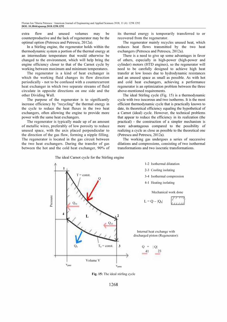
The ideal Stirling cycle (Fig. 15) is a thermodynamic
cycle with two isocorous and two isotherms. It is the most
efficient thermodynamic cycle that is practically known to
date, its theoretical efficiency equaling the hypothetical of
a Carnot (ideal) cycle. However, the technical problems
that appear to reduce the efficiency in its realization (the
practical) - the construction of a simpler mechanism is
more advantageous compared to the possibility of
realizing a cycle as close as possible to the theoretical one
(Petrescu and Petrescu, 2012a).
The working gas undergoes a series of successive
dilations and compressions, consisting of two isothermal
transformations and two isocratic transformations.
Fig. 15: The ideal stirling cycle
1
4
Pre
ssure
T = const. Q
Q23
L
Q41
2
3 Q0 T0 = const.
Volume V vpmi vpme
Q =
41 23
| Q|
Internal heat exchange with discharged piston (Regenerator):
L = Q − |Q0|
Mechanical work done
1-2 Isothermal dilatation
2-3 Cooling isolating
3-4 Isothermal compression
4-1 Heating isolating
The ideal Carnot cycle for the Stirling engine

Florian Ion Tiberiu Petrescu / American Journal of Engineering and Applied Sciences 2018, 11 (4): 1258.1292
DOI: 10.3844/ajeassp.2018.1258.1292
1269
Time 1: 1-2 on the graph is an isothermal (constant
temperature) degradation during which the gas performs
mechanical work on the environment. The heat absorbed
Q and the L12 mechanical work are linked by formula
(I) (Petrescu and Petrescu, 2012a):
2
12 12
1
lnV
Q L n R TV
= = ⋅ ⋅ ⋅ (I)
Time 2: 2-3 on the graph is an isochoric cooling (at
constant volume) during which the gas is brought to its
initial state by heat transfer to the regenerator. The cured
heat is determined by the formula (II):
( )23 0vQ n C T T= ⋅ ⋅ − (II)
Time 3: 3-4 on the graph is an isothermal compression
(it is constantly constant at constant temperature), where
the mechanical work required to modify the volume L34
is equal to the cured heat, Q0 (relation III):
3
0 34 34
4
lnV
Q Q L n R TV
≡ = = ⋅ ⋅ ⋅ (III)
Time 4: 4-1 on the graph is an isocorous heating
(takes place at constant volume) during which the heat
absorbed by the regenerator during the regenerator is
ceded to the gas (relation IV), its value being:
( )41 0vQ n C T T= ⋅ ⋅ − (IV)
The useful mechanical work appears in the pV
diagram of Fig. 15, it being the area or area closed by
the cycle curve, whereas in a Ts (entropy-temperature)
diagram it would appear as a result of the difference
between the absorbed and the calorific energy, being
the one that produces the useful power Wt,
(relationship V):
0
0abs ced
Q Q L
L Q Q Q Q
= +
= − = − (V)
Using the formulas above for Q and Q0, the useful
mechanical work takes the form of VI:
( )
2 3
1 4
2 3
0
1 4
2 3
1 4
0
ln
ln ln
ln
pme
pmi
pme
pmi
V VL n R T n R T
V V
V VL n R T T
V V
VV V
V V V
VL n R T T
V
= ⋅ ⋅ ⋅ − ⋅ ⋅ ⋅
⇒ = ⋅ ⋅ ⋅ − ⋅ = = ⇒ = ⋅ ⋅ ⋅ −
(VI)
Fig. 16: The yield of the Carnot cycle is also the thermal efficiency of the Stirling engine
The yield of the Carnot cycle is also the thermal efficiency of the Stirling engine
1.0
0.9
0.8
0.7
0.6
0.5
0.4
0.3
0.2
0.1
0
η
200 300 400 600 800 1000 1200 1400 1600 TW [K]
-73 27 146 327 527 727 927 1127 1327 [°C]
200 <-> -73 250 <-> -23 300 <-> -27
TK TK
[K] [°C]
1W K K
W W
T T T
T Tη
−
= = −

Florian Ion Tiberiu Petrescu / American Journal of Engineering and Applied Sciences 2018, 11 (4): 1258.1292
DOI: 10.3844/ajeassp.2018.1258.1292
1270
The weakly stated point of the Stirling engines is
the energy cycle yield (Carnot cycle yield). In
principle, the Stirling engines can not achieve a high
Carnot yield (Fig. 16), because the maximum working
temperature is limited by the hot source temperature.
In practice, the working gas cannot be heated above
800 [°K] (527 [°C]). At these low temperature
differences the Carnot yield is about 66% and is thus
much lower than that of the internal combustion
engines. Internal combustion engines frequently reach
temperatures of 727 [°C] (1000 [°K]), for which
Carnot's energy efficiency is about 76%.
This problem also occurs in thermal power stations
equipped with steam generating turbines that reach 66%
of their Carnot yield, resulting in an effective efficiency
of just over 40%. The current Stirling engines reach 50-
60% of their Carnot yield and work with a
correspondingly lower effective efficiency.
We aim to bring some improvements to the Stirling
engine from a mechanical point of view, improvements
that will also affect its thermal performance, so these
improvements can create a new Stirling engine that
works with a superior mechanical efficiency (Petrescu
and Petrescu, 2012a).
Improvements of the proposed mechanical nature will
be presented in the Results section.
Results
Determination of Mechanical Efficiency in Piston-
Rod-Crank System
The piston crank shaft has many uses, being used
mainly in two main ways, as a motor or compressor. In
four-stroke internal combustion engines, the piston crank
shaft mechanism is a single-stroke engine of the total of
four (Grunwald, 1980). In the other three times, the
mechanism behaves like a compressor, receiving the
power (being driven) from the crank (crankshaft) and
pushing the piston (in the two compression or discharge
times) or pulling it (at the intake). Practically, the four-
stroke engine power cycle is completed in two complete
kinematic cycles (Petrescu and Petrescu, 2012a).
The efficiency of the motor mechanism (driven by
piston power) differs from that of the compressor
mechanism (driven by the crankcase) (Grunwald, 1980;
Hargreaves, 1991; Homeţescu, 2003; Martini, 1978;
Petrescu and Petrescu, 2014a; 2014b; 2014c; 2012a;
2005a; 2005b; 2003; Petrescu, 2012).
For this reason, the two distinct cases will be studied
separately:
A. When the mechanism works in the engine mode,
being driven by the piston
B. When the mechanism works in the compressor (or
pump) mode, it is driven by the crankshaft
Figure 17 shows the kinematic diagram of the piston
crank shaft mechanism. The constructive parameters of
the mechanism are: r, the crank radius (or the distance
from the spindle spindle axis to the spindle spindle axis);
l, spike length (distance from spindle spindle axis to
spindle pin spindle); e, the eccentricity (distance from
the spindle spindle axis to the piston guide axis). The
mechanism is positioned by the angle, j, which
represents the angle of rotation and positioning of the
crank. White is positioned at one of the two angles, a or
y (Fig. 17). The distance from the center of rotation of
the crank O to the center of the piston bolt B, projected
on the translation axis of the piston, is marked with the
variable yB (Petrescu and Petrescu, 2012a).
We design the vector equation of the contour of the
mechanism on two rectangular planar axes Ox and Oy
and obtain the two scalar positions of the mechanism
given by the position system 1 (Fig. 17):
cos cos
sin sinB
r l e
r l y
ϕ ψ
ϕ ψ
⋅ + ⋅ = −
⋅ + ⋅ = (1)
It is customary to solve the disconnected position
system (1), from the first relation of the system to the
y-axis cosine (according to relation 2) and the second
one to isolate the displacement s of the piston
(according to relation 3):
cos
cos
e r
l
ϕψ
+ ⋅
= − (2)
sin sinB
s y r lϕ ψ= = ⋅ + ⋅ (3)
By deriving the position system (1), the speed system
(4) is obtained:
sin sin 0
cos cosB
r l
r l y
ϕ ϕ ψ ψ
ϕ ϕ ψ ψ
− ⋅ ⋅ − ⋅ ⋅ =
⋅ ⋅ + ⋅ ⋅ =
ɺ ɺ
ɺ ɺ ɺ (4)
From the first relation of the system (4) the angular
velocity (according to relation 5) is calculated and the
linear velocity of the piston (relation 6) is determined
from the second velocity (4) equation:
sin
sin
r
l
ϕψ ϕ
ψ
⋅
= − ⋅
⋅
ɺ ɺ (5)
cos cosBy r lϕ ϕ ψ ψ= ⋅ ⋅ + ⋅ ⋅ɺ ɺɺ (6)
The velocity system (4) is also derived in order to
obtain the acceleration system (7):
2 2
2 2
cos cos sin 0
sin sin cosB
r l l
r l l y
ϕ ϕ ψ ψ ψ ψ
ϕ ϕ ψ ψ ψ ψ
− ⋅ ⋅ − ⋅ ⋅ − ⋅ ⋅ =− ⋅ ⋅ − ⋅ ⋅ − ⋅ ⋅ =
ɺ ɺ ɺɺ
ɺ ɺ ɺɺ ɺɺ
(7)

Florian Ion Tiberiu Petrescu / American Journal of Engineering and Applied Sciences 2018, 11 (4): 1258.1292
DOI: 10.3844/ajeassp.2018.1258.1292
1271
Fig. 17: The kinematic scheme of the piston crankshaft mechanism
From the first equation of the system (7) the angular
acceleration ψɺɺ (according to relation 8) is calculated and
from the second equation of the system (7) the linear
acceleration of the piston Byɺɺ , (relation 9) is determined:
2 2cos cos
sin
r l
l
ϕ ϕ ψ ψψ
ψ
⋅ ⋅ + ⋅ ⋅
= −
⋅
ɺ ɺɺɺ (8)
2 2
cos sin sinBy l r lψ ψ ϕ ϕ ψ ψ= ⋅ ⋅ − ⋅ ⋅ − ⋅ ⋅ɺɺ ɺ ɺɺɺ (9)
Angle α is expressed according to the angle ψ,
according to the expression (10):
90α ψ= − (10)
The links between the basic trigonometric functions
of these angles are expressed by system relations (11):
cos sin
sin cos
α ψ
α ψ
=
= − (11)
The sinus of the angle α, sinα is expressed by the
relationship (2) and the second equality in the system
(11), obtaining the relation of the form (12):
cossin
e r
l
ϕα
+ ⋅
= (12)
The speed of the piston takes shape (13) (Petrescu
and Petrescu, 2012a):
( )
( ) ( )
( )
cos cos
sin coscos
sin
cos sin sin cossin
sin sin
sin sin
sin
sin
B B
B
v y r l
rr
r
r r
v r
ϕ ϕ ψ ψ
ϕ ϕ ψϕ ϕ
ψ
ϕϕ ψ ϕ ψ
ψ
ψ ϕ ψ ϕϕ ω
ψ ψ
ψ ϕω
ψ
= = ⋅ ⋅ + ⋅ ⋅ ⋅ ⋅ ⋅= ⋅ ⋅ − ⋅= ⋅ ⋅ − ⋅
− −= ⋅ ⋅ = ⋅ ⋅
− = ⋅ ⋅
ɺ ɺɺ
ɺɺ
ɺ
ɺ
(13)
The piston crank shaft mechanism works in the
engine mode for a single time in the four (or two) times
of the power cycle of the four-stroke Otto or Diesel
engine (or two-stroke engines respectively type Stirling).
The engine time has a corresponding crank
movement of about 180 degrees (about p radians) when
the piston moves from the dead point to the distant dead
point (i.e., when the piston moves between its two
extreme positions, but necessarily from the minimum
volume to the maximum working volume of the
respective cylinder – Fig. 18), the crank from position a
(in extension to white) and reaching position b (overlaid
over white); this is the driving time of the energy cycle.
y
B
0
3
2
l
yB
P
α
e
O
0
r 1
ϕ
ω
A
ψ
x

Florian Ion Tiberiu Petrescu / American Journal of Engineering and Applied Sciences 2018, 11 (4): 1258.1292
DOI: 10.3844/ajeassp.2018.1258.1292
1272
(a) (b)
Fig. 18: Kinematic schemes of the engine mechanism in extreme positions (a) When the crank is in the extension of the bar (b)
When the crank overlaps over the bar
Fig. 19: The forces in the piston crank mechanism, when the power (the driving force) is transmitted from the piston to the crank
0 0
BI
y
3 l
αI
AI
ϕI
1
O
r
ψI
2
P
e 0 ω
Near dead point
l + r
x
2
3
y
BII
αII
l-r
l
1
e
P
0
O
Distant dead point
ϕII
ω
ψII
AII
r
The crank is in prolonging
with the connecting-rod The crank is overlapped
on the connecting-rod
x
y
B
α
α
Fn
Fτ
ψ-ϕ
yB
ψ
ϕ
l
Fm
α
A
ψ-ϕ
ψ-ϕ
Fu
Fn
Fc
r
ϕ
O
e
P
0
x
ω
Florian Ion Tiberiu Petrescu / American Journal of Engineering and Applied Sciences 2018, 11 (4): 1258.1292
DOI: 10.3844/ajeassp.2018.1258.1292
1273
For Otto or Diesel engines, the energy cycle contains
two kinematic cycles (the big disadvantage of these
engines), while the Lenoir, Stirling, Wankel, Atkinson
engines overlap with the kinematic (the big advantage of
these engines).
To determine the efficiency of the piston crank shaft
mechanism when working as a motor, it is necessary to
determine the force distribution in the mechanism going
from the piston to the crank (Fig. 19).
The engine power, consumed (input force) Fm, is
divided into two components: (1) Fn - normal force
(oriented along the rod); (2) Fτ - tangential force
(perpendicular to B, per bar); see system (14); (Fig. 18 ω is
negative, the crank being printed with an hourly rotation):
cos sin
sin cos
n m m
m m
F F F
F F Fτ
α ψ
α ψ
= ⋅ = ⋅
= ⋅ = − ⋅ (14)
Fn is the only force transmitted through the bead
(along it) from B to A (because the bar has its
characteristic, general, rotary, roto-translational
movement, having no direct link to the bead; when the
bar has a connection, a coupling to the fixed element, it
turns from the bar to the rocker and it can only transmit
moment, the third possible case is that of a bar that slides
in a cylinder that also has a rotation lock with the bar,
there is a multiple rotation and translation coupling, in
which case the bar will have a movement of the rod
passing through it along a force, but there will also be a
rotation movement around the coupling with the beam
thus transmitting momentum.
In A, the force Fn is also divided into two
components: 1. Fu - the force that is perpendicular to the
crank; and 2. Fc - compressive or tensile force acting
along the crank. See system (15):
( ) ( )
( ) ( )
sin sin sin
cos sin cos
u n m
c n m
F F F
F F F
ψ ϕ ψ ψ ϕ
ψ ϕ ψ ψ ϕ
= ⋅ − = ⋅ ⋅ −
= ⋅ − = ⋅ ⋅ − (15)
The useful power Pu can be written as (16):
( )sin sin
u u A u
m
P F v F r
F r
ω
ω ψ ψ ϕ
= ⋅ = ⋅ ⋅
= ⋅ ⋅ ⋅ ⋅ −
(16)
The power consumed by Pc takes the form of the
expression (17):
( )sin
sinc m B mP F v F r
ψ ϕω
ψ
−
= ⋅ = ⋅ ⋅ ⋅ (17)
The instantaneous ηi mechanical yield can be
expressed using the relation (18):
( )
( )
( )2
2 2
2
sin sin
1sin
sin
cossin cos 1
mu
i
c
m
F rP
PF r
e r
l
ω ψ ψ ϕη
ω ψ ϕψ
ϕψ α
⋅ ⋅ ⋅ ⋅ −= =
⋅ ⋅ ⋅ − ⋅
+ ⋅= = = −
(18)
In order to calculate the mechanical efficiency η, the
expression of the instantaneous efficiency ηi from the
near dead point to the distant dead point, from ϕI to ϕ
II
(Fig. 19, system 19) can be integrated:
cos
2 cos
I
i
II
f
ea
l r
ea
l r
ϕ ϕ π
ϕ ϕ π
≡ = − +
≡ = ⋅ − −
(19)
It is possible to determine more easily the mechanical
efficiency starting from the system (18) but not using the
variable ϕ with the limits given by (19), but the variable
α, when the extreme values of the angle α, αM and αm
are known (or can be determined) (relations 20-22).
The misalignment e reduces yield, so it will take e = 0.
A ratio r/l = λ can be adopted so small that a
convenient yield is achieved at the engine mechanism.
As typically λ is constructively chosen less than 0.3, the
mechanical efficiency of the engine mechanism (the
piston crank engine during engine) is more than 96%,
provided that the deaeration is zero. The piston crank
shaft mechanism, when working in the engine, has a
very good mechanical (very high) efficiency:
( )
( )( )
( )
( ) ( )
( ) ( )
( ) ( )( )
21 1
cos
cos 2 11
2
1cos 2 1
2
1 1sin 2
2 2
sin 2 sin 21
2 2
sin 2 sin 20.5
4
sin 2 sin 20.5
4
sin cos0.5
M M
m m
M
m
M
m
M
m
i
M m
M m
M m
M m
M M
d d
d
d
α α
α α
α
α
α
α
α
α
η η α α αα α
αα
α
α αα
α αα
α α
αα
α α
α
α α
α α
α α
= ⋅ ⋅ = ⋅∆ ∆
⋅ += ⋅∆
= + ⋅⋅ ∆
= ⋅ ⋅ ⋅ + ⋅ ∆
− = + ∆
⋅∆
⋅ − ⋅= +
⋅∆
⋅ − ⋅= +
⋅ −
= +
∫ ∫
∫
∫
( )sin cos
2
m m
M m
α α
α α
−
⋅ −
(20)

Florian Ion Tiberiu Petrescu / American Journal of Engineering and Applied Sciences 2018, 11 (4): 1258.1292
DOI: 10.3844/ajeassp.2018.1258.1292
1274
arcsin
0
M
m
r eFor l r e
l
For r e
α
α
+ > + ⇒ =
> ⇒ =
(21)
( )
( )
0,1 6 0,99 99%;
0, 3 0,962 96,2%;
0,5 0,913 91,3%
For
For
For
λ η
λ
λ η
≤ ⇒ ≥ ≡
= ⇒= ≡ = ⇒ = ≡
(22)
The piston crank shaft mechanism (system) works
as a motor mechanism (with piston actuation), as we
have shown in one time, a single stroke within an
energy cycle, the other one or three times being
working times in the regimen crank (with crank drive
- from crankshaft).
On two-stroke cylinders (cylinders), one of the
times is the engine and at the other time the engine is
driven from the crank. Four-stroke engine cylinders
except for the Stirling have one engine time out of the
four, all three other with crank drive, which greatly
reduces the efficiency of these engines because the
mechanical efficiency of crank drive is about two
times lower than that of an actual engine time, as will
be seen immediately.
In this respect, the four-stroke four-stroke engine type
Stirling is the most advantageous, being driven
continuously from the piston (thus always having a
maximum drive motor drive).
For this reason, it has a stranger load feature, which
is said to be inappropriate for car use (the more
crankshaft driven crankshaft, although having less
mechanical efficiency, have a much longer stable and
respond quickly to changes in the working regimes
required by a vehicle, especially due to the large inertial
help of the shaft, plus the steering wheel, which are more
"nerve-wise" and therefore more dynamic).
This can, however, be easily corrected in Stirling
engines by using multiple cylinders simultaneously,
trapped on the same shaft (multi-cylinder Stirling), the
shaft having a high inertia, which can be further
enhanced by -a wheel.
Even though the cylinders work most of the time in
motor regimes, they are permanently connected to the
output shaft which must have a very high inertia in
construction, the movement at the output of the motor
being picked from the shaft.
Further, the piston rod crank system, if it is driven from
the crank (from the crankshaft, Fig. 20), will be studied.
We determine the distribution of forces and on the
basis of them and the known speeds we will already be
able to calculate the powers and the mechanical
efficiency of the system.
Fig. 20: The forces in a piston crankshaft, when it is driven from the crank
Fm
Fu
Ft
α
α
B
Fn α
yB
P e 0
O
ω ϕ
α A
r Ft
Ψ
Ψ-ϕ
Ψ-ϕ
ϕ
Ψ-ϕ=λ
y
Fn
x

Florian Ion Tiberiu Petrescu / American Journal of Engineering and Applied Sciences 2018, 11 (4): 1258.1292
DOI: 10.3844/ajeassp.2018.1258.1292
1275
The input force, the driving force (consumed motor
force), Fm, perpendicular to A on the crank OA (r), is
divided into two components: 1. Fn - the normal force
representing the active component, the only component
transmitted from the coupling A to Coupling B through
the bead (where forces are transmitted only along it); 2.
Fτ - tangential force, which, although not transmitted by
the bead, can rotate and deform it elastically at the same
time (bending); the equations to determine the two
components are given by the system (23):
( )
( )
sin
cos
n m
m
F F
F Fτ
ψ ϕ
ψ ϕ
= ⋅ −
= ⋅ − (23)
In Coupling B, the transmitted Fn force is divided
into two components: 1. Fu - force; 2. Fr - a normal force
on the guide axis (the axis of the guide); see the equation
system (24):
( )
( )
cos sin sin sin
sin cos sin cos
u n n m
r n n m
F F F F
F F F F
α ψ ψ ϕ ψ
α ψ ψ ϕ ψ
= ⋅ = ⋅ = ⋅ − ⋅
= ⋅ = − ⋅ = − ⋅ − ⋅ (24)
The useful power can be written in the form (25) and
the one consumed takes shape (26):
( )( )
( )2
sinsin sin
sin
sin
u u B m
m
rP F v F
F r
ω ψ ϕψ ϕ ψ
ψ
ω ψ ϕ
−
= ⋅ = ⋅ − ⋅ ⋅
= ⋅ ⋅ ⋅ −
(25)
c m A mP F v F r ω= ⋅ = ⋅ ⋅ (26)
The instantaneous mechanical efficiency of the
crank-shaft crankshaft driven by the crank can be
determined by the relationship (27):
( )( )
( ) ( )
2
2
222
2
sinsin
cos cos cos sin
mu
i
c m
F rP
P F r
l e r e r
l
ω ψ ϕη ψ ϕ
ω
ϕ ϕ ϕ ϕ
⋅ ⋅ ⋅ −= = = −
⋅ ⋅
− + ⋅ ⋅ + + ⋅ ⋅ =
(27)
In order to determine the mechanical efficiency of the
crankshaft system, it would be difficult to integrate the
middle expression of the system (27) when the
integration variable is the angle φ (integration being
possible only by approximate methods, which would not
allow for a final expression).
Using the angles ψ and φ as the variable, the
integrated relationship (the first part of the system 27) is
simplified. But it is even easier to integrate the relation
(27) from the bottom when we have a single variable, λ
(relation 28):
( )( )( )
( )
( ) ( )
( ) ( )
( ) ( )( )
21 1sin
1 cos 21 11 cos 2
2 2.
1 1sin 2
2. 2
sin 2 sin 21
2 2
sin 2 sin 21
2 4
sin 2 sin 20,5
4
sin cos0,5
M M
m m
M M
m m
M
m
i
M m
M m
M m
M m
M
d d
d d
λ λ
λ λ
λ λ
λ λ
λ
λ
η η λ λ λλ λ
λλ λ λ
λ λ
λ λλ
λ λλ
λ
λ λ
λ
λ λ
λ λ
λ λ
= ⋅ ⋅ = ⋅∆ ∆
− ⋅= ⋅ = − ⋅ ⋅∆ ∆
= ⋅ − ⋅ ⋅ ∆
− = ∆ −
⋅∆
⋅ − ⋅= −
⋅∆
⋅ − ⋅= −
⋅ −
⋅= −
∫ ∫
∫ ∫
( )sin cos
2
M m m
M m
λ λ
λ λ
− ⋅ ⋅ −
(28)
As it results from the final relations (28), the
mechanical efficiency of the crankcase crankshaft driven
by the crankshaft (motor shaft) cannot exceed the
maximum value of 50%.
So, at optimal design, the efficiency of the crank
shaft crankshaft piston system is approaching 100%
and that of the crankshaft (the motor shaft) is below
50%, it follows that the best cylinder system is the one
that is permanently driven from the piston, i.e. the
Stirling engine.
In a stirring engine, the mechanical efficiency over the entire energy cycle (which coincides with the kinematic cycle) is about 80-99.9% depending on the design mode. The thermal yield (of the Carnot cycle) for optimal high temperature operation (as seen in the first
chapter) reaches 55-65%. It results that the total (final) yield of a well-designed
Stirling, with a hot source of high temperatures, reaches between 44% and 65%, which means a lot. No other thermal engine reaches such values.
Because some say that Stirling has lower returns
than Otto or Diesel and others, on the contrary, that
Stirling's performance is its strong point, we need to
make a more detailed discussion at this point. What
benefit does Otto and Diesel achieve at a heat output of
65-75% compared to only 55-65% in the Stirling
engines, if the final output of an engine is the product
of its thermal and mechanical efficiency and in terms of
mechanical efficiency a Stirling in a four-stroke, well-
designed, can achieve theoretically 99.999% (i.e.,
almost 100%), while a four-stroke Diesel or Otto will
practically achieve a mechanical efficiency of no more
than 56% (3*45%+90%): 4] so that the total (final)
output of an Otto or Diesel will be only about 39%
(56*70), well below the maximum of a Stirling, 65%.

Florian Ion Tiberiu Petrescu / American Journal of Engineering and Applied Sciences 2018, 11 (4): 1258.1292
DOI: 10.3844/ajeassp.2018.1258.1292
1276
Let's recall that for a long time the Otto or Diesel
engines were running at a final yield of only 12-20%
and with a high weight they reached the final yields of
25-30%, while the Stirling engines reached 50-65%? However, engines in V are able to achieve higher
overall yields. With a mechanical efficiency of about 70% and a maximum thermal level of 75%, an Otto or Diesel engine in V can achieve a final yield of about 52- 53%.
Constructively, a piston cylinder version with the piston stroke as small as possible and the largest bore should be adopted.
Dynamic Kinematic of the Rod Piston Crank System
The cinematic of the piston crankshaft mechanism of Fig. 21 is generally known to be solved by the relationships (A1-A13):
cos cos
sin sinB
r l e
r l y
ϕ ψ
ϕ ψ
⋅ + ⋅ = −
⋅ + ⋅ = (A1)
cos
cos
e r
l
ϕψ
+ ⋅
= − (A2)
sin sinB
s y r lϕ ψ= = ⋅ + (A3)
sin sin 0
cos cosB
r l
r l y
ϕ ϕ ψ ψ
ϕ ϕ ψ ψ
− ⋅ ⋅ − ⋅ ⋅ =
⋅ ⋅ + ⋅ ⋅ =
ɺ ɺ
ɺ ɺ ɺ (A4)
sin
sin
r
l
ϕψ ϕ
ψ
⋅
= − ⋅
⋅
ɺ ɺ (A5)
cos cosBy r lϕ ϕ ψ ψ= ⋅ ⋅ + ⋅ ⋅ɺ ɺɺ (A6)
2 2
2 2
cos cos sin 0
sin sin cosB
r l l
r l l y
ϕ ϕ ψ ψ ψ ψ
ϕ ϕ ψ ψ ψ ψ
− ⋅ ⋅ − ⋅ ⋅ − ⋅ ⋅ =− ⋅ ⋅ − ⋅ ⋅ + ⋅ ⋅ =
ɺ ɺ ɺɺ
ɺ ɺ ɺɺ ɺɺ
(A7)
2 2cos cos
sin
r l
l
ϕ ϕ ψ ψψ
ψ
⋅ ⋅ + ⋅ ⋅
= −
⋅
ɺ ɺɺɺ (A8)
2 2
cos sin sinBy l r lψ ψ ϕ ϕ ψ ψ= ⋅ ⋅ − ⋅ ⋅ − ⋅ ⋅ɺɺ ɺ ɺɺɺ (A9)
90α ψ= − (A10)
cos sin
sin cos
α ψ
α ψ
=
= − (A11)
cos
sine r
l
ϕα
+ ⋅
= (A12)
( )
( ) ( )
( )
cos cos
sin coscos
sin
cos sin sin cossin
sin sin
sin sin
sin
sin
B B
B
v y r l
rr
r
r r
v r
ϕ ϕ ψ ψ
ϕ ϕ ψϕ ϕ
ψ
ϕϕ ψ ϕ ψ
ψ
ψ ϕ ψ ϕϕ ω
ψ ψ
ψ ϕω
ψ
= = ⋅ ⋅ + ⋅ ⋅ ⋅ ⋅ ⋅= ⋅ ⋅ − ⋅= ⋅ ⋅ − ⋅
− −= ⋅ ⋅ = ⋅ ⋅
− = ⋅ ⋅
ɺ ɺɺ
ɺɺ
ɺ
ɺ
(A13)
Fig. 21: The kinematic scheme of the piston crankshaft mechanism
yB
B
y
3
2 0
l
α
ψ
A
r 1
ϕ
ω
O P
e 0
x

Florian Ion Tiberiu Petrescu / American Journal of Engineering and Applied Sciences 2018, 11 (4): 1258.1292
DOI: 10.3844/ajeassp.2018.1258.1292
1277
Fig. 22: Dynamic forces and speeds in the piston crank shaft mechanism, when power is transmitted from the piston to the crank
In Dynamic Cinematic, the (dynamic) velocities are
aligned in the direction of the forces as is natural, so that
they no longer coincide with the kinematic speeds
imposed by the couplings of the mechanism (Fig. 22).
Dynamic speeds due to forces occur, speeds that
represent the dynamic kinematics (the influence of
inertial forces, influence that determines the final
dynamic aspect of speeds).
The dynamic kinematics is therefore the kinematic
study of the displacements, speeds and accelerations
resulting from the direction of operation of the velocities
following the direction of the forces. The expressions of
velocity in the dynamic kinematics are easily obtained, it
is derived in relation to the time to determine the
expressions of the accelerations in the dynamic
kinematics and the expressions of the velocities are
integrated in order to obtain the corresponding
movements. Determining the movements in the dynamic
cinematic becomes therefore more difficult.
To begin with, we will determine the velocities in the
dynamic kinematics for piston crank shaft mechanism
actuated by the piston (Fig. 22). We can write the
relationships (A14-A16):
B mv v= (A14)
cos sinn m mv v vα ψ= ⋅ = ⋅ (A15)
( ) ( )sin sin sinu n mv v vψ ϕ ψ ψ ϕ= ⋅ − = ⋅ ⋅ − (A16)
We also want to find out the dynamic performance,
more precisely the mechanical efficiency instantly when
the mechanism has dynamic regimes and the speeds are
those in the dynamic cinematic, the actuation of the
mechanism being of the motor type, i.e., from the piston.
The useful force is determined by the relation (A17)
presented in the previous chapter:
( ) ( )sin sin sinu n m
F F Fψ ϕ ψ ψ ϕ= ⋅ − = ⋅ ⋅ − (A17)
The useful power is written in this case in form A18:
( ) ( )
( )2 2
sin sin sin sin
sin sin
u u u
m m
m m
P F v
F v
F v
ψ ψ ϕ ψ ψ ϕ
ψ ψ ϕ
= ⋅= ⋅ ⋅ − ⋅ ⋅ ⋅ −
= ⋅ ⋅ ⋅ −
(A18)
Expression of power consumed is given by
relationship A19:
c m mP F v= ⋅ (A19)
We can now determine the dynamic yield, more
precisely the dynamic dynamic dynamics (relationship
A20):
( )2 2sin sin
DM Mu
i i
c
PD
Pη ψ ψ ϕ η= = ⋅ − = ⋅ (A20)
where, ηi is the instantaneous mechanical efficiency of the
crank shaft piston actuated by the piston and DM
is a
dynamic coefficient, which for the piston-driven piston
crank mechanism (in Motor mode) has the expression A21:
P
yB
B
y
vτ vn
Fn Fτ
vm
Fm
α
α
α
e 0
O
r ϕ ω
ϕ
ψ-ϕ
ψ-ϕ
ψ-ϕ
ψ
Fu
Fn vn
vu
l
A
Fc vc
x

Florian Ion Tiberiu Petrescu / American Journal of Engineering and Applied Sciences 2018, 11 (4): 1258.1292
DOI: 10.3844/ajeassp.2018.1258.1292
1278
( ) ( )2 2sin sin
MD ψ ϕ ϕ ψ= − = − (A21)
In this case, let us recall that the instantaneous
mechanical efficiency has the expression A22:
2
sini
η ψ= (A22)
It should be noted that the dynamic yield is precisely
the product of the known, simple (cinematic) yield and
the dynamic coefficient (relation A23):
DM M
i iDη η= ⋅ (A23)
The kinematic expression of the speed of point B
(relationship A24) is known:
( )sin
sinm B Av v v
ψ ϕ
ψ
−
≡ = ⋅ (A24)
With relation A24 introduced in formula A16,
velocity vu takes shape A25:
( ) ( )
( )( ) ( )2
sin sin sin
sinsin sin sin
sin
u n m
A A
D
A A
v v v
v v
v v D
ψ ϕ ψ ψ ϕ
ψ ϕψ ψ ϕ ψ ϕ
ψ
= ⋅ − = ⋅ ⋅ −
−= ⋅ ⋅ ⋅ − = ⋅ −
≡ − ⋅
(A25)
( )2sin
MD ψ ϕ= − (A26)
It is obtained from here (from the dynamic
kinematics) the expression of the dynamic coefficient
DM of the reciprocating piston actuated mechanism
(relation A26), observing that it is identical to the
expression A21 where the dynamic coefficient was
determined based on the dynamic calculation. This
checks the uniqueness of the dynamic coefficient for
the same mechanism operated in the same way. To
complete this new theory, the dynamic coefficient of
the piston crank shaft actuated by the crank (in
compressor mode) is still to be determined.
Figure 23 shows the transmission of forces aligned
with the forces, which occurs in the dynamic cinematics.
Fig. 23: Dynamic forces and speeds in a piston crank shaft system, when driven from the crank
yB
O
Fn
vn vu
Fu
Fr vr
α
α
B
y
α
α
Fm
vm
Fτ
vτ A
r
Fn
vn
ψ-ϕ = λ
ψ-ϕ
ψ-ϕ
ψ
ϕ ω
0 e P
ϕ
x

Florian Ion Tiberiu Petrescu / American Journal of Engineering and Applied Sciences 2018, 11 (4): 1258.1292
DOI: 10.3844/ajeassp.2018.1258.1292
1279
The inlet force Fm and the inlet velocity vm decompose
generating the component along the line Fn and vn
respectively. Forces are the real forces acting on the
mechanism and these cinematic-dynamic velocities are the
natural ones that follow the trajectories (directions)
imposed by the forces. Generally, they overlap and
impose over known kinematic (static) velocities, which
are calculated on the basis of the links imposed by the
kinematic couple of the mechanism (depending on the
kinematic chain). You can write for speeds A27:
( ) ( )
( )
( )
( )( )
2
sin sin;
sin sin
cos sin sin sin
sin sin
sinsin sin
sin
sin
D C C
B A B B A
u n n m
A
D C
u B A A
C
v v v v D v D
v v v v
v
v v v v D
D
ψ ϕ ψ ϕ
ψ ψ
α ψ ψ ψ ϕ
ψ ψ ϕ
ψ ϕψ ψ ϕ
ψ
ψ
− −= ⋅ = ⋅ = ⋅ ⋅
= ⋅ = ⋅ = ⋅ ⋅ −= ⋅ ⋅ −
− = ⇒ ⋅ ⋅ − = ⋅ ⋅
⇒ =
(A27)
For forces, powers and yields, the following
relationships are written (A28-A34):
( )
( )
sin
cos
n m
m
F F
F Fτ
ψ ϕ
ψ ϕ
= ⋅ −
= ⋅ − (A28)
( )
( )
cos sin sin sin
sin cos sin cos
u n n m
r n n m
F F F F
F F F F
α ψ ψ ϕ ψ
α ψ ψ ϕ ψ
= ⋅ = ⋅ = ⋅ − ⋅
= ⋅ = − ⋅ = − ⋅ − ⋅ (A29)
( )( )
( ) ( )2 2
sinsin sin
sin
sin sin
u u B m
m m A
rP F v F
F r F v
ω ψ ϕψ ϕ ψ
ψ
ω ψ ϕ ψ ϕ
⋅ ⋅ −= ⋅ = ⋅ − ⋅ ⋅
= ⋅ ⋅ ⋅ − = ⋅ ⋅ −
(A30)
c m A mP F v F r ω= ⋅ = ⋅ ⋅ (A31)
( )( )
2
2sin
sinm Au
i
c m A
F vP
P F v
ψ ϕη ψ ϕ
⋅ ⋅ −
= = = −
⋅
(A32)
( ) ( )
( )
( )
2 2
2 2
sin sin sin sin
sin sin
sin sin
D D
u u B
m A
m
m A
P F v
F v
F r
F v
ψ ϕ ψ ψ ψ ϕ
ω ψ ϕ ψ
ψ ϕ ψ
= ⋅= ⋅ − ⋅ ⋅ ⋅ ⋅ −
= ⋅ ⋅ ⋅ − ⋅
= ⋅ ⋅ − ⋅
(A33)
( )
( )
2 2
2 2
sin sin
sin sin
D
m ADC u
i
c m A
C
i
F vP
P F v
D
ψ ψ ϕη
ψ ϕ ψ η
⋅ ⋅ ⋅ −
= =
⋅
= − ⋅ = ⋅
(A34)
The first conclusion that can be drawn is that the
instantaneous dynamic mechanical efficiency (which is
closer to the real mechanism) is less than the ordinary
mechanical mechanics, because the dynamic yield is
even the classic mechanical efficiency multiplied by
the dynamic coefficient which being subunitarily
results that the dynamic yield will be smaller or at most
equal to the classic one. In addition, the dynamic yield is the same for crank
drive and piston engine actuation and will have the same value regardless of the drive type. The dynamic yield is practically uniform, but not all operating modes of the thermal motors are completely dynamic. This makes the Stirling engine or the two-stroke engine (Lenoir) real mechanical performance not much higher than the four-stroke Otto or Diesel engines. The higher the working speeds, the operating modes become almost completely dynamic.
Today, with high and very high working speeds, four-
stroke internal combustion engines reach comparable
performance to those of the Stirling engine or two-stroke
engines. The more working regimes take place at higher
speeds, the benefits of Stirling or Lenoir decrease. Although the dynamic mechanical performance
(closest to the real) is practically calculated with the same formula regardless of the drive type, the dynamic speeds and accelerations in the couplings differ depending on the drive mode, even for the same coupling.
Thus dynamic velocities (in the dynamic kinematics)
of point B are calculated with relations A35. Even if the output dynamically becomes uniform, the
speeds and accelerations are more linear in the crank and sharper (and vibrational) drives during the piston stroke, so four-stroke internal combustion engines are more advantageous at this point view, followed by the two-stroke (Lenoir), the last being the Stirling type engines:
( )
( )( )
( )
( )
( )
( )
2 2
2
3
2
2
2 2
:
sin ; sin ;
sinsin
sin
sin
sin
sin
sin
sin ; sin ;
M
i
D
B B A
A
D
A A
D
C
i
Case A withaction fromthe piston
D regimeMotor
v v D v
v
v v D r
D
CaseB withaction fromthecrank
D regimeComp
ψ ϕ η ψ
ψ ϕψ ϕ
ψ
ψ ϕ
ψ
ω ψ ϕ
ω ω ω ψ ϕ
ψ η ψ ϕ
−
= − =
−= ⋅ = ⋅ ⋅ −
−= ⋅
= ⋅ = ⋅ ⋅ −
= ⋅ = ⋅ −
−
= = −
( )
( )
2
3
2
2
sinsin
sin
sin sin
sin
sin
D
B B A
A
D
A A
D
ressor
v v D v
v
v v D r
D
ψ ϕψ
ψ
ψ ϕ ψ
ω ψ
ω ω ω ψ
−= ⋅ = ⋅ ⋅
= ⋅ − ⋅ = ⋅ = ⋅ ⋅
= ⋅ = ⋅
(A35)
Dynamic accelerations are determined with
relationships A36, in which the dynamic velocity relationship (appropriately arranged) is derived to obtain dynamic acceleration expression.
Florian Ion Tiberiu Petrescu / American Journal of Engineering and Applied Sciences 2018, 11 (4): 1258.1292
DOI: 10.3844/ajeassp.2018.1258.1292
1280
( )( )
( ) ( ) ( )
( ) ( ) ( )
( ) ( ) ( )2
sinsin sin
sin
sin cos sin cos
sin cos cos
sin
sin sin sin cos cossin
D D
B A B A
D D
B B A
D
A BD
B
D A
B
v v D v v D
v v v D D
v D D vv
va D D D
ψ ϕψ ψ ϕ
ψ
ψ ψ ψ ψ ϕ ψ ϕ ψ ϕ
ψ ϕ ψ ϕ ψ ϕ ψ ψ
ψ
ψ ψ ϕ ψ ψ ϕ ψ ϕ ψψ
−= ⋅ ⋅ ⇒ ⋅ = ⋅ ⋅ −
⋅ + ⋅ ⋅ − ⋅ ⋅ − + ⋅ − ⋅ −
⋅ ⋅ − + ⋅ − ⋅ − − ⋅ ⋅ ⇒ =
⇒ = ⋅ ⋅ ⋅ − + ⋅ ⋅ − ⋅ − − ⋅
ɺɺ ɺ ɺɺ
ɺ ɺ ɺ ɺ
ɺ
ɺ ɺ ɺ ( )
( ) ( )
( ) ( ) ( ) ( )
2
2
2
sin
sin sin sin sinsin
:
sin ; 2 sin cos
sin ; 2 sin cos
A
M M
C C
vD D D
Case A withaction fromthe piston
D D
CaseB withaction fromthecrank
D D
CaseC canobrain
ψ ϕ ψ
ψ ψ ϕ ψ ϕ ϕ ψ ψ ϕψ
ψ ϕ ψ ϕ ψ ϕ ψ ϕ
ψ ψ ψ ψ
⋅ − ⋅
= ⋅ ⋅ ⋅ − + ⋅ ⋅ − ⋅ ⋅ −
−
= − = ⋅ − ⋅ − ⋅ −
−
= = ⋅ ⋅ ⋅
−
ɺ
ɺ ɺ ɺ
ɺ ɺ ɺ
ɺ ɺ
:
1; 0.
s thenormal accelerationwith
D D
= = ɺ
(A36)
Through a calculation program, dynamic velocities and accelerations are determined for different types of thermal
motors using relations (A35) and (A36).
Figures 24 and 25 are the two-stroke diagrams (Lenoir) in Fig. 24 being the dynamic speeds and in Fig. 25 the
dynamic accelerations can be observed.
Fig. 24: Dynamic speeds on the Lenoir engine, two-stroke (with larger squares brown color)
0
150
100
50
0
-50
-100
-150
100 200 300 400 500 600 700 800 900
vB [m/s]
vBD [m/s]

Florian Ion Tiberiu Petrescu / American Journal of Engineering and Applied Sciences 2018, 11 (4): 1258.1292
DOI: 10.3844/ajeassp.2018.1258.1292
1281
Fig. 25: Dynamic accelerations on the Lenoir engine, two-stroke (with larger squares brown color)
Fig. 26: Dynamic speeds on the four-stroke Otto (or Diesel) engine
In the four-stroke Otto (or Diesel) engine, the
energy cycle no longer coincides with the kinematic,
so only the fourth part of the entire energy cycle is the
engine and only for it the dynamic speeds are shrunk
(see below, see diagram in Fig. 26) and dynamic
accelerations show shocks, vibrations and noises
(follow the diagram in Fig. 27).
In the four-stroke Stirling engine, all times are
engines, so the dynamic speeds are shrunk (thin, see the
diagram in Fig. 28) and dynamic accelerations are
shocks, vibrations and noises (follow the diagram in
Fig. 29) throughout the range.
It is seen that the dynamic disadvantages of thermal
motors are in fact a contradiction. The dynamics of their
mechanisms is better at crank drive (from the
crankshaft), but motor times (which have a lower
dynamic kinematics) are virtually the ones needed, the
only ones that produce the power (effectively) and which
40000
30000
20000
10000
0
-10000
-20000
-30000
-40000
-50000
0 100 200 300 400 500 600 700 800 900 aB[m/s2]
aBD[m/s2]
150
100
50
0
-50
-100
-150
aB[m/s2]
aBD[m/s2]
0 100 200 300 400 500 600 700 800 900
Florian Ion Tiberiu Petrescu / American Journal of Engineering and Applied Sciences 2018, 11 (4): 1258.1292
DOI: 10.3844/ajeassp.2018.1258.1292
1282
also generate high returns at the respective thermal
engine; on the other hand, however, these motorways
produce not only irregular operation with shocks,
vibrations and noise on the thermal engine but also
generate disadvantageous features. For this reason, the
Stirling four-stroke engine and two phases with each
active phase have the most power-and-load characteristic
at the most disadvantageous speed.
Fig. 27: Dynamic accelerations on the four-stroke Otto (or Diesel) engine
Fig. 28: Dynamic speeds in the Stirling four-stroke engine
40000
30000
20000
10000
0
-10000
-20000
-30000
-40000
-50000
aB[m/s2]
aBD[m/s2]
0 100 200 300 400 500 600 700 800 900
vB[m/s2]
vBD[m/s2]
0 100 200 300 400 500 600 700 800 900
20
15
10
5
0
-5
-10
-15
-20

Florian Ion Tiberiu Petrescu / American Journal of Engineering and Applied Sciences 2018, 11 (4): 1258.1292
DOI: 10.3844/ajeassp.2018.1258.1292
1283
Fig. 29: Dynamic accelerations in the Stirling four-stroke engine
The two-stroke internal combustion engine does not
have a very good feature and it also works with
vibrations, vibrations and very large noises, which can
overcome the known beatings of the four-stroke diesel
engines, the traction being shocks (interruptions) even
surpass those of the Stirling engines. The Lenoir engine
does not make an engine brake, a vehicle equipped with
a two-stroke thermal engine is overloaded (the brakes
get too hot), the safety of the traffic being very low and
the comfort of the passengers in the passenger
compartment much diminished.
From this point of view, the four-stroke Otto or
Diesel engines are the most advantageous, the first ones
actually representing the highest version. For the Otto
engines not to lose the advantage of fuel injection, many
years ago, carburetors were dropped, Otto engines being
gradually fueled by diesel fuel (keeps the ignition,
because gasoline does not fire itself as it does diesel).
Discussion
In the process of transforming thermal energy into
mechanical work, among the known thermal machines,
the Stirling engine is the one that can achieve the highest
yield (theoretically up to the maximum yield of the
Carnot cycle), although in practice it is reduced by the
properties of gas and materials used such as friction
coefficient, thermal conductivity, melting point, breaking
strength, plastic deformation, etc. This type of engine
can operate on the basis of a heat source irrespective of
its quality, whether it is solar, chemical, nuclear,
biological, etc.
Unlike internal combustion engines, the Stirling
engines can be economical, quieter, safer and less
maintenance-free. They are preferred in specific
applications where these advantages are reaped,
especially if the main objective is not to minimize
investment costs per unit of power (RON / kW) but to
those per unit of energy (RON / kWh). Compared to
internal combustion engines of a given power, the
Stirling engines require higher capital expenditure, are
larger and heavier, for which reason, viewed from this
point of view, this technology is uncompetitive. For
some applications, however, a sound analysis of the
earnings-to-revenue ratio may favor Stirling engines
versus internal combustion engines.
More recently, Stirling's benefits have become visible
compared to rising energy costs, lack of energy resources
and environmental issues such as climate change.
Increasing interest in Stirling engine technology has
spurred research and development in this area lately.
Uses range from water pumping to astronautics and
power generation based on rich sources of energy
incompatible with internal combustion engines such as
solar energy, or plant and animal scraps.
Another feature of the Stirling engines is their
reversibility. Mechanically operated, they can act as heat
pumps. Tests were conducted using wind energy to drive
a Stirling cycle heat pump to heat and condition air for
dwelling in cold weather.
Stirling engines today have different uses.
Stirling engines are especially used in natural,
unfavorable environments, in isolated locations, etc.
15000
10000
5000
0
-5000
-10000
-15000
aB[m/s2]
aBD[m/s2]
0 100 200 300 400 500 600 700 800 900

Florian Ion Tiberiu Petrescu / American Journal of Engineering and Applied Sciences 2018, 11 (4): 1258.1292
DOI: 10.3844/ajeassp.2018.1258.1292
1284
Powerful stationary or mobile generators are built
today with the Stirling motors, which operate an
electric generator, thus obtaining heat and electricity
in isolated places.
In theory, any temperature difference will put into
operation a Stirling engine. The heat source can be both
the energy emitted by burning a fuel (which justifies using
the term external combustion engine) as well as solar,
geothermal, nuclear, or even biological origin, in which
case the Stirling engine used can no longer be called
external thermal combustion engine, but a heat engine
with the use of an external power source. As we have
already shown, it can work by using a thermal gradient.
This thermal gradient (temperature difference) can be
considered in either direction (positive or negative) so that
Stirling engines can function not only when the external
source of temperature is warmer than the internal source
(the environment) but also when it is more cold (than
ambient temperature), using ice or snow for this purpose.
The cold source appears in the place where cryogenic
liquids or ice are used. In order to generate significant
power at low temperature differences, it is necessary to
transport large amounts of fluid through the external heat
exchanger, which will cause additional losses and reduce
cycle efficiency. Because the heat source and the working
gas are separated by a heat exchanger, a wide range of
heat sources including fuels or residual heat from other
processes can be used. Since they do not come in contact
with internal moving parts, the Stirling engine can also
work with siloxane-containing biogas, without the danger
of accumulating silicates that would damage components,
as is the case with the internal combustion engine which
would use the same type of fuel. Lubricant life is
significantly higher than the internal combustion engine,
which is another significant advantage of the Stirling
engines compared to the internal combustion engine.
La "U.S. Department of Energy in Washington,
NASA Glenn Research Center "(from Cleveland), a free
piston engine (Stirling type) is being studied for a
radioactive isotope generator. This device will use a
plutonium-based heat source. The "Los Alamos National Laboratory" developed a
"Stirling Thermal Acoustic Wave Machine" without moving parts. This machine converts heat into acoustic power waves (quoted from the indicated source) "can be used directly in acoustic waves or chillers with impulse tubes to produce cold by means of a heat source without using moving parts, or (...) to generate power through a linear generator or other electroacoustic power transformer."
Obviously the Stirling engine is also used here to
generate electricity and the heat that is used as a source
of energy can be taken from various sources.
On the basis of this principle, we can today take over
and transform the excessive heat that occurs day in
surface sand in desert areas into electricity. The cold area
is the sand from the greater depth, or even the air in the
environment.
In the desert the temperature differences are higher
because the surface sand gets very hot on the day.
Sahara with 9,000,000 km² is the largest desert on
earth. The Sahara comprises a third of Africa (roughly
the surface of the United States of America, or 26 times
the surface of Germany). This dry desert stretches from
the Atlantic Ocean to the Red Sea, forming a trapezium
with a length of east-west side of about 1,500-2,000 km
and north-south with a base length of 4,500-5,5000 km .
Most of the wilderness is rocky (Hamada) with gravel
(Serir), the sandy beach (Erg) occupying a smaller area. The name Sahara comes from the Arabic language -
"Sahara" which in tuareg dialect means "the sand desert". Another hypothesis is that the origin of the expression would be "sahraa" or "es-sah-ra" which means sterile, sterile. The Romans called the southern province of Carthage "Desert" (i.e., land uninhabited, abandoned). In the Middle Ages it was simply called the Great Desert and in the nineteenth century it was called the Sahara. Arabs call Sahara "Bahr bela ma" which would mean "Great without water".
The Sahara desert occupies almost entirely North
Africa, extending 5630 km from west to east, from the
Atlantic Ocean to the Red Sea and 1930 km from north to
south, from the Atlas Mountains and the Mediterranean
Sea up to in the area of savannah in the Sudan region.
In a narrow sense, it stretches to the east only to the
Valley of the Nile; the desert from the East of the Nile to
the Red Sea is known as the Arabian Desert.
Sahara occupies large parts of the states:
Morocco, Algeria, Tunisia, Libya, Egypt, Mauritania,
Mali, Niger, Chad, Sudan and a small part of Senegal
and Burkina Faso.
The climate is desert-tropical, with high average
temperatures (38°C), particularly hot and dry; the
dominant wind all year round is the Pasat wind, a dry
wind that brings rain. The wind and high temperature
variations from day to night have led to the formation of
the desert. In the winter, during the night the air
temperature drops to -10 degrees, while the summer can
reach during the day 58 degrees Celsius. Precipitation is
reduced (20-200 mm/year) and very high daily diurnal
heat (30°C in air and 70°C on the ground). The average
January temperature is +10°C and July 35°C. Lack of
permanent watercourses, the hydrographic network is
represented by winds (drought channels) that fill with
water during occasional rains.
The Sahara desert is a very energetic potential
(especially the day in the warmer months of the year).
Here, daytime temperatures of the soil often reach 70
[°C] (343 [°K]), which would allow a Stirling engine to
produce a Carnot energy yield of about 20-25%, that is, a
third or even half of the maximum efficiency with which
these types of engines work normally.

Florian Ion Tiberiu Petrescu / American Journal of Engineering and Applied Sciences 2018, 11 (4): 1258.1292
DOI: 10.3844/ajeassp.2018.1258.1292
1285
The soil/air temperature difference of 30-400 m/min
decreases the yield, but using the temperature difference
between the surface soil and the depth of about 500, a
satisfactory yield can be obtained.
An effective fitting of such high-powered Stirling
engine to drive a high-frequency alternating current
electric power generator could donate much more energy
to the desert area during the day than solar systems
(whether sand, gravel or rock) from which the engine is
warm, overheating that will be done as well as in modern
solar plants , through mirrors focused on that area; in this
way the place that has to be a hot source will remain hot
during the day (not influenced by the heat absorbed by the
engine) and additionally not only will the hot zone be
maintained but it will become even hotter, fact which will
increase Carnot's engine output from 15-20% to much
higher values, the higher the sand temperature will be.
This method allows you to get electricity (electric) on
a daily basis in any season, so not only in the summer
and it can also be practiced anywhere, leaving no need
for a desert area.
By cogeneration, from a pre-existing energy source,
usually an industrial process, with the help of an
installation, in addition to the mechanical or electrical
power delivered, heat is provided for heating. Normally
the primary heat source is the entry for the Stirling
engine heater and as such will have a higher temperature
than the heat source for the heating application made up
of the engine exhaust.
The power produced by the Stirling engine is often
used in agriculture in various processes, resulting in
biomass waste that in turn can be used as motor fuel to
avoid the cost of transporting and storing waste. The
process is generally abundant in energy resources being
economically advantageous.
WhisperGen, based in Christchurch/New Zealand,
has developed an AC Micro Combined Heat and Power
co-generation based on the Stirling cycle. These micro-
plants are methane-fueled heating systems that also
supply electricity to the grid. WhisperGen announced in
2004 that it will produce 80000 homes of this type for
UK housing. A batch of 20 plants started the test in
Germany in 2006.
In nuclear power plants there is the possibility of
using Stirling machines for power generation. By
replacing the Stirling engine turbines, the complexity of
the construction can be reduced, a higher yield can be
achieved and radioactive waste can be reduced. Certain
uranium enrichment reactors use liquid sodium as a
cooling agent. If the thermal energy is still used in a
steam plant, water/sodium heat exchangers are needed
which increases the degree of danger due to the
possibility of violent reaction of sodium with water in
case of direct contact. Using the Stirling engine causes
the water to be removed from the cycle.
US government laboratories have developed a
modern Stirling engine under the name SRG (Stirling
Radioisotope Generator) for use in space exploration. It
is designed to generate electricity for spacecraft leaving
the solar system with a life span of several decades.
This engine employs a single discharge piston (to
reduce moving parts) and high energy acoustic waves for
energy transfer. The heat source is a radioactive fuel
block and the residual heat is eliminated in space. This
assembly produces four times more energy from the
same fuel block as compared to a similar radiator (RTG)
type radiator (radiosotope thermoelectric generator).
Theoretically, Stirling engines would also have the
advantage of being an airplane engine. They are
quieter and less polluting, yields increase with altitude
(internal combustion engine output decreases with
altitude), are safer in operation due to fewer
components, especially mobile components and lack
of ignition, produce less vibration (structure of
resistance will last longer), are more reliable and safer
using less explosive fuel.
Kockums, the Swedish ship builder, constructed at
least 8 Gotland submarines with Stirling drives in 1980.
In the automotive industry, the use of Stirling engines
to drive cars is often argued by the power / weight ratio
too low and a start-up time too long.
Alongside projects from Ford and American Motor
Companies at NASA, at least two Stirling engines
were built.
The bigger problems lie in the long start time, the
slow response to acceleration, stop and load that has not
been resolved immediately. Many believe that hybrid
drive would eliminate these shortcomings, but for the
time being, no vehicle has been built on this basis.
The vehicles designed at NASA were called MOD I
and MOD II. In the case of MOD II, a normal spark
ignition engine was replaced by a 4-door Chevrolet
Celebrity hatchback in 1985.
In the report published in 1986, Annex A states that
consumption on both the highway and the city has
decreased for the average car from 5.88 L/100 km to
4.05 L/100 km and for the high-capacity car from 9.05
L/100 km to 7.13 L/100 km.
The start time of the NASA vehicle was 30 seconds,
while the Ford pilot car using an electric preheater in the
hot air area managed to start in just a few seconds.
Conclusions
The most common external combustion engines were
steam engines. Although initially used as a naval engine,
the emergence and development of steam engines (as
well as the first cam mechanism) are closely related to
the emergence and development of tissue wounds
(automatic tissue machines).

Florian Ion Tiberiu Petrescu / American Journal of Engineering and Applied Sciences 2018, 11 (4): 1258.1292
DOI: 10.3844/ajeassp.2018.1258.1292
1286
Today, stirring thermal combustion engines
complement and even replace steam engines, but in large
part those with internal combustion.
Most uses, stirling engines, have them in vehicles and
road, land and marine vehicles, but also within modern
energy systems.
Because the stirling engines started harder and less
adapted to the car-load feature of a car, initially the
stirring engines were introduced on adaptive cars, or
together with an internal combustion engine (diesel or
Otto) under the form of hybrid engines, or more recently
with an electric motor.
Along with an internal combustion engine, the stirring
engine greatly increases the efficiency of the hybrid
system, because it even works with the heat dissipated by
the diesel engine or Otto, that is, cooling the internal
combustion engine is not done by dissipating (heat loss)
but all the thermal energy (which is in the form of heat)
that has to lose the internal combustion engine will be the
warm source of the stirling engine and instead of losing it,
it will act effectively on the stirling engine, thus greatly
enhancing the efficiency of the system.
In green, sustainable, renewable, clean and friendly
energy, stirling engines are mainly used in two ways:
• Like a power generator in solar farms, where all the
redesigned and concentrated heat from the sun, lots
of parabolic mirrors, heat concentrated on a huge
boiler with water or oil, is used to heat the boiler,
which is the source constantly warming the stirring
engine, effectively acting it and it still rotates a very
high current generator
• Or as a motor positioned in the glare of a huge
parabolic mirror, acting constantly on the mirror,
rotating it in all directions so that it can permanently
capture as much solar energy as possible
In addition to vehicles and green energy, stirring
engines are still used since their appearance in power
groups, stationary or portable power generators,
hospitals, military units and so on.
Today the conquest of space is done through
robotization, automation, with modern, fast, autonomous
spacecraft, with many capabilities, but also with stirling
generators (Petrescu et al., 2017k; 2017l; 2017m; 2017n;
2017o; 2017p; 2017q; 2017r; 2017s; 2017t; 2017u;
2017v; 2017w; 2017x; 2017y; 2017z; 2017aa; 2017ab;
2017ac; 2017ad; 2017ae).
The operation of a main mechanism of a stirling
engine is basically similar to internal combustion heat
engines, with the exception that all times are engines.
From this point of view, the mechanical efficiency of a
stirring engine has the advantage of being greatly
increased compared to internal combustion engines, all
times being active, provided that the heat output of the
stirring engine can be raised from the design (by using a
warm source at a minimum of 900 degrees).
A stirling engine uses to operate a temperature gradient,
so any difference between the ambient temperature and the
source used can cause a stirring engine to work. You can
use high temperatures (hot source), or low (a cold source).
The working principle of an external combustion heat
engine is similar to that of the refrigerator, but it is reversed.
Acknowledgment
The work was appreciated by Professor Aniello
Riccio SECONDA UNIVERSITA’ DEGLI STUDI DI
NAPOLI Italy and Dr. (Ms.) Shweta Agarwala Senior
Research Scientist at Singapore Center for 3D Printing
Nanyang Technological University Singapore, whom we
thanks and in this way.
Funding Information
Research contract: Contract number 36-5-4D/1986
from 24IV1985, beneficiary CNST RO (Romanian
National Center for Science and Technology) Improving
dynamic mechanisms internal combustion engines.
Preliminary Contract from 2010-03-13 with:
BMW Group Germany
Virtuelle Innovations-Agentur (VIA)
Knorrstraße 147
D-80788 München
http://www.bmwgroup.com/
------------------------------------------------
Bayerische Motoren Werke Aktiengesellschaft
Vorstand: Norbert Reithofer, Vorsitzender,
Frank-Peter Arndt, Herbert Diess, Klaus Draeger,
Friedrich Eichiner, Harald Krüger, Ian Robertson
Vorsitzender des Aufsichtsrats: Joachim Milberg
Sitz und Registergericht: München HRB 42243
------------------------------------------------
Preliminary Contract from 2010-03-13 with:
Mercedes Benz Daimler AG, Germany
All these matters are copyrighted.
Copyrights: 398-tDGpbsxgrD, from 18-02-2010
01:16:36 and 394-qodGnhhtej, from 17-02-2010 13:42:18.
Ethics
This article is original. Authors declare that are not
ethical issues that may arise after the publication of this
manuscript.
References
Antonescu, P., 2000. Mechanisms and Handlers. 1st
Edn., Printech Publishing House, Bucharest.

Florian Ion Tiberiu Petrescu / American Journal of Engineering and Applied Sciences 2018, 11 (4): 1258.1292
DOI: 10.3844/ajeassp.2018.1258.1292
1287
Antonescu, P. and F. Petrescu, 1985. Analytical
method of synthesis of cam mechanism and flat
stick. Proceedings of the 4th International
Symposium on Mechanism Theory and Practice,
(TPM’ 85), Bucharest.
Antonescu, P. and F. Petrescu, 1989. Contributions to
cinetoelastodynamic analysis of distribution
mechanisms. Bucharest.
Antonescu, P., M. Oprean and F. Petrescu, 1985a.
Contributions to the synthesis of oscillating cam
mechanism and oscillating flat stick. Proceedings of
the 4th International Symposium on Theory and
Practice of Mechanisms, (TPM’ 85), Bucharest.
Antonescu, P., M. Oprean and F. Petrescu, 1985b. At the
projection of the oscillante cams, there are
mechanisms and distribution variables. Proceedings
of the 5th Conference for Engines, Automobiles,
Tractors and Agricultural Machines, I-Engines and
Automobiles, (AMA’ 85), Brasov.
Antonescu, P., M. Oprean and F. Petrescu, 1986.
Projection of the profile of the rotating camshaft
acting on the oscillating plate with disengagement.
Proceedings of the 3rd National Computer Assisted
Designing Symposium in Mechanisms and Machine
Bodies, (MOM’ 86), Brasov.
Antonescu, P., M. Oprean and F. Petrescu, 1987.
Dynamic analysis of the cam distribution
mechanisms. Proceedings of the 7th National
Symposium of Industrial Robots and Spatial
Mechanisms, (IMS’ 87), Bucharest.
Antonescu, P., M. Oprean and F. Petrescu, 1988.
Analytical synthesis of Kurz profile, rotating flat
cam cam. Machine Build. Rev. Bucharest.
Antonescu, P., F. Petrescu and O. Antonescu, 1994.
Contributions to the synthesis of the rotating cam
mechanism and the tip of the balancing tip. Brasov.
Antonescu, P., F. Petrescu and D. Antonescu, 1997.
Geometrical synthesis of the rotary cam and balance
tappet mechanism. Bucharest. Antonescu, P., F. Petrescu and O. Antonescu, 2000a.
Contributions to the synthesis of the rotary disc-cam profile. Proceedings of the 8th International Conference on Theory of Machines and Mechanisms, (TMM’ 00), Liberec, Czech Republic, pp: 51-56.
Antonescu, P., F. Petrescu and O. Antonescu, 2000b. Synthesis of the rotary cam profile with balance follower. Proceedings of the 8th Symposium on Mechanisms and Mechanical Transmissions, (MMT’ 000), Timişoara, pp: 39-44.
Antonescu, P., F. Petrescu and O. Antonescu, 2001.
Contributions to the synthesis of mechanisms with
rotary disc-cam. Proceedings of the 8th IFToMM
International Symposium on Theory of Machines
and Mechanisms, (TMM’ 01), Bucharest,
ROMANIA, pp: 31-36.
Aversa, R., R.V. Petrescu, A. Apicella and F.I.T.
Petrescu, 2017a. Nano-diamond hybrid materials for
structural biomedical application. Am. J. Biochem.
Biotechnol., 13: 34-41.
DOI: 10.3844/ajbbsp.2017.34.41
Aversa, R., R.V. Petrescu, B. Akash, R.B. Bucinell and
J.M. Corchado et al., 2017b. Kinematics and forces
to a new model forging manipulator. Am. J. Applied
Sci., 14: 60-80. DOI: 10.3844/ajassp.2017.60.80
Aversa, R., R.V. Petrescu, A. Apicella, F.I.T. Petrescu
and J.K. Calautit et al., 2017c. Something about the
V engines design. Am. J. Applied Sci., 14: 34-52.
DOI: 10.3844/ajassp.2017.34.52
Aversa, R., D. Parcesepe, R.V. Petrescu, F. Berto and G.
Chen et al., 2017d. Processability of bulk metallic
glasses. Am. J. Applied Sci., 14: 294-301.
DOI: 10.3844/ajassp.2017.294.301
Aversa, R., R.V. Petrescu, A. Apicella and F.I.T. Petrescu,
2017e. Modern transportation and photovoltaic energy
for urban ecotourism. Transylvanian Rev. Admin. Sci.,
13: 5-20. DOI: 10.24193/tras.SI2017.1
Aversa, R., F.I.T. Petrescu, R.V. Petrescu and A.
Apicella, 2016a. Biomimetic FEA bone modeling
for customized hybrid biological prostheses
development. Am. J. Applied Sci., 13: 1060-1067.
DOI: 10.3844/ajassp.2016.1060.1067
Aversa, R., D. Parcesepe, R.V. Petrescu, G. Chen and
F.I.T. Petrescu et al., 2016b. Glassy amorphous
metal injection molded induced morphological
defects. Am. J. Applied Sci., 13: 1476-1482.
DOI: 10.3844/ajassp.2016.1476.1482
Aversa, R., R.V. Petrescu, F.I.T. Petrescu and A.
Apicella, 2016c. Smart-factory: Optimization and
process control of composite centrifuged pipes. Am.
J. Applied Sci., 13: 1330-1341.
DOI: 10.3844/ajassp.2016.1330.1341
Aversa, R., F. Tamburrino, R.V. Petrescu, F.I.T.
Petrescu and M. Artur et al., 2016d.
Biomechanically inspired shape memory effect
machines driven by muscle like acting NiTi alloys.
Am. J. Applied Sci., 13: 1264-1271.
DOI: 10.3844/ajassp.2016.1264.1271 Cao, W., H. Ding, Z. Bin and C. Ziming, 2013. New
structural representation and digital-analysis platform for symmetrical parallel mechanisms. Int. J. Adv. Robot. Syst. DOI: 10.5772/56380
Cataldo, R., 2006 Overview of planetary power system options for education. ITEA Human Exploration Project Authors, at Glenn Research Center. Brooke Park, OH.
Cayley George, From Wikipedia. The free encyclopedia.
https://en.wikipedia.org/wiki/George_Cayley Chen, J. and R.J. Patton, 1999. Robust Model-Based
Fault Diagnosis for Dynamic Systems. 1st Edn., Kluwer Academic Publisher, Boston, ISBN-10: 0792384113, pp: 356.

Florian Ion Tiberiu Petrescu / American Journal of Engineering and Applied Sciences 2018, 11 (4): 1258.1292
DOI: 10.3844/ajeassp.2018.1258.1292
1288
Clément, A., From Wikipedia. The free encyclopedia.
https://en.wikipedia.org/wiki/Cl%C3%A9ment_Ader
Coandă-1910, From Wikipedia. The free encyclopedia.
https://en.wikipedia.org/wiki/Coand%C4%83-1910
Comănescu, A., D. Comănescu, I. Dugăeşescu and A.
Boureci, 2010. The Basics of Modeling Mechanisms.
1st Edn., Politehnica Press Publishing House,
Bucharest, ISBN-10: 978-606-515-115-4, pp: 274.
Crickmore, P.F., 1997. Lockheed's blackbirds-A-12, YF-
12 and SR-71A. Wings Fame, 8: 30-93.
Donald, D., 2003. Lockheed's blackbirds: A-12, YF-12
and SR-71". Black Jets. AIRtime.
Dong, H., N. Giakoumidis, N. Figueroa and N. Mavridis,
2013. Approaching behaviour monitor and vibration
indication in developing a General Moving Object
Alarm System (GMOAS). Int. J. Adv. Robot. Sys.
DOI: 10.5772/56586
Droste, J., 1915. On the field of a single centre in
Einstein's theory of gravitation. Koninklijke
Nederlandsche Akademie van Wetenschappen Proc.,
17: 998-1011.
De Melo, L.F., S.F. Rosário and J.M., Rosário, 2012.
Mobile robot navigation modelling, control and
applications. Int. Rev. Modell. Simulat., 5: 1059-
1068.
Fawcett, G.F. and J.N. Fawcett, 1974. Comparison of
Polydyne and Non Polydyne Cams. In: Cams and
Cam Mechanisms, Rees Joned, J. (Ed.), MEP,
London and Birmingham, Alabama. Fernandez, V., F. Luis, L.F. Penin, J. Araujo and A.
Caramagno, 2005. Modeling and FDI specification of a RLV Re-entry for robust estimation of sensor and actuator faults. Proceedings of the AIAA Guidance, Navigation and Control Conference and Exhibit, Aug. 15-18, San Francisco.
DOI: 10.2514/6.2005-6254 Finkelstein, D., 1958. Past-future asymmetry of the
gravitational field of a point particle. Phys. Rev.,
110: 965-967. Fonod, R., D. Henry, C. Charbonnel and E. Bornschlegl
et al., 2015. Position and attitude model-based thruster fault diagnosis: A comparison study. J. Guidance Control Dynam., 38: 1012-1026.
DOI: 10.2514/1.G000309 Frăţilă, G., M. Frăţilă and S. Samoilă, 2011.
Automobiles, Construction, Exploitation,
Reparation. 10th Edn., EDP, Bucharest, ISBN-13:
978-973-30-2857-4.
Garcia, E., M.A. Jimenez, P.G. De Santos and M. Armada, 2007. The evolution of robotics research. IEEE Robot. Autom. Magaz., 14: 90-103.
DOI: 10.1109/MRA.2007.339608
Garcia-Murillo, M., J. Gallardo-Alvarado and E.
Castillo-Castaneda, 2013. Finding the generalized
forces of a series-parallel manipulator. IJARS.
DOI: 10.5772/53824
Goddard, 1916. Rocket apparatus patent. Smithsonian
Institution Archives.
Goodall, J., 2003. Lockheed's SR-71 "Blackbird"
Family. 1st Edn., Aerofax/Midland Publishing,
Hinckley, UK, ISBN-10: 1-85780-138-5.
Gorder, P.F., 2015. What’s on the surface of a black
hole? Not a “firewall”—and the nature of the
universe depends on it, a physicist explains.
Graham, R.H., 2002. SR-71 Blackbird: Stories, Tales
and Legends. 1st Edn., Zenith Imprint, North
Branch, Minnesota, ISBN-10: 1610607503.
Gruener, J.E., 2006. Lunar exploration (Presentation to
ITEA Human Exploration Project Authors, Johnson
Space Center). Houston, TX.
Gunston, B., 2010. Airbus: The Complete Story. 1st
Edn., Haynes Publishing UK, Sparkford, ISBN-10:
1844255859, pp: 288.
Grunwald, B., 1980. Theory, Calculation and
Construction of Motor Vehicles for Road Vehicles.
1st Edn., Didactic and Pedagogical Publishing
House, Bucharest.
Hargreaves, C.M., 1991. The Philips Stirling Engine. 1st
Edn., Elsevier Publishers, ISBN-10: 0-444-88463-7.
He, B., Z. Wang, Q. Li, H. Xie and R. Shen, 2013. An
analytic method for the kinematics and dynamics of
a multiple-backbone continuum robot. IJARS.
DOI: 10.5772/54051
Hewish, A., 1970. Pulsars. Ann. Rev. Astronomy
Astrophys., 8: 265-296.
Homeţescu, C.A., 2003. Introduction to stirling
machines. 1st Edn., CERMI Publishing House, Iaşi.
Jenkins, D.R., 2001. Lockheed Secret Projects: Inside
the Skunk Works. 1st Edn., Zenith Imprint, St. Paul,
Minnesota: MBI Publishing Company, ISBN-10:
1610607287.
Jones, J.R. and J.E. Reeve, 1974. Dynamic Response of
Cam Curves Based on Sinusoidal Segments. In:
Cams and Cam Mechanisms, Rees Jones, J. (Ed.),
London and Birmingham, Alabama.
Kaufman, H.R., 1959. Installations at NASA Glenn.
Koster, M.P., 1974. The Effects of Backlash and Shaft
Flexibility on the Dynamic Behavior of a Cam
Mechanism. In: Cams and Cam Mechanisms, Rees
Jones, J. (Ed.), London and Birmingham, Alabama,
pp: 141-146.
Laming, T., 2000. Airbus A320. 1st Edn., Zenith Press.
Landis, T.R. and D.R. Jenkins, 2005. Lockheed
Blackbirds. 1st Edn., Specialty Press, North Branch,
ISBN-10: 1580070868, pp: 104.
Larson, G.C., 2015. Electrical power will change the
look of aviation. Air and Space Magazine.
https://www.airspacemag.com/flight-today/NASA-
electric-propulsion-180957302/

Florian Ion Tiberiu Petrescu / American Journal of Engineering and Applied Sciences 2018, 11 (4): 1258.1292
DOI: 10.3844/ajeassp.2018.1258.1292
1289
Lee, B.J., 2013. Geometrical derivation of differential
kinematics to calibrate model parameters of flexible
manipulator. Int. J. Adv. Robot. Sys.
DOI: 10.5772/55592
Lin, W., B. Li, X. Yang and D. Zhang, 2013. Modelling
and control of inverse dynamics for a 5-DOF
parallel kinematic polishing machine. Int. J. Adv.
Robot. Sys. DOI: 10.5772/54966
List the first flights, From Wikipedia, free encyclopedia.
https://ro.wikipedia.org/wiki/List%C4%83_cu_prim
ele_zboruri
Liu, H., W. Zhou, X. Lai and S. Zhu, 2013. An efficient
inverse kinematic algorithm for a PUMA560-
structured robot manipulator. IJARS.
DOI: 10.5772/56403
Lu, P., L. Van Eykeren, E. van Kampen and Q. P. Chu,
2015. Selective-reinitialization multiple-model
adaptive estimation for fault detection and
diagnosis. J. Guidance Control Dynam., 38: 1409-
1424. DOI: 10.2514/1.G000587
Lu, P., L. Van Eykeren, E. van Kampen, C.C. de Visser
and Q.P. Chu, 2016. Adaptive three-step kalman
filter for air data sensor fault detection and diagnosis.
J. Guidance Control Dynam., 39: 590-604.
DOI: 10.2514/1.G001313
Martini, W., 1978. Stirling engine design manual,
NASA-CR-135382. NASA.
Michell, J., 1784. On the means of discovering the
distance, magnitude and c. of the fixed stars, in
consequence of the diminution of the velocity of
their light, in case such a diminution should be
found to take place in any of them and such other
data should be procured from observations, as would
be farther necessary for that purpose. Philosophical
Trans. Royal Society, 74: 35-57.
Mirsayar, M.M., V.A. Joneidi, R.V. Petrescu, F.I.T.
Petrescu and F. Berto, 2017. Extended MTSN
criterion for fracture analysis of soda lime glass.
Eng. Fracture Mechan., 178: 50-59.
DOI: 10.1016/j.engfracmech.2017.04.018 Murray, K., A. Marcos and L.F. Penin, 2010.
Development and testing of a GNC-FDI filter for a reusable launch vehicle during ascent. Proceedings of the AIAA Guidance, Navigation and Control Conference, Aug. 2-5, Toronto, Ontario Canada. DOI: 10.2514/6.2010-8195
Norris, G., 2010. Airbus A380: Superjumbo of the 21st Century. 1st Edn., Zenith Press.
Oberth, H., 1955. They come from outer space. Fly. Saucer Rev., 1: 12-14.
Oppenheimer, J.R. and G.M. Volkoff, 1939. On massive neutron cores. Phys. Rev., 55: 374-381.
Padula, F. and V. Perdereau, 2013. An on-line path
planner for industrial manipulators. Int. J. Adv.
Robot. Sys. DOI: 10.5772/55063
Palumbo, R., G. Morani, M. De Stefano Fumo, C.
Richiello and M. Di Donato et al., 2012. Concept
study of an atmospheric reentry using a winged
unmanned space vehicle. Proceedings of the 18th
AIAA/3AF International Space Planes and
Hypersonic Systems and Technologies Conference,
Sept. 24-28, Tours, France.
DOI: 10.2514/6.2012-5857
Patre, P. and S.M. Joshi, 2011. Accommodating sensor
bias in MRAC for state tracking. Proceedings of the
AIAA Guidance, Navigation and Control
Conference, Aug. 8-11, Portland, Oregon.
DOI: 10.2514/6.2011-6605
Pelecudi, C., 1967. The Basics of Mechanism Analysis.
Publishing house: Academy of the People's
Republic of Romania.
Perumaal, S. and N. Jawahar, 2013. Automated
trajectory planner of industrial robot for pick-and-
place task. IJARS. DOI: 10.5772/53940
Petrescu, F. and R. Petrescu, 1995a. Contributions to
optimization of the polynomial motion laws of the
stick from the internal combustion engine
distribution mechanism. Bucharest.
Petrescu, F. and R. Petrescu, 1995b. Contributions to the
synthesis of internal combustion engine distribution
mechanisms. Bucharest.
Petrescu, F. and R. Petrescu, 1997a. Dynamics of cam
mechanisms (exemplified on the classic distribution
mechanism). Bucharest.
Petrescu, F. and R. Petrescu, 1997b. Contributions to the
synthesis of the distribution mechanisms of internal
combustion engines with Cartesian coordinate
method. Bucharest.
Petrescu, F. and R. Petrescu, 1997c. Contributions to
maximizing polynomial laws for the active stroke of
the distribution mechanism from internal
combustion engines. Bucharest.
Petrescu, F. and R. Petrescu, 2000a. Synthesis of
distribution mechanisms by the rectangular
(cartesian) coordinate method. University of
Craiova, Craiova. Petrescu, F. and R. Petrescu, 2000b. The design
(synthesis) of cams using the polar coordinate method (the triangle method). University of Craiova, Craiova.
Petrescu, F. and R. Petrescu, 2002a. Motion laws for cams. Proceedings of the 7th National Symposium with International Participation Computer Assisted Design, (PAC’ 02), Braşov, pp: 321-326.
Petrescu, F. and R. Petrescu, 2002b. Camshaft dynamics elements. Proceedings of the 7th National
Symposium with International Participation Computer Assisted Design, (PAC’ 02), Braşov, pp: 327-332.

Florian Ion Tiberiu Petrescu / American Journal of Engineering and Applied Sciences 2018, 11 (4): 1258.1292
DOI: 10.3844/ajeassp.2018.1258.1292
1290
Petrescu, F. and R. Petrescu, 2003. Some elements
regarding the improvement of the engine design.
Proceedings of the 8th National Symposium,
Descriptive Geometry, Technical Graphics and
Design, (GTD’ 03), Braşov, pp: 353-358.
Petrescu, F. and R. Petrescu, 2005a. The cam design for
a better efficiency. Proceedings of the International
Conference on Engineering Graphics and Design,
(EGD’ 05), Bucharest, pp: 245-248.
Petrescu, F. and R. Petrescu, 2005b. Contributions at the
dynamics of cams. Proceedings of the 9th IFToMM
International Symposium on Theory of Machines
and Mechanisms, (TMM’ 05), Bucharest, Romania,
pp: 123-128.
Petrescu, F. and R. Petrescu, 2005c. Determining the
dynamic efficiency of cams. Proceedings of the 9th
IFToMM International Symposium on Theory of
Machines and Mechanisms, (TMM’ 05), Bucharest,
Romania, pp: 129-134.
Petrescu, F. and R. Petrescu, 2005d. An original internal
combustion engine. Proceedings of the 9th IFToMM
International Symposium on Theory of Machines
and Mechanisms, (TMM’ 05), Bucharest, Romania,
pp: 135-140.
Petrescu, F. and R. Petrescu, 2005e. Determining the
mechanical efficiency of Otto engine’s mechanism.
Proceedings of the 9th IFToMM International
Symposium on Theory of Machines and
Mechanisms, (TMM’ 05), Bucharest, Romania, pp:
141-146.
Petrescu, F.I. and R.V. Petrescu, 2013. Cinematics of the
3R Dyad. Engevista, 15: 118-124. Petrescu, F.I.T. and R.V. Petrescu, 2012a. The Aviation
History. Publisher: Books On Demand, ISBN-13: 978-3848230778.
Petrescu, F.I. and R.V. Petrescu, 2012b. Mecatronica-Sisteme Seriale si Paralele. Create Space Publisher, USA, ISBN-10: 978-1-4750-6613-5, pp: 128.
Petrescu, FIT., Petrescu RV., 2012c. Motoare Termice. Create Space publisher, 164 pages, ISBN-13: 978-1480204881.
Petrescu, F.I. and R.V. Petrescu, 2011. Mechanical
Systems, Serial and Parallel-Course (in Romanian). LULU Publisher, London, UK, ISBN-10: 978-1-4466-0039-9, pp: 124.
Petrescu, F.I. and R.V. Petrescu, 2016a. Parallel moving mechanical systems kinematics, ENGEVISTA, 18: 455-491.
Petrescu, F.I. and R.V. Petrescu, 2016b. Direct and
inverse kinematics to the Anthropomorphic Robots,
ENGEVISTA, 18: 109-124.
Petrescu, F. and R. Petrescu, 2016c. An otto engine
dynamic model. IJM&P, 7: 038-048.
Petrescu, F.I. and R.V. Petrescu, 2016d. Otto motor
dynamics. GEINTEC, 6: 3392-3406.
Petrescu, F.I. and R.V. Petrescu, 2016e. Dynamic
cinematic to a structure 2R. GEINTEC, 6: 3143-3154.
Petrescu, F.I., B. Grecu, A. Comanescu and R.V.
Petrescu, 2009. Some mechanical design elements.
Proceeding of the International Conference on
Computational Mechanics and Virtual Engineering,
(MEC’ 09), Braşov, pp: 520-525.
Petrescu, R.V., R. Aversa, A. Apicella, M.M. Mirsayar
and F.I.T. Petrescu, 2016a. About the gear
efficiency to a simple planetary train. Am. J.
Applied Sci., 13: 1428-1436.
DOI: 10.3844/ajassp.2016.1428.1436
Petrescu, R.V., R. Aversa, A. Apicella, S. Li and G.
Chen et al., 2016b. Something about electron
dimension. Am. J. Applied Sci., 13: 1272-1276.
DOI: 10.3844/ajassp.2016.1272.1276
Petrescu, F.I.T., A. Apicella, R. Aversa, R.V. Petrescu
and J.K. Calautit et al., 2016c. Something about the
mechanical moment of inertia. Am. J. Applied Sci.,
13: 1085-1090.
DOI: 10.3844/ajassp.2016.1085.1090
Petrescu, R.V., R. Aversa, A. Apicella, F. Berto and S.
Li et al., 2016d. Ecosphere protection through green
energy. Am. J. Applied Sci., 13: 1027-1032.
DOI: 10.3844/ajassp.2016.1027.1032
Petrescu, F.I.T., A. Apicella, R.V. Petrescu, S.P.
Kozaitis and R.B. Bucinell et al., 2016e.
Environmental protection through nuclear energy.
Am. J. Applied Sci., 13: 941-946.
DOI: 10.3844/ajassp.2016.941.946
Petrescu, F.I.T. and J.K. Calautit, 2016a. About nano
fusion and dynamic fusion. Am. J. Applied Sci., 13:
261-266. DOI: 10.3844/ajassp.2016.261.266
Petrescu, F.I.T. and J.K. Calautit, 2016b. About the light
dimensions. Am. J. Applied Sci., 13: 321-325.
DOI: 10.3844/ajassp.2016.321.325 Petrescu, R.V., R. Aversa, B. Akash, R. Bucinell and J.
Corchado et al., 2017a. Modern propulsions for aerospace-a review. J. Aircraft Spacecraft Technol., 1: 1-8. DOI: 10.3844/jastsp.2017.1.8
Petrescu, R.V., R. Aversa, B. Akash, R. Bucinell and J. Corchado et al., 2017b. Modern propulsions for aerospace-part II. J. Aircraft Spacecraft Technol., 1: 9-17. DOI: 10.3844/jastsp.2017.9.17
Petrescu, R.V., R. Aversa, B. Akash, R. Bucinell and J. Corchado et al., 2017c. History of aviation-a short review. J. Aircraft Spacecraft Technol., 1: 30-49. DOI: 10.3844/jastsp.2017.30.49
Petrescu, R.V., R. Aversa, B. Akash, R. Bucinell and J. Corchado et al., 2017d. Lockheed martin-a short review. J. Aircraft Spacecraft Technol., 1: 50-68. DOI: 10.3844/jastsp.2017.50.68
Petrescu, R.V., R. Aversa, B. Akash, J. Corchado and F. Berto et al., 2017e. Our universe. J. Aircraft Spacecraft Technol., 1: 69-79.
DOI: 10.3844/jastsp.2017.69.79

Florian Ion Tiberiu Petrescu / American Journal of Engineering and Applied Sciences 2018, 11 (4): 1258.1292
DOI: 10.3844/ajeassp.2018.1258.1292
1291
Petrescu, R.V., R. Aversa, B. Akash, J. Corchado and F.
Berto et al., 2017f. What is a UFO? J. Aircraft
Spacecraft Technol., 1: 80-90. DOI: 10.3844/jastsp.2017.80.90 Petrescu, R.V., R. Aversa, B. Akash, J. Corchado and F.
Berto et al., 2017g. About bell helicopter FCX-001 concept aircraft-a short review. J. Aircraft Spacecraft Technol., 1: 91-96.
DOI: 10.3844/jastsp.2017.91.96
Petrescu, R.V., R. Aversa, B. Akash, J. Corchado and F.
Berto et al., 2017h. Home at airbus. J. Aircraft
Spacecraft Technol., 1: 97-118.
DOI: 10.3844/jastsp.2017.97.118
Petrescu, R.V., R. Aversa, B. Akash, J. Corchado and F.
Berto et al., 2017i. Airlander. J. Aircraft Spacecraft
Technol., 1: 119-148.
DOI: 10.3844/jastsp.2017.119.148
Petrescu, R.V., R. Aversa, B. Akash, J. Corchado and F.
Berto et al., 2017j. When boeing is dreaming-a
review. J. Aircraft Spacecraft Technol., 1: 149-161.
DOI: 10.3844/jastsp.2017.149.161
Petrescu, R.V., R. Aversa, B. Akash, J. Corchado and F.
Berto et al., 2017k. About Northrop Grumman. J.
Aircraft Spacecraft Technol., 1: 162-185. DOI: 10.3844/jastsp.2017.162.185 Petrescu, R.V., R. Aversa, B. Akash, J. Corchado and F.
Berto et al., 2017l. Some special aircraft. J. Aircraft
Spacecraft Technol., 1: 186-203.
DOI: 10.3844/jastsp.2017.186.203
Petrescu, R.V., R. Aversa, B. Akash, J. Corchado and F.
Berto et al., 2017m. About helicopters. J. Aircraft
Spacecraft Technol., 1: 204-223.
DOI: 10.3844/jastsp.2017.204.223
Petrescu, R.V., R. Aversa, B. Akash, F. Berto and A.
Apicella et al., 2017n. The modern flight. J. Aircraft
Spacecraft Technol., 1: 224-233.
DOI: 10.3844/jastsp.2017.224.233
Petrescu, R.V., R. Aversa, B. Akash, F. Berto and A.
Apicella et al., 2017o. Sustainable energy for
aerospace vessels. J. Aircraft Spacecraft Technol., 1:
234-240. DOI: 10.3844/jastsp.2017.234.240
Petrescu, R.V., R. Aversa, B. Akash, F. Berto and A.
Apicella et al., 2017p. Unmanned helicopters. J.
Aircraft Spacecraft Technol., 1: 241-248.
DOI: 10.3844/jastsp.2017.241.248
Petrescu, R.V., R. Aversa, B. Akash, F. Berto and A.
Apicella et al., 2017q. Project HARP. J. Aircraft
Spacecraft Technol., 1: 249-257.
DOI: 10.3844/jastsp.2017.249.257
Petrescu, R.V., R. Aversa, B. Akash, F. Berto and A.
Apicella et al., 2017r. Presentation of romanian
engineers who contributed to the development of
global aeronautics-part I. J. Aircraft Spacecraft
Technol., 1: 258-271.
DOI: 10.3844/jastsp.2017.258.271
Petrescu, R.V., R. Aversa, B. Akash, F. Berto and A.
Apicella et al., 2017s. A first-class ticket to the
planet mars, please. J. Aircraft Spacecraft
Technol., 1: 272-281. DOI: 10.3844/jastsp.2017.272.281 Petrescu, R.V., R. Aversa, B. Akash, F. Berto and A.
Apicella et al., 2017t. Forces of a 3R robot. J. Mechatronics Robotics, 1: 1-14.
DOI: 10.3844/jmrsp.2017.1.14 Petrescu, R.V., R. Aversa, B. Akash, F. Berto and A.
Apicella et al., 2017u. Direct geometry and cinematic to the MP-3R systems. J. Mechatronics Robotics, 1: 15-23.
DOI: 10.3844/jmrsp.2017.15.23 Petrescu, R.V., R. Aversa, B. Akash, F. Berto and A.
Apicella et al., 2017v. Dynamic elements at MP3R. J. Mechatronics Robotics, 1: 24-37.
DOI: 10.3844/jmrsp.2017.24.37 Petrescu, R.V., R. Aversa, B. Akash, F. Berto and A.
Apicella et al., 2017w. Geometry and direct kinematics to MP3R with 4×4 operators. J. Mechatronics Robotics, 1: 38-46.
DOI: 10.3844/jmrsp.2017.38.46 Petrescu, R.V., R. Aversa, A. Apicella, M.M. Mirsayar
and S. Kozaitis et al., 2017x. Current stage in the field of mechanisms with gears and rods. J. Mechatronics Robotics, 1: 47-57.
DOI: 10.3844/jmrsp.2017.47.57 Petrescu, R.V., R. Aversa, A. Apicella, M.M. Mirsayar
and S. Kozaitis et al., 2017y. Geometry and inverse kinematic at the MP3R mobile systems. J. Mechatronics Robotics, 1: 58-65.
DOI: 10.3844/jmrsp.2017.58.65 Petrescu, R.V., R. Aversa, A. Apicella, M.M.
Mirsayar and S. Kozaitis et al., 2017z. Synthesis of optimal trajectories with functions control at the level of the kinematic drive couplings. J. Mechatronics Robotics, 1: 66-74.
DOI: 10.3844/jmrsp.2017.66.74
Petrescu, R.V., R. Aversa, A. Apicella, M.M. Mirsayar
and S. Kozaitis et al., 2017aa. The inverse
kinematics of the plane system 2-3 in a mechatronic
MP2R system, by a trigonometric method. J.
Mechatronics Robotics, 1: 75-87.
DOI: 10.3844/jmrsp.2017.75.87
Petrescu, R.V., R. Aversa, A. Apicella, M.M. Mirsayar
and S. Kozaitis et al., 2017ab. Serial,
anthropomorphic, spatial, mechatronic systems can
be studied more simply in a plan. J. Mechatronics
Robotics, 1: 88-97. DOI: 10.3844/jmrsp.2017.88.97
Petrescu, R.V., R. Aversa, A. Apicella, M.M.
Mirsayar and S. Kozaitis et al., 2017ac. Analysis
and synthesis of mechanisms with bars and gears
used in robots and manipulators. J. Mechatronics
Robotics, 1: 98-108.
DOI: 10.3844/jmrsp.2017.98.108

Florian Ion Tiberiu Petrescu / American Journal of Engineering and Applied Sciences 2018, 11 (4): 1258.1292
DOI: 10.3844/ajeassp.2018.1258.1292
1292
Petrescu, R.V., R. Aversa, A. Apicella, M.M. Mirsayar and S. Kozaitis et al., 2017ad. Speeds and accelerations in direct kinematics to the MP3R systems. J. Mechatronics Robotics, 1: 109-117. DOI: 10.3844/jmrsp.2017.109.117
Petrescu, R.V., R. Aversa, A. Apicella, M.M. Mirsayar and S. Kozaitis et al., 2017ae. Geometry and determining the positions of a plan transporter manipulator. J. Mechatronics Robotics, 1: 118-126. DOI: 10.3844/jmrsp.2017.118.126
Petrescu, F.I.T., 2008. Theoretical and applied
contributions about the dynamic of planar
mechanisms with superior linkages. Ph.D. Thesis.
Reddy, P., K.V. Shihabudheen and J. Jacob, 2012. Precise
non linear modeling of flexible link flexible joint
manipulator. IReMoS, 5: 1368-1374.
Sava, I., 1970. Contributions to the optimum dynamics
and synthesis of cams mechanisms. PhD Thesis,
I.P.B.
Sava, I., 1971. Regarding the dynamic functioning of the
internal combustion engine valve control valve.
C.M. No.12., Bucharest.
Sevil, H.E. and A. Dogan, 2015. Fault diagnosis in air
data sensors for receiver aircraft in aerial refueling.
J. Guidance Control Dynam., 38: 1959-1975.
DOI: 10.2514/1.G000527
Sherson, J.F., H. Krauter, RK. Olsson, B. Julsgaard and
K. Hammerer et al., 2006. Quantum teleportation
between light and matter. Nature, 443: 557-560.
DOI: 10.1038/nature05136
Sun, J.Z. and S.M. Joshi, 2009. An indirect adaptive
control scheme in the presence of actuator and
sensor failures. Proceedings of the AIAA Guidance,
Navigation and Control Conference, Aug. 10-13,
Chicago, Illinois. DOI: 10.2514/6.2009-5740
Tabaković, S., M. Zeljković, R. Gatalo and A.
Zeivković, 2013. Program suite for conceptual
designing of parallel mechanism-based robots and
machine tools. Int. J. Adv. Robot Sys.
DOI: 10.5772/56633
Tang, X., D. Sun and Z. Shao, 2013. The structure and
dimensional design of a reconfigurable PKM.
IJARS. DOI: 10.5772/54696
Tesar, D. and G.K. Matthew, 1974. The design of
modelled cam sistems. In cams and cam
mechanisms.
The Future of Aircraft Propulsion is Electric | NASA.
https://www.nasa.gov/centers/armstrong/Features/le
aptech.html
Tong, G., J. Gu and W. Xie, 2013. Virtual entity-based
rapid prototype for design and simulation of
humanoid robots. Int. J. Adv. Robot. Sys.
DOI: 10.5772/55936
Venkataraman, G., 1992. Chandrasekhar and his Limit.
1st Edn., Universities Press,
ISBN-10: 817371035X, pp: 89.
Wang, K., M. Luo, T. Mei, J. Zhao and Y. Cao, 2013.
Dynamics analysis of a three-DOF planar serial-
parallel mechanism for active dynamic balancing
with respect to a given trajectory. Int. J. Adv.
Robotic Sys. DOI: 10.5772/54201
Wiederrich, J.L. and B. Roth, 1974. Design of Low
Vibration Cam Profiles. In: Cams and Cam
Mechanisms, Rees Jones, J. (Ed.), London and
Birmingham, Alabama.
Williams, D.R., 1995. Saturnian satellite fact sheet.
NASA.
https://nssdc.gsfc.nasa.gov/planetary/factsheet/satur
niansatfact.html
Wen, S., J. Zhu, X. Li, A. Rad and X. Chen, 2012. End-
point contact force control with quantitative
feedback theory for mobile robots. IJARS.
DOI: 10.5772/53742
Source of Figures
Petrescu and Petrescu, 2012c.