Evaluation of a Magnetically-Filtered Faraday Probe for measuring the ion current density profile of...
14
American Institute of Aeronautics and Astronautics 1 Evaluation of a Magnetically-Filtered Faraday Probe for measuring the ion current density profile of a Hall thruster Joshua L. Rovey * , Mitchell L.R. Walker * , and Alec D. Gallimore † Plasmadynamics and Electric Propulsion Laboratory Department of Aerospace Engineering University of Michigan 1919 Green Rd. Rm. B107 Ann Arbor, MI 48109 USA Phone: 734-764-4199 Fax: 734-763-7158 Peter Y. Peterson ‡ QSS Inc. NASA Glenn Research Center Cleveland, Ohio 44135 The ability of a magnetically-filtered Faraday probe (MFFP) to obtain the ion current density profile of a Hall thruster is investigated. The MFFP is designed to eliminate the collection of low energy, charge-exchange (CEX) ions by using a variable magnetic field as an ion filter. In this study, a MFFP, boxed Faraday probe (BFP), and nude Faraday probe are used to measure the ion current density profile of a 5 kW Hall thruster operated over the range of 300-500 V and 5-10 mg/s. The probes are evaluated in the University of Michigan Large Vacuum Test Facility at operating pressures within the range of 3.3x10 -6 Torr to 8.4x10 -6 Torr on xenon in order to study the ability of the Faraday probe designs to filter out CEX ions. Detailed examination of the results shows that the nude probe measures a greater ion current density profile than both the MFFP and BFP over the range of angular positions investigated for each operating condition. Because all other parameters are identical, the differences between the current density profiles obtained by each probe are attributed to the ion filtering systems employed. Analysis of the results shows that the MFFP provides the best agreement with flight-test data and between operating pressures. Nomenclature B = magnetic field flux density D = probe diameter E = ion energy I b = ion beam current I d = discharge current I tot = integrated ion beam current, calculated by integrating j z (θ) I tot,c = corrected integrated ion beam current, calculated by integrating j(θ) j(θ) = initial ion current density, calculated using beam attenuation j z (θ) = ion current density measured at downstream position z L = magnetic field filtering length m = ion mass n b = facility background number density * Graduate Student, Aerospace Engineering, AIAA Student Member. † Professor, Aerospace Engineering, AIAA Associate Fellow. ‡ Research Engineer, AIAA member. Copyright © 2004 by Joshua L. Rovey Published by the American Institute of Aeronautics and Astronautics, Inc. with permission. 40 th AIAA/ASME/SAE/ASEE Joint Propulsion Conference and Exhibit AIAA-2004-3948 11-14 July 2004, Fort Lauderdale, Florida
-
Upload
independent -
Category
Documents
-
view
2 -
download
0
Transcript of Evaluation of a Magnetically-Filtered Faraday Probe for measuring the ion current density profile of...
American Institute of Aeronautics and Astronautics
1
Evaluation of a Magnetically-Filtered Faraday Probe for measuring the ion current density profile of a Hall thruster
Joshua L. Rovey*, Mitchell L.R. Walker*, and Alec D. Gallimore† Plasmadynamics and Electric Propulsion Laboratory
Department of Aerospace Engineering University of Michigan
1919 Green Rd. Rm. B107 Ann Arbor, MI 48109 USA
Phone: 734-764-4199 Fax: 734-763-7158
Peter Y. Peterson‡
QSS Inc. NASA Glenn Research Center
Cleveland, Ohio 44135
The ability of a magnetically-filtered Faraday probe (MFFP) to obtain the ion current density profile of a Hall thruster is investigated. The MFFP is designed to eliminate the collection of low energy, charge-exchange (CEX) ions by using a variable magnetic field as an ion filter. In this study, a MFFP, boxed Faraday probe (BFP), and nude Faraday probe are used to measure the ion current density profile of a 5 kW Hall thruster operated over the range of 300-500 V and 5-10 mg/s. The probes are evaluated in the University of Michigan Large Vacuum Test Facility at operating pressures within the range of 3.3x10⁻⁶ Torr to 8.4x10⁻⁶ Torr on xenon in order to study the ability of the Faraday probe designs to filter out CEX ions. Detailed examination of the results shows that the nude probe measures a greater ion current density profile than both the MFFP and BFP over the range of angular positions investigated for each operating condition. Because all other parameters are identical, the differences between the current density profiles obtained by each probe are attributed to the ion filtering systems employed. Analysis of the results shows that the MFFP provides the best agreement with flight-test data and between operating pressures.
Nomenclature B = magnetic field flux density D = probe diameter E = ion energy Ib = ion beam current Id = discharge current Itot = integrated ion beam current, calculated by integrating jz(θ) Itot,c = corrected integrated ion beam current, calculated by integrating j(θ) j(θ) = initial ion current density, calculated using beam attenuation jz(θ) = ion current density measured at downstream position z L = magnetic field filtering length m = ion mass nb = facility background number density * Graduate Student, Aerospace Engineering, AIAA Student Member. † Professor, Aerospace Engineering, AIAA Associate Fellow. ‡ Research Engineer, AIAA member. Copyright © 2004 by Joshua L. Rovey Published by the American Institute of Aeronautics and Astronautics, Inc. with permission.
40th AIAA/ASME/SAE/ASEE Joint Propulsion Conference and Exhibit AIAA-2004-3948 11-14 July 2004, Fort Lauderdale, Florida
American Institute of Aeronautics and Astronautics
2
Pb = base pressure Pc = corrected pressure Pi = indicated pressure q = ion charge rL = Larmor radius v = ion velocity
z = downstream distance from thruster exit plane aη = anode efficiency
bη = current utilization efficiency
mη = mass utilization efficiency
qη = charge utilization efficiency
vη = voltage utilization efficiency sce = charge exchange collision cross-section θ = angular position
I. Introduction As the available spacecraft power increases, the trend in Hall effect thruster (HET) development also continues
towards elevated power levels. Over the past decade government agencies and U.S. industry have devoted resources toward the development of high-power HETs. This effort is most notably characterized by on-going activities for qualifying the BPT-4000 (3.0 and 4.5 kW),1,2 a 1000 hour test of the P&W T-220 (10 kW), and testing of the T-220HT (6-20 kW).3,4 The NASA Glenn Research Center (GRC) has operated a nominal 50 kW thruster over a range of 9-72 kW on both xenon and krypton propellants.5,6 With the advent of nuclear fission reactors for space applications under project Prometheus, the use of 50-100 kW thrusters will become an even more distinct possibility.7 By increasing HET power, the need for chemical rockets to perform orbit-raising and stationkeeping maneuvers on satellites and deep space probes may be eliminated.
Considering the cost of improving facility pumping speed ($1-$4 l/s)8 and the fact that most facilities already contain a considerable number of cryosurfaces, it is unlikely that improvements in facility pumping speed will occur in the near future. Because high-power HET plume test data are vitally important to understanding the interaction of the plume with spacecraft surfaces and instrumentation, there is a growing need in the United States to develop the methodologies and diagnostics to obtain these measurements at increased facility pressures where CEX collisions greatly affect the data. As a result, the University of Michigan has launched an investigation seeking to understand facility effects introduced by elevated backpressures more fundamentally. This investigation has included the characterization of the performance of the P5 HET at different pumping speeds,9 an evaluation of a collimated Faraday probe’s ability to filter out CEX ions while measuring the ion current density at elevated backpressures,10 characterization of the Large Vacuum Test Facility (LVTF) backpressure during thruster cold-flow and hot-flow operation,11,12 and the investigation of plasma properties near a nude Faraday probe during HET plume characterization.13
This paper investigates three types of Faraday probe plume diagnostics: a nude Faraday probe, a magnetically-filtered Faraday probe (MFFP), and a boxed Faraday probe (BFP). Both the MFFP and BFP utilize ion filtration to eliminate the collection of facility induced CEX ions. By filtering CEX ions the ion current density profiles at different facility backpressures should be nearly identical. The purpose of this work is to aid in the development of plume characterization techniques for obtaining the true ion current density profile of a HET regardless of the facility pumping speed. This paper briefly explains the shortcomings of nude Faraday probes, describes the diagnostics and experimental apparatus, shows the experimental data, and provides an explanation of the results.
II. Faraday Probes Several numerical codes have been developed for determining the impact of a HET plume on a spacecraft.
Inputs for these codes are typically the ion energy and ion current density distributions. Ion energy distributions are usually obtained with electrostatic energy analyzers as a function of the angle with respect to the thruster centerline while the ion current density distribution is typically obtained using a nude Faraday probe. Due to facility effects, nude Faraday probe results can be significantly different depending on the facility geometry and background pressures. This makes the comparison of current density profiles taken in different facilities, which inevitably have different pumping speeds and background pressures, questionable.

American Institute of Aeronautics and Astronautics
3
At elevated backpressure, facility effects are primarily driven by resonant CEX collisions in which a “fast” moving plume ion exchanges an electron with a “slow” moving background neutral. The result of this process is a “slow” moving positively charged ion and a “fast” neutral. A nude Faraday probe is incapable of distinguishing between “slow” moving CEX ions and “fast” moving plume ions and thus both add to the measured current density. There are also many CEX ions created at or near the thruster exit plane and subsequently accelerated to significant velocity. These ions are part of the thruster plume and need to be included in any numerical sputtering model. It is only desirable to obtain the ion current density profile that would be present if CEX collisions between plume ions and the facility background gas were not present, i.e., the true ion current density profile. de Grys, et al., suggest that CEX ions due primarily to facility effects are below a typical material threshold and have energies less than 20 eV.14
Previous methods for obtaining the true ion current density profile have had varying degrees of success and have included using a second Faraday cup pointed away from the thruster,15 a retarding potential analyzer (RPA) to screen out CEX ions,16 a gridded Faraday probe, and a biased collimator to filter CEX ions before they reach a Faraday probe.10,14 Each of these techniques has its own advantages, but there is still another possible approach to obtaining the true ion current density profile. By utilizing a magnetic field, low energy ions can affectively be turned so that their trajectories do not intersect the ion collecting surface. In this way the magnetic field acts as an ion filter, allowing only ions above a given energy threshold to be collected. In the following section a simple ion trajectory model yields a first-order approximation of the flux density of the magnetic field required and the distance over which it should be applied.
III. Ion Filtration Devices
A. Magnetic Filter Consider the setup shown in Fig. 1 where a magnetic field with length, L, is placed in front of a nude Faraday probe with diameter, D. The magnetic field is uniform and directed out of the page with flux density, B. An ion with energy, E, (or velocity, v ) entering on the probe centerline and traveling toward the probe will turn because of the perpendicular magnetic field. The ion follows an arc path of a circle with radius equal to the Larmor radius defined by Eqn. 1,17
qBmvrL = (1)
where m is the mass of the ion and q is its charge. By setting the length, diameter, and magnetic field it is possible to determine the energy of an ion whose trajectory intersects the outer edge of the collection surface. This relation is given by Eqn. 2.
[ ]222
DL
4D
m2qBeVE
+= (2)
The energy of the ions to be filtered is approximately 20 eV,14 and the diameter of the collector of the probe is fixed at 2.31 cm. If we assume singly-charged xenon ions, a relation between the flux density, B, of the magnetic field and the distance over which it should be applied, L, can be determined. These results provide a baseline from which the magnetic field design and modeling is initiated using the magnetostatic code MagNet 6.0™.
Spacer
Solenoid
Faraday Probe
Permanent Magnets
Iron Plate
y
x
Figure 2: Solid model of the magnetic filter. Particles enter along the z-axis, directed into the page.
Faraday Probe
B-field out of page
Energetic Ion Trajectory, Collected
Low Energy Ion Trajectory, Not Collected
L
D
Limiting Case, Ion intersects collector edge
Figure 1: First order ion trajectory model for approximating the required distance and magnetic field to filter low-energy, CEX ions.

American Institute of Aeronautics and Astronautics
4
Since the magnetic filter is to be placed on an arm that rotates through the thruster plume, weight is a significant design consideration. It is also desirable to adjust the flux density of the magnetic field. This provides the capability of changing the filtered ion energy threshold so that more or fewer ions are allowed to reach the collection electrode. After multiple design iterations, the device in Fig. 2 is selected as the magnetic filter. Note that the Faraday probe is positioned behind the filter so that ions must first pass through the magnetic field before colliding with the probe. The magnetic filter contains a cylindrical solenoid connected to two iron plates to form a “C” shape. Permanent samarium cobalt magnets are connected to the iron plates via a cylindrical iron spacer and are held in place by their own magnetic force. The spacers are found to aid in turning the flux from the horizontal direction in the iron plates to the required vertical direction. The solenoid can operate between ±5 A, with +5 A increasing the flux density and -5 A reducing it. This yields a magnetic field with a flux density range of approximately 500-750 Gauss in the center of the filter. A two-dimensional magnetic field map taken in the x-z plane is shown in Fig. 3. An approximate ion energy filtration range is obtained by taking the line average of the magnetic field over the distance through which an ion experiences it. The average value can then be used in the trajectory model described above to obtain an estimation of the ion filtration range. This method yields a range of approximately 8 – 30 eV when the solenoid current is varied from -5 to +5 A. A Faraday probe, identical to the JPL Faraday probe described in Ref. 18, is positioned behind the filter to collect ions that pass through the magnetic field. A graphite faceplate is attached to the front of the filter and two aluminum side panels are also attached. The faceplate has a 2.54 cm (1 in.) diameter hole machined directly upstream of the probe to allow ions to enter. The distance from the faceplate hole to the probe is 5.85 cm. The side panels prevent stray ions from entering from the sides and being turned into the probe. In the back, the area between the probe and the filter is covered with graph-foil to prevent ions from entering from behind the filter and being collected by the probe. These measures attempt to ensure that ions only enter through the faceplate hole. This setup is referred to as the magnetically-filtered Faraday probe (MFFP).
B. Box It is important to note that the MFFP is essentially a collimated Faraday probe with a magnetic field inside the collimator. Thus there are two forms of ion filtration that are being utilized: a geometric collimator and a magnetic field. In order to analyze which filtration method is contributing to changes in the measured ion current density, a boxed Faraday probe is also tested. The box does not contain magnetics and is simply a 4-sided aluminum shell with a graphite faceplate. Like the MFFP, a Faraday probe is positioned behind the box. The open area between the probe and the box is covered with graph-foil, and the device is as similar to the MFFP as possible. This setup is referred to as the boxed Faraday probe (BFP).
Both the MFFP and BFP utilize a geometric collimator as an ion filtration device, so collimated probe theory is required to compare those data sets with the nude Faraday probe. Collimated probe theory allows the comparison of data taken with a collimated and an uncollimated probe by utilizing a theoretical scaling factor based on the viewing angle (or geometry) of the probe. The scaling factor is the ratio between the ion current density that would be collected by an uncollimated probe divided by the current collected by a collimated probe. A detailed discussion of this theory is presented elsewhere10,14 and will not be repeated here.
-1 -0.75 -0.5 -0.25 0 0.25 0.5 0.750
0.4
0.8
1.2
1.6
2B (Gauss)
Width, x-dir. (in.)
Distance toward probe, z-dir. (in.)
700-750650-700600-650550-600500-550450-500400-450350-400300-350
Faraday Probe Collector
Figure 3: Experimentally measured magnetic field with a solenoid current of +5 Amps. Ions enter between points (-0.5, 0) and (0.5, 0). The probe collector is located between points (-0.5, 2) and (0.5,2).
1.20
1.15
1.10
1.05
1.00
Sca
le F
acto
r
-100 -80 -60 -40 -20 0 20 40 60 80 100Angular Position (Degrees)
Figure 4: The scaling factor is used to correct the collimated probe data. It is calculated based on the procedure outlined in Ref. 10.
American Institute of Aeronautics and Astronautics
5
However, a plot of the scaling factor calculated using the method outlined in Ref. 10 is provided in Fig. 4. All data reported here for the MFFP and BFP have been multiplied by the scaling factor.
IV. Experimental Apparatus
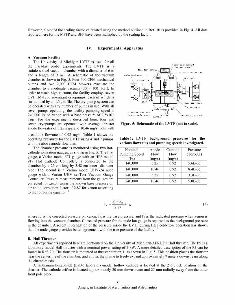
A. Vacuum Facility The University of Michigan LVTF is used for all the Faraday probe experiments. The LVTF is a stainless-steel vacuum chamber with a diameter of 6 m and a length of 9 m. A schematic of the vacuum chamber is shown in Fig. 5. Four 400 CFM mechanical pumps and two 2,000 CFM blowers evacuate the chamber to a moderate vacuum (30 – 100 Torr). In order to reach high vacuum, the facility employs seven CVI TM-1200 re-entrant cryopumps, each of which is surrounded by an LN2 baffle. The cryopump system can be operated with any number of pumps in use. With all seven pumps operating, the facility pumping speed is 240,000 l/s on xenon with a base pressure of 2.5x10⁻⁷ Torr. For the experiments described here, four and seven cryopumps are operated with average thruster anode flowrates of 5.25 mg/s and 10.46 mg/s, both with
a cathode flowrate of 0.92 mg/s. Table 1 shows the operating pressures for the LVTF using 4 and 7 pumps with the above anode flowrates. The chamber pressure is monitored using two hot-cathode ionization gauges, as shown in Fig. 5. The first gauge, a Varian model 571 gauge with an HPS model 919 Hot Cathode Controller, is connected to the chamber by a 25-cm-long by 3.48-cm-inner- diameter tube. The second is a Varian model UHV-24 nude gauge with a Varian UHV senTorr Vacuum Gauge Controller. Pressure measurements from the gauges are corrected for xenon using the known base pressure on air and a correction factor of 2.87 for xenon according to the following equation19
bbi
c P87.2PP
P +−
= (3)
where Pc is the corrected pressure on xenon, Pb is the base pressure, and Pi is the indicated pressure when xenon is flowing into the vacuum chamber. Corrected pressure for the nude ion gauge is reported as the background pressure in the chamber. A recent investigation of the pressure inside the LVTF during HET cold-flow operation has shown that the nude gauge provides better agreement with the true pressure of the facility.11
B. Hall Thruster All experiments reported here are performed on the University of Michigan/AFRL P5 Hall thruster. The P5 is a laboratory-model Hall thruster with a nominal power rating of 5 kW. A more detailed description of the P5 can be found in Ref. 20. The thruster is mounted at thruster station 1, as shown in Fig. 5. This position places the thruster near the centerline of the chamber, and allows the plume to freely expand approximately 7 meters downstream along the chamber axis. A lanthanum hexaboride (LaB6) laboratory-model hollow cathode is located at the 2 o’clock position on the thruster. The cathode orifice is located approximately 30 mm downstream and 25 mm radially away from the outer front pole piece.
Table 1: LVTF background pressures for the various flowrates and pumping speeds investigated.
Nominal Pumping Speed
(l/s)
Anode Flow
(mg/s)
Cathode Flow
(mg/s)
Pressure (Torr-Xe)
140,000 5.25 0.92 5.6E-06 140,000 10.46 0.92 8.4E-06 240,000 5.25 0.92 3.3E-06 240,000 10.46 0.92 5.0E-06
Figure 5: Schematic of the LVTF (not to scale).

American Institute of Aeronautics and Astronautics
6
High-purity (99.999% pure) xenon propellant is supplied to the Hall thruster from compressed bottles through stainless-steel feedlines. The anode and cathode propellant flowrates are metered by MKS 1179JA mass flow controllers. Calibration of the flow controllers is accomplished using a custom apparatus that measures the gas pressure and temperature inside a known volume. The mass flow controllers have an accuracy of ±1% full scale.
C. Faraday Probe The MFFP, BFP, and nude Faraday probe are investigated simultaneously. The Faraday probes used for the MFFP and BFP are identical to the nude Faraday probe. Figure 6 shows a photograph of the JPL probe. Table 2 presents the relevant dimensions. Each probe has a 2.31 cm (0.91 in.) diameter collection electrode enclosed within a guard ring. A spray-coating of tungsten over the aluminum collector helps to minimize secondary-electron emission. In order to create a flat, uniform sheath over the collection electrode, both the collector and guard ring are designed to be biased to a negative potential below facility ground as shown in Fig. 7.
D. Data Acquisition System The probes are attached to a rotating arm, positioned 100 ± 0.05
cm downstream of the thruster, and aligned with the center of the P5 exit plane. Rotation of the probes is accomplished using a Parker Daedal 20600RT rotary table, which is driven by an Empire Magnetics VSU23 stepper motor. The entire setup is mounted approximately 0.75 m above the thruster to a steel platform that allows the rotary table to be easily adjusted so that the axis of rotation is directly over the thruster exit plane. A National Instruments NuDrive 4SX-411 powers the stepper motor. Control of the table is provided by a National Instruments PCI-7344 stepper controller through a LabView 6 interface. An angular coordinate system is set up such that the thruster centerline is considered zero degrees. Facing downstream from the thruster exit plane and rotating counterclockwise is considered the positive direction. With the MFFP positioned on centerline the BFP and nude Faraday probe are located at -14.85º and 29.8º, respectively. This setup allows the arm to be rotated ± 130º, which ensures each probe is rotated at least ± 100º through the thruster plume.
A 22-bit Agilent Data Logger head unit with a 20-channel multiplexer is used to acquire the data. The same LabView interface is used to both control the rotary table and acquire the data. The Data Logger was used to measure the voltage drop across three current shunts. Ion current density is calculated by dividing the measured voltage by the known probe area and the shunt resistance. Measurements from all three probes are taken in 1º increments.
V. Experimental Results Prior use of nude JPL probes at PEPL has indicated that a bias voltage of -20 V below ground is sufficient for
the collector to enter ion saturation without substantial sheath growth.10 Since both the MFFP and BFP are new diagnostics, a bias voltage study is done. Figure 8 presents the results with the MFFP at 0 degrees and at 70 degrees. The probes are biased between 0 V and -50 V while recording the collected current. Similar results are obtained with the MFFP at other angular orientations and thruster operating conditions. Based on these results the collector and guard ring of all three probes are biased to -20 V. Reported data are taken with the collector and guard ring of all the JPL Faraday probes biased at this potential.
Table 2: Dimensions of the nude JPL Faraday probe.
Part Name Dimension [cm (in.)]
Nude JPL Collector Outer Diameter 2.31 (0.91) Gap Thickness 0.23 (0.09)
Nude JPL Guard Ring Outer Diameter 2.540 (1.000)
Thickness 0.074 (0.029)
Guard Ring
Collector
Figure 6: Photograph of the nude JPL Faraday probe.
-20 V
107 Ω 107.3 Ω 106.3 Ω
nude probe
MFFP BFP
Figure 7: Electrical setup of the nude probe, MFFP, and BFP.

American Institute of Aeronautics and Astronautics
7
In order to verify that collected data are independent of the data acquisition system, several variations are made before and during testing. The shunt resistances used to convert data from voltage to current are verified using a Fluke multimeter. Voltage data collected by the Data Logger are also verified using a Fluke multimeter. The rotary table is motionless while the Data Logger acquires data and the arm is found to have negligible vibration during data acquisition. Data taken with the probes rotating in the clockwise or counterclockwise direction are essentially identical. These measures attempt to ensure that the data obtained are independent of the data acquisition system.
Table 3 presents the investigated thruster operating conditions. The thruster is operated at discharge voltages of 300 V and 500 V with discharge currents of 5 A and 10 A, at background pressures within the range of 3.3x10⁻⁶ Torr to 8.4x10⁻⁶ Torr on xenon. In the discussion that follows, all data reported for the BFP and MFFP have been multiplied by the collimator scaling factor.
Figures 9 – 12 show ion current density profiles for the nude probe, MFFP, and BFP at the operating conditions investigated. The nude probe, BFP, and MFFP measure similar plume profiles and similar trends are seen in all the current density profiles at all thruster operating conditions. The nude probe consistently measures a larger current density at each angular position, and this trend becomes increasingly noticeable farther from centerline.
On centerline the nude probe measures current densities that are on average 17% and 32% larger than the BFP and MFFP (+5A solenoid current), respectively. At a -5 A solenoid current, the MFFP measures approximately the same centerline current density as the BFP. However, when the MFFP is operated at +5 A the percent difference increases to 11% and the MFFP always measures a smaller current density.
Figures 13 and 14 show the effect of changing the solenoid current on the measured current density profile at off-centerline angular positions. The BFP consistently measures a larger current density than the MFFP, regardless of the solenoid current and facility pressure. For the MFFP, increasing the solenoid current causes a decrease in the measured current density. The differences become increasingly apparent as the angular position from centerline increases. Changing the facility pressure has little effect on these trends. Because all other parameters are identical, the differences between the current density profiles obtained by each probe must be due to the ion filtering systems employed. The points of interest in each of these figures and the data collected will be discussed in subsequent sections of this paper.
0
100
200
300
400
500
600
700
-55 -50 -45 -40 -35 -30 -25 -20 -15 -10 -5 0Vbias (V)
V p
robe
shu
nt (m
V)
MFFP (-5A) 0 DegBFP -15 DegNude -30 Deg
01020304050607080
-55 -50 -45 -40 -35 -30 -25 -20 -15 -10 -5 0
Vbias (V)
V pr
obe
shun
t (m
V)
MFFP (-5A) 70 DegBFP 55 DegNude 40 Deg
Figure 8: Effect of varying the probe bias on the collected current.
Table 3: P5 operating conditions.
# of Pumps Vd (V) Id (A)
Anode Flow (mg/s)
Cathode Flow (mg/s) Iic (A) Ioc (A) Vc-g (V)
Pressure (Torr-Xe)
Probe Bias wrt Grd (V)
4 300 4.80 5.25 0.92 2.25 1.08 -17.3 5.6E-06 -20 4 300 9.78 10.46 0.92 4.00 2.00 -23.3 8.4E-06 -20 4 500 5.38 5.25 0.92 3.52 1.51 -15.8 5.6E-06 -20 4 500 9.80 10.46 0.92 5.00 2.01 -27.4 8.4E-06 -20
7 300 4.78 5.25 0.92 2.22 1.05 -16.4 3.3E-06 -20 7 300 9.44 10.46 0.92 4.00 2.00 -20.3 5.0E-06 -20 7 500 5.18 5.25 0.92 3.52 1.50 -16.6 3.3E-06 -20 7 500 9.52 10.46 0.92 5.01 2.00 -21.3 5.0E-06 -20

American Institute of Aeronautics and Astronautics
8
0.001
0.01
0.1
1
Cur
rent
Den
sity
( m
A/c
m2 )
-100 -80 -60 -40 -20 0 20 40 60 80 100Angular Position ( Degrees )
8.4x10⁻⁶ Torr, Nude 5.0x10⁻⁶ Torr, Nude 8.4x10⁻⁶ Torr, MFFP 5.0x10⁻⁶ Torr, MFFP 8.4x10⁻⁶ Torr, BFP 5.0x10⁻⁶ Torr, BFP
Figure 10: Ion current density versus position for the nude probe, MFFP (+5 A), and BFP at facility pressures of 8.4x10⁻⁶ Torr and 5.0x10⁻⁶
Torr on xenon. (Thruster operating at 500 V, 9.80 A and 9.52 A, respectively)
0.001
0.01
0.1
1C
urre
nt D
ensi
ty (
mA
/cm
2 )
-100 -80 -60 -40 -20 0 20 40 60 80 100Angular Position ( Degrees )
5.6x10⁻⁶ Torr, Nude 3.3x10⁻⁶ Torr, Nude 5.6x10⁻⁶ Torr, MFFP 3.3x10⁻⁶ Torr, MFFP 5.6x10⁻⁶ Torr, BFP 3.3x10⁻⁶ Torr, BFP
Figure 9: Ion current density versus position for the nude probe, MFFP (+5 A), and BFP at facility pressures of 5.6x10⁻⁶ Torr and 3.3x10⁻⁶
Torr on xenon. (Thruster operating at 500 V, 5.38 A and 5.18 A, respectively)
0.001
0.01
0.1
1
Cur
rent
Den
sity
( m
A/c
m2 )
-100 -80 -60 -40 -20 0 20 40 60 80 100Angular Position ( Degrees )
8.4x10⁻⁶ Torr, Nude 5.0x10⁻⁶ Torr, Nude 8.4x10⁻⁶ Torr, MFFP 5.0x10⁻⁶ Torr, MFFP 8.4x10⁻⁶ Torr, BFP 5.0x10⁻⁶ Torr, BFP
Figure 12: Ion current density versus position for the nude probe, MFFP (+5 A), and BFP at facility pressures of 8.4x10⁻⁶ Torr and 5.0x10⁻⁶
Torr on xenon. (Thruster operating at 300 V, 9.78 A and 9.44 A, respectively)
10-4
10-3
10-2
10-1
100
Cur
rent
Den
sity
( m
A/c
m2 )
-100 -80 -60 -40 -20 0 20 40 60 80 100Angular Position ( Degrees )
5.6x10⁻⁶ Torr, Nude 3.3x10⁻⁶ Torr, Nude 5.6x10⁻⁶ Torr, MFFP 3.3x10⁻⁶ Torr, MFFP 5.6x10⁻⁶ Torr, BFP 3.3x10⁻⁶ Torr, BFP
Figure 11: Ion current density versus position for the nude probe, MFFP (+5 A), and BFP at facility pressures of 5.6x10⁻⁶ Torr and 3.3x10⁻⁶
Torr on xenon. (Thruster operating at 300 V, 4.80 A and 4.78 A, respectively)
0.001
0.01
0.1
1
Cur
rent
Den
sity
( m
A/c
m2 )
-100 -90 -80 -70 -60 -50 -40 -30Angular Position ( Degrees )
Nude BFP MFFP (-5 A) MFFP (0 A) MFFP (+5 A)
Figure 13: Comparison of off-centerline current density profiles for the nude probe, BFP, and MFFP. Operating conditions are 500 V, 9.52 A at a facility pressure of 5.0x10⁻⁶ Torr on xenon.
0.001
0.01
0.1
1
Cur
rent
Den
sity
( m
A/c
m2 )
-100 -90 -80 -70 -60 -50 -40 -30Angular Position ( Degrees )
Nude BFP MFFP (-5 A) MFFP (0 A) MFFP (+5 A)
Figure 14: Comparison of off-centerline current density profiles for the nude probe, BFP, and MFFP. Operating conditions are 500 V, 9.80 A at a facility pressure of 8.4x10⁻⁶ Torr on xenon.

American Institute of Aeronautics and Astronautics
9
VI. Discussion Figures 15 and 16 are plots of the integrated ion beam current versus the facility background pressure. Integrated
ion beam current is calculated using Eqn. 4,21
( )∫π
θθθπ=2
0z
2tot dsinjz2I (4)
where z is the probe distance from the thruster and jz(θ) is the ion current density measured at the angular position, θ. Due to the asymmetry of the current density profile, two integrated ion beam current values are calculated, one for the positive and one for the negative side of the current density profile. The average of the two integrated ion beam current values is reported as the integrated ion beam current. Increasing the facility pressure causes the integrated ion beam current measured by the nude probe to increase, but for the BFP and MFFP the integrated ion beam current decreases with increasing pressure. This trend is expected because at higher facility pressures more beam ions are converted to filtered CEX ions. The nude probe integrated ion beam current increases an average of 0.9% when the facility pressures increases. Integrated ion beam current measurements for the BFP showed an average decrease of 5% as the facility pressure increased. At -5 A, 0 A, and +5 A the MFFP decreased an average of 2.7%, 6.4%, and 6.3%, respectively.
Figures 17 and 18 examine the changes in the 90% plume divergence angle as a function of the facility pressure. Divergence angles calculated using the BFP and MFFP consistently decreased as the facility pressure increased. The nude probe did not display the same trend for each thruster operating condition. For the 500 V, 5 A case an increase in facility pressure caused an increase in the divergence angle, but for the 300 V, 5 A condition it caused a decrease in divergence angle. Similar results for nude probes have also been reported by Walker.18
34
33
32
31
30
29
28Div
erge
nce
Ang
le (D
egre
es)
8.5x10-68.07.57.06.56.05.55.04.54.03.53.0Facility Pressure (Torr-Xe)
Nude 9.78 A BFP 9.78 A MFFP -5 A, 9.78 A MFFP 0 A, 9.78 A MFFP +5 A, 9.78 A Nude 4.8 A BFP 4.8 A MFFP -5 A, 4.8 A MFFP 0 A, 4.8 A MFFP +5 A, 4.8 A
Figure 17: Plume divergence angle as a function of facility pressure for the nude probe, BFP, and MFFP. Thruster operating conditions are 300 V and 4.80 A or 9.78 A.
12
10
8
6
4
2
Tota
l Cur
rent
(A)
8.5x10-68.07.57.06.56.05.55.04.54.03.53.0Facility Pressure (Torr-Xe)
Nude 9.8 A BFP 9.8 A MFFP -5 A,9.8 A MFFP 0 A, 9.8 A MFFP +5 A, 9.8 A Nude 5.38 A BFP 5.38 A MFFP -5 A, 5.38 A MFFP 0 A, 5.38 A MFFP +5 A, 5.38 A
Figure 15: Integrated ion beam current as a function of facility pressure for the nude probe, BFP, and MFFP. Thruster operating conditions are 500 V and 5.38 A or 9.80 A.
12
10
8
6
4
2
Tota
l Cur
rent
(A)
8.5x10-68.07.57.06.56.05.55.04.54.03.53.0Facility Pressure (Torr-Xe)
Nude 9.78 A BFP 9.78 A MFFP -5 A, 9.78 A MFFP 0 A, 9.78 A MFFP +5 A, 9.78 A Nude 4.8 A BFP 4.8 A MFFP -5 A, 4.8 A MFFP 0 A, 4.8 A MFFP +5 A, 4.8 A
Figure 16: Integrated ion beam current as a function of facility pressure for the nude probe, BFP, and MFFP. Thruster operating conditions are 300 V and 4.80 A or 9.78 A.
34
32
30
28
26D
iver
genc
e A
ngle
(Deg
rees
)
8.5x10-68.07.57.06.56.05.55.04.54.03.53.0Facility Pressure (Torr-Xe)
Nude 9.8 A BFP 9.8 A MFFP -5 A, 9.8 A MFFP 0 A, 9.8 A MFFP +5 A, 9. A Nude 5.38 A BFP 5.38 A MFFP -5 A, 5.38 A MFFP 0 A, 5.3 A MFFP +5 A, 5.38 A
Figure 18: Plume divergence angle as a function of facility pressure for the nude probe, BFP, and MFFP. Thruster operating conditions are 500 V and 5.38 A or 9.80 A.

American Institute of Aeronautics and Astronautics
10
Previous explanations of the increased current density measured by nude probes consider the biased probe as a point source potential sink for slow, CEX ions.22 Slow CEX ions are drawn toward the probe because it is biased -20 V below ground, and thus are collected. More recent results suggest that a minimal electric field exists near the Faraday probe and that CEX ions reach the probe due to their random flux, not because of the -20 V bias.13 In this experiment the nude probe collects the largest random flux of CEX ion current because it lacks any type of filtering capability. CEX ions with an angular orientation of 0 degrees up to possibly 90 degrees with respect to the collector normal may be collected by the nude probe. The BFP only collects ions that enter through the face plate hole and intersect with the probe collector. In this case ions approaching from angles outside the acceptance angle of the BFP collide with the box and do not register current. This significantly reduces the number of particles that are allowed to contribute to the current density. The same filtering technique used for the BFP is also present for the MFFP, however, it also utilizes a magnetic field, which further reduces the number of ions allowed to be collected. The ions that are within the acceptance angle of the probe are also subjected to a magnetic field, which causes them to change their trajectory depending on their energy (or velocity). In this way the BFP and MFFP are filtering CEX ions. Trends associated with the integrated ion beam current may be explained by considering the beam attenuation due to CEX collisions.
As the plume expands, ions necessarily have collisions with neutral particles that are present due to the plume and also due to the background pressure of the facility. At a higher facility pressure fewer ions are capable of traversing the distance to the probe without suffering a CEX collision. The decrease in the beam current density due to CEX collisions is known as attenuation or weakening of the beam. Beam attenuation may not be apparent with a nude probe because at higher pressures it records more CEX ions, thus negating evidence of the attenuation effect of beam ions. Because the BFP and MFFP are filtering CEX ions, attenuation may explain why these probes measure a lower integrated ion beam current at higher facility pressures. A first order estimation of the beam attenuation due to CEX collisions is obtained by considering the ion continuity equation in one dimension. The ratio of the ion current density at some downstream position to the initial ion current density is obtained by integrating over the pathlength, z. The result is Eqn. 5,23
( )( ) )znexp(j
jceb
z σ−=θθ
(5)
where jz(θ) is the ion current density at downstream position z and angular position θ, j(θ) is the initial ion current density at position θ, nb is the neutral background number density, and sce is the CEX collision cross-section. Facility induced CEX ions are most noticeable at large off-axis angles where the pressure is approximately equal to the facility background pressure, therefore the neutral background number density is based on the facility background pressure. The beam attenuation for the pressures investigated is given in Table 4. These calculations are evaluated at 100 cm downstream of the thruster and assume a neutral temperature of 300 K and a CEX collision cross-section of 55 Å2.24 These values will provide an order of magnitude estimation of the beam attenuation.
At the 5 A operating condition the beam attenuation decreases by approximately 3% when going from 4 to 7 pumps (5.6x10⁻⁶ Torr to 3.3x10⁻⁶ Torr). This change is 6%, at the 10 A operating condition. Calculation of the initial ion current density and the subsequent corrected integrated ion beam current provides a better comparison of each of the probes. The procedure for this comparison is accomplished by dividing the experimental data at each angular location by the corresponding beam attenuation, which yields the initial ion current density at that position. The corrected integrated ion beam current is then obtained by using equation 6 and integrating over the initial ion current density.
( )∫π
θθθπ=2
0
2c,tot dsinjz2I (6)
This allows the integrated ion beam current, Itot, obtained by integrating the experimentally measured ion current density profile, jz, to be compared with the corrected integrated ion beam current, Itot.c, obtained by integrating the initial ion current density profile, j.
When the 4 and 7 pump (5.6x10⁻⁶ Torr, 8.4x10⁻⁶
Table 4: Beam attenuation due to CEX collisions over a 100 cm path length.
Operating Condition Pressure (Torr-Xe) Attenuation 5 A: 300 V, 500 V 3.3E-06 0.94 5 A: 300 V, 500 V 5.6E-06 0.91
10 A: 300 V, 500 V 5.0E-06 0.92 10 A: 300 V, 500 V 8.4E-06 0.86

American Institute of Aeronautics and Astronautics
11
Torr and 3.3x10⁻⁶ Torr, 5.0x10⁻⁶ Torr) corrected integrated ion beam current data for the MFFP, BFP, and nude probe are compared, changes in the trends associated with this data become apparent. These trends are quantified utilizing a percent difference calculated by dividing the difference between the 4 and 7 pump integrated ion beam current by the 4 pump integrated ion beam current. A positive percent difference means the 4 pump integrated beam current is larger than the 7 pump, and a negative percent difference means the opposite. All of the thruster operating conditions except for the 500 V, 5 A condition show the same general trend for the corrected integrated ion beam current. The largest percent difference is obtained by the nude probe, followed by the BFP, and then the MFFP. When the thruster is operated at 500 V, 5 A the corrected integrated ion beam current data no longer follow the same trend. Most notably the BFP, MFFP (0 A), and MFFP (+5 A) record a larger percent difference for both Itot and Itot,c. An explanation for this difference has not yet been determined. Based on the three other operating conditions, the MFFP at +5 A shows the best corrected integrated ion beam current agreement between facility pressures. Table 5 summarizes these results.
The current density profiles associated with the MFFP are also more consistent with data obtained from Russian Express Satellites. Current density profiles obtained on-orbit do not exhibit the increased current densities at off-axis angles as often seen in ground test data.25 Compared to the nude probe and BFP, the MFFP provides a profile more consistent with flight test data because it measures a lower current density at angles off centerline and shows the characteristic r-2 dependence.
In order to further investigate the ability of the MFFP to eliminate CEX ions due to the facility background gas, the three probes are positioned behind the thruster. The solenoid current of the MFFP is varied while measuring the collected ion current. If facility induced CEX ions are within the 8 – 30 eV filtering range of the MFFP, a decrease in the measured current should be apparent as the solenoid current is increased past the CEX ion energy threshold. Unfortunately this trend is not seen, and the MFFP records ion current densities on the order of 10-4 mA-cm-2 at all solenoid current values. These densities are several orders of magnitude lower than on centerline and 1 order of magnitude lower than those measured at 100±. Behind the thruster, the BFP records approximately double the ion current of the MFFP and the nude probe measures an ion current that is an order of magnitude larger than the MFFP. The ion current recorded by the nude probe suggests that there are ions behind the thruster, but because both the BFP and MFFP utilize a collimator the majority of ions are unable to reach the probe. Because the MFFP ion current is so small, any change in the ion current is too low to resolve and a solenoid current that creates a magnetic field that eliminates facility induced CEX ions is unable to be determined.
The ability of each probe to obtain the correct ion beam current can be analyzed by comparing the corrected integrated ion beam current to discharge current ratio with the P5 current utilization efficiency. The current utilization efficiency, bη , is defined as the ratio of the ion beam current to the discharge current, Ib/Id. An estimation of the current utilization efficiency for the P5 can be obtained by considering the following equation for the anode efficiency.
mqvba ηηηη=η (7)
aη is the anode efficiency, qη is the charge utilization efficiency, mη is the mass utilization efficiency, and vη is
the voltage utilization efficiency. In order to determine the current utilization efficiency, values for the other four
Table 5: Comparison of the integrated ion beam current and corrected integrated ion beam current percent difference between the 4 and 7 pump data.
4 Pump (5.6E-06 Torr) to 7 Pump (3.3E-06 Torr)
4 Pump (8.4E-06 Torr) to 7 Pump (5.0E-06 Torr)
300 V, 5 A 500 V, 5 A 300 V, 10 A 500 V, 10 A
Itot Percent
Diff. (%)
Itot,c Percent
Diff. (%)
Itot Percent
Diff. (%)
Itot,c Percent
Diff. (%)
Itot Percent
Diff. (%)
Itot,c Percent
Diff. (%)
Itot Percent
Diff. (%)
Itot,c Percent
Diff. (%) Nude 0.4 3.6 0.4 3.6 2.0 8.4 0.8 7.3 BFP -4.7 -1.3 -9.0 -5.6 -3.0 3.7 -3.6 3.2 MFFP (-5 A) -3.1 0.2 -2.3 0.9 -2.8 3.9 -2.7 4.0 MFFP (0 A) -3.3 0.0 -10.1 -6.6 -4.3 2.5 -8.0 3.1 MFFP (+5 A) -3.8 -0.4 -11.0 -7.4 -4.7 2.2 -6.0 1.0

American Institute of Aeronautics and Astronautics
12
efficiencies must be obtained. The P5 anode efficiency has been reported by Hofer.26 Gulczinski has reported ion energy data for the P5 which suggest that the voltage utilization efficiency is approximately 90%.27 The charge utilization efficiency and mass utilization efficiency are calculated using far-field ion species fraction data provided by Gulczinski27 and the Hall thruster performance model for a multiply-charged plasma recently developed by Hofer.26 Unfortunately ion species fraction data are not available for the 300 V 10 A operating condition therefore the current utilization at this condition cannot be obtained. The results are summarized in Table 6. Ideally a Faraday probe should have an integrated ion beam current to discharge current ratio equal to the current utilization efficiency. Comparison of the calculated current utilization efficiency for the P5 and the Itot,c/Id for each probe is shown in Table 7. The nude probe performs worst and consistently over-predicts the ion beam current. Depending on the operating condition, either the BFP or MFFP provides the best agreement with the estimated current utilization efficiency.
VII. Conclusions Measured integrated ion beam current for the BFP and MFFP decreases with increasing facility pressure, but for
the nude probe the integrated ion beam current increases with increasing pressure. These trends are attributed to the ion filtration apparatus utilized by the BFP and MFFP. Because a higher pressure results in the production of more CEX ions, filtration of these ions by the BFP and MFFP result in a lower current density and subsequent integrated ion beam current. Application of the beam attenuation equation to the current density profiles results in a corrected integrated ion beam current. Analysis of the results based on the corrected integrated ion beam current show the MFFP operated at a +5 A solenoid current provides the best agreement between the facility pressures. The MFFP also provides a current density profile with a lower current density at large off-axis positions. This result is more consistent with on-orbit data.25 Comparison of Itot,c/Id with the P5 current utilization efficiency shows that either the BFP or MFFP provides the best agreement depending on the thruster operating conditions. Further study of the MFFP and its ability to filter facility induced CEX ions is required.
Table 7: Comparison of Itot,c/Id for the nude probe, BFP, and MFFP and the estimated Ib/Id for the P5 at the investigated operating conditions.
Pressure (Torr-Xe)
# of Pumps Vd (V) Id (A)
Nude probe Itot,c/Id
BFP Itot,c/Id
MFFP (-5 A) Itot,c/Id
MFFP (0 A) Itot,c/Id
MFFP (+5 A) Itot,c/Id
Estimated
P5 Ib/Id 5.6E-06 4 300 4.8 0.94 0.72 0.66 0.59 0.56 0.70 5.6E-06 4 500 5.38 0.87 0.66 0.62 0.57 0.55 0.80 8.4E-06 4 500 9.8 1.03 0.78 0.73 0.65 0.64 0.72
3.3E-06 7 300 4.78 0.91 0.73 0.66 0.60 0.57 0.70 3.3E-06 7 500 5.18 0.87 0.73 0.64 0.63 0.61 0.80 5.0E-06 7 500 9.52 0.99 0.77 0.72 0.68 0.65 0.72
Table 6: Approximation of the P5 current utilization efficiency based on the charge, mass, voltage, and anode efficiencies.
Operating Condition
Anode Efficiency
Voltage Utilization Efficiency
Charge Utilization Efficiency
Mass Utilization Efficiency
Current Utilization Efficiency
300 V, 5 A 0.47 0.9 0.98 0.76 0.70 500 V, 5 A 0.50 0.9 0.96 0.72 0.80 500 V, 10 A 0.56 0.9 0.99 0.88 0.72

American Institute of Aeronautics and Astronautics
13
VIII. Acknowledgements We would like to thank Dr. Colleen Marrese at JPL for loaning PEPL the nude Faraday probes, Dr. Sergi Khartov at MAI for the use of the LaB6 cathode, Mr. Terry Larrow for fabricating the hardware used in this study, undergraduates M. Baldwin, C. Berkley, R. Livingston, S. Shepard, and J. Topper for assembly and preliminary testing of the MFFP, Torsten Stindl of the Universität Stuttgart for help with experimental setup and data acquisition, and the departmental technical staff and other graduate students at PEPL for help in maintaining the facilities. This research was supported by the Air Force Office of Scientific Research through grants F49620-00-1-0201 and F49620-01-1-0061. In addition, Mr. Mitchell Walker is supported by the Michigan Space Grant Consortium and the National Science Foundation. The authors greatly appreciate this support.
IX. References 1de Grys, K. H., Rayburn, C., Wilson, F., Fisher, J., "Multi-Mode 4.5 kW BPT-4000 Hall thruster Qualification Status," AIAA-2003-4552, 39th Joint Propulsion Conference, Huntsville, AL, July 20-23, 2003. 2Pollard, J. E., Diamant, K. D., Khayms, V., Werthman, L., King, D., de Grys, K. H., "Ion Flux, Energy, and Charge-State Measurments for the BPT-4000 Hall thruster," AIAA-2001-3351, 37th Joint Propulsion Conference, Salt Lake City, Utah, July 8-11, 2001. 3McVey, J. B., Britt, E. J., Engelman, S. F., Gulczinski, F. S., Beiting, E. J., Pollard, J. E., "Characteristics of the T-220HT Hall-Effect thruster," AIAA 2003-5158, 39th Joint Propulsion Conference, Huntsville, Alabama, July 20-23, 2003. 4Britt, E. J., McVey, J. B., "Electric Propulsion Activities in U.S. Industries," AIAA-2002-3559, 38th Joint Propulsion Conference, Indianapolis, IN, July 7-10, 2002. 5Manzella, D. H., Jankovsky, R., Hofer, R. R., "Laboratory Model 50 kW Hall thruster," AIAA-2002-3676, 38th Joint Propulsion Conference, Indianapolis, IN., July 7-10, 2002. 6Jacobson, D. T., Manzella, D. H., "50 kW Class Krypton Hall thruster Performance," AIAA-2003-4550, 39th Joint Propulsion Conference, Huntsville, AL, July 20-23, 2003. 7Oleson, S., Katz, I., "Electric Propulsion for Project Prometheus," AIAA-2003-5279, 39th Joint Propulsion Conference, Huntsville, AL, July 20-23, 2003. 8Garner, C. E., Polk, J. E., Brophy, J. R., Goodfellow, K., "Methods for Cryopumping Xenon," AIAA-96-3206, 32nd Joint Propulsion Conference, Lake Buena Vista, FL., July 1-3, 1996. 9Hofer, R. R., Peterson, P. Y., Gallimore, A. D., "Characterizing Vacuum Facility Backpressure Effects on the Performance of a Hall thruster," IEPC-01-045, 27th International Electric Propulsion Conference, Pasadena, CA, October 15-19, 2001. 10Hofer, R. R., Walker, M. L. R., Gallimore, A. D., "A Comparison of Nude and Collimated Faraday Probes for Use with Hall thrusters," IEPC-01-020, 27th International Electric Propulsion Conference, Pasadena, CA, October 15-19, 2001. 11Walker, M. L. R., Gallimore, A. D., Chunpei, C., Boyd, I. D., "Pressure Map of a Facility as a function of Flow Rate to study Facility Effects," AIAA-2002-3815, 38th Joint Propulsion Conference, Indianapolis, IN, July 7-10, 2002. 12Walker, M. L. R., Gallimore, A. D., "Hot Flow Pressure Map of a Vacuum Facility as a function of Flow Rate to study Facility Effects," IEPC-03-0077, 28th International Electric Propulsion Conference, Toulouse, France, March 17-21, 2003. 13Walker, M. L. R., Victor, A. L., Hofer, R. R., Gallimore, A. D., "Effect of Backpressure on Measured Ion Current Density Profiles of Hall thruster Plumes," Journal of Propulsion and Power, (to be printed). 14de Grys, K. H., Tilley, D. L., Aadland, R. S., "BPT Hall thruster Plume Characteristics," AIAA-99-2283, 35th Joint Propulsion Conference, Los Angeles, CA, June 20-24, 1999. 15King, L. B., Gallimore, A. D., Marrese, C. M., "Transport-Property Measurements in the Plume of an SPT-100 Hall thruster," Journal of Propulsion and Power, Vol. 14, No. 3, pp. 327-335, May-June 1998. 16Kim, V., "Investigation of the Anode Configuration Influence on the PPS-1350 Laboratory Model Plume Divergence," AIAA-98-3787, 34th Joint Propulsion Conference, Cleveland, OH, July 13-15, 1998. 17Chen, F. F., Introduction to Plasma Physics and Controlled Fusion, Vol. 1: Plasma Physics, Plenum Press, New York, 1984. 18Walker, M. L. R., Hofer, R. R., Gallimore, A. D., "The Effects of Nude Faraday Probe Design and Vacuum Facility Backpressure on the measured ion current density profile of Hall thruster Plumes," AIAA-2002-4253, 38th Joint Propulsion Conference, Indianapolis, IN, July 7-10, 2002. 19Dushman, S., Scientific Foundations of Vacuum Technique, Vol. 4, Wiley, New York, 1958. 20Haas, J. M., Gulczinski, F. S., Gallimore, A. D., Spanjers, G. G., Spores, R. A., "Performance Characteristics of a 5 kW Laboratory Hall thruster," AIAA-98-3503, 34th Joint Propulsion Conference, Cleveland, OH, July 12-15, 1998. 21Manzella, D. H., "Hall thruster Ion Beam Characterization," AIAA-95-2927, 31st Joint Propulsion Conference, San Diego, CA, July 10-12, 1995. 22Haas, J. M., "Low-Perturbation Interrogation of the Internal and Near-field Plasma Structure of a Hall thruster using a High-Speed Probe Positioning System," Doctoral Thesis, Dept. of Aerospace Engineering, University of Michigan, Ann Arbor, MI, 2001.

American Institute of Aeronautics and Astronautics
14
23Sovey, J. S., Patterson, M. J., "Ion Beam Sputtering in Electric Propulsion Facilities," AIAA-91-2117, 27th Joint Propulsion Conference, Sacramento, CA, June 24-27, 1991. 24Pullins, S., Dressler, R. A., Chiu, Y. H., Levandier, D. J., "Ion Dynamics in Hall Effect and Ion thrusters: Xe+ + Xe Symmetric Charge Transfer," AIAA-2000-0603, 38th Aerospace Sciences Conference, Reno, NV, January 10-13, 2000. 25Manzella, D. H., Jankovsky, R., Elliott, F., Mikellides, I., Jongeward, G., Allen, D., "Hall thruster Plume Measurements On-board the Russian Express Satellites," IEPC-01-44, 27th International Electric Propulsion Conference, Pasadena, CA, October 15-19, 2001. 26Hofer, R. R., "Development and Characterization of High-Efficiency, High-Specific Impulse Xenon Hall thrusters," Doctoral Thesis, Dept. of Aerospace Engineering, University of Michigan, Ann Arbor, MI, 2004. 27Gulczinski, F. S., "Examination of the Structure and Evolution of Ion Energy Properties of a 5 kW Class Laboratory Hall Effect thruster at Various Operational Conditions," Doctoral Thesis, Dept. of Aerospace Engineering, University of Michigan, Ann Arbor, MI, 1999.