ELEVATED WATER RESERVOIR MONITORING USING OPTICAL FIBER ACCELEROMETER
11
This article was downloaded by: [b-on: Biblioteca do conhecimento online UA] On: 11 April 2013, At: 03:00 Publisher: Taylor & Francis Informa Ltd Registered in England and Wales Registered Number: 1072954 Registered office: Mortimer House, 37-41 Mortimer Street, London W1T 3JH, UK Instrumentation Science & Technology Publication details, including instructions for authors and subscription information: http://www.tandfonline.com/loi/list20 ELEVATED WATER RESERVOIR MONITORING USING OPTICAL FIBER ACCELEROMETER Paulo Fernando da Costa Antunes a b , Hugo Filipe Pinheiro Rodrigues c , Humberto Varum c & Paulo Sérgio de Brito André a b a Instituto de Telecomunicações, Campus de Santiago, Aveiro, Portugal b Departamento de Física, Universidade de Aveiro, Campus de Santiago, Aveiro, Portugal c Departamento de Engenharia Civil, Universidade de Aveiro, Campus de Santiago, Aveiro, Portugal Accepted author version posted online: 24 Oct 2012.Version of record first published: 10 Apr 2013. To cite this article: Paulo Fernando da Costa Antunes , Hugo Filipe Pinheiro Rodrigues , Humberto Varum & Paulo Sérgio de Brito André (2013): ELEVATED WATER RESERVOIR MONITORING USING OPTICAL FIBER ACCELEROMETER, Instrumentation Science & Technology, 41:2, 125-134 To link to this article: http://dx.doi.org/10.1080/10739149.2012.735308 PLEASE SCROLL DOWN FOR ARTICLE Full terms and conditions of use: http://www.tandfonline.com/page/terms-and-conditions This article may be used for research, teaching, and private study purposes. Any substantial or systematic reproduction, redistribution, reselling, loan, sub-licensing, systematic supply, or distribution in any form to anyone is expressly forbidden. The publisher does not give any warranty express or implied or make any representation that the contents will be complete or accurate or up to date. The accuracy of any instructions, formulae, and drug doses should be independently verified with primary sources. The publisher shall not be liable for any loss, actions, claims, proceedings, demand, or costs or damages whatsoever or howsoever caused arising directly or indirectly in connection with or arising out of the use of this material.
-
Upload
independent -
Category
Documents
-
view
0 -
download
0
Transcript of ELEVATED WATER RESERVOIR MONITORING USING OPTICAL FIBER ACCELEROMETER

This article was downloaded by: [b-on: Biblioteca do conhecimento online UA]On: 11 April 2013, At: 03:00Publisher: Taylor & FrancisInforma Ltd Registered in England and Wales Registered Number: 1072954 Registeredoffice: Mortimer House, 37-41 Mortimer Street, London W1T 3JH, UK
Instrumentation Science & TechnologyPublication details, including instructions for authors andsubscription information:http://www.tandfonline.com/loi/list20
ELEVATED WATER RESERVOIRMONITORING USING OPTICAL FIBERACCELEROMETERPaulo Fernando da Costa Antunes a b , Hugo Filipe Pinheiro Rodriguesc , Humberto Varum c & Paulo Sérgio de Brito André a ba Instituto de Telecomunicações, Campus de Santiago, Aveiro,Portugalb Departamento de Física, Universidade de Aveiro, Campus deSantiago, Aveiro, Portugalc Departamento de Engenharia Civil, Universidade de Aveiro,Campus de Santiago, Aveiro, PortugalAccepted author version posted online: 24 Oct 2012.Version ofrecord first published: 10 Apr 2013.
To cite this article: Paulo Fernando da Costa Antunes , Hugo Filipe Pinheiro Rodrigues , HumbertoVarum & Paulo Sérgio de Brito André (2013): ELEVATED WATER RESERVOIR MONITORING USING OPTICALFIBER ACCELEROMETER, Instrumentation Science & Technology, 41:2, 125-134
To link to this article: http://dx.doi.org/10.1080/10739149.2012.735308
PLEASE SCROLL DOWN FOR ARTICLE
Full terms and conditions of use: http://www.tandfonline.com/page/terms-and-conditions
This article may be used for research, teaching, and private study purposes. Anysubstantial or systematic reproduction, redistribution, reselling, loan, sub-licensing,systematic supply, or distribution in any form to anyone is expressly forbidden.
The publisher does not give any warranty express or implied or make any representationthat the contents will be complete or accurate or up to date. The accuracy of anyinstructions, formulae, and drug doses should be independently verified with primarysources. The publisher shall not be liable for any loss, actions, claims, proceedings,demand, or costs or damages whatsoever or howsoever caused arising directly orindirectly in connection with or arising out of the use of this material.
ELEVATED WATER RESERVOIR MONITORING USING OPTICALFIBER ACCELEROMETER
Paulo Fernando da Costa Antunes,1,2 Hugo Filipe Pinheiro Rodrigues,3
Humberto Varum,3 and Paulo Sergio de Brito Andre1,2
1Instituto de Telecomunicacoes, Campus de Santiago, Aveiro, Portugal2Departamento de Fısica, Universidade de Aveiro, Campus de Santiago, Aveiro, Portugal3Departamento de Engenharia Civil, Universidade de Aveiro, Campus de Santiago,Aveiro, Portugal
& Structural health monitoring is defined as the structural behavior surveillance during apredetermined time or throughout the structure’s lifetime, in order to detect materials or structuraldegradation. Periodical measurements can detect changes in the natural frequencies of the struc-ture, and indicate the structural damage or deterioration. In this work, we experimentally demon-strated the use of a fiber Bragg grating–based biaxial accelerometer in dynamic measurements onan elevated reinforced concrete water reservoir. This elevated water reservoir structure was suitableto be used as a demonstration of the application of optical accelerometers in the structure naturalfrequencies measurement, under environmental excitation. The obtained experimental valuesfor first natural frequency in the transverse and longitudinal directions were 0.805 Hz and0.903 Hz, respectively. These values present a relative error smaller than 0.5% when comparedwith that obtained by the structure numerical simulation.
Keywords accelerometer, fiber Bragg gratings–based sensors, structural healthmonitoring
INTRODUCTION
The main aim of structural health monitoring (SHM) is the structuralbehavior surveillance, in-situ, under different load conditions, during apredetermined time or throughout the structure’s useful lifetime, in orderto detect materials and=or structural response degradation. For theimplementation of SHM strategies, advanced sensors are used in order toevaluate the integrity and durability of the structure in question. Moreover,
This paper was submitted as part of a special issue on Optical Fiber Sensors and Applicationsorganized by Dr. Yong Zhao of Northeastern University, China.
Address correspondence to Paulo Sergio de Brito Andre, Instituto de Telecomunicacoes, Campusde Santiago 3810-193, Aveiro, Portugal. E-mail: [email protected]
Instrumentation Science and Technology, 41:125–134, 2013Copyright # Taylor & Francis Group, LLCISSN: 1073-9149 print/1525-6030 onlineDOI: 10.1080/10739149.2012.735308
Instrumentation Science and Technology, 41:125–134, 2013Copyright # Taylor & Francis Group, LLCISSN: 1073-9149 print/1525-6030 onlineDOI: 10.1080/10739149.2012.735308
Dow
nloa
ded
by [
b-on
: Bib
liote
ca d
o co
nhec
imen
to o
nlin
e U
A]
at 0
3:00
11
Apr
il 20
13

preventive evaluation, based on monitoring, can identify problems in earlystages and assist in setting guidelines for structural rehabilitation. This kindof preventive action can save human lives and decrease reparation costs.[1–3]
In the last few decades there has been a significant development in thearea of structural monitoring, namely in terms of new monitoring techni-ques and equipment. In particular, fiber optic sensors, namely fiber Bragggrating (FBG) sensors, have gained significant importance in this field,due to their durability, stability, immunity to external electromagneticinfluences, and usually, with minimal invasion to the aesthetics beingparticularly interesting for long-term health monitoring.[4–11]
Structures are often subjected to diverse loads from different sources (asself-weight of the structural and nonstructural elements, live loads, wind, traf-fic, construction operations, and vibrations, among many others), andoccasionally, during their lifetime, they can be affected by unexpectedextreme demands, as those induced by earthquakes, storms, explosions,fires, collisions, etc. The cumulative damage resulting from such loads canhave serious effects in the structural integrity, and evenmay lead to structuralcollapse, with associated serious economic and human losses. This becomesparticularly important in the case of structures with historical significance orgreat economic importance. In the case of infrastructures, for example waterreservoirs and bridges, they are frequently subjected to extreme loads such asstrong winds and=or excessive vibrations. Moreover, early detection of dam-age, such as that due to extreme events or even due to structural decay, maybe required as a comprehensive structural safety evaluation.[12–14] The dataresulting from this monitoring can also be used to calibrate and updatenumerical models representing the structural behavior. Bidirectional inter-action between parameters resulting from the monitoring and the numericalstructural analysis tools is, usually, very limited and, consequently, numericalmodels do not always represents the real behavior and condition of the struc-ture, which may be seriously affected by eventual damages.
In the monitored structures, data acquisition is usually made occasion-ally, and so update and calibration of the numerical models is only madeperiodically, without continuous interaction, as would be desirable. There-fore, a strategy based on a continuous monitoring and structural assess-ment using the monitored data is essential for structural safety andintegrity control. Moreover, if this continuous assessment strategy is com-bined with an alert system for risk situations, severe structural damagesand=or collapses may be prevented.
This article is divided in five sections: first, the acceleration sensor weused is presented, as well as its operation principle. The following sectiondeals with the structure description we studied and on-site measurements.The numerical modeling of the structure and its main outputs are presentedafter that. Finally, the main conclusions are drawn.
126 P. F. da Costa Antunes et al.
Dow
nloa
ded
by [
b-on
: Bib
liote
ca d
o co
nhec
imen
to o
nlin
e U
A]
at 0
3:00
11
Apr
il 20
13

OPTICAL ACCELEROMETER
To obtain the natural frequencies for an elevated water reservoir, abiaxial accelerometer, based on optical fiber Bragg gratings, was used.The monitoring equipment includes the optical accelerometer, an opticalsource with high spectral width, ALS model CL-17-B-FA from Amonics(Kowloon, Hong Kong), an optical circulator and an optical spectrometerfrom Ibsen model I-MON E (Denmark), with an acquisition rate of 950Hz.
The optical fiber accelerometer employs four FBGs positioned inopposite positions, and the mechanical parts consists of two machinedaluminum blocks, connected in the bottom to a stiff base by bolts, andby four FBGs at the top, as illustrated in Figure 1 and described in detailin a previous article.[15] The optical fibers are bonded to the sensor struc-ture with epoxy resin and are pretensioned.[16]
The central element (inertial mass) is an aluminum cylinder with 4mmdiameter at the bottom. This reduced diameter allows the inertial mass lat-eral movement, in the presence of external acceleration, imposing theFBGs stretching and=or compression and consequentially a measurableshift in the FBGs reflected spectra. The external acceleration value isachieved by considering the numerical difference between the spectral shiftof each FBG. Since one is compressed and the other is elongated we obtaina sensitivity that is doubled when compared with an optical FBG–basedaccelerometer using only one FBG per direction. Moreover, since all theFBGs are written in the same optical fiber, the temperature drift will result
FIGURE 1 Photography of the optical accelerometer used. (color figure available online.)
Water Reservoir Monitoring Using Optical Fiber 127
Dow
nloa
ded
by [
b-on
: Bib
liote
ca d
o co
nhec
imen
to o
nlin
e U
A]
at 0
3:00
11
Apr
il 20
13
in wavelength shifts analogous in both FBGs per direction; consequently,the proposed accelerometer is insensitive to external temperature varia-tions. Another characteristic is that for external accelerations occurringin a direction perpendicular to the measuring direction, both FBGs suffera similar elongation or compression, so the difference between the wave-length shifts of the FBG will be null; in this way, the effects of cross-axisacceleration are minimized.[15]
WATER RESERVOIR AND ON-SITE MEASUREMENTS
In this work, the case studied structure was the water reservoir of theCampus of the University of Aveiro, Aveiro, Portugal. This structure wasdesigned by the architect Alvaro Siza Vieira (winner of the Pritzker Awardin 1992, among many other prizes and honors), and by the structuralengineers of the design company Gabinete de Organizacao e Projectos,Lda (GOP). The structure of the reservoir was built between 1988 and 1989.
The reinforced concrete reservoir is constituted by a 30.9m concreteblade, 4m wide and 0.3m thick, and a concrete tubular section element(30.9m height) with an inner diameter of 1.2m and 0.6m thick. The rein-forced concrete reservoir is at the top of these structures, with hollowparallel-piped geometry. At each third of the height exists stainless steelbars with a hollow section with an outside diameter of 150mm (thickness:5mm) between the blade and the tubular concrete section. The reservoirhas a total height of 35.25m.
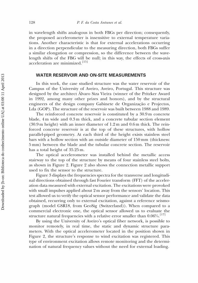
The optical accelerometer was installed behind the metallic accessstairway to the top of the structure by means of four stainless steel bolts,as shown in Figure 2. Figure 2 also shows the connection metallic supportused to fix the sensor to the structure.
Figure 3 displays the frequencies spectra for the transverse and longitudi-nal directions obtained through fast Fourier transform (FFT) of the acceler-ation data measured with external excitation. The excitations were provokedwith small impulses applied about 2m away from the sensors’ location. Thistest allowed us to verify the optical sensor performance and validate the dataobtained, recurring only to external excitation, against a reference seismo-graph (model GSR18, from GeoSig (Switzerland)). When compared to acommercial electronic one, the optical sensor allowed us to evaluate thestructure natural frequencies with a relative error smaller than 0.06%.[17]
By using the University of Aveiro’s optical fiber network, is possible tomonitor remotely, in real time, the static and dynamic structure para-meters. With the optical accelerometer located in the position shown inFigure 2, the structure’s response to wind excitation was registered. Thistype of environment excitation allows remote monitoring and the determi-nation of natural frequency values without the need for external loading.
128 P. F. da Costa Antunes et al.
Dow
nloa
ded
by [
b-on
: Bib
liote
ca d
o co
nhec
imen
to o
nlin
e U
A]
at 0
3:00
11
Apr
il 20
13
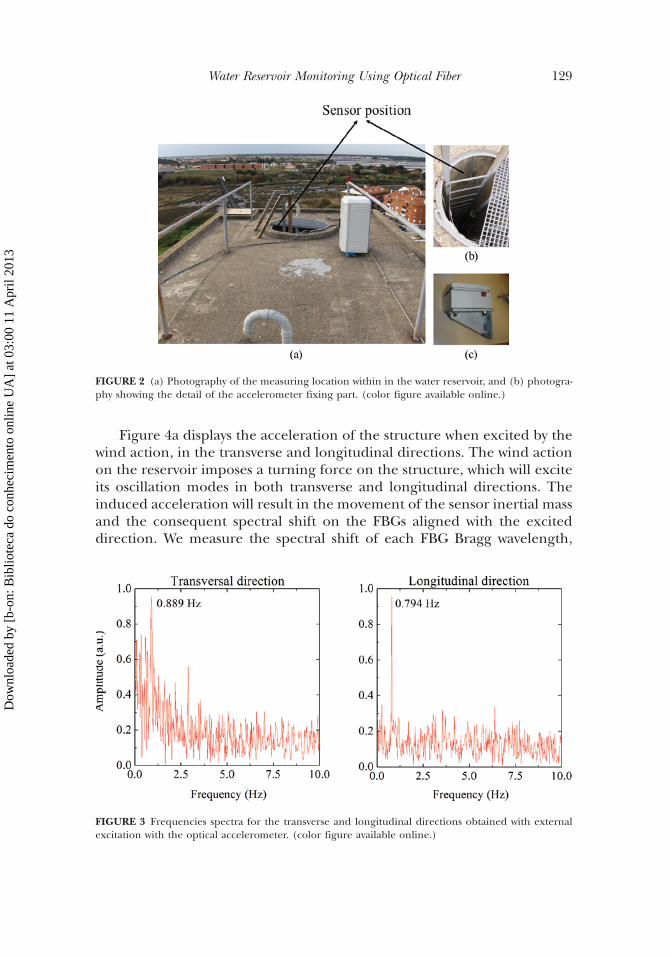
Figure 4a displays the acceleration of the structure when excited by thewind action, in the transverse and longitudinal directions. The wind actionon the reservoir imposes a turning force on the structure, which will exciteits oscillation modes in both transverse and longitudinal directions. Theinduced acceleration will result in the movement of the sensor inertial massand the consequent spectral shift on the FBGs aligned with the exciteddirection. We measure the spectral shift of each FBG Bragg wavelength,
FIGURE 3 Frequencies spectra for the transverse and longitudinal directions obtained with externalexcitation with the optical accelerometer. (color figure available online.)
FIGURE 2 (a) Photography of the measuring location within in the water reservoir, and (b) photogra-phy showing the detail of the accelerometer fixing part. (color figure available online.)
Water Reservoir Monitoring Using Optical Fiber 129
Dow
nloa
ded
by [
b-on
: Bib
liote
ca d
o co
nhec
imen
to o
nlin
e U
A]
at 0
3:00
11
Apr
il 20
13
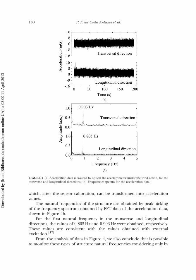
which, after the sensor calibration, can be transformed into accelerationvalues.
The natural frequencies of the structure are obtained by peak-pickingof the frequency spectrum obtained by FFT data of the acceleration data,shown in Figure 4b.
For the first natural frequency in the transverse and longitudinaldirections, the values of 0.805Hz and 0.903Hz were obtained, respectively.These values are consistent with the values obtained with externalexcitation.[17]
From the analysis of data in Figure 4, we also conclude that is possibleto monitor these types of structure natural frequencies considering only by
FIGURE 4 (a) Acceleration data measured by optical the accelerometer under the wind action, for thetransverse and longitudinal directions. (b) Frequencies spectra for the acceleration data.
130 P. F. da Costa Antunes et al.
Dow
nloa
ded
by [
b-on
: Bib
liote
ca d
o co
nhec
imen
to o
nlin
e U
A]
at 0
3:00
11
Apr
il 20
13
wind action, which potentiates the inclusion of the sensor in the remotemonitoring schemes.
NUMERICAL MODELING RESULTS
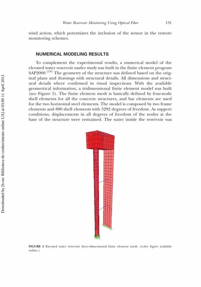
To complement the experimental results, a numerical model of theelevated water reservoir under study was built in the finite element programSAP2000.[18] The geometry of the structure was defined based on the orig-inal plans and drawings with structural details. All dimensions and struct-ural details where confirmed in visual inspections. With the availablegeometrical information, a tridimensional finite element model was built(see Figure 5). The finite element mesh is basically defined by four-nodeshell elements for all the concrete structures, and bar elements are usedfor the two horizontal steel elements. The model is composed by two frameelements and 880 shell elements with 5292 degrees of freedom. As supportconditions, displacements in all degrees of freedom of the nodes at thebase of the structure were restrained. The water inside the reservoir was
FIGURE 5 Elevated water reservoir three-dimensional finite element mesh. (color figure availableonline.)
Water Reservoir Monitoring Using Optical Fiber 131
Dow
nloa
ded
by [
b-on
: Bib
liote
ca d
o co
nhec
imen
to o
nlin
e U
A]
at 0
3:00
11
Apr
il 20
13
simulated as a static vertical load and as additional mass for the represen-tation of the dynamic response of the system.
The main parameters that influence the structural response of the elev-ated water reservoir are the mesh size, the dimension of the sections, thick-ness of the elements, support conditions, material properties, level of water,and self-weight of concrete. For the majority of the listed parameters, theuncertainty is limited. But the material properties, typically represented byYoung’s modulus, may have a high uncertainty associated with the adoptionof the ‘‘estimated values.’’ Also, the state of conservation and eventualdamages in the structure are transduced in this mechanical parameter.
As so, to account with the major uncertainty related with the Young’smodulus and its effect in the dynamic characteristics of the elevated waterreservoir, the adjustment of the concrete Young’s modulus was adopted as acalibration methodology.
Based on the accelerations measured in-situ, the dynamic propertiesof the structure were estimated, and then the material properties of thestructural elements were calibrated in the model, in accordance with thecalibration methodology proposed. For the calibration of the numericalmodel, initial values were adopted for the material properties based on
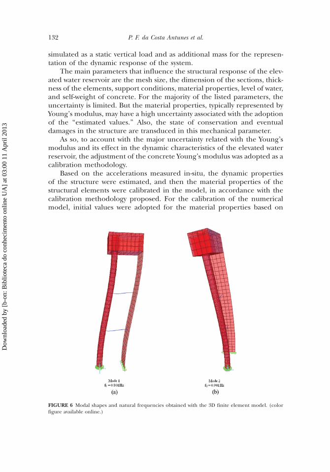
FIGURE 6 Modal shapes and natural frequencies obtained with the 3D finite element model. (colorfigure available online.)
132 P. F. da Costa Antunes et al.
Dow
nloa
ded
by [
b-on
: Bib
liote
ca d
o co
nhec
imen
to o
nlin
e U
A]
at 0
3:00
11
Apr
il 20
13

the information available in the drawings, and then an iterative procedurewas adopted that corrected the values until a good agreement betweenthe model and measurements is reached. A variation of about 20% in theYoung’s modulus was done to calibrate the numerical model. Figure 6presents the first two vibration modal shapes and the corresponding naturalfrequencies that were obtained with the three-dimensional model. A goodagreement, with relative errors of 0.22% and 0.49%, were found betweenthe experimentally measured frequencies and the frequencies estimatedwith the structural numerical model, for the longitudinal and transversedirections, which constitutes the initial validation of the numerical model.
CONCLUSION
In this article, we report the dynamic monitoring of a high reinforcedconcrete structure using optical accelerometers. The studied elevated waterreservoir was suitable to the viability demonstration of FBG accelerometersused to remotely obtain its natural frequencies. The obtained experimentalvalues were used in a structural health monitoring method to calibrate anumerical model that can replicate the structure’s behavior under severalhigh-risk situations. A good agreement, with relative errors of 0.22% and0.49%, was found between the experimentally measured frequencies andthe frequencies estimated with the structural numerical model for thelongitudinal and transverse directions.
ACKNOWLEDGMENT
Paulo Antunes acknowledges the financial support from Fundacao paraa Ciencia e Tecnologia (FCT) through the Postdoctoral fellowship SFRH=BPD=76735=2011.
REFERENCES
1. Adams, D. Health Monitoring of Structural Materials and Components: Methods with Applications; JohnWiley & Sons Inc.: Hoboken, NJ, 2007.
2. Antunes, P.; Lima, H.; Alberto, N.; Bilro, L.; Pinto, P.; Costa, A.; Rodrigues, H.; Pinto, J. L.; Nogueira,R.; Varum, H.; Andre, P. S. Optical sensors based on fiber Bragg gratings for structural healthmonitoring. Ed. S. C. Mukhopadhyay In New Developments in Sensing Technology for Structural HealthMonitoring; Springer-Verlag: New York, 2011, pp. 253–295.
3. Wenzel, H.; Furtner, P. SHM at the civil infrastructure: Applications, recent progress and future demands;2010. Available from: http://www.brimos.com/Brimos/HTML/FRAMESET/Frameset_Downloads.htm.
4. Antunes, P.; Travanca, R.; Varum, H.; Andre, P. Dynamic monitoring and numerical modelling ofcommunication towers with FBG based accelerometers. J. Constr. Steel Res. 2012, 74, 58–62.
5. Antunes, P. F. C.; Lima, H. F. T.; Alberto, N. J.; Rodrigues, H.; Pinto, P. M. F.; Pinto, J. L.; Nogueira,R. N.; Varum, H. S. A.; Costa, A. G.; Andre, P. S. B. Optical fiber accelerometer system for structuraldynamic monitoring. IEEE Sens. J. 2009, 9(11), 1347–1354.
Water Reservoir Monitoring Using Optical Fiber 133
Dow
nloa
ded
by [
b-on
: Bib
liote
ca d
o co
nhec
imen
to o
nlin
e U
A]
at 0
3:00
11
Apr
il 20
13

6. Chan, T. H. T.; Yu, L.; Tam, H. Y.; Ni, Y. Q.; Chung, W. H.; Cheng, L. K. Fiber Bragg grating sensorsfor structural health monitoring of Tsing Ma bridge: Background and experimental observation.Eng. Struct. 2006, 28(5), 648–659.
7. Csipkes, S. F. A.; Graver, T. W.; Haber, T. C.; Mendez, A.; Miller, J. W. The Maturing of Optical SensingTechnology for Commercial Applications; Micron Optics Inc.: Atlanta, GA, 2005.
8. Lima, H. F.; Vicente, R.; Nogueira, R. N.; Abe, I.; Andre, P. S.; Fernandes, C.; Rodrigues, H.; Varum,H.; Kalinowski, H. J.; Costa, A.; Pinto, J. L. Structural health monitoring of the Church of Santa Casada Misericordia of Aveiro using FBG sensors. IEEE Sens. J. 2008, 8(7), 1236–1242.
9. Maaskant, R.; Alavie, T.; Measures, R. M.; Tadros, G.; Rizkalla, S. H.; GuhaThakurta, A. Fiber-opticBragg grating sensors for bridge monitoring. Cem. Concr. Compos. 1997, 19(1), 21–33.
10. Majumder, M.; Gangopadhyay, T. K.; Chakraborty, A. K.; Dasgupta, K.; Bhattacharya, D. K. FibreBragg gratings in structural health monitoring—present status and applications. Sens. Actuators, A2008, 147(1), 150–164.
11. Zhou, D. P.; Graver, T.; Hsu, L.; Ou, J. P. Techniques of advanced FBG sensors: Fabrication, demodu-lation, encapsulation and their applications in the structural health monitoring of bridges. Pac. Sci.Rev. 2003, 5, 116–121.
12. Julio, E.; Rebelo, C.; Dias-da-Costa, D. Structural assessment of the tower of the University ofCoimbra by modal identification. Eng. Struct. 2008, 30(12), 3468–3477.
13. Milani, G.; Casolo, S.; Naliato, A.; Tralli, A. Seismic assessment of a Medieval masonry tower innorthern Italy by limit, nonlinear static, and full dynamic analyses. Int. J. Archit. Herit. 2011, 6(5),489–524.
14. Pena, F.; Lourenco, P. B.; Mendes, N.; Oliveira, D. V. Numerical models for the seismic assessment ofan old masonry tower. Eng. Struct. 2010, 32(5), 1466–1478.
15. Antunes, P. F. C.; Marques, C. A.; Varum, H.; Andre, P. S. Biaxial optical accelerometer andhigh-angle inclinometer with temperature and cross-axis insensitivity. IEEE Sens. J. 2012, 12(7),2399–2406.
16. Antunes, P.; Lima, H.; Monteiro, J.; Andre, P. S. Elastic constant measurement for standard andphotosensitive single mode optical fibres. Microwave Opt. Technol. Lett. 2008, 50(9), 2467–2469.
17. Antunes, P.; Rodrigues, H.; Melo, J.; Varum, H.; Andre, P. Dynamic monitoring of an elevated waterreservoir with an optical biaxial accelerometer, In Proceedings of OSA Sensors 2012, Monterey, CA,USA, June 24–28, 2012; OSA: Washington, DC, 2012.
18. Computers and Structures Inc (CSI). SAP2000—Integrated Finite Element Analysis and Design ofStructures; CSI: Berkeley, CA, 1996.
134 P. F. da Costa Antunes et al.
Dow
nloa
ded
by [
b-on
: Bib
liote
ca d
o co
nhec
imen
to o
nlin
e U
A]
at 0
3:00
11
Apr
il 20
13