
Compositional dependence of the electrical conductivity of calcium vanadate glassy semiconductors

ORIGINAL PAPER
Electrocatalytic reduction of NAD+ at glassy carbonelectrode modified with single-walled carbon nanotubesand Ru(III) complexes
Abdollah Salimi & Mohadeseh Izadi & Rahman Hallaj &Saied Soltanian & Hassan Hadadzadeh
Received: 27 January 2008 /Accepted: 6 May 2008 / Published online: 10 June 2008# Springer-Verlag 2008
Abstract A simple procedure was developed to prepare aglassy carbon electrode modified with carbon nanotubes andRuthenium (III) complexes. First, 25 μl of dimethylsulfoxide–carbon nanotubes solutions (0.4 mg/ml) was caston the surface of the glassy carbon electrode and dried in airto form a carbon nanotube film at the electrode surface.Then, the glassy carbon/carbon nanotube-modified electrodewas immersed into a Ruthenium (III) complex solution(direct deposition) for a short period of time (10–20 s formultiwalled carbon nanotubes and 20–40 s for single-walledcarbon nanotubes). The cyclic voltammograms of themodified electrode in aqueous solution shows a pair ofwell-defined, stable, and nearly reversible redox couple, Ru(III)/Ru(II), with surface-confined characteristics. The attrac-tive mechanical and electrical characteristics of carbonnanostructures and unique properties and reactivity of Rucomplexes are combined. The transfer coefficient (α),heterogeneous electron transfer rate constants (ks), andsurface concentrations (Γ) for the glassy carbon/single-walled carbon nanotubes/Ru(III) complex-, glassy carbon/multiwalled carbon nanotubes/Ru(III) complex-, and glassycarbon/Ru(III) complex-modified electrodes were calculat-
ed using the cyclic voltammetry technique. The modifiedelectrodes showed excellent catalytic activity, fast responsetime, and high sensitivity toward the reduction of nicotin-amide adenine dinucleotide in phosphate buffer solutions ata pH range of 4–8. The catalytic cathodic current dependson the nicotinamide adenine dinucleotide concentration. Inthe presence of alcohol dehydrogenase, the modifiedelectrode exhibited a response to addition of acetaldehyde.Therefore, the main product of nicotinamide adeninedinucleotide electroreduction at the Ru(III) complex/carbonnanotube-modified electrode was the enzymatically activeNADH. The purposed sensor can be used for acetaldehydedetermination.
Keywords CNTs . Ru(III) complexes . Glassy carbon .
NAD+ . Alcohol dehydrogenase . Acetaldehyde . Sensor
Introduction
Nicotinamide adenine dinucleotide (NAD+) is a ubiquitouscofactor, used by more than 300 dehydrogenase enzymes.The electrochemical reduction of NAD+ to the enzymati-cally active form nicotinamide adenine dinucleotide(NADH) has attracted considerable attention due to theindustrial and biomedical importance of reduced derivativesof adenine. Furthermore, electrochemical reduction ofNAD+ is known to be an efficient means for this purposeand has potential application for fabrication of biosensors.In addition, the high cost of NADH to a bioreactor has beenthe major motivation for research in the development of insitu NADH regeneration techniques. The NAD+/NADHredox couple has a formal potential of −0.32 V vs. thestandard hydrogen electrode (pH7), but its direct reductionrequires a large overpotential [1]. The direct reduction of
J Solid State Electrochem (2009) 13:485–496DOI 10.1007/s10008-008-0583-6
DO00583; No of Pages
A. Salimi (*) :M. Izadi :R. HallajDepartment of Chemistry, University of Kurdistan,P.O. Box 416, Sanandaj, Irane-mail: [email protected]
A. Salimi : S. SoltanianResearch Center for Nanotechnology,University of Kurdistan,P.O. Box 416, Sanandaj, Iran
H. HadadzadehDepartment of Chemistry, Isfahan University of Technology,Isfahan, Iran

NAD+ on unmodified metallic electrodes results mostly inthe formation of an inactive dimmer NAD2, which can beonly partially protonated and further reduced to both 1,4-and 1,6-NADH at significantly higher negative overpoten-tials [2, 3]. Among these products, only the 1,4-NADH isactive in enzyme-coupled reactions, and the indirectelectrocatalytic reduction of the NAD+ seems to be a betterway to decrease the overpotential and to get a high yield of1,4-NADH [4]. The fast dimerization reaction, coupledwith the slow second reaction step, is the major reason forthe direct reduction of NAD+ on unmodified electrodes,which results in the formation of NAD2 rather thanenzymatically active NADH ([5] and references there in).Numerous modified electrodes based on the use ofdifferent electron transfer mediators such as cerium hexa-chloroplatinate [6], iron hexachloroplatinate [7], flavineadenine dinucleotide (FAD)-modified zinc oxide film [8],poly-natural red [9, 10], poly(3-methylthiophene)/phenol[11], poly-pyrrole rhodium bis-terpyridine [12], ruthenium-modified glassy carbon (GC) electrode[13], and poly-crystalline gold electrode [14] have been used for theelectrocatalytic reduction of NAD+. Furthermore, electro-chemical properties of NAD+/NADH redox couple on hybridpoly-(luminal)/FAD film [15] and nordihydroguaiaretic acid/FAD hybrid film [16] have been investigated. In addition, thereduction of NAD+ to NADH on electrodes modified by alayer of immobilized methyl viologen and lipoamidedehydrogenase [17, 18], methyl viologen, and diphorase[19, 20] have been reported. Although enzymatic modifica-tion of an electrode surface gives encouraging results in thereduction of NAD+ to enzymatically active 1,4-NADH, thisapproach results in a rather complex electrode system dueto difficulties related to the immobilization of an enzymemediator at the electrode surface, lack of stability, and lossof the enzyme activity due to the intrinsic nature of theenzyme, electron mediator leakage, and slow NADHregeneration rate. Moreover, high cost and low reproduc-ibility and repeatability are other disadvantages of enzymeelectrodes. Hence, it is pertinent to develop a simple andreliable method for the modification of the electrodesurface using new electron transfer mediators, which wouldallow electrochemical regeneration of an enzymaticallyactive form of NADH.
Ruthenium is a remarkable transition metal that displaysdifferent oxidation states, which make wide variations ofredox reactions possible [21–24]. Owing to its reversibleredox activity and excellent electrocatalytic properties, Rucomplexes have received considerable attention in the fieldof electroanalysis and fabrication of chemically modifiedelectrodes [13, 25–32]. The modification of differentelectrode surfaces with Ru complexes is possible in severalways such as adsorption and entrapping into the carbonpaste, conductive composites, and polymer matrix.
Carbon nanotubes (CNTs) are a new kind of nano-structure material, which is promising as an immobilizationsubstance because of its significant mechanical strength,high surface area, excellent electrical conductivity, andgood chemical stability [33]. Recently, many efforts havebeen focused on the fictionalizations of CNTs with variousmolecules by using covalent or noncovalent approaches toobtain desired properties [34–38]. Among theseapproaches, the fictionalization of the side walls of CNTsin the noncovalent way is an effective way to preserve thesp2 nanotube structure and thus their electronic character-istics. In addition, the strong interaction of aromatic groupswith π-staking of CNTs is a similar manner to achieve thedesired purpose. Immobilization of molecules and biomol-cules on CNTs has been pursued in the past, motivated bythe prospects of using nanotubes as new types of sensor andbiosensors. Due to electronic and specific recognitionproperties of CNTs as immobilized systems, they can beused for making ideal miniaturized sensors. The surface ofCNTs can be chemically modified to impart a specificdesired property, either covalently or physically adsorption[39–42]. The compatibility and electrochemical applica-tions of CNTs to immobilize a variety of species on theexternal and internal surfaces of them have been reported[41–47]. It was shown earlier that the electrocatalyticproperties of CNTs toward other slow redox systems canbe improved by coupling metal centers with them [48, 49].
Recently, we used CNT-modified electrodes for theimmobilization of different electron transfer mediators andtheir application in sensors and biosensors fabrication[50–54]. In the current study, a simple and fast procedurewas used for immobilization of Ru(III) complexes on a GCelectrode modified with CNTs and their application forelectrocatalytic reduction of NAD+. The electron transfer rateconstants of the Ru(III)/Ru(II) redox couple and the catalyticrate constant of the modified electrode for NAD+ reductionwere also evaluated and calculated. The ability of themodified electrode for the fabrication of an acetaldehydebiosensor was evaluated.
Experimental
Chemical and reagents The Ru(III) complexes used inthis study (Scheme 1) were [Ru(trpy)Cl3] (where trpy =2,2 ′-6 ′,2″-terpyridine), [Ru(NH3)5(2,4,5-Cl3pcyd)](ClO4)2 (where 2,4,5-Cl3pcyd = 2,4,5-trichloro phenyl-cyanamide anion), and [Ru(phen)2(phen-dioxime)](PF6)2(where phen = 1,10-phenanthroline and Phen-dioxime =1,10-phenanthroline-5,6-dioxime), which were synthesized,purified, and characterized as reported [55–57]. NAD+ withpurity of 95% was from Sigma and used without furtherpurification. Alcohol dehydrogenase (ADH; EC 1.1.1.1.,from Baker’s Yeast) was purchased from Sigma. Acetonitrile
486 J Solid State Electrochem (2009) 13:485–496

(ACN) and dimethyl sulfoxide (DMSO) were from Merck.Multiwall CNTs (MWCNTs) with 95% purity (10–20 nmdiameter) and 1 μm length were obtained from Nanolab(Brighton, MA, USA). Single-wall CNTs (SWCNTs) havebeen manufactured by CNI (USA). Double-distillate water wasused to prepare all solutions. Buffer solutions (0.1 M) wereprepared from H2SO4, H3PO4, NaH2PO4, and Na2HPO4.Hydrogen chloride (HCl) and sodium hydroxide (NaOH)were used for pH adjustment. Solutions were deaerated bybubbling high purity (99.99%) of argon gas through themprior to the experiments. All electrochemical experimentswere carried out at room temperature 25 ± 0.1 °C.
Apparatus and procedures Electrochemical experimentswere performed with a computer controlled μ-Autolabmodular electrochemical system (Eco Chemie, Ultecht, The
Netherlands), driven with a general-purpose electrochemicalsystem software (Eco Chemie). A conventional three-electrode cell was used with a Ag/AgCl/(saturated KCl) asthe reference electrode, a Pt wire as a counterelectrode, and aGC disk (modified and unmodified) as a working electrode.Voltammetry on electrodes coated with Ru complex–CNTswas done in buffers containing no complex. All of the usedelectrodes were from Metrohm. A personal computer wasused for data storage and processing. The morphologies ofthe surface were observed in a Vega-Tescan electronmicroscope.
Preparation of Ru(III) complex–CNTs–GC and Ru(III)–GC-modified electrodes The GC electrode was first care-fully polished with alumina (1.0 and 0.05 μm) on apolishing cloth. The electrode was placed in an ethanolcontainer, and a bath ultrasonic cleaner was used to removeadsorbed particles. Then, 25 μl of DMSO–CNTs solutions(0.4 mg/ml) was cast on the surface of the GC electrode anddried in air to form a CNT film at the electrode surface. Byimmersing the GC electrode modified with CNTs in0.1 mM ACN solution of Ru(III) complex for 5–30 s, astable film of complex adsorbed on the surface of theelectrode. After rinsing of the modified electrode withwater, it can be used for electrochemical experimentsimmediately. The effective surface area of the electrodesmodified with the immobilization of MWCNTs andSWCNTs were determined as 0.12 and 0.15 cm2 fromcyclic voltammograms of 1 mM K3[Fe(CN)6] in phosphatebuffer solution (pH7) [58]. To attach the Ru(III) complex tothe surface of the GC electrode with the cyclic voltammetrytechnique, the GC electrode was carefully polished withalumina on a polishing cloth. With cycling of the potentialbetween 0.1 and −0.5 V (30 cycles) at a scan rate of100 mV s−1, in an ACN solution containing 0.1 mM Ru(III)complex, a film of the Ru complex adsorbed on theelectrode surface. For the adsorption of the complex onthe surface of the reactivated GC electrode, the process wascarried out in two steps. First, the GC electrode was heldunder a constant potential of 1.8 V for 5 min in 1 M H2SO4
solution. Second, the preanodized GC electrode wasimmersed in an ACN solution containing 0.1mM of Ru(III) complex for 1 h.
Results and discussions
Characterization of Ru complex-modified CNTs
Due to a large specific surface area of CNTs, a highquantity of Ru complexes can be adsorbed onto CNTsthrough strong π–π-stocking force between these two kind
N
N
N
Ru
Cl
Cl
Cl
Complex (A)
NH3
NH3
NH3 NH3
NH3
N NRu Cl
Cl
Cl
(ClO4)2C
Complex (B)
N
N
N
N
NN
Ru
HONNOH
(PF6)2
Complex (C)Scheme 1. The structures of used complexes
J Solid State Electrochem (2009) 13:485–496 487
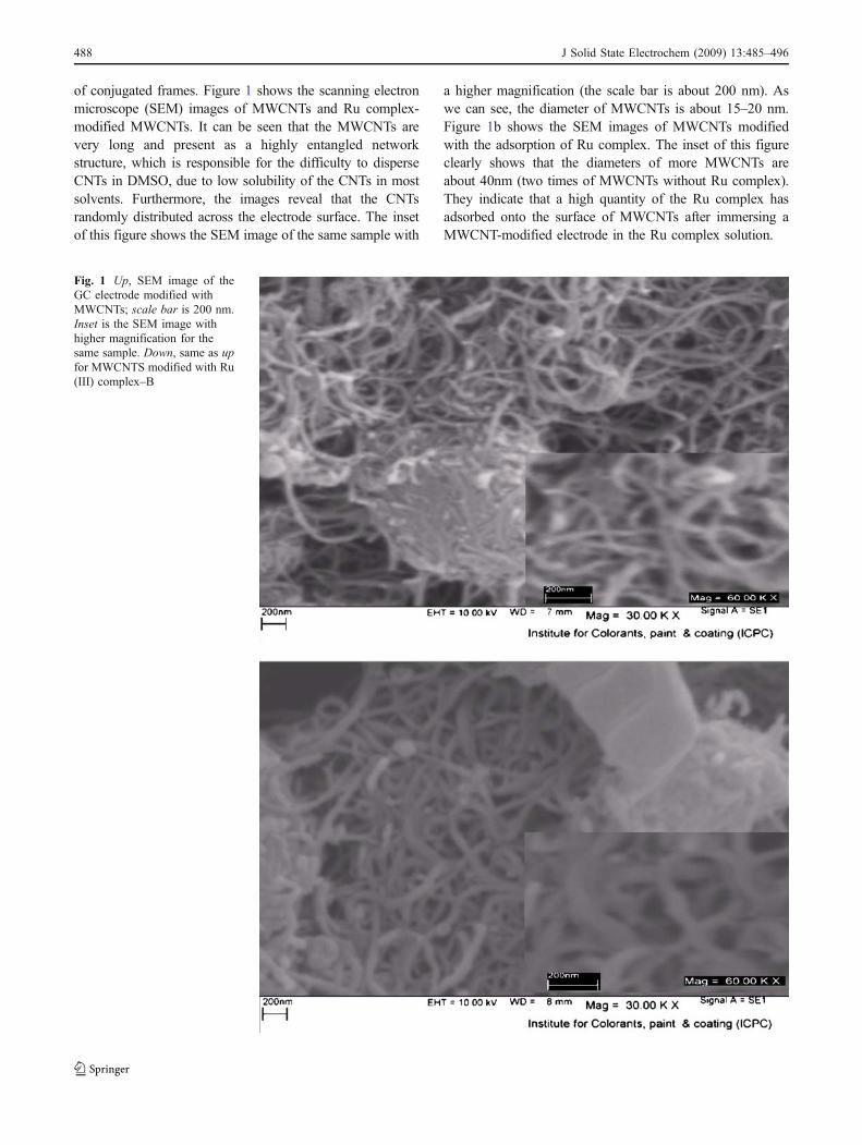
of conjugated frames. Figure 1 shows the scanning electronmicroscope (SEM) images of MWCNTs and Ru complex-modified MWCNTs. It can be seen that the MWCNTs arevery long and present as a highly entangled networkstructure, which is responsible for the difficulty to disperseCNTs in DMSO, due to low solubility of the CNTs in mostsolvents. Furthermore, the images reveal that the CNTsrandomly distributed across the electrode surface. The insetof this figure shows the SEM image of the same sample with
a higher magnification (the scale bar is about 200 nm). Aswe can see, the diameter of MWCNTs is about 15–20 nm.Figure 1b shows the SEM images of MWCNTs modifiedwith the adsorption of Ru complex. The inset of this figureclearly shows that the diameters of more MWCNTs areabout 40nm (two times of MWCNTs without Ru complex).They indicate that a high quantity of the Ru complex hasadsorbed onto the surface of MWCNTs after immersing aMWCNT-modified electrode in the Ru complex solution.
Fig. 1 Up, SEM image of theGC electrode modified withMWCNTs; scale bar is 200 nm.Inset is the SEM image withhigher magnification for thesame sample. Down, same as upfor MWCNTS modified with Ru(III) complex–B
488 J Solid State Electrochem (2009) 13:485–496

Electrochemical properties of Ru(III)complex–CNT-modified GC electrodes
Figure 2 shows the cyclic voltammograms of SWCNTs andSWCNTs/Ru(III) complex–B-modified GC electrodes atpH1 buffer solution (voltammograms a and b). For theSWCNTs/GC electrode, no redox peak between 1.0 and−0.6 V was found, and the background current was high.By immersing the electrode for 40 s in the complexsolution, a thin layer of the Ru complex adsorbed on thesurface of the CNT-modified GC electrode. Four indepen-dent GC electrodes were modified with CNTs and Rucomplex with the same procedure. A well-defined redoxcouple with peak current 23.8 μA (±0.5) and peak potentialseparation less than 20 mV (± 2) was observed for theadsorbed complex. For the GC electrode modified withMWCNTs–Ru(III) complex, a cyclic voltammogram with alower peak current, 10 μA (±0.4), and more peak potentialseparation, 100 mV (±5), was observed (Fig. 2 voltammogramd). No response was observed at the same potential range forthe GC–MWCNT-modified electrode (Fig. 2 voltammogramc). SWCNTs can increase the surface area of the electrode;therefore, the background current and capacitances for theSWCNT-coated surface is higher than the GC electrodecoated with MWCNTs. In addition, SWCNTs are highlypermeable porous films, and electrolytes can penetratethrough the film and gain access to the interior surface [59].Figure 3a shows a cyclic voltammogram of the GC electrodemodified with Ru complex–B, using consequence potentialcycling (30 cycles at a scan rate of 100 mV s−1 between 0.1and −0.5 V in 0.1 mM Ru(III) complex–B). As can be seenfor the Ru complex-modified GC electrode, a voltammogram
with small peak current, 1.1 μA, more peak potentialseparations, 100 mV, and higher background currentwas observed. For the GC electrode modified withimmersing the preanodized electrode in the ACNsolution containing 1 mM Ru complex–B during60 min, a cyclic voltammogram with smaller peakcurrent (0.1 μA) and high peak potential separation(70 mV) was observed (Fig. 3b). For voltammograms aand b, the peak separation between oxidation andreduction peaks is increased due to the increasing theresistance of the thicker film. However, observing a pairof well-defined redox couple with low peak potentialseparation (20 mV) indicates that the reversibility of theredox system is significantly improved. Due to high specificand conductive area of CNTs [60], the Ru complex moreeasily penetrates through the conductive porous channels ofthe electrode, leading to higher sensitivity. Figure 4 showscyclic voltammograms of a SWCNTs–Ru(III) complex–B-modified GC electrode with different surface concentra-tion of the complex, obtained by soaking the SWCNTs/GCelectrode in 0.1 mM complex solution for different times. Asshown in this figure, by immersing the electrode in the Rucomplex solution for 10 s, a stable thin layer of complexadsorbed at the surface of electrode. By increasing theimmersing time, the surface concentration of the Ru(III)complex is increased and then starts to level off after 40 s. Incomparison to the GC electrode modified with SWCNTs, forthe MWCNT-modified GC electrode at shorter period ofimmersing time, the peak currents level off (20 vs. 40 s).This is due to the fact that the effective surface area ofSWCNTs is higher and they are highly permeable porousfilms and can adsorb more Ru complex molecules.
-25
-20
-15
-10
-5
0
5
10
15
20
25
-0.7 -0.5 -0.3 -0.1 0.1 0.3 0.5 0.7 0.9 1.1
potential(v) v.s Ag/AgCl
curr
ent(
µA)
GC/SWCNT/Ru-Complex (b)
GC/MWCNT/Ru-Complex (d)
GC/MWCNT(c)
GC/SWCNTs(a)
Fig. 2 a Cyclic voltammogramsof a SWCNTs/GC-modified elec-trode in buffer solution (pH 1), bsame as a for SWCNTs/Rucomplex–B-modified electrode. c,d Same as a and b for MWCNTs,the immersing time for electrodemodification is 40 and 20 s forGC electrodes covered withSWCNTs and MWCNTs, with ascan rate of 100 mV s−1
J Solid State Electrochem (2009) 13:485–496 489
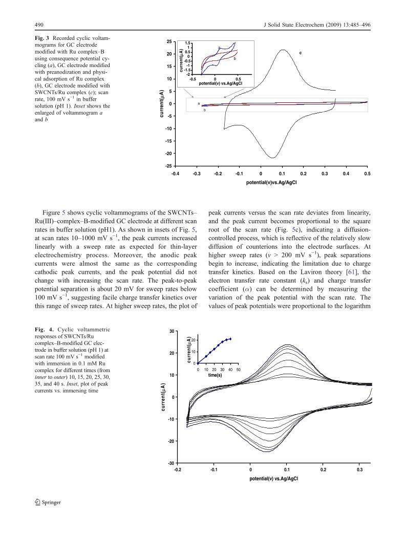
Figure 5 shows cyclic voltammograms of the SWCNTs–Ru(III)–complex–B-modified GC electrode at different scanrates in buffer solution (pH1). As shown in insets of Fig. 5,at scan rates 10–1000 mV s−1, the peak currents increasedlinearly with a sweep rate as expected for thin-layerelectrochemistry process. Moreover, the anodic peakcurrents were almost the same as the correspondingcathodic peak currents, and the peak potential did notchange with increasing the scan rate. The peak-to-peakpotential separation is about 20 mV for sweep rates below100 mV s−1, suggesting facile charge transfer kinetics overthis range of sweep rates. At higher sweep rates, the plot of
peak currents versus the scan rate deviates from linearity,and the peak current becomes proportional to the squareroot of the scan rate (Fig. 5c), indicating a diffusion-controlled process, which is reflective of the relatively slowdiffusion of counterions into the electrode surfaces. Athigher sweep rates (v > 200 mV s−1), peak separationsbegin to increase, indicating the limitation due to chargetransfer kinetics. Based on the Laviron theory [61], theelectron transfer rate constant (ks) and charge transfercoefficient (α) can be determined by measuring thevariation of the peak potential with the scan rate. Thevalues of peak potentials were proportional to the logarithm
-25
-20
-15
-10
-5
0
5
10
15
20
25
-0.4 -0.3 -0.2 -0.1 0 0.1 0.2 0.3 0.4 0.5
potential(v)vs.Ag/AgCl
curr
ent(
µA)
-2-1.5
-1-0.5
00.5
11.5
-0.5 0 0.5potential(v) vs.Ag/AgCl
curr
ent(
µA)
b
a
a
b
c
Fig. 3 Recorded cyclic voltam-mograms for GC electrodemodified with Ru complex–Busing consequence potential cy-cling (a), GC electrode modifiedwith preanodization and physi-cal adsorption of Ru complex(b), GC electrode modified withSWCNTs/Ru complex (c); scanrate, 100 mV s−1 in buffersolution (pH 1). Inset shows theenlarged of voltammogram aand b
-30
-20
-10
0
10
20
30
-0.2 -0.1 0 0.1 0.2 0.3
potential(v) vs.Ag/AgCl
curr
ent(
µA)
0
10
20
0 10 20 30 40 50time(s)
curr
ent(
µA)
Fig. 4. Cyclic voltammetricresponses of SWCNTs/Rucomplex–B-modified GC elec-trode in buffer solution (pH 1) atscan rate 100 mV s−1 modifiedwith immersion in 0.1 mM Rucomplex for different times (frominner to outer) 10, 15, 20, 25, 30,35, and 40 s. Inset, plot of peakcurrents vs. immersing time
490 J Solid State Electrochem (2009) 13:485–496

of the scan rate for scan rates higher than 2.0 V s−1
(Fig. 5D). The slope of the ΔEpc vs. log (v) was about142.3 mV. Using the equation Ep ¼ K � 2:3030 RT=anFð Þlog vð Þ and one electron transferred for Ru(III) complex, acharge transfer coefficient of α = 0.42 was obtained.Introducing this α value in the following equation [61],an apparent heterogeneous electron transfer rate constant,ks = 3.78s−1 (±0.20), was estimated.
log ks ¼ a log 1� að Þ þ 1� að Þ log a� log RT=nFvð Þ � a 1� að ÞnFE=2:3RT ð1Þ
For other Ru(III) complexes used in this study (complexesA and C), the charge transfer and electron transfer rateconstants on the surface GC electrodes modified withSWCNTs and MWCNTs are reported in Table 1. For the GCelectrode modified with the adsorption of Ru complex–B,without using CNTs, the electron transfer rate constant is2.2s−1. The large value of the electron transfer rate constantindicates the high ability of CNTs for promote an electronbetween the Ru complex and electrode surface. The surfacesof CNTs contain the large number of defects, and a specialnanostructure of CNT may act as molecular wires to enhancethe direct electron transfer of the Ru complex at CNT. Thesurface concentration of electroactive species, Γ, can becalculated from the slope of the plot of Ipa versus the scan
rate (v < 100 mV s−1) by the following equation [62]. Thecalculated value of Γ is 1.47 × 10⁻⁹mol cm−2.
Ip ¼ n2F2vAΓ c
�4RT ð2Þ
where v is the sweep rate, A is the surface area, and the othersymbols have their usual meaning. For other modifiedelectrodes, the calculated Γ values are reported in Table 1.The working stability of the modified electrode was verifiedby monitoring the remaining amount of active substanceafter successive sweeps of cyclic voltammograms. The peakheight and peak potential of the immobilized redox systemduring potential cycling over the range 0.55 to −0.2Vremained nearly constant, and the amount of the rutheniumcomplex remaining on the electrode surface was almost 94%of its initial value after 200 cycles (Fig. 6). In addition, nosignificant decrease was observed after replacing theelectrolyte used for 200 repetitive cycles with the freshbuffer solution. Furthermore, the storage stability of thechemically modified electrodes was very good. The electro-des were found to have reserved 97% of their initial activityfor more than 1 month when kept in air at room temperature.The cyclic voltammogram of the GC electrode modified withthe Ru complex, using consequence potential cyclingtechnique, is recorded under the same condition. Althougha well-defied redox couple was observed for the modifiedelectrode, after 50 potential cycles, about 40% of the
y = 0.1431x - 0.3132R2 = 0.9983
y = -0.1423x + 0.3253R2 = 0.9947
-0.3
-0.1
0.1
0.3
0 2 4log scan rate(mv/s)
Ep
(Ep
-E0)
vs.
Ag
/Ag
Cl
-25
-15
-5
5
15
25
-0.2 -0.1 0 0.1 0.2 0.3
potential(v) vs. Ag/AgCl
curr
ent(
µA)
A
-1000
-500
0
500
1000
0 50 100
scan rate1/2(mv/s)1/2
curr
ent(
µA)
C
D
∆
y = -0.2324x + 1.1892R2 = 0.9994
y = 0.2138x - 0.5898R2 = 0.9981-
-500
0
500
1000
0 2000 4000scan rate(mv/s)
curr
ent(
µA)
B
1000
Fig. 5 A Cyclic voltammetricresponses of SWCNTs/Rucomplex–B-modified GC elec-trode in acidic buffer solution(pH 1) at scan rates (inner toouter) 10, 20, 30, 40, 50, 60, 70,80, 90, and 100 mV s−1. Insets(B, C), plots of peak currents vs.square root of scan rate and scanrate. D Variation of peak poten-tial separation vs. log of scan rate
Table 1 The values of α, ks, and Γ for modified electrodes
CNT SWNT MWNT
Complex α ks (s−1) Γ×10−9 (mol/cm2) α ks (s
−1) Γ×10−9 (mol/cm2)
Complex (B) 0.44 3.83 1.193 0.41 3.73 0.642Complex (A) 0.44 3.84 1.152 0.40 3.67 0.629Complex (C) 0.45 3.85 1.147 0.4556 3.74 0.695
J Solid State Electrochem (2009) 13:485–496 491
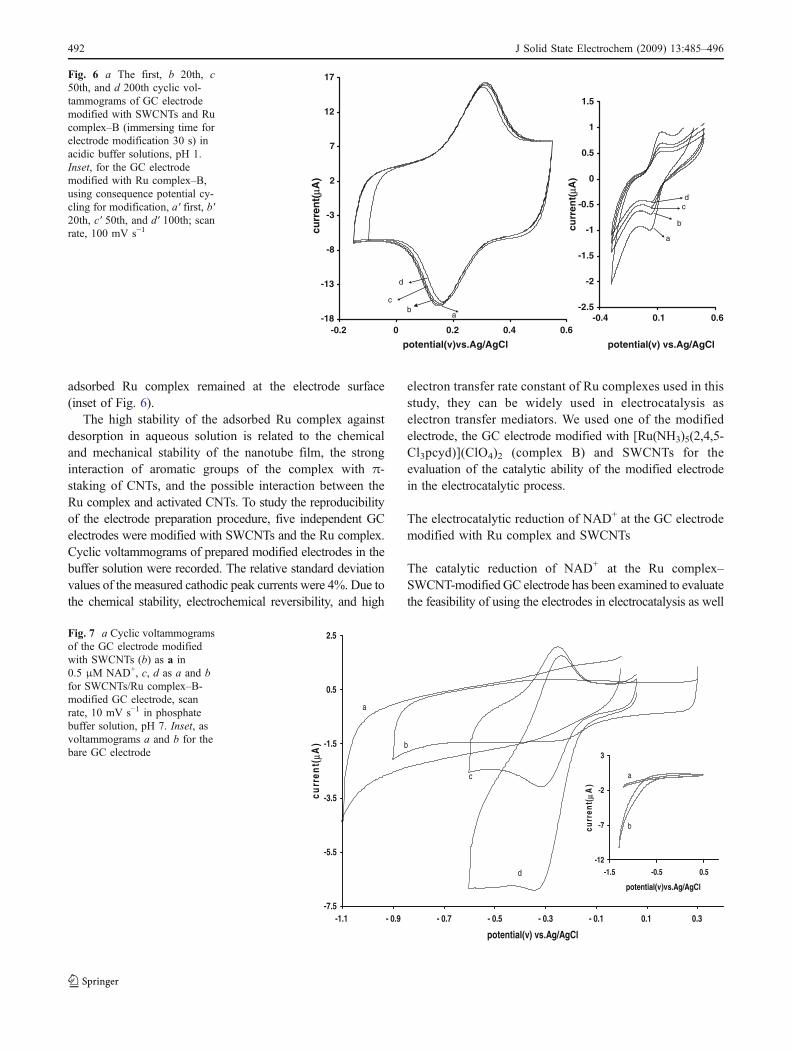
adsorbed Ru complex remained at the electrode surface(inset of Fig. 6).
The high stability of the adsorbed Ru complex againstdesorption in aqueous solution is related to the chemicaland mechanical stability of the nanotube film, the stronginteraction of aromatic groups of the complex with π-staking of CNTs, and the possible interaction between theRu complex and activated CNTs. To study the reproducibilityof the electrode preparation procedure, five independent GCelectrodes were modified with SWCNTs and the Ru complex.Cyclic voltammograms of prepared modified electrodes in thebuffer solution were recorded. The relative standard deviationvalues of the measured cathodic peak currents were 4%. Due tothe chemical stability, electrochemical reversibility, and high
electron transfer rate constant of Ru complexes used in thisstudy, they can be widely used in electrocatalysis aselectron transfer mediators. We used one of the modifiedelectrode, the GC electrode modified with [Ru(NH3)5(2,4,5-Cl3pcyd)](ClO4)2 (complex B) and SWCNTs for theevaluation of the catalytic ability of the modified electrodein the electrocatalytic process.
The electrocatalytic reduction of NAD+ at the GC electrodemodified with Ru complex and SWCNTs
The catalytic reduction of NAD+ at the Ru complex–SWCNT-modified GC electrode has been examined to evaluatethe feasibility of using the electrodes in electrocatalysis as well
-18
-13
-8
-3
2
7
12
17
-0.2 0 0.2 0.4 0.6
potential(v)vs.Ag/AgCl
curr
ent(
µA)
ab
c
d
-2.5
-2
-1.5
-1
-0.5
0
0.5
1
1.5
-0.4 0.1 0.6
potential(v) vs.Ag/AgCl
curr
ent(
µA)
a
b
cd
Fig. 6 a The first, b 20th, c50th, and d 200th cyclic vol-tammograms of GC electrodemodified with SWCNTs and Rucomplex–B (immersing time forelectrode modification 30 s) inacidic buffer solutions, pH 1.Inset, for the GC electrodemodified with Ru complex–B,using consequence potential cy-cling for modification, a′ first, b′20th, c′ 50th, and d′ 100th; scanrate, 100 mV s−1
-7.5
-5.5
-3.5
-1.5
0.5
2.5
-1.1 - 0.9 - 0.7 - 0.5 - 0.3 - 0.1 0.1 0.3
potential(v) vs.Ag/AgCl
curr
ent(
µA)
a
b
d
c
-12
-7
-2
3
-1.5 -0.5 0.5
potential(v)vs.Ag/AgCl
curr
ent(
µA)
a
b
Fig. 7 a Cyclic voltammogramsof the GC electrode modifiedwith SWCNTs (b) as a in0.5 μM NAD+, c, d as a and bfor SWCNTs/Ru complex–B-modified GC electrode, scanrate, 10 mV s−1 in phosphatebuffer solution, pH 7. Inset, asvoltammograms a and b for thebare GC electrode
492 J Solid State Electrochem (2009) 13:485–496
as electroanalysis. One of the objectives of the current studywas fabricating a modified electrode that is capable for theelectrocatalytic reduction of NAD+ to the enzymatically activecompound NADH at a reduced overpotential. To test theelectrocatalytic activity of the modified electrodes, the cyclicvoltammograms were obtained in the absence and presence ofNAD+ in buffer solution (pH7). Figure 7 shows cyclicvoltammograms of GC electrodes modified with SWCNTsand Ru complex–B + SWCNTs in buffer solution (pH7) freeof and containing NAD+. Upon the addition of 0.5 μM ofNAD+, there is a dramatic enhancement of the cathodic peakcurrent, and the anodic peak currents decrease (Fig. 7d),which indicate a strong catalytic effect of the mediator forNAD+ reduction. The cathodic peak current for NAD+
reduction was observed at the SWCNT-modified GC elec-trode, but the peak current is about 15% of the response of theGC–SWCNTs–Ru complex-modified electrode under thesame condition, and current decay is faster during conse-quence potential cycling. The inset of Fig. 7 shows therecorded cyclic voltammogram of the bare GC electrode inthe absence and presence of NAD+. As shown for the GCelectrode, no cathodic response was observed for NAD+
reduction until −0.7 V.To optimize the electrocatalytic response of the modified
electrode toward NAD+ reduction, the effect of pH on thecatalytic behavior of the modified electrode was investigat-ed. The cyclic voltammograms of the modified electrode in1 μM NAD+ at different pH values (1 to 8) were recorded(not shown). At pH4 to 8, the modified electrode showselectrocatalytic activity, but higher peak currents areobserved at pH7, and this value was chosen as optimized.Additionally, peak potentials are shifted to negative values
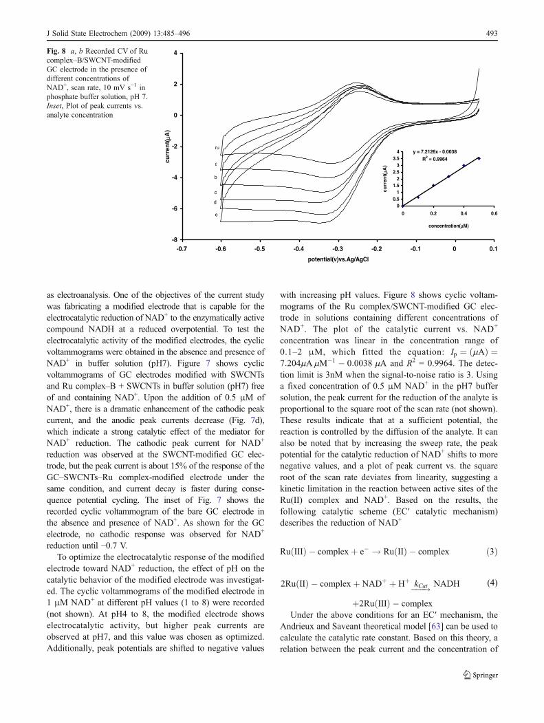
with increasing pH values. Figure 8 shows cyclic voltam-mograms of the Ru complex/SWCNT-modified GC elec-trode in solutions containing different concentrations ofNAD+. The plot of the catalytic current vs. NAD+
concentration was linear in the concentration range of0.1–2 μM, which fitted the equation: Ip ¼ mAð Þ ¼7:204mAmM�1 � 0:0038 mA and R2 = 0.9964. The detec-tion limit is 3nM when the signal-to-noise ratio is 3. Usinga fixed concentration of 0.5 μM NAD+ in the pH7 buffersolution, the peak current for the reduction of the analyte isproportional to the square root of the scan rate (not shown).These results indicate that at a sufficient potential, thereaction is controlled by the diffusion of the analyte. It canalso be noted that by increasing the sweep rate, the peakpotential for the catalytic reduction of NAD+ shifts to morenegative values, and a plot of peak current vs. the squareroot of the scan rate deviates from linearity, suggesting akinetic limitation in the reaction between active sites of theRu(II) complex and NAD+. Based on the results, thefollowing catalytic scheme (EC′ catalytic mechanism)describes the reduction of NAD+
Ru IIIð Þ � complexþ e� ! Ru IIð Þ � complex ð3Þ
2Ru IIð Þ � complexþ NADþ þ Hþ���!kCat NADH
þ2Ru IIIð Þ � complexUnder the above conditions for an EC′ mechanism, the
Andrieux and Saveant theoretical model [63] can be used tocalculate the catalytic rate constant. Based on this theory, arelation between the peak current and the concentration of
-8
-6
-4
-2
0
2
4
-0.7 -0.6 -0.5 -0.4 -0.3 -0.2 -0.1 0 0.1
potential(v)vs.Ag/AgCl
curr
ent(
µA)
ru
a
b
c
d
e
y = 7.2126x - 0.0038R2 = 0.9964
00.5
11.5
22.5
33.5
4
0 0.2 0.4 0.6
concentration(µM)
curr
ent(
µA)
Fig. 8 a, b Recorded CV of Rucomplex–B/SWCNT-modifiedGC electrode in the presence ofdifferent concentrations ofNAD+, scan rate, 10 mV s−1 inphosphate buffer solution, pH 7.Inset, Plot of peak currents vs.analyte concentration
(4)
J Solid State Electrochem (2009) 13:485–496 493
the substrate compound for the case of slow scan rates anda large catalytic rate constant exists:
Ip¼ 0:446nFAD12
vF
RT
� �12
Cs ð5Þ
where D and Cs are the diffusion coefficient (cm2 s-1) andthe bulk concentration (mol cm−3) of the substrate (NAD+),respectively, and other symbols have their usual meanings.Low values of kCat results in values of the coefficient lowerthan 0.446. For a low scan rate (5–20 mV s−1), the averagevalue of this coefficient was found to be 0.36 for the Ru(III)complex/SWCNT-modified GC electrode with a coverageof 1.193 × 10⁻⁹mol cm−2 and an effective surface area (A)of 0.15cm2 in 0.5 μM NAD+ at the phosphate buffersolution (pH7). According to the approach of Andrieux andSaveant and using Fig. 1 of [63], the average value of kCatcalculated is 1.38 (±0.2) × 103M−1 s−1. Due to highcatalytic rate constants, the Ru complex adsorbed ontoSWCNTs can be used as an electron transfer mediator forthe electrocatalytic reduction of NAD+ to NADH.
The biocatalytic activity of the modified electrodein the presence alcohol dehydrogenase
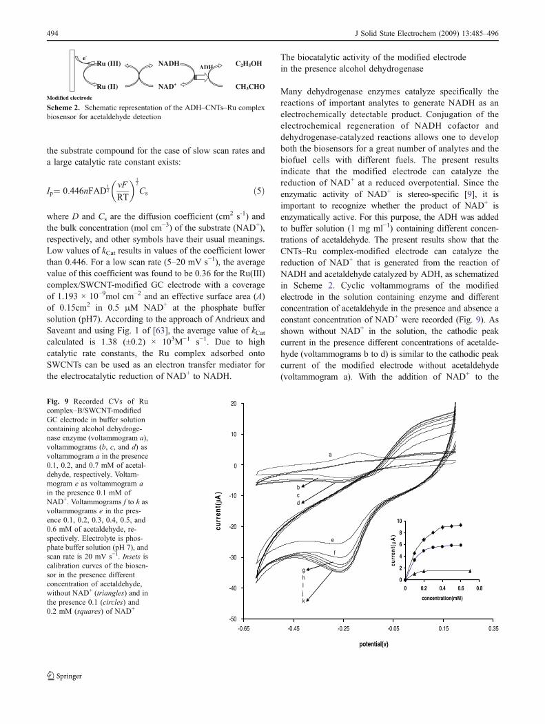
Many dehydrogenase enzymes catalyze specifically thereactions of important analytes to generate NADH as anelectrochemically detectable product. Conjugation of theelectrochemical regeneration of NADH cofactor anddehydrogenase-catalyzed reactions allows one to developboth the biosensors for a great number of analytes and thebiofuel cells with different fuels. The present resultsindicate that the modified electrode can catalyze thereduction of NAD+ at a reduced overpotential. Since theenzymatic activity of NAD+ is stereo-specific [9], it isimportant to recognize whether the product of NAD+ isenzymatically active. For this purpose, the ADH was addedto buffer solution (1 mg ml−1) containing different concen-trations of acetaldehyde. The present results show that theCNTs–Ru complex-modified electrode can catalyze thereduction of NAD+ that is generated from the reaction ofNADH and acetaldehyde catalyzed by ADH, as schematizedin Scheme 2. Cyclic voltammograms of the modifiedelectrode in the solution containing enzyme and differentconcentration of acetaldehyde in the presence and absence aconstant concentration of NAD+ were recorded (Fig. 9). Asshown without NAD+ in the solution, the cathodic peakcurrent in the presence different concentrations of acetalde-hyde (voltammograms b to d) is similar to the cathodic peakcurrent of the modified electrode without acetaldehyde(voltammogram a). With the addition of NAD+ to the
Modified electrode
Ru (III)
Ru (II)
NADH
NAD+
C2H5OH
CH3CHO
ADH
e-
Scheme 2. Schematic representation of the ADH–CNTs–Ru complexbiosensor for acetaldehyde detection
-50
-40
-30
-20
-10
0
10
20
-0.65 -0.45 -0.25 -0.05 0.15 0.35
potential(v)
curr
ent(
µA)
0
2
4
6
8
10
0 0.2 0.4 0.6 0.8
concentration(mM)
curr
ent(
µA)
a
bcd
e
f
ghIjk
Fig. 9 Recorded CVs of Rucomplex–B/SWCNT-modifiedGC electrode in buffer solutioncontaining alcohol dehydroge-nase enzyme (voltammogram a),voltammograms (b, c, and d) asvoltammogram a in the presence0.1, 0.2, and 0.7 mM of acetal-dehyde, respectively. Voltam-mogram e as voltammogram ain the presence 0.1 mM ofNAD+. Voltammograms f to k asvoltammograms e in the pres-ence 0.1, 0.2, 0.3, 0.4, 0.5, and0.6 mM of acetaldehyde, re-spectively. Electrolyte is phos-phate buffer solution (pH 7), andscan rate is 20 mV s−1. Insets iscalibration curves of the biosen-sor in the presence differentconcentration of acetaldehyde,without NAD+ (triangles) and inthe presence 0.1 (circles) and0.2 mM (squares) of NAD+
494 J Solid State Electrochem (2009) 13:485–496
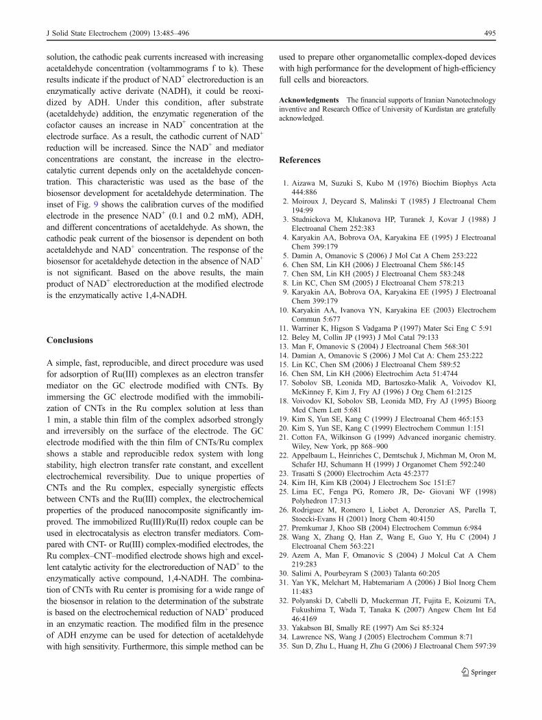
solution, the cathodic peak currents increased with increasingacetaldehyde concentration (voltammograms f to k). Theseresults indicate if the product of NAD+ electroreduction is anenzymatically active derivate (NADH), it could be reoxi-dized by ADH. Under this condition, after substrate(acetaldehyde) addition, the enzymatic regeneration of thecofactor causes an increase in NAD+ concentration at theelectrode surface. As a result, the cathodic current of NAD+
reduction will be increased. Since the NAD+ and mediatorconcentrations are constant, the increase in the electro-catalytic current depends only on the acetaldehyde concen-tration. This characteristic was used as the base of thebiosensor development for acetaldehyde determination. Theinset of Fig. 9 shows the calibration curves of the modifiedelectrode in the presence NAD+ (0.1 and 0.2 mM), ADH,and different concentrations of acetaldehyde. As shown, thecathodic peak current of the biosensor is dependent on bothacetaldehyde and NAD+ concentration. The response of thebiosensor for acetaldehyde detection in the absence of NAD+
is not significant. Based on the above results, the mainproduct of NAD+ electroreduction at the modified electrodeis the enzymatically active 1,4-NADH.
Conclusions
A simple, fast, reproducible, and direct procedure was usedfor adsorption of Ru(III) complexes as an electron transfermediator on the GC electrode modified with CNTs. Byimmersing the GC electrode modified with the immobili-zation of CNTs in the Ru complex solution at less than1 min, a stable thin film of the complex adsorbed stronglyand irreversibly on the surface of the electrode. The GCelectrode modified with the thin film of CNTs/Ru complexshows a stable and reproducible redox system with longstability, high electron transfer rate constant, and excellentelectrochemical reversibility. Due to unique properties ofCNTs and the Ru complex, especially synergistic effectsbetween CNTs and the Ru(III) complex, the electrochemicalproperties of the produced nanocomposite significantly im-proved. The immobilized Ru(III)/Ru(II) redox couple can beused in electrocatalysis as electron transfer mediators. Com-pared with CNT- or Ru(III) complex-modified electrodes, theRu complex–CNT–modified electrode shows high and excel-lent catalytic activity for the electroreduction of NAD+ to theenzymatically active compound, 1,4-NADH. The combina-tion of CNTs with Ru center is promising for a wide range ofthe biosensor in relation to the determination of the substrateis based on the electrochemical reduction of NAD+ producedin an enzymatic reaction. The modified film in the presenceof ADH enzyme can be used for detection of acetaldehydewith high sensitivity. Furthermore, this simple method can be
used to prepare other organometallic complex-doped deviceswith high performance for the development of high-efficiencyfull cells and bioreactors.
Acknowledgments The financial supports of Iranian Nanotechnologyinventive and Research Office of University of Kurdistan are gratefullyacknowledged.
References
1. Aizawa M, Suzuki S, Kubo M (1976) Biochim Biophys Acta444:886
2. Moiroux J, Deycard S, Malinski T (1985) J Electroanal Chem194:99
3. Studnickova M, Klukanova HP, Turanek J, Kovar J (1988) JElectroanal Chem 252:383
4. Karyakin AA, Bobrova OA, Karyakina EE (1995) J ElectroanalChem 399:179
5. Damin A, Omanovic S (2006) J Mol Cat A Chem 253:2226. Chen SM, Lin KH (2006) J Electroanal Chem 586:1457. Chen SM, Lin KH (2005) J Electroanal Chem 583:2488. Lin KC, Chen SM (2005) J Electroanal Chem 578:2139. Karyakin AA, Bobrova OA, Karyakina EE (1995) J Electroanal
Chem 399:17910. Karyakin AA, Ivanova YN, Karyakina EE (2003) Electrochem
Commun 5:67711. Warriner K, Higson S Vadgama P (1997) Mater Sci Eng C 5:9112. Beley M, Collin JP (1993) J Mol Catal 79:13313. Man F, Omanovic S (2004) J Electroanal Chem 568:30114. Damian A, Omanovic S (2006) J Mol Cat A: Chem 253:22215. Lin KC, Chen SM (2006) J Electroanal Chem 589:5216. Chen SM, Lin KH (2006) Electrochim Acta 51:474417. Sobolov SB, Leonida MD, Bartoszko-Malik A, Voivodov KI,
McKinney F, Kim J, Fry AJ (1996) J Org Chem 61:212518. Voivodov KI, Sobolov SB, Leonida MD, Fry AJ (1995) Bioorg
Med Chem Lett 5:68119. Kim S, Yun SE, Kang C (1999) J Electroanal Chem 465:15320. Kim S, Yun SE, Kang C (1999) Electrochem Commun 1:15121. Cotton FA, Wilkinson G (1999) Advanced inorganic chemistry.
Wiley, New York, pp 868–90022. Appelbaum L, Heinriches C, Demtschuk J, Michman M, Oron M,
Schafer HJ, Schumann H (1999) J Organomet Chem 592:24023. Trasatti S (2000) Electrochim Acta 45:237724. Kim IH, Kim KB (2004) J Electrochem Soc 151:E725. Lima EC, Fenga PG, Romero JR, De- Giovani WF (1998)
Polyhedron 17:31326. Rodriguez M, Romero I, Liobet A, Deronzier AS, Parella T,
Stoecki-Evans H (2001) Inorg Chem 40:415027. Premkumar J, Khoo SB (2004) Electrochem Commun 6:98428. Wang X, Zhang Q, Han Z, Wang E, Guo Y, Hu C (2004) J
Electroanal Chem 563:22129. Azem A, Man F, Omanovic S (2004) J Molcul Cat A Chem
219:28330. Salimi A, Pourbeyram S (2003) Talanta 60:20531. Yan YK, Melchart M, Habtemariam A (2006) J Biol Inorg Chem
11:48332. Polyanski D, Cabelli D, Muckerman JT, Fujita E, Koizumi TA,
Fukushima T, Wada T, Tanaka K (2007) Angew Chem Int Ed46:4169
33. Yakabson BI, Smally RE (1997) Am Sci 85:32434. Lawrence NS, Wang J (2005) Electrochem Commun 8:7135. Sun D, Zhu L, Huang H, Zhu G (2006) J Electroanal Chem 597:39
J Solid State Electrochem (2009) 13:485–496 495

36. Zhao K, Song H, Zhung S, Dai L, He P, Fang Y (2007)Electrochem Commun 9:65
37. Li Z, Chen J, Pan D, Tao W, Nie L, Yao S (2006) ElectrochimActa 51:4255
38. Czerw R, Guo Z, Ajayan PM, Sun YP, Carol DL (2001) NanoLett 1:423
39. Kooi SE, Schlecht U, Burghard M, Kern K (2002) Angew Chem114:1409
40. Chen J, Liu H, Weimer WA, Halls MD, Waldeck DH, Walker GC(2002) J Am Chem Soc 124:9034
41. Chen RJ, Zhang Y, Wang D, Dai H (2001) J Am Chem Soc123:3838
42. Frehill F, Vos JG, Benrezzak S, Koos AA, Konya Z, Ruther MG,Blau WJ, Fonseca A, Nagy JB, Biro LP, Minett AI, Panhuis M(2002) J Am Chem Soc 124:13694
43. Wang J (2005) Electroanalysis 17:744. Sherigara BS, Kutner W, Souza FD (2003) Electroanalysis 15:75345. Davis JJ, Green MLH, Hill HAO, Leung YC, Sadler JO, Sloan
JSC, Tsang SC (1998) Inorg Chim Acta 272:26146. Tsang SC, Davis JJ, Green MLH, Hill HAO, Leung YC, Sadler JP
(1995) J Chem Soc Chem Commun 180347. Davis JJ, Coles RJ, Hill HAO (1997) J Electroanal Chem 440:27948. Wang J, Chen G, Wang M, Chatrathi MP (2004) Analyst 129:512
49. Hrapovic S, Liu YL, Male KB, Luong JHT (2004) Anal Chem76:1083
50. Salimi A, Noorbakhsh A, Ghadermarzi M (2007) Sens ActuatorsB 123:530
51. Salimi A, Hallaj R (2005) Talanta 66:96752. Salimi A, Noorbakhsh A, Ghadermarzi M (2005) Anal Biochem
344:1653. Salimi A, Noorbakhsh A, Soltanian S (2006) Electroanalysis 18:1654. Salimi A, Mamkhezri H, Mohebbi S (2006) Electrochem
Commun 8:68855. Sullivan BP, Calvert JM, Meyer TJ (1980) Inorg Chem 19:140456. Crutchley RJ, McCaw K, Lee FL, Gabe EJ (1990) Inorg Chem
29:257657. Bodige S, Mac Donnell FM (1997) Tetrahedron Lett 38:815958. Bard AJ, Faulkner LR (2001) Electrochemical methods, funda-
mentals and applications. Wiley, New York, p 23159. Li J, Cassell A, Delzeit L, Han J, Meyyapan M (2002) J Phys
Chem B 106:929960. Peigney A, Laurent C, Flahaut E, Bacsa RR, Rousset A (2001)
Carbon 47:50761. Laviron E (1974) J Electroanal Chem 52:35562. Wang J (1994) Analytical electrochemistry. VCH, New York63. Andriex CP, Saveant JM (1978) J Electroanal Chem 93:163
496 J Solid State Electrochem (2009) 13:485–496
Copyright © 2022 FDOKUMEN


![Determination of S(IV) Oxoanions at Poly[Ru(5-NO2-Phen)2Cl] Tetrapyridylporphyrin Glassy Carbon Modified Electrode](https://static.fdokumen.com/doc/165x107/631be605a906b217b906b030/determination-of-siv-oxoanions-at-polyru5-no2-phen2cl-tetrapyridylporphyrin.jpg)

