Efficient photocatalytic degradation of organic water pollutants using V–N-codoped TiO 2 thin...
8
Applied Catalysis B: Environmental 150–151 (2014) 74–81 Contents lists available at ScienceDirect Applied Catalysis B: Environmental jo ur nal home p ag e: www.elsevier.com/locate/apcatb Efficient photocatalytic degradation of organic water pollutants using V–N-codoped TiO 2 thin films N. Patel a,∗ , R. Jaiswal b , T. Warang a , G. Scarduelli a , Alpa Dashora b , B.L. Ahuja c , D.C. Kothari b , A. Miotello a a Dipartimento di Fisica, Università degli Studi di Trento, Via Sommarive 14, Povo, I-38123, Trento, Italy b Department of Physics, University of Mumbai, Vidyanagari, Santacruz (E), 400 098, Mumbai, India c Department of Physics, M.L. Sukhadia University, 313001, Udaipur, Rajasthan, India a r t i c l e i n f o Article history: Received 5 October 2013 Received in revised form 18 November 2013 Accepted 20 November 2013 Available online 28 November 2013 Keywords: Photocatalytic degradation Visible light V–N codoped TiO2 RF-sputtering a b s t r a c t TiO 2 , N-doped TiO 2 , V-doped TiO 2 , and V–N-codoped TiO 2 thin films have been prepared using RF- magnetron sputtering and their photocatalytic activities have been investigated. The codoping strategy was adopted to decrease both the band gap of TiO 2 and the recombination rate of the photo-generated electron–hole pairs. Low concentration doping with single element (V or N) preserves the anatase dom- inated phase in TiO 2 film while codoping with V and N produces a mixed phase of nearly equal amount of rutile and anatase as inferred from the XRD and Raman spectroscopy studies. XPS studies reveal that, for N-doped TiO 2 elemental N resides at interstitial lattice positions but codoping with V permits N to reside in both substitutional and interstitial sites in TiO 2 lattice. UV–vis studies indicate that the band gap of TiO 2 (3.2 eV) reduced to 3.0 eV, 2.8 eV and 2.5 eV, by N-doping, V-doping and V–N codoping, respec- tively. The photocatalytic activity of pure, N-doped, V-doped, and V–N codoped TiO 2 thin films were tested by examining the degradation of methylene blue, chlorophenol and nitrophenol as a function of time. It was observed that the codoped TiO 2 gave the highest photocatalytic activity in comparison to the mono-doped and undoped TiO 2 because of high visible light absorption and possible reduction in the recombination of photo-generated charges. Density of states calculated using density functional theory (DFT) showed that the narrowing of band-gap for the codoped TiO 2 is obtained by the formation of iso- lated energy levels of V 3d and N 2p states below the conduction band and above the valence band of pure TiO 2 , respectively. While for the mono-doped TiO 2 the narrowing of the band gap is only contributed by impurity levels formed near any one of the band edges. It is concluded that for the codoped TiO 2 , high visible light absorption is caused by the formation of impurity energy states near both the band edges which also act as the trapping sites for both the photo-generated charges to reduce the recombination process. © 2013 Elsevier B.V. All rights reserved. 1. Introduction The toxic organic chemicals, coming from various industrial pro- cesses and human activities, contaminate the earth’s water which is a serious problem to the living being. The contaminants from industries, mainly dyes, chlorinated benzenes, phenols, etc., are persistent in nature and pollute the aquatic environment. Photocatalysis is one of the best routes for the degradation of waste water pollutants into harmless by products (H 2 O and CO 2 ) [1]. It is very useful in removing highly toxic and hazardous organic pollutants miscible in water, which are difficult to remove by con- ventional methods. Even-though most of the organic pollutants ∗ Corresponding author. Tel.: +39 461 282012; fax: +39 461 281696. E-mail addresses: [email protected], [email protected] (N. Patel). can be degraded by the photocatalysis route, the low efficiency of the reaction demands further research in this field. The develop- ment of highly active photo-catalysts with visible light sensitivity is required as it will allow the use of Sun-light for the degradation of waste water pollutants. TiO 2 semiconductor, with energy band gap of 3.2 eV (anatase phase), shows relatively high reactivity and chemical stability under ultraviolet light [2]. However, for high photocatalytic activ- ity it is necessary to extend the photo-response of TiO 2 to the visible spectrum by modification of its structure and composi- tion. Taking this into consideration, the majority of studies are focused on reducing the band gap of TiO 2 by doping with metals and non-metals to enhance the photocatalytic activity of TiO 2 [3]. Another problem with TiO 2 is the high recombination rate of photo- generated electron–hole pairs which can be limited by introducing charge traps, in the form of dopant element species, for electrons 0926-3373/$ – see front matter © 2013 Elsevier B.V. All rights reserved. http://dx.doi.org/10.1016/j.apcatb.2013.11.033
-
Upload
independent -
Category
Documents
-
view
4 -
download
0
Transcript of Efficient photocatalytic degradation of organic water pollutants using V–N-codoped TiO 2 thin...

Eu
NBa
b
c
a
ARR1AA
KPVVR
1
ciip
w[pv
0h
Applied Catalysis B: Environmental 150– 151 (2014) 74– 81
Contents lists available at ScienceDirect
Applied Catalysis B: Environmental
jo ur nal home p ag e: www.elsev ier .com/ locate /apcatb
fficient photocatalytic degradation of organic water pollutantssing V–N-codoped TiO2 thin films
. Patela,∗, R. Jaiswalb, T. Waranga, G. Scarduelli a, Alpa Dashorab,.L. Ahujac, D.C. Kotharib, A. Miotelloa
Dipartimento di Fisica, Università degli Studi di Trento, Via Sommarive 14, Povo, I-38123, Trento, ItalyDepartment of Physics, University of Mumbai, Vidyanagari, Santacruz (E), 400 098, Mumbai, IndiaDepartment of Physics, M.L. Sukhadia University, 313001, Udaipur, Rajasthan, India
r t i c l e i n f o
rticle history:eceived 5 October 2013eceived in revised form8 November 2013ccepted 20 November 2013vailable online 28 November 2013
eywords:hotocatalytic degradationisible light–N codoped TiO2
F-sputtering
a b s t r a c t
TiO2, N-doped TiO2, V-doped TiO2, and V–N-codoped TiO2 thin films have been prepared using RF-magnetron sputtering and their photocatalytic activities have been investigated. The codoping strategywas adopted to decrease both the band gap of TiO2 and the recombination rate of the photo-generatedelectron–hole pairs. Low concentration doping with single element (V or N) preserves the anatase dom-inated phase in TiO2 film while codoping with V and N produces a mixed phase of nearly equal amountof rutile and anatase as inferred from the XRD and Raman spectroscopy studies. XPS studies reveal that,for N-doped TiO2 elemental N resides at interstitial lattice positions but codoping with V permits N toreside in both substitutional and interstitial sites in TiO2 lattice. UV–vis studies indicate that the band gapof TiO2 (3.2 eV) reduced to 3.0 eV, 2.8 eV and 2.5 eV, by N-doping, V-doping and V–N codoping, respec-tively. The photocatalytic activity of pure, N-doped, V-doped, and V–N codoped TiO2 thin films weretested by examining the degradation of methylene blue, chlorophenol and nitrophenol as a function oftime. It was observed that the codoped TiO2 gave the highest photocatalytic activity in comparison tothe mono-doped and undoped TiO2 because of high visible light absorption and possible reduction in therecombination of photo-generated charges. Density of states calculated using density functional theory(DFT) showed that the narrowing of band-gap for the codoped TiO2 is obtained by the formation of iso-
lated energy levels of V 3d and N 2p states below the conduction band and above the valence band of pureTiO2, respectively. While for the mono-doped TiO2 the narrowing of the band gap is only contributed byimpurity levels formed near any one of the band edges. It is concluded that for the codoped TiO2, highvisible light absorption is caused by the formation of impurity energy states near both the band edgeswhich also act as the trapping sites for both the photo-generated charges to reduce the recombinationprocess.. Introduction
The toxic organic chemicals, coming from various industrial pro-esses and human activities, contaminate the earth’s water whichs a serious problem to the living being. The contaminants fromndustries, mainly dyes, chlorinated benzenes, phenols, etc., areersistent in nature and pollute the aquatic environment.
Photocatalysis is one of the best routes for the degradation ofaste water pollutants into harmless by products (H2O and CO2)
1]. It is very useful in removing highly toxic and hazardous organicollutants miscible in water, which are difficult to remove by con-entional methods. Even-though most of the organic pollutants
∗ Corresponding author. Tel.: +39 461 282012; fax: +39 461 281696.E-mail addresses: [email protected], [email protected] (N. Patel).
926-3373/$ – see front matter © 2013 Elsevier B.V. All rights reserved.ttp://dx.doi.org/10.1016/j.apcatb.2013.11.033
© 2013 Elsevier B.V. All rights reserved.
can be degraded by the photocatalysis route, the low efficiency ofthe reaction demands further research in this field. The develop-ment of highly active photo-catalysts with visible light sensitivityis required as it will allow the use of Sun-light for the degradationof waste water pollutants.
TiO2 semiconductor, with energy band gap of 3.2 eV (anatasephase), shows relatively high reactivity and chemical stabilityunder ultraviolet light [2]. However, for high photocatalytic activ-ity it is necessary to extend the photo-response of TiO2 to thevisible spectrum by modification of its structure and composi-tion. Taking this into consideration, the majority of studies arefocused on reducing the band gap of TiO2 by doping with metals
and non-metals to enhance the photocatalytic activity of TiO2 [3].Another problem with TiO2 is the high recombination rate of photo-generated electron–hole pairs which can be limited by introducingcharge traps, in the form of dopant element species, for electrons
nviro
aavFdsasfts
obtfgLbGodssoatbpdelbosr
atdNflntapctp
2
2
duwpwwtsp
N. Patel et al. / Applied Catalysis B: E
nd/or holes, thus prolonging the recombination time [4]. Manyttempts have been made to develop TiO2 photo-catalysts withisible light activity by doping with transition metal ions (Cr, V,e, etc.) [5–7]. Another approach to sensitize TiO2 in visible light isoping with non-metal elements such as nitrogen [8], carbon [9],ulphur [10], iodine [11] etc. which noticeably increase photocat-lytic activity of TiO2 under visible light. Nevertheless, these dopantpecies when used in large amount can create recombination sitesor electrons and holes that limit the photocatalytic activity [12]. Onhe other hand, low doping content (generally < 2 at%) leads to onlymall shift in the absorption edge of TiO2 towards visible region.
Recently it was observed that low concentration co-dopingf cations (metals) and anions (non-metals) in TiO2 are able tooth enhance the visible light absorption efficiency and reducehe recombination of the photo-generated charges. Cong et al. [5]ound that TiO2 nano-particles codoped with N and Fe(III) showreatly-enhanced visible light irradiated photocatalytic activities.i et al. [13] reported that N and F codoped TiO2 had higher visi-le light activity than N-doped or F-doped TiO2. Liu et al. [14] andu et al. [15] have synthesized codoped TiO2 with V and N andbserved an enhancement in the degradation of methylene blueye and of pentachlorophenol, respectively, as compared to theingle-element doped TiO2. Wen et al. [16] reported the synthe-is of I and F codoped TiO2 and studied photocatalytic degradationf methylene blue solution. The synergetic effects on the opticalbsorption, crystallinity, and activity of TiO2 due to co-doping ofwo non-metals like N, S atoms [17] and C, N atoms [18] have alsoeen reported. In our recent work [19], V–N codoped TiO2 nano-owders, synthesized by sol–gel method, were able to efficientlyegrade Rhodamine dye under visible light due to the synergicffect created by V and N species. However, the powders have prob-ems related to separation and aggregation. Also, powders cannote used in industrial waste water treatment plant based on continu-us flow system. Thin film photo-catalyst deposited on appropriateupport can be easily recovered and reused, thus solving problemselated to powder catalysts.
Thus, in the present study V and N codoped TiO2 photocat-lyst is synthesized in the form of thin film catalyst to studyhe photocatalytic performance, under visible light irradiation, inegradation of three organic pollutants, namely 4-Nitrophenol (4-P), 4-Chlorophenol (4-CP), and Methylene Blue (MB) dye, different
rom that investigated in our past work [19]. In addition, DFT calcu-ation was also performed to understand the origin of the band gaparrowing. The detailed analytical characterization and the pho-ocatalytic results showed that V and N codoped TiO2 thin filmsre superior to mono-doped and undoped TiO2 for the enhancedhotocatalytic activity. By testing the recyclability of the thin filmatalyst we realized that the present form is suitable for the indus-rial waste water treatment application which is not viable withowder catalyst.
. Experimental and computational methods
.1. Catalyst preparation
RF-magnetron sputtering was used to synthesize pure TiO2, N-oped TiO2, V-doped TiO2, and V–N codoped TiO2 thin films. Forndoped TiO2 films, pure TiO2 disc (99.99%) and pure Ar (99.99%)ere used as sputtering target and working gas, respectively. Baseressure of less than 3 × 10⁻⁵ Pa and working Ar pressure of 0.8 Paere used for the deposition. Before the deposition, the TiO2 target
as pre-sputtered for 20 min in order to remove any surface con-amination. TiO2 target was sputtered on both glass and Si (1 0 0)ubstrates at room temperature using RF power of 150 W. The sam-le and target distance was maintained at 5 cm for all the samples.
nmental 150– 151 (2014) 74– 81 75
Nitrogen gas was introduced during the deposition of N-doped TiO2films by maintaining the Ar/N2 flow rate equal to 3. V-doped TiO2films were synthesized by partially covering the TiO2 target sur-face with small V-metal pieces. The combination of the above twostrategies was utilized to deposit V–N codoped TiO2 thin film. Afterdeposition, all TiO2 samples were annealed in air at 500 ◦C for 2 h.Our past investigation with V–N-codoped TiO2 powder showedthat dopants concentration must be kept low and concentrationof N atoms should be about 2 times than that of V atoms to obtainenhanced photocatalytic activity [19]. Thus by varying the numberof V-metal pieces on TiO2 target and Ar/N2 flow ratio in the cham-ber the concentration of dopants was optimized to 1 at% for V and2 at% for N dopant.
2.2. Catalyst characterization
The structural characterization of the deposited samples wascarried out by conventional X-ray diffraction (XRD), Cu K� radia-tion (� = 1.5414 A), in Bragg–Brentano (�–2�) configuration. Ramanspectra were recorded using HORIBA Jobin Yvon Lab RAMA ramisRaman spectrometer with diode pumped solid state laser at532 nm. X-ray photoelectron spectra (XPS) were acquired using aKratos AXIS UltraDLD instrument equipped with a monochromaticAl K� (1486.6 eV) X-Ray source and a hemispherical analyzer. Noelectrical charge compensation was required to perform XPS analy-sis. Survey spectra were measured over a binding energy (BE) rangefrom 0 to 1200 eV using a constant pass energy of 160 eV and a stepsize of 0.5 eV, while Ti 2p, V 2p, O 1s, N 1s and C 1s core levelswere acquired using a constant pass energy of 20 eV and a stepsize of 0.1 eV. All the binding energies were referred to the C 1smain peak at the lower-BE-side of the C 1s envelope in order totake the O 1s main peak at the lower-BE-side of the O 1s envelopeat 529.9 eV. Data analysis was performed by using Kratos VisualProcessing software. Different background-types (linear, Shirleyand Tougaard) and different Gauss-Lorentzian line shape func-tions were tested in order to evaluate any differences in peakareas and to minimize the residual curve. Optical measurementsof all TiO2 films were performed using VARIAN Cary 5000 UV–Vis-NIR spectrophotometer with incoming beam incident normally. Toobtain the absorbance spectra of samples deposited on glass slides,the measurements were performed in the photon energy rangebetween 1.0 to 4.5 eV.
2.3. Photocatalytic activity measurement
The photocatalytic activity of all TiO2 thin films was testedby degradation of water pollutants. 4-Nitrophenol (4-NP), 4Chlorophenol (4-CP), and Methylene Blue dye (MB, Alfa Aesar), dis-solved in water solution were used as organic pollutants. Undopedand doped TiO2 films were dipped in pollutants solution and stirredin dark for 30 min to establish adsorption equilibrium betweenthe solution and the catalysts. Later, for the photocatalytic reac-tion, each pollutant solutions were irradiated by 150 W tungstenhalogen lamp (which consists of mostly visible light spectrum inthe range of 350–900 nm) in the presence of photo-catalyst. Nooxidants or no aerated conditions were used for the photocat-alytic measurements. After established time intervals, 1 ml aqueoussolution was filtered out from the reactor vessel. The UV–visibleabsorption measurements of the filtered solution were carriedout using a spectrophotometer (Cary 5000). The concentration ofeach pollutant was estimated by measuring the normalized inten-sity of the absorption peak in UV–visible range and plotting it as
a function of time of irradiation. All the photo-catalysis experi-ments were performed at room temperature, maintained constantby using a cooling system operated with a continuous water flow.The pH of the solution was maintained neutral during all the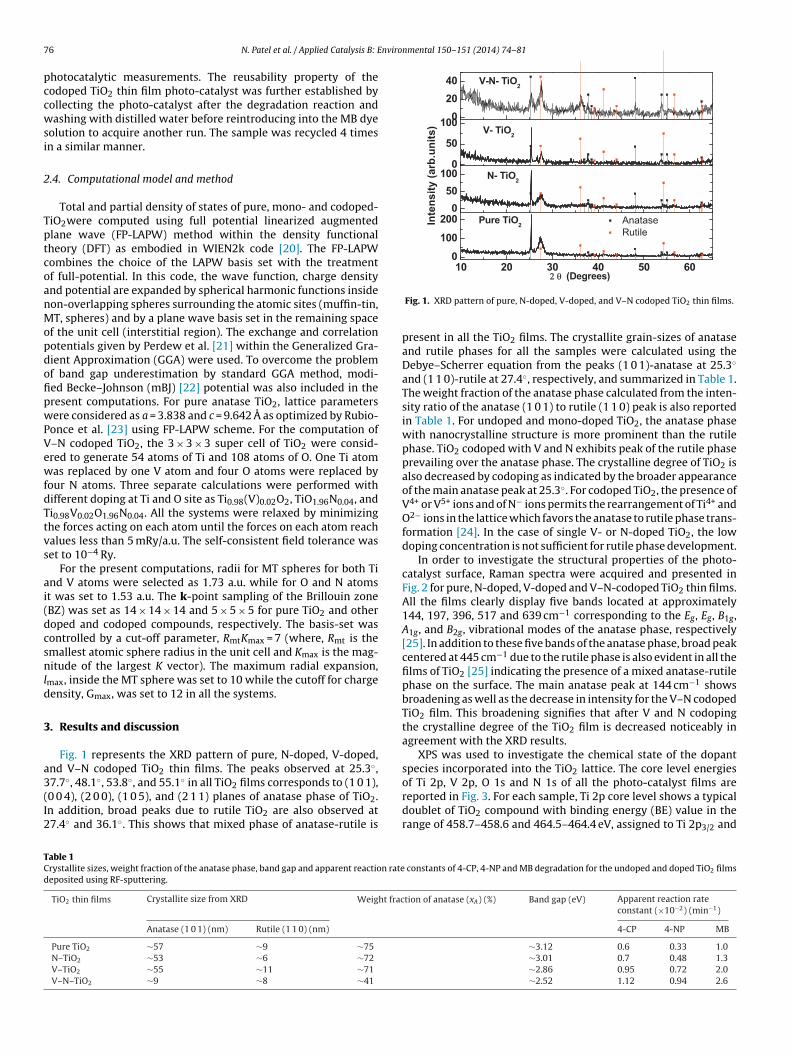
7 nvironmental 150– 151 (2014) 74– 81
pccwsi
2
TptcoanMopdofipwPVewfdTtvs
ai(dcsnld
3
a3(I2
10 20 30 40 50 600
100
2000
50100
0
50
10002040
22 θθ (Degrees )
Pure TiO2
N- TiO2
V- TiO2
Anatase Rutile
Inte
nsity
(arb
.uni
ts)
V-N- TiO2
TCd
6 N. Patel et al. / Applied Catalysis B: E
hotocatalytic measurements. The reusability property of theodoped TiO2 thin film photo-catalyst was further established byollecting the photo-catalyst after the degradation reaction andashing with distilled water before reintroducing into the MB dye
olution to acquire another run. The sample was recycled 4 timesn a similar manner.
.4. Computational model and method
Total and partial density of states of pure, mono- and codoped-iO2were computed using full potential linearized augmentedlane wave (FP-LAPW) method within the density functionalheory (DFT) as embodied in WIEN2k code [20]. The FP-LAPWombines the choice of the LAPW basis set with the treatmentf full-potential. In this code, the wave function, charge densitynd potential are expanded by spherical harmonic functions insideon-overlapping spheres surrounding the atomic sites (muffin-tin,T, spheres) and by a plane wave basis set in the remaining space
f the unit cell (interstitial region). The exchange and correlationotentials given by Perdew et al. [21] within the Generalized Gra-ient Approximation (GGA) were used. To overcome the problemf band gap underestimation by standard GGA method, modi-ed Becke–Johnson (mBJ) [22] potential was also included in theresent computations. For pure anatase TiO2, lattice parametersere considered as a = 3.838 and c = 9.642 A as optimized by Rubio-
once et al. [23] using FP-LAPW scheme. For the computation of–N codoped TiO2, the 3 × 3 × 3 super cell of TiO2 were consid-red to generate 54 atoms of Ti and 108 atoms of O. One Ti atomas replaced by one V atom and four O atoms were replaced by
our N atoms. Three separate calculations were performed withifferent doping at Ti and O site as Ti0.98(V)0.02O2, TiO1.96N0.04, andi0.98V0.02O1.96N0.04. All the systems were relaxed by minimizinghe forces acting on each atom until the forces on each atom reachalues less than 5 mRy/a.u. The self-consistent field tolerance waset to 10−4 Ry.
For the present computations, radii for MT spheres for both Tind V atoms were selected as 1.73 a.u. while for O and N atomst was set to 1.53 a.u. The k-point sampling of the Brillouin zoneBZ) was set as 14 × 14 × 14 and 5 × 5 × 5 for pure TiO2 and otheroped and codoped compounds, respectively. The basis-set wasontrolled by a cut-off parameter, RmtKmax = 7 (where, Rmt is themallest atomic sphere radius in the unit cell and Kmax is the mag-itude of the largest K vector). The maximum radial expansion,
max, inside the MT sphere was set to 10 while the cutoff for chargeensity, Gmax, was set to 12 in all the systems.
. Results and discussion
Fig. 1 represents the XRD pattern of pure, N-doped, V-doped,nd V–N codoped TiO2 thin films. The peaks observed at 25.3◦,
7.7◦, 48.1◦, 53.8◦, and 55.1◦ in all TiO2 films corresponds to (1 0 1),0 0 4), (2 0 0), (1 0 5), and (2 1 1) planes of anatase phase of TiO2.n addition, broad peaks due to rutile TiO2 are also observed at7.4◦ and 36.1◦. This shows that mixed phase of anatase-rutile isable 1rystallite sizes, weight fraction of the anatase phase, band gap and apparent reaction rateeposited using RF-sputtering.
TiO2 thin films Crystallite size from XRD Weight frac
Anatase (1 0 1) (nm) Rutile (1 1 0) (nm)
Pure TiO2 ∼57 ∼9 ∼75
N–TiO2 ∼53 ∼6 ∼72
V–TiO2 ∼55 ∼11 ∼71
V–N–TiO2 ∼9 ∼8 ∼41
Fig. 1. XRD pattern of pure, N-doped, V-doped, and V–N codoped TiO2 thin films.
present in all the TiO2 films. The crystallite grain-sizes of anataseand rutile phases for all the samples were calculated using theDebye–Scherrer equation from the peaks (1 0 1)-anatase at 25.3◦
and (1 1 0)-rutile at 27.4◦, respectively, and summarized in Table 1.The weight fraction of the anatase phase calculated from the inten-sity ratio of the anatase (1 0 1) to rutile (1 1 0) peak is also reportedin Table 1. For undoped and mono-doped TiO2, the anatase phasewith nanocrystalline structure is more prominent than the rutilephase. TiO2 codoped with V and N exhibits peak of the rutile phaseprevailing over the anatase phase. The crystalline degree of TiO2 isalso decreased by codoping as indicated by the broader appearanceof the main anatase peak at 25.3◦. For codoped TiO2, the presence ofV4+ or V5+ ions and of N− ions permits the rearrangement of Ti4+ andO2− ions in the lattice which favors the anatase to rutile phase trans-formation [24]. In the case of single V- or N-doped TiO2, the lowdoping concentration is not sufficient for rutile phase development.
In order to investigate the structural properties of the photo-catalyst surface, Raman spectra were acquired and presented inFig. 2 for pure, N-doped, V-doped and V–N-codoped TiO2 thin films.All the films clearly display five bands located at approximately144, 197, 396, 517 and 639 cm−1 corresponding to the Eg, Eg, B1g,A1g, and B2g, vibrational modes of the anatase phase, respectively[25]. In addition to these five bands of the anatase phase, broad peakcentered at 445 cm−1 due to the rutile phase is also evident in all thefilms of TiO2 [25] indicating the presence of a mixed anatase-rutilephase on the surface. The main anatase peak at 144 cm−1 showsbroadening as well as the decrease in intensity for the V–N codopedTiO2 film. This broadening signifies that after V and N codopingthe crystalline degree of the TiO2 film is decreased noticeably inagreement with the XRD results.
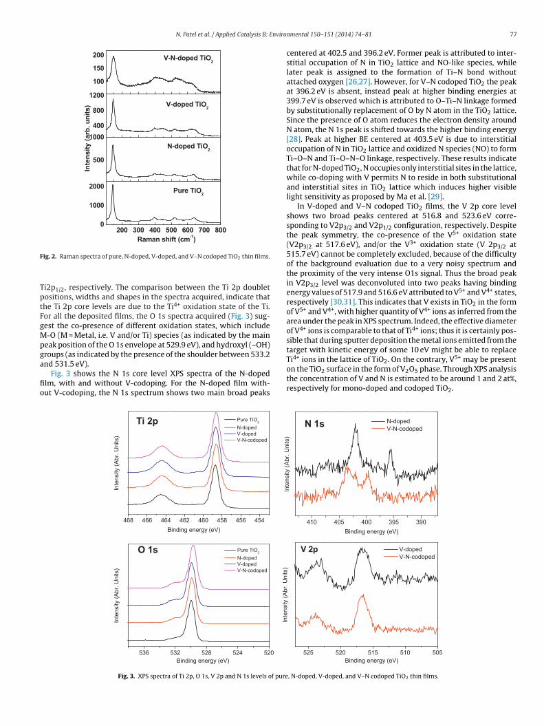
XPS was used to investigate the chemical state of the dopantspecies incorporated into the TiO2 lattice. The core level energies
of Ti 2p, V 2p, O 1s and N 1s of all the photo-catalyst films arereported in Fig. 3. For each sample, Ti 2p core level shows a typicaldoublet of TiO2 compound with binding energy (BE) value in therange of 458.7–458.6 and 464.5–464.4 eV, assigned to Ti 2p3/2 andconstants of 4-CP, 4-NP and MB degradation for the undoped and doped TiO2 films
tion of anatase (xA) (%) Band gap (eV) Apparent reaction rateconstant (×10−2) (min−1)
4-CP 4-NP MB
∼3.12 0.6 0.33 1.0∼3.01 0.7 0.48 1.3∼2.86 0.95 0.72 2.0∼2.52 1.12 0.94 2.6
N. Patel et al. / Applied Catalysis B: Enviro
200 300 400 500 600 700 8000
1000
2000
500
1000400
800
1200
100
150
200
Pure TiO2
Raman shift (cm-1)
N-doped TiO2
V-doped TiO2
Inte
nsity
(arb
. uni
ts)
V-N-doped TiO2
F
TptFgMpga
fio
Ti ions in the lattice of TiO2. On the contrary, V may be present
ig. 2. Raman spectra of pure, N-doped, V-doped, and V–N codoped TiO2 thin films.
i2p1/2, respectively. The comparison between the Ti 2p doubletositions, widths and shapes in the spectra acquired, indicate thathe Ti 2p core levels are due to the Ti4+ oxidation state of the Ti.or all the deposited films, the O 1s spectra acquired (Fig. 3) sug-est the co-presence of different oxidation states, which include-O (M = Metal, i.e. V and/or Ti) species (as indicated by the main
eak position of the O 1s envelope at 529.9 eV), and hydroxyl (–OH)roups (as indicated by the presence of the shoulder between 533.2
nd 531.5 eV).Fig. 3 shows the N 1s core level XPS spectra of the N-dopedlm, with and without V-codoping. For the N-doped film with-ut V-codoping, the N 1s spectrum shows two main broad peaks
Fig. 3. XPS spectra of Ti 2p, O 1s, V 2p and N 1s levels of pure
nmental 150– 151 (2014) 74– 81 77
centered at 402.5 and 396.2 eV. Former peak is attributed to inter-stitial occupation of N in TiO2 lattice and NO-like species, whilelater peak is assigned to the formation of Ti–N bond withoutattached oxygen [26,27]. However, for V–N codoped TiO2 the peakat 396.2 eV is absent, instead peak at higher binding energies at399.7 eV is observed which is attributed to O–Ti–N linkage formedby substitutionally replacement of O by N atom in the TiO2 lattice.Since the presence of O atom reduces the electron density aroundN atom, the N 1s peak is shifted towards the higher binding energy[28]. Peak at higher BE centered at 403.5 eV is due to interstitialoccupation of N in TiO2 lattice and oxidized N species (NO) to formTi–O–N and Ti–O–N–O linkage, respectively. These results indicatethat for N-doped TiO2, N occupies only interstitial sites in the lattice,while co-doping with V permits N to reside in both substitutionaland interstitial sites in TiO2 lattice which induces higher visiblelight sensitivity as proposed by Ma et al. [29].
In V-doped and V–N codoped TiO2 films, the V 2p core levelshows two broad peaks centered at 516.8 and 523.6 eV corre-sponding to V2p3/2 and V2p1/2 configuration, respectively. Despitethe peak symmetry, the co-presence of the V5+ oxidation state(V2p3/2 at 517.6 eV), and/or the V3+ oxidation state (V 2p3/2 at515.7 eV) cannot be completely excluded, because of the difficultyof the background evaluation due to a very noisy spectrum andthe proximity of the very intense O1s signal. Thus the broad peakin V2p3/2 level was deconvoluted into two peaks having bindingenergy values of 517.9 and 516.6 eV attributed to V5+ and V4+ states,respectively [30,31]. This indicates that V exists in TiO2 in the formof V5+ and V4+, with higher quantity of V4+ ions as inferred from thearea under the peak in XPS spectrum. Indeed, the effective diameterof V4+ ions is comparable to that of Ti4+ ions; thus it is certainly pos-sible that during sputter deposition the metal ions emitted from thetarget with kinetic energy of some 10 eV might be able to replace
4+ 5+
on the TiO2 surface in the form of V2O5 phase. Through XPS analysisthe concentration of V and N is estimated to be around 1 and 2 at%,respectively for mono-doped and codoped TiO2.
, N-doped, V-doped, and V–N codoped TiO2 thin films.

78 N. Patel et al. / Applied Catalysis B: Environmental 150– 151 (2014) 74– 81
350 40 0 45 0 50 0 55 0
2.0 2.5 3.0 3.5 4. 0
Wavelength (nm)
Abs
orba
nce
(a. u
.)
TiO2
N-doped TiO2
V-dop ed TiO2
V-N-cod oped TiO2
Tran
smis
sion
(a. u
.)
Ene rgy (eV)
........ Curve fitting
FTo
dacdfi
l
wma��aTswbpuiibt
pTmFmittntndTofiow
0
10
20 EF
EF
(a) TiO2
0
100
200 (b) N-TiO2 EF
0
200
400 (c) V-T iO2
DO
S (s
tate
s/eV
)
-4 -2 0 2 40
100
200 EF
(d) V-N-TiO2
Ene rgy (eV)
ig. 4. UV–visible absorption spectra of pure, N-doped, V-doped, and V–N codopediO2 thin films. Inset shows the same spectra in Transmission mode with the fittingf absorption edge with Eq. (1) to obtain band gap values.
Fig. 4 shows the optical absorption spectra of undoped andoped TiO2 films. It is clearly visible from the spectra that the tail ofbsorption edge gets significantly shifted to the visible region aftero-doping with V and N in TiO2 as compared to single-elementoped and undoped TiO2. The band gap values were obtained bytting the absorption edge using the following equation [32]:
n T = ln T0 − C
(�ω − Eg
)v
�ω(1)
here Eg is the band gap, C is a constant, and T0 is the optical trans-ission of the substrate. Depending on the type of transition, �
ssumes different values: for direct, allowed (forbidden) transitions = 1/2 (� = 3/2) and for indirect, allowed (forbidden) transitions = 2 (� = 3). We have used � = 2 for the present nano-crystalline ormorphous films according to Ref. [33]. Near the absorption edge,0 and C are approximately constant and the Eg value of all the TiO2amples is obtained (see Table 1) by fitting the absorption edgeith Eq. (1) (inset of Fig. 4). The value of band gap of 3.12 eV lies in
etween the theoretical values of anatase (3.2 eV) and rutile (3.0 eV)hase, thus signaling the presence of mixed anatase-rutile phase inndoped TiO2. For N-doped TiO2 a slight change in band gap (3.0 eV)
s observed. In the case of V-doped TiO2, the tail of absorption edges clearly shifted to 2.8 eV while significant narrowing to 2.5 eV ofand gap is observed for V–N codoped TiO2. This result indicateshat higher visible light absorption can be achieved by codoping.
Theoretical studies were carried out using DFT with GGA + mBJotentials to understand the noticeable decrease in the band gap ofiO2 after co-doping. The concentration used in the present experi-ents (1 at% V and 2 at% N) were chosen for the theoretical studies.
ig. 5 represents the calculated total density of states (DOS) of pure,ono-doped, and codoped TiO2. For pure TiO2, Fermi energy (EF)
s set to 0 eV while for the other systems highest occupied elec-ronic states of TiO2 is considered as a reference point and shiftedo 0.0 eV, while EF is represented by dotted line. It is seen that for-type (V) doping in TiO2, EF is shifted close to CBM while for p-ype (N) doping, EF is close to VBM. While, V+2N doping (due toet p-type doping) again shifts the EF close to VBM. Additional DOSue to dopants are clearly observed for mono-doped and codopediO2 within the band gap region. In order to understand the originf these electronic levels, partial density of states (PDOS) for all the
our TiO2 systems (pure, N-doped, V-doped, and V–N codoped TiO2)s plotted in Fig. 6. Here, position of EF is also shifted as in the casef Fig. 5. Pure TiO2 (Fig. 6a) shows the band gap of 2.9 eV which isithin 10% variation with the experimental band gap (3.2 eV) (DFTFig. 5. Total density of states of (a) pure anatase TiO2, (b) N–TiO2, (c) V–TiO2 and(d) V–N-TiO2.
with mBJ potential produces results within 10% of experimentalvalues). From PDOS, the valence bands (VB) are mainly dominatedby O 2p states while conduction bands are contributed by Ti-3dstates (eg + t2g) with major contribution by t2g electrons. In the caseof N-doped TiO2 (Fig. 6b), N 2p states are localized just above thevalence band maxima (VBM) which overlaps with VB to shift theVBM to higher energy by 0.1 eV with respect to pure TiO2 (Fig. 6b).This narrowing is in good agreement with that obtained experi-mentally. Some fraction of N 2p states are hybridized with the O2p states in the valence region while the CB is still dominated byTi 3d (mainly eg) states. For V-doped TiO2 (Fig. 6c), isolated energystates of eg electron of V 3d orbitals are formed at 0.7 eV below theconduction band minima (CBM) of pure TiO2 (Fig. 6a). While thevalence bands are still dominated by O 2p states, hybridization of Vand Ti 3d states is also observed in lower conduction band region.For V doping the contribution of Ti 3d (t2g) orbitals increases whichmay be due to the change in Ti valance states (Ti4+ → Ti3+). In thecase of V–N codoped TiO2, the VB mostly consists of O 2p and N2p states, while CB is dominated by Ti 3d (eg) and V 3d (t2g) states(Fig. 6d). On the other hand, the impurity energy levels due to N2p and V 3d (eg) states are formed just above the VBM and belowthe CBM, respectively. As compared to single-element doped TiO2 aslight variation in the position in the isolated energy levels createdby V and N in TiO2 band gap is observed due to the interaction ofV 3d and N 2p orbitals. It is also observed that the lowering of CBMis reduced in comparison to V-doped TiO2 which can be ascribedto the occupancy of N-ions in oxygen vacancy sites generated byV-doping. This shows that maximum narrowing of the band gapobtained with V–N codoped TiO2 is mainly attributed to the forma-tion of impurity energy states near both the band edges. While formondoped TiO2 the narrowing of the band gap is only contributedby impurity level formed near any one of the band edges.
The photocatalytic activity of pure, N-doped, V-doped, andV–N codoped TiO2 thin films was tested by examining thedegradation of organic pollutants as a function of time. Thedecrease of relative concentration of the 4-CP, 4-NP, MB dyewas estimated by measuring the relative intensity of the peakat 225, 320, and 664 nm from the optical absorbance spectra,respectively. Langmuir–Hinshelwood model usually describes thephoto-degradation reaction of organic pollutants. The apparentreaction rate constant (k) of the model was obtained from the slopeof the ln(C/C0) vs irradiation time plot (Fig. 7). All the data points of
Fig. 7 were well fitted linearly indicating that all photo-degradationreactions follow first order kinetics. Thus the diffusion of organicmolecules on the catalyst surface is the rate limiting step duringthe degradation reaction. All the TiO2 photo-catalyst samples were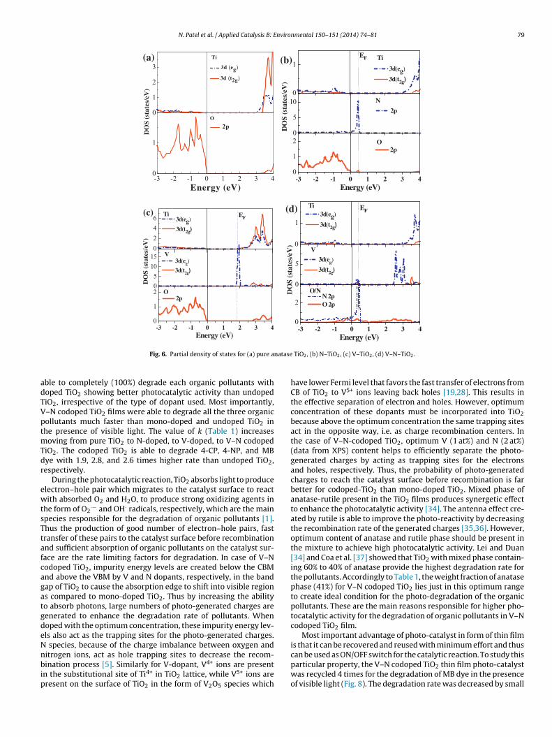
N. Patel et al. / Applied Catalysis B: Environmental 150– 151 (2014) 74– 81 79
natase
adTVptmTdr
ewtsTtafcagatgdeNnbip
Fig. 6. Partial density of states for (a) pure a
ble to completely (100%) degrade each organic pollutants withoped TiO2 showing better photocatalytic activity than undopediO2, irrespective of the type of dopant used. Most importantly,–N codoped TiO2 films were able to degrade all the three organicollutants much faster than mono-doped and undoped TiO2 inhe presence of visible light. The value of k (Table 1) increases
oving from pure TiO2 to N-doped, to V-doped, to V–N codopediO2. The codoped TiO2 is able to degrade 4-CP, 4-NP, and MBye with 1.9, 2.8, and 2.6 times higher rate than undoped TiO2,espectively.
During the photocatalytic reaction, TiO2 absorbs light to producelectron–hole pair which migrates to the catalyst surface to reactith absorbed O2 and H2O, to produce strong oxidizing agents in
he form of O2·− and OH· radicals, respectively, which are the main
pecies responsible for the degradation of organic pollutants [1].hus the production of good number of electron–hole pairs, fastransfer of these pairs to the catalyst surface before recombinationnd sufficient absorption of organic pollutants on the catalyst sur-ace are the rate limiting factors for degradation. In case of V–Nodoped TiO2, impurity energy levels are created below the CBMnd above the VBM by V and N dopants, respectively, in the bandap of TiO2 to cause the absorption edge to shift into visible regions compared to mono-doped TiO2. Thus by increasing the abilityo absorb photons, large numbers of photo-generated charges areenerated to enhance the degradation rate of pollutants. Whenoped with the optimum concentration, these impurity energy lev-ls also act as the trapping sites for the photo-generated charges.
species, because of the charge imbalance between oxygen and
itrogen ions, act as hole trapping sites to decrease the recom-ination process [5]. Similarly for V-dopant, V4+ ions are presentn the substitutional site of Ti4+ in TiO2 lattice, while V5+ ions areresent on the surface of TiO2 in the form of V2O5 species which
TiO2, (b) N–TiO2, (c) V–TiO2, (d) V–N–TiO2.
have lower Fermi level that favors the fast transfer of electrons fromCB of TiO2 to V5+ ions leaving back holes [19,28]. This results inthe effective separation of electron and holes. However, optimumconcentration of these dopants must be incorporated into TiO2because above the optimum concentration the same trapping sitesact in the opposite way, i.e. as charge recombination centers. Inthe case of V–N-codoped TiO2, optimum V (1 at%) and N (2 at%)(data from XPS) content helps to efficiently separate the photo-generated charges by acting as trapping sites for the electronsand holes, respectively. Thus, the probability of photo-generatedcharges to reach the catalyst surface before recombination is farbetter for codoped-TiO2 than mono-doped TiO2. Mixed phase ofanatase-rutile present in the TiO2 films produces synergetic effectto enhance the photocatalytic activity [34]. The antenna effect cre-ated by rutile is able to improve the photo-reactivity by decreasingthe recombination rate of the generated charges [35,36]. However,optimum content of anatase and rutile phase should be present inthe mixture to achieve high photocatalytic activity. Lei and Duan[34] and Coa et al. [37] showed that TiO2 with mixed phase contain-ing 60% to 40% of anatase provide the highest degradation rate forthe pollutants. Accordingly to Table 1, the weight fraction of anatasephase (41%) for V–N codoped TiO2 lies just in this optimum rangeto create ideal condition for the photo-degradation of the organicpollutants. These are the main reasons responsible for higher pho-tocatalytic activity for the degradation of organic pollutants in V–Ncodoped TiO2 film.
Most important advantage of photo-catalyst in form of thin filmis that it can be recovered and reused with minimum effort and thus
can be used as ON/OFF switch for the catalytic reaction. To study thisparticular property, the V–N codoped TiO2 thin film photo-catalystwas recycled 4 times for the degradation of MB dye in the presenceof visible light (Fig. 8). The degradation rate was decreased by small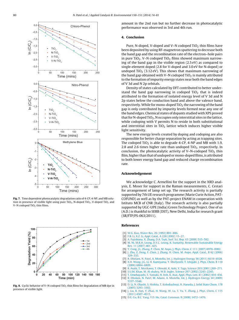
80 N. Patel et al. / Applied Catalysis B: Enviro
0 50 100 15 0 20 0 250 300-5
-4
-3
-2
-1
0
TiO2
N-TiO2
V-TiO2
V-N-TiO2
ln (C
/C0)
Time ( mins )
Methylene Blue
0 50 100 15 0 20 0 25 0
-3,0
-2,5
-2,0
-1,5
-1,0
-0,5
0,0 Chloro-Pheno l
Time ( mins)
ln (C
/C0)
TiO2
N-TiO2
V-Ti O2
V- N-Ti O2
0 50 10 0 150 200 250-3,0
-2,5
-2,0
-1,5
-1,0
-0,5
0,0
Time (mins)
ln (C
/C0)
TiO2
N- TiO2
V- TiO2
V-N- TiO2
Nitro-Pheno l
Fig. 7. Time dependent photocatalytic degradation ratio of 4-CP, 4-NP, and MB solu-tion in presence of visible light using pure TiO2, N-doped TiO2, V-doped TiO2 andV–N codoped TiO2 thin films.
0 20 40 60 80 100 12 0 14 0 16 0 18 00
20
40
60
80
100
Deg
rada
tion
Yiel
d (%
)
Time ( min)
1st 2n d 3rd 4th
Fig. 8. Cyclic behavior of V–N codoped TiO2 thin films for degradation of MB dye inpresence of visible light.
[[[
[
[
[
nmental 150– 151 (2014) 74– 81
amount in the 2nd run but no further decrease in photocatalyticperformance was observed in 3rd and 4th run.
4. Conclusion
Pure, N-doped, V-doped and V–N codoped TiO2 thin films havebeen deposited by using RF-magnetron sputtering to decrease boththe band gap and the recombination rate of the electron–hole pairsin pure TiO2. V–N codoped TiO2 films showed maximum narrow-ing of the band gap in the visible region (2.5 eV) as compared tosingle-element doped (2.8 for V-doped and 3.0 eV for N-doped) orundoped TiO2 (3.12 eV). This shows that maximum narrowing ofthe band gap obtained with V–N codoped TiO2 is mainly attributedto the formation of impurity energy states near both the band edgesof V 3d and N 2p orbitals.
Density of states calculated by DFT contributed to better under-stand the band gap narrowing in codoped TiO2 that is indeedattributed to the formation of isolated energy level of V 3d and N2p states below the conduction band and above the valence band,respectively. While for mono-doped TiO2 the narrowing of the bandgap is only contributed by impurity levels formed near any one ofthe band edges. Chemical states of dopants studied with XPS provedthat for N-doped TiO2, N occupies only interstitial sites in the lattice,while codoping with V permits N to reside in both substitutionaland interstitial sites in TiO2 lattice which induces higher visiblelight sensitivity.
The new energy levels created by doping and codoping are alsoresponsible for better charge separation by acting as trapping sites.The codoped TiO2 is able to degrade 4-CP, 4-NP and MB with 1.9,2.8 and 2.6 times higher rate than undoped TiO2, respectively. Inconclusion, the photocatalytic activity of V–N-codoped TiO2 thinfilm, higher than that of undoped or mono-doped films, is attributedto both lower energy band gap and reduced charge recombinationrate.
Acknowledgement
We acknowledge C. Armellini for the support in the XRD anal-ysis, E. Moser for support in the Raman measurements, C. Cestarifor arrangement of lamp set up. The research activity is partiallysupported by 7th UE research programme (Marie Curie Action, PAT-COFUND) as well as by the PAT-project ENAM in cooperation withIstituto MCB of CNR (Italy). The research activity is also partiallysupported by UGC-UPE (India) Green Technology Project. One of us(A.D.) is thankful to SERB (DST), New Delhi, India for research grant(SR/FTP/PS-063/2011).
References
[1] W.G. Kuo, Water Res. 26 (1992) 881–886.[2] F.B. Li, X.Z. Li, Appl. Catal., A 228 (2002) 15–27.[3] A. Fujishima, X. Zhang, D.A. Tryk, Surf. Sci. Rep. 63 (2008) 515–582.[4] M. Ni, M.K.H. Leung, D.Y.C. Leung, K. Sumathy, Renewable Sustainable Energy
Rev. 11 (2007) 401–425.[5] Y. Cong, J.L. Zhang, F. Chen, M. Anpo, J. Phys. Chem. C 111 (2007) 6976–6982.[6] J. Zhu, Z. Deng, F. Chen, J. Zhang, H. Chen, M. Anpo, Appl. Catal., B 62 (2006)
329–335.[7] R. Dholam, N. Patel, A. Miotello, Int. J. Hydrogen Energy 36 (2011) 6519–6528.[8] X.H. Wang, J.G. Li, H. Kamiyama, Y. Moriyoshi, T. Ishigaki, J. Phys. Chem. B 110
(2006) 6804–6809.[9] R. Asahi, T. Morikawa, T. Ohwaki, K. Aoki, Y. Taga, Science 293 (2001) 269–271.10] S.U.M. Khan, M. Al-shahry, W.B. Ingler, Science 297 (2002) 2243–2245.11] T. Umebayashi, T. Yamaki, H. Itoh, K. Asai, Appl. Phys. Lett. 81 (2002) 454–456.12] R. Dholam, N. Patel, M. Adami, A. Miotello, Int, J. Hydrogen Energy 34 (2009)
5337–5346.
13] D. Li, N. Ohashi, S. Hishita, T. Kolodiazhnyi, H. Haneda, J. Solid State Chem. 178(2005) 3293–3302.14] J. Liu, R. Han, Y. Zhao, H. Wang, W. Lu, T. Yu, Y. Zhang, J. Phys. Chem. C 115
(2011) 4507–4515.15] D.E. Gu, B.C. Yang, Y.D. Hu, Catal. Commun. 9 (2008) 1472–1476.
nviro
[
[
[
[[
[
[[
[[
[
[
[[[[
[
[[
N. Patel et al. / Applied Catalysis B: E
16] C. Wen, Y.J. Zhu, T. Kanbara, H.Z. Zhu, C.F. Xiao, Desalination 249 (2009)621–625.
17] Y. Xie, Q.N. Zhao, X.J. Zhao, Y.Z. Li, Catal. Lett. 118 (2007)231–237.
18] D. Chen, Z. Jiang, J. Geng, Q. Wang, D. Yang, Ind. Eng. Chem. Res. 46 (2007)2741–2748.
19] R. Jaiswal, N. Patel, D.C. Kothari, A. Miotello, Appl. Catal., B 126 (2012) 47–54.20] P. Blaha, K. Schwarz, G.K.H. Madsen, D. Kvasnicka, J. Luitz, Wien2K Code, An
Augmented Plane Wave Plus Local Orbitals Program for Calculating CrystalProperties, Vienna University of Technology, Vienna, Austria, 2012.
21] J.P. Perdew, A. Ruzsinszky, G.I. Csonka, O.A. Vydrov, G.E. Scuseria, L.A. Con-stantin, X. Zhou, K. Burke, Phys. Rev. Lett. 100 (2008) 136406, ibid. 2009 102039902 (E).
22] F. Tran, P. Blaha, Phys. Rev. Lett. 102 (2009) 226401–226404.23] A. Rubio-Ponce, A. Conde-Gallardo, D. Olguín, Phys. Rev. B: Condens. Matter 78
(2008) 035107–35109.24] F.C. Gennari, D.M. Pasquevich, J. Am. Ceram. Soc. 82 (1999) 1915–1921.25] K. Yanagisawa, J. Ovenstone, J. Phys. Chem. B 103 (1999) 7781–7787.
[
[
[
nmental 150– 151 (2014) 74– 81 81
26] X.F. Chen, X.C. Wang, Y.D. Hou, J.H. Huang, L. Wu, X.Z. Fu, J. Catal. 255 (2008)59–67.
27] T. Horikawa, M. Katoh, T. Tomida, Microporous Mesoporous Mater. 110 (2008)397–404.
28] H. Liu, G. Liu, X. Shi, Colloids Surf., A 363 (2010) 35–40.29] X. Ma, L. Miao, S. Bie, J. Jang, Solid State Commun. 150 (2010) 689–692.30] B.M. Reddy, P.M. Sreekanth, E.P. Reddy, J. Phys. Chem. B 106 (2002) 5695–5700.31] X. Yang, F.Y. Ma, K.X. Li, Y.N. Guo, J.L. Hu, M.X.W. Huo, H.J. Guo, J. Hazard. Mater.
175 (2010) 429–438.32] W. Lohstroh, R.J. Westerwaal, V.J.L.M. Mechelen, C. Chacon, E. Johansson, B.
Dam, R. Griessen, Phys. Rev. B: Condens. Matter 70 (2004) 165411–165511.33] E.A. Davis, N.F. Mott, Philos. Mag. 22 (1970) 903–922.34] S. Lei, W. Duan, J. Environ. Sci. 20 (2008) 1263–1267.
35] T. Kawahara, Y. Konishi, H. Tada, N. Tohge, J. Nishii, S. Ito, Angew. Chem. Int. Ed(2002) 2811–2813.36] D.C. Hurum, A.G. Agrios, K.A. Gray, T. Rajh, M.C. Thurnauer, J. Phys. Chem. B 107
(2003) 4545–4549.37] W. Zhang, T. Zhang, W. Yin, G. Cao, J. Chin. Chem. Phys. 20 (2007) 95–98.