Effect of temperature and concentration on commercial silicon module based low-concentration...
11
Effect of temperature and concentration on commercial silicon module based low-concentration photovoltaic system Pankaj Yadav, Brijesh Tripathi, Makarand Lokhande, and Manoj Kumar Citation: J. Renewable Sustainable Energy 5, 013113 (2013); doi: 10.1063/1.4790817 View online: http://dx.doi.org/10.1063/1.4790817 View Table of Contents: http://jrse.aip.org/resource/1/JRSEBH/v5/i1 Published by the American Institute of Physics. Related Articles Precipitated iron: A limit on gettering efficacy in multicrystalline silicon J. Appl. Phys. 113, 044521 (2013) Towards an optimized all lattice-matched InAlAs/InGaAsP/InGaAs multijunction solar cell with efficiency >50% Appl. Phys. Lett. 102, 033901 (2013) Thin-film-based CdTe photovoltaic module characterization: Measurements and energy prediction improvement Rev. Sci. Instrum. 84, 015114 (2013) Enhanced external quantum efficiency in rectangular single nanowire solar cells Appl. Phys. Lett. 102, 021101 (2013) Modelling of GaAsP/InGaAs/GaAs strain-balanced multiple-quantum well solar cells J. Appl. Phys. 113, 024512 (2013) Additional information on J. Renewable Sustainable Energy Journal Homepage: http://jrse.aip.org/ Journal Information: http://jrse.aip.org/about/about_the_journal Top downloads: http://jrse.aip.org/features/most_downloaded Information for Authors: http://jrse.aip.org/authors
-
Upload
independent -
Category
Documents
-
view
3 -
download
0
Transcript of Effect of temperature and concentration on commercial silicon module based low-concentration...

Effect of temperature and concentration on commercial silicon modulebased low-concentration photovoltaic systemPankaj Yadav, Brijesh Tripathi, Makarand Lokhande, and Manoj Kumar Citation: J. Renewable Sustainable Energy 5, 013113 (2013); doi: 10.1063/1.4790817 View online: http://dx.doi.org/10.1063/1.4790817 View Table of Contents: http://jrse.aip.org/resource/1/JRSEBH/v5/i1 Published by the American Institute of Physics. Related ArticlesPrecipitated iron: A limit on gettering efficacy in multicrystalline silicon J. Appl. Phys. 113, 044521 (2013) Towards an optimized all lattice-matched InAlAs/InGaAsP/InGaAs multijunction solar cell with efficiency >50% Appl. Phys. Lett. 102, 033901 (2013) Thin-film-based CdTe photovoltaic module characterization: Measurements and energy prediction improvement Rev. Sci. Instrum. 84, 015114 (2013) Enhanced external quantum efficiency in rectangular single nanowire solar cells Appl. Phys. Lett. 102, 021101 (2013) Modelling of GaAsP/InGaAs/GaAs strain-balanced multiple-quantum well solar cells J. Appl. Phys. 113, 024512 (2013) Additional information on J. Renewable Sustainable EnergyJournal Homepage: http://jrse.aip.org/ Journal Information: http://jrse.aip.org/about/about_the_journal Top downloads: http://jrse.aip.org/features/most_downloaded Information for Authors: http://jrse.aip.org/authors
Effect of temperature and concentration on commercial siliconmodule based low-concentration photovoltaic system
Pankaj Yadav,1 Brijesh Tripathi,1,2 Makarand Lokhande,2
and Manoj Kumar2,a)
1School of Solar Energy, Pandit Deendayal Petroleum University, Gandhinagar 382007,India2School of Technology, Pandit Deendayal Petroleum University, Gandhinagar 382007,India
(Received 17 October 2012; accepted 25 January 2013; published online 8 February 2013)
A low-concentration photovoltaic (LCPV) system has immense potential for further
cost reduction of solar photovoltaic (PV) power as compared to flat panel PV. This
paper explains the performance of commercially available solar PV module mounted
on parabolic trough collector experimentally and theoretically. A piecewise linear
parabolic trough collector is modeled and designed to focus the solar radiation with
uniform intensity on solar PV module. Silicon solar PV module based LCPV system
is also modeled and simulated to study the variation of output power, open-circuit
voltage, and short-circuit current with respect to module temperature and irradiance.
The developed theoretical model is able to predict the performance of a LCPV
system under the actual test conditions (ATCs). It was observed that the open-circuit
voltage decreases from 9.86 to 8.24 V with temperature coefficient of voltage
��0.021 V/K under ATC. The short-circuit current of LCPV system shows
increasing trend with light concentration with a rate of �0.285 Am2/kW. The results
confirm that the commercially available silicon solar PV module performs
satisfactorily up to �8 Sun concentration. VC 2013 American Institute of Physics.
[http://dx.doi.org/10.1063/1.4790817]
NOMENCLATURE
CR Concentration ratio
W Width of the profile
D Depth of the profile
1r Rim angle
hc Acceptance angle
F Focus point
r Reflectivity of mirrors
Rmin Half width of the solar panel
L Parabolic trough length
a Absorption coefficient
A a Aperture area
kB Boltzmann’s constant (1.38 � 10�23)
IPH Light generated current or photocurrent
IS Cell saturation or dark current
q Electron charge (1.6�10�19 C)
A Ideality factor
TC Working temperature of solar cell (K)
RSH Shunt resistance
a)Author to whom correspondence should be addressed. Electronic mail: [email protected]. Tel.: þ91 79 2327
5328. Fax: þ91 79 2327 5030.
1941-7012/2013/5(1)/013113/10/$30.00 VC 2013 American Institute of Physics5, 013113-1
JOURNAL OF RENEWABLE AND SUSTAINABLE ENERGY 5, 013113 (2013)

I. INTRODUCTION
Silicon based solar photovoltaic (PV) technology is emerging as a potential renewable
energy source for future power requirements. Still the cost reduction of this technology is an
important area of concern. There are several ways by which the cost of this technology can be
reduced, e.g., improving the efficiency, efficient light trapping, using thinner wafer, thin-film
silicon technology, concentrator photovoltaic (CPV) technology, etc. Compared to non-
concentrating solar PV systems, the required area for solar PV module is reduced by the factor
of concentration ratio (CR), providing significant reduction in the overall cost of solar PV sys-
tem. A considerable amount of research is going-on in the field of CPV systems with different
optics (mirrors or lenses—Fresnel or anidolic), spot sizes and geometries, tracking strategies,
cooling systems (active or passive), and cells (Si or III–V compound semiconductors, whether
single or multi-junction).1,2 Composite split-spectrum concentrator solar cell having efficiency
of 43% has been reported at laboratory level.3 The III-V compound based multi-junction solar
cells are quite expensive4 and for bringing them to commercial level, it needs a geometrical CR
of greater than 500. Generally, higher the concentration ratio, greater the accuracy needed in
tracking the Sun and smaller the manufacturing and installing tolerances permitted. This means
that high efficiency and high concentration concepts need very accurate systems, including their
manufacture, installation, and Sun tracking which increases their cost.
The two remarkable exceptions where silicon was used for CPV, the Euclides system,
which used laser-grooved buried contact Si solar cells made by BP Solar as mentioned by Sala
et al.,5 and the back point contact Si solar cells manufactured by Amonix, Inc. as mentioned in
Ref. 6. These technologies are unable to find a niche for itself in CPV market.
Low-concentration photovoltaic (LCPV) systems (<20�) have gained researcher’s interest
in recent years.7–11 In the beginning of this decade, Sala et al.5 have shown that the efficiency
of silicon based photovoltaic system increases with concentration ratio, wherein they show that
the optimum performance for silicon solar cells lies near to 5 Sun to extract maximum. An in-
dustrialization potential of silicon based concentrator photovoltaic system with an estimated
cost of $0.5/Wp is reported by Castro et al.,12 where the group uses back contact solar cells
under 100 Sun. A detailed review of modeling in relation to low-concentration solar concentrat-
ing photovoltaic is presented by Zahedi.13 Ming et al. have studied the performance of solar
cell array based on a trough concentrating photovoltaic/thermal system.14 Recently, Schuetz
et al.15 have reported design and construction of �7� low-concentration CPV system based on
compound parabolic concentrators.
In this paper, construction, modeling, simulation, and experimental validation of a LCPV
system fabricated by using commercially available crystalline silicon solar cells (manufactured
for 1-Sun application) for geometric CR �8 are reported.
II. MODELING OF PARABOLIC TROUGH CONCENTRATOR
A schematic diagram of piecewise linear parabolic trough collector (PLPTC) is shown in
Fig. 1. The design of PLPTC depends on receiver’s geometry; acceptance angle subtended by
the receiver with parabolic reflector and desired geometric concentration.
RS Series resistance
NS Series number of cells in a PV module
NP Parallel number of modules for a PV array
ISC Cell’s short-circuit current at 25 �C and 1 kW/m2
KI Cell’s short-circuit current temperature coefficient
TRef Cell’s reference temperature
k Solar insolation in kW/m2
r Reflection coefficient of mirror
IRS Cell’s reverse saturation current at a reference temperature and solar radiation
Eg Band-gap energy of the semiconductor used in the cell
013113-2 Yadav et al. J. Renewable Sustainable Energy 5, 013113 (2013)

The level of the concentration is restricted by the design parameters, which include rim
angle (1r), acceptance angle (hc), and effective entrance aperture area (width, W � length, L).
In this section, theoretical model of a PLPTC with geometrical CR �8 Sun is presented.16
The actual concentration ratio is calculated by the following equation:
CR ¼ 180 � sin 1r � sinhc cosð1r � hcÞp ð1r þ 90 � hcÞsinhc
� �: (1)
The amount of light received by solar PV module depends on the reflectivity of mirrors used in
the LCPV system. In this article, reflectivity of the mirrors is taken as �80%.
The line of focus for PLPTC can be located using the following equation:
F ¼ W2
16 D: (2)
Using focal length and the depth of parabola, the rim angle is calculated from the following
equation:
cos1r ¼2Fffiffiffiffiffiffiffiffiffiffiffiffiffiffiffiffiffiffiffiffiffiffiffiffiffiffiffiffiffiffiffiffiffiffiffiffiffiffiffiffiffiffi
ð0:5WÞ2 þ ðD� FÞ2q
0B@
1CA� 1: (3)
For the condition of F ¼ D in Eq. (3), the rim angle becomes equal to 90� and the receiver
makes minimum intercept angle with radiation reflected from PLPTC. The relation between
Rmin and the acceptance angle is given by the following equation:
sin hc ¼Rmin ð1þ cos 1rÞ
2F: (4)
The receiver with the width of Rmin (equal to 3.2 cm in this case) is able to intercept all the
radiation coming with an angle 21r. From these equations, it is established that the CR can be
FIG. 1. Basic geometry of parabolic trough concentrator.
013113-3 Yadav et al. J. Renewable Sustainable Energy 5, 013113 (2013)
changed by changing the effective aperture area. In developed PLPTC, the numbers of reflect-
ing mirrors are varied from 2 to 8 to change the effective exit aperture area, which gives desira-
ble geometrical CR (�2 to 8 Sun).
III. MODELING OF CURRENT-VOLTAGE CHARACTERISTICS OF LCPV MODULE
Solar PV module is an integral part of solar power generation system. A solar PV module
is made of series connected solar cells. Solar cell is basically a semiconductor p-n junction de-
vice fabricated using a thin wafer or layers of p-type, n-type, and intrinsic semiconductor mate-
rials. The solar radiations are directly converted into electricity through solar photovoltaic effect
exhibited by the p-n junction. When exposed to the sunlight, photons with energy greater than
the band-gap energy of the semiconductor are absorbed and create electron-hole pairs propor-
tional to the incident radiation wavelength. When a solar PV module is exposed to solar
radiation, it shows non-linear current-voltage characteristics. The output current-voltage charac-
teristic of solar PV module is mainly influenced by the solar insolation and cell temperature.
There exist many mathematical models used for computer simulation, which describe the effect
of solar insolation and cell temperature on output current-voltage characteristics of solar PV
module.17–21 But there is scarcity of generalized simulation model for concentration photovol-
taics application in the literature. This scarcity has motivated the development of a generalized
model for LCPV solar system, using MATLAB/SIMULINK. The reported model can be used to pre-
dict expected outcome of LCPV system under actual test condition (ATC).
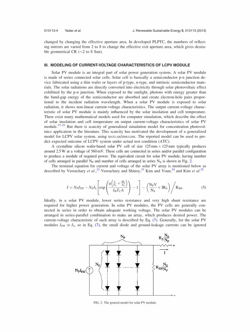
A crystalline silicon wafer-based solar PV cell of size 125 mm� 125 mm typically produces
around 2.5 W at a voltage of 560 mV. These cells are connected in series and/or parallel configuration
to produce a module of required power. The equivalent circuit for solar PV module, having number
of cells arranged in parallel NP and number of cells arranged in series NS is shown in Fig. 2.
The terminal equation for current and voltage of the solar PV array is mentioned below as
described by Veerachary et al.,22 Veerachary and Shinoy,23 Kim and Youn,24 and Kim et al.25
I ¼ NPIPH � NPIS expq V
NSþ IRS
NP
� �kBTCA
0@
1A� 1
24
35� NPV
NS
þ IRS
� �,RSH: (5)
Ideally, in a solar PV module, lower series resistance and very high shunt resistance are
required for higher power generation. In solar PV modules, the PV cells are generally con-
nected in series in order to obtain adequate working voltage. The solar PV modules can be
arranged in series-parallel combination to make an array, which produces desired power. The
current-voltage characteristic of such array is described by Eq. (7). Generally, for the solar PV
modules IPH � IS, so in Eq. (7), the small diode and ground-leakage currents can be ignored
FIG. 2. The general model for solar PV module.
013113-4 Yadav et al. J. Renewable Sustainable Energy 5, 013113 (2013)
under zero-terminal voltage. Therefore, the short-circuit current is approximately equal to the
photocurrent. The expression for IPH is given by the following equation:
IPH ¼ ½ISC þ KIðTC � TRef Þk; (6)
where k ¼ r � CR� Global Irradiation in W=m2.
The photocurrent (IPH) mainly depends on the solar insolation and cell’s working tempera-
ture. The saturation current of a solar cell varies with the cell temperature, which is described
by the following equation:
IS ¼ IRSTC
TRef
� �3
expqEg
1TRef� 1
TC
� �kBA
24
35: (7)
Reverse saturation current of the cell at reference temperature depends on the open-circuit volt-
age (VOC) and can be approximated from Eq. (8), after Tsai et al.26
IRS ¼ ISC=½expðqVOC=NSkBATCÞ � 1: (8)
Based on the theoretical model described above, the LCPV system is simulated using MATLAB/
SIMULINK.
IV. SIMULATION OF LCPV SYSTEM
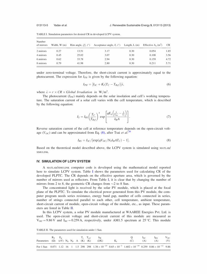
A MATLAB/SIMULINK computer code is developed using the mathematical model reported
here to simulate LCPV system. Table I shows the parameters used for calculating CR of the
developed PLPTC. The CR depends on the effective aperture area, which is governed by the
number of mirrors used as reflectors. From Table I, it is clear that by changing the number of
mirrors from 2 to 8, the geometric CR changes from �2 to 8 Sun.
The concentrated light is received by the solar PV module, which is placed at the focal
plane of the PLPTC. To simulate the electrical power generated from this PV module, the com-
puter program needs series resistance, energy band gap, number of cells connected in series,
number of strings connected parallel to each other, cell temperature, ambient temperature,
short-circuit current of module, open-circuit voltage of the module, etc., as input. These param-
eters are listed in Table II.
In this LCPV system, a solar PV module manufactured at WAAREE Energies Pvt. Ltd. is
used. The open-circuit voltage and short-circuit current of this module are measured as
VOC¼ 9.86 V and ISC¼ 0.259 A, respectively, under AM1.5 spectrum at 25 �C. This module
TABLE I. Simulation parameters for desired CR in developed LCPV system.
Number
of mirrors Width, W (m) Rim angle, 1r (�) Acceptance angle, hc (�) Length, L (m) Effective Aa (m2) CR
2 mirrors 0.27 13.51 3.17 0.30 0.054 1.85
4 mirrors 0.45 25.02 3.07 0.30 0.108 3.56
6 mirrors 0.62 33.78 2.94 0.30 0.159 4.72
8 mirrors 0.79 41.98 2.80 0.30 0.211 5.71
TABLE II. The parameters used for simulation under 1 Sun.
Parameters
RS
(X)
Eg
(eV) NS NP A
Tc
(K)
Tref
(K)
kB
(J/K) KI
Q
(C)
ISC
(A)
IRS
(A)
VOC
(V)
For 1 Sun 0.071 1.12 16 1 1.5 298 298 1.38� 10�23 0.65� 10�3 1.602� 10�19 0.259 0.86� 10�12 9.86
013113-5 Yadav et al. J. Renewable Sustainable Energy 5, 013113 (2013)

consists of only one string of 16 cells of dimensions 64 mm � 14 mm connected in series. The
current-voltage output characteristics of generalized solar PV module under AM1.5 solar
spectrum are shown in Fig. 3. In the simulation short-circuit current, open-circuit voltage, series
resistance, and cell temperature measured under standard test conditions (STCs) by manufac-
turer are taken as input parameters. The current-voltage characteristic generated from simulation
program matches well with the experimental current-voltage characteristic.
Looking at the current-voltage curve, it can be stated that the photovoltaic module is a con-
stant current source at lower values of voltage with current equal to the short-circuit current
(ISC). With further increase in voltage values, the current starts decreasing exponentially at cer-
tain point. The value of current becomes zero at open-circuit voltage (VOC). The point where
the module operates at the highest efficiency is called maximum power point (PMAX).
V. DEVELOPMENT OF LCPV SYSTEM
A piecewise linear parabolic LCPV system is developed as shown in Fig. 4 by using the
modeling parameters listed in Table I. The effective aperture area available using 8 mirrors is
0.211 m2 and the effective receiver area is 0.027 m2, which give the geometric concentration
ratio of �8. In this LCPV system, the reflecting mirrors can be added or removed so that effec-
tive aperture area can be changed and as a result concentration ratio can be varied as listed in
Table I. The receiver is made of a solar PV module fabricated by a string of 16 silicon cell
pieces (material: mono-crystalline silicon, size: 14 mm � 64 mm, efficiency �14%) cut from
commercially available solar cell. The reason behind the selection of the specific size of the
cells mentioned here is to solve the current handling problem of the solar cells under concentra-
tion. A typical solar cell of size 125 mm � 125 mm producing 2.5 W at a voltage of 560 mV
would have a current handling capability of around 4.5 A. This cell when used under 10 Sun
concentration may produce 45 A current by assuming a linear relationship between the current
increment and CR. But if the size of the cell is reduced to 1/10th of normal size, then the cur-
rent generated under 10 Sun concentration would be less than or equal to 4.5 A, then it will be
easily handled without damaging the solar cell contacts. This module was tested under STC
and detailed parameters are given in Table II. The incident solar radiation is reflected by the
PLPTC and concentrated on the focal plane having width of 0.64 mm. The receiver is mounted
at the focal plane to intercept all the reflected radiations from PLPTC. The effective concentra-
tion is dependent on the reflectivity of the mirrors used in PLPTC. In this case, the reflectivity
of the mirrors used is measured as �80%. At a concentration of �8, the cell temperature
increases above 100 �C for solar irradiance �876 W/m2. Due to increased temperature, the open
FIG. 3. Current-voltage characteristics of the designed solar PV module under 1 Sun, AM1.5 at 25 �C.
013113-6 Yadav et al. J. Renewable Sustainable Energy 5, 013113 (2013)

circuit voltage decreases considerably to produce quite low power. This problem is generally
avoided by using either passive or active cooling methods. In this case, an active cooling mech-
anism is employed by flowing normal water behind the encapsulated solar PV module, which is
shown in Fig. 4. By employing this mechanism, module temperature could be lowered down to
45 �C. A light dependent resistor (LDR) based one axis tracking system is developed for Sun
tracking with a provision of manual tracking on second axis with an accuracy of 63� as shown
in Fig. 4.
VI. RESULTS AND DISCUSSION
The global irradiance is measured using pyranometers and under ATC is �876 W/m2. A
non-contact laser based thermometer is used to measure the temperature of module at different
concentrations. Continuous water flow is maintained to keep the solar PV module at low tem-
perature. The current-voltage measurements of a LCPV system are taken by Agilent SMU
6632B and by using multi-meters and load rheostat. The developed LCPV system is studied by
varying the number of reflecting mirrors arranged in PLPTC. Experimental parameters are
noted for 2 mirrors, 4 mirrors, 6 mirrors, and 8 mirrors as listed in Table III. The current-
voltage characteristic curves are plotted in Fig. 7 for 2 mirrors, 4 mirrors, 6 mirrors, and 8
mirrors.
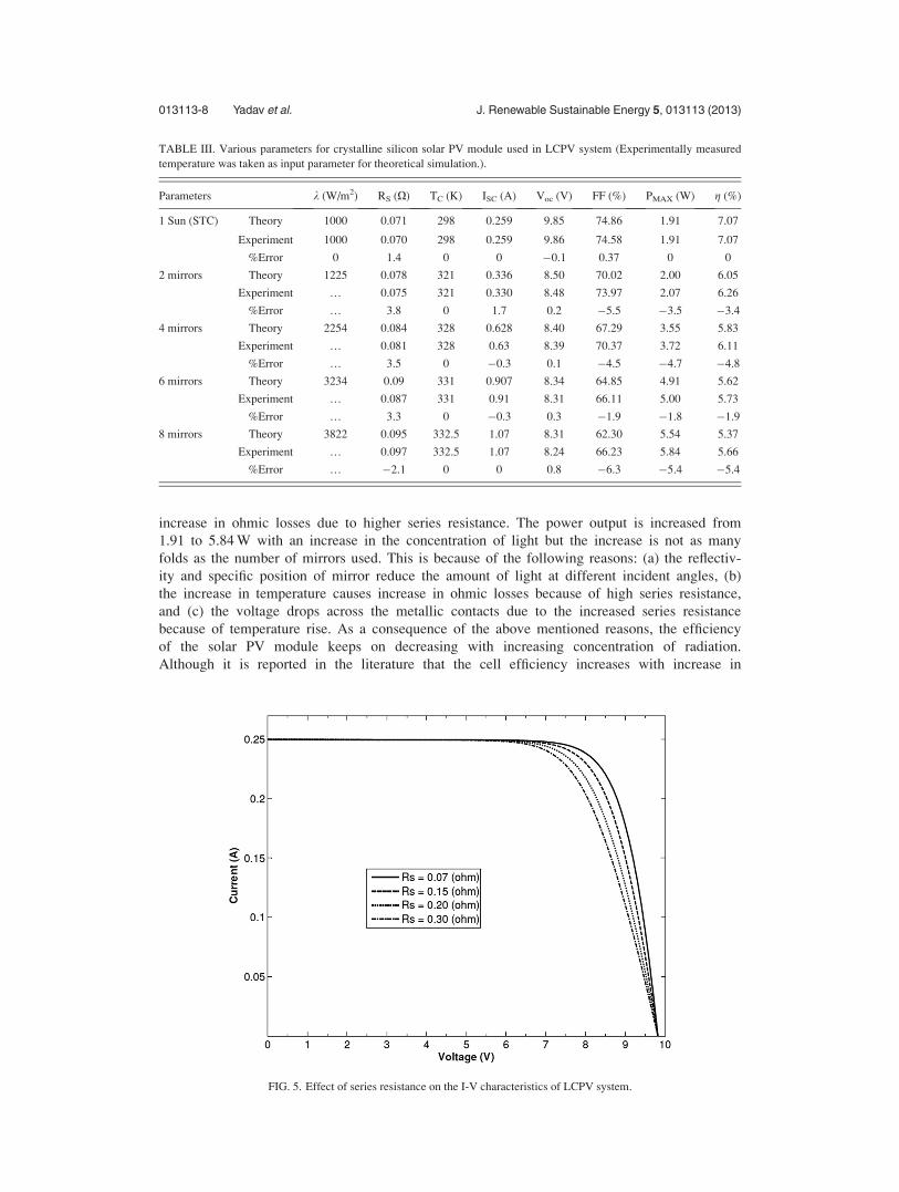
The effect of series resistance on the current-voltage characteristics of LCPV system is
shown in Fig. 5 and it is observed that the series resistance of the crystalline silicon solar PV
module increases from 0.0715 X to 0.095 X with increasing concentration of incident radiation.
This is because the cell temperature has increased from 321 K to 332.5 K. The effect of temper-
ature on current-voltage characteristics is simulated for the LCPV system as shown in the Fig.
6. As the device temperature increases, small increase in short-circuit current is observed; how-
ever, the open-circuit voltage rapidly decreases due to the exponential dependence of the satura-
tion current on the temperature as explained in Eq. (8).27 In the actual experiments, similar
effect of temperature on open-circuit voltage (VOC) was observed and it was found that the
VOC decreases from 9.86 to 8.24 V with temperature coefficient of voltage ��0.021 V/K under
ATC as shown in Fig. 7. The increase in cell temperature causes the bandwidth of solar cell to
become narrow and the recombination rate of electron-hole pair in depletion region increases,
therefore, it reduces the open-circuit voltage. Fill factor decreases from 74.58% to 66.23% with
an increase in concentration and temperature of the solar cell. This may be attributed to the
FIG. 4. The constructed prototype of CPV system.
013113-7 Yadav et al. J. Renewable Sustainable Energy 5, 013113 (2013)
increase in ohmic losses due to higher series resistance. The power output is increased from
1.91 to 5.84 W with an increase in the concentration of light but the increase is not as many
folds as the number of mirrors used. This is because of the following reasons: (a) the reflectiv-
ity and specific position of mirror reduce the amount of light at different incident angles, (b)
the increase in temperature causes increase in ohmic losses because of high series resistance,
and (c) the voltage drops across the metallic contacts due to the increased series resistance
because of temperature rise. As a consequence of the above mentioned reasons, the efficiency
of the solar PV module keeps on decreasing with increasing concentration of radiation.
Although it is reported in the literature that the cell efficiency increases with increase in
TABLE III. Various parameters for crystalline silicon solar PV module used in LCPV system (Experimentally measured
temperature was taken as input parameter for theoretical simulation.).
Parameters k (W/m2) RS (X) TC (K) ISC (A) Voc (V) FF (%) PMAX (W) g (%)
1 Sun (STC) Theory 1000 0.071 298 0.259 9.85 74.86 1.91 7.07
Experiment 1000 0.070 298 0.259 9.86 74.58 1.91 7.07
%Error 0 1.4 0 0 �0.1 0.37 0 0
2 mirrors Theory 1225 0.078 321 0.336 8.50 70.02 2.00 6.05
Experiment … 0.075 321 0.330 8.48 73.97 2.07 6.26
%Error … 3.8 0 1.7 0.2 �5.5 �3.5 �3.4
4 mirrors Theory 2254 0.084 328 0.628 8.40 67.29 3.55 5.83
Experiment … 0.081 328 0.63 8.39 70.37 3.72 6.11
%Error … 3.5 0 �0.3 0.1 �4.5 �4.7 �4.8
6 mirrors Theory 3234 0.09 331 0.907 8.34 64.85 4.91 5.62
Experiment … 0.087 331 0.91 8.31 66.11 5.00 5.73
%Error … 3.3 0 �0.3 0.3 �1.9 �1.8 �1.9
8 mirrors Theory 3822 0.095 332.5 1.07 8.31 62.30 5.54 5.37
Experiment … 0.097 332.5 1.07 8.24 66.23 5.84 5.66
%Error … �2.1 0 0 0.8 �6.3 �5.4 �5.4
FIG. 5. Effect of series resistance on the I-V characteristics of LCPV system.
013113-8 Yadav et al. J. Renewable Sustainable Energy 5, 013113 (2013)

concentration but that happens only for constant temperature. In this case, the decrease in effi-
ciency is observed because of increasing temperature.28
The simulated results are in accordance with the experimental observations. Slight devia-
tion is observed because of the data, which are manually collected. The developed model
explains the behavior of a LCPV system under ATC. Further, the developed model is used to
predict the behavior of a LCPV system for any value of concentration and temperature.
FIG. 7. Simulated and experimental I-V characteristics of LCPV system under ATC.
FIG. 6. The current-voltage characteristics of LCPV system under various temperatures.
013113-9 Yadav et al. J. Renewable Sustainable Energy 5, 013113 (2013)

VII. CONCLUSIONS
In this study design, construction, modeling, and simulation of the LCPV system are pre-
sented. The experiments based on LCPV system were performed to investigate the performance
of commercially available crystalline silicon solar cells under low concentration. The experi-
mental results show that the commercially available silicon solar cells have quite good perform-
ance under concentration conditions. Some factors that affect the output performance of the
commercially available silicon solar PV module are explored experimentally and by theoretical
calculations. The developed theoretical model is able to predict the performance of a LCPV
system under the ATC. The open-circuit voltage was found to decrease from 9.86 to 8.24 V
with temperature coefficient of voltage ��0.021 V/K under ATC. This study shows that the
commercially available silicon solar PV cells can be used to work under low level concentra-
tion (<10 Sun) to have higher power output without compromising with the performance of the
solar cell.
ACKNOWLEDGMENTS
The authors acknowledge the financial support provided by Gujarat Energy Development
Agency (GEDA) to develop CPV system by GrantNo. GEDA\EC:REC\March-2010/3/9174. The
authors also acknowledge WAAREE Energies Pvt. Ltd., India for providing encapsulated crystal-
line silicon solar PV modules for this study.
1G. Sala, D. Pachon, and I. Anton, “Test, Rating and Specification of PV Concentrator Components and Systems(C-Rating Project),” in Book 1. Classification of PV Concentrators (Universidad Polit�ecnica de Madrid, Spain, 2002);access online at http://www.ies-def.upm.es/ies/CRATING/crating.htm.
2M. Yamaguchi and A. Luque, IEEE Trans. Electron Devices 46, 2139–2144 (1999).3M. A. Green and A. Ho-Baillie, Prog. Photovoltaics 18, 42–47 (2010).4H. Cotal, C. Fetzer, J. Boisvert, G. Kinsey, R. King, P. Hebert, H. Yoon, and N. Karam, Energy Environ. Sci. 2, 174–192(2009).
5G. Sala, I. Anton, J. Monedero, P. Valera, M. P. Friend, M. Cendagorta, F. Perez, E. Mera, and E. Camblor, in Proceed-ings of the 17th EUPVSEC, Munich, Germany (2001), pp. 488–491.
6V. Garboushian, S. Yoon, G. Turner, A. Gunn, and D. Fair, in Proceedings of the 1st WCPEC, Hawaii, USA (1994),1060–1063.
7S. Hatwaambo, H. Hakansson, J. Nilsson, and B. Karlsson, Sol. Energy Mater. Sol. Cells 92, 1347–1351 (2008).8M. M. Bunea, K. W. Johnston, C. M. Bonner, P. Cousins, D. D. Smith, D. H. Rose, W. P. Mulligan, and R. M. Swanson,in Proceedings of 35th IEEE Photovoltaic Specialists Conference (2010), pp. 823–826.
9D. C. Walter, V. Everett, A. Blakers, M. Vivar, J. Harvey, J. Muric-Nesic, T. Ratcliff, S. Surve, R. Van Scheppingen,P. Le Lievre, M. Greaves, and A. Tanner, in Proceedings of 35th IEEE Photovoltaic Specialists Conference (2010),pp. 831–836.
10T. K. Mallick and P. C. Eames, Sol. Energy Mater. Sol. Cells 91, 597–608 (2007).11A. Luque, G. Sala, G. L. Araugo, and T. Bruton, Int. J. Sol. Energy 17, 179–198 (1995).12M. Castro, I. Anton, and G. Sala, Sol. Energy Mater. Sol. Cells 92, 1697–1705 (2008).13A. Zahedi, Renewable Sustainable Energy Rev. 15, 1609–1614 (2011).14M. Li, X. Ji, G. Li, S. Wei, Y. Li, and F. Shi, Appl. Energy 88, 3218–3227 (2011).15M. A. Schuetz, K. A. Shell, S. A. Brown, G. S. Reinbolt, R. H. French, and R. J. Davis, IEEE J. Photovoltaics 2, 382–386
(2012).16H. J. Riveros, Sol. Energy 36, 313–322 (1986).17M. J. Kerr and A. Cuevas, Sol. Energy 76, 263–267 (2003).18E. Radziemska and E. Klugmann, Energy Convers. Manage. 43, 1889–1900 (2002).19E. E. Van Dyk et al., S. Afr. J. Sci. 96, 198–200 (2000).20J. Thongpron, K. Kirtikara, and C. Jivicate, Sol. Energy Mater. Sol. Cells 90, 3078–3084 (2006).21A. Gow and C. D. Manning, IEE Proc.: Electr. Power Appl. 146(2), 193–200 (1999).22M. Veerachary, T. Senjyu, and K. Uezato, IEEE Trans. Aerosp. Electron. Syst. 38(1), 262–270 (2002).23M. Veerachary and K. S. Shinoy, IEE Proc.: Electr. Power Appl. 152(5), 1263–1270 (2005).24I. S. Kim and M. J. Youn, IEE Proc.: Electr. Power Appl. 152(4), 953–959 (2005).25I. S. Kim, M. B. Kim, and M. J. Youn, IEEE Trans. Ind. Electron. 53(4), 1027–1035 (2006).26H. L. Tsai, C. S. Tu, and Y. J. Su, in Proceedings of the World Congress on Engineering and Computer Science, San
Francisco, USA, 22–24 October 2008.27S. M. Sze, Physics of Semiconductor Device, 2nd ed. (Wiley, New York, 1981).28R. Chenni, M. Makhlouf, T. Kerbache, and A. Bouzid, Energy 32, 1724–1730 (2007).
013113-10 Yadav et al. J. Renewable Sustainable Energy 5, 013113 (2013)