Silicon-drift detectors SDD
199
Development of high performance large area Silicon-drift detectors SDD for High Precision X-ray Measurements in astrophysics and at synchrotron light sources Track • Few introductory remarks • Our daily SDD; working principle • 2007 ALICE detector more than 1 m 2 • Large Area & Low energy X-rays: • Towards X-ray astrophysics • EXTP • Light Sources experimental stations •PiXDD Andrea Vacchi INFN Trieste & Uni Udine for the redsox collaboration [email protected] Scuola F. Bonaudi XXVII Giornate di Studio sui Rivelatori
-
Upload
khangminh22 -
Category
Documents
-
view
0 -
download
0
Transcript of Silicon-drift detectors SDD

Development of high performance large area Silicon-drift detectors SDD
for High Precision X-ray Measurements
in astrophysicsand at synchrotron light sources
Track• Few introductory remarks • Our daily SDD; working principle• 2007 ALICE detector more than 1 m2
• Large Area & Low energy X-rays:• Towards X-ray astrophysics• EXTP• Light Sources experimental stations•PiXDD
Andrea Vacchi INFN Trieste & Uni Udinefor the redsox collaboration
Scuola F. Bonaudi XXVII Giornate di Studio sui Rivelatori

Foreword: in 1983 E. Gatti and P. Rehak have proposed Silicon Drift Detectors (SDD).
• It is now 35 years that this very versatile and elegant device evolves in different directions. The SDD operation principle has given rise to the development of a variety of solutions adapted to very challenging specific needs.
All this is made possible by the planar technology introduced in 1980 by J. Kemmer dedicated to the field of high performance detectors.
The first large area SDD, for particles tracking in a high multiplicity environment, was published in 1990, while in 2007 more than 1 m2 of SDD was made operative in the tracking system of the LHC-ALICE experiment, demonstrating the possibility of industrial mass production with high production yield.
Far from being an exhausted branch, large area SDD’s continue to develop, driven by very advanced applications needing SDD’s unique potentials.
2/15/2019Andrea Vacchi INFN Trieste

E. GATTI P.F> MANFREDILA RIVISTA DEL NUOVO CIMENTO VOL 9 SERIE 3 1986
Based upon a novel charge transport scheme, the silicon drift chamber allows accurate position sensing, yet requiring a limited number of readout channels. The drift chamber is a fully depleted silicon detector with the space charge of donors providing a potential well for the electrons. The electrons are confined in the middle plane of the detector, parallel to its upper and lower surfaces. Drifting is obtained with a uniform electric field parallel to the wafer surfaces. Such a field is provided for, by keeping the corresponding p+ strips of the upper and lower arrays at voltages that are negatives with respect to the collecting anodes and scaled down of a suitable quantity from one strip to the next one. The drift field determines an uniform motion of the primary electrons towards the low capacitance n+ collecting electrode implanted on one side
3

1988-2018 Large Area SDD 30 years of progressive effort
4
NIM A273 (1988) 865-868

2/15/2019
Andrea Vacchi INFN Trieste

The First Large-area Silicon Drift Detector (1991 )
1991
2/15/2019
UA6?
Andrea Vacchi INFN Trieste

2/15/2019
Andrea Vacchi INFN Trieste

First Large area SDD for tracking applications 1988
Andrea Vacchi INFN Trieste
on board high voltage divider connects the field strips.
cathode/field strips
collecting anodes
edge region HV gard rings

SILICON DRIFT DETECTORS WORKING PRINCIPLE
very elegant and easily adaptable detector demonstrates the many potentials of designing specific solid state silicon detection systems tailored for specific application
2/15/2019
Andrea Vacchi INFN Trieste

Silicon Drift Detectors (SDD) Basic Working Principle
SDD have best possible noise performance and are also well suited for low-energy X-ray spectroscopy applications.
n-side
p-side
divider
anodes
oxide (SiO2)
metal
depletionpotential-U
driftpotential
anode drift distance
Drift region
Anodes collection region
Andrea Vacchi INFN Trieste
very low capacitance anodes

2/15/2019Andrea Vacchi INFN Trieste

2/15/2019
Andrea Vacchi INFN Trieste

2007 CERN LHC ALICE; FIRST LARGE SIZE SDD BASED DETECTION SYSTEM
SDD unambiguously identify the two coordinates of the particle’s impact point even in presence of high particles multiplicity
10 years of R&D + 2 years production of large-area SDDs for the ALICE experiment ( 600 detectors tested, 370 passed to the following assembly).
2/15/2019
Andrea Vacchi INFN Trieste

2/15/2019
Andrea Vacchi INFN Trieste
14first mass production
PAUL BURGER

year 2000
Andrea Vacchi INFN Trieste
new unique injectors for self calibration

2/15/2019
INFN & CANBERRA
Andrea Vacchi INFN Trieste

ALICE-ITS-SDD
260 detectors (1.37 m2) operational in LHC since 2007 .
Manufactured by Canberra in collaboration with INFN-Ts.
•production yield better than 60%(>90% for last batches)
Nuclear collisions at the LHC have allowed experimenters to study strongly interacting matter inunprecedented conditions of temperature and density and with a much enhance range of probes
unveiling new features of the quark-gluon plasma in these extreme conditions.
Andrea Vacchi INFN Trieste

18
The ALICE Inner Tracking System
6 layers all silicon
low mass: 8 % X0SPD 2.3 %SDD 2.4 %SSD 1.7 %structure 1.3 %
layertype R
[cm]area[m2]
chan-nels
occu-pancy
s_Rf s_Z
1 pixels
SPD
4 0.07 3.3 M 2.112 mm 100 mm
2 8 0.14 6.6 M 0.6
3 drift
SDD
15 0.42 43 k 2.535 mm 25 mm
4 24 0.89 90 k 1
5 double sided strip SSD
38 2.2 1.1 M 4
20 mm 830 mm6 43 2.8 1.5 M 3.3
specials
SPD: fastOR triggerSDD: DE signalSSD : DE signal
take a look to the number of read-out channels !!

SDD ladders and layers
CARLOS board• 8 inputs fed in parallel by 8 AMBRAs
1 Carlos per SDD module
• 2D 2-threshold zero suppression• Formats data and sends to DAQ
Layer # ladders
Modules/ladder
# modules
Material Budget
(% of X0)
3 14 6 84 1.134 22 8 176 1.26
Andrea Vacchi INFN Trieste

Large Area SDD
Central Cathode at -HV
Edrift
Edrift
Voltage divider
vd (e-)
vd (e-)
256x2 Anodes
Hybrid with front-end electronics (4 pairs of ASICs)
HV, MV supply
LV supplyCommandsTrigger
Data
291 Drift cathodes12
0 mm
pitch
294 mm pitch
Electron potential in linear SDD
Andrea Vacchi INFN Trieste

Wafer type: 5” Neutron Transmutation Doped <111>
3 k·cm, thickness 300 mmArea: Sensitive: 7.02 7.53 ≈ 53 cm2,
divided in 2 drift regions total: 7.25 8.76 cm2, (ratio = 0.83)
Each drift region: drift length of 35 mm 291 cathodes biased by an integrated
voltage divider 256 anodes – pitch of 294 mm 3 lines of 33 MOS charge injectors for
the drift velocity calibrationGuard region: independent voltage dividersIntegrated dividers: Equivalent resistance of all voltage
dividers Rtot = 4781 kΩEach anode: has a very small anode capacitance
of ~100 f F this reads an area of 10 mm2
SDD for LHC-ALICE experiment
Specs for the detector :
HV bias: -2.4 kV, 8V/cathode E = 670 V/cm
35mm in a drift time of 4.3 ms, vd = 8 mm/ns
total current on the voltage dividers ~0.48 mA
on board power consumption: 1.15 W
Andrea Vacchi INFN Trieste

27 Sept 2007: Central tracker installation finished
2/15/2019
Andrea Vacchi INFN Trieste

ALICE SDD layout details and terminology
n-side
p-side
Integrated voltage divider (implanted resistors)
Anodes
“push-up”cathodes(W1, W2)
Drift cathodes (C0 … C291)
Drift cathodes (C0 … C291)
guard cathodes
GRID electrode
2/15/2019
Andrea Vacchi INFN Trieste

guard cathodes (32 mm pitch)
292 drift cathodes (120 mm pitch)
implanted HV voltage dividers
256 collection anodes (294 mm pitch)
collection zone close-up
injector lines close-up
injector line bonding pad
MOS injector (every 8th anode)
Detector design features
Andrea Vacchi INFN Trieste

Unique feature Point like charge injectors> continuous on line calibration
anodes
time
m T-2.5
vd = m x E
Monitoring vd fluctuations
Andrea Vacchi INFN Triesteinjector’s charge distribution at the anodes

2/15/2019
Andrea Vacchi INFN Trieste

A precise knowledge of the drift speed is a crucial element for the correct operation of any drift detector. Given its strict dependence on the detector temperature, the drift speed must be very frequently monitored. To reach the design precision of 35 mm on a drift distance of as much as 35 mm (from the point farthest from the anodes) the drift speed must be known with an accuracy of better than 0.1%.
Drift values as a function of the anode number of one half module; each point represents the result of the fit on the three corresponding charge injectors.
Andrea Vacchi INFN Trieste

Running conditions Detector characteristics:
Readout and DAQ parameters245 (out of 260) modules stably in DAQ
Parameter 20 MHz AM sampling
40 MHzAM sampling
Time bin size 50 ns 25 nsNumber of time samples 128 256Readout dead time 1 ms 2 msMax. event rate 1 kHz 500 HzEvent size (cosmics) 12 kB 25 kB
Parameter ValueHV (central cathode) 1800 VMV (cathode 291) 40 VDrift field 500 V/cmResolution (z x r) 25x35 mm
Edrift
Cathode 291

2/15/2019
ALICE_LHC Material Budget
Improving Detector Simulation• central part (< 450): very precisely measured (< 5%)• forward part: improved description in simulation
(using design drawings/installation photo’s)
Material in simulation
SSD
SDD
SPD
FMD multiplicityNot fully corrected
Andrea Vacchi INFN Trieste

Drift distance (mm)
Res
olu
tion
(mm
)
anode axis (Z)
drift-time axis (R-F)
test beam data
The spatial precision
along the drift direction, is better than 30 μm over the whole detector surface.
The precision along the anode, is better than 30 μm over 94% of the detector surface and reaches 60 μm close to the anodes, where a fraction of clusters affects only one anode.
The average values are 35 μm x 25 μm respectively.
.

High multiplicity the two coordinates Clean delivery!
2/15/2019 Andrea Vacchi INFN Trieste

Higl level productin technology suitable for low-energy X-ray spectroscopy applications:
+ anode capacitance is about 50 fF,
+ the leakage current at the anode measured at room temperature is very low.
This allows a very-low noise contribution from the front-end electronics.
More than two order of magnitudes larger sensitive area than standard spectroscopic SDDs,this detector can open the way to application areas of the X-ray spectroscopy that requirewide surface coverage.
Each anode sees a 10 mm2 surface - the reported current values correspond to 4 anodes read-out together

2016 SDD high duty cycle highest efficiency after almost 10 years
looks like ready for space
33

Alice SDD detection system run active time since 2016 year beginning
2/15/2019
Andrea Vacchi INFN Trieste

ALIC SDD mission accomplished First RUN 2007 last RUN 2018
35

36
SDD eventsdata sizedistribution
Different populations corresponding to the different triggers used.The bump with Event size between 200 and 350 kB is that of the trigger on central Pb-Pb collisions,the bump between 50 and 100 kB is for semi-peripheral collisionsand the underlying distribution and q of the Minimum Bias collisions.

A NEW COLLABORATION HAS GIVEN RISE TO A NEW STREAM OF PROJECTS
1. Given the results in production yield and leakage current showing a clear progress and new potentials
2. High readiness level for applications Synchrotron light accelerators
3. High technology readiness level for space applications
37

Silicon Drift Detectors
Un poco di storiaFamiliarizziamo con il principioALICE più di 1 m2
raggi X di bassa energia• Gli sviluppi per Sorgenti di Luce Avanzata
• Gli sviluppi per il passaggio a 6” e la tecnologia LOFT
INFN Trieste
FBK Trento
Elettra Sincrotrone Trieste
INAF IASF INFN Roma 2
INFN INAF Bologna
INFN Pavia
INFN TIFPA Trento
ICTP Mlab Trieste
INFN Firenze Labec
Poli Milano El.&Det.
The redsox collaboration born within the frames of INFN board 5 has given rise to a noticeable number of concrete projects in various fields demonstrating a considerable effective and timely potential
REDSOX Silicon Drift Detrctors SDD dedicated optimized solutions
The approach of the Redsox collaboration in elaborating solutions for various front edge research themes brought to a considerable cross-fertilization and a factual excellence in each specific field of application.
eXTP SDD12×7.2 cm2
X-ray astrophysics
Twinmic@Elettra

continuous flow of technology front edge developments feeding technologically hungry scientific fields
Highly specialized preamplifiers & dedicated
VLSI developments
Highly specialized preamplifiers & dedicated
VLSI developments
High Energy resolution for low energy X-raysHigh Energy resolution for low energy X-rays
Developing state of the art Detector technology low leakage currentsimul
Developing state of the art Detector technology low leakage currentsimul
High Energy resolution for low energy X-raysHigh Energy resolution for low energy X-rays
Fast evolving dedicated designs for detectors and
electronics
allows unbeatable performances
Fast evolving dedicated designs for detectors and
electronics
allows unbeatable performances
time resolved X-ray Astrophysics
energy range << 5 KeV
time resolved X-ray Astrophysics
energy range << 5 KeV
pixellized imaging capable detectors pixellized imaging capable detectors
Large area low power consumption low number of read-out channels high
efficiency
Large area low power consumption low number of read-out channels high
efficiency
Large area high efficiency detectors for
synchrotron radiation and Advanced light
Sources
energy range << 5 KeV
Large area high efficiency detectors for
synchrotron radiation and Advanced light
Sources
energy range << 5 KeV
fast, excellent E resolution performances at room temperatures
fast, excellent E resolution performances at room temperatures 2/15/2019

Low Noise Spectroscopy and Imaging with large area Silicon Drift Detectors and
low noise integrated electronics
Applications in the fields of
Advanced Light Sources TwinMic at Elettra e XAFS at Elettra and SESAME
X e astrophysic: ASI (HERMES pathfinder), ESA (ASTROGAM, THESEUS, PANGEA), NASA (LOFT-Probe StrobeX ), Cina (eXTP, Einstein Probe), Russia (MVN-N2)
in collaboration with INFN experiment FLARES Cultural Heritage 40

FROM FBK TRENTO ITALY OUR TECHNOLOGY TODAY

DEDICATED FRONT END VLSI POLIMILANO

Front End

X-RAY ASTROPHYSICS
Unique expertise in the SDD designing and production allows to focus on large area SDD’s application in X-ray astrophysics to gain in detection efficiency and almost two orders of magnitudes in energy resolution
2/15/2019
Andrea Vacchi INFN Trieste

LOFT SCIENCE
LOFT ADDRESSES THE COSMIC VISION THEME“Matter Under Extreme Conditions”
Probe gravity theory in the very strong field environment of Black Holes
(“Strong Gravity”)
Probe physics of hundreds of galactic and bright extragalactic cosmic sources
(“Observatory Science”)
Probe the state of matter at supra nuclear densities in Neutron Stars
(“Dense Matter”)

2/15/2019
2009 LOFT concept

The strong force determines the state of nuclear matter - from atomic nuclei to neutron stars.
It is a major problem within modern physics.
PROGRESS IS DRIVENBY LABORATORYEXPERIMENT ANDASTROPHYSICALOBSERVATION.
LOFT DENSE MATTER THEME
QCD computationally intractable beyond single particles – e.g. for many nucleon systems that we want to understand! Rely instead on phenomenological models that are developed to fit data. Progress is DRIVEN by experiment and observation.

Measuring the neutron star equation of state using x-ray timing
REVIEWS OF MODERN PHYSICS, VOLUME 88, APRIL–JUNE 2016
2/15/2019
Andrea Vacchi INFN Trieste

X-ray Timing and Polarization (XTP) missionSingularity?Neutron orQuark Star?Extreme gravity
magnetismdensity

DENSE MATTER AND NEUTRON STARS – A UNIQUE REGIMEHYPOTHETICAL STATES OF MATTER ACCESSED BY NEUTRON STARSAND CURRENT OR PLANNED LABORATORY EXPERIMENTS
LOFT WILL STUDY NUCLEONIC MATTER IN A UNIQUE REGIME, ANDEXOTIC STATES OF MATTER THAT COULD NEVER EXIST IN THE LABORATORY.
Neutron Stars
Neutron stars contain the
densest and mostneutron-rich matter in the
Universe.
LOFT

Stellar structure equations
EOS Mass-Radius (M-R)
EXTP MUST MEASURE BOTH M AND R TO HIGH PRECISION(LOW STATISTICAL AND SYSTEMATIC ERRORS) FOR A RANGE OF M.
Strong force, equation of state, mass-radius relation
51/27

General Relativity Detailed simulations carried out to evaluate fitting procedure and accuracies (Lo et al. 2013, ApJ).
Few % accuracy needs ~106 photons: large area crucial.
Multiple same-source cross-checks.
USING ONLY KNOWN SOURCES, PULSE PROFILE MODELLINGMEASUREMENTS WILL MAP THE M-R RELATION AND HENCE THE EOS.
8 10 12 14 16Radius (km)
0.0
0.5
1.0
1.5
2.0
2.5
3.0
Mas
s (M
O •)
RXTE
LOFT
8 10 12 14 16Radius (km)
0.0
0.5
1.0
1.5
2.0
2.5
3.0
Mas
s (M
O •)
LOFTLOFT/ eXTP
Spectral-Timing Mapping EOS with Large-Area Experiments
Neutron or Quark Star?

• Frame dragging: central hot torus precesses• Hard radiation sweeps around over disk• Reflection line profile varies periodically
LOFT observations:• Confirm black hole frame dragging • Track the line profile, probing the disk velocity and
redshift map
LOFT simulations Adam Ingram
FRAME DRAGGING PRECESSION
Precessing hot torusLOFT10 ksec

Gravity near the event horizon:
near the event horizon
RELATIVISTIC EFFECTS DOMINATE
ASTROPHYSICS NEAR BLACK HOLES: STRONG FIELD EFFECTS• Inner Stable Circular Orbit• Orbital motion near Orbital and epicyclic frequencies• Frame dragging, light deflection, Shapiro effect
54/27
Current best tests of General Relativity: millisecond radiopulsars in weak-field regime (GR small perturbation) GW150914/GW151226: strong field in a highly dynamic regime
LOFT/e-XTP: GR effects in a stationary spacetime

ACCRETION NEAR THE EVENT HORIZON
Current best tests of General Relativity: millisecond radiopulsars in weak-field regime (GR small perturbation) GW150914/GW151226: strong field in a highly dynamic regime
LOFT: GR effects in a stationary spacetime
LOFT: near the event horizon
RELATIVISTIC EFFECTS DOMINATE
ASTROPHYSICS NEAR BLACK HOLES: STRONG FIELD EFFECTS
• Inner Stable Circular Orbit • Orbital motion near ISCO • Orbital and epicyclic frequencies• Frame dragging, light deflection,
Shapiro effect
Motta et al. 2013

COMPLEMENTARY TO GRAVITATIONAL WAVEEXPERIMENTS:
EXTP PROBES STATIONARY SPACETIME
Strong gravity arena: accreting black holes
X-ray binary system
Active galactic nucleus
Stellar mass black hole (or neutron star)
Strongly curved spacetime.(1016 times Solar)
Supermassive black hole
Weakly curved spacetime(~Solar)
eXTP covers wide mass range in uniform setting

Motta et al. 2013
• Strong gravity dynamical frequencies justdetected in current (RXTE) data
• eXTP diagnoses strong field gravity very precisely by:
– timing of the flux variations– time resolved spectroscopyat very high signal to noise
• Uses known phenomena
Spectral-Timing for strong field gravityGeneral Relativity predicts preciseorbital and epicyclic frequencies at each radius
Orbiting inhomogeneities make frequencies observable
LOFT/eXTP:10x the signal to noise
Wellons et al. 2013
SFA 1 keV
57/67

THE LOFT APPROACH
Good Energy Resolution (XMM-class)
Large Collecting Area
LHC SDD Detectors Heritage
Microchannel Plate Collimators
200 eV
LOFT-M3

59/27
One of the primary science goals of the next generation of hard X-ray timing instruments is to determine the equation of state of the matter at supranuclear densities inside neutron stars, by measuring the radius of neutron stars with different masses to accuracies of a few percent.

60/27

enhanced XTP (eXTP=XTP+LOFT)
61/27
4 LAD panels (LOFT-like): 640 detectors• ~3.5 m2 effective area for collimating detectors
Optimistic for selection in 2016-17 for launch in 2023-2025

MISSION APPROACHES
LOFTLarge Observatory For x-ray Timing
(ESA)
eXTPenhanced X-ray Timing and Polarization mission (CAS)
Bright sources: Large Collimated Area
Weak/soft sources: Collimated Area + Telescopes.
And Polarimeter
LOFT-PLOFT-Probe
(NASA)
Dense MatterStrong Field GravityStrong Magnetic FieldObservatory Science


THREE POSSIBLE MISSION APPROACHES
LOFT / LOFT-PLarge Observatory For x-ray Timing (ESA or
NASA)
eXTPenhanced X-ray
Timing and Polarization mission
(CAS)
Bright sources: Large Collimated Area
Weak/soft sources: Collimated + Focused Area
8-10 m23.4m2
1m2
0.6m2
LOFT/LOFT-P

Large Area (SDD) for low energy X-rays
although they were born for tracking in high multiplicity ambient LA – SDD have small charge collection anodes and tourned out to be optimal also for low energy X-rays detection
• small capacitance collection anodes• low leakage current
But need to adapt the electrodes geometry to the low energy X-rays so to obtain a good efficiency especially at the surface
2/15/2019 Andrea Vacchi INFN Trieste 65
n-side
p-side
divider
anodes
oxide (SiO2)
metal
depletionpotential-U
driftpotential
anode drift distance
Drift region
Anodes collection region

An heritage of the Inner Tracking System of the ALICE experiment at the Large Hadron Collider (CERN):1.5 m2 of SDD detectors (approximately 300 units), operating since 2008. High TRL. Proven mass production.
towards LOFT- LAD Configuration:Thickness 450 µmMonolithic Active Area 76 cm2
Drift time <5 µsAnode Pitch 970 µmSingle-channel area 0.3 cm2
starting from ALICE Large-Area SDD towards LOFT Configuration:
2/15/2019
Andrea Vacchi INFN Trieste

THE EXTP ENHANCED TIMING AND POLARIMETRY MISSIONSCIENTIFIC PAYLOAD
LADLarge Area Detector
PFA – Polarimetry Focusing Array
WFMWide Field Monitor
SFA - Spectroscopy Focusing Array
11 X-ray SGO optics, 6200 cm2 @6 keV, 4.5m FL, 1’ PSF, SDD, 0.5-10 keV, <100 µs
2 X-ray SGO optics, 1100 cm2 @6 keV, 4.5m FL,15” PSF, GPD polarimeters, 2-10 keV
3.4 m2 “LOFT” SDD detectors, 2-30 keV, <300 eV @ 6 keV
3 units, 2-50 keV, 4 sr FoV, 80 cm2/unit, 5’ angular resolution
eXTP a mission concept currently carried ahead by an international consortium led by the IHEP of the Chinese academy of science, and with the contribution of several european institutions


Pixel SDD

Attenuation length (1/e) of several materialsas a function of x-ray energy
70

Evolution of ALICE-D4 design
The new FBK prototypes include design modifications
(drift cathodes have been enlarged keeping the same pitch, so that their distance equals that between guards) In this way the potential minimum is pushed closer to the surfaceand the dead volume in the substrate is reduced by a factor of about 4.
ALICE LOFT
2/15/2019 71

2/15/2019
A. Vacchi for the XDXL collaboration
72

eXTPenanched x-ray t im ingand polarimetry mission
EXTPMEETINGXIAMEN - MAY 2018
EXTP SDDEFFICIENCY

Efficiency modulation @ 4.5 keV, 200 μm spot size: ottimizzazione della risposta alle basse energie (FBK-1 vs
Alice)
In red old design In black new design
2/15/2019 74

Second FBK prototype run
XDXL-1 SDD
2/15/2019 75

SDD DESIGN OPTIMIZATIONFOR X-RAY SPECTROSCOPY AND IMAGING
SUBSTRATE OPTIMIZATION FOR X-RAYDETECTION
MATERIAL: NTD → FZGEOMETRIC AREA (filling factor): 5” → 6” wafer <100>RESISTIVITY: 4 kΩ cm→ 9 kΩ cmTHICKNESS (QE): 300 µm → 450 µm
DESIGN OPTIMIZATION FOR X-RAYDETECTION AND SPACE APP.
VOTLAGE DIVIDER: reduced powerSURFACE CURRENT: minimizationSi-SiO2 INTERFACE GAP: minimizationFIELD PLATE: optimization for minimal surface currentQUANTUM EFFICIENCY: optimization for low EphANODE PITCH: opt. for spectral-timing & imaging
Detector development activity performed in the framework of the XDXL and ReDSoX R&D INFN programs
Prototypes designed, manufactured and tested in collaboration between INFN, INAF and FBK.
(Rachevski et al., JINST, 2015)
ALICE2002

E_XTP SDDLOT OF MODIFICATIONS TO IMPROVE LOW ENERGY X-RAY DETECTION
eXTP SDD typical parameters (HV=1300V) The drift time is about 5 μs.when the photon is absorbed close to the top of the 35 mm long drift channel (corresponding to the central line of the Silicon tile). The charge cloud reaches a maximum size of about 1 mm,
•Active area: 53 cm2 76 cm2, increment of 43%•Power consumption at 1300 V: 350 mW• 37 mW, reduction of a factor ~ 9•Average QE media increased of ~ 27% at 4.5 keV

LAD SDDLARGEST LINEAR SDD
First full-scale prototypes produced 2014Cut out from 6” waferGeometric area: 120.3 x 72.5 mm2
Sensitive area: 108.5 X 70.0 mm2
Leakage current: <200 pA/cm2 @ Troom
Largest monolithic SDD ever built
•Space qualification tests successfully passed: vacuum, radiation damage (NIEL, total dose, CCE), space dust impacts (micro meteorites and orbital debris)•Optimization for X-ray spectroscopy or imaging

SPECTROSCOPIC PERFORMANCE
INTEGRATED SET-UP
VEGA low-power (<500 µW/ch) ASIC designed by PoliMi & Pavia University
PCB - designed and realized by the University of Geneva (DPNC)
NI TE - INAF/IASF Bo, University of Bologna
XDXL2, ReDSoX1 and ReDSoX 3 detectors
(Ahangarianabhari, 2014; Campana, 2014, Ambrosino in prep)
Spectroscopic performance characterized in IAPS Rome X-ray facility
Ileak ~ 5pA/anode (~LOFT/LAD EoL)single anode events selected
55Fe with CMN correction (205 eV FWHM)18.1 e- rms taking into account residual CMN

DETECTOR QUALIFICATIONNIEL, TID
At 20 °C, the measured average increase of leakage current is 9.2 nA/anode, the predicted incrementis 8.7 nA/anode (Segneri et al. 2009), agreement within 6% .
The TID (1.4 krad(SiO2)) is representative of eXTP and gives a negligible current increase.The annealing follows (2σ) the prediction (Moll et al., 2002).
XDXL2 irradiated @ PIF (PSI) with 2.5 × 10⁹ p/cm2 - 11.2 MeV (6 MeV FWHM) →120 year in 600km/5° orbit
Del Monte et al., 2014

81Cina accademy of sciences (CAS)+ LOFT consortium
enhanced X-Ray Timing and Polarimetry (eXTP)

82

83
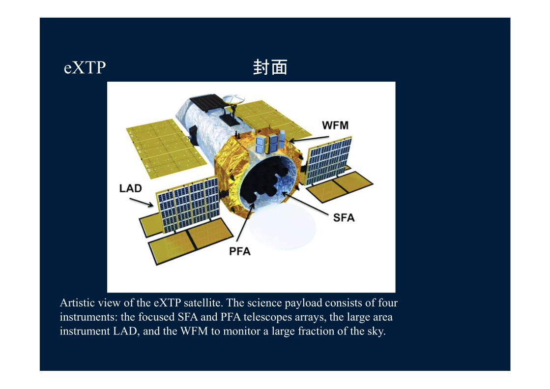
eXTP 封面
Artistic view of the eXTP satellite. The science payload consists of fourinstruments: the focused SFA and PFA telescopes arrays, the large area instrument LAD, and the WFM to monitor a large fraction of the sky.

The detector
85

eXTP LARGE AREA DETECTOR
86

see later the PiXDDdevelopment
87

TOWARDS THE MONOLITHIC MULTIELEMENT SDD

Figure 24 WFM configuration based on three camera pairs. Each camera pairis built by two orthogonal WFM cameras.
89

Energy resolution (FWHM) of the WFM detectors as a function of the photon energy. Solid circles represent the resolution values averagedon the whole SDD channel while the shaded area shows the range of
energy resolution for each photon energy.
90

91

92

93

94

95

96

E-XTP One of the primary science goals of the next generation of hard X-ray timing
instruments is to determine the equation of state of the matter at supranuclear densities inside neutron stars, by measuring the radius of neutron stars with different masses to accuracies of a few percent.
Three main techniques can be used to achieve this goal. The first involves waveform modelling. The flux we observe from a hotspot on the neutron star surface offset from the rotational pole will be modulated by the star's rotation, giving rise to a pulsation. Information about mass and radius is encoded into the pulse profile via relativistic effects, and tight constraints on mass and radius can be obtained. The second technique involves characterizing the spin distribution of accreting neutron stars. The most rapidly rotating stars provide a very clean constraint, since the mass-shedding limit is a function of mass and radius. However the overall spin distribution also provides a guide to the torque mechanisms in operation and the moment of inertia, both of which can depend sensitively on dense matter physics. The third technique is to search for quasi-periodic oscillations in X-ray flux associated with global seismic vibrations of magnetars (the most highly magnetized neutron stars), triggered by magnetic explosions. The vibrational frequencies depend on stellar parameters including the dense matter equation of state. We illustrate how these complementary X-ray timing techniques can be used to constrain the dense matter equation of state, and discuss the results that might be expected from a 10m$^2$ instrument. We also discuss how the results from such a facility would compare to other astronomical investigations of neutron star properties. [Modified for arXiv] 97

XGS
A future compact and modular X and gamma-ray spectrometer (XGS) has been designed and a series of proto- types have been developed and tested.
The experiment envisages the use of CsI scintillator bars read out at both ends by single-cell 25 mm² Silicon Drift Detectors.
Digital algorithms are used to discriminate between events absorbed in the Silicon layer (lower energy X rays) and events absorbed in the scintillator crystal (higher energy X rays and -rays).
The prototype characterization is shown and the modular design for future experiments with possible astrophysical applications (e.g. for the THESEUS mission proposed for the ESA M5 call) are discussed.
98


102
Laboratory prototypes
Simultaneous 241Am + 137Cs spectrum, demonstrating PSA capabilities in separating X and γ-ray eventsX-ray low energy threshold below 1 keV(ENC ~20 e- rms with discrete-elements front-end electronics)

Laboratory prototypes
Low noise SDDs allow a ~20 keV threshold also for scintillation eventsbesides an excellent resolution at high energies

Laboratory prototypes
Spatial resolution of ~2.2 mm in gamma-raysUsing a 5 cm long CsI(Tl) bar and comparing the readout of the SDDs at the two barends

HERMES
• GRB• Multimessenger revolution• Space-time structure
MISSION CONCEPT
Disruptive technologies: cheap, underperforming, but producing high impact.
Distributed instrument, tens/hundreds of simple units
A costellation of nano-satellites for high energy astrophysics and fundamental physics reseach

PAYLOAD• Scintillator cristal (GAGG) + Photo
detector (SDD)• 3-2000 keV• ~50 cm2 coll. area• a few sr FOV• Temporal res. ≈100 ns• Power < 4W• ~1.8kg
3Ucubesat simplest basic configuration

107

108

HERMES wide-band sensitivity
Feasible only withSDDs & Low Noise FEE
Dual Simultaneous Functionality for SDDs:
Solid State Detector for Low Energy X-rays
Scintillator readout systemfor Higher Energy X/-rays

Ce:GAGGCerium-doped Gadolinium-Aluminum-Gallium Garnet
Yoneyama+2018
• Light output: 40 – 60 ph/keV• No intrinsic background• Not hygroscopic• Decay time ~90 ns • High density (6.63 g/cm3)• Peak emission at 520 nm• Hardness: 8 Mohs scale• Energy resolution ~ 5% @ 662 keV
Ce:Gd3(GaxAl1-x)5O12 (x=1-5, typ.=3)
Available from industry since ~2014
1x1x3cm
Very promising literature radiation testsPlanned further test to better understand Afterglow effects
Measured @ Bo-Lab ~23 e-
/keV
Measured @ Bo-Lab ~30 e-
/keV
1x1x3cm
10krad 70MeVp+

HERMESUna costellazione di nano-satelliti per l'astrofisica delle alte energie e la ricerca di fisica fondamentale
• 3Ucubesat• 1U -> detector• Detector: Scintillator cristal (GAGG) + Photo
detector (SDD)• 3-2000 keV• ~50 cm2 coll. area• a few sr FOV• Temporal res. ≈100 ns• Power < 4W• ~1.8kg
HERMES Pathfinder• Pathfinder tecnologico: 3 nanosati• Premiale ASI: inizio maggio 2018• Lancio a metà del 2020 (volo inaugurale
VegaC o Vega)
Scintillator crystal
Commissione Scientifica Nazionale 5 (CSN5)
SDD – Silicon Drift Detector • Designed by INFN-TS• Built by FBK-Trento• Dedicated FEE by PoliMi
UNIUD DMIF: PRID SenSiA
New detection principle

112
The Transient High Energy Sky and Early Universe Surveyor (THESEUS) isa mission concept submitted to ESA in January 2015 by a large internationalcollaboration in response to the Call for next M4 mission within the CosmicVision Program. The main goal of THESEUS is fully exploiting GRBs as cosmological probes, thus providing a fundamental and unique step forward in our understanding of the early Universe. This is achieved via a unique payload providing an unprecedented combinationof: (i) wide and deep sky monitoring in a broad energy band (0.3keV–20 MeV); (ii) focusing capabilities in the soft X-ray band granting large grasp and high angular resolutioniii) on board near-IR capabilities for immediate transient identification and first redshift estimate.
XGS for THESEUS ESA 2 years assessment phase

113

114

115

116

117

118

119

120

121

122

2/15/2019
Andrea Vacchi INFN Trieste

2/15/2019
Andrea Vacchi INFN Trieste

2/15/2019
Andrea Vacchi INFN Trieste

2/15/2019
Andrea Vacchi INFN Trieste

XGIS in Theseus
127
3 XGIS units
C. Labanti CDF KO Noordwijk 13 September 2018

XGIS one unit
128
Coded maskProvides imaging capabilitiesbelow ~30 keV
Field delimiterShields the FoVbelow ~150 keV
Detection plane(SDD+CsI for a total of 4096 pixel)
C. Labanti CDF KO Noordwijk 13 September 2018
The three units will be pointed at misaligned directions (e.g.+/- 35 deg) to partially overlap their fields of view in order toguarantees an optimal sensitivity in the SXI FOV (104x31deg2).

129
One XGIS unit at a glance - 2
Energy band 2 keV – 20 MeV
# of pixels per module 4096
Pixel size active size 5.5 x 3.8 mm2 (SDD)5x5 mm2 (CsI)
Low Energy detector (2-30keV)
Silicon Drift Detector (SDD)
High Energy detector (>30keV)
CsI(Tl) scintillator, readout by SDD
Discrimination of LE/HE events
Pulse shape analysis (baseline)
Size [cm]50 × 50 mask40 × 40 detector base85 overall height
Power [W] 30
Weight [kg] 35.3C. Labanti CDF KO Noordwijk 13 September 2018

130
XGIS tasks
• Produces standard data histograms• Autonomous GRB trigger capability based
on• Ratemeters
• On different time scales (e.g. 10 ms, 100 ms, 1 s, 10 s)
• In different energies bands• On different zones of detector plane
• Images in the 2–30 keV range• accumulates an deconvolve images on different
time scales• compare with previous accumulated images• looks for significant excesses
C. Labanti CDF KO Noordwijk 13 September 2018

SDD array hypotesis for a module
131
8x8 array with SDD 5.5x5.5 mm in size 0.4 mmthickOn the left the optical side (p-side) to read thescintillation ligth, each pixel will be separated by analuminized gap .5 mm in size
C. Labanti CDF KO Noordwijk 13 September 2018

Detection-element module= 8 x 8 pixels
132
Basic detection element
Top SDD matrixS
Top PCB with holesS
ScintillatorsS
Pre-amp ASICS
Connection to Back End ElectronicsS
Bottom SDD matrix, pre-amp ASIC and PCB S
Back End ElectronicsPCBS
C. Labanti CDF KO Noordwijk 13 September 2018

133

134

135

APPLICATIONS TO SYNCHROTRON LIGHT BEAM LINES
If we can design dedicated – non off shelf – optimized detectors for the specific needs of SL beam lines we may reach solutions allowing to gain up to two times in exposure times and in the cost of each single analysis
2/15/2019
Andrea Vacchi INFN Trieste

9 mm2 cell with SIRIO PA, at -20C
2/15/2019
Andrea Vacchi INFN Trieste
tanto per allietarti il fine settimana: questa e' la celletta da 9mm2 con il SIRIO, a -20C. Misure fatte dai bolognesi. Sono arrivati a 127 eV sul Fe55.

Small collecting anode current & low capacitance
The SDD, with an active area of 13 mm, has been manufactured by optimizing the production processes in order to reduce the anode current, successfully reaching leakage current densities between 19 pA/cm and 25 pA/cm at 20 C.
2/15/2019
Andrea Vacchi INFN Trieste


room temperature state of the art this collaboration
2/15/2019
Andrea Vacchi INFN Trieste

state of the art
Spectrum of 55Fe acquired at +20 C.The pulser line width is 64 eV FWHM, corresponding to 7.4 electrons r.m.s.
2/15/2019
Andrea Vacchi INFN Trieste


• Third and fourth generation light sources have revolutionized the research in many scientific and technological disciplines.
• New scientific challenges impose the construction of cutting-edge performance machines and experimental stations.
• In this context, off-the-shelf detection systems severely constrain the achievable results.
• These reasons led to the birth of the ReDSoX research project, aiming to explore new solutions related to energy resolving imagers based on silicon drift detectors (SDD), which are among the most employed acquisition devices in X-ray fluorescence spectroscopy.
• The main goal of the project is to develop novel detection systems able to cover a large photoemission solid angle, being easily adaptable to the needs of different X-ray spectroscopy beamlines and ready to cope with high photon count-rates in order to exploit all the power of new light sources.

144
• XAFS measurements are usually made by means of ionization chambers, but XRF becomes necessary when a specimen is non-transparent for X-rays or is highly diluted. Recently more and more experiments require this approach.
• Photon flow is usually very high, so that if single large area sensor is employed, it is necessary to move the detector away from the analyzed sample in order to avoid saturation phenomena by reducing the collection solid angle .
• On the other side multi-element detector avoids this problem: the active area of the new XAFS SDD system has been divided into 64 elements of 9 mm2 active area each.
• The energies involved in XAFS analyses generally range from 4 to 30 keV, so that detectors operating in vacuum are usually not necessary. The multi-element detectors are installed in a controlled nitrogen atmosphere, isolated in their case through a mylar window, designed to be easily interfaced with various measurement environments.
• Each detector is equipped with a tungsten collimator for a total collimated active area of 499 mm2 on 8 monolithic detectors, assembled to obtain an 8x8 elements matrix

145
The front-end and the rest of the acquisition chain follow the same pattern for both setups, except for the specifications of the two particular cases. The first read-out stage is entrusted to the ultra-low noise SIRIO charge sensitive preamplifier [9], specifically designed in two versions for the two cases' specification. The preamplifier output signals, one for each detector element, are filtered and further amplified by CR-RC2 analogue pre-shaper with a peaking time of 0.4 μs for LEXRF spectroscopy and a selectable shaper of 0.3 or 1.24 μs peaking time for XAFS purposes. The peak-shaped signals are sampled by multichannel ADCs with a resolution of 12 bits at 40 MHz sampling rate and further filtered with trapezoidal FIR filters of variable length and adaptive coefficients in order to guarantee the maximum energy resolution in each environment. Digital filtering, settings and complete monitoring of the instrument are made by high performance FPGAs, which send the collected data to a host computer via TCP/IP protocol. Both developed instruments respond to a series of 8-bit basic commands, easy to implement in any beamline control software. Moreover, a high-level dedicated software has been developed for an easy and immediate way to operate with the new multi-element detector systems also offering some useful X-ray fluorescence measurements utilities.
X-ray fluorescence spectrum of a biological sample acquired on the TwinMic beamline of Elettra – Sincrotrone Trieste. The figure show C (277 eV), O (525 eV), Na (1041 eV), Mg (1254 eV), Al (1487 eV) and Si (1740 eV) Kα emission lines and the synchrotron photon beam elastic peak (near 2 keV).

146
A prototype of the XAFS fluorescence detection system, consisting in two 8-element modules installed in the central positions of the detector case, was tested on the XAFS beamline and in the Hard & Soft X-ray Optical Engineering Laboratory, both in Elettra – Sincrotrone Trieste. The main goal of the tests was to confirm the ability of the new system to work at high count-rates while maintaining low dead time and a good energy resolution. Experimental results confirmed the targeted design parameters, reaching a maximum acquisition rate of 3.1 Mcounts/cm2s with a peaking time of 0.4 µs . This means an output count-rate (OCR) of 15.5 Mcount/s for the whole 64 elements collimated detector.There is obviously a trade-off between energy resolution and short process time, which permits high throughputs. The maximum OCR was obtained with a peaking time of 0.4 µs; the energy resolution was around 175 eV FWHM at Mn Kα. The longer the shaping time, the lower the voltage noise. Being the leakage current for a single XAFS 9 mm2 SDD element as low as 10 pA at 20 ºC, the energy resolution is improved rising the shaping time towards some microseconds. As mentioned above, an energy resolution below 150 eV FWHM at Mn Kα line was measured using 1.6 µs peaking time. With this peaking time the maximum achievable OCR results around 1 Mcounts/cm2s, however with a slightly worse energy resolution (155 eV FWHM at Mn Kα) a maximum OCR of 1.6 Mcounts/cm2s was obtained with 0.9 µs peaking time.

Characterization of the Detector System for the XAFS beam-line of the synchrotron light source
SESAME

Outline
SESAME Detector system Acquisition system: FICUS Test (beamline & laboratory) - before
stabilization in temperature Comparison with actual XAFS detector Cooling system Test (beamline & laboratory) - after cooling
system for stabilization of temperature Conclusions (next steps and possible future
developments)

SESAMESynchrotron-Light for Experimental Science and Applications in the Middle East (Jordan) http://www.sesame.org.jo/sesame/
Preliminary measurement on strips for SESAMEdetector (8 strip with 8 cells with area of 3x3 mm2 -total collimated sensitive area of 499 mm2)

An ambitious target SESAME Detector system
1. Front-end PCBs2. Conditioning PCBs3. Brass profile with
cooling liquid flowing inside
4. Insertion guides at flanks of detecting heads
5. Rails for eight detection heads
6. Power supply and filters7. Back-end PCBs8. Inlet cooling distribution9. Outlet cooling
distribution10. Ethernet PCBs11. Power supply
connectors

Case short time scale
Project showed at 3rd ReDSoXMeeting Trento, 26-28/4/2017
Current state

FICUSFluorescence Instrumentation Control Universal Software
Single display combining data from all the cells
Energy calibration
ROIs calculation
recognize the elements of the ROIs

FICUS
Individual cells data and (some) parameters available
Full system settings
FICUS can accept commands from the outside, in particular from the line control software, so that it can be integrated and synchronized with the normal measurement cycle of the line

Test (beamline & laboratory)Test detector SESAME
Test with Ag X-ray Tube in X-ray optical laboratory of ELETTRA

Test strip8 - Characterization of detector materials
Characterization of detector materials:
1. Glue of detector
2. Glue of ASIC
3. PCB e ASIC
4. Peltier cell
5. Glue of Peltier
2
3
4
5
1 2
3
- Scattering: Argon, Potassium, Iron, Nickel, Copper, Bromine
- Glue detector: Chlorine, Argon, Potassium, Iron, Cobalt, Zinc, Gallium,
Germanium, Bromo
- Colla ASIC Argon, Potassium, Iron, Cobalt, Nichel, Copper, Zinc, Gallium, Bromine
- PCB+Detector: Argon, Calcium, Iron, Nickel, Zinc, Bromine
- Glue Peltier: Argon, Calcium, Titanium, Chrome, Iron, Nickel, Copper, Gallioum,
Arsenic, Bromine, Strontium
- Glue Peltier: Argon, Calcium, Iron, Nickel, Zinc, Arsenic, Bromine
1
4 5

Performance measurement Calibration of the integrated temperature sensor Test strip8 with X-ray tube and 55Fe source
performance measurements:o - Changing the generator currento - Changing the filter appliedo - Changing the waiting time after reset
Performance when the temperature changes
-25
-20
-15
-10
-5
00 10 20 30 40
Calibration of the temperature sensor
32
33
34
35
36
37
38
39
155 160 165 170 175
Tem
per
ature
[°C
]
Resolution - FWHM 55Fe [eV]

Test detector SESAME
Test on beamline XAFS of ELETTRA (energy range: from 2.4 to 27 keV)

Position of detectors on beamline XAFS-ELETTRA
Detector in normalposition
Detector in parasitic position

Calibration sample (Zr, K, Br, Zn, Mn, T)
Identificati:Kα Ti – 4511 eVKβ Ti – 4932 eVKα Mn – 5899 eVKβ Mn – 6490 eVKα Ni – 7478 eVKα Cu – 8048 eVKα Zn – 8639 eVKβ Zn – 9572 eVKα Br – 11924 eVKβ Br – 13291 eVKα Zr – 15775 eVKβ Zr – 17668 eV

Calibration sample (1ch vs 13 ch)

Resolution analysis according to temperature [55Fe]


Comparison with current line detector
KETEK GmbH AXAS-M Silicon Drift Detector
It has a single 100mm2 SDD cell (80mm2 of effective area with collimation) with an FWHM energy resolution of 170 eV for the Mn Kα line at 5.89 keV for a peaking time of 1.32 μs at −70°. It reaches up to 50% of dead time with 1.3 × 10⁵ counts s−1
of output.
[Fabiani, S. "Development of the multicell SDD for Elettra and SESAME XAFS beamlines." Nuovo Cim. 40 (2017): 103.] http://inspirehep.net/record/1624092/files/fulltext.pdf

XAFS spectrum normalized for the two detectors
This measurement was achieved thanks to the synchronization capabilities of our system. In this way we were able to measure at the same time with both our system
and the Ketek one transparently and accordingly to the beamline control software

Cooling system
3 – Exchangers Back-end
2 - Inlet and outlet cooling distribution1 - Brass
profile and peltier cells
1 3
3
2
2


168

169

Test with cooling system [55Fe]
Chiller: 18 °CPeltier: 3.5 VT_det8: 9.6 °C

Comparison with and without cooling system [55Fe]
Canale
Strip1Mn Kα FWHM [eV]
Strip8Mn Kα FWHM [eV]
Strip8 (PyMCA)
Mn Kα FWHM [eV]
Strip1Mn Kα FWHM [eV]
01/08/17In climatic room, only
strip1T_amb: 26 °C –
T_det1: -°C
Strip8Mn Kα FWHM [eV]Mis01-26/10/17
Detector in the metallic case
T_amb: 23,9 °C – T_det8: 33,2 °C
CH1 - 147,73 151 - 164,0
CH2 - 141,25 150 - 168,8
CH3 171,12 143,34 153 173 184,9
CH4 159,21 143,99 150 177 177,5
CH5 159,87 143,03 145 192 168,5
CH6 156,85 143,59 146 181 167,6
CH7 163,94 163,13 150 187 191,6
CH8 - 144,37 146 - 161,0
Chiller: 18 °C - Peltier: 3.5 VT_det8: 9.6 °C mis_26/01/18

Output count-rate (OCR) was measured with a single module SDDs asa function of Input count-rate (ICR).

Soft X-ray spectro-microscopy station:TwinMic operates in the soft X-ray energy range (400-2000 eV) and can provide a micron and sub-micron spatial resolution
When working in Scanning Transmission mode morphological information (provided absorption and phase contrast images) can be couple with elemental mapping (XRF)
Accessible elements at TwinMic
TwinMic beamline @ Elettra – Sinctrotrone Trieste

Development for Elettra/TwinMic
• Combination of scanning and full-field imaging in a single instrument
• Energy range 400 – 2200 eV, lateral resolution of 30 nm – 1 mm
• Goal of the project: an order of magnitude reduction of the measurement time
Improved measurement throughput
Reduced damage to the sample
Alternatively, acquire larger maps
8× PNSensor SDDs (collimated 20 – 30 mm2) arranged on a copper ring used for cooling
Andrea Vacchi INFN Trieste

TwinMic current XRF system RedSox system installed at TwinMic
Detectors 30 mm2 SDD with 30nm Al window (PnSensor) and 75 nm Si3N4 protection membrane
Energy resolution (FWHM)
69 eV @ C-1s and 83 eV @ Na-1s without energy spreading up to 30 kcts
Mounting geometry In 28 mm distance and 20 degree to the sample
Solid angle acceptance
Ω = 3x10⁻² sr per detector (0.24 sr for 8 SDD)
Fluorescence photons/incident photon
≈ 10-5 C-1s considering 1450 eV excitation energy and SDD quantum efficiency of 90 %
Electronics Customized pulsed reset preamplifier and FPGA-based MCA (XGLab.com)

2/15/2019
Andrea Vacchi INFN Trieste

2/15/2019
Andrea Vacchi INFN Trieste

2/15/2019
Andrea Vacchi INFN Trieste

Investigation of Al distribution in soybean roots
Beamtime at TwinMic beamline, Elettra – Sincrotrone Triestewith proposal title:“Elemental mapping of plant cells utilizing novel spectroscopic pixel detectors”
Aluminium Toxicity
Soluble Al – “the most important growth-limiting factor for plants in most strongly acid soils and mine spoils” Foy (1984)
Acid soils occupy ~ 40 billion hectares (~ 30 %) of the world's ice free land areavon Uexküll and Mutert (1995)
In Australia alone, acid soils cost $1.5 billion p.a. in lost productivity
A study revealing new insights on Al toxicity based on elemental mapping of these soybean roots@ TwinMic has been recently published:
Kopittke P M, Moore K L, Lombi E, Gianoncelli A, Ferguson B J, Blamey F P C, Menzies N W, Nicholson T M, McKenna B A, Wang P, Gresshoff P M, Kourousias G, Webb R I, Green K and Tollenaere A 2015 Identification of the primary lesion of toxic aluminum (Al) in plant roots. Plant Physiol (In Press, 08 February 2015, PLANTPHYSIOL/2014/253229).

Al-Mg-Si-O-Na spectrum of a soybean root sectionacquired with the new TwinMic detector system.
TwimMic (Elettra) beam linemaps of a soybean root section
acquired with the new detector system, realized within the REDSOX collaboratio
Al MgSi
O Na
Andrea Vacchi INFN Trieste

The new TwinMic detector system
2/15/2019
• 6 not collimated hexagonal pixels (total area of 182 cm2) read out by SIRIO preamplifiers
• 8× analog CR-RC2
filters
• 8×ADC 12 bit 40 MSPS
• FPGA Cyclone 5
Four detectors mounted in the experimental chamber in vacuum conditions; for the test the distance from the sample was not yet optimal

Sample n.2 – Time: 30 minT = -4,6 °CData: Trap1(green)_ch4FWHM Mg_Kα = 88 + 1 eV
TwinMicBeamline (ElettraSinctroneTrieste)

Beamline measurements
2/15/2019
Si-Al-Mg-Na-O spectra of a euphorbia pityusa plant section acquired with one cell of the new TwinMic detector and with 6 SDDs of the standard system
• Optimized digital filtering not yet available at that time, tR = 0.95 µs
• Relevant background below 1.4 keV (electrons extracted from the sample?)
• Successive test with new mechanical support showed a doubling of the rate
89 eV FWHM
Andrea Vacchi INFN Trieste

Beamline measurements6 cells of the standard detector Cell #1 of trapezoid #1
Elemental maps of the euphorbia pityusa plant section together with the corresponding absorption image

80um x 80um, 68 x 68 pixels, 10s/pixel
TwinMic 8 SDDs system
Investigation of Al distribution in soybean roots
Novel Multicell Detector system – counting 8 time faster
2/15/2019
Andrea Vacchi INFN Trieste


REDSOX2 – Fluorescence detector the TwinMic beamline
Full system tested in December 2017
• Energy resolution equal or better than the standard system
• Sensitivity down to C fluorescence (280 eV)
• Need to improve background at low energy
• Topography analysis of the sample is possible
• Next steps: engineering of the system

Energy [keV]
Baseline
O
Al
Si
Scattering
Sidefix XRF Topography [preliminary]

volevo aggiornarla subito della prima bella novità del beamtime su TwinMic: siamo riusciti a vedere il carbonio! :)
Lo spettro si riferisce alla cella centrale del trapezio inclinato a 45° alla temperatura di -4,6 °C
189
FWHM Ka Mg line [1253,6 eV] : 88 eV
FWHM Ka C line [277 eV] : 80 eV

190

REDSOX2 – Fluorescence detector for Sesame & Elettra XAFS beamlinesREDSOX2 – Fluorescence detector for Sesame & Elettra XAFS beamlines
First results from the XAFS fluorescence detector
• Detector integrated in parasitic mode on Elettra beamline
• Calibration of the detector with ad-hoc samples prepared by Elettra colleagues
• The Sesame detector is able to function up to 8 MCPS,
• Better energy resolution than the Ketek (≈ 150 eV) with moderate cooling (+10 °C)
• New SDDs with optimized effective area have been produced and will be integrated soon
• Detector delivered to Sesame January 2018
Br_Ka

"A new large solid angle multi-element Silicon Drift Detector systemfor low energy X-ray fluorescence spectroscopy" ICXOM24,
"The XAFS Fluorescence Detector System based on 64 Silicon Drift Detectors for the SESAME Synchrotron Light Source"14th Pisa Meeitng on Advanced Detectors (May-June 2018)
"Large solid angle ang high detection efficiency multi-element silicon drift detectors for synchrotorn based X-ray spectroscopy" (SRI 2018)
the ReDSoX TWINMIC detectorThe ReDSoX XAFS SESAME detector

193

194
PixDD is aimed at the measurement of X-rays between 0.5 and 15 keV with a nearly "Fano-limited" spectral resolution, a timing resolution of few microsecondsand a photon-by-photon fast read-out

16 square pixels 500 μm × 500 μm wide

REDSOX2 – Pixel Drift Detector (PixDD) highlights
combined design and manufacturing technology of INFN-Trieste and Fondazione Bruno Kessler (FBK, Trento), the read-out electronics, SIRIO charge preamplifier developed at Polytechnic of Milan. (single channel ENC ≤ 10 e− r.m.s.) and spectroscopic capabilities (∆E ≤ 150 eV FWHM at 5.9 keV)arXiv:1808.08041v2 [astro-ph.IM] 29 Aug 2018
Light curve Pixel dimension characterization
PixDD is aimed at the measurement of X-rays between 0.5 and 15 keV with a nearly"Fano-limited" spectral resolution, a timing resolution of few microseconds and a photon-by-photon fast read-out


THANK YOUTHE REDSOX COLLABORATION
Resulting from an open and tight collaboration between users and developers the large area monolithic multichannel silicon drift detector capable of an high energy and good time resolution at room temperature has shown a wide range of adaptations allowing for new experimental approaches with substantial quality leaps
199